Embed Size (px)
Citation preview
International Journal of Advanced Research in Computer Engineering & Technology (IJARCET)
Volume 4 Issue 9, September 2015
3601
ISSN: 2278 – 1323 All Rights Reserved © 2015 IJARCET
Speed Control of Photovoltaic Pumping System
Employing PMSM Drive
Mahesh kagitha PG student, EEE Department ,
Gudlavalleru Engineering College (JNTUK),
Gudlavalleru, AP, India.
Balaji Gutta Assistant professor, EEE Department,
Gudlavalleru Engineering College, Gudlavalleru, AP,
India
Abstract - Permanent Magnet Synchronous Motor (PMSM)
motors are commonly used for several industrial applications
because of their small size, high torque and high efficiency.
This paper deals with the stand alone solar PV (Photo Voltaic)
supplied PMSM (Permanent Magnet Synchronous Motor)
drive for water pumping system. In power system involving a
load, a battery and a solar array, MPPT (maximum power
point tracking) is a promising principal to extract the
maximum amount of energy from the solar array and
distribute it to the battery and loads. Due to the demand for
more powerful photovoltaic irrigation systems, a Permanent
Magnet Synchronous Motor (PMSM) has been designed and
developed. An interlink Boost converter is used between solar
PV panel and DC bus of PMSM drive. The DC bus voltage of
PMSM drive is maintained constant by controlling the duty
cycle of boost converter. Three phase VSI (Voltage Source
Inverter) is controlled to supply PMSM under change in solar
irradiation to regulate discharge of water. The performance of
photovoltaic pumping system employing PMSM drive with
proportional integrator controller and fuzzy logic controller is
analyzed. The current, voltage and torque ripple harmonics
will be reduced and THD (total harmonic distraction) also
reduced. The simulation and control of the PMSM motor is
done by using the MATLAB/SIMULINK
Keywords- Permanent Magnet Synchronous Motor
(PMSM),DC to DC Boost Converter, Maximum Power Point
Tracking(MPPT),Vector Oriented Control(VOC),Voltage
Source Inverter(VSI),PhotoVoltaic (PV) Array.
1. INTRODUCTION
Renewable energy penetrations are increased in power sector to reduce dependency on fossil fuels [1]. Solar PV (Photo-Voltaic) systems are now well recognized for trapping solar energy. Solar energy has the greatest availability compared to other energy sources. It has been estimated that the amount of energy supplied to the earth in one day is sufficient to cater energy needs of the earth of one year [2]. For such solar PV systems, maximum power point tracking control is preferred for efficient operation [3]-[5]. Matsui et. al have presented a MPPT control system for solar PV system by utilizing steady state power balancing condition at DC link [6]. It has further improved by Mikihiko for sensorless application [7]. Integration of PV system with the
grid fulfil standard power quality requirements and it have been reported in [8]-[10]. The solar PV system has found many potential applications such as residential, vehicular, space air craft and water pumping system [11]. PV water-pumping is highly competitive compared to traditional energy technologies and best suited for remote site applications that have small to moderate power requirements. Most of the existing photovoltaic irrigation systems offer a mechanical output power from 0.85 kW up to 2.2 kW. The efficiency of Induction motors are less compared to permanent magnet motors, whereas DC machines are not suitable for submersible installations [12]. In recent years, the use of PMSM (Permanent Magnet Synchronous Motors) are increased for drives applications due to its high efficiency, large torque to weight ratio, longer life and recent development in permanent magnet technologies [13]-[15]. It need power processor for effective control [16]. PMSM become a serious challenger of induction motors in hybrid electric vehicle applications [17]-[18]. This paper presents a standalone solar PV supplied PMSM drive for water pumping system. Pumping water is a universal need for agriculture and the use of PV panels is a natural choice for such applications. The performance of photovoltaic pumping system employing PMSM drive with proportional integrator controller and fuzzy logic controller is analyzed.
II SYSTEM CONFIGURATION AND PRINCIPLE OF OPERATION
Fig.1 shows schematic diagram for the stand-alone solar PV
based PMSM drive for water pumping system. The proposed system consists of solar PV panel, a boost converter, a three phase VSI (Voltage Source Inverter) and a PMSM coupled with a centrifugal water pump. A PV or solar cell is the basic building block of a PV system. An individual PV cell is usually quite small, typically producing about 1 or 2W of power. To increase the power output of PV cells, these cells are connected in series and parallel to assemble larger unit called PV module. The

International Journal of Advanced Research in Computer Engineering & Technology (IJARCET)
Volume 4 Issue 9, September 2015
3602
ISSN: 2278 – 1323 All Rights Reserved © 2015 IJARCET
PV array is connected to the DC to DC boost converter to increase the output voltage level. An IGBT (Insulated Gate Bipolar Transistor) based VSI is used for DC to AC conversion and connected to the PMSM drive. The constant DC voltage is converted to the AC output using a VSI. Reference speed of PMSM is a function of solar irradiation. The continuation of this article is made up of the following sections: Section III discusses the modeling of the system topologies of photovoltaic water pumping system, the MPPT based on P&O algorithm, Boost converter and VSI. Section IV discusses the The performance of photovoltaic pumping system employing PMSM drive with proportional integrator controller and fuzzy logic controller is analyzed. Finally, Section V presents the simulation results of the overall system.
III MODELING OF SYSTEM
The structure of photovoltaic water pumping system
considered in this work is illustrated by Fig.1
Fig 1. Synoptic block of photovoltaic water
Pumping system
A. Design of PV Array:
Cell photovoltaic is component the most elementary of a module PV [16], the current generated by these cells is
very weak. A solar module is a combination amongst solar
cells, which are joined in series NS or shunt NP in order to
increase
the power of a PV module, it is modelled as a power current
(Ph)with diode (D) in parallel, shunt and series resistance
designed respectively by Rsh and Rs. The model circuit of
PV array is indicated in Fig. 2
Fig 2 .Equivalent circuit for PV Array.
The PV Array is design by using equation (1), q is the unit
charge, k is the Boltzman’s constant, A is the p-n junction
ideality factor, and Tc is the cell temperature, iscr is the
Current cell reverse saturation current, which varies with
temperature according to
𝐼𝑝𝑣 = 0.01[𝑖𝑠𝑐𝑟 + 𝐾𝑣(𝑇𝑐 − 𝑇𝑟𝑒𝑓 )]S (1)
iscr the cell short-circuit current at the reference temperature
and radiation, a temperature coefficient, and the insolation
level in kW/m . The power delivered by the PV array is
calculated by multiplying both sides of equation (1) by Vpv
𝑃𝑝𝑣 = 𝑛𝑝 𝑖𝑝ℎ𝑣𝑝𝑣 − 𝑛𝑝𝑖𝑟𝑠𝑣𝑝𝑣 exp 𝑞
𝑘𝐴𝑇𝑐
𝑣𝑝𝑣
𝑛𝑠 − 1 (2)
it is evident that the power delivered by the PV array is a
function of insolation level at any given temperature.
B. Perturb and Observe (P&O) MPPT techniques:
In this method, the sign of the last perturbation
and the sign of the last increment in the power are used to
decide what the next perturbation should be If there is an increment in the power, the perturbation should be kept in
the same direction and if the power decreases, then the next
perturbation should be in the opposite direction. Based on
these facts, the algorithm is implemented . A scheme of the
algorithm is shown in Fig 3.
Fig.3. MPPT (P&O) algorithm
c. Design of Boost Converter.
The boost converter is used to feed the active power
from PV array to the DC link capacitor connected VSI fed
PMSM. The design parameters of the boost converter are
given as,
Fig4. Equivalent circuit of Boost converter
𝐿 =𝑉𝑝𝑣 𝐷
2∗∆𝑖∗𝐹𝑠𝑤 (3)
where D is duty cycle, Vpv is output voltage of PV array, fsw
is switching frequency, ∆i is ripple in output current of PV

International Journal of Advanced Research in Computer Engineering & Technology (IJARCET)
Volume 4 Issue 9, September 2015
3603
ISSN: 2278 – 1323 All Rights Reserved © 2015 IJARCET
array. Considering Vpv=198.99V, ∆i=10% of PV current and
fsw = 15 kHz, the value of L is obtained as 2.67 mH.
The maximum current through boost converter IGBTs is
obtained as 1.25 (ipp+ Ipv) where ipp is peak to peak ripple current considering 10% ripple 25 A, 600 V IGBT is
used for boost converter. C. Voltage Source Inverter
The apparent power rating of a VSI is given as,
𝑆𝑉𝑆𝐼 = 𝑃2 + 𝑄2
(4)
It is obtained as 1500 VA. The rms current through a VSI is
given as,
𝐼𝑉𝑆𝐼 =𝑘𝑤∗103
𝑉𝑚 3 (5)
where Vm is stator voltage of PMSM. The maximum current
through IGBTs is obtained as 1.25 (ipp+ IVSI) [20].Considering 7.5% peak-peak ripple current, 25 A, 600 V IGBTs are used in a VSI.
IV. CONTROL SCHEME Fig.1 shows the comprehensive control scheme for a speed controlerof solar PV based PMSM drive. The control
scheme is discussed in two parts, i.e. control of boost converter to maintain constant DC link voltage and control
of VSI in vector oriented mode to achieve fast dynamic response under change in solar irradiances and load
conditions. Basic equations. used in control algorithms are as follows.
A. Control of Boost Converter:
The DC bus voltage and the output of the DC PI controller
is used to estimate the DC voltage error at the kth sampling
instant is as
𝑉𝑑𝑐𝑒 𝐾 = 𝑉𝑑𝑐∗ (𝐾) − 𝑉𝑑𝑐(𝐾)
(6)
where 𝑉𝑑𝑐 and 𝑉𝑑𝑐∗
are sensed and reference DC bus voltages
respectively.The output of the DC PI controller at the kth
sampling instant is expressed as,
𝐼𝑝𝑣∗ 𝑘 = 𝐼𝑝𝑣
∗ 𝑘 − 1 + 𝑘𝑝𝑎 𝑣𝑑𝑐𝑒 𝑘 − 𝑉𝑑𝑐𝑒 𝑘 − 1
+ 𝑘𝑖𝑎𝑉𝑑𝑐𝑒(𝑘)
(7)
where 𝑘𝑝𝑎 and 𝑘𝑖𝑎 are the proportional and integral gain
constants of the PI controller. Vdce (k) and Vdce (k-1) are the
DC bus voltage errors in the kth and (k-1)th sampling instant
and 𝐼𝑝𝑣∗ 𝑘 and 𝐼𝑝𝑣
∗ 𝑘 − 1 are output of DC PI controller in
the kth and (k-1)th instant needed for voltage control. The
reference and actual PV bus current are used to estimate the
PV bus current error at the kth sampling instant as,
𝐼𝑝𝑣 𝑘 = 𝐼𝑝𝑣∗ 𝑘 − 𝐼𝑝𝑣(𝑘) (8)
The PV bus current error (Ipve) is amplified using gain K
and compared with fixed frequency carrier signal to generate
switching signals for IGBT used in boost converter.
B. Control of VSI
For the VSI, a VOC (Vector Oriented Control) scheme is
used. Two Hall effect current sensors are used to sense two
phase motor currents ia, ib and third phase source current ic is
estimated considering that instantaneous sum of three-phase
currents is zero. Reference motor speed (ω*r) is the function
of solar irradiation and used to track the maximum power.
Irradiation sensor transducer gives the output in the form of
voltage signal which is fed to the look up table. Reference
speed is compared with the measured rotor speed (ωr) and it
provided speed error ωe. The speed error at the kth sampling
instant is given as,
𝜔𝑟𝑒 𝑘 = 𝜔𝑟∗ 𝑘 − 𝜔𝑟(𝑘) (9)
Speed error is processed using the speed PI controller, which
provide the reference electromagnetic torque (T*ref). The
reference torque (T*ref) is used to generate reference qaxis
current (i*q) as follows,
𝑖𝑞∗(𝑘) = 𝑖𝑞
∗ 𝑘 − 1 + 𝑘𝑝𝑎[𝜔𝑒 𝑘 − 𝜔𝑒(k-1)]+𝑘𝑖𝑎𝜔𝑒(𝑘) (10)
where 𝑘𝑝𝑎 and 𝑘𝑖𝑎 are the proportional and integral gain
constants of the PI controller. 𝜔𝑒 𝑘 and 𝜔𝑒(k-1) are the speed errors in the kth and (k-1)th sampling instant and
𝑖𝑞∗ 𝑘 and 𝑖𝑞
∗ 𝑘 − 1 is the output of speed PI controller in
the kth and (k-1)th instant needed for speed control. Similarly, from the sensed rotor speed of the PMSM,magnitude of d-axis PMSM current (i*d) is obtained
which is consider zero below rated speed.
𝑖𝑑∗ = 0 (11)
For the estimation of three phase PMSM currents the
transformation angle (θre) is obtained as,
𝜃𝑟𝑒 = 𝑃
2 𝜃𝑟 (12)
where P is the number of poles of the PMSM. Three-phase
reference PMSM currents (𝑖𝑎∗ , 𝑖𝑏
∗ , 𝑖𝑐∗ ) are obtained using i*d
and i*q and the rotor angular position in electrical rad/sec by
inverse park transformation.
Three-phase reference PMSM currents are as [13],
𝑖𝑎∗ = 𝑖𝑑
∗ cos 𝜃𝑟𝑒 − 𝑖𝑞∗ sin 𝜃𝑟𝑒 (13)
𝑖𝑏∗ = 𝑖𝑑
∗ cos( 𝜃𝑟𝑒 −2𝜋
3) − 𝑖𝑞
∗ sin( 𝜃𝑟𝑒 −2𝜋
3) (14)
𝑖𝑐∗ = 𝑖𝑑
∗ cos( 𝜃𝑟𝑒 +2𝜋
3) − 𝑖𝑞
∗ sin( 𝜃𝑟𝑒 +2𝜋
3) (15)
International Journal of Advanced Research in Computer Engineering & Technology (IJARCET)
Volume 4 Issue 9, September 2015
3604
ISSN: 2278 – 1323 All Rights Reserved © 2015 IJARCET
Three phase reference currents (𝑖𝑎∗ , 𝑖𝑏
∗ , 𝑖𝑐∗ ) are compared
with sensed PMSM currents (ia, ib, ic) and resulting current
errors are fed to the PWM current controller for generating
the switching signals.
C. Speed Controller
The photovoltaic water pumping system according to the
speed rotation of the PMSM motor which drives the
centrifugal pump, then the speed of motor control is add to
the speed controller returns to the start of water constant. In
this work we consider two types of controllers: proportional
integral (PI) controller and fuzzy logic controller (FLC).
4.1. Proportional Integral Regulator
The traditional regulator PI is the most used in regulation
because it is simple and reliable in operation. So in this the
PI is used for speed control of PMSM, so the rotor speed
(ωr) and compared with the reference speed (ωr*). As shown
in the following equations.
𝑒𝑟 𝑥 = 𝜔𝑟 𝑥 − 𝜔𝑟(𝑥 − 1) (16)
∆𝑒𝑟 𝑥 = 𝑒𝑟 𝑥 − 𝑒𝑟(𝑥 − 1) (17)
The quadrate current reference is given by:
𝐼𝑞−𝑟𝑒𝑓 𝑥 = 𝐼𝑞−𝑟𝑒𝑓 𝑥 − 1 + 𝐾𝑝. ∆𝑒𝑟(𝑥) + 𝐾𝑖. 𝑒𝑟(𝑥) (18)
Where,
er(x): speed error of working interval,
er(x-1): speed error of previous interval,
Kp and Ki: proportional and integrator speed controller
gains, respectively.
4.2 Fuzzy Logic Controller
The fuzzy controller is an intelligent controller defines the
laws of control of all the system from adopting rules, he
composed two inputs: error and variation in the error rate as
expressed in equation (21):
𝑒𝑟 𝑥 = 𝜔𝑟 𝑥 − 𝜔𝑟(𝑥 − 1) (19)
∆𝑒𝑟 𝑥 = 𝑒𝑟 𝑥 − 𝑒𝑟(𝑥 − 1) (20)
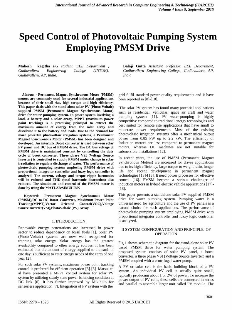
It involves three steps: fuzzification, inference and
defuzzification. The Fig. 5 presents the diagram of fuzzy
logic controller.
Fig5. Structure of fuzzy logic controller
In the fuzzification stage, variable digital inputs are
converted into linguistic variable in our case with the
sevenvalues NB: Negative big; NM: Negative medium
NS:Negative small; Z: Zero; PS: Positive small; PM:
Positive medium; PB: Positive big, as seen in Fig. 6.
Fig6. Rules of fuzzy logic controller
Fig7. Surface of fuzzy logic controller
The inference rules will be illustrated in Table 1 with two
input variables as (e) and (Δe) where (d) as the output
Table 1. Fuzzy rules
Δe/e NB NM NS Z PS PM PB
NB NB NM NS NS NS NS Z
NM NB NM NS NS NS Z Z
NS NM NS NS NS Z NS PM
Z NS NS NS Z PS PM PM
PS NS NS Z PS PS PS PS
PM NS Z NS PM PS PM PM
PB Z PS PM PB PB PB PB
International Journal of Advanced Research in Computer Engineering & Technology (IJARCET)
Volume 4 Issue 9, September 2015
3605
ISSN: 2278 – 1323 All Rights Reserved © 2015 IJARCET
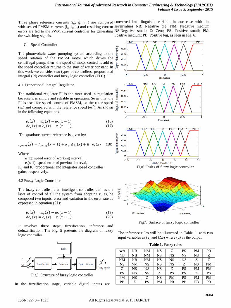
V.RESULTS AND DISCUSSION
The simulation results of the speed control of PV water
pumping system employing PMSM drive are developed
using MATLAB/ SIMULINK R2010. The performance of
the PV based PMSM drive system for water pumping
application is evaluated under various operating conditions
and observed in terms of PV voltage (VPV), PV currents
(IPV), PMSM currents (Imabc), PMSM speed (N),
electromagnetic torque and load torque (T,Tl), DC link
voltage (Vdc) and mechanical power (Pm) is presented. Fig.8 presents the simulation diagram.
Fig8. Simulation block
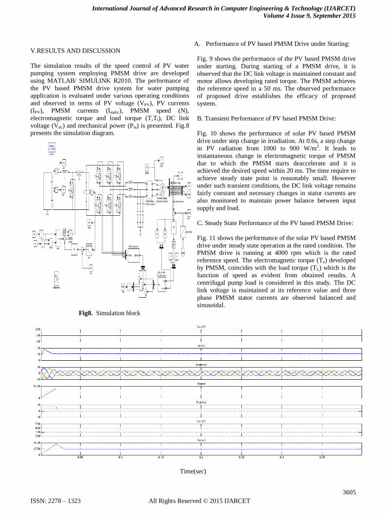
A. Performance of PV based PMSM Drive under Starting:
Fig. 9 shows the performance of the PV based PMSM drive
under starting. During starting of a PMSM drive, it is
observed that the DC link voltage is maintained constant and motor allows developing rated torque. The PMSM achieves
the reference speed in a 50 ms. The observed performance
of proposed drive establishes the efficacy of proposed
system.
B. Transient Performance of PV based PMSM Drive:
Fig. 10 shows the performance of solar PV based PMSM
drive under step change in irradiation. At 0.6s, a step change
in PV radiation from 1000 to 900 W/m2. It leads to
instantaneous change in electromagnetic torque of PMSM
due to which the PMSM starts deaccelerate and it is achieved the desired speed within 20 ms. The time require to
achieve steady state point is reasonably small. However
under such transient conditions, the DC link voltage remains
fairly constant and necessary changes in stator currents are
also monitored to maintain power balance between input
supply and load.
C. Steady State Performance of the PV based PMSM Drive:
Fig. 11 shows the performance of the solar PV based PMSM
drive under steady state operation at the rated condition. The PMSM drive is running at 4000 rpm which is the rated
reference speed. The electromagnetic torque (Te) developed
by PMSM, coincides with the load torque (TL) which is the
function of speed as evident from obtained results. A
centrifugal pump load is considered in this study. The DC
link voltage is maintained at its reference value and three
phase PMSM stator currents are observed balanced and
sinusoidal.
Time(sec)

International Journal of Advanced Research in Computer Engineering & Technology (IJARCET)
Volume 4 Issue 9, September 2015
3606
ISSN: 2278 – 1323 All Rights Reserved © 2015 IJARCET
Fig 9. Performance of PV based PMSM drive during starting
Time(sec)
Fig 10. Performance of the PV based PMSM drive under change in solar irradiation
Time(sec)

International Journal of Advanced Research in Computer Engineering & Technology (IJARCET)
Volume 4 Issue 9, September 2015
3607
ISSN: 2278 – 1323 All Rights Reserved © 2015 IJARCET
Fig11. Performance of the solar PV based PMSM drive under constant solar irradiation.
Voltage(V)
Time(sec)
Fig12. Inverter voltages(V)
Motor currents Imabc(A)
Time(sec)
Fig13. PMSM Motor currents Imabc(A)
The performance of photovoltaic pumping system employing PMSM drive with proportional integrator controller and fuzzy
logic controller is analyzed. Performance of the solar PV based PMSM drive with fuzzy logic controller is shown in Fig.14. Performance of PV based PMSM drive - during starting is from time 0 to 0.4 sec, under change in solar irradiation is from
0.55 to 0.65 sec and under constant solar irradiation is from 0.5 to 0.6 sec.

International Journal of Advanced Research in Computer Engineering & Technology (IJARCET)
Volume 4 Issue 9, September 2015
3608
ISSN: 2278 – 1323 All Rights Reserved © 2015 IJARCET
Time(sec)
Fig14 .Performance of the solar PV based PMSM drive with Fuzzy logic controller
Motor Currents with PI controller Motor currents with Fuzzy logic controller
Time(sec)
Fig15. Comparison of motor currents with PI controller and Fuzzy logic controller
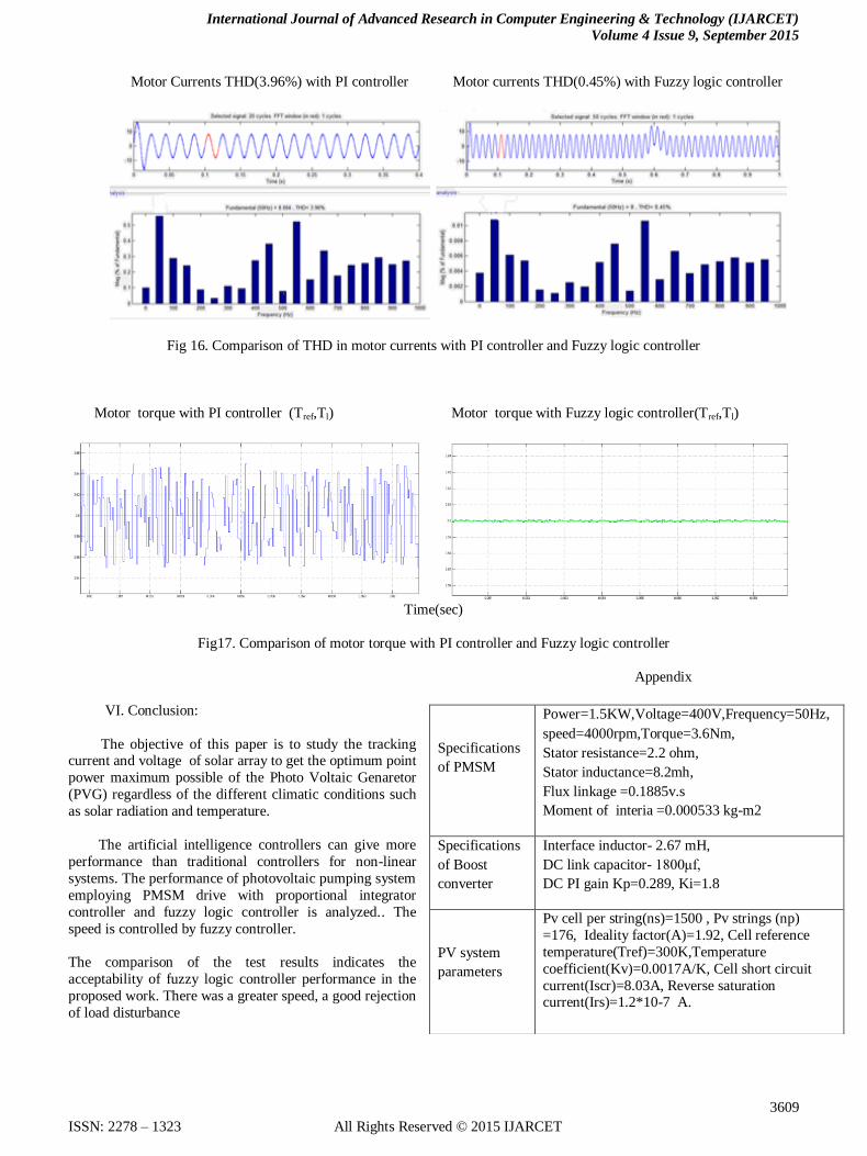
From the above results the currents for PI controller the total harmonic distraction (THD) value is 3.96% and currents for
Fuzzy logic controller (THD) value is 0.45% so the harmonics and ripple are reduced. The FFT analysis and torque ripple is
also reduced shown in fig:16 and 17.
International Journal of Advanced Research in Computer Engineering & Technology (IJARCET)
Volume 4 Issue 9, September 2015
3609
ISSN: 2278 – 1323 All Rights Reserved © 2015 IJARCET
Motor Currents THD(3.96%) with PI controller Motor currents THD(0.45%) with Fuzzy logic controller
Fig 16. Comparison of THD in motor currents with PI controller and Fuzzy logic controller
Motor torque with PI controller (Tref,Tl) Motor torque with Fuzzy logic controller(Tref,Tl)
Time(sec)
Fig17. Comparison of motor torque with PI controller and Fuzzy logic controller
Appendix
VI. Conclusion:
The objective of this paper is to study the tracking current and voltage of solar array to get the optimum point
power maximum possible of the Photo Voltaic Genaretor
(PVG) regardless of the different climatic conditions such
as solar radiation and temperature.
The artificial intelligence controllers can give more
performance than traditional controllers for non-linear
systems. The performance of photovoltaic pumping system
employing PMSM drive with proportional integrator
controller and fuzzy logic controller is analyzed.. The
speed is controlled by fuzzy controller.
The comparison of the test results indicates the
acceptability of fuzzy logic controller performance in the
proposed work. There was a greater speed, a good rejection
of load disturbance
Specifications
of PMSM
Power=1.5KW,Voltage=400V,Frequency=50Hz,
speed=4000rpm,Torque=3.6Nm,
Stator resistance=2.2 ohm,
Stator inductance=8.2mh,
Flux linkage =0.1885v.s
Moment of interia =0.000533 kg-m2
Specifications
of Boost
converter
Interface inductor- 2.67 mH,
DC link capacitor- 1800μf,
DC PI gain Kp=0.289, Ki=1.8
PV system
parameters
Pv cell per string(ns)=1500 , Pv strings (np)
=176, Ideality factor(A)=1.92, Cell reference
temperature(Tref)=300K,Temperature
coefficient(Kv)=0.0017A/K, Cell short circuit
current(Iscr)=8.03A, Reverse saturation current(Irs)=1.2*10-7 A.

International Journal of Advanced Research in Computer Engineering & Technology (IJARCET)
Volume 4 Issue 9, September 2015
3610
ISSN: 2278 – 1323 All Rights Reserved © 2015 IJARCET
REFERENCES
[1] Menka Dubey, Shailendra Sharma,”Solar PV Stand-Alone Water Pumping System Employing PMSM Drive” Member IEEE and Rakesh Saxena Electrical Engineering Department 2014 IEEE Students’ Conference on Electrical, Electronics and Computer Science [2] Hamza Bouzeria etal “Speed Control of Photovoltaic
Pumping System” international journal of renewable energy
research,vol.4,no.3,2014
[3] R. Teodorescu, M. Liserre and P. Rodriguez, Grid Converters for Photovoltaic and Wind Power Systems, 1st edition, John Wiley, United Kingdom, 2011. [4] M.G Villalva, J.R. Gazoli and E.R. Filho, “Comprehensive Approach to Modeling and Simulation of Photovoltaic
Arrays,” IEEE Trans. Power Electronics, vol. 24, no. 5, pp. 1198-1208, Mar. 2009. [5] W. J. A. Teulings, J. C. Marpinard, A. Capel, and D. O’Sullivan, “A new maximum power point tracking system,” Proc. IEEE 24th Annu. Power Electron. Spec. Conf., Jun. 1993, pp. 833–838. [6] T. Esram and P. L. Chapman, “Comparison of photovoltaic array maximum power point tracking techniques,” IEEE Trans. Energy Conversion, vol. 22, no. 2, pp. 439-449, June 2007. [7 ]F. Mayssa , F. Aymen and S. Lassaad, “ Influence of photovoltaic DC bus voltage on the high speed PMSM drive,”
Proc. IEEE IECON Conf.,Oct. 2012 , pp. 4489 - 4494. [8] H. Moussa, M. Fadel and H. Kanaan, “A single stage DC-AC boost topology and control for solar PV systems supplying a PMSM,” in Proc REDEC Conf.,Nov.2012, pp.1-7. [9] J. M. Shen, H. L. Jou and J. C. Wu, “Novel transformer
less grid connected power converter with negative grounding
for photovoltaic generation system,” IEEE Trans. Power
Electronics, vol. 27, no. 4, pp. 1818-1829, Apr. 2012.
[10] A. K. Verma, B. Singh and T. Shahani, “Grid interfaced solar photovoltaic power generating system with power quality
improvement at ac mains,” Proc IEEE ICSET Conf. ,Sep.
2012, pp. 177-182.
[11] H. Moussa, M. Fadel and H. Kanaan, “A single-stage DC-
AC boost topology and control for solar PV systems supplying
a PMSM,” in Proc REDEC Conf., Nov. 2012, pp. 1-7.
[12] W. Lawrance, B. Wichert and D. Langridge, “Simulation
and performance of a photovoltaic pumping system,” Proc.
Power Electronics and Drive systems Conf., vol. 1, Feb. 1995.
pp. 513–518.
[13] S. Henneberger, S. V. Haute, K. Hameyer and R.
Belmans, “Submersible installed permanent magnet
synchronous motor for a photovoltaic pump system,” Proc.
IEEE Electric Machines and Drives Conf., May 1997, pp.
WB2/10.1 - WB2/10.3. [14] P. Vas, Sensor less Vector and Direct Torque Control,
Oxford University Press, 1998.
[15] B. K. Bose, Power Electronics and Variable Frequency
Drives Technology andApplication, IEEE Press, New York,
1996.
[16] R. Krishnan, Permanent Magnet Synchronous and
Brushless DC Motor Drives, CRC Press, New York, 2010.
[17].P. Pillay and R. Krishnan, “Modeling of permanent
magnet motor drives, IEEE Trans. Industrial Electronics, vol.
35, no. 4, pp. 537-541, Nov. 1988.
[18] B. A. Essalam and K. Mabrouk, “Grid-Connected
Modeling, Control and simulation of single phase two-level photovoltaic power generation system coupled to a permanent
magnet synchronous,” Proc. IEEE WOSSPA Workshop, May
2011, pp. 29 34.
Mahesh. K Received his B.Tech degree in
Electrical and Electronics Engineering from Sri
Vasavi Instutite of Enginnering and
techonalogy, Nandamurru, affiliated to JNTU,
Kakinada in 2013. He is pursuing M.Tech in
the department of Electrical and Electrical Engineering with specialization in Power Electronics and Electric Drives in
Gudlavalleru Engineering College, Gudlavalleru, A.P, India.
His research interests include Power Electronic Converters and
Drives.
BALAJI GUTTA has received his B.Tech
degree from Gudlavalleru Engineering college,
Gudlavalleru under J.N.T.University,
Hyderabad in the year 2002. M.Tech degree
with the specialization of Electrical Drives and Control from
Pondicherry Engineering College in the year 2006. At present he is working as an Assistant Professor in Gudlavalleru
Engineering college, Gudlavalleru. His areas of interest are
Electrical Machines and Drives, Power Electronics, Electrical
Circuits, and Control Systems.