Embed Size (px)
Citation preview

1
Vocoders

2
The Channel Vocoder (analyzer): The channel vocoder employs a bank of
bandpass filters, Each having a bandwidth between 100 Hz and 300
Hz.
Typically, 16-20 linear phase FIR filter are used.
The output of each filter is rectified and lowpassfiltered. The bandwidth of the lowpass filter is selected to
match the time variations in the characteristics of the vocal tract.
For measurement of the spectral magnitudes, a voicing detector and a pitch estimator are included in the speech analysis.

3
The Channel Vocoder (analyzer block diagram):
Bandpass
Filter
A/D
Converter
Lowpass
Filter
A/D
Converter
Lowpass
FilterRectifier
Rectifier
Bandpass
Filter
Voicing
detector
Pitch
detector
Encoder
S(n)To
Channel

4
The Channel Vocoder (synthesizer):
16-20 linear-phase FIR filters
Covering 0-4 kHz
Each having a bandwidth between 100-300 Hz
20-ms frames, or 50 Hz changing of spectral magnitude
LPF bandwidth: 20-25 Hz
Sampling rate of the output of the filters: 50 Hz

5
The Channel Vocoder (synthesizer):
Bit rate:
1 bit for voicing detector
6 bits for pitch period
For 16 channels, each coded with 3-4 bits,
updated 50 times per second
Then the total bit rate is 2400-3200 bps
Further reductions to 1200 bps can be
achieved by exploiting frequency correlations
of the spectrum magnitude

6
The Channel Vocoder (synthesizer):
At the receiver the signal samples are passed through D/A converters.
The outputs of the D/As are multiplied by the voiced or unvoiced signal sources.
The resulting signal are passed through bandpass filters.
The outputs of the bandpass filters are summed to form the synthesized speech signal.

7
The Channel Vocoder (synthesizer block diagram):
D/A
Converter
Decoder
D/A
Converter
Voicing
Information
Pitch
period
Pulse
generator
Random
Noise
generator
Bandpass
Filter
Bandpass
Filter
Switch
∑Output
speech
From
Channel

8
The Phase Vocoder :
The phase vocoder is similar to the channel vocoder.
However, instead of estimating the pitch, the phase vocoder estimates the phase derivative at the output of each filter.
By coding and transmitting the phase derivative, this vocoder destroys the phase information .

9
The Phase Vocoder(analyzer block diagram, kth channel)
nkcos nksin
nkcos
Lowpass
Filter
Encoder
Lowpass
Filter
Differentiator
Differentiator
Decimator
Decimator
Compute
Short-term
Magnitude
And
Phase
Derivative
To
Channel
S(n)
nksin
nkcos
nak
nbk
Short-term
magnitude
Short-term phase
derivative

10
The Phase Vocoder(synthesizer block diagram, kth channel)
nkcos
Interpolator
Decoder
∑
From
ChannelCos
Integrator
InterpolatorSin
Decimated
Short-term
amplitude
Decimated
Short-term
Phase
derivative
nksin
11
The Phase Vocoder :
LPF bandwidth: 50 Hz
Demodulation separation: 100 Hz
Number of filters: 25-30
Sampling rate of spectrum magnitude and phase
derivative: 50-60 samples per second
Spectral magnitude is coded using PCM or
DPCM
Phase derivative is coded linearly using 2-3 bits
The resulting bit rate is 7200 bps

12
The Formant Vocoder :
The formant vocoder can be viewed as a
type of channel vocoder that estimates the
first three or four formants in a segment of
speech.
It is this information plus the pitch period
that is encoded and transmitted to the
receiver.
13
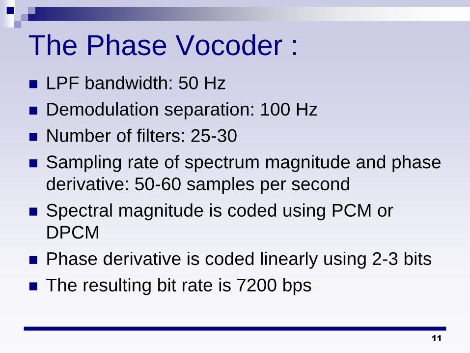
The Formant Vocoder : Example of formant:
(a) : The spectrogram of the utterance “day one” showing the pitch and the harmonic structure of speech.
(b) : A zoomed spectrogram of the fundamental and the second harmonic.
(a) (b)

14
The Formant Vocoder (analyzer block diagram):
F3
F2
F1
PitchAnd
V/UDecoder
F3
B3
F2
B2
F1
B1
V/U
F0
Fk :The frequency of the kth formant
Bk :The bandwidth of the kth formant
Input
Speech

15
The Formant Vocoder (synthesizer block diagram):
F3
F2
F1
Excitation
Signal
F3
B3
F2
B2
F1
B1
V/U
F0
∑
16
Linear Predictive Coding : The objective of LP analysis is to estimate
parameters of an all-pole model for the vocal tract.
Several methods have been devised for generating the excitation sequence for speech synthesizes.
Various LPC-type speech analysis and synthesis methods differ primarily in the type of excitation signal generated for speech synthesis.

17
LPC 10 :
This methods is called LPC-10 because of
10 coefficient are typically employed.
LPC-10 partitions the speech into the 180
sample frame.
Pitch and voicing decision are determined
by using the AMDF and zero crossing
measures.

18
A General Discrete-Time Model For Speech Production
DT
Impulse
generator
G(z)
Glottal
Filter
Uncorrelated
Noise
generator
H(z)
Vocal tract
Filter
R(z)
LP
Filter
Voiced
Unvoiced
Pitch Gain
Gain
V
U
U(n)
Voiced
Volume
velocity
s(n)
Speech
Signal

54از 19صفحه
تعيين مرتبه پيشگويي
پيشگويي خطي

54از 20صفحه
تعيين مرتبه پيشگويي
پيشگويي خطي

54از 21صفحه
تعيين مرتبه پيشگويي
پيشگويي خطي
m
Mmn
m
Mmn
ne
nsPG
1
2
1
2
][
][log10

54از 22صفحه
مثال
M=4
M=10
پيشگويي خطي

54از 23صفحه
مثال
M=2
M=10
M=54
پيشگويي خطي

54از 24صفحه
M=10M=50
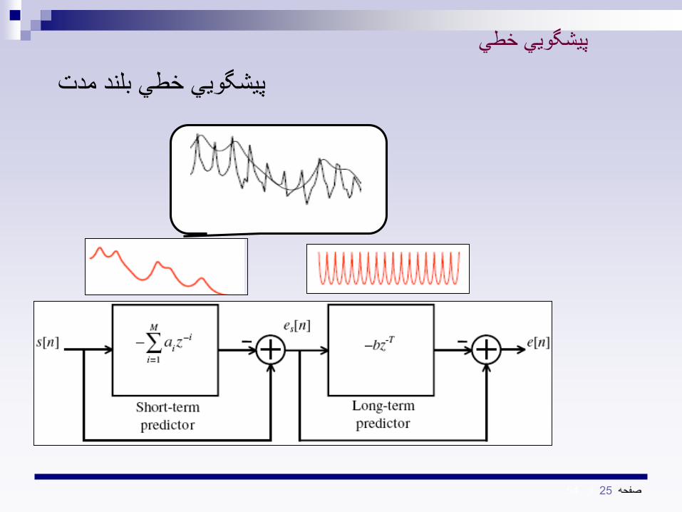
ايده پيشگويي خطي بلند مدت
پيشگويي خطي
54از 25صفحه
پيشگويي خطي بلند مدت
پيشگويي خطي

26صفحه
54از
مشخصات عمومي
LPC10وكدر
LPC10

54از 27صفحه
كد كننده
LPC LPC
Bit Encoder
PCM
LPC
LPC10وكدر

28صفحه
54از
تشخيص پريود پيچ
YMC
m
Nmnl]s[n]s[nR[l,m]
1
m
Nmn
lnsnsmlMDF
1
][][],[
mNmneNnsbns 1 ],[][ .][

54از 29صفحه
MDF
T=20,21,…,39,40,42,…,80,84,…,154
LPC10وكدر
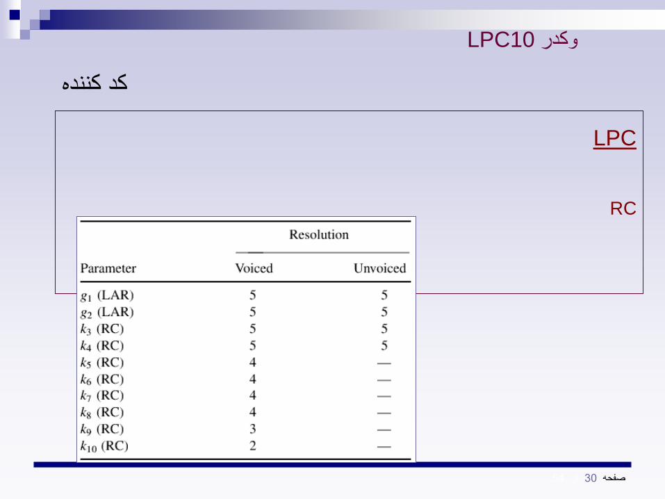
54از 30صفحه
LPC
RC
كد كننده
LPC10وكدر

31صفحه
54از
سنتز گفتار
سيگنال اصلي
بخش كد كننده
ريمبي صدا بودن ف/تعيين صدادار•
ت تعيين دوره گام فثط براي حال•صدادار
محاسبه بهره سيگنال•
G
ودقطار ضربه با پري
يراير دوره گام
نويز
تصادفي
V/U
گفتار سنتز شده
LPC10وكدر
32صفحه
54از
AR
محدوديتها
LPC10وكدر

33
Residual Excited LP Vocoder :
Speech quality can be improved at the
expense of a higher bit rate by computing
and transmitting a residual error, as done
in the case of DPCM.
One method is that the LPC model and
excitation parameters are estimated from
a frame of speech.
34
Residual Excited LP Vocoder :
The speech is synthesized at the transmitter and
subtracted from the original speech signal to
form the residual error.
The residual error is quantized, coded, and
transmitted to the receiver
At the receiver the signal is synthesized by
adding the residual error to the signal generated
from the model.

The residual signal is low-pass filtered at 1000 Hz in the
analyzer to reduce bit rate
In the synthesizer, it is rectified and spectrum flattened
(using a HPF), the lowpass and highpass signals are
summed and the resulting residual error signal is used to
excite the LPC model.
RELP vocoder provides communication-quality speech
at about 9600 bps.
35
Residual Excited LP Vocoder :

36
RELP Analyzer (type 1):
Buffer
And
window
stLP
analysis
∑
Encoder
LP
Synthesis
model
S(n)
To
ChannelExcitation
parameters
LPParameters
f (n; m) e (n; m)
Residualerror
m)}(i;a{
estimatepitch ,P
decision V/U,
estimategain ,Θ0

37
Buffer
And
window
S(n) f (n; m) Inverse
Filter
m)(z;A
Lowpass
FilterDecimator DFT Encoder
To
Channel
Prediction
Residual
m)(n;
stLP
analysis
LPParameters
m)}(i;a{
RELP Analyzer (type 2):

38
Synthesizer for a RELP vocoder
DecoderFrom
Channel
Buffer
And
ControllerInterpolator Rectifier
Highpass
Filter
Residual
LP
synthesizer
LP
model
Parameter
updates
∑
Excitation

39
RELP needs to regenerate the high-
frequency components at the decoder.
A crude approximation of the high frequencies
The multipulse LPC is a time domain
analysis-by-synthesis method that results
in a better excitation signal for the LPC
vocal system filter.
Multipulse LPC Vocoder

40
Multipulse LPC Vocoder The information concerning the excitation sequence
includes: the location of the pulses
an overall scale factor corresponding to the largest pulse amplitude
The pulse amplitudes relative to the overall scale factor
The scale factor is logarithmically quantized into 6 bits.
The amplitudes are linearly quantized into 4 bits.
The pulse locations are encoded using a differential coding scheme.
The excitation parameters are updated every 5 msec.
The LPC vocal-tract parameters and the pitch period are updated every 20 msec.
The bit rate is 9600 bps.

41
Analysis-by-synthesis coder
)/(ˆ
)(ˆ
)(ˆ
)/(ˆ)(
czA
zA
z
czzW
A stored sequence from a Gaussian
excitation codebook is scaled and used to
excite the cascade of a pitch synthesis filter
and the LPC synthesis filter
The synthetic speech is compared with the
original speech
Residual error signal is weighted
perceptually by a filter
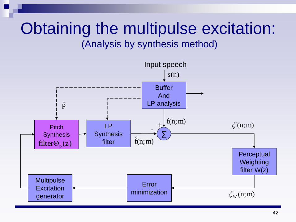
42
Obtaining the multipulse excitation:(Analysis by synthesis method)
LP
Synthesis
filter
Buffer
And
LP analysis
Multipulse
Excitation
generator
Error
minimization
Perceptual
Weighting
filter W(z)
∑m)(n;f
m)f(n;
s(n)
Input speech
m)(n;
m)(n;W
+-Pitch
Synthesis
(z)filterΘp
P

43
Code Excited LP :
CELP is an analysis-by-synthesis method
in which the excitation sequence is
selected from a codebook of zero-mean
Gaussian sequence.
The bit rate of the CELP is 4800 bps.

44
CELP (analysis-by-synthesis coder) :
Gaussian
Excitation
codebook
Pitch
Synthesis
filter
Spectral
Envelope
(LP)
Synthesis filter
∑
Perceptual
Weighting
Filter W(z)
Computer
Energy
(square and sum)
Buffer and
LP
analysis
Side
informationGain
LP
parameters
Speech samples
Index of
Excitation
sequence
45
Analysis-by-synthesis coder
This weighted error is squared and
summed over a subframe block to give the
error energy
By performing an exhaustive search
through the codebook we find the
excitation sequence that minimize the
error energy
46
Analysis-by-synthesis coder
The gain factor for scaling the excitation
sequence is determined for each
codeword in the codebook by minimizing
the error energy for the block of samples

47
CELP (synthesizer) :
From
Channeldecoder
Buffer
And
controller
Gaussian
Excitation
codebook
Pitch
Synthesis
filter
LP
Synthesis
filter
LP parameters,
gain and pitch
estimate
updates

48
CELP synthesizer Cascade of two all-pole filter with coefficients
that are updated periodically
First filter is a long-delay pitch filter used to
generate the pitch periodicity in voiced speech
This filter has this form
p
p
pbz
z
1
)(

49
CELP
Parameters of the filter can be determined
by minimizing the prediction error energy,
after pitch estimation ,over a frame
duration of 5msec
Second filter is a short-delay all-pole
(vocal-tract) filter and has 10-12
coefficients that are determined every 10-
20msec

50
Example:
sampling frequency is 8khz
subframe block duration for the pitch
estimation and excitation sequence is
performed every 5msec.
We have 40 samples per 5-msec
The excitation sequence consist of 40
samples

51
Example: A codebook of 1024 sequences gives
good-quality speech
For such codebook size ,we require
10bits to send codebook index
Hence the bit rate is reduced by a factor
of 4
The transmission of pitch predictor
parameters and spectral predictor brings
the bit rate to about 4800 bps

52
Low-delay CELP coder
CELP has been used to achieve toll-
quality speech at 16000 bps with low
delay.
Although other types of vocoders
produces high quality speech at 16000
bps these vocoders buffer 10-20msec of
speech samples

53
Low-delay CELP coder
The one way delay is of the order of 20-40
msec
With modification of CELP, it is possible to
reduce the one-way delay to about 2ms
Low-delay CELP is achieved by using a
backward-adaptive predictor with a gain
parameter and an excitation vector size as
small as 5 samples
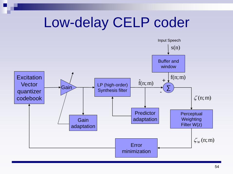
54
Low-delay CELP coder
Excitation
Vector
quantizer
codebook
LP (high-order)
Synthesis filter ∑
Perceptual
Weighting
Filter W(z)
Error
minimization
Buffer and
window
Input Speech
+
-m)(n;
m)(n;W
m)f(n;
s(n)
Gain
Gain
adaptation
Predictor
adaptation
m)(n;f

55
Low-delay CELP coder
Pitch predictor used in the conventional
forward-adaptive coder is eliminated
In order to compensate for the loss in pitch
information, the LPC predictor order is
increased significantly , to an order of 50

56
Low-delay CELP coder
LPC coefficients are updated more
frequently, every 2.5 ms
5-sample excitation vector corresponds to
an excitation block duration of 0.625 msec
at 8-kHz sampling rate
57
Low-delay CELP coder
The logarithm of the excitation gain is
adapted every subframe excitation block
by employing a 10th-order adaptive linear
predictor in the logarithmic scale
The coefficients of the logarithmic-gain
predictor are updated every four blocks by
performing an LPC analysis of previously
quantized excitation signal blocks

58
Low-delay CELP coder
The perceptual weighting filter is also 10th
order and is updated once every four
blocks by employing an LPC analysis on
frames of the input speech signal of
duration 2.5 msec
The excitation codebook in the low-delay
CELP is also modified compared to
conventional CELP
10-bit excitation codebook is employed

59
Vector Sum Excited LP : The VSELP coder and decoder basically differ in
method by which the excitation sequence is formed
In the next block diagram of the VSELP, there are three excitation sources
One excitation is obtained from the pitch period state
The other two excitation sources are obtained from two codebooks

60
VSELP Decoder :
1
0
Long-term
Filter state
Codebook
1
Codebook
2
∑
Pitch
synthesis
filter
Spectral
post filter
Spectral
envelop
(LP)
synthesis
filter
Synthetic
Speech
2

61
VSELP Decoder
LPC synthesis filter is implemented as a
10-pole filter and its coefficients are coded
and transmitted every 20ms
Coefficients are updated in each 5-ms
frame by interpolation
Excitation parameters are also updated
every 5ms

62
VSELP Decoder
128 codewords in each of the two
codebooks
codewords are constructed from two sets
of seven basis codewords by forming
linear combinations of the seven basis
codewords
The long-term filter state is also a
codebook with 128 codeword sequences

63
VSELP Decoder In each 5-msec frame, the codewords from
this codebook are filtered through the
speech system filter and correlated
with the input speech sequence
The filtered codeword is used to update
the history and the lag is transmitted to the
decoder
)(ˆ z
64
VSELP Decoder
Thus the update occurs by appending the
best-filtered codeword to the history
codebook
The oldest sample in the history array is
discarded
The result is that the long-term state
becomes an adaptive codebook

65
VSELP Decoder
The three excitation sequences are
selected sequentially from each of three
codebooks
Each codebook search attempts to find the
codeword that minimizes the total energy
of the perceptually weighted error
Once the codewords have been selected
the three gain parameters are optimized

66
VSELP Decoder
Joint gain optimization is sequentially
accomplished by orthogonalizing each
weighted codeword vectors prior to the
codebook search
These parameters are vector quantized to
one of 256 eight-bit vectors and
transmitted in every 5-ms frame

67
Vector Sum Excited LP :
The bit rate of the VSELP is about 8000 bps.
Bit allocations for 8000-bps VSELP
Parameters Bits/5-ms Frame Bits/20ms
10 LPC coefficients - 38
Average speech energy - 5Excitation codewords from
two VSELP codebooks 14 56
Gain parameters 8 32
Lag of pitch filter 7 28
Total 29 159

68
VSELP Decoder Finally, an adaptive spectral post filter is
employed in VSELP following the LPC
synthesis filter; this post filter is a pole-zero
filter of the form
)/(ˆ
)(ˆ
)(ˆ
)/(ˆ)(
czA
zA
z
czzW

69
DEMO
Speech Codec Male
Speaker
Female
Speaker
Music
Original Speech/Music
(16-bit sampled at 8KHz)
FS-1015 (LPC-10e 2.4
kb/s)
FS-1016(CELP 4.8 kb/s)
IS-54 ( VSELP 7.95 kb/s)
G.721 (32 kb/s ADPCM)

Standard Voice Algorithms
G.711 The most widely used digital representation of voice signals is that of
the G.711 or PCM (Pulse Code Modulation)
This codec represents a 4 kHz band limited voice signal sampled at 8
kHz using 8 bits per sample A-law or m-law coding.
G.726 The protocol for the G.726 codec requires a 64 kbps A-Law or m-law
PCM signal to be encoded into four different bit rate options ranging
from 2 bits per sample to 5 bits per sample
The algorithm is based on Adaptive Differential Pulse Code Modulation
(ADPCM) and is based on 1 sample backward prediction scheme.
70

G.728 The G.728 algorithm compresses PCM codec voice signals to a bit rate of 16 kbps.
This algorithm is based on a strong backward prediction scheme and is by far considered as one
of the most complex voice algorithms to be produced by the ITU standard organization.
G.729 For compression of voice signals at 8 kbps the G.729 algorithm offers toll quality with built in
algorithmic delays of less than 15 msec
Additional features described in the G.729 Annex ensure VAD1 and Comfort Noise Generation
functionalities to enhance the quality and reduce the overall bit rate
G.723.1 The most widely used algorithm for band limited channels, such as VoIP and video conferencing,
is that of G.723.1
The algorithm has two operating bit rates of 6.3 kbps and 5.3 kbps
Although the delay is not as low as that of the other ITU standards its quality is near toll quality for
the given low bit rates, making it very efficient in bit usage.
71

GSM2—AMR
The latest GSM standard is the multi rate Adaptive Code Excited Linear Prediction
that provides compression in the range of 4.75 to 12.2 kbps
In total the codec provides 12 bit rates that cover the half rate to full rate channel
capacity.
GSM—FR
The first digital codec used in a mobile environment is the GSM Full Rate vocoder
The codec compresses 13 bit PCM sample signals to a rate of 13 kbps
The algorithm is based on a very simple Regular Pulse Excited – Linear Prediction
Coding technique.
GSM—HR
To increase capacity, the GSM committee decided on a lower bit rate of 5.6 kbps for
the voice channel
The algorithm is based on the Vector Sum Excited Linear Predictive (VSELP) and is
computationally as complex as other low bit rate algorithms.
72