Embed Size (px)
Citation preview
ENMET CorporationPO Box 979Ann Arbor, MI 48106-0979
80003-033September 1997MCN-186; 03/06/98MCN-204; 10/20/99MCN-221; 11/10/99MCN-228; 11/30/99MCN-244; 09/25/00MCN-252; 04/05/01MCN-268; 11/05/01MCN-276; 05/10/02MCN-293; 05/27/03MCN-308; 10/16/03MCN-315; 02/12/04
Spectrum ON-LINE
Instrument Manual

Table of ContentsINTRODUCTION............................................................................................................................................................. 1
1.1 Unpack...............................................................................................................................................................................11.1.1 Check Order................................................................................................................................................................11.1.2 Serial Numbers ...........................................................................................................................................................1
1.2 Turn the instrument ON.....................................................................................................................................................21.2.1 Verify...........................................................................................................................................................................21.2.2 Acknowledge alarm.....................................................................................................................................................21.2.3 Remove gas .................................................................................................................................................................21.2.4 Contact ENMET.........................................................................................................................................................2
2.0 FEATURES AND INSTALLATION................................................................................................................................ 22.1 Features..............................................................................................................................................................................22.2 Installation .........................................................................................................................................................................3
2.2.1 Mount Enclosure.........................................................................................................................................................32.2.2 Relay Contacts ............................................................................................................................................................32.2.3 Turn On.......................................................................................................................................................................3
3.0 OPERATION ........................................................................................................................................................... 43.1 Operational Menu ..............................................................................................................................................................43.2 Gas Concentration Display and Alarms.............................................................................................................................53.4 Alarm Acknowledge ..........................................................................................................................................................53.5 Data....................................................................................................................................................................................53.6 Interference Gases..............................................................................................................................................................5
4.0 MAINTENANCE....................................................................................................................................................... 64.1 Maintenance Menu ............................................................................................................................................................6
4.1.1 Key ..............................................................................................................................................................................74.1.2 Zero.............................................................................................................................................................................74.1.3 Calibration..................................................................................................................................................................84.1.4 Changing the Alarm Level ..........................................................................................................................................94.1.5 Setting a New Key .......................................................................................................................................................9
4.2 Changing Components.......................................................................................................................................................94.2.1 Sensor Removal and Replacement ..............................................................................................................................9
5.0 REPLACEMENT PART NUMBERS ........................................................................................................................... 106.0 WARRANTY...................................................................................................................................................... 11APPENDIX A: CALIBRATION DATA TABLES ................................................................................................................. 12APPENDIX B: INTERFERENCE GASES.......................................................................................................................... 14
List of IllustrationsFigure 1: SPECTRUM ON-LINE Features .......................................................................................................................................3Figure 2: Operation Menu Diagram.............................................................................................................................................4Figure 3: Maintenance Menu Diagram ........................................................................................................................................6Figure 4:Intial Calibration of Replacement Sensor......................................................................................................................8Table 1: Gas Ranges, Alarm Points and Sensor Life .................................................................................................................12Table 2: Spectrum Calibration Voltage and Countdown Times ................................................................................................13Figure 5: Identification of Calibration Adapters & Sample Draw System ................................................................................13
Reference information:NOTE: [important information about use of instrument – if not followed may have to redo some steps.]
CAUTION: [affects equipment – if not followed may cause damage to instrument, sensor etc…]
WARNING: [affects personnel safety – if not followed may cause bodily injury or death.]

Spectrum ON-LINE ENMET Corporation
1
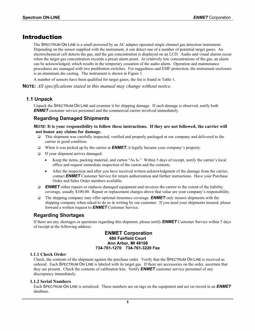
IntroductionThe SPECTRUM ON LINE is a small powered by an AC adapter operated single channel gas detection instrument.Depending on the sensor supplied with the instrument, it can detect one of a number of potential target gases. Anelectrochemical cell detects the gas, and the gas concentration is displayed on an LCD. Audio and visual alarms occurwhen the target gas concentration exceeds a preset alarm point. At relatively low concentrations of the gas, an alarmcan be acknowledged, which results in the temporary cessation of the audio alarm. Operation and maintenanceprocedures are managed with two pushbutton switches. For ruggedness and EMF protection, the instrument enclosureis an aluminum die casting. The instrument is shown in Figure 1.A number of sensors have been qualified for target gases, the list is found in Table 1.
NOTE: All specifications stated in this manual may change without notice.
1.1 UnpackUnpack the SPECTRUM ON LINE and examine it for shipping damage. If such damage is observed, notify bothENMET customer service personnel and the commercial carrier involved immediately.
Regarding Damaged ShipmentsNOTE: It is your responsibility to follow these instructions. If they are not followed, the carrier willnot honor any claims for damage.
This shipment was carefully inspected, verified and properly packaged at our company and delivered to thecarrier in good condition.
When it was picked up by the carrier at ENMET, it legally became your company’s property. If your shipment arrives damaged:• Keep the items, packing material, and carton “As Is.” Within 5 days of receipt, notify the carrier’s local
office and request immediate inspection of the carton and the contents.• After the inspection and after you have received written acknowledgment of the damage from the carrier,
contact ENMET Customer Service for return authorization and further instructions. Have your PurchaseOrder and Sales Order numbers available.
ENMET either repairs or replaces damaged equipment and invoices the carrier to the extent of the liabilitycoverage, usually $100.00. Repair or replacement charges above that value are your company’s responsibility.
The shipping company may offer optional insurance coverage. ENMET only insures shipments with theshipping company when asked to do so in writing by our customer. If you need your shipments insured, pleaseforward a written request to ENMET Customer Service.
Regarding ShortagesIf there are any shortages or questions regarding this shipment, please notify ENMET Customer Service within 5 daysof receipt at the following address:
ENMET Corporation680 Fairfield Court
Ann Arbor, MI 48108734-761-1270 734-761-3220 Fax
1.1.1 Check OrderCheck, the contents of the shipment against the purchase order. Verify that the SPECTRUM ON LINE is received asordered. Each SPECTRUM ON LINE is labeled with its target gas. If there are accessories on the order, ascertain thatthey are present. Check the contents of calibration kits. Notify ENMET customer service personnel of anydiscrepancy immediately.
1.1.2 Serial NumbersEach SPECTRUM ON LINE is serialized. These numbers are on tags on the equipment and are on record in an ENMETdatabase.
ENMET Corporation Spectrum ON-LINE
2
1.2 Turn the instrument ONTurn the instrument ON, by plugging the power supply into a standard 110 VAC wall outlet. In uncontaminated air,for most instruments the display should read 0000 within ten seconds of turn-on. For an oxygen SPECTRUM ON LINE,the display reads near 20.9%.NOTE: Instruments using biased sensors, this time is extended to 4 minutes, stabilization may take as long as 1 hour.
See Table 1.
1.2.1 VerifyThe SPECTRUM ON LINE is calibrated prior to shipment. However, if the target gas is available, expose the sensor to itto verify that no damage occurred during shipment.
1.2.2 Acknowledge alarmIf the concentration of the target gas is greater than the alarm set point, the instrument indicates an alarm condition.Acknowledge the alarm by pressing and releasing the right hand pushbutton, SELECT; this silences the audio alarmfor four minutes unless the concentration of the target gas is greater than the upper alarm limit. See Table 1 for a listof alarm set points and upper alarm limits for various target gases.
1.2.3 Remove gasRemove the source of the target gas. After the display reads zero or close to it, unplug the instrument.
1.2.4 Contact ENMETIf the instrument does not operate as described, contact ENMET customer service personnel immediately.
2.0 Features and Installation2.1 Features
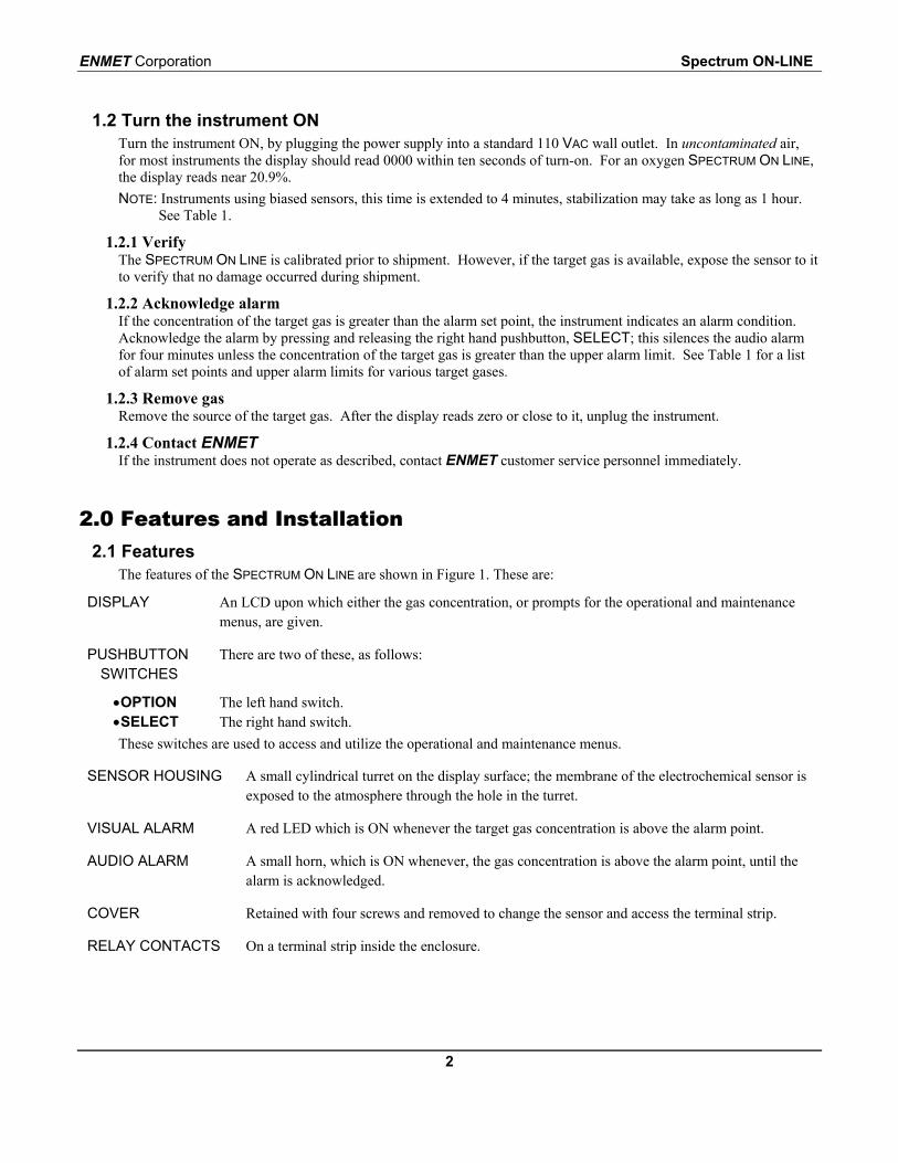
The features of the SPECTRUM ON LINE are shown in Figure 1. These are:
DISPLAY An LCD upon which either the gas concentration, or prompts for the operational and maintenancemenus, are given.
PUSHBUTTONSWITCHES
There are two of these, as follows:
•OPTION The left hand switch.•SELECT The right hand switch.These switches are used to access and utilize the operational and maintenance menus.
SENSOR HOUSING A small cylindrical turret on the display surface; the membrane of the electrochemical sensor isexposed to the atmosphere through the hole in the turret.
VISUAL ALARM A red LED which is ON whenever the target gas concentration is above the alarm point.
AUDIO ALARM A small horn, which is ON whenever, the gas concentration is above the alarm point, until thealarm is acknowledged.
COVER Retained with four screws and removed to change the sensor and access the terminal strip.
RELAY CONTACTS On a terminal strip inside the enclosure.
Spectrum ON-LINE ENMET Corporation
3
Figure 1: SPECTRUM ON-LINE Features2.2 Installation
2.2.1 Mount EnclosureMount enclosure at an appropriate location using the four mounting holes accessible inside the enclosure. See Figure 1Dimensions are in inches.
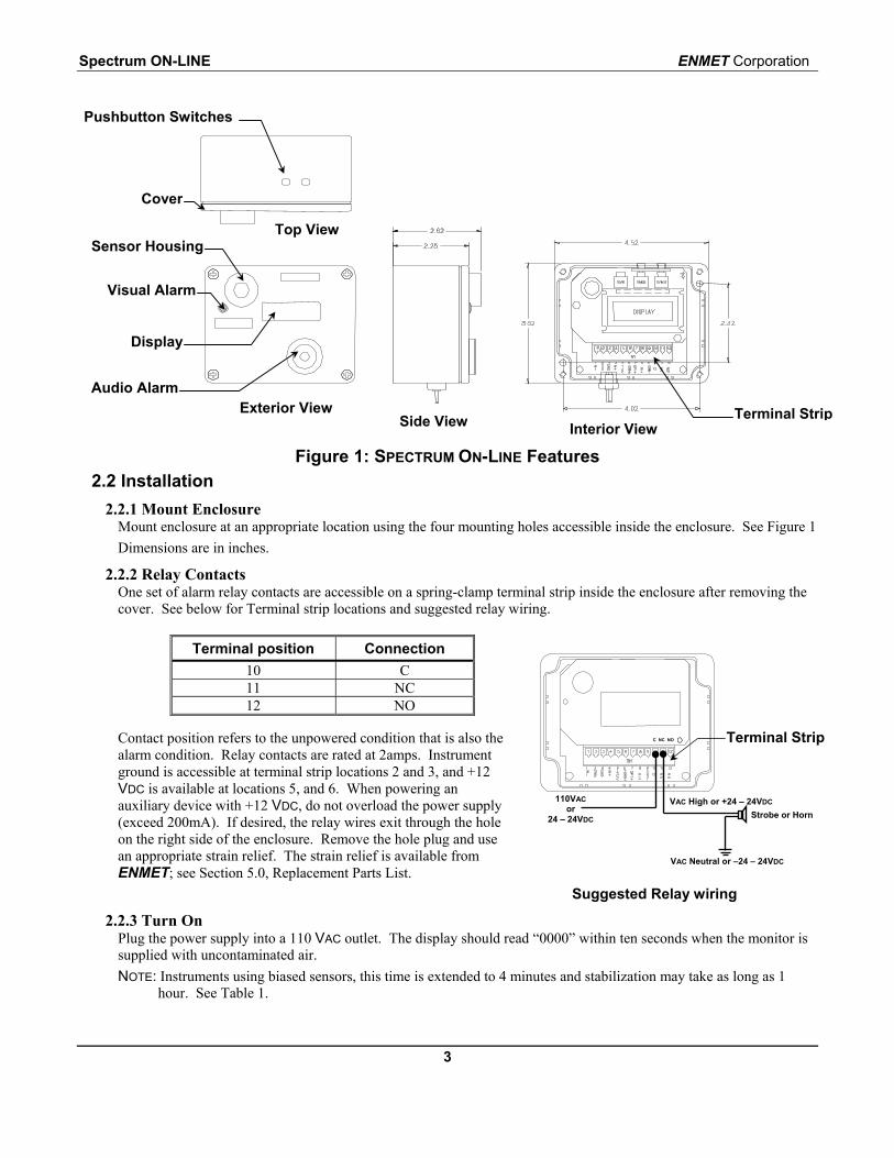
2.2.2 Relay ContactsOne set of alarm relay contacts are accessible on a spring-clamp terminal strip inside the enclosure after removing thecover. See below for Terminal strip locations and suggested relay wiring.
Terminal position Connection10 C11 NC12 NO
Contact position refers to the unpowered condition that is also thealarm condition. Relay contacts are rated at 2amps. Instrumentground is accessible at terminal strip locations 2 and 3, and +12VDC is available at locations 5, and 6. When powering anauxiliary device with +12 VDC, do not overload the power supply(exceed 200mA). If desired, the relay wires exit through the holeon the right side of the enclosure. Remove the hole plug and usean appropriate strain relief. The strain relief is available fromENMET; see Section 5.0, Replacement Parts List.
Suggested Relay wiring
2.2.3 Turn OnPlug the power supply into a 110 VAC outlet. The display should read “0000” within ten seconds when the monitor issupplied with uncontaminated air.NOTE: Instruments using biased sensors, this time is extended to 4 minutes and stabilization may take as long as 1
hour. See Table 1.
Exterior ViewInterior View
Sensor Housing
Side View
Top View
Pushbutton Switches
Audio Alarm
Display
Cover
Visual Alarm
Terminal Strip
110VACor
24 – 24VDC
VAC Neutral or –24 – 24VDC
VAC High or +24 – 24VDC
Strobe or Horn
C NC NO Terminal Strip
ENMET Corporation Spectrum ON-LINE
4
3.0 Operation3.1 Operational Menu
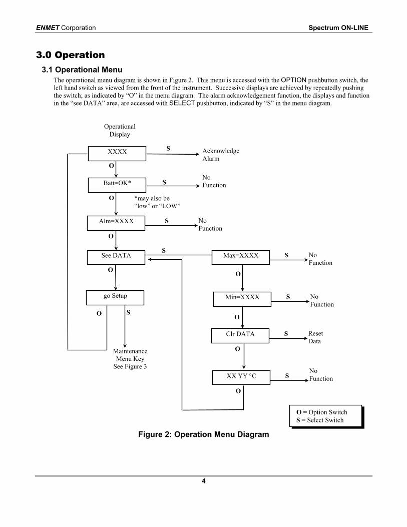
The operational menu diagram is shown in Figure 2. This menu is accessed with the OPTION pushbutton switch, theleft hand switch as viewed from the front of the instrument. Successive displays are achieved by repeatedly pushingthe switch; as indicated by “O” in the menu diagram. The alarm acknowledgement function, the displays and functionin the “see DATA” area, are accessed with SELECT pushbutton, indicated by “S” in the menu diagram.
Figure 2: Operation Menu Diagram
O
XX YY °CNoFunctionS
MaintenanceMenu Key
See Figure 3
O
Clr DATA ResetData
S
O
go Setup
O
Min=XXXX NoFunction
S
OO
SMax=XXXXSee DATA No
FunctionS
O
Alm=XXXX NoFunction
S
O
O
Batt=OK*NoFunction
*may also be“low” or “LOW”
S
OperationalDisplay
XXXX AcknowledgeAlarm
S
S
O = Option Switch S = Select Switch
Spectrum ON-LINE ENMET Corporation
5
3.2 Gas Concentration Display and AlarmsThe LCD furnishes a numerical display of the target gas concentration from 0000 to the upper limit of the range,shown in Table 1. The display of the target gas concentration is termed the "operational display". If the target gasconcentration exceeds the upper limit of the range, the display is the numerical upper limit and a plus sign, forexample,"0200+", for hydrogen sulfide. When the concentration of the target gas exceeds the alarm set point, theaudio and visual alarms are activated. The gas concentration continues to be displayed during alarm. The alarm pointis adjustable between a lower and upper alarm limit by accessing the maintenance menu; these and the factory settingof the alarm point are also given in Table 1. A user should have a justifiable application-based reason for setting thealarm point higher than the factory setting. When the target gas concentration drops below the alarm point, the audioand visual alarms cease operation. The alarm point setting can be observed on the display by pushing the OPTIONpushbutton twice.Some types of gases are difficult to detect in an ambient/static atmosphere. For these types of gases ENMETrecommends using a sampling system similar to ENMET Sample Draw Module 03700-029. See Appendix A Table 2.For the oxygen SPECTRUM ON LINE, the zero gas display is 20.9% oxygen, and the two alarm points are at 19.5%(adjustable) and 23.5% (fixed).If an alarm concentration is encountered when the display is at a location in the operational menu other than theoperational display, the audio and visual alarms are activated and the alarm cannot be acknowledged.If the display is left idle at a location other than the operational display for 45 seconds it automatically transfers to theoperational display.
3.4 Alarm AcknowledgeWhen the instrument is in alarm, and the target gas concentration is below the upper alarm limit, the alarm can beacknowledged by pressing and releasing the SELECT pushbutton, but only when the instrument is at the operationaldisplay. The acknowledgement causes the temporary cessation of the audio alarm; the red LED continues to be ON.The audio alarm is OFF for a period of four minutes, after which it is reactivated, if the gas concentration is still abovethe alarm point. The alarm can again be acknowledged. However, acknowledgement of the alarm at gasconcentrations above the upper alarm limit does not result in audio alarm cessation, and if the gas concentration risesabove the upper alarm limit during an alarm condition which has been acknowledged, the audio alarm resumesoperation.
3.5 DataThe SPECTRUM ON LINE retains the maximum and minimum gas concentration values encountered since turn-on, orsince the data was cleared and reset. To access this press the OPTION pushbutton three times; "see DATA" isdisplayed. Press the SELECT pushbutton; the maximum concentration since turn-on or last reset is displayed. Pressthe OPTION pushbutton again; the minimum concentration since turn-on or last reset is displayed. Press theOPTION pushbutton again; "clr DATA" is displayed. Pushing the SELECT pushbutton clears the data and resets it tothe current concentration. See comments on the use of this feature in Section 4.1.3, Calibration.Pushing the OPTION pushbutton once more results in a display the internal temperature of the instrument in degreescentigrade and Fahrenheit. Another push of the OPTION pushbutton results in a display of the version of the codestored in the instrument. Push the OPTION pushbutton three more times to return to the operational display.
3.6 Interference GasesFor each target gas, some gases other than the target gas cause a sensor response, and thus are termed "interferencegases". A compilation of known interference gases for the various target gases is given in Appendix B, along withgases that are known to not cause a sensor response.
ENMET Corporation Spectrum ON-LINE
6
4.0 Maintenance4.1 Maintenance Menu
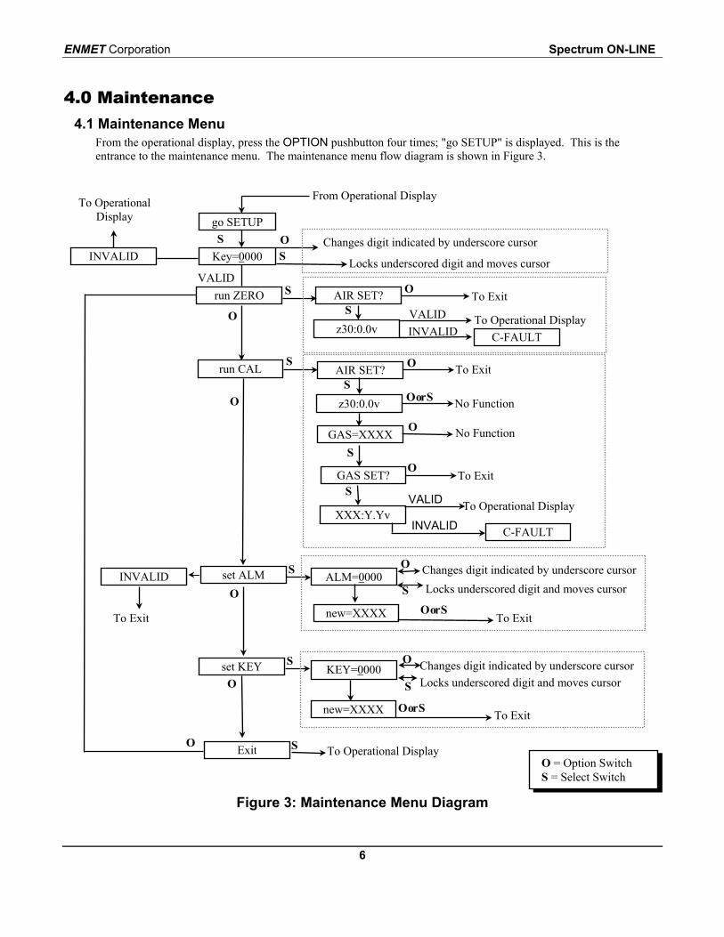
From the operational display, press the OPTION pushbutton four times; "go SETUP" is displayed. This is theentrance to the maintenance menu. The maintenance menu flow diagram is shown in Figure 3.
Figure 3: Maintenance Menu Diagram
O = Option Switch S = Select Switch
go SETUP
INVALID
To OperationalDisplay
From Operational Display
Changes digit indicated by underscore cursor
Locks underscored digit and moves cursor
S
VALID
Exit To Operational DisplayO S
O
run ZERO S
SAIR SET? To Exit
z30:0.0vC-FAULT
To Operational DisplayVALIDINVALID
O
O
run CAL S
z30:0.0v No Function
AIR SET? To ExitS
GAS=XXXX No Function
S
GAS SET? To ExitS
XXX:Y.YvC-FAULT
To Operational DisplayVALID
INVALID
O
O or S
O
O
Key=0000OS
Oset KEY S
new=XXXX
KEY=0000 Changes digit indicated by underscore cursorLocks underscored digit and moves cursor
O
S
O or S To Exit
INVALIDO
Sset ALM
O or Snew=XXXX
ALM=0000 Changes digit indicated by underscore cursorLocks underscored digit and moves cursor
O
S
To ExitTo Exit
Spectrum ON-LINE ENMET Corporation
7
4.1.1 KeyEntrance to the maintenance menu is guarded with a four digit numerical key. The factory default setting of the key is1270(The process by which a different key is set is given in paragraph 4.1.5, below). When the valid numerical key isinserted, the user is allowed to enter the maintenance menu.When in the "go SETUP" location, press the SELECT pushbutton; "Key=0000" is displayed. The underscore cursor isunder the left hand digit. To insert the key, press the OPTION pushbutton to change the left hand digit, and choose thecorrect digit; then press the SELECT pushbutton, which locks in the chosen left hand digit and moves the underscorecursor one space to the right. Continue this process until the four digit key is complete. When the valid key is insertedin this manner, the display is transferred to the "run ZERO" portion of the maintenance menu. When an invalid key isinserted, "INVALID" is briefly displayed, and the instrument returns to the operational display.
4.1.2 ZeroA valid key entry sets the instrument at the "run ZERO" location, of the maintenance menu, which enables the settingof the zero gas concentration point. This is desirable if the zero reference of the gas sensor has drifted over a period oftime, indicated by a persistent gas concentration reading in a clean environment. Note that the calibration sequencegiven below also includes setting the zero point. If a full calibration is required, instead of setting just the zero point,push the OPTION button once; "run CAL" is displayed. See paragraph 4.1.3, below.To set the zero point without performing full calibration, from the "run ZERO" location press the SELECT pushbutton;"AIR SET?" is displayed. Be certain that the instrument is in clean air, uncontaminated by the target gas. If uncertainof the environment, use pure compressed air from a pressurized cylinder, and flow it over the sensor at a low rate.With the instrument in “AIR SET?”, press the SELECT pushbutton again. "z30:0.0v" is displayed; this is a counterthat counts down in seconds from 30 to 0. The validity of the new zero setting is then examined; if it is with in presetparameters, the display is transferred to the operational display in the operation menu.If the new zero setting is not between preset parameters, "C-FAULT" is displayed. Unplugging and then plugging inthe power supply turns the instrument OFF, then ON again. This re-boots the system with the most recent valid zerosetting.
ENMET Corporation Spectrum ON-LINE
8
Sensor, Bottom View
4.1.3 CalibrationNOTE: Calibration must be performed at normal room temperature (20-25°C) for optimal performance. If the
instrument is exposed to temperature extremes just prior to calibration, allow it to stabilize to room temperature.The internal temperature of the instrument is verified by cycling through the "see DATA" menu.
In order to calibrate the instrument, it is first zeroed in a procedure similar to the one described above. Then the sensoris presented with a known concentration of the target gas, in air or an inert gas such as nitrogen, called the "span gas".After an appropriate interval, which is timed, the new span setting is examined for validity.In some cases, the concentration of target gas in the span gas is greater than the concentration expected in theworkplace. If action is not taken, the calibration gas concentration may become the permanent maximumconcentration retained and displayed as data (see Section 3.5). It is good practice to record any data desired beforecalibration, and then to reset after calibration to clear the calibration gas concentration form memory.A valid key entry sets the instrument at the "run ZERO" location of the maintenance menu. Press the OPTIONpushbutton once to access the "run CAL" display, then press the SELECT pushbutton; "AIR SET?" is displayed. Zerothe instrument as described in paragraph 4.1.2 above. When the zero timer is complete, the display indicates"GAS=XXXX", where the numbers indicate the correct span gas concentration the instrument is equipped to detect;for a CO SPECTRUM the span gas is 100 ppm CO, for Cl2 SPECTRUM the span gas is 5 ppm chlorine, and so forth.The correct span gas is given in Table 2 of Appendix A, for various target gases.At the “GAS=XXXX” display:
1. Assure that the correct span gas is available.2. Connect the calibration adapter to the cylinder along with the correct calibration cover; see Appendix A Table 2.3. Open the calibration valve so that the span gas flows.4. Press the SELECT pushbutton; "GAS SET?" is displayed.5. Connect the span gas to the instrument so the calibration gas flows over the sensor.6. Press the SELECT pushbutton; "XXX:Y.Yv" is displayed.7. Remove span gas
The XXX is a counter which counts down in seconds to zero from the correct starting time to provide the proper timeinterval for calibration; this time interval may vary depending on your target gas. The Y.Y v indicates a sensor signalwhich is used during the sensor replacement procedure. When the timer reaches zero, the new calibration and zero gassettings are examined for validity. If the value is with in preset parameters, the display is transferred to the gasoperational display in the operations menu.During calibration the audio alarm is disabled, and after calibration is complete the audio alarm remains disabled forup to 2.5 minutes.If the new settings are not within preset parameters, "C-FAULT" is displayed. Unplugging and then plugging in thepower supply turns the instrument OFF, then ON again. This re-boots the system with the most recent valid zero andcalibration settings. Recalibrate. If after recalibration the instrument still displays “C-FAULT” the sensor may beexpired. Replace the sensor in accordance with Section 4.2.1.
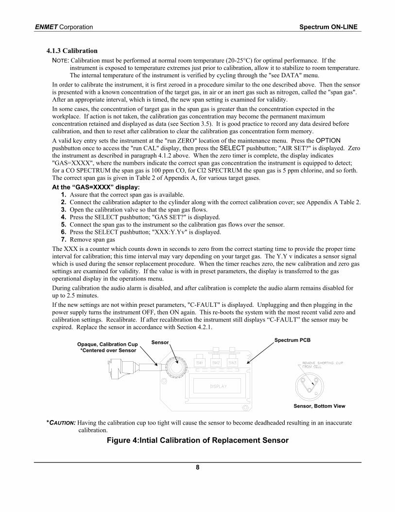
*CAUTION: Having the calibration cup too tight will cause the sensor to become deadheaded resulting in an inaccuratecalibration.
Figure 4:Intial Calibration of Replacement Sensor
Opaque, Calibration Cup*Centered over Sensor
Sensor Spectrum PCB
Spectrum ON-LINE ENMET Corporation
9
4.1.4 Changing the Alarm LevelA valid key entry sets the instrument at the "run ZERO" location of the maintenance menu. Press the OPTIONpushbutton twice to access the "set ALM" display, then press the SELECT pushbutton; ALM=0000" is displayed.This is called the alarm update window, and the value displayed is the present alarm setpoint. The underscore cursor isunder the far left digit. Press the OPTION pushbutton to change the underscored digit; select the desired digit, andpress the SELECT pushbutton to lock in the desired digit and move the underscore cursor one position to the right.When the desired new alarm point is set “new=XXXX” is displayed. Press either the OPTION or SELECTpushbutton to exit the alarm update window. If the new alarm setting is valid, "exit" is displayed. Press the OPTIONpushbutton to return to the operational display, or the SELECT pushbutton to return to “run ZERO”.For the safety of the user, there are upper and lower limits past which the alarm setting is invalid, and the instrumentdoes not accept them. If an invalid alarm setting is attempted, after the numerical value is inserted in the"ALM=0000" window, pressing the OPTION or SELECT pushbutton results in a momentary display of "INVALID"after which the display returns to the alarm update window. Exiting the alarm update window at this point results in analarm point setting unchanged from the value present when the procedure was begun.Factory default alarm setpoints and alarm limits are shown in Table 1.
4.1.5 Setting a New KeyA valid key entry sets the instrument at the "run ZERO" location of the maintenance menu. Press the OPTIONpushbutton four times to access the "set KEY" display. Press the SELECT pushbutton once; "KEY=0000 isdisplayed. A new key can be set by changing the underscored number with the OPTION pushbutton and moving theunderscore cursor with the SELECT pushbutton. After the new key is entered “new-XXXX” is displayed, press theOPTION or SELECT pushbutton to display to “exit”, then press the OPTION pushbutton to return to “run ZERO”.NOTE: Four digit key numbers should be selected carefully and recorded. Without the correct key, the maintenance
menu cannot be accessed. If a four digit key number is lost, call ENMET customer service personnel.
4.2 Changing ComponentsChanging the sensor, or the display requires that the cover of the instrument to be removed; remove the four phillipshead, cover retaining, screws and then the cover.
4.2.1 Sensor Removal and ReplacementA sensor must be replaced when it no longer responds adequately to the target gas. This is indicated by a low gasconcentration reading when exposed to a known concentration of the target gas, and the inability to calibrate the instrument,without a "C-FAULT" display after calibration. Expected sensor lifetimes in normal environments are given in Table 1.After removing the cover of the enclosure, unplug the sensor from the circuit board.
CAUTION: New sensors may come with a shorting clip that must be removed for proper operation.Remove the shorting clip (if present) from the new sensor and plug the new sensor in place. Allow the sensor tostabilize in the instrument with the power on for one hour before the initial calibration of a new sensor.The initial calibration of a new sensor must be performed with the cover removed from the instrument enclosure.Follow the procedure for calibrating the instrument as outlined in Section 4.1.3 of this manual with the followingmodification:
NOTE: During this procedure put the OPAQUE calibration cup, 02552-008, directly over the sensor and make sure it stayscentered.
During the application of the span gas, the counter counts down from an upper value given in Table 2. Whenthe counter gets down to 60, adjust the potentiometer located to the left of the display on the instrument circuitboard, so that the display to the right of the counter reads a little above the calibration voltage given for thetarget gas in Table 2. As the counter continues, turn the pot so that the calibration voltage is reached when thecounter reaches 30. This is a one-time adjustment to align the sensor output with the instrument electronics. Itshould only be performed upon sensor replacement. All future calibrations should follow the procedure inSection 4.1.3.Replace the cover of the instrument. Recalibrate the instrument according to the procedure in Section 4.1.3. to assuresensor output alignment.
NOTE: that the sensor must be replaced with a sensor for the same target gas; the instrument cannot be changed to detecta different target gas without modifications in addition to changing the sensor type.
ENMET Corporation Spectrum ON-LINE
10
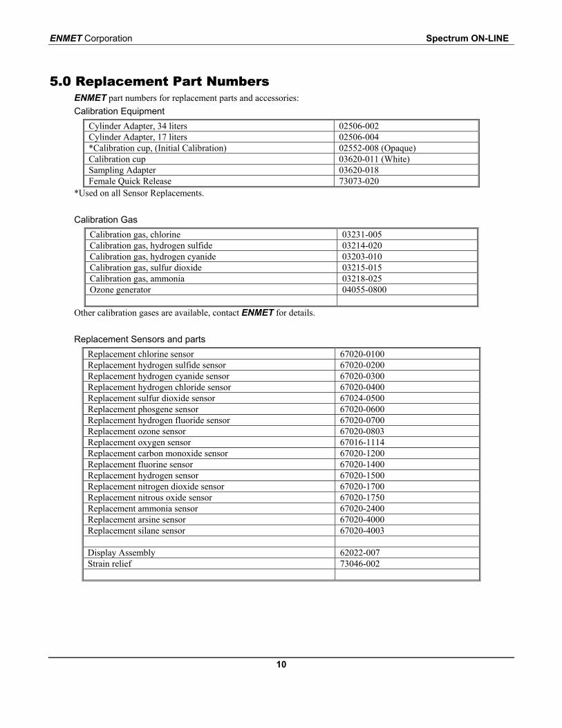
5.0 Replacement Part NumbersENMET part numbers for replacement parts and accessories:Calibration Equipment
Cylinder Adapter, 34 liters 02506-002Cylinder Adapter, 17 liters 02506-004*Calibration cup, (Initial Calibration) 02552-008 (Opaque)Calibration cup 03620-011 (White)Sampling Adapter 03620-018Female Quick Release 73073-020
*Used on all Sensor Replacements.
Calibration GasCalibration gas, chlorine 03231-005Calibration gas, hydrogen sulfide 03214-020Calibration gas, hydrogen cyanide 03203-010Calibration gas, sulfur dioxide 03215-015Calibration gas, ammonia 03218-025Ozone generator 04055-0800
Other calibration gases are available, contact ENMET for details.
Replacement Sensors and partsReplacement chlorine sensor 67020-0100Replacement hydrogen sulfide sensor 67020-0200Replacement hydrogen cyanide sensor 67020-0300Replacement hydrogen chloride sensor 67020-0400Replacement sulfur dioxide sensor 67024-0500Replacement phosgene sensor 67020-0600Replacement hydrogen fluoride sensor 67020-0700Replacement ozone sensor 67020-0803Replacement oxygen sensor 67016-1114Replacement carbon monoxide sensor 67020-1200Replacement fluorine sensor 67020-1400Replacement hydrogen sensor 67020-1500Replacement nitrogen dioxide sensor 67020-1700Replacement nitrous oxide sensor 67020-1750Replacement ammonia sensor 67020-2400Replacement arsine sensor 67020-4000Replacement silane sensor 67020-4003
Display Assembly 62022-007Strain relief 73046-002
Spectrum ON-LINE ENMET Corporation
11
6.0 WARRANTY
ENMET warrants new instruments to be free from defects in workmanship and material under normal use for a periodof one year from date of shipment from ENMET. The warranty covers both parts and labor excluding instrumentcalibration and expendable parts such as calibration gas, filters, batteries, etc... Equipment believed to be defectiveshould be returned to ENMET within the warranty period (transportation prepaid) for inspection. If the evaluation byENMET confirms that the product is defective, it will be repaired or replaced at no charge, within the statedlimitations, and returned prepaid to any location in the United States by the most economical means, e.g. SurfaceUPS/FedEx Ground. If an expedient means of transportation is requested during the warranty period, the customer isresponsible for the difference between the most economical means and the expedient mode. ENMET shall not beliable for any loss or damage caused by the improper use of the product. The purchaser indemnifies and savesharmless the company with respect to any loss or damages that may arise through the use by the purchaser or others ofthis equipment.
This warranty is expressly given in lieu of all other warranties, either expressed or implied, including that ofmerchantability, and all other obligations or liabilities of ENMET which may arise in connection with this equipment.ENMET neither assumes nor authorizes any representative or other person to assume for it any obligation or liabilityother than that which is set forth herein.
NOTE: When returning an instrument to the factory for service: Be sure to include paperwork. A purchase order, return address and telephone number will assist in the expedient repair and return of your unit. Include any specific instructions. For warranty service, include date of purchase If you require an estimate, please contact ENMET Corporation.
There is Return for Repair Instructions and Form on the last pages of this manual. This form can be copied or used asneeded.
ENMET Corporation Spectrum ON-LINE
12
Appendix A: Calibration Data Tables
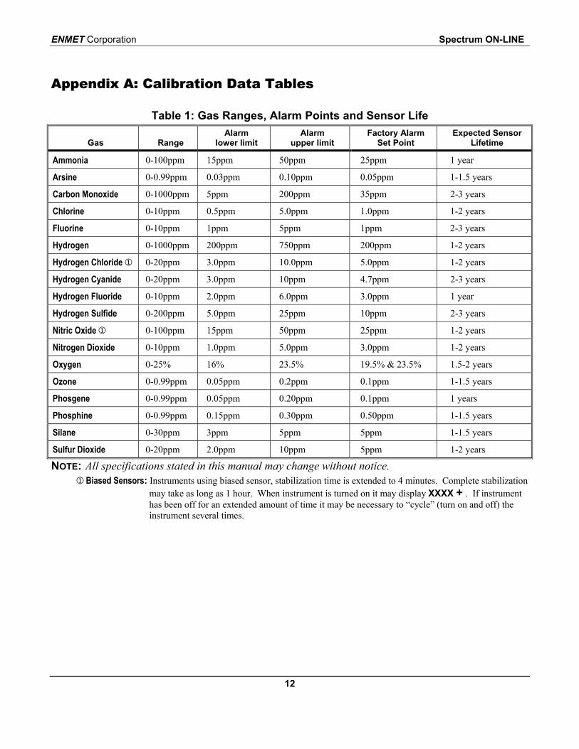
Table 1: Gas Ranges, Alarm Points and Sensor Life
Gas RangeAlarm
lower limitAlarm
upper limitFactory Alarm
Set PointExpected Sensor
Lifetime
Ammonia 0-100ppm 15ppm 50ppm 25ppm 1 year
Arsine 0-0.99ppm 0.03ppm 0.10ppm 0.05ppm 1-1.5 years
Carbon Monoxide 0-1000ppm 5ppm 200ppm 35ppm 2-3 years
Chlorine 0-10ppm 0.5ppm 5.0ppm 1.0ppm 1-2 years
Fluorine 0-10ppm 1ppm 5ppm 1ppm 2-3 years
Hydrogen 0-1000ppm 200ppm 750ppm 200ppm 1-2 years
Hydrogen Chloride 0-20ppm 3.0ppm 10.0ppm 5.0ppm 1-2 years
Hydrogen Cyanide 0-20ppm 3.0ppm 10ppm 4.7ppm 2-3 years
Hydrogen Fluoride 0-10ppm 2.0ppm 6.0ppm 3.0ppm 1 year
Hydrogen Sulfide 0-200ppm 5.0ppm 25ppm 10ppm 2-3 years
Nitric Oxide 0-100ppm 15ppm 50ppm 25ppm 1-2 years
Nitrogen Dioxide 0-10ppm 1.0ppm 5.0ppm 3.0ppm 1-2 years
Oxygen 0-25% 16% 23.5% 19.5% & 23.5% 1.5-2 years
Ozone 0-0.99ppm 0.05ppm 0.2ppm 0.1ppm 1-1.5 years
Phosgene 0-0.99ppm 0.05ppm 0.20ppm 0.1ppm 1 years
Phosphine 0-0.99ppm 0.15ppm 0.30ppm 0.50ppm 1-1.5 years
Silane 0-30ppm 3ppm 5ppm 5ppm 1-1.5 years
Sulfur Dioxide 0-20ppm 2.0ppm 10ppm 5ppm 1-2 years
NOTE: All specifications stated in this manual may change without notice. Biased Sensors: Instruments using biased sensor, stabilization time is extended to 4 minutes. Complete stabilization
may take as long as 1 hour. When instrument is turned on it may display XXXX + . If instrumenthas been off for an extended amount of time it may be necessary to “cycle” (turn on and off) theinstrument several times.
Spectrum ON-LINE ENMET Corporation
13
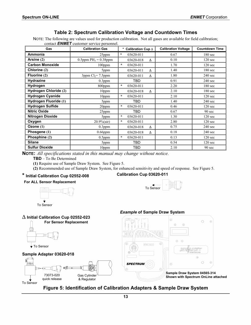
Table 2: Spectrum Calibration Voltage and Countdown TimesNOTE: The following are values used for production calibration. Not all gases are available for field calibration;
contact ENMET customer service personnel.Gas Calibration Gas * Calibration Cup ∆ Calibration Voltage Countdown Time
Ammonia 25ppm * 03620-011 0.67 180 secArsine (2) 0.5ppm PH3 = 0.38ppm 03620-018 ∆ 0.10 120 secCarbon Monoxide 100ppm * 03620-011 1.70 120 secChlorine (2) 5ppm 03620-011 ∆ 1.40 180 secFluorine (2) 3ppm Cl2= 7.5ppm 03620-011 ∆ 1.80 240 secHydrazine 0.3ppm TBD 0.91 240 secHydrogen 800ppm * 03620-011 2.20 180 secHydrogen Chloride (2) 10ppm 03620-018 ∆ 2.10 180 secHydrogen Cyanide 10ppm * 03620-011 2.10 120 secHydrogen Fluoride (1) 5ppm TBD 1.40 240 secHydrogen Sulfide 20ppm * 03620-011 0.46 120 secNitric Oxide 25ppm TBD 0.67 90 secNitrogen Dioxide 5ppm * 03620-011 1.30 120 secOxygen 20.9%(air) * 03620-011 2.80 120 secOzone (1) 0.3ppm 03620-018 ∆ 0.75 240 secPhosgene (1) 0.66ppm 03620-018 ∆ 0.18 240 secPhosphine (2) 0.5ppm * 03620-011 0.13 120 secSilane 5ppm TBD 0.54 120 secSulfur Dioxide 10ppm TBD 2.10 90 sec
NOTE: All specifications stated in this manual may change without notice.TBD – To Be Determined(1) Require use of Sample Draw System. See Figure 5.(2) Recommended use of Sample Draw System, for enhanced sensitivity and speed of response. See Figure 5.
* Initial Calibration Cup 02552-008For ALL Sensor Replacement
∆ Initial Calibration Cup 02552-023For Sensor Replacement
Sample Adapter 03620-018
Calibration Cup 03620-011
Example of Sample Draw System
Figure 5: Identification of Calibration Adapters & Sample Draw System
To Sensor
Sample Draw System 04565-314Shown with Spectrum OnLine attached
To Sensor
To Sensor
73073-020quick release
Gas Cylinder& Regulator
To Sensor
ENMET Corporation Spectrum ON-LINE
14
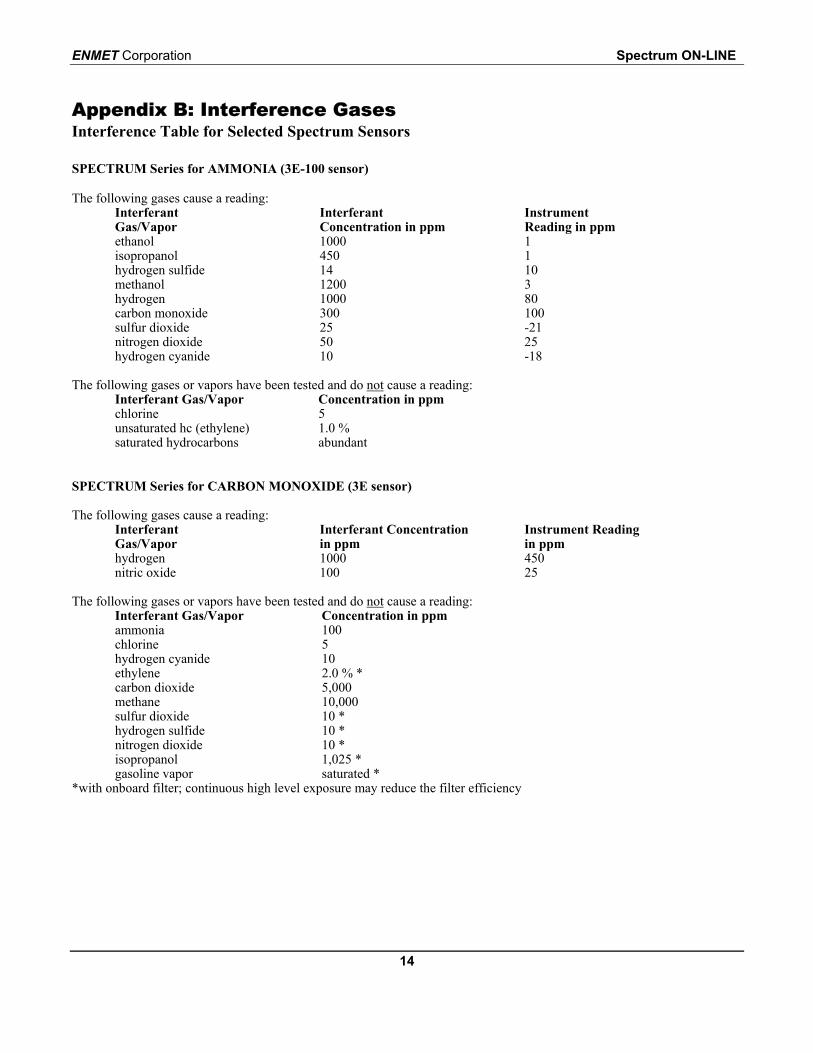
Appendix B: Interference GasesInterference Table for Selected Spectrum Sensors
SPECTRUM Series for AMMONIA (3E-100 sensor)
The following gases cause a reading:InterferantGas/Vapor
InterferantConcentration in ppm
InstrumentReading in ppm
ethanol 1000 1isopropanol 450 1hydrogen sulfide 14 10methanol 1200 3hydrogen 1000 80carbon monoxide 300 100sulfur dioxide 25 -21nitrogen dioxide 50 25hydrogen cyanide 10 -18
The following gases or vapors have been tested and do not cause a reading:Interferant Gas/Vapor Concentration in ppmchlorine 5unsaturated hc (ethylene) 1.0 %saturated hydrocarbons abundant
SPECTRUM Series for CARBON MONOXIDE (3E sensor)
The following gases cause a reading:InterferantGas/Vapor
Interferant Concentrationin ppm
Instrument Readingin ppm
hydrogen 1000 450nitric oxide 100 25
The following gases or vapors have been tested and do not cause a reading:Interferant Gas/Vapor Concentration in ppmammonia 100chlorine 5hydrogen cyanide 10ethylene 2.0 % *carbon dioxide 5,000methane 10,000sulfur dioxide 10 *hydrogen sulfide 10 *nitrogen dioxide 10 *isopropanol 1,025 *gasoline vapor saturated *
*with onboard filter; continuous high level exposure may reduce the filter efficiency
Spectrum ON-LINE ENMET Corporation
15
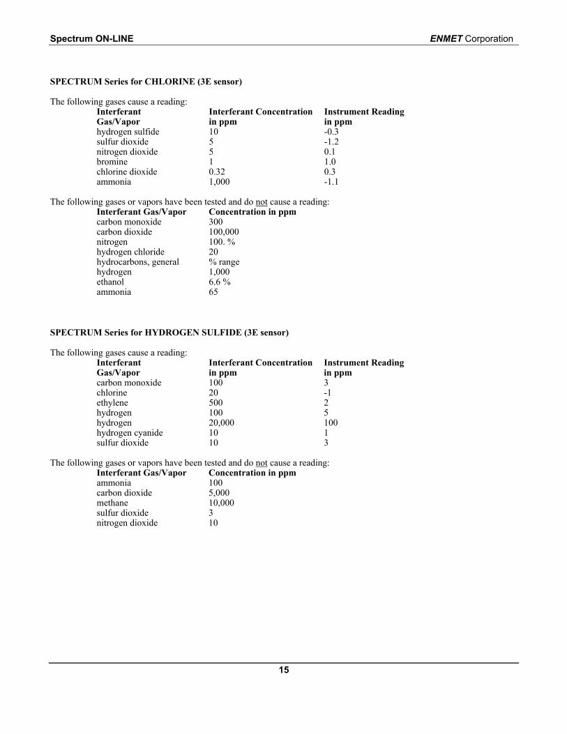
SPECTRUM Series for CHLORINE (3E sensor)
The following gases cause a reading:InterferantGas/Vapor
Interferant Concentrationin ppm
Instrument Readingin ppm
hydrogen sulfide 10 -0.3sulfur dioxide 5 -1.2nitrogen dioxide 5 0.1bromine 1 1.0chlorine dioxide 0.32 0.3ammonia 1,000 -1.1
The following gases or vapors have been tested and do not cause a reading:Interferant Gas/Vapor Concentration in ppmcarbon monoxide 300carbon dioxide 100,000nitrogen 100. %hydrogen chloride 20hydrocarbons, general % rangehydrogen 1,000ethanol 6.6 %ammonia 65
SPECTRUM Series for HYDROGEN SULFIDE (3E sensor)
The following gases cause a reading:InterferantGas/Vapor
Interferant Concentrationin ppm
Instrument Readingin ppm
carbon monoxide 100 3chlorine 20 -1ethylene 500 2hydrogen 100 5hydrogen 20,000 100hydrogen cyanide 10 1sulfur dioxide 10 3
The following gases or vapors have been tested and do not cause a reading:Interferant Gas/Vapor Concentration in ppmammonia 100carbon dioxide 5,000methane 10,000sulfur dioxide 3nitrogen dioxide 10
ENMET Corporation Spectrum ON-LINE
16
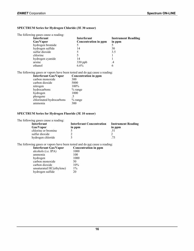
SPECTRUM Series for Hydrogen Chloride (3E 30 sensor)
The following gases cause a reading:InterferantGas/Vapor
InterferantConcentration in ppm
Instrument Readilngin ppm
hydrogen bromide 5 5hydrogen sulfide 14 30sulfur dioxide 5 3.5chlorine 5 1hydrogen cyanide 14 1arsine 330 ppb .4ethanol 6.6% 6
The following gases or vapors have been tested and do not cause a reading:Interferant Gas/Vapor Concentration in ppmcarbon monoxide 300carbon dioxide 5000nitrogen 100%hydrocarbons % rangehydrogen 1000phosgene .5chlorinated hydrocarbons % rangeammonia 300
SPECTRUM Series for Hydrogen Fluoride (3E 10 sensor)
The following gases cause a reading:InterferantGas/Vapor
Interferant Concentrationin ppm
Instrument Readingin ppm
chlorine or bromine 5 .51sulfur dioxide 2 2hydrogen chloride 5 .75
The following gases or vapors have been tested and do not cause a reading:Interferant Gas/Vapor Concentration in ppmalcohols (i.e. IPA) 1000ammonia 100hydrogen 1000carbon monoxide 50carbon dioxide 10%unsaturated HC(ethylene) 1%hydrogen sulfide 20
Spectrum ON-LINE ENMET Corporation
17
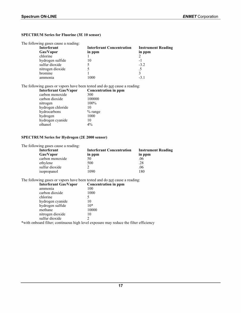
SPECTRUM Series for Fluorine (3E 10 sensor)
The following gases cause a reading:InterferantGas/Vapor
Interferant Concentrationin ppm
Instrument Readingin ppm
chlorine 1 2hydrogen sulfide 10 -1sulfur dioxide 5 -3.2nitrogen dioxide 5 .5bromine 1 3ammonia 1000 -3.1
The following gases or vapors have been tested and do not cause a reading:Interferant Gas/Vapor Concentration in ppmcarbon monoxide 300carbon dioxide 100000nitrogen 100%hydrogen chloride 10hydrocarbons % rangehydrogen 1000hydrogen cyanide 10ethanol 4%
SPECTRUM Series for Hydrogen (2E 2000 sensor)
The following gases cause a reading:InterferantGas/Vapor
Interferant Concentrationin ppm
Instrument Readingin ppm
carbon monoxide 50 .06ethylene 500 .28sulfur dioxide 2 .06isopropanol 1090 180
The following gases or vapors have been tested and do not cause a reading:Interferant Gas/Vapor Concentration in ppmammonia 100carbon dioxide 1000chlorine 5hydrogen cyanide 10hydrogen sulfide 10*methane 10000nitrogen dioxide 10sulfur dioxide 2
*with onboard filter; continuous high level exposure may reduce the filter efficiency
ENMET Corporation Spectrum ON-LINE
18
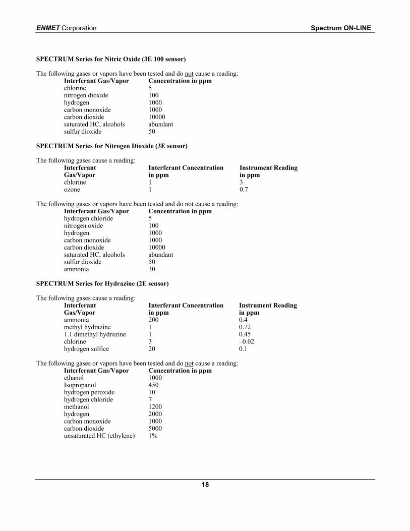
SPECTRUM Series for Nitric Oxide (3E 100 sensor)
The following gases or vapors have been tested and do not cause a reading:Interferant Gas/Vapor Concentration in ppmchlorine 5nitrogen dioxide 100hydrogen 1000carbon monoxide 1000carbon dioxide 10000saturated HC, alcohols abundantsulfur dioxide 50
SPECTRUM Series for Nitrogen Dioxide (3E sensor)
The following gases cause a reading:InterferantGas/Vapor
Interferant Concentrationin ppm
Instrument Readingin ppm
chlorine 1 3ozone 1 0.7
The following gases or vapors have been tested and do not cause a reading:Interferant Gas/Vapor Concentration in ppmhydrogen chloride 5nitrogen oxide 100hydrogen 1000carbon monoxide 1000carbon dioxide 10000saturated HC, alcohols abundantsulfur dioxide 50ammonia 30
SPECTRUM Series for Hydrazine (2E sensor)
The following gases cause a reading:InterferantGas/Vapor
Interferant Concentrationin ppm
Instrument Readingin ppm
ammonia 200 0.4methyl hydrazine 1 0.721.1 dimethyl hydrazine 1 0.45chlorine 3 –0.02hydrogen sulfice 20 0.1
The following gases or vapors have been tested and do not cause a reading:Interferant Gas/Vapor Concentration in ppmethanol 1000Isopropanol 450hydrogen peroxide 10hydrogen chloride 7methanol 1200hydrogen 2000carbon monoxide 1000carbon dioxide 5000unsaturated HC (ethylene) 1%
Spectrum ON-LINE ENMET Corporation
19
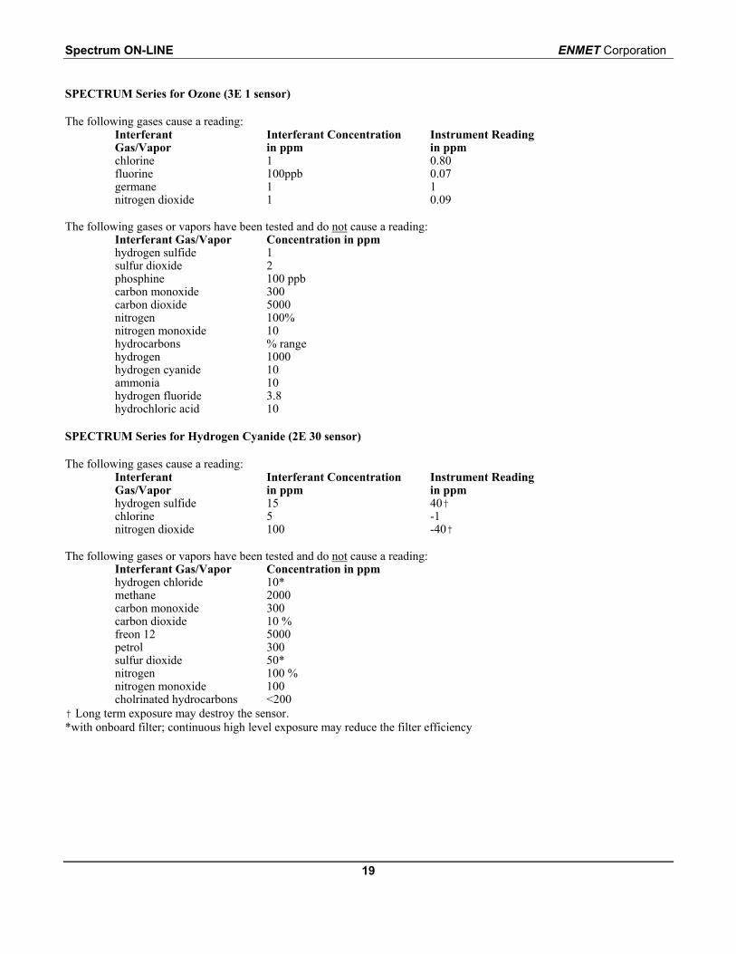
SPECTRUM Series for Ozone (3E 1 sensor)
The following gases cause a reading:InterferantGas/Vapor
Interferant Concentrationin ppm
Instrument Readingin ppm
chlorine 1 0.80fluorine 100ppb 0.07germane 1 1nitrogen dioxide 1 0.09
The following gases or vapors have been tested and do not cause a reading:Interferant Gas/Vapor Concentration in ppmhydrogen sulfide 1sulfur dioxide 2phosphine 100 ppbcarbon monoxide 300carbon dioxide 5000nitrogen 100%nitrogen monoxide 10hydrocarbons % rangehydrogen 1000hydrogen cyanide 10ammonia 10hydrogen fluoride 3.8hydrochloric acid 10
SPECTRUM Series for Hydrogen Cyanide (2E 30 sensor)
The following gases cause a reading:InterferantGas/Vapor
Interferant Concentrationin ppm
Instrument Readingin ppm
hydrogen sulfide 15 40†chlorine 5 -1nitrogen dioxide 100 -40†
The following gases or vapors have been tested and do not cause a reading:Interferant Gas/Vapor Concentration in ppmhydrogen chloride 10*methane 2000carbon monoxide 300carbon dioxide 10 %freon 12 5000petrol 300sulfur dioxide 50*nitrogen 100 %nitrogen monoxide 100cholrinated hydrocarbons <200
† Long term exposure may destroy the sensor.*with onboard filter; continuous high level exposure may reduce the filter efficiency
ENMET Corporation Spectrum ON-LINE
20
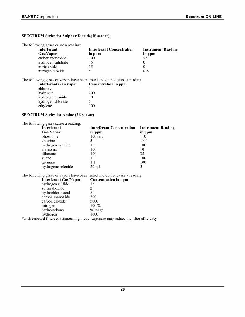
SPECTRUM Series for Sulphur Dioxide(4S sensor)
The following gases cause a reading:InterferantGas/Vapor
Interferant Concentrationin ppm
Instrument Readingin ppm
carbon monoxide 300 <3hydrogen sulphide 15 0nitric oxide 35 0nitrogen dioxide 5 ≈-5
The following gases or vapors have been tested and do not cause a reading:Interferant Gas/Vapor Concentration in ppmchlorine 1hydrogen 200hydrogen cyanide 10hydrogen chloride 5ethylene 100
SPECTRUM Series for Arsine (2E sensor)
The following gases cause a reading:InterferantGas/Vapor
Interferant Concentrationin ppm
Instrument Readingin ppm
phosphine 100 ppb 110chlorine 5 -400hydrogen cyanide 10 100ammonia 100 10diborane 100 35silane 1 100germane 1.1 100hydrogene selenide 50 ppb 5
The following gases or vapors have been tested and do not cause a reading:Interferant Gas/Vapor Concentration in ppmhydrogen sulfide 1*sulfur dioxide 2hydrochloric acid 5carbon monoxide 300carbon dioxide 5000nitrogen 100 %hydrocarbons % rangehydrogen 1000
*with onboard filter; continuous high level exposure may reduce the filter efficiency
Spectrum ON-LINE ENMET Corporation
21
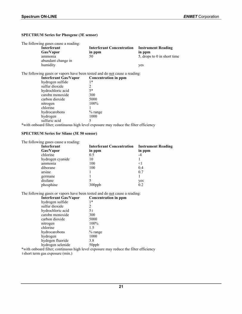
SPECTRUM Series for Phosgene (3E sensor)
The following gases cause a reading:InterferantGas/Vapor
Interferant Concentrationin ppm
Instrument Readingin ppm
ammonia 50 5, drops to 0 in short timeabundant change inhumidity yes
The following gases or vapors have been tested and do not cause a reading:Interferant Gas/Vapor Concentration in ppmhydrogen sulfide 1*sulfur dioxide 2hydrochloric acid 5*carobn monoxide 300carbon dioxide 5000nitrogen 100%chlorine 1hydrocarobons % rangehydrogen 1000sulfuric acid 5
*with onboard filter; continuous high level exposure may reduce the filter efficiency
SPECTRUM Series for Silane (3E 50 sensor)
The following gases cause a reading:InterferantGas/Vapor
Interferant Concentrationin ppm
Instrument Readingin ppm
chlorine 0.5 -4hydrogen cyanide 10 1ammonia 100 <1diborane 100 0.4arsine 1 0.7germane 1 1disilane 5 yesphosphine 300ppb 0.2
The following gases or vapors have been tested and do not cause a reading:Interferant Gas/Vapor Concentration in ppmhydrogen sulfide 1*sulfur dioxide 2hydrochloric acid 5‡carobn monoxide 300carbon dioxide 5000nitrogen 100%chlorine 1.5hydrocarobons % rangehydrogen 1000hydogen fluoride 3.8hydrogen selenide 50ppb
*with onboard filter; continuous high level exposure may reduce the filter efficiency‡short term gas exposure (min.)

ENMET Corporation Spectrum ON-LINE
22
Notes:
PO Box 979680 Fairfield CourtAnn Arbor, Michigan 48106-0979734.761.1270 Fax 734.761.3220
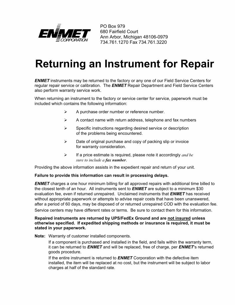
Returning an Instrument for RepairENMET instruments may be returned to the factory or any one of our Field Service Centers forregular repair service or calibration. The ENMET Repair Department and Field Service Centersalso perform warranty service work.
When returning an instrument to the factory or service center for service, paperwork must beincluded which contains the following information:
A purchase order number or reference number.
A contact name with return address, telephone and fax numbers
Specific instructions regarding desired service or descriptionof the problems being encountered.
Date of original purchase and copy of packing slip or invoicefor warranty consideration.
If a price estimate is required, please note it accordingly and besure to include a fax number.
Providing the above information assists in the expedient repair and return of your unit.
Failure to provide this information can result in processing delays.
ENMET charges a one hour minimum billing for all approved repairs with additional time billed tothe closest tenth of an hour. All instruments sent to ENMET are subject to a minimum $30evaluation fee, even if returned unrepaired. Unclaimed instruments that ENMET has receivedwithout appropriate paperwork or attempts to advise repair costs that have been unanswered,after a period of 60 days, may be disposed of or returned unrepaired COD with the evaluation fee.Service centers may have different rates or terms. Be sure to contact them for this information.
Repaired instruments are returned by UPS/FedEx Ground and are not insured unlessotherwise specified. If expedited shipping methods or insurance is required, it must bestated in your paperwork.
Note: Warranty of customer installed components.If a component is purchased and installed in the field, and fails within the warranty term,it can be returned to ENMET and will be replaced, free of charge, per ENMET’s returnedgoods procedure.If the entire instrument is returned to ENMET Corporation with the defective iteminstalled, the item will be replaced at no cost, but the instrument will be subject to laborcharges at half of the standard rate.

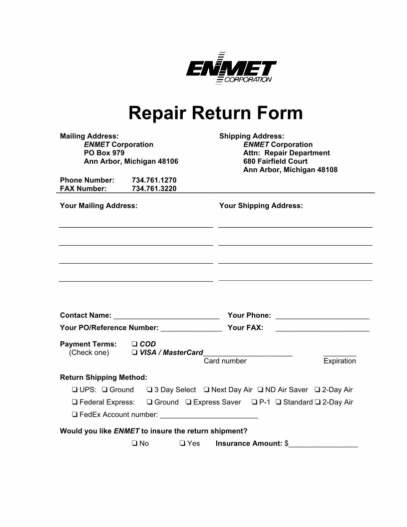
Repair Return FormMailing Address:
ENMET CorporationPO Box 979Ann Arbor, Michigan 48106
Phone Number: 734.761.1270FAX Number: 734.761.3220
Shipping Address:ENMET CorporationAttn: Repair Department680 Fairfield CourtAnn Arbor, Michigan 48108
Your Mailing Address: Your Shipping Address:
Contact Name: __________________________ Your Phone: _______________________
Your PO/Reference Number: _______________ Your FAX: _______________________
Payment Terms: COD(Check one) VISA / MasterCard______________________ ________
Card number Expiration
Return Shipping Method: UPS: Ground 3 Day Select Next Day Air ND Air Saver 2-Day Air
Federal Express: Ground Express Saver P-1 Standard 2-Day Air
FedEx Account number: ________________________
Would you like ENMET to insure the return shipment? No Yes Insurance Amount: $_________________