Embed Size (px)
Citation preview
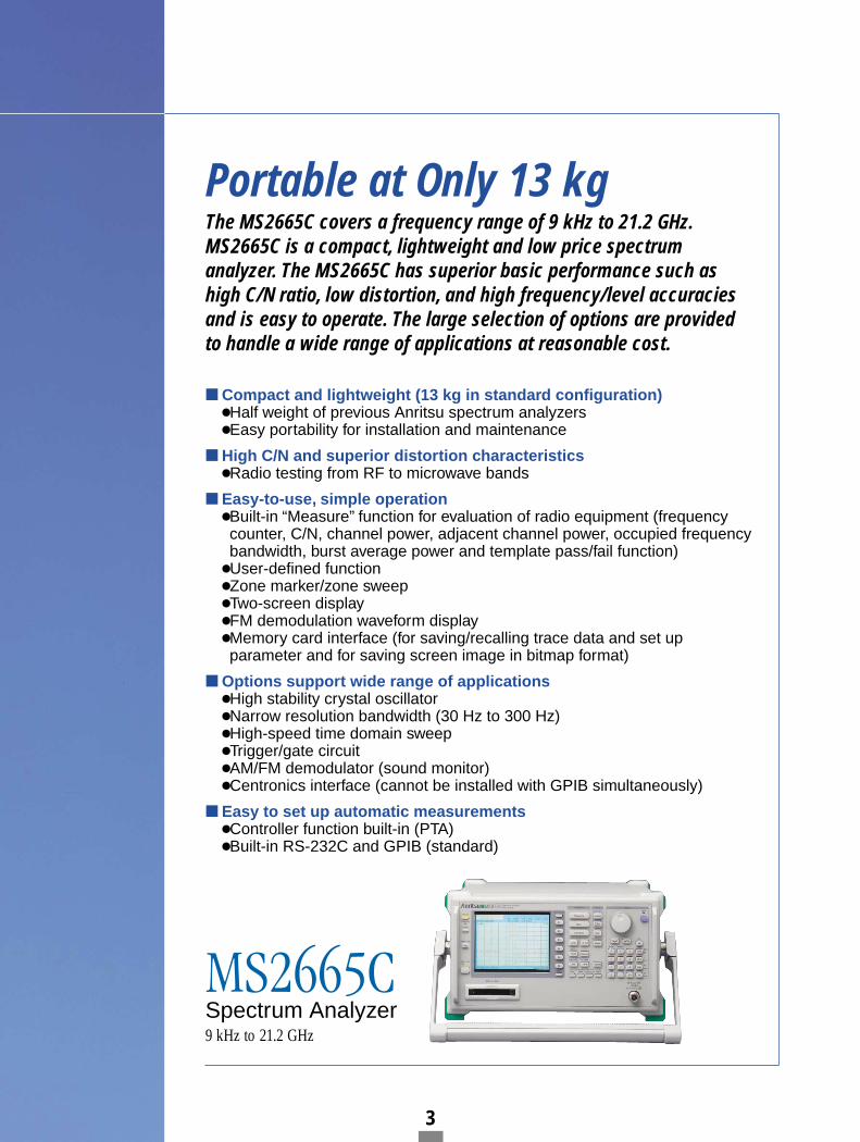
MS2665CSpectrum Analyzer9 kHz to 21.2 GHz
For Various Applications
MS2665CSpectrum Analyzer
3
Compact and lightweight (13 kg in standard configuration) Half weight of previous Anritsu spectrum analyzers Easy portability for installation and maintenance
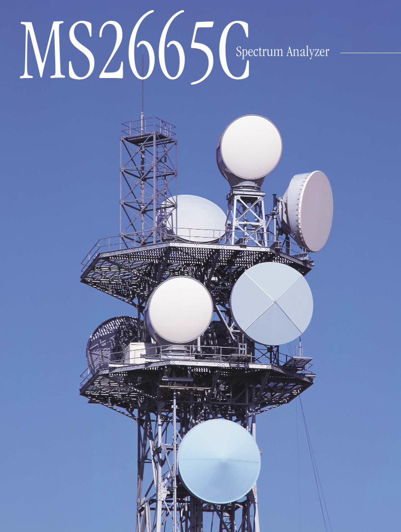
High C/N and superior distortion characteristics Radio testing from RF to microwave bands
Easy-to-use, simple operation Built-in “Measure” function for evaluation of radio equipment (frequencycounter, C/N, channel power, adjacent channel power, occupied frequencybandwidth, burst average power and template pass/fail function)
User-defined function Zone marker/zone sweep Two-screen display FM demodulation waveform display Memory card interface (for saving/recalling trace data and set up parameter and for saving screen image in bitmap format)
Options support wide range of applications High stability crystal oscillator Narrow resolution bandwidth (30 Hz to 300 Hz) High-speed time domain sweep Trigger/gate circuit AM/FM demodulator (sound monitor) Centronics interface (cannot be installed with GPIB simultaneously)
Easy to set up automatic measurements Controller function built-in (PTA) Built-in RS-232C and GPIB (standard)
MS2665CSpectrum Analyzer9 kHz to 21.2 GHz
Portable at Only 13 kgThe MS2665C covers a frequency range of 9 kHz to 21.2 GHz.MS2665C is a compact, lightweight and low price spectrum analyzer. The MS2665C has superior basic performance such ashigh C/N ratio, low distortion, and high frequency/level accuraciesand is easy to operate. The large selection of options are providedto handle a wide range of applications at reasonable cost.
Small and weighing only 13 kg The MS2665C is compact and lightweight, measuring 320 (W) 177 (H) 351 (D) mm and weighing only 13 kg. In additionto benchtop use, this can be carried easily for field use, mak-ing it the ideal choice for manufacturing and maintenance ofradio equipment.
Synthesized local oscillatorThe synthesized local oscillator design permits stable mea-surements without disturbance due to frequency drift of thespectrum analyzer itself. The level stabilizes in 30 minutesafter power-on, making this unit especially suitable for on-sitemaintenance and adjustment where work must be completedquickly.
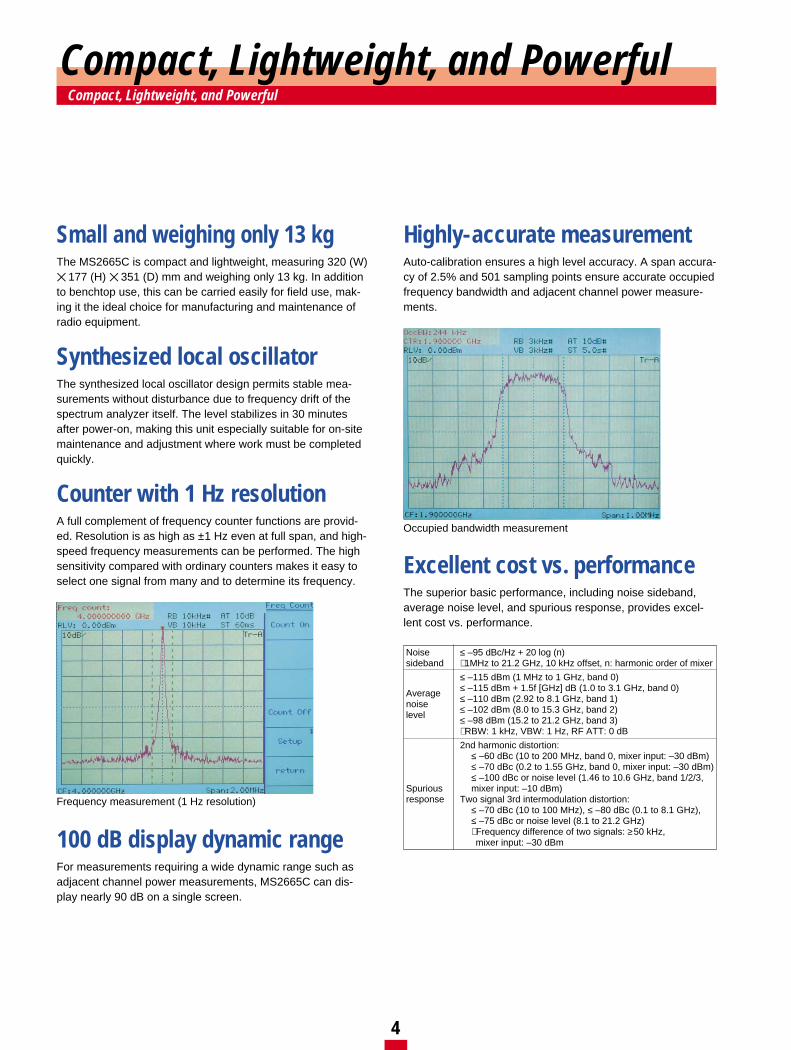
Counter with 1 Hz resolution A full complement of frequency counter functions are provid-ed. Resolution is as high as ±1 Hz even at full span, and high-speed frequency measurements can be performed. The highsensitivity compared with ordinary counters makes it easy toselect one signal from many and to determine its frequency.
100 dB display dynamic rangeFor measurements requiring a wide dynamic range such asadjacent channel power measurements, MS2665C can dis-play nearly 90 dB on a single screen.
Highly-accurate measurementAuto-calibration ensures a high level accuracy. A span accura-cy of 2.5% and 501 sampling points ensure accurate occupiedfrequency bandwidth and adjacent channel power measure-ments.
Excellent cost vs. performanceThe superior basic performance, including noise sideband,average noise level, and spurious response, provides excel-lent cost vs. performance.
4
Compact, Lightweight, and PowerfulCompact, Lightweight, and Powerful
Frequency measurement (1 Hz resolution)
Occupied bandwidth measurement
Noise ≤ –95 dBc/Hz + 20 log (n)sideband ∗ 1MHz to 21.2 GHz, 10 kHz offset, n: harmonic order of mixer
≤ –115 dBm (1 MHz to 1 GHz, band 0)
Average ≤ –115 dBm + 1.5f [GHz] dB (1.0 to 3.1 GHz, band 0)
noise ≤ –110 dBm (2.92 to 8.1 GHz, band 1)
level ≤ –102 dBm (8.0 to 15.3 GHz, band 2)≤ –98 dBm (15.2 to 21.2 GHz, band 3)∗ RBW: 1 kHz, VBW: 1 Hz, RF ATT: 0 dB
2nd harmonic distortion:≤ –60 dBc (10 to 200 MHz, band 0, mixer input: –30 dBm)≤ –70 dBc (0.2 to 1.55 GHz, band 0, mixer input: –30 dBm)≤ –100 dBc or noise level (1.46 to 10.6 GHz, band 1/2/3,
Spurious mixer input: –10 dBm)response Two signal 3rd intermodulation distortion:
≤ –70 dBc (10 to 100 MHz), ≤ –80 dBc (0.1 to 8.1 GHz),≤ –75 dBc or noise level (8.1 to 21.2 GHz)∗ Frequency difference of two signals: ≥50 kHz, mixer input: –30 dBm
Convenient, Easy-to-Use FunctionsConvenient, Easy-to-Use Functions
5
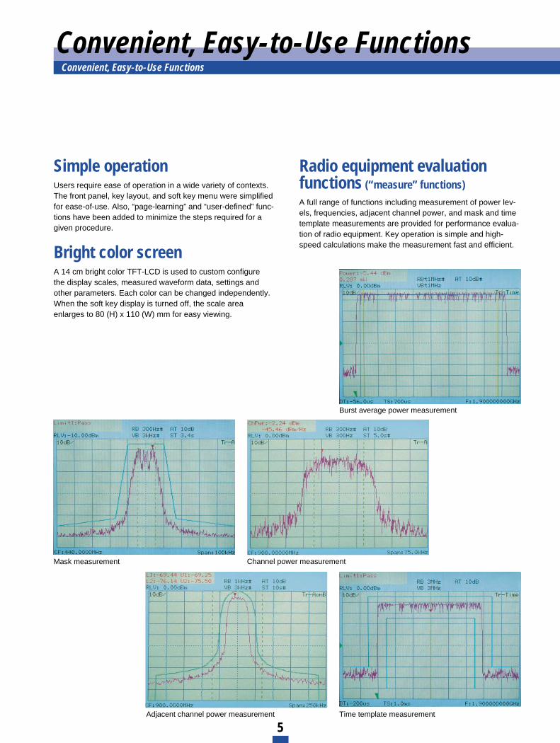
Radio equipment evaluationfunctions (“measure” functions) A full range of functions including measurement of power lev-els, frequencies, adjacent channel power, and mask and timetemplate measurements are provided for performance evalua-tion of radio equipment. Key operation is simple and high-speed calculations make the measurement fast and efficient.
Simple operationUsers require ease of operation in a wide variety of contexts.The front panel, key layout, and soft key menu were simplifiedfor ease-of-use. Also, “page-learning” and “user-defined” func-tions have been added to minimize the steps required for agiven procedure.
Bright color screenA 14 cm bright color TFT-LCD is used to custom configure the display scales, measured waveform data, settings andother parameters. Each color can be changed independently.When the soft key display is turned off, the scale areaenlarges to 80 (H) x 110 (W) mm for easy viewing.
Burst average power measurement
Mask measurement Channel power measurement
Adjacent channel power measurement Time template measurement
Convenient, Easy-to-Use Functions
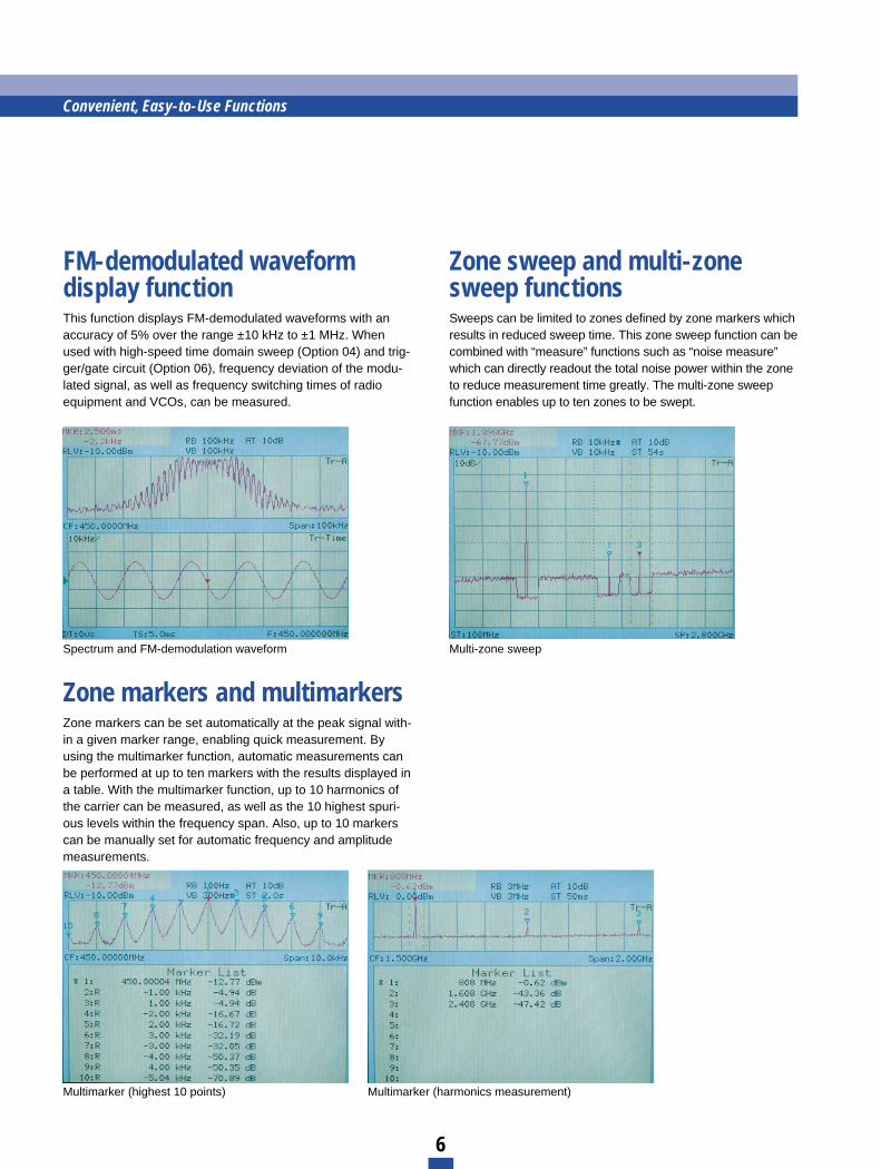
Zone markers and multimarkersZone markers can be set automatically at the peak signal with-in a given marker range, enabling quick measurement. Byusing the multimarker function, automatic measurements canbe performed at up to ten markers with the results displayed ina table. With the multimarker function, up to 10 harmonics ofthe carrier can be measured, as well as the 10 highest spuri-ous levels within the frequency span. Also, up to 10 markerscan be manually set for automatic frequency and amplitudemeasurements.
FM-demodulated waveform display function This function displays FM-demodulated waveforms with anaccuracy of 5% over the range ±10 kHz to ±1 MHz. Whenused with high-speed time domain sweep (Option 04) and trig-ger/gate circuit (Option 06), frequency deviation of the modu-lated signal, as well as frequency switching times of radioequipment and VCOs, can be measured.
Zone sweep and multi-zonesweep functionsSweeps can be limited to zones defined by zone markers whichresults in reduced sweep time. This zone sweep function can becombined with “measure” functions such as “noise measure”which can directly readout the total noise power within the zoneto reduce measurement time greatly. The multi-zone sweepfunction enables up to ten zones to be swept.
Spectrum and FM-demodulation waveform Multi-zone sweep
Multimarker (highest 10 points) Multimarker (harmonics measurement)
6
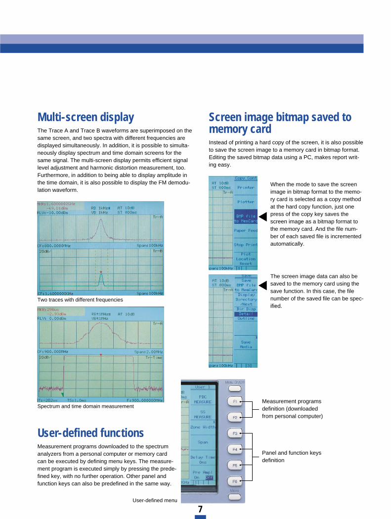
Multi-screen displayThe Trace A and Trace B waveforms are superimposed on thesame screen, and two spectra with different frequencies aredisplayed simultaneously. In addition, it is possible to simulta-neously display spectrum and time domain screens for thesame signal. The multi-screen display permits efficient signallevel adjustment and harmonic distortion measurement, too.Furthermore, in addition to being able to display amplitude inthe time domain, it is also possible to display the FM demodu-lation waveform.
User-defined functionsMeasurement programs downloaded to the spectrumanalyzers from a personal computer or memory cardcan be executed by defining menu keys. The measure-ment program is executed simply by pressing the prede-fined key, with no further operation. Other panel andfunction keys can also be predefined in the same way.
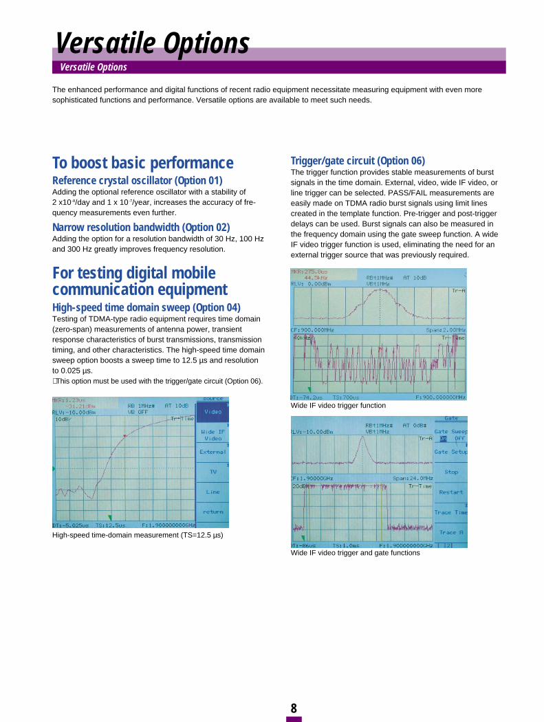
Screen image bitmap saved tomemory cardInstead of printing a hard copy of the screen, it is also possibleto save the screen image to a memory card in bitmap format.Editing the saved bitmap data using a PC, makes report writ-ing easy.
When the mode to save the screenimage in bitmap format to the memo-ry card is selected as a copy methodat the hard copy function, just onepress of the copy key saves thescreen image as a bitmap format tothe memory card. And the file num-ber of each saved file is incrementedautomatically.
The screen image data can also besaved to the memory card using thesave function. In this case, the filenumber of the saved file can be spec-ified.
Two traces with different frequencies
Spectrum and time domain measurement
7
Measurement programsdefinition (downloadedfrom personal computer)
Panel and function keysdefinition
User-defined menu
To boost basic performanceReference crystal oscillator (Option 01) Adding the optional reference oscillator with a stability of 2 x10⁻⁸/day and 1 x 10⁻⁷/year, increases the accuracy of fre-quency measurements even further.
Narrow resolution bandwidth (Option 02)Adding the option for a resolution bandwidth of 30 Hz, 100 Hzand 300 Hz greatly improves frequency resolution.
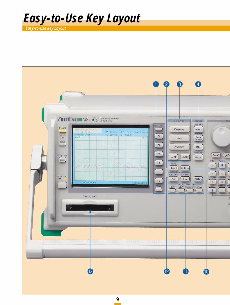
For testing digital mobile communication equipment High-speed time domain sweep (Option 04)Testing of TDMA-type radio equipment requires time domain(zero-span) measurements of antenna power, transientresponse characteristics of burst transmissions, transmissiontiming, and other characteristics. The high-speed time domainsweep option boosts a sweep time to 12.5 µs and resolution to 0.025 µs. ∗ This option must be used with the trigger/gate circuit (Option 06).
Trigger/gate circuit (Option 06)The trigger function provides stable measurements of burstsignals in the time domain. External, video, wide IF video, orline trigger can be selected. PASS/FAIL measurements areeasily made on TDMA radio burst signals using limit lines created in the template function. Pre-trigger and post-triggerdelays can be used. Burst signals can also be measured inthe frequency domain using the gate sweep function. A wideIF video trigger function is used, eliminating the need for anexternal trigger source that was previously required.
The enhanced performance and digital functions of recent radio equipment necessitate measuring equipment with even moresophisticated functions and performance. Versatile options are available to meet such needs.
High-speed time-domain measurement (TS=12.5 µs)
Wide IF video trigger function
Wide IF video trigger and gate functions
8
Versatile OptionsVersatile Options
Easy-to-Use Key LayoutEasy-to-Use Key Layout
9
10
qFunction keys F1 to F6Select on-screen menu items Menu on/off keys turn menus on and off, and [more] key turns menu pages.
wSave/recallSaves and recalls measurement settings and measured waveforms Data can be saved either to internal memory or to a memory card. (In internal memory,up to 12 data sets can be saved.)
eMain Functions Set frequency, span, amplitude and other parameters
rMarkersNormal markers, multimarkers (maximum 10 numbers), zone markers and zonesweeping are provided.
tEntry keys Input numeric values, units, and alphabetic characters
yUser keysRegister any panel and menu key functions, as well as application software functions to user keys.
uUser define key Define functions of user-defined keysUp to 3-pages can be predefined.
iMeasure key Executes various operations based on waveform data High-speed measurements and computations are performed without the need for anexternal computer.
oCalibrationThe built-in high-precision calibration signal source provides accurate measurements.
!0Trigger/gateThe trigger can be set in the time domain mode.
!1Coupled-function keys Set parameters other than those set using main function keys Normally set “Auto” for optimum values
!2Display Can be switched between frequency and time domains, and has two-screen displaymodes
!3Memory card slots Support memory cards up to 2 Mbytes Two type-1 memory cards conforming to PCMCIA ver. 2.0 standards can be usedsimultaneously.
!4RF connectorFor input of signals at levels up to +30 dBm (maximum DC input: ±0 V)
Printer
Plotter
Personal computer
Personal computer
Personal computer
ModemModem
Printer
Plotter
Printer
Plotter
RS-232C, GPIB or Centronics
Centronics or GPIBRS-232C
RS-232C Line RS-232C
GPIB RS-232C
MS2665C
MS2665C
MS2665C
MS2665C
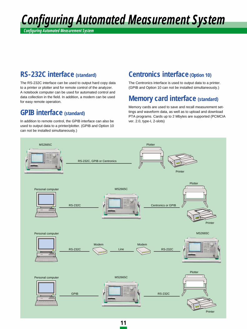
RS-232C interface (standard) The RS-232C interface can be used to output hard copy datato a printer or plotter and for remote control of the analyzer.A notebook computer can be used for automated control anddata collection in the field. In addition, a modem can be usedfor easy remote operation.
GPIB interface (standard) In addition to remote control, the GPIB interface can also beused to output data to a printer/plotter. (GPIB and Option 10can not be installed simultaneously.)
Centronics interface (Option 10) The Centronics interface is used to output data to a printer.(GPIB and Option 10 can not be installed simultaneously.)
Memory card interface (standard) Memory cards are used to save and recall measurement set-tings and waveform data, as well as to upload and downloadPTA programs. Cards up to 2 Mbytes are supported (PCMCIAver. 2.0, type-I, 2-slots)
Configuring Automated Measurement SystemConfiguring Automated Measurement System
11
12
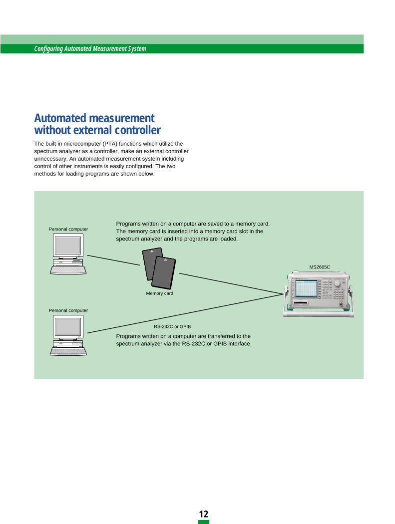
Automated measurement without external controllerThe built-in microcomputer (PTA) functions which utilize thespectrum analyzer as a controller, make an external controllerunnecessary. An automated measurement system includingcontrol of other instruments is easily configured. The twomethods for loading programs are shown below.
Personal computer
Personal computer
MS2665C
Memory card
RS-232C or GPIB
Programs written on a computer are saved to a memory card.The memory card is inserted into a memory card slot in thespectrum analyzer and the programs are loaded.
Programs written on a computer are transferred to thespectrum analyzer via the RS-232C or GPIB interface.
Configuring Automated Measurement System
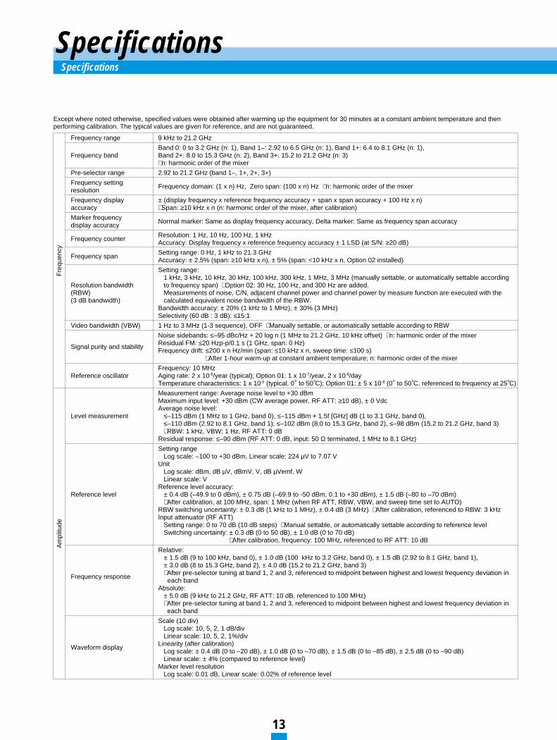
Frequency range 9 kHz to 21.2 GHz
Band 0: 0 to 3.2 GHz (n: 1), Band 1–: 2.92 to 6.5 GHz (n: 1), Band 1+: 6.4 to 8.1 GHz (n: 1),Frequency band Band 2+: 8.0 to 15.3 GHz (n: 2), Band 3+: 15.2 to 21.2 GHz (n: 3)
∗ n: harmonic order of the mixer
Pre-selector range 2.92 to 21.2 GHz (band 1–, 1+, 2+, 3+)
Frequency setting Frequency domain: (1 x n) Hz, Zero span: (100 x n) Hz ∗ n: harmonic order of the mixerresolution
Frequency display ± (display frequency x reference frequency accuracy + span x span accuracy + 100 Hz x n)accuracy ∗ Span: ≥10 kHz x n (n: harmonic order of the mixer, after calibration)
Marker frequency Normal marker: Same as display frequency accuracy, Delta marker: Same as frequency span accuracydisplay accuracy
Frequency counter Resolution: 1 Hz, 10 Hz, 100 Hz, 1 kHzAccuracy: Display frequency x reference frequency accuracy ± 1 LSD (at S/N: ≥20 dB)
Frequency span Setting range: 0 Hz, 1 kHz to 21.3 GHzAccuracy: ± 2.5% (span: ≥10 kHz x n), ± 5% (span: <10 kHz x n, Option 02 installed)
Setting range:1 kHz, 3 kHz, 10 kHz, 30 kHz, 100 kHz, 300 kHz, 1 MHz, 3 MHz (manually settable, or automatically settable according
Resolution bandwidth to frequency span) ∗ Option 02: 30 Hz, 100 Hz, and 300 Hz are added.(RBW) Measurements of noise, C/N, adjacent channel power and channel power by measure function are executed with the(3 dB bandwidth) calculated equivalent noise bandwidth of the RBW.
Bandwidth accuracy: ± 20% (1 kHz to 1 MHz), ± 30% (3 MHz)Selectivity (60 dB : 3 dB): ≤15:1
Video bandwidth (VBW) 1 Hz to 3 MHz (1-3 sequence), OFF ∗ Manually settable, or automatically settable according to RBW
Noise sidebands: ≤–95 dBc/Hz + 20 log n (1 MHz to 21.2 GHz, 10 kHz offset) ∗ n: harmonic order of the mixer
Signal purity and stability Residual FM: ≤20 Hzp-p/0.1 s (1 GHz, span: 0 Hz)Frequency drift: ≤200 x n Hz/min (span: ≤10 kHz x n, sweep time: ≤100 s)
∗ After 1-hour warm-up at constant ambient temperature; n: harmonic order of the mixer
Frequency: 10 MHzReference oscillator Aging rate: 2 x 10⁻⁶/year (typical); Option 01: 1 x 10⁻⁷/year, 2 x 10⁻⁸/day
Temperature characteristics: 1 x 10⁻⁵ (typical, 0° to 50°C); Option 01: ± 5 x 10⁻⁸ (0° to 50°C, referenced to frequency at 25°C)
Measurement range: Average noise level to +30 dBmMaximum input level: +30 dBm (CW average power, RF ATT: ≥10 dB), ± 0 VdcAverage noise level:
Level measurement ≤–115 dBm (1 MHz to 1 GHz, band 0), ≤–115 dBm + 1.5f [GHz] dB (1 to 3.1 GHz, band 0),≤–110 dBm (2.92 to 8.1 GHz, band 1), ≤–102 dBm (8.0 to 15.3 GHz, band 2), ≤–98 dBm (15.2 to 21.2 GHz, band 3)∗ RBW: 1 kHz, VBW: 1 Hz, RF ATT: 0 dB
Residual response: ≤–90 dBm (RF ATT: 0 dB, input: 50 Ω terminated, 1 MHz to 8.1 GHz)
Setting rangeLog scale: –100 to +30 dBm, Linear scale: 224 µV to 7.07 V
UnitLog scale: dBm, dB µV, dBmV, V, dB µVemf, WLinear scale: V
Reference level accuracy:Reference level ± 0.4 dB (–49.9 to 0 dBm), ± 0.75 dB (–69.9 to -50 dBm, 0.1 to +30 dBm), ± 1.5 dB (–80 to –70 dBm)
∗ After calibration, at 100 MHz, span: 1 MHz (when RF ATT, RBW, VBW, and sweep time set to AUTO)RBW switching uncertainty: ± 0.3 dB (1 kHz to 1 MHz), ± 0.4 dB (3 MHz) ∗ After calibration, referenced to RBW: 3 kHzInput attenuator (RF ATT)
Setting range: 0 to 70 dB (10 dB steps) ∗ Manual settable, or automatically settable according to reference levelSwitching uncertainty: ± 0.3 dB (0 to 50 dB), ± 1.0 dB (0 to 70 dB)
∗ After calibration, frequency: 100 MHz, referenced to RF ATT: 10 dB
Relative:± 1.5 dB (9 to 100 kHz, band 0), ± 1.0 dB (100 kHz to 3.2 GHz, band 0), ± 1.5 dB (2.92 to 8.1 GHz, band 1),± 3.0 dB (8 to 15.3 GHz, band 2), ± 4.0 dB (15.2 to 21.2 GHz, band 3)
Frequency response ∗ After pre-selector tuning at band 1, 2 and 3, referenced to midpoint between highest and lowest frequency deviation ineach band
Absolute:± 5.0 dB (9 kHz to 21.2 GHz, RF ATT: 10 dB, referenced to 100 MHz)∗ After pre-selector tuning at band 1, 2 and 3, referenced to midpoint between highest and lowest frequency deviation in each band
Scale (10 div) Log scale: 10, 5, 2, 1 dB/divLinear scale: 10, 5, 2, 1%/div
Waveform display Linearity (after calibration)Log scale: ± 0.4 dB (0 to –20 dB), ± 1.0 dB (0 to –70 dB), ± 1.5 dB (0 to –85 dB), ± 2.5 dB (0 to –90 dB)Linear scale: ± 4% (compared to reference level)
Marker level resolutionLog scale: 0.01 dB, Linear scale: 0.02% of reference level
13
SpecificationsSpecifications
Am
plitu
deF
requ
ency
Except where noted otherwise, specified values were obtained after warming up the equipment for 30 minutes at a constant ambient temperature and then performing calibration. The typical values are given for reference, and are not guaranteed.
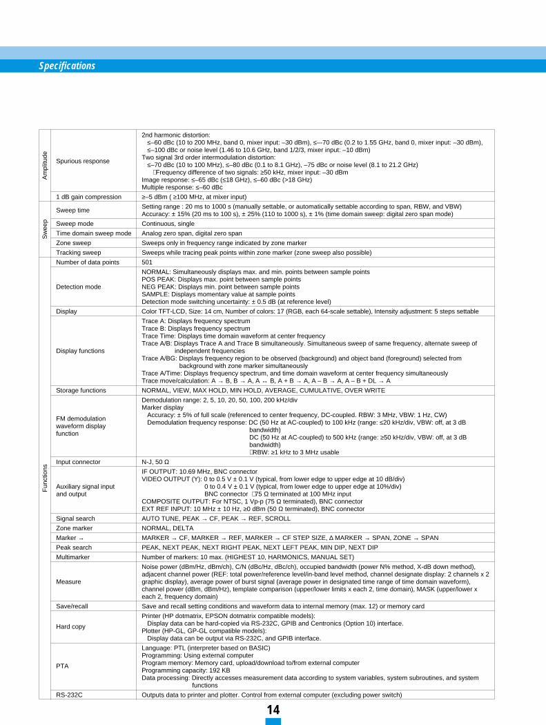
2nd harmonic distortion:≤–60 dBc (10 to 200 MHz, band 0, mixer input: –30 dBm), ≤–-70 dBc (0.2 to 1.55 GHz, band 0, mixer input: –30 dBm),≤–100 dBc or noise level (1.46 to 10.6 GHz, band 1/2/3, mixer input: –10 dBm)
Spurious response Two signal 3rd order intermodulation distortion:≤–70 dBc (10 to 100 MHz), ≤–80 dBc (0.1 to 8.1 GHz), –75 dBc or noise level (8.1 to 21.2 GHz)
∗ Frequency difference of two signals: ≥50 kHz, mixer input: –30 dBmImage response: ≤–65 dBc (≤18 GHz), ≤–60 dBc (>18 GHz)Multiple response: ≤–60 dBc
1 dB gain compression ≥–5 dBm ( ≥100 MHz, at mixer input)
Sweep time Setting range : 20 ms to 1000 s (manually settable, or automatically settable according to span, RBW, and VBW) Accuracy: ± 15% (20 ms to 100 s), ± 25% (110 to 1000 s), ± 1% (time domain sweep: digital zero span mode)
Sweep mode Continuous, single
Time domain sweep mode Analog zero span, digital zero span
Zone sweep Sweeps only in frequency range indicated by zone marker
Tracking sweep Sweeps while tracing peak points within zone marker (zone sweep also possible)
Number of data points 501
NORMAL: Simultaneously displays max. and min. points between sample pointsPOS PEAK: Displays max. point between sample points
Detection mode NEG PEAK: Displays min. point between sample pointsSAMPLE: Displays momentary value at sample pointsDetection mode switching uncertainty: ± 0.5 dB (at reference level)
Display Color TFT-LCD, Size: 14 cm, Number of colors: 17 (RGB, each 64-scale settable), Intensity adjustment: 5 steps settable
Trace A: Displays frequency spectrumTrace B: Displays frequency spectrumTrace Time: Displays time domain waveform at center frequencyTrace A/B: Displays Trace A and Trace B simultaneously. Simultaneous sweep of same frequency, alternate sweep of
Display functions independent frequenciesTrace A/BG: Displays frequency region to be observed (background) and object band (foreground) selected from
background with zone marker simultaneouslyTrace A/Time: Displays frequency spectrum, and time domain waveform at center frequency simultaneouslyTrace move/calculation: A → B, B → A, A ↔ B, A + B → A, A – B → A, A – B + DL → A
Storage functions NORMAL, VIEW, MAX HOLD, MIN HOLD, AVERAGE, CUMULATIVE, OVER WRITE
Demodulation range: 2, 5, 10, 20, 50, 100, 200 kHz/divMarker display
FM demodulation Accuracy: ± 5% of full scale (referenced to center frequency, DC-coupled. RBW: 3 MHz, VBW: 1 Hz, CW)
waveform display Demodulation frequency response: DC (50 Hz at AC-coupled) to 100 kHz (range: ≤20 kHz/div, VBW: off, at 3 dB
function bandwidth)DC (50 Hz at AC-coupled) to 500 kHz (range: ≥50 kHz/div, VBW: off, at 3 dB bandwidth)∗ RBW: ≥1 kHz to 3 MHz usable
Input connector N-J, 50 ΩIF OUTPUT: 10.69 MHz, BNC connectorVIDEO OUTPUT (Y): 0 to 0.5 V ± 0.1 V (typical, from lower edge to upper edge at 10 dB/div)
Auxiliary signal input 0 to 0.4 V ± 0.1 V (typical, from lower edge to upper edge at 10%/div)and output BNC connector ∗ 75 Ω terminated at 100 MHz input
COMPOSITE OUTPUT: For NTSC, 1 Vp-p (75 Ω terminated), BNC connectorEXT REF INPUT: 10 MHz ± 10 Hz, ≥0 dBm (50 Ω terminated), BNC connector
Signal search AUTO TUNE, PEAK → CF, PEAK → REF, SCROLL
Zone marker NORMAL, DELTA
Marker → MARKER → CF, MARKER → REF, MARKER → CF STEP SIZE, ∆ MARKER → SPAN, ZONE → SPAN
Peak search PEAK, NEXT PEAK, NEXT RIGHT PEAK, NEXT LEFT PEAK, MIN DIP, NEXT DIP
Multimarker Number of markers: 10 max. (HIGHEST 10, HARMONICS, MANUAL SET)
Noise power (dBm/Hz, dBm/ch), C/N (dBc/Hz, dBc/ch), occupied bandwidth (power N% method, X-dB down method), adjacent channel power (REF: total power/reference level/in-band level method, channel designate display: 2 channels x 2
Measure graphic display), average power of burst signal (average power in designated time range of time domain waveform), channel power (dBm, dBm/Hz), template comparison (upper/lower limits x each 2, time domain), MASK (upper/lower x each 2, frequency domain)
Save/recall Save and recall setting conditions and waveform data to internal memory (max. 12) or memory card
Printer (HP dotmatrix, EPSON dotmatrix compatible models):
Hard copy Display data can be hard-copied via RS-232C, GPIB and Centronics (Option 10) interface.Plotter (HP-GL, GP-GL compatible models):
Display data can be output via RS-232C, and GPIB interface.
Language: PTL (interpreter based on BASIC)Programming: Using external computer
PTA Program memory: Memory card, upload/download to/from external computerProgramming capacity: 192 KBData processing: Directly accesses measurement data according to system variables, system subroutines, and system
functions
RS-232C Outputs data to printer and plotter. Control from external computer (excluding power switch)
Specifications
14
Fun
ctio
nsS
wee
pA
mpl
itude
15
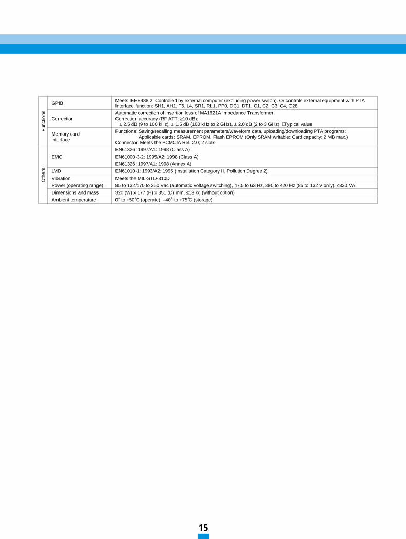
GPIB Meets IEEE488.2. Controlled by external computer (excluding power switch). Or controls external equipment with PTAInterface function: SH1, AH1, T6, L4, SR1, RL1, PP0, DC1, DT1, C1, C2, C3, C4, C28
Automatic correction of insertion loss of MA1621A Impedance TransformerCorrection Correction accuracy (RF ATT: ≥10 dB):
± 2.5 dB (9 to 100 kHz), ± 1.5 dB (100 kHz to 2 GHz), ± 2.0 dB (2 to 3 GHz) ∗ Typical value
Memory card Functions: Saving/recalling measurement parameters/waveform data, uploading/downloading PTA programs;
interface Applicable cards: SRAM, EPROM, Flash EPROM (Only SRAM writable; Card capacity: 2 MB max.)Connector: Meets the PCMCIA Rel. 2.0; 2 slots
EN61326: 1997/A1: 1998 (Class A)
EMC EN61000-3-2: 1995/A2: 1998 (Class A)
EN61326: 1997/A1: 1998 (Annex A)
LVD EN61010-1: 1993/A2: 1995 (Installation Category ΙΙ , Pollution Degree 2)
Vibration Meets the MIL-STD-810D
Power (operating range) 85 to 132/170 to 250 Vac (automatic voltage switching), 47.5 to 63 Hz, 380 to 420 Hz (85 to 132 V only), ≤330 VA
Dimensions and mass 320 (W) x 177 (H) x 351 (D) mm, ≤13 kg (without option)
Ambient temperature 0° to +50°C (operate), –40° to +75°C (storage)
Fun
ctio
nsO
ther
s
16
Specifications
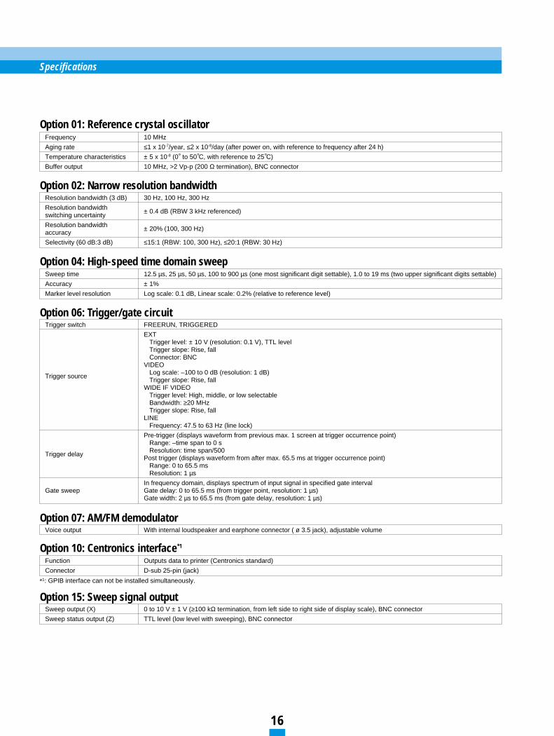
Frequency 10 MHz
Aging rate ≤1 x 10⁻⁷/year, ≤2 x 10⁻⁸/day (after power on, with reference to frequency after 24 h)
Temperature characteristics ± 5 x 10⁻⁸ (0° to 50°C, with reference to 25°C)
Buffer output 10 MHz, >2 Vp-p (200 Ω termination), BNC connector
Option 01: Reference crystal oscillator
*1: GPIB interface can not be installed simultaneously.
Resolution bandwidth (3 dB) 30 Hz, 100 Hz, 300 Hz
Resolution bandwidth ± 0.4 dB (RBW 3 kHz referenced)switching uncertainty
Resolution bandwidth ± 20% (100, 300 Hz)accuracy
Selectivity (60 dB:3 dB) ≤15:1 (RBW: 100, 300 Hz), ≤20:1 (RBW: 30 Hz)
Option 02: Narrow resolution bandwidth
Sweep time 12.5 µs, 25 µs, 50 µs, 100 to 900 µs (one most significant digit settable), 1.0 to 19 ms (two upper significant digits settable)
Accuracy ± 1%
Marker level resolution Log scale: 0.1 dB, Linear scale: 0.2% (relative to reference level)
Option 04: High-speed time domain sweep
Voice output With internal loudspeaker and earphone connector ( ø 3.5 jack), adjustable volume
Option 07: AM/FM demodulator
Function Outputs data to printer (Centronics standard)
Connector D-sub 25-pin (jack)
Option 10: Centronics interface*1
Sweep output (X) 0 to 10 V ± 1 V (≥100 kΩ termination, from left side to right side of display scale), BNC connector
Sweep status output (Z) TTL level (low level with sweeping), BNC connector
Option 15: Sweep signal output
Trigger switch FREERUN, TRIGGERED
EXTTrigger level: ± 10 V (resolution: 0.1 V), TTL levelTrigger slope: Rise, fallConnector: BNC
VIDEO
Trigger source Log scale: –100 to 0 dB (resolution: 1 dB)Trigger slope: Rise, fall
WIDE IF VIDEOTrigger level: High, middle, or low selectableBandwidth: ≥20 MHzTrigger slope: Rise, fall
LINEFrequency: 47.5 to 63 Hz (line lock)
Pre-trigger (displays waveform from previous max. 1 screen at trigger occurrence point)Range: –time span to 0 s
Trigger delay Resolution: time span/500Post trigger (displays waveform from after max. 65.5 ms at trigger occurrence point)
Range: 0 to 65.5 msResolution: 1 µs
In frequency domain, displays spectrum of input signal in specified gate intervalGate sweep Gate delay: 0 to 65.5 ms (from trigger point, resolution: 1 µs)
Gate width: 2 µs to 65.5 ms (from gate delay, resolution: 1 µs)
Option 06: Trigger/gate circuit
17
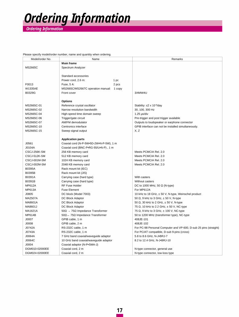
Ordering InformationOrdering Information
Model/order No. Name Remarks
Main frame
MS2665C Spectrum Analyzer
Standard accessories
Power cord, 2.6 m: 1 pc
F0013 Fuse, 5 A: 2 pcs
W1335AE MS2665C/MS2667C operation manual: 1 copy
B0329G Front cover 3/4MW4U
Options
MS2665C-01 Reference crystal oscillator Stability: ≤2 x 10⁻⁸/day
MS2665C-02 Narrow resolution bandwidth 30, 100, 300 Hz
MS2665C-04 High-speed time domain sweep 1.25 µs/div
MS2665C-06 Trigger/gate circuit Pre-trigger and post trigger available
MS2665C-07 AM/FM demodulator Outputs to loudspeaker or earphone connector
MS2665C-10 Centronics interface GPIB interface can not be installed simultaneously.
MS2665C-15 Sweep signal output X, Z
Application parts
J0561 Coaxial cord (N-P-5W•5D-2W•N-P-5W), 1 m
J0104A Coaxial cord (BNC-P•RG-55/U•N-P) , 1 m
CSCJ-256K-SM 256 KB memory card Meets PCMCIA Rel. 2.0
CSCJ-512K-SM 512 KB memory card Meets PCMCIA Rel. 2.0
CSCJ-001M-SM 1024 KB memory card Meets PCMCIA Rel. 2.0
CSCJ-002M-SM 2048 KB memory card Meets PCMCIA Rel. 2.0
B0395A Rack mount kit (IEC)
B0395B Rack mount kit (JIS)
B0391A Carrying case (hard type) With casters
B0391B Carrying case (hard type) Without casters
MP612A RF Fuse Holder DC to 1000 MHz, 50 Ω (N-type)
MP613A Fuse Element For MP612A
J0805 DC block (Model 7003) 10 kHz to 18 GHz, ± 50 V, N-type, Weinschel product
MA2507A DC Block Adaptor 50 Ω, 9 kHz to 3 GHz, ± 50 V, N-type
MA8601A DC Block Adaptor 50 Ω, 30 kHz to 2 GHz, ± 50 V, N-type
MA8601J DC Block Adaptor 75 Ω, 10 kHz to 2.2 GHz, ± 50 V, NC-type
MA1621A 50Ω → 75Ω Impedance Transformer 75 Ω, 9 kHz to 3 GHz, ± 100 V, NC-type
MP614B 50Ω↔ 75Ω Impedance Transformer 50 to 1200 MHz (transformer type), NC-type
J0007 GPIB cable, 1 m 408JE-101
J0008 GPIB cable, 2 m 408JE-102
J0742A RS-232C cable, 1 m For PC-98 Personal Computer and VP-600, D-sub 25 pins (straight)
J0743A RS-232C cable, 1 m For PC/AT compatible, D-sub 9-pins (cross)
J0064A 7 GHz band coaxial/waveguide adaptor 5.8 to 8.6 GHz, N-J•BRJ-7
J0064C 10 GHz band coaxial/waveguide adaptor 8.2 to 12.4 GHz, N-J•BRJ-10
J0004 Coaxial adaptor (N-P•SMA-J)
DGM010-02000EE Coaxial cord, 2 m N-type connector, general use
DGM024-02000EE Coaxial cord, 2 m N-type connector, low-loss type
Please specify model/order number, name and quantity when ordering.
ANRITSU CORPORATION1800 Onna, Atsugi-shi, Kanagawa, 243-8555 JapanPhone: +81-046-223-1111Fax: +81-46-296-1264
• U.S.A.ANRITSU COMPANYNorth American Region Headquarters1155 East Collins Blvd., Richardson, TX 75081, U.S.A.Toll Free: 1-800-ANRITSU (267-4878)Phone: +1-972-644-1777Fax: +1-972-671-1877
• CanadaANRITSU ELECTRONICS LTD.700 Silver Seven Road, Suite 120, Kanata, ON K2V 1C3, CanadaPhone: +1-613-591-2003 Fax: +1-613-591-1006
• Brasil ANRITSU ELETRÔNICA LTDA.Praca Amadeu Amaral, 27 - 1 andar01327-010 - Paraiso, Sao Paulo, BrazilPhone: +55-11-2283-2511Fax: +55-21-2886940
• U.K.ANRITSU LTD.200 Capability Green, Luton, Bedfordshire LU1 3LU, U.K.Phone: +44-1582-433280 Fax: +44-1582-731303
• GermanyANRITSU GmbHGrafenberger Allee 54-56, 40237 Düsseldorf, Germany Phone: +49-211-96855-0 Fax: +49-211-96855-55
• FranceANRITSU S.A.9, Avenue du Québec Z.A. de Courtabœuf 91951 LesUlis Cedex, France Phone: +33-1-60-92-15-50Fax: +33-1-64-46-10-65
• ItalyANRITSU S.p.A.Via Elio Vittorini, 129, 00144 Roma EUR, ItalyPhone: +39-06-509-9711 Fax: +39-06-502-24-25
• SwedenANRITSU ABBotvid Center, Fittja Backe 1-3 145 84 Stockholm,SwedenPhone: +46-853470700 Fax: +46-853470730
• SingaporeANRITSU PTE LTD.10, Hoe Chiang Road #07-01/02, Keppel Towers,Singapore 089315 Phone: +65-6282-2400 Fax: +65-6282-2533
• Hong Kong ANRITSU COMPANY LTD.Suite 923, 9/F., Chinachem Golden Plaza, 77 ModyRoad, Tsimshatsui East, Kowloon, Hong Kong, ChinaPhone: +852-2301-4980Fax: +852-2301-3545
• P. R. ChinaANRITSU COMPANY LTD.Beijing Representative OfficeRoom 1515, Beijing Fortune Building, No. 5 North Road,the East 3rd Ring Road, Chao-Yang DistrictBeijing 100004, P.R. ChinaPhone: +86-10-6590-9230
• KoreaANRITSU CORPORATION8F Hyun Juk Bldg. 832-41, Yeoksam-dong, Kangnam-ku, Seoul, 135-080, KoreaPhone: +82-2-553-6603Fax: +82-2-553-6604˜ 5
• AustraliaANRITSU PTY LTD.Unit 3/170 Forster Road Mt. Waverley, Victoria, 3149,AustraliaPhone: +61-3-9558-8177Fax: +61-3-9558-8255
• TaiwanANRITSU COMPANY INC.7F, No. 316, Sec. 1, NeiHu Rd., Taipei, TaiwanPhone: +886-2-8751-1816Fax: +886-2-8751-1817
Specifications are subject to change without notice.
Catalog No. MS2665C-E-A-1-(3.00) Printed in Japan 2003-5 30KL/O
030508