Embed Size (px)
Citation preview
Spectroscopy
Spectral analysis is probably the most important method for learning about the physics of the astronomical sources
Simplest method to get spectral information is using filters
In this case the size of the spectral elemet we can resolve is the width of the filter
More detailed information is obtained if the light is sent through a dispersive element
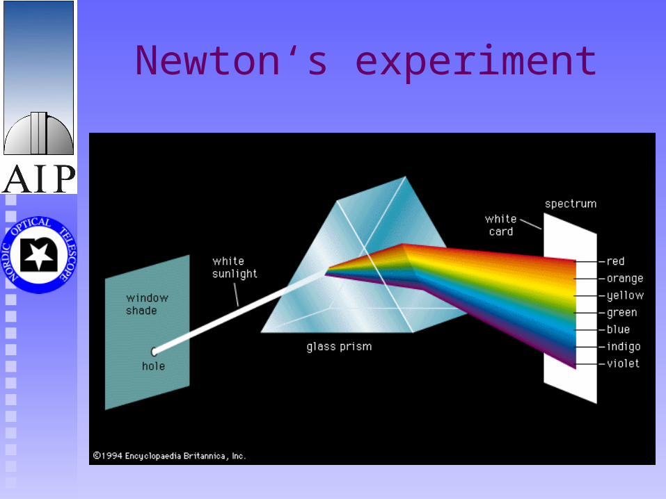
Newton‘s experiment
Dispersive elements
The core optical element of an astronomical spectrograph is its dispersive element
With a dispersive element, the angle at which the light leaves it, is wavelength dependent.
There are three kinds of dispersive elements: Prisms Grating Grisms
Prism 1
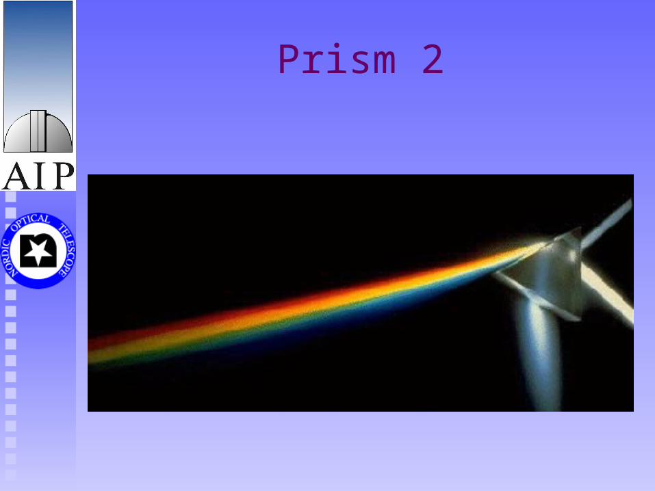
When light moves from one medium to a denser medium, it is slowed down and as a result either bent (refracted) or reflected.
The refractive index of a material is a measure of the light speed in that material. It depends on the wavelength.
The white light entering the prism is a mixture of different wavelengths, each of which gets bent slightly differently. Blue light is slowed more down than red light and will therefore be bent more than red light.
Prism 2
Grating 1
The diffraction grating is the primary dispersing element in most astronomical spectrometers
It has significantly larger limiting resolution than a prism of comparable size
A grating is also versatile in the spectral formats it can provide
And it can be quite efficient over a reasonable spectral range, though usually not as efficient as a prism
Grating 2
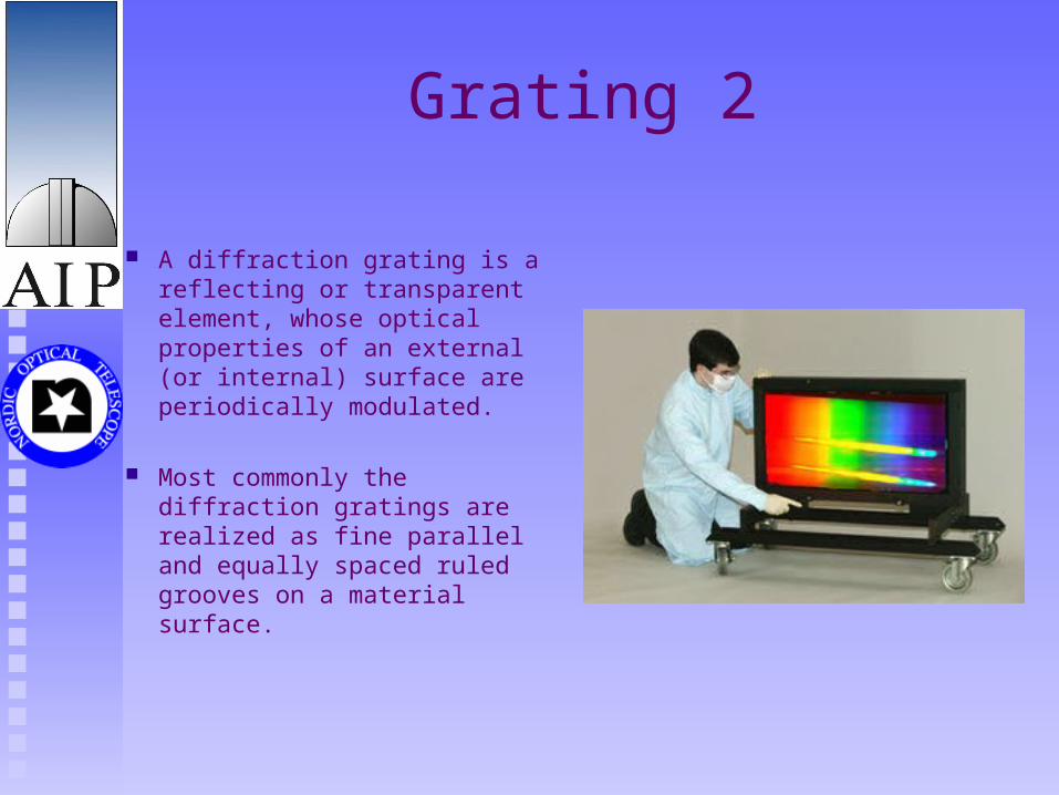
A diffraction grating is a reflecting or transparent element, whose optical properties of an external (or internal) surface are periodically modulated.
Most commonly the diffraction gratings are realized as fine parallel and equally spaced ruled grooves on a material surface.
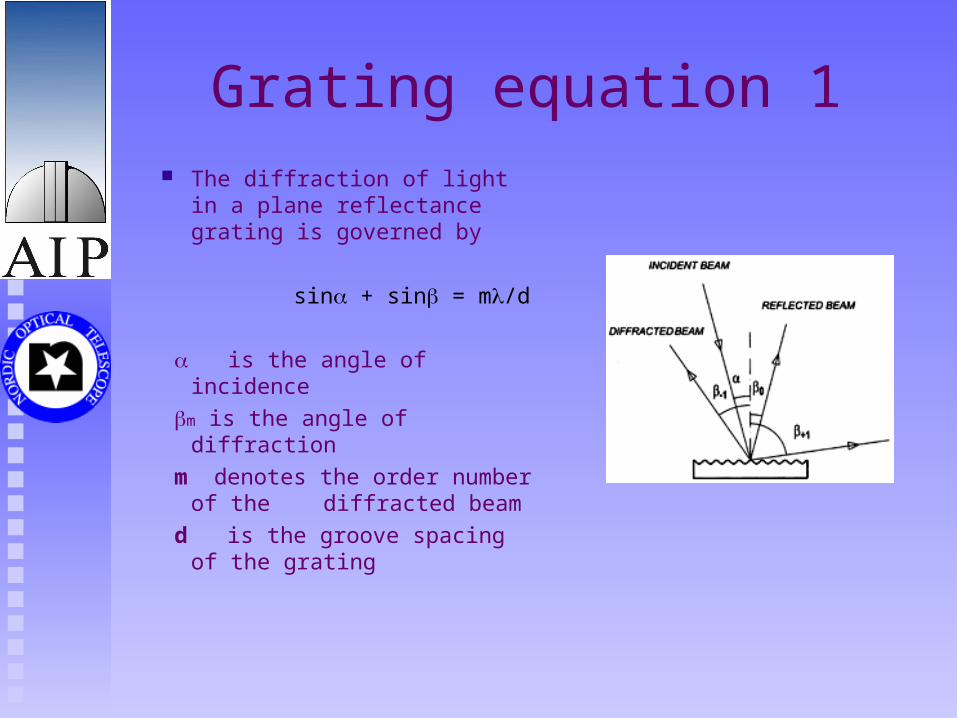
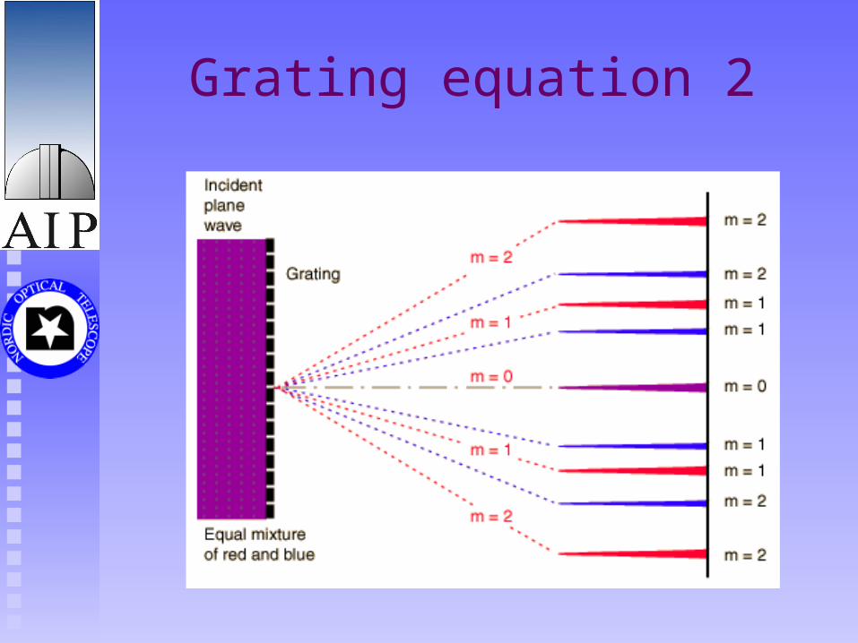
Grating equation 1 The diffraction of light in a
plane reflectance grating is governed by
sin + sin = m/d
is the angle of incidence m is the angle of diffraction m denotes the order
number of the diffracted beam
d is the groove spacing of the grating
Grating equation 2
Échelle grating 1
For high resolution astronomical work échelle is the preferred choise over a grating used in low order
The reasons for this are: Larger luminosity Two dimensional format that permits broad spectral
coverage
Échelle grating 2
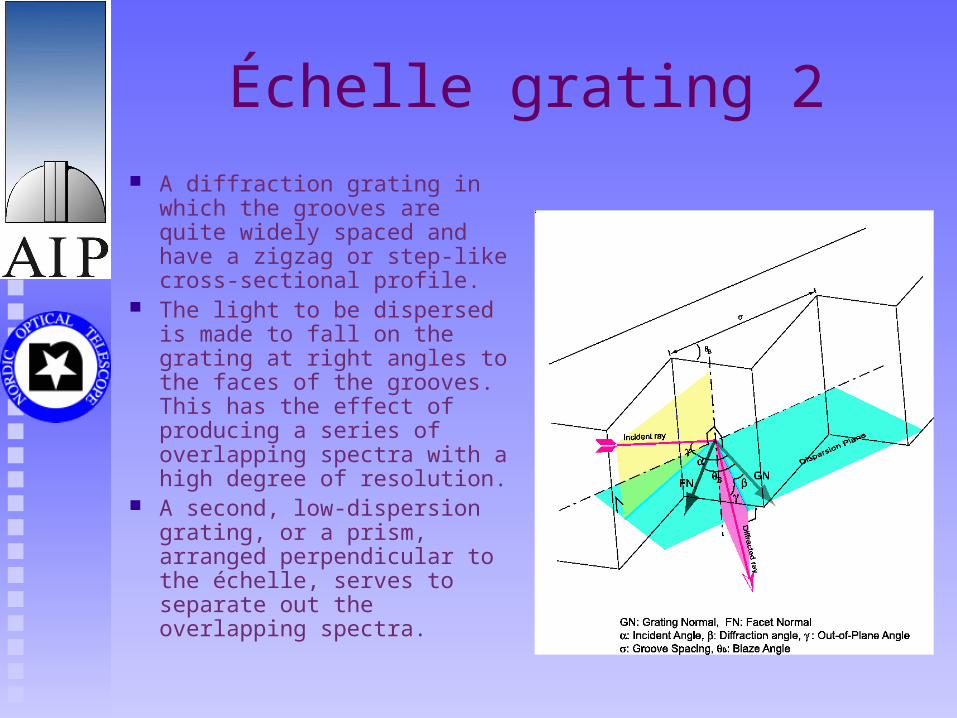
A diffraction grating in which the grooves are quite widely spaced and have a zigzag or step-like cross-sectional profile.
The light to be dispersed is made to fall on the grating at right angles to the faces of the grooves. This has the effect of producing a series of overlapping spectra with a high degree of resolution.
A second, low-dispersion grating, or a prism, arranged perpendicular to the échelle, serves to separate out the overlapping spectra.
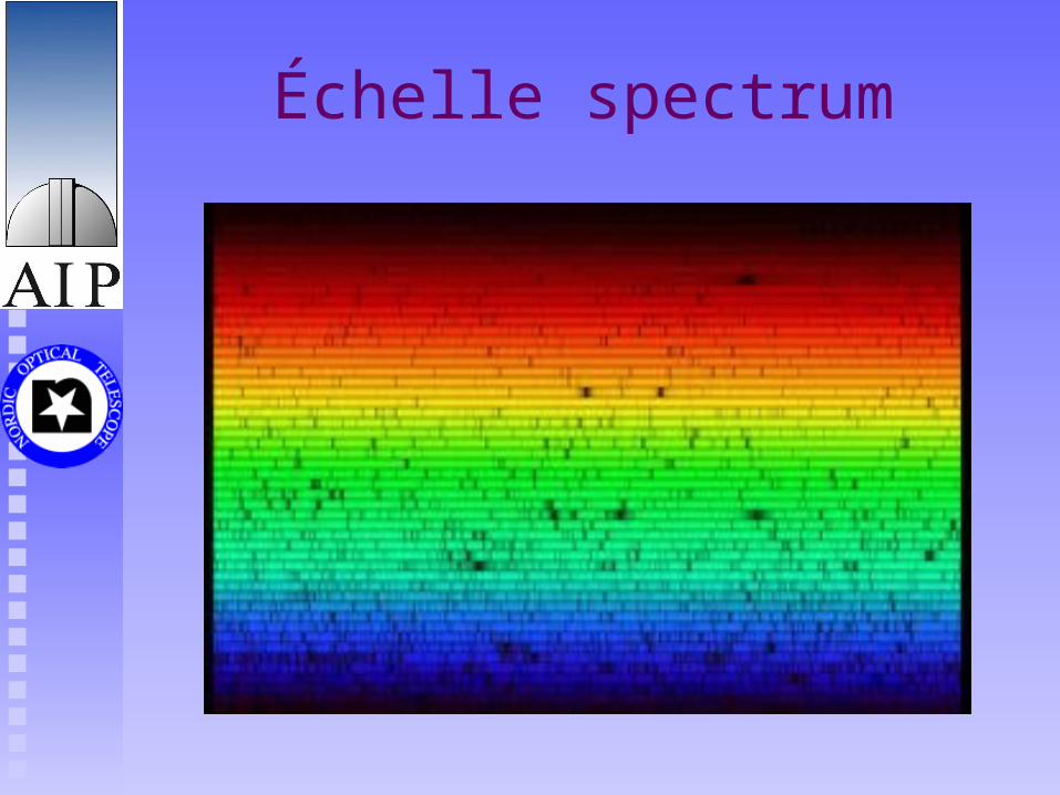
Échelle spectrum
Grism
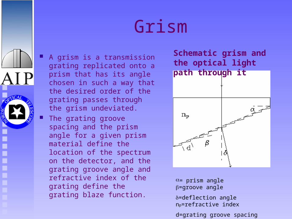
A grism is a transmission grating replicated onto a prism that has its angle chosen in such a way that the desired order of the grating passes through the grism undeviated.
The grating groove spacing and the prism angle for a given prism material define the location of the spectrum on the detector, and the grating groove angle and refractive index of the grating define the grating blaze function.
Schematic grism and the optical light path through it
= prism angle =groove angle
=deflection angle np=refractive index
d=grating groove spacing
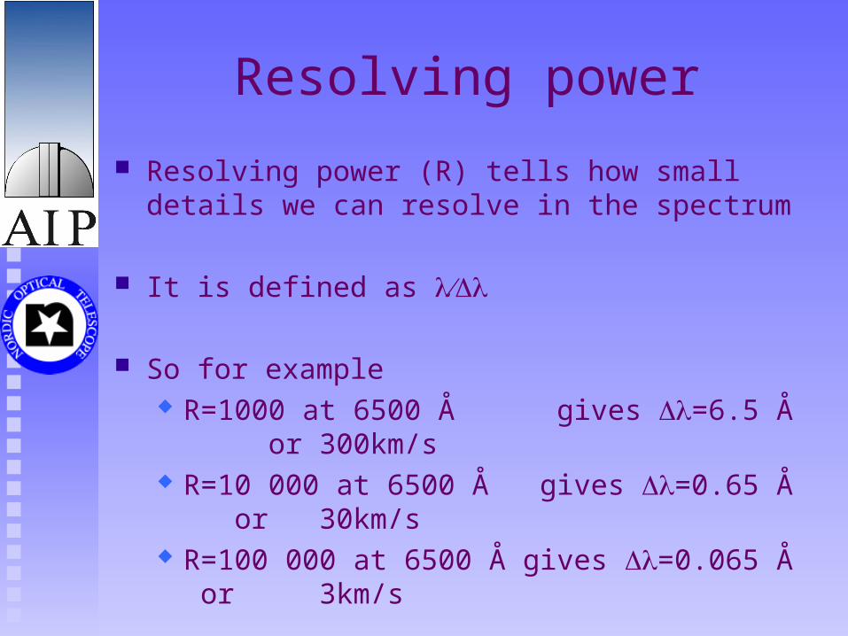
Resolving power
Resolving power (R) tells how small details we can resolve in the spectrum
It is defined as
So for example R=1000 at 6500 Å gives =6.5 Å or 300km/s R=10 000 at 6500 Å gives =0.65 Å or 30km/s R=100 000 at 6500 Å gives =0.065 Å or 3km/s
Which resolving power to use for your observations?
Always „the larger the better“ is not the answer
High resolution needs a lot of photons, so to get any signal one needs a bright source and/or a large telescope
Also, in some cases there is no need for high resoltion. If the process you want to study produces velocities of 1000km/s, there is not much point studying it with resolution of 1 km/s
Spectroscopy at NOT
NOT has 4 instruments with spectroscopic capabilities:
Optical multi purposes spectrograph, ALFOSC Low to medium resoltion IR spectrograph, NOTCam 2 high resolution échelle spectrographs, FIES & SOFIN
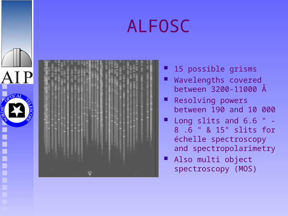
ALFOSC
15 possible grisms Wavelengths covered between
3200-11000 Å Resolving powers between 190
and 10 000 Long slits and 6.6 " -8 .6 " &
15" slits for échelle spectroscopy and spectropolarimetry
Also multi object spectroscopy (MOS)
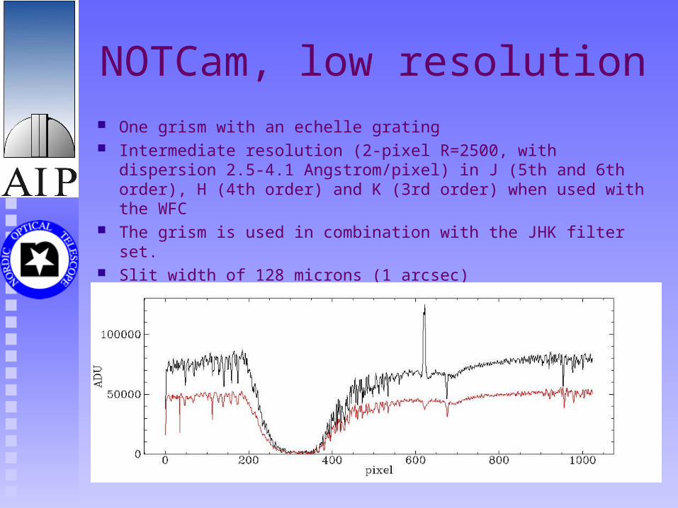
NOTCam, low resolution One grism with an echelle grating Intermediate resolution (2-pixel R=2500, with dispersion 2.5-4.1
Angstrom/pixel) in J (5th and 6th order), H (4th order) and K (3rd order) when used with the WFC
The grism is used in combination with the JHK filter set. Slit width of 128 microns (1 arcsec)
NOTCam, medium resolution
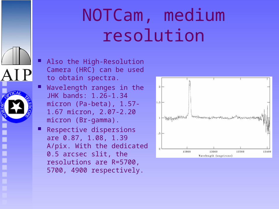
Also the High-Resolution Camera (HRC) can be used to obtain spectra.
Wavelength ranges in the JHK bands: 1.26-1.34 micron (Pa-beta), 1.57-1.67 micron, 2.07-2.20 micron (Br-gamma).
Respective dispersions are 0.87, 1.08, 1.39 A/pix. With the dedicated 0.5 arcsec slit, the resolutions are R=5700, 5700, 4900 respectively.
FIES 1
Cross-dispersed high-resolution echelle spectrograph, R=60 000
Spectral range 4000-8300 Å is covered without gaps in a single setting
Mounted in a well insulated building separate from and adjacent to the NOT dome.
FIES 2
The optical fibre connecting the telescope with the spectrograph is permanently mounted with a movable 45-degree mirror
Being a permanently mounted instrument, FIES can be used at any time, also for short periods of time while other instruments are mounted.
Equipped with a 100 micron fibre, corresponding to 1.3 arcseconds on
the sky at a spectral resolution of R =40 000.
We expect a new and more extensive fiber unit to be installed, which
contains a new 100 micron fiber (but with exit slit) offering a resolution of R = 60 000
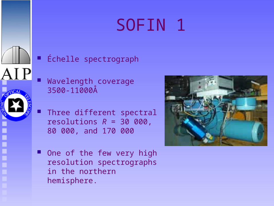
SOFIN 1
Échelle spectrograph
Wavelength coverage 3500-11000Å
Three different spectral resolutions R = 30 000, 80 000, and 170 000
One of the few very high resolution spectrographs in the northern hemisphere.
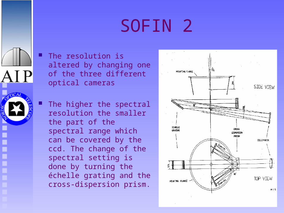
SOFIN 2
The resolution is altered by changing one of the three different optical cameras
The higher the spectral resolution the smaller the part of the spectral range which can be covered by the ccd. The change of the spectral setting is done by turning the échelle grating and the cross-dispersion prism.
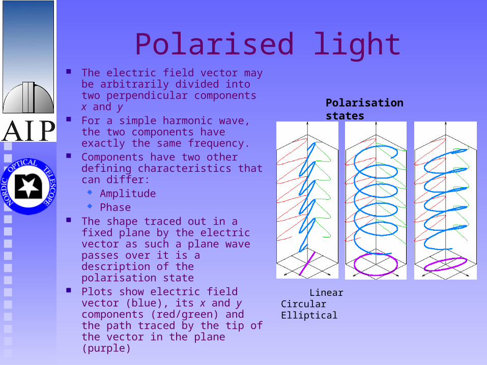
Polarised light The electric field vector may be
arbitrarily divided into two perpendicular components x and y
For a simple harmonic wave, the two components have exactly the same frequency.
Components have two other defining characteristics that can differ:
Amplitude Phase
The shape traced out in a fixed plane by the electric vector as such a plane wave passes over it is a description of the polarisation state
Plots show electric field vector (blue), its x and y components (red/green) and the path traced by the tip of the vector in the plane (purple)
Linear Circular Elliptical
Polarisation states
Why is it usefull?
Mechanisms for creating polarisation: Scattering by small dust particles or free electrons Various absorption and emission processes in magnetic
fields
Polarisation provides information about: The geometry of the light emitting source And the radiation process involved
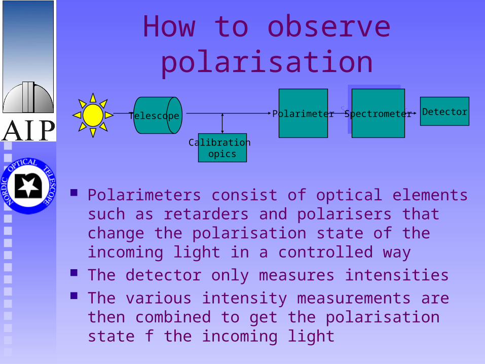
How to observe polarisation
Polarimeters consist of optical elements such as retarders and polarisers that change the polarisation state of the incoming light in a controlled way
The detector only measures intensities The various intensity measurements are then combined to
get the polarisation state f the incoming light
Calibration opics
Polarimeter DetectorSpectrometerSpectrometerTelescope
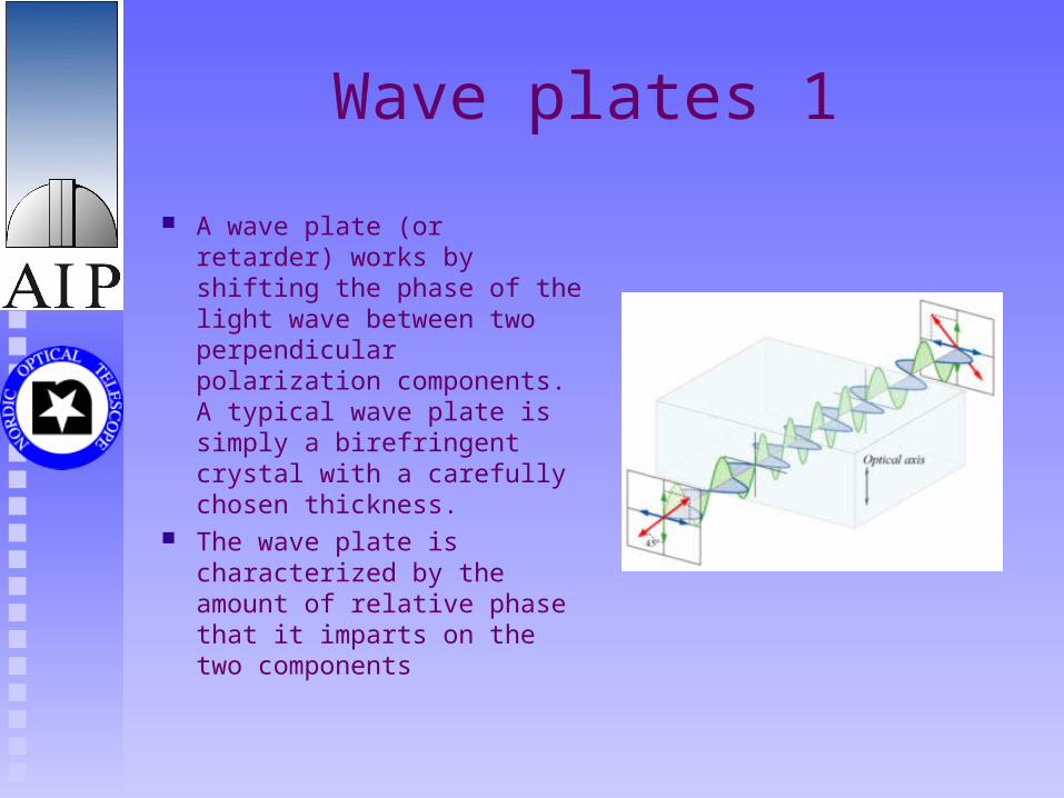
Wave plates 1
A wave plate (or retarder) works by shifting the phase of the light wave between two perpendicular polarization components. A typical wave plate is simply a birefringent crystal with a carefully chosen thickness.
The wave plate is characterized by the amount of relative phase that it imparts on the two components
Wave plates 2
Quater wave plate creates a quarter wavelength phase shift and can change linearly polarized light to circular and vice versa.
Half wave plate retards one polarisation by a half wavelength, or 180 degrees. This type of wave plate rotates the polarization direction of linear polarized light.
Polarisers 1
Polariser is an optical element that produces (at least partially) polarised light from unpolarised input beam
Many types of polarisers, for example
Polaroid Christal polarisers
Polaroid
First polaroid by Edwin Land in 1928 used herapathite chrystals, which were spread as a thin layer between supporting sheets
The chrystals have a magnetic dipole moment, so that if the suspension is placed in a very strong magnetic field they become oriented to form a uniform dichroic layer
Nowadays other materials are used, e.g., polyvinyl alcohol and polyvinylene
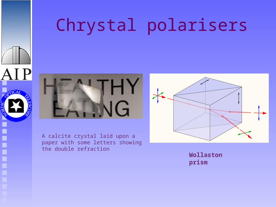
Chrystal polarisers
Wollaston prism
A calcite crystal laid upon a paper with some letters showing the double refraction
Polarimetry with ALFOSC
ALFOSC has a polarimetry unit FAPOL which can be equiped either with half wave plate (linear polarisation) or quater wave plate (cicular + linear polarisation)
A calcite plate is needed in the aperture wheel to provide a simultaneous measurement of the ordinary and the extraordinary components.
The unvigneted field is limited by the size of the calcites to 140" in diameter.
Both photo- and spectropolarimetry can be obtained
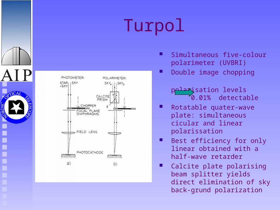
Turpol
Simultaneous five-colour polarimeter (UVBRI)
Double image chopping
polarisation levels 0.01%
detectable Rotatable quater-wave plate:
simultaneous cicular and linear polarissation
Best efficiency for only linear obtained with a half-wave retarder
Calcite plate polarising beam splitter yields direct elimination of sky back-grund polarization