Embed Size (px)
Citation preview
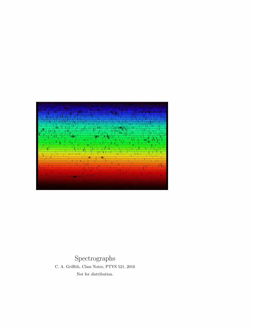
SpectrographsC. A. Griffith, Class Notes, PTYS 521, 2016
Not for distribution.
1. Spectrographs and their characteristics
A spectrograph is an instrument that disperseslight into a frequency spectrum, which is generallyrecorded with the use of a camera that focuses thedispersed light on a detector.
1.1. Diffraction Gratings & Dispersion Ele-
ments
The principal method for dispersing light in UVto IR wavelengths is through diffraction gratings. Inthe same way a large series of equally spaced slits canproduce a very sharp diffraction pattern, a reflectivediffraction grating, a mirror cut with many equallyspaced grooves at similar angles, can also cause adiffraction pattern. Transmission diffractive gratings,such that light passes through a plate, are also used.The plates often contain hundreds to thousands ofgrooves per millimeter, such that the originals are cutby diamond across a metal surface. Replica casts canbe made from liquid plastic, which when cooled canbe coated with a reflective material.
Light can also be dispersed by prisms and grisms.Prisms are used for low dispersion needs, such ascross-dispersers. To achieve high precision, prismsmust be large, and which then leads to greater absorp-tion and lower throughput. In addition, prisms donot disperse uniformly from blue to red. A grism (orgrating prism) combines a prism and grating so thatlight at a chosen central wavelength passes through.The advantage grisms is that the same camera canbe used both for imaging (without the grism) andspectroscopy (with the grism) without having to bemoved. Grisms are inserted into a camera beam thatis already collimated. They create a dispersed spec-trum centered on the object’s location in the camera’sfield of view. Interferometry is another method formeasuring spectra. We’ll discuss that later.
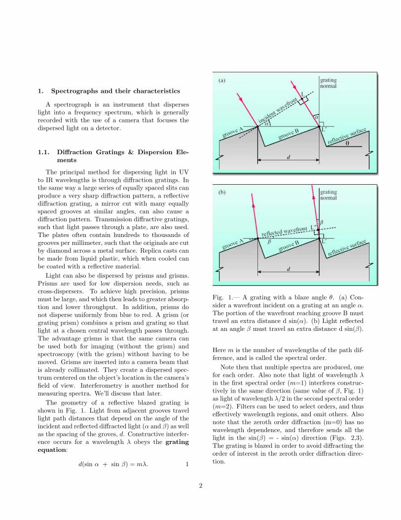
The geometry of a reflective blazed grating isshown in Fig. 1. Light from adjacent grooves travellight path distances that depend on the angle of theincident and reflected diffracted light (α and β) as wellas the spacing of the groves, d. Constructive interfer-ence occurs for a wavelength λ obeys the grating
equation:
d(sin α + sin β) = mλ. 1
θ
Fig. 1.— A grating with a blaze angle θ. (a) Con-sider a wavefront incident on a grating at an angle α.The portion of the wavefront reaching groove B musttravel an extra distance d sin(α). (b) Light reflectedat an angle β must travel an extra distance d sin(β).
Here m is the number of wavelengths of the path dif-ference, and is called the spectral order.
Note then that multiple spectra are produced, onefor each order. Also note that light of wavelength λin the first spectral order (m=1) interferes construc-tively in the same direction (same value of β, Fig. 1)as light of wavelength λ/2 in the second spectral order(m=2). Filters can be used to select orders, and thuseffectively wavelength regions, and omit others. Alsonote that the zeroth order diffraction (m=0) has nowavelength dependence, and therefore sends all thelight in the sin(β) = - sin(α) direction (Figs. 2,3).The grating is blazed in order to avoid diffracting theorder of interest in the zeroth order diffraction direc-tion.
2

Fig. 2.— Here we can see that the 0-order diffractedlight occurs when β = -α. Note that these angles aredefined in terms of the normal to the grating (notfacet) and are opposite signs at opposite sides to thenormal. This light is “white” and best scattered awayfrom the desired the order to be measured.
Another aspect of diffraction gratings is that whenthe relationship between the incident light and themth-order diffracted light describes mirror reflectionwith respect to the facet surface of the grooves, mostof the energy is concentrated into this mth-orderdiffracted light (Fig. 3). The facet angle of thegrooves at this point is called the blaze angle, θ,satisfies the following:
α+ β = 2θ. 2
Note that the blaze angle depends on the incidentand reflected angles. Alternatively, based on Eq. 1, itdepends on the incident angle and the wavelength.We can combine equation 1 and 2, and determinethe wavelength at which the maximum intensity ofdiffracted light is concentrated for a given incidentangle, order, and blaze angle. Combining Eqs. 1 and2, the blaze wavelength is:
λB =2d
msin(θ)cos(α− θ).
The efficiency of the blazed grating in order, m, illu-minated at an incident angle, α, peaks at this wave-length. The blaze angle is set so as to avoid mixingthe spectrum with the zero order light (e.g. as in Fig.3).
Fig. 3.— In this configuration the grating is illumi-nated with incident normal light. The blaze wave-length is that for which light is scattered like a mirrorreflection off of the groove facet, as shown. This lightis scattered away from the 0th order light, as desired.
The angular dispersion, ∆β/∆λ, the change in thedispersion angle that results from a change in thewavelength, provides a measure of the spectral res-olution possible for a certain slit width. This valuecan be derived from the grating equation, written assin β = mλ/d - sin α:
A =∂β
∂λ=
∂β
∂ sinβ
∂ sinβ
∂λ
∂β
∂λ=
1
∂ sinβ/∂β
∂ sinβ
∂λ
∂β
∂λ=
1
cosβ
m
d=
sin(α) + sin(β)
λcos(β)
Thus, the angular dispersion can be increased bygoing to a higher spectral order, m, or by using aspectrograph with a narrower groove spacing, d.
1.2. Getting light to the spectrograph
Light enters the spectrograph in the form of par-allel rays. To achieve this illumination, a converging
3
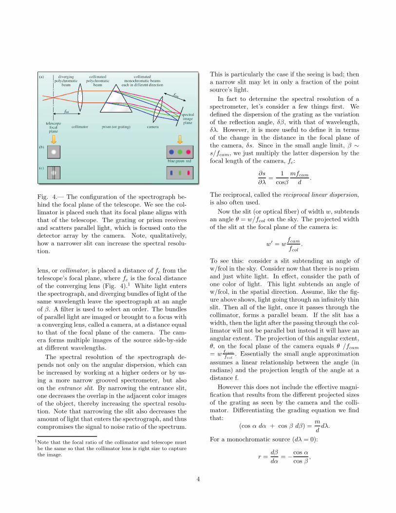
Fig. 4.— The configuration of the spectrograph be-hind the focal plane of the telescope. We see the col-limator is placed such that its focal plane aligns withthat of the telescope. The grating or prism receivesand scatters parallel light, which is focused onto thedetector array by the camera. Note, qualitatively,how a narrower slit can increase the spectral resolu-tion.
lens, or collimator, is placed a distance of fc from thetelescope’s focal plane, where fc is the focal distanceof the converging lens (Fig. 4).1 White light entersthe spectrograph, and diverging bundles of light of thesame wavelength leave the spectrograph at an angleof β. A filter is used to select an order. The bundlesof parallel light are imaged or brought to a focus witha converging lens, called a camera, at a distance equalto that of the focal plane of the camera. The cam-era forms multiple images of the source side-by-sideat different wavelengths.
The spectral resolution of the spectrograph de-pends not only on the angular dispersion, which canbe increased by working at a higher orders or by us-ing a more narrow grooved spectrometer, but alsoon the entrance slit. By narrowing the entrance slit,one decreases the overlap in the adjacent color imagesof the object, thereby increasing the spectral resolu-tion. Note that narrowing the slit also decreases theamount of light that enters the spectrograph, and thuscompromises the signal to noise ratio of the spectrum.
1Note that the focal ratio of the collimator and telescope must
be the same so that the collimator lens is right size to capture
the image.
This is particularly the case if the seeing is bad; thena narrow slit may let in only a fraction of the pointsource’s light.
In fact to determine the spectral resolution of aspectrometer, let’s consider a few things first. Wedefined the dispersion of the grating as the variationof the reflection angle, δβ, with that of wavelength,δλ. However, it is more useful to define it in termsof the change in the distance in the focal plane ofthe camera, δs. Since in the small angle limit, β ∼
s/fcam, we just multiply the latter dispersion by thefocal length of the camera, fc:
∂s
∂λ=
1
cosβ
mfcamd
.
The reciprocal, called the reciprocal linear dispersion,is also often used.
Now the slit (or optical fiber) of width w, subtendsan angle θ = w/fcol on the sky. The projected widthof the slit at the focal plane of the camera is:
w′ = wfcamfcol
.
To see this: consider a slit subtending an angle ofw/fcol in the sky. Consider now that there is no prismand just white light. In effect, consider the path ofone color of light. This light subtends an angle ofw/fcol, in the spatial direction. Assume, like the fig-ure above shows, light going through an infinitely thinslit. Then all of the light, once it passes through thecollimator, forms a parallel beam. If the slit has awidth, then the light after the passing through the col-limator will not be parallel but instead it will have anangular extent. The projection of this angular extent,θ, on the focal plane of the camera equals θ /fcam= w fcam
fcol. Essentially the small angle approximation
assumes a linear relationship between the angle (inradians) and the projection length of the angle at adistance f.
However this does not include the effective magni-fication that results from the different projected sizesof the grating as seen by the camera and the colli-mator. Differentiating the grading equation we findthat:
(cos α dα + cos β dβ) =m
ddλ.
For a monochromatic source (dλ = 0):
r =dβ
dα= −
cos α
cos β,
4
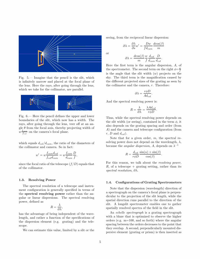
Fig. 5.— Imagine that the pencil is the slit, whichis infinitely narrow and placed at the focal plane ofthe lens. Here the rays, after going through the lens,which we take for the collimator, are parallel.
Fig. 6.— Here the pencil defines the upper and lowerboundaries of the slit, which now has a width. Therays, after going through the lens, veer off at an an-gle θ from the focal axis, thereby projecting width ofw fcam
fcolon the camera’s focal plane.
which equals dcol/dcam, the ratio of the diameters ofthe collimator and camera. So in fact:
w′ = wfcamdcolfcoldcam
= wfcamdcam
D
f,
since the focal ratio of the telescope (f/D) equals thatof the collimator.
1.3. Resolving Power
The spectral resolution of a telescope and instru-ment configuration is generally specified in terms ofthe spectral resolving power rather than the an-gular or linear dispersions. The spectral resolvingpower, defined as
R =λ
∂λ,
has the advantage of being independent of the wave-length, and rather a function of the specifications ofthe dispersion element (e.g. grating) and the tele-scope.
We can estimate this value, limited by a slit or the
seeing, from the reciprocal linear dispersion:
∂λ =∂λ
∂sw′ =
Dw
fdcam
dcos(β)
m
or
∂λ =dcos(β)
m
w
f
dcoldcam
D
dcol.
Here the first term is the angular dispersion, A, ofthe spectrometer. The second term on the right φ=w
f
is the angle that the slit width (w) projects on thesky. The third term is the magnification caused bythe different projected sizes of the grating as seen bythe collimator and the camera, r. Therefore:
∂λ =rφD
Adcol.
And the spectral resolving power is:
R =λ
∂λ=
λAdcolrφD
.
Thus, while the spectral resolving power depends onthe slit width (or seeing), contained in the term φ, italso depends on the grating spacing and order (fromA) and the camera and telescope configuration (fromr, D and dcol).
Note that for a given order, m, the spectral re-solving power does not depend on the wavelength, λ,because the angular dispersion, A, depends on λ−1
R =dcolrφD
sin(α) + sin(β)
cos(β).
For this reason, we talk about the resolving power,R, of a telescope + grating setting, rather than itsspectral resolution, ∂λ.
1.4. Configurations of Grating Spectrometers
Note that the dispersion (wavelength) direction ofa spectrograph on the camera’s focal plane is perpen-dicular to the projection of the slit length, while thespatial direction runs parallel to the direction of theslit. A longslit spectrometer enables one to gatherspatially resolved spectra of the field in the slit.
An echelle spectrograph is a grating spectrographwith a blaze that is optimized to observe the higherorders (e.g. m=100, and so forth) where the angularspacing between the orders decreases to the point thatthey overlap. A second, perpendicularly mounted dis-persive element (grating or prism) is then inserted as
5
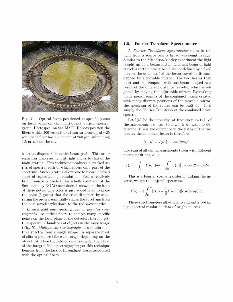
Fig. 7.— Optical fibers positioned at specific pointson focal plane on the multi-object optical spectro-graph, Hectospec, on the MMT. Robots position thefibers within 300 seconds to within an accuracy of∼25µm. Each fiber has a diameter of 250 µm, subtending1.5 arcsec on the sky.
a “cross disperser” into the beam path. This orderseparator disperses light at right angles to that of themain grating. This technique produces a stacked se-ries of spectra, each of which covers only part of thespectrum. Such a grating allows one to record a broadspectral region at high resolution. Yet, a relativelybright source is needed. An echelle spectrum of theSun, taken by NOAO next door, is shown on the frontof these notes. The color is just added later to makethe point (I guess) that the cross-disperser, by sepa-rating the orders, essentially stacks the spectrum fromthe blue wavelengths down to the red wavelengths.
Integral field unit spectrographs or fiber-fed spec-
trographs use optical fibers to sample many specificpoints on the focal plane of the detector, thereby get-ting spectra of hundreds of objects in the same image(Fig. 5). Multiple slit spectrographs also obtain mul-tiple spectra from a single image. A separate maskof slits is prepared for each image, depending on theobject list. Here the field of view is smaller than thatof the integral field spectrographs; yet this techniquebenefits from the lack of throughput losses associatedwith the optical fibers.
1.5. Fourier Transform Spectrometer
A Fourier Transform Spectrometer takes in thelight from a source over a broad wavelength range.Similar to the Michelson-Morley experiment the lightis split up by a beamsplitter. One half beam of lighttravels a certain proscribed distance defined by a fixedmirror; the other half of the beam travels a distancedefined by a movable mirror. The two beams thenmeet and superimpose, with one beam delayed as aresult of the different distance traveled, which is ad-justed by moving the adjustable mirror. By makingmany measurements of the combined beams createdwith many discrete positions of the movable mirror,the spectrum of the source can be built up. It issimply the Fourier Transform of the combined beamspectra.
Let I(ν) be the intensity, at frequency ν=1/λ, ofthe astronomical source, that which we want to de-termine. If p is the difference in the paths of the twobeams, the combined beam is therefore:
I(p, ν) = I(ν)[1 + cos(2πνp)].
The sum of all the measurements taken with differentmirror positions, d, is
I(p) =
∫∞
0
I(p, ν)dν =
∫∞
0
I(ν)[1 + cos(2πνp)]dν
This is a Fourier cosine transform. Taking the in-verse, we get the object’s spectrum.
I(ν) = 4
∫∞
0
[I(p)−1
2I(p = 0)]cos(2πνp)]dp.
These spectrometers allow one to efficiently obtainhigh spectral resolution data of bright sources.
6