Embed Size (px)
Citation preview
Spectre Circuit Simulator Reference
Spectre® Circuit Simulator Reference
Product Version 19.1 January 2020
January 2020 1 Product Version 19.1© 2003-2020 All Rights Reserved.

Spectre Circuit Simulator Reference
© 2003–2020 Cadence Design Systems, Inc. All rights reserved.
Printed in the United States of America.
Cadence Design Systems, Inc. (Cadence), 2655 Seely Ave., San Jose, CA 95134, USA.
MMSIM contains technology licensed from, and copyrighted by: C. L. Lawson, R. J. Hanson, D. Kincaid, and F. T. Krogh © 1979, J. J. Dongarra, J. Du Croz, S. Hammarling, and R. J. Hanson © 1988, J. J. Dongarra, J. Du Croz, I. S. Duff, and S. Hammarling © 1990; University of Tennessee, Knoxville, TN and Oak Ridge National Laboratory, Oak Ridge, TN © 1992-1996; Brian Paul © 1999-2003; M. G. Johnson, Brisbane, Queensland, Australia © 1994; Kenneth S. Kundert and the University of California, 1111 Franklin St., Oakland, CA 94607-5200 © 1985-1988; Hewlett-Packard Company, 3000 Hanover Street, Palo Alto, CA 94304-1185 USA © 1994, Silicon Graphics Computer Systems, Inc., 1140 E. Arques Ave., Sunnyvale, CA 94085 © 1996-1997, Moscow Center for SPARC Technology, Moscow, Russia © 1997; Regents of the University of California, 1111 Franklin St., Oakland, CA 94607-5200 © 1990-1994, Sun Microsystems, Inc., 4150 Network Circle Santa Clara, CA 95054 USA © 1994-2000, Scriptics Corporation, and other parties © 1998-1999; Aladdin Enterprises, 35 Efal St., Kiryat Arye, Petach Tikva, Israel 49511 © 1999 and Jean-loup Gailly and Mark Adler © 1995-2005; RSA Security, Inc., 174 Middlesex Turnpike Bedford, MA 01730 © 2005.
All rights reserved. Associated third party license terms may be found at <install_dir>/doc/OpenSource/*
Open SystemC, Open SystemC Initiative, OSCI, SystemC, and SystemC Initiative are trademarks or registered trademarks of Open SystemC Initiative, Inc. in the United States and other countries and are used with permission.
Trademarks: Trademarks and service marks of Cadence Design Systems, Inc. contained in this document are attributed to Cadence with the appropriate symbol. For queries regarding Cadence’s trademarks, contact the corporate legal department at the address shown above or call 800.862.4522. All other trademarks are the property of their respective holders.
Restricted Permission: This publication is protected by copyright law and international treaties and contains trade secrets and proprietary information owned by Cadence. Unauthorized reproduction or distribution of this publication, or any portion of it, may result in civil and criminal penalties. Except as specified in this permission statement, this publication may not be copied, reproduced, modified, published, uploaded, posted, transmitted, or distributed in any way, without prior written permission from Cadence. Unless otherwise agreed to by Cadence in writing, this statement grants Cadence customers permission to print one (1) hard copy of this publication subject to the following conditions:
1. The publication may be used only in accordance with a written agreement between Cadence and its customer.
2. The publication may not be modified in any way. 3. Any authorized copy of the publication or portion thereof must include all original copyright, trademark,
and other proprietary notices and this permission statement. 4. The information contained in this document cannot be used in the development of like products or
software, whether for internal or external use, and shall not be used for the benefit of any other party, whether or not for consideration.
Disclaimer: Information in this publication is subject to change without notice and does not represent a commitment on the part of Cadence. Except as may be explicitly set forth in such agreement, Cadence does not make, and expressly disclaims, any representations or warranties as to the completeness, accuracy or usefulness of the information contained in this document. Cadence does not warrant that use of such information will not infringe any third party rights, nor does Cadence assume any liability for damages or costs of any kind that may result from use of such information.
January 2020 2 Product Version 19.1© 2003-2020 All Rights Reserved.

Spectre Circuit Simulator Reference
Restricted Rights: Use, duplication, or disclosure by the Government is subject to restrictions as set forth in FAR52.227-14 and DFAR252.227-7013 et seq. or its successor
January 2020 3 Product Version 19.1© 2003-2020 All Rights Reserved.

Spectre Circuit Simulator Reference
January 2020 4 Product Version 19.1© 2003-2020 All Rights Reserved.
Spectre Circuit Simulator Reference
Contents
Preface. . . . . . . . . . . . . . . . . . . . . . . . . . . . . . . . . . . . . . . . . . . . . . . . . . . . . . . . . . . . . 11
Related Documents . . . . . . . . . . . . . . . . . . . . . . . . . . . . . . . . . . . . . . . . . . . . . . . . . . . . . 12Typographic and Syntax Conventions . . . . . . . . . . . . . . . . . . . . . . . . . . . . . . . . . . . . . . . 12References . . . . . . . . . . . . . . . . . . . . . . . . . . . . . . . . . . . . . . . . . . . . . . . . . . . . . . . . . . . 13Additional Learning Resources . . . . . . . . . . . . . . . . . . . . . . . . . . . . . . . . . . . . . . . . . . . . 14
1Introducing the Spectre Circuit Simulator. . . . . . . . . . . . . . . . . . . . . . 15
Spectre Circuit Simulator . . . . . . . . . . . . . . . . . . . . . . . . . . . . . . . . . . . . . . . . . . . . . . . . . 16Spectre Circuit Simulator Features . . . . . . . . . . . . . . . . . . . . . . . . . . . . . . . . . . . . . . 17Benefits of Using the Spectre Circuit Simulator . . . . . . . . . . . . . . . . . . . . . . . . . . . . . 21
Spectre Accelerated Parallel Simulator . . . . . . . . . . . . . . . . . . . . . . . . . . . . . . . . . . . . . . 22Benefits of Spectre APS . . . . . . . . . . . . . . . . . . . . . . . . . . . . . . . . . . . . . . . . . . . . . . . 22
Spectre eXtensive Partitioning Simulator . . . . . . . . . . . . . . . . . . . . . . . . . . . . . . . . . . . . 23Benefits of Spectre XPS . . . . . . . . . . . . . . . . . . . . . . . . . . . . . . . . . . . . . . . . . . . . . . . 23
1Command Options. . . . . . . . . . . . . . . . . . . . . . . . . . . . . . . . . . . . . . . . . . . . . . . . 25
Default Values . . . . . . . . . . . . . . . . . . . . . . . . . . . . . . . . . . . . . . . . . . . . . . . . . . . . . . . . . 39Default Parameter Values . . . . . . . . . . . . . . . . . . . . . . . . . . . . . . . . . . . . . . . . . . . . . . . . 39
1Analysis Statements. . . . . . . . . . . . . . . . . . . . . . . . . . . . . . . . . . . . . . . . . . . . . . 41
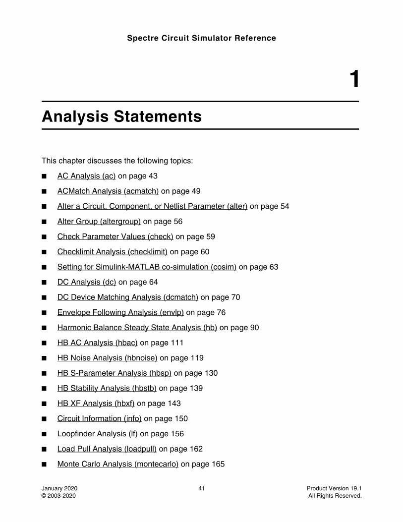
AC Analysis (ac) . . . . . . . . . . . . . . . . . . . . . . . . . . . . . . . . . . . . . . . . . . . . . . . . . . . . . . . 43ACMatch Analysis (acmatch) . . . . . . . . . . . . . . . . . . . . . . . . . . . . . . . . . . . . . . . . . . . . . . 49Alter a Circuit, Component, or Netlist Parameter (alter) . . . . . . . . . . . . . . . . . . . . . . . . . 54Alter Group (altergroup) . . . . . . . . . . . . . . . . . . . . . . . . . . . . . . . . . . . . . . . . . . . . . . . . . . 56Check Parameter Values (check) . . . . . . . . . . . . . . . . . . . . . . . . . . . . . . . . . . . . . . . . . . 59Checklimit Analysis (checklimit) . . . . . . . . . . . . . . . . . . . . . . . . . . . . . . . . . . . . . . . . . . . . 60Setting for Simulink-MATLAB co-simulation (cosim) . . . . . . . . . . . . . . . . . . . . . . . . . . . . 63
January 2020 5 Product Version 19.1© 2003-2020 All Rights Reserved.
Spectre Circuit Simulator Reference
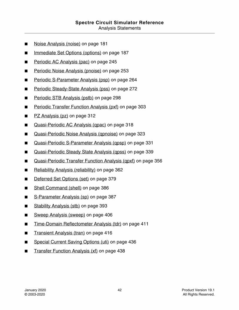
DC Analysis (dc) . . . . . . . . . . . . . . . . . . . . . . . . . . . . . . . . . . . . . . . . . . . . . . . . . . . . . . . 64DC Device Matching Analysis (dcmatch) . . . . . . . . . . . . . . . . . . . . . . . . . . . . . . . . . . . . . 70Envelope Following Analysis (envlp) . . . . . . . . . . . . . . . . . . . . . . . . . . . . . . . . . . . . . . . . 76Harmonic Balance Steady State Analysis (hb) . . . . . . . . . . . . . . . . . . . . . . . . . . . . . . . . 90HB AC Analysis (hbac) . . . . . . . . . . . . . . . . . . . . . . . . . . . . . . . . . . . . . . . . . . . . . . . . . 111HB Noise Analysis (hbnoise) . . . . . . . . . . . . . . . . . . . . . . . . . . . . . . . . . . . . . . . . . . . . . 119HB S-Parameter Analysis (hbsp) . . . . . . . . . . . . . . . . . . . . . . . . . . . . . . . . . . . . . . . . . . 130HB Stability Analysis (hbstb) . . . . . . . . . . . . . . . . . . . . . . . . . . . . . . . . . . . . . . . . . . . . . 139HB XF Analysis (hbxf) . . . . . . . . . . . . . . . . . . . . . . . . . . . . . . . . . . . . . . . . . . . . . . . . . . 143Circuit Information (info) . . . . . . . . . . . . . . . . . . . . . . . . . . . . . . . . . . . . . . . . . . . . . . . . 150Loopfinder Analysis (lf) . . . . . . . . . . . . . . . . . . . . . . . . . . . . . . . . . . . . . . . . . . . . . . . . . 156Load Pull Analysis (loadpull) . . . . . . . . . . . . . . . . . . . . . . . . . . . . . . . . . . . . . . . . . . . . . 162Monte Carlo Analysis (montecarlo) . . . . . . . . . . . . . . . . . . . . . . . . . . . . . . . . . . . . . . . . 165Noise Analysis (noise) . . . . . . . . . . . . . . . . . . . . . . . . . . . . . . . . . . . . . . . . . . . . . . . . . . 181Immediate Set Options (options) . . . . . . . . . . . . . . . . . . . . . . . . . . . . . . . . . . . . . . . . . . 187Periodic AC Analysis (pac) . . . . . . . . . . . . . . . . . . . . . . . . . . . . . . . . . . . . . . . . . . . . . . 245Periodic Noise Analysis (pnoise) . . . . . . . . . . . . . . . . . . . . . . . . . . . . . . . . . . . . . . . . . . 253Periodic S-Parameter Analysis (psp) . . . . . . . . . . . . . . . . . . . . . . . . . . . . . . . . . . . . . . . 264Periodic Steady-State Analysis (pss) . . . . . . . . . . . . . . . . . . . . . . . . . . . . . . . . . . . . . . . 272Periodic STB Analysis (pstb) . . . . . . . . . . . . . . . . . . . . . . . . . . . . . . . . . . . . . . . . . . . . . 298Periodic Transfer Function Analysis (pxf) . . . . . . . . . . . . . . . . . . . . . . . . . . . . . . . . . . . 303PZ Analysis (pz) . . . . . . . . . . . . . . . . . . . . . . . . . . . . . . . . . . . . . . . . . . . . . . . . . . . . . . . 312Quasi-Periodic AC Analysis (qpac) . . . . . . . . . . . . . . . . . . . . . . . . . . . . . . . . . . . . . . . . 318Quasi-Periodic Noise Analysis (qpnoise) . . . . . . . . . . . . . . . . . . . . . . . . . . . . . . . . . . . . 323Quasi-Periodic S-Parameter Analysis (qpsp) . . . . . . . . . . . . . . . . . . . . . . . . . . . . . . . . 331Quasi-Periodic Steady State Analysis (qpss) . . . . . . . . . . . . . . . . . . . . . . . . . . . . . . . . 339Quasi-Periodic Transfer Function Analysis (qpxf) . . . . . . . . . . . . . . . . . . . . . . . . . . . . . 356Reliability Analysis (reliability) . . . . . . . . . . . . . . . . . . . . . . . . . . . . . . . . . . . . . . . . . . . . 362Deferred Set Options (set) . . . . . . . . . . . . . . . . . . . . . . . . . . . . . . . . . . . . . . . . . . . . . . . 379Shell Command (shell) . . . . . . . . . . . . . . . . . . . . . . . . . . . . . . . . . . . . . . . . . . . . . . . . . 386S-Parameter Analysis (sp) . . . . . . . . . . . . . . . . . . . . . . . . . . . . . . . . . . . . . . . . . . . . . . . 387Stability Analysis (stb) . . . . . . . . . . . . . . . . . . . . . . . . . . . . . . . . . . . . . . . . . . . . . . . . . . 393Reliability Stress Analysis (stress) . . . . . . . . . . . . . . . . . . . . . . . . . . . . . . . . . . . . . . . . . 401Sweep Analysis (sweep) . . . . . . . . . . . . . . . . . . . . . . . . . . . . . . . . . . . . . . . . . . . . . . . . 406Time-Domain Reflectometer Analysis (tdr) . . . . . . . . . . . . . . . . . . . . . . . . . . . . . . . . . . 411THERMAL Analysis (thermal) . . . . . . . . . . . . . . . . . . . . . . . . . . . . . . . . . . . . . . . . . . . . 413
January 2020 6 Product Version 19.1© 2003-2020 All Rights Reserved.
Spectre Circuit Simulator Reference
Transient Analysis (tran) . . . . . . . . . . . . . . . . . . . . . . . . . . . . . . . . . . . . . . . . . . . . . . . . 416Special Current Saving Options (uti) . . . . . . . . . . . . . . . . . . . . . . . . . . . . . . . . . . . . . . . 436Transfer Function Analysis (xf) . . . . . . . . . . . . . . . . . . . . . . . . . . . . . . . . . . . . . . . . . . . 438
1Other Simulation Topics . . . . . . . . . . . . . . . . . . . . . . . . . . . . . . . . . . . . . . . . 445
AHDL Linter Usage (ahdllint) . . . . . . . . . . . . . . . . . . . . . . . . . . . . . . . . . . . . . . . . . . . . . 447Using analogmodel for Model Passing (analogmodel) . . . . . . . . . . . . . . . . . . . . . . . . . 451Behavioral Source Use Model (bsource) . . . . . . . . . . . . . . . . . . . . . . . . . . . . . . . . . . . . 453Checkpoint - Restart (checkpoint) . . . . . . . . . . . . . . . . . . . . . . . . . . . . . . . . . . . . . . . . . 462Configuring CMI Shared Objects (cmiconfig) . . . . . . . . . . . . . . . . . . . . . . . . . . . . . . . . 464Built-in Mathematical and Physical Constants (constants) . . . . . . . . . . . . . . . . . . . . . . 466Convergence Difficulties (convergence) . . . . . . . . . . . . . . . . . . . . . . . . . . . . . . . . . . . . 468The dcopt command line option (dcopt) . . . . . . . . . . . . . . . . . . . . . . . . . . . . . . . . . . . . 470encryption (encryption) . . . . . . . . . . . . . . . . . . . . . . . . . . . . . . . . . . . . . . . . . . . . . . . . . 471Expressions (expressions) . . . . . . . . . . . . . . . . . . . . . . . . . . . . . . . . . . . . . . . . . . . . . . . 474The fastdc command line option (fastdc) . . . . . . . . . . . . . . . . . . . . . . . . . . . . . . . . . . . . 478Fault List for Transient Fault Analysis (faults) . . . . . . . . . . . . . . . . . . . . . . . . . . . . . . . . 479User Defined Functions (functions) . . . . . . . . . . . . . . . . . . . . . . . . . . . . . . . . . . . . . . . . 481Global Nodes (global) . . . . . . . . . . . . . . . . . . . . . . . . . . . . . . . . . . . . . . . . . . . . . . . . . . 482IBIS Component Use Model (ibis) . . . . . . . . . . . . . . . . . . . . . . . . . . . . . . . . . . . . . . . . . 483Initial Conditions (ic) . . . . . . . . . . . . . . . . . . . . . . . . . . . . . . . . . . . . . . . . . . . . . . . . . . . 490The Structural if-statement (if) . . . . . . . . . . . . . . . . . . . . . . . . . . . . . . . . . . . . . . . . . . . . 491Include File (include) . . . . . . . . . . . . . . . . . . . . . . . . . . . . . . . . . . . . . . . . . . . . . . . . . . . 493Spectre Netlist Keywords (keywords) . . . . . . . . . . . . . . . . . . . . . . . . . . . . . . . . . . . . . . 495Library - Sectional Include (library) . . . . . . . . . . . . . . . . . . . . . . . . . . . . . . . . . . . . . . . . 498Tips for Reducing Memory Usage (memory) . . . . . . . . . . . . . . . . . . . . . . . . . . . . . . . . . 500Multi-Technology Simulation Mode (mts) . . . . . . . . . . . . . . . . . . . . . . . . . . . . . . . . . . . 501Node Sets (nodeset) . . . . . . . . . . . . . . . . . . . . . . . . . . . . . . . . . . . . . . . . . . . . . . . . . . . 502Parameter Soft Limits (param_limits) . . . . . . . . . . . . . . . . . . . . . . . . . . . . . . . . . . . . . . 503Netlist Parameters (parameters) . . . . . . . . . . . . . . . . . . . . . . . . . . . . . . . . . . . . . . . . . . 506Parameter Set - Block of Data (paramset) . . . . . . . . . . . . . . . . . . . . . . . . . . . . . . . . . . . 509The postlayout command line option (postlayout) . . . . . . . . . . . . . . . . . . . . . . . . . . . . . 510Pspice_include File (pspice_include) . . . . . . . . . . . . . . . . . . . . . . . . . . . . . . . . . . . . . . . 511Tips for Reducing Memory Usage with SpectreRF (rfmemory) . . . . . . . . . . . . . . . . . . . 512
January 2020 7 Product Version 19.1© 2003-2020 All Rights Reserved.
Spectre Circuit Simulator Reference
Output Selections (save) . . . . . . . . . . . . . . . . . . . . . . . . . . . . . . . . . . . . . . . . . . . . . . . . 517Savestate - Recover (savestate) . . . . . . . . . . . . . . . . . . . . . . . . . . . . . . . . . . . . . . . . . . 520Sensitivity Analyses (sens) . . . . . . . . . . . . . . . . . . . . . . . . . . . . . . . . . . . . . . . . . . . . . . 524SpectreRF Summary (spectrerf) . . . . . . . . . . . . . . . . . . . . . . . . . . . . . . . . . . . . . . . . . . 526Stitch Flow Use Model (stitch) . . . . . . . . . . . . . . . . . . . . . . . . . . . . . . . . . . . . . . . . . . . . 527Subcircuit Definitions (subckt) . . . . . . . . . . . . . . . . . . . . . . . . . . . . . . . . . . . . . . . . . . . . 533Vec/Vcd/Evcd Digital Stimulus (vector) . . . . . . . . . . . . . . . . . . . . . . . . . . . . . . . . . . . . . 538Verilog-A Usage and Language Summary (veriloga) . . . . . . . . . . . . . . . . . . . . . . . . . . 541
1Circuit Checks. . . . . . . . . . . . . . . . . . . . . . . . . . . . . . . . . . . . . . . . . . . . . . . . . . . . 553
Dynamic Subckt Instance Activity Check (dyn_activity) . . . . . . . . . . . . . . . . . . . . . . . . 555Dynamic Active Node Check (dyn_actnode) . . . . . . . . . . . . . . . . . . . . . . . . . . . . . . . . . 557Dynamic Capacitor Voltage Check (dyn_capv) . . . . . . . . . . . . . . . . . . . . . . . . . . . . . . . 559Dynamic DC Leakage Path Check (dyn_dcpath) . . . . . . . . . . . . . . . . . . . . . . . . . . . . . 561Dynamic Delay Check (dyn_delay) . . . . . . . . . . . . . . . . . . . . . . . . . . . . . . . . . . . . . . . . 564Dynamic Diode Voltage Check (dyn_diodev) . . . . . . . . . . . . . . . . . . . . . . . . . . . . . . . . 567Dynamic Excessive Element Current Check (dyn_exi) . . . . . . . . . . . . . . . . . . . . . . . . . 569Dynamic Excessive Rise, Fall, Undefined State Time Check (dyn_exrf) . . . . . . . . . . . 571Dynamic Floating Node Induced DC Leakage Path Check (dyn_floatdcpath) . . . . . . . 574Dynamic Floating Node Statistical Check (dyn_float_tran_stat) . . . . . . . . . . . . . . . . . . 582Dynamic Glitch Check (dyn_glitch) . . . . . . . . . . . . . . . . . . . . . . . . . . . . . . . . . . . . . . . . 586Dynamic HighZ Node Check (dyn_highz) . . . . . . . . . . . . . . . . . . . . . . . . . . . . . . . . . . . 589Dynamic MOSFET Voltage Check (dyn_mosv) . . . . . . . . . . . . . . . . . . . . . . . . . . . . . . . 594Dynamic Node Capacitance Check (dyn_nodecap) . . . . . . . . . . . . . . . . . . . . . . . . . . . 596Dynamic Noisy Node Check (dyn_noisynode) . . . . . . . . . . . . . . . . . . . . . . . . . . . . . . . 598Dynamic Pulse Width Check (dyn_pulsewidth) . . . . . . . . . . . . . . . . . . . . . . . . . . . . . . . 601Dynamic Resistor Voltage Check (dyn_resv) . . . . . . . . . . . . . . . . . . . . . . . . . . . . . . . . 604Dynamic Setup and Hold Check (dyn_setuphold) . . . . . . . . . . . . . . . . . . . . . . . . . . . . . 606Dynamic Statistical HighZ Node Check (dyn_stahighz) . . . . . . . . . . . . . . . . . . . . . . . . 609Dynamic Subckt Port Voltage/Current Check (dyn_subcktport) . . . . . . . . . . . . . . . . . . 612Dynamic Subckt Port Power Check (dyn_subcktpwr) . . . . . . . . . . . . . . . . . . . . . . . . . . 614Static Capacitor Check (static_capacitor) . . . . . . . . . . . . . . . . . . . . . . . . . . . . . . . . . . . 617Static Capacitor Voltage Check (static_capv) . . . . . . . . . . . . . . . . . . . . . . . . . . . . . . . . 619Static Coupling Impact Check (static_coupling) . . . . . . . . . . . . . . . . . . . . . . . . . . . . . . 621
January 2020 8 Product Version 19.1© 2003-2020 All Rights Reserved.
Spectre Circuit Simulator Reference
Static DC Leakage Path Check (static_dcpath) . . . . . . . . . . . . . . . . . . . . . . . . . . . . . . . 624Static Diode Voltage Check (static_diodev) . . . . . . . . . . . . . . . . . . . . . . . . . . . . . . . . . . 626Static ERC Check (static_erc) . . . . . . . . . . . . . . . . . . . . . . . . . . . . . . . . . . . . . . . . . . . . 628Static Highfanout Check (static_highfanout) . . . . . . . . . . . . . . . . . . . . . . . . . . . . . . . . . 631Static HighZ Node Check (static_highz) . . . . . . . . . . . . . . . . . . . . . . . . . . . . . . . . . . . . 634Static MOSFET Voltage Check (static_mosv) . . . . . . . . . . . . . . . . . . . . . . . . . . . . . . . . 637Static NMOS to vdd count (static_nmos2vdd) . . . . . . . . . . . . . . . . . . . . . . . . . . . . . . . . 639Static NMOS Forward Bias Bulk Check (static_nmosb) . . . . . . . . . . . . . . . . . . . . . . . . 640Static Always Conducting NMOSFET Check (static_nmosvgs) . . . . . . . . . . . . . . . . . . 643Static PMOS to gnd count (static_pmos2gnd) . . . . . . . . . . . . . . . . . . . . . . . . . . . . . . . . 645Static PMOS Forward Bias Bulk Check (static_pmosb) . . . . . . . . . . . . . . . . . . . . . . . . 647Static Always Conducting PMOSFET Check (static_pmosvgs) . . . . . . . . . . . . . . . . . . 650Static RCDelay Check (static_rcdelay) . . . . . . . . . . . . . . . . . . . . . . . . . . . . . . . . . . . . . 653Static Resistor Check (static_resistor) . . . . . . . . . . . . . . . . . . . . . . . . . . . . . . . . . . . . . . 656Static Resistor Voltage Check (static_resv) . . . . . . . . . . . . . . . . . . . . . . . . . . . . . . . . . . 658Static Subckt Port Voltage Check (static_subcktport) . . . . . . . . . . . . . . . . . . . . . . . . . . 660Static Transmission Gate Check (static_tgate) . . . . . . . . . . . . . . . . . . . . . . . . . . . . . . . 662Static Voltage Domain Conflict Check (static_vconflict) . . . . . . . . . . . . . . . . . . . . . . . . 664Static Voltage Domain Device Check (static_voltdomain) . . . . . . . . . . . . . . . . . . . . . . . 665
1References . . . . . . . . . . . . . . . . . . . . . . . . . . . . . . . . . . . . . . . . . . . . . . . . . . . . . . . 667
Index . . . . . . . . . . . . . . . . . . . . . . . . . . . . . . . . . . . . . . . . . . . . . . . . . . . . . . . . . . . . . . 669
January 2020 9 Product Version 19.1© 2003-2020 All Rights Reserved.

Spectre Circuit Simulator Reference
January 2020 10 Product Version 19.1© 2003-2020 All Rights Reserved.
Spectre Circuit Simulator Reference
January 2020 11 Product Version 19.1© 2003-2020 All Rights Reserved.
Preface
This manual assumes that you are familiar with the development, design, and simulation of integrated circuits and that you have some familiarity with SPICE simulation. It contains information about the Spectre® circuit simulator.
Spectre is an advanced circuit simulator that simulates analog and digital circuits at the differential equation level. The simulator uses improved algorithms that offer increased simulation speed and greatly improved convergence characteristics over SPICE. Besides the basic capabilities, the Spectre circuit simulator provides significant additional capabilities over SPICE. Verilog®-A uses functional description text files (modules) to model the behavior of electrical circuits and other systems. Spectre RF Simulation option adds several new analyses that support the efficient calculation of the operating point, transfer function, noise, and distortion of common RF and communication circuits, such as mixers, oscillators, sample holds, and switched-capacitor filters.
This preface discusses the following topics:
■ Related Documents on page -12
■ Typographic and Syntax Conventions on page -12
■ References on page 13
Spectre Circuit Simulator ReferencePreface
January 2020 12 Product Version 19.1© 2003-2020 All Rights Reserved.
Related Documents
The following can give you more information about the Spectre circuit simulator and related products:
■ To learn more about the equations used in the Spectre circuit simulator, consult the Cadence Circuit Simulator Device Model Equations manual.
■ The Spectre circuit simulator is often run within the Cadence® analog circuit design environment, under the Cadence® design framework II. To see how the Spectre circuit simulator is run under the analog circuit design environment, read the Virtuoso Analog Design Environment User Guide.
■ For more information about using the Spectre circuit simulator with Verilog-A, see the Verilog-A Language Reference manual.
■ If you want to see how SpectreRF is run under the analog circuit design environment, read SpectreRF Simulation Option User Guide.
■ For more information about RF theory, see SpectreRF Simulation Option Theory.
■ For more information about how you work with the design framework II interface, see Design Framework II Help.
■ For more information about specific applications of Spectre analyses, see The Designer’s Guide to SPICE & Spectre1.
Typographic and Syntax Conventions
This list describes the syntax conventions used for the Spectre circuit simulator.
1. Kundert, Kenneth S. The Designer’s Guide to SPICE & Spectre. Boston: Kluwer Academic Publishers, 1995.
literal Nonitalic words indicate keywords that you must enter literally. These keywords represent command (function, routine) or option names, file names and paths, and any other sort of type-in commands.
Spectre Circuit Simulator ReferencePreface
January 2020 13 Product Version 19.1© 2003-2020 All Rights Reserved.
Important
The language requires many characters not included in the preceding list. You must enter required characters exactly as shown.
References
Text within brackets ([ ]) are references. See Appendix 1, “References” for more information.
argument Words in italics indicate user-defined arguments for which you must substitute a name or a value. (The characters before the underscore (_) in the word indicate the data types that this argument can take. Names are case sensitive.
|Vertical bars (OR-bars) separate possible choices for a single argument. They take precedence over any other character.
[ ] Brackets denote optional arguments. When used with OR-bars, they enclose a list of choices. You can choose one argument from the list.
{ } Braces are used with OR-bars and enclose a list of choices. You must choose one argument from the list.
... Three dots (...) indicate that you can repeat the previous argument. If you use them with brackets, you can specify zero or more arguments. If they are used without brackets, you must specify at least one argument, but you can specify more.
Spectre Circuit Simulator ReferencePreface
January 2020 14 Product Version 19.1© 2003-2020 All Rights Reserved.
Additional Learning Resources
Cadence provides various Rapid Adoption Kits that you can use to learn how to employ Virtuoso applications in your design flows. These kits contain workshop databases, designs, and instructions to run the design flow.
Cadence offers the following training courses on the Spectre circuit simulator:
■ Spectre Circuit Simulator
■ Spectre Simulations Using Virtuoso ADE
For further information on the training courses available in your region, visit the Cadence Training portal. You can also write to [email protected].
Note: The links in this section open in a new browser. The course links initially display the requested training information for North America, but if required, you can navigate to the courses available in other regions.
Spectre Circuit Simulator Reference
January 2020 15 Product Version 19.1© 2003-2020 All Rights Reserved.
1Introducing the Spectre Circuit Simulator
This chapter discusses the following topics:
■ Spectre Circuit Simulator on page 16
❑ Spectre Circuit Simulator Features on page 17
❑ Benefits of Using the Spectre Circuit Simulator on page 21
■ Spectre Accelerated Parallel Simulator on page 22
❑ Benefits of Spectre APS on page 22
■ Spectre eXtensive Partitioning Simulator on page 23
❑ Benefits of Spectre XPS on page 23
Spectre Circuit Simulator ReferenceIntroducing the Spectre Circuit Simulator
January 2020 16 Product Version 19.1© 2003-2020 All Rights Reserved.
Spectre Circuit Simulator
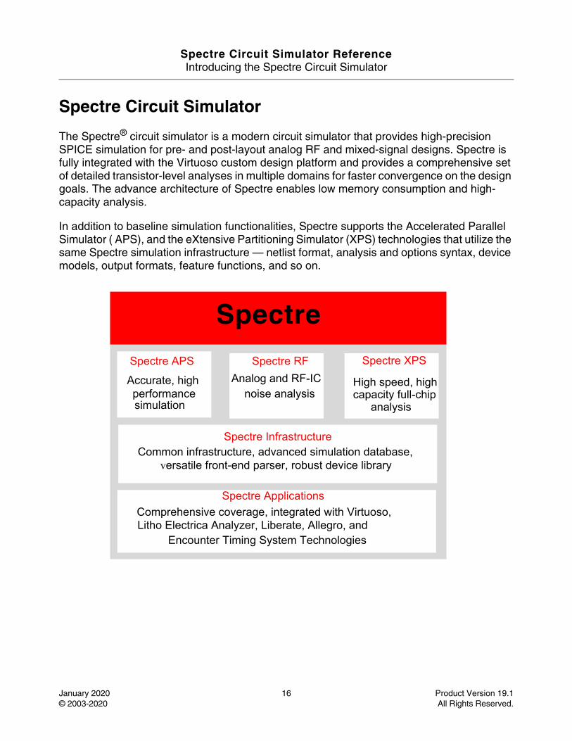
The Spectre® circuit simulator is a modern circuit simulator that provides high-precision SPICE simulation for pre- and post-layout analog RF and mixed-signal designs. Spectre is fully integrated with the Virtuoso custom design platform and provides a comprehensive set of detailed transistor-level analyses in multiple domains for faster convergence on the design goals. The advance architecture of Spectre enables low memory consumption and high-capacity analysis.
In addition to baseline simulation functionalities, Spectre supports the Accelerated Parallel Simulator ( APS), and the eXtensive Partitioning Simulator (XPS) technologies that utilize the same Spectre simulation infrastructure — netlist format, analysis and options syntax, device models, output formats, feature functions, and so on.
Spectre
Spectre APS
Accurate, high performancesimulation
Spectre RFAnalog and RF-IC
noise analysis
Spectre XPS
High speed, highcapacity full-chip
analysis
Spectre InfrastructureCommon infrastructure, advanced simulation database,
versatile front-end parser, robust device library
Spectre ApplicationsComprehensive coverage, integrated with Virtuoso,
Encounter Timing System TechnologiesLitho Electrica Analyzer, Liberate, Allegro, and
Spectre Circuit Simulator ReferenceIntroducing the Spectre Circuit Simulator
January 2020 17 Product Version 19.1© 2003-2020 All Rights Reserved.
Spectre Circuit Simulator Features
The Spectre circuit simulator provides the following features.
Proven Circuit Simulation Techniques
Spectre uses proprietary techniques — including adaptive time step control, sparse matrix solving, and multi-processing of MOS models — to provide high performance while maintaining sign-off accuracy. It includes native support for both Spectre and SPICE syntax, providing you the flexibility to use the Spectre technology for any design flow without worrying about the design format. In addition, it converges to results that are “silicon-accurate” by modeling extensive physical effects in devices for deep sub-micron processes.
Comprehensive Statistical Analysis
Spectre bridges the gap between manufacturability and time to market nodes by providing a comprehensive set of statistical analysis tools tailored to IC design at advanced process nodes. Advanced Monte Carlo algorithms enable smart selection of process and design parameters to characterize the yield with significantly reduced simulation runs. The DC Match capability efficiently analyzes local process mismatch effects and identifies the yield-limiting devices and parameters. Tight integration between the Spectre Circuit Simulator and the Virtuoso Analog Design Environment offers user-friendly interactive setup and advanced visualization of statistical results.
Transient Noise Analysis
Spectre provides transient noise analysis for accurate calculation of the large signal noise in nonlinear non-periodic circuits. All noise types are supported, including thermal, shot, and flicker.
Built-in Verilog-A and MDL
The Spectre Circuit Simulator offers design abstraction for faster convergence on results, including behavioral modeling capabilities in full compliance with Verilog-A 2.0. The compiled Verilog-A implementation is optimized for compact device models, thus offering comparable performance to built-in device models.
In addition to supporting standard SPICE measurement functions (.measure), it offers a measurement description language (MDL) to automate cell and library characterization. Spectre MDL enables the designer to post-process the results and tune the simulator to provide the best performance/accuracy trade-off for a specific measurement.
Spectre Circuit Simulator ReferenceIntroducing the Spectre Circuit Simulator
January 2020 18 Product Version 19.1© 2003-2020 All Rights Reserved.
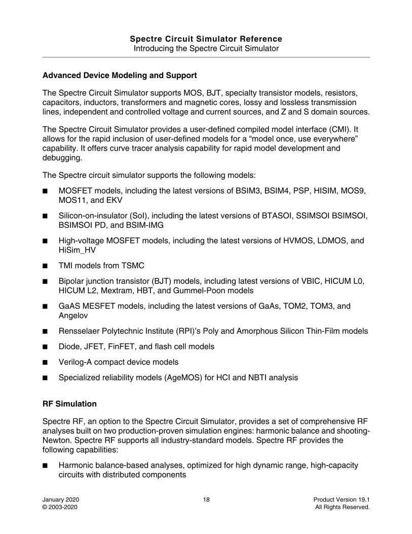
Advanced Device Modeling and Support
The Spectre Circuit Simulator supports MOS, BJT, specialty transistor models, resistors, capacitors, inductors, transformers and magnetic cores, lossy and lossless transmission lines, independent and controlled voltage and current sources, and Z and S domain sources.
The Spectre Circuit Simulator provides a user-defined compiled model interface (CMI). It allows for the rapid inclusion of user-defined models for a “model once, use everywhere” capability. It offers curve tracer analysis capability for rapid model development and debugging.
The Spectre circuit simulator supports the following models:
■ MOSFET models, including the latest versions of BSIM3, BSIM4, PSP, HISIM, MOS9, MOS11, and EKV
■ Silicon-on-insulator (SoI), including the latest versions of BTASOI, SSIMSOI BSIMSOI, BSIMSOI PD, and BSIM-IMG
■ High-voltage MOSFET models, including the latest versions of HVMOS, LDMOS, and HiSim_HV
■ TMI models from TSMC
■ Bipolar junction transistor (BJT) models, including latest versions of VBIC, HICUM L0, HICUM L2, Mextram, HBT, and Gummel-Poon models
■ GaAS MESFET models, including the latest versions of GaAs, TOM2, TOM3, and Angelov
■ Rensselaer Polytechnic Institute (RPI)’s Poly and Amorphous Silicon Thin-Film models
■ Diode, JFET, FinFET, and flash cell models
■ Verilog-A compact device models
■ Specialized reliability models (AgeMOS) for HCI and NBTI analysis
RF Simulation
Spectre RF, an option to the Spectre Circuit Simulator, provides a set of comprehensive RF analyses built on two production-proven simulation engines: harmonic balance and shooting-Newton. Spectre RF supports all industry-standard models. Spectre RF provides the following capabilities:
■ Harmonic balance-based analyses, optimized for high dynamic range, high-capacity circuits with distributed components
Spectre Circuit Simulator ReferenceIntroducing the Spectre Circuit Simulator
January 2020 19 Product Version 19.1© 2003-2020 All Rights Reserved.
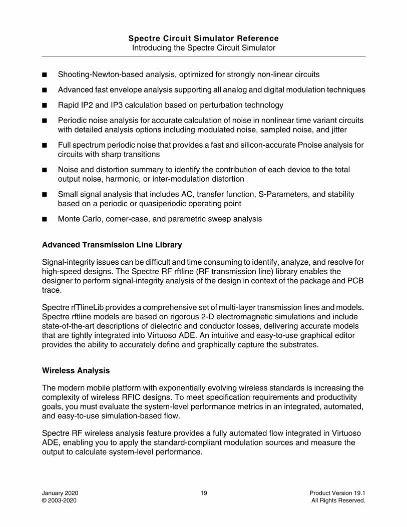
■ Shooting-Newton-based analysis, optimized for strongly non-linear circuits
■ Advanced fast envelope analysis supporting all analog and digital modulation techniques
■ Rapid IP2 and IP3 calculation based on perturbation technology
■ Periodic noise analysis for accurate calculation of noise in nonlinear time variant circuits with detailed analysis options including modulated noise, sampled noise, and jitter
■ Full spectrum periodic noise that provides a fast and silicon-accurate Pnoise analysis for circuits with sharp transitions
■ Noise and distortion summary to identify the contribution of each device to the total output noise, harmonic, or inter-modulation distortion
■ Small signal analysis that includes AC, transfer function, S-Parameters, and stability based on a periodic or quasiperiodic operating point
■ Monte Carlo, corner-case, and parametric sweep analysis
Advanced Transmission Line Library
Signal-integrity issues can be difficult and time consuming to identify, analyze, and resolve for high-speed designs. The Spectre RF rftline (RF transmission line) library enables the designer to perform signal-integrity analysis of the design in context of the package and PCB trace.
Spectre rfTlineLib provides a comprehensive set of multi-layer transmission lines and models. Spectre rftline models are based on rigorous 2-D electromagnetic simulations and include state-of-the-art descriptions of dielectric and conductor losses, delivering accurate models that are tightly integrated into Virtuoso ADE. An intuitive and easy-to-use graphical editor provides the ability to accurately define and graphically capture the substrates.
Wireless Analysis
The modern mobile platform with exponentially evolving wireless standards is increasing the complexity of wireless RFIC designs. To meet specification requirements and productivity goals, you must evaluate the system-level performance metrics in an integrated, automated, and easy-to-use simulation-based flow.
Spectre RF wireless analysis feature provides a fully automated flow integrated in Virtuoso ADE, enabling you to apply the standard-compliant modulation sources and measure the output to calculate system-level performance.
Spectre Circuit Simulator ReferenceIntroducing the Spectre Circuit Simulator
January 2020 20 Product Version 19.1© 2003-2020 All Rights Reserved.
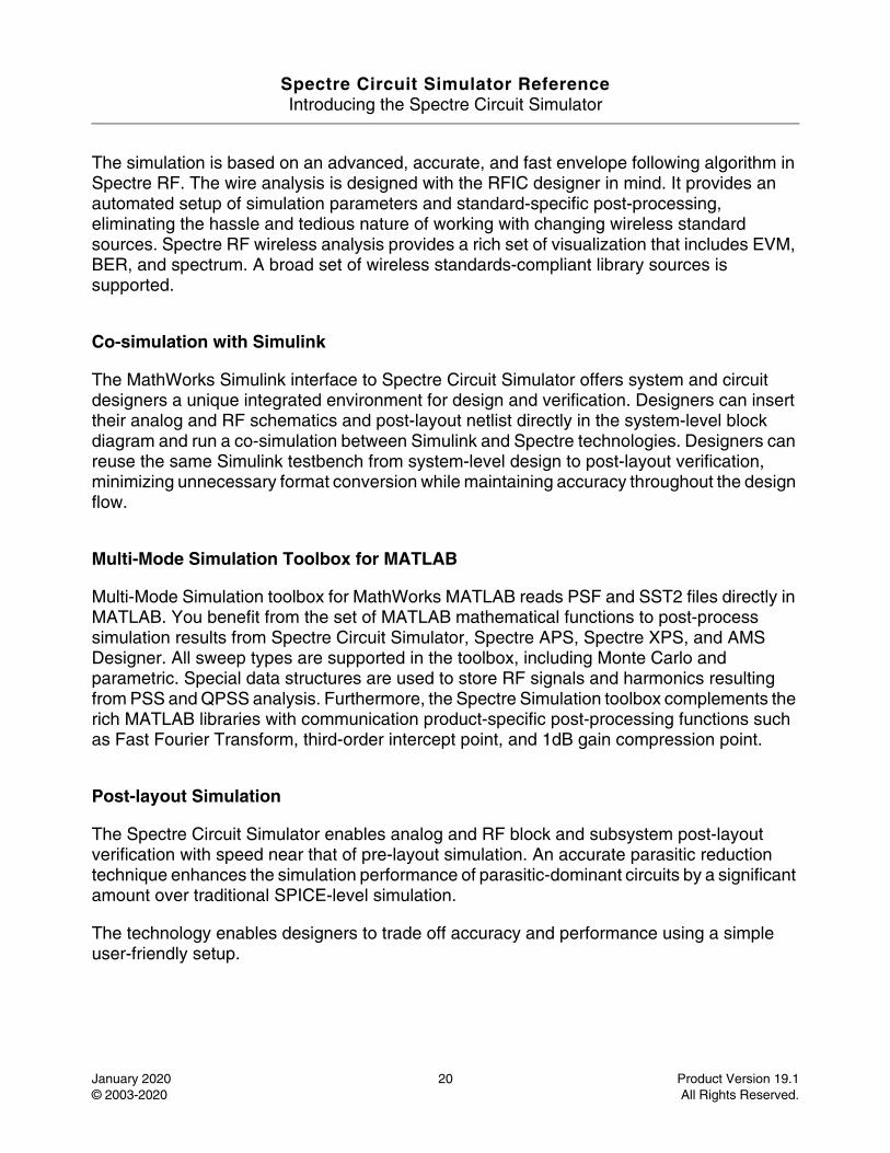
The simulation is based on an advanced, accurate, and fast envelope following algorithm in Spectre RF. The wire analysis is designed with the RFIC designer in mind. It provides an automated setup of simulation parameters and standard-specific post-processing, eliminating the hassle and tedious nature of working with changing wireless standard sources. Spectre RF wireless analysis provides a rich set of visualization that includes EVM, BER, and spectrum. A broad set of wireless standards-compliant library sources is supported.
Co-simulation with Simulink
The MathWorks Simulink interface to Spectre Circuit Simulator offers system and circuit designers a unique integrated environment for design and verification. Designers can insert their analog and RF schematics and post-layout netlist directly in the system-level block diagram and run a co-simulation between Simulink and Spectre technologies. Designers can reuse the same Simulink testbench from system-level design to post-layout verification, minimizing unnecessary format conversion while maintaining accuracy throughout the design flow.
Multi-Mode Simulation Toolbox for MATLAB
Multi-Mode Simulation toolbox for MathWorks MATLAB reads PSF and SST2 files directly in MATLAB. You benefit from the set of MATLAB mathematical functions to post-process simulation results from Spectre Circuit Simulator, Spectre APS, Spectre XPS, and AMS Designer. All sweep types are supported in the toolbox, including Monte Carlo and parametric. Special data structures are used to store RF signals and harmonics resulting from PSS and QPSS analysis. Furthermore, the Spectre Simulation toolbox complements the rich MATLAB libraries with communication product-specific post-processing functions such as Fast Fourier Transform, third-order intercept point, and 1dB gain compression point.
Post-layout Simulation
The Spectre Circuit Simulator enables analog and RF block and subsystem post-layout verification with speed near that of pre-layout simulation. An accurate parasitic reduction technique enhances the simulation performance of parasitic-dominant circuits by a significant amount over traditional SPICE-level simulation.
The technology enables designers to trade off accuracy and performance using a simple user-friendly setup.

Spectre Circuit Simulator ReferenceIntroducing the Spectre Circuit Simulator
January 2020 21 Product Version 19.1© 2003-2020 All Rights Reserved.
Benefits of Using the Spectre Circuit Simulator
The Spectre Circuit Simulator provides the following benefits:
■ Provides high-performance, high-capacity SPICE-level analog and RF simulation with out-of-the-box tuning for accuracy and faster convergence.
■ Facilitates the trade-off between accuracy and performance through user-friendly simulation setup applicable to most complex analog and custom-digital ICs.
■ Enables accurate and efficient post-layout simulation.
■ Supports out-of-the-box S-Parameter models, enabling simulation of complex n-port devices.
■ Delivers signal integrity analysis capability with an advanced transmission line library and graphical editor.
■ Provides a platform to measure and analyze system-level performance metric.
■ Performs application-specific analysis of RF performance parameters (spectral response, gain compression, intermodulation distortion, impedance matching, stability, and isolation).
■ Offers advanced statistical analysis to help design companies improve the manufacturability and yield of ICs at advanced process nodes without sacrificing time to market.
■ Delivers fast interactive simulation setup, cross-probing, visualization, and post-processing of simulation results through tight integration with the Virtuoso Analog Design Environment.
■ Ensures higher design quality using silicon-accurate, industry-standard, foundry-certified device models shared across the simulation engines.
Spectre Circuit Simulator ReferenceIntroducing the Spectre Circuit Simulator
January 2020 22 Product Version 19.1© 2003-2020 All Rights Reserved.
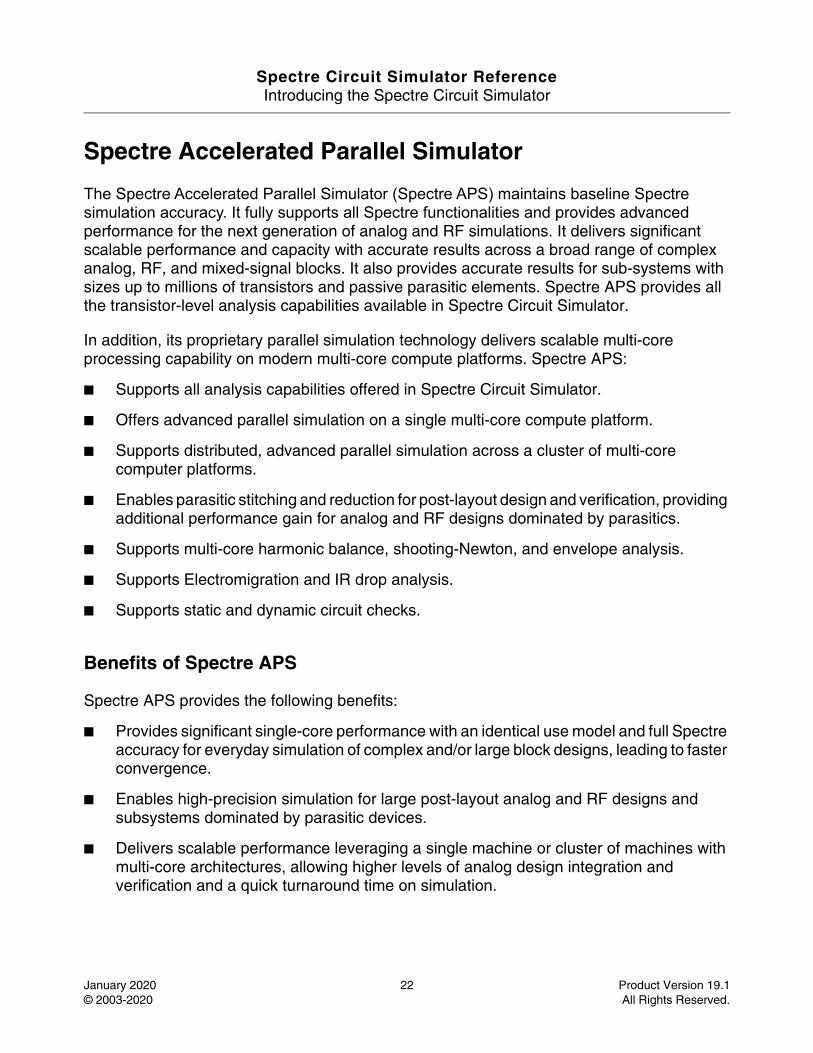
Spectre Accelerated Parallel Simulator
The Spectre Accelerated Parallel Simulator (Spectre APS) maintains baseline Spectre simulation accuracy. It fully supports all Spectre functionalities and provides advanced performance for the next generation of analog and RF simulations. It delivers significant scalable performance and capacity with accurate results across a broad range of complex analog, RF, and mixed-signal blocks. It also provides accurate results for sub-systems with sizes up to millions of transistors and passive parasitic elements. Spectre APS provides all the transistor-level analysis capabilities available in Spectre Circuit Simulator.
In addition, its proprietary parallel simulation technology delivers scalable multi-core processing capability on modern multi-core compute platforms. Spectre APS:
■ Supports all analysis capabilities offered in Spectre Circuit Simulator.
■ Offers advanced parallel simulation on a single multi-core compute platform.
■ Supports distributed, advanced parallel simulation across a cluster of multi-core computer platforms.
■ Enables parasitic stitching and reduction for post-layout design and verification, providing additional performance gain for analog and RF designs dominated by parasitics.
■ Supports multi-core harmonic balance, shooting-Newton, and envelope analysis.
■ Supports Electromigration and IR drop analysis.
■ Supports static and dynamic circuit checks.
Benefits of Spectre APS
Spectre APS provides the following benefits:
■ Provides significant single-core performance with an identical use model and full Spectre accuracy for everyday simulation of complex and/or large block designs, leading to faster convergence.
■ Enables high-precision simulation for large post-layout analog and RF designs and subsystems dominated by parasitic devices.
■ Delivers scalable performance leveraging a single machine or cluster of machines with multi-core architectures, allowing higher levels of analog design integration and verification and a quick turnaround time on simulation.
Spectre Circuit Simulator ReferenceIntroducing the Spectre Circuit Simulator
January 2020 23 Product Version 19.1© 2003-2020 All Rights Reserved.
■ Enables fast and accurate analysis of complete transceivers and large post-layout RF IC blocks by significantly improving the performance and capacity of harmonic balance analysis using a multi-core compute platform.
Spectre eXtensive Partitioning Simulator
Spectre® eXtensive Partitioning Simulator (Spectre XPS) is a newer generation transistor- level circuit simulator emphasizing high simulation performance and large simulation capacity, with a vision to fundamentally address the design and verification needs of full-chip low-power designs at advanced process nodes.
Spectre XPS incorporates a completely new circuit partitioning and multi-rate technology, and further extends the simulation performance and simulation capacity to effectively enable full-chip simulation at advanced process nodes. In particular, Spectre XPS supports a variation analysis capability to provide circuit designers practical assessment on design robustness.
The Spectre XPS simulation technology is integrated into the Spectre binary, sharing the same product infrastructure with Spectre and Spectre APS. The Spectre XPS use model is identical to that of Spectre and Spectre APS, with the netlist syntax, device models, analysis setups, and output formats being fully compatible. It provides transient simulation capability for SRAM timing and power analysis, EM/IR analyses with an advanced power network solver, advanced parasitic reduction for faster post-layout simulation, and a set of circuit-checking features.
Benefits of Spectre XPS
Spectre XPS provides the following benefits:
■ Provides high performance and capacity pre-and post-layout simulation for design and IP characterization at the block and chip level.
■ Provides a comprehensive set of transistor-level electrical rule checks.
■ Delivers advanced EM and IR drop analysis for optimal throughput.
■ Supports large and complex post-layout designs delivering a significant reduction in simulation runtime compared to the traditional FastSPICE simulator.
■ Uses proven Spectre use-model for simplified setting up and post processing of results.
■ Fully integrated into the Virtuoso Analog Design Environment (ADE).

Spectre Circuit Simulator ReferenceIntroducing the Spectre Circuit Simulator
January 2020 24 Product Version 19.1© 2003-2020 All Rights Reserved.
Spectre Circuit Simulator Reference
January 2020 25 Product Version 19.1© 2003-2020 All Rights Reserved.
1Command Options
This chapter lists the options you can use with the spectre command and gives a brief description of each. It also discusses the following topics:
Default Values on page 39
Default Parameter Values on page 39
The spectre command takes the following syntax at the command line:
spectre options inputfile
If no options are specified, the Spectre® circuit simulator saves the .print file in the current working directory, and saves the .measure and .mt0 files in the .raw subdirectory of the netlist directory.
The Spectre circuit simulator reads default values for all the command line arguments marked with a dagger (†) from the UNIX environment variable %S_DEFAULTS.
-help Lists the Spectre command options and their descriptions. In addition, lists the available components, analyses, and design checks. You can use -h as an abbreviation of -help.
-help name Displays help information for the specified component or analysis name. If name is all, the help information for all components and analyses is displayed. You can use -h as an abbreviation of -help.
-helpsort name Displays the help information for the specified component or analysis name and sorts all the parameters alphabetically. You can use -hs as an abbreviation of -helpsort.
Spectre Circuit Simulator ReferenceCommand Options
January 2020 26 Product Version 19.1© 2003-2020 All Rights Reserved.
-helpfull name Displays detailed information for the specified component or analysis name, including parameter types and range limits. You can use -hf as an abbreviation of -helpfull.
-helpsortfull name Displays detailed information for the specified component or analysis name, including parameter types and range limits. In addition, it sorts all parameters by name. You can use -hsf as an abbreviation of -helpsortfull.
-param Ignores the file containing the suggested parameter range limits. You can use -p as an abbreviation of -param.
+param file Reads the specified file for suggested parameter range limits. You can use +p as an abbreviation of +param.
+paramdefault file Reads the default values of the parameters from the specified file and applies them. However, if same parameters are specified in the netlist, their values override the default values in the specified file. This option can be set multiple times. Each line in the parameter file should contain three entries: primitive name, parameter name, and value. For example:
tran start 2e-3The primitive name is limited to analyses primitives, which includes the options analysis. The value should be a constant. Expressions are not allowed.
=paramdefault file Reads the specified file and ignores all previously specified files. Refer to +paramedefault for details.
-paramdefault Disables the reading of any parameter defaults that have been specified.
-log Displays the log information on the standard output (shell) only and does not copy it to a log file. You can use -l as an abbreviation of -log.
+log file Displays the log information on the standard output (shell) and copies it to the specified log file. You can use +l as an abbreviation of +log.
Spectre Circuit Simulator ReferenceCommand Options
January 2020 27 Product Version 19.1© 2003-2020 All Rights Reserved.
=log file Sends the log informaion to the specified file only and does not display it on the standard output (shell). You can use =l as an abbreviation of =log.
-raw raw Saves the simulation results in the specified file or directory named raw. In raw, %C, which is specified in the directory or file name is replaced by a circuit name. You can use -r as an abbreviation of -raw.
-format fmt Generates raw data in the format fmt. You can use -f as an abbreviation of -format. Possible values for fmt are nutbin, nutascii, wsfbin, wsfascii, psfbin, psfascii, psfbinf, psfxl, awb, sst2, fsdb, fsdb5, wdf, uwi, and tr0ascii.
+rtsf Enables the fast waveform viewing mode for psf output. You can use this option only if you have specified the -f psfbin, -f psfbinf or -f psfxl format options.
-outdir path Changes the default location of Spectre output files. It does not change the location of raw directory if explicitly specified with the -raw option, and of files that contain slashes in the name.
-uwifmt name Specifies a user defined output format. To specify multiple formats use : as a delimiter. This option is valid only when waveform format is defined as uwi using the -format option.
-uwilib lib Absolute path to the user-defined output format library. This option is used together with -uwifmt. Use : to specify more than one library.
+checkpoint Turns on the checkpoint capability. You can use +cp as an abbreviation of +checkpoint.
-checkpoint Turns off the checkpoint capability. You can use -cp as an abbreviation of -checkpoint.
+savestate Turns on the savestate capability. You may use +ss as an abbreviation of +savestate.
-savestate Turns off the savestate capability. You may use -ss as an abbreviation of -savestate.
Spectre Circuit Simulator ReferenceCommand Options
January 2020 28 Product Version 19.1© 2003-2020 All Rights Reserved.
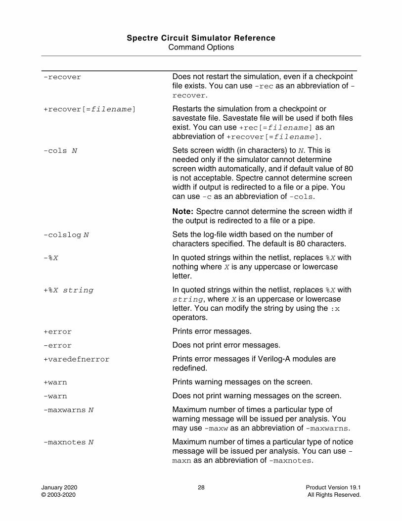
-recover Does not restart the simulation, even if a checkpoint file exists. You can use -rec as an abbreviation of -recover.
+recover[=filename] Restarts the simulation from a checkpoint or savestate file. Savestate file will be used if both files exist. You can use +rec[=filename] as an abbreviation of +recover[=filename].
-cols N Sets screen width (in characters) to N. This is needed only if the simulator cannot determine screen width automatically, and if default value of 80 is not acceptable. Spectre cannot determine screen width if output is redirected to a file or a pipe. You can use -c as an abbreviation of -cols.
Note: Spectre cannot determine the screen width if the output is redirected to a file or a pipe.
-colslog N Sets the log-file width based on the number of characters specified. The default is 80 characters.
-%X In quoted strings within the netlist, replaces %X with nothing where X is any uppercase or lowercase letter.
+%X string In quoted strings within the netlist, replaces %X with string, where X is an uppercase or lowercase letter. You can modify the string by using the :x operators.
+error Prints error messages.
-error Does not print error messages.
+varedefnerror Prints error messages if Verilog-A modules are redefined.
+warn Prints warning messages on the screen.
-warn Does not print warning messages on the screen.
-maxwarns N Maximum number of times a particular type of warning message will be issued per analysis. You may use -maxw as an abbreviation of -maxwarns.
-maxnotes N Maximum number of times a particular type of notice message will be issued per analysis. You can use -maxn as an abbreviation of -maxnotes.
Spectre Circuit Simulator ReferenceCommand Options
January 2020 29 Product Version 19.1© 2003-2020 All Rights Reserved.
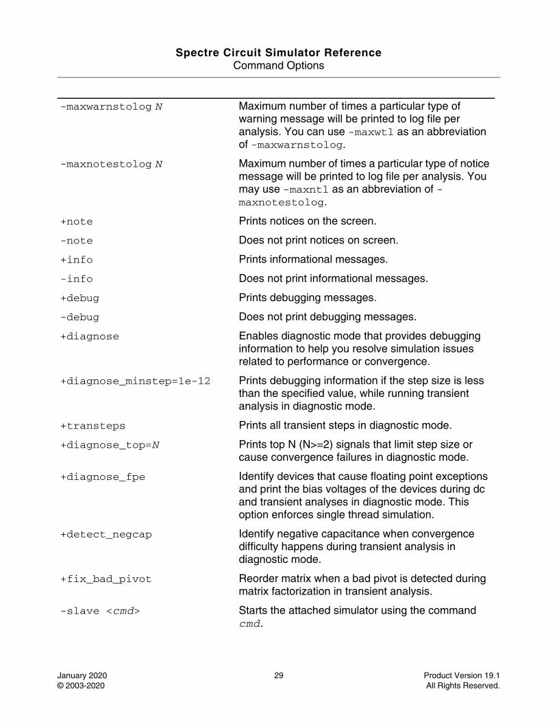
-maxwarnstolog N Maximum number of times a particular type of warning message will be printed to log file per analysis. You can use -maxwtl as an abbreviation of -maxwarnstolog.
-maxnotestolog N Maximum number of times a particular type of notice message will be printed to log file per analysis. You may use -maxntl as an abbreviation of -maxnotestolog.
+note Prints notices on the screen.
-note Does not print notices on screen.
+info Prints informational messages.
-info Does not print informational messages.
+debug Prints debugging messages.
-debug Does not print debugging messages.
+diagnose Enables diagnostic mode that provides debugging information to help you resolve simulation issues related to performance or convergence.
+diagnose_minstep=1e-12 Prints debugging information if the step size is less than the specified value, while running transient analysis in diagnostic mode.
+transteps Prints all transient steps in diagnostic mode.
+diagnose_top=N Prints top N (N>=2) signals that limit step size or cause convergence failures in diagnostic mode.
+diagnose_fpe Identify devices that cause floating point exceptions and print the bias voltages of the devices during dc and transient analyses in diagnostic mode. This option enforces single thread simulation.
+detect_negcap Identify negative capacitance when convergence difficulty happens during transient analysis in diagnostic mode.
+fix_bad_pivot Reorder matrix when a bad pivot is detected during matrix factorization in transient analysis.
-slave <cmd> Starts the attached simulator using the command cmd.
Spectre Circuit Simulator ReferenceCommand Options
January 2020 30 Product Version 19.1© 2003-2020 All Rights Reserved.
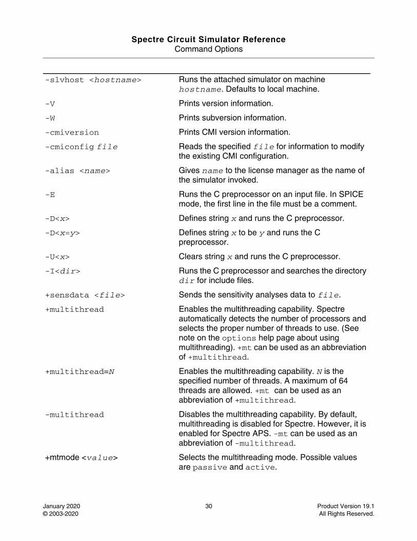
-slvhost <hostname> Runs the attached simulator on machine hostname. Defaults to local machine.
-V Prints version information.
-W Prints subversion information.
-cmiversion Prints CMI version information.
-cmiconfig file Reads the specified file for information to modify the existing CMI configuration.
-alias <name> Gives name to the license manager as the name of the simulator invoked.
-E Runs the C preprocessor on an input file. In SPICE mode, the first line in the file must be a comment.
-D<x> Defines string x and runs the C preprocessor.
-D<x=y> Defines string x to be y and runs the C preprocessor.
-U<x> Clears string x and runs the C preprocessor.
-I<dir> Runs the C preprocessor and searches the directory dir for include files.
+sensdata <file> Sends the sensitivity analyses data to file.
+multithread Enables the multithreading capability. Spectre automatically detects the number of processors and selects the proper number of threads to use. (See note on the options help page about using multithreading). +mt can be used as an abbreviation of +multithread.
+multithread=N Enables the multithreading capability. N is the specified number of threads. A maximum of 64 threads are allowed. +mt can be used as an abbreviation of +multithread.
-multithread Disables the multithreading capability. By default, multithreading is disabled for Spectre. However, it is enabled for Spectre APS. -mt can be used as an abbreviation of -multithread.
+mtmode <value> Selects the multithreading mode. Possible values are passive and active.
Spectre Circuit Simulator ReferenceCommand Options
January 2020 31 Product Version 19.1© 2003-2020 All Rights Reserved.
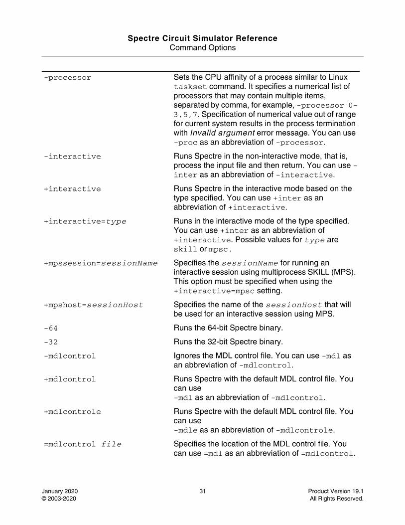
-processor Sets the CPU affinity of a process similar to Linux taskset command. It specifies a numerical list of processors that may contain multiple items, separated by comma, for example, -processor 0-3,5,7. Specification of numerical value out of range for current system results in the process termination with Invalid argument error message. You can use -proc as an abbreviation of -processor.
-interactive Runs Spectre in the non-interactive mode, that is, process the input file and then return. You can use -inter as an abbreviation of -interactive.
+interactive Runs Spectre in the interactive mode based on the type specified. You can use +inter as an abbreviation of +interactive.
+interactive=type Runs in the interactive mode of the type specified. You can use +inter as an abbreviation of +interactive. Possible values for type are skill or mpsc.
+mpssession=sessionName Specifies the sessionName for running an interactive session using multiprocess SKILL (MPS). This option must be specified when using the +interactive=mpsc setting.
+mpshost=sessionHost Specifies the name of the sessionHost that will be used for an interactive session using MPS.
-64 Runs the 64-bit Spectre binary.
-32 Runs the 32-bit Spectre binary.
-mdlcontrol Ignores the MDL control file. You can use -mdl as an abbreviation of -mdlcontrol.
+mdlcontrol Runs Spectre with the default MDL control file. You can use -mdl as an abbreviation of -mdlcontrol.
+mdlcontrole Runs Spectre with the default MDL control file. You can use -mdle as an abbreviation of -mdlcontrole.
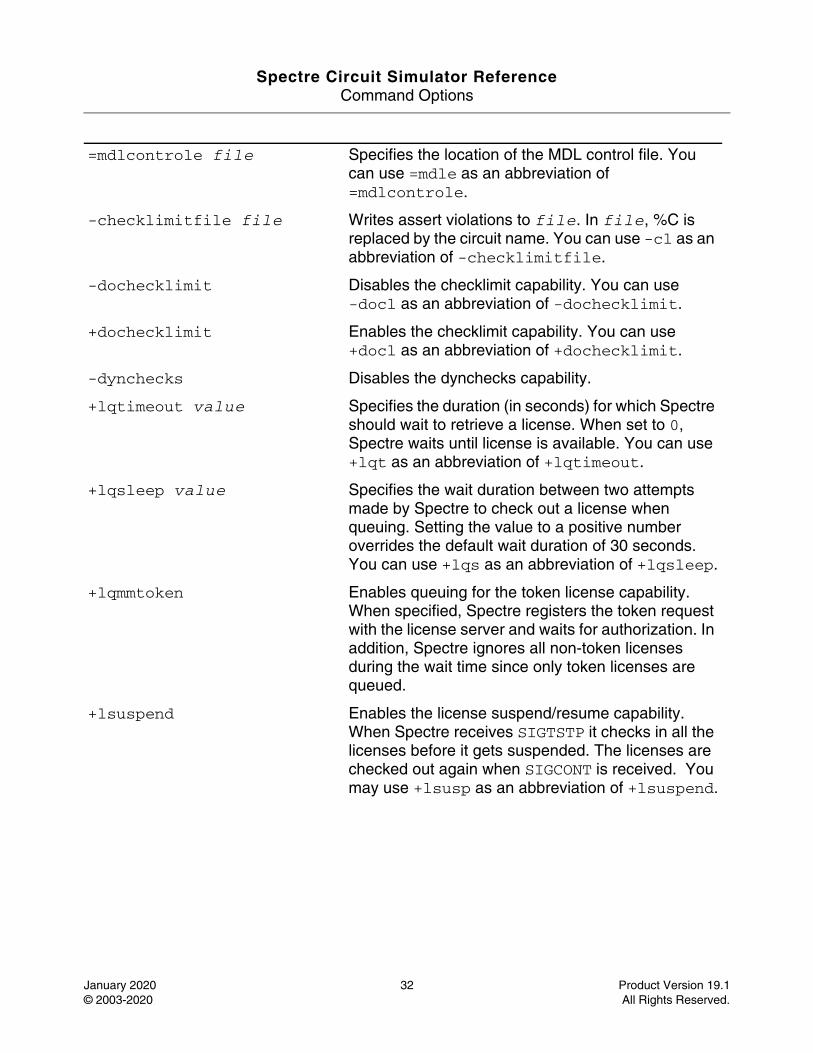
=mdlcontrol file Specifies the location of the MDL control file. You can use =mdl as an abbreviation of =mdlcontrol.
Spectre Circuit Simulator ReferenceCommand Options
January 2020 32 Product Version 19.1© 2003-2020 All Rights Reserved.
=mdlcontrole file Specifies the location of the MDL control file. You can use =mdle as an abbreviation of =mdlcontrole.
-checklimitfile file Writes assert violations to file. In file, %C is replaced by the circuit name. You can use -cl as an abbreviation of -checklimitfile.
-dochecklimit Disables the checklimit capability. You can use-docl as an abbreviation of -dochecklimit.
+dochecklimit Enables the checklimit capability. You can use +docl as an abbreviation of +dochecklimit.
-dynchecks Disables the dynchecks capability.
+lqtimeout value Specifies the duration (in seconds) for which Spectre should wait to retrieve a license. When set to 0, Spectre waits until license is available. You can use +lqt as an abbreviation of +lqtimeout.
+lqsleep value Specifies the wait duration between two attempts made by Spectre to check out a license when queuing. Setting the value to a positive number overrides the default wait duration of 30 seconds. You can use +lqs as an abbreviation of +lqsleep.
+lqmmtoken Enables queuing for the token license capability. When specified, Spectre registers the token request with the license server and waits for authorization. In addition, Spectre ignores all non-token licenses during the wait time since only token licenses are queued.
+lsuspend Enables the license suspend/resume capability. When Spectre receives SIGTSTP it checks in all the licenses before it gets suspended. The licenses are checked out again when SIGCONT is received. You may use +lsusp as an abbreviation of +lsuspend.
Spectre Circuit Simulator ReferenceCommand Options
January 2020 33 Product Version 19.1© 2003-2020 All Rights Reserved.
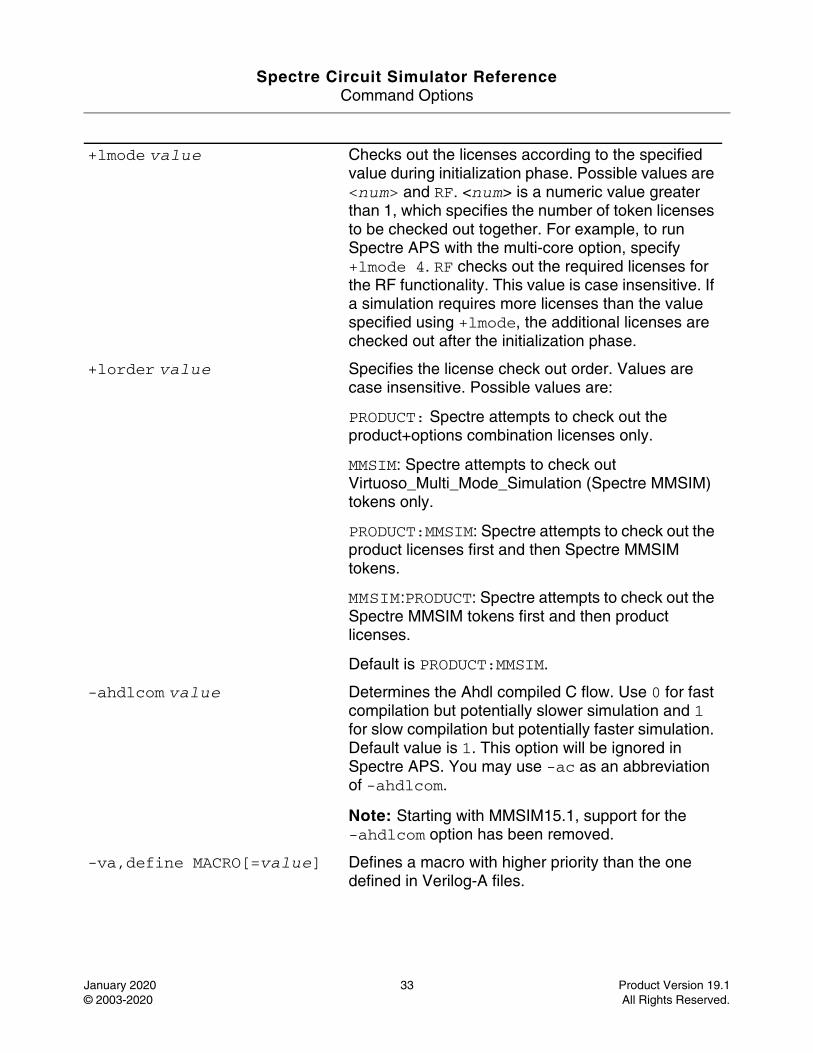
+lmode value Checks out the licenses according to the specified value during initialization phase. Possible values are <num> and RF. <num> is a numeric value greater than 1, which specifies the number of token licenses to be checked out together. For example, to run Spectre APS with the multi-core option, specify +lmode 4. RF checks out the required licenses for the RF functionality. This value is case insensitive. If a simulation requires more licenses than the value specified using +lmode, the additional licenses are checked out after the initialization phase.
+lorder value Specifies the license check out order. Values are case insensitive. Possible values are:
PRODUCT: Spectre attempts to check out the product+options combination licenses only.
MMSIM: Spectre attempts to check out Virtuoso_Multi_Mode_Simulation (Spectre MMSIM) tokens only.
PRODUCT:MMSIM: Spectre attempts to check out the product licenses first and then Spectre MMSIM tokens.
MMSIM:PRODUCT: Spectre attempts to check out the Spectre MMSIM tokens first and then product licenses.
Default is PRODUCT:MMSIM.
-ahdlcom value Determines the Ahdl compiled C flow. Use 0 for fast compilation but potentially slower simulation and 1 for slow compilation but potentially faster simulation. Default value is 1. This option will be ignored in Spectre APS. You may use -ac as an abbreviation of -ahdlcom.
Note: Starting with MMSIM15.1, support for the -ahdlcom option has been removed.
-va,define MACRO[=value] Defines a macro with higher priority than the one defined in Verilog-A files.
Spectre Circuit Simulator ReferenceCommand Options
January 2020 34 Product Version 19.1© 2003-2020 All Rights Reserved.
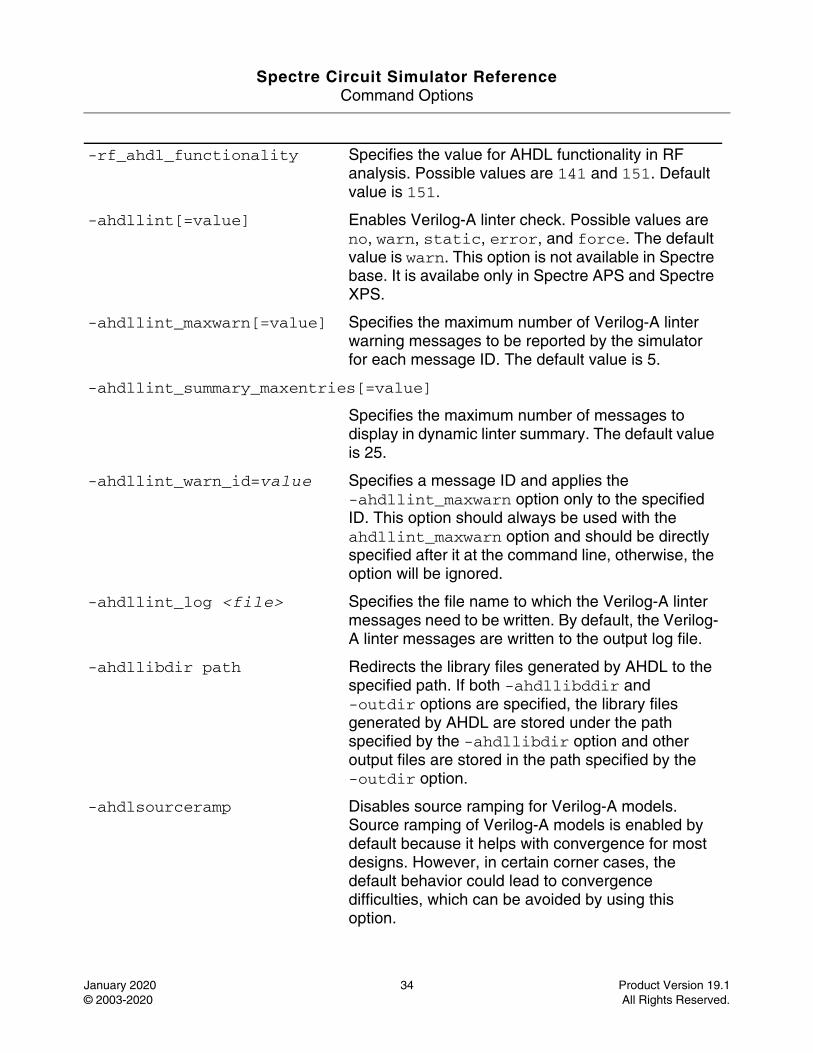
-rf_ahdl_functionality Specifies the value for AHDL functionality in RF analysis. Possible values are 141 and 151. Default value is 151.
-ahdllint[=value] Enables Verilog-A linter check. Possible values are no, warn, static, error, and force. The default value is warn. This option is not available in Spectre base. It is availabe only in Spectre APS and Spectre XPS.
-ahdllint_maxwarn[=value] Specifies the maximum number of Verilog-A linter warning messages to be reported by the simulator for each message ID. The default value is 5.
-ahdllint_summary_maxentries[=value]
Specifies the maximum number of messages to display in dynamic linter summary. The default value is 25.
-ahdllint_warn_id=value Specifies a message ID and applies the -ahdllint_maxwarn option only to the specified ID. This option should always be used with the ahdllint_maxwarn option and should be directly specified after it at the command line, otherwise, the option will be ignored.
-ahdllint_log <file> Specifies the file name to which the Verilog-A linter messages need to be written. By default, the Verilog-A linter messages are written to the output log file.
-ahdllibdir path Redirects the library files generated by AHDL to the specified path. If both -ahdllibddir and -outdir options are specified, the library files generated by AHDL are stored under the path specified by the -ahdllibdir option and other output files are stored in the path specified by the -outdir option.
-ahdlsourceramp Disables source ramping for Verilog-A models. Source ramping of Verilog-A models is enabled by default because it helps with convergence for most designs. However, in certain corner cases, the default behavior could lead to convergence difficulties, which can be avoided by using this option.
Spectre Circuit Simulator ReferenceCommand Options
January 2020 35 Product Version 19.1© 2003-2020 All Rights Reserved.
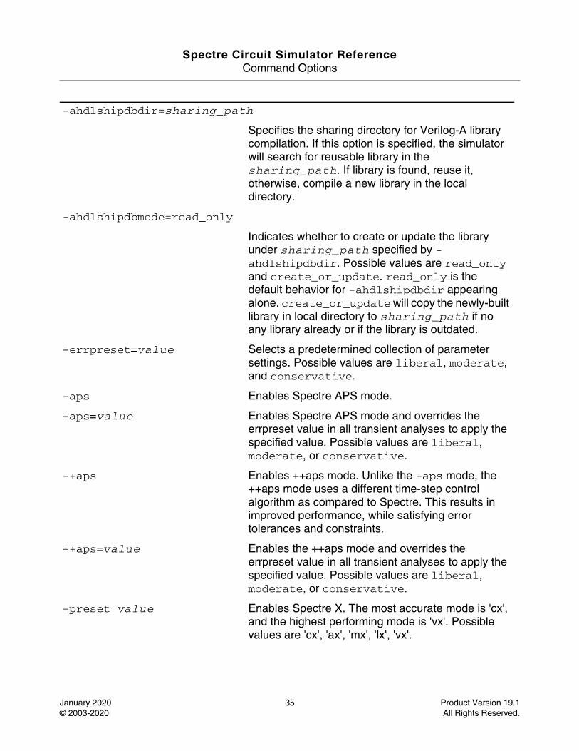
-ahdlshipdbdir=sharing_path
Specifies the sharing directory for Verilog-A library compilation. If this option is specified, the simulator will search for reusable library in the sharing_path. If library is found, reuse it, otherwise, compile a new library in the local directory.
-ahdlshipdbmode=read_only
Indicates whether to create or update the library under sharing_path specified by -ahdlshipdbdir. Possible values are read_only and create_or_update. read_only is the default behavior for -ahdlshipdbdir appearing alone. create_or_update will copy the newly-built library in local directory to sharing_path if no any library already or if the library is outdated.
+errpreset=value Selects a predetermined collection of parameter settings. Possible values are liberal, moderate, and conservative.
+aps Enables Spectre APS mode.
+aps=value Enables Spectre APS mode and overrides the errpreset value in all transient analyses to apply the specified value. Possible values are liberal, moderate, or conservative.
++aps Enables ++aps mode. Unlike the +aps mode, the ++aps mode uses a different time-step control algorithm as compared to Spectre. This results in improved performance, while satisfying error tolerances and constraints.
++aps=value Enables the ++aps mode and overrides the errpreset value in all transient analyses to apply the specified value. Possible values are liberal, moderate, or conservative.
+preset=value Enables Spectre X. The most accurate mode is 'cx', and the highest performing mode is 'vx'. Possible values are 'cx', 'ax', 'mx', 'lx', 'vx'.
Spectre Circuit Simulator ReferenceCommand Options
January 2020 36 Product Version 19.1© 2003-2020 All Rights Reserved.
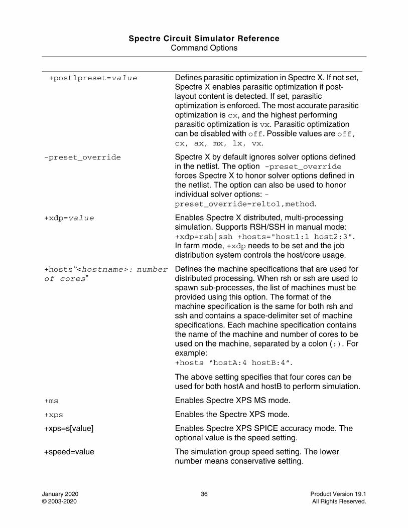
+postlpreset=value Defines parasitic optimization in Spectre X. If not set, Spectre X enables parasitic optimization if post-layout content is detected. If set, parasitic optimization is enforced. The most accurate parasitic optimization is cx, and the highest performing parasitic optimization is vx. Parasitic optimization can be disabled with off. Possible values are off, cx, ax, mx, lx, vx.
-preset_override Spectre X by default ignores solver options defined in the netlist. The option -preset_override forces Spectre X to honor solver options defined in the netlist. The option can also be used to honor individual solver options: -preset_override=reltol,method.
+xdp=value Enables Spectre X distributed, multi-processing simulation. Supports RSH/SSH in manual mode: +xdp=rsh|ssh +hosts="host1:1 host2:3". In farm mode, +xdp needs to be set and the job distribution system controls the host/core usage.
+hosts “<hostname>: number of cores”
Defines the machine specifications that are used for distributed processing. When rsh or ssh are used to spawn sub-processes, the list of machines must be provided using this option. The format of the machine specification is the same for both rsh and ssh and contains a space-delimiter set of machine specifications. Each machine specification contains the name of the machine and number of cores to be used on the machine, separated by a colon (:). For example:+hosts “hostA:4 hostB:4”.
The above setting specifies that four cores can be used for both hostA and hostB to perform simulation.
+ms Enables Spectre XPS MS mode.
+xps Enables the Spectre XPS mode.
+xps=s[value] Enables Spectre XPS SPICE accuracy mode. The optional value is the speed setting.
+speed=value The simulation group speed setting. The lower number means conservative setting.
Spectre Circuit Simulator ReferenceCommand Options
January 2020 37 Product Version 19.1© 2003-2020 All Rights Reserved.
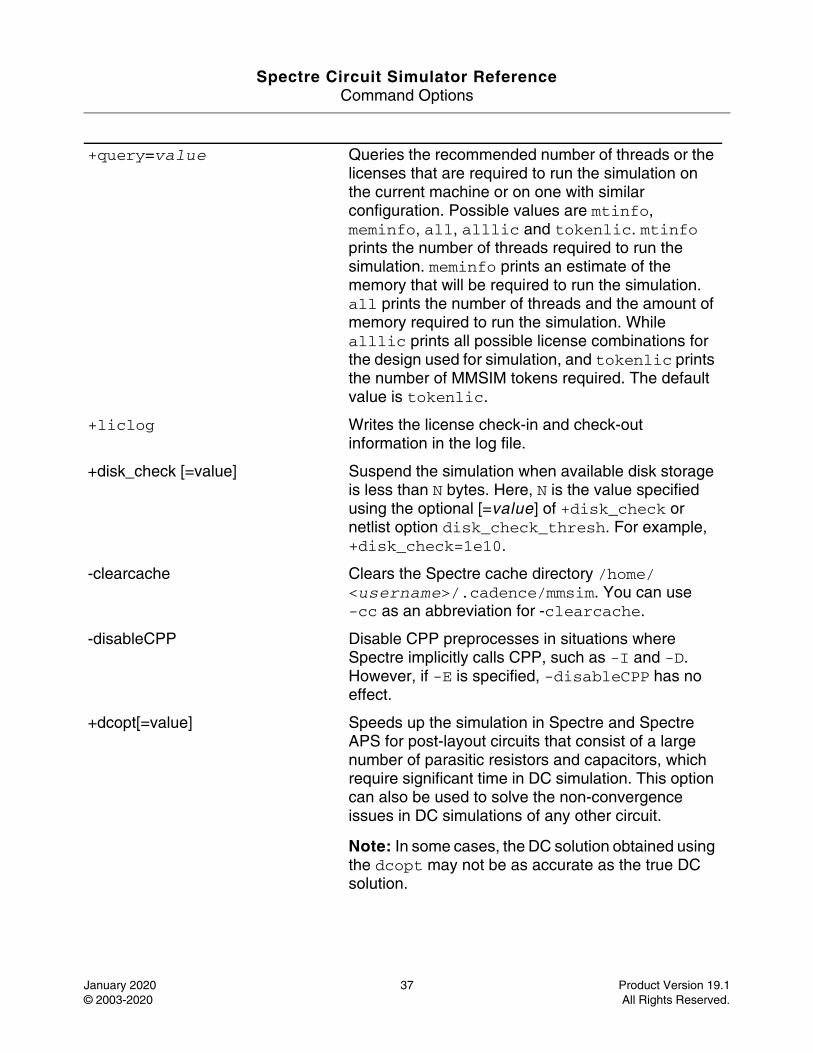
+query=value Queries the recommended number of threads or the licenses that are required to run the simulation on the current machine or on one with similar configuration. Possible values are mtinfo, meminfo, all, alllic and tokenlic. mtinfo prints the number of threads required to run the simulation. meminfo prints an estimate of the memory that will be required to run the simulation. all prints the number of threads and the amount of memory required to run the simulation. While alllic prints all possible license combinations for the design used for simulation, and tokenlic prints the number of MMSIM tokens required. The default value is tokenlic.
+liclog Writes the license check-in and check-out information in the log file.
+disk_check [=value] Suspend the simulation when available disk storage is less than N bytes. Here, N is the value specified using the optional [=value] of +disk_check or netlist option disk_check_thresh. For example, +disk_check=1e10.
-clearcache Clears the Spectre cache directory /home/<username>/.cadence/mmsim. You can use -cc as an abbreviation for -clearcache.
-disableCPP Disable CPP preprocesses in situations where Spectre implicitly calls CPP, such as -I and -D. However, if -E is specified, -disableCPP has no effect.
+dcopt[=value] Speeds up the simulation in Spectre and Spectre APS for post-layout circuits that consist of a large number of parasitic resistors and capacitors, which require significant time in DC simulation. This option can also be used to solve the non-convergence issues in DC simulations of any other circuit.
Note: In some cases, the DC solution obtained using the dcopt may not be as accurate as the true DC solution.
Spectre Circuit Simulator ReferenceCommand Options
January 2020 38 Product Version 19.1© 2003-2020 All Rights Reserved.
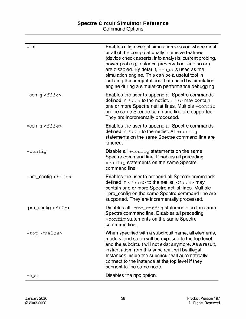
+lite Enables a lightweight simulation session where most or all of the computationally intensive features (device check asserts, info analysis, current probing, power probing, instance preservation, and so on) are disabled. By default, ++aps is used as the simulation engine. This can be a useful tool in isolating the computational time used by simulation engine during a simulation performance debugging.
+config <file> Enables the user to append all Spectre commands defined in file to the netlist. file may contain one or more Spectre netlist lines. Multiple +config on the same Spectre command line are supported. They are incrementally processed.
=config <file> Enables the user to append all Spectre commands defined in file to the netlist. All +config statements on the same Spectre command line are ignored.
-config Disable all +config statements on the same Spectre command line. Disables all preceding =config statements on the same Spectre command line.
+pre_config <file> Enables the user to prepend all Spectre commands defined in <file> to the netlist. <file> may contain one or more Spectre netlist lines. Multiple +pre_config on the same Spectre command line are supported. They are incrementally processed.
-pre_config <file> Disables all +pre_config statements on the same Spectre command line. Disables all preceding =config statements on the same Spectre command line.
+top <value> When specified with a subcircuit name, all elements, models, and so on will be exposed to the top level and the subcircuit will not exist anymore. As a result, instantiation from this subcircuit will be illegal. Instances inside the subcircuit will automatically connect to the instance at the top level if they connect to the same node.
-hpc Disables the hpc option.
Spectre Circuit Simulator ReferenceCommand Options
January 2020 39 Product Version 19.1© 2003-2020 All Rights Reserved.
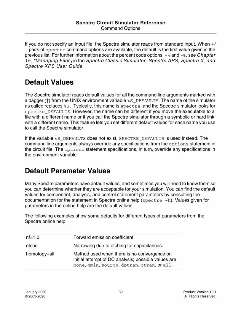
If you do not specify an input file, the Spectre simulator reads from standard input. When +/- pairs of spectre command options are available, the default is the first value given in the previous list. For further information about the percent code options, +% and -%, see Chapter 15, “Managing Files, in the Spectre Classic Simulator, Spectre APS, Spectre X, and Spectre XPS User Guide.
Default Values
The Spectre simulator reads default values for all the command line arguments marked with a dagger (†) from the UNIX environment variable %S_DEFAULTS. The name of the simulator as called replaces %S. Typically, this name is spectre, and the Spectre simulator looks for spectre_DEFAULTS. However, the name can be different if you move the executable to a file with a different name or if you call the Spectre simulator through a symbolic or hard link with a different name. This feature lets you set different default values for each name you use to call the Spectre simulator.
If the variable %S_DEFAULTS does not exist, SPECTRE_DEFAULTS is used instead. The command line arguments always override any specifications from the options statement in the circuit file. The options statement specifications, in turn, override any specifications in the environment variable.
Default Parameter Values
Many Spectre parameters have default values, and sometimes you will need to know them so you can determine whether they are acceptable for your simulation. You can find the default values for component, analysis, and control statement parameters by consulting the documentation for the statement in Spectre online help (spectre -h). Values given for parameters in the online help are the default values.
The following examples show some defaults for different types of parameters from the Spectre online help:
nf=1.0 Forward emission coefficient.
etchc Narrowing due to etching for capacitances.
homotopy=all Method used when there is no convergence on initial attempt of DC analysis; possible values are none, gmin, source, dptran, ptran, or all.

Spectre Circuit Simulator ReferenceCommand Options
January 2020 40 Product Version 19.1© 2003-2020 All Rights Reserved.
For more information about percent codes and colon modifiers, see “Description of Spectre Predefined Percent Codes,” “Customizing Percent Codes,” and “Creating Filenames from Parts of Input Filenames” in the Spectre Classic Simulator, Spectre APS, Spectre X, and Spectre XPS User Guide.
Spectre Circuit Simulator Reference
January 2020 41 Product Version 19.1© 2003-2020 All Rights Reserved.
1Analysis Statements
This chapter discusses the following topics:
■ AC Analysis (ac) on page 43
■ ACMatch Analysis (acmatch) on page 49
■ Alter a Circuit, Component, or Netlist Parameter (alter) on page 54
■ Alter Group (altergroup) on page 56
■ Check Parameter Values (check) on page 59
■ Checklimit Analysis (checklimit) on page 60
■ Setting for Simulink-MATLAB co-simulation (cosim) on page 63
■ DC Analysis (dc) on page 64
■ DC Device Matching Analysis (dcmatch) on page 70
■ Envelope Following Analysis (envlp) on page 76
■ Harmonic Balance Steady State Analysis (hb) on page 90
■ HB AC Analysis (hbac) on page 111
■ HB Noise Analysis (hbnoise) on page 119
■ HB S-Parameter Analysis (hbsp) on page 130
■ HB Stability Analysis (hbstb) on page 139
■ HB XF Analysis (hbxf) on page 143
■ Circuit Information (info) on page 150
■ Loopfinder Analysis (lf) on page 156
■ Load Pull Analysis (loadpull) on page 162
■ Monte Carlo Analysis (montecarlo) on page 165
Spectre Circuit Simulator ReferenceAnalysis Statements
January 2020 42 Product Version 19.1© 2003-2020 All Rights Reserved.
■ Noise Analysis (noise) on page 181
■ Immediate Set Options (options) on page 187
■ Periodic AC Analysis (pac) on page 245
■ Periodic Noise Analysis (pnoise) on page 253
■ Periodic S-Parameter Analysis (psp) on page 264
■ Periodic Steady-State Analysis (pss) on page 272
■ Periodic STB Analysis (pstb) on page 298
■ Periodic Transfer Function Analysis (pxf) on page 303
■ PZ Analysis (pz) on page 312
■ Quasi-Periodic AC Analysis (qpac) on page 318
■ Quasi-Periodic Noise Analysis (qpnoise) on page 323
■ Quasi-Periodic S-Parameter Analysis (qpsp) on page 331
■ Quasi-Periodic Steady State Analysis (qpss) on page 339
■ Quasi-Periodic Transfer Function Analysis (qpxf) on page 356
■ Reliability Analysis (reliability) on page 362
■ Deferred Set Options (set) on page 379
■ Shell Command (shell) on page 386
■ S-Parameter Analysis (sp) on page 387
■ Stability Analysis (stb) on page 393
■ Sweep Analysis (sweep) on page 406
■ Time-Domain Reflectometer Analysis (tdr) on page 411
■ Transient Analysis (tran) on page 416
■ Special Current Saving Options (uti) on page 436
■ Transfer Function Analysis (xf) on page 438
Spectre Circuit Simulator ReferenceAnalysis Statements
January 2020 43 Product Version 19.1© 2003-2020 All Rights Reserved.
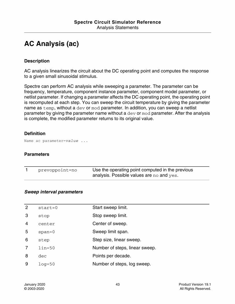
AC Analysis (ac)
Description
AC analysis linearizes the circuit about the DC operating point and computes the response to a given small sinusoidal stimulus.
Spectre can perform AC analysis while sweeping a parameter. The parameter can be frequency, temperature, component instance parameter, component model parameter, or netlist parameter. If changing a parameter affects the DC operating point, the operating point is recomputed at each step. You can sweep the circuit temperature by giving the parameter name as temp, without a dev or mod parameter. In addition, you can sweep a netlist parameter by giving the parameter name without a dev or mod parameter. After the analysis is complete, the modified parameter returns to its original value.
DefinitionName ac parameter=value ...
Parameters
Sweep interval parameters
1 prevoppoint=no Use the operating point computed in the previous analysis. Possible values are no and yes.
2 start=0 Start sweep limit.
3 stop Stop sweep limit.
4 center Center of sweep.
5 span=0 Sweep limit span.
6 step Step size, linear sweep.
7 lin=50 Number of steps, linear sweep.
8 dec Points per decade.
9 log=50 Number of steps, log sweep.
Spectre Circuit Simulator ReferenceAnalysis Statements
January 2020 44 Product Version 19.1© 2003-2020 All Rights Reserved.
Sweep variable parameters
State-file parameters
Initial condition parameters
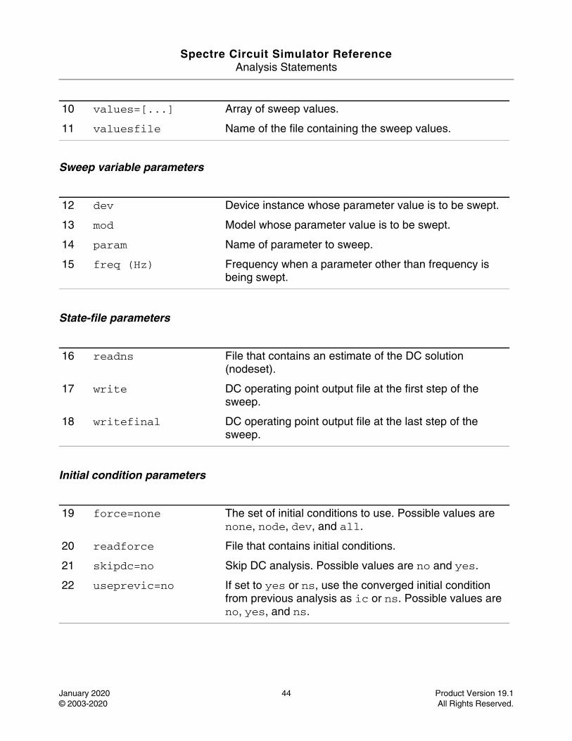
10 values=[...] Array of sweep values.
11 valuesfile Name of the file containing the sweep values.
12 dev Device instance whose parameter value is to be swept.
13 mod Model whose parameter value is to be swept.
14 param Name of parameter to sweep.
15 freq (Hz) Frequency when a parameter other than frequency is being swept.
16 readns File that contains an estimate of the DC solution (nodeset).
17 write DC operating point output file at the first step of the sweep.
18 writefinal DC operating point output file at the last step of the sweep.
19 force=none The set of initial conditions to use. Possible values are none, node, dev, and all.
20 readforce File that contains initial conditions.
21 skipdc=no Skip DC analysis. Possible values are no and yes.
22 useprevic=no If set to yes or ns, use the converged initial condition from previous analysis as ic or ns. Possible values are no, yes, and ns.
Spectre Circuit Simulator ReferenceAnalysis Statements
January 2020 45 Product Version 19.1© 2003-2020 All Rights Reserved.
Output parameters
Convergence parameters
Annotation parameters
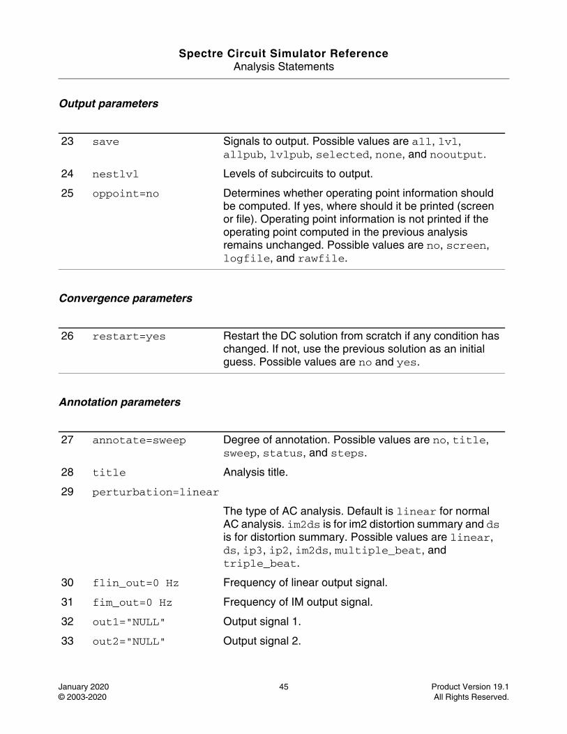
23 save Signals to output. Possible values are all, lvl, allpub, lvlpub, selected, none, and nooutput.
24 nestlvl Levels of subcircuits to output.
25 oppoint=no Determines whether operating point information should be computed. If yes, where should it be printed (screen or file). Operating point information is not printed if the operating point computed in the previous analysis remains unchanged. Possible values are no, screen, logfile, and rawfile.
26 restart=yes Restart the DC solution from scratch if any condition has changed. If not, use the previous solution as an initial guess. Possible values are no and yes.
27 annotate=sweep Degree of annotation. Possible values are no, title, sweep, status, and steps.
28 title Analysis title.
29 perturbation=linear
The type of AC analysis. Default is linear for normal AC analysis. im2ds is for im2 distortion summary and ds is for distortion summary. Possible values are linear, ds, ip3, ip2, im2ds, multiple_beat, and triple_beat.
30 flin_out=0 Hz Frequency of linear output signal.
31 fim_out=0 Hz Frequency of IM output signal.
32 out1="NULL" Output signal 1.
33 out2="NULL" Output signal 2.
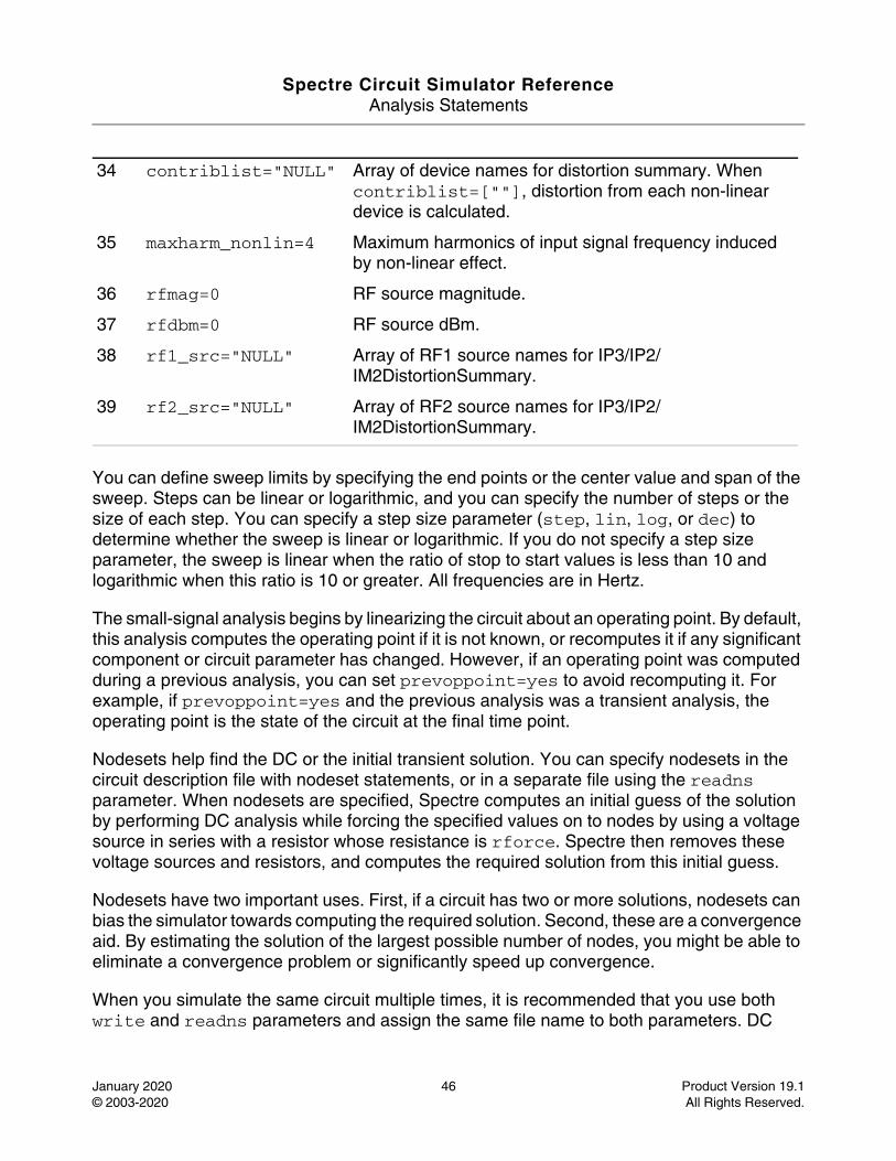
Spectre Circuit Simulator ReferenceAnalysis Statements
January 2020 46 Product Version 19.1© 2003-2020 All Rights Reserved.
You can define sweep limits by specifying the end points or the center value and span of the sweep. Steps can be linear or logarithmic, and you can specify the number of steps or the size of each step. You can specify a step size parameter (step, lin, log, or dec) to determine whether the sweep is linear or logarithmic. If you do not specify a step size parameter, the sweep is linear when the ratio of stop to start values is less than 10 and logarithmic when this ratio is 10 or greater. All frequencies are in Hertz.
The small-signal analysis begins by linearizing the circuit about an operating point. By default, this analysis computes the operating point if it is not known, or recomputes it if any significant component or circuit parameter has changed. However, if an operating point was computed during a previous analysis, you can set prevoppoint=yes to avoid recomputing it. For example, if prevoppoint=yes and the previous analysis was a transient analysis, the operating point is the state of the circuit at the final time point.
Nodesets help find the DC or the initial transient solution. You can specify nodesets in the circuit description file with nodeset statements, or in a separate file using the readns parameter. When nodesets are specified, Spectre computes an initial guess of the solution by performing DC analysis while forcing the specified values on to nodes by using a voltage source in series with a resistor whose resistance is rforce. Spectre then removes these voltage sources and resistors, and computes the required solution from this initial guess.
Nodesets have two important uses. First, if a circuit has two or more solutions, nodesets can bias the simulator towards computing the required solution. Second, these are a convergence aid. By estimating the solution of the largest possible number of nodes, you might be able to eliminate a convergence problem or significantly speed up convergence.
When you simulate the same circuit multiple times, it is recommended that you use both write and readns parameters and assign the same file name to both parameters. DC
34 contriblist="NULL" Array of device names for distortion summary. When contriblist=[""], distortion from each non-linear device is calculated.
35 maxharm_nonlin=4 Maximum harmonics of input signal frequency induced by non-linear effect.
36 rfmag=0 RF source magnitude.
37 rfdbm=0 RF source dBm.
38 rf1_src="NULL" Array of RF1 source names for IP3/IP2/IM2DistortionSummary.
39 rf2_src="NULL" Array of RF2 source names for IP3/IP2/IM2DistortionSummary.
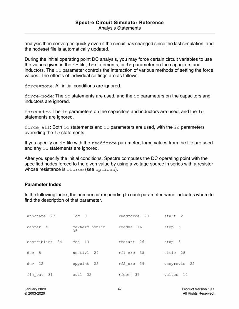
Spectre Circuit Simulator ReferenceAnalysis Statements
January 2020 47 Product Version 19.1© 2003-2020 All Rights Reserved.
analysis then converges quickly even if the circuit has changed since the last simulation, and the nodeset file is automatically updated.
During the initial operating point DC analysis, you may force certain circuit variables to use the values given in the ic file, ic statements, or ic parameter on the capacitors and inductors. The ic parameter controls the interaction of various methods of setting the force values. The effects of individual settings are as follows:
force=none: All initial conditions are ignored.
force=node: The ic statements are used, and the ic parameters on the capacitors and inductors are ignored.
force=dev: The ic parameters on the capacitors and inductors are used, and the ic statements are ignored.
force=all: Both ic statements and ic parameters are used, with the ic parameters overriding the ic statements.
If you specify an ic file with the readforce parameter, force values from the file are used and any ic statements are ignored.
After you specify the initial conditions, Spectre computes the DC operating point with the specified nodes forced to the given value by using a voltage source in series with a resistor whose resistance is rforce (see options).
Parameter Index
In the following index, the number corresponding to each parameter name indicates where to find the description of that parameter.
annotate 27 log 9 readforce 20 start 2
center 4 maxharm_nonlin 35
readns 16 step 6
contriblist 34 mod 13 restart 26 stop 3
dec 8 nestlvl 24 rf1_src 38 title 28
dev 12 oppoint 25 rf2_src 39 useprevic 22
fim_out 31 out1 32 rfdbm 37 values 10

Spectre Circuit Simulator ReferenceAnalysis Statements
January 2020 48 Product Version 19.1© 2003-2020 All Rights Reserved.
flin_out 30 out2 33 rfmag 36 valuesfile 11
force 19 param 14 save 23 write 17
freq 15 perturbation 29 skipdc 21 writefinal 18
lin 7 prevoppoint 1 span 5
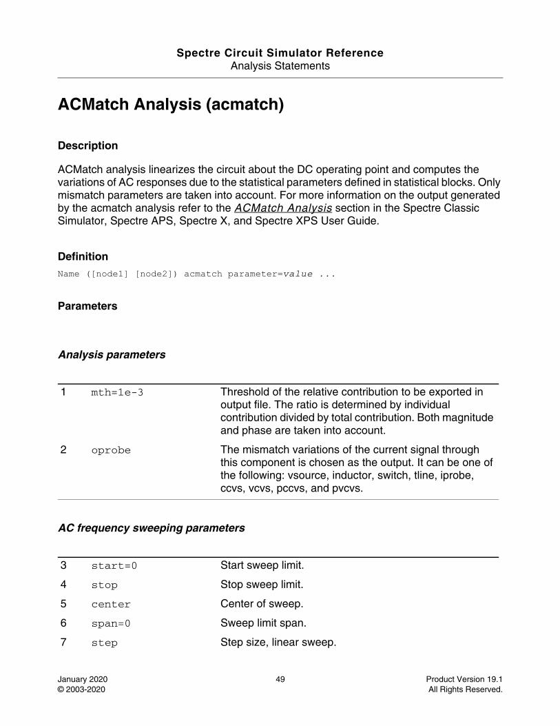
Spectre Circuit Simulator ReferenceAnalysis Statements
January 2020 49 Product Version 19.1© 2003-2020 All Rights Reserved.
ACMatch Analysis (acmatch)
Description
ACMatch analysis linearizes the circuit about the DC operating point and computes the variations of AC responses due to the statistical parameters defined in statistical blocks. Only mismatch parameters are taken into account. For more information on the output generated by the acmatch analysis refer to the ACMatch Analysis section in the Spectre Classic Simulator, Spectre APS, Spectre X, and Spectre XPS User Guide.
DefinitionName ([node1] [node2]) acmatch parameter=value ...
Parameters
Analysis parameters
AC frequency sweeping parameters
1 mth=1e-3 Threshold of the relative contribution to be exported in output file. The ratio is determined by individual contribution divided by total contribution. Both magnitude and phase are taken into account.
2 oprobe The mismatch variations of the current signal through this component is chosen as the output. It can be one of the following: vsource, inductor, switch, tline, iprobe, ccvs, vcvs, pccvs, and pvcvs.
3 start=0 Start sweep limit.
4 stop Stop sweep limit.
5 center Center of sweep.
6 span=0 Sweep limit span.
7 step Step size, linear sweep.
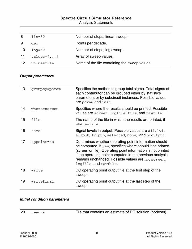
Spectre Circuit Simulator ReferenceAnalysis Statements
January 2020 50 Product Version 19.1© 2003-2020 All Rights Reserved.
Output parameters
Initial condition parameters
8 lin=50 Number of steps, linear sweep.
9 dec Points per decade.
10 log=50 Number of steps, log sweep.
11 values=[...] Array of sweep values.
12 valuesfile Name of the file containing the sweep values.
13 groupby=param Specifies the method to group total sigma. Total sigma of each contributor can be grouped either by statistics parameters or by subcircuit instances. Possible values are param and inst.
14 where=screen Specifies where the results should be printed. Possible values are screen, logfile, file, and rawfile.
15 file The name of the file in which the results are printed, if where=file.
16 save Signal levels in output. Possible values are all, lvl, allpub, lvlpub, selected, none, and nooutput.
17 oppoint=no Determines whether operating point information should be computed. If yes, specifies where should it be printed (screen or file). Operating point information is not printed if the operating point computed in the previous analysis remains unchanged. Possible values are no, screen, logfile, and rawfile.
18 write DC operating point output file at the first step of the sweep.
19 writefinal DC operating point output file at the last step of the sweep.
20 readns File that contains an estimate of DC solution (nodeset).
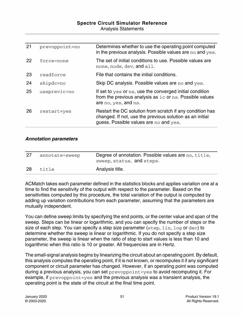
Spectre Circuit Simulator ReferenceAnalysis Statements
January 2020 51 Product Version 19.1© 2003-2020 All Rights Reserved.
Annotation parameters
ACMatch takes each parameter defined in the statistics blocks and applies variation one at a time to find the sensitivity of the output with respect to the parameter. Based on the sensitivities computed by this procedure, the total variation of the output is computed by adding up variation contributions from each parameter, assuming that the parameters are mutually independent.
You can define sweep limits by specifying the end points, or the center value and span of the sweep. Steps can be linear or logarithmic, and you can specify the number of steps or the size of each step. You can specify a step size parameter (step, lin, log or dec) to determine whether the sweep is linear or logarithmic. If you do not specify a step size parameter, the sweep is linear when the ratio of stop to start values is less than 10 and logarithmic when this ratio is 10 or greater. All frequencies are in Hertz.
The small-signal analysis begins by linearizing the circuit about an operating point. By default, this analysis computes the operating point, if it is not known, or recomputes it if any significant component or circuit parameter has changed. However, if an operating point was computed during a previous analysis, you can set prevoppoint=yes to avoid recomputing it. For example, if prevoppoint=yes and the previous analysis was a transient analysis, the operating point is the state of the circuit at the final time point.
21 prevoppoint=no Determines whether to use the operating point computed in the previous analysis. Possible values are no and yes.
22 force=none The set of initial conditions to use. Possible values are none, node, dev, and all.
23 readforce File that contains the initial conditions.
24 skipdc=no Skip DC analysis. Possible values are no and yes.
25 useprevic=no If set to yes or ns, use the converged initial condition from the previous analysis as ic or ns. Possible values are no, yes, and ns.
26 restart=yes Restart the DC solution from scratch if any condition has changed. If not, use the previous solution as an initial guess. Possible values are no and yes.
27 annotate=sweep Degree of annotation. Possible values are no, title, sweep, status, and steps.
28 title Analysis title.

Spectre Circuit Simulator ReferenceAnalysis Statements
January 2020 52 Product Version 19.1© 2003-2020 All Rights Reserved.
Nodesets help find the DC or the initial transient solution. You can specify nodesets in the circuit description file with nodeset statements, or in a separate file using the readns parameter. When nodesets are specified, Spectre computes an initial guess of the solution by performing DC analysis while forcing the specified values on to nodes by using a voltage source in series with a resistor whose resistance is rforce. Spectre then removes these voltage sources and resistors, and computes the required solution from this initial guess.
Nodesets have two important uses. First, if a circuit has two or more solutions, nodesets can bias the simulator towards computing the required solution. Second, this is a convergence aid. By estimating the solution of the largest possible number of nodes, you might be able to eliminate a convergence problem or significantly speed up convergence.
When you simulate the same circuit multiple times, it is recommended that you use both write and readns parameters and assign the same file name to both parameters. DC analysis then converges quickly even if the circuit has changed since the last simulation, and the nodeset file is automatically updated.
During the initial operating point DC analysis, you may force some of the circuit variables to the values given in the ic file, ic statements, or ic parameter on the capacitors and inductors. The ic parameter controls the interaction of various methods of setting the force values. The effects of individual settings are as follows:
force=none: All initial conditions are ignored.
force=node: The ic statements are used, and the ic parameters on the capacitors and inductors are ignored.
force=dev: The ic parameters on the capacitors and inductors are used, and the ic statements are ignored.
force=all: Both ic statements and ic parameters are used, with the ic parameters overriding the ic statements.
If you specify an ic file with the readforce parameter, force values from the file are used and any ic statements are ignored.
After you specify the initial conditions, Spectre computes the DC operating point with the specified nodes forced to the given value by using a voltage source in series with a resistor whose resistance is rforce (see spectre -h options).
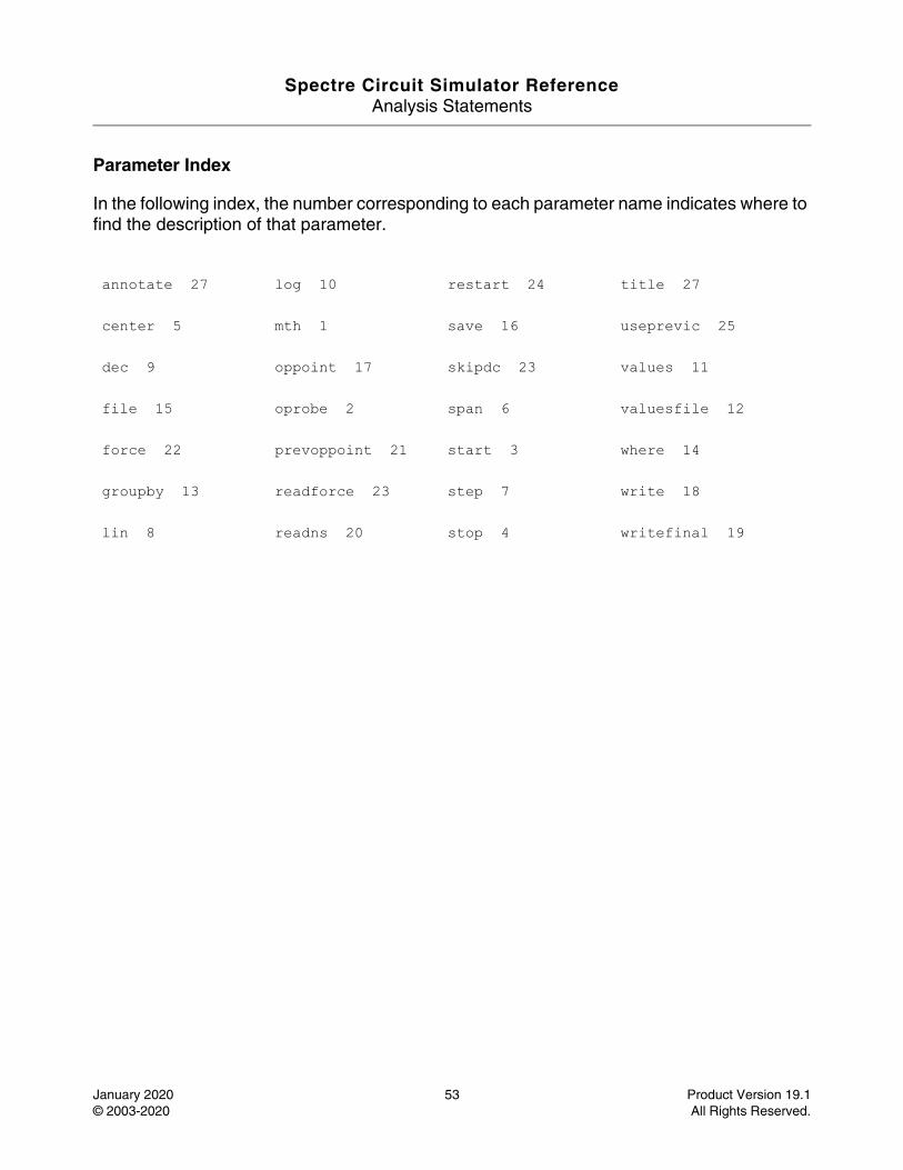
Spectre Circuit Simulator ReferenceAnalysis Statements
January 2020 53 Product Version 19.1© 2003-2020 All Rights Reserved.
Parameter Index
In the following index, the number corresponding to each parameter name indicates where to find the description of that parameter.
annotate 27 log 10 restart 24 title 27
center 5 mth 1 save 16 useprevic 25
dec 9 oppoint 17 skipdc 23 values 11
file 15 oprobe 2 span 6 valuesfile 12
force 22 prevoppoint 21 start 3 where 14
groupby 13 readforce 23 step 7 write 18
lin 8 readns 20 stop 4 writefinal 19
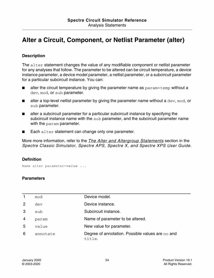
Spectre Circuit Simulator ReferenceAnalysis Statements
January 2020 54 Product Version 19.1© 2003-2020 All Rights Reserved.
Alter a Circuit, Component, or Netlist Parameter (alter)
Description
The alter statement changes the value of any modifiable component or netlist parameter for any analyses that follow. The parameter to be altered can be circuit temperature, a device instance parameter, a device model parameter, a netlist parameter, or a subcircuit parameter for a particular subcircuit instance. You can:
■ alter the circuit temperature by giving the parameter name as param=temp without a dev, mod, or sub parameter.
■ alter a top-level netlist parameter by giving the parameter name without a dev, mod, or sub parameter.
■ alter a subcircuit parameter for a particular subcircuit instance by specifying the subcircuit instance name with the sub parameter, and the subcircuit parameter name with the param parameter.
■ Each alter statement can change only one parameter.
More more information, refer to the The Alter and Altergroup Statements section in the Spectre Classic Simulator, Spectre APS, Spectre X, and Spectre XPS User Guide.
DefinitionName alter parameter=value ...
Parameters
1 mod Device model.
2 dev Device instance.
3 sub Subcircuit instance.
4 param Name of parameter to be altered.
5 value New value for parameter.
6 annotate Degree of annotation. Possible values are no and title.
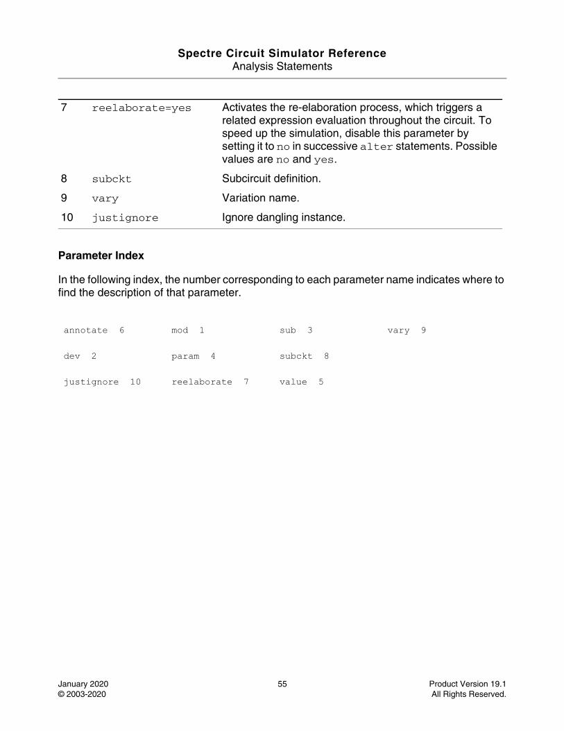
Spectre Circuit Simulator ReferenceAnalysis Statements
January 2020 55 Product Version 19.1© 2003-2020 All Rights Reserved.
Parameter Index
In the following index, the number corresponding to each parameter name indicates where to find the description of that parameter.
7 reelaborate=yes Activates the re-elaboration process, which triggers a related expression evaluation throughout the circuit. To speed up the simulation, disable this parameter by setting it to no in successive alter statements. Possible values are no and yes.
8 subckt Subcircuit definition.
9 vary Variation name.
10 justignore Ignore dangling instance.
annotate 6 mod 1 sub 3 vary 9
dev 2 param 4 subckt 8
justignore 10 reelaborate 7 value 5
Spectre Circuit Simulator ReferenceAnalysis Statements
January 2020 56 Product Version 19.1© 2003-2020 All Rights Reserved.
Alter Group (altergroup)
Description
The altergroup statement changes the values of any modifiable model, instance or netlist parameter for any analyses that follow. Within an alter group, you can specify model statements, instance statements, parameter statements and options statements (only supports temp, tnom, and scale). These statements should be bound within braces. The opening brace is required at the end of the line defining the altergroup. Altergroups cannot be specified within subcircuits. The following statements are not allowed within altergroups (analyses, export, paramset, save, and sens).
Within an altergroup, each device (instance or model) is first set to default and then the device parameters are updated. For netlist parameters, the expressions are updated and evaluated.
For subcircuit within altergroup, all instances of the subcircuits are modified when running altergroup. There are strict checks that do not allow changes to topology.
You can include files into the altergroup and can use the simulator lang=spice directive. See spectre -h include for more information. A model defined in the netlist should have the same model name and primitive type (bsim2, bsim3, bjt) in the altergroup. An instance defined in the netlist, should have the same instance name, terminal connections, and primitive type. For model groups, you can change the number of models in the group. However, you cannot change from a model to a model group and vice versa. See spectre -h bsim3v3 for details on model groups.
More more information, refer to the The Alter and Altergroup Statements section in the Spectre Classic Simulator, Spectre APS, Spectre X, and Spectre XPS User Guide.
DefinitionName altergroup parameter=value ...
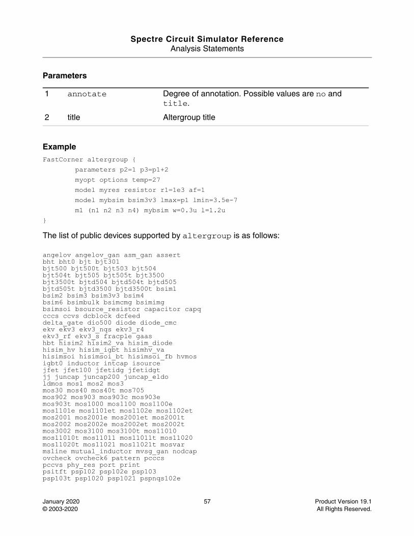
Spectre Circuit Simulator ReferenceAnalysis Statements
January 2020 57 Product Version 19.1© 2003-2020 All Rights Reserved.
Parameters
ExampleFastCorner altergroup { parameters p2=1 p3=p1+2 myopt options temp=27 model myres resistor r1=1e3 af=1 model mybsim bsim3v3 lmax=p1 lmin=3.5e-7 m1 (n1 n2 n3 n4) mybsim w=0.3u l=1.2u }
The list of public devices supported by altergroup is as follows:
angelov angelov_gan asm_gan assertbht bht0 bjt bjt301bjt500 bjt500t bjt503 bjt504bjt504t bjt505 bjt505t bjt3500bjt3500t bjtd504 bjtd504t bjtd505bjtd505t bjtd3500 bjtd3500t bsim1bsim2 bsim3 bsim3v3 bsim4bsim6 bsimbulk bsimcmg bsimimgbsimsoi bsource_resistor capacitor capqcccs ccvs dcblock dcfeeddelta_gate dio500 diode diode_cmcekv ekv3 ekv3_nqs ekv3_r4ekv3_rf ekv3_s fracple gaashbt hisim2 hisim2_va hisim_diodehisim_hv hisim_igbt hisimhv_vahisimsoi hisimsoi_bt hisimsoi_fb hvmosigbt0 inductor intcap isourcejfet jfet100 jfetidg jfetidgtjj juncap juncap200 juncap_eldoldmos mos1 mos2 mos3mos30 mos40 mos40t mos705mos902 mos903 mos903c mos903emos903t mos1000 mos1100 mos1100emos1101e mos1101et mos1102e mos1102etmos2001 mos2001e mos2001et mos2001tmos2002 mos2002e mos2002et mos2002tmos3002 mos3100 mos3100t mos11010mos11010t mos11011 mos11011t mos11020mos11020t mos11021 mos11021t mosvarmsline mutual_inductor mvsg_gan nodcapovcheck ovcheck6 pattern pcccspccvs phy_res port printpsitft psp102 psp102e psp103psp103t psp1020 psp1021 pspnqs102e
1 annotate Degree of annotation. Possible values are no and title.
2 title Altergroup title
Spectre Circuit Simulator ReferenceAnalysis Statements
January 2020 58 Product Version 19.1© 2003-2020 All Rights Reserved.
pspnqs103 pspnqs1020 pspnqs1021 pvccspvcvs r2 r3 rdiffresistor rlck_matrix spmos tlinetom2 tom3 tom3v1 transformerutsoi2 vbic vccs vcvsvsource wprobe wsource
The list of public devices not supported by altergroup is as follows:
a2d atft b3soipd bendbend2 bit cktrom conductorcore corner cross curved2a delay dielectric ibis_bufferiprobe iswitch jitterevent loc mos0mos15 mtline nport relay scccs sccvsstackup step svccs svcvsswitch tee vswitch windingzcccs zccvs zvccs zvcvs
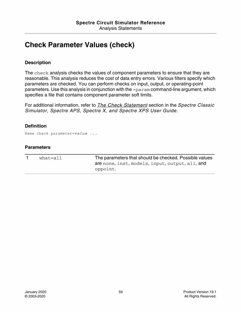
Spectre Circuit Simulator ReferenceAnalysis Statements
January 2020 59 Product Version 19.1© 2003-2020 All Rights Reserved.
Check Parameter Values (check)
Description
The check analysis checks the values of component parameters to ensure that they are reasonable. This analysis reduces the cost of data entry errors. Various filters specify which parameters are checked. You can perform checks on input, output, or operating-point parameters. Use this analysis in conjunction with the +param command-line argument, which specifies a file that contains component parameter soft limits.
For additional information, refer to The Check Statement section in the Spectre Classic Simulator, Spectre APS, Spectre X, and Spectre XPS User Guide.
DefinitionName check parameter=value ...
Parameters
1 what=all The parameters that should be checked. Possible values are none, inst, models, input, output, all, and oppoint.
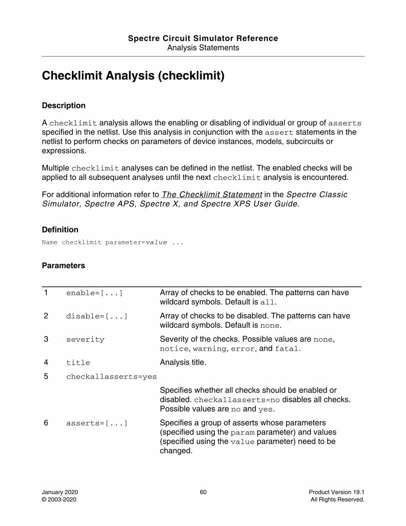
Spectre Circuit Simulator ReferenceAnalysis Statements
January 2020 60 Product Version 19.1© 2003-2020 All Rights Reserved.
Checklimit Analysis (checklimit)
Description
A checklimit analysis allows the enabling or disabling of individual or group of asserts specified in the netlist. Use this analysis in conjunction with the assert statements in the netlist to perform checks on parameters of device instances, models, subcircuits or expressions.
Multiple checklimit analyses can be defined in the netlist. The enabled checks will be applied to all subsequent analyses until the next checklimit analysis is encountered.
For additional information refer to The Checklimit Statement in the Spectre Classic Simulator, Spectre APS, Spectre X, and Spectre XPS User Guide.
DefinitionName checklimit parameter=value ...
Parameters
1 enable=[...] Array of checks to be enabled. The patterns can have wildcard symbols. Default is all.
2 disable=[...] Array of checks to be disabled. The patterns can have wildcard symbols. Default is none.
3 severity Severity of the checks. Possible values are none, notice, warning, error, and fatal.
4 title Analysis title.
5 checkallasserts=yes
Specifies whether all checks should be enabled or disabled. checkallasserts=no disables all checks. Possible values are no and yes.
6 asserts=[...] Specifies a group of asserts whose parameters (specified using the param parameter) and values (specified using the value parameter) need to be changed.
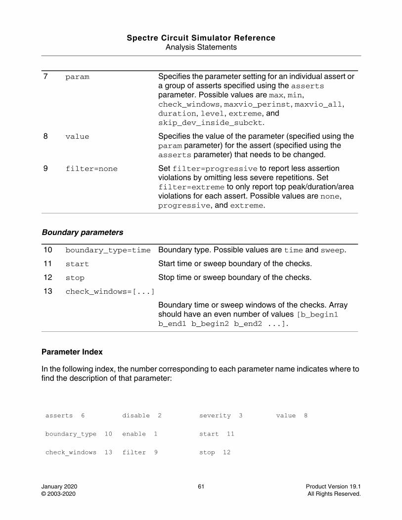
Spectre Circuit Simulator ReferenceAnalysis Statements
January 2020 61 Product Version 19.1© 2003-2020 All Rights Reserved.
Boundary parameters
Parameter Index
In the following index, the number corresponding to each parameter name indicates where to find the description of that parameter:
7 param Specifies the parameter setting for an individual assert or a group of asserts specified using the asserts parameter. Possible values are max, min, check_windows, maxvio_perinst, maxvio_all, duration, level, extreme, and skip_dev_inside_subckt.
8 value Specifies the value of the parameter (specified using the param parameter) for the assert (specified using the asserts parameter) that needs to be changed.
9 filter=none Set filter=progressive to report less assertion violations by omitting less severe repetitions. Set filter=extreme to only report top peak/duration/area violations for each assert. Possible values are none, progressive, and extreme.
10 boundary_type=time Boundary type. Possible values are time and sweep.
11 start Start time or sweep boundary of the checks.
12 stop Stop time or sweep boundary of the checks.
13 check_windows=[...]
Boundary time or sweep windows of the checks. Array should have an even number of values [b_begin1 b_end1 b_begin2 b_end2 ...].
asserts 6 disable 2 severity 3 value 8
boundary_type 10 enable 1 start 11
check_windows 13 filter 9 stop 12

Spectre Circuit Simulator ReferenceAnalysis Statements
January 2020 62 Product Version 19.1© 2003-2020 All Rights Reserved.
checkallasserts 5
param 7 title 4
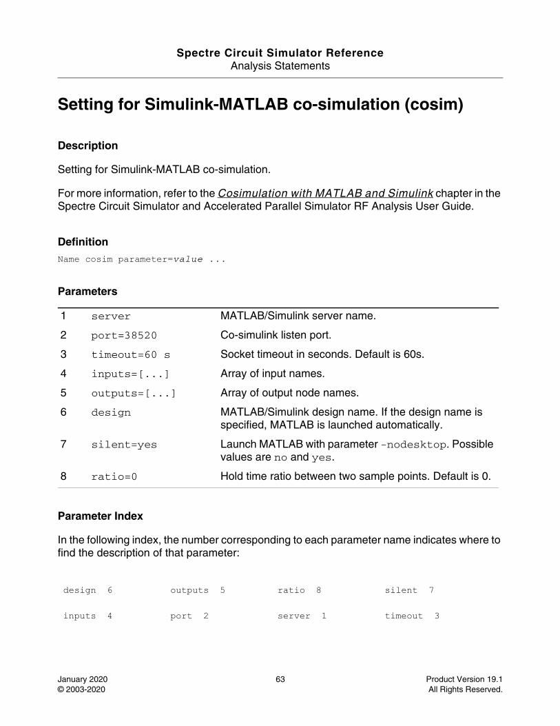
Spectre Circuit Simulator ReferenceAnalysis Statements
January 2020 63 Product Version 19.1© 2003-2020 All Rights Reserved.
Setting for Simulink-MATLAB co-simulation (cosim)
Description
Setting for Simulink-MATLAB co-simulation.
For more information, refer to the Cosimulation with MATLAB and Simulink chapter in the Spectre Circuit Simulator and Accelerated Parallel Simulator RF Analysis User Guide.
DefinitionName cosim parameter=value ...
Parameters
Parameter Index
In the following index, the number corresponding to each parameter name indicates where to find the description of that parameter:
1 server MATLAB/Simulink server name.
2 port=38520 Co-simulink listen port.
3 timeout=60 s Socket timeout in seconds. Default is 60s.
4 inputs=[...] Array of input names.
5 outputs=[...] Array of output node names.
6 design MATLAB/Simulink design name. If the design name is specified, MATLAB is launched automatically.
7 silent=yes Launch MATLAB with parameter -nodesktop. Possible values are no and yes.
8 ratio=0 Hold time ratio between two sample points. Default is 0.
design 6 outputs 5 ratio 8 silent 7
inputs 4 port 2 server 1 timeout 3
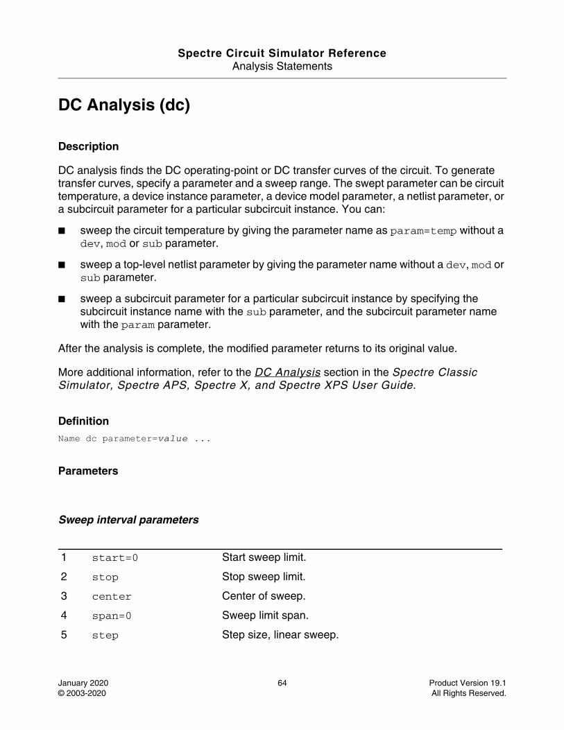
Spectre Circuit Simulator ReferenceAnalysis Statements
January 2020 64 Product Version 19.1© 2003-2020 All Rights Reserved.
DC Analysis (dc)
Description
DC analysis finds the DC operating-point or DC transfer curves of the circuit. To generate transfer curves, specify a parameter and a sweep range. The swept parameter can be circuit temperature, a device instance parameter, a device model parameter, a netlist parameter, or a subcircuit parameter for a particular subcircuit instance. You can:
■ sweep the circuit temperature by giving the parameter name as param=temp without a dev, mod or sub parameter.
■ sweep a top-level netlist parameter by giving the parameter name without a dev, mod or sub parameter.
■ sweep a subcircuit parameter for a particular subcircuit instance by specifying the subcircuit instance name with the sub parameter, and the subcircuit parameter name with the param parameter.
After the analysis is complete, the modified parameter returns to its original value.
More additional information, refer to the DC Analysis section in the Spectre Classic Simulator, Spectre APS, Spectre X, and Spectre XPS User Guide.
DefinitionName dc parameter=value ...
Parameters
Sweep interval parameters
1 start=0 Start sweep limit.
2 stop Stop sweep limit.
3 center Center of sweep.
4 span=0 Sweep limit span.
5 step Step size, linear sweep.
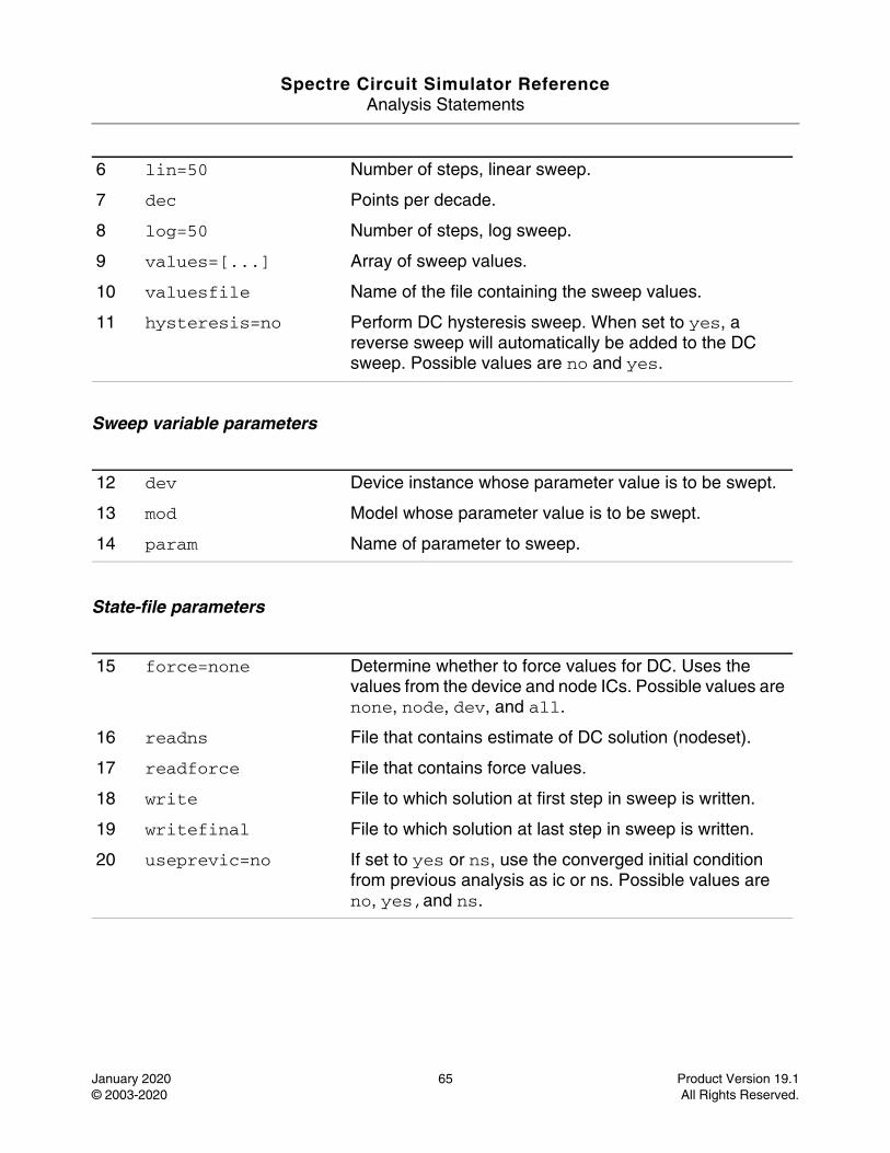
Spectre Circuit Simulator ReferenceAnalysis Statements
January 2020 65 Product Version 19.1© 2003-2020 All Rights Reserved.
Sweep variable parameters
State-file parameters
6 lin=50 Number of steps, linear sweep.
7 dec Points per decade.
8 log=50 Number of steps, log sweep.
9 values=[...] Array of sweep values.
10 valuesfile Name of the file containing the sweep values.
11 hysteresis=no Perform DC hysteresis sweep. When set to yes, a reverse sweep will automatically be added to the DC sweep. Possible values are no and yes.
12 dev Device instance whose parameter value is to be swept.
13 mod Model whose parameter value is to be swept.
14 param Name of parameter to sweep.
15 force=none Determine whether to force values for DC. Uses the values from the device and node ICs. Possible values are none, node, dev, and all.
16 readns File that contains estimate of DC solution (nodeset).
17 readforce File that contains force values.
18 write File to which solution at first step in sweep is written.
19 writefinal File to which solution at last step in sweep is written.
20 useprevic=no If set to yes or ns, use the converged initial condition from previous analysis as ic or ns. Possible values are no, yes,and ns.
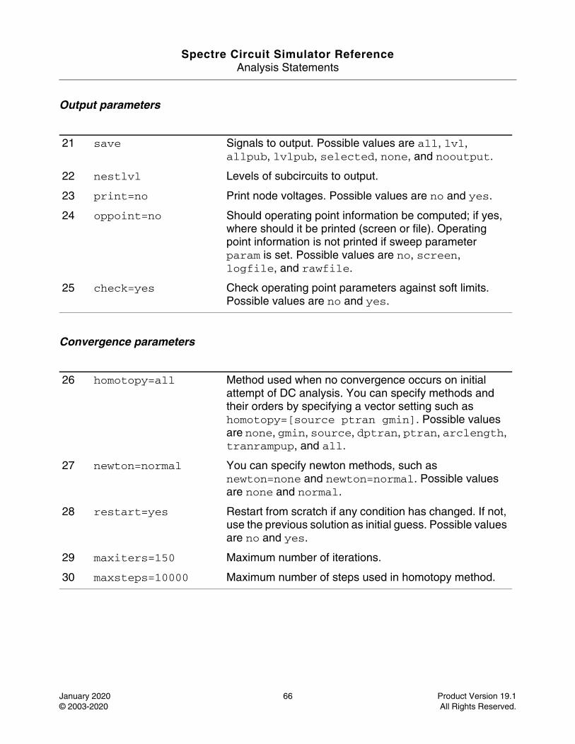
Spectre Circuit Simulator ReferenceAnalysis Statements
January 2020 66 Product Version 19.1© 2003-2020 All Rights Reserved.
Output parameters
Convergence parameters
21 save Signals to output. Possible values are all, lvl, allpub, lvlpub, selected, none, and nooutput.
22 nestlvl Levels of subcircuits to output.
23 print=no Print node voltages. Possible values are no and yes.
24 oppoint=no Should operating point information be computed; if yes, where should it be printed (screen or file). Operating point information is not printed if sweep parameter param is set. Possible values are no, screen, logfile, and rawfile.
25 check=yes Check operating point parameters against soft limits. Possible values are no and yes.
26 homotopy=all Method used when no convergence occurs on initial attempt of DC analysis. You can specify methods and their orders by specifying a vector setting such as homotopy=[source ptran gmin]. Possible values are none, gmin, source, dptran, ptran, arclength, tranrampup, and all.
27 newton=normal You can specify newton methods, such as newton=none and newton=normal. Possible values are none and normal.
28 restart=yes Restart from scratch if any condition has changed. If not, use the previous solution as initial guess. Possible values are no and yes.
29 maxiters=150 Maximum number of iterations.
30 maxsteps=10000 Maximum number of steps used in homotopy method.
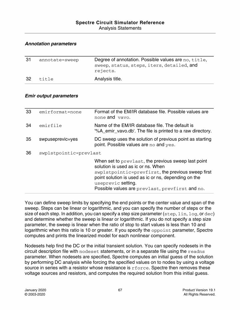
Spectre Circuit Simulator ReferenceAnalysis Statements
January 2020 67 Product Version 19.1© 2003-2020 All Rights Reserved.
Annotation parameters
Emir output parameters
You can define sweep limits by specifying the end points or the center value and span of the sweep. Steps can be linear or logarithmic, and you can specify the number of steps or the size of each step. In addition, you can specify a step size parameter (step, lin, log, or dec) and determine whether the sweep is linear or logarithmic. If you do not specify a step size parameter, the sweep is linear when the ratio of stop to start values is less than 10 and logarithmic when this ratio is 10 or greater. If you specify the oppoint parameter, Spectre computes and prints the linearized model for each nonlinear component.
Nodesets help find the DC or the initial transient solution. You can specify nodesets in the circuit description file with nodeset statements, or in a separate file using the readns parameter. When nodesets are specified, Spectre computes an initial guess of the solution by performing DC analysis while forcing the specified values on to nodes by using a voltage source in series with a resistor whose resistance is rforce. Spectre then removes these voltage sources and resistors, and computes the required solution from this initial guess.
31 annotate=sweep Degree of annotation. Possible values are no, title, sweep, status, steps, iters, detailed, and rejects.
32 title Analysis title.
33 emirformat=none Format of the EM/IR database file. Possible values are none and vavo.
34 emirfile Name of the EM/IR database file. The default is '%A_emir_vavo.db'. The file is printed to a raw directory.
35 swpuseprevic=yes DC sweep uses the solution of previous point as starting point. Possible values are no and yes.
36 swp1stpointic=prevlast
When set to prevlast, the previous sweep last point solution is used as ic or ns. When swp1stpointic=prevfirst, the previous sweep first point solution is used as ic or ns, depending on the useprevic setting.Possible values are prevlast, prevfirst and no.
Spectre Circuit Simulator ReferenceAnalysis Statements
January 2020 68 Product Version 19.1© 2003-2020 All Rights Reserved.
Nodesets have two important uses. First, if a circuit has two or more solutions, nodesets can bias the simulator towards computing the required solution. Second, this is a convergence aid. By estimating the solution of the largest possible number of nodes, you might be able to eliminate a convergence problem or significantly speed up convergence.
When you simulate the same circuit multiple times, it is recommended that you use both write and readns parameters and assign the same file name to both parameters. DC analysis then converges quickly even if the circuit has changed since the last simulation, and the nodeset file is automatically updated.
You can set the force parameter and specify the values to force the DC analysis. The values used to force signals are specified by using the force file, the ic statement, or the ic parameter on the capacitors and inductors. The force parameter controls the interaction of various methods of setting the force values. The effects of individual settings are as follows:
force=none: All initial conditions are ignored.
force=node: The ic statements are used, and the ic parameter on the capacitors and inductors are ignored.
force=dev: The ic parameters on the capacitors and inductors are used, and the ic statements are ignored.
force=all: Both the ic statements and the ic parameters are used, with the ic parameters overriding the ic statements.
If you specify a force file with the readforce parameter, force values read from the file are used, and any ic statements are ignored.
After you specify the force conditions, Spectre performs DC analysis with the specified nodes forced to the given value by using a voltage source in series with a resistor whose resistance is rforce (see options).
Parameter Index
In the following index, the number corresponding to each parameter name indicates where to find the description of that parameter:
annotate 31 hysteresis 11 param 14 stop 2
center 3 lin 6 print 23 swpuseprevic 33
Spectre Circuit Simulator ReferenceAnalysis Statements
January 2020 69 Product Version 19.1© 2003-2020 All Rights Reserved.
check 25 log 8 readforce 17 swp1stpointic 36
dec 7 maxiters 29 readns 16 title 32
dev 12 maxsteps 30 restart 28 useprevic 20
emirfile 34 mod 13 save 21 values 9
emirformat 33 nestlvl 22 span 4 valuesfile 10
force 15 newton 27 start 1 write 18
homotopy 26 oppoint 24 step 5 writefinal 19

Spectre Circuit Simulator ReferenceAnalysis Statements
January 2020 70 Product Version 19.1© 2003-2020 All Rights Reserved.
DC Device Matching Analysis (dcmatch)
Description
DCMATCH analysis performs device matching analysis on the operating point for a specified output. It computes the deviation in the operating point of the circuit due to processing or environmental variation in modeled devices. If method=standard is specified, a set of dcmatch parameters in the model cards is required for each supported device contributing to the deviation. The analysis applies device matching models to construct equivalent mismatch current sources to all the devices that are modeled. These current sources are assumed to have zero mean and certain variance. The variance of the current sources is computed according to device matching models. Next, the 3-sigma variance of DC voltages or currents (due to the mismatch current sources) is computed at the specified outputs. The simulation result displays the devices rank ordered by their contribution to the outputs. In addition, for MOSFET devices, it displays threshold voltage mismatch, current factor mismatch, gate voltage mismatch, and drain current mismatch. For bipolar devices, it displays base-emitter junction voltage mismatch. For resistors, it displays resistor mismatches.
The analysis replaces multiple simulation runs that determine changes in accuracy with any changes in size. It automatically identifies the set of critical matched components during circuit design. For example, when there are matched pairs in the circuit, the contribution of two matched transistors is equal in magnitude but opposite in sign. Typical usage is to simulate the output offset voltage of operational amplifiers, estimate the variation in bandgap voltages, and predict the accuracy of current steering DACS.
For method=standard, DCMATCH analysis can be applied to following devices: BSIM3V3, BSIM4, BSIMSOI, EKV, PSP102, PSP103, BJT, VBIC, BHT, RESISTOR, PHY_RES, R3, and resistor-type bsource. If method=statistics is specified, a statistics block is required to list the parameters that are considered as randomly varying. By default, all statistics parameters found in the statistics block are considered in computation, unless the option variations is explicitly specified. Device matching models are not used in this case and dcmatch model parameters are not required.
More more information, refer to the DCMatch Analysis section in the Spectre Classic Simulator, Spectre APS, Spectre X, and Spectre XPS User Guide.
DefinitionName ... dcmatch parameter=value ...
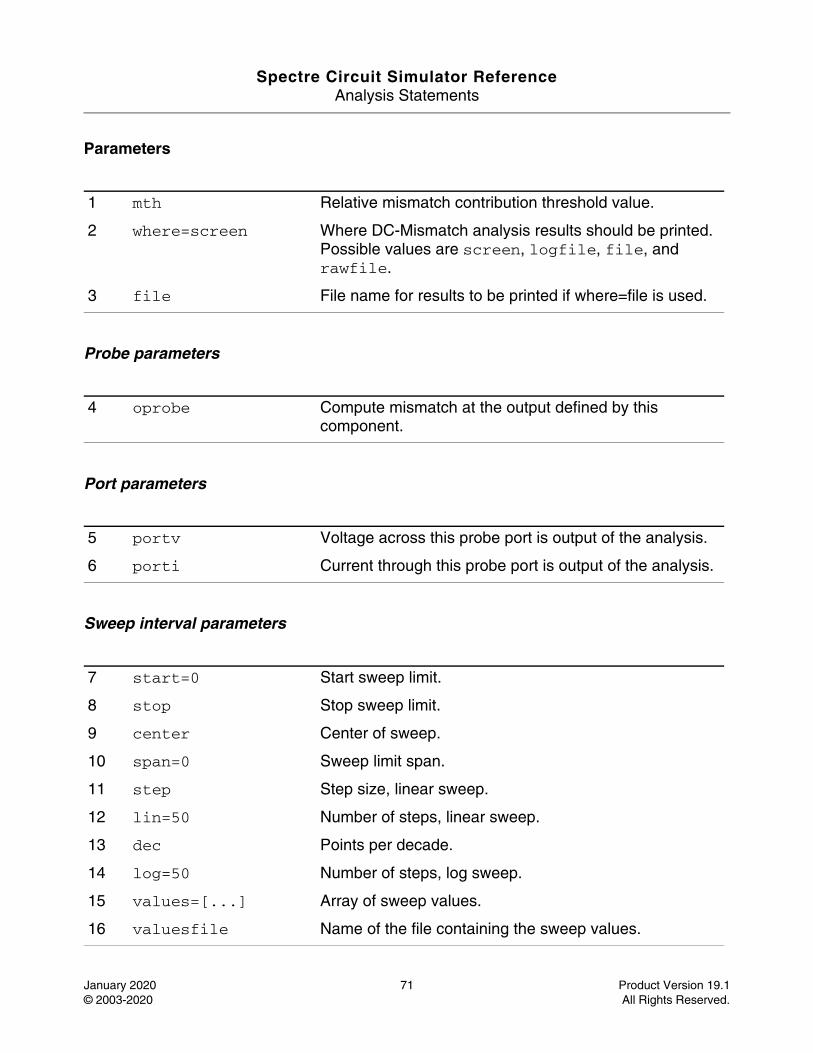
Spectre Circuit Simulator ReferenceAnalysis Statements
January 2020 71 Product Version 19.1© 2003-2020 All Rights Reserved.
Parameters
Probe parameters
Port parameters
Sweep interval parameters
1 mth Relative mismatch contribution threshold value.
2 where=screen Where DC-Mismatch analysis results should be printed. Possible values are screen, logfile, file, and rawfile.
3 file File name for results to be printed if where=file is used.
4 oprobe Compute mismatch at the output defined by this component.
5 portv Voltage across this probe port is output of the analysis.
6 porti Current through this probe port is output of the analysis.
7 start=0 Start sweep limit.
8 stop Stop sweep limit.
9 center Center of sweep.
10 span=0 Sweep limit span.
11 step Step size, linear sweep.
12 lin=50 Number of steps, linear sweep.
13 dec Points per decade.
14 log=50 Number of steps, log sweep.
15 values=[...] Array of sweep values.
16 valuesfile Name of the file containing the sweep values.
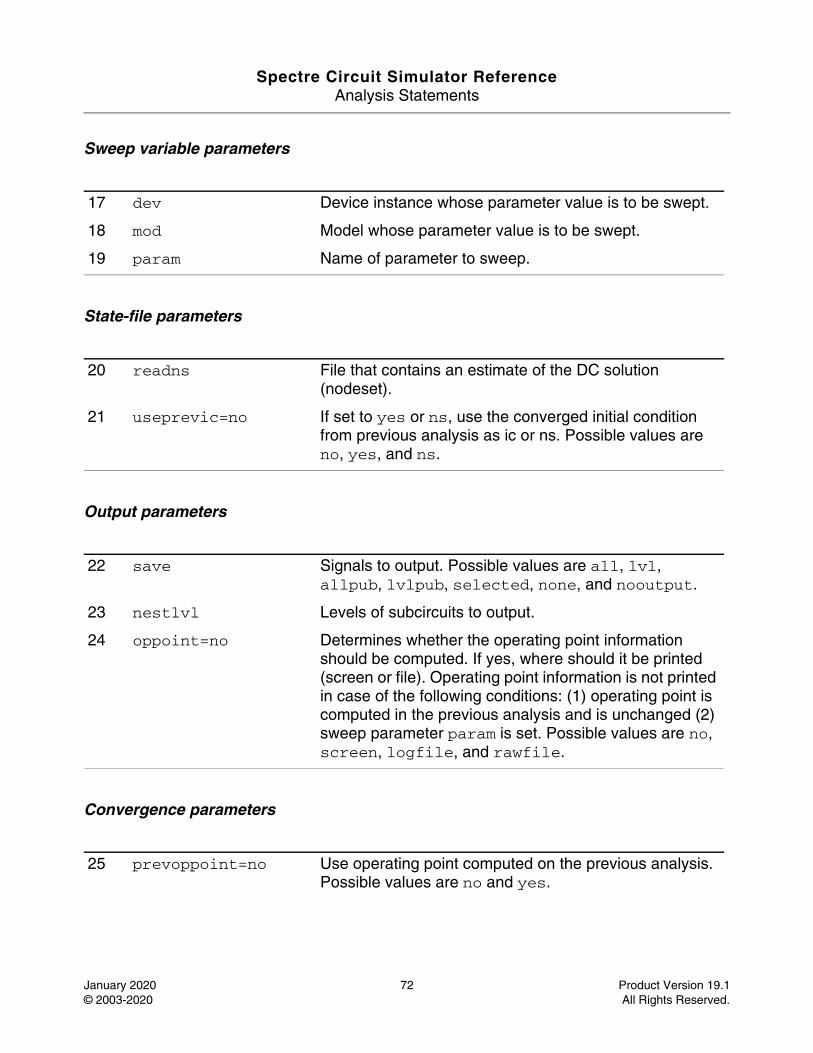
Spectre Circuit Simulator ReferenceAnalysis Statements
January 2020 72 Product Version 19.1© 2003-2020 All Rights Reserved.
Sweep variable parameters
State-file parameters
Output parameters
Convergence parameters
17 dev Device instance whose parameter value is to be swept.
18 mod Model whose parameter value is to be swept.
19 param Name of parameter to sweep.
20 readns File that contains an estimate of the DC solution (nodeset).
21 useprevic=no If set to yes or ns, use the converged initial condition from previous analysis as ic or ns. Possible values are no, yes, and ns.
22 save Signals to output. Possible values are all, lvl, allpub, lvlpub, selected, none, and nooutput.
23 nestlvl Levels of subcircuits to output.
24 oppoint=no Determines whether the operating point information should be computed. If yes, where should it be printed (screen or file). Operating point information is not printed in case of the following conditions: (1) operating point is computed in the previous analysis and is unchanged (2) sweep parameter param is set. Possible values are no, screen, logfile, and rawfile.
25 prevoppoint=no Use operating point computed on the previous analysis. Possible values are no and yes.
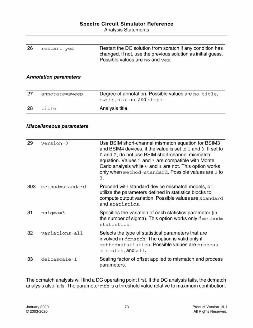
Spectre Circuit Simulator ReferenceAnalysis Statements
January 2020 73 Product Version 19.1© 2003-2020 All Rights Reserved.
Annotation parameters
Miscellaneous parameters
The dcmatch analysis will find a DC operating point first. If the DC analysis fails, the dcmatch analysis also fails. The parameter mth is a threshold value relative to maximum contribution.
26 restart=yes Restart the DC solution from scratch if any condition has changed. If not, use the previous solution as initial guess. Possible values are no and yes.
27 annotate=sweep Degree of annotation. Possible values are no, title, sweep, status, and steps.
28 title Analysis title.
29 version=0 Use BSIM short-channel mismatch equation for BSIM3 and BSIM4 devices, if the value is set to 1 and 3. If set to 0 and 2, do not use BSIM short-channel mismatch equation. Values 2 and 3 are compatible with Monte Carlo analysis while 0 and 1 are not. This option works only when method=standard. Possible values are 0 to 3.
303 method=standard Proceed with standard device mismatch models, or utilize the parameters defined in statistics blocks to compute output variation. Possible values are standard and statistics.
31 nsigma=3 Specifies the variation of each statistics parameter (in the number of sigma). This option works only if method= statistics.
32 variations=all Selects the type of statistical parameters that are involved in dcmatch. The option is valid only if method=statistics. Possible values are process, mismatch, and all.
33 deltascale=1 Scaling factor of offset applied to mismatch and process parameters.
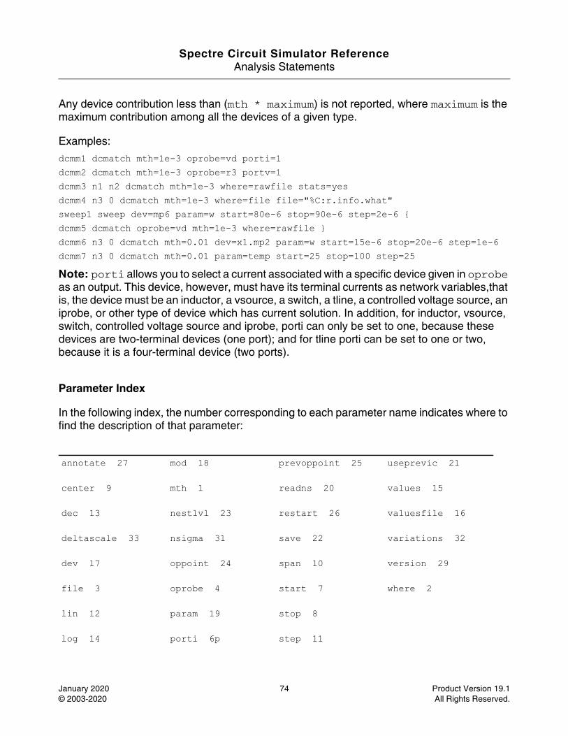
Spectre Circuit Simulator ReferenceAnalysis Statements
January 2020 74 Product Version 19.1© 2003-2020 All Rights Reserved.
Any device contribution less than (mth * maximum) is not reported, where maximum is the maximum contribution among all the devices of a given type.
Examples:
dcmm1 dcmatch mth=1e-3 oprobe=vd porti=1 dcmm2 dcmatch mth=1e-3 oprobe=r3 portv=1 dcmm3 n1 n2 dcmatch mth=1e-3 where=rawfile stats=yes dcmm4 n3 0 dcmatch mth=1e-3 where=file file="%C:r.info.what" sweep1 sweep dev=mp6 param=w start=80e-6 stop=90e-6 step=2e-6 {dcmm5 dcmatch oprobe=vd mth=1e-3 where=rawfile }dcmm6 n3 0 dcmatch mth=0.01 dev=x1.mp2 param=w start=15e-6 stop=20e-6 step=1e-6 dcmm7 n3 0 dcmatch mth=0.01 param=temp start=25 stop=100 step=25 Note: porti allows you to select a current associated with a specific device given in oprobe as an output. This device, however, must have its terminal currents as network variables,that is, the device must be an inductor, a vsource, a switch, a tline, a controlled voltage source, an iprobe, or other type of device which has current solution. In addition, for inductor, vsource, switch, controlled voltage source and iprobe, porti can only be set to one, because these devices are two-terminal devices (one port); and for tline porti can be set to one or two, because it is a four-terminal device (two ports).
Parameter Index
In the following index, the number corresponding to each parameter name indicates where to find the description of that parameter:
annotate 27 mod 18 prevoppoint 25 useprevic 21
center 9 mth 1 readns 20 values 15
dec 13 nestlvl 23 restart 26 valuesfile 16
deltascale 33 nsigma 31 save 22 variations 32
dev 17 oppoint 24 span 10 version 29
file 3 oprobe 4 start 7 where 2
lin 12 param 19 stop 8
log 14 porti 6p step 11

Spectre Circuit Simulator ReferenceAnalysis Statements
January 2020 75 Product Version 19.1© 2003-2020 All Rights Reserved.
method 30 ortv 5 title 28
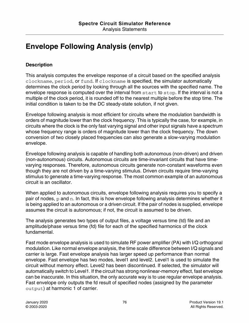
Spectre Circuit Simulator ReferenceAnalysis Statements
January 2020 76 Product Version 19.1© 2003-2020 All Rights Reserved.
Envelope Following Analysis (envlp)
Description
This analysis computes the envelope response of a circuit based on the specified analysis clockname, period, or fund. If clockname is specified, the simulator automatically determines the clock period by looking through all the sources with the specified name. The envelope response is computed over the interval from start to stop. If the interval is not a multiple of the clock period, it is rounded off to the nearest multiple before the stop time. The initial condition is taken to be the DC steady-state solution, if not given.
Envelope following analysis is most efficient for circuits where the modulation bandwidth is orders of magnitude lower than the clock frequency. This is typically the case, for example, in circuits where the clock is the only fast varying signal and other input signals have a spectrum whose frequency range is orders of magnitude lower than the clock frequency. The down conversion of two closely placed frequencies can also generate a slow-varying modulation envelope.
Envelope following analysis is capable of handling both autonomous (non-driven) and driven (non-autonomous) circuits. Autonomous circuits are time-invariant circuits that have time-varying responses. Therefore, autonomous circuits generate non-constant waveforms even though they are not driven by a time-varying stimulus. Driven circuits require time-varying stimulus to generate a time-varying response. The most common example of an autonomous circuit is an oscillator.
When applied to autonomous circuits, envelope following analysis requires you to specify a pair of nodes, p and n. In fact, this is how envelope following analysis determines whether it is being applied to an autonomous or a driven circuit. If the pair of nodes is supplied, envelope assumes the circuit is autonomous; if not, the circuit is assumed to be driven.
The analysis generates two types of output files, a voltage versus time (td) file and an amplitude/phase versus time (fd) file for each of the specified harmonics of the clock fundamental.
Fast mode envelope analysis is used to simulate RF power amplifier (PA) with I/Q orthogonal modulation. Like normal envelope analysis, the time scale difference between I/Q signals and carrier is large. Fast envelope analysis has larger speed up performance than normal envelope. Fast envelope has two modes, level1 and level2. Level1 is used to simulate the circuit without memory effect. Level2 has been discontinued. If selected, the simulator will automatically switch to Level1. If the circuit has strong nonlinear-memory effect, fast envelope can be inaccurate. In this situation, the only accurate way is to use regular envelope analysis. Fast envelope only outputs the fd result of specified nodes (assigned by the parameter output) at harmonic 1 of carrier.
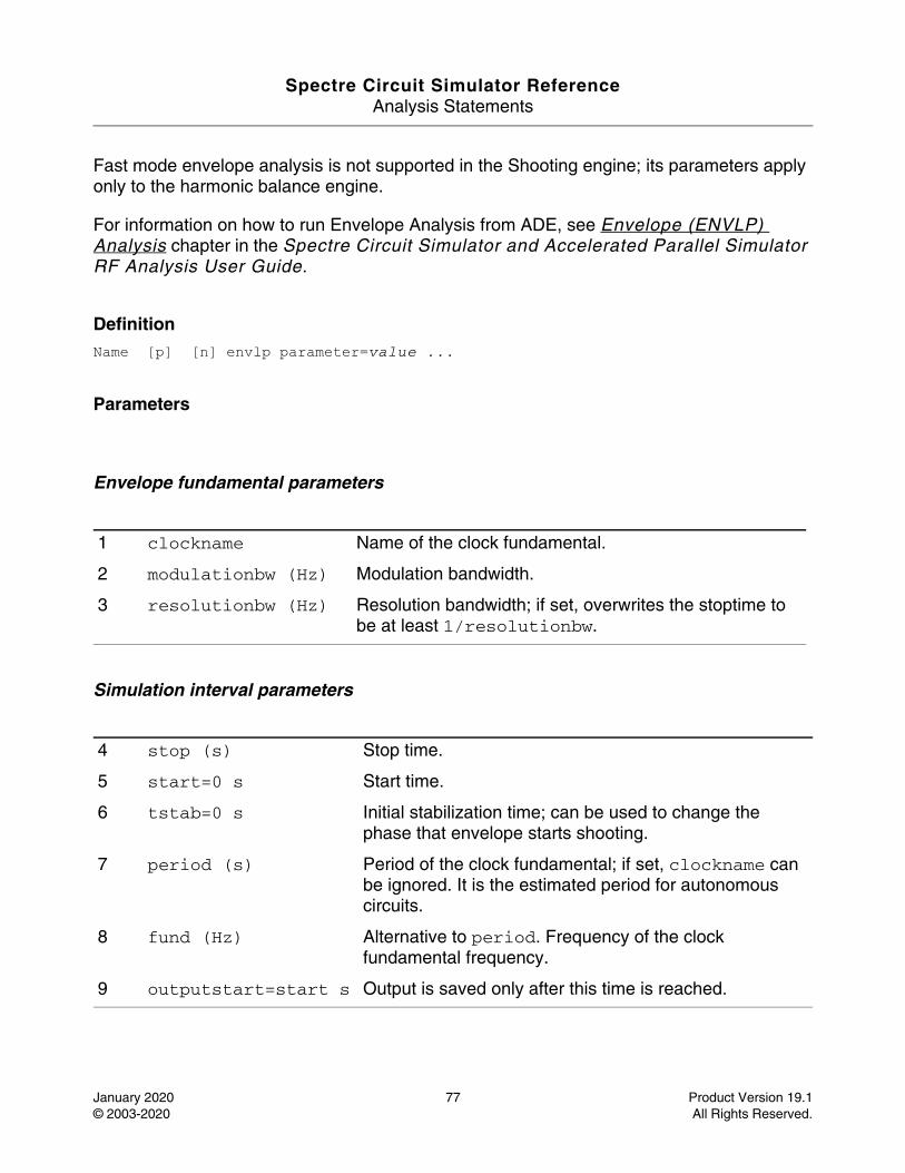
Spectre Circuit Simulator ReferenceAnalysis Statements
January 2020 77 Product Version 19.1© 2003-2020 All Rights Reserved.
Fast mode envelope analysis is not supported in the Shooting engine; its parameters apply only to the harmonic balance engine.
For information on how to run Envelope Analysis from ADE, see Envelope (ENVLP) Analysis chapter in the Spectre Circuit Simulator and Accelerated Parallel Simulator RF Analysis User Guide.
DefinitionName [p] [n] envlp parameter=value ...
Parameters
Envelope fundamental parameters
Simulation interval parameters
1 clockname Name of the clock fundamental.
2 modulationbw (Hz) Modulation bandwidth.
3 resolutionbw (Hz) Resolution bandwidth; if set, overwrites the stoptime to be at least 1/resolutionbw.
4 stop (s) Stop time.
5 start=0 s Start time.
6 tstab=0 s Initial stabilization time; can be used to change the phase that envelope starts shooting.
7 period (s) Period of the clock fundamental; if set, clockname can be ignored. It is the estimated period for autonomous circuits.
8 fund (Hz) Alternative to period. Frequency of the clock fundamental frequency.
9 outputstart=start s Output is saved only after this time is reached.
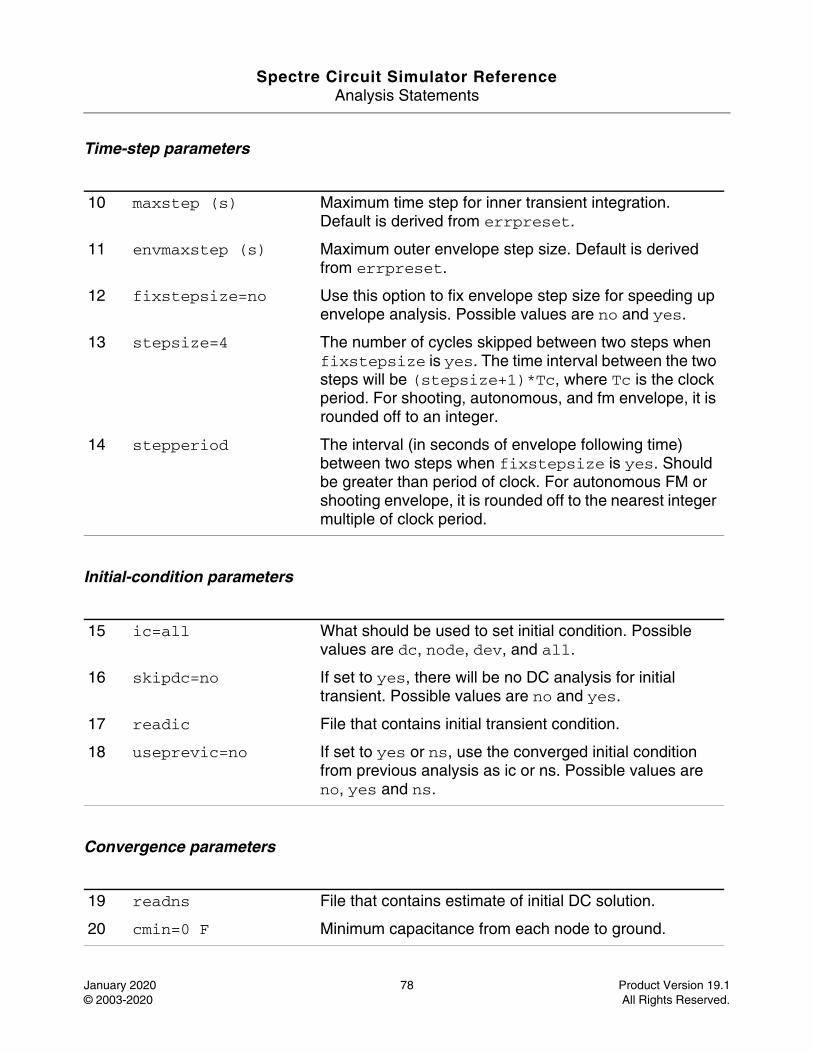
Spectre Circuit Simulator ReferenceAnalysis Statements
January 2020 78 Product Version 19.1© 2003-2020 All Rights Reserved.
Time-step parameters
Initial-condition parameters
Convergence parameters
10 maxstep (s) Maximum time step for inner transient integration. Default is derived from errpreset.
11 envmaxstep (s) Maximum outer envelope step size. Default is derived from errpreset.
12 fixstepsize=no Use this option to fix envelope step size for speeding up envelope analysis. Possible values are no and yes.
13 stepsize=4 The number of cycles skipped between two steps when fixstepsize is yes. The time interval between the two steps will be (stepsize+1)*Tc, where Tc is the clock period. For shooting, autonomous, and fm envelope, it is rounded off to an integer.
14 stepperiod The interval (in seconds of envelope following time) between two steps when fixstepsize is yes. Should be greater than period of clock. For autonomous FM or shooting envelope, it is rounded off to the nearest integer multiple of clock period.
15 ic=all What should be used to set initial condition. Possible values are dc, node, dev, and all.
16 skipdc=no If set to yes, there will be no DC analysis for initial transient. Possible values are no and yes.
17 readic File that contains initial transient condition.
18 useprevic=no If set to yes or ns, use the converged initial condition from previous analysis as ic or ns. Possible values are no, yes and ns.
19 readns File that contains estimate of initial DC solution.
20 cmin=0 F Minimum capacitance from each node to ground.
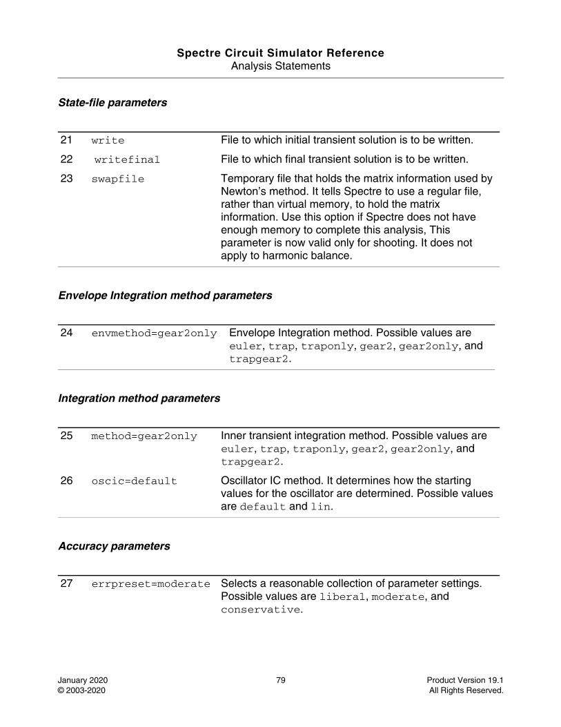
Spectre Circuit Simulator ReferenceAnalysis Statements
January 2020 79 Product Version 19.1© 2003-2020 All Rights Reserved.
State-file parameters
Envelope Integration method parameters
Integration method parameters
Accuracy parameters
21 write File to which initial transient solution is to be written.
22 writefinal File to which final transient solution is to be written.
23 swapfile Temporary file that holds the matrix information used by Newton’s method. It tells Spectre to use a regular file, rather than virtual memory, to hold the matrix information. Use this option if Spectre does not have enough memory to complete this analysis, This parameter is now valid only for shooting. It does not apply to harmonic balance.
24 envmethod=gear2only Envelope Integration method. Possible values are euler, trap, traponly, gear2, gear2only, and trapgear2.
25 method=gear2only Inner transient integration method. Possible values are euler, trap, traponly, gear2, gear2only, and trapgear2.
26 oscic=default Oscillator IC method. It determines how the starting values for the oscillator are determined. Possible values are default and lin.
27 errpreset=moderate Selects a reasonable collection of parameter settings. Possible values are liberal, moderate, and conservative.
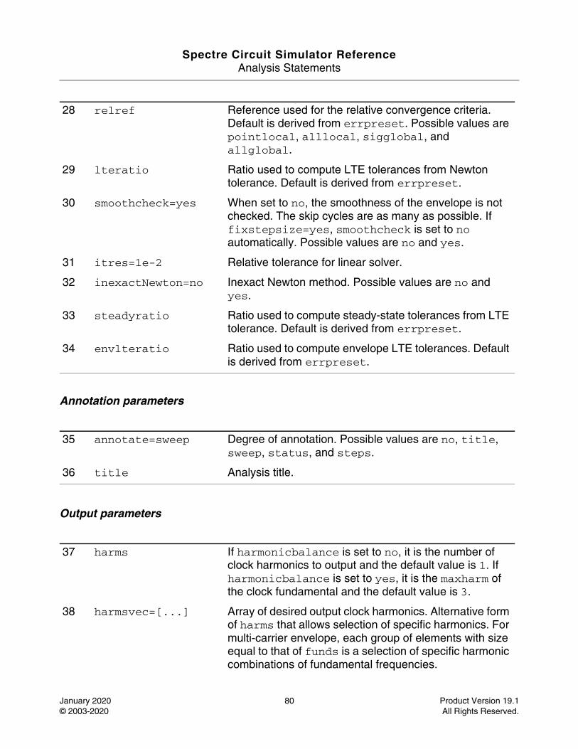
Spectre Circuit Simulator ReferenceAnalysis Statements
January 2020 80 Product Version 19.1© 2003-2020 All Rights Reserved.
Annotation parameters
Output parameters
28 relref Reference used for the relative convergence criteria. Default is derived from errpreset. Possible values are pointlocal, alllocal, sigglobal, and allglobal.
29 lteratio Ratio used to compute LTE tolerances from Newton tolerance. Default is derived from errpreset.
30 smoothcheck=yes When set to no, the smoothness of the envelope is not checked. The skip cycles are as many as possible. If fixstepsize=yes, smoothcheck is set to no automatically. Possible values are no and yes.
31 itres=1e-2 Relative tolerance for linear solver.
32 inexactNewton=no Inexact Newton method. Possible values are no and yes.
33 steadyratio Ratio used to compute steady-state tolerances from LTE tolerance. Default is derived from errpreset.
34 envlteratio Ratio used to compute envelope LTE tolerances. Default is derived from errpreset.
35 annotate=sweep Degree of annotation. Possible values are no, title, sweep, status, and steps.
36 title Analysis title.
37 harms If harmonicbalance is set to no, it is the number of clock harmonics to output and the default value is 1. If harmonicbalance is set to yes, it is the maxharm of the clock fundamental and the default value is 3.
38 harmsvec=[...] Array of desired output clock harmonics. Alternative form of harms that allows selection of specific harmonics. For multi-carrier envelope, each group of elements with size equal to that of funds is a selection of specific harmonic combinations of fundamental frequencies.
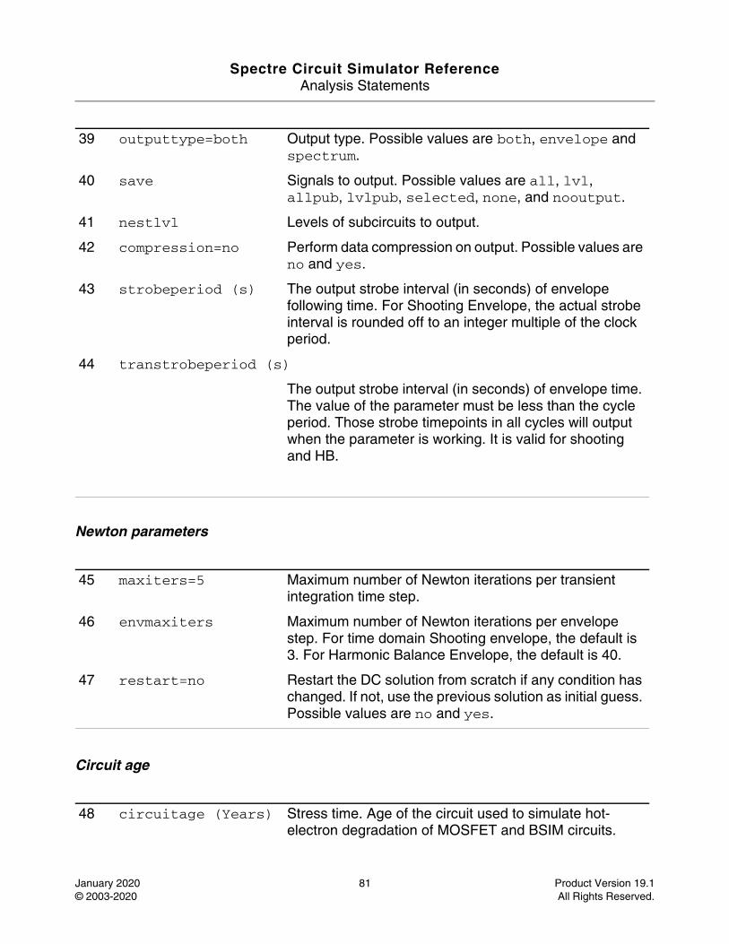
Spectre Circuit Simulator ReferenceAnalysis Statements
January 2020 81 Product Version 19.1© 2003-2020 All Rights Reserved.
Newton parameters
Circuit age
39 outputtype=both Output type. Possible values are both, envelope and spectrum.
40 save Signals to output. Possible values are all, lvl, allpub, lvlpub, selected, none, and nooutput.
41 nestlvl Levels of subcircuits to output.
42 compression=no Perform data compression on output. Possible values are no and yes.
43 strobeperiod (s) The output strobe interval (in seconds) of envelope following time. For Shooting Envelope, the actual strobe interval is rounded off to an integer multiple of the clock period.
44 transtrobeperiod (s)
The output strobe interval (in seconds) of envelope time. The value of the parameter must be less than the cycle period. Those strobe timepoints in all cycles will output when the parameter is working. It is valid for shooting and HB.
45 maxiters=5 Maximum number of Newton iterations per transient integration time step.
46 envmaxiters Maximum number of Newton iterations per envelope step. For time domain Shooting envelope, the default is 3. For Harmonic Balance Envelope, the default is 40.
47 restart=no Restart the DC solution from scratch if any condition has changed. If not, use the previous solution as initial guess. Possible values are no and yes.
48 circuitage (Years) Stress time. Age of the circuit used to simulate hot-electron degradation of MOSFET and BSIM circuits.
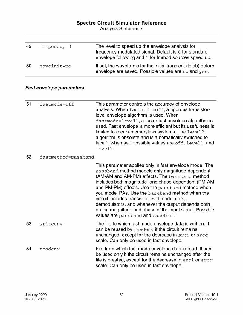
Spectre Circuit Simulator ReferenceAnalysis Statements
January 2020 82 Product Version 19.1© 2003-2020 All Rights Reserved.
Fast envelope parameters
49 fmspeedup=0 The level to speed up the envelope analysis for frequency modulated signal. Default is 0 for standard envelope following and 1 for fmmod sources speed up.
50 saveinit=no If set, the waveforms for the initial transient (tstab) before envelope are saved. Possible values are no and yes.
51 fastmode=off This parameter controls the accuracy of envelope analysis. When fastmode=off, a rigorous transistor-level envelope algorithm is used. When fastmode=level1, a faster fast envelope algorithm is used. Fast envelope is more efficient but its usefulness is limited to (near)-memoryless systems. The level2 algorithm is obsolete and is automatically switched to level1, when set. Possible values are off, level1, and level2.
52 fastmethod=passband
This parameter applies only in fast envelope mode. The passband method models only magnitude-dependent (AM-AM and AM-PM) effects. The baseband method includes both magnitude- and phase-dependent (PM-AM and PM-PM) effects. Use the passband method when you model PAs. Use the baseband method when the circuit includes transistor-level modulators, demodulators, and whenever the output depends both on the magnitude and phase of the input signal. Possible values are passband and baseband.
53 writeenv The file to which fast mode envelope data is written. It can be reused by readenv if the circuit remains unchanged, except for the decrease in srci or srcq scale. Can only be used in fast envelope.
54 readenv File from which fast mode envelope data is read. It can be used only if the circuit remains unchanged after the file is created, except for the decrease in srci or srcq scale. Can only be used in fast envelope.
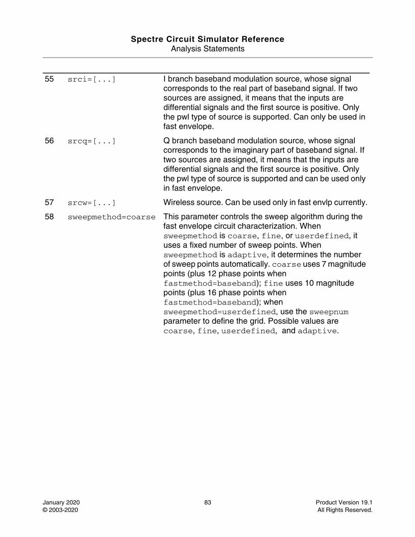
Spectre Circuit Simulator ReferenceAnalysis Statements
January 2020 83 Product Version 19.1© 2003-2020 All Rights Reserved.
55 srci=[...] I branch baseband modulation source, whose signal corresponds to the real part of baseband signal. If two sources are assigned, it means that the inputs are differential signals and the first source is positive. Only the pwl type of source is supported. Can only be used in fast envelope.
56 srcq=[...] Q branch baseband modulation source, whose signal corresponds to the imaginary part of baseband signal. If two sources are assigned, it means that the inputs are differential signals and the first source is positive. Only the pwl type of source is supported and can be used only in fast envelope.
57 srcw=[...] Wireless source. Can be used only in fast envlp currently.
58 sweepmethod=coarse This parameter controls the sweep algorithm during the fast envelope circuit characterization. When sweepmethod is coarse, fine, or userdefined, it uses a fixed number of sweep points. When sweepmethod is adaptive, it determines the number of sweep points automatically. coarse uses 7 magnitude points (plus 12 phase points when fastmethod=baseband); fine uses 10 magnitude points (plus 16 phase points when fastmethod=baseband); when sweepmethod=userdefined, use the sweepnum parameter to define the grid. Possible values are coarse, fine, userdefined, and adaptive.
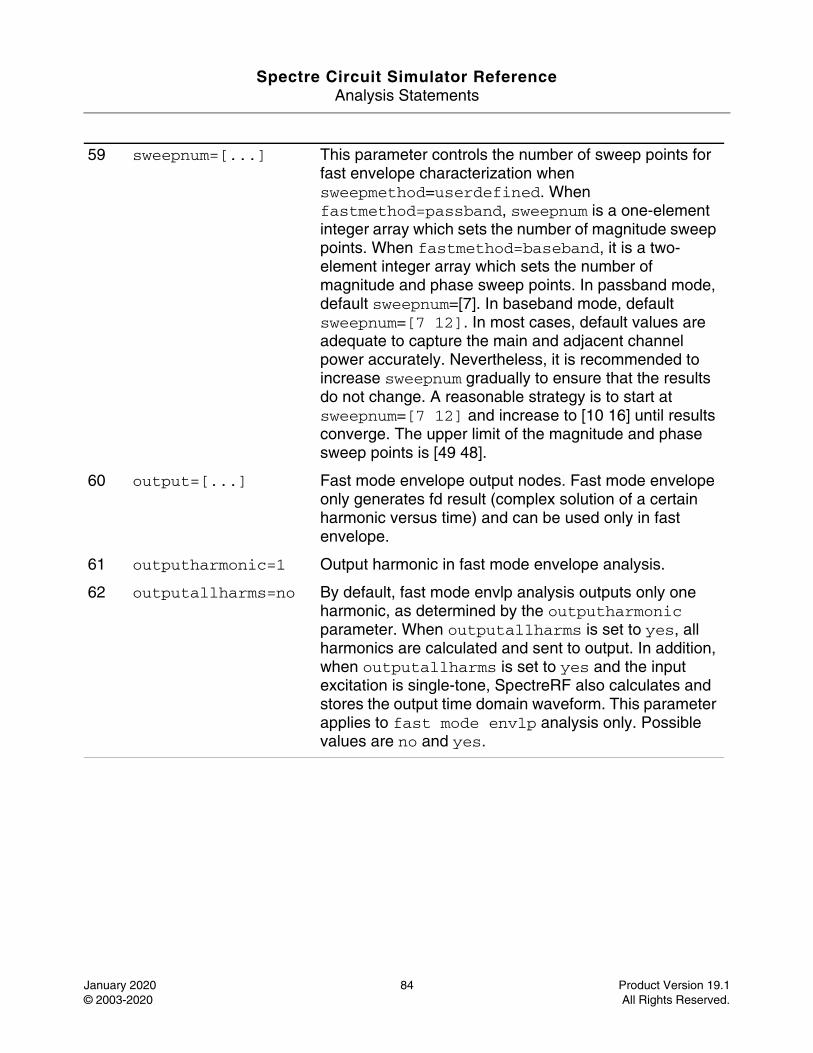
Spectre Circuit Simulator ReferenceAnalysis Statements
January 2020 84 Product Version 19.1© 2003-2020 All Rights Reserved.
59 sweepnum=[...] This parameter controls the number of sweep points for fast envelope characterization when sweepmethod=userdefined. When fastmethod=passband, sweepnum is a one-element integer array which sets the number of magnitude sweep points. When fastmethod=baseband, it is a two-element integer array which sets the number of magnitude and phase sweep points. In passband mode, default sweepnum=[7]. In baseband mode, default sweepnum=[7 12]. In most cases, default values are adequate to capture the main and adjacent channel power accurately. Nevertheless, it is recommended to increase sweepnum gradually to ensure that the results do not change. A reasonable strategy is to start at sweepnum=[7 12] and increase to [10 16] until results converge. The upper limit of the magnitude and phase sweep points is [49 48].
60 output=[...] Fast mode envelope output nodes. Fast mode envelope only generates fd result (complex solution of a certain harmonic versus time) and can be used only in fast envelope.
61 outputharmonic=1 Output harmonic in fast mode envelope analysis.
62 outputallharms=no By default, fast mode envlp analysis outputs only one harmonic, as determined by the outputharmonic parameter. When outputallharms is set to yes, all harmonics are calculated and sent to output. In addition, when outputallharms is set to yes and the input excitation is single-tone, SpectreRF also calculates and stores the output time domain waveform. This parameter applies to fast mode envlp analysis only. Possible values are no and yes.
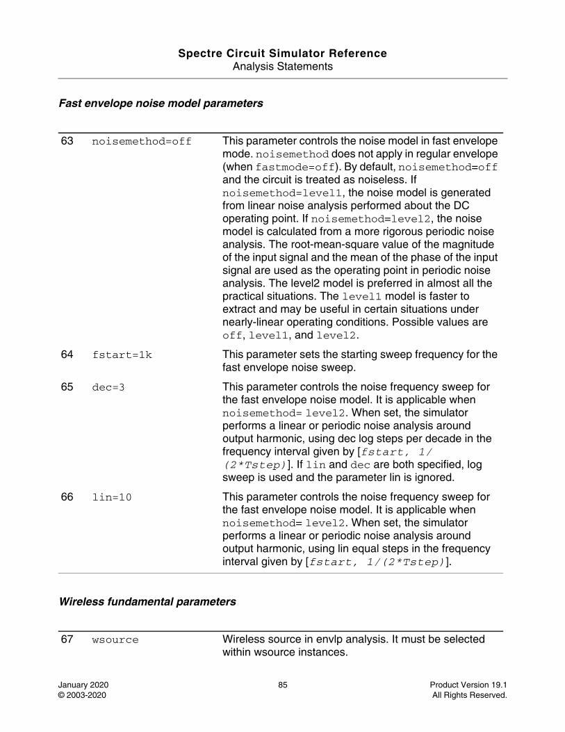
Spectre Circuit Simulator ReferenceAnalysis Statements
January 2020 85 Product Version 19.1© 2003-2020 All Rights Reserved.
Fast envelope noise model parameters
Wireless fundamental parameters
63 noisemethod=off This parameter controls the noise model in fast envelope mode. noisemethod does not apply in regular envelope (when fastmode=off). By default, noisemethod=off and the circuit is treated as noiseless. If noisemethod=level1, the noise model is generated from linear noise analysis performed about the DC operating point. If noisemethod=level2, the noise model is calculated from a more rigorous periodic noise analysis. The root-mean-square value of the magnitude of the input signal and the mean of the phase of the input signal are used as the operating point in periodic noise analysis. The level2 model is preferred in almost all the practical situations. The level1 model is faster to extract and may be useful in certain situations under nearly-linear operating conditions. Possible values are off, level1, and level2.
64 fstart=1k This parameter sets the starting sweep frequency for the fast envelope noise sweep.
65 dec=3 This parameter controls the noise frequency sweep for the fast envelope noise model. It is applicable when noisemethod= level2. When set, the simulator performs a linear or periodic noise analysis around output harmonic, using dec log steps per decade in the frequency interval given by [fstart, 1/(2*Tstep)]. If lin and dec are both specified, log sweep is used and the parameter lin is ignored.
66 lin=10 This parameter controls the noise frequency sweep for the fast envelope noise model. It is applicable when noisemethod= level2. When set, the simulator performs a linear or periodic noise analysis around output harmonic, using lin equal steps in the frequency interval given by [fstart, 1/(2*Tstep)].
67 wsource Wireless source in envlp analysis. It must be selected within wsource instances.
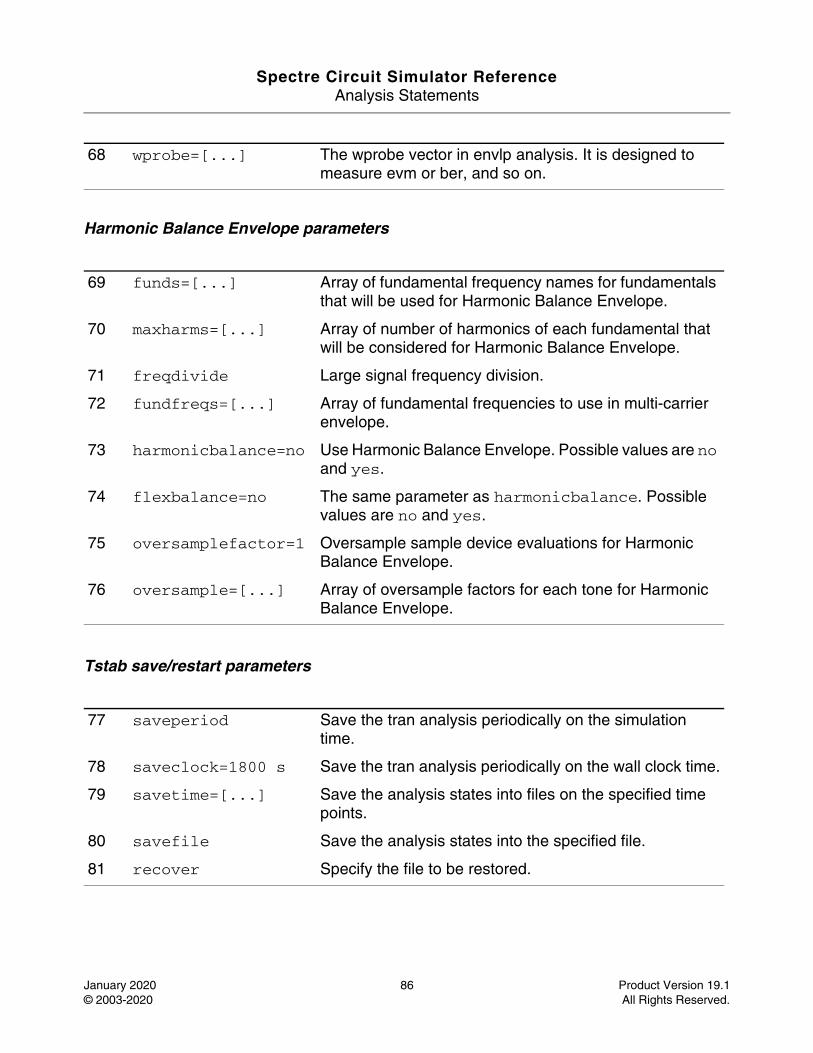
Spectre Circuit Simulator ReferenceAnalysis Statements
January 2020 86 Product Version 19.1© 2003-2020 All Rights Reserved.
Harmonic Balance Envelope parameters
Tstab save/restart parameters
68 wprobe=[...] The wprobe vector in envlp analysis. It is designed to measure evm or ber, and so on.
69 funds=[...] Array of fundamental frequency names for fundamentals that will be used for Harmonic Balance Envelope.
70 maxharms=[...] Array of number of harmonics of each fundamental that will be considered for Harmonic Balance Envelope.
71 freqdivide Large signal frequency division.
72 fundfreqs=[...] Array of fundamental frequencies to use in multi-carrier envelope.
73 harmonicbalance=no Use Harmonic Balance Envelope. Possible values are no and yes.
74 flexbalance=no The same parameter as harmonicbalance. Possible values are no and yes.
75 oversamplefactor=1 Oversample sample device evaluations for Harmonic Balance Envelope.
76 oversample=[...] Array of oversample factors for each tone for Harmonic Balance Envelope.
77 saveperiod Save the tran analysis periodically on the simulation time.
78 saveclock=1800 s Save the tran analysis periodically on the wall clock time.
79 savetime=[...] Save the analysis states into files on the specified time points.
80 savefile Save the analysis states into the specified file.
81 recover Specify the file to be restored.
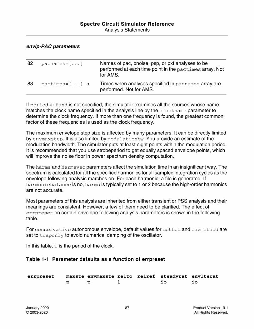
Spectre Circuit Simulator ReferenceAnalysis Statements
January 2020 87 Product Version 19.1© 2003-2020 All Rights Reserved.
envlp-PAC parameters
If period or fund is not specified, the simulator examines all the sources whose name matches the clock name specified in the analysis line by the clockname parameter to determine the clock frequency. If more than one frequency is found, the greatest common factor of these frequencies is used as the clock frequency.
The maximum envelope step size is affected by many parameters. It can be directly limited by envmaxstep. It is also limited by modulationbw. You provide an estimate of the modulation bandwidth. The simulator puts at least eight points within the modulation period. It is recommended that you use strobeperiod to get equally spaced envelope points, which will improve the noise floor in power spectrum density computation.
The harms and harmsvec parameters affect the simulation time in an insignificant way. The spectrum is calculated for all the specified harmonics for all sampled integration cycles as the envelope following analysis marches on. For each harmonic, a file is generated. If harmonicbalance is no, harms is typically set to 1 or 2 because the high-order harmonics are not accurate.
Most parameters of this analysis are inherited from either transient or PSS analysis and their meanings are consistent. However, a few of them need to be clarified. The effect of errpreset on certain envelope following analysis parameters is shown in the following table.
For conservative autonomous envelope, default values for method and envmethod are set to traponly to avoid numerical damping of the oscillator.
In this table, T is the period of the clock.
Table 1-1 Parameter defaults as a function of errpreset
82 pacnames=[...] Names of pac, pnoise, psp, or pxf analyses to be performed at each time point in the pactimes array. Not for AMS.
83 pactimes=[...] s Times when analyses specified in pacnames array are performed. Not for AMS.
errpreset maxstep
envmaxstep
reltol
relref steadyratio
envlteratio
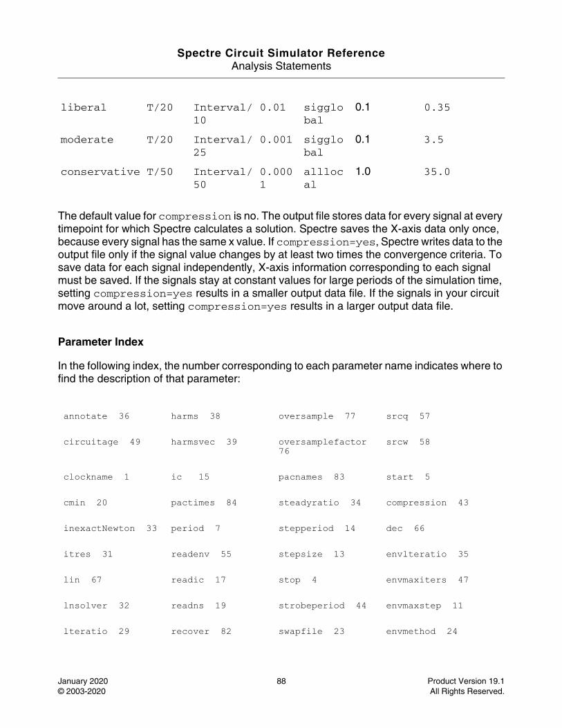
Spectre Circuit Simulator ReferenceAnalysis Statements
January 2020 88 Product Version 19.1© 2003-2020 All Rights Reserved.
The default value for compression is no. The output file stores data for every signal at every timepoint for which Spectre calculates a solution. Spectre saves the X-axis data only once, because every signal has the same x value. If compression=yes, Spectre writes data to the output file only if the signal value changes by at least two times the convergence criteria. To save data for each signal independently, X-axis information corresponding to each signal must be saved. If the signals stay at constant values for large periods of the simulation time, setting compression=yes results in a smaller output data file. If the signals in your circuit move around a lot, setting compression=yes results in a larger output data file.
Parameter Index
In the following index, the number corresponding to each parameter name indicates where to find the description of that parameter:
liberal T/20 Interval/10
0.01 sigglobal
0.1 0.35
moderate T/20 Interval/25
0.001 sigglobal
0.1 3.5
conservative T/50 Interval/50
0.0001
alllocal
1.0 35.0
annotate 36 harms 38 oversample 77 srcq 57
circuitage 49 harmsvec 39 oversamplefactor 76
srcw 58
clockname 1 ic 15 pacnames 83 start 5
cmin 20 pactimes 84 steadyratio 34 compression 43
inexactNewton 33 period 7 stepperiod 14 dec 66
itres 31 readenv 55 stepsize 13 envlteratio 35
lin 67 readic 17 stop 4 envmaxiters 47
lnsolver 32 readns 19 strobeperiod 44 envmaxstep 11
lteratio 29 recover 82 swapfile 23 envmethod 24
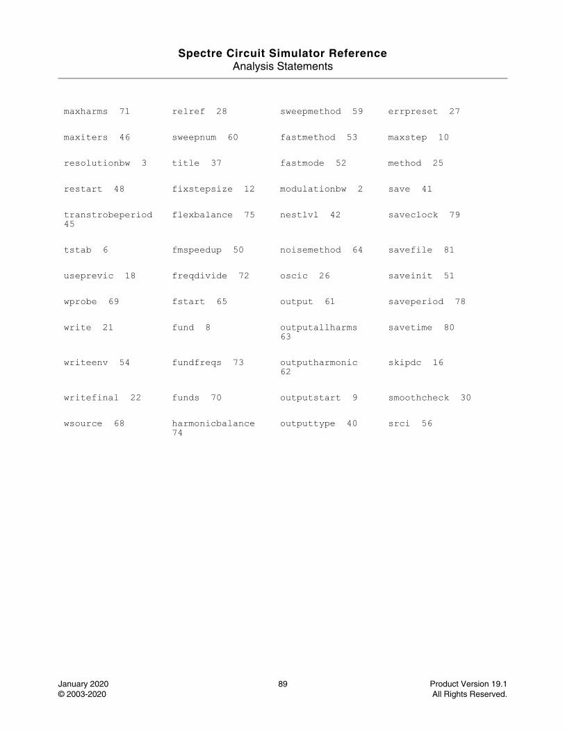
Spectre Circuit Simulator ReferenceAnalysis Statements
January 2020 89 Product Version 19.1© 2003-2020 All Rights Reserved.
maxharms 71 relref 28 sweepmethod 59 errpreset 27
maxiters 46 sweepnum 60 fastmethod 53 maxstep 10
resolutionbw 3 title 37 fastmode 52 method 25
restart 48 fixstepsize 12 modulationbw 2 save 41
transtrobeperiod 45
flexbalance 75 nestlvl 42 saveclock 79
tstab 6 fmspeedup 50 noisemethod 64 savefile 81
useprevic 18 freqdivide 72 oscic 26 saveinit 51
wprobe 69 fstart 65 output 61 saveperiod 78
write 21 fund 8 outputallharms 63
savetime 80
writeenv 54 fundfreqs 73 outputharmonic 62
skipdc 16
writefinal 22 funds 70 outputstart 9 smoothcheck 30
wsource 68 harmonicbalance 74
outputtype 40 srci 56

Spectre Circuit Simulator ReferenceAnalysis Statements
January 2020 90 Product Version 19.1© 2003-2020 All Rights Reserved.
Harmonic Balance Steady State Analysis (hb)
Description
This analysis uses harmonic balance (in the frequency domain) to compute the response of circuits with one fundamental frequency (periodic steady-state, PSS) or multiple fundamental frequencies (quasi-periodic steady-state, QPSS). The simulation time required for an HB analysis is independent of the time-constants of the circuit. This analysis also determines the circuit’s periodic or quasi-periodic operating point, which can then be used during a periodic or quasi-periodic time-varying small-signal analysis, such as HBAC, HBSP, or HBNOISE.
Usually, harmonic balance (HB) analysis is an efficient way to simulate weak nonlinear circuits. In addition, HB analysis works better than shooting analysis (in the time domain) for frequency-dependent components, such as delay, transmission line, and S-parameter data.
An HB analysis consists of two phases. The first phase calculates an initial solution, which the second phase then uses to compute the periodic or quasi-periodic steady-state solution, by using the Newton method.
The two most important parameters for HB analysis are funds and maxharms. The funds parameter accepts a list of names of fundamentals that are present in the sources. These names are specified in the sources by the fundname parameter. If only one name appears, the analysis is an HB PSS analysis. On the other hand, if more than one name appears, the analysis is an HB QPSS analysis. The maxharms parameter accepts a list of numbers of the harmonics that are required to adequately model the responses due to the different fundamentals.
The annotate parameter has two values specific to HB analysis: detailed_hb and internal_hb. When annotate is set to detailed_hb or internal_hb, additional analysis debug information is printed to the log files. In the case of internal_hb, encrypted debug information is stored in the internal log file. Both options are valid for pss and qpss analyses with flexbalance=yes.
For information on how to run hb analysis from ADE, see Frequency Domain Analysis: Harmonic Balance chapter in the Spectre Circuit Simulator and Accelerated Parallel Simulator RF Analysis User Guide.
DefinitionName [p] [n] hb parameter=value ...
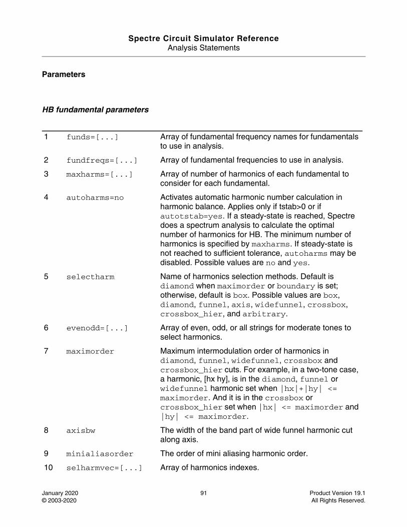
Spectre Circuit Simulator ReferenceAnalysis Statements
January 2020 91 Product Version 19.1© 2003-2020 All Rights Reserved.
Parameters
HB fundamental parameters
1 funds=[...] Array of fundamental frequency names for fundamentals to use in analysis.
2 fundfreqs=[...] Array of fundamental frequencies to use in analysis.
3 maxharms=[...] Array of number of harmonics of each fundamental to consider for each fundamental.
4 autoharms=no Activates automatic harmonic number calculation in harmonic balance. Applies only if tstab>0 or if autotstab=yes. If a steady-state is reached, Spectre does a spectrum analysis to calculate the optimal number of harmonics for HB. The minimum number of harmonics is specified by maxharms. If steady-state is not reached to sufficient tolerance, autoharms may be disabled. Possible values are no and yes.
5 selectharm Name of harmonics selection methods. Default is diamond when maximorder or boundary is set; otherwise, default is box. Possible values are box, diamond, funnel, axis, widefunnel, crossbox, crossbox_hier, and arbitrary.
6 evenodd=[...] Array of even, odd, or all strings for moderate tones to select harmonics.
7 maximorder Maximum intermodulation order of harmonics in diamond, funnel, widefunnel, crossbox and crossbox_hier cuts. For example, in a two-tone case, a harmonic, [hx hy], is in the diamond, funnel or widefunnel harmonic set when |hx|+|hy| <= maximorder. And it is in the crossbox or crossbox_hier set when |hx| <= maximorder and |hy| <= maximorder.
8 axisbw The width of the band part of wide funnel harmonic cut along axis.
9 minialiasorder The order of mini aliasing harmonic order.
10 selharmvec=[...] Array of harmonics indexes.
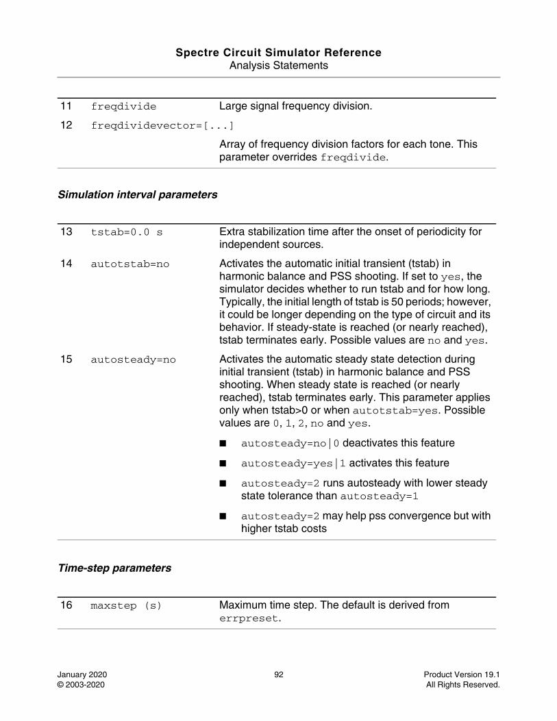
Spectre Circuit Simulator ReferenceAnalysis Statements
January 2020 92 Product Version 19.1© 2003-2020 All Rights Reserved.
Simulation interval parameters
Time-step parameters
11 freqdivide Large signal frequency division.
12 freqdividevector=[...]
Array of frequency division factors for each tone. This parameter overrides freqdivide.
13 tstab=0.0 s Extra stabilization time after the onset of periodicity for independent sources.
14 autotstab=no Activates the automatic initial transient (tstab) in harmonic balance and PSS shooting. If set to yes, the simulator decides whether to run tstab and for how long. Typically, the initial length of tstab is 50 periods; however, it could be longer depending on the type of circuit and its behavior. If steady-state is reached (or nearly reached), tstab terminates early. Possible values are no and yes.
15 autosteady=no Activates the automatic steady state detection during initial transient (tstab) in harmonic balance and PSS shooting. When steady state is reached (or nearly reached), tstab terminates early. This parameter applies only when tstab>0 or when autotstab=yes. Possible values are 0, 1, 2, no and yes.
■ autosteady=no|0 deactivates this feature
■ autosteady=yes|1 activates this feature
■ autosteady=2 runs autosteady with lower steady state tolerance than autosteady=1
■ autosteady=2 may help pss convergence but with higher tstab costs
16 maxstep (s) Maximum time step. The default is derived from errpreset.
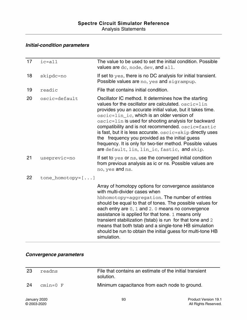
Spectre Circuit Simulator ReferenceAnalysis Statements
January 2020 93 Product Version 19.1© 2003-2020 All Rights Reserved.
Initial-condition parameters
Convergence parameters
17 ic=all The value to be used to set the initial condition. Possible values are dc, node, dev, and all.
18 skipdc=no If set to yes, there is no DC analysis for initial transient. Possible values are no, yes and sigrampup.
19 readic File that contains initial condition.
20 oscic=default Oscillator IC method. It determines how the starting values for the oscillator are calculated. oscic=lin provides you an accurate initial value, but it takes time. oscic=lin_ic, which is an older version of oscic=lin is used for shooting analysis for backward compatibility and is not recommended. oscic=fastic is fast, but it is less accurate. oscic=skip directly uses the frequency you provided as the initial guess frequency. It is only for two-tier method. Possible values are default, lin, lin_ic, fastic, and skip.
21 useprevic=no If set to yes or ns, use the converged initial condition from previous analysis as ic or ns. Possible values are no, yes and ns.
22 tone_homotopy=[...]
Array of homotopy options for convergence assistance with multi-divider cases when hbhomotopy=aggregation. The number of entries should be equal to that of tones. The possible values for each entry are 0, 1 and 2. 0 means no convergence assistance is applied for that tone. 1 means only transient stabilization (tstab) is run for that tone and 2 means that both tstab and a single-tone HB simulation should be run to obtain the initial guess for multi-tone HB simulation.
23 readns File that contains an estimate of the initial transient solution.
24 cmin=0 F Minimum capacitance from each node to ground.
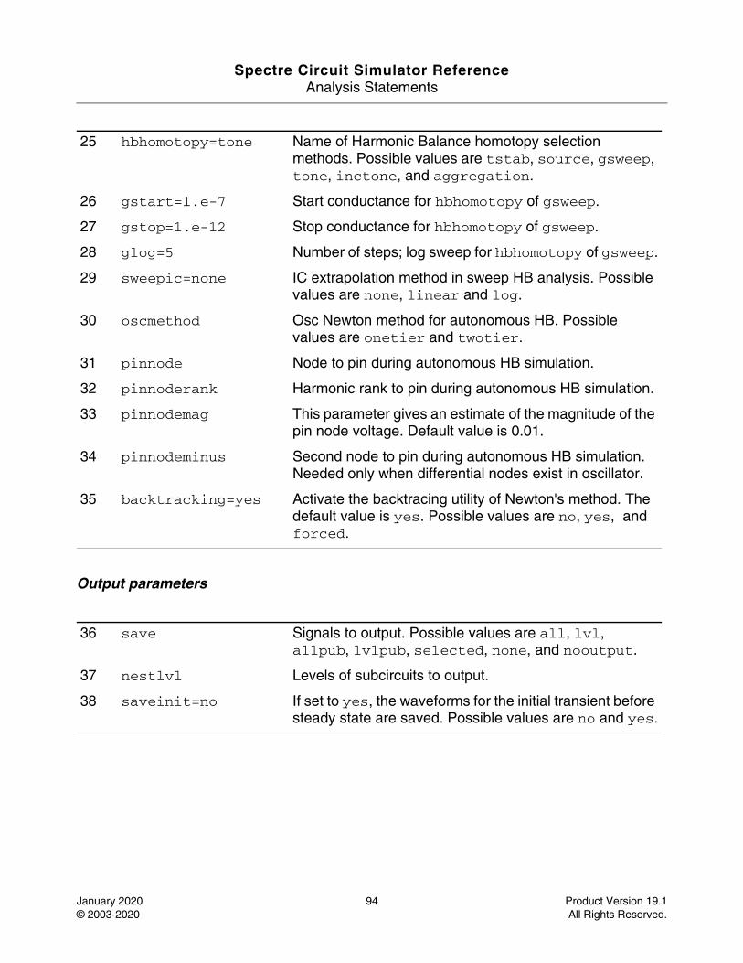
Spectre Circuit Simulator ReferenceAnalysis Statements
January 2020 94 Product Version 19.1© 2003-2020 All Rights Reserved.
Output parameters
25 hbhomotopy=tone Name of Harmonic Balance homotopy selection methods. Possible values are tstab, source, gsweep, tone, inctone, and aggregation.
26 gstart=1.e-7 Start conductance for hbhomotopy of gsweep.
27 gstop=1.e-12 Stop conductance for hbhomotopy of gsweep.
28 glog=5 Number of steps; log sweep for hbhomotopy of gsweep.
29 sweepic=none IC extrapolation method in sweep HB analysis. Possible values are none, linear and log.
30 oscmethod Osc Newton method for autonomous HB. Possible values are onetier and twotier.
31 pinnode Node to pin during autonomous HB simulation.
32 pinnoderank Harmonic rank to pin during autonomous HB simulation.
33 pinnodemag This parameter gives an estimate of the magnitude of the pin node voltage. Default value is 0.01.
34 pinnodeminus Second node to pin during autonomous HB simulation. Needed only when differential nodes exist in oscillator.
35 backtracking=yes Activate the backtracing utility of Newton's method. The default value is yes. Possible values are no, yes, and forced.
36 save Signals to output. Possible values are all, lvl, allpub, lvlpub, selected, none, and nooutput.
37 nestlvl Levels of subcircuits to output.
38 saveinit=no If set to yes, the waveforms for the initial transient before steady state are saved. Possible values are no and yes.
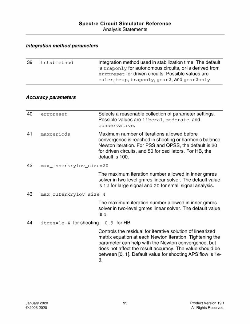
Spectre Circuit Simulator ReferenceAnalysis Statements
January 2020 95 Product Version 19.1© 2003-2020 All Rights Reserved.
Integration method parameters
Accuracy parameters
39 tstabmethod Integration method used in stabilization time. The default is traponly for autonomous circuits, or is derived from errpreset for driven circuits. Possible values are euler, trap, traponly, gear2, and gear2only.
40 errpreset Selects a reasonable collection of parameter settings. Possible values are liberal, moderate, and conservative.
41 maxperiods Maximum number of iterations allowed before convergence is reached in shooting or harmonic balance Newton iteration. For PSS and QPSS, the default is 20 for driven circuits, and 50 for oscillators. For HB, the default is 100.
42 max_innerkrylov_size=20
The maximum iteration number allowed in inner gmres solver in two-level gmres linear solver. The default value is 12 for large signal and 20 for small signal analysis.
43 max_outerkrylov_size=4
The maximum iteration number allowed in inner gmres solver in two-level gmres linear solver. The default value is 4.
44 itres=1e-4 for shooting, 0.9 for HB
Controls the residual for iterative solution of linearized matrix equation at each Newton iteration. Tightening the parameter can help with the Newton convergence, but does not affect the result accuracy. The value should be between [0, 1]. Default value for shooting APS flow is 1e-3.
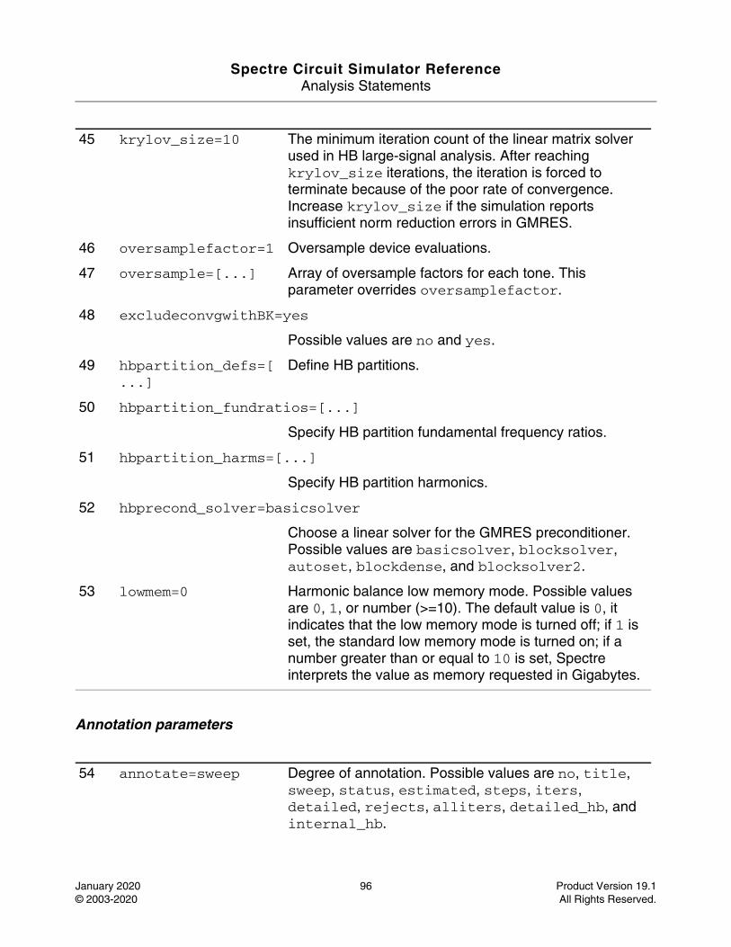
Spectre Circuit Simulator ReferenceAnalysis Statements
January 2020 96 Product Version 19.1© 2003-2020 All Rights Reserved.
Annotation parameters
45 krylov_size=10 The minimum iteration count of the linear matrix solver used in HB large-signal analysis. After reaching krylov_size iterations, the iteration is forced to terminate because of the poor rate of convergence. Increase krylov_size if the simulation reports insufficient norm reduction errors in GMRES.
46 oversamplefactor=1 Oversample device evaluations.
47 oversample=[...] Array of oversample factors for each tone. This parameter overrides oversamplefactor.
48 excludeconvgwithBK=yes
Possible values are no and yes.
49 hbpartition_defs=[...]
Define HB partitions.
50 hbpartition_fundratios=[...]
Specify HB partition fundamental frequency ratios.
51 hbpartition_harms=[...]
Specify HB partition harmonics.
52 hbprecond_solver=basicsolver
Choose a linear solver for the GMRES preconditioner. Possible values are basicsolver, blocksolver, autoset, blockdense, and blocksolver2.
53 lowmem=0 Harmonic balance low memory mode. Possible values are 0, 1, or number (>=10). The default value is 0, it indicates that the low memory mode is turned off; if 1 is set, the standard low memory mode is turned on; if a number greater than or equal to 10 is set, Spectre interprets the value as memory requested in Gigabytes.
54 annotate=sweep Degree of annotation. Possible values are no, title, sweep, status, estimated, steps, iters, detailed, rejects, alliters, detailed_hb, and internal_hb.
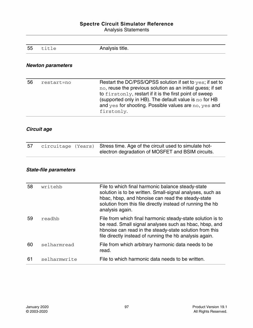
Spectre Circuit Simulator ReferenceAnalysis Statements
January 2020 97 Product Version 19.1© 2003-2020 All Rights Reserved.
Newton parameters
Circuit age
State-file parameters
55 title Analysis title.
56 restart=no Restart the DC/PSS/QPSS solution if set to yes; if set to no, reuse the previous solution as an initial guess; if set to firstonly, restart if it is the first point of sweep (supported only in HB). The default value is no for HB and yes for shooting. Possible values are no, yes and firstonly.
57 circuitage (Years) Stress time. Age of the circuit used to simulate hot-electron degradation of MOSFET and BSIM circuits.
58 writehb File to which final harmonic balance steady-state solution is to be written. Small-signal analyses, such as hbac, hbsp, and hbnoise can read the steady-state solution from this file directly instead of running the hb analysis again.
59 readhb File from which final harmonic steady-state solution is to be read. Small signal analyses such as hbac, hbsp, and hbnoise can read in the steady-state solution from this file directly instead of running the hb analysis again.
60 selharmread File from which arbitrary harmonic data needs to be read.
61 selharmwrite File to which harmonic data needs to be written.
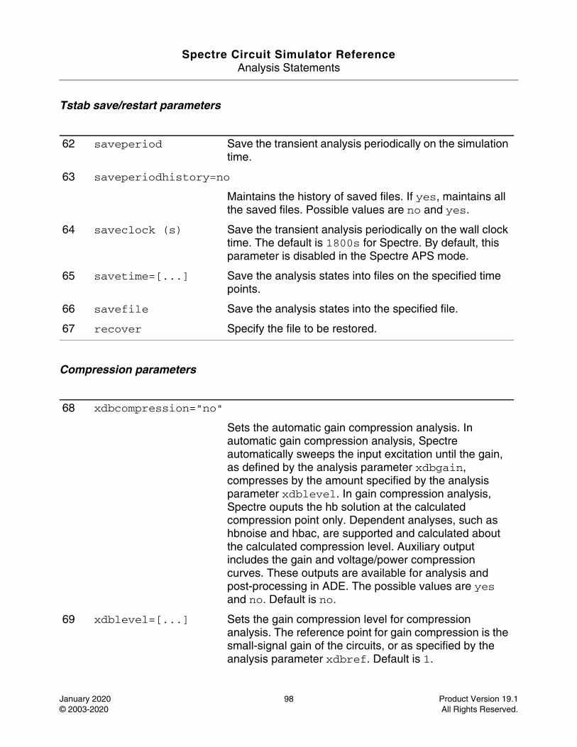
Spectre Circuit Simulator ReferenceAnalysis Statements
January 2020 98 Product Version 19.1© 2003-2020 All Rights Reserved.
Tstab save/restart parameters
Compression parameters
62 saveperiod Save the transient analysis periodically on the simulation time.
63 saveperiodhistory=no
Maintains the history of saved files. If yes, maintains all the saved files. Possible values are no and yes.
64 saveclock (s) Save the transient analysis periodically on the wall clock time. The default is 1800s for Spectre. By default, this parameter is disabled in the Spectre APS mode.
65 savetime=[...] Save the analysis states into files on the specified time points.
66 savefile Save the analysis states into the specified file.
67 recover Specify the file to be restored.
68 xdbcompression="no"
Sets the automatic gain compression analysis. In automatic gain compression analysis, Spectre automatically sweeps the input excitation until the gain, as defined by the analysis parameter xdbgain, compresses by the amount specified by the analysis parameter xdblevel. In gain compression analysis, Spectre ouputs the hb solution at the calculated compression point only. Dependent analyses, such as hbnoise and hbac, are supported and calculated about the calculated compression level. Auxiliary output includes the gain and voltage/power compression curves. These outputs are available for analysis and post-processing in ADE. The possible values are yes and no. Default is no.
69 xdblevel=[...] Sets the gain compression level for compression analysis. The reference point for gain compression is the small-signal gain of the circuits, or as specified by the analysis parameter xdbref. Default is 1.
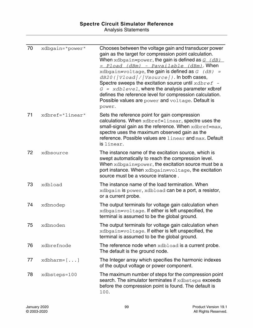
Spectre Circuit Simulator ReferenceAnalysis Statements
January 2020 99 Product Version 19.1© 2003-2020 All Rights Reserved.
70 xdbgain="power" Chooses between the voltage gain and transducer power gain as the target for compression point calculation. When xdbgain=power, the gain is defined as G (dB) = Pload (dBm) - Pavailable (dBm). When xdbgain=voltage, the gain is defined as G (dB) = dB20(|Vload|/|Vsource|). In both cases, Spectre sweeps the excitation source until xdbref - G = xdblevel, where the analysis parameter xdbref defines the reference level for compression calculation. Possible values are power and voltage. Default is power.
71 xdbref="linear" Sets the reference point for gain compression calculations. When xdbref=linear, spectre uses the small-signal gain as the reference. When xdbref=max, spectre uses the maximum observed gain as the reference. Possible values are linear and max. Default is linear.
72 xdbsource The instance name of the excitation source, which is swept automatically to reach the compression level. When xdbgain=power, the excitation source must be a port instance. When xdbgain=voltage, the excitation source must be a vsource instance .
73 xdbload The instance name of the load termination. When xdbgain is power, xdbload can be a port, a resistor, or a current probe.
74 xdbnodep The output terminals for voltage gain calculation when xdbgain=voltage. If either is left unspecified, the terminal is assumed to be the global ground.
75 xdbnoden The output terminals for voltage gain calculation when xdbgain=voltage. If either is left unspecified, the terminal is assumed to be the global ground.
76 xdbrefnode The reference node when xdbload is a current probe. The default is the ground node.
77 xdbharm=[...] The Integer array which specifies the harmonic indexes of the output voltage or power component.
78 xdbsteps=100 The maximum number of steps for the compression point search. The simulator terminates if xdbsteps exceeds before the compression point is found. The default is 100.
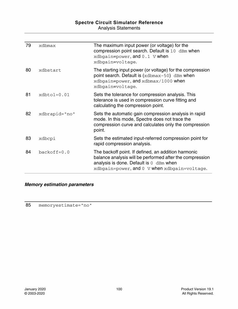
Spectre Circuit Simulator ReferenceAnalysis Statements
January 2020 100 Product Version 19.1© 2003-2020 All Rights Reserved.
Memory estimation parameters
79 xdbmax The maximum input power (or voltage) for the compression point search. Default is 10 dBm when xdbgain=power, and 0.1 V when xdbgain=voltage.
80 xdbstart The starting input power (or voltage) for the compression point search. Default is (xdbmax-50) dBm when xdbgain=power, and xdbmax/1000 when xdbgain=voltage.
81 xdbtol=0.01 Sets the tolerance for compression analysis. This tolerance is used in compression curve fitting and calculating the compression point.
82 xdbrapid="no" Sets the automatic gain compression analysis in rapid mode. In this mode, Spectre does not trace the compression curve and calculates only the compression point.
83 xdbcpi Sets the estimated input-referred compression point for rapid compression analysis.
84 backoff=0.0 The backoff point. If defined, an addition harmonic balance analysis will be performed after the compression analysis is done. Default is 0 dBm when xdbgain=power, and 0 V when xdbgain=voltage.
85 memoryestimate="no"
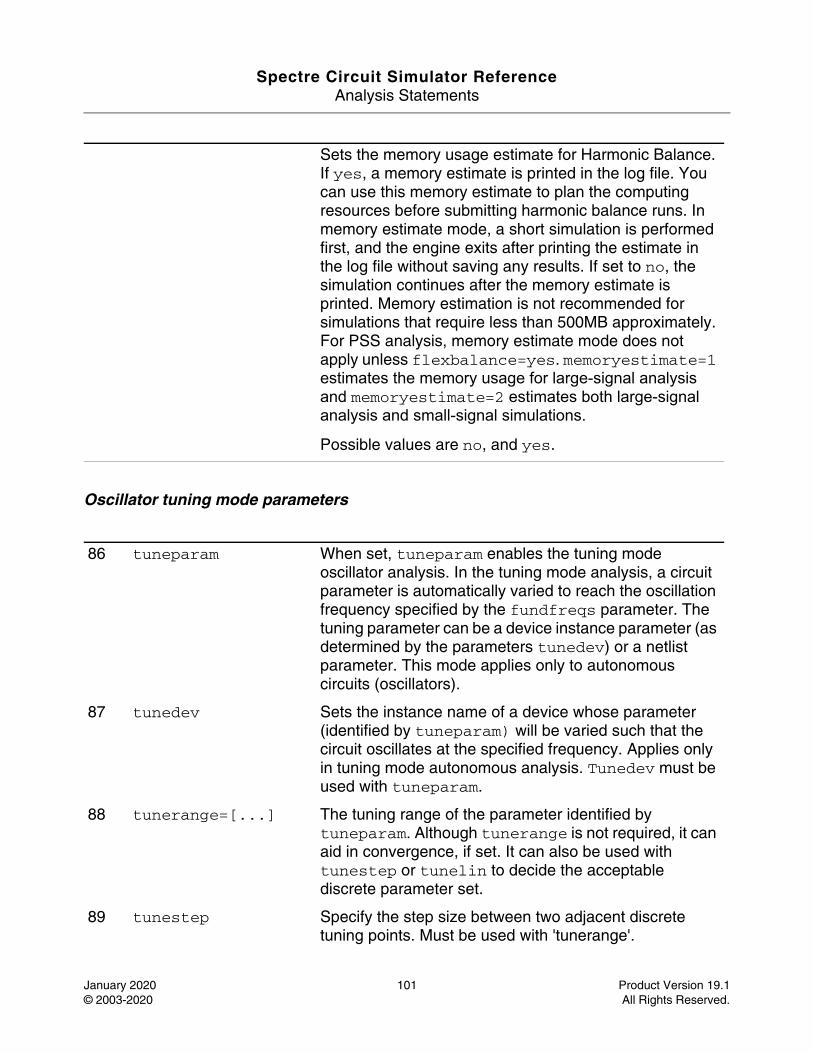
Spectre Circuit Simulator ReferenceAnalysis Statements
January 2020 101 Product Version 19.1© 2003-2020 All Rights Reserved.
Oscillator tuning mode parameters
Sets the memory usage estimate for Harmonic Balance. If yes, a memory estimate is printed in the log file. You can use this memory estimate to plan the computing resources before submitting harmonic balance runs. In memory estimate mode, a short simulation is performed first, and the engine exits after printing the estimate in the log file without saving any results. If set to no, the simulation continues after the memory estimate is printed. Memory estimation is not recommended for simulations that require less than 500MB approximately. For PSS analysis, memory estimate mode does not apply unless flexbalance=yes. memoryestimate=1 estimates the memory usage for large-signal analysis and memoryestimate=2 estimates both large-signal analysis and small-signal simulations.
Possible values are no, and yes.
86 tuneparam When set, tuneparam enables the tuning mode oscillator analysis. In the tuning mode analysis, a circuit parameter is automatically varied to reach the oscillation frequency specified by the fundfreqs parameter. The tuning parameter can be a device instance parameter (as determined by the parameters tunedev) or a netlist parameter. This mode applies only to autonomous circuits (oscillators).
87 tunedev Sets the instance name of a device whose parameter (identified by tuneparam) will be varied such that the circuit oscillates at the specified frequency. Applies only in tuning mode autonomous analysis. Tunedev must be used with tuneparam.
88 tunerange=[...] The tuning range of the parameter identified by tuneparam. Although tunerange is not required, it can aid in convergence, if set. It can also be used with tunestep or tunelin to decide the acceptable discrete parameter set.
89 tunestep Specify the step size between two adjacent discrete tuning points. Must be used with 'tunerange'.
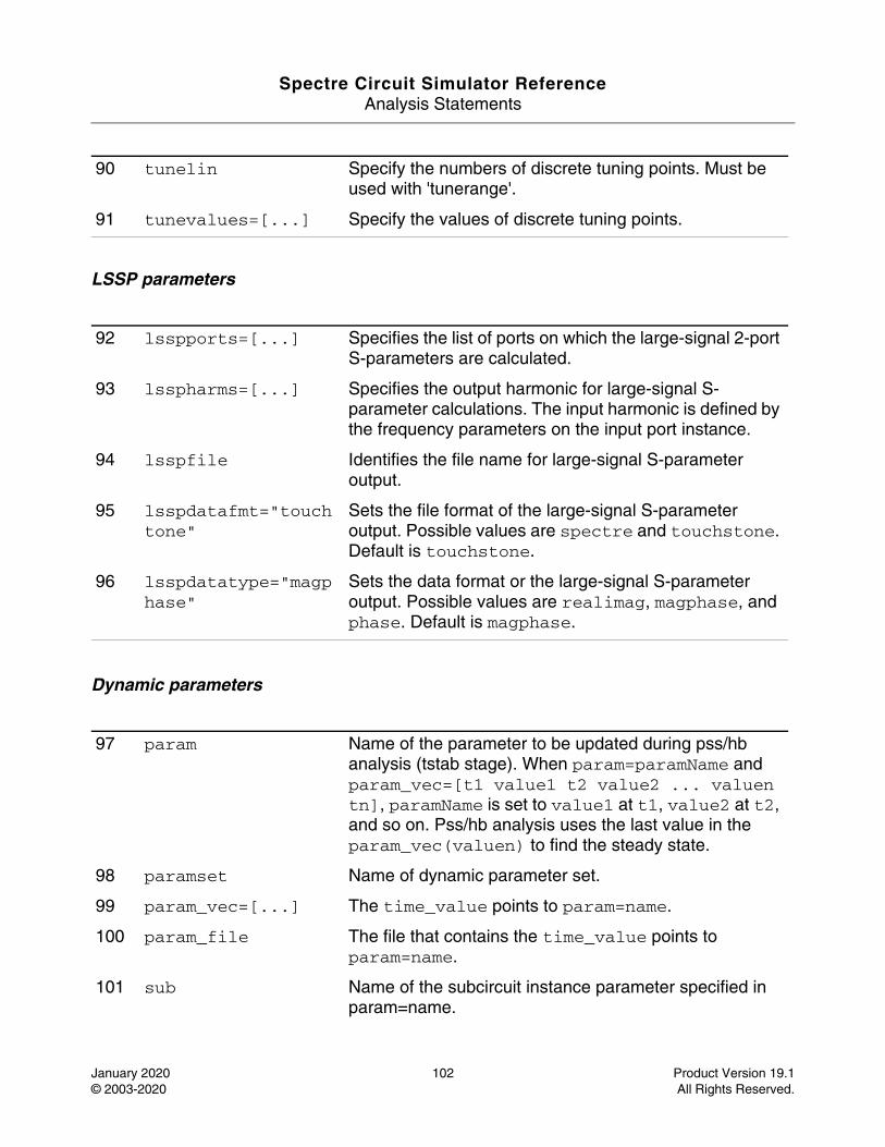
Spectre Circuit Simulator ReferenceAnalysis Statements
January 2020 102 Product Version 19.1© 2003-2020 All Rights Reserved.
LSSP parameters
Dynamic parameters
90 tunelin Specify the numbers of discrete tuning points. Must be used with 'tunerange'.
91 tunevalues=[...] Specify the values of discrete tuning points.
92 lsspports=[...] Specifies the list of ports on which the large-signal 2-port S-parameters are calculated.
93 lsspharms=[...] Specifies the output harmonic for large-signal S-parameter calculations. The input harmonic is defined by the frequency parameters on the input port instance.
94 lsspfile Identifies the file name for large-signal S-parameter output.
95 lsspdatafmt="touchtone"
Sets the file format of the large-signal S-parameter output. Possible values are spectre and touchstone. Default is touchstone.
96 lsspdatatype="magphase"
Sets the data format or the large-signal S-parameter output. Possible values are realimag, magphase, and phase. Default is magphase.
97 param Name of the parameter to be updated during pss/hb analysis (tstab stage). When param=paramName and param_vec=[t1 value1 t2 value2 ... valuen tn], paramName is set to value1 at t1, value2 at t2, and so on. Pss/hb analysis uses the last value in the param_vec(valuen) to find the steady state.
98 paramset Name of dynamic parameter set.
99 param_vec=[...] The time_value points to param=name.
100 param_file The file that contains the time_value points to param=name.
101 sub Name of the subcircuit instance parameter specified in param=name.
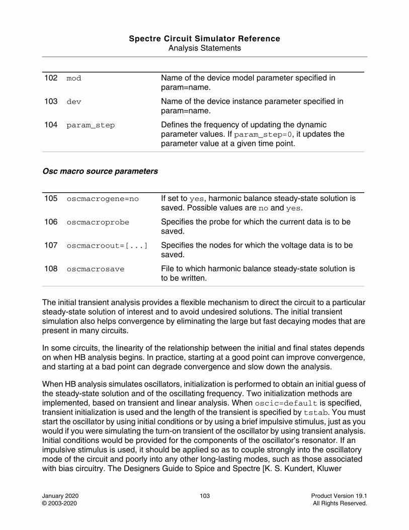
Spectre Circuit Simulator ReferenceAnalysis Statements
January 2020 103 Product Version 19.1© 2003-2020 All Rights Reserved.
Osc macro source parameters
The initial transient analysis provides a flexible mechanism to direct the circuit to a particular steady-state solution of interest and to avoid undesired solutions. The initial transient simulation also helps convergence by eliminating the large but fast decaying modes that are present in many circuits.
In some circuits, the linearity of the relationship between the initial and final states depends on when HB analysis begins. In practice, starting at a good point can improve convergence, and starting at a bad point can degrade convergence and slow down the analysis.
When HB analysis simulates oscillators, initialization is performed to obtain an initial guess of the steady-state solution and of the oscillating frequency. Two initialization methods are implemented, based on transient and linear analysis. When oscic=default is specified, transient initialization is used and the length of the transient is specified by tstab. You must start the oscillator by using initial conditions or by using a brief impulsive stimulus, just as you would if you were simulating the turn-on transient of the oscillator by using transient analysis. Initial conditions would be provided for the components of the oscillator’s resonator. If an impulsive stimulus is used, it should be applied so as to couple strongly into the oscillatory mode of the circuit and poorly into any other long-lasting modes, such as those associated with bias circuitry. The Designers Guide to Spice and Spectre [K. S. Kundert, Kluwer
102 mod Name of the device model parameter specified in param=name.
103 dev Name of the device instance parameter specified in param=name.
104 param_step Defines the frequency of updating the dynamic parameter values. If param_step=0, it updates the parameter value at a given time point.
105 oscmacrogene=no If set to yes, harmonic balance steady-state solution is saved. Possible values are no and yes.
106 oscmacroprobe Specifies the probe for which the current data is to be saved.
107 oscmacroout=[...] Specifies the nodes for which the voltage data is to be saved.
108 oscmacrosave File to which harmonic balance steady-state solution is to be written.
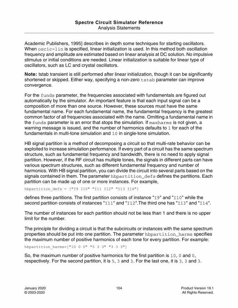
Spectre Circuit Simulator ReferenceAnalysis Statements
January 2020 104 Product Version 19.1© 2003-2020 All Rights Reserved.
Academic Publishers, 1995] describes in depth some techniques for starting oscillators. When oscic=lin is specified, linear initialization is used. In this method both oscillation frequency and amplitude are estimated based on linear analysis at DC solution. No impulsive stimulus or initial conditions are needed. Linear initialization is suitable for linear type of oscillators, such as LC and crystal oscillators.
Note: tstab transient is still performed after linear initialization, though it can be significantly shortened or skipped. Either way, specifying a non-zero tstab parameter can improve convergence.
For the funds parameter, the frequencies associated with fundamentals are figured out automatically by the simulator. An important feature is that each input signal can be a composition of more than one source. However, these sources must have the same fundamental name. For each fundamental name, the fundamental frequency is the greatest common factor of all frequencies associated with the name. Omitting a fundamental name in the funds parameter is an error that stops the simulation. If maxharms is not given, a warning message is issued, and the number of harmonics defaults to 1 for each of the fundamentals in multi-tone simulation and 10 in single-tone simulation.
HB signal partition is a method of decomposing a circuit so that multi-rate behavior can be exploited to increase simulation performance. If every part of a circuit has the same spectrum structure, such as fundamental frequency and bandwidth, there is no need to apply signal partition. However, if the RF circuit has multiple tones, the signals in different parts can have various spectrum structures, such as different fundamental frequency and number of harmonics. With HB signal partition, you can divide the circuit into several parts based on the signals contained in them. The parameter hbpartition_defs defines the partitions. Each partition can be made up of one or more instances. For example,
hbpartition_defs = ["I9 I10" "I11 I12" "I13 I14"]
defines three partitions. The first partition consists of instance "I9" and "I10" while the second partition consists of instances "I11" and "I12".The third one has "I13" and "I14".
The number of instances for each partition should not be less than 1 and there is no upper limit for the number.
The principle for dividing a circuit is that the subcircuits or instances with the same spectrum properties should be put into one partition. The parameter hbpartition_harms specifies the maximum number of positive harmonics of each tone for every partition. For example:
hbpartition_harms=["10 0 0" "5 3 3" "3 3 3"]
So, the maximum number of positive harmonics for the first partition is 10, 0 and 0, respectively. For the second partition, it is 5, 3 and 3. For the last one, it is 3, 3 and 3.

Spectre Circuit Simulator ReferenceAnalysis Statements
January 2020 105 Product Version 19.1© 2003-2020 All Rights Reserved.
The parameter hbpartition_fundratios indicates the fundamental frequency ratio of each tone for each partition. With these ratios, it is easy to know the fundamental frequencies of each tone of the partitions. For example:
hbpartition_fundratios=["2 1 1" "1 1 1" "1 1 1"]
If three global fundamental frequencies are defined as: LO=1GHz, RF1=1.1GHz and RF2=1.13GHz, it indicates the fundamental frequencies of each tone of the first partition is 2*LO, 1*RF1, and 1*RF2, respectively. The second and third partition has the same frequencies for their each tone: 1*LO, 1*RF1 and 1*RF2. However, you have to make sure that the global fundamental frequencies for each tone are the smallest among all the partitions and the ratios are integers.
The parameter maxperiods default value is set to 50 for HB.
The errpreset parameter lets you adjust the simulator parameters to fit your needs quickly. In most cases, it should also be the only parameter you need to adjust. If you want a fast simulation with reasonable accuracy, you can set errpreset to liberal (it is not recommended to use liberal on an RF circuit). If you have some concern for accuracy, you can set errpreset to moderate. If accuracy is your main interest, you can set errpreset to conservative.
The following table shows the effect of errpreset on other parameters in HB with One-tone Driven Circuits, Multi-tone Driven Circuits and Autonomous Circuits:
Parameter defaults as a function of errpreset with different circuits
* : lteratio=10.0 for conservative errpreset by default. However, when the option reltol <= 1e-4*10.0/3.5, lteratio is set to 3.5 for one-tone driven circuits and when the option reltol <= 1e-5*10.0/3.5, lteratio is set to 3.5 for multi-tone driven circuits and autonomous circuits.
The values of reltol are usually different in the tstab interval and in the hb interval. During tstab, reltol is set to the option reltol, whose default value is 1e-3. This part is not impacted by errpreset. If you want to change the value, set reltol in Spectre options. Any value more than 1e-3 is ignored.
One-tone Driven Circuits Multi-tone Driven Circuits and Autonomous Circuits
errpreset reltol (max) lteratio reltol (max) lteratio
liberal 1e-3 3.5 1e-3 3.5
moderate 1e-3 3.5 1e-4 3.5
conservative 1e-4 * 1e-5 *
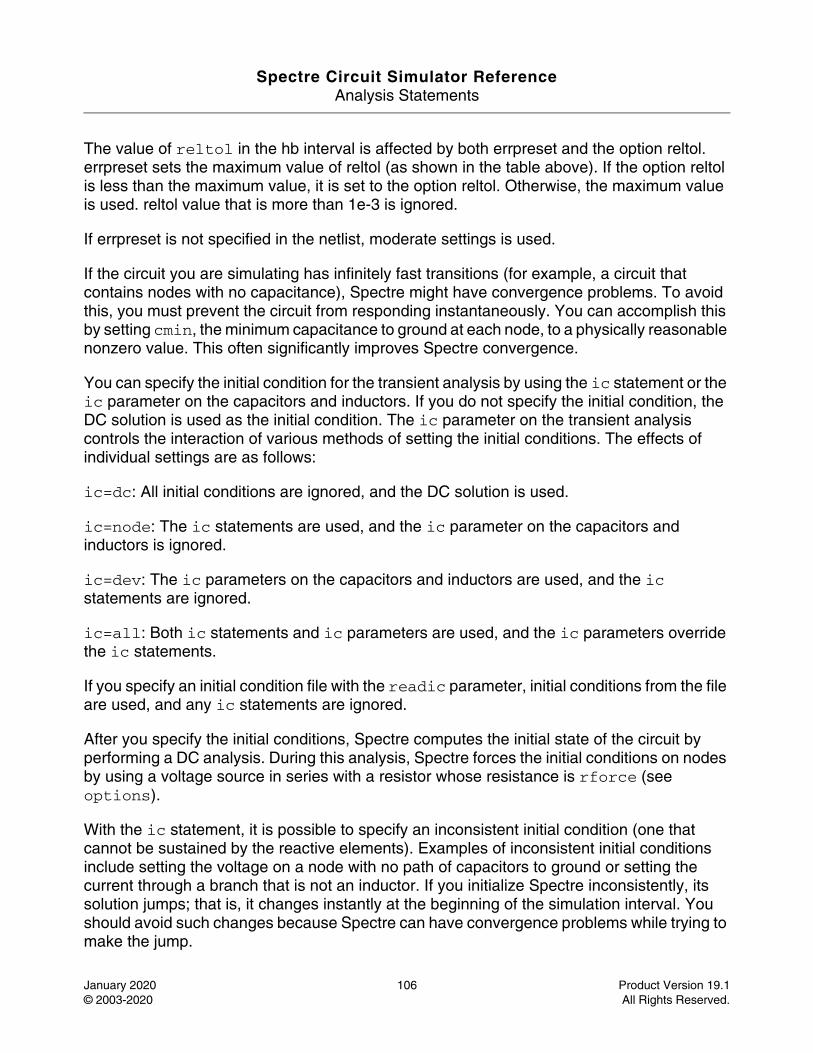
Spectre Circuit Simulator ReferenceAnalysis Statements
January 2020 106 Product Version 19.1© 2003-2020 All Rights Reserved.
The value of reltol in the hb interval is affected by both errpreset and the option reltol. errpreset sets the maximum value of reltol (as shown in the table above). If the option reltol is less than the maximum value, it is set to the option reltol. Otherwise, the maximum value is used. reltol value that is more than 1e-3 is ignored.
If errpreset is not specified in the netlist, moderate settings is used.
If the circuit you are simulating has infinitely fast transitions (for example, a circuit that contains nodes with no capacitance), Spectre might have convergence problems. To avoid this, you must prevent the circuit from responding instantaneously. You can accomplish this by setting cmin, the minimum capacitance to ground at each node, to a physically reasonable nonzero value. This often significantly improves Spectre convergence.
You can specify the initial condition for the transient analysis by using the ic statement or the ic parameter on the capacitors and inductors. If you do not specify the initial condition, the DC solution is used as the initial condition. The ic parameter on the transient analysis controls the interaction of various methods of setting the initial conditions. The effects of individual settings are as follows:
ic=dc: All initial conditions are ignored, and the DC solution is used.
ic=node: The ic statements are used, and the ic parameter on the capacitors and inductors is ignored.
ic=dev: The ic parameters on the capacitors and inductors are used, and the ic statements are ignored.
ic=all: Both ic statements and ic parameters are used, and the ic parameters override the ic statements.
If you specify an initial condition file with the readic parameter, initial conditions from the file are used, and any ic statements are ignored.
After you specify the initial conditions, Spectre computes the initial state of the circuit by performing a DC analysis. During this analysis, Spectre forces the initial conditions on nodes by using a voltage source in series with a resistor whose resistance is rforce (see options).
With the ic statement, it is possible to specify an inconsistent initial condition (one that cannot be sustained by the reactive elements). Examples of inconsistent initial conditions include setting the voltage on a node with no path of capacitors to ground or setting the current through a branch that is not an inductor. If you initialize Spectre inconsistently, its solution jumps; that is, it changes instantly at the beginning of the simulation interval. You should avoid such changes because Spectre can have convergence problems while trying to make the jump.
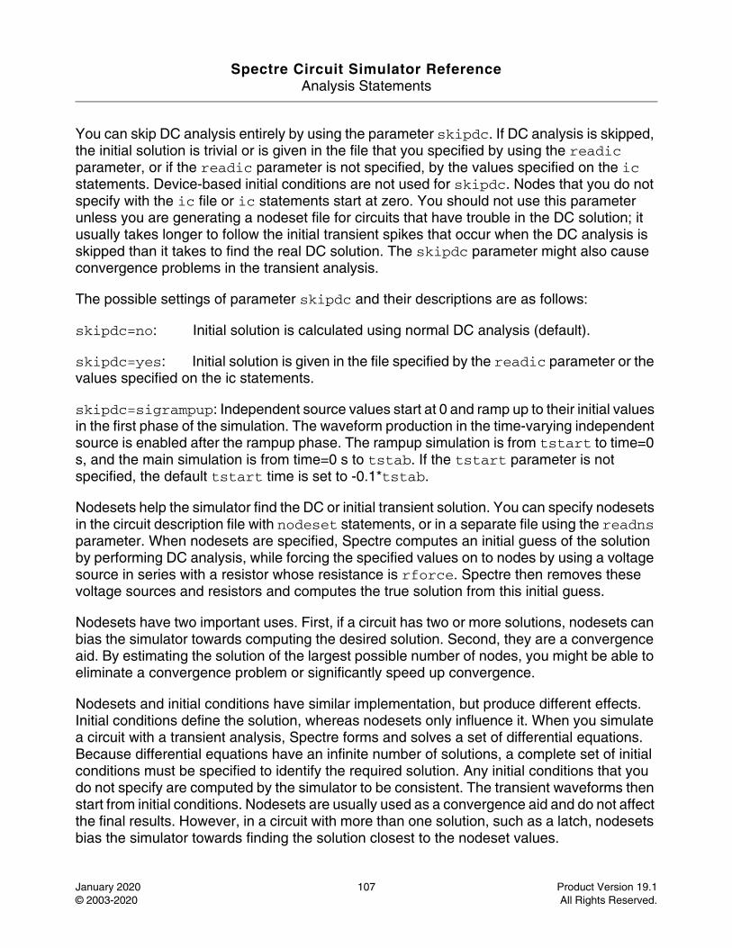
Spectre Circuit Simulator ReferenceAnalysis Statements
January 2020 107 Product Version 19.1© 2003-2020 All Rights Reserved.
You can skip DC analysis entirely by using the parameter skipdc. If DC analysis is skipped, the initial solution is trivial or is given in the file that you specified by using the readic parameter, or if the readic parameter is not specified, by the values specified on the ic statements. Device-based initial conditions are not used for skipdc. Nodes that you do not specify with the ic file or ic statements start at zero. You should not use this parameter unless you are generating a nodeset file for circuits that have trouble in the DC solution; it usually takes longer to follow the initial transient spikes that occur when the DC analysis is skipped than it takes to find the real DC solution. The skipdc parameter might also cause convergence problems in the transient analysis.
The possible settings of parameter skipdc and their descriptions are as follows:
skipdc=no: Initial solution is calculated using normal DC analysis (default).
skipdc=yes: Initial solution is given in the file specified by the readic parameter or the values specified on the ic statements.
skipdc=sigrampup: Independent source values start at 0 and ramp up to their initial values in the first phase of the simulation. The waveform production in the time-varying independent source is enabled after the rampup phase. The rampup simulation is from tstart to time=0 s, and the main simulation is from time=0 s to tstab. If the tstart parameter is not specified, the default tstart time is set to -0.1*tstab.
Nodesets help the simulator find the DC or initial transient solution. You can specify nodesets in the circuit description file with nodeset statements, or in a separate file using the readns parameter. When nodesets are specified, Spectre computes an initial guess of the solution by performing DC analysis, while forcing the specified values on to nodes by using a voltage source in series with a resistor whose resistance is rforce. Spectre then removes these voltage sources and resistors and computes the true solution from this initial guess.
Nodesets have two important uses. First, if a circuit has two or more solutions, nodesets can bias the simulator towards computing the desired solution. Second, they are a convergence aid. By estimating the solution of the largest possible number of nodes, you might be able to eliminate a convergence problem or significantly speed up convergence.
Nodesets and initial conditions have similar implementation, but produce different effects. Initial conditions define the solution, whereas nodesets only influence it. When you simulate a circuit with a transient analysis, Spectre forms and solves a set of differential equations. Because differential equations have an infinite number of solutions, a complete set of initial conditions must be specified to identify the required solution. Any initial conditions that you do not specify are computed by the simulator to be consistent. The transient waveforms then start from initial conditions. Nodesets are usually used as a convergence aid and do not affect the final results. However, in a circuit with more than one solution, such as a latch, nodesets bias the simulator towards finding the solution closest to the nodeset values.
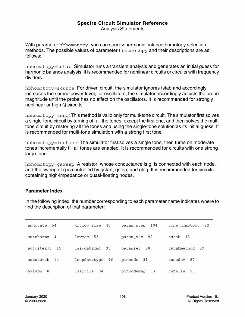
Spectre Circuit Simulator ReferenceAnalysis Statements
January 2020 108 Product Version 19.1© 2003-2020 All Rights Reserved.
With parameter hbhomotopy, you can specify harmonic balance homotopy selection methods. The possible values of parameter hbhomotopy and their descriptions are as follows:
hbhomotopy=tstab: Simulator runs a transient analysis and generates an initial guess for harmonic balance analysis; it is recommended for nonlinear circuits or circuits with frequency dividers.
hbhomotopy=source: For driven circuit, the simulator ignores tstab and accordingly increases the source power level; for oscillators, the simulator accordingly adjusts the probe magnitude until the probe has no effect on the oscillators. It is recommended for strongly nonlinear or high Q circuits.
hbhomotopy=tone: This method is valid only for multi-tone circuit. The simulator first solves a single-tone circuit by turning off all the tones, except the first one, and then solves the multi-tone circuit by restoring all the tones and using the single-tone solution as its initial guess. It is recommended for multi-tone simulation with a strong first tone.
hbhomotopy=inctone: The simulator first solves a single tone, then turns on moderate tones incrementally till all tones are enabled. It is recommended for circuits with one strong large tone.
hbhomotopy=gsweep: A resistor, whose conductance is g, is connected with each node, and the sweep of g is controlled by gstart, gstop, and glog. It is recommended for circuits containing high-impedance or quasi-floating nodes.
Parameter Index
In the following index, the number corresponding to each parameter name indicates where to find the description of that parameter:
annotate 54 krylov_size 45 param_step 104 tone_homotopy 22
autoharms 4 lowmem 53 param_vec 99 tstab 13
autosteady 15 lsspdatafmt 95 paramset 98 tstabmethod 39
autotstab 14 lsspdatatype 96 pinnode 31 tunedev 87
axisbw 8 lsspfile 94 pinnodemag 33 tunelin 90
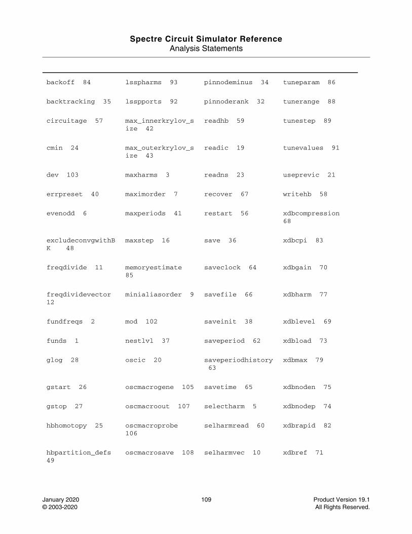
Spectre Circuit Simulator ReferenceAnalysis Statements
January 2020 109 Product Version 19.1© 2003-2020 All Rights Reserved.
backoff 84 lsspharms 93 pinnodeminus 34 tuneparam 86
backtracking 35 lsspports 92 pinnoderank 32 tunerange 88
circuitage 57 max_innerkrylov_size 42
readhb 59 tunestep 89
cmin 24 max_outerkrylov_size 43
readic 19 tunevalues 91
dev 103 maxharms 3 readns 23 useprevic 21
errpreset 40 maximorder 7 recover 67 writehb 58
evenodd 6 maxperiods 41 restart 56 xdbcompression 68
excludeconvgwithBK 48
maxstep 16 save 36 xdbcpi 83
freqdivide 11 memoryestimate 85
saveclock 64 xdbgain 70
freqdividevector 12
minialiasorder 9 savefile 66 xdbharm 77
fundfreqs 2 mod 102 saveinit 38 xdblevel 69
funds 1 nestlvl 37 saveperiod 62 xdbload 73
glog 28 oscic 20 saveperiodhistory 63
xdbmax 79
gstart 26 oscmacrogene 105 savetime 65 xdbnoden 75
gstop 27 oscmacroout 107 selectharm 5 xdbnodep 74
hbhomotopy 25 oscmacroprobe 106
selharmread 60 xdbrapid 82
hbpartition_defs 49
oscmacrosave 108 selharmvec 10 xdbref 71
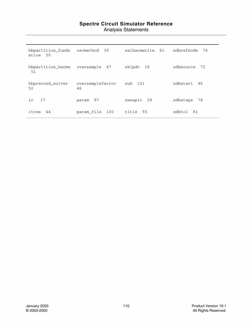
Spectre Circuit Simulator ReferenceAnalysis Statements
January 2020 110 Product Version 19.1© 2003-2020 All Rights Reserved.
hbpartition_fundratios 50
oscmethod 30 selharmwrite 61 xdbrefnode 76
hbpartition_harms 51
oversample 47 skipdc 18 xdbsource 72
hbprecond_solver 52
oversamplefactor 46
sub 101 xdbstart 80
ic 17 param 97 sweepic 29 xdbsteps 78
itres 44 param_file 100 title 55 xdbtol 81
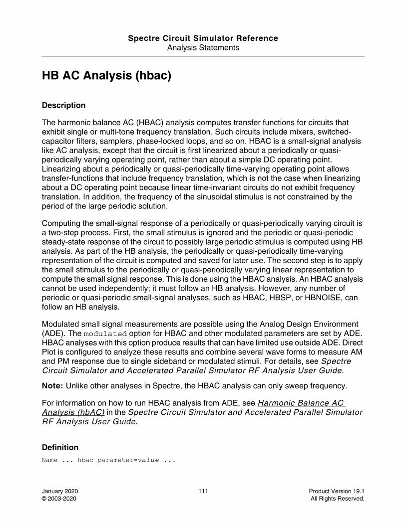
Spectre Circuit Simulator ReferenceAnalysis Statements
January 2020 111 Product Version 19.1© 2003-2020 All Rights Reserved.
HB AC Analysis (hbac)
Description
The harmonic balance AC (HBAC) analysis computes transfer functions for circuits that exhibit single or multi-tone frequency translation. Such circuits include mixers, switched-capacitor filters, samplers, phase-locked loops, and so on. HBAC is a small-signal analysis like AC analysis, except that the circuit is first linearized about a periodically or quasi-periodically varying operating point, rather than about a simple DC operating point. Linearizing about a periodically or quasi-periodically time-varying operating point allows transfer-functions that include frequency translation, which is not the case when linearizing about a DC operating point because linear time-invariant circuits do not exhibit frequency translation. In addition, the frequency of the sinusoidal stimulus is not constrained by the period of the large periodic solution.
Computing the small-signal response of a periodically or quasi-periodically varying circuit is a two-step process. First, the small stimulus is ignored and the periodic or quasi-periodic steady-state response of the circuit to possibly large periodic stimulus is computed using HB analysis. As part of the HB analysis, the periodically or quasi-periodically time-varying representation of the circuit is computed and saved for later use. The second step is to apply the small stimulus to the periodically or quasi-periodically varying linear representation to compute the small signal response. This is done using the HBAC analysis. An HBAC analysis cannot be used independently; it must follow an HB analysis. However, any number of periodic or quasi-periodic small-signal analyses, such as HBAC, HBSP, or HBNOISE, can follow an HB analysis.
Modulated small signal measurements are possible using the Analog Design Environment (ADE). The modulated option for HBAC and other modulated parameters are set by ADE. HBAC analyses with this option produce results that can have limited use outside ADE. Direct Plot is configured to analyze these results and combine several wave forms to measure AM and PM response due to single sideband or modulated stimuli. For details, see Spectre Circuit Simulator and Accelerated Parallel Simulator RF Analysis User Guide.
Note: Unlike other analyses in Spectre, the HBAC analysis can only sweep frequency.
For information on how to run HBAC analysis from ADE, see Harmonic Balance AC Analysis (hbAC) in the Spectre Circuit Simulator and Accelerated Parallel Simulator RF Analysis User Guide.
DefinitionName ... hbac parameter=value ...
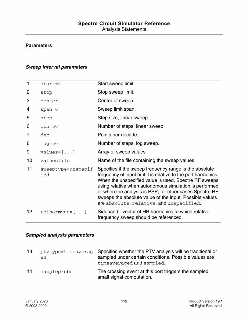
Spectre Circuit Simulator ReferenceAnalysis Statements
January 2020 112 Product Version 19.1© 2003-2020 All Rights Reserved.
Parameters
Sweep interval parameters
Sampled analysis parameters
1 start=0 Start sweep limit.
2 stop Stop sweep limit.
3 center Center of sweep.
4 span=0 Sweep limit span.
5 step Step size, linear sweep.
6 lin=50 Number of steps, linear sweep.
7 dec Points per decade.
8 log=50 Number of steps, log sweep.
9 values=[...] Array of sweep values.
10 valuesfile Name of the file containing the sweep values.
11 sweeptype=unspecified
Specifies if the sweep frequency range is the absolute frequency of input or if it is relative to the port harmonics. When the unspecified value is used, Spectre RF sweeps using relative when autonomous simulation is performed or when the analysis is PSP; for other cases Spectre RF sweeps the absolute value of the input. Possible values are absolute, relative, and unspecified.
12 relharmvec=[...] Sideband - vector of HB harmonics to which relative frequency sweep should be referenced.
13 ptvtype=timeaveraged
Specifies whether the PTV analysis will be traditional or sampled under certain conditions. Possible values are timeaveraged and sampled.
14 sampleprobe The crossing event at this port triggers the sampled small signal computation.
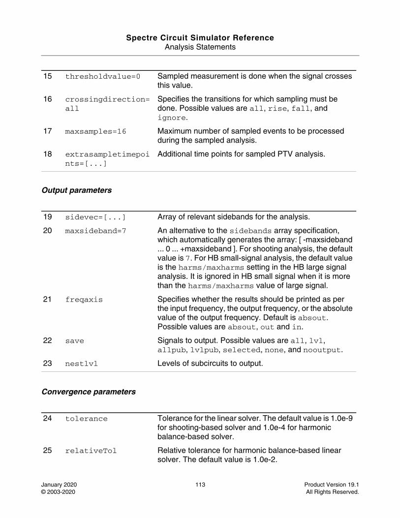
Spectre Circuit Simulator ReferenceAnalysis Statements
January 2020 113 Product Version 19.1© 2003-2020 All Rights Reserved.
Output parameters
Convergence parameters
15 thresholdvalue=0 Sampled measurement is done when the signal crosses this value.
16 crossingdirection=all
Specifies the transitions for which sampling must be done. Possible values are all, rise, fall, and ignore.
17 maxsamples=16 Maximum number of sampled events to be processed during the sampled analysis.
18 extrasampletimepoints=[...]
Additional time points for sampled PTV analysis.
19 sidevec=[...] Array of relevant sidebands for the analysis.
20 maxsideband=7 An alternative to the sidebands array specification, which automatically generates the array: [ -maxsideband ... 0 ... +maxsideband ]. For shooting analysis, the default value is 7. For HB small-signal analysis, the default value is the harms/maxharms setting in the HB large signal analysis. It is ignored in HB small signal when it is more than the harms/maxharms value of large signal.
21 freqaxis Specifies whether the results should be printed as per the input frequency, the output frequency, or the absolute value of the output frequency. Default is absout. Possible values are absout, out and in.
22 save Signals to output. Possible values are all, lvl, allpub, lvlpub, selected, none, and nooutput.
23 nestlvl Levels of subcircuits to output.
24 tolerance Tolerance for the linear solver. The default value is 1.0e-9 for shooting-based solver and 1.0e-4 for harmonic balance-based solver.
25 relativeTol Relative tolerance for harmonic balance-based linear solver. The default value is 1.0e-2.
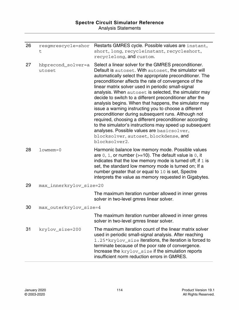
Spectre Circuit Simulator ReferenceAnalysis Statements
January 2020 114 Product Version 19.1© 2003-2020 All Rights Reserved.
26 resgmrescycle=short
Restarts GMRES cycle. Possible values are instant, short, long, recycleinstant, recycleshort, recyclelong, and custom.
27 hbprecond_solver=autoset
Select a linear solver for the GMRES preconditioner. Default is autoset. With autoset, the simulator will automatically select the appropriate preconditioner. The preconditioner affects the rate of convergence of the linear matrix solver used in periodic small-signal analysis. When autoset is selected, the simulator may decide to switch to a different preconditioner after the analysis begins. When that happens, the simulator may issue a warning instructing you to choose a different preconditioner during subsequent runs. Although not required, choosing a different preconditioner according to the simulator’s instructions may speed up subsequent analyses. Possible values are basicsolver, blocksolver, autoset, blockdense, and blocksolver2.
28 lowmem=0 Harmonic balance low memory mode. Possible values are 0, 1, or number (>=10). The default value is 0, it indicates that the low memory mode is turned off; if 1 is set, the standard low memory mode is turned on; If a number greater that or equal to 10 is set, Spectre interprets the value as memory requested in Gigabytes.
29 max_innerkrylov_size=20
The maximum iteration number allowed in inner gmres solver in two-level gmres linear solver.
30 max_outerkrylov_size=4
The maximum iteration number allowed in inner gmres solver in two-level gmres linear solver.
31 krylov_size=200 The maximum iteration count of the linear matrix solver used in periodic small-signal analysis. After reaching 1.25*krylov_size iterations, the iteration is forced to terminate because of the poor rate of convergence. Increase the krylov_size if the simulation reports insufficient norm reduction errors in GMRES.
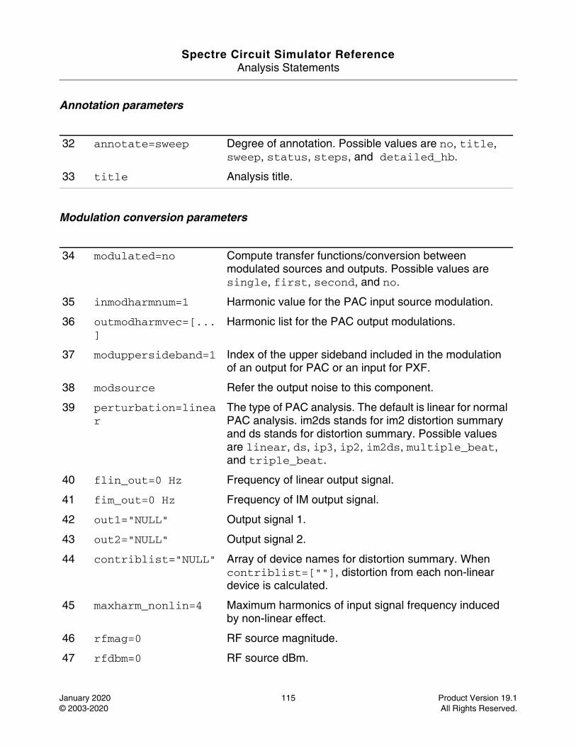
Spectre Circuit Simulator ReferenceAnalysis Statements
January 2020 115 Product Version 19.1© 2003-2020 All Rights Reserved.
Annotation parameters
Modulation conversion parameters
32 annotate=sweep Degree of annotation. Possible values are no, title, sweep, status, steps, and detailed_hb.
33 title Analysis title.
34 modulated=no Compute transfer functions/conversion between modulated sources and outputs. Possible values are single, first, second, and no.
35 inmodharmnum=1 Harmonic value for the PAC input source modulation.
36 outmodharmvec=[...]
Harmonic list for the PAC output modulations.
37 moduppersideband=1 Index of the upper sideband included in the modulation of an output for PAC or an input for PXF.
38 modsource Refer the output noise to this component.
39 perturbation=linear
The type of PAC analysis. The default is linear for normal PAC analysis. im2ds stands for im2 distortion summary and ds stands for distortion summary. Possible values are linear, ds, ip3, ip2, im2ds, multiple_beat, and triple_beat.
40 flin_out=0 Hz Frequency of linear output signal.
41 fim_out=0 Hz Frequency of IM output signal.
42 out1="NULL" Output signal 1.
43 out2="NULL" Output signal 2.
44 contriblist="NULL" Array of device names for distortion summary. When contriblist=[""], distortion from each non-linear device is calculated.
45 maxharm_nonlin=4 Maximum harmonics of input signal frequency induced by non-linear effect.
46 rfmag=0 RF source magnitude.
47 rfdbm=0 RF source dBm.
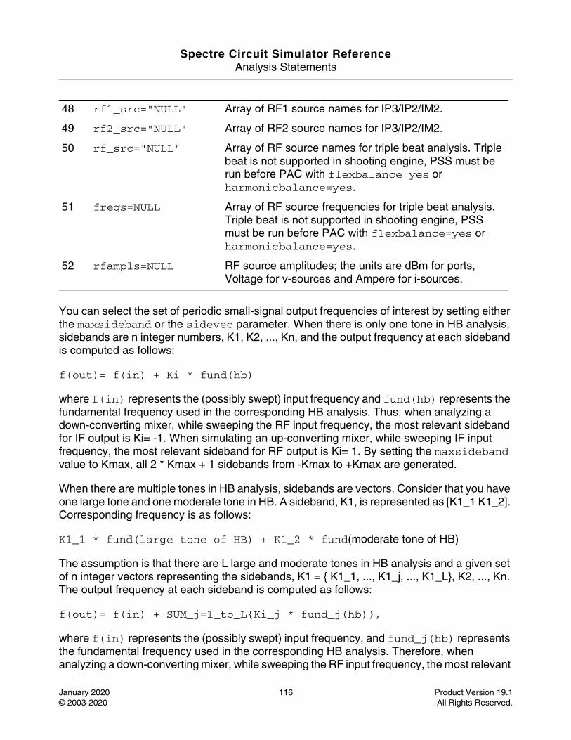
Spectre Circuit Simulator ReferenceAnalysis Statements
January 2020 116 Product Version 19.1© 2003-2020 All Rights Reserved.
You can select the set of periodic small-signal output frequencies of interest by setting either the maxsideband or the sidevec parameter. When there is only one tone in HB analysis, sidebands are n integer numbers, K1, K2, ..., Kn, and the output frequency at each sideband is computed as follows:
f(out)= f(in) + Ki * fund(hb)
where f(in) represents the (possibly swept) input frequency and fund(hb) represents the fundamental frequency used in the corresponding HB analysis. Thus, when analyzing a down-converting mixer, while sweeping the RF input frequency, the most relevant sideband for IF output is Ki= -1. When simulating an up-converting mixer, while sweeping IF input frequency, the most relevant sideband for RF output is Ki= 1. By setting the maxsideband value to Kmax, all 2 * Kmax + 1 sidebands from -Kmax to +Kmax are generated.
When there are multiple tones in HB analysis, sidebands are vectors. Consider that you have one large tone and one moderate tone in HB. A sideband, K1, is represented as [K1_1 K1_2]. Corresponding frequency is as follows:
K1_1 * fund(large tone of HB) + K1_2 * fund(moderate tone of HB)
The assumption is that there are L large and moderate tones in HB analysis and a given set of n integer vectors representing the sidebands, K1 = { K1_1, ..., K1_j, ..., K1_L}, K2, ..., Kn. The output frequency at each sideband is computed as follows:
f(out)= f(in) + SUM_j=1_to_L{Ki_j * fund_j(hb)},
where f(in) represents the (possibly swept) input frequency, and fund_j(hb) represents the fundamental frequency used in the corresponding HB analysis. Therefore, when analyzing a down-converting mixer, while sweeping the RF input frequency, the most relevant
48 rf1_src="NULL" Array of RF1 source names for IP3/IP2/IM2.
49 rf2_src="NULL" Array of RF2 source names for IP3/IP2/IM2.
50 rf_src="NULL" Array of RF source names for triple beat analysis. Triple beat is not supported in shooting engine, PSS must be run before PAC with flexbalance=yes or harmonicbalance=yes.
51 freqs=NULL Array of RF source frequencies for triple beat analysis. Triple beat is not supported in shooting engine, PSS must be run before PAC with flexbalance=yes or harmonicbalance=yes.
52 rfampls=NULL RF source amplitudes; the units are dBm for ports, Voltage for v-sources and Ampere for i-sources.
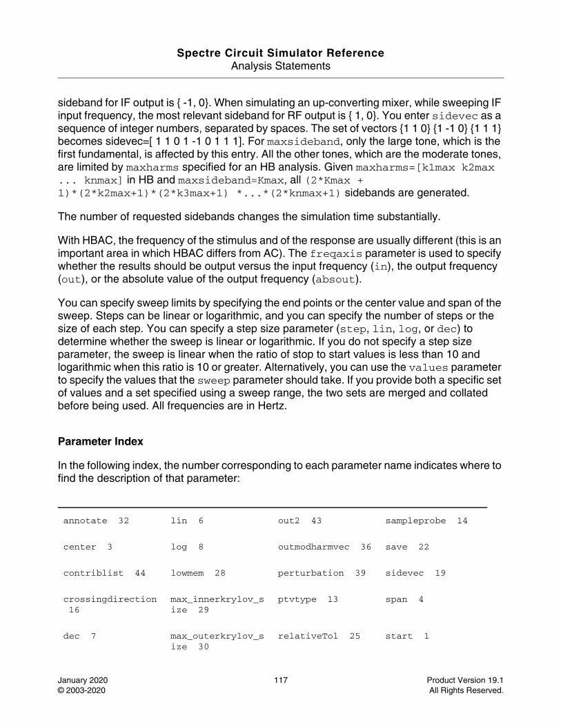
Spectre Circuit Simulator ReferenceAnalysis Statements
January 2020 117 Product Version 19.1© 2003-2020 All Rights Reserved.
sideband for IF output is { -1, 0}. When simulating an up-converting mixer, while sweeping IF input frequency, the most relevant sideband for RF output is { 1, 0}. You enter sidevec as a sequence of integer numbers, separated by spaces. The set of vectors {1 1 0} {1 -1 0} {1 1 1} becomes sidevec=[ 1 1 0 1 -1 0 1 1 1]. For maxsideband, only the large tone, which is the first fundamental, is affected by this entry. All the other tones, which are the moderate tones, are limited by maxharms specified for an HB analysis. Given maxharms=[k1max k2max ... knmax] in HB and maxsideband=Kmax, all (2*Kmax + 1)*(2*k2max+1)*(2*k3max+1) *...*(2*knmax+1) sidebands are generated.
The number of requested sidebands changes the simulation time substantially.
With HBAC, the frequency of the stimulus and of the response are usually different (this is an important area in which HBAC differs from AC). The freqaxis parameter is used to specify whether the results should be output versus the input frequency (in), the output frequency (out), or the absolute value of the output frequency (absout).
You can specify sweep limits by specifying the end points or the center value and span of the sweep. Steps can be linear or logarithmic, and you can specify the number of steps or the size of each step. You can specify a step size parameter (step, lin, log, or dec) to determine whether the sweep is linear or logarithmic. If you do not specify a step size parameter, the sweep is linear when the ratio of stop to start values is less than 10 and logarithmic when this ratio is 10 or greater. Alternatively, you can use the values parameter to specify the values that the sweep parameter should take. If you provide both a specific set of values and a set specified using a sweep range, the two sets are merged and collated before being used. All frequencies are in Hertz.
Parameter Index
In the following index, the number corresponding to each parameter name indicates where to find the description of that parameter:
annotate 32 lin 6 out2 43 sampleprobe 14
center 3 log 8 outmodharmvec 36 save 22
contriblist 44 lowmem 28 perturbation 39 sidevec 19
crossingdirection 16
max_innerkrylov_size 29
ptvtype 13 span 4
dec 7 max_outerkrylov_size 30
relativeTol 25 start 1
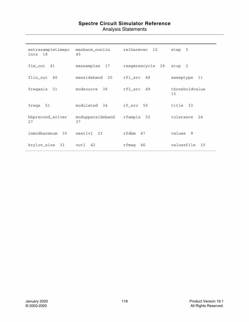
Spectre Circuit Simulator ReferenceAnalysis Statements
January 2020 118 Product Version 19.1© 2003-2020 All Rights Reserved.
extrasampletimepoints 18
maxharm_nonlin 45
relharmvec 12 step 5
fim_out 41 maxsamples 17 resgmrescycle 26 stop 2
flin_out 40 maxsideband 20 rf1_src 48 sweeptype 11
freqaxis 21 modsource 38 rf2_src 49 thresholdvalue 15
freqs 51 modulated 34 rf_src 50 title 33
hbprecond_solver 27
moduppersideband 37
rfampls 52 tolerance 24
inmodharmnum 35 nestlvl 23 rfdbm 47 values 9
krylov_size 31 out1 42 rfmag 46 valuesfile 10

Spectre Circuit Simulator ReferenceAnalysis Statements
January 2020 119 Product Version 19.1© 2003-2020 All Rights Reserved.
HB Noise Analysis (hbnoise)
Description
The Periodic or Quasi-Periodic Noise (HBNOISE) analysis is similar to the conventional noise analysis, except that HBNOISE analysis includes frequency conversion effects. Hence, it is useful for predicting the noise behavior of mixers, switched-capacitor filters, and other periodically or quasi-periodically driven circuits. It is particularly useful for predicting the phase noise of autonomous circuits, such as oscillators.
HBNOISE analysis linearizes the circuit about the periodic or quasi-periodic operating point computed in the prerequisite HB analysis. It is the periodically or quasi-periodically time-varying nature of the linearized circuit that accounts for the frequency conversion. In addition, the effect of a periodically or quasi-periodically time-varying bias point on the noise generated by the various components in the circuit is also included.
The time-average of the noise at the output of the circuit is computed in the form of a spectral density versus frequency. The output of the circuit is specified with either a pair of nodes or a probe component. To specify the output of a circuit with a probe, specify it using the oprobe parameter. If the output is voltage (or potential), choose a resistor or port as the output probe. If the output is current (or flow), choose a vsource or iprobe as the output probe.
If the input-referred noise or noise figure is desired, specify the input source using the iprobe parameter. For input-referred noise, use either a vsource or isource as the input probe; for noise figure, use a port as the probe. Currently, only a vsource, an isource, or a port can be used as an input probe. If the input source is noisy, as is a port, the noise analysis computes the noise factor (F) and noise figure (NF). To match the IEEE definition of noise figure, the input probe must be a port with no excess noise and its noisetemp must be set to 16.85C (290K). In addition, the output load must be a resistor or port and must be identified as the oprobe.
If port is specified as the input probe, both input-referred noise and gain are referred back to the equivalent voltage source inside the port. S-parameter analysis calculates those values in traditional sense.
The reference sideband (refsideband) specifies which conversion gain is used when computing input-referred noise, noise factor, and noise figure. The reference sideband specifies the input frequency relative to the output frequency with:
|f(input)| = |f(out) + refsideband frequency shift|.
For periodic noise (only one tone in HB analysis), refsideband is a number. Use refsideband=0 when the input and output of the circuit are at the same frequency, such as

Spectre Circuit Simulator ReferenceAnalysis Statements
January 2020 120 Product Version 19.1© 2003-2020 All Rights Reserved.
with amplifiers and filters. When refsideband differs from 0, the single side-band noise figure is computed.
While for quasi-periodic noise (multiple tones in HB analysis), reference sidebands are vectors. Assume that there is one large tone and one moderate tone in HB. A sideband Ki is a vector [Ki_1 Ki_2]. It gives the frequency at:
Ki_1 * fund(large tone of HB) + Ki_2 * fund(moderate tone of HB)
Use refsideband=[0 0 ...] when the input and output of the circuit are at the same frequency, such as with amplifiers and filters.
The reference sideband option (refsidebandoption) specifies whether to consider the input at the frequency or the input at the individual quasi-periodic sideband specified.
Note: Different sidebands can lead to the same frequency.
The noise analysis always computes the total noise at the output, which includes contributions from the input source and the output load. The amount of the output noise that is attributable to each noise source in the circuit is also computed and output individually. If the input source is identified (using iprobe) and is a vsource or isource, the input-referred noise is computed, which includes the noise from the input source itself. Finally, if the input source is identified (using iprobe) and is noisy, as is the case with ports, the noise factor and noise figure are computed. Therefore, if:
No = total output noise
Ns = noise at the output due to the input probe (the source)
Nsi = noise at the output due to the image harmonic at the source
Nso = noise at the output due to harmonics other than input at the source
Nl = noise at the output due to the output probe (the load)
IRN = input referred noise
G = gain of the circuit
F = noise factor
NF = noise figure
Fdsb = double sideband noise factor
NFdsb = double sideband noise figure
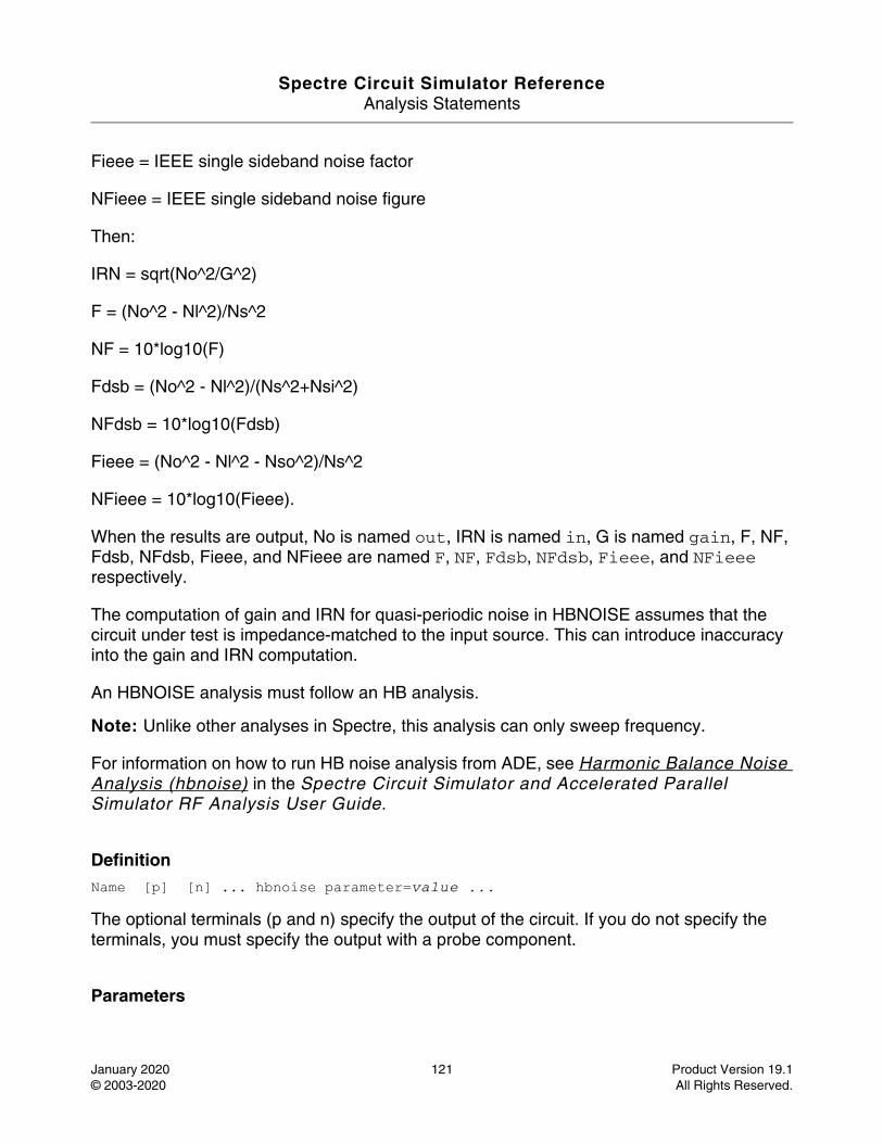
Spectre Circuit Simulator ReferenceAnalysis Statements
January 2020 121 Product Version 19.1© 2003-2020 All Rights Reserved.
Fieee = IEEE single sideband noise factor
NFieee = IEEE single sideband noise figure
Then:
IRN = sqrt(No^2/G^2)
F = (No^2 - Nl^2)/Ns^2
NF = 10*log10(F)
Fdsb = (No^2 - Nl^2)/(Ns^2+Nsi^2)
NFdsb = 10*log10(Fdsb)
Fieee = (No^2 - Nl^2 - Nso^2)/Ns^2
NFieee = 10*log10(Fieee).
When the results are output, No is named out, IRN is named in, G is named gain, F, NF, Fdsb, NFdsb, Fieee, and NFieee are named F, NF, Fdsb, NFdsb, Fieee, and NFieee respectively.
The computation of gain and IRN for quasi-periodic noise in HBNOISE assumes that the circuit under test is impedance-matched to the input source. This can introduce inaccuracy into the gain and IRN computation.
An HBNOISE analysis must follow an HB analysis.
Note: Unlike other analyses in Spectre, this analysis can only sweep frequency.
For information on how to run HB noise analysis from ADE, see Harmonic Balance Noise Analysis (hbnoise) in the Spectre Circuit Simulator and Accelerated Parallel Simulator RF Analysis User Guide.
DefinitionName [p] [n] ... hbnoise parameter=value ...
The optional terminals (p and n) specify the output of the circuit. If you do not specify the terminals, you must specify the output with a probe component.
Parameters
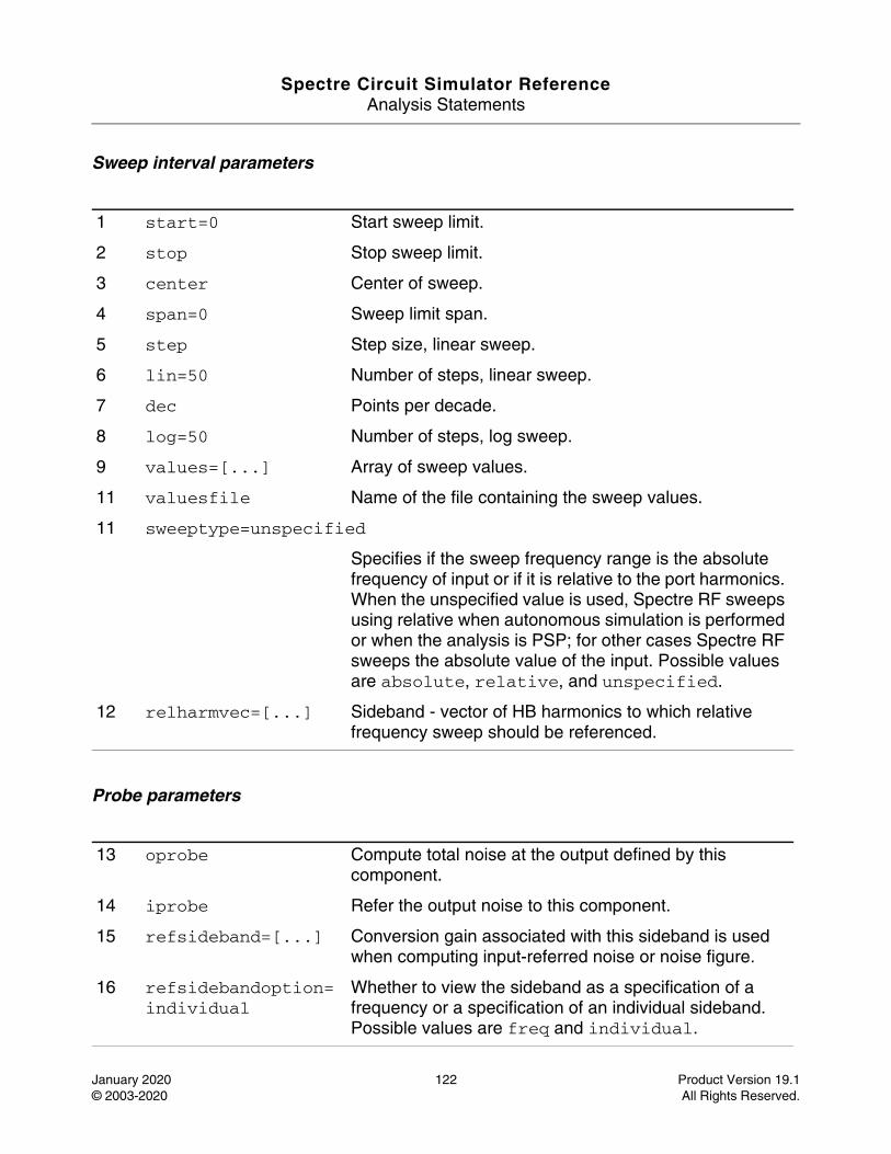
Spectre Circuit Simulator ReferenceAnalysis Statements
January 2020 122 Product Version 19.1© 2003-2020 All Rights Reserved.
Sweep interval parameters
Probe parameters
1 start=0 Start sweep limit.
2 stop Stop sweep limit.
3 center Center of sweep.
4 span=0 Sweep limit span.
5 step Step size, linear sweep.
6 lin=50 Number of steps, linear sweep.
7 dec Points per decade.
8 log=50 Number of steps, log sweep.
9 values=[...] Array of sweep values.
11 valuesfile Name of the file containing the sweep values.
11 sweeptype=unspecified
Specifies if the sweep frequency range is the absolute frequency of input or if it is relative to the port harmonics. When the unspecified value is used, Spectre RF sweeps using relative when autonomous simulation is performed or when the analysis is PSP; for other cases Spectre RF sweeps the absolute value of the input. Possible values are absolute, relative, and unspecified.
12 relharmvec=[...] Sideband - vector of HB harmonics to which relative frequency sweep should be referenced.
13 oprobe Compute total noise at the output defined by this component.
14 iprobe Refer the output noise to this component.
15 refsideband=[...] Conversion gain associated with this sideband is used when computing input-referred noise or noise figure.
16 refsidebandoption=individual
Whether to view the sideband as a specification of a frequency or a specification of an individual sideband. Possible values are freq and individual.
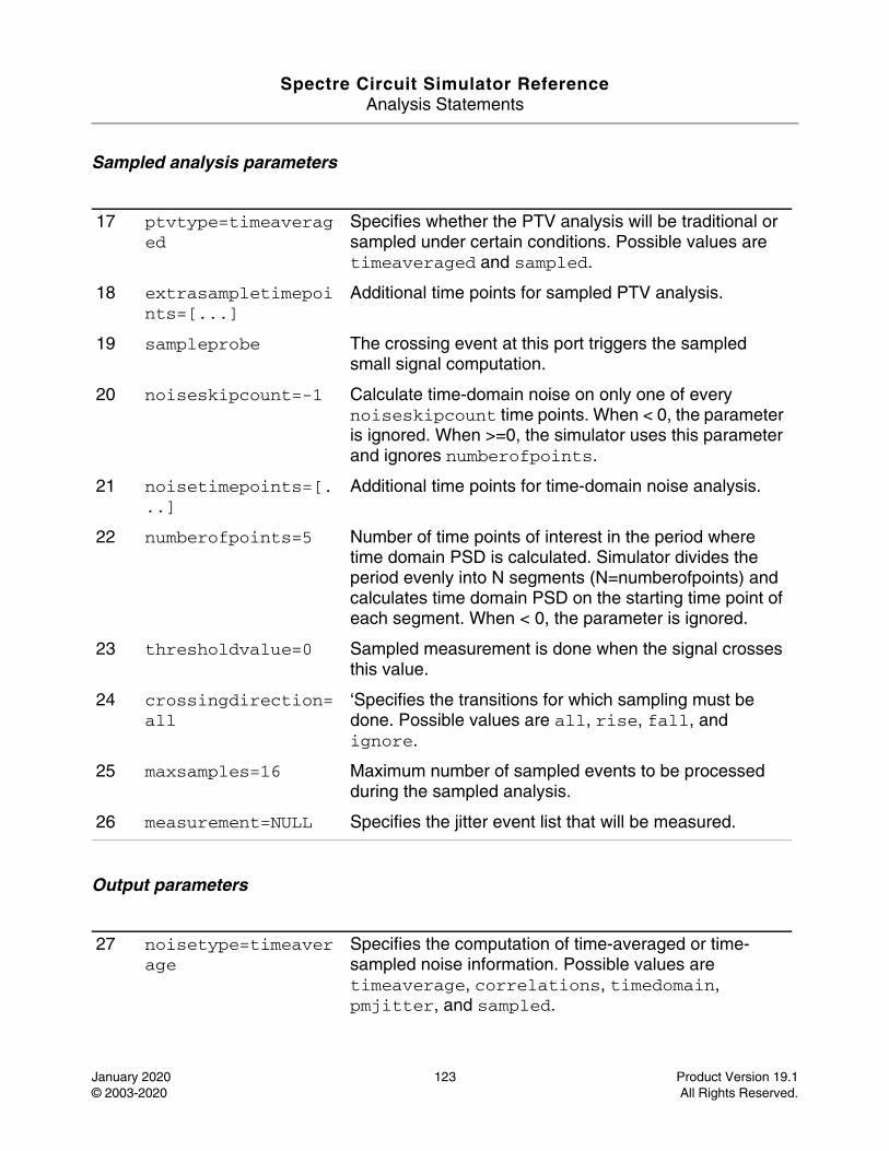
Spectre Circuit Simulator ReferenceAnalysis Statements
January 2020 123 Product Version 19.1© 2003-2020 All Rights Reserved.
Sampled analysis parameters
Output parameters
17 ptvtype=timeaveraged
Specifies whether the PTV analysis will be traditional or sampled under certain conditions. Possible values are timeaveraged and sampled.
18 extrasampletimepoints=[...]
Additional time points for sampled PTV analysis.
19 sampleprobe The crossing event at this port triggers the sampled small signal computation.
20 noiseskipcount=-1 Calculate time-domain noise on only one of every noiseskipcount time points. When < 0, the parameter is ignored. When >=0, the simulator uses this parameter and ignores numberofpoints.
21 noisetimepoints=[...]
Additional time points for time-domain noise analysis.
22 numberofpoints=5 Number of time points of interest in the period where time domain PSD is calculated. Simulator divides the period evenly into N segments (N=numberofpoints) and calculates time domain PSD on the starting time point of each segment. When < 0, the parameter is ignored.
23 thresholdvalue=0 Sampled measurement is done when the signal crosses this value.
24 crossingdirection=all
‘Specifies the transitions for which sampling must be done. Possible values are all, rise, fall, and ignore.
25 maxsamples=16 Maximum number of sampled events to be processed during the sampled analysis.
26 measurement=NULL Specifies the jitter event list that will be measured.
27 noisetype=timeaverage
Specifies the computation of time-averaged or time-sampled noise information. Possible values are timeaverage, correlations, timedomain, pmjitter, and sampled.
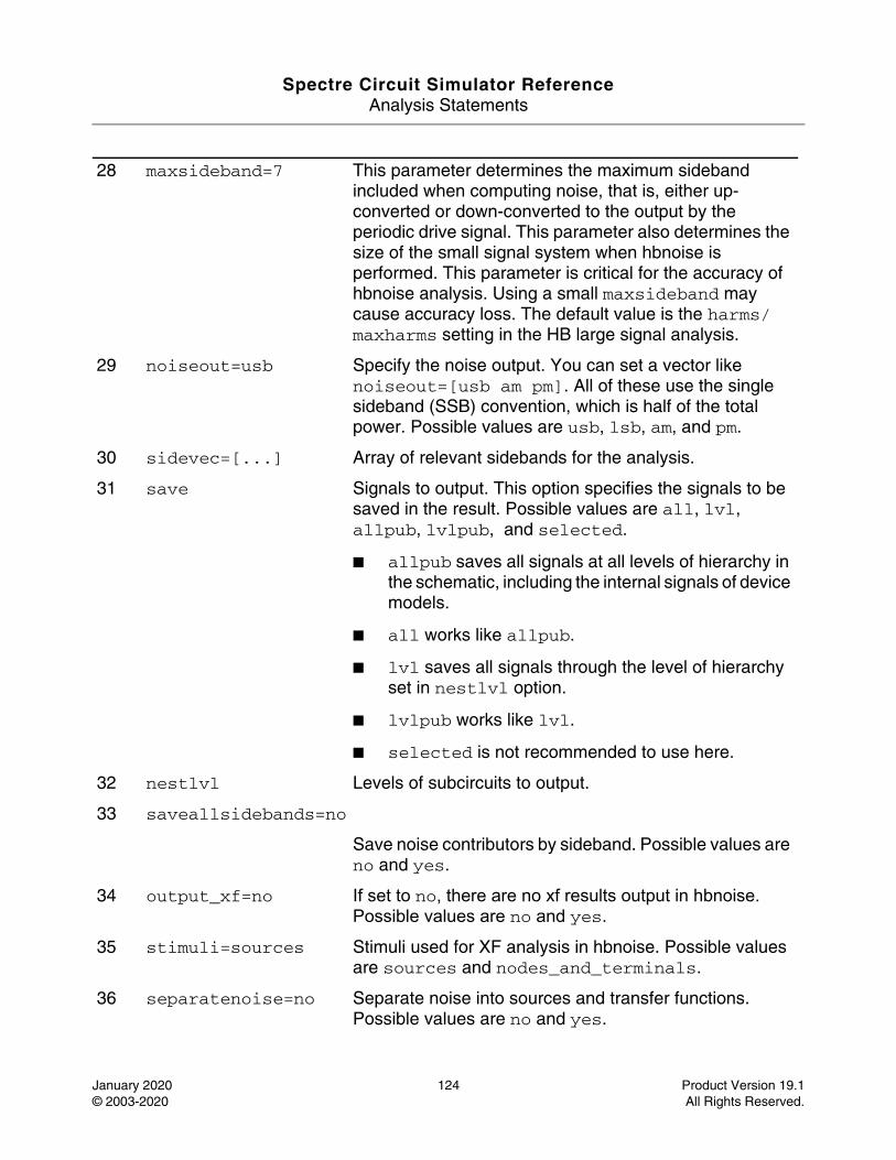
Spectre Circuit Simulator ReferenceAnalysis Statements
January 2020 124 Product Version 19.1© 2003-2020 All Rights Reserved.
28 maxsideband=7 This parameter determines the maximum sideband included when computing noise, that is, either up-converted or down-converted to the output by the periodic drive signal. This parameter also determines the size of the small signal system when hbnoise is performed. This parameter is critical for the accuracy of hbnoise analysis. Using a small maxsideband may cause accuracy loss. The default value is the harms/maxharms setting in the HB large signal analysis.
29 noiseout=usb Specify the noise output. You can set a vector like noiseout=[usb am pm]. All of these use the single sideband (SSB) convention, which is half of the total power. Possible values are usb, lsb, am, and pm.
30 sidevec=[...] Array of relevant sidebands for the analysis.
31 save Signals to output. This option specifies the signals to be saved in the result. Possible values are all, lvl, allpub, lvlpub, and selected.
■ allpub saves all signals at all levels of hierarchy in the schematic, including the internal signals of device models.
■ all works like allpub.
■ lvl saves all signals through the level of hierarchy set in nestlvl option.
■ lvlpub works like lvl.
■ selected is not recommended to use here.
32 nestlvl Levels of subcircuits to output.
33 saveallsidebands=no
Save noise contributors by sideband. Possible values are no and yes.
34 output_xf=no If set to no, there are no xf results output in hbnoise. Possible values are no and yes.
35 stimuli=sources Stimuli used for XF analysis in hbnoise. Possible values are sources and nodes_and_terminals.
36 separatenoise=no Separate noise into sources and transfer functions. Possible values are no and yes.
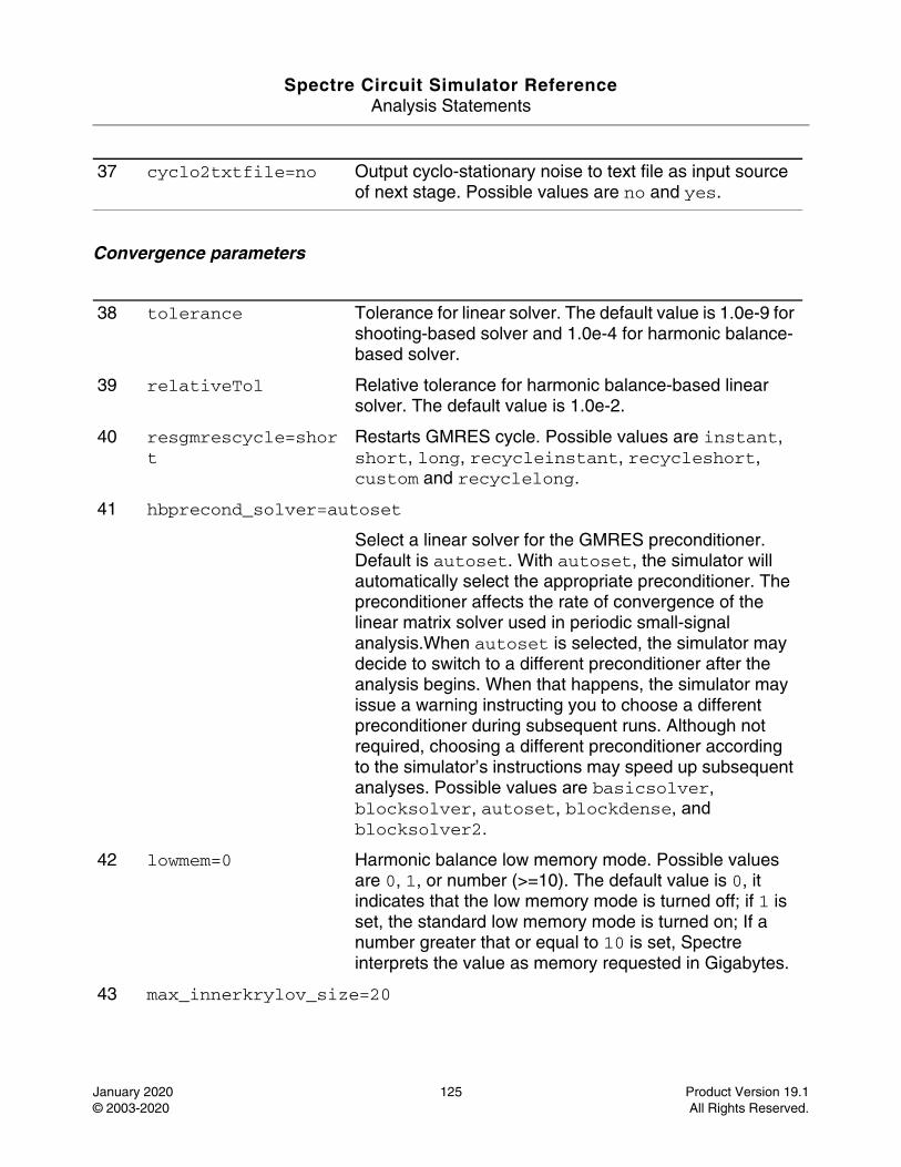
Spectre Circuit Simulator ReferenceAnalysis Statements
January 2020 125 Product Version 19.1© 2003-2020 All Rights Reserved.
Convergence parameters
37 cyclo2txtfile=no Output cyclo-stationary noise to text file as input source of next stage. Possible values are no and yes.
38 tolerance Tolerance for linear solver. The default value is 1.0e-9 for shooting-based solver and 1.0e-4 for harmonic balance-based solver.
39 relativeTol Relative tolerance for harmonic balance-based linear solver. The default value is 1.0e-2.
40 resgmrescycle=short
Restarts GMRES cycle. Possible values are instant, short, long, recycleinstant, recycleshort, custom and recyclelong.
41 hbprecond_solver=autoset
Select a linear solver for the GMRES preconditioner. Default is autoset. With autoset, the simulator will automatically select the appropriate preconditioner. The preconditioner affects the rate of convergence of the linear matrix solver used in periodic small-signal analysis.When autoset is selected, the simulator may decide to switch to a different preconditioner after the analysis begins. When that happens, the simulator may issue a warning instructing you to choose a different preconditioner during subsequent runs. Although not required, choosing a different preconditioner according to the simulator’s instructions may speed up subsequent analyses. Possible values are basicsolver, blocksolver, autoset, blockdense, and blocksolver2.
42 lowmem=0 Harmonic balance low memory mode. Possible values are 0, 1, or number (>=10). The default value is 0, it indicates that the low memory mode is turned off; if 1 is set, the standard low memory mode is turned on; If a number greater that or equal to 10 is set, Spectre interprets the value as memory requested in Gigabytes.
43 max_innerkrylov_size=20
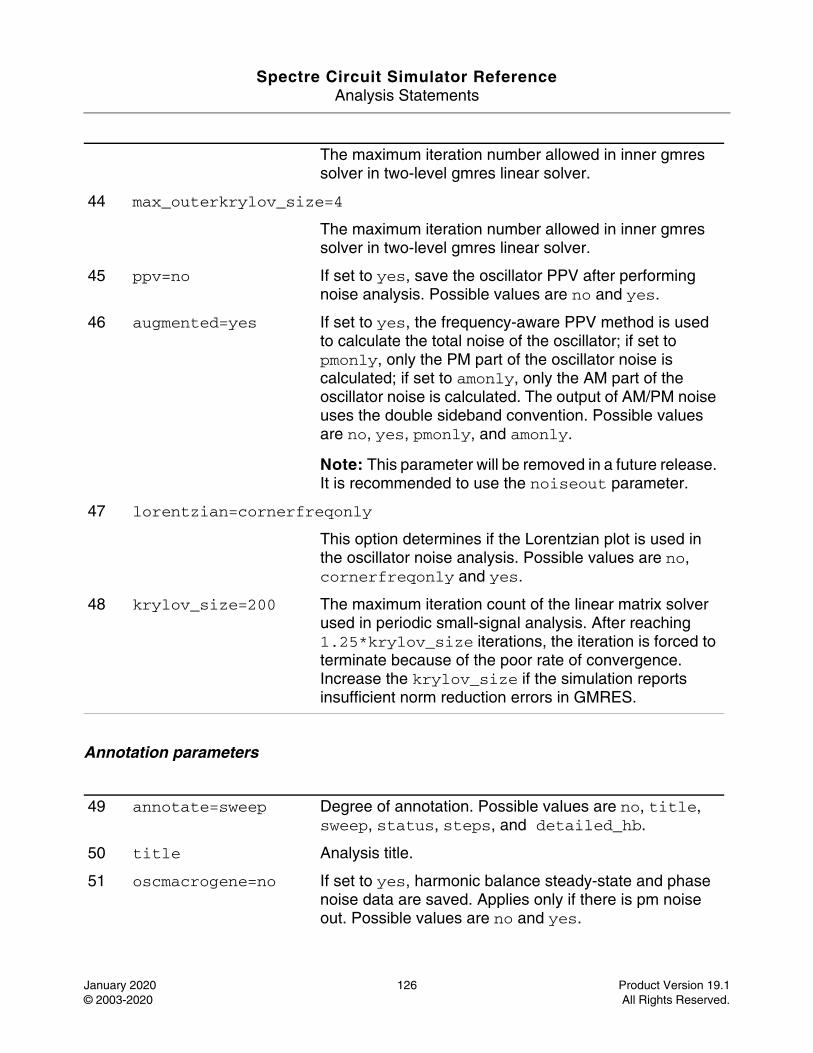
Spectre Circuit Simulator ReferenceAnalysis Statements
January 2020 126 Product Version 19.1© 2003-2020 All Rights Reserved.
Annotation parameters
The maximum iteration number allowed in inner gmres solver in two-level gmres linear solver.
44 max_outerkrylov_size=4
The maximum iteration number allowed in inner gmres solver in two-level gmres linear solver.
45 ppv=no If set to yes, save the oscillator PPV after performing noise analysis. Possible values are no and yes.
46 augmented=yes If set to yes, the frequency-aware PPV method is used to calculate the total noise of the oscillator; if set to pmonly, only the PM part of the oscillator noise is calculated; if set to amonly, only the AM part of the oscillator noise is calculated. The output of AM/PM noise uses the double sideband convention. Possible values are no, yes, pmonly, and amonly.
Note: This parameter will be removed in a future release. It is recommended to use the noiseout parameter.
47 lorentzian=cornerfreqonly
This option determines if the Lorentzian plot is used in the oscillator noise analysis. Possible values are no, cornerfreqonly and yes.
48 krylov_size=200 The maximum iteration count of the linear matrix solver used in periodic small-signal analysis. After reaching 1.25*krylov_size iterations, the iteration is forced to terminate because of the poor rate of convergence. Increase the krylov_size if the simulation reports insufficient norm reduction errors in GMRES.
49 annotate=sweep Degree of annotation. Possible values are no, title, sweep, status, steps, and detailed_hb.
50 title Analysis title.
51 oscmacrogene=no If set to yes, harmonic balance steady-state and phase noise data are saved. Applies only if there is pm noise out. Possible values are no and yes.
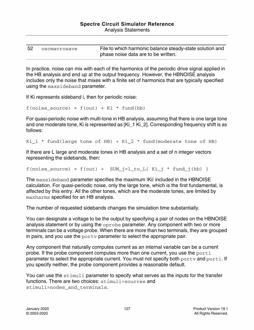
Spectre Circuit Simulator ReferenceAnalysis Statements
January 2020 127 Product Version 19.1© 2003-2020 All Rights Reserved.
In practice, noise can mix with each of the harmonics of the periodic drive signal applied in the HB analysis and end up at the output frequency. However, the HBNOISE analysis includes only the noise that mixes with a finite set of harmonics that are typically specified using the maxsideband parameter.
If Ki represents sideband i, then for periodic noise:
f(noise_source) = f(out) + Ki * fund(hb)
For quasi-periodic noise with multi-tone in HB analysis, assuming that there is one large tone and one moderate tone, Ki is represented as [Ki_1 Ki_2]. Corresponding frequency shift is as follows:
Ki_1 * fund(large tone of HB) + Ki_2 * fund(moderate tone of HB)
If there are L large and moderate tones in HB analysis and a set of n integer vectors representing the sidebands, then:
f(noise_source) = f(out) + SUM_j=1_to_L{ Ki_j * fund_j(hb) }
The maxsideband parameter specifies the maximum |Ki| included in the HBNOISE calculation. For quasi-periodic noise, only the large tone, which is the first fundamental, is affected by this entry. All the other tones, which are the moderate tones, are limited by maxharms specified for an HB analysis.
The number of requested sidebands changes the simulation time substantially.
You can designate a voltage to be the output by specifying a pair of nodes on the HBNOISE analysis statement or by using the oprobe parameter. Any component with two or more terminals can be a voltage probe. When there are more than two terminals, they are grouped in pairs, and you use the portv parameter to select the appropriate pair.
Any component that naturally computes current as an internal variable can be a current probe. If the probe component computes more than one current, you use the porti parameter to select the appropriate current. You must not specify both portv and porti. If you specify neither, the probe component provides a reasonable default.
You can use the stimuli parameter to specify what serves as the inputs for the transfer functions. There are two choices: stimuli=sources and stimuli=nodes_and_terminals.
52 oscmacrosave File to which harmonic balance steady-state solution and phase noise data are to be written.
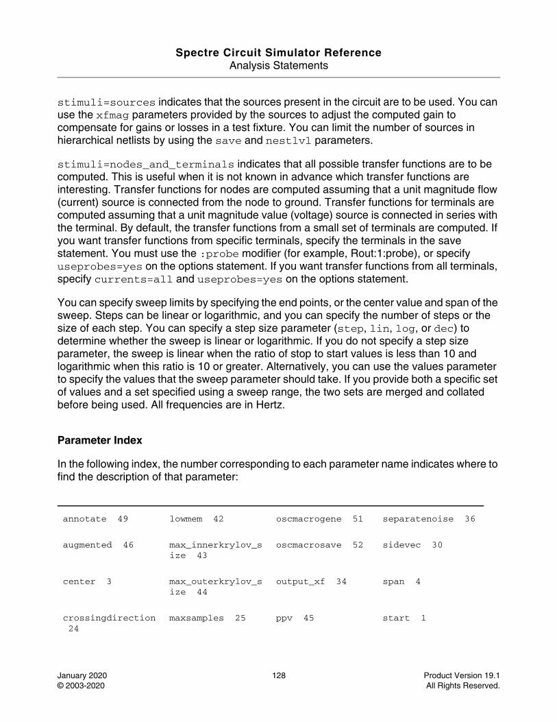
Spectre Circuit Simulator ReferenceAnalysis Statements
January 2020 128 Product Version 19.1© 2003-2020 All Rights Reserved.
stimuli=sources indicates that the sources present in the circuit are to be used. You can use the xfmag parameters provided by the sources to adjust the computed gain to compensate for gains or losses in a test fixture. You can limit the number of sources in hierarchical netlists by using the save and nestlvl parameters.
stimuli=nodes_and_terminals indicates that all possible transfer functions are to be computed. This is useful when it is not known in advance which transfer functions are interesting. Transfer functions for nodes are computed assuming that a unit magnitude flow (current) source is connected from the node to ground. Transfer functions for terminals are computed assuming that a unit magnitude value (voltage) source is connected in series with the terminal. By default, the transfer functions from a small set of terminals are computed. If you want transfer functions from specific terminals, specify the terminals in the save statement. You must use the :probe modifier (for example, Rout:1:probe), or specify useprobes=yes on the options statement. If you want transfer functions from all terminals, specify currents=all and useprobes=yes on the options statement.
You can specify sweep limits by specifying the end points, or the center value and span of the sweep. Steps can be linear or logarithmic, and you can specify the number of steps or the size of each step. You can specify a step size parameter (step, lin, log, or dec) to determine whether the sweep is linear or logarithmic. If you do not specify a step size parameter, the sweep is linear when the ratio of stop to start values is less than 10 and logarithmic when this ratio is 10 or greater. Alternatively, you can use the values parameter to specify the values that the sweep parameter should take. If you provide both a specific set of values and a set specified using a sweep range, the two sets are merged and collated before being used. All frequencies are in Hertz.
Parameter Index
In the following index, the number corresponding to each parameter name indicates where to find the description of that parameter:
annotate 49 lowmem 42 oscmacrogene 51 separatenoise 36
augmented 46 max_innerkrylov_size 43
oscmacrosave 52 sidevec 30
center 3 max_outerkrylov_size 44
output_xf 34 span 4
crossingdirection 24
maxsamples 25 ppv 45 start 1
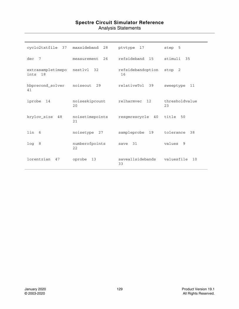
Spectre Circuit Simulator ReferenceAnalysis Statements
January 2020 129 Product Version 19.1© 2003-2020 All Rights Reserved.
cyclo2txtfile 37 maxsideband 28 ptvtype 17 step 5
dec 7 measurement 26 refsideband 15 stimuli 35
extrasampletimepoints 18
nestlvl 32 refsidebandoption 16
stop 2
hbprecond_solver 41
noiseout 29 relativeTol 39 sweeptype 11
iprobe 14 noiseskipcount 20
relharmvec 12 thresholdvalue 23
krylov_size 48 noisetimepoints 21
resgmrescycle 40 title 50
lin 6 noisetype 27 sampleprobe 19 tolerance 38
log 8 numberofpoints 22
save 31 values 9
lorentzian 47 oprobe 13 saveallsidebands 33
valuesfile 10
Spectre Circuit Simulator ReferenceAnalysis Statements
January 2020 130 Product Version 19.1© 2003-2020 All Rights Reserved.
HB S-Parameter Analysis (hbsp)
Description
The periodic or quasi-periodic SP (HBSP) analysis is used to compute scattering and noise parameters for n-port circuits such as mixers that exhibit frequency translation. It is a small-signal analysis similar to SP analysis, except that in HBAC and HBNOISE, the circuit is first linearized about a periodically varying operating point as opposed to a simple DC operating point. Linearizing about a periodically or quasi-periodically time-varying operating point allows the computation of S-parameters between circuit ports that convert signals from one frequency band to another. HBSP can also calculate noise parameters in frequency-converting circuits. In addition, HBSP computes noise figure (both single-sideband and double-sideband), input referred noise, equivalent noise parameters, and noise correlation matrices. Similar to HBNOISE, but unlike SP, the noise features of the HBSP analysis include noise folding effects due to the periodic time-varying nature of the circuit.
Computing the n-port S-parameters and noise parameters of a periodically varying circuit is a two-step process. First, the small stimulus is ignored and the periodic or quasi-periodic steady-state response of the circuit to possibly large periodic stimulus is computed using HB analysis. As part of the HB analysis, the periodically time-varying representation of the circuit is computed and saved for later use. The second step is to apply small-signal excitations to compute the n-port S-parameters and noise parameters. This is done using the HBSP analysis. HBSP analysis cannot be used independently; it must follow HB analysis. However, any number of periodic small-signal analyses such as HBAC, HBSP, HBNOISE, can follow an HB analysis.
Note: Unlike other analyses in Spectre, this analysis can only sweep frequency.
For information on how to run HB noise analysis from ADE, see hbSP Analysis in the Spectre Circuit Simulator and Accelerated Parallel Simulator RF Analysis User Guide.
DefinitionName hbsp parameter=value ...
Parameters
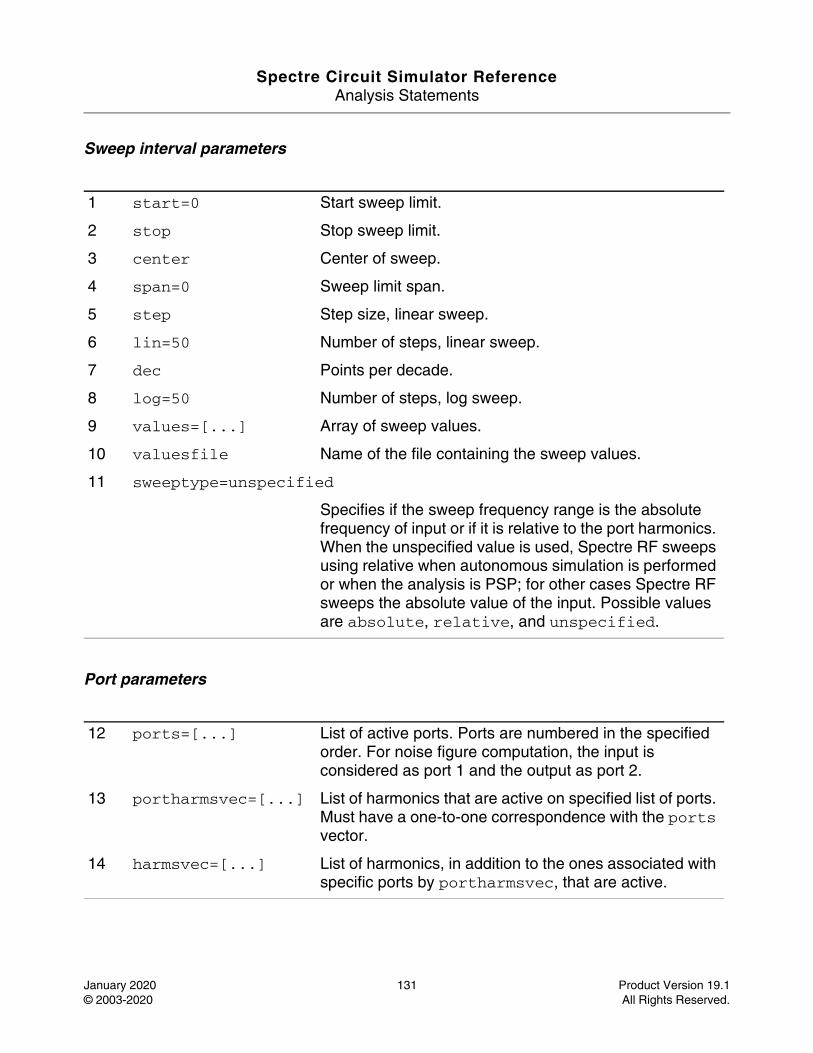
Spectre Circuit Simulator ReferenceAnalysis Statements
January 2020 131 Product Version 19.1© 2003-2020 All Rights Reserved.
Sweep interval parameters
Port parameters
1 start=0 Start sweep limit.
2 stop Stop sweep limit.
3 center Center of sweep.
4 span=0 Sweep limit span.
5 step Step size, linear sweep.
6 lin=50 Number of steps, linear sweep.
7 dec Points per decade.
8 log=50 Number of steps, log sweep.
9 values=[...] Array of sweep values.
10 valuesfile Name of the file containing the sweep values.
11 sweeptype=unspecified
Specifies if the sweep frequency range is the absolute frequency of input or if it is relative to the port harmonics. When the unspecified value is used, Spectre RF sweeps using relative when autonomous simulation is performed or when the analysis is PSP; for other cases Spectre RF sweeps the absolute value of the input. Possible values are absolute, relative, and unspecified.
12 ports=[...] List of active ports. Ports are numbered in the specified order. For noise figure computation, the input is considered as port 1 and the output as port 2.
13 portharmsvec=[...] List of harmonics that are active on specified list of ports. Must have a one-to-one correspondence with the ports vector.
14 harmsvec=[...] List of harmonics, in addition to the ones associated with specific ports by portharmsvec, that are active.
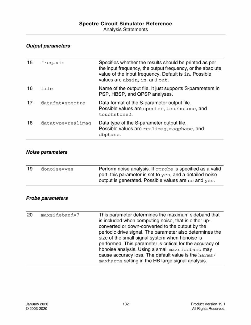
Spectre Circuit Simulator ReferenceAnalysis Statements
January 2020 132 Product Version 19.1© 2003-2020 All Rights Reserved.
Output parameters
Noise parameters
Probe parameters
15 freqaxis Specifies whether the results should be printed as per the input frequency, the output frequency, or the absolute value of the input frequency. Default is in. Possible values are absin, in, and out.
16 file Name of the output file. It just supports S-parameters in PSP, HBSP, and QPSP analyses.
17 datafmt=spectre Data format of the S-parameter output file.Possible values are spectre, touchstone, and touchstone2.
18 datatype=realimag Data type of the S-parameter output file.Possible values are realimag, magphase, and dbphase.
19 donoise=yes Perform noise analysis. If oprobe is specified as a valid port, this parameter is set to yes, and a detailed noise output is generated. Possible values are no and yes.
20 maxsideband=7 This parameter determines the maximum sideband that is included when computing noise, that is either up-converted or down-converted to the output by the periodic drive signal. The parameter also determines the size of the small signal system when hbnoise is performed. This parameter is critical for the accuracy of hbnoise analysis. Using a small maxsideband may cause accuracy loss. The default value is the harms/maxharms setting in the HB large signal analysis.
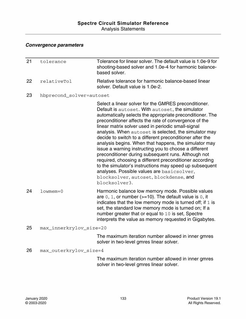
Spectre Circuit Simulator ReferenceAnalysis Statements
January 2020 133 Product Version 19.1© 2003-2020 All Rights Reserved.
Convergence parameters
21 tolerance Tolerance for linear solver. The default value is 1.0e-9 for shooting-based solver and 1.0e-4 for harmonic balance-based solver.
22 relativeTol Relative tolerance for harmonic balance-based linear solver. Default value is 1.0e-2.
23 hbprecond_solver=autoset
Select a linear solver for the GMRES preconditioner. Default is autoset. With autoset, the simulator automatically selects the appropriate preconditioner. The preconditioner affects the rate of convergence of the linear matrix solver used in periodic small-signal analysis. When autoset is selected, the simulator may decide to switch to a different preconditioner after the analysis begins. When that happens, the simulator may issue a warning instructing you to choose a different preconditioner during subsequent runs. Although not required, choosing a different preconditioner according to the simulator’s instructions may speed up subsequent analyses. Possible values are basicsolver, blocksolver, autoset, blockdense, and blocksolver3.
24 lowmem=0 Harmonic balance low memory mode. Possible values are 0, 1, or number (>=10). The default value is 0, it indicates that the low memory mode is turned off; if 1 is set, the standard low memory mode is turned on; If a number greater that or equal to 10 is set, Spectre interprets the value as memory requested in Gigabytes.
25 max_innerkrylov_size=20
The maximum iteration number allowed in inner gmres solver in two-level gmres linear solver.
26 max_outerkrylov_size=4
The maximum iteration number allowed in inner gmres solver in two-level gmres linear solver.
Spectre Circuit Simulator ReferenceAnalysis Statements
January 2020 134 Product Version 19.1© 2003-2020 All Rights Reserved.
Annotation parameters
To specify the HBSP analysis, the port and port harmonic relations must be specified. You can select the ports of interest by setting the port parameter, and select the set of periodic small-signal output frequencies of interest by setting portharmsvec or harmsvec parameters. For a given set of n integer numbers representing the harmonics K1, K2, ... Kn, the scattering parameters at each port are computed at the following frequencies:
For periodic SP in one-tone HB analysis, frequency is:
f(scattered)= f(rel) + Ki * fund(HB)
For quasi-periodic noise with multi-tone in HB analysis, sidebands are vectors. Consider that you have one large tone and one moderate tone in HB. Then, the above sideband K1 will be represented as [K1_1 K1_2]. In this case, the corresponding frequency is:
K1_1 * fund(large tone of HB) + K1_2 * fund(moderate tone of HB)= SUM_j=1_to_L{Ki_j * fund_j(HB)}
If there are L (1 large plus L-1 moderate) tones in HB analysis and a given set of n integer vectors representing the sidebands:
K1 = { K1_1,...K1_j..., K1_L } , K2, ... Kn
If you specify the relative frequency, the scattering parameters at each port are computed at the frequencies:
f(scattered)= f(rel) + SUM_j=1_to_L{Ki_j * fund_j(hb)},
27 krylov_size=200 The maximum iteration count of the linear matrix solver used in periodic small-signal analysis. After reaching 1.25*krylov_size iterations, the iteration is forced to terminate because of the poor rate of convergence. Increase the krylov_size if the simulation reports insufficient norm reduction errors in GMRES.
28 annotate=sweep Degree of annotation. Possible values are no, title, sweep, status, steps, and detailed_hb.
29 title Analysis title.
Spectre Circuit Simulator ReferenceAnalysis Statements
January 2020 135 Product Version 19.1© 2003-2020 All Rights Reserved.
where f(rel) represents the relative frequency of a signal incident on a port, f(scattered) represents the frequency to which the relevant scattering parameter represents the conversion, and fund(one-tone HB) or fund_j(multi-tone HB) represents the fundamental frequency used in the corresponding HB analysis.
During analysis of a down-converting mixer with a blocker and the signal in the upper sideband, we sweep the input frequency of the signal coming into RF port. In case of periodic SP with one-tone HB, the most relevant harmonic for RF input is Ki= 1 and for IF output Ki= 0. Therefore, we can associate K2=0 with the IF port and K1=1 with the RF port. S21 represents the transmission of signal from the RF to IF, and S11 represents the reflection of signal back to the RF port. If the signal was in the lower sideband, a choice of K1=-1 is more appropriate. For quasi-periodic SP with multi-tone HB, the most relevant sideband for this input is Ki= {1 , 0} and for IF output Ki= {0 , 0}. Therefore, we can associate K1={1 , 0} with the RF port and K2={0 , 0} with the IF port. If the signal was in the lower sideband, then a choice of K1={-1 , 0} is more appropriate.
The parameter portharmsvec or harmsvec can be used to specify the harmonics of interest. If portharmsvec is specified, the harmonics must be in one-to-one correspondence with the ports, with each harmonic associated with a single port. If harmonics are specified in the optional harmsvec parameter, all possible frequency-translating scattering parameters associated with the specified harmonics are computed.
With HBSP, the frequencies of the input and of the response are usually different (this is an important area in which HBSP differs from SP). Because the HBSP computation involves inputs and outputs at frequencies that are relative to multiple harmonics or sidebands, the freqaxis and sweeptype parameters behave differently in HBSP than in HBAC and HBNOISE.
The sweeptype parameter controls the way the frequencies in the HBSP analysis are swept. Specifying a relative sweep indicates the sweep to be relative to the analysis harmonics or port sideband (not the HB fundamental) and specifying an absolute sweep indicates the sweep of the absolute input source frequency.
For example, in case of periodic SP with one-tone HB and HB fundamental of 100MHz, portharmsvec is set to [9 1] to examine a downconverting mixer. Using sweeptype=relative and a sweep range of f(rel)=0->50MHz, S21 represents the strength of signal transmitted from the input port in the range 900->950MHz to the output port at frequencies 100->150MHz. Using sweeptype=absolute and sweeping the frequency from 900->950MHz calculates the same quantities, because f(abs)=900->950MHz, f(rel) = f(abs) - K1 * fund(hb) = 0->50MHz, with K1=9, and fund(hb) = 100MHz.
For quasi-periodic noise with multi-tone HB and HB fundamentals of 1000MHz (LO) and 966MHz (blocker in RF channel), portharmsvec could be set to [0 1 -1 1] to examine a downconverting mixer. Consider setting sweeptype=relative and a sweep range of

Spectre Circuit Simulator ReferenceAnalysis Statements
January 2020 136 Product Version 19.1© 2003-2020 All Rights Reserved.
f(rel)=-10MHz<->10MHz, S21 represents the strength of the signal transmitted from the input port in the range 956->976MHz to the output port at the frequencies 24<->44MHz. Using sweeptype=absolute and sweeping the frequency from 966<->976MHz calculates the same quantities, because f(abs)=956<->976MHz, f(rel) = f(abs) - ( K1_1 * fund_1(hb) + K1_2 * fund_2(hb)) = -10MHz<->10MHz, with K1_1=0, K1_2=1, fund_1(hb) = 1000MHz, and fund_2(hb) = 966MHz.
The freqaxis parameter is used to specify whether the results should be output versus the scattered frequency at the input port (in), the scattered frequency at the output port (out), or the absolute value of the frequency swept at the input port (absin).
HBSP analysis also computes noise figures, equivalent noise sources, and noise parameters. The noise computation, which is skipped only when donoise=no, requires additional simulation time. If:
No = total output noise at frequency f
Ns = noise at the output due to the input probe (the source)
Nsi = noise at the output due to the image harmonic at the source
Nso = noise at the output due to harmonics other than input at the source
Nl = noise at the output due to the output probe (the load)
IRN = input referred noise
G = gain of the circuit
F = noise factor (single side band)
NF = noise figure (single side band)
Fdsb = double sideband noise factor
NFdsb = double sideband noise figure
Fieee = IEEE single sideband noise factor
NFieee = IEEE single sideband noise figure
Then:
IRN = sqrt(No^2/G^2)
F = (No^2 - Nl^2)/Ns^2
Spectre Circuit Simulator ReferenceAnalysis Statements
January 2020 137 Product Version 19.1© 2003-2020 All Rights Reserved.
NF = 10*log10(F)
Fdsb = (No^2 - Nl^2)/(Ns^2+Nsi^2)
NFdsb = 10*log10(Fdsb)
Fieee = (No^2 - Nl^2 - Nso^2)/Ns^2
NFieee = 10*log10(Fieee).
When the results are output, IRN is named in, G is named gain, F, NF, Fdsb, NFdsb, Fieee, and NFieee are named F, NF, Fdsb, NFdsb, Fieee, and NFieee, respectively.
Note: The gain computed by HBSP is the voltage gain from the actual circuit input to the circuit output, not the gain from the internal port voltage source to the output.
To ensure accurate noise calculations, the maxsideband or sidebands parameters must be set to include the relevant noise folding effects. maxsideband is only relevant to the noise computation features of HBSP.
You can specify sweep limits by specifying the end points or by specifying the center value and span of the sweep. Steps can be linear or logarithmic, and you can specify the number of steps or the size of each step. You can specify a step size parameter (step, lin, log, or dec) to determine whether the sweep is linear or logarithmic. If you do not specify a step size parameter, the sweep is linear when the ratio of stop to start values is less than 10, and logarithmic when this ratio is 10 or greater. Alternatively, you can use the values parameter to specify the values that the sweep parameter should take. If you provide both a specific set of values and a set specified using a sweep range, the two sets are merged and collated before being used. All frequencies are in Hertz.
Parameter Index
In the following index, the number corresponding to each parameter name indicates where to find the description of that parameter:
annotate 28 harmsvec 14 maxsideband 20 sweeptype 11
center 3 hbprecond_solver 23
portharmsvec 13 title 29
datafmt 17 krylov_size 27 ports 12 tolerance 21
Spectre Circuit Simulator ReferenceAnalysis Statements
January 2020 138 Product Version 19.1© 2003-2020 All Rights Reserved.
datatype 18 lin 6 relativeTol 22 values 9
dec 7 log 8 span 4 valuesfile 10
donoise 19 lowmem 24 start 1
file 16 max_innerkrylov_size 25
step 5
freqaxis 15 max_outerkrylov_size 26
stop 2
Spectre Circuit Simulator ReferenceAnalysis Statements
January 2020 139 Product Version 19.1© 2003-2020 All Rights Reserved.
HB Stability Analysis (hbstb)
Description
The HBSTB analysis is used to evaluate the local stability of a periodically varying feedback circuit. It is a small-signal analysis like STB analysis, except that the circuit is first linearized about a periodically varying operating point as opposed to a simple DC operating point. Linearizing about a periodically time-varying operating point allows the stability evaluation to include the effect of the time-varying operating point.
Evaluating the stability of a periodically varying circuit is a two-step process. In the first step, the small stimulus is ignored and HB analysis is used to compute the periodic steady-state response of the circuit to a possibly large periodic stimulus. As part of the HB analysis, the periodically time-varying representation of the circuit is computed and saved for later use. In the second step, a probe is used to compute the loop gain of the zero sideband. The local stability can be evaluated using gain margin, phase margin, or a Nyquist plot of the loop gain. To perform HBSTB analysis, a probe instance must be specified as probe parameter.
The loop-based algorithm requires that a probe be placed on the feedback loop to identify and characterize the particular loop of interest. The introduction of the probe component should not change any of the circuit characteristics. For the time-varying property of the circuit, the loop gain at different places can be different, but all values can be used to evaluate the stability. The loop-based algorithm provides stability information for single-loop circuits and for multi-loop circuits in which a probe component can be placed on a critical wire to break all loops. For a typical multi-loop circuit, such a critical wire may not be available. The loop-based algorithm can be used only on individual feedback loops to ensure that they are stable.
The device based algorithm requires the probe be a gain instant, such as a bjt transistor or a mos transistor. The device-based algorithm evaluates the loop gain around the probe, which can be involved in mutiloops.
Note: Note: Unlike other analyses in Spectre, this analysis can only sweep frequency.
For information on how to run HBSTB analysis from ADE, see Harmonic Balance Stability Analysis (HBSTB)in the Spectre Circuit Simulator and Accelerated Parallel Simulator RF Analysis User Guide.
DefinitionName hbstb parameter=value ...
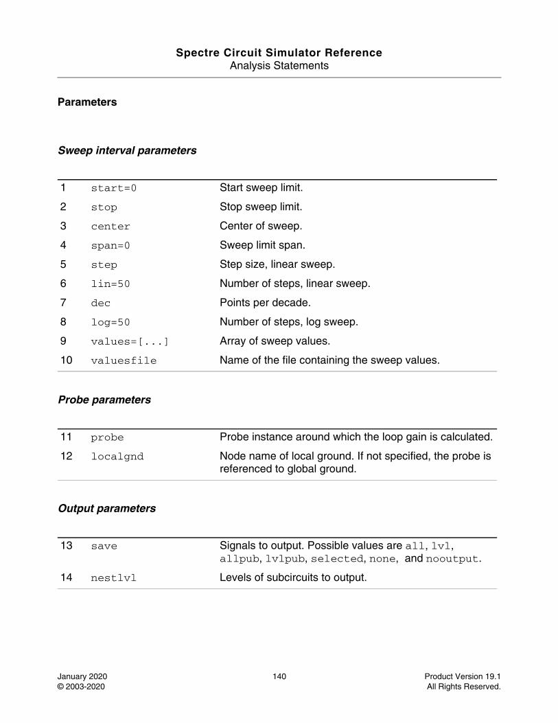
Spectre Circuit Simulator ReferenceAnalysis Statements
January 2020 140 Product Version 19.1© 2003-2020 All Rights Reserved.
Parameters
Sweep interval parameters
Probe parameters
Output parameters
1 start=0 Start sweep limit.
2 stop Stop sweep limit.
3 center Center of sweep.
4 span=0 Sweep limit span.
5 step Step size, linear sweep.
6 lin=50 Number of steps, linear sweep.
7 dec Points per decade.
8 log=50 Number of steps, log sweep.
9 values=[...] Array of sweep values.
10 valuesfile Name of the file containing the sweep values.
11 probe Probe instance around which the loop gain is calculated.
12 localgnd Node name of local ground. If not specified, the probe is referenced to global ground.
13 save Signals to output. Possible values are all, lvl, allpub, lvlpub, selected, none, and nooutput.
14 nestlvl Levels of subcircuits to output.
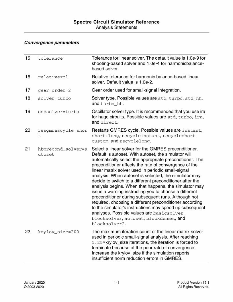
Spectre Circuit Simulator ReferenceAnalysis Statements
January 2020 141 Product Version 19.1© 2003-2020 All Rights Reserved.
Convergence parameters
15 tolerance Tolerance for linear solver. The default value is 1.0e-9 for shooting-based solver and 1.0e-4 for harmonicbalance-based solver.
16 relativeTol Relative tolerance for harmonic balance-based linear solver. Default value is 1.0e-2.
17 gear_order=2 Gear order used for small-signal integration.
18 solver=turbo Solver type. Possible values are std, turbo, std_hh, and turbo_hh.
19 oscsolver=turbo Oscillator solver type. It is recommended that you use ira for huge circuits. Possible values are std, turbo, ira, and direct.
20 resgmrescycle=short
Restarts GMRES cycle. Possible values are instant, short, long, recycleinstant, recycleshort, custom, and recyclelong.
21 hbprecond_solver=autoset
Select a linear solver for the GMRES preconditioner. Default is autoset. With autoset, the simulator will automatically select the appropriate precondtioner. The preconditioner affects the rate of convergence of the linear matrix solver used in periodic small-signal analysis. When autoset is selected, the simulator may decide to switch to a different preconditioner after the analysis begins. When that happens, the simulator may issue a warning instructing you to choose a different preconditioner during subsequent runs. Although not required, choosing a different preconditioner according to the simulator's instructions may speed up subsequent analyses. Possible values are basicsolver, blocksolver, autoset, blockdense,, and blocksolver2.
22 krylov_size=200 The maximum iteration count of the linear matrix solver used in periodic small-signal analysis. After reaching 1.25*krylov_size iterations, the iteration is forced to terminate because of the poor rate of convergence. Increase the krylov_size if the simulation reports insufficient norm reduction errors in GMRES.
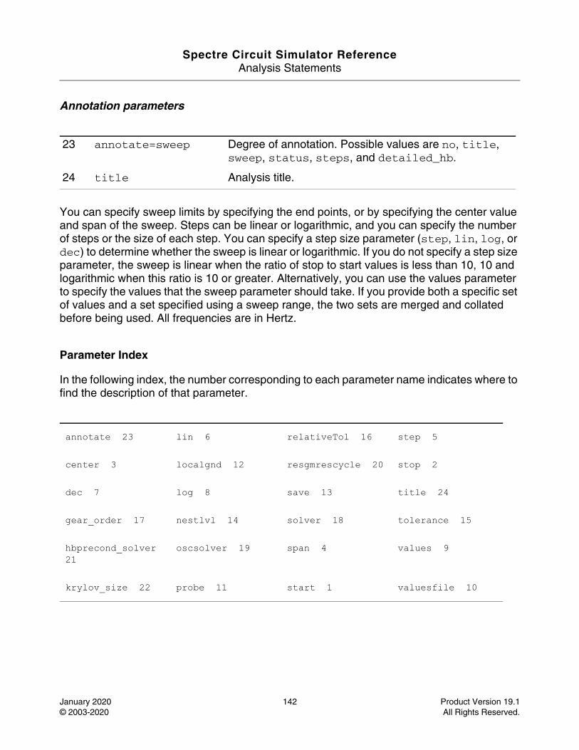
Spectre Circuit Simulator ReferenceAnalysis Statements
January 2020 142 Product Version 19.1© 2003-2020 All Rights Reserved.
Annotation parameters
You can specify sweep limits by specifying the end points, or by specifying the center value and span of the sweep. Steps can be linear or logarithmic, and you can specify the number of steps or the size of each step. You can specify a step size parameter (step, lin, log, or dec) to determine whether the sweep is linear or logarithmic. If you do not specify a step size parameter, the sweep is linear when the ratio of stop to start values is less than 10, 10 and logarithmic when this ratio is 10 or greater. Alternatively, you can use the values parameter to specify the values that the sweep parameter should take. If you provide both a specific set of values and a set specified using a sweep range, the two sets are merged and collated before being used. All frequencies are in Hertz.
Parameter Index
In the following index, the number corresponding to each parameter name indicates where to find the description of that parameter.
23 annotate=sweep Degree of annotation. Possible values are no, title, sweep, status, steps, and detailed_hb.
24 title Analysis title.
annotate 23 lin 6 relativeTol 16 step 5
center 3 localgnd 12 resgmrescycle 20 stop 2
dec 7 log 8 save 13 title 24
gear_order 17 nestlvl 14 solver 18 tolerance 15
hbprecond_solver 21
oscsolver 19 span 4 values 9
krylov_size 22 probe 11 start 1 valuesfile 10
Spectre Circuit Simulator ReferenceAnalysis Statements
January 2020 143 Product Version 19.1© 2003-2020 All Rights Reserved.
HB XF Analysis (hbxf)
Description
A conventional transfer function analysis computes the transfer function from every source in the circuit to a single output. Unlike a conventional AC analysis that computes the response from a single stimulus to every node in the circuit, the Harmonic Balance Transfer Function or HBXF analysis computes the transfer functions from any source at any frequency to a single output at a single frequency. Thus, like HBAC analysis, HBXF analysis includes frequency conversion effects.
The HBXF analysis directly computes such useful quantities as conversion efficiency (transfer function from input to output at required frequency), image and sideband rejection (input to output at undesired frequency), and LO feed-through and power supply rejection (undesired input to output at all frequencies).
As with a HBAC, HBSP, and HBNoise analyses, a HBXF analysis must follow a HB analysis.
Note: Note: Unlike other analyses in Spectre, this analysis can only sweep frequency.
DefinitionName [p] [n] ... hbxf parameter=value ...
The optional terminals (p and n) specify the output of the circuit. If you do not specify the terminals, you must specify the output with a probe component.
For information on how to run HB noise analysis from ADE, see Harmonic Balance Transfer Function Analysis (HBXF) in the Spectre Circuit Simulator and Accelerated Parallel Simulator RF Analysis User Guide.
Parameters
Sweep interval parameters
1 start=0 Start sweep limit.
2 stop Stop sweep limit.
3 center Center of sweep.
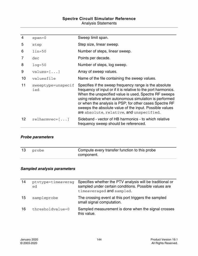
Spectre Circuit Simulator ReferenceAnalysis Statements
January 2020 144 Product Version 19.1© 2003-2020 All Rights Reserved.
Probe parameters
Sampled analysis parameters
4 span=0 Sweep limit span.
5 step Step size, linear sweep.
6 lin=50 Number of steps, linear sweep.
7 dec Points per decade.
8 log=50 Number of steps, log sweep.
9 values=[...] Array of sweep values.
10 valuesfile Name of the file containing the sweep values.
11 sweeptype=unspecified
Specifies if the sweep frequency range is the absolute frequency of input or if it is relative to the port harmonics. When the unspecified value is used, Spectre RF sweeps using relative when autonomous simulation is performed or when the analysis is PSP; for other cases Spectre RF sweeps the absolute value of the input. Possible values are absolute, relative, and unspecified.
12 relharmvec=[...] Sideband - vector of HB harmonics - to which relative frequency sweep should be referenced.
13 probe Compute every transfer function to this probe component.
14 ptvtype=timeaveraged
Specifies whether the PTV analysis will be traditional or sampled under certain conditions. Possible values are timeaveraged and sampled.
15 sampleprobe The crossing event at this port triggers the sampled small signal computation.
16 thresholdvalue=0 Sampled measurement is done when the signal crosses this value.
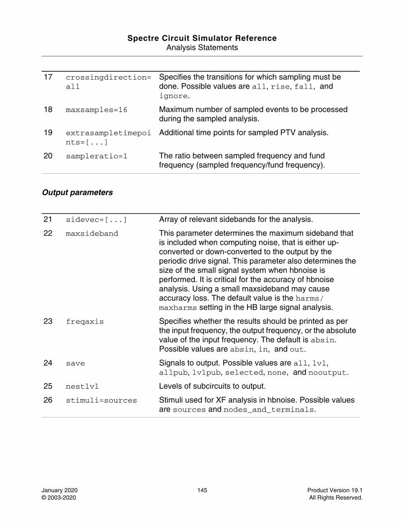
Spectre Circuit Simulator ReferenceAnalysis Statements
January 2020 145 Product Version 19.1© 2003-2020 All Rights Reserved.
Output parameters
17 crossingdirection=all
Specifies the transitions for which sampling must be done. Possible values are all, rise, fall, and ignore.
18 maxsamples=16 Maximum number of sampled events to be processed during the sampled analysis.
19 extrasampletimepoints=[...]
Additional time points for sampled PTV analysis.
20 sampleratio=1 The ratio between sampled frequency and fund frequency (sampled frequency/fund frequency).
21 sidevec=[...] Array of relevant sidebands for the analysis.
22 maxsideband This parameter determines the maximum sideband that is included when computing noise, that is either up-converted or down-converted to the output by the periodic drive signal. This parameter also determines the size of the small signal system when hbnoise is performed. It is critical for the accuracy of hbnoise analysis. Using a small maxsideband may cause accuracy loss. The default value is the harms/maxharms setting in the HB large signal analysis.
23 freqaxis Specifies whether the results should be printed as per the input frequency, the output frequency, or the absolute value of the input frequency. The default is absin. Possible values are absin, in, and out.
24 save Signals to output. Possible values are all, lvl, allpub, lvlpub, selected, none, and nooutput.
25 nestlvl Levels of subcircuits to output.
26 stimuli=sources Stimuli used for XF analysis in hbnoise. Possible values are sources and nodes_and_terminals.
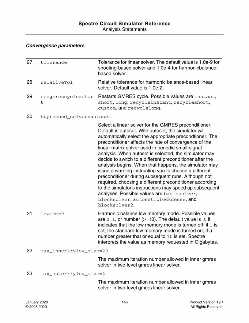
Spectre Circuit Simulator ReferenceAnalysis Statements
January 2020 146 Product Version 19.1© 2003-2020 All Rights Reserved.
Convergence parameters
27 tolerance Tolerance for linear solver. The default value is 1.0e-9 for shooting-based solver and 1.0e-4 for harmonicbalance-based solver.
28 relativeTol Relative tolerance for harmonic balance-based linear solver. Default value is 1.0e-2.
29 resgmrescycle=short
Restarts GMRES cycle. Possible values are instant, short, long, recycleinstant, recycleshort, custom, and recyclelong.
30 hbprecond_solver=autoset
Select a linear solver for the GMRES preconditioner. Default is autoset. With autoset, the simulator will automatically select the appropriate precondtioner. The preconditioner affects the rate of convergence of the linear matrix solver used in periodic small-signal analysis. When autoset is selected, the simulator may decide to switch to a different preconditioner after the analysis begins. When that happens, the simulator may issue a warning instructing you to choose a different preconditioner during subsequent runs. Although not required, choosing a different preconditioner according to the simulator's instructions may speed up subsequent analyses. Possible values are basicsolver, blocksolver, autoset, blockdense, and blocksolver2.
31 lowmem=0 Harmonic balance low memory mode. Possible values are 0, 1, or number (>=10). The default value is 0, it indicates that the low memory mode is turned off; if 1 is set, the standard low memory mode is turned on; If a number greater that or equal to 10 is set, Spectre interprets the value as memory requested in Gigabytes.
32 max_innerkrylov_size=20
The maximum iteration number allowed in inner gmres solver in two-level gmres linear solver.
33 max_outerkrylov_size=4
The maximum iteration number allowed in inner gmres solver in two-level gmres linear solver.
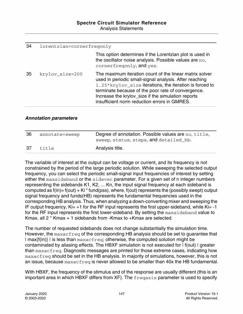
Spectre Circuit Simulator ReferenceAnalysis Statements
January 2020 147 Product Version 19.1© 2003-2020 All Rights Reserved.
Annotation parameters
The variable of interest at the output can be voltage or current, and its frequency is not constrained by the period of the large periodic solution. While sweeping the selected output frequency, you can select the periodic small-signal input frequencies of interest by setting either the maxsideband or the sidevec parameter. For a given set of n integer numbers representing the sidebands K1, K2, ... Kn, the input signal frequency at each sideband is computed as f(in)= f(out) + Ki * fund(pss), where, f(out) represents the (possibly swept) output signal frequency and funds(HB) represents the fundamental frequencies used in the corresponding HB analysis. Thus, when analyzing a down-converting mixer and sweeping the IF output frequency, Ki= +1 for the RF input represents the first upper-sideband, while Ki= -1 for the RF input represents the first lower-sideband. By setting the maxsideband value to Kmax, all 2 * Kmax + 1 sidebands from -Kmax to +Kmax are selected.
The number of requested sidebands does not change substantially the simulation time. However, the maxacfreq of the corresponding HB analysis should be set to guarantee that | max{f(in)} | is less than maxacfreq; otherwise, the computed solution might be contaminated by aliasing effects. The HBXF simulation is not executed for | f(out) | greater than maxacfreq. Diagnostic messages are printed for those extreme cases, indicating how maxacfreq should be set in the HB analysis. In majority of simulations, however, this is not an issue, because maxacfreq is never allowed to be smaller than 40x the HB fundamental.
With HBXF, the frequency of the stimulus and of the response are usually different (this is an important area in which HBXF differs from XF). The freqaxis parameter is used to specify
34 lorentzian=cornerfreqonly
This option determines if the Lorentzian plot is used in the oscillator noise analysis. Possible values are no, cornerfreqonly, and yes.
35 krylov_size=200 The maximum iteration count of the linear matrix solver used in periodic small-signal analysis. After reaching 1.25*krylov_size iterations, the iteration is forced to terminate because of the poor rate of convergence. Increase the krylov_size if the simulation reports insufficient norm reduction errors in GMRES.
36 annotate=sweep Degree of annotation. Possible values are no, title, sweep, status, steps, and detailed_hb.
37 title Analysis title.
Spectre Circuit Simulator ReferenceAnalysis Statements
January 2020 148 Product Version 19.1© 2003-2020 All Rights Reserved.
whether the results should be output versus the input frequency (in), the output frequency (out), or the absolute value of the input frequency (absin).
You can specify the output with a pair of nodes or a probe component. Any component with two or more terminals can be a voltage probe. When there are more than two terminals, they are grouped in pairs, and you use the portv parameter to select the appropriate pair of terminals. Alternatively, you can specify a voltage to be the output by giving a pair of nodes on the HBXF analysis statement.
Any component that naturally computes current as an internal variable can be a current probe. If the probe component computes more than one current, you use the porti parameter to select the appropriate current. It is an error to specify both portv and porti. If neither is specified, the probe component provides a reasonable default.
The stimuli parameter specifies the inputs for the transfer functions. There are two choices. stimuli=sources indicates that the sources present in the circuit should be used. The xfmag parameters provided by the sources may be used to adjust the computed gain to compensate for gains or losses in a test fixture. One can limit the number of sources in hierarchical netlists by using the save and nestlvl parameters. stimuli=nodes_and_terminals indicates that all possible transfer functions should be computed.
This is useful when it is not known in advance which transfer functions are interesting. Transfer functions for nodes are computed assuming that a unit magnitude flow (current) source is connected from the node to ground. Transfer functions for terminals are computed assuming that a unit magnitude value (voltage) source is connected in series with the terminal. By default, the transfer functions from a small set of terminals are computed. If transfer functions from specific terminals are required, specify the terminals in the save statement. You must use the :probe modifier (for example, Rout:1:probe) or specify useprobes=yes on the options statement. If transfer functions from all terminals are required, specify currents=all and useprobes=yes on the options statement.
You can specify sweep limits by specifying the end points, or the center value and span of the sweep. Steps can be linear or logarithmic, and you can specify the number of steps or the size of each step. You can specify a step size parameter (step, lin, log, or dec) to determine whether the sweep is linear or logarithmic. If you do not specify a step size parameter, the sweep is linear when the ratio of stop to start values is less than 10 and logarithmic when this ratio is 10 or greater. Alternatively, you can use the values parameter to specify the values that the sweep parameter should take. If you provide both a specific set of values and a set specified using a sweep range, the two sets are merged and collated before being used. All frequencies are in Hertz.
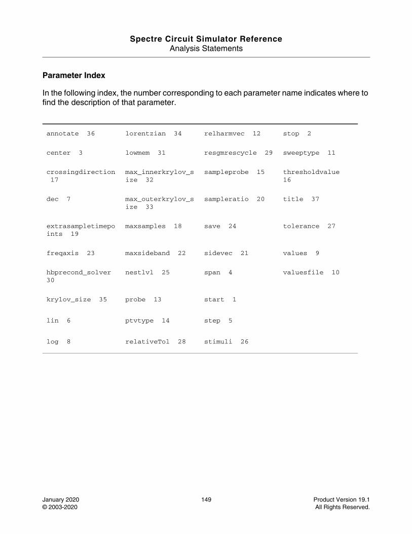
Spectre Circuit Simulator ReferenceAnalysis Statements
January 2020 149 Product Version 19.1© 2003-2020 All Rights Reserved.
Parameter Index
In the following index, the number corresponding to each parameter name indicates where to find the description of that parameter.
annotate 36 lorentzian 34 relharmvec 12 stop 2
center 3 lowmem 31 resgmrescycle 29 sweeptype 11
crossingdirection 17
max_innerkrylov_size 32
sampleprobe 15 thresholdvalue 16
dec 7 max_outerkrylov_size 33
sampleratio 20 title 37
extrasampletimepoints 19
maxsamples 18 save 24 tolerance 27
freqaxis 23 maxsideband 22 sidevec 21 values 9
hbprecond_solver 30
nestlvl 25 span 4 valuesfile 10
krylov_size 35 probe 13 start 1
lin 6 ptvtype 14 step 5
log 8 relativeTol 28 stimuli 26
Spectre Circuit Simulator ReferenceAnalysis Statements
January 2020 150 Product Version 19.1© 2003-2020 All Rights Reserved.
Circuit Information (info)
Description
The circuit information analysis outputs several types of information about the circuit and its components. You can use various filters to specify what information is output. You can create a listing of model, instance, temperature-dependent, input, output, and operating point parameters. You can also generate a summary of the minimum and maximum parameter values (by using extremes=yes or only). Finally, you can request that Spectre provides a node-to-terminal map (by using what=terminals) or a terminal-to-node map (by using what=nodes).
The following are brief descriptions of the types of parameters you can request with the info statement:
■ Input parameters: Parameters that you specify in the netlist, such as the given length of a MOSFET or the saturation current of a bipolar transistor (use what=inst, models, input, or all)
■ Output parameters: Parameters that are computed by Spectre, such as temperature-dependent parameters and the effective length of a MOSFET after scaling (use what=output or all)
■ Operating-point parameters: Parameters that depend on the solution computed (use what=oppoint)
Initial condition file creation writes node voltages and source currents into a file that can be read by the transient analysis readic/readns statement.
For additional information, refer to The info Statement in the Spectre Classic Simulator, Spectre APS, Spectre X, and Spectre XPS User Guide.
DefinitionName info parameter=value ...
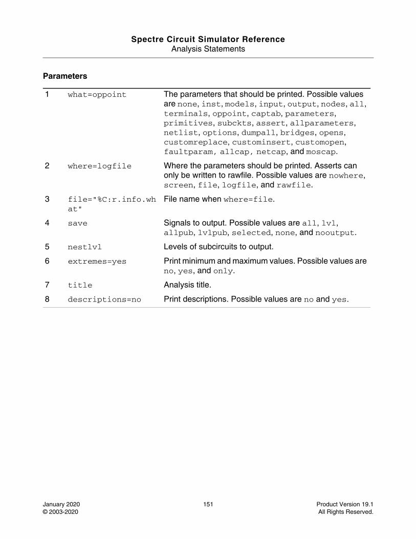
Spectre Circuit Simulator ReferenceAnalysis Statements
January 2020 151 Product Version 19.1© 2003-2020 All Rights Reserved.
Parameters
1 what=oppoint The parameters that should be printed. Possible values are none, inst, models, input, output, nodes, all, terminals, oppoint, captab, parameters, primitives, subckts, assert, allparameters, netlist, options, dumpall, bridges, opens, customreplace, custominsert, customopen, faultparam, allcap, netcap, and moscap.
2 where=logfile Where the parameters should be printed. Asserts can only be written to rawfile. Possible values are nowhere, screen, file, logfile, and rawfile.
3 file="%C:r.info.what"
File name when where=file.
4 save Signals to output. Possible values are all, lvl, allpub, lvlpub, selected, none, and nooutput.
5 nestlvl Levels of subcircuits to output.
6 extremes=yes Print minimum and maximum values. Possible values are no, yes, and only.
7 title Analysis title.
8 descriptions=no Print descriptions. Possible values are no and yes.
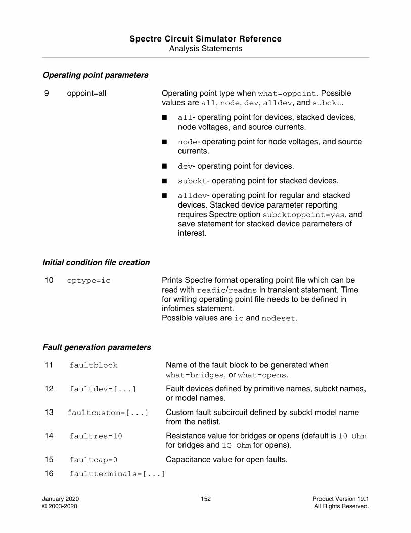
Spectre Circuit Simulator ReferenceAnalysis Statements
January 2020 152 Product Version 19.1© 2003-2020 All Rights Reserved.
Operating point parameters
Initial condition file creation
Fault generation parameters
9 oppoint=all Operating point type when what=oppoint. Possible values are all, node, dev, alldev, and subckt.
■ all- operating point for devices, stacked devices, node voltages, and source currents.
■ node- operating point for node voltages, and source currents.
■ dev- operating point for devices.
■ subckt- operating point for stacked devices.
■ alldev- operating point for regular and stacked devices. Stacked device parameter reporting requires Spectre option subcktoppoint=yes, and save statement for stacked device parameters of interest.
10 optype=ic Prints Spectre format operating point file which can be read with readic/readns in transient statement. Time for writing operating point file needs to be defined in infotimes statement.Possible values are ic and nodeset.
11 faultblock Name of the fault block to be generated when what=bridges, or what=opens.
12 faultdev=[...] Fault devices defined by primitive names, subckt names, or model names.
13 faultcustom=[...] Custom fault subcircuit defined by subckt model name from the netlist.
14 faultres=10 Resistance value for bridges or opens (default is 10 Ohm for bridges and 1G Ohm for opens).
15 faultcap=0 Capacitance value for open faults.
16 faultterminals=[...]
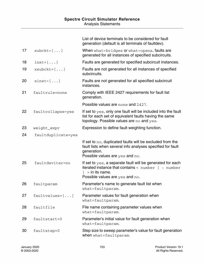
Spectre Circuit Simulator ReferenceAnalysis Statements
January 2020 153 Product Version 19.1© 2003-2020 All Rights Reserved.
List of device terminals to be considered for fault generation (default is all terminals of faultdev).
17 subckt=[...] When what=bridges or what=opens, faults are generated for all instances of specified subcircuits.
18 inst=[...] Faults are generated for specified subcircuit instances.
19 xsubckt=[...] Faults are not generated for all instances of specified subcircuits.
20 xinst=[...] Faults are not generated for all specified subcircuit instances.
21 faultrule=none Comply with IEEE 2427 requirements for fault list generation.
Possible values are none and 2427.
22 faultcollapse=yes If set to yes, only one fault will be included into the fault list for each set of equivalent faults having the same topology. Possible values are no and yes.
23 weight_expr Expression to define fault weighting function.
24 faultduplicate=yes
If set to no, duplicated faults will be excluded from the fault lists when several info analyses specified for fault generation.Possible values are yes and no.
25 faultdeviter=no If set to yes, a separate fault will be generated for each iterated instance that contains < number [ : number ] > in its name. Possible values are yes and no.
26 faultparam Parameter's name to generate fault list when what=faultparam.
27 faultvalues=[...] Parameter values for fault generation when what=faultparam.
28 faultfile File name containing parameter values when what=faultparam.
29 faultstart=0 Parameter's initial value for fault generation when what=faultparam.
30 faultstep=0 Step size to sweep parameter's value for fault generation when what=faultparam.
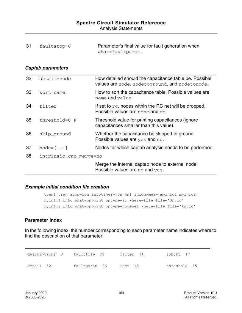
Spectre Circuit Simulator ReferenceAnalysis Statements
January 2020 154 Product Version 19.1© 2003-2020 All Rights Reserved.
Captab parameters
Example initial condition file creation tran1 tran stop=10n infotimes=[3n 4n] infonames=[myinfo1 myinfo2] myinfo1 info what=oppoint optype=ic where=file file='3n.ic' myinfo2 info what=oppoint optype=nodeset where=file file='4n.ic'
Parameter Index
In the following index, the number corresponding to each parameter name indicates where to find the description of that parameter:
31 faultstop=0 Parameter's final value for fault generation when what=faultparam.
32 detail=node How detailed should the capacitance table be. Possible values are node, nodetoground, and nodetonode.
33 sort=name How to sort the capacitance table. Possible values are name and value.
34 filter If set to rc, nodes within the RC net will be dropped.Possible values are none and rc.
35 threshold=0 F Threshold value for printing capacitances (ignore capacitances smaller than this value).
36 skip_ground Whether the capacitance be skipped to ground.Possible values are yes and no.
37 node=[...] Nodes for which captab analysis needs to be performed.
38 intrinsic_cap_merge=no
Merge the internal captab node to external node. Possible values are no and yes.
descriptions 8 faultfile 28 filter 34 subckt 17
detail 32 faultparam 26 inst 18 threshold 35
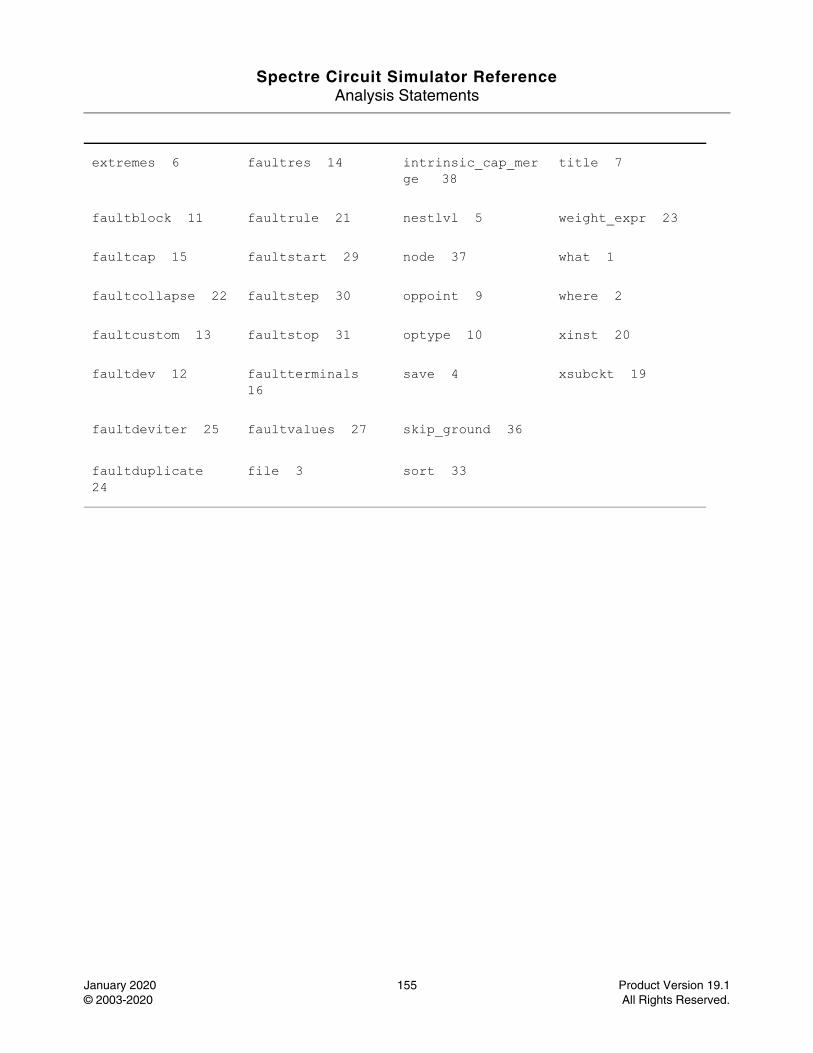
Spectre Circuit Simulator ReferenceAnalysis Statements
January 2020 155 Product Version 19.1© 2003-2020 All Rights Reserved.
extremes 6 faultres 14 intrinsic_cap_merge 38
title 7
faultblock 11 faultrule 21 nestlvl 5 weight_expr 23
faultcap 15 faultstart 29 node 37 what 1
faultcollapse 22 faultstep 30 oppoint 9 where 2
faultcustom 13 faultstop 31 optype 10 xinst 20
faultdev 12 faultterminals 16
save 4 xsubckt 19
faultdeviter 25 faultvalues 27 skip_ground 36
faultduplicate 24
file 3 sort 33
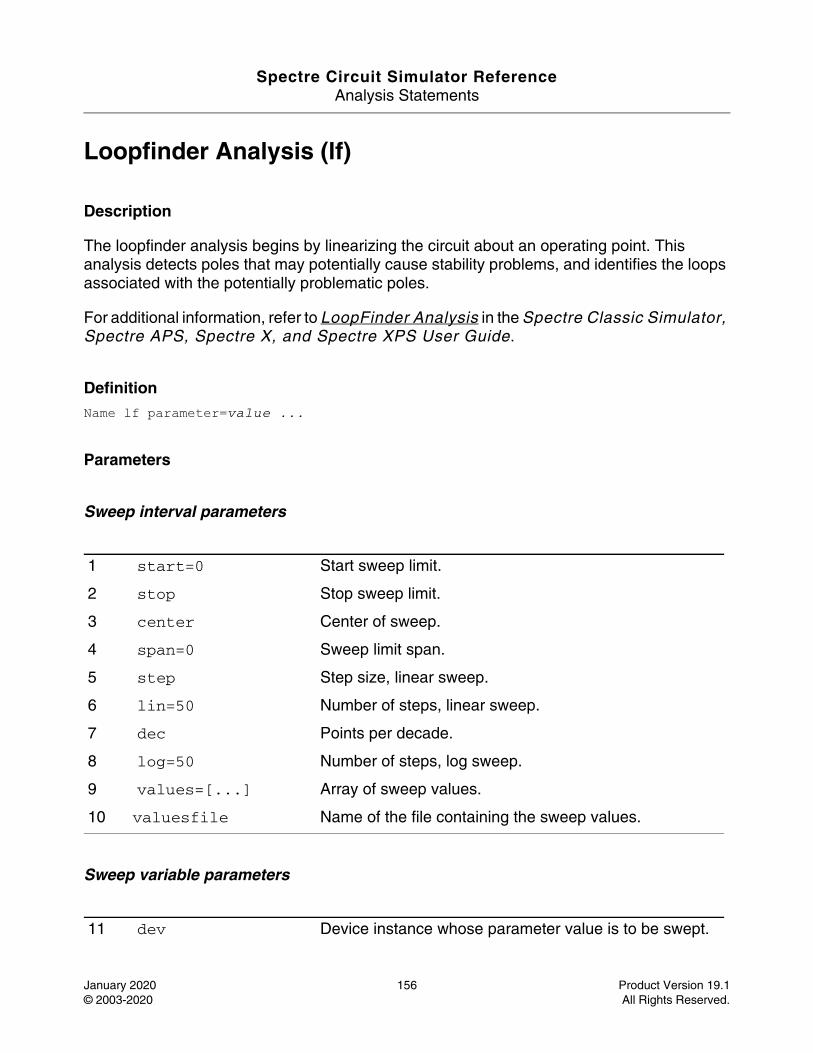
Spectre Circuit Simulator ReferenceAnalysis Statements
January 2020 156 Product Version 19.1© 2003-2020 All Rights Reserved.
Loopfinder Analysis (lf)
Description
The loopfinder analysis begins by linearizing the circuit about an operating point. This analysis detects poles that may potentially cause stability problems, and identifies the loops associated with the potentially problematic poles.
For additional information, refer to LoopFinder Analysis in the Spectre Classic Simulator, Spectre APS, Spectre X, and Spectre XPS User Guide.
DefinitionName lf parameter=value ...
Parameters
Sweep interval parameters
Sweep variable parameters
1 start=0 Start sweep limit.
2 stop Stop sweep limit.
3 center Center of sweep.
4 span=0 Sweep limit span.
5 step Step size, linear sweep.
6 lin=50 Number of steps, linear sweep.
7 dec Points per decade.
8 log=50 Number of steps, log sweep.
9 values=[...] Array of sweep values.
10 valuesfile Name of the file containing the sweep values.
11 dev Device instance whose parameter value is to be swept.
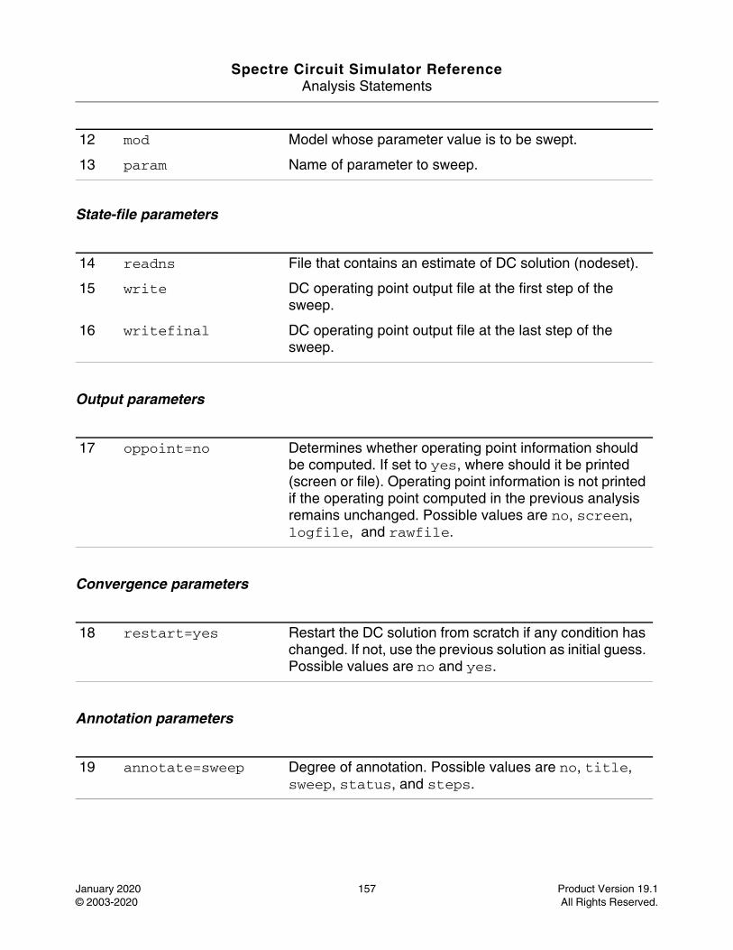
Spectre Circuit Simulator ReferenceAnalysis Statements
January 2020 157 Product Version 19.1© 2003-2020 All Rights Reserved.
State-file parameters
Output parameters
Convergence parameters
Annotation parameters
12 mod Model whose parameter value is to be swept.
13 param Name of parameter to sweep.
14 readns File that contains an estimate of DC solution (nodeset).
15 write DC operating point output file at the first step of the sweep.
16 writefinal DC operating point output file at the last step of the sweep.
17 oppoint=no Determines whether operating point information should be computed. If set to yes, where should it be printed (screen or file). Operating point information is not printed if the operating point computed in the previous analysis remains unchanged. Possible values are no, screen, logfile, and rawfile.
18 restart=yes Restart the DC solution from scratch if any condition has changed. If not, use the previous solution as initial guess. Possible values are no and yes.
19 annotate=sweep Degree of annotation. Possible values are no, title, sweep, status, and steps.
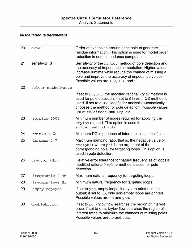
Spectre Circuit Simulator ReferenceAnalysis Statements
January 2020 158 Product Version 19.1© 2003-2020 All Rights Reserved.
Miscellaneous parameters
20 order Order of expansion around each pole to generate residue information. This option is used for model order reduction in node impedance computation.
21 sensitivity=3 Sensitivity of the krylov method of pole detection and the accuracy of impedance computation. Higher values increase runtime while reduce the chance of missing a pole and improve the accuracy of impedance values. Possible values are 1, 2, 3, 4, and 5.
22 solver_method=auto
If set to krylov, the modified rational krylov method is used for pole detection; if set to direct, QZ method is used. If set to auto, loopfinder analysis automatically chooses the method for pole detection. Possible values are auto, direct, and krylov.
23 romsize=6000 Minimum number of nodes required for applying the krylov method. This option is used if solver_method=auto.
24 zmin=0.1 Ω Minimum DC impedance of interest in loop identification.
25 dampmax=0.7 Maximum damping ratio, that is, the negative value of cos(phi) where phi is the argument of the corresponding pole, for targeting loops. This option is used in pole detection.
26 freqtol (Hz) Relative error tolerance for natural frequencies of loops if modified rational krylov method is used for pole detection.
27 freqmax=1e10 Hz Maximum natural frequency for targeting loops.
28 freqmin=1e-2 Hz Minimum natural frequency for targeting loops.
29 emptyloop=yes If set to yes, empty loops, if any, are printed in the output; if set to no, only non-empty loops are printed. Possible values are no and yes.
30 doublekrylov If set to no, krylov flow searches the region of interest once; if set to yes, krylov flow searches the region of interest twice to minimize the chances of missing poles. Possible values are no and yes.
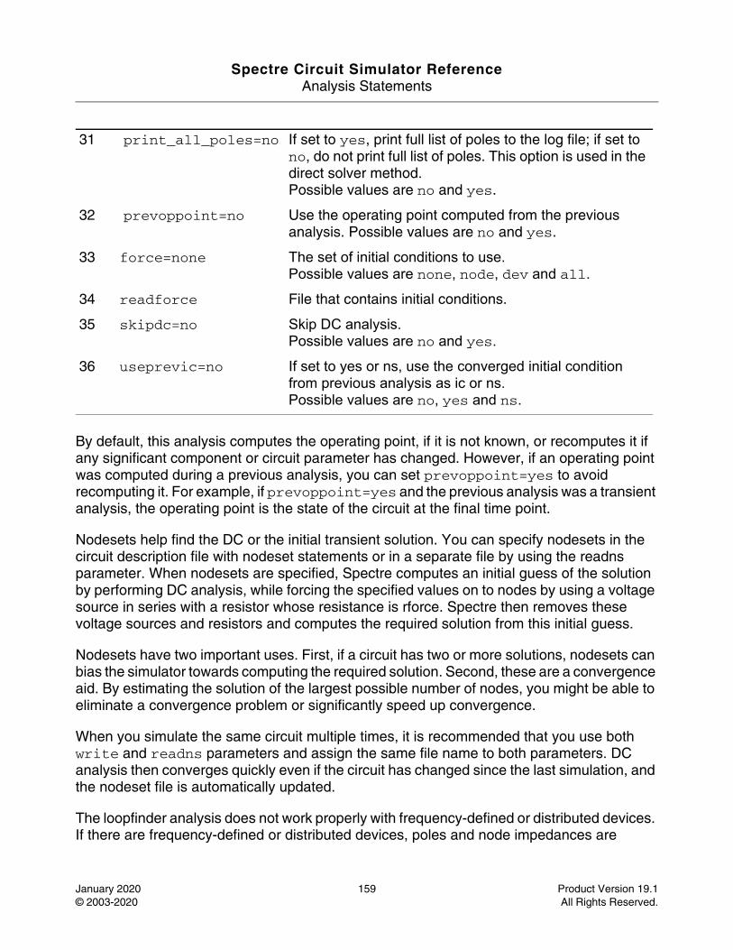
Spectre Circuit Simulator ReferenceAnalysis Statements
January 2020 159 Product Version 19.1© 2003-2020 All Rights Reserved.
By default, this analysis computes the operating point, if it is not known, or recomputes it if any significant component or circuit parameter has changed. However, if an operating point was computed during a previous analysis, you can set prevoppoint=yes to avoid recomputing it. For example, if prevoppoint=yes and the previous analysis was a transient analysis, the operating point is the state of the circuit at the final time point.
Nodesets help find the DC or the initial transient solution. You can specify nodesets in the circuit description file with nodeset statements or in a separate file by using the readns parameter. When nodesets are specified, Spectre computes an initial guess of the solution by performing DC analysis, while forcing the specified values on to nodes by using a voltage source in series with a resistor whose resistance is rforce. Spectre then removes these voltage sources and resistors and computes the required solution from this initial guess.
Nodesets have two important uses. First, if a circuit has two or more solutions, nodesets can bias the simulator towards computing the required solution. Second, these are a convergence aid. By estimating the solution of the largest possible number of nodes, you might be able to eliminate a convergence problem or significantly speed up convergence.
When you simulate the same circuit multiple times, it is recommended that you use both write and readns parameters and assign the same file name to both parameters. DC analysis then converges quickly even if the circuit has changed since the last simulation, and the nodeset file is automatically updated.
The loopfinder analysis does not work properly with frequency-defined or distributed devices. If there are frequency-defined or distributed devices, poles and node impedances are
31 print_all_poles=no If set to yes, print full list of poles to the log file; if set to no, do not print full list of poles. This option is used in the direct solver method.Possible values are no and yes.
32 prevoppoint=no Use the operating point computed from the previous analysis. Possible values are no and yes.
33 force=none The set of initial conditions to use.Possible values are none, node, dev and all.
34 readforce File that contains initial conditions.
35 skipdc=no Skip DC analysis.Possible values are no and yes.
36 useprevic=no If set to yes or ns, use the converged initial condition from previous analysis as ic or ns.Possible values are no, yes and ns.
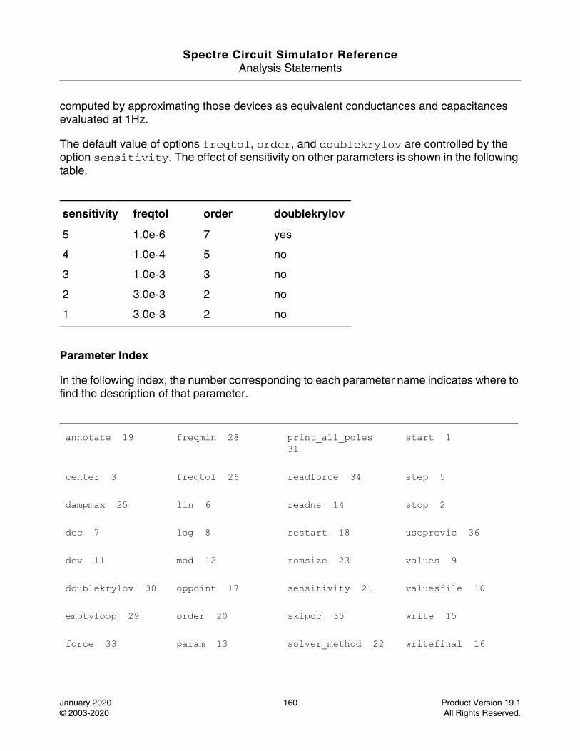
Spectre Circuit Simulator ReferenceAnalysis Statements
January 2020 160 Product Version 19.1© 2003-2020 All Rights Reserved.
computed by approximating those devices as equivalent conductances and capacitances evaluated at 1Hz.
The default value of options freqtol, order, and doublekrylov are controlled by the option sensitivity. The effect of sensitivity on other parameters is shown in the following table.
Parameter Index
In the following index, the number corresponding to each parameter name indicates where to find the description of that parameter.
sensitivity freqtol order doublekrylov
5 1.0e-6 7 yes
4 1.0e-4 5 no
3 1.0e-3 3 no
2 3.0e-3 2 no
1 3.0e-3 2 no
annotate 19 freqmin 28 print_all_poles 31
start 1
center 3 freqtol 26 readforce 34 step 5
dampmax 25 lin 6 readns 14 stop 2
dec 7 log 8 restart 18 useprevic 36
dev 11 mod 12 romsize 23 values 9
doublekrylov 30 oppoint 17 sensitivity 21 valuesfile 10
emptyloop 29 order 20 skipdc 35 write 15
force 33 param 13 solver_method 22 writefinal 16

Spectre Circuit Simulator ReferenceAnalysis Statements
January 2020 161 Product Version 19.1© 2003-2020 All Rights Reserved.
freqmax 27 prevoppoint 32 span 4 zmin 24
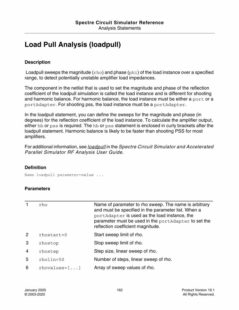
Spectre Circuit Simulator ReferenceAnalysis Statements
January 2020 162 Product Version 19.1© 2003-2020 All Rights Reserved.
Load Pull Analysis (loadpull)
Description
Loadpull sweeps the magnitude (rho) and phase (phi) of the load instance over a specified range, to detect potentially unstable amplifier load impedances.
The component in the netlist that is used to set the magnitude and phase of the reflection coefficient of the loadpull simulation is called the load instance and is different for shooting and harmonic balance. For harmonic balance, the load instance must be either a port or a portAdapter. For shooting pss, the load instance must be a portAdapter.
In the loadpull statement, you can define the sweeps for the magnitude and phase (in degrees) for the reflection coefficient of the load instance. To calculate the amplifier output, either hb or pss is required. The hb or pss statement is enclosed in curly brackets after the loadpull statement. Harmonic balance is likely to be faster than shooting PSS for most amplifiers.
For additional information, see loadpull in the Spectre Circuit Simulator and Accelerated Parallel Simulator RF Analysis User Guide.
DefinitionName loadpull parameter=value ...
Parameters
1 rho Name of parameter to rho sweep. The name is arbitrary and must be specified in the parameter list. When a portAdapter is used as the load instance, the parameter must be used in the portAdapter to set the reflection coefficient magnitude.
2 rhostart=0 Start sweep limit of rho.
3 rhostop Stop sweep limit of rho.
4 rhostep Step size, linear sweep of rho.
5 rholin=50 Number of steps, linear sweep of rho.
6 rhovalues=[...] Array of sweep values of rho.
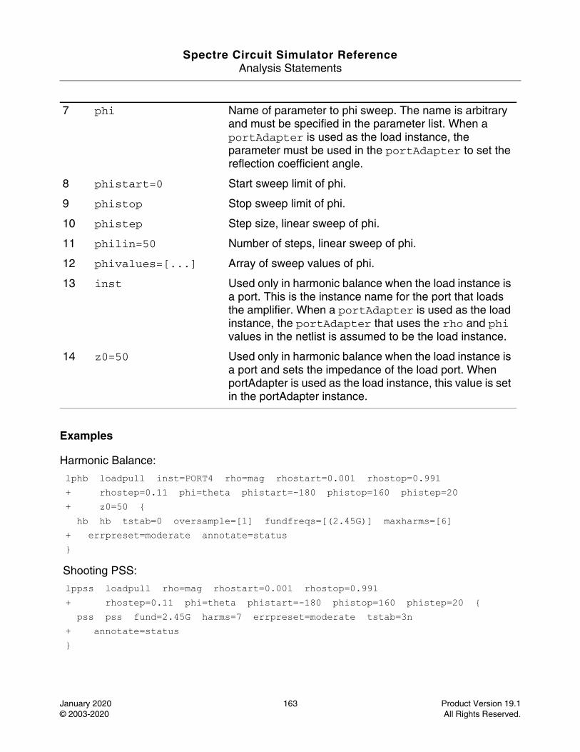
Spectre Circuit Simulator ReferenceAnalysis Statements
January 2020 163 Product Version 19.1© 2003-2020 All Rights Reserved.
Examples
Harmonic Balance:
lphb loadpull inst=PORT4 rho=mag rhostart=0.001 rhostop=0.991 + rhostep=0.11 phi=theta phistart=-180 phistop=160 phistep=20 + z0=50 { hb hb tstab=0 oversample=[1] fundfreqs=[(2.45G)] maxharms=[6] + errpreset=moderate annotate=status }
Shooting PSS:
lppss loadpull rho=mag rhostart=0.001 rhostop=0.991 + rhostep=0.11 phi=theta phistart=-180 phistop=160 phistep=20 { pss pss fund=2.45G harms=7 errpreset=moderate tstab=3n + annotate=status }
7 phi Name of parameter to phi sweep. The name is arbitrary and must be specified in the parameter list. When a portAdapter is used as the load instance, the parameter must be used in the portAdapter to set the reflection coefficient angle.
8 phistart=0 Start sweep limit of phi.
9 phistop Stop sweep limit of phi.
10 phistep Step size, linear sweep of phi.
11 philin=50 Number of steps, linear sweep of phi.
12 phivalues=[...] Array of sweep values of phi.
13 inst Used only in harmonic balance when the load instance is a port. This is the instance name for the port that loads the amplifier. When a portAdapter is used as the load instance, the portAdapter that uses the rho and phi values in the netlist is assumed to be the load instance.
14 z0=50 Used only in harmonic balance when the load instance is a port and sets the impedance of the load port. When portAdapter is used as the load instance, this value is set in the portAdapter instance.

Spectre Circuit Simulator ReferenceAnalysis Statements
January 2020 164 Product Version 19.1© 2003-2020 All Rights Reserved.
Parameter Index
In the following index, the number corresponding to each parameter name indicates where to find the description of that parameter.
inst 13 phistep 10 rholin 5 rhovalues 6
phi 7 phistop 9 rhostart 2 z0 14
philin 11 phivalues 12 rhostep 4
phistart 8 rho 1 rhostop 3
Spectre Circuit Simulator ReferenceAnalysis Statements
January 2020 165 Product Version 19.1© 2003-2020 All Rights Reserved.
Monte Carlo Analysis (montecarlo)
Description
The montecarlo analysis is a swept analysis with associated child analyses similar to the sweep analysis (see spectre -h sweep.) The Monte Carlo analysis refers to "statistics blocks" where statistical distributions and correlations of netlist parameters are specified (detailed information about statistics blocks is given below). For each iteration of the Monte Carlo analysis, new pseudo-random values are generated for the specified netlist parameters (according to their specified distributions) and the list of child analyses are then executed.
Expressions are associated with the child analyses. These expressions, which you constructed as scalar calculator expressions during Monte Carlo analysis setup, can be used to measure circuit metrics, such as the slew-rate of an op-amp. For each iteration during a Monte Carlo analysis, the expression results vary with the netlist parameters. Therefore, Monte Carlo analysis allows you to examine and predict circuit performance variations, which affect yield.
The statistics blocks allow you to specify batch-to-batch (process) and per-instance (mismatch) variations for netlist parameters. These statistically-varying netlist parameters can be referenced by models or instances in the main netlist and may represent IC manufacturing process variation or component variations for board-level designs. The following description gives a simplified example of the Monte Carlo analysis flow:
perform nominal run if requested
if any errors in nominal run then stop
foreach Monte Carlo iteration {
if process variations specified then
apply process variation to parameters
if mismatch variations specified then
foreach subcircuit instance {
apply mismatch variation to parameters
}
foreach child analysis {
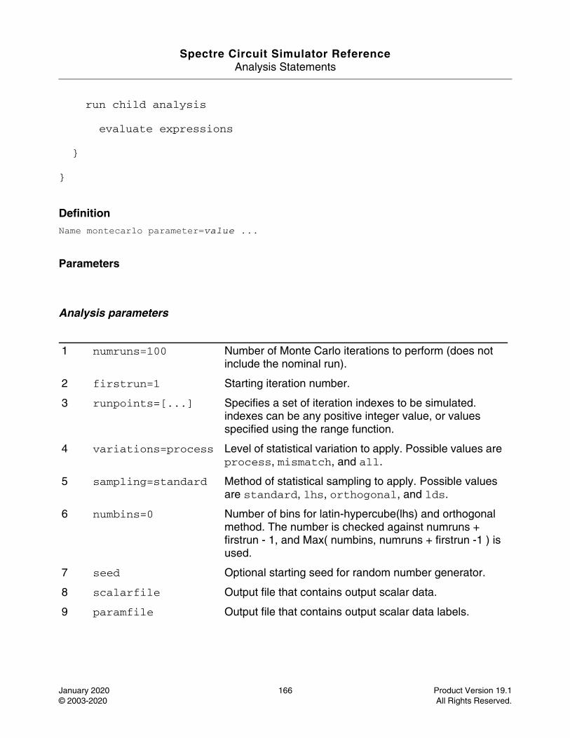
Spectre Circuit Simulator ReferenceAnalysis Statements
January 2020 166 Product Version 19.1© 2003-2020 All Rights Reserved.
run child analysis
evaluate expressions
}
}
DefinitionName montecarlo parameter=value ...
Parameters
Analysis parameters
1 numruns=100 Number of Monte Carlo iterations to perform (does not include the nominal run).
2 firstrun=1 Starting iteration number.
3 runpoints=[...] Specifies a set of iteration indexes to be simulated. indexes can be any positive integer value, or values specified using the range function.
4 variations=process Level of statistical variation to apply. Possible values are process, mismatch, and all.
5 sampling=standard Method of statistical sampling to apply. Possible values are standard, lhs, orthogonal, and lds.
6 numbins=0 Number of bins for latin-hypercube(lhs) and orthogonal method. The number is checked against numruns + firstrun - 1, and Max( numbins, numruns + firstrun -1 ) is used.
7 seed Optional starting seed for random number generator.
8 scalarfile Output file that contains output scalar data.
9 paramfile Output file that contains output scalar data labels.
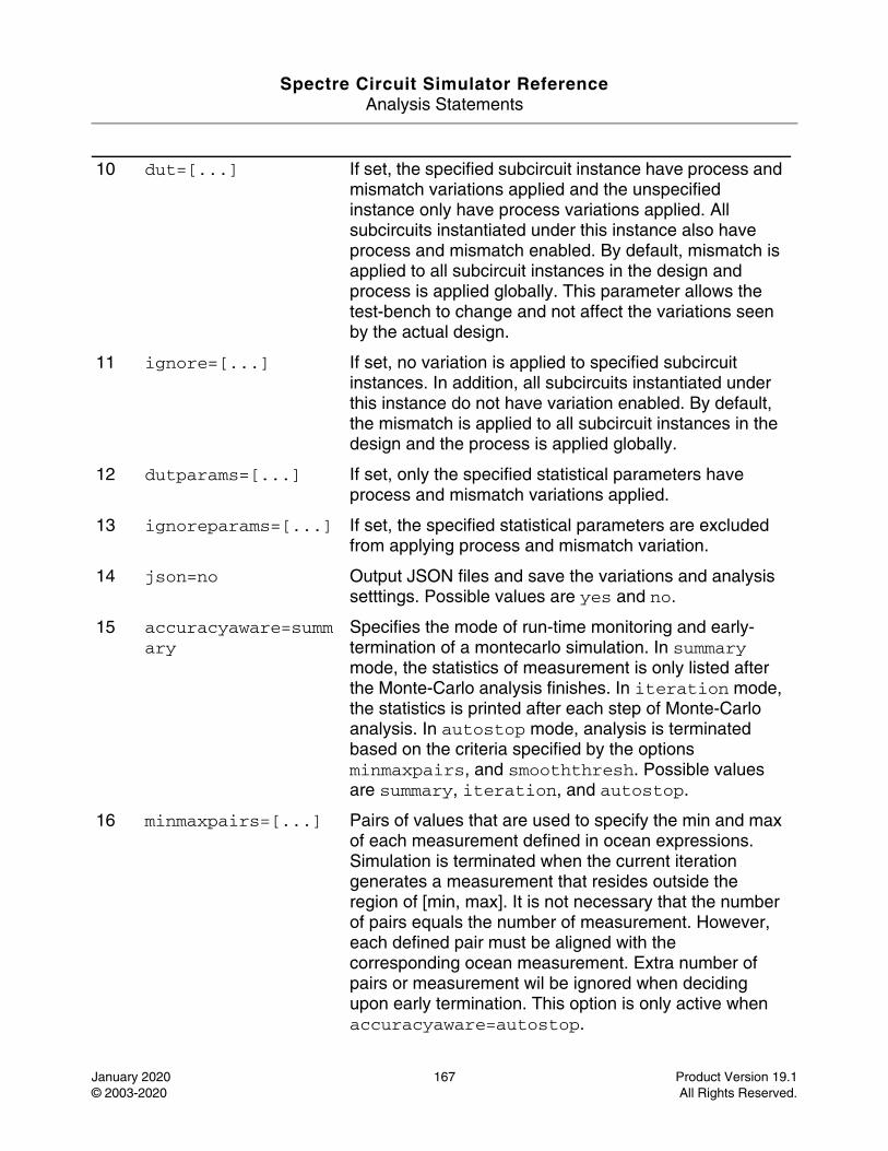
Spectre Circuit Simulator ReferenceAnalysis Statements
January 2020 167 Product Version 19.1© 2003-2020 All Rights Reserved.
10 dut=[...] If set, the specified subcircuit instance have process and mismatch variations applied and the unspecified instance only have process variations applied. All subcircuits instantiated under this instance also have process and mismatch enabled. By default, mismatch is applied to all subcircuit instances in the design and process is applied globally. This parameter allows the test-bench to change and not affect the variations seen by the actual design.
11 ignore=[...] If set, no variation is applied to specified subcircuit instances. In addition, all subcircuits instantiated under this instance do not have variation enabled. By default, the mismatch is applied to all subcircuit instances in the design and the process is applied globally.
12 dutparams=[...] If set, only the specified statistical parameters have process and mismatch variations applied.
13 ignoreparams=[...] If set, the specified statistical parameters are excluded from applying process and mismatch variation.
14 json=no Output JSON files and save the variations and analysis setttings. Possible values are yes and no.
15 accuracyaware=summary
Specifies the mode of run-time monitoring and early-termination of a montecarlo simulation. In summary mode, the statistics of measurement is only listed after the Monte-Carlo analysis finishes. In iteration mode, the statistics is printed after each step of Monte-Carlo analysis. In autostop mode, analysis is terminated based on the criteria specified by the options minmaxpairs, and smooththresh. Possible values are summary, iteration, and autostop.
16 minmaxpairs=[...] Pairs of values that are used to specify the min and max of each measurement defined in ocean expressions. Simulation is terminated when the current iteration generates a measurement that resides outside the region of [min, max]. It is not necessary that the number of pairs equals the number of measurement. However, each defined pair must be aligned with the corresponding ocean measurement. Extra number of pairs or measurement wil be ignored when deciding upon early termination. This option is only active when accuracyaware=autostop.
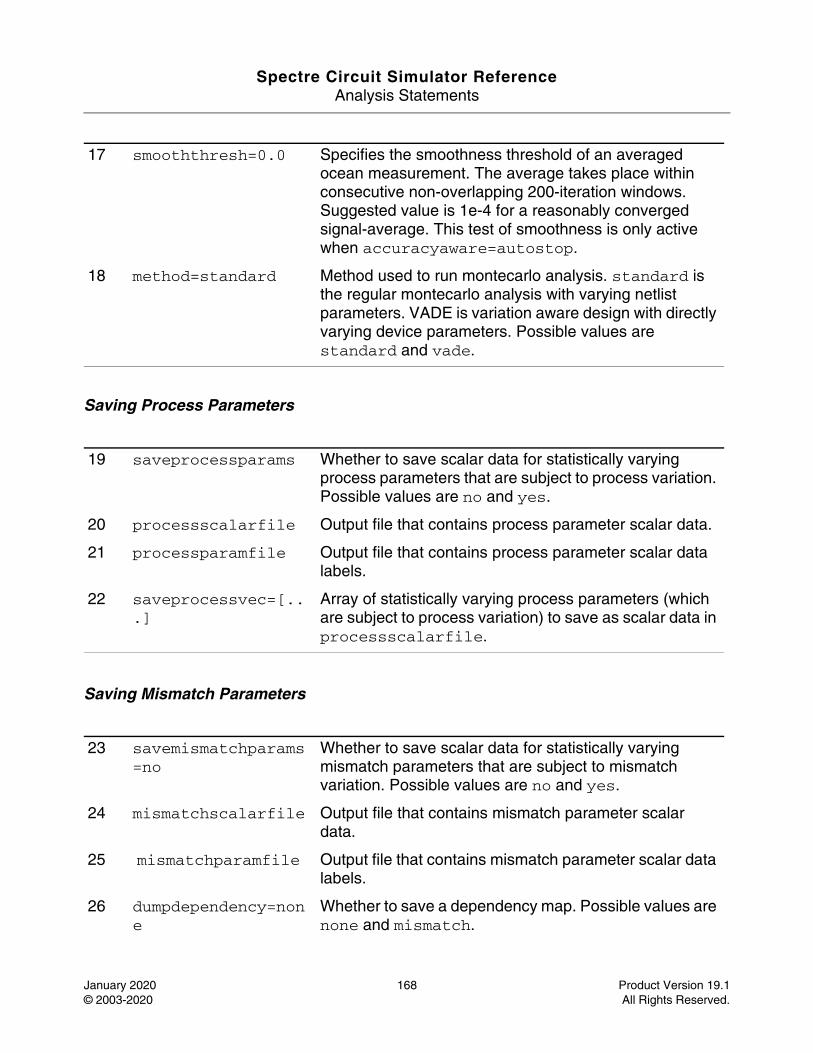
Spectre Circuit Simulator ReferenceAnalysis Statements
January 2020 168 Product Version 19.1© 2003-2020 All Rights Reserved.
Saving Process Parameters
Saving Mismatch Parameters
17 smooththresh=0.0 Specifies the smoothness threshold of an averaged ocean measurement. The average takes place within consecutive non-overlapping 200-iteration windows. Suggested value is 1e-4 for a reasonably converged signal-average. This test of smoothness is only active when accuracyaware=autostop.
18 method=standard Method used to run montecarlo analysis. standard is the regular montecarlo analysis with varying netlist parameters. VADE is variation aware design with directly varying device parameters. Possible values are standard and vade.
19 saveprocessparams Whether to save scalar data for statistically varying process parameters that are subject to process variation. Possible values are no and yes.
20 processscalarfile Output file that contains process parameter scalar data.
21 processparamfile Output file that contains process parameter scalar data labels.
22 saveprocessvec=[...]
Array of statistically varying process parameters (which are subject to process variation) to save as scalar data in processscalarfile.
23 savemismatchparams=no
Whether to save scalar data for statistically varying mismatch parameters that are subject to mismatch variation. Possible values are no and yes.
24 mismatchscalarfile Output file that contains mismatch parameter scalar data.
25 mismatchparamfile Output file that contains mismatch parameter scalar data labels.
26 dumpdependency=none
Whether to save a dependency map. Possible values are none and mismatch.
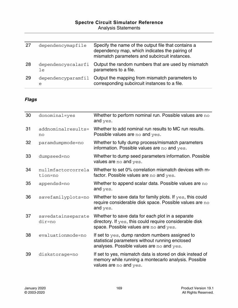
Spectre Circuit Simulator ReferenceAnalysis Statements
January 2020 169 Product Version 19.1© 2003-2020 All Rights Reserved.
Flags
27 dependencymapfile Specify the name of the output file that contains a dependency map, which indicates the pairing of mismatch parameters and subcircuit instances.
28 dependencyscalarfile
Output the random numbers that are used by mismatch parameters to a file.
29 dependencyparamfile
Output the mapping from mismatch parameters to corresponding subcircuit instances to a file.
30 donominal=yes Whether to perform nominal run. Possible values are no and yes.
31 addnominalresults=no
Whether to add nominal run results to MC run results. Possible values are no and yes.
32 paramdumpmode=no Whether to fully dump process/mismatch parameters information. Possible values are no and yes.
33 dumpseed=no Whether to dump seed parameters information. Possible values are no and yes.
34 nullmfactorcorrelation=no
Whether to set 0% correlation mismatch devices with m-factor. Possible values are no and yes.
35 appendsd=no Whether to append scalar data. Possible values are no and yes.
36 savefamilyplots=no Whether to save data for family plots. If yes, this could require considerable disk space. Possible values are no and yes.
37 savedatainseparatedir=no
Whether to save data for each plot in a separate directory. If yes, this could require considerable disk space. Possible values are no and yes.
38 evaluationmode=no If set to yes, dump random numbers assigned to statistical parameters without running enclosed analyses. Possible values are no and yes.
39 diskstorage=no If set to yes, mismatch data is stored on disk instead of memory while running a montecarlo analysis. Possible values are no and yes.
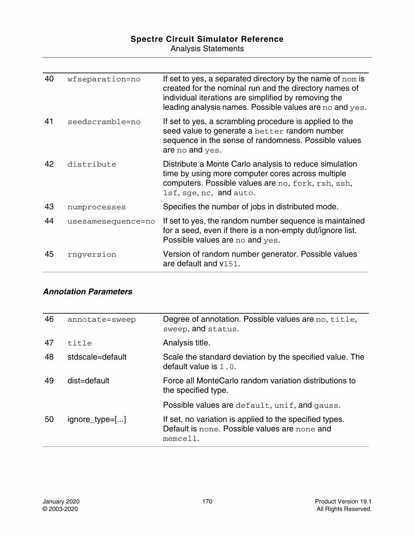
Spectre Circuit Simulator ReferenceAnalysis Statements
January 2020 170 Product Version 19.1© 2003-2020 All Rights Reserved.
Annotation Parameters
40 wfseparation=no If set to yes, a separated directory by the name of nom is created for the nominal run and the directory names of individual iterations are simplified by removing the leading analysis names. Possible values are no and yes.
41 seedscramble=no If set to yes, a scrambling procedure is applied to the seed value to generate a better random number sequence in the sense of randomness. Possible values are no and yes.
42 distribute Distribute a Monte Carlo analysis to reduce simulation time by using more computer cores across multiple computers. Possible values are no, fork, rsh, ssh, lsf, sge, nc, and auto.
43 numprocesses Specifies the number of jobs in distributed mode.
44 usesamesequence=no If set to yes, the random number sequence is maintained for a seed, even if there is a non-empty dut/ignore list. Possible values are no and yes.
45 rngversion Version of random number generator. Possible values are default and v151.
46 annotate=sweep Degree of annotation. Possible values are no, title, sweep, and status.
47 title Analysis title.
48 stdscale=default Scale the standard deviation by the specified value. The default value is 1.0.
49 dist=default Force all MonteCarlo random variation distributions to the specified type.
Possible values are default, unif, and gauss.
50 ignore_type=[...] If set, no variation is applied to the specified types. Default is none. Possible values are none and memcell.
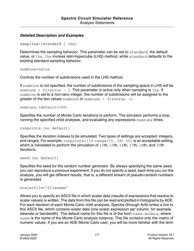
Spectre Circuit Simulator ReferenceAnalysis Statements
January 2020 171 Product Version 19.1© 2003-2020 All Rights Reserved.
Detailed Description and Examples
sampling=[standard | lhs]
Determines the sampling behavior. This parameter can be set to standard, the default value, or lhs. lhs invokes latin-hypercube (LHS) method, while standard defaults to the existing standard sampling behavior.
numbins=value
Controls the number of subdivisions used in the LHS method.
If numbins is not specified, the number of subdivisions of the sampling space in LHS will be numruns + firstrun - 1. This parameter is active only when sampling is lhs. If numbins is set to a non-zero integer, the number of subdivisions will be assigned to the greater of the two values numbins or numruns + firstrun -1.
numruns:(default=100)
Specifies the number of Monte Carlo iterations to perform. The simulator performs a loop, running the specified child analyses, and evaluating any expressions numruns times.
runpoints:(no default)
Specifies the iteration indexes to be simulated. Two types of settings are accepted: integers, and ranges. For example, runpoints=[10 range(15, 18) 20] is an acceptable setting, which is translated to perform the simulation of 10th, 15th, 16th, 17th, 18th, and 20th iterations.
seed:(no default)
Specifies the seed for the random number generator. By always specifying the same seed, you can reproduce a previous experiment. If you do not specify a seed, each time you run the analysis, you will get different results, that is, a different stream of pseudo-random numbers is generated.
scalarfile="filename"
Allows you to specify an ASCII file in which scalar data (results of expressions that resolve to scalar values) is written. The data from this file can be read and plotted in histograms by ADE. For each iteration of each Monte Carlo child analyses, Spectre (through Artil) writes a line to this ASCII file, which contains scalar data (one scalar expression per column, for example, slewrate or bandwidth). The default name for this file is of the form name.mcdata, where name is the name of the Monte Carlo analysis instance. This file contains only the matrix of numeric values. If you are an ADE Monte Carlo user, you will be more familiar with the term
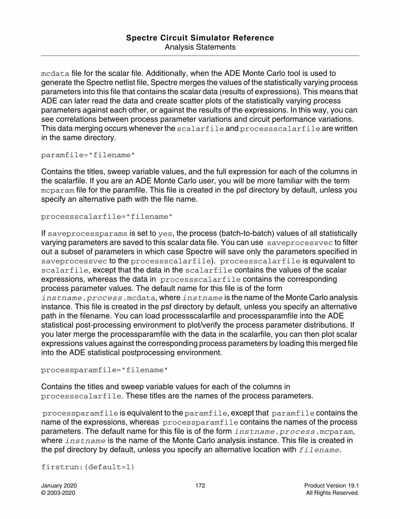
Spectre Circuit Simulator ReferenceAnalysis Statements
January 2020 172 Product Version 19.1© 2003-2020 All Rights Reserved.
mcdata file for the scalar file. Additionally, when the ADE Monte Carlo tool is used to generate the Spectre netlist file, Spectre merges the values of the statistically varying process parameters into this file that contains the scalar data (results of expressions). This means that ADE can later read the data and create scatter plots of the statistically varying process parameters against each other, or against the results of the expressions. In this way, you can see correlations between process parameter variations and circuit performance variations. This data merging occurs whenever the scalarfile and processscalarfile are written in the same directory.
paramfile="filename"
Contains the titles, sweep variable values, and the full expression for each of the columns in the scalarfile. If you are an ADE Monte Carlo user, you will be more familiar with the term mcparam file for the paramfile. This file is created in the psf directory by default, unless you specify an alternative path with the file name.
processscalarfile="filename"
If saveprocessparams is set to yes, the process (batch-to-batch) values of all statistically varying parameters are saved to this scalar data file. You can use saveprocessvec to filter out a subset of parameters in which case Spectre will save only the parameters specified in saveprocessvec to the processscalarfile). processscalarfile is equivalent to scalarfile, except that the data in the scalarfile contains the values of the scalar expressions, whereas the data in processscalarfile contains the corresponding process parameter values. The default name for this file is of the form instname.process.mcdata, where instname is the name of the Monte Carlo analysis instance. This file is created in the psf directory by default, unless you specify an alternative path in the filename. You can load processscalarfile and processparamfile into the ADE statistical post-processing environment to plot/verify the process parameter distributions. If you later merge the processparamfile with the data in the scalarfile, you can then plot scalar expressions values against the corresponding process parameters by loading this merged file into the ADE statistical postprocessing environment.
processparamfile="filename"
Contains the titles and sweep variable values for each of the columns in processscalarfile. These titles are the names of the process parameters.
processparamfile is equivalent to the paramfile, except that paramfile contains the name of the expressions, whereas processparamfile contains the names of the process parameters. The default name for this file is of the form instname.process.mcparam, where instname is the name of the Monte Carlo analysis instance. This file is created in the psf directory by default, unless you specify an alternative location with filename.
firstrun:(default=1)

Spectre Circuit Simulator ReferenceAnalysis Statements
January 2020 173 Product Version 19.1© 2003-2020 All Rights Reserved.
Specifies the index of the first iteration. If the first iteration is specified as some number n greater than one, then the beginning n-1 iterations are skipped, that is, the Monte Carlo analysis behaves as if the first n-1 iterations were run, but without performing the child analyses for these iterations. The subsequent stream of random numbers generated for the remaining iterations will be the same as if the first n-1 iterations were run. By specifying the first iteration number and the same value for seed, you can reproduce a particular run or sequence of runs from a previous experiment (for example, to examine an outlier case in more detail).
variations={process,mismatch,all} (defaults to process)
Determines whether to apply only process (batch-to-batch) variations, or only mismatch (per-instance) variations, or both. This parameter assumes that you have specified appropriate statistical distributions in the statistics block. You cannot request that mismatch variations be applied unless you have specified mismatch statistics in the statistics block. You cannot request that process variations be applied unless you have specified process statistics in the statistics block.
saveprocessvec=[rshsp TOX ...]
If saveprocessparams is set to yes, this parameter saves the process (batch-to-batch) values of only those parameters that are listed in saveprocessvec to the processparamfile. This acts as a filter so that you do not save all process parameters to the file. If you do not want to filter the list of process parameters, do not specify this parameter.
donominal={yes,no}(defaults to yes)
Controls whether Spectre should perform a nominal run before starting the main Monte Carlo loop of iterations. If any errors are encountered during the nominal run (for example, convergence problems, incorrect expressions, and so on) then Spectre issues an appropriate error message and immediately abandons the Monte Carlo analysis.
If set to no, Spectre runs only the Monte Carlo iteration, and does not perform nominal analysis. If any errors are encountered during the Monte Carlo iterations, Spectre issues a warning and continues with the next iteration of the Monte Carlo loop.
addnominalresults={yes,no} (defaults to no).
Controls whether Spectre should append nominal run results after the Monte Carlo run results in the data files.
paramdumpmode={yes,no} (defaults to no).
Controls whether Spectre should dump out each process/mismatch parameter distribution type, mean value, s.t.d value, and correlation information into additional parameter files. The

Spectre Circuit Simulator ReferenceAnalysis Statements
January 2020 174 Product Version 19.1© 2003-2020 All Rights Reserved.
names for these files are instname.process_full.param, instname.mismatch_full.param, instname.process.correlate.param and instname.mismatch.correlate.param, where instname is the name of the Monte Carlo analysis instance.
dumpseed={yes,no} (defaults to no)
Controls whether Spectre should dump out seed parameter and iteration number into the instname.seed file, where instname is the name of the Monte Carlo analysis instance.
nullmfactorcorrelation={yes,no} (defaults to no)
Controls whether Spectre should emulate a 0% correlation for mismatch devices with m-factor.
appendsd={yes,no} (defaults to no)
Specifies whether to append scalar data to an existing scalarfile, or to overwrite the existing scalarfile. This flag applies to both the scalar file and the processscalarfile.
savefamilyplots={yes,no}
If set to yes, a data file (for example, psf) is saved for each analysis for each Monte Carlo iteration, in addition to the expressions scalar results that are saved to the ASCII scalar data file at the end of each iteration. Saving the full data files between runs enables the cloud plotting feature (overlaid waveforms) in ADE. It also enables you to define/evaluate new calculator measurements after the simulation has been run using the ViVA XL calculator. This feature could result in a huge amount of data being stored to disk, and it is advised that you use this feature with care. If you do decide to use this feature, it is advisable to keep the saved data to a minimum. If this parameter is set to no, data files are overwritten by each Monte Carlo iteration.
savedatainseparatedir={yes,no}
If set to yes, a data file (for example, psf) is saved for each analysis for each Monte Carlo iteration in a separate directory, in addition to the expressions scalar results that are saved to the ASCII scalar data file at the end of each iteration. This feature can result in a huge amount of data being stored to the disk. Therefore, it is recommended that you use this feature with care and keep the saved data to a minimum. If this parameter is set to no, data files are overwritten by each Monte Carlo iteration.
annotate={no,title,sweep,status}
Specifies the degree of annotation. Use the maximum value of status to print a summary of the runs that did not converge, had problems evaluating expressions, and so on.
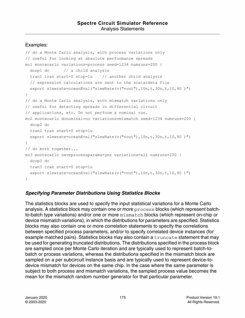
Spectre Circuit Simulator ReferenceAnalysis Statements
January 2020 175 Product Version 19.1© 2003-2020 All Rights Reserved.
Examples:
// do a Monte Carlo analysis, with process variations only// useful for looking at absolute performance spreadsmc1 montecarlo variations=process seed=1234 numruns=200 { dcop1 dc // a child analysis tran1 tran start=0 stop=1u // another child analysis // expression calculations are sent to the scalardata file export slewrate=oceanEval("slewRate(v("vout"),10n,t,30n,t,10,90 )")}// do a Monte Carlo analysis, with mismatch variations only// useful for detecting spreads in differential circuit // applications, etc. Do not perform a nominal run.mc2 montecarlo donominal=no variations=mismatch seed=1234 numruns=200 { dcop2 dc tran2 tran start=0 stop=1u export slewrate=oceanEval("slewRate(v("vout"),10n,t,30n,t,10,90 )")}// do both together...mc3 montecarlo saveprocessparams=yes variations=all numruns=200 { dcop3 dc tran3 tran start=0 stop=1u export slewrate=oceanEval("slewRate(v("vout"),10n,t,30n,t,10,90 )")}
Specifying Parameter Distributions Using Statistics Blocks
The statistics blocks are used to specify the input statistical variations for a Monte Carlo analysis. A statistics block may contain one or more process blocks (which represent batch-to-batch type variations) and/or one or more mismatch blocks (which represent on-chip or device mismatch variations), in which the distributions for parameters are specified. Statistics blocks may also contain one or more correlation statements to specify the correlations between specified process parameters, and/or to specify correlated device instances (for example matched pairs). Statistics blocks may also contain a truncate statement that may be used for generating truncated distributions. The distributions specified in the process block are sampled once per Monte Carlo iteration and are typically used to represent batch-to-batch or process variations, whereas the distributions specified in the mismatch block are sampled on a per subcircuit instance basis and are typically used to represent device-to-device mismatch for devices on the same chip. In the case where the same parameter is subject to both process and mismatch variations, the sampled process value becomes the mean for the mismatch random number generator for that particular parameter.
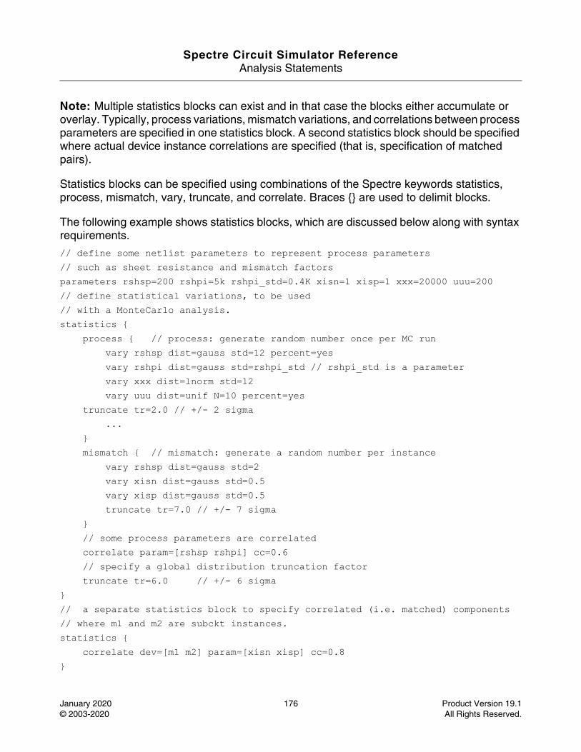
Spectre Circuit Simulator ReferenceAnalysis Statements
January 2020 176 Product Version 19.1© 2003-2020 All Rights Reserved.
Note: Multiple statistics blocks can exist and in that case the blocks either accumulate or overlay. Typically, process variations, mismatch variations, and correlations between process parameters are specified in one statistics block. A second statistics block should be specified where actual device instance correlations are specified (that is, specification of matched pairs).
Statistics blocks can be specified using combinations of the Spectre keywords statistics, process, mismatch, vary, truncate, and correlate. Braces {} are used to delimit blocks.
The following example shows statistics blocks, which are discussed below along with syntax requirements.
// define some netlist parameters to represent process parameters // such as sheet resistance and mismatch factors parameters rshsp=200 rshpi=5k rshpi_std=0.4K xisn=1 xisp=1 xxx=20000 uuu=200// define statistical variations, to be used // with a MonteCarlo analysis. statistics { process { // process: generate random number once per MC run vary rshsp dist=gauss std=12 percent=yes vary rshpi dist=gauss std=rshpi_std // rshpi_std is a parameter vary xxx dist=lnorm std=12 vary uuu dist=unif N=10 percent=yes truncate tr=2.0 // +/- 2 sigma ... } mismatch { // mismatch: generate a random number per instance vary rshsp dist=gauss std=2 vary xisn dist=gauss std=0.5 vary xisp dist=gauss std=0.5 truncate tr=7.0 // +/- 7 sigma } // some process parameters are correlated correlate param=[rshsp rshpi] cc=0.6 // specify a global distribution truncation factor truncate tr=6.0 // +/- 6 sigma }// a separate statistics block to specify correlated (i.e. matched) components // where m1 and m2 are subckt instances.statistics { correlate dev=[m1 m2] param=[xisn xisp] cc=0.8 }
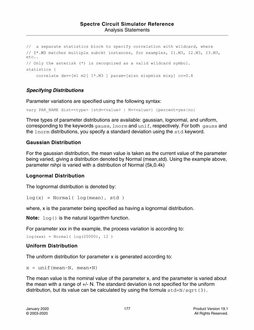
Spectre Circuit Simulator ReferenceAnalysis Statements
January 2020 177 Product Version 19.1© 2003-2020 All Rights Reserved.
// a separate statistics block to specify correlation with wildcard, where // I*.M3 matches multiple subckt instances, for examples, I1.M3, I2.M3, I3.M3, etc..// Only the asterisk (*) is recognized as a valid wildcard symbol.statistics { correlate dev=[m1 m2[ I*.M3 ] param=[xisn xispmisx mixy] cc=0.8
Specifying Distributions
Parameter variations are specified using the following syntax:
vary PAR_NAME dist=<type> {std=<value> | N=<value>} {percent=yes|no}
Three types of parameter distributions are available: gaussian, lognormal, and uniform, corresponding to the keywords gauss, lnorm and unif, respectively. For both gauss and the lnorm distributions, you specify a standard deviation using the std keyword.
Gaussian Distribution
For the gaussian distribution, the mean value is taken as the current value of the parameter being varied, giving a distribution denoted by Normal (mean,std). Using the example above, parameter rshpi is varied with a distribution of Normal (5k,0.4k)
Lognormal Distribution
The lognormal distribution is denoted by:
log(x) = Normal( log(mean), std )
where, x is the parameter being specified as having a lognormal distribution.
Note: log() is the natural logarithm function.
For parameter xxx in the example, the process variation is according to:
log(xxx) = Normal( log(20000), 12 )
Uniform Distribution
The uniform distribution for parameter x is generated according to:
x = unif(mean-N, mean+N)
The mean value is the nominal value of the parameter x, and the parameter is varied about the mean with a range of +/- N. The standard deviation is not specified for the uniform distribution, but its value can be calculated by using the formula std=N/sqrt(3).
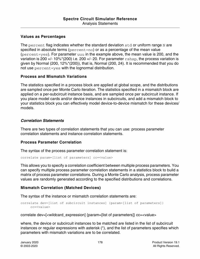
Spectre Circuit Simulator ReferenceAnalysis Statements
January 2020 178 Product Version 19.1© 2003-2020 All Rights Reserved.
Values as Percentages
The percent flag indicates whether the standard deviation std or uniform range N are specified in absolute terms (percent=no) or as a percentage of the mean value (percent=yes). For parameter uuu in the example above, the mean value is 200, and the variation is 200 +/- 10%*(200) i.e. 200 +/- 20. For parameter rshsp, the process variation is given by Normal (200, 12%*(200)), that is, Normal (200, 24). It is recommended that you do not use percent=yes with the lognormal distribution.
Process and Mismatch Variations
The statistics specified in a process block are applied at global scope, and the distributions are sampled once per Monte Carlo iteration. The statistics specified in a mismatch block are applied on a per-subcircuit instance basis, and are sampled once per subcircuit instance. If you place model cards and/or device instances in subcircuits, and add a mismatch block to your statistics block you can effectively model device-to-device mismatch for these devices/models.
Correlation Statements
There are two types of correlation statements that you can use: process parameter correlation statements and instance correlation statements.
Process Parameter Correlation
The syntax of the process parameter correlation statement is:
correlate param=[list of parameters] cc=<value>
This allows you to specify a correlation coefficient between multiple process parameters. You can specify multiple process parameter correlation statements in a statistics block to build a matrix of process parameter correlations. During a Monte Carlo analysis, process parameter values are randomly generated according to the specified distributions and correlations.
Mismatch Correlation (Matched Devices)
The syntax of the instance or mismatch correlation statements are:
correlate dev=[list of subcircuit instances] {param=[list of parameters]} cc=<value>
correlate dev=[<wildcard_expression] {param=[list of parameters]} cc=<value>
where, the device or subcircuit instances to be matched are listed in the list of subcircuit instances or regular expressions with asterisk (*), and the list of parameters specifies which parameters with mismatch variations are to be correlated.
Spectre Circuit Simulator ReferenceAnalysis Statements
January 2020 179 Product Version 19.1© 2003-2020 All Rights Reserved.
The instance mismatch correlation statement is used to specify correlations for particular subcircuit instances. If a subcircuit contains a device, you can effectively use the instance correlation statements to specify that certain devices are correlated (that is, matched) and give the correlation coefficient. You can optionally specify which parameters are to be correlated by giving a list of parameters (each of which must have had distributions specified for it in a mismatch block), or specify no parameter list, in which case all parameters with mismatch statistics specified are correlated with the given correlation coefficient. The correlation coefficients are specified in the <value> field and must be between +/- 1.0.
Note: Correlation coefficients can be constants or expressions, as can std and N when specifying distributions.
Truncation Factor
The default truncation factor for gaussian distributions (and for the gaussian distribution underlying the lognormal distribution) is 4.0 sigma. Randomly generated values that are outside the range of mean +/- 4.0 sigma are automatically rejected and regenerated until they fall inside the range. You can change the truncation factor using the truncate statement. The syntax is:
truncate tr=<value>
The following conditions should be considered while setting the truncate factor:
■ The value of the truncation factor can be a constant or an expression.
■ Parameter correlations can be affected by using small truncation factors.
■ There are different truncate for process and mismatch blocks. If a truncate for process or mismatch block is not given, it will be set to the value of truncate in statistic block.
Hints to Improve Performance
To get better run performance on small-sized designs, it is recommended to use the following settings:
■ Set the global option narrate=compact to reduce the annotation messages
■ Reduce the number of saved signals, or use the save=nooutput option
■ Use just the measure statement to measure the simulation results
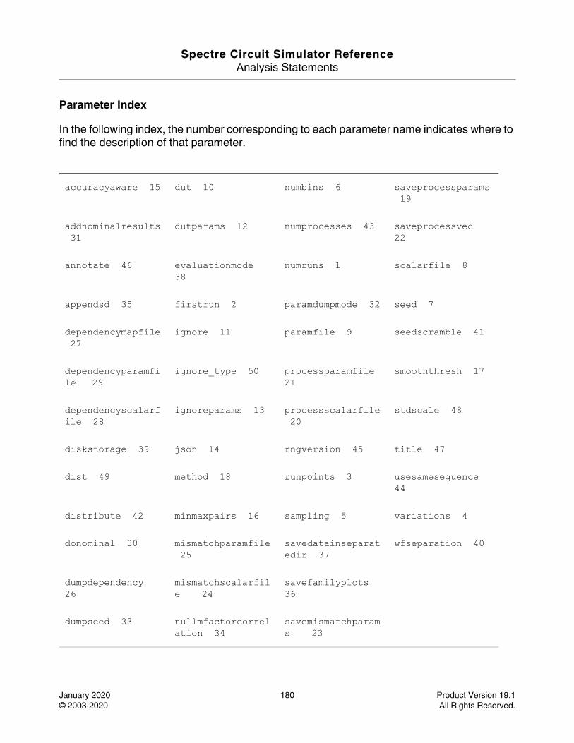
Spectre Circuit Simulator ReferenceAnalysis Statements
January 2020 180 Product Version 19.1© 2003-2020 All Rights Reserved.
Parameter Index
In the following index, the number corresponding to each parameter name indicates where to find the description of that parameter.
accuracyaware 15 dut 10 numbins 6 saveprocessparams 19
addnominalresults 31
dutparams 12 numprocesses 43 saveprocessvec 22
annotate 46 evaluationmode 38
numruns 1 scalarfile 8
appendsd 35 firstrun 2 paramdumpmode 32 seed 7
dependencymapfile 27
ignore 11 paramfile 9 seedscramble 41
dependencyparamfile 29
ignore_type 50 processparamfile 21
smooththresh 17
dependencyscalarfile 28
ignoreparams 13 processscalarfile 20
stdscale 48
diskstorage 39 json 14 rngversion 45 title 47
dist 49 method 18 runpoints 3 usesamesequence 44
distribute 42 minmaxpairs 16 sampling 5 variations 4
donominal 30 mismatchparamfile 25
savedatainseparatedir 37
wfseparation 40
dumpdependency 26
mismatchscalarfile 24
savefamilyplots 36
dumpseed 33 nullmfactorcorrelation 34
savemismatchparams 23

Spectre Circuit Simulator ReferenceAnalysis Statements
January 2020 181 Product Version 19.1© 2003-2020 All Rights Reserved.
Noise Analysis (noise)
Description
Noise analysis linearizes the circuit about the operating point and computes the noise spectral density at the output. If you identify an input source, the transfer function and the input-referred noise for an equivalent noise-free network are computed. If the input source is noisy, the noise figure is also computed.
The noise is computed at the output of the circuit. The output is specified with either a pair of nodes or a probe component. To specify the output of a circuit with a probe, specify it with the oprobe parameter. If the output is voltage (or potential), choose a resistor or a port as the output probe. If the output is current (or flow), choose a vsource or iprobe as the output probe.
If the input-referred noise is desired, specify the input source by using the iprobe parameter. Currently, only a vsource, an isource, or a port may be used as an input probe. If the input source is noisy, as is a port, the noise analysis computes the noise factor (F) and noise figure (NF). To match the IEEE definition of noise figure, the input probe must be a port with no excess noise and its noisetemp must be set to 16.85C (290K). In addition, the output load must be a resistor or port and must be identified as the oprobe.
If port is specified as the input probe, both input-referred noise and gain are referred back to the equivalent voltage source inside the port. S-parameter analysis calculates those values in traditional sense.
The noise analysis always computes the total noise at the output, which includes contributions from the input source and the output load. The amount of output noise that is attributable to each noise source in the circuit is also computed and output individually. If the input source is identified, the input-referred noise is computed, which include
s the noise from the input source itself. Finally, if the input source is identified and is noisy, the noise factor and noise figure are computed. Therefore, if:
No = total output noise
Ns = noise at the output due to the input probe (the source)
Nl = noise at the output due to the output probe (the load)IRN = input referred noise
G = gain of the circuit
F = noise factor
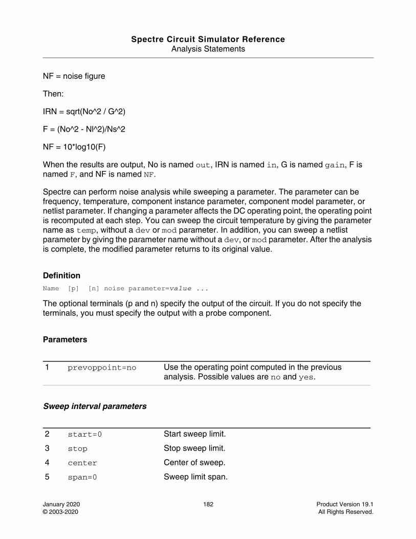
Spectre Circuit Simulator ReferenceAnalysis Statements
January 2020 182 Product Version 19.1© 2003-2020 All Rights Reserved.
NF = noise figure
Then:
IRN = sqrt(No^2 / G^2)
F = (No^2 - Nl^2)/Ns^2
NF = 10*log10(F)
When the results are output, No is named out, IRN is named in, G is named gain, F is named F, and NF is named NF.
Spectre can perform noise analysis while sweeping a parameter. The parameter can be frequency, temperature, component instance parameter, component model parameter, or netlist parameter. If changing a parameter affects the DC operating point, the operating point is recomputed at each step. You can sweep the circuit temperature by giving the parameter name as temp, without a dev or mod parameter. In addition, you can sweep a netlist parameter by giving the parameter name without a dev, or mod parameter. After the analysis is complete, the modified parameter returns to its original value.
DefinitionName [p] [n] noise parameter=value ...
The optional terminals (p and n) specify the output of the circuit. If you do not specify the terminals, you must specify the output with a probe component.
Parameters
Sweep interval parameters
1 prevoppoint=no Use the operating point computed in the previous analysis. Possible values are no and yes.
2 start=0 Start sweep limit.
3 stop Stop sweep limit.
4 center Center of sweep.
5 span=0 Sweep limit span.
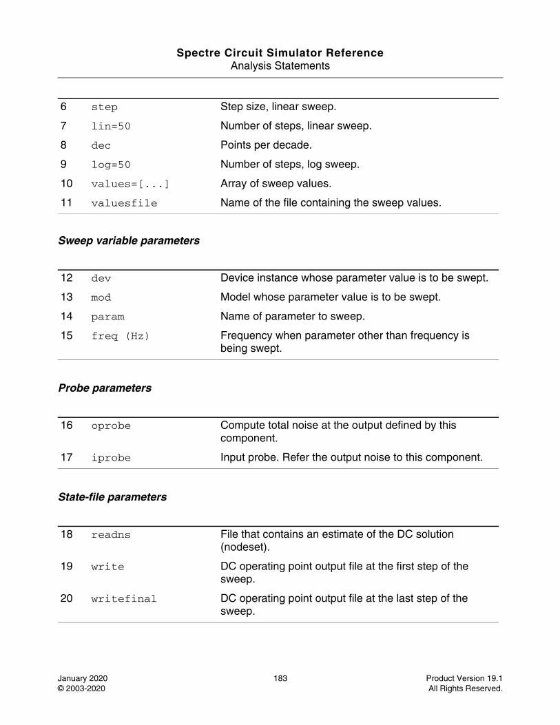
Spectre Circuit Simulator ReferenceAnalysis Statements
January 2020 183 Product Version 19.1© 2003-2020 All Rights Reserved.
Sweep variable parameters
Probe parameters
State-file parameters
6 step Step size, linear sweep.
7 lin=50 Number of steps, linear sweep.
8 dec Points per decade.
9 log=50 Number of steps, log sweep.
10 values=[...] Array of sweep values.
11 valuesfile Name of the file containing the sweep values.
12 dev Device instance whose parameter value is to be swept.
13 mod Model whose parameter value is to be swept.
14 param Name of parameter to sweep.
15 freq (Hz) Frequency when parameter other than frequency is being swept.
16 oprobe Compute total noise at the output defined by this component.
17 iprobe Input probe. Refer the output noise to this component.
18 readns File that contains an estimate of the DC solution (nodeset).
19 write DC operating point output file at the first step of the sweep.
20 writefinal DC operating point output file at the last step of the sweep.
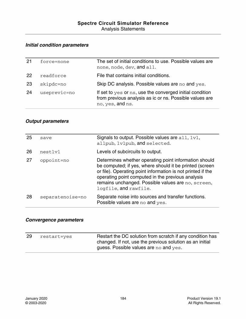
Spectre Circuit Simulator ReferenceAnalysis Statements
January 2020 184 Product Version 19.1© 2003-2020 All Rights Reserved.
Initial condition parameters
Output parameters
Convergence parameters
21 force=none The set of initial conditions to use. Possible values are none, node, dev, and all.
22 readforce File that contains initial conditions.
23 skipdc=no Skip DC analysis. Possible values are no and yes.
24 useprevic=no If set to yes or ns, use the converged initial condition from previous analysis as ic or ns. Possible values are no, yes, and ns.
25 save Signals to output. Possible values are all, lvl, allpub, lvlpub, and selected.
26 nestlvl Levels of subcircuits to output.
27 oppoint=no Determines whether operating point information should be computed; if yes, where should it be printed (screen or file). Operating point information is not printed if the operating point computed in the previous analysis remains unchanged. Possible values are no, screen, logfile, and rawfile.
28 separatenoise=no Separate noise into sources and transfer functions. Possible values are no and yes.
29 restart=yes Restart the DC solution from scratch if any condition has changed. If not, use the previous solution as an initial guess. Possible values are no and yes.
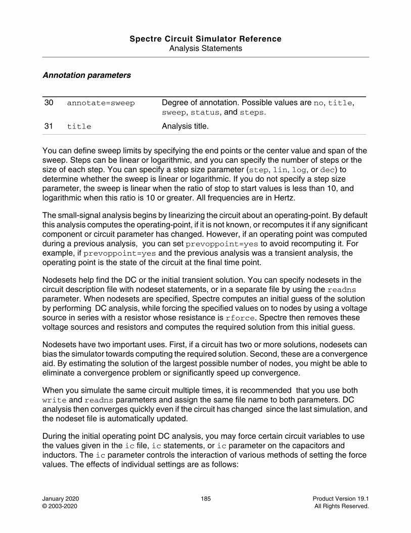
Spectre Circuit Simulator ReferenceAnalysis Statements
January 2020 185 Product Version 19.1© 2003-2020 All Rights Reserved.
Annotation parameters
You can define sweep limits by specifying the end points or the center value and span of the sweep. Steps can be linear or logarithmic, and you can specify the number of steps or the size of each step. You can specify a step size parameter (step, lin, log, or dec) to determine whether the sweep is linear or logarithmic. If you do not specify a step size parameter, the sweep is linear when the ratio of stop to start values is less than 10, and logarithmic when this ratio is 10 or greater. All frequencies are in Hertz.
The small-signal analysis begins by linearizing the circuit about an operating-point. By default this analysis computes the operating-point, if it is not known, or recomputes it if any significant component or circuit parameter has changed. However, if an operating point was computed during a previous analysis, you can set prevoppoint=yes to avoid recomputing it. For example, if prevoppoint=yes and the previous analysis was a transient analysis, the operating point is the state of the circuit at the final time point.
Nodesets help find the DC or the initial transient solution. You can specify nodesets in the circuit description file with nodeset statements, or in a separate file by using the readns parameter. When nodesets are specified, Spectre computes an initial guess of the solution by performing DC analysis, while forcing the specified values on to nodes by using a voltage source in series with a resistor whose resistance is rforce. Spectre then removes these voltage sources and resistors and computes the required solution from this initial guess.
Nodesets have two important uses. First, if a circuit has two or more solutions, nodesets can bias the simulator towards computing the required solution. Second, these are a convergence aid. By estimating the solution of the largest possible number of nodes, you might be able to eliminate a convergence problem or significantly speed up convergence.
When you simulate the same circuit multiple times, it is recommended that you use both write and readns parameters and assign the same file name to both parameters. DC analysis then converges quickly even if the circuit has changed since the last simulation, and the nodeset file is automatically updated.
During the initial operating point DC analysis, you may force certain circuit variables to use the values given in the ic file, ic statements, or ic parameter on the capacitors and inductors. The ic parameter controls the interaction of various methods of setting the force values. The effects of individual settings are as follows:
30 annotate=sweep Degree of annotation. Possible values are no, title, sweep, status, and steps.
31 title Analysis title.
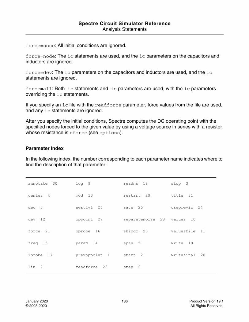
Spectre Circuit Simulator ReferenceAnalysis Statements
January 2020 186 Product Version 19.1© 2003-2020 All Rights Reserved.
force=none: All initial conditions are ignored.
force=node: The ic statements are used, and the ic parameters on the capacitors and inductors are ignored.
force=dev: The ic parameters on the capacitors and inductors are used, and the ic statements are ignored.
force=all: Both ic statements and ic parameters are used, with the ic parameters overriding the ic statements.
If you specify an ic file with the readforce parameter, force values from the file are used, and any ic statements are ignored.
After you specify the initial conditions, Spectre computes the DC operating point with the specified nodes forced to the given value by using a voltage source in series with a resistor whose resistance is rforce (see options).
Parameter Index
In the following index, the number corresponding to each parameter name indicates where to find the description of that parameter:
annotate 30 log 9 readns 18 stop 3
center 4 mod 13 restart 29 title 31
dec 8 nestlvl 26 save 25 useprevic 24
dev 12 oppoint 27 separatenoise 28 values 10
force 21 oprobe 16 skipdc 23 valuesfile 11
freq 15 param 14 span 5 write 19
iprobe 17 prevoppoint 1 start 2 writefinal 20
lin 7 readforce 22 step 6
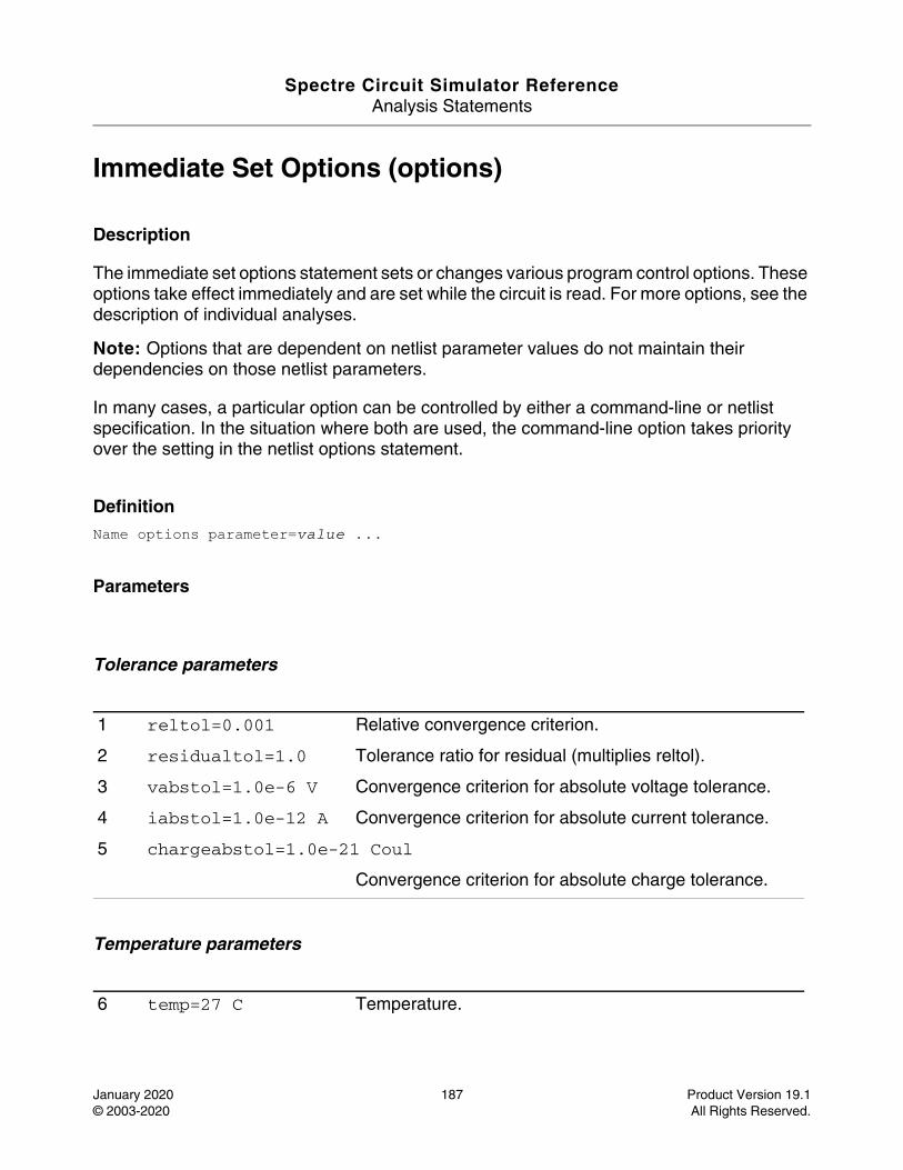
Spectre Circuit Simulator ReferenceAnalysis Statements
January 2020 187 Product Version 19.1© 2003-2020 All Rights Reserved.
Immediate Set Options (options)
Description
The immediate set options statement sets or changes various program control options. These options take effect immediately and are set while the circuit is read. For more options, see the description of individual analyses.
Note: Options that are dependent on netlist parameter values do not maintain their dependencies on those netlist parameters.
In many cases, a particular option can be controlled by either a command-line or netlist specification. In the situation where both are used, the command-line option takes priority over the setting in the netlist options statement.
DefinitionName options parameter=value ...
Parameters
Tolerance parameters
Temperature parameters
1 reltol=0.001 Relative convergence criterion.
2 residualtol=1.0 Tolerance ratio for residual (multiplies reltol).
3 vabstol=1.0e-6 V Convergence criterion for absolute voltage tolerance.
4 iabstol=1.0e-12 A Convergence criterion for absolute current tolerance.
5 chargeabstol=1.0e-21 Coul
Convergence criterion for absolute charge tolerance.
6 temp=27 C Temperature.
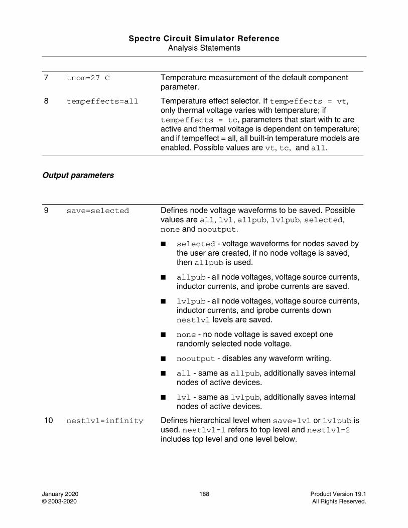
Spectre Circuit Simulator ReferenceAnalysis Statements
January 2020 188 Product Version 19.1© 2003-2020 All Rights Reserved.
Output parameters
7 tnom=27 C Temperature measurement of the default component parameter.
8 tempeffects=all Temperature effect selector. If tempeffects = vt, only thermal voltage varies with temperature; if tempeffects = tc, parameters that start with tc are active and thermal voltage is dependent on temperature; and if tempeffect = all, all built-in temperature models are enabled. Possible values are vt, tc, and all.
9 save=selected Defines node voltage waveforms to be saved. Possible values are all, lvl, allpub, lvlpub, selected, none and nooutput.
■ selected - voltage waveforms for nodes saved by the user are created, if no node voltage is saved, then allpub is used.
■ allpub - all node voltages, voltage source currents, inductor currents, and iprobe currents are saved.
■ lvlpub - all node voltages, voltage source currents, inductor currents, and iprobe currents down nestlvl levels are saved.
■ none - no node voltage is saved except one randomly selected node voltage.
■ nooutput - disables any waveform writing.
■ all - same as allpub, additionally saves internal nodes of active devices.
■ lvl - same as lvlpub, additionally saves internal nodes of active devices.
10 nestlvl=infinity Defines hierarchical level when save=lvl or lvlpub is used. nestlvl=1 refers to top level and nestlvl=2 includes top level and one level below.
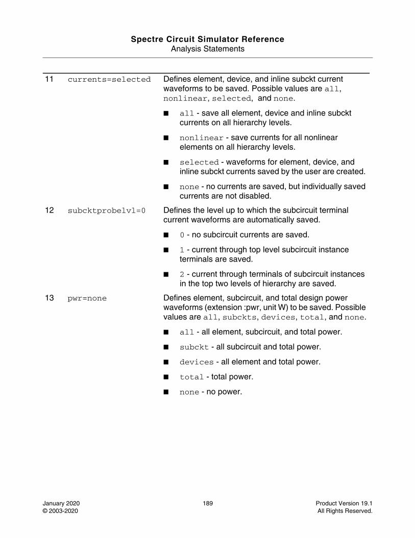
Spectre Circuit Simulator ReferenceAnalysis Statements
January 2020 189 Product Version 19.1© 2003-2020 All Rights Reserved.
11 currents=selected Defines element, device, and inline subckt current waveforms to be saved. Possible values are all, nonlinear, selected, and none.
■ all - save all element, device and inline subckt currents on all hierarchy levels.
■ nonlinear - save currents for all nonlinear elements on all hierarchy levels.
■ selected - waveforms for element, device, and inline subckt currents saved by the user are created.
■ none - no currents are saved, but individually saved currents are not disabled.
12 subcktprobelvl=0 Defines the level up to which the subcircuit terminal current waveforms are automatically saved.
■ 0 - no subcircuit currents are saved.
■ 1 - current through top level subcircuit instance terminals are saved.
■ 2 - current through terminals of subcircuit instances in the top two levels of hierarchy are saved.
13 pwr=none Defines element, subcircuit, and total design power waveforms (extension :pwr, unit W) to be saved. Possible values are all, subckts, devices, total, and none.
■ all - all element, subcircuit, and total power.
■ subckt - all subcircuit and total power.
■ devices - all element and total power.
■ total - total power.
■ none - no power.
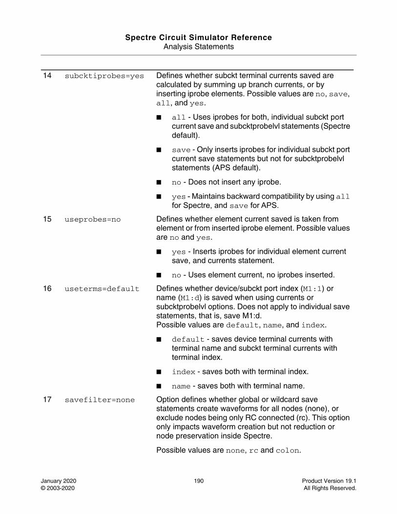
Spectre Circuit Simulator ReferenceAnalysis Statements
January 2020 190 Product Version 19.1© 2003-2020 All Rights Reserved.
14 subcktiprobes=yes Defines whether subckt terminal currents saved are calculated by summing up branch currents, or by inserting iprobe elements. Possible values are no, save, all, and yes.
■ all - Uses iprobes for both, individual subckt port current save and subcktprobelvl statements (Spectre default).
■ save - Only inserts iprobes for individual subckt port current save statements but not for subcktprobelvl statements (APS default).
■ no - Does not insert any iprobe.
■ yes - Maintains backward compatibility by using all for Spectre, and save for APS.
15 useprobes=no Defines whether element current saved is taken from element or from inserted iprobe element. Possible values are no and yes.
■ yes - Inserts iprobes for individual element current save, and currents statement.
■ no - Uses element current, no iprobes inserted.
16 useterms=default Defines whether device/subckt port index (M1:1) or name (M1:d) is saved when using currents or subcktprobelvl options. Does not apply to individual save statements, that is, save M1:d. Possible values are default, name, and index.
■ default - saves device terminal currents with terminal name and subckt terminal currents with terminal index.
■ index - saves both with terminal index.
■ name - saves both with terminal name.
17 savefilter=none Option defines whether global or wildcard save statements create waveforms for all nodes (none), or exclude nodes being only RC connected (rc). This option only impacts waveform creation but not reduction or node preservation inside Spectre.
Possible values are none, rc and colon.
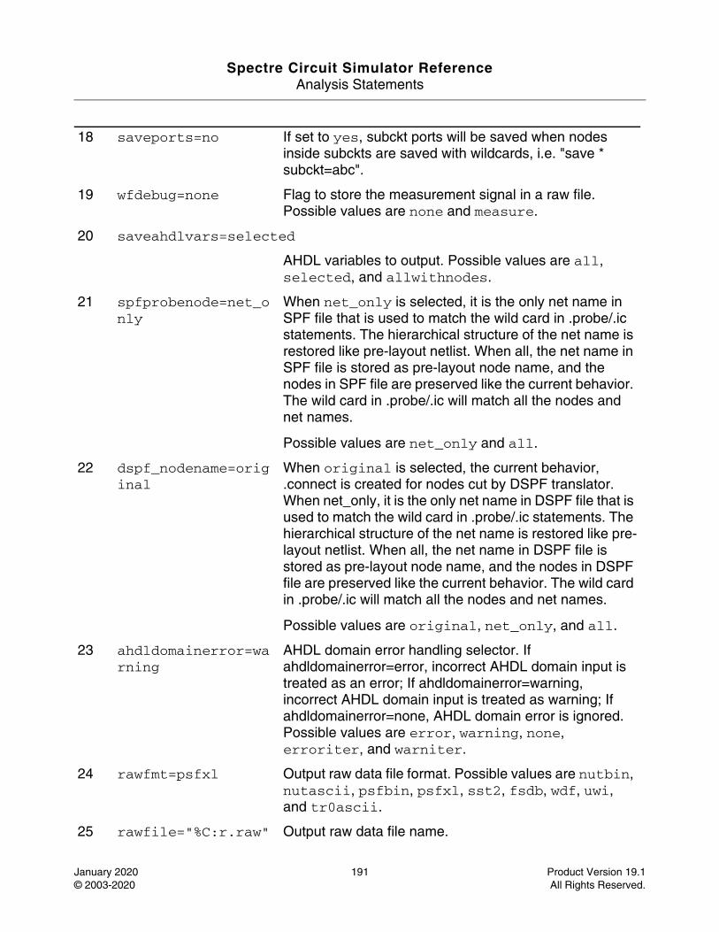
Spectre Circuit Simulator ReferenceAnalysis Statements
January 2020 191 Product Version 19.1© 2003-2020 All Rights Reserved.
18 saveports=no If set to yes, subckt ports will be saved when nodes inside subckts are saved with wildcards, i.e. "save * subckt=abc".
19 wfdebug=none Flag to store the measurement signal in a raw file. Possible values are none and measure.
20 saveahdlvars=selected
AHDL variables to output. Possible values are all, selected, and allwithnodes.
21 spfprobenode=net_only
When net_only is selected, it is the only net name in SPF file that is used to match the wild card in .probe/.ic statements. The hierarchical structure of the net name is restored like pre-layout netlist. When all, the net name in SPF file is stored as pre-layout node name, and the nodes in SPF file are preserved like the current behavior. The wild card in .probe/.ic will match all the nodes and net names.
Possible values are net_only and all.
22 dspf_nodename=original
When original is selected, the current behavior, .connect is created for nodes cut by DSPF translator. When net_only, it is the only net name in DSPF file that is used to match the wild card in .probe/.ic statements. The hierarchical structure of the net name is restored like pre-layout netlist. When all, the net name in DSPF file is stored as pre-layout node name, and the nodes in DSPF file are preserved like the current behavior. The wild card in .probe/.ic will match all the nodes and net names.
Possible values are original, net_only, and all.
23 ahdldomainerror=warning
AHDL domain error handling selector. If ahdldomainerror=error, incorrect AHDL domain input is treated as an error; If ahdldomainerror=warning, incorrect AHDL domain input is treated as warning; If ahdldomainerror=none, AHDL domain error is ignored. Possible values are error, warning, none, erroriter, and warniter.
24 rawfmt=psfxl Output raw data file format. Possible values are nutbin, nutascii, psfbin, psfxl, sst2, fsdb, wdf, uwi, and tr0ascii.
25 rawfile="%C:r.raw" Output raw data file name.
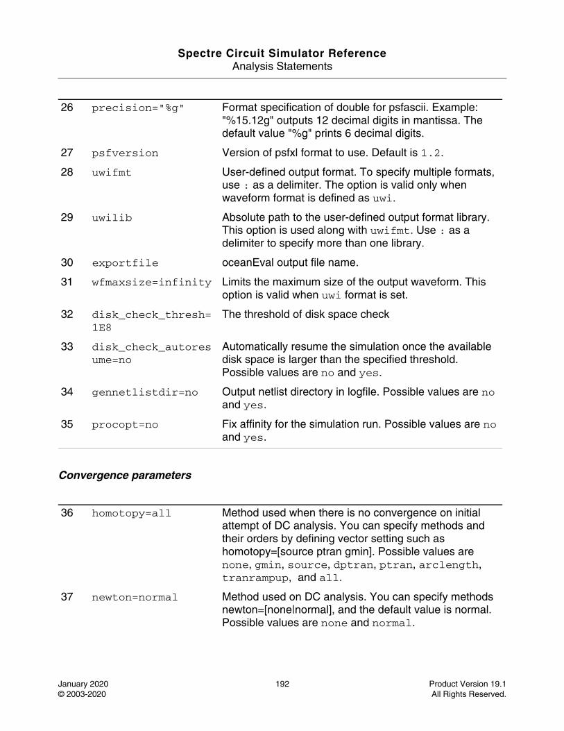
Spectre Circuit Simulator ReferenceAnalysis Statements
January 2020 192 Product Version 19.1© 2003-2020 All Rights Reserved.
Convergence parameters
26 precision="%g" Format specification of double for psfascii. Example: "%15.12g" outputs 12 decimal digits in mantissa. The default value "%g" prints 6 decimal digits.
27 psfversion Version of psfxl format to use. Default is 1.2.
28 uwifmt User-defined output format. To specify multiple formats, use : as a delimiter. The option is valid only when waveform format is defined as uwi.
29 uwilib Absolute path to the user-defined output format library. This option is used along with uwifmt. Use : as a delimiter to specify more than one library.
30 exportfile oceanEval output file name.
31 wfmaxsize=infinity Limits the maximum size of the output waveform. This option is valid when uwi format is set.
32 disk_check_thresh=1E8
The threshold of disk space check
33 disk_check_autoresume=no
Automatically resume the simulation once the available disk space is larger than the specified threshold.Possible values are no and yes.
34 gennetlistdir=no Output netlist directory in logfile. Possible values are no and yes.
35 procopt=no Fix affinity for the simulation run. Possible values are no and yes.
36 homotopy=all Method used when there is no convergence on initial attempt of DC analysis. You can specify methods and their orders by defining vector setting such as homotopy=[source ptran gmin]. Possible values are none, gmin, source, dptran, ptran, arclength, tranrampup, and all.
37 newton=normal Method used on DC analysis. You can specify methods newton=[none|normal], and the default value is normal. Possible values are none and normal.
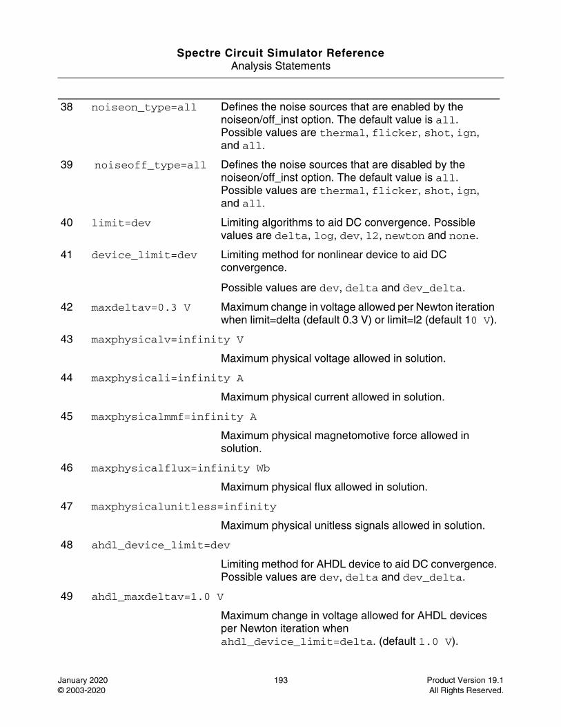
Spectre Circuit Simulator ReferenceAnalysis Statements
January 2020 193 Product Version 19.1© 2003-2020 All Rights Reserved.
38 noiseon_type=all Defines the noise sources that are enabled by the noiseon/off_inst option. The default value is all. Possible values are thermal, flicker, shot, ign, and all.
39 noiseoff_type=all Defines the noise sources that are disabled by the noiseon/off_inst option. The default value is all.Possible values are thermal, flicker, shot, ign, and all.
40 limit=dev Limiting algorithms to aid DC convergence. Possible values are delta, log, dev, l2, newton and none.
41 device_limit=dev Limiting method for nonlinear device to aid DC convergence.
Possible values are dev, delta and dev_delta.
42 maxdeltav=0.3 V Maximum change in voltage allowed per Newton iteration when limit=delta (default 0.3 V) or limit=l2 (default 10 V).
43 maxphysicalv=infinity V
Maximum physical voltage allowed in solution.
44 maxphysicali=infinity A
Maximum physical current allowed in solution.
45 maxphysicalmmf=infinity A
Maximum physical magnetomotive force allowed in solution.
46 maxphysicalflux=infinity Wb
Maximum physical flux allowed in solution.
47 maxphysicalunitless=infinity
Maximum physical unitless signals allowed in solution.
48 ahdl_device_limit=dev
Limiting method for AHDL device to aid DC convergence.Possible values are dev, delta and dev_delta.
49 ahdl_maxdeltav=1.0 V
Maximum change in voltage allowed for AHDL devices per Newton iteration when ahdl_device_limit=delta. (default 1.0 V).
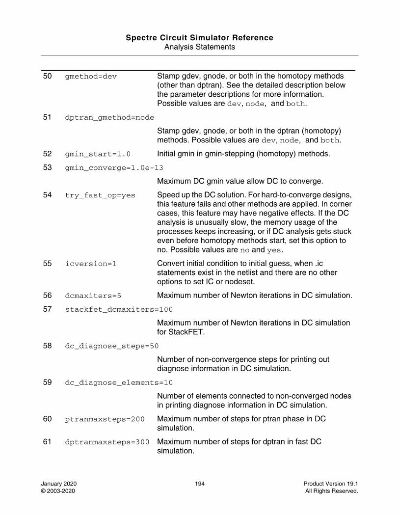
Spectre Circuit Simulator ReferenceAnalysis Statements
January 2020 194 Product Version 19.1© 2003-2020 All Rights Reserved.
50 gmethod=dev Stamp gdev, gnode, or both in the homotopy methods (other than dptran). See the detailed description below the parameter descriptions for more information. Possible values are dev, node, and both.
51 dptran_gmethod=node
Stamp gdev, gnode, or both in the dptran (homotopy) methods. Possible values are dev, node, and both.
52 gmin_start=1.0 Initial gmin in gmin-stepping (homotopy) methods.
53 gmin_converge=1.0e-13
Maximum DC gmin value allow DC to converge.
54 try_fast_op=yes Speed up the DC solution. For hard-to-converge designs, this feature fails and other methods are applied. In corner cases, this feature may have negative effects. If the DC analysis is unusually slow, the memory usage of the processes keeps increasing, or if DC analysis gets stuck even before homotopy methods start, set this option to no. Possible values are no and yes.
55 icversion=1 Convert initial condition to initial guess, when .ic statements exist in the netlist and there are no other options to set IC or nodeset.
56 dcmaxiters=5 Maximum number of Newton iterations in DC simulation.
57 stackfet_dcmaxiters=100
Maximum number of Newton iterations in DC simulation for StackFET.
58 dc_diagnose_steps=50
Number of non-convergence steps for printing out diagnose information in DC simulation.
59 dc_diagnose_elements=10
Number of elements connected to non-converged nodes in printing diagnose information in DC simulation.
60 ptranmaxsteps=200 Maximum number of steps for ptran phase in DC simulation.
61 dptranmaxsteps=300 Maximum number of steps for dptran in fast DC simulation.
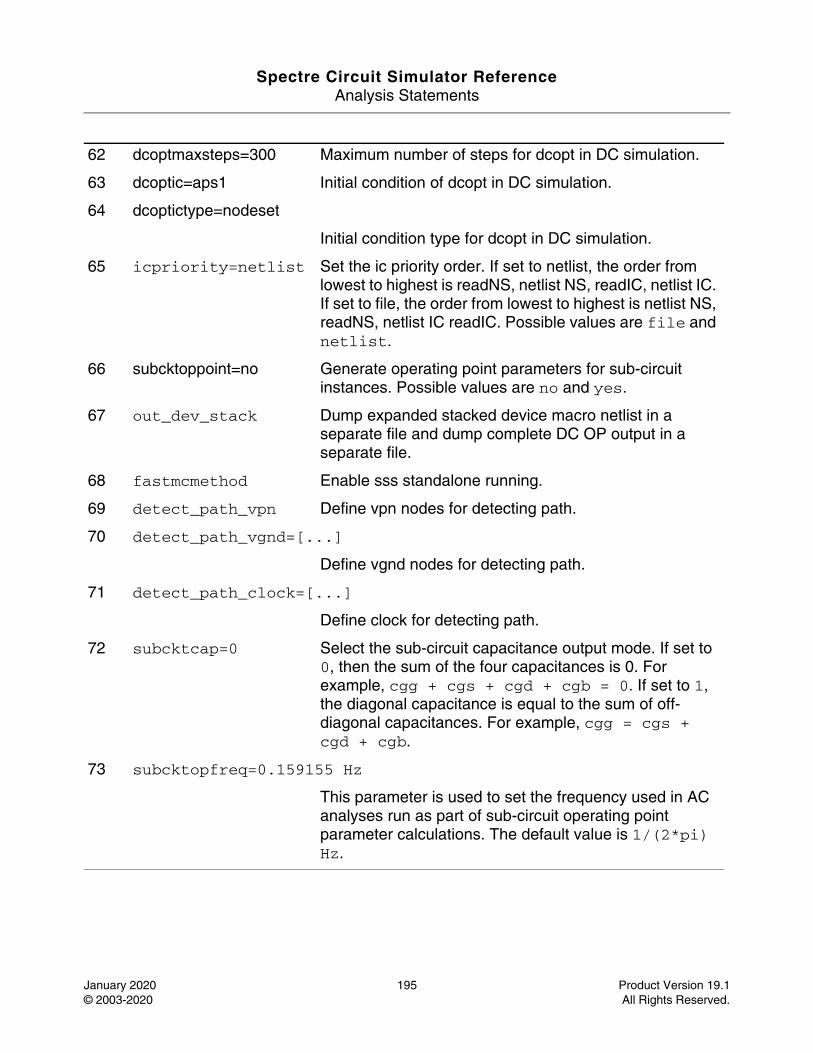
Spectre Circuit Simulator ReferenceAnalysis Statements
January 2020 195 Product Version 19.1© 2003-2020 All Rights Reserved.
62 dcoptmaxsteps=300 Maximum number of steps for dcopt in DC simulation.
63 dcoptic=aps1 Initial condition of dcopt in DC simulation.
64 dcoptictype=nodeset
Initial condition type for dcopt in DC simulation.
65 icpriority=netlist Set the ic priority order. If set to netlist, the order from lowest to highest is readNS, netlist NS, readIC, netlist IC. If set to file, the order from lowest to highest is netlist NS, readNS, netlist IC readIC. Possible values are file and netlist.
66 subcktoppoint=no Generate operating point parameters for sub-circuit instances. Possible values are no and yes.
67 out_dev_stack Dump expanded stacked device macro netlist in a separate file and dump complete DC OP output in a separate file.
68 fastmcmethod Enable sss standalone running.
69 detect_path_vpn Define vpn nodes for detecting path.
70 detect_path_vgnd=[...]
Define vgnd nodes for detecting path.
71 detect_path_clock=[...]
Define clock for detecting path.
72 subcktcap=0 Select the sub-circuit capacitance output mode. If set to 0, then the sum of the four capacitances is 0. For example, cgg + cgs + cgd + cgb = 0. If set to 1, the diagonal capacitance is equal to the sum of off-diagonal capacitances. For example, cgg = cgs + cgd + cgb.
73 subcktopfreq=0.159155 Hz
This parameter is used to set the frequency used in AC analyses run as part of sub-circuit operating point parameter calculations. The default value is 1/(2*pi) Hz.

Spectre Circuit Simulator ReferenceAnalysis Statements
January 2020 196 Product Version 19.1© 2003-2020 All Rights Reserved.
Multithreading parameters
74 multithread=off Enable or disable multithreading capability. When multithreading is enabled but the number of threads (nThreads) is not specified, Spectre will automatically detect the number of processors and select the proper number of threads to use. (See important note about using multithreading in the detailed description below the parameter descriptions). Possible values are off and on.
75 nthreads Specifies the number of threads for multithreading.
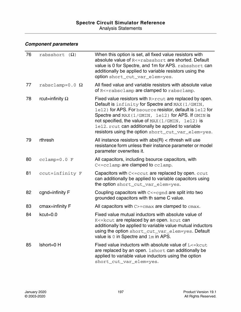
Spectre Circuit Simulator ReferenceAnalysis Statements
January 2020 197 Product Version 19.1© 2003-2020 All Rights Reserved.
Component parameters
76 rabsshort (Ω) When this option is set, all fixed value resistors with absolute value of R<=rabsshort are shorted. Default value is 0 for Spectre, and 1m for APS. rabsshort can additionally be applied to variable resistors using the option short_cut_var_elem=yes.
77 rabsclamp=0.0 Ω All fixed value and variable resistors with absolute value of R<=rabsclamp are clamped to rabsclamp.
78 rcut=infinity Ω Fixed value resistors with R>rcut are replaced by open. Default is infinity for Spectre and MAX(1/GMIN, 1e12) for APS. For bsource resistor, default is 1e12 for Spectre and MAX(1/GMIN, 1e12) for APS. If GMIN is not specified, the value of MAX(1/GMIN, 1e12) is 1e12. rcut can additionally be applied to variable resistors using the option short_cut_var_elem=yes.
79 rthresh All instance resistors with abs(R) < rthresh will use resistance form unless their instance parameter or model parameter overwrites it.
80 cclamp=0.0 F All capacitors, including bsource capacitors, with C<=cclamp are clamped to cclamp.
81 ccut=infinity F Capacitors with C<=ccut are replaced by open. ccut can additionally be applied to variable capacitors using the option short_cut_var_elem=yes.
82 cgnd=infinity F Coupling capacitors with C<=cgnd are split into two grounded capacitors with th same C value.
83 cmax=infinity F All capacitors with C>=cmax are clamped to cmax.
84 kcut=0.0 Fixed value mutual inductors with absolute value of K<=kcut are replaced by an open. kcut can additionally be applied to variable value mutual inductors using the option short_cut_var_elem=yes. Default value is 0 in Spectre and 1m in APS.
85 lshort=0 H Fixed value inductors with absolute value of L<=kcut are replaced by an open. lshort can additionally be applied to variable value inductors using the option short_cut_var_elem=yes.
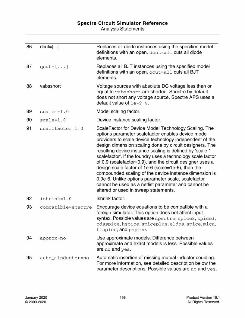
Spectre Circuit Simulator ReferenceAnalysis Statements
January 2020 198 Product Version 19.1© 2003-2020 All Rights Reserved.
86 dcut=[...] Replaces all diode instances using the specified model definitions with an open. dcut=all cuts all diode elements.
87 qcut=[...] Replaces all BJT instances using the specified model definitions with an open. qcut=all cuts all BJT elements.
88 vabsshort Voltage sources with absolute DC voltage less than or equal to vabsshort are shorted. Spectre by default does not short any voltage source, Spectre APS uses a default value of 1e-9 V.
89 scalem=1.0 Model scaling factor.
90 scale=1.0 Device instance scaling factor.
91 scalefactor=1.0 ScaleFactor for Device Model Technology Scaling. The options parameter scalefactor enables device model providers to scale device technology independent of the design dimension scaling done by circuit designers. The resulting device instance scaling is defined by 'scale * scalefactor'. If the foundry uses a technology scale factor of 0.9 (scalefactor=0.9), and the circuit designer uses a design scale factor of 1e-6 (scale=1e-6), then the compounded scaling of the device instance dimension is 0.9e-6. Unlike options parameter scale, scalefactor cannot be used as a netlist parameter and cannot be altered or used in sweep statements.
92 ishrink=1.0 Ishrink factor.
93 compatible=spectre Encourage device equations to be compatible with a foreign simulator. This option does not affect input syntax. Possible values are spectre, spice2, spice3, cdsspice, hspice, spiceplus, eldos, spice, mica, tispice, and pspice.
94 approx=no Use approximate models. Difference between approximate and exact models is less. Possible values are no and yes.
95 auto_minductor=no Automatic insertion of missing mutual inductor coupling. For more information, see detailed description below the parameter descriptions. Possible values are no and yes.
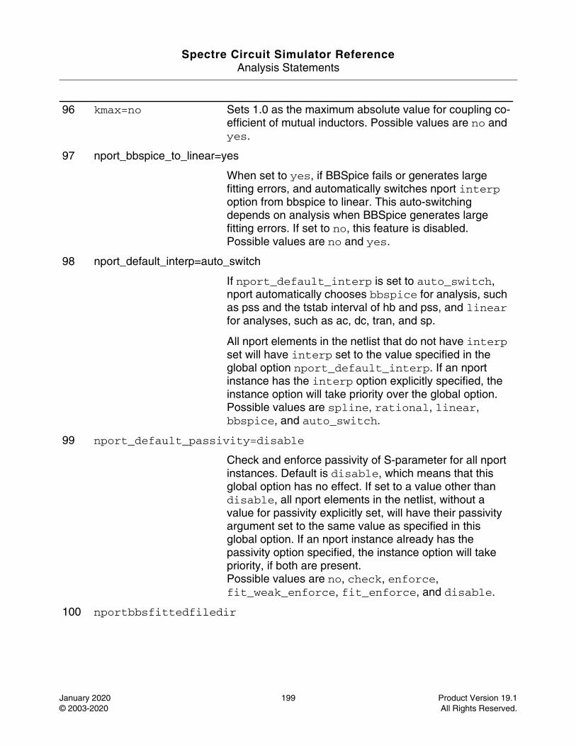
Spectre Circuit Simulator ReferenceAnalysis Statements
January 2020 199 Product Version 19.1© 2003-2020 All Rights Reserved.
96 kmax=no Sets 1.0 as the maximum absolute value for coupling co-efficient of mutual inductors. Possible values are no and yes.
97 nport_bbspice_to_linear=yes
When set to yes, if BBSpice fails or generates large fitting errors, and automatically switches nport interp option from bbspice to linear. This auto-switching depends on analysis when BBSpice generates large fitting errors. If set to no, this feature is disabled.Possible values are no and yes.
98 nport_default_interp=auto_switch
If nport_default_interp is set to auto_switch, nport automatically chooses bbspice for analysis, such as pss and the tstab interval of hb and pss, and linear for analyses, such as ac, dc, tran, and sp.
All nport elements in the netlist that do not have interp set will have interp set to the value specified in the global option nport_default_interp. If an nport instance has the interp option explicitly specified, the instance option will take priority over the global option. Possible values are spline, rational, linear, bbspice, and auto_switch.
99 nport_default_passivity=disable
Check and enforce passivity of S-parameter for all nport instances. Default is disable, which means that this global option has no effect. If set to a value other than disable, all nport elements in the netlist, without a value for passivity explicitly set, will have their passivity argument set to the same value as specified in this global option. If an nport instance already has the passivity option specified, the instance option will take priority, if both are present.Possible values are no, check, enforce, fit_weak_enforce, fit_enforce, and disable.
100 nportbbsfittedfiledir
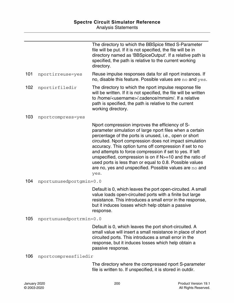
Spectre Circuit Simulator ReferenceAnalysis Statements
January 2020 200 Product Version 19.1© 2003-2020 All Rights Reserved.
The directory to which the BBSpice fitted S-Parameter file will be put. If it is not specified, the file will be in directory named as 'BBSpiceOutput'. If a relative path is specified, the path is relative to the current working directory.
101 nportirreuse=yes Reuse impulse responses data for all nport instances. If no, disable this feature. Possible values are no and yes.
102 nportirfiledir The directory to which the nport impulse response file will be written. If it is not specified, the file will be written to /home/<username>/.cadence/mmsim/. If a relative path is specified, the path is relative to the current working directory.
103 nportcompress=yes
Nport compression improves the efficiency of S-parameter simulation of large nport files when a certain percentage of the ports is unused, i.e., open or short circuited. Nport compression does not impact simulation accuracy. This option turns off compression if set to no and attempts to force compression if set to yes. If left unspecified, compression is on if N>=10 and the ratio of used ports is less than or equal to 0.8. Possible values are no, yes and unspecified. Possible values are no and yes.
104 nportunusedportgmin=0.0
Default is 0, which leaves the port open-circuited. A small value loads open-circuited ports with a finite but large resistance. This introduces a small error in the response, but it induces losses which help obtain a passive response.
105 nportunusedportrmin=0.0
Default is 0, which leaves the port short-circuited. A small value will insert a small resistance in place of short circuited ports. This introduces a small error in the response, but it induces losses which help obtain a passive response.
106 nportcompressfiledir
The directory where the compressed nport S-parameter file is written to. If unspecified, it is stored in outdir.
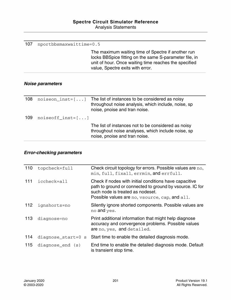
Spectre Circuit Simulator ReferenceAnalysis Statements
January 2020 201 Product Version 19.1© 2003-2020 All Rights Reserved.
Noise parameters
Error-checking parameters
107 nportbbsmaxwaittime=0.5
The maximum waiting time of Spectre if another run locks BBSpice fitting on the same S-parameter file, in unit of hour. Once waiting time reaches the specified value, Spectre exits with error.
108 noiseon_inst=[...] The list of instances to be considered as noisy throughout noise analysis, which include, noise, sp noise, pnoise and tran noise.
109 noiseoff_inst=[...]
The list of instances not to be considered as noisy throughout noise analyses, which include noise, sp noise, pnoise and tran noise.
110 topcheck=full Check circuit topology for errors. Possible values are no, min, full, fixall, errmin, and errfull.
111 iccheck=all Check if nodes with initial conditions have capacitive path to ground or connected to ground by vsource. IC for such node is treated as nodeset.Possible values are no, vsource, cap, and all.
112 ignshorts=no Silently ignore shorted components. Possible values are no and yes.
113 diagnose=no Print additional information that might help diagnose accuracy and convergence problems. Possible values are no, yes, and detailed.
114 diagnose_start=0 s Start time to enable the detailed diagnosis mode.
115 diagnose_end (s) End time to enable the detailed diagnosis mode. Default is transient stop time.
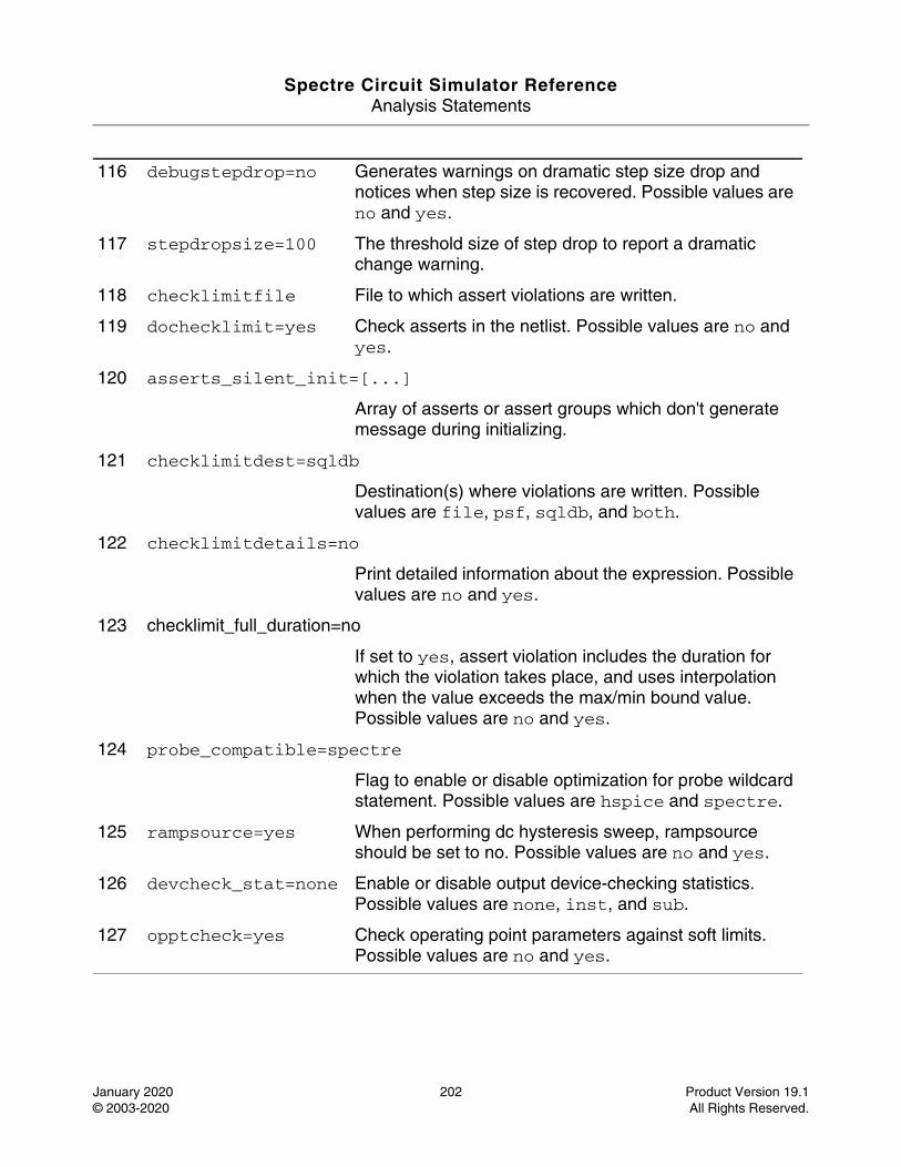
Spectre Circuit Simulator ReferenceAnalysis Statements
January 2020 202 Product Version 19.1© 2003-2020 All Rights Reserved.
116 debugstepdrop=no Generates warnings on dramatic step size drop and notices when step size is recovered. Possible values are no and yes.
117 stepdropsize=100 The threshold size of step drop to report a dramatic change warning.
118 checklimitfile File to which assert violations are written.
119 dochecklimit=yes Check asserts in the netlist. Possible values are no and yes.
120 asserts_silent_init=[...]
Array of asserts or assert groups which don't generate message during initializing.
121 checklimitdest=sqldb
Destination(s) where violations are written. Possible values are file, psf, sqldb, and both.
122 checklimitdetails=no
Print detailed information about the expression. Possible values are no and yes.
123 checklimit_full_duration=no
If set to yes, assert violation includes the duration for which the violation takes place, and uses interpolation when the value exceeds the max/min bound value. Possible values are no and yes.
124 probe_compatible=spectre
Flag to enable or disable optimization for probe wildcard statement. Possible values are hspice and spectre.
125 rampsource=yes When performing dc hysteresis sweep, rampsource should be set to no. Possible values are no and yes.
126 devcheck_stat=none Enable or disable output device-checking statistics. Possible values are none, inst, and sub.
127 opptcheck=yes Check operating point parameters against soft limits. Possible values are no and yes.
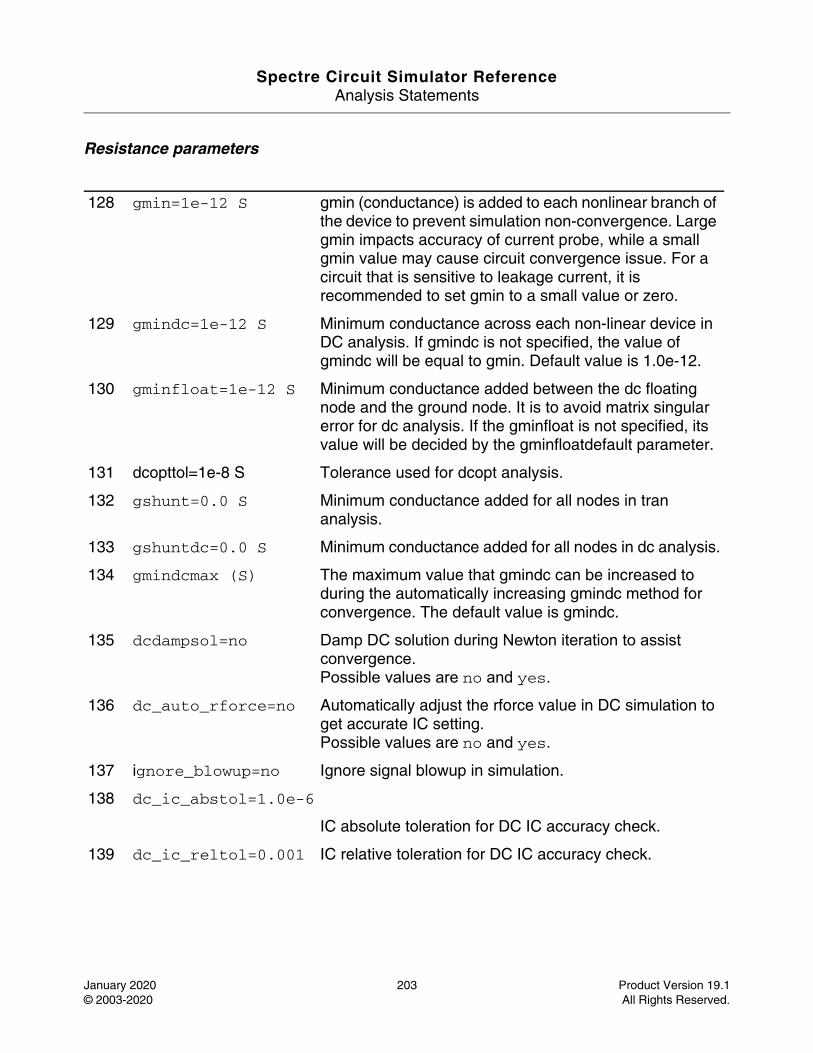
Spectre Circuit Simulator ReferenceAnalysis Statements
January 2020 203 Product Version 19.1© 2003-2020 All Rights Reserved.
Resistance parameters
128 gmin=1e-12 S gmin (conductance) is added to each nonlinear branch of the device to prevent simulation non-convergence. Large gmin impacts accuracy of current probe, while a small gmin value may cause circuit convergence issue. For a circuit that is sensitive to leakage current, it is recommended to set gmin to a small value or zero.
129 gmindc=1e-12 S Minimum conductance across each non-linear device in DC analysis. If gmindc is not specified, the value of gmindc will be equal to gmin. Default value is 1.0e-12.
130 gminfloat=1e-12 S Minimum conductance added between the dc floating node and the ground node. It is to avoid matrix singular error for dc analysis. If the gminfloat is not specified, its value will be decided by the gminfloatdefault parameter.
131 dcopttol=1e-8 S Tolerance used for dcopt analysis.
132 gshunt=0.0 S Minimum conductance added for all nodes in tran analysis.
133 gshuntdc=0.0 S Minimum conductance added for all nodes in dc analysis.
134 gmindcmax (S) The maximum value that gmindc can be increased to during the automatically increasing gmindc method for convergence. The default value is gmindc.
135 dcdampsol=no Damp DC solution during Newton iteration to assist convergence.Possible values are no and yes.
136 dc_auto_rforce=no Automatically adjust the rforce value in DC simulation to get accurate IC setting.Possible values are no and yes.
137 ignore_blowup=no Ignore signal blowup in simulation.
138 dc_ic_abstol=1.0e-6
IC absolute toleration for DC IC accuracy check.
139 dc_ic_reltol=0.001 IC relative toleration for DC IC accuracy check.
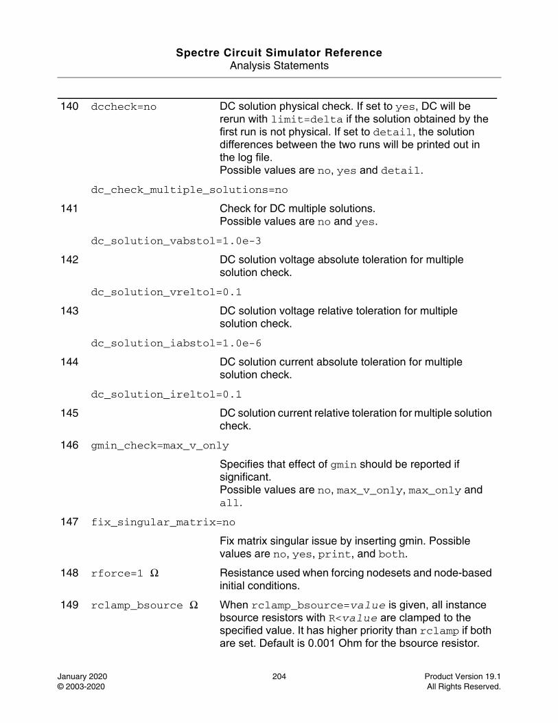
Spectre Circuit Simulator ReferenceAnalysis Statements
January 2020 204 Product Version 19.1© 2003-2020 All Rights Reserved.
140 dccheck=no DC solution physical check. If set to yes, DC will be rerun with limit=delta if the solution obtained by the first run is not physical. If set to detail, the solution differences between the two runs will be printed out in the log file.Possible values are no, yes and detail.
dc_check_multiple_solutions=no
141 Check for DC multiple solutions.Possible values are no and yes.
dc_solution_vabstol=1.0e-3
142 DC solution voltage absolute toleration for multiple solution check.
dc_solution_vreltol=0.1
143 DC solution voltage relative toleration for multiple solution check.
dc_solution_iabstol=1.0e-6
144 DC solution current absolute toleration for multiple solution check.
dc_solution_ireltol=0.1
145 DC solution current relative toleration for multiple solution check.
146 gmin_check=max_v_only
Specifies that effect of gmin should be reported if significant.Possible values are no, max_v_only, max_only and all.
147 fix_singular_matrix=no
Fix matrix singular issue by inserting gmin. Possible values are no, yes, print, and both.
148 rforce=1 Ω Resistance used when forcing nodesets and node-based initial conditions.
149 rclamp_bsource Ω When rclamp_bsource=value is given, all instance bsource resistors with R<value are clamped to the specified value. It has higher priority than rclamp if both are set. Default is 0.001 Ohm for the bsource resistor.
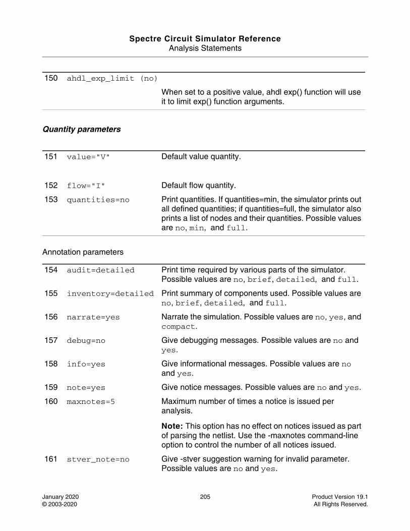
Spectre Circuit Simulator ReferenceAnalysis Statements
January 2020 205 Product Version 19.1© 2003-2020 All Rights Reserved.
Quantity parameters
Annotation parameters
150 ahdl_exp_limit (no)
When set to a positive value, ahdl exp() function will use it to limit exp() function arguments.
151 value="V" Default value quantity.
152 flow="I" Default flow quantity.
153 quantities=no Print quantities. If quantities=min, the simulator prints out all defined quantities; if quantities=full, the simulator also prints a list of nodes and their quantities. Possible values are no, min, and full.
154 audit=detailed Print time required by various parts of the simulator. Possible values are no, brief, detailed, and full.
155 inventory=detailed Print summary of components used. Possible values are no, brief, detailed, and full.
156 narrate=yes Narrate the simulation. Possible values are no, yes, and compact.
157 debug=no Give debugging messages. Possible values are no and yes.
158 info=yes Give informational messages. Possible values are no and yes.
159 note=yes Give notice messages. Possible values are no and yes.
160 maxnotes=5 Maximum number of times a notice is issued per analysis.
Note: This option has no effect on notices issued as part of parsing the netlist. Use the -maxnotes command-line option to control the number of all notices issued.
161 stver_note=no Give -stver suggestion warning for invalid parameter. Possible values are no and yes.
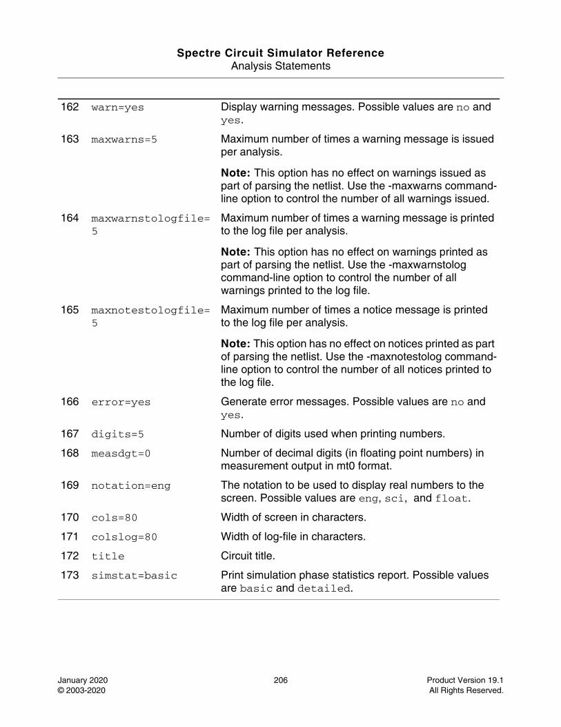
Spectre Circuit Simulator ReferenceAnalysis Statements
January 2020 206 Product Version 19.1© 2003-2020 All Rights Reserved.
162 warn=yes Display warning messages. Possible values are no and yes.
163 maxwarns=5 Maximum number of times a warning message is issued per analysis.
Note: This option has no effect on warnings issued as part of parsing the netlist. Use the -maxwarns command-line option to control the number of all warnings issued.
164 maxwarnstologfile=5
Maximum number of times a warning message is printed to the log file per analysis.
Note: This option has no effect on warnings printed as part of parsing the netlist. Use the -maxwarnstolog command-line option to control the number of all warnings printed to the log file.
165 maxnotestologfile=5
Maximum number of times a notice message is printed to the log file per analysis.
Note: This option has no effect on notices printed as part of parsing the netlist. Use the -maxnotestolog command-line option to control the number of all notices printed to the log file.
166 error=yes Generate error messages. Possible values are no and yes.
167 digits=5 Number of digits used when printing numbers.
168 measdgt=0 Number of decimal digits (in floating point numbers) in measurement output in mt0 format.
169 notation=eng The notation to be used to display real numbers to the screen. Possible values are eng, sci, and float.
170 cols=80 Width of screen in characters.
171 colslog=80 Width of log-file in characters.
172 title Circuit title.
173 simstat=basic Print simulation phase statistics report. Possible values are basic and detailed.
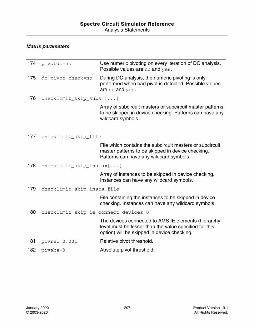
Spectre Circuit Simulator ReferenceAnalysis Statements
January 2020 207 Product Version 19.1© 2003-2020 All Rights Reserved.
Matrix parameters
174 pivotdc=no Use numeric pivoting on every iteration of DC analysis. Possible values are no and yes.
175 dc_pivot_check=no During DC analysis, the numeric pivoting is only performed when bad pivot is detected. Possible values are no and yes.
176 checklimit_skip_subs=[...]
Array of subcircuit masters or subcircuit master patterns to be skipped in device checking. Patterns can have any wildcard symbols.
177 checklimit_skip_file
File which contains the subcircuit masters or subcircuit master patterns to be skipped in device checking. Patterns can have any wildcard symbols.
178 checklimit_skip_insts=[...]
Array of instances to be skipped in device checking. Instances can have any wildcard symbols.
179 checklimit_skip_insts_file
File containing the instances to be skipped in device checking. Instances can have any wildcard symbols.
180 checklimit_skip_ie_connect_devices=0
The devices connected to AMS IE elements (hierarchy level must be lesser than the value specified for this option) will be skipped in device checking.
181 pivrel=0.001 Relative pivot threshold.
182 pivabs=0 Absolute pivot threshold.
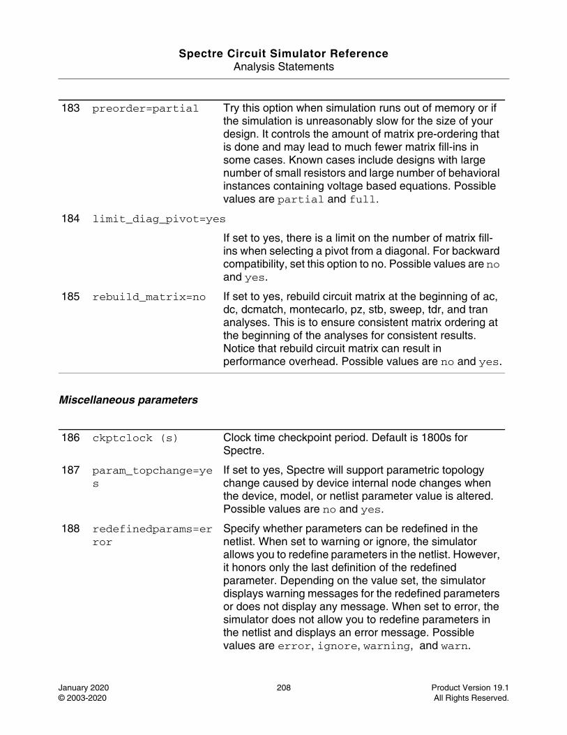
Spectre Circuit Simulator ReferenceAnalysis Statements
January 2020 208 Product Version 19.1© 2003-2020 All Rights Reserved.
Miscellaneous parameters
183 preorder=partial Try this option when simulation runs out of memory or if the simulation is unreasonably slow for the size of your design. It controls the amount of matrix pre-ordering that is done and may lead to much fewer matrix fill-ins in some cases. Known cases include designs with large number of small resistors and large number of behavioral instances containing voltage based equations. Possible values are partial and full.
184 limit_diag_pivot=yes
If set to yes, there is a limit on the number of matrix fill-ins when selecting a pivot from a diagonal. For backward compatibility, set this option to no. Possible values are no and yes.
185 rebuild_matrix=no If set to yes, rebuild circuit matrix at the beginning of ac, dc, dcmatch, montecarlo, pz, stb, sweep, tdr, and tran analyses. This is to ensure consistent matrix ordering at the beginning of the analyses for consistent results. Notice that rebuild circuit matrix can result in performance overhead. Possible values are no and yes.
186 ckptclock (s) Clock time checkpoint period. Default is 1800s for Spectre.
187 param_topchange=yes
If set to yes, Spectre will support parametric topology change caused by device internal node changes when the device, model, or netlist parameter value is altered. Possible values are no and yes.
188 redefinedparams=error
Specify whether parameters can be redefined in the netlist. When set to warning or ignore, the simulator allows you to redefine parameters in the netlist. However, it honors only the last definition of the redefined parameter. Depending on the value set, the simulator displays warning messages for the redefined parameters or does not display any message. When set to error, the simulator does not allow you to redefine parameters in the netlist and displays an error message. Possible values are error, ignore, warning, and warn.
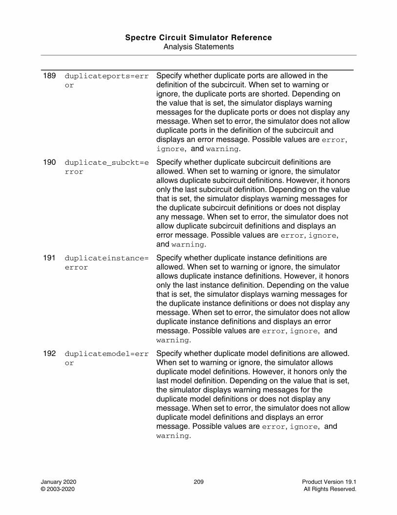
Spectre Circuit Simulator ReferenceAnalysis Statements
January 2020 209 Product Version 19.1© 2003-2020 All Rights Reserved.
189 duplicateports=error
Specify whether duplicate ports are allowed in the definition of the subcircuit. When set to warning or ignore, the duplicate ports are shorted. Depending on the value that is set, the simulator displays warning messages for the duplicate ports or does not display any message. When set to error, the simulator does not allow duplicate ports in the definition of the subcircuit and displays an error message. Possible values are error, ignore, and warning.
190 duplicate_subckt=error
Specify whether duplicate subcircuit definitions are allowed. When set to warning or ignore, the simulator allows duplicate subcircuit definitions. However, it honors only the last subcircuit definition. Depending on the value that is set, the simulator displays warning messages for the duplicate subcircuit definitions or does not display any message. When set to error, the simulator does not allow duplicate subcircuit definitions and displays an error message. Possible values are error, ignore, and warning.
191 duplicateinstance=error
Specify whether duplicate instance definitions are allowed. When set to warning or ignore, the simulator allows duplicate instance definitions. However, it honors only the last instance definition. Depending on the value that is set, the simulator displays warning messages for the duplicate instance definitions or does not display any message. When set to error, the simulator does not allow duplicate instance definitions and displays an error message. Possible values are error, ignore, and warning.
192 duplicatemodel=error
Specify whether duplicate model definitions are allowed. When set to warning or ignore, the simulator allows duplicate model definitions. However, it honors only the last model definition. Depending on the value that is set, the simulator displays warning messages for the duplicate model definitions or does not display any message. When set to error, the simulator does not allow duplicate model definitions and displays an error message. Possible values are error, ignore, and warning.
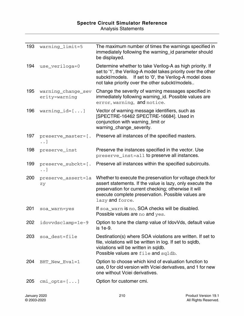
Spectre Circuit Simulator ReferenceAnalysis Statements
January 2020 210 Product Version 19.1© 2003-2020 All Rights Reserved.
193 warning_limit=5 The maximum number of times the warnings specified in immediately following the warning_id parameter should be displayed.
194 use_veriloga=0 Determine whether to take Verilog-A as high priority. If set to '1', the Verilog-A model takes priority over the other subckt/models. If set to '0', the Verilog-A model does not take priority over the other subckt/models..
195 warning_change_severity=warning
Change the severity of warning messages specified in immediately following warning_id. Possible values are error, warning, and notice.
196 warning_id=[...] Vector of warning message identifiers, such as [SPECTRE-16462 SPECTRE-16684]. Used in conjunction with warning_limit or warning_change_severity.
197 preserve_master=[...]
Preserve all instances of the specified masters.
198 preserve_inst Preserve the instances specified in the vector. Use preserve_inst=all to preserve all instances.
199 preserve_subckt=[...]
Preserve all instances within the specified subcircuits.
200 preserve_assert=lazy
Whether to execute the preservation for voltage check for assert statements. If the value is lazy, only execute the preservation for current checking; otherwise it will execute complete preservation. Possible values are lazy and force.
201 soa_warn=yes If soa_warn is no, SOA checks will be disabled. Possible values are no and yes.
202 idovvdsclamp=1e-9 Option to tune the clamp value of IdovVds, default value is 1e-9.
203 soa_dest=file Destination(s) where SOA violations are written. If set to file, violations will be written in log. If set to sqldb, violations will be written in sqldb.Possible values are file and sqldb.
204 BHT_New_Eval=1 Option to choose which kind of evaluation function to use, 0 for old version with Vciei derivatives, and 1 for new one without Vciei derivatives.
205 cmi_opts=[...] Option for customer cmi.
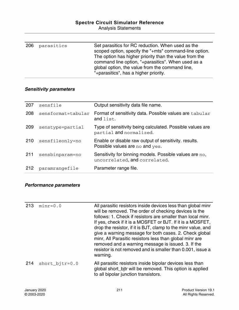
Spectre Circuit Simulator ReferenceAnalysis Statements
January 2020 211 Product Version 19.1© 2003-2020 All Rights Reserved.
Sensitivity parameters
Performance parameters
206 parasitics Set parasitics for RC reduction. When used as the scoped option, specify the "+mts" command-line option. The option has higher priority than the value from the command line option, "+parasitics". When used as a global option, the value from the command line, "+parasitics", has a higher priority.
207 sensfile Output sensitivity data file name.
208 sensformat=tabular Format of sensitivity data. Possible values are tabular and list.
209 senstype=partial Type of sensitivity being calculated. Possible values are partial and normalized.
210 sensfileonly=no Enable or disable raw output of sensitivity. results. Possible values are no and yes.
211 sensbinparam=no Sensitivity for binning models. Possible values are no, uncorrelated, and correlated.
212 paramrangefile Parameter range file.
213 minr=0.0 All parasitic resistors inside devices less than global minr will be removed. The order of checking devices is the follows: 1. Check if resistors are smaller than local minr. If yes, check if it is a MOSFET or BJT. If it is a MOSFET, drop the resistor, if it is BJT, clamp to the minr value, and give a warning message for both cases. 2. Check global minr, All Parasitic resistors less than global minr are removed and a warning message is issued. 3. If the resistor is not removed and is smaller than 0.001, issue a warning.
214 short_bjtr=0.0 All parasitic resistors inside bipolar devices less than global short_bjtr will be removed. This option is applied to all bipolar junction transistors.
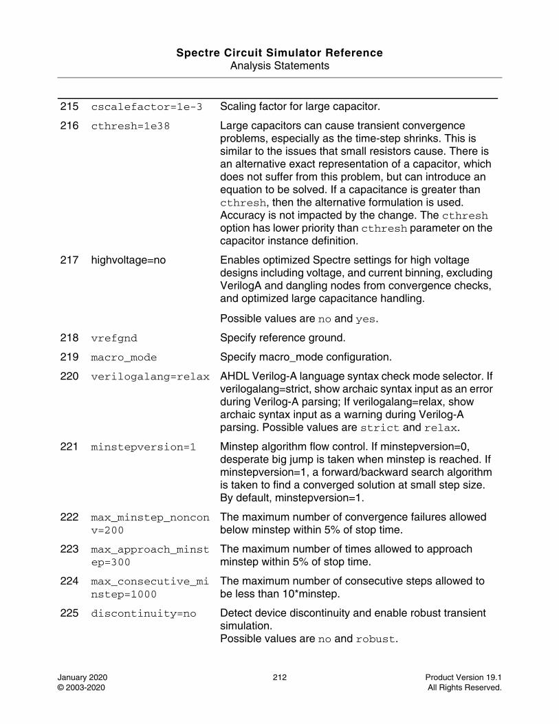
Spectre Circuit Simulator ReferenceAnalysis Statements
January 2020 212 Product Version 19.1© 2003-2020 All Rights Reserved.
215 cscalefactor=1e-3 Scaling factor for large capacitor.
216 cthresh=1e38 Large capacitors can cause transient convergence problems, especially as the time-step shrinks. This is similar to the issues that small resistors cause. There is an alternative exact representation of a capacitor, which does not suffer from this problem, but can introduce an equation to be solved. If a capacitance is greater than cthresh, then the alternative formulation is used. Accuracy is not impacted by the change. The cthresh option has lower priority than cthresh parameter on the capacitor instance definition.
217 highvoltage=no Enables optimized Spectre settings for high voltage designs including voltage, and current binning, excluding VerilogA and dangling nodes from convergence checks, and optimized large capacitance handling.
Possible values are no and yes.
218 vrefgnd Specify reference ground.
219 macro_mode Specify macro_mode configuration.
220 verilogalang=relax AHDL Verilog-A language syntax check mode selector. If verilogalang=strict, show archaic syntax input as an error during Verilog-A parsing; If verilogalang=relax, show archaic syntax input as a warning during Verilog-A parsing. Possible values are strict and relax.
221 minstepversion=1 Minstep algorithm flow control. If minstepversion=0, desperate big jump is taken when minstep is reached. If minstepversion=1, a forward/backward search algorithm is taken to find a converged solution at small step size. By default, minstepversion=1.
222 max_minstep_nonconv=200
The maximum number of convergence failures allowed below minstep within 5% of stop time.
223 max_approach_minstep=300
The maximum number of times allowed to approach minstep within 5% of stop time.
224 max_consecutive_minstep=1000
The maximum number of consecutive steps allowed to be less than 10*minstep.
225 discontinuity=no Detect device discontinuity and enable robust transient simulation.Possible values are no and robust.
Spectre Circuit Simulator ReferenceAnalysis Statements
January 2020 213 Product Version 19.1© 2003-2020 All Rights Reserved.
Model parameters
226 autostop=no If yes, tran analysis is terminated when all event-type measurement expressions have been evaluated. Event-type expressions use thresholding, event, or delay type functions. If the value is spice, autostop is consistent with spice simulator. Possible values are no, yes, and spice.
227 large_newton_reject=1
Reject Newton iteration when large residue or delta solution occurs during transient analysis.
228 soft_bin=singlemodels
If set to singlemodels, it is used only on non-binned models.Possible values are singlemodels, no and allmodels.
229 xpssdc_disable_output=1
When set to 1, disable waveform output for xpssdc child process.
230 sram_macro_model=0
When set to 1, the 6T mosfets in a cell will be replaced by sramCell instance.
231 sram_macro_model_diverge_at_large_wl=1
When set to 1, diverge the cell when wl > 0.3 vdd.
232 sram_macro_model_adjust_monotonic=0
When set to 1, adjust vp voltage to confirm monotonic.
233 sram_macro_model_reset_cell_group_prop_at_each_iter=0
When set to 1, reset the cell group prop as unevaluated at each iteration, instead of at each partition's tranload.
234 sram_macro_model_adjust_monotonic_shift_vp=1
The value is used to adjust non-monotonic region.
235 sram_macro_model_iter_ratio=1
Spectre Circuit Simulator ReferenceAnalysis Statements
January 2020 214 Product Version 19.1© 2003-2020 All Rights Reserved.
While sram macro model is used, use the ratio to extend the maximal iteration limit.
236 sram_macro_model_limiting=1
The value is used to control limiting method for sram cell, 1: limited in DC; 2: limited in TRAN; 3: limited in DC and TRAN.
237 sram_macro_model_group_cells=0
When set to 1, group cells of the same bit-line to reuse unique Prop.
238 sram_macro_model_bypass=0
When set to 1, bypass interpolation by extract DevProp.
239 sram_macro_model_convert_mtm_to_cmi=0
When set to 1, convert mtm to cmi for mosfet inside cell.
240 sram_macro_model_merge_port_cap=0
When set to 1, count all cell's connected node into cell's coupling cap candidate.
241 sram_macro_model_stampa=1
When set to 1, stamp G+C/h s.c. for power down stage.
242 sram_macro_model_disable_bypass_stampa=1
When set to 1, disable bypass in stampA.
243 sram_macro_model_dynamic_switch=0
When set to 1, don't use table when vp < 0.3 * vdd; when set to 2, use G+C/h and I+dQ/h as cell property, and disable bypass for cell.
244 sram_macro_model_skip_node_set=0
When set to 1, skip nodeset for state node.
245 sram_macro_model_enable_active_cell=0
When set to 1, set sram macro model on active cells.
246 sram_macro_model_tran_solve=0
When set to 1, the sramCell instance use tran solve for internal state.
Spectre Circuit Simulator ReferenceAnalysis Statements
January 2020 215 Product Version 19.1© 2003-2020 All Rights Reserved.
247 sram_macro_model_fast_out=0
When set to 1, enable fast out when sram_macro_model=1.
248 sram_macro_model_check_prop_region=0
When set to 1, reuse the cell prop of the same bit-line while the port bias is inside quantity region (10mV in default).
249 sram_macro_model_bbm_solve=0
When set to 1, the sramCell use bbm DC solve to perform S.C. ; when set to 0, use st0, st1 as vn, vp.
250 sram_macro_model_bbm_solve_dc=0
When set to 1, the sramCell use bbm DC solve to perform S.C. in DC stage; when set to 0, use st0, st1 as vn, vp.
251 sram_macro_model_bbm_ignore_non_converge=0
When set to 1, the sramCell use previous state node voltages to stamp G/C/I/Q.
252 sram_macro_model_reconn_st_cplcap_to_port=0
When set to 1, reconnect the coupling from idle state node to cell's port, add ground cap on state node; while set to 2, reconnect the coupling cap from idle state node to port, and ignore the cap effect on state node.
253 sram_macro_model_assert_active_wl=0
When set to 1, the sramCell instance asserts while the wordline bias > 0.3.
254 sram_macro_model_bucket_count=20000
When the value is non-zero, use the value to initialize hash table bucket size.
255 sram_macro_model_adjust_monotonic_bits=264
The bitwise value denotes which op index to check monotonic for sram macro model.
256 sram_macro_model_use_table=0
When set to 1, the sram cell can reuse prop while the voltages meets equal criteria.
Spectre Circuit Simulator ReferenceAnalysis Statements
January 2020 216 Product Version 19.1© 2003-2020 All Rights Reserved.
257 sram_macro_model_jacobi=0
When set to 1, while reusing previous prop, update I as G*deltaV.
258 sram_macro_model_quantity=0.001
This parameter is used to tune sram macro model voltage key quantity.
259 sram_macro_model_min_ratio=0.3
This parameter is used to control minimal voltage to enter stamp A region.
260 sram_macro_model_max_ratio=0.35
This parameter is used to control maximal wl value as vdd * this ratio.
261 sram_macro_model_tstep=1e-12
This parameter is used to calculate sram macro model S.C..
262 sram_macro_model_debug_start_time=0
This parameter is used to dump the debug message while the time > the value.
263 sram_macro_model_debug_end_time=0
This parameter is used to dump the debug message while the time < the value.
264 sram_macro_model_debug_level=0
This parameter is used to turn on sram macro model debug information.
265 sram_macro_model_level=0
This parameter is used to tune macro modeling.
266 sram_macro_model_bbm=1
This parameter is used to setup bbm value for macro modeling.
267 sram_macro_model_compensate_bulk_current=0
This parameter is used to control whether to compensate bulk current.
Spectre Circuit Simulator ReferenceAnalysis Statements
January 2020 217 Product Version 19.1© 2003-2020 All Rights Reserved.
268 rcr_net_vpn The virtual power node names, globally.
269 rcr_net_vpn_groups The virtual power node groups, globally.
270 rcr_net_node_auto_res_bump
The auto res_bump value specified on the value.
271 rcr_net_node_fmax The fmax specified will be applied to the RCR engine of the RC network which contains the node.
272 rcr_net_preserve_pn_ports=0
When set to 1, preserves ports of parasitic networks that are connected to a DC vsource.
273 rcr_net_preserve_ground_reg_ports=0
When set to 1, preserves ports of parasitic networks that are connected to a ground regular type.
274 rcr_net_preserve_vpn_ports=0
When set to 1, preserves ports of parasitic networks that are connected to a VPN source.
275 rcr_net_preserve_active_word_line_ports=0
When set to 1, preserves ports of parasitic networks that are connected to an active word-line node.
276 rcr_net_preserve_idle_word_line_ports=0
When set to 1, preserves ports of parasitic networks that are connected to an idle word-line node.
277 rcr_net_preserve_active_bit_line_ports=0
When set to 1, preserves ports of parasitic networks that are connected to an active bit-line node.
278 rcr_net_preserve_idle_bit_line_ports=0
When set to 1, preserves ports of parasitic networks that are connected to an idle bit-line node.
279 rcr_net_preserve_active_state_ports=0
When set to 1, preserves ports of parasitic networks that are connected to an active-state node.
280 rcr_net_preserve_idle_state_ports=0
Spectre Circuit Simulator ReferenceAnalysis Statements
January 2020 218 Product Version 19.1© 2003-2020 All Rights Reserved.
When set to 1, preserves ports of parasitic networks that are connected to an idle-state node.
281 rcr_net_preserve_active_sa_to_gnd_ports=0
When set to 1, preserves ports of parasitic networks that are connected to active nodes from sa to gnd.
282 rcr_net_preserve_idle_sa_to_gnd_ports=0
When set to 1, preserves ports of parasitic networks that are connected to idle nodes from sa to gnd.
283 rcr_net_preserve_active_clk_to_sgc_ports=0
When set to 1, preserves ports of parasitic networks that are connected to active nodes from clk to sa-to-gnd controlling gate.
284 rcr_net_preserve_idle_clk_to_sgc_ports=0
When set to 1, preserves ports of parasitic networks that are connected to idle nodes from clk to sa-to-gnd controlling gate.
285 rcr_net_preserve_active_heavy_load_ports=0
When set to 1, preserves ports of parasitic networks that are connected to active heavy load nodes.
286 rcr_net_preserve_idle_heavy_load_ports=0
When set to 1, preserves ports of parasitic networks that are connected to idle heavy load nodes.
287 rcr_net_preserve_drain_source_signals=0
When set to 1, preserves ports of parasitic networks that are connected to a source and drain device terminals, when set to 2, preserves drain/source on idle reg network, preserves on all ports for other no type network, when set to 3, preserves drain/source ports, when set to 4, do not preserve port for idle REG network, preserve all ports or drain/source port on other no type networks.
288 rcr_net_preserve_idle_reg_drain_source=0
When set to 1, preserves drain/source on idle reg network.
289 rcr_net_preserve_active_reg_drain_source=0
Spectre Circuit Simulator ReferenceAnalysis Statements
January 2020 219 Product Version 19.1© 2003-2020 All Rights Reserved.
When set to 1, preserves drain/source on idle reg network.
290 rcr_net_merge_pn_idle_state_ports=0
When set to 1, allows merging of those ports of power or vpn parasitic networks, that are connected to idle state nodes.
291 rcr_net_active_word_line_conly=0
When set to 1, short all resistors of the parasitic networks that are connected to an active word-line.
292 rcr_net_idle_word_line_conly=0
When set to 1, short all resistors of the parasitic networks that are connected to an idle word-line.
293 rcr_net_active_bit_line_conly=0
When set to 1, short all resistors of the parasitic networks that are connected to an active bit-line.
294 rcr_net_idle_bit_line_conly=0
When set to 1, short all resistors of the parasitic networks that are connected to an idle bit-line.
295 rcr_net_active_state_conly=0
When set to 1, short all resistors of the parasitic networks that are connected to an active state.
296 rcr_net_idle_reg_conly=0
When set to 1, short all resistors of the parasitic networks that are connected to an idle reg signal.
297 rcr_net_idle_state_conly=0
When set to 1, short all resistors of the parasitic networks that are connected to an idle state.
298 rcr_net_idle_state_vpn_conly=0
When set to 1, short all resistors of VPN parasitic networks that are connected to idle state parasitic networks.
299 rcr_net_floating1_conly=0
Spectre Circuit Simulator ReferenceAnalysis Statements
January 2020 220 Product Version 19.1© 2003-2020 All Rights Reserved.
When set to 1, short all resistors of FL1 parasitic networks that are connected to idle state parasitic networks.
300 rcr_net_floating2_conly=0
When set to 1, short all resistors of FL2 parasitic networks that are connected to idle state parasitic networks.
301 rcr_net_floating3_conly=0
When set to 1, short all resistors of FL3 parasitic networks that are connected to idle state parasitic networks.
302 rcr_net_ground_conly=0
When set to 1, short all resistors of ground parasitic networks.
303 rcr_net_ground_reg_conly=0
When set to 1, short all resistors of ground reg parasitic networks.
304 rcr_net_active_sa_to_gnd_conly=0
When set to 1, short all resistors of the parasitic networks that are connected to active nodes from sa to gnd path.
305 rcr_net_idle_sa_to_gnd_conly=0
When set to 1, short all resistors of the parasitic networks that are connected to idle nodes from sa to gnd path.
306 rcr_net_dump_protect
This parameter is used to dump all preserved nodes in RCR flow.
307 rcr_net_option_file
User specified RCR option for each specific node.
308 rcr_fmax=1 This parameter is used to set the max frequency used by rc reduction.
309 rcr_rshort=1.00E-03
This parameter is used to set the minimum value of resistor that should be cut.
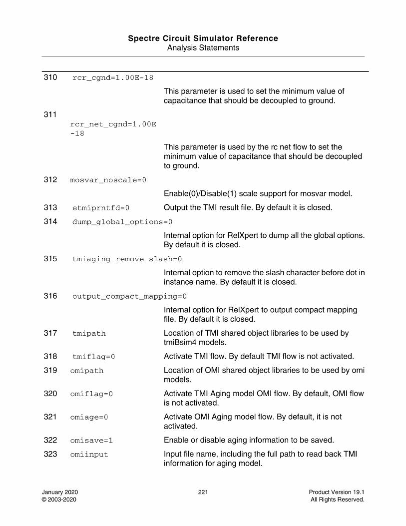
Spectre Circuit Simulator ReferenceAnalysis Statements
January 2020 221 Product Version 19.1© 2003-2020 All Rights Reserved.
310 rcr_cgnd=1.00E-18
This parameter is used to set the minimum value of capacitance that should be decoupled to ground.
311 rcr_net_cgnd=1.00E-18
This parameter is used by the rc net flow to set the minimum value of capacitance that should be decoupled to ground.
312 mosvar_noscale=0
Enable(0)/Disable(1) scale support for mosvar model.
313 etmiprntfd=0 Output the TMI result file. By default it is closed.
314 dump_global_options=0
Internal option for RelXpert to dump all the global options. By default it is closed.
315 tmiaging_remove_slash=0
Internal option to remove the slash character before dot in instance name. By default it is closed.
316 output_compact_mapping=0
Internal option for RelXpert to output compact mapping file. By default it is closed.
317 tmipath Location of TMI shared object libraries to be used by tmiBsim4 models.
318 tmiflag=0 Activate TMI flow. By default TMI flow is not activated.
319 omipath Location of OMI shared object libraries to be used by omi models.
320 omiflag=0 Activate TMI Aging model OMI flow. By default, OMI flow is not activated.
321 omiage=0 Activate OMI Aging model flow. By default, it is not activated.
322 omisave=1 Enable or disable aging information to be saved.
323 omiinput Input file name, including the full path to read back TMI information for aging model.
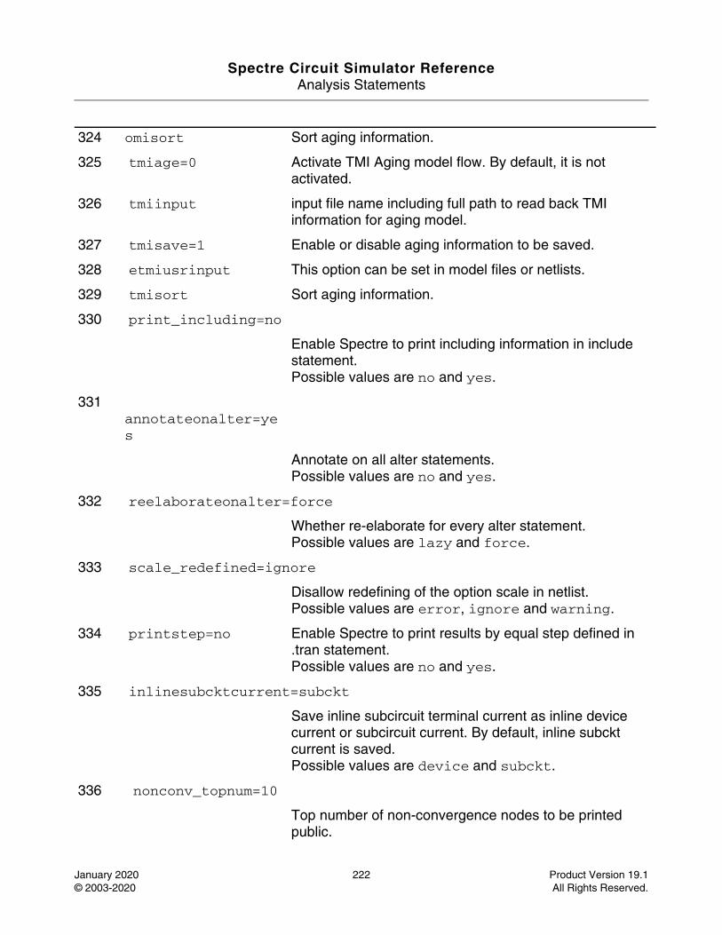
Spectre Circuit Simulator ReferenceAnalysis Statements
January 2020 222 Product Version 19.1© 2003-2020 All Rights Reserved.
324 omisort Sort aging information.
325 tmiage=0 Activate TMI Aging model flow. By default, it is not activated.
326 tmiinput input file name including full path to read back TMI information for aging model.
327 tmisave=1 Enable or disable aging information to be saved.
328 etmiusrinput This option can be set in model files or netlists.
329 tmisort Sort aging information.
330 print_including=no
Enable Spectre to print including information in include statement.Possible values are no and yes.
331 annotateonalter=yes
Annotate on all alter statements.Possible values are no and yes.
332 reelaborateonalter=force
Whether re-elaborate for every alter statement.Possible values are lazy and force.
333 scale_redefined=ignore
Disallow redefining of the option scale in netlist.Possible values are error, ignore and warning.
334 printstep=no Enable Spectre to print results by equal step defined in .tran statement.Possible values are no and yes.
335 inlinesubcktcurrent=subckt
Save inline subcircuit terminal current as inline device current or subcircuit current. By default, inline subckt current is saved.Possible values are device and subckt.
336 nonconv_topnum=10
Top number of non-convergence nodes to be printed public.
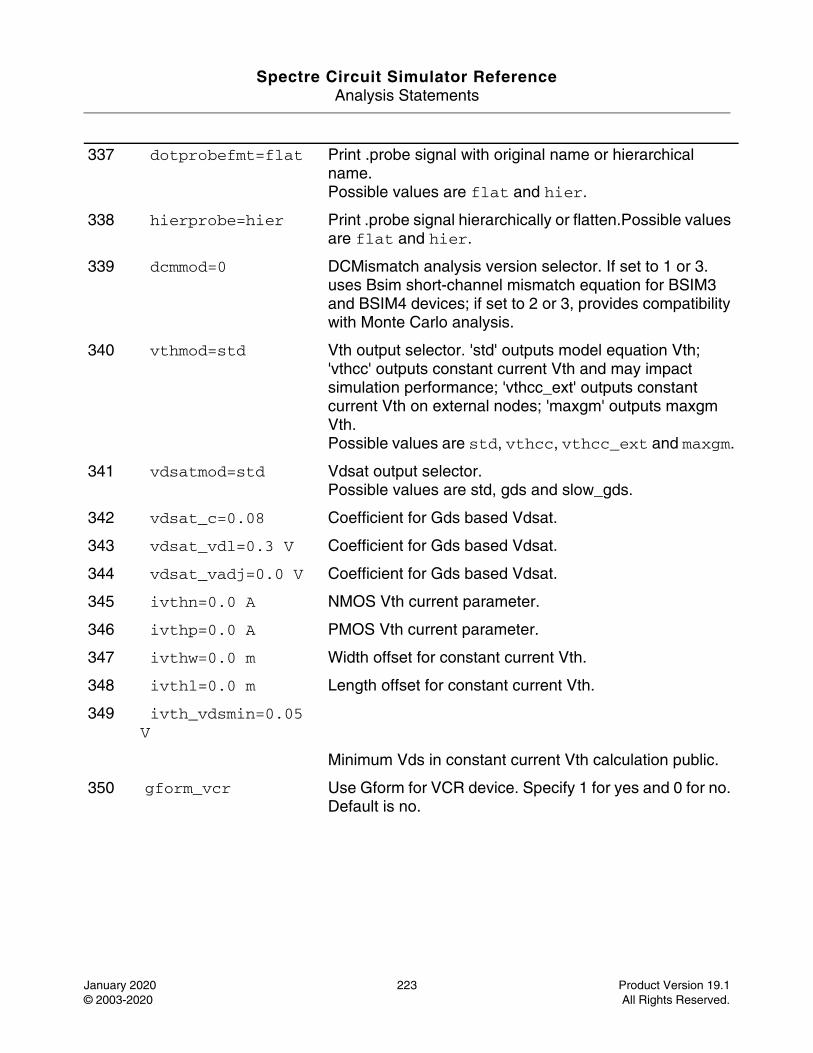
Spectre Circuit Simulator ReferenceAnalysis Statements
January 2020 223 Product Version 19.1© 2003-2020 All Rights Reserved.
337 dotprobefmt=flat Print .probe signal with original name or hierarchical name.Possible values are flat and hier.
338 hierprobe=hier Print .probe signal hierarchically or flatten.Possible values are flat and hier.
339 dcmmod=0 DCMismatch analysis version selector. If set to 1 or 3. uses Bsim short-channel mismatch equation for BSIM3 and BSIM4 devices; if set to 2 or 3, provides compatibility with Monte Carlo analysis.
340 vthmod=std Vth output selector. 'std' outputs model equation Vth; 'vthcc' outputs constant current Vth and may impact simulation performance; 'vthcc_ext' outputs constant current Vth on external nodes; 'maxgm' outputs maxgm Vth.Possible values are std, vthcc, vthcc_ext and maxgm.
341 vdsatmod=std Vdsat output selector.Possible values are std, gds and slow_gds.
342 vdsat_c=0.08 Coefficient for Gds based Vdsat.
343 vdsat_vdl=0.3 V Coefficient for Gds based Vdsat.
344 vdsat_vadj=0.0 V Coefficient for Gds based Vdsat.
345 ivthn=0.0 A NMOS Vth current parameter.
346 ivthp=0.0 A PMOS Vth current parameter.
347 ivthw=0.0 m Width offset for constant current Vth.
348 ivthl=0.0 m Length offset for constant current Vth.
349 ivth_vdsmin=0.05 V
Minimum Vds in constant current Vth calculation public.
350 gform_vcr Use Gform for VCR device. Specify 1 for yes and 0 for no. Default is no.
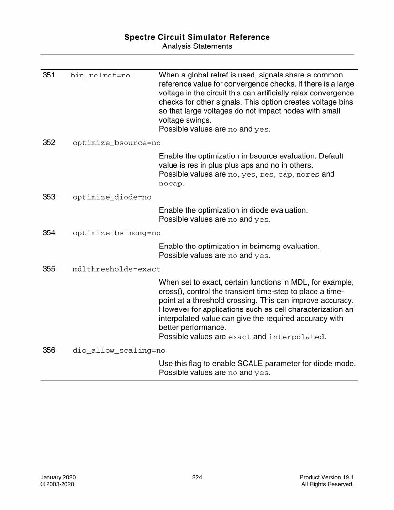
Spectre Circuit Simulator ReferenceAnalysis Statements
January 2020 224 Product Version 19.1© 2003-2020 All Rights Reserved.
351 bin_relref=no When a global relref is used, signals share a common reference value for convergence checks. If there is a large voltage in the circuit this can artificially relax convergence checks for other signals. This option creates voltage bins so that large voltages do not impact nodes with small voltage swings.Possible values are no and yes.
352 optimize_bsource=no
Enable the optimization in bsource evaluation. Default value is res in plus plus aps and no in others.Possible values are no, yes, res, cap, nores and nocap.
353 optimize_diode=no
Enable the optimization in diode evaluation.Possible values are no and yes.
354 optimize_bsimcmg=no
Enable the optimization in bsimcmg evaluation.Possible values are no and yes.
355 mdlthresholds=exact
When set to exact, certain functions in MDL, for example, cross(), control the transient time-step to place a time-point at a threshold crossing. This can improve accuracy. However for applications such as cell characterization an interpolated value can give the required accuracy with better performance.Possible values are exact and interpolated.
356 dio_allow_scaling=no
Use this flag to enable SCALE parameter for diode mode.Possible values are no and yes.
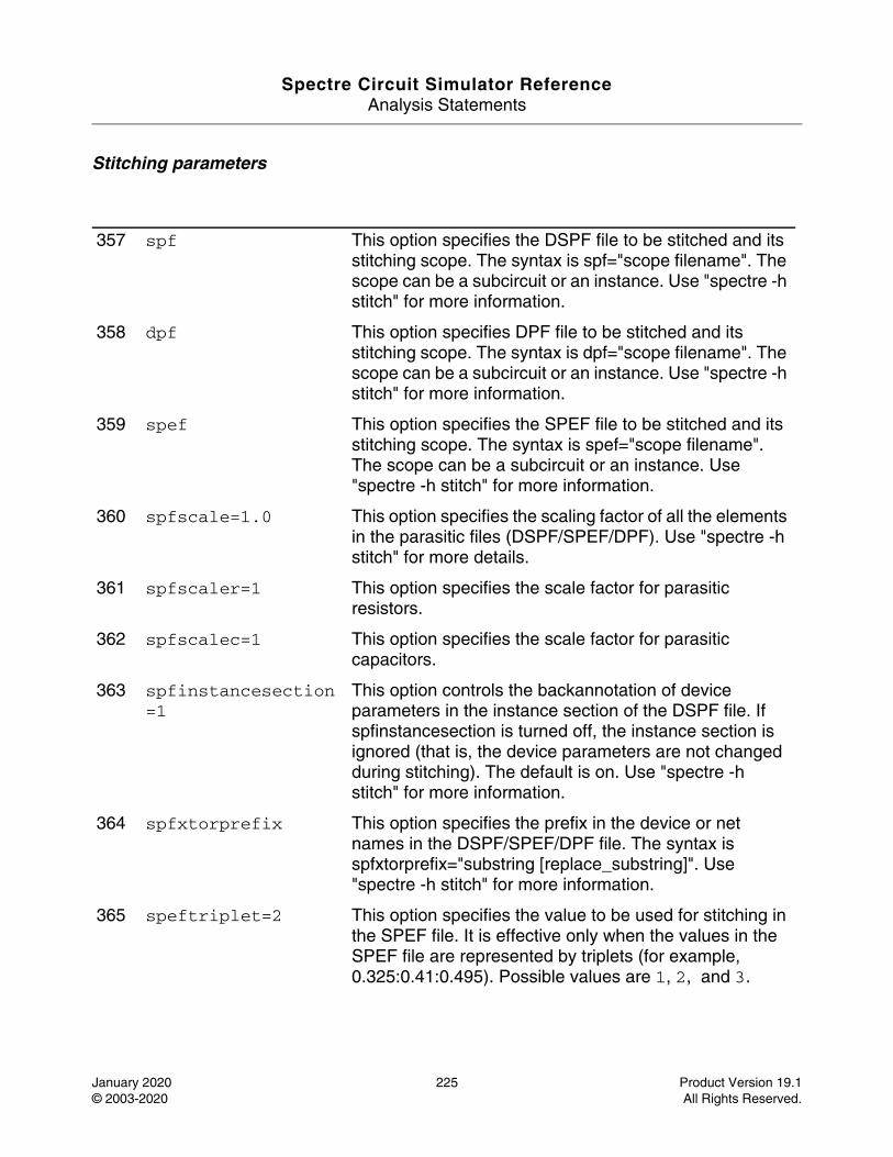
Spectre Circuit Simulator ReferenceAnalysis Statements
January 2020 225 Product Version 19.1© 2003-2020 All Rights Reserved.
Stitching parameters
357 spf This option specifies the DSPF file to be stitched and its stitching scope. The syntax is spf="scope filename". The scope can be a subcircuit or an instance. Use "spectre -h stitch" for more information.
358 dpf This option specifies DPF file to be stitched and its stitching scope. The syntax is dpf="scope filename". The scope can be a subcircuit or an instance. Use "spectre -h stitch" for more information.
359 spef This option specifies the SPEF file to be stitched and its stitching scope. The syntax is spef="scope filename". The scope can be a subcircuit or an instance. Use "spectre -h stitch" for more information.
360 spfscale=1.0 This option specifies the scaling factor of all the elements in the parasitic files (DSPF/SPEF/DPF). Use "spectre -h stitch" for more details.
361 spfscaler=1 This option specifies the scale factor for parasitic resistors.
362 spfscalec=1 This option specifies the scale factor for parasitic capacitors.
363 spfinstancesection=1
This option controls the backannotation of device parameters in the instance section of the DSPF file. If spfinstancesection is turned off, the instance section is ignored (that is, the device parameters are not changed during stitching). The default is on. Use "spectre -h stitch" for more information.
364 spfxtorprefix This option specifies the prefix in the device or net names in the DSPF/SPEF/DPF file. The syntax is spfxtorprefix="substring [replace_substring]". Use "spectre -h stitch" for more information.
365 speftriplet=2 This option specifies the value to be used for stitching in the SPEF file. It is effective only when the values in the SPEF file are represented by triplets (for example, 0.325:0.41:0.495). Possible values are 1, 2, and 3.
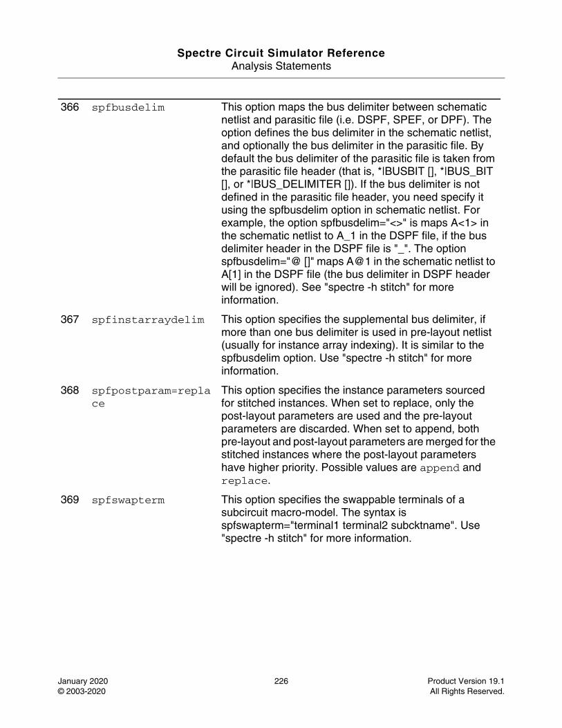
Spectre Circuit Simulator ReferenceAnalysis Statements
January 2020 226 Product Version 19.1© 2003-2020 All Rights Reserved.
366 spfbusdelim This option maps the bus delimiter between schematic netlist and parasitic file (i.e. DSPF, SPEF, or DPF). The option defines the bus delimiter in the schematic netlist, and optionally the bus delimiter in the parasitic file. By default the bus delimiter of the parasitic file is taken from the parasitic file header (that is, *|BUSBIT [], *|BUS_BIT [], or *|BUS_DELIMITER []). If the bus delimiter is not defined in the parasitic file header, you need specify it using the spfbusdelim option in schematic netlist. For example, the option spfbusdelim="<>" is maps A<1> in the schematic netlist to A_1 in the DSPF file, if the bus delimiter header in the DSPF file is "_". The option spfbusdelim="@ []" maps A@1 in the schematic netlist to A[1] in the DSPF file (the bus delimiter in DSPF header will be ignored). See "spectre -h stitch" for more information.
367 spfinstarraydelim This option specifies the supplemental bus delimiter, if more than one bus delimiter is used in pre-layout netlist (usually for instance array indexing). It is similar to the spfbusdelim option. Use "spectre -h stitch" for more information.
368 spfpostparam=replace
This option specifies the instance parameters sourced for stitched instances. When set to replace, only the post-layout parameters are used and the pre-layout parameters are discarded. When set to append, both pre-layout and post-layout parameters are merged for the stitched instances where the post-layout parameters have higher priority. Possible values are append and replace.
369 spfswapterm This option specifies the swappable terminals of a subcircuit macro-model. The syntax is spfswapterm="terminal1 terminal2 subcktname". Use "spectre -h stitch" for more information.
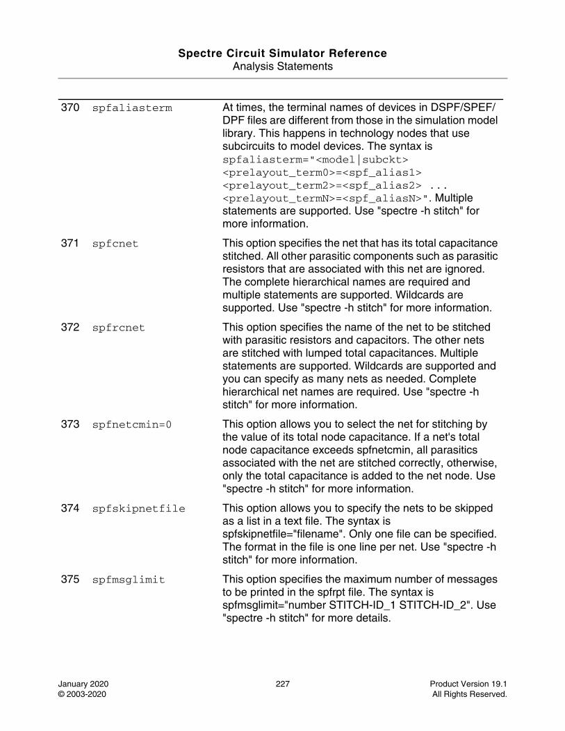
Spectre Circuit Simulator ReferenceAnalysis Statements
January 2020 227 Product Version 19.1© 2003-2020 All Rights Reserved.
370 spfaliasterm At times, the terminal names of devices in DSPF/SPEF/DPF files are different from those in the simulation model library. This happens in technology nodes that use subcircuits to model devices. The syntax is spfaliasterm="<model|subckt> <prelayout_term0>=<spf_alias1> <prelayout_term2>=<spf_alias2> ... <prelayout_termN>=<spf_aliasN>". Multiple statements are supported. Use "spectre -h stitch" for more information.
371 spfcnet This option specifies the net that has its total capacitance stitched. All other parasitic components such as parasitic resistors that are associated with this net are ignored. The complete hierarchical names are required and multiple statements are supported. Wildcards are supported. Use "spectre -h stitch" for more information.
372 spfrcnet This option specifies the name of the net to be stitched with parasitic resistors and capacitors. The other nets are stitched with lumped total capacitances. Multiple statements are supported. Wildcards are supported and you can specify as many nets as needed. Complete hierarchical net names are required. Use "spectre -h stitch" for more information.
373 spfnetcmin=0 This option allows you to select the net for stitching by the value of its total node capacitance. If a net's total node capacitance exceeds spfnetcmin, all parasitics associated with the net are stitched correctly, otherwise, only the total capacitance is added to the net node. Use "spectre -h stitch" for more information.
374 spfskipnetfile This option allows you to specify the nets to be skipped as a list in a text file. The syntax is spfskipnetfile="filename". Only one file can be specified. The format in the file is one line per net. Use "spectre -h stitch" for more information.
375 spfmsglimit This option specifies the maximum number of messages to be printed in the spfrpt file. The syntax is spfmsglimit="number STITCH-ID_1 STITCH-ID_2". Use "spectre -h stitch" for more details.
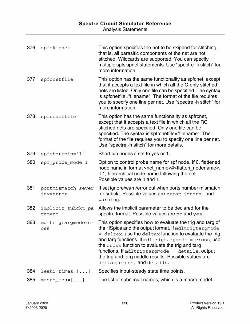
Spectre Circuit Simulator ReferenceAnalysis Statements
January 2020 228 Product Version 19.1© 2003-2020 All Rights Reserved.
376 spfskipnet This option specifies the net to be skipped for stitching, that is, all parasitic components of the net are not stitched. Wildcards are supported. You can specify multiple spfskipnet statements. Use "spectre -h stitch" for more information.
377 spfcnetfile This option has the same functionality as spfcnet, except that it accepts a text file in which all the C-only stitched nets are listed. Only one file can be specified. The syntax is spfcnetfile="filename". The format of the file requires you to specify one line per net. Use "spectre -h stitch" for more information.
378 spfrcnetfile This option has the same functionality as spfrcnet, except that it accepts a text file in which all the RC stitched nets are specified. Only one file can be specified. The syntax is spfrcnetfile="filename". The format of the file requires you to specify one line per net. Use "spectre -h stitch" for more details.
379 spfshortpin="1" Short pin nodes if set to yes or 1.
380 spf_probe_mode=1 Option to control probe name for spf node. If 0, flattened node name in format <net_name>#<flatten_nodename>, if 1, hierarchical node name following the net.Possible values are 0 and 1.
381 portmismatch_severity=error
If set ignore/warn/error out when ports number mismatch for subckt. Possible values are error, ignore, and warning.
382 implicit_subckt_param=no
Allows the implicit parameter to be declared for the spectre format. Possible values are no and yes.
383 mdltrigtargmode=cross
This option specifies how to evaluate the trig and targ of the HSpice and the output format. If mdltrigtargmode = deltax, use the deltax function to evaluate the trig and targ functions. If mdltrigtargmode = cross, use the cross function to evaluate the trig and targ functions. If mdltrigtargmode = details, output the trig and targ middle results. Possible values are deltax, cross, and details.
384 leaki_times=[...] Specifies input-steady state time points.
385 macro_mos=[...] The list of subcircuit names, which is a macro model.
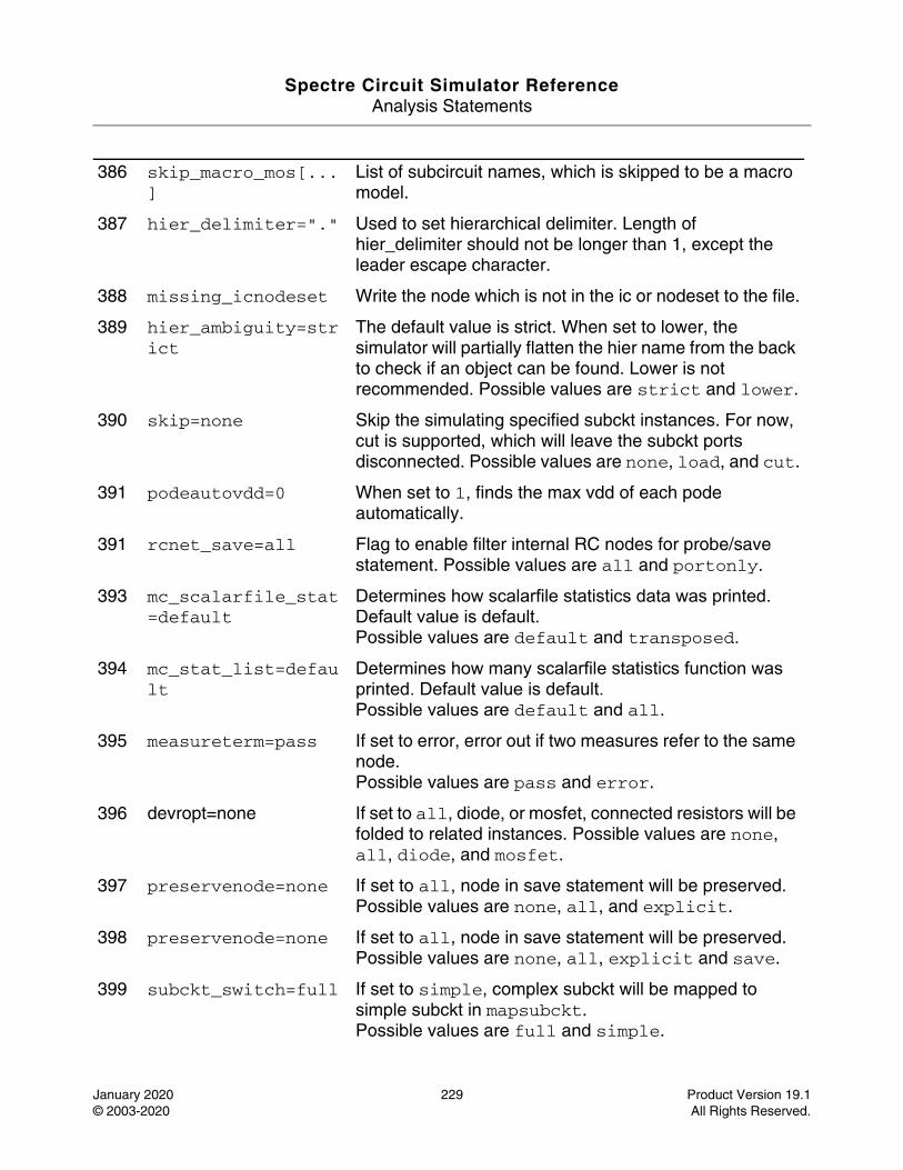
Spectre Circuit Simulator ReferenceAnalysis Statements
January 2020 229 Product Version 19.1© 2003-2020 All Rights Reserved.
386 skip_macro_mos[...]
List of subcircuit names, which is skipped to be a macro model.
387 hier_delimiter="." Used to set hierarchical delimiter. Length of hier_delimiter should not be longer than 1, except the leader escape character.
388 missing_icnodeset Write the node which is not in the ic or nodeset to the file.
389 hier_ambiguity=strict
The default value is strict. When set to lower, the simulator will partially flatten the hier name from the back to check if an object can be found. Lower is not recommended. Possible values are strict and lower.
390 skip=none Skip the simulating specified subckt instances. For now, cut is supported, which will leave the subckt ports disconnected. Possible values are none, load, and cut.
391 podeautovdd=0 When set to 1, finds the max vdd of each pode automatically.
391 rcnet_save=all Flag to enable filter internal RC nodes for probe/save statement. Possible values are all and portonly.
393 mc_scalarfile_stat=default
Determines how scalarfile statistics data was printed. Default value is default.Possible values are default and transposed.
394 mc_stat_list=default
Determines how many scalarfile statistics function was printed. Default value is default.Possible values are default and all.
395 measureterm=pass If set to error, error out if two measures refer to the same node.Possible values are pass and error.
396 devropt=none If set to all, diode, or mosfet, connected resistors will be folded to related instances. Possible values are none, all, diode, and mosfet.
397 preservenode=none If set to all, node in save statement will be preserved. Possible values are none, all, and explicit.
398 preservenode=none If set to all, node in save statement will be preserved.Possible values are none, all, explicit and save.
399 subckt_switch=full If set to simple, complex subckt will be mapped to simple subckt in mapsubckt.Possible values are full and simple.
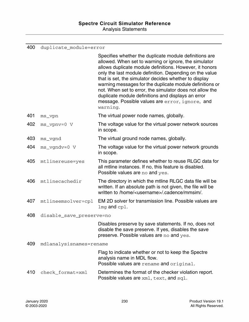
Spectre Circuit Simulator ReferenceAnalysis Statements
January 2020 230 Product Version 19.1© 2003-2020 All Rights Reserved.
400 duplicate_module=error
Specifies whether the duplicate module definitions are allowed. When set to warning or ignore, the simulator allows duplicate module definitions. However, it honors only the last module definition. Depending on the value that is set, the simulator decides whether to display warning messages for the duplicate module definitions or not. When set to error, the simulator does not allow the duplicate module definitions and displays an error message. Possible values are error, ignore, and warning.
401 ms_vpn The virtual power node names, globally.
402 ms_vpnv=0 V The voltage value for the virtual power network sources in scope.
403 ms_vgnd The virtual ground node names, globally.
404 ms_vgndv=0 V The voltage value for the virtual power network grounds in scope.
405 mtlinereuse=yes This parameter defines whether to reuse RLGC data for all mtline instances. If no, this feature is disabled. Possible values are no and yes.
406 mtlinecachedir The directory in which the mtline RLGC data file will be written. If an absolute path is not given, the file will be written to /home/<username>/.cadence/mmsim/.
407 mtlineemsolver=cpl EM 2D solver for transmission line. Possible values are lmg and cpl.
408 disable_save_preserve=no
Disables preserve by save statements. If no, does not disable the save preserve. If yes, disables the save preserve. Possible values are no and yes.
409 mdlanalysisnames=rename
Flag to indicate whether or not to keep the Spectre analysis name in MDL flow.Possible values are rename and original.
410 check_format=xml Determines the format of the checker violation report. Possible values are xml, text, and sql.
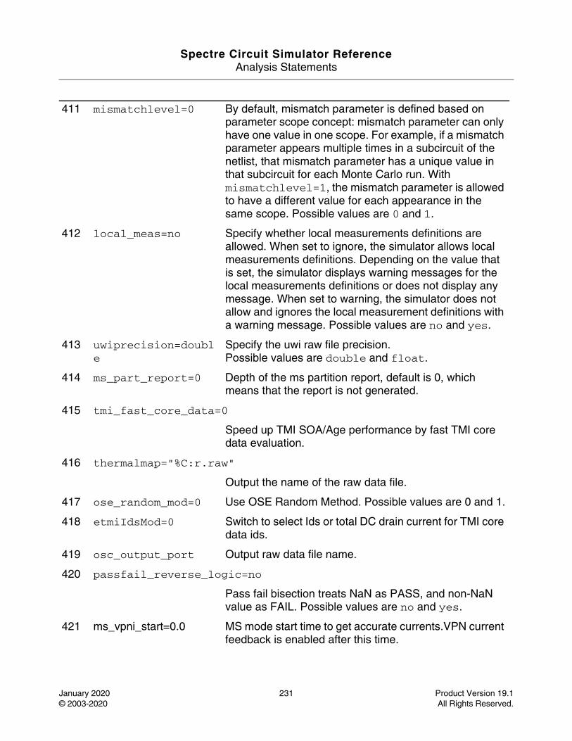
Spectre Circuit Simulator ReferenceAnalysis Statements
January 2020 231 Product Version 19.1© 2003-2020 All Rights Reserved.
411 mismatchlevel=0 By default, mismatch parameter is defined based on parameter scope concept: mismatch parameter can only have one value in one scope. For example, if a mismatch parameter appears multiple times in a subcircuit of the netlist, that mismatch parameter has a unique value in that subcircuit for each Monte Carlo run. With mismatchlevel=1, the mismatch parameter is allowed to have a different value for each appearance in the same scope. Possible values are 0 and 1.
412 local_meas=no Specify whether local measurements definitions are allowed. When set to ignore, the simulator allows local measurements definitions. Depending on the value that is set, the simulator displays warning messages for the local measurements definitions or does not display any message. When set to warning, the simulator does not allow and ignores the local measurement definitions with a warning message. Possible values are no and yes.
413 uwiprecision=double
Specify the uwi raw file precision.Possible values are double and float.
414 ms_part_report=0 Depth of the ms partition report, default is 0, which means that the report is not generated.
415 tmi_fast_core_data=0
Speed up TMI SOA/Age performance by fast TMI core data evaluation.
416 thermalmap="%C:r.raw"
Output the name of the raw data file.
417 ose_random_mod=0 Use OSE Random Method. Possible values are 0 and 1.
418 etmiIdsMod=0 Switch to select Ids or total DC drain current for TMI core data ids.
419 osc_output_port Output raw data file name.
420 passfail_reverse_logic=no
Pass fail bisection treats NaN as PASS, and non-NaN value as FAIL. Possible values are no and yes.
421 ms_vpni_start=0.0 MS mode start time to get accurate currents.VPN current feedback is enabled after this time.
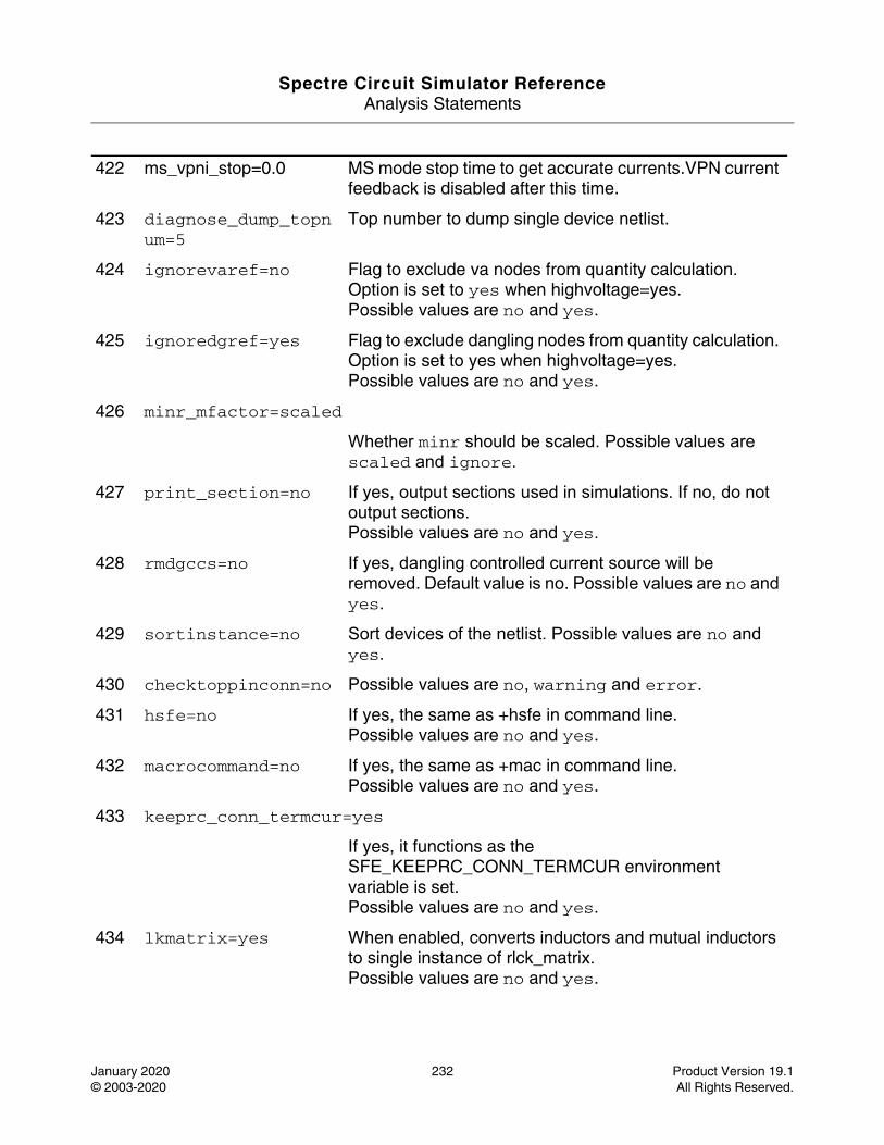
Spectre Circuit Simulator ReferenceAnalysis Statements
January 2020 232 Product Version 19.1© 2003-2020 All Rights Reserved.
422 ms_vpni_stop=0.0 MS mode stop time to get accurate currents.VPN current feedback is disabled after this time.
423 diagnose_dump_topnum=5
Top number to dump single device netlist.
424 ignorevaref=no Flag to exclude va nodes from quantity calculation. Option is set to yes when highvoltage=yes.Possible values are no and yes.
425 ignoredgref=yes Flag to exclude dangling nodes from quantity calculation. Option is set to yes when highvoltage=yes.Possible values are no and yes.
426 minr_mfactor=scaled
Whether minr should be scaled. Possible values are scaled and ignore.
427 print_section=no If yes, output sections used in simulations. If no, do not output sections.Possible values are no and yes.
428 rmdgccs=no If yes, dangling controlled current source will be removed. Default value is no. Possible values are no and yes.
429 sortinstance=no Sort devices of the netlist. Possible values are no and yes.
430 checktoppinconn=no Possible values are no, warning and error.
431 hsfe=no If yes, the same as +hsfe in command line.Possible values are no and yes.
432 macrocommand=no If yes, the same as +mac in command line.Possible values are no and yes.
433 keeprc_conn_termcur=yes
If yes, it functions as the SFE_KEEPRC_CONN_TERMCUR environment variable is set. Possible values are no and yes.
434 lkmatrix=yes When enabled, converts inductors and mutual inductors to single instance of rlck_matrix.Possible values are no and yes.
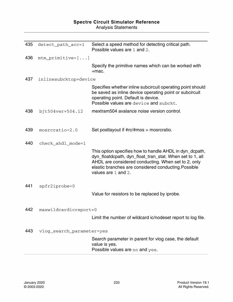
Spectre Circuit Simulator ReferenceAnalysis Statements
January 2020 233 Product Version 19.1© 2003-2020 All Rights Reserved.
435 detect_path_acc=1 Select a speed method for detecting critical path. Possible values are 1 and 2.
436 mtm_primitive=[...]
Specify the primitive names which can be worked with +mac.
437 inlinesubcktop=device
Specifies whether inline subcircuit operating point should be saved as inline device operating point or subcircuit operating point. Default is device.Possible values are device and subckt.
438 bjt504ver=504.12 mextram504 avalance noise version control.
439 mosrcratio=2.0 Set postlayout if #rc/#mos > mosrcratio.
440 check_ahdl_mode=1
This option specifies how to handle AHDL in dyn_dcpath, dyn_floatdcpath, dyn_float_tran_stat. When set to 1, all AHDL are considered conducting. When set to 2, only elastic branches are considered conducting.Possible values are 1 and 2.
441 spfr2iprobe=0
Value for resistors to be replaced by iprobe.
442 maxwildcardicreport=0
Limit the number of wildcard ic/nodeset report to log file.
443 vlog_search_parameter=yes
Search parameter in parent for vlog case, the default value is yes.Possible values are no and yes.
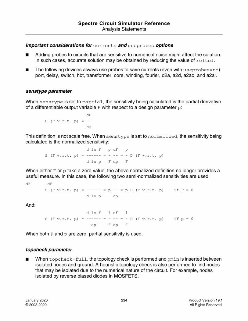
Spectre Circuit Simulator ReferenceAnalysis Statements
January 2020 234 Product Version 19.1© 2003-2020 All Rights Reserved.
Important considerations for currents and useprobes options
■ Adding probes to circuits that are sensitive to numerical noise might affect the solution. In such cases, accurate solution may be obtained by reducing the value of reltol.
■ The following devices always use probes to save currents (even with useprobes=no): port, delay, switch, hbt, transformer, core, winding, fourier, d2a, a2d, a2ao, and a2ai.
senstype parameter
When senstype is set to partial, the sensitivity being calculated is the partial derivative of a differentiable output variable F with respect to a design parameter p:
dF D (F w.r.t. p) = -- dp
This definition is not scale free. When senstype is set to normalized, the sensitivity being calculated is the normalized sensitivity:
d ln F p dF p S (F w.r.t. p) = ------ = - -- = - D (F w.r.t. p) d ln p F dp F
When either F or p take a zero value, the above normalized definition no longer provides a useful measure. In this case, the following two semi-normalized sensitivities are used:
dF dF S (F w.r.t. p) = ------ = p -- = p D (F w.r.t. p) if F = 0 d ln p dp
And:
d ln F 1 dF 1 S (F w.r.t. p) = ------ = - -- = - D (F w.r.t. p) if p = 0 dp F dp F
When both F and p are zero, partial sensitivity is used.
topcheck parameter
■ When topcheck=full, the topology check is performed and gmin is inserted between isolated nodes and ground. A heuristic topology check is also performed to find nodes that may be isolated due to the numerical nature of the circuit. For example, nodes isolated by reverse biased diodes in MOSFETS.
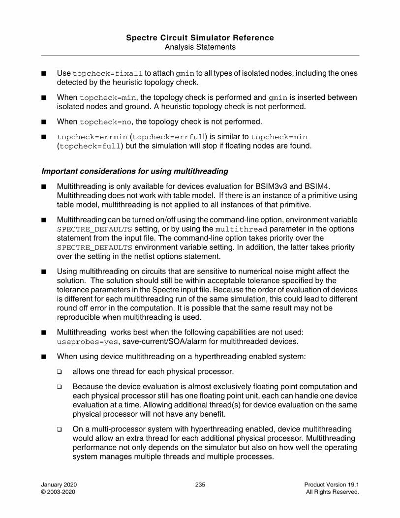
Spectre Circuit Simulator ReferenceAnalysis Statements
January 2020 235 Product Version 19.1© 2003-2020 All Rights Reserved.
■ Use topcheck=fixall to attach gmin to all types of isolated nodes, including the ones detected by the heuristic topology check.
■ When topcheck=min, the topology check is performed and gmin is inserted between isolated nodes and ground. A heuristic topology check is not performed.
■ When topcheck=no, the topology check is not performed.
■ topcheck=errmin (topcheck=errfull) is similar to topcheck=min (topcheck=full) but the simulation will stop if floating nodes are found.
Important considerations for using multithreading
■ Multithreading is only available for devices evaluation for BSIM3v3 and BSIM4. Multithreading does not work with table model. If there is an instance of a primitive using table model, multithreading is not applied to all instances of that primitive.
■ Multithreading can be turned on/off using the command-line option, environment variable SPECTRE_DEFAULTS setting, or by using the multithread parameter in the options statement from the input file. The command-line option takes priority over the SPECTRE_DEFAULTS environment variable setting. In addition, the latter takes priority over the setting in the netlist options statement.
■ Using multithreading on circuits that are sensitive to numerical noise might affect the solution. The solution should still be within acceptable tolerance specified by the tolerance parameters in the Spectre input file. Because the order of evaluation of devices is different for each multithreading run of the same simulation, this could lead to different round off error in the computation. It is possible that the same result may not be reproducible when multithreading is used.
■ Multithreading works best when the following capabilities are not used: useprobes=yes, save-current/SOA/alarm for multithreaded devices.
■ When using device multithreading on a hyperthreading enabled system:
❑ allows one thread for each physical processor.
❑ Because the device evaluation is almost exclusively floating point computation and each physical processor still has one floating point unit, each can handle one device evaluation at a time. Allowing additional thread(s) for device evaluation on the same physical processor will not have any benefit.
❑ On a multi-processor system with hyperthreading enabled, device multithreading would allow an extra thread for each additional physical processor. Multithreading performance not only depends on the simulator but also on how well the operating system manages multiple threads and multiple processes.
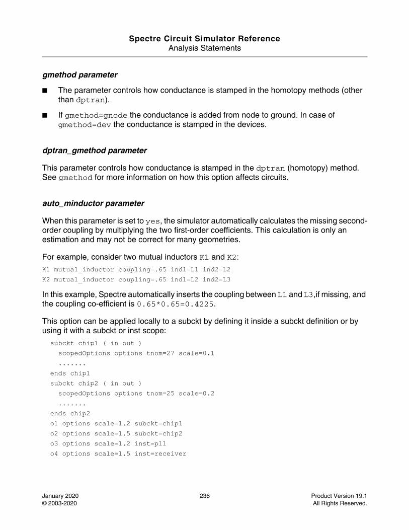
Spectre Circuit Simulator ReferenceAnalysis Statements
January 2020 236 Product Version 19.1© 2003-2020 All Rights Reserved.
gmethod parameter
■ The parameter controls how conductance is stamped in the homotopy methods (other than dptran).
■ If gmethod=gnode the conductance is added from node to ground. In case of gmethod=dev the conductance is stamped in the devices.
dptran_gmethod parameter
This parameter controls how conductance is stamped in the dptran (homotopy) method. See gmethod for more information on how this option affects circuits.
auto_minductor parameter
When this parameter is set to yes, the simulator automatically calculates the missing second-order coupling by multiplying the two first-order coefficients. This calculation is only an estimation and may not be correct for many geometries.
For example, consider two mutual inductors K1 and K2:
K1 mutual_inductor coupling=.65 ind1=L1 ind2=L2 K2 mutual_inductor coupling=.65 ind1=L2 ind2=L3
In this example, Spectre automatically inserts the coupling between L1 and L3,if missing, and the coupling co-efficient is 0.65*0.65=0.4225.
This option can be applied locally to a subckt by defining it inside a subckt definition or by using it with a subckt or inst scope:
subckt chip1 ( in out ) scopedOptions options tnom=27 scale=0.1 ....... ends chip1 subckt chip2 ( in out ) scopedOptions options tnom=25 scale=0.2 ....... ends chip2 o1 options scale=1.2 subckt=chip1 o2 options scale=1.5 subckt=chip2 o3 options scale=1.2 inst=pll o4 options scale=1.5 inst=receiver
Spectre Circuit Simulator ReferenceAnalysis Statements
January 2020 237 Product Version 19.1© 2003-2020 All Rights Reserved.
Parameter Index
In the following index, the number corresponding to each parameter name indicates where to find the description of that parameter.
BHT_New_Eval 204 hierprobe 338 out_dev_stack 67 speftriplet 365
ahdl_device_limit 48
highvoltage 217 output_compact_mapping 316
spf 357
ahdl_exp_limit 150
homotopy 36 param_topchange 187
spf_probe_mode 380
ahdl_maxdeltav 49
hsfe 431 paramrangefile 212
spfaliasterm 370
ahdldomainerror 23
iabstol 4 parasitics 206 spfbusdelim 366
annotateonalter 331
iccheck 111 passfail_reverse_logic 420
spfcnet 371
approx 94 icpriority 65 pivabs 182 spfcnetfile 377
asserts_silent_init 120
icversion 55 pivotdc 174 spfinstancesection 363
audit 154 idovvdsclamp 202 pivrel 181 spfinstarraydelim 367
auto_minductor 95
ignore_blowup 137
podeautovdd 391 spfmsglimit 375
autostop 226 ignoredgref 425 portmismatch_severity 381
spfnetcmin 373
bin_relref 351 ignorevaref 424 precision 26 spfpostparam 368
bjt504ver 438 ignshorts 112 preorder 183 spfprobenode 21
cclamp 80 implicit_subckt_param 382
preserve_assert 200
spfr2iprobe 441
Spectre Circuit Simulator ReferenceAnalysis Statements
January 2020 238 Product Version 19.1© 2003-2020 All Rights Reserved.
ccut 81 info 158 preserve_inst 198
spfrcnet 372
cgnd 82 inlinesubcktcurrent 335
preserve_master 197
spfrcnetfile 378
chargeabstol 5 inlinesubcktop 437
preserve_subckt 199
spfscale 360
check_ahdl_mode 440
inventory 155 preservenode 397 spfscalec 362
check_format 410 ishrink 92 print_including 330
spfscaler 361
checklimit_full_duration 123
ivth_vdsmin 349 print_section 427
spfshortpin 379
checklimit_skip_file 177
ivthl 348 printstep 334 spfskipnet 376
checklimit_skip_ie_connect_devices 180
ivthn 345 probe_compatible 124
spfskipnetfile 374
checklimit_skip_insts 178
ivthp 346 probedepthcount 398
spfswapterm 369
checklimit_skip_insts_file 179
ivthw 347 procopt 35 spfxtorprefix 364
checklimit_skip_subs 176
kcut 84 psfversion 27 sram_macro_model 230
checklimitdest 121
keeprc_conn_termcur 433
ptranmaxsteps 60 sram_macro_model_adjust_monotonic 232
checklimitdetails 122
kmax 96 pwr 13 sram_macro_model_adjust_monotonic_bits 255
checklimitfile 118
large_newton_reject 227
qcut 87 sram_macro_model_adjust_monotonic_shift_vp 234
Spectre Circuit Simulator ReferenceAnalysis Statements
January 2020 239 Product Version 19.1© 2003-2020 All Rights Reserved.
checktoppinconn 430
leaki_times 384 quantities 153 sram_macro_model_assert_active_wl 253
ckptclock 186 limit 40 rabsclamp 77 sram_macro_model_bbm 266
cmax 83 limit_diag_pivot 184
rabsshort 76 sram_macro_model_bbm_ignore_non_converge 251
cmi_opts 205 lkmatrix 434 rampsource 125 sram_macro_model_bbm_solve 249
cols 170 local_meas 412 rawfile 25 sram_macro_model_bbm_solve_dc 250
colslog 171 lshort 85 rawfmt 24 sram_macro_model_bucket_count 254
compatible 93 macro_mode 219 rclamp_bsource 149
sram_macro_model_bypass 238
cscalefactor 215 macro_mos 385 rcnet_save 392 sram_macro_model_check_prop_region 248
cthresh 216 macrocommand 432 rcr_cgnd 310 sram_macro_model_compensate_bulk_current 267
currents 11 max_approach_minstep 223
rcr_fmax 308 sram_macro_model_convert_mtm_to_cmi 239
dc_auto_rforce 136
max_consecutive_minstep 224
rcr_net_active_bit_line_conly 293
sram_macro_model_debug_end_time 263
dc_check_multiple_solutions 141
max_minstep_nonconv 222
rcr_net_active_sa_to_gnd_conly 304
sram_macro_model_debug_level 264
dc_diagnose_elements 59
maxdeltav 42 rcr_net_active_state_conly 295
sram_macro_model_debug_start_time 262
Spectre Circuit Simulator ReferenceAnalysis Statements
January 2020 240 Product Version 19.1© 2003-2020 All Rights Reserved.
dc_diagnose_time 58
maxnotes 160 rcr_net_active_word_line_conly 291
sram_macro_model_disable_bypass_stampa 242
dc_ic_abstol 138 maxnotestologfile 165
rcr_net_cgnd 311 sram_macro_model_diverge_at_large_wl 231
dc_ic_reltol 139 maxphysicalflux 46
rcr_net_dump_protect 306
sram_macro_model_dynamic_switch 243
dc_pivot_check 175
maxphysicali 44 rcr_net_floating1_conly 299
sram_macro_model_enable_active_cell 245
dc_solution_iabstol 144
maxphysicalmmf 45
rcr_net_floating2_conly 300
sram_macro_model_fast_out 247
dc_solution_ireltol 145
maxphysicalunitless 47
rcr_net_floating3_conly 301
sram_macro_model_group_cells 237
dc_solution_vabstol 142
maxphysicalv 43 rcr_net_ground_conly 302
sram_macro_model_iter_ratio 235
dc_solution_vreltol 143
maxwarns 163 rcr_net_ground_reg_conly 303
sram_macro_model_jacobi 257
dccheck 140 maxwarnstologfile 164
rcr_net_idle_bit_line_conly 294
sram_macro_model_level 265
dcdampsol 135 maxwildcardicreport 442
rcr_net_idle_reg_conly 296
sram_macro_model_limiting 236
dcmaxiters 56 mc_scalarfile_stat 393
rcr_net_idle_sa_to_gnd_conly 305
sram_macro_model_max_ratio 260
dcmmod 339 mc_stat_list 394 rcr_net_idle_state_conly 297
sram_macro_model_merge_port_cap 240
dcoptic 63 mdlanalysisnames 409
rcr_net_idle_word_line_conly 292
sram_macro_model_min_ratio 259
dcoptictype 64 mdlthresholds 355
rcr_net_merge_pn_idle_state_ports 290
sram_macro_model_quantity 258
Spectre Circuit Simulator ReferenceAnalysis Statements
January 2020 241 Product Version 19.1© 2003-2020 All Rights Reserved.
dcoptmaxsteps 62 mdltrigtargmode 383
rcr_net_node_auto_res_bump 270
sram_macro_model_reconn_st_cplcap_to_port 252
dcopttol 131 measdgt 168 rcr_net_node_fmax 271
sram_macro_model_reset_cell_group_prop_at_each_iter 233
dcut 86 measureterm 395 rcr_net_option_file 307
sram_macro_model_skip_node_set 244
debug 157 minr 213 rcr_net_preserve_active_bit_line_ports 277
sram_macro_model_stampa 241
debugstepdrop 116
minr_mfactor 426 rcr_net_preserve_active_clk_to_sgc_ports 283
sram_macro_model_tran_solve 246
detect_path_acc 435
minstepversion 221
rcr_net_preserve_active_heavy_load_ports 285
sram_macro_model_tstep 261
detect_path_clock 71
mismatchlevel 411
rcr_net_preserve_active_reg_drain_source 289
sram_macro_model_use_table 256
detect_path_vgnd 70
missing_icnodeset 388
rcr_net_preserve_active_sa_to_gnd_ports 281
stackfet_dcmaxiters 57
detect_path_vpn 69
mosrcratio 439 rcr_net_preserve_active_state_ports 279
stepdropsize 117
devcheck_stat 126
mosvar_noscale 312
rcr_net_preserve_active_word_line_ports 275
stver_note 161
device_limit 41 ms_part_report 414
rcr_net_preserve_drain_source_signals 287
subckt_switch 399
devropt 396 ms_vgnd 403 rcr_net_preserve_ground_reg_ports 273
subcktcap 72
Spectre Circuit Simulator ReferenceAnalysis Statements
January 2020 242 Product Version 19.1© 2003-2020 All Rights Reserved.
diagnose 113 ms_vgndv 404 rcr_net_preserve_idle_bit_line_ports 278
subcktiprobes 14
diagnose_dump_topnum 423
ms_vpn 401 rcr_net_preserve_idle_clk_to_sgc_ports 284
subcktopfreq 73
diagnose_end 115 ms_vpni_start 421
rcr_net_preserve_idle_heavy_load_ports 286
subcktoppoint 66
diagnose_start 114
ms_vpni_stop 422 rcr_net_preserve_idle_reg_drain_source 288
subcktprobelvl 12
digits 167 ms_vpnv 402 rcr_net_preserve_idle_sa_to_gnd_ports 282
temp 6
dio_allow_scaling 356
mtlinecachedir 406
rcr_net_preserve_idle_state_ports 280
tempeffects 8
disable_save_preserve 408
mtlineemsolver 407
rcr_net_preserve_idle_word_line_ports 276
thermalmap 416
discontinuity 225
mtlinereuse 405 rcr_net_preserve_pn_ports 272
title 172
disk_check_autoresume 33
mtm_primitive 436
rcr_net_preserve_vpn_ports 274
tmi_fast_core_data 415
disk_check_thresh 32
multithread 74 rcr_net_state_idle_vpn_conly 298
tmiage 325
dochecklimit 119 narrate 156 rcr_net_vpn 268 tmiaging_remove_slash 315
dotprobefmt 337 nestlvl 10 rcr_net_vpn_groups 269
tmiflag 318
dpf 358 newton 37 rcr_rshort 309 tmiinput 326
dptran_gmethod 51
noiseoff_inst 109
rcut 78 tmipath 317
Spectre Circuit Simulator ReferenceAnalysis Statements
January 2020 243 Product Version 19.1© 2003-2020 All Rights Reserved.
dptranmaxsteps 61
noiseoff_type 39 rebuild_matrix 185
tmisave 327
dspf_nodename 22 noiseon_inst 108 redefinedparams 188
tmisort 329
dump_global_options 314
noiseon_type 38 reelaborateonalter 332
tnom 7
duplicate_module 400
nonconv_topnum 336
reltol 1 topcheck 110
duplicate_subckt 190
notation 169 residualtol 2 try_fast_op 54
duplicateinstance 191
note 159 rforce 148 use_veriloga 194
duplicatemodel 192
nport_bbspice_to_linear 97
rmdgccs 428 useprobes 15
duplicateports 189
nport_default_interp 98
rthresh 79 useterms 16
error 166 nport_default_passivity 99
save 9 uwifmt 28
etmiIdsMod 418 nportbbsfittedfiledir 100
saveahdlvars 20 uwilib 29
etmiprntfd 313 nportbbsmaxwaittime 107
savefilter 17 uwiprecision 413
etmiusrinput 328 nportcompress 103
saveports 18 vabsshort 88
exportfile 30 nportcompressfiledir 106
scale 90 vabstol 3
fastmcmethod 68 nportirfiledir 102
scale_redefined 333
value 151
fix_singular_matrix 147
nportirreuse 101 scalefactor 91 vdsat_c 342
Spectre Circuit Simulator ReferenceAnalysis Statements
January 2020 244 Product Version 19.1© 2003-2020 All Rights Reserved.
flow 152 nportunusedportgmin 104
scalem 89 vdsat_vadj 344
gennetlistdir 34 nportunusedportrmin 105
sensbinparam 211 vdsat_vdl 343
gform_vcr 350 nthreads 75 sensfile 207 vdsatmod 341
gmethod 50 omiage 321 sensfileonly 210 verilogalang 220
gmin 128 omiflag 320 sensformat 208 vlog_search_parameter 443
gmin_check 146 omiinput 323 senstype 209 vrefgnd 218
gmin_converge 53 omipath 319 short_bjtr 214 vthmod 340
gmin_start 52 omisave 322 simstat 173 warn 162
gmindc 129 omisort 324 skip 390 warning_change_severity 195
gmindcmax 134 opptcheck 127 skip_macro_mos 386
warning_id 196
gminfloat 130 optimize_bsimcmg 354
soa_dest 203 warning_limit 193
gshunt 132 optimize_bsource 352
soa_warn 201 wfdebug 19
gshuntdc 133 optimize_diode 353
soft_bin 228 wfmaxsize 31
hier_ambiguity 389
osc_output_port 419
sortinstance 429 xpssdc_disable_output 229
hier_delimiter 387
ose_random_mod 417
spef 359
Spectre Circuit Simulator ReferenceAnalysis Statements
January 2020 245 Product Version 19.1© 2003-2020 All Rights Reserved.
Periodic AC Analysis (pac)
Description
The periodic AC (PAC) analysis is used to compute transfer functions for circuits that exhibit frequency translation. Such circuits include mixers, switched-capacitor filters, samplers, phase-locked loops, and the like. PAC is a small-signal analysis similar to AC analysis, except that the circuit is first linearized about a periodically varying operating point as opposed to a simple DC operating point. Linearizing about a periodically time-varying operating point allows transfer-functions that include frequency translation, which is not the case when linearizing about a DC operating point because linear time-invariant circuits do not exhibit frequency translation. In addition, the frequency of the sinusoidal stimulus is not constrained by the period of the large periodic solution.
Computing the small-signal response of a periodically varying circuit is a two-step process. First, the small stimulus is ignored and the periodic steady-state response of the circuit to possibly large periodic stimulus is computed using PSS analysis. As part of the PSS analysis, the periodically time-varying representation of the circuit is computed and saved for later use. The second step is to apply the small stimulus to the periodically varying linear representation to compute the small signal response. This is done using the PAC analysis. A PAC analysis cannot be used alone, it must follow a PSS analysis. However, any number of periodic small-signal analyses such as PAC, PSP, PXF, and PNoise, can follow a PSS analysis.
Modulated small signal measurements are possible by using the Analog Design Environment (ADE). The modulated option for PAC and the other modulated parameters are set by Artist. PAC analyses with this option produces results that could have limited use outside such an environment. Direct Plot is configured to analyze these results and combine several wave forms to measure AM and PM response due to single sideband or modulated stimuli. For details, see the Spectre RF User Guide.
Unlike AC analysis, PAC analysis can print the time-domain simulation results by specifying the outputperiod parameter. In addition, unlike other analyses in Spectre, this analysis can only sweep frequency.
For information on how to run PAC analysis from ADE, see Periodic AC Analysis (PAC) in the Spectre Circuit Simulator and Accelerated Parallel Simulator RF Analysis User Guide.
DefinitionName ... pac parameter=value ...
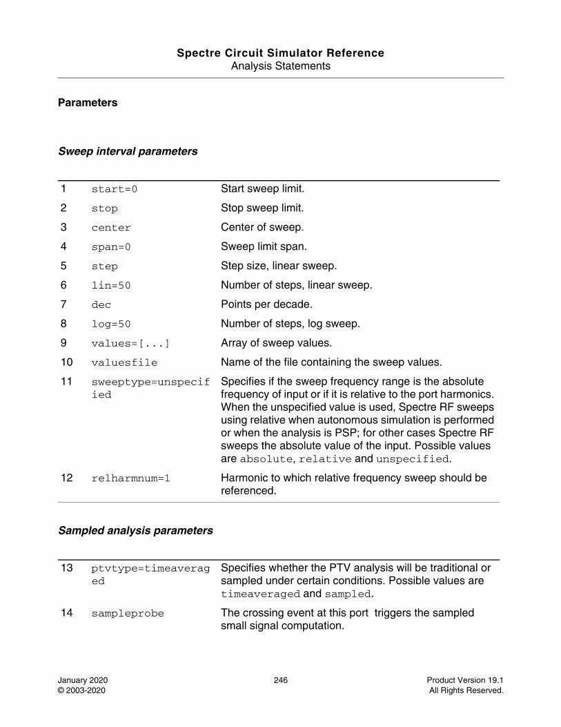
Spectre Circuit Simulator ReferenceAnalysis Statements
January 2020 246 Product Version 19.1© 2003-2020 All Rights Reserved.
Parameters
Sweep interval parameters
Sampled analysis parameters
1 start=0 Start sweep limit.
2 stop Stop sweep limit.
3 center Center of sweep.
4 span=0 Sweep limit span.
5 step Step size, linear sweep.
6 lin=50 Number of steps, linear sweep.
7 dec Points per decade.
8 log=50 Number of steps, log sweep.
9 values=[...] Array of sweep values.
10 valuesfile Name of the file containing the sweep values.
11 sweeptype=unspecified
Specifies if the sweep frequency range is the absolute frequency of input or if it is relative to the port harmonics. When the unspecified value is used, Spectre RF sweeps using relative when autonomous simulation is performed or when the analysis is PSP; for other cases Spectre RF sweeps the absolute value of the input. Possible values are absolute, relative and unspecified.
12 relharmnum=1 Harmonic to which relative frequency sweep should be referenced.
13 ptvtype=timeaveraged
Specifies whether the PTV analysis will be traditional or sampled under certain conditions. Possible values are timeaveraged and sampled.
14 sampleprobe The crossing event at this port triggers the sampled small signal computation.
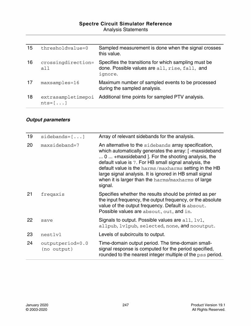
Spectre Circuit Simulator ReferenceAnalysis Statements
January 2020 247 Product Version 19.1© 2003-2020 All Rights Reserved.
Output parameters
15 thresholdvalue=0 Sampled measurement is done when the signal crosses this value.
16 crossingdirection=all
Specifies the transitions for which sampling must be done. Possible values are all, rise, fall, and ignore.
17 maxsamples=16 Maximum number of sampled events to be processed during the sampled analysis.
18 extrasampletimepoints=[...]
Additional time points for sampled PTV analysis.
19 sidebands=[...] Array of relevant sidebands for the analysis.
20 maxsideband=7 An alternative to the sidebands array specification, which automatically generates the array: [ -maxsideband ... 0 ... +maxsideband ]. For the shooting analysis, the default value is 7. For HB small signal analysis, the default value is the harms/maxharms setting in the HB large signal analysis. It is ignored in HB small signal when it is larger than the harms/maxharms of large signal.
21 freqaxis Specifies whether the results should be printed as per the input frequency, the output frequency, or the absolute value of the output frequency. Default is absout. Possible values are absout, out, and in.
22 save Signals to output. Possible values are all, lvl, allpub, lvlpub, selected, none, and nooutput.
23 nestlvl Levels of subcircuits to output.
24 outputperiod=0.0 (no output)
Time-domain output period. The time-domain small-signal response is computed for the period specified, rounded to the nearest integer multiple of the pss period.
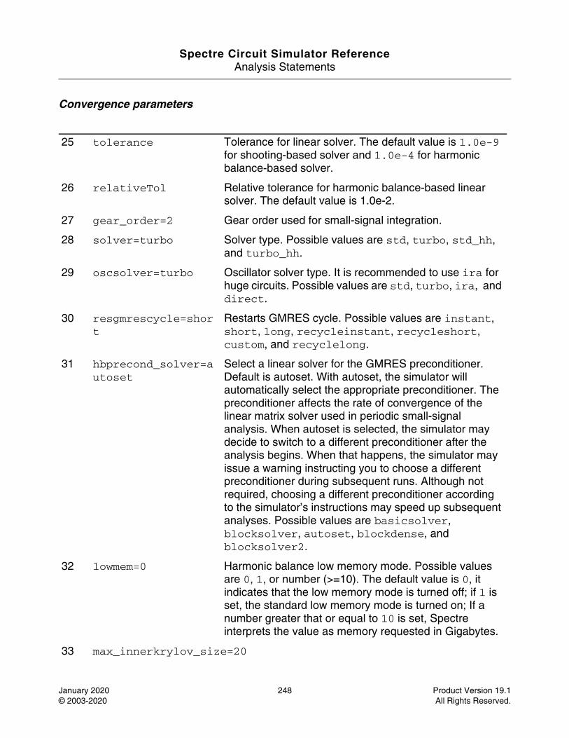
Spectre Circuit Simulator ReferenceAnalysis Statements
January 2020 248 Product Version 19.1© 2003-2020 All Rights Reserved.
Convergence parameters
25 tolerance Tolerance for linear solver. The default value is 1.0e-9 for shooting-based solver and 1.0e-4 for harmonic balance-based solver.
26 relativeTol Relative tolerance for harmonic balance-based linear solver. The default value is 1.0e-2.
27 gear_order=2 Gear order used for small-signal integration.
28 solver=turbo Solver type. Possible values are std, turbo, std_hh, and turbo_hh.
29 oscsolver=turbo Oscillator solver type. It is recommended to use ira for huge circuits. Possible values are std, turbo, ira, and direct.
30 resgmrescycle=short
Restarts GMRES cycle. Possible values are instant, short, long, recycleinstant, recycleshort, custom, and recyclelong.
31 hbprecond_solver=autoset
Select a linear solver for the GMRES preconditioner. Default is autoset. With autoset, the simulator will automatically select the appropriate preconditioner. The preconditioner affects the rate of convergence of the linear matrix solver used in periodic small-signal analysis. When autoset is selected, the simulator may decide to switch to a different preconditioner after the analysis begins. When that happens, the simulator may issue a warning instructing you to choose a different preconditioner during subsequent runs. Although not required, choosing a different preconditioner according to the simulator’s instructions may speed up subsequent analyses. Possible values are basicsolver, blocksolver, autoset, blockdense, and blocksolver2.
32 lowmem=0 Harmonic balance low memory mode. Possible values are 0, 1, or number (>=10). The default value is 0, it indicates that the low memory mode is turned off; if 1 is set, the standard low memory mode is turned on; If a number greater that or equal to 10 is set, Spectre interprets the value as memory requested in Gigabytes.
33 max_innerkrylov_size=20
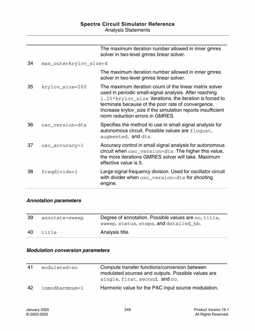
Spectre Circuit Simulator ReferenceAnalysis Statements
January 2020 249 Product Version 19.1© 2003-2020 All Rights Reserved.
Annotation parameters
Modulation conversion parameters
The maximum iteration number allowed in inner gmres solver in two-level gmres linear solver.
34 max_outerkrylov_size=4
The maximum iteration number allowed in inner gmres solver in two-level gmres linear solver.
35 krylov_size=200 The maximum iteration count of the linear matrix solver used in periodic small-signal analysis. After reaching 1.25*krylov_size iterations, the iteration is forced to terminate because of the poor rate of convergence. Increase krylov_size if the simulation reports insufficient norm reduction errors in GMRES.
36 osc_version=dts Specifies the method to use in small signal analysis for autonomous circuit. Possible values are floquet, augmented, and dts.
37 osc_accuracy=1 Accuracy control in small signal analysis for autonomous circuit when osc_version=dts. The higher this value, the more iterations GMRES solver will take. Maximum effective value is 5.
38 freqdivide=1 Large signal frequency division. Used for oscillator circuit with divider when osc_version=dts for shooting engine.
39 annotate=sweep Degree of annotation. Possible values are no, title, sweep, status, steps, and detailed_hb.
40 title Analysis title.
41 modulated=no Compute transfer functions/conversion between modulated sources and outputs. Possible values are single, first, second, and no.
42 inmodharmnum=1 Harmonic value for the PAC input source modulation.
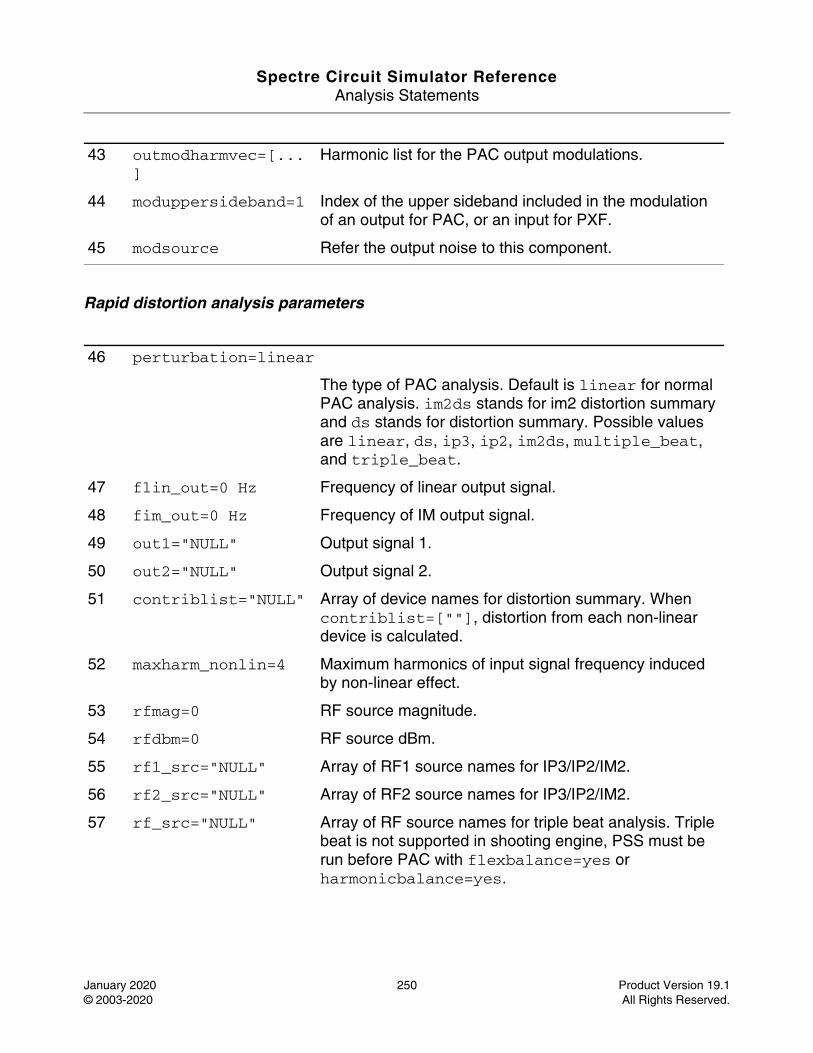
Spectre Circuit Simulator ReferenceAnalysis Statements
January 2020 250 Product Version 19.1© 2003-2020 All Rights Reserved.
Rapid distortion analysis parameters
43 outmodharmvec=[...]
Harmonic list for the PAC output modulations.
44 moduppersideband=1 Index of the upper sideband included in the modulation of an output for PAC, or an input for PXF.
45 modsource Refer the output noise to this component.
46 perturbation=linear
The type of PAC analysis. Default is linear for normal PAC analysis. im2ds stands for im2 distortion summary and ds stands for distortion summary. Possible values are linear, ds, ip3, ip2, im2ds, multiple_beat, and triple_beat.
47 flin_out=0 Hz Frequency of linear output signal.
48 fim_out=0 Hz Frequency of IM output signal.
49 out1="NULL" Output signal 1.
50 out2="NULL" Output signal 2.
51 contriblist="NULL" Array of device names for distortion summary. When contriblist=[""], distortion from each non-linear device is calculated.
52 maxharm_nonlin=4 Maximum harmonics of input signal frequency induced by non-linear effect.
53 rfmag=0 RF source magnitude.
54 rfdbm=0 RF source dBm.
55 rf1_src="NULL" Array of RF1 source names for IP3/IP2/IM2.
56 rf2_src="NULL" Array of RF2 source names for IP3/IP2/IM2.
57 rf_src="NULL" Array of RF source names for triple beat analysis. Triple beat is not supported in shooting engine, PSS must be run before PAC with flexbalance=yes or harmonicbalance=yes.
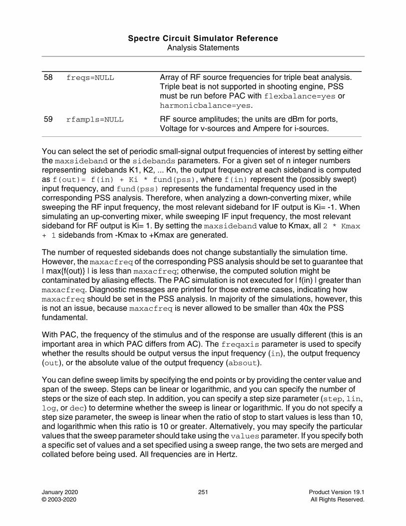
Spectre Circuit Simulator ReferenceAnalysis Statements
January 2020 251 Product Version 19.1© 2003-2020 All Rights Reserved.
You can select the set of periodic small-signal output frequencies of interest by setting either the maxsideband or the sidebands parameters. For a given set of n integer numbers representing sidebands K1, K2, ... Kn, the output frequency at each sideband is computed as f(out)= f(in) + Ki * fund(pss), where f(in) represent the (possibly swept) input frequency, and fund(pss) represents the fundamental frequency used in the corresponding PSS analysis. Therefore, when analyzing a down-converting mixer, while sweeping the RF input frequency, the most relevant sideband for IF output is Ki= -1. When simulating an up-converting mixer, while sweeping IF input frequency, the most relevant sideband for RF output is Ki= 1. By setting the maxsideband value to Kmax, all 2 * Kmax + 1 sidebands from -Kmax to +Kmax are generated.
The number of requested sidebands does not change substantially the simulation time. However, the maxacfreq of the corresponding PSS analysis should be set to guarantee that | max{f(out)} | is less than maxacfreq; otherwise, the computed solution might be contaminated by aliasing effects. The PAC simulation is not executed for | f(in) | greater than maxacfreq. Diagnostic messages are printed for those extreme cases, indicating how maxacfreq should be set in the PSS analysis. In majority of the simulations, however, this is not an issue, because maxacfreq is never allowed to be smaller than 40x the PSS fundamental.
With PAC, the frequency of the stimulus and of the response are usually different (this is an important area in which PAC differs from AC). The freqaxis parameter is used to specify whether the results should be output versus the input frequency (in), the output frequency (out), or the absolute value of the output frequency (absout).
You can define sweep limits by specifying the end points or by providing the center value and span of the sweep. Steps can be linear or logarithmic, and you can specify the number of steps or the size of each step. In addition, you can specify a step size parameter (step, lin, log, or dec) to determine whether the sweep is linear or logarithmic. If you do not specify a step size parameter, the sweep is linear when the ratio of stop to start values is less than 10, and logarithmic when this ratio is 10 or greater. Alternatively, you may specify the particular values that the sweep parameter should take using the values parameter. If you specify both a specific set of values and a set specified using a sweep range, the two sets are merged and collated before being used. All frequencies are in Hertz.
58 freqs=NULL Array of RF source frequencies for triple beat analysis. Triple beat is not supported in shooting engine, PSS must be run before PAC with flexbalance=yes or harmonicbalance=yes.
59 rfampls=NULL RF source amplitudes; the units are dBm for ports, Voltage for v-sources and Ampere for i-sources.
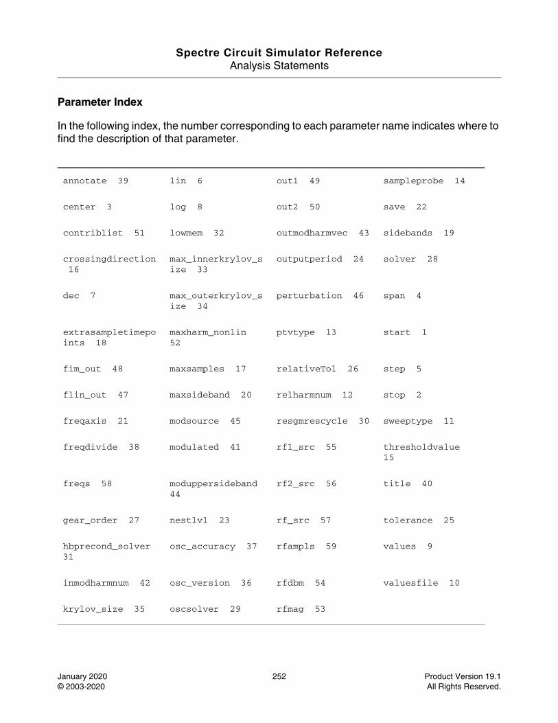
Spectre Circuit Simulator ReferenceAnalysis Statements
January 2020 252 Product Version 19.1© 2003-2020 All Rights Reserved.
Parameter Index
In the following index, the number corresponding to each parameter name indicates where to find the description of that parameter.
annotate 39 lin 6 out1 49 sampleprobe 14
center 3 log 8 out2 50 save 22
contriblist 51 lowmem 32 outmodharmvec 43 sidebands 19
crossingdirection 16
max_innerkrylov_size 33
outputperiod 24 solver 28
dec 7 max_outerkrylov_size 34
perturbation 46 span 4
extrasampletimepoints 18
maxharm_nonlin 52
ptvtype 13 start 1
fim_out 48 maxsamples 17 relativeTol 26 step 5
flin_out 47 maxsideband 20 relharmnum 12 stop 2
freqaxis 21 modsource 45 resgmrescycle 30 sweeptype 11
freqdivide 38 modulated 41 rf1_src 55 thresholdvalue 15
freqs 58 moduppersideband 44
rf2_src 56 title 40
gear_order 27 nestlvl 23 rf_src 57 tolerance 25
hbprecond_solver 31
osc_accuracy 37 rfampls 59 values 9
inmodharmnum 42 osc_version 36 rfdbm 54 valuesfile 10
krylov_size 35 oscsolver 29 rfmag 53
Spectre Circuit Simulator ReferenceAnalysis Statements
January 2020 253 Product Version 19.1© 2003-2020 All Rights Reserved.
Periodic Noise Analysis (pnoise)
Description
The Periodic Noise, or PNoise analysis is similar to the conventional noise analysis, except that it includes frequency conversion effects. Hence, it is useful for predicting the noise behavior of mixers, switched-capacitor filters, and other periodically driven circuits. It is particularly useful for predicting the phase noise of autonomous circuits, such as oscillators.
PNoise analysis linearizes the circuit about the periodic operating point computed in the prerequisite PSS analysis. It is the periodically time-varying nature of the linearized circuit that accounts for the frequency conversion. In addition, the affect of a periodically time-varying bias point on the noise generated by the various components in the circuit is also included.
The time-average of the noise at the output of the circuit is computed in the form of spectral density versus frequency. The output of the circuit is specified with either a pair of nodes or a probe component. To specify the output of a circuit with a probe, specify it using the oprobe parameter. If the output is voltage (or potential), choose a resistor or a port as the output probe. If the output is current (or flow), choose a vsource or iprobe as the output probe.
If the input-referred noise or noise figure is desired, specify the input source by using the iprobe parameter. For input-referred noise, use vsource or isource as the input probe; for noise figure, use a port as the probe. Currently, only a vsource, an isource, or a port may be used as an input probe. If the input source is noisy, as is a port, the noise analysis computes the noise factor (F) and noise figure (NF). To match the IEEE definition of noise figure, the input probe must be a port with no excess noise and its noisetemp must be set to 16.85C (290K). In addition, the output load must be a resistor or port and must be identified as the oprobe.
If port is specified as the input probe, both input-referred noise and gain are referred back to the equivalent voltage source inside the port. S-parameter analysis calculates those values in traditional sense.
The reference sideband (refsideband) specifies which conversion gain is used when computing input-referred noise, noise factor, and noise figure. The reference sideband specifies the input frequency relative to the output frequency with:
|f(input)| = |f(out) + refsideband * fund(pss)|
Use refsideband=0 when the input and output of the circuit are at the same frequency (such as with amplifiers and filters). When refsideband differs from 0, the single side-band noise figure is computed.
Spectre Circuit Simulator ReferenceAnalysis Statements
January 2020 254 Product Version 19.1© 2003-2020 All Rights Reserved.
The noise analysis always computes the total noise at the output, which includes contributions from the input source and the output load. The amount of the output noise that is attributable to each noise source in the circuit is also computed and output individually. If the input source is identified (using iprobe) and is a vsource or isource, the input-referred noise is computed, which includes the noise from the input source itself. Finally, if the input source is identified (using iprobe) and is noisy, as is the case with ports, the noise factor and noise figure are computed. Therefore, if:
No = total output noise
Ns = noise at the output due to the input probe (the source)
Nsi = noise at the output due to the image harmonic at the source
Nso = noise at the output due to harmonics other than input at the source
Nl = noise at the output due to the output probe (the load)
IRN = input referred noise
G = gain of the circuit
F = noise factor
NF = noise figure
Fdsb = double sideband noise factor
NFdsb = double sideband noise figure
Fieee = IEEE single sideband noise factor
NFieee = IEEE single sideband noise figure
Then:
IRN = sqrt(No^2/G^2)
F = (No^2 - Nl^2)/Ns^2
NF = 10*log10(F)
Fdsb = (No^2 - Nl^2)/(Ns^2+Nsi^2)
NFdsb = 10*log10(Fdsb)
Spectre Circuit Simulator ReferenceAnalysis Statements
January 2020 255 Product Version 19.1© 2003-2020 All Rights Reserved.
Fieee = (No^2 - Nl^2 - Nso^2)/Ns^2
NFieee = 10*log10(Fieee).
When the results are output, No is named out, IRN is named in, G is named gain, F, NF, Fdsb, NFdsb, Fieee, and NFieee are named F, NF, Fdsb, NFdsb, Fieee, and NFieee, respectively.
In a phase noise analysis for an oscillator, the line width, which is also known as the corner frequency, is defined as either the full width at half maximum (FWHM), or as twice the half power (-3dB) width (HW). In the absence of 1/f noise and ignoring any noise floor, the phase noise spectrum satisfies the Lorentzian equation:
L(f) = (1/pi) * [ pi * c * fosc^2 ] / [(pi * c * fosc^2)^2 + f^2],
Where, c is a constant that defines the phase noise characteristics of the oscillator, fosc is the fundamental frequency of the oscillator, and f is the offset frequency of the oscillator. Therefore:
line width := FWHM = 2* HW = 2 * pi * c * fosc^2.
Note: Unlike other analyses in Spectre, this analysis can only sweep frequency.
For information on how to run Pnoise analysis from ADE, see Periodic Noise Analysis (Pnoise) in the Spectre Circuit Simulator and Accelerated Parallel Simulator RF Analysis User Guide.
DefinitionName [p] [n] ... pnoise parameter=value ...
The optional terminals (p and n) specify the output of the circuit. If you do not specify the terminals, you must specify the output with a probe component.
Parameters
Sweep interval parameters
1 start=0 Start sweep limit.
2 stop Stop sweep limit.
Spectre Circuit Simulator ReferenceAnalysis Statements
January 2020 256 Product Version 19.1© 2003-2020 All Rights Reserved.
Probe parameters
Sampled analysis parameters
3 center Center of sweep.
4 span=0 Sweep limit span.
5 step Step size, linear sweep.
6 lin=50 Number of steps, linear sweep.
7 dec Points per decade.
8 log=50 Number of steps, log sweep.
9 values=[...] Array of sweep values.
10 valuesfile Name of the file containing the sweep values.
11 sweeptype=unspecified
Specifies if the sweep frequency range is the absolute frequency of input or if it is relative to the port harmonics. When the unspecified value is used, Spectre RF sweeps using relative when autonomous simulation is performed or when the analysis is PSP; for other cases Spectre RF sweeps the absolute value of the input. Possible values are absolute, relative, and unspecified.
12 relharmnum=1 Harmonic to which relative frequency sweep should be referenced.
13 oprobe Compute total noise at the output defined by this component.
14 iprobe Refer the output noise to this component.
15 refsideband Conversion gain associated with this sideband; is used when computing input-referred noise or noise figure.
16 thresholdvalue=0 Sampled measurement is done when the signal crosses this value.
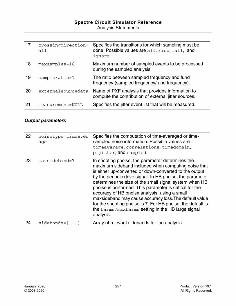
Spectre Circuit Simulator ReferenceAnalysis Statements
January 2020 257 Product Version 19.1© 2003-2020 All Rights Reserved.
Output parameters
17 crossingdirection=all
Specifies the transitions for which sampling must be done. Possible values are all, rise, fall, and ignore.
18 maxsamples=16 Maximum number of sampled events to be processed during the sampled analysis.
19 sampleratio=1 The ratio between sampled frequency and fund frequency (sampled frequency/fund frequency).
20 externalsourcedata Name of PXF analysis that provides information to compute the contribution of external jitter sources.
21 measurement=NULL Specifies the jitter event list that will be measured.
22 noisetype=timeaverage
Specifies the computation of time-averaged or time-sampled noise information. Possible values are timeaverage, correlations, timedomain, pmjitter, and sampled.
23 maxsideband=7 In shooting pnoise, the parameter determines the maximum sideband included when computing noise that is either up-converted or down-converted to the output by the periodic drive signal. In HB pnoise, the parameter determines the size of the small signal system when HB pnoise is performed. This parameter is critical for the accuracy of HB pnoise analysis; using a small maxsideband may cause accuracy loss.The default value for the shooting pnoise is 7. For HB pnoise, the default is the harms/maxharms setting in the HB large signal analysis.
24 sidebands=[...] Array of relevant sidebands for the analysis.
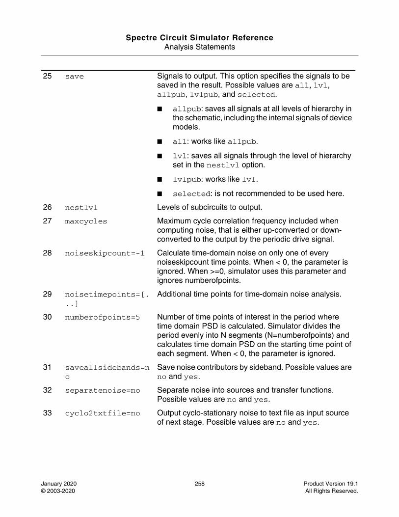
Spectre Circuit Simulator ReferenceAnalysis Statements
January 2020 258 Product Version 19.1© 2003-2020 All Rights Reserved.
25 save Signals to output. This option specifies the signals to be saved in the result. Possible values are all, lvl, allpub, lvlpub, and selected.
■ allpub: saves all signals at all levels of hierarchy in the schematic, including the internal signals of device models.
■ all: works like allpub.
■ lvl: saves all signals through the level of hierarchy set in the nestlvl option.
■ lvlpub: works like lvl.
■ selected: is not recommended to be used here.
26 nestlvl Levels of subcircuits to output.
27 maxcycles Maximum cycle correlation frequency included when computing noise, that is either up-converted or down-converted to the output by the periodic drive signal.
28 noiseskipcount=-1 Calculate time-domain noise on only one of every noiseskipcount time points. When < 0, the parameter is ignored. When >=0, simulator uses this parameter and ignores numberofpoints.
29 noisetimepoints=[...]
Additional time points for time-domain noise analysis.
30 numberofpoints=5 Number of time points of interest in the period where time domain PSD is calculated. Simulator divides the period evenly into N segments (N=numberofpoints) and calculates time domain PSD on the starting time point of each segment. When < 0, the parameter is ignored.
31 saveallsidebands=no
Save noise contributors by sideband. Possible values are no and yes.
32 separatenoise=no Separate noise into sources and transfer functions. Possible values are no and yes.
33 cyclo2txtfile=no Output cyclo-stationary noise to text file as input source of next stage. Possible values are no and yes.
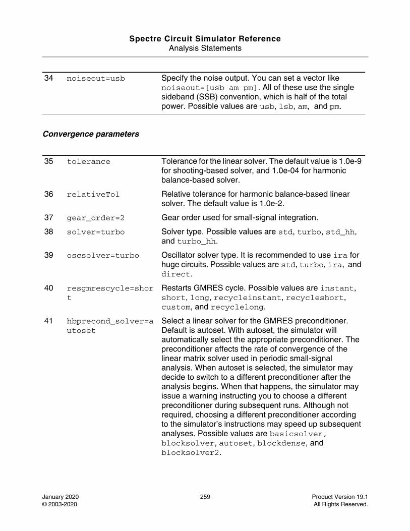
Spectre Circuit Simulator ReferenceAnalysis Statements
January 2020 259 Product Version 19.1© 2003-2020 All Rights Reserved.
Convergence parameters
34 noiseout=usb Specify the noise output. You can set a vector like noiseout=[usb am pm]. All of these use the single sideband (SSB) convention, which is half of the total power. Possible values are usb, lsb, am, and pm.
35 tolerance Tolerance for the linear solver. The default value is 1.0e-9 for shooting-based solver, and 1.0e-04 for harmonic balance-based solver.
36 relativeTol Relative tolerance for harmonic balance-based linear solver. The default value is 1.0e-2.
37 gear_order=2 Gear order used for small-signal integration.
38 solver=turbo Solver type. Possible values are std, turbo, std_hh, and turbo_hh.
39 oscsolver=turbo Oscillator solver type. It is recommended to use ira for huge circuits. Possible values are std, turbo, ira, and direct.
40 resgmrescycle=short
Restarts GMRES cycle. Possible values are instant, short, long, recycleinstant, recycleshort, custom, and recyclelong.
41 hbprecond_solver=autoset
Select a linear solver for the GMRES preconditioner. Default is autoset. With autoset, the simulator will automatically select the appropriate preconditioner. The preconditioner affects the rate of convergence of the linear matrix solver used in periodic small-signal analysis. When autoset is selected, the simulator may decide to switch to a different preconditioner after the analysis begins. When that happens, the simulator may issue a warning instructing you to choose a different preconditioner during subsequent runs. Although not required, choosing a different preconditioner according to the simulator’s instructions may speed up subsequent analyses. Possible values are basicsolver, blocksolver, autoset, blockdense, and blocksolver2.
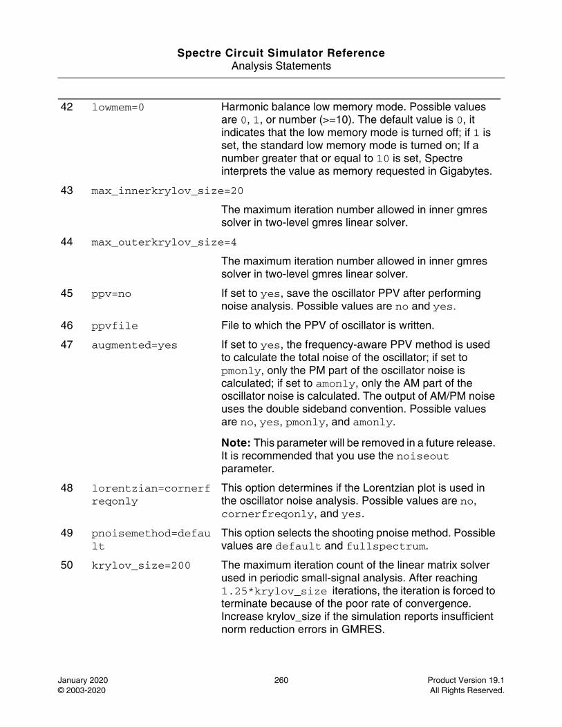
Spectre Circuit Simulator ReferenceAnalysis Statements
January 2020 260 Product Version 19.1© 2003-2020 All Rights Reserved.
42 lowmem=0 Harmonic balance low memory mode. Possible values are 0, 1, or number (>=10). The default value is 0, it indicates that the low memory mode is turned off; if 1 is set, the standard low memory mode is turned on; If a number greater that or equal to 10 is set, Spectre interprets the value as memory requested in Gigabytes.
43 max_innerkrylov_size=20
The maximum iteration number allowed in inner gmres solver in two-level gmres linear solver.
44 max_outerkrylov_size=4
The maximum iteration number allowed in inner gmres solver in two-level gmres linear solver.
45 ppv=no If set to yes, save the oscillator PPV after performing noise analysis. Possible values are no and yes.
46 ppvfile File to which the PPV of oscillator is written.
47 augmented=yes If set to yes, the frequency-aware PPV method is used to calculate the total noise of the oscillator; if set to pmonly, only the PM part of the oscillator noise is calculated; if set to amonly, only the AM part of the oscillator noise is calculated. The output of AM/PM noise uses the double sideband convention. Possible values are no, yes, pmonly, and amonly.
Note: This parameter will be removed in a future release. It is recommended that you use the noiseout parameter.
48 lorentzian=cornerfreqonly
This option determines if the Lorentzian plot is used in the oscillator noise analysis. Possible values are no, cornerfreqonly, and yes.
49 pnoisemethod=default
This option selects the shooting pnoise method. Possible values are default and fullspectrum.
50 krylov_size=200 The maximum iteration count of the linear matrix solver used in periodic small-signal analysis. After reaching 1.25*krylov_size iterations, the iteration is forced to terminate because of the poor rate of convergence. Increase krylov_size if the simulation reports insufficient norm reduction errors in GMRES.
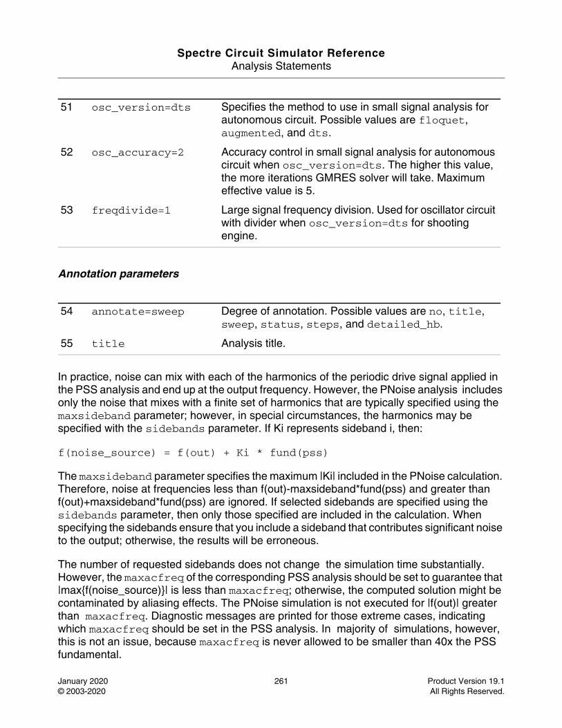
Spectre Circuit Simulator ReferenceAnalysis Statements
January 2020 261 Product Version 19.1© 2003-2020 All Rights Reserved.
Annotation parameters
In practice, noise can mix with each of the harmonics of the periodic drive signal applied in the PSS analysis and end up at the output frequency. However, the PNoise analysis includes only the noise that mixes with a finite set of harmonics that are typically specified using the maxsideband parameter; however, in special circumstances, the harmonics may be specified with the sidebands parameter. If Ki represents sideband i, then:
f(noise_source) = f(out) + Ki * fund(pss)
The maxsideband parameter specifies the maximum |Ki| included in the PNoise calculation. Therefore, noise at frequencies less than f(out)-maxsideband*fund(pss) and greater than f(out)+maxsideband*fund(pss) are ignored. If selected sidebands are specified using the sidebands parameter, then only those specified are included in the calculation. When specifying the sidebands ensure that you include a sideband that contributes significant noise to the output; otherwise, the results will be erroneous.
The number of requested sidebands does not change the simulation time substantially. However, the maxacfreq of the corresponding PSS analysis should be set to guarantee that |max{f(noise_source)}| is less than maxacfreq; otherwise, the computed solution might be contaminated by aliasing effects. The PNoise simulation is not executed for |f(out)| greater than maxacfreq. Diagnostic messages are printed for those extreme cases, indicating which maxacfreq should be set in the PSS analysis. In majority of simulations, however, this is not an issue, because maxacfreq is never allowed to be smaller than 40x the PSS fundamental.
51 osc_version=dts Specifies the method to use in small signal analysis for autonomous circuit. Possible values are floquet, augmented, and dts.
52 osc_accuracy=2 Accuracy control in small signal analysis for autonomous circuit when osc_version=dts. The higher this value, the more iterations GMRES solver will take. Maximum effective value is 5.
53 freqdivide=1 Large signal frequency division. Used for oscillator circuit with divider when osc_version=dts for shooting engine.
54 annotate=sweep Degree of annotation. Possible values are no, title, sweep, status, steps, and detailed_hb.
55 title Analysis title.
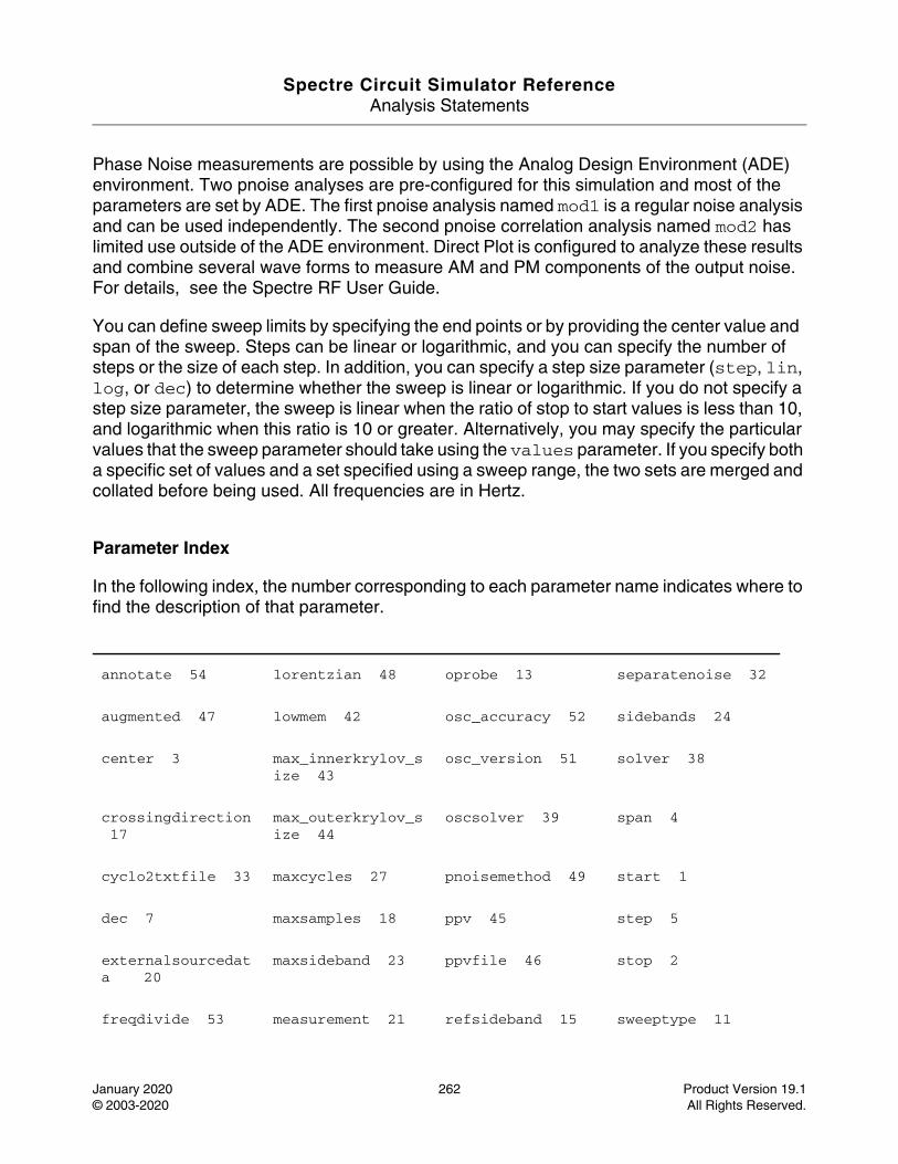
Spectre Circuit Simulator ReferenceAnalysis Statements
January 2020 262 Product Version 19.1© 2003-2020 All Rights Reserved.
Phase Noise measurements are possible by using the Analog Design Environment (ADE) environment. Two pnoise analyses are pre-configured for this simulation and most of the parameters are set by ADE. The first pnoise analysis named mod1 is a regular noise analysis and can be used independently. The second pnoise correlation analysis named mod2 has limited use outside of the ADE environment. Direct Plot is configured to analyze these results and combine several wave forms to measure AM and PM components of the output noise. For details, see the Spectre RF User Guide.
You can define sweep limits by specifying the end points or by providing the center value and span of the sweep. Steps can be linear or logarithmic, and you can specify the number of steps or the size of each step. In addition, you can specify a step size parameter (step, lin, log, or dec) to determine whether the sweep is linear or logarithmic. If you do not specify a step size parameter, the sweep is linear when the ratio of stop to start values is less than 10, and logarithmic when this ratio is 10 or greater. Alternatively, you may specify the particular values that the sweep parameter should take using the values parameter. If you specify both a specific set of values and a set specified using a sweep range, the two sets are merged and collated before being used. All frequencies are in Hertz.
Parameter Index
In the following index, the number corresponding to each parameter name indicates where to find the description of that parameter.
annotate 54 lorentzian 48 oprobe 13 separatenoise 32
augmented 47 lowmem 42 osc_accuracy 52 sidebands 24
center 3 max_innerkrylov_size 43
osc_version 51 solver 38
crossingdirection 17
max_outerkrylov_size 44
oscsolver 39 span 4
cyclo2txtfile 33 maxcycles 27 pnoisemethod 49 start 1
dec 7 maxsamples 18 ppv 45 step 5
externalsourcedata 20
maxsideband 23 ppvfile 46 stop 2
freqdivide 53 measurement 21 refsideband 15 sweeptype 11
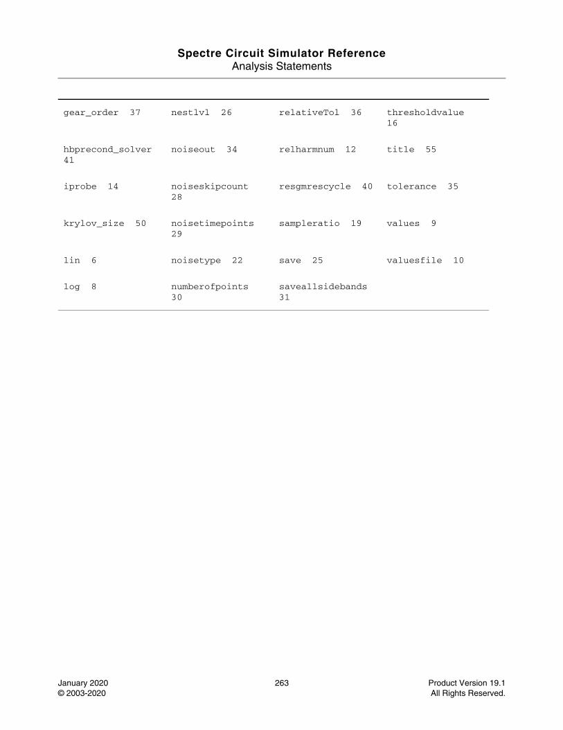
Spectre Circuit Simulator ReferenceAnalysis Statements
January 2020 263 Product Version 19.1© 2003-2020 All Rights Reserved.
gear_order 37 nestlvl 26 relativeTol 36 thresholdvalue 16
hbprecond_solver 41
noiseout 34 relharmnum 12 title 55
iprobe 14 noiseskipcount 28
resgmrescycle 40 tolerance 35
krylov_size 50 noisetimepoints 29
sampleratio 19 values 9
lin 6 noisetype 22 save 25 valuesfile 10
log 8 numberofpoints 30
saveallsidebands 31
Spectre Circuit Simulator ReferenceAnalysis Statements
January 2020 264 Product Version 19.1© 2003-2020 All Rights Reserved.
Periodic S-Parameter Analysis (psp)
Description
The periodic SP (PSP) analysis is used to compute scattering and noise parameters for n-port circuits that exhibit frequency translation, such as mixers. It is a small-signal analysis like SP analysis, except, as in PAC and PXF, the circuit is first linearized about a quasi-periodically varying operating point as opposed to a simple DC operating point. Linearizing about a periodically time-varying operating point allows the computation of S-parameters between circuit ports that convert signals from one frequency band to another. PSP can also calculate noise parameters in frequency-converting circuits. PSP computes noise figure (both single-sideband and double-sideband), input referred noise, equivalent noise parameters, and noise correlation matrices. Similar to PNoise, but unlike SP, the noise features of the PSP analysis include noise folding effects due to the periodically time-varying nature of the circuit.
Computing the n-port S-parameters and noise parameters of a periodically varying circuit is a two step process. First, the small stimulus is ignored and the periodic steady-state response of the circuit to possibly large periodic stimulus is computed using PSS analysis. As a part of the PSS analysis, the periodically time-varying representation of the circuit is computed and saved for later use. The second step is to apply small-signal excitations to compute the n-port S-parameters and noise parameters. This is done using PSP analysis. PSP analysis cannot be used independently, it must follow a PSS analysis. However, any number of periodic small-signal analyses such as PAC, PSP, PXF, PNoise, can follow a PSS analysis.
Note: Unlike other analyses in Spectre, this analysis can only sweep frequency.
For information on how to run PSP analysis from ADE, see Periodic S-Parameter Analysis (PSP) in the Spectre Circuit Simulator and Accelerated Parallel Simulator RF Analysis User Guide.
DefinitionName psp parameter=value ...
Parameters
Sweep interval parameters
1 start=0 Start sweep limit.
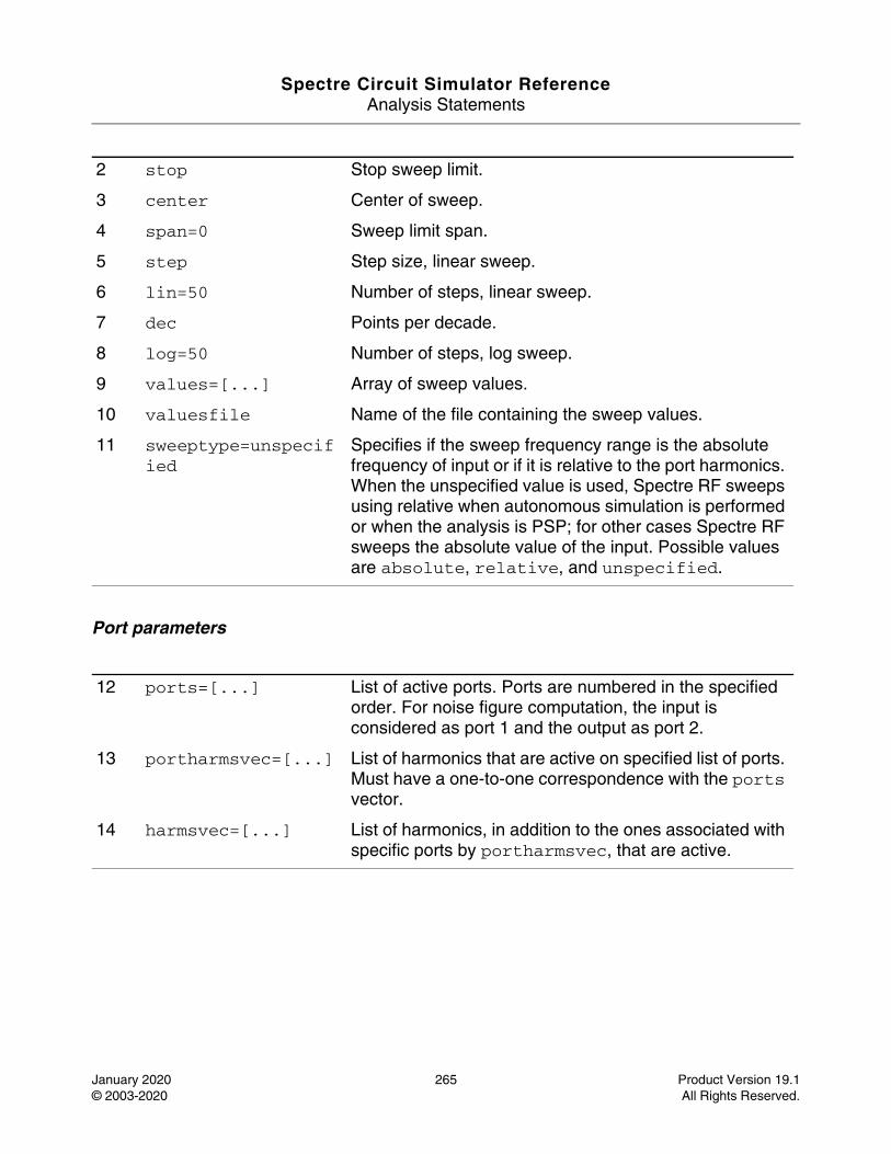
Spectre Circuit Simulator ReferenceAnalysis Statements
January 2020 265 Product Version 19.1© 2003-2020 All Rights Reserved.
Port parameters
2 stop Stop sweep limit.
3 center Center of sweep.
4 span=0 Sweep limit span.
5 step Step size, linear sweep.
6 lin=50 Number of steps, linear sweep.
7 dec Points per decade.
8 log=50 Number of steps, log sweep.
9 values=[...] Array of sweep values.
10 valuesfile Name of the file containing the sweep values.
11 sweeptype=unspecified
Specifies if the sweep frequency range is the absolute frequency of input or if it is relative to the port harmonics. When the unspecified value is used, Spectre RF sweeps using relative when autonomous simulation is performed or when the analysis is PSP; for other cases Spectre RF sweeps the absolute value of the input. Possible values are absolute, relative, and unspecified.
12 ports=[...] List of active ports. Ports are numbered in the specified order. For noise figure computation, the input is considered as port 1 and the output as port 2.
13 portharmsvec=[...] List of harmonics that are active on specified list of ports. Must have a one-to-one correspondence with the ports vector.
14 harmsvec=[...] List of harmonics, in addition to the ones associated with specific ports by portharmsvec, that are active.
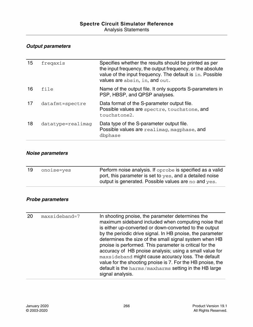
Spectre Circuit Simulator ReferenceAnalysis Statements
January 2020 266 Product Version 19.1© 2003-2020 All Rights Reserved.
Output parameters
Noise parameters
Probe parameters
15 freqaxis Specifies whether the results should be printed as per the input frequency, the output frequency, or the absolute value of the input frequency. The default is in. Possible values are absin, in, and out.
16 file Name of the output file. It only supports S-parameters in PSP, HBSP, and QPSP analyses.
17 datafmt=spectre Data format of the S-parameter output file.Possible values are spectre, touchstone, and touchstone2.
18 datatype=realimag Data type of the S-parameter output file.Possible values are realimag, magphase, and dbphase
19 onoise=yes Perform noise analysis. If oprobe is specified as a valid port, this parameter is set to yes, and a detailed noise output is generated. Possible values are no and yes.
20 maxsideband=7 In shooting pnoise, the parameter determines the maximum sideband included when computing noise that is either up-converted or down-converted to the output by the periodic drive signal. In HB pnoise, the parameter determines the size of the small signal system when HB pnoise is performed. This parameter is critical for the accuracy of HB pnoise analysis; using a small value for maxsideband might cause accuracy loss. The default value for the shooting pnoise is 7. For the HB pnoise, the default is the harms/maxharms setting in the HB large signal analysis.
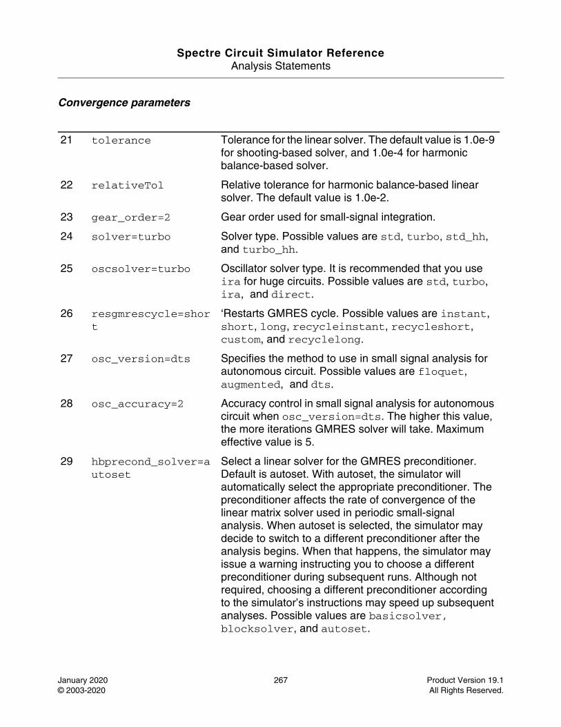
Spectre Circuit Simulator ReferenceAnalysis Statements
January 2020 267 Product Version 19.1© 2003-2020 All Rights Reserved.
Convergence parameters
21 tolerance Tolerance for the linear solver. The default value is 1.0e-9 for shooting-based solver, and 1.0e-4 for harmonic balance-based solver.
22 relativeTol Relative tolerance for harmonic balance-based linear solver. The default value is 1.0e-2.
23 gear_order=2 Gear order used for small-signal integration.
24 solver=turbo Solver type. Possible values are std, turbo, std_hh, and turbo_hh.
25 oscsolver=turbo Oscillator solver type. It is recommended that you use ira for huge circuits. Possible values are std, turbo, ira, and direct.
26 resgmrescycle=short
‘Restarts GMRES cycle. Possible values are instant, short, long, recycleinstant, recycleshort, custom, and recyclelong.
27 osc_version=dts Specifies the method to use in small signal analysis for autonomous circuit. Possible values are floquet, augmented, and dts.
28 osc_accuracy=2 Accuracy control in small signal analysis for autonomous circuit when osc_version=dts. The higher this value, the more iterations GMRES solver will take. Maximum effective value is 5.
29 hbprecond_solver=autoset
Select a linear solver for the GMRES preconditioner. Default is autoset. With autoset, the simulator will automatically select the appropriate preconditioner. The preconditioner affects the rate of convergence of the linear matrix solver used in periodic small-signal analysis. When autoset is selected, the simulator may decide to switch to a different preconditioner after the analysis begins. When that happens, the simulator may issue a warning instructing you to choose a different preconditioner during subsequent runs. Although not required, choosing a different preconditioner according to the simulator’s instructions may speed up subsequent analyses. Possible values are basicsolver, blocksolver, and autoset.
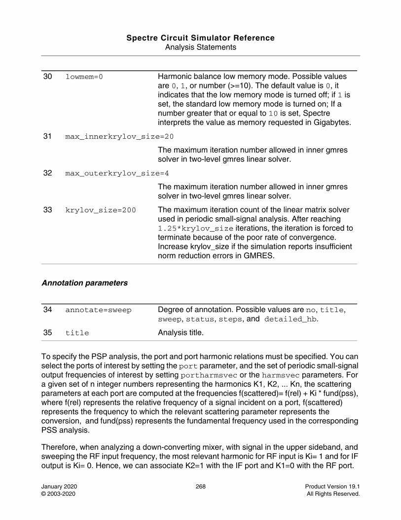
Spectre Circuit Simulator ReferenceAnalysis Statements
January 2020 268 Product Version 19.1© 2003-2020 All Rights Reserved.
Annotation parameters
To specify the PSP analysis, the port and port harmonic relations must be specified. You can select the ports of interest by setting the port parameter, and the set of periodic small-signal output frequencies of interest by setting portharmsvec or the harmsvec parameters. For a given set of n integer numbers representing the harmonics K1, K2, ... Kn, the scattering parameters at each port are computed at the frequencies f(scattered)= f(rel) + Ki * fund(pss), where f(rel) represents the relative frequency of a signal incident on a port, f(scattered) represents the frequency to which the relevant scattering parameter represents the conversion, and fund(pss) represents the fundamental frequency used in the corresponding PSS analysis.
Therefore, when analyzing a down-converting mixer, with signal in the upper sideband, and sweeping the RF input frequency, the most relevant harmonic for RF input is Ki= 1 and for IF output is Ki= 0. Hence, we can associate K2=1 with the IF port and K1=0 with the RF port.
30 lowmem=0 Harmonic balance low memory mode. Possible values are 0, 1, or number (>=10). The default value is 0, it indicates that the low memory mode is turned off; if 1 is set, the standard low memory mode is turned on; If a number greater that or equal to 10 is set, Spectre interprets the value as memory requested in Gigabytes.
31 max_innerkrylov_size=20
The maximum iteration number allowed in inner gmres solver in two-level gmres linear solver.
32 max_outerkrylov_size=4
The maximum iteration number allowed in inner gmres solver in two-level gmres linear solver.
33 krylov_size=200 The maximum iteration count of the linear matrix solver used in periodic small-signal analysis. After reaching 1.25*krylov_size iterations, the iteration is forced to terminate because of the poor rate of convergence. Increase krylov_size if the simulation reports insufficient norm reduction errors in GMRES.
34 annotate=sweep Degree of annotation. Possible values are no, title, sweep, status, steps, and detailed_hb.
35 title Analysis title.
Spectre Circuit Simulator ReferenceAnalysis Statements
January 2020 269 Product Version 19.1© 2003-2020 All Rights Reserved.
S21 represents the transmission of signal from the RF to IF and S11 the reflection of signal back to the RF port. If the signal was in the lower sideband, a choice of K1=-1 would be more appropriate.
Either portharmsvec or harmsvec can be used to specify the harmonics of interest. If portharmsvec is given, the harmonics must be in one-to-one correspondence with the ports, with each harmonic associated with a single port. If harmonics are specified in the optional harmsvec parameter, all possible frequency-translating scattering parameters associated with the specified harmonics are computed.
With PSP, the frequency of the input and of the response are usually different (this is an important area in which PSP differs from SP). Because the PSP computation involves inputs and outputs at frequencies that are relative to multiple harmonics, the freqaxis and sweeptype parameters behave differently in PSP than in PAC and PXF.
The sweeptype parameter controls the way the frequencies in the PSP analysis are swept. A relative sweep is a sweep relative to the analysis harmonics (not the PSS fundamental), and an absolute sweep is a sweep of the absolute input source frequency. For example, with a PSS fundamental of 100MHz, portharmsvec set to [9 1] to examine a down-converting mixer, sweeptype=relative, and a sweep range of f(rel)=0->50MHz, S21 would represent the strength of signal transmitted from the input port in the range 900->950MHz to the output port at frequencies 100->150MHz. Using sweeptype=absolute and sweeping the frequency from 900->950MHz would calculate the same quantities, because f(abs)=900->950MHz, and f(rel) = f(abs) - K1 * fund(pss) = 0->50MHz, where, K1=9 and fund(pss) = 100MHz.
Usually, it is not necessary to sweep frequency in PSP over more than one fundamental PSS period.
The freqaxis parameter is used to specify whether the results should be output versus the scattered frequency at the input port (in), the scattered frequency at the output port (out), or the absolute value of the frequency swept at the input port (absin). If freqaxis is absin, the S-parameters at negative frequencies are taken conjugate and output at corresponding positive frequencies.
Unlike in PAC/PXF/PNoise, increasing the number of requested ports and harmonics increases the simulation time substantially.
To ensure accurate results in PSP, the maxacfreq of the corresponding PSS analysis should be set to guarantee that | max{f(scattered)} | is less than maxacfreq; otherwise, the computed solution might be contaminated by aliasing effects.
PSP analysis also computes noise figures, equivalent noise sources, and noise parameters. The noise computation, which is skipped only when donoise=no, requires additional simulation time. If:
Spectre Circuit Simulator ReferenceAnalysis Statements
January 2020 270 Product Version 19.1© 2003-2020 All Rights Reserved.
No = total output noise at frequency f
Ns = noise at the output due to the input probe (the source)
Nsi = noise at the output due to the image harmonic at the source
Nso = noise at the output due to harmonics other than input at the source
Nl = noise at the output due to the output probe (the load)
IRN = input referred noise
G = gain of the circuit
F = noise factor (single side band)
NF = noise figure (single side band)
Fdsb = double sideband noise factor
NFdsb = double sideband noise figure
Fieee = IEEE single sideband noise factor
NFieee = IEEE single sideband noise figure
Then:
IRN = sqrt(No^2/G^2)
F = (No^2 - Nl^2)/Ns^2
NF = 10*log10(F)
Fdsb = (No^2 - Nl^2)/(Ns^2+Nsi^2)
NFdsb = 10*log10(Fdsb)
Fieee = (No^2 - Nl^2 - Nso^2)/Ns^2
NFieee = 10*log10(Fieee).
When the results are output, IRN is named in, G is named gain, F, NF, Fdsb, NFdsb, Fieee, and NFieee are named F, NF, Fdsb, NFdsb, Fieee, and NFieee, respectively.
Note: The gain computed by PSP is the voltage gain from the actual circuit input to the circuit output, and not the gain from the internal port voltage source to the output.
Spectre Circuit Simulator ReferenceAnalysis Statements
January 2020 271 Product Version 19.1© 2003-2020 All Rights Reserved.
To ensure accurate noise calculations, the maxsideband or sidebands parameters must be set to include the relevant noise folding effects. maxsideband is only relevant to the noise computation features of PSP.
You can define the sweep limits by specifying the end points or by providing the center value and span of the sweep. Steps can be linear or logarithmic, and you can specify the number of steps or the size of each step. In addition, you can specify a step size parameter (step, lin, log, or dec) to determine whether the sweep is linear or logarithmic. If you do not specify a step size parameter, the sweep is linear when the ratio of stop to start values is less than 10, and logarithmic when this ratio is 10 or greater. Alternatively, you may specify the particular values that the sweep parameter should take using the values parameter. If you specify both a specific set of values and a set specified using a sweep range, the two sets are merged and collated before being used. All frequencies are in Hertz.
Parameter Index
In the following index, the number corresponding to each parameter name indicates where to find the description of that parameter:
annotate 34 harmsvec 14 osc_accuracy 28 start 1
center 3 hbprecond_solver 29
osc_version 27 step 5
datafmt 17 krylov_size 33 oscsolver 25 stop 2
datatype 18 lin 6 portharmsvec 13 sweeptype 11
dec 7 log 8 ports 12 title 35
donoise 19 lowmem 30 relativeTol 22 tolerance 21
file 16 max_innerkrylov_size 31
resgmrescycle 26 values 9
freqaxis 15 max_outerkrylov_size 32
solver 24 valuesfile 10
gear_order 23 maxsideband 20 span 4

Spectre Circuit Simulator ReferenceAnalysis Statements
January 2020 272 Product Version 19.1© 2003-2020 All Rights Reserved.
Periodic Steady-State Analysis (pss)
Description
This analysis computes the periodic steady-state (PSS) response of a circuit by using harmonic balance (in the frequency domain) or shooting (in the time domain). The simulation time of PSS analysis is independent of the time-constants of the circuit. In addition, PSS analysis determines the periodic operating point for the circuit. The periodic operating point can then be used during a periodic time-varying small-signal analysis, such as PAC, PXF, PNOISE, PSP, or PSTB.
Harmonic balance (HB) is efficient in simulating weak non-linear circuits while shooting is more suitable for highly non-linear circuits with sharply rising and falling signals. HB is also advantageous over shooting in handling frequency dependent components, such as delay, transmission line, and S-parameter data.
PSS analysis can handle both autonomous (non-driven) and driven (non-autonomous) circuits. Autonomous circuits, even though they are not driven by a time-varying stimulus, generate non-constant waveforms. Driven circuits require some time-varying stimulus to generate a time-varying response. The most common example of an autonomous circuit is an oscillator. Common driven circuits include amplifiers, filters, and mixers. When PSS is applied to autonomous circuits, it requires you to specify a pair of nodes, p and n. This is how PSS analysis determines whether it is being applied to an autonomous or a driven circuit. If the pair of nodes is supplied, PSS assumes the circuit is autonomous; if not, the circuit is assumed to be driven.
With driven circuits, specify the analysis period or its corresponding fundamental frequency fund. The period must be an integer multiple of the period of the drive signal or signals. Autonomous circuits have no drive signal, and the actual period of oscillation is not known precisely in advance. Instead, you specify an estimate of the oscillation period and PSS analysis computes the precise period along with the periodic solution waveforms.
PSS analysis consists of two phases, an initial transient phase, which initializes the circuit, and the shooting or harmonic balance phase, which computes the periodic steady-state solution. The transient phase consists of three intervals. The first interval starts at tstart, which is normally 0, and continues through the onset of periodicity tonset for the independent sources. The onset of periodicity, which is automatically generated, is the minimum time for which all sources are periodic. The second interval is an optional user-specified stabilization interval whose length is tstab. The final interval length is period for driven circuits, or four times period for autonomous circuits. This interval has a special use for the autonomous PSS analysis, that is, the PSS analysis monitors the waveforms in the circuit and develops a better estimate of the oscillation period. After the initial transient phase is complete, the shooting or HB phase begins. In this phase, the circuit is iteratively solved
Spectre Circuit Simulator ReferenceAnalysis Statements
January 2020 273 Product Version 19.1© 2003-2020 All Rights Reserved.
using Newton method to find the periodic steady-state solution (and the period when applied to autonomous circuits).
For information on how to run PSS analysis from ADE, see Overview of Periodic Steady-State (pss) Analysis in the Spectre Circuit Simulator and Accelerated Parallel Simulator RF Analysis User Guide.
DefinitionName [p] [n] pss parameter=value ...
Parameters
Simulation interval parameters
1 period (s) Steady state analysis period (or its estimate for autonomous circuits).
2 fund (Hz) Alternative to period specification. Steady state analysis fundamental frequency (or its estimate for autonomous circuits).
3 autofund=no If the value is yes, the program ignores period/fund value and calculates the fundamental frequency automatically from source information. Possible values are no and yes.
4 harms=9 for shooting, 10 for HB
For shooting, it is the number of solution harmonics to output when outputtype=freq or all; for HB, it directly determines the solution dimension to be solved and impacts the accuracy and convergence of the simulation.
5 autoharms=no Activates automatic harmonic number calculation in harmonic balance. Applies only if tstab>0 or if autotstab=yes. If a steady-state is reached, Spectre does a spectrum analysis to calculate the optimal number of harmonics for HB. The minimum number of harmonics is specified by maxharms. If steady-state is not reached to sufficient tolerance, autoharms may be disabled. Possible values are no and yes.
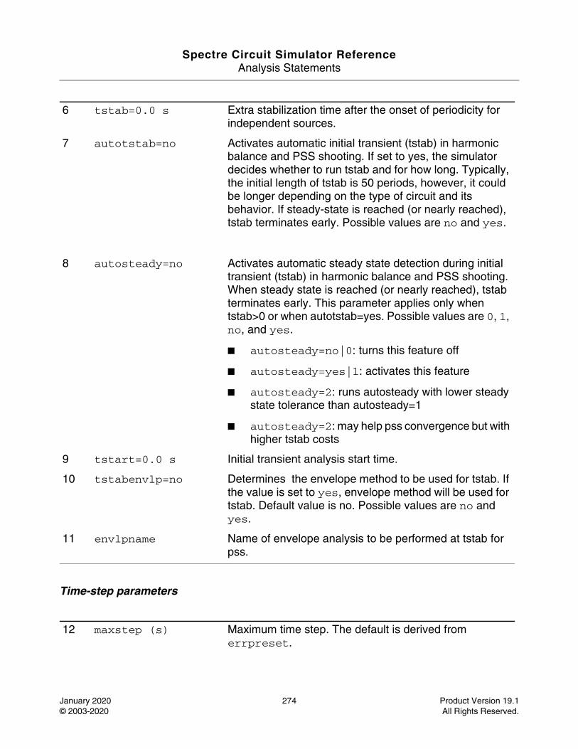
Spectre Circuit Simulator ReferenceAnalysis Statements
January 2020 274 Product Version 19.1© 2003-2020 All Rights Reserved.
Time-step parameters
6 tstab=0.0 s Extra stabilization time after the onset of periodicity for independent sources.
7 autotstab=no Activates automatic initial transient (tstab) in harmonic balance and PSS shooting. If set to yes, the simulator decides whether to run tstab and for how long. Typically, the initial length of tstab is 50 periods, however, it could be longer depending on the type of circuit and its behavior. If steady-state is reached (or nearly reached), tstab terminates early. Possible values are no and yes.
8 autosteady=no Activates automatic steady state detection during initial transient (tstab) in harmonic balance and PSS shooting. When steady state is reached (or nearly reached), tstab terminates early. This parameter applies only when tstab>0 or when autotstab=yes. Possible values are 0, 1, no, and yes.
■ autosteady=no|0: turns this feature off
■ autosteady=yes|1: activates this feature
■ autosteady=2: runs autosteady with lower steady state tolerance than autosteady=1
■ autosteady=2: may help pss convergence but with higher tstab costs
9 tstart=0.0 s Initial transient analysis start time.
10 tstabenvlp=no Determines the envelope method to be used for tstab. If the value is set to yes, envelope method will be used for tstab. Default value is no. Possible values are no and yes.
11 envlpname Name of envelope analysis to be performed at tstab for pss.
12 maxstep (s) Maximum time step. The default is derived from errpreset.
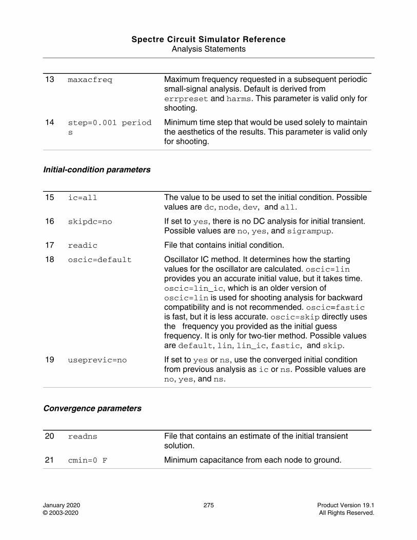
Spectre Circuit Simulator ReferenceAnalysis Statements
January 2020 275 Product Version 19.1© 2003-2020 All Rights Reserved.
Initial-condition parameters
Convergence parameters
13 maxacfreq Maximum frequency requested in a subsequent periodic small-signal analysis. Default is derived from errpreset and harms. This parameter is valid only for shooting.
14 step=0.001 period s
Minimum time step that would be used solely to maintain the aesthetics of the results. This parameter is valid only for shooting.
15 ic=all The value to be used to set the initial condition. Possible values are dc, node, dev, and all.
16 skipdc=no If set to yes, there is no DC analysis for initial transient. Possible values are no, yes, and sigrampup.
17 readic File that contains initial condition.
18 oscic=default Oscillator IC method. It determines how the starting values for the oscillator are calculated. oscic=lin provides you an accurate initial value, but it takes time. oscic=lin_ic, which is an older version of oscic=lin is used for shooting analysis for backward compatibility and is not recommended. oscic=fastic is fast, but it is less accurate. oscic=skip directly uses the frequency you provided as the initial guess frequency. It is only for two-tier method. Possible values are default, lin, lin_ic, fastic, and skip.
19 useprevic=no If set to yes or ns, use the converged initial condition from previous analysis as ic or ns. Possible values are no, yes, and ns.
20 readns File that contains an estimate of the initial transient solution.
21 cmin=0 F Minimum capacitance from each node to ground.
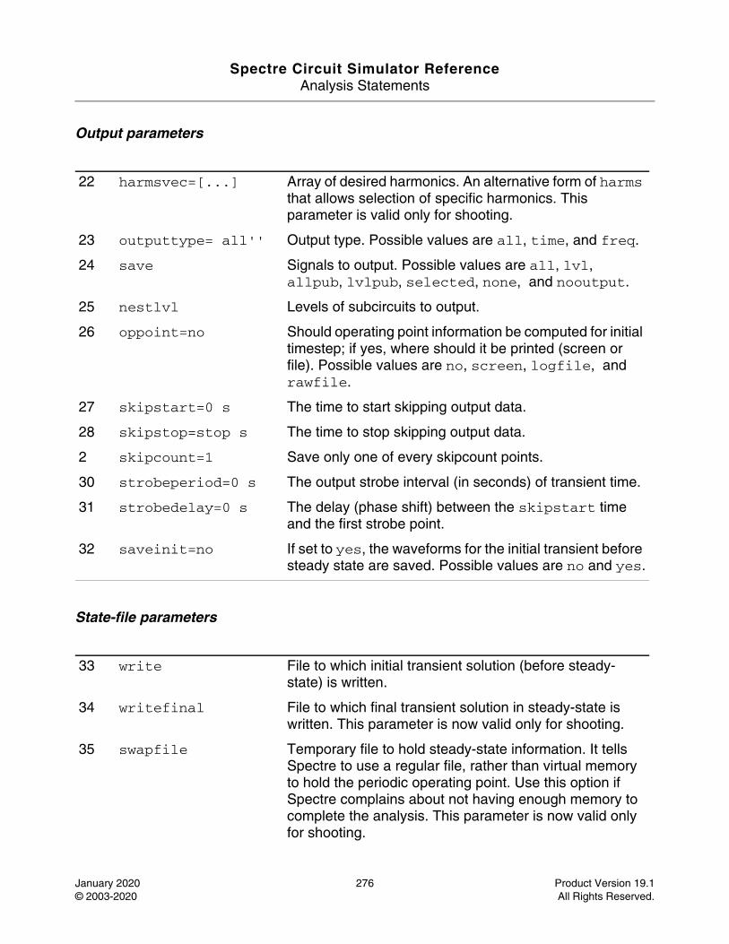
Spectre Circuit Simulator ReferenceAnalysis Statements
January 2020 276 Product Version 19.1© 2003-2020 All Rights Reserved.
Output parameters
State-file parameters
22 harmsvec=[...] Array of desired harmonics. An alternative form of harms that allows selection of specific harmonics. This parameter is valid only for shooting.
23 outputtype= all'' Output type. Possible values are all, time, and freq.
24 save Signals to output. Possible values are all, lvl, allpub, lvlpub, selected, none, and nooutput.
25 nestlvl Levels of subcircuits to output.
26 oppoint=no Should operating point information be computed for initial timestep; if yes, where should it be printed (screen or file). Possible values are no, screen, logfile, and rawfile.
27 skipstart=0 s The time to start skipping output data.
28 skipstop=stop s The time to stop skipping output data.
2 skipcount=1 Save only one of every skipcount points.
30 strobeperiod=0 s The output strobe interval (in seconds) of transient time.
31 strobedelay=0 s The delay (phase shift) between the skipstart time and the first strobe point.
32 saveinit=no If set to yes, the waveforms for the initial transient before steady state are saved. Possible values are no and yes.
33 write File to which initial transient solution (before steady-state) is written.
34 writefinal File to which final transient solution in steady-state is written. This parameter is now valid only for shooting.
35 swapfile Temporary file to hold steady-state information. It tells Spectre to use a regular file, rather than virtual memory to hold the periodic operating point. Use this option if Spectre complains about not having enough memory to complete the analysis. This parameter is now valid only for shooting.
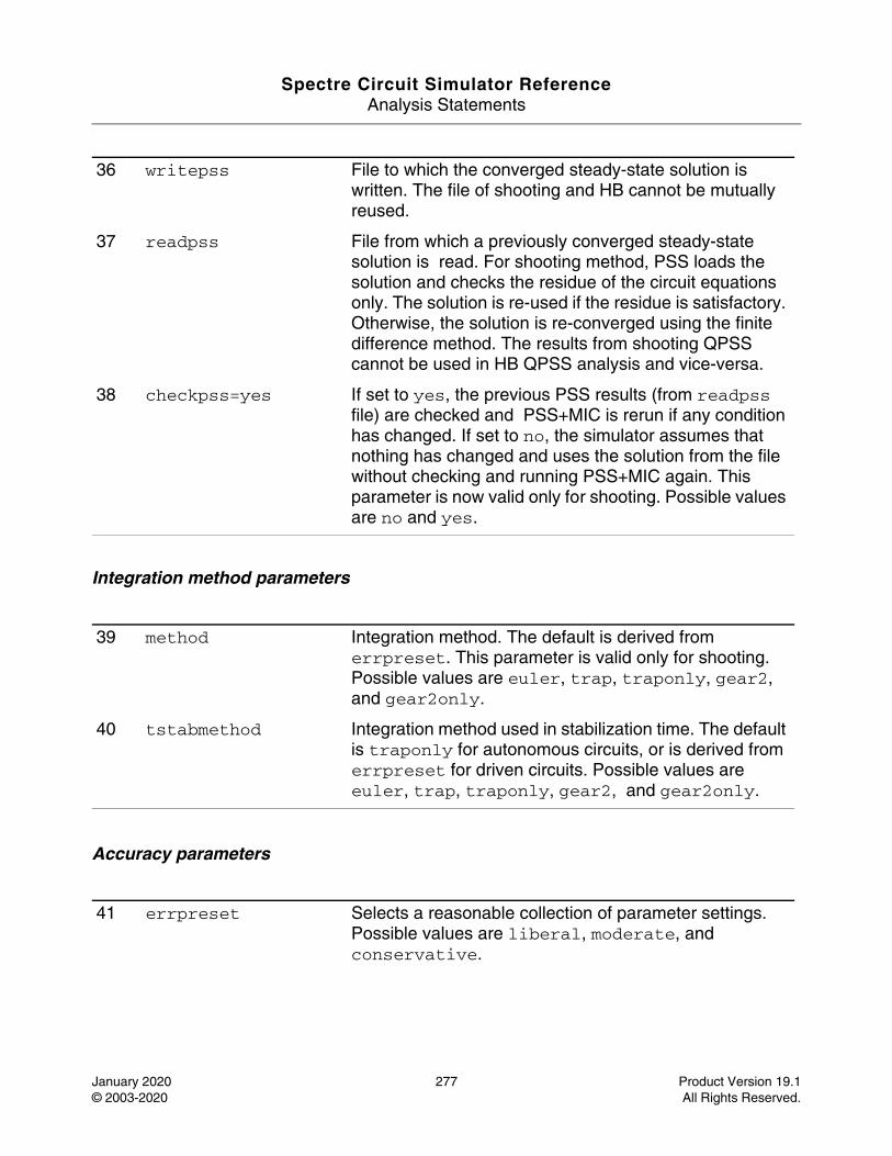
Spectre Circuit Simulator ReferenceAnalysis Statements
January 2020 277 Product Version 19.1© 2003-2020 All Rights Reserved.
Integration method parameters
Accuracy parameters
36 writepss File to which the converged steady-state solution is written. The file of shooting and HB cannot be mutually reused.
37 readpss File from which a previously converged steady-state solution is read. For shooting method, PSS loads the solution and checks the residue of the circuit equations only. The solution is re-used if the residue is satisfactory. Otherwise, the solution is re-converged using the finite difference method. The results from shooting QPSS cannot be used in HB QPSS analysis and vice-versa.
38 checkpss=yes If set to yes, the previous PSS results (from readpss file) are checked and PSS+MIC is rerun if any condition has changed. If set to no, the simulator assumes that nothing has changed and uses the solution from the file without checking and running PSS+MIC again. This parameter is now valid only for shooting. Possible values are no and yes.
39 method Integration method. The default is derived from errpreset. This parameter is valid only for shooting. Possible values are euler, trap, traponly, gear2, and gear2only.
40 tstabmethod Integration method used in stabilization time. The default is traponly for autonomous circuits, or is derived from errpreset for driven circuits. Possible values are euler, trap, traponly, gear2, and gear2only.
41 errpreset Selects a reasonable collection of parameter settings. Possible values are liberal, moderate, and conservative.
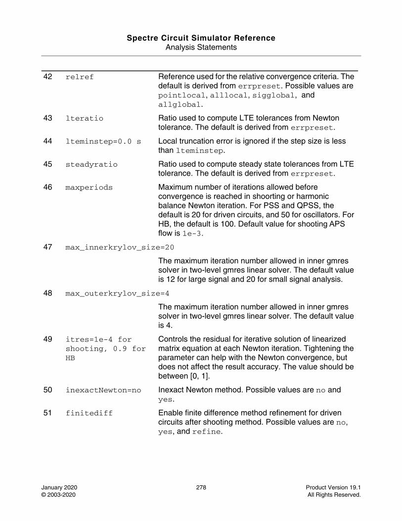
Spectre Circuit Simulator ReferenceAnalysis Statements
January 2020 278 Product Version 19.1© 2003-2020 All Rights Reserved.
42 relref Reference used for the relative convergence criteria. The default is derived from errpreset. Possible values are pointlocal, alllocal, sigglobal, and allglobal.
43 lteratio Ratio used to compute LTE tolerances from Newton tolerance. The default is derived from errpreset.
44 lteminstep=0.0 s Local truncation error is ignored if the step size is less than lteminstep.
45 steadyratio Ratio used to compute steady state tolerances from LTE tolerance. The default is derived from errpreset.
46 maxperiods Maximum number of iterations allowed before convergence is reached in shoorting or harmonic balance Newton iteration. For PSS and QPSS, the default is 20 for driven circuits, and 50 for oscillators. For HB, the default is 100. Default value for shooting APS flow is 1e-3.
47 max_innerkrylov_size=20
The maximum iteration number allowed in inner gmres solver in two-level gmres linear solver. The default value is 12 for large signal and 20 for small signal analysis.
48 max_outerkrylov_size=4
The maximum iteration number allowed in inner gmres solver in two-level gmres linear solver. The default value is 4.
49 itres=1e-4 for shooting, 0.9 for HB
Controls the residual for iterative solution of linearized matrix equation at each Newton iteration. Tightening the parameter can help with the Newton convergence, but does not affect the result accuracy. The value should be between [0, 1].
50 inexactNewton=no Inexact Newton method. Possible values are no and yes.
51 finitediff Enable finite difference method refinement for driven circuits after shooting method. Possible values are no, yes, and refine.
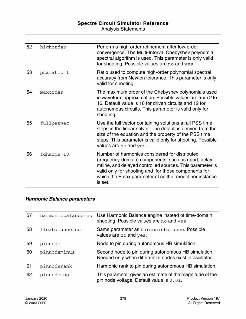
Spectre Circuit Simulator ReferenceAnalysis Statements
January 2020 279 Product Version 19.1© 2003-2020 All Rights Reserved.
Harmonic Balance parameters
52 highorder Perform a high-order refinement after low-order convergence. The Multi-Interval Chebyshev polynomial spectral algorithm is used. This parameter is only valid for shooting. Possible values are no and yes.
53 psaratio=1 Ratio used to compute high-order polynomial spectral accuracy from Newton tolerance. This parameter is only valid for shooting.
54 maxorder The maximum order of the Chebyshev polynomials used in waveform approximation. Possible values are from 2 to 16. Default value is 16 for driven circuits and 12 for autonomous circuits. This parameter is valid only for shooting.
55 fullpssvec Use the full vector containing solutions at all PSS time steps in the linear solver. The default is derived from the size of the equation and the property of the PSS time steps. This parameter is valid only for shooting. Possible values are no and yes.
56 fdharms=10 Number of harmonics considered for distributed (frequency-domain) components, such as nport, delay, mtline, and delayed controlled sources. This parameter is valid only for shooting and for those components for which the Fmax parameter of neither model nor instance is set.
57 harmonicbalance=no Use Harmonic Balance engine instead of time-domain shooting. Possible values are no and yes.
58 flexbalance=no Same parameter as harmonicbalance. Possible values are no and yes.
59 pinnode Node to pin during autonomous HB simulation.
60 pinnodeminus Second node to pin during autonomous HB simulation. Needed only when differential nodes exist in oscillator.
61 pinnoderank Harmonic rank to pin during autonomous HB simulation.
62 pinnodemag This parameter gives an estimate of the magnitude of the pin node voltage. Default value is 0.01.
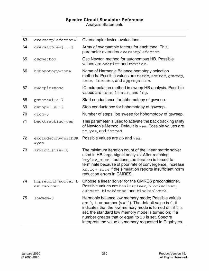
Spectre Circuit Simulator ReferenceAnalysis Statements
January 2020 280 Product Version 19.1© 2003-2020 All Rights Reserved.
63 oversamplefactor=1 Oversample device evaluations.
64 oversample=[...] Array of oversample factors for each tone. This parameter overrides oversamplefactor.
65 oscmethod Osc Newton method for autonomous HB. Possible values are onetier and twotier.
66 hbhomotopy=tone Name of Harmonic Balance homotopy selection methods. Possible values are tstab, source, gsweep, tone, inctone, and aggregation.
67 sweepic=none IC extrapolation method in sweep HB analysis. Possible values are none, linear, and log.
68 gstart=1.e-7 Start conductance for hbhomotopy of gsweep.
69 gstop=1.e-12 Stop conductance for hbhomotopy of gsweep.
70 glog=5 Number of steps, log sweep for hbhomotopy of gsweep.
71 backtracking=yes This parameter is used to activate the back tracking utility of Newton’s Method. Default is yes. Possible values are no, yes, and forced.
72 excludeconvgwithBK=yes
Possible values are no and yes.
73 krylov_size=10 The minimum iteration count of the linear matrix solver used in HB large-signal analysis. After reaching krylov_size iterations, the iteration is forced to terminate because of poor rate of convergence. Increase krylov_size if the simulation reports insufficient norm reduction errors in GMRES.
74 hbprecond_solver=basicsolver
Choose a linear solver for the GMRES preconditioner.Possible values are basicsolver, blocksolver, autoset, blockdense, and blocksolver2.
75 lowmem=0 Harmonic balance low memory mode; Possible values are 0, 1, or number (>=10). The default value is 0, it indicates that the low memory mode is turned off; if 1 is set, the standard low memory mode is turned on; If a number greater that or equal to 10 is set, Spectre interprets the value as memory requested in Gigabytes.
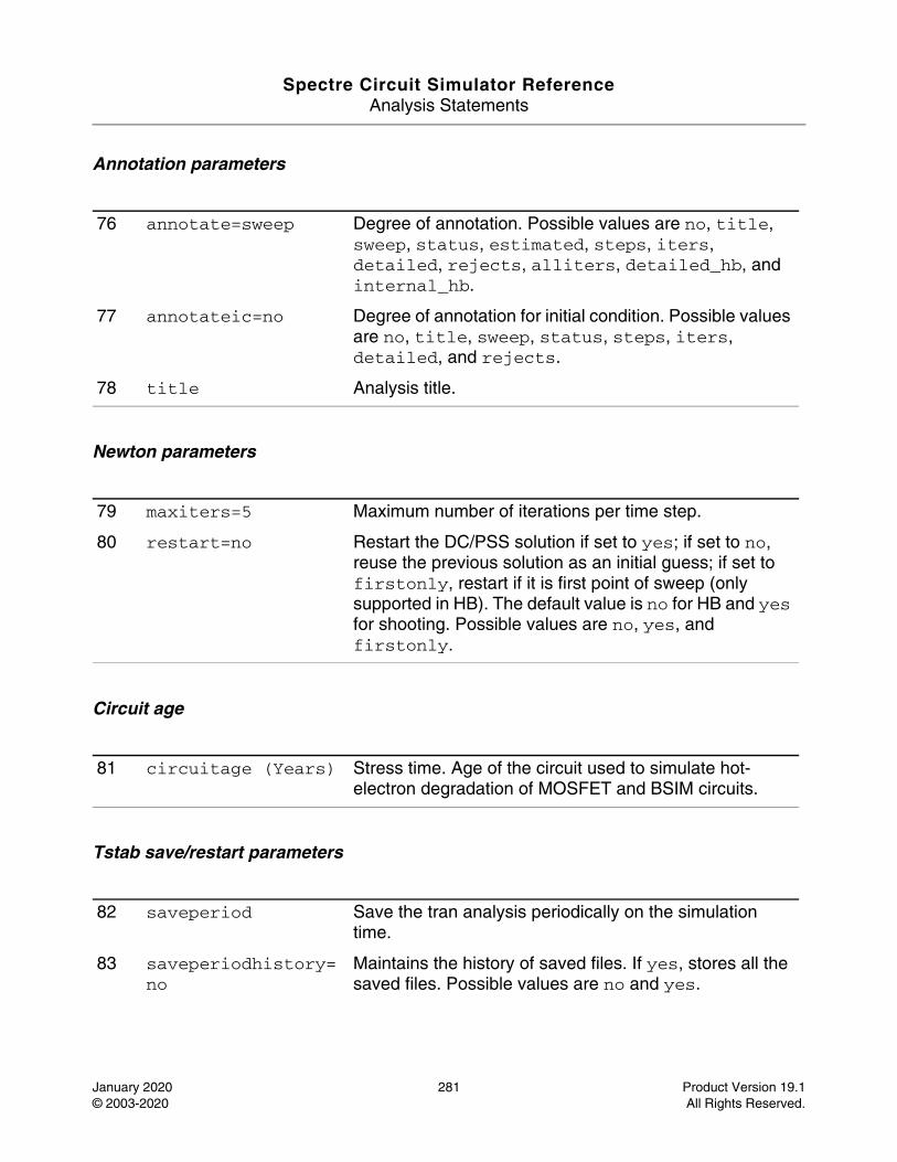
Spectre Circuit Simulator ReferenceAnalysis Statements
January 2020 281 Product Version 19.1© 2003-2020 All Rights Reserved.
Annotation parameters
Newton parameters
Circuit age
Tstab save/restart parameters
76 annotate=sweep Degree of annotation. Possible values are no, title, sweep, status, estimated, steps, iters, detailed, rejects, alliters, detailed_hb, and internal_hb.
77 annotateic=no Degree of annotation for initial condition. Possible values are no, title, sweep, status, steps, iters, detailed, and rejects.
78 title Analysis title.
79 maxiters=5 Maximum number of iterations per time step.
80 restart=no Restart the DC/PSS solution if set to yes; if set to no, reuse the previous solution as an initial guess; if set to firstonly, restart if it is first point of sweep (only supported in HB). The default value is no for HB and yes for shooting. Possible values are no, yes, and firstonly.
81 circuitage (Years) Stress time. Age of the circuit used to simulate hot-electron degradation of MOSFET and BSIM circuits.
82 saveperiod Save the tran analysis periodically on the simulation time.
83 saveperiodhistory=no
Maintains the history of saved files. If yes, stores all the saved files. Possible values are no and yes.
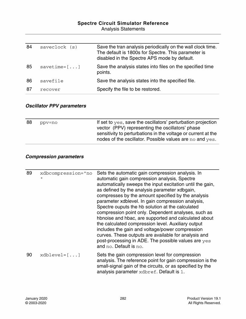
Spectre Circuit Simulator ReferenceAnalysis Statements
January 2020 282 Product Version 19.1© 2003-2020 All Rights Reserved.
Oscillator PPV parameters
Compression parameters
84 saveclock (s) Save the tran analysis periodically on the wall clock time. The default is 1800s for Spectre. This parameter is disabled in the Spectre APS mode by default.
85 savetime=[...] Save the analysis states into files on the specified time points.
86 savefile Save the analysis states into the specified file.
87 recover Specify the file to be restored.
88 ppv=no If set to yes, save the oscillators’ perturbation projection vector (PPV) representing the oscillators’ phase sensitivity to perturbations in the voltage or current at the nodes of the oscillator. Possible values are no and yes.
89 xdbcompression="no"
Sets the automatic gain compression analysis. In automatic gain compression analysis, Spectre automatically sweeps the input excitation until the gain, as defined by the analysis parameter xdbgain, compresses by the amount specified by the analysis parameter xdblevel. In gain compression analysis, Spectre ouputs the hb solution at the calculated compression point only. Dependent analyses, such as hbnoise and hbac, are supported and calculated about the calculated compression level. Auxiliary output includes the gain and voltage/power compression curves. These outputs are available for analysis and post-processing in ADE. The possible values are yes and no. Default is no.
90 xdblevel=[...] Sets the gain compression level for compression analysis. The reference point for gain compression is the small-signal gain of the circuits, or as specified by the analysis parameter xdbref. Default is 1.

Spectre Circuit Simulator ReferenceAnalysis Statements
January 2020 283 Product Version 19.1© 2003-2020 All Rights Reserved.
91 xdbgain="power" Chooses between the voltage gain or transducer power gain as the target for compression point calculation. When xdbgain=power, the gain is defined as G (dB) = Pload (dBm) - Pavailable (dBm). When xdbgain=voltage, the gain is defined as G (dB) = dB20(|Vload|/|Vsource|). In both cases, Spectre sweeps the excitation source until xdbref - G = xdblevel, where the analysis parameter xdbref defines the reference level for compression calculation. Possible values are power and voltage. Default is power.
92 xdbref="linear" Sets the reference point for gain compression calculations. When xdbref=linear, spectre uses the small-signal gain as the reference. When xdbref=max, spectre uses the maximum observed gain as the reference. Possible values are linear and max. Default is linear.
93 xdbsource The instance name of the excitation source, which is swept automatically to reach the compression level. When xdbgain=power, the excitation source must be a port instance. When xdbgain=voltage, the excitation source must be a vsource instance.
94 xdbload The instance name of the load termination. When xdbgain is power, xdbload can be a port, a resistor, or a current probe.
95 xdbnodep The output terminals for voltage gain calculation when xdbgain=voltage. If either is left unspecified, the terminal is assumed to be the global ground.
96 xdbnoden The output terminals for voltage gain calculation when xdbgain=voltage. If either is left unspecified, the terminal is assumed to be the global ground.
97 xdbrefnode The reference node when xdbload is a current probe. The default is the ground node.
98 xdbharm=[...] The Integer array which specifies the harmonic indexes of the output voltage or power component.
99 xdbsteps=100 The maximum number of steps for the compression point search. The simulator terminates if xdbsteps exceeds before the compression point is found. The default is 100.
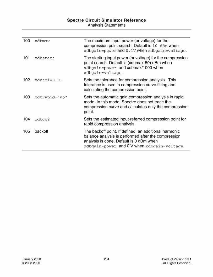
Spectre Circuit Simulator ReferenceAnalysis Statements
January 2020 284 Product Version 19.1© 2003-2020 All Rights Reserved.
100 xdbmax The maximum input power (or voltage) for the compression point search. Default is 10 dBm when xdbgain=power and 0.1V when xdbgain=voltage.
101 xdbstart The starting input power (or voltage) for the compression point search. Default is (xdbmax-50) dBm when xdbgain=power, and xdbmax/1000 when xdbgain=voltage.
102 xdbtol=0.01 Sets the tolerance for compression analysis. This tolerance is used in compression curve fitting and calculating the compression point.
103 xdbrapid="no" Sets the automatic gain compression analysis in rapid mode. In this mode, Spectre does not trace the compression curve and calculates only the compression point.
104 xdbcpi Sets the estimated input-referred compression point for rapid compression analysis.
105 backoff The backoff point. If defined, an additional harmonic balance analysis is performed after the compression analysis is done. Default is 0 dBm when xdbgain=power, and 0 V when xdbgain=voltage.
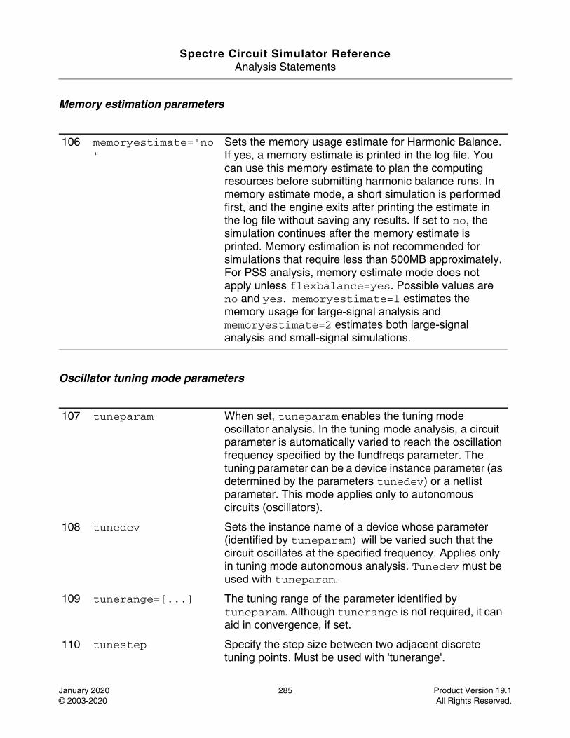
Spectre Circuit Simulator ReferenceAnalysis Statements
January 2020 285 Product Version 19.1© 2003-2020 All Rights Reserved.
Memory estimation parameters
Oscillator tuning mode parameters
106 memoryestimate="no"
Sets the memory usage estimate for Harmonic Balance. If yes, a memory estimate is printed in the log file. You can use this memory estimate to plan the computing resources before submitting harmonic balance runs. In memory estimate mode, a short simulation is performed first, and the engine exits after printing the estimate in the log file without saving any results. If set to no, the simulation continues after the memory estimate is printed. Memory estimation is not recommended for simulations that require less than 500MB approximately. For PSS analysis, memory estimate mode does not apply unless flexbalance=yes. Possible values are no and yes. memoryestimate=1 estimates the memory usage for large-signal analysis and memoryestimate=2 estimates both large-signal analysis and small-signal simulations.
107 tuneparam When set, tuneparam enables the tuning mode oscillator analysis. In the tuning mode analysis, a circuit parameter is automatically varied to reach the oscillation frequency specified by the fundfreqs parameter. The tuning parameter can be a device instance parameter (as determined by the parameters tunedev) or a netlist parameter. This mode applies only to autonomous circuits (oscillators).
108 tunedev Sets the instance name of a device whose parameter (identified by tuneparam) will be varied such that the circuit oscillates at the specified frequency. Applies only in tuning mode autonomous analysis. Tunedev must be used with tuneparam.
109 tunerange=[...] The tuning range of the parameter identified by tuneparam. Although tunerange is not required, it can aid in convergence, if set.
110 tunestep Specify the step size between two adjacent discrete tuning points. Must be used with 'tunerange'.
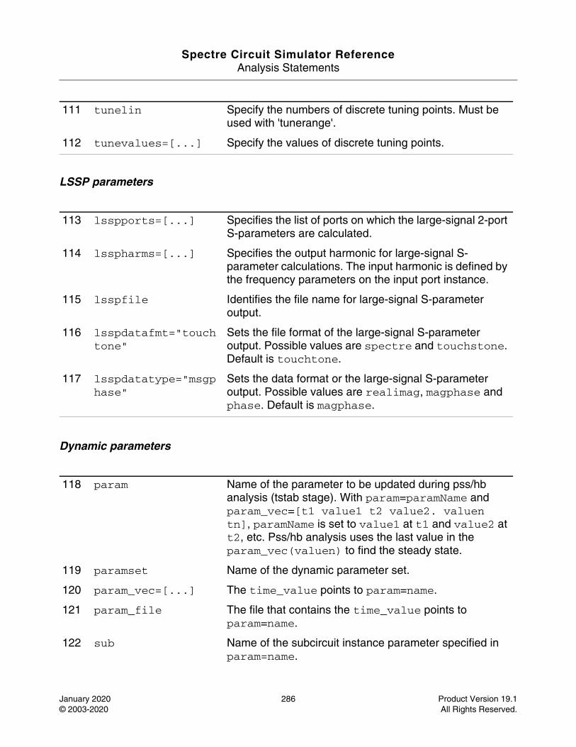
Spectre Circuit Simulator ReferenceAnalysis Statements
January 2020 286 Product Version 19.1© 2003-2020 All Rights Reserved.
LSSP parameters
Dynamic parameters
111 tunelin Specify the numbers of discrete tuning points. Must be used with 'tunerange'.
112 tunevalues=[...] Specify the values of discrete tuning points.
113 lsspports=[...] Specifies the list of ports on which the large-signal 2-port S-parameters are calculated.
114 lsspharms=[...] Specifies the output harmonic for large-signal S-parameter calculations. The input harmonic is defined by the frequency parameters on the input port instance.
115 lsspfile Identifies the file name for large-signal S-parameter output.
116 lsspdatafmt="touchtone"
Sets the file format of the large-signal S-parameter output. Possible values are spectre and touchstone. Default is touchtone.
117 lsspdatatype="msgphase"
Sets the data format or the large-signal S-parameter output. Possible values are realimag, magphase and phase. Default is magphase.
118 param Name of the parameter to be updated during pss/hb analysis (tstab stage). With param=paramName and param_vec=[t1 value1 t2 value2. valuen tn], paramName is set to value1 at t1 and value2 at t2, etc. Pss/hb analysis uses the last value in the param_vec(valuen) to find the steady state.
119 paramset Name of the dynamic parameter set.
120 param_vec=[...] The time_value points to param=name.
121 param_file The file that contains the time_value points to param=name.
122 sub Name of the subcircuit instance parameter specified in param=name.
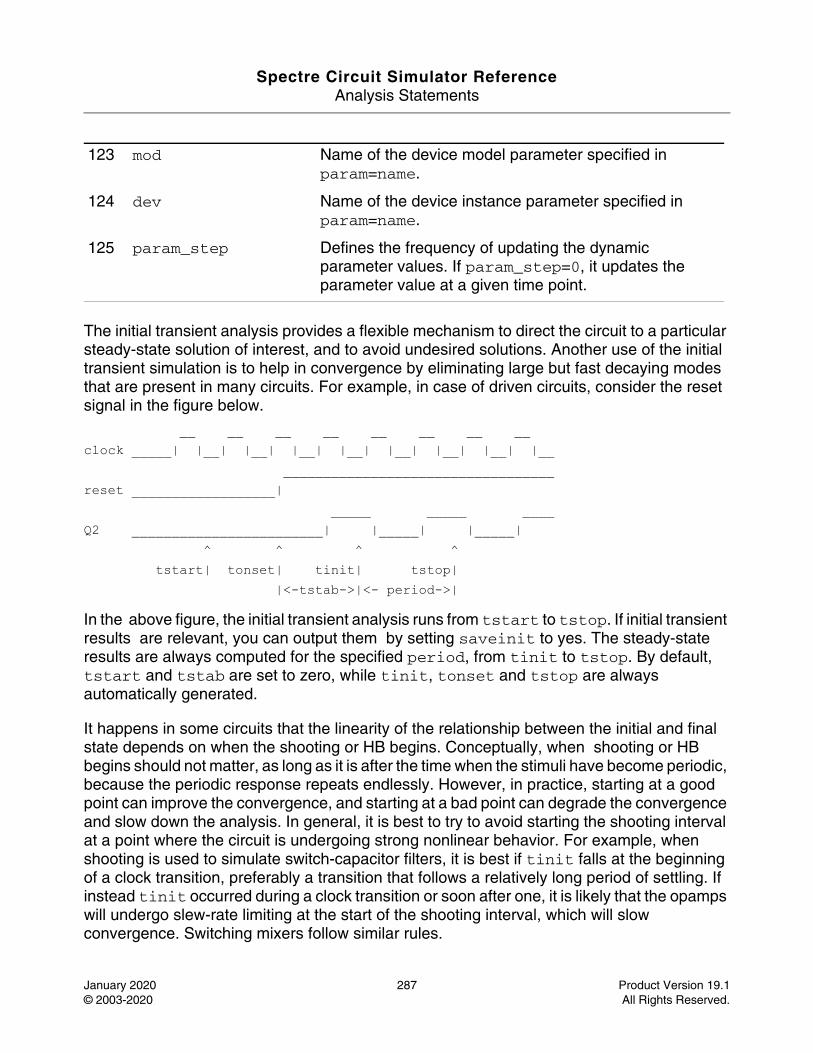
Spectre Circuit Simulator ReferenceAnalysis Statements
January 2020 287 Product Version 19.1© 2003-2020 All Rights Reserved.
The initial transient analysis provides a flexible mechanism to direct the circuit to a particular steady-state solution of interest, and to avoid undesired solutions. Another use of the initial transient simulation is to help in convergence by eliminating large but fast decaying modes that are present in many circuits. For example, in case of driven circuits, consider the reset signal in the figure below.
__ __ __ __ __ __ __ __clock _____| |__| |__| |__| |__| |__| |__| |__| |__ __________________________________reset __________________| _____ _____ ____Q2 ________________________| |_____| |_____| ^ ^ ^ ^ tstart| tonset| tinit| tstop| |<-tstab->|<- period->|
In the above figure, the initial transient analysis runs from tstart to tstop. If initial transient results are relevant, you can output them by setting saveinit to yes. The steady-state results are always computed for the specified period, from tinit to tstop. By default, tstart and tstab are set to zero, while tinit, tonset and tstop are always automatically generated.
It happens in some circuits that the linearity of the relationship between the initial and final state depends on when the shooting or HB begins. Conceptually, when shooting or HB begins should not matter, as long as it is after the time when the stimuli have become periodic, because the periodic response repeats endlessly. However, in practice, starting at a good point can improve the convergence, and starting at a bad point can degrade the convergence and slow down the analysis. In general, it is best to try to avoid starting the shooting interval at a point where the circuit is undergoing strong nonlinear behavior. For example, when shooting is used to simulate switch-capacitor filters, it is best if tinit falls at the beginning of a clock transition, preferably a transition that follows a relatively long period of settling. If instead tinit occurred during a clock transition or soon after one, it is likely that the opamps will undergo slew-rate limiting at the start of the shooting interval, which will slow convergence. Switching mixers follow similar rules.
123 mod Name of the device model parameter specified in param=name.
124 dev Name of the device instance parameter specified in param=name.
125 param_step Defines the frequency of updating the dynamic parameter values. If param_step=0, it updates the parameter value at a given time point.
Spectre Circuit Simulator ReferenceAnalysis Statements
January 2020 288 Product Version 19.1© 2003-2020 All Rights Reserved.
When PSS analysis simulates oscillators, either transient or linear initialization is performed to obtain an initial guess of the steady-state solution and the oscillating frequency. Two initialization methods are implemented based on transient and linear analysis, respectively. When oscic=default is specified, transients initialization is used and the length of the transient is specified by tstab. It is necessary to start the oscillator by using initial conditions, or by using a brief impulsive stimulus, just as you would if you were simulating the turn-on transient of the oscillator using transient analysis. Initial conditions would be provided for the components of the oscillators’ resonator. If an impulsive stimulus is used, it should be applied so as to couple strongly into the oscillatory mode of the circuit, and poorly into any other long-lasting modes, such as those associated with bias circuitry. The Designers Guide to Spice and Spectre [K. S. Kundert, Kluwer Academic Publishers, 1995] describes techniques for starting oscillators in some depth. When oscic=default is specified, oscic=lin, linear initialization is used. In this method, both oscillation frequency and amplitude are estimated based on linear analysis at DC solution. No impulsive stimulus or initial conditions are needed. Linear initialization is suitable for linear type of oscillators, such as LC and crystal oscillators.
Note: tstab transient is still performed after linear initialization though it can be significantly shortened (or skipped in HB). Either way, specifying a non-zero tstab parameter can improve convergence.
By default, only the time-domain results are computed in shooting. If you specify either harms or harmsvec, or set outputtype to freq or all, the frequency-domain results will also be computed. If frequency-domain results are requested, but the desired harmonics are not specified, its default value is 9. The time-domain output waveform generation can be inhibited by setting outputtype to freq.
The accuracy of the results does not depend on the number of harmonics that are requested, but only on the accuracy parameters, which are set in the same fashion as in the transient analysis. Besides a few new parameters, like steadyratio and maxacfreq, all the others parameters work in PSS analysis in the same manner as they work on transient analysis. For HB, besides reltol, abstol, steadyratio and lteratio, the number of harmonics has the most impact on the accuracy of simulation results. When too few harmonics are used, an error occurs due to the aliasing effect. To obtain accurate results, harms should be big enough to cover the signal bandwidth.
Several parameters determine the accuracy of the PSS analysis. reltol and abstol control the accuracy of the discretized equation solution. These parameters determine how well charge is conserved and how accurately steady-state or equilibrium points are computed. You can set the integration errors in the computation of the circuit dynamics (such as time constants), relative to reltol and abstol, by setting the lteratio parameter.
For shooting, the steadyratio parameter adjusts the maximum allowed mismatch in node voltages or current branches from the beginning to the end of the steady-state period. For HB,

Spectre Circuit Simulator ReferenceAnalysis Statements
January 2020 289 Product Version 19.1© 2003-2020 All Rights Reserved.
the steadyratio parameter adjusts the maximum allowed error in the node voltages or in the current branches of the steady-state. This value is multiplied by lteratio and reltol to determine the convergence criterion. The relative convergence norm is printed along with the actual mismatch value at the end of each iteration, indicating the progress of the steady-state iteration.
For shooting, the parameter maxperiods controls the maximum number of shooting iterations for PSS analysis. Its default value is set to 20 for driven PSS and 50 for autonomous PSS. For HB, the parameter maxperiods controls the maximum number of HB iterations for both driven and autonomous HB analysis. Its default value is set to 100.
The finitediff parameter allows the use of finite difference (FD) after shooting. Usually this eliminates the above mismatch in node voltages or current branches. It can also refine the grid of time steps. In some cases, numerical error of the linear solver still introduces a mismatch. You can set steadyratio to a smaller value to activate a tighter tolerance for the iterative linear solver. If finitediff is set to no, FD method is turned off. If it is set to yes, PSS applies FD method and tries to improve the beginning small time steps, if necessary. If it is set to refine, PSS applies FD method and tries to refine the time steps. When the simulation uses second-order method, uniform second order gear is used. finitediff is automatically changed from no to yes when readpss and writepss are specified to re-use PSS results.
The maxacfreq parameter is used to automatically adjust the maxstep and reduce errors due to aliasing in frequency-domain results. By default, the maxacfreq is set to four times the frequency of the largest requested harmonic, but is never set to less than forty times the fundamental.
The parameter relref determines how the relative error is treated. The relref values are as follows:
■ relref=pointlocal: Compares the relative errors in quantities at each node to that node alone.
■ relref=alllocal: Compares the relative errors at each node to the largest values found for that node alone for all past time.
■ relref=sigglobal: Compares relative errors in each circuit signal to the maximum for all signals at any previous point in time.
■ relref=allglobal: Same as relref=sigglobal, except that it also compares the residues (KCL error) for each node to the maximum of each node’s past history.
The errpreset parameter lets you adjust the simulator parameters to fit your needs quickly. In most cases, it should also be the only parameter you need to adjust.
Guidelines for using errpreset in driven circuits in shooting are as follows:
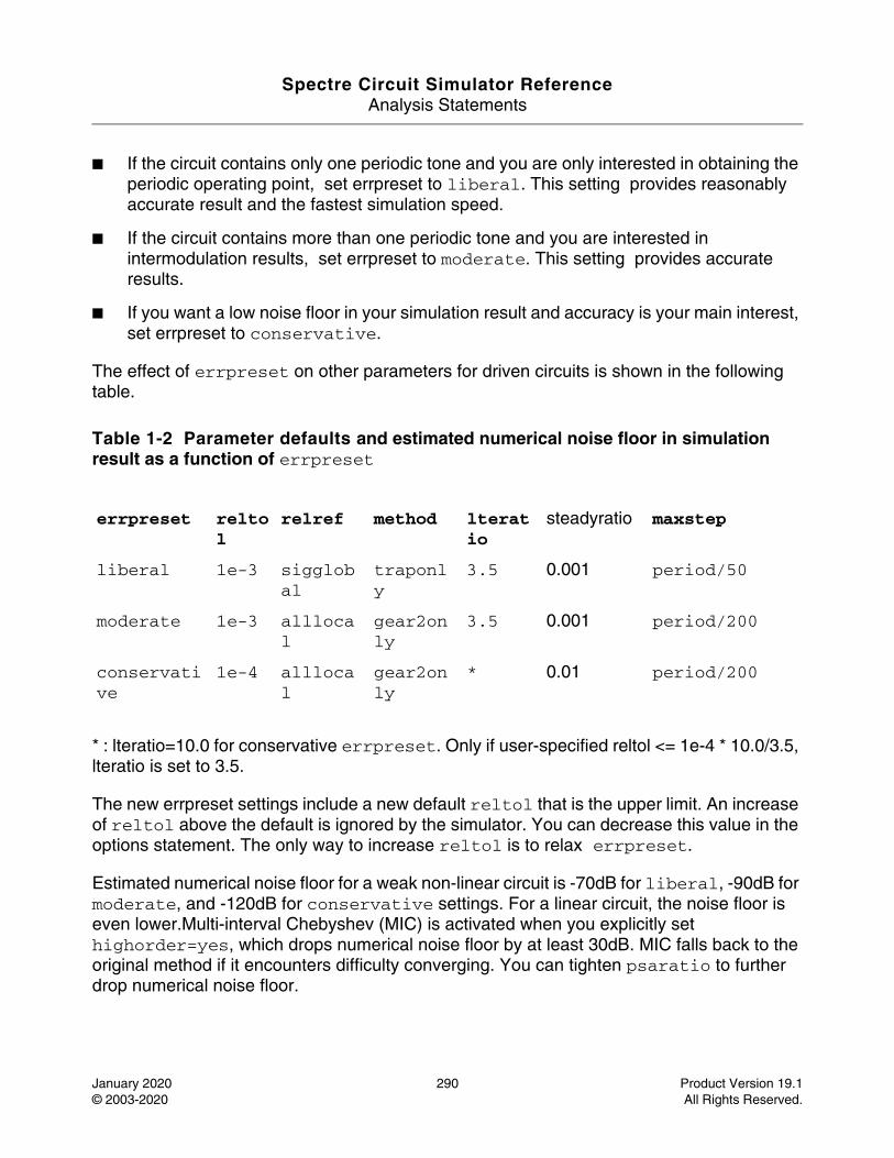
Spectre Circuit Simulator ReferenceAnalysis Statements
January 2020 290 Product Version 19.1© 2003-2020 All Rights Reserved.
■ If the circuit contains only one periodic tone and you are only interested in obtaining the periodic operating point, set errpreset to liberal. This setting provides reasonably accurate result and the fastest simulation speed.
■ If the circuit contains more than one periodic tone and you are interested in intermodulation results, set errpreset to moderate. This setting provides accurate results.
■ If you want a low noise floor in your simulation result and accuracy is your main interest, set errpreset to conservative.
The effect of errpreset on other parameters for driven circuits is shown in the following table.
Table 1-2 Parameter defaults and estimated numerical noise floor in simulation result as a function of errpreset
* : lteratio=10.0 for conservative errpreset. Only if user-specified reltol <= 1e-4 * 10.0/3.5, lteratio is set to 3.5.
The new errpreset settings include a new default reltol that is the upper limit. An increase of reltol above the default is ignored by the simulator. You can decrease this value in the options statement. The only way to increase reltol is to relax errpreset.
Estimated numerical noise floor for a weak non-linear circuit is -70dB for liberal, -90dB for moderate, and -120dB for conservative settings. For a linear circuit, the noise floor is even lower.Multi-interval Chebyshev (MIC) is activated when you explicitly set highorder=yes, which drops numerical noise floor by at least 30dB. MIC falls back to the original method if it encounters difficulty converging. You can tighten psaratio to further drop numerical noise floor.
errpreset reltol
relref method lteratio
steadyratio maxstep
liberal 1e-3 sigglobal
traponly
3.5 0.001 period/50
moderate 1e-3 alllocal
gear2only
3.5 0.001 period/200
conservative
1e-4 alllocal
gear2only
* 0.01 period/200
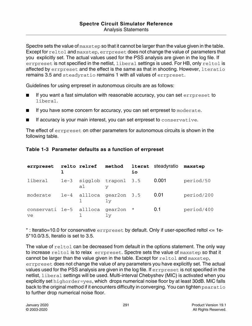
Spectre Circuit Simulator ReferenceAnalysis Statements
January 2020 291 Product Version 19.1© 2003-2020 All Rights Reserved.
Spectre sets the value of maxstep so that it cannot be larger than the value given in the table. Except for reltol and maxstep, errpreset does not change the value of parameters that you explicitly set. The actual values used for the PSS analysis are given in the log file. If errpreset is not specified in the netlist, liberal settings is used. For HB, only reltol is affected by errpreset and the effect is the same as that in shooting. However, lteratio remains 3.5 and steadyratio remains 1 with all values of errpreset.
Guidelines for using errpreset in autonomous circuits are as follows:
■ If you want a fast simulation with reasonable accuracy, you can set errpreset to liberal.
■ If you have some concern for accuracy, you can set errpreset to moderate.
■ If accuracy is your main interest, you can set errpreset to conservative.
The effect of errpreset on other parameters for autonomous circuits is shown in the following table.
Table 1-3 Parameter defaults as a function of errpreset
* : lteratio=10.0 for conservative errpreset by default. Only if user-specified reltol <= 1e-5*10.0/3.5, lteratio is set to 3.5.
The value of reltol can be decreased from default in the options statement. The only way to increase reltol is to relax errpreset. Spectre sets the value of maxstep so that it cannot be larger than the value given in the table. Except for reltol and maxstep, errpreset does not change the value of any parameters you have explicitly set. The actual values used for the PSS analysis are given in the log file. If errpreset is not specified in the netlist, liberal settings will be used. Multi-interval Chebyshev (MIC) is activated when you explicitly set highorder=yes, which drops numerical noise floor by at least 30dB. MIC falls back to the original method if it encounters difficulty in converging. You can tighten psaratio to further drop numerical noise floor.
errpreset reltol
relref method lteratio
steadyratio maxstep
liberal 1e-3 sigglobal
traponly
3.5 0.001 period/50
moderate 1e-4 alllocal
gear2only
3.5 0.01 period/200
conservative
1e-5 alllocal
gear2only
* 0.1 period/400
Spectre Circuit Simulator ReferenceAnalysis Statements
January 2020 292 Product Version 19.1© 2003-2020 All Rights Reserved.
A long stabilization (by specifying a large tstab) can help with PSS convergence. However, it can slow down simulation. By default, in the stabilization stage, the following settings are used: reltol=1e-3, maxstep=period/25, relref=sigglobal, and method=traponly. These settings are overwritten when maxstep, relref, or tstabmethod are specified explicitly in pss statement, or reltol is specified explicitly in options statement.
If the circuit you are simulating has infinitely fast transitions (for example, a circuit that contains nodes with no capacitance), Spectre might have convergence problems. To avoid this, you must prevent the circuit from responding instantaneously. You can accomplish this by setting cmin, the minimum capacitance to ground at each node, to a physically reasonable nonzero value. This often significantly improves Spectre convergence.
You can specify the initial condition for the transient analysis by using the ic statement or the ic parameter on the capacitors and inductors. If you do not specify the initial condition, the DC solution is used as the initial condition. The ic parameter on the transient analysis controls the interaction of various methods of setting the initial conditions. The effects of individual settings are as follows:
■ ic=dc: All initial conditions are ignored, and the DC solution is used.
■ ic=node: The ic statements are used, and the ic parameter on the capacitors and inductors is ignored.
■ ic=dev: The ic parameters on the capacitors and inductors are used, and the ic statements are ignored.
■ ic=all: Both ic statements and ic parameters are used, and the ic parameters override the ic statements.
If you specify an initial condition file with the readic parameter, initial conditions from the file are used, and any ic statements are ignored.
After you specify the initial conditions, Spectre computes the actual initial state of the circuit by performing a DC analysis. During this analysis, Spectre forces the initial conditions on nodes by using a voltage source in series with a resistor whose resistance is rforce (see options).
With the ic statement, it is possible to specify an inconsistent initial condition (one that cannot be sustained by the reactive elements). Examples of inconsistent initial conditions include setting the voltage on a node with no path of capacitors to ground, or setting the current through a branch that is not an inductor. If you initialize Spectre inconsistently, its solution jumps, that is, it changes instantly at the beginning of the simulation interval. You should avoid such changes because Spectre can have convergence problems while trying to make the jump.
Spectre Circuit Simulator ReferenceAnalysis Statements
January 2020 293 Product Version 19.1© 2003-2020 All Rights Reserved.
You can skip DC analysis entirely by using the parameter skipdc. If DC analysis is skipped, the initial solution is trivial or is given in the file that you specified by using the readic parameter, or if the readic parameter is not specified, by the values specified on the ic statements. Device-based initial conditions are not used for skipdc. Nodes that you do not specify with the ic file or ic statements start at zero. You should not use this parameter unless you are generating a nodeset file for circuits that have trouble in the DC solution; it usually takes longer to follow the initial transient spikes that occur when the DC analysis is skipped than it takes to find the real DC solution. The skipdc parameter might also cause convergence problems in the transient analysis.
The possible settings of parameter skipdc and their meanings are as follows:
skipdc=no: Initial solution is calculated using normal DC analysis (default).
skipdc=yes: Initial solution is given in the file specified by the readic parameter or the values specified on the ic statements.
skipdc=sigrampup: Independent source values start at 0 and ramp up to their initial values in the first phase of the simulation. The waveform production in the time-varying independent source is enabled after the rampup phase. The rampup simulation is from tstart to time=0 s, and the main simulation is from time=0 s to tstab. If the tstart parameter is not specified, the default tstart time is set to -0.1*tstab.
Nodesets help find the DC or the initial transient solution. You can specify nodesets in the circuit description file with nodeset statements or in a separate file by using the readns parameter. When nodesets are specified, Spectre computes an initial guess of the solution by performing a DC analysis, while forcing the specified values on to nodes by using a voltage source in series with a resistor whose resistance is rforce. Spectre then removes these voltage sources and resistors and computes the required solution from this initial guess.
Nodesets have two important uses. First, if a circuit has two or more solutions, nodesets can bias the simulator towards computing the required solution. Second, they are a convergence aid. By estimating the solution of the largest possible number of nodes, you might be able to eliminate a convergence problem or dramatically speed convergence.
When you simulate the same circuit multiple times, it is recommended that you use both write and readns parameters and assign the same file name to both parameters. DC analysis then converges quickly even if the circuit has changed since the last simulation, and the nodeset file is automatically updated.
Nodesets and initial conditions have similar implementation, but produce different effects. Initial conditions define the solution, whereas nodesets only influence it. When you simulate a circuit with a transient analysis, Spectre forms and solves a set of differential equations. Because differential equations have an infinite number of solutions, a complete set of initial conditions must be specified to identify the required solution. Any initial conditions that you
Spectre Circuit Simulator ReferenceAnalysis Statements
January 2020 294 Product Version 19.1© 2003-2020 All Rights Reserved.
do not specify are computed by the simulator to be consistent. The transient waveforms then start from initial conditions. Nodesets are usually used as a convergence aid and do not affect the final results. However, in a circuit with more than one solution, such as a latch, nodesets bias the simulator towards finding the solution closest to the nodeset values.
The method parameter specifies the integration method. The possible settings and their meanings are as follows:
method=euler: Backward-Euler is used exclusively.
method=traponly: Trapezoidal rule is used almost exclusively.
method=trap: Backward-Euler and the trapezoidal rule are used.
method=gear2only: Gear’s second-order backward-difference method is used almost exclusively.
method=gear2: Backward-Euler and second-order Gear are used.
The trapezoidal rule is usually the most efficient when you want high accuracy. This method can exhibit point-to-point ringing, but you can control this by tightening the error tolerances. For this reason, though, if you choose loose tolerances to get a quick answer, the backward-Euler or second-order Gear will probably give better results than the trapezoidal rule. Second-order Gear and backward-Euler can make systems appear more stable than they are. This effect is less pronounced with second-order Gear or when you request high accuracy.
Spectre provides two methods for reducing the number of output data points saved: strobing, based on the simulation time, and skipping time points, which saves only every N’th point.
The parameters strobeperiod and strobedelay control the strobing method. strobeperiod sets the interval between the points that you want to save, and strobedelay sets the offset within the period relative to skipstart. The simulator forces a time step on each point to be saved, so that the data is computed, and not interpolated.
The skipping method is controlled by skipcount. If this is set to N, only every N’th point is saved.
The parameters skipstart and skipstop apply to both data reduction methods. Before skipstart and after skipstop, Spectre saves all computed data.
With parameter hbhomotopy, you can specify harmonic balance homotopy selection methods. The possible values of parameter hbhomotopy and their meanings are as follows:
Spectre Circuit Simulator ReferenceAnalysis Statements
January 2020 295 Product Version 19.1© 2003-2020 All Rights Reserved.
hbhomotopy=tstab: Simulator runs a transient analysis and generates an initial guess for harmonic balance analysis; it is recommended for nonlinear circuits or circuits with frequency dividers.
hbhomotopy=source: For driven circuit, the simulator ignores tstab and accordingly increases the source power level; for oscillators, the simulator accordingly adjusts the probe magnitude until the probe has no effect on the oscillators. It is recommended for strongly nonlinear or high Q circuits
hbhomotopy=tone: This method is valid only for multi-tone circuit. The simulator first solves a single-tone circuit by turning off all the tones, except the first one, and then solves the multi-tone circuit by restoring all the tones and using the single-tone solution as its initial guess; it is recommended for multi-tone simulation with a strong first tone.
hbhomotopy=inctone: Simulator first solves a single tone, then turns on moderate tones incrementally till all tones are enabled. It is recommended for circuits with one strong large tone.
hbhomotopy=gsweep: A resistor, whose conductance is g, is connected with each node, and the sweep of g is controlled by gstart, gstop, and glog. It is recommended for circuits containing high-impedance or quasi-floating nodes.
Parameter Index
In the following index, the number corresponding to each parameter name indicates where to find the description of that parameter:
annotate 76 krylov_size 73 pinnode 59 tstabenvlp 10
annotateic 77 lowmem 75 pinnodemag 62 tstabmethod 40
autofund 3 lsspdatafmt 116 pinnodeminus 60 tstart 9
autoharms 5 lsspdatatype 117 pinnoderank 61 tunedev 108
autosteady 8 lsspfile 115 ppv 88 tunelin 111
autotstab 7 lsspharms 114 psaratio 53 tuneparam 107
backoff 105 lsspports 113 readic 17 tunerange 109
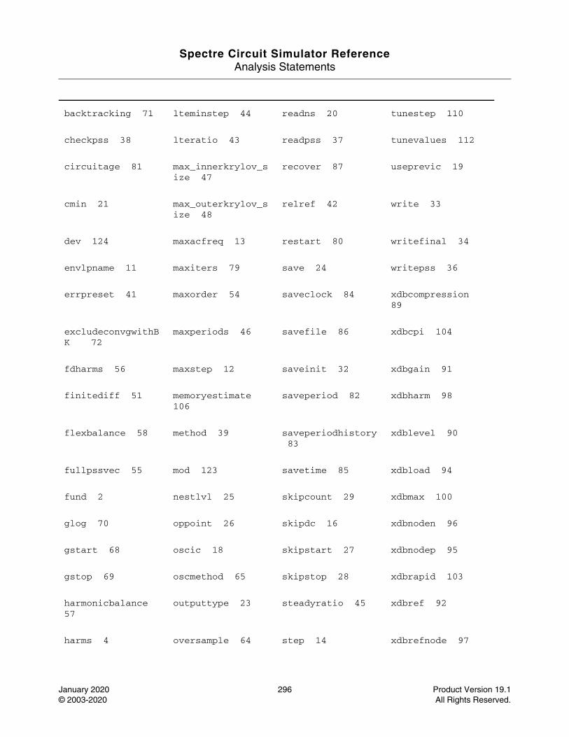
Spectre Circuit Simulator ReferenceAnalysis Statements
January 2020 296 Product Version 19.1© 2003-2020 All Rights Reserved.
backtracking 71 lteminstep 44 readns 20 tunestep 110
checkpss 38 lteratio 43 readpss 37 tunevalues 112
circuitage 81 max_innerkrylov_size 47
recover 87 useprevic 19
cmin 21 max_outerkrylov_size 48
relref 42 write 33
dev 124 maxacfreq 13 restart 80 writefinal 34
envlpname 11 maxiters 79 save 24 writepss 36
errpreset 41 maxorder 54 saveclock 84 xdbcompression 89
excludeconvgwithBK 72
maxperiods 46 savefile 86 xdbcpi 104
fdharms 56 maxstep 12 saveinit 32 xdbgain 91
finitediff 51 memoryestimate 106
saveperiod 82 xdbharm 98
flexbalance 58 method 39 saveperiodhistory 83
xdblevel 90
fullpssvec 55 mod 123 savetime 85 xdbload 94
fund 2 nestlvl 25 skipcount 29 xdbmax 100
glog 70 oppoint 26 skipdc 16 xdbnoden 96
gstart 68 oscic 18 skipstart 27 xdbnodep 95
gstop 69 oscmethod 65 skipstop 28 xdbrapid 103
harmonicbalance 57
outputtype 23 steadyratio 45 xdbref 92
harms 4 oversample 64 step 14 xdbrefnode 97
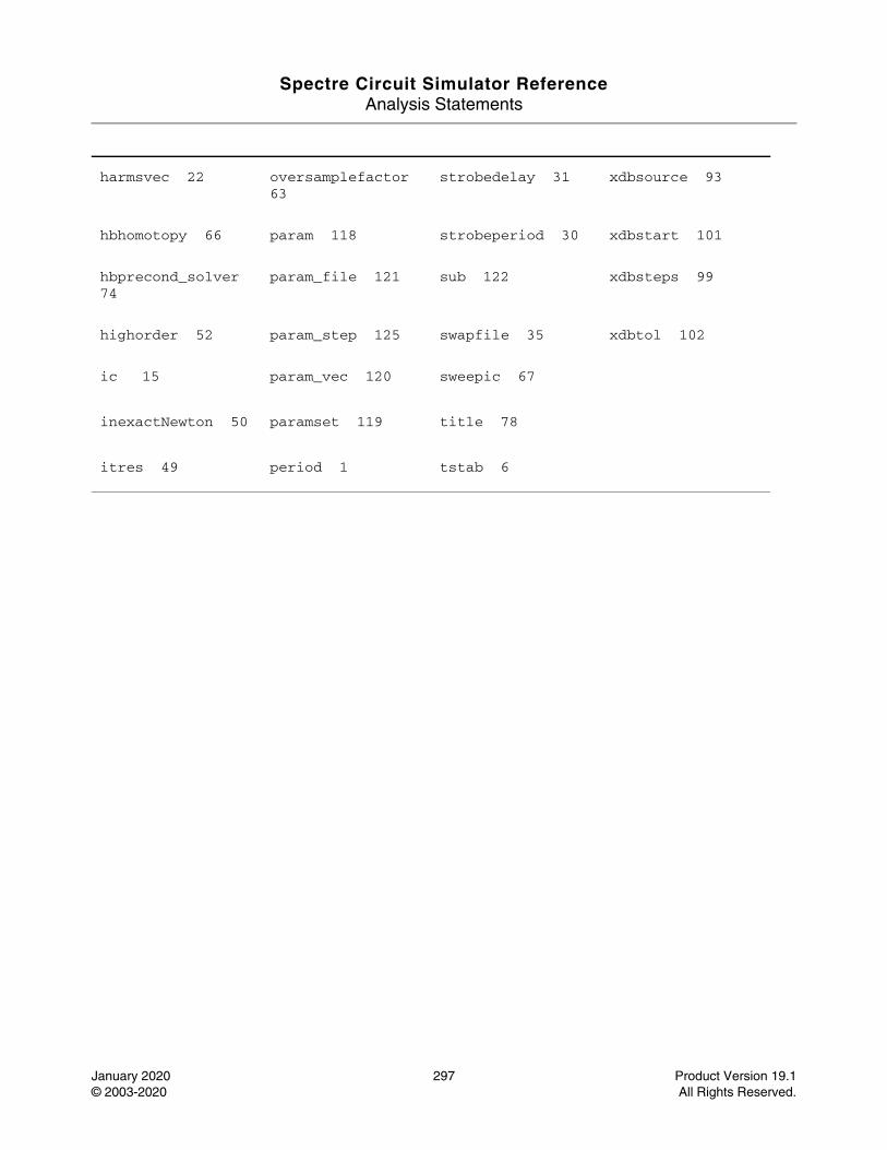
Spectre Circuit Simulator ReferenceAnalysis Statements
January 2020 297 Product Version 19.1© 2003-2020 All Rights Reserved.
harmsvec 22 oversamplefactor 63
strobedelay 31 xdbsource 93
hbhomotopy 66 param 118 strobeperiod 30 xdbstart 101
hbprecond_solver 74
param_file 121 sub 122 xdbsteps 99
highorder 52 param_step 125 swapfile 35 xdbtol 102
ic 15 param_vec 120 sweepic 67
inexactNewton 50 paramset 119 title 78
itres 49 period 1 tstab 6
Spectre Circuit Simulator ReferenceAnalysis Statements
January 2020 298 Product Version 19.1© 2003-2020 All Rights Reserved.
Periodic STB Analysis (pstb)
Description
The periodic STB (PSTB) analysis is used to evaluate the local stability of a periodically varying feedback circuit. It is a small-signal analysis like STB analysis, except that the circuit is first linearized about a periodically varying operating point as opposed to a simple DC operating point. Linearizing about a periodically time-varying operating point allows the stability evaluation to include the effect of the time-varying operating point.
Evaluating the stability of a periodically varying circuit is a two-step process. In the first step, the small stimulus is ignored and PSS analysis is used to compute the periodic steady-state response of the circuit to a possibly large periodic stimulus. As part of the PSS analysis, the periodically time-varying representation of the circuit is computed and saved for later use. In the second step, a probe is used to compute the loop gain of the zero sideband. The local stability can be evaluated using gain margin, phase margin, or a Nyquist plot of the loop gain. To perform PSTB analysis, a probe instance must be specified as probe parameter.
The loop-based algorithm requires that a probe be placed on the feedback loop to identify and characterize the particular loop of interest. The introduction of the probe component should not change any of the circuit characteristics. For the time-varying property of the circuit, the loop gain at different places can be different, but all values can be used to evaluate the stability. The loop-based algorithm provides stability information for single-loop circuits and for multi-loop circuits in which a probe component can be placed on a critical wire to break all loops. For a typical multi-loop circuit, such a critical wire may not be available. The loop-based algorithm can be used only on individual feedback loops to ensure that they are stable.
The device based algorithm requires the probe be a gain instant, such as a bjt transistor or a mos transistor. The device-based algorithm evaluates the loop gain around the probe, which can be involved in multi-loops.
Unlike other analyses in Spectre, this analysis can only sweep frequency.
For information on how to run PSTB analysis from ADE, see Periodic Stability Analysis (PSTB) in the Spectre Circuit Simulator and Accelerated Parallel Simulator RF Analysis User Guide.
DefinitionName pstb parameter=value ...

Spectre Circuit Simulator ReferenceAnalysis Statements
January 2020 299 Product Version 19.1© 2003-2020 All Rights Reserved.
Parameters
Sweep interval parameters
Probe parameters
Output parameters
1 start=0 Start sweep limit.
2 stop Stop sweep limit.
3 center Center of sweep.
4 span=0 Sweep limit span.
5 step Step size, linear sweep.
6 lin=50 Number of steps, linear sweep.
7 dec Points per decade.
8 log=50 Number of steps, log sweep.
9 values=[...] Array of sweep values.
10 valuesfile Name of the file containing the sweep values.
11 probe Probe instance around which the loop gain is calculated.
12 localgnd Node name of local ground. If not specified, the probe is referenced to global ground.
13 save Signals to output. Possible values are all, lvl, allpub, lvlpub, selected, none, and nooutput.
14 nestlvl Levels of subcircuits to output.
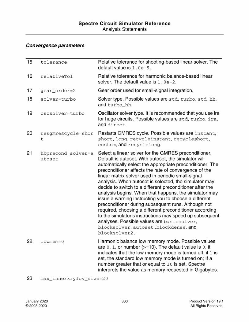
Spectre Circuit Simulator ReferenceAnalysis Statements
January 2020 300 Product Version 19.1© 2003-2020 All Rights Reserved.
Convergence parameters
15 tolerance Relative tolerance for shooting-based linear solver. The default value is 1.0e-9.
16 relativeTol Relative tolerance for harmonic balance-based linear solver. The default value is 1.0e-2.
17 gear_order=2 Gear order used for small-signal integration.
18 solver=turbo Solver type. Possible values are std, turbo, std_hh, and turbo_hh.
19 oscsolver=turbo Oscillator solver type. It is recommended that you use ira for huge circuits. Possible values are std, turbo, ira, and direct.
20 resgmrescycle=short
Restarts GMRES cycle. Possible values are instant, short, long, recycleinstant, recycleshort, custom, and recyclelong.
21 hbprecond_solver=autoset
Select a linear solver for the GMRES preconditioner. Default is autoset. With autoset, the simulator will automatically select the appropriate preconditioner. The preconditioner affects the rate of convergence of the linear matrix solver used in periodic small-signal analysis. When autoset is selected, the simulator may decide to switch to a different preconditioner after the analysis begins. When that happens, the simulator may issue a warning instructing you to choose a different preconditioner during subsequent runs. Although not required, choosing a different preconditioner according to the simulator’s instructions may speed up subsequent analyses. Possible values are basicsolver, blocksolver, autoset ,blockdense, and blocksolver2.
22 lowmem=0 Harmonic balance low memory mode. Possible values are 0, 1, or number (>=10). The default value is 0, it indicates that the low memory mode is turned off; if 1 is set, the standard low memory mode is turned on; If a number greater that or equal to 10 is set, Spectre interprets the value as memory requested in Gigabytes.
23 max_innerkrylov_size=20
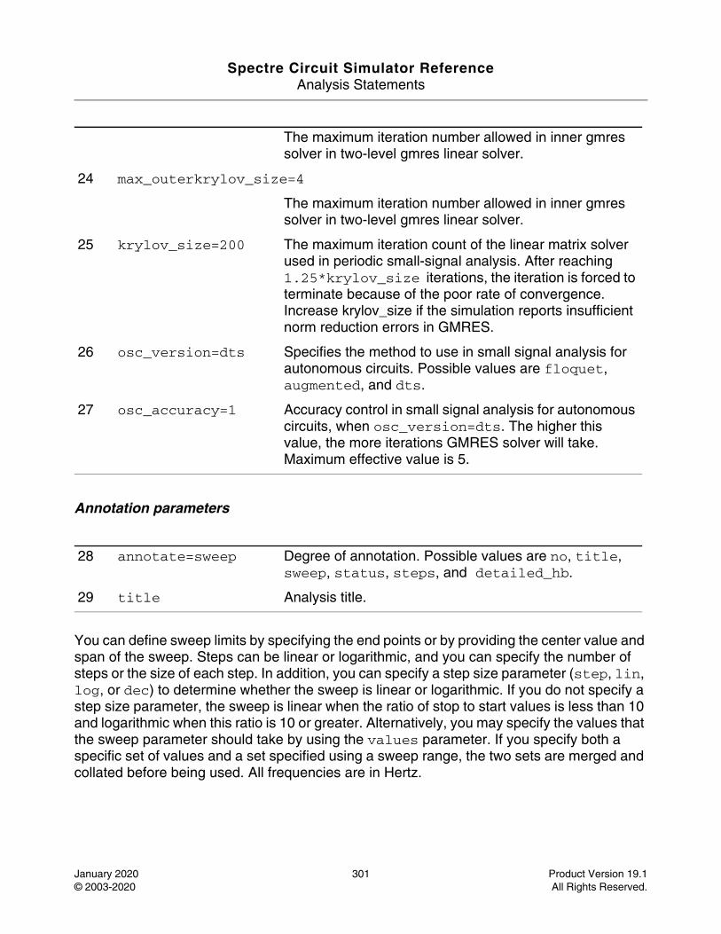
Spectre Circuit Simulator ReferenceAnalysis Statements
January 2020 301 Product Version 19.1© 2003-2020 All Rights Reserved.
Annotation parameters
You can define sweep limits by specifying the end points or by providing the center value and span of the sweep. Steps can be linear or logarithmic, and you can specify the number of steps or the size of each step. In addition, you can specify a step size parameter (step, lin, log, or dec) to determine whether the sweep is linear or logarithmic. If you do not specify a step size parameter, the sweep is linear when the ratio of stop to start values is less than 10 and logarithmic when this ratio is 10 or greater. Alternatively, you may specify the values that the sweep parameter should take by using the values parameter. If you specify both a specific set of values and a set specified using a sweep range, the two sets are merged and collated before being used. All frequencies are in Hertz.
The maximum iteration number allowed in inner gmres solver in two-level gmres linear solver.
24 max_outerkrylov_size=4
The maximum iteration number allowed in inner gmres solver in two-level gmres linear solver.
25 krylov_size=200 The maximum iteration count of the linear matrix solver used in periodic small-signal analysis. After reaching 1.25*krylov_size iterations, the iteration is forced to terminate because of the poor rate of convergence. Increase krylov_size if the simulation reports insufficient norm reduction errors in GMRES.
26 osc_version=dts Specifies the method to use in small signal analysis for autonomous circuits. Possible values are floquet, augmented, and dts.
27 osc_accuracy=1 Accuracy control in small signal analysis for autonomous circuits, when osc_version=dts. The higher this value, the more iterations GMRES solver will take. Maximum effective value is 5.
28 annotate=sweep Degree of annotation. Possible values are no, title, sweep, status, steps, and detailed_hb.
29 title Analysis title.
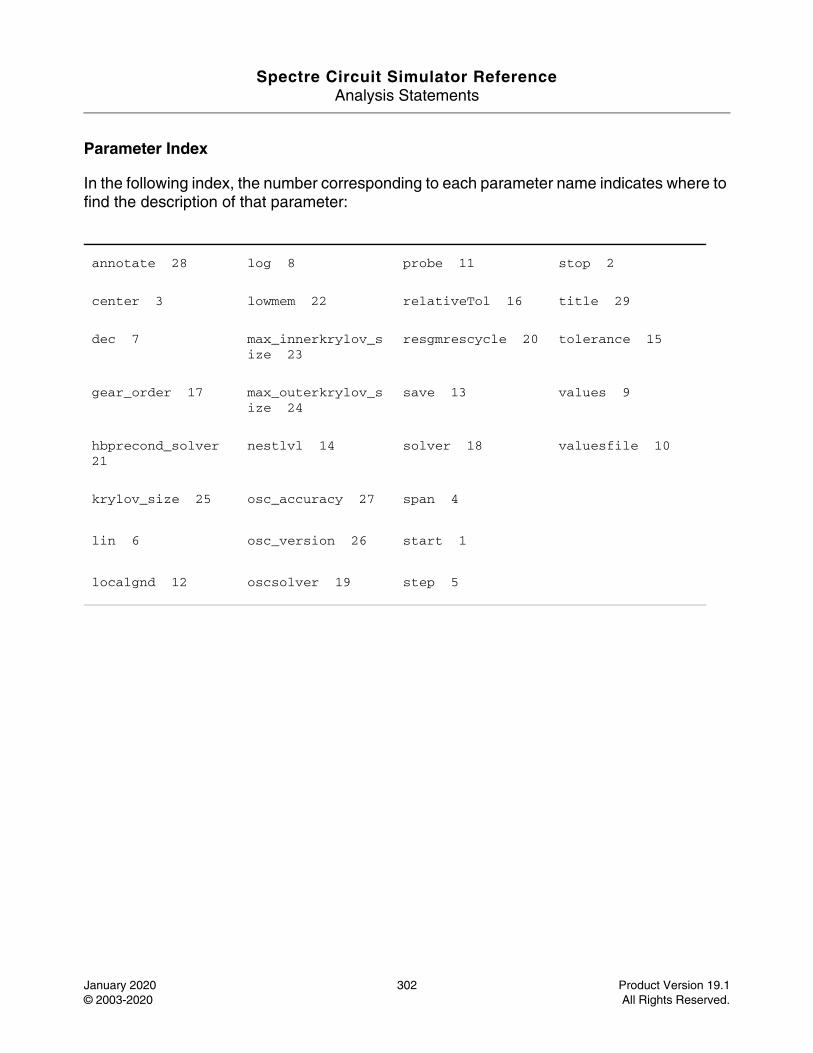
Spectre Circuit Simulator ReferenceAnalysis Statements
January 2020 302 Product Version 19.1© 2003-2020 All Rights Reserved.
Parameter Index
In the following index, the number corresponding to each parameter name indicates where to find the description of that parameter:
annotate 28 log 8 probe 11 stop 2
center 3 lowmem 22 relativeTol 16 title 29
dec 7 max_innerkrylov_size 23
resgmrescycle 20 tolerance 15
gear_order 17 max_outerkrylov_size 24
save 13 values 9
hbprecond_solver 21
nestlvl 14 solver 18 valuesfile 10
krylov_size 25 osc_accuracy 27 span 4
lin 6 osc_version 26 start 1
localgnd 12 oscsolver 19 step 5
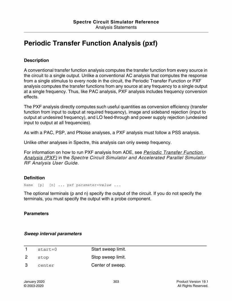
Spectre Circuit Simulator ReferenceAnalysis Statements
January 2020 303 Product Version 19.1© 2003-2020 All Rights Reserved.
Periodic Transfer Function Analysis (pxf)
Description
A conventional transfer function analysis computes the transfer function from every source in the circuit to a single output. Unlike a conventional AC analysis that computes the response from a single stimulus to every node in the circuit, the Periodic Transfer Function or PXF analysis computes the transfer functions from any source at any frequency to a single output at a single frequency. Thus, like PAC analysis, PXF analysis includes frequency conversion effects.
The PXF analysis directly computes such useful quantities as conversion efficiency (transfer function from input to output at required frequency), image and sideband rejection (input to output at undesired frequency), and LO feed-through and power supply rejection (undesired input to output at all frequencies).
As with a PAC, PSP, and PNoise analyses, a PXF analysis must follow a PSS analysis.
Unlike other analyses in Spectre, this analysis can only sweep frequency.
For information on how to run PXF analysis from ADE, see Periodic Transfer Function Analysis (PXF) in the Spectre Circuit Simulator and Accelerated Parallel Simulator RF Analysis User Guide.
DefinitionName [p] [n] ... pxf parameter=value ...
The optional terminals (p and n) specify the output of the circuit. If you do not specify the terminals, you must specify the output with a probe component.
Parameters
Sweep interval parameters
1 start=0 Start sweep limit.
2 stop Stop sweep limit.
3 center Center of sweep.

Spectre Circuit Simulator ReferenceAnalysis Statements
January 2020 304 Product Version 19.1© 2003-2020 All Rights Reserved.
Probe parameters
Sampled analysis parameters
4 span=0 Sweep limit span.
5 step Step size, linear sweep.
6 lin=50 Number of steps, linear sweep.
7 dec Points per decade.
8 log=50 Number of steps, log sweep.
9 values=[...] Array of sweep values.
10 valuesfile Name of the file containing the sweep values.
11 sweeptype=unspecified
Specifies if the sweep frequency range is the absolute frequency of input or if it is relative to the port harmonics. When the unspecified value is used, Spectre RF sweeps using relative when autonomous simulation is performed or when the analysis is PSP; for other cases Spectre RF sweeps the absolute value of the input. Possible values are absolute, relative, and unspecified.
12 relharmnum=1 Harmonic to which relative frequency sweep should be referenced.
13 probe Compute every transfer function to this probe component.
14 ptvtype=timeaveraged
Specifies if the PTV analysis will be traditional or sampled under certain conditions. Possible values are timeaveraged and sampled.
15 sampleprobe The crossing event at this port triggers the sampled small signal computation.
16 thresholdvalue=0 Sampled measurement is done when the signal crosses this value.
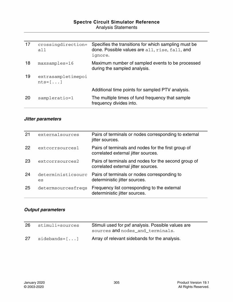
Spectre Circuit Simulator ReferenceAnalysis Statements
January 2020 305 Product Version 19.1© 2003-2020 All Rights Reserved.
Jitter parameters
Output parameters
17 crossingdirection=all
Specifies the transitions for which sampling must be done. Possible values are all, rise, fall, and ignore.
18 maxsamples=16 Maximum number of sampled events to be processed during the sampled analysis.
19 extrasampletimepoints=[...]
Additional time points for sampled PTV analysis.
20 sampleratio=1 The multiple times of fund frequency that sample frequency divides into.
21 externalsources Pairs of terminals or nodes corresponding to external jitter sources.
22 extcorrsources1 Pairs of terminals and nodes for the first group of correlated external jitter sources.
23 extcorrsources2 Pairs of terminals and nodes for the second group of correlated external jitter sources.
24 deterministicsources
Pairs of terminals or nodes corresponding to deterministic jitter sources.
25 determsourcesfreqs Frequency list corresponding to the external deterministic jitter sources.
26 stimuli=sources Stimuli used for pxf analysis. Possible values are sources and nodes_and_terminals.
27 sidebands=[...] Array of relevant sidebands for the analysis.
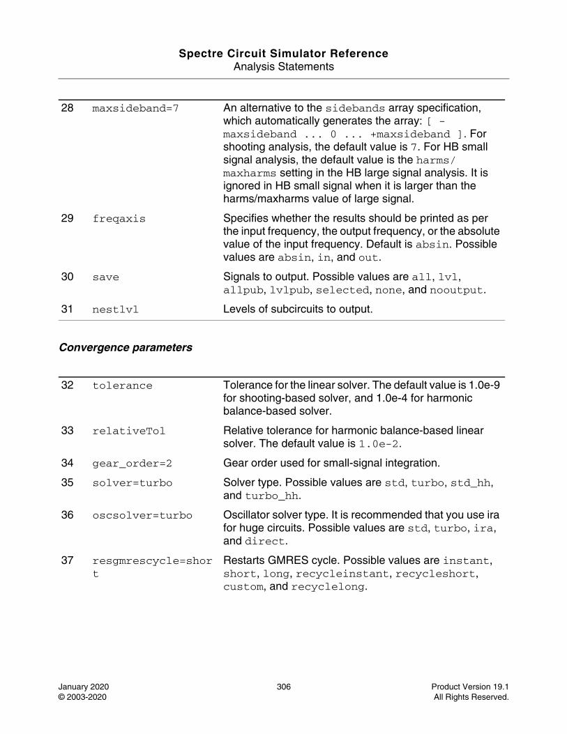
Spectre Circuit Simulator ReferenceAnalysis Statements
January 2020 306 Product Version 19.1© 2003-2020 All Rights Reserved.
Convergence parameters
28 maxsideband=7 An alternative to the sidebands array specification, which automatically generates the array: [ -maxsideband ... 0 ... +maxsideband ]. For shooting analysis, the default value is 7. For HB small signal analysis, the default value is the harms/maxharms setting in the HB large signal analysis. It is ignored in HB small signal when it is larger than the harms/maxharms value of large signal.
29 freqaxis Specifies whether the results should be printed as per the input frequency, the output frequency, or the absolute value of the input frequency. Default is absin. Possible values are absin, in, and out.
30 save Signals to output. Possible values are all, lvl, allpub, lvlpub, selected, none, and nooutput.
31 nestlvl Levels of subcircuits to output.
32 tolerance Tolerance for the linear solver. The default value is 1.0e-9 for shooting-based solver, and 1.0e-4 for harmonic balance-based solver.
33 relativeTol Relative tolerance for harmonic balance-based linear solver. The default value is 1.0e-2.
34 gear_order=2 Gear order used for small-signal integration.
35 solver=turbo Solver type. Possible values are std, turbo, std_hh, and turbo_hh.
36 oscsolver=turbo Oscillator solver type. It is recommended that you use ira for huge circuits. Possible values are std, turbo, ira, and direct.
37 resgmrescycle=short
Restarts GMRES cycle. Possible values are instant, short, long, recycleinstant, recycleshort, custom, and recyclelong.
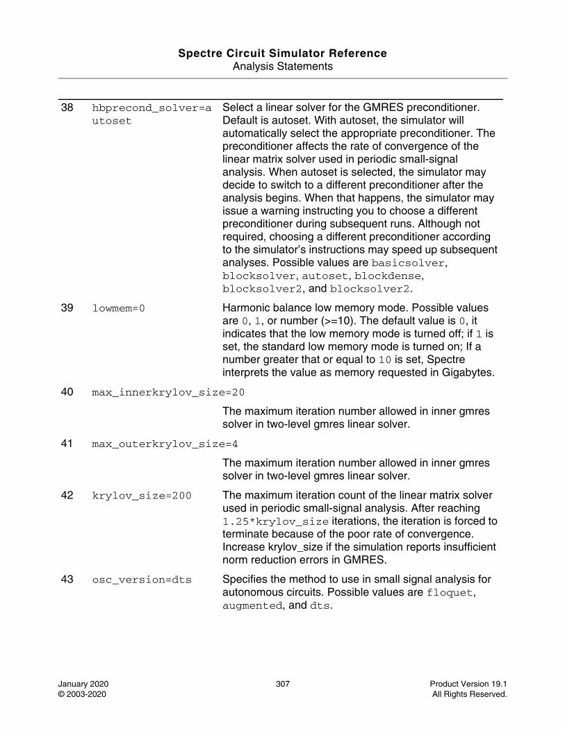
Spectre Circuit Simulator ReferenceAnalysis Statements
January 2020 307 Product Version 19.1© 2003-2020 All Rights Reserved.
38 hbprecond_solver=autoset
Select a linear solver for the GMRES preconditioner. Default is autoset. With autoset, the simulator will automatically select the appropriate preconditioner. The preconditioner affects the rate of convergence of the linear matrix solver used in periodic small-signal analysis. When autoset is selected, the simulator may decide to switch to a different preconditioner after the analysis begins. When that happens, the simulator may issue a warning instructing you to choose a different preconditioner during subsequent runs. Although not required, choosing a different preconditioner according to the simulator’s instructions may speed up subsequent analyses. Possible values are basicsolver, blocksolver, autoset, blockdense, blocksolver2, and blocksolver2.
39 lowmem=0 Harmonic balance low memory mode. Possible values are 0, 1, or number (>=10). The default value is 0, it indicates that the low memory mode is turned off; if 1 is set, the standard low memory mode is turned on; If a number greater that or equal to 10 is set, Spectre interprets the value as memory requested in Gigabytes.
40 max_innerkrylov_size=20
The maximum iteration number allowed in inner gmres solver in two-level gmres linear solver.
41 max_outerkrylov_size=4
The maximum iteration number allowed in inner gmres solver in two-level gmres linear solver.
42 krylov_size=200 The maximum iteration count of the linear matrix solver used in periodic small-signal analysis. After reaching 1.25*krylov_size iterations, the iteration is forced to terminate because of the poor rate of convergence. Increase krylov_size if the simulation reports insufficient norm reduction errors in GMRES.
43 osc_version=dts Specifies the method to use in small signal analysis for autonomous circuits. Possible values are floquet, augmented, and dts.
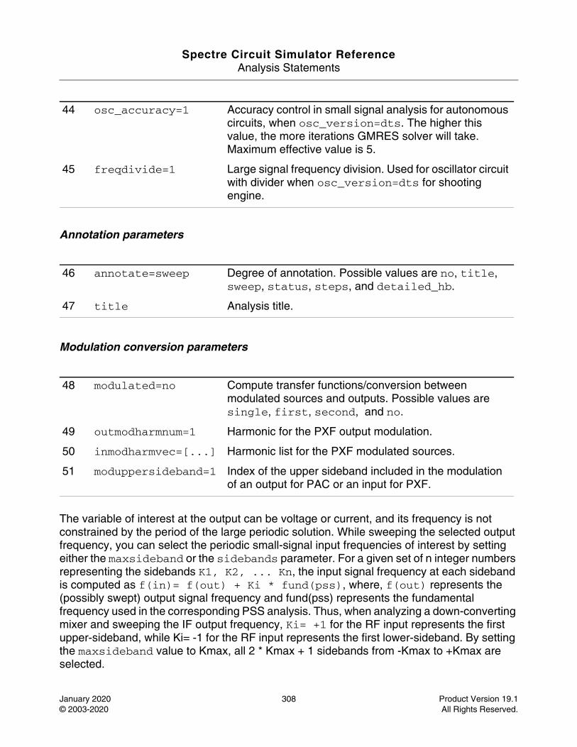
Spectre Circuit Simulator ReferenceAnalysis Statements
January 2020 308 Product Version 19.1© 2003-2020 All Rights Reserved.
Annotation parameters
Modulation conversion parameters
The variable of interest at the output can be voltage or current, and its frequency is not constrained by the period of the large periodic solution. While sweeping the selected output frequency, you can select the periodic small-signal input frequencies of interest by setting either the maxsideband or the sidebands parameter. For a given set of n integer numbers representing the sidebands K1, K2, ... Kn, the input signal frequency at each sideband is computed as f(in)= f(out) + Ki * fund(pss), where, f(out) represents the (possibly swept) output signal frequency and fund(pss) represents the fundamental frequency used in the corresponding PSS analysis. Thus, when analyzing a down-converting mixer and sweeping the IF output frequency, Ki= +1 for the RF input represents the first upper-sideband, while Ki= -1 for the RF input represents the first lower-sideband. By setting the maxsideband value to Kmax, all 2 * Kmax + 1 sidebands from -Kmax to +Kmax are selected.
44 osc_accuracy=1 Accuracy control in small signal analysis for autonomous circuits, when osc_version=dts. The higher this value, the more iterations GMRES solver will take. Maximum effective value is 5.
45 freqdivide=1 Large signal frequency division. Used for oscillator circuit with divider when osc_version=dts for shooting engine.
46 annotate=sweep Degree of annotation. Possible values are no, title, sweep, status, steps, and detailed_hb.
47 title Analysis title.
48 modulated=no Compute transfer functions/conversion between modulated sources and outputs. Possible values are single, first, second, and no.
49 outmodharmnum=1 Harmonic for the PXF output modulation.
50 inmodharmvec=[...] Harmonic list for the PXF modulated sources.
51 moduppersideband=1 Index of the upper sideband included in the modulation of an output for PAC or an input for PXF.
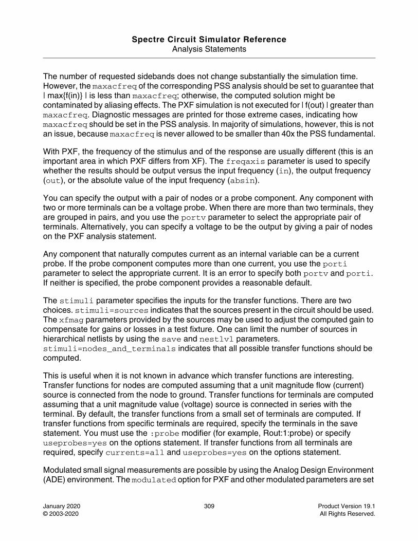
Spectre Circuit Simulator ReferenceAnalysis Statements
January 2020 309 Product Version 19.1© 2003-2020 All Rights Reserved.
The number of requested sidebands does not change substantially the simulation time. However, the maxacfreq of the corresponding PSS analysis should be set to guarantee that | max{f(in)} | is less than maxacfreq; otherwise, the computed solution might be contaminated by aliasing effects. The PXF simulation is not executed for | f(out) | greater than maxacfreq. Diagnostic messages are printed for those extreme cases, indicating how maxacfreq should be set in the PSS analysis. In majority of simulations, however, this is not an issue, because maxacfreq is never allowed to be smaller than 40x the PSS fundamental.
With PXF, the frequency of the stimulus and of the response are usually different (this is an important area in which PXF differs from XF). The freqaxis parameter is used to specify whether the results should be output versus the input frequency (in), the output frequency (out), or the absolute value of the input frequency (absin).
You can specify the output with a pair of nodes or a probe component. Any component with two or more terminals can be a voltage probe. When there are more than two terminals, they are grouped in pairs, and you use the portv parameter to select the appropriate pair of terminals. Alternatively, you can specify a voltage to be the output by giving a pair of nodes on the PXF analysis statement.
Any component that naturally computes current as an internal variable can be a current probe. If the probe component computes more than one current, you use the porti parameter to select the appropriate current. It is an error to specify both portv and porti. If neither is specified, the probe component provides a reasonable default.
The stimuli parameter specifies the inputs for the transfer functions. There are two choices. stimuli=sources indicates that the sources present in the circuit should be used. The xfmag parameters provided by the sources may be used to adjust the computed gain to compensate for gains or losses in a test fixture. One can limit the number of sources in hierarchical netlists by using the save and nestlvl parameters. stimuli=nodes_and_terminals indicates that all possible transfer functions should be computed.
This is useful when it is not known in advance which transfer functions are interesting. Transfer functions for nodes are computed assuming that a unit magnitude flow (current) source is connected from the node to ground. Transfer functions for terminals are computed assuming that a unit magnitude value (voltage) source is connected in series with the terminal. By default, the transfer functions from a small set of terminals are computed. If transfer functions from specific terminals are required, specify the terminals in the save statement. You must use the :probe modifier (for example, Rout:1:probe) or specify useprobes=yes on the options statement. If transfer functions from all terminals are required, specify currents=all and useprobes=yes on the options statement.
Modulated small signal measurements are possible by using the Analog Design Environment (ADE) environment. The modulated option for PXF and other modulated parameters are set
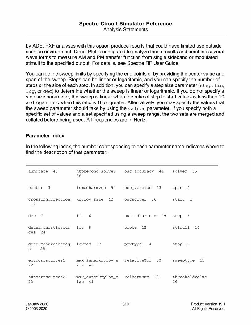
Spectre Circuit Simulator ReferenceAnalysis Statements
January 2020 310 Product Version 19.1© 2003-2020 All Rights Reserved.
by ADE. PXF analyses with this option produce results that could have limited use outside such an environment. Direct Plot is configured to analyze these results and combine several wave forms to measure AM and PM transfer function from single sideband or modulated stimuli to the specified output. For details, see Spectre RF User Guide.
You can define sweep limits by specifying the end points or by providing the center value and span of the sweep. Steps can be linear or logarithmic, and you can specify the number of steps or the size of each step. In addition, you can specify a step size parameter (step, lin, log, or dec) to determine whether the sweep is linear or logarithmic. If you do not specify a step size parameter, the sweep is linear when the ratio of stop to start values is less than 10 and logarithmic when this ratio is 10 or greater. Alternatively, you may specify the values that the sweep parameter should take by using the values parameter. If you specify both a specific set of values and a set specified using a sweep range, the two sets are merged and collated before being used. All frequencies are in Hertz.
Parameter Index
In the following index, the number corresponding to each parameter name indicates where to find the description of that parameter:
annotate 46 hbprecond_solver 38
osc_accuracy 44 solver 35
center 3 inmodharmvec 50 osc_version 43 span 4
crossingdirection 17
krylov_size 42 oscsolver 36 start 1
dec 7 lin 6 outmodharmnum 49 step 5
deterministicsources 24
log 8 probe 13 stimuli 26
determsourcesfreqs 25
lowmem 39 ptvtype 14 stop 2
extcorrsources1 22
max_innerkrylov_size 40
relativeTol 33 sweeptype 11
extcorrsources2 23
max_outerkrylov_size 41
relharmnum 12 thresholdvalue 16
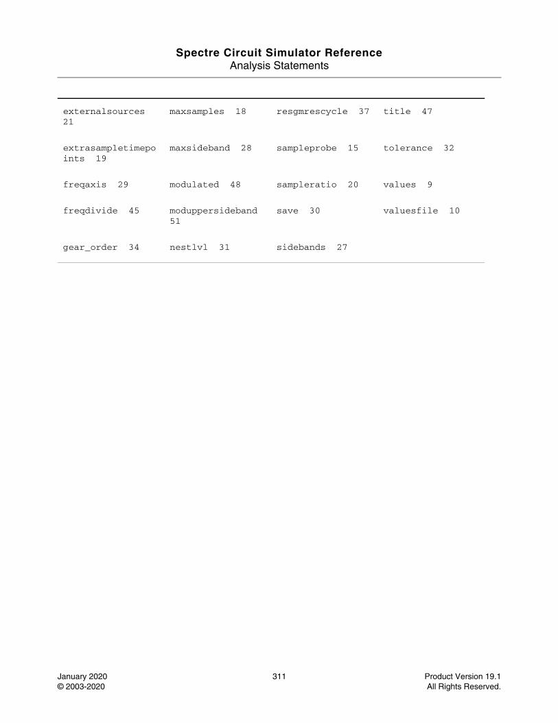
Spectre Circuit Simulator ReferenceAnalysis Statements
January 2020 311 Product Version 19.1© 2003-2020 All Rights Reserved.
externalsources 21
maxsamples 18 resgmrescycle 37 title 47
extrasampletimepoints 19
maxsideband 28 sampleprobe 15 tolerance 32
freqaxis 29 modulated 48 sampleratio 20 values 9
freqdivide 45 moduppersideband 51
save 30 valuesfile 10
gear_order 34 nestlvl 31 sidebands 27
Spectre Circuit Simulator ReferenceAnalysis Statements
January 2020 312 Product Version 19.1© 2003-2020 All Rights Reserved.
PZ Analysis (pz)
Description
The PZ analysis linearizes the circuit about the DC operating point and computes the poles and zeros of the linearized network. To compute zeros, you need to specify input sources and output voltages or currents. If no input or output is given, only poles are computed. If there are frequency-dependent components, poles and zeros are computed by approximating those components as equivalent conductances and capacitances evaluated at 1Hz. The PZ analysis uses the default direct solver (method=qz) for better accuracy. Performance is better on small-to-medium sized circuits. For larger circuits, a Krylov subspace iterative solver (method=arnoldi) can be used for better performance, but, with lesser accuracy.
Note: A frequency-dependent component means that the capacitance or conductance-equivalent representation of the component varies with the frequency. Examples are transmission lines or bjts with excess phases. A linear capacitor is not a frequency-dependent component.
Spectre can perform the analysis while sweeping a parameter. The parameter can be temperature, component instance parameter, component model parameter, or netlist parameter. If changing a parameter affects the DC operating point, the operating point is recomputed at each step. You can sweep the parameter temp or a netlist parameter by specifying the parameter name without a dev or mod parameter. After the analysis is complete, the modified parameter returns to its original value.
Pole-zero cancellation is performed when a neighboring pole-zero pair is located within absdiff distance. The distance is also determined relatively as reldiff times the magnitude of the pole or zero. Spectre uses the larger value of the two distances for cancellation. By default, a lower bound of resistance is enforced. You may remove this limitation by defining the resistor parameter rac. This may affect pz results.
For additional information on pz analysis, see Pole Zero Analysis in the Spectre Circuit Simulator and Accelerated Parallel Simulator User Guide.
DefinitionName ... pz parameter=value ...
Parameters
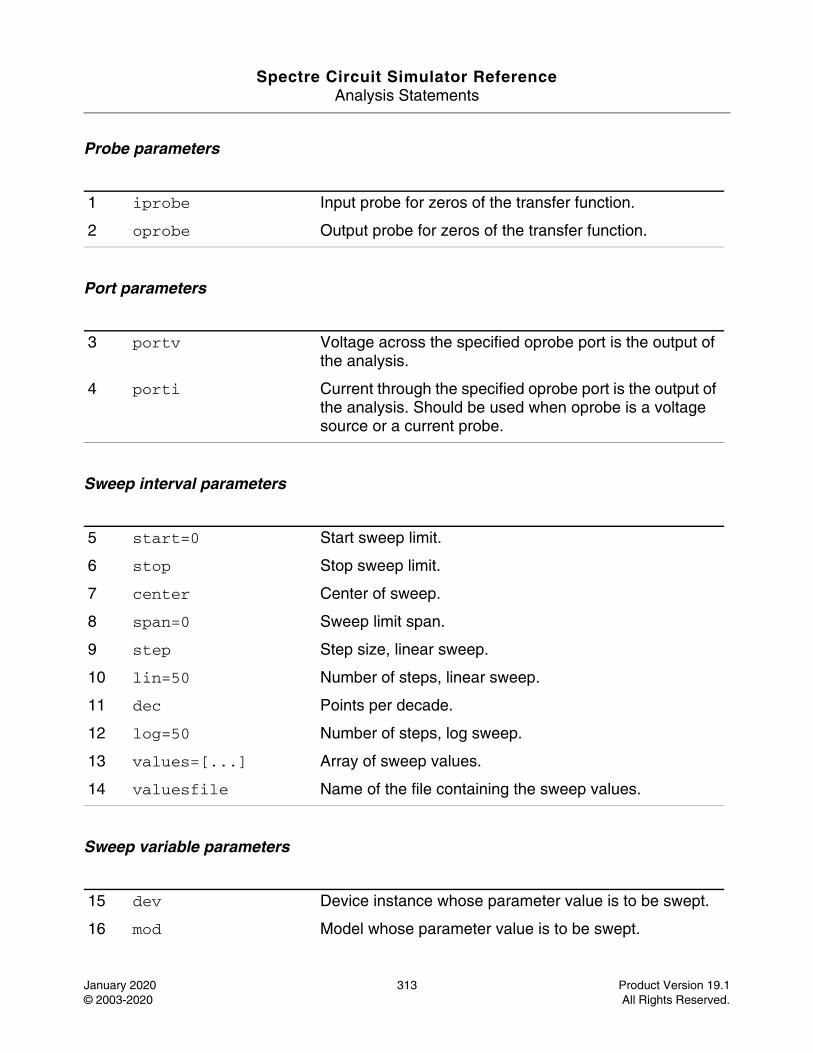
Spectre Circuit Simulator ReferenceAnalysis Statements
January 2020 313 Product Version 19.1© 2003-2020 All Rights Reserved.
Probe parameters
Port parameters
Sweep interval parameters
Sweep variable parameters
1 iprobe Input probe for zeros of the transfer function.
2 oprobe Output probe for zeros of the transfer function.
3 portv Voltage across the specified oprobe port is the output of the analysis.
4 porti Current through the specified oprobe port is the output of the analysis. Should be used when oprobe is a voltage source or a current probe.
5 start=0 Start sweep limit.
6 stop Stop sweep limit.
7 center Center of sweep.
8 span=0 Sweep limit span.
9 step Step size, linear sweep.
10 lin=50 Number of steps, linear sweep.
11 dec Points per decade.
12 log=50 Number of steps, log sweep.
13 values=[...] Array of sweep values.
14 valuesfile Name of the file containing the sweep values.
15 dev Device instance whose parameter value is to be swept.
16 mod Model whose parameter value is to be swept.
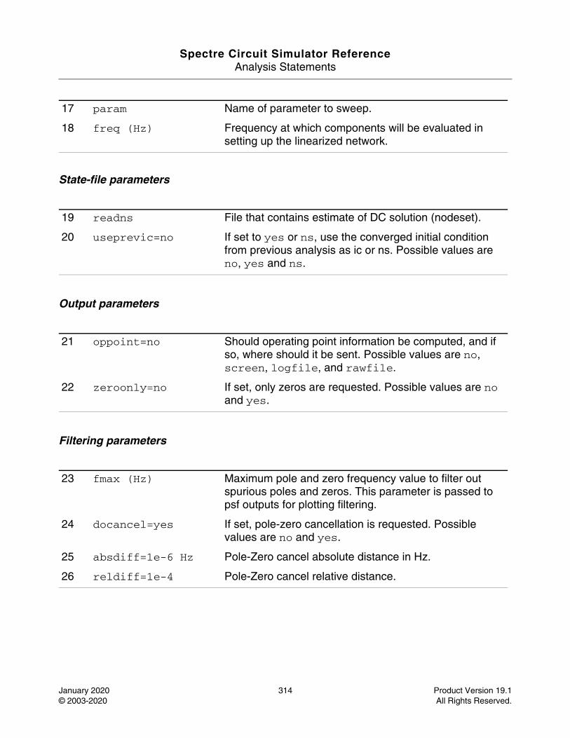
Spectre Circuit Simulator ReferenceAnalysis Statements
January 2020 314 Product Version 19.1© 2003-2020 All Rights Reserved.
State-file parameters
Output parameters
Filtering parameters
17 param Name of parameter to sweep.
18 freq (Hz) Frequency at which components will be evaluated in setting up the linearized network.
19 readns File that contains estimate of DC solution (nodeset).
20 useprevic=no If set to yes or ns, use the converged initial condition from previous analysis as ic or ns. Possible values are no, yes and ns.
21 oppoint=no Should operating point information be computed, and if so, where should it be sent. Possible values are no, screen, logfile, and rawfile.
22 zeroonly=no If set, only zeros are requested. Possible values are no and yes.
23 fmax (Hz) Maximum pole and zero frequency value to filter out spurious poles and zeros. This parameter is passed to psf outputs for plotting filtering.
24 docancel=yes If set, pole-zero cancellation is requested. Possible values are no and yes.
25 absdiff=1e-6 Hz Pole-Zero cancel absolute distance in Hz.
26 reldiff=1e-4 Pole-Zero cancel relative distance.
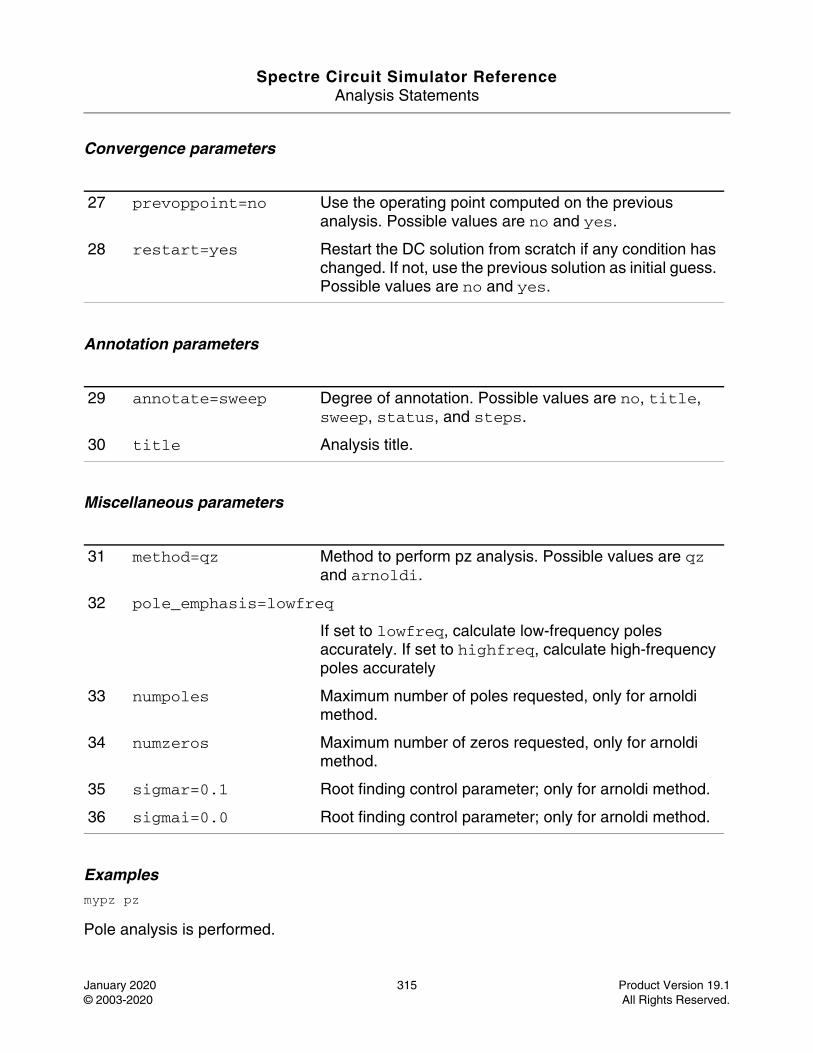
Spectre Circuit Simulator ReferenceAnalysis Statements
January 2020 315 Product Version 19.1© 2003-2020 All Rights Reserved.
Convergence parameters
Annotation parameters
Miscellaneous parameters
Examplesmypz pz
Pole analysis is performed.
27 prevoppoint=no Use the operating point computed on the previous analysis. Possible values are no and yes.
28 restart=yes Restart the DC solution from scratch if any condition has changed. If not, use the previous solution as initial guess. Possible values are no and yes.
29 annotate=sweep Degree of annotation. Possible values are no, title, sweep, status, and steps.
30 title Analysis title.
31 method=qz Method to perform pz analysis. Possible values are qz and arnoldi.
32 pole_emphasis=lowfreq
If set to lowfreq, calculate low-frequency poles accurately. If set to highfreq, calculate high-frequency poles accurately
33 numpoles Maximum number of poles requested, only for arnoldi method.
34 numzeros Maximum number of zeros requested, only for arnoldi method.
35 sigmar=0.1 Root finding control parameter; only for arnoldi method.
36 sigmai=0.0 Root finding control parameter; only for arnoldi method.
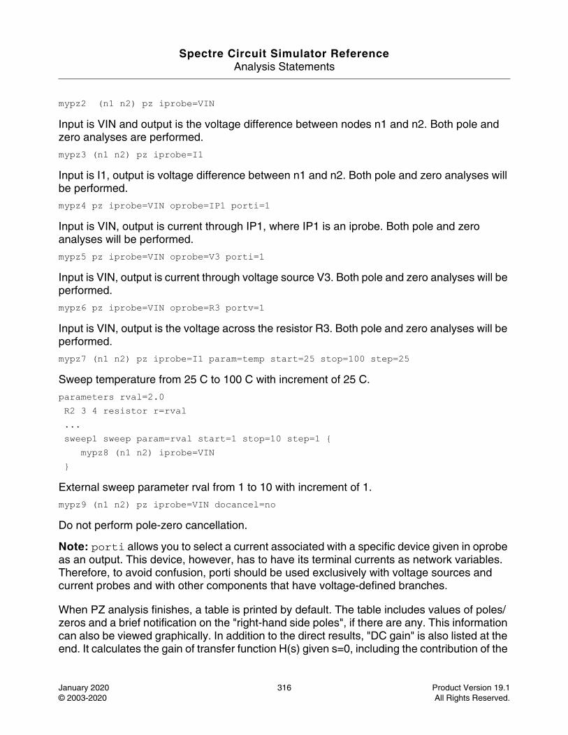
Spectre Circuit Simulator ReferenceAnalysis Statements
January 2020 316 Product Version 19.1© 2003-2020 All Rights Reserved.
mypz2 (n1 n2) pz iprobe=VIN
Input is VIN and output is the voltage difference between nodes n1 and n2. Both pole and zero analyses are performed.
mypz3 (n1 n2) pz iprobe=I1
Input is I1, output is voltage difference between n1 and n2. Both pole and zero analyses will be performed.
mypz4 pz iprobe=VIN oprobe=IP1 porti=1
Input is VIN, output is current through IP1, where IP1 is an iprobe. Both pole and zero analyses will be performed.
mypz5 pz iprobe=VIN oprobe=V3 porti=1
Input is VIN, output is current through voltage source V3. Both pole and zero analyses will be performed.
mypz6 pz iprobe=VIN oprobe=R3 portv=1
Input is VIN, output is the voltage across the resistor R3. Both pole and zero analyses will be performed.
mypz7 (n1 n2) pz iprobe=I1 param=temp start=25 stop=100 step=25
Sweep temperature from 25 C to 100 C with increment of 25 C.
parameters rval=2.0 R2 3 4 resistor r=rval ... sweep1 sweep param=rval start=1 stop=10 step=1 { mypz8 (n1 n2) iprobe=VIN }
External sweep parameter rval from 1 to 10 with increment of 1.
mypz9 (n1 n2) pz iprobe=VIN docancel=no
Do not perform pole-zero cancellation.
Note: porti allows you to select a current associated with a specific device given in oprobe as an output. This device, however, has to have its terminal currents as network variables. Therefore, to avoid confusion, porti should be used exclusively with voltage sources and current probes and with other components that have voltage-defined branches.
When PZ analysis finishes, a table is printed by default. The table includes values of poles/zeros and a brief notification on the "right-hand side poles", if there are any. This information can also be viewed graphically. In addition to the direct results, "DC gain" is also listed at the end. It calculates the gain of transfer function H(s) given s=0, including the contribution of the
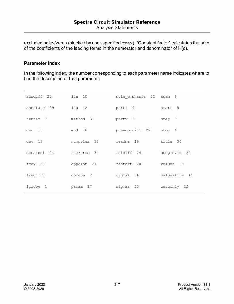
Spectre Circuit Simulator ReferenceAnalysis Statements
January 2020 317 Product Version 19.1© 2003-2020 All Rights Reserved.
excluded poles/zeros (blocked by user-specified fmax). "Constant factor" calculates the ratio of the coefficients of the leading terms in the numerator and denominator of H(s).
Parameter Index
In the following index, the number corresponding to each parameter name indicates where to find the description of that parameter:
absdiff 25 lin 10 pole_emphasis 32 span 8
annotate 29 log 12 porti 4 start 5
center 7 method 31 portv 3 step 9
dec 11 mod 16 prevoppoint 27 stop 6
dev 15 numpoles 33 readns 19 title 30
docancel 24 numzeros 34 reldiff 26 useprevic 20
fmax 23 oppoint 21 restart 28 values 13
freq 18 oprobe 2 sigmai 36 valuesfile 14
iprobe 1 param 17 sigmar 35 zeroonly 22
Spectre Circuit Simulator ReferenceAnalysis Statements
January 2020 318 Product Version 19.1© 2003-2020 All Rights Reserved.
Quasi-Periodic AC Analysis (qpac)
Description
The quasi periodic AC (QPAC) analysis is used to compute transfer functions for circuits that exhibit multitone frequency translation. Such circuits include mixers, switched-capacitor filters, samplers, phase-locked loops, and the like. It is a small-signal analysis like AC analysis, except that the circuit is first linearized about a quasi-periodically varying operating point, as opposed to a simple DC operating point. Linearizing about a quasi-periodically time-varying operating point allows transfer-functions that include frequency translation, whereas linearizing about a DC operating point could not because linear time-invariant circuits do not exhibit frequency translation. In addition, the frequency of the sinusoidal stimulus is not constrained by the period of the large periodic solution.
Computing the small-signal response of a quasi-periodically varying circuit is a two-step process. First, the small stimulus is ignored and the quasi-periodic steady-state response of the circuit to possibly large periodic stimuli is computed using QPSS analysis. As part of the QPSS analysis, the quasi-periodically time-varying representation of the circuit is computed and saved for later use. The second step is to apply the small stimulus to the periodically varying linear representation to compute the small signal response. This is done using the QPAC analysis.
A QPAC analysis cannot be used independently; it must follow a QPSS analysis. However, any number of quasi-periodic small-signal analyses, such as QPAC, QPSP, QPXF, QPNOISE, can follow a QPSS analysis.
For information on how to run QPAC analysis from ADE, see Quasi Periodic AC Analysis (QPAC) in the Spectre Circuit Simulator and Accelerated Parallel Simulator RF Analysis User Guide.
Unlike other analyses in Spectre, this analysis can only sweep frequency.
DefinitionName qpac parameter=value ...
Parameters
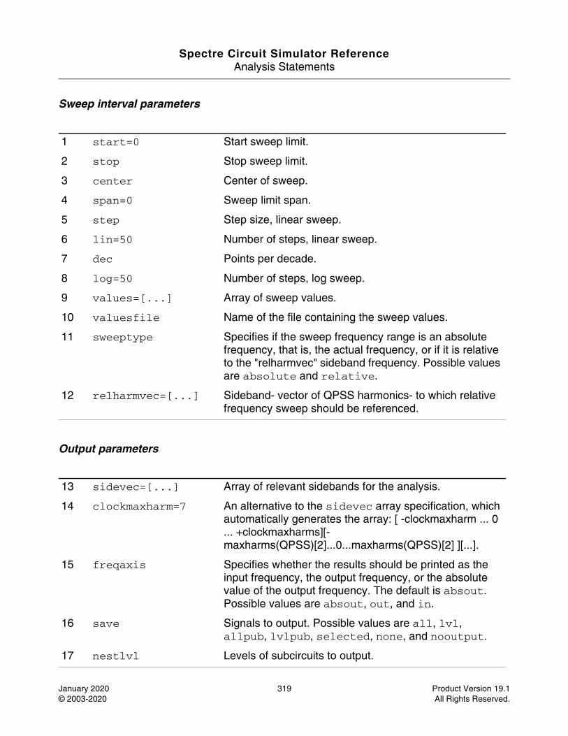
Spectre Circuit Simulator ReferenceAnalysis Statements
January 2020 319 Product Version 19.1© 2003-2020 All Rights Reserved.
Sweep interval parameters
Output parameters
1 start=0 Start sweep limit.
2 stop Stop sweep limit.
3 center Center of sweep.
4 span=0 Sweep limit span.
5 step Step size, linear sweep.
6 lin=50 Number of steps, linear sweep.
7 dec Points per decade.
8 log=50 Number of steps, log sweep.
9 values=[...] Array of sweep values.
10 valuesfile Name of the file containing the sweep values.
11 sweeptype Specifies if the sweep frequency range is an absolute frequency, that is, the actual frequency, or if it is relative to the "relharmvec" sideband frequency. Possible values are absolute and relative.
12 relharmvec=[...] Sideband- vector of QPSS harmonics- to which relative frequency sweep should be referenced.
13 sidevec=[...] Array of relevant sidebands for the analysis.
14 clockmaxharm=7 An alternative to the sidevec array specification, which automatically generates the array: [ -clockmaxharm ... 0 ... +clockmaxharms][-maxharms(QPSS)[2]...0...maxharms(QPSS)[2] ][...].
15 freqaxis Specifies whether the results should be printed as the input frequency, the output frequency, or the absolute value of the output frequency. The default is absout. Possible values are absout, out, and in.
16 save Signals to output. Possible values are all, lvl, allpub, lvlpub, selected, none, and nooutput.
17 nestlvl Levels of subcircuits to output.
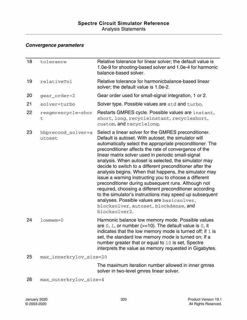
Spectre Circuit Simulator ReferenceAnalysis Statements
January 2020 320 Product Version 19.1© 2003-2020 All Rights Reserved.
Convergence parameters
18 tolerance Relative tolerance for linear solver; the default value is 1.0e-9 for shooting-based solver and 1.0e-4 for harmonic balance-based solver.
19 relativeTol Relative tolerance for harmonicbalance-based linear solver; the default value is 1.0e-2.
20 gear_order=2 Gear order used for small-signal integration, 1 or 2.
21 solver=turbo Solver type. Possible values are std and turbo.
22 resgmrescycle=short
Restarts GMRES cycle. Possible values are instant, short, long, recycleinstant, recycleshort, custom, and recyclelong.
23 hbprecond_solver=autoset
Select a linear solver for the GMRES preconditioner. Default is autoset. With autoset, the simulator will automatically select the appropriate preconditioner. The preconditioner affects the rate of convergence of the linear matrix solver used in periodic small-signal analysis. When autoset is selected, the simulator may decide to switch to a different preconditioner after the analysis begins. When that happens, the simulator may issue a warning instructing you to choose a different preconditioner during subsequent runs. Although not required, choosing a different preconditioner according to the simulator’s instructions may speed up subsequent analyses. Possible values are basicsolver, blocksolver, autoset, blockdense, and blocksolver2.
24 lowmem=0 Harmonic balance low memory mode. Possible values are 0, 1, or number (>=10). The default value is 0, it indicates that the low memory mode is turned off; if 1 is set, the standard low memory mode is turned on; If a number greater that or equal to 10 is set, Spectre interprets the value as memory requested in Gigabytes.
25 max_innerkrylov_size=20
The maximum iteration number allowed in inner gmres solver in two-level gmres linear solver.
26 max_outerkrylov_size=4
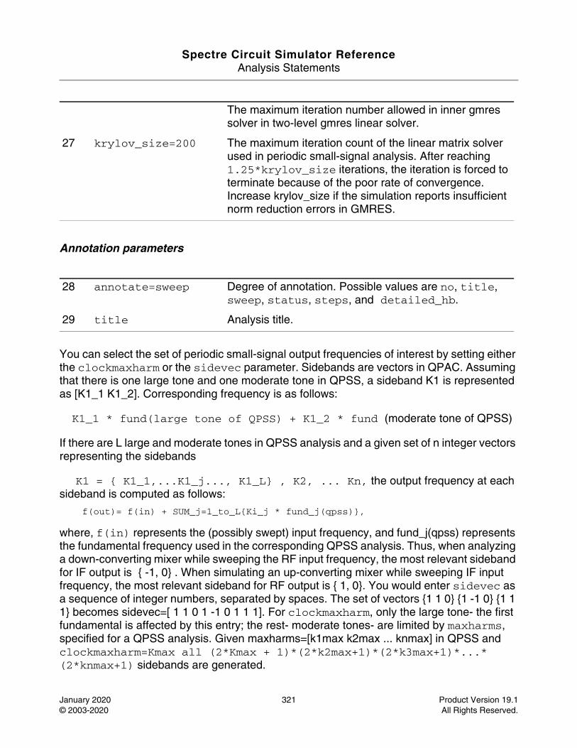
Spectre Circuit Simulator ReferenceAnalysis Statements
January 2020 321 Product Version 19.1© 2003-2020 All Rights Reserved.
Annotation parameters
You can select the set of periodic small-signal output frequencies of interest by setting either the clockmaxharm or the sidevec parameter. Sidebands are vectors in QPAC. Assuming that there is one large tone and one moderate tone in QPSS, a sideband K1 is represented as [K1_1 K1_2]. Corresponding frequency is as follows:
K1_1 * fund(large tone of QPSS) + K1_2 * fund (moderate tone of QPSS)
If there are L large and moderate tones in QPSS analysis and a given set of n integer vectors representing the sidebands
K1 = { K1_1,...K1_j..., K1_L} , K2, ... Kn, the output frequency at each sideband is computed as follows:
f(out)= f(in) + SUM_j=1_to_L{Ki_j * fund_j(qpss)},
where, f(in) represents the (possibly swept) input frequency, and fund_j(qpss) represents the fundamental frequency used in the corresponding QPSS analysis. Thus, when analyzing a down-converting mixer while sweeping the RF input frequency, the most relevant sideband for IF output is { -1, 0} . When simulating an up-converting mixer while sweeping IF input frequency, the most relevant sideband for RF output is { 1, 0}. You would enter sidevec as a sequence of integer numbers, separated by spaces. The set of vectors {1 1 0} {1 -1 0} {1 1 1} becomes sidevec=[ 1 1 0 1 -1 0 1 1 1]. For clockmaxharm, only the large tone- the first fundamental is affected by this entry; the rest- moderate tones- are limited by maxharms, specified for a QPSS analysis. Given maxharms=[k1max k2max ... knmax] in QPSS and clockmaxharm=Kmax all (2*Kmax + 1)*(2*k2max+1)*(2*k3max+1)*...*(2*knmax+1) sidebands are generated.
The maximum iteration number allowed in inner gmres solver in two-level gmres linear solver.
27 krylov_size=200 The maximum iteration count of the linear matrix solver used in periodic small-signal analysis. After reaching 1.25*krylov_size iterations, the iteration is forced to terminate because of the poor rate of convergence. Increase krylov_size if the simulation reports insufficient norm reduction errors in GMRES.
28 annotate=sweep Degree of annotation. Possible values are no, title, sweep, status, steps, and detailed_hb.
29 title Analysis title.
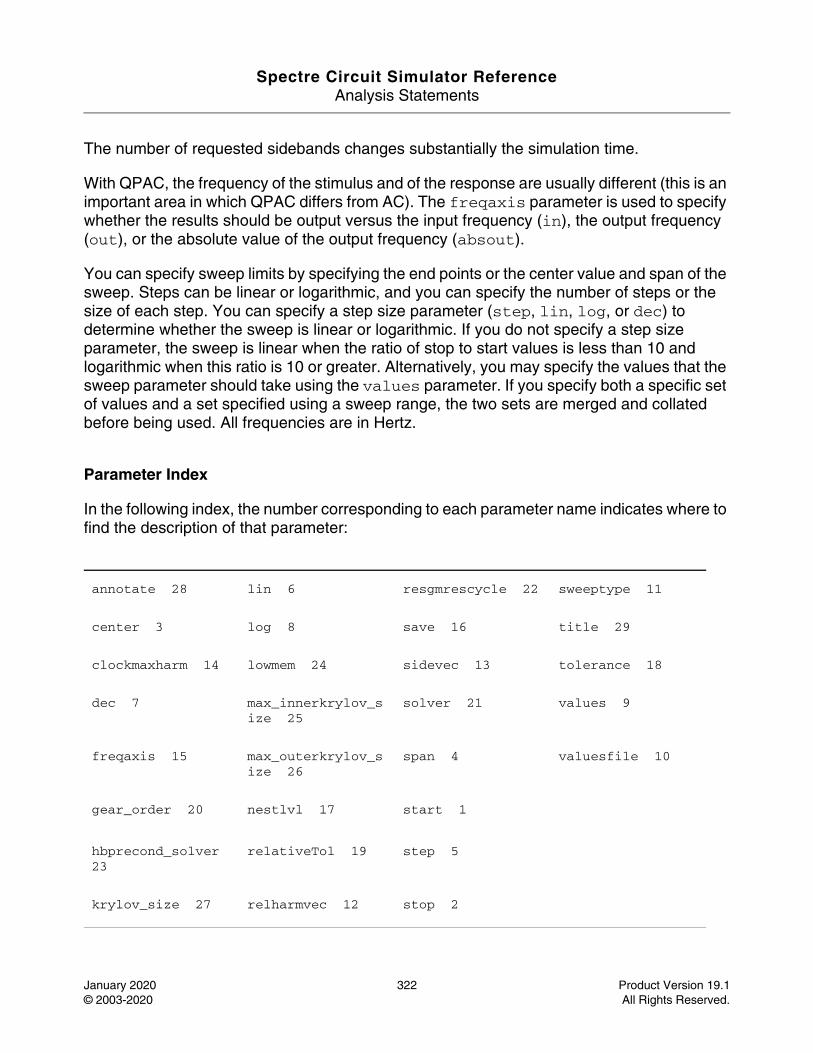
Spectre Circuit Simulator ReferenceAnalysis Statements
January 2020 322 Product Version 19.1© 2003-2020 All Rights Reserved.
The number of requested sidebands changes substantially the simulation time.
With QPAC, the frequency of the stimulus and of the response are usually different (this is an important area in which QPAC differs from AC). The freqaxis parameter is used to specify whether the results should be output versus the input frequency (in), the output frequency (out), or the absolute value of the output frequency (absout).
You can specify sweep limits by specifying the end points or the center value and span of the sweep. Steps can be linear or logarithmic, and you can specify the number of steps or the size of each step. You can specify a step size parameter (step, lin, log, or dec) to determine whether the sweep is linear or logarithmic. If you do not specify a step size parameter, the sweep is linear when the ratio of stop to start values is less than 10 and logarithmic when this ratio is 10 or greater. Alternatively, you may specify the values that the sweep parameter should take using the values parameter. If you specify both a specific set of values and a set specified using a sweep range, the two sets are merged and collated before being used. All frequencies are in Hertz.
Parameter Index
In the following index, the number corresponding to each parameter name indicates where to find the description of that parameter:
annotate 28 lin 6 resgmrescycle 22 sweeptype 11
center 3 log 8 save 16 title 29
clockmaxharm 14 lowmem 24 sidevec 13 tolerance 18
dec 7 max_innerkrylov_size 25
solver 21 values 9
freqaxis 15 max_outerkrylov_size 26
span 4 valuesfile 10
gear_order 20 nestlvl 17 start 1
hbprecond_solver 23
relativeTol 19 step 5
krylov_size 27 relharmvec 12 stop 2
Spectre Circuit Simulator ReferenceAnalysis Statements
January 2020 323 Product Version 19.1© 2003-2020 All Rights Reserved.
Quasi-Periodic Noise Analysis (qpnoise)
Description
The Quasi-Periodic Noise, or QPNOISE analysis is similar to the conventional noise analysis, except that it includes frequency conversion and intermodulation effects. Hence, it is useful for predicting the noise behavior of mixers, switched-capacitor filters, and other periodically or quasi-periodically driven circuits.
QPNOISE analysis linearizes the circuit about the quasi-periodic operating point computed in the prerequisite QPSS analysis. It is the quasi-periodically time-varying nature of the linearized circuit that accounts for the frequency conversion and intermodulation. The effect of a quasi-periodically time-varying bias point on the noise generated by the various components in the circuit is also included.
The time-average of the noise at the output of the circuit is computed in the form of spectral density versus frequency. The output of the circuit is specified with a pair of nodes or a probe component. To specify the output of a circuit with a probe, specify it using the oprobe parameter. If the output is voltage (or potential), choose a resistor or a port as the output probe. If the output is current (or flow), choose a vsource or iprobe as the output probe.
If the input-referred noise is required, specify the input source by using the iprobe parameter. Currently, only a vsource, an isource, or a port may be used as an input probe. If the input source is noisy, as is a port, the noise analysis computes the noise factor (F) and noise figure (NF). To match the IEEE definition of noise figure, the input probe must be a port with no excess noise and its noisetemp must be set to 16.85C (290K). In addition, the output load must be a resistor or port and must be identified as the oprobe.
If port is specified as the input probe, both input-referred noise and gain are referred back to the equivalent voltage source inside the port. S-parameter analysis calculates those values in traditional sense.
The reference sideband (refsideband) specifies which conversion gain is used when computing input-referred noise, noise factor, and noise figure. The reference sideband satisfies:
|f(input)| = |f(out) + refsideband frequency shift|.
The reference sideband option (refsidebandoption) specifies whether to consider the input at the frequency or at the individual quasi-periodic sideband that is specified.
Note: Different sidebands can lead to the same frequency.

Spectre Circuit Simulator ReferenceAnalysis Statements
January 2020 324 Product Version 19.1© 2003-2020 All Rights Reserved.
Sidebands are vectors in QPNOISE. Assuming one large tone and one moderate tone in QPSS, a sideband Ki is a vector [Ki_1 Ki_2]. It gives the frequency at :
Ki_1 * fund(large tone of QPSS) + Ki_2 * fund (moderate tone of QPSS)
Use refsideband=[0 0 ...] when the input and output of the circuit are at the same frequency, such as with amplifiers and filters.
The noise analysis always computes the total noise at the output, which includes contributions from the input source and the output load. The amount of the output noise that is attributable to each noise source in the circuit is also computed and output individually. If the input source is identified (using iprobe) and is a vsource or isource, the input-referred noise is computed, which includes the noise from the input source itself. Finally, if the input source is identified (using iprobe) and is noisy, as is the case with ports, the noise factor and noise figure are computed. Thus, if:
No = total output noise
Ns = noise at the output due to the input probe (the source)
Nsi = noise at the output due to the image harmonic at the source
Nso = noise at the output due to harmonics other than input at the source
Nl = noise at the output due to the output probe (the load)
IRN = input referred noise
G = gain of the circuit
F = noise factor
NF = noise figure
Fdsb = double sideband noise factor
NFdsb = double sideband noise figure
Fieee = IEEE single sideband noise factor
NFieee = IEEE single sideband noise figure
Then:
IRN = sqrt(No^2 / G^2)
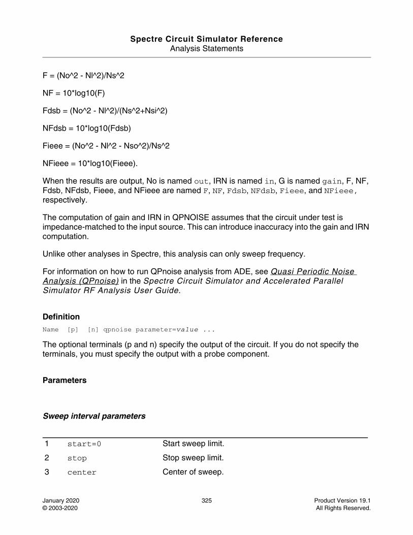
Spectre Circuit Simulator ReferenceAnalysis Statements
January 2020 325 Product Version 19.1© 2003-2020 All Rights Reserved.
F = (No^2 - Nl^2)/Ns^2
NF = 10*log10(F)
Fdsb = (No^2 - Nl^2)/(Ns^2+Nsi^2)
NFdsb = 10*log10(Fdsb)
Fieee = (No^2 - Nl^2 - Nso^2)/Ns^2
NFieee = 10*log10(Fieee).
When the results are output, No is named out, IRN is named in, G is named gain, F, NF, Fdsb, NFdsb, Fieee, and NFieee are named F, NF, Fdsb, NFdsb, Fieee, and NFieee, respectively.
The computation of gain and IRN in QPNOISE assumes that the circuit under test is impedance-matched to the input source. This can introduce inaccuracy into the gain and IRN computation.
Unlike other analyses in Spectre, this analysis can only sweep frequency.
For information on how to run QPnoise analysis from ADE, see Quasi Periodic Noise Analysis (QPnoise) in the Spectre Circuit Simulator and Accelerated Parallel Simulator RF Analysis User Guide.
DefinitionName [p] [n] qpnoise parameter=value ...
The optional terminals (p and n) specify the output of the circuit. If you do not specify the terminals, you must specify the output with a probe component.
Parameters
Sweep interval parameters
1 start=0 Start sweep limit.
2 stop Stop sweep limit.
3 center Center of sweep.
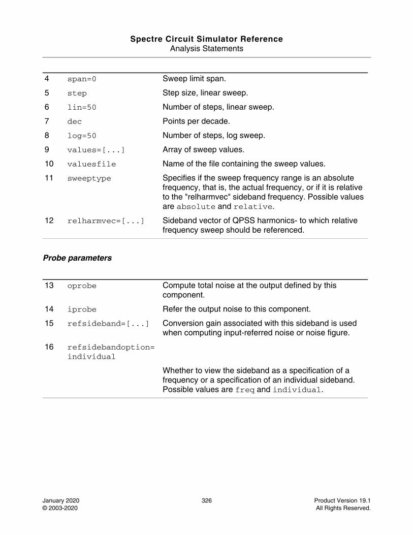
Spectre Circuit Simulator ReferenceAnalysis Statements
January 2020 326 Product Version 19.1© 2003-2020 All Rights Reserved.
Probe parameters
4 span=0 Sweep limit span.
5 step Step size, linear sweep.
6 lin=50 Number of steps, linear sweep.
7 dec Points per decade.
8 log=50 Number of steps, log sweep.
9 values=[...] Array of sweep values.
10 valuesfile Name of the file containing the sweep values.
11 sweeptype Specifies if the sweep frequency range is an absolute frequency, that is, the actual frequency, or if it is relative to the "relharmvec" sideband frequency. Possible values are absolute and relative.
12 relharmvec=[...] Sideband vector of QPSS harmonics- to which relative frequency sweep should be referenced.
13 oprobe Compute total noise at the output defined by this component.
14 iprobe Refer the output noise to this component.
15 refsideband=[...] Conversion gain associated with this sideband is used when computing input-referred noise or noise figure.
16 refsidebandoption=individual
Whether to view the sideband as a specification of a frequency or a specification of an individual sideband. Possible values are freq and individual.
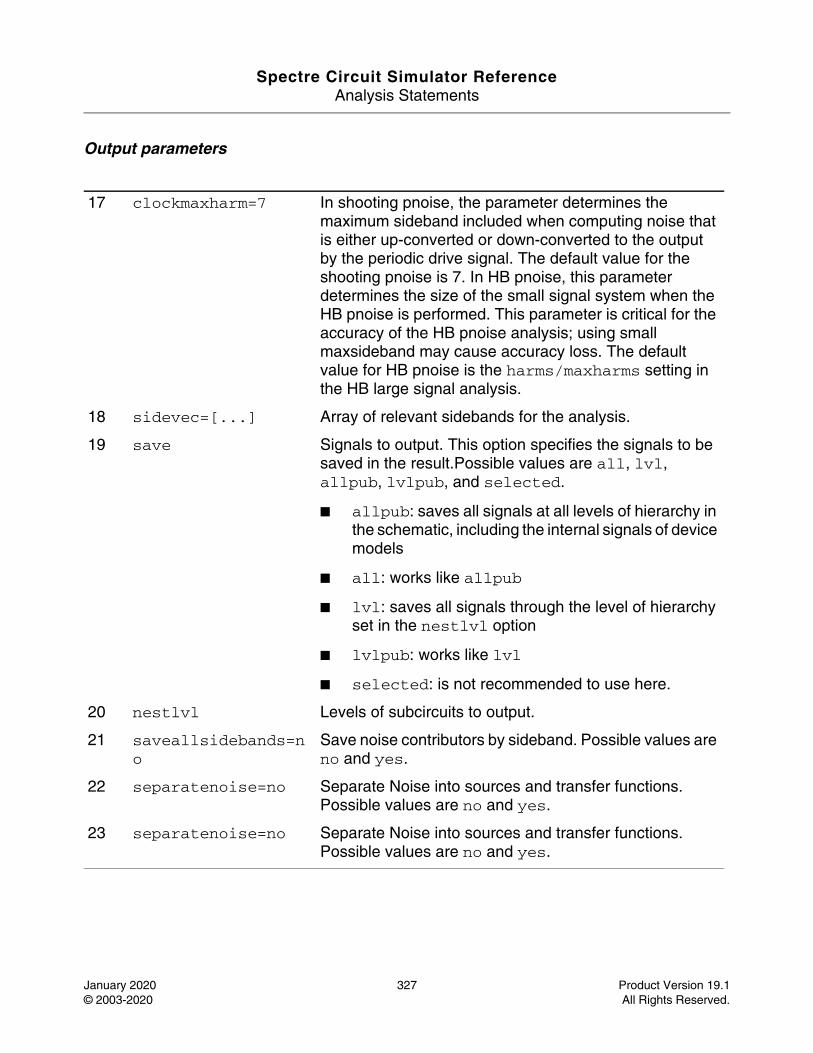
Spectre Circuit Simulator ReferenceAnalysis Statements
January 2020 327 Product Version 19.1© 2003-2020 All Rights Reserved.
Output parameters
17 clockmaxharm=7 In shooting pnoise, the parameter determines the maximum sideband included when computing noise that is either up-converted or down-converted to the output by the periodic drive signal. The default value for the shooting pnoise is 7. In HB pnoise, this parameter determines the size of the small signal system when the HB pnoise is performed. This parameter is critical for the accuracy of the HB pnoise analysis; using small maxsideband may cause accuracy loss. The default value for HB pnoise is the harms/maxharms setting in the HB large signal analysis.
18 sidevec=[...] Array of relevant sidebands for the analysis.
19 save Signals to output. This option specifies the signals to be saved in the result.Possible values are all, lvl, allpub, lvlpub, and selected.
■ allpub: saves all signals at all levels of hierarchy in the schematic, including the internal signals of device models
■ all: works like allpub
■ lvl: saves all signals through the level of hierarchy set in the nestlvl option
■ lvlpub: works like lvl
■ selected: is not recommended to use here.
20 nestlvl Levels of subcircuits to output.
21 saveallsidebands=no
Save noise contributors by sideband. Possible values are no and yes.
22 separatenoise=no Separate Noise into sources and transfer functions. Possible values are no and yes.
23 separatenoise=no Separate Noise into sources and transfer functions. Possible values are no and yes.
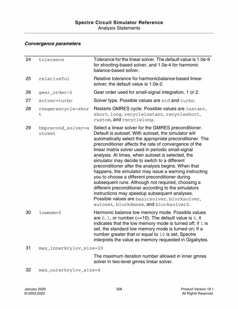
Spectre Circuit Simulator ReferenceAnalysis Statements
January 2020 328 Product Version 19.1© 2003-2020 All Rights Reserved.
Convergence parameters
24 tolerance Tolerance for the linear solver. The default value is 1.0e-9 for shooting-based solver, and 1.0e-4 for harmonic balance-based solver.
25 relativeTol Relative tolerance for harmonicbalance-based linear solver; the default value is 1.0e-2.
26 gear_order=2 Gear order used for small-signal integration, 1 or 2.
27 solver=turbo Solver type. Possible values are std and turbo.
28 resgmrescycle=short
Restarts GMRES cycle. Possible values are instant, short, long, recycleinstant, recycleshort, custom, and recyclelong.
29 hbprecond_solver=autoset
Select a linear solver for the GMRES preconditioner. Default is autoset. With autoset, the simulator will automatically select the appropriate preconditioner. The preconditioner affects the rate of convergence of the linear matrix solver used in periodic small-signal analysis. At times, when autoset is selected, the simulator may decide to switch to a different preconditioner after the analysis begins. When that happens, the simulator may issue a warning instructing you to choose a different preconditioner during subsequent runs. Although not required, choosing a different preconditioner according to the simulators instructions may speedup subsequent analyses. Possible values are basicsolver, blocksolver, autoset, blockdense, and blocksolver2.
30 lowmem=0 Harmonic balance low memory mode. Possible values are 0, 1, or number (>=10). The default value is 0, it indicates that the low memory mode is turned off; if 1 is set, the standard low memory mode is turned on; If a number greater that or equal to 10 is set, Spectre interprets the value as memory requested in Gigabytes.
31 max_innerkrylov_size=20
The maximum iteration number allowed in inner gmres solver in two-level gmres linear solver.
32 max_outerkrylov_size=4
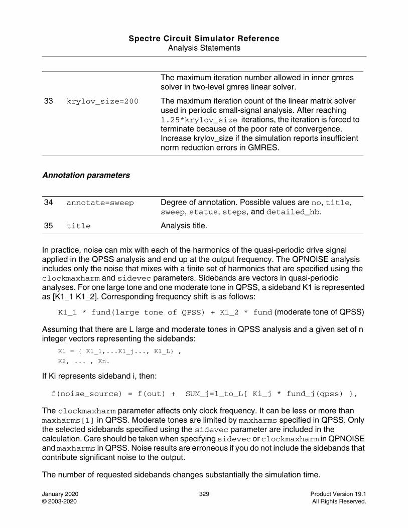
Spectre Circuit Simulator ReferenceAnalysis Statements
January 2020 329 Product Version 19.1© 2003-2020 All Rights Reserved.
Annotation parameters
In practice, noise can mix with each of the harmonics of the quasi-periodic drive signal applied in the QPSS analysis and end up at the output frequency. The QPNOISE analysis includes only the noise that mixes with a finite set of harmonics that are specified using the clockmaxharm and sidevec parameters. Sidebands are vectors in quasi-periodic analyses. For one large tone and one moderate tone in QPSS, a sideband K1 is represented as [K1_1 K1_2]. Corresponding frequency shift is as follows:
K1_1 * fund(large tone of QPSS) + K1_2 * fund (moderate tone of QPSS)
Assuming that there are L large and moderate tones in QPSS analysis and a given set of n integer vectors representing the sidebands:
K1 = { K1_1,...K1_j..., K1_L} , K2, ... , Kn.
If Ki represents sideband i, then:
f(noise_source) = f(out) + SUM_j=1_to_L{ Ki_j * fund_j(qpss) },
The clockmaxharm parameter affects only clock frequency. It can be less or more than maxharms[1] in QPSS. Moderate tones are limited by maxharms specified in QPSS. Only the selected sidebands specified using the sidevec parameter are included in the calculation. Care should be taken when specifying sidevec or clockmaxharm in QPNOISE and maxharms in QPSS. Noise results are erroneous if you do not include the sidebands that contribute significant noise to the output.
The number of requested sidebands changes substantially the simulation time.
The maximum iteration number allowed in inner gmres solver in two-level gmres linear solver.
33 krylov_size=200 The maximum iteration count of the linear matrix solver used in periodic small-signal analysis. After reaching 1.25*krylov_size iterations, the iteration is forced to terminate because of the poor rate of convergence. Increase krylov_size if the simulation reports insufficient norm reduction errors in GMRES.
34 annotate=sweep Degree of annotation. Possible values are no, title, sweep, status, steps, and detailed_hb.
35 title Analysis title.
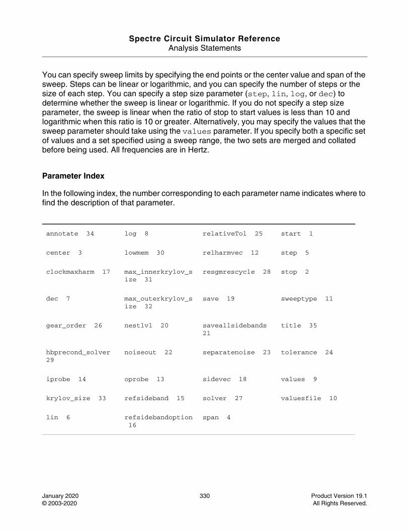
Spectre Circuit Simulator ReferenceAnalysis Statements
January 2020 330 Product Version 19.1© 2003-2020 All Rights Reserved.
You can specify sweep limits by specifying the end points or the center value and span of the sweep. Steps can be linear or logarithmic, and you can specify the number of steps or the size of each step. You can specify a step size parameter (step, lin, log, or dec) to determine whether the sweep is linear or logarithmic. If you do not specify a step size parameter, the sweep is linear when the ratio of stop to start values is less than 10 and logarithmic when this ratio is 10 or greater. Alternatively, you may specify the values that the sweep parameter should take using the values parameter. If you specify both a specific set of values and a set specified using a sweep range, the two sets are merged and collated before being used. All frequencies are in Hertz.
Parameter Index
In the following index, the number corresponding to each parameter name indicates where to find the description of that parameter.
annotate 34 log 8 relativeTol 25 start 1
center 3 lowmem 30 relharmvec 12 step 5
clockmaxharm 17 max_innerkrylov_size 31
resgmrescycle 28 stop 2
dec 7 max_outerkrylov_size 32
save 19 sweeptype 11
gear_order 26 nestlvl 20 saveallsidebands 21
title 35
hbprecond_solver 29
noiseout 22 separatenoise 23 tolerance 24
iprobe 14 oprobe 13 sidevec 18 values 9
krylov_size 33 refsideband 15 solver 27 valuesfile 10
lin 6 refsidebandoption 16
span 4
Spectre Circuit Simulator ReferenceAnalysis Statements
January 2020 331 Product Version 19.1© 2003-2020 All Rights Reserved.
Quasi-Periodic S-Parameter Analysis (qpsp)
Description
The quasi-periodic SP (QPSP) analysis is used to compute scattering and noise parameters for n-port circuits that exhibit frequency translation. Such circuits include mixers, switched-capacitor filters, samplers, phase-locked loops, and the like. It is a small-signal analysis like SP analysis, except, as done in QPAC and QPXF, the circuit is first linearized about a quasi-periodically varying operating point as opposed to a simple DC operating point. Linearizing about a quasi-periodically time-varying operating point allows the computation of S-parameters between circuit ports that convert signals from one frequency band to another. QPSP can also calculate noise parameters in frequency-converting circuits. QPSP computes noise figure (both single-sideband and double-sideband), input referred noise, equivalent noise parameters, and noise correlation matrices. As in QPNOISE, but unlike SP, the noise features of the QPSP analysis include noise folding effects due to the periodically time-varying nature of the circuit.
Computing the n-port S-parameters and noise parameters of a quasi-periodically varying circuit is a two-step process. First, the small stimulus is ignored and the quasi-periodic steady-state response of the circuit to possibly large periodic stimulus is computed using QPSS analysis. As part of the QPSS analysis, the quasi-periodically time-varying representation of the circuit is computed and saved for later use. The second step is to apply small-signal excitations to compute the n-port S-parameters and noise parameters. This is done using the QPSP analysis. A QPSP analysis cannot be used independently; it must follow a QPSS analysis. However, any number of periodic small-signal analyses, such as QPAC, QPSP, QPXF, QPNOISE, can follow a single QPSS analysis.
Unlike other analyses in Spectre, this analysis can only sweep frequency.
For information on how to run QPSP analysis from ADE, see QPSP Analysis in the Spectre Circuit Simulator and Accelerated Parallel Simulator RF Analysis User Guide.
DefinitionName qpsp parameter=value ...
Parameters
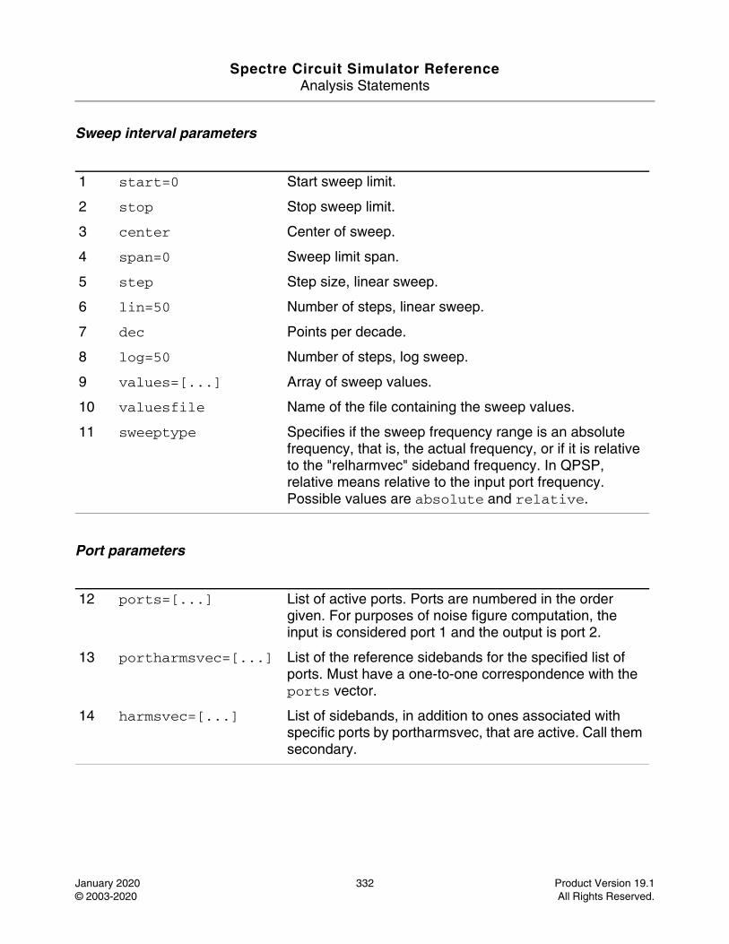
Spectre Circuit Simulator ReferenceAnalysis Statements
January 2020 332 Product Version 19.1© 2003-2020 All Rights Reserved.
Sweep interval parameters
Port parameters
1 start=0 Start sweep limit.
2 stop Stop sweep limit.
3 center Center of sweep.
4 span=0 Sweep limit span.
5 step Step size, linear sweep.
6 lin=50 Number of steps, linear sweep.
7 dec Points per decade.
8 log=50 Number of steps, log sweep.
9 values=[...] Array of sweep values.
10 valuesfile Name of the file containing the sweep values.
11 sweeptype Specifies if the sweep frequency range is an absolute frequency, that is, the actual frequency, or if it is relative to the "relharmvec" sideband frequency. In QPSP, relative means relative to the input port frequency. Possible values are absolute and relative.
12 ports=[...] List of active ports. Ports are numbered in the order given. For purposes of noise figure computation, the input is considered port 1 and the output is port 2.
13 portharmsvec=[...] List of the reference sidebands for the specified list of ports. Must have a one-to-one correspondence with the ports vector.
14 harmsvec=[...] List of sidebands, in addition to ones associated with specific ports by portharmsvec, that are active. Call them secondary.
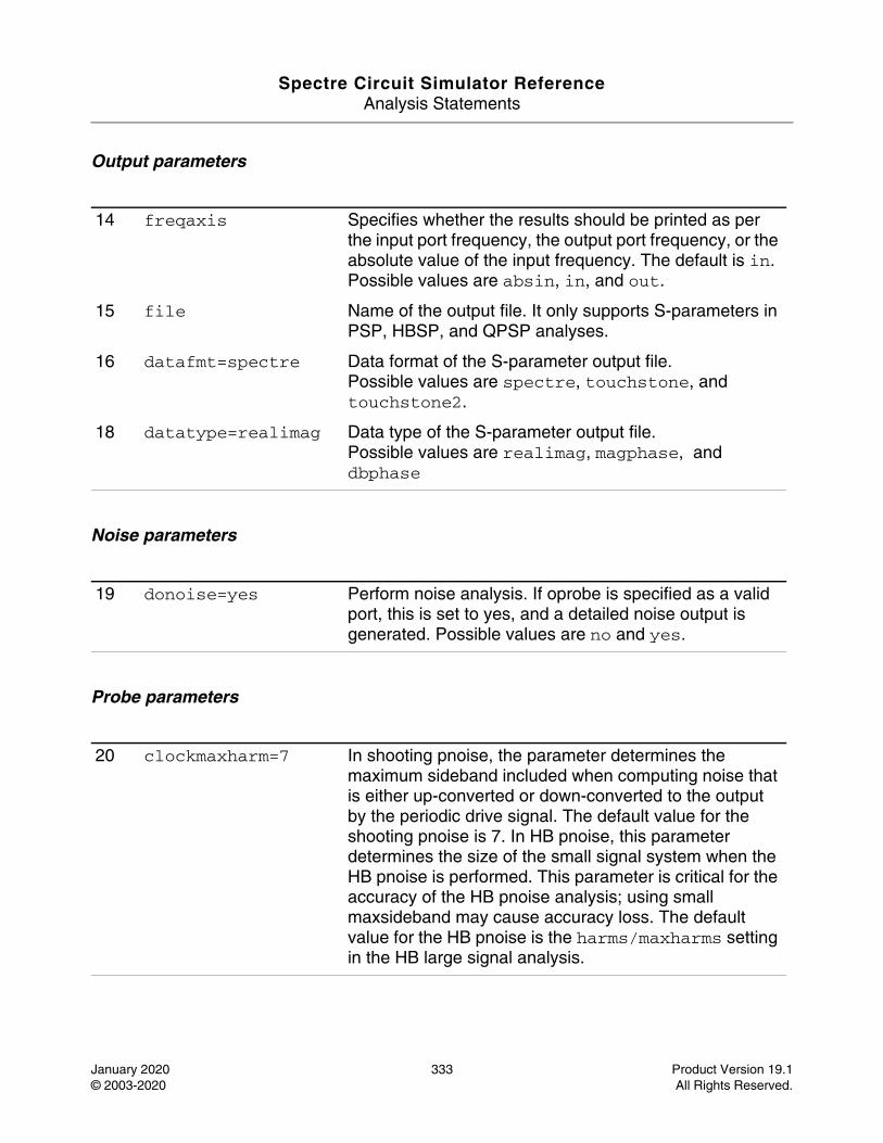
Spectre Circuit Simulator ReferenceAnalysis Statements
January 2020 333 Product Version 19.1© 2003-2020 All Rights Reserved.
Output parameters
Noise parameters
Probe parameters
14 freqaxis Specifies whether the results should be printed as per the input port frequency, the output port frequency, or the absolute value of the input frequency. The default is in. Possible values are absin, in, and out.
15 file Name of the output file. It only supports S-parameters in PSP, HBSP, and QPSP analyses.
16 datafmt=spectre Data format of the S-parameter output file.Possible values are spectre, touchstone, and touchstone2.
18 datatype=realimag Data type of the S-parameter output file.Possible values are realimag, magphase, and dbphase
19 donoise=yes Perform noise analysis. If oprobe is specified as a valid port, this is set to yes, and a detailed noise output is generated. Possible values are no and yes.
20 clockmaxharm=7 In shooting pnoise, the parameter determines the maximum sideband included when computing noise that is either up-converted or down-converted to the output by the periodic drive signal. The default value for the shooting pnoise is 7. In HB pnoise, this parameter determines the size of the small signal system when the HB pnoise is performed. This parameter is critical for the accuracy of the HB pnoise analysis; using small maxsideband may cause accuracy loss. The default value for the HB pnoise is the harms/maxharms setting in the HB large signal analysis.
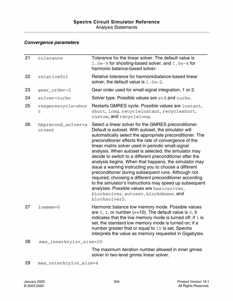
Spectre Circuit Simulator ReferenceAnalysis Statements
January 2020 334 Product Version 19.1© 2003-2020 All Rights Reserved.
Convergence parameters
21 tolerance Tolerance for the linear solver. The default value is 1.0e-9 for shooting-based solver, and 1.0e-4 for harmonic balance-based solver.
22 relativeTol Relative tolerance for harmonicbalance-based linear solver; the default value is 1.0e-2.
23 gear_order=2 Gear order used for small-signal integration, 1 or 2.
24 solver=turbo Solver type. Possible values are std and turbo.
25 resgmrescycle=short
Restarts GMRES cycle. Possible values are instant, short, long, recycleinstant, recycleshort, custom, and recyclelong.
26 hbprecond_solver=autoset
Select a linear solver for the GMRES preconditioner. Default is autoset. With autoset, the simulator will automatically select the appropriate preconditioner. The preconditioner affects the rate of convergence of the linear matrix solver used in periodic small-signal analysis. When autoset is selected, the simulator may decide to switch to a different preconditioner after the analysis begins. When that happens, the simulator may issue a warning instructing you to choose a different preconditioner during subsequent runs. Although not required, choosing a different preconditioner according to the simulator’s instructions may speed up subsequent analyses. Possible values are basicsolver, blocksolver, autoset, blockdense, and blocksolver2.
27 lowmem=0 Harmonic balance low memory mode. Possible values are 0, 1, or number (>=10). The default value is 0, it indicates that the low memory mode is turned off; if 1 is set, the standard low memory mode is turned on; if a number greater that or equal to 10 is set, Spectre interprets the value as memory requested in Gigabytes.
28 max_innerkrylov_size=20
The maximum iteration number allowed in inner gmres solver in two-level gmres linear solver.
29 max_outerkrylov_size=4
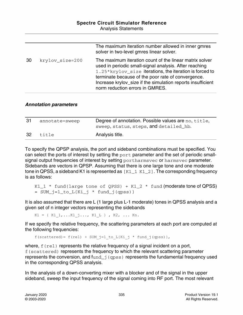
Spectre Circuit Simulator ReferenceAnalysis Statements
January 2020 335 Product Version 19.1© 2003-2020 All Rights Reserved.
Annotation parameters
To specify the QPSP analysis, the port and sideband combinations must be specified. You can select the ports of interest by setting the port parameter and the set of periodic small-signal output frequencies of interest by setting portharmsvec or harmsvec parameter. Sidebands are vectors in QPSP. Assuming that there is one large tone and one moderate tone in QPSS, a sideband K1 is represented as [K1_1 K1_2]. The corresponding frequency is as follows:
K1_1 * fund(large tone of QPSS) + K1_2 * fund (moderate tone of QPSS) = SUM_j=1_to_L{Ki_j * fund_j(qpss)}
It is also assumed that there are L (1 large plus L-1 moderate) tones in QPSS analysis and a given set of n integer vectors representing the sidebands
K1 = { K1_1,...K1_j..., K1_L } , K2, ... Kn.
If we specify the relative frequency, the scattering parameters at each port are computed at the following frequencies:
f(scattered)= f(rel) + SUM_j=1_to_L{Ki_j * fund_j(qpss)},
where, f(rel) represents the relative frequency of a signal incident on a port, f(scattered) represents the frequency to which the relevant scattering parameter represents the conversion, and fund_j(qpss) represents the fundamental frequency used in the corresponding QPSS analysis.
In the analysis of a down-converting mixer with a blocker and of the signal in the upper sideband, sweep the input frequency of the signal coming into RF port. The most relevant
The maximum iteration number allowed in inner gmres solver in two-level gmres linear solver.
30 krylov_size=200 The maximum iteration count of the linear matrix solver used in periodic small-signal analysis. After reaching 1.25*krylov_size iterations, the iteration is forced to terminate because of the poor rate of convergence. Increase krylov_size if the simulation reports insufficient norm reduction errors in GMRES.
31 annotate=sweep Degree of annotation. Possible values are no, title, sweep, status, steps, and detailed_hb.
32 title Analysis title.
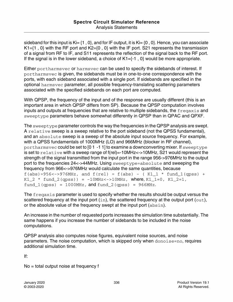
Spectre Circuit Simulator ReferenceAnalysis Statements
January 2020 336 Product Version 19.1© 2003-2020 All Rights Reserved.
sideband for this input is Ki= {1 , 0}, and for IF output, it is Ki= {0 , 0}. Hence, you can associate K1={1 , 0} with the RF port and K2={0 , 0} with the IF port. S21 represents the transmission of a signal from RF to IF, and S11 represents the reflection of the signal back to the RF port. If the signal is in the lower sideband, a choice of K1={-1 , 0} would be more appropriate.
Either portharmsvec or harmsvec can be used to specify the sidebands of interest. If portharmsvec is given, the sidebands must be in one-to-one correspondence with the ports, with each sideband associated with a single port. If sidebands are specified in the optional harmsvec parameter, all possible frequency-translating scattering parameters associated with the specified sidebands on each port are computed.
With QPSP, the frequency of the input and of the response are usually different (this is an important area in which QPSP differs from SP). Because the QPSP computation involves inputs and outputs at frequencies that are relative to multiple sidebands, the freqaxis and sweeptype parameters behave somewhat differently in QPSP than in QPAC and QPXF.
The sweeptype parameter controls the way the frequencies in the QPSP analysis are swept. A relative sweep is a sweep relative to the port sideband (not the QPSS fundamental), and an absolute sweep is a sweep of the absolute input source frequency. For example, with a QPSS fundamentals of 1000MHz (LO) and 966MHz (blocker in RF channel), portharmsvec could be set to [0 1 -1 1] to examine a downconverting mixer. If sweeptype is set to relative with a sweep range of f(rel)=-10MHz<->10MHz, S21 would represent the strength of the signal transmitted from the input port in the range 956->976MHz to the output port to the frequencies 24<->44MHz. Using sweeptype=absolute and sweeping the frequency from 966<->976MHz would calculate the same quantities, because f(abs)=956<->976MHz, and f(rel) = f(abs) - ( K1_1 * fund_1(qpss) + K1_2 * fund_2(qpss)) = -10MHz<->10MHz, where, K1_1=0, K1_2=1, fund_1(qpss) = 1000MHz, and fund_2(qpss) = 966MHz.
The freqaxis parameter is used to specify whether the results should be output versus the scattered frequency at the input port (in), the scattered frequency at the output port (out), or the absolute value of the frequency swept at the input port (absin).
An increase in the number of requested ports increases the simulation time substantially. The same happens if you increase the number of sidebands to be included in the noise computations.
QPSP analysis also computes noise figures, equivalent noise sources, and noise parameters. The noise computation, which is skipped only when donoise=no, requires additional simulation time.
If:
No = total output noise at frequency f
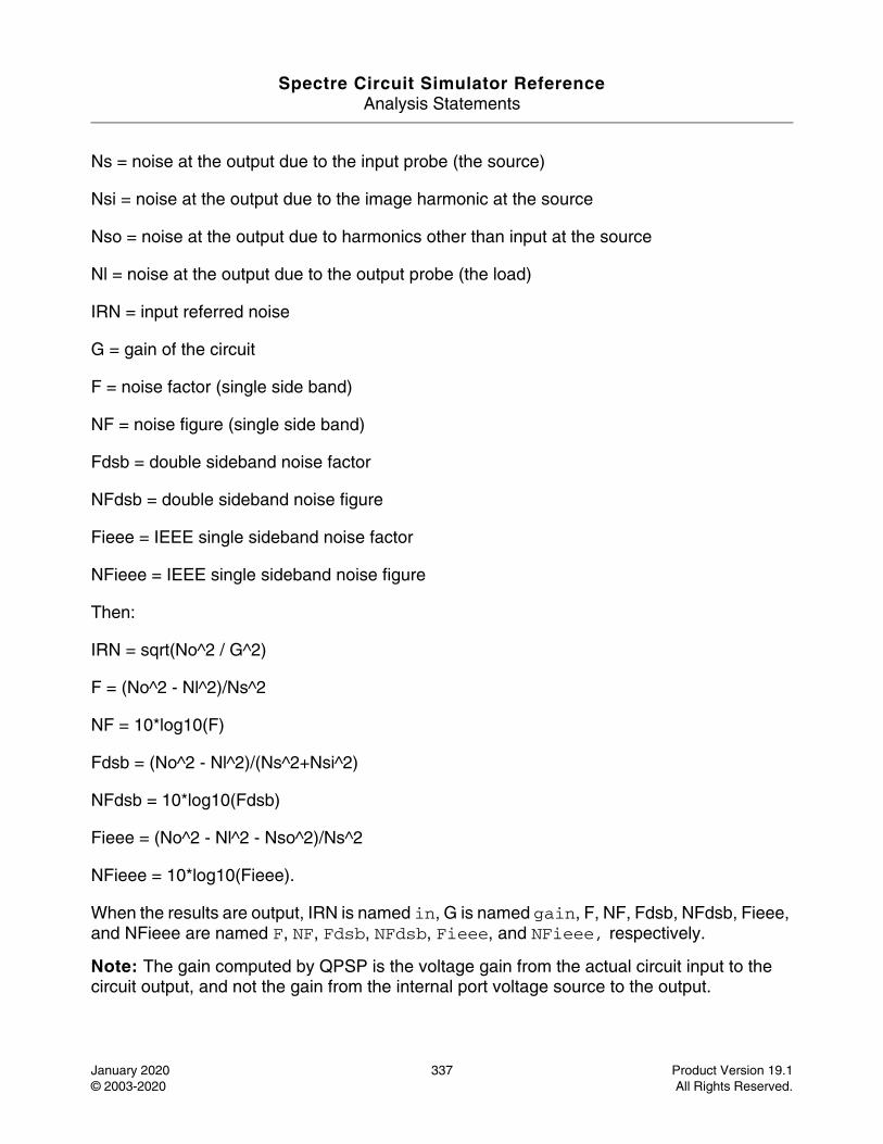
Spectre Circuit Simulator ReferenceAnalysis Statements
January 2020 337 Product Version 19.1© 2003-2020 All Rights Reserved.
Ns = noise at the output due to the input probe (the source)
Nsi = noise at the output due to the image harmonic at the source
Nso = noise at the output due to harmonics other than input at the source
Nl = noise at the output due to the output probe (the load)
IRN = input referred noise
G = gain of the circuit
F = noise factor (single side band)
NF = noise figure (single side band)
Fdsb = double sideband noise factor
NFdsb = double sideband noise figure
Fieee = IEEE single sideband noise factor
NFieee = IEEE single sideband noise figure
Then:
IRN = sqrt(No^2 / G^2)
F = (No^2 - Nl^2)/Ns^2
NF = 10*log10(F)
Fdsb = (No^2 - Nl^2)/(Ns^2+Nsi^2)
NFdsb = 10*log10(Fdsb)
Fieee = (No^2 - Nl^2 - Nso^2)/Ns^2
NFieee = 10*log10(Fieee).
When the results are output, IRN is named in, G is named gain, F, NF, Fdsb, NFdsb, Fieee, and NFieee are named F, NF, Fdsb, NFdsb, Fieee, and NFieee, respectively.
Note: The gain computed by QPSP is the voltage gain from the actual circuit input to the circuit output, and not the gain from the internal port voltage source to the output.
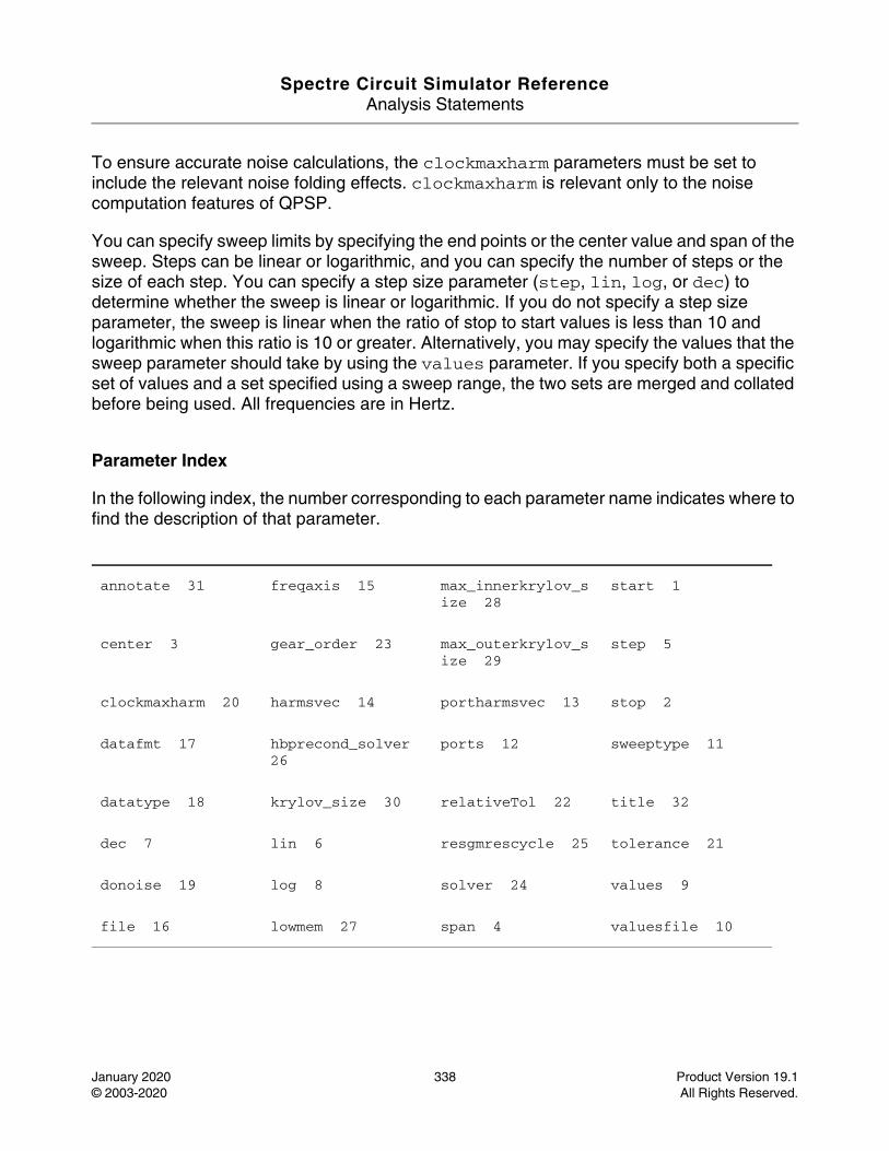
Spectre Circuit Simulator ReferenceAnalysis Statements
January 2020 338 Product Version 19.1© 2003-2020 All Rights Reserved.
To ensure accurate noise calculations, the clockmaxharm parameters must be set to include the relevant noise folding effects. clockmaxharm is relevant only to the noise computation features of QPSP.
You can specify sweep limits by specifying the end points or the center value and span of the sweep. Steps can be linear or logarithmic, and you can specify the number of steps or the size of each step. You can specify a step size parameter (step, lin, log, or dec) to determine whether the sweep is linear or logarithmic. If you do not specify a step size parameter, the sweep is linear when the ratio of stop to start values is less than 10 and logarithmic when this ratio is 10 or greater. Alternatively, you may specify the values that the sweep parameter should take by using the values parameter. If you specify both a specific set of values and a set specified using a sweep range, the two sets are merged and collated before being used. All frequencies are in Hertz.
Parameter Index
In the following index, the number corresponding to each parameter name indicates where to find the description of that parameter.
annotate 31 freqaxis 15 max_innerkrylov_size 28
start 1
center 3 gear_order 23 max_outerkrylov_size 29
step 5
clockmaxharm 20 harmsvec 14 portharmsvec 13 stop 2
datafmt 17 hbprecond_solver 26
ports 12 sweeptype 11
datatype 18 krylov_size 30 relativeTol 22 title 32
dec 7 lin 6 resgmrescycle 25 tolerance 21
donoise 19 log 8 solver 24 values 9
file 16 lowmem 27 span 4 valuesfile 10
Spectre Circuit Simulator ReferenceAnalysis Statements
January 2020 339 Product Version 19.1© 2003-2020 All Rights Reserved.
Quasi-Periodic Steady State Analysis (qpss)
Description
Quasi-periodic steady-state (QPSS) analysis computes circuit response with multiple fundamental frequencies using harmonic balance (in frequency domain) or shooting. QPSS can compute circuit responses with closely spaced or incommensurate fundamentals, which cannot be resolved by PSS efficiently. The simulation time of QPSS analysis is independent of the time-constants of the circuit. In addition, QPSS analysis sets the circuit quasi-periodic operating point, which can then be used during a quasi-periodic time-varying small-signal analysis, such as QPAC, QPXF, QPSP, and QPNOISE.
Harmonic balance (HB) is efficient in simulating weak nonlinear circuits while shooting is more suitable for computing a circuit response to several moderate input signals, in addition to a large signal. The large signal, which represents a LO or clock signal, is usually the one that causes the most nonlinearity or the largest response. A typical example is the intermodulation distortion measurements of a mixer with two closely spaced moderate input signals. HB is more efficient than shooting in handling frequency-dependent components, such as delay, transmission line, and S-parameter data.
QPSS consists of three phases. First, an initial transient analysis with all moderate input signals suppressed is carried out. Second, a number of (at least 2) stabilizing iterations are run with all signals activated. Finally, the Newton method is followed.
When the shooting method is used, QPSS employs the Mixed Frequency Time (MFT) algorithm extended to multiple fundamental frequencies. For details of MFT algorithm, see Steady-State Methods for Simulating Analog and Microwave Circuits, by K. S. Kundert, J.K. White, and A. Sangiovanni-Vincentelli, Kluwer, Boston, 1990.
Similar to shooting in PSS, shooting in QPSS uses Newton method as its backbone. However, instead of doing a single transient integration, each Newton iteration does a number of transient integrations of one large signal period. Each of the integrations differs by a phase-shift in each moderate input signal. The number of integrations is determined by the numbers of harmonics of moderate fundamentals specified by maxharms. Given maxharms=[k1 k2 ... kn], QPSS always treats k1 as the maximum harmonic of the large signal, and the total number of integrations is (2*k2+1)*(2*k3+1)*...*(2*kn+1). One consequence is that the efficiency of the algorithm depends significantly on the number of harmonics required to model the responses of moderate fundamentals. Another consequence is that the number of harmonics of the large fundamental does not significantly affect the efficiency of the shooting algorithm. The boundary conditions of a shooting interval are such that the time domain integrations are consistent with a frequency domain transformation with a shift of one large signal period.
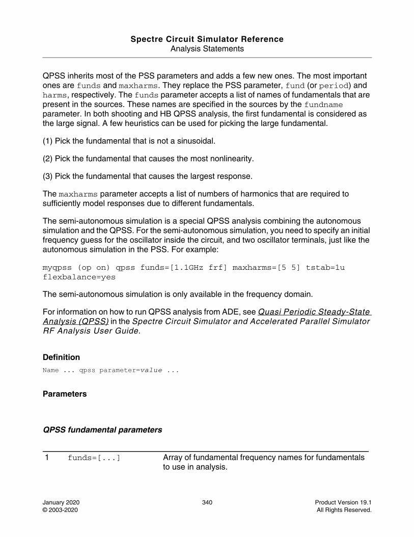
Spectre Circuit Simulator ReferenceAnalysis Statements
January 2020 340 Product Version 19.1© 2003-2020 All Rights Reserved.
QPSS inherits most of the PSS parameters and adds a few new ones. The most important ones are funds and maxharms. They replace the PSS parameter, fund (or period) and harms, respectively. The funds parameter accepts a list of names of fundamentals that are present in the sources. These names are specified in the sources by the fundname parameter. In both shooting and HB QPSS analysis, the first fundamental is considered as the large signal. A few heuristics can be used for picking the large fundamental.
(1) Pick the fundamental that is not a sinusoidal.
(2) Pick the fundamental that causes the most nonlinearity.
(3) Pick the fundamental that causes the largest response.
The maxharms parameter accepts a list of numbers of harmonics that are required to sufficiently model responses due to different fundamentals.
The semi-autonomous simulation is a special QPSS analysis combining the autonomous simulation and the QPSS. For the semi-autonomous simulation, you need to specify an initial frequency guess for the oscillator inside the circuit, and two oscillator terminals, just like the autonomous simulation in the PSS. For example:
myqpss (op on) qpss funds=[1.1GHz frf] maxharms=[5 5] tstab=1u flexbalance=yes
The semi-autonomous simulation is only available in the frequency domain.
For information on how to run QPSS analysis from ADE, see Quasi Periodic Steady-State Analysis (QPSS) in the Spectre Circuit Simulator and Accelerated Parallel Simulator RF Analysis User Guide.
DefinitionName ... qpss parameter=value ...
Parameters
QPSS fundamental parameters
1 funds=[...] Array of fundamental frequency names for fundamentals to use in analysis.
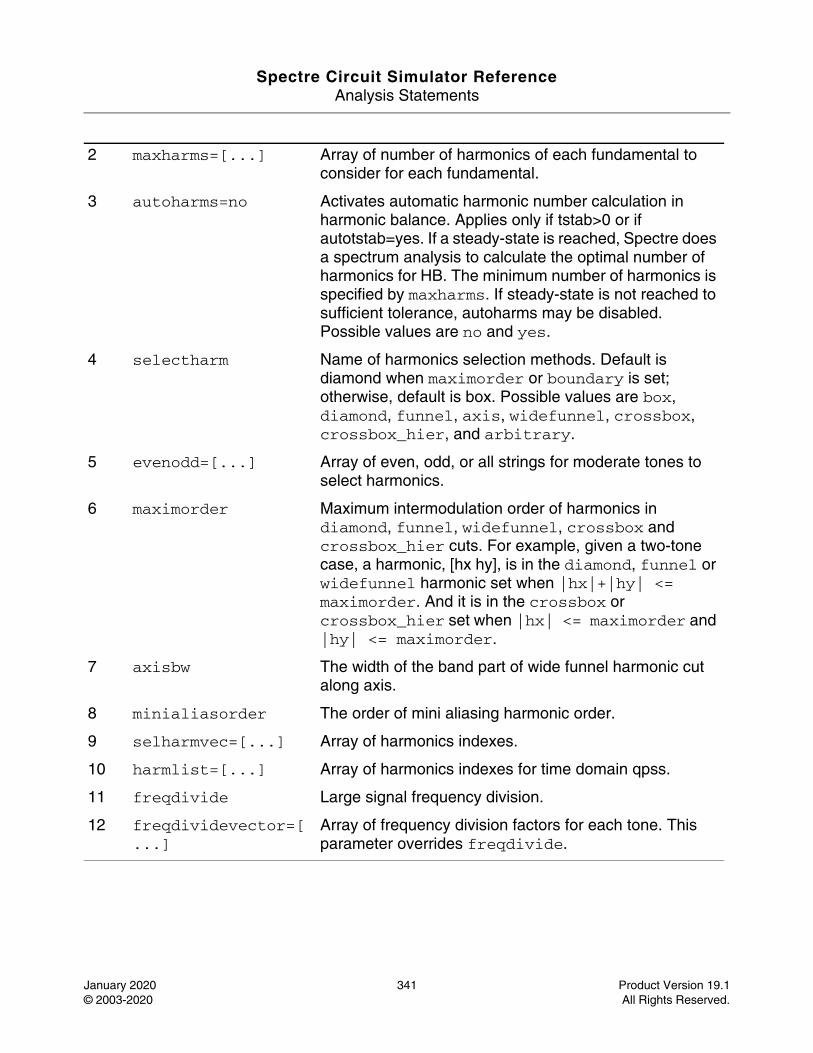
Spectre Circuit Simulator ReferenceAnalysis Statements
January 2020 341 Product Version 19.1© 2003-2020 All Rights Reserved.
2 maxharms=[...] Array of number of harmonics of each fundamental to consider for each fundamental.
3 autoharms=no Activates automatic harmonic number calculation in harmonic balance. Applies only if tstab>0 or if autotstab=yes. If a steady-state is reached, Spectre does a spectrum analysis to calculate the optimal number of harmonics for HB. The minimum number of harmonics is specified by maxharms. If steady-state is not reached to sufficient tolerance, autoharms may be disabled. Possible values are no and yes.
4 selectharm Name of harmonics selection methods. Default is diamond when maximorder or boundary is set; otherwise, default is box. Possible values are box, diamond, funnel, axis, widefunnel, crossbox, crossbox_hier, and arbitrary.
5 evenodd=[...] Array of even, odd, or all strings for moderate tones to select harmonics.
6 maximorder Maximum intermodulation order of harmonics in diamond, funnel, widefunnel, crossbox and crossbox_hier cuts. For example, given a two-tone case, a harmonic, [hx hy], is in the diamond, funnel or widefunnel harmonic set when |hx|+|hy| <= maximorder. And it is in the crossbox or crossbox_hier set when |hx| <= maximorder and |hy| <= maximorder.
7 axisbw The width of the band part of wide funnel harmonic cut along axis.
8 minialiasorder The order of mini aliasing harmonic order.
9 selharmvec=[...] Array of harmonics indexes.
10 harmlist=[...] Array of harmonics indexes for time domain qpss.
11 freqdivide Large signal frequency division.
12 freqdividevector=[...]
Array of frequency division factors for each tone. This parameter overrides freqdivide.
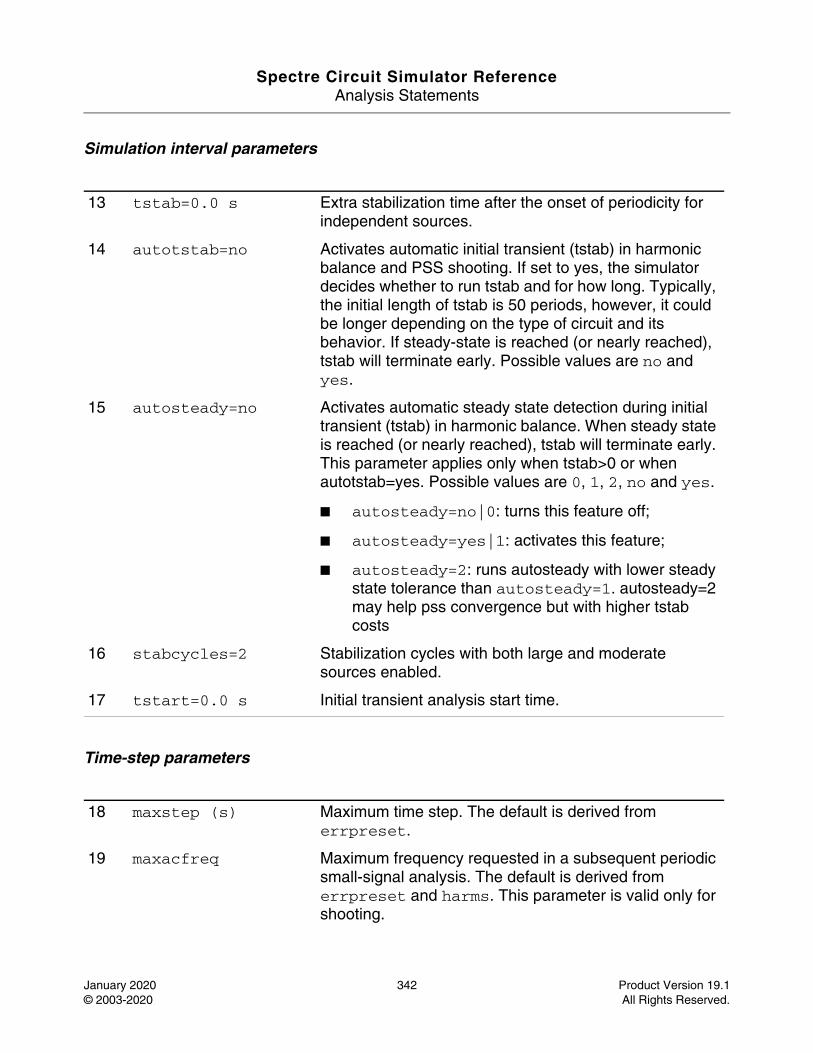
Spectre Circuit Simulator ReferenceAnalysis Statements
January 2020 342 Product Version 19.1© 2003-2020 All Rights Reserved.
Simulation interval parameters
Time-step parameters
13 tstab=0.0 s Extra stabilization time after the onset of periodicity for independent sources.
14 autotstab=no Activates automatic initial transient (tstab) in harmonic balance and PSS shooting. If set to yes, the simulator decides whether to run tstab and for how long. Typically, the initial length of tstab is 50 periods, however, it could be longer depending on the type of circuit and its behavior. If steady-state is reached (or nearly reached), tstab will terminate early. Possible values are no and yes.
15 autosteady=no Activates automatic steady state detection during initial transient (tstab) in harmonic balance. When steady state is reached (or nearly reached), tstab will terminate early. This parameter applies only when tstab>0 or when autotstab=yes. Possible values are 0, 1, 2, no and yes.
■ autosteady=no|0: turns this feature off;
■ autosteady=yes|1: activates this feature;
■ autosteady=2: runs autosteady with lower steady state tolerance than autosteady=1. autosteady=2 may help pss convergence but with higher tstab costs
16 stabcycles=2 Stabilization cycles with both large and moderate sources enabled.
17 tstart=0.0 s Initial transient analysis start time.
18 maxstep (s) Maximum time step. The default is derived from errpreset.
19 maxacfreq Maximum frequency requested in a subsequent periodic small-signal analysis. The default is derived from errpreset and harms. This parameter is valid only for shooting.
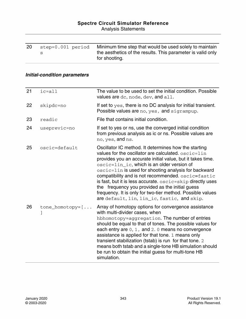
Spectre Circuit Simulator ReferenceAnalysis Statements
January 2020 343 Product Version 19.1© 2003-2020 All Rights Reserved.
Initial-condition parameters
20 step=0.001 period s
Minimum time step that would be used solely to maintain the aesthetics of the results. This parameter is valid only for shooting.
21 ic=all The value to be used to set the initial condition. Possible values are dc, node, dev, and all.
22 skipdc=no If set to yes, there is no DC analysis for initial transient. Possible values are no, yes, and sigrampup.
23 readic File that contains initial condition.
24 useprevic=no If set to yes or ns, use the converged initial condition from previous analysis as ic or ns. Possible values are no, yes, and ns.
25 oscic=default Oscillator IC method. It determines how the starting values for the oscillator are calculated. oscic=lin provides you an accurate initial value, but it takes time. oscic=lin_ic, which is an older version of oscic=lin is used for shooting analysis for backward compatibility and is not recommended. oscic=fastic is fast, but it is less accurate. oscic=skip directly uses the frequency you provided as the initial guess frequency. It is only for two-tier method. Possible values are default, lin, lin_ic, fastic, and skip.
26 tone_homotopy=[...]
Array of homotopy options for convergence assistance with multi-divider cases, when hbhomotopy=aggregation. The number of entries should be equal to that of tones. The possible values for each entry are 0, 1, and 2. 0 means no convergence assistance is applied for that tone. 1 means only transient stabilization (tstab) is run for that tone. 2 means both tstab and a single-tone HB simulation should be run to obtain the initial guess for multi-tone HB simulation.
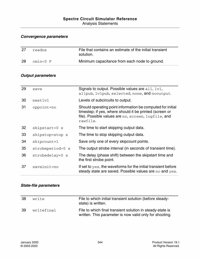
Spectre Circuit Simulator ReferenceAnalysis Statements
January 2020 344 Product Version 19.1© 2003-2020 All Rights Reserved.
Convergence parameters
Output parameters
State-file parameters
27 readns File that contains an estimate of the initial transient solution.
28 cmin=0 F Minimum capacitance from each node to ground.
29 save Signals to output. Possible values are all, lvl, allpub, lvlpub, selected, none, and nooutput.
30 nestlvl Levels of subcircuits to output.
31 oppoint=no Should operating point information be computed for initial timestep; if yes, where should it be printed (screen or file). Possible values are no, screen, logfile, and rawfile.
32 skipstart=0 s The time to start skipping output data.
33 skipstop=stop s The time to stop skipping output data.
34 skipcount=1 Save only one of every skipcount points.
35 strobeperiod=0 s The output strobe interval (in seconds of transient time).
36 strobedelay=0 s The delay (phase shift) between the skipstart time and the first strobe point.
37 saveinit=no If set to yes, the waveforms for the initial transient before steady state are saved. Possible values are no and yes.
38 write File to which initial transient solution (before steady-state) is written.
39 writefinal File to which final transient solution in steady-state is written. This parameter is now valid only for shooting.
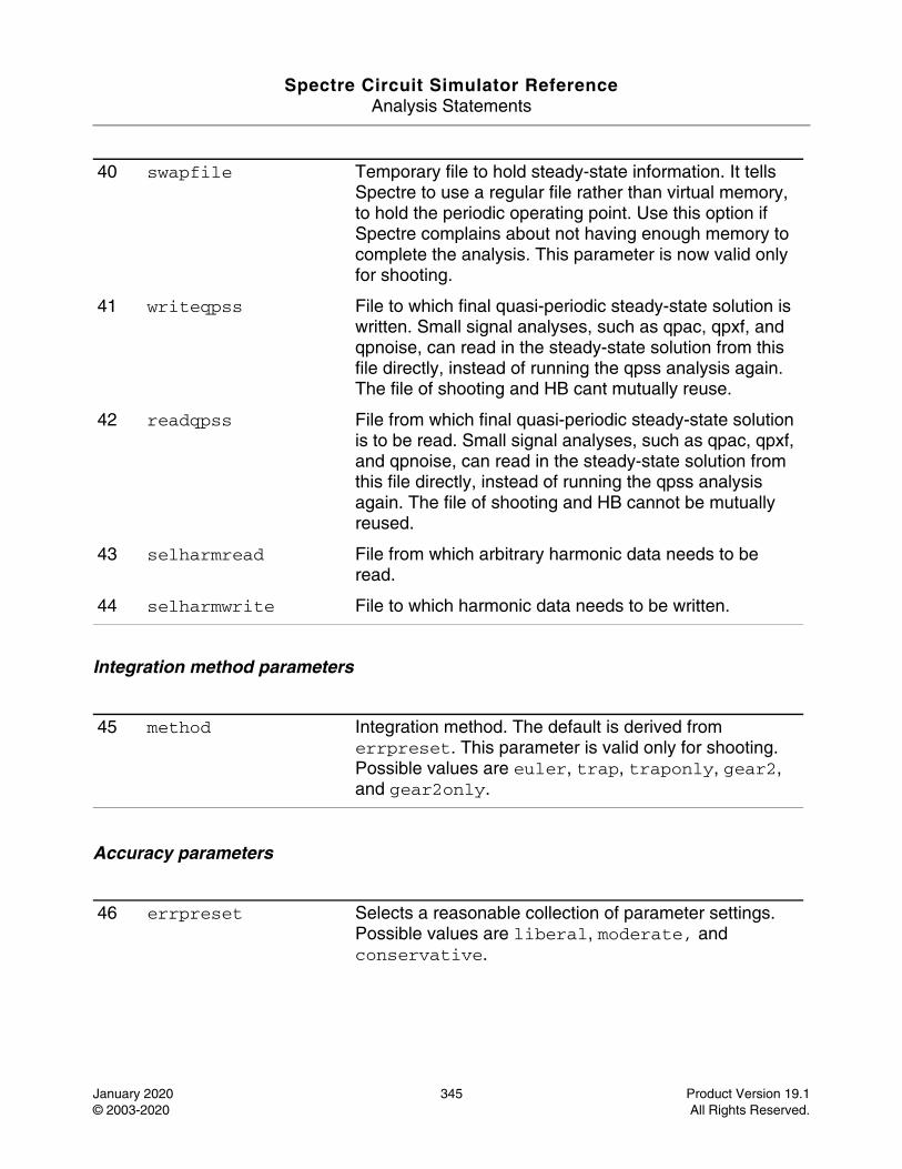
Spectre Circuit Simulator ReferenceAnalysis Statements
January 2020 345 Product Version 19.1© 2003-2020 All Rights Reserved.
Integration method parameters
Accuracy parameters
40 swapfile Temporary file to hold steady-state information. It tells Spectre to use a regular file rather than virtual memory, to hold the periodic operating point. Use this option if Spectre complains about not having enough memory to complete the analysis. This parameter is now valid only for shooting.
41 writeqpss File to which final quasi-periodic steady-state solution is written. Small signal analyses, such as qpac, qpxf, and qpnoise, can read in the steady-state solution from this file directly, instead of running the qpss analysis again. The file of shooting and HB cant mutually reuse.
42 readqpss File from which final quasi-periodic steady-state solution is to be read. Small signal analyses, such as qpac, qpxf, and qpnoise, can read in the steady-state solution from this file directly, instead of running the qpss analysis again. The file of shooting and HB cannot be mutually reused.
43 selharmread File from which arbitrary harmonic data needs to be read.
44 selharmwrite File to which harmonic data needs to be written.
45 method Integration method. The default is derived from errpreset. This parameter is valid only for shooting. Possible values are euler, trap, traponly, gear2, and gear2only.
46 errpreset Selects a reasonable collection of parameter settings. Possible values are liberal, moderate, and conservative.
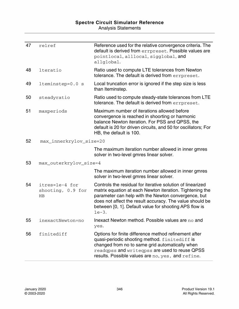
Spectre Circuit Simulator ReferenceAnalysis Statements
January 2020 346 Product Version 19.1© 2003-2020 All Rights Reserved.
47 relref Reference used for the relative convergence criteria. The default is derived from errpreset. Possible values are pointlocal, alllocal, sigglobal, and allglobal.
48 lteratio Ratio used to compute LTE tolerances from Newton tolerance. The default is derived from errpreset.
49 lteminstep=0.0 s Local truncation error is ignored if the step size is less than lteminstep.
50 steadyratio Ratio used to compute steady-state tolerances from LTE tolerance. The default is derived from errpreset.
51 maxperiods Maximum number of iterations allowed before convergence is reached in shoorting or harmonic balance Newton iteration. For PSS and QPSS, the default is 20 for driven circuits, and 50 for oscillators; For HB, the default is 100.
52 max_innerkrylov_size=20
The maximum iteration number allowed in inner gmres solver in two-level gmres linear solver.
53 max_outerkrylov_size=4
The maximum iteration number allowed in inner gmres solver in two-level gmres linear solver.
54 itres=1e-4 for shooting, 0.9 for HB
Controls the residual for iterative solution of linearized matrix equation at each Newton iteration. Tightening the parameter can help with the Newton convergence, but does not affect the result accuracy. The value should be between [0, 1]. Default value for shooting APS flow is 1e-3.
55 inexactNewton=no Inexact Newton method. Possible values are no and yes.
56 finitediff Options for finite difference method refinement after quasi-periodic shooting method. finitediff is changed from no to same grid automatically when readqpss and writeqpss are used to reuse QPSS results. Possible values are no, yes, and refine.
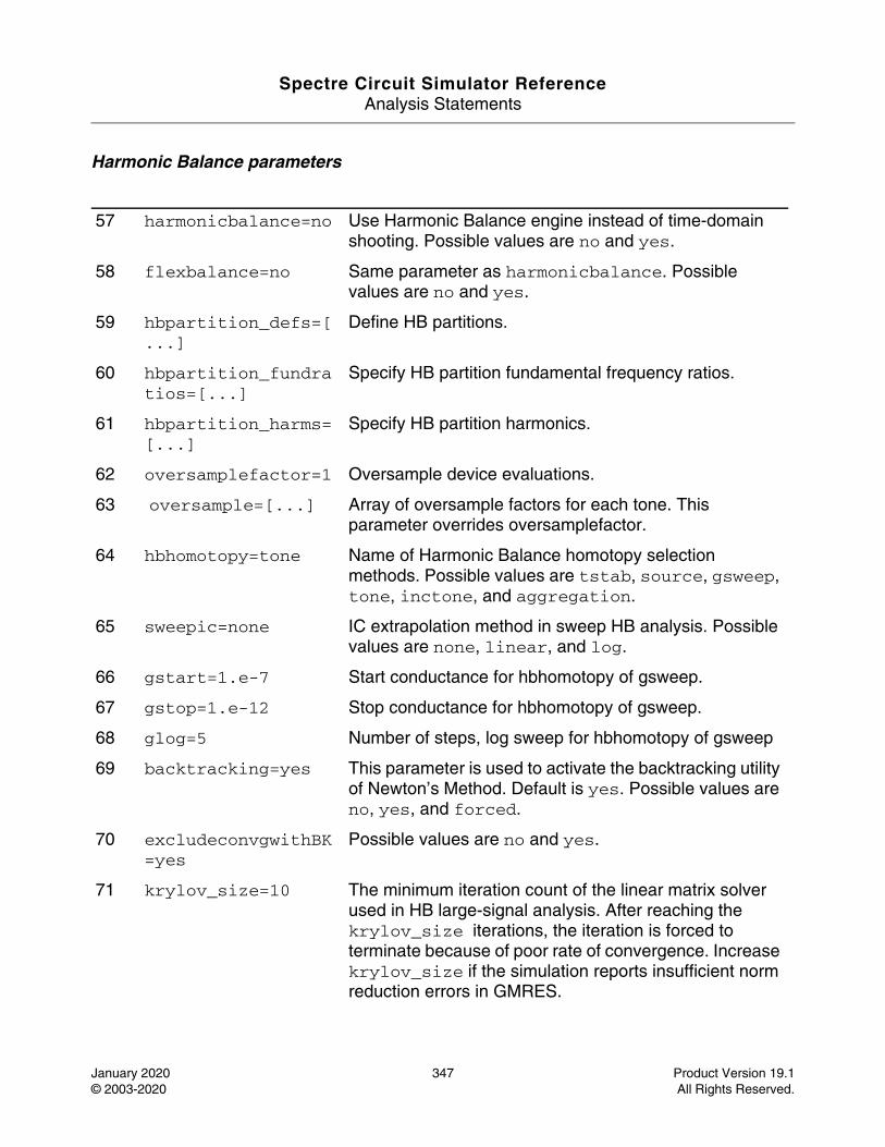
Spectre Circuit Simulator ReferenceAnalysis Statements
January 2020 347 Product Version 19.1© 2003-2020 All Rights Reserved.
Harmonic Balance parameters
57 harmonicbalance=no Use Harmonic Balance engine instead of time-domain shooting. Possible values are no and yes.
58 flexbalance=no Same parameter as harmonicbalance. Possible values are no and yes.
59 hbpartition_defs=[...]
Define HB partitions.
60 hbpartition_fundratios=[...]
Specify HB partition fundamental frequency ratios.
61 hbpartition_harms=[...]
Specify HB partition harmonics.
62 oversamplefactor=1 Oversample device evaluations.
63 oversample=[...] Array of oversample factors for each tone. This parameter overrides oversamplefactor.
64 hbhomotopy=tone Name of Harmonic Balance homotopy selection methods. Possible values are tstab, source, gsweep, tone, inctone, and aggregation.
65 sweepic=none IC extrapolation method in sweep HB analysis. Possible values are none, linear, and log.
66 gstart=1.e-7 Start conductance for hbhomotopy of gsweep.
67 gstop=1.e-12 Stop conductance for hbhomotopy of gsweep.
68 glog=5 Number of steps, log sweep for hbhomotopy of gsweep
69 backtracking=yes This parameter is used to activate the backtracking utility of Newton’s Method. Default is yes. Possible values are no, yes, and forced.
70 excludeconvgwithBK=yes
Possible values are no and yes.
71 krylov_size=10 The minimum iteration count of the linear matrix solver used in HB large-signal analysis. After reaching the krylov_size iterations, the iteration is forced to terminate because of poor rate of convergence. Increase krylov_size if the simulation reports insufficient norm reduction errors in GMRES.
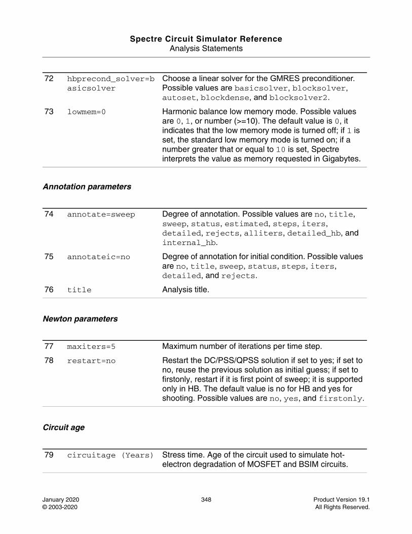
Spectre Circuit Simulator ReferenceAnalysis Statements
January 2020 348 Product Version 19.1© 2003-2020 All Rights Reserved.
Annotation parameters
Newton parameters
Circuit age
72 hbprecond_solver=basicsolver
Choose a linear solver for the GMRES preconditioner.Possible values are basicsolver, blocksolver, autoset, blockdense, and blocksolver2.
73 lowmem=0 Harmonic balance low memory mode. Possible values are 0, 1, or number (>=10). The default value is 0, it indicates that the low memory mode is turned off; if 1 is set, the standard low memory mode is turned on; if a number greater that or equal to 10 is set, Spectre interprets the value as memory requested in Gigabytes.
74 annotate=sweep Degree of annotation. Possible values are no, title, sweep, status, estimated, steps, iters, detailed, rejects, alliters, detailed_hb, and internal_hb.
75 annotateic=no Degree of annotation for initial condition. Possible values are no, title, sweep, status, steps, iters, detailed, and rejects.
76 title Analysis title.
77 maxiters=5 Maximum number of iterations per time step.
78 restart=no Restart the DC/PSS/QPSS solution if set to yes; if set to no, reuse the previous solution as initial guess; if set to firstonly, restart if it is first point of sweep; it is supported only in HB. The default value is no for HB and yes for shooting. Possible values are no, yes, and firstonly.
79 circuitage (Years) Stress time. Age of the circuit used to simulate hot-electron degradation of MOSFET and BSIM circuits.
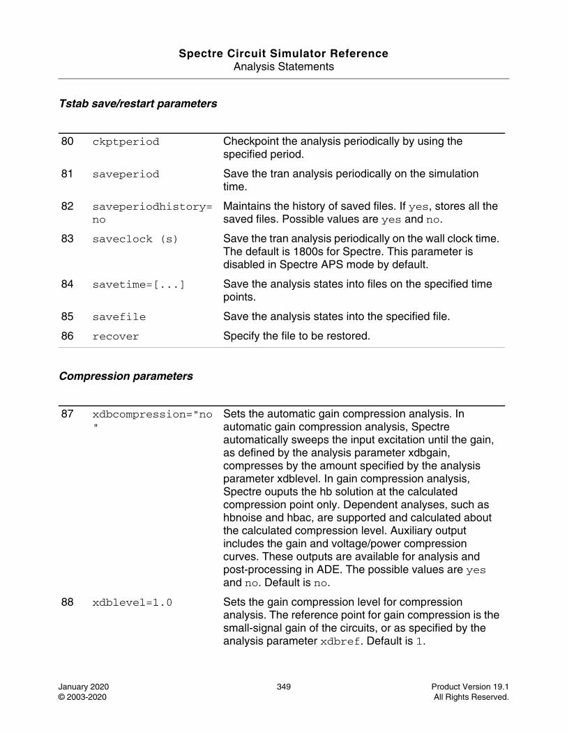
Spectre Circuit Simulator ReferenceAnalysis Statements
January 2020 349 Product Version 19.1© 2003-2020 All Rights Reserved.
Tstab save/restart parameters
Compression parameters
80 ckptperiod Checkpoint the analysis periodically by using the specified period.
81 saveperiod Save the tran analysis periodically on the simulation time.
82 saveperiodhistory=no
Maintains the history of saved files. If yes, stores all the saved files. Possible values are yes and no.
83 saveclock (s) Save the tran analysis periodically on the wall clock time. The default is 1800s for Spectre. This parameter is disabled in Spectre APS mode by default.
84 savetime=[...] Save the analysis states into files on the specified time points.
85 savefile Save the analysis states into the specified file.
86 recover Specify the file to be restored.
87 xdbcompression="no"
Sets the automatic gain compression analysis. In automatic gain compression analysis, Spectre automatically sweeps the input excitation until the gain, as defined by the analysis parameter xdbgain, compresses by the amount specified by the analysis parameter xdblevel. In gain compression analysis, Spectre ouputs the hb solution at the calculated compression point only. Dependent analyses, such as hbnoise and hbac, are supported and calculated about the calculated compression level. Auxiliary output includes the gain and voltage/power compression curves. These outputs are available for analysis and post-processing in ADE. The possible values are yes and no. Default is no.
88 xdblevel=1.0 Sets the gain compression level for compression analysis. The reference point for gain compression is the small-signal gain of the circuits, or as specified by the analysis parameter xdbref. Default is 1.

Spectre Circuit Simulator ReferenceAnalysis Statements
January 2020 350 Product Version 19.1© 2003-2020 All Rights Reserved.
89 xdbgain="power" Chooses between the voltage gain or transducer power gain as the target for compression point calculation. When xdbgain=power, the gain is defined as G (dB) = Pload (dBm) - Pavailable (dBm). When xdbgain=voltage, the gain is defined as G (dB) = dB20(|Vload|/|Vsource|). In both cases, Spectre sweeps the excitation source until xdbref - G = xdblevel, where the analysis parameter xdbref defines the reference level for compression calculation. Possible values are power and voltage. Default is power.
90 xdbref="linear" Sets the reference point for gain compression calculations. When xdbref=linear, spectre uses the small-signal gain as the reference. When xdbref=max, spectre uses the maximum observed gain as the reference. Possible values are linear and max. Default is linear.
91 xdbsource The instance name of the excitation source, which is swept automatically to reach the compression level. When xdbgain=power, the excitation source must be a port instance. When xdbgain=voltage, the excitation source must be a vsource instance.
92 xdbload The instance name of the load termination. When xdbgain is power, xdbload can be a port, a resistor, or a current probe.
93 xdbnodep The output terminals for voltage gain calculation when xdbgain=voltage. If either is left unspecified, the terminal is assumed to be the global ground.
94 xdbnoden The output terminals for voltage gain calculation when xdbgain=voltage. If either is left unspecified, the terminal is assumed to be the global ground.
95 xdbrefnode The reference node when xdbload is a current probe. The default is the ground node.
96 xdbharm=[...] The Integer array which specifies the harmonic indexes of the output voltage or power component.
97 xdbsteps=100 The maximum number of steps for the compression point search. The simulator terminates if xdbsteps exceeds before the compression point is found. The default is 100.
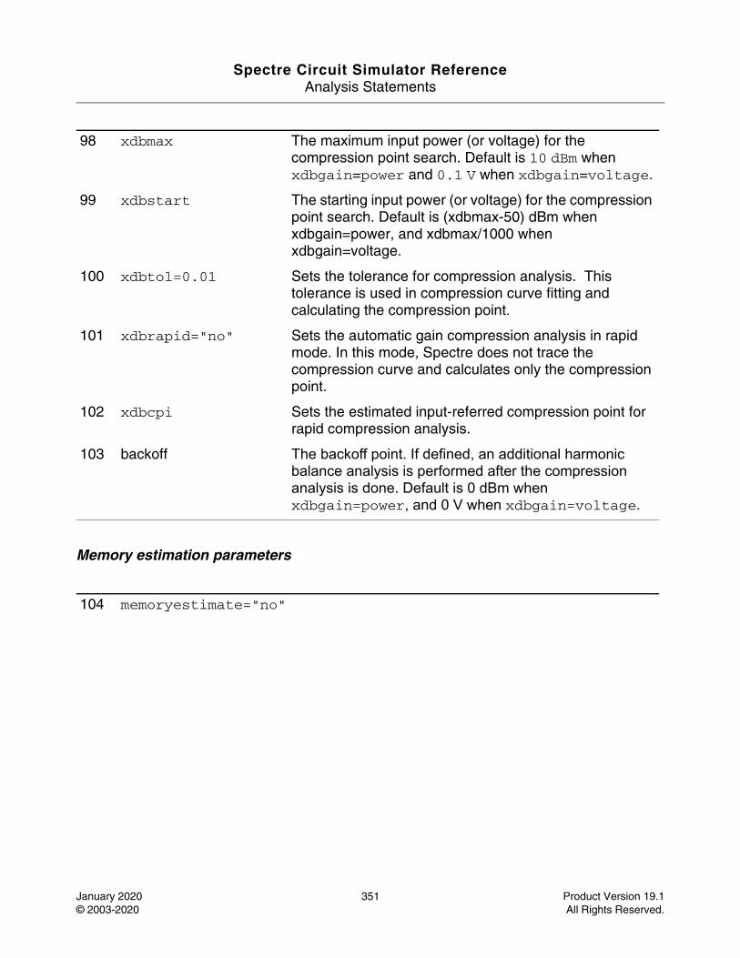
Spectre Circuit Simulator ReferenceAnalysis Statements
January 2020 351 Product Version 19.1© 2003-2020 All Rights Reserved.
Memory estimation parameters
98 xdbmax The maximum input power (or voltage) for the compression point search. Default is 10 dBm when xdbgain=power and 0.1 V when xdbgain=voltage.
99 xdbstart The starting input power (or voltage) for the compression point search. Default is (xdbmax-50) dBm when xdbgain=power, and xdbmax/1000 when xdbgain=voltage.
100 xdbtol=0.01 Sets the tolerance for compression analysis. This tolerance is used in compression curve fitting and calculating the compression point.
101 xdbrapid="no" Sets the automatic gain compression analysis in rapid mode. In this mode, Spectre does not trace the compression curve and calculates only the compression point.
102 xdbcpi Sets the estimated input-referred compression point for rapid compression analysis.
103 backoff The backoff point. If defined, an additional harmonic balance analysis is performed after the compression analysis is done. Default is 0 dBm when xdbgain=power, and 0 V when xdbgain=voltage.
104 memoryestimate="no"
Spectre Circuit Simulator ReferenceAnalysis Statements
January 2020 352 Product Version 19.1© 2003-2020 All Rights Reserved.
Most of QPSS analysis parameters are inherited from PSS analysis and their meanings remain essentially unchanged. Two new important parameters are funds and maxharms. They replace and extend the role of fund and harms parameters of PSS analysis. One important difference is that funds accepts a list of fundamental names, instead of actual frequencies. The frequencies associated with fundamentals are figured out automatically by the simulator. An important feature is that each input signal can be a composition of more than one source. However, these sources must have the same fundamental name. For each fundamental name, its fundamental frequency is the greatest common factor of all frequencies associated with the name. Omitting fundamental name in the funds parameter is an error that stops the simulation. If maxharms is not given, a warning message is issued, and the number of harmonics defaults to 1 for each fundamental.
For QPSS analyses, the role of some PSS parameters is extended compared to their role in PSS analysis. In QPSS, the parameter maxperiods that controls the maximum number of shooting iterations for PSS analysis also controls the number of the maximum number of shooting iterations for QPSS analysis. Its default value is set to 50.
The tstab parameter controls both the length of the initial transient integration with only the clock tone activated and the number of stable iterations with moderate tones activated. The stable iterations are run before shooting or HB Newton iterations.
The errpreset parameter lets you adjust several simulator parameters to fit your needs. In most cases, errpreset should be the only parameter you need to adjust. If you want a fast simulation with reasonable accuracy, set errpreset to liberal. If you have some concern for accuracy, set errpreset to moderate. If accuracy is your main interest, set errpreset to conservative.
Sets the memory usage estimate for Harmonic Balance. If yes, a memory estimate is printed in the log file. You can use this memory estimate to plan the computing resources before submitting harmonic balance runs. In memory estimate mode, a short simulation is performed first, and the engine exits after printing the estimate in the log file without saving any results. If set to no, the simulation continues after the memory estimate is printed.Memory estimation is not recommended for simulations that require less than 500MB approximately. For PSS analysis, memory estimate mode does not apply unless flexbalance=yes. Possible values are no, and yes. memoryestimate=1 estimates the memory usage for large-signal analysis and memoryestimate=2 estimates both large-signal analysis and small-signal simulations.
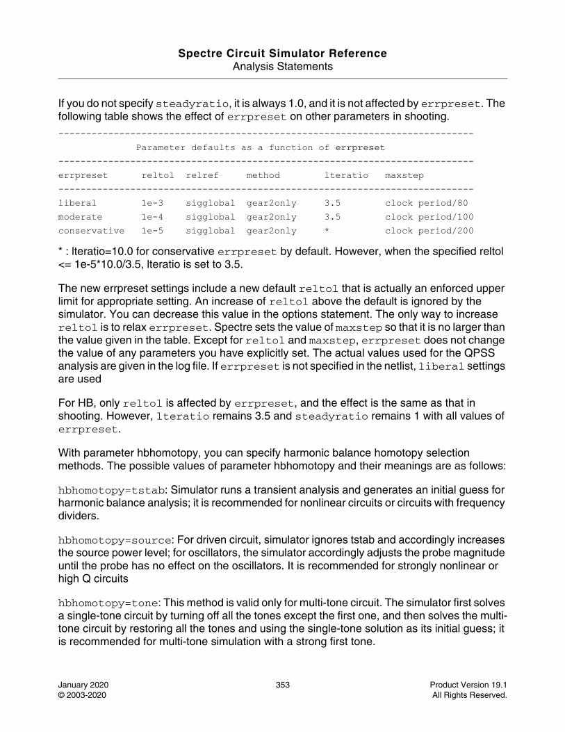
Spectre Circuit Simulator ReferenceAnalysis Statements
January 2020 353 Product Version 19.1© 2003-2020 All Rights Reserved.
If you do not specify steadyratio, it is always 1.0, and it is not affected by errpreset. The following table shows the effect of errpreset on other parameters in shooting.
--------------------------------------------------------------------------- Parameter defaults as a function of errpreset---------------------------------------------------------------------------errpreset reltol relref method lteratio maxstep---------------------------------------------------------------------------liberal 1e-3 sigglobal gear2only 3.5 clock period/80 moderate 1e-4 sigglobal gear2only 3.5 clock period/100conservative 1e-5 sigglobal gear2only * clock period/200
* : lteratio=10.0 for conservative errpreset by default. However, when the specified reltol <= 1e-5*10.0/3.5, lteratio is set to 3.5.
The new errpreset settings include a new default reltol that is actually an enforced upper limit for appropriate setting. An increase of reltol above the default is ignored by the simulator. You can decrease this value in the options statement. The only way to increase reltol is to relax errpreset. Spectre sets the value of maxstep so that it is no larger than the value given in the table. Except for reltol and maxstep, errpreset does not change the value of any parameters you have explicitly set. The actual values used for the QPSS analysis are given in the log file. If errpreset is not specified in the netlist, liberal settings are used
For HB, only reltol is affected by errpreset, and the effect is the same as that in shooting. However, lteratio remains 3.5 and steadyratio remains 1 with all values of errpreset.
With parameter hbhomotopy, you can specify harmonic balance homotopy selection methods. The possible values of parameter hbhomotopy and their meanings are as follows:
hbhomotopy=tstab: Simulator runs a transient analysis and generates an initial guess for harmonic balance analysis; it is recommended for nonlinear circuits or circuits with frequency dividers.
hbhomotopy=source: For driven circuit, simulator ignores tstab and accordingly increases the source power level; for oscillators, the simulator accordingly adjusts the probe magnitude until the probe has no effect on the oscillators. It is recommended for strongly nonlinear or high Q circuits
hbhomotopy=tone: This method is valid only for multi-tone circuit. The simulator first solves a single-tone circuit by turning off all the tones except the first one, and then solves the multi-tone circuit by restoring all the tones and using the single-tone solution as its initial guess; it is recommended for multi-tone simulation with a strong first tone.
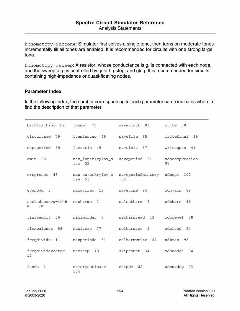
Spectre Circuit Simulator ReferenceAnalysis Statements
January 2020 354 Product Version 19.1© 2003-2020 All Rights Reserved.
hbhomotopy=inctone: Simulator first solves a single tone, then turns on moderate tones incrementally till all tones are enabled. It is recommended for circuits with one strong large tone.
hbhomotopy=gsweep: A resistor, whose conductance is g, is connected with each node, and the sweep of g is controlled by gstart, gstop, and glog. It is recommended for circuits containing high-impedance or quasi-floating nodes.
Parameter Index
In the following index, the number corresponding to each parameter name indicates where to find the description of that parameter.
backtracking 69 lowmem 73 saveclock 83 write 38
circuitage 79 lteminstep 49 savefile 85 writefinal 39
ckptperiod 80 lteratio 48 saveinit 37 writeqpss 41
cmin 28 max_innerkrylov_size 52
saveperiod 81 xdbcompression 87
errpreset 46 max_outerkrylov_size 53
saveperiodhistory 82
xdbcpi 102
evenodd 5 maxacfreq 19 savetime 84 xdbgain 89
excludeconvgwithBK 70
maxharms 2 selectharm 4 xdbharm 96
finitediff 56 maximorder 6 selharmread 43 xdblevel 88
flexbalance 58 maxiters 77 selharmvec 9 xdbload 92
freqdivide 11 maxperiods 51 selharmwrite 44 xdbmax 98
freqdividevector 12
maxstep 18 skipcount 34 xdbnoden 94
funds 1 memoryestimate 104
skipdc 22 xdbnodep 93
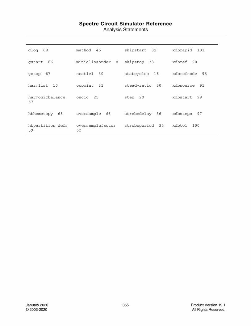
Spectre Circuit Simulator ReferenceAnalysis Statements
January 2020 355 Product Version 19.1© 2003-2020 All Rights Reserved.
glog 68 method 45 skipstart 32 xdbrapid 101
gstart 66 minialiasorder 8 skipstop 33 xdbref 90
gstop 67 nestlvl 30 stabcycles 16 xdbrefnode 95
harmlist 10 oppoint 31 steadyratio 50 xdbsource 91
harmonicbalance 57
oscic 25 step 20 xdbstart 99
hbhomotopy 65 oversample 63 strobedelay 36 xdbsteps 97
hbpartition_defs 59
oversamplefactor 62
strobeperiod 35 xdbtol 100
Spectre Circuit Simulator ReferenceAnalysis Statements
January 2020 356 Product Version 19.1© 2003-2020 All Rights Reserved.
Quasi-Periodic Transfer Function Analysis (qpxf)
Description
A conventional transfer function analysis computes the transfer function from every source in the circuit to a single output. Unlike a conventional AC analysis that computes the response from a single stimulus to every node in the circuit, the Quasi Periodic Transfer Function or QPXF analysis computes the transfer functions from any source at any frequency to a single output at a single frequency. Thus, like QPAC analysis, QPXF analysis includes frequency conversion effects.
The QPXF analysis directly computes such useful quantities as conversion efficiency (transfer function from input to output at required frequency), image and sideband rejection (input to output at undesired frequency), and LO feed-through and power supply rejection (undesired input to output at all frequencies).
As with a QPAC, QPSP, and QPNOISE analyses, a QPXF analysis must follow a QPSS analysis.
Unlike other analyses in Spectre, this analysis can only sweep frequency.
For information on how to run QPXF analysis from ADE, see QPXF Analysis in the Spectre Circuit Simulator and Accelerated Parallel Simulator RF Analysis User Guide.
DefinitionName [p] [n] qpxf parameter=value ...
The optional terminals (p and n) specify the output of the circuit. If you do not specify the terminals, you must specify the output with a probe component.
Parameters
Sweep interval parameters
1 start=0 Start sweep limit.
2 stop Stop sweep limit.
3 center Center of sweep.
Spectre Circuit Simulator ReferenceAnalysis Statements
January 2020 357 Product Version 19.1© 2003-2020 All Rights Reserved.
Probe parameters
Output parameters
4 span=0 Sweep limit span.
5 step Step size, linear sweep.
6 lin=50 Number of steps, linear sweep.
7 dec Points per decade.
8 log=50 Number of steps, log sweep.
9 values=[...] Array of sweep values.
10 valuesfile Name of the file containing the sweep values.
11 sweeptype Specifies if the sweep frequency range is an absolute frequency, that is, the actual frequency, or if it is relative to the "relharmvec" sideband frequency. Possible values are absolute and relative.
12 relharmvec=[...] Sideband- vector of QPSS harmonics- to which relative frequency sweep should be referenced.
13 probe Compute every transfer function to this probe component.
14 stimuli=sources Stimuli used for xf analysis. Possible values are sources and nodes_and_terminals.
15 sidevec=[...] Array of relevant sidebands for the analysis.
16 clockmaxharm=7 An alternative to the sidevec array specification, which automatically generates the array: [ -clockmaxharm ... 0 ... +clockmaxharms][-maxharms(QPSS)[2]...0...maxharms(QPSS)[2] ][...].
17 freqaxis Specifies whether the results should be printed as per the input frequency, the output frequency, or the absolute value of the input frequency. The default is absin. Possible values are absin, in, and out.
Spectre Circuit Simulator ReferenceAnalysis Statements
January 2020 358 Product Version 19.1© 2003-2020 All Rights Reserved.
Convergence parameters
18 save Signals to output. Possible values are all, lvl, allpub, lvlpub, selected, none, and nooutput.
19 nestlvl Levels of subcircuits to output.
20 tolerance Relative tolerance for linear solver; the default value is 1.0e-9 for shooting-based solver and 1.0e-6 for harmonicbalance-based solver.
21 relativeTol Relative tolerance for harmonicbalance-based linear solver; the default value is 1.0e-2.
22 gear_order=2 Gear order used for small-signal integration, 1 or 2.
23 solver=turbo Solver type. Possible values are std or turbo.
24 resgmrescycle=short
Restarts GMRES cycle. Possible values are instant, short, long, recycleinstant, recycleshort, custom, and recyclelong.
25 hbprecond_solver=autoset
Select a linear solver for the GMRES preconditioner. Default is autoset. With autoset, the simulator will automatically select the appropriate preconditioner. The preconditioner affects the rate of convergence of the linear matrix solver used in periodic small-signal analysis. When autoset is selected, the simulator may decide to switch to a different preconditioner after the analysis begins. When that happens, the simulator may issue a warning instructing you to choose a different preconditioner during subsequent runs. Although not required, choosing a different preconditioner according to the simulator’s instructions may speed up subsequent analyses. Possible values are basicsolver, blocksolver, autoset, blockdense, and blocksolver2.
Spectre Circuit Simulator ReferenceAnalysis Statements
January 2020 359 Product Version 19.1© 2003-2020 All Rights Reserved.
Annotation parameters
The variable of interest at the output can be voltage or current, and its frequency is not constrained by the period of the large periodic solution. While sweeping the selected output frequency, select the periodic small-signal input frequencies of interest by setting either the clockmaxharm or sidevec parameter. Sidebands are vectors in QPXF. Assuming that there is one large tone and one moderate tone in QPSS, a sideband K1 is represented as [K1_1 K1_2]. The corresponding frequency is as follows:
K1_1 * fund (large tone of QPSS) + K1_2 * fund (moderate tone of QPSS)
In addition, assume that there are L (1 large plus L-1 moderate) tones in QPSS analysis and a given set of n integer vectors representing the sidebands:
K1 = { K1_1,...K1_j..., K1_L} , K2, ... Kn.
27 lowmem=0 Harmonic balance low memory mode. Possible values are 0, 1, or number (>=10). The default value is 0, it indicates that the low memory mode is turned off; if 1 is set, the standard low memory mode is turned on; if a number greater that or equal to 10 is set, Spectre interprets the value as memory requested in Gigabytes.
27 max_innerkrylov_size=20
The maximum iteration number allowed in inner gmres solver in two-level gmres linear solver.
28 max_outerkrylov_size=4
The maximum iteration number allowed in inner gmres solver in two-level gmres linear solver.
29 krylov_size=200 The maximum iteration count of the linear matrix solver used in periodic small-signal analysis. After reaching 1.25*krylov_size iterations, the iteration is forced to terminate because of the poor rate of convergence. Increase krylov_size if the simulation reports insufficient norm reduction errors in GMRES.
30 annotate=sweep Degree of annotation. Possible values are no, title, sweep, status, steps, and detailed_hb.
31 title Analysis title.
Spectre Circuit Simulator ReferenceAnalysis Statements
January 2020 360 Product Version 19.1© 2003-2020 All Rights Reserved.
The input signal frequency at each sideband is computed as follows:
f(in)= f(out) + SUM_j=1_to_L{Ki_j * fund_j(qpss)},
where, f(out) represents the (possibly swept) output signal frequency, and fund_j(pss) represents the fundamental frequency used in the corresponding QPSS analysis. Thus, when analyzing a down-converting mixer and sweeping the IF output frequency, Ki= {1, 0} for the RF input represents the first upper-sideband, while Ki= {-1, 0} for the RF input represents the first lower-sideband.
Enter sidevec as a sequence of integer numbers, separated by spaces. The set of vectors {1 1 0} {1 -1 0} {1 1 1} becomes sidevec=[ 1 1 0 1 -1 0 1 1 1]. For clockmaxharm, only the large tone- the first fundamental is affected; the rest- moderate tones- are limited by maxharms, specified for a QPSS analysis. Given maxharms=[k1max k2max ... knmax] in QPSS and clockmaxharm=Kmax, all (2*Kmax + 1)*(2*k2max+1)*(2*k3max+1)*...*(2*knmax+1) sidebands are generated.
The number of requested sidebands changes substantially the simulation time.
With QPXF, the frequency of the stimulus and of the response are usually different (this is an important area in which QPXF differs from XF). The freqaxis parameter is used to specify whether the results should be output versus the input frequency (in), the output frequency (out), or the absolute value of the input frequency (absin).
You can specify the output with a pair of nodes or a probe component. Any component with two or more terminals can be a voltage probe. When there are more than two terminals, they are grouped in pairs, and you use the portv parameter to select the appropriate pair of terminals. Alternatively, you can specify a voltage to be the output by giving a pair of nodes on the QPXF analysis statement.
Any component that naturally computes current as an internal variable can be a current probe. If the probe component computes more than one current, you use the porti parameter to select the appropriate current. It is an error to specify both portv and porti. If neither is specified, the probe component provides a reasonable default.
The stimuli parameter specifies the inputs for the transfer functions. There are two choices. stimuli=sources indicates that the sources present in the circuit should be used. The xfmag parameters provided by the sources may be used to adjust the computed gain to compensate for gains or losses in a test fixture. You can limit the number of sources in hierarchical netlists by using the save and nestlvl parameters. stimuli=nodes_and_terminals indicates that all possible transfer functions should be computed.
This is useful when it is not known in advance which transfer functions are interesting. Transfer functions for nodes are computed assuming that a unit magnitude flow (current)
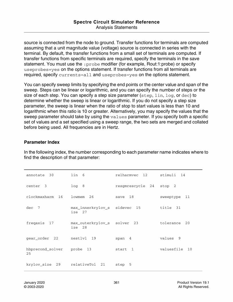
Spectre Circuit Simulator ReferenceAnalysis Statements
January 2020 361 Product Version 19.1© 2003-2020 All Rights Reserved.
source is connected from the node to ground. Transfer functions for terminals are computed assuming that a unit magnitude value (voltage) source is connected in series with the terminal. By default, the transfer functions from a small set of terminals are computed. If transfer functions from specific terminals are required, specify the terminals in the save statement. You must use the :probe modifier (for example, Rout:1:probe) or specify useprobes=yes on the options statement. If transfer functions from all terminals are required, specify currents=all and useprobes=yes on the options statement.
You can specify sweep limits by specifying the end points or the center value and span of the sweep. Steps can be linear or logarithmic, and you can specify the number of steps or the size of each step. You can specify a step size parameter (step, lin, log, or dec) to determine whether the sweep is linear or logarithmic. If you do not specify a step size parameter, the sweep is linear when the ratio of stop to start values is less than 10 and logarithmic when this ratio is 10 or greater. Alternatively, you may specify the values that the sweep parameter should take by using the values parameter. If you specify both a specific set of values and a set specified using a sweep range, the two sets are merged and collated before being used. All frequencies are in Hertz.
Parameter Index
In the following index, the number corresponding to each parameter name indicates where to find the description of that parameter:
annotate 30 lin 6 relharmvec 12 stimuli 14
center 3 log 8 resgmrescycle 24 stop 2
clockmaxharm 16 lowmem 26 save 18 sweeptype 11
dec 7 max_innerkrylov_size 27
sidevec 15 title 31
freqaxis 17 max_outerkrylov_size 28
solver 23 tolerance 20
gear_order 22 nestlvl 19 span 4 values 9
hbprecond_solver 25
probe 13 start 1 valuesfile 10
krylov_size 29 relativeTol 21 step 5
Spectre Circuit Simulator ReferenceAnalysis Statements
January 2020 362 Product Version 19.1© 2003-2020 All Rights Reserved.
Reliability Analysis (reliability)
Description
This analysis computes the reliability for MOSFETs and the circuit. The three reliability modules are:
■ MOSFET Hot-Carrier Injection (HCI) module
Predicts transistor and circuit performance degradation due to HCI effects
■ PMOSFET Negative Bias Temperature Instability (NBTI) module:
Predicts PMOSFET and circuit performance degradation due to NBTI and NBTI recovery effects
■ NMOSFET Positive Bias Temperature Instability (PBTI) module:
Predicts NMOSFET and circuit performance degradation due to PBTI effects
Synopsis:
name reliability <global options> {<reliability control statements> ...<stress simulation statements> ...<aging testbench statements> ...<aging/post-stress simulation statements> ...
}Note: Starting from MMSIM10.1.0 release version, the <global options> are ignored.
The other four sections should be listed in the specified order.
Also see Spectre Reliability Analysis in the Spectre Classic Simulator, Spectre APS, Spectre X, and Spectre XPS User Guide.
DefinitionName reliability parameter=value ...
Parameters
1 Analysis parameters Analysis title
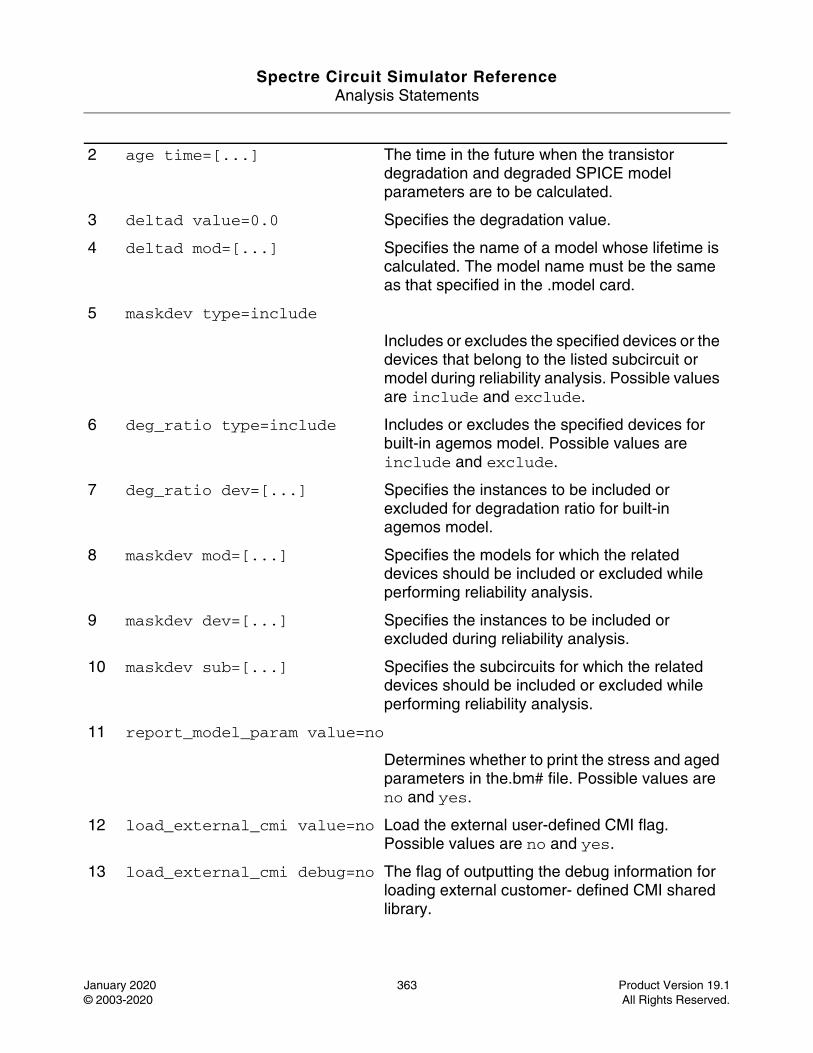
Spectre Circuit Simulator ReferenceAnalysis Statements
January 2020 363 Product Version 19.1© 2003-2020 All Rights Reserved.
2 age time=[...] The time in the future when the transistor degradation and degraded SPICE model parameters are to be calculated.
3 deltad value=0.0 Specifies the degradation value.
4 deltad mod=[...] Specifies the name of a model whose lifetime is calculated. The model name must be the same as that specified in the .model card.
5 maskdev type=include
Includes or excludes the specified devices or the devices that belong to the listed subcircuit or model during reliability analysis. Possible values are include and exclude.
6 deg_ratio type=include Includes or excludes the specified devices for built-in agemos model. Possible values are include and exclude.
7 deg_ratio dev=[...] Specifies the instances to be included or excluded for degradation ratio for built-in agemos model.
8 maskdev mod=[...] Specifies the models for which the related devices should be included or excluded while performing reliability analysis.
9 maskdev dev=[...] Specifies the instances to be included or excluded during reliability analysis.
10 maskdev sub=[...] Specifies the subcircuits for which the related devices should be included or excluded while performing reliability analysis.
11 report_model_param value=no
Determines whether to print the stress and aged parameters in the.bm# file. Possible values are no and yes.
12 load_external_cmi value=no Load the external user-defined CMI flag. Possible values are no and yes.
13 load_external_cmi debug=no The flag of outputting the debug information for loading external customer- defined CMI shared library.
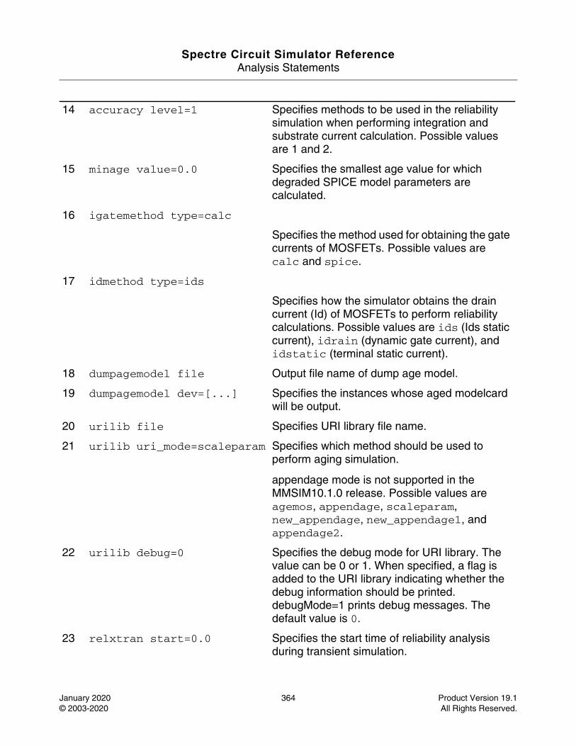
Spectre Circuit Simulator ReferenceAnalysis Statements
January 2020 364 Product Version 19.1© 2003-2020 All Rights Reserved.
14 accuracy level=1 Specifies methods to be used in the reliability simulation when performing integration and substrate current calculation. Possible values are 1 and 2.
15 minage value=0.0 Specifies the smallest age value for which degraded SPICE model parameters are calculated.
16 igatemethod type=calc
Specifies the method used for obtaining the gate currents of MOSFETs. Possible values are calc and spice.
17 idmethod type=ids
Specifies how the simulator obtains the drain current (Id) of MOSFETs to perform reliability calculations. Possible values are ids (Ids static current), idrain (dynamic gate current), and idstatic (terminal static current).
18 dumpagemodel file Output file name of dump age model.
19 dumpagemodel dev=[...] Specifies the instances whose aged modelcard will be output.
20 urilib file Specifies URI library file name.
21 urilib uri_mode=scaleparam Specifies which method should be used to perform aging simulation.
appendage mode is not supported in the MMSIM10.1.0 release. Possible values are agemos, appendage, scaleparam, new_appendage, new_appendage1, and appendage2.
22 urilib debug=0 Specifies the debug mode for URI library. The value can be 0 or 1. When specified, a flag is added to the URI library indicating whether the debug information should be printed. debugMode=1 prints debug messages. The default value is 0.
23 relxtran start=0.0 Specifies the start time of reliability analysis during transient simulation.
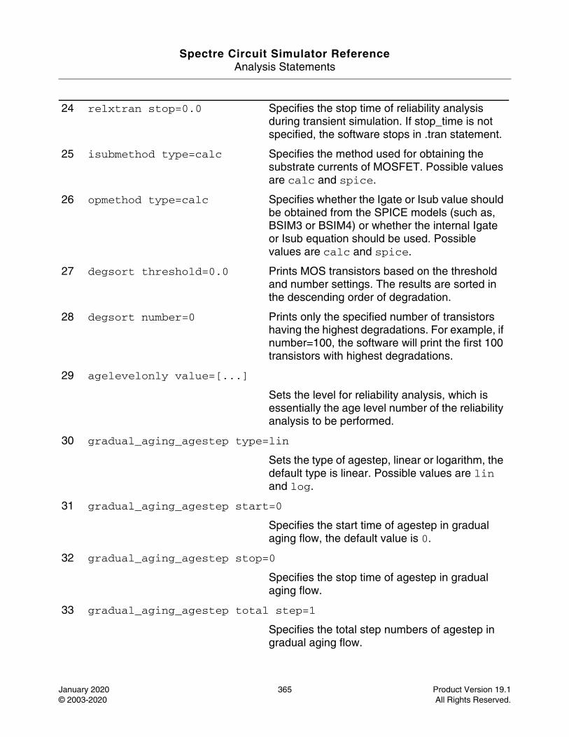
Spectre Circuit Simulator ReferenceAnalysis Statements
January 2020 365 Product Version 19.1© 2003-2020 All Rights Reserved.
24 relxtran stop=0.0 Specifies the stop time of reliability analysis during transient simulation. If stop_time is not specified, the software stops in .tran statement.
25 isubmethod type=calc Specifies the method used for obtaining the substrate currents of MOSFET. Possible values are calc and spice.
26 opmethod type=calc Specifies whether the Igate or Isub value should be obtained from the SPICE models (such as, BSIM3 or BSIM4) or whether the internal Igate or Isub equation should be used. Possible values are calc and spice.
27 degsort threshold=0.0 Prints MOS transistors based on the threshold and number settings. The results are sorted in the descending order of degradation.
28 degsort number=0 Prints only the specified number of transistors having the highest degradations. For example, if number=100, the software will print the first 100 transistors with highest degradations.
29 agelevelonly value=[...]
Sets the level for reliability analysis, which is essentially the age level number of the reliability analysis to be performed.
30 gradual_aging_agestep type=lin
Sets the type of agestep, linear or logarithm, the default type is linear. Possible values are lin and log.
31 gradual_aging_agestep start=0
Specifies the start time of agestep in gradual aging flow, the default value is 0.
32 gradual_aging_agestep stop=0
Specifies the stop time of agestep in gradual aging flow.
33 gradual_aging_agestep total step=1
Specifies the total step numbers of agestep in gradual aging flow.
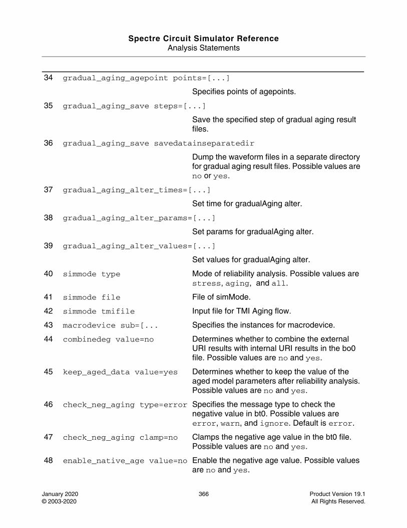
Spectre Circuit Simulator ReferenceAnalysis Statements
January 2020 366 Product Version 19.1© 2003-2020 All Rights Reserved.
34 gradual_aging_agepoint points=[...]
Specifies points of agepoints.
35 gradual_aging_save steps=[...]
Save the specified step of gradual aging result files.
36 gradual_aging_save savedatainseparatedir
Dump the waveform files in a separate directory for gradual aging result files. Possible values are no or yes.
37 gradual_aging_alter_times=[...]
Set time for gradualAging alter.
38 gradual_aging_alter_params=[...]
Set params for gradualAging alter.
39 gradual_aging_alter_values=[...]
Set values for gradualAging alter.
40 simmode type Mode of reliability analysis. Possible values are stress, aging, and all.
41 simmode file File of simMode.
42 simmode tmifile Input file for TMI Aging flow.
43 macrodevice sub=[... Specifies the instances for macrodevice.
44 combinedeg value=no Determines whether to combine the external URI results with internal URI results in the bo0 file. Possible values are no and yes.
45 keep_aged_data value=yes Determines whether to keep the value of the aged model parameters after reliability analysis. Possible values are no and yes.
46 check_neg_aging type=error Specifies the message type to check the negative value in bt0. Possible values are error, warn, and ignore. Default is error.
47 check_neg_aging clamp=no Clamps the negative age value in the bt0 file. Possible values are no and yes.
48 enable_native_age value=no Enable the negative age value. Possible values are no and yes.
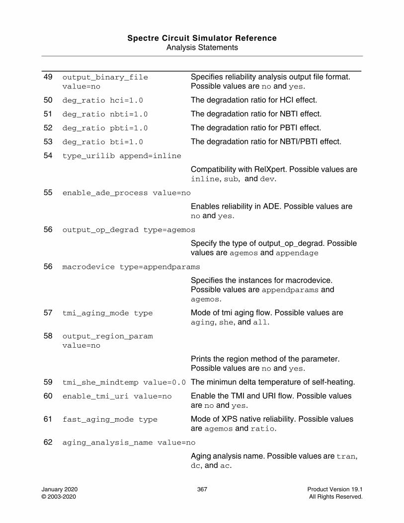
Spectre Circuit Simulator ReferenceAnalysis Statements
January 2020 367 Product Version 19.1© 2003-2020 All Rights Reserved.
49 output_binary_file value=no
Specifies reliability analysis output file format. Possible values are no and yes.
50 deg_ratio hci=1.0 The degradation ratio for HCI effect.
51 deg_ratio nbti=1.0 The degradation ratio for NBTI effect.
52 deg_ratio pbti=1.0 The degradation ratio for PBTI effect.
53 deg_ratio bti=1.0 The degradation ratio for NBTI/PBTI effect.
54 type_urilib append=inline
Compatibility with RelXpert. Possible values are inline, sub, and dev.
55 enable_ade_process value=no
Enables reliability in ADE. Possible values are no and yes.
56 output_op_degrad type=agemos
Specify the type of output_op_degrad. Possible values are agemos and appendage
56 macrodevice type=appendparams
Specifies the instances for macrodevice. Possible values are appendparams and agemos.
57 tmi_aging_mode type Mode of tmi aging flow. Possible values are aging, she, and all.
58 output_region_param value=no
Prints the region method of the parameter. Possible values are no and yes.
59 tmi_she_mindtemp value=0.0 The minimun delta temperature of self-heating.
60 enable_tmi_uri value=no Enable the TMI and URI flow. Possible values are no and yes.
61 fast_aging_mode type Mode of XPS native reliability. Possible values are agemos and ratio.
62 aging_analysis_name value=no
Aging analysis name. Possible values are tran, dc, and ac.
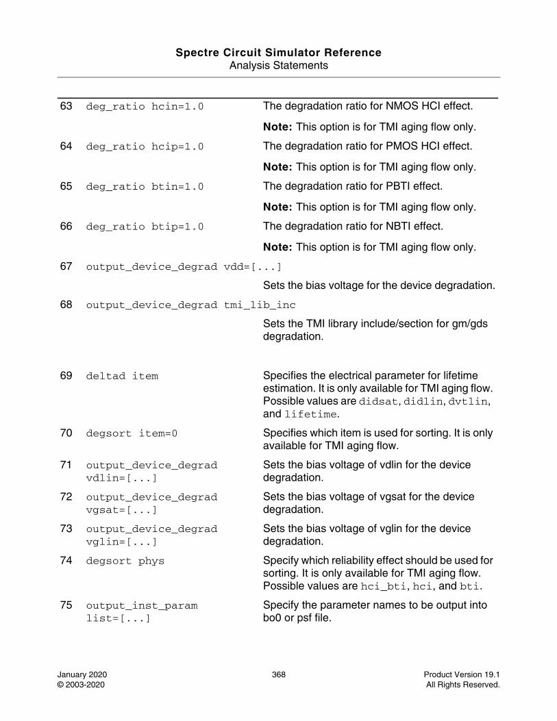
Spectre Circuit Simulator ReferenceAnalysis Statements
January 2020 368 Product Version 19.1© 2003-2020 All Rights Reserved.
63 deg_ratio hcin=1.0 The degradation ratio for NMOS HCI effect.
Note: This option is for TMI aging flow only.
64 deg_ratio hcip=1.0 The degradation ratio for PMOS HCI effect.
Note: This option is for TMI aging flow only.
65 deg_ratio btin=1.0 The degradation ratio for PBTI effect.
Note: This option is for TMI aging flow only.
66 deg_ratio btip=1.0 The degradation ratio for NBTI effect.
Note: This option is for TMI aging flow only.
67 output_device_degrad vdd=[...]
Sets the bias voltage for the device degradation.
68 output_device_degrad tmi_lib_inc
Sets the TMI library include/section for gm/gds degradation.
69 deltad item Specifies the electrical parameter for lifetime estimation. It is only available for TMI aging flow. Possible values are didsat, didlin, dvtlin, and lifetime.
70 degsort item=0 Specifies which item is used for sorting. It is only available for TMI aging flow.
71 output_device_degrad vdlin=[...]
Sets the bias voltage of vdlin for the device degradation.
72 output_device_degrad vgsat=[...]
Sets the bias voltage of vgsat for the device degradation.
73 output_device_degrad vglin=[...]
Sets the bias voltage of vglin for the device degradation.
74 degsort phys Specify which reliability effect should be used for sorting. It is only available for TMI aging flow.Possible values are hci_bti, hci, and bti.
75 output_inst_param list=[...]
Specify the parameter names to be output into bo0 or psf file.
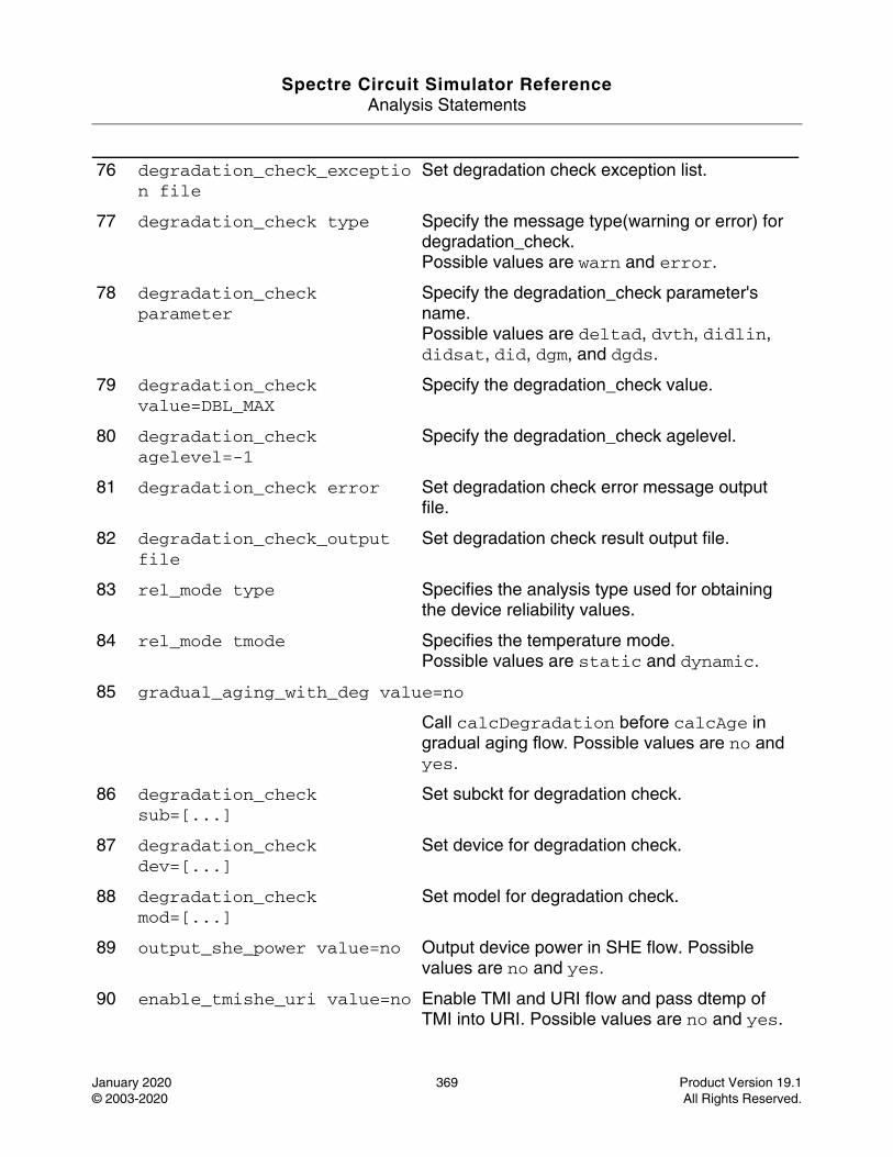
Spectre Circuit Simulator ReferenceAnalysis Statements
January 2020 369 Product Version 19.1© 2003-2020 All Rights Reserved.
76 degradation_check_exception file
Set degradation check exception list.
77 degradation_check type Specify the message type(warning or error) for degradation_check.Possible values are warn and error.
78 degradation_check parameter
Specify the degradation_check parameter's name.Possible values are deltad, dvth, didlin, didsat, did, dgm, and dgds.
79 degradation_check value=DBL_MAX
Specify the degradation_check value.
80 degradation_check agelevel=-1
Specify the degradation_check agelevel.
81 degradation_check error Set degradation check error message output file.
82 degradation_check_output file
Set degradation check result output file.
83 rel_mode type Specifies the analysis type used for obtaining the device reliability values.
84 rel_mode tmode Specifies the temperature mode.Possible values are static and dynamic.
85 gradual_aging_with_deg value=no
Call calcDegradation before calcAge in gradual aging flow. Possible values are no and yes.
86 degradation_check sub=[...]
Set subckt for degradation check.
87 degradation_check dev=[...]
Set device for degradation check.
88 degradation_check mod=[...]
Set model for degradation check.
89 output_she_power value=no Output device power in SHE flow. Possible values are no and yes.
90 enable_tmishe_uri value=no Enable TMI and URI flow and pass dtemp of TMI into URI. Possible values are no and yes.
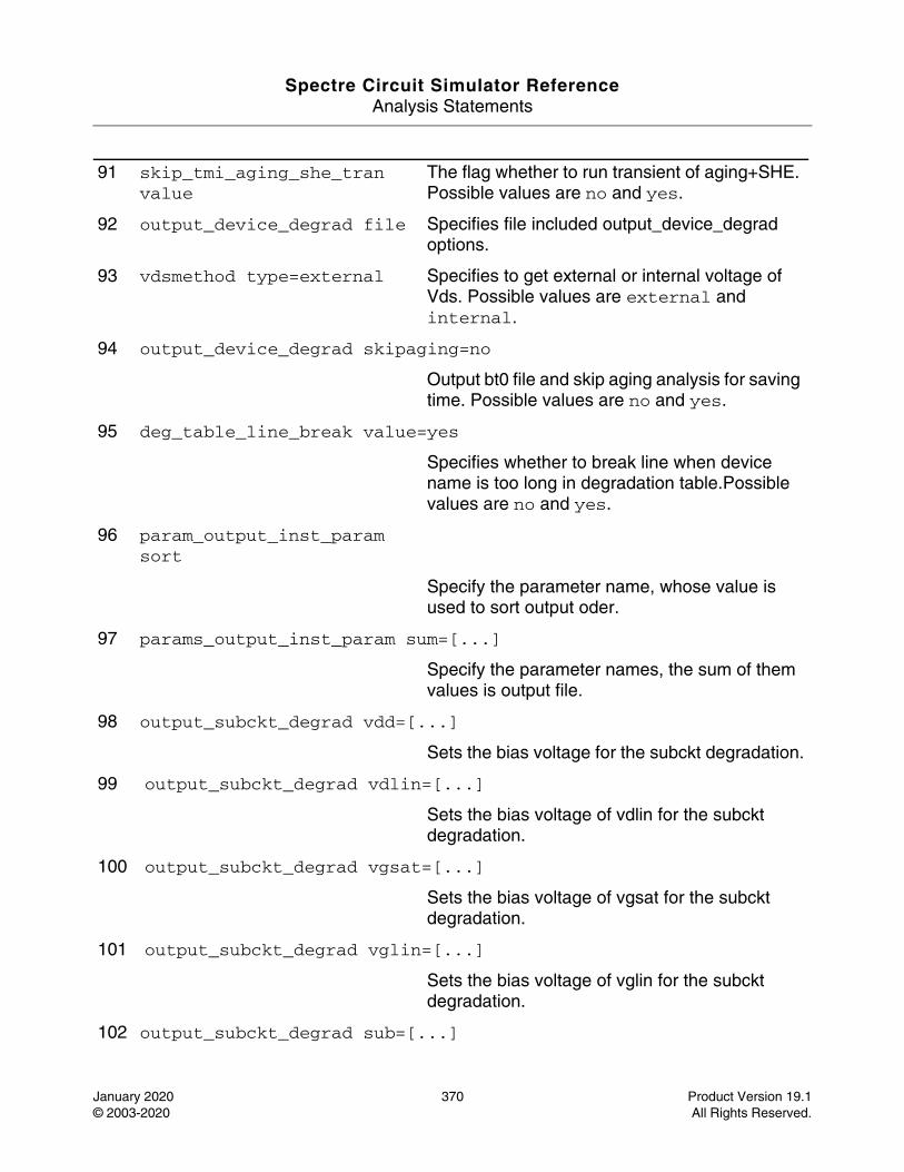
Spectre Circuit Simulator ReferenceAnalysis Statements
January 2020 370 Product Version 19.1© 2003-2020 All Rights Reserved.
91 skip_tmi_aging_she_tran value
The flag whether to run transient of aging+SHE. Possible values are no and yes.
92 output_device_degrad file Specifies file included output_device_degrad options.
93 vdsmethod type=external Specifies to get external or internal voltage of Vds. Possible values are external and internal.
94 output_device_degrad skipaging=no
Output bt0 file and skip aging analysis for saving time. Possible values are no and yes.
95 deg_table_line_break value=yes
Specifies whether to break line when device name is too long in degradation table.Possible values are no and yes.
96 param_output_inst_param sort
Specify the parameter name, whose value is used to sort output oder.
97 params_output_inst_param sum=[...]
Specify the parameter names, the sum of them values is output file.
98 output_subckt_degrad vdd=[...]
Sets the bias voltage for the subckt degradation.
99 output_subckt_degrad vdlin=[...]
Sets the bias voltage of vdlin for the subckt degradation.
100 output_subckt_degrad vgsat=[...]
Sets the bias voltage of vgsat for the subckt degradation.
101 output_subckt_degrad vglin=[...]
Sets the bias voltage of vglin for the subckt degradation.
102 output_subckt_degrad sub=[...]
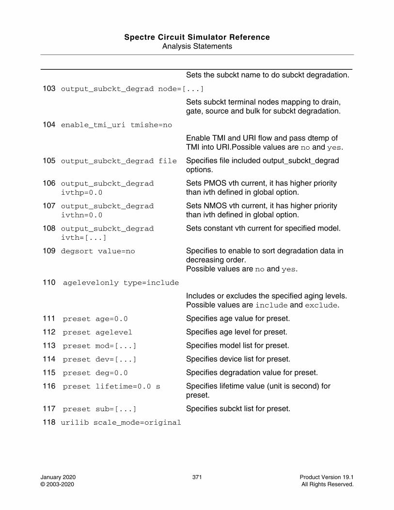
Spectre Circuit Simulator ReferenceAnalysis Statements
January 2020 371 Product Version 19.1© 2003-2020 All Rights Reserved.
Sets the subckt name to do subckt degradation.
103 output_subckt_degrad node=[...]
Sets subckt terminal nodes mapping to drain, gate, source and bulk for subckt degradation.
104 enable_tmi_uri tmishe=no
Enable TMI and URI flow and pass dtemp of TMI into URI.Possible values are no and yes.
105 output_subckt_degrad file Specifies file included output_subckt_degrad options.
106 output_subckt_degrad ivthp=0.0
Sets PMOS vth current, it has higher priority than ivth defined in global option.
107 output_subckt_degrad ivthn=0.0
Sets NMOS vth current, it has higher priority than ivth defined in global option.
108 output_subckt_degrad ivth=[...]
Sets constant vth current for specified model.
109 degsort value=no Specifies to enable to sort degradation data in decreasing order.Possible values are no and yes.
110 agelevelonly type=include
Includes or excludes the specified aging levels.Possible values are include and exclude.
111 preset age=0.0 Specifies age value for preset.
112 preset agelevel Specifies age level for preset.
113 preset mod=[...] Specifies model list for preset.
114 preset dev=[...] Specifies device list for preset.
115 preset deg=0.0 Specifies degradation value for preset.
116 preset lifetime=0.0 s Specifies lifetime value (unit is second) for preset.
117 preset sub=[...] Specifies subckt list for preset.
118 urilib scale_mode=original
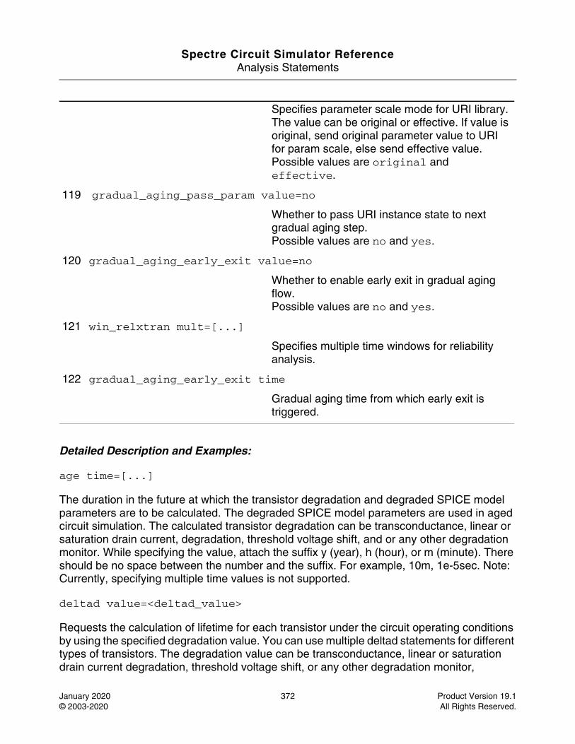
Spectre Circuit Simulator ReferenceAnalysis Statements
January 2020 372 Product Version 19.1© 2003-2020 All Rights Reserved.
Detailed Description and Examples:
age time=[...]
The duration in the future at which the transistor degradation and degraded SPICE model parameters are to be calculated. The degraded SPICE model parameters are used in aged circuit simulation. The calculated transistor degradation can be transconductance, linear or saturation drain current, degradation, threshold voltage shift, and or any other degradation monitor. While specifying the value, attach the suffix y (year), h (hour), or m (minute). There should be no space between the number and the suffix. For example, 10m, 1e-5sec. Note: Currently, specifying multiple time values is not supported.
deltad value=<deltad_value>
Requests the calculation of lifetime for each transistor under the circuit operating conditions by using the specified degradation value. You can use multiple deltad statements for different types of transistors. The degradation value can be transconductance, linear or saturation drain current degradation, threshold voltage shift, or any other degradation monitor,
Specifies parameter scale mode for URI library. The value can be original or effective. If value is original, send original parameter value to URI for param scale, else send effective value.Possible values are original and effective.
119 gradual_aging_pass_param value=no
Whether to pass URI instance state to next gradual aging step.Possible values are no and yes.
120 gradual_aging_early_exit value=no
Whether to enable early exit in gradual aging flow.Possible values are no and yes.
121 win_relxtran mult=[...]
Specifies multiple time windows for reliability analysis.
122 gradual_aging_early_exit time
Gradual aging time from which early exit is triggered.
Spectre Circuit Simulator ReferenceAnalysis Statements
January 2020 373 Product Version 19.1© 2003-2020 All Rights Reserved.
depending on the definitions of the lifetime parameters H and m. deltad_value can be in decimal notation (xx.xx) or in engineering notation (x.xxe+xx).
maskdev type={include | exclude} {sub=<subckt_list> | mod=<model_list> | dev=<device_list>}
Includes or excludes the specified devices or the devices that belong to the listed subcircuit or model during reliability analysis.
Note: Starting from MMSIM10.1, the include and exclude values are mutually exclusive.
report_model_param value={yes | no}(defaults to no)
Determines whether to print the stress and aged parameters in the.bm# file. Possible values are yes and no. When set to yes, the stress and aged parameters are printed to the .bm# file.
accuracy level={1 | 2}(defaults to 1)
Specifies methods used in the reliability simulation when performing integration and substrate current calculation. In other words, specifies trapezoidal integration when performing integrations and calculates Isub for Vgs < Vth. When set to 1, the software uses backward Euler integration and sets Isub=0 when Vgs < Vth. When set to 2, the software uses trapezoidal integration and calculates Isub when Vgs < Vth. Setting accuracy to 2 is more accurate, but increases simulation time when compared to when accuracy is set to 1.
minage value=<minage_value>
Specifies the smallest Age value for which degraded SPICE model parameters are calculated. This statement speeds up aging calculation by using stress SPICE model parameters if the transistor Age value is smaller than the specified minage_value. minage_value can be in decimal notation (xx.xx) or in engineering notation (x.xxe+xx).
igatemethod type={calc | spice}(defaults to calc)
Specifies the method used for obtaining the gate terminal current of a MOSFET. During MOSFET HCI simulation, the gate terminal current is required for calculating the degradation value. The simulator can either calculate this value or obtain it from the SPICE output rawfile, if the SPICE simulator in use provides such an option. If this command is not used, the simulator calculates the gate terminal current by using its own model parameters. Possible values are calc (default) and spice. When calc is specified, the gate terminal current is calculated using the model parameters, and when spice is specified, the gate terminal current value is obtained from the SPICE output rawfile.
idmethod type={ids | idrain}(defaults to ids)
Spectre Circuit Simulator ReferenceAnalysis Statements
January 2020 374 Product Version 19.1© 2003-2020 All Rights Reserved.
Specifies how the simulator obtains the drain current (Id) to perform reliability calculations. The following types of drain currents, which are available from SPICE, are supported by reliability analysis:
* Dynamic drain current (also called AC drain current)- the current that flows into the drain node.
* Static drain current (also called channel drain current, DC drain current, or Ids)- Possible values are ids (Ids static current ) or idrain (dynamic drain current). The default is ids.
uri_lib file={"filename"} uri_mode={agemos | appendage} debug={0 | 1}
Loads the Unified Reliability interface (URI) shared library and specifies which method (uri_mode) should be used to perform aging simulation.
Note: appendage mode is not supported in the MMSIM10.1 release.
relx_tran start=<start_time> stop=<stop_time>
Specifies the start and stop time for reliability analysis during transient analysis. If stop_time is not specified, the software stops in .tran statement.
isubmethod type={calc | spice}(defaults to calc)
Specifies the method used for obtaining substrate terminal current of a MOSFET. During MOSFET HCI simulation, the substrate terminal current is required for calculating the degradation value. The Spectre RelXpert simulator can either calculate this value or obtain it from the SPICE output rawfile, if the SPICE simulator in use provides such an option. If this command is not used, the simulator calculates the substrate terminal current by using its own model parameters. Possible values are calc (default) and spice. When calc is specified, the substrate terminal current is calculated using the model parameters, and when spice is specified, the substrate terminal current value is obtained from the SPICE output rawfile.
opmethod type={calc | spice}(defaults to calc)
Specifies whether the Igate or Isub value should be obtained from the SPICE models (for example, BSIM3 or BSIM4) or the internal Igate or Isub equation should be used. Possible values are calc or spice. calc calculates the gate and substrate terminal current by using the Cadence Igate and Isub model equations (default). spice obtains the gate and substrate terminal current value from the SPICE model.
degsort {threshold=<threshold_value> | number=<number_value>}
Prints MOS transistors based on the threshold value or number settings. The results are sorted in the descending order of degradation.
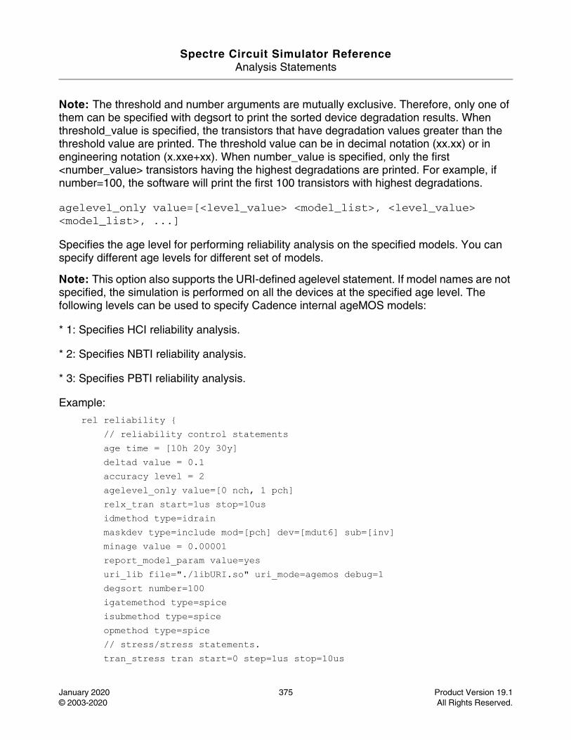
Spectre Circuit Simulator ReferenceAnalysis Statements
January 2020 375 Product Version 19.1© 2003-2020 All Rights Reserved.
Note: The threshold and number arguments are mutually exclusive. Therefore, only one of them can be specified with degsort to print the sorted device degradation results. When threshold_value is specified, the transistors that have degradation values greater than the threshold value are printed. The threshold value can be in decimal notation (xx.xx) or in engineering notation (x.xxe+xx). When number_value is specified, only the first <number_value> transistors having the highest degradations are printed. For example, if number=100, the software will print the first 100 transistors with highest degradations.
agelevel_only value=[<level_value> <model_list>, <level_value> <model_list>, ...]
Specifies the age level for performing reliability analysis on the specified models. You can specify different age levels for different set of models.
Note: This option also supports the URI-defined agelevel statement. If model names are not specified, the simulation is performed on all the devices at the specified age level. The following levels can be used to specify Cadence internal ageMOS models:
* 1: Specifies HCI reliability analysis.
* 2: Specifies NBTI reliability analysis.
* 3: Specifies PBTI reliability analysis.
Example:
rel reliability { // reliability control statements age time = [10h 20y 30y] deltad value = 0.1 accuracy level = 2 agelevel_only value=[0 nch, 1 pch] relx_tran start=1us stop=10us idmethod type=idrain maskdev type=include mod=[pch] dev=[mdut6] sub=[inv] minage value = 0.00001 report_model_param value=yes uri_lib file="./libURI.so" uri_mode=agemos debug=1 degsort number=100 igatemethod type=spice isubmethod type=spice opmethod type=spice // stress/stress statements. tran_stress tran start=0 step=1us stop=10us
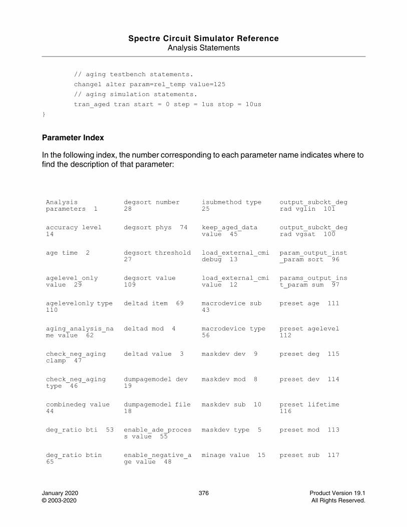
Spectre Circuit Simulator ReferenceAnalysis Statements
January 2020 376 Product Version 19.1© 2003-2020 All Rights Reserved.
// aging testbench statements. change1 alter param=rel_temp value=125 // aging simulation statements. tran_aged tran start = 0 step = 1us stop = 10us}
Parameter Index
In the following index, the number corresponding to each parameter name indicates where to find the description of that parameter:
Analysis parameters 1
degsort number 28
isubmethod type 25
output_subckt_degrad vglin 101
accuracy level 14
degsort phys 74 keep_aged_data value 45
output_subckt_degrad vgsat 100
age time 2 degsort threshold 27
load_external_cmi debug 13
param_output_inst_param sort 96
agelevel_only value 29
degsort value 109
load_external_cmi value 12
params_output_inst_param sum 97
agelevelonly type 110
deltad item 69 macrodevice sub 43
preset age 111
aging_analysis_name value 62
deltad mod 4 macrodevice type 56
preset agelevel 112
check_neg_aging clamp 47
deltad value 3 maskdev dev 9 preset deg 115
check_neg_aging type 46
dumpagemodel dev 19
maskdev mod 8 preset dev 114
combinedeg value 44
dumpagemodel file 18
maskdev sub 10 preset lifetime 116
deg_ratio bti 53 enable_ade_process value 55
maskdev type 5 preset mod 113
deg_ratio btin 65
enable_negative_age value 48
minage value 15 preset sub 117
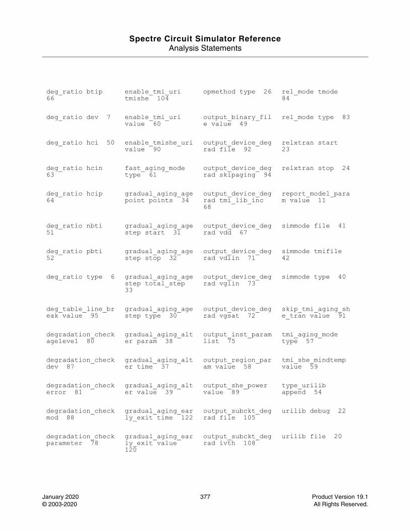
Spectre Circuit Simulator ReferenceAnalysis Statements
January 2020 377 Product Version 19.1© 2003-2020 All Rights Reserved.
deg_ratio btip 66
enable_tmi_uri tmishe 104
opmethod type 26 rel_mode tmode 84
deg_ratio dev 7 enable_tmi_uri value 60
output_binary_file value 49
rel_mode type 83
deg_ratio hci 50 enable_tmishe_uri value 90
output_device_degrad file 92
relxtran start 23
deg_ratio hcin 63
fast_aging_mode type 61
output_device_degrad skipaging 94
relxtran stop 24
deg_ratio hcip 64
gradual_aging_agepoint points 34
output_device_degrad tmi_lib_inc 68
report_model_param value 11
deg_ratio nbti 51
gradual_aging_agestep start 31
output_device_degrad vdd 67
simmode file 41
deg_ratio pbti 52
gradual_aging_agestep stop 32
output_device_degrad vdlin 71
simmode tmifile 42
deg_ratio type 6 gradual_aging_agestep total_step 33
output_device_degrad vglin 73
simmode type 40
deg_table_line_break value 95
gradual_aging_agestep type 30
output_device_degrad vgsat 72
skip_tmi_aging_she_tran value 91
degradation_check agelevel 80
gradual_aging_alter param 38
output_inst_param list 75
tmi_aging_mode type 57
degradation_check dev 87
gradual_aging_alter time 37
output_region_param value 58
tmi_she_mindtemp value 59
degradation_check error 81
gradual_aging_alter value 39
output_she_power value 89
type_urilib append 54
degradation_check mod 88
gradual_aging_early_exit time 122
output_subckt_degrad file 105
urilib debug 22
degradation_check parameter 78
gradual_aging_early_exit value 120
output_subckt_degrad ivth 108
urilib file 20
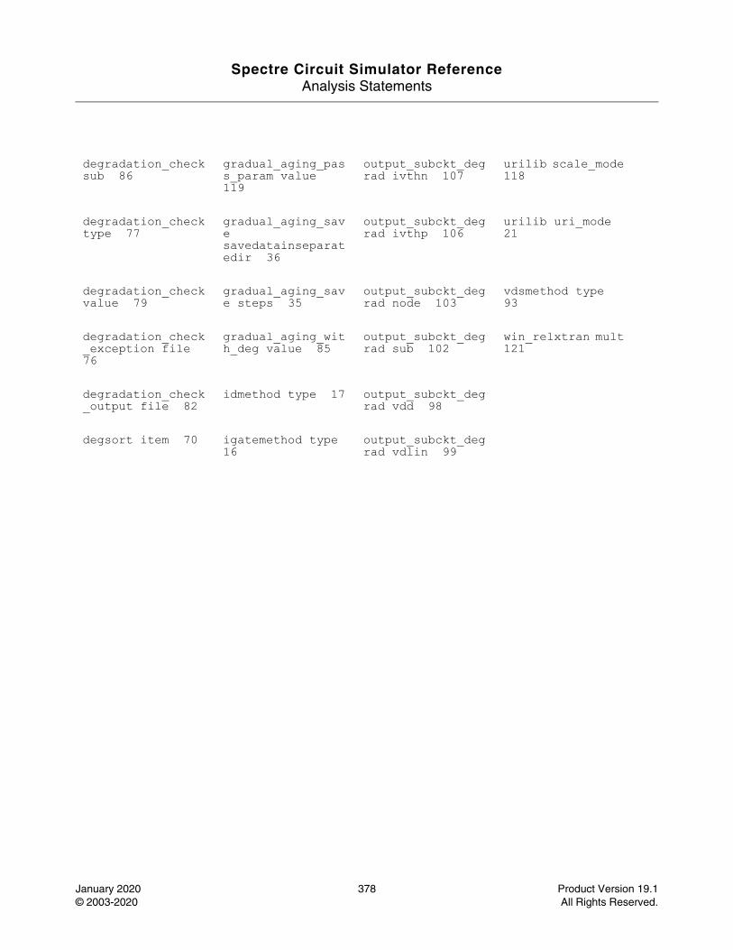
Spectre Circuit Simulator ReferenceAnalysis Statements
January 2020 378 Product Version 19.1© 2003-2020 All Rights Reserved.
degradation_check sub 86
gradual_aging_pass_param value 119
output_subckt_degrad ivthn 107
urilib scale_mode 118
degradation_check type 77
gradual_aging_save savedatainseparatedir 36
output_subckt_degrad ivthp 106
urilib uri_mode 21
degradation_check value 79
gradual_aging_save steps 35
output_subckt_degrad node 103
vdsmethod type 93
degradation_check_exception file 76
gradual_aging_with_deg value 85
output_subckt_degrad sub 102
win_relxtran mult 121
degradation_check_output file 82
idmethod type 17 output_subckt_degrad vdd 98
degsort item 70 igatemethod type 16
output_subckt_degrad vdlin 99
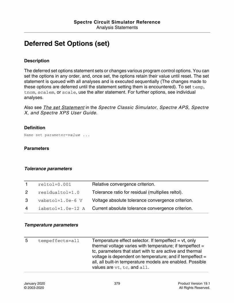
Spectre Circuit Simulator ReferenceAnalysis Statements
January 2020 379 Product Version 19.1© 2003-2020 All Rights Reserved.
Deferred Set Options (set)
Description
The deferred set options statement sets or changes various program control options. You can set the options in any order, and, once set, the options retain their value until reset. The set statement is queued with all analyses and is executed sequentially (The changes made to these options are deferred until the statement setting them is encountered). To set temp, tnom, scalem, or scale, use the alter statement. For further options, see individual analyses.
Also see The set Statement in the Spectre Classic Simulator, Spectre APS, Spectre X, and Spectre XPS User Guide.
DefinitionName set parameter=value ...
Parameters
Tolerance parameters
Temperature parameters
1 reltol=0.001 Relative convergence criterion.
2 residualtol=1.0 Tolerance ratio for residual (multiplies reltol).
3 vabstol=1.0e-6 V Voltage absolute tolerance convergence criterion.
4 iabstol=1.0e-12 A Current absolute tolerance convergence criterion.
5 tempeffects=all Temperature effect selector. If tempeffect = vt, only thermal voltage varies with temperature; if tempeffect = tc, parameters that start with tc are active and thermal voltage is dependent on temperature; and if tempeffect = all, all built-in temperature models are enabled. Possible values are vt, tc, and all.
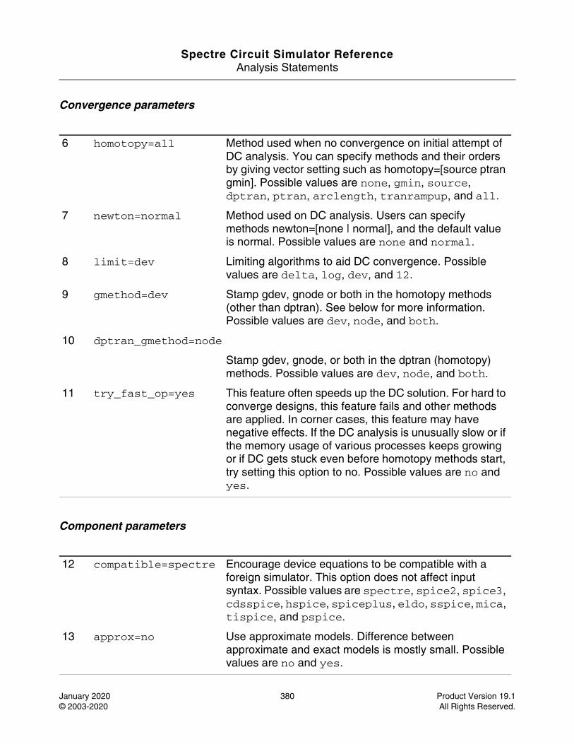
Spectre Circuit Simulator ReferenceAnalysis Statements
January 2020 380 Product Version 19.1© 2003-2020 All Rights Reserved.
Convergence parameters
Component parameters
6 homotopy=all Method used when no convergence on initial attempt of DC analysis. You can specify methods and their orders by giving vector setting such as homotopy=[source ptran gmin]. Possible values are none, gmin, source, dptran, ptran, arclength, tranrampup, and all.
7 newton=normal Method used on DC analysis. Users can specify methods newton=[none | normal], and the default value is normal. Possible values are none and normal.
8 limit=dev Limiting algorithms to aid DC convergence. Possible values are delta, log, dev, and 12.
9 gmethod=dev Stamp gdev, gnode or both in the homotopy methods (other than dptran). See below for more information. Possible values are dev, node, and both.
10 dptran_gmethod=node
Stamp gdev, gnode, or both in the dptran (homotopy) methods. Possible values are dev, node, and both.
11 try_fast_op=yes This feature often speeds up the DC solution. For hard to converge designs, this feature fails and other methods are applied. In corner cases, this feature may have negative effects. If the DC analysis is unusually slow or if the memory usage of various processes keeps growing or if DC gets stuck even before homotopy methods start, try setting this option to no. Possible values are no and yes.
12 compatible=spectre Encourage device equations to be compatible with a foreign simulator. This option does not affect input syntax. Possible values are spectre, spice2, spice3, cdsspice, hspice, spiceplus, eldo, sspice, mica, tispice, and pspice.
13 approx=no Use approximate models. Difference between approximate and exact models is mostly small. Possible values are no and yes.
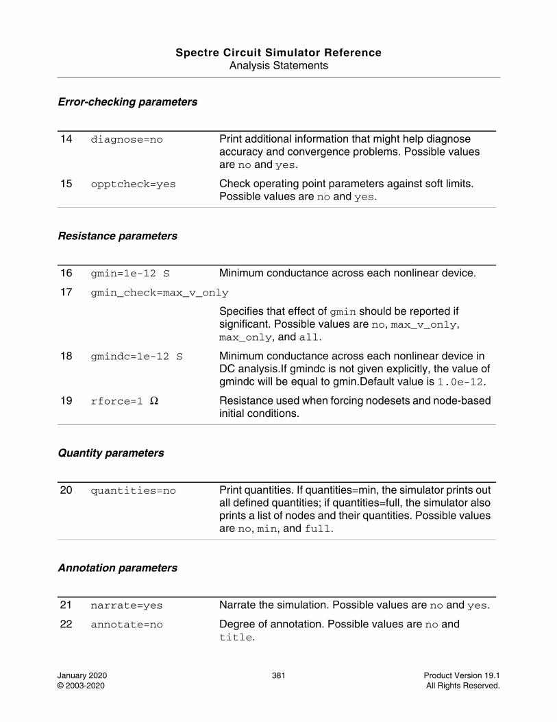
Spectre Circuit Simulator ReferenceAnalysis Statements
January 2020 381 Product Version 19.1© 2003-2020 All Rights Reserved.
Error-checking parameters
Resistance parameters
Quantity parameters
Annotation parameters
14 diagnose=no Print additional information that might help diagnose accuracy and convergence problems. Possible values are no and yes.
15 opptcheck=yes Check operating point parameters against soft limits. Possible values are no and yes.
16 gmin=1e-12 S Minimum conductance across each nonlinear device.
17 gmin_check=max_v_only
Specifies that effect of gmin should be reported if significant. Possible values are no, max_v_only, max_only, and all.
18 gmindc=1e-12 S Minimum conductance across each nonlinear device in DC analysis.If gmindc is not given explicitly, the value of gmindc will be equal to gmin.Default value is 1.0e-12.
19 rforce=1 Ω Resistance used when forcing nodesets and node-based initial conditions.
20 quantities=no Print quantities. If quantities=min, the simulator prints out all defined quantities; if quantities=full, the simulator also prints a list of nodes and their quantities. Possible values are no, min, and full.
21 narrate=yes Narrate the simulation. Possible values are no and yes.
22 annotate=no Degree of annotation. Possible values are no and title.
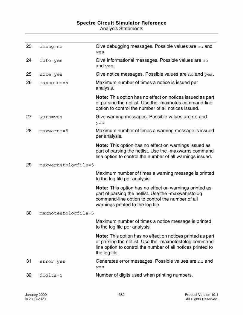
Spectre Circuit Simulator ReferenceAnalysis Statements
January 2020 382 Product Version 19.1© 2003-2020 All Rights Reserved.
23 debug=no Give debugging messages. Possible values are no and yes.
24 info=yes Give informational messages. Possible values are no and yes.
25 note=yes Give notice messages. Possible values are no and yes.
26 maxnotes=5 Maximum number of times a notice is issued per analysis.
Note: This option has no effect on notices issued as part of parsing the netlist. Use the -maxnotes command-line option to control the number of all notices issued.
27 warn=yes Give warning messages. Possible values are no and yes.
28 maxwarns=5 Maximum number of times a warning message is issued per analysis.
Note: This option has no effect on warnings issued as part of parsing the netlist. Use the -maxwarns command-line option to control the number of all warnings issued.
29 maxwarnstologfile=5
Maximum number of times a warning message is printed to the log file per analysis.
Note: This option has no effect on warnings printed as part of parsing the netlist. Use the -maxwarnstolog command-line option to control the number of all warnings printed to the log file.
30 maxnotestologfile=5
Maximum number of times a notice message is printed to the log file per analysis.
Note: This option has no effect on notices printed as part of parsing the netlist. Use the -maxnotestolog command-line option to control the number of all notices printed to the log file.
31 error=yes Generates error messages. Possible values are no and yes.
32 digits=5 Number of digits used when printing numbers.
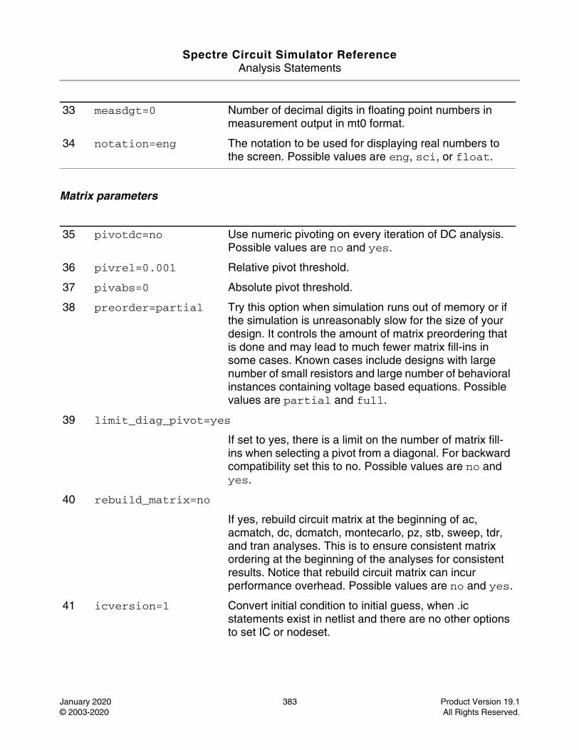
Spectre Circuit Simulator ReferenceAnalysis Statements
January 2020 383 Product Version 19.1© 2003-2020 All Rights Reserved.
Matrix parameters
33 measdgt=0 Number of decimal digits in floating point numbers in measurement output in mt0 format.
34 notation=eng The notation to be used for displaying real numbers to the screen. Possible values are eng, sci, or float.
35 pivotdc=no Use numeric pivoting on every iteration of DC analysis. Possible values are no and yes.
36 pivrel=0.001 Relative pivot threshold.
37 pivabs=0 Absolute pivot threshold.
38 preorder=partial Try this option when simulation runs out of memory or if the simulation is unreasonably slow for the size of your design. It controls the amount of matrix preordering that is done and may lead to much fewer matrix fill-ins in some cases. Known cases include designs with large number of small resistors and large number of behavioral instances containing voltage based equations. Possible values are partial and full.
39 limit_diag_pivot=yes
If set to yes, there is a limit on the number of matrix fill-ins when selecting a pivot from a diagonal. For backward compatibility set this to no. Possible values are no and yes.
40 rebuild_matrix=no
If yes, rebuild circuit matrix at the beginning of ac, acmatch, dc, dcmatch, montecarlo, pz, stb, sweep, tdr, and tran analyses. This is to ensure consistent matrix ordering at the beginning of the analyses for consistent results. Notice that rebuild circuit matrix can incur performance overhead. Possible values are no and yes.
41 icversion=1 Convert initial condition to initial guess, when .ic statements exist in netlist and there are no other options to set IC or nodeset.
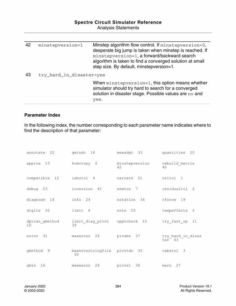
Spectre Circuit Simulator ReferenceAnalysis Statements
January 2020 384 Product Version 19.1© 2003-2020 All Rights Reserved.
Parameter Index
In the following index, the number corresponding to each parameter name indicates where to find the description of that parameter:
42 minstepversion=1 Minstep algorithm flow control. If minstepversion=0, desperate big jump is taken when minstep is reached. If minstepversion=1, a forward/backward search algorithm is taken to find a converged solution at small step size. By default, minstepversion=1.
43 try_hard_in_disaster=yes
When minstepversion=1, this option means whether simulator should try hard to search for a converged solution in disaster stage. Possible values are no and yes.
annotate 22 gmindc 18 measdgt 33 quantities 20
approx 13 homotopy 6 minstepversion 42
rebuild_matrix 40
compatible 12 iabstol 4 narrate 21 reltol 1
debug 23 icversion 41 newton 7 residualtol 2
diagnose 14 info 24 notation 34 rforce 19
digits 32 limit 8 note 25 tempeffects 5
dptran_gmethod 10
limit_diag_pivot 39
opptcheck 15 try_fast_op 11
error 31 maxnotes 26 pivabs 37 try_hard_in_disaster 43
gmethod 9 maxnotestologfile 30
pivotdc 35 vabstol 3
gmin 16 maxwarns 28 pivrel 36 warn 27

Spectre Circuit Simulator ReferenceAnalysis Statements
January 2020 385 Product Version 19.1© 2003-2020 All Rights Reserved.
gmin_check 17 maxwarnstologfile 29
preorder 38
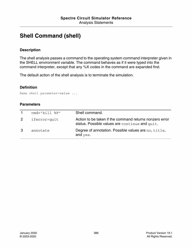
Spectre Circuit Simulator ReferenceAnalysis Statements
January 2020 386 Product Version 19.1© 2003-2020 All Rights Reserved.
Shell Command (shell)
Description
The shell analysis passes a command to the operating system command interpreter given in the SHELL environment variable. The command behaves as if it were typed into the command interpreter, except that any %X codes in the command are expanded first.
The default action of the shell analysis is to terminate the simulation.
DefinitionName shell parameter=value ...
Parameters
1 cmd="kill %P" Shell command.
2 iferror=quit Action to be taken if the command returns nonzero error status. Possible values are continue and quit.
3 annotate Degree of annotation. Possible values are no, title, and yes.
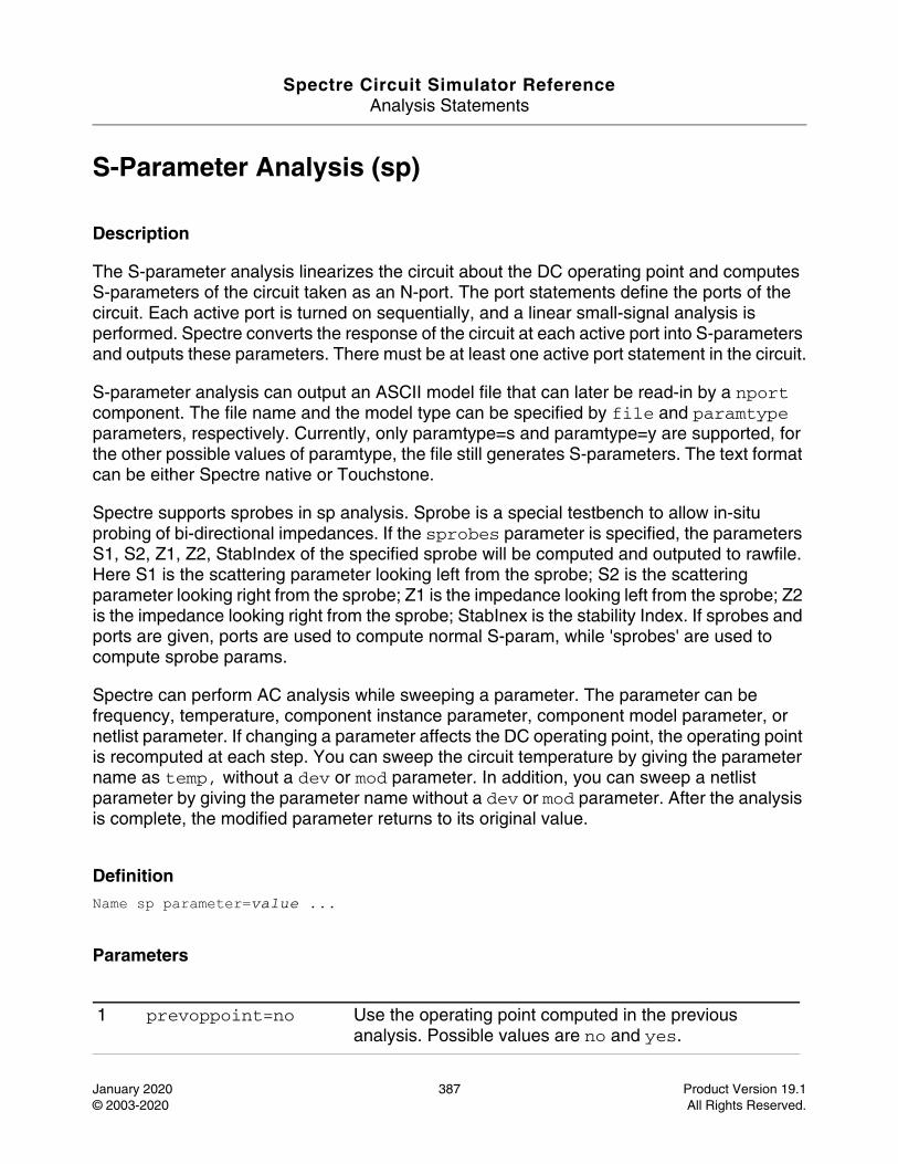
Spectre Circuit Simulator ReferenceAnalysis Statements
January 2020 387 Product Version 19.1© 2003-2020 All Rights Reserved.
S-Parameter Analysis (sp)
Description
The S-parameter analysis linearizes the circuit about the DC operating point and computes S-parameters of the circuit taken as an N-port. The port statements define the ports of the circuit. Each active port is turned on sequentially, and a linear small-signal analysis is performed. Spectre converts the response of the circuit at each active port into S-parameters and outputs these parameters. There must be at least one active port statement in the circuit.
S-parameter analysis can output an ASCII model file that can later be read-in by a nport component. The file name and the model type can be specified by file and paramtype parameters, respectively. Currently, only paramtype=s and paramtype=y are supported, for the other possible values of paramtype, the file still generates S-parameters. The text format can be either Spectre native or Touchstone.
Spectre supports sprobes in sp analysis. Sprobe is a special testbench to allow in-situ probing of bi-directional impedances. If the sprobes parameter is specified, the parameters S1, S2, Z1, Z2, StabIndex of the specified sprobe will be computed and outputed to rawfile. Here S1 is the scattering parameter looking left from the sprobe; S2 is the scattering parameter looking right from the sprobe; Z1 is the impedance looking left from the sprobe; Z2 is the impedance looking right from the sprobe; StabInex is the stability Index. If sprobes and ports are given, ports are used to compute normal S-param, while 'sprobes' are used to compute sprobe params.
Spectre can perform AC analysis while sweeping a parameter. The parameter can be frequency, temperature, component instance parameter, component model parameter, or netlist parameter. If changing a parameter affects the DC operating point, the operating point is recomputed at each step. You can sweep the circuit temperature by giving the parameter name as temp, without a dev or mod parameter. In addition, you can sweep a netlist parameter by giving the parameter name without a dev or mod parameter. After the analysis is complete, the modified parameter returns to its original value.
DefinitionName sp parameter=value ...
Parameters
1 prevoppoint=no Use the operating point computed in the previous analysis. Possible values are no and yes.
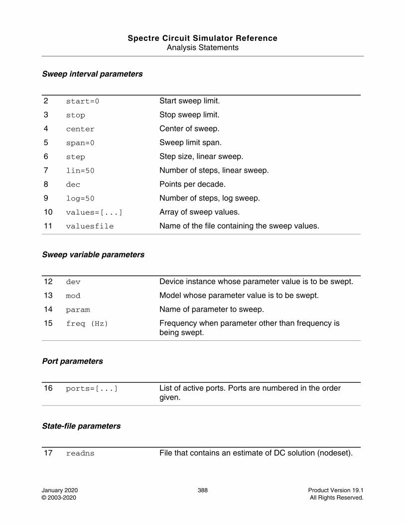
Spectre Circuit Simulator ReferenceAnalysis Statements
January 2020 388 Product Version 19.1© 2003-2020 All Rights Reserved.
Sweep interval parameters
Sweep variable parameters
Port parameters
State-file parameters
2 start=0 Start sweep limit.
3 stop Stop sweep limit.
4 center Center of sweep.
5 span=0 Sweep limit span.
6 step Step size, linear sweep.
7 lin=50 Number of steps, linear sweep.
8 dec Points per decade.
9 log=50 Number of steps, log sweep.
10 values=[...] Array of sweep values.
11 valuesfile Name of the file containing the sweep values.
12 dev Device instance whose parameter value is to be swept.
13 mod Model whose parameter value is to be swept.
14 param Name of parameter to sweep.
15 freq (Hz) Frequency when parameter other than frequency is being swept.
16 ports=[...] List of active ports. Ports are numbered in the order given.
17 readns File that contains an estimate of DC solution (nodeset).
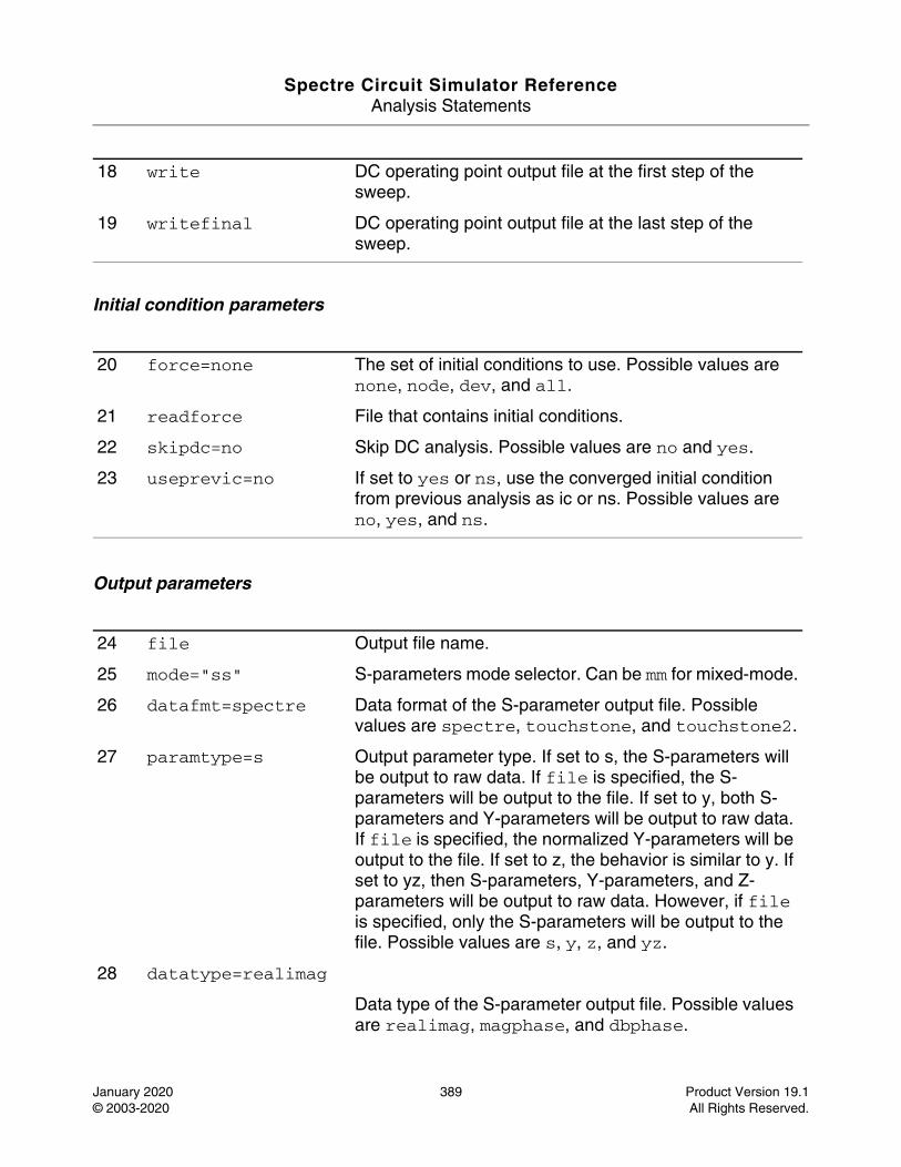
Spectre Circuit Simulator ReferenceAnalysis Statements
January 2020 389 Product Version 19.1© 2003-2020 All Rights Reserved.
Initial condition parameters
Output parameters
18 write DC operating point output file at the first step of the sweep.
19 writefinal DC operating point output file at the last step of the sweep.
20 force=none The set of initial conditions to use. Possible values are none, node, dev, and all.
21 readforce File that contains initial conditions.
22 skipdc=no Skip DC analysis. Possible values are no and yes.
23 useprevic=no If set to yes or ns, use the converged initial condition from previous analysis as ic or ns. Possible values are no, yes, and ns.
24 file Output file name.
25 mode="ss" S-parameters mode selector. Can be mm for mixed-mode.
26 datafmt=spectre Data format of the S-parameter output file. Possible values are spectre, touchstone, and touchstone2.
27 paramtype=s Output parameter type. If set to s, the S-parameters will be output to raw data. If file is specified, the S-parameters will be output to the file. If set to y, both S-parameters and Y-parameters will be output to raw data. If file is specified, the normalized Y-parameters will be output to the file. If set to z, the behavior is similar to y. If set to yz, then S-parameters, Y-parameters, and Z-parameters will be output to raw data. However, if file is specified, only the S-parameters will be output to the file. Possible values are s, y, z, and yz.
28 datatype=realimag
Data type of the S-parameter output file. Possible values are realimag, magphase, and dbphase.
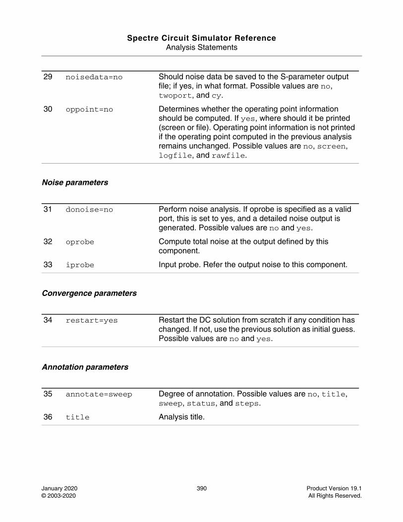
Spectre Circuit Simulator ReferenceAnalysis Statements
January 2020 390 Product Version 19.1© 2003-2020 All Rights Reserved.
Noise parameters
Convergence parameters
Annotation parameters
29 noisedata=no Should noise data be saved to the S-parameter output file; if yes, in what format. Possible values are no, twoport, and cy.
30 oppoint=no Determines whether the operating point information should be computed. If yes, where should it be printed (screen or file). Operating point information is not printed if the operating point computed in the previous analysis remains unchanged. Possible values are no, screen, logfile, and rawfile.
31 donoise=no Perform noise analysis. If oprobe is specified as a valid port, this is set to yes, and a detailed noise output is generated. Possible values are no and yes.
32 oprobe Compute total noise at the output defined by this component.
33 iprobe Input probe. Refer the output noise to this component.
34 restart=yes Restart the DC solution from scratch if any condition has changed. If not, use the previous solution as initial guess. Possible values are no and yes.
35 annotate=sweep Degree of annotation. Possible values are no, title, sweep, status, and steps.
36 title Analysis title.
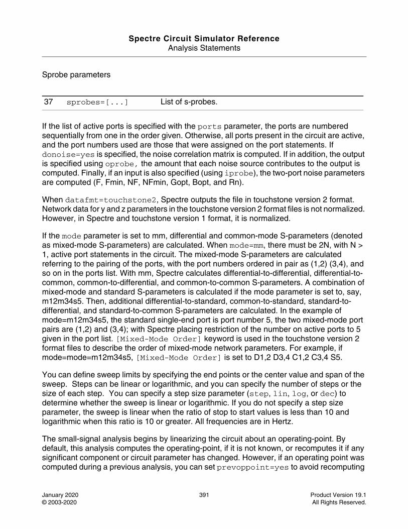
Spectre Circuit Simulator ReferenceAnalysis Statements
January 2020 391 Product Version 19.1© 2003-2020 All Rights Reserved.
Sprobe parameters
If the list of active ports is specified with the ports parameter, the ports are numbered sequentially from one in the order given. Otherwise, all ports present in the circuit are active, and the port numbers used are those that were assigned on the port statements. If donoise=yes is specified, the noise correlation matrix is computed. If in addition, the output is specified using oprobe, the amount that each noise source contributes to the output is computed. Finally, if an input is also specified (using iprobe), the two-port noise parameters are computed (F, Fmin, NF, NFmin, Gopt, Bopt, and Rn).
When datafmt=touchstone2, Spectre outputs the file in touchstone version 2 format. Network data for y and z parameters in the touchstone version 2 format files is not normalized. However, in Spectre and touchstone version 1 format, it is normalized.
If the mode parameter is set to mm, differential and common-mode S-parameters (denoted as mixed-mode S-parameters) are calculated. When mode=mm, there must be 2N, with N > 1, active port statements in the circuit. The mixed-mode S-parameters are calculated referring to the pairing of the ports, with the port numbers ordered in pair as (1,2) (3,4), and so on in the ports list. With mm, Spectre calculates differential-to-differential, differential-to-common, common-to-differential, and common-to-common S-parameters. A combination of mixed-mode and standard S-parameters is calculated if the mode parameter is set to, say, m12m34s5. Then, additional differential-to-standard, common-to-standard, standard-to-differential, and standard-to-common S-parameters are calculated. In the example of mode=m12m34s5, the standard single-end port is port number 5, the two mixed-mode port pairs are (1,2) and (3,4); with Spectre placing restriction of the number on active ports to 5 given in the port list. [Mixed-Mode Order] keyword is used in the touchstone version 2 format files to describe the order of mixed-mode network parameters. For example, if mode=mode=m12m34s5, [Mixed-Mode Order] is set to D1,2 D3,4 C1,2 C3,4 S5.
You can define sweep limits by specifying the end points or the center value and span of the sweep. Steps can be linear or logarithmic, and you can specify the number of steps or the size of each step. You can specify a step size parameter (step, lin, log, or dec) to determine whether the sweep is linear or logarithmic. If you do not specify a step size parameter, the sweep is linear when the ratio of stop to start values is less than 10 and logarithmic when this ratio is 10 or greater. All frequencies are in Hertz.
The small-signal analysis begins by linearizing the circuit about an operating-point. By default, this analysis computes the operating-point, if it is not known, or recomputes it if any significant component or circuit parameter has changed. However, if an operating point was computed during a previous analysis, you can set prevoppoint=yes to avoid recomputing
37 sprobes=[...] List of s-probes.
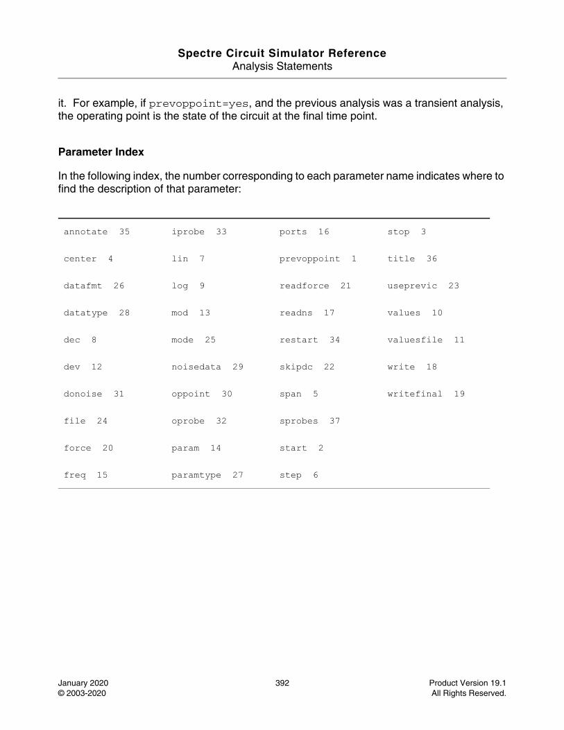
Spectre Circuit Simulator ReferenceAnalysis Statements
January 2020 392 Product Version 19.1© 2003-2020 All Rights Reserved.
it. For example, if prevoppoint=yes, and the previous analysis was a transient analysis, the operating point is the state of the circuit at the final time point.
Parameter Index
In the following index, the number corresponding to each parameter name indicates where to find the description of that parameter:
annotate 35 iprobe 33 ports 16 stop 3
center 4 lin 7 prevoppoint 1 title 36
datafmt 26 log 9 readforce 21 useprevic 23
datatype 28 mod 13 readns 17 values 10
dec 8 mode 25 restart 34 valuesfile 11
dev 12 noisedata 29 skipdc 22 write 18
donoise 31 oppoint 30 span 5 writefinal 19
file 24 oprobe 32 sprobes 37
force 20 param 14 start 2
freq 15 paramtype 27 step 6
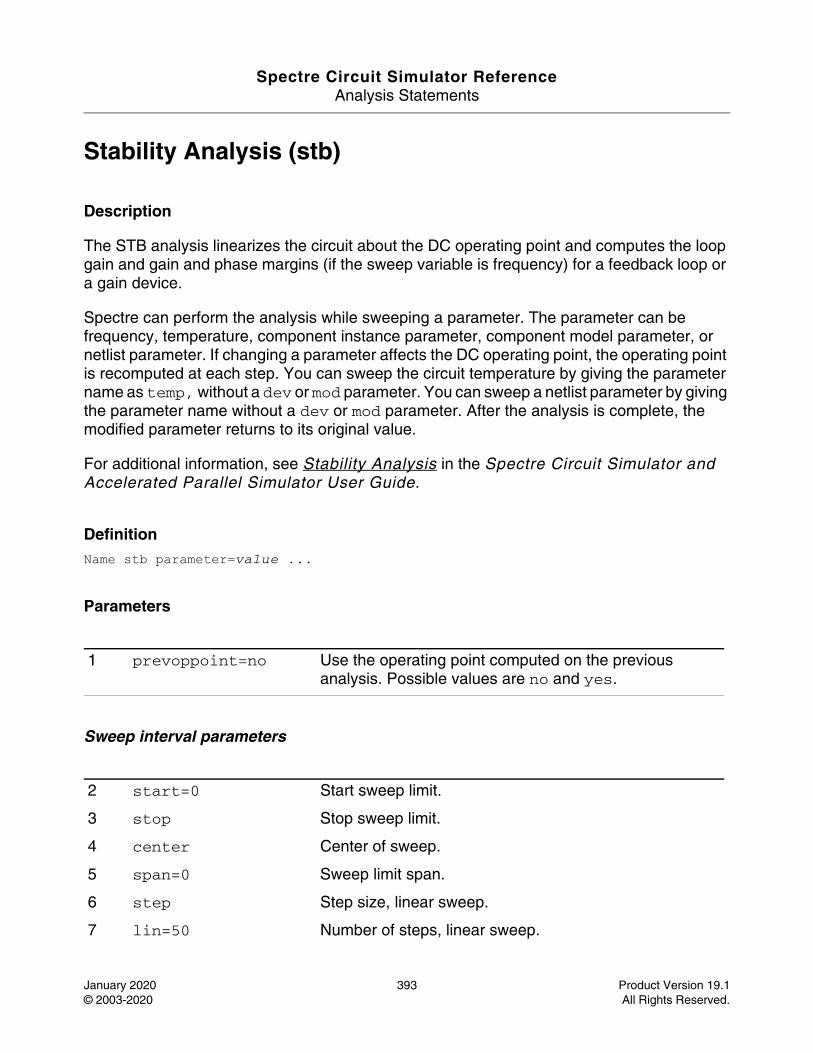
Spectre Circuit Simulator ReferenceAnalysis Statements
January 2020 393 Product Version 19.1© 2003-2020 All Rights Reserved.
Stability Analysis (stb)
Description
The STB analysis linearizes the circuit about the DC operating point and computes the loop gain and gain and phase margins (if the sweep variable is frequency) for a feedback loop or a gain device.
Spectre can perform the analysis while sweeping a parameter. The parameter can be frequency, temperature, component instance parameter, component model parameter, or netlist parameter. If changing a parameter affects the DC operating point, the operating point is recomputed at each step. You can sweep the circuit temperature by giving the parameter name as temp, without a dev or mod parameter. You can sweep a netlist parameter by giving the parameter name without a dev or mod parameter. After the analysis is complete, the modified parameter returns to its original value.
For additional information, see Stability Analysis in the Spectre Circuit Simulator and Accelerated Parallel Simulator User Guide.
DefinitionName stb parameter=value ...
Parameters
Sweep interval parameters
1 prevoppoint=no Use the operating point computed on the previous analysis. Possible values are no and yes.
2 start=0 Start sweep limit.
3 stop Stop sweep limit.
4 center Center of sweep.
5 span=0 Sweep limit span.
6 step Step size, linear sweep.
7 lin=50 Number of steps, linear sweep.
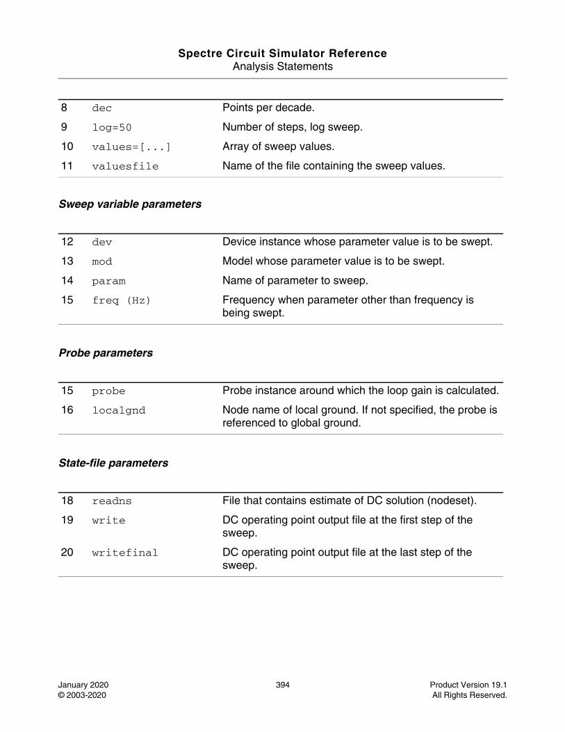
Spectre Circuit Simulator ReferenceAnalysis Statements
January 2020 394 Product Version 19.1© 2003-2020 All Rights Reserved.
Sweep variable parameters
Probe parameters
State-file parameters
8 dec Points per decade.
9 log=50 Number of steps, log sweep.
10 values=[...] Array of sweep values.
11 valuesfile Name of the file containing the sweep values.
12 dev Device instance whose parameter value is to be swept.
13 mod Model whose parameter value is to be swept.
14 param Name of parameter to sweep.
15 freq (Hz) Frequency when parameter other than frequency is being swept.
15 probe Probe instance around which the loop gain is calculated.
16 localgnd Node name of local ground. If not specified, the probe is referenced to global ground.
18 readns File that contains estimate of DC solution (nodeset).
19 write DC operating point output file at the first step of the sweep.
20 writefinal DC operating point output file at the last step of the sweep.
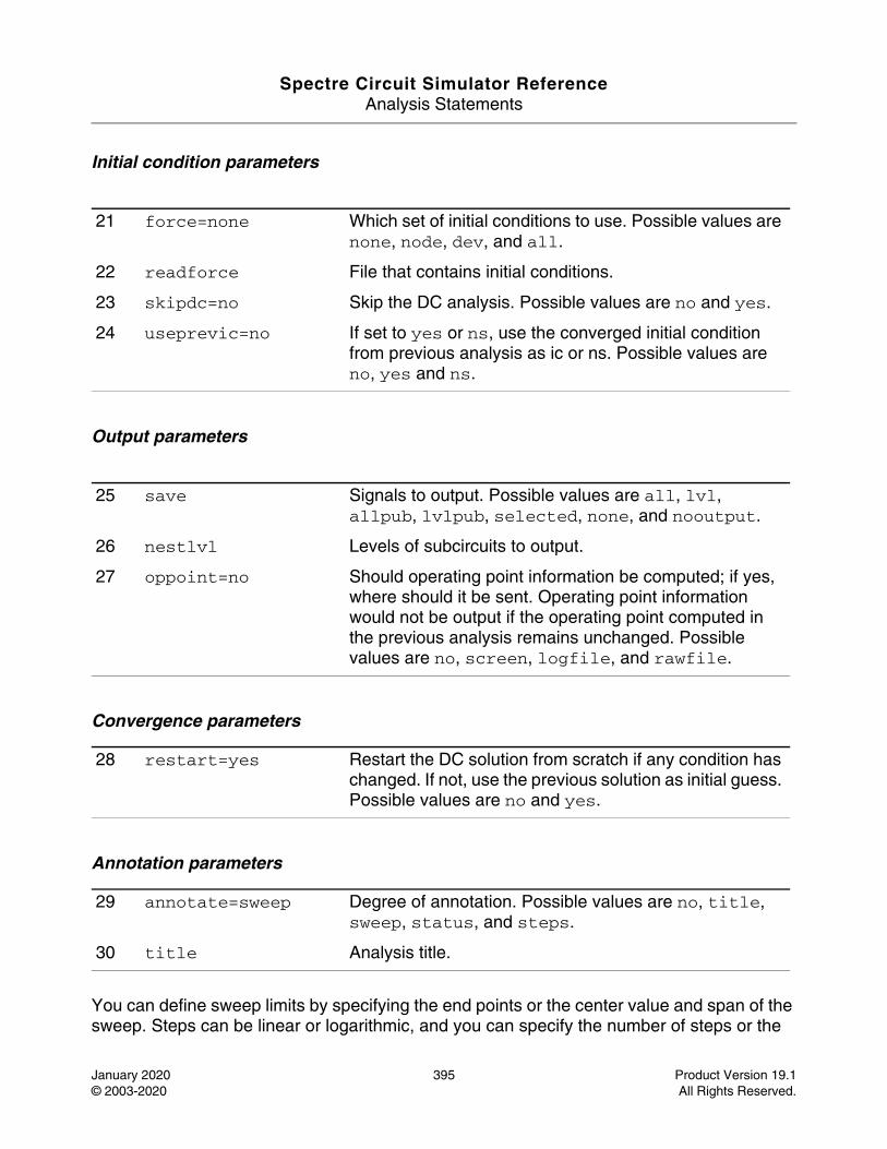
Spectre Circuit Simulator ReferenceAnalysis Statements
January 2020 395 Product Version 19.1© 2003-2020 All Rights Reserved.
Initial condition parameters
Output parameters
Convergence parameters
Annotation parameters
You can define sweep limits by specifying the end points or the center value and span of the sweep. Steps can be linear or logarithmic, and you can specify the number of steps or the
21 force=none Which set of initial conditions to use. Possible values are none, node, dev, and all.
22 readforce File that contains initial conditions.
23 skipdc=no Skip the DC analysis. Possible values are no and yes.
24 useprevic=no If set to yes or ns, use the converged initial condition from previous analysis as ic or ns. Possible values are no, yes and ns.
25 save Signals to output. Possible values are all, lvl, allpub, lvlpub, selected, none, and nooutput.
26 nestlvl Levels of subcircuits to output.
27 oppoint=no Should operating point information be computed; if yes, where should it be sent. Operating point information would not be output if the operating point computed in the previous analysis remains unchanged. Possible values are no, screen, logfile, and rawfile.
28 restart=yes Restart the DC solution from scratch if any condition has changed. If not, use the previous solution as initial guess. Possible values are no and yes.
29 annotate=sweep Degree of annotation. Possible values are no, title, sweep, status, and steps.
30 title Analysis title.
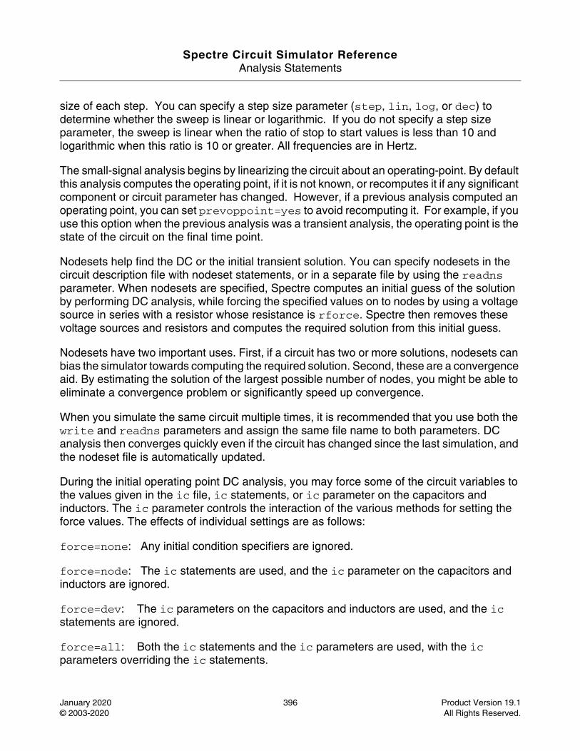
Spectre Circuit Simulator ReferenceAnalysis Statements
January 2020 396 Product Version 19.1© 2003-2020 All Rights Reserved.
size of each step. You can specify a step size parameter (step, lin, log, or dec) to determine whether the sweep is linear or logarithmic. If you do not specify a step size parameter, the sweep is linear when the ratio of stop to start values is less than 10 and logarithmic when this ratio is 10 or greater. All frequencies are in Hertz.
The small-signal analysis begins by linearizing the circuit about an operating-point. By default this analysis computes the operating point, if it is not known, or recomputes it if any significant component or circuit parameter has changed. However, if a previous analysis computed an operating point, you can set prevoppoint=yes to avoid recomputing it. For example, if you use this option when the previous analysis was a transient analysis, the operating point is the state of the circuit on the final time point.
Nodesets help find the DC or the initial transient solution. You can specify nodesets in the circuit description file with nodeset statements, or in a separate file by using the readns parameter. When nodesets are specified, Spectre computes an initial guess of the solution by performing DC analysis, while forcing the specified values on to nodes by using a voltage source in series with a resistor whose resistance is rforce. Spectre then removes these voltage sources and resistors and computes the required solution from this initial guess.
Nodesets have two important uses. First, if a circuit has two or more solutions, nodesets can bias the simulator towards computing the required solution. Second, these are a convergence aid. By estimating the solution of the largest possible number of nodes, you might be able to eliminate a convergence problem or significantly speed up convergence.
When you simulate the same circuit multiple times, it is recommended that you use both the write and readns parameters and assign the same file name to both parameters. DC analysis then converges quickly even if the circuit has changed since the last simulation, and the nodeset file is automatically updated.
During the initial operating point DC analysis, you may force some of the circuit variables to the values given in the ic file, ic statements, or ic parameter on the capacitors and inductors. The ic parameter controls the interaction of the various methods for setting the force values. The effects of individual settings are as follows:
force=none: Any initial condition specifiers are ignored.
force=node: The ic statements are used, and the ic parameter on the capacitors and inductors are ignored.
force=dev: The ic parameters on the capacitors and inductors are used, and the ic statements are ignored.
force=all: Both the ic statements and the ic parameters are used, with the ic parameters overriding the ic statements.
Spectre Circuit Simulator ReferenceAnalysis Statements
January 2020 397 Product Version 19.1© 2003-2020 All Rights Reserved.
If you specify an ic file with the readforce parameter, force values from the file are used, and any ic statements are ignored.
After you specify the initial conditions, Spectre computes the DC operating point with the specified nodes forced to the given value by using a voltage source in series with a resistor whose resistance is rforce (see options).
Understanding Loop-Based and Device-Based Algorithms
Two algorithms- loop-based and device-based are available for small-signal stability analysis. Both algorithms are based on the calculation of Bode’s return ratio. Loop gain waveform, gain margin, and phase margin are the analysis output.
The probe parameter must be specified to perform stability analysis. When it points to a current probe or voltage source instance, the loop-based algorithm is run; when the parameter points to a supported active device instance, the device-based algorithm is run.
Loop-Based Algorithm
The loop-based algorithm calculates the true loop gain, which consists of normal loop gain and reverse loop gain. The loop-based algorithm requires the probe being placed on the feedback loop to identify and characterize the particular loop of interest. The introduction of the probe component should not change any of the circuit characteristics.
The loop-based algorithm provides accurate stability information for single loop circuits and also for multi-loop circuits in which a probe component can be placed on a critical wire to break all loops. For a general multi-loop circuit, such a critical wire may not be available. The loop-based algorithm can only be performed on individual feedback loops to ensure that they are stable. Although the stability of all feedback loops is only a necessary condition for the whole circuit to be stable, the multi-loop circuit tends to be stable if all individual loops are associated with reasonable stability margins.
For the loop based algorithm, a probe needs to be placed on the feedback loop.The common way is to insert a current probe or voltage source instance in the netlist, and the probe parameter points to this instance. The second way to insert the probe is by specifying the terminal of some instance.
The snytax format :
probe = X:n
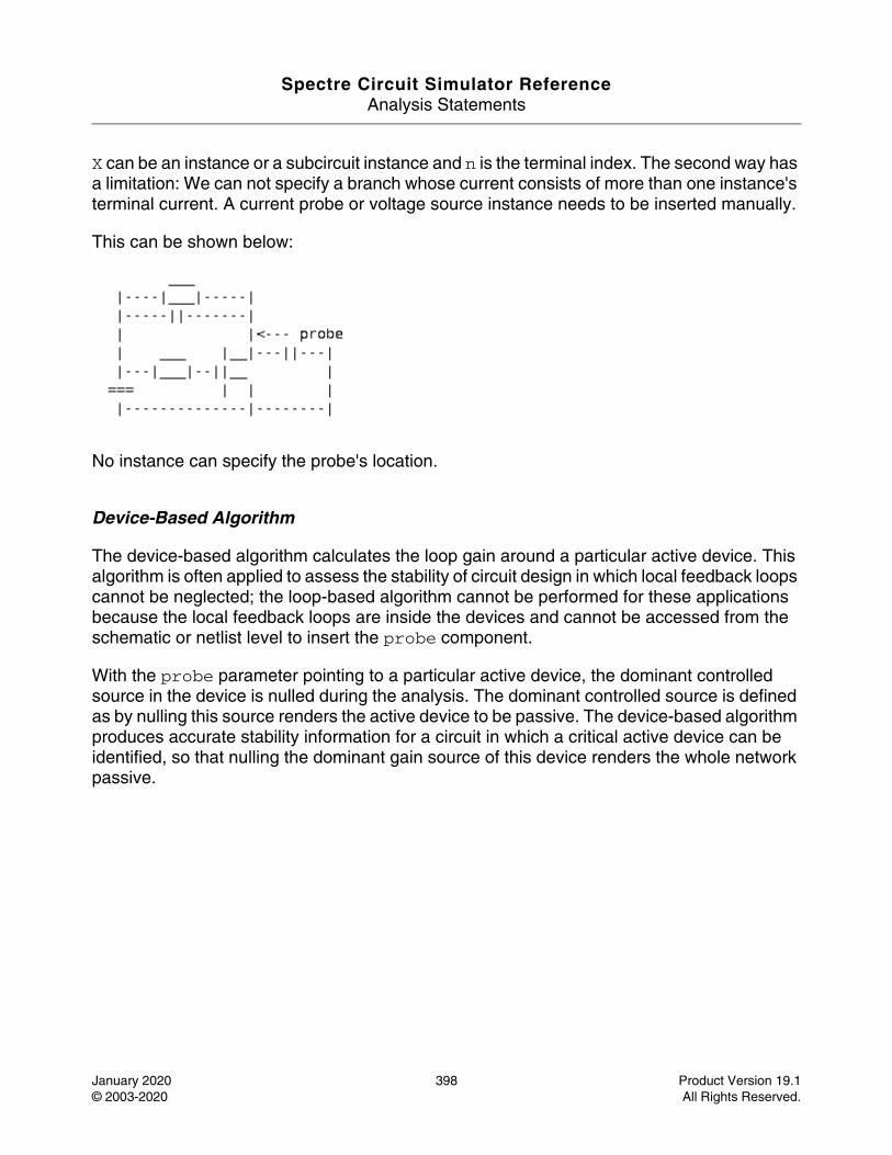
Spectre Circuit Simulator ReferenceAnalysis Statements
January 2020 398 Product Version 19.1© 2003-2020 All Rights Reserved.
X can be an instance or a subcircuit instance and n is the terminal index. The second way has a limitation: We can not specify a branch whose current consists of more than one instance's terminal current. A current probe or voltage source instance needs to be inserted manually.
This can be shown below:
No instance can specify the probe's location.
Device-Based Algorithm
The device-based algorithm calculates the loop gain around a particular active device. This algorithm is often applied to assess the stability of circuit design in which local feedback loops cannot be neglected; the loop-based algorithm cannot be performed for these applications because the local feedback loops are inside the devices and cannot be accessed from the schematic or netlist level to insert the probe component.
With the probe parameter pointing to a particular active device, the dominant controlled source in the device is nulled during the analysis. The dominant controlled source is defined as by nulling this source renders the active device to be passive. The device-based algorithm produces accurate stability information for a circuit in which a critical active device can be identified, so that nulling the dominant gain source of this device renders the whole network passive.
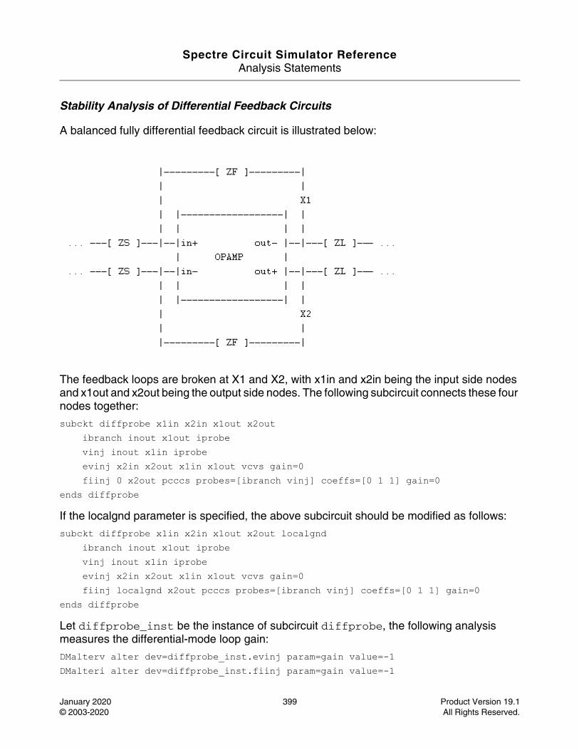
Spectre Circuit Simulator ReferenceAnalysis Statements
January 2020 399 Product Version 19.1© 2003-2020 All Rights Reserved.
Stability Analysis of Differential Feedback Circuits
A balanced fully differential feedback circuit is illustrated below:
The feedback loops are broken at X1 and X2, with x1in and x2in being the input side nodes and x1out and x2out being the output side nodes. The following subcircuit connects these four nodes together:
subckt diffprobe x1in x2in x1out x2out ibranch inout x1out iprobe vinj inout x1in iprobe evinj x2in x2out x1in x1out vcvs gain=0 fiinj 0 x2out pcccs probes=[ibranch vinj] coeffs=[0 1 1] gain=0
ends diffprobe
If the localgnd parameter is specified, the above subcircuit should be modified as follows:
subckt diffprobe x1in x2in x1out x2out localgnd ibranch inout x1out iprobe vinj inout x1in iprobe evinj x2in x2out x1in x1out vcvs gain=0 fiinj localgnd x2out pcccs probes=[ibranch vinj] coeffs=[0 1 1] gain=0
ends diffprobe
Let diffprobe_inst be the instance of subcircuit diffprobe, the following analysis measures the differential-mode loop gain:
DMalterv alter dev=diffprobe_inst.evinj param=gain value=-1 DMalteri alter dev=diffprobe_inst.fiinj param=gain value=-1
Spectre Circuit Simulator ReferenceAnalysis Statements
January 2020 400 Product Version 19.1© 2003-2020 All Rights Reserved.
DMloopgain stb probe=diffprobe_inst.vinj
and, the following analysis measures the common-mode loop gain:
CMalterv alter dev=diffprobe_inst.evinj param=gain value=1 CMalteri alter dev=diffprobe_inst.fiinj param=gain value=1 CMloopgain stb probe=diffprobe_inst.vinj
Parameter Index
In the following index, the number corresponding to each parameter name indicates where to find the description of that parameter.
annotate 29 log 9 readns 18 title 30
center 4 mod 12 restart 28 useprevic 24
dec 8 nestlvl 26 save 25 values 10
dev 12 oppoint 27 skipdc 23 valuesfile 11
force 21 param 14 span 5 write 18
freq 15 prevoppoint 1 start 2 writefinal 20
lin 7 probe 16 step 6
localgnd 17 readforce 22 stop 3
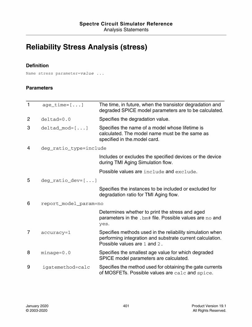
Spectre Circuit Simulator ReferenceAnalysis Statements
January 2020 401 Product Version 19.1© 2003-2020 All Rights Reserved.
Reliability Stress Analysis (stress)
DefinitionName stress parameter=value ...
Parameters
1 age_time=[...] The time, in future, when the transistor degradation and degraded SPICE model parameters are to be calculated.
2 deltad=0.0 Specifies the degradation value.
3 deltad_mod=[...] Specifies the name of a model whose lifetime is calculated. The model name must be the same as specified in the.model card.
4 deg_ratio_type=include
Includes or excludes the specified devices or the device during TMI Aging Simulation flow.
Possible values are include and exclude.
5 deg_ratio_dev=[...]
Specifies the instances to be included or excluded for degradation ratio for TMI Aging flow.
6 report_model_param=no
Determines whether to print the stress and aged parameters in the .bm# file. Possible values are no and yes.
7 accuracy=1 Specifies methods used in the reliability simulation when performing integration and substrate current calculation. Possible values are 1 and 2.
8 minage=0.0 Specifies the smallest age value for which degraded SPICE model parameters are calculated.
9 igatemethod=calc Specifies the method used for obtaining the gate currents of MOSFETs. Possible values are calc and spice.
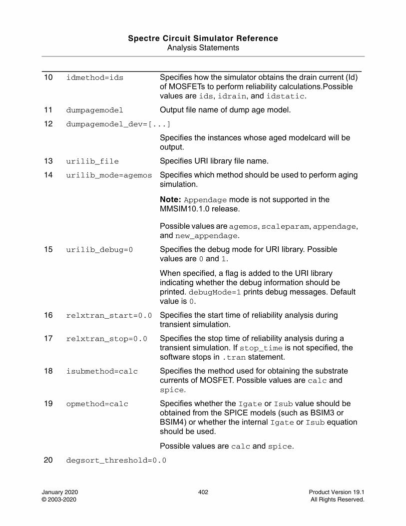
Spectre Circuit Simulator ReferenceAnalysis Statements
January 2020 402 Product Version 19.1© 2003-2020 All Rights Reserved.
10 idmethod=ids Specifies how the simulator obtains the drain current (Id) of MOSFETs to perform reliability calculations.Possible values are ids, idrain, and idstatic.
11 dumpagemodel Output file name of dump age model.
12 dumpagemodel_dev=[...]
Specifies the instances whose aged modelcard will be output.
13 urilib_file Specifies URI library file name.
14 urilib_mode=agemos Specifies which method should be used to perform aging simulation.
Note: Appendage mode is not supported in the MMSIM10.1.0 release.
Possible values are agemos, scaleparam, appendage, and new_appendage.
15 urilib_debug=0 Specifies the debug mode for URI library. Possible values are 0 and 1.
When specified, a flag is added to the URI library indicating whether the debug information should be printed. debugMode=1 prints debug messages. Default value is 0.
16 relxtran_start=0.0 Specifies the start time of reliability analysis during transient simulation.
17 relxtran_stop=0.0 Specifies the stop time of reliability analysis during a transient simulation. If stop_time is not specified, the software stops in .tran statement.
18 isubmethod=calc Specifies the method used for obtaining the substrate currents of MOSFET. Possible values are calc and spice.
19 opmethod=calc Specifies whether the Igate or Isub value should be obtained from the SPICE models (such as BSIM3 or BSIM4) or whether the internal Igate or Isub equation should be used.
Possible values are calc and spice.
20 degsort_threshold=0.0
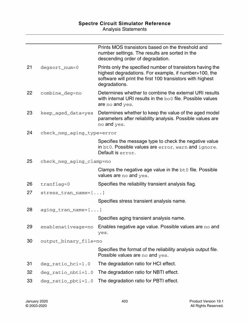
Spectre Circuit Simulator ReferenceAnalysis Statements
January 2020 403 Product Version 19.1© 2003-2020 All Rights Reserved.
Prints MOS transistors based on the threshold and number settings. The results are sorted in the descending order of degradation.
21 degsort_num=0 Prints only the specified number of transistors having the highest degradations. For example, if number=100, the software will print the first 100 transistors with highest degradations.
22 combine_deg=no Determines whether to combine the external URI results with internal URI results in the bo0 file. Possible values are no and yes.
23 keep_aged_data=yes Determines whether to keep the value of the aged model parameters after reliability analysis. Possible values are no and yes.
24 check_neg_aging_type=error
Specifies the message type to check the negative value in bt0. Possible values are error, warn and ignore. Default is error.
25 check_neg_aging_clamp=no
Clamps the negative age value in the bt0 file. Possible values are no and yes.
26 tranflag=0 Specifies the reliability transient analysis flag.
27 stress_tran_name=[...]
Specifies stress transient analysis name.
28 aging_tran_name=[...]
Specifies aging transient analysis name.
29 enablenativeage=no Enables negative age value. Possible values are no and yes.
30 output_binary_file=no
Specifies the format of the reliability analysis output file. Possible values are no and yes.
31 deg_ratio_hci=1.0 The degradation ratio for HCI effect.
32 deg_ratio_nbti=1.0 The degradation ratio for NBTI effect.
33 deg_ratio_pbti=1.0 The degradation ratio for PBTI effect.
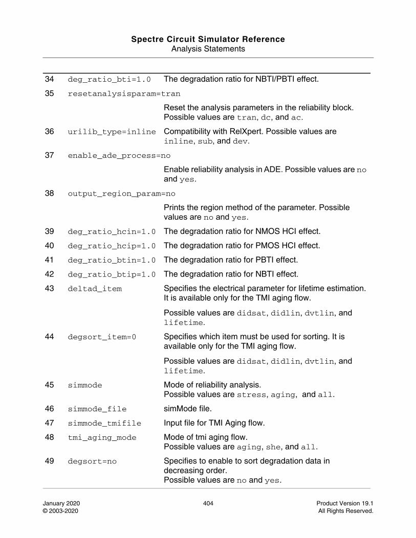
Spectre Circuit Simulator ReferenceAnalysis Statements
January 2020 404 Product Version 19.1© 2003-2020 All Rights Reserved.
34 deg_ratio_bti=1.0 The degradation ratio for NBTI/PBTI effect.
35 resetanalysisparam=tran
Reset the analysis parameters in the reliability block. Possible values are tran, dc, and ac.
36 urilib_type=inline Compatibility with RelXpert. Possible values are inline, sub, and dev.
37 enable_ade_process=no
Enable reliability analysis in ADE. Possible values are no and yes.
38 output_region_param=no
Prints the region method of the parameter. Possible values are no and yes.
39 deg_ratio_hcin=1.0 The degradation ratio for NMOS HCI effect.
40 deg_ratio_hcip=1.0 The degradation ratio for PMOS HCI effect.
41 deg_ratio_btin=1.0 The degradation ratio for PBTI effect.
42 deg_ratio_btip=1.0 The degradation ratio for NBTI effect.
43 deltad_item Specifies the electrical parameter for lifetime estimation. It is available only for the TMI aging flow.
Possible values are didsat, didlin, dvtlin, and lifetime.
44 degsort_item=0 Specifies which item must be used for sorting. It is available only for the TMI aging flow.
Possible values are didsat, didlin, dvtlin, and lifetime.
45 simmode Mode of reliability analysis.Possible values are stress, aging, and all.
46 simmode_file simMode file.
47 simmode_tmifile Input file for TMI Aging flow.
48 tmi_aging_mode Mode of tmi aging flow.Possible values are aging, she, and all.
49 degsort=no Specifies to enable to sort degradation data in decreasing order.Possible values are no and yes.
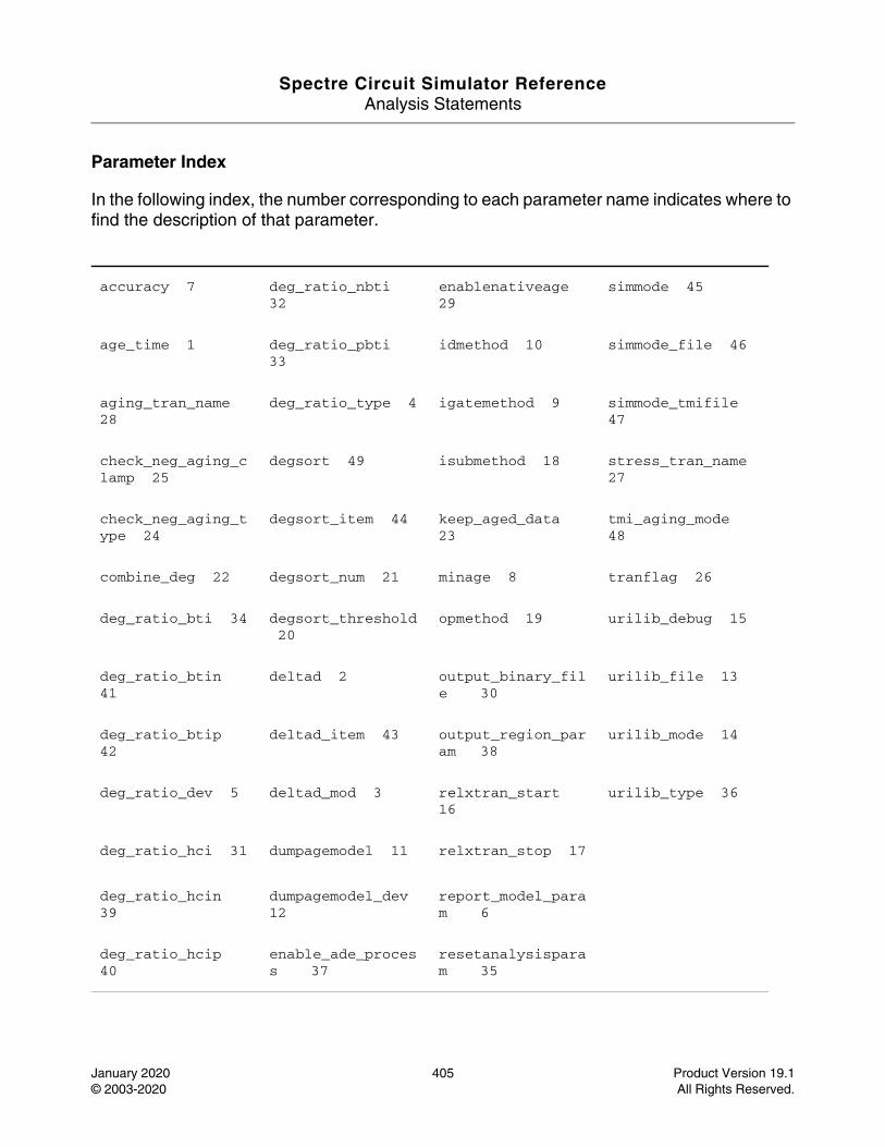
Spectre Circuit Simulator ReferenceAnalysis Statements
January 2020 405 Product Version 19.1© 2003-2020 All Rights Reserved.
Parameter Index
In the following index, the number corresponding to each parameter name indicates where to find the description of that parameter.
accuracy 7 deg_ratio_nbti 32
enablenativeage 29
simmode 45
age_time 1 deg_ratio_pbti 33
idmethod 10 simmode_file 46
aging_tran_name 28
deg_ratio_type 4 igatemethod 9 simmode_tmifile 47
check_neg_aging_clamp 25
degsort 49 isubmethod 18 stress_tran_name 27
check_neg_aging_type 24
degsort_item 44 keep_aged_data 23
tmi_aging_mode 48
combine_deg 22 degsort_num 21 minage 8 tranflag 26
deg_ratio_bti 34 degsort_threshold 20
opmethod 19 urilib_debug 15
deg_ratio_btin 41
deltad 2 output_binary_file 30
urilib_file 13
deg_ratio_btip 42
deltad_item 43 output_region_param 38
urilib_mode 14
deg_ratio_dev 5 deltad_mod 3 relxtran_start 16
urilib_type 36
deg_ratio_hci 31 dumpagemodel 11 relxtran_stop 17
deg_ratio_hcin 39
dumpagemodel_dev 12
report_model_param 6
deg_ratio_hcip 40
enable_ade_process 37
resetanalysisparam 35
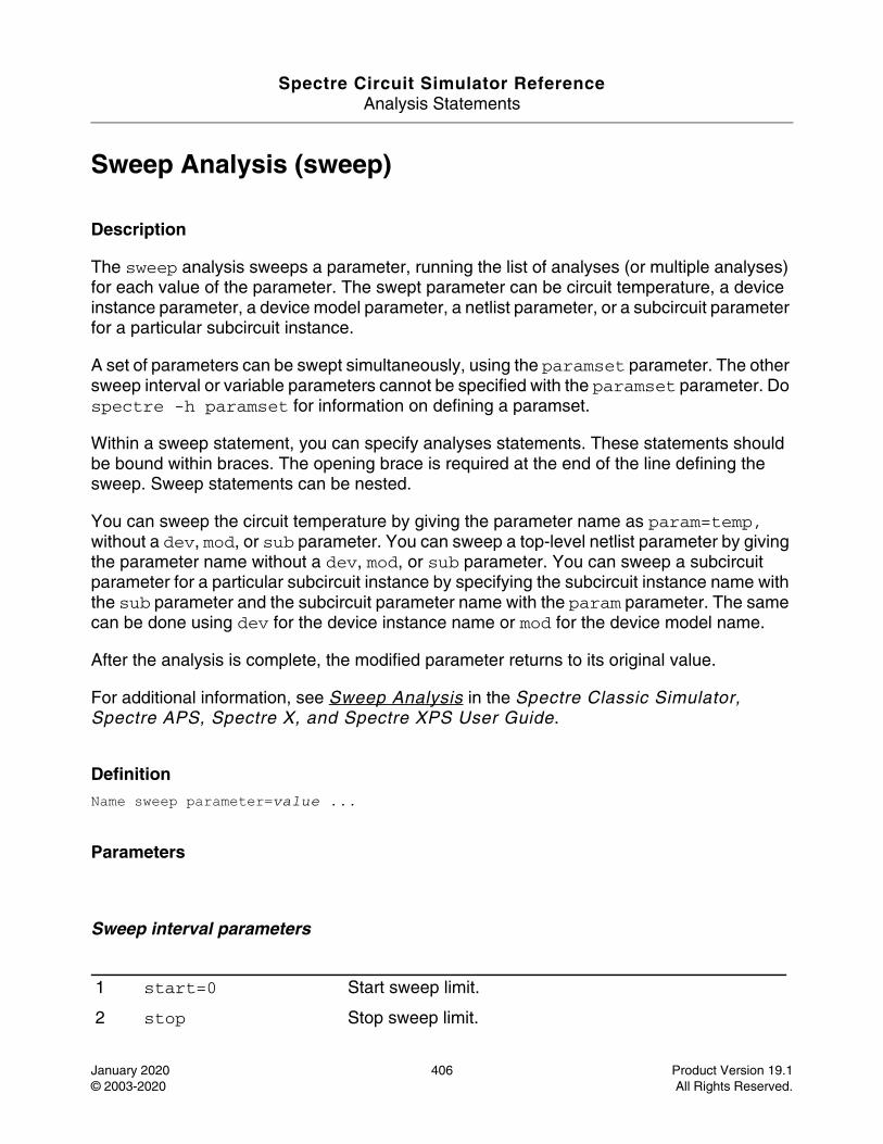
Spectre Circuit Simulator ReferenceAnalysis Statements
January 2020 406 Product Version 19.1© 2003-2020 All Rights Reserved.
Sweep Analysis (sweep)
Description
The sweep analysis sweeps a parameter, running the list of analyses (or multiple analyses) for each value of the parameter. The swept parameter can be circuit temperature, a device instance parameter, a device model parameter, a netlist parameter, or a subcircuit parameter for a particular subcircuit instance.
A set of parameters can be swept simultaneously, using the paramset parameter. The other sweep interval or variable parameters cannot be specified with the paramset parameter. Do spectre -h paramset for information on defining a paramset.
Within a sweep statement, you can specify analyses statements. These statements should be bound within braces. The opening brace is required at the end of the line defining the sweep. Sweep statements can be nested.
You can sweep the circuit temperature by giving the parameter name as param=temp, without a dev, mod, or sub parameter. You can sweep a top-level netlist parameter by giving the parameter name without a dev, mod, or sub parameter. You can sweep a subcircuit parameter for a particular subcircuit instance by specifying the subcircuit instance name with the sub parameter and the subcircuit parameter name with the param parameter. The same can be done using dev for the device instance name or mod for the device model name.
After the analysis is complete, the modified parameter returns to its original value.
For additional information, see Sweep Analysis in the Spectre Classic Simulator, Spectre APS, Spectre X, and Spectre XPS User Guide.
DefinitionName sweep parameter=value ...
Parameters
Sweep interval parameters
1 start=0 Start sweep limit.
2 stop Stop sweep limit.
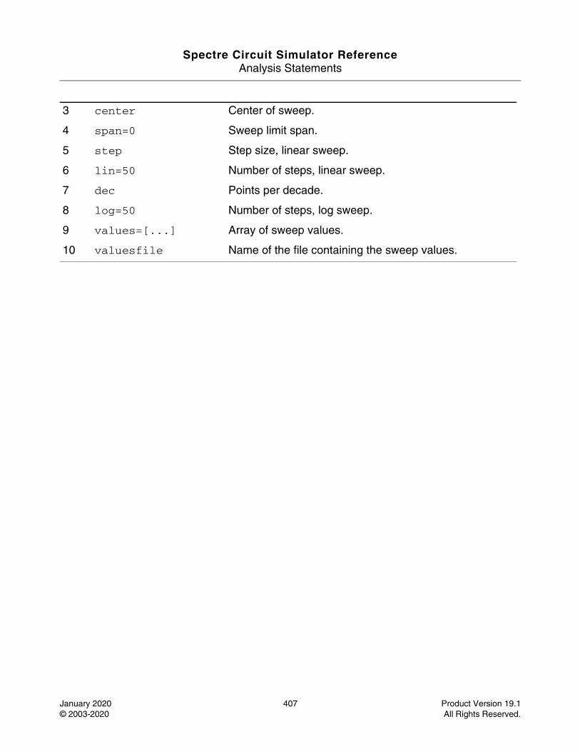
Spectre Circuit Simulator ReferenceAnalysis Statements
January 2020 407 Product Version 19.1© 2003-2020 All Rights Reserved.
3 center Center of sweep.
4 span=0 Sweep limit span.
5 step Step size, linear sweep.
6 lin=50 Number of steps, linear sweep.
7 dec Points per decade.
8 log=50 Number of steps, log sweep.
9 values=[...] Array of sweep values.
10 valuesfile Name of the file containing the sweep values.
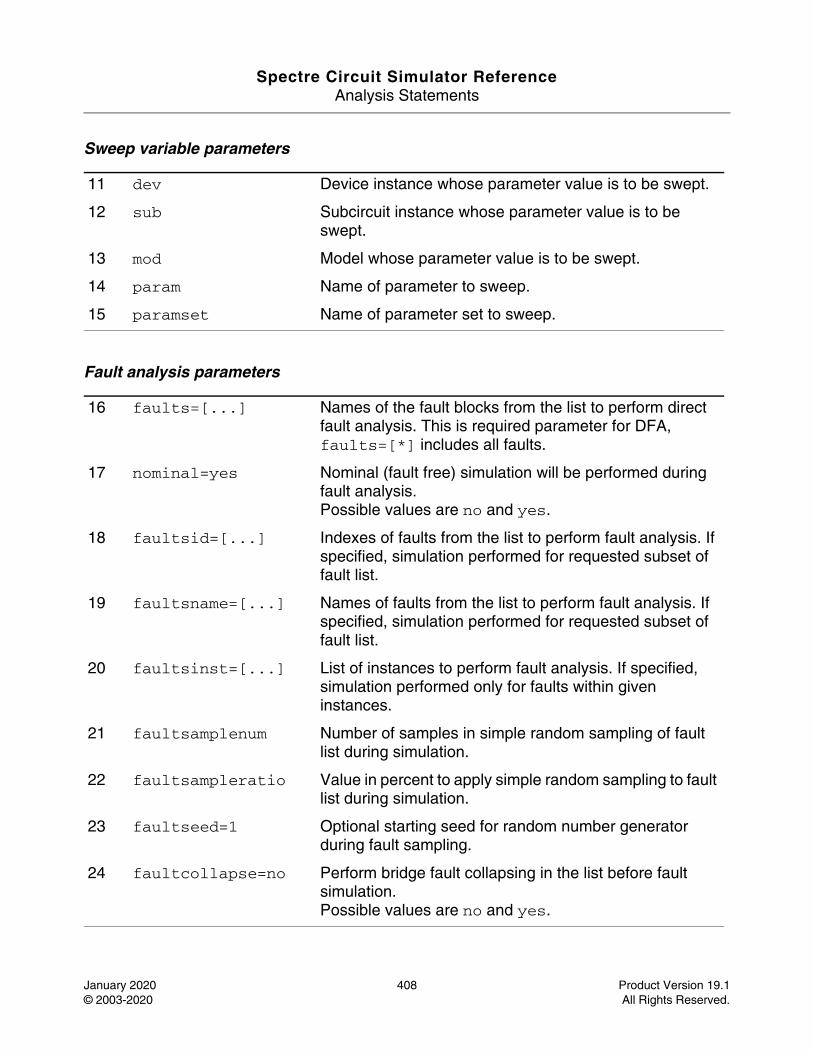
Spectre Circuit Simulator ReferenceAnalysis Statements
January 2020 408 Product Version 19.1© 2003-2020 All Rights Reserved.
Sweep variable parameters
Fault analysis parameters
11 dev Device instance whose parameter value is to be swept.
12 sub Subcircuit instance whose parameter value is to be swept.
13 mod Model whose parameter value is to be swept.
14 param Name of parameter to sweep.
15 paramset Name of parameter set to sweep.
16 faults=[...] Names of the fault blocks from the list to perform direct fault analysis. This is required parameter for DFA, faults=[*] includes all faults.
17 nominal=yes Nominal (fault free) simulation will be performed during fault analysis.Possible values are no and yes.
18 faultsid=[...] Indexes of faults from the list to perform fault analysis. If specified, simulation performed for requested subset of fault list.
19 faultsname=[...] Names of faults from the list to perform fault analysis. If specified, simulation performed for requested subset of fault list.
20 faultsinst=[...] List of instances to perform fault analysis. If specified, simulation performed only for faults within given instances.
21 faultsamplenum Number of samples in simple random sampling of fault list during simulation.
22 faultsampleratio Value in percent to apply simple random sampling to fault list during simulation.
23 faultseed=1 Optional starting seed for random number generator during fault sampling.
24 faultcollapse=no Perform bridge fault collapsing in the list before fault simulation.Possible values are no and yes.
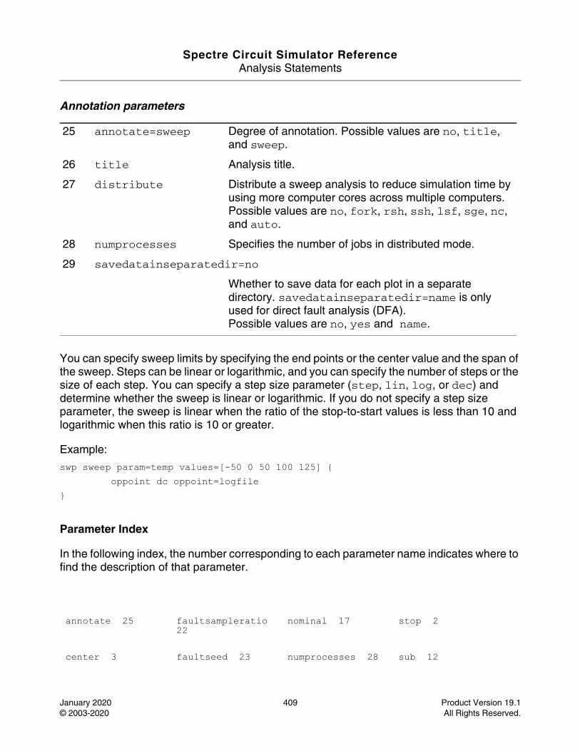
Spectre Circuit Simulator ReferenceAnalysis Statements
January 2020 409 Product Version 19.1© 2003-2020 All Rights Reserved.
Annotation parameters
You can specify sweep limits by specifying the end points or the center value and the span of the sweep. Steps can be linear or logarithmic, and you can specify the number of steps or the size of each step. You can specify a step size parameter (step, lin, log, or dec) and determine whether the sweep is linear or logarithmic. If you do not specify a step size parameter, the sweep is linear when the ratio of the stop-to-start values is less than 10 and logarithmic when this ratio is 10 or greater.
Example:
swp sweep param=temp values=[-50 0 50 100 125] { oppoint dc oppoint=logfile}
Parameter Index
In the following index, the number corresponding to each parameter name indicates where to find the description of that parameter.
25 annotate=sweep Degree of annotation. Possible values are no, title, and sweep.
26 title Analysis title.
27 distribute Distribute a sweep analysis to reduce simulation time by using more computer cores across multiple computers.Possible values are no, fork, rsh, ssh, lsf, sge, nc, and auto.
28 numprocesses Specifies the number of jobs in distributed mode.
29 savedatainseparatedir=no
Whether to save data for each plot in a separate directory. savedatainseparatedir=name is only used for direct fault analysis (DFA).Possible values are no, yes and name.
annotate 25 faultsampleratio 22
nominal 17 stop 2
center 3 faultseed 23 numprocesses 28 sub 12
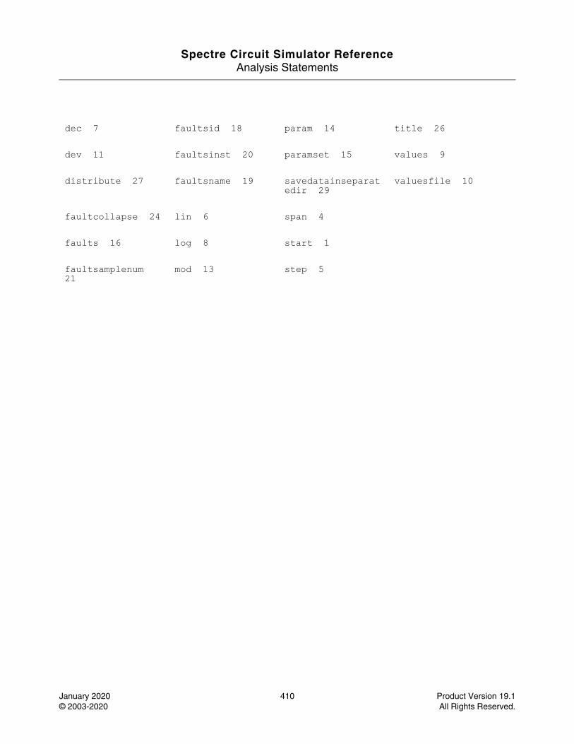
Spectre Circuit Simulator ReferenceAnalysis Statements
January 2020 410 Product Version 19.1© 2003-2020 All Rights Reserved.
dec 7 faultsid 18 param 14 title 26
dev 11 faultsinst 20 paramset 15 values 9
distribute 27 faultsname 19 savedatainseparatedir 29
valuesfile 10
faultcollapse 24 lin 6 span 4
faults 16 log 8 start 1
faultsamplenum 21
mod 13 step 5
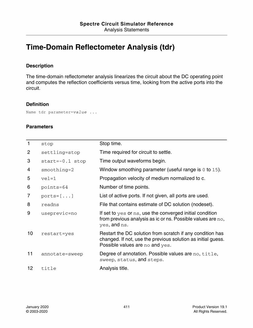
Spectre Circuit Simulator ReferenceAnalysis Statements
January 2020 411 Product Version 19.1© 2003-2020 All Rights Reserved.
Time-Domain Reflectometer Analysis (tdr)
Description
The time-domain reflectometer analysis linearizes the circuit about the DC operating point and computes the reflection coefficients versus time, looking from the active ports into the circuit.
DefinitionName tdr parameter=value ...
Parameters
1 stop Stop time.
2 settling=stop Time required for circuit to settle.
3 start=-0.1 stop Time output waveforms begin.
4 smoothing=2 Window smoothing parameter (useful range is 0 to 15).
5 vel=1 Propagation velocity of medium normalized to c.
6 points=64 Number of time points.
7 ports=[...] List of active ports. If not given, all ports are used.
8 readns File that contains estimate of DC solution (nodeset).
9 useprevic=no If set to yes or ns, use the converged initial condition from previous analysis as ic or ns. Possible values are no, yes, and ns.
10 restart=yes Restart the DC solution from scratch if any condition has changed. If not, use the previous solution as initial guess. Possible values are no and yes.
11 annotate=sweep Degree of annotation. Possible values are no, title, sweep, status, and steps.
12 title Analysis title.
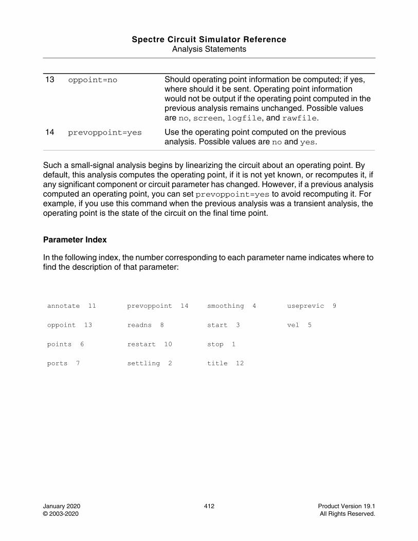
Spectre Circuit Simulator ReferenceAnalysis Statements
January 2020 412 Product Version 19.1© 2003-2020 All Rights Reserved.
Such a small-signal analysis begins by linearizing the circuit about an operating point. By default, this analysis computes the operating point, if it is not yet known, or recomputes it, if any significant component or circuit parameter has changed. However, if a previous analysis computed an operating point, you can set prevoppoint=yes to avoid recomputing it. For example, if you use this command when the previous analysis was a transient analysis, the operating point is the state of the circuit on the final time point.
Parameter Index
In the following index, the number corresponding to each parameter name indicates where to find the description of that parameter:
13 oppoint=no Should operating point information be computed; if yes, where should it be sent. Operating point information would not be output if the operating point computed in the previous analysis remains unchanged. Possible values are no, screen, logfile, and rawfile.
14 prevoppoint=yes Use the operating point computed on the previous analysis. Possible values are no and yes.
annotate 11 prevoppoint 14 smoothing 4 useprevic 9
oppoint 13 readns 8 start 3 vel 5
points 6 restart 10 stop 1
ports 7 settling 2 title 12
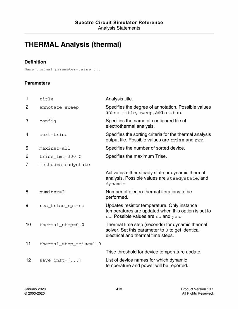
Spectre Circuit Simulator ReferenceAnalysis Statements
January 2020 413 Product Version 19.1© 2003-2020 All Rights Reserved.
THERMAL Analysis (thermal)
DefinitionName thermal parameter=value ...
Parameters
1 title Analysis title.
2 annotate=sweep Specifies the degree of annotation. Possible values are no, title, sweep, and status.
3 config Specifies the name of configured file of electrothermal analysis.
4 sort=trise Specifies the sorting criteria for the thermal analysis output file. Possible values are trise and pwr.
5 maxinst=all Specifies the number of sorted device.
6 trise_lmt=300 C Specifies the maximum Trise.
7 method=steadystate
Activates either steady state or dynamic thermal analysis. Possible values are steadystate, and dynamic.
8 numiter=2 Number of electro-thermal iterations to be performed.
9 res_trise_rpt=no Updates resistor temperature. Only instance temperatures are updated when this option is set to no. Possible values are no and yes.
10 thermal_step=0.0 Thermal time step (seconds) for dynamic thermal solver. Set this parameter to 0 to get identical electrical and thermal time steps.
11 thermal_step_trise=1.0
Trise threshold for device temperature update.
12 save_inst=[...] List of device names for which dynamic temperature and power will be reported.
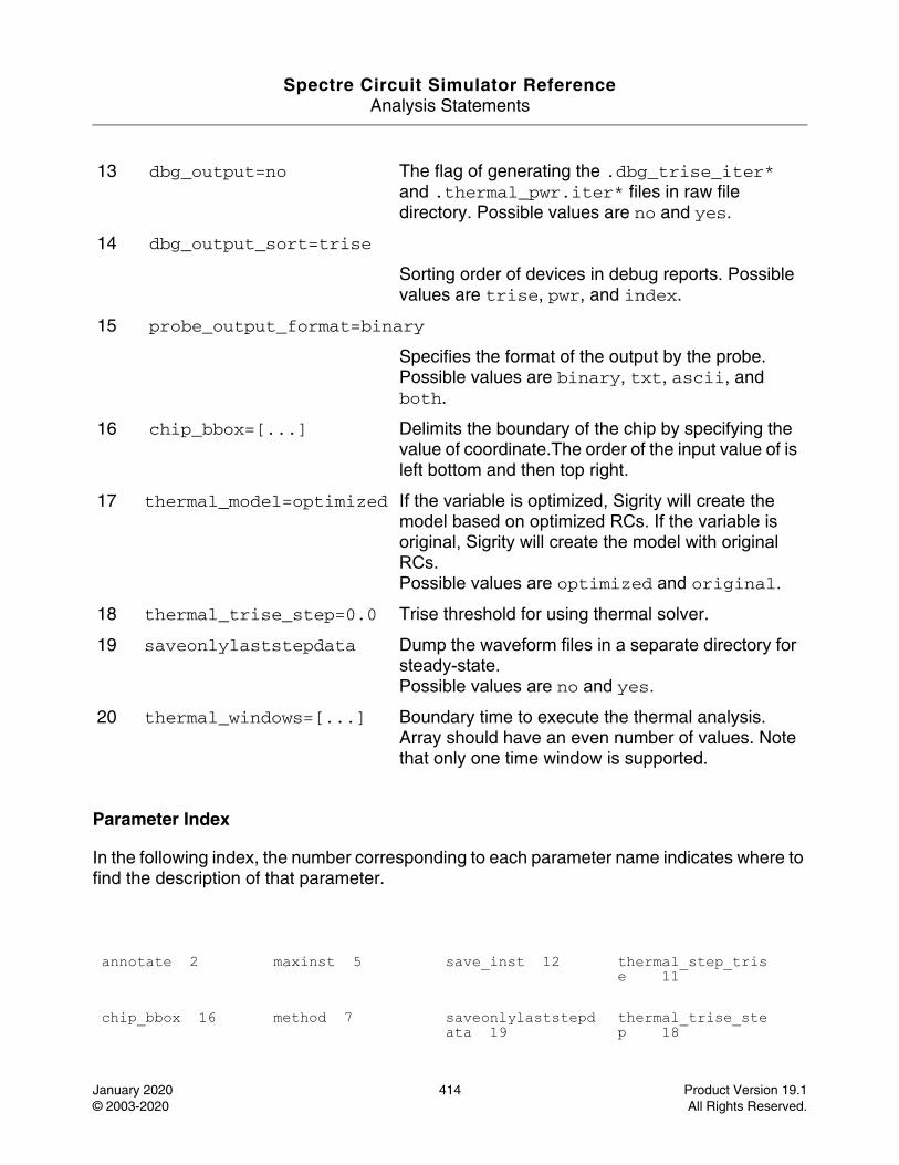
Spectre Circuit Simulator ReferenceAnalysis Statements
January 2020 414 Product Version 19.1© 2003-2020 All Rights Reserved.
Parameter Index
In the following index, the number corresponding to each parameter name indicates where to find the description of that parameter.
13 dbg_output=no The flag of generating the .dbg_trise_iter* and .thermal_pwr.iter* files in raw file directory. Possible values are no and yes.
14 dbg_output_sort=trise
Sorting order of devices in debug reports. Possible values are trise, pwr, and index.
15 probe_output_format=binary
Specifies the format of the output by the probe. Possible values are binary, txt, ascii, and both.
16 chip_bbox=[...] Delimits the boundary of the chip by specifying the value of coordinate.The order of the input value of is left bottom and then top right.
17 thermal_model=optimized If the variable is optimized, Sigrity will create the model based on optimized RCs. If the variable is original, Sigrity will create the model with original RCs.Possible values are optimized and original.
18 thermal_trise_step=0.0 Trise threshold for using thermal solver.
19 saveonlylaststepdata Dump the waveform files in a separate directory for steady-state.Possible values are no and yes.
20 thermal_windows=[...] Boundary time to execute the thermal analysis. Array should have an even number of values. Note that only one time window is supported.
annotate 2 maxinst 5 save_inst 12 thermal_step_trise 11
chip_bbox 16 method 7 saveonlylaststepdata 19
thermal_trise_step 18
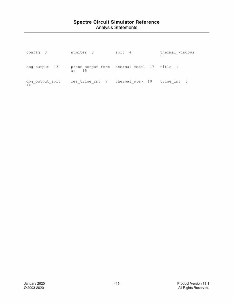
Spectre Circuit Simulator ReferenceAnalysis Statements
January 2020 415 Product Version 19.1© 2003-2020 All Rights Reserved.
config 3 numiter 8 sort 4 thermal_windows 20
dbg_output 13 probe_output_format 15
thermal_model 17 title 1
dbg_output_sort 14
res_trise_rpt 9 thermal_step 10 trise_lmt 6
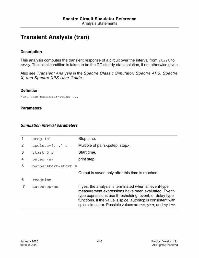
Spectre Circuit Simulator ReferenceAnalysis Statements
January 2020 416 Product Version 19.1© 2003-2020 All Rights Reserved.
Transient Analysis (tran)
Description
This analysis computes the transient response of a circuit over the interval from start to stop. The initial condition is taken to be the DC steady-state solution, if not otherwise given.
Also see Transient Analysis in the Spectre Classic Simulator, Spectre APS, Spectre X, and Spectre XPS User Guide.
DefinitionName tran parameter=value ...
Parameters
Simulation interval parameters
1 stop (s) Stop time.
2 tpoints=[...] s Multiple of pairs<pstep, stop>.
3 start=0 s Start time.
4 pstep (s) print step.
5 outputstart=start s
Output is saved only after this time is reached.
6 readtime
7 autostop=no If yes, the analysis is terminated when all event-type measurement expressions have been evaluated. Event-type expressions use thresholding, event, or delay type functions. If the value is spice, autostop is consistent with spice simulator. Possible values are no, yes, and spice.
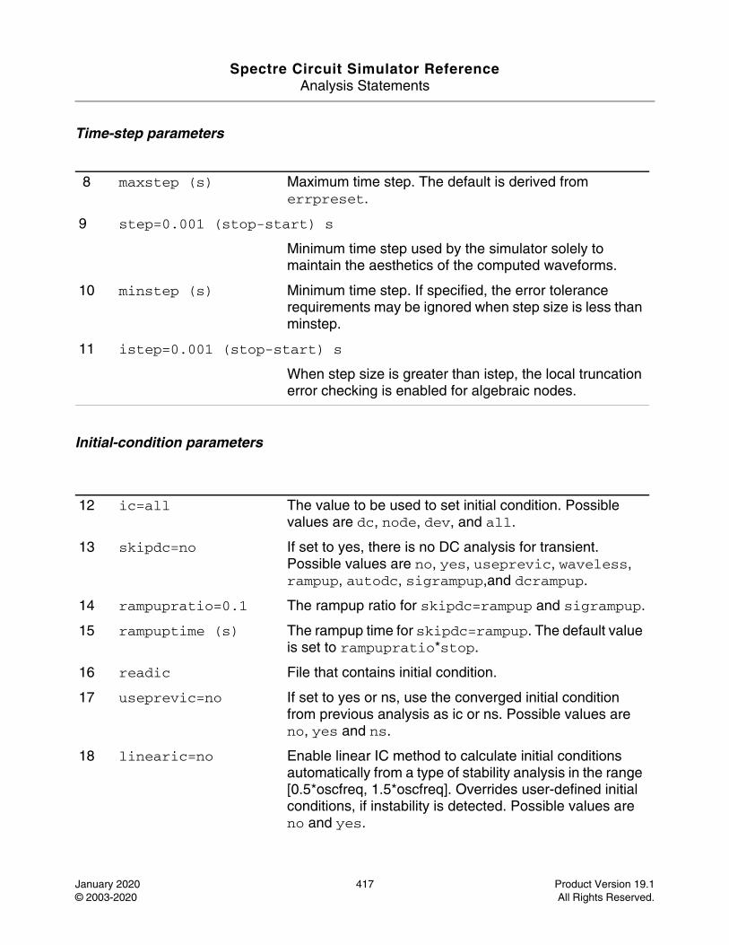
Spectre Circuit Simulator ReferenceAnalysis Statements
January 2020 417 Product Version 19.1© 2003-2020 All Rights Reserved.
Time-step parameters
Initial-condition parameters
8 maxstep (s) Maximum time step. The default is derived from errpreset.
9 step=0.001 (stop-start) s
Minimum time step used by the simulator solely to maintain the aesthetics of the computed waveforms.
10 minstep (s) Minimum time step. If specified, the error tolerance requirements may be ignored when step size is less than minstep.
11 istep=0.001 (stop-start) s
When step size is greater than istep, the local truncation error checking is enabled for algebraic nodes.
12 ic=all The value to be used to set initial condition. Possible values are dc, node, dev, and all.
13 skipdc=no If set to yes, there is no DC analysis for transient. Possible values are no, yes, useprevic, waveless, rampup, autodc, sigrampup,and dcrampup.
14 rampupratio=0.1 The rampup ratio for skipdc=rampup and sigrampup.
15 rampuptime (s) The rampup time for skipdc=rampup. The default value is set to rampupratio*stop.
16 readic File that contains initial condition.
17 useprevic=no If set to yes or ns, use the converged initial condition from previous analysis as ic or ns. Possible values are no, yes and ns.
18 linearic=no Enable linear IC method to calculate initial conditions automatically from a type of stability analysis in the range [0.5*oscfreq, 1.5*oscfreq]. Overrides user-defined initial conditions, if instability is detected. Possible values are no and yes.
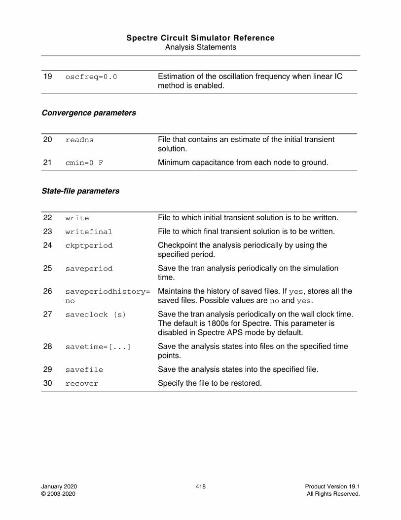
Spectre Circuit Simulator ReferenceAnalysis Statements
January 2020 418 Product Version 19.1© 2003-2020 All Rights Reserved.
Convergence parameters
State-file parameters
19 oscfreq=0.0 Estimation of the oscillation frequency when linear IC method is enabled.
20 readns File that contains an estimate of the initial transient solution.
21 cmin=0 F Minimum capacitance from each node to ground.
22 write File to which initial transient solution is to be written.
23 writefinal File to which final transient solution is to be written.
24 ckptperiod Checkpoint the analysis periodically by using the specified period.
25 saveperiod Save the tran analysis periodically on the simulation time.
26 saveperiodhistory=no
Maintains the history of saved files. If yes, stores all the saved files. Possible values are no and yes.
27 saveclock (s) Save the tran analysis periodically on the wall clock time. The default is 1800s for Spectre. This parameter is disabled in Spectre APS mode by default.
28 savetime=[...] Save the analysis states into files on the specified time points.
29 savefile Save the analysis states into the specified file.
30 recover Specify the file to be restored.
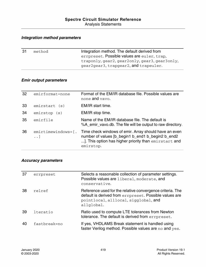
Spectre Circuit Simulator ReferenceAnalysis Statements
January 2020 419 Product Version 19.1© 2003-2020 All Rights Reserved.
Integration method parameters
Emir output parameters
Accuracy parameters
31 method Integration method. The default derived from errpreset. Possible values are euler, trap, traponly, gear2, gear2only, gear3, gear3only, gear2gear3, trapgear2, and trapeuler.
32 emirformat=none Format of the EM/IR database file. Possible values are none and vavo.
33 emirstart (s) EM/IR start time.
34 emirstop (s) EM/IR stop time.
35 emirfile Name of the EM/IR database file. The default is %A_emir_vavo.db. The file will be output to raw directory.
36 emirtimewindows=[...]
Time check windows of emir. Array should have an even number of values [b_begin1 b_end1 b_begin2 b_end2 ...]. This option has higher priority than emirstart and emirstop.
37 errpreset Selects a reasonable collection of parameter settings. Possible values are liberal, moderate, and conservative.
38 relref Reference used for the relative convergence criteria. The default is derived from errpreset. Possible values are pointlocal, alllocal, sigglobal, and allglobal.
39 lteratio Ratio used to compute LTE tolerances from Newton tolerance. The default is derived from errpreset.
40 fastbreak=no If yes, VHDLAMS Break statement is handled using faster Verilog method. Possible values are no and yes.
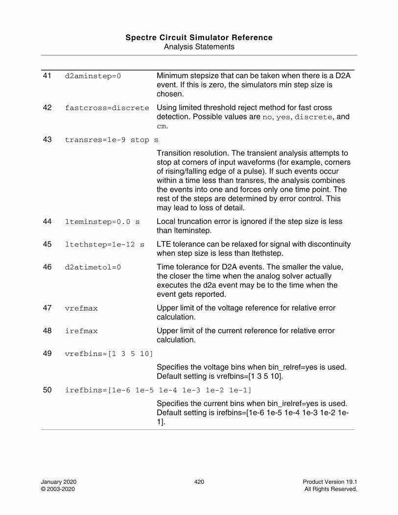
Spectre Circuit Simulator ReferenceAnalysis Statements
January 2020 420 Product Version 19.1© 2003-2020 All Rights Reserved.
41 d2aminstep=0 Minimum stepsize that can be taken when there is a D2A event. If this is zero, the simulators min step size is chosen.
42 fastcross=discrete Using limited threshold reject method for fast cross detection. Possible values are no, yes, discrete, and cm.
43 transres=1e-9 stop s
Transition resolution. The transient analysis attempts to stop at corners of input waveforms (for example, corners of rising/falling edge of a pulse). If such events occur within a time less than transres, the analysis combines the events into one and forces only one time point. The rest of the steps are determined by error control. This may lead to loss of detail.
44 lteminstep=0.0 s Local truncation error is ignored if the step size is less than lteminstep.
45 ltethstep=1e-12 s LTE tolerance can be relaxed for signal with discontinuity when step size is less than ltethstep.
46 d2atimetol=0 Time tolerance for D2A events. The smaller the value, the closer the time when the analog solver actually executes the d2a event may be to the time when the event gets reported.
47 vrefmax Upper limit of the voltage reference for relative error calculation.
48 irefmax Upper limit of the current reference for relative error calculation.
49 vrefbins=[1 3 5 10]
Specifies the voltage bins when bin_relref=yes is used. Default setting is vrefbins=[1 3 5 10].
50 irefbins=[1e-6 1e-5 1e-4 1e-3 1e-2 1e-1]
Specifies the current bins when bin_irelref=yes is used. Default setting is irefbins=[1e-6 1e-5 1e-4 1e-3 1e-2 1e-1].
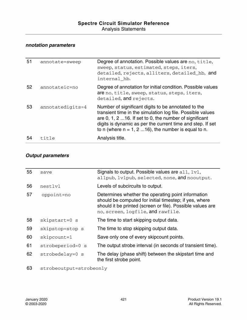
Spectre Circuit Simulator ReferenceAnalysis Statements
January 2020 421 Product Version 19.1© 2003-2020 All Rights Reserved.
nnotation parameters
Output parameters
51 annotate=sweep Degree of annotation. Possible values are no, title, sweep, status, estimated, steps, iters, detailed, rejects, alliters, detailed_hb, and internal_hb.
52 annotateic=no Degree of annotation for initial condition. Possible values are no, title, sweep, status, steps, iters, detailed, and rejects.
53 annotatedigits=4 Number of significant digits to be annotated to the transient time in the simulation log file. Possible values are 0, 1, 2 ...16. If set to 0, the number of significant digits is dynamic as per the current time and step. If set to n (where n = 1, 2 ...16), the number is equal to n.
54 title Analysis title.
55 save Signals to output. Possible values are all, lvl, allpub, lvlpub, selected, none, and nooutput.
56 nestlvl Levels of subcircuits to output.
57 oppoint=no Determines whether the operating point information should be computed for initial timestep; if yes, where should it be printed (screen or file). Possible values are no, screen, logfile, and rawfile.
58 skipstart=0 s The time to start skipping output data.
59 skipstop=stop s The time to stop skipping output data.
60 skipcount=1 Save only one of every skipcount points.
61 strobeperiod=0 s The output strobe interval (in seconds of transient time).
62 strobedelay=0 s The delay (phase shift) between the skipstart time and the first strobe point.
63 strobeoutput=strobeonly
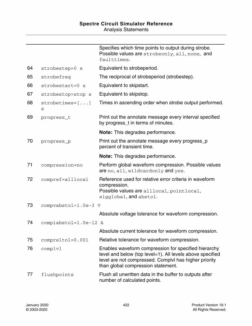
Spectre Circuit Simulator ReferenceAnalysis Statements
January 2020 422 Product Version 19.1© 2003-2020 All Rights Reserved.
Specifies which time points to output during strobe. Possible values are strobeonly, all, none, and faulttimes.
64 strobestep=0 s Equivalent to strobeperiod.
65 strobefreq The reciprocal of strobeperiod (strobestep).
66 strobestart=0 s Equivalent to skipstart.
67 strobestop=stop s Equivalent to skipstop.
68 strobetimes=[...] s
Times in ascending order when strobe output performed.
69 progress_t Print out the annotate message every interval specified by progress_t in terms of minutes.
Note: This degrades performance.
70 progress_p Print out the annotate message every progress_p percent of transient time.
Note: This degrades performance.
71 compression=no Perform global waveform compression. Possible values are no, all, wildcardonly and yes.
72 compref=alllocal Reference used for relative error criteria in waveform compression.Possible values are alllocal, pointlocal, sigglobal, and abstol.
73 compvabstol=1.0e-3 V
Absolute voltage tolerance for waveform compression.
74 compiabstol=1.0e-12 A
Absolute current tolerance for waveform compression.
75 compreltol=0.001 Relative tolerance for waveform compression.
76 complvl Enables waveform compression for specified hierarchy level and below (top level=1). All levels above specified level are not compressed. Complvl has higher priority than global compression statement.
77 flushpoints Flush all unwritten data in the buffer to outputs after number of calculated points.
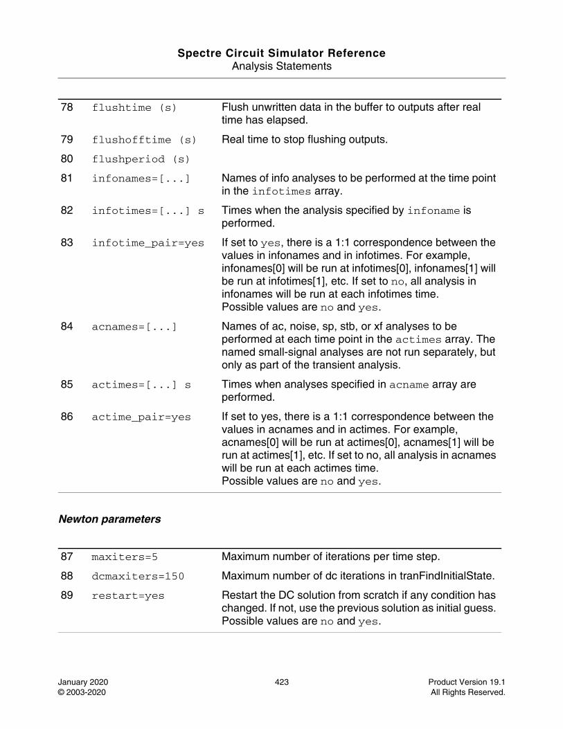
Spectre Circuit Simulator ReferenceAnalysis Statements
January 2020 423 Product Version 19.1© 2003-2020 All Rights Reserved.
Newton parameters
78 flushtime (s) Flush unwritten data in the buffer to outputs after real time has elapsed.
79 flushofftime (s) Real time to stop flushing outputs.
80 flushperiod (s)
81 infonames=[...] Names of info analyses to be performed at the time point in the infotimes array.
82 infotimes=[...] s Times when the analysis specified by infoname is performed.
83 infotime_pair=yes If set to yes, there is a 1:1 correspondence between the values in infonames and in infotimes. For example, infonames[0] will be run at infotimes[0], infonames[1] will be run at infotimes[1], etc. If set to no, all analysis in infonames will be run at each infotimes time.Possible values are no and yes.
84 acnames=[...] Names of ac, noise, sp, stb, or xf analyses to be performed at each time point in the actimes array. The named small-signal analyses are not run separately, but only as part of the transient analysis.
85 actimes=[...] s Times when analyses specified in acname array are performed.
86 actime_pair=yes If set to yes, there is a 1:1 correspondence between the values in acnames and in actimes. For example, acnames[0] will be run at actimes[0], acnames[1] will be run at actimes[1], etc. If set to no, all analysis in acnames will be run at each actimes time.Possible values are no and yes.
87 maxiters=5 Maximum number of iterations per time step.
88 dcmaxiters=150 Maximum number of dc iterations in tranFindInitialState.
89 restart=yes Restart the DC solution from scratch if any condition has changed. If not, use the previous solution as initial guess. Possible values are no and yes.
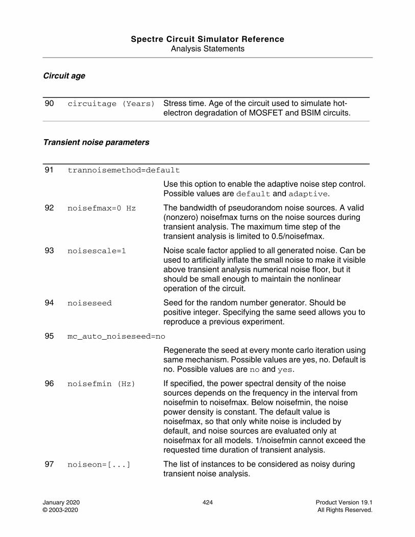
Spectre Circuit Simulator ReferenceAnalysis Statements
January 2020 424 Product Version 19.1© 2003-2020 All Rights Reserved.
Circuit age
Transient noise parameters
90 circuitage (Years) Stress time. Age of the circuit used to simulate hot-electron degradation of MOSFET and BSIM circuits.
91 trannoisemethod=default
Use this option to enable the adaptive noise step control. Possible values are default and adaptive.
92 noisefmax=0 Hz The bandwidth of pseudorandom noise sources. A valid (nonzero) noisefmax turns on the noise sources during transient analysis. The maximum time step of the transient analysis is limited to 0.5/noisefmax.
93 noisescale=1 Noise scale factor applied to all generated noise. Can be used to artificially inflate the small noise to make it visible above transient analysis numerical noise floor, but it should be small enough to maintain the nonlinear operation of the circuit.
94 noiseseed Seed for the random number generator. Should be positive integer. Specifying the same seed allows you to reproduce a previous experiment.
95 mc_auto_noiseseed=no
Regenerate the seed at every monte carlo iteration using same mechanism. Possible values are yes, no. Default is no. Possible values are no and yes.
96 noisefmin (Hz) If specified, the power spectral density of the noise sources depends on the frequency in the interval from noisefmin to noisefmax. Below noisefmin, the noise power density is constant. The default value is noisefmax, so that only white noise is included by default, and noise sources are evaluated only at noisefmax for all models. 1/noisefmin cannot exceed the requested time duration of transient analysis.
97 noiseon=[...] The list of instances to be considered as noisy during transient noise analysis.
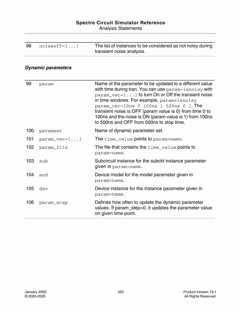
Spectre Circuit Simulator ReferenceAnalysis Statements
January 2020 425 Product Version 19.1© 2003-2020 All Rights Reserved.
Dynamic parameters
98 noiseoff=[...] The list of instances to be considered as not noisy during transient noise analysis.
99 param Name of the parameter to be updated to a different value with time during tran. You can use param=isnoisy with param_vec=[...] to turn On or Off the transient noise in time windows. For example, param=isnoisy param_vec=[0ns 0 100ns 1 500ns 0 ]. The transient noise is OFF (param value is 0) from time 0 to 100ns and the noise is ON (param value is 1) from 100ns to 500ns and OFF from 500ns to stop time.
100 paramset Name of dynamic parameter set.
101 param_vec=[...] The time_value points to param=name.
102 param_file The file that contains the time_value points to param=name.
103 sub Subcircuit instance for the subckt instance parameter given in param=name.
104 mod Device model for the model parameter given in param=name.
105 dev Device instance for the instance parameter given in param=name.
106 param_step Defines how often to update the dynamic parameter values. If param_step=0, it updates the parameter value on given time point.
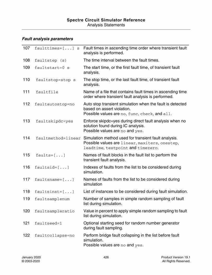
Spectre Circuit Simulator ReferenceAnalysis Statements
January 2020 426 Product Version 19.1© 2003-2020 All Rights Reserved.
Fault analysis parameters
107 faulttimes=[...] s Fault times in ascending time order where transient fault analysis is performed.
108 faultstep (s) The time interval between the fault times.
109 faultstart=0 s The start time, or the first fault time, of transient fault analysis.
110 faultstop=stop s The stop time, or the last fault time, of transient fault analysis.
111 faultfile Name of a file that contains fault times in ascending time order where transient fault analysis is performed.
112 faultautostop=no Auto stop transient simulation when the fault is detected based on assert violation.Possible values are no, func, check, and all.
113 faultskipdc=yes Enforce skipdc=yes during direct fault analysis when no solution found during IC analysis.Possible values are no and yes.
114 faultmethod=linear Simulation method used for transient fault analysis. Possible values are linear, maxiters, onestep, leadtime, testpoint and timezero.
115 faults=[...] Names of fault blocks in the fault list to perform the transient fault analysis.
116 faultsid=[...] Indexes of faults from the list to be considered during simulation.
117 faultsname=[...] Names of faults from the list to be considered during simulation
118 faultsinst=[...] List of instances to be considered during fault simulation.
119 faultsamplenum Number of samples in simple random sampling of fault list during simulation.
120 faultsampleratio Value in percent to apply simple random sampling to fault list during simulation.
121 faultseed=1 Optional starting seed for random number generator during fault sampling.
122 faultcollapse=no Perform bridge fault collapsing in the list before fault simulation.Possible values are no and yes.
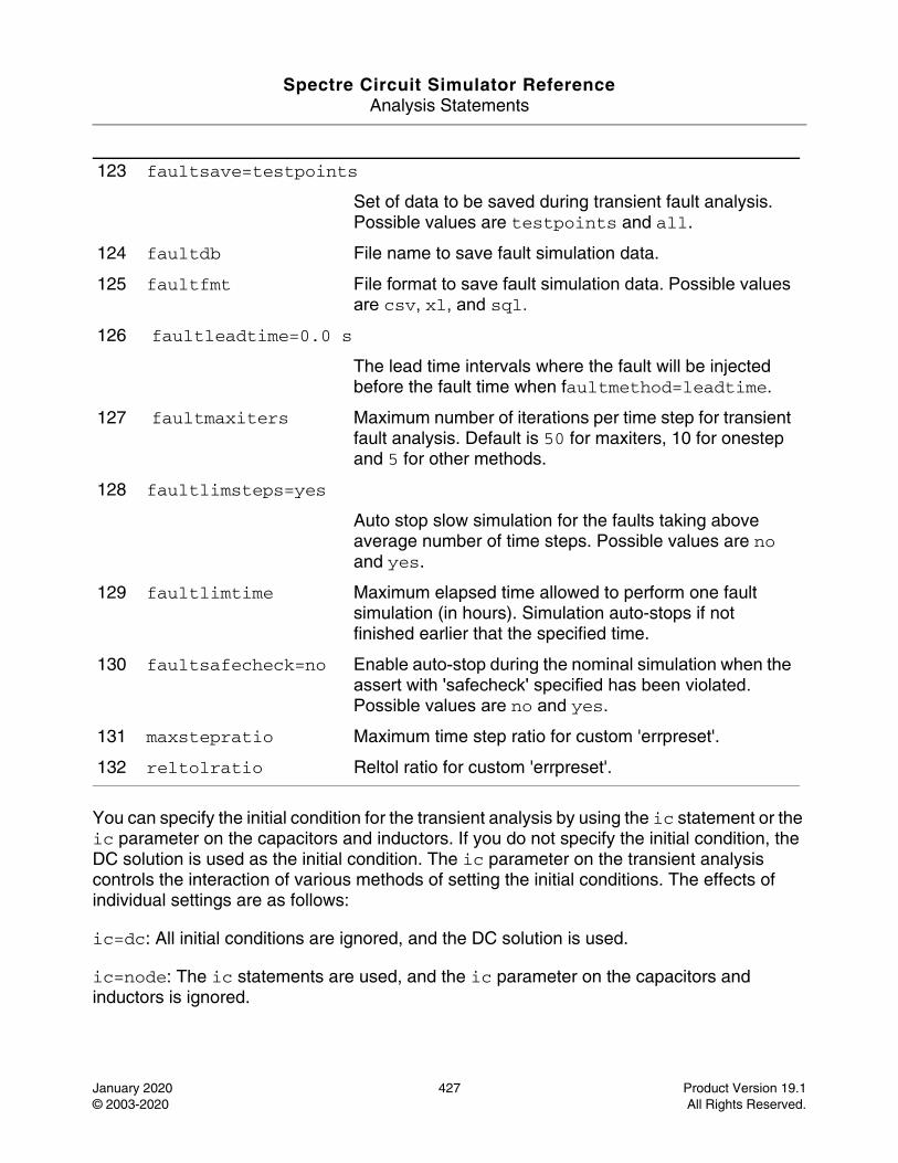
Spectre Circuit Simulator ReferenceAnalysis Statements
January 2020 427 Product Version 19.1© 2003-2020 All Rights Reserved.
You can specify the initial condition for the transient analysis by using the ic statement or the ic parameter on the capacitors and inductors. If you do not specify the initial condition, the DC solution is used as the initial condition. The ic parameter on the transient analysis controls the interaction of various methods of setting the initial conditions. The effects of individual settings are as follows:
ic=dc: All initial conditions are ignored, and the DC solution is used.
ic=node: The ic statements are used, and the ic parameter on the capacitors and inductors is ignored.
123 faultsave=testpoints
Set of data to be saved during transient fault analysis. Possible values are testpoints and all.
124 faultdb File name to save fault simulation data.
125 faultfmt File format to save fault simulation data. Possible values are csv, xl, and sql.
126 faultleadtime=0.0 s
The lead time intervals where the fault will be injected before the fault time when faultmethod=leadtime.
127 faultmaxiters Maximum number of iterations per time step for transient fault analysis. Default is 50 for maxiters, 10 for onestep and 5 for other methods.
128 faultlimsteps=yes
Auto stop slow simulation for the faults taking above average number of time steps. Possible values are no and yes.
129 faultlimtime Maximum elapsed time allowed to perform one fault simulation (in hours). Simulation auto-stops if not finished earlier that the specified time.
130 faultsafecheck=no Enable auto-stop during the nominal simulation when the assert with 'safecheck' specified has been violated.Possible values are no and yes.
131 maxstepratio Maximum time step ratio for custom 'errpreset'.
132 reltolratio Reltol ratio for custom 'errpreset'.
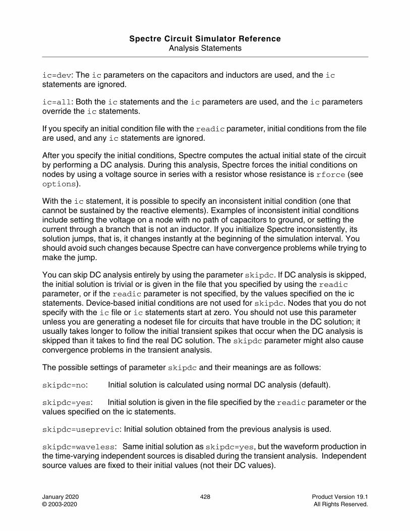
Spectre Circuit Simulator ReferenceAnalysis Statements
January 2020 428 Product Version 19.1© 2003-2020 All Rights Reserved.
ic=dev: The ic parameters on the capacitors and inductors are used, and the ic statements are ignored.
ic=all: Both the ic statements and the ic parameters are used, and the ic parameters override the ic statements.
If you specify an initial condition file with the readic parameter, initial conditions from the file are used, and any ic statements are ignored.
After you specify the initial conditions, Spectre computes the actual initial state of the circuit by performing a DC analysis. During this analysis, Spectre forces the initial conditions on nodes by using a voltage source in series with a resistor whose resistance is rforce (see options).
With the ic statement, it is possible to specify an inconsistent initial condition (one that cannot be sustained by the reactive elements). Examples of inconsistent initial conditions include setting the voltage on a node with no path of capacitors to ground, or setting the current through a branch that is not an inductor. If you initialize Spectre inconsistently, its solution jumps, that is, it changes instantly at the beginning of the simulation interval. You should avoid such changes because Spectre can have convergence problems while trying to make the jump.
You can skip DC analysis entirely by using the parameter skipdc. If DC analysis is skipped, the initial solution is trivial or is given in the file that you specified by using the readic parameter, or if the readic parameter is not specified, by the values specified on the ic statements. Device-based initial conditions are not used for skipdc. Nodes that you do not specify with the ic file or ic statements start at zero. You should not use this parameter unless you are generating a nodeset file for circuits that have trouble in the DC solution; it usually takes longer to follow the initial transient spikes that occur when the DC analysis is skipped than it takes to find the real DC solution. The skipdc parameter might also cause convergence problems in the transient analysis.
The possible settings of parameter skipdc and their meanings are as follows:
skipdc=no: Initial solution is calculated using normal DC analysis (default).
skipdc=yes: Initial solution is given in the file specified by the readic parameter or the values specified on the ic statements.
skipdc=useprevic: Initial solution obtained from the previous analysis is used.
skipdc=waveless: Same initial solution as skipdc=yes, but the waveform production in the time-varying independent sources is disabled during the transient analysis. Independent source values are fixed to their initial values (not their DC values).
Spectre Circuit Simulator ReferenceAnalysis Statements
January 2020 429 Product Version 19.1© 2003-2020 All Rights Reserved.
skipdc=rampup: Independent source values start at 0 and ramp up to their initial values in from start to rampuptime. If rampuptime is not given, rampuptime will be set to rampupratio*stop. After that their values remain constant. Zero initial solution is used.
skipdc=autodc: Same as skipdc=waveless if a nonzero initial condition is specified. Otherwise, same as skipdc=rampup.
skipdc=sigrampup: Independent source values start at 0 and ramp up to their initial values in the first phase of the simulation. Unlike skipdc=rampup, the waveform production in the time-varying independent source is enabled after the rampup phase. The rampup simulation is from the start parameter. If the start parameter is not specified, the default start time is set to rampupratio*stop.
Nodesets help find the DC or the initial transient solution. You can specify nodesets in the circuit description file with nodeset statements, or in a separate file using the readns parameter. When nodesets are specified, Spectre computes an initial guess of the solution by performing DC analysis, while forcing the specified values on to nodes by using a voltage source in series with a resistor whose resistance is rforce. Spectre then removes these voltage sources and resistors and computes the required solution from this initial guess.
Nodesets have two important uses. First, if a circuit has two or more solutions, nodesets can bias the simulator towards computing the required solution. Second, these are a convergence aid. By estimating the solution of the largest possible number of nodes, you might be able to eliminate a convergence problem or significantly speed up convergence.
When you simulate the same circuit multiple times, it is recommended that you use both write and readns parameters and assign the same file name to both parameters. DC analysis then converges quickly even if the circuit has changed since the last simulation, and the nodeset file is automatically updated.
Nodesets and initial conditions have similar implementation, but produce different effects. Initial conditions define the solution, whereas nodesets only influence it. When you simulate a circuit with a transient analysis, Spectre forms and solves a set of differential equations. Because differential equations have an infinite number of solutions, a complete set of initial conditions must be specified to identify the required solution. Any initial conditions that you do not specify are computed by the simulator to be consistent. The transient waveforms then start from initial conditions. Nodesets are usually used as a convergence aid and do not affect the final results. However, in a circuit with more than one solution, such as a latch, nodesets bias the simulator towards finding the solution closest to the nodeset values.
The method parameter specifies the integration method. The possible settings and their meanings are as follows:
method=euler: Backward-Euler is used exclusively.
Spectre Circuit Simulator ReferenceAnalysis Statements
January 2020 430 Product Version 19.1© 2003-2020 All Rights Reserved.
method=traponly: Trapezoidal rule is used almost exclusively.
method=trapeuler: Backward-Euler and the trapezoidal rule are used.
method=gear2only: Gear’s second-order backward-difference method is used almost exclusively.
method=gear2: Backward-Euler and second-order Gear are used.
method=trapgear2: Allows all three integration methods to be used.
method=trap: An advanced version of trap that uses all three integration methods.
The trapezoidal rule is usually the most efficient when you want high accuracy. This method can exhibit point-to-point ringing, but you can control this by tightening the error tolerances. For this reason, though, if you choose loose tolerances to get a quick answer, the backward-Euler or second-order Gear will probably give better results than the trapezoidal rule. Second-order Gear and backward-Euler can make systems appear more stable than they are. This effect is less pronounced with second-order Gear or when you request high accuracy.
Several parameters determine the accuracy of the transient analysis. reltol and abstol control the accuracy of the discretized equation solution. These parameters determine how well charge is conserved and how accurately steady-state or equilibrium points are computed. You can set the integration errors in the computation of the circuit dynamics (such as time constants), relative to reltol and abstol by setting the lteratio parameter.
The parameter relref determines how the relative error is treated. The relref options are as follows:
relref=pointlocal: Compares the relative errors in quantities at each node to that node alone.
relref=alllocal: Compares the relative errors at each node to the largest values found for that node alone for all past time.
relref=sigglobal: Compares relative errors in each circuit signal to the maximum for all signals at any previous point in time.
relref=allglobal: Same as relref=sigglobal, except that it also compares the residues (KCL error) for each node to the maximum of that node’s past history.
The errpreset parameter lets you adjust the simulator parameters to fit your needs quickly. You can set errpreset to conservative if the circuit is sensitive, or you can set it to liberal for a fast, but possibly inaccurate, simulation. The setting errpreset=moderate suits most needs.
Spectre Circuit Simulator ReferenceAnalysis Statements
January 2020 431 Product Version 19.1© 2003-2020 All Rights Reserved.
The effect of errpreset on other parameters is shown in the following table. In this table, T= stop - start.
errpreset reltol relref method maxstep lteratio--------------------------------------------------------------------liberal * 10 sigglobal trapgear2 Interval/50 3.5moderate sigglobal traponly Interval/50 3.5conservative * 0.1 alllocal gear2only Interval/100 10.0
The default value for errpreset is moderate.
The value of reltol is increased or decreased from its value in the options statement, but it is not allowed to be larger than 0.01. Spectre sets the value of maxstep so that it is no larger than the value given in the table. Except for reltol and maxstep, errpreset does not change the value of any parameters you have explicitly set. The actual values used for the transient analysis are given in the log file.
errpreset also controls the LTE Check:
Liberal Moderate Conservative --------- ----------- ------------LTE Check Caps/Inds Loose nodes strict nodes
It controls how the simulator follows signals other than capacitor voltages and inductor currents. When errpreset=liberal, the timestep is not controlled to follow these signals. When errpreset=moderate, the timestep is reduced to follow large changes in these signals. When errpreset=conservative, the timestep is reduced to follow small changes in these signals.
If the circuit you are simulating has infinitely fast transitions (for example, a circuit that contains nodes with no capacitance), Spectre might have convergence problems. To avoid this, you must prevent the circuit from responding instantaneously. You can accomplish this by setting cmin, the minimum capacitance to ground at each node, to a physically reasonable nonzero value. This often significantly improves Spectre convergence.
Spectre provides two methods for reducing the number of output data points saved: strobing, based on the simulation time, and skipping time points, which saves only every N’th point.
The parameters strobeperiod and strobedelay control the strobing method.strobeperiod sets the interval between the points that you want to save, and strobedelay sets the offset within the period relative to skipstart. The simulator forces a time step on each point to be saved, so that the data is computed, and not interpolated.
The skipping method is controlled by skipcount. If this is set to N, only every N’th point is saved.
Spectre Circuit Simulator ReferenceAnalysis Statements
January 2020 432 Product Version 19.1© 2003-2020 All Rights Reserved.
The parameters skipstart and skipstop apply to both data reduction methods. Before skipstart and after skipstop, Spectre saves all computed data.
If you do not want any data saved before a given time, use outputstart. If you do not want any data saved after a given time, change the stop time.
Dynamic Parameters during Transient Analysis
The parameters defined in the Dynamic parameters section allows you to change temperature, design parameters or some option parameters (reltol, residualtol, vabstol, iabstol, and isnoisy) during transient simulation.
Example1: change temperature during tran with param_step=0(default).
tran1 tran stop=0.5u param=temp param_vec=[0ns 20 50ns 25]
In this tran run, the temperature is 20C from 0ns-50ns, then it changes to 25C at 50ns. After tran is done, the temperature is reset back to its default value.
You can also define time value pairs in a file and give the file name through parameter param_file.
The format of the file is defined as follows:
; comments tscale tscale_value time value 20 50.0 30 60.0
where, the comment line starts with a semicolon (;), tscale is a keyword, and tscale_value is a value, such as 1.0e-6 or 1.0e-9, that is applied to each time point under the time column. time and value are two key words that identify the time and value columns. The values under the time column define the time points and each time point is scaled by tscale_value. The values under the value column define the values for the dynamic parameter.
Note: No unit is supported in the file format.
Example2: change temperature during tran with param_step=10ns
tran1 tran stop=0.5u param=temp param_vec=[0ns 20 50ns 25] param_step=10nsIn this tran run, the temperature is interpolated with slope (25-20)/(50ns-0ns) and updated every param_step (10ns).
Example3: change design parameter.
tran1 tran stop=0.5u param=gain sub=x1 param_vec=[0 5 1u 20]
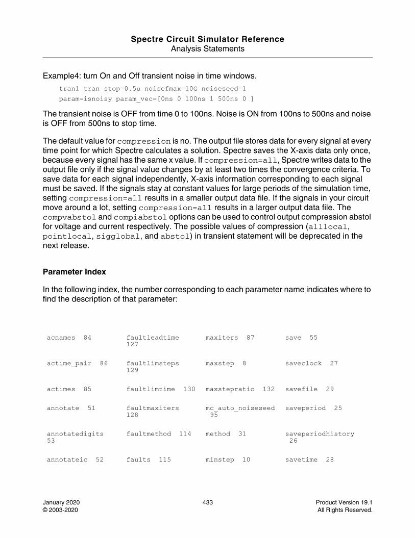
Spectre Circuit Simulator ReferenceAnalysis Statements
January 2020 433 Product Version 19.1© 2003-2020 All Rights Reserved.
Example4: turn On and Off transient noise in time windows.
tran1 tran stop=0.5u noisefmax=10G noiseseed=1param=isnoisy param_vec=[0ns 0 100ns 1 500ns 0 ]
The transient noise is OFF from time 0 to 100ns. Noise is ON from 100ns to 500ns and noise is OFF from 500ns to stop time.
The default value for compression is no. The output file stores data for every signal at every time point for which Spectre calculates a solution. Spectre saves the X-axis data only once, because every signal has the same x value. If compression=all, Spectre writes data to the output file only if the signal value changes by at least two times the convergence criteria. To save data for each signal independently, X-axis information corresponding to each signal must be saved. If the signals stay at constant values for large periods of the simulation time, setting compression=all results in a smaller output data file. If the signals in your circuit move around a lot, setting compression=all results in a larger output data file. The compvabstol and compiabstol options can be used to control output compression abstol for voltage and current respectively. The possible values of compression (alllocal, pointlocal, sigglobal, and abstol) in transient statement will be deprecated in the next release.
Parameter Index
In the following index, the number corresponding to each parameter name indicates where to find the description of that parameter:
acnames 84 faultleadtime 127
maxiters 87 save 55
actime_pair 86 faultlimsteps 129
maxstep 8 saveclock 27
actimes 85 faultlimtime 130 maxstepratio 132 savefile 29
annotate 51 faultmaxiters 128
mc_auto_noiseseed 95
saveperiod 25
annotatedigits 53
faultmethod 114 method 31 saveperiodhistory 26
annotateic 52 faults 115 minstep 10 savetime 28
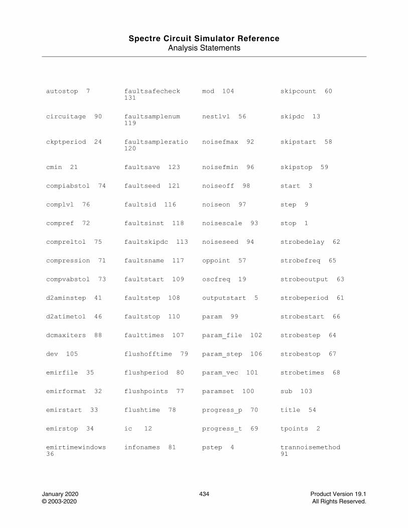
Spectre Circuit Simulator ReferenceAnalysis Statements
January 2020 434 Product Version 19.1© 2003-2020 All Rights Reserved.
autostop 7 faultsafecheck 131
mod 104 skipcount 60
circuitage 90 faultsamplenum 119
nestlvl 56 skipdc 13
ckptperiod 24 faultsampleratio 120
noisefmax 92 skipstart 58
cmin 21 faultsave 123 noisefmin 96 skipstop 59
compiabstol 74 faultseed 121 noiseoff 98 start 3
complvl 76 faultsid 116 noiseon 97 step 9
compref 72 faultsinst 118 noisescale 93 stop 1
compreltol 75 faultskipdc 113 noiseseed 94 strobedelay 62
compression 71 faultsname 117 oppoint 57 strobefreq 65
compvabstol 73 faultstart 109 oscfreq 19 strobeoutput 63
d2aminstep 41 faultstep 108 outputstart 5 strobeperiod 61
d2atimetol 46 faultstop 110 param 99 strobestart 66
dcmaxiters 88 faulttimes 107 param_file 102 strobestep 64
dev 105 flushofftime 79 param_step 106 strobestop 67
emirfile 35 flushperiod 80 param_vec 101 strobetimes 68
emirformat 32 flushpoints 77 paramset 100 sub 103
emirstart 33 flushtime 78 progress_p 70 title 54
emirstop 34 ic 12 progress_t 69 tpoints 2
emirtimewindows 36
infonames 81 pstep 4 trannoisemethod 91
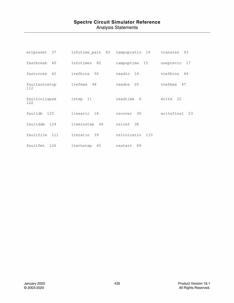
Spectre Circuit Simulator ReferenceAnalysis Statements
January 2020 435 Product Version 19.1© 2003-2020 All Rights Reserved.
errpreset 37 infotime_pair 83 rampupratio 14 transres 43
fastbreak 40 infotimes 82 rampuptime 15 useprevic 17
fastcross 42 irefbins 50 readic 16 vrefbins 49
faultautostop 112
irefmax 48 readns 20 vrefmax 47
faultcollapse 122
istep 11 readtime 6 write 22
faultdb 125 linearic 18 recover 30 writefinal 23
faultddm 124 lteminstep 44 relref 38
faultfile 111 lteratio 39 reltolratio 133
faultfmt 126 ltethstep 45 restart 89

Spectre Circuit Simulator ReferenceAnalysis Statements
January 2020 436 Product Version 19.1© 2003-2020 All Rights Reserved.
Special Current Saving Options (uti)
Description
This command is used to report the dynamic current of all devices connected to the specified voltage source during dynamic simulation.
DefinitionName uti parameter=value ...
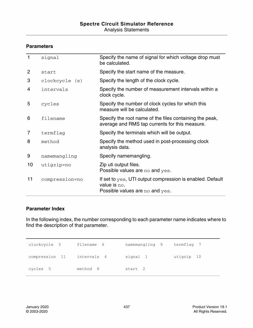
Spectre Circuit Simulator ReferenceAnalysis Statements
January 2020 437 Product Version 19.1© 2003-2020 All Rights Reserved.
Parameters
Parameter Index
In the following index, the number corresponding to each parameter name indicates where to find the description of that parameter.
1 signal Specify the name of signal for which voltage drop must be calculated.
2 start Specify the start name of the measure.
3 clockcycle (s) Specify the length of the clock cycle.
4 intervals Specify the number of measurement intervals within a clock cycle.
5 cycles Specify the number of clock cycles for which this measure will be calculated.
6 filename Specify the root name of the files containing the peak, average and RMS tap currents for this measure.
7 termflag Specify the terminals which will be output.
8 method Specify the method used in post-processing clock analysis data.
9 namemangling Specify namemangling.
10 utigzip=no Zip uti output files.Possible values are no and yes.
11 compression=no If set to yes, UTI output compression is enabled. Default value is no.Possible values are no and yes.
clockcycle 3 filename 6 namemangling 9 termflag 7
compression 11 intervals 4 signal 1 utigzip 10
cycles 5 method 8 start 2
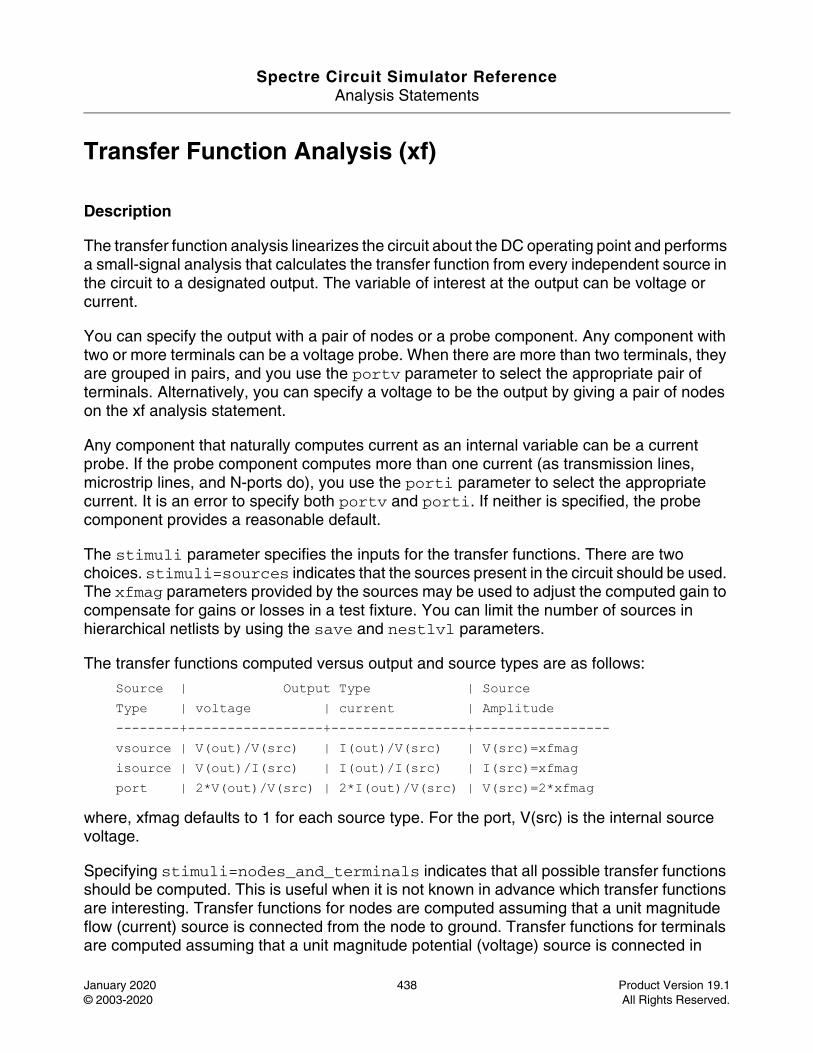
Spectre Circuit Simulator ReferenceAnalysis Statements
January 2020 438 Product Version 19.1© 2003-2020 All Rights Reserved.
Transfer Function Analysis (xf)
Description
The transfer function analysis linearizes the circuit about the DC operating point and performs a small-signal analysis that calculates the transfer function from every independent source in the circuit to a designated output. The variable of interest at the output can be voltage or current.
You can specify the output with a pair of nodes or a probe component. Any component with two or more terminals can be a voltage probe. When there are more than two terminals, they are grouped in pairs, and you use the portv parameter to select the appropriate pair of terminals. Alternatively, you can specify a voltage to be the output by giving a pair of nodes on the xf analysis statement.
Any component that naturally computes current as an internal variable can be a current probe. If the probe component computes more than one current (as transmission lines, microstrip lines, and N-ports do), you use the porti parameter to select the appropriate current. It is an error to specify both portv and porti. If neither is specified, the probe component provides a reasonable default.
The stimuli parameter specifies the inputs for the transfer functions. There are two choices. stimuli=sources indicates that the sources present in the circuit should be used. The xfmag parameters provided by the sources may be used to adjust the computed gain to compensate for gains or losses in a test fixture. You can limit the number of sources in hierarchical netlists by using the save and nestlvl parameters.
The transfer functions computed versus output and source types are as follows:
Source | Output Type | Source Type | voltage | current | Amplitude --------+-----------------+-----------------+----------------- vsource | V(out)/V(src) | I(out)/V(src) | V(src)=xfmag isource | V(out)/I(src) | I(out)/I(src) | I(src)=xfmag port | 2*V(out)/V(src) | 2*I(out)/V(src) | V(src)=2*xfmag
where, xfmag defaults to 1 for each source type. For the port, V(src) is the internal source voltage.
Specifying stimuli=nodes_and_terminals indicates that all possible transfer functions should be computed. This is useful when it is not known in advance which transfer functions are interesting. Transfer functions for nodes are computed assuming that a unit magnitude flow (current) source is connected from the node to ground. Transfer functions for terminals are computed assuming that a unit magnitude potential (voltage) source is connected in
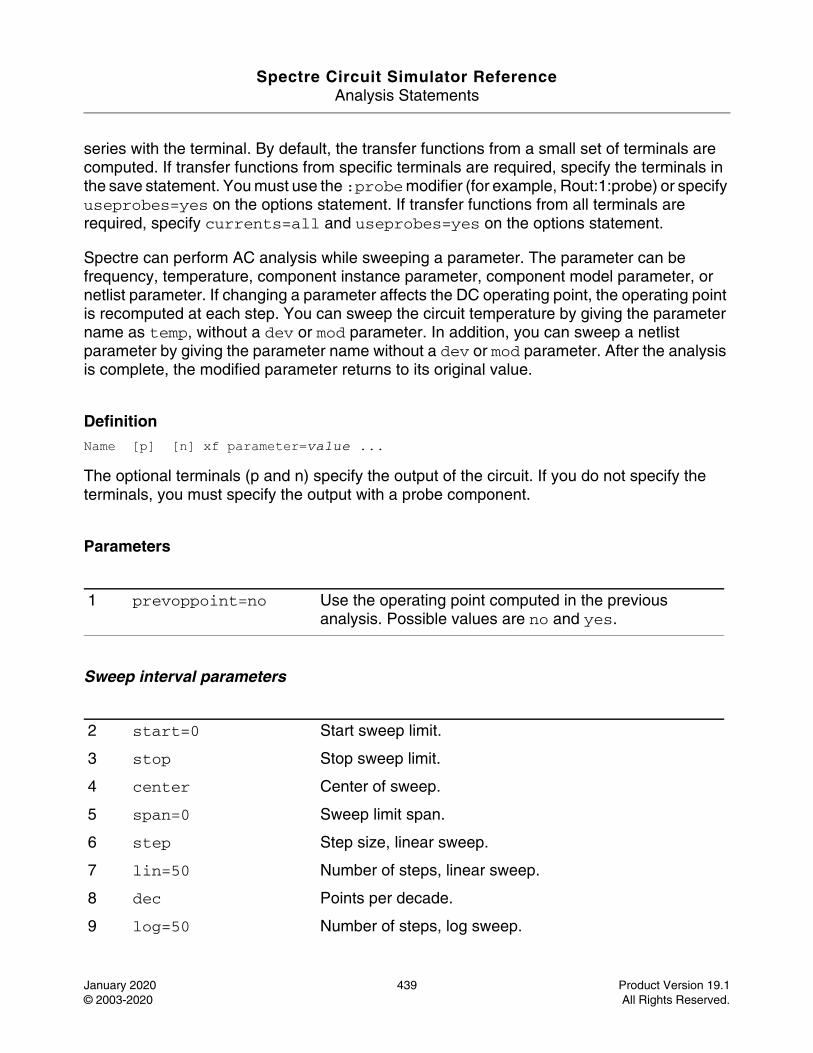
Spectre Circuit Simulator ReferenceAnalysis Statements
January 2020 439 Product Version 19.1© 2003-2020 All Rights Reserved.
series with the terminal. By default, the transfer functions from a small set of terminals are computed. If transfer functions from specific terminals are required, specify the terminals in the save statement. You must use the :probe modifier (for example, Rout:1:probe) or specify useprobes=yes on the options statement. If transfer functions from all terminals are required, specify currents=all and useprobes=yes on the options statement.
Spectre can perform AC analysis while sweeping a parameter. The parameter can be frequency, temperature, component instance parameter, component model parameter, or netlist parameter. If changing a parameter affects the DC operating point, the operating point is recomputed at each step. You can sweep the circuit temperature by giving the parameter name as temp, without a dev or mod parameter. In addition, you can sweep a netlist parameter by giving the parameter name without a dev or mod parameter. After the analysis is complete, the modified parameter returns to its original value.
DefinitionName [p] [n] xf parameter=value ...
The optional terminals (p and n) specify the output of the circuit. If you do not specify the terminals, you must specify the output with a probe component.
Parameters
Sweep interval parameters
1 prevoppoint=no Use the operating point computed in the previous analysis. Possible values are no and yes.
2 start=0 Start sweep limit.
3 stop Stop sweep limit.
4 center Center of sweep.
5 span=0 Sweep limit span.
6 step Step size, linear sweep.
7 lin=50 Number of steps, linear sweep.
8 dec Points per decade.
9 log=50 Number of steps, log sweep.
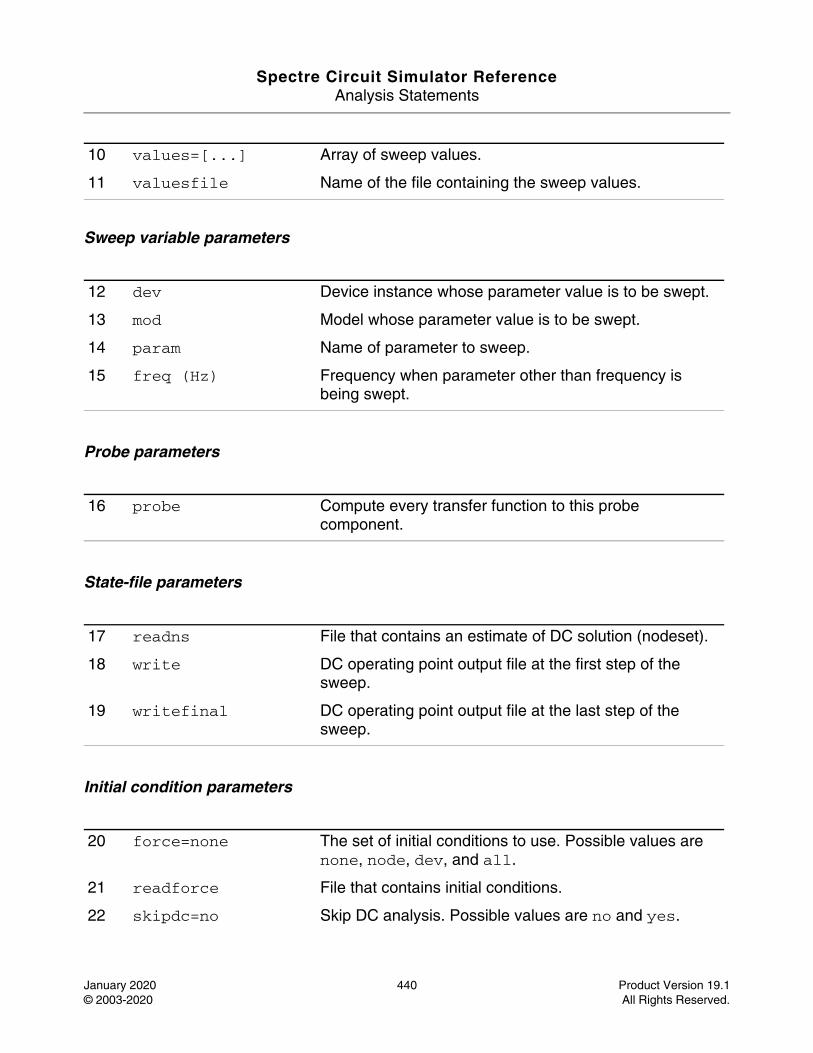
Spectre Circuit Simulator ReferenceAnalysis Statements
January 2020 440 Product Version 19.1© 2003-2020 All Rights Reserved.
Sweep variable parameters
Probe parameters
State-file parameters
Initial condition parameters
10 values=[...] Array of sweep values.
11 valuesfile Name of the file containing the sweep values.
12 dev Device instance whose parameter value is to be swept.
13 mod Model whose parameter value is to be swept.
14 param Name of parameter to sweep.
15 freq (Hz) Frequency when parameter other than frequency is being swept.
16 probe Compute every transfer function to this probe component.
17 readns File that contains an estimate of DC solution (nodeset).
18 write DC operating point output file at the first step of the sweep.
19 writefinal DC operating point output file at the last step of the sweep.
20 force=none The set of initial conditions to use. Possible values are none, node, dev, and all.
21 readforce File that contains initial conditions.
22 skipdc=no Skip DC analysis. Possible values are no and yes.
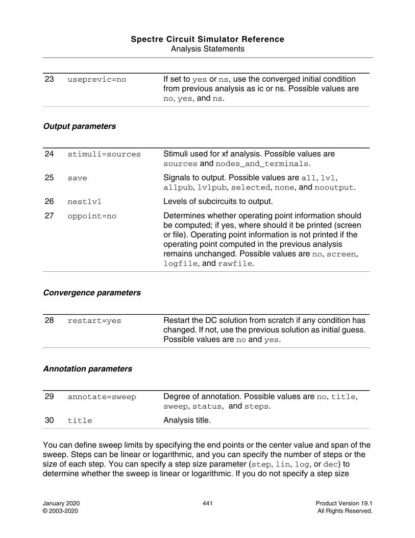
Spectre Circuit Simulator ReferenceAnalysis Statements
January 2020 441 Product Version 19.1© 2003-2020 All Rights Reserved.
Output parameters
Convergence parameters
Annotation parameters
You can define sweep limits by specifying the end points or the center value and span of the sweep. Steps can be linear or logarithmic, and you can specify the number of steps or the size of each step. You can specify a step size parameter (step, lin, log, or dec) to determine whether the sweep is linear or logarithmic. If you do not specify a step size
23 useprevic=no If set to yes or ns, use the converged initial condition from previous analysis as ic or ns. Possible values are no, yes, and ns.
24 stimuli=sources Stimuli used for xf analysis. Possible values are sources and nodes_and_terminals.
25 save Signals to output. Possible values are all, lvl, allpub, lvlpub, selected, none, and nooutput.
26 nestlvl Levels of subcircuits to output.
27 oppoint=no Determines whether operating point information should be computed; if yes, where should it be printed (screen or file). Operating point information is not printed if the operating point computed in the previous analysis remains unchanged. Possible values are no, screen, logfile, and rawfile.
28 restart=yes Restart the DC solution from scratch if any condition has changed. If not, use the previous solution as initial guess. Possible values are no and yes.
29 annotate=sweep Degree of annotation. Possible values are no, title, sweep, status, and steps.
30 title Analysis title.

Spectre Circuit Simulator ReferenceAnalysis Statements
January 2020 442 Product Version 19.1© 2003-2020 All Rights Reserved.
parameter, the sweep is linear when the ratio of stop to start values is less than 10 and logarithmic when this ratio is 10 or greater. All frequencies are in Hertz.
The small-signal analysis begins by linearizing the circuit about an operating point. By default this analysis computes the operating point, if it is not known, or recomputes it if any significant component or circuit parameter has changed. However, if an operating point was calculated during a previous analysis , you can set prevoppoint=yes to avoid recomputing it. For example, if prevoppoint=yes and the previous analysis was a transient analysis, the operating point is the state of the circuit at the final time point.
Nodesets help find the DC or the initial transient solution. You can specify nodesets in the circuit description file with nodeset statements, or in a separate file using the readns parameter. When nodesets are specified, Spectre computes an initial guess of the solution by performing a DC analysis, while forcing the specified values on to nodes by using a voltage source in series with a resistor whose resistance is rforce. Spectre then removes these voltage sources and resistors and computes the required solution from this initial guess.
Nodesets have two important uses. First, if a circuit has two or more solutions, nodesets can bias the simulator towards computing the required solution. Second, these are a convergence aid. By estimating the solution of the largest possible number of nodes, you might be able to eliminate a convergence problem or significantly speed up convergence.
When you simulate the same circuit multiple times, it is recommended that you use both write and readns parameters and assign the same file name to both parameters. DC analysis then converges quickly even if the circuit has changed since the last simulation, and the nodeset file is automatically updated.
During the initial operating point DC analysis, you may force some of the circuit variables to the values given in the ic file, ic statements, or ic parameter on the capacitors and inductors. The ic parameter controls the interaction of various methods of setting the force values. The effects of individual settings are as follows:
force=none: All initial conditions are ignored.
force=node: The ic statements are used, and the ic parameters on the capacitors and inductors are ignored.
force=dev: The ic parameters on the capacitors and inductors are used, and the ic statements are ignored.
force=all: Both ic statements and ic parameters are used, with the ic parameters overriding the ic statements.
If you specify an ic file with the readforce parameter, force values from the file are used, and any ic statements are ignored.
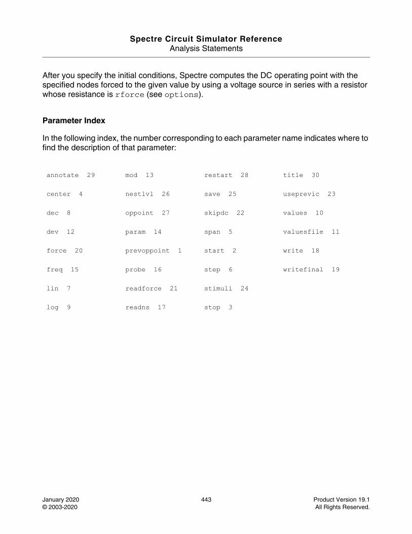
Spectre Circuit Simulator ReferenceAnalysis Statements
January 2020 443 Product Version 19.1© 2003-2020 All Rights Reserved.
After you specify the initial conditions, Spectre computes the DC operating point with the specified nodes forced to the given value by using a voltage source in series with a resistor whose resistance is rforce (see options).
Parameter Index
In the following index, the number corresponding to each parameter name indicates where to find the description of that parameter:
annotate 29 mod 13 restart 28 title 30
center 4 nestlvl 26 save 25 useprevic 23
dec 8 oppoint 27 skipdc 22 values 10
dev 12 param 14 span 5 valuesfile 11
force 20 prevoppoint 1 start 2 write 18
freq 15 probe 16 step 6 writefinal 19
lin 7 readforce 21 stimuli 24
log 9 readns 17 stop 3

Spectre Circuit Simulator ReferenceAnalysis Statements
January 2020 444 Product Version 19.1© 2003-2020 All Rights Reserved.
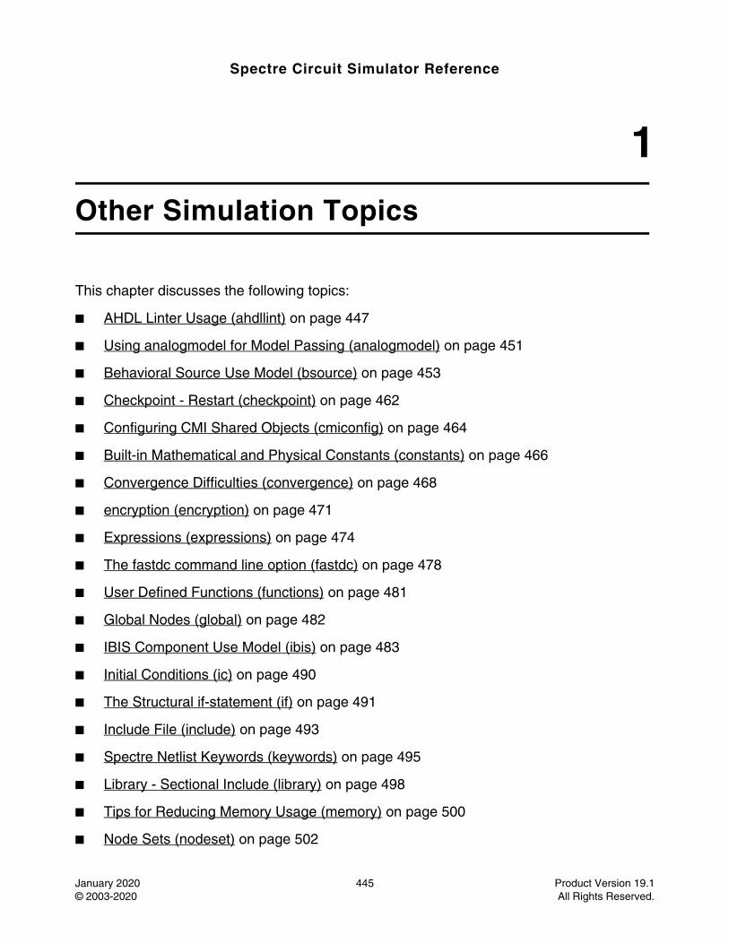
Spectre Circuit Simulator Reference
January 2020 445 Product Version 19.1© 2003-2020 All Rights Reserved.
1Other Simulation Topics
This chapter discusses the following topics:
■ AHDL Linter Usage (ahdllint) on page 447
■ Using analogmodel for Model Passing (analogmodel) on page 451
■ Behavioral Source Use Model (bsource) on page 453
■ Checkpoint - Restart (checkpoint) on page 462
■ Configuring CMI Shared Objects (cmiconfig) on page 464
■ Built-in Mathematical and Physical Constants (constants) on page 466
■ Convergence Difficulties (convergence) on page 468
■ encryption (encryption) on page 471
■ Expressions (expressions) on page 474
■ The fastdc command line option (fastdc) on page 478
■ User Defined Functions (functions) on page 481
■ Global Nodes (global) on page 482
■ IBIS Component Use Model (ibis) on page 483
■ Initial Conditions (ic) on page 490
■ The Structural if-statement (if) on page 491
■ Include File (include) on page 493
■ Spectre Netlist Keywords (keywords) on page 495
■ Library - Sectional Include (library) on page 498
■ Tips for Reducing Memory Usage (memory) on page 500
■ Node Sets (nodeset) on page 502
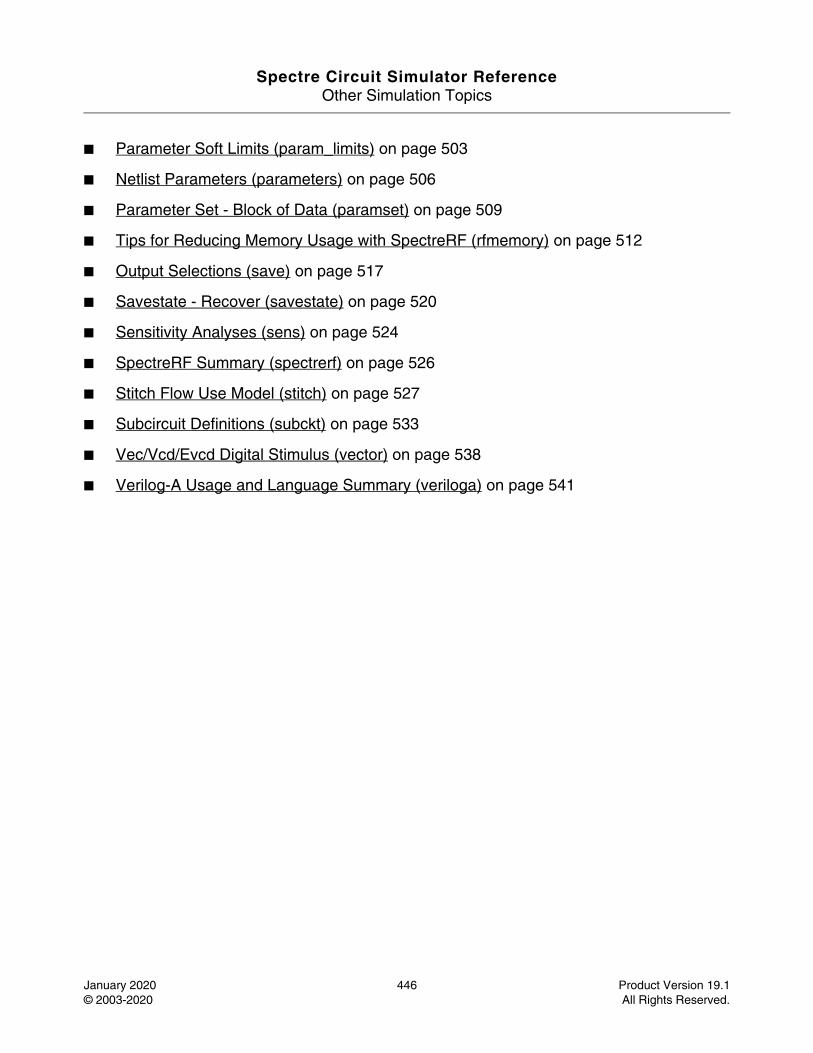
Spectre Circuit Simulator ReferenceOther Simulation Topics
January 2020 446 Product Version 19.1© 2003-2020 All Rights Reserved.
■ Parameter Soft Limits (param_limits) on page 503
■ Netlist Parameters (parameters) on page 506
■ Parameter Set - Block of Data (paramset) on page 509
■ Tips for Reducing Memory Usage with SpectreRF (rfmemory) on page 512
■ Output Selections (save) on page 517
■ Savestate - Recover (savestate) on page 520
■ Sensitivity Analyses (sens) on page 524
■ SpectreRF Summary (spectrerf) on page 526
■ Stitch Flow Use Model (stitch) on page 527
■ Subcircuit Definitions (subckt) on page 533
■ Vec/Vcd/Evcd Digital Stimulus (vector) on page 538
■ Verilog-A Usage and Language Summary (veriloga) on page 541
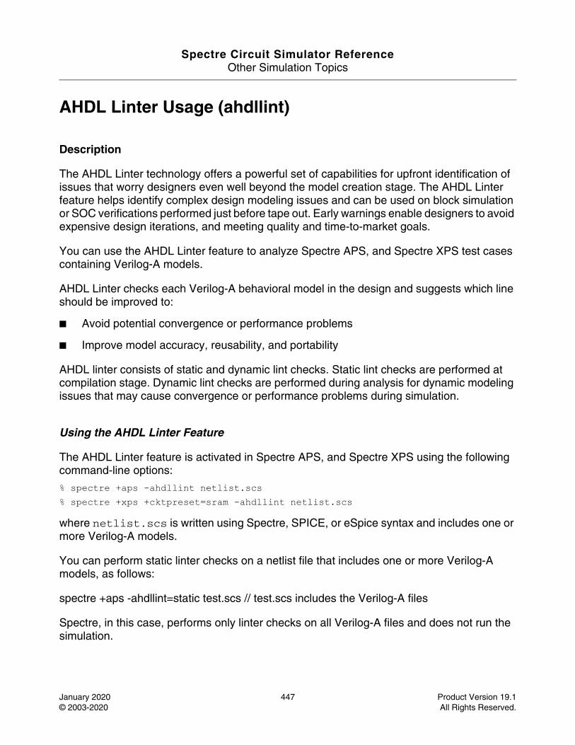
Spectre Circuit Simulator ReferenceOther Simulation Topics
January 2020 447 Product Version 19.1© 2003-2020 All Rights Reserved.
AHDL Linter Usage (ahdllint)
Description
The AHDL Linter technology offers a powerful set of capabilities for upfront identification of issues that worry designers even well beyond the model creation stage. The AHDL Linter feature helps identify complex design modeling issues and can be used on block simulation or SOC verifications performed just before tape out. Early warnings enable designers to avoid expensive design iterations, and meeting quality and time-to-market goals.
You can use the AHDL Linter feature to analyze Spectre APS, and Spectre XPS test cases containing Verilog-A models.
AHDL Linter checks each Verilog-A behavioral model in the design and suggests which line should be improved to:
■ Avoid potential convergence or performance problems
■ Improve model accuracy, reusability, and portability
AHDL linter consists of static and dynamic lint checks. Static lint checks are performed at compilation stage. Dynamic lint checks are performed during analysis for dynamic modeling issues that may cause convergence or performance problems during simulation.
Using the AHDL Linter Feature
The AHDL Linter feature is activated in Spectre APS, and Spectre XPS using the following command-line options:
% spectre +aps -ahdllint netlist.scs% spectre +xps +cktpreset=sram -ahdllint netlist.scs
where netlist.scs is written using Spectre, SPICE, or eSpice syntax and includes one or more Verilog-A models.
You can perform static linter checks on a netlist file that includes one or more Verilog-A models, as follows:
spectre +aps -ahdllint=static test.scs // test.scs includes the Verilog-A files
Spectre, in this case, performs only linter checks on all Verilog-A files and does not run the simulation.
Spectre Circuit Simulator ReferenceOther Simulation Topics
January 2020 448 Product Version 19.1© 2003-2020 All Rights Reserved.
You can also perform static lint checks on a Verilog-A file directly without specifying the top-level netlist file (.scs), as follows:
spectre +aps -ahdllint=static test.va //perform static lint check on test.va
The -ahdllint option accepts the following arguments:
Note: The -ahdllint option can be used without any argument, which is equivalent to specifying -ahdlint=warn. You can also set the -ahdllint option as default by setting the SPECTRE_DEFAULTS environment variable, as follows:
setenv SPECTRE_DEFAULTS "-ahdllint=warn"
You can use the -ahdllint_maxwarn =n command-line option to control the maximum number of static and dynamic warnings. The default value is 5.
You can also control the maximum number of warnings by using the environment variable SPECTRE_DEFAULTS or ULSTRASIM_DEFAULTS, as show below.
setenv SPECTRE_DEFAULTS "-ahdllint -ahllint_maxwarn=10"setenv ULSTRASIM_DEFAULTS "-ahdllint -ahllint_maxwarn=10"
You can use the -ahdllint_warn_id=<ID> option to control the warning messages for a specific message ID. ID should be a positive integer value between 5001 and 6000 or 8001
no Disables lint checks. There is no change in the existing compilation or simulation error messages.
warn (default) Turns on the static lint and dynamic lint checks. Except the models with attribute (* ahdllint = "no" *), the static lint checks all models, continues the simulation, and then performs dynamic lint checks.
error Turns on the static lint check. Dynamic lint checks are performed only when static lint issues are not detected. Except the models with attribute (* ahdllint = "no" *), the static lint checks all models. The simulator generates an error and exits if there is any static lint warning reported after compiling all the models of the circuit. If there are no static lint warnings, the simulator continues the simulation and performs dynamic lint checks. However, in the case of dynamic lint issues, the simulator does not error out.
force Similar to warn, but this option overrides the model attribute (* ahdllint = "no" *), and forces to check all models, continue the simulation, and perform dynamic lint checks.
static Performs static lint checks on a Verilog-A file directly.
Spectre Circuit Simulator ReferenceOther Simulation Topics
January 2020 449 Product Version 19.1© 2003-2020 All Rights Reserved.
and 9999. In addition, the -ahdllint_warn_id option should always be used with the -ahdllint_maxwarn option and should be directly specified after it in the command line, otherwise, the option will be ignored. For example:
spectre +aps -ahdllint -ahdllint_maxwarn=2 -ahdllint_warn_id=5001 input.scs
In the above example, Spectre will display only two warning messages related to the message ID 5001.
You can specify the -ahdllint_maxwarn and -ahdllint_warn_id options multiple times at the command line. For example:
spectre +aps -ahdllint -ahdllint_maxwarn=1 -ahdllint_warn_id=5001 -ahdllint_maxwarn=3 -ahdllint_warn_id=8001 input.scs
In the above example, only one warning message related to the message ID 5001 will be displayed. In addition, three warning messages related to the message ID 8001 will be displayed.
You can also specify multiple IDs with the -ahdllint_warn_id option. However, the IDs must be specified using double quotes with a space between them. For example:
spectre +aps -ahdllint -ahdllint_maxwarn=2 -ahdllint_warn_id="5001 5003 5005" input.scs
Use the -ahdllint_minstep=value command-line option to set the minimal time step size boundary that will trigger an AHDL Linter warning, when the step size imposed by a Verilog-AMS filter or function, such as transition, cross, above, $bound_step, and timer is smaller than value. The default value is 1e-12.
You can use the -ahdllint_summary_maxentries=<value> command-line option to control the maximum number of messages to be displayed in dynamic lint summary. The default value is 25. For example:
spectre -ahdllint_summary_maxentries=20 input.scs
By default, the static and dynamic lint warnings and the dynamic lint summary output are sent to the simulation log file. You can use the -ahdllint_log=file command-line option to output all the information to a specified file instead of the output log file.
Filtering AHDL Messages
You can filter the AHDL Linter messages using the options control statement, as follows:
Name options warning_limit=num warning_id=id
where:
Spectre Circuit Simulator ReferenceOther Simulation Topics
January 2020 450 Product Version 19.1© 2003-2020 All Rights Reserved.
warning_limit specifies the number of messages to be printed.
warning_id specifies the message id that needs to be printed.
Example1myoptions options warning_limit=0 warning_id=[AHDLLINT-8004 AHDLLINT-8005]
In the above example, Spectre APS/XPS will not print any message with the id AHDLLINT-8004 and AHDLLINT-8005.
Example2myoptions2 options warning_limit=1 warning_id=[AHDLLINT-8005]
In the above example, Spectre APS/XPS will print only one message with the id AHDLLINT-8005.
For more information about the options control statement, see spectre -h options.
Using the ahdlhelp Utility
You can use the ahdlhelp utility to view the extended help on various messages reported by AHDL Linter. To view the extended help, you need to provide the AHD Linter id number as an argument, as shown below.
% ahdlhelp 8005
The following is an example of the ahdlhelp utility:
% ahdlhelp 5012AHDLLINT-5012: Detected $abstime in an equality expression inside a conditional.Analog simulations select timepoints using a variable timestep size algorithm based on accuracy considerations, so the value of "time" only changes between discrete real values. In order to perform an event at a particular time, the @(timer) construct must be used to tell the simulator to step to a particular timepoint and execute the desired code when that event actually occurs.example: if ($abstime==50n) xval=2;solution:
@(timer(50n)) xval=2;
Spectre Circuit Simulator ReferenceOther Simulation Topics
January 2020 451 Product Version 19.1© 2003-2020 All Rights Reserved.
Using analogmodel for Model Passing (analogmodel)
Description
analogmodel is a reserved word in Spectre that allows you to bind an instance to different masters based on the value of a special instance parameter called modelname. An instance of analogmodel must have a parameter named modelname, whose string value represents the name of the master this instance will be bound to. The value of modelname can be passed into subcircuits.
The analogmodel keyword is used by the Cadence Analog Design Environment to enable model name passing through the schematic hierarchy.
Sample Instance Statementname [(]node1 ... nodeN[)] analogmodel modelname=mastername [[param1=value1] ...[paramN=valueN]]
Example//example spectre netlist to illustrate modelname parameter simulator lang=spectre parameters b="bottom" include "VerilogAStuff.va" topInst1 (out in) top topInst2 (out in) analogmodel modelname="VAMaster" //VAMaster is defined in
"VerilogAStuff.va" topInst3 (out in) analogmodel modelname="resistor" //topInst3 binds to a primitive topInst4 (out 0) analogmodel modelname="myOwnRes" //topInst4 binds to modelcard
name Name of the statement or instance label.
[(]node1...nodeN[)] Names of the nodes that connect to the component.
analogmodel Special device name to indicate that this instance will have its master name specified by the value of the modelname parameter on the instance.
modelname Parameter to specify the master of this instance indicated by mastername. The mastername must either be a valid string identifier or a netlist parameter that must resolve to a valid master name, a primitive, a model, a subckt, or an AHDL module.
param1 param2... Parameter values for the component. Depending on the master type, these can either be device parameters or netlist parameters. It is optional to specify these parameter values.
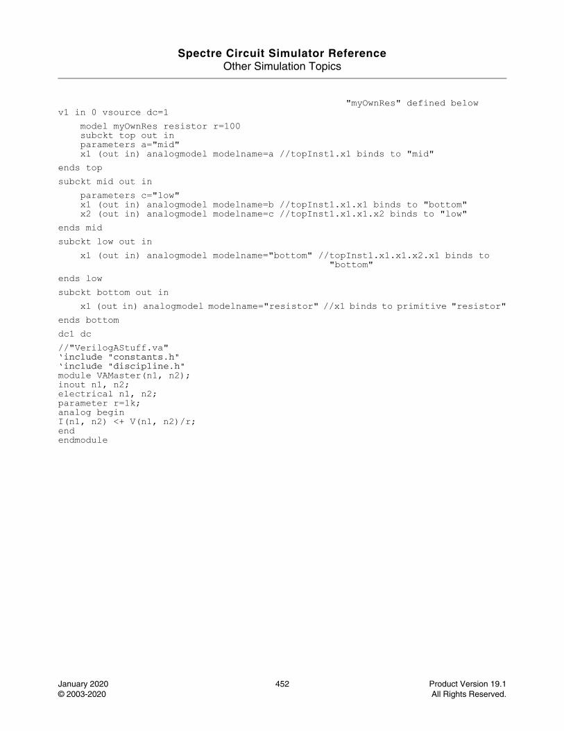
Spectre Circuit Simulator ReferenceOther Simulation Topics
January 2020 452 Product Version 19.1© 2003-2020 All Rights Reserved.
"myOwnRes" defined belowv1 in 0 vsource dc=1
model myOwnRes resistor r=100subckt top out in parameters a="mid" x1 (out in) analogmodel modelname=a //topInst1.x1 binds to "mid"
ends top subckt mid out in
parameters c="low" x1 (out in) analogmodel modelname=b //topInst1.x1.x1 binds to "bottom" x2 (out in) analogmodel modelname=c //topInst1.x1.x1.x2 binds to "low"
ends mid subckt low out in
x1 (out in) analogmodel modelname="bottom" //topInst1.x1.x1.x2.x1 binds to"bottom"
ends low subckt bottom out in
x1 (out in) analogmodel modelname="resistor" //x1 binds to primitive "resistor"ends bottom dc1 dc //"VerilogAStuff.va" ‘include "constants.h" ‘include "discipline.h" module VAMaster(n1, n2); inout n1, n2; electrical n1, n2; parameter r=1k; analog begin I(n1, n2) <+ V(n1, n2)/r; end endmodule
Spectre Circuit Simulator ReferenceOther Simulation Topics
January 2020 453 Product Version 19.1© 2003-2020 All Rights Reserved.
Behavioral Source Use Model (bsource)
Description
Behavioral source enables you to model a resistor, inductor, capacitor, voltage or current source as a behavioral component. Using bsource, you can express the value of a resistance, capacitance, voltage or current as a combination of node voltages, branch currents, time expression, and built-in Spectre expressions.
The syntax for bsource is as follows:
name (node1 node2) bsource behav_param param_list
where behav_param can be:
simple_expr is defined as an Spectre expression, which contains:
■ Netlist parameters.
■ Current simulation time, $time.
■ Current frequency, $freq.
■ Node voltage, v(a,b), where a and b are nodes in the Spectre netlist, or node voltage v(a), which is the voltage between node a and ground.
■ Branch currents, i("inst_id:index"), where inst_id is an instance name given in the netlist and index is the port index that starts from 1. The default value of index is 1.
Note: If the value of the port index is set to 0, simple_expr treats it as the default value 1.
generic_expr is defined as a simple_expr or ddt() or idt() of simple_expr.
c=simple_expr, capacitance between the nodes
g=simple_expr, conductance between the nodes
i=generic_expr, current through bsource
l=simple_expr, inductance between the nodes
phi=simple_expr, flux in the bsource device
q=simple_expr, charge in bsource device
r=simple_expr, resistance between the nodes
v=generic_expr, voltage across the nodes
Spectre Circuit Simulator ReferenceOther Simulation Topics
January 2020 454 Product Version 19.1© 2003-2020 All Rights Reserved.
param_list is param_name=value.
param_name can have the multiplicity factor m. The value of m defaults to 1.
Temperature Parameters
Clipping Parameters
tc1 Linear temperature co-efficient. Valid for all behavioral elements. Default value is 0 1/C.
tc2 Quadratic temperature co-efficient. Valid for all behavioral elements. Default value is 0 C^-2.
temp Parameter for ambient temperature. Valid for all behavioral elements. Default value is $temperature - 273.15.
tnom Parameters measurement temperature. Valid for all behavioral elements. Default value is 27.0.
trise Temperature rise for ambient. Valid for all behavioral elements. Default value is 0.0.
T Effective value of temperature. Valid for all behavioral elements. Default value is temp+trise-tnom.
tc1c Linear temperature coefficient of capacitor. Valid for resistor type behavioral element. Default value is 0 1/C.
tc2c Quadratic temperature coefficient of capacitor. Valid for resistor type behavioral element. Default value is 0 C^-2.
max_val Maximum value of bsource expression. Valid for all behavioral elements, but used with i and v elements to clip the current or voltage between the specified values.
min_val Minimum value of bsource expression. Valid for all behavioral elements, but used with i and v elements to clip the current or voltage between the specified values.
bv_max Generate a warning when bsource voltage of two terminals exceeds the value specified by bv_max. Valid for resistor and capacitor.
Spectre Circuit Simulator ReferenceOther Simulation Topics
January 2020 455 Product Version 19.1© 2003-2020 All Rights Reserved.
Noise Parameters
DC Mismatch Parameters
Other Parameters
af Flicker noise exponent. Valid for r and g elements. Default value is 2.
fexp Flicker noise frequency exponent. Valid for r, g, v, and i elements. Default value is 1.
ef The alias parameter of fexp.
ldexp Flicker (1/f) noise L exponent. Valid for r and g elements. Default value is 1.0.
lf The alias parameter of ldexp.
wdexp Flicker (1/f) noise W exponent. Valid for r and g elements. Default value is 1.0.
wf The alias parameter of wdexp.
isnoisy Specifies whether to generate noise. Valid for r, g, i, and v elements. Valid values are yes and no. Default value is yes.
kf Flicker noise co-efficient. Valid for r and g elements. Default value is 0.
white_noise White noise expression. Valid for v and i elements.
flicker_noise Flicker noise expression. Valid for v and i elements.
mr DC-Mismatch parameter. Valid only for r.
scale, scaleb, scaler, scalei, scalec
Bsource scaling factor. Default value is 1.0.
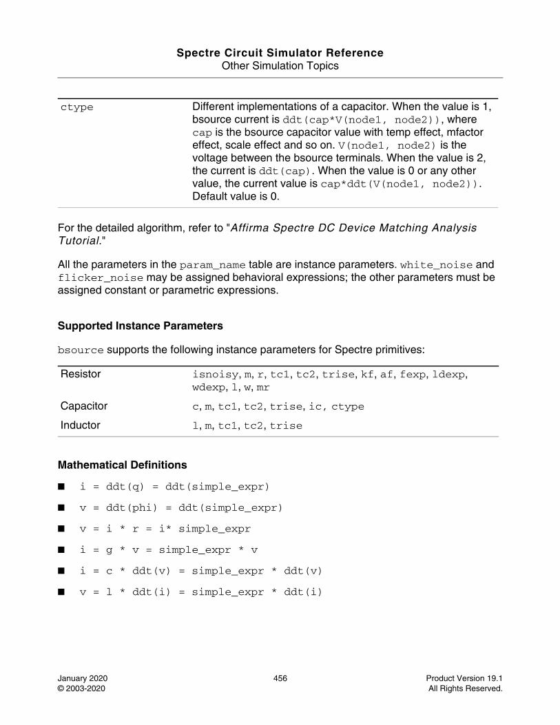
Spectre Circuit Simulator ReferenceOther Simulation Topics
January 2020 456 Product Version 19.1© 2003-2020 All Rights Reserved.
For the detailed algorithm, refer to "Affirma Spectre DC Device Matching Analysis Tutorial."
All the parameters in the param_name table are instance parameters. white_noise and flicker_noise may be assigned behavioral expressions; the other parameters must be assigned constant or parametric expressions.
Supported Instance Parameters
bsource supports the following instance parameters for Spectre primitives:
Mathematical Definitions
■ i = ddt(q) = ddt(simple_expr)
■ v = ddt(phi) = ddt(simple_expr)
■ v = i * r = i* simple_expr
■ i = g * v = simple_expr * v
■ i = c * ddt(v) = simple_expr * ddt(v)
■ v = l * ddt(i) = simple_expr * ddt(i)
ctype Different implementations of a capacitor. When the value is 1, bsource current is ddt(cap*V(node1, node2)), where cap is the bsource capacitor value with temp effect, mfactor effect, scale effect and so on. V(node1, node2) is the voltage between the bsource terminals. When the value is 2, the current is ddt(cap). When the value is 0 or any other value, the current value is cap*ddt(V(node1, node2)). Default value is 0.
Resistor isnoisy, m, r, tc1, tc2, trise, kf, af, fexp, ldexp, wdexp, l, w, mr
Capacitor c, m, tc1, tc2, trise, ic, ctype
Inductor l, m, tc1, tc2, trise
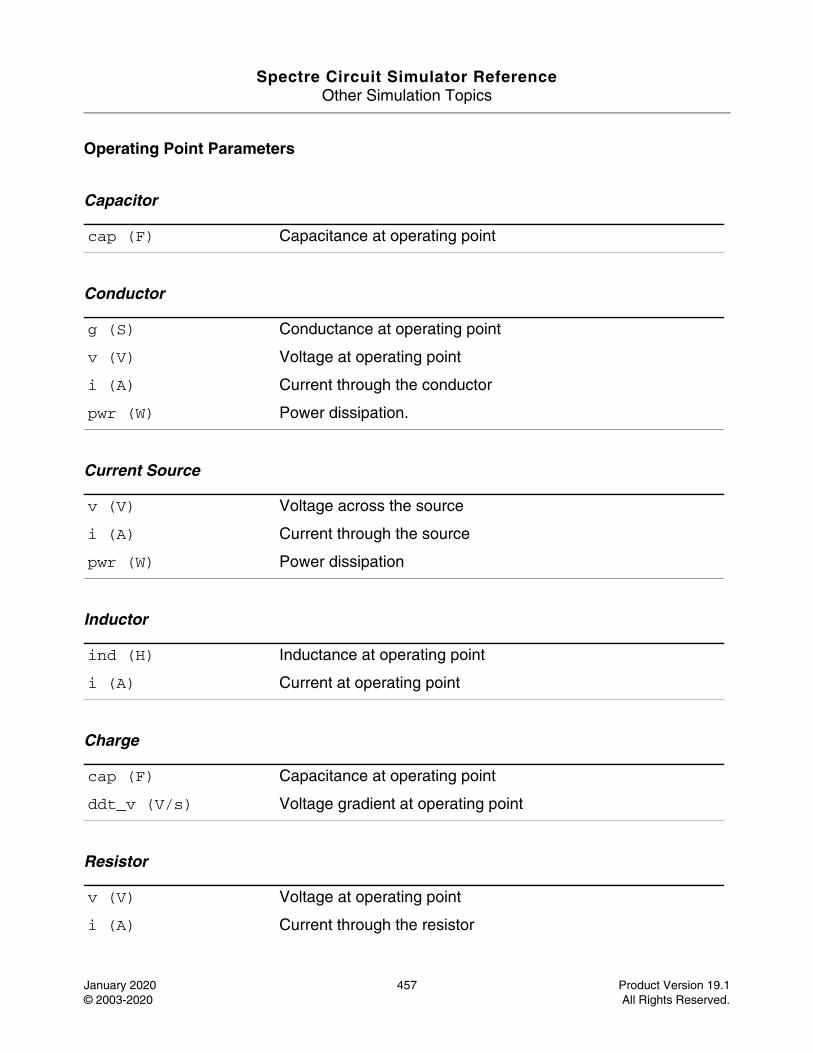
Spectre Circuit Simulator ReferenceOther Simulation Topics
January 2020 457 Product Version 19.1© 2003-2020 All Rights Reserved.
Operating Point Parameters
Capacitor
Conductor
Current Source
Inductor
Charge
Resistor
cap (F) Capacitance at operating point
g (S) Conductance at operating point
v (V) Voltage at operating point
i (A) Current through the conductor
pwr (W) Power dissipation.
v (V) Voltage across the source
i (A) Current through the source
pwr (W) Power dissipation
ind (H) Inductance at operating point
i (A) Current at operating point
cap (F) Capacitance at operating point
ddt_v (V/s) Voltage gradient at operating point
v (V) Voltage at operating point
i (A) Current through the resistor
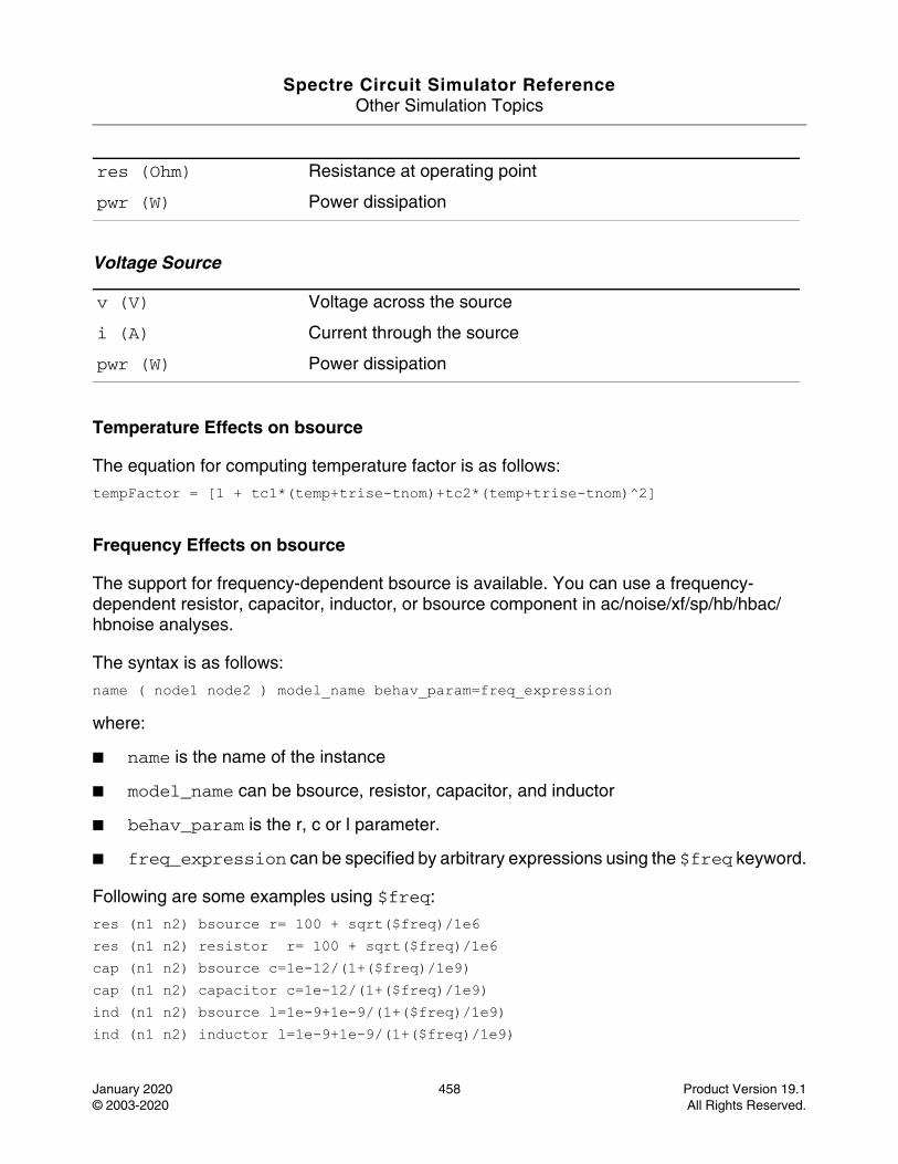
Spectre Circuit Simulator ReferenceOther Simulation Topics
January 2020 458 Product Version 19.1© 2003-2020 All Rights Reserved.
Voltage Source
Temperature Effects on bsource
The equation for computing temperature factor is as follows:
tempFactor = [1 + tc1*(temp+trise-tnom)+tc2*(temp+trise-tnom)^2]
Frequency Effects on bsource
The support for frequency-dependent bsource is available. You can use a frequency-dependent resistor, capacitor, inductor, or bsource component in ac/noise/xf/sp/hb/hbac/hbnoise analyses.
The syntax is as follows:
name ( node1 node2 ) model_name behav_param=freq_expression
where:
■ name is the name of the instance
■ model_name can be bsource, resistor, capacitor, and inductor
■ behav_param is the r, c or l parameter.
■ freq_expression can be specified by arbitrary expressions using the $freq keyword.
Following are some examples using $freq:
res (n1 n2) bsource r= 100 + sqrt($freq)/1e6res (n1 n2) resistor r= 100 + sqrt($freq)/1e6cap (n1 n2) bsource c=1e-12/(1+($freq)/1e9)cap (n1 n2) capacitor c=1e-12/(1+($freq)/1e9)ind (n1 n2) bsource l=1e-9+1e-9/(1+($freq)/1e9)ind (n1 n2) inductor l=1e-9+1e-9/(1+($freq)/1e9)
res (Ohm) Resistance at operating point
pwr (W) Power dissipation
v (V) Voltage across the source
i (A) Current through the source
pwr (W) Power dissipation
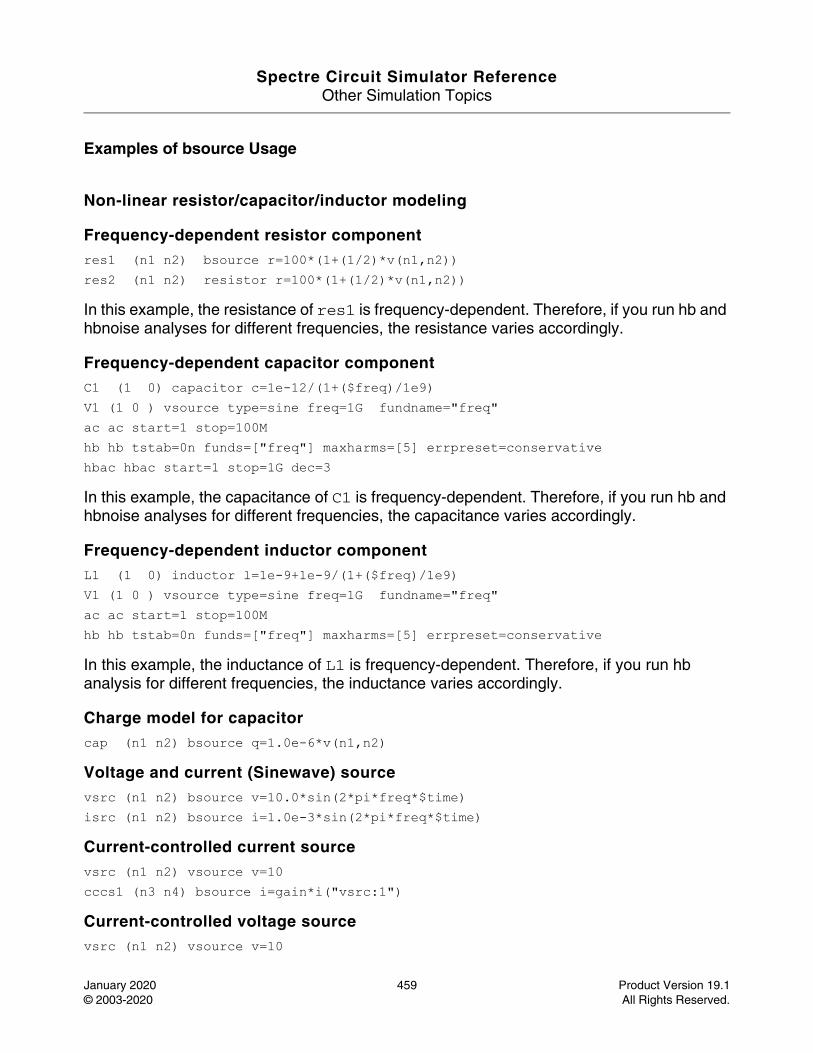
Spectre Circuit Simulator ReferenceOther Simulation Topics
January 2020 459 Product Version 19.1© 2003-2020 All Rights Reserved.
Examples of bsource Usage
Non-linear resistor/capacitor/inductor modeling
Frequency-dependent resistor componentres1 (n1 n2) bsource r=100*(1+(1/2)*v(n1,n2)) res2 (n1 n2) resistor r=100*(1+(1/2)*v(n1,n2))
In this example, the resistance of res1 is frequency-dependent. Therefore, if you run hb and hbnoise analyses for different frequencies, the resistance varies accordingly.
Frequency-dependent capacitor componentC1 (1 0) capacitor c=1e-12/(1+($freq)/1e9)V1 (1 0 ) vsource type=sine freq=1G fundname="freq" ac ac start=1 stop=100M hb hb tstab=0n funds=["freq"] maxharms=[5] errpreset=conservative hbac hbac start=1 stop=1G dec=3
In this example, the capacitance of C1 is frequency-dependent. Therefore, if you run hb and hbnoise analyses for different frequencies, the capacitance varies accordingly.
Frequency-dependent inductor componentL1 (1 0) inductor l=1e-9+1e-9/(1+($freq)/1e9) V1 (1 0 ) vsource type=sine freq=1G fundname="freq" ac ac start=1 stop=100M hb hb tstab=0n funds=["freq"] maxharms=[5] errpreset=conservative
In this example, the inductance of L1 is frequency-dependent. Therefore, if you run hb analysis for different frequencies, the inductance varies accordingly.
Charge model for capacitor
cap (n1 n2) bsource q=1.0e-6*v(n1,n2)
Voltage and current (Sinewave) source
vsrc (n1 n2) bsource v=10.0*sin(2*pi*freq*$time) isrc (n1 n2) bsource i=1.0e-3*sin(2*pi*freq*$time)
Current-controlled current source vsrc (n1 n2) vsource v=10 cccs1 (n3 n4) bsource i=gain*i("vsrc:1")
Current-controlled voltage source vsrc (n1 n2) vsource v=10
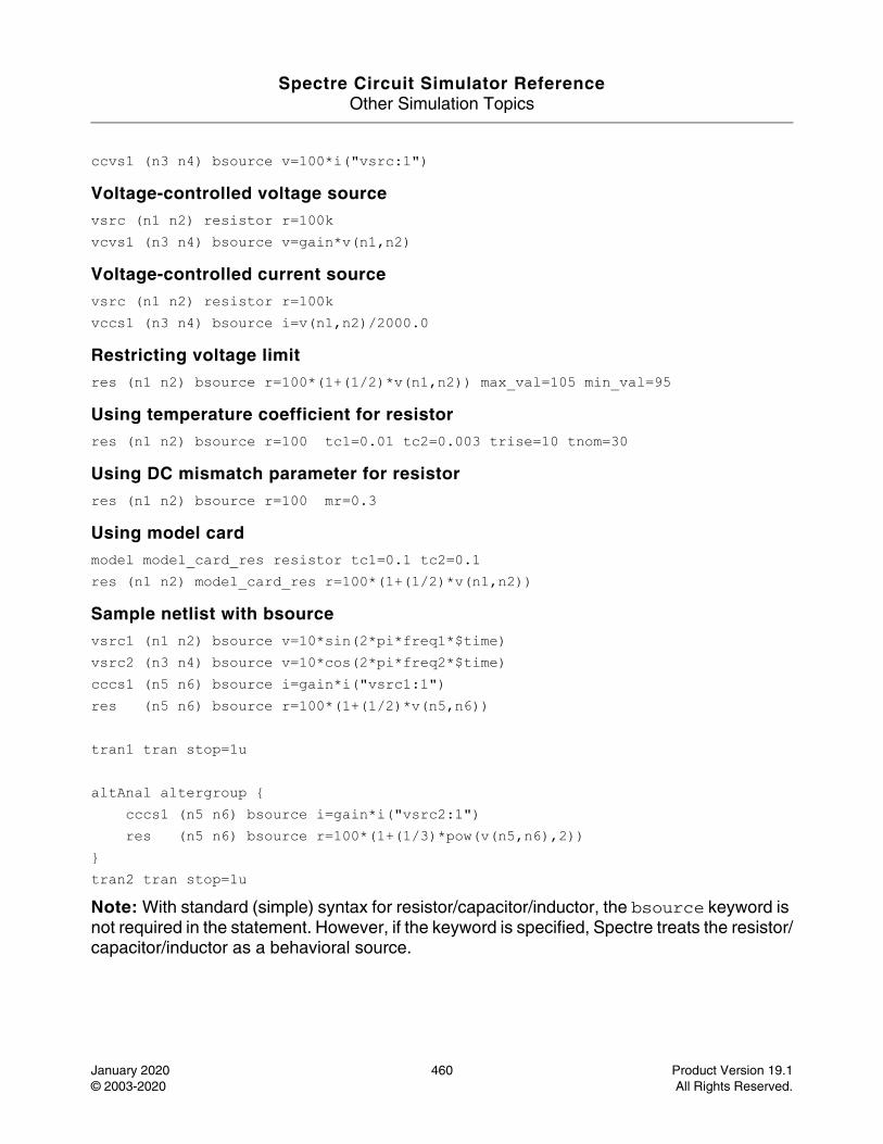
Spectre Circuit Simulator ReferenceOther Simulation Topics
January 2020 460 Product Version 19.1© 2003-2020 All Rights Reserved.
ccvs1 (n3 n4) bsource v=100*i("vsrc:1")
Voltage-controlled voltage source vsrc (n1 n2) resistor r=100k vcvs1 (n3 n4) bsource v=gain*v(n1,n2)
Voltage-controlled current source
vsrc (n1 n2) resistor r=100k vccs1 (n3 n4) bsource i=v(n1,n2)/2000.0
Restricting voltage limit res (n1 n2) bsource r=100*(1+(1/2)*v(n1,n2)) max_val=105 min_val=95
Using temperature coefficient for resistor res (n1 n2) bsource r=100 tc1=0.01 tc2=0.003 trise=10 tnom=30
Using DC mismatch parameter for resistor res (n1 n2) bsource r=100 mr=0.3
Using model card model model_card_res resistor tc1=0.1 tc2=0.1res (n1 n2) model_card_res r=100*(1+(1/2)*v(n1,n2))
Sample netlist with bsource vsrc1 (n1 n2) bsource v=10*sin(2*pi*freq1*$time)vsrc2 (n3 n4) bsource v=10*cos(2*pi*freq2*$time)cccs1 (n5 n6) bsource i=gain*i("vsrc1:1")res (n5 n6) bsource r=100*(1+(1/2)*v(n5,n6)) tran1 tran stop=1u altAnal altergroup {
cccs1 (n5 n6) bsource i=gain*i("vsrc2:1")res (n5 n6) bsource r=100*(1+(1/3)*pow(v(n5,n6),2))
}tran2 tran stop=1uNote: With standard (simple) syntax for resistor/capacitor/inductor, the bsource keyword is not required in the statement. However, if the keyword is specified, Spectre treats the resistor/capacitor/inductor as a behavioral source.

Spectre Circuit Simulator ReferenceOther Simulation Topics
January 2020 461 Product Version 19.1© 2003-2020 All Rights Reserved.
bsource Compilation
Spectre automatically translates bsource components into verilogA models for simulation. As such, they are compiled prior to simulation just like any other verilogA model.
Spectre Circuit Simulator ReferenceOther Simulation Topics
January 2020 462 Product Version 19.1© 2003-2020 All Rights Reserved.
Checkpoint - Restart (checkpoint)
Description
Spectre has the ability to save the checkpoint files generated during analyses, and to restart an analysis from its checkpoint file. Checkpoint files can be generated in the following ways:
■ Periodically, based on real time (wall clock time).
■ Asynchronous UNIX signals.
■ By other methods unique to the analyses.
To generate checkpoint files periodically based on real time, set the Spectre option ckptclock to the time interval, in seconds. This option is turned on by default with a value of 1800 seconds (30 minutes). Spectre deletes the checkpoint file if the simulation completes normally. If the simulation terminates abnormally, the checkpoint file is not deleted.
If Spectre receives the UNIX signal USR2, Spectre immediately writes a checkpoint file. If Spectre receives interrupt signals, such as QUIT, TERM, INT, or HUP, Spectre attempts to write a checkpoint file and then exits. For other fatal signals, Spectre may not write a checkpoint file.
The name of the checkpoint file is a combination of the circuit name and the analysis name with the extension.ckpt. For example, if the circuit is named test1 and the transient analysis is named timeSweep, the checkpoint file is named test1.timeSweep.tran.ckpt.
Spectre keeps only the latest checkpoint file. It creates a new checkpoint file with a temporary name. After the file is successfully written, Spectre deletes the previous checkpoint file created earlier and renames the new file.
Currently, only transient analysis supports checkpoint files and restart.
Checkpoint
Transient analysis can generate checkpoint files periodically based on the transient simulation time. This is done by using a transient analysis parameter named ckptperiod, which is turned off by default. To enable the checkpoint feature, the argument +checkpoint must be added to the spectre command.
Spectre Circuit Simulator ReferenceOther Simulation Topics
January 2020 463 Product Version 19.1© 2003-2020 All Rights Reserved.
Restart
To restart an analysis from a checkpoint file, use the +recover option with the spectre command. Spectre searches the analyses log for the checkpoint file. If the checkpoint file for the analysis exists, Spectre skips over any previous analyses, and restarts the analysis by using the information from the file.
For more information, see Recovering From Transient Analysis Terminations section in the Spectre Classic Simulator, Spectre APS, Spectre X, and Spectre XPS User Guide.
Spectre Circuit Simulator ReferenceOther Simulation Topics
January 2020 464 Product Version 19.1© 2003-2020 All Rights Reserved.
Configuring CMI Shared Objects (cmiconfig)
Description
Spectre supports the ability to install devices dynamically from shared objects at run time. CMI Configuration files are used to determine and locate the set of shared objects to be installed as follows:
1. Spectre first reads the default CMI configuration file that specifies the default shared objects provided by Cadence.
2. The configuration file specified by the value of the CMI_CONFIG environment variable is then read.
3. The third configuration file that Spectre reads is ~/.cmiconfig.
4. Finally, the configuration file specified in the -cmiconfig command-line argument is read.
Each CMI configuration file modifies the existing configuration established by the configuration files read before.
The following commands can be used in a CMI configuration file.
setpath: Specifies and resets the search path
setpath <path> or setpath ( <path1> <path2> ... <pathN> )
prepend: Adds a path before the current search path
prepend <path> or prepend ( <path1> <path2> ... <pathN> )
append: Adds a path after the current search path
append <path> or append ( <path1> <path2> ... <pathN> )
load: Adds a shared object to the list of shared objects to load
loads [path/]<shared_object_name>
unload: Removes a shared object from the list of shared objects to load
unload <shared_object_name>
For example, given the following CMI configuration file:
append /hm/MMSIM_INSTALL/tools.lnx86/cmi/lib/cmi/5.0load libbjtx+tfet.soload libmosx.so

Spectre Circuit Simulator ReferenceOther Simulation Topics
January 2020 465 Product Version 19.1© 2003-2020 All Rights Reserved.
The shared objects libbjtx+tfet.so and libmosx.so are loaded from /hm/MMSIM_INSTALL/tools.lnx86/cmi/lib/cmi/5.0, in addition to the default shared objects provided by Cadence.
For more information, refer to the Using Compiled-Model Interface chapter in the Spectre Classic Simulator, Spectre APS, Spectre X, and Spectre XPS User Guide.
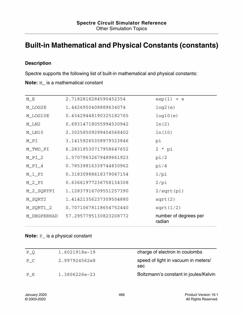
Spectre Circuit Simulator ReferenceOther Simulation Topics
January 2020 466 Product Version 19.1© 2003-2020 All Rights Reserved.
Built-in Mathematical and Physical Constants (constants)
Description
Spectre supports the following list of built-in mathematical and physical constants:
Note: M_ is a mathematical constant
Note: P_ is a physical constant
M_E 2.7182818284590452354 exp(1) = e
M_LOG2E 1.4426950408889634074 log2(e)
M_LOG10E 0.43429448190325182765 log10(e)
M_LN2 0.69314718055994530942 ln(2)
M_LN10 2.30258509299404568402 ln(10)
M_PI 3.14159265358979323846 pi
M_TWO_PI 6.28318530717958647652 2 * pi
M_PI_2 1.57079632679489661923 pi/2
M_PI_4 0.78539816339744830962 pi/4
M_1_PI 0.31830988618379067154 1/pi
M_2_PI 0.63661977236758134308 2/pi
M_2_SQRTPI 1.12837916709551257390 2/sqrt(pi)
M_SQRT2 1.41421356237309504880 sqrt(2)
M_SQRT1_2 0.70710678118654752440 sqrt(1/2)
M_DEGPERRAD 57.2957795130823208772 number of degrees per radian
P_Q 1.6021918e-19 charge of electron in coulombs
P_C 2.997924562e8 speed of light in vacuum in meters/sec
P_K 1.3806226e-23 Boltzmann’s constant in joules/Kelvin
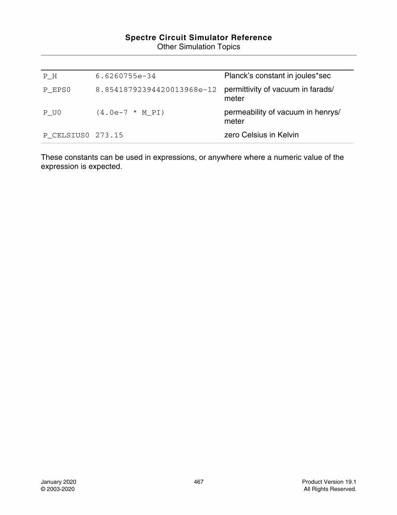
Spectre Circuit Simulator ReferenceOther Simulation Topics
January 2020 467 Product Version 19.1© 2003-2020 All Rights Reserved.
These constants can be used in expressions, or anywhere where a numeric value of the expression is expected.
P_H 6.6260755e-34 Planck’s constant in joules*sec
P_EPS0 8.85418792394420013968e-12 permittivity of vacuum in farads/meter
P_U0 (4.0e-7 * M_PI) permeability of vacuum in henrys/meter
P_CELSIUS0 273.15 zero Celsius in Kelvin
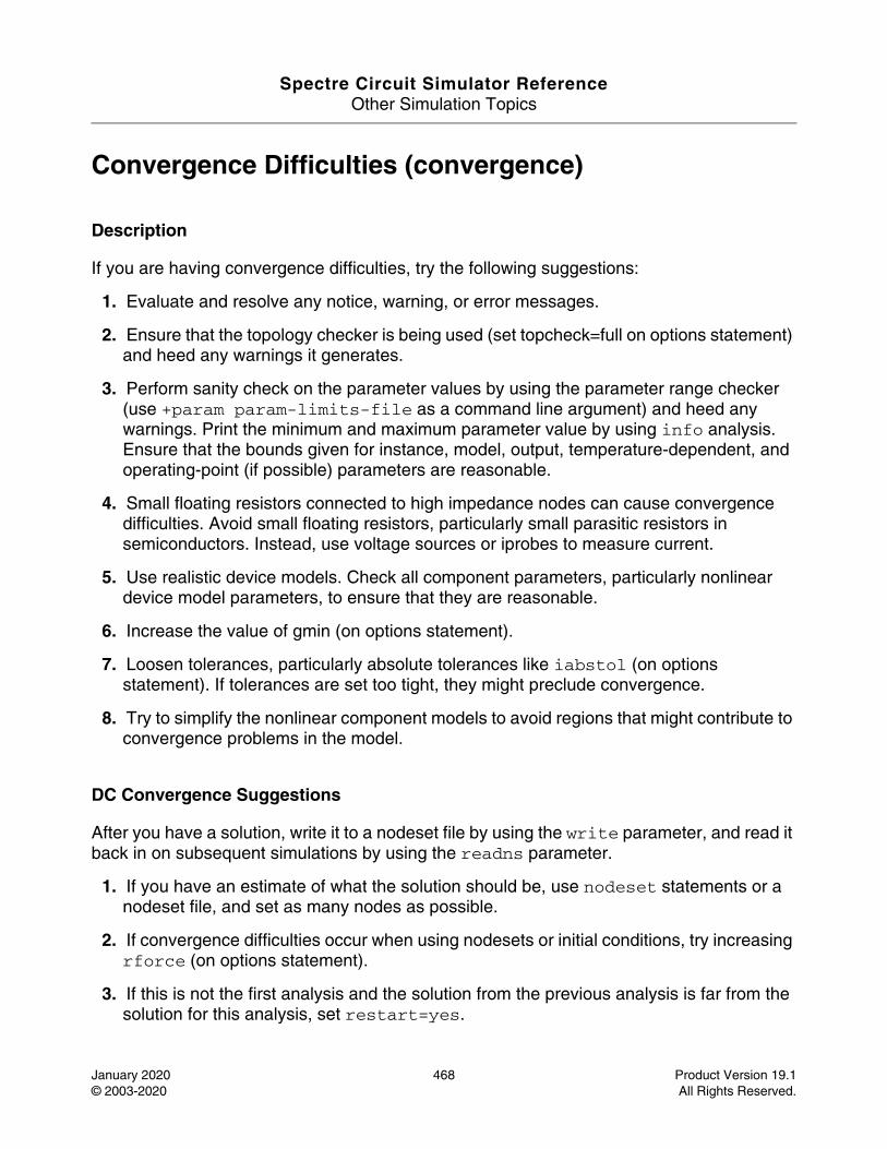
Spectre Circuit Simulator ReferenceOther Simulation Topics
January 2020 468 Product Version 19.1© 2003-2020 All Rights Reserved.
Convergence Difficulties (convergence)
Description
If you are having convergence difficulties, try the following suggestions:
1. Evaluate and resolve any notice, warning, or error messages.
2. Ensure that the topology checker is being used (set topcheck=full on options statement) and heed any warnings it generates.
3. Perform sanity check on the parameter values by using the parameter range checker (use +param param-limits-file as a command line argument) and heed any warnings. Print the minimum and maximum parameter value by using info analysis. Ensure that the bounds given for instance, model, output, temperature-dependent, and operating-point (if possible) parameters are reasonable.
4. Small floating resistors connected to high impedance nodes can cause convergence difficulties. Avoid small floating resistors, particularly small parasitic resistors in semiconductors. Instead, use voltage sources or iprobes to measure current.
5. Use realistic device models. Check all component parameters, particularly nonlinear device model parameters, to ensure that they are reasonable.
6. Increase the value of gmin (on options statement).
7. Loosen tolerances, particularly absolute tolerances like iabstol (on options statement). If tolerances are set too tight, they might preclude convergence.
8. Try to simplify the nonlinear component models to avoid regions that might contribute to convergence problems in the model.
DC Convergence Suggestions
After you have a solution, write it to a nodeset file by using the write parameter, and read it back in on subsequent simulations by using the readns parameter.
1. If you have an estimate of what the solution should be, use nodeset statements or a nodeset file, and set as many nodes as possible.
2. If convergence difficulties occur when using nodesets or initial conditions, try increasing rforce (on options statement).
3. If this is not the first analysis and the solution from the previous analysis is far from the solution for this analysis, set restart=yes.
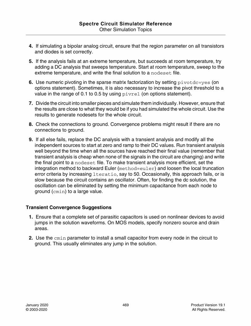
Spectre Circuit Simulator ReferenceOther Simulation Topics
January 2020 469 Product Version 19.1© 2003-2020 All Rights Reserved.
4. If simulating a bipolar analog circuit, ensure that the region parameter on all transistors and diodes is set correctly.
5. If the analysis fails at an extreme temperature, but succeeds at room temperature, try adding a DC analysis that sweeps temperature. Start at room temperature, sweep to the extreme temperature, and write the final solution to a nodeset file.
6. Use numeric pivoting in the sparse matrix factorization by setting pivotdc=yes (on options statement). Sometimes, it is also necessary to increase the pivot threshold to a value in the range of 0.1 to 0.5 by using pivrel (on options statement).
7. Divide the circuit into smaller pieces and simulate them individually. However, ensure that the results are close to what they would be if you had simulated the whole circuit. Use the results to generate nodesets for the whole circuit.
8. Check the connections to ground. Convergence problems might result if there are no connections to ground.
9. If all else fails, replace the DC analysis with a transient analysis and modify all the independent sources to start at zero and ramp to their DC values. Run transient analysis well beyond the time when all the sources have reached their final value (remember that transient analysis is cheap when none of the signals in the circuit are changing) and write the final point to a nodeset file. To make transient analysis more efficient, set the integration method to backward Euler (method=euler) and loosen the local truncation error criteria by increasing lteratio, say to 50. Occasionally, this approach fails, or is slow because the circuit contains an oscillator. Often, for finding the dc solution, the oscillation can be eliminated by setting the minimum capacitance from each node to ground (cmin) to a large value.
Transient Convergence Suggestions
1. Ensure that a complete set of parasitic capacitors is used on nonlinear devices to avoid jumps in the solution waveforms. On MOS models, specify nonzero source and drain areas.
2. Use the cmin parameter to install a small capacitor from every node in the circuit to ground. This usually eliminates any jump in the solution.
Spectre Circuit Simulator ReferenceOther Simulation Topics
January 2020 470 Product Version 19.1© 2003-2020 All Rights Reserved.
The dcopt command line option (dcopt)
Description
The dcopt option speeds up the DC simulation in Spectre and APS for post-layout circuits that consist of large number of parasitic resistors and capacitors, which require significant time in DC simulation. It can also be used to solve the non-convergence issues in DC simulations of any other circuit.
Note: In some cases, the DC solution obtained using the dcopt command-line option may not be as accurate as the true DC solution.
Definition+dcopt in the command line
Spectre Circuit Simulator ReferenceOther Simulation Topics
January 2020 471 Product Version 19.1© 2003-2020 All Rights Reserved.
encryption (encryption)
Description
Encryption enables you to protect your proprietary parameters, subcircuits, models, netlists, and release your libraries to your customers without revealing sensitive information.
1. Define Encryption blocks in the netlist
Keywords (protect, unprotect) are used for defining an encryption block.The dot keywords are used in the context of the spice mode: .protect, .unprotect.protect, unprotect can be abbreviated to prot, unprot(or, .prot, .unprot in spice).
If the whole file needs to be encrypted, one method is to put protect at the beginning of the file and unprotect at the end of the file. Alternatively,you can use the -all option of the spectre encrypt command.
Examples of netlist with protected blocks:
Example: Protection of subcktsprotectsubckt sub1 ( ... ) ....ends sub1subckt sub2 ( ... ).....ends sub2unprotect
2. Encrypt the netlist
spectre_encrypt is a standalone encryptor, and is used as follows:
spectre_encrypt [-i input_file] [-o output_file] [-all] where
[-i Input_file]: Netlist to be encrypted
[-o output _file]: Output file of the encrypted netlist
[-all]: The whole file will be encrypted in the input netlist
Note: You can separately encrypt the include files or the library files in the netlist. Spectre encryptor does not encrypt the included files automatically.
Spectre Circuit Simulator ReferenceOther Simulation Topics
January 2020 472 Product Version 19.1© 2003-2020 All Rights Reserved.
3. Simulate the encrypted netlist
There is no difference in how you run Spectre on an encrypted or unencrypted netlist. Spectre automatically decrypts an encrypted netlist.
For encrypted netlists, Spectre turns on the protection for devices, models, signals, and parameters in the encrypted blocks. Any error or warning messages and the outputs from the protected information is suppressed or filtered out.
The following list describes how protection is implemented:
❑ Circuit inventory does not include encrypted parts.
❑ The info command suppresses all information on encrypted parts.
❑ Errors on encrypted parts are reported as:
Error has occurred within the encrypted block (no details are given).❑ If a portion of the model is encrypted, the entire model is encrypted.
❑ Any command that references the protected elements results in an error message reporting that those elements do not exist.
❑ Protected device and model parameters cannot be altered directly through alter. However, if they depend on other alterable parameters, protected parameters are recalculated. Protected devices and models can be replaced in the altergroup.
❑ Protected nodes are output in an encrypted format when the ic file is requested (similarly, for nodes in checking point and restart).
❑ The encryption feature is not available in models using CMI 2.0.
4. Output operating points on protected devices
By default, all information about the protected devices is suppressed and is not visible. However, IP providers have the control to expose the operating points of the protected devices to the end users for back annotation.
Keywords (visible, invisible) or (.visible, .invisible) in the spice netlist content are defined to expose the operating points of encrypted devices.
The operating point of the protected devices between visible and invisible is not suppressed by adding what=oppoints to the visible statement.
For example:
protx1 n1 n2 n3 n4 nmosvisible what=oppoints x2 n5 n6 n7 n8 nmos
Spectre Circuit Simulator ReferenceOther Simulation Topics
January 2020 473 Product Version 19.1© 2003-2020 All Rights Reserved.
x3 n9 n10 n10 n8 pmosinvisible X4 n11 n12 n13 n13 pmosunprot
For more information, refer to the Encryption chapter in Spectre Classic Simulator, Spectre APS, Spectre X, and Spectre XPS User Guide.
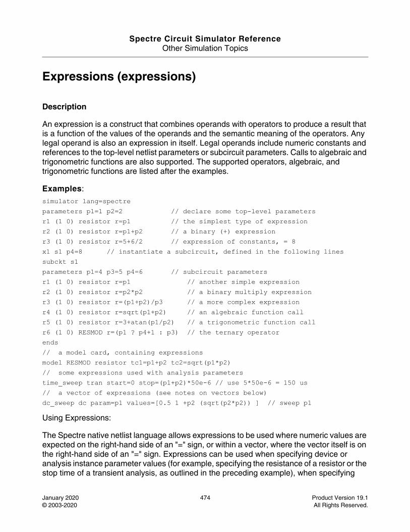
Spectre Circuit Simulator ReferenceOther Simulation Topics
January 2020 474 Product Version 19.1© 2003-2020 All Rights Reserved.
Expressions (expressions)
Description
An expression is a construct that combines operands with operators to produce a result that is a function of the values of the operands and the semantic meaning of the operators. Any legal operand is also an expression in itself. Legal operands include numeric constants and references to the top-level netlist parameters or subcircuit parameters. Calls to algebraic and trigonometric functions are also supported. The supported operators, algebraic, and trigonometric functions are listed after the examples.
Examples:
simulator lang=spectreparameters p1=1 p2=2 // declare some top-level parametersr1 (1 0) resistor r=p1 // the simplest type of expressionr2 (1 0) resistor r=p1+p2 // a binary (+) expression r3 (1 0) resistor r=5+6/2 // expression of constants, = 8 x1 s1 p4=8 // instantiate a subcircuit, defined in the following linessubckt s1parameters p1=4 p3=5 p4=6 // subcircuit parametersr1 (1 0) resistor r=p1 // another simple expressionr2 (1 0) resistor r=p2*p2 // a binary multiply expressionr3 (1 0) resistor r=(p1+p2)/p3 // a more complex expressionr4 (1 0) resistor r=sqrt(p1+p2) // an algebraic function callr5 (1 0) resistor r=3+atan(p1/p2) // a trigonometric function callr6 (1 0) RESMOD r=(p1 ? p4+1 : p3) // the ternary operatorends// a model card, containing expressionsmodel RESMOD resistor tc1=p1+p2 tc2=sqrt(p1*p2)// some expressions used with analysis parameterstime_sweep tran start=0 stop=(p1+p2)*50e-6 // use 5*50e-6 = 150 us// a vector of expressions (see notes on vectors below)dc_sweep dc param=p1 values=[0.5 1 +p2 (sqrt(p2*p2)) ] // sweep p1
Using Expressions:
The Spectre native netlist language allows expressions to be used where numeric values are expected on the right-hand side of an "=" sign, or within a vector, where the vector itself is on the right-hand side of an "=" sign. Expressions can be used when specifying device or analysis instance parameter values (for example, specifying the resistance of a resistor or the stop time of a transient analysis, as outlined in the preceding example), when specifying
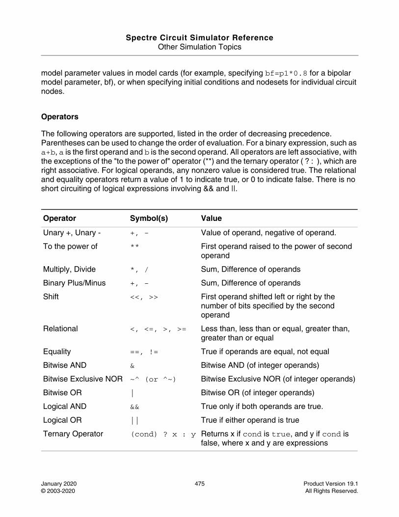
Spectre Circuit Simulator ReferenceOther Simulation Topics
January 2020 475 Product Version 19.1© 2003-2020 All Rights Reserved.
model parameter values in model cards (for example, specifying bf=p1*0.8 for a bipolar model parameter, bf), or when specifying initial conditions and nodesets for individual circuit nodes.
Operators
The following operators are supported, listed in the order of decreasing precedence. Parentheses can be used to change the order of evaluation. For a binary expression, such as a+b, a is the first operand and b is the second operand. All operators are left associative, with the exceptions of the "to the power of" operator (**) and the ternary operator ( ? : ), which are right associative. For logical operands, any nonzero value is considered true. The relational and equality operators return a value of 1 to indicate true, or 0 to indicate false. There is no short circuiting of logical expressions involving && and ||.
Operator Symbol(s) Value
Unary +, Unary - +, - Value of operand, negative of operand.
To the power of ** First operand raised to the power of second operand
Multiply, Divide *, / Sum, Difference of operands
Binary Plus/Minus +, - Sum, Difference of operands
Shift <<, >> First operand shifted left or right by the number of bits specified by the second operand
Relational <, <=, >, >= Less than, less than or equal, greater than, greater than or equal
Equality ==, != True if operands are equal, not equal
Bitwise AND & Bitwise AND (of integer operands)
Bitwise Exclusive NOR ~^ (or ^~) Bitwise Exclusive NOR (of integer operands)
Bitwise OR | Bitwise OR (of integer operands)
Logical AND && True only if both operands are true.
Logical OR || True if either operand is true
Ternary Operator (cond) ? x : y Returns x if cond is true, and y if cond is false, where x and y are expressions
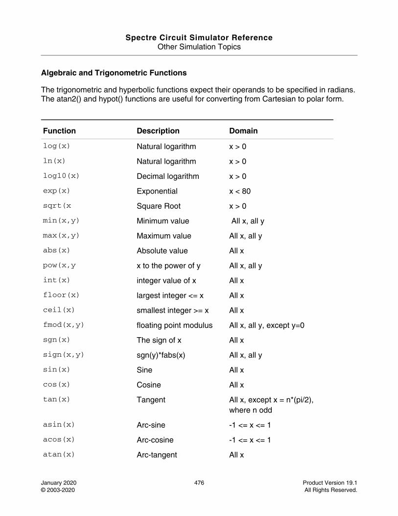
Spectre Circuit Simulator ReferenceOther Simulation Topics
January 2020 476 Product Version 19.1© 2003-2020 All Rights Reserved.
Algebraic and Trigonometric Functions
The trigonometric and hyperbolic functions expect their operands to be specified in radians. The atan2() and hypot() functions are useful for converting from Cartesian to polar form.
Function Description Domain
log(x) Natural logarithm x > 0
ln(x) Natural logarithm x > 0
log10(x) Decimal logarithm x > 0
exp(x) Exponential x < 80
sqrt(x Square Root x > 0
min(x,y) Minimum value All x, all y
max(x,y) Maximum value All x, all y
abs(x) Absolute value All x
pow(x,y x to the power of y All x, all y
int(x) integer value of x All x
floor(x) largest integer <= x All x
ceil(x) smallest integer >= x All x
fmod(x,y) floating point modulus All x, all y, except y=0
sgn(x) The sign of x All x
sign(x,y) sgn(y)*fabs(x) All x, all y
sin(x) Sine All x
cos(x) Cosine All x
tan(x) Tangent All x, except x = n*(pi/2), where n odd
asin(x) Arc-sine -1 <= x <= 1
acos(x) Arc-cosine -1 <= x <= 1
atan(x) Arc-tangent All x
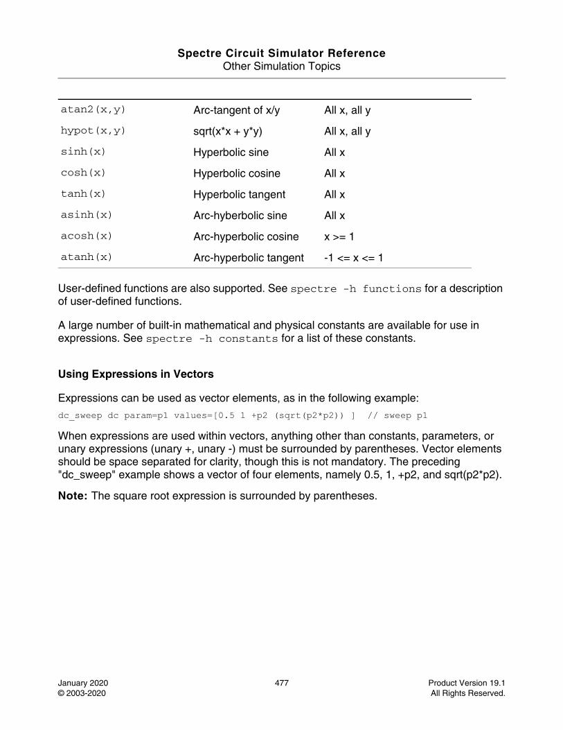
Spectre Circuit Simulator ReferenceOther Simulation Topics
January 2020 477 Product Version 19.1© 2003-2020 All Rights Reserved.
User-defined functions are also supported. See spectre -h functions for a description of user-defined functions.
A large number of built-in mathematical and physical constants are available for use in expressions. See spectre -h constants for a list of these constants.
Using Expressions in Vectors
Expressions can be used as vector elements, as in the following example:
dc_sweep dc param=p1 values=[0.5 1 +p2 (sqrt(p2*p2)) ] // sweep p1
When expressions are used within vectors, anything other than constants, parameters, or unary expressions (unary +, unary -) must be surrounded by parentheses. Vector elements should be space separated for clarity, though this is not mandatory. The preceding "dc_sweep" example shows a vector of four elements, namely 0.5, 1, +p2, and sqrt(p2*p2).
Note: The square root expression is surrounded by parentheses.
atan2(x,y) Arc-tangent of x/y All x, all y
hypot(x,y) sqrt(x*x + y*y) All x, all y
sinh(x) Hyperbolic sine All x
cosh(x) Hyperbolic cosine All x
tanh(x) Hyperbolic tangent All x
asinh(x) Arc-hyberbolic sine All x
acosh(x) Arc-hyperbolic cosine x >= 1
atanh(x) Arc-hyperbolic tangent -1 <= x <= 1
Spectre Circuit Simulator ReferenceOther Simulation Topics
January 2020 478 Product Version 19.1© 2003-2020 All Rights Reserved.
The fastdc command line option (fastdc)
Description
The fastdc option speeds up the DC simulation in Spectre and APS for large-scale circuits and for cases where DC convergence is slow or there is difficulty in DC convergence.
The fastdc option provides a way to quickly obtain the approximate DC solution to start transient analysis.
Note: The DC solution obtained using the fastdc command-line option may not be as accurate as the true DC solution. The solution accuracy depends on the value specified for fastdc. The available values are 0, 1, 2, 3, and 4 (default).
0 - The most accurate DC result and closest to true DC solutions with the slowest performance. It should be used for the circuits that require accurate DC solution, such as analog circuits.
1 - The conservative DC result with slow performance. It should be used for the circuits that are sensitive to DC solution, such as analog dominated circuits.
2 - The reasonable DC result with moderate performance. It should be used for the circuits that are lightly sensitive to DC solution, such as mixed-signal circuits.
3 - The liberate DC results with fast performance. It should be used for the circuits that are less sensitive to DC solution, such as digital dominated circuits.
4 - The least accurate DC result with the fastest performance. It should be used for the circuits that are not sensitive to DC solution, such as digital and memory circuits.
Definition
Note: +fastdc (equal to +fastdc=4) or +fastdc=x (0, 1, 2, 3, 4) in the command line
Spectre Circuit Simulator ReferenceOther Simulation Topics
January 2020 479 Product Version 19.1© 2003-2020 All Rights Reserved.
Fault List for Transient Fault Analysis (faults)
Description
The faults block is used to specify the faults to be simulated during Transient Fault Analysis. It can contain two types of faults: bridges (or equivalently shorts) and opens.
The bridge (short) block specifies the resistance value between any two nodes of the circuit. The node names may be specified hierarchically.
The open block specifies the nodes that will be split into two.
Parameter r specifies resistance between the new fault node and the original node.
Optional parameter c specifies capacitance between the new fault node and the original node.
The last block describes topology change: how the instances connected to the original node will be connected to the new fault node. All terminals of the instances specified in the open statement will be connected to the new node. All terminals that are not specified will remain connected to the original node.
If no instance list is specified, a warning is issued and the fault is ignored. The terminals are specified by name or numerically starting from 1. If the specified terminal number 1 is the first terminal of the instance. If the specified terminal number of an instance in the instance list is not connected to the original node, an error is generated. If no terminal list is specified for an instance, all the terminals connected to the original node will remain connected to the original node. The node and instance names can be specified hierarchically.
Within the faults block, the bridge, short, and open blocks are optional. If none are specified, a warning is issued and the faults block is ignored. If more than one bridge, short, or open block is specified within a faults block, they are concatenated and treated as one block. Every fault name in a faults block must be unique. Duplicate names result in an error.
More than one faults block may be specified in the netlist and each faults block must have a unique name and a set of parameters associated with it.
Definition
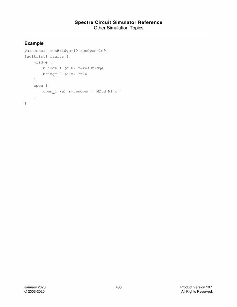
Spectre Circuit Simulator ReferenceOther Simulation Topics
January 2020 480 Product Version 19.1© 2003-2020 All Rights Reserved.
Exampleparameters resBridge=10 resOpen=1e9faultlist1 faults { bridge { bridge_1 (g 0) r=resBridge bridge_2 (d s) r=10 } open { open_1 (a) r=resOpen { M2:d M1:g } } }
Spectre Circuit Simulator ReferenceOther Simulation Topics
January 2020 481 Product Version 19.1© 2003-2020 All Rights Reserved.
User Defined Functions (functions)
Description
Spectre’s user-defined function capability allows you to build upon the provided set of built-in mathematical and trigonometric functions. You can write your own functions, and call these functions from within any expression. The syntax for calling a user-defined function is the same as the syntax for calling a built-in algebraic or trigonometric function. The user-defined functions must be defined before they are referenced (called). Arguments to user-defined functions are taken as real values, and the functions return real values. A user-defined function may contain only a single statement in braces, and this statement must return an expression (which is typically an expression involving the function arguments). The return expression may reference the built-in parameters temp and tnom. User-defined functions must be declared only at the top level, and must not be declared within subcircuits. User-defined functions may be called from anywhere an expression can be currently used in Spectre. User-defined functions may call other functions (both user-defined and built-in), however, any user-defined function needs to be declared before it can be called. User-defined functions can override built-in mathematical and trigonometric functions.
Note: Only real values for arguments and return values are supported in this release.
See spectre -h expressions for a list of built-in algebraic and trigonometric functions.
Definition real myfunc( [real arg1, ...real argn] ) {
}
Examples
real myfunc( real a, real b ) {return a+b*2+sqrt(a*sin(b));
}
An example of a function calling a previously defined function is as follows:
real yourfunc( real a, real b ) {return a+b*myfunc(a,b); // call "myfunc"
}
The final example shows how a user-defined function may be called from an expression in the Spectre netlist:
r1 (1 0) resistor r=myfunc(2.0, 4.5)

Spectre Circuit Simulator ReferenceOther Simulation Topics
January 2020 482 Product Version 19.1© 2003-2020 All Rights Reserved.
Global Nodes (global)
Description
The global statement allows a set of nodes to be designated as common to the main circuit and all subcircuits. Thus, components inside subcircuits can be attached to global nodes, even though the subcircuit terminals are not attached to these nodes.
Any number of global nodes may be specified using the global statement. To do this, follow the keyword global with a list of the node names that you wish to declare as global. The first node name that appears in this list is taken to be the name of the ground node. Ground is also known as the datum or reference node. If a global statement is not used, 0 is taken to be the name of the ground node.
Ground is always treated as global even if a global statement is not used. Multiple global statements are supported.
Definitionglobal <ground> <node> ...
Spectre Circuit Simulator ReferenceOther Simulation Topics
January 2020 483 Product Version 19.1© 2003-2020 All Rights Reserved.
IBIS Component Use Model (ibis)
Description
IBIS (I/O Buffer Information Specification) is a standard for electronic behavioral specification of integrated circuit (IC) input/output analog characteristics. It allows you to define a model for the IC component package, and a buffer model for each pin. IBIS standard also allows you to describe a board-level component containing several components on a common substrate or printed circuit board (PCB). For example, a SIMM module is a board-level component that is used to attach several DRAM components on the PCB to a motherboard through edge connector pins. Board pins, components on the board, and connections between them are defined in an Electrical Board Description file with extension.ebd. Component pins, buffers, and package descriptions are in a separate IBIS file with extension.ibs. An Additional Package file with extension.pkg can be used to describe advanced package models.
Spectre supports IBIS 6.0 and previous versions. Some keywords are not supported.
IBIS files can be referenced in Spectre netlist by using the ibis_include statement:
ibis_include "DRAM.ibs" [options]
IBIS file "DRAM.ibs" is translated into Spectre netlist format by using ibis2subckt utility. The output file, "DRAM.scs", containing subcircuit definitions for each IBIS component, board, and package found in the input IBIS file, is included in the netlist. The list of options may consist of: corner={typ|min|max|slow|fast}, swsel=<int> and mdsel=<int>. These options are transferred to ibis2subckt. They are used to select IBIS buffer model corner, change position of series-switch models, and choose the required models from model selector list.
IBIS component and board subcircuits can be instantiated in a Spectre netlist along with regular Spectre primitives. Subcircuit name is the same as the component name, but is appended with the suffix_ibis. Subcircuit terminals are component pins, arranged in the order they are listed in the IBIS file. Each pin terminal is followed by a number of signal terminals, depending on the type of the pin buffer model. For example, if m1 is defined in IBIS file as an input buffer model, and m2 - as I/O type, the following IBIS component:
[Component] IC [Pin] signal_name model_name R_pin L_pin C_pin p1 s1 GND p3 s3 m1 p4 s4 NC p5 s5 m2 p2 s2 POWER
Spectre Circuit Simulator ReferenceOther Simulation Topics
January 2020 484 Product Version 19.1© 2003-2020 All Rights Reserved.
can be instantiated in the netlist as:
x_ic ( p1 p3 s3_in p4 p5 s5_in s5_out s5_en p2 ) IC_ibis
ibis2subckt can also be used as a stand-alone utility with the following command-line arguments:
ibis2subckt -in <IBIS files> -out <subckt file> -corner {typ|min|max|slow|fast} -swsel <int> -mdsel <int>
Default values are:
corner typ mdsel -1 swsel -1
SPICE NETLIST SUPPORT
For the IBIS component, Spectre also supports the SPICE .IBIS and .EBD statements.
The supported parameters of.IBIS syntax are file, component, mod_sel, package, and typ.
Spectre Circuit Simulator ReferenceOther Simulation Topics
January 2020 485 Product Version 19.1© 2003-2020 All Rights Reserved.
.IBIS Parameters
The supported parameters of the .EBD syntax are file, model, and component.
.EBD Parameters
Examples.ibis I1 + file = file.ibs + component = Component + mod_sel = DQ=DQ1,CQ=CQ1 + package=0
file = <string> Specifies the IBIS file name with suffix .ibs.
component = <string> Specifies the used component name in the .ibs file.
mod_sel = <string1=string2> Maps the model selector name (string1) to the actual model name (string2), given as [Model selector] in the .ibis file. Multiple selectors are supported.
package = <3|0|1|2> Specifies the type of package. Default value is 3 (use the best available package model). package=0 means no package is used. package=1 means that an RLC package is used with the same values for all pins provided in the [Package] section. package=2 means that an RLC package is used with individual RLC values for each pin provided in the [Pin] section. package=3 means that an advanced package model is used in the [Package Model] section.
typ = <typ|min|max|fast|slow>
Specifies the corner of the IBIS buffer. Default value is typ (typical).
file = <string> Specifies the EBD file name with the suffix .ebd
model = <string> Specifies name of the board-level model provided in .ebd file
component = <string>
Specifies the component name of the ibis buffer. Multiple components are supported.
Spectre Circuit Simulator ReferenceOther Simulation Topics
January 2020 486 Product Version 19.1© 2003-2020 All Rights Reserved.
+ typ=slow
.ebd pkg + file = file.ebd+ model = XXXX + component = Component1 + component = Component2
Supported IBIS Keywords in Spectre
Note: The supported keywords list below is based on IBIS version 6.0.
The following shows the sections and keywords in the IBIS file that are supported in Spectre:
.ibis FILEFILE Header Section
[IBIS Ver][Comment Char] [File Name] [File Rev] [Date][Source][Notes][Disclaimer][Copyright]
[Component] Si Location, Timing_location[Manufacturer] [Package] R_pkg, L_pkg, C_pkg[Pin] signal_name, model_name, R_pin, L_pin, C_pin[Package Model][Pin Mapping] pulldown_ref, pullup_ref, gnd_clamp_ref,
power_clamp_ref, ext_ref[Diff Pin] inv_pin, vdiff, tdelay_typ, tdelay_min, tdelay_max[Series Pin Mapping] pin_2, model_name, function_table_group[Series Switch Groups] On (m), Off (m)
[Model Selector][Model] Model_type, Polarity, Enable, Vinl, Vinh, C_comp,
C_comp_pullup, C_comp_pulldown, C_comp_power_clamp, C_comp_gnd_clamp, Vmeas, Cref, Rref, Vref
[Model Spec] Vinh, Vin1[Add Submodel][Driver Schedule][Temperature Range]
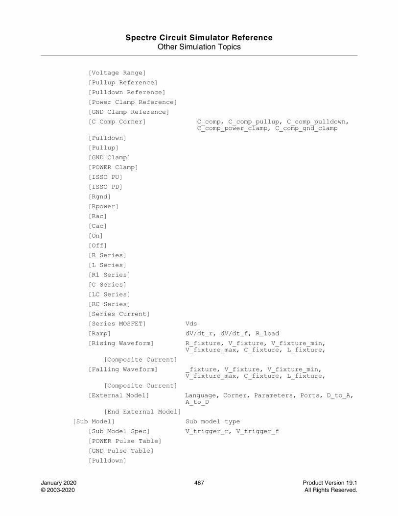
Spectre Circuit Simulator ReferenceOther Simulation Topics
January 2020 487 Product Version 19.1© 2003-2020 All Rights Reserved.
[Voltage Range][Pullup Reference][Pulldown Reference][Power Clamp Reference][GND Clamp Reference][C Comp Corner] C_comp, C_comp_pullup, C_comp_pulldown,
C_comp_power_clamp, C_comp_gnd_clamp[Pulldown][Pullup][GND Clamp][POWER Clamp][ISSO PU][ISSO PD][Rgnd][Rpower][Rac][Cac][On][Off][R Series][L Series][R1 Series][C Series][LC Series][RC Series][Series Current][Series MOSFET] Vds[Ramp] dV/dt_r, dV/dt_f, R_load[Rising Waveform] R_fixture, V_fixture, V_fixture_min,
V_fixture_max, C_fixture, L_fixture,[Composite Current]
[Falling Waveform] _fixture, V_fixture, V_fixture_min, V_fixture_max, C_fixture, L_fixture,
[Composite Current][External Model] Language, Corner, Parameters, Ports, D_to_A,
A_to_D[End External Model]
[Sub Model] Sub model type[Sub Model Spec] V_trigger_r, V_trigger_f[POWER Pulse Table] [GND Pulse Table] [Pulldown]
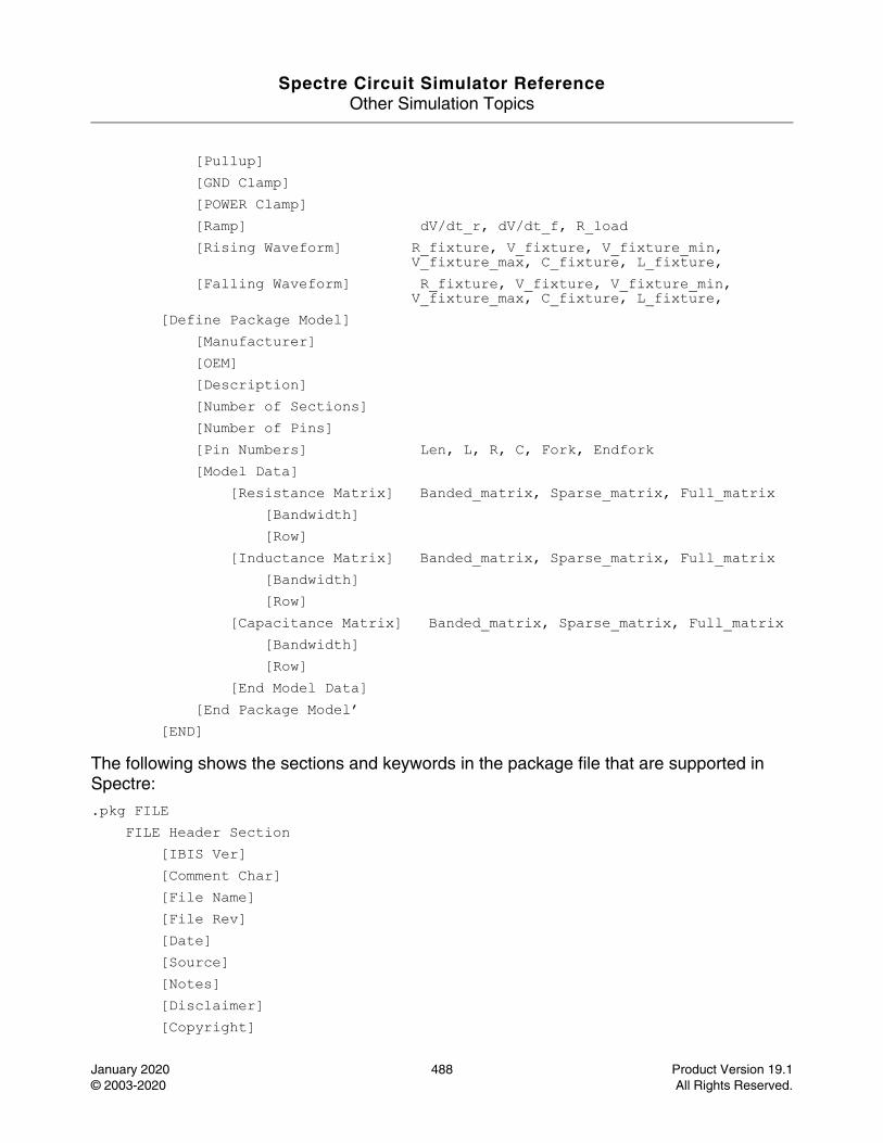
Spectre Circuit Simulator ReferenceOther Simulation Topics
January 2020 488 Product Version 19.1© 2003-2020 All Rights Reserved.
[Pullup] [GND Clamp] [POWER Clamp] [Ramp] dV/dt_r, dV/dt_f, R_load[Rising Waveform] R_fixture, V_fixture, V_fixture_min,
V_fixture_max, C_fixture, L_fixture,[Falling Waveform] R_fixture, V_fixture, V_fixture_min,
V_fixture_max, C_fixture, L_fixture,[Define Package Model]
[Manufacturer][OEM][Description][Number of Sections][Number of Pins][Pin Numbers] Len, L, R, C, Fork, Endfork[Model Data]
[Resistance Matrix] Banded_matrix, Sparse_matrix, Full_matrix[Bandwidth][Row]
[Inductance Matrix] Banded_matrix, Sparse_matrix, Full_matrix[Bandwidth][Row]
[Capacitance Matrix] Banded_matrix, Sparse_matrix, Full_matrix[Bandwidth][Row]
[End Model Data][End Package Model’
[END]
The following shows the sections and keywords in the package file that are supported in Spectre:
.pkg FILEFILE Header Section
[IBIS Ver][Comment Char] [File Name] [File Rev] [Date][Source][Notes][Disclaimer][Copyright]
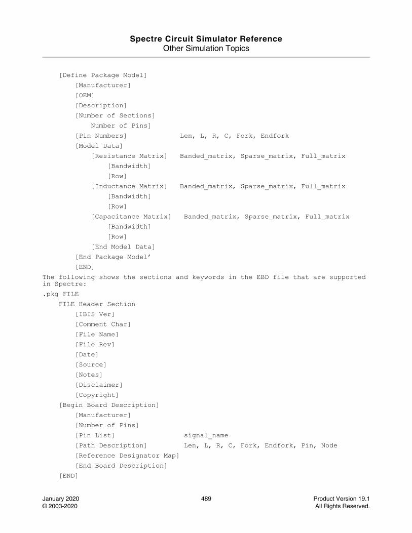
Spectre Circuit Simulator ReferenceOther Simulation Topics
January 2020 489 Product Version 19.1© 2003-2020 All Rights Reserved.
[Define Package Model][Manufacturer][OEM][Description][Number of Sections]
Number of Pins][Pin Numbers] Len, L, R, C, Fork, Endfork[Model Data]
[Resistance Matrix] Banded_matrix, Sparse_matrix, Full_matrix[Bandwidth][Row]
[Inductance Matrix] Banded_matrix, Sparse_matrix, Full_matrix[Bandwidth][Row]
[Capacitance Matrix] Banded_matrix, Sparse_matrix, Full_matrix[Bandwidth][Row]
[End Model Data][End Package Model’[END]
The following shows the sections and keywords in the EBD file that are supported in Spectre:.pkg FILE
FILE Header Section[IBIS Ver][Comment Char] [File Name] [File Rev] [Date][Source][Notes][Disclaimer][Copyright]
[Begin Board Description][Manufacturer][Number of Pins][Pin List] signal_name[Path Description] Len, L, R, C, Fork, Endfork, Pin, Node[Reference Designator Map][End Board Description]
[END]
Spectre Circuit Simulator ReferenceOther Simulation Topics
January 2020 490 Product Version 19.1© 2003-2020 All Rights Reserved.
Initial Conditions (ic)
Description
The ic statement is used to provide initial conditions for nodes in transient analysis. It can occur multiple times in the input, and the information provided in all the occurrences is collected. Initial conditions are accepted only for inductor currents and node voltages where the nodes have a path of capacitors to ground. For more information, read the description of transient analysis.
Note: Specifying cmin for a transient analysis, does not satisfy the condition that a node has a capacitive path to ground.
Definitionic <X[:param]=value> ...
This statement takes a list of signals with the state information to the DC and transient analyses. X can be a node, a component, or a subcircuit and param can either be a component output parameter or a terminal index. To specify a class of signals, use the pattern matching characters * for any string and ? for any character.
The concept of nodes for the statement has been generalized to signals where a signal is a value associated with a topological node of the circuit or some other unknown that is solved by the simulator, such as the current through an inductor or the voltage of the internal node in a diode. Topological nodes can either be at the top-level or in a subcircuit.
For example:
ic 7=0 out=1 OpAmp1.comp=5 L1:1=1.0u
where, 7=0 implies that node 7 should start at 0V, node out should start at 1V, node comp in subcircuit OpAmp1 should start at 5V, and the current through the first terminal of L1 should start at 1uA.
For more information, refer to The ic and nodeset Statements in the Spectre Classic Simulator, Spectre APS, Spectre X, and Spectre XPS User Guide.
Spectre Circuit Simulator ReferenceOther Simulation Topics
January 2020 491 Product Version 19.1© 2003-2020 All Rights Reserved.
The Structural if-statement (if)
Description
The structural if-statement can be used to conditionally instantiate other instance statements.
Definitionif <condition> <statement1> [ else <statement2> ]
The condition is a Boolean expression based on the comparisons of various arithmetic expressions that are evaluated during circuit hierarchy flattening. The statement1 and statement2 fields can be ordinary instance statements, if-statements, or a list of these within braces ({}). The ordinary instance statements need a newline to terminate them. The else part is optional. When if-statements are nested without braces, an else matches the closest previous unmatched if at the same level.
It is possible to have duplicate instance names within the if statement under strict topological conditions. These conditions are as follows:
■ References to an instance with duplicate names is possible only within a structural if statement that has both an "if" part and an "else" part.
■ Both the "if" part and the "else" part must be a simple one-statement block, or another structural if statement to which these same rules apply.
■ The duplicate instances must have the same number of terminals and be bound to the same list of nodes.
■ The duplicate instances must refer to the same primitive or model.
■ Where duplicate instances refer to a model, the underlying primitive must be the same.
This feature allows automatic model selection based on any netlist or subcircuit parameter. As an example, consider using Spectre’s inline subcircuits and structural if statement to implement automatic model selection based on bipolar device area. Here, the duplicate instances are the inline components.
model npn_default bjt is=3.2e-16 va=59.8model npn10x10 bjt is=3.5e-16 va=61.5model npn20x20 bjt is=3.77e-16 va=60.5// npn_mod chooses scaled models binned on area!// if ( area < 100e-12 ) use model npn10x10// else if ( area < 400e-12 ) use model npn20x20// else use model npn_default
Spectre Circuit Simulator ReferenceOther Simulation Topics
January 2020 492 Product Version 19.1© 2003-2020 All Rights Reserved.
inline subckt npn_mod (c b e s) parameters area=5e-12 if ( area < 100e-12 ) { npn_mod (c b e s) npn10x10 // 10u * 10u, inline device } else if ( area < 400e-12 ) { npn_mod (c b e s) npn20x20 // 20u * 20u, inline device } else { npn_mod (c b e s) npn_default // 5u * 5u, inline device }ends npn_modq1 (1 2 0 0) npn_mod area=350e-12 // gets 20x20 model q2 (1 3 0 0) npn_mod area=25e-12 // gets 10x10 model q3 (1 3 0 0) npn_mod area=1000e-12 // gets default model
For additional information, refer to the Conditional Instances section in the Spectre Classic Simulator, Spectre APS, Spectre X, and Spectre XPS User Guide.
Spectre Circuit Simulator ReferenceOther Simulation Topics
January 2020 493 Product Version 19.1© 2003-2020 All Rights Reserved.
Include File (include)
Description
File inclusion allows the circuit description to be spread over several files. The include statement itself is replaced by the contents of the file named. An included file may also contain include statements. If the name given is not an absolute path specification, the path is taken relative to the directory of the file currently being read.
To read existing SPICE library and model files, Spectre automatically switches to SPICE input mode when it opens an include file. Thus, all files that use the Spectre native language must begin with a simulator lang=spectre statement. The one exception is files that end with a ".scs" file extension, which are treated specially and are read in Spectre input mode. This language mode treatment applies to files included by both the Spectre include statement, and the CPP #include statement.
After reading the include file, Spectre restores the language processing mode to what it was before the file was included, and continues reading the original file starting at the line after the include statement. Lines cannot be continued across file boundaries.
The CPP #include statement differs from Spectre include statement in that the CPP macro processing is not performed on files included by Spectre, but is performed on files included by CPP. If your netlist contains a #include statement, you must run CPP to perform this inclusion; otherwise, an error occurs.
If the file to be included cannot be found in the same directory as the including file, both the Spectre include and CPP #include search for the file to be included along the search path specified by the -I command-line arguments.
The Spectre include statement allows you to include a library section. The following is the syntax for specifying a library reference:
include "file" section=sectionName
where, file is the name of the library file to be included, and sectionName matches the name of the section defined in the library. The library reference statement looks like an include statement, except for the specification of the library section. When the file is being inserted, only the named section is actually included.
The Spectre include statement allows you to embed special characters in the name of the file to be included. The Spectre include statement automatically expands the ~ character to the user’s home directory,will expand the environment variables and % codes, such as
include "~/models/${SIMULATOR}_pd/npn.scs"
Spectre Circuit Simulator ReferenceOther Simulation Topics
January 2020 494 Product Version 19.1© 2003-2020 All Rights Reserved.
which looks in the directory given by the environment variable SIMULATOR, followed by _pd, which is under the models directory in the user’s home directory.
Note: These special character features are not available with the CPP #include statement.
For additional information, see Input Data from Multiple Files in the Spectre Classic Simulator, Spectre APS, Spectre X, and Spectre XPS User Guide.
Definitioninclude "filename"
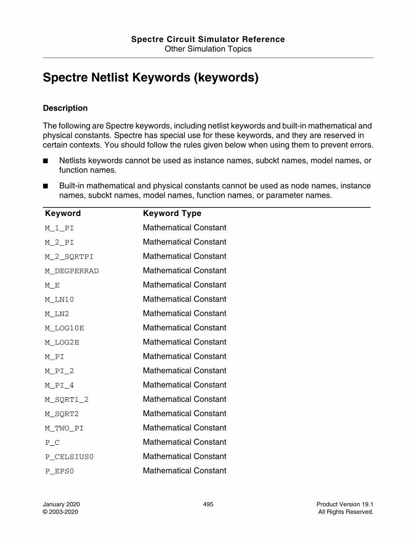
Spectre Circuit Simulator ReferenceOther Simulation Topics
January 2020 495 Product Version 19.1© 2003-2020 All Rights Reserved.
Spectre Netlist Keywords (keywords)
Description
The following are Spectre keywords, including netlist keywords and built-in mathematical and physical constants. Spectre has special use for these keywords, and they are reserved in certain contexts. You should follow the rules given below when using them to prevent errors.
■ Netlists keywords cannot be used as instance names, subckt names, model names, or function names.
■ Built-in mathematical and physical constants cannot be used as node names, instance names, subckt names, model names, function names, or parameter names.
Keyword Keyword Type
M_1_PI Mathematical Constant
M_2_PI Mathematical Constant
M_2_SQRTPI Mathematical Constant
M_DEGPERRAD Mathematical Constant
M_E Mathematical Constant
M_LN10 Mathematical Constant
M_LN2 Mathematical Constant
M_LOG10E Mathematical Constant
M_LOG2E Mathematical Constant
M_PI Mathematical Constant
M_PI_2 Mathematical Constant
M_PI_4 Mathematical Constant
M_SQRT1_2 Mathematical Constant
M_SQRT2 Mathematical Constant
M_TWO_PI Mathematical Constant
P_C Mathematical Constant
P_CELSIUS0 Mathematical Constant
P_EPS0 Mathematical Constant
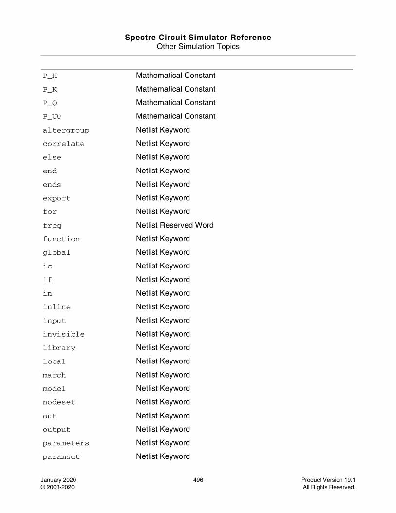
Spectre Circuit Simulator ReferenceOther Simulation Topics
January 2020 496 Product Version 19.1© 2003-2020 All Rights Reserved.
P_H Mathematical Constant
P_K Mathematical Constant
P_Q Mathematical Constant
P_U0 Mathematical Constant
altergroup Netlist Keyword
correlate Netlist Keyword
else Netlist Keyword
end Netlist Keyword
ends Netlist Keyword
export Netlist Keyword
for Netlist Keyword
freq Netlist Reserved Word
function Netlist Keyword
global Netlist Keyword
ic Netlist Keyword
if Netlist Keyword
in Netlist Keyword
inline Netlist Keyword
input Netlist Keyword
invisible Netlist Keyword
library Netlist Keyword
local Netlist Keyword
march Netlist Keyword
model Netlist Keyword
nodeset Netlist Keyword
out Netlist Keyword
output Netlist Keyword
parameters Netlist Keyword
paramset Netlist Keyword
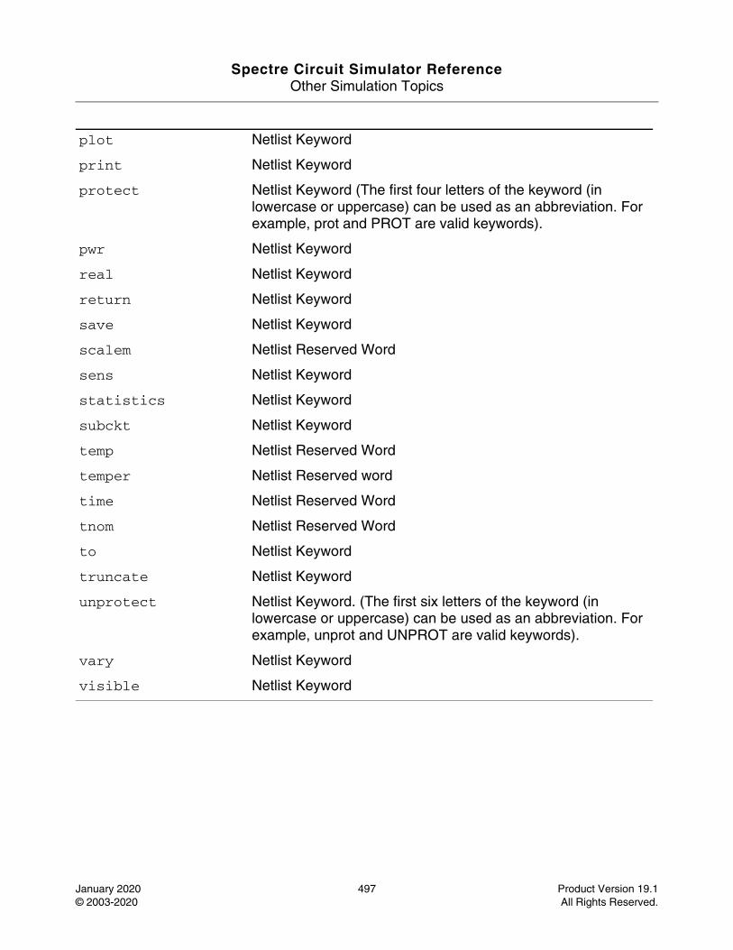
Spectre Circuit Simulator ReferenceOther Simulation Topics
January 2020 497 Product Version 19.1© 2003-2020 All Rights Reserved.
plot Netlist Keyword
print Netlist Keyword
protect Netlist Keyword (The first four letters of the keyword (in lowercase or uppercase) can be used as an abbreviation. For example, prot and PROT are valid keywords).
pwr Netlist Keyword
real Netlist Keyword
return Netlist Keyword
save Netlist Keyword
scalem Netlist Reserved Word
sens Netlist Keyword
statistics Netlist Keyword
subckt Netlist Keyword
temp Netlist Reserved Word
temper Netlist Reserved word
time Netlist Reserved Word
tnom Netlist Reserved Word
to Netlist Keyword
truncate Netlist Keyword
unprotect Netlist Keyword. (The first six letters of the keyword (in lowercase or uppercase) can be used as an abbreviation. For example, unprot and UNPROT are valid keywords).
vary Netlist Keyword
visible Netlist Keyword
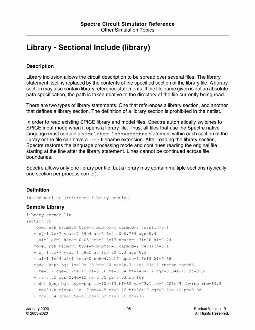
Spectre Circuit Simulator ReferenceOther Simulation Topics
January 2020 498 Product Version 19.1© 2003-2020 All Rights Reserved.
Library - Sectional Include (library)
Description
Library inclusion allows the circuit description to be spread over several files. The library statement itself is replaced by the contents of the specified section of the library file. A library section may also contain library reference statements. If the file name given is not an absolute path specification, the path is taken relative to the directory of the file currently being read.
There are two types of library statements. One that references a library section, and another that defines a library section. The definition of a library section is prohibited in the netlist.
In order to read existing SPICE library and model files, Spectre automatically switches to SPICE input mode when it opens a library file. Thus, all files that use the Spectre native language must contain a simulator lang=spectre statement within each section of the library or the file can have a .scs filename extension. After reading the library section, Spectre restores the language processing mode and continues reading the original file starting at the line after the library statement. Lines cannot be continued across file boundaries.
Spectre allows only one library per file, but a library may contain multiple sections (typically, one section per process corner).
DefinitionInside netlist (reference library section)
Sample Librarylibrary corner_libsection tt model nch bsim3v3 type=n mobmod=1 capmod=2 version=3.1 + xj=1.7e-7 vsat=7.99e4 at=3.6e4 a0=0.799 ags=0.4 + a1=0 a2=1 keta=-0.05 nch=2.8e17 ngate=1.31e20 k1=0.74 model pch bsim3v3 type=p mobmod=1 capmod=2 version=3.1 + xj=1.7e-7 vsat=1.38e5 at=1e5 a0=1.3 ags=0.3 + a1=1.1e-4 a2=1 keta=0 nch=4.1e17 ngate=7.6e19 k1=0.88 model knpn bjt is=10e-13 bf=170 va=58.7 ik=5.63e-3 rb=rbn rbm=86 + re=3.2 cje=0.25e-12 pe=0.76 me=0.34 tf=249e-12 cjc=0.34e-12 pc=0.55 + mc=0.35 ccs=2.4e-12 ms=0.35 ps=0.53 rc=169 model kpnp bjt type=pnp is=10e-13 bf=60 va=43.1 ik=0.206e-3 rb=rbp rbm=64.3 + re=33.8 cje=0.16e-12 pe=0.5 me=0.26 tf=36e-9 cjc=0.72e-12 pc=0.58 + mc=0.34 ccs=2.5e-12 ps=0.53 ms=0.35 rc=276
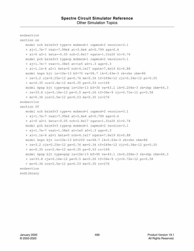
Spectre Circuit Simulator ReferenceOther Simulation Topics
January 2020 499 Product Version 19.1© 2003-2020 All Rights Reserved.
endsectionsection ss model nch bsim3v3 type=n mobmod=1 capmod=2 version=3.1 + xj=1.7e-7 vsat=7.99e4 at=3.6e4 a0=0.799 ags=0.4 + a1=0 a2=1 keta=-0.05 nch=2.8e17 ngate=1.31e20 k1=0.74 model pch bsim3v3 type=p mobmod=1 capmod=2 version=3.1 + xj=1.7e-7 vsat=1.38e5 at=1e5 a0=1.3 ags=0.3 + a1=1.1e-4 a2=1 keta=0 nch=4.1e17 ngate=7.6e19 k1=0.88 model knpn bjt is=10e-13 bf=70 va=58.7 ik=5.63e-3 rb=rbn rbm=86 + re=3.2 cje=0.25e-12 pe=0.76 me=0.34 tf=249e-12 cjc=0.34e-12 pc=0.55 + mc=0.35 ccs=2.4e-12 ms=0.35 ps=0.53 rc=169 model kpnp bjt type=pnp is=10e-13 bf=30 va=43.1 ik=0.206e-3 rb=rbp rbm=64.3 + re=33.8 cje=0.16e-12 pe=0.5 me=0.26 tf=36e-9 cjc=0.72e-12 pc=0.58 + mc=0.34 ccs=2.5e-12 ps=0.53 ms=0.35 rc=276endsectionsection ff model nch bsim3v3 type=n mobmod=1 capmod=2 version=3.1 + xj=1.7e-7 vsat=7.99e4 at=3.6e4 a0=0.799 ags=0.4 + a1=0 a2=1 keta=-0.05 nch=2.8e17 ngate=1.31e20 k1=0.74 model pch bsim3v3 type=p mobmod=1 capmod=2 version=3.1 + xj=1.7e-7 vsat=1.38e5 at=1e5 a0=1.3 ags=0.3 + a1=1.1e-4 a2=1 keta=0 nch=4.1e17 ngate=7.6e19 k1=0.88 model knpn bjt is=10e-13 bf=220 va=58.7 ik=5.63e-3 rb=rbn rbm=86 + re=3.2 cje=0.25e-12 pe=0.76 me=0.34 tf=249e-12 cjc=0.34e-12 pc=0.55 + mc=0.35 ccs=2.4e-12 ms=0.35 ps=0.53 rc=169 model kpnp bjt type=pnp is=10e-13 bf=90 va=43.1 ik=0.206e-3 rb=rbp rbm=64.3 + re=33.8 cje=0.16e-12 pe=0.5 me=0.26 tf=36e-9 cjc=0.72e-12 pc=0.58 + mc=0.34 ccs=2.5e-12 ps=0.53 ms=0.35 rc=276endsectionendlibrary

Spectre Circuit Simulator ReferenceOther Simulation Topics
January 2020 500 Product Version 19.1© 2003-2020 All Rights Reserved.
Tips for Reducing Memory Usage (memory)
Description
If you are facing an insufficient memory problem, try the following suggestions:
1. Try using a 64-bit executable if you are using the 32-bit one.
2. Try ulimit/unlimit command to adjust memory limitations.
3. Try another machine that has more memory, if hardware limit is the cause
4. Refer to spectre -h rfmemory, if you faced the problem during RF analyses.
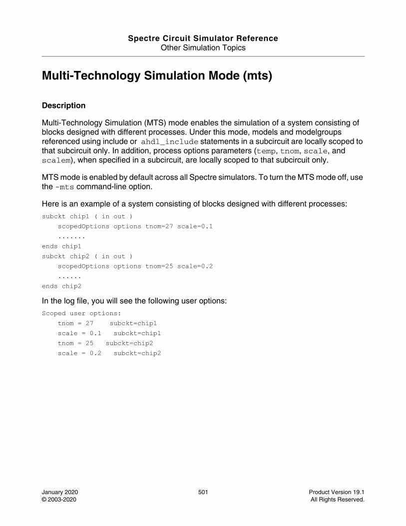
Spectre Circuit Simulator ReferenceOther Simulation Topics
January 2020 501 Product Version 19.1© 2003-2020 All Rights Reserved.
Multi-Technology Simulation Mode (mts)
Description
Multi-Technology Simulation (MTS) mode enables the simulation of a system consisting of blocks designed with different processes. Under this mode, models and modelgroups referenced using include or ahdl_include statements in a subcircuit are locally scoped to that subcircuit only. In addition, process options parameters (temp, tnom, scale, and scalem), when specified in a subcircuit, are locally scoped to that subcircuit only.
MTS mode is enabled by default across all Spectre simulators. To turn the MTS mode off, use the -mts command-line option.
Here is an example of a system consisting of blocks designed with different processes:
subckt chip1 ( in out )scopedOptions options tnom=27 scale=0.1.......
ends chip1subckt chip2 ( in out )
scopedOptions options tnom=25 scale=0.2......
ends chip2
In the log file, you will see the following user options:
Scoped user options:tnom = 27 subckt=chip1scale = 0.1 subckt=chip1tnom = 25 subckt=chip2scale = 0.2 subckt=chip2
Spectre Circuit Simulator ReferenceOther Simulation Topics
January 2020 502 Product Version 19.1© 2003-2020 All Rights Reserved.
Node Sets (nodeset)
Description
The nodeset statement is used to provide an initial guess for nodes in DC analysis or to provide the initial condition calculation for transient analysis. The nodeset statement can occur multiple times in the input and the information provided in all the occurrences is collected. For more information, read the description of DC analysis.
Definitionnodeset <X>[:param]=value
This statement takes a list of signals with the state information to the DC and transient analyses. X can be a node, a component, or a subcircuit, and param can be either a component output parameter or a terminal index. To specify a class of signals, use the pattern matching character * for any string and ? for any character.
The concept of nodes for the statement has been generalized to signals, where a signal is a value associated with a topological node of the circuit or some other unknown that is solved by the simulator, such as the current through an inductor or the voltage of the internal node in a diode. Topological nodes can be either at the top-level or in a subcircuit.
For example:
nodeset 7=0 out=1 OpAmp1.comp=5 L1:1=1.0u
where, 7=0 implies that node 7 should be about 0V, node out should be about 1V, node comp in subcircuit OpAmp1 should be about 5V, and the current through the first terminal of L1 should be about 1uA.
For more information, refer to The ic and nodeset Statements in the Spectre Classic Simulator, Spectre APS, Spectre X, and Spectre XPS User Guide.
Spectre Circuit Simulator ReferenceOther Simulation Topics
January 2020 503 Product Version 19.1© 2003-2020 All Rights Reserved.
Parameter Soft Limits (param_limits)
Description
The parameter values passed to Spectre components and analysis are subject to both hard and soft limits. If you set a parameter to a value that violates a hard limit, such as giving z0=0 to a transmission line, Spectre issues an error message and quits. If the given parameter value violates a soft limit, a warning is issued, but Spectre uses the value of the component as given. Hard limits are used to prevent you from using values that would cause Spectre to fail or put a model in an invalid region. Soft limits are used to call attention to unusual parameter values that might have been given mistakenly. If a parameter value violates a soft limit, a message similar to one of the following sample messages is printed:
Parameter rb has the unusually small value of 1uOhms.
or
Parameter rb has the unusually large value of 1MOhms.
Spectre has built-in soft limits on a few parameter values. However, it is possible for you to override these limits or to provide limits on parameters that do not have built-in limits. To do so, create a parameter range limits file and run Spectre by providing the name of the file after the +param command-line option. For example:
spectre +param limits-file input-file
Limits are specified using the following syntax:
[PrimitiveName] [model] [LowerLimit <[=]] [|]Param[|] [<[=] UpperLimit]
The limits can be given as strict (using <=) or nonstrict (using <). If the limits are strict, there can be no space between < and =. The limits for one parameter are given on one line. There is no way of continuing the specification of the limits for a parameter over more than one line. If a parameter is specified more than once, the limits specified at last override the earlier limits. The primitive name must be a Spectre primitive name, and not a name used for SPICE compatibility. For example, mos3 must be used instead of mos. Parameter limits can be written using Spectre native mode metric scale factors. Therefore, a limit of f <= 1.0e6 can also be written as f <= 1M.
Examples
mos3 0.5u <= l <= 100u0.5u <= w0 < as <= 1e-80 < ad <= 1e-8
model |vto| <= 3
Spectre Circuit Simulator ReferenceOther Simulation Topics
January 2020 504 Product Version 19.1© 2003-2020 All Rights Reserved.
It is not necessary to specify the primitive name each time. If the primitive name is not specified, it is assumed to be the same as the previous parameter. Upper and lower limits may be specified, but if these are not specified, there is no limit on the parameter value. Therefore, in the example, if w is less than 0.5um, a warning is issued, but there is no limit on how large w can be. If a parameter is mentioned, but no limits are given, all limits are disabled for that parameter. Limits are placed on model parameters by giving the model keyword. If the model keyword is not given, the limits are applied to instance parameters. Notice that you can also place upper or lower limits on the absolute value of a parameter. For example:
resistor 0.1 < |r| < 1M
indicates that the absolute value of r should be greater than 0.1 Ohm and less than 1 MOhm. There can be no spaces between the absolute value symbols and the parameter name.
Examples
1 <= x < 0.51 <= y <= 11 < z < 1
In the first case, the lower bound is larger than the upper bound, which indicates that the range of x is all real numbers, except those from 0.5 to 1, including 0.5. The limits are applied separately, therefore, x must be both greater than or equal to 1 (1 <= x) and less than 0.5 (x < 0.5). The second case specifies that y should be 1, and the third case specifies that z should not be 1.
It is possible to specify limits for any scalar parameter that takes a real number, an integer, or an enumeration. To specify the limits of a parameter that takes enumerations, use the indexes associated with the enumerations. For example, consider the region parameter of the bjt. There are four possible regions: off, fwd, rev, and sat (see spectre -help bjt). Each enumeration is assigned a number starting at 0 and counting up. Therefore, off=0, fwd=1, rev=2, and sat=3. The specification bjt 3 <= region <= 1 indicates that a warning should be printed if region=rev because the conditions (3 <= region) and (region <= 1) exclude only (region=2) and region 2 is rev.
It is possible to read a parameter limits file from within another file. To do so, use an include statement. For example,
include "filename"
temporarily suspends the reading of the current file until the contents of filename have been read. Include statements may be nested arbitrarily deep with the condition that the operating system may limit the number of files that Spectre may have open at once. Paths in file names are taken to be relative to the directory that contains the current file, and not from the directory from which Spectre was run.
Spectre Circuit Simulator ReferenceOther Simulation Topics
January 2020 505 Product Version 19.1© 2003-2020 All Rights Reserved.
Spectre can be instructed to always read a parameter limits file by using the SPECTRE_DEFAULTS environment variable. For example, if you put the following in you shell initialization file (.profile for sh, .cshrc for csh)
setenv SPECTRE_DEFAULTS "+param /cds/etc/spectre/param.lmts"
Spectre always reads the specified limits file.
For more information, see Selecting Limits for Parameter Value Warning Messages in the Spectre Classic Simulator, Spectre APS, Spectre X, and Spectre XPS User Guide.
Spectre Circuit Simulator ReferenceOther Simulation Topics
January 2020 506 Product Version 19.1© 2003-2020 All Rights Reserved.
Netlist Parameters (parameters)
Description
The Spectre native netlist language allows parameters to be specified and referenced in the netlist, both at the top-level scope and within subcircuit declarations (run spectre -h subckt for more details on parameters within subcircuits).
Definitionparameters <param=value> [param=value]...
Examples:
simulator lang=spectreparameters p1=1 p2=2 // declare some parametersr1 (1 0) resistor r=p1 // use a parameter, value=1r2 (1 0) resistor r=p1+p2 // use parameters in an expression, value=3x1 s1 p4=8 // "s1" is defined below, pass in value 8 for "p4"subckt s1parameters p1=4 p3=5 p4=6 // note: no "p2" here, p1 "redefined"r1 (1 0) resistor r=p1 // local definition used: value=4r2 (1 0) resistor r=p2 // inherit from parent(top-level) value=2r3 (1 0) resistor r=p3 // use local definition, value=5r4 (1 0) resistor r=p4 // use passed-in value, value=8r5 (1 0) resistor r=p1+p2/p3 // use local+inherited/local = (4+2/5) = 4.4endstime_sweep tran start=0 stop=(p1+p2)*50e-6 // use 5*50e-6 = 150 usdc_sweep dc param=p1 values=[0.5 1 +p2 (sqrt(p2*p2)) ] // sweep p1
Parameter Declaration
Parameters can be declared anywhere in the top-level circuit description or on the first line of a subcircuit definition. Multiple parameters can be declared on a single line. When parameters are declared in the top-level, their values must be specified. When parameters are declared within subcircuits, their default values are optionally specified.
Parameter Inheritance
Subcircuit definitions inherit parameters from their parent (enclosing subcircuit definition or top-level definition). This inheritance continues across all levels of nesting of subcircuit
Spectre Circuit Simulator ReferenceOther Simulation Topics
January 2020 507 Product Version 19.1© 2003-2020 All Rights Reserved.
definitions, that is, if a subcircuit s1 is defined, which itself contains a nested subcircuit definition s2, then any parameters accessible within the scope of s1 are also accessible from within s2. In addition, any parameters declared within the top-level circuit description are also accessible within both s1 and s2. However, any subcircuit definition can redefine a parameter that it has inherited. In this case, if no value is specified for the redefined parameter when the subcircuit is instantiated, the redefined parameter uses the locally defined default value, rather than inheriting the actual parameter value from the parent.
Parameter Referencing
Spectre netlist parameters can be referenced anywhere. A numeric value is normally specified on the right-hand side of an "=" sign or within a vector, where the vector itself is on the right-hand side of an "=" sign. This includes referencing of parameters in expressions (run spectre -h expressions for more details on netlist expression handling), as indicated in the preceding examples. You can use expressions containing parameter references when specifying device or analysis instance parameter values (for example, specifying the resistance of a resistor or the stop time of a transient analysis, as outlined in the preceding example), when specifying model parameter values in model cards (for example, specifying bf=p1*0.8 for a bipolar model parameter bf), or when specifying initial conditions and nodesets for individual circuit nodes.
Altering/Sweeping Parameters
Just as certain Spectre analyses (for example, sweep, alter, ac, dc, noise, sp, xf) can sweep device instance or model parameters, they can also sweep netlist parameters. Run spectre -h <analysis> to view the details for any of these analyses, where <analysis> is the analysis of interest.
Temperature as a Parameter
You can use the reserved parameters temp and tnom anywhere an expression can be used, including within expressions and user-defined functions. The temp parameter always represents the simulator (circuit) temperature, and tnom always represents the measurement temperature. All expressions involving temp or tnom are re-evaluated everytime the circuit temperature or measurement temperature changes.
You can also alter or sweep the temp and tnom parameters by using any of the techniques available for altering or sweeping the netlist or subcircuit parameters (with the exception of s).
This capability allows you to write temperature dependent models, for example, by using temp in an equation for a model or an instance parameter. For example:
r1 1 0 res r=(temp-tnom)*15+10k // temp is temperature
Spectre Circuit Simulator ReferenceOther Simulation Topics
January 2020 508 Product Version 19.1© 2003-2020 All Rights Reserved.
o1 options temp=55 // causes a change in above resistor r1
Reserved Parameters
The following parameters are reserved and must not be declared as either top-level parameters or subcircuit parameters: temp, tnom, scale, scalem, freq, time.
For additional information, refer to the Parameters Statement section in the Spectre Classic Simulator, Spectre APS, Spectre X, and Spectre XPS User Guide.
Spectre Circuit Simulator ReferenceOther Simulation Topics
January 2020 509 Product Version 19.1© 2003-2020 All Rights Reserved.
Parameter Set - Block of Data (paramset)
Description
A parameter set is a block of data, which can be referenced by a sweep analysis. Within a paramset, the first row contains an array of top-level netlist parameters. All other rows contain numbers that are used to alter the value of the parameters during the sweep. Each row represents an iteration of the sweep. This data should be bound within braces. The opening brace is required at the end of the line defining the paramset. The paramset cannot be defined within subcircuits or cannot be nested.
Definition<Name> paramset {}
Example: data paramset { p1 p2 p3 1.1 2.2 3.3 4.4 5.5 6.6 }
Spectre Circuit Simulator ReferenceOther Simulation Topics
January 2020 510 Product Version 19.1© 2003-2020 All Rights Reserved.
The postlayout command line option (postlayout)
Description
This option enables various technologies to speed up post-layout simulation including RC reduction, efficient coupling capacitor handling, advanced DC algorithms optimized for large post-layout circuits, along with other advanced numerical techniques.
The +postlayout option delivers best simulation performance, with acceptable accuracy, for custom digital designs, memory designs, and analog/mixed-signal designs where high simulation precision is not required.
+postlayout=hpa provides higher simulation precision for analog /mixed-signal designs.
+postlayout=upa delivers the ultimate post-layout simulation accuracy, similar to +postlayout=hpa, but with RC reduction completely disabled.
Even though not recommended, +rcnet_fmax=N command-line option can be used to adjust the simulation accuracy associated with +postlayout. The unit for N is in GHz and the default value is 125. N=25 is considered aggressive, whereas N=250 is considered conservative. The +rcnet_fmax option not only controls RC reduction accuracy with any local RC net, but also defines the accuracy/performance trade-off of other non-reduction based techniques. rcnet_fmax is available as a Spectre command-line argument or option.
+postlayout=legacy/legacy_rf options provide backward compatibility with the +parasitics/+parasitics=rf options respectively. Accuracy of the +postlayout=legacy option can also be adjusted using the rcr_fmax option.
Definition +postlayout in the command line
Spectre Circuit Simulator ReferenceOther Simulation Topics
January 2020 511 Product Version 19.1© 2003-2020 All Rights Reserved.
Pspice_include File (pspice_include)
Description
Spectre supports PSPICE netlist format targeting to include PCB components that are modeled in PSPICE format. This solution does not support PSPICE designs. A top-level netlist and control statement needs to be defined in Spectre or SPICE format. The recommended approach is to define a subckt in PSPICE netlist format and to instantiate the subckt in a Spectre netlist.
A PSPICE netlist can be included in Spectre by using the following include statements.
pspice_include <file> (Spectre format) .pspice_include <file> (SPICE format)
PSPICE file inclusion allows the circuit description to be spread over several files. The include statement itself is replaced by the contents of the file named. If the name given is not an absolute path specification, it is taken relative to the directory of the file currently being read.
The PSPICE file defined in the pspice_include statement is required to contain only PSPICE netlist format. A PSPICE file may also contain include statements such as .inc or .lib to include other PSPICE files. The pspice_include statement cannot be used in a PSPICE netlist.
When Spectre-simulator opens a pspice_include file then it automatically switches to PSPICE mode. When in PSPICE mode, all elements and device models used in the PSPICE netlist are simulated using PSPICE default values and equations. Switching from PSPICE mode to Spectre mode inside a PSPICE file is not supported. After reading the include file, Spectre restores the language processing mode to what it was before the file was included, and continues reading the original file starting at the line after the include statement. Lines cannot be continued across file boundaries.
Definition Pspice_include "filename"
Spectre Circuit Simulator ReferenceOther Simulation Topics
January 2020 512 Product Version 19.1© 2003-2020 All Rights Reserved.
Tips for Reducing Memory Usage with SpectreRF (rfmemory)
Description
Problem: How can you reduce memory usage when running SpectreRF simulations? What are the things that you need to be aware of?
Solution: The amount of swap/memory that Spectre/SpectreRF requires depends on the following:
■ The analysis type you are running (PSS, QPSS, transient, dc, and so on). PSS and QPSS can take up a lot of memory.
■ PSS and QPSS shooting can take up a lot of memory. If a reasonably small number of harmonics is needed for your circuit, then harmonic balance will require less memory than the shooting method, especially for systems with multiple input frequencies. More details are provided below.
■ The amount of memory required is roughly proportional to the number of nodes in the circuit. Remember that most device models have multiple nodes inside the model.
■ The number of nodes/nets you save has only a small effect on memory use and runtime. The number of nodes/nets you save does change the amount of disk space required to save the simulation result.
This help is broken into four sections; Shooting, Harmonic Balance, Small-Signal Analyses, and Envelope.
PSS analysis
The amount of memory required depends on the number of time points in the PSS solution. The number of time points in the solution depends on several factors.
■ If you increase the number of harmonics above 10, the minimum number of time points is 20*number of harmonics. Closely spaced input frequencies require a large number of harmonics to be calculated, and thus require large amount of memory.
For example, consider a system with 2.4GHz and 2.4GHz minus 1MHz, or 2.399GHz. To get to the second harmonic of 2.4 GHz requires 4,800 harmonics, which in turn requires 96,000 timepoints. This large number of timepoints would require a large amount of memory. For such systems, use harmonic balance (hb) instead.
Spectre Circuit Simulator ReferenceOther Simulation Topics
January 2020 513 Product Version 19.1© 2003-2020 All Rights Reserved.
■ Increasing the accuracy by selecting conservative or by reducing the value of reltol and/or vabstol has the effect of producing more timepoints. A rough estimate is that for every power of 10 smaller you set reltol, five times as many timepoints will be produced.
■ Setting a small maxstep compared to the PSS period or setting maxacfreq above 40*PSS beat frequency will produce more timepoints. Unless you see warning messages in the small-signal analyses that instruct you to set maxacfreq, it is better to leave maxstep and maxacfreq unspecified and set conservative and/or a smaller values for reltol and vabstol. This will have the effect of taking more timesteps only in areas of transition, and longer timesteps where the waveform is static.
■ The waveforms produced by the circuit can also affect the number of timepoints. If there are fast transitions in your circuit, the timestep will be reduced in the areas of the transitions to preserve high accuracy of the simulation.
QPSS analysis
■ QPSS Analysis should be used only for nonlinear circuits like sampling circuits or switched-capacitor circuits. For other circuits, use hb instead.
■ QPSS analysis runs a series of PSS analyses that depend on the number of moderate tones and the number of harmonics set in each moderate tone. Each PSS analysis is one cycle of the signal designated as Large in the QPSS Choosing Analyses Form with all of the input signals applied. The number of harmonics for the large tone and the accuracy settings mentioned above set the number of timepoints for each PSS analysis. The number of PSS analyses (called transient integrations in the Spectre output window) is (2*number of harmonics on moderate tone 1)+1 * (2*number of harmonics on moderate tone 2)+1 and continuing for more input tones. Assuming three harmonics on two moderate tones the number of PSS analyses is (2*3)+1 * (2*3)+1, or 49 total PSS analyses.
Harmonic Balance analysis
■ The amount of memory required depends primarily on the number of harmonics in the solution. Setting accuracy options will have only a small effect on the memory size.
■ The number of harmonics in the solution depends on the number of input frequencies, the number of harmonics to be calculated for each frequency, and whether frequency cuts are used. The default number of harmonics is calculated as follows: (2*number of harmonics on tone 1)+1 * (2*number of harmonics on tone 2)+1 * (2*number of harmonics on tone 3)+1 and increasing if more inputs are present.
■ For a single input and 7 harmonics, (2*7)+1 or 15 harmonics are needed. If there are two inputs with 7 and 3 harmonics set, then 15*7 or 105 harmonics are needed by default.
Spectre Circuit Simulator ReferenceOther Simulation Topics
January 2020 514 Product Version 19.1© 2003-2020 All Rights Reserved.
■ Frequency cuts can reduce the number of harmonics that needs to be calculated. For more information on frequency cuts, see the SpectreRF User Guide, Chapter 3. If you want to use frequency cuts, the safest general recommendation is to use the funnel cut with maximum order set between 5 and 9. Use the smallest value of maximum order that produces accurate results.
Small-Signal analysis
Once the PSS, QPSS or HB analysis runs, additional memory is required to run the small-signal analyses. The amount of memory is difficult to predict because different analyses require different amounts of memory. As a rough estimate, the amount of memory might double or triple shortly after the small-signal analysis starts. For shooting method, setting maximum sidebands above about 50 will require more memory. For harmonic balance, the memory depends on the number of harmonics present in the harmonic balance large-signal analysis.
Envelope method
■ Envelope method has two engines; shooting and harmonic balance. Harmonic balance is recommended because it always requires less memory and time to run, and it has a fast envelope level 1 analysis available.
■ Transistor-level and Level 1 harmonic balance envelope is harmonic balance with a transient engine. The memory required is only slightly more than a single-tone hb analysis with the same number of harmonics that are used in envelope.
■ For transistor-level envelope, a harmonic balance simulation is done at each time in the envelope analysis. For fast envelope, a series of harmonic balance analyses are run at the start to characterize the circuit, and then a behavioral simulation runs after that.
You can consider using the following strategies:
1. Never set useprobes=yes for SpectreRF simulations. It can cause large errors in the small signal Pxx analyses. Use useprobes for linear AC analysis only.
2. Check to see how much swap and memory you have on your computer. Greater than 2GB RAM and 5GB swap is recommended.
A 64-bit Spectre executable is available with MMSIM releases. This means that there is no 4GB process size limit, which was the case with the 32-bit Spectre executable. This allows much larger circuits to be simulated. If the memory required for simulation is larger than the amount of RAM installed on the machine, the machine will start swapping which dramatically slows the simulation and may cause the simulation to almost completely stop because the disk is so active. The best solution is more RAM on the system. A

Spectre Circuit Simulator ReferenceOther Simulation Topics
January 2020 515 Product Version 19.1© 2003-2020 All Rights Reserved.
partial solution for shooting only is to use the swap file option described below. At least one large machine should be available for post-parasitic simulations to complete successfully without swapping.
3. If you are using shooting and your machine starts to swap, consider setting the swapfile option. This option writes much of the data from pss and qpss shooting large-signal analyses to disk files on your system. Large files will be produced. If the disk is local to the machine that is running the simulation, this will speed things up slightly compared to swapping in the operating system because Spectre manages the disk operations to put the data in concentric cylinders on the machine, but it is still fundamentally much slower than running on a machine that has more RAM. If the disk is a networked drive, the network latency may actually slow the simulation down. Only setting the option will allow runtime comparisons. Harmonic balance does not have this option.
4. For post-layout simulations, consider using RC reduction to reduce the number of nodes in the circuit.
5. Choose the largest possible PSSfund frequency. A higher fundamental frequency (PSSfund) yields a shorter simulation time.
6. If you have two or more closely spaced frequencies, use harmonic balance instead of PSS.
7. When shooting is used, try to use 10 harmonics or less and don't set the macacfreq or maxstep options unless you get errors from the small-signal analyses. Don't over-tighten the accuracy options.
8. In harmonic balance, use the smallest number of harmonics you can that produce accurate results, and consider using frequency cuts for circuits with multiple input frequencies.
9. If you are using names in harmonic balance or if you are using qpss, make sure that all the sources at the same frequency have the same Frequency Name 1 property.
Note: This is NOT the Instance Name property which all must be unique.
Setting the Frequency Name 1 property to the same name signifies to Spectre to treat those sources as a single frequency. For example, imagine you have differential RF inputs at 2.4GHz and I and Q differential LOs at 2.41GHz. There are two RF sources and four LO sources. Both RF sources have the same frequency and all four LO sources have the same frequency. As an example, you might set the RF sources to have the frequency name 1 property "RF" and all the LO sources "LO." In this case, Spectre will solve for two different frequencies as it should. If you named the sources RF1, RF2, LO1, LO2, LO3, and LO4, Spectre will consider these as all separate input frequencies. This becomes a six-tone simulation instead of a two-tone simulation and will take much longer to run and require hugely more memory.

Spectre Circuit Simulator ReferenceOther Simulation Topics
January 2020 516 Product Version 19.1© 2003-2020 All Rights Reserved.
10. In shooting small-signal analyses try to keep the number of sidebands to about 50 or less. More than 50 sidebands will require more memory. Full spectrum pnoise requires less memory than traditional pnoise. In hb small-signal analyses, leave the number of sidebands field unspecified and use the smallest number of harmonics in the harmonic balance analysis that you can that also produce accurate results.
11. In envelope analysis, use the smallest number of harmonics you can to get an accurate result.
12. Run Spectre when no other users are using the same machine so all the RAM is available for your use.
13. In harmonic balance, run the memory estimator on the circuit to have an understanding of the rough memory consumption.
Spectre Circuit Simulator ReferenceOther Simulation Topics
January 2020 517 Product Version 19.1© 2003-2020 All Rights Reserved.
Output Selections (save)
Description
The save statement indicates that the values of specific nodes or signals must be saved in the output file. It works in conjunction with the save parameter for most analyses. The output file is written in Cadence Waveform Storage Format (WSF), Cadence Parameter Storage Format (PSF), or in Nutmeg/SPICE3 format, which is controlled by a command-line argument or a global option (see the options statement). An appropriate postprocessor should be used to view the output, generate plots, or do any further processing.
Definitionsave X[:param] ... [depth=num] [sigtype=node|dev|subckt|all] [devtype=component_type] [subckt=subckt_master] [exclude=[wildcard_patterns_list]] [compression=no|yes] [ports=yes|no] [filter=none|rc] [probelvl=num] time_window=[t1 t2 t3 t4 ...]
The save statement takes a list of signals followed by some optional parameters as an argument. X can be a node, a component, or a subcircuit and param can be a component output parameter or a terminal index. To specify a class of signals, use the pattern matching character * for any string and ? for any character. The parameters control pattern matching. depth controls the depth of pattern matching and, by default, matches signals at all hierarchical levels. sigtype with the default value node defines the type of X. If sigtype=all, X can be a node, a component, or a subcircuit. devtype defines the component type and has no default value. subckt is used to save signals that are contained only in instances of a given subcircuit master. The signals matching a pattern from the list specified with exclude are not saved. When subckt is given, the wildcard patterns in the save statement and the depth of pattern matching must be relative to the subcircuit master.
The concept of nodes for the save statement is generalized to signals where a signal is a value associated with a topological node of the circuit or some other unknown that is solved by the simulator, such as the current through an inductor or the voltage of the internal node in a diode. Topological nodes can be at the top level or in the subcircuit.
By default, the waveforms defined in the save statement are not compressed. Compression can be enabled globally for selected hierarchy levels in the transient statement (compression, complvl). Compression can also be enabled or disabled individually for each save statement. The compression settings in the save statement overwrite the compression settings in the transient statement.
time_window is used to specify the output time interval for transient analysis.Signals in [t1 t2] and [t3 t4]... are outputted.
Spectre Circuit Simulator ReferenceOther Simulation Topics
January 2020 518 Product Version 19.1© 2003-2020 All Rights Reserved.
The ports parameter saves the subckt ports names as well if yes is specified. The default value is no. The filter parameter works with wildcarding to filter out the nodes that connect only to parasitics, if rc is specified. The default value is none.
To probe terminal currents hierarchically at a specified depth, specify the depth using the probelvl option to obtain the terminal current for all terminals connected within that depth.
For example:
save 7 out OpAmp1.comp M1:currents D3:oppoint L1:1 R4:pwr
specifies that node 7, node out, node comp in subcircuit OpAmp1, the currents through the terminals of M1, the oppoint information for diode D3, the current through the first terminal of L1, and the instantaneous power dissipated by R4 should be saved. These outputs are saved in addition to any outputs specified by the save parameter for the analysis.
To specify a component terminal current, specify the name of the component and the name or the index of the terminal separated by a colon. If currents is specified after the component and the colon, all the terminal currents for the component are saved unless the component has only two terminals, in which case only the current through the first terminal is saved. Current is positive if it enters the terminal flowing into the component.
If a component name is followed by a colon and oppoint, then the operating point information associated with the component is computed and saved. If the colon is followed by an operating point parameter name (see each component for list of operating point parameters), then the value of that parameter is output.
If only a component name is given, all available information about the component, including the terminal currents and the operating point parameter values, is saved.
Examples of pattern matching
■ save x*.*1 depth=3
Saves the voltages of all nodes from level 2 to level 3 whose name starts with x and ends in 1. For example, x1.n1, x1.x2.x3 but not x1.x2.x3.x4.
■ save x*.*1 sigtype=subckt
Saves all terminal currents of subcircuits from level 2 and above whose name starts with x and ends in 1. For example, x1.x21:2, x1.x2.x31:3.
■ save *:c devtype=bjt
Saves all collector currents
■ save * subckt=inv
Spectre Circuit Simulator ReferenceOther Simulation Topics
January 2020 519 Product Version 19.1© 2003-2020 All Rights Reserved.
Saves the voltages of all nodes in the instances of the subcircuit inv. For example, X1.n1 for an instance X1 of inv but not net091 at the top-level
■ save * exclude=[X1* X2*]
Saves the voltages of all nodes excluding the ones whose names start with X1 or X2. For example, net091, X0.res3.n2 but not X21.res3.n2.
■ save X1:A probelvl=3
Saves all terminal currents that are connected to terminal A of subcircuit X1, till the third-level depth.
■ save nA:currents probelvl=2
Saves the currents of all terminals that are connected to node nA, till the second-level depth.
■ save N1 time_window=[1m 2m 3m 4m]
Save node N1 from 1ms to 2ms and 3ms to 4ms.
■ save N1 time_window=[1m 2m]
save N1 time_window=[0.5m 2.5m 3m 4m]
Save node N1 from 0.5ms to 2.5ms and 3ms to 4ms
■ save N1 time_window = [ 1m 2m]
Saves all waveforms starting with N for entire simulation time, except N1 which is only saved from 1ms to 2ms.
For more information, see The Save Statement in the Spectre Classic Simulator, Spectre APS, Spectre X, and Spectre XPS User Guide.
Spectre Circuit Simulator ReferenceOther Simulation Topics
January 2020 520 Product Version 19.1© 2003-2020 All Rights Reserved.
Savestate - Recover (savestate)
Description
Savestate-Recover is a transient analysis feature. It is a replacement for Checkpoint-Restart capability.
The Checkpoint-Restart capability saves only the circuit solution for the timepoint at which the simulation is interrupted. Because there is no history information saved for the circuit, glitches, convergence issues, and inaccuracies can result when the simulation is resumed. The Savestate-Recover feature saves the complete state of the circuit, avoiding these issues.
Savestate-Recover provides the following functions:
■ You have the option to save circuit information at set intervals or at multiple points during transient analysis. If the simulation halts unexpectedly, you can restart transient analysis from any saved timepoint.
■ You can experiment with different accuracy settings over different transient time periods to obtain the optimal speed/accuracy trade-off.
Requirements for Savestate-Recover
When the simulation is restarted:
■ Netlist topology must not be changed. Topology changes or the removal/addition of nodes in the restore file causes a fatal error.
■ You may edit any netlist parameter as long as the circuit topology remains the same.
■ The stop time of Transient analysis must be larger than the timepoint corresponding to the savestate file.
■ Saved state file is binary and platform dependent.
■ Savestate-Recover works only for transient analysis and the transient analysis must not be within a Sweep or Monte Carlo analysis.
Use Model
■ Savestate
Savestate is enabled/disabled by using the spectre command, as follows.
spectre [+savestate ] [-savestate ] ...
Spectre Circuit Simulator ReferenceOther Simulation Topics
January 2020 521 Product Version 19.1© 2003-2020 All Rights Reserved.
where:
❑ +savestate - Enables Savestate. You may use +ss as an abbreviation for +savestate.
❑ -savestate - Disables Savestate. You may use -ss as an abbreviation for -savestate.
By default, savestate is on, and checkpoint is off.
■ Define saved time points and state file in the tran statement. For example:
DoTran tran stop=stoptime [ [saveperiod=time] | [saveclock=clock_time] | [savetime=[time1 time2...]] [savefile=file.srf]where:
❑ saveperiod, saveclock, and savetime define the time points to save the states.
❍ If saveperiod is given, Spectre generates a saved state file periodically based on the transient simulation time. Only the last saved state file is kept.
❍ If saveclock is given, Spectre generates a saved state file periodically based on real time (wall clock time). Its default value is 1800 seconds (30 minutes).
❍ If savetime is given, Spectre generates a saved state file on each specified time point.
❑ savefile defines where the saved states are written.
❍ If savefile is not defined, the default file name is %C.%A.srf.
Where %C is the input circuit file name, and %A is the analysis name.
If multiple save time points are given, That is,
analysisName tran stop=stoptime savetime=[time1 time2 ...] savefile=filename the saved state file is filename_at_time1, filename_at_time2, and so on.
Besides saving the state based on saveperiod or saveclock or savetime, if savestate is enabled, Spectre automatically saves the states to a file when an interrupt signal like QUIT, TERM, INT, or HUP is received for the first time. If interrupt signals are received more than once, Spectre quits immediately.
The saveclock, saveperiod, and savetime parameters should not be specified at the same time.
If more than one parameter is specified, Spectre reads them in the following order:
saveperiod
Spectre Circuit Simulator ReferenceOther Simulation Topics
January 2020 522 Product Version 19.1© 2003-2020 All Rights Reserved.
savetime saveclock
■ Recover
There are two ways to recover the simulation from the saved state file. The first is to define the recover file using the spectre command. The second is to define the recover file in a tran statement.
Defining the recover file in the tran statement is strongly recommended, especially if there are multiple analyses statements in the netlist.
■ Recover from command line
spectre [+recover[=filename]] [-recover] ... where:
❑ +recover - Enables recover. You may use +rec as an abbreviation for +recover.
❑ -recover - Disables recover. You may use -rec as an abbreviation for -recover.
■ Recover from the tran statement
analysisName tran recover=filename ... By default, recover is disabled.
■ Output Directory on Recovering
When recovering from a saved state in a Spectre run by using +recover=state_file in a command-line option, a new raw directory is created to avoid overwriting the previous simulation results. However, if recover=state_file is given in a tran statement, the default raw directory is used.
When defining recover=state_file in a tran statement, use a different tran name to avoid previous simulation results to be overwritten by the recovered results.
When a new raw directory is created, the raw directory name is the same as the default raw directory, except that an index (starting from 0) is suffixed to raw, such as *.raw#, where # is 0, 1, 2, and so on.
For example, in the first run, enter:
spectre input.scs Spectre saves the simulation state in a file on a time point. By default, input.raw directory is created.
When Spectre runs in recover mode:
spectre +recover=saved_state_file input.scs
Spectre Circuit Simulator ReferenceOther Simulation Topics
January 2020 523 Product Version 19.1© 2003-2020 All Rights Reserved.
a new raw directory named input.raw0 is created. The index of the raw directory is increased by one at each successive recover run. Another use model is that you define multiple transient-analysis runs in a netlist. In the first transient-analysis run, Spectre saves the simulation state on a time point.
In the next transient analysis run, simulation is continued from the saved time point. For example:
tran1 tran step=1ps stop=200ns savetime=[50ns] savefile=tran1_savetran2 tran step=1p stop=400ns recover=tran1_save_at_50.00nsIn this case, the default raw directory is used.
For more information, see Recovering From Transient Analysis Terminations section in the Spectre Classic Simulator, Spectre APS, Spectre X, and Spectre XPS User Guide.
Spectre Circuit Simulator ReferenceOther Simulation Topics
January 2020 524 Product Version 19.1© 2003-2020 All Rights Reserved.
Sensitivity Analyses (sens)
Description
Use the sens control statement to find partial or normalized sensitivities of the output variables with respect to component and instance parameters for the list of the analyses performed. Currently, DC and AC sensitivity analyses are supported. The results of the sensitivity analyses are stored in the output files written in Cadence Parameter Storage Format (PSF). The global option parameter senstype (see the options statement) is used to control the type of sensitivity being calculated. In addition, you can use +sensdata filename command-line argument or a global option (see the options statement) to direct sensitivity analyses results into a specified ASCII file.
Definitionsens (output_variables_list) to (design_parameters_list) for (analyses_list)
where:
■ output_variables_list = ovar1 ovar2, and so on.
■ design_parameters_list = dpar1, dpar2, and so on.
■ analyses_list = anal1 anal2 , and so on.
The list of design parameters may include valid instance and model parameters. You can also specify device instances or device models without a modifier. In this case, Spectre attempts to compute sensitivities with respect to all corresponding instance or model parameters. Caution should be exercised in using this option as warnings or errors may be generated if many instance and model parameters cannot be modified. If no design parameters are specified, then all the instance and model parameters are added. The list of the output variables for both AC and DC analyses may include node voltages and branch currents. For DC analyses, it may also include device instance operating point parameters.
Examples
■ sens (q1:betadc 2 Out) to (vcc:dc nbjt1:rb) for (analDC)
For this statement, DC sensitivities of betadc operating point parameter of transistor q1 and of nodes 2 and Out are computed with respect to dc voltage level of voltage source vcc and model parameter rb for the DC analysis analDC. The results are stored in the raw directory with the name in the format analysisname.sens.analysistype, that is, dc.sens.analDC.
■ sens (1 n2 7) to (q1:area nbjt1:rb) for (analAC)
Spectre Circuit Simulator ReferenceOther Simulation Topics
January 2020 525 Product Version 19.1© 2003-2020 All Rights Reserved.
For this statement, AC sensitivities of nodes 1, n2, and 7 are computed with respect to the area parameter of transistor q1 and the model parameter rb for each frequency of the AC analysis analAC. The results are stored in the output file analAC.sens.ac.
■ sens (1 n2 7) for (analAC)
For this statement, AC sensitivities of nodes 1, n2, and 7 are computed with respect to all instance and model parameters of all devices in the design for each frequency of the AC analysis analAC. The results are stored in the file in the format ac.sens.analAC.
■ sens (vbb:p q1:int_c q1:gm 7) to (q1:area nbjt1:rb) for (analDC1)
For this statement, DC sensitivities of branch current vbb:p, the operating point parameter gm of the transistor q1, the internal collector voltage q1:int_c and the node 7 voltage are computed with respect to instance parameter area for instance q1 and model parameter rb for model nbjt1.
For additional information, see Sensitivity Analysis in the Spectre Classic Simulator, Spectre APS, Spectre X, and Spectre XPS User Guide.
Spectre Circuit Simulator ReferenceOther Simulation Topics
January 2020 526 Product Version 19.1© 2003-2020 All Rights Reserved.
SpectreRF Summary (spectrerf)
Description
SpectreRF is an optional collection of analyses that are useful for circuits that are driven with a large periodic signal. Examples include mixers, oscillators, switched-capacitor filters, sample-and-holds, chopper stabilized amplifiers, frequency multipliers, frequency dividers, and samplers. They efficiently and directly compute the periodic and quasiperiodic steady-state solution of such circuits and are capable of computing large-and-small-signal behavior, including noise behavior. Therefore, SpectreRF is capable of computing the noise figure or intermodulation distortion of a mixer, the phase noise and harmonic distortion of an oscillator, and the frequency-response and noise behavior of a switched-capacitor filter. For more information about the SpectreRF analyses, run spectre -help analysisName where analysisName is pss, pac, pxf, pnoise, psp, pstb, qpss, qpac, qpxf, qpnoise, qpsp, envlp, hb, hbac, hbsp, or hbnoise.
Spectre Circuit Simulator ReferenceOther Simulation Topics
January 2020 527 Product Version 19.1© 2003-2020 All Rights Reserved.
Stitch Flow Use Model (stitch)
Description
Stitching enables Spectre APS to plug in the parasitic elements while simulation is running. Compared to the flat RC netlist and the hierarchical RC netlist approaches, the Stitching flow has the following advantages:
■ Reuse of the pre-layout simulation test-bench. There is no need to change the probe and the measure statements.
■ What-if analysis powered by selective stitching.
Spectre APS stitching is enabled by options.
Parasitic File Loading Parameters
■ spf
This option specifies the to-be-stitched DSPF file and its stitching scope. The syntax is spf="scope filename". The scope can be a subcircuit or an instance. When a subcircuit is specified as the scope, the DSPF file is stitched to all the instances of that subcircuit. When an instance is specified as the scope, the DSPF file is stitched to that instance only. Multiple DSPF files can be specified for stitching by using the option multiple times.
Example:
spf="mem mem.dspf"■ dpf
This option specifies the to-be-stitched DPF file and its stitching scope. The syntax is dpf="scope filename". The scope can be a subcircuit or an instance. When a subcircuit is specified as the scope, the DPF file is stitched to all the instances of that subcircuit. When an instance is specified as the scope, the DPF file is stitched to that instance only. Multiple DPF files can be specified for stitching by using the option multiple times.
Example:
dpf="X1.XPLL PLL.dpf" dpf="X1.XMEM mem.dpf"This means that the PLL.dpf file needs to be stitched to the X1.XPLL instance and the mem.dpf file needs to be stitched to the X1.XMEM instance.
■ spef
Spectre Circuit Simulator ReferenceOther Simulation Topics
January 2020 528 Product Version 19.1© 2003-2020 All Rights Reserved.
This option specifies the to-be-stitched SPEF file and its stitching scope. The syntax is spef="scope filename". The scope can be a subcircuit or an instance. When a subcircuit is specified as the scope, the SPEF file is stitched to all the instances of that subcircuit. When an instance is specified as the scope, the SPEF file is stitched to that instance only. Multiple SPEF files can be specified for stitching by using the option multiple times.
Example:
spef="adc a.spef"
Stitching Parsing Options
■ spfscale
This option specifies the scaling factor of all the elements in the parasitic files (DSPF/SPEF/DPF). For example, consider that the width of a device in the DSPF file is w=2. If spfscale=1.0e-6 is used, the actual width will be w=2.0e-6.
■ spfscalec
This option specifies the scaling factor of all the capacitors in the parasitic files (DSPF/SPEF/DPF). Example, suppose a capacitor's value in the DSPF file is 2. If spfscalec=1.0e-15 is used, the actual capacitor value will be 2.0e-15.
■ spfscaler
This option specifies the scaling factor of all the resistors in the parasitic files (DSPF/SPEF/DPF). Example, suppose a resistor’s value in the DSPF file is 2. If spfscaler=1.0e-3 is used, the actual capacitor value will be w=2.0e-3.
■ spfswapterm
This option specifies the swappable terminals of a subcircuit macro-model. The syntax is spfswapterm="terminal1 terminal2 subcktname".
Example:
spfswapterm="n1 n2 nch_mac"This indicates that terminals n1 and n2 of subckt nch_mac are swappable. In general, this is applicable to devices that are modeled by subcircuits. Multiple spfswapterm statements are supported.
■ spfxtorprefix
This option specifies the prefix in the names (devices and nets) in the DSPF/SPEF/DPF file. The device names in the prelayout netlist and the DSPF/SPEF file often do not
Spectre Circuit Simulator ReferenceOther Simulation Topics
January 2020 529 Product Version 19.1© 2003-2020 All Rights Reserved.
match. The spfxtorprefix option can be used to help match the device names. The syntax is spfxtorprefix="<substring> [<replace_substring>]".
Example:
spfxtorprefix="XM X"XX1/XM1 exists in the prelayout netlist but the corresponding device name in the DSPF file is XMX1/XM1. This option will change XM to X.
■ spfaliasterm
Sometimes the terminal names of devices in DSPF/SPEF/DPF files are different from those in the simulation model library. This happens often in the technology nodes that uses subcircuits to model devices. The syntax is spfaliasterm="<model|subckt> <prelayout_term1>=<spf_alias1> <prelayout_term2>=<spf_alias2>... <prelayout_termN>=<spf_aliasN>". Multiple statements are supported.
Example:
spfaliasterm="nfet_mac n1=D n2=G n3=S n4=B"This means that in subckt nfet_mac, terminal n1 corresponds to terminal D in the DSPF file, n1 corresponds to terminal G, n3 corresponds to terminal S and n4 corresponds to terminal B.
■ speftriplet
This option specifies the value that should be used for stitching in the SPEF file. This is effective only when the values in the SPEF file are represented by triplets (for instance, 0.325:0.41:0.495). Default value is 2. Possible values are 1, 2 and 3.
■ spfinstancesection
This option controls the backannotation of device parameters in the instance section of the DSPF file. If spfinstancesection is turned off, the instance section is ignored (that is, the device parameters are not changed during stitching). Default is on.
■ spfbusdelim = busdelim_schematic [busdelim_parasitic]
This option maps the bus delimiter between schematic netlist and parasitic file (i.e. DSPF, SPEF, or DPF). The option defines the bus delimiter in the schematic netlist, and optionally the bus delimiter in the parasitic file. By default, the bus delimiter of the parasitic file is taken from the parasitic file header (i.e. *|BUSBIT [], *|BUS_BIT [], or *|BUS_DELIMITER []). If the bus delimiter is not defined in the parasitic file header, you need to specify it by using the spfbusdelim option in schematic netlist.
Example:
Spectre Circuit Simulator ReferenceOther Simulation Topics
January 2020 530 Product Version 19.1© 2003-2020 All Rights Reserved.
❑ spfbusdelim=<> - A<1> in the schematic netlist is mapped to A_1 in the DSPF file, if the bus delimiter header in the DSPF file is "_".
❑ spfbusdelim=@ [] - A@1 in the schematic netlist is mapped to to A[1] in the DSPF file (the bus delimiter in DSPF header will be ignored).
■ spfinstarraydelim
This option specifies the supplemental bus delimiter, if more than one bus delimiter is used in the pre-layout netlist (usually for instance array indexing). This option is similar to spfbusdelim.
Selective Stitching Options
■ spfcnet
This option specifies the net that has its total capacitance stitched. All other parasitic components, say parasitic resistors, associated with this net are ignored. The full hierarchical names are required. Multiple statements are supported. Wildcards are supported.
Example:
spfcnet=X1.netA■ spfcnetfile
This option has the same functionality as spfcent.However, it accepts a text file in which all the C-only stitched nets are listed. Only one file can be specified. The syntax is spfcnetfile="filename". The format in the file is one line per net.
Example:
spfcnetfile="nets.tex"The format in the nets.tex is:
netAnetBnetC
■ spfrcnet
This option specifies the name of the net to be stitched with parasitic resistors and capacitors. The other nets are stitched with lumped total capacitances. Multiple statements are supported. Wildcards are supported and you can specify multiple nets. Full hierarchical names are required.
Example:
spfrcnet=netA
Spectre Circuit Simulator ReferenceOther Simulation Topics
January 2020 531 Product Version 19.1© 2003-2020 All Rights Reserved.
■ spfrcnetfile
This option has the same functionality as spfrcnet. However, it accepts a text file in which all the RC stitched nets are specified. Only one file can be specified. The syntax is spfrcnetfile="filename". The format in the file is one line per net.
Example:
spfrcnetfile="nets.tex"The format in the nets.tex is:
netAnetBnetC
■ spfnetcmin
This option allows you to select the net for stitching by the value of its total node capacitance. If a net’s total node capacitance exceeds spfnetcmin, all parasitics associated with the net are stitched correctly; otherwise, only the total capacitance is added to the net node.
Example:
spfnetcmin=1.0e-6■ spfskipnet
This option specifies the net to be skipped for stitching, that is, all parasitic components of the net are not stitched. Wildcards and multiple statements are supported.
Example:
spfskipnet=X1.nodeA■ spfskipnetfile
This option allows you to specify the nets to be skipped as a list in the text file called file_name. The syntax is spfskipnetfile="filename". Only one file can be specified. The format in the file is one line per net.
Example:
spfskipnetfile="nets.tex"nets.tex file format is:
netAnetBnetC
Spectre Circuit Simulator ReferenceOther Simulation Topics
January 2020 532 Product Version 19.1© 2003-2020 All Rights Reserved.
Stitching Message Control Option
■ spfmsglimit
This option specifies the maximum number of messages to be printed in the spfrpt file. The messages in the spfrpt file are categorized by their ID number (STITCH-ID). This option specifies the maximum number of messages for a particular type of messages by using their STITCH-ID. The syntax is spfmsglimit="number STITCH-ID_1 STITCH-ID_2". When STITCH-ID is not specified, the tool assigns the maximum message number limit to all messages categories (STITCH-IDs).
Example:
spfmsglimit="10 STITCH-0010"This tells the tool to print not more than 10 messages for the STITCH-0010 message category, in the meantime, for the other message categories, the default maximum limit of 50 messages will apply.
For additional information, see Parasitic Backannotation of DPSF/SPEF/DPF Files in the Spectre Classic Simulator, Spectre APS, Spectre X, and Spectre XPS User Guide.
Spectre Circuit Simulator ReferenceOther Simulation Topics
January 2020 533 Product Version 19.1© 2003-2020 All Rights Reserved.
Subcircuit Definitions (subckt)
Description
Hierarchical Circuit
The subckt statement is used to define a subcircuit. Subcircuit definitions are circuit macros that can be expanded anywhere in the circuit any number of times. When an instance in your input file refers to a subcircuit definition, the instances specified within the subcircuit are inserted into the circuit. Subcircuits may be nested. Therefore, a subcircuit definition may contain instances of other subcircuits. Subcircuits may also contain component, analysis, or model statements. Subcircuit definitions can also be nested, in which case the innermost subcircuit definition can only be referenced from within the subcircuit in which it is defined, and cannot be referenced from elsewhere.
Instances that instantiate a subcircuit definition are referred to as subcircuit calls. The node names (or numbers) specified in the subcircuit call are substituted, in order, for the node names given in the subcircuit definition. All instances that refer to a subcircuit definition must have the same number of nodes as are specified in the subcircuit definition and in the same order. Node names inside the subcircuit definition are strictly local unless declared otherwise in the input file with a global statement.
Subcircuit Parameters
Parameter specification in subcircuit definitions is optional. In the case of nested subcircuit definitions, parameters that have been declared for the outer subcircuit definition are also available within the inner subcircuit definition. Parameters that are specified are referred to by name, optionally followed by an = sign and a default value. If, when making a subcircuit call, you do not specify a particular parameter, this default value is used in the macro expansion. Subcircuit parameters can be used in expressions within the subcircuit consisting of subcircuit parameters, constants, and various mathematical operators. Run spectre -h expressions for details about Spectre expression handling capability. Run spectre -h parameters for details about how Spectre handles netlist parameters, including subcircuit parameters, and how they inherit within nested subcircuit definitions.
Subcircuits always have an implicitly defined parameter m. This parameter is passed to all components in the subcircuit, and each component is expected to multiply it by its own multiplicity factor. In this way, it is possible to efficiently model several copies of the subcircuit in parallel. Any attempt to explicitly define m on a parameters line results in an error. In addition, because m is only implicitly defined, it is not available for use in expressions in the subcircuit.
Spectre Circuit Simulator ReferenceOther Simulation Topics
January 2020 534 Product Version 19.1© 2003-2020 All Rights Reserved.
Inline Subcircuits
An inline subckt is a special case of a subckt where one of the devices or models instantiated within this subckt does not get its full hierarchical name. It instead inherits the subckt call name. An inline subckt is syntactically denoted by the presence of the keyword inline before the subckt. It is called in the same manner as a regular subcircuit. The body of the inline subcircuit can typically contain one of the following, based on different use models:
■ Multiple device instances, one of which is the inline component
■ Multiple device instances, one of which is inline and one or more parameterized models
■ A single inline device instance and a parameterized model to which the device instance refers
The inline component is denoted by giving it the same name as the inline subcircuit. When the subcircuit is flattened, the inline component does not take on a hierarchical name such as X1.M1, it instead takes on the name of the subckt call, such as X1. Any non-inline components in the subckt take on the regular hierarchical name, as if the subcircuit were a regular subckt (that is, not an inline subckt).
Probing the inline device
Spectre allows the following list of items to be saved or probed for primitive devices. These would also apply to devices modeled as the inline components of inline subcircuits:
■ All terminal currents. For example, save q1:currents
■ Specific (index) terminal current. For example, save q1:1 (#1=collector)
■ Specific (named) terminal current. For example, save q1:b ("b"=base)
■ Save all operating point info. For example, save q1:oppoint
■ Save specific operating point info. For example, save q1:vbe
■ Save all currents and oppoint info. For example, save q1
Parameterized Models and Inline Subckts
Inline subckts can be used in the same way as regular subcircuits to implement parameterized models, however, inline subckts provide some powerful new options. When an inline subcircuit contains both a parameterized model and an inline device that references that model, you can create instances of the device, and each device automatically gets an appropriately scaled model assigned to it. For example, the instance parameters to an inline
Spectre Circuit Simulator ReferenceOther Simulation Topics
January 2020 535 Product Version 19.1© 2003-2020 All Rights Reserved.
subckt could represent something like emitter width and length of a BJT device, and within the subckt, a model card that is parameterized for emitter width and length and scales can be created accordingly. When you instantiate the macro, supply the values for the emitter width and length, and a device is instantiated with an appropriate geometrically scaled model. Again, the inline device does not get a hierarchical name and can be probed in the same manner as the inline device in the previous section on modeling parasitics, that is, the inline device can be probed just as if it were a simple device, and not actually embedded in a subckt
Automatic Model Selection using Inline Subckts
See spectre -h if for a description on how to combine Spectres structural if statement with inline subckts to perform automatic model selection based on any netlist/subckt parameter.
For additional information on subcircuits, see Subcircuits in the Spectre Classic Simulator, Spectre APS, Spectre X, and Spectre XPS User Guide.
Definition[inline] subckt <Name> (<node1> ... <nodeN>)
Example 1: subckt subckt coax (i1 o1 i2 o2)
parameters zin=50 zout=50 vin=1 vout=1 len=0inner i1 o1 i2 o2 tline z0=zin vel=vin len=lenouter o1 0 o2 0 tline z0=zout vel=vout len=len
ends coax
Defines a parameterized coaxial transmission line macro from two ideal transmission lines. To instantiate this subcircuit, one could use an instance statement such as:
Coax1 pin nin out gnd coax zin=75 zout=150 len=35m
Example 2: inline subckt - parasitics
Consider the following example of an inline subcircuit, which contains a mosfet instance, and two parasitic capacitances:
inline subckt s1 (a b) // "s1" is name of subckt parameters p1=1u p2=2us1 (a b 0 0) mos_mod l=p1 w=p2 // "s1" is "inline" componentcap1 (a 0) capacitor c=1ncap2 (b 0) capacitor c=1n
ends s1
Spectre Circuit Simulator ReferenceOther Simulation Topics
January 2020 536 Product Version 19.1© 2003-2020 All Rights Reserved.
The following circuit creates a simple mos device instance M1, and calls the inline subcircuit s1 twice (M2 and M3)
M1 (2 1 0 0) mos_modM2 (5 6) s1 p1=6u p2=7uM3 (6 7) s1
This expands/flattens to:
M1 (2 1 0 0) mos_modM2 (5 6 0 0) mos_mod l=6u w=7u // the "inline" component, inherits call nameM2.cap1 (5 0) capacitor c=1n // a regular hierarchical nameM2.cap2 (6 0) capacitor c=1nM3 (6 7 0 0) mos_mod l=1u w=2u // the "inline" component, inherits call nameM3.cap1 (6 0) capacitor c=1nM3.cap2 (7 0) capacitor c=1n
Here, the final flattened names of the three mosfets (one for each instance) are M1, M2, and M3, rather than M1, M2.s1, and M3.s1 as they would be if s1 was a regular subcircuit. However, the parasitic capacitors (which you may not interested in, or perhaps, even aware of, if the inline subckt definition was written by a different modeling engineer) have full hierarchical names.
Example 3: inline subckt - scaled models
Consider the following example, in which a parameterized model is declared within an inline subcircuit for a bipolar transistor. The model parameters are emitter width, length, and area, and also the temperature delta (trise) of the device above nominal. Ninety-nine instances of a 4*4 transistor are then placed and one instance of a transistor with area=50 is placed. Each transistor gets an appropriately scaled model.
Declare a subckt, which instantiates a transistor with a parameterized model. The parameters are emitter width and length.
inline subckt bjtmod (c b e s)parameters le=1u we=2u area=le*we trise=0model mod1 bjt type=npn bf=100+(le+we)/2*(area/1e-12) + is=1e-12*(le/we)*(area/1e-12) bjtmod (c b e s) mod1 trise=trise // "inline" componentends bjtmod
some instances of this subckt
q1 (2 3 1 0) bjtmod le=4u we=4u // trise defaults to zeroq2 (2 3 2 0) bjtmod le=4u we=4u trise=2q3 (2 3 3 0) bjtmod le=4u we=4u.....

Spectre Circuit Simulator ReferenceOther Simulation Topics
January 2020 537 Product Version 19.1© 2003-2020 All Rights Reserved.
.....q99 (2 3 99 0) bjtmod le=4u we=4uq100 (2 3 100 0) bjtmod le=1u area=50e-12
Spectre Circuit Simulator ReferenceOther Simulation Topics
January 2020 538 Product Version 19.1© 2003-2020 All Rights Reserved.
Vec/Vcd/Evcd Digital Stimulus (vector)
Description
Spectre supports Digital Vector (VEC), Verilog-Value Change Dump (VCD), and Extended Verilog-Value Change Dump (EVCD).
VEC
To process digital vector files, the following command card needs to be specified in the netlist.
In Spice netlist:
.vec "vector_filename" [HLCheck = 0|1]
or
.vec vector_filename [HLCheck = 0|1]
Quotation marks can be double or single in Spice Netlist.
In Spectre netlist,
vec_include "vector_filename" [HLCheck = 0|1]
where,
vector_filename is the filename of the digital vector file.
HLCheck = 0 | 1 is a special flag (default = off) to create the vector output check for the H and L states of input signals. Bidirectional and output signals always check H and L states and are unaffected by the HLCheck flag.
Normally, you do not need to use the HLCheck flag.
Each command card specifies only one VEC file. If a netlist needs to include multiple VEC files, multiple.vec/vec_include cards must be used. For example, if a netlist contains three VEC files, it needs three .vec cards, as given below:
.vec "file1.vec"
.vec "file2.vec"
.vec "file3.vec"
Spectre Circuit Simulator ReferenceOther Simulation Topics
January 2020 539 Product Version 19.1© 2003-2020 All Rights Reserved.
VCD/EVCD
VCD and EVCD formats are widely used in digital circuit design and contain different kinds of information for transistor-level simulation. You need to provide signal information, such as timing characteristics, voltage threshold, and driving ability of input signals, for each VCD or EVCD file.
Because VCD and EVCD formats are compatible, the same signal information file can be shared between them.
The VCD file (ASCII format) contains information about value changes for selected variables in the circuit design. Spectre simulator supports two types of VCD files:
Four states - represents variable changes in 0, 1, x (unknown or not needed), and z (tri-state) without providing strength information and port direction.
Extended - represents variable changes in all states and provides strength information and port direction.
To process the VCD/EVCD file in Spectre, the following command card needs to be specified in the netlist.
In Spice netlist:
.vcd "vcd_filename" "signal_info_filename"
.evcd "evcd_filename" "signal_info_filename"
In Spectre netlist:
vcd_include "vcd_filename" "signal_info_filename"evcd_include "evcd_filename" "signal_info_filename"
Each command card specifies only one VCD file. If a netlist needs to include multiple VCD files, multiple.vcd/vcd_include cards must be used. For example, if a netlist contains three VCD files, it needs three.vcd cards, as given below:
.vcd "file1.vcd" "file1.signal"
.vcd "file2.vcd" "file2.signal"
.vcd "file3.vcd" "file3.signal"
Output Check
For VEC, VCD, and EVCD output check, the results are written in two files under the raw directory, one a check error report file %A.vecerr and the other a check summary report file %A.veclog where, %A is the analysis name.

Spectre Circuit Simulator ReferenceOther Simulation Topics
January 2020 540 Product Version 19.1© 2003-2020 All Rights Reserved.
To find VEC VCD and EVCD file, signal_info file format description and examples, refer to the Digital Vector File Format chapter in the Spectre Classic Simulator, Spectre APS, Spectre X, and Spectre XPS User Guide for details.
Spectre Circuit Simulator ReferenceOther Simulation Topics
January 2020 541 Product Version 19.1© 2003-2020 All Rights Reserved.
Verilog-A Usage and Language Summary (veriloga)
Description
Verilog-A is an analog hardware description language standard from Open Verilog International. It enables analog circuit behavior to be described at a high level of abstraction. Behavioral descriptions of modules and components may be instantiated in a Spectre netlist along with regular Spectre primitives.
Verilog-A descriptions are written in files different from the Spectre netlist file. These descriptions are written in modules (see the module alpha below). To include a module in the Spectre netlist, first add the line ahdl_include "VerilogAfile.va to the Spectre netlist file (where, VerilogAfile.va is the name of the file in which the required module is defined). The module is instantiated in the Spectre netlist in the same manner as Spectre primitives, for example:
name (node1 node2) alpha arg1=4.0 arg2=2
This instantiates an element alpha, which has two nodes and two parameters.
AHDL Linter can be used to improve Verilog-A model quality. It can help to avoid potential convergence or performance problems, and to improve model accuracy, reusability and portability. Refer to the Verilog-A Language Reference manual for more information.
Verilog-A simulation performance has been improved by compiling the Verilog-A modules. This is explained in more detail in the Verilog-A compilation section below.
Module Template
The following is a Verilog-A module template
include "discipline.h"
include "constants.h"
module alpha( n1, n2 );electrical n1, n2;parameter real arg1 = 2.0;parameter integer arg2 = 0;
real local;// this is a commentanalog begin
@ ( initial_step ) begin // performed at the first timestep of an analysis end
Spectre Circuit Simulator ReferenceOther Simulation Topics
January 2020 542 Product Version 19.1© 2003-2020 All Rights Reserved.
// module behavioral description V(n1, n2) <+ I(n1, n2) * arg1;@ ( final_step ) begin// performed at the last time step of an analysisend
end endmodule
Verilog-A Compilation
The first time a verilogA file is used in simulation, Spectre performs a one-time compilation step. Following the initial compilation, recompilation is performed only if the Verilog-A source is changed.
The compiled C code flow stores the compiled shared objects in a database on the disk for the simulation to use. The shared objects are stored in a directory named ahdlSimDB. By default, this database is created in the current working directory and given a name created by appending .ahdlSimDB to the circuit name. You can specify an alternative location for ahdlSimDB by setting the CDS_AHDLCMI_SIMDB_DIR environment variable to the path of a directory, as follows:
setenv CDS_AHDLCMI_SIMDB_DIR /projects/ahdlcmiSimDirs
If the path is writable, adhlSimDB is created there. If the path is not writable or does not exist, an error is reported.
To store compiled objects, use a second type of database, named ahdlShipDBs. To create such databases, set the CDS_AHDLCMI_SHIPDB_COPY to YES, as follows:
setenv CDS_AHDLCMI_SHIPDB_COPY YES
In this case, an ahdlShipDB is created for each Verilog-A file in the directory that contains the Verilog-A files, if the directory is writable. If the directory is not writable, no ahdlShipDBs are created for the modules in the Verilog-A file that is being processed.
If the CDS_AHDLCMI_SHIPDB_DIR environment variable (or the equivalent, but obsolete, CDS_AHDLCMI_DIR variable) is also set to a writable path, the ahdlShipDB database is created there and shared by all the Verilog-A files used for simulations that are run while this environmental variable is set. If the CDS_AHDLCMI_SHIPDB_DIR is not set to a writable path or the path does not exist, a warning is reported and ahdlShipDBs are not created.
The reuse of Verilog-A compiled library can also be achieved by command-line options, refer to the usage of the Spectre command-line options: -ahdlshipdbdir and -ahdlshipdbmode.

Spectre Circuit Simulator ReferenceOther Simulation Topics
January 2020 543 Product Version 19.1© 2003-2020 All Rights Reserved.
Language Summary
The following provides a summary of the Verilog-A analog hardware description language. For more information refer to Verilog-A Reference Manual.
Spectre Circuit Simulator ReferenceOther Simulation Topics
January 2020 544 Product Version 19.1© 2003-2020 All Rights Reserved.
Analog Operators/Waveform Filters
ddt(x <,abstol> ) Differentiate x with respect to time.
idt(x, ic <, assert <, abstol> > )
Integrate x with respect to time. Output = ic during dc analysis and when assert is 1.
idtmod(x <, <ic <, modulus <, offset <, abstol> > > > )
Circular Integration of x with respect to time. Output = ic during DC analysis. Integration is performed with given offset and modulus, if specified.
transition(x <, delay <, trise <, tfall <, timetol> > > >)
Specify details of signal transitions. For efficient simulation, it is recommended that x not be a continuous signal, that is, a function of a probe. See the Verilog-A manual for further explanation of this issue.
slew(x <, SRpos <, SRneg>>)
Model slew rate behavior.
delay(x, time_delay, max_delay)
Response(t) = x(t - time_delay).
zi_nd(x, numer, denom, period, < ttransition <,sample offset time > )
z-domain filter function, numerator-denominator form.
zi_zd(x, zeros, denom, period, < ttransition <,sample offset time > )
z-domain filter function, zero-denominator form.
zi_np(x, numer, poles, period, < ttransition <,sample offset time > )
z-domain filter function, numerator-pole form.
zi_zp(x, zeros, poles, period, < ttransition <,sample offset time > )
z-domain filter function, zero-pole form.
laplace_nd(x, numer, denom, <, abstol > )
s-domain filter function, numerator-denominator form.
laplace_zd(x, zeros, denom, <, abstol > )
s-domain filter function, zero-denominator form.
laplace_np(x, numer, poles, <, abstol > )

Spectre Circuit Simulator ReferenceOther Simulation Topics
January 2020 545 Product Version 19.1© 2003-2020 All Rights Reserved.
s-domain filter function, numerator-pole form.
laplace_zp(x, zeros, poles, <, abstol > )
s-domain filter function, zero-pole form.
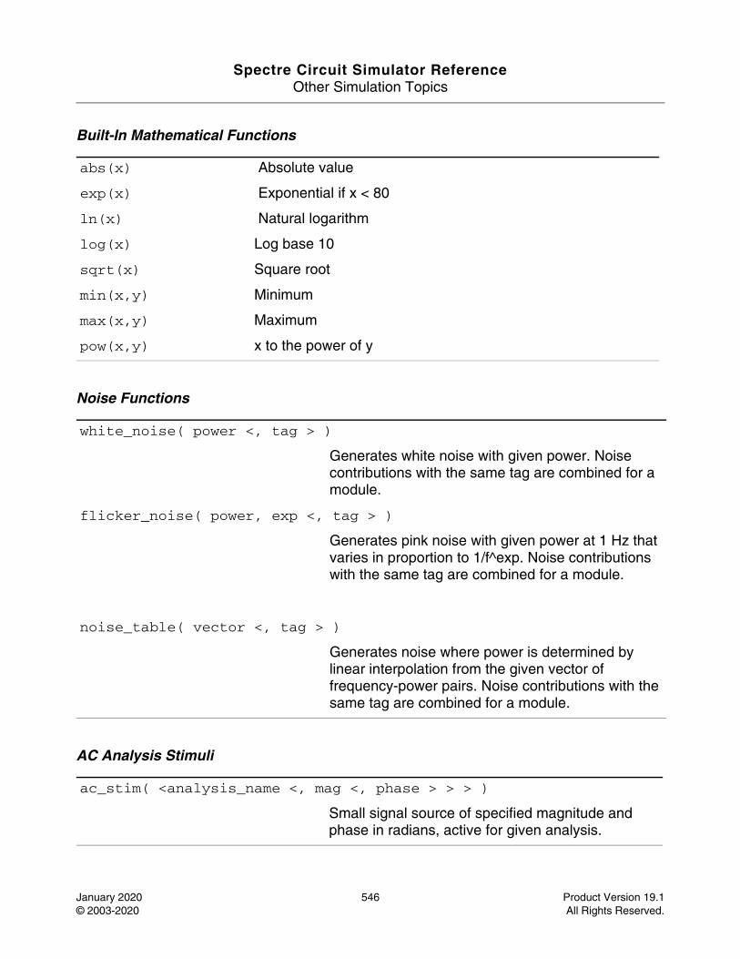
Spectre Circuit Simulator ReferenceOther Simulation Topics
January 2020 546 Product Version 19.1© 2003-2020 All Rights Reserved.
Built-In Mathematical Functions
Noise Functions
AC Analysis Stimuli
abs(x) Absolute value
exp(x) Exponential if x < 80
ln(x) Natural logarithm
log(x) Log base 10
sqrt(x) Square root
min(x,y) Minimum
max(x,y) Maximum
pow(x,y) x to the power of y
white_noise( power <, tag > )
Generates white noise with given power. Noise contributions with the same tag are combined for a module.
flicker_noise( power, exp <, tag > )
Generates pink noise with given power at 1 Hz that varies in proportion to 1/f^exp. Noise contributions with the same tag are combined for a module.
noise_table( vector <, tag > )
Generates noise where power is determined by linear interpolation from the given vector of frequency-power pairs. Noise contributions with the same tag are combined for a module.
ac_stim( <analysis_name <, mag <, phase > > > )
Small signal source of specified magnitude and phase in radians, active for given analysis.
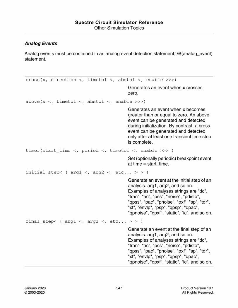
Spectre Circuit Simulator ReferenceOther Simulation Topics
January 2020 547 Product Version 19.1© 2003-2020 All Rights Reserved.
Analog Events
Analog events must be contained in an analog event detection statement; @(analog_event) statement.
cross(x, direction <, timetol <, abstol <, enable >>>)
Generates an event when x crosses zero.
above(x <, timetol <, abstol <, enable >>>)
Generates an event when x becomes greater than or equal to zero. An above event can be generated and detected during initialization. By contrast, a cross event can be generated and detected only after at least one transient time step is complete.
timer(start_time <, period <, timetol <, enable >>> )
Set (optionally periodic) breakpoint event at time = start_time.
initial_step< ( arg1 <, arg2 <, etc... > > )
Generate an event at the initial step of an analysis. arg1, arg2, and so on. Examples of analyses strings are "dc", "tran", "ac", "pss", "noise", "pdisto", "qpss", "pac", "pnoise", "pxf", "sp", "tdr", "xf", "envlp", "psp", "qpsp", "qpac", "qpnoise", "qpxf", "static", "ic", and so on.
final_step< ( arg1 <, arg2 <, etc... > > )
Generate an event at the final step of an analysis. arg1, arg2, and so on. Examples of analyses strings are "dc", "tran", "ac", "pss", "noise", "pdisto", "qpss", "pac", "pnoise", "pxf", "sp", "tdr", "xf", "envlp", "psp", "qpsp", "qpac", "qpnoise", "qpxf", "static", "ic", and so on.
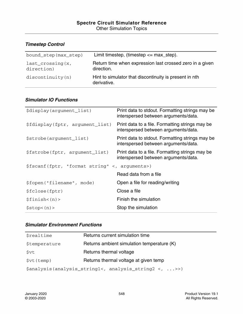
Spectre Circuit Simulator ReferenceOther Simulation Topics
January 2020 548 Product Version 19.1© 2003-2020 All Rights Reserved.
Timestep Control
Simulator IO Functions
Simulator Environment Functions
bound_step(max_step) Limit timestep, (timestep <= max_step).
last_crossing(x, direction)
Return time when expression last crossed zero in a given direction.
discontinuity(n) Hint to simulator that discontinuity is present in nth derivative.
$display(argument_list) Print data to stdout. Formatting strings may be interspersed between arguments/data.
$fdisplay(fptr, argument_list) Print data to a file. Formatting strings may be interspersed between arguments/data.
$strobe(argument_list) Print data to stdout. Formatting strings may be interspersed between arguments/data.
$fstrobe(fptr, argument_list) Print data to a file. Formatting strings may be interspersed between arguments/data.
$fscanf(fptr, "format string" <, arguments>)
Read data from a file
$fopen("filename", mode) Open a file for reading/writing
$fclose(fptr) Close a file
$finish<(n)> Finish the simulation
$stop<(n)> Stop the simulation
$realtime Returns current simulation time
$temperature Returns ambient simulation temperature (K)
$vt Returns thermal voltage
$vt(temp) Returns thermal voltage at given temp
$analysis(analysis_string1<, analysis_string2 <, ...>>)
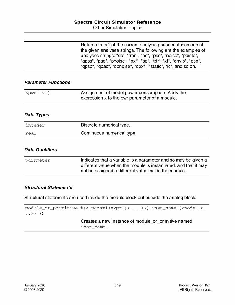
Spectre Circuit Simulator ReferenceOther Simulation Topics
January 2020 549 Product Version 19.1© 2003-2020 All Rights Reserved.
Parameter Functions
Data Types
Data Qualifiers
Structural Statements
Structural statements are used inside the module block but outside the analog block.
Returns true(1) if the current analysis phase matches one of the given analyses strings. The following are the examples of analyses strings: "dc", "tran", "ac", "pss", "noise", "pdisto", "qpss", "pac", "pnoise", "pxf", "sp", "tdr", "xf", "envlp", "psp", "qpsp", "qpac", "qpnoise", "qpxf", "static", "ic", and so on.
$pwr( x ) Assignment of model power consumption. Adds the expression x to the pwr parameter of a module.
integer Discrete numerical type.
real Continuous numerical type.
parameter Indicates that a variable is a parameter and so may be given a different value when the module is instantiated, and that it may not be assigned a different value inside the module.
module_or_primitive #(<.param1(expr1)<,...>>) inst_name (<node1 <, ..>> );
Creates a new instance of module_or_primitive named inst_name.
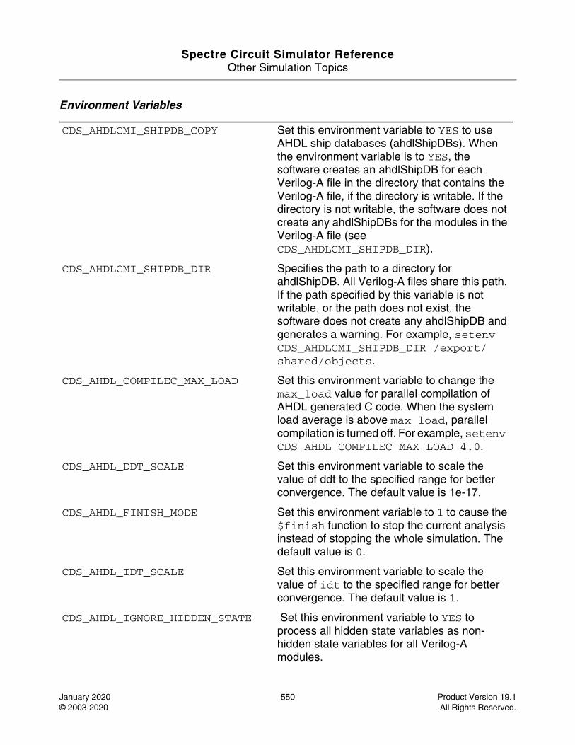
Spectre Circuit Simulator ReferenceOther Simulation Topics
January 2020 550 Product Version 19.1© 2003-2020 All Rights Reserved.
Environment Variables
CDS_AHDLCMI_SHIPDB_COPY Set this environment variable to YES to use AHDL ship databases (ahdlShipDBs). When the environment variable is to YES, the software creates an ahdlShipDB for each Verilog-A file in the directory that contains the Verilog-A file, if the directory is writable. If the directory is not writable, the software does not create any ahdlShipDBs for the modules in the Verilog-A file (see CDS_AHDLCMI_SHIPDB_DIR).
CDS_AHDLCMI_SHIPDB_DIR Specifies the path to a directory for ahdlShipDB. All Verilog-A files share this path. If the path specified by this variable is not writable, or the path does not exist, the software does not create any ahdlShipDB and generates a warning. For example, setenv CDS_AHDLCMI_SHIPDB_DIR /export/shared/objects.
CDS_AHDL_COMPILEC_MAX_LOAD Set this environment variable to change the max_load value for parallel compilation of AHDL generated C code. When the system load average is above max_load, parallel compilation is turned off. For example, setenv CDS_AHDL_COMPILEC_MAX_LOAD 4.0.
CDS_AHDL_DDT_SCALE Set this environment variable to scale the value of ddt to the specified range for better convergence. The default value is 1e-17.
CDS_AHDL_FINISH_MODE Set this environment variable to 1 to cause the $finish function to stop the current analysis instead of stopping the whole simulation. The default value is 0.
CDS_AHDL_IDT_SCALE Set this environment variable to scale the value of idt to the specified range for better convergence. The default value is 1.
CDS_AHDL_IGNORE_HIDDEN_STATE Set this environment variable to YES to process all hidden state variables as non-hidden state variables for all Verilog-A modules.
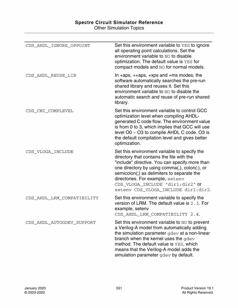
Spectre Circuit Simulator ReferenceOther Simulation Topics
January 2020 551 Product Version 19.1© 2003-2020 All Rights Reserved.
CDS_AHDL_IGNORE_OPPOINT Set this environment variable to YES to ignore all operating point calculations. Set the environment variable to NO to disable optimization. The default value is YES for compact models and NO for normal models.
CDS_AHDL_REUSE_LIB In +aps, ++aps, +xps and +ms modes, the software automatically searches the pre-run shared library and reuses it. Set this environment variable to NO to disable the automatic search and reuse of pre-run shared library.
CDS_CMI_COMPLEVEL Set this environment variable to control GCC optimization level when compiling AHDL-generated C code flow. The environment value is from 0 to 3, which implies that GCC will use level O0 ~ O3 to compile AHDL C code. O3 is the default compilation level and gives better optimization.
CDS_VLOGA_INCLUDE Set this environment variable to specify the directory that contains the file with the "include" directive. You can specify more than one directory by using comma(,), colon(:), or semicolon(;) as delimiters to separate the directories. For example, setenv CDS_VLOGA_INCLUDE "dir1;dir2" or setenv CDS_VLOGA_INCLUDE dir1:dir2.
CDS_AHDL_LRM_COMPATIBILITY Set this environment variable to specify the version of LRM. The default value is 2.3. For example, setenv CDS_AHDL_LRM_COMPATIBILITY 2.4.
CDS_AHDL_AUTOGDEV_SUPPORT Set this environment variable to NO to prevent a Verilog-A model from automatically adding the simulation parameter gdev at a non-linear branch when the kernel uses the gdev method. The default value is YES, which means that the Verilog-A model adds the simulation parameter gdev by default.

Spectre Circuit Simulator ReferenceOther Simulation Topics
January 2020 552 Product Version 19.1© 2003-2020 All Rights Reserved.
CDS_AHDL_AUTOGMIN_INSERT Set this environment variable to YES to enable a Verilog-A model to add the simulation parameter gmin at a non-linear branch. The default value is NO.
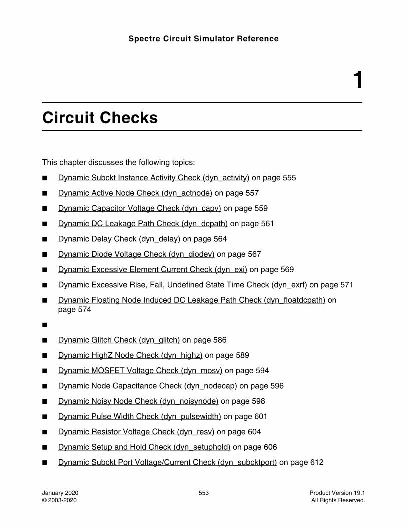
Spectre Circuit Simulator Reference
January 2020 553 Product Version 19.1© 2003-2020 All Rights Reserved.
1Circuit Checks
This chapter discusses the following topics:
■ Dynamic Subckt Instance Activity Check (dyn_activity) on page 555
■ Dynamic Active Node Check (dyn_actnode) on page 557
■ Dynamic Capacitor Voltage Check (dyn_capv) on page 559
■ Dynamic DC Leakage Path Check (dyn_dcpath) on page 561
■ Dynamic Delay Check (dyn_delay) on page 564
■ Dynamic Diode Voltage Check (dyn_diodev) on page 567
■ Dynamic Excessive Element Current Check (dyn_exi) on page 569
■ Dynamic Excessive Rise, Fall, Undefined State Time Check (dyn_exrf) on page 571
■ Dynamic Floating Node Induced DC Leakage Path Check (dyn_floatdcpath) on page 574
■
■ Dynamic Glitch Check (dyn_glitch) on page 586
■ Dynamic HighZ Node Check (dyn_highz) on page 589
■ Dynamic MOSFET Voltage Check (dyn_mosv) on page 594
■ Dynamic Node Capacitance Check (dyn_nodecap) on page 596
■ Dynamic Noisy Node Check (dyn_noisynode) on page 598
■ Dynamic Pulse Width Check (dyn_pulsewidth) on page 601
■ Dynamic Resistor Voltage Check (dyn_resv) on page 604
■ Dynamic Setup and Hold Check (dyn_setuphold) on page 606
■ Dynamic Subckt Port Voltage/Current Check (dyn_subcktport) on page 612
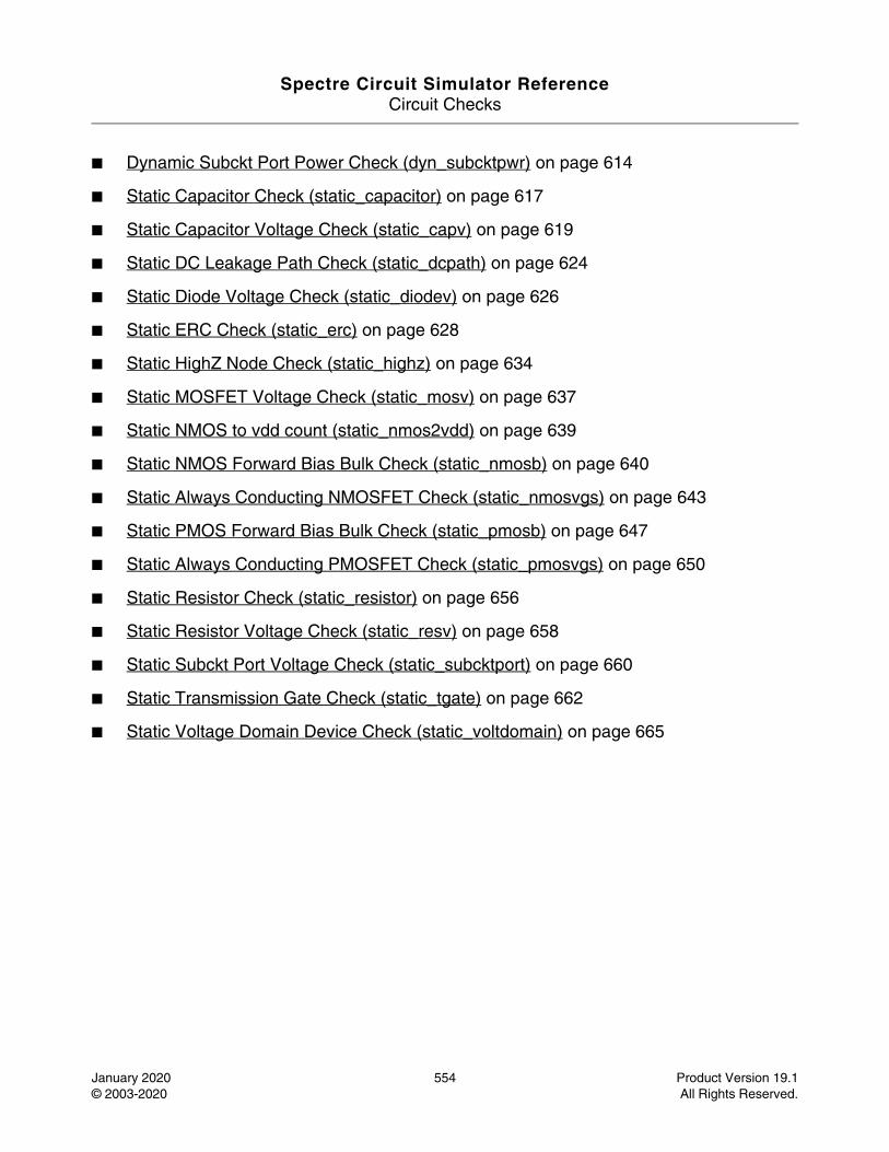
Spectre Circuit Simulator ReferenceCircuit Checks
January 2020 554 Product Version 19.1© 2003-2020 All Rights Reserved.
■ Dynamic Subckt Port Power Check (dyn_subcktpwr) on page 614
■ Static Capacitor Check (static_capacitor) on page 617
■ Static Capacitor Voltage Check (static_capv) on page 619
■ Static DC Leakage Path Check (static_dcpath) on page 624
■ Static Diode Voltage Check (static_diodev) on page 626
■ Static ERC Check (static_erc) on page 628
■ Static HighZ Node Check (static_highz) on page 634
■ Static MOSFET Voltage Check (static_mosv) on page 637
■ Static NMOS to vdd count (static_nmos2vdd) on page 639
■ Static NMOS Forward Bias Bulk Check (static_nmosb) on page 640
■ Static Always Conducting NMOSFET Check (static_nmosvgs) on page 643
■ Static PMOS Forward Bias Bulk Check (static_pmosb) on page 647
■ Static Always Conducting PMOSFET Check (static_pmosvgs) on page 650
■ Static Resistor Check (static_resistor) on page 656
■ Static Resistor Voltage Check (static_resv) on page 658
■ Static Subckt Port Voltage Check (static_subcktport) on page 660
■ Static Transmission Gate Check (static_tgate) on page 662
■ Static Voltage Domain Device Check (static_voltdomain) on page 665

Spectre Circuit Simulator ReferenceCircuit Checks
January 2020 555 Product Version 19.1© 2003-2020 All Rights Reserved.
Dynamic Subckt Instance Activity Check (dyn_activity)
Description
This check reports activity percentage of an instance relative to a circuit. The activity percentage is the ratio of the events in the instance versus the events in the entire circuit.
The results are written to the dynamic.xml file, which can be viewed in a Web browser. This check is supported only by Spectre XPS.
For additional information, refer to the Dynamic Subckt Instance Activity Check section in the Spectre Classic Simulator, Spectre APS, Spectre X, and Spectre XPS User Guide.
DefinitionName dyn_activity parameter=value ...
Parameters
Filtering parameters
Wildcard scoping
1 time_window=[tstart, tstop] sec
Time window during which the circuit check is applied. Multiple non-overlapping time windows are supported. Default time window is 0 to tend.
2 error_limit=10000 Maximum number of errors reported. Default is 10000.
3 min_activity=0 Any block activity below the minimum activity percentage will not be reported. The value can be between 0 and 1. Default is 0.
4 inst=[...] Subcircuit instances to which the check is applied. Default includes all instances (inst=*).
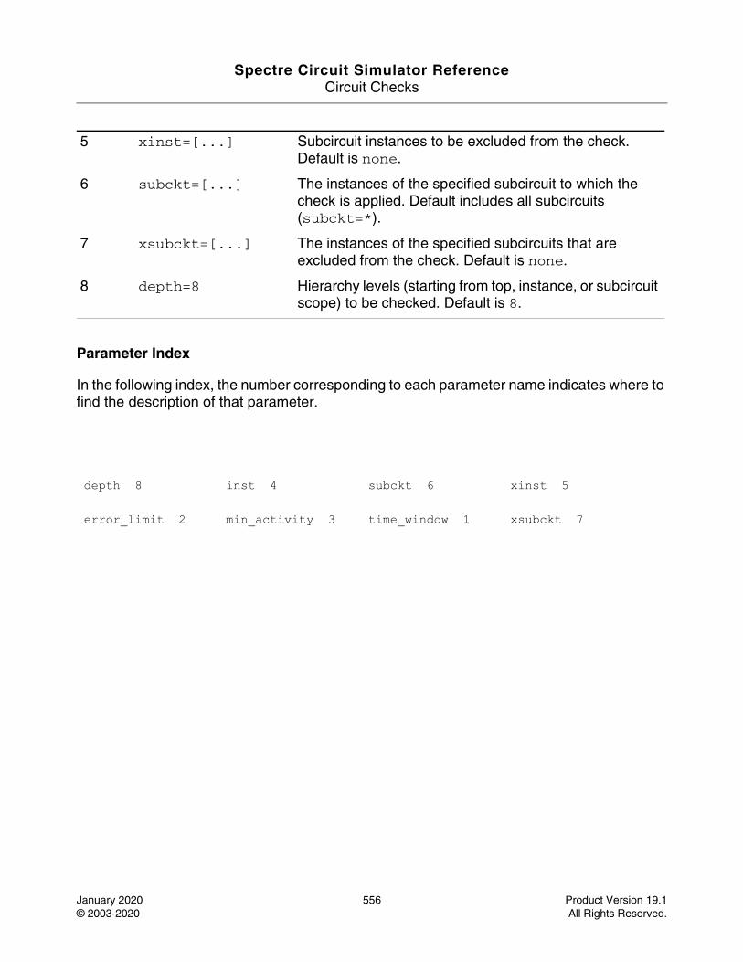
Spectre Circuit Simulator ReferenceCircuit Checks
January 2020 556 Product Version 19.1© 2003-2020 All Rights Reserved.
Parameter Index
In the following index, the number corresponding to each parameter name indicates where to find the description of that parameter.
5 xinst=[...] Subcircuit instances to be excluded from the check. Default is none.
6 subckt=[...] The instances of the specified subcircuit to which the check is applied. Default includes all subcircuits (subckt=*).
7 xsubckt=[...] The instances of the specified subcircuits that are excluded from the check. Default is none.
8 depth=8 Hierarchy levels (starting from top, instance, or subcircuit scope) to be checked. Default is 8.
depth 8 inst 4 subckt 6 xinst 5
error_limit 2 min_activity 3 time_window 1 xsubckt 7
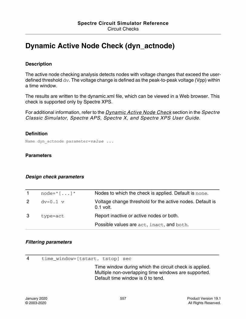
Spectre Circuit Simulator ReferenceCircuit Checks
January 2020 557 Product Version 19.1© 2003-2020 All Rights Reserved.
Dynamic Active Node Check (dyn_actnode)
Description
The active node checking analysis detects nodes with voltage changes that exceed the user-defined threshold dv. The voltage change is defined as the peak-to-peak voltage (Vpp) within a time window.
The results are written to the dynamic.xml file, which can be viewed in a Web browser. This check is supported only by Spectre XPS.
For additional information, refer to the Dynamic Active Node Check section in the Spectre Classic Simulator, Spectre APS, Spectre X, and Spectre XPS User Guide.
DefinitionName dyn_actnode parameter=value ...
Parameters
Design check parameters
Filtering parameters
1 node="[...]" Nodes to which the check is applied. Default is none.
2 dv=0.1 v Voltage change threshold for the active nodes. Default is 0.1 volt.
3 type=act Report inactive or active nodes or both.
Possible values are act, inact, and both.
4 time_window=[tstart, tstop] sec
Time window during which the circuit check is applied. Multiple non-overlapping time windows are supported. Default time window is 0 to tend.
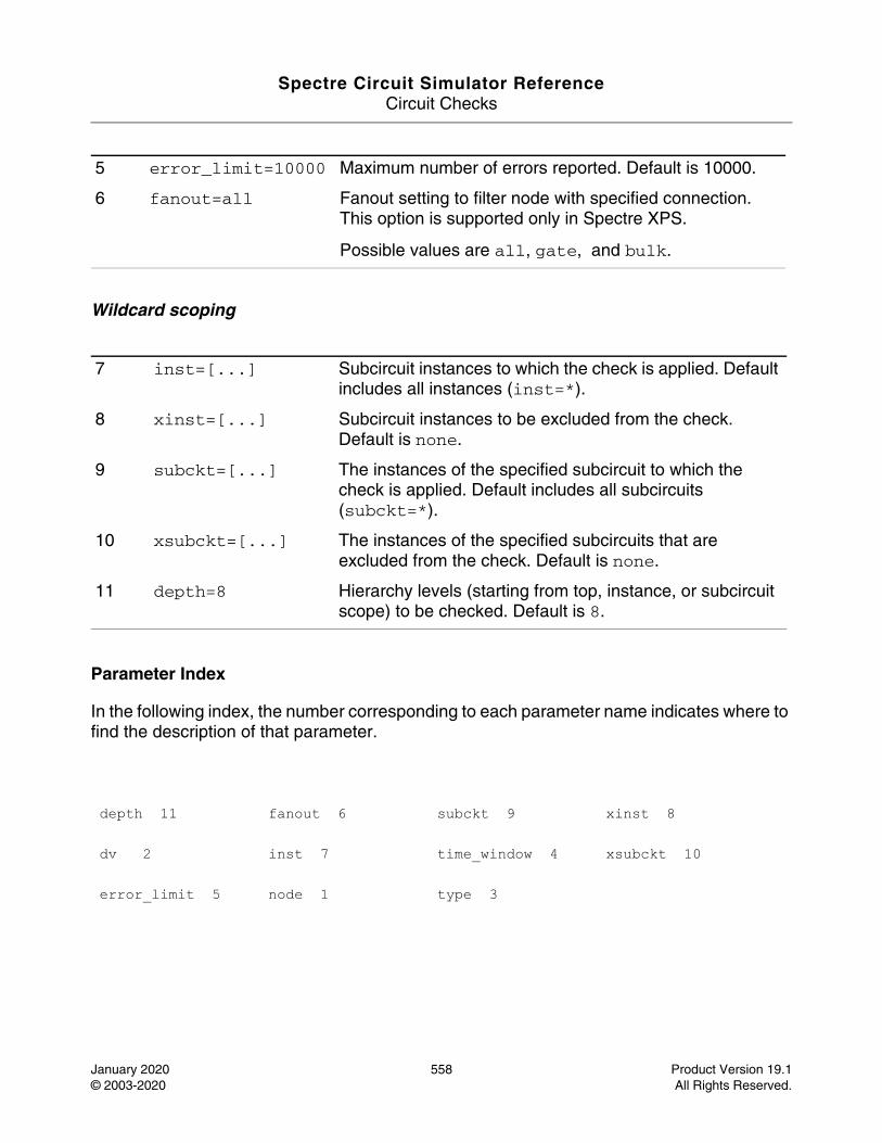
Spectre Circuit Simulator ReferenceCircuit Checks
January 2020 558 Product Version 19.1© 2003-2020 All Rights Reserved.
Wildcard scoping
Parameter Index
In the following index, the number corresponding to each parameter name indicates where to find the description of that parameter.
5 error_limit=10000 Maximum number of errors reported. Default is 10000.
6 fanout=all Fanout setting to filter node with specified connection. This option is supported only in Spectre XPS.
Possible values are all, gate, and bulk.
7 inst=[...] Subcircuit instances to which the check is applied. Default includes all instances (inst=*).
8 xinst=[...] Subcircuit instances to be excluded from the check. Default is none.
9 subckt=[...] The instances of the specified subcircuit to which the check is applied. Default includes all subcircuits (subckt=*).
10 xsubckt=[...] The instances of the specified subcircuits that are excluded from the check. Default is none.
11 depth=8 Hierarchy levels (starting from top, instance, or subcircuit scope) to be checked. Default is 8.
depth 11 fanout 6 subckt 9 xinst 8
dv 2 inst 7 time_window 4 xsubckt 10
error_limit 5 node 1 type 3
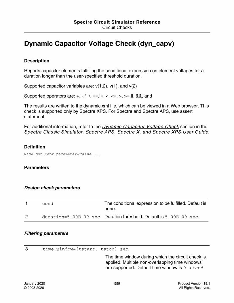
Spectre Circuit Simulator ReferenceCircuit Checks
January 2020 559 Product Version 19.1© 2003-2020 All Rights Reserved.
Dynamic Capacitor Voltage Check (dyn_capv)
Description
Reports capacitor elements fulfilling the conditional expression on element voltages for a duration longer than the user-specified threshold duration.
Supported capacitor variables are: v(1,2), v(1), and v(2)
Supported operators are: +, -,*, /, ==,!=, <, <=, >, >=,||, &&, and !
The results are written to the dynamic.xml file, which can be viewed in a Web browser. This check is supported only by Spectre XPS. For Spectre and Spectre APS, use assert statement.
For additional information, refer to the Dynamic Capacitor Voltage Check section in the Spectre Classic Simulator, Spectre APS, Spectre X, and Spectre XPS User Guide.
DefinitionName dyn_capv parameter=value ...
Parameters
Design check parameters
Filtering parameters
1 cond The conditional expression to be fulfilled. Default is none.
2 duration=5.00E-09 sec Duration threshold. Default is 5.00E-09 sec.
3 time_window=[tstart, tstop] sec
The time window during which the circuit check is applied. Multiple non-overlapping time windows are supported. Default time window is 0 to tend.
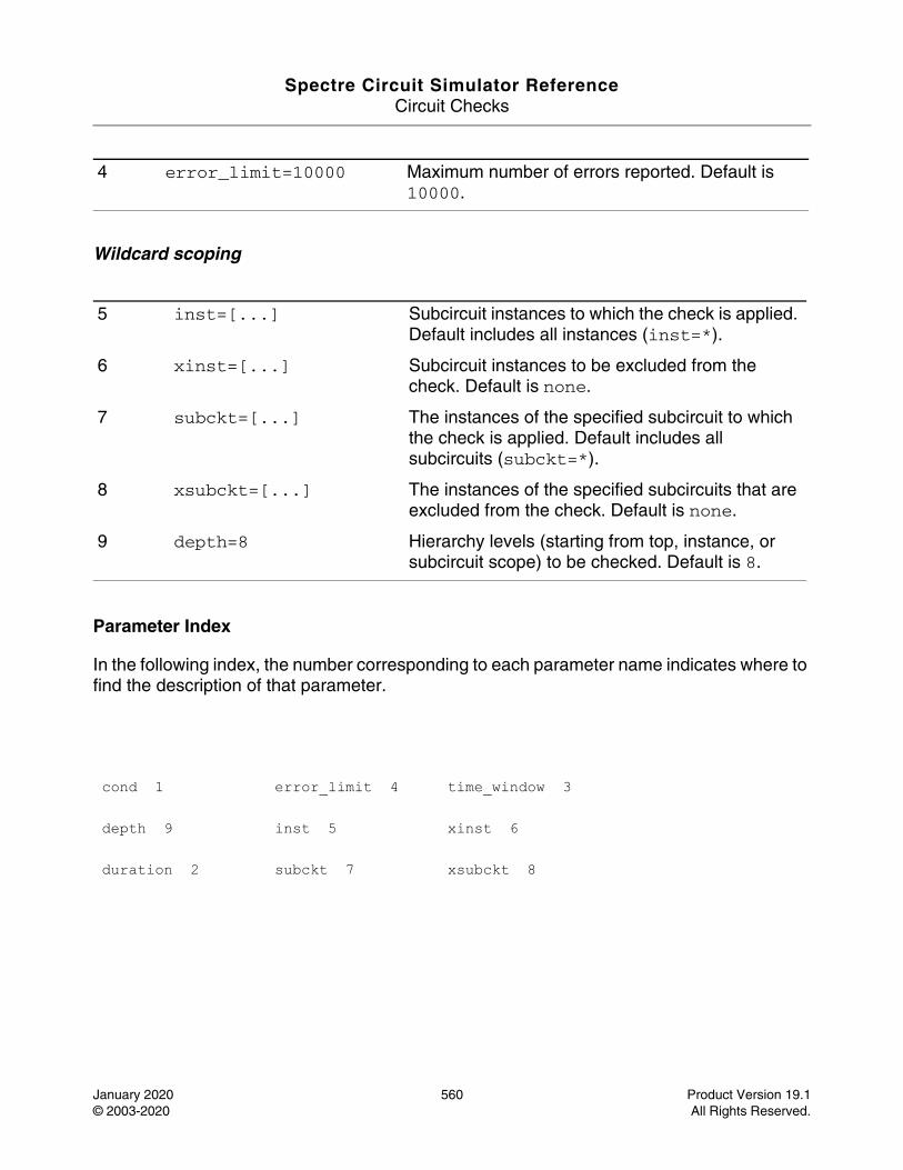
Spectre Circuit Simulator ReferenceCircuit Checks
January 2020 560 Product Version 19.1© 2003-2020 All Rights Reserved.
Wildcard scoping
Parameter Index
In the following index, the number corresponding to each parameter name indicates where to find the description of that parameter.
4 error_limit=10000 Maximum number of errors reported. Default is 10000.
5 inst=[...] Subcircuit instances to which the check is applied. Default includes all instances (inst=*).
6 xinst=[...] Subcircuit instances to be excluded from the check. Default is none.
7 subckt=[...] The instances of the specified subcircuit to which the check is applied. Default includes all subcircuits (subckt=*).
8 xsubckt=[...] The instances of the specified subcircuits that are excluded from the check. Default is none.
9 depth=8 Hierarchy levels (starting from top, instance, or subcircuit scope) to be checked. Default is 8.
cond 1 error_limit 4 time_window 3
depth 9 inst 5 xinst 6
duration 2 subckt 7 xsubckt 8
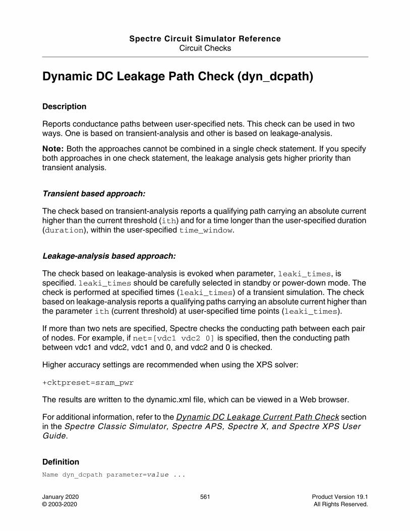
Spectre Circuit Simulator ReferenceCircuit Checks
January 2020 561 Product Version 19.1© 2003-2020 All Rights Reserved.
Dynamic DC Leakage Path Check (dyn_dcpath)
Description
Reports conductance paths between user-specified nets. This check can be used in two ways. One is based on transient-analysis and other is based on leakage-analysis.
Note: Both the approaches cannot be combined in a single check statement. If you specify both approaches in one check statement, the leakage analysis gets higher priority than transient analysis.
Transient based approach:
The check based on transient-analysis reports a qualifying path carrying an absolute current higher than the current threshold (ith) and for a time longer than the user-specified duration (duration), within the user-specified time_window.
Leakage-analysis based approach:
The check based on leakage-analysis is evoked when parameter, leaki_times, is specified. leaki_times should be carefully selected in standby or power-down mode. The check is performed at specified times (leaki_times) of a transient simulation. The check based on leakage-analysis reports a qualifying paths carrying an absolute current higher than the parameter ith (current threshold) at user-specified time points (leaki_times).
If more than two nets are specified, Spectre checks the conducting path between each pair of nodes. For example, if net=[vdc1 vdc2 0] is specified, then the conducting path between vdc1 and vdc2, vdc1 and 0, and vdc2 and 0 is checked.
Higher accuracy settings are recommended when using the XPS solver:
+cktpreset=sram_pwr
The results are written to the dynamic.xml file, which can be viewed in a Web browser.
For additional information, refer to the Dynamic DC Leakage Current Path Check section in the Spectre Classic Simulator, Spectre APS, Spectre X, and Spectre XPS User Guide.
DefinitionName dyn_dcpath parameter=value ...
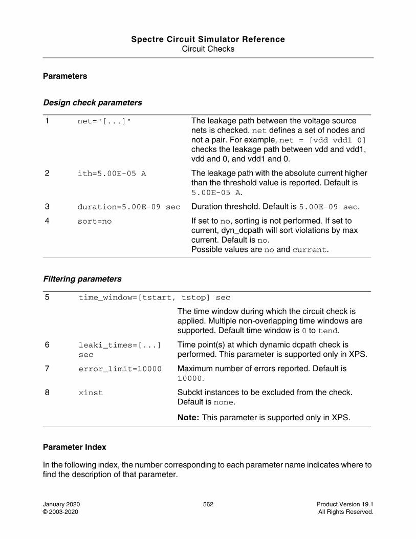
Spectre Circuit Simulator ReferenceCircuit Checks
January 2020 562 Product Version 19.1© 2003-2020 All Rights Reserved.
Parameters
Design check parameters
Filtering parameters
Parameter Index
In the following index, the number corresponding to each parameter name indicates where to find the description of that parameter.
1 net="[...]" The leakage path between the voltage source nets is checked. net defines a set of nodes and not a pair. For example, net = [vdd vdd1 0] checks the leakage path between vdd and vdd1, vdd and 0, and vdd1 and 0.
2 ith=5.00E-05 A The leakage path with the absolute current higher than the threshold value is reported. Default is 5.00E-05 A.
3 duration=5.00E-09 sec Duration threshold. Default is 5.00E-09 sec.
4 sort=no If set to no, sorting is not performed. If set to current, dyn_dcpath will sort violations by max current. Default is no.Possible values are no and current.
5 time_window=[tstart, tstop] sec
The time window during which the circuit check is applied. Multiple non-overlapping time windows are supported. Default time window is 0 to tend.
6 leaki_times=[...] sec
Time point(s) at which dynamic dcpath check is performed. This parameter is supported only in XPS.
7 error_limit=10000 Maximum number of errors reported. Default is 10000.
8 xinst Subckt instances to be excluded from the check. Default is none.
Note: This parameter is supported only in XPS.

Spectre Circuit Simulator ReferenceCircuit Checks
January 2020 563 Product Version 19.1© 2003-2020 All Rights Reserved.
duration 3 ith 2 net 1 time_window 5
error_limit 7 leaki_times 6 sort 4 xinst 8
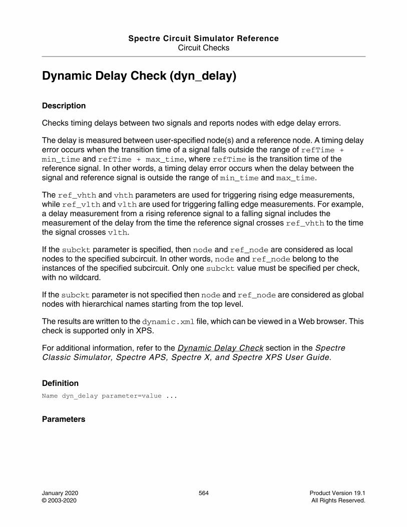
Spectre Circuit Simulator ReferenceCircuit Checks
January 2020 564 Product Version 19.1© 2003-2020 All Rights Reserved.
Dynamic Delay Check (dyn_delay)
Description
Checks timing delays between two signals and reports nodes with edge delay errors.
The delay is measured between user-specified node(s) and a reference node. A timing delay error occurs when the transition time of a signal falls outside the range of refTime + min_time and refTime + max_time, where refTime is the transition time of the reference signal. In other words, a timing delay error occurs when the delay between the signal and reference signal is outside the range of min_time and max_time.
The ref_vhth and vhth parameters are used for triggering rising edge measurements, while ref_vlth and vlth are used for triggering falling edge measurements. For example, a delay measurement from a rising reference signal to a falling signal includes the measurement of the delay from the time the reference signal crosses ref_vhth to the time the signal crosses vlth.
If the subckt parameter is specified, then node and ref_node are considered as local nodes to the specified subcircuit. In other words, node and ref_node belong to the instances of the specified subcircuit. Only one subckt value must be specified per check, with no wildcard.
If the subckt parameter is not specified then node and ref_node are considered as global nodes with hierarchical names starting from the top level.
The results are written to the dynamic.xml file, which can be viewed in a Web browser. This check is supported only in XPS.
For additional information, refer to the Dynamic Delay Check section in the Spectre Classic Simulator, Spectre APS, Spectre X, and Spectre XPS User Guide.
DefinitionName dyn_delay parameter=value ...
Parameters
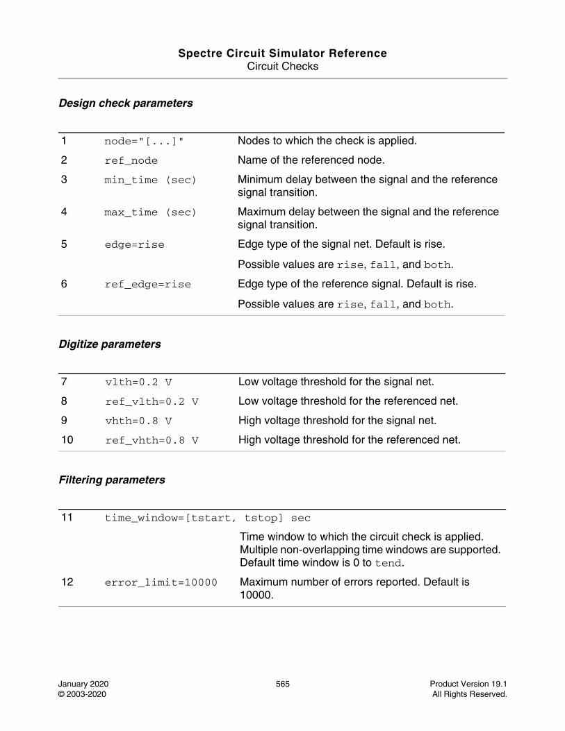
Spectre Circuit Simulator ReferenceCircuit Checks
January 2020 565 Product Version 19.1© 2003-2020 All Rights Reserved.
Design check parameters
Digitize parameters
Filtering parameters
1 node="[...]" Nodes to which the check is applied.
2 ref_node Name of the referenced node.
3 min_time (sec) Minimum delay between the signal and the reference signal transition.
4 max_time (sec) Maximum delay between the signal and the reference signal transition.
5 edge=rise Edge type of the signal net. Default is rise.
Possible values are rise, fall, and both.
6 ref_edge=rise Edge type of the reference signal. Default is rise.
Possible values are rise, fall, and both.
7 vlth=0.2 V Low voltage threshold for the signal net.
8 ref_vlth=0.2 V Low voltage threshold for the referenced net.
9 vhth=0.8 V High voltage threshold for the signal net.
10 ref_vhth=0.8 V High voltage threshold for the referenced net.
11 time_window=[tstart, tstop] sec
Time window to which the circuit check is applied. Multiple non-overlapping time windows are supported. Default time window is 0 to tend.
12 error_limit=10000 Maximum number of errors reported. Default is 10000.
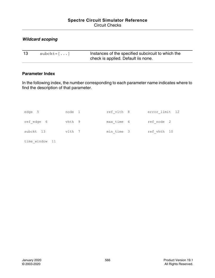
Spectre Circuit Simulator ReferenceCircuit Checks
January 2020 566 Product Version 19.1© 2003-2020 All Rights Reserved.
Wildcard scoping
Parameter Index
In the following index, the number corresponding to each parameter name indicates where to find the description of that parameter.
13 subckt=[...] Instances of the specified subcircuit to which the check is applied. Default iis none.
edge 5 node 1 ref_vlth 8 error_limit 12
ref_edge 6 vhth 9 max_time 4 ref_node 2
subckt 13 vlth 7 min_time 3 ref_vhth 10
time_window 11
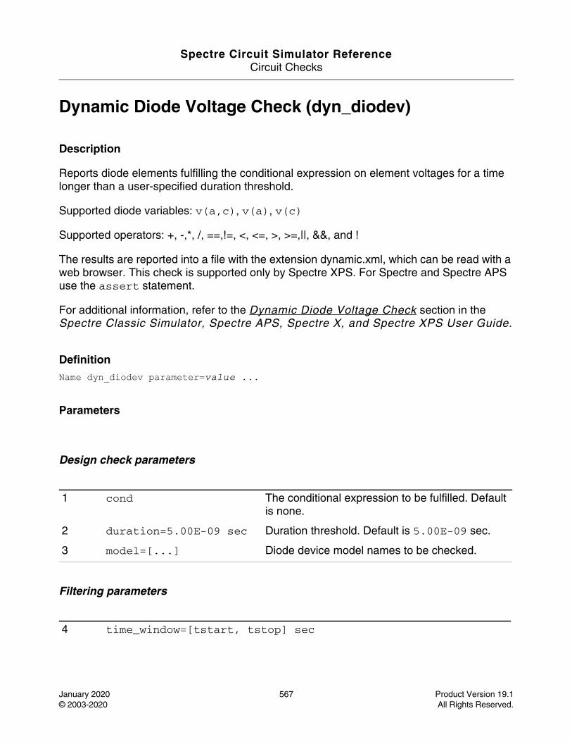
Spectre Circuit Simulator ReferenceCircuit Checks
January 2020 567 Product Version 19.1© 2003-2020 All Rights Reserved.
Dynamic Diode Voltage Check (dyn_diodev)
Description
Reports diode elements fulfilling the conditional expression on element voltages for a time longer than a user-specified duration threshold.
Supported diode variables: v(a,c), v(a), v(c)
Supported operators: +, -,*, /, ==,!=, <, <=, >, >=,||, &&, and !
The results are reported into a file with the extension dynamic.xml, which can be read with a web browser. This check is supported only by Spectre XPS. For Spectre and Spectre APS use the assert statement.
For additional information, refer to the Dynamic Diode Voltage Check section in the Spectre Classic Simulator, Spectre APS, Spectre X, and Spectre XPS User Guide.
DefinitionName dyn_diodev parameter=value ...
Parameters
Design check parameters
Filtering parameters
1 cond The conditional expression to be fulfilled. Default is none.
2 duration=5.00E-09 sec Duration threshold. Default is 5.00E-09 sec.
3 model=[...] Diode device model names to be checked.
4 time_window=[tstart, tstop] sec
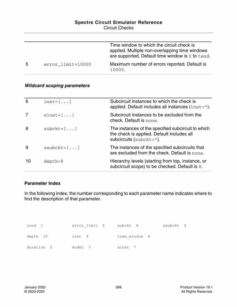
Spectre Circuit Simulator ReferenceCircuit Checks
January 2020 568 Product Version 19.1© 2003-2020 All Rights Reserved.
Wildcard scoping parameters
Parameter Index
In the following index, the number corresponding to each parameter name indicates where to find the description of that parameter.
Time window to which the circuit check is applied. Multiple non-overlapping time windows are supported. Default time window is 0 to tend.
5 error_limit=10000 Maximum number of errors reported. Default is 10000.
6 inst=[...] Subcircuit instances to which the check is applied. Default includes all instances (inst=*).
7 xinst=[...] Subcircuit instances to be excluded from the check. Default is none.
8 subckt=[...] The instances of the specified subcircuit to which the check is applied. Default includes all subcircuits (subckt=*).
9 xsubckt=[...] The instances of the specified subcircuits that are excluded from the check. Default is none.
10 depth=8 Hierarchy levels (starting from top, instance, or subcircuit scope) to be checked. Default is 8.
cond 1 error_limit 5 subckt 8 xsubckt 9
depth 10 inst 6 time_window 4
duration 2 model 3 xinst 7
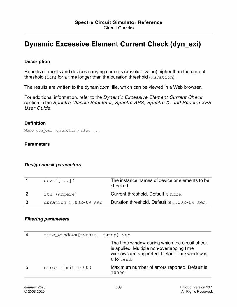
Spectre Circuit Simulator ReferenceCircuit Checks
January 2020 569 Product Version 19.1© 2003-2020 All Rights Reserved.
Dynamic Excessive Element Current Check (dyn_exi)
Description
Reports elements and devices carrying currents (absolute value) higher than the current threshold (ith) for a time longer than the duration threshold (duration).
The results are written to the dynamic.xml file, which can be viewed in a Web browser.
For additional information, refer to the Dynamic Excessive Element Current Check section in the Spectre Classic Simulator, Spectre APS, Spectre X, and Spectre XPS User Guide.
DefinitionName dyn_exi parameter=value ...
Parameters
Design check parameters
Filtering parameters
1 dev="[...]" The instance names of device or elements to be checked.
2 ith (ampere) Current threshold. Default is none.
3 duration=5.00E-09 sec Duration threshold. Default is 5.00E-09 sec.
4 time_window=[tstart, tstop] sec
The time window during which the circuit check is applied. Multiple non-overlapping time windows are supported. Default time window is 0 to tend.
5 error_limit=10000 Maximum number of errors reported. Default is 10000.
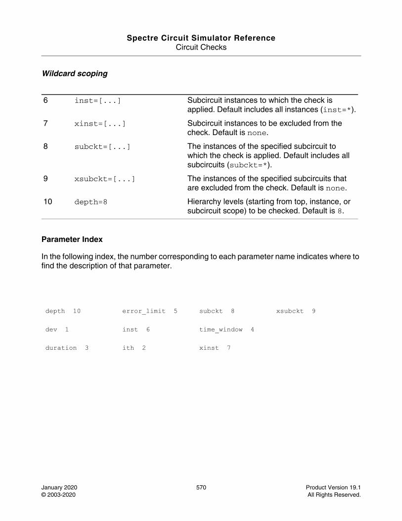
Spectre Circuit Simulator ReferenceCircuit Checks
January 2020 570 Product Version 19.1© 2003-2020 All Rights Reserved.
Wildcard scoping
Parameter Index
In the following index, the number corresponding to each parameter name indicates where to find the description of that parameter.
6 inst=[...] Subcircuit instances to which the check is applied. Default includes all instances (inst=*).
7 xinst=[...] Subcircuit instances to be excluded from the check. Default is none.
8 subckt=[...] The instances of the specified subcircuit to which the check is applied. Default includes all subcircuits (subckt=*).
9 xsubckt=[...] The instances of the specified subcircuits that are excluded from the check. Default is none.
10 depth=8 Hierarchy levels (starting from top, instance, or subcircuit scope) to be checked. Default is 8.
depth 10 error_limit 5 subckt 8 xsubckt 9
dev 1 inst 6 time_window 4
duration 3 ith 2 xinst 7
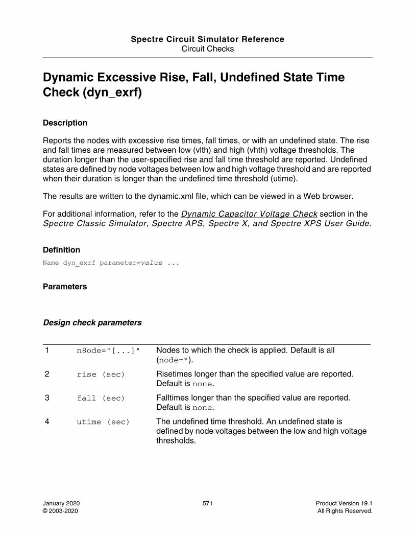
Spectre Circuit Simulator ReferenceCircuit Checks
January 2020 571 Product Version 19.1© 2003-2020 All Rights Reserved.
Dynamic Excessive Rise, Fall, Undefined State Time Check (dyn_exrf)
Description
Reports the nodes with excessive rise times, fall times, or with an undefined state. The rise and fall times are measured between low (vlth) and high (vhth) voltage thresholds. The duration longer than the user-specified rise and fall time threshold are reported. Undefined states are defined by node voltages between low and high voltage threshold and are reported when their duration is longer than the undefined time threshold (utime).
The results are written to the dynamic.xml file, which can be viewed in a Web browser.
For additional information, refer to the Dynamic Capacitor Voltage Check section in the Spectre Classic Simulator, Spectre APS, Spectre X, and Spectre XPS User Guide.
DefinitionName dyn_exrf parameter=value ...
Parameters
Design check parameters
1 n8ode="[...]" Nodes to which the check is applied. Default is all (node=*).
2 rise (sec) Risetimes longer than the specified value are reported. Default is none.
3 fall (sec) Falltimes longer than the specified value are reported. Default is none.
4 utime (sec) The undefined time threshold. An undefined state is defined by node voltages between the low and high voltage thresholds.
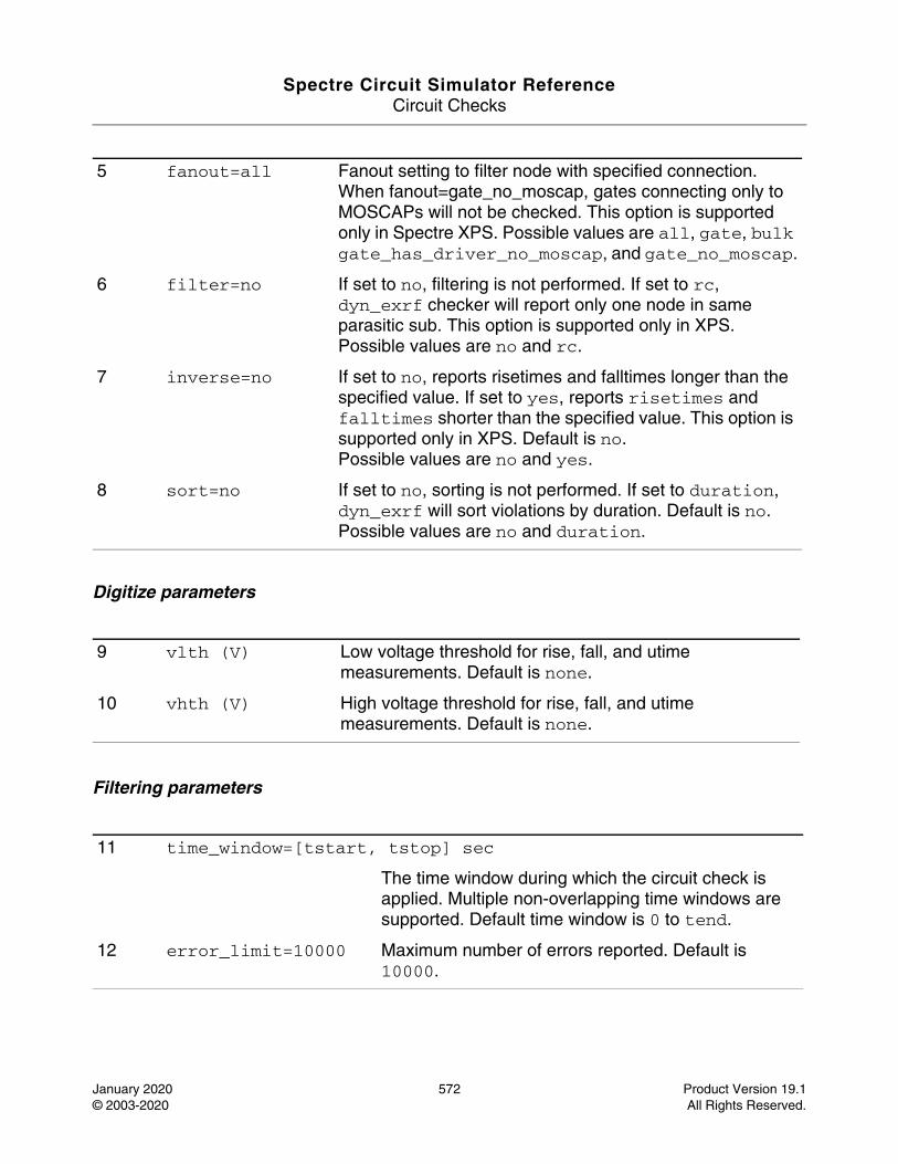
Spectre Circuit Simulator ReferenceCircuit Checks
January 2020 572 Product Version 19.1© 2003-2020 All Rights Reserved.
Digitize parameters
Filtering parameters
5 fanout=all Fanout setting to filter node with specified connection. When fanout=gate_no_moscap, gates connecting only to MOSCAPs will not be checked. This option is supported only in Spectre XPS. Possible values are all, gate, bulk gate_has_driver_no_moscap, and gate_no_moscap.
6 filter=no If set to no, filtering is not performed. If set to rc, dyn_exrf checker will report only one node in same parasitic sub. This option is supported only in XPS.Possible values are no and rc.
7 inverse=no If set to no, reports risetimes and falltimes longer than the specified value. If set to yes, reports risetimes and falltimes shorter than the specified value. This option is supported only in XPS. Default is no.Possible values are no and yes.
8 sort=no If set to no, sorting is not performed. If set to duration, dyn_exrf will sort violations by duration. Default is no.Possible values are no and duration.
9 vlth (V) Low voltage threshold for rise, fall, and utime measurements. Default is none.
10 vhth (V) High voltage threshold for rise, fall, and utime measurements. Default is none.
11 time_window=[tstart, tstop] sec
The time window during which the circuit check is applied. Multiple non-overlapping time windows are supported. Default time window is 0 to tend.
12 error_limit=10000 Maximum number of errors reported. Default is 10000.
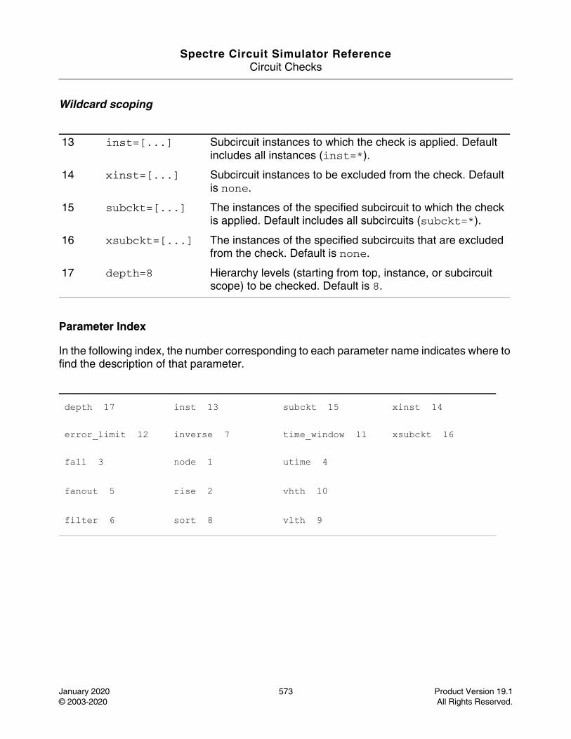
Spectre Circuit Simulator ReferenceCircuit Checks
January 2020 573 Product Version 19.1© 2003-2020 All Rights Reserved.
Wildcard scoping
Parameter Index
In the following index, the number corresponding to each parameter name indicates where to find the description of that parameter.
13 inst=[...] Subcircuit instances to which the check is applied. Default includes all instances (inst=*).
14 xinst=[...] Subcircuit instances to be excluded from the check. Default is none.
15 subckt=[...] The instances of the specified subcircuit to which the check is applied. Default includes all subcircuits (subckt=*).
16 xsubckt=[...] The instances of the specified subcircuits that are excluded from the check. Default is none.
17 depth=8 Hierarchy levels (starting from top, instance, or subcircuit scope) to be checked. Default is 8.
depth 17 inst 13 subckt 15 xinst 14
error_limit 12 inverse 7 time_window 11 xsubckt 16
fall 3 node 1 utime 4
fanout 5 rise 2 vhth 10
filter 6 sort 8 vlth 9
Spectre Circuit Simulator ReferenceCircuit Checks
January 2020 574 Product Version 19.1© 2003-2020 All Rights Reserved.
Dynamic Floating Node Induced DC Leakage Path Check (dyn_floatdcpath)
Description
Reports the DC leakage paths that are caused by floating nodes.
This check can be used in two ways. One is based on transient analysis and other is based on leakage analysis. Both approaches cannot be combined in one check statement. If you specify both approaches in one check statement, then leakage analysis gets higher priority than transient analysis.
Transient based approach:
The check based on transient analysis is evoked when parameters time_window or/and duration are specified. It reports the qualifying path carrying an absolute current higher than the parameter ith for a duration longer than the specified duration, within the specified time_window. This qualifying path must also have a MOSFET with gate floating for duration longer than the specified duration, within the specified time_window. The violations will be the union of dyn_highz and dyn_dcpath, if same settings are used. This methodology does not give the worst case leakage path. If the settings of dyn_dcpath and dyn_floatdcpath are same, then the violations of dyn_floatdcpath will be a subset of dyn_dcpath. The following parameters are irrelevant: Vmin, vmax, points, rforce, leaki_times, sweep, floatgate, detailed_report, debug_net, distribute, numprocesses. The floating node detection is similar to dyn_highz. The path detection is similar to dyn_dcpath.
Leakage analysis based approach:
The check based on leakage-analysis is evoked when parameter, leaki_times, is specified. leaki_times should be carefully selected in standby or power-down mode.
The check is performed at specified times (leaki_times) of a transient simulation. Floating nodes and MOSFET devices with floating gates are detected. Potential leakage paths (sweep=no) or worst leakage paths (sweep=all,single,all_once) caused by floating gate MOSFET devices are reported.The leakage paths are checked between user-specified power supply nodes (net). The floating node detection and path detection, in Leakage analysis based approach, are explained below:
Floating node detection (leaki_times)
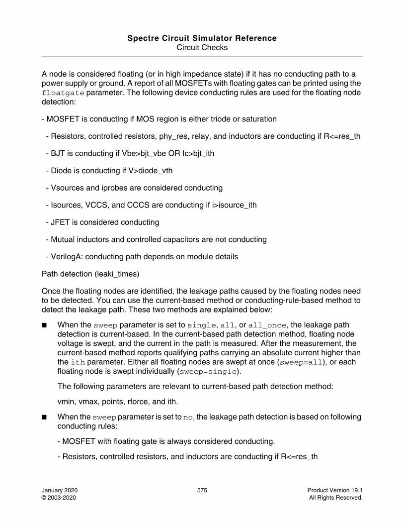
Spectre Circuit Simulator ReferenceCircuit Checks
January 2020 575 Product Version 19.1© 2003-2020 All Rights Reserved.
A node is considered floating (or in high impedance state) if it has no conducting path to a power supply or ground. A report of all MOSFETs with floating gates can be printed using the floatgate parameter. The following device conducting rules are used for the floating node detection:
- MOSFET is conducting if MOS region is either triode or saturation
- Resistors, controlled resistors, phy_res, relay, and inductors are conducting if R<=res_th
- BJT is conducting if Vbe>bjt_vbe OR Ic>bjt_ith
- Diode is conducting if V>diode_vth
- Vsources and iprobes are considered conducting
- Isources, VCCS, and CCCS are conducting if i>isource_ith
- JFET is considered conducting
- Mutual inductors and controlled capacitors are not conducting
- VerilogA: conducting path depends on module details
Path detection (leaki_times)
Once the floating nodes are identified, the leakage paths caused by the floating nodes need to be detected. You can use the current-based method or conducting-rule-based method to detect the leakage path. These two methods are explained below:
■ When the sweep parameter is set to single, all, or all_once, the leakage path detection is current-based. In the current-based path detection method, floating node voltage is swept, and the current in the path is measured. After the measurement, the current-based method reports qualifying paths carrying an absolute current higher than the ith parameter. Either all floating nodes are swept at once (sweep=all), or each floating node is swept individually (sweep=single).
The following parameters are relevant to current-based path detection method:
vmin, vmax, points, rforce, and ith.
■ When the sweep parameter is set to no, the leakage path detection is based on following conducting rules:
- MOSFET with floating gate is always considered conducting.
- Resistors, controlled resistors, and inductors are conducting if R<=res_th

Spectre Circuit Simulator ReferenceCircuit Checks
January 2020 576 Product Version 19.1© 2003-2020 All Rights Reserved.
- BJT is conducting if Vbe>bjt_vbe OR Ic>bjt_ith
- Diode is conducting if V>diode_vth
- Vsources is conducting if V=0 otherwise it is not conducting
- iprobes are considered conducting
- Isources, VCCS, and CCCS are conducting if i>isource_ith
- VerilogA: conducting path depends on module details
The following parameters are irrelevant with sweep=no:
Vmin, vmax, points, rforce, and ith.
If more than two nets are specified, Spectre checks the leakage path between each pair of nets. For example, if net=[vdc1 vdc2 0] is specified, then the conducting path between vdc1 and vdc2, vdc1 and 0, and vdc2 and 0 is checked.
Higher accuracy settings are recommended when using the Spectre XPS solver: +cktpreset=sram_pwr.
The results are written to the dynamic.xml file, which can be viewed in a Web browser.
For additional information, refer to the Dynamic Floating Gate Induced Leakage Check section in the Spectre Classic Simulator, Spectre APS, Spectre X, and Spectre XPS User Guide.
DefinitionName dyn_floatdcpath parameter=value ...
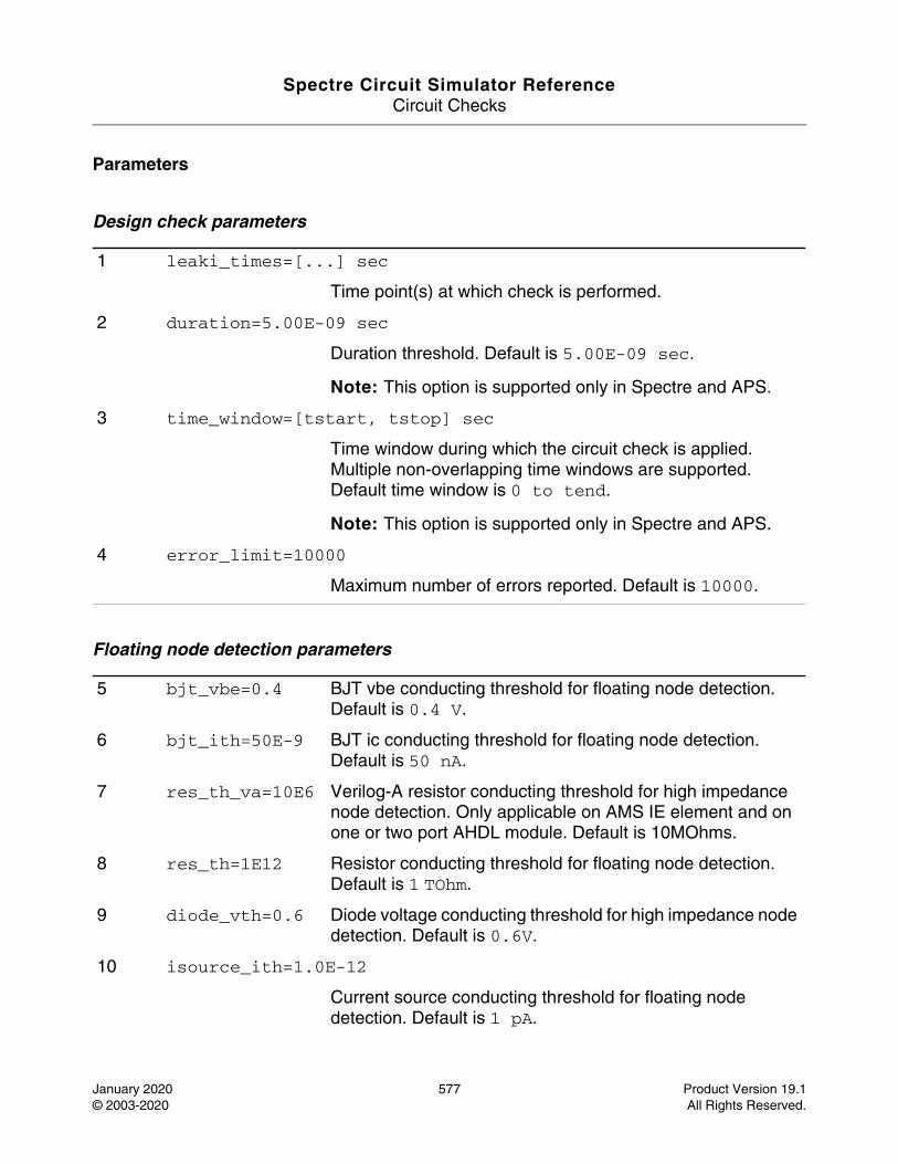
Spectre Circuit Simulator ReferenceCircuit Checks
January 2020 577 Product Version 19.1© 2003-2020 All Rights Reserved.
Parameters
Design check parameters
Floating node detection parameters
1 leaki_times=[...] sec
Time point(s) at which check is performed.
2 duration=5.00E-09 sec
Duration threshold. Default is 5.00E-09 sec.
Note: This option is supported only in Spectre and APS.
3 time_window=[tstart, tstop] sec
Time window during which the circuit check is applied. Multiple non-overlapping time windows are supported. Default time window is 0 to tend.
Note: This option is supported only in Spectre and APS.
4 error_limit=10000
Maximum number of errors reported. Default is 10000.
5 bjt_vbe=0.4 BJT vbe conducting threshold for floating node detection. Default is 0.4 V.
6 bjt_ith=50E-9 BJT ic conducting threshold for floating node detection. Default is 50 nA.
7 res_th_va=10E6 Verilog-A resistor conducting threshold for high impedance node detection. Only applicable on AMS IE element and on one or two port AHDL module. Default is 10MOhms.
8 res_th=1E12 Resistor conducting threshold for floating node detection. Default is 1 TOhm.
9 diode_vth=0.6 Diode voltage conducting threshold for high impedance node detection. Default is 0.6V.
10 isource_ith=1.0E-12
Current source conducting threshold for floating node detection. Default is 1 pA.
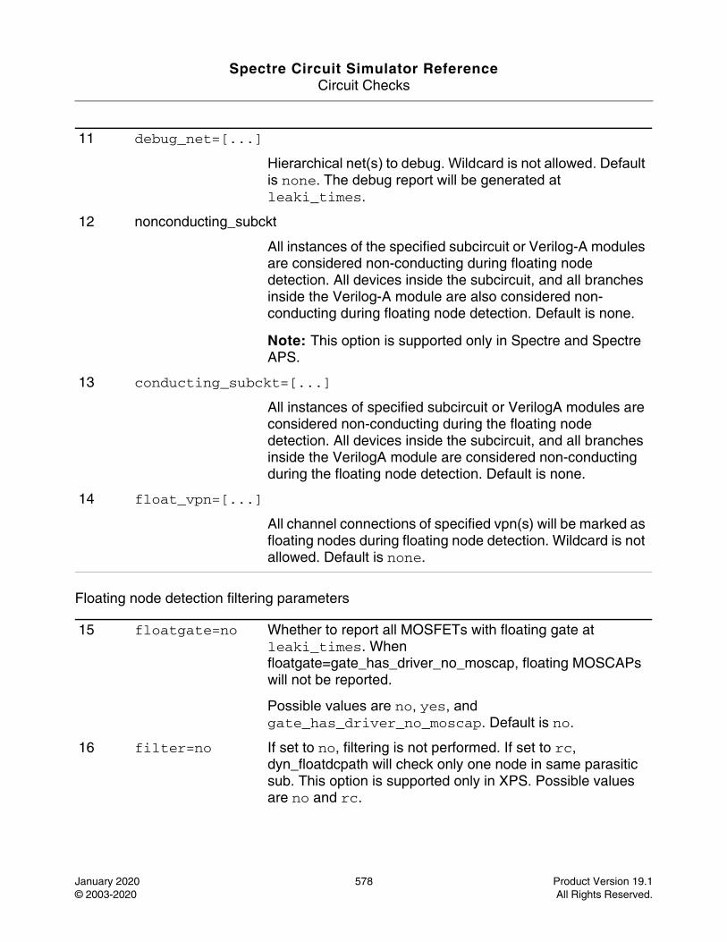
Spectre Circuit Simulator ReferenceCircuit Checks
January 2020 578 Product Version 19.1© 2003-2020 All Rights Reserved.
Floating node detection filtering parameters
11 debug_net=[...]
Hierarchical net(s) to debug. Wildcard is not allowed. Default is none. The debug report will be generated at leaki_times.
12 nonconducting_subckt
All instances of the specified subcircuit or Verilog-A modules are considered non-conducting during floating node detection. All devices inside the subcircuit, and all branches inside the Verilog-A module are also considered non-conducting during floating node detection. Default is none.
Note: This option is supported only in Spectre and Spectre APS.
13 conducting_subckt=[...]
All instances of specified subcircuit or VerilogA modules are considered non-conducting during the floating node detection. All devices inside the subcircuit, and all branches inside the VerilogA module are considered non-conducting during the floating node detection. Default is none.
14 float_vpn=[...]
All channel connections of specified vpn(s) will be marked as floating nodes during floating node detection. Wildcard is not allowed. Default is none.
15 floatgate=no Whether to report all MOSFETs with floating gate at leaki_times. When floatgate=gate_has_driver_no_moscap, floating MOSCAPs will not be reported.
Possible values are no, yes, and gate_has_driver_no_moscap. Default is no.
16 filter=no If set to no, filtering is not performed. If set to rc, dyn_floatdcpath will check only one node in same parasitic sub. This option is supported only in XPS. Possible values are no and rc.
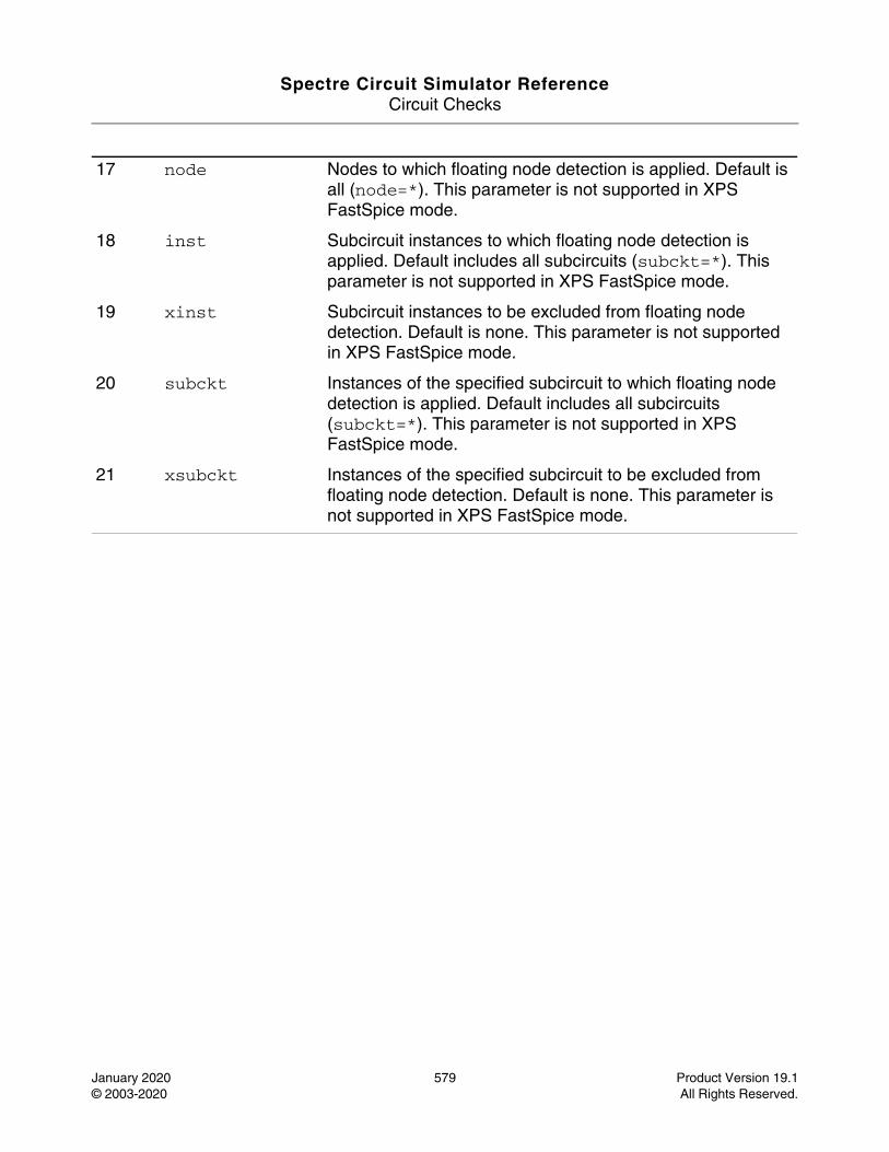
Spectre Circuit Simulator ReferenceCircuit Checks
January 2020 579 Product Version 19.1© 2003-2020 All Rights Reserved.
17 node Nodes to which floating node detection is applied. Default is all (node=*). This parameter is not supported in XPS FastSpice mode.
18 inst Subcircuit instances to which floating node detection is applied. Default includes all subcircuits (subckt=*). This parameter is not supported in XPS FastSpice mode.
19 xinst Subcircuit instances to be excluded from floating node detection. Default is none. This parameter is not supported in XPS FastSpice mode.
20 subckt Instances of the specified subcircuit to which floating node detection is applied. Default includes all subcircuits (subckt=*). This parameter is not supported in XPS FastSpice mode.
21 xsubckt Instances of the specified subcircuit to be excluded from floating node detection. Default is none. This parameter is not supported in XPS FastSpice mode.
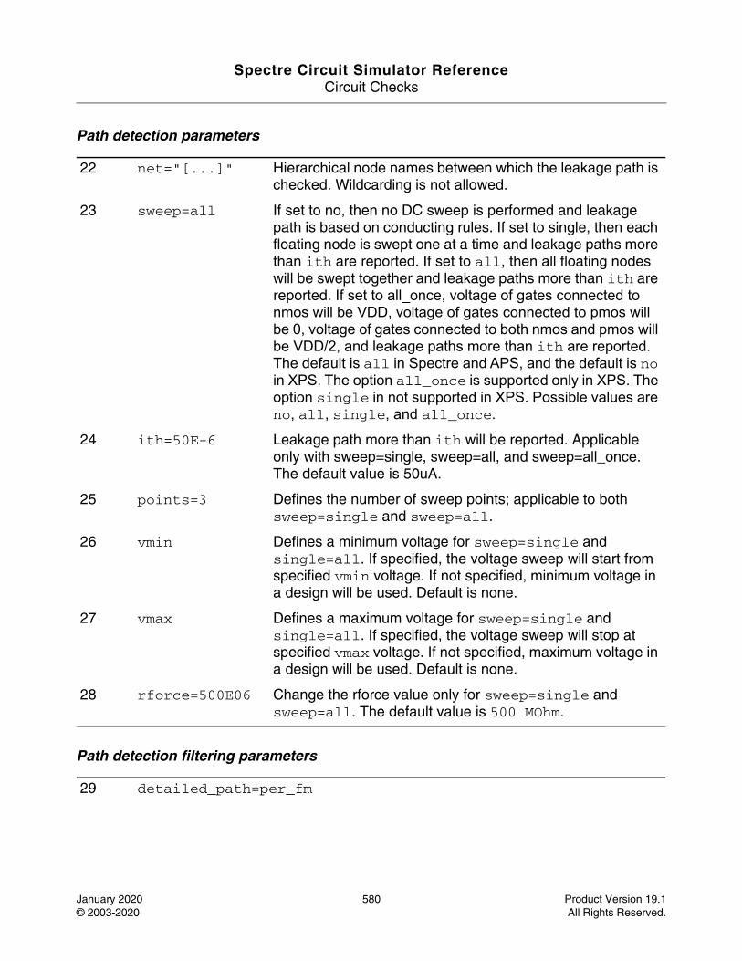
Spectre Circuit Simulator ReferenceCircuit Checks
January 2020 580 Product Version 19.1© 2003-2020 All Rights Reserved.
Path detection parameters
Path detection filtering parameters
22 net="[...]" Hierarchical node names between which the leakage path is checked. Wildcarding is not allowed.
23 sweep=all If set to no, then no DC sweep is performed and leakage path is based on conducting rules. If set to single, then each floating node is swept one at a time and leakage paths more than ith are reported. If set to all, then all floating nodes will be swept together and leakage paths more than ith are reported. If set to all_once, voltage of gates connected to nmos will be VDD, voltage of gates connected to pmos will be 0, voltage of gates connected to both nmos and pmos will be VDD/2, and leakage paths more than ith are reported. The default is all in Spectre and APS, and the default is no in XPS. The option all_once is supported only in XPS. The option single in not supported in XPS. Possible values are no, all, single, and all_once.
24 ith=50E-6 Leakage path more than ith will be reported. Applicable only with sweep=single, sweep=all, and sweep=all_once. The default value is 50uA.
25 points=3 Defines the number of sweep points; applicable to both sweep=single and sweep=all.
26 vmin Defines a minimum voltage for sweep=single and single=all. If specified, the voltage sweep will start from specified vmin voltage. If not specified, minimum voltage in a design will be used. Default is none.
27 vmax Defines a maximum voltage for sweep=single and single=all. If specified, the voltage sweep will stop at specified vmax voltage. If not specified, maximum voltage in a design will be used. Default is none.
28 rforce=500E06 Change the rforce value only for sweep=single and sweep=all. The default value is 500 MOhm.
29 detailed_path=per_fm
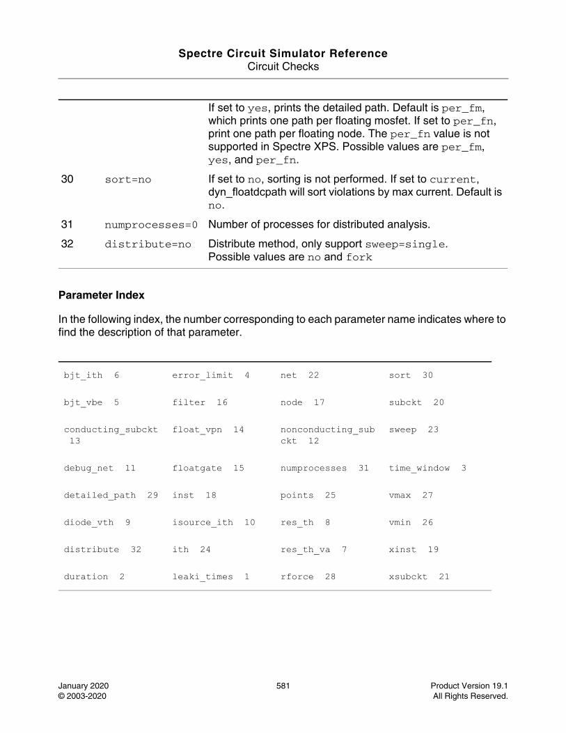
Spectre Circuit Simulator ReferenceCircuit Checks
January 2020 581 Product Version 19.1© 2003-2020 All Rights Reserved.
Parameter Index
In the following index, the number corresponding to each parameter name indicates where to find the description of that parameter.
If set to yes, prints the detailed path. Default is per_fm, which prints one path per floating mosfet. If set to per_fn, print one path per floating node. The per_fn value is not supported in Spectre XPS. Possible values are per_fm, yes, and per_fn.
30 sort=no If set to no, sorting is not performed. If set to current, dyn_floatdcpath will sort violations by max current. Default is no.
31 numprocesses=0 Number of processes for distributed analysis.
32 distribute=no Distribute method, only support sweep=single.Possible values are no and fork
bjt_ith 6 error_limit 4 net 22 sort 30
bjt_vbe 5 filter 16 node 17 subckt 20
conducting_subckt 13
float_vpn 14 nonconducting_subckt 12
sweep 23
debug_net 11 floatgate 15 numprocesses 31 time_window 3
detailed_path 29 inst 18 points 25 vmax 27
diode_vth 9 isource_ith 10 res_th 8 vmin 26
distribute 32 ith 24 res_th_va 7 xinst 19
duration 2 leaki_times 1 rforce 28 xsubckt 21
Spectre Circuit Simulator ReferenceCircuit Checks
January 2020 582 Product Version 19.1© 2003-2020 All Rights Reserved.
Dynamic Floating Node Statistical Check (dyn_float_tran_stat)
Description
Identifies and reports nodes that are in high impedance state at a user given time. Deploys a statistical method of forcing (pinging) different voltage levels or voltage ramp ups to all nodes, and detecting floating nodes based on the current changes in the connecting devices.
The results are written to the dynamic.xml file, which can be viewed in a Web browser.
DefinitionName dyn_float_tran_stat parameter=value ...

Spectre Circuit Simulator ReferenceCircuit Checks
January 2020 583 Product Version 19.1© 2003-2020 All Rights Reserved.
Parameters
Design check parameters
1 domains="[...]" Pairs of power supply domains in which floating nodes are checked. Example: domains=[VDD VSS VPP VSS]. Domain also defines high voltage (high_voltage) value for forcing node voltages. Wildcarding is not allowed.Default is none.
2 ping_start="[...]" Time at which the check is initiated.
3 ping_count=300 Number of statistical periods being used. Default is 300.
4 ping_duration Duration of a ping. A ping consists of two phases: high/low forcing phase and ramp up forcing phase. Length of each phase is half of ping_duration. Default is none.
5 ping_ibias Lowest bias current in the design. Default is none. Internal value ping_resistor=domain_voltage/(ping_ibias).
6 ping_iabsthresh Current threshold for floating node detection during high/low forcing. Default is domain_voltage/ping_resistor.
7 ping_iabsthresh_ramp
Current threshold for floating node detection during ramp forcing. Default is 100*high_voltage/ping_resistor.
8 ping_irelthresh=1000
Relative threshold for floating node detection for both high/low and ramp forcing. Default is 1000.
9 seed=3 Seed for random number generation.
10 domain_voltage_thresh=0.0
Lowest threshold for domain voltage. If a node has voltage less than domain_voltage_thresh, it will be excluded from ping. Default is 0.0.
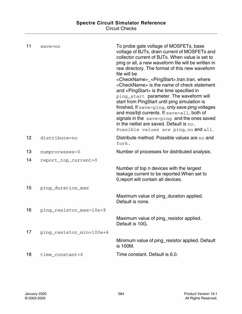
Spectre Circuit Simulator ReferenceCircuit Checks
January 2020 584 Product Version 19.1© 2003-2020 All Rights Reserved.
11 save=no To probe gate voltage of MOSFETs, base voltage of BJTs, drain current of MOSFETs and collector current of BJTs. When value is set to ping or all, a new waveform file will be written in raw directory. The format of this new waveform file will be <CheckName>_<PingStart>.tran.tran, where <CheckName> is the name of check statement and <PingStart> is the time specified in ping_start parameter. The waveform will start from PingStart until ping simulation is finished. If save=ping, only save ping voltages and mos/bjt currents. If save=all, both of signals in the save=ping and the ones saved in the netlist are saved. Default is no. Possible values are ping, no and all.
12 distribute=no Distribute method. Possible values are no and fork.
13 numprocesses=0 Number of processes for distributed analysis.
14 report_top_current=0
Number of top n devices with the largest leakage current to be reported.When set to 0,report will contain all devices.
15 ping_duration_max
Maximum value of ping_duration applied. Default is none.
16 ping_resistor_max=10e+9
Maximum value of ping_resistor applied. Default is 10G.
17 ping_resistor_min=100e+6
Minimum value of ping_resistor applied. Default is 100M.
18 time_constant=6 Time constant. Default is 6.0.
Spectre Circuit Simulator ReferenceCircuit Checks
January 2020 585 Product Version 19.1© 2003-2020 All Rights Reserved.
Parameter Index
In the following index, the number corresponding to each parameter name indicates where to find the description of that parameter.
distribute 12 ping_duration 4 ping_irelthresh 8
save 11
domain_voltage_thresh 10
ping_duration_max 15
ping_resistor_max 16
seed 9
domains 1 ping_iabsthresh 6
ping_resistor_min 17
time_constant 18
numprocesses 13 ping_iabsthresh_ramp 7
ping_start 2
ping_count 3 ping_ibias 5 report_top_current 15
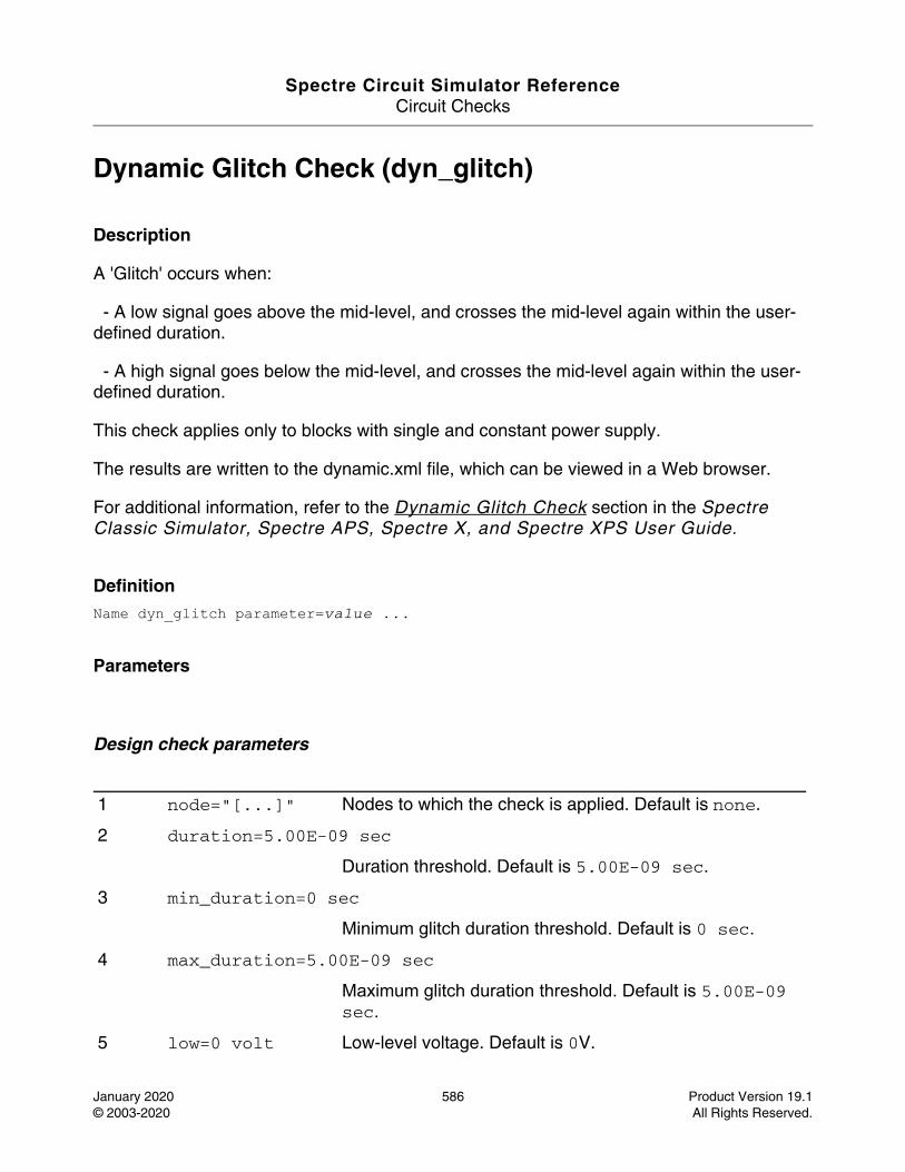
Spectre Circuit Simulator ReferenceCircuit Checks
January 2020 586 Product Version 19.1© 2003-2020 All Rights Reserved.
Dynamic Glitch Check (dyn_glitch)
Description
A 'Glitch' occurs when:
- A low signal goes above the mid-level, and crosses the mid-level again within the user-defined duration.
- A high signal goes below the mid-level, and crosses the mid-level again within the user-defined duration.
This check applies only to blocks with single and constant power supply.
The results are written to the dynamic.xml file, which can be viewed in a Web browser.
For additional information, refer to the Dynamic Glitch Check section in the Spectre Classic Simulator, Spectre APS, Spectre X, and Spectre XPS User Guide.
DefinitionName dyn_glitch parameter=value ...
Parameters
Design check parameters
1 node="[...]" Nodes to which the check is applied. Default is none.
2 duration=5.00E-09 sec
Duration threshold. Default is 5.00E-09 sec.
3 min_duration=0 sec
Minimum glitch duration threshold. Default is 0 sec.
4 max_duration=5.00E-09 sec
Maximum glitch duration threshold. Default is 5.00E-09 sec.
5 low=0 volt Low-level voltage. Default is 0V.
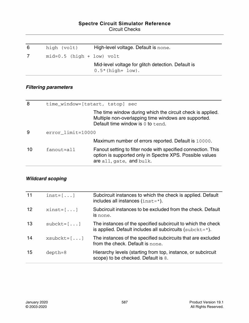
Spectre Circuit Simulator ReferenceCircuit Checks
January 2020 587 Product Version 19.1© 2003-2020 All Rights Reserved.
Filtering parameters
Wildcard scoping
6 high (volt) High-level voltage. Default is none.
7 mid=0.5 (high + low) volt
Mid-level voltage for glitch detection. Default is 0.5*(high+ low).
8 time_window=[tstart, tstop] sec
The time window during which the circuit check is applied. Multiple non-overlapping time windows are supported. Default time window is 0 to tend.
9 error_limit=10000
Maximum number of errors reported. Default is 10000.
10 fanout=all Fanout setting to filter node with specified connection. This option is supported only in Spectre XPS. Possible values are all, gate, and bulk.
11 inst=[...] Subcircuit instances to which the check is applied. Default includes all instances (inst=*).
12 xinst=[...] Subcircuit instances to be excluded from the check. Default is none.
13 subckt=[...] The instances of the specified subcircuit to which the check is applied. Default includes all subcircuits (subckt=*).
14 xsubckt=[...] The instances of the specified subcircuits that are excluded from the check. Default is none.
15 depth=8 Hierarchy levels (starting from top, instance, or subcircuit scope) to be checked. Default is 8.

Spectre Circuit Simulator ReferenceCircuit Checks
January 2020 588 Product Version 19.1© 2003-2020 All Rights Reserved.
Parameter Index
In the following index, the number corresponding to each parameter name indicates where to find the description of that parameter.
depth 15 high 6 mid 7 time_window 8
duration 2 inst 11 min_duration 3 xinst 12
error_limit 9 low 5 node 1 xsubckt 14
fanout 10 max_duration 4 subckt 13
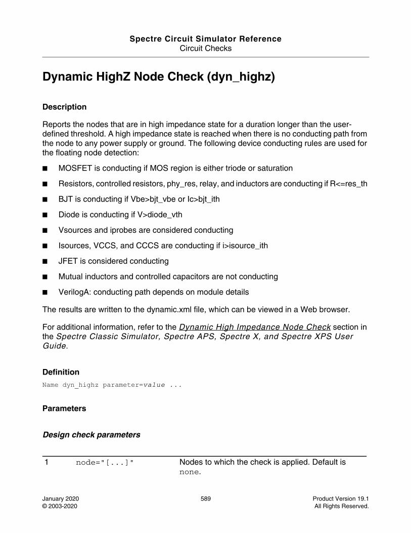
Spectre Circuit Simulator ReferenceCircuit Checks
January 2020 589 Product Version 19.1© 2003-2020 All Rights Reserved.
Dynamic HighZ Node Check (dyn_highz)
Description
Reports the nodes that are in high impedance state for a duration longer than the user- defined threshold. A high impedance state is reached when there is no conducting path from the node to any power supply or ground. The following device conducting rules are used for the floating node detection:
■ MOSFET is conducting if MOS region is either triode or saturation
■ Resistors, controlled resistors, phy_res, relay, and inductors are conducting if R<=res_th
■ BJT is conducting if Vbe>bjt_vbe or Ic>bjt_ith
■ Diode is conducting if V>diode_vth
■ Vsources and iprobes are considered conducting
■ Isources, VCCS, and CCCS are conducting if i>isource_ith
■ JFET is considered conducting
■ Mutual inductors and controlled capacitors are not conducting
■ VerilogA: conducting path depends on module details
The results are written to the dynamic.xml file, which can be viewed in a Web browser.
For additional information, refer to the Dynamic High Impedance Node Check section in the Spectre Classic Simulator, Spectre APS, Spectre X, and Spectre XPS User Guide.
DefinitionName dyn_highz parameter=value ...
Parameters
Design check parameters
1 node="[...]" Nodes to which the check is applied. Default is none.
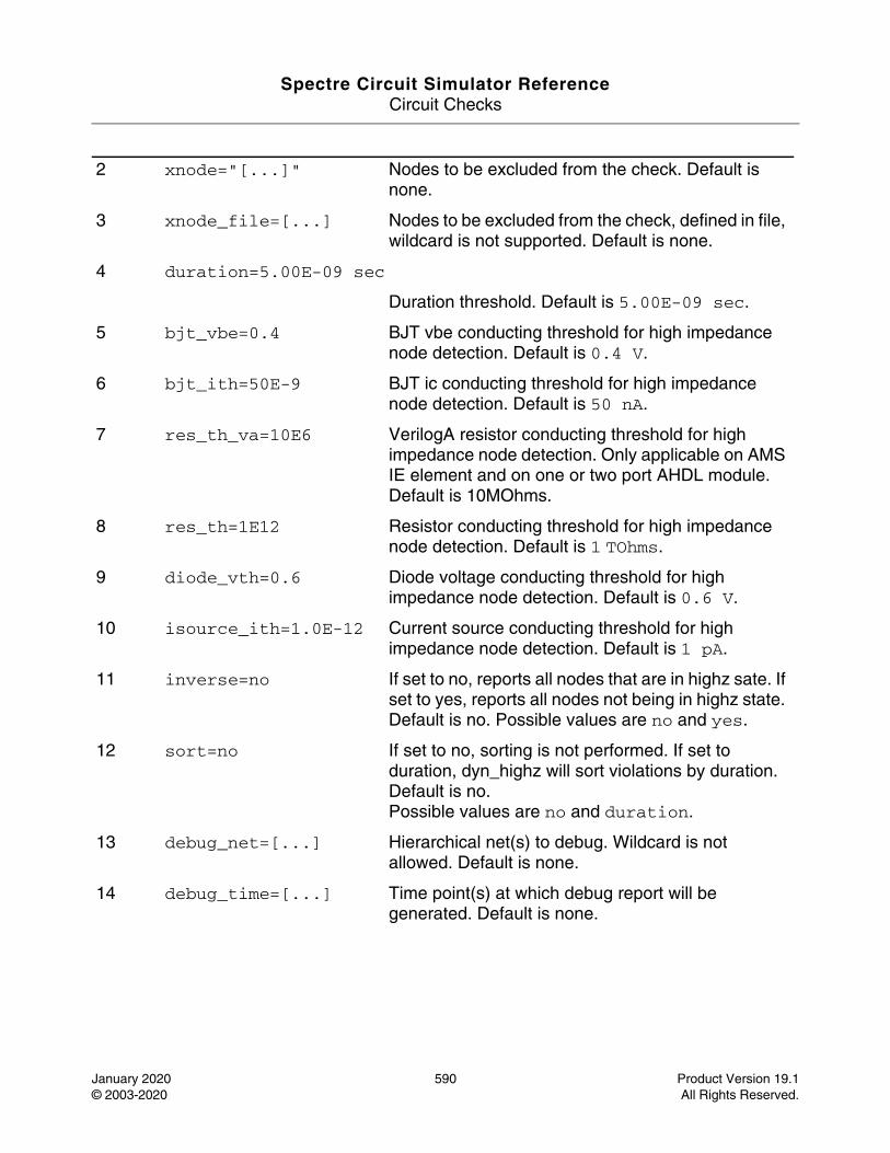
Spectre Circuit Simulator ReferenceCircuit Checks
January 2020 590 Product Version 19.1© 2003-2020 All Rights Reserved.
2 xnode="[...]" Nodes to be excluded from the check. Default is none.
3 xnode_file=[...] Nodes to be excluded from the check, defined in file, wildcard is not supported. Default is none.
4 duration=5.00E-09 sec
Duration threshold. Default is 5.00E-09 sec.
5 bjt_vbe=0.4 BJT vbe conducting threshold for high impedance node detection. Default is 0.4 V.
6 bjt_ith=50E-9 BJT ic conducting threshold for high impedance node detection. Default is 50 nA.
7 res_th_va=10E6 VerilogA resistor conducting threshold for high impedance node detection. Only applicable on AMS IE element and on one or two port AHDL module. Default is 10MOhms.
8 res_th=1E12 Resistor conducting threshold for high impedance node detection. Default is 1 TOhms.
9 diode_vth=0.6 Diode voltage conducting threshold for high impedance node detection. Default is 0.6 V.
10 isource_ith=1.0E-12 Current source conducting threshold for high impedance node detection. Default is 1 pA.
11 inverse=no If set to no, reports all nodes that are in highz sate. If set to yes, reports all nodes not being in highz state. Default is no. Possible values are no and yes.
12 sort=no If set to no, sorting is not performed. If set to duration, dyn_highz will sort violations by duration. Default is no.Possible values are no and duration.
13 debug_net=[...] Hierarchical net(s) to debug. Wildcard is not allowed. Default is none.
14 debug_time=[...] Time point(s) at which debug report will be generated. Default is none.
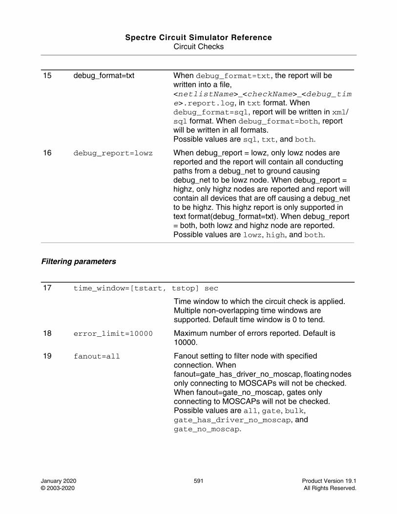
Spectre Circuit Simulator ReferenceCircuit Checks
January 2020 591 Product Version 19.1© 2003-2020 All Rights Reserved.
Filtering parameters
15 debug_format=txt When debug_format=txt, the report will be written into a file, <netlistName>_<checkName>_<debug_time>.report.log, in txt format. When debug_format=sql, report will be written in xml/sql format. When debug_format=both, report will be written in all formats.Possible values are sql, txt, and both.
16 debug_report=lowz When debug_report = lowz, only lowz nodes are reported and the report will contain all conducting paths from a debug_net to ground causing debug_net to be lowz node. When debug_report = highz, only highz nodes are reported and report will contain all devices that are off causing a debug_net to be highz. This highz report is only supported in text format(debug_format=txt). When debug_report = both, both lowz and highz node are reported.Possible values are lowz, high, and both.
17 time_window=[tstart, tstop] sec
Time window to which the circuit check is applied. Multiple non-overlapping time windows are supported. Default time window is 0 to tend.
18 error_limit=10000 Maximum number of errors reported. Default is 10000.
19 fanout=all Fanout setting to filter node with specified connection. When fanout=gate_has_driver_no_moscap, floating nodes only connecting to MOSCAPs will not be checked. When fanout=gate_no_moscap, gates only connecting to MOSCAPs will not be checked.Possible values are all, gate, bulk, gate_has_driver_no_moscap, and gate_no_moscap.
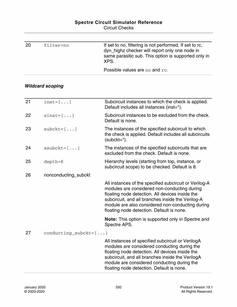
Spectre Circuit Simulator ReferenceCircuit Checks
January 2020 592 Product Version 19.1© 2003-2020 All Rights Reserved.
Wildcard scoping
20 filter=no If set to no, filtering is not performed. If set to rc, dyn_highz checker will report only one node in same parasitic sub. This option is supported only in XPS.
Possible values are no and rc.
21 inst=[...] Subcircuit instances to which the check is applied. Default includes all instances (inst=*).
22 xinst=[...] Subcircuit instances to be excluded from the check. Default is none.
23 subckt=[...] The instances of the specified subcircuit to which the check is applied. Default includes all subcircuits (subckt=*).
24 xsubckt=[...] The instances of the specified subcircuits that are excluded from the check. Default is none.
25 depth=8 Hierarchy levels (starting from top, instance, or subcircuit scope) to be checked. Default is 8.
26 nonconducting_subckt
All instances of the specified subcircuit or Verilog-A modules are considered non-conducting during floating node detection. All devices inside the subcircuit, and all branches inside the Verilog-A module are also considered non-conducting during floating node detection. Default is none.
Note: This option is supported only in Spectre and Spectre APS.
27 conducting_subckt=[...]
All instances of specified subcircuit or VerilogA modules are considered conducting during the floating node detection. All devices inside the subcircuit, and all branches inside the VerilogA module are considered conducting during the floating node detection. Default is none.
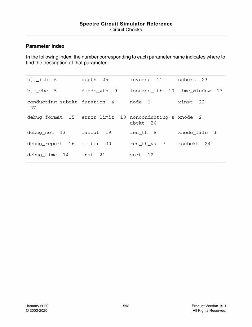
Spectre Circuit Simulator ReferenceCircuit Checks
January 2020 593 Product Version 19.1© 2003-2020 All Rights Reserved.
Parameter Index
In the following index, the number corresponding to each parameter name indicates where to find the description of that parameter.
bjt_ith 6 depth 25 inverse 11 subckt 23
bjt_vbe 5 diode_vth 9 isource_ith 10 time_window 17
conducting_subckt 27
duration 4 node 1 xinst 22
debug_format 15 error_limit 18 nonconducting_subckt 26
xnode 2
debug_net 13 fanout 19 res_th 8 xnode_file 3
debug_report 16 filter 20 res_th_va 7 xsubckt 24
debug_time 14 inst 21 sort 12
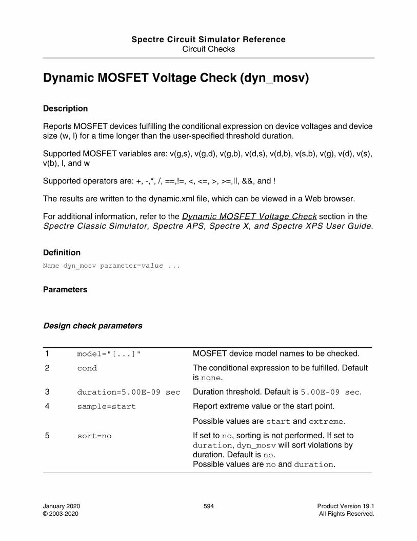
Spectre Circuit Simulator ReferenceCircuit Checks
January 2020 594 Product Version 19.1© 2003-2020 All Rights Reserved.
Dynamic MOSFET Voltage Check (dyn_mosv)
Description
Reports MOSFET devices fulfilling the conditional expression on device voltages and device size (w, l) for a time longer than the user-specified threshold duration.
Supported MOSFET variables are: v(g,s), v(g,d), v(g,b), v(d,s), v(d,b), v(s,b), v(g), v(d), v(s), v(b), l, and w
Supported operators are: +, -,*, /, ==,!=, <, <=, >, >=,||, &&, and !
The results are written to the dynamic.xml file, which can be viewed in a Web browser.
For additional information, refer to the Dynamic MOSFET Voltage Check section in the Spectre Classic Simulator, Spectre APS, Spectre X, and Spectre XPS User Guide.
DefinitionName dyn_mosv parameter=value ...
Parameters
Design check parameters
1 model="[...]" MOSFET device model names to be checked.
2 cond The conditional expression to be fulfilled. Default is none.
3 duration=5.00E-09 sec Duration threshold. Default is 5.00E-09 sec.
4 sample=start Report extreme value or the start point.
Possible values are start and extreme.
5 sort=no If set to no, sorting is not performed. If set to duration, dyn_mosv will sort violations by duration. Default is no.Possible values are no and duration.
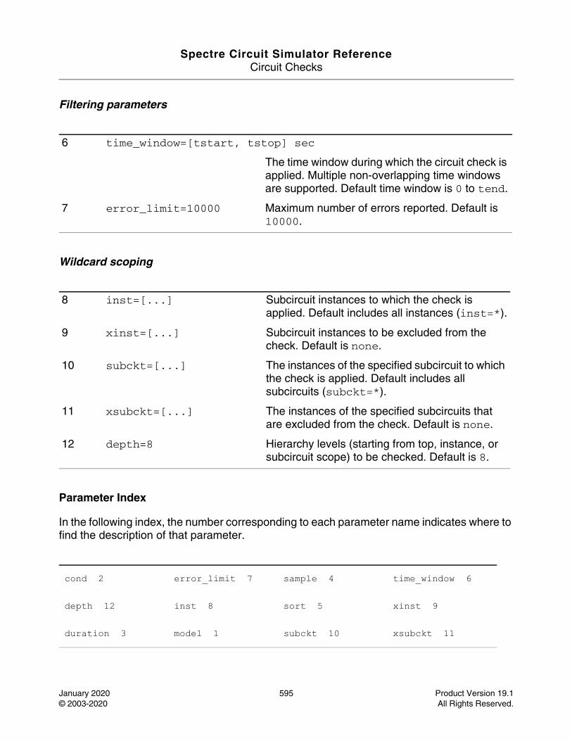
Spectre Circuit Simulator ReferenceCircuit Checks
January 2020 595 Product Version 19.1© 2003-2020 All Rights Reserved.
Filtering parameters
Wildcard scoping
Parameter Index
In the following index, the number corresponding to each parameter name indicates where to find the description of that parameter.
6 time_window=[tstart, tstop] sec
The time window during which the circuit check is applied. Multiple non-overlapping time windows are supported. Default time window is 0 to tend.
7 error_limit=10000 Maximum number of errors reported. Default is 10000.
8 inst=[...] Subcircuit instances to which the check is applied. Default includes all instances (inst=*).
9 xinst=[...] Subcircuit instances to be excluded from the check. Default is none.
10 subckt=[...] The instances of the specified subcircuit to which the check is applied. Default includes all subcircuits (subckt=*).
11 xsubckt=[...] The instances of the specified subcircuits that are excluded from the check. Default is none.
12 depth=8 Hierarchy levels (starting from top, instance, or subcircuit scope) to be checked. Default is 8.
cond 2 error_limit 7 sample 4 time_window 6
depth 12 inst 8 sort 5 xinst 9
duration 3 model 1 subckt 10 xsubckt 11
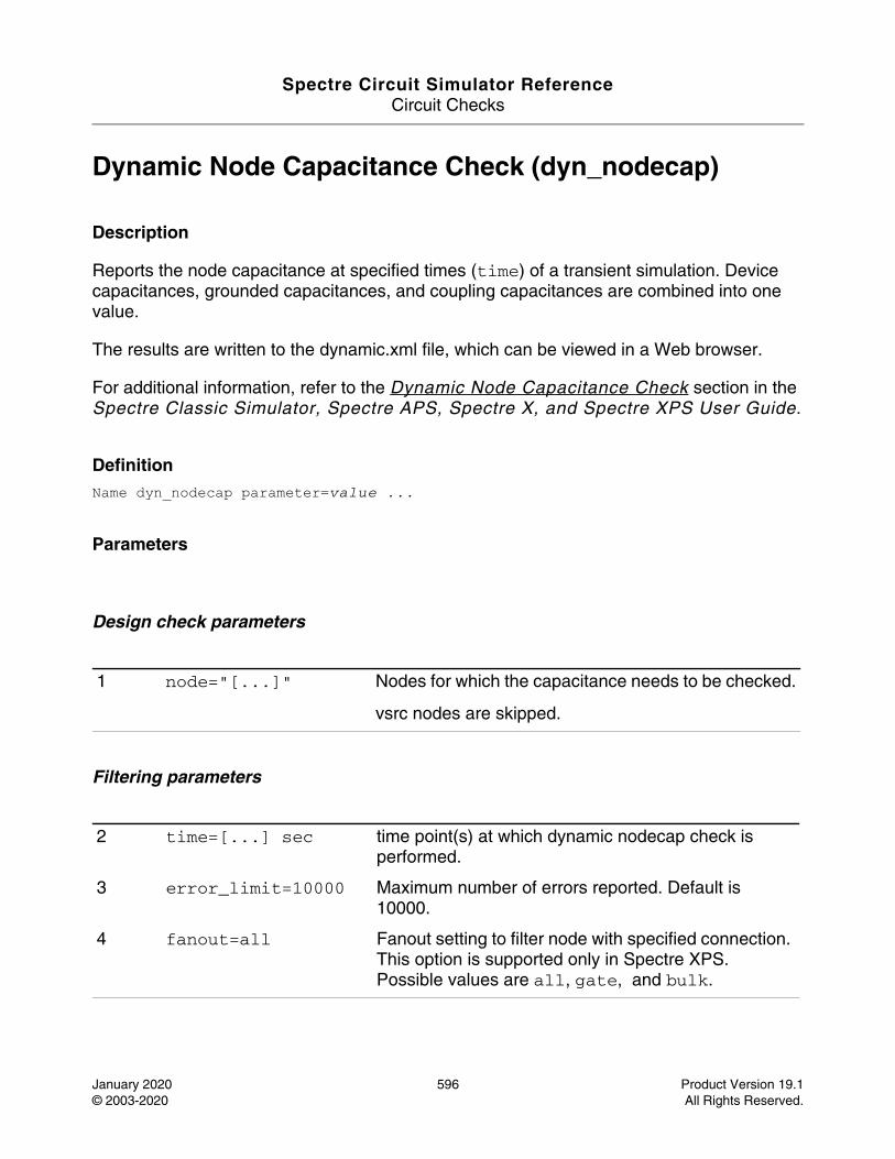
Spectre Circuit Simulator ReferenceCircuit Checks
January 2020 596 Product Version 19.1© 2003-2020 All Rights Reserved.
Dynamic Node Capacitance Check (dyn_nodecap)
Description
Reports the node capacitance at specified times (time) of a transient simulation. Device capacitances, grounded capacitances, and coupling capacitances are combined into one value.
The results are written to the dynamic.xml file, which can be viewed in a Web browser.
For additional information, refer to the Dynamic Node Capacitance Check section in the Spectre Classic Simulator, Spectre APS, Spectre X, and Spectre XPS User Guide.
DefinitionName dyn_nodecap parameter=value ...
Parameters
Design check parameters
Filtering parameters
1 node="[...]" Nodes for which the capacitance needs to be checked.
vsrc nodes are skipped.
2 time=[...] sec time point(s) at which dynamic nodecap check is performed.
3 error_limit=10000 Maximum number of errors reported. Default is 10000.
4 fanout=all Fanout setting to filter node with specified connection. This option is supported only in Spectre XPS. Possible values are all, gate, and bulk.
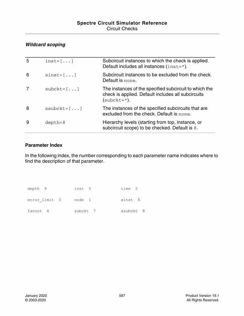
Spectre Circuit Simulator ReferenceCircuit Checks
January 2020 597 Product Version 19.1© 2003-2020 All Rights Reserved.
Wildcard scoping
Parameter Index
In the following index, the number corresponding to each parameter name indicates where to find the description of that parameter.
5 inst=[...] Subcircuit instances to which the check is applied. Default includes all instances (inst=*).
6 xinst=[...] Subcircuit instances to be excluded from the check. Default is none.
7 subckt=[...] The instances of the specified subcircuit to which the check is applied. Default includes all subcircuits (subckt=*).
8 xsubckt=[...] The instances of the specified subcircuits that are excluded from the check. Default is none.
9 depth=8 Hierarchy levels (starting from top, instance, or subcircuit scope) to be checked. Default is 8.
depth 9 inst 5 time 2
error_limit 3 node 1 xinst 6
fanout 4 subckt 7 xsubckt 8
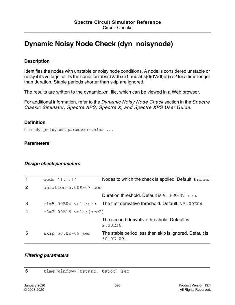
Spectre Circuit Simulator ReferenceCircuit Checks
January 2020 598 Product Version 19.1© 2003-2020 All Rights Reserved.
Dynamic Noisy Node Check (dyn_noisynode)
Description
Identifies the nodes with unstable or noisy node conditions. A node is considered unstable or noisy if its voltage fulfills the condition abs(dV/dt)>e1 and abs(d(dV/dt)dt)>e2 for a time longer than duration. Stable periods shorter than skip are ignored.
The results are written to the dynamic.xml file, which can be viewed in a Web browser.
For additional information, refer to the Dynamic Noisy Node Check section in the Spectre Classic Simulator, Spectre APS, Spectre X, and Spectre XPS User Guide.
DefinitionName dyn_noisynode parameter=value ...
Parameters
Design check parameters
Filtering parameters
1 node="[...]" Nodes to which the check is applied. Default is none.
2 duration=5.00E-07 sec
Duration threshold. Default is 5.00E-07 sec.
3 e1=5.00E04 volt/sec The first derivative threshold. Default is 5.00E04.
4 e2=2.00E16 volt/(sec2)
The second derivative threshold. Default is 2.00E16.
5 skip=50.0E-09 sec The stable period less than skip is ignored. Default is 50.0E-09.
6 time_window=[tstart, tstop] sec
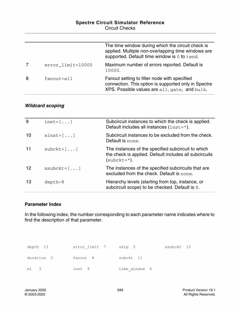
Spectre Circuit Simulator ReferenceCircuit Checks
January 2020 599 Product Version 19.1© 2003-2020 All Rights Reserved.
Wildcard scoping
Parameter Index
In the following index, the number corresponding to each parameter name indicates where to find the description of that parameter.
The time window during which the circuit check is applied. Multiple non-overlapping time windows are supported. Default time window is 0 to tend.
7 error_limit=10000 Maximum number of errors reported. Default is 10000.
8 fanout=all Fanout setting to filter node with specified connection. This option is supported only in Spectre XPS. Possible values are all, gate, and bulk.
9 inst=[...] Subcircuit instances to which the check is applied. Default includes all instances (inst=*).
10 xinst=[...] Subcircuit instances to be excluded from the check. Default is none.
11 subckt=[...] The instances of the specified subcircuit to which the check is applied. Default includes all subcircuits (subckt=*).
12 xsubckt=[...] The instances of the specified subcircuits that are excluded from the check. Default is none.
13 depth=8 Hierarchy levels (starting from top, instance, or subcircuit scope) to be checked. Default is 8.
depth 13 error_limit 7 skip 5 xsubckt 12
duration 2 fanout 8 subckt 11
e1 3 inst 9 time_window 6

Spectre Circuit Simulator ReferenceCircuit Checks
January 2020 600 Product Version 19.1© 2003-2020 All Rights Reserved.
e2 4 node 1 xinst 10
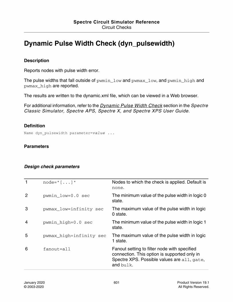
Spectre Circuit Simulator ReferenceCircuit Checks
January 2020 601 Product Version 19.1© 2003-2020 All Rights Reserved.
Dynamic Pulse Width Check (dyn_pulsewidth)
Description
Reports nodes with pulse width error.
The pulse widths that fall outside of pwmin_low and pwmax_low, and pwmin_high and pwmax_high are reported.
The results are written to the dynamic.xml file, which can be viewed in a Web browser.
For additional information, refer to the Dynamic Pulse Width Check section in the Spectre Classic Simulator, Spectre APS, Spectre X, and Spectre XPS User Guide.
DefinitionName dyn_pulsewidth parameter=value ...
Parameters
Design check parameters
1 node="[...]" Nodes to which the check is applied. Default is none.
2 pwmin_low=0.0 sec The minimum value of the pulse width in logic 0 state.
3 pwmax_low=infinity sec The maximum value of the pulse width in logic 0 state.
4 pwmin_high=0.0 sec The minimum value of the pulse width in logic 1 state.
5 pwmax_high=infinity sec The maximum value of the pulse width in logic 1 state.
6 fanout=all Fanout setting to filter node with specified connection. This option is supported only in Spectre XPS. Possible values are all, gate, and bulk.
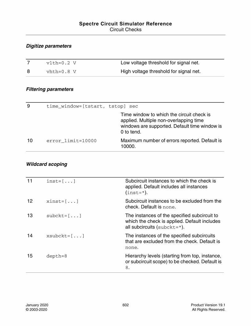
Spectre Circuit Simulator ReferenceCircuit Checks
January 2020 602 Product Version 19.1© 2003-2020 All Rights Reserved.
Digitize parameters
Filtering parameters
Wildcard scoping
7 vlth=0.2 V Low voltage threshold for signal net.
8 vhth=0.8 V High voltage threshold for signal net.
9 time_window=[tstart, tstop] sec
Time window to which the circuit check is applied. Multiple non-overlapping time windows are supported. Default time window is 0 to tend.
10 error_limit=10000 Maximum number of errors reported. Default is 10000.
11 inst=[...] Subcircuit instances to which the check is applied. Default includes all instances (inst=*).
12 xinst=[...] Subcircuit instances to be excluded from the check. Default is none.
13 subckt=[...] The instances of the specified subcircuit to which the check is applied. Default includes all subcircuits (subckt=*).
14 xsubckt=[...] The instances of the specified subcircuits that are excluded from the check. Default is none.
15 depth=8 Hierarchy levels (starting from top, instance, or subcircuit scope) to be checked. Default is 8.

Spectre Circuit Simulator ReferenceCircuit Checks
January 2020 603 Product Version 19.1© 2003-2020 All Rights Reserved.
Parameter Index
In the following index, the number corresponding to each parameter name indicates where to find the description of that parameter.
depth 15 node 1 pwmin_low 2 vlth 7
error_limit 10 pwmax_high 5 subckt 13 xinst 12
fanout 6 pwmax_low 3 time_window 9 xsubckt 14
inst 11 pwmin_high 4 vhth 8
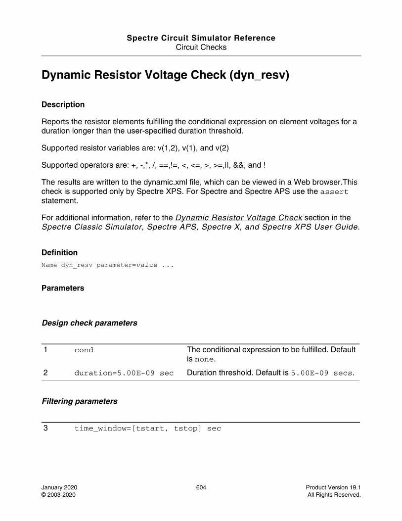
Spectre Circuit Simulator ReferenceCircuit Checks
January 2020 604 Product Version 19.1© 2003-2020 All Rights Reserved.
Dynamic Resistor Voltage Check (dyn_resv)
Description
Reports the resistor elements fulfilling the conditional expression on element voltages for a duration longer than the user-specified duration threshold.
Supported resistor variables are: v(1,2), v(1), and v(2)
Supported operators are: +, -,*, /, ==,!=, <, <=, >, >=,||, &&, and !
The results are written to the dynamic.xml file, which can be viewed in a Web browser.This check is supported only by Spectre XPS. For Spectre and Spectre APS use the assert statement.
For additional information, refer to the Dynamic Resistor Voltage Check section in the Spectre Classic Simulator, Spectre APS, Spectre X, and Spectre XPS User Guide.
DefinitionName dyn_resv parameter=value ...
Parameters
Design check parameters
Filtering parameters
1 cond The conditional expression to be fulfilled. Default is none.
2 duration=5.00E-09 sec Duration threshold. Default is 5.00E-09 secs.
3 time_window=[tstart, tstop] sec
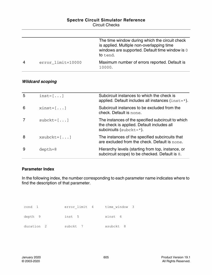
Spectre Circuit Simulator ReferenceCircuit Checks
January 2020 605 Product Version 19.1© 2003-2020 All Rights Reserved.
Wildcard scoping
Parameter Index
In the following index, the number corresponding to each parameter name indicates where to find the description of that parameter.
The time window during which the circuit check is applied. Multiple non-overlapping time windows are supported. Default time window is 0 to tend.
4 error_limit=10000 Maximum number of errors reported. Default is 10000.
5 inst=[...] Subcircuit instances to which the check is applied. Default includes all instances (inst=*).
6 xinst=[...] Subcircuit instances to be excluded from the check. Default is none.
7 subckt=[...] The instances of the specified subcircuit to which the check is applied. Default includes all subcircuits (subckt=*).
8 xsubckt=[...] The instances of the specified subcircuits that are excluded from the check. Default is none.
9 depth=8 Hierarchy levels (starting from top, instance, or subcircuit scope) to be checked. Default is 8.
cond 1 error_limit 4 time_window 3
depth 9 inst 5 xinst 6
duration 2 subckt 7 xsubckt 8
Spectre Circuit Simulator ReferenceCircuit Checks
January 2020 606 Product Version 19.1© 2003-2020 All Rights Reserved.
Dynamic Setup and Hold Check (dyn_setuphold)
Description
Reports nodes with setup or hold timing errors with reference to a clock signal. The transition time of the clock signal is refTime.
For setup timing, transitions that happen between refTime + delay - setupTime and refTime + delay are reported.
For hold timing, transitions that happen between refTime + delay and refTime + delay + holdTime are reported.
ref_vhth and vhth parameters are used for triggering rising edge measurements, while ref_vlth and vlth are used for triggering falling edge measurements.
If the subckt parameter is specified, node and ref_node are considered as local nodes to the specified subcircuit. In other words, node and ref_node belong to instances of the specified subcircuit. Only one subckt value can be specified per check, with no wildcard.
If the subckt parameter is not specified, node and ref_node are considered as global nodes with hierarchical names starting from the top level.
The parameters inst, xinst, xsubckt, and depth are not supported.
The results are written to the dynamic.xml file, which can be viewed in a Web browser.
For additional information, refer to the Dynamic Setup and Hold Check section in the Spectre Classic Simulator, Spectre APS, Spectre X, and Spectre XPS User Guide.
DefinitionName dyn_setuphold parameter=value ...
Parameters
Design check parameters
1 node="[...]" Nodes to which the check is applied. Default is none.
Spectre Circuit Simulator ReferenceCircuit Checks
January 2020 607 Product Version 19.1© 2003-2020 All Rights Reserved.
Digitize parameters
Filtering parameters
2 ref_node Name of the referenced clock. Wildcards are not supported.
3 setup_time=0.0 sec Setup time violation window. If specified, the setup check is enabled. Default is 0.0 sec.
4 hold_time=0.0 sec Hold time violation window. If specified, the hold check is enabled.
5 delay=0.0 sec Delay of the reference signal.
6 edge=rise Edge type of the signal net. Possible values are rise, fall, and both. Default is rise. Possible values are rise, fall, and both.
7 ref_edge=rise Edge type of the reference signal. Possible values are rise, fall, and both. Default is rise. Possible values are rise, fall, and both.
8 fanout=all Fanout setting to filter node with specified connection. This option is supported only in Spectre XPS. Possible values are all, gate, and bulk.
9 setup_chk_time=0.0 sec
Setup time checking window.
10 hold_chk_time=0.0 sec
Hold time checking window.
11 vlth=0.2 V Low voltage threshold for the signal net.
12 ref_vlth=0.2 V Low voltage threshold for the referenced net.
13 vhth=0.8 V High voltage threshold for the signal net.
14 ref_vhth=0.8 V High voltage threshold for the referenced net.
15 time_window=[tstart, tstop] sec
The time window during which the circuit check is applied. Multiple non-overlapping time windows are supported. Default time window is 0 to tend.
Spectre Circuit Simulator ReferenceCircuit Checks
January 2020 608 Product Version 19.1© 2003-2020 All Rights Reserved.
Wildcard scoping
Parameter Index
In the following index, the number corresponding to each parameter name indicates where to find the description of that parameter.
16 error_limit=10000 Maximum number of errors reported. Default is 10000.
17 subckt=none Instances of the specified subcircuit to which the check is applied. Default is none.
18 report=violation Report all checks or violation only. Default is violation.Possible values are all and violation.
delay 5 hold_time 4 ref_vlth 12 time_window 15
edge 6 node 1 report 18 vhth 13
error_limit 16 ref_edge 7 setup_chk_time 9 vlth 11
fanout 8 ref_node 2 setup_time 3
hold_chk_time 10 ref_vhth 14 subckt 17

Spectre Circuit Simulator ReferenceCircuit Checks
January 2020 609 Product Version 19.1© 2003-2020 All Rights Reserved.
Dynamic Statistical HighZ Node Check (dyn_stahighz)
Description
Identifies and reports nodes that are in high impedance state at a user given time. Deploys a statistical method of forcing (pinging) different voltage levels or voltage ramp ups to all nodes, and detecting floating nodes based on the current changes in the connecting devices.
The results are written to the dynamic.xml file, which can be viewed in a Web browser.
DefinitionName dyn_stahighz parameter=value ...
Spectre Circuit Simulator ReferenceCircuit Checks
January 2020 610 Product Version 19.1© 2003-2020 All Rights Reserved.
Parameters
Design check parameters
1 domains="[...]" Pairs of power supply domains in which floating nodes are checked. Example: domains=[VDD VSS VPP VSS]. Domain also defines high voltage (high_voltage) value for forcing node voltages. Default is none. Wildcards not allowed.
2 ping_start=[...] sec
Time at which the check is initiated.
3 ping_count=300 Number of statistical periods being used. Default is 300.
4 ping_duration
Duration of one statistical period. One ping consists of 3 ping_duration (high/low forcing, ramp up forcing, release). Default is none.
5 ping_ibias Lowest bias current in the design. Default is none. Internal value ping_resistor=high_voltage/(ping_ibias/10).
6 ping_iabsthresh Current threshold for floating node detection during high/low forcing. Default is high_voltage/ping_resistor.
7 ping_iabsthresh_ramp
Current threshold for floating node detection during ramp forcing. Default is 100*high_voltage/ping_resistor.
8 ping_irelthresh=1000
Relative threshold for floating node detection for both high/low and ramp forcing. Default is 1000.
9 seed=3 Seed for random number generation.
10 domain_voltage_thresh=0.0
Lowest threshold for domain voltage. If a node has voltage less than domain_voltage_thresh, it will be excluded from ping. Default is 0.0.
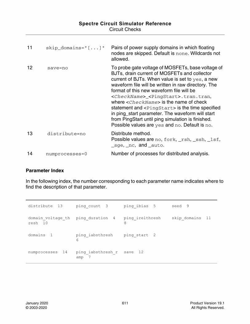
Spectre Circuit Simulator ReferenceCircuit Checks
January 2020 611 Product Version 19.1© 2003-2020 All Rights Reserved.
Parameter Index
In the following index, the number corresponding to each parameter name indicates where to find the description of that parameter.
11 skip_domains="[...]" Pairs of power supply domains in which floating nodes are skipped. Default is none. Wildcards not allowed.
12 save=no To probe gate voltage of MOSFETs, base voltage of BJTs, drain current of MOSFETs and collector current of BJTs. When value is set to yes, a new waveform file will be written in raw directory. The format of this new waveform file will be <CheckName>_<PingStart>.tran.tran, where <CheckName> is the name of check statement and <PingStart> is the time specified in ping_start parameter. The waveform will start from PingStart until ping simulation is finished. Possible values are yes and no. Default is no.
13 distribute=no Distribute method.Possible values are no, fork, _rsh, _ssh, _lsf, _sge, _nc, and _auto.
14 numprocesses=0 Number of processes for distributed analysis.
distribute 13 ping_count 3 ping_ibias 5 seed 9
domain_voltage_thresh 10
ping_duration 4 ping_irelthresh 8
skip_domains 11
domains 1 ping_iabsthresh 6
ping_start 2
numprocesses 14 ping_iabsthresh_ramp 7
save 12
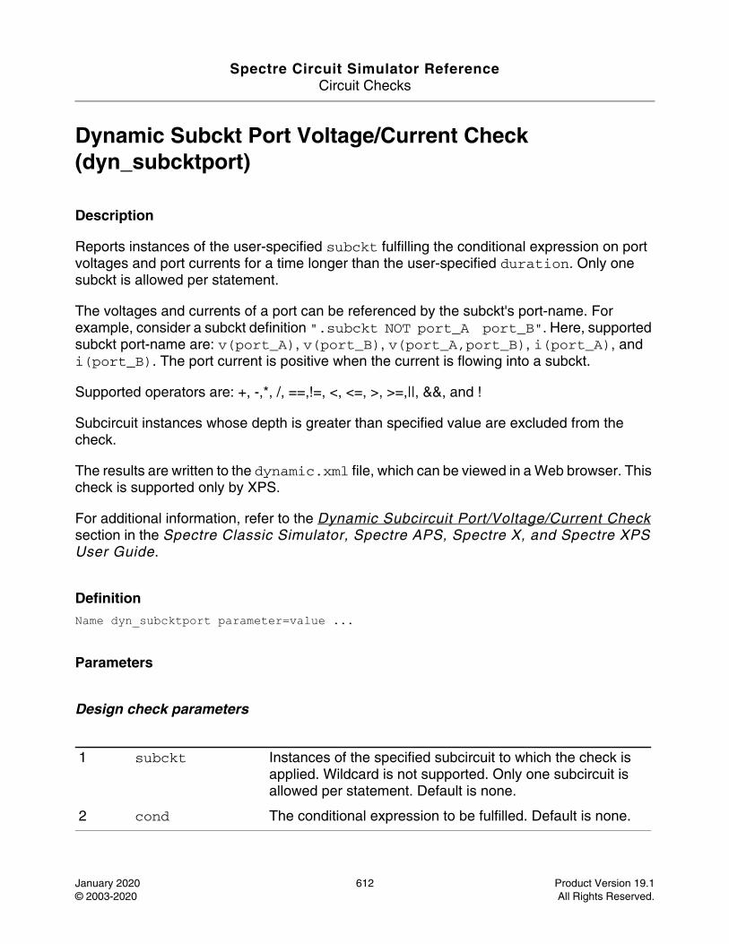
Spectre Circuit Simulator ReferenceCircuit Checks
January 2020 612 Product Version 19.1© 2003-2020 All Rights Reserved.
Dynamic Subckt Port Voltage/Current Check (dyn_subcktport)
Description
Reports instances of the user-specified subckt fulfilling the conditional expression on port voltages and port currents for a time longer than the user-specified duration. Only one subckt is allowed per statement.
The voltages and currents of a port can be referenced by the subckt's port-name. For example, consider a subckt definition ".subckt NOT port_A port_B". Here, supported subckt port-name are: v(port_A), v(port_B), v(port_A,port_B), i(port_A), and i(port_B). The port current is positive when the current is flowing into a subckt.
Supported operators are: +, -,*, /, ==,!=, <, <=, >, >=,||, &&, and !
Subcircuit instances whose depth is greater than specified value are excluded from the check.
The results are written to the dynamic.xml file, which can be viewed in a Web browser. This check is supported only by XPS.
For additional information, refer to the Dynamic Subcircuit Port/Voltage/Current Check section in the Spectre Classic Simulator, Spectre APS, Spectre X, and Spectre XPS User Guide.
DefinitionName dyn_subcktport parameter=value ...
Parameters
Design check parameters
1 subckt Instances of the specified subcircuit to which the check is applied. Wildcard is not supported. Only one subcircuit is allowed per statement. Default is none.
2 cond The conditional expression to be fulfilled. Default is none.
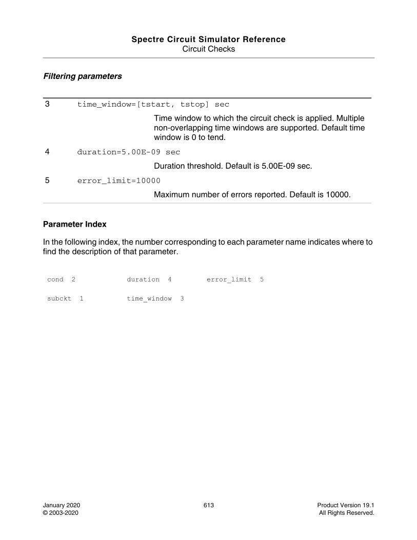
Spectre Circuit Simulator ReferenceCircuit Checks
January 2020 613 Product Version 19.1© 2003-2020 All Rights Reserved.
Filtering parameters
Parameter Index
In the following index, the number corresponding to each parameter name indicates where to find the description of that parameter.
3 time_window=[tstart, tstop] sec
Time window to which the circuit check is applied. Multiple non-overlapping time windows are supported. Default time window is 0 to tend.
4 duration=5.00E-09 sec
Duration threshold. Default is 5.00E-09 sec.
5 error_limit=10000
Maximum number of errors reported. Default is 10000.
cond 2 duration 4 error_limit 5
subckt 1 time_window 3
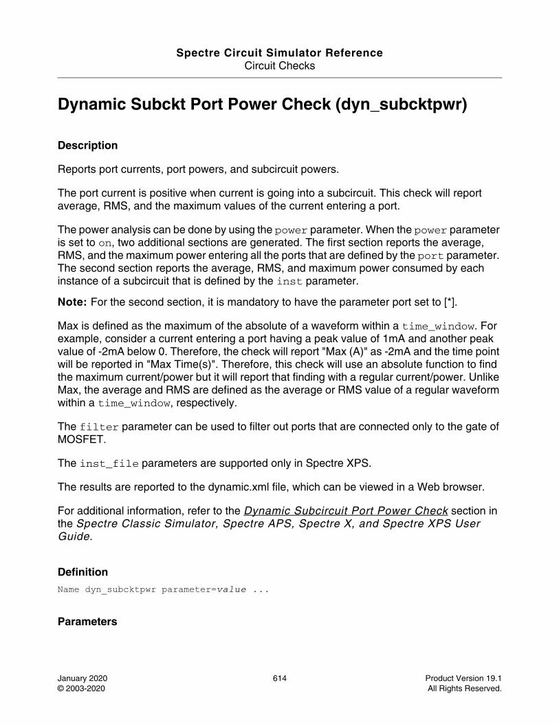
Spectre Circuit Simulator ReferenceCircuit Checks
January 2020 614 Product Version 19.1© 2003-2020 All Rights Reserved.
Dynamic Subckt Port Power Check (dyn_subcktpwr)
Description
Reports port currents, port powers, and subcircuit powers.
The port current is positive when current is going into a subcircuit. This check will report average, RMS, and the maximum values of the current entering a port.
The power analysis can be done by using the power parameter. When the power parameter is set to on, two additional sections are generated. The first section reports the average, RMS, and the maximum power entering all the ports that are defined by the port parameter. The second section reports the average, RMS, and maximum power consumed by each instance of a subcircuit that is defined by the inst parameter.
Note: For the second section, it is mandatory to have the parameter port set to [*].
Max is defined as the maximum of the absolute of a waveform within a time_window. For example, consider a current entering a port having a peak value of 1mA and another peak value of -2mA below 0. Therefore, the check will report "Max (A)" as -2mA and the time point will be reported in "Max Time(s)". Therefore, this check will use an absolute function to find the maximum current/power but it will report that finding with a regular current/power. Unlike Max, the average and RMS are defined as the average or RMS value of a regular waveform within a time_window, respectively.
The filter parameter can be used to filter out ports that are connected only to the gate of MOSFET.
The inst_file parameters are supported only in Spectre XPS.
The results are reported to the dynamic.xml file, which can be viewed in a Web browser.
For additional information, refer to the Dynamic Subcircuit Port Power Check section in the Spectre Classic Simulator, Spectre APS, Spectre X, and Spectre XPS User Guide.
DefinitionName dyn_subcktpwr parameter=value ...
Parameters
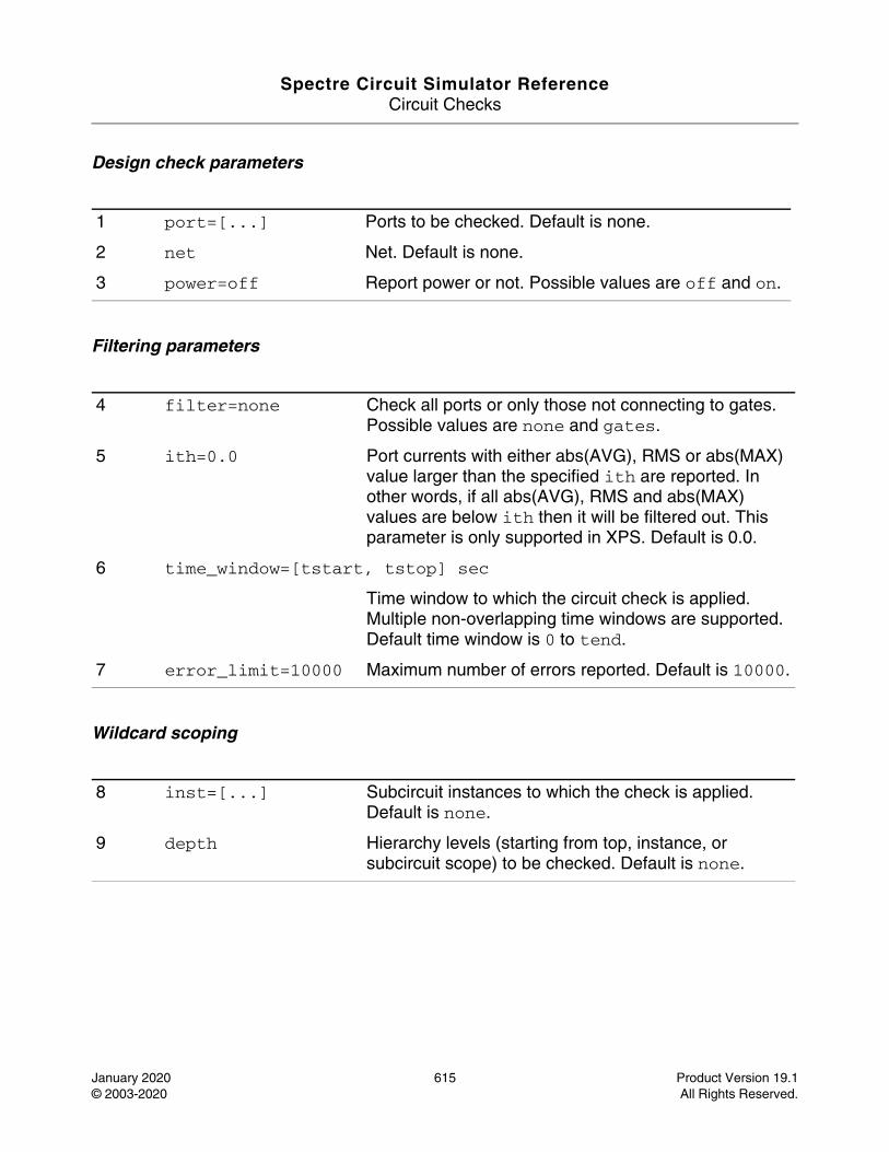
Spectre Circuit Simulator ReferenceCircuit Checks
January 2020 615 Product Version 19.1© 2003-2020 All Rights Reserved.
Design check parameters
Filtering parameters
Wildcard scoping
1 port=[...] Ports to be checked. Default is none.
2 net Net. Default is none.
3 power=off Report power or not. Possible values are off and on.
4 filter=none Check all ports or only those not connecting to gates. Possible values are none and gates.
5 ith=0.0 Port currents with either abs(AVG), RMS or abs(MAX) value larger than the specified ith are reported. In other words, if all abs(AVG), RMS and abs(MAX) values are below ith then it will be filtered out. This parameter is only supported in XPS. Default is 0.0.
6 time_window=[tstart, tstop] sec
Time window to which the circuit check is applied. Multiple non-overlapping time windows are supported. Default time window is 0 to tend.
7 error_limit=10000 Maximum number of errors reported. Default is 10000.
8 inst=[...] Subcircuit instances to which the check is applied. Default is none.
9 depth Hierarchy levels (starting from top, instance, or subcircuit scope) to be checked. Default is none.
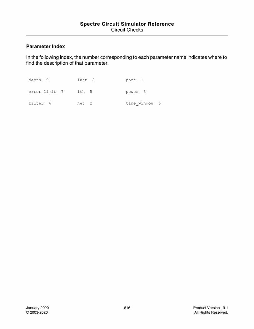
Spectre Circuit Simulator ReferenceCircuit Checks
January 2020 616 Product Version 19.1© 2003-2020 All Rights Reserved.
Parameter Index
In the following index, the number corresponding to each parameter name indicates where to find the description of that parameter.
depth 9 inst 8 port 1
error_limit 7 ith 5 power 3
filter 4 net 2 time_window 6
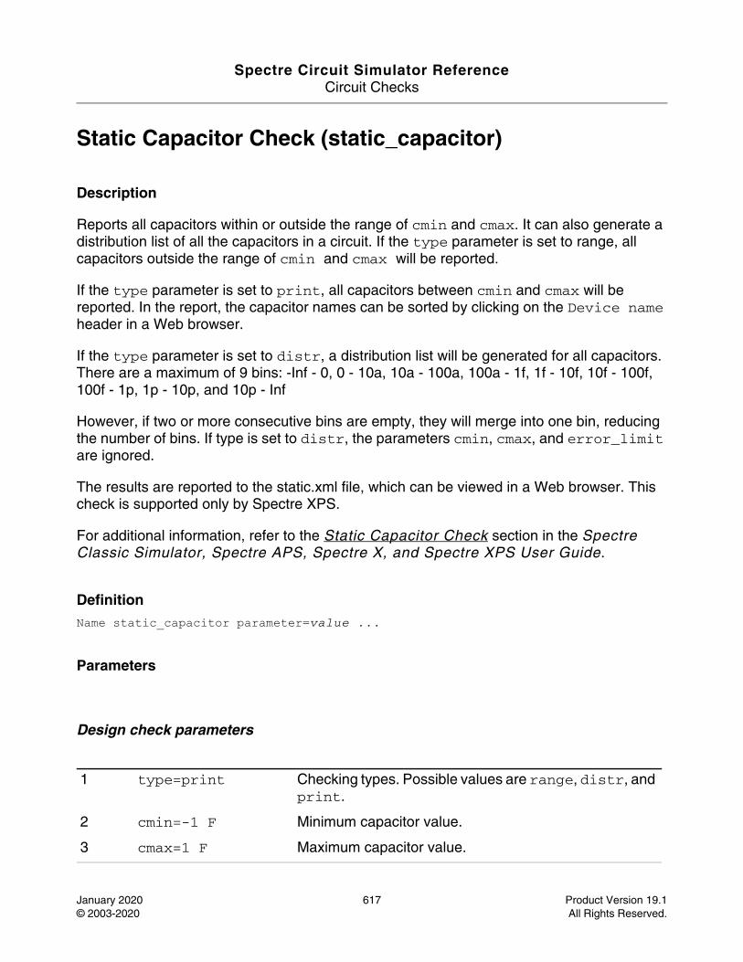
Spectre Circuit Simulator ReferenceCircuit Checks
January 2020 617 Product Version 19.1© 2003-2020 All Rights Reserved.
Static Capacitor Check (static_capacitor)
Description
Reports all capacitors within or outside the range of cmin and cmax. It can also generate a distribution list of all the capacitors in a circuit. If the type parameter is set to range, all capacitors outside the range of cmin and cmax will be reported.
If the type parameter is set to print, all capacitors between cmin and cmax will be reported. In the report, the capacitor names can be sorted by clicking on the Device name header in a Web browser.
If the type parameter is set to distr, a distribution list will be generated for all capacitors. There are a maximum of 9 bins: -Inf - 0, 0 - 10a, 10a - 100a, 100a - 1f, 1f - 10f, 10f - 100f, 100f - 1p, 1p - 10p, and 10p - Inf
However, if two or more consecutive bins are empty, they will merge into one bin, reducing the number of bins. If type is set to distr, the parameters cmin, cmax, and error_limit are ignored.
The results are reported to the static.xml file, which can be viewed in a Web browser. This check is supported only by Spectre XPS.
For additional information, refer to the Static Capacitor Check section in the Spectre Classic Simulator, Spectre APS, Spectre X, and Spectre XPS User Guide.
DefinitionName static_capacitor parameter=value ...
Parameters
Design check parameters
1 type=print Checking types. Possible values are range, distr, and print.
2 cmin=-1 F Minimum capacitor value.
3 cmax=1 F Maximum capacitor value.

Spectre Circuit Simulator ReferenceCircuit Checks
January 2020 618 Product Version 19.1© 2003-2020 All Rights Reserved.
Filtering parameters
4 error_limit=10000 Maximum number of errors reported. Default is 10000.
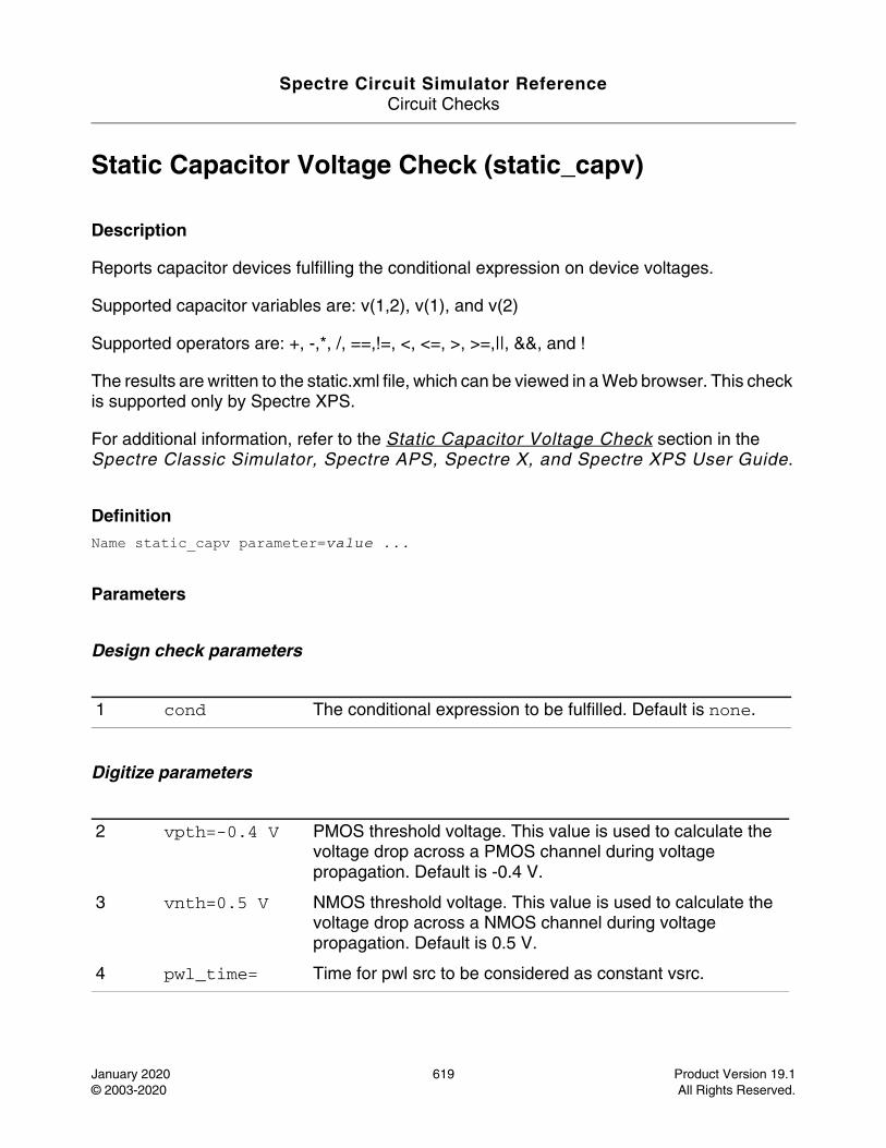
Spectre Circuit Simulator ReferenceCircuit Checks
January 2020 619 Product Version 19.1© 2003-2020 All Rights Reserved.
Static Capacitor Voltage Check (static_capv)
Description
Reports capacitor devices fulfilling the conditional expression on device voltages.
Supported capacitor variables are: v(1,2), v(1), and v(2)
Supported operators are: +, -,*, /, ==,!=, <, <=, >, >=,||, &&, and !
The results are written to the static.xml file, which can be viewed in a Web browser. This check is supported only by Spectre XPS.
For additional information, refer to the Static Capacitor Voltage Check section in the Spectre Classic Simulator, Spectre APS, Spectre X, and Spectre XPS User Guide.
DefinitionName static_capv parameter=value ...
Parameters
Design check parameters
Digitize parameters
1 cond The conditional expression to be fulfilled. Default is none.
2 vpth=-0.4 V PMOS threshold voltage. This value is used to calculate the voltage drop across a PMOS channel during voltage propagation. Default is -0.4 V.
3 vnth=0.5 V NMOS threshold voltage. This value is used to calculate the voltage drop across a NMOS channel during voltage propagation. Default is 0.5 V.
4 pwl_time= Time for pwl src to be considered as constant vsrc.
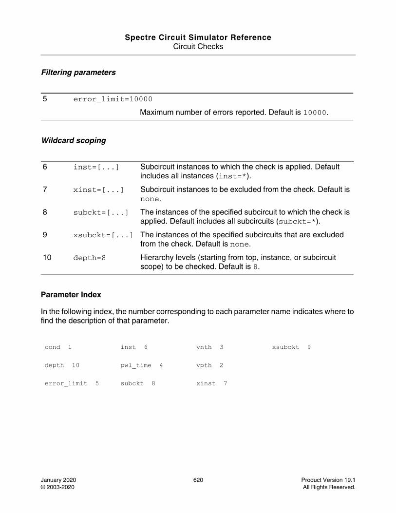
Spectre Circuit Simulator ReferenceCircuit Checks
January 2020 620 Product Version 19.1© 2003-2020 All Rights Reserved.
Filtering parameters
Wildcard scoping
Parameter Index
In the following index, the number corresponding to each parameter name indicates where to find the description of that parameter.
5 error_limit=10000
Maximum number of errors reported. Default is 10000.
6 inst=[...] Subcircuit instances to which the check is applied. Default includes all instances (inst=*).
7 xinst=[...] Subcircuit instances to be excluded from the check. Default is none.
8 subckt=[...] The instances of the specified subcircuit to which the check is applied. Default includes all subcircuits (subckt=*).
9 xsubckt=[...] The instances of the specified subcircuits that are excluded from the check. Default is none.
10 depth=8 Hierarchy levels (starting from top, instance, or subcircuit scope) to be checked. Default is 8.
cond 1 inst 6 vnth 3 xsubckt 9
depth 10 pwl_time 4 vpth 2
error_limit 5 subckt 8 xinst 7
Spectre Circuit Simulator ReferenceCircuit Checks
January 2020 621 Product Version 19.1© 2003-2020 All Rights Reserved.
Static Coupling Impact Check (static_coupling)
Description
Evaluate the possible coupling effects in the circuit.
For each victim node, identify its voltage level impact from aggressors by dividing the total agressor's charge with its total capacitance (including cc+gc+device cap). Each agressor's charge is calculated by multiplying the coupling aggressor's voltage level (using Vmax for worst case analysis) by coupling capacitance. In this check, only capacitors written in netlist are counted.
The results are reported into a file with the extension static.xml, which can be read with a web browser.
DefinitionName static_coupling parameter=value ...
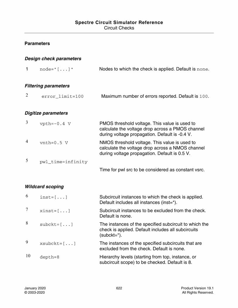
Spectre Circuit Simulator ReferenceCircuit Checks
January 2020 622 Product Version 19.1© 2003-2020 All Rights Reserved.
Parameters
Design check parameters
Filtering parameters
Digitize parameters
Wildcard scoping
1 node="[...]" Nodes to which the check is applied. Default is none.
2 error_limit=100 Maximum number of errors reported. Default is 100.
3 vpth=-0.4 V PMOS threshold voltage. This value is used to calculate the voltage drop across a PMOS channel during voltage propagation. Default is -0.4 V.
4 vnth=0.5 V NMOS threshold voltage. This value is used to calculate the voltage drop across a NMOS channel during voltage propagation. Default is 0.5 V.
5 pwl_time=infinity
Time for pwl src to be considered as constant vsrc.
6 inst=[...] Subcircuit instances to which the check is applied. Default includes all instances (inst=*).
7 xinst=[...] Subcircuit instances to be excluded from the check. Default is none.
8 subckt=[...] The instances of the specified subcircuit to which the check is applied. Default includes all subcircuits (subckt=*).
9 xsubckt=[...] The instances of the specified subcircuits that are excluded from the check. Default is none.
10 depth=8 Hierarchy levels (starting from top, instance, or subcircuit scope) to be checked. Default is 8.
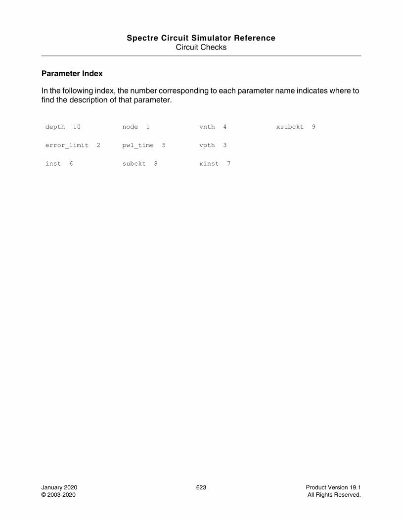
Spectre Circuit Simulator ReferenceCircuit Checks
January 2020 623 Product Version 19.1© 2003-2020 All Rights Reserved.
Parameter Index
In the following index, the number corresponding to each parameter name indicates where to find the description of that parameter.
depth 10 node 1 vnth 4 xsubckt 9
error_limit 2 pwl_time 5 vpth 3
inst 6 subckt 8 xinst 7
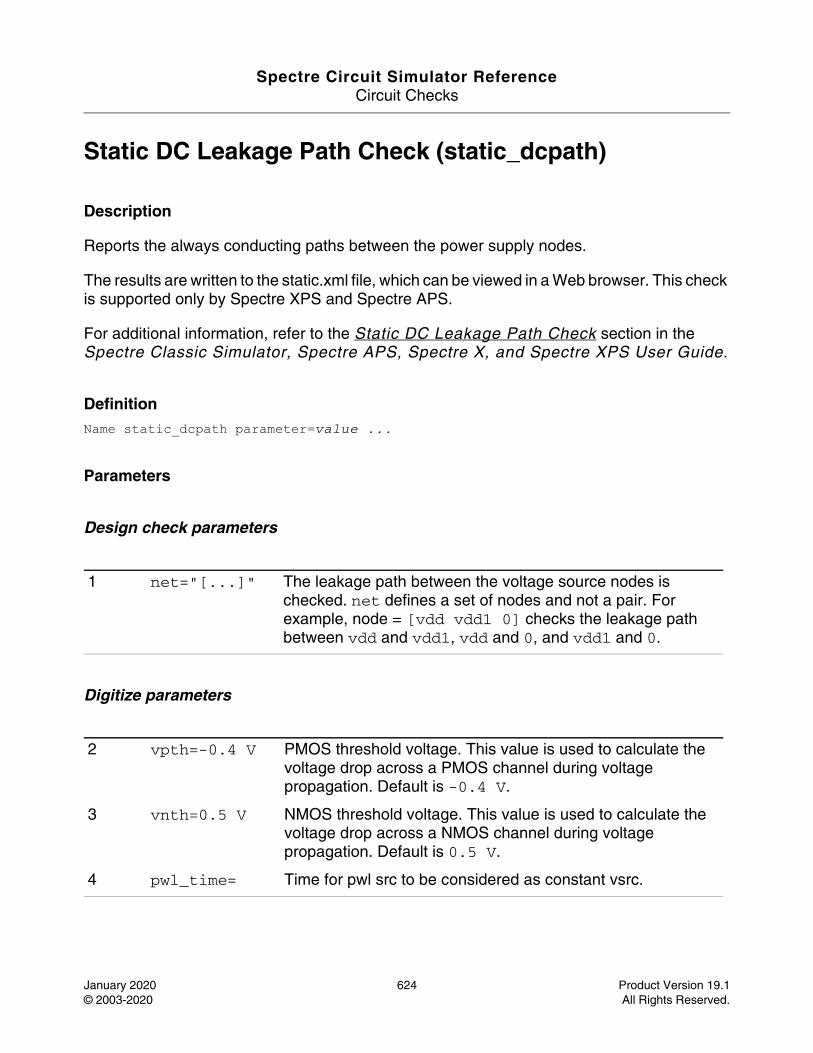
Spectre Circuit Simulator ReferenceCircuit Checks
January 2020 624 Product Version 19.1© 2003-2020 All Rights Reserved.
Static DC Leakage Path Check (static_dcpath)
Description
Reports the always conducting paths between the power supply nodes.
The results are written to the static.xml file, which can be viewed in a Web browser. This check is supported only by Spectre XPS and Spectre APS.
For additional information, refer to the Static DC Leakage Path Check section in the Spectre Classic Simulator, Spectre APS, Spectre X, and Spectre XPS User Guide.
DefinitionName static_dcpath parameter=value ...
Parameters
Design check parameters
Digitize parameters
1 net="[...]" The leakage path between the voltage source nodes is checked. net defines a set of nodes and not a pair. For example, node = [vdd vdd1 0] checks the leakage path between vdd and vdd1, vdd and 0, and vdd1 and 0.
2 vpth=-0.4 V PMOS threshold voltage. This value is used to calculate the voltage drop across a PMOS channel during voltage propagation. Default is -0.4 V.
3 vnth=0.5 V NMOS threshold voltage. This value is used to calculate the voltage drop across a NMOS channel during voltage propagation. Default is 0.5 V.
4 pwl_time= Time for pwl src to be considered as constant vsrc.
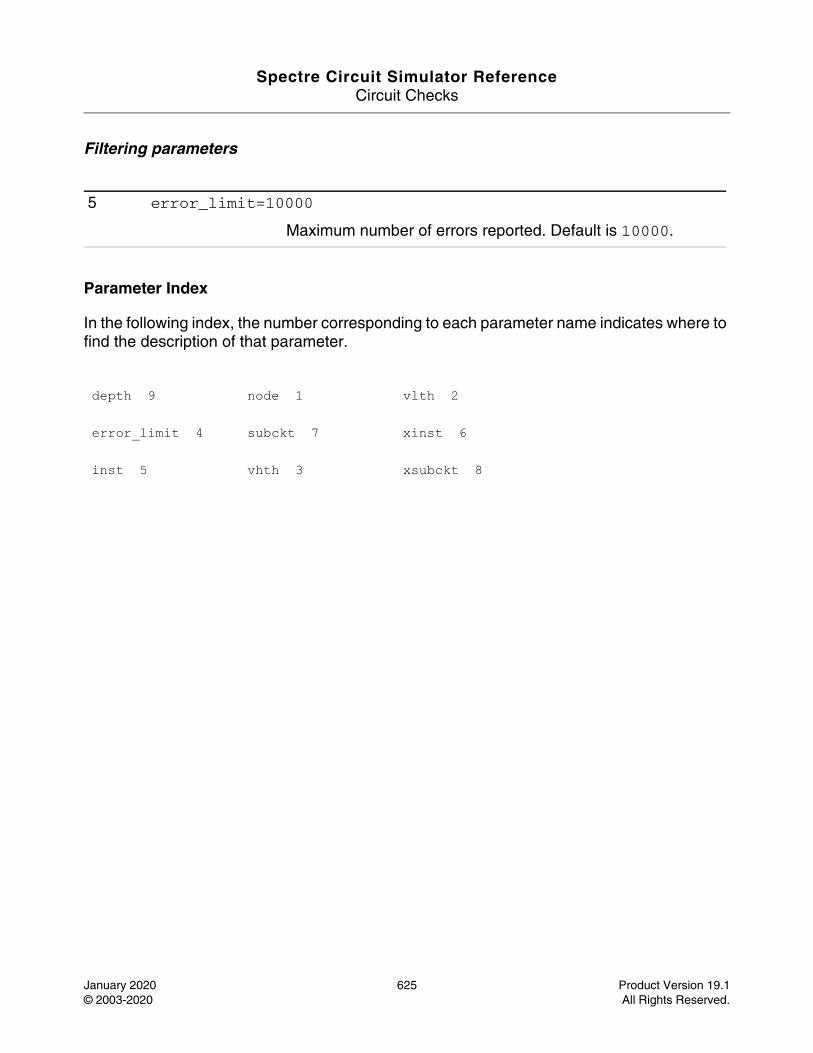
Spectre Circuit Simulator ReferenceCircuit Checks
January 2020 625 Product Version 19.1© 2003-2020 All Rights Reserved.
Filtering parameters
Parameter Index
In the following index, the number corresponding to each parameter name indicates where to find the description of that parameter.
5 error_limit=10000
Maximum number of errors reported. Default is 10000.
depth 9 node 1 vlth 2
error_limit 4 subckt 7 xinst 6
inst 5 vhth 3 xsubckt 8
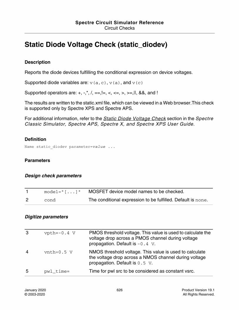
Spectre Circuit Simulator ReferenceCircuit Checks
January 2020 626 Product Version 19.1© 2003-2020 All Rights Reserved.
Static Diode Voltage Check (static_diodev)
Description
Reports the diode devices fulfilling the conditional expression on device voltages.
Supported diode variables are: v(a,c), v(a), and v(c)
Supported operators are: +, -,*, /, ==,!=, <, <=, >, >=,||, &&, and !
The results are written to the static.xml file, which can be viewed in a Web browser.This check is supported only by Spectre XPS and Spectre APS.
For additional information, refer to the Static Diode Voltage Check section in the Spectre Classic Simulator, Spectre APS, Spectre X, and Spectre XPS User Guide.
DefinitionName static_diodev parameter=value ...
Parameters
Design check parameters
Digitize parameters
1 model="[...]" MOSFET device model names to be checked.
2 cond The conditional expression to be fulfilled. Default is none.
3 vpth=-0.4 V PMOS threshold voltage. This value is used to calculate the voltage drop across a PMOS channel during voltage propagation. Default is -0.4 V.
4 vnth=0.5 V NMOS threshold voltage. This value is used to calculate the voltage drop across a NMOS channel during voltage propagation. Default is 0.5 V.
5 pwl_time= Time for pwl src to be considered as constant vsrc.
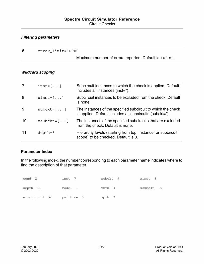
Spectre Circuit Simulator ReferenceCircuit Checks
January 2020 627 Product Version 19.1© 2003-2020 All Rights Reserved.
Filtering parameters
Wildcard scoping
Parameter Index
In the following index, the number corresponding to each parameter name indicates where to find the description of that parameter.
6 error_limit=10000
Maximum number of errors reported. Default is 10000.
7 inst=[...] Subcircuit instances to which the check is applied. Default includes all instances (inst=*).
8 xinst=[...] Subcircuit instances to be excluded from the check. Default is none.
9 subckt=[...] The instances of the specified subcircuit to which the check is applied. Default includes all subcircuits (subckt=*).
10 xsubckt=[...] The instances of the specified subcircuits that are excluded from the check. Default is none.
11 depth=8 Hierarchy levels (starting from top, instance, or subcircuit scope) to be checked. Default is 8.
cond 2 inst 7 subckt 9 xinst 8
depth 11 model 1 vnth 4 xsubckt 10
error_limit 6 pwl_time 5 vpth 3
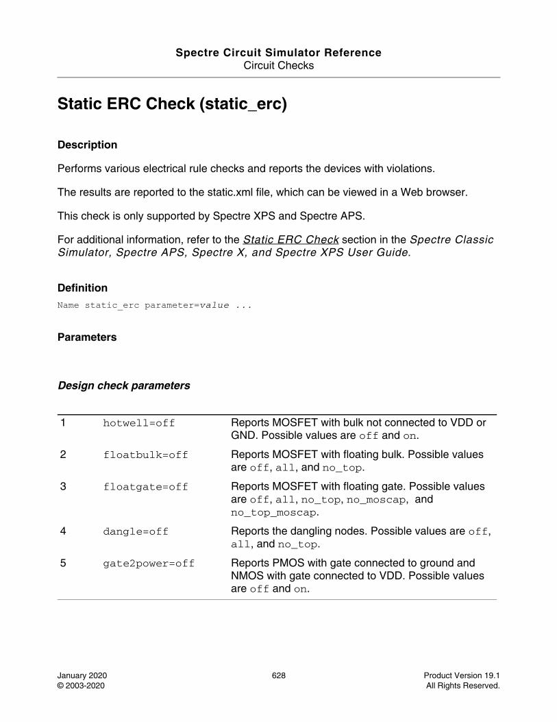
Spectre Circuit Simulator ReferenceCircuit Checks
January 2020 628 Product Version 19.1© 2003-2020 All Rights Reserved.
Static ERC Check (static_erc)
Description
Performs various electrical rule checks and reports the devices with violations.
The results are reported to the static.xml file, which can be viewed in a Web browser.
This check is only supported by Spectre XPS and Spectre APS.
For additional information, refer to the Static ERC Check section in the Spectre Classic Simulator, Spectre APS, Spectre X, and Spectre XPS User Guide.
DefinitionName static_erc parameter=value ...
Parameters
Design check parameters
1 hotwell=off Reports MOSFET with bulk not connected to VDD or GND. Possible values are off and on.
2 floatbulk=off Reports MOSFET with floating bulk. Possible values are off, all, and no_top.
3 floatgate=off Reports MOSFET with floating gate. Possible values are off, all, no_top, no_moscap, and no_top_moscap.
4 dangle=off Reports the dangling nodes. Possible values are off, all, and no_top.
5 gate2power=off Reports PMOS with gate connected to ground and NMOS with gate connected to VDD. Possible values are off and on.
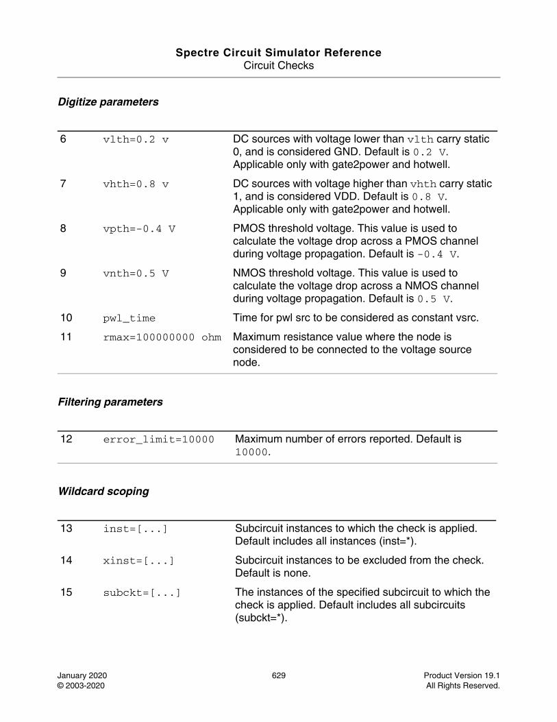
Spectre Circuit Simulator ReferenceCircuit Checks
January 2020 629 Product Version 19.1© 2003-2020 All Rights Reserved.
Digitize parameters
Filtering parameters
Wildcard scoping
6 vlth=0.2 v DC sources with voltage lower than vlth carry static 0, and is considered GND. Default is 0.2 V. Applicable only with gate2power and hotwell.
7 vhth=0.8 v DC sources with voltage higher than vhth carry static 1, and is considered VDD. Default is 0.8 V. Applicable only with gate2power and hotwell.
8 vpth=-0.4 V PMOS threshold voltage. This value is used to calculate the voltage drop across a PMOS channel during voltage propagation. Default is -0.4 V.
9 vnth=0.5 V NMOS threshold voltage. This value is used to calculate the voltage drop across a NMOS channel during voltage propagation. Default is 0.5 V.
10 pwl_time Time for pwl src to be considered as constant vsrc.
11 rmax=100000000 ohm Maximum resistance value where the node is considered to be connected to the voltage source node.
12 error_limit=10000 Maximum number of errors reported. Default is 10000.
13 inst=[...] Subcircuit instances to which the check is applied. Default includes all instances (inst=*).
14 xinst=[...] Subcircuit instances to be excluded from the check. Default is none.
15 subckt=[...] The instances of the specified subcircuit to which the check is applied. Default includes all subcircuits (subckt=*).
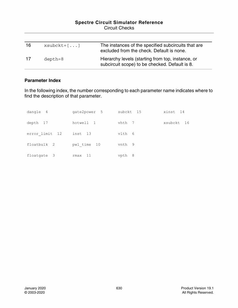
Spectre Circuit Simulator ReferenceCircuit Checks
January 2020 630 Product Version 19.1© 2003-2020 All Rights Reserved.
Parameter Index
In the following index, the number corresponding to each parameter name indicates where to find the description of that parameter.
16 xsubckt=[...] The instances of the specified subcircuits that are excluded from the check. Default is none.
17 depth=8 Hierarchy levels (starting from top, instance, or subcircuit scope) to be checked. Default is 8.
dangle 4 gate2power 5 subckt 15 xinst 14
depth 17 hotwell 1 vhth 7 xsubckt 16
error_limit 12 inst 13 vlth 6
floatbulk 2 pwl_time 10 vnth 9
floatgate 3 rmax 11 vpth 8

Spectre Circuit Simulator ReferenceCircuit Checks
January 2020 631 Product Version 19.1© 2003-2020 All Rights Reserved.
Static Highfanout Check (static_highfanout)
Description
This check detects the MOSFETs having gate connected to a highfanout node, and reports the nodes having count larger than the specified count.
The results are reported into a file with the extension static.xml, which can be read with a web browser.
DefinitionName static_highfanout parameter=value ...
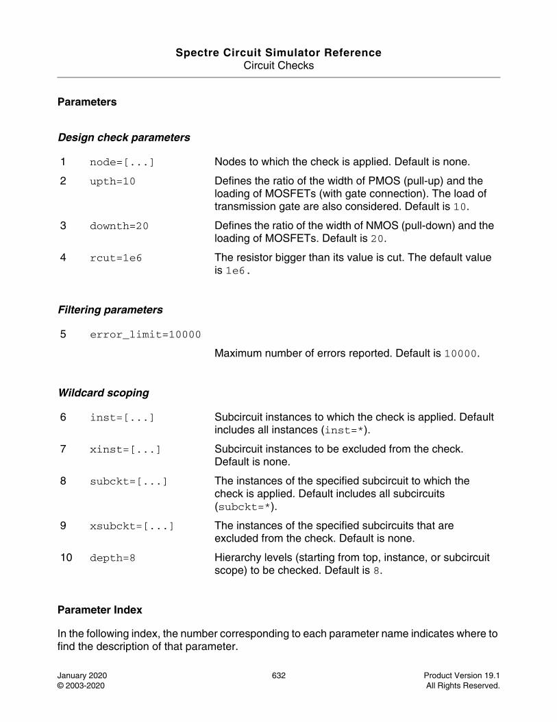
Spectre Circuit Simulator ReferenceCircuit Checks
January 2020 632 Product Version 19.1© 2003-2020 All Rights Reserved.
Parameters
Design check parameters
Filtering parameters
Wildcard scoping
Parameter Index
In the following index, the number corresponding to each parameter name indicates where to find the description of that parameter.
1 node=[...] Nodes to which the check is applied. Default is none.
2 upth=10 Defines the ratio of the width of PMOS (pull-up) and the loading of MOSFETs (with gate connection). The load of transmission gate are also considered. Default is 10.
3 downth=20 Defines the ratio of the width of NMOS (pull-down) and the loading of MOSFETs. Default is 20.
4 rcut=1e6 The resistor bigger than its value is cut. The default value is 1e6.
5 error_limit=10000
Maximum number of errors reported. Default is 10000.
6 inst=[...] Subcircuit instances to which the check is applied. Default includes all instances (inst=*).
7 xinst=[...] Subcircuit instances to be excluded from the check. Default is none.
8 subckt=[...] The instances of the specified subcircuit to which the check is applied. Default includes all subcircuits (subckt=*).
9 xsubckt=[...] The instances of the specified subcircuits that are excluded from the check. Default is none.
10 depth=8 Hierarchy levels (starting from top, instance, or subcircuit scope) to be checked. Default is 8.
Spectre Circuit Simulator ReferenceCircuit Checks
January 2020 633 Product Version 19.1© 2003-2020 All Rights Reserved.
depth 10 inst 6 subckt 8 xsubckt 9
downth 3 node 1 upth 2
error_limit 5 rcut 4 xinst 7
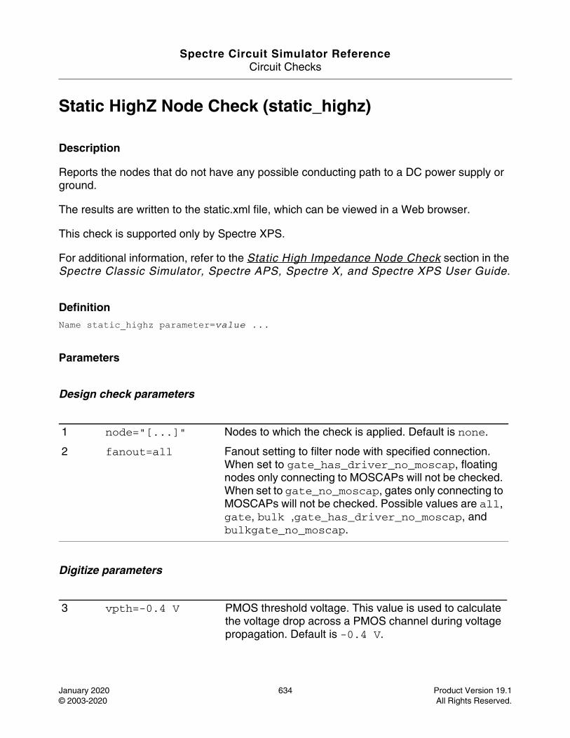
Spectre Circuit Simulator ReferenceCircuit Checks
January 2020 634 Product Version 19.1© 2003-2020 All Rights Reserved.
Static HighZ Node Check (static_highz)
Description
Reports the nodes that do not have any possible conducting path to a DC power supply or ground.
The results are written to the static.xml file, which can be viewed in a Web browser.
This check is supported only by Spectre XPS.
For additional information, refer to the Static High Impedance Node Check section in the Spectre Classic Simulator, Spectre APS, Spectre X, and Spectre XPS User Guide.
DefinitionName static_highz parameter=value ...
Parameters
Design check parameters
Digitize parameters
1 node="[...]" Nodes to which the check is applied. Default is none.
2 fanout=all Fanout setting to filter node with specified connection. When set to gate_has_driver_no_moscap, floating nodes only connecting to MOSCAPs will not be checked. When set to gate_no_moscap, gates only connecting to MOSCAPs will not be checked. Possible values are all, gate, bulk ,gate_has_driver_no_moscap, and bulkgate_no_moscap.
3 vpth=-0.4 V PMOS threshold voltage. This value is used to calculate the voltage drop across a PMOS channel during voltage propagation. Default is -0.4 V.
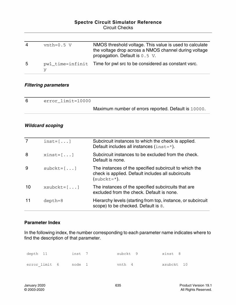
Spectre Circuit Simulator ReferenceCircuit Checks
January 2020 635 Product Version 19.1© 2003-2020 All Rights Reserved.
Filtering parameters
Wildcard scoping
Parameter Index
In the following index, the number corresponding to each parameter name indicates where to find the description of that parameter.
4 vnth=0.5 V NMOS threshold voltage. This value is used to calculate the voltage drop across a NMOS channel during voltage propagation. Default is 0.5 V.
5 pwl_time=infinity
Time for pwl src to be considered as constant vsrc.
6 error_limit=10000
Maximum number of errors reported. Default is 10000.
7 inst=[...] Subcircuit instances to which the check is applied. Default includes all instances (inst=*).
8 xinst=[...] Subcircuit instances to be excluded from the check. Default is none.
9 subckt=[...] The instances of the specified subcircuit to which the check is applied. Default includes all subcircuits (subckt=*).
10 xsubckt=[...] The instances of the specified subcircuits that are excluded from the check. Default is none.
11 depth=8 Hierarchy levels (starting from top, instance, or subcircuit scope) to be checked. Default is 8.
depth 11 inst 7 subckt 9 xinst 8
error_limit 6 node 1 vnth 4 xsubckt 10

Spectre Circuit Simulator ReferenceCircuit Checks
January 2020 636 Product Version 19.1© 2003-2020 All Rights Reserved.
fanout 2 pwl_time 5 vpth 3
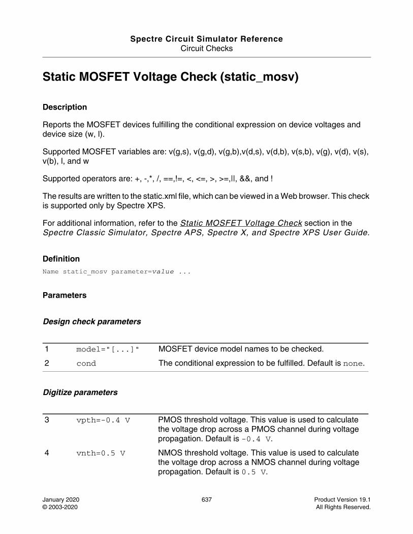
Spectre Circuit Simulator ReferenceCircuit Checks
January 2020 637 Product Version 19.1© 2003-2020 All Rights Reserved.
Static MOSFET Voltage Check (static_mosv)
Description
Reports the MOSFET devices fulfilling the conditional expression on device voltages and device size (w, l).
Supported MOSFET variables are: v(g,s), v(g,d), v(g,b),v(d,s), v(d,b), v(s,b), v(g), v(d), v(s), v(b), l, and w
Supported operators are: +, -,*, /, ==,!=, <, <=, >, >=,||, &&, and !
The results are written to the static.xml file, which can be viewed in a Web browser. This check is supported only by Spectre XPS.
For additional information, refer to the Static MOSFET Voltage Check section in the Spectre Classic Simulator, Spectre APS, Spectre X, and Spectre XPS User Guide.
DefinitionName static_mosv parameter=value ...
Parameters
Design check parameters
Digitize parameters
1 model="[...]" MOSFET device model names to be checked.
2 cond The conditional expression to be fulfilled. Default is none.
3 vpth=-0.4 V PMOS threshold voltage. This value is used to calculate the voltage drop across a PMOS channel during voltage propagation. Default is -0.4 V.
4 vnth=0.5 V NMOS threshold voltage. This value is used to calculate the voltage drop across a NMOS channel during voltage propagation. Default is 0.5 V.
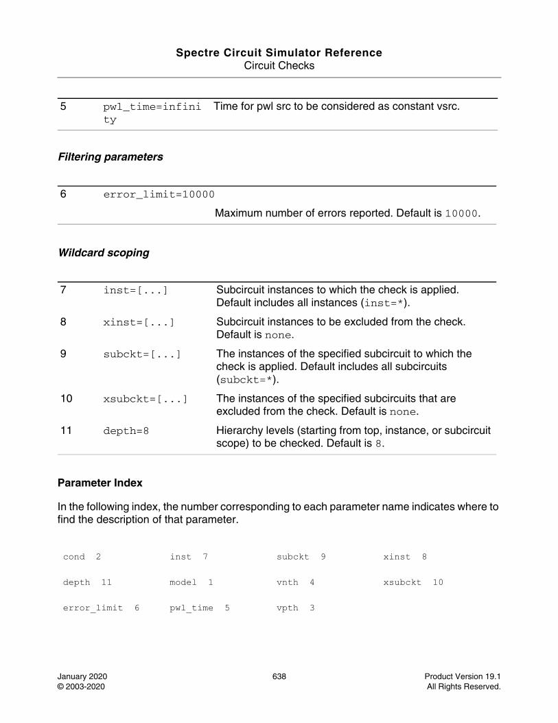
Spectre Circuit Simulator ReferenceCircuit Checks
January 2020 638 Product Version 19.1© 2003-2020 All Rights Reserved.
Filtering parameters
Wildcard scoping
Parameter Index
In the following index, the number corresponding to each parameter name indicates where to find the description of that parameter.
5 pwl_time=infinity
Time for pwl src to be considered as constant vsrc.
6 error_limit=10000
Maximum number of errors reported. Default is 10000.
7 inst=[...] Subcircuit instances to which the check is applied. Default includes all instances (inst=*).
8 xinst=[...] Subcircuit instances to be excluded from the check. Default is none.
9 subckt=[...] The instances of the specified subcircuit to which the check is applied. Default includes all subcircuits (subckt=*).
10 xsubckt=[...] The instances of the specified subcircuits that are excluded from the check. Default is none.
11 depth=8 Hierarchy levels (starting from top, instance, or subcircuit scope) to be checked. Default is 8.
cond 2 inst 7 subckt 9 xinst 8
depth 11 model 1 vnth 4 xsubckt 10
error_limit 6 pwl_time 5 vpth 3
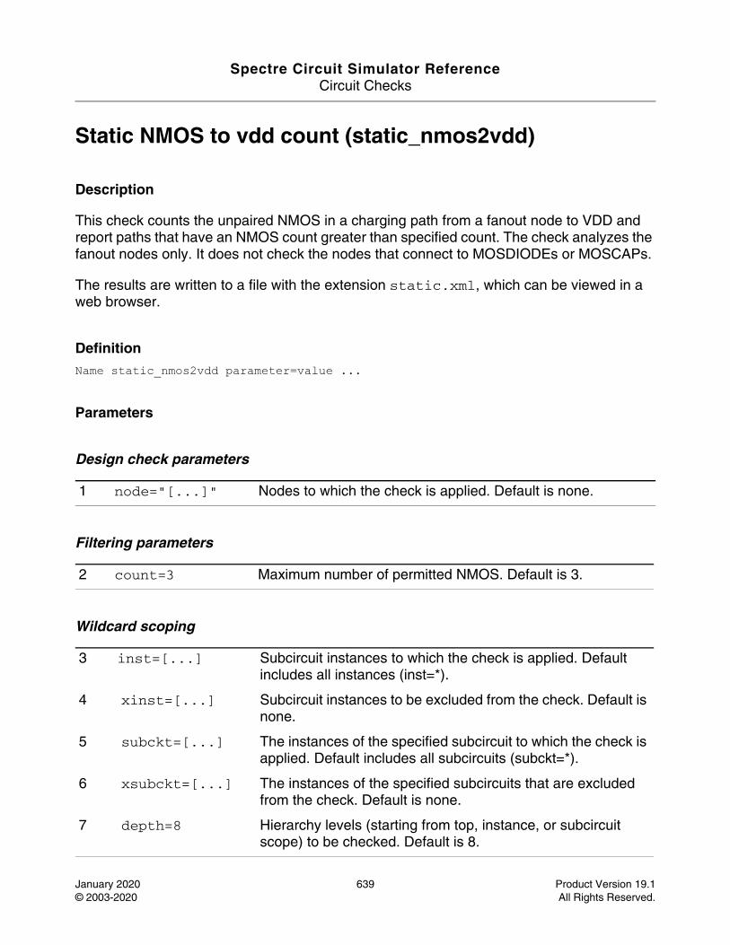
Spectre Circuit Simulator ReferenceCircuit Checks
January 2020 639 Product Version 19.1© 2003-2020 All Rights Reserved.
Static NMOS to vdd count (static_nmos2vdd)
Description
This check counts the unpaired NMOS in a charging path from a fanout node to VDD and report paths that have an NMOS count greater than specified count. The check analyzes the fanout nodes only. It does not check the nodes that connect to MOSDIODEs or MOSCAPs.
The results are written to a file with the extension static.xml, which can be viewed in a web browser.
DefinitionName static_nmos2vdd parameter=value ...
Parameters
Design check parameters
Filtering parameters
Wildcard scoping
1 node="[...]" Nodes to which the check is applied. Default is none.
2 count=3 Maximum number of permitted NMOS. Default is 3.
3 inst=[...] Subcircuit instances to which the check is applied. Default includes all instances (inst=*).
4 xinst=[...] Subcircuit instances to be excluded from the check. Default is none.
5 subckt=[...] The instances of the specified subcircuit to which the check is applied. Default includes all subcircuits (subckt=*).
6 xsubckt=[...] The instances of the specified subcircuits that are excluded from the check. Default is none.
7 depth=8 Hierarchy levels (starting from top, instance, or subcircuit scope) to be checked. Default is 8.
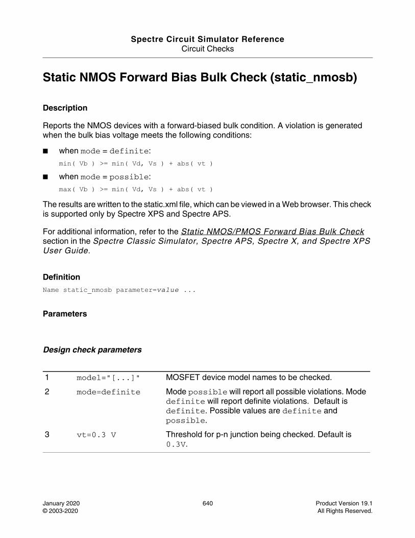
Spectre Circuit Simulator ReferenceCircuit Checks
January 2020 640 Product Version 19.1© 2003-2020 All Rights Reserved.
Static NMOS Forward Bias Bulk Check (static_nmosb)
Description
Reports the NMOS devices with a forward-biased bulk condition. A violation is generated when the bulk bias voltage meets the following conditions:
■ when mode = definite:
min( Vb ) >= min( Vd, Vs ) + abs( vt ) ■ when mode = possible:
max( Vb ) >= min( Vd, Vs ) + abs( vt )
The results are written to the static.xml file, which can be viewed in a Web browser. This check is supported only by Spectre XPS and Spectre APS.
For additional information, refer to the Static NMOS/PMOS Forward Bias Bulk Check section in the Spectre Classic Simulator, Spectre APS, Spectre X, and Spectre XPS User Guide.
DefinitionName static_nmosb parameter=value ...
Parameters
Design check parameters
1 model="[...]" MOSFET device model names to be checked.
2 mode=definite Mode possible will report all possible violations. Mode definite will report definite violations. Default is definite. Possible values are definite and possible.
3 vt=0.3 V Threshold for p-n junction being checked. Default is 0.3V.
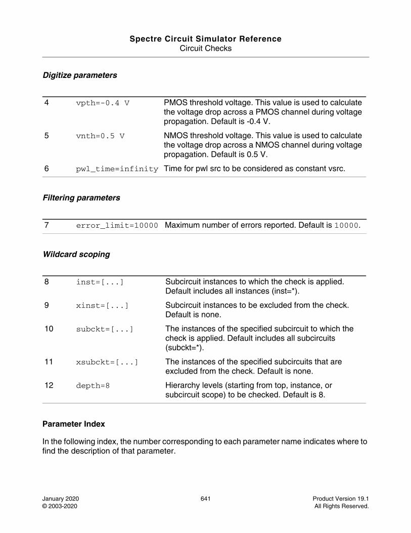
Spectre Circuit Simulator ReferenceCircuit Checks
January 2020 641 Product Version 19.1© 2003-2020 All Rights Reserved.
Digitize parameters
Filtering parameters
Wildcard scoping
Parameter Index
In the following index, the number corresponding to each parameter name indicates where to find the description of that parameter.
4 vpth=-0.4 V PMOS threshold voltage. This value is used to calculate the voltage drop across a PMOS channel during voltage propagation. Default is -0.4 V.
5 vnth=0.5 V NMOS threshold voltage. This value is used to calculate the voltage drop across a NMOS channel during voltage propagation. Default is 0.5 V.
6 pwl_time=infinity Time for pwl src to be considered as constant vsrc.
7 error_limit=10000 Maximum number of errors reported. Default is 10000.
8 inst=[...] Subcircuit instances to which the check is applied. Default includes all instances (inst=*).
9 xinst=[...] Subcircuit instances to be excluded from the check. Default is none.
10 subckt=[...] The instances of the specified subcircuit to which the check is applied. Default includes all subcircuits (subckt=*).
11 xsubckt=[...] The instances of the specified subcircuits that are excluded from the check. Default is none.
12 depth=8 Hierarchy levels (starting from top, instance, or subcircuit scope) to be checked. Default is 8.

Spectre Circuit Simulator ReferenceCircuit Checks
January 2020 642 Product Version 19.1© 2003-2020 All Rights Reserved.
depth 12 mode 2 subckt 10 vt 3
error_limit 7 model 1 vnth 5 xinst 9
inst 8 pwl_time 6 vpth 4 xsubckt 11
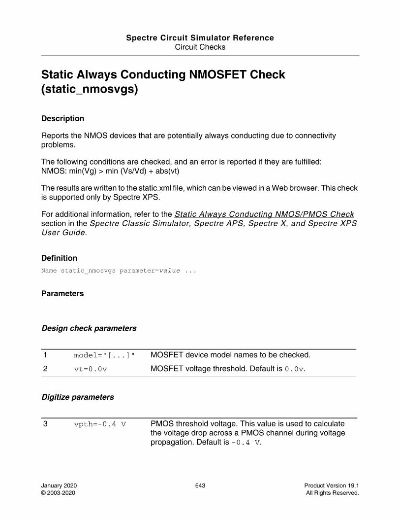
Spectre Circuit Simulator ReferenceCircuit Checks
January 2020 643 Product Version 19.1© 2003-2020 All Rights Reserved.
Static Always Conducting NMOSFET Check (static_nmosvgs)
Description
Reports the NMOS devices that are potentially always conducting due to connectivity problems.
The following conditions are checked, and an error is reported if they are fulfilled: NMOS: min(Vg) > min (Vs/Vd) + abs(vt)
The results are written to the static.xml file, which can be viewed in a Web browser. This check is supported only by Spectre XPS.
For additional information, refer to the Static Always Conducting NMOS/PMOS Check section in the Spectre Classic Simulator, Spectre APS, Spectre X, and Spectre XPS User Guide.
DefinitionName static_nmosvgs parameter=value ...
Parameters
Design check parameters
Digitize parameters
1 model="[...]" MOSFET device model names to be checked.
2 vt=0.0v MOSFET voltage threshold. Default is 0.0v.
3 vpth=-0.4 V PMOS threshold voltage. This value is used to calculate the voltage drop across a PMOS channel during voltage propagation. Default is -0.4 V.
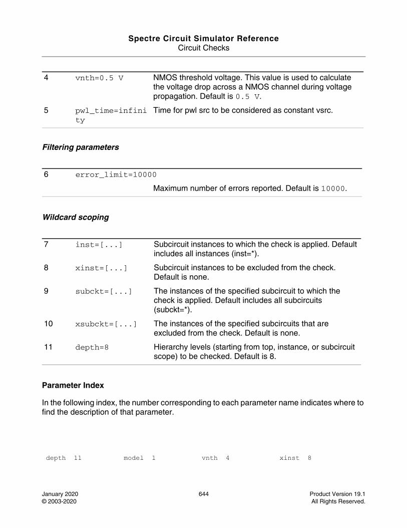
Spectre Circuit Simulator ReferenceCircuit Checks
January 2020 644 Product Version 19.1© 2003-2020 All Rights Reserved.
Filtering parameters
Wildcard scoping
Parameter Index
In the following index, the number corresponding to each parameter name indicates where to find the description of that parameter.
4 vnth=0.5 V NMOS threshold voltage. This value is used to calculate the voltage drop across a NMOS channel during voltage propagation. Default is 0.5 V.
5 pwl_time=infinity
Time for pwl src to be considered as constant vsrc.
6 error_limit=10000
Maximum number of errors reported. Default is 10000.
7 inst=[...] Subcircuit instances to which the check is applied. Default includes all instances (inst=*).
8 xinst=[...] Subcircuit instances to be excluded from the check. Default is none.
9 subckt=[...] The instances of the specified subcircuit to which the check is applied. Default includes all subcircuits (subckt=*).
10 xsubckt=[...] The instances of the specified subcircuits that are excluded from the check. Default is none.
11 depth=8 Hierarchy levels (starting from top, instance, or subcircuit scope) to be checked. Default is 8.
depth 11 model 1 vnth 4 xinst 8
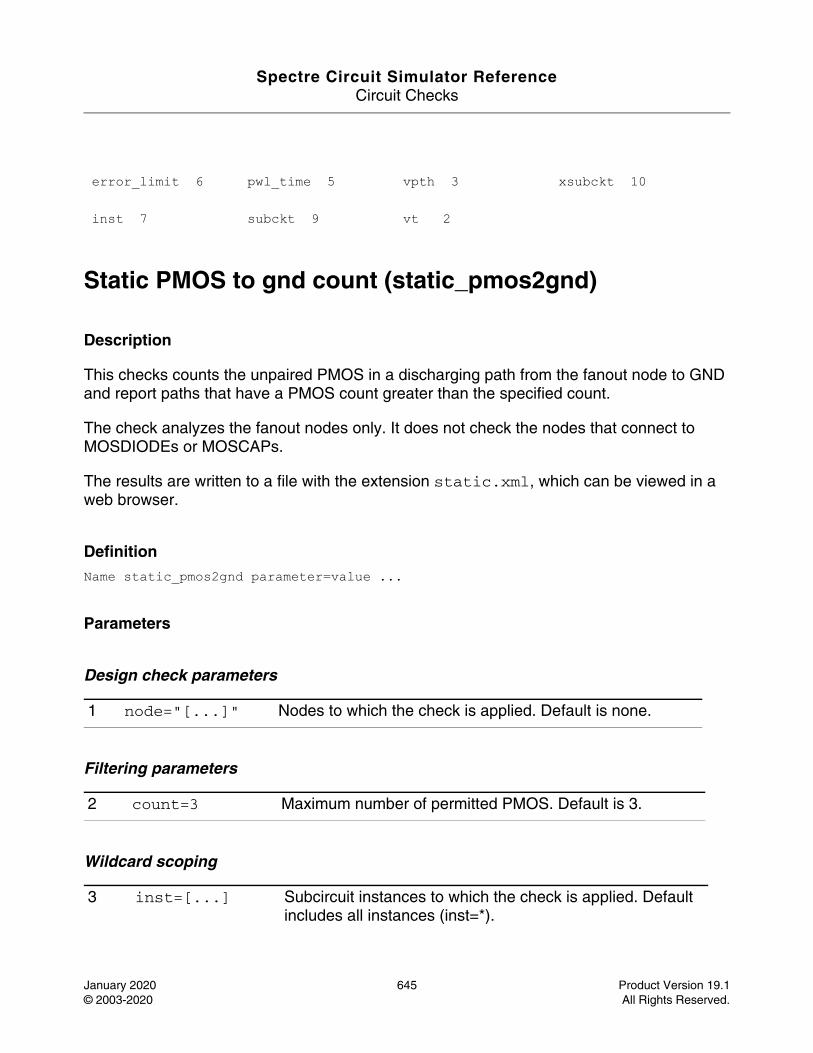
Spectre Circuit Simulator ReferenceCircuit Checks
January 2020 645 Product Version 19.1© 2003-2020 All Rights Reserved.
Static PMOS to gnd count (static_pmos2gnd)
Description
This checks counts the unpaired PMOS in a discharging path from the fanout node to GND and report paths that have a PMOS count greater than the specified count.
The check analyzes the fanout nodes only. It does not check the nodes that connect to MOSDIODEs or MOSCAPs.
The results are written to a file with the extension static.xml, which can be viewed in a web browser.
DefinitionName static_pmos2gnd parameter=value ...
Parameters
Design check parameters
Filtering parameters
Wildcard scoping
error_limit 6 pwl_time 5 vpth 3 xsubckt 10
inst 7 subckt 9 vt 2
1 node="[...]" Nodes to which the check is applied. Default is none.
2 count=3 Maximum number of permitted PMOS. Default is 3.
3 inst=[...] Subcircuit instances to which the check is applied. Default includes all instances (inst=*).
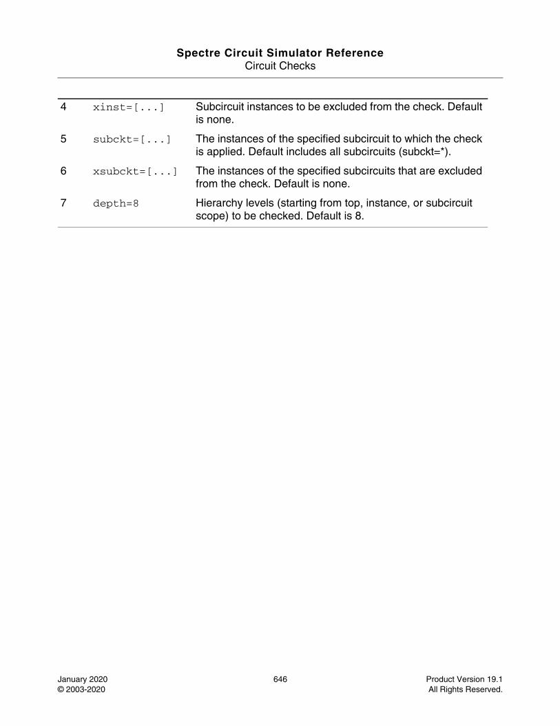
Spectre Circuit Simulator ReferenceCircuit Checks
January 2020 646 Product Version 19.1© 2003-2020 All Rights Reserved.
4 xinst=[...] Subcircuit instances to be excluded from the check. Default is none.
5 subckt=[...] The instances of the specified subcircuit to which the check is applied. Default includes all subcircuits (subckt=*).
6 xsubckt=[...] The instances of the specified subcircuits that are excluded from the check. Default is none.
7 depth=8 Hierarchy levels (starting from top, instance, or subcircuit scope) to be checked. Default is 8.
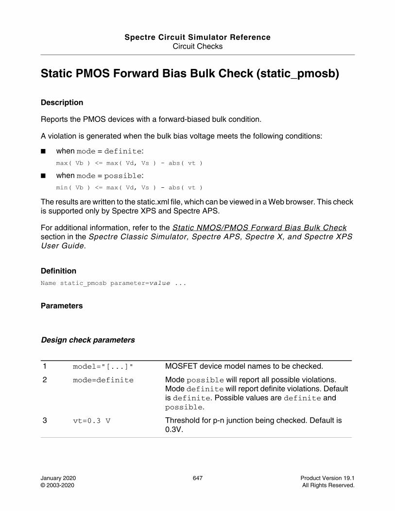
Spectre Circuit Simulator ReferenceCircuit Checks
January 2020 647 Product Version 19.1© 2003-2020 All Rights Reserved.
Static PMOS Forward Bias Bulk Check (static_pmosb)
Description
Reports the PMOS devices with a forward-biased bulk condition.
A violation is generated when the bulk bias voltage meets the following conditions:
■ when mode = definite:
max( Vb ) <= max( Vd, Vs ) - abs( vt ) ■ when mode = possible:
min( Vb ) <= max( Vd, Vs ) - abs( vt )
The results are written to the static.xml file, which can be viewed in a Web browser. This check is supported only by Spectre XPS and Spectre APS.
For additional information, refer to the Static NMOS/PMOS Forward Bias Bulk Check section in the Spectre Classic Simulator, Spectre APS, Spectre X, and Spectre XPS User Guide.
DefinitionName static_pmosb parameter=value ...
Parameters
Design check parameters
1 model="[...]" MOSFET device model names to be checked.
2 mode=definite Mode possible will report all possible violations. Mode definite will report definite violations. Default is definite. Possible values are definite and possible.
3 vt=0.3 V Threshold for p-n junction being checked. Default is 0.3V.
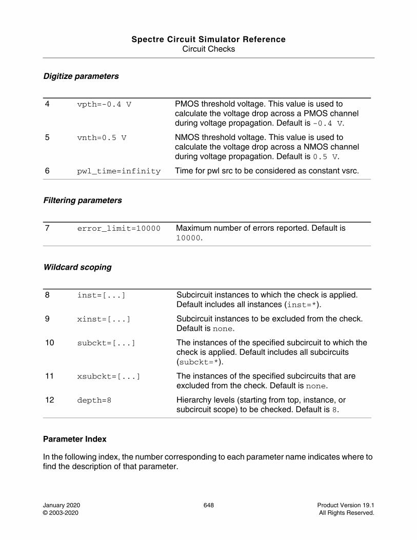
Spectre Circuit Simulator ReferenceCircuit Checks
January 2020 648 Product Version 19.1© 2003-2020 All Rights Reserved.
Digitize parameters
Filtering parameters
Wildcard scoping
Parameter Index
In the following index, the number corresponding to each parameter name indicates where to find the description of that parameter.
4 vpth=-0.4 V PMOS threshold voltage. This value is used to calculate the voltage drop across a PMOS channel during voltage propagation. Default is -0.4 V.
5 vnth=0.5 V NMOS threshold voltage. This value is used to calculate the voltage drop across a NMOS channel during voltage propagation. Default is 0.5 V.
6 pwl_time=infinity Time for pwl src to be considered as constant vsrc.
7 error_limit=10000 Maximum number of errors reported. Default is 10000.
8 inst=[...] Subcircuit instances to which the check is applied. Default includes all instances (inst=*).
9 xinst=[...] Subcircuit instances to be excluded from the check. Default is none.
10 subckt=[...] The instances of the specified subcircuit to which the check is applied. Default includes all subcircuits (subckt=*).
11 xsubckt=[...] The instances of the specified subcircuits that are excluded from the check. Default is none.
12 depth=8 Hierarchy levels (starting from top, instance, or subcircuit scope) to be checked. Default is 8.
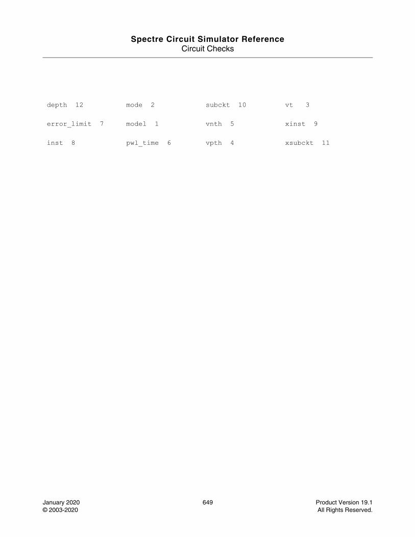
Spectre Circuit Simulator ReferenceCircuit Checks
January 2020 649 Product Version 19.1© 2003-2020 All Rights Reserved.
depth 12 mode 2 subckt 10 vt 3
error_limit 7 model 1 vnth 5 xinst 9
inst 8 pwl_time 6 vpth 4 xsubckt 11
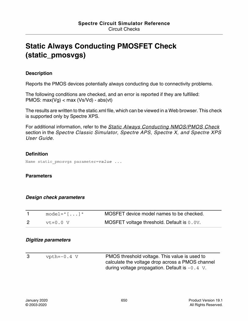
Spectre Circuit Simulator ReferenceCircuit Checks
January 2020 650 Product Version 19.1© 2003-2020 All Rights Reserved.
Static Always Conducting PMOSFET Check (static_pmosvgs)
Description
Reports the PMOS devices potentially always conducting due to connectivity problems.
The following conditions are checked, and an error is reported if they are fulfilled: PMOS: max(Vg) < max (Vs/Vd) - abs(vt)
The results are written to the static.xml file, which can be viewed in a Web browser. This check is supported only by Spectre XPS.
For additional information, refer to the Static Always Conducting NMOS/PMOS Check section in the Spectre Classic Simulator, Spectre APS, Spectre X, and Spectre XPS User Guide.
DefinitionName static_pmosvgs parameter=value ...
Parameters
Design check parameters
Digitize parameters
1 model="[...]" MOSFET device model names to be checked.
2 vt=0.0 V MOSFET voltage threshold. Default is 0.0V.
3 vpth=-0.4 V PMOS threshold voltage. This value is used to calculate the voltage drop across a PMOS channel during voltage propagation. Default is -0.4 V.
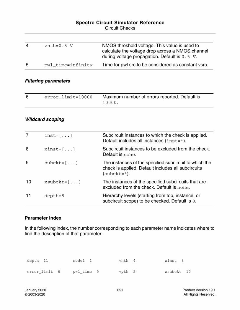
Spectre Circuit Simulator ReferenceCircuit Checks
January 2020 651 Product Version 19.1© 2003-2020 All Rights Reserved.
Filtering parameters
Wildcard scoping
Parameter Index
In the following index, the number corresponding to each parameter name indicates where to find the description of that parameter.
4 vnth=0.5 V NMOS threshold voltage. This value is used to calculate the voltage drop across a NMOS channel during voltage propagation. Default is 0.5 V.
5 pwl_time=infinity Time for pwl src to be considered as constant vsrc.
6 error_limit=10000 Maximum number of errors reported. Default is 10000.
7 inst=[...] Subcircuit instances to which the check is applied. Default includes all instances (inst=*).
8 xinst=[...] Subcircuit instances to be excluded from the check. Default is none.
9 subckt=[...] The instances of the specified subcircuit to which the check is applied. Default includes all subcircuits (subckt=*).
10 xsubckt=[...] The instances of the specified subcircuits that are excluded from the check. Default is none.
11 depth=8 Hierarchy levels (starting from top, instance, or subcircuit scope) to be checked. Default is 8.
depth 11 model 1 vnth 4 xinst 8
error_limit 6 pwl_time 5 vpth 3 xsubckt 10

Spectre Circuit Simulator ReferenceCircuit Checks
January 2020 652 Product Version 19.1© 2003-2020 All Rights Reserved.
inst 7 subckt 9 vt 2
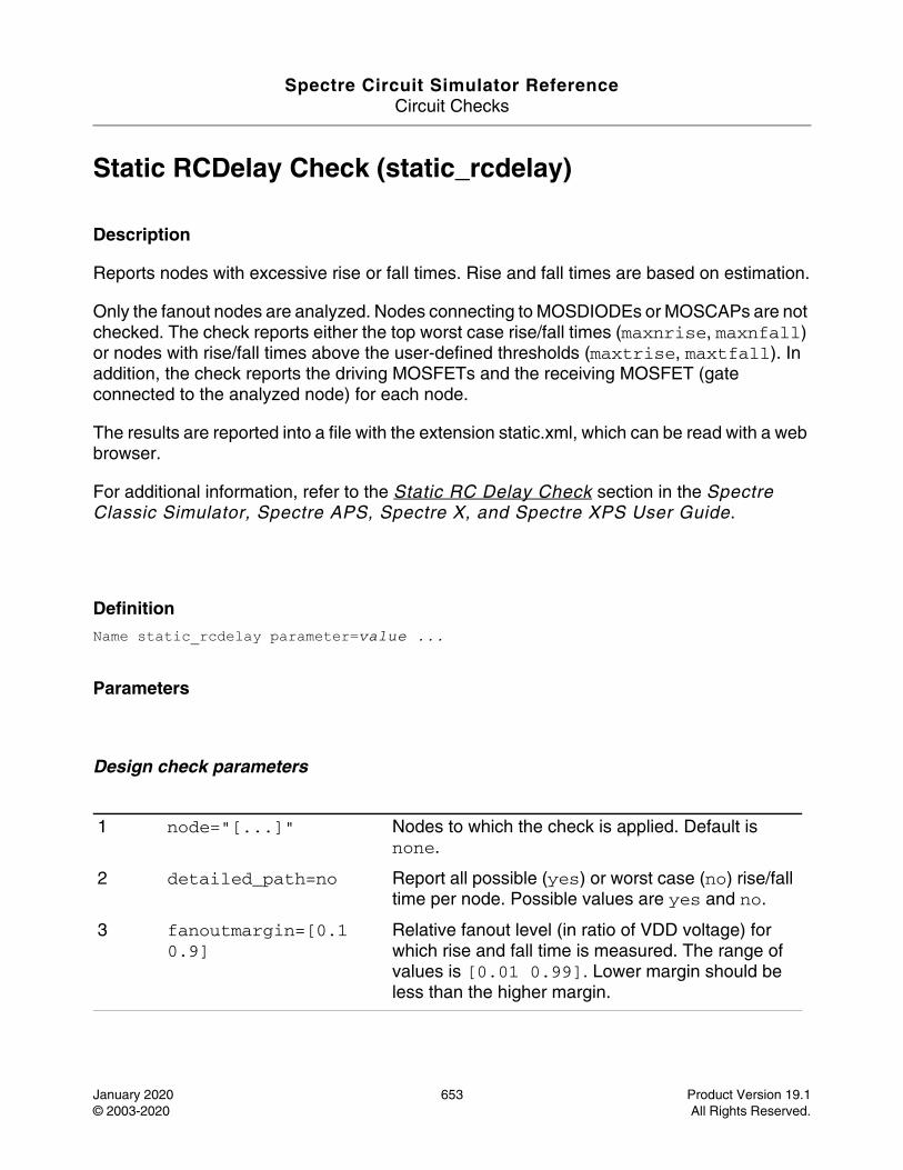
Spectre Circuit Simulator ReferenceCircuit Checks
January 2020 653 Product Version 19.1© 2003-2020 All Rights Reserved.
Static RCDelay Check (static_rcdelay)
Description
Reports nodes with excessive rise or fall times. Rise and fall times are based on estimation.
Only the fanout nodes are analyzed. Nodes connecting to MOSDIODEs or MOSCAPs are not checked. The check reports either the top worst case rise/fall times (maxnrise, maxnfall) or nodes with rise/fall times above the user-defined thresholds (maxtrise, maxtfall). In addition, the check reports the driving MOSFETs and the receiving MOSFET (gate connected to the analyzed node) for each node.
The results are reported into a file with the extension static.xml, which can be read with a web browser.
For additional information, refer to the Static RC Delay Check section in the Spectre Classic Simulator, Spectre APS, Spectre X, and Spectre XPS User Guide.
DefinitionName static_rcdelay parameter=value ...
Parameters
Design check parameters
1 node="[...]" Nodes to which the check is applied. Default is none.
2 detailed_path=no Report all possible (yes) or worst case (no) rise/fall time per node. Possible values are yes and no.
3 fanoutmargin=[0.1 0.9]
Relative fanout level (in ratio of VDD voltage) for which rise and fall time is measured. The range of values is [0.01 0.99]. Lower margin should be less than the higher margin.
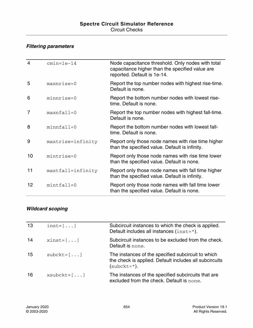
Spectre Circuit Simulator ReferenceCircuit Checks
January 2020 654 Product Version 19.1© 2003-2020 All Rights Reserved.
Filtering parameters
Wildcard scoping
4 cmin=1e-14 Node capacitance threshold. Only nodes with total capacitance higher than the specified value are reported. Default is 1e-14.
5 maxnrise=0 Report the top number nodes with highest rise-time. Default is none.
6 minnrise=0 Report the bottom number nodes with lowest rise-time. Default is none.
7 maxnfall=0 Report the top number nodes with highest fall-time. Default is none.
8 minnfall=0 Report the bottom number nodes with lowest fall-time. Default is none.
9 maxtrise=infinity Report only those node names with rise time higher than the specified value. Default is infinity.
10 mintrise=0 Report only those node names with rise time lower than the specified value. Default is none.
11 maxtfall=infinity Report only those node names with fall time higher than the specified value. Default is infinity.
12 mintfall=0 Report only those node names with fall time lower than the specified value. Default is none.
13 inst=[...] Subcircuit instances to which the check is applied. Default includes all instances (inst=*).
14 xinst=[...] Subcircuit instances to be excluded from the check. Default is none.
15 subckt=[...] The instances of the specified subcircuit to which the check is applied. Default includes all subcircuits (subckt=*).
16 xsubckt=[...] The instances of the specified subcircuits that are excluded from the check. Default is none.

Spectre Circuit Simulator ReferenceCircuit Checks
January 2020 655 Product Version 19.1© 2003-2020 All Rights Reserved.
Parameter Index
In the following index, the number corresponding to each parameter name indicates where to find the description of that parameter.
17 depth=8 Hierarchy levels (starting from top, instance, or subcircuit scope) to be checked. Default is 8.
cmin 4 inst 13 maxtrise 9 mintrise 10
xsubckt 16 depth 17 maxnfall 7 minnfall 8
node 1 detailed_path 2 maxnrise 5 minnrise 6
subckt 15 fanoutmargin 3 maxtfall 11 mintfall 12
xinst 14
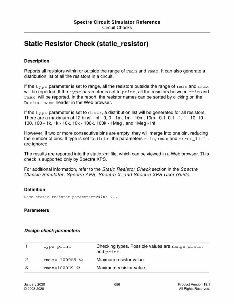
Spectre Circuit Simulator ReferenceCircuit Checks
January 2020 656 Product Version 19.1© 2003-2020 All Rights Reserved.
Static Resistor Check (static_resistor)
Description
Reports all resistors within or outside the range of rmin and rmax. It can also generate a distribution list of all the resistors in a circuit.
If the type parameter is set to range, all the resistors outside the range of rmin and rmax will be reported. If the type parameter is set to print, all the resistors between rmin and rmax will be reported. In the report, the resistor names can be sorted by clicking on the Device name header in the Web browser.
If the type parameter is set to distr, a distribution list will be generated for all resistors. There are a maximum of 12 bins: -Inf - 0, 0 - 1m, 1m - 10m, 10m - 0.1, 0.1 - 1, 1 - 10, 10 - 100, 100 - 1k, 1k - 10k, 10k - 100k, 100k - 1Meg , and 1Meg - Inf
However, if two or more consecutive bins are empty, they will merge into one bin, reducing the number of bins. If type is set to distr, the parameters rmin, rmax and error_limit are ignored.
The results are reported into the static.xml file, which can be viewed in a Web browser. This check is supported only by Spectre XPS.
For additional information, refer to the Static Resistor Check section in the Spectre Classic Simulator, Spectre APS, Spectre X, and Spectre XPS User Guide.
DefinitionName static_resistor parameter=value ...
Parameters
Design check parameters
1 type=print Checking types. Possible values are range, distr, and print.
2 rmin=-1000E9 Ω Minimum resistor value.
3 rmax=1000E9 Ω Maximum resistor value.

Spectre Circuit Simulator ReferenceCircuit Checks
January 2020 657 Product Version 19.1© 2003-2020 All Rights Reserved.
Filtering parameters
4 error_limit=10000 Maximum number of errors reported. Default is 10000.
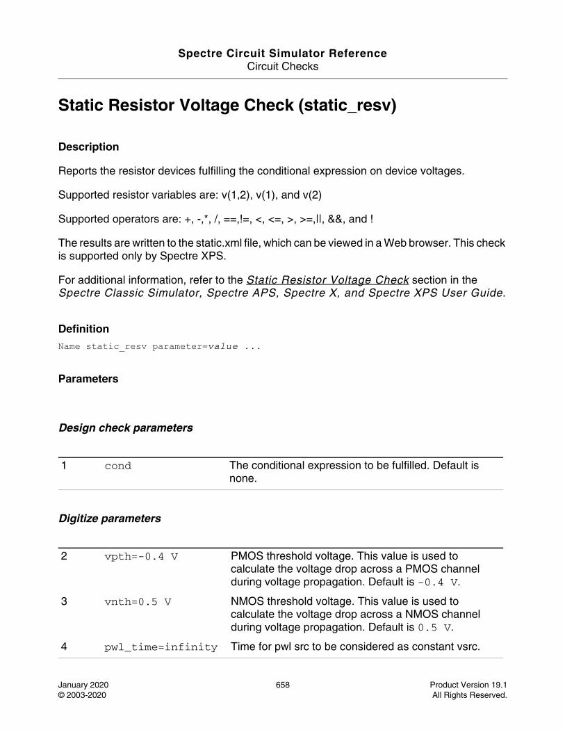
Spectre Circuit Simulator ReferenceCircuit Checks
January 2020 658 Product Version 19.1© 2003-2020 All Rights Reserved.
Static Resistor Voltage Check (static_resv)
Description
Reports the resistor devices fulfilling the conditional expression on device voltages.
Supported resistor variables are: v(1,2), v(1), and v(2)
Supported operators are: +, -,*, /, ==,!=, <, <=, >, >=,||, &&, and !
The results are written to the static.xml file, which can be viewed in a Web browser. This check is supported only by Spectre XPS.
For additional information, refer to the Static Resistor Voltage Check section in the Spectre Classic Simulator, Spectre APS, Spectre X, and Spectre XPS User Guide.
DefinitionName static_resv parameter=value ...
Parameters
Design check parameters
Digitize parameters
1 cond The conditional expression to be fulfilled. Default is none.
2 vpth=-0.4 V PMOS threshold voltage. This value is used to calculate the voltage drop across a PMOS channel during voltage propagation. Default is -0.4 V.
3 vnth=0.5 V NMOS threshold voltage. This value is used to calculate the voltage drop across a NMOS channel during voltage propagation. Default is 0.5 V.
4 pwl_time=infinity Time for pwl src to be considered as constant vsrc.
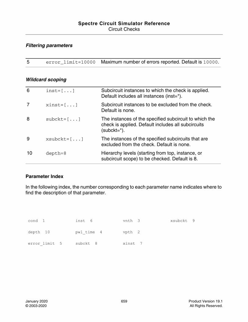
Spectre Circuit Simulator ReferenceCircuit Checks
January 2020 659 Product Version 19.1© 2003-2020 All Rights Reserved.
Filtering parameters
Wildcard scoping
Parameter Index
In the following index, the number corresponding to each parameter name indicates where to find the description of that parameter.
5 error_limit=10000 Maximum number of errors reported. Default is 10000.
6 inst=[...] Subcircuit instances to which the check is applied. Default includes all instances (inst=*).
7 xinst=[...] Subcircuit instances to be excluded from the check. Default is none.
8 subckt=[...] The instances of the specified subcircuit to which the check is applied. Default includes all subcircuits (subckt=*).
9 xsubckt=[...] The instances of the specified subcircuits that are excluded from the check. Default is none.
10 depth=8 Hierarchy levels (starting from top, instance, or subcircuit scope) to be checked. Default is 8.
cond 1 inst 6 vnth 3 xsubckt 9
depth 10 pwl_time 4 vpth 2
error_limit 5 subckt 8 xinst 7
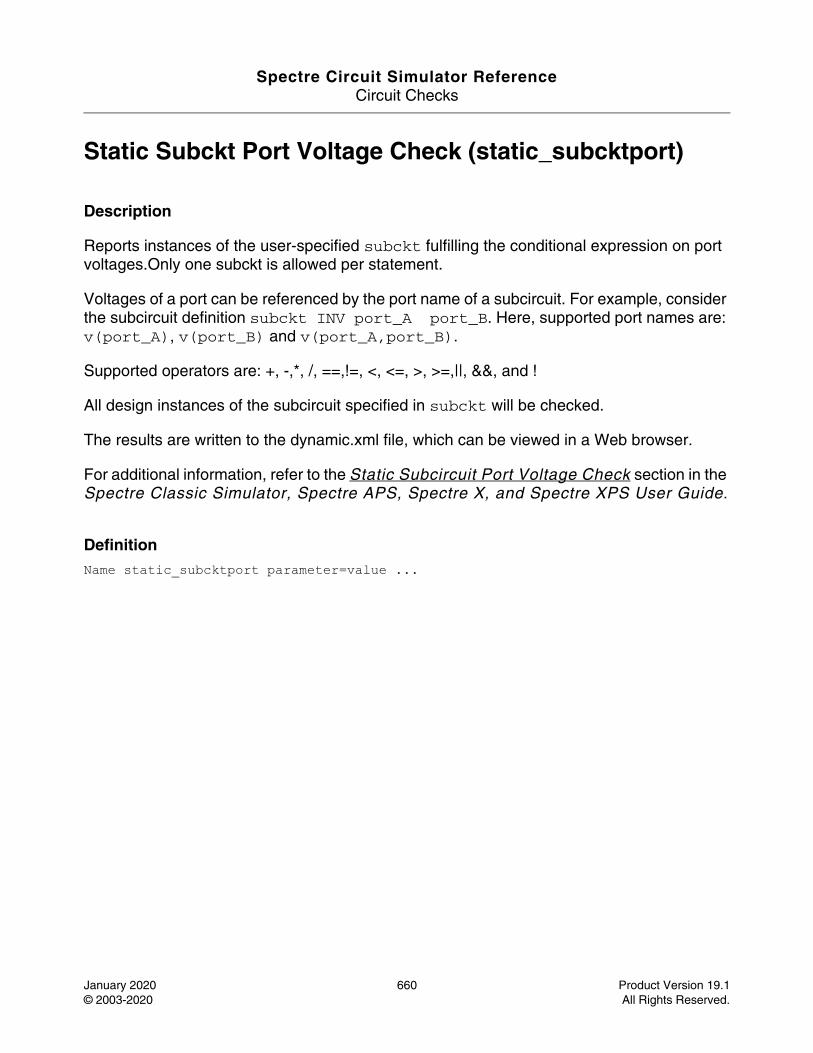
Spectre Circuit Simulator ReferenceCircuit Checks
January 2020 660 Product Version 19.1© 2003-2020 All Rights Reserved.
Static Subckt Port Voltage Check (static_subcktport)
Description
Reports instances of the user-specified subckt fulfilling the conditional expression on port voltages.Only one subckt is allowed per statement.
Voltages of a port can be referenced by the port name of a subcircuit. For example, consider the subcircuit definition subckt INV port_A port_B. Here, supported port names are: v(port_A), v(port_B) and v(port_A,port_B).
Supported operators are: +, -,*, /, ==,!=, <, <=, >, >=,||, &&, and !
All design instances of the subcircuit specified in subckt will be checked.
The results are written to the dynamic.xml file, which can be viewed in a Web browser.
For additional information, refer to the Static Subcircuit Port Voltage Check section in the Spectre Classic Simulator, Spectre APS, Spectre X, and Spectre XPS User Guide.
DefinitionName static_subcktport parameter=value ...
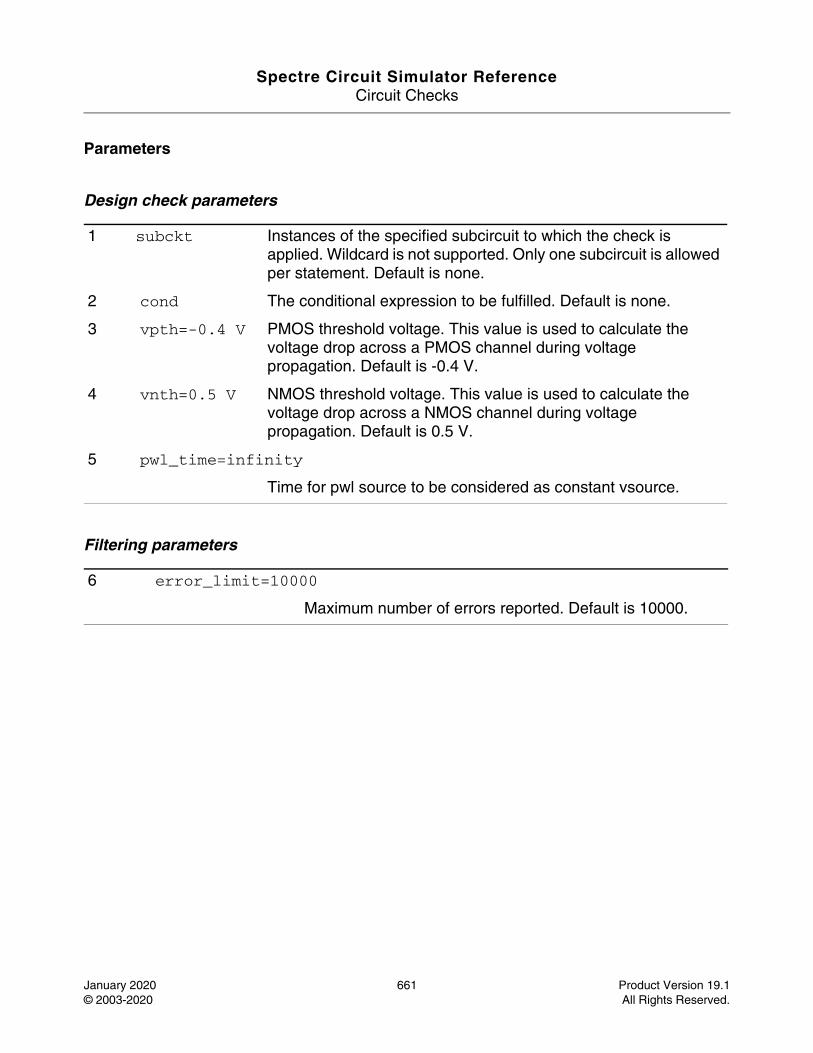
Spectre Circuit Simulator ReferenceCircuit Checks
January 2020 661 Product Version 19.1© 2003-2020 All Rights Reserved.
Parameters
Design check parameters
Filtering parameters
1 subckt Instances of the specified subcircuit to which the check is applied. Wildcard is not supported. Only one subcircuit is allowed per statement. Default is none.
2 cond The conditional expression to be fulfilled. Default is none.
3 vpth=-0.4 V PMOS threshold voltage. This value is used to calculate the voltage drop across a PMOS channel during voltage propagation. Default is -0.4 V.
4 vnth=0.5 V NMOS threshold voltage. This value is used to calculate the voltage drop across a NMOS channel during voltage propagation. Default is 0.5 V.
5 pwl_time=infinity
Time for pwl source to be considered as constant vsource.
6 error_limit=10000
Maximum number of errors reported. Default is 10000.
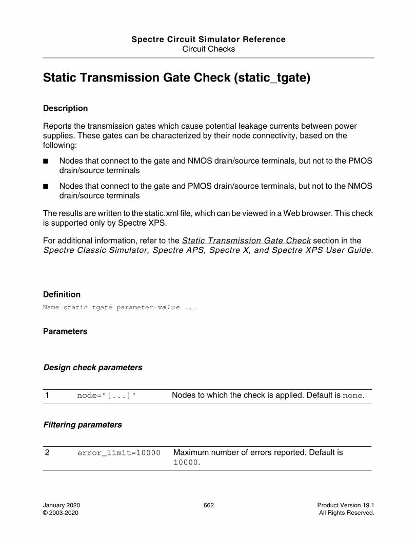
Spectre Circuit Simulator ReferenceCircuit Checks
January 2020 662 Product Version 19.1© 2003-2020 All Rights Reserved.
Static Transmission Gate Check (static_tgate)
Description
Reports the transmission gates which cause potential leakage currents between power supplies. These gates can be characterized by their node connectivity, based on the following:
■ Nodes that connect to the gate and NMOS drain/source terminals, but not to the PMOS drain/source terminals
■ Nodes that connect to the gate and PMOS drain/source terminals, but not to the NMOS drain/source terminals
The results are written to the static.xml file, which can be viewed in a Web browser. This check is supported only by Spectre XPS.
For additional information, refer to the Static Transmission Gate Check section in the Spectre Classic Simulator, Spectre APS, Spectre X, and Spectre XPS User Guide.
DefinitionName static_tgate parameter=value ...
Parameters
Design check parameters
Filtering parameters
1 node="[...]" Nodes to which the check is applied. Default is none.
2 error_limit=10000 Maximum number of errors reported. Default is 10000.
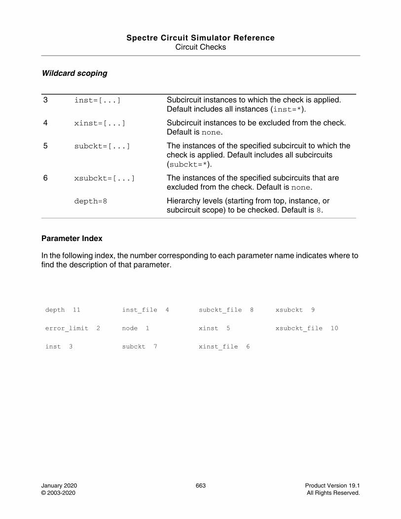
Spectre Circuit Simulator ReferenceCircuit Checks
January 2020 663 Product Version 19.1© 2003-2020 All Rights Reserved.
Wildcard scoping
Parameter Index
In the following index, the number corresponding to each parameter name indicates where to find the description of that parameter.
3 inst=[...] Subcircuit instances to which the check is applied. Default includes all instances (inst=*).
4 xinst=[...] Subcircuit instances to be excluded from the check. Default is none.
5 subckt=[...] The instances of the specified subcircuit to which the check is applied. Default includes all subcircuits (subckt=*).
6 xsubckt=[...] The instances of the specified subcircuits that are excluded from the check. Default is none.
depth=8 Hierarchy levels (starting from top, instance, or subcircuit scope) to be checked. Default is 8.
depth 11 inst_file 4 subckt_file 8 xsubckt 9
error_limit 2 node 1 xinst 5 xsubckt_file 10
inst 3 subckt 7 xinst_file 6
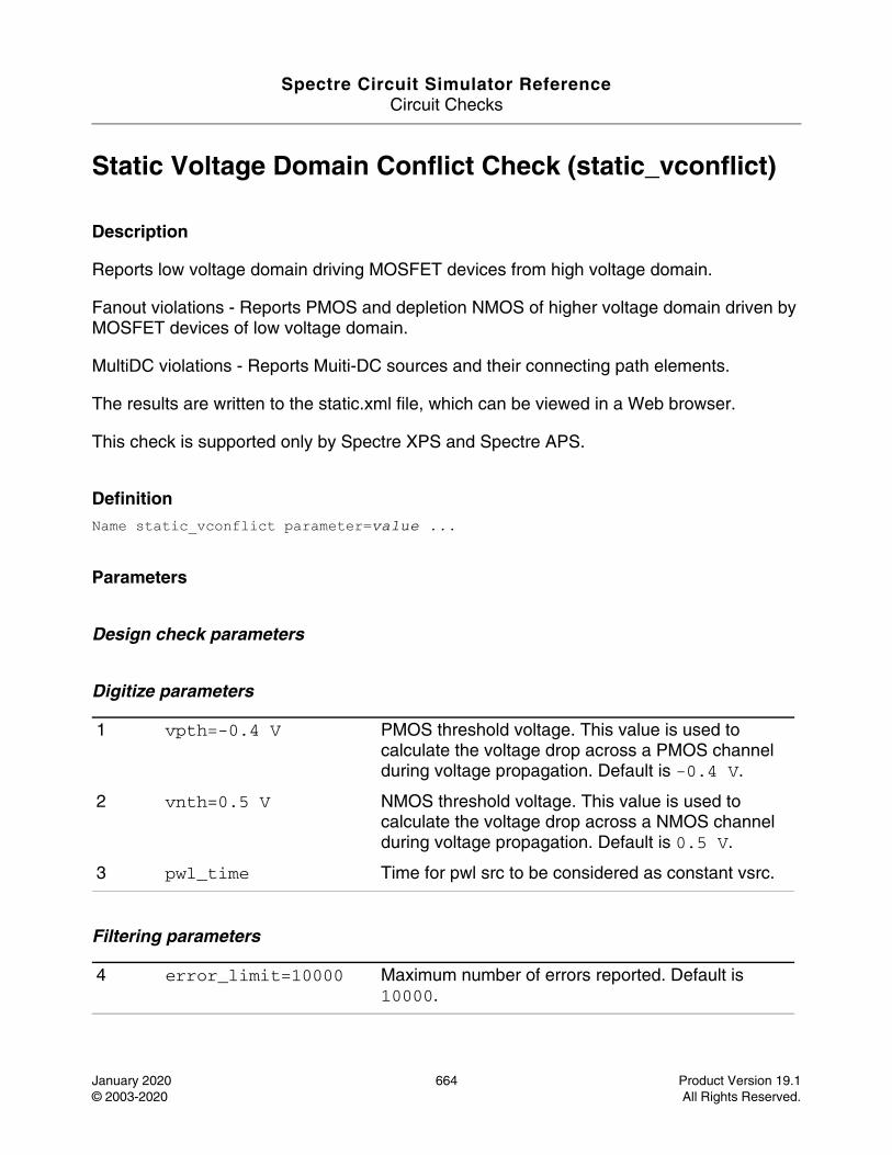
Spectre Circuit Simulator ReferenceCircuit Checks
January 2020 664 Product Version 19.1© 2003-2020 All Rights Reserved.
Static Voltage Domain Conflict Check (static_vconflict)
Description
Reports low voltage domain driving MOSFET devices from high voltage domain.
Fanout violations - Reports PMOS and depletion NMOS of higher voltage domain driven by MOSFET devices of low voltage domain.
MultiDC violations - Reports Muiti-DC sources and their connecting path elements.
The results are written to the static.xml file, which can be viewed in a Web browser.
This check is supported only by Spectre XPS and Spectre APS.
DefinitionName static_vconflict parameter=value ...
Parameters
Design check parameters
Digitize parameters
Filtering parameters
1 vpth=-0.4 V PMOS threshold voltage. This value is used to calculate the voltage drop across a PMOS channel during voltage propagation. Default is -0.4 V.
2 vnth=0.5 V NMOS threshold voltage. This value is used to calculate the voltage drop across a NMOS channel during voltage propagation. Default is 0.5 V.
3 pwl_time Time for pwl src to be considered as constant vsrc.
4 error_limit=10000 Maximum number of errors reported. Default is 10000.
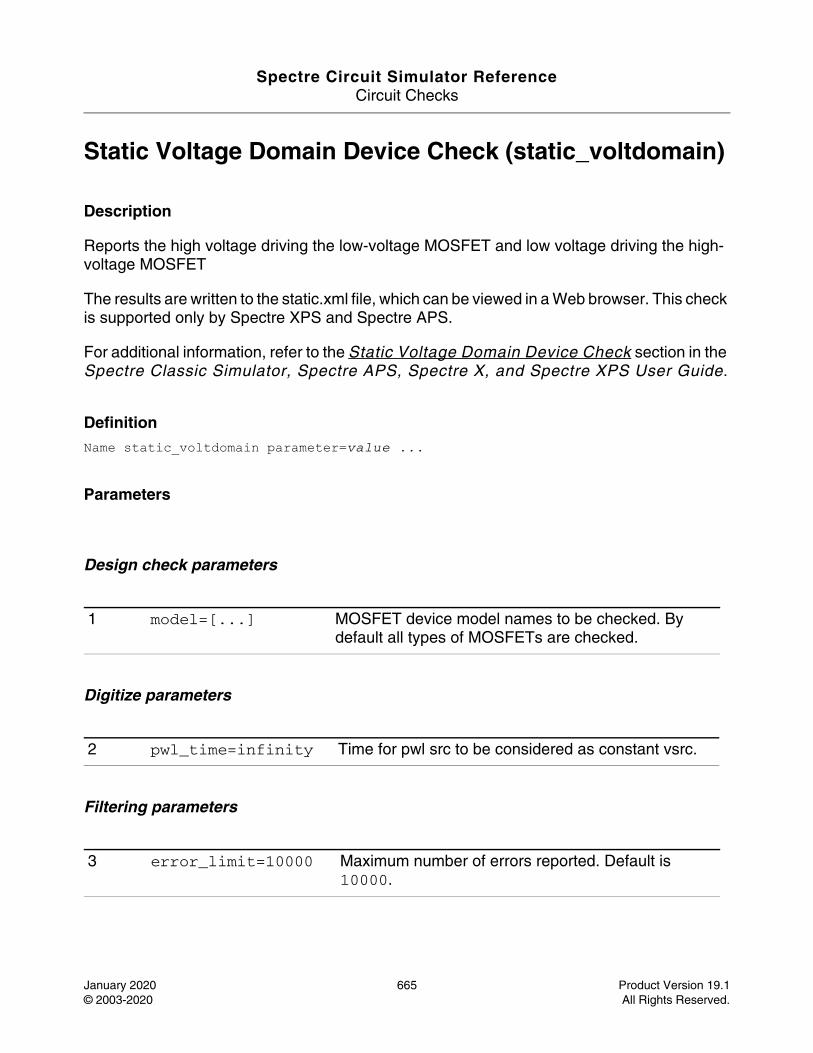
Spectre Circuit Simulator ReferenceCircuit Checks
January 2020 665 Product Version 19.1© 2003-2020 All Rights Reserved.
Static Voltage Domain Device Check (static_voltdomain)
Description
Reports the high voltage driving the low-voltage MOSFET and low voltage driving the high-voltage MOSFET
The results are written to the static.xml file, which can be viewed in a Web browser. This check is supported only by Spectre XPS and Spectre APS.
For additional information, refer to the Static Voltage Domain Device Check section in the Spectre Classic Simulator, Spectre APS, Spectre X, and Spectre XPS User Guide.
DefinitionName static_voltdomain parameter=value ...
Parameters
Design check parameters
Digitize parameters
Filtering parameters
1 model=[...] MOSFET device model names to be checked. By default all types of MOSFETs are checked.
2 pwl_time=infinity Time for pwl src to be considered as constant vsrc.
3 error_limit=10000 Maximum number of errors reported. Default is 10000.
Spectre Circuit Simulator ReferenceCircuit Checks
January 2020 666 Product Version 19.1© 2003-2020 All Rights Reserved.
Wildcard scoping
Parameter Index
In the following index, the number corresponding to each parameter name indicates where to find the description of that parameter.
4 inst=[...] Subcircuit instances to which the check is applied. Default includes all instances (inst=*).
5 xinst=[...] Subcircuit instances to be excluded from the check. Default is none.
6 subckt=[...] The instances of the specified subcircuit to which the check is applied. Default includes all subcircuits (subckt=*).
7 xsubckt=[...] The instances of the specified subcircuits that are excluded from the check. Default is none.
8 depth=8 Hierarchy levels (starting from top, instance, or subcircuit scope) to be checked. Default is 8.
depth 8 inst 4 pwl_time 2 xinst 5
error_limit 3 model 1 subckt 6 xsubckt 7
Spectre Circuit Simulator Reference
January 2020 667 Product Version 19.1© 2003-2020 All Rights Reserved.
1References
This section gives additional details about the source documents referred to in the text.
■ [antognetti88] Paolo Antognetti, Giuseppe Massobrio. Semiconductor Device Modeling with SPICE. McGraw-Hill, New York, 1988.
■ [gear71] C. William Gear. Numerical Initial Value Problems in Ordinary Differential Equations. Prentice-Hall, 1971.
■ [hammerstad80] E. Hammerstad, O. Jensen. “Accurate models for microstrip computer-aided design.” IEEE MTT-S 1980 International Microwave Symposium Digest, pages 407-409.
■ [jansen83] Rolf H. Jansen, Martin Kirschning. “Arguments and an accurate model for the power-current formulation of microstrip characteristic impedance.” Arch. Elek. Ubertragung (AEU), vol. 37, 1983, pages 108-112.
■ [kirschning82] M. Kirschning, R. H. Jansen. “Accurate model for effective dielectric constant of microstrip with validity up to millimetre-wave frequencies.” Electronic Letters, vol. 18, no. 6, 18 March 1982, pages 272-273.
■ [kundert90]Kenneth S. Kundert, Jacob K. White, Alberto Sangiovanni-Vincentelli. Steady-State Methods for Simulating Analog and Microwave Circuits. Kluwer Academic Publishers, 1990.
■ [nagel75]Laurence W. Nagel. SPICE2: A Computer Program to Simulate Semiconductor Circuits. Ph. D. dissertation, University of California at Berkeley, May 1975. Available through Electronics Research Laboratory Publications, U. C. B., 94720; Memorandum No. UCB/ERL M520.
■ [quarles89] Thomas L. Quarles. Analysis of Performance and Convergence Issues for Circuit Simulation. Ph. D. dissertation, University of California at Berkeley, April 1989. Extensively documents the Spice3 program. Available through Electronics Research Laboratory Publications, U. C. B., 94720; Memorandum No. UCB/ERL M89/42.

Spectre Circuit Simulator ReferenceReferences
January 2020 668 Product Version 19.1© 2003-2020 All Rights Reserved.
■ [statz87]Hermann Statz, Paul Newman, Irl W. Smith, Robert A. Pucel, Hermann A. Haus. “GaAs FET device and circuit simulation in SPICE.” IEEE Transactions on Electron Devices, vol. ED-34, no. 2, pages 160-169, February 1987.
■ [vladimirescu81]A. Vladimirescu, Kaihe Zhang, A. R. Newton, D. O. Pederson, A. Sangiovanni-Vincentelli. SPICE Version 2G User’s Guide, August 1981. Available through Industrial Liaison Program Software Distribution office, Department of Electrical Engineering and Computer Sciences, University of California at Berkeley, 94720.
■ [yang82]Ping Yang, Pallab K. Chatterjee. “SPICE modeling for small geometry MOSFET circuits.” IEEE Transactions on Computer-Aided Design of Integrated Circuits and Systems, vol. CAD-1, no. 4, pages 169-182, October 1982.
Spectre Circuit Simulator Reference
Index
Symbols%S_DEFAULTS 39%X (+/-), spectre command option 28+/-interactive, spectre command option 31
Aac
analysisdefinition 43description 43parameters 43
AC Analysis analyses 43ac(AC Analysis) 43acmatch
analysisdefinition 49description 49parameters 49
ACMatch Analysis analyses 49acmatch(ACMatch Analysis) 49-alias, spectre command option 30alter
analysisdefinition 54description 54parameters 54
Alter a Circuit, Component, or Netlist Parameter analyses 54
Alter Group analyses 56alter(Alter a Circuit, Component, or Netlist
Parameter) 54altergroup
analysisdefinition 56description 56parameters 57
altergroup(Alter Group) 56analogmodel
otherdescription 451
analogmodel(Using analogmodel for Model Passing) 451
analyses
AC Analysis 43ACMatch Analysis 49Alter a Circuit, Component, or Netlist
Parameter 54Alter Group 56Check Parameter Values 59Checklimit Analysis 60Circuit Information 150DC Analysis 64DC Device Matching Analysis 70Deferred Set Options 379Envelope Following Analysis 76Harmonic Balance Steady State
Analysis 90HB AC Analysis 111HB Noise Analysis 119HB S-Parameter Analysis 130HB Stability Analysis 139HB XF Analysis 143Immediate Set Options 187Load Pull Analysis 162Monte Carlo Analysis 165Noise Analysis 181Periodic AC Analysis 245Periodic Noise Analysis 253Periodic S-Parameter Analysis 264Periodic STB Analysis 298Periodic Steady-State Analysis 272Periodic Transfer Function
Analysis 303PZ Analysis 312Quasi-Periodic AC Analysis 318Quasi-Periodic Noise Analysis 323Quasi-Periodic S-Parameter
Analysis 331Quasi-Periodic Steady State
Analysis 339Quasi-Periodic Transfer Function
Analysis 356Reliability Analysis 362Setting for Simulink-MATLAB co-
simulation 63Shell Command 386S-Parameter Analysis 387Special current saving options 436Stability Analysis 393
January 2020 669 Product Version 19.1© 2003-2020 All Rights Reserved.
Spectre Circuit Simulator Reference
Sweep Analysis 406THERMAL Analysis 413Time-Domain Reflectometer
Analysis 411Transfer Function Analysis 438
analysisdefinition
(ac) 43(acmatch) 49(alter) 54(altergroup) 56(check) 59(checklimit) 60(cosim) 63(dc) 64(dcmatch) 70(envlp) 77(hb) 90(hbac) 111(hbnoise) 121(hbsp) 130(hbstb) 139(hbxf) 143(info) 150(lf) 156(loadpull) 162(montecarlo) 166(noise) 182(options) 187(pac) 245(pnoise) 255(psp) 264(pss) 273(pstb) 298(pxf) 303(pz) 312(qpac) 318(qpnoise) 325(qpsp) 331(qpss) 340(qpxf) 356(reliability) 362(set) 379(shell) 386(sp) 387(stb) 393, 401(sweep) 406(tdr) 411(thermal) 413(tran) 416(uti) 436
(xf) 439description
(ac) 43(acmatch) 49(alter) 54(altergroup) 56(check) 59(checklimit) 60(cosim) 63(dc) 64(dcmatch) 70(envlp) 76(hb) 90(hbac) 111(hbnoise) 119(hbsp) 130(hbstb) 139(hbxf) 143(info) 150(loadpull) 162(montecarlo) 165(noise) 181(options) 187(pac) 245(pnoise) 253(psp) 264(pss) 272(pstb) 298(pxf) 303(pz) 312(qpac) 318(qpnoise) 323(qpsp) 331(qpss) 339(qpxf) 356(reliability) 362(set) 379(shell) 386(sp) 387(stb) 393(sweep) 406(tdr) 411(tran) 416(uti) 436(xf) 438
parameters(ac) 43(acmatch) 49(alter) 54(altergroup) 57(check) 59
January 2020 670 Product Version 19.1© 2003-2020 All Rights Reserved.
Spectre Circuit Simulator Reference
(checklimit) 60(cosim) 63(dc) 64(dcmatch) 71(envlp) 77(hb) 91(hbac) 112(hbnoise) 121(hbsp) 130(hbstb) 140(hbxf) 143(info) 151(loadpull) 162(montecarlo) 166(noise) 182(options) 187(pac) 246(pnoise) 255(psp) 264(pss) 273(pstb) 299(pxf) 303(pz) 312(qpac) 318(qpnoise) 325(qpsp) 331(qpss) 340(qpxf) 356(reliability) 362(set) 379(shell) 386(sp) 387(stb) 393, 401(sweep) 406(tdr) 411(thermal) 413(tran) 416(uti) 437(xf) 439
attached simulator control 29
BBehavioural Source Use Model other 453bsource
otherdescription 453
bsource(Behavioural Source Use Model) 453
Built-in Mathematical and Physical
Constants other 466
CC preprocessor (CPP) control 30check
analysisdefinition 59description 59parameters 59
Check Parameter Values analyses 59check(Check Parameter Values) 59checker
definition(dyn_activity) 555(dyn_actnode) 557(dyn_capv) 559(dyn_dcpath) 561(dyn_delay) 564(dyn_diodev) 567(dyn_exi) 569(dyn_exrf) 571(dyn_float_tran_stat) 582(dyn_floatdcpath) 576(dyn_glitch) 586(dyn_highz) 589(dyn_mosv) 594(dyn_nodecap) 596(dyn_noisynode) 598(dyn_pulsewidth) 601(dyn_resv) 604(dyn_setuphold) 606(dyn_stahighz) 609(dyn_subcktport) 612(dyn_subcktpwr) 614(static_capacitor) 617(static_capv) 619(static_coupling) 621(static_dcpath) 624(static_diodev) 626(static_erc) 628(static_highfanout) 631(static_highz) 634(static_mosv) 637(static_nmos2vdd) 639(static_nmosb) 640(static_nmosvgs) 643(static_pmos2gnd) 645(static_pmosb) 647(static_pmosvgs) 650
January 2020 671 Product Version 19.1© 2003-2020 All Rights Reserved.
Spectre Circuit Simulator Reference
(static_rcdelay) 653(static_resistor) 656(static_resv) 658(static_subcktport) 660(static_tgate) 662(static_vconflict) 664(static_voltdomain) 665
description(dyn_actnode) 557(dyn_capv) 555, 559(dyn_dcpath) 561(dyn_delay) 564(dyn_diodev) 567(dyn_exi) 569(dyn_exrf) 571(dyn_float_tran_stat) 582(dyn_floatdcpath) 574(dyn_glitch) 586(dyn_highz) 589(dyn_mosv) 594(dyn_nodecap) 596(dyn_noisynode) 598(dyn_pulsewidth) 601(dyn_resv) 604(dyn_setuphold) 606(dyn_stahighz) 609(dyn_subcktport) 612(dyn_subcktpwr) 614(static_capacitor) 617(static_capv) 619(static_coupling) 621(static_dcpath) 624(static_diodev) 626(static_erc) 628(static_highfanout) 631(static_highz) 634(static_mosv) 637(static_nmos2vdd) 639(static_nmosb) 640(static_nmosvgs) 643(static_pmos2gnd) 645(static_pmosb) 647(static_pmosvgs) 650(static_rcdelay) 653(static_resistor) 656(static_resv) 658(static_subcktport) 660(static_tgate) 662(static_vconflict) 664(static_voltdomain) 665
parameters
(dyn_activity) 555(dyn_actnode) 557(dyn_capv) 559(dyn_dcpath) 562(dyn_delay) 564(dyn_diodev) 567(dyn_exi) 569(dyn_exrf) 571(dyn_float_tran_stat) 583(dyn_floatdcpath) 577(dyn_glitch) 586(dyn_highz) 589(dyn_mosv) 594(dyn_nodecap) 596(dyn_noisynode) 598(dyn_pulsewidth) 601(dyn_resv) 604(dyn_setuphold) 606(dyn_stahighz) 610(dyn_subcktport) 612(dyn_subcktpwr) 614(static_capacitor) 617(static_capv) 619(static_coupling) 622(static_dcpath) 624(static_diodev) 626(static_erc) 628(static_highfanout) 632(static_highz) 634(static_mosv) 637(static_nmos2vdd) 639(static_nmosb) 640(static_nmosvgs) 643(static_pmos2gnd) 645(static_pmosb) 647(static_pmosvgs) 650(static_rcdelay) 653(static_resistor) 656(static_resv) 658(static_subcktport) 661(static_tgate) 662(static_vconflict) 664(static_voltdomain) 665
checkersDynamic Capacitor Voltage Check
Violations 559Dynamic DC Leakage Path Check
Violations 561Dynamic Delay Check 564Dynamic Diode Voltage Check 567Dynamic Excessive Element Current
January 2020 672 Product Version 19.1© 2003-2020 All Rights Reserved.
Spectre Circuit Simulator Reference
Check Violations 569Dynamic Excessive Rise, Fall, Undefined
State Time Check Violations 571
Dynamic Floating Node Induced DC Leakage Path Check Violations 574
Dynamic Floating Node Statistical Check 582
Dynamic Glitch Check Violations 586Dynamic HighZ Node Check
Violations 589Dynamic MOSFET Voltage Check
Violations 594Dynamic Node Capacitance Check 596Dynamic Noisy Node Check
Violations 598Dynamic Pulse Width Check 601Dynamic Resistor Voltage Check
Violations 604Dynamic Setup and Hold Check
Violations 606Dynamic Statistical HighZ Node
Check 609Dynamic Subckt Instance Activity
Check 555Dynamic Subckt Port Power Check
Violations 614Dynamic Subckt Port voltage/current
Check 612Static Always Conducting MOSFET
Check Violations 643, 650Static Capacitor Check Violations 617Static Capacitor Voltage Check
Violations 619Static Coupling Impact Check 621Static DC Leakage Path Check
Violations 624Static Diode Voltage Check 626Static ERC Check Violations 628Static Forward Bias Bulk Check
Violations 640, 647Static Highfanout Check 631Static HighZ Node Check
Violations 634Static MOSFET Voltage Check
Violations 637Static PMOS to gnd count 645Static RCDelay Check 653Static Resistor Check Violations 656Static Resistor Voltage Check
Violations 658Static Subckt Port Voltage Check 660Static Transmission Gate Check
Violations 662Static Voltage Domain Conflict
Check 664Static Voltage Domain Device Check
Violations 665checklimit
analysisdefinition 60description 60parameters 60
Checklimit Analysis analyses 60checklimit(Checklimit Analysis ) 60Checkpoint - Restart other 462checkpoint (+/-), spectre command
option 27checkpoint and recovery 27checkpoint(Checkpoint - Restart) 462Circuit Information analyses 150cmiconfig
otherdescription 464
cmiconfig(Configuring CMI Shared Objects) 464
-cols, spectre command option 28-colslog, spectre command option 28Configuring CMI Shared Objects other 464constants
otherdescription 466
constants(Built-in Mathematical and Physical Constants) 466
conventions 12, 13convergence
otherdescription 468
Convergence Difficulties other 468convergence(Convergence
Difficulties) 468cosim
analysisdefinition 63description 63parameters 63
cosim(Setting for Simulink-MATLAB co-simulation) 63
January 2020 673 Product Version 19.1© 2003-2020 All Rights Reserved.
Spectre Circuit Simulator Reference
D-D, spectre command option 30dc
analysisdefinition 64description 64parameters 64
DC Analysis analyses 64DC Device Matching Analysis analyses 70dc(DC Analysis) 64dcmatch
analysisdefinition 70description 70parameters 71
dcmatch(DC Device Matching Analysis) 70dcopt
otherdefinition 470description 470
debug (+/-), spectre command option 29defaults of parameter values 39Deferred Set Options analyses 379dyn_activity
checkerdefinition 555parameters 555
dyn_activity(Dynamic Subckt Instance Activity Check) 555
dyn_actnodechecker
definition 557description 557parameters 557
dyn_capvchecker
definition 559description 555, 559parameters 559
dyn_capv(Dynamic Capacitor Voltage Check Violations) 559
dyn_dcpathchecker
definition 561description 561parameters 562
dyn_dcpath(Dynamic DC Leakage Path Check Violations) 561
dyn_delay
checkerdefinition 564description 564parameters 564
dyn_delay(Dynamic Delay Check) 564dyn_diodev
checkerdefinition 567description 567parameters 567
dyn_diodev(Dynamic Diode Voltage Check) 567
dyn_exichecker
definition 569description 569parameters 569
dyn_exi(Dynamic Excessive Element Current Check Violations) 569
dyn_exrfchecker
definition 571description 571parameters 571
dyn_exrf(Dynamic Excessive Rise, Fall, Undefined State Time Check Violations) 571
dyn_float_tran_statchecker
definition 582description 582parameters 583
dyn_float_tran_stat(Dynamic Floating Node Statistical Check) 582
dyn_floatdcpathchecker
definition 576description 574parameters 577
dyn_floatdcpath(Dynamic Floating Node Induced DC Leakage Path Check Violations) 574
dyn_glitchchecker
definition 586description 586parameters 586
dyn_glitch(Dynamic Glitch Check Violations) 586
dyn_highzchecker
January 2020 674 Product Version 19.1© 2003-2020 All Rights Reserved.
Spectre Circuit Simulator Reference
definition 589description 589parameters 589
dyn_highz(Dynamic HighZ Node Check Violations) 589
dyn_mosvchecker
definition 594description 594parameters 594
dyn_mosv(Dynamic MOSFET Voltage Check Violations) 594
dyn_nodecapchecker
definition 596description 596parameters 596
dyn_nodecap(Dynamic Node Capacitance Check) 596
dyn_noisynodechecker
definition 598description 598parameters 598
dyn_noisynode(Dynamic Noisy Node Check Violations) 598
dyn_pulsewidthchecker
definition 601description 601parameters 601
dyn_pulsewidth(Dynamic Pulse Width Check) 601
dyn_resvchecker
definition 604description 604parameters 604
dyn_resv(Dynamic Resistor Voltage Check Violations) 604
dyn_setupholdchecker
definition 606description 606parameters 606
dyn_setuphold(Dynamic Setup and Hold Check Violations) 606
dyn_stahighzchecker
definition 609description 609
parameters 610dyn_stahighz(Dynamic Statistical HighZ
Node Check) 609dyn_subcktport
checkerdefinition 612description 612parameters 612
dyn_subcktport(Dynamic Subckt Port voltage/current Check) 612
dyn_subcktpwrchecker
definition 614description 614parameters 614
dyn_subcktpwr(Dynamic Subckt Port Power Check Violations) 614
Dynamic Capacitor Voltage Check Violations checkers 559
Dynamic DC Leakage Path Check Violations checkers 561
Dynamic Delay Check checkers 564Dynamic Diode Voltage Check
checkers 567Dynamic Excessive Element Current Check
Violations checkers 569Dynamic Excessive Rise, Fall, Undefined
State Time Check Violations checkers 571
Dynamic Floating Node Induced DC Leakage Path Check Violations checkers 574
Dynamic Floating Node Statistical Check checkers 582
Dynamic Glitch Check Violations checkers 586
Dynamic HighZ Node Check Violations checkers 589
Dynamic MOSFET Voltage Check Violations checkers 594
Dynamic Node Capacitance Check checkers 596
Dynamic Noisy Node Check Violations checkers 598
Dynamic Pulse Width Check checkers 601Dynamic Resistor Voltage Check Violations
checkers 604Dynamic Setup and Hold Check Violations
checkers 606Dynamic Statistical HighZ Node Check
checkers 609
January 2020 675 Product Version 19.1© 2003-2020 All Rights Reserved.
Spectre Circuit Simulator Reference
Dynamic Subckt Instance Activity Check checkers 555
Dynamic Subckt Port Power Check Violations checkers 614
Dynamic Subckt Port voltage/current Check checkers 612
E-E, spectre command option 30encryption
otherdescription 471
encryption other 471encryption(encryption) 471Envelope Following Analysis analyses 76environment variable
%S_DEFAULTS 39SPECTRE_DEFAULTS 39
envlpanalysis
definition 77description 76parameters 77
envlp(Envelope Following Analysis) 76error (+/-), spectre command option 28expressions
otherdescription 474
Expressions other 474expressions(Expressions) 474
Ffastdc
otherdefinition 478description 478
fastdc(The fastdc command line option) 478
faultsother
definition 479description 479
filename replacement 28-format, spectre command option 27formatting of results 27functions
other
definition 481description 481
functions(User Defined Functions) 481
Gglobal
otherdefinition 482description 482
Global Nodes other 482global(Global Nodes) 482
HHarmonic Balance Steady State Analysis
analyses 90hb
analysisdefinition 90description 90parameters 91
HB AC Analysis analyses 111HB Noise Analysis analyses 119HB S-Parameter Analysis analyses 130HB Stability Analysis analyses 139HB XF Analysis analyses 143hb(Harmonic Balance Steady State
Analysis) 90hbac
analysisdefinition 111description 111parameters 112
hbac(HB AC Analysis) 111hbnoise
analysisdefinition 121description 119parameters 121
hbnoise(HB Noise Analysis) 119hbsp
analysisdefinition 130description 130parameters 130
hbsp(HB S-Parameter Analysis) 130hbstb
analysis
January 2020 676 Product Version 19.1© 2003-2020 All Rights Reserved.
Spectre Circuit Simulator Reference
definition 139description 139parameters 140
hbstb(HB Stability Analysis) 139hbxf
analysisdefinition 143description 143parameters 143
hbxf(HB XF Analysis) 143help features online 25-help, spectre command option 25-helpfull, spectre command option 26-helpsort, spectre command option 25-helpsortfull, spectre command option 26
I-I, spectre command option 30ibis
otherdescription 483
IBIS Component Use Model other 483ibis(IBIS Component Use Model) 483ic
otherdefinition 490description 490
ic(Initial Conditions) 490if
otherdefinition 491description 491
if(The Structural if-statement) 491Immediate Set Options analyses 187include
otherdefinition 494description 493
Include File other 493include(Include File) 493info
analysisdefinition 150description 150parameters 151
info (+/-), spectre command option 29info(Circuit Information) 150Initial Conditions other 490italics in syntax 13
Kkeywords 12
otherdescription 495
keywords(Spectre Netlist Keywords) 495
Llf
analysisdefinition 156
libraryother
definition 498description 498
Library - Sectional Include other 498library(Library - Sectional Include) 498license manager 30literal characters 12Load Pull Analysis analyses 162loadpull
analysisdefinition 162description 162parameters 162
loadpull(Load Pull Analysis) 162log (+/-/=), spectre command option 26
Mmemory
otherdescription 500
memory(Tips for Reducing Memory Usage) 500
message control 28Monte Carlo Analysis analyses 165montecarlo
analysisdefinition 166description 165parameters 166
montecarlo(Monte Carlo Analysis) 165-mt, spectre command option 30mts
otherdescription 501
January 2020 677 Product Version 19.1© 2003-2020 All Rights Reserved.
Spectre Circuit Simulator Reference
mts(Multi-Technology Simulation Mode) 501
Multi-Technology Simulation Mode other 501
NNetlist Parameters other 506Node Sets other 502nodeset
otherdefinition 502description 502
nodeset(Node Sets) 502noise
analysisdefinition 182description 181parameters 182
Noise Analysis analyses 181noise(Noise Analysis) 181
Oonline help 25options
analysisdefinition 187description 187parameters 187
options(Immediate Set Options) 187other
Behavioural Source Use Model 453Built-in Mathematical and Physical
Constants 466Checkpoint - Restart 462Configuring CMI Shared Objects 464Convergence Difficulties 468definition
(dcopt) 470(fastdc) 478(faults) 479(functions) 481(global) 482(ic) 490(if) 491(include) 494(library) 498(nodeset) 502
(parameters) 506(paramset) 509(postlayout) 510(save) 517(sens) 524(subckt) 535
description(analogmodel) 451(bsource) 453(cmiconfig) 464(constants) 466(convergence) 468(dcopt) 470(encryption) 471(expressions) 474(fastdc) 478(faults) 479(functions) 481(global) 482(ibis) 483(ic) 490(if) 491(include) 493(keywords) 495(library) 498(memory) 500(mts) 501(nodeset) 502(param_limits) 503(parameters) 506(paramset) 509(postlayout) 510(rfmemory) 512(save) 517(savestate) 520(sens) 524(spectrerf) 526(stitch) 527(subckt) 533(vector) 538(veriloga) 541
encryption 471Expressions 474Global Nodes 482IBIS Component Use Model 483Include File 493Initial Conditions 490Library - Sectional Include 498Multi-Technology Simulation Mode 501Netlist Parameters 506Node Sets 502
January 2020 678 Product Version 19.1© 2003-2020 All Rights Reserved.
Spectre Circuit Simulator Reference
Output Selections 517Parameter Set - Block of Data 509Parameter Soft Limits 503Savestate - Recover 520Sensitivity Analyses 524Spectre Netlist Keywords 495SpectreRF Summary 526Stitch Flow Use Model 527Subcircuit Definitions 533The fastdc command line option 478The postlayout command line
option 510The Structural if-statement 491Tips for Reducing Memory Usage 500Tips for Reducing Memory Usage with
SpectreRF 512User Defined Functions 481Using analogmodel for Model
Passing 451Vec/Vcd/Evcd Digital Stimulus 538Verilog-A Usage and Language
Summary 541Output Selections other 517
Ppac
analysisdefinition 245description 245parameters 246
pac(Periodic AC Analysis) 245param_limits
otherdescription 503
param_limits(Parameter Soft Limits) 503-param, spectre command option 26Parameter Set - Block of Data other 509Parameter Soft Limits other 503parameters
default values 39other
definition 506description 506
parameters(Netlist Parameters) 506paramset
otherdefinition 509description 509
paramset(Parameter Set - Block of
Data) 509Periodic AC Analysis analyses 245Periodic Noise Analysis analyses 253Periodic S-Parameter Analysis
analyses 264Periodic STB Analysis analyses 298Periodic Steady-State Analysis
analyses 272Periodic Transfer Function Analysis
analyses 303pnoise
analysisdefinition 255description 253parameters 255
pnoise(Periodic Noise Analysis) 253postlayout
otherdefinition 510description 510
postlayout(The postlayout command line option) 510
pspanalysis
definition 264description 264parameters 264
psp(Periodic S-Parameter Analysis) 264pss
analysisdefinition 273description 272parameters 273
pss(Periodic Steady-State Analysis) 272pstb
analysisdefinition 298description 298parameters 299
pstb(Periodic STB Analysis) 298pxf
analysisdefinition 303description 303parameters 303
pxf(Periodic Transfer Function Analysis) 303
pzanalysis
definition 312description 312
January 2020 679 Product Version 19.1© 2003-2020 All Rights Reserved.
Spectre Circuit Simulator Reference
parameters 312PZ Analysis analyses 312pz(PZ Analysis) 312
Qqpac
analysisdefinition 318description 318parameters 318
qpac(Quasi-Periodic AC Analysis) 318qpnoise
analysisdefinition 325description 323parameters 325
qpnoise(Quasi-Periodic Noise Analysis) 323
qpspanalysis
definition 331description 331parameters 331
qpsp(Quasi-Periodic S-Parameter Analysis) 331
qpssanalysis
definition 340description 339parameters 340
qpss(Quasi-Periodic Steady State Analysis) 339
qpxfanalysis
definition 356description 356parameters 356
qpxf(Quasi-Periodic Transfer Function Analysis) 356
Quasi-Periodic AC Analysis analyses 318Quasi-Periodic Noise Analysis
analyses 323Quasi-Periodic S-Parameter Analysis
analyses 331Quasi-Periodic Steady State Analysis
analyses 339Quasi-Periodic Transfer Function Analysis
analyses 356
R-raw, spectre command option 27recover (+/-), spectre command option 28recovery features 27reliability
analysisdefinition 362description 362parameters 362
Reliability Analysis analyses 362reliability(Reliability Analysis) 362results formatting 27rfmemory
otherdescription 512
rfmemory(Tips for Reducing Memory Usage with SpectreRF) 512
Ssave
otherdefinition 517description 517
save(Output Selections) 517savestate
otherdescription 520
Savestate - Recover other 520savestate (+/-), spectre command
option 27savestate(Savestate - Recover) 520screen width control 28sens
control with spectre command 30other
definition 524description 524
sens(Sensitivity Analyses) 524-sensdata, spectre command option 30Sensitivity Analyses other 524set
analysisdefinition 379description 379parameters 379
set(Deferred Set Options) 379Setting for Simulink-MATLAB co-simulation
January 2020 680 Product Version 19.1© 2003-2020 All Rights Reserved.
Spectre Circuit Simulator Reference
analyses 63shell
analysisdefinition 386description 386parameters 386
Shell Command analyses 386shell(Shell Command) 386-slave, spectre command option 29-slvhost, spectre command option 30sp
analysisdefinition 387description 387parameters 387
sp(S-Parameter Analysis) 387S-Parameter Analysis analyses 387Special current saving options
analyses 436Spectre
differences from SPICE 16, 25spectre command 25
attached simulator control 29C preprocessor (CPP) control 30checkpoint and recovery 27defaults
+/- pairs of options 39filename replacement 28license manager 30message control 28online help features 25options
-+/-interactive 31-alias 30+/-checkpoint 27-cols 28-colslog 28-D 30+/-debug 29-E 30+/-error 28-format 27-help 25-helpfull 26-helpsort 25-helpsortfull 26-I 30+/-info 29+/-/=log 26-mt 30-param 26
-raw 27+/-recover 28+/-savestate 27-sensdata 30-slave 29-slvhost 30-U 30-uwifmt 27-uwilib 27-V 30-W 30+/-warn 28+/-%X 28
results formatting 27screen width control 28sensitivity analysis control 30version information 30
Spectre Netlist Keywords other 495SPECTRE_DEFAULTS 39SpectreRF
brief description 11spectrerf
otherdescription 526
SpectreRF Summary other 526spectrerf(SpectreRF Summary) 526SPICE
differences from Spectre 16, 25Stability Analysis analyses 393statements
AC Analysis 43ACMatch Analysis 49Alter a Circuit, Component, or Netlist
Parameter 54Alter Group 56Behavioural Source Use Model 453Built-in Mathematical and Physical
Constants 466Check Parameter Values 59Checklimit Analysis 60Checkpoint - Restart 462Circuit Information 150Configuring CMI Shared Objects 464Convergence Difficulties 468DC Analysis 64DC Device Matching Analysis 70Deferred Set Options 379Dynamic Capacitor Voltage Check
Violations 559Dynamic DC Leakage Path Check
Violations 561
January 2020 681 Product Version 19.1© 2003-2020 All Rights Reserved.
Spectre Circuit Simulator Reference
Dynamic Delay Check 564Dynamic Diode Voltage Check 567Dynamic Excessive Element Current
Check Violations 569Dynamic Excessive Rise, Fall, Undefined
State Time Check Violations 571
Dynamic Floating Node Induced DC Leakage Path Check Violations 574
Dynamic Floating Node Statistical Check 582
Dynamic Glitch Check Violations 586Dynamic HighZ Node Check
Violations 589Dynamic MOSFET Voltage Check
Violations 594Dynamic Node Capacitance Check 596Dynamic Noisy Node Check
Violations 598Dynamic Pulse Width Check 601Dynamic Resistor Voltage Check
Violations 604Dynamic Setup and Hold Check
Violations 606Dynamic Statistical HighZ Node
Check 609Dynamic Subckt Instance Activity
Check 555Dynamic Subckt Port Power Check
Violations 614Dynamic Subckt Port voltage/current
Check 612encryption 471Envelope Following Analysis 76Expressions 474Global Nodes 482Harmonic Balance Steady State
Analysis 90HB AC Analysis 111HB Noise Analysis 119HB S-Parameter Analysis 130HB Stability Analysis 139HB XF Analysis 143IBIS Component Use Model 483Immediate Set Options 187Include File 493Initial Conditions 490Library - Sectional Include 498Load Pull Analysis 162Monte Carlo Analysis 165
Multi-Technology Simulation Mode 501Netlist Parameters 506Node Sets 502Noise Analysis 181Output Selections 517Parameter Set - Block of Data 509Parameter Soft Limits 503Periodic AC Analysis 245Periodic Noise Analysis 253Periodic S-Parameter Analysis 264Periodic STB Analysis 298Periodic Steady-State Analysis 272Periodic Transfer Function
Analysis 303PZ Analysis 312Quasi-Periodic AC Analysis 318Quasi-Periodic Noise Analysis 323Quasi-Periodic S-Parameter
Analysis 331Quasi-Periodic Steady State
Analysis 339Quasi-Periodic Transfer Function
Analysis 356Reliability Analysis 362Savestate - Recover 520Sensitivity Analyses 524Setting for Simulink-MATLAB co-
simulation 63Shell Command 386S-Parameter Analysis 387Special current saving options 436Spectre Netlist Keywords 495SpectreRF Summary 526Stability Analysis 393Static Always Conducting MOSFET
Check Violations 643, 650Static Capacitor Check Violations 617Static Capacitor Voltage Check
Violations 619Static Coupling Impact Check 621Static DC Leakage Path Check
Violations 624Static Diode Voltage Check 626Static ERC Check Violations 628Static Forward Bias Bulk Check
Violations 640, 647Static Highfanout Check 631Static HighZ Node Check
Violations 634Static MOSFET Voltage Check
Violations 637
January 2020 682 Product Version 19.1© 2003-2020 All Rights Reserved.
Spectre Circuit Simulator Reference
Static PMOS to gnd count 645Static RCDelay Check 653Static Resistor Check Violations 656Static Resistor Voltage Check
Violations 658Static Subckt Port Voltage Check 660Static Transmission Gate Check
Violations 662Static Voltage Domain Conflict
Check 664Static Voltage Domain Device Check
Violations 665Stitch Flow Use Model 527Subcircuit Definitions 533Sweep Analysis 406The fastdc command line option 478The postlayout command line
option 510The Structural if-statement 491THERMAL Analysis 413Time-Domain Reflectometer
Analysis 411Tips for Reducing Memory Usage 500Tips for Reducing Memory Usage with
SpectreRF 512Transfer Function Analysis 438User Defined Functions 481Using analogmodel for Model
Passing 451Vec/Vcd/Evcd Digital Stimulus 538Verilog-A Usage and Language
Summary 541Static Always Conducting MOSFET Check
Violations checkers 643, 650Static Capacitor Check Violations
checkers 617Static Capacitor Voltage Check Violations
checkers 619Static Coupling Impact Check
checkers 621Static DC Leakage Path Check Violations
checkers 624Static Diode Voltage Check checkers 626Static ERC Check Violations checkers 628Static Forward Bias Bulk Check Violations
checkers 640, 647Static Highfanout Check checkers 631Static HighZ Node Check Violations
checkers 634Static MOSFET Voltage Check Violations
checkers 637
Static PMOS to gnd count checkers 645Static RCDelay Check checkers 653Static Resistor Check Violations
checkers 656Static Resistor Voltage Check Violations
checkers 658Static Subckt Port Voltage Check
checkers 660Static Transmission Gate Check Violations
checkers 662Static Voltage Domain Conflict Check
checkers 664Static Voltage Domain Device Check
Violations checkers 665static_capacitor
checkerdefinition 617description 617parameters 617
static_capacitor(Static Capacitor Check Violations) 617
static_capvchecker
definition 619description 619parameters 619
static_capv(Static Capacitor Voltage Check Violations) 619
static_couplingchecker
definition 621description 621parameters 622
static_coupling(Static Coupling Impact Check) 621
static_dcpathchecker
definition 624description 624parameters 624
static_dcpath(Static DC Leakage Path Check Violations) 624
static_diodevchecker
definition 626description 626parameters 626
static_diodev(Static Diode Voltage Check) 626
static_ercchecker
January 2020 683 Product Version 19.1© 2003-2020 All Rights Reserved.
Spectre Circuit Simulator Reference
definition 628description 628parameters 628
static_erc(Static ERC Check Violations) 628
static_highfanoutchecker
definition 631description 631parameters 632
static_highfanout(Static Highfanout Check) 631
static_highzchecker
definition 634description 634parameters 634
static_highz(Static HighZ Node Check Violations) 634
static_mosvchecker
definition 637description 637parameters 637
static_mosv(Static MOSFET Voltage Check Violations) 637
static_nmos2vddchecker
definition 639description 639parameters 639
static_nmosbchecker
definition 640description 640parameters 640
static_nmosb(Static Forward Bias Bulk Check Violations) 640
static_nmosvgschecker
definition 643description 643parameters 643
static_nmosvgs(Static Always Conducting MOSFET Check Violations) 643
static_pmos2gndchecker
definition 645description 645parameters 645
static_pmos2gnd(Static PMOS to gnd
count) 645static_pmosb
checkerdefinition 647description 647parameters 647
static_pmosb(Static Forward Bias Bulk Check Violations) 647
static_pmosvgschecker
definition 650description 650parameters 650
static_pmosvgs(Static Always Conducting MOSFET Check Violations) 650
static_rcdelaychecker
definition 653description 653parameters 653
static_rcdelay(Static RCDelay Check) 653static_resistor
checkerdefinition 656description 656parameters 656
static_resistor(Static Resistor Check Violations) 656
static_resvchecker
definition 658description 658parameters 658
static_resv(Static Resistor Voltage Check Violations) 658
static_subcktportchecker
definition 660description 660parameters 661
static_subcktport(Static Subckt Port Voltage Check) 660
static_tgatechecker
definition 662description 662parameters 662
static_tgate(Static Transmission Gate Check Violations) 662
static_vconflictchecker
January 2020 684 Product Version 19.1© 2003-2020 All Rights Reserved.
Spectre Circuit Simulator Reference
definition 664description 664parameters 664
static_vconflict(Static Voltage Domain Conflict Check) 664
static_voltdomainchecker
definition 665description 665parameters 665
static_voltdomain(Static Voltage Domain Device Check Violations) 665
stbanalysis
definition 393, 401description 393parameters 393, 401
stb(Stability Analysis) 393stitch
otherdescription 527
Stitch Flow Use Model other 527stitch(Stitch Flow Use Model) 527Subcircuit Definitions other 533subckt
otherdefinition 535description 533
subckt(Subcircuit Definitions) 533sweep
analysisdefinition 406description 406parameters 406
Sweep Analysis analyses 406sweep(Sweep Analysis) 406syntax conventions 12
Ttdr
analysisdefinition 411description 411parameters 411
tdr(Time-Domain Reflectometer Analysis) 411
The fastdc command line option other 478The postlayout command line option
other 510
The Structural if-statement other 491thermal
analysisdefinition 413parameters 413
THERMAL Analysis analyses 413thermal(THERMAL Analysis) 413Time-Domain Reflectometer Analysis
analyses 411Tips for Reducing Memory Usage
other 500Tips for Reducing Memory Usage with
SpectreRF other 512tran
analysisdefinition 416description 416parameters 416
Transfer Function Analysis analyses 438
U-U, spectre command option 30User Defined Functions other 481Using analogmodel for Model Passing
other 451uti
analysisdefinition 436description 436parameters 437
uti(Special current saving options) 436-uwifmt, spectre command option 27-uwilib, spectre command option 27
V-V, spectre command option 30Vec/Vcd/Evcd Digital Stimulus other 538vector
otherdescription 538
vector(Vec/Vcd/Evcd Digital Stimulus) 538Verilog-A 11veriloga
otherdescription 541
Verilog-A Usage and Language Summary other 541
January 2020 685 Product Version 19.1© 2003-2020 All Rights Reserved.
Spectre Circuit Simulator Reference
veriloga(Verilog-A Usage and Language Summary) 541
version information 30
W-W, spectre command option 30warn (+/-), spectre command option 28
Xxf
analysisdefinition 439description 438parameters 439
xf(Transfer Function Analysis) 438
January 2020 686 Product Version 19.1© 2003-2020 All Rights Reserved.