Embed Size (px)
Citation preview

Finnigan™
SpectraSYSTEM™
UV3000 and UV3000HR DetectorsReference Manual
A0099-546 Revision C

Technical information contained in this publication is for reference purposes only and is subject to change without notice. Every effort has been made to supply complete and accurate information; however, Thermo Electron Corporation assumes no responsibility and will not be liable for any errors, omissions, damage, or loss that might result from any use of this manual or the information contained therein (even if this information is properly followed and problems still arise).
This publication is not part of the Agreement of Sale between Thermo Electron Corporation and the purchaser of an LC system. In the event of any conflict between the provisions of this document and those contained in Thermo Electron Corporation’s Terms and Conditions, the provisions of the Terms and Conditions shall govern.
System Configurations and Specifications supersede all previous information and are subject to changewithout notice.
The products of Thermo Electron San Jose are produced under ISO 9001 accredited quality management systems.
Australia: P.O. Box 239 Rydalmere • Unit 14, 38 – 46 South Street • Rydalmere, N.S.W. 2116 • [61] (02) 9898-9000Austria: Wehlistrasse 27b • A-1200 Wien • [43] (01) 333 50 34-0Belgium: Technologiestraat 47 • B-1082 Brussels • [32] (02) 482 30 30Canada: 5716 Coopers Avenue, Unit 1 • Mississauga, Ontario • L4Z 2E8 • [1] (905) 712-2258France: 16 Avenue du Québec • Silic 765 • Z.A. de Courtaboeuf • F-91963 Les Ulis Cédex • [33] (01) 60 92 48 00Germany: Im Steingrund 4-6 • D-63303 Dreieich • [49] (06103) 408 0Italy: Strada Rivoltana • I-20090 Rodano (Milano) • [39] (02) 95059 226Japan: C-2F • 3-9, Moriya-cho, Kanagawa-ku • Yokohama, Kanagawa • 221-0022 • [81] (45) 453 9100Japan: Esaka Grand Building • 2-3-1 Esaka-cho, Suita City • Osaka 564-0063 • [81] (06) 6387-6681Netherlands: Takkebijsters 1 • NL-4817 BL Breda • [31] (076) 5878 722P.R. China: Room 901, Ping-an Mansion • No. 23, Jin Rong Street • Xi Cheng District • Beijing 100032 • [86] (010) 6621 0839Spain: Sepulveda 7 A • ES-28108 Alcobendas (Madrid) • [34] (091) 657 4930Spain: Acer 30 – 32 • Edificio Sertram – Planta 2, Modulo 3 • ES-08038 Barcelona • [34] (093) 223 0918Sweden: Pyramidbacken 3 • S-141 75 Kungens Kurva (Stockholm) • [46] (08) 556 468 00United Kingdom: Stafford House • 1 Boundary Park • Boundary Way • Hemel Hempstead • Hertfordshire HP2 7GE • [44] (01442) 233 555U.S.A.: 355 River Oaks Parkway • San Jose, CA 95134-1991 • [1] (408) 965-6000
Notes: The country code is enclosed in square brackets [ ]. The city code or area code is enclosed in parenthesis ( ). For countries other than the U.S.A., when you are dialing from within the specified country, dial the 0 of the city code. For countries other than Italy, when you are dialing from outside the country, do not dial the 0 of the city code.
Finnigan™ and SpectraSystem™ are trademarks of Thermo Electron Corporation.
Printing History: Revision C printed in January 2004
Published by Technical Publications, Thermo Electron Corporation, San Jose, California.Copyright© 2004 Thermo Electron Corporation. All rights reserved. Printed in the United States of America.

Customer Registration... Register now and receive all the privileges associated with being a Thermo Electron, Finnigan product user, including application reports and technical reports.
Name _______________________________________________________________________________________
Title ________________________________________________________________________________________
Company ___________________________________________________________________________________
Address _____________________________________________________________________________________
City/State/Postal Code _________________________________________________________________________
Country _____________________________________________________________________________________
Telephone _____________________________________________Ext. __________________________________
Tell us more... Let us know more about how you use this product:
My Organization Is: (Check one only) My Primary Application Is: (Check one only)� Commercial (for profit) lab � Analytical� Government lab � Biomedical
� Hospital / Clinic � Clinical / Toxicology� Research Institute � Energy� University / College � Food / Agriculture
� Veterinary � Forensic / Toxicology� Other ___________________________ � Pharmaceutical
� Research / Education
Job Function: (Check one only)� Other ___________________________
� Administration� Lab Management
� Operator� Other ___________________________
Reader Survey... Help us to improve the quality of our documentation by answering a few questions:
Finnigan SpectraSYSTEMUV3000 and UV3000HR Detector Reference Manual
Revision CA0099-546
Strongly Agree Agree Disagree
Strongly Disagree
The manual is well organized. 1 2 3 4The manual is clearly written. 1 2 3 4
The manual contains all of the information I need. 1 2 3 4The instructions are easy to follow. 1 2 3 4The instructions are complete. 1 2 3 4
The technical information is easy to understand. 1 2 3 4The figures are helpful. 1 2 3 4
I was able to operate the system by using this manual. (If not, please comment below.)
1 2 3 4
Additional Comments: (Attach additional sheets if necessary.)_____________________________________________________________________________________________________________________________________________________________________________________________________________________________________________________________________________________________________________________________________________________________________________________________________________________________________________________________________________________________________________________________________________________________________________________________________
Tear this sheet from the manual, fold it closed, stamp it, and drop it in the mail.
SpectraSYSTEM UV3000 Detector Serial #_________________Date Purchased ________________________

PlaceStampHere
EDITOR, TECHNICAL PUBLICATIONSTHERMO ELECTRON SAN JOSE355 RIVER OAKS PARKWAYSAN JOSE, CA 95134-1991UNITED STATES OF AMERICA
From _______________________________
____________________________________
____________________________________
fold
fold
i
Contents
Customer Support ................................................................................................................................................ iii
Safety and EMC Information............................................................................................................................. vii
Startup Checklist...................................................................................................................................................xi
Chapter 1 Installation
Introduction .....................................................................................................................................................1 Hardware Installation.......................................................................................................................................1 Chromatography Software .............................................................................................................................13 Lamp Ignition ................................................................................................................................................13 Shutdown.......................................................................................................................................................13
Chapter 2 Troubleshooting
Introduction ...................................................................................................................................................15 Theory of Operation ......................................................................................................................................15 Common Problems ........................................................................................................................................17 Troubleshooting Table...................................................................................................................................17
Chapter 3 Required Maintenance
Introduction ...................................................................................................................................................21 Flowcells........................................................................................................................................................21 Lamps ............................................................................................................................................................28
Appendix A Specifications ..................................................................................................................................35
Appendix B Accessories, Replacement Parts and Flowcell Characteristics...................................................37
Appendix C Diagnostics
Introduction ...................................................................................................................................................39 Accessing the Diagnostics Program in Atlas .................................................................................................39
Index


iii
Customer Support Thermo Electron San Jose products are supported by Thermo Electron Customer Service Engineers with customer support available in North America, in Europe, and in Australasia and Asia.
IN NORTH AMERICA
In North America, Thermo Electron Customer Service Engineers are available from each of the Thermo Electron field offices as follows:
Northeastern Region Phone [1] (732) 627-0220 Fax [1] (732) 627-0260
Southern Region Phone [1] (770) 516-5589 Fax [1] (770) 516-6916
Central Region Phone [1] (847) 310-0140 Fax [1] (847) 310-0145
Western Region Phone [1] (408) 965-6000 Fax [1] (408) 965-6123
Canada Phone [1] (905) 712-2258 Fax [1] (905) 712-4203 In the Americas, use the following telephone number or fax number to order parts for all instruments:
Thermo Electron Customer Service Operations 1400 Northpoint Parkway, Suite 10 West Palm Beach, FL 33407
Phone: [1] (800) 532-4752 Fax: [1] (561) 688-8731
Thermo Electron Technical Support is available at the following location:
Thermo Electron Technical Support Operations 1400 Northpoint Parkway, Suite 10 West Palm Beach, FL 33407
Phone: [1] (800) 685-9535 Fax: [1] (561) 688-8736

iv
IN EUROPE
In Europe, customer support, replaceable parts, and technical support are available from each of the Thermo Electron offices as follows:
Wien (Vienna), Austria Phone [43] (01) 333 50 34-0 Fax [43] (01) 333 50 34-26
Brussels, Belgium Phone [32] (02) 482 30 30 Fax [32] (02) 482 30 31
Les Ulis Cédex, France Phone [33] (01) 60 92 48 00 Fax [33] (01) 60 92 49 00
Dreieich, Germany Phone [49] (06103) 408 0 Fax [49] (06103) 408 1222
Milano, Italy Phone [39] (02) 95 059 226 Fax [39] (02) 95 320 370
Breda, Netherlands Phone [31] (076) 587 8722 Fax [31] (076) 571 4171
Madrid, Spain Phone [34] (091) 657 4930 Fax [34] (091) 657 4937
Barcelona, Spain Phone [34] (093) 223 0918 Fax [34] (093) 223 0982
Stockholm, Sweden Phone [46] (08) 556 468 00 Fax [46] (08) 556 468 08
Hemel Hempstead, United Kingdom Phone [44] (01442) 233 555 Fax [44] (01442) 233 667
For all other countries, contact your local Thermo Electron dealer.

v
IN AUSTRALASIA AND ASIA
In Australasia and Asia, customer support, replaceable parts, and technical support are available from each of the Thermo Electron offices as follows:
Rydalmere, N.S.W., Australia Phone [61] (02) 9898-9000 Fax [61] (02) 9898-9800
Yokohama, Japan Phone [81] (45) 453-9100 Fax [81] (06) 453-9110
Osaka, Japan Phone [81] (06) 6387-6681 Fax [81] (06) 6387-6641
Beijing, P.R. China Phone [86] (010) 6621 0839 Fax [86] (010) 6621 0851
For all other countries, contact your local Thermo Electron dealer.


vii
Safety and EMC Information In accordance with Thermo Electron’s commitment to customer service and safety, these instruments have satisfied the requirements for the FCC and the European CE Mark including the Low Voltage Directive.
Designed, manufactured and tested in an ISO9001 Registered facility, this system has been shipped to you from our manufacturing facility in a safe condition.
IDENTIFYING SAFETY INFORMATION
This reference manual contains precautionary statements that can prevent personal injury, instrument damage, and loss of data if properly followed. All statements of this nature are called to your attention through the use of bold type and the following icons:
CAUTION!
HOT SURFACE!
HIGH VOLTAGE!
Every instrument has specific hazards, so be sure to read and comply with the following precautions. They will help ensure the safe, long-term use of your system.
1. Before plugging in any of the instrument modules or turning on the power, always make sure that the voltage and fuses are set appropriately for your local power supply.
2. Only use fuses of the type and current rating specified. Do not use repaired fuses and do not short-circuit the fuse holder.
3. The supplied power cord must be inserted into a power outlet with a protective earth contact (ground). When using an extension cord, make sure that the cord also has an earth contact.
4. Do not change the external or internal grounding connections. Tampering with or disconnecting these connections could endanger you and/or damage the system.
CAUTION! The instrument is properly grounded in accordance with these regulations when shipped. You do not need to make any changes to the electrical connections or to the instrument’s chassis to ensure safe operation.
CAUTION! Do not override the lamp cover safety interlock, which turns the lamps off when the cover is removed, or personal injury could result.
viii
5. Never run the system without the top cover on. Permanent damage can occur.
6. Do not turn the instrument on if you suspect that it has incurred any kind of electrical damage. Instead, disconnect the power cord and contact a Thermo Electron Service Representative for a product evaluation. Do not attempt to use the instrument until it has been evaluated. (Electrical damage may have occurred if the system shows visible signs of damage, or has been transported under severe stress.)
7. Damage can also result if the instrument is stored for prolonged periods under unfavorable conditions (e.g., subjected to heat, water, etc.).
8. Always disconnect the power cord before attempting any type of maintenance.
9. Capacitors inside the instrument may still be charged even if the instrument is turned off.
10. Never try to repair or replace any component of the system that is not described in this manual without the assistance of Thermo Electron.
GOOD LABORATORY PRACTICES
Keep Good Records To help identify and isolate problems with either your equipment or your methodology, we recommend that you keep good records of all system conditions (e.g., %RSDs on migration times and peak areas, peak shape and resolution). At a minimum, keep an electropherogram of a typical sample and standard mixture, well-documented with system conditions, for future reference. Careful comparison of migration times, peak shapes, peak sensitivity, and baseline noise can provide valuable clues to identifying and solving future problems.
Chemical Toxicity Although the large volume of toxic and flammable solvents used and stored in laboratories can be quite dangerous, don’t ignore the potential hazards posed by your samples. Take special care to read and follow all precautions that ensure proper ventilation, storage, handling, and disposal of both solvents and samples. Become familiar with the toxicity data and potential hazards associated with all chemicals by referring to the manufacturers’ Material Safety Data Sheets (MSDS).
Sample Preparation Always consider the solubility of your sample in the electrolyte buffer. Sample precipitation can plug the system by obstructing the flow through the capillary. This obstruction may result in irreparable damage to parts of the system. Particulate matter can be avoided by filtering the samples through 0.45- or 0.2-micron (or less) filters.

ix
Solvent Requirements Many chemical manufacturers provide a line of high-purity or spectro-quality reagents that are free of chemical impurities. Routine filtration of all solvents or eluents through a 0.45- or 0.2-micron (or less) fluorocarbon filter before placing them in the solvent reservoir will significantly prolong the life and effectiveness of the inlet filters, check valves and seals, injector, and column. Typically, HPLC-grade solvents do not require filtration.
Choose a mobile phase that’s compatible with the sample and column you’ve selected for your separation. Remember that some solvents are corrosive to stainless steel. Inert/biocompatible instrument versions are also available from Thermo Electron.
Degas the Eluents Degas your eluents using either the vacuum degassing or the helium sparging technique. Complete information for using either of these techniques is found in separate documentation provided with degas accessories.
Solvent Disposal Make sure you have a solvent waste container or other kind of drain system available at or below the benchtop level. Most solvents have special disposal requirements and should not be disposed of directly down a drain. Follow all governmental regulations when disposing of any chemical.
High-pressure Systems and Leaks LC systems operate at high pressures, but since liquids aren’t highly compressible, they do not store much energy. Thus, little immediate danger arises from the high pressure in an LC system. However, if a leak occurs, it should be corrected as soon as possible. Finally, we recommend that you always wear eye and skin protection when working on an LC system and that you always shut down the system and return it to atmospheric pressure before attempting any maintenance.


xi
Startup Checklist This is a brief summary of the steps that must be completed for the proper installation of your SpectraSYSTEM™ UV3000 or UV3000 HR detector. Complete installation information can be found in Chapter 1.
❒ Unpack and inspect your instrument.
❒ Read the Safety section.
❒ Position the detector appropriately.
❒ Select voltage and check fuses.
❒ Connect the power cord.
❒ Make rear panel connections.
❒ Connect the flowcell.
❒ Turn on the instrument.
❒ Check initial response to power-on.
❒ Check operation with the LC Test Mix.
This detector was installed by:
_______________________________ _____________________ (Name) (Date)


1
1 Installation
Introduction
This chapter covers the initial installation of your UV3000 detector, including connection to other chromatographic instrumentation. As you go through unpacking and installation, you may want to use the Start-up Checklist located at the beginning of this manual. The checklist is an abbreviated version of this chapter and is supplied as a quick reference of how to conduct a successful installation. After installation, verify that the detector is working properly by running the diagnostics described on page 44.
Hardware Installation
UNPACKING Carefully remove the detector from the shipping container and inspect both the detector and packing for any signs of damage. If you find any damage, immediately contact the shipping company.
The shipping container should contain the detector, an accessory kit, any options you ordered for your detector, and this manual. The accessory kit should contain the following items:
• 10-pin connector (P/N 2110-0217) • 1560-M pin terminal (P/N 2150-0039) • 1625-3 connector plug (P/N 2150-0037) • Analog cable (P/N 6040-0103) • External run/auto zero cable (P/N 6040-0102) • 1/16” nut/fitting (P/N 3256-0024) • Nut & ferrule tube set (P/N 3256-0022) • Teflon® tubing, 31/16” O.D. (P/N 3256-0023) • Nut & ferrule tube set (P/N 3256-0025) • White union fitting (P/N 3256-0026) • Lock washer (P/N 2808-0006) • Flat washer (P/N 2808-0015) • Cap screw assembly (9550-0203) • LC test mix (A3469-020)
Carefully check to make sure you received all the items listed on the packing list. If any items are missing, contact your Thermo Electron field service engineer immediately.

2
You will need the following tools for installation:
• a narrow-tip screwdriver (2 mm wide)
• a #2 Phillips screwdriver
Place the detector on the benchtop as close as possible to the chromatographic column outlet (thus minimizing the length of tubing necessary for connection to the flowcell inlet). Allow at least five inches (13 cm) of clear space between the detector’s rear panel and any wall or obstruction. This provides both access to the rear-panel connectors and a free flow of cooling air.
CHECKING THE POWER
The detector is shipped with the voltage and fuses preset for your location. To verify the correct setting, look through the cut-out window on the voltage selector cover (Figure 1.1). (The cover is located on the detector’s rear panel but, if your instrument is new, it may be hidden behind a precautionary sticker.) If the voltage setting satisfies your local site requirements, skip to "Fuses" on page 3. If not, proceed to the next section, "Voltage Selection."
NOTE: Do not plug in the instrument without first verifying that the voltage is properly set for your location! And never run the detector at more than 10% below the nominal line voltage!
VOLTAGE SELECTION
If the preset voltage does not satisfy your local site requirements, select the correct voltage by following these steps:
1. Insert a small flat-blade screwdriver into the slot at the top of the voltage selector cover (Figure 1.1).
DG-Z006E
/ST
I O
PRY OPE N HER E
Figure 1.1 Opening the voltage selector cover
Pry Open Here

3
FuseHolder
Voltage-S electorDrum
CurrentVoltageS election
DT-Z026E/DG
Figure 1.2 Voltage selector barrel and fuse holders
2. Gently pry open the cover. Once unlatched, the cover will swing downward to reveal the voltage selector barrel and the fuses.
3. Remove the voltage selector barrel from the detector. The selector resembles a wheel with four settings: 100, 120, 220, and 240 V (Figure 1.2).
4. Rotate the barrel such that the desired voltage setting will be visible through the cut-out in the cover when it is replaced.
5. Replace the barrel in the detector. Before closing the cover, check the fuses according to the procedure below.
FUSES To verify that your detector is fitted with the correct fuses, follow these steps. (If you haven’t already done so, first open the voltage selector cover according to step 1 in the "Voltage Selection" procedure listed above.)
1. Pull each fuse holder straight towards you. The fuse holders are the black squares with arrows located directly beneath the voltage selector (Figure 1.2).
2. Remove each fuse from its holder. Check the fuse amperage, voltage, and type according to the following description.

4
You should have either:
• two T2.0A fuses (for 100 or 120 V), or
• two T1.0A fuses (for 220 or 240 V)
DT-
Z02
7E\D
G
Fuse
Fuse Holders
Door ofPower-Entry Module
Figure 1.3 Fuses
3. Assuming that you have the proper fuses on hand, reinsert the fuses and fuse holders, making sure that the arrows on the holders are oriented in the same direction as the arrow inside the cover panel (Figure 1.3).
4. Close the cover panel by swinging it upward and pressing it in until it snaps closed. The correct voltage should appear in the cut-out panel.
NOTE: To avoid damaging the instrument, verify that the new voltage setting (displayed in the cut-out window) is correct before you turn it on!
Power Cord Attach the power cord at the lower left of the detector’s rear panel.

5
I ON
O OFF
GN
D
AU
TO Z
ER
O
RU
N/E
VE
NT
INT. 1V
/AU
GN
D
1RECORDERS
2 3 4
GN
D A BCAB C
A B CAB C
REC.1 REC.3REC.2 REC.4
NO NCB
NO NCA
ACCESSORYRELAY
SERIAL PORTRS-232
I/OPort
Serial PortRS-232
(Computer)
Analog OutputVoltage Range
Selector
U3-
Z00
4E/S
T
GN
D
AU
TO Z
ER
O
RU
N/E
VE
NT
INT. 1V
/AU
GN
D
1
RECORDERS
2 3 4
GN
D A BCA BC
AB CA B C
REC.1 REC.3REC.2 REC.4
NO NCB
NO NCA
ACCESSORYRELAY
SERIAL PORTRS-232
Figure 1.4 Detector rear panel
MAKING REAR PANEL CONNECTIONS
Use the cables supplied with your detector to make the connections described in this section. For each connection, insert the cable’s bare wire into the appropriate detector terminal. Hold the wire in place while you tighten the small setscrew located next to each opening.
Computer Connect your computer to the UV3000 serial port using an RS-232 serial cable with DB25 (male end) connector (not included).

6
Integrator/Workstation The Int. output on the 10-pin terminal provides a 1 V/AU fixed-span output for use with an integrator or workstation. This output is independent of the range selected in the programming menus. The output is affected by the rise time and auto zero values. The integrator and/or workstation control the attenuation of the signal. If connected to an integrator or workstation, an attenuation of X1 gives a full scale range of 0.001 AUFS. Under proper operating conditions, the noise level should be less than 2% (approximately 4 mm).
Recorder Connection: The recorder cables are connected at the 10-pin terminal on the detector rear panel. The cables provided in the installation kit have ¼-inch of bare wire at each end. To make the connection:
1. Press in on the orange tab with a small-bladed screwdriver.
2. Insert the wire into the hole located to the left of the orange tab, and release the tab.
To disconnect the wire:
1. Press the orange tab inward.
2. Pull the wire out, and release the tab. The recorder used should have a floating ground input. Typically, the negative recorder input is connected to one of the ground (GND) terminals on the detector, and the positive recorder input (red is connected to one of the four recorder connections (labeled 1, 2 ,3, or 4). The recorder outputs are controlled by the range, rise time, and auto zero functions of the detector. These outputs can also be selected for 10 mV, 100 mV, or 1.0 V full scale. Refer to “Setting the Full-scale Voltage” for the proper configuration.
NOTE: Do not connect the detector’s GROUND to any earth ground on your recorder. This would lead to an increased noise level and a subsequent decrease in sensitivity.
Setting the Range (Full-scale Voltage): The detector can accommodate up to four strip-chart recorder channels connected simultaneously. The full scale voltage for each channel may be independently set at 10 mV, 100 mV, or 1.0 V, using a bank of switches located on the rear panel immediately below the I/O connection block.

7
U3-
Z00
5E\S
T
A B CA B C
A B CA B C
REC.1 REC.3REC.2 REC.4
ON
OFF10mV
A B CA B C
A B CA B C
REC.1 REC.3REC.2 REC.4
ON
OFF100 mV
A B CA B C
A B CA B C
REC.1 REC.3REC.2 REC.4
ON
OFF1 V
A= 1.00 V FSB= 100 MV FSC= 10 MV FSWhite= Switch Position
Figure 1.5 Full-scale voltage settings—rear panel
This bank has twelve switches; three (labeled A, B, and C) for each of the recorder (REC) channels. The switches correspond to output ranges of 1 V, 100 mV, and 10 mV, respectively. For each channel, the switch corresponding to the desired range should be ON (up). The other two switches for that channel should be OFF (down). Normally, the full-scale voltage should match the recorder input span. Note the switch positions for a 10 mV full-scale output on all channels (Figure 1.5).
To change a range, move the appropriate switches using a small screwdriver or the tip of a pen. Remember, for each recorder, set one switch down (ON) and the other two switches up (OFF).
NOTE: If more than one switch (B and C for example) is set to the down position for a given channel, the instrument will not work.

8
Remote Communications Connections
The UV3000 offers the following remote communications inputs and outputs:
AUTO ZERO (Input) The auto zero connection on the rear block duplicates the function of the ZERO key on the front panel. It is used to zero the absorbance display from a remote source, generally at the start or end of each sample. It is triggered from a remote device by either a contact closure or TTL low. If the remote instrument will be using TTL to trigger the auto zero, then the TTL trigger is connected to the AUTO ZERO and the ground of the triggering device connected to GND of the detector. If the remote instrument will be using a relay or contact closure, then the common terminal is connected to GND and the “Normally Open” terminal connected to AUTO ZERO.
Run/Event (Input) This input receives an inject signal from the autosampler or manual injector and sends a run-start signal to PC1000. During installation, you must hardwire this input to your autosampler or injector output. For SpectraSYSTEM autosamplers, connect this input to the autosampler’s Inject Out (pin 6) output. If the autosampler or injector uses TTL to trigger the run, connect the TTL trigger to the Run/Event Input, and the ground to GND. If the autosampler or injector uses a relay, connect the common terminal to GND and the Normally Open terminal to the Run/Event input. (Refer to the autosampler or injector documentation to determine whether TTL or a relay is used.)
OTHER CONNECTIONS
The detector has a number of other connections for accessories. You need not connect these to finish the initial installation and check-out. If you do not choose to connect the relays or serial port at this time, you may proceed directly to Connecting to the Flowcell section.
RS-232-C Serial Port The RS-232-C port provides for remote digital control of your detector. also offers a computer software package that can enhance the operation of your detector via RS-232-C.
FRONT PANEL INDICATORS/ CONNECTIONS
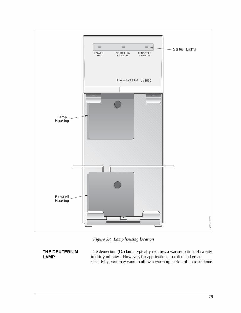
The UV3000 front panel (Figure 1.6) has three lights that indicate whether the instrument is turned on, and which lamp is in use. From the front panel you can also access the lamps and flowcell.

9
Connecting to the Flowcell
Use the following steps to connect the flowcell:
1. Remove the front panel of the detector. Although the flowcell assembly is located behind the lower housing (Figure 1.6), the housing does not need to be removed to connect your inlet and outlet lines.
U3-
Z00
2E\S
T
S tatus Lights
LampHousing
F lowcellHousing
UV 3000SpectraSY ST E M
P OWE RON
DE UT E R IUML A MP ON
T UNG S T E NL A MP ON
Figure 1.6 The flowcell assembly is located behind the flowcell housing

10
2. Use the finger-tight fitting and ferrule sets included with the installation kit to connect the column outlet directly to the detector’s flowcell (fluid) inlet. Figure 1.7 shows how the inlet line enters the detector from the left side, and winds around the flowcell before entering the flowcell from the bottom.
NOTE: If additional tubing is required to reach the inlet, use a zero dead-volume union.
3. Connect the detector’s fluid outlet to the low-pressure union and waste tubing supplied in the installation kit.
HINT: If you have several detectors (fluorescence, refractive index, electrochemical, etc.) hooked up in series, place your UV3000 or UV3000HR detector closest to the column outlet, as its flowcell can withstand the greatest back-pressure.
4. Replace the front panel of the detector, making sure that the tubing passes through the slots without being pinched.
DT-
Z01
9E\F
M
FlowcellInlet
TubingClamp
FlowcellOutlet
FlowcellAssembly
Flowcell AssemblyThumbscrews
PhotodiodeMount
Figure 1.7 The flowcell assembly showing thumbscrews, photodiode mount, and flowcell inlet

11
Optional Flowcells
Thermo Electron offers several different flowcells for use in different applications. Each flowcell possesses distinct design characteristics and performance specifications. These characteristics are compiled in Table 1.1. Contact your Thermo Electron field service engineer for details.
Table 1.1 Design and Performance Specifications for SpectraSYSTEM Flowcells* Path Max. Path Length Tubing Max. Flow Press. Flowcell (mm) Volume (�L) Diam. (in.) Material** (mL/min) (psi)
Analytical LC 6 9 .01 SS1 50 1000
Analytical LC 10 15 .01 SS1 50 1000
Microbore 3 1.2 .005 SS1 10 1000
Microbore 6 7.0 .007 SS1 20 1000
Semi-Prep, Open Column 3 4.5 .02 SS1 100 1000
* All cells use sapphire for windows. All but the preparative flowcells have a heat exchanger. ** SS1 = Stainless Steel with TFE Gaskets.
Flowcell Orientation The flowcells listed above are configured for use with any SpectraSYSTEM detector. These detectors are vertically-oriented detectors that have the tubing clamp located above the flowcell as shown in Figure 1.8.
If you plan to use any of these flowcells on non-SpectraSYSTEM detectors (primarily horizontally-oriented detectors that have their tubing clamps located to the left side of the flowcell as shown in Figure 1.9), you must realign the cell holder as described in the following instructions.
Figure 1.8 shows the flowcell as it is shipped.
NOTE: Figures 1.8 and 1.9 show the tubing clamp as an aid to the proper positioning of the inlet and outlet tubes. The tubing clamp, however, is actually mounted onto the detector and is not part of the flowcell itself.
HINT: To ensure proper alignment, always hold the cell holder and flowcell in the orientation shown in the illustrations.

12
DE
T\Z
014\
FM
MountingScrews
Inlet Tube Outlet Tube
PhotodiodeStandoffs
A.
Tubing Clamp(onvertically-orienteddetectors)
Figure 1.8 The alignment of UV3000 flowcells as they are shipped
1. Remove the mounting screws and set them aside.
2. Rotate the cell holder 90° counterclockwise. Do not rotate the cell body! Part B of Figure 1.9 shows the cell holder in its new position. Note the new position of the photodiode standoffs.
Mounting ScrewHolesB. C.
Inlet Tube
Outlet Tube
PhotodiodeStandoffs
(on horizontally-oriented detectors)
Tubing Clamp
Cell Holder
Figure 1.9 Changing the alignment of a flowcell so that it can be used on other detectors. (Turn the cell holder as shown in Part B.
Align the inlet and outlet tubes with the tubing clamp as shown in Part C.)

13
3. Reattach the cell body by replacing and securing the mounting screws.
4. Gently bend the inlet and outlet tubes as shown in Part C of Figure 1.9. The inlet tube (wound around the cell body) should always enter at the bottom of the flowcell; the outlet tube should always exit at the top of the flowcell.
Chromatography Software To control your UV3000 detector, you must have Atlas Software Ver. 2003, R2 or higher or ChromQuest Ver. 2.5 or higher.
Lamp Ignition
The lamp ignition period takes about 20 seconds for the D2 lamp. Only the D2 lamp ignites automatically when the power has been turned on. The tungsten lamp is controlled from the software. See Appendix C.
Shutdown Shutting down the system involves simply turning the power switch on the back panel to OFF.
NOTE: Ensure that the flowcell does not contain any buffers at shutdown. Flush the flowcell with several volumes of clean, non-ionic eluant before shutdown.


15
2 Troubleshooting
Introduction
This chapter provides you with helpful information for troubleshooting possible detector and chromatographic system problems. We have divided it into two sections:
• a brief theory of operation
• a troubleshooting guide that lists symptoms, possible problems, and remedies
For information on software error messages, refer to your PC1000 Ver. 3.0 Reference Manual. For information on error messages that could occur when running the UV3000 diagnostics program, refer to Appendix C.
Theory of Operation
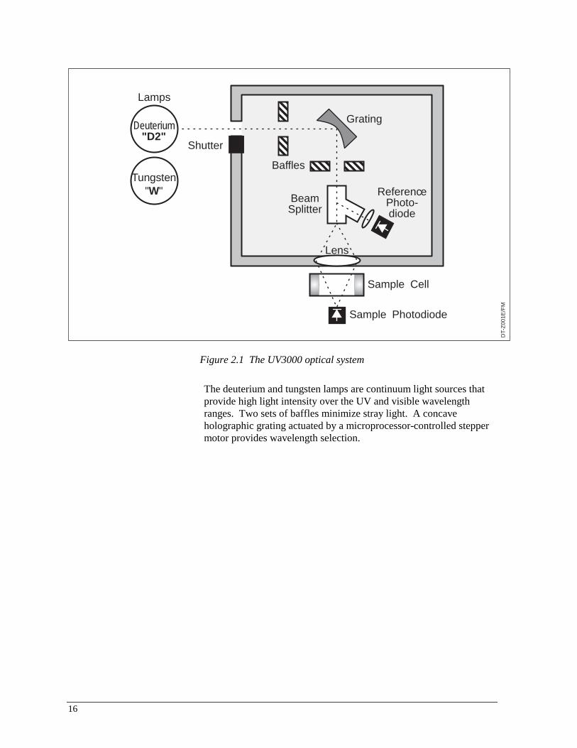
This brief theory of operation is included to aid you in troubleshooting problems and performing maintenance for your detector. For more detailed information, you should contact your Field Service representative.
OVERVIEW Figure 2.1 shows the optical system used in the UV3000 and the UV3000HR detectors. The detector operates in a double-beam mode using a fiber-optic beam-splitter that creates sample and reference beams. The reference beam is directed to a reference photodiode. The sample beam is lens-focused prior to passing through the flowcell to a sample photodiode.
An analog PCB processes the signals from the photodiodes and provides analog output signals through a 10-pin external connector. The digital PCB contains the EPROM (the built-in firmware), provides digital processing circuitry, and interfaces with the remote communications devices. The Motherboard provides all the necessary interconnections and power supplies.
16
DT-
Z00
1E/F
M
Deuterium"D2"
Tungsten"W"
Lamps
Shutter
Baffles
Grating
ReferencePhoto-diode
BeamSplitter
Lens
Sample Cell
Sample Photodiode
Figure 2.1 The UV3000 optical system
The deuterium and tungsten lamps are continuum light sources that provide high light intensity over the UV and visible wavelength ranges. Two sets of baffles minimize stray light. A concave holographic grating actuated by a microprocessor-controlled stepper motor provides wavelength selection.

17
Common Problems
This next section contains a table of symptoms, possible causes, and remedies for some common problems you may observe in detector response. Many of the problems attributed to the detector may actually be due to other components in the chromatographic system, so we have included references to these types of problems and solutions as well.
Troubleshooting Table
Symptom Cause Remedy
1. Spikes on baseline. a. Gas bubbles in the flowcell. a. Degas mobile phase. Supply back-pressure device to flowcell (check back-pressure rating). Check for leaks at high-pressure fittings.
b. Immiscible solvent bubbles following mobile phase changeover.
b. Flush flowcell with 2-propanol, then with mobile phase.
c. Electrical interference. c. Check electrical lines for good connections and/or interference from broadcast radiation. Check for ground loops.
d. Extremely large fluctuations in voltage on AC line.
d. Remove systems (e.g., ovens) that cause voltage fluctuations, isolate the detector to "quiet" circuit, or use UPS (UPS, uninterruptable power supply).
2. Random noisy baseline. a. Contaminated flowcell. a. Flush flowcell with cleaning solvents as described in Chapter 3. Check for leaks.
b. Leak in sample inlet line. b. Check all fittings from column outlet to flowcell inlet for leaks.
c. Bubble trapped in flowcell. c. Increase flow rate until bubble is removed. Supply back-pressure device to flowcell (check back-pressure rating to avoid rupturing flowcell).
d. Leaking flowcell. d. Replace flowcell.
18
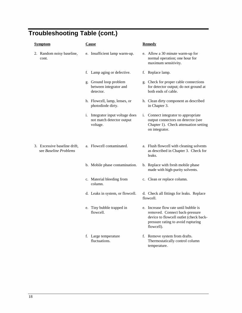
Troubleshooting Table (cont.)
Symptom Cause Remedy
2. Random noisy baseline, cont.
e. Insufficient lamp warm-up. e. Allow a 30 minute warm-up for normal operation; one hour for maximum sensitivity.
f. Lamp aging or defective. f. Replace lamp.
g. Ground loop problem between integrator and detector.
g. Check for proper cable connections for detector output; do not ground at both ends of cable.
h. Flowcell, lamp, lenses, or photodiode dirty.
h. Clean dirty component as described in Chapter 3.
i. Integrator input voltage does not match detector output voltage.
i. Connect integrator to appropriate output connectors on detector (see Chapter 1). Check attenuation setting on integrator.
3. Excessive baseline drift, see Baseline Problems
a. Flowcell contaminated. a. Flush flowcell with cleaning solvents as described in Chapter 3. Check for leaks.
b. Mobile phase contamination. b. Replace with fresh mobile phase made with high-purity solvents.
c. Material bleeding from column.
c. Clean or replace column.
d. Leaks in system, or flowcell. d. Check all fittings for leaks. Replace flowcell.
e. Tiny bubble trapped in flowcell.
e. Increase flow rate until bubble is removed. Connect back-pressure device to flowcell outlet (check back-pressure rating to avoid rupturing flowcell).
f. Large temperature fluctuations.
f. Remove system from drafts. Thermostatically control column temperature.

19
Troubleshooting Table (cont.)
Symptom Cause Remedy
4. No peaks, or peaks much smaller than expected.
a. Incorrect wavelength setting. a. Check wavelength setting. Make sure the correct file is selected.
b. Lamp not on or defective. b. Make sure lamp is lit. Run detector’s diagnostic tests to check lamp. Replace lamp if necessary.
c. Integrator input voltage does not match detector output voltage.
c. Connect integrator to appropriate output connectors on detector (see Chapter 1). Check attenuation setting on integrator.
d. Insufficient sample reaching the detector.
d. Check entire chromatographic system for leaks. Verify sample injection volume.
5. Broad, tailing peaks. a. Rise time is too large (too slow).
a. Lower the rise time selection.
b. Flowcell volume too large. b. Change to a flowcell with smaller volume.
6. Clicking sound when UV3000 is in dual-wavelength mode.
a. Noise comes from grating motor, and is normal.
a. No action necessary.
7. Detector won’t power up. a. Tripped circuit breaker at AC wall outlet.
a. Resolve problem, reset circuit breaker.
b. Blown detector fuse. b. Resolve problem, replace fuse.
c. Incorrect voltage selected. c. Reset detector for correct incoming line-voltage (see Chapter 1).
d. Power cord not connected. d. Connect power cord.

20

21
3 Required Maintenance
Introduction
SpectraSYSTEM detectors are finely-tuned scientific instruments that we at Thermo Electron are proud to stand behind. Even so, routine maintenance is necessary to ensure peak performance, so we can only guarantee our detectors’ performance if you follow proper care and maintenance procedures.
This chapter shows you how to replace and clean your detector’s flowcell and lamps.
Also included in this chapter is a procedure for testing the detector’s absorbance linearity. This characteristic is particularly useful if your laboratory’s standard operating procedures require periodic detector validation. You will need the optional cuvette holder to perform the test.
If you have any questions on proper maintenance or would like to arrange for a preventive maintenance program, please contact your local Thermo Electron field service engineer.
Flowcells
This section describes the changing and general cleaning of your detector’s flowcell. For other flowcell problems, such as a cracked window or leaks that occur in locations other than at the inlet/outlet fittings, contact your Thermo Electron field service engineer.
NOTE: Flowcells are factory-assembled units that should not be disassembled under any circumstance.
22
CHANGING THE FLOWCELL
The flowcell needs to be removed whenever you replace a broken cell, change specialized applications, or clean the cell with nitric acid. For a list of available flowcells, see Appendix C. All flowcells are shipped premounted in a holder for easier installation and alignment.
To access the flowcell, remove the front panel of the detector. The flowcell assembly is located behind the lower housing (Figure 3.1). Once the housing is removed, the flowcell is easily identified by the tubing that extends from the fittings on either side of the cell body (Figure 3.2).

23
U3-
Z00
2E\S
T
S tatus Lights
LampHousing
F lowcellHousing
UV 3000SpectraSY ST E M
P OWE RON
DE UT E R IUML A MP ON
T UNG S T E NL A MP ON
Figure 3.1 Detector flowcell and lamp housings
Flowcell Removal Use the following steps to remove the flowcell:
1. Disconnect the power cord from the rear panel of the detector and make sure that the instrument is turned off.
2. If you have not already done so, remove the detector’s front panel by grasping the bottom of the panel firmly with one hand and pulling back.

24
3. Loosen the knurled thumbscrew that holds the flowcell housing in place, and remove and set aside both the thumbscrew and the housing.
4. Disconnect the flowcell inlet tube from the chromatograph and free the flowcell outlet tubing from the waste reservoir.
5. Loosen the two thumbscrews on the photodiode mount and carefully pull the mount straight back (Figure 3.2). The cable that connects the photodiode mount to the detector is sufficiently long to allow the mount to rest on the bench top.
NOTE: Avoid putting fingerprints or scratches on the flowcell windows, photodiode surface, or monochromator lens, all of which are exposed during these procedures. If dirty, the surfaces should be cleaned with spectroscopic-grade methanol (or isopropanol) and lint-free lens paper only.
DT-
Z01
9E\F
M
FlowcellInlet
TubingClamp
FlowcellOutlet
FlowcellAssembly
Flowcell AssemblyThumbscrews
PhotodiodeMount
Figure 3.2 Removing the cell cover to expose the flowcell and the photodiode mount
6. Loosen the thumbscrew that holds the tubing clamp in place. Gently pull the clamp toward you just far enough to disengage the tubing.
7. Loosen the two thumbscrews that hold the flowcell assembly. Carefully pull the assembly toward you to remove it from the detector.
25
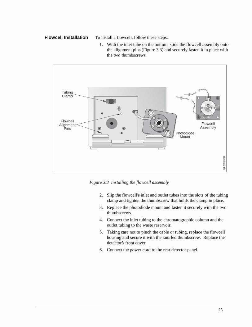
Flowcell Installation To install a flowcell, follow these steps:
1. With the inlet tube on the bottom, slide the flowcell assembly onto the alignment pins (Figure 3.3) and securely fasten it in place with the two thumbscrews.
DT-
Z02
0E\F
M
FlowcellAlignment
PinsPhotodiode
Mount
FlowcellAssembly
TubingClamp
Figure 3.3 Installing the flowcell assembly
2. Slip the flowcell’s inlet and outlet tubes into the slots of the tubing clamp and tighten the thumbscrew that holds the clamp in place.
3. Replace the photodiode mount and fasten it securely with the two thumbscrews.
4. Connect the inlet tubing to the chromatographic column and the outlet tubing to the waste reservoir.
5. Taking care not to pinch the cable or tubing, replace the flowcell housing and secure it with the knurled thumbscrew. Replace the detector’s front cover.
6. Connect the power cord to the rear detector panel.

26
CLEANING THE FLOWCELL
The exterior and/or interior surfaces of the flowcell can become contaminated. When flowcell contamination occurs, it is usually caused by precipitation or solubility problems, such as when the quality of your mobile phase solvent components and the cleanliness of your samples are variable. Signs of a contaminated flowcell are increased baseline noise, signal spiking, erratic or drifting baselines, and increased back-pressure.
Cleaning with Organic Solvents
If you suspect that your flowcell needs to be cleaned, start with the following procedure using organic solvents.
NOTE: Flowcells are factory-assembled units that should not be disassembled under any circumstance. If you encounter contamination problems that are not remedied by this cleaning procedure, contact your local Thermo Electron field service engineer to arrange for repair or replacement.
1. Make certain that the cleaning solvent(s) you plan to use is/are miscible with the solvent already present in the flowcell and pump. Isopropanol is a good choice for most applications.
NOTE: If the last solvent in the pump was an aqueous buffer solution, be sure to pump 25 - 40 mL of HPLC-grade water (or equivalent) through the system to remove any salts before flushing with the cleaning solvent(s).
2. Flush the flowcell with 40 - 50 milliliters of solvent (HPLC-grade water, methanol, or isopropanol). You can either pump the solvent through the flowcell with the chromatographic pump, or you can draw the solvent through the flowcell using a large-volume syringe.
If you use an LC pump to flush the flowcell, first remove the column from your chromatographic system to avoid column degradation. Replace the column with an appropriate length of tubing, ensuring that all connections are snug and leak-free. If you use a syringe, always draw the solution through the flowcell.
CAUTION! Never use a syringe to force solvent through a flowcell. Pressurizing the syringe could cause a leak or rupture that would result in an extremely dangerous, uncontrolled spraying of solvent.

27
Cleaning with Nitric Acid
Methanol or isopropanol is generally sufficient for cleaning a flowcell. However, if the flowcell is still contaminated after flushing with organic solvents, follow this nitric acid procedure.
CAUTION! Nitric acid is extremely corrosive and can react explosively with alcohols (especially methanol). Be sure to wear protective clothing and eye protection and adhere to your company’s safety procedures for handling and disposal of corrosive acids. Flush the flowcell with water to remove all traces of alcohol prior to flushing with nitric acid!
1. Remove the flowcell assembly from the detector housing (following the procedure on page 23) before cleaning with a nitric acid solution. This will prevent possible leaks from harming the mechanical or electronic components of the detector.
2. Flush the flowcell with water before proceeding. This step is very important!
3. Prepare a 20% (v/v) solution of nitric acid in HPLC-grade water.
4. Pump the nitric acid solution through the flowcell with the chromatographic pump or draw it through with a large-volume syringe.
If you use an LC pump, replace your column with tubing and make sure water was the last solvent in the pump and solvent reservoir. If you use a syringe, always draw the solution through the flowcell.
CAUTION! Never use a syringe to force nitric acid through a flowcell. Pressurizing the syringe could cause a leak or rupture that would result in an extremely dangerous, uncontrolled spraying of nitric acid.
5. After you have finished the cleaning procedure and before returning to the buffer solution, pump another 25 - 40 mL of water through the flowcell to remove all traces of nitric acid before returning to your chromatographic solvents. Reinstall the flowcell assembly.
NOTE: Flush the pump with water immediately after the nitric acid flush. Leaving nitric acid solution in the pump for prolonged periods can damage pump seals.
28
Lamps
As lamps age, there is a reduction in light output that results in increased baseline noise. If the noise level on your detector’s output signal is increasing and cleaning the flowcell doesn’t help, you should change the appropriate lamp, using the procedures in this section.
Remove the front panel of the detector. The deuterium and tungsten lamps are located in the upper housing (Figure 3.4). Both lamps are supplied prealigned in their individual assemblies to make them easy to install and align.
NOTE: Never loosen the screws that hold the lamp to its assembly or attempt to rotate or move the lamp up or down in the assembly. Either of these actions can cause a loss of alignment and degrade the system’s performance.
29
U3-
Z00
2E\S
T
S tatus Lights
LampHousing
F lowcellHousing
UV 3000SpectraSY ST E M
P OWE RON
DE UT E R IUML A MP ON
T UNG S T E NL A MP ON
Figure 3.4 Lamp housing location
THE DEUTERIUM LAMP
The deuterium (D2) lamp typically requires a warm-up time of twenty to thirty minutes. However, for applications that demand great sensitivity, you may want to allow a warm-up period of up to an hour.
30
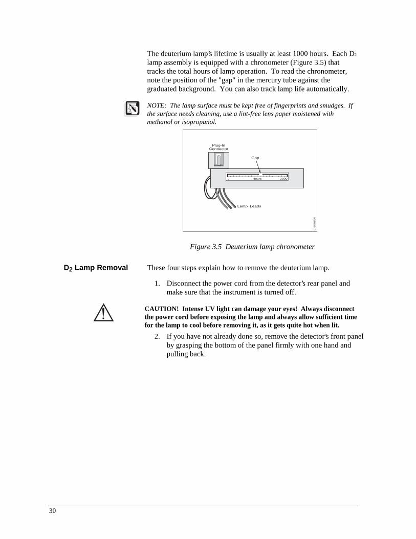
The deuterium lamp’s lifetime is usually at least 1000 hours. Each D2 lamp assembly is equipped with a chronometer (Figure 3.5) that tracks the total hours of lamp operation. To read the chronometer, note the position of the "gap" in the mercury tube against the graduated background. You can also track lamp life automatically.
NOTE: The lamp surface must be kept free of fingerprints and smudges. If the surface needs cleaning, use a lint-free lens paper moistened with methanol or isopropanol.
DT-
Z038
E/D
G
Gap
Plug-InConnector
Lamp Leads
Hours 20000
Figure 3.5 Deuterium lamp chronometer
D2 Lamp Removal These four steps explain how to remove the deuterium lamp.
1. Disconnect the power cord from the detector’s rear panel and make sure that the instrument is turned off.
CAUTION! Intense UV light can damage your eyes! Always disconnect the power cord before exposing the lamp and always allow sufficient time for the lamp to cool before removing it, as it gets quite hot when lit.
2. If you have not already done so, remove the detector’s front panel by grasping the bottom of the panel firmly with one hand and pulling back.

31
U3-
Z00
6E\S
T
TungstenLamp Assembly
DeuteriumLamp Assembly
F lowcellInlet
F lowcellOutlet
F lowcellAssembly
UV 3000SpectraSY ST E M
P OWE RON
DE UT E R IUML A MP ON
T UNG S T E NL A MP ON
Figure 3.6 Deuterium and tungsten lamp assemblies
3. Remove the lamp housing by loosening the thumbscrew and pulling the cover straight back to expose the lamp assemblies (Figure 3.6).
4. Unplug the deuterium lamp lead from the detector, taking care not to twist the connector as you gently pull it out.
5. Loosen the two thumbscrews that hold the lamp assembly in place and pull the assembly straight out.

32
D2 Lamp Installation Follow these steps to install a new D2 lamp.
1. Hold the deuterium lamp assembly so that the leads are at the top. Slide the assembly onto the alignment pin shown in Figure 3.7. (The alignment pin is located directly below the detector’s monochromator aperture.)
2. Securely fasten the assembly in place with the two thumbscrews and aluminum standoffs.
3. Connect the lamp lead to the right-hand terminal in the lamp compartment.
4. Replace the lamp housing and secure it with the knurled thumbscrew. Replace the detector’s front cover.
5. Connect the power cord to the rear detector panel.
TungstenLamp
AlignmentP ins
DeuteriumLamp
AlignmentP in
DT-
Z02
1E/M
Figure 3.7 Deuterium and tungsten lamp alignment pins
33
THE TUNGSTEN LAMP
The tungsten (W) lamp typically requires only fifteen minutes of warm-up time. Its lifetime is approximately 2500 hours. You can track lamp life automatically.
W Lamp Removal Follow the steps below to remove the tungsten lamp.
1. Disconnect the power cord from the detector’s rear panel and make sure that the instrument is turned off.
CAUTION � Hot Surface! Avoid burns. Always allow sufficient time for the lamp to cool before removing it.
2. If you have not already done so, remove the detector’s front panel by grasping the bottom of the panel firmly with one hand and pulling back.
3. Remove the lamp housing by loosening the thumbscrew and pulling the cover straight back to expose the lamp assembly (Figure 3.8).
4. Unplug the tungsten lamp lead from the detector, taking care not to twist the connector as you gently pull it out.
5. Loosen the thumbscrew and the aluminum standoff that hold the lamp assembly in place and pull the assembly straight out.
W Lamp Installation These five steps explain how to replace the tungsten lamp.
1. Hold the lamp assembly so that the leads are at the top. Slide the assembly onto the two alignment pins shown in Figure 3.7. (The alignment pins are located on either side of the detector’s monochromator aperture.)
2. Securely fasten the assembly in place with the thumbscrew and aluminum standoff.
3. Connect the lamp lead to the left-hand terminal in the lamp compartment.
4. Replace the lamp housing and fasten securely with the thumbscrew.
5. Connect the power cord to the rear detector panel.


35
A Specifications
Specifications Wavelength Ranges:
D2 lamp: 190 to 365 nm W lamp: 366 to 800 nm
Wavelength Accuracy: ± 1.0 nm
Wavelength Precision: <0.01 nm
Bandwidth: UV3000HR: 2.8 nm UV3000: 6 nm
Absorbance Linearity: Better than 1% to 2 AU @ 254 nm Drift UV3000HR: < 2 x 10 -4 AU/hour @ 254 nm
UV3000: < 2 x 10 -4 AU/hour @ 254 nm Slew Time: 0.020 sec
Lamp(s): Deuterium and tungsten, pre-aligned
Rise Time: Digital filter, 0.0 to 9.9 sec
Recorder Outputs: 3 unattenutated at either 10 mV, 100 mV, and 1.0 V per 2 AU
Remote Controls: Autozero input, 25-pin RS-232

36
Specifications (continued)
Dimensions: 14.5” (37 cm) x 6” (15 cm) x 18.5” (47 cm) (H x W x D)
Weight: 40 lb. (11 kg)
Power Requirements: 100/120/220/240 VAC; 50/60 Hz 1.5/1.6/0.8/0.8A, 225VA
Environmental Conditions 10-40°C; 5-95%RH, noncondensing
High Sensitivity Mode
Number of Wavelengths Monitored 1-3 Data Rate 24 points/sec Noise:
Single-wavelength Mode: UV3000HR: ±2.0 x 10 -5 AU @ 254 nm or 546 nm UV3000: ±1.0 x 10 -5 AU @ 254 nm or 546 nm
Scanning Mode
Scan Speed 96 - 960 nm/sec
Data Rate 96 points/sec
Noise: UV3000HR: ±4.0 x 10 -5 AU @ 254 nm or 546 nm UV3000: ±2.0 x 10 -5 AU @ 254 nm or 546 nm

37
B Accessories, Replacement Parts and Flowcell Characteristics
Table B.1 Accessories and Replacement Parts
Flowcells 9550-0053S
9550-0100S
9550-0101S
9550-0103S
9550-0197S
9550-0234S
9550-0263S
9550-0265S
9550-0147-01S
9550-0150-01S
9550-0155-01S
9551-0070-01S
3 mm microbore
6 mm analytical, 9 µL
3 mm Semi-preparative, Open Column, 4.5 µL
6 mm Inert/biocompatible (Kel-F®), 9 µL
6 mm Inert/Biocompatible (titanium)
10 mm Analytical, 15 µL
Cuvette Cell Holder (for 10 mm I.D., 12.5 MM O.D. cuvettes)
6 mm Microbore, 5 µL
0-3 mm Bio-preparative
2 mm High Pressure Microbore, 0.25 µL
On-column Capillary
0-3 mm Preparative
Other Accessories And Replacement Parts 9551-0023
9551-0022
6040-0102
6040-0103
9051-0143
Deuterium Lamp Assembly (pre-aligned)
Tungsten Lamp Assembly, replacement lamp (pre-aligned)
External Run/Auto Zero Cable
Analog Recorder Cable
Variable Regulated Back-pressure Device

38
Table B.1 Accessories and Replacement Parts — continued
Manuals A0099-546 UV3000/UV3000HR Detectors Reference Manual (English)
Maintenance Parts A4051-010 A4061
Standard Fittings Kit (Kit includes stainless steel fittings and tubing used in SpectraSYSTEM LC system) Inert/Biocompatible Fittings Kit (Kit includes PEEK fittings and tubing used in an inert/biocompatible SpectraSYSTEM LC system)

39
C Diagnostics
Introduction
From the UV3000 diagnostics program, you can obtain general light level information and send commands directly to your detector Specifically you can
• Zero the detector from the PC
• Calibrate the detector wavelength
• Adjust the wavelength
• Control the lamps
• Obtain general light level information
• View the last error message that occurred
Accessing the Detector Status Page in Atlas
To access the UV3000 Detector Status window in Atlas:
1. From the Windows taskbar, choose Start | Programs (or All Programs) | Atlas | Instrument Manager.
2. Open the Instrument Status window for your instrument by double-clicking on its icon.
3. From the bank of tabs located at the bottom of the Instrument Status window, click on the Detector tab to display the Instrument Status window for the UV3000 shown in Figure C.1.
FEATURES OF THE INSTRUMENT STATUS WINDOW
The Instrument Status window for the UV3000 detector contains a Monitor pane with scrollbars, a Reset Monitor button, a Direct Control button, and General readback group box, and three Signal group boxes.
Monitor Pane
The monitor pane displays the signal data from the wavelengths entered in the Direct Control dialog box. The buffer stores data for up to 240 minutes. After 240 minutes, the buffer is cleared and data acquisition begins at time zero. Right-clicking in the display opens a

40
shortcut menu that allows you to format the axes and the chromatograms.
Reset Monitor Button
Clicking on the Reset Monitor button clears the buffers and restarts the data display at time zero. Closing the Instrument Status window also clears the buffers.
Direct Control Button
Clicking on the Direct Control button opens the Direct Control dialog box shown in Figure C.2.
General Group Box
The General group box contains a Status readback, a Run Time readback, a Program readback, a Deuterium Lamp readback, and a Tungsten Lamp readback.
Status
The Status readback has four possible states: Not Connected, Not Ready, Ready, and Running. In addition, the following error messages are displayed:
• INVALID Wavelength. You attempted to enter a wavelength from 190 nm or above 800 nm.
• Low Light from Deuterium Lamp. Either the deuterium lamp has failed to light on the second try (most likely), or the light energy is below acceptable limits.
• Low Light from Tungsten Lamp. Either the tungsten lamp has failed to light on the second try (most likely), or the light energy is below acceptable limits.
• Lamp Cover Open. You tried to open the flowcell cover with the diagnostics program in progress.
Run Time
The Run Time readback displays the elapsed run time.
Program
The program readback displays the operating mode of the detector. The possible states are: Single, Dual, Triple, and Scanning.
Deuterium Lamp
The Deuterium Lamp group box displays the operating state of the deuterium lamp. The possible states are On and Off.

41
Tungsten Lamp
The Tungsten Lamp group box displays the operating state of the tungsten lamp. The possible states are On and Off.
Signal Group Boxes
There are three signal group boxes, one for each of the possible wavelengths being collected. In the single wavelength mode, the signal is displayed in the Signal 1 group box. In the dual wavelength mode, the first wavelength is displayed in the Signal 1 group box and the second wavelength is displayed in the Signal 2 group box. In the triple wavelength mode, the first, second, and third wavelengths are displayed in the Signal 1, Signal 2, and Signal 3 group boxes, respectively.
Wavelength
The value of the wavelength being monitored by the detector is displayed. The range is 190 nm to 800 nm.
Absorbance
The most recent value returned by the detector is displayed. The range is -3 AU to 3 AU.
Figure C.1 UV3000 Detector Status window
DIRECT CONTROL
Clicking on the Direct Control button in the Status window for the UV3000 detector opens the Direct Control dialog box (Figure C.2)

42
The Direct Control dialog box contains three group boxes: Program, Settings, and Performance.
Figure C.2 UV3000 Diagnostics window
Program Group Box
The Program group box allows you to select the wavelengths that you want to monitor in the Instrument Status window. You can select the Single, Dual, or Triple wavelength mode. You can also select the UV mode or the Visible mode. Clicking on the Apply button downloads the settings to the detector.
Settings Group Box
The Settings group box contains the Zero on Wavelength Change, Deuterium Lamp On, Tungsten Lamp On check boxes, the Rise Time list box, the Zero button, and the Autocal button.
Zero On Wavelength Change
Selecting this checkbox zeros the absorbance scale at the current value. Future values are then reported relative to this value.
Deuterium Lamp On
Selecting this checkbox turns on the deuterium lamp.

43
Tungsten Lamp On
Selecting this checkbox turns on the tungsten lamp.
Rise Time
Rise time is a mathematical filter applied to acquired absorbance data. The greater the rise time, the slower the response of the detector to light intensity changes and the lower the baseline noise. The allowable values are: 0.0, 0.1, 0.2, 0.5, 1.0, 2.0, 5.0 and 9.99 seconds.
Zero
Clicking on the Zero button zeros the absorbance scale at the current level. Future values are then reported relative to this value.
Autocal
Clicking on the Autocal button automatically calibrates the detector. This feature uses the spectral output of the deuterium lamp. Therefore, the deuterium lamp must be on.
Performance Group Box
The Performance group box displays valued obtained when the Get Values button is clicked.
Voltage to Frequency The voltage-to-frequency values are responsive to light level changes. You should expect a sizable increase (jump) in the reference values when a detector lamp is first turned on. If not, suspect a failed lamp or a shutter problem.
NOTE: A lack of increase in the sample values upon lamp powerup does not necessarily indicate a light level problem, but it could indicate a flowcell blockage.
Osc (Oscillator) These columns contain base values used in the V/F calculations. The specific values in these columns are not useful for diagnostic purposes. However, during normal operation, the Osc values are continually updated. If these values remain constant, suspect an instrument problem, and contact your Thermo Electron field service engineer.
Bias These values indicate a general background noise level. The specific values in this column are not useful for diagnostic purposes. However, during normal operation, the Bias values should not be 0000. Contact your Thermo Electron field service engineer if you obtain a 0000 value in this column.

44
LIGHT LEVEL DIAGNOSTICS
To diagnose the condition of the flowcell and lamps, access the UV3000 diagnostics to check the light levels at all wavelengths appropriate for the application. The best way to use light levels in troubleshooting is to know the typical light levels for a particular setup. Then, if you suspect a problem, you can compare the typical levels with the current levels. Note that light levels will significantly change with such factors as lamp age and flowcell type. The following general guidelines can help in troubleshooting detector problems.
A sudden decrease in the Reference light level, with a normal Sample light level, can indicate a problem with the reference photodiode, beamsplitter, or one of the printed circuit boards.
A sudden decrease in the Sample light level, with a normal Reference light level, can indicate a problem with the flowcell, sample photodiode, beamsplitter, or one of the printed circuit boards.
A sudden decrease in the Reference light level and Sample light level can indicate a problem with the lamp, grating, or one of the printed circuit boards. To investigate this problem, turn off the lamp and check to see if the light levels change. If they do not, then the instrument is not generating or is not detecting light. If this is the case, follow standard troubleshooting procedures to isolate the fault.
In general, a dirty flowcell will yield acceptable reference levels and poor sample to reference ratios. However, use care, since excess solvent absorbance can generate the same results as a dirty flowcell. A weak lamp will yield poor reference and sample light levels with an acceptable or near-acceptable sample-to-reference ratio.
LC TEST MIX DIAGNOSTIC
An ampule of prepared LC Test Mix is included as part of your detector’s accessory kit. An instruction sheet describing the parameters for running the test mix and showing the resulting chromatogram is also included with the Test Mix. This is a good test of run when you first set up your LC system.
HINT: Keep the chromatogram that you generate with the LC Test Mix. It can be a useful baseline for troubleshooting problems later on.

I
INDEX
A
Accessory kit, 1 Amperage requirements, see Fuses, 3 Analog outputs, connections to
recorders, 6 Atlas
Direct Control dialog box, 42 Instrument Status window, 39
Australasia and Asia, customer support, v Autocal button, 43
B
Back-pressure causes of, 26 detectors in series, 10 increasing, 26 specifications for flowcells, 11
Baseline problems drifting, causes of, 26 erratic, causes of, 26 noise, causes of, 17, 26 spikes, causes of, 17, 26
Bias field, 43
C
Changing the fuses, 3 Chronometer
illustration of, 30 tracking deuterium lamp life, 30
Cleaning procedures deuterium lamp surface, 30 flowcell, 26
Clicking sound, 19 Column bleed, 18 customer support
Australasia and Asia, v Europe, iv North America, iii
D
Deuterium lamp alignment of, 32 changing the, 30 chronometer, 30 cleaning the surface, 30 illustration of, 31 lamp life, 30 tracking D2 hours, 30 warm-up time, 29
Diagnostic tests, external LC test mix, 44
Drift, see Baseline problems, 18
E
Electrical interference, causes of, 17 error messages, 40 Europe, customer support, iv External contacts, 6
connectors, 6 making connections, 5 READY(Output), 8 ZERO(Input), 8
F
Floating ground, 6 Flowcell
bubbles in the, 17, 18 changing the, 22 cleaning the
safety precautions, 27 using a pump, 27 using a syringe, 27 with nitric acid, 27 with organic solvents, 26
connecting to inlet/outlet lines, 9 contamination of, 26 different types of, 11 disassembly of, 21 installing the, 25 leaks, 17 location of, 22
II
maintenance of, 21 orientation for non-SpectraSYSTEM detectors, 11 removing flowcell and housing, 23 specifications, 11
Fluid connections, 9 Fuses
changing the, 3 illustration of fuses, 4 illustration of holders, 3 requirements, 4
G
Ground loop problems, causes of, 18
H
Installation accessory kit, 1 analog outputs, connecting to recorders, 6 connecting to inlet/outlet lines, 9 flowcell connections, 9 fluid connections, 9 fuses, 3
illustration of, 4 illustration of holders, 3 requirements, 4
positioning the detector, 2 power cord, 4 power requirements, 2 rear panel connections, 6 tools for, 2 unpacking, 1 voltage selection, 2
Integrators/Workstations rear panel connections to, 6
Invalid wavelength message, 40
A
Lamps aging, 28 alignment illustrated, 32 changing the, 28, 33 deuterium, see Deuterium lamp, 30 illustration of assemblies, 31 installation of, 32, 33 lamp life, 29, 33 location of, 28 removal of, 30, 33 tungsten, see Tungsten lamp, 33
LC test mix, 44
Light level diagnostics guidelines, 44
Low Light from Deuterium Lamp message, 40, 44 Maintenance, see Chapter 5:, 21
M
Messages Invalid wavelength, 40 Low Light from Deuterium Lamp, 40
Monochromator, illustration of apertures, 25
N
Nitric acid safety precautions, 27 used to clean the flowcell, 27
North America, customer support, iii Optical system, 16 Organic solvents, used to clean flowcells, 26 oscillator values, 43 Peak problems
broadening, 19 size, 19 tailing, 19
Photodiode mount. illustration of, 10, 24 Positioning the detector, 2 Power
cord, 4 requirements, 2
Preventative maintenance, 21 Pumps, used to clean flowcells, 27
R
READY output, connecting to terminal, 8 Recorders, connecting to analog outputs, 6 rise time, 19, 43 Run/Event, ready signal for external devices, 8
S
Safety, nitric acid precautions, 27 Solvents used to clean the flowcell, 26 Specifications flowcells, 11 Spiking, 26

III
T
Temperature fluctuations, results of, 18 Theory of operation, 15 Tools needed for installation, 2 Troubleshooting
clicking sound, 19 flowcell contamination, 26 Table of common problems, 17
Tungsten lamp alignment of, 32 changing the, 33 illustration of, 31 warm-up time, 33
U
Unpacking your detector, 1 UPS, uninterrupTable power supply, 17
UV3000 installation, 1 maintenance, 21 periodic validation, 21 troubleshooting, 17
V
V/F field, 43 Voltage
AC line problems, 17 preset, 2 selector barrel
illustration of, 3 location of, 2
Zero, from an external device, 8 ZERO (Input) terminal, 8 Zero button in Atlas, 43


![SpectraSYSTEM UV/Vis Detectors Reference Manual Version Gtools.thermofisher.com/content/sfs/manuals/Man-A...Phone [1] (847) 310-0140 Fax [1] (847) 310-0145 Western Region Phone [1]](https://img.pdfslide.us/doc/110x75/600dbaf8589c760aa01827a5/spectrasystem-uvvis-detectors-reference-manual-version-phone-1-847-310-0140.jpg)