Embed Size (px)
Citation preview
Sp
Ba
b
a
ARA
KSIFF
1
teirwlhi[cpmcepsahcn(
h0
Optik 125 (2014) 5956–5961
Contents lists available at ScienceDirect
Optik
jo ur nal homepage: www.elsev ier .de / i j leo
pectral switching-based fan-out architecture and informationrocessing in free-space
harat Kumar Yadava,∗, Hem Chandra Kandpala,b
Optical Radiation Standards, CSIR National Physical Laboratory, Dr. K.S. Krishnan Road, New Delhi, IndiaQuantum Optics and Photon Physics, CSIR-National Physical Laboratory, Dr. K.S. Krishnan Road, New Delhi, India
r t i c l e i n f o
rticle history:eceived 26 October 2013ccepted 30 May 2014
eywords:
a b s t r a c t
In this paper, we elaborate different type of spectral switching techniques and spectral switching-basedinformation processing (SSBIP) schemes. On the basis of theoretical, experimental and empirical studiescarried out so far on spectral switching, we demonstrate novel type of interference-induced 1 × N (1input N outputs) and 1 × N × M (1 input N × M outputs) spectral switching-based fan-out architectures for
pectral switchingnformation encodingSOSO interconnects
information transmission in free-space. In addition, a comprehensive analysis is presented to explore thefeasibility of SSBIP scheme in contrast to the recent technological advancements. The spectral switching-based techniques are contrived ideas but might find potential applications in optical computing, state-of-the-art technique like SIMO (single-input multiple-output), free-space optical (FSO) interconnects andpolychromatic light-based FSO communications.
. Introduction
Spectral switching is now a well-known phenomenon. Duringhe last few years, the study on this phenomenon and SSBIP hasmerged as an area of great interest for the science and engineer-ng researchers [1–14]. The studies carried out so far show that ifed-shift and blue-shift in spectral switching could be associatedith information bits “1” and “0”, the spectral flipping of diffracted
ight (near singular points) from lower frequency (red-shift) toigher frequency (blue-shift) or vice versa might be utilized for
nformation encoding and information transmission in free-space6]. Despite some experimental constraints, SSBIP has attractedonsiderable attention due to its unique features [1–3]. For exam-le, spectral switching may be controlled through internal controlechanism as well as external control mechanism. In the former
ase, one may control spectral switching by changing the prop-rties of light source namely coherence [6,9], polarization [4,10],hase [3], and intensity [1]. In the latter case, the user may controlpectral switching by changing wedge of the aperture [11], slit sep-rations [12], and diffraction angles [13]. In addition, informationiding, possibilities of multi-level information encoding [2], and
ompatibility to exploit two popular information encoding tech-iques namely on–off keying (OOK) and frequency-shift keyingFSK) [14] may make SSBIP more significant.∗ Corresponding author.E-mail address: [email protected] (B.K. Yadav).
ttp://dx.doi.org/10.1016/j.ijleo.2014.07.071030-4026/© 2014 Elsevier GmbH. All rights reserved.
© 2014 Elsevier GmbH. All rights reserved.
Although spectral switching phenomenon and its applicationshave been studied by several research groups [1–14], most of theexperimental work is carried out in CSIR-National Physical Labora-tory, New Delhi, India [5,9,10,13,14]. Till date, this phenomenonhas been studied with different optical setups. The theoreticaland experimental studies reveal that spectral switching might beexploited to exchange information in free-space. However, theinvestigations about applications of spectral switching are still con-fined into the laboratory frame. Technological realization may takemore time. In fact, the introduction of spectral switching and SSBIPto FSO community is quite new but the theoretical and experimen-tal studies indicate that it has significant scope in this field. SSBIPmay find potential applications in polychromatic light-based FSOsystems. It is well known that the spectral switching is a peculiarbehavior of polychromatic light; it might be exploited in sev-eral applications. The polychromatic light-based optical networksare becoming more popular day by day, especially in indoor FSOcommunications [15]. This paper is an initial step to explore thepotential applications of SSBIP in the field of polychromatic light-based FSO techniques, FSO interconnects, and optical computing.
Including introduction, this paper is segmented into fivesections. Section 2 discusses experimental arrangements, obser-vations, switching schemes, encoding strategies, and controlmechanism. Section 3 is dedicated to demonstrate novel type
of interference-induced 1 × N and 1 × N × M spectral switching-based fan-out architectures for information processing in free-space while Section 4 presents comparative analysis betweenbasic FSO communication system and spectral switching-based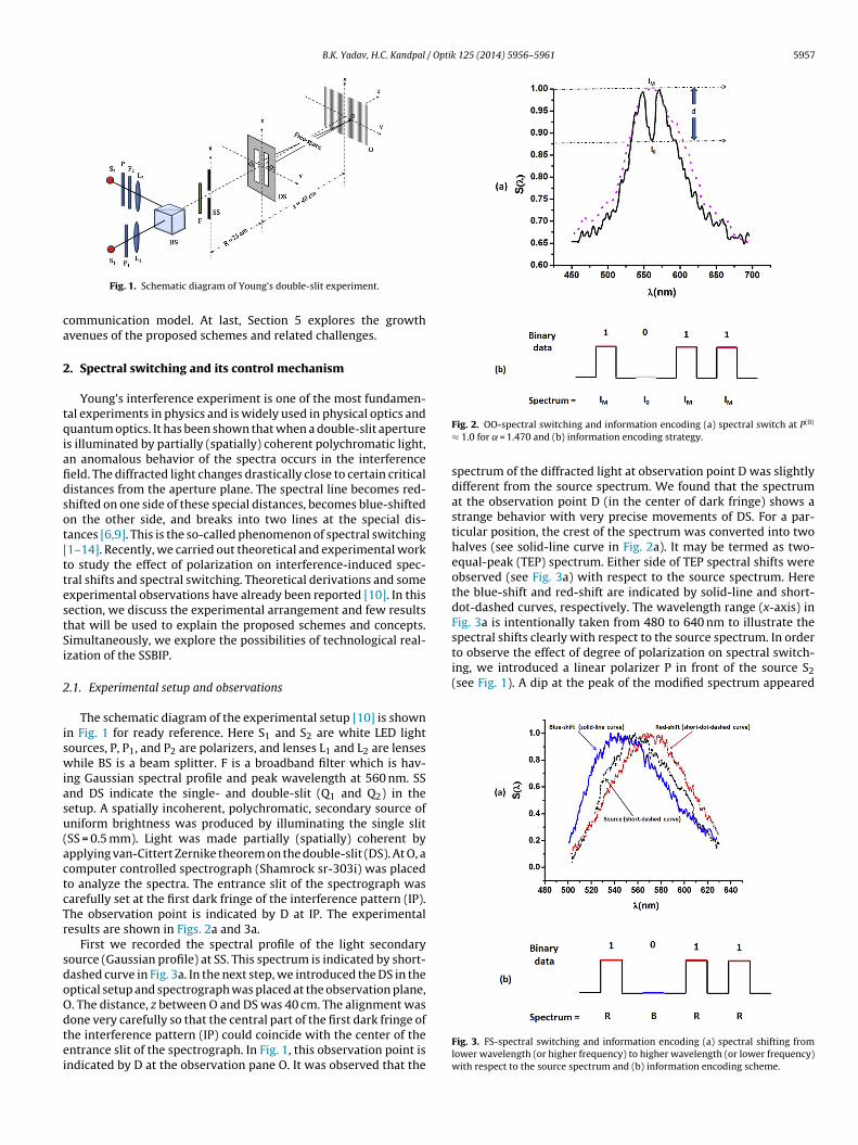
B.K. Yadav, H.C. Kandpal / Optik 125 (2014) 5956–5961 5957
ca
2
tqiafidsot[ttestSi
2
iswiasu(actcTr
sdoOdtei
spectral shifts clearly with respect to the source spectrum. In orderto observe the effect of degree of polarization on spectral switch-ing, we introduced a linear polarizer P in front of the source S2(see Fig. 1). A dip at the peak of the modified spectrum appeared
Fig. 1. Schematic diagram of Young’s double-slit experiment.
ommunication model. At last, Section 5 explores the growthvenues of the proposed schemes and related challenges.
. Spectral switching and its control mechanism
Young’s interference experiment is one of the most fundamen-al experiments in physics and is widely used in physical optics anduantum optics. It has been shown that when a double-slit aperture
s illuminated by partially (spatially) coherent polychromatic light,n anomalous behavior of the spectra occurs in the interferenceeld. The diffracted light changes drastically close to certain criticalistances from the aperture plane. The spectral line becomes red-hifted on one side of these special distances, becomes blue-shiftedn the other side, and breaks into two lines at the special dis-ances [6,9]. This is the so-called phenomenon of spectral switching1–14]. Recently, we carried out theoretical and experimental worko study the effect of polarization on interference-induced spec-ral shifts and spectral switching. Theoretical derivations and somexperimental observations have already been reported [10]. In thisection, we discuss the experimental arrangement and few resultshat will be used to explain the proposed schemes and concepts.imultaneously, we explore the possibilities of technological real-zation of the SSBIP.
.1. Experimental setup and observations
The schematic diagram of the experimental setup [10] is shownn Fig. 1 for ready reference. Here S1 and S2 are white LED lightources, P, P1, and P2 are polarizers, and lenses L1 and L2 are lenseshile BS is a beam splitter. F is a broadband filter which is hav-
ng Gaussian spectral profile and peak wavelength at 560 nm. SSnd DS indicate the single- and double-slit (Q1 and Q2) in theetup. A spatially incoherent, polychromatic, secondary source ofniform brightness was produced by illuminating the single slitSS = 0.5 mm). Light was made partially (spatially) coherent bypplying van-Cittert Zernike theorem on the double-slit (DS). At O, aomputer controlled spectrograph (Shamrock sr-303i) was placedo analyze the spectra. The entrance slit of the spectrograph wasarefully set at the first dark fringe of the interference pattern (IP).he observation point is indicated by D at IP. The experimentalesults are shown in Figs. 2a and 3a.
First we recorded the spectral profile of the light secondaryource (Gaussian profile) at SS. This spectrum is indicated by short-ashed curve in Fig. 3a. In the next step, we introduced the DS in theptical setup and spectrograph was placed at the observation plane,. The distance, z between O and DS was 40 cm. The alignment was
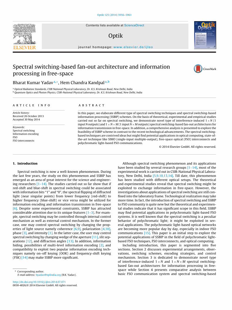
one very carefully so that the central part of the first dark fringe ofhe interference pattern (IP) could coincide with the center of thentrance slit of the spectrograph. In Fig. 1, this observation point isndicated by D at the observation pane O. It was observed that theFig. 2. OO-spectral switching and information encoding (a) spectral switch at P(0)
≈ 1.0 for = 1.470 and (b) information encoding strategy.
spectrum of the diffracted light at observation point D was slightlydifferent from the source spectrum. We found that the spectrumat the observation point D (in the center of dark fringe) shows astrange behavior with very precise movements of DS. For a par-ticular position, the crest of the spectrum was converted into twohalves (see solid-line curve in Fig. 2a). It may be termed as two-equal-peak (TEP) spectrum. Either side of TEP spectral shifts wereobserved (see Fig. 3a) with respect to the source spectrum. Herethe blue-shift and red-shift are indicated by solid-line and short-dot-dashed curves, respectively. The wavelength range (x-axis) inFig. 3a is intentionally taken from 480 to 640 nm to illustrate the
Fig. 3. FS-spectral switching and information encoding (a) spectral shifting fromlower wavelength (or higher frequency) to higher wavelength (or lower frequency)with respect to the source spectrum and (b) information encoding scheme.
5 / Optik 125 (2014) 5956–5961
atastFs
2
bsia(wsetwvr
2
sdict
2
oPtdcsPfTpdbsaw
wpEoTmuls
2
t
958 B.K. Yadav, H.C. Kandpal
gain after precise movement of DS. The movements were made inhe transverse direction over the minimum intensity regime. For
particular position of DS, a significant dip was observed in TEPpectrum. We also found that the depth of the dip in TEP spec-rum kept on changing with changes in the degree of polarization.or some values (e.g., P(0) ≈ 0.7), the TEP spectrum becomes almostource-like spectrum. It is indicated by dashed-line curve in Fig. 2a.
.2. Type of spectral switching
The spectral changes in the vicinity of singular point [6–8] maye regarded as two types of spectral switching namely on–offpectral switching (OO-SS) and frequency-shift spectral switch-ng (FS-SS). In spectral switching, a considerable intensity dropt central wavelength produces two-equal-peak (TEP) spectrumFig. 2a). This behavior of the diffracted light at a fixed point (centralavelength, �0 = 560 nm in our experiment) exhibits on–off type
pectral switching. It may be regarded as OO-SS and for informationncoding point of view, it is similar to traditional OOK scheme. Onhe other hand, spectral shifting from lower-frequency (or higher-avelength) to higher-frequency (or lower-wavelength) or vice
ersa with respect to the source spectrum (see Fig. 3a) may beegarded as FS-SS and it similar to FSK scheme.
.3. Spectral switching control mechanisms
Interestingly, in this experimental arrangement, the spectralwitching may be controlled in three ways: (i) by changing theegree of polarization at a fixed diffraction angle, (ii) by chang-
ng the diffraction angle at fixed degree of polarization, and (iii) byhanging both. However, every control process has its own advan-ages and limitations.
.4. On–off spectral switching and information encoding
To analyze the polarization effect on spectral switching, we tookbservations for different degrees of polarization, i.e., P(0) ≈ 0.7,(0) ≈ 0.8, P(0) ≈ 0.9, and P(0) ≈ 1.0. It was observed that TEP spec-rum occurs for each degree of polarization but at differentiffraction angle. For example, when we adjusted P(0) ≈ 1.0, therest of the modified spectrum was converted into two peaks (TEPpectrum) and a significant dip appeared at = 1.470 (Fig. 2a). For(0) ≈ 0.9, the spectral switching was observed at = 1.471, whileor P(0) ≈ 0.7, it was observed at = 1.471 (figures are not depicted).hese observations reveal that change in degree of polarizationroduces a new spectral switch but for a different value of theiffraction angle ˛. Hence one may get multiple spectral switchesy changing the degree of polarization. In order to exploit suchituation for SSBIP, one may fix a particular value of diffractionngle and may change the value degree of polarization to get OO-SSithin experimental uncertainties.
In Fig. 2a, the direction of OO-SS is indicated by a thick arrow,hile “d” shows the depth of the spectral switch with respect to theeak of the source-like spectrum at P(0) ≈ 0.7 (dashed-line curve).ach OO-SS occurs at different value of “d” depending on the res-lution power of the spectrograph/detector at observation plane.o illustrate the information encoding strategy, in Fig. 2b, a deci-al digit (11)10 is encoded in the binary equivalent form, (1011)2
sing spectral position IM (peak wavelength value of the source-ike spectrum, say “1”) and I0 (intensity drop in modified spectrum,ay “0”).
.5. Frequency shift spectral switching and information encoding
As we have discussed earlier, one may get FS-SS by changinghe value of the diffraction angle, while the degree of polarization
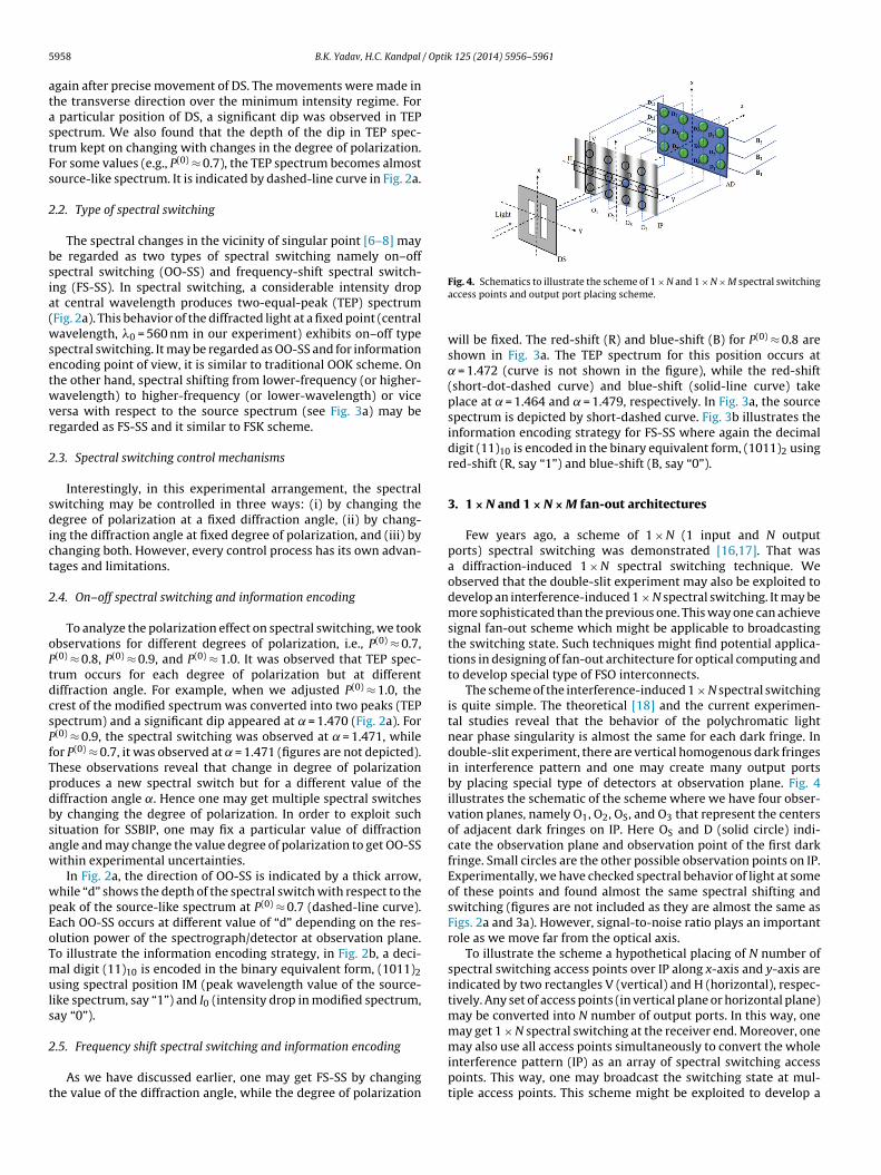
Fig. 4. Schematics to illustrate the scheme of 1 × N and 1 × N × M spectral switchingaccess points and output port placing scheme.
will be fixed. The red-shift (R) and blue-shift (B) for P(0) ≈ 0.8 areshown in Fig. 3a. The TEP spectrum for this position occurs at
= 1.472 (curve is not shown in the figure), while the red-shift(short-dot-dashed curve) and blue-shift (solid-line curve) takeplace at = 1.464 and = 1.479, respectively. In Fig. 3a, the sourcespectrum is depicted by short-dashed curve. Fig. 3b illustrates theinformation encoding strategy for FS-SS where again the decimaldigit (11)10 is encoded in the binary equivalent form, (1011)2 usingred-shift (R, say “1”) and blue-shift (B, say “0”).
3. 1 × N and 1 × N × M fan-out architectures
Few years ago, a scheme of 1 × N (1 input and N outputports) spectral switching was demonstrated [16,17]. That wasa diffraction-induced 1 × N spectral switching technique. Weobserved that the double-slit experiment may also be exploited todevelop an interference-induced 1 × N spectral switching. It may bemore sophisticated than the previous one. This way one can achievesignal fan-out scheme which might be applicable to broadcastingthe switching state. Such techniques might find potential applica-tions in designing of fan-out architecture for optical computing andto develop special type of FSO interconnects.
The scheme of the interference-induced 1 × N spectral switchingis quite simple. The theoretical [18] and the current experimen-tal studies reveal that the behavior of the polychromatic lightnear phase singularity is almost the same for each dark fringe. Indouble-slit experiment, there are vertical homogenous dark fringesin interference pattern and one may create many output portsby placing special type of detectors at observation plane. Fig. 4illustrates the schematic of the scheme where we have four obser-vation planes, namely O1, O2, OS, and O3 that represent the centersof adjacent dark fringes on IP. Here OS and D (solid circle) indi-cate the observation plane and observation point of the first darkfringe. Small circles are the other possible observation points on IP.Experimentally, we have checked spectral behavior of light at someof these points and found almost the same spectral shifting andswitching (figures are not included as they are almost the same asFigs. 2a and 3a). However, signal-to-noise ratio plays an importantrole as we move far from the optical axis.
To illustrate the scheme a hypothetical placing of N number ofspectral switching access points over IP along x-axis and y-axis areindicated by two rectangles V (vertical) and H (horizontal), respec-tively. Any set of access points (in vertical plane or horizontal plane)may be converted into N number of output ports. In this way, onemay get 1 × N spectral switching at the receiver end. Moreover, onemay also use all access points simultaneously to convert the whole
interference pattern (IP) as an array of spectral switching accesspoints. This way, one may broadcast the switching state at mul-tiple access points. This scheme might be exploited to develop a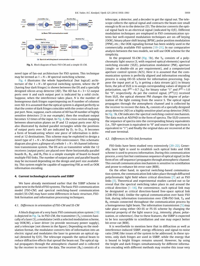
B.K. Yadav, H.C. Kandpal / Optik
nm
t(dpShotpsbbaoaendtrbmmii
4
qmml
4
icsauenrnb
Fig. 5. Block diagram of basic FSO-CM and a simple SS-CM.
ovel type of fan-out architecture for FSO system. This techniqueay be termed as 1 × N × M spectral switching scheme.Fig. 4 illustrates the whole hypothetical (but logical) archi-
ecture of the 1 × N × M spectral switching system, where the IPhaving four dark fringes) is shown between the DS and a speciallyesigned silicon array detector (AD). The AD has 4 × 3 = 12 outputorts over it and each output port is indicated by a solid circle.uppose, when the interference takes place, N is the number ofomogenous dark fringes superimposing on N number of columnsver AD. It is assumed that the optical system is aligned perfectly sohat the center of dark fringes coincides with the center of each out-ut port. Now, suppose, each column of AD has M number of highlyensitive detectors (3 in our example), then the resultant outputecomes 12 times of the input. In Fig. 4, the cross-section mappingetween observation planes on IP and 12 output ports over AD islso illustrated by dashed parallel rectangles while the positionsf output ports over AD are indicated by D1 to D12. It becomes
form of broadcasting where one piece of information is deliv-red at 12 destinations. This scheme may be exploited to design aovel type of 1 × N × M channel FSO-interconnect. This schematiciagram also gives a glimpse of a whole 1 × N × M channel informa-ion transmission system. The DS acts as transmitter while the 12eceivers (output ports) are placed over three horizontally paralleloards B1, B2, and B3.This is a simple example of board-to-boardultiple FSO links. The number of output ports and parallel boardsay be increased depending on the design and port size availabil-
ty. This system might be capable of supporting FSK as well as OOKnformation encoding.
. Current technological scenario and SSBIP
We have already mentioned earlier that the SSBIP scheme isuite new in the field of FSO systems. The basic FSO-communicationodel (FSO-CM) and spectral switching-based communicationodel (SS-CM) may have some differences in basic structure, FSO-
ink formation and information processing techniques.
.1. Differences in orientation of FSO-CM and SS-CM
A block diagram of a very basic FSO communication system [19]s depicted in Fig. 5a. In FSO-CM, the transmitter (TX) consists basi-ally of a laser (S), a modulator (with a selected modulation scheme,ay OOK/M), a laser driver (to provide necessary power supply),nd a telescope (not shown in the figure). Depending on the mod-lation format, the modulator converts bits of information into anlectric signal and modulates the laser to generate an optical sig-
al (denoted by E/O). The telescope expands the optical beam toeduce diffractive effects that spread the beam out. The optical sig-al propagates through the atmospheric channel and is collectedy the receiver to recover the data. The receiver (RX) consists of a125 (2014) 5956–5961 5959
telescope, a detector, and a decoder to get the signal out. The tele-scope collects the optical signal and contracts the beam size smallenough to fit on to the detector (D). The detector converts the opti-cal signal back to an electrical signal (indicated by O/E). Differentmodulation techniques are employed in FSO communication sys-tems but well-reputed modulation techniques are on–off keying(OOK), binary phase shift keying (BPSK), pulse position modulation(PPM), etc.; the OOK signaling format has been widely used in thecommercially available FSO systems [19–21]. In our comparativeanalysis between the two models, we will use OOK scheme for thesimplicity.
In the proposed SS-CM (Fig. 5b), the TX consists of a poly-chromatic light source (S, with required optical elements) spectralswitching encoder (SS/E), polarization modulator (PM), aperture(single- or double-slit as per requirement), and a computerizedaperture control system (ACS). Here it is assumed that the com-munication system is perfectly aligned and information encodingprocess is using OO-SS scheme for information processing. Sup-pose the input port at TX is getting a data stream (g(t)) in binaryform, the job of SS/E is to assign corresponding values of degree ofpolarization, say P(0) ≈ 0.7 (IM) for binary value “1” and P(0) ≈ 1.0for “0”, respectively. As per the control signal, (P(0)(t)) receivedfrom SS/E, the optical element PM changes the degree of polar-ization of the light coming from the source S. The optical signalpropagates through the atmospheric channel and is collected bythe receiver to recover the data. RX consists of a specially designedarray detector (AD) or a highly sensitive pixel array detector (PAD).In Fig. 5b, CM indicates the spectral switching control mechanism.The data reach at AD/PAD in the form of spectra. The SS/D convertsthe sequence of spectra into the corresponding binary equivalents(i.e., TEP-spectrum is equivalent to “0” and source-like spectrum isequivalent to “1”) and finally the original data are recovered at theend user terminal.
4.2. Differences in FSO-link formation
FSO-links have been studied very extensively [20–22]. Gener-ally, laser light is used to establish such optical links and OOKscheme is used to process information. During this communicationprocess, a very fast but continuous sequence of optical signal (in theform of on–off sequence) propagates through atmospheric channel.This overall communication mechanism is sensitive to scintillationand prone to enhance bit-error-rate (BER).
On the other hand, in spectral switching-based communica-tion system, the communication link takes place through diffractedpolychromatic light field where critical directions [7] act as FSOlinks [5]. Theoretical and experimental studies carried out so farreveal that the spectral switching takes place in and around thecritical direction [1–14]. For convenience, such optical link maybe designated as critical direction-based free-space optical link(CDB-FSO link). Unlike the optical communication over basic FSOlink, during information transmission over CDB-FSO link, TX andRX remain connected throughout the communication process bya homogeneous light beam. The information transmission [5] maytake place using either OO-SS or FS-SS scheme by changing theinternal property of the light source (e.g., intensity, phase, polar-ization, or coherence). Due to these features, the SSBIP is expectedto be less susceptible to scintillation and one may expect betterbit-error-rat (BER).
It is worthwhile to mention here that in diffraction as well asinterference-induced SSBIP, energy efficiency and signal-to-noiseratio (SNR) like issues of the system to be addressed. In these sys-
tems, only dark fringes are used in SSBIP, while the energy thatis bound to bright fringes remains unused. However, by usingthe bright and dark fringes simultaneously for different informa-tion encoding with different methods may resolve this issue very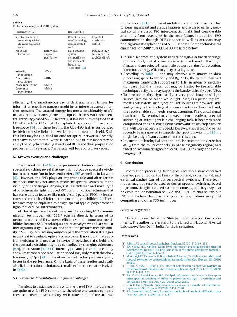
5960 B.K. Yadav, H.C. Kandpal / Optik
Table 1Performance analysis of SSBIP system.
Transmitter (Tx) Receiver (Rx)
Spectral switchingcontrol capacitiesclaimed/proposedso far
Detection sys-tem/technologydemonstratedso far
Expectedmaximumoutput
Proposedtechniques
Bandwidthsupportpossibility
Light detectionsystemcompatible tosupport clockfrequency<100 MHz [24]
Data rate maybe reached upto alOO MB p/s
Intensitymodulation
≈THz
Polarizationmodulation
≈GHz
eititCfbFesp
5
si[dvohtfl
npbiiitt[sfbai
5
at
Phase modulation ≈MHzCoherence
modulation≈MHz
fficiently. The simultaneous use of dark and bright fringes fornformation encoding purpose might be an interesting area of fur-her research. The unused energy became a considerably usefuln dark hollow beams (DHBs, i.e., optical beams with zero cen-ral intensity)-based SSBIP. Recently, it has been investigated thatDB-FSO link in DHBs might be exploited to process information inree-space [14]. In these beams, the CDB-FSO link is surroundedy high-intensity light that works like a protection shield. SuchSO-link may be exploited for outdoor optical networks. Recently,xtensive experimental work is carried out in our laboratory totudy the polychromatic light-induced DHBs and their propagationroperties in free-space. The results will be reported very soon.
. Growth avenues and challenges
The theoretical [1–4,6] and experimental studies carried out onpectral switching reveal that one might produce spectral switch-ng in near zone (up to few centimeters [9]) as well as in far zone5]. However, the SNR plays an important role and after certainistances one may not able to resole the spectral switching in theicinity of dark fringes. Anyways, it is a different and novel typef polychromatic light-induced FSO communication technique thatas some unique features like multiple and parallel FSO link forma-ions and multi-level information encoding capabilities [2]. Theseeatures may be exploited to design special type of polychromaticight-induced FSO interconnects.
At this stage, one cannot compare the existing FSO commu-ication techniques with SSBIP scheme directly in terms of itserformance, reliability, power efficiency, and throughput possi-ilities because SSBIP techniques are relatively new and are still at
nvestigation stage. To get an idea about the performance possibil-ty in SSBIP system, we may only compare the modulation strategiesn contrast to available optical technologies. It is evident that spec-ral switching is a peculiar behavior of polychromatic light andhe spectral switching might be controlled by changing coherence6,9], polarization [4,10,14], intensity [1], and phase [3]. The studyhows that coherence modulation speed may only match the clockrequency ≈1/�s [23] while other related techniques are slightlyetter in the performance. On the basis of these studies and avail-ble light detection techniques, a small performance matrix is givenn Table 1.
.1. Experimental limitations and future challenges
The ideas to design spectral switching-based FSO interconnectsre quite new for FSO community therefore one cannot comparehese contrived ideas directly with other state-of-the-art FSO
125 (2014) 5956–5961
interconnects [21] in terms of architecture and performance. Dueto some significant and unique features as discussed earlier, spec-tral switching-based FSO interconnects might find considerableattentions from researches in the near future. In addition, FSOcommunication through DHBs (indoor as well as outdoor) mayfind significant applications of SSBIP scheme. Some technologicalchallenges for SSBIP over CDB-FSO are listed below.
• In such schemes, the system uses faint signal in the dark fringethan obviously a lot of power is wasted (that is bound to the brightfringes and are rejected), and little power remains for detection.Therefore, energy efficiency may be a big issue.
• According to Table 1, one may observe a mismatch in dataprocessing speed between TX and RX. At TX, the system may findmaximum bandwidth support up to THz (in intensity modula-tion case) but the throughput may be limited by the availabletechniques at RX that may support the bandwidth only up to MHz.
• To produce quality signal at TX, a very good broadband lightsource (like the so-called while light laser) is a prime require-ment. Fortunately, such types of light sources are now availableand getting fast technological advancements. On the other hand,the receiver side still needs a great attention. The optical signalreaching at RX terminal may be weak, hence resolving spectralswitching at output port is a challenging task. It becomes morecomplicated and challenging when one wants to develop a devicethat will work at very high speed. However, a novel technique hasrecently been reported to amplify the spectral switching [25]; itmight be a significant advancement in this area.
• In current technological scenario, precise information detectionat RX from the multi-channels (in phase singularity region) andfaded polychromatic light-induced CDB-FSO link might be a chal-lenging task.
6. Conclusion
Information processing techniques and some new contrivedideas are presented on the basis of theoretical, experimental, andempirical studies carried out on spectral switching. These tech-niques may not only be used to design spectral switching-basedpolychromatic light-induced FSO interconnects, but they may alsobe exploited for formation of 1 × N and 1 × N × M channel fan-outFSO architecture that may find potential applications in opticalcomputing and other FSO techniques.
Acknowledgments
The authors are thankful to Stuti Joshi for her support in exper-iments. The authors are grateful to the Director, National PhysicalLaboratory, New Delhi, India, for the inspiration.
References
[1] P. Han, All optical spectral switches, Opt. Lett. 37 (2012) 2319–2321.[2] B.K. Yadav, H.C. Kandpal, Multi-level information encoding through spectral
switches and multiple FSO link formation in the phase singularity domain, J.Opt. 13 (2011) 075403–075410.
[3] M. Amiri, M.T. Tavassoly, H. Dolatkhah, Z. Alirezaei, Tunable spectral shifts andspectral switches by controllable phase modulation, Opt. Express 18 (2010)25089.
[4] L. Pan, Z. Zhao, C. Ding, B. Lu, Effect of polarization on spectral switches inthe diffraction of stochastic electromagnetic beams, Appl. Phys. Lett. 95 (2009)1811121–1811123.
[5] B.K. Yadav, Swati Raman, H.C. Kandpal, Information exchange in free-spaceusing spectral switching of diffracted polychromatic light – possibilities and
limitations, J. Opt. Soc. Am. A 25 (2008) 2952–2959.[6] J. Pu, C. Cai, S. Nemoto, Spectral anomalies in Young’s double-slit interferenceexperiment, Opt. Express 12 (2004) 5131–5140.
[7] S.A. Ponomarenka, E. Wolf, Spectral anomalies in a Fraunhofer diffraction pat-tern, Opt. Lett. 27 (2002) 1211–1213.
/ Optik
[
[
[
[
[
[
[
[
[
[
[
[
[
[optical coherence by electronically synthesized holographic grating, J. Appl.
B.K. Yadav, H.C. Kandpal
[8] J.T. Foley, E. Wolf, Phenomenon of spectral switches as a new effect in singularoptics with polychromatic light, J. Opt. Soc. Am. A 19 (2002) 2510–2516.
[9] B.K. Yadav, S.A.M. Rizvi, H.C. Kandpal, Experimental observation of spectralchanges of partially coherent light in Young’s experiment, J. Opt. A: Pure Appl.Opt. 8 (2006) 72–76.
10] S. Joshi, B.K. Yadav, M. Verma, M.S. Khan, H.C. Kandpal, Effect of polarizationon spectral anomalies of diffracted stochastic electromagnetic beam, J. Opt. 15(2013) 035405 (5).
11] P. Han, Spectral switches for a circular aperture with a variable wedge, J. Opt.Soc. Am. A 26 (2009) 473–479.
12] P. Han, Spectral switches of a double-slit with a movable central part in thefar-field, J. Opt. A: Pure Appl. Opt. 11 (2009) 085410 (6).
13] B.K. Yadav, S.A.M. Rizvi, S. Raman, R. Mehrotra, H.C. Kandpal, Informationencoding by spectral anomalies of spatially coherent light diffracted by anannular aperture, Opt. Commun. 269 (2007) 253–260.
14] B.K. Yadav, H.C. Kandpal, Spectral anomalies of polychromatic DHGB and itsapplications in FSO, J. Lightwave Technol. 29 (2011) 960–966.
15] Z. Wu, J. Chau, T. Little, Modeling and designing of a new indoor free spacevisible light communication system, 16th European Conf. (NOC, 2011), pp.72–75.
16] J. Pu, S. Nemoto, Spectral changes and 1×N spectral switches in the diffractionof partially coherent light by an aperture, J. Opt. Soc. Am. A 19 (2002) 339–344.
[
[
125 (2014) 5956–5961 5961
17] S. Anand, B.K. Yadav, H.C. Kandpal, Experimental study of the phenomenon of1×N spectral switches due to diffraction of partially coherence light, J. Opt. Soc.Am. A 19 (2002) 2223–2228.
18] B.K. Yadav, N.S. Bisht, R. Mehrotra, H.C. Kandpal, Diffraction-induced spectralanomalies for information encoding and information hiding – possibilities andlimitations, Opt. Commun. 277 (2007) 24–32.
19] A.K. Majumdar, J.C. Ricklin, Free-space laser communications – principles andadvances, 1st ed., Springer Science Publications, USA, 2007.
20] B. Barua, D. Barua, Evaluate the performance of FSO communication link withdifferent modulation techniques under turbulent conditions, Proc. 14th Int.Conf. (CICCIT, Dhaka, Bangladesh, 2011), pp. 22–24.
21] W. Feiyang, et al., Integrated receiver architectures for board-to-board free-space optical interconnects, Appl. Phys. A 95 (2009) 1079–1088.
22] G.A. Tyler, Spatial bandwidth considerations for optical communicationthrough a free-space propagation link, Opt. Lett. 36 (2011) 4650–4652.
23] J. Turunen, E. Tervonen, A.T. Friberg, Acousto-optic control and modulation of
Phys. 67 (1990) 49–59.24] M. El-Desouki, et al., CMOS image sensors for high speed applications, Sensors
9 (2009) 430–444, http://dx.doi.org/10.3390/s90100430.25] P. Han, Spectral shift amplification, Opt. Lett. 37 (2012), 4895-4895.