Embed Size (px)
Citation preview

I N S T A L L A T I O N
C3446M-B (8/09)
Spectra® Mini IPDome System

C3446M-B (8/09) 3
Contents
Important Safety Instructions. . . . . . . . . . . . . . . . . . . . . . . . . . . . . . . . . . . . . . . . . . . . . . . . . . . . . . . . . . . . . 6
Important Notices. . . . . . . . . . . . . . . . . . . . . . . . . . . . . . . . . . . . . . . . . . . . . . . . . . . . . . . . . . . . . . . . . . . . . . 7Legal Notice . . . . . . . . . . . . . . . . . . . . . . . . . . . . . . . . . . . . . . . . . . . . . . . . . . . . . . . . . . . . . . . . . . . . . 7Regulatory Notice. . . . . . . . . . . . . . . . . . . . . . . . . . . . . . . . . . . . . . . . . . . . . . . . . . . . . . . . . . . . . . . . . 7Open Source Software Notice . . . . . . . . . . . . . . . . . . . . . . . . . . . . . . . . . . . . . . . . . . . . . . . . . . . . . . . 8
Description . . . . . . . . . . . . . . . . . . . . . . . . . . . . . . . . . . . . . . . . . . . . . . . . . . . . . . . . . . . . . . . . . . . . . . . . . . . 9System Models. . . . . . . . . . . . . . . . . . . . . . . . . . . . . . . . . . . . . . . . . . . . . . . . . . . . . . . . . . . . . . . . . . . 9Parts List . . . . . . . . . . . . . . . . . . . . . . . . . . . . . . . . . . . . . . . . . . . . . . . . . . . . . . . . . . . . . . . . . . . . . . . . 9Basic System Configurations . . . . . . . . . . . . . . . . . . . . . . . . . . . . . . . . . . . . . . . . . . . . . . . . . . . . . . . 10
DHCP Network . . . . . . . . . . . . . . . . . . . . . . . . . . . . . . . . . . . . . . . . . . . . . . . . . . . . . . . . . . . . . 11Endura Network . . . . . . . . . . . . . . . . . . . . . . . . . . . . . . . . . . . . . . . . . . . . . . . . . . . . . . . . . . . . 11Private Network . . . . . . . . . . . . . . . . . . . . . . . . . . . . . . . . . . . . . . . . . . . . . . . . . . . . . . . . . . . . 12Static Network . . . . . . . . . . . . . . . . . . . . . . . . . . . . . . . . . . . . . . . . . . . . . . . . . . . . . . . . . . . . . 13
Cover and Back Box Installation. . . . . . . . . . . . . . . . . . . . . . . . . . . . . . . . . . . . . . . . . . . . . . . . . . . . . . . . . . 14Surface Mount Installation . . . . . . . . . . . . . . . . . . . . . . . . . . . . . . . . . . . . . . . . . . . . . . . . . . . . . . . . 14Recessed Installation . . . . . . . . . . . . . . . . . . . . . . . . . . . . . . . . . . . . . . . . . . . . . . . . . . . . . . . . . . . . . 16
Suspended Ceiling . . . . . . . . . . . . . . . . . . . . . . . . . . . . . . . . . . . . . . . . . . . . . . . . . . . . . . . . . . 16Hard Ceiling . . . . . . . . . . . . . . . . . . . . . . . . . . . . . . . . . . . . . . . . . . . . . . . . . . . . . . . . . . . . . . . 18
Wiring Tables . . . . . . . . . . . . . . . . . . . . . . . . . . . . . . . . . . . . . . . . . . . . . . . . . . . . . . . . . . . . . . . . . . . . . . . . 19Cat5 Cable . . . . . . . . . . . . . . . . . . . . . . . . . . . . . . . . . . . . . . . . . . . . . . . . . . . . . . . . . . . . . . . . . . . . . 19Connecting Audio . . . . . . . . . . . . . . . . . . . . . . . . . . . . . . . . . . . . . . . . . . . . . . . . . . . . . . . . . . . . . . . . 20Connecting 24 VAC Power (Optional). . . . . . . . . . . . . . . . . . . . . . . . . . . . . . . . . . . . . . . . . . . . . . . . . 21Connecting a Relay Device. . . . . . . . . . . . . . . . . . . . . . . . . . . . . . . . . . . . . . . . . . . . . . . . . . . . . . . . . 21Connecting Alarms . . . . . . . . . . . . . . . . . . . . . . . . . . . . . . . . . . . . . . . . . . . . . . . . . . . . . . . . . . . . . . . 22
Supervised Alarms . . . . . . . . . . . . . . . . . . . . . . . . . . . . . . . . . . . . . . . . . . . . . . . . . . . . . . . . . . 22Unsupervised Alarms . . . . . . . . . . . . . . . . . . . . . . . . . . . . . . . . . . . . . . . . . . . . . . . . . . . . . . . . 23Alarm Connections . . . . . . . . . . . . . . . . . . . . . . . . . . . . . . . . . . . . . . . . . . . . . . . . . . . . . . . . . . 24
Reset Button . . . . . . . . . . . . . . . . . . . . . . . . . . . . . . . . . . . . . . . . . . . . . . . . . . . . . . . . . . . . . . . . . . . . . . . . . 25
Troubleshooting . . . . . . . . . . . . . . . . . . . . . . . . . . . . . . . . . . . . . . . . . . . . . . . . . . . . . . . . . . . . . . . . . . . . . . 26
Specifications . . . . . . . . . . . . . . . . . . . . . . . . . . . . . . . . . . . . . . . . . . . . . . . . . . . . . . . . . . . . . . . . . . . . . . . . 28
4 C3446M-B (8/09)
List of Illustrations
1 DHCP Network Example . . . . . . . . . . . . . . . . . . . . . . . . . . . . . . . . . . . . . . . . . . . . . . . . . . . . . . . . . . . 112 Endura Network Example . . . . . . . . . . . . . . . . . . . . . . . . . . . . . . . . . . . . . . . . . . . . . . . . . . . . . . . . . . 113 Private Network Example . . . . . . . . . . . . . . . . . . . . . . . . . . . . . . . . . . . . . . . . . . . . . . . . . . . . . . . . . . 124 Static Network Example. . . . . . . . . . . . . . . . . . . . . . . . . . . . . . . . . . . . . . . . . . . . . . . . . . . . . . . . . . . 135 Ceiling Installation . . . . . . . . . . . . . . . . . . . . . . . . . . . . . . . . . . . . . . . . . . . . . . . . . . . . . . . . . . . . . . . 156 Concrete Ceiling Installation . . . . . . . . . . . . . . . . . . . . . . . . . . . . . . . . . . . . . . . . . . . . . . . . . . . . . . . 157 Spring Paddle Flex Assembly . . . . . . . . . . . . . . . . . . . . . . . . . . . . . . . . . . . . . . . . . . . . . . . . . . . . . . . 168 Removing the Surface Mount Ring . . . . . . . . . . . . . . . . . . . . . . . . . . . . . . . . . . . . . . . . . . . . . . . . . . 169 Recessed Installation . . . . . . . . . . . . . . . . . . . . . . . . . . . . . . . . . . . . . . . . . . . . . . . . . . . . . . . . . . . . . 17
10 Wiring Diagram . . . . . . . . . . . . . . . . . . . . . . . . . . . . . . . . . . . . . . . . . . . . . . . . . . . . . . . . . . . . . . . . . 1911 Audio Wiring . . . . . . . . . . . . . . . . . . . . . . . . . . . . . . . . . . . . . . . . . . . . . . . . . . . . . . . . . . . . . . . . . . . 2012 Relay Wiring Example . . . . . . . . . . . . . . . . . . . . . . . . . . . . . . . . . . . . . . . . . . . . . . . . . . . . . . . . . . . . 2113 Supervised Alarm Conditions. . . . . . . . . . . . . . . . . . . . . . . . . . . . . . . . . . . . . . . . . . . . . . . . . . . . . . . 2214 Normally Closed Supervised Alarm Input Wiring . . . . . . . . . . . . . . . . . . . . . . . . . . . . . . . . . . . . . . . 2215 Normally Open Supervised Alarm Input Wiring. . . . . . . . . . . . . . . . . . . . . . . . . . . . . . . . . . . . . . . . . 2216 Unsupervised Alarm Conditions. . . . . . . . . . . . . . . . . . . . . . . . . . . . . . . . . . . . . . . . . . . . . . . . . . . . . 2317 Normally Closed Unsupervised Alarm Input Wiring . . . . . . . . . . . . . . . . . . . . . . . . . . . . . . . . . . . . . 2318 Normally Open Unsupervised Alarm Input Wiring. . . . . . . . . . . . . . . . . . . . . . . . . . . . . . . . . . . . . . . 2319 Unsupervised Alarm Input Wiring . . . . . . . . . . . . . . . . . . . . . . . . . . . . . . . . . . . . . . . . . . . . . . . . . . . 2420 Location of Reset Button and LED . . . . . . . . . . . . . . . . . . . . . . . . . . . . . . . . . . . . . . . . . . . . . . . . . . . 25

C3446M-B (8/09) 5
List of Tables
A Legend for System Configuration Example Diagrams . . . . . . . . . . . . . . . . . . . . . . . . . . . . . . . . . . . . 10B Recommended Wire Gauge and Wiring Distances . . . . . . . . . . . . . . . . . . . . . . . . . . . . . . . . . . . . . . 21C Reset Modes . . . . . . . . . . . . . . . . . . . . . . . . . . . . . . . . . . . . . . . . . . . . . . . . . . . . . . . . . . . . . . . . . . . 25D Troubleshooting the Spectra Mini IP . . . . . . . . . . . . . . . . . . . . . . . . . . . . . . . . . . . . . . . . . . . . . . . . . 26

Important Safety Instructions
1. Read these instructions.
2. Keep these instructions.
3. Heed all warnings.
4. Follow all instructions.
5. Do not use this apparatus near water.
6. Do not block any ventilation openings. Install in accordance with the manufacturer’s instructions.
7. Only use attachments/accessories specified by the manufacturer.
8. Apparatus shall not be exposed to dripping or splashing and that no objects filled with liquids, such as vases shall be placed on the apparatus.
9. Installation should be done only by qualified personnel and conform to all local codes.
10. Unless the unit is specifically marked as a NEMA Type 3, 3R, 3S, 4, 4X, 6, or 6P enclosure, it is designed for indoor use only and it must not be installed where exposed to rain and moisture.
11. Use only installation methods and materials capable of supporting four times the maximum specified load.
12. Use stainless steel hardware to fasten the mount to outdoor surfaces.
13. Only use replacement parts recommended by Pelco.
14. After replacement/repair of this unit’s electrical components, conduct a resistance measurement between the line and exposed parts to verify the exposed parts have not been connected to the line circuitry.
6 C3446M-B (8/09)

Important NoticesLEGAL NOTICE
SOME PELCO EQUIPMENT CONTAINS, AND THE SOFTWARE ENABLES, AUDIO/VISUAL AND RECORDING CAPABILITIES, THE IMPROPER USE OF WHICH MAY SUBJECT YOU TO CIVIL AND CRIMINAL PENALTIES. APPLICABLE LAWS REGARDING THE USE OF SUCH CAPABILITIES VARY BETWEEN JURISDICTIONS AND MAY REQUIRE, AMONG OTHER THINGS, EXPRESS WRITTEN CONSENT FROM RECORDED SUBJECTS. YOU ARE SOLELY RESPONSIBLE FOR INSURING STRICT COMPLIANCE WITH SUCH LAWS AND FOR STRICT ADHERENCE TO ANY/ALL RIGHTS OF PRIVACY AND PERSONALTY. USE OF THIS EQUIPMENT AND/OR SOFTWARE FOR ILLEGAL SURVEILLANCE OR MONITORING SHALL BE DEEMED UNAUTHORIZED USE IN VIOLATION OF THE END USER SOFTWARE AGREEMENT AND RESULT IN THE IMMEDIATE TERMINATION OF YOUR LICENSE RIGHTS THEREUNDER.
REGULATORY NOTICEThis device complies with Part 15 of the FCC Rules. Operation is subject to the following two conditions: (1) this device may not cause harmful interference, and (2) this device must accept any interference received, including interference that may cause undesired operation.
RADIO AND TELEVISION INTERFERENCEThis equipment has been tested and found to comply with the limits of a Class B digital device, pursuant to Part 15 of the FCC Rules. These limits are designed to provide reasonable protection against harmful interference in a residential installation. This equipment generates, uses, and can radiate radio frequency energy and, if not installed and used in accordance with the instructions, may cause harmful interference to radio communications. However there is no guarantee that the interference will not occur in a particular installation. If this equipment does cause harmful interference to radio or television reception, which can be determined by turning the equipment off and on, the user is encouraged to try to correct the interference by one or more of the following measures:• Reorient or relocate the receiving antenna.• Increase the separation between the equipment and the receiver.• Connect the equipment into an outlet on a circuit different from that to which the receiver is
connected.• Consult the dealer or an experienced radio/TV technician for help.
You may also find helpful the following booklet, prepared by the FCC: “How to Identify and Resolve Radio-TV Interference Problems.” This booklet is available from the U.S. Government Printing Office, Washington D.C. 20402.
Changes and Modifications not expressly approved by the manufacturer or registrant of this equipment can void your authority to operate this equipment under Federal Communications Commission’s rules.
This Class B digital apparatus complies with Canadian ICES-003.
Cet appareil numérique de la classe B est conforme à la norme NMB-003 du Canada.
C3446M-B (8/09) 7

OPEN SOURCE SOFTWARE NOTICEThis product includes certain open source or other software originated from third parties that is subject to the GNU General Public License (GPL), GNU Library/Lesser General Public License (LGPL) and different and/or additional copyright licenses, disclaimers and notices.
The exact terms of GPL, LGPL and some other licenses are provided to you with this product. Please refer to the exact terms of the GPL and LGPL at www.fsf.org (Free Software Foundation) and www.opensource.org (Open Source Initiative) regarding your rights under said license. You may obtain a complete corresponding machine-readable copy of the source code of such software under the GPL or LGPL by sending your request to [email protected] and the subject line should read Source Code Request. You will then receive a link in the e-mail for you to download the source code.
This offer is valid for a period of three (3) years from the date of the distribution of this product by Pelco.
8 C3446M-B (8/09)
Description
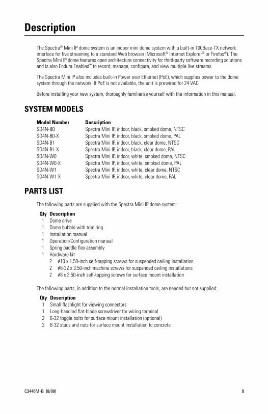
The Spectra® Mini IP dome system is an indoor mini dome system with a built-in 100Base-TX network interface for live streaming to a standard Web browser (Microsoft® Internet Explorer® or Firefox®). The Spectra Mini IP dome features open architecture connectivity for third-party software recording solutions and is also Endura Enabled™ to record, manage, configure, and view multiple live streams.
The Spectra Mini IP also includes built-in Power over Ethernet (PoE), which supplies power to the dome system through the network. If PoE is not available, the unit is prewired for 24 VAC.
Before installing your new system, thoroughly familiarize yourself with the information in this manual.
SYSTEM MODELS
PARTS LIST
The following parts are supplied with the Spectra Mini IP dome system:
The following parts, in addition to the normal installation tools, are needed but not supplied:
Model Number DescriptionSD4N-B0 Spectra Mini IP, indoor, black, smoked dome, NTSCSD4N-B0-X Spectra Mini IP, indoor, black, smoked dome, PALSD4N-B1 Spectra Mini IP, indoor, black, clear dome, NTSCSD4N-B1-X Spectra Mini IP, indoor, black, clear dome, PALSD4N-W0 Spectra Mini IP, indoor, white, smoked dome, NTSCSD4N-W0-X Spectra Mini IP, indoor, white, smoked dome, PALSD4N-W1 Spectra Mini IP, indoor, white, clear dome, NTSCSD4N-W1-X Spectra Mini IP, indoor, white, clear dome, PAL
Qty Description1 Dome drive1 Dome bubble with trim ring1 Installation manual1 Operation/Configuration manual1 Spring paddle flex assembly1 Hardware kit
2 #10 x 1.50-inch self-tapping screws for suspended ceiling installation2 #8-32 x 3.50-inch machine screws for suspended ceiling installations2 #8 x 3.50-inch self-tapping screws for surface mount installation
Qty Description1 Small flashlight for viewing connectors1 Long-handled flat-blade screwdriver for wiring terminal2 6-32 toggle bolts for surface mount installation (optional)2 8-32 studs and nuts for surface mount installation to concrete
C3446M-B (8/09) 9

BASIC SYSTEM CONFIGURATIONSThe following illustrations demonstrate the possible configurations of Spectra Mini IP with a variety of network options.
IMPORTANT NOTE. PLEASE READ. The network implementations in this document are shown as general representations only and are not intended to show detailed network topologies. Your actual network will differ, requiring changes or perhaps additional network equipment to accommodate the systems as illustrated. Please contact your local Pelco Representative to discuss your specific requirements.
Refer to Network Settings in the Spectra Mini IP Operation/Configuration manual for more information about DHCP and static IP networks. Refer to Table A when viewing Figure 1, Figure 2, Figure 3, and Figure 4.
Table A. Legend for System Configuration Example Diagrams
Spectra Mini IP dome system
Web browser
TCP/IP/Internet
Endura® network
DVR
Network switch
Cable modem router/switch
10 C3446M-B (8/09)
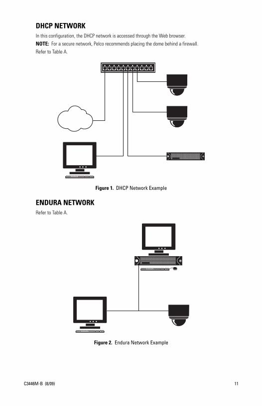
DHCP NETWORKIn this configuration, the DHCP network is accessed through the Web browser.
NOTE: For a secure network, Pelco recommends placing the dome behind a firewall.
Refer to Table A.
Figure 1. DHCP Network Example
ENDURA NETWORKRefer to Table A.
Figure 2. Endura Network Example
C3446M-B (8/09) 11
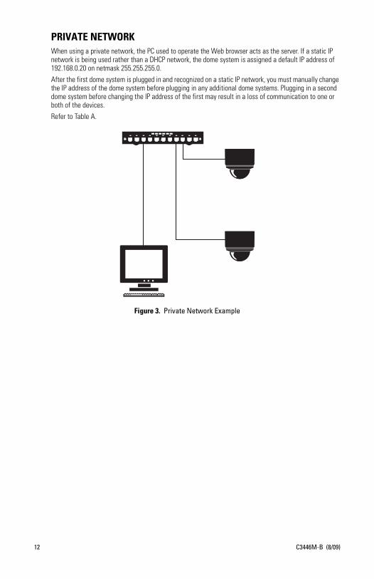
PRIVATE NETWORKWhen using a private network, the PC used to operate the Web browser acts as the server. If a static IP network is being used rather than a DHCP network, the dome system is assigned a default IP address of 192.168.0.20 on netmask 255.255.255.0.
After the first dome system is plugged in and recognized on a static IP network, you must manually change the IP address of the dome system before plugging in any additional dome systems. Plugging in a second dome system before changing the IP address of the first may result in a loss of communication to one or both of the devices.
Refer to Table A.
Figure 3. Private Network Example
12 C3446M-B (8/09)
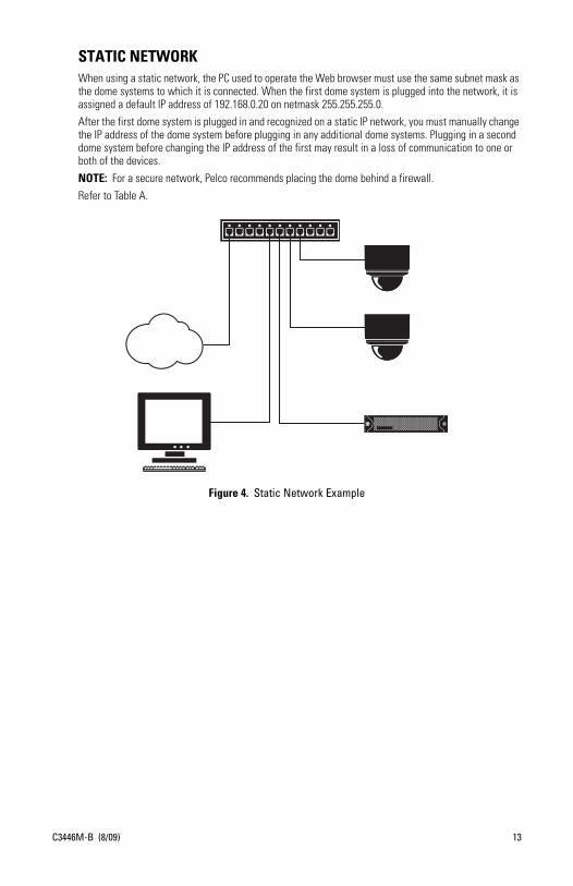
STATIC NETWORKWhen using a static network, the PC used to operate the Web browser must use the same subnet mask as the dome systems to which it is connected. When the first dome system is plugged into the network, it is assigned a default IP address of 192.168.0.20 on netmask 255.255.255.0.
After the first dome system is plugged in and recognized on a static IP network, you must manually change the IP address of the dome system before plugging in any additional dome systems. Plugging in a second dome system before changing the IP address of the first may result in a loss of communication to one or both of the devices.
NOTE: For a secure network, Pelco recommends placing the dome behind a firewall.
Refer to Table A.
Figure 4. Static Network Example
C3446M-B (8/09) 13

Cover and Back Box Installation
The Spectra Mini IP is an indoor dome system designed for ceiling applications. The dome can be mounted to the surface of ceilings, or it can be recessed in hard ceilings or standard 2 x 2 ft (61 x 61 cm) tiles in suspended ceilings.
SURFACE MOUNT INSTALLATION1. Prepare the ceiling as follows:
a. Using the surface mount ring as a template, drill holes for the mounting hardware.
• Standard ceiling: When mounting the dome system to a standard ceiling, use either 6-32 toggle bolts (not supplied) or #8 x 3.50-inch self-tapping screws (supplied). Refer to Figure 5.
• Concrete ceiling: When mounting the dome system to a concrete system, use 8-32 studs and nuts (not supplied). Refer to Figure 6.
b. Drill a hole in the ceiling for wiring. You do not have to run wiring through the ceiling; you can fasten the wires to the ceiling and then run the wires through the air gap between the ceiling and the surface mount ring.
2. Connect the wiring using one of the following options:
• Plug the network cable into the RJ-45 connector on the side of the dome drive.• If the network has no PoE, connect a 24 VAC Class 2 power supply to the 24 VAC power
connector.
Refer to Figure 10 for wiring connections.
3. If you are operating the dome system using 24 VAC and you are wiring more than one dome drive to the same transformer, connect one side of the transformer to pin 1 of the 2-position terminal block on all modules. Connect the other side of the transformer to pin 2 of the terminal block on all modules.
NOTE: Failure to connect all modules identically may introduce noise in the video for some installations.
14 C3446M-B (8/09)

4. Attach the dome drive to the ceiling.
Refer to Figure 5 and Figure 6 when installing the dome drive.
5. Line up the tabs on the trim ring with the slots in the dome drive. Snap the trim ring and bubble into place.
WARNING: Do not overtighten the mounting hardware; doing so can impede the pan movement of the dome drive.
Figure 5. Ceiling Installation Figure 6. Concrete Ceiling Installation
6-32 toggle bolts (not supplied)
#8 x 3.50-inch self-tapping screws (supplied)
NOTE: Use either toggle bolts or self-tapping screws when mounting the dome to a standard ceiling.
Nuts (not supplied)
8-32 studs (not supplied)
C3446M-B (8/09) 15

RECESSED INSTALLATION
SUSPENDED CEILING1. Remove the spring paddle flex assembly from the surface mount ring (refer to Figure 7).
Figure 7. Spring Paddle Flex Assembly
2. Remove the surface mount ring from the dome drive as follows (refer to Figure 8):
a. Place fingers on the circular marks located on the sides of the surface mount ring.
b. Pinch the sides.
c. Lift and remove the surface mount ring from the dome drive.
Figure 8. Removing the Surface Mount Ring
3. Attach the spring paddle flex assembly to the dome drive using the two #8-32 x 3.50-inch machine screws (supplied). Thread the screws into the ends of the spring paddle flex assembly flex assembly so the paddles remain at the end of the screws.
4. Cut a 5-inch diameter hole in the ceiling tile. You can either use the two holes in the spring paddle flex assembly as a compass tool to mark the 5-inch diameter hole to be cut, or use a 5-inch hole saw.
5. Pull all wiring through the hole in the ceiling tile and terminate all wires.
6. Connect your wiring to the dome drive using one of the following options:
• Plug the network cable into the RJ-45 connector on the side of the dome drive.• If the network has no PoE, connect a 24 VAC Class 2 power supply to the 24 VAC power
connector.
Refer to Figure 10 for wiring connections.
7. Attach the dome drive to the ceiling tile (refer to Figure 9).
a. Stabilize the spring paddle flex assembly by applying pressure to the machine screws.
b. With the screws stabilized, insert the spring paddle flex assembly and dome drive into the hole in the ceiling tile.
1LINE OUT +2LINE OUT -3LINE IN +4LINE IN -5AUX +6AUX -7ALARM-8ALARM+
16 C3446M-B (8/09)
C3446M-B (8/09) 17
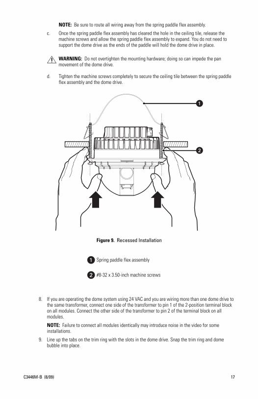
NOTE: Be sure to route all wiring away from the spring paddle flex assembly.
c. Once the spring paddle flex assembly has cleared the hole in the ceiling tile, release the machine screws and allow the spring paddle flex assembly to expand. You do not need to support the dome drive as the ends of the paddle will hold the dome drive in place.
d. Tighten the machine screws completely to secure the ceiling tile between the spring paddle flex assembly and the dome drive.
Figure 9. Recessed Installation
8. If you are operating the dome system using 24 VAC and you are wiring more than one dome drive to the same transformer, connect one side of the transformer to pin 1 of the 2-position terminal block on all modules. Connect the other side of the transformer to pin 2 of the terminal block on all modules.
NOTE: Failure to connect all modules identically may introduce noise in the video for some installations.
9. Line up the tabs on the trim ring with the slots in the dome drive. Snap the trim ring and dome bubble into place.
WARNING: Do not overtighten the mounting hardware; doing so can impede the pan movement of the dome drive.
Spring paddle flex assembly
#8-32 x 3.50-inch machine screws

HARD CEILING1. Remove the spring paddle flex assembly from the surface mount ring.
2. Remove the surface mount ring from the dome drive as follows (refer to Figure 8):
a. Place fingers on the circular marks located on the sides of the surface mount ring.
b. Pinch the sides.
c. Lift and remove the surface mount ring from the dome drive.
3. Attach the spring paddle flex assembly to the dome drive using the two #8-32 x 3.50-inch machine screws (supplied). Thread the screws into the ends of the spring paddle flex assembly so the paddles remain at the end of the screws.
4. Cut a 5-inch diameter hole in the ceiling. You can either use the two holes in the spring paddle flex assembly as a compass tool to mark the 5-inch diameter hole to be cut, or use a 5-inch hole saw.
5. Pull the wiring for power, network, and control through the ceiling.
6. Connect the wiring using one of the following options:
• Plug the network cable into the RJ-45 connector on the side of the dome drive.• If the network has no PoE, connect a 24 VAC Class 2 power supply to the 24 VAC power
connector.
Refer to Figure 10 for wiring connections.
7. If you are operating the dome system using 24 VAC and you are wiring more than one dome drive to the same transformer, connect one side of the transformer to pin 1 of the 2-position terminal block on all modules. Connect the other side of the transformer to pin 2 of the terminal block on all modules.
NOTE: Failure to connect all modules identically may introduce noise in the video for some installations.
8. Attach the dome drive to the ceiling, (refer to Figure 9).
a. Stabilize the spring paddle flex assembly by applying pressure to the machine screws.
b. With the screws stabilized, insert the spring paddle flex assembly and dome drive into the hole in the ceiling. You may need to insert the dome drive at an angel to allow the ends of the paddle to clear the hole.
NOTE: Be sure to route all wiring away from the spring paddle flex assembly.
c. Once the spring paddle flex assembly has cleared the hole in the ceiling, release the machine screws and allow the spring paddle flex assembly to expand. You do not need to support the dome drive as the ends of the paddle will hold the dome drive in place.
d. Tighten the machine screws completely to secure the dome drive to the ceiling.
9. Line up the tabs on the trim ring with the slots in the dome drive. Snap the trim ring and bubble into place.
WARNING: Do not overtighten the mounting hardware; doing so can impede the pan movement of the dome drive.
18 C3446M-B (8/09)
Wiring Tables
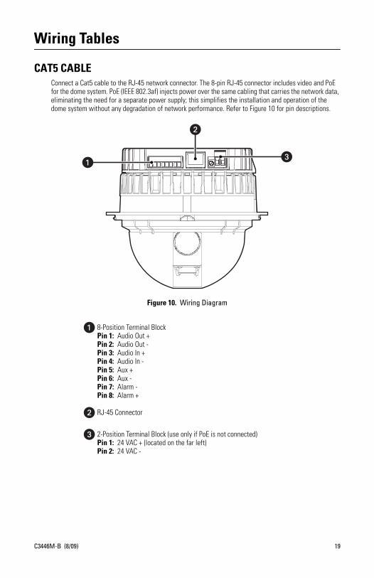
CAT5 CABLE Connect a Cat5 cable to the RJ-45 network connector. The 8-pin RJ-45 connector includes video and PoE for the dome system. PoE (IEEE 802.3af) injects power over the same cabling that carries the network data, eliminating the need for a separate power supply; this simplifies the installation and operation of the dome system without any degradation of network performance. Refer to Figure 10 for pin descriptions.
Figure 10. Wiring Diagram
8-Position Terminal BlockPin 1: Audio Out + Pin 2: Audio Out - Pin 3: Audio In +Pin 4: Audio In -Pin 5: Aux +Pin 6: Aux -Pin 7: Alarm -Pin 8: Alarm +
RJ-45 Connector
2-Position Terminal Block (use only if PoE is not connected)Pin 1: 24 VAC + (located on the far left)Pin 2: 24 VAC -
C3446M-B (8/09) 19
CONNECTING AUDIO
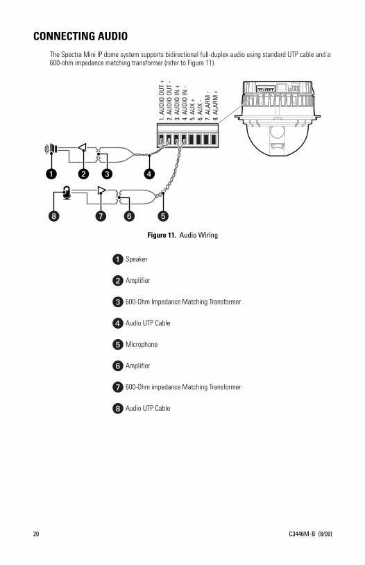
The Spectra Mini IP dome system supports bidirectional full-duplex audio using standard UTP cable and a 600-ohm impedance matching transformer (refer to Figure 11).
Figure 11. Audio Wiring
Speaker
Amplifier
600-Ohm Impedance Matching Transformer
Audio UTP Cable
Microphone
Amplifier
600-Ohm impedance Matching Transformer
Audio UTP Cable
1. A
UDIO
OUT
+2.
AUD
IO O
UT -
3. A
UDIO
IN +
4. A
UDIO
IN -
5. A
UX +
6. A
UX -
7. A
LARM
-8.
ALA
RM +
1. A
UDIO
OUT
+2.
AUD
IO O
UT -
3. A
UDIO
IN +
4. A
UDIO
IN -
5. A
UX +
6. A
UX -
7. A
LARM
-8.
ALA
RM +
20 C3446M-B (8/09)

CONNECTING 24 VAC POWER (OPTIONAL)If PoE is not used, the camera includes a 24 VAC power connector. Connect the power cable to the 2-pin power connector on the back of the camera using the terminal block connector (provided). Refer to Recommended Wire Gauge and Wiring Distances on page 21.
The power supply connector is shown in Figure 6. Use only a Class 2 isolated power supply. Refer to Specifications on page 28 for power consumption.
The following are the recommended maximum distances for 24 VAC applications and are calculated with a 10 percent voltage drop. (Ten percent is generally the maximum allowable voltage drop for AC-powered devices.)
NOTE: Power consumption is 18 VA per unit. Use a power source with a minimum of 18 VA per unit.
CONNECTING A RELAY DEVICEThe Spectra Mini IP dome system has an output for triggering an external device. It supports both momentary and continuous relay operation.
You can operate the relay interactively, during an active connection, or automatically to coincide with certain events. Typical applications include activating a door, gate or lock, or switching on lights or other electrical devices.
Figure 12 shows how to wire the relay with its power source to the Spectra Mini IP.
Figure 12. Relay Wiring Example
Table B. Recommended Wire Gauge and Wiring Distances
VoltageWire Gauge
18(1.0 mm2)
16(1.5 mm2)
14(2.5 mm2)
12(3.5 mm2)
24 VAC 215 ft(97 m)
341 ft(154 m)
542 ft(245 m)
863 ft(391 m)
WARNINGS:• Do not exceed the maximum rating of 12 VDC, 0.15 A.• The green/white wire is internally connected to the dome chassis. Any connected signaling
device should be left floating with respect to the dome chassis, otherwise damage may result.
Aux -
Aux +
+_
DC
C3446M-B (8/09) 21

CONNECTING ALARMSThe Spectra Mini IP provides an alarm input for external signaling devices, such as door contacts or motion detectors. Both normally open and normally closed devices are supported.
SUPERVISED ALARMSWhen an alarm is configured as a supervised alarm, Spectra Mini IP maintains a constant electrical current through the alarm circuit (3.3 VDC, 1 kohm). If the alarm circuit length changes, due to an electrical short or a bypass, the voltage fluctuates from its normal state. Therefore, the unit triggers an alarm.
NOTE: Install the 1-kohm resistor as close to the switch as possible.
Figure 13 shows the alarm and no alarm conditions of a supervised alarm input. Whether the alarm is normally closed or normally open, neither a cut nor a bypass can defeat these alarms.
Figure 13 and Figure 14 illustrate the wiring configuration for supervised alarm inputs.
Figure 13. Supervised Alarm Conditions
Figure 14. Normally Closed Supervised Alarm Input Wiring
Figure 15. Normally Open Supervised Alarm Input Wiring
NORMALLY OPENNORMALLY CLOSED
ALARMGND
+V
+V
ALARMGND +V
+VALARM
GND
CUT
NO ALARMNO ALARMGND
ALARMGND
+V
+V
+V
+VALARM
GND
BYPASS
CUT
BYPASS
GND
ALARMGND
1 K
1 K
1 K
1 K
1 K
1 K
1 K
1 K
1 K
1 K
22 C3446M-B (8/09)
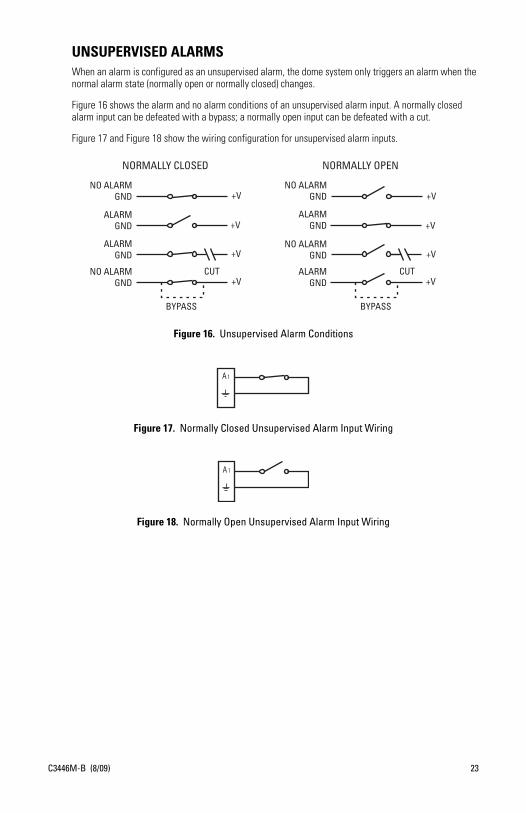
UNSUPERVISED ALARMSWhen an alarm is configured as an unsupervised alarm, the dome system only triggers an alarm when the normal alarm state (normally open or normally closed) changes.
Figure 16 shows the alarm and no alarm conditions of an unsupervised alarm input. A normally closed alarm input can be defeated with a bypass; a normally open input can be defeated with a cut.
Figure 17 and Figure 18 show the wiring configuration for unsupervised alarm inputs.
Figure 16. Unsupervised Alarm Conditions
Figure 17. Normally Closed Unsupervised Alarm Input Wiring
Figure 18. Normally Open Unsupervised Alarm Input Wiring
NORMALLY OPENNORMALLY CLOSED
ALARMGND
+V
+V
ALARMGND +V
+VNO ALARM
GND
ALARMGND
+V
+V
+VNO ALARM
GND
CUT
BYPASS
CUT
NO ALARMGND
NO ALARMGND
+V
BYPASS
ALARMGND
C3446M-B (8/09) 23
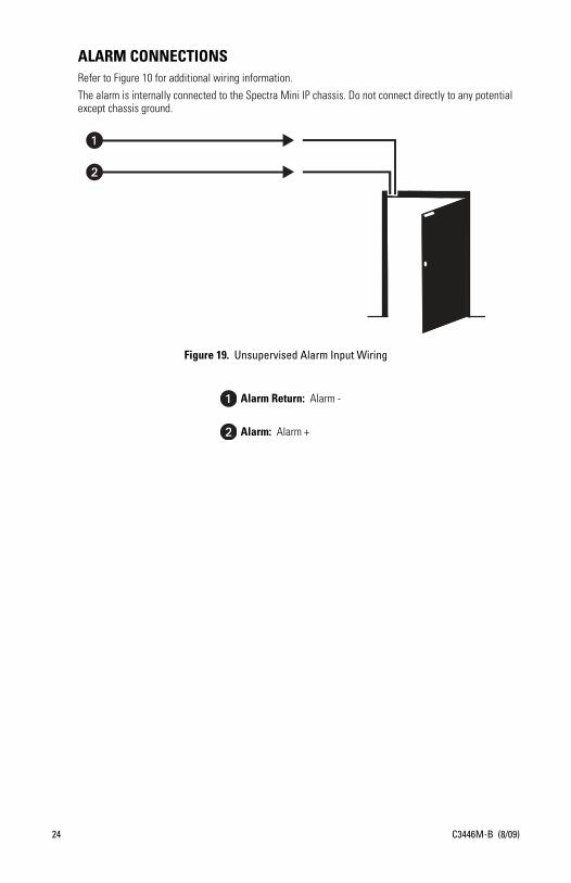
ALARM CONNECTIONSRefer to Figure 10 for additional wiring information.
The alarm is internally connected to the Spectra Mini IP chassis. Do not connect directly to any potential except chassis ground.
Figure 19. Unsupervised Alarm Input Wiring
Alarm Return: Alarm -
Alarm: Alarm +
24 C3446M-B (8/09)
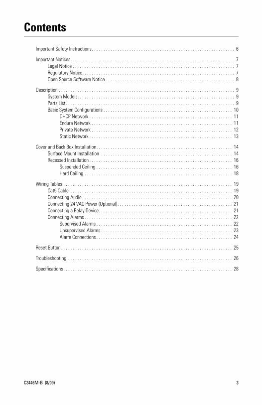
Reset Button
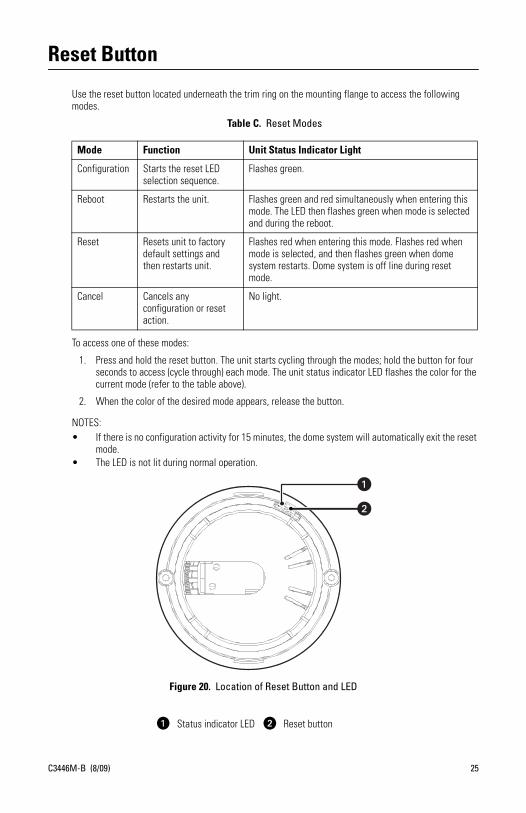
Use the reset button located underneath the trim ring on the mounting flange to access the following modes.
To access one of these modes:
1. Press and hold the reset button. The unit starts cycling through the modes; hold the button for four seconds to access (cycle through) each mode. The unit status indicator LED flashes the color for the current mode (refer to the table above).
2. When the color of the desired mode appears, release the button.
NOTES:• If there is no configuration activity for 15 minutes, the dome system will automatically exit the reset
mode.• The LED is not lit during normal operation.
Figure 20. Location of Reset Button and LED
Table C. Reset Modes
Mode Function Unit Status Indicator Light
Configuration Starts the reset LED selection sequence.
Flashes green.
Reboot Restarts the unit. Flashes green and red simultaneously when entering this mode. The LED then flashes green when mode is selected and during the reboot.
Reset Resets unit to factory default settings and then restarts unit.
Flashes red when entering this mode. Flashes red when mode is selected, and then flashes green when dome system restarts. Dome system is off line during reset mode.
Cancel Cancels any configuration or reset action.
No light.
ì Status indicator LED î Reset button
C3446M-B (8/09) 25
Troubleshooting
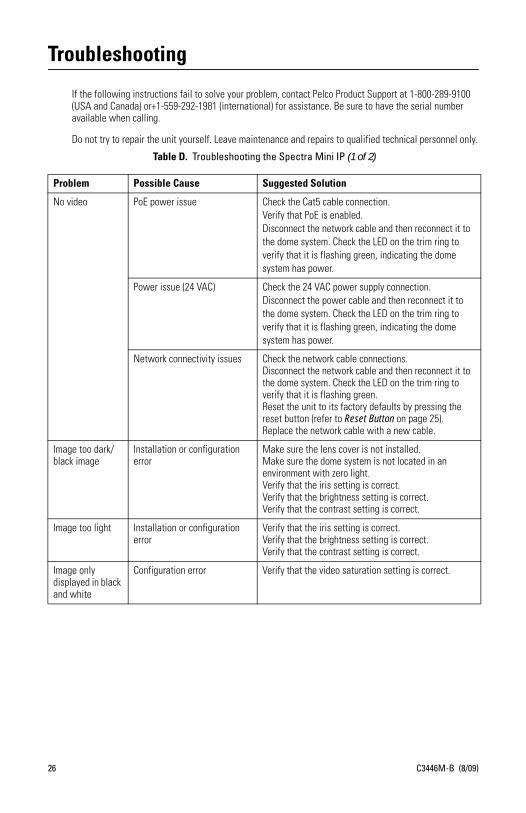
If the following instructions fail to solve your problem, contact Pelco Product Support at 1-800-289-9100 (USA and Canada) or+1-559-292-1981 (international) for assistance. Be sure to have the serial number available when calling.
Do not try to repair the unit yourself. Leave maintenance and repairs to qualified technical personnel only.
Table D. Troubleshooting the Spectra Mini IP (1 of 2)
Problem Possible Cause Suggested Solution
No video PoE power issue Check the Cat5 cable connection.Verify that PoE is enabled.Disconnect the network cable and then reconnect it to the dome system. Check the LED on the trim ring to verify that it is flashing green, indicating the dome system has power.
Power issue (24 VAC) Check the 24 VAC power supply connection.Disconnect the power cable and then reconnect it to the dome system. Check the LED on the trim ring to verify that it is flashing green, indicating the dome system has power.
Network connectivity issues Check the network cable connections.Disconnect the network cable and then reconnect it to the dome system. Check the LED on the trim ring to verify that it is flashing green.Reset the unit to its factory defaults by pressing the reset button (refer to Reset Button on page 25).Replace the network cable with a new cable.
Image too dark/black image
Installation or configuration error
Make sure the lens cover is not installed.Make sure the dome system is not located in an environment with zero light.Verify that the iris setting is correct.Verify that the brightness setting is correct.Verify that the contrast setting is correct.
Image too light Installation or configuration error
Verify that the iris setting is correct.Verify that the brightness setting is correct.Verify that the contrast setting is correct.
Image only displayed in black and white
Configuration error Verify that the video saturation setting is correct.
26 C3446M-B (8/09)

Dome system not discovered
No dome system power Verify that the dome system is powered correctly with PoE or with 24 VAC. Confirm the power consumption using either the Web interface of the PoE-capable switch or using the blinking green LED during the dome system power-up.
Network conflict Verify that the dome system is physically connected to the same network as the PC running the Pelco Device Utility. The Device Utility will not work on a network that blocks multicast traffic.Confirm that the green LED blinks when power is applied to the dome system, indicating network connectivity.
Network not working
Faulty cable connection Check all cable connections and ensure that all plugs are properly connected to a power source.
Incorrect network device configuration
A hub will not work with the available network bandwidth shared across all ports. Use a Fast Ethernet switch, Gigabit Ethernet switch, or a cable modem router with an n-Port switch.
Network connectivity issues Contact your network administrator.
Audio signal is weak
Incorrect type of transformer Be sure you are using a 600-ohm impedance matching transformer.
Wiring distance connecting the audio equipment may be too long
Test the equipment using a shorter wiring distance.
Gain is not properly adjusted If you are using an external amplifier and it has an adjustable gain, increase the gain until the signal is acceptable.
Echoes when audio is received
Speaker volume is too high Lower the speaker volume.
Microphone and speaker are too close
If your call station does not have built-in echo cancellation, move the microphone and speaker farther apart.
Call station does not have built-in echo cancellation
Use a call station with built-in echo cancellation.
Table D. Troubleshooting the Spectra Mini IP (2 of 2)
Problem Possible Cause Suggested Solution
C3446M-B (8/09) 27
Specifications
MECHANICALPan Movement 360° continuous pan rotation
Vertical Tilt Unobstructed +2° to -92°
Manual Pan/Tilt SpeedsPan 0.4° to 80°/sec manual operation, 100°/sec turboTilt 0.7° to 40°/sec manual operation
Preset SpeedsPan 140°/secTilt 80°/sec
For variable speed operation an appropriate controller is required.
ELECTRICALInput Voltage/Amps 18 to 30 VAC, 24 VAC; 0.75 A, 50/60 Hz nominal
Input Power 18 VA nominal
PoE IEEE 802.3af Class 3
AUDIOStreaming Bidirectional: full or half duplex
Input/Output Terminal block, analog for microphone and speaker; 600-ohm differential; 1 Vp-p maximum signal level
Compression G.711 PCM 8 bit, 8 kHz mono at 64 kbit/s
GENERALConstruction
Top Cap Alodined cast aluminumTrim Ring andSurface Mount Ring ABS plasticBubble Acrylic
Finish White or black
Light AttenuationSmoked f/0.5 light lossClear Zero light loss
Cable Entry Single RJ-45 connectorAlarm and audio connector
Environment Indoor
Operating Temperature 32° to 122°F (0° to 50°)
Weight 1.88 lb (0.85 kg)
28 C3446M-B (8/09)
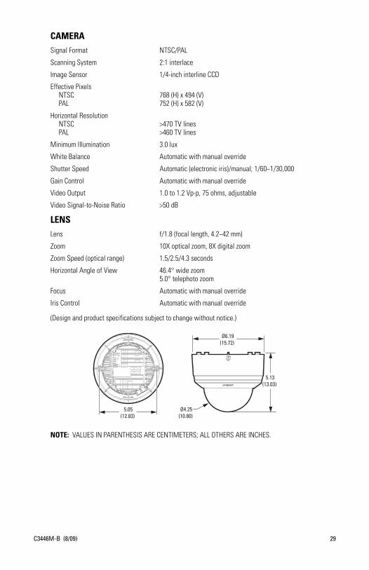
CAMERASignal Format NTSC/PAL
Scanning System 2:1 interlace
Image Sensor 1/4-inch interline CCD
Effective PixelsNTSC 768 (H) x 494 (V)PAL 752 (H) x 582 (V)
Horizontal ResolutionNTSC >470 TV linesPAL >460 TV lines
Minimum Illumination 3.0 lux
White Balance Automatic with manual override
Shutter Speed Automatic (electronic iris)/manual; 1/60~1/30,000
Gain Control Automatic with manual override
Video Output 1.0 to 1.2 Vp-p, 75 ohms, adjustable
Video Signal-to-Noise Ratio >50 dB
LENSLens f/1.8 (focal length, 4.2~42 mm)
Zoom 10X optical zoom, 8X digital zoom
Zoom Speed (optical range) 1.5/2.5/4.3 seconds
Horizontal Angle of View 46.4° wide zoom5.0° telephoto zoom
Focus Automatic with manual override
Iris Control Automatic with manual override
(Design and product specifications subject to change without notice.)
NOTE: VALUES IN PARENTHESIS ARE CENTIMETERS; ALL OTHERS ARE INCHES.
Ø6.19(15.72)
5.13(13.03)
Ø4.25(10.80)
5.05(12.83)
C3446M-B (8/09) 29

WARNING: This product is sensitive to Electrostatic Discharge (ESD). To avoid ESD damage to this product, use ESD safe practices during installation. Before touching, adjusting or handling this product, correctly attach an ESD wrist strap to your wrist and appropriately discharge your body and tools. For more information about ESD control and safe handling practices of electronics, please refer to ANSI/ESD S20.20-1999 or contact the Electrostatic Discharge Association (www.esda.org).
The materials used in the manufacture of this document and its components are compliant to the requirements of Directive 2002/95/EC.
This equipment contains electrical or electronic components that must be recycled properly to comply with Directive 2002/96/EC of the European Union regarding the disposal of waste electrical and electronic equipment (WEEE). Contact your local dealer for procedures for recycling this equipment.
REVISION HISTORYManual # Date CommentsC3446M 7/08 Original version.C3446M-A 11/08 Added line-in audio information per CN21957.C3446M-B 8/09 Added bidirectional full-duplex audio information per CN23055.
Pelco, the Pelco logo, Camclosure, Digital Sentry, Endura, Esprit, ExSite, Genex, Intelli-M, Legacy, and Spectra are registered trademarks of Pelco, Inc.Spectra III is a trademark of Pelco, Inc.DLP is a registered trademark of Texas Instruments Incorporated.All product names and services identified throughout this document are trademarks or registered trademarks of their respective companies. The absence of a trademark or registered trademark from this document does not constitute a waiver of intellectual property rights.© Copyright 2009, Pelco, Inc. All rights reserved.
30 C3446M-B (8/09)
PRODUCT WARRANTY AND RETURN INFORMATION
WARRANTYPelco will repair or replace, without charge, any merchandise proved defective in material or workmanship for a period of one year after the date ofshipment.
Exceptions to this warranty are as noted below:
• Five years:– Fiber optic products– TW3000 Series unshielded twisted pair (UTP) transmission products– CC3701H-2, CC3701H-2X, CC3751H-2, CC3651H-2X, MC3651H-2, and MC3651H-2X camera models
• Three years:– Pelco-branded fixed camera models (CCC1390H Series, C10DN Series, C10CH Series, IP3701H Series, and IX Series)– EH1500 Series enclosures– Spectra® IV products (including Spectra IV IP)– Camclosure® Series (IS, ICS, IP) integrated camera systems– DX Series digital video recorders, DVR5100 Series digital video recorders, Digital Sentry® Series hardware products, DVX Series digital video
recorders, and NVR300 Series network video recorders– Endura® Series distributed network-based video products– Genex® Series products (multiplexers, server, and keyboard)– PMCL200/300/400 Series LCD monitors
• Two years:– Standard varifocal, fixed focal, and motorized zoom lenses.– DF5/DF8 Series fixed dome products– Legacy® Series integrated positioning systems– Spectra III™, Spectra Mini, Spectra Mini IP, Esprit®, ExSite®, and PS20 scanners, including when used in continuous motion applications.– Esprit Ti and TI2500 Series thermal imaging products– Esprit and WW5700 Series window wiper (excluding wiper blades).– CM6700/CM6800/CM9700 Series matrix– Digital Light Processing (DLP®) displays (except lamp and color wheel). The lamp and color wheel will be covered for a period of 90 days.
The air filter is not covered under warranty.– Intelli-M® eIDC controllers
• One year:– Video cassette recorders (VCRs), except video heads. Video heads will be covered for a period of six months.
• Six months:– All pan and tilts, scanners, or preset lenses used in continuous motion applications (preset scan, tour, and auto scan modes).
Pelco will warrant all replacement parts and repairs for 90 days from the date of Pelco shipment. All goods requiring warranty repair shall be sentfreight prepaid to a Pelco designated location. Repairs made necessary by reason of misuse, alteration, normal wear, or accident are not covered underthis warranty.
Pelco assumes no risk and shall be subject to no liability for damages or loss resulting from the specific use or application made of the Products.Pelco’s liability for any claim, whether based on breach of contract, negligence, infringement of any rights of any party or product liability, relating tothe Products shall not exceed the price paid by the Dealer to Pelco for such Products. In no event will Pelco be liable for any special, incidental, orconsequential damages (including loss of use, loss of profit, and claims of third parties) however caused, whether by the negligence of Pelco orotherwise.
The above warranty provides the Dealer with specific legal rights. The Dealer may also have additional rights, which are subject to variation from stateto state.
If a warranty repair is required, the Dealer must contact Pelco at (800) 289-9100 or (559) 292-1981 to obtain a Repair Authorization number (RA), andprovide the following information:
1. Model and serial number2. Date of shipment, P.O. number, sales order number, or Pelco invoice number3. Details of the defect or problem
If there is a dispute regarding the warranty of a product that does not fall under the warranty conditions stated above, please include a writtenexplanation with the product when returned.
Method of return shipment shall be the same or equal to the method by which the item was received by Pelco.
RETURNSTo expedite parts returned for repair or credit, please call Pelco at (800) 289-9100 or (559) 292-1981 to obtain an authorization number (CA number ifreturned for credit, and RA number if returned for repair) and designated return location.
All merchandise returned for credit may be subject to a 20 percent restocking and refurbishing charge.
Goods returned for repair or credit should be clearly identified with the assigned CA or RA number and freight should be prepaid 12-23-08

Pelco, Inc. Worldwide Headquarters 3500 Pelco Way Clovis, California 93612 USAUSA & Canada Tel (800) 289-9100 Fax (800) 289-9150
International Tel +1 (559) 292-1981 Fax +1 (559) 348-1120
www.pelco.com