Embed Size (px)
Citation preview

Specifying Irrigation Pump Stations
Today: How to Size and Specify Suction Lift Pumps
Tony AdamsonRain Bird Pump Sales & Marketing Manager
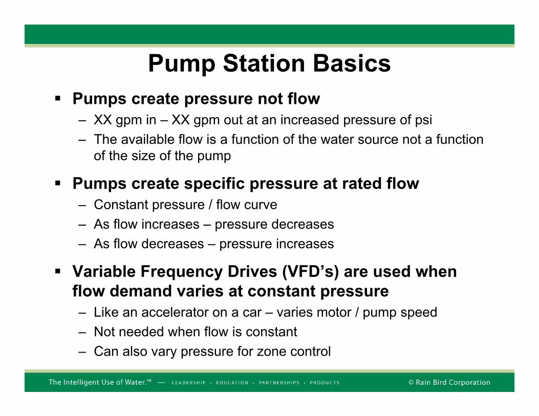
Pump Station BasicsPumps create pressure not flow– XX gpm in – XX gpm out at an increased pressure of psi– The available flow is a function of the water source not a function
of the size of the pump
Pumps create specific pressure at rated flow– Constant pressure / flow curve– As flow increases – pressure decreases– As flow decreases – pressure increases
Variable Frequency Drives (VFD’s) are used when flow demand varies at constant pressure – Like an accelerator on a car – varies motor / pump speed– Not needed when flow is constant– Can also vary pressure for zone control
How to Size and Specify Pumps for
Suction Lift Applications

Suction Lift Application
8’
Suction piping friction loss = 3’Atmospheric pressure14.2 PSIA (1,000’ elev.)
• Atmospheric pressure = 32.8’ (14.2 X 2.31)• Elevation of source = -8’ (below pump)• Suction plumbing friction loss = 3’
• NPSHA = 32.8’ – 8’ – 3’ = 21.8’
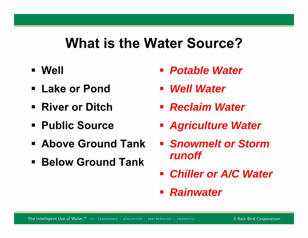
What is the Water Source?
WellLake or PondRiver or DitchPublic SourceAbove Ground TankBelow Ground Tank
Potable WaterWell WaterReclaim WaterAgriculture WaterSnowmelt or Storm runoffChiller or A/C WaterRainwater
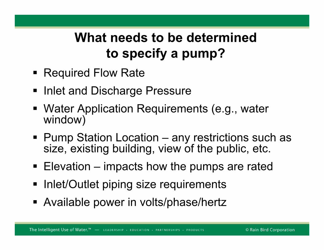
What needs to be determined to specify a pump?
Required Flow RateInlet and Discharge PressureWater Application Requirements (e.g., water window)Pump Station Location – any restrictions such as size, existing building, view of the public, etc.Elevation – impacts how the pumps are ratedInlet/Outlet piping size requirementsAvailable power in volts/phase/hertz
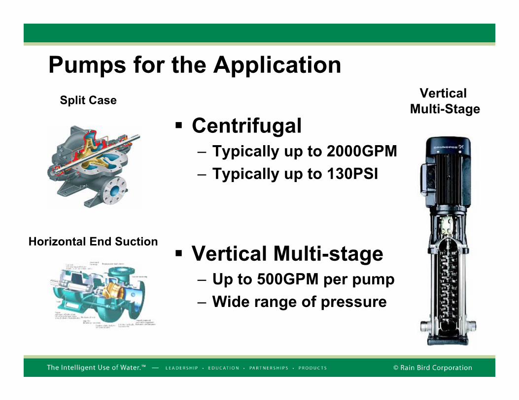
Pumps for the Application
Centrifugal– Typically up to 2000GPM– Typically up to 130PSI
Vertical Multi-stage– Up to 500GPM per pump – Wide range of pressure
Vertical Multi-Stage
Split Case
Horizontal End Suction

Vertical Turbine
Submersible Turbine
Pumps for the Application
Pump Motor
Location
Pump Motor
Location
• Vertical Turbine• Typically up to 1000GPM per pump• Wide range of pressure• Motor on top
• Submersible Turbine• Typically up to 600GPM per pump • Wide range of pressure• Motor on bottom

Key Numbers and Units
You get 100GPM @ 120PSI for every 10HP– 60HP pump delivers 600GPM @ 120PSI– 75HP pump delivers 750GPM @ 120PSI– If pressure ↓, flow ↑
100PSI = 231FT– The discharge of a pump is usually stated in Feet– The discharge of a pump station is usually stated in PSI
Friction Loss (Schedule 40 Steel Pipe) – 1000GPM in a 10” pipe suffers 5FT head loss per
1000FT of pipe
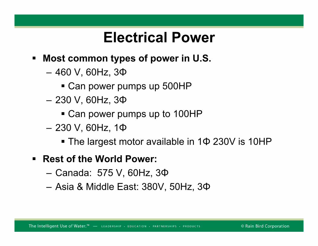
Electrical PowerMost common types of power in U.S.– 460 V, 60Hz, 3Φ
Can power pumps up 500HP– 230 V, 60Hz, 3Φ
Can power pumps up to 100HP– 230 V, 60Hz, 1Φ
The largest motor available in 1Φ 230V is 10HP
Rest of the World Power:– Canada: 575 V, 60Hz, 3Φ– Asia & Middle East: 380V, 50Hz, 3Φ
Hydraulic Design - Pump Curves

The Pump CurveBowl Power
Bowl Efficiency
NPSHr
BEP(Best Efficiency Point)
The Pump Curve
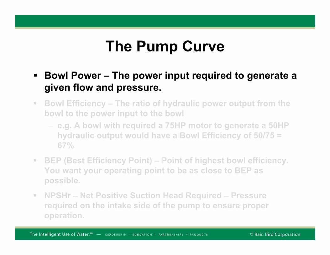
Bowl Power – The power input required to generate a given flow and pressure.Bowl Efficiency – The ratio of hydraulic power output from the bowl to the power input to the bowl– e.g. A bowl with required a 75HP motor to generate a 50HP
hydraulic output would have a Bowl Efficiency of 50/75 = 67%
BEP (Best Efficiency Point) – Point of highest bowl efficiency. You want your operating point to be as close to BEP as possible.
NPSHr – Net Positive Suction Head Required – Pressure required on the intake side of the pump to ensure proper operation.
The Pump Curve
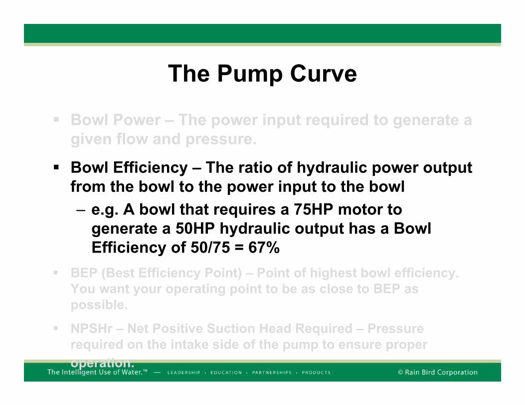
Bowl Power – The power input required to generate a given flow and pressure.
Bowl Efficiency – The ratio of hydraulic power output from the bowl to the power input to the bowl– e.g. A bowl that requires a 75HP motor to
generate a 50HP hydraulic output has a Bowl Efficiency of 50/75 = 67%
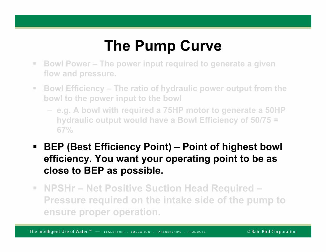
BEP (Best Efficiency Point) – Point of highest bowl efficiency. You want your operating point to be as close to BEP as possible.
NPSHr – Net Positive Suction Head Required – Pressure required on the intake side of the pump to ensure proper operation.
The Pump CurveBowl Power – The power input required to generate a given flow and pressure.
Bowl Efficiency – The ratio of hydraulic power output from the bowl to the power input to the bowl– e.g. A bowl with required a 75HP motor to generate a 50HP
hydraulic output would have a Bowl Efficiency of 50/75 = 67%
BEP (Best Efficiency Point) – Point of highest bowl efficiency. You want your operating point to be as close to BEP as possible.
NPSHr – Net Positive Suction Head Required –Pressure required on the intake side of the pump to ensure proper operation.

The Pump CurveBowl Power – The power input required to generate a given flow and pressure.
Bowl Efficiency – The ratio of hydraulic power output from the bowl to the power input to the bowl– e.g. A bowl with required a 75HP motor to generate a 50HP
hydraulic output would have a Bowl Efficiency of 50/75 = 67%
BEP (Best Efficiency Point) – Point of highest bowl efficiency. You want your operating point to be as close to BEP as possible.
NPSHr – Net Positive Suction Head Required –Pressure required on the intake side of the pump to ensure proper operation. Remember: Pumps don’t suck!
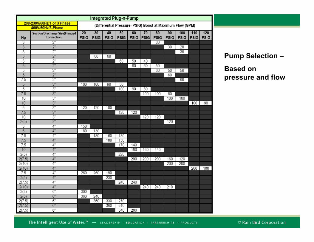
Pump Selection –
Based on pressure and flow


Electrical Calculations
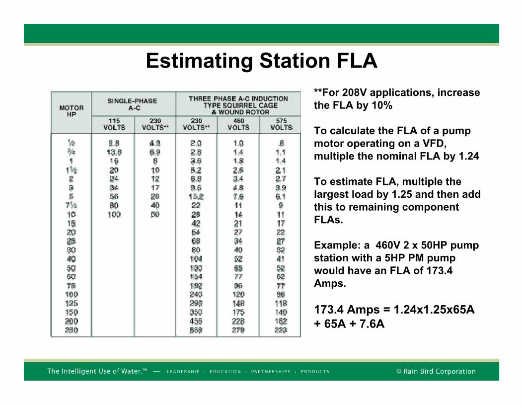
Estimating Station FLA**For 208V applications, increase the FLA by 10%
To calculate the FLA of a pump motor operating on a VFD, multiple the nominal FLA by 1.24
To estimate FLA, multiple the largest load by 1.25 and then add this to remaining component FLAs.
Example: a 460V 2 x 50HP pump station with a 5HP PM pump would have an FLA of 173.4 Amps.
173.4 Amps = 1.24x1.25x65A + 65A + 7.6A

Surge Protection. Helps protect the
pump station against transients associated
with power disturbances.
Through-Door Mail Electrical Disconnect. Shuts off power to the electrical panel if the panel door is opened.
Step-down Transformer.
Provides 120V single phase control power.
Optional 7.5KVA Step Down Transformer. Provides additional
120V power.
Other Electrical Panel Components

Specifying a Suction Lift StationA sports complex cannot obtain the permits to build a wet-well for a proposed vertical turbine station or a vault for a floodedsuction station. The site’s only option is to purchase and install a Suction Lift Pump Station.
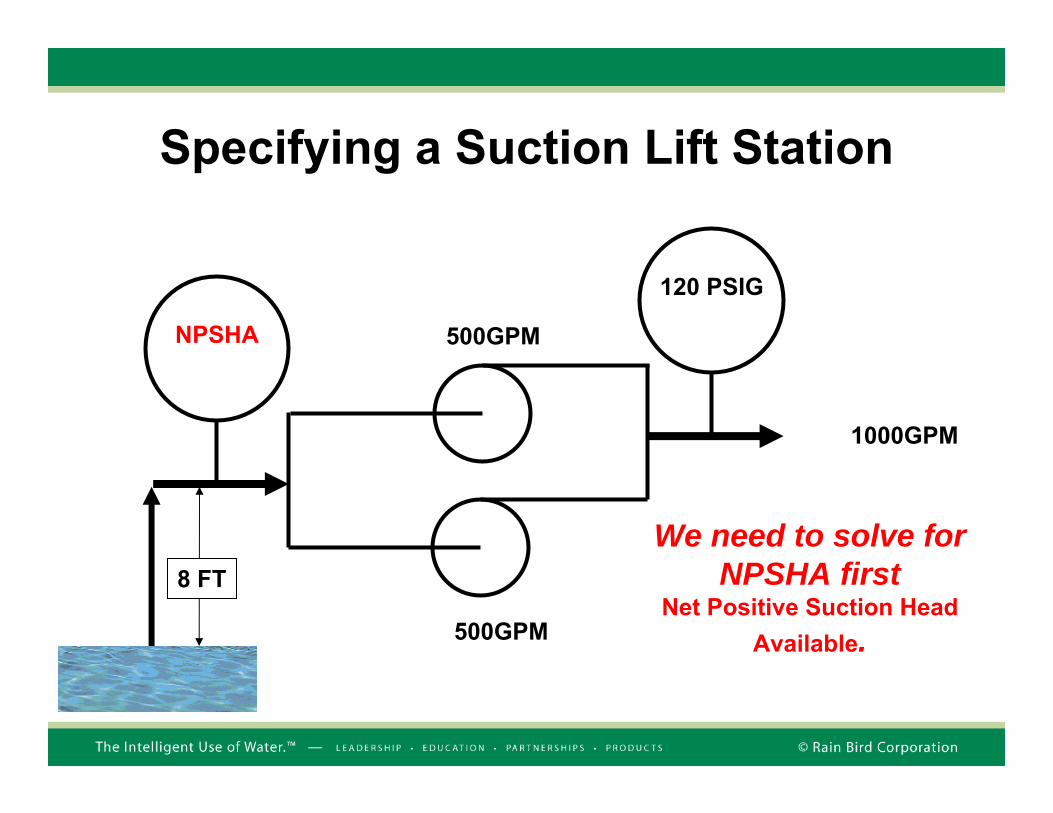
The sports complex requires 1000GPM at 120PSI.
The vertical distance between the surface of the irrigation pondand the centerline of the proposed pump station intake pipe is 8FT (Suction lift is best used for under 15FT).
The altitude at the site is 700FT.
Available power is 460V, 3Φ
Specifying a Suction Lift Station
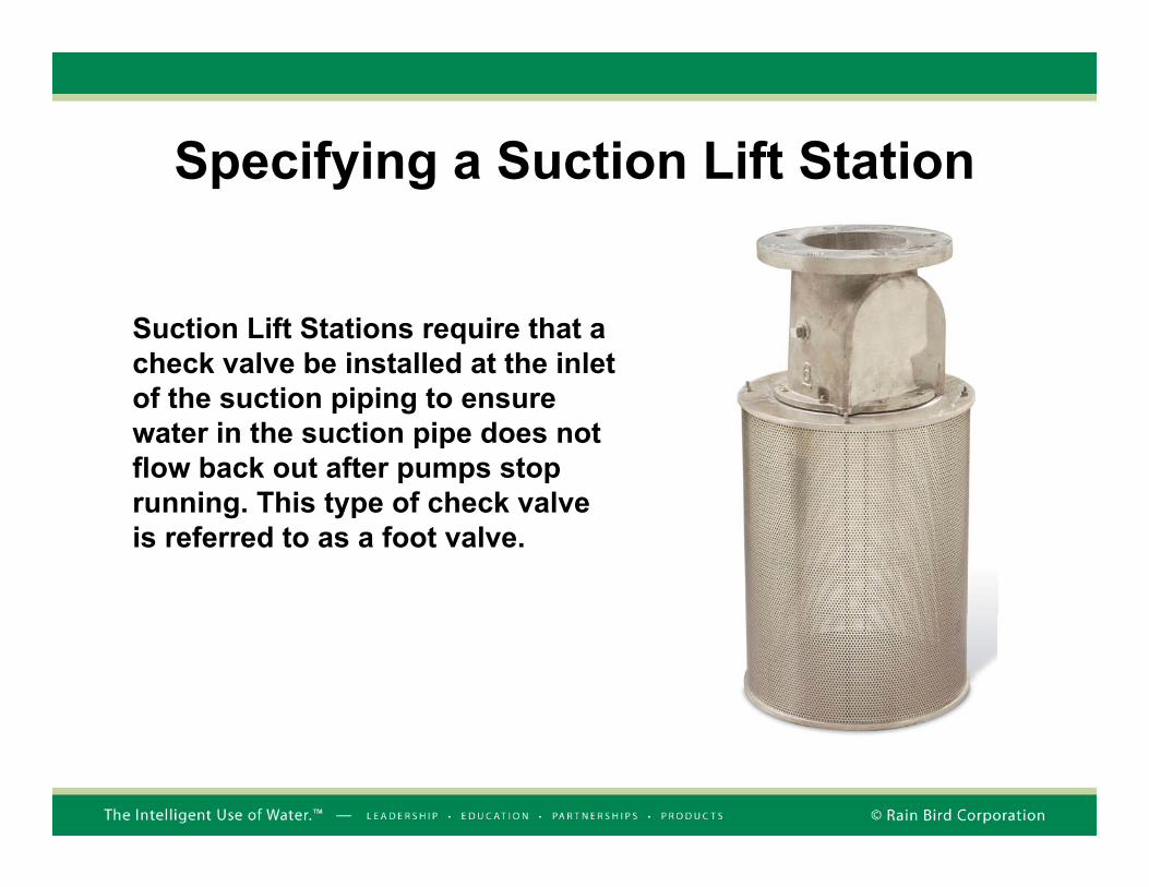
Suction Lift Stations require that a check valve be installed at the inlet of the suction piping to ensure water in the suction pipe does not flow back out after pumps stop running. This type of check valve is referred to as a foot valve.
500GPM
500GPM
1000GPM
NPSHA
120 PSIG
Specifying a Suction Lift Station
We need to solve for NPSHA first
Net Positive Suction Head Available.
8 FT

Calculating NPSHAH = The vertical distance between the surface of the irrigation pond and the center-line of the pump station intake pipe.
L = Friction loss in the suction pipe.(Assume 5FT for this problem)
A = Site Altitude (700FT in this problem.
Atmospheric Pressure
H = 8FTL = 5FT
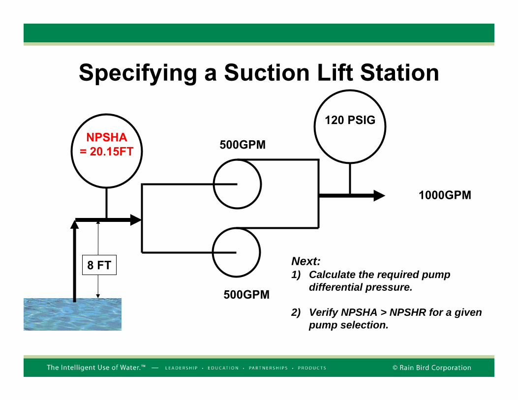
NPSHA = [2.31 x (14.7 – (0.0005 x A))] – H – L = [2.31 x (14.7 – 0.35)] – 8 – 5= [2.31 x 14.35] – 8 – 5= 20.15FT
500GPM
500GPM
1000GPM
NPSHA= 20.15FT
120 PSIG
Specifying a Suction Lift Station
8 FT Next:1) Calculate the required pump
differential pressure.
2) Verify NPSHA > NPSHR for a given pump selection.

Specifying a Suction Lift StationRequired Differential Pressure = 120PSIG –20.14FT
120PSIG + 14.7PSIG = 134.7PSI (2.31) = 312.16FT
Required Differential Pressure = 312.16FT (Discharge) – 20.14FT(Inlet) = 292FT
Add 10PSI to account for station losses 10PSI = 23.1FT
Total = 292FT + 23.1FT = 315FT

500GPM at 315FT
500GPM at 315FT
1000GPM
NPSHA= 20.15FT
120 PSIG
Specifying a Suction Lift Station
8 FT We built 10PSI of station loss into our calculation.

Verify NPSHA > NPSHR
NPSHA = 20.14FT
NPSHR = 11FT
Horizontal End Suction – 60 HP 75% Efficient
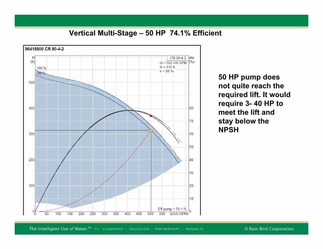
Vertical Multi-Stage – 50 HP 74.1% Efficient
50 HP pump does not quite reach the required lift. It would require 3- 40 HP to meet the lift and stay below the NPSH

Vertical Multi-Stage – 50 HP 74.1% Efficient
At pump run out, the NPSH would exceed the 20 psi maximum
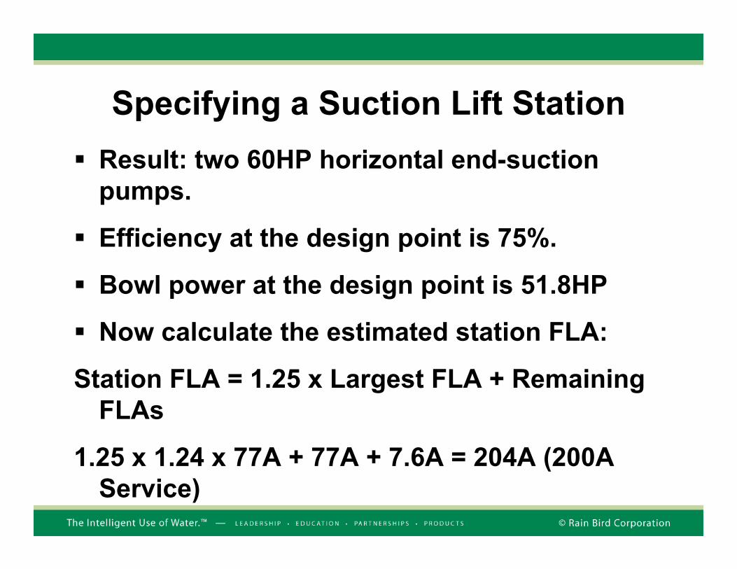
Result: two 60HP horizontal end-suction pumps.
Efficiency at the design point is 75%.
Bowl power at the design point is 51.8HP
Now calculate the estimated station FLA:
Station FLA = 1.25 x Largest FLA + Remaining FLAs
1.25 x 1.24 x 77A + 77A + 7.6A = 204A (200A Service)
Specifying a Suction Lift Station

Suction Lift ProblemsLoss of PrimeThe pressure in the suction line is less than atmospheric pressure. A leaking foot valve or suction pipe can allow air to leak into the suction line. Air then replaces water at the inlet to the pump. This is referred to as a Loss of Prime. Pumps cannot pump air, so the pump just spins, performing zero hydraulic work.
Air

Self-Cleaning Suction Lift Kits
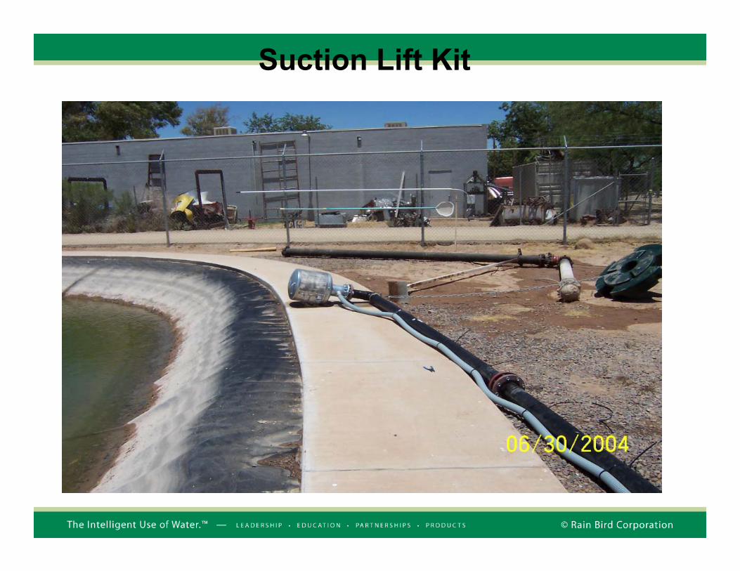
Suction Lift Kit

Suction Lift Kit

Suction Lift Station

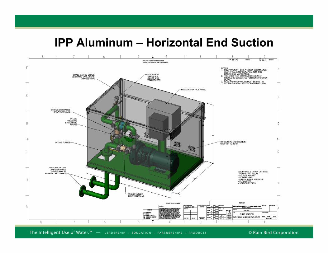
IPP Aluminum – Horizontal End Suction
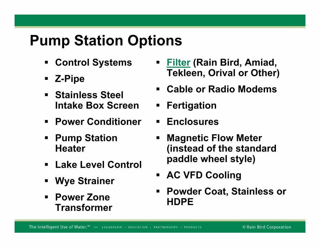
Pump Station OptionsControl SystemsZ-PipeStainless Steel Intake Box ScreenPower ConditionerPump Station HeaterLake Level Control Wye StrainerPower Zone Transformer
Filter (Rain Bird, Amiad, Tekleen, Orival or Other)Cable or Radio ModemsFertigationEnclosuresMagnetic Flow Meter (instead of the standard paddle wheel style)AC VFD CoolingPowder Coat, Stainless or HDPE
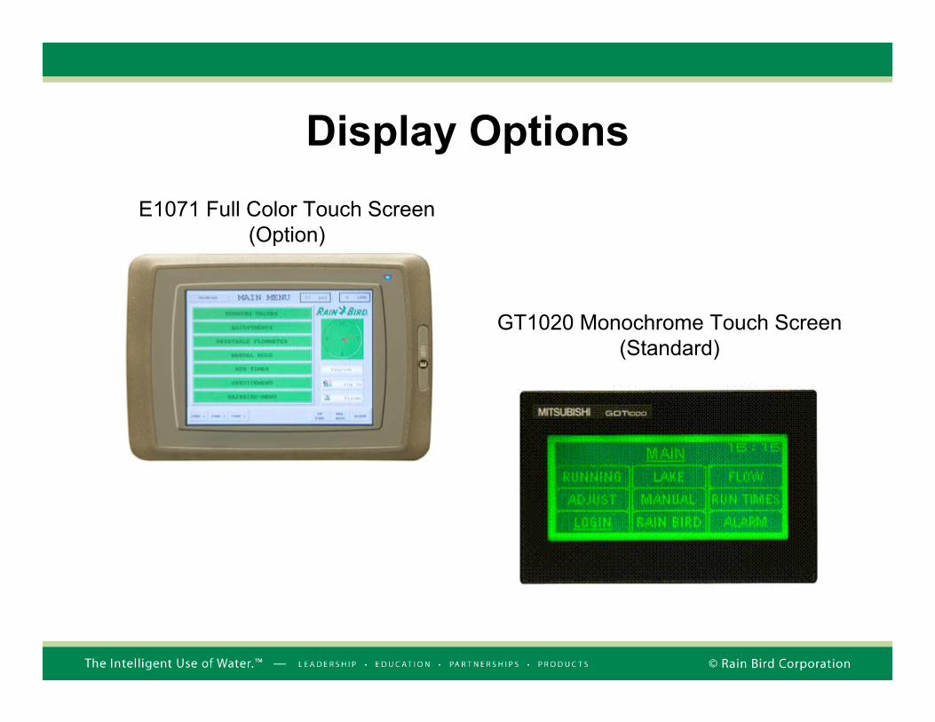
Display Options
GT1020 Monochrome Touch Screen (Standard)
E1071 Full Color Touch Screen (Option)
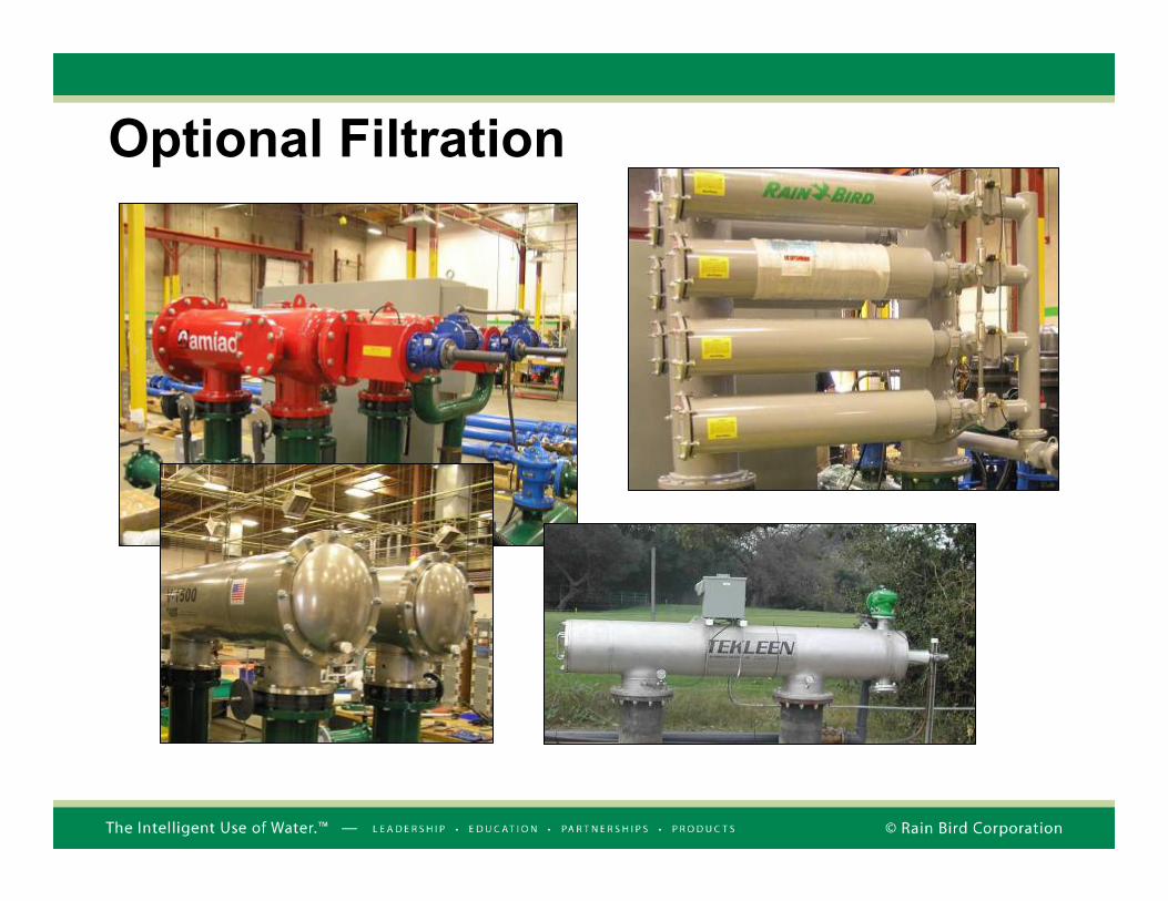
Optional Filtration
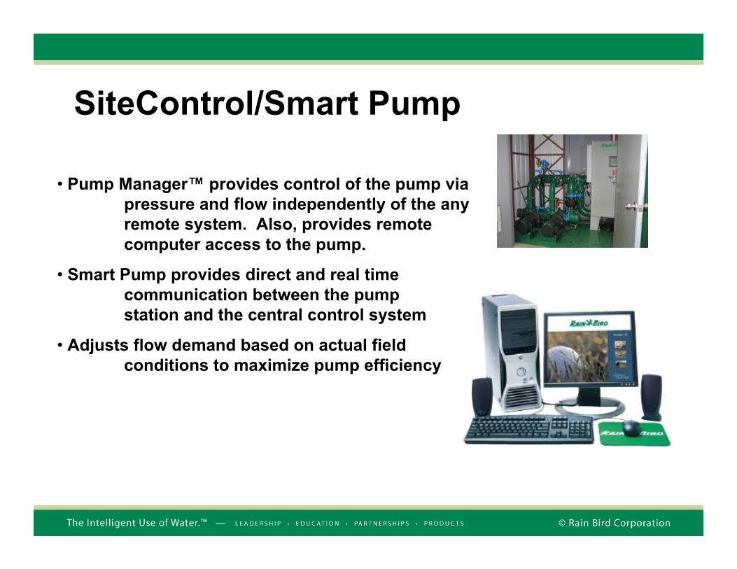
SiteControl/Smart Pump
• Pump Manager™ provides control of the pump via pressure and flow independently of the any remote system. Also, provides remote computer access to the pump.
• Smart Pump provides direct and real time communication between the pump station and the central control system
• Adjusts flow demand based on actual field conditions to maximize pump efficiency
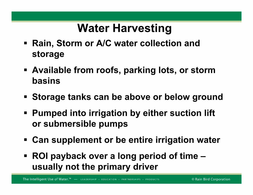
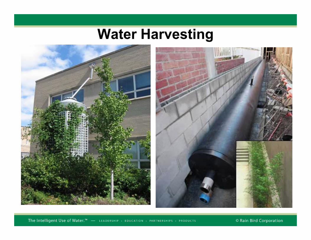
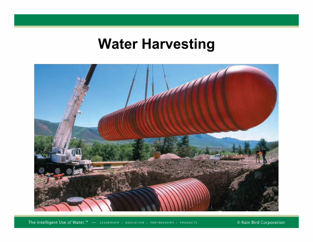
Water HarvestingRain, Storm or A/C water collection and storage
Available from roofs, parking lots, or storm basins
Storage tanks can be above or below ground
Pumped into irrigation by either suction lift or submersible pumps
Can supplement or be entire irrigation water
ROI payback over a long period of time –usually not the primary driver
Water Harvesting

Water Harvesting

Water Harvesting
Water Harvesting

Water Harvesting
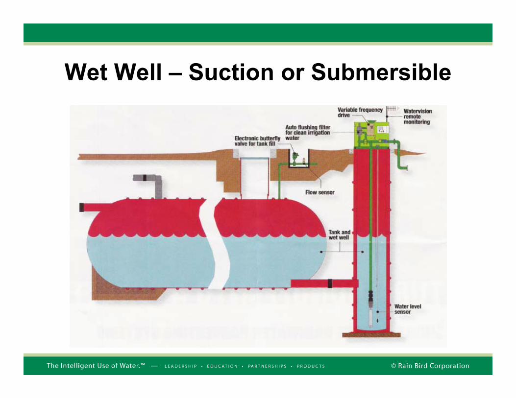
Wet Well – Suction or Submersible
Rain Bird Pump Stations Design TeamProposal packages with a standardized quotation are provided with 48 hours of completed requests. Drawings are available based on the most common configurations upon request.
Factory Contacts:Request for Quotation
Alejandro Carrillo (520) 806-5688Robbi Tolksdorf (520) 741-6145Fax # (520) 741-6191 Email [email protected]
Sales & MarketingTony Adamson (520) 741-6185Herb Hofmann (602) 725-5517
Product ManagerGordon Van Dyke (520) 806-6131
55
Pump Station Sales Team: (520) 806-5620

The Intelligent Use of Water™We believe it is our responsibility to develop products and technologies that use water efficiently. Our commitment also extends to education, training and services for our industry and our communities. The need to conserve water has never been greater. We want to do even more, and with your help, we can.IUOW Summits
IUOW White Papers
IUOW Film Competition
IUOW Awards
IUOW Scholarship
Find more at www.rainbird.com/iuow