Embed Size (px)
Citation preview
4234
4773
5453
44
71
65
39
7241
30
1168
950
467
56
51
8
5238
3315
60
5
10
64 66
6
75
61
58
57
55
4048
76
49
74
431
2
10
78
1
14
32
34 44 47 5354 65 7380
7821
3
92977
69
67
7087
82
2217 37
23
3513
79
12
36
2512
18
7924
16 83
84
26
88
40 48 49 5758 61 7681
43
20
4519
43
See Page 3
54-40-7571
B36B1-1/4" STROKE SAWZALL®
6538-21
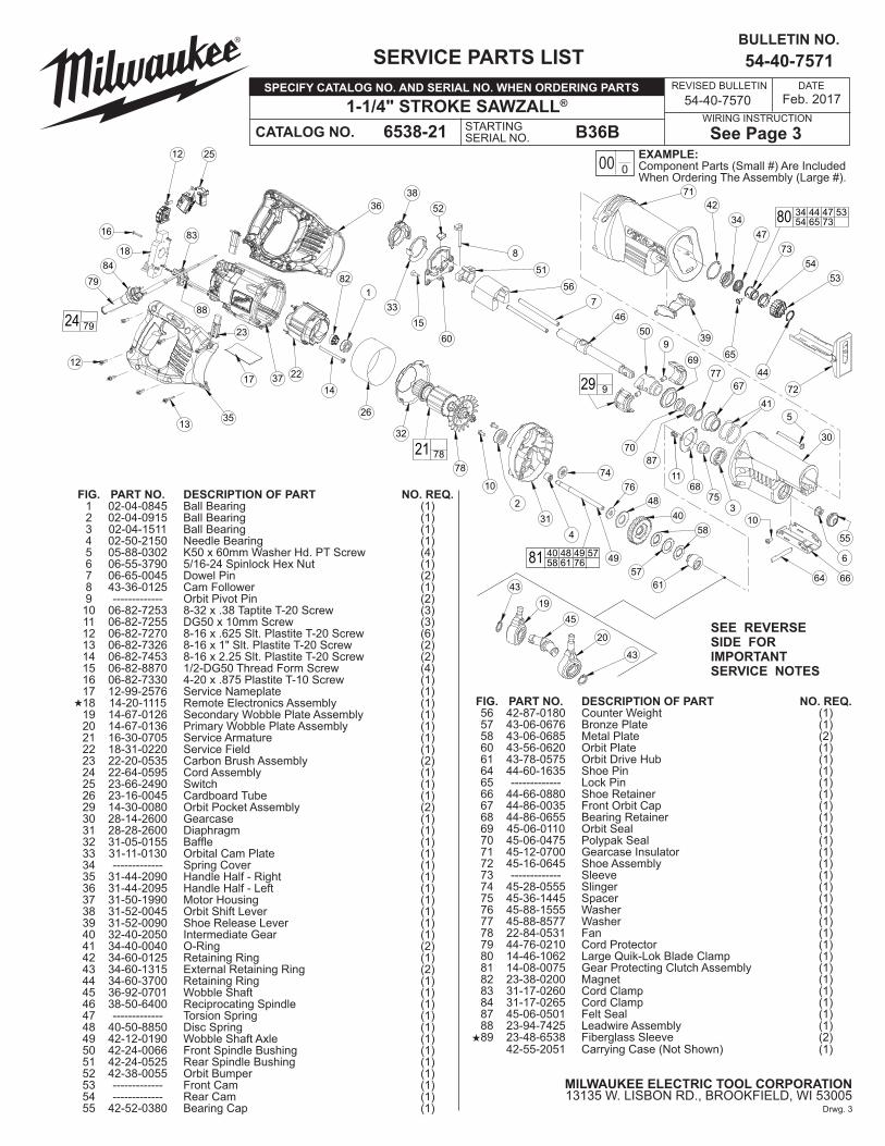
FIG. PART NO. DESCRIPTION OF PART NO. REQ. 1 02-04-0845 Ball Bearing (1) 2 02-04-0915 Ball Bearing (1) 3 02-04-1511 Ball Bearing (1) 4 02-50-2150 Needle Bearing (1) 5 05-88-0302 K50 x 60mm Washer Hd. PT Screw (4) 6 06-55-3790 5/16-24 Spinlock Hex Nut (1) 7 06-65-0045 Dowel Pin (2) 8 43-36-0125 Cam Follower (1) 9 ------------- Orbit Pivot Pin (2) 10 06-82-7253 8-32 x .38 Taptite T-20 Screw (3) 11 06-82-7255 DG50 x 10mm Screw (3) 12 06-82-7270 8-16 x .625 Slt. Plastite T-20 Screw (6) 13 06-82-7326 8-16 x 1" Slt. Plastite T-20 Screw (2) 14 06-82-7453 8-16 x 2.25 Slt. Plastite T-20 Screw (2) 15 06-82-8870 1/2-DG50 Thread Form Screw (4) 16 06-82-7330 4-20 x .875 Plastite T-10 Screw (1) 17 12-99-2576 Service Nameplate (1) 18 14-20-1115 Remote Electronics Assembly (1) 19 14-67-0126 Secondary Wobble Plate Assembly (1) 20 14-67-0136 Primary Wobble Plate Assembly (1) 21 16-30-0705 Service Armature (1) 22 18-31-0220 Service Field (1) 23 22-20-0535 Carbon Brush Assembly (2) 24 22-64-0595 Cord Assembly (1) 25 23-66-2490 Switch (1) 26 23-16-0045 Cardboard Tube (1) 29 14-30-0080 Orbit Pocket Assembly (2) 30 28-14-2600 Gearcase (1) 31 28-28-2600 Diaphragm (1) 32 31-05-0155 Baffle (1) 33 31-11-0130 Orbital Cam Plate (1) 34 ------------- Spring Cover (1) 35 31-44-2090 Handle Half - Right (1) 36 31-44-2095 Handle Half - Left (1) 37 31-50-1990 Motor Housing (1) 38 31-52-0045 Orbit Shift Lever (1) 39 31-52-0090 Shoe Release Lever (1) 40 32-40-2050 Intermediate Gear (1) 41 34-40-0040 O-Ring (2) 42 34-60-0125 Retaining Ring (1) 43 34-60-1315 External Retaining Ring (2) 44 34-60-3700 Retaining Ring (1) 45 36-92-0701 Wobble Shaft (1) 46 38-50-6400 Reciprocating Spindle (1) 47 ------------- Torsion Spring (1) 48 40-50-8850 Disc Spring (1) 49 42-12-0190 Wobble Shaft Axle (1) 50 42-24-0066 Front Spindle Bushing (1) 51 42-24-0525 Rear Spindle Bushing (1) 52 42-38-0055 Orbit Bumper (1) 53 ------------- Front Cam (1) 54 ------------- Rear Cam (1) 55 42-52-0380 Bearing Cap (1)
SEE REVERSE SIDE FOR IMPORTANT SERVICE NOTES
REVISED BULLETIN
SERVICE PARTS LIST BULLETIN NO.
CATALOG NO.
SPECIFY CATALOG NO. AND SERIAL NO. WHEN ORDERING PARTS
WIRING INSTRUCTIONSTARTING SERIAL NO.
DATE
MILWAUKEE ELECTRIC TOOL CORPORATION13135 W. LISBON RD., BROOKFIELD, WI 53005
FIG. PART NO. DESCRIPTION OF PART NO. REQ. 56 42-87-0180 Counter Weight (1) 57 43-06-0676 Bronze Plate (1) 58 43-06-0685 Metal Plate (2) 60 43-56-0620 Orbit Plate (1) 61 43-78-0575 Orbit Drive Hub (1) 64 44-60-1635 Shoe Pin (1) 65 ------------- Lock Pin (1) 66 44-66-0880 Shoe Retainer (1) 67 44-86-0035 Front Orbit Cap (1) 68 44-86-0655 Bearing Retainer (1) 69 45-06-0110 Orbit Seal (1) 70 45-06-0475 Polypak Seal (1) 71 45-12-0700 Gearcase Insulator (1) 72 45-16-0645 Shoe Assembly (1) 73 ------------- Sleeve (1) 74 45-28-0555 Slinger (1) 75 45-36-1445 Spacer (1) 76 45-88-1555 Washer (1) 77 45-88-8577 Washer (1) 78 22-84-0531 Fan (1) 79 44-76-0210 Cord Protector (1) 80 14-46-1062 Large Quik-Lok Blade Clamp (1) 81 14-08-0075 Gear Protecting Clutch Assembly (1) 82 23-38-0200 Magnet (1) 83 31-17-0260 Cord Clamp (1) 84 31-17-0265 Cord Clamp (1) 87 45-06-0501 Felt Seal (1) 88 23-94-7425 Leadwire Assembly (1) 89 23-48-6538 Fiberglass Sleeve (2) 42-55-2051 Carrying Case (Not Shown) (1)
EXAMPLE:Component Parts (Small #) Are Included When Ordering The Assembly (Large #).
00 0
Feb. 2017
Drwg. 3
54-40-7570
«
«

Leg
Hole/Groove
Spindle
Spring Cover
Torsion Spring
Sleeve
Rear Cam
Front Cam
RetainingRing
Lock Pin
FIG. NOTES:1 Bearing to be installed with seal towards commutator.
4,31 Pressneedlebearingflush±.005withinnersurfaceofdiaphragm.
6,49 Apply Blue Loctite® 242 to treads of wobble shaft axle prior to installing spinlock hex nut. Torque spinlock hex nut to 160-190 in. lbs.
6,40 Hold the intermediate gear still with a large pair of pliers and a piece of rubber hose (or other tough, but pliable material to protect the gear from the jaws of the pliers) and remove the 5/16" spinlock hex nut with a wrench, as shown.
7,46,50,51,56 Pressdowelpinsflushtofrontsideoffrontspindlebushing.Pressdowel pinsflushtobacksideofrearspindlebushing.NOTE: Reciprocating spindle (46) and counter weight (56) must be installed inside assembly (7,50) and (7,51) prior to pressing last spindle bushing into place. Be sure to orientate the counter weight with the hole on bottom towards rear spindle bushing, as shown.
17,37 Install nameplate in motor housing recess prior to assembling diaphragm onto motor housing.
29,42 Service fixture #61-10-0205 must be used when installing retaining ring (42) onto orbit pocket assembly (29).
40,57 Tabs of bronze plate engage intermediate gear.
40,48 Concave side of disc spring towards intermediate gear.
58,61 Tabs of metal plates engage orbit drive hub.
70 O-ring of polypak seal faces mechanism - toward rear of tool.
74 Shoulder extension of grease slinger should face bearing.
REMOVING THE STEEL QUIK-LOK® BLADE CLAMP• Remove external retaining ring (44) and pull front cam (53) off. • Pull lock pin (65) out and remove remainder of parts and discard.REASSEMBLY OF THE STEEL QUIK-LOK® BLADE CLAMP• Coat new lock pin with powdered graphite.• Hold tool in a vertical position.• Place spring cover (34) onto spindle.• Slide torsion spring (47) onto spindle shaft with leg positioned at the 6:00 position.• Slide sleeve (73) onto spindle aligning hole on sleeve with hole in spindle.• Slide rear cam (54) over sleeve, aligning hole in rear cam with spring leg. Ensure spring leg inserts into hole in rear cam.• Rotate rear cam (54) counter clockwise until there is clearance for lock pin (65) to be inserted into sleeve/spindle holes. Insert lock pin.• Align front cam (53) inner ribs with rear cam outer slots (see insert) and slide front cam onto sleeve until it bottoms. Retaining ring (44) groove should be completely visible. • Attach retaining ring by separating coils and inserting end of ring into groove, then wind remainder of ring into groove. Ensure ring is seated in groove.• Blade clamp should rotate freely. During normal usage, debris may not allow blade clamp to rotate freely. The use of spray lubricant can help free blade clamp. In extreme conditions, follow these instructions to remove, clean and reassemble blade clamp.
41
29
rear spindle bushing (51)
counter weight (56)
dowel pin (7)
reciprocating spindle (46)
front spindle bushing (50)
Orient counter weightas shown with hole on bottom towards rear spindle bushing.
Place a thin film of lubrication on dowel pins prior to assembly.
LARGEINNER
RIB
LARGEOUTER
SLOTSMALLOUTERSLOT
(53)
(54)
SMALLINNER RIB
FIG. LUBRICATION:
29,41 Lightly coat o-rings with lubrication for ease of installation onto assembled orbit pockets.
30 Place3.2oz.(80grams±8grams)oftype"T"grease(Cat.No.49-08-4290), in mechanism cavity of gear case. 31 Place.8oz.(20grams±2grams)oftype"T"grease(Cat.No.49-08-4290), in lower needle bearing-gear train cavity of diaphragm.
40,58 Apply a thin coat of type "T" grease (Cat. No. 49-08-4290) between gear and metal plate.
65 Pin to be coated with graphite prior to assembly.
87 Soak in lightweight bushing oil prior to assembly.
Service Fixture61-10-0270(Pressing Pin Tool)
1
8
3
2
9
5 4
SpeedDialWires
}
15
1
73
6
95
4
1736
954
8
15
2
14
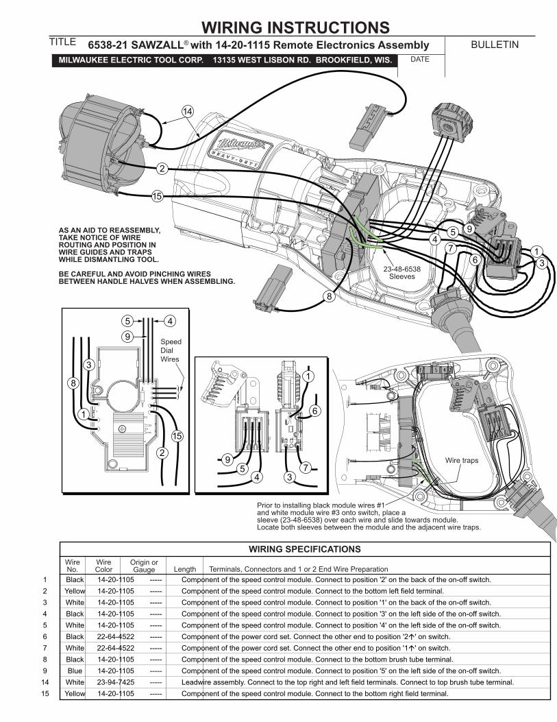
Prior to installing black module wires #1and white module wire #3 onto switch, place a sleeve (23-48-6538) over each wire and slide towards module.Locate both sleeves between the module and the adjacent wire traps.
Wire traps
23-48-6538Sleeves
AS AN AID TO REASSEMBLY, TAKE NOTICE OF WIRE ROUTING AND POSITION IN WIRE GUIDES AND TRAPS WHILE DISMANTLING TOOL.
BE CAREFUL AND AVOID PINCHING WIRES BETWEEN HANDLE HALVES WHEN ASSEMBLING.
1 Black 14-20-1105 ----- Component of the speed control module. Connect to position '2' on the back of the on-off switch. 2 Yellow 14-20-1105 ----- Componentofthespeedcontrolmodule.Connecttothebottomleftfieldterminal. 3 White 14-20-1105 ----- Component of the speed control module. Connect to position '1' on the back of the on-off switch. 4 Black 14-20-1105 ----- Component of the speed control module. Connect to position '3' on the left side of the on-off switch. 5 White 14-20-1105 ----- Component of the speed control module. Connect to position '4' on the left side of the on-off switch. 6 Black 22-64-4522 ----- Component of the power cord set. Connect the other end to position '2á' on switch. 7 White 22-64-4522 ----- Component of the power cord set. Connect the other end to position '1á' on switch. 8 Black 14-20-1105 ----- Component of the speed control module. Connect to the bottom brush tube terminal. 9 Blue 14-20-1105 ----- Component of the speed control module. Connect to position '5' on the left side of the on-off switch. 14 White 23-94-7425 ----- Leadwireassembly.Connecttothetoprightandleftfieldterminals.Connecttotopbrushtubeterminal. 15 Yellow 14-20-1105 ----- Componentofthespeedcontrolmodule.Connecttothebottomrightfieldterminal.
Terminals, Connectors and 1 or 2 End Wire PreparationWireColor
Origin orGauge
WireNo. Length
WIRING SPECIFICATIONS
WIRING INSTRUCTIONSTITLE
DATEMILWAUKEE ELECTRIC TOOL CORP. 13135 WEST LISBON RD. BROOKFIELD, WIS.6538-21 SAWZALL® with 14-20-1115 Remote Electronics Assembly BULLETIN