Embed Size (px)
Citation preview

Specifier’s Guide for Pervious Concrete Pavement Design
Version 1.2
Colorado Ready Mixed Concrete Association 6855 South Havana Street Suite 540 Centennial, CO 80112 303-290-0303 [email protected] www.crmca.org

Specifiers Guide for Pervious Concrete Pavement Design – Version 1.2 Page 2
This guide is intended to assist designers specifying the pervious concrete component of a stormwater management system. There are many other components of a stormwater management system that are not addressed in this guide. Hydrological design is beyond the scope of this document. This guide is intended to supplement ACI 522R-06 Pervious Concrete and ACI 522.1-08 Specification for Pervious Concrete Pavement. Specifically, this guide is intended to aid in the design, placement, and curing of pervious concrete pavements located in an arid environment with the potential of freezing and thawing.
Specifiers Guide for Pervious Concrete Pavement Design – Version 1.2 Page 3
Pervious Concrete Pavement Design
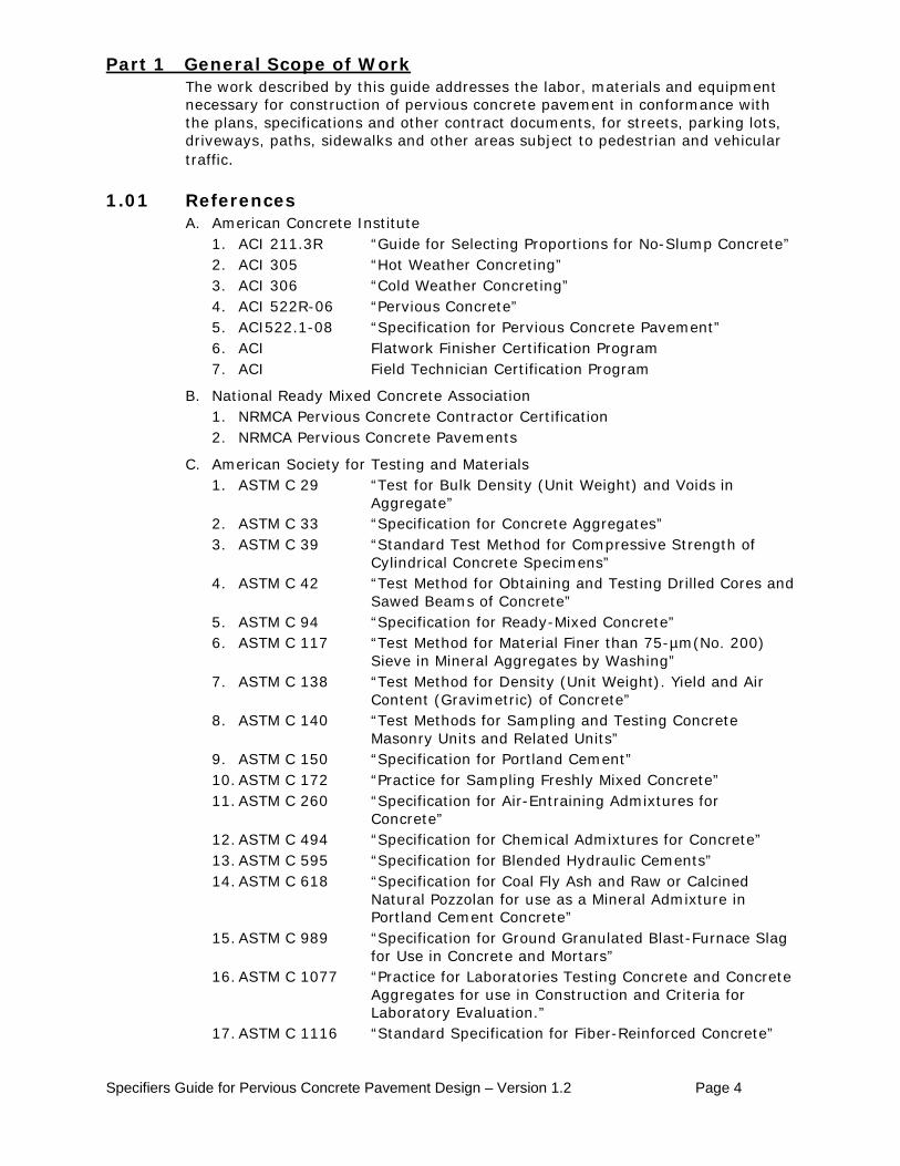
Forward This specifier’s guide has been written for consideration by designers of stormwater management for sites with vehicular or pedestrian pavements in Colorado land development. This guide specifically addresses Colorado’s freeze-thaw cycles, seasonal temperature variations, and extremely dry environment, and is intended to facilitate the design, installation and performance of pervious concrete pavement.
In addition to stormwater runoff control, Pervious Concrete Pavement may contribute to qualifying for LEED® (Leadership in Energy and Environmental Design) points in the areas of stormwater design – quantity, stormwater design – quality, heat island effect – nonroof, water efficient landscaping, optimized energy performance, recycled content, regional materials, construction waste management, site development – protect or restore habitat, and innovation in design. LEED® Certification by the U.S. Green Building Council is growing in importance for developers, designers and communities.
This guide may be used to develop the necessary communicative tools (plans, specifications, and other contract documents) which will convey the intentions of the project Architect/Engineer to the Permitting Agency, the Contractor and the Inspector. Actual project conditions will require modifications and additions to this guide.
The contents of this guide were developed by a task group consisting of members from the ready-mixed concrete industry, design and quality control testing field, and academia. Members of this group include:
Ed Bush – Colorado Ready Mixed Concrete Association
Bernie Cawley – Colorado Ready Mixed Concrete Association
Stephan Durham – University of Colorado Denver
Ken MacKenzie – Urban Drainage and Flood Control District
Joe Rottman – Colorado Ready Mixed Concrete Association
Damon Thomas – CTL Thompson, Inc.
Pervious Concrete Pavement Pervious concrete pavement does not look or behave like conventional concrete pavement. The finished surface is not tight and uniform, but is open and varied, to admit large quantities of stormwater. Surface irregularities and minor amounts of surface raveling are normal. Traditional concrete testing procedures for slump are not applicable to this type of concrete. Instead, standard test methods identified in this guide are used to test for density (unit weight), void content, compressive strength, and thickness. This assures a durable, drainable pavement. In order to maintain optimum porosity, pervious concrete requires specific maintenance procedures described in Appendix F Developers, architects and engineers are strongly encouraged to visit locations where pervious concrete pavement has been installed before making the decision to use this product. The Colorado Ready Mixed Concrete Association (CRMCA) can provide a list of locations in Colorado where pervious concrete has been placed. Technical assistance and installation training is available in Colorado from CRMCA. CRMCA can also provide planning, design, materials, and construction guidance.
Specifiers Guide for Pervious Concrete Pavement Design – Version 1.2 Page 4
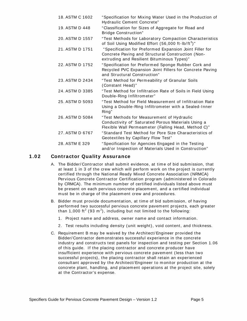
The work described by this guide addresses the labor, materials and equipment necessary for construction of pervious concrete pavement in conformance with the plans, specifications and other contract documents, for streets, parking lots, driveways, paths, sidewalks and other areas subject to pedestrian and vehicular traffic.
Part 1 General Scope of Work
1.01 References A. American Concrete Institute
1. ACI 211.3R “Guide for Selecting Proportions for No-Slump Concrete” 2. ACI 305 “Hot Weather Concreting” 3. ACI 306 “Cold Weather Concreting” 4. ACI 522R-06 “Pervious Concrete” 5. ACI522.1-08 “Specification for Pervious Concrete Pavement” 6. ACI Flatwork Finisher Certification Program 7. ACI Field Technician Certification Program
B. National Ready Mixed Concrete Association 1. NRMCA Pervious Concrete Contractor Certification 2. NRMCA Pervious Concrete Pavements
C. American Society for Testing and Materials 1. ASTM C 29 “Test for Bulk Density (Unit Weight) and Voids in
Aggregate” 2. ASTM C 33 “Specification for Concrete Aggregates” 3. ASTM C 39 “Standard Test Method for Compressive Strength of
Cylindrical Concrete Specimens” 4. ASTM C 42 “Test Method for Obtaining and Testing Drilled Cores and
Sawed Beams of Concrete” 5. ASTM C 94 “Specification for Ready-Mixed Concrete” 6. ASTM C 117 “Test Method for Material Finer than 75-µm(No. 200)
Sieve in Mineral Aggregates by Washing” 7. ASTM C 138 “Test Method for Density (Unit Weight). Yield and Air
Content (Gravimetric) of Concrete” 8. ASTM C 140 “Test Methods for Sampling and Testing Concrete
Masonry Units and Related Units” 9. ASTM C 150 “Specification for Portland Cement” 10. ASTM C 172 “Practice for Sampling Freshly Mixed Concrete” 11. ASTM C 260 “Specification for Air-Entraining Admixtures for
Concrete” 12. ASTM C 494 “Specification for Chemical Admixtures for Concrete” 13. ASTM C 595 “Specification for Blended Hydraulic Cements” 14. ASTM C 618 “Specification for Coal Fly Ash and Raw or Calcined
Natural Pozzolan for use as a Mineral Admixture in Portland Cement Concrete”
15. ASTM C 989 “Specification for Ground Granulated Blast-Furnace Slag for Use in Concrete and Mortars”
16. ASTM C 1077 “Practice for Laboratories Testing Concrete and Concrete Aggregates for use in Construction and Criteria for Laboratory Evaluation.”
17. ASTM C 1116 “Standard Specification for Fiber-Reinforced Concrete”
Specifiers Guide for Pervious Concrete Pavement Design – Version 1.2 Page 5
18. ASTM C 1602 “Specification for Mixing Water Used in the Production of Hydraulic Cement Concrete”
19. ASTM D 448 “Classification for Sizes of Aggregate for Road and Bridge Construction”
20. ASTM D 1557 “Test Methods for Laboratory Compaction Characteristics of Soil Using Modified Effort (56,000 ft-lb/ft3)”
21. ASTM D 1751 “Specification for Preformed Expansion Joint Filler for Concrete Paving and Structural Construction (Non-extruding and Resilient Bituminous Types)”
22. ASTM D 1752 “Specification for Preformed Sponge Rubber Cork and Recycled PVC Expansion Joint Fillers for Concrete Paving and Structural Construction”
23. ASTM D 2434 “Test Method for Permeability of Granular Soils (Constant Head)”
24. ASTM D 3385 “Test Method for Infiltration Rate of Soils in Field Using Double-Ring Infiltrometer”
25. ASTM D 5093 “Test Method for Field Measurement of Infiltration Rate Using a Double-Ring Infiltrometer with a Sealed-Inner Ring”
26. ASTM D 5084 “Test Methods for Measurement of Hydraulic Conductivity of’ Saturated Porous Materials Using a Flexible Wall Permeameter (Falling Head, Method C)”
27. ASTM D 6767 “Standard Test Method for Pore Size Characteristics of Geotextiles by Capillary Flow Test”
28. ASTM E 329 “Specification for Agencies Engaged in the Testing and/or Inspection of Materials Used in Construction”
1.02 Contractor Quality Assurance A. The Bidder/Contractor shall submit evidence, at time of bid submission, that
at least 1 in 3 of the crew which will perform work on the project is currently certified through the National Ready Mixed Concrete Association (NRMCA) Pervious Concrete Contractor Certification program (administered in Colorado by CRMCA). The minimum number of certified individuals listed above must be present on each pervious concrete placement, and a certified individual must be in charge of the placement crew and procedures.
B. Bidder must provide documentation, at time of bid submission, of having performed two successful pervious concrete pavement projects, each greater than 1,000 ft2 (93 m2), including but not limited to the following: 1. Project name and address, owner name and contact information. 2. Test results including density (unit weight), void content, and thickness.
C. Requirement B may be waived by the Architect/Engineer provided the Bidder/Contractor demonstrates successful experience in the concrete industry and constructs test panels for inspection and testing per Section 1.06 of this guide. If the placing contractor and concrete producer have insufficient experience with pervious concrete pavement (less than two successful projects), the placing contractor shall retain an experienced consultant approved by the Architect/Engineer to monitor production at the concrete plant, handling, and placement operations at the project site, solely at the Contractor’s expense.
Specifiers Guide for Pervious Concrete Pavement Design – Version 1.2 Page 6
1.03 Special Equipment Pervious concrete requires specific equipment for compaction and jointing. The concrete shall be jointed and compacted using the methods listed, or alternatives, as demonstrated and approved by the Architect/Engineer.
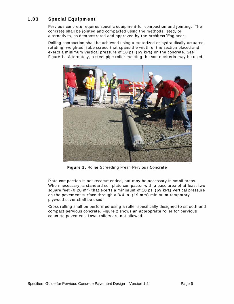
Rolling compaction shall be achieved using a motorized or hydraulically actuated, rotating, weighted, tube screed that spans the width of the section placed and exerts a minimum vertical pressure of 10 psi (69 kPa) on the concrete. See Figure 1. Alternately, a steel pipe roller meeting the same criteria may be used.
Figure 1. Roller Screeding Fresh Pervious Concrete
Plate compaction is not recommended, but may be necessary in small areas. When necessary, a standard soil plate compactor with a base area of at least two square feet (0.20 m2) that exerts a minimum of 10 psi (69 kPa) vertical pressure on the pavement surface through a 3/4 in. (19 mm) minimum temporary plywood cover shall be used.
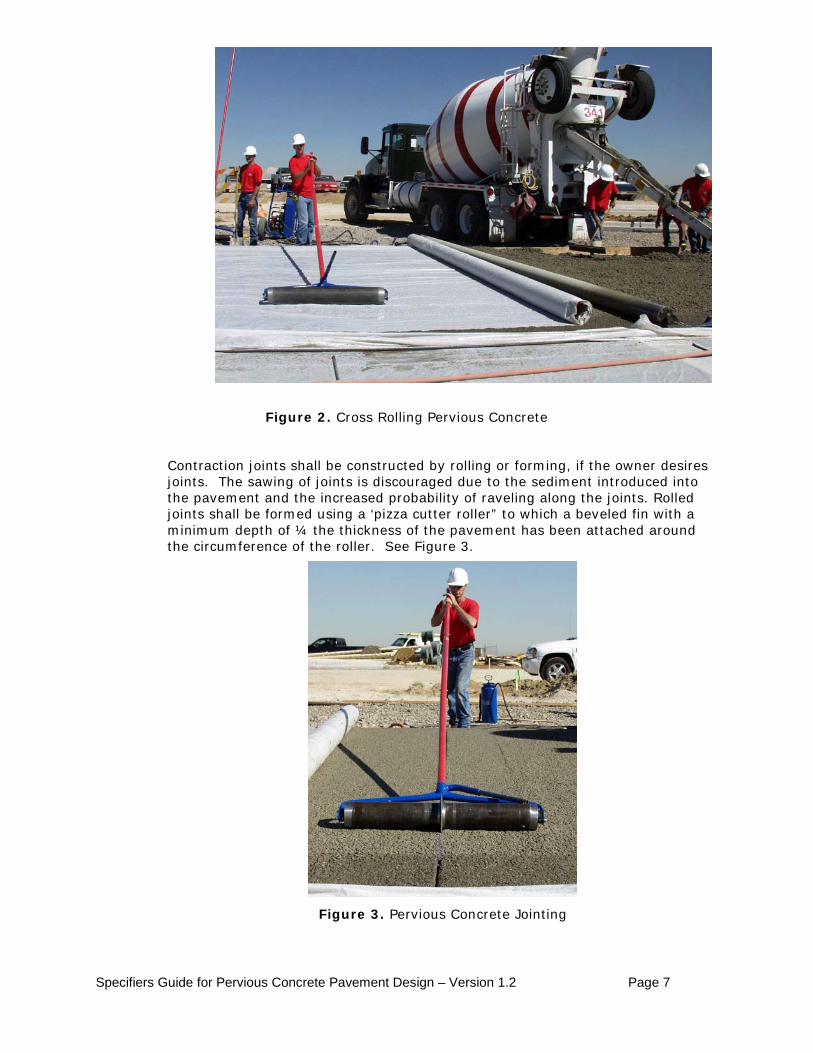
Cross rolling shall be performed using a roller specifically designed to smooth and compact pervious concrete. Figure 2 shows an appropriate roller for pervious concrete pavement. Lawn rollers are not allowed.
Specifiers Guide for Pervious Concrete Pavement Design – Version 1.2 Page 7
Figure 2. Cross Rolling Pervious Concrete
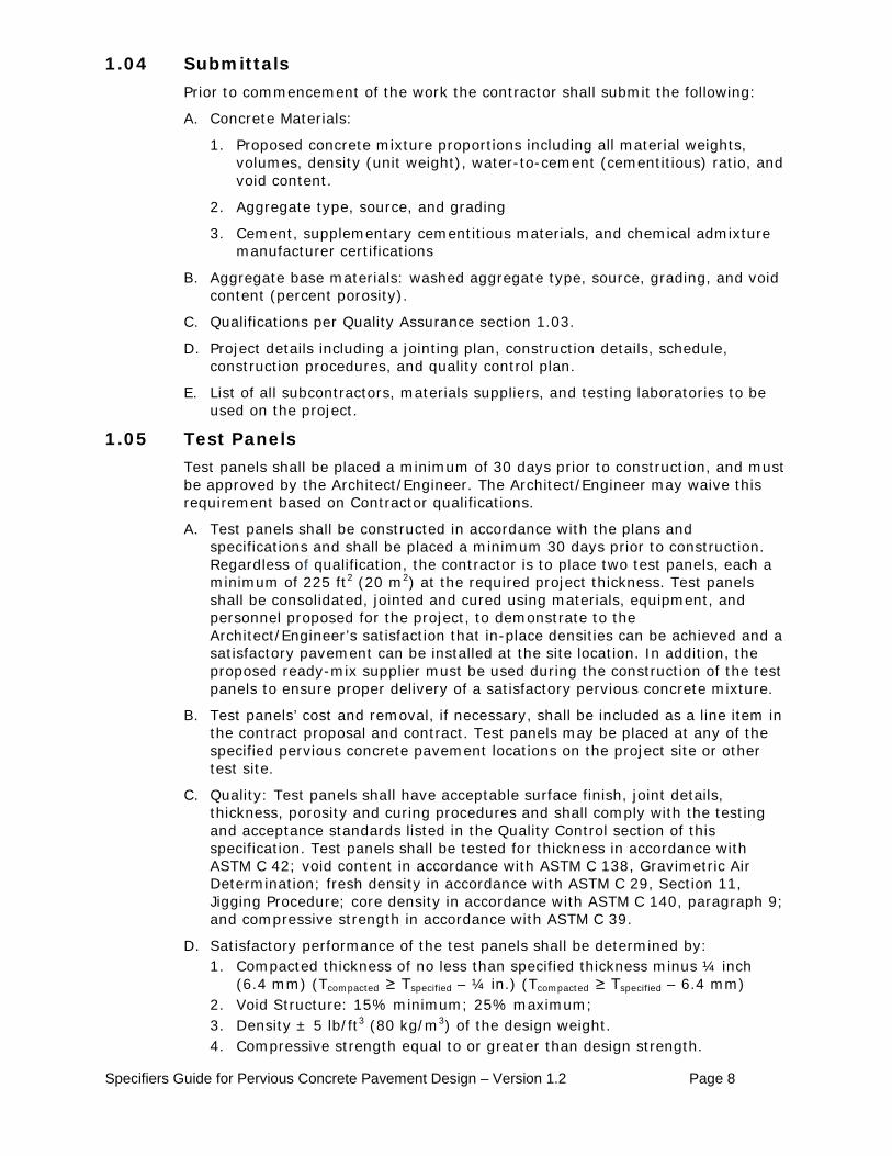
Contraction joints shall be constructed by rolling or forming, if the owner desires joints. The sawing of joints is discouraged due to the sediment introduced into the pavement and the increased probability of raveling along the joints. Rolled joints shall be formed using a ‘pizza cutter roller” to which a beveled fin with a minimum depth of ¼ the thickness of the pavement has been attached around the circumference of the roller. See Figure 3.
Figure 3. Pervious Concrete Jointing
Specifiers Guide for Pervious Concrete Pavement Design – Version 1.2 Page 8
1.04 Submittals Prior to commencement of the work the contractor shall submit the following:
A. Concrete Materials:
1. Proposed concrete mixture proportions including all material weights, volumes, density (unit weight), water-to-cement (cementitious) ratio, and void content.
2. Aggregate type, source, and grading
3. Cement, supplementary cementitious materials, and chemical admixture manufacturer certifications
B. Aggregate base materials: washed aggregate type, source, grading, and void content (percent porosity).
C. Qualifications per Quality Assurance section 1.03.
D. Project details including a jointing plan, construction details, schedule, construction procedures, and quality control plan.
E. List of all subcontractors, materials suppliers, and testing laboratories to be used on the project.
1.05 Test Panels Test panels shall be placed a minimum of 30 days prior to construction, and must be approved by the Architect/Engineer. The Architect/Engineer may waive this requirement based on Contractor qualifications.
A. Test panels shall be constructed in accordance with the plans and specifications and shall be placed a minimum 30 days prior to construction. Regardless of qualification, the contractor is to place two test panels, each a minimum of 225 ft2 (20 m2) at the required project thickness. Test panels shall be consolidated, jointed and cured using materials, equipment, and personnel proposed for the project, to demonstrate to the Architect/Engineer’s satisfaction that in-place densities can be achieved and a satisfactory pavement can be installed at the site location. In addition, the proposed ready-mix supplier must be used during the construction of the test panels to ensure proper delivery of a satisfactory pervious concrete mixture.
B. Test panels’ cost and removal, if necessary, shall be included as a line item in the contract proposal and contract. Test panels may be placed at any of the specified pervious concrete pavement locations on the project site or other test site.
C. Quality: Test panels shall have acceptable surface finish, joint details, thickness, porosity and curing procedures and shall comply with the testing and acceptance standards listed in the Quality Control section of this specification. Test panels shall be tested for thickness in accordance with ASTM C 42; void content in accordance with ASTM C 138, Gravimetric Air Determination; fresh density in accordance with ASTM C 29, Section 11, Jigging Procedure; core density in accordance with ASTM C 140, paragraph 9; and compressive strength in accordance with ASTM C 39.
D. Satisfactory performance of the test panels shall be determined by: 1. Compacted thickness of no less than specified thickness minus ¼ inch
(6.4 mm) (Tcompacted ≥ Tspecified – ¼ in.) (Tcompacted ≥ Tspecified – 6.4 mm) 2. Void Structure: 15% minimum; 25% maximum; 3. Density ± 5 lb/ft3 (80 kg/m3) of the design weight. 4. Compressive strength equal to or greater than design strength.
Specifiers Guide for Pervious Concrete Pavement Design – Version 1.2 Page 9
E. If test panels are found to be unsatisfactory, they shall be removed at the Contractor’s expense and disposed of in an approved landfill or recycling facility. If test panels are found to be satisfactory, they may be left in-place and included in the completed work, at no additional cost to the project.
1.06 Project Conditions A. Weather Restrictions
1. The Contractor shall not place pervious concrete pavement when the ambient temperature is predicted by the National Weather Service Point Forecast for the jobsite to be 40°F (4.4ºC) or lower during the seven days following placement, unless otherwise permitted in writing by the Architect/Engineer.
2. The Contractor shall not place pervious concrete pavement later in the year than November 1 or earlier in the year than April 1 unless otherwise permitted in writing by the Architect/Engineer.
3. The Contractor shall not place pervious concrete pavement when the ambient temperature is predicted by the National Weather Service Point Forecast for the jobsite to rise above 90°F (32.2ºC) during the seven days following placement, unless otherwise permitted in writing by the Architect/Engineer.
4. Pervious concrete pavement shall not be placed on frozen subgrade.
5. Fogging shall be applied from the time of discharge until pervious concrete is covered with plastic due to the high rates of evaporation typical in Colorado.
B. Pre-Paving Conference
1. A pre-paving conference with the Architect/Engineer shall be held within one week prior to beginning placement. The pervious concrete supplier and the entire concrete crew that will form and place the concrete shall attend this meeting.
2. The document Checklist for the Concrete Pre-Construction Conference (available from the CRMCA, NRMCA, or the American Society of Concrete Contractors) shall be used to review all requirements of the contract during the meeting. Meeting emphasis shall include how paving with pervious concrete differs from paving with conventional concrete.
3. A pre-construction conference shall be held and/or notice shall be provided to all subcontractors identifying the special precautions that are required when constructing pervious concrete pavement.
Part 2 2.01 Isolation (Expansion) Joint Material
Products
Joint material shall be ¼ inch or ½ inch (6 mm or 13 mm) flexible foam expansion joint with relative density of 1.7 or higher, meeting ASTM D 4819-88, or vinyl expansion joint in compliance with ASTM D 1751 or ASTM D 1752.
2.02 Curing Materials A. Polyethylene sheeting - The primary method of curing pervious concrete shall
be the placement of a ballasted waterproof covering consisting of a minimum of 6 mil thick polyethylene sheeting.
Specifiers Guide for Pervious Concrete Pavement Design – Version 1.2 Page 10
B. Other moisture loss control - For prevention of moisture loss prior to the primary method of curing:
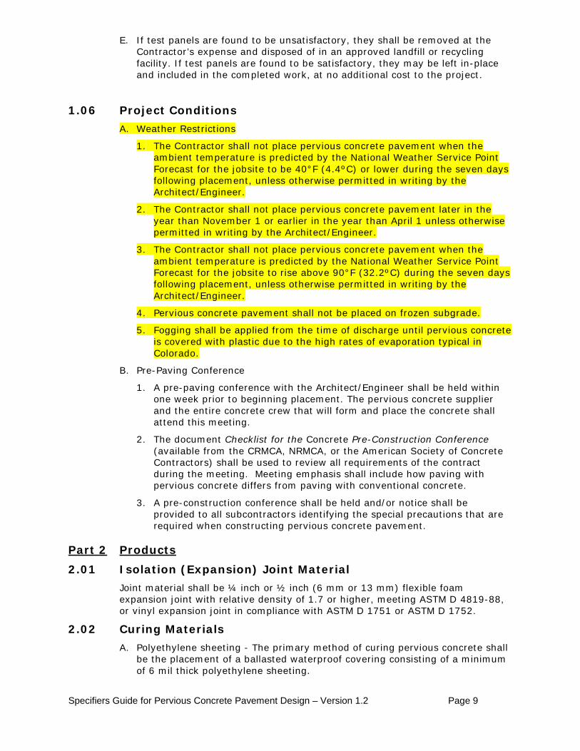
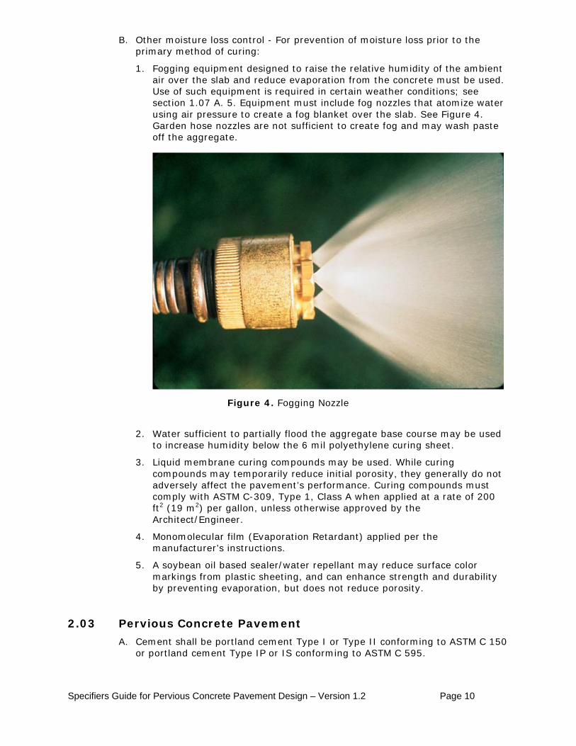
1. Fogging equipment designed to raise the relative humidity of the ambient air over the slab and reduce evaporation from the concrete must be used. Use of such equipment is required in certain weather conditions; see section 1.07 A. 5. Equipment must include fog nozzles that atomize water using air pressure to create a fog blanket over the slab. See Figure 4. Garden hose nozzles are not sufficient to create fog and may wash paste off the aggregate.
Figure 4. Fogging Nozzle
2. Water sufficient to partially flood the aggregate base course may be used to increase humidity below the 6 mil polyethylene curing sheet.
3. Liquid membrane curing compounds may be used. While curing compounds may temporarily reduce initial porosity, they generally do not adversely affect the pavement’s performance. Curing compounds must comply with ASTM C-309, Type 1, Class A when applied at a rate of 200 ft2 (19 m2) per gallon, unless otherwise approved by the Architect/Engineer.
4. Monomolecular film (Evaporation Retardant) applied per the manufacturer’s instructions.
5. A soybean oil based sealer/water repellant may reduce surface color markings from plastic sheeting, and can enhance strength and durability by preventing evaporation, but does not reduce porosity.
2.03 Pervious Concrete Pavement
A. Cement shall be portland cement Type I or Type II conforming to ASTM C 150 or portland cement Type IP or IS conforming to ASTM C 595.
Specifiers Guide for Pervious Concrete Pavement Design – Version 1.2 Page 11
B. Supplementary Cementitious Materials:
1. Fly ash conforming to ASTM C 618.
C. Admixtures:
1. Air entraining admixtures meeting ASTM C 260.
2. Chemical admixtures shall comply with ASTM C 494.
a. Water reducing admixtures: Type A. mid-range water reducing admixtures (MRWRA) or high range water reducing admixtures (HRWRA) Type F or G are permitted due to low water-to-cement (cementitious) ratios specified for pervious concrete.
b. Hydration stabilizing admixtures meeting requirements of ASTM C 494 Type B Retarding or Type D Water Reducing/Retarding admixtures are required. This stabilizer suspends cement hydration by forming a protective barrier around the cementitious particles, delaying the initial set as the pervious concrete heats up in the truck. A standard retarder will not prevent premature hydration while the stabilizer will. The use of hot water during cold weather will require an increased dosage of Hydration Stabilizer.
D. Aggregates:
1. Coarse Aggregate shall meet the grading and quality requirement of ASTM C 33, based on meeting the project requirements. [Data for proposed alternate material shall be submitted for approval per Section l.05A of this guide.]
2. Fine aggregate complying with ASTM C 33 shall provide 6 % ± 2 % of total aggregate weight.
3. A combined coarse and fine aggregates gradation shall be provided and a minimum of 10% of the material shall pass the #4 sieve. (Research suggests that the inclusion of additional sand increases the freeze thaw resistance, durability, and strength while still allowing adequate porosity.)
4. Larger aggregate sizes may increase porosity but can decrease workability and strength. Well graded aggregates shall be avoided as they may reduce porosity and may not provide adequate void content.
5. Natural rounded aggregates, where available, are recommended.
E. Water shall be potable and comply with ASTM C 1602.
F. Fiber reinforcement, if used, shall comply with ASTM C 1116.
G. Recommended Mixture Proportions:
The Contractor shall furnish a proposed mixture design, with proportions of materials, or if mixture proportions are proprietary, a written submittal from the concrete supplier, prior to commencement of work. The data shall include densities determined in accordance with ASTM C 29 section 11, Jigging Procedure. The composition of the proposed concrete mixture shall be submitted to the Architect/Engineer for review and/or approval and shall comply with the following provisions unless an alternative composition is demonstrated to comply with the project requirements. Mixture performance will be affected by the properties of the particular materials used. Trial mixtures must be tested to establish proper proportions and determine expected behavior. Concrete producers may have mixture proportions for pervious concrete optimized for performance with local materials. Appendix 6 of ACI 21 l.3R provides a guide for pervious concrete mixture proportioning. General mixture recommendations are as follows:
Specifiers Guide for Pervious Concrete Pavement Design – Version 1.2 Page 12
1. Concrete mixture density: range of 105 lb/ft3 to 130 lb/ft3 (1682 kg/m3 to 2082 kg/m3) per ASTM C 29, section 11, Jigging Procedure.
2. Concrete mixture void content: range of 15% to 25%, per ASTM C 138, Gravimetric Air Determination.
3. Cementitious content: range of 450 lbs/yd3 to 550 lb/yd3 (267kg/m3 to 326kg/m3)
4. Supplementary cementitious content: Fly ash: 20% maximum; combined supplementary cementitious content: 20% maximum.
5. Water-to-cement (cementitious) ratio: range from 0.26 to 0.35. 6. Aggregate content: The bulk volume of aggregate per cubic yard (cubic
meter) shall be equal to 27ft3 (1000L) when calculated from the density (unit weight) determined in accordance with ASTM C 29 Jigging Procedure.
7. Admixtures: Admixtures shall be used in accordance with the manufacturers’ instructions and recommendations.
8. Mixture Water: The quantity of mixing water shall be established to produce a pervious concrete mixture of the desirable workability to facilitate placement, compaction, and finishing to the desired surface characteristics. Mixture water shall be such that the cement paste displays a wet metallic sheen without causing the paste to flow from the aggregate. (A cement paste with a dull-dry appearance has insufficient mixture water for hydration.) Insufficient mix water results in inconsistency in the mix and poor bond strength. High water content may result in the paste sealing the void system primarily at the bottom and poor bond at the upper surface.
9. Air Entrainment: has been shown to increase freeze thaw durability of pervious concrete.
10. Fiber Reinforcement: may help prevent raveling but may decrease workability.
Part 3
3.01 Notification
Execution
The Architect/Engineer shall be notified at least 24 hours prior to all pervious concrete paving work.
3.02 Installation of Pervious Concrete Pavement A. Pervious concrete pavement shall be placed above a stormwater management
system capable of preventing water from standing in the pavement following a storm event.
B. Pavement thickness shall be designed by a professional engineer. Minimum thickness for all applications (excluding heavy traffic loads) shall be a single-coarse placement with a minimum thickness of 6 inches (15 cm) unless otherwise specified. Pavements frequently used by vehicles heavier than single axle service/delivery trucks shall have a minimum thickness of 8 inches (20 cm). Heavy truck traffic may require special design. Composite designs that use traditional concrete pavement in drive lanes and heavy traffic areas are preferred, and may include up to 2 ft2 (0.19 m2) of impervious area for each ft2 (.09 m2) of pervious concrete.
Specifiers Guide for Pervious Concrete Pavement Design – Version 1.2 Page 13
C. Formwork materials are permitted to be of wood or steel and shall be the full depth of the pavement. Caution should be used to protect the filter fabric and impermeable membranes from puncture or tear when placing forms and form pins. Forms shall be of sufficient strength and stability to support mechanical equipment without deformation of plan profiles following spreading, strike-off and compaction operations. Forms may have a removable spacer of ½ in. to ¾ in. (13 mm to 19 mm) thickness placed above the depth of pavement. The spacers shall be removed following placement and vibratory strike-off to allow roller compaction. (Removable spacers may not be necessary if other means of strike-off and consolidation are used, such as a motorized or hydraulically actuated weighted pipe roller screed.)
D. Mixing and Transportation:
1. Production: Pervious concrete shall be manufactured and delivered in accordance with ASTM C 94.
2. Mixing: Pervious concrete shall be batched in central mixers or in transit (truck) mixers. (When concrete is delivered in agitating or non-agitating units. the concrete shall be mixed in the central mixer for a minimum of 1 minute or until a homogenous mixture is achieved. Concrete mixed in transit mixers shall be mixed at the mixing speed designated by the manufacturer for 70 - 100 revolutions.
3. Transportation: Pervious concrete may be transported or mixed on site and discharge of individual loads shall be completed within one (1) hour of the introduction of mixture water to the cement. Discharge times may be extended beyond one hour when an increased dosage of hydration stabilizer is used to maintain a wet metallic sheen.
4. Discharge: Each truckload shall be visually inspected for moisture consistency. Water addition shall be permitted at the point of discharge to obtain the required mixture consistency, and as needed to maintain a wet metallic sheen. A minimum of 30 revolutions at the manufacturer’s designated mixing speed shall be required following the addition of any water to the mixture, prior to further discharge. If water is added more than three times to a load, the dosage rate of hydration stabilizing admixture should be increased in subsequent loads. Discharge shall he a continuous operation and shall be completed as quickly as possible. Concrete shall be deposited as close to its final position as practical and such that discharged concrete is incorporated into previously placed plastic concrete. If consolidation occurs during concrete discharge, placement shall be halted, the mixture shall be addressed, and the consolidated portion removed and replaced immediately.
E. Placing and Finishing:
1. The base shall be in a damp or semi-flooded condition at time of placement. Failure to provide a moist base will result in an absorption of water from the pervious concrete into the base, consequently reducing the concrete strength and overall quality of the pavement
2. Concrete may be deposited into the forms by mixer truck chute, conveyor or buggy.
3. Placing, finishing, and tooled jointing must be completed within 20 minutes from the time the pervious concrete is discharged from the truck.
4. Unless otherwise permitted, the Contractor shall utilize a mechanical vibratory screed to strike off the concrete ½ in. to ¾ in. (13 mm to 19 mm) above final elevation, utilizing the form spacers described in section 3.02 C. Formwork. An alternative method of strike off and compaction is
Specifiers Guide for Pervious Concrete Pavement Design – Version 1.2 Page 14
to use a motorized or hydraulically actuated weighted pipe roller screed, as described in section 1.04 A., Special Equipment. If approved by the Architect/Engineer in writing, the Contractor may place the pervious concrete with either slip form or vibratory form riding equipment followed by a compacting unit that will provide a minimum of 10 psi (69 kPa) vertical force to the concrete. Similarly, strike off by hand straightedge followed by compaction may be permitted for sidewalks and other small areas.
5. Care must be taken to prevent closing the void structure of pervious concrete. Finishing operations not described in this guide are not allowed. Internal vibration shall not be permitted. (If surface vibration is applied, it shall be shut off immediately when forward progress is halted for any reason.)
6. Placed concrete shall not be disturbed while in the plastic state including edging. Low spots after the screeding operation shall be over-filled for surface repair and tamped to the desired elevation with hand tampers or re-screeded with the motorized or hydraulically actuated weighted pipe roller screed.
7. Following strike-off, remove spacers and compact the concrete to the form level utilizing a steel roller, a plate compactor on plywood or other method approved by the Architect/Engineer.
8. Freshly compacted concrete shall be protected from evaporation using one or more methods described in section 3.02 G 2.
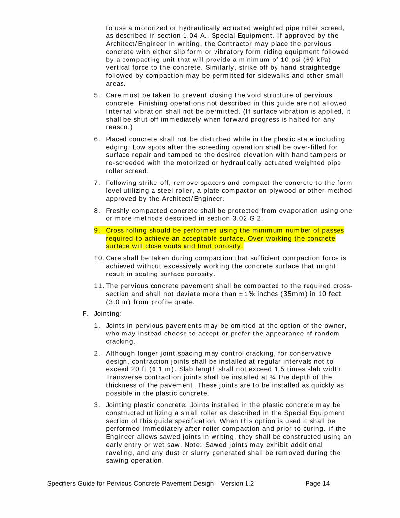
9. Cross rolling should be performed using the minimum number of passes required to achieve an acceptable surface. Over working the concrete surface will close voids and limit porosity.
10. Care shall be taken during compaction that sufficient compaction force is achieved without excessively working the concrete surface that might result in sealing surface porosity.
11. The pervious concrete pavement shall be compacted to the required cross-section and shall not deviate more than ±1⅜ inches (35mm) in 10 feet (3.0 m) from profile grade.
F. Jointing:
1. Joints in pervious pavements may be omitted at the option of the owner, who may instead choose to accept or prefer the appearance of random cracking.
2. Although longer joint spacing may control cracking, for conservative design, contraction joints shall be installed at regular intervals not to exceed 20 ft (6.1 m). Slab length shall not exceed 1.5 times slab width. Transverse contraction joints shall be installed at ¼ the depth of the thickness of the pavement. These joints are to be installed as quickly as possible in the plastic concrete.
3. Jointing plastic concrete: Joints installed in the plastic concrete may be constructed utilizing a small roller as described in the Special Equipment section of this guide specification. When this option is used it shall be performed immediately after roller compaction and prior to curing. If the Engineer allows sawed joints in writing, they shall be constructed using an early entry or wet saw. Note: Sawed joints may exhibit additional raveling, and any dust or slurry generated shall be removed during the sawing operation.
Specifiers Guide for Pervious Concrete Pavement Design – Version 1.2 Page 15
4. Transverse construction joints: Transverse construction joints shall be installed whenever placement is suspended for 30 minutes or whenever concrete is no longer workable.
5. Isolation joints: Isolate slabs from other parts of the structure, such as walls, footings, columns, garage slabs, stairs, light poles, and other points of restraint. Isolation joints permit independent vertical and horizontal movement between adjoining parts of the structure and help minimize cracking.
6. Edging shall be performed along isolation joints and construction joints in order to reduce potential for raveling under traffic.
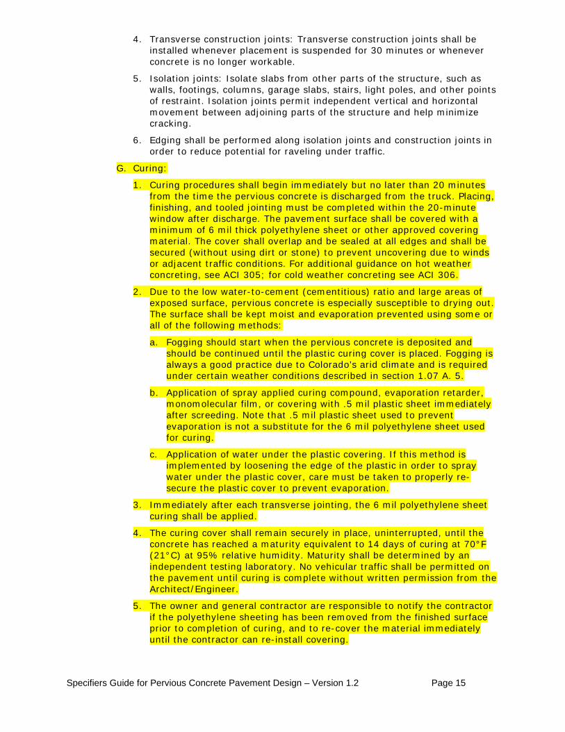
G. Curing:
1. Curing procedures shall begin immediately but no later than 20 minutes from the time the pervious concrete is discharged from the truck. Placing, finishing, and tooled jointing must be completed within the 20-minute window after discharge. The pavement surface shall be covered with a minimum of 6 mil thick polyethylene sheet or other approved covering material. The cover shall overlap and be sealed at all edges and shall be secured (without using dirt or stone) to prevent uncovering due to winds or adjacent traffic conditions. For additional guidance on hot weather concreting, see ACI 305; for cold weather concreting see ACI 306.
2. Due to the low water-to-cement (cementitious) ratio and large areas of exposed surface, pervious concrete is especially susceptible to drying out. The surface shall be kept moist and evaporation prevented using some or all of the following methods:
a. Fogging should start when the pervious concrete is deposited and should be continued until the plastic curing cover is placed. Fogging is always a good practice due to Colorado’s arid climate and is required under certain weather conditions described in section 1.07 A. 5.
b. Application of spray applied curing compound, evaporation retarder, monomolecular film, or covering with .5 mil plastic sheet immediately after screeding. Note that .5 mil plastic sheet used to prevent evaporation is not a substitute for the 6 mil polyethylene sheet used for curing.
c. Application of water under the plastic covering. If this method is implemented by loosening the edge of the plastic in order to spray water under the plastic cover, care must be taken to properly re-secure the plastic cover to prevent evaporation.
3. Immediately after each transverse jointing, the 6 mil polyethylene sheet curing shall be applied.
4. The curing cover shall remain securely in place, uninterrupted, until the concrete has reached a maturity equivalent to 14 days of curing at 70°F (21°C) at 95% relative humidity. Maturity shall be determined by an independent testing laboratory. No vehicular traffic shall be permitted on the pavement until curing is complete without written permission from the Architect/Engineer.
5. The owner and general contractor are responsible to notify the contractor if the polyethylene sheeting has been removed from the finished surface prior to completion of curing, and to re-cover the material immediately until the contractor can re-install covering.

Specifiers Guide for Pervious Concrete Pavement Design – Version 1.2 Page 16
Appendix A Associated Stormwater Management Components Subgrade – The subgrade upon which it is constructed is critical to the design and performance of a system of Pervious Concrete Pavement with Detention. Infiltration rate of the subgrade soil will affect design of the stormwater storage layer. Testing to determine the subgrade soil infiltration rate must be conducted by a qualified testing laboratory. Stormwater Storage - Stormwater storage in the system envisioned by this guide is accomplished entirely within an aggregate base layer beneath the pervious concrete pavement sufficient to capture and discharge stormwater at a rate such that a 100-year storm will not cause stormwater to be retained in the pavement. The storage layer may be comprised of more than one layer of aggregate, each layer having a different size aggregate and void content. For additional storage volume, the aggregate layer(s) may extend beneath adjacent impervious pavements on the site, and may include chambers, cisterns, vaults, tanks or other receptacles, as necessary to economically accommodate the design stormwater storage volume. In addition, designers may anticipate extended storage for future harvest by a landscape irrigation system. An impervious liner may also be used to store larger quantities of stormwater for re-use, or as a barrier to keep stormwater from entering contaminated soils, such as on brownfield sites. Maximum draw-down time shall be five days; any combination of subgrade soil infiltration, evaporation, and positive outlets may be used to achieve draw-down. Note: Some local authorities may require a calculated storage volume that can contain a specific rainfall event or the first-flush (defined as the first .5 to 1 inch of rain fall) for up to 72 hours. Plan thickness requirements for stormwater storage in the aggregate layer of the system, whether designed for retention, detention, or recharge, may be verified using the Pervious Concrete Hydrological Analysis Program1
. The designer must take into account the slope of the subgrade to a) compute stormwater storage volume, and b) to consider need for cross-slope “check dams” for erosion prevention at the soil surface below the storage layer or to retain water more evenly. Greater stormwater storage volume will provide additional freeze-thaw protection.
1 Program by Malcolm, Leming and Nunez, of the Civil Engineering Department. North Carolina State University, Raleigh, North Carolina. The software is available from the Colorado Ready Mixed Concrete Association, the National Ready Mixed Concrete Association or the Portland Cement Association.

Specifiers Guide for Pervious Concrete Pavement Design – Version 1.2 Page 17
Appendix B Proposed Testing Laboratory Qualifications The testing laboratory shall have its laboratory equipment and procedures inspected at intervals not to exceed 2 years by a qualified national authority as evidence of its competence to perform the required tests and material designs. Acceptable national authority will include the AASHTO Materials Reference Laboratory (AMRL) and/or the Cement and Concrete Reference Laboratory (CCRL), as appropriate. In addition, testing machines and equipment must be calibrated annually or more frequently by impartial means using devices of accuracy traceable to the National Bureau of Standards. In fields other than those covered by the referenced ASTM standards, the testing laboratory shall accept only those assignments which it is able to perform competently by use of its own personnel and equipment. Any work to be subcontracted must be to laboratories meeting the same criteria. The testing laboratory shall have demonstrated its competence in the applicable fields for a period of not less than 3 years. The inspection and testing services of the testing laboratory shall be under the direction of a full-time employee registered as a professional engineer in the State of Colorado. He shall have a minimum of 5 years of professional engineering experience in inspection and testing of concrete construction.
Specifiers Guide for Pervious Concrete Pavement Design – Version 1.2 Page 18
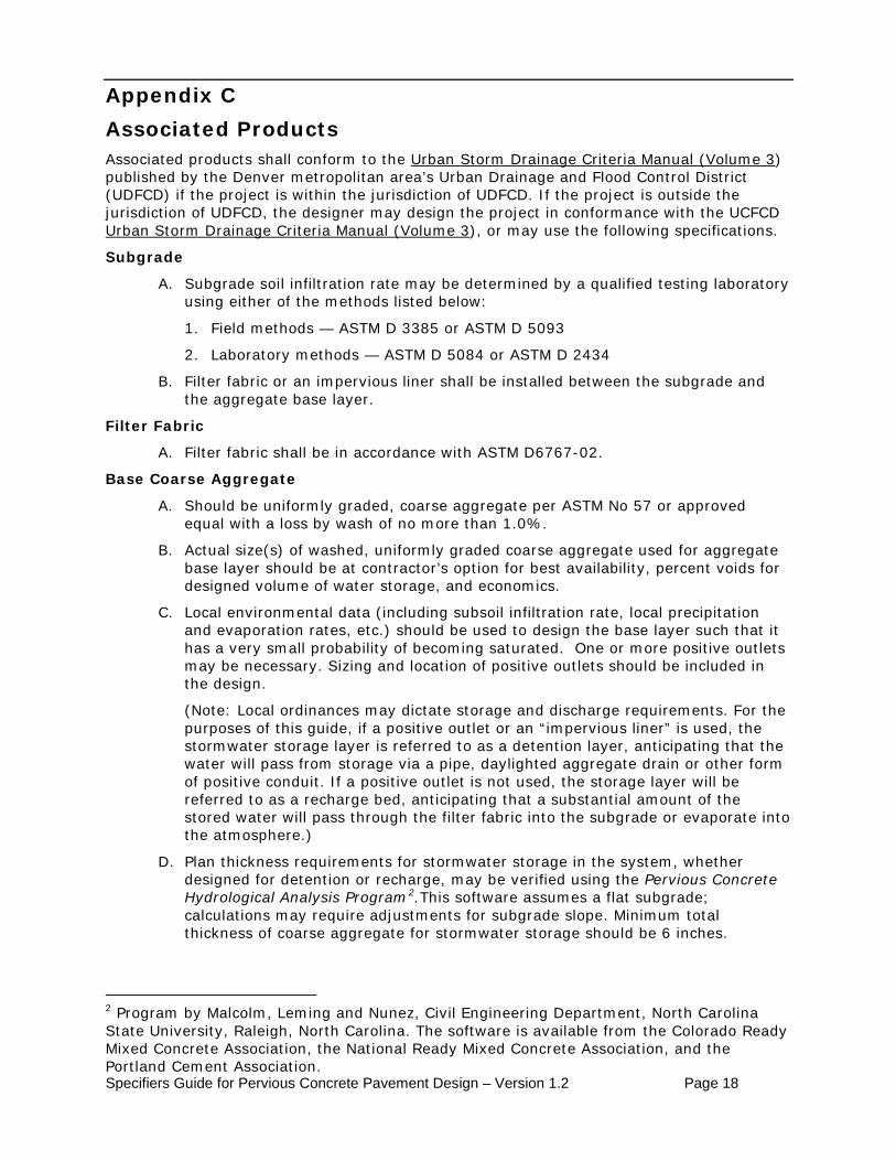
Appendix C Associated Products Associated products shall conform to the Urban Storm Drainage Criteria Manual (Volume 3) published by the Denver metropolitan area’s Urban Drainage and Flood Control District (UDFCD) if the project is within the jurisdiction of UDFCD. If the project is outside the jurisdiction of UDFCD, the designer may design the project in conformance with the UCFCD Urban Storm Drainage Criteria Manual (Volume 3
Subgrade
), or may use the following specifications.
A. Subgrade soil infiltration rate may be determined by a qualified testing laboratory using either of the methods listed below:
1. Field methods — ASTM D 3385 or ASTM D 5093
2. Laboratory methods — ASTM D 5084 or ASTM D 2434
B. Filter fabric or an impervious liner shall be installed between the subgrade and the aggregate base layer.
Filter Fabric
A. Filter fabric shall be in accordance with ASTM D6767-02.
Base Coarse Aggregate
A. Should be uniformly graded, coarse aggregate per ASTM No 57 or approved equal with a loss by wash of no more than 1.0%.
B. Actual size(s) of washed, uniformly graded coarse aggregate used for aggregate base layer should be at contractor’s option for best availability, percent voids for designed volume of water storage, and economics.
C. Local environmental data (including subsoil infiltration rate, local precipitation and evaporation rates, etc.) should be used to design the base layer such that it has a very small probability of becoming saturated. One or more positive outlets may be necessary. Sizing and location of positive outlets should be included in the design.
(Note: Local ordinances may dictate storage and discharge requirements. For the purposes of this guide, if a positive outlet or an “impervious liner” is used, the stormwater storage layer is referred to as a detention layer, anticipating that the water will pass from storage via a pipe, daylighted aggregate drain or other form of positive conduit. If a positive outlet is not used, the storage layer will be referred to as a recharge bed, anticipating that a substantial amount of the stored water will pass through the filter fabric into the subgrade or evaporate into the atmosphere.)
D. Plan thickness requirements for stormwater storage in the system, whether designed for detention or recharge, may be verified using the Pervious Concrete Hydrological Analysis Program2
2 Program by Malcolm, Leming and Nunez, Civil Engineering Department, North Carolina State University, Raleigh, North Carolina. The software is available from the Colorado Ready Mixed Concrete Association, the National Ready Mixed Concrete Association, and the Portland Cement Association.
.This software assumes a flat subgrade; calculations may require adjustments for subgrade slope. Minimum total thickness of coarse aggregate for stormwater storage should be 6 inches.
Specifiers Guide for Pervious Concrete Pavement Design – Version 1.2 Page 19
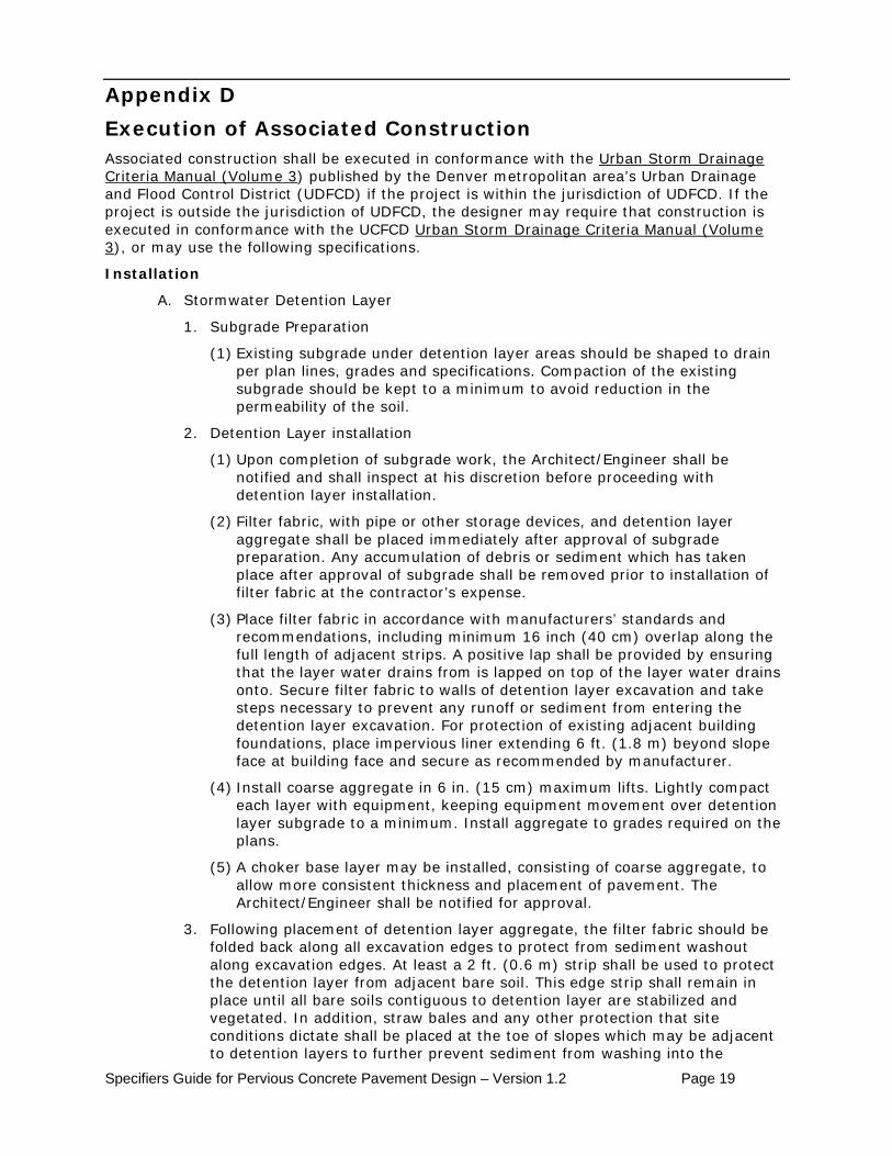
Appendix D Execution of Associated Construction Associated construction shall be executed in conformance with the Urban Storm Drainage Criteria Manual (Volume 3) published by the Denver metropolitan area’s Urban Drainage and Flood Control District (UDFCD) if the project is within the jurisdiction of UDFCD. If the project is outside the jurisdiction of UDFCD, the designer may require that construction is executed in conformance with the UCFCD Urban Storm Drainage Criteria Manual (Volume 3
Installation
), or may use the following specifications.
A. Stormwater Detention Layer
1. Subgrade Preparation
(1) Existing subgrade under detention layer areas should be shaped to drain per plan lines, grades and specifications. Compaction of the existing subgrade should be kept to a minimum to avoid reduction in the permeability of the soil.
2. Detention Layer installation
(1) Upon completion of subgrade work, the Architect/Engineer shall be notified and shall inspect at his discretion before proceeding with detention layer installation.
(2) Filter fabric, with pipe or other storage devices, and detention layer aggregate shall be placed immediately after approval of subgrade preparation. Any accumulation of debris or sediment which has taken place after approval of subgrade shall be removed prior to installation of filter fabric at the contractor’s expense.
(3) Place filter fabric in accordance with manufacturers’ standards and recommendations, including minimum 16 inch (40 cm) overlap along the full length of adjacent strips. A positive lap shall be provided by ensuring that the layer water drains from is lapped on top of the layer water drains onto. Secure filter fabric to walls of detention layer excavation and take steps necessary to prevent any runoff or sediment from entering the detention layer excavation. For protection of existing adjacent building foundations, place impervious liner extending 6 ft. (1.8 m) beyond slope face at building face and secure as recommended by manufacturer.
(4) Install coarse aggregate in 6 in. (15 cm) maximum lifts. Lightly compact each layer with equipment, keeping equipment movement over detention layer subgrade to a minimum. Install aggregate to grades required on the plans.
(5) A choker base layer may be installed, consisting of coarse aggregate, to allow more consistent thickness and placement of pavement. The Architect/Engineer shall be notified for approval.
3. Following placement of detention layer aggregate, the filter fabric should be folded back along all excavation edges to protect from sediment washout along excavation edges. At least a 2 ft. (0.6 m) strip shall be used to protect the detention layer from adjacent bare soil. This edge strip shall remain in place until all bare soils contiguous to detention layer are stabilized and vegetated. In addition, straw bales and any other protection that site conditions dictate shall be placed at the toe of slopes which may be adjacent to detention layers to further prevent sediment from washing into the
Specifiers Guide for Pervious Concrete Pavement Design – Version 1.2 Page 20
detention layers during site development. As the site is fully stabilized, excess filter fabric along the detention layer edges can be cut back to coarse aggregate edge.
B. Groundwater Recharge Bed
1. Subgrade Preparation (a flat subgrade is preferred for a recharge bed)
(1) Existing subgrade under recharge bed areas shall NOT be compacted or subject to excessive construction equipment traffic prior to coarse aggregate bed placement.
(2) Where erosion of subgrade has caused accumulation of fine materials and/or surface ponding, this material shall be removed with light equipment and the underlying soils scarified to a minimum depth of 6 in. (15 cm) with a rake or equivalent and light tractor.
(3) Bring subgrade of coarse aggregate recharge bed to line, grade, and elevations required.
(4) Fill and lightly regrade any areas damaged by erosion, ponding, or traffic compaction before the placing of coarse aggregate.
2. Recharge Bed Installation
(1) Upon completion of subgrade preparation, the Architect/Engineer shall be notified and shall inspect at his discretion before the contractor may proceed with recharge bed installation.
(2) Filter fabric, with pipe or any other storage devices, and recharge bed aggregate shall be placed immediately after approval of subgrade preparation. Any accumulation of debris or sediment which has taken place after approval of subgrade shall be removed prior to installation of filter fabric at the contractor’s expense.
(3) Place filter fabric in accordance with manufacturer’s standards and recommendations. Adjacent strips of filter fabric shall overlap a minimum of 16 in. (40 cm) The contractor shall secure fabric at least 2 ft (0.6 m) outside of bed and take steps necessary to prevent any runoff or sediment from entering the storage bed. For protection of existing adjacent building foundations, the contractor shall place impervious liner over filter fabric extending 6 ft. (1.8 m) beyond toe of slope face at building face. and secure as recommended by manufacturer. Install coarse aggregate in 6 in. (15 cm) maximum lifts. Lightly compact each layer with roller, keeping equipment movement over storage bed subgrades to a minimum. Install aggregate to grades required on the drawings.
(4) A choker base course may be installed to allow more consistent thickness and placement of pavement. The Architect/Engineer shall be notified for approval.
(5) Following placement of bed aggregate, the filter fabric shall be folded back along all bed edges to protect from sediment washout along bed edges. At least a 2 ft (0.6 m) strip shall be used to protect beds from adjacent bare soil. This edge strip shall remain in place until all bare soils adjacent to beds are stabilized and vegetated. In addition, hay bales (if allowed) shall be placed at the toe of slopes which may be adjacent to beds to further prevent sediment from washing into beds during site development. As the site is fully stabilized, excess filter fabric along the bed edges can be cut back to coarse aggregate edge.
Specifiers Guide for Pervious Concrete Pavement Design – Version 1.2 Page 21
Appendix E Concrete Quality Control
A. The Architect/Engineer shall employ a testing laboratory that conforms to the requirements of ASTM E329 and ASTM C 1077. All personnel engaged in concrete testing shall be certified ACI Grade I Field Testing Technicians.
B. Traditional concrete testing procedures for strength and slump control are not applicable to this type of pavement material. Procedures to be used per this guide specification include: ASTM C 172. ASTM C 29. ASTM C 42 and ASTM C 138.
C. Concrete tests shall be performed for each 50 yd3 (38m3) or fraction thereof, with a minimum of one set of tests for each day’s placement.
D. Sampling - Plastic concrete shall be sampled in accordance with ASTM C 172.
E. Density (unit weight)— Density shall be performed in accordance with ASTM C 29. The measure is to be filled and compacted in accordance with Section 11, Jigging Procedure. The density of the delivered concrete shall be within ± 5 lb/ft3 (80 kg/m3) of the design density (unit weight).
F. Void content - Void content of the plastic concrete shall be determined in accordance to ASTM C138 Gravimetric Air Determination (determine fresh density in accordance with ASTM C 29 Section 11, Jigging Procedure) and core density in accordance with ASTM C 140, paragraph 9.3, and compared to the void percentage required by design. Unless otherwise specified, the void content shall be between 15% and 25%.
G. After a minimum of seven (7) days, hardened concrete shall be tested at a rate of one set of three cores per 50 yd3 (38 m3) of concrete placed on one day or fraction thereof. Cores shall be drilled in accordance with ASTM C 42. The cores shall be measured for thickness, void structure and density.
H. Thickness may be verified, at the discretion of the Engineer/Architect, by measuring untrimmed hardened core samples. The average of all production cores when measured for length shall not be more than ½ in. (13 mm) less than the specified design thickness.
I. Core density (unit weight) and void content - The cores shall be tested for density (unit weight) and void content following ASTM C 140. Density (unit weight) of cores trimmed and tested in the saturated condition, per ASTM C 140, paragraph 9.3.1 shall be ± 5lb/ft3 (80 kg/m3) of the design density. Void content shall not be more than 2% below the specified design void content. Void content shall calculated as follows: %Voids = 1-(Dd/Di) * 100 where: Dd = oven dried density of core Di = immersed density of core
Specifiers Guide for Pervious Concrete Pavement Design – Version 1.2 Page 22
Appendix F Maintaining Pervious Concrete Over time, sand, dust, and other debris can collect in pervious concrete’s voids and reduce its porosity. In order to preserve maximum functionality, pervious concrete should be cleaned from time to time. Particular attention should be given to areas where debris accumulation is visible. Best practices for maintaining pervious concrete include sweeping with a streetsweeper that uses water in conjunction with brushes and vacuum to clean debris from the surface and prevent it from reducing the concrete’s void volume. If that method is unsuccessful, or as an alternate method of cleaning if using a streetsweeper is not practical, pervious concrete may be cleaned by washing with high pressure water. Using a vacuum to collect as much of the water-debris mixture as possible may increase the effectiveness of pressure washing. Snow removal should be accomplished using a rotary broom. If use of a rotary broom is not possible, snow should be cleared using a plow with a lower edge made of plastic or rubber. Metal plows should be avoided; their blades tend to catch stones (particularly at joints) and cause raveling.
Specifiers Guide for Pervious Concrete Pavement Design – Version 1.2 Page 23
Related Publications Urban Storm Drainage Criteria Manual (Volume 1
Urban Drainage and Flood Control District; Denver, CO )
Urban Storm Drainage Criteria Manual (Volume 2
Urban Drainage and Flood Control District; Denver, CO )
Urban Storm Drainage Criteria Manual (Volume 3
Urban Drainage and Flood Control District; Denver, CO )
Recommended Specifications for Portland Cement Pervious Pavement
The Carolinas Ready Mixed Concrete Association, Inc.
Guide for Construction of Portland Cement Concrete Pervious Pavement
Georgia Concrete and Products Association
Design of Pervious Concrete Mixtures
Portland Cement Association
SPECIFIER‘S GUIDE FOR PERVIOUS CONCRETE PAVEMENT DESIGN
Michigan Concrete Association
Ohio Ready Mixed Concrete Association SPECIFIER‘S GUIDE FOR PERVIOUS CONCRETE PAVEMENT WITH DETENTION
Pervious Concrete “The California Experience”
California Nevada Cement Promotion Council
Angela Hager. Doctoral Dissertation, University of Colorado Denver. (UMI No. 3360870).
Sustainable Design of Pervious Concrete Pavements.
Specifiers Guide for Pervious Concrete Pavement Design – Version 1.2 Page 24
Disclaimer This specifier’s guide is intended solely for use by professional personnel who are competent to evaluate the significance and limitations of the information provided and who will accept responsibility for the application of this information. The Colorado Ready Mixed Concrete Association (CRMCA) disclaims all responsibility and liability for the accuracy and application of the information contained in this publication to the full extent permitted by law.
There are many material facts concerning pervious concrete pavement with detention that are not fully analyzed in this guide. While this guide contains information that CRMCA considers to be reliable, CRMCA does not guaranty that it is accurate or complete. The opinions expressed in this guide reflect the judgment of CRMCA at this date and are subject to change.