Embed Size (px)
Citation preview
TECHNICAL SPECIFICATIONS TABLE OF CONTENTS
CENTRAL WATER INTEGRATION PIPELINE TERMINUS TREATMENT FACILITY PRESSURE FILTER EARLY PROCUREMENT PACKAGE TABLE OF CONTENTS MAY 2018
TOC - i
Section Title
DIVISION 11 – EQUIPMENT
11200 Water Filtration System
APPENDIX A – DIVISION 1 – GENERAL REQUIREMENTS
01300 Submittals
01600 Material and Equipment
01640 Manufacturer’s Field Services
01730 Operation and Maintenance Data
01740 Warranties and Bonds
01752 Facility Startup Commissioning Requirements
APPENDIX B: DIVISION 15 – MECHANICAL
15000 Mechanical General Requirements
15100 Valves and Appurtenances
APPENDIX C: DIVISION 17 – INSTRUMENTATION
17310 Flow Instruments
17314 Pressure Instruments
17325 Process Control System Control Panels
17327 Panel Mounted Control Devices
17328 Uninterruptible Power Supply
17410 Process Instrument Schedule
17500 Programmable Logic Controller
APPENDIX D: DRAWINGS
DIVISION 11
EQUIPMENT
CENTRAL WATER INTEGRATION PIPELINE TERMINUS TREATMENT FACILITY WATER FILTRATION EQUIPMENT MAY 2018
11200 - 1
SECTION 11200
WATER FILTRATION EQUIPMENT
PART 1 - GENERAL
1.01 DESCRIPTION
A. Scope of Work:
1. This specification describes a complete operational system to be furnished by a single responsible Filter System Supplier (FSS or Supplier) for installation by Others (Contractor).
2. The work covered in these specifications includes the design, furnishing and installation supervision of a complete filter system. The filter system will remove turbidity from potable water from the Vista Ridge Regional Supply project that is further treated with carbon dioxide and lime upstream of the filters to achieve a target calcium hardness of up to 80 mg/L as CaCO3. The filter system shall have a total capacity of 35.0 MGD that will blend with up to 14.5 MGD of Vista Ridge Regional Supply untreated water.
a. The system shall consist of eight (8) 2-cell pressure vessels, each containing the surface area and filter media as specified under herein.
b. The system shall be capable of being expanded in the future by construction of eight (8) additional 2-cell pressure vessels.
c. The filtrate water quantity and quality specified herein shall be met at startup and throughout the warranty period.
d. The backwash quantity and frequency specified herein shall be met at startup and throughout the warranty period.
3. The filter system shall be furnished by one of the pre-approved Filter System Suppliers that are listed under Subsection 1.02, Quality Assurance of this Specification Section.
4. The Filter System Supplier will be selected and issued a Purchase Order by the Owner for early submittal of shop drawings prior to advertising and bidding of the Terminus Treatment Facilities Bid Package, which will be awarded to a General Contractor, referenced herein as Contractor. The Filter System Supplier shall be responsible for coordination with the construction schedule of the Contractor to ensure that equipment is delivered to the site in accordance with the Contractor’s critical path schedule. The FSS shall also coordinate with the Contractor to ensure that all related systems furnished under the Contractor’s scope of work will form a complete integrated operating system. The filter
CENTRAL WATER INTEGRATION PIPELINE TERMINUS TREATMENT FACILITY WATER FILTRATION EQUIPMENT MAY 2018
11200 - 2
system supplier for this project shall coordinate the filter system with the following equipment supplied by the Contractor, and their manufacturers:
a. Interconnecting Process Piping and Valves
b. Instrumentation and Control
c. Electrical
5. The filter system supplier shall be responsible for furnishing filtration support equipment and appurtenances as listed below and specified herein.
a. Eight two (2) cell pressure vessels
b. Backwash Supply Pumps
c. Air Scour Blowers with Sound Attenuating Enclosures
d. Four (4) Pressure and Flow Monitoring Panels
e. Two (2) Programmable Logic Controller (PLCs) Panels
f. The filter system supplier shall be responsible for engineering selection and purchasing of all motor operated valves (MOVs) and specialty control valves associated with the filter system. All valves and actuators shall be furnished in full conformance with Section 15100.
g. The filter system supplier shall be responsible for the purchase and testing of field devices related to the filter monitoring panels noted above. Field devices manufacturers and equipment models shall be coordinated with equipment furnished in other process areas by the Process Control System Integrator (PCSI). Like items of equipment shall be the product of one manufacturer to facilitate standardization of performance, operation, spare parts, maintenance and manufacturer’s service.
6. The Filter System Supplier shall be responsible for coordination with the PCSI, and shall assume ultimate responsibility in providing all items required to form a complete and operable filter system whether specified herein or not.
7. The proposed filter system shall employ a state-of-the-art, fully automated control system for all normal daily operations including automated sequencing of system start-up, automated control of normal operation at steady state conditions, and automated sequencing of plant shutdowns (both emergency and operator initiated). The filter system supplier shall be responsible for providing filter process control strategies that safeguard the filter system equipment and warranties, and account for specific equipment furnished for the project. The developed control strategies shall be sufficiently detailed to allow use by the PCSI for control system coordination efforts. The filter system supplier shall be
CENTRAL WATER INTEGRATION PIPELINE TERMINUS TREATMENT FACILITY WATER FILTRATION EQUIPMENT MAY 2018
11200 - 3
responsible for coordination of control strategies with the PCSI throughout the control system programming effort, and shall assist the PCSI with any changes that are required during startup and testing.
B. Related Work Described Elsewhere:
1. 01600 Material and Equipment 2. 01640 Manufacturer’s Field Services 3. 01730 Operation and Maintenance Data 4. 01740 Warranties and Bonds 5. 01752 Facility Startup Commissioning Requirements 6. 15000 Mechanical General Requirements 7. 15100 Valves and Appurtenances 8. 16000 Electrical – General Provisions 9. 17310 Flow Instruments 10. 17314 Pressure Instruments 11. 17325 Process Control System Control Panels 12. 17327 Panel Mounted Control Devices 13. 17328 Uninterruptible Power Supply 14. 17500 Programmable Logic Controller
1.02 QUALITY ASSURANCE
A. Backwash Waste Production
1. The Owner considers water conservation an intrinsic part of this project. Filter System Suppliers shall provide with their submittal a backwash generation calculation and guarantee.
B. Qualified Filter System Suppliers shall have experience manufacturing pressure filter vessels including simultaneous backwash systems for at least five (5) years with no less than 10 successful installations in the municipal market, of which 3 must have been 10 MGD or larger. All qualified suppliers shall provide evidence of a local field technical support crew within an eight (8) hour drive of San Antonio, TX, and be able to mobilize within 24-hour notification. Approved Suppliers are listed below, no equals will be accepted.
1. Tonka Water using Simul-Wash backwash method.
2. Loprest Division of WRT using Syncro-Cleanse backwash method.
3. WesTech using MULTIWASH backwash method.
1.03 SUBMITTALS
A. Pre-Purchase Contract Schedule: It is anticipated that this pre-purchase contract will follow the approximate schedule below:
1. Submittals – Preliminary: June 20, 2018 (with the bid)
CENTRAL WATER INTEGRATION PIPELINE TERMINUS TREATMENT FACILITY WATER FILTRATION EQUIPMENT MAY 2018
11200 - 4
2. SAWS Board Award: July 10, 2018
3. Purchase Order for Submittals Only: July 13, 2018
4. Submittals – Level 1: August 1, 2018
5. Submittals – Level 2: August 31, 2018
B. The filter system supplier shall submit the following with the bid:
1. Preliminary vessel shop or fabrication drawings with all dimensions indicated. Include identification and catalog cuts for purchases components and details for manufactured components.
2. Pump and Blower data including:
a. Submit catalog sheets showing pump/blower characteristics and dimensions, including the Dimensional and Layout Data:
1) Certified dimensional drawings of each item of equipment and auxiliary apparatus to be furnished.
b. Submit Manufacturer's certified rating curves for each pump, showing pump characteristics for discharge head, capacity, brake horsepower, pump efficiency at the "rated" point, pump efficiency curve for pump, and guaranteed net positive suction head required (NPSHR) over the entire range of pumping requirements. This information shall be prepared specifically for each pump provided. Catalog sheets showing a family of curves will not be acceptable.
c. Submit dry weights of pump, motor, and base plate, and weight of entire pumping unit.
d. Submit dry weights of blower, motor, and enclosure, and weight of entire blower assembly.
3. Media configuration.
4. Valve supplier and data sheets
5. Summary Table listing the make and model of all valves, actuators, instrumentation field devices, and any other appurtenances to be furnished with the Filter System.
6. Performance guarantee approved by authorized signatory that states at a minimum:
CENTRAL WATER INTEGRATION PIPELINE TERMINUS TREATMENT FACILITY WATER FILTRATION EQUIPMENT MAY 2018
11200 - 5
a. The backwash collection system incorporated into the provided vertical pressure filtration system will operate with media loss of one inch per year or less subject to the system being operated in accordance with operating procedures, practices and air and water flow rates required for the system as detailed in the Supplier Operation and Maintenance Manual.
b. With the backwash system incorporated into the pressure filtration system, Supplier guarantees the backwash wastewater volumes in accordance with the backwash waste volumes outlined in our proposal.
c. At a minimum, Supplier guarantees that the iron will be removed to the USEPA Secondary Standards of 0.3 mg/l (Fe) and turbidity will be removed to 0.6 ntu.
C. The filter system supplier shall submit the following with Level 1 submittals (August 1, 2018):
1. Vessel shop or fabrication drawings with all dimensions indicated. Include identification and catalog cuts for purchases components and details for manufactured components. Identify materials, surface preparation, and finishes. Include ASME calculations of wall thickness for the vessel, manways and nozzles.
2. Flow schematic drawing indicating line sizes of pipes connecting to and from pressure vessels, valving, method of support, utility (air, water, drain, electric) line sizes and connections.
3. A list of any and all parameters, ratings or other characteristics where the proposed system deviates from the requirements set forth in these Specifications.
4. Backwash system sizing calculations.
5. Complete pump and blower package submittal including:
a. Submit catalog sheets showing pump/blower characteristics and dimensions, including the Dimensional and Layout Data:
1) Certified baseplate and anchor bolt plans and details.
2) Schematic electrical wiring diagram and other data as required for complete pump/blower installation.
3) Certified sectional drawing of blower / pumping unit with part numbers and material specifications.
CENTRAL WATER INTEGRATION PIPELINE TERMINUS TREATMENT FACILITY WATER FILTRATION EQUIPMENT MAY 2018
11200 - 6
b. Cross-sectional drawings with detailed construction of each component in the pump/blower along with the ASTM material designations.
c. Bill of materials.
d. Shaft seal drawing, shaft coupling and bill of materials.
e. Certified support and anchor bolt plans and details.
f. Electrical and instrumentation data as detailed below.
g. Performance curves.
h. Data sheets applicable to proposals, purchase, and as-built drawings.
i. Performance information.
j. Certified drawings of auxiliary systems.
k. Forces and moments analysis, along with thrust calculations at the pump feet and at the anchor bolts. Also provide certified pump support and anchor bolt plans and details.
l. Manufacturer’s installation instructions.
m. Qualifications of Service Engineer.
n. Factory test procedure.
o. Schedules for factory witness testing.
p. Materials certifications for castings, impellers, shafts, and shaft sleeves.
q. Certified motor test data.
r. Spare parts recommendations and price lists.
s. Submit qualifications of pump company service Engineer to check out installation.
t. Submit blower/pump/motor coupling manufacturer, model number, AGMA 9002-A clearances and tolerances.
u. Pumps: submit hydraulic thrust and radial load calculations along with L10 bearing life of each bearing.
v. Pumps: submit shaft design calculations including deflection at impeller and at mechanical seals.
6. Complete valve submittal according to Section 15100.
CENTRAL WATER INTEGRATION PIPELINE TERMINUS TREATMENT FACILITY WATER FILTRATION EQUIPMENT MAY 2018
11200 - 7
7. Affidavits of compliance with referenced standards and codes.
8. Applicable certifications and ratings.
9. Shop inspection schedule.
10. Detailed drawings illustrating equipment arrangement, bill of materials, weights (dry and operating), size, and location of all anchor bolts and nuts, and plan view system drawing.
11. Piping arrangement drawings or plans and elevation drawings including details (i.e., flanged etc.) and location of all required connections to utilities and piping.
12. Unloading, storage and installation instructions.
13. List of any extra materials or supplies provided.
14. Delegated-Design Submittal: For design of seismic restraints, including analysis data signed and sealed by the qualified professional engineer in the state of Texas responsible for their preparations.
a. Anchor Details: Detail fabrication of each anchor indicated. Show dimensions and methods of assembly and attachment.
b. Structural and seismic calculations for pressure vessels, backwash pumps and blowers. Include calculations for reactions at anchor bolts and selection of the size depth and number of bolts required for use with Simpson Set Epoxy anchor system. (Supplier can assume grade 60 rebar with 4.000 psi concrete.)
15. Interior Tank Lining Data:
a. Submit a letter of certification from the manufacturer of the interior lining to verify conformance with ANSI/NSF Standard 61 requirements and compatibility of coating system with the proposed process service.
b. The tank lining applicator shall be fully experienced in the application of tank coatings and shall be certified by the interior lining coating manufacturer.
c. Submit qualifications for an independent paint testing company to perform testing of the internal lining. At a minimum the paint testing shall include mil thickness and Holiday testing. The paint testing company shall be a NACE certified firm acceptable to the tank manufacturer and the Engineer. The paint testing company shall provide a list of previous experience with at least five (5) previous projects of equal or larger sized tanks in the last five years.
d. Submit tank testing procedures and proposed locations where testing will be performed. Included in testing procedures should be the models
CENTRAL WATER INTEGRATION PIPELINE TERMINUS TREATMENT FACILITY WATER FILTRATION EQUIPMENT MAY 2018
11200 - 8
of proposed testing equipment and testing equipment calibration procedures.
e. Notify the Owner and Engineer at least two (2) weeks prior to testing to allow witnessing of the paint testing activities, if desired.
f. Submit results of interior tank lining testing to the Engineer prior to shipment of the tank to the job site.
D. The filter system supplier shall submit the following with Level 2 submittals (August 31, 2018):
1. Electrical/Instrumentation data including: complete electrical, instrumentation and control, and wiring diagrams in sufficient detail to allow installation of instrumentation and controls and electrical components. The following submittals shall be required:
a. The following information shall be submitted with the motor drawings
for review.
1) Name of Drive
2) Horsepower of Motor
3) Phase
4) Full Load Efficiency
5) Voltage
6) Full Load Power Factor
7) Speed
8) NEMA Design Starting Torque
9) NEMA Frame and Dimensions
10) Full Load Current
11) Locked Rotor Current
12) Insulation Class
13) Temperature Rise at 1.15 SF
14) Enclosure
CENTRAL WATER INTEGRATION PIPELINE TERMINUS TREATMENT FACILITY WATER FILTRATION EQUIPMENT MAY 2018
11200 - 9
15) Bearing life design
16) Special features (i.e., space heater voltage/ wattage, RTDs,
oversize conduit box and corrosion resistant features).
17) Nameplate Drawing with Information as listed herein.
18) Lugs and connectors.
b. Field Instrument Submittal
19) Submit complete documentation of all field instruments using
ISA-S20 data sheet formats. Submit separate data sheets for each
instrument
20) Certified calibration data for all flow metering devices
21) Refer to all other Division 17 for additional specific submittal
requirements.
c. Control System Submittal
1) The Supplier shall coordinate with the Contractor to schedule all
control system submittals in a timely manner, such that the plant
control system programming schedule will not be delayed.
2) Control System Hardware: This submittal shall provide
complete documentation of the proposed hardware (PLCs, OITs,
communication equipment, cables, and peripherals). The
submittal shall include the following:
a) System Block Diagram
b) Complete Bill of Materials
c) Loop Drawings
d) Control Panel Layout Drawings
e) Equipment Data Sheets
3) Filter System Control Narrative Submittal: This submittal shall
provide the following information:
a. System Overview
b. Mode of Operation
CENTRAL WATER INTEGRATION PIPELINE TERMINUS TREATMENT FACILITY WATER FILTRATION EQUIPMENT MAY 2018
11200 - 10
c. Local Manual Control
d. Local Automatic Control
e. Remote Manual Control
f. Remote Automatic Control
g. Alarms
h. Interlocks
i. Tuning Parameters
j. Equipment Runtimes
k. Historical Recording
4) Input/Output (I/O) List Submittal: This submittal shall provide
the following information:
a) Field device tag name
b) I/O tag
c) Description
d) Physical point address: rack, slot and point for each I/O
point
e) Logical point address: I/O address of each point
f) I/O type: use DO - Discrete Output, DI - Discrete Input,
AO - Analog Output, AI -Analog Input, PI - Pulse Input,
PO – Pulse Output or Ethernet (serial DI/DO/AI/AO).
g) Range
h) Engineering unit
5) Software Package Submittal:
a) Submit details of all software packages provided with
the PLC and the OIT. Indicate all standard and optional
features provided. Include copies of license agreements
indicating assignment of licenses to the Owner.
CENTRAL WATER INTEGRATION PIPELINE TERMINUS TREATMENT FACILITY WATER FILTRATION EQUIPMENT MAY 2018
11200 - 11
b) Indicate the specific software versions that will be
provided for each package.
c) Submit process control narratives prepared specifically
for this project.
6) Control System Standards and Conventions Submittal:
a) Submit system configuration, including network
(TCP/IP) addressing. Network addressing shall be
defined to enable the plant PLC system to communicate
with the Filter System control system.
b) Software tag naming conventions
c) OIT Graphic display standards, including color
conventions, equipment symbols, display format, and
samples of each proposed type of graphic display.
d) Alarm configuration standards, including priorities,
logging, and resetting
e) Security configuration standards, including user groups
and privileges
f) PLC software templates, including equipment control,
sequence control and equipment runtime calculations
7) Operator Interface Submittal
a) Submit all proposed graphic displays, trends, and logs.
b) Quantity of graphic displays to be submitted shall be as
required to depict all monitoring and control
requirements, defined herein and in the contract
documents. As a minimum, the following graphic
displays and types shall be submitted:
Process Overview Displays
Unit Process Displays
Alarm Summary Display
Key Performance Indicators (KPI): provide dedicated
graphic displays for system key performance indicators.
CENTRAL WATER INTEGRATION PIPELINE TERMINUS TREATMENT FACILITY WATER FILTRATION EQUIPMENT MAY 2018
11200 - 12
Control Strategy Setup Displays
Equipment Control Pop-up Displays
System Diagnostic Displays
d. Data Transfer Address List Submittal
1) Submit a complete Data Transfer List defining all software
points for communication to/from the plant SCADA.
2) The data transfer points shall be based on the Drawings, the
requirements outlined in the Specifications, and coordination
meetings with the Owner, Engineer, General Contractor and
Process Control Systems Integrator (PCSI).
3) The data transfer list shall be submitted in both a Microsoft
Excel readable electronic file format and hard copy.
4) As a minimum, the data transfer list shall include the following
information:
a) TAG NAME: The identifier assigned to the software
point.
b) DESCRIPTION: A description of the function of the
device
c) LOGICAL POINT ADDRESS: Software address of
each point.
d) POINT TYPE:
DO - Discrete Output is written to the OSHG control
system by the plant PCS.
DI - Discrete Input is read from the OSHG control
system by the plant PCS.
AO - Analog Output is written to the OSHG control
system by the plant PCS.
AI - Analog Input is read from the OSHG control system
by the plant PCS.
CENTRAL WATER INTEGRATION PIPELINE TERMINUS TREATMENT FACILITY WATER FILTRATION EQUIPMENT MAY 2018
11200 - 13
5) DATA FORMAT: For analog points, the data format shall be
either Integer or floating point. For discrete points, the data
format shall be either maintained or momentary.
6) RANGE/STATE: The range in engineering units corresponding
to an analog 4-20 mA signal; or, the state at which the value of
the discrete points are “1.”
7) ENGINEERING UNITS: The engineering units associated with
the Analog points.
E. The filter system supplier shall submit the following with Level 3 submittals:
1. The Supplier shall submit operation and maintenance data in accordance with Section 01730. Manuals shall include data for the backwash system, and include the blower, pump, and motors.
2. Submit a Manufacturer's field report, including a report of installation, inspection, testing, and observations for each pressure vessel, pumping unit, blower package and the media installation in a Letter of Certification.
3. Testing Submittals
a. Submit the procedures proposed to be followed for each test. Procedures
shall include test descriptions, forms, and checklists to be used to control
and document the required tests. Include sign-off forms for each testing
phase or loop with signoff areas for the Manufacturer, Engineer, and
Owner.
b. Preliminary documentation shall be provided at least 2 weeks prior to the
various tests which shall include a Factory Acceptance Test (FAT),
pressure test report and site performance test.
c. Pressure test reports and certificates of inspection for the vessel shall be
in accordance with procedures for ASME pressure rating and ASME
Boiler and Pressure Vessel Code. Reports shall be furnished prior to
shipment of the vessels.
d. Site Performance Test shall satisfy the requirements specified herein.
Included shall be the certified data guaranteeing the backwash volume
generated for each pressure filter per backwash, which shall be measured
during performance test.
e. Media Test Submittal: Prior to media shipment, submit signed
representative Sample Analysis, (i.e. effective size, uniformity
CENTRAL WATER INTEGRATION PIPELINE TERMINUS TREATMENT FACILITY WATER FILTRATION EQUIPMENT MAY 2018
11200 - 14
coefficient, specific gravity, acid solubility and MOH hardness for
Anthracite only.). All testing shall conform to the requirements of the
latest edition of AWWA B100.
1.04 PRODUCT DELIVERY, STORAGE AND HANDLING
A. System components delivered to the site shall be stored in such a manner that they will not constitute distractions or a safety hazard.
PART 2 - PRODUCTS
2.01 GENERAL
A. All materials that come into contact with the water being treated or the finished water shall be ANSI/NSF Standard 61 certified for use in contact with potable water. Manufacturers shall submit an affidavit with the shop drawings indicating ANSI/NSF Standard 61 conformance for the materials used in products that come into contact with the water.
B. Water from the VRRS after lime addition will be treated through pressure filters designed in accordance with the criteria listed in this section and as identified in the construction documents. The horizontal configured Pressure Filters will remove calcium carbonate solids flocs created by polymer addition upstream of the filters and iron particulates and other suspended solids present in the VRRS supply source. A filter aid polymer system will be provided and installed by the Contractor to allow for feeding of a polymer at an injection point upstream of the filter system. The Filter System Supplier shall confirm in the shop drawing submittal if a filter aid polymer is required to achieve the performance requirements as specified herein, and shall include the chemical information and the maximum dose of any such pretreatment chemicals.
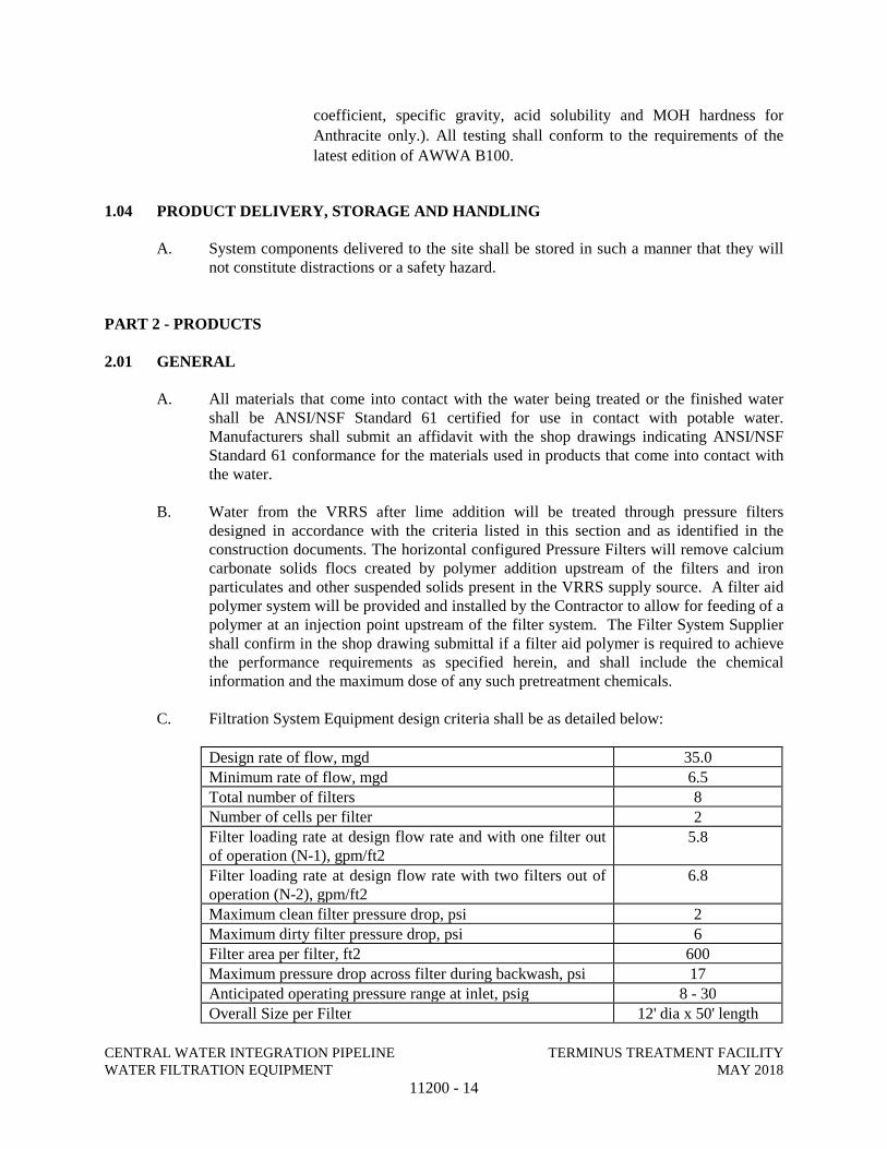
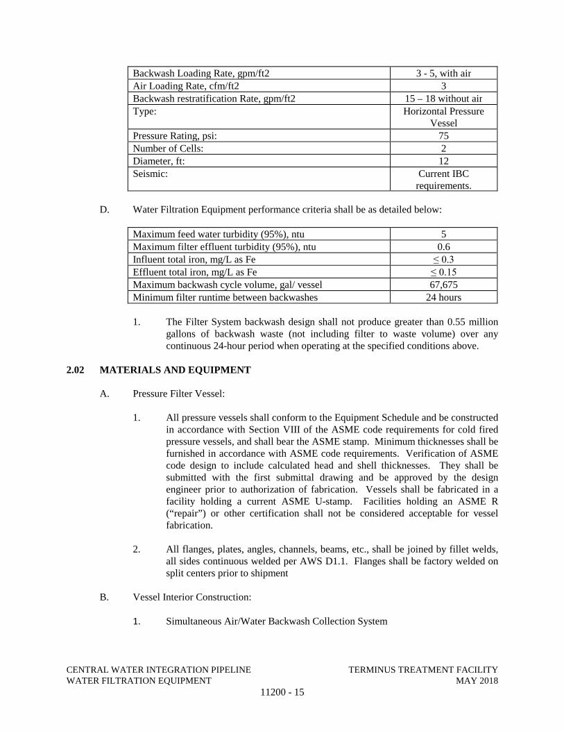
C. Filtration System Equipment design criteria shall be as detailed below:
Design rate of flow, mgd 35.0
Minimum rate of flow, mgd 6.5Total number of filters 8Number of cells per filter 2Filter loading rate at design flow rate and with one filter out of operation (N-1), gpm/ft2
5.8
Filter loading rate at design flow rate with two filters out of operation (N-2), gpm/ft2
6.8
Maximum clean filter pressure drop, psi 2Maximum dirty filter pressure drop, psi 6Filter area per filter, ft2 600Maximum pressure drop across filter during backwash, psi 17Anticipated operating pressure range at inlet, psig 8 - 30Overall Size per Filter 12' dia x 50' length
CENTRAL WATER INTEGRATION PIPELINE TERMINUS TREATMENT FACILITY WATER FILTRATION EQUIPMENT MAY 2018
11200 - 15
Backwash Loading Rate, gpm/ft2 3 - 5, with airAir Loading Rate, cfm/ft2 3Backwash restratification Rate, gpm/ft2 15 – 18 without airType: Horizontal Pressure
VesselPressure Rating, psi: 75Number of Cells: 2Diameter, ft: 12Seismic: Current IBC
requirements.
D. Water Filtration Equipment performance criteria shall be as detailed below:
Maximum feed water turbidity (95%), ntu 5Maximum filter effluent turbidity (95%), ntu 0.6Influent total iron, mg/L as Fe ≤ 0.3Effluent total iron, mg/L as Fe ≤ 0.15Maximum backwash cycle volume, gal/ vessel 67,675Minimum filter runtime between backwashes 24 hours
1. The Filter System backwash design shall not produce greater than 0.55 million gallons of backwash waste (not including filter to waste volume) over any continuous 24-hour period when operating at the specified conditions above.
2.02 MATERIALS AND EQUIPMENT
A. Pressure Filter Vessel:
1. All pressure vessels shall conform to the Equipment Schedule and be constructed in accordance with Section VIII of the ASME code requirements for cold fired pressure vessels, and shall bear the ASME stamp. Minimum thicknesses shall be furnished in accordance with ASME code requirements. Verification of ASME code design to include calculated head and shell thicknesses. They shall be submitted with the first submittal drawing and be approved by the design engineer prior to authorization of fabrication. Vessels shall be fabricated in a facility holding a current ASME U-stamp. Facilities holding an ASME R (“repair”) or other certification shall not be considered acceptable for vessel fabrication.
2. All flanges, plates, angles, channels, beams, etc., shall be joined by fillet welds, all sides continuous welded per AWS D1.1. Flanges shall be factory welded on split centers prior to shipment
B. Vessel Interior Construction:
1. Simultaneous Air/Water Backwash Collection System
CENTRAL WATER INTEGRATION PIPELINE TERMINUS TREATMENT FACILITY WATER FILTRATION EQUIPMENT MAY 2018
11200 - 16
a. The required number of simultaneous air/water backwash troughs shall be installed in each filter and be specifically designed to accept a sustained backwash flow of air and water simultaneously without loss of media and without inhibiting the removal of suspended solids. Sustained is defined as a single duration greater than 10 minutes at specified air and water rates while backwash water overflows the trough.
b. Simultaneous air/water backwash collection troughs shall be constructed of minimum 12-gauge Type 304/304L stainless steel. All mounting hardware shall be stainless steel.
c. The simultaneous air/water collector troughs shall be designed to simultaneous accept the design air and water backwash rates indicated previously.
d. The simultaneous air/water backwash collection troughs shall be of the overflow type without deep, overlapping baffles and shall include a quiescent zone for media/solids separation. Filter backwashing with water only, air followed by water, or combined air and water for short periods, limited by filter geometry, (freeboard combined air/water backwash using upturned elbows) shall not be acceptable or considered equal.
e. The simultaneous air/water collector troughs shall be designed with weir edges along the entire length of trough to allow for equal distribution and collection of water. Pipe collectors with submerged or semi-submerged orifice collection points shall not be acceptable due to the inherent plugging.
f. The backwash collection trough design is critical to preventing media loss during the simultaneous air/water backwash. Filter System Supplier shall guarantee media loss of less than one inch per year when backwashing in accordance with the methods described herein.
g. Alternative backwash methods that do not incorporate simultaneous air and water for a sustained duration are not acceptable. Sustained is defined as an uninterrupted duration of 10 minutes, minimum. Filter backwashing with air followed by water, or air and water for short periods limited by filter geometry, shall not be acceptable.
2. Vessel Underdrain System
a. The underdrain shall consist of an arched plate false-bottom design. The underdrain system shall be structurally reinforced as necessary to withstand a differential pressure in either direction of 12 psig. The underdrain plate shall be fitted with openings to accept underdrain nozzles located throughout the entire cross section of the underdrain area.
CENTRAL WATER INTEGRATION PIPELINE TERMINUS TREATMENT FACILITY WATER FILTRATION EQUIPMENT MAY 2018
11200 - 17
b. The underdrain diffuser nozzles shall be non-metallic, self-cleaning nozzles. They shall be mounted in the underdrain plate with orifice control area of the underdrain diffuser nozzle equal to 0.3% of the total filter bed measured at the surface of the filter media. Nozzles shall be provided with openings as required to collect and distribute flow laterally. Slot openings shall be designed to prevent lodging of support gravel in the slot opening.
C. Vessel Miscellaneous Components
1. Each filter shall be equipped with four (4) 24” full opening manways with hinged covers to allow for removal without heavy lifting equipment and two (2) 6” x 8” handholes, rated for the working pressure of the vessel.
a. One full opening manway shall be placed in each cell near the top of the vessel for access into the filter for purposes of media loading, and one manway shall be placed below the underdrain plate of each cell to allow for access during painting, welding and inspection. The manways shall conform to the requirements of the ASME code for pressure vessels section VIII, Division 1. The manway weld collar shall be 6” of carbon steel. The manway cover shall be constructed of carbon steel and the wing-nut washer hinge pins shall be 304 stainless steel. Manways shall be furnished with a Buna-N material gasket.
b. Each filter shall be equipped with two (2) 6” x 8” handholes (1 per cell) for observation of backwash functions. The hand hole shall be supplied with a Buna-N gasket.
2. Each horizontal pressure vessel shall be subdivided into equal isolated filter cells. The filter feed will be divided into two (2) filter cells. When a single filter is taken offline both filter cells are taken offline as the filtrate and backwash systems are not completely isolated. Each cell wall shall be subjected to 1.5 times the differential pressure during shop testing.
3. Structural steel saddles shall be provided for support of the vessels.
4. 1/2” diameter, threaded full couplings shall be provided as shown on the Drawings for sample taps.
5. Manufacturer shall furnish anchor bolts as required per the manufacturer’s seismic design to be shipped loose with the equipment and installed by the Contractor.
6. Pipe nozzles shall be of the size as shown on the Drawings and shall consist of Sch. 40 steel pipe, projecting and terminating in a flange 6” from the outside face of the sideshell. Flanges shall be Class 150, standard ANSI pattern, welded on split centers and shall be true and plumb.
CENTRAL WATER INTEGRATION PIPELINE TERMINUS TREATMENT FACILITY WATER FILTRATION EQUIPMENT MAY 2018
11200 - 18
7. A 2” drain with ball valve and plug shall be provided at the bottom head center consisting of a welded threaded outlet.
8. An air release half coupling shall be provided in the top center of the shell as required per manufacturers design requirements, but shall be no less than 2-inches.
9. Gauge taps shall be furnished in the influent and effluent nozzle connections (1/2” NPT half coupling with plug).
D. Support Gravels and Filtration Media
1. The support gravel shall consist of hard rounded stones with an average specific gravity of not less than 2.5. It shall not contain more than 2% of weight of pieces in which the length is three times the width. The gravel shall be free of shale, mica, clay, sand, dirt and organic impurities.
2. The support gravels shall be placed in the tank shall be as required to meet the performance requirements specified herein.
3. The bottom layer of the screened support gravel shall be placed by hand to avoid damage to the diffuser assemblies. Each layer shall be placed and leveled before the addition of the next layer is started. A gravel-less underdrain shall not be acceptable.
4. The filter media shall be placed on top of the support gravel and shall be as required to meet the performance requirements specified herein, at a minimum:
Filter Media Total Depth
Filter Media /Sand Specific Gravity Thickness Effective size Uniformity Coefficient
36 inches minimum
2.60 minimum 12 inches minimum 0.45 to 0.55 mm < 1.6
Filter Media /Anthracite Specific Gravity Thickness Effective size Uniformity Coefficient
1.5 minimum 18 inches minimum 0.9 to 1.1 mm < 1.6
5. The support gravels and filter media shall be procured from a manufacturer that complies with AWWA B-100 standards.
6. Provide media quantities to account for skimming requirements.
7. Material shall be delivered in “SuperSacks” with bottom discharge on a flatbed truck capable of being unloaded from both sides. “SuperSacks” shall have lifting
CENTRAL WATER INTEGRATION PIPELINE TERMINUS TREATMENT FACILITY WATER FILTRATION EQUIPMENT MAY 2018
11200 - 19
eyes suitable for use with forklifts. Division of material shall be for one (1) filter cell at a time.
8. Material shall be tested as specified in Part 1 of this section prior to shipment.
E. Water Airwash System
1. Grid
a. The airwash system shall be a header-lateral system located at the media/gravel interface for complete scouring of filtration media. Vertical penetrations of air pipe through the media will not be permitted. Air header pipes shall generally enter the filter cells at the media/gravel interface elevation.
b. Materials. The system construction shall be Sch. 80 PVC pipe and fittings with headers being supported at not greater than 4 ft. intervals using stainless steel U-bolts, steel angles, and stainless steel anchorage. Laterals shall be shop fabricated from Sch. 80 PVC, minimum 3/4” diameter and shipped loose for installation by the contractor. Laterals shall be evenly spaced at not more than 12” lateral to lateral spacing along the entire length of the header, each side. Laterals shall be supported at not greater than 2’ intervals using steel angles, vertical supports, base plates, and anchorage. Supports shall be adjustable in two directions.
c. Lateral Design. Each lateral shall be fitted with an end cap and a specially machined Sch. 80 male adapter for screwing or solvent welding into the airwash header. A specially sized air metering slot shall be placed parallel to the axis of the lateral at 6” intervals. The slot width and length shall be designed to reject all media it comes in contact with. The slots shall allow the proper range of air per square foot of area, based on operating conditions. Systems are not allowed which use clamping or other friction type fits.
d. Configuration. The system used shall be of rigid pipe construction. Systems utilizing multiple penetrations into the filter cells shall be prohibited due to the high potential for hydraulic short circuiting. Systems utilizing flexible piping or hoses (rubber, polyethylene, polypropylene, etc.) shall be prohibited due to their inherent movement in the filtration bed and their inability to remain rigid during normal filter operation. Calculations verifying adequate air distribution design including orifice headloss calculations, shall be submitted to the design engineer for approval.
2. Airwash Blower with Sound Enclosure and Accessories
CENTRAL WATER INTEGRATION PIPELINE TERMINUS TREATMENT FACILITY WATER FILTRATION EQUIPMENT MAY 2018
11200 - 20
a. The Filter System Supplier shall furnish two (2) airwash blower packages.
b. Each airwash blower package shall include a rotary lobe positive displacement type.
1) Sized to deliver a minimum of 1,000 scfm of air at 6 psi.
2) Acceptable manufactures: Gardner Denver 4500 Series, Howden ROOTS-FLO, or Aerzen.
3) Housing shall be cast iron per ASTM A-48 Class 30B
4) Shaft sleeves shall be cast iron per ASTM A-48 and hardened.
5) Discharge temperature shall not exceed 200°F at the duty condition with ambient inlet air temperatures.
c. The blower motor shall not exceed 50 hp.
d. The blower and motor shall be coupled together and mounted on a common baseplate, and shall include necessary belts, sheaves, and guards.
e. The blower motor shall be TEFC, and shall be rated for continuous duty at no more than 1800 rpm nominal speed. Motors shall conform to the requirements listed below for NEMA motors.
f. Digital Monitor / Controller
Each blower will have a controller that at a minimum offers the following monitoring / control of the blower:
1) Inlet/Discharge Pressure
2) Inlet/Discharge Temperatures
3) Differential Temperature Protection
4) Excessive Enclosure Temperature Protection
5) Remote start/stop control
6) Remote speed control
g. Inlet Filter/Silencer
Each blower will have a filter/silencer with paper media that removes 99.5% of 2-micron particles and have the attenuation performance of the RIS series inlet silencer. The maximum
CENTRAL WATER INTEGRATION PIPELINE TERMINUS TREATMENT FACILITY WATER FILTRATION EQUIPMENT MAY 2018
11200 - 21
pressure drop across the clean element shall be less than 2-inches of water column. The minimum noise reduction shall be 16 dB. The filter/silencer shall be Stoddard FH64 or equal.
h. Discharge Silencer
1) Silencers shall be of the multiple-chamber design. Silencers will have acoustically packed nozzle next to blowers operating above transition speed. Silencer shall be separate from base frame.
2) The discharge silencer shall be sized on inlet CFM. Air velocity shall be 5500 to 7000 feet per minute.
i. Flexible Joint
Each blower shall have a flexible joint located between the blower and discharge silencer to minimize vibration transmission to downstream piping. The joint’s elastomer must be rated higher than the maximum expected service temperature and pressure.
j. Pressure Relief Valve
Each blower shall be protected by a spring-loaded pressure relief valve preset to start opening at half a PSIG above the PSIG listed in the Conditions of Service, be full open at not more that 10% above the set pressure, and rated for the SCFM and PSIG listed in the Conditions of Service. If the valve malfunctions it shall do so in the open condition to prevent blower damage.
k. Check Valve
Each blower shall have a discharge check valve with wafer connection, cast-iron body, cast-iron split discs and seal rated above the maximum anticipated discharge temperature. Valve shall be shipped installed on the system.
l. Isolation Valve
Each blower shall have a discharge isolation valve. Valves less than two inches in diameter will be ball valves. Valves 2-inches and larger shall be stainless steel lugged-body butterfly type with a locking handle. Valves more than eight feet above the floor shall have a chain wheel operator. The temperature rating
CENTRAL WATER INTEGRATION PIPELINE TERMINUS TREATMENT FACILITY WATER FILTRATION EQUIPMENT MAY 2018
11200 - 22
of the seat must exceed the maximum anticipated discharge temperature. The valve shall be shipped installed on the system.
m. Unloading Valve and Silencer
Each blower shall have an open to atmosphere, electrically actuated, unloading valve and matched dissipative silencer for noise control. The valve will automatically be closed after the motor has reached operating speed. The unloading valve shall be two pipe sizes larger than the pressure relief valve’s inlet port. The unloading valve shall be equipped with a 120V single phase motor actuator.
n. Pressure Gauge
Each blower shall have a 4” diameter, pressure gauge with a 0-15 PSIG scale on systems operating up to 10 PSIG and 0-30 PSIG for higher pressures. Pressure gauges shall conform to the specifications detailed in Section 17314: Pressure Instruments.
o. Filter Restriction Gauge
Each inlet filter shall have a filter restriction gauge that progressively measures vacuum in the filter element. A visual indicator, with a manual reset, shall lock at the current vacuum when the blower is shut off.
p. Sound enclosure
1) Each blower assembly shall be furnished with a weather tight, sound attenuating enclosure. The enclosure shall be manufactured of 16 gage aluminum, and shall be lined with acoustical foam, and 20 gauge galvanized perforated steel; sufficient to meet 60 dba at one meter from any exterior surface of the enclosure. The enclosure shall have removable side panels which will allow full access to the assembly for maintenance or repair.
2) The sound enclosure shall not interfere with accessing accessories of the blower package and shall not require disassembly of the piping or the use of tools.
3) Sound enclosure shall cover the entire blower package including the blower, drive motor, inlet silencer, and discharge silencer.
CENTRAL WATER INTEGRATION PIPELINE TERMINUS TREATMENT FACILITY WATER FILTRATION EQUIPMENT MAY 2018
11200 - 23
The sound enclosure must be designed for inspection and maintenance of all blower package components.
4) The enclosure and the blower package must be both mounted on a skid / oil-drip pan designed for meeting environment protection standards and for easy transportation and installation provided by the Contractor.
5) A grounding strap shall be installed between the blower base and the package skid to bypass any vibration isolating mounts.
6) Quick release panels, each less than 50 lb (as mandated by MSHA) must provide access for routine maintenance of the blower and the package components. Should the panels be heavier than 50 pounds, hinged doors must be supplied, with an appropriate frame, reinforcements, and supporting elements.
7) A shaft-mounted or motor driven ventilation cooling fan for sufficient heat removal from the sound enclosure shall be provided.
8) Electrical components, instrumentation and instrument connections shall not be mounted or interface with moving panels of the sound enclosure.
3. Backwash Supply Pumps and Accessories
a. The Filter System Supplier shall furnish and install two (2) backwash pumps with accessories for installation by the Contractor.
b. The backwash pumps shall be the double suction, horizontal split case type, as manufactured by Goulds, Flowserve, Patterson, or Fairbanks Nijhuis.
c. The backwash water source shall normally be the filtered supply water. The backwash system shall be sized to accommodate the range of pressures available in the filtrate header as the level in the tank fluctuates. Control shall be provided by both the VFD on the backwash supply pumps, and modulation of the backwash supply valve at each pressure vessel. The filtrate storage tank (SAWS Storage Tank) will operate at the following ranges in water level:
1. High Water Level: 1058-ft 2. Low Water Level: 1012-ft
CENTRAL WATER INTEGRATION PIPELINE TERMINUS TREATMENT FACILITY WATER FILTRATION EQUIPMENT MAY 2018
11200 - 24
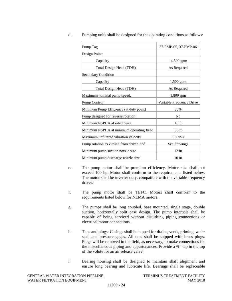
d. Pumping units shall be designed for the operating conditions as follows:
Pump Tag 37-PMP-05, 37-PMP-06
Design Point:
Capacity 4,500 gpm
Total Design Head (TDH) As Required
Secondary Condition
Capacity 1,500 gpm
Total Design Head (TDH) As Required
Maximum nominal pump speed. 1,800 rpm
Pump Control Variable Frequency Drive
Minimum Pump Efficiency (at duty point) 80%
Pump designed for reverse rotation No
Minimum NSPHA at rated head 40 ft
Minimum NSPHA at minimum operating head 50 ft
Maximum unfiltered vibration velocity 0.2 in/s
Pump rotation as viewed from driven end See drawings
Minimum pump suction nozzle size 12 in
Minimum pump discharge nozzle size 10 in
e. The pump motor shall be premium efficiency. Motor size shall not exceed 100 hp. Motor shall conform to the requirements listed below. The motor shall be inverter duty, compatible with the variable frequency drives.
f. The pump motor shall be TEFC. Motors shall conform to the requirements listed below for NEMA motors.
g. The pumps shall be long coupled, base mounted, single stage, double suction, horizontally split case design. The pump internals shall be capable of being serviced without disturbing piping connections or electrical motor connections.
h. Taps and plugs: Casings shall be tapped for drains, vents, priming, water seal, and pressure gages. All taps shall be shipped with brass plugs. Plugs will be removed in the field, as necessary, to make connections for the miscellaneous piping and appurtenances. Provide a ¾” tap in the top of the volute for an air release valve.
i. Bearing housing shall be designed to maintain shaft alignment and ensure long bearing and lubricate life. Bearings shall be replaceable
CENTRAL WATER INTEGRATION PIPELINE TERMINUS TREATMENT FACILITY WATER FILTRATION EQUIPMENT MAY 2018
11200 - 25
without disturbing the system piping and shall be regreaseable without removal of the bearings from the bearing housing. Pump bearings shall be designed and sized for 100,000 hours (40,000 hours used on OPPS) L10 rated bearing life at 25% BEP per ANSI/HI 1.3-2013. All bearings shall be manufactured in the United States.
j. Pumps shall be supplied initially with mechanical split type seals which are interchangeable with conventional packing. Mechanical seals shall be Chesterton 442 or Flex-a-seal model 85.
k. Seal glands shall have a flush connection at the top and along the vertical centerline or at 30 to 45 degrees from the horizontal centerline. Seal must consist of assemblies which fit together over a shaft to form a self-setting and aligning cartridge seal design. The seal must eliminate the need for shims or dimensions to be taken for proper installation.
l. Shafts, where exposed to water or passing through glands and stuffing boxes, shall be protected by renewable (removable) sleeves. Stuffing boxes shall have hardware constructed of corrosion-resistant metals. Materials of construction for shafts shall be 410 or 416 stainless steel, 350 Brinell hardness.
m. Provide seal water flushing per API Plan 11 with stainless steel seal water tubing, with stainless steel hand valve, from the pump casing to the gland flush connection. The hand valve shall be tagged with a stainless steel warning tag indicating the valve is to be open at all times during operation.
n. Any additional equipment required, such as pressure relief valve, flow switch, or flow indicator shall be provided by Filter System Supplier at no additional cost to the Owner. Any instrumentation required for these devices shall be provided by the Filter System Supplier.
o. Impeller shall be of the enclosed double suction type made of entirely of ANSI Stainless Steel Type 316.
p. Statically and dynamically balanced to prevent whipping and vibration throughout the operating range, from shutoff head to run out. Perform a precision balance of each impeller to ISO Grade G2.5 and provide the balance certificate in the quality control section of the O&M Manual.
q. Pump/Motor Couplings shall be heavy-duty flexible type, keyed, and locked to the shaft. The drive shaft coupling gear shall be gear type and all metal. Lubrication shall be oil or grease. Coupling guards shall be enclosed type. Bolts and nuts on the exterior surfaces shall be Grade 5 or 8 fasteners. Baseplates shall be cast iron or fabricated steel.
r. Pump casing shall be of a cast iron conforming to ASTM A48 axially-split design with flanges drilled for 125 PSI ANSI companion flanges
CENTRAL WATER INTEGRATION PIPELINE TERMINUS TREATMENT FACILITY WATER FILTRATION EQUIPMENT MAY 2018
11200 - 26
working pressures and mounting feet integral cast into the bottom half of the casing. Suction and discharge flanges shall be on a common centerline in both the horizontal and vertical planes, and the volute shall include Martensitic Stainless Steel, Brinell 300+ Casing Wear Rings, priming port, gauge ports at nozzles, and vent and drain ports. The upper half casing shall be capable of being removed without disturbing piping connections or electrical motor connections.
s. Pump and motors shall be factory aligned, and shall be realigned after installation by the manufacturer’s representative. Pump characteristics shall be such that the head of the pump under varying conditions shall not exceed the rated horsepower of the drive motor.
t. Base plate shall be of cast iron, structural steel or fabricated steel channel with fully enclosed sides and ends, and securely welded cross members. Grouting area shall be fully open. The combined pump and motor base plate shall be sufficiently stiff as to limit the susceptibility of vibration. The minimum base plate stiffness shall conform to ANSI/HI Pump standards.
u. The pump NPSH shall conform to the ANSI/HI 9.6.1- 2017 standards for Centrifugal and Vertical Pumps for NPSH Margin.
v. Pumping equipment shall be provided with all necessary equipment appurtenances to make the pumping units functional.
w. Metal equipment guards shall be provided on all equipment driven by open shafts. Guards shall be designed to enclose the drive mechanism completely and be easily removable.
x. Nameplate shall be 16-gauge stainless steel with ¼-inch die-stamped equipment tag number securely mounted in a readily visible location. Nameplate shall clearly show pump information and complete performance data, including:
1) Manufacturer's name. 2) Pump size, type, and model number. 3) Serial number. 4) Speed. 5) Impeller diameter. 6) Capacity and head rating. 7) Bearing identification, name, and number. 8) Pump weight, motor weight. 9) Date of manufacture.
y. Factory Pre-mounting and Alignment. Pumps with their job motors shall be pre-mounted and pre-aligned. Mounting holes shall be drilled and tapped at Pump Manufacturer's factory. Factory alignment data shall be furnished to the Contractor. Pump Manufacturer shall drill pump and
CENTRAL WATER INTEGRATION PIPELINE TERMINUS TREATMENT FACILITY WATER FILTRATION EQUIPMENT MAY 2018
11200 - 27
motor feet only for dowels. Do not drill base plate or install dowels at factory; ship loose.
z. Testing: Each pumping unit shall by hydrostatically tested in accordance with the Hydraulic Institute Standards.
1) Hydrostatic Tests: Pump casings tested at 150 percent of shutoff head. Test pressure maintained for not less than 30 minutes.
2) Factory Test Report: Include performance curve test results, performance test logs, noise and vibration test results, for review prior to shipment.
3) Functional Test (in the field): Perform 3-hour continuous run test on equipment. Perform Manufacturer's standard tests, including vibration test, as follows:
a) Dynamically balance rotating parts of each pump and its driving unit before final assembly.
b) Limits:
Driving Unit Alone: Less than 95 percent of NEMA MG 1 limits.
Complete Rotating Assembly Including Coupling, Drive Unit, and Motor.
4) Performance Test (in the field):
a) Conduct on each pump including motor at full speed. All tests and test reports shall be made in conformity with the requirements and recommendations of the Hydraulic Institute Standards. Acceptance testing shall be Table 14.6.3.4 Grade 1B.
b) Tests over full range of design operating conditions specified shall include the following: Head, capacity and wire-to-water efficiency.
c) Test for a continuous 3-hour period at rated pumping capacity and total dynamic head without malfunction.
d) Test Log: Record the following:
Total Head.
Flow capacity measured by factory instrumentation and storage volumes.
Power requirements.
CENTRAL WATER INTEGRATION PIPELINE TERMINUS TREATMENT FACILITY WATER FILTRATION EQUIPMENT MAY 2018
11200 - 28
Average difference in elevation of water surface in suction well to pump discharge centerline for duration of test.
Pump suction and discharge pressure converted to feet of liquid pumped and corrected to pump discharge centerline.
Pump speed.
Water temperature.
Elevation of test stand.
F.F.T. vibration plots of amplitude versus time out to 150,000 cycles/min at twelve points (three points per bearing, x, y, z). Vibration levels on test stand shall meet the specified vibration limits at the factory. Field vibration analysis shall be performed by an independent testing laboratory on installed pump unit.
Perform noise test based on the A-weighted scale at 3 feet, when measured in accordance with IEEE Std. 85 shall not exceed 85 dBA.
e) Adjust, realign, or modify units and retest in accordance with Hydraulic Institute Standards, if necessary.
F. NEMA Frame Induction Motors
a. Motor voltage shall be TEFC enclosure design, 3-phase, single voltage, as shown on the Drawings, and in compliance with IEEE 841.
b. Motors shall have NEMA standard Class "F" insulation with a maximum temperature rise of 90 Deg C above a 40 Deg C ambient, on a continuous operation or intermittent duty, at nameplate horsepower.
c. Motors shall have non-hygroscopic encapsulated windings. Motor leads shall be Class F rated, with permanent identification.
d. Motor rotors and assembly, shall be dynamically balanced.
e. Motors shall be NEMA Premium Efficiency.
f. The motor insulation system for motors controlled with VFD’s shall be inverter duty rated and have full capability to handle the common mode voltage conditions imposed by the VFD. Motor insulation system shall
CENTRAL WATER INTEGRATION PIPELINE TERMINUS TREATMENT FACILITY WATER FILTRATION EQUIPMENT MAY 2018
11200 - 29
conform to all of the requirements of the latest version of NEMA MG1, Part 31 for peak voltage withstand capability.
g. All motors controlled with VFD’s shall have minimum 1600 Volt insulation system.
h. The critical speed of the shaft and rotor assembly shall exceed the operating speed by a minimum of 10 percent.
i. The no-load sound pressure level, based on the A-weighted scale at 3 feet, when measured in accordance with IEEE Std. 85 shall not exceed 85 dBA.
j. Vibration limits shall not exceed 0.2-in/sec at any frequency.
k. Motors shall have a minimum of one grounding pad on each motor frame.
l. Bearings
1) Motors larger than 5 HP shall have oil or grease-lubricated antifriction ball- bearings with L10 lifetime of 50,000 HRS.
2) Vertical motor thrust and guide bearings shall conform to AFBMA standards and shall have L10 lifetime ratings as specified for ball-bearings of the same horsepower range. Down thrust information shall be provided to the motor manufacturer by the equipment supplier.
3) Anti-friction motor bearings shall be designed to be regreasable and initially shall be filled with grease suitable for the motor ambient temperature specified.
4) Grease lubricated bearings, except those specified to be factory sealed and lubricated, shall be fitted with easily accessible grease supply, flush, drain and relief fittings. Extension tubes shall be used when necessary. Grease supply fittings shall be standard hydraulic type as manufactured by the Alemite Division of the Stewart Warner Corporation.
5) Sealed bearings shall be contact seal (lip) or non-contact labyrinth type.
6) Motors controlled by VFD’s shall have the opposite drive and bearing insulated and a shaft grounding brush installed on the drive end bearing.
m. Space Heaters
CENTRAL WATER INTEGRATION PIPELINE TERMINUS TREATMENT FACILITY WATER FILTRATION EQUIPMENT MAY 2018
11200 - 30
1) Space heaters shall be supplied with all outdoor, 3-phase motors, 10hp and above and shall conform to the following:
Heaters shall be of the cartridge or flexible wrap around type installed within the motor enclosure adjacent to core iron. Heaters shall be rated for 120 V, single phase with wattage as required. The heater wattage and voltage shall be embossed on the motor nameplate. Power leads for heaters shall be brought out at the motor accessory lead junction box.
n. Subject to compliance with the Contract Documents, the following Manufacturers are acceptable:
1) General Electric
2) U.S. Motors
G. Facepiping
1. Filter facepiping will be supplied and installed by the Contractor. The Filter System Supplier shall confirm all connecting facepiping diameters and locations on the vessel, and note any necessary deviations from the Contract Documents in shop drawing submittals for coordination with the Contractor.
H. Process Valves
1. The Filter System Supplier shall furnish all valves as called for in these specifications, or as required for proper operation of the equipment in all operating modes, including rinse to waste. The valve manufacturer shall furnish detailed technical information as required by the Engineer for evaluating the quality of the valves and as required by the Supplier for proper valve installation. The technical information shall include complete dimensions, weights, and material lists. No valve will be approved for installation until the required information has been received and reviewed.
2. The Filter System Supplier shall furnish all incidental materials necessary for installation of the valves such as flange gaskets, flange bolts and nuts, and all other materials required for the complete installation.
3. Remote control stations shall be provided for all valve actuators located more than 60-inches above the finished floor.
4. Filter function valves shall be shipped loose for installation by the Contractor.
5. All filter function valves shall be as detailed in Section 15100: Process Valves and Appurtenances.
6. Where specified on plans and in Section 15100, an electric motor operator shall be supplied on butterfly valves.
CENTRAL WATER INTEGRATION PIPELINE TERMINUS TREATMENT FACILITY WATER FILTRATION EQUIPMENT MAY 2018
11200 - 31
I. Instrumentation
1. Pressure and Flow Monitoring Panel
a. The Filter System Supplier shall furnish four (4) stainless steel pressure and flow monitoring panels (one for each pair of filter vessels) completely factory fabricated from 3/16” brushed aluminum plate having a textured finish, with minimum dimensions of 18” x 22” for each pair of vessels.
b. Pressure gauges shall conform to the specifications detailed in Section 17314: Pressure Instruments. The gauge panel shall have the following flush-mounted gauges:
Four (4) Inlet header (0-60 psi). One (1) per filter cell.
Two (2) Effluent header (0-60 psi). One (1) per filter vessel.
c. Pressure transmitters shall conform to the specifications detailed in Section 17314: Pressure Instruments. The pressure and flow panel shall have the following flush-mounted gauges:
Two (2) Loss of head - between influent and effluent headers (0-10 psi differential pressure transmitter with local indication). One (1) per filter vessel.
d. Each panel shall be equipped with the following components:
Two (2) local flow indicator for the Filtrate magnetic flow meter. One (1) per filter vessel.
Six (6) flush mounted sample taps for influent and effluent locations as shown on the Drawings.
e. Each panel shall conform to the specifications in Section 17327: Panel Mounted Control Devices.
f. Filter System Supplier shall furnish mounting hardware (brackets, U-bolts, nuts, washers, etc.) for affixing to facepiping. Installation of panel shall be by Contractor.
2. Flow Meters
a. Eight (8) flanged in-line magnetic flow meters shall be used to measure Filtrate of each vessel. Size and location shall be as shown on the Drawings and provided by Filter System Supplier.
b. The flow meters shall be as specified in Section 17310.
CENTRAL WATER INTEGRATION PIPELINE TERMINUS TREATMENT FACILITY WATER FILTRATION EQUIPMENT MAY 2018
11200 - 32
J. Automatic Filter Controls
1. General: The Filter System Supplier shall furnish an automatic control system consisting of a PLC-based control panel with operator interface terminal (OIT), necessary hardware, components, timers, OIT, enclosure, relays, switches, alarms, I/O, and other items necessary for a complete operational system. The automatic filter control system shall be essentially as described below.
2. The automatic filter control system shall provide control and monitoring of all equipment indicating on the Drawings, including the monitoring of the Filter Feed Panel, the control and monitoring of the Backwash Supply Pumps and the Air Scour Blowers and full valve control.
3. The automatic filter control system shall be provided in two (2) PLC cabinets, 30-CP-01 AND 30-CP-02, as shown on the Drawings which shall accept the I/O for half of the system in each cabinet.
4. The Filter System Supplier shall schedule and administer a minimum of two (2) mandatory Coordination Meetings. The Filter System Supplier shall plan and schedule coordination meetings; prepare agendas and distribute copes to participants at least one (1) week before schedule meetings. The meetings shall be held at Owner’s Offices and shall include, as a minimum, attendance by the Owner’s Engineer and the Application Services Provider’s (ASP) Project Engineer.
a. The first coordination meeting shall be held in advance of the Supplier shop drawing submittals for Data Transfer List and Control Narratives. The purpose of the meeting shall be for the Supplier to:
Summarize their understanding of the project.
Provide a forum for the Supplier and Owner to coordinate hardware and software related issues.
Request any additional information required from the Owner and/or Engineer.
b. The second coordination meeting shall be held after the Field Instruments, Control Panel Layout Drawing/Wiring Diagrams, Data Transfer List and Control Narratives Submittal packages have been reviewed by the Engineer and returned to the Supplier. The purpose of the second meeting shall be to discuss:
Review comments made on the submittal packages.
Provide a forum for additional coordination.
CENTRAL WATER INTEGRATION PIPELINE TERMINUS TREATMENT FACILITY WATER FILTRATION EQUIPMENT MAY 2018
11200 - 33
5. The PLC for the Pressure Filter System provides supervisory control and monitoring for all of the pressure vessels, the backwash system, as well as providing the interface for control and monitoring by the plant SCADA system. A plant SCADA network may be connected to the PLC through available network protocols and will be able to access designated read and write data. Additionally the PLC and HMI will optionally be accessible through a remote connection for the purpose of monitoring logic and making online changes.
6. Control Architecture
a) System level control will include the following functionality:
1) Pressure Filter Start-up and Shut down commands
2) Management of Pressure Filter backwash priorities and number of Pressure Filters required to be in service based on flow and target requirements
3) Provide System monitoring and operator control functions through a panel mounted operator interface
4) Detect and respond to System level fault conditions including alarm annunciations at the HMI as well as to the Plant SCADA System
5) Provide System interface to the Plant PLC via the SCADA connection
7. Control Modes
a) There are two modes of System control that can be selected via the HMI: “Auto” and “Manual”. The Operator must enter a password on the Operator Interface Terminal to change System mode.
1) Remote: With the System in “Remote” mode, Start Up and Shut Down requests are initiated by the Plant via SCADA commands.
2) Local: With the UV System in “Local” mode, all plant control SCADA commands are disabled. The Pressure Filters can be operated in “Manual” or “Automatic” mode, selectable via the HMI. Pressure Filters may be manually given start-up and shutdown requests.
3) Off: With the System in “Off” mode, all the Pressure Filters will be placed into “Off” mode. The system will not be functional in “Off” mode. All valves, pumps and blowers will be de-energized. Only local controls at the devices will be operational.
8. Control States and Transitions
a) Each filter can be in one of three different states; “Online”, “Backwash” or “Shutdown”. The entire filter system can be in one of two different state; “Online” or “Out of Service”.
CENTRAL WATER INTEGRATION PIPELINE TERMINUS TREATMENT FACILITY WATER FILTRATION EQUIPMENT MAY 2018
11200 - 34
b) Start Up Sequence
1) System is in “Automatic” mode and in the “Offline” state.
2) System receives a start request as determined from Plant SCADA system. Start shall be selectable at the Plant SCADA HMI.
3) PLC will request to open the filtrate isolation valve, backwash waste flow control valve, and filter supply valves.
4) Individual requests will be sent to all required pressure vessels and they will begin their normal start-up sequences.
5) After all required vessels valve open signals are active and the backwash waste turbidity is below an operator adjustable setpoint ([x.x] ntu) the system will be “Online”.
6) PLC will request to open the filtrate flow control valve. Once closed signal is inactive, the PLC will request to close the backwash waste control valve and place the filtrate flow control valve into PID flow control.
7) During normal operation feed water is diverted to each cell in the vessel where it flows through the dual media system, gravel and into the filtrate collection chamber. The filtrate collection chamber is shared by all cells in the vessel. The filtrate line is flow controlled to maintain a calculated setpoint based on the raw water feed to the plant and the number of vessels online.
c) Shut Down Sequence
1) The System is in the “Online” state.
2) A shutdown request has been made at the SCADA, PLC or a Critical alarm condition occurs.
3) The System status will change to the “Shutdown” state.
4) PLC will request to shutdown all pumps and blowers, and close all filter header valves except the filtrate isolation valve and the backwash waste flow control valve.
5) Once all vessels have transitioned to a “Offline” states, the System will changes from “Shutdown” to “Out of Service” if a critical alarm has triggered the shutdown.
d) Backwash Sequence
CENTRAL WATER INTEGRATION PIPELINE TERMINUS TREATMENT FACILITY WATER FILTRATION EQUIPMENT MAY 2018
11200 - 35
1) Filter vessels can issue a backwash request based on a differential pressure setpoint, a run time, or a scheduler that selects which day of the week and time each vessel is to be backwashed.
2) The pressure vessel will begin a backwash sequence when no other backwash sequences are active and the Backwash Recovery Basin has the capacity to receive an entire backwash sequence. If multiple vessels request a backwash they will be placed into a queue which is prioritized based on the differential pressure of the vessel. Vessels will continue to operate while in the backwash queue.
3) The backwash sequence will be as determined by the Filter System Supplier to provide a successful simultaneous air-water backwash with the maximum backwash volume produced as required herein. The backwash shall include drain, fill, backwash with air scour and a restratification steps. The backwash pump PID flow rate controller shall be set to a setpoint of either 1,500 gpm (during backwash) or 4,500 gpm (during restratification). The pump shall be called to a minimum speed setpoint during the fill step. The backwash supply valve will be modulating and will be called to a set position according to the backpressure requirements of the pump as determined during startup.
9. Communications Heartbeat
a) A Communications Heartbeat will be utilized to ensure communications is active between the Filter PLC and Plant SCADA. This will be accomplished by monitoring a SCADA signal with its value automatically changing. Should the value received from Plant SCADA stay the same value for a period of time, communications will be deemed lost and an alarm will be generated locally as well as possible control actions as determined and stated earlier in this document.
10. Hardware
a. PLC. The automatic control panel shall be PLC-based as specified in Section 17500: Programmable Logic Controllers for Field PLC processor.
b. The automatic control panel shall conform to the requirements specified in 17325: Process Control System Control Panels.
c. The automatic control panel shall be provided with uninterruptible power supply as specified in Section 17328.
CENTRAL WATER INTEGRATION PIPELINE TERMINUS TREATMENT FACILITY WATER FILTRATION EQUIPMENT MAY 2018
11200 - 36
d. Network and Communications. The automatic control panel shall be provided with the following devices and equipment for proper communication:
1) Fiber Optic Patch Panel for use in PLC control panel enclosures shall be the Wall-mountable Interconnect Center (WIC) type, LANscape series, as manufactured by Corning Incorporated.
a) All fiber cables shall be terminated to a patch panel with a fanout kit. The model shall be as recommended by the cable manufacturer.
2) Industrial Ethernet Media Converter. a) Power Supply: 24 VDC b) Microprocessor based managed type c) DIN rail mountable d) Functional Performance e) Per port status LED indication f) Wire Speed switching g) 10/100BaseT ports with RJ-45 connectors for Category
6 cabling, provide with PoE as shown on the Drawings. h) ST or SC type Fiber Optic Connectors for 100BaseFX,
1000BaseLX for Single-Mode fiber as shown on the Drawings.
2.03 PAINTING
A. Pressure Vessels
1. The tank shall be leak tested and all welding operations completed before preparation of the tank interior to receive the lining. All welded and machined edges shall be ground smooth to a minimum 1/8 inch radius to facilitate application of the lining. All interior surfaces shall be blasted to a SSPC-SP5/NACE 1 white metal blast grade.
2. Surface preparation:
a. Interior - Sandblast to near white blast cleaning (SSPC-SP10).
b. Exterior - Sandblast to commercial blast cleaning (SSPC-SP6).
3. Interior Coating (factory applied):
a. Stripe coating: hand-apply one coat to all welds and hard to reach areas (i.e. interior ribbing, interior pipe nozzle, etc) using high quality natural or synthetic bristle brush, to a dry film thickness of 3-5 mils.
Tnemec Series N140-15BL, or equal
CENTRAL WATER INTEGRATION PIPELINE TERMINUS TREATMENT FACILITY WATER FILTRATION EQUIPMENT MAY 2018
11200 - 37
b. Prime coating: primer to a dry mil thickness of 3-5 mils before any rust can form.
Tnemec Series N140-1255, or equal
c. Finish coating: to a dry mil thickness of 4-6 mils for a total dry film thickness of 7-11 mils.
Tnemec Series N140-15BL, or equal
d. The interior lining shall be applied only by an experienced applicator who shall demonstrate previous experience with the application of the specified coating. The interior lining shall extend into all tank nozzles. The intermediate and final coats shall be performed in strict compliance with the coating manufacturer's recommendations.
e. The internal lining shall be tested for dry film millage and holidays by the approved independent paint testing company. Testing of the internal lining for dry film thickness shall at a minimum be performed at five (5) equally spaced locations along the length of the tank, including each end and the center of the tank straight shell. Each location shall include testing of 12 locations along the interior perimeter of the tank starting at the top and equally spaced at increments of 30-degrees. The tank manufacturer shall retain sample coupons from the shell for use by the paint testing firm for calibration of the testing equipment. The testing shall be performed using a wet sponge type electric holiday tester and magnetic dry film thickness gauge, both of acceptable manufacturer by the Engineer. The tank manufacturer shall repair all holidays and low millage areas in strict accordance with the lining manufacturer's established repair procedures. The tank shall then be retested to determine if all lining defects have been successfully repaired.
4. Exterior Coating
a. The exterior surface shall be blasted to a SSPC-SP6/NACE 3 commercial blast grade and one coat of shop applied epoxy primer.
b. Prime Coat (factory applied): Two component, cross-linked epoxy primer.
Tnemec Series 69 epoxy primer.
c. Finish coating: The exterior finish coat shall be field applied by the Contractor upon installation.
5. The total exterior coating system shall be the product of and be applied in accordance with the recommendations of one manufacturer. Alternate coating systems must be pre-approved by Engineer.
CENTRAL WATER INTEGRATION PIPELINE TERMINUS TREATMENT FACILITY WATER FILTRATION EQUIPMENT MAY 2018
11200 - 38
B. Backwash Pumps
1. Interior Finish for Casings
a. Coat interior of pump casings with ceramic epoxy coating to enhance pump efficiency. Prepare and shop-prime in accordance specified herein.
b. Materials: Prime and Finish Coating: Minimum of 25 mils DFT of Belzona 1341N coating for potable water (ceramic epoxy coating) or fusion bonded epoxy.
c. Procedure:
Surface Preparation: As recommended by coatings Manufacturer, minimum blast clean to near white SSPC-SP-10.
Application (prime and finish coating): Apply 25 mils DFT of Belzona coating or fusion bonded epoxy.
Testing: Perform Holiday Test.
Touchup: After testing is complete and prior to shipment, touch up surfaces. Provide touch up kit for contractors use during installation. If holiday test is required, perform at shop prior to shipment and provide certification.
2. Exterior Finish
a. Exterior of pumps, motors, frames, base plates, and appurtenances shall be painted prior to shipment from factory. Pump units shall be prepared and shop-primed in accordance specified herein.
b. Units shall receive finish coating in the field by the Contractor.
PART 3 - EXECUTION
3.01 FACTORY SERVICES AND START-UP
A. Factory Acceptance Test of Control Panels shall be completed prior to shipment according to specifications in Section 17302: Process Control System Testing.
B. Factory Acceptance Test of Pumping Units and Blowers shall be completed prior to shipment according to specifications herein.
C. System Start-Up and Training
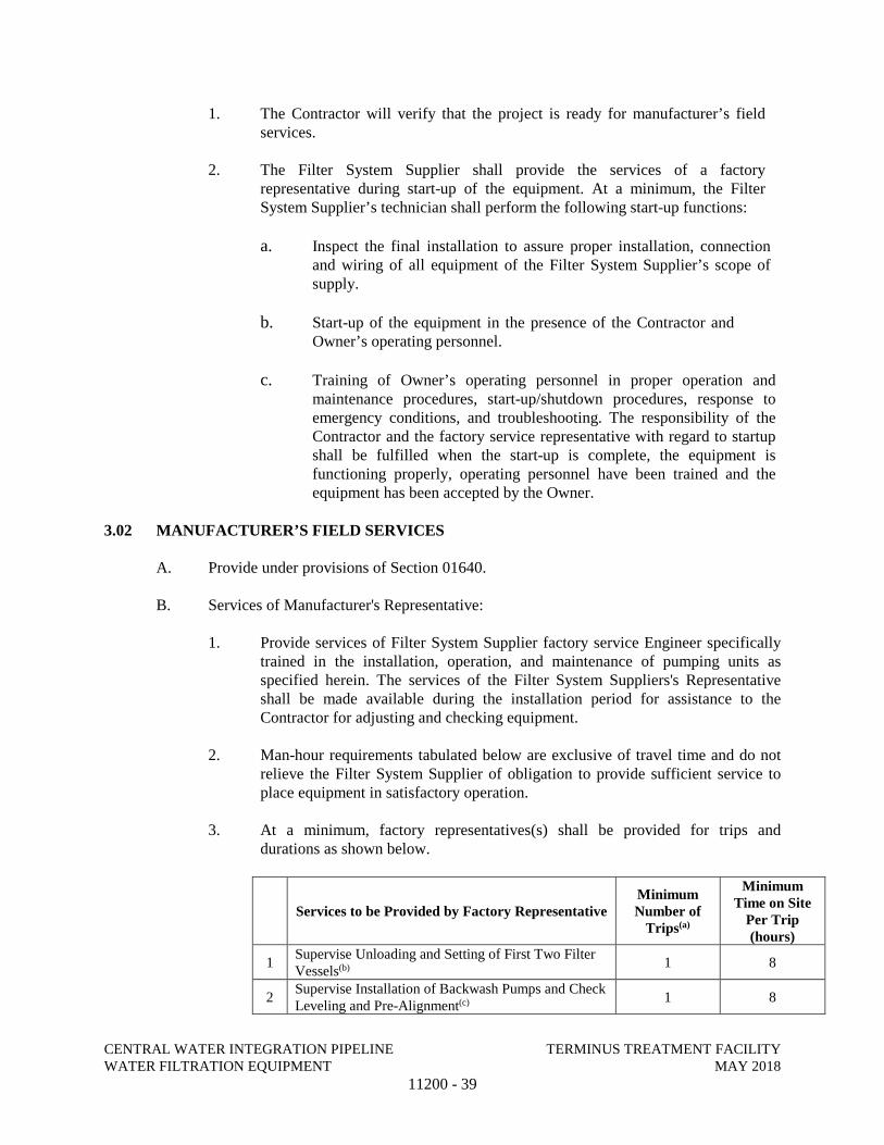
CENTRAL WATER INTEGRATION PIPELINE TERMINUS TREATMENT FACILITY WATER FILTRATION EQUIPMENT MAY 2018
11200 - 39
1. The Contractor will verify that the project is ready for manufacturer’s field services.
2. The Filter System Supplier shall provide the services of a factory representative during start-up of the equipment. At a minimum, the Filter System Supplier’s technician shall perform the following start-up functions:
a. Inspect the final installation to assure proper installation, connection and wiring of all equipment of the Filter System Supplier’s scope of supply.
b. Start-up of the equipment in the presence of the Contractor and Owner’s operating personnel.
c. Training of Owner’s operating personnel in proper operation and maintenance procedures, start-up/shutdown procedures, response to emergency conditions, and troubleshooting. The responsibility of the Contractor and the factory service representative with regard to startup shall be fulfilled when the start-up is complete, the equipment is functioning properly, operating personnel have been trained and the equipment has been accepted by the Owner.
3.02 MANUFACTURER’S FIELD SERVICES
A. Provide under provisions of Section 01640.
B. Services of Manufacturer's Representative:
1. Provide services of Filter System Supplier factory service Engineer specifically trained in the installation, operation, and maintenance of pumping units as specified herein. The services of the Filter System Suppliers's Representative shall be made available during the installation period for assistance to the Contractor for adjusting and checking equipment.
2. Man-hour requirements tabulated below are exclusive of travel time and do not relieve the Filter System Supplier of obligation to provide sufficient service to place equipment in satisfactory operation.
3. At a minimum, factory representatives(s) shall be provided for trips and durations as shown below.
Services to be Provided by Factory Representative Minimum Number of
Trips(a)
Minimum Time on Site
Per Trip (hours)
1 Supervise Unloading and Setting of First Two Filter Vessels(b) 1 8
2 Supervise Installation of Backwash Pumps and Check Leveling and Pre-Alignment(c) 1 8
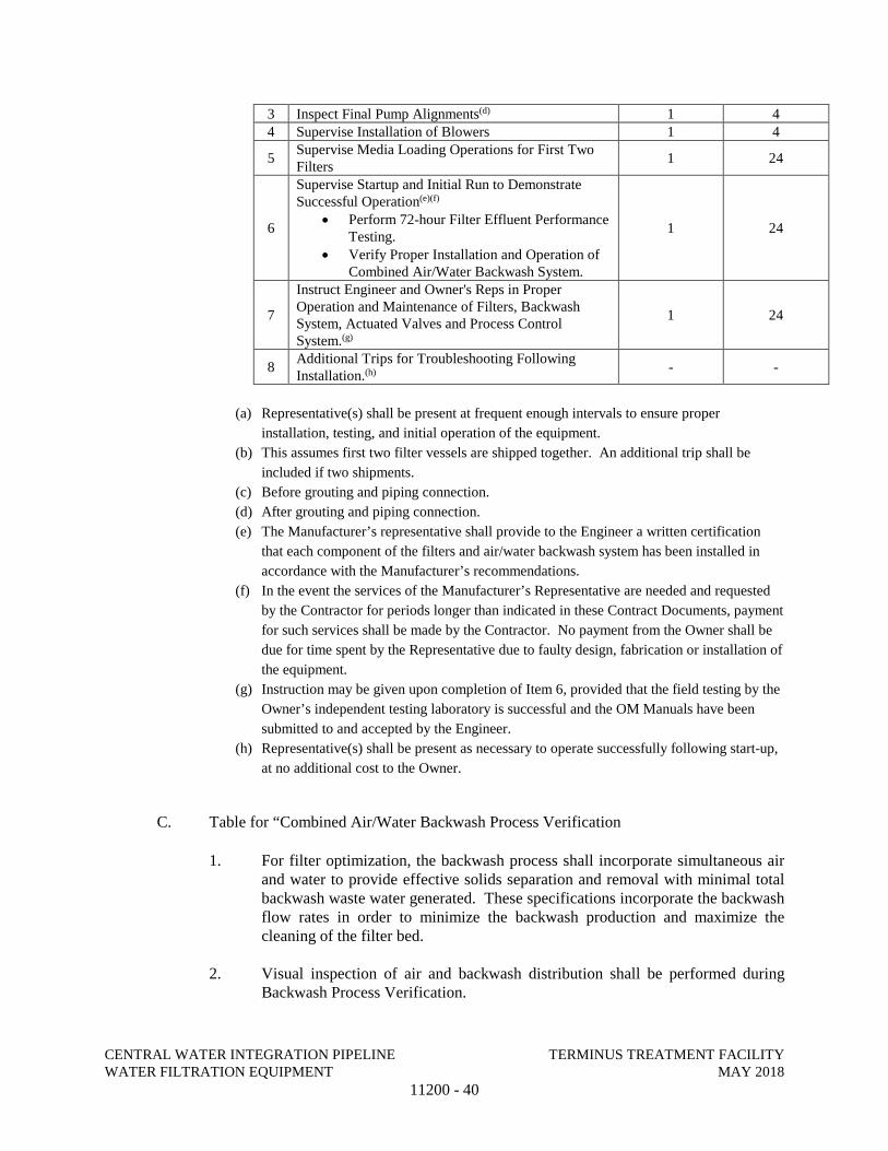
CENTRAL WATER INTEGRATION PIPELINE TERMINUS TREATMENT FACILITY WATER FILTRATION EQUIPMENT MAY 2018
11200 - 40
3 Inspect Final Pump Alignments(d) 1 4 4 Supervise Installation of Blowers 1 4
5 Supervise Media Loading Operations for First Two Filters
1 24
6
Supervise Startup and Initial Run to Demonstrate Successful Operation(e)(f)
• Perform 72-hour Filter Effluent Performance Testing.
• Verify Proper Installation and Operation of Combined Air/Water Backwash System.
1 24
7
Instruct Engineer and Owner's Reps in Proper Operation and Maintenance of Filters, Backwash System, Actuated Valves and Process Control System.(g)
1 24
8 Additional Trips for Troubleshooting Following Installation.(h) - -
(a) Representative(s) shall be present at frequent enough intervals to ensure proper
installation, testing, and initial operation of the equipment.
(b) This assumes first two filter vessels are shipped together. An additional trip shall be
included if two shipments.
(c) Before grouting and piping connection.
(d) After grouting and piping connection.
(e) The Manufacturer’s representative shall provide to the Engineer a written certification
that each component of the filters and air/water backwash system has been installed in
accordance with the Manufacturer’s recommendations.
(f) In the event the services of the Manufacturer’s Representative are needed and requested
by the Contractor for periods longer than indicated in these Contract Documents, payment
for such services shall be made by the Contractor. No payment from the Owner shall be
due for time spent by the Representative due to faulty design, fabrication or installation of
the equipment.
(g) Instruction may be given upon completion of Item 6, provided that the field testing by the
Owner’s independent testing laboratory is successful and the OM Manuals have been
submitted to and accepted by the Engineer.
(h) Representative(s) shall be present as necessary to operate successfully following start-up,
at no additional cost to the Owner.
C. Table for “Combined Air/Water Backwash Process Verification
1. For filter optimization, the backwash process shall incorporate simultaneous air and water to provide effective solids separation and removal with minimal total backwash waste water generated. These specifications incorporate the backwash flow rates in order to minimize the backwash production and maximize the cleaning of the filter bed.
2. Visual inspection of air and backwash distribution shall be performed during Backwash Process Verification.
CENTRAL WATER INTEGRATION PIPELINE TERMINUS TREATMENT FACILITY WATER FILTRATION EQUIPMENT MAY 2018
11200 - 41
3. Supplier shall provide certification following start-up that the system will be run within accepted backwash volume ranges during backwash, as defined in the Water Filtration Equipment design and performance criteria listed above. A representative of the Owner/Design Engineer will witness and verify in writing that the system is operating according to specified rates at the time start-up is completed, and that they have been trained in this operation. A copy of the start-up report containing this verification shall be provided to the Owner/Design Engineer.
D. Manufacturer’s Instructions. Installation shall be as shown on the Drawings and in accordance with the manufacturer’s recommendations, installation instructions and assembly drawings. Manufacturer’s installation instructions and assembly drawings shall be submitted and approved by the design engineer prior to shipment of equipment. Installation of the filtration system shall be in strict accordance with the details shown on the drawings and in complete conformance to manufacturer’s instructions and procedures.
E. Filter Effluent Performance Testing (72 hours)
1. A detailed filter system performance test shall be prepared by the Filter System Supplier and submitted as specified in Part 1 of this section.
2. During start-up, the Filter System Supplier’s representative shall perform feed water and filtered effluent field turbidity and iron tests to confirm performance of the equipment.
3. Analytical methods employed for field testing shall be performed by a digital colorimeter.
4. Sampling for conformance shall be taken during the middle of a filter run.
END OF SECTION
APPENDIX A
DIVISION 1
GENERAL REQUIREMENTS
CENTRAL WATER INTEGRATION PIPELINE TERMINUS TREATMENT FACILITY SUBMITTALS MAY 2018
01300- 1
SECTION 01300
SUBMITTALS
PART 1 - GENERAL
1.01 DESCRIPTION OF WORK
A. This section describes the requirements for preparing and presenting submittals that are necessary for the execution of this contract. Requirements within the following subject areas are included:
1. Definitions.
2. Procedures.
3. Product Data.
4. Shop drawings.
5. Samples.
6. Manufacturer’s certificates.
7. Miscellaneous submittals.
8. Schedule of Values.
9. Quality Control Documentation (Blank Copies of Report).
1.02 DEFINITIONS
A. Product Data and Shop Drawing - General Definition
1. Drawings, diagrams, illustrations, brochures, schedules, bills of materials and other data prepared by the CONTRACTOR, his subcontractors, suppliers or distributors, or equipment manufacturers and fabricators; illustrating the manufacture, fabrication, construction, or installation of the Work or a portion thereof.
B. Shop Drawings
1. Assembly and fabrication drawings, bills of materials for items shop fabricated exclusively for this project. In addition, shop drawings should show fabrication details of each part, the assembly of each part and how each part and/or assembly is integrated into the project including existing parts or assemblies.
CENTRAL WATER INTEGRATION PIPELINE TERMINUS TREATMENT FACILITY SUBMITTALS MAY 2018
01300- 2
C. Manufacturer’s Representative
1. Manufacturer’s representative shall be from the manufacturer’s plant with five (5) years of experience in the actual problems of manufacturing, installing, and operating the particular product. Sales representatives or agents of the manufacturer will not be acceptable.
D. Working Drawings
1. CONTRACTOR prepared plans for temporary structures and facilities. Working drawings for elements of work that may affect the safety and health of persons or property will be certified by an engineer licensed in the State of Texas. Calculations, as necessary, will accompany working drawings.
E. Design Calculations
1. Whenever the CONTRACTOR is required to submit design calculations as part of a submittal, such calculations shall bear the signature and seal of an engineer registered in the appropriate branch and in the State of Texas. OWNER reserves the right to request submittal by CONTRACTOR of a hard copy of design calculations.
1.03 PROCEDURES
A. Electronic Submittal Procedures
1. All electronic submittals shall be transmitted in Portable Document Format (PDF) as generated by the Adobe Acrobat Professional Version 7.0 or higher.
2. It will be the CONTRACTOR’s responsibility to scan all necessary documents or convert previously received electronic files from vendors into pdf format before uploading the files to the specific designated project site. Scanned images must be at a readable resolution. For most documents, they should be scanned at 300 dots per inch (dpi). Optical character Recognition (OCR) capture must be performed on these images so that text can be searched and copied from the generated PDF file.
3. When it is not possible to make submittals electronically, CONTRACTOR may deliver submittals to OWNER using conventional mail only after securing OWNER's written approval. When electronic submittals are not possible, hard copy submissions will be made as required in this section. Submittal of a transmittal page into the contract-specific Prolog site of Portal by CONTRACTOR shall still be required for recordkeeping.
4. When electronic submittal is not possible and upon securing OWNER's written approval, CONTRACTOR may submit hard copies of product data and shop drawings according to the following distribution list:
a. OWNER's designated Agent (if applicable): Three (3) copies.
b. OWNER (if a designated Agent reviews the submittals): One (1) copy.
CENTRAL WATER INTEGRATION PIPELINE TERMINUS TREATMENT FACILITY SUBMITTALS MAY 2018
01300- 3
c. ENGINEER: One (1) copy.
5. If regular mail delivery is approved by OWNER, the submittal transmittal form shall still be logged into the contract specific Contract and Project Management System (CPMS) by CONTRACTOR for record keeping purposes.
6. All responses to a submittal by OWNER will be made electronically and no hard copies of the response will be sent to CONTRACTOR.
B. Contractor’s Responsibilities
1. Submit a list of specified submittals and identify the long lead items to the OWNER within five (5) calendar days of receipt of the Notice to Proceed (NTP).
2. Within 30 days after the pre-construction conference and at the same time that the initial critical path schedule is submitted, a schedule shall be submitted of the items of materials and equipment for which shop drawings are required by the specifications. For each required shop drawing, the date shall be given for intended submission of the drawing to ENGINEER for review and the date required for its return to avoid delay in any activity beyond the scheduled start date. Sufficient time shall be allowed for initial review, correction and resubmission, and final review of all shop drawings. In no case shall a schedule be acceptable which allows less than 21 days for each review by ENGINEER or Designer.
3. Submissions shall be made to the OWNER's office. Data and correspondence that originates with subcontractors and suppliers must be submitted to the OWNER through the CONTRACTOR. CONTRACTOR to approve all submittals prior to submission.
4. CONTRACTOR shall submit dimensional and layout drawings and product data, certified correct for construction, for review by the OWNER.
5. Submit shop drawings and product data in accordance with the approved submittal schedule. Also, submit shop drawings to the OWNER for review prior to their need in the Work, allowing sufficient time for the OWNER’s review and the CONTRACTOR response.
6. CONTRACTOR shall make specific mention of those items that vary from the requirements of the Contract Documents in the letter of transmittal. The letter transmittal shall include the specification number, detail name/number, or plan sheet of the item being submitted.
7. Submit shop drawings and product data covering related items of equipment or material or integrated systems of equipment or material at the same time. Partial submissions will not be accepted.
8. All submittals, regardless of origin, shall be stamped with the approval of CONTRACTOR and identified with the name and number of this contract, CONTRACTOR’S name, and references to applicable specification paragraphs and Contract Drawings. Each submittal shall indicate the intended use of the item in the Work. When catalog pages are submitted, applicable items shall be clearly identified and inapplicable data crossed out. The current revision, issue number, and date shall be indicated on all drawings and other descriptive data.
CENTRAL WATER INTEGRATION PIPELINE TERMINUS TREATMENT FACILITY SUBMITTALS MAY 2018
01300- 4
9. CONTRACTOR shall be solely responsible for the completeness of each submission. CONTRACTOR’S stamp of approval is a representation to OWNER that CONTRACTOR accepts sole responsibility for determining and verifying all quantities, dimensions, field construction criteria, materials, catalog number, and similar data, and that CONTRACTOR has reviewed and coordinated each submittal with the requirements of the Work and the Contract Documents.
10. CONTRACTOR shall coordinate shop drawings and product data with drawings previously submitted, with drawings being prepared, and with drawings and data previously approved. All such coordination shall be indicated by reference.
11. CONTRACTOR shall assign a sequential number to each submittal.
a. Assignment of numbers shall be by means of a letter prefix, a sequence number, a letter suffix to indicate resubmittals and a specification number. For example, submittal SD-012C-01300 is the third re-submittal of the twelfth Shop Drawing for the Project.
b. The sequence number shall be issued in chronological order. Resubmittals shall be followed by a letter of the alphabet to indicate the number of times a submittal has been resubmitted to the OWNER for processing. As an example, a shop drawing with the number SD-001 indicates that the submittal is the first shop drawing submitted for the project. Shop Drawing Number SD-002A indicates that the submittal is the second shop drawing submitted for and is being submitted for the second time. Acceptable prefixes for submittals are as follows:
i. SD -Shop Drawing ii. PS – Project Schedule
iii. RD – Record Data iv. OM – Operation and Maintenance Manual
c. Correct assignment of numbers is essential as different submittal types are processed in different ways. Some submittals received do not require that any response be given for the material. CONTRACTOR and OWNER shall both maintain a log of submissions to allow the processing of CONTRACTOR's submittals to be monitored. Logs will be reviewed periodically to determine that all submittals are received and processed.
d. Submittals shall be marked to show clearly the applicable sections of the specification and sheet number of drawings.
e. Submittals shall be accompanied by a Submittal Transmittal Form to be provided by the OWNER. A separate form shall be used for each specific item, class of material, equipment, and items specified in separate discrete sections, etc. for which a submittal is required. Submittals for various items shall be made with a single form when the items taken together constitute a manufacturer's package or are so functionally related that they should be.
12. CONTRACTOR shall not deliver to the site, storage, or incorporate into the Work, any materials or equipment for which approved submittals have not been obtained.
CENTRAL WATER INTEGRATION PIPELINE TERMINUS TREATMENT FACILITY SUBMITTALS MAY 2018
01300- 5
13. If a submittal is returned to the CONTRACTOR marked “NO EXCEPTIONS NOTED”, formal revision and resubmission shall not be required. CONTRACTOR may proceed to perform submittal related Work.
14. If a submittal is returned marked “EXCEPTIONS NOTED”, CONTRACTOR shall make the corrections on the submittal, but formal revision and resubmission shall not be required and the CONTRACTOR shall proceed with the Work.
15. If a submittal is returned marked “RETURNED FOR CORRECTION,” the CONTRACTOR shall revise it and resubmit to the OWNER for review. Resubmittal and a grade of “NO EXCEPTIONS NOTED” or “EXCEPTIONS NOTED” is required before the CONTRACTOR may proceed with the Work, unless approved in writing by the OWNER. Resubmittal of portions of multi-page or multi-drawing submittals shall not be allowed. For example, if a Shop Drawing submittal consisting of 10 drawings contains one drawing noted as “RETURNED FOR CORRECTION”, the submittal as a whole is deemed “RETURNED FOR CORRECTION”, and all 10 drawings are required to be resubmitted.
16. If a submittal is returned marked “NOT ACCEPTABLE,” it shall mean either that the submitted material or product does not satisfy the Specification, the submittal is so incomplete that it cannot be reviewed, or it is a substitution request not in accordance with the General Conditions of the Contract. CONTRACTOR shall prepare and deliver a new submittal to the OWNER for review.
17. Resubmittal of rejected portions of a previous submittal shall not be allowed. When resubmittals are needed, every change from a submittal to a resubmittal or from a resubmittal to a subsequent resubmittal shall be clearly identified and flagged on the resubmittal by CONTRACTOR.
18. When resubmittals are needed, resubmittals shall be made within 30 days of the date on which documents to be modified or corrected were posted on CPMS by OWNER or its designated reviewer (electronic submittals) or of the postmark date of the letter returning the material (if a hard copy-type submittal was approved by OWNER), whichever is later. A time extension shall be considered by OWNER only if within the required number of days CONTRACTOR submits an acceptable request for an extension of time, listing the reasons why the resubmittal cannot be completed within the stipulated time.
19. The need for more than one resubmittal, or any other delay in obtaining OWNER's review of submittals, shall not entitle CONTRACTOR to extension of the Contract Times unless delay of the Work is the direct result of a change in the Work authorized by a Change Order or failure of OWNER to review and return any submittal to CONTRACTOR within the specified review period.
20. CONTRACTOR shall not deliver to the site, store, or incorporate into the Work, any materials or equipment for which approved submittals have not been obtained.
21. When electronic submittals are not possible, hard copy submissions shall be made as required in this Section. Submittal of a transmittal form into the contract-specific web-based project management system by CONTRACTOR shall still be required for record keeping.
CENTRAL WATER INTEGRATION PIPELINE TERMINUS TREATMENT FACILITY SUBMITTALS MAY 2018
01300- 6
22. CONTRACTOR is responsible for frequent monitoring of the web-based documents and the submittal process status.
C. OWNER Responsibility
1. OWNER will conduct a thorough review within 21 calendar days after its receipt in the OWNER’s office so as not to create delay. This review will be for general conformance, subject to the requirements of the Contract Documents, and will be an effort to assist the CONTRACTOR to discover errors and omissions in submittals. OWNER review, approval, or other appropriate action regarding CONTRACTOR submissions will be only to check conformity with the design concept of the Project and for compliance with the information contained in the Contract Documents and shall not extend to means, methods, techniques, sequences or procedures of construction (except where a specific means, method, technique, sequence or procedure of construction is indicated in or required by the Contract Documents) or to safety precautions or programs incident thereto. The review and approval of a separate component item will not indicate approval of the assembly into which the item is functionally integrated. CONTRACTOR shall make corrections required by OWNER, and shall return the required number of corrected copies of Shop Drawings to the OWNER. CONTRACTOR may be required to resubmit, as required, revised Shop Drawings or Samples for further review and approval. CONTRACTOR shall direct specific attention in writing to any new revisions not specified by CONTRACTOR on previous CONTRACTOR submissions.
2. OWNER review does not relieve the CONTRACTOR of the obligation and responsibility to coordinate the Work and plan the details of the Work.
3. The OWNER reserves the right to require written confirmation from the CONTRACTOR that the comments placed on submittals stamped "Exceptions Noted" will actually be followed.
4. Review by the OWNER will not be construed as relieving the CONTRACTOR of the responsibility for the accuracy, proper fit, functioning, or performance of the Work.
1.04 PRODUCT DATA
A. Product data, including materials reproduced from manufacturer’s product catalogs will not be larger than 8 ½" by 11" in size.
B. Catalog data will be explicit with regards to the name of the manufacturer and to the details of the products being furnished. It will also be complete enough to enable the OWNER to determine that the products being submitted conform to the requirements of the Specifications.
C. For submittals with more than one style or size of a product on a sheet, the CONTRACTOR will clearly indicate which product is being submitted for review.
D. CONTRACTOR will provide electronic submittals in .pdf format of all product data to the OWNER. Files shall be readable using Adobe Acrobat Reader Version 7.0.
CENTRAL WATER INTEGRATION PIPELINE TERMINUS TREATMENT FACILITY SUBMITTALS MAY 2018
01300- 7
1.05 SHOP DRAWINGS
A. CONTRACTOR shall reasonably check and verify all field measurements and will submit to the OWNER for review and approval. These shop drawings will bear a stamp from the CONTRACTOR that indicates that the CONTRACTOR has reviewed the shop drawings and that the submittal is complete and in compliance with Contract Documents.
B. Substitute and “Or Approved Equal” Items: Meet requirements of Paragraph 5.12 of the General Conditions.
C. CONTRACTOR will submit detailed drawings and descriptions of proposed deviations from details or component arrangement indicated on the Plans.
D. Single line drawings will not be acceptable. Copies of the Plans will not be accepted for submission as drawings, nor will catalog numbers alone of materials or equipment.
E. CONTRACTOR will submit electronic copies in .pdf format of each shop drawing to the OWNER for review. Files shall be readable using Adobe Acrobat Reader 7.0.
1.06 SAMPLES
A. CONTRACTOR will furnish samples of items and materials as required. Samples shall be submitted to the OWNER in duplicate. Each sample will be properly labeled and identified by providing the following:
1. Date.
2. Job name for which it is offered.
3. Specification section and paragraph.
4. CONTRACTOR’s name.
5. Supplier and trade name.
6. Other data indicating conformance to the Specifications.
7. Color charts or samples with manufacturer’s number.
1.07 MANUFACTURER’S CERTIFICATES AND AFFIDAVITS
A. Where specified in the Contract Documents that a certificate and affidavit shall be submitted to the OWNER for review of a particular product, or component of a product, such submittals shall be made in accordance with the following:
1. A certificate submitted for a product, or component of a product, indicates test results proving that product, or component of a product, meets the requirements of the standard specified in the Contract Documents.
CENTRAL WATER INTEGRATION PIPELINE TERMINUS TREATMENT FACILITY SUBMITTALS MAY 2018
01300- 8
2. An affidavit consisting of a sworn statement by an official of the company manufacturing the product indicating that the information on the certificate is true and accurate shall accompany the certificate.
3. A statement from the CONTRACTOR, or his subcontractors, suppliers, or other agent which indicates that a particular item of equipment, product, or component of a product, meets the requirements of the Contract Documents shall not be considered a certificate and will not be approved.
1.08 MANUFACTURER'S REPRESENTATIVE
A. CONTRACTOR will include in the Contract Price the cost of furnishing competent and experienced manufacturer’s representatives who will represent the manufacturer on products finished and to assist the CONTRACTOR to install the products in conformity with the Contract Documents.
1.09 MISCELLANEOUS SUBMISSIONS
A. Provide the following submissions electronically using the designated project website (to be defined during the initial construction meeting). Files shall be readable using Adobe Acrobat Reader 7.0. Provide hard copies as requested by OWNER.
1. Work plans.
2. Quality Control (QC) Plan.
(i) QC Plan must be submitted and approved prior to commencing Work.
3. Accident reports.
4. Inspection and test reports.
5. Guarantees and warranties.
6. Operation and Maintenance Manuals.
7. Course of Action Plan (Fuel Spill or Other Substances).
(i) CONTRACTOR must submit the Course of Action Plan (Fuel Spill or Other Substances) to the OWNER prior to start of construction.
(ii) With regard to the accidental spill of fuel, the Plan must address the procedures required by applicable regulations and laws.
8. CONTRACTOR’s Safety and Health Plan.
PART 2 PRODUCTS – NOT USED
CENTRAL WATER INTEGRATION PIPELINE TERMINUS TREATMENT FACILITY SUBMITTALS MAY 2018
01300- 9
PART 3 EXECUTION
1.01 RECORD DRAWINGS
A. CONTRACTOR will keep at his/her job site a set of “red-lined”, up to date, plans of record. It will be made available for inspection prior to approval of each month’s payment request.
END OF SECTION
CENTRAL WATER INTEGRATION PIPELINE TERMINUS TREATMENT FACILITY MATERIAL AND EQUIPMENT MAY 2018
01600- 1
SECTION 01600
MATERIAL AND EQUIPMENT
PART 1 GENERAL
1.01 DESCRIPTION OF WORK
A. This Section describes the requirements for material and equipment that are necessary for the execution of this contract. Requirements within the following subject areas are included:
1. Products.
2. Preparation for shipment.
3. Packaging and delivery of spare parts and tools.
4. Shipment and handling.
5. Inspection
6. Storage and protection
7. Inventory control.
8. Product options.
9. Substitutions.
10. Systems demonstration.
11. Warranties.
1.02 PRODUCTS
A. The term "products" means new material, machinery, components, equipment, fixtures, and systems forming the Work. It does not include machinery and equipment used for preparation, fabrication, conveying, and erection of the Work. Products may also include existing materials or components required for reuse.
B. Do not use materials and equipment salvaged from this project, except as specifically permitted by the Plans.
C. Materials and equipment to be provided under this contract shall be standard catalogue products of manufacturers regularly engaged in the manufacture of the products and shall duplicate material and equipment in satisfactory service for at least two (2) years.
D. Material and equipment shall meet the requirements of the Contract and shall be suitable for the installation for which they are planned. Where two (2) or more of the same equipment class are furnished, the equipment shall be from the same manufacturer and shall be interchangeable. Materials and equipment shall be new and free from defects.
CENTRAL WATER INTEGRATION PIPELINE TERMINUS TREATMENT FACILITY MATERIAL AND EQUIPMENT MAY 2018
01600- 2
E. Materials and equipment shall be installed in accordance with the requirements of the Plans and approved recommendations of the manufacturer.
1.03 PREPARATION FOR SHIPMENT
A. When practical, equipment shall be factory assembled. The equipment parts and assemblies that are shipped unassembled shall be furnished with an assembly plan and instructions. The separate parts and assemblies will be match-marked or tagged in a manner to facilitate field assembly.
B. Generally, machined and unpainted parts subject to damage by the elements shall be protected with an application of a strippable protective coating.
C. Equipment shall be packaged or crated in a manner that will provide protection from damage during shipping, handling, and storage.
D. The outside of the package or crate shall be adequately marked or tagged to indicate its contents by name and equipment number, if applicable, approximate weight, special handling precautions, and recommended storage procedures.
1.04 PACKAGING AND DELIVERY OF SPARE PARTS AND SPECIAL TOOLS
A. Spare parts and special tools shall be properly marked to identify the associated equipment by name, equipment type, and part number. Parts shall be packaged in a manner for protection against damage from the elements during shipping, handling, and storage. Spare parts and special tools shall be shipped in boxes that shall be marked to indicate the contents. Delivery of spare parts and special tools shall be made prior to the time the associated equipment is scheduled for its initial test run.
1.05 SHIPMENT AND HANDLING
A. Shipments shall be addressed to the CONTRACTOR who will be responsible for their receipt, unloading, handling, and storage at the site. The OWNER will not accept deliveries on behalf of the CONTRACTOR or his subcontractors nor assume responsibility for the security of the materials, equipment, or supplies delivered to the site.
B. CONTRACTOR will transport and handle products in accordance with manufacturer’s instructions.
C. Provide equipment and personnel to handle products by methods to prevent soiling, disfigurement, or damage.
1.06 INSPECTION
A. Immediately upon receipt of equipment and materials at the job site, the CONTRACTOR will inspect for completeness and any evidence of damage. Should there appear to be any damage, the CONTRACTOR will immediately notify the Construction Observer/Inspector (COI).
CENTRAL WATER INTEGRATION PIPELINE TERMINUS TREATMENT FACILITY MATERIAL AND EQUIPMENT MAY 2018
01600- 3
CONTRACTOR will then be responsible for notifying the manufacturers and the transportation company of the extent of the damage. If the item or items require replacing, the CONTRACTOR will take the necessary measures for replacement.
1.07 STORAGE AND PROTECTION
A. CONTRACTOR will store products in accordance with the manufacturer’s instructions, with seals and labels intact and legible. Sensitive items will be stored in weather-tight enclosures; with the humidity and temperature maintained within the ranges recommended by the manufacturer.
B. For exterior storage of fabricated products, the CONTRACTOR will place on sloped supports above ground. Products that are subject to deterioration will be covered with an impervious sheet and will be supplied with adequate ventilation to avoid condensation.
C. CONTRACTOR will store loose granular materials on solid surfaces in a well-drained area in such a manner as to prevent mixing.
D. CONTRACTOR shall arrange to provide access for inspection. He will also periodically inspect to ensure products are undamaged and are maintained under required conditions.
1.08 INVENTORY CONTROL
A. Equipment and materials shall be stored in a manner to provide easy access for inspection and inventory control. CONTRACTOR shall keep a running account of all materials in storage to facilitate inspection and to estimate progress payments for materials delivered but not installed in the Work.
1.09 PRODUCT OPTIONS
A. CONTRACTOR has the following options in providing products specified for the Work:
1. Products specified by reference standards or by description only: CONTRACTOR may provide any product meeting the standard.
2. Products specified by naming one or more manufacturers: CONTRACTOR may provide the product from the named manufacturer or he may submit a request for substitution for any manufacturer not specifically named.
1.10 SUBSTITUTIONS
A. Only after execution of the Contract will the OWNER consider requests from the CONTRACTOR for substitutions. Substitutions will be considered only when a product becomes unavailable due to no fault of the CONTRACTOR or is shown to be superior to the specified product.
CENTRAL WATER INTEGRATION PIPELINE TERMINUS TREATMENT FACILITY MATERIAL AND EQUIPMENT MAY 2018
01600- 4
B. CONTRACTOR will document each request with complete data substantiating compliance of proposed substitution with the Contract Documents. Each request constitutes a declaration from the CONTRACTOR that:
1. CONTRACTOR has investigated the proposed product and determined that it meets or exceeds, in all respects, the specified product.
2. CONTRACTOR will provide the same warranty for substitution as for the specified product.
3. CONTRACTOR will coordinate installation and make all other changes, which may be required for the Work to be complete in all respects.
4. CONTRACTOR waives claims for additional costs and/or time, which may subsequently become apparent.
C. Substitutions will not be considered when they are indicated or implied on shop drawings or product data submittals without a separate written request, or when acceptance will require substantial revision of the Contract Documents.
D. OWNER will determine acceptability of proposed substitution, and will notify CONTRACTOR of acceptance or rejection in writing within a reasonable period of time.
E. Only one request for substitution will be considered for each product. When substitution is not accepted, the CONTRACTOR will provide the specified product.
1.11 SYSTEMS DEMONSTRATION
A. Prior to final inspection, demonstrate operation of each system to the OWNER.
B. CONTRACTOR will instruct the OWNER's personnel in operation, adjustment, and maintenance of equipment and systems, using the operation and maintenance data as the basis of instruction.
PART 2 PRODUCTS – NOT USED
PART 3 EXECUTION – NOT USED
END OF SECTION
CENTRAL WATER INTEGRATION PIPELINE TERMINUS TREATMENT FACILITY MANUFACTURER’S FIELD SERVICES MAY 2018
01640 - 1
SECTION 01640
MANUFACTURER’S FIELD SERVICES
PART 1 GENERAL
1.01 SCOPE
This section shall govern the requirements established for MANUFACTURER’S field services associated with the installation of equipment.
1.02 RELATED WORK
A. Section 01300 – Submittals
B. Section 01600 – Material and Equipment
C. Section 01752 – Facility Start Up/Commissioning Requirements
1.03 DESCRIPTION OF WORK
CONTRACTOR shall arrange for and coordinate the MANUFACTURER’S services as specified below.
1.04 SUBMITTALS
A. Training Plan (Pre Start Up and Post Start Up):
1. Submit not less than 21 calendar days prior to start of equipment testing and revise as necessary for OWNER’s acceptance.
2. Submit MANUFACTURER’S tentative training schedule, training plan, and contact person not less than 60 calendar days prior to commencement of any training.
a. MANUFACTURER’S proposed Training Plan shall include the elements presented in the Outline of Instruction Training Plan specified herein. Specific components and procedures shall be identified in the proposed Training Plan. Hands-on demonstrations planned for the instruction shall be described in the Training Plan. The MANUFACTURER shall indicate the estimated duration of each segment of the Training Plan.
b. Outline of Instruction Training Plan:
i. Equipment Description and Purpose ii. Equipment operation
iii. Detailed component description iv. Equipment preventative maintenance (PM) v. Equipment troubleshooting
vi. Equipment corrective maintenance
CENTRAL WATER INTEGRATION PIPELINE TERMINUS TREATMENT FACILITY MANUFACTURER’S FIELD SERVICES MAY 2018
01640 - 2
3. Provide complete training materials, to include operation and maintenance data as required in this section to be retained by each trainee.
B. Quality Control Submittals:
1. MANUFACTURER’S Certificate of Proper Installation:
a. When specified in the individual equipment specification sections or Equipment Schedule, submit certificate certifying:
i. The product or system has been installed in accordance with the MANUFACTURER’S recommendations, inspected by a MANUFACTURER’S authorized representative, and serviced with the proper lubricants.
ii. Necessary safety equipment has been properly installed. iii. Electrical and mechanical connections have been made meeting
quality and safety standards as required. iv. Free from undue stress imposed by exterior connections or loads. v. Proper adjustments have been made and the product or system is
ready for testing, facilities startup, operational test, and operation.
b. Submit MANUFACTURER’S Certificated of Proper Installation Form at end of this Specification.
4. Certificate of Successful Equipment Testing: Prepare and submit where specified in individual equipment specification sections or Equipment Schedule, and upon completion of successful testing of respective equipment by the CONTRACTOR. See Certificate of Successful Equipment Testing Form at end of this Specification.
5. Certificate of Successful Equipment System, Subsystem or Component, Start Up Testing including Functional and Performance Tests: Prepare and submit where specified in individual equipment specification sections or Equipment Schedule, and upon completion of successful Start Up testing of respective equipment system, subsystem or component by the CONTRACTOR. See Certificate of Successful Equipment System, subsystem or component Start Up Testing Form at end of this Specification.
6. Certificate of qualification of MANUFACTURER’S representative.
1.05 QUALIFICATION OF MANUFACTURER’S REPRESENTATIVE
Authorized representative of the MANUFACTURER, Certified by MANUFACTURER, factory trained, and experienced in the technical applications, installation, operation, and maintenance of respective equipment, system, subsystem, or component. Representative subject to acceptance by OWNER. No substitute representatives will be allowed unless prior written approval by OWNER has been given.
1.06 FULFILLMENT OF SPECIFIED MINIMUM SERVICES
A. Where MANUFACTURER’S field services are specified, furnish MANUFACTURER’S representative qualified to provide these services. Where time is necessary in excess of that
CENTRAL WATER INTEGRATION PIPELINE TERMINUS TREATMENT FACILITY MANUFACTURER’S FIELD SERVICES MAY 2018
01640 - 3
stated in the Contract Documents for MANUFACTURER’S' field services, additional time required to perform the specified services shall be considered incidental work.
B. Coordinate and Schedule MANUFACTURER’S field services to avoid conflicting with other field testing or other MANUFACTURER’S field services. Determine that all conditions necessary to allow successful testing have been met before scheduling field services.
C. Only those days of service approved by OWNER will be credited to fulfill the specified minimum services.
D. If specified, MANUFACTURER’S field services shall include as a minimum:
1. Assistance during installation to include observation, guidance, instruction of CONTRACTOR's assembly, erection, installation or application procedures.
2. Inspection, checking, and adjustment as required for equipment to function as warranted by MANUFACTURER and necessary to provide written approval of installation.
3. Revisiting the site as required to correct problems and until installation and operation are acceptable to OWNER.
4. Resolution of assembly or installation problems attributable to, or associated with, respective MANUFACTURER’S products, equipment, system, subsystem and components.
5. Assistance during testing and Start Up demonstration, and until product acceptance by the OWNER.
6. Training of OWNER's personnel in the operation and maintenance of respective products as required herein.
7. Completion of MANUFACTURER’S Certificate of Proper Installation and applicable certificates of Successful Equipment Testing and Successful Equipment System, Subsystem or Component Start Up Testing, as required, including functional and performance tests service. (Forms at the end of this Specification)
1.07 TRAINING SCHEDULE
A. List specified equipment, system, subsystem, and component with respective MANUFACTURERs that require training services of MANUFACTURER’S representatives and show:
1. Estimated dates for installation completion.
2. Estimate training dates to allow for multiple sessions when several shifts are involved.
CENTRAL WATER INTEGRATION PIPELINE TERMINUS TREATMENT FACILITY MANUFACTURER’S FIELD SERVICES MAY 2018
01640 - 4
3. Use Equipment Schedule as guidance and revise as needed to meet individual equipment specifications or MANUFACTURER’S requirements for the preparation of estimated dates. Dates must be included as milestones on general project schedule, and must be coordinated as to allow completion of the project including Start Up Phase by Substantial Completion Date.
B. Adjust training schedule to ensure training of appropriate personnel as deemed necessary by OWNER and to allow full participation by MANUFACTURER’S representatives. Adjust schedule for interruptions in operability of equipment.
C. Training shall not proceed until all individual equipment, systems, subsystems or components have been installed and approved by the MANUFACTURER and completed the testing requirements indicated in specification 01650.
D. Pre Start Up Training:
1. Coordinate and furnish classroom training sessions with the OWNER's operating personnel and MANUFACTURER’S representatives.
2. Conduct training prior to as defined in Specification Section 01752 – Facility Start-up/Commissioning Requirements.
3. Provide Draft O&M Manuals.
E. Post Start Up Training:
1. Coordinate and furnish on-site training sessions with the OWNER’s operating personnel and MANUFACTURER’S representatives.
2. Conduct after Facility Start Up, but prior to Operational Testing of the equipment as defined in Specification Section 01752.
3. Provide Final O&M Manuals.
1.08 TRAINING OWNER'S PERSONNEL
A. Provide trained, articulate personnel acceptable to the OWNER to coordinate and expedite training, to be present during training coordination meetings with OWNER and familiar with operation and maintenance manual information.
B. MANUFACTURER’S Representative shall provide the number of days of training for equipment as indicated in the Equipment Schedule section. Operator training days shall be in addition to MANUFACTURER’S field services required as indicated in the Equipment Schedule and submittals sections.
1. All training will be performed during the operating staff's normal business hours and at other times requested and approved by the OWNER.
C. MANUFACTURER’S representatives to provide detailed training to OWNER's personnel on operation and maintenance of specified product (equipment, system, subsystem, and
CENTRAL WATER INTEGRATION PIPELINE TERMINUS TREATMENT FACILITY MANUFACTURER’S FIELD SERVICES MAY 2018
01640 - 5
component) and as required in applicable Contract Documents. This includes operation, disassembly, and assembly of major equipment items, start up, shutdown, safety concerns, troubleshooting, installation, alignment, and recommended corrective and preventative maintenance procedures for all equipment.
1. Training services include Pre Start Up classroom instruction and Post Start Up onsite hands-on instruction.
2. MANUFACTURER’S Representative shall be familiar with system operation and maintenance requirements for specified equipment, system, subsystem, or component.
D. Taping of Training Sessions: MANUFACTURER to videotape Pre Start and Post Start Up training sessions and furnish to the OWNER.
PART 2 PRODUCTS – NOT USED
PART 3 EXECUTION – NOT USED
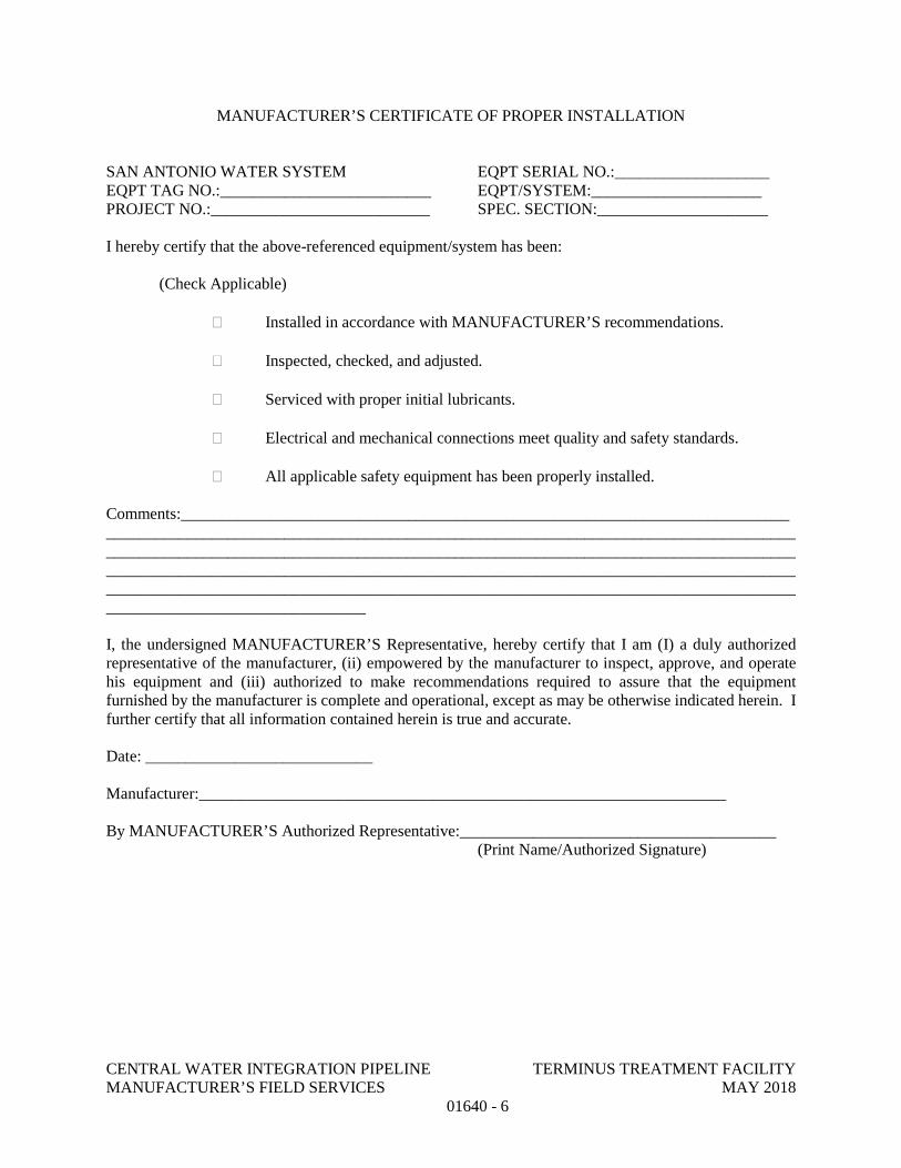
CENTRAL WATER INTEGRATION PIPELINE TERMINUS TREATMENT FACILITY MANUFACTURER’S FIELD SERVICES MAY 2018
01640 - 6
MANUFACTURER’S CERTIFICATE OF PROPER INSTALLATION
SAN ANTONIO WATER SYSTEM EQPT SERIAL NO.:___________________ EQPT TAG NO.:__________________________ EQPT/SYSTEM:_____________________ PROJECT NO.:___________________________ SPEC. SECTION:_____________________
I hereby certify that the above-referenced equipment/system has been:
(Check Applicable)
Installed in accordance with MANUFACTURER’S recommendations.
Inspected, checked, and adjusted.
Serviced with proper initial lubricants.
Electrical and mechanical connections meet quality and safety standards.
All applicable safety equipment has been properly installed.
Comments:_______________________________________________________________________________________________________________________________________________________________________________________________________________________________________________________________________________________________________________________________________________________________________________________________________________________________________________________________
I, the undersigned MANUFACTURER’S Representative, hereby certify that I am (I) a duly authorized representative of the manufacturer, (ii) empowered by the manufacturer to inspect, approve, and operate his equipment and (iii) authorized to make recommendations required to assure that the equipment furnished by the manufacturer is complete and operational, except as may be otherwise indicated herein. I further certify that all information contained herein is true and accurate.
Date: ____________________________
Manufacturer:_________________________________________________________________
By MANUFACTURER’S Authorized Representative:_______________________________________ (Print Name/Authorized Signature)
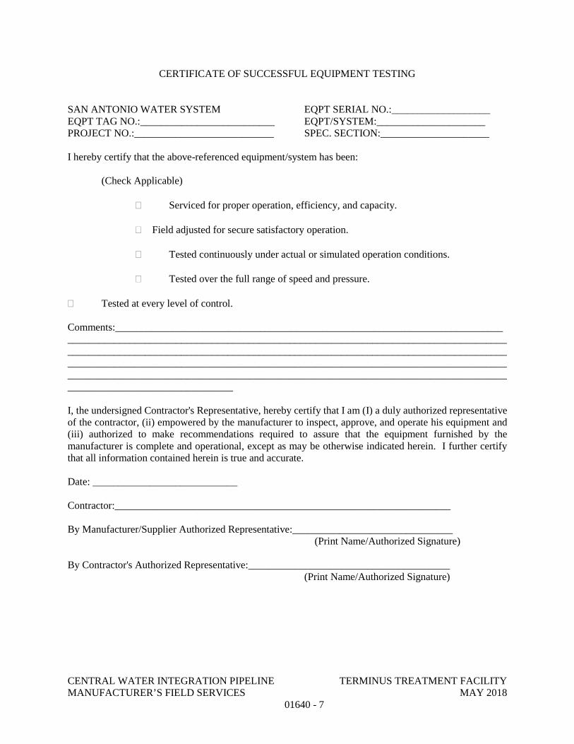
CENTRAL WATER INTEGRATION PIPELINE TERMINUS TREATMENT FACILITY MANUFACTURER’S FIELD SERVICES MAY 2018
01640 - 7
CERTIFICATE OF SUCCESSFUL EQUIPMENT TESTING
SAN ANTONIO WATER SYSTEM EQPT SERIAL NO.:___________________ EQPT TAG NO.:__________________________ EQPT/SYSTEM:_____________________ PROJECT NO.:___________________________ SPEC. SECTION:_____________________
I hereby certify that the above-referenced equipment/system has been:
(Check Applicable)
Serviced for proper operation, efficiency, and capacity.
Field adjusted for secure satisfactory operation.
Tested continuously under actual or simulated operation conditions.
Tested over the full range of speed and pressure.
Tested at every level of control.
Comments:_______________________________________________________________________________________________________________________________________________________________________________________________________________________________________________________________________________________________________________________________________________________________________________________________________________________________________________________________
I, the undersigned Contractor's Representative, hereby certify that I am (I) a duly authorized representative of the contractor, (ii) empowered by the manufacturer to inspect, approve, and operate his equipment and (iii) authorized to make recommendations required to assure that the equipment furnished by the manufacturer is complete and operational, except as may be otherwise indicated herein. I further certify that all information contained herein is true and accurate.
Date: ____________________________
Contractor:_________________________________________________________________
By Manufacturer/Supplier Authorized Representative:_______________________________ (Print Name/Authorized Signature)
By Contractor's Authorized Representative:_______________________________________ (Print Name/Authorized Signature)
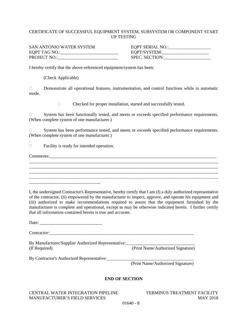
CENTRAL WATER INTEGRATION PIPELINE TERMINUS TREATMENT FACILITY MANUFACTURER’S FIELD SERVICES MAY 2018
01640 - 8
CERTIFICATE OF SUCCESSFUL EQUIPMENT SYSTEM, SUBSYSTEM OR COMPONENT START UP TESTING
SAN ANTONIO WATER SYSTEM EQPT SERIAL NO.:___________________ EQPT TAG NO.:__________________________ EQPT/SYSTEM:_____________________ PROJECT NO.:___________________________ SPEC. SECTION:_____________________
I hereby certify that the above-referenced equipment/system has been:
(Check Applicable)
Demonstrate all operational features, instrumentation, and control functions while in automatic mode.
Checked for proper installation, started and successfully tested.
System has been functionally tested, and meets or exceeds specified performance requirements. (When complete system of one manufacturer.)
System has been performance tested, and meets or exceeds specified performance requirements. (When complete system of one manufacturer.) . Facility is ready for intended operation.
Comments:_______________________________________________________________________________________________________________________________________________________________________________________________________________________________________________________________________________________________________________________________________________________________________________________________________________________________________________________________
I, the undersigned Contractor's Representative, hereby certify that I am (I) a duly authorized representative of the contractor, (ii) empowered by the manufacturer to inspect, approve, and operate his equipment and (iii) authorized to make recommendations required to assure that the equipment furnished by the manufacturer is complete and operational, except as may be otherwise indicated herein. I further certify that all information contained herein is true and accurate.
Date: ____________________________
Contractor:_________________________________________________________________
By Manufacturer/Supplier Authorized Representative:_______________________________ (If Required) (Print Name/Authorized Signature)
By Contractor's Authorized Representative:_______________________________________ (Print Name/Authorized Signature)
END OF SECTION
CENTRAL WATER INTEGRATION PIPELINE TERMINUS TREATMENT FACILITY OPERATION AND MAINTENANCE DATA MAY 2018
01730 - 1
SECTION 01730
OPERATION AND MAINTENANCE DATA
PART 1 GENERAL
1.01 DEFINITIONS
A. Maintenance Operation: As used in the Maintenance Summary Form, attached to this specification, maintenance operation is defined to mean any routine operation required to ensure satisfactory performance and longevity of equipment. Examples of typical maintenance operations are lubrication, belt tensioning, adjustment of pump packing glands, and routine adjustments.
B. System and Subsystem: Refer to Section 01652 – System Operation and Section 01752 – Facility Startup and Commissioning Requirements.
1.02 QUALITY ASSURANCE
A. Manuals for equipment and systems shall be prepared by equipment manufacturer or system Supplier.
1.03 SEQUENCING AND SCHEDULING
A. Manual Outline: Submit detailed outline of each manual prior to preparation of Preliminary Manuals.
B. Manuals for Equipment and Systems:
1. Preliminary Manuals: Submit prior to shipment date for equipment, system, subsystem, or component. Include copy of warranties, bonds, and service agreements if specified.
2. Final Manuals: Submit not less than 30 days prior to equipment or system field testing or startup.
C. Manuals for Materials and Finishes:
1. Preliminary Manuals: Submit at least 30 days prior to request for final inspection.
2. Final Manuals: Submit within 10 days after final inspection.
1.04 GENERAL
A. Furnish for each item of equipment or system as specified in the individual Specification sections.
B. Prepare data for use by OWNER's personnel in the form of an instructional manual in both paper format and on electronic media. Data for electronic media shall be provided to OWNER on optical compact disc.
CENTRAL WATER INTEGRATION PIPELINE TERMINUS TREATMENT FACILITY OPERATION AND MAINTENANCE DATA MAY 2018
01730 - 2
C. Manual Format:
1. Size: 8-1/2 inches x 11 inches.
2. Paper: 20-pound minimum, white for typed pages.
3. Text: Manufacturer's printed data, or neatly typewritten.
4. Three-hole punch data for binding and composition; arrange printing so that punched holes do not obliterate data.
5. Provide flyleaf for each separate product or each piece of operating equipment, with typed description of product and major component parts of equipment and provide with heavy section dividers with numbered plastic index tabs.
6. Provide each manual with title page, and typed table of contents with consecutive page numbers. Place contents of entire set, identified by volume number, in each binder.
7. Cover: Identify each volume with typed or printed title “OPERATION AND MAINTENANCE MANUAL, VOLUME NO. – OF – ”, if applicable, and list:
a. Project title.
b. Designate the system or equipment for which it is intended.
c. Identity of separate structure as applicable.
d. Identity of equipment number and Specification section.
8. Assemble and bind material in same order as specified, as much as possible.
9. Final copy shall not have fax copies or photocopies of manufacturer information. Each manual shall have original materials.
10. Binders:
a. Preliminary Manuals: Heavy paper covers.
b. Final Manuals: Commercial quality, substantial, permanent, three-ring binders with durable, cleanable, plastic binders.
11. Table of contents neatly typewritten, arranged in a systematic order:
a. CONTRACTOR, name of responsible principal, address, and telephone number.
b. List of each product required to be included, indexed to content of each volume.
CENTRAL WATER INTEGRATION PIPELINE TERMINUS TREATMENT FACILITY OPERATION AND MAINTENANCE DATA MAY 2018
01730 - 3
c. List with Each Product: Name, address, and telephone number of Subcontractor, Supplier, installer, and maintenance contractor, as appropriate.
i. Identify area of responsibility of each.
ii. Provide local source of supply for parts and replacement.
d. Identify each product by product name and other identifying numbers or symbols as set forth in Contract Documents.
12. Product Data:
a. Include only those sheets that are pertinent to specific product.
b. Clearly annotate each sheet to:
i. Identify specific product or part installed.
ii. Identify data applicable to installation.
iii. Delete references to inapplicable information.
13. Drawings: Supplement product data with Drawings as necessary to clearly illustrate:
a. Relations of component parts of equipment and systems.
b. Control and flow diagrams.
c. Coordinate drawings with Project record documents to assure correct illustration of completed installation.
d. Do not use Project record documents as maintenance manual drawings.
e. Provide reinforced punched binder tab, bind in with text.
f. Reduced to 8-1/2 inches x 11 inches, or 11 inches x 17 inches folded to 8-1/2 inches x 11 inches.
g. Where reduction is impractical, fold and place in 8-1/2-inch x 11-inch envelopes bound in text.
h. Identify Specification section and product on Drawings and envelopes.
14. Instructions and Procedures: Within text, as required to supplement product data.
CENTRAL WATER INTEGRATION PIPELINE TERMINUS TREATMENT FACILITY OPERATION AND MAINTENANCE DATA MAY 2018
01730 - 4
a. Handling, storage, maintenance during storage, assembly, erection, installation, adjusting, testing, operating, shutdown in emergency, troubleshooting, maintenance, interface, and as may otherwise be required.
b. Organize in a consistent format under separate heading for each different procedure.
c. Provide a logical sequence of instructions for each procedure.
d. Provide information sheet for OWNER's personnel, including:
i. Proper procedures in the event of failure.
ii. Instances that might affect the validity of warranties or Bonds.
15. Warranties, Bonds, and Service Agreements.
D. Electronic Format: All electronic submittals shall be transmitted in Portable Document Format (PDF) as generated by the Adobe Acrobat Professional Version 7.0 or higher. The PDF file(s) shall be fully indexed using the Table of Contents, searchable with thumbnails generated.
1. File names shall use the “eight dot three” convention (XXXXX_YY.pdf), where X is the five digit number corresponding to the specification section, and YY is a sequential ID number. The ID number is to track multiple O&M manuals per specification section. If technical problems require breaking of the submittal into multiple files then a letter extension shall be added to the end of the filename (example: 13100.01A.PDF). The number of files shall be kept to a minimum.
2. Scanned images must be at a readable resolution. For most documents, they should be scanned at 300 dots per inch (dpi). Optical Character Recognition (OCR) capture must be performed on these images. OCR settings shall be performed with the “original image with hidden text” option in Adobe Acrobat Exchange.
3. One PDF document (PDF file) shall be created for each equipment service manual. The entire manual shall be converted to a single .PDF file via scanning or other method of conversion. Drawings or other graphics shall also be converted to .PDF format and included into the single PDF document. Pages that must be viewed in landscape format shall be rotated to the appropriate position for easy reading on screen. Word searches of the PDF document must operate successfully.
4. The PDF documents shall have a bookmark created in the navigation frame for each major entry (“Section” or “Chapter”) in the Table of Contents. Thumbnails shall be generated for each page or graphic in the PDF file.
5. Labeling: As a minimum requirement, include the following labeling on all final O&M materials.
CENTRAL WATER INTEGRATION PIPELINE TERMINUS TREATMENT FACILITY OPERATION AND MAINTENANCE DATA MAY 2018
01730 - 5
a. Manufacturer Name
b. Equipment name and/or O&M title spelled out in complete words. (example: “Operations and Maintenance Manual” “Oscillating Wastewater Converter”)
c. Specification Section No.
d. Project Name
1.05 SUBMITTAL PROCEDURE
A. Sequencing and Scheduling
1. Manual Outline: Submit to OWNER detailed outline of each manual prior to preparation of Preliminary Manuals.
2. Manuals for Equipment and Systems
a. Preliminary Manuals: Submit prior to shipment date for equipment, system, subsystem, or component. Include copy of warranties, Bonds, and service agreements if specified.
b. Final Manuals: Submit not less than 30 days prior to equipment or system field testing or startup.
3. Manuals for Materials and Finishes
a. Preliminary Manuals: Submit at least 30 days prior to request for final inspection.
b. Final Manuals: Submit within 10 days after final inspection.
B. Preliminary Manuals
1. Submittal Procedure: In accordance with Section 01300 – Submittals.
2. If Accepted submit six (6) hard copies of Final Manual.
3. If Rejected:
a. Follow procedure as outlined in Section 01300 – Submittals.
C. Final Manuals:
1. If different than accepted Preliminary Manuals, submit:
a. Two (2) copies of any necessary supplemental material, including revised table of contents.
b. Instructions for insertion of supplemental material in unreturned sets.
CENTRAL WATER INTEGRATION PIPELINE TERMINUS TREATMENT FACILITY OPERATION AND MAINTENANCE DATA MAY 2018
01730 - 6
2. If Final Manuals are acceptable, CONTRACTOR will be so notified as outlined in Section 01300 – Submittals.
3. If rejected, and at OWNER's option:
a. Follow procedure as outlined in Section 01300 – Submittals.
1.02 MANUALS FOR EQUIPMENT AND SYSTEMS
A. Content for Each Unit (or Common Units) and System:
1. Description of unit and component parts, including controls, accessories, and appurtenances:
a. Function, normal operating characteristics, and limiting conditions.
b. Performance curves, engineering data, nameplate data, and tests.
c. Complete nomenclature and commercial number of replaceable parts.
2. Operating Procedures:
a. Startup, break-in, routine, and normal operating instructions.
b. Test procedures and results of factory tests where required.
c. Regulation, control, stopping, and emergency instructions.
d. Description of operation sequence by control manufacturer.
e. Shutdown instructions for both short and extended duration.
f. Summer and winter operating instructions, as applicable.
g. Safety precautions.
h. Special operating instructions.
i. Installation instructions.
3. Maintenance and Overhaul Procedures:
a. Routine operations.
b. Guide to troubleshooting.
c. Disassembly, removal, repair, reinstallation, and reassemble.
4. Installation Instructions: Including alignment, adjusting, calibrating, and checking.
CENTRAL WATER INTEGRATION PIPELINE TERMINUS TREATMENT FACILITY OPERATION AND MAINTENANCE DATA MAY 2018
01730 - 7
5. Original manufacturer's parts list, illustrations, detailed assembly drawings showing each part with part numbers and sequentially numbered parts list, and diagrams required for maintenance.
6. Spare parts ordering instructions.
7. Where applicable, identify installed spares and other provisions for future work (e.g., reserved panel space, unused components, wiring, and terminals).
8. Manufacturer's printed operating and maintenance instructions.
9. As-installed, color-coded piping diagrams.
10. Charts of valve tag numbers, with the location and function of each valve.
B. Maintenance Summary:
1. Compile an individual Maintenance Summary for each applicable equipment item, respective unit or system, and for components or sub-units.
2. Format:
a. Use Maintenance Summary Form bound with this section, or an electronic facsimile of such.
b. Each Maintenance Summary may take as many pages as required.
c. Use only 8-1/2-inch x 11-inch size paper.
d. Complete using typewriter or electronic printing.
3. Include detailed lubrication instructions and diagrams showing points to be greased or oiled; recommend type, grade, and temperature range of lubricants and frequency of lubrication.
4. Recommended Spare Parts:
a. Data to be consistent with manufacturer's Bill of Materials/Parts List furnished in O&M manuals.
b. “Unit” is the unit of measure for ordering the part.
c. “Quantity” is the number of units recommended.
d. “Unit Cost” is the current purchase price.
C. Content for Each Electric or Electronic Item or System:
1. Description of Unit and Component Parts:
a. Function, normal operating characteristics, and limiting conditions.
CENTRAL WATER INTEGRATION PIPELINE TERMINUS TREATMENT FACILITY OPERATION AND MAINTENANCE DATA MAY 2018
01730 - 8
b. Performance curves, engineering data, nameplate data, and tests.
c. Complete nomenclature and commercial number of replaceable parts.
d. Interconnection wiring diagrams, including all control and lighting systems.
2. Circuit Directories of Panel Boards:
a. Electrical service.
b. Controls.
c. Communications.
3. List of electrical relay settings, and control and alarm contact settings.
4. Electrical interconnection wiring diagram, including control and lighting systems.
5. As-installed control diagrams by control manufacturer.
6. Operating Procedures:
a. Routine and normal operating instructions.
b. Sequences required.
c. Safety precautions.
d. Special operating instructions.
7. Maintenance Procedures:
a. Routine operations.
b. Guide to troubleshooting.
c. Adjustment and checking.
d. List of relay settings, control and alarm contact settings.
8. Manufacturer's printed operating and maintenance instructions.
9. List of original manufacturer's spare parts, manufacturer's current prices, and recommended quantities to be maintained in storage.
1.07 MANUALS FOR MATERIALS AND FINISHES
A. Content for Architectural Products, Applied Materials, and Finishes:
1. Manufacturer's data, giving full information on products:
CENTRAL WATER INTEGRATION PIPELINE TERMINUS TREATMENT FACILITY OPERATION AND MAINTENANCE DATA MAY 2018
01730 - 9
a. Catalog number, size, and composition.
b. Color and texture designations.
c. Information required for reordering special-manufactured products.
2. Instructions for Care and Maintenance:
a. Manufacturer's recommendation for types of cleaning agents and methods.
b. Cautions against cleaning agents and methods that are detrimental to product.
c. Recommended schedule for cleaning and maintenance.
B. Content for Moisture Protection and Weather Exposed Products:
1. Manufacturer's data, giving full information on products:
a. Applicable standards.
b. Chemical composition.
c. Details of installation.
2. Instructions for inspections, maintenance, and repair.
1.08 SUPPLEMENTS
A. The supplements listed below, following “END OF SECTION”, are part of this Specification.
1. Forms: Maintenance Summary Form.
PART 2 PRODUCTS – NOT USED
PART 3 EXECUTION – NOT USED
END OF SECTION
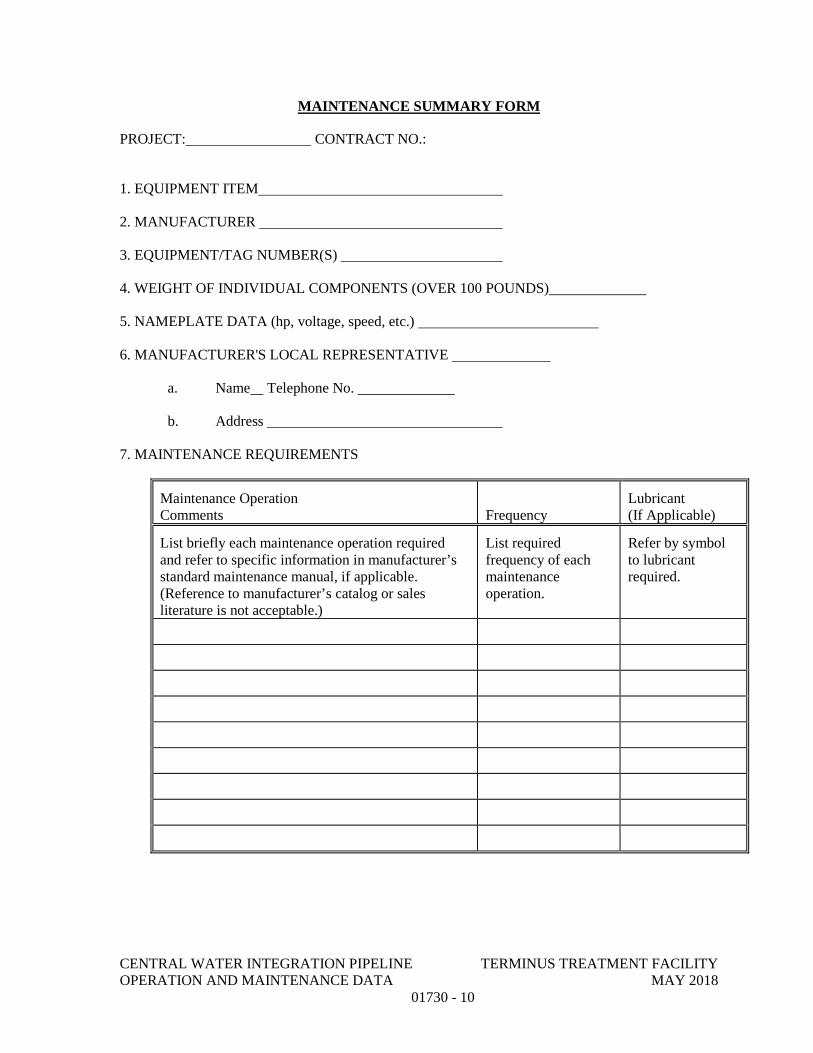
CENTRAL WATER INTEGRATION PIPELINE TERMINUS TREATMENT FACILITY OPERATION AND MAINTENANCE DATA MAY 2018
01730 - 10
MAINTENANCE SUMMARY FORM
PROJECT: CONTRACT NO.:
1. EQUIPMENT ITEM
2. MANUFACTURER
3. EQUIPMENT/TAG NUMBER(S)
4. WEIGHT OF INDIVIDUAL COMPONENTS (OVER 100 POUNDS)
5. NAMEPLATE DATA (hp, voltage, speed, etc.)
6. MANUFACTURER'S LOCAL REPRESENTATIVE
a. Name Telephone No.
b. Address
7. MAINTENANCE REQUIREMENTS
Maintenance Operation Comments Frequency
Lubricant (If Applicable)
List briefly each maintenance operation required and refer to specific information in manufacturer’s standard maintenance manual, if applicable. (Reference to manufacturer’s catalog or sales literature is not acceptable.)
List required frequency of each maintenance operation.
Refer by symbol to lubricant required.
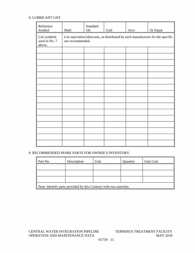
CENTRAL WATER INTEGRATION PIPELINE TERMINUS TREATMENT FACILITY OPERATION AND MAINTENANCE DATA MAY 2018
01730 - 11
8. LUBRICANT LIST
Reference Symbol Shell
Standard Oil Gulf Arco Or Equal
List symbols used in No. 7 above.
List equivalent lubricants, as distributed by each manufacturer for the specific use recommended.
9. RECOMMENDED SPARE PARTS FOR OWNER’S INVENTORY.
Part No. Description Unit Quantity Unit Cost
Note: Identify parts provided by this Contract with two asterisks.
CENTRAL WATER INTEGRATION PIPELINE TERMINUS TREATMENT FACILITY WARRANTIES AND BONDS MAY 2018
01740- 1
SECTION 01740
WARRANTIES AND BONDS
PART 1 - GENERAL
1.01 DESCRIPTION
A. Related Work Described Elsewhere:
1. Contract Closeout: Section 01700.
1.02 SUBMITTAL REQUIREMENTS
A. Assemble warranties, bonds and service and maintenance contracts, executed by each of the respective manufacturers, suppliers, and subcontractors.
B. Number of original signed copies required: Two (2) each.
C. Table of Contents: Neatly typed, in orderly sequence. Provide complete information for each item.
1. Product of work item.
2. Firm, with name of principal, address and telephone number.
3. Scope.
4. Date of beginning of warranty, bond or service and maintenance contract.
5. Duration of warranty, bond or service maintenance contract.
6. Provide information for Owner's personnel:
a. Proper procedure in case of failure. b. Instances which might affect the validity or warranty or bond.
7. Contractor, name of responsible principal, address and telephone number.
1.03 FORM OF SUBMITTALS
A. Prepare in duplicate packets.
B. Format:
1. Size 8-1/2 inches by 11 inches, punch sheets for standard three (3) ring binder. a. Fold larger sheets to fit into binders.
CENTRAL WATER INTEGRATION PIPELINE TERMINUS TREATMENT FACILITY WARRANTIES AND BONDS MAY 2018
01740- 2
2. Cover: Identify each packet with typed or printed title "WARRANTIES AND BONDS". List:
a. Title of Project. b. Name of Contractor.
C. Binders: Commercial quality, three (3) D-ring type binders with durable and cleanable white plastic covers and maximum D-ring width of two (2) inches. Binders shall be presentation type with clear vinyl covers on front, back, and spine. Binders shall include two sheet lifters and two horizontal inside pockets.
1.04 WARRANTY SUBMITTALS REQUIREMENTS
A. For all major pieces of equipment, submit a warranty from the equipment manufacturer. The manufacturer's warranty period shall be concurrent with the Contractor's for two (2) years, unless otherwise specified, commencing at the time of final acceptance by the Owner which shall begin no later than April 15, 2020.
B. The Contractor shall be responsible for obtaining certificates for equipment warranty for all major equipment. Electrical and which has at least a 1 hp motor or which lists for more than $1,000. The Engineer reserves the right to request warranties for equipment not classified as major. The Contractor shall still warrant equipment not considered to be "major" in the Contractor's one-year warranty period even though certificates of warranty may not be required.
C. In the event that the equipment manufacturer or supplier is unwilling to provide a one (1) year warranty commencing at the start of the Correction Period, the Contractor shall obtain from the manufacturer a two (2) year warranty commencing at the time of equipment delivery to the job site. This two (2) year warranty from the manufacturer shall not relieve the Contractor of the two (2) year warranty, starting at the time of Owner's acceptance of the equipment.
D. The Owner shall incur no labor or equipment cost during the guarantee period.
E. Guarantee shall cover all necessary labor, equipment, materials, and replacement parts resulting from faulty or inadequate equipment design, improper assembly or erection, defective workmanship and materials, leakage, breakage or other failure of all equipment and components furnished by the manufacturer or the Contractor.
PART 2 - PRODUCTS (NOT USED)
PART 3 - EXECUTION (NOT USED)
END OF SECTION
CENTRAL WATER INTEGRATION PIPELINE TERMINUS TREATMENT FACILITY FACILITY START UP COMMISSIONING REQUIREMENTS MAY 2018
01752 - 1
SECTION 01752
FACILITY START UP COMMISSIONING REQUIREMENTS
PART 1 GENERAL
1.01 SCOPE
A. This section covers starting of systems for all items of mechanical, electrical, and control equipment. Additional requirements may be specified in individual equipment section.
B. Procedures and actions required of the CONTRACTOR, which are necessary to achieve a Letter of Substantial Completion.
1. Pre Start Up (Construction Phase)
a. Factory Tests
b. Field Test
c. Test Log Submittals
2. System Start Up
a. Functional Tests
b. Performance Tests
C. Procedures and actions required of the CONTRACTOR, which are necessary to achieve a Memo of Final Acceptance.
1. Operational Test
1.02 RELATED WORK
A. Section 01300 – Submittals
B. Section 01600 – Material and Equipment
C. Section 01640 – Manufacturer’s Field Services
1.03 DEFINITIONS
A. System: The overall process, or a portion thereof, that performs a specific function. A system may consist of the entire facility or two (2) or more subsystems as well as two (2) or more types of equipment or components.
CENTRAL WATER INTEGRATION PIPELINE TERMINUS TREATMENT FACILITY FACILITY START UP COMMISSIONING REQUIREMENTS MAY 2018
01752 - 2
B. Pre Start Up: The period of time of unspecified duration during construction and installation activities which the CONTRACTOR, with assistance from MANUFACTURER’s Representatives, performs the following sequence:
1. Finishes construction work so that the Project has reached a tentative state of Substantial Completion pending completion of the System Start Up.
2. MANUFACTURER’s Field Services
a. Equipment and Pre Start Up Assistance
b. Installation and Equipment Testing Certifications
c. Pre Start Up Training
C. System Start Up: A period of time of specified duration, following the Pre-Start Up Period, during which the CONTRACTOR initiates process flow through the facility and operates the facility without exceeding specified downtime limitations, to prove the functional integrity of the mechanical and electrical equipment and components; the control interfaces of the respective equipment; and components comprising the facility, as evidence of Substantial Completion. The following test activities must be executed by the CONTRACTOR with assistance from the MANUFACTURER’s Representative as needed.
1. Functional Tests: Test or tests performed by the CONTRACTOR in the presence of the OWNER to demonstrate that installed equipment, system, subsystem or components meet MANUFACTURER’s installation and adjustment requirements; and other requirements specified including, but not limited to: noise, vibration, alignment, speed, proper electrical and mechanical connections, thrust restraint, proper rotation, and initial servicing.
2. Performance Test: A test performed by the CONTRACTOR in the presence of the OWNER and after all required functional tests specified, to demonstrate and confirm that the equipment, system, subsystem or components meet the specified performance requirements.
3. MANUFACTURER’s Field Services
a. Equipment and System Start Up Assistance
b. Equipment, System, Subsystem, or Component Start Up Testing Certification.
c. Post Start Up Training
D. Operational Test: A test of specified duration, performed by the OWNER with the assistance of the CONTRACTOR after all System Start Up testing has been completed. The equipment, system, subsystem, or component shall operate continuously without any malfunctions.
PART 2 PRODUCTS – NOT USED
CENTRAL WATER INTEGRATION PIPELINE TERMINUS TREATMENT FACILITY FACILITY START UP COMMISSIONING REQUIREMENTS MAY 2018
01752 - 3
PART 3 EXECUTION
3.01 DESCRIPTION OF WORK
A. All items of mechanical and electrical equipment shall be tested for proper operation, efficiency, and capacity. All required adjustments, tests, operation checks, and other Pre Start Up activity shall be provided.
3.02 PRE START UP (CONSTRUCTION PHASE)
A. FACTORY TESTS
1. All items of equipment so specified shall be tested at the point of MANUFACTURER’s facility at the CONTRACTOR's expense. Submittals shall in accordance with Section 01300 – Submittals.
2. Coordinate with the OWNER and ENGINEER for factory test schedule, if witness testing of equipment is specified in individual specification of the equipment.
3. Equipment shall not be shipped until the ENGINEER has reviewed the test results and notified the CONTRACTOR in writing that the equipment is acceptable for shipment. Such acceptance, however, shall not be considered as final acceptance, which will only be made on the basis of the test results of the equipment after installation.
B. FIELD TESTS
1. All items of mechanical, electrical, and control equipment shall be tested by the CONTRACTOR after installation for proper operation, efficiency, and capacity. CONTRACTOR's test operation of each piece of equipment shall continue for not less than eight (8) hours without interruption. All moving parts of equipment and machinery shall be carefully tested for operation, and adjusted so all parts move freely and function to secure satisfactory operation. All parts shall operate satisfactorily in all respects, under continuous full load and in accordance with the specified requirements, for the full duration of the eight (8) hour test period. If necessary, corrections or repairs shall be made and the full eight-hour test operation, as specified, shall be completed after all parts operate satisfactorily.
2. CONTRACTOR shall furnish and pay for all power, water, fuels, oil, grease, chemicals, and auxiliaries that are required for conducting the CONTRACTOR's testing of the equipment for proper operation, efficiency, and capacity during Pre Start Up.
3. Field Tests of all process and pumping equipment, drive motors, including auxiliaries shall be made in accordance with the appropriate and approved test codes of the American Society of Mechanical Engineers (ASME), Hydraulic Institute Standards, National Electrical Manufacturers Association (NEMA), and Institute of Electrical and Electronics Engineers (IEEE).
CENTRAL WATER INTEGRATION PIPELINE TERMINUS TREATMENT FACILITY FACILITY START UP COMMISSIONING REQUIREMENTS MAY 2018
01752 - 4
4. Field testing shall be conducted before the Work is ready for System Start Up and is substantially complete so each item of equipment is ready for integrated operation with other equipment at the facility. Testing, measuring, and calibrating procedures shall be submitted to the ENGINEER for review and acceptance prior to field testing of equipment. The facility control system must be in place and MANUFACTURER’s Certificate of Proper Installation must be completed prior to equipment tests.
5. All equipment shall be tested continuously under actual or simulated operating conditions. Equipment shall be tested over the full range of speed, capacity and pressure. Equipment shall also be tested at every level of control. Valves shall be throttled as required to simulate the full operating range. Curves shall be developed from the test data and compared to the specified performance criteria. CONTRACTOR shall provide all appurtenances as required, but not limited to flow meters for liquid and gas flow pressure gauges and throttling valves, to verify performance. CONTRACTOR shall be fully responsible for the operation and maintenance of the equipment during Pre Start Up. During testing, pressure, flow rate, amperage, voltage, vibration, equipment temperature, ambient temperature, tank level and the level of all water surfaces shall be measured. MANUFACTURER's representative shall make all necessary field adjustments and correct defects in materials or workmanship during this test period. The equipment shall be properly filled, by the CONTRACTOR, with oil and grease.
6. The period of inspection, Pre Start Up operation, and field adjustment shall be as required to achieve satisfactory installation and operation of the items furnished.
C. TEST LOG SUBMITTALS
1. MANUFACTURER’s Certificate of Proper Installation – Utilize the MANUFACTURER’s Certificate of Proper Installation Form from Section 01640 – Manufacturer’s Field Services, supplemented as necessary, to document results, problems, and conclusions.
2. Equipment Test - Test report and certification of test for each piece of equipment, system, subsystem, or component specified. See Section 01640.
3. I/O Loop Test – Third Party Independent Test Agency.
4. Equipment Calibration Sheets - Certifications of calibration for testing equipment and permanent equipment.
5. Electrical Testing - Third Party Independent Test Agency.
6. Certificate of Successful Equipment Testing – Utilize the Certificate of Successful Equipment Testing Form from Section 01640 – Manufacturer’s Field Services, supplemented as necessary to document results, problems, and conclusions.
D. ADDITIONAL PRE START UP ACTIVITIES
1. General activities include:
CENTRAL WATER INTEGRATION PIPELINE TERMINUS TREATMENT FACILITY FACILITY START UP COMMISSIONING REQUIREMENTS MAY 2018
01752 - 5
a. Cleaning.
b. Removing temporary protective coatings.
c. Flushing and replacing greases and lubricants, where required by the MANUFACTURER.
d. Lubrication.
e. Check shaft and coupling alignments and reset where needed.
f. Check and set motor, pump and other equipment rotation, safety interlocks, and belt tensions.
g. Check and correct if necessary leveling plates, grout, bearing plates, anchor bolts, fasteners, and alignment of piping which may put stress on pumping equipment connected to it.
h. All adjustments required.
2. Minimum activities include:
a. Bearings and Shafts
i. Inspect for cleanliness, clean and remove foreign materials.
ii. Verify alignment.
iii. Replace defective bearings, and those which run rough or noisy.
iv. Grease as necessary, in accordance with MANUFACTURER's recommendations.
b. Drives
i. Adjust tension in V-belt drives, and adjust vary pitch sheaves and drives for proper equipment speed (if necessary).
ii. Adjust drives for alignment.
iii. Clean and remove foreign materials before starting operation.
c. Motors
i. Check each motor for comparison to amperage nameplate value.
ii. Correct conditions which produce excessive current flow, and which exist due to equipment malfunction.
iii. Check each motor for proper rotation.
d. Pumps
i. Check glands and seals for cleanliness and adjustment before running pump.
ii. Inspect shaft sleeves for scoring.
iii. Inspect mechanical faces, chambers, and seal rings, and replace if defective.
iv. Verify that piping system is free of dirt and scale before
CENTRAL WATER INTEGRATION PIPELINE TERMINUS TREATMENT FACILITY FACILITY START UP COMMISSIONING REQUIREMENTS MAY 2018
01752 - 6
circulating liquid through the pump.
e. Valves
i. Open and close valves by hand and operate to check for binding, interference, or improper functioning.
ii. Inspect both manual and automatic control valves, clean bonnets and stems.
iii. Tighten packing glands to assure no leakage, but permit valve stems to operate without galling.
iv. Replace packing in valves to retain maximum adjustment after system is judged complete.
v. Replace packing on any valve which continues to leak.
vi. Remove and repair bonnets which leak.
vii. Coat packing gland threads and valve stems with an appropriate surface preparation after cleaning.
f. Verify that control valve seats are free from foreign material, and are properly positioned for intended service.
g. Tighten all pipe joints after system has been field tested. Replace gaskets which show any sign of leaking after tightening.
h. Inspect all joints for leakage.
i. Promptly remake each joint which appears to be faulty, do not wait for rust to form.
j. Clean threads on both parts, apply compound and remake joints.
k. Clean strainers, dirt pockets, orifices, valve seats, and headers in fluid system, to assure freedom from foreign materials.
l. Open traps and air vents where used, remove operating elements. Clean thoroughly, replace internal parts and put back in readiness mode.
m. Remove rust, scale and foreign materials from equipment and renew defaced surfaces.
n. Set and calibrate permanent equipment.
o. Check each electrical control circuit to assure that operation complies with Contract Documents and requirements to provide desired performance.
p. Inspect each pressure gage and thermometer for calibration. Replace items which are defaced, broken, or which read incorrectly.
q. Repair damaged insulation.
r. Vent gases trapped in any part of systems. Verify that liquids are drained from all parts of gas or air system.
s. Calibrate testing equipment for accurate results.
t. Check power supply to electric-powered equipment for correct voltage.
CENTRAL WATER INTEGRATION PIPELINE TERMINUS TREATMENT FACILITY FACILITY START UP COMMISSIONING REQUIREMENTS MAY 2018
01752 - 7
u. Adjust clearances and torque.
v. Test piping for leaks.
w. Balance HVAC systems, measuring airflow (cfm) static pressure, and component pressure losses. Furnish report documenting results of balancing.
x. Equipment and electrical tagging complete.
y. All spare parts and special tools delivered to OWNER.
3.03 SYSTEM START UP
A. SUBMITTALS
1. Administrative Submittals.
a. Functional and Performance test schedules.
b. Plan for equipment, systems, subsystem, or component at least twenty-one (21) calendar days prior to start of related testing. Include test plan, procedures, and log format.
c. Schedule and plan of System Start Up activities at least thirty (30) calendar days prior to commencement.
2. Certificate of Successful Equipment, System, Subsystem, or Component Start Up Testing – Utilize the Certificate of Successful Equipment, system, subsystem, or component Start Up Testing Form from Section 01640 – Manufacturer’s Field Services, supplemented as necessary, to document functional and performance procedures, results, problems, and conclusions.
B. CONTRACTOR FACILITY START UP RESPONSIBILITIES
1. General
a. Prepare and pretest all equipment insofar as possible to check its ability for sustained operation, including inspections and adjustments by manufacturer’s servicemen.
b. Be responsible for System Start Up of all facilities constructed under this Contract.
c. Perform Work for tests specified.
d. Demonstrate proper installation, adjustment, function and performance of equipment, systems, subsystem, or components, control devices, and required interfaces individually and in conjunction with process instrumentation and control system.
e. CONTRACTOR shall furnish and pay for all power, water, fuels, oil, grease, chemicals, and auxiliaries that are required for conducting CONTRACTOR's testing of the equipment for proper operation, efficiency, and the capacity during System Start Up.
CENTRAL WATER INTEGRATION PIPELINE TERMINUS TREATMENT FACILITY FACILITY START UP COMMISSIONING REQUIREMENTS MAY 2018
01752 - 8
C. OWNER’S FACILITY STARTUP RESPONSIBILITIES
1. General
a. Review CONTRACTOR's test plan and schedule.
b. Witness each functional and performance tests.
c. Provide assistance and support for start up and performance testing.
d. OWNER will operate the portion of facilities that are not part of the construction contract.
D. TESTING PREPARATION
1. General.
a. Complete Work associated with the equipment, system, subsystem, or components and related processes before testing, including related MANUFACTURER's representative services.
b. Furnish qualified MANUFACTURER's representatives when required to assist in testing.
c. Utilize the Certificate of Successful Equipment, System, Subsystem or component Start Up Testing Form from Section 01640 – Manufacturers Field Services, supplemented as necessary, to document functional and performance procedures, results, problems, and conclusions.
d. Schedule and attend pretest (functional and performance) meetings related to test schedule, plan of test, materials, chemicals, and liquids required, facilities' operations interface, OWNER involvement.
e. Designate and furnish one or more persons to be responsible for coordinating and expediting CONTRACTOR's System Start Up duties. The person or persons shall be present during System Start Up meetings and shall be available at all times during the System Start Up period.
f. Provide temporary valves, gauges, piping, test equipment and other materials and equipment required to conduct testing.
2. Cleaning and Checking: Prior to starting functional testing.
a. Calibrate testing equipment for accurate results.
b. Inspect and clean equipment, devices, connected piping, and structures so they are free of foreign material.
c. Lubricate equipment in accordance with MANUFACTURER’s instructions.
d. Turn rotating equipment by hand and check motor-driven equipment for correct rotation.
CENTRAL WATER INTEGRATION PIPELINE TERMINUS TREATMENT FACILITY FACILITY START UP COMMISSIONING REQUIREMENTS MAY 2018
01752 - 9
e. Open and close valves by hand and operate other devices to check for binding, interference, or improper functioning.
f. Check power supply to electric-powered equipment for correct voltage.
g. Adjust clearances and torque.
h. Test piping for leaks.
i. Obtain completion of applicable portions of MANUFACTURER's Certificate of Proper Installation in accordance with Section 01640 – Manufacturer’s Field Services.
3. Ready-to-test determination will be by OWNER based at least on the following:
a. Notification by CONTRACTOR of equipment and system readiness for testing.
b. Acceptable Test Log Submittal to OWNER.
c. Acceptable testing plan.
d. Acceptable Final Draft Operation and Maintenance Manuals.
e. Receipt of MANUFACTURER's Certificate of Proper Installation, as required.
f. Receipt of Certificate of Successful Equipment Testing, as required.
g. Adequate completion of Work adjacent to, or interfacing with, equipment to be tested.
h. Availability and acceptability of MANUFACTURER's representative, when specified, to assist in testing of respective equipment, and satisfactory fulfillment of other specified MANUFACTURER's responsibilities.
i. Equipment and electrical tagging complete.
j. All spare parts and special tools delivered to and become property of the OWNER.
E. FUNCTIONAL TEST - GENERAL
1. Begin testing at a time mutually agreed upon by the OWNER and CONTRACTOR.
2. OWNER and MANUFACTURER’s Representative will be present during test. Notify in writing MANUFACTURER's representative(s) at least twenty-one (21) calendar days prior to scheduled date of functional tests.
3. Separate items of equipment demonstrated to function properly during subsystem testing may require no further Functional test if documentation of subsystem testing is acceptable to OWNER.
4. Conduct functional tests as specified for each equipment, system, subsystem, on component for a minimum period of eight (8) hours.
CENTRAL WATER INTEGRATION PIPELINE TERMINUS TREATMENT FACILITY FACILITY START UP COMMISSIONING REQUIREMENTS MAY 2018
01752 - 10
5. Demonstrate all operational features and instrumentation and control functions while in automatic mode.
6. If, in OWNER's opinion, functional test results do not meet requirements specified, the systems will be considered as non-conforming.
7. Performance testing shall not commence until the equipment, system, subsystem, or components meets the specified functional tests.
F. PERFORMANCE TEST - GENERAL
1. Begin testing at a time mutually agreed upon by the OWNER and CONTRACTOR.
2. OWNER will be present during test. Notify in writing MANUFACTURER’s representative(s) at least twenty-one (21) days prior to scheduled date of performance tests.
3. Conduct performance tests as specified for each equipment, system, subsystem, or component for a minimum period of one (1) day.
4. Unless otherwise indicated, furnish all labor, materials, and supplies for conducting the test and taking all samples and performance measurements.
5. Prepare performance test report summarizing test method. Include test logs, pertinent calculations, and CONTRACTOR's Certificate of Successful Equipment, System, Subsystem, or Component Start Up Testing.
G. SYSTEM START UP TEST PERIOD
1. General.
a. Attend planning meetings and arrange for attendance by key major equipment MANUFACTURER representatives as required by the Contract Documents.
b. Designate one or more persons on the CONTRACTOR's staff to be able for coordinating and expediting CONTRACTOR's System Start Up duties.
c. When System Start Up has commenced, schedule remaining Work so as not to interfere with or delay the completion of System Start Up.
d. Support System Start Up activities with adequate staff to prevent delays. Such staff shall include, but not be limited to, equipment, system, subsystem, or component, MANUFACTURER's representatives, electricians, instrumentation and control personnel, millwrights, pipe fitters, and plumbers.
e. Furnish and coordinate specified MANUFACTURER's System Start Up services.
2. System Start Up Testing.
a. System Start Up of the entire system or any portion thereof requires the
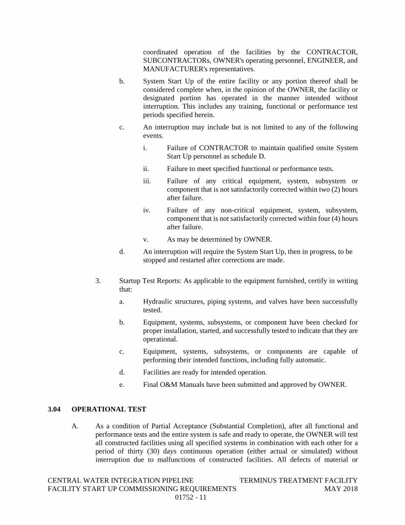
CENTRAL WATER INTEGRATION PIPELINE TERMINUS TREATMENT FACILITY FACILITY START UP COMMISSIONING REQUIREMENTS MAY 2018
01752 - 11
coordinated operation of the facilities by the CONTRACTOR, SUBCONTRACTORs, OWNER's operating personnel, ENGINEER, and MANUFACTURER's representatives.
b. System Start Up of the entire facility or any portion thereof shall be considered complete when, in the opinion of the OWNER, the facility or designated portion has operated in the manner intended without interruption. This includes any training, functional or performance test periods specified herein.
c. An interruption may include but is not limited to any of the following events.
i. Failure of CONTRACTOR to maintain qualified onsite System Start Up personnel as schedule D.
ii. Failure to meet specified functional or performance tests.
iii. Failure of any critical equipment, system, subsystem or component that is not satisfactorily corrected within two (2) hours after failure.
iv. Failure of any non-critical equipment, system, subsystem, component that is not satisfactorily corrected within four (4) hours after failure.
v. As may be determined by OWNER.
d. An interruption will require the System Start Up, then in progress, to be stopped and restarted after corrections are made.
3. Startup Test Reports: As applicable to the equipment furnished, certify in writing that:
a. Hydraulic structures, piping systems, and valves have been successfully tested.
b. Equipment, systems, subsystems, or component have been checked for proper installation, started, and successfully tested to indicate that they are operational.
c. Equipment, systems, subsystems, or components are capable of performing their intended functions, including fully automatic.
d. Facilities are ready for intended operation.
e. Final O&M Manuals have been submitted and approved by OWNER.
3.04 OPERATIONAL TEST
A. As a condition of Partial Acceptance (Substantial Completion), after all functional and performance tests and the entire system is safe and ready to operate, the OWNER will test all constructed facilities using all specified systems in combination with each other for a period of thirty (30) days continuous operation (either actual or simulated) without interruption due to malfunctions of constructed facilities. All defects of material or
CENTRAL WATER INTEGRATION PIPELINE TERMINUS TREATMENT FACILITY FACILITY START UP COMMISSIONING REQUIREMENTS MAY 2018
01752 - 12
workmanship which appear during this test period shall be corrected by the CONTRACTOR. After such corrections are made, the thirty (30) day test shall be restarted at zero and run again before partial acceptance (substantial completion) of the equipment. The time need not be continuous based on malfunctions of associated existing facilities.
B. OWNER will supply all power, water, oil, fuels, grease, chemicals, auxiliaries, and operating personnel required for this final operational test.
C. Each MANUFACTURER who furnishes equipment that requires factory trained service personnel shall adjust the equipment until the operational tests have been met and the results of the operational tests have been accepted by the ENGINEER.
D. CONTRACTOR’s Representative shall be on site for the thirty (30) day operational test for assisting in the operation and maintenance of the System.
END OF SECTION
APPENDIX B
DIVISION 15
MECHANICAL
CENTRAL WATER INTEGRATION PIPELINE TERMINUS TREATMENT FACILITY MECHANICAL GENERAL REQUIREMENTS MAY 2018
15000- 1
SECTION 15000
MECHANICAL GENERAL REQUIREMENTS
PART 1 GENERAL
1.01 DESCRIPTION
A. Scope of Work:
1. All equipment furnished and installed under this contract shall conform to the general stipulations set forth in this section except as otherwise specified in other sections.
2. Contractor shall coordinate all details of equipment with other related parts of the Work, including verification that all structures, piping, wiring, and equipment components are compatible. Contractor shall be responsible for all structural and other alternations in the Work required to accommodate equipment differing in dimensions or other characteristics from that contemplated in the Contract Drawings or Specifications.
B. General Design:
1. Contract Drawings and Specifications: The Contract Drawings and Specifications shall be considered as complementary, one to the other, so that materials and work indicated, called for, or implied by the one and not by the other shall be supplied and installed as though specifically called for by both. The Contract Drawings are to be considered diagrammatic, not necessarily showing in detail or to scale all of the equipment or minor items. In the event of discrepancies between the Contract Drawings and Specifications, or between either of these and any regulations or ordinances governing work of these specifications, the bidder shall notify the Engineer in ample time to permit revisions.
1.02 RELATED SECTIONS
A. The Following is a list of related sections. Other section may also apply.
1. General Requirements: Division 1 2. Concrete: Division 3 3. Metals: Division 5 4. Finishes: Division 9 5. Equipment: Division 11 6. Special Construction: Division 13 7. Mechanical: Division 15 8. Electrical: Division 16
CENTRAL WATER INTEGRATION PIPELINE TERMINUS TREATMENT FACILITY MECHANICAL GENERAL REQUIREMENTS MAY 2018
15000- 2
1.03 QUALITY ASSURANCE
A. Materials and Equipment: Unless otherwise specified, all materials and equipment furnished for permanent installation in the work shall conform to applicable standards and specifications and shall be new, unused, and undamaged when installed or otherwise incorporated in the work. No such material or equipment shall be used by the Contractor for any purpose other than that intended or specified, unless such use is specifically authorized in writing by the Owner. No material shall be delivered to the work site workout prior acceptance of drawings and data by the Engineer.
B. Equivalent Materials and Equipment:
1. Whenever a material or article is specified or described by using the name of a proprietary product or the name of a particular manufacturer or vendor, the specific item mentioned shall be understood as establishing the type, function, and quality desired. Other manufacturers' products will be accepted provided sufficient information is submitted to allow the Engineer to determine that the products proposed are equivalent to those named. Such items shall be submitted for review in accordance with Section 01300 – Submittals.
2. Requests for review of equivalency will not be accepted from anyone except the Contractor and such requests will not be considered until after the contract has been awarded.
C. Governing Standards: Equipment and appurtenances shall be designed in conformity with ANSI, ASME, ASTM, IEEE, NEMA, OSHA, AGMA, and other generally accepted applicable standards. They shall be of rugged construction and of sufficient strength to withstand all stresses which may occur during fabrication, testing, transportation, installation, and all conditions or operations. All bearings and moving parts shall be adequately protected against wear by bushings or other acceptable means. Provisions shall be made for adequate lubrication with readily accessible means.
D. Tolerances: Machinery parts shall conform to the dimensions indicated on the drawings within allowable tolerances. Protruding members such as joints, corners, and gear covers shall be finished in appearance. All exposed welds shall be ground smooth and the corners of structural shapes shall be rounded or chamfered.
E. Clearances: Ample clearances shall be provided for inspection and adjustment. All equipment shall fit the allotted space and shall leave reasonable access room for servicing and repairs. Greater space and room required by substituted equipment shall be provided by the Contractor and at his expense.
F. Testing:
1. When the equipment is specified to be factory tested, the results of the tests shall be submitted to the Engineer and approval of the test results shall be obtained before shipment of the equipment.
CENTRAL WATER INTEGRATION PIPELINE TERMINUS TREATMENT FACILITY MECHANICAL GENERAL REQUIREMENTS MAY 2018
15000- 3
2. When an item of equipment, including controls and instrumentation, has been completely erected, the Contractor shall notify the Engineer, who will designate a time to make such tests as required, and operate the item to the satisfaction of the Contractor. All testing shall be done in the presence of the Contractor. "Completely erected" shall mean that the installation is erected, all necessary adjustments have been made, all required utility connections have been made, required lubricants and hydraulic fluid have been added and the unit has been cleaned and painted.
G. Pressure Test:
1. Contractor shall provide a blind flange with cap for pressure testing. After installation, all piping shall be pressure tested. Piping shall be tested in accordance with Section 15085 – Water Pipeline Testing for water distribution piping.
2. All tests shall be made in the presence of and to the satisfaction of the Engineer and also, to the satisfaction of any local or state inspector having jurisdiction.
a. Provide not less than three (3) days notice to the Engineer and the authority having jurisdiction when it is proposed to make the tests.
b. Any piping or equipment that has been left unprotected and subject to mechanical or other injury in the opinion of the Engineer shall be retested in part or in whole as directed by the Engineer.
c. The piping systems may be tested in sections as the work progresses by no joint or portion of the system shall be left untested.
3. All elements within the system that may be damaged by the testing operation shall be removed or otherwise protected during the operation.
4. All defects and leaks observed during the tests shall be corrected and made tight in an approved manner and the tests repeated until the system is proven tight.
5. Repair all damage done to existing or adjacent work or materials due to or on account of the tests.
6. Provide test pumps, gauges, or other instruments and equipment required for the performance of all tests. Provide all temporary bracing, test plugs, additional restraint, and thrust blocking which may be required for test pressures above normal working pressures.
7. All tests shall be maintained for as long a time as required to detect all defects and leaks but not less than the duration specified for each type of pipe or piping system in this Division.
CENTRAL WATER INTEGRATION PIPELINE TERMINUS TREATMENT FACILITY MECHANICAL GENERAL REQUIREMENTS MAY 2018
15000- 4
H. Failure of Test:
1. Defects: Any defects in the equipment, or deviations from the guarantees or requirements of the Specifications, shall be promptly corrected by the Contractor by replacements or otherwise. The decision of the Engineer as to whether or not the Contractor has fulfilled his obligations under the Contract shall be final and conclusive. If the Contractor fails to correct any defects or deviations, or if the replaced equipment when tested shall fail again to meet the guarantees or specified requirements, the Owner, notwithstanding his having made partial payment for work and materials which have entered into the manufacturer for such equipment, may reject that equipment and order the Contractor to remove it from the premises at the Contractor's expense.
2. Rejection of Equipment: In case the Owner rejects a particular item of equipment, then the Contractor hereby agrees to repay to the Owner all sums of money paid to him to deliver to the Contractor a bill of sale of all his rights, title, and interest in and to the rejected equipment provided, however that the equipment shall not be removed from the premises until the Owner obtains from other sources other equipment to take the place of that rejected. The bill of sale shall not abrogate the Owner's right to recover damages for delays, losses or other conditions arising out of the basic Contract. The Owner hereby agrees to obtain the alternate equipment within a reasonable time and the Contractor agrees that the Owner may use the original equipment furnished by him without rental or other charge until the other equipment is obtained.
I. Responsibility During Tests: The Contractor shall be fully responsible for the proper operation of equipment during tests and instruction periods and shall neither have nor make any claim for damage which may occur to equipment prior to the time when the Owner formally takes over the operation thereof.
J. Acceptance of Materials:
1. Only new materials and equipment shall be incorporated in the work. All materials and equipment furnished by the Contractor shall be subject to the inspection and acceptance of the Owner. No material shall be delivered to the work without prior submittal approval of the Engineer.
2. The Contractor shall submit to the Project Manager and Professional Engineer data relating to materials and equipment he proposes to furnish for the work. Such data shall be in sufficient detail to enable the Engineer to identify the particular product and to form an opinion as to its conformity to the specifications.
3. Facilities and labor for handling and inspection of all materials and equipment shall be furnished by the Contractor. If the Engineer requires, either prior to beginning or during the progress of the work, the Contractor shall submit samples of materials for such special test as may be necessary to demonstrate
CENTRAL WATER INTEGRATION PIPELINE TERMINUS TREATMENT FACILITY MECHANICAL GENERAL REQUIREMENTS MAY 2018
15000- 5
that they conform to the specification. Such sample shall be furnished, stored, packed, and shipped as directed at the Contractor's expense. Except as otherwise noted, the Owner will make arrangements for and pay for tests.
4. The Contractor shall submit data and samples sufficiently early to permit consideration and acceptance before materials are necessary for incorporation in the work.
K. Safety Requirements:
1. In addition to the components shown and specified, all machinery and equipment shall be safeguarded in accordance with the safety features required by the current codes and regulations of ANSI, OSHA, and local industrial codes.
2. The Contractor shall provide for each V-belt drive or rotating shaft a protective guard which shall be securely bolted to the floor or apparatus. The guard shall completely enclose drives and pulleys and be constructed to comply with all safety requirements.
3. For double inlet fans, the belt guard shall be arranged so as not to restrict the air flow into the fan inlet. Guards shall not interfere with lubrication of equipment.
1.04 SUBMITTALS
A. See Section 01300 – Submittals.
1.05 PRODUCT DELIVERY, STORAGE AND HANDLING
A. Packaging: All equipment shall be suitably packaged to facilitate handling and protect against damage during transit and storage. All equipment shall be boxed, crated, or otherwise completely enclosed and protected during shipment, handling, and storage. All equipment shall be protected from exposure to the elements and shall be kept thoroughly dry at all times.
B. Protection: All machined surfaces and shafting shall be cleaned and protected from corrosion by the proper type and amount of coating necessary to assure protection during shipment and prior to installation. Painted surfaces shall be protected against impact, abrasion, discoloration, and other damage as specified in Sections 09900 – Paints and Coatings. All painted surfaces which are damaged prior to acceptance of equipment shall be repainted to the satisfaction of Engineer.
C. Lubrication: Grease and lubricating oil shall be applied to all bearings and similar items as necessary to prevent damage during shipment and storage.
D. Marking: Each item of equipment shall be tagged or marked as identified in the delivery schedule or on the Shop Drawings. Complete packing lists and bills of material shall be included with each shipment.
CENTRAL WATER INTEGRATION PIPELINE TERMINUS TREATMENT FACILITY MECHANICAL GENERAL REQUIREMENTS MAY 2018
15000- 6
E. Fabricated sub-assemblies, if any, shall be shipped in convenient sections as permitted by carrier regulations and shall be properly match-marked for ease of field erection.
F. Responsibility:
1. The Contractor shall be responsible for all material, equipment, and supplies sold and delivered to the site under this Contract until final inspection of the work and acceptance thereof by the Owner. In the event any such material, equipment, and supplies are lost, stolen, damaged, or destroyed prior to final inspection and acceptance, the Contractor shall replace same without additional cost to the Owner.
2. Should the Contractor fail to take proper action on storage and handling of equipment supplied under this Contract within seven days after written notice to do so has been given, the Owner retains the right to correct all deficiencies noted in previously transmitted written notice and deduct the cost associated with these corrections from the Contractor's Contract. These costs may be comprised of expenditures for labor, equipment usage, administrative, clerical, engineering, and any other costs associated with making the necessary corrections.
G. Delivery: The Contractor shall arrange deliveries of products in accordance with construction schedules and coordinate to avoid conflict with work and condition at the site.
1. The Contractor shall deliver products in undamaged condition, in manufacturer's original containers or packaging, with identifying labels intact and legible.
2. Immediately on delivery, the Contractor shall inspect shipments to assure compliance with requirements of Contract Documents and accepted submittals, and that products are properly protected and undamaged.
3. Under no circumstances shall the Contractor deliver equipment to the site more than one month prior to installation without written authorization from the Engineer. Operation and maintenance data shall be submitted to the Engineer for review prior to shipment of equipment as described in Section 01730 – Operation and Maintenance Data.
H. Storage and Protection of Products:
1. The Contractor shall furnish a covered, weather-protected storage structure providing a clean, dry noncorrosive environment for all mechanical equipment, valves, architectural items, electrical and instrumentation equipment, and special equipment to be incorporated into this project. Storage of equipment shall be in strict accordance with the "Instructions for Storage" of each equipment supplier and manufacturer including connection of space heaters, and placing of storage lubricants in equipment. Corroded, damaged, or deteriorated equipment and parts shall be replaced before acceptance of the project. Equipment and materials not properly stored will not be included in a payment estimate.
CENTRAL WATER INTEGRATION PIPELINE TERMINUS TREATMENT FACILITY MECHANICAL GENERAL REQUIREMENTS MAY 2018
15000- 7
a. The Contractor shall store products subject to damage by the elements in weathertight enclosures.
b. The Contractor shall maintain temperature and humidity within the ranges required by manufacturer's instructions.
c. The Contractor shall store fabricated products above the ground, on blocking or skids, to prevent soiling or staining. The Contractor shall cover products which are subject to deterioration with impervious sheet coverings and provide adequate ventilation to avoid condensation.
d. The Contractor shall store loose granular materials in a well drained area on solid surfaces to prevent mixing with foreign matter.
2. All materials and equipment to be incorporated in the work shall be handled and stored by the Contractor before, during, and after shipment in a manner to prevent warping, twisting, bending, breaking, chipping, rusting, and any injury, theft, or damage of any kind whatsoever to the material or equipment.
3. Cement, sand, lime shall be stored under a roof and off the ground, and shall be kept completely dry at all times. All structural and miscellaneous steel and reinforcing steel shall be stored off the ground or otherwise to prevent accumulations of dirt, or grease, and in a position to prevent accumulations of standing water, staining, chipping, or cracking. Brick, block, and similar masonry products shall be handled and stored in a manner to reduce breakage, chipping, cracking and peeling to a minimum.
4. All materials which, in the opinion of the Engineer, have become damaged and are unfit for the use intended or specified, shall be promptly removed from the site of the work, and the Contractor shall receive no compensation for the damaged material or its removal.
5. The Contractor shall arrange storage in a manner to provide easy access for inspection. The Contractor shall make periodic inspections of stored products to assure products are maintained under specified conditions, and free from damage or deterioration.
6. Protection After Installation: The Contractor shall provide substantial coverings as necessary to protect installed products from damage from traffic and subsequent construction operations. The Contractor shall remove covering when no longer needed.
I. Extended Storage Requirements For Equipment: Because of the long period allowed for construction, special attention shall be given to extended storage and handling of equipment onsite. As a minimum, the procedure specified herein shall be followed:
1. If equipment will be stored onsite for more than one month prior to incorporation into the Work, the Contractor shall submit a written request to the Engineer
CENTRAL WATER INTEGRATION PIPELINE TERMINUS TREATMENT FACILITY MECHANICAL GENERAL REQUIREMENTS MAY 2018
15000- 8
outlining any special provision to be made to protect and maintain the equipment while it is being stored. All such provisions shall be acceptable to the Engineer. No equipment shall be stored onsite for more than one month without prior written authorization from the Engineer.
2. All equipment having moving parts including gears, electric motors, and/or instruments shall be stored in a temperature and humidity controlled building accepted by the Engineer, until such time as the equipment is to be installed.
3. All equipment shall be stored fully lubricated with oil and grease unless otherwise instructed by the manufacturer.
4. Manufacturer's storage instructions shall be carefully studied by the Contractor and reviewed by him with the Manufacturer’s Representative. These instructions shall be carefully followed and a written record of this review kept by the Contractor.
5. Moving parts shall be rotated a minimum of once weekly to ensure proper lubrication and to avoid metal-to-metal "welding". Upon installation of the equipment, the Contractor shall start the equipment, and operate loaded when possible, weekly for an adequate period of time to ensure that the equipment does not deteriorate from lack of use.
6. Lubricants shall be changed upon completion of installation and as frequently as required thereafter during the period between installation and acceptance. Mechanical equipment to be used in the work, if stored for longer than ninety days, shall have the bearings cleaned, flushed, and lubricated prior to testing and startup, at no extra cost to the Owner.
7. Prior to acceptance of the equipment, the Contractor shall have the manufacturer inspect the equipment and certify that its condition has not been detrimentally affected by the long storage period. Such certifications by the manufacturer shall be deemed to mean that the equipment is judged by the manufacturer to be in a condition equal to that of equipment that has been shipped, installed, tested, and accepted in a minimum time period. As such, the manufacturer will guarantee the equipment equally in both instances. If such a certification is not given, the equipment shall be judged to be defective, and it shall be removed and replaced at the Contractor's expense.
8. A maintenance log shall be maintained by the Contractor outlining the schedule of maintenance required for each piece of equipment as well as the date on which the maintenance was actually performed and the initials of the individual performing the work. Submit a copy of the maintenance log monthly with the progress pay application.
CENTRAL WATER INTEGRATION PIPELINE TERMINUS TREATMENT FACILITY MECHANICAL GENERAL REQUIREMENTS MAY 2018
15000- 9
1.06 WARRANTY AND GUARANTEES
A. Provide equipment warranty in accordance with Sections 01740: Warranties and Bonds.
B. The manufacturer's written warranty shall be submitted for all major pieces of equipment, as specified in Section 01600 – Material and Equipment.
PART 2 - PRODUCTS
2.01 GENERAL
A. All materials that come into contact with the water being treated or the finished water shall be on either the EPA or NSF lists of products approved for use in contact with potable water. Manufacturers shall submit an affidavit with the shop drawings indicating approval by the EPA or NSF for the materials used in products that come into contact with the water, in accordance with Rule 290.44(a) of the Texas Administrative Code.
2.02 MATERIALS AND EQUIPMENT
A. Fabrication and Manufacture:
1. Workmanship and Materials:
a. Contractor shall guarantee all equipment against faulty or inadequate design, improper assembly or erection, defective workmanship or materials, and leakage, breakage or other failure. Materials shall be suitable for service conditions.
b. All equipment shall be designed, fabricated, and assembled in accordance with recognized and acceptable engineering and shop practice. Individual parts shall be manufactured to standard sizes and gages so that repair parts, furnished at any time, can be installed in the field. Like parts of duplicate units shall be interchangeable. Equipment shall not have been in service at any time prior to delivery, except as required by tests.
c. Except where otherwise specified, structural and miscellaneous fabricated steel used in equipment shall conform to AISC standards. All structural members shall be designed for shock or vibratory loads. Unless otherwise specified, all steel which will be submerged, all or in part, during normal operation of the equipment shall be at least 1/4 inch thick.
2. Lubrication:
a. Equipment shall be adequately lubricated by systems which require attention no more frequently than weekly during continuous operation. Lubrications systems shall not require attention during startup or shutdown and shall not waste lubricants.
CENTRAL WATER INTEGRATION PIPELINE TERMINUS TREATMENT FACILITY MECHANICAL GENERAL REQUIREMENTS MAY 2018
15000- 10
b. Lubricants of the type recommended by the equipment manufacturer shall be furnished by the Contractor in sufficient quantity to fill all lubricant reservoirs and to replace all consumption during testing, startup, and operation prior to acceptance of equipment by Owner. Unless otherwise specified or permitted, the use of synthetic lubricants will not be acceptable.
c. Lubrication facilities shall be convenient and accessible. Oil drains and fill openings shall be easily accessible from the normal operating area or platform. Drains shall allow for convenient collection of waste oil in containers from the normal operating area or platform without removing the unit from its normal installed position.
3. Electric Motors: Unless otherwise specified, motors furnished with equipment shall be rated and constructed as specified in Division 16 – Electrical.
a. Manufacturer's standard motor may be supplied on integrally constructed, packaged assemblies such as appliances, tools, unit heaters, and similar equipment specified by model number, in which case a redesign of the unit would be required to furnish motors of other than the manufacturer's standard design. However, in all cases, totally enclosed motors are preferred and shall be furnished if offered by the manufacturer as a standard option.
4. Drive Units: The nominal input horsepower rating of each gear or speed reducer shall be at least equal to the nameplate horsepower of the drive motor. Drive units shall be designed for 24 hour continuous service.
a. Gear Reducers:
i. Each gear reducer shall be a totally enclosed unit with oil or grease lubricated antifriction, rolling element bearings throughout.
ii. Helical, spiral bevel, combination bevel-helical, and worm gear reducers shall have a service factor of at least 1.50 based on the nameplate horsepower of the drive motor. Shaft-mounted and flange-mounted gear reducers shall be rated AGMA Class 11. Helical gear reducers shall have a gear strength rating to catalog rating of 1.5. Each gear reducer shall bear an AGMA nameplate.
iii. The thermal horsepower rating of each unit shall equal or exceed the nameplate horsepower of the drive motor. During continuous operation, the maximum sump oil temperature shall not rise more than 100 F above the ambient air temperature in the vicinity of the unit and shall not exceed 200 F.
iv. Each grease lubricated bearing shall be installed in a bearing housing designed to facilitate periodic regreasing of the bearing by means of a manually operated grease gun. Each bearing housing shall be designed to evenly distribute new grease, to
CENTRAL WATER INTEGRATION PIPELINE TERMINUS TREATMENT FACILITY MECHANICAL GENERAL REQUIREMENTS MAY 2018
15000- 11
properly dispose of old grease, and to prevent overgreasing of the bearing. The use of permanently sealed, grease lubricated bearings will not be acceptable. An internal or external oil pump and appurtenances shall be provided if required to properly lubricate oil lubricated bearings. A dipstick or sight glass arranged to permit visual inspection of lubricant level shall be provided on each unit.
v. Gear reducers which require the removal of parts or periodic disassembly of the unit for cleaning and manual regreasing of bearings will not be acceptable.
vi. Certification shall be furnished by the gear reducer manufacturer indicating that the intended application of each unit has been reviewed in detail by the manufacturer and that the unit provided is fully compatible with the conditions of installation and service.
b. Variable Speed Drives: Each variable speed drive shall have a service factor of at least 1.75 at maximum speed based on the nameplate horsepower of the drive motor. A spare belt shall be provided with each variable speed drive unit employing a belt for speed change. Unless specifically permitted by the detailed equipment specifications, bracket type mounting will not be acceptable for variable speed drives.
c. V-Belt Drives: Each V-belt drive shall include a sliding base or other suitable tension adjustment. V-belt drives shall have a service factor of at least 1.6 maximum speed based on the nameplate horsepower of the drive motor.
5. Safety Guards: All belt or chain drives, fan blades, couplings, and other moving or rotating parts shall be covered on all sides by a safety guard. Safety guards shall be fabricated form 16 USS gage or heavier galvanized or aluminum-clad sheet steel or 1/2 inch mesh galvanized expanded metal. Each guard shall be designed for easy installation and removal. All necessary supports and accessories shall be provided for each guard. Supports and accessories, including bolts, shall be galvanized. All safety guards in outdoor locations shall be designed to prevent the entrance of rain and dripping water.
6. Equipment Foundation Supports:
a. All foundations, platforms and hangers required for the proper installation of equipment shall be furnished and installed by the Contractor.
b. Unless otherwise indicated or specified, all equipment shall be installed on reinforced concrete bases at least 6 inches high and shall conform to Section 03300 – Cast-in-Place Concrete. Cast iron or welded steel baseplates shall be provided for pumps, compressors, and other equipment. Each unit and its drive assembly shall be supported on a
CENTRAL WATER INTEGRATION PIPELINE TERMINUS TREATMENT FACILITY MECHANICAL GENERAL REQUIREMENTS MAY 2018
15000- 12
single baseplate of neat design. Baseplates shall have pads for anchoring all components and adequate grout holes. Baseplates for pumps shall have a means for collecting leakage and a threaded drain connection. Baseplates shall be anchored to the concrete base with suitable anchor bolts and the space beneath filled with grout as specified in Section 03300. All open equipment bases shall be filled with nonshrinking grout sloped to drain to the perimeter of the base.
c. The Contractor shall furnish, install and protect all necessary guides, bearing plates, anchor and attachment bolts, and all other appurtenances required for the installation of equipment. These shall be of ample size and strength for the purpose intended.
d. Equipment suppliers shall furnish suitable anchor bolts for each item of equipment. Anchor bolts, together with templates or setting drawings, shall be delivered sufficiently early to permit setting the anchor bolts when the structural concrete is placed. Anchor bolts shall comply with Division 5 – Metals and, unless otherwise specified, shall have a minimum diameter of 3/4 inch. Unless otherwise indicated or specified, anchor bolts for items of equipment mounted on baseplates shall be long enough to permit 1-1/2 inches of grout beneath the baseplate and to provide adequate anchorage into structural concrete.
e. Structural steel supports and miscellaneous steel required for supporting and/or hanging equipment and piping furnished under this Division shall be provided and installed by Contractor.
f. All foundations, anchor pads, piers, thrust blocks, inertia blocks and structural steel supports shall be built to template and reinforced as required for loads imposed on them.
g. The Contractor shall assume all responsibility for sizes, locations and design of all foundations, anchor pads, pier, thrust blocks, inertia blocks, curbs and structural steel supports.
7. Shop Painting:
a. All steel and iron surfaces shall be protected by suitable paint or coatings applied in the shop. Surfaces which will be inaccessible after assembly shall be protected for the life of the equipment. Exposed surfaces shall be finished smooth, thoroughly cleaned, and filled as necessary to provide a smooth uniform base for painting. Electric motors, speed reducers, starters, and other self-contained or enclosed components shall be shop primed or finished with a high-grade oil resistant enamel suitable for coating in the field with an alkyd enamel. Coatings shall be suitable for the environment where the equipment is installed.
CENTRAL WATER INTEGRATION PIPELINE TERMINUS TREATMENT FACILITY MECHANICAL GENERAL REQUIREMENTS MAY 2018
15000- 13
b. Surfaces to be painted after installation shall be prepared for painting as recommended by the paint manufacturer for the intended service, and then shop painted with one or more coats of the specified primer. Unless otherwise specified, the shop primer for steel and iron surfaces shall be Cook "391-N-167 Barrier Coat", Koppers "No. 10 Inhibitive Primer", or equal.
c. Machined, polished, and nonferrous surfaces which are not to be painted shall be coated with rust-preventive compound, Houghton "Rust Veto 344", Rust-Oleum "R-9", or equal.
8. Nameplates: Contractor shall provide equipment identification nameplates for each item of equipment. Nameplates shall be 1/8-inch Type 304 stainless steel and shall be permanently fastened. Plates shall be fastened using round head metallic drive screws, or where metallic drive screws are impractical, with stainless steel pop rivets. Metallic drive screws shall be brass or stainless steel, Type V and No. 8 by 3/8-inch long. Names and/or equipment designations shall be engraved on the plates and the engraving painted with a primer and black paint system compatible with stainless steel. Contractor shall submit a list of proposed names and designations for review prior to fabrication of nameplates. At a minimum, each nameplate shall include equipment manufacturers name, year of manufacture, serial number and principal rating data.
9. Pipe Identification:
a. Underground pipe and tube: Pipe and tube shall be located by laying 2-inch wide plastic tape continuously along the run of pipe or tube. Where possible, color of tape shall be consistent with the color of bands on interior pipe and as approved by the Engineer, or shall bear an imprinted identification of the line.
i. Location: Tape shall be laid approximately 12 inches below ground surface and directly over pipe location.
ii. Manufacturer: Tape shall be an inert plastic film highly resistant to alkaline, acids or other destructive chemical components likely to be encountered in soils and shall be Terra Tape as manufactured by Griffolyn Company, or underground warning tape by Seton Name Plate Corporation or equal. Pipe of PVC shall be protected with a detectable tape with a metallized foil core and shall be Terra Tape "D" or equal.
10. Valve Identification: On all valves, except shut-off valves located at a fixture or piece of equipment, the Contractor shall provide a coded and numbered tag attached with brass chain and/or brass "S" hooks.
a. Tag Types:
CENTRAL WATER INTEGRATION PIPELINE TERMINUS TREATMENT FACILITY MECHANICAL GENERAL REQUIREMENTS MAY 2018
15000- 14
i. Tags for valves on pipe and tube lines conducting hot medium (steam, condensate, hot water, etc.) shall be brass or anodized aluminum.
ii. Tags for all other valves shall be Type 304 stainless steel. iii. Square tags shall be used to indicate normally closed valves and
round tags shall indicate normally open valves.
b. Coding: In addition to the color coding, each tag shall be stamped or engraved with wording or abbreviations to indicate the line service. All color and letter coding shall be approved by the Engineer.
c. Valve Schedule: The Contractor shall provide a typewritten list of all tagged valves giving tag shape, letter code and number, the valve size, type, use and general location within building.
11. Noise Attenuation and Control:
a. Unless otherwise specified, the maximum permissible noise level for a complete installed piece of equipment located within or outside a structure shall not exceed 85 dB at 3 feet. A complete piece of equipment includes the driver and driven equipment, plus any intermediate couplings, gears, and auxiliaries. All equipment provided herein that is specified to be factory and field tested shall be tested as specified herein for noise generation at the equipment manufacturer's expense.
b. Maximum permissible noise (sound pressure) levels shall be in decibels as read on the "A" weighting scale of a standard sound level meter (dB); all measurements shall be made in relation to a reference pressure of 0.0002 microbar. Measurements of emitted noise levels shall be made on a sound level meter meeting at least the Type 2 requirements set forth in ANSI S1.4, Specification for Sound Level Meters. The sound level meter shall be set on the "A" scale and to slow response. Unless otherwise specified for a particular piece of equipment, the point of measurement of sound level shall be made at the specified distance from any major surface along the entire perimeter and at midheight of the piece of equipment, or at the specified distance from an outer major surface encompassing the sound source including inlets or outlets.
12. Fire Hazard Rating:
a. All piping, duct work, and equipment insulation, fastener, and jacketing materials shall have a fire hazard rating not to exceed 25 for flame spread, 50 for fuel contributed, and 50 for smoke developed. Rating shall be determined by ASTM Designation E84, "Surface Burning Characteristics of Building Materials". Corresponding ratings determined by Underwriters' Laboratories, Inc., UL-723, "Test Method
CENTRAL WATER INTEGRATION PIPELINE TERMINUS TREATMENT FACILITY MECHANICAL GENERAL REQUIREMENTS MAY 2018
15000- 15
for Fire Hazard Classification of Building Materials", will also be acceptable.
b. Flameproofing treatments will not be acceptable.
13. Heating, Ventilation and Domestic Plumbing Equipment:
a. Interchangeability: In all design and purchasing, interchangeability of items of equipment, subassemblies, parts, motors, starters, relays, and other items is essential. All similar items shall be of the same manufacturer, type, model, and dimensions.
2.03 ACCESSORIES
A. Special Tools and Accessories: Equipment requiring periodic repair and adjustment shall be furnished complete with all special tools, instruments, and accessories required for proper maintenance. Equipment requiring special devices for lifting or handling shall be furnished complete with those devices.
2.04 SPARE PARTS
A. Spare parts for certain equipment provided under Divisions 11, 13, 15, and 16 have been specified in the pertinent sections of the specifications. The Contractor shall collect and store all spare parts in an area to be designated by the Engineer. In addition, the Contractor shall furnish to the Engineer an inventory listing of all spare part, the equipment they are associated with, and the name and address of the supplier.
B. Maintenance Materials:
1. All grease, oil, and fuel required for testing of equipment shall be furnished with the respective equipment. The Owner shall be furnished with a year's supply of required lubricants including grease and oil of the type recommended by the manufacturer with each item of equipment supplied.
2.. The Contractor shall be responsible for changing the oil in all drives and intermediate drives of each mechanical equipment after initial break-in of the equipment, which in no event shall be any longer than three weeks of operation.
2.05 QUALITY CONTROL
A. Contractor shall follow Manufacturer's and Supplier's recommended product quality control specifics as required for project.
CENTRAL WATER INTEGRATION PIPELINE TERMINUS TREATMENT FACILITY MECHANICAL GENERAL REQUIREMENTS MAY 2018
15000- 16
PART 3 - EXECUTION
3.01 INSTALLATION
A. Installation: Equipment shall not be installed or operated except by, or with the guidance of, qualified personnel having the knowledge and experience necessary for proper results. When so specified, or when employees of Contractor or his subcontractors are not qualified, such personnel shall be field representatives of the manufacturer of the equipment or materials being installed.
1. The Contractor shall have on site sufficient proper construction equipment and machinery of ample capacity to facilitate the work and to handle all emergencies normally encountered in work of this character. To minimize field erection problems, mechanical units shall be factory assembled when practical.
2. Equipment shall be erected in a neat and workmanlike manner on the foundations and supports at the locations and elevations shown on the Drawings, unless otherwise directed by the Engineer during installation.
3. All equipment shall be installed in such a manner as to provide access for routine maintenance including lubrication.
4. For equipment such as pumping units, which require field alignment and connections, the Contractor shall provide the services of the equipment manufacturer's qualified mechanic, millwright, machinist, or authorized representative, to align the pump and motor prior to making piping connections or anchoring the pump base.
5. Equipment of a portable nature which require no installation shall be delivered to a location designated by the Owner.
B. Tolerances: Precision gauges and levels shall be used in setting all equipment. All piping and equipment shall be perfectly aligned, horizontally and vertically. Tolerances for piping and equipment installation shall be 1/2 inch to 30 ft horizontal and vertically. All valves and operators shall be installed in the position shown on the Contract Drawings or as directed by the Engineer, if not shown.
C. Alignment and Level: The equipment shall be brought to proper level by shims (1/4 inch maximum). After the machine has been leveled and aligned, the nuts on the anchor bolts shall be tightened to bind the machine firmly into place against the wedges or shims. Grouting shall be as specified in Section 03300.
D. Grouting: The grout shall be tamped into position with a board, steel bar, or other tool. Tamping should not be so hard as to raise or otherwise displace the plate.
E. Contact of Dissimilar Metals: Where the contact of dissimilar metal may cause electrolysis and where aluminum will contact concrete, mortar, or plaster, the contact
CENTRAL WATER INTEGRATION PIPELINE TERMINUS TREATMENT FACILITY MECHANICAL GENERAL REQUIREMENTS MAY 2018
15000- 17
surface of the metals shall be separated using not less than one coat of zinc chromate primer and one heavy coat of aluminum pigmented asphalt paint on each surface.
F. Cutting and Patching: All cutting and patching necessary for the work shall be performed by the Contractor.
G. Operation: All equipment installed under this Contract, including that furnished by Owner or others under separate contract, shall be placed into successful operation according to the written instructions of the manufacturer or the instructions of the manufacturer's field representative. All required adjustments, tests, operation checks, and other startup activity shall be provided.
3.02 INSPECTION AND TESTING
A. Where the specifications require observation of performance tests by the Engineer, such tests shall comply with the quality assurance paragraph in this section.
3.03 START-UP AND INSTRUCTION
A. Services Furnished Under This Contract:
1. An experienced, competent, and authorized representative of the manufacturer of each item of equipment shall visit the site of the Work and inspect, check, adjust if necessary, and approve the equipment installation. In each case, the manufacturer's representative shall be present when the equipment is placed in operation. The manufacturer's representative shall revisit the jobsite as often as necessary until all trouble is corrected and the equipment installation and operation are satisfactory in the opinion of Engineer.
2. Each manufacturer's representative shall furnish to Engineer, Owner and Contractor, a letter of certification stating that the equipment has been properly installed and lubricated; is in accurate alignment; is free from any undue stress imposed by connecting piping or anchor bolts; and has been operated under full load conditions and that it operated satisfactorily.
3. All costs for field services shall be included in the contract amount.
END OF SECTION
CENTRAL WATER INTEGRATION PIPELINE TERMINUS TREATMENT FACILITY VALVES AND APPURTENANCES JUNE 2018
15100 - 1
SECTION 15100
VALVES AND APPURTENANCES
PART 1 - GENERAL
1.01 DESCRIPTION
A. Scope of Work:
1. Furnish all labor, materials, equipment and incidentals required to install complete and ready for operation all valves and appurtenances as shown on the Drawings as specified herein.
2. The equipment shall include, but not be limited to the following:
a. Butterfly Valves b. Ball Valves c. Plug Valves d. Check Valves e. Gate Valves f. Pressure Relief Valve g. Backpressure Sustaining Valve i. Isolation Valve j. Solenoid Valves k. Valve Operators l. Air Release Valves m. Expansion Joints n. Vacuum Relief Valves o. Strainers
B. Related Work Described Elsewhere:
1. Section 09900 – Painting and Coating 2. Section 15014 – Pressure Testing of Piping 3. Section 15015 – Identification for Process Piping and Valves 4. Section 15111 – Pipe Hangers and Supports for Process Piping 5. Section 15120 – Control Valves 6. Section 15141 – Coupling, Connectors and Adaptors 7. Division 16: Electrical 8. Division 17: Instrumentation
C. General Design:
1. All of the equipment and materials specified herein are intended to be standard for use in controlling the flow of water, air, chemicals, etc., depending on the applications.
CENTRAL WATER INTEGRATION PIPELINE TERMINUS TREATMENT FACILITY VALVES AND APPURTENANCES JUNE 2018
15100 - 2
1.02 QUALITY ASSURANCE
A. All of the types of valves and appurtenances shall be products of well established reputable firms who are fully experienced, reputable and qualified in the manufacture of the particular equipment to be furnished. The equipment shall be designed, constructed and installed in accordance with the best practices and methods and shall comply with these specifications as applicable.
1.03 SUBMITTALS
A. Submit to the Engineer within 30 days after execution of the contract a schedule of valves to be furnished. The valve schedule shall include valve tags organized by process with the valve manufacturer, supplier, and the date of delivery to the site.
B. Complete shop drawings of all valves and appurtenances shall be submitted to the Engineer for approval in accordance with the requirements of Section 01300 and the General Requirements. In addition, valve manufacturer shall certify in writing that valve design and materials of construction are suitable for the intended service.
C. Quality Control Submittals:
1. Certificate of Compliance for:
a. Electric operators; full compliance with AWWA C540.
b. AWWA service butterfly valves; full compliance with AWWA C504.
2. Tests and inspection data.
3. Manufacturer's Certificate of Proper Installation.
4. Operation and Maintenance Manual.
1.04 PRODUCT DELIVERY, STORAGE AND HANDLING
A. Equipment shall be handled, shipped and stored in accordance with Section 01600: Material and Equipment.
1.05 WARRANTY AND GUARANTEES
A. Provide equipment warranty in accordance with Sections 01740: Warranties and Bonds.
1.06 SPARE PARTS
A. Provide one (1) replacement set of valve stem packing or seals as applicable for every five valves supplied. No less than one (1) set shall be provided for each type and model of valve supplied.
CENTRAL WATER INTEGRATION PIPELINE TERMINUS TREATMENT FACILITY VALVES AND APPURTENANCES JUNE 2018
15100 - 3
B. Provide one (1) full set of gaskets as applicable for each valve supplied.
C. Special tools, if required for normal operation and maintenance shall be supplied with the equipment.
D. Provide three (3) handheld actuator programming devices for electric motor actuators supplied.
PART 2 - PRODUCTS
2.01 GENERAL
A. Valves shall include operator, actuator, handwheel, chain wheel, extension stem, floor stand, worm and gear operator, operating nut, chain, wrench, and accessories as required for a complete and operable installation.
B. All valves and appurtenances shall be of the size shown on the Drawings and all equipment of the same type shall be from one manufacturer.
C. All valves and appurtenances shall have the name of the manufacturer and the working pressure for which they are designed cast in raised letters upon some appropriate part of the body.
D. Unless specified otherwise, all hardware on the valve and actuator including bolts, washers, and nuts shall be at a minimum Type 304 stainless steel for valves with ferrous body materials and Type 316 stainless steel for valves with stainless steel or thermoplastic body materials, except for acid service valves which shall be provided with Hastelloy C-276 hardware.
E. Factory Finishing:
1. Epoxy Lining and Coating:
a. NSF approved and in accordance with AWWA C550 unless otherwise specified.
b. Either two-part liquid material or heat-activated (fusion) material except only heat-activated material if specified as "fusion" or "fusion bonded" epoxy.
c. Minimum 7-mil dry film thickness except where limited by valve operating tolerances.
2. Exposed Valves:
a. In accordance with Section 09900: Painting and Coating.
CENTRAL WATER INTEGRATION PIPELINE TERMINUS TREATMENT FACILITY VALVES AND APPURTENANCES JUNE 2018
15100 - 4
b. Safety isolation valves and lockout valves with handles, handwheels, or chain wheels "safety yellow."
3. Stainless Steel Valves:
a. Pickling & Passivation shall be provided for all stainless steel valves to provide a bright, uniform finish of the valve body interior and exterior surfaces, including the valve trim, and hardware.
2.02 MATERIALS AND EQUIPMENT
A. Approved Materials:
1. All materials that come into contact with the water being treated or the finished water shall be on either the EPA or NSF lists of products approved for use in contact with potable water. Manufacturers shall submit an affidavit with the shop drawings indicating approval by the EPA or NSF for the materials used in products that come into contact with the water, in accordance with Texas Administrative Code (TAC).
2. Brass and bronze valve components and accessories that have surfaces in contact with water to be alloys containing less than 16 percent zinc and 2 percent aluminum.
3. Approved alloys are of the following ASTM designations:
a. B61, B62, B98 (Alloy UNS No. C65100, C65500, or C66100), B139 (Alloy UNS No. C51000), B584 (Alloy UNS No. C90300 or C94700), B164, B194, and B127.
b. Stainless steel Alloy 18-8 may be substituted for bronze.
B. Butterfly Valves:
1. General:
a. Valves shall be bubble tight in either direction at the rated pressure and shall be suitable for throttling and/or operation after long periods of inactivity.
b. Valves shall be furnished with position indication as shown on the drawings.
2. BFV1:
a. Valve: Butterfly valve shall be lug style, ductile iron fully rubber lined body ASTM A536 with a solid 316 stainless steel shaft. Disc shall be
CENTRAL WATER INTEGRATION PIPELINE TERMINUS TREATMENT FACILITY VALVES AND APPURTENANCES JUNE 2018
15100 - 5
316 stainless steel with TFE coated stainless steel bearings and EPDM resilient seat. Seals shall be EPDM or PTFE.
b. Operator: Per Valve Schedule.
c. Pressure: 150 psi.
d. Service: Filter Feed, Filter Effluent, Backwash Supply, Backwash Waste.
e. Bray Control Series 31, Pratt MK2, or DeZurik Model BRS. No equals will be considered.
2. BFV2:
a. Valve: Butterfly valve shall be flanged style, cast or ductile iron fully rubber lined body ASTM A126. Disc shall be ductile iron ATM A536 Grade 65-42-132 with 316 stainless steel disc edge, and EPDM seat. Seals shall be EPDM or PTFE.
b. Operator: Per Valve Schedule.
c. Pressure: 75 psi.
d. Service: Filter Feed, Bypass (large diameter, above ground)
e. DeZurik AWWA or Pratt TRITON XR-70. No equals will be considered.
4. BFV3:
a. Valve: Butterfly valve shall be mechanical joint or flanged (per drawings) cast or ductile iron body ASTM A126 Class B with a 316 stainless steel shaft. Disc shall be 316 stainless steel ASTM A351, Grade CF8M. Interior of valve body shall have a resilient EPDM seat and lining vulcanized to the valve body. Valves shall be fully rubber lined beyond the point of pipe insertion or flange connection. Valve shall have PTFE seals and adjustable packing.
b. Operator: Per Valve Schedule.
c. Pressure: 150 psi.
d. Service: Carbonated Water, pH adjusted with CO2
e. DeZurik AWWA or Pratt Groundhog.
7. BFV4:
CENTRAL WATER INTEGRATION PIPELINE TERMINUS TREATMENT FACILITY VALVES AND APPURTENANCES JUNE 2018
15100 - 6
a. Valve: Butterfly valve shall be mechanical joint of flanged body (per the Drawings). Materials of construction shall be cast or ductile iron body ASTM A126 Class B with a 304 stainless steel shaft ASTM A276. Disc shall be cast iron ASTM A48 Class 40C with an EPDM resilient seat and PTFE seals and adjustable packing. Seat ring shall be 316 stainless steel.
b. Operator: Per Valve Schedule.
c. Pressure: 150 psi.
d. Service: Finished Water.
e. DeZurik AWWA or Pratt Groundhog.
8. BFV5:
a. Valve: Butterfly valve shall be lug style, 316 stainless steel body ASTM A351, Grade CF8M with a solid 316 stainless steel shaft ASTM A479. Disc shall be 316 stainless steel with PTFE resilient seat. Seals shall be PTFE.
b. Operator: Per Valve Schedule.
c. Pressure: 150 psi.
d. Service: Compressed air
e. Dezurik Model BHP, or Pratt HP series. No equals will be considered.
C. Ball Valve
1. BV1:
a. Valve: Ball valves for general process service shall be manufactured of Grade I, Type I, PVC with Teflon seats. Seals shall be EPDM except for when used with acidic and oxidizing process services, which shall be furnished with Viton seals. Valve shall be provided with double unions and ball blocking feature.
b. Operator: Handle.
c. Pressure: 150 psi @ 73°F.
d. Service: Finished Water, Raw Water, Drain
CENTRAL WATER INTEGRATION PIPELINE TERMINUS TREATMENT FACILITY VALVES AND APPURTENANCES JUNE 2018
15100 - 7
e. Plast-O-Matic True Blue or Asahi/America Type 21 Ball Valve.
2. BV2:
a. Valve: Ball valves shall be manufactured of Grade I, Type I, PVC with Teflon seats. Seals shall be Viton. Valve shall be provided with double unions and ball blocking feature.
b. Operator: Handle.
c. Pressure: 150 psi @ 73°F.
d. Service: Sodium Hypochlorite
e. Plast-O-Matic True Blue or Asahi/America Type 21 Ball Valve.
3. BV3:
a. Valve: Ball valves in sizes 1/4”-3” for Feed Water and high pressure process services shall be 2-piece body ball valves with standard ports and threaded end connections. Valves shall be manufactured of CF8M stainless steel body and wetted internals conforming to ASTM A351 Grade CF8M and ANSI B16 with a solid 316 stainless steel ball and stem. RPTFE seat and seal.
b. Operator: Handle with Safety Lockout Feature.
c. Pressure: 300 psi.
d. Service: Instrument isolation.
e. Apollo Series 76F-100-A
E. Plug Valves:
1. General:
a. Plug valves shall be the non-lubricated eccentric type for use in wastewater service with flanged or mechanical joint ends as specified herein. Valves shall open by turning to the left (counter-clockwise), when viewed from the stem. Port area of the valves shall be a minimum of 80 percent of full pipe area. Valves shall be capable of providing drip-tight shutoff to the full valve rating with the pressure in either direction.
b. Plug valves shall be tested in accordance with AWWA C504-80 Section 5. Each valve shall be performance tested in accordance with 5.2 and shall be given leakage test and hydrostatic test as described in
CENTRAL WATER INTEGRATION PIPELINE TERMINUS TREATMENT FACILITY VALVES AND APPURTENANCES JUNE 2018
15100 - 8
paragraph 5.3 and 5.4. The leakage test shall be applied to the face of the plug tending to unseat the valve. The leakage test shall be performed at valve rating pressure as specified in B above. The manufacturer shall furnish certified copies of reports covering proof of design testing as described in Section 5.5.
c. All interior ferrous surfaces of the valve that will have contact with wastewater shall be coated with a factory applied, thermally bonded epoxy coating in accordance with AWWA C550, latest revision. Surfaces shall be clean, dry and free from rust, oil, grease before coating. Exterior surfaces of valve shall be coated as specified hereinafter.
d. Valve joints. All plug valves installed above-ground, in valve vaults or on flanged piping shall have flanged ends. Flanges shall comply with facing, drilling and thickness of ANSI Standards for Class 125 dimensions. Nuts and bolts for flanged connections in valve vaults or corrosive atmospheres shall be Type 304 stainless steel in accordance with ASTM A320, Class 2. Nuts and bolts for above-ground installations or non-corrosive atmospheres shall be carbon steel in accordance with ASTM A307,Grade B. All buried plug valves shall have mechanical joint ends with dimensions, bolting patterns and assembly in strict accordance with ANSI/AWWA C111 latest revision. Tee head bolts and nuts for mechanical joints shall be manufactured of CORTEN-A, high strength, low alloy, corrosion resistant steel as manufactured by NSS Industries, Plymouth, Michigan or an equal approved by the Engineer.
e. Plug valves 4-inch in size buried underground, and all plug valves 6-inch in size and larger installed above-ground, buried or in valve vaults shall be furnished with mechanical gear actuators. Gear actuators shall be furnished with AWWA Standard 2-inch square operating nuts for buried valves, or handwheel, chainwheel or 2-inch square nut operators for above-ground or valve vault installation, as shown on the drawings. Gear actuator shall be sized for the maximum pressure differential across the valve, equal to the pressure rating of the valve. All gearing shall be enclosed in a high strength cast iron housing, suitable for running in a lubricant.
2. PV1:
a. Valve: Valve bodies shall be constructed of high strength cast iron conforming to ASTM A126, Class B and AWWA C504, latest revisions. Valve bodies shall be cast with raised eccentric seats which have a corrosion resistant welded-in overlay of not less than 90 percent pure nickel on all surfaces contacting the plug face. Valve seats shall be in accordance with AWWA C504 and AWWA C507, latest revisions. Valves shall be furnished with resilient faced plugs and Neoprene facing, suitable for use with wastewater. Valves shall be furnished with
CENTRAL WATER INTEGRATION PIPELINE TERMINUS TREATMENT FACILITY VALVES AND APPURTENANCES JUNE 2018
15100 - 9
replaceable, permanently lubricated, stainless steel, sleeve-type bearings in the upper and lower plug stem journals. Plug stem bearings shall comply with AWWA C504 and C507, latest revisions. Valves shall be bolted bonnet design. Valves shaft seals shall be designed so that they can be repacked without removing the bonnet and the packing shall be adjustable. Packing material shall be Buna-Vee type packing. Valve shaft seals shall be in accordance with AWWA C504 and AWWA C507, latest revisions. All exposed valve nuts, bolts, springs, washers and the like shall be Type 304 stainless steel.
b. Operator: 4” and below – Lever, 6” and above – Weatherproof Handwheel.
c. Pressure Rating: ANSI B16.1-1967:
i. 12 inch and less: 175 psi
ii. 14 inch through 54 inch: 150 psi
d. Service: Wastewater
e. DeZurik Fig. 118.
3. PV2:
a. Valve: Valve bodies shall be constructed of high strength cast iron conforming to ASTM A126, Class B and AWWA C504, latest revisions. Valve bodies shall be cast with raised eccentric seats which have a corrosion resistant welded-in overlay of not less than 90 percent pure nickel on all surfaces contacting the plug face. Valve seats shall be in accordance with AWWA C504 and AWWA C507, latest revisions. Valves shall be furnished with resilient faced plugs and Viton facing, suitable for use with chlorinated water. Valves shall be furnished with replaceable, permanently lubricated, stainless steel, sleeve-type bearings in the upper and lower plug stem journals. Plug stem bearings shall comply with AWWA C504 and C507, latest revisions. Valves shall be bolted bonnet design. Valves shaft seals shall be designed so that they can be repacked without removing the bonnet and the packing shall be adjustable. Packing material shall be PTFE type packing. Valve shaft seals shall be in accordance with AWWA C504 and AWWA C507, latest revisions. All exposed valve nuts, bolts, springs, washers and the like shall be Type 316 stainless steel.
b. Operator: 4” and below – Lever, 6” and above – Weatherproof Handwheel.
c. Pressure Rating: ANSI B16.1-1967:
CENTRAL WATER INTEGRATION PIPELINE TERMINUS TREATMENT FACILITY VALVES AND APPURTENANCES JUNE 2018
15100 - 10
i. 12 inch and less: 175 psi
ii. 14 inch through 54 inch: 150 psi
d. Service: Chlorinated Water
e. DeZurik Fig. 118.
F. Check Valves:
1. General:
a. Check valves for cast iron and ductile iron pipelines 2-inch through 12-inch shall be swing type and shall conform to the material requirement of AWWA Specification C508.
b. Prior to shipment from the factory, the interior ferrous surfaces of the valve, except for finished or bearing surfaces, shall be coated with a two-part thermosetting epoxy coating in accordance with AWWA C550, latest revision. Surfaces shall be clean, dry and free from rust and grease before coating.
4. CV1:
a. Valve: Check valves shall be the double door type, fully lugged or wafer style body per the valve schedule, with ductile iron body, ASTM A536 Grade 65-45-12. The stainless steel doors shall be castings of Type 304 stainless steel, ASTM A351 Grade CF3. The hinge pin, stop pin, pin retainers, spring, and lifting eye bolt shall be Type 316 stainless steel ASTM A276 S31600. The seat material shall be EPDM.
b. Pressure: 150 psi.
c. Service: Backwash Supply, Backwash Waste, Finished Water, Potable Water.
d. APCO Series 9000, Mueller Steam 72I, or Titan Flow Control CV41-DI.
7. CV2:
a. Valve: Check valves shall be the double door type, fully lugged style body, with Type 316 stainless steel body and trim. The stainless steel body and doors shall be castings of ASTM A351 Grade CF8M. The hinge pin, stop pin, pin retainers, spring, and lifting eye bolt shall be T316 stainless steel ASTM A276 S31600. The seat material shall be EPDM.
b. Pressure: 150 psi
CENTRAL WATER INTEGRATION PIPELINE TERMINUS TREATMENT FACILITY VALVES AND APPURTENANCES JUNE 2018
15100 - 11
c. Service: Air.
d. APCO Series 9000, Mueller Steam 72H, or Titan Flow Control CV42L-SS. No equals will be considered.
8. CV3:
a. Valve: Double-door check valves shall be manufactured of Type I, Grade 1 PVC with Viton seals, and designed for equal effectiveness when installed in any position.
b. Pressure: 100 psi @ 70°F.
c. Service: Water.
d. Techno Corporation Technocheck Seatless Check Valve.
9. CV4:
a. Valve: Ball check valve shall be manufactured of Type 316 stainless steel, with Viton seals, and designed for horizontal or vertical installation with equal effectiveness. Valves installed on threaded piping 3-inches in diameter and less shall be provided with FNPT connections and a minimum of 1 union on the adjacent piping to allow for maintenance and removal. Valves installed on stainless tubing with compression fittings shall be compression fitting type.
b. Pressure: 300 psi.
c. Service: Calcium Hydroxide, Calcium Chloride
d. Swagelok, Apollo, or NUPRO.
G. Gate Valves:
1. General:
a. Gate valves shall have a clear waterway equal to the nominal diameter of the pipe when fully open.
b. Operating nut or wheel shall have an arrow cast in the metal indicating the direction of opening. Each valve shall have the manufacturer's distinctive marking, pressure rating and year of manufacture cast on the body. Prior to shipment from the factory, each valve shall be tested by applying to it a hydrostatic pressure equal to twice the specified working pressure.
CENTRAL WATER INTEGRATION PIPELINE TERMINUS TREATMENT FACILITY VALVES AND APPURTENANCES JUNE 2018
15100 - 12
c. Hydrostatic and leakage test shall be conducted in strict accordance with ANSI/AWWA C500, latest revision or ANSI/AWWA C509, latest revision whichever is applicable.
d. All gate valves which are installed on pipe sizes greater than 3" shall have mechanical joint or flanged ends to fit the pipe run in which they are to be used. Flanged valves shall be faced and drilled to ANSI 125/150 pound standard. Mechanical joint ends shall be to the AWWA Standard C111-72. Gate valves installed on pipes 3" and smaller shall have slip on joints or screwed ends. Screwed ends shall be to the NPT standard.
e. Gate valves shall open left or counter-clockwise when viewed from the stem.
f. Buried gate valves shall be furnished with 2-inch square AWWA standard nut operators with a valve box and cover. Gate valves located above ground or inside structures shall be furnished with hand wheel operators and shall have a suitable indicator arrow to give valve position from fully open to fully closed.
2. GV1:
a. Valve: Gate valves with nominal sizes from 2 to 3 inches shall conform to ANSI/AWWA C500, latest revision. Valves shall be iron body, bronze mounted, double disc, parallel seat, non-rising stem type with O-ring stem seals. Interior ferrous surfaces of valve, except for finished or bearing surfaces, shall be coated with a two-part thermosetting epoxy coating in accordance with AWWA C550, latest revision. Surfaces shall be clean, dry and free from rust and grease before coating. Exterior surfaces of valve shall be as specified hereinafter.
b. Operator: Handwheel, lever, or 2-inch Square Nut as required.
c. Pressure: 150 psi.
d. Service: Water.
e. Mueller Co. AWWA Gate Valve, American Valve and Hydrant Co. or approved equal.
3. GV2:
a. Valve: Gate valves with nominal sizes from 4 to 12 inches shall conform to ANSI/AWWA C509, latest revision. Valves shall be iron body, resilient seat type with non-rising stem and O-ring stem seals. The valve stem, stem nut, glands and bushings shall be bronze. Valve disc shall be constructed to assure uniform seating pressure between disc seat
CENTRAL WATER INTEGRATION PIPELINE TERMINUS TREATMENT FACILITY VALVES AND APPURTENANCES JUNE 2018
15100 - 13
ring and body seating surface. Body seating surface shall be machined. Resilient seat of valve shall be formed by replaceable resilient seat ring seals made from internally reinforced molded rubber which are attached to the disc ring with stainless steel screws, or by a special corrosion resistant, synthetic elastomer which is permanently bonded to and completely encapsulates a cast iron valve disc. Interior to valve body and valve disc shall be coated with a two-part thermosetting epoxy coating in accordance with AWWA C550, latest revision. Surfaces shall be clean, dry and free from rust and grease before coating. Exterior surfaces of valve shall be coated as specified hereinafter.
b. Operator: 2-inch Square Nut.
c. Pressure: 150 psi.
d. Service: Water.
e. Mueller Co. AWWA Gate Valve, American Valve and Hydrant Co. CRS-80 or approved equal.
4. GV3:
a. Tapping Valves: Tapping valves shall conform to ANSI/AWWA C500 or C509, latest revision and shall be designed for a minimum working pressure of 150 psi.
i. Tapping valves 3 to 12 inches in size shall be resilient seat type gate valves as specified hereinabove for gate valves 3 to 12 inches in size. Resilient seat type tapping valves shall be furnished with a raised guide ring cast integrally on the flanged end which is designed to match the groove in the tapping sleeve. The purpose of this guide ring shall be to ensure true alignment of the valve with the tapping sleeve.
ii. Tapping valves larger than 12 inches shall be iron body, bronze mounted gate valves, with double disc, parallel seat and non-rising stem. Stem shall be bronze and sealed by two "O" rings. Stem nut shall be bronze and cast integrally into the top wedge. The valve disc seating mechanism shall be bottom wedging, hook and wedge type, with disc hooks and wedges as separate interacting parts. Valve shall be designed for vertical mounting in approximately level setting on buried water lines. Valve ends shall be flanged American Standard Class 125 pound steam pressure rating on one side of the valve and mechanical joint on the other side for use with the class and type of pipe to be installed from the tapping valve. Tapping valves 12 inches and larger shall be furnished with a raised guide ring cast integrally on the flanged end as specified above for resilient seat type
CENTRAL WATER INTEGRATION PIPELINE TERMINUS TREATMENT FACILITY VALVES AND APPURTENANCES JUNE 2018
15100 - 14
tapping valves. Interior ferrous surfaces of the valve, except for finished and bearing surfaces, shall be coated with a two-part thermosetting epoxy coating in accordance with AWWA C550, latest revision. Surfaces shall be clean, dry and free from rust and grease before coating. Exterior surfaces of valve shall be coated as specified hereinafter. The valve shall open left or counterclockwise when viewed from the stem. The valve shall be furnished with a 2-inch square AWWA standard nut operator with a valve box and cover.
b. Tapping Sleeves: Shall be cast iron, mechanical joint type, with working pressure rating of 200 psi for sizes 4 inches through 12 inches and 150 psi for sizes 14 inches and larger, and shall conform to the applicable Sections of AWWA Standard C110 of latest revision. Sleeve and glands shall be split type for assembly on pipe, and sleeve and mechanical joint glands and gaskets shall be sized for use with the class and type of pipe being tapped. Sleeve and glands shall be Standard Bituminous Coated, and shall be furnished complete with all accessories. Outlet flange shall be Class 125 Standard. Contractor shall obtain approval from the Engineer for drilling machine used prior to tapping operations.
c. Operator: 2-inch Square Nut.
d. Pressure: 150 psi.
e. Service: Water.
f. Mueller Co., American Valve and Hydrant Co., Kennedy Valve, or approved equal.
5. GV4
a. Valve: Thermoplastic gate valves (sizes 1-1/2 through 8 inches) shall be constructed of high impact PVC with ANSI 150 Class flanged connections molded into the valve body. The valve shall be designed to have no metal to media contact, and the gate shall be a tapered cylindrical plug design with CPVC-lined SBR elastomeric plug to provide bubble tight seal. PVC shall conform to ASTM D1784 Cell Classification 12454-A. The valve shall have a non-rising stem and shall be furnished with a sealed position indicator and clean-out plug as standard. Valve seals shall be Viton.
b. Operator: Handwheel
c. Pressure: 150 psi
d. Service: Wastewater
CENTRAL WATER INTEGRATION PIPELINE TERMINUS TREATMENT FACILITY VALVES AND APPURTENANCES JUNE 2018
15100 - 15
e. Asahi Type P, Chemline Plastics CGA Series, or Engineer approved equal.
H. Pressure Relief Valves:
1. PRV1:
a. Valve: Pressure relief valve shall be of the angle pattern design and manufactured of Grade 1, Type 1, PVC with a EPDM seal. Valve shall be provided with threaded-end connections.
b. Operator: Adjusting screw
c. Pressure: 100 psi
d. Service: Sodium Hypochlorite.
e. Plast-O-Matic, Blacoh, or Simtech.
2.. PRV2:
1) Valve: The pressure relief valve shall be used for either back pressure sustaining or safety pressure relief, as indicated on the drawings.
For backpressure sustaining valves: if upstream pressure drops below valve setting, the valve will close.
For pressure relief valves: if upstream pressure increases greater than valve setting, the valve will open.
Valve shall be of the in-line pattern design and manufactured of PVC with Teflon wetted diaphragm, stainless steel spring, and HDPE adjusting screw. Valve shall be supplied with 316 stainless steel hardware.
2) Valve Body: PVC
3) O-Ring Material: EPDM
4) Adjusting bolt and locknut: Stainless Steel
5) Fasteners: Stainless steel
6) Control spring: Galvanized steel.
7) Control spring housing: PVC
8) Pressure: 150 psi
9) Service: Sample.
CENTRAL WATER INTEGRATION PIPELINE TERMINUS TREATMENT FACILITY VALVES AND APPURTENANCES JUNE 2018
15100 - 16
10) Plast-O-Matic Series RVDT, Chemline Plastics Type SB12.
I. Backpressure Valve, BPV:
1. BPV1
a. Valve: The back pressure sustaining valve shall throttle to maintain a pre-set pressure on the upstream side of the valve. If upstream pressure drops below valve setting, the valve will close. Turning clockwise on the sustaining pilot handwheel will increase the setting and turning counterclockwise will decrease the setting. Backpressure valve shall be of the in-line pattern design and manufactured of PVC with Teflon wetted diaphragm, stainless steel spring, and HDPE adjusting screw. Valve shall be supplied with 316 stainless steel hardware.
b. Operator: Adjusting screw
c. Pressure: 150 psi
d. Service: Sodium Hypochlorite.
e. Plast-O-Matic, Blacoh, or Simtech.
J. Solenoid Valves:
1. SV1:
a. Valve: Solenoid valve shall be normally closed equipped with a manual override operator. Valve shall be bronze body, resilient seated, general purpose.
b. Operator: Solenoid,120 volt service.
c. Pressure: 100 psi.
d. Service: Potable Water.
e. ASCO Red-Hat or approved equal.
2. SV2:
a. Valve: Solenoid valve shall be normally open (fail safe) equipped with a manual override operator. Valve shall be stainless steel with PTFE seals.
b. Operator: Solenoid,120 volt service.
CENTRAL WATER INTEGRATION PIPELINE TERMINUS TREATMENT FACILITY VALVES AND APPURTENANCES JUNE 2018
15100 - 17
c. Pressure: 150 psi.
d. Service: Process Samples, Backwash Air Drain.
e. Asco 8210 or approved equal.
K. Needle Valve
1. NV
a. Valve: Needle valves shall be constructed of Type 316 stainless steel, ASTM A182 body with Type 316 stainless steel internals and trim. Needle valves shall be used for fine flow control of process analyzer streams, and valve sizing, flow rate, and pressure requirements shall be confirmed by the instrument supplier. The valve body pattern shall be angle pattern or straight pattern as required for the proposed manner of installation and plumbing configuration (panel mounted or directly located on process piping). Valve end connections shall be NPT threaded or tubing compression fitting type based on the connecting plumbing type. The valve handle shall be Type 316 stainless steel bar. Valve seals shall be Viton.
a. Pressure: 300 psi
b. Service: Process Instrument Sample.
c. Swagelok Integral-Bonnet Needle Valves, Tylok Ty-Flo Needle Valves or Engineer approved equal.
L. Sample Valve
1. S
a. Sample valves shall be mounted to the panel fronts or located directly on process piping as shown in the Contract Documents. Each valve shall be fitted with a 1/4-inch 316 SS tubing discharge spout, to prevent splashing.
b. Sample valves shall be Type 316 stainless steel, 1/4 turn plug valves, 1/4-inch size, as manufactured by Swagelok, NUPRO or Ham-Let.
c. Tubing and tubing connectors shall be Type 316 stainless steel, 1/4-inch steel design, with plastic tube inserts, Swagelok or engineer approved equal.
M. Air Release Valve:
2. ARV1:
CENTRAL WATER INTEGRATION PIPELINE TERMINUS TREATMENT FACILITY VALVES AND APPURTENANCES JUNE 2018
15100 - 18
a. Valve: The combination air-vacuum-air release shall be designed to operate while the system is pressurized, allowing entrained air to escape through the air release orifice. After entrained air escapes through the air release orifice, the valve orifice shall be closed by a needle mounted on a simple level mechanism energized by a float. The main valve shall remain closed until more air accumulates and the opening cycle repeats automatically. The valve body and cover shall be manufactured of cast iron. With the exception of the Buna-N seat, the linkage mechanism, float and all other internal trim shall be of stainless steel. The valve shall be furnished with a 3/4 inch shutoff valve and have a 3/4 inch inlet and 1/8 inch discharge orifice. The discharge from the air release valve shall be piped to direct the discharge to the concrete slab.
b. Pressure: 150 psi.
c. Service: Potable Water.
d. APCO Model No. 65, Val-matic Model No. 25 or approved equal.
4. ARV2
a. Valve: Automatic Air Release Valve for low pressure process systems shall be a single chamber design, directly operated by the flow medium. The valve shall close and fully seal when water fills the valve, and shall release accumulated air from the system while it is under pressure.
b. Pressure: 1/2" thru 1" NPT connections - 250 psi at 140°F.
c. Service: Raw Water, Final Water, Potable Water.
d. A.R.I. Model S-050 LP, Hayward, or approved equal.
b. Valve End Connections:
i. Valves shall have a screwed BSP-NPT male end connection.
ii. All air release and vacuum release valves for raw water and backwash waste service shall be isolated from the service line with a stainless steel ball valve (type BV4 as specified herein) for valves up to 2 inches, and a flanged body stainless steel butterfly valve (type BFV 1 as specified herein) for valves greater than 2 inches (provide a spacer plate or pipe spool if required to clear the rotation of the butterfly disc).
O. Reduced Pressure Backflow Preventers
CENTRAL WATER INTEGRATION PIPELINE TERMINUS TREATMENT FACILITY VALVES AND APPURTENANCES JUNE 2018
15100 - 19
1. RPBP-1 (Potable Water Service)
a. Reduced pressure backflow preventers for potable water service shall meet the requirements of AWWA C511 and shall be as specified in Section 15445: Domestic Water Piping Specialties.
P. Valve Operators:
1. General:
a. Size all operators to operate the valve at 150% of the valve's full-rated pressure.
b. Valve operators, handwheels or levers shall open by turning counter-clockwise.
c. Non-buried (exposed) valve operators shall be furnished with chainwheel operators, geared operators, extension stems, floor stands, and other elements to permit operation from the normal operating level. Valves located in process piping trenches, vaults, clearwells, wetwells, sumps and similar confined spaces shall be furnished with all necessary appurtenances to allow valve operation from the finished floor or above-grade level.
d. Ferrous materials of construction may be used on valve operators where permitted within the specifications. Operators for valves used in corrosive services (e.g. process valves made of stainless steel or thermoplastic construction) shall be fully protected from corrosion due to leaks, sprays, and fumes from the process water and from high humidity, condensation, and moist/damp environmental conditions. Fusion bonded epoxy coating systems shall be used to encapsulate all ferrous components from such conditions. Components subject to wear from mechanical operation shall be stainless steel of suitable grade to resist corrosion from the environment. Soley using galvanized treatment of ferrous materials is not considered acceptable to meeting these requirements.
2. Manual Operators:
a. Manual operators include handwheel, chainwheel, lever and handle type operators. When the maximum force to operate a valve under full operating head exceeds 40 pounds, gear reduction operators shall be provided.
b. Lever Operator:
i. Lever shall be fabricated steel. They shall include a set screw and grease lubricated.
CENTRAL WATER INTEGRATION PIPELINE TERMINUS TREATMENT FACILITY VALVES AND APPURTENANCES JUNE 2018
15100 - 20
ii. Operator shall be capable of being locked in any position and shall be provided within adjustable memory stop.
c. Handwheel:
i. Gate operators shall be selected so that no more than 40 pounds (lb) effort on the operator will be required to pen or close a gate. Gate operators shall be located at a maximum height of 42-inches above the structure. When the normal yoke elevation is above 42-inches above structure, the geared lift shall be coupled to a 90 degree bevel gear box by means of a floating shaft and lovejoy couplings. This gearbox shall be mounted on the edge of the self-contained yoke. All shafts and couplings shall be Type 304 stainless steel and aligned to acceptable coupling tolerance. All cast iron gearbox housings shall be epoxy coated in accordance with Section 09900: Painting.
ii. All operators shall be geared and shall have a weatherproof case iron housing or pedestal with a bronze operating nut. An effective gear ratio of at least 2:1 is required.
iii. Operator shall include position indicator and self-locking feature to prevent the disc or plug from creeping.
iv. Gear operators shall be totally enclosed and lubricated. Operators shall be grease lubricated and provided with grease fittings.
v. Handwheel operators supplied with floorstands and benchstands shall be self-locking at any position of stem travel. Cranks and handwheels shall be cast iron and hot dip galvanized after fabrication. Cranks shall be no less than 12-inches long and shall be keyed to the operating nut. Handwheels shall not have a diameter greater than 30-inches.
vi. Self-locking gear shall be a one-piece design of gear bronze material (ASTM B 427), accurately machine cut. The sector gear shall be hardened alloy steel (ASTM A 322), grade G41500 or ASTM-A 148, Grade 105-85, with thread ground and polished. The reduction gearing shall run in a proper lubricant.
c. Chainwheel:
i. Where valve location is not accessible from a standing position at a walkway or slab floor, Chainwheel operators shall be provided. Gearboxes shall be as specified for handwheel
CENTRAL WATER INTEGRATION PIPELINE TERMINUS TREATMENT FACILITY VALVES AND APPURTENANCES JUNE 2018
15100 - 21
operators above, only with a chainwheel and chain guide assembly.
ii. Chain shall be type 304 stainless steel for ferrous valves, and type 316 stainless steel for stainless steel and thermoplastic valves and for valves located in chemical or corrosive process areas.
d. Buried Operators:
i. Buried service operators on valves larger than 2-1/2 inches shall have a 2-inch AWWA operating nut. Buried operators on valves 2-inches and smaller shall have cross handle for operation for forked key. All moving parts of the valve and operators shall be enclosed in a housing to prevent contact with the soil.
ii. Buried service operators for quarter-turn valves shall be designed to withstand 450 foot-pounds of input torque at the fully open or fully closed positions without damage to the valve or operator and shall be grease packed and gasketed to withstand a submersion in water to 10 psi.
iii. Valves shall be installed with extension stems, as required, and valve boxes.
3. Electric Motor Operated Valve Actuators:
a. General:
i. The actuators shall be suitable for use on a nominal 480 volt three-phase 60 Hertz power supply and are to incorporate motor, integral reversing starter, local control facilities, and terminals for remote control and indication connections.
ii. The actuator shall include a device to ensure that the motor runs with the correct rotation for the required direction of valve travel with either phase sequence of the three-phase power supply connected to the actuator.
iii. It shall be possible to carry out the setting of the torque, turns, and configuration of the indication contacts without the necessity to remove any electrical compartment covers.
b. Actuator Sizing:
i. The actuator shall be sized to guarantee valve closure at the specified differential pressure. The safety margin of motor power available for seating and unseating the valve shall be
CENTRAL WATER INTEGRATION PIPELINE TERMINUS TREATMENT FACILITY VALVES AND APPURTENANCES JUNE 2018
15100 - 22
sufficient to ensure torque switch trip at maximum valve torque with the supply voltage 10% below nominal. The operating speed shall be such as to give valve closing and opening at approximately 10-12 inches per minute.
c. Ambient Temperature:
i. The actuator shall be capable of functioning in an ambient temperature ranging from minus 22 °F (-30°C) to + 158°F (+70°C).
d. Motor:
i. The electric motor shall be Class F insulated with a time rating of at least 15 minutes at 104°F (40°C) or twice the valve stroking time, whichever is the longer, at an average load of at least 33% of maximum valve torque.
ii. Electrical and mechanical disconnection of the motor should be possible without draining the lubricant from the actuator gear case.
e. Motor Protection:
i. Protection shall be provided for the motor as follows:
(a) The motor shall be de-energized in the event of stall when attempting to unseat a jammed valve.
(b) Motor temperature shall be sensed by a thermostat to protect against overheating.
(c) Single phasing protection.
f. Gearing:
i. The actuator gearing shall be totally enclosed in an oil-filled gear case suitable for operation at any angle. All main drive gearing must be of metal construction. Where the actuator operates gate valves or large diameter ball or plug valves, the drive shall incorporate a lost-motion hammerblow feature. For rising spindle valve s, the output shaft shall be hollow to accept a rising stem and incorporate thrust bearings of the ball or roller type at the base of the actuator, and the design should be such as to permit the gear case to be opened for inspection or disassembled without releasing the stem thrust or taking the valve out of service.
ii. Gear lubricant shall be as specified and warranted by the actuator manufacturer.
CENTRAL WATER INTEGRATION PIPELINE TERMINUS TREATMENT FACILITY VALVES AND APPURTENANCES JUNE 2018
15100 - 23
g. Hand Operation:
i. A handwheel shall be provided for emergency operation engaged when the motor is declutched by a lever or similar means; the drive being restored to power automatically by starting the motor. The hand/auto selection lever should be padlockable in both "Hand" and "Auto" positions. It should be possible to select hand operation while the actuator is running or start the actuator motor while the hand/auto selection lever is locked in "Hand" without damage to the drive train.
ii. The handwheel drive must be mechanically independent of the motor drive, and any gearing should be such as to permit emergency manual operation in a reasonable time. Clockwise operation of the handwheel shall give closing movement of the valve.
h. Drive Bushing:
i. The actuator shall be furnished with a drive bushing easily detachable for machining to suit the valve stem or gearbox input shaft. Normally the drive bushing shall be positioned in a detachable base of the actuator. Thrust bearings, when housed in a separate thrust base, should be of the sealed-for-life type.
i. Torque and Turns Limitations:
i. Torque and turns limitation to be adjustable as follows:
(a) Position setting range: 2.5 to 100,000 turns, with resolution to 7.5° of actuator output.
(b) Torque setting: 40% to 100% rated torque. (c) Torque sensing must be affected directly electrically or
electronically. (d) “Latching" to be provided for the torque sensing system
to inhibit torque off during unseating or during starting in mid-travel against high inertia loads.
ii. The electric circuit diagram of the actuator should not vary with valve type remaining identical regardless of whether the valve is to open or close on torque or position limit. An inexpensive setting tool is required for non-intrusive calibration and interrogation of the actuator. This setting tool will provide speedy interrogation capabilities as well as security in a non-intrusive intrinsically safe watertight casing.
j. Remote Valve Position/Actuator Status Indication:
CENTRAL WATER INTEGRATION PIPELINE TERMINUS TREATMENT FACILITY VALVES AND APPURTENANCES JUNE 2018
15100 - 24
i. Four contacts shall be provided which can be selected to indicate any position of the valve with each contact externally selectable as normally open or normally closed. The contacts shall be rated at 5A, 250V AC, 30V DC.
ii. As an alternative to providing valve position, any of the four above contacts shall be selectable to signal one of the following:
(a) Valve Opening or Closing (b) Valve Moving (Continuous or Pulsing) (c) Local Stop Selected (d) Local Selected (e) Remote Selected (f) Open or Close Interlock Active (g) ESD Active (h) Motor Tripped on Torque in Mid-Travel (i) Motor Tripped on Torque Going Open (j) Motor Tripped on Torque Going Closed (k) Pre-Set Torque Exceeded (l) Valve Jammed (m) Actuator Being Operated by Handwheel (n) Lost Main Power Phase (o) Customer 24V DC or 120V AC Supply Lost (p) Internal Failure Detected (q) Thermostat Tripped
iii. Provision shall be made in the design for the addition of a contact-less transmitter to give a 4-20mA analog signal corresponding to valve travel for remote indication when required.
k. Local Position Indication:
i. The actuator must provide a local display of the position of the valve. The display shall be able to be rotated in 90 degree increments so as to provide easy viewing regardless of mounting position.
ii. The actuator shall include a digital position indicator with a display from fully open to fully closed in 1% increments. Red, green, and yellow lights corresponding to Open, Closed, and Intermediate positions shall be included on the actuator. The digital display shall be maintained even when the power to the actuator is isolated.
iii. The local display should be large enough to be viewed from a distance of six feet (6’) when the actuator is powered up.
CENTRAL WATER INTEGRATION PIPELINE TERMINUS TREATMENT FACILITY VALVES AND APPURTENANCES JUNE 2018
15100 - 25
l. Integral Starter and Transformer:
i. The reversing starter, control transformer, and local controls shall be integral with the valve actuator, suitably housed to prevent breathing and condensation buildup. For ON/OFF service, this starter shall be an electromechanical type suitable for 60 starts per hour and of rating appropriate to motor size. For modulating duty, the starter shall be suitable for up to a maximum of 1,200 starts per hour. The controls supply transformer shall be fed from two of the incoming three phases. It shall have the necessary tapings and be adequately rated to provide power for the following functions:
ii. 120V AC energization of the contactor coils
(a) 24V DC output where required for remote controls (b) Supply for all the internal electrical circuits (c) The primary and secondary windings shall be protected
by easily replaceable fuses.
m. Integral Push Buttons and Selector:
i. Integral to the actuator shall be local controls for Open, Close, and Stop, and a local/remote selector Switch, padlockable in any one of the following three positions:
(a) Local Control Only (b) Off (No Electrical Operation) (c) Remote Control plus Local Stop Only
ii. It shall be possible to select maintained or non-maintained local control.
iii. The local controls shall be arranged so that the direction of valve travel can be reversed without the necessity of stopping the actuator.
n. Control Facilities:
i. The necessary wiring and terminals shall be provided in the actuator for the following control functions:
ii. Removable links for substitution by external interlocks to inhibit valve opening and/or closing.
iii. Connections for external remote controls fed from an internal 24V DC supply and/or from an external supply of (min. 12V,
CENTRAL WATER INTEGRATION PIPELINE TERMINUS TREATMENT FACILITY VALVES AND APPURTENANCES JUNE 2018
15100 - 26
max. 120V) to be suitable for any one or more of the following methods of control:
(a) Open, Close, and Stop (b) Open and Close (c) Overriding Emergency, Shutdown to Close (or Open)
Valve from a "Make" Contact. (d) Two-Wire Control, Energize to Close (or Open), De-
Energize to Open (or Close)
iv. Selection of maintained or push-to-run control for modes (a) and (b) above shall be provided and it shall be possible to reverse valve travel without the necessity of stopping the actuator. The starter contactors shall be protected from excessive current surges during travel reversal by an automatic time delay on energization of approximately 300 ms.
v. Provision shall be made for connectivity with field bus control systems via a plug-in card.
vi. The internal circuits associated with the remote control and monitoring functions are to be designed to withstand simulated lightning impulses of up to 2.0 kV.
o. Monitoring and Diagnostics Facilities:
i. Facilities shall be provided for monitoring actuator operation and availability as follows:
ii. Monitor (availability) relay, having one change-over contact, the relay being energized from the control transformer only when the Local/Off/Remote selector is in the "Remote" position to indicate that the actuator is available for remote (control room) operation.
iii. Where required, it shall be possible to provide indication of thermostat trip and "Remote" selected as discreet signals.
iv. A non-intrusive hand-held computer must be available, capable of duplex communication for uploading and downloading all variables for the actuator as well as performing detailed diagnostics.
v. Actuators shall include a diagnostic module, which will store and enable download of historical actuator data to permit analysis of changes in actuator or valve performance. A software tool shall be provided to allow configuration and
CENTRAL WATER INTEGRATION PIPELINE TERMINUS TREATMENT FACILITY VALVES AND APPURTENANCES JUNE 2018
15100 - 27
diagnostic information to be reviewed and analyzed and reconfigured.
vi. Diagnostic status screens must be provided to show multiple functions simultaneously so troubleshooting can be affected rapidly and efficiently. All diagnostic information should be contained on no more than eight (8) screens so multiple functions can be checked simultaneously.
vii. Provision shall be made to display valve torque demand as a percent of rated actuator torque and position simultaneously, so as to facilitate valve troubleshooting and diagnostics.
p. Wiring and Terminals:
i. Internal wiring shall be of tropical grade PVC insulated stranded cable of appropriate size for the control and three-phase power. Each wire shall be clearly identified at each end.
ii. The terminals shall be embedded in a terminal block of high tracking resistance compound.
iii. The terminal compartment shall be separated from the inner electrical components of the actuator by means of a watertight seal.
iv. The terminal compartment of the actuator shall be provided with a minimum of three threaded cable entries. When required, a forth cable entry shall be provided.
v. All wiring supplied as part of the actuator to be contained within the main enclosure for physical and environmental protection. External conduit connections between components are not acceptable.
vi. Control logic circuit boards and relay boards must be mounted on plastic mounts to comply with double insulated standards. No more than a single primary size fuse shall be provided to minimize the need to remove single covers for replacement.
vii. A durable terminal identification card showing plan of terminals shall be provided attached to the inside of the terminal box cover indicating:
(a) Serial Number (b) External Voltage Values (c) Wiring Diagram Number (d) Terminal Layout
CENTRAL WATER INTEGRATION PIPELINE TERMINUS TREATMENT FACILITY VALVES AND APPURTENANCES JUNE 2018
15100 - 28
viii. This must be suitable for the contractor to inscribe cable core identification beside terminal numbers.
q. Enclosure:
i. Actuators shall be 'O' ring sealed, watertight to NEMA 6, and shall at the same time have an inner watertight and dustproof 'O' ring seal between the terminal compartment and the internal electrical elements of the actuator fully protecting the motor and all other internal electrical elements of the actuator from ingress of moisture and dust when the terminal cover is removed on site for cabling.
ii. Enclosure must allow for temporary site storage without the need for electrical supply connection.
iii. All external fasteners should be of stainless steel.
iv. Actuators for explosion/hazardous applications shall in addition be certified flameproof for Zones 1 and 2 (Divisions 1 and 2) Group gases.
r. Startup Kit:
i. Each actuator shall be supplied with a startup kit comprising installation instruction, electrical wiring diagram, and sufficient spare cover screws and seals to make good any site losses during the commissioning period.
s. Performance Test Certificate:
i. Each actuator must be performance tested and individual test certificates shall be supplied free-of-charge. The test equipment should simulate a typical valve load and the following parameters should be recorded:
(a) Current at maximum torque setting (b) Torque at maximum torque setting (c) Flash Test Voltage (d) Actuator Output Speed or Operating Time
ii. In addition, the test certificate should record details of specification, such as gear ratios for both manual and automatic drive, closing direction, and wiring diagram code number.
t. Warranty:
CENTRAL WATER INTEGRATION PIPELINE TERMINUS TREATMENT FACILITY VALVES AND APPURTENANCES JUNE 2018
15100 - 29
i. Provide equipment warranty in accordance with Sections 01740: Warranties and Bonds.
u. Experience:
i. All technologies and devices used in the actuator must have a minimum of five years’ of commercial operating experience for that specific manufacturer, including torque and position sensing, lubrication, and electrical compartment design.
v. Acceptable Manufacturers:
i. Emerson EIM™ ii. Limitorque Valve Controls iii. No equals will be considered
4. Valve Operator Accessories:
a. Valve boxes for Buried Service Valves:
i. Valve boxes shall be two-piece sliding type cast iron with extension shafts. Units shall be Mueller H-10364, Clow Figure F-2452, or approved equal.
ii. Extension pipe shall be cast iron cut to fit finished grade. Coat buried cast iron pieces with coal tar epoxy.
b. Extension Stems for Buried Valve Operators:
i. Where the depth of the valve is such that its centerline is more than four feet below grade, provide operating extension stems to bring the operating nut to a point of six inches below the surface of the ground and/or box cover.
ii. Extension stems shall be steel and shall be complete with a two-inch operating nut.
iii. Where the location of the valve is such that it is located directly below another pipe, install the gear reducing operator on the side of the valve with the operating nut in the vertical position to provide easy access to the operator.
c. Valve Tags:
i. Each valve operator shall be provided with a 1-1/2-inch minimum diameter stainless steel tag. Each tag shall bear the valve number shown on the Drawings. The tags shall be attached to the operator with stainless steel key rings so that ring
CENTRAL WATER INTEGRATION PIPELINE TERMINUS TREATMENT FACILITY VALVES AND APPURTENANCES JUNE 2018
15100 - 30
and tag cannot be removed. The numbers and letters shall be of block type, with 1/4-inch high numbers and letters stamped thereon.
2.03 ACCESSORIES
A. Strainers:
1. Strainers shall be installed as shown on the Drawings and shall be of the "Y" type. Strainers for water service shall have bronze bodies with a removable bronze screen.
B. Unions:
1. Unions on ferrous pipe 2 inches in diameter and smaller shall be 150 pounds malleable iron, zinc-coated. Unions on water piping 2-1/2 inches in diameter and larger shall be flange pattern, 125-pound class, zinc-coated. Gaskets for flanged unions shall be of the best quality fiber, plastic, or leather. Unions shall not be concealed in walls, ceilings, or partitions.
C. T-Handled Operating Wrench:
1. One each galvanized operating wrenches, 4 feet long.
2. Manufacturers and Products:
a. Mueller; No. A-224610.
b. Clow No.; F-2520.
D. Extension Bonnet for Valve Operator: Complete with stem and accessories for valve and operator.
1. Manufacturers and Products:
a. Pratt.
b. DeZurik
2.04 QUALITY CONTROL
A. Contractor shall follow Manufacturer's and Supplier's recommended product quality control specifics as required for this project.
PART 3 - EXECUTION
3.01 PREPARATION
CENTRAL WATER INTEGRATION PIPELINE TERMINUS TREATMENT FACILITY VALVES AND APPURTENANCES JUNE 2018
15100 - 31
A. All exterior surfaces of iron body valves shall be clean, dry and free from rust and grease before coating.
B. For valves installed underground or in valve vaults, all exterior ferrous parts or valve and actuator shall be coated at the factory with a thermally bonded epoxy coating in accordance with AWWA C550, latest revision, or with coal tar epoxy. Coal tar epoxy shall be applied in two 8 mil dry film thickness coats for a minimum total finish dry film thickness of 16 mils. Prior to backfilling, all uncoated nuts, bolts, glands, rods and other part of joints shall be coated in the field with coal tar epoxy. The coal tar epoxy shall be Carboline Bitumastic No. 300-M, Amercoat No. 78, or approved equal.
C. For above-ground service, the exterior ferrous parts of all valves shall be coated as follows:
1. Prior to shipment from the factory, valves shall be coated with a thermally bonded epoxy coating in accordance with AWWA C550, latest revision, or shall be shop painted with one coat, 1.5 mils dry film thickness, of a combination lead and chromate primer with rust-inhibitive pigments and synthetic resins.
2. Following installation in the field, valves shall be painted with one coat, 1.5 mils dry film thickness, of a combination lead and chromate primer with rust-inhibitive pigments and synthetic resins. Valves shall be finish painted with two coats, 1.5 mils dry film thickness each coat, of a medium to long oil alkyd resin coating. Field applied coatings shall be as manufactured by the Carboline or an equal approved by the Engineer. The color of the finish coats shall be in accordance with the piping color code in the painting schedule.
D. All exterior surfaces of stainless steel valves shall be clean, dry and free from rust and surface contaminants. Stainless steel castings shall be of a smooth, bright, pitt-free appearance. Fabricated stainless steel valve bodies shall be pickled and passivated following the fabrication process to remove surface contaminants.
3.02 INSTALLATION
A. All valves and appurtenances shall be installed in the locations shown, true to alignment and rigidly supported. Any damage to the above items shall be repaired to the satisfaction of the Engineer before they are installed.
B. After installation, all valves and appurtenances shall be tested at least 2 hours at the working pressure corresponding to the class of pipe, unless a different test pressure is specified. If any joint proves to be defective, it shall be repaired to the satisfaction of the Engineer.
C. Install all floor boxes, brackets, extension rods, guides, the various types of operators and appurtenances as shown on the Drawings that are in masonry floors or walls, and install concrete inserts for hangers and supports as soon as forms are erected and before concrete is poured. Before setting these items, the Contractor shall check all plans and figures which have a direct bearing on their location and he shall be responsible for the
CENTRAL WATER INTEGRATION PIPELINE TERMINUS TREATMENT FACILITY VALVES AND APPURTENANCES JUNE 2018
15100 - 32
proper location of these valves and appurtenances during the construction of the structures.
D. Pipe for use with flexible couplings shall have plain ends as specified in the respective pipe sections in Division 15.
E. Flanged joints shall be made with bright finish Type 316 stainless steel bolts, nuts and washers. Mechanical joints shall be made with mild corrosion resistant alloy steel bolts and nuts. All exposed bolts shall be painted the same color as the pipe. All buried bolts and nuts shall be heavily coated with two (2) coats of bituminous paint comparable to Inertol No. 66 Special Heavy.
F. Pressure gauges shall not be installed until after the substantial completion date unless otherwise requested by the Owner.
G. Valve boxes with concrete bases shall be installed for each buried valve as shown on the Drawings. The valve box shall be centered accurately over the operating nut and the entire assembly shall be plumb. The tops of valve boxes shall be adjusted to the proper elevation as specified below and as shown on the Drawings.
1. In paved areas, top of valve box covers shall be set flush with pavement. Following paving operations, a 30-inch square shall be neatly cut in the pavement around the box and the paving removed. The top of the box shall then be adjusted to the proper elevation and a 30-inch square by 6-inch thick concrete pad poured around the box cover. Concrete pads in traffic areas shall be reinforced with No. 4 reinforcement bars as shown on the drawings. Concrete for the pad shall be 3,000 psi compressive strength.
2. In unpaved areas, tops of valve box covers shall be at least 0.20 foot above finished grade. After the top of the box is set to the proper elevation, a 30-inch square by 6-inch thick concrete pad shall be poured around the box cover. Concrete for the pad shall be 3,000 psi compressive strength.
3. The concrete pad for the valve box cover shall have a 2-inch diameter, bronze disc embedded in the surface as shown on the Drawings. The bronze disc shall have the following information neatly stamped on it: the size of the valve; the number of turns to open; the direction to open; and the year of installation.
H. Valve Orientation:
1. Install operating stem vertical when valve is installed in horizontal runs of pipe having centerline elevations 4 feet inches or less above finished floor, unless otherwise shown.
2. Install operating stem horizontal in horizontal runs of pipe having centerline elevations between 4 feet 6 inches and 6 feet 9 inches above finish floor, unless otherwise shown.
CENTRAL WATER INTEGRATION PIPELINE TERMINUS TREATMENT FACILITY VALVES AND APPURTENANCES JUNE 2018
15100 - 33
3. If no plug valve seat position is shown, locate as follows:
a. Horizontal Flow: The flow shall produce an "unseating" pressure, and the plug shall open into the top half of valve.
b. Vertical Flow: Install seat in the highest portion of the valve.
I. Install a line size ball valve and union upstream of each solenoid valve, in-line flow switch, or the in-line electrical device, excluding magnetic flowmeters, for isolation during maintenance.
J. Locate valve to provide accessibility for control and maintenance. Install access doors in finished walls and plaster ceilings for valve access.
K. Floor Box and Stem: Steel extension stem length shall locate operating nut in floor box.
3.03 INSPECTION AND TESTING
A. Completed pipe shall be subjected to hydrostatic pressure test for 4 hours at full working pressure. All leaks shall be repaired and lines retested as approved by the Engineer. Prior to testing, the gravity pipelines shall be supported in an approved manner to prevent movement during tests.
3.04 START-UP AND INSTRUCTION
A. Provide in accordance with Sections 01752: Facility Startup Commissioning Requirements.
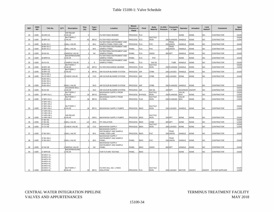
Table 15100-1: Valve Schedule
REFDWG
NO.TAG No. QTY Description
Size
(in)
Type /
StyleLocation
Mount:
Process or
Panel
FluidBody
Material
CLASS /
Pressure
Connectio
n TypeOperator Actuation
Limit
Switch?Comments
Spec
Section
19 I-1005 30-ARV-01 1AIR RELIEF VALVE 2 FILTER FEED HEADER PROCESS FLS NONE NONE NO CONTRACTOR 15100
20 I-1005 30-BFV-01 1BUTTERFLY VALVE 42 BFV2 FILTER FEED HEADER PROCESS FLS
DUCTILE IRON 150 FLANGED HANDLE NONE NO CONTRACTOR
1510011200
21 I-1005 30-BV-01-1 1 BALL VALVE 1 BV1FILTER FEED INSTRUMENT AND SAMPLE PANEL FEED LINE PROCESS FLS PVC 150
TRUE UNION HANDLE NONE NO CONTRACTOR 15100
22 I-100530-BV-01-2,30-BV-01-3 2 BALL VALVE 1 BV1
FILTER FEED INSTRUMENT AND SAMPLE PANEL PANEL FLS PVC 150
TRUE UNION HANDLE NONE NO CONTRACTOR 15100
23 I-1005 30-NV-01 1 NEEDLE VALVE 1 NVFILTER FEED INSTRUMENT AND SAMPLE PANEL PANEL FLS 316SS 300 NPT HANDLE NONE NO CONTRACTOR 15100
24 I-1005 30-BPR-01 1BACKPRESSURE VALVE 1
FILTER FEED INSTRUMENT AND SAMPLE PANEL PANEL FLS PVC NONE NONE NO CONTRACTOR 15100
25 I-1005 30-GV-01 1 SAMPLE VALVE 1 SFILTER FEED INSTRUMENT AND SAMPLE PANEL PANEL FLS 316 SS TUBE HANDLE NONE NO CONTRACTOR 15100
26 I-1005 30-BFV-85 1BUTTERFLY VALVE 42 BFV3 FILTER DISCHARGE HEADER PROCESS FLW
DUCTILE IRON 150 FLANGED HANDLE NONE NO CONTRACTOR
1510011200
27 I-100535-BFV-01,35-BFV-02 2
BUTTERFLY VALVE 6 BFV5 AIR SCOUR BLOWER SYSTEM PROCESS AIR CF8M 150 LUGGED HANDLE NONE NO CONTRACTOR 15100
28 I-100535-CV-05-1,35-CV-05-2 2 CHECK VALVE 6 CV2 AIR SCOUR BLOWER SYSTEM PROCESS AIR CF8M 150 LUGGED NONE NONE NO CONTRACTOR 15100
29 I-1005
35-BV-05-1,35-BV-05-2,35-BV-05-3,35-BV-05-4 4 BALL VALVE BV3 AIR SCOUR BLOWER SYSTEM PROCESS AIR CF8M 150 FLANGED HANDLE NONE NO CONTRACTOR 15100
30 I-1005 35-SV-05 1SOLENOID BALL VALVE 1 SV2 AIR SCOUR BLOWER SYSTEM PROCESS AIR 304 SS 150 NPT SOLENOID ON/OFF NO CONTRACTOR
1510011200
31 I-1005 37-BFV-01-1 1BUTTERFLY VALVE 16 BFV3
BACKWASH SUPPLY FROM BYPASS PROCESS BYPASS
DUCTILE IRON 150 FLANGED
VALVE BOX NONE NO CONTRACTOR
1510011200
32 I-1005 37-BFV-01-2 1BUTTERFLY VALVE 16 BFV3
BACKWASH SUPPLY FROM FILTERS PROCESS FLW
DUCTILE IRON 150 FLANGED
VALVE BOX NONE NO CONTRACTOR
1510011200
33 I-1005
37-BFV-05-1,37-BFV-05-2,37-BFV-06-1,37-BFV-06-2 4
BUTTERFLY VALVE 16 BFV1 BACKWASH SUPPLY PUMPS PROCESS BWS
DUCTILE IRON 150 LUGGED HANDLE NONE NO CONTRACTOR
1510011200
34 I-1005
37-ARV-05-1,37-ARV-05-2,37-ARV-06-1,37-ARV-06-2 4
AIR RELIEF VALVE 2 ARV1 BACKWASH SUPPLY PUMPS PROCESS BWS
DUCTILE IRON 150 NPT NONE NONE NO CONTRACTOR 15100
35 I-100537-BV-05,37-BV-06 2 BALL VALVE 1/2 BV3 PIT ISOLATION PROCESS BWS CF8M 300 NPT NONE NONE NO CONTRACTOR
1510011200
36 I-100537-CV-05,37-CV-06 2 CHECK VALVE 16 CV1 BACKWASH SUPPLY PROCESS BWS
DUCTILE IRON 150 LUGGED NONE NONE NO CONTRACTOR
1510011200
37 I-1005 37-BV-09-1 1 BALL VALVE 1 BV1
BACKWASH SUPPLY INSTRUMENT AND SAMPLE PANEL FEED LINE PROCESS BWS PVC 150
TRUE UNION HANDLE NONE NO CONTRACTOR 15100
38 I-100537-BV-09-2,37-BV-09-3 2 BALL VALVE 1 BV1
BACKWASH SUPPLY INSTRUMENT AND SAMPLE PANEL PANEL BWS PVC 150
TRUE UNION HANDLE NONE NO CONTRACTOR 15100
39 I-1005 37-NV-09 1 NEEDLE VALVE 1 NV
BACKWASH SUPPLY INSTRUMENT AND SAMPLE PANEL PANEL BWS 316SS 300 NPT HANDLE NONE NO CONTRACTOR 15100
40 I-1005 37-BPR-09 1BACKPRESSURE VALVE 1 FOR FUTURE TESTING PANEL BWS NONE NONE NO CONTRACTOR 15100
41 I-1006
30-MOV-11,30-MOV-21,30-MOV-31,30-MOV-41,30-MOV-51,30-MOV-61,30-MOV-71,30-MOV-81 8
BUTTERFLY VALVE 16 BFV1
FILTER CELL NO. 1 FEED ISOLATION PROCESS FLS
DUCTILE IRON 150 LUGGED MOTOR ON/OFF ON/OFF FILTER SUPPLIER
1510011200
CENTRAL WATER INTEGRATION PIPELINE
VALVES AND APPURTENANCES
15100-34
TERMINUS TREATMENT FACILITY
MAY 2018
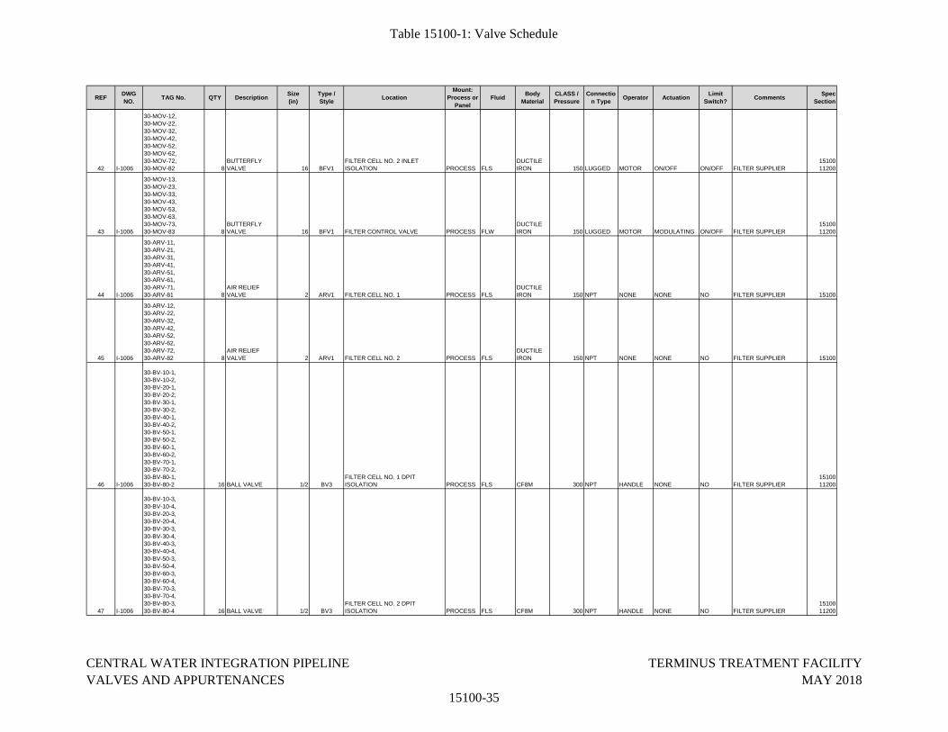
Table 15100-1: Valve Schedule
REFDWG
NO.TAG No. QTY Description
Size
(in)
Type /
StyleLocation
Mount:
Process or
Panel
FluidBody
Material
CLASS /
Pressure
Connectio
n TypeOperator Actuation
Limit
Switch?Comments
Spec
Section
42 I-1006
30-MOV-12,30-MOV-22,30-MOV-32,30-MOV-42,30-MOV-52,30-MOV-62,30-MOV-72,30-MOV-82 8
BUTTERFLY VALVE 16 BFV1
FILTER CELL NO. 2 INLET ISOLATION PROCESS FLS
DUCTILE IRON 150 LUGGED MOTOR ON/OFF ON/OFF FILTER SUPPLIER
1510011200
43 I-1006
30-MOV-13,30-MOV-23,30-MOV-33,30-MOV-43,30-MOV-53,30-MOV-63,30-MOV-73,30-MOV-83 8
BUTTERFLY VALVE 16 BFV1 FILTER CONTROL VALVE PROCESS FLW
DUCTILE IRON 150 LUGGED MOTOR MODULATING ON/OFF FILTER SUPPLIER
1510011200
44 I-1006
30-ARV-11,30-ARV-21,30-ARV-31,30-ARV-41,30-ARV-51,30-ARV-61,30-ARV-71,30-ARV-81 8
AIR RELIEF VALVE 2 ARV1 FILTER CELL NO. 1 PROCESS FLS
DUCTILE IRON 150 NPT NONE NONE NO FILTER SUPPLIER 15100
45 I-1006
30-ARV-12,30-ARV-22,30-ARV-32,30-ARV-42,30-ARV-52,30-ARV-62,30-ARV-72,30-ARV-82 8
AIR RELIEF VALVE 2 ARV1 FILTER CELL NO. 2 PROCESS FLS
DUCTILE IRON 150 NPT NONE NONE NO FILTER SUPPLIER 15100
46 I-1006
30-BV-10-1,30-BV-10-2,30-BV-20-1,30-BV-20-2,30-BV-30-1,30-BV-30-2,30-BV-40-1,30-BV-40-2,30-BV-50-1,30-BV-50-2,30-BV-60-1,30-BV-60-2,30-BV-70-1,30-BV-70-2,30-BV-80-1,30-BV-80-2 16 BALL VALVE 1/2 BV3
FILTER CELL NO. 1 DPIT ISOLATION PROCESS FLS CF8M 300 NPT HANDLE NONE NO FILTER SUPPLIER
1510011200
47 I-1006
30-BV-10-3,30-BV-10-4,30-BV-20-3,30-BV-20-4,30-BV-30-3,30-BV-30-4,30-BV-40-3,30-BV-40-4,30-BV-50-3,30-BV-50-4,30-BV-60-3,30-BV-60-4,30-BV-70-3,30-BV-70-4,30-BV-80-3,30-BV-80-4 16 BALL VALVE 1/2 BV3
FILTER CELL NO. 2 DPIT ISOLATION PROCESS FLS CF8M 300 NPT HANDLE NONE NO FILTER SUPPLIER
1510011200
CENTRAL WATER INTEGRATION PIPELINE
VALVES AND APPURTENANCES
15100-35
TERMINUS TREATMENT FACILITY
MAY 2018
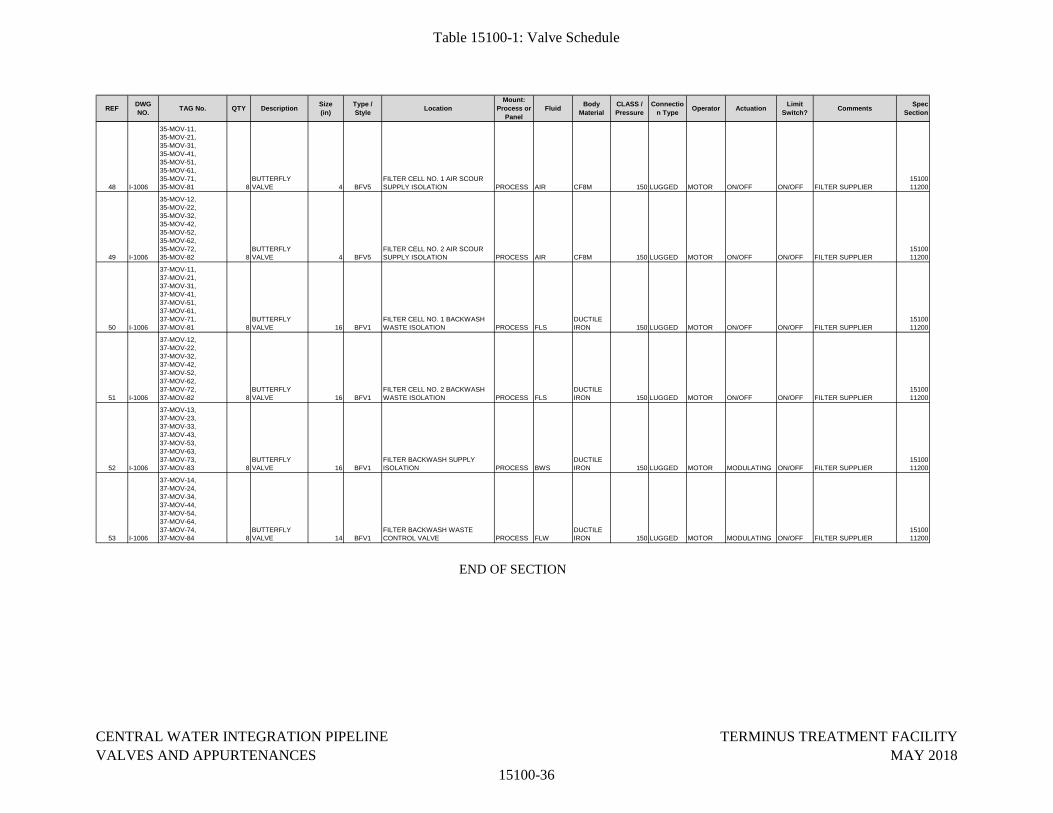
Table 15100-1: Valve Schedule
REFDWG
NO.TAG No. QTY Description
Size
(in)
Type /
StyleLocation
Mount:
Process or
Panel
FluidBody
Material
CLASS /
Pressure
Connectio
n TypeOperator Actuation
Limit
Switch?Comments
Spec
Section
48 I-1006
35-MOV-11,35-MOV-21,35-MOV-31,35-MOV-41,35-MOV-51,35-MOV-61,35-MOV-71,35-MOV-81 8
BUTTERFLY VALVE 4 BFV5
FILTER CELL NO. 1 AIR SCOUR SUPPLY ISOLATION PROCESS AIR CF8M 150 LUGGED MOTOR ON/OFF ON/OFF FILTER SUPPLIER
1510011200
49 I-1006
35-MOV-12,35-MOV-22,35-MOV-32,35-MOV-42,35-MOV-52,35-MOV-62,35-MOV-72,35-MOV-82 8
BUTTERFLY VALVE 4 BFV5
FILTER CELL NO. 2 AIR SCOUR SUPPLY ISOLATION PROCESS AIR CF8M 150 LUGGED MOTOR ON/OFF ON/OFF FILTER SUPPLIER
1510011200
50 I-1006
37-MOV-11,37-MOV-21,37-MOV-31,37-MOV-41,37-MOV-51,37-MOV-61,37-MOV-71,37-MOV-81 8
BUTTERFLY VALVE 16 BFV1
FILTER CELL NO. 1 BACKWASH WASTE ISOLATION PROCESS FLS
DUCTILE IRON 150 LUGGED MOTOR ON/OFF ON/OFF FILTER SUPPLIER
1510011200
51 I-1006
37-MOV-12,37-MOV-22,37-MOV-32,37-MOV-42,37-MOV-52,37-MOV-62,37-MOV-72,37-MOV-82 8
BUTTERFLY VALVE 16 BFV1
FILTER CELL NO. 2 BACKWASH WASTE ISOLATION PROCESS FLS
DUCTILE IRON 150 LUGGED MOTOR ON/OFF ON/OFF FILTER SUPPLIER
1510011200
52 I-1006
37-MOV-13,37-MOV-23,37-MOV-33,37-MOV-43,37-MOV-53,37-MOV-63,37-MOV-73,37-MOV-83 8
BUTTERFLY VALVE 16 BFV1
FILTER BACKWASH SUPPLY ISOLATION PROCESS BWS
DUCTILE IRON 150 LUGGED MOTOR MODULATING ON/OFF FILTER SUPPLIER
1510011200
53 I-1006
37-MOV-14,37-MOV-24,37-MOV-34,37-MOV-44,37-MOV-54,37-MOV-64,37-MOV-74,37-MOV-84 8
BUTTERFLY VALVE 14 BFV1
FILTER BACKWASH WASTE CONTROL VALVE PROCESS FLW
DUCTILE IRON 150 LUGGED MOTOR MODULATING ON/OFF FILTER SUPPLIER
1510011200
END OF SECTION
CENTRAL WATER INTEGRATION PIPELINE
VALVES AND APPURTENANCES
15100-36
TERMINUS TREATMENT FACILITY
MAY 2018
APPENDIX C
DIVISION 17
INSTRUMENTATION
CENTRAL WATER INTEGRATION PIPELINE TERMINUS TREATMENT FACILITY FLOW INSTRUMENTS MAY 2018
17310 - 1
SECTION 17310
FLOW INSTRUMENTS
PART 1 GENERAL
1.01 SCOPE OF WORK
A. Furnish, install and test all flow measurement, flow control devices and appurtenances, as shown on the Drawings, specified in the Related Work Sections and Divisions, and as specified herein.
B. Flow equipment, specified in other Divisions, shall be manufactured in accordance with this Section and submitted as a part of the equipment specified in other Divisions.
1.02 RELATED WORK
A. Electrical Equipment Division.
B. Process Equipment Division.
C. Mechanical Equipment Division.
D. Section 17300 Process Control Systems General Provisions
E. Section 17302 Process Control Systems Testing
F. Section 17345 Instrument Support Hardware
G. Section 17410 Process Instrument Schedule
1.03 SUBMITTALS
A. Submit catalog data for all items supplied from this specification Section as applicable. Submittal shall include catalog data, functions, ratings, inputs, outputs, displays, etc., sufficient to confirm that the meter or relay provides every specified requirement. Any options or exceptions shall be clearly indicated.
B. Submittals for equipment specified herein, for other Sections or Divisions, shall be made as a part of equipment submittals furnished under other Sections or Divisions.
C. Installation experience documentation shall be submitted for approval with the Section Equipment Submittal
D. Operation and Maintenance Manuals.
1. Operation and Maintenance manuals shall be constructed in accordance with Division 1 and shall include the following information:
a. Manufacturer’s contact address and telephone number for parts and
CENTRAL WATER INTEGRATION PIPELINE TERMINUS TREATMENT FACILITY FLOW INSTRUMENTS MAY 2018
17310 - 2
service.
b. Instruction books and/or leaflets
c. Recommended renewal parts list
d. Record Documents for the information required by the Submittals above.
1.04 REFERENCE CODES AND STANDARDS
A. The equipment in this specification shall be designed and manufactured according to latest revision of the following standards (unless otherwise noted):
1. ISO 2975/VII liquids and BS 5857-2.4 for gases. Transit Time Meters
2. ISO 9555-1 and ISO 9555-2. Liquid flow in open channels. Radiotracer dilution method of calibration for open channel flow measurements.
3. American Society of Mechanical Engineers (ASME). 1971. Fluid meters: Their theory and application.
4. International Organization of Standards (ISO 5167-1). 1991. Measurement of fluid flow by means of pressure differential devices Venturi Tube w/ liquid
5. ASME PTC 19.2 Pressure Measurement
6. ANSI B88.1 Pressure Transducers Calibration
7. ISA S37.6 Strain Gage Transducers Potentiometric
8. Calibration AVS 6.2, 6.4, 6.5 Hazardous Areas
9. IEC 79-10 Intrinsically Safe Circuits
10. ANSI 913 Electrical Instruments in Hazardous Atmospheres
B. All meters, relays and associated equipment shall comply with the requirements of the National Electric Code and Underwriters Laboratories (UL) where applicable.
C. Each specified device shall also conform to the standards and codes listed in the individual device paragraphs.
1.05 QUALITY ASSURANCE
A. The manufacturer of this equipment shall have produced similar instrumentation equipment for a minimum period of five (5) years. When requested by the Owner/Engineer, an acceptable list of installations with similar equipment shall be provided demonstrating compliance with this requirement.
B. Equipment submitted shall fit within the space or location shown on the Drawings. Equipment which does not fit within the space or location is not acceptable.
CENTRAL WATER INTEGRATION PIPELINE TERMINUS TREATMENT FACILITY FLOW INSTRUMENTS MAY 2018
17310 - 3
C. For the equipment specified herein, the manufacturer shall be ISO 9001 2000 certified.
1.06 WARRANTY
A. Provide equipment warranty in accordance with Section 01740: Warranties and Bonds.
PART 2 PRODUCTS
2.01 ELECTROMAGNETIC FLOW METER
A. Subject to compliance with the Contract Documents, the following manufacturers are acceptable:
1. ABB
2. Endress & Hauser
3. Siemens
B. The listing of specific manufacturers above does not imply acceptance of their products that do not meet the specified ratings, features and functions. Manufacturers listed above are not relieved from meeting these specifications in their entirety.
C. General
1. Provide sufficient lengths of manufacturer’s specialty cables for installation of power and signal conductors as provided with each instrument.
2. Provide a hand-held programmer, for each transmitter, where full setup is not available for the instrument directly.
3. Each electromagnetic flowmeter shall be provided according to the Table 17410-1 in Section 17410: Process Instrument Schedule.
D. Type
1. Microprocessor based intelligent type.
E. Function/Performance:
1. Output: 4-20 mA DC. Output shall be linear for pressure applications.
2. Accuracy: 0.5 percent of span (linear output).
3. Stability: Combined temperature effects shall be less than 0.2 percent of maximum span per 50 degrees F temperature change. Effect on accuracy, due to static pressure changes, shall be negligible.
4. RFI Protection: 0.1 percent error between 27 and 500 MHZ at 30 v/m field intensity.
CENTRAL WATER INTEGRATION PIPELINE TERMINUS TREATMENT FACILITY FLOW INSTRUMENTS MAY 2018
17310 - 4
5. Drift: 0.10 percent per six months for 4-20 mA output.
6. Temperature rating: Suitable for process liquid temperature up to 70 d e gre es C and an ambient of 65 degrees C.
7 Pressure rating: 240 PSI if 150 lb flanges are used; 700 PSI if 300 lb f l a n ge s are used.
8. Meter shall be capable of running empty indefinitely without damage to any component.
F. Physical:
1. Metering Tube
a. Carbon steel with 304 Stainless interior unless otherwise indicated.
b. Electrical Classification: Rating shall be FM approved for the location shown on the Drawings
c. Tube Flanges: Match piping AWWA rating of the pipe. Minimum AWWA 150# Flange.
d. Tube Liner: Polyurethane or EDPM, certified as ANSI/MSF Standard 61 compliant for direct contact with potable water, unless noted otherwise.
e. Tube Electrodes: ANSI 316 stainless steel or Hastelloy C, bullet nosed or elliptical self-cleaning type unless otherwise noted.
f. Tube Housing: Meters in below grade, vaults, basements, etc., shall be designed for accidental submergence in 30 feet of water for 24 hours. Meters above grade shall be of splash proof/drip proof design unless otherwise noted.
g. Painting: All external surfaces shall be painted with a chemical and corrosion resistant epoxy finish.
2. Transmitter
a. Transmitter Enclosure: NEMA 4X.
b. Electrical Classification: Rating shall be FM approved for the location shown on the Drawings
c. Transmitter shall be remotely mounted unless indicated on Drawings.
G. Power Requirements
1. As shown on the Drawings.
CENTRAL WATER INTEGRATION PIPELINE TERMINUS TREATMENT FACILITY FLOW INSTRUMENTS MAY 2018
17310 - 5
H. Options/ Accessories
1. Factory calibration: Each meter shall be factory calibrated, with a copy of the Report delivered with the device and in the O&M manual.
2. Grounding: Meter shall be grounded with rings. Provide 316 Stainless Steel ground rings, ground wires, and gaskets, etc. All materials shall be suitable for the liquid being measured.
3. Electrode cleaning: Where listed on the instrument device schedules, or shown on the Drawings, provide an electrode cleaning system. The cleaning system electronics shall be housed in a NEMA 4X wall mounted panel. Provide all necessary cables and connectors. The system shall be powered through the special cables to the magnetic flow meter.
4. Provide a hand-held programmer for each transmitter, where full setup is not available from the instrument transmitter display directly.
2.02 SPARES:
A. Contractor shall furnish a minimum of one or 10 percent of each installed instrument, whichever is greater.
B. All spare equipment shall be packed in a manner suitable for long-term storage and shall be adequately protected against corrosion, humidity and temperature. Individually mark and vacuum seal all spare parts. Provide other spare parts as indicated on the individual device specifications.
PART 3 EXECUTION
3.01 INSTALLER’S QUALIFICATIONS
A. Installer shall be specialized in installing this type of equipment with minimum 5 years documented experience
3.02 EXAMINATION
A. Examine installation area to assure there is enough clearance to install the equipment.
B. Verify that the equipment is ready to install.
C. Verify field measurements are as instructed by the manufacturer.
3.03 INSTALLATION
A. The Contractor shall install all equipment per the manufacturer's recommendations and Contract Drawings.
B. All process connections shall be 316 stainless steel tubing, 3/8” minimum, unless otherwise shown on the Drawings. Fittings shall be of the compression type, 316 stainless steel.
CENTRAL WATER INTEGRATION PIPELINE TERMINUS TREATMENT FACILITY FLOW INSTRUMENTS MAY 2018
17310 - 6
C. All conduit entries into the instruments shall use hubs of watertight, threaded aluminum, insulated throat, stainless steel grounding screw, as manufactured by T&B H150GRA Series, or equal.
D. Install stainless steel instrument labels with instrument ID, secured with safety wire.
3.04 RACEWAY SEALING
A. Where raceways enter terminal boxes, junction boxes, or instrumentation equipment, all entrances shall be sealed with 3M 1000NS Watertight Sealant, or approved equal.
3.05 FIELD QUALITY CONTROL
A. Inspect installed equipment for anchoring, alignment, grounding and physical damage.
B. Check tightness of all accessible electrical connections. Minimum acceptable values shall be specified in the manufacturer's instructions.
3.06 FIELD ADJUSTING
A. Adjust all equipment for proper range and field conditions, as described in the manufacturer's instructions.
B. Any field adjustments, required for proper system operation, shall be included in the Final O&M.
3.07 FIELD TESTING
A. Perform all electrical field tests recommended by the manufacturer.
B. Test each interlock system for proper functioning.
C. Test all control logic for proper operation.
3.08 CLEANING
A. Remove all rubbish and debris from inside and around the equipment. Remove dirt, dust, or concrete spatter from the interior and exterior of the equipment using brushes, vacuum cleaner, or clean, lint free rags. Do not use compressed air.
3.09 EQUIPMENT PROTECTION AND RESTORATION
A. Touch-up and restore damaged surfaces to factory finish, as approved by the manufacturer. If the damaged surface cannot be returned to factory specification, the surface shall be replaced.
3.10 MANUFACTURER’S CERTIFICATION
A. A qualified factory-trained and certified representative shall certify in writing that the

CENTRAL WATER INTEGRATION PIPELINE TERMINUS TREATMENT FACILITY FLOW INSTRUMENTS MAY 2018
17310 - 7
equipment has been installed, adjusted, including all settings as defined in the Contract Documents.
B. The Contractor shall provide three copies of the representative’s certification.
END OF SECTION
CENTRAL WATER INTEGRATION PIPELINE TERMINUS TREATMENT FACILITY PRESSURE INSTRUMENTS MAY 2018
17314 - 1
SECTION 17314
PRESSURE INSTRUMENTS
PART 1 GENERAL
1.01 SCOPE OF WORK:
A. Furnish, install and test all pressure measurement, pressure control devices and appurtenances, as shown on the Drawings, specified in the Related Work Sections and Divisions, and as specified herein.
B. Pressure equipment, specified in other Divisions, shall be manufactured in accordance with this Section, and submitted as a part of the equipment specified in other Divisions.
1.02 RELATED WORK:
A. Electrical Equipment Division.
B. Process Equipment Division
C. Mechanical Equipment Division.
D. Section 17300 Process Control Systems General Provisions
E. Section 17302 Process Control Systems Testing
F. Section 17345 Instrument Support Hardware
G. Section 17410 Process Instrument Schedule
1.03 SUBMITTALS:
A. Submit catalog data for all items supplied from this specification Section as applicable. Submittal shall include catalog data, functions, ratings, inputs, outputs, displays, etc., sufficient to confirm that the meter or relay provides every specified requirement. Any options or exceptions shall be clearly indicated.
B. Submittals for equipment specified herein, for other Sections or Divisions, shall be made as a part of equipment submittals furnished under other Sections or Divisions.
C. Installation experience documentation shall be submitted for approval with the Section Equipment Submittal
D. Operation and Maintenance Manuals.
1. Operation and Maintenance manuals shall be constructed in accordance with Division 1 and shall include the following information:
CENTRAL WATER INTEGRATION PIPELINE TERMINUS TREATMENT FACILITY PRESSURE INSTRUMENTS MAY 2018
17314 - 2
a. Manufacturer’s contact address and telephone number for parts and service.
b. Instruction books and/or leaflets
c. Recommended renewal parts list
d. Record Documents for the information required by the Submittals above.
1.03 REFERENCE CODES AND STANDARDS:
A. The equipment in this specification shall be designed and manufactured according to latest revision of the following standards (unless otherwise noted):
1. ANSI B40.1 Pressure Gauges
2. ASME PTC 19.2 Pressure Measurement
3. ANSI B88.1 Pressure Transducers Calibration
4. ISA S37.6Strain Gage Transducers Potentiometric
5. ISA S37.3 5 Vacuum Gauges
6. Calibration AVS 6.2, 6.4, 6.5 Hazardous Areas
7. IEC 79-10 Intrinsically Safe
Circuits 8. IEC 79-3
9. 913 Electrical Instruments in Hazardous Atmospheres
10. ISA RP12.1, 4, 6, 10, 11 Weighing Scales
11. ASME PTC 19.5.1
B. All meters, relays and associated equipment shall comply with the requirements of the National Electric Code and Underwriters Laboratories (UL) where applicable.
C. Each specified device shall also conform to the standards and codes listed in the individual device paragraphs.
1.04 QUALITY ASSURANCE:
A. The manufacturer of this equipment shall have produced similar instrumentation equipment for a minimum period of five (5) years. When requested by the Owner/Engineer, an acceptable list of installations with similar equipment shall be provided demonstrating compliance with this requirement.
CENTRAL WATER INTEGRATION PIPELINE TERMINUS TREATMENT FACILITY PRESSURE INSTRUMENTS MAY 2018
17314 - 3
B. Equipment submitted shall fit within the space or location shown on the Drawings. Equipment which does not fit within the space or location is not acceptable.
C. For the equipment specified herein, the manufacturer shall be ISO 9001 2000 certified.
1.05 WARRANTY:
A. Provide equipment warranty in accordance with Section 01740: Warranties and Bonds.
PART 2 PRODUCTS
2.01 DIFFERENTIAL PRESSURE TRANSMITTER:
A. Subject to compliance with the Contract Documents, the following Manufacturers are acceptable:
1. Endress + Houser
2. Foxboro
3. Rosemount
4. Siemens
5. Approved Equal
B. The listing of specific manufacturers above does not imply acceptance of their products that do not meet the specified ratings, features and functions. Manufacturers listed above are not relieved from meeting these specifications in their entirety.
C. General
1. Provide signal surge protection at all transmitters.
2. Each differential pressure transmitters shall be provided according to the Table 17410-1 in Section 17410: Process Instrument Schedule
D. Type
1. Microprocessor based intelligent type.
2. Diaphragm actuated.
E. Function/Performance:
1. Output: 4-20 mA DC. Output shall be linear for pressure applications.
2. Accuracy: 0.1 percent of span (linear output).
CENTRAL WATER INTEGRATION PIPELINE TERMINUS TREATMENT FACILITY PRESSURE INSTRUMENTS MAY 2018
17314 - 4
3. Stability: Combined temperature effects shall be less than 0.2 percent of maximum span per 50 degrees F temperature change. Effect on accuracy due to static pressure changes shall be negligible.
4. RFI Protection: 0.1 percent error between 27 and 500 MHZ at 30 v/m field intensity.
5. Drift: 0.10 percent per six months for 4-20 mA output.
6. Sensor Technology: Digital.
7. Over Range Protection: Provide positive over range protection.
F. Physical
1. Electrical Classification: Intrinsically safe for Class I and Class II, Division 1 locations.
2. Enclosure: NEMA 4X.
3. Sensor Diaphragm Material: 316 Stainless Steel alloy or Hastelloy C.
4. Gaskets: Teflon.
5. Sensor Fill Fluid: Shall be suitable for process fluid being measured. When used for chemical metering service, sensor fill fluid shall be rated specifically for the chemical being measured.
G. Power Requirements:
1. Loop powered, two wire type.
H. Required Options/Accessories
1. Provide span and zero adjustment at each transmitter.
2. Provide local indication at each transmitter using LCD readout. Scale shall be in engineering units. With a minimum of 4 digits of precision
3. For each transmitter provide a manifold as specified herein, with the following Modes:
a. Normal Mode
b. Zeroing Mode
c. Isolation Mode
d. Calibration Mode
CENTRAL WATER INTEGRATION PIPELINE TERMINUS TREATMENT FACILITY PRESSURE INSTRUMENTS MAY 2018
17314 - 5
e. Blowdown Mode
4. Provide hand held programmer(s) where full setup is not available for the instrument directly from the display.
2.02 PRESSURE TRANSMITTER:
A. Subject to compliance with the Contract Documents, the following Manufacturers are acceptable:
1. Endress + Houser
2. Foxboro
3. Rosemount
4. Siemens
5. Approved Equal
B. The listing of specific manufacturers above does not imply acceptance of their products that do not meet the specified ratings, features and functions. Manufacturers listed above are not relieved from meeting these specifications in their entirety.
C. General
1. Provide surge protection for each instrument.
2. Each pressure transmitter shall be provided according to the Table 17410-1 in Section 17410: Process Instrument Schedule
D. Type
1. Microprocessor based intelligent type, diaphragm actuated.
2. The instrument shall measure gage pressure.
E. Function/Performance
1. Accuracy: Plus or minus 0.1 percent of calibrated span.
2. Over Range Protection: Provide positive over range protection to maximum process pressure.
3. RFI Protection: 0.1 percent error between 27 and 500 MHZ at 20 v/m field intensity.
4. Output: 4-20 mA
5. Stability: Combined temperature effects shall be less than 0.2 percent of
CENTRAL WATER INTEGRATION PIPELINE TERMINUS TREATMENT FACILITY PRESSURE INSTRUMENTS MAY 2018
17314 - 6
maximum span per 50 degrees F temperature change.
F. Physical
1. Electrical Classification: Intrinsically safe or explosion proof for Class I and Class II, Division 1 locations.
2. Enclosure: Rated NEMA 4X.
3. Diaphragm Sensor Material: 316 Stainless Steel alloy or Hastelloy C.
4. Sensor Fill Fluid: Shall be suitable for process fluid being measured. When used for chemical metering service, the fill fluid shall be rated for the chemical being measured.
G. Power Requirements
1. Loop powered two wire type
H. Required Options/Accessories
1. If required to meet the range or suppression/elevation requirements, the Contractor shall supply a differential pressure transmitter.
2. Provide a shutoff valve and mounting bracket for each transmitter.
3. Provide an integral indicator scaled in engineering units.
4. Provide hand held programmer(s) where full setup is not available for the instrument directly.
2.03 FLANGE MOUNTED PRESSURE TRANSMITTER:
A. Subject to compliance with the Contract Documents, the following Manufacturers are acceptable:
1. Endress + Houser
2. Foxboro
3. Rosemount
4. Siemens
5. Approved Equal
B. The listing of specific manufacturers above does not imply acceptance of their products that do not meet the specified ratings, features and functions. Manufacturers listed above are not relieved from meeting these specifications in their entirety.
CENTRAL WATER INTEGRATION PIPELINE TERMINUS TREATMENT FACILITY PRESSURE INSTRUMENTS MAY 2018
17314 - 7
C. General
1. Provide sufficient lengths of any Manufacturer’s specialty cables for installation of power and signal conductors as provided with each instrument.
2. Each flange-mounted pressure transmitters shall be provided according to the Table 17410-1 in Section 17410: Process Instrument Schedule
D. Type
1. Differential pressure type with remote flanged diaphragm seal(s).
2. Microprocessor based intelligent type.
E. Function/Performance
1. Accuracy: Plus or minus 0.1 percent of calibrated span.
2. Output: 4-20 mA
3. RFI Protection: 0.1 percent error between 27 and 500 MHZ at 20 v/m field intensity.
4. Over Range Protection: Positive over range protection.
5 Stability: Combined temperature effects shall be less than 0.2 percent of maximum span per 50 degree F temperature change.
F. Physical
1. Electrical Classification: Intrinsically safe or explosion proof for Class I and Class II, Division 1 locations.
2. Enclosure: NEMA 4X.
3. Diaphragm Sensor Material: 316 Stainless Steel alloy or Hastelloy C.
4. Connection: Process connection shall be with a 2-in, Class 150, carbon steel flange.
5. Process or atmospheric reference connection shall be a ½-in NPT.
6. Sensor Fill Fluid: Suitable for the process fluid being measured. When used for chemical metering service, the fill fluid shall be rated for the chemical being measured.
G. Power Requirement
1. Loop powered 2 wire types.
CENTRAL WATER INTEGRATION PIPELINE TERMINUS TREATMENT FACILITY PRESSURE INSTRUMENTS MAY 2018
17314 - 8
H. Options/Accessories
1. Provide an integral indicator scaled in engineering units.
2. Provide hand held programmer(s) as specified under tools and test equipment.
3. Provide all necessary remote seal equipment and accessories to mount the transmitter up to ten feet from the remote seal.
4. Provide hand held programmer(s) where full setup is not available for the instrument directly.
2.04 MANIFOLD:
A. Subject to compliance with the Contract Documents, the following Manufacturers are acceptable:
1. D/A Manufacturing Model GP5TC
2. Parker H Series
3. Swagelok
4. Approved Equal
B. The listing of specific manufacturers above does not imply acceptance of their products that do not meet the specified ratings, features and functions. Manufacturers listed above are not relieved from meeting these specifications in their entirety.
C. General
1. Provide fully machined surfaces.
D. Type
1. Type as shown on Drawings or specified else ware.
E. Functions/Performance
1. Five or three valve, as shown or specified else ware.
F. Physical
1. Manifold shall be of 316 stainless steel.
2. Flanged or Transmount as shown on the Drawings.
G. Power Requirements
1. None
CENTRAL WATER INTEGRATION PIPELINE TERMINUS TREATMENT FACILITY PRESSURE INSTRUMENTS MAY 2018
17314 - 9
H. Required Options/Accessories
1. Provide one set of spare gaskets.
2.05 DIAPHRAGM SEAL – THREADED:
A. Subject to compliance with the Contract Documents, the following Manufacturers are acceptable:
1. Red Valve Company, Inc.
2. Ashcroft.
3. Approved equal.
B. The listing of specific manufacturers above does not imply acceptance of their products that do not meet the specified ratings, features and functions. Manufacturers listed above are not relieved from meeting these specifications in their entirety.
C. General
1. Rating to match pipe rating.
D. Type
1. Thread attached.
2. Welded Metal Diaphragm.
3. Exposed Surfaces - 316 stainless steel.
E. Function/Performance
1. Purpose: To protect instruments or gauges from the process medium.
2. A flexible diaphragm shall separate the process medium from the instrument element. Space on the instrument side of the diaphragm shall be completely filled with a suitable silicone or instrument oil. The process pressure is transmitted by the liquid filled system to the instrument element.
3. Filling Screw: Include on all units.
4. Pressure Limits: 1,000 psi.
5. Flushing Connection: Include on all units.
6. Tubing as required to connect with related instrument. ¼ ID minimum size flexible stainless.
CENTRAL WATER INTEGRATION PIPELINE TERMINUS TREATMENT FACILITY PRESSURE INSTRUMENTS MAY 2018
17314 - 10
F. Physical
1. Top Housing: Carbon Steel, Cadmium plated.
2. Diaphragm: 316 ELC Stainless Steel.
3. Exposed Surfaces: 316 stainless steel.
4. Bolts, Nuts and Plugs: 18-8 stainless steel or 316 stainless steel.
G. Power Requirements
1. None
H. Required Options/Accessories
1. Provide one set of spare gaskets.
2.06 DIAPHRAGM SEAL - CONCENTRIC FLANGE MOUNTED:
A. Subject to compliance with the Contract Documents, the following Manufacturers are acceptable:
1. Red Valve Company, Inc.
2. Ashcroft.
3. Approved equal.
B. The listing of specific manufacturers above does not imply acceptance of their products that do not meet the specified ratings, features and functions. Manufacturers listed above are not relieved from meeting these specifications in their entirety.
C. General
1. Rating to be equal to or greater than the piping.
D. Type
1. Line mounted, between two flanges.
2. Flange Drilling conforms to ANSI #125 flanges.
3. Carbon Steel Body.
E. Function/Performance
1. Protect instruments or gauges from the process medium.
2. Operating principle: A 360° sensing sleeve shall separate the process medium
CENTRAL WATER INTEGRATION PIPELINE TERMINUS TREATMENT FACILITY PRESSURE INSTRUMENTS MAY 2018
17314 - 11
from the instrument element. The volume on the instrument side of the sensing sleeve shall be completely filled with sensing liquid. The process pressure shall be transferred to the instrument element by the sensing liquid.
3. Pressure Limit: Correspond to flange ratings.
4. Inside diameter shall conform to schedule 40 pipe.
5. Bolt drilling shall conform to ANSI 125/150 pound flange and bolting dimensions.
F. Physical
1. Body material: Carbon steel.
2. Process connection: 1/4- inch NPT. Minimum
3. Sensing Sleeve: Buna-N.
4. Sensing Liquid: Silicone Oil.
G. Power Requirements
1. None
H. Required Options/Accessories
1. Provide one set of spare gaskets.
2.07 PRESSURE GAUGE:
A. Subject to compliance with the Contract Documents, the following Manufacturers are acceptable
1. Ashcroft Model 1279
2. Ametek/U.S. Gauge Division
3. Wika
4. Approved equal
B. The listing of specific manufacturers above does not imply acceptance of their products that do not meet the specified ratings, features and functions. Manufacturers listed above are not relieved from meeting these specifications in their entirety.
C. General
1. Ratings shall be equal to or exceed the piping.
CENTRAL WATER INTEGRATION PIPELINE TERMINUS TREATMENT FACILITY PRESSURE INSTRUMENTS MAY 2018
17314 - 12
2. Each pressure guage shall be provided according to the Table 17410-1 in Section 17410: Process Instrument Schedule
D. Type:
1. Bourdon tube actuated pressure gauge.
E. Function/Performance:
1. Accuracy: Plus or minus 1.0 percent of span or better.
F. Physical:
1. Case: Phenolic shock resistant or 316 stainless steel for surface/stem mounting with a pressure relieving back. The case shall be vented for temperature/atmospheric compensation. Gauge shall be capable of being liquid filled in the field or at the factory.
2. Window: Clear acrylic or shatter proof glass.
3. Bourdon Tube: 316 stainless steel.
4. Connection: ½-in NPT.
5. Gauge size: Minimum 4.0 inches viewable.
6 Pointer travel: Not less than 200 degrees nor more than 270 degree arc.
7. Range: As indicated in the instrument device schedule.
G. Power Requirements
1. None
H. Required Options/Accessories
1. Shutoff valve: Each gauge shall have a process shutoff valve which can also be used as an adjustable pressure snubber.
2. Special scales: The Engineer reserves the right to require special scales and/or calibration if the manufacturer’s standard is not suitable for the application.
3. Gauges listed as liquid filled in the Instrument Device Schedule shall be liquid filled at the Manufacturer’s Factory.
2.08 PRESSURE SWITCH:
A. Subject to compliance with the Contract Documents, the following Manufacturers are acceptable:
CENTRAL WATER INTEGRATION PIPELINE TERMINUS TREATMENT FACILITY PRESSURE INSTRUMENTS MAY 2018
17314 - 13
1. Static-O-Ring (SOR)
2. United Electric
3. Ashcroft
4. Approved equal
B. The listing of specific manufacturers above does not imply acceptance of their products that do not meet the specified ratings, features and functions. Manufacturers listed above are not relieved from meeting these specifications in their entirety.
C. General
1. Ratings shall be equal to or exceed the piping.
2. Each pressure switch shall be provided according to the Table 17410-1 in Section 17410: Process Instrument Schedule
D. Type:
1. Diaphragm actuated.
E. Function/Performance:
1. Repeatability: Greater than 1.0 percent of pressure.
2. Setpoint: Field adjustable and set between 30 and 70 percent of the adjustable range.
3. Dead Band: Adjustable
4. Reset: Unit shall be of the automatic reset type unless noted otherwise on the Instrument Device Schedules.
5. Over Range Protection: Over range protection to maximum process line pressure.
6. Switch Rating: 250 V AC at 10 amps; and 30 V DC at 5 amps.
F. Physical:
1. Housing: NEMA 4X.
2. Switching Arrangement: Single pole double throw (SPDT) unless double pole double throw (DPDT) switches are shown on the instrument device schedule.
3. Wetted Parts: 316 Stainless Steel Alloy, Hastelloy C or Monel diaphragm, viton seals, stainless steel connection port as confirmed compatible with the process
CENTRAL WATER INTEGRATION PIPELINE TERMINUS TREATMENT FACILITY PRESSURE INSTRUMENTS MAY 2018
17314 - 14
fluid by the manufacture.
4. Connection Size: ½-in NPT.
G. Power Requirements
1. None
H. Required Options/Accessories
1. Shutoff Valve: Provide process shutoff valve which can be used as an adjustable pressure snubber.
2.09 DIFFERENTIAL PRESSURE SWITCH:
A. Subject to compliance with the Contract Documents, the following Manufacturers are acceptable:
1. Dwyer Series 1630
2. Ashcroft
3. Approved equal
B. The listing of specific manufacturers above does not imply acceptance of their products that do not meet the specified ratings, features and functions. Manufacturers listed above are not relieved from meeting these specifications in their entirety.
C. General
1. Ratings shall be equal to or exceed the piping.
2. Each differential pressure switch shall be provided according to the Table 17410-1 in Section 17410: Process Instrument Schedule
D. Type:
1. Differential pressure actuated.
E. Function/Performance:
1. Setpoint: Field adjustable.
2. Dead Band: Factory set.
3. Switch Rating: 250 V AC at 10 amps
F. Physical:
1. Housing: NEMA 4X.
CENTRAL WATER INTEGRATION PIPELINE TERMINUS TREATMENT FACILITY PRESSURE INSTRUMENTS MAY 2018
17314 - 15
2. Switching Arrangement: Single pole double throw (SPDT) unless double pole double throw (DPDT) switches are shown on the instrument device schedule.
3. Connection Size: 1/4-in NPT Minimum.
G. Power Requirements
1. None
H. Required Options/Accessories
1. Shutoff Valve: Provide process shutoff valve which can be used as an adjustable pressure snubber.
2.10 SPARES:
I. Contractor shall furnish a minimum of one or 10 percent of each installed instrument, whichever is greater.
J. All spare equipment shall be packed in a manner suitable for long-term storage and shall be adequately protected against corrosion, humidity and temperature. Individually mark and vacuum seal all spare parts. Provide other spare parts as indicated on the individual device specifications.
PART 3 EXECUTION
3.01 INSTALLER’S QUALIFICATIONS:
A. Installer shall be specialized in installing this type of equipment with minimum 5 years documented experience
3.02 EXAMINATION:
A. Examine installation area to assure there is enough clearance to install the equipment.
B. Verify that the equipment is ready to install.
C. Verify field measurements are as instructed by the manufacturer.
3.03 INSTALLATION:
A. The Contractor shall install all equipment per the manufacturer's recommendations and Contract Drawings.
B. All process connections shall be 316 stainless steel tubing, 3/8” minimum, unless otherwise shown on the Drawings. Fittings shall be of the compression type, 316 stainless steel.
C. All conduit entries into the instruments shall use hubs of watertight, threaded aluminum,
CENTRAL WATER INTEGRATION PIPELINE TERMINUS TREATMENT FACILITY PRESSURE INSTRUMENTS MAY 2018
17314 - 16
insulated throat, stainless steel grounding screw, as manufactured by T&B H150GRA Series, or equal.
D. Install stainless steel instrument labels with instrument ID, secured with safety wire.
3.04 RACEWAY SEALING:
A. Where raceways enter instrumentation equipment, all entrances shall be sealed with 3M 1000NS Watertight Sealant, or approved equal.
CENTRAL WATER INTEGRATION PIPELINE TERMINUS TREATMENT FACILITY PRESSURE INSTRUMENTS MAY 2018
17314 - 17
3.05 FIELD QUALITY CONTROL:
A. Inspect installed equipment for anchoring, alignment, grounding and physical damage.
B. Check tightness of all accessible electrical connections. Minimum acceptable values shall be specified in the manufacturer's instructions.
3.06 FIELD ADJUSTING:
A. Adjust all equipment for proper range and field conditions, as described in the manufacturer's instructions.
B. Any field adjustments, required for proper system operation, shall be included in the Final O&M.
3.07 3.08 CLEANING:
A. Remove all rubbish and debris from inside and around the equipment. Remove dirt, dust, or concrete spatter from the interior and exterior of the equipment using brushes, vacuum cleaner, or clean, lint free rags. Do not use compressed air.
3.08 EQUIPMENT PROTECTION AND RESTORATION:
A. Touch-up and restore damaged surfaces to factory finish, as approved by the manufacturer. If the damaged surface cannot be returned to factory specification, the surface shall be replaced.
3.09 MANUFACTURER’S CERTIFICATION:
A. A qualified factory-trained and certified representative shall certify in writing that the equipment has been installed, adjusted, including all settings as defined in the Contract Documents.
B. The Contractor shall provide three copies of the representative’s certification.
END OF SECTION
CENTRAL WATER INTEGRATION PIPELINE TERMINUS TREATMENT FACILITY PROCESS CONTROL SYSTEMS CONTROL PANELS MAY 2018
17325 - 1
SECTION 17325
PROCESS CONTROL SYSTEM CONTROL PANELS
GENERAL
SCOPE OF WORK
A. Furnish and install fully functional control panels to manually and automatically operate control systems as specified in the detailed requirements of the instrumentation sections of Division 17, and supplemented with logic and schematics diagrams as shown on the Electrical and Instrumentation Drawings.
B. It is the intent of these specifications to have all I/O and signal conditioning components included within their respective control panels. The panel sizes listed herein shall be considered minimum. The Process Control System Integrator (PCSI) shall be responsible for final sizing of enclosures to meet the clearance requirements of NFPA 79, the NEC and as specified herein. Should the PCSI submit a panel size and layout that is, in the opinion of the Owner and/or Engineer, insufficient in size to meet these requirements, the submittal will not be approved and will be returned for revision and resubmission. The PCSI shall be required to revise the panel size and layout and resubmit for approval at no additional cost to the Owner.
C. Control panels as specified in the Process Equipment Division, Electrical Equipment Division or Mechanical Equipment Divisions, except as specifically stated herein shall not be submitted under this section.
D. All enclosures and panel components shall be of the same manufacture wherever possible.
E. Installation and configuration of network infrastructure cabling and equipment shall be a cooperative and coordinated effort between the General Contractor, the PCSI and the Application Services Provider (ASP). The PCSI shall furnish all labor necessary for the installation and testing as required to fully meet the applicable specifications of this equipment.
F. The following panels shall be furnished by the PCSI. Each panel shall be supplied with full back panels and side panels as necessary. The Contractor shall be responsible for furnishing any and all control panels shown in the Drawings but not included in the following listing.
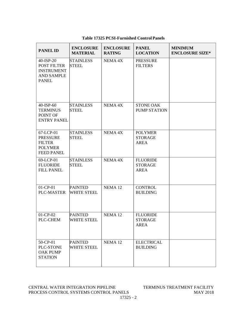
CENTRAL WATER INTEGRATION PIPELINE TERMINUS TREATMENT FACILITY PROCESS CONTROL SYSTEMS CONTROL PANELS MAY 2018
17325 - 2
Table 17325 PCSI-Furnished Control Panels
PANEL IDENCLOSURE MATERIAL
ENCLOSURE RATING
PANEL LOCATION
MINIMUM ENCLOSURE SIZE*
40-ISP-20 POST FILTER INSTRUMENT AND SAMPLE PANEL
STAINLESS STEEL
NEMA 4X PRESSURE FILTERS
40-ISP-60 TERMINUS POINT OF ENTRY PANEL
STAINLESS STEEL
NEMA 4X STONE OAK PUMP STATION
67-LCP-01 PRESSURE FILTER POLYMER FEED PANEL
STAINLESS STEEL
NEMA 4X POLYMER STORAGE AREA
69-LCP-01 FLUORIDE FILL PANEL
STAINLESS STEEL
NEMA 4X FLUORIDE STORAGE AREA
01-CP-01 PLC-MASTER
PAINTED WHITE STEEL
NEMA 12 CONTROL BUILDING
01-CP-02 PLC-CHEM
PAINTED WHITE STEEL
NEMA 12 FLUORIDE STORAGE AREA
50-CP-01 PLC-STONE OAK PUMP STATION
PAINTED WHITE STEEL
NEMA 12 ELECTRICAL BUILDING
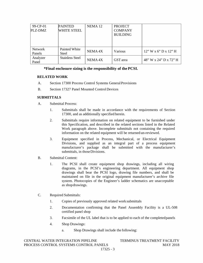
CENTRAL WATER INTEGRATION PIPELINE TERMINUS TREATMENT FACILITY PROCESS CONTROL SYSTEMS CONTROL PANELS MAY 2018
17325 - 3
99-CP-01 PLZ-DMZ
PAINTED WHITE STEEL
NEMA 12 PROJECT COMPANY BUILDING
Network Panels
Painted White Steel
NEMA 4X Various 12” W x 6” D x 12” H
Analyzer Panel
Stainless Steel NEMA 4X GST area 48” W x 24” D x 72” H
*Final enclosure sizing is the responsibility of the PCSI.
RELATED WORK
A. Section 17300 Process Control Systems General Provisions
B. Section 17327 Panel Mounted Control Devices
SUBMITTALS
A. Submittal Process:
1. Submittals shall be made in accordance with the requirements of Section 17300, and as additionally specified herein.
2. Submittals require information on related equipment to be furnished under this Specification, and described in the related sections listed in the Related Work paragraph above. Incomplete submittals not containing the required information on the related equipment will be returned un-reviewed.
3. Equipment specified in Process, Mechanical, or Electrical Equipment Divisions, and supplied as an integral part of a process equipment manufacturer’s package shall be submitted with the manufacturer’s submittals, in those Divisions.
B. Submittal Content:
1. The PCSI shall create equipment shop drawings, including all wiring diagrams, in the PCSI’s engineering department. All equipment shop drawings shall bear the PCSI logo, drawing file numbers, and shall be maintained on file in the original equipment manufacturer’s archive file system. Photocopies of the Engineer’s ladder schematics are unacceptable as shop drawings.
C. Required Submittals:
1. Copies of previously approved related work submittals
2. Documentation confirming that the Panel Assembly Facility is a UL-508 certified panel shop
3. Facsimile of the UL label that is to be applied to each of the completed panels
4. Shop Drawings:
a. Shop Drawings shall include the following:
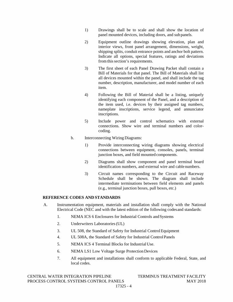
CENTRAL WATER INTEGRATION PIPELINE TERMINUS TREATMENT FACILITY PROCESS CONTROL SYSTEMS CONTROL PANELS MAY 2018
17325 - 4
1) Drawings shall be to scale and shall show the location of panel mounted devices, including doors, and sub panels.
2) Equipment outline drawings showing elevation, plan and interior views, front panel arrangement, dimensions, weight, shipping splits, conduit entrance points and anchor bolt pattern. Indicate all options, special features, ratings and deviations from this section’s requirements.
3) The first sheet of each Panel Drawing Packet shall contain a Bill of Materials for that panel. The Bill of Materials shall list all devices mounted within the panel, and shall include the tag number, description, manufacturer, and model number of each item.
4) Following the Bill of Material shall be a listing, uniquely identifying each component of the Panel, and a description of the item used, i.e. devices by their assigned tag numbers, nameplate inscriptions, service legend, and annunciator inscriptions.
5) Include power and control schematics with external connections. Show wire and terminal numbers and color-coding.
b. Interconnecting Wiring Diagrams:
1) Provide interconnecting wiring diagrams showing electrical connections between equipment, consoles, panels, terminal junction boxes, and field mounted components.
2) Diagrams shall show component and panel terminal board identification numbers, and external wire and cable numbers.
3) Circuit names corresponding to the Circuit and Raceway Schedule shall be shown. The diagram shall include intermediate terminations between field elements and panels (e.g., terminal junction boxes, pull boxes, etc.)
REFERENCE CODES AND STANDARDS
A. Instrumentation equipment, materials and installation shall comply with the National Electrical Code (NEC and with the latest edition of the following codes and standards:
1. NEMA ICS 6 Enclosures for Industrial Controls and Systems
2. Underwriters Laboratories (UL)
3. UL 508, the Standard of Safety for Industrial Control Equipment
4. UL 508A, the Standard of Safety for Industrial Control Panels
5. NEMA ICS 4 Terminal Blocks for Industrial Use.
6. NEMA LS1 Low Voltage Surge Protection Devices
7. All equipment and installations shall conform to applicable Federal, State, and local codes.
CENTRAL WATER INTEGRATION PIPELINE TERMINUS TREATMENT FACILITY PROCESS CONTROL SYSTEMS CONTROL PANELS MAY 2018
17325 - 5
QUALITY ASSURANCE
A. The manufacturer of this equipment shall have produced similar equipment for a minimum period of five (5) years. When requested by the Owner or Engineer, an acceptable list of installations with similar equipment shall be provided demonstrating compliance with this requirement.
B. The control panels shall be assembled in a UL-certified panel shop, experienced in the assembled of control panels for water and waste water treatment systems. A submittal of the documentation, that certifies the panel fabrication shop is a UL-certified shop, is required.
C. Equipment components and devices shall be UL labeled wherever UL standards exist for such equipment. The completed control panel shall be UL Labeled in accordance with UL 508 and or 508A as applicable. The panel shall be UL labeled for the environment in which it is to be placed. A UL label shall be affixed to the inside of the external door by the panel fabrication assembly shop. Submit a facsimile of the UL label in the submittal information.
D. Equipment submitted shall fit within the space shown on the drawings. Equipment which does not fit within the space is not acceptable.
DELIVERY STORAGE AND HANDLING
A. Completed control panels and related equipment shall be handled and stored in accordance with manufacturer's instructions. Two (2) copies of these instructions shall be included with the equipment at time of shipment, and shall be made available to the general contractor, the Owner and Engineer.
B. Shipping groups shall be designed to be shipped by truck, rail, or ship. Indoor groups shall be bolted to skids. Accessories shall be packaged and shipped with each panel.
C. Visible shipping damage to any portion of a shipment shall be assumed to have also damaged the surrounding portion. The visibly damaged and the surrounding panels shall be returned to the manufacturer’s UL 508 facility, for examination and damaged equipment replaced, followed by a Witnessed Test of the returned portion, as specified in Section 17302, at no expense to the Owner or Engineer.
D. Control Panels shall be installed in their permanent finished location shown on the drawings within seven (7) calendar days of arriving onsite. If the equipment cannot be installed within seven (7) calendar days, the equipment shall not be delivered to the site, but stored offsite, at the contractor’s expense, until such time that the site is ready for permanent installation of the equipment.
E. Space heaters shall be furnished in control panels and the contractor shall provide temporary electrical power and operate space heaters during storage, and after equipment is installed in permanent location, until equipment is placed in service.
WARRANTY
A. Provide equipment warranty in accordance with Section 01740: Warranties and Bonds.
PRODUCTS
MATERIAL MANUFACTURERS
CENTRAL WATER INTEGRATION PIPELINE TERMINUS TREATMENT FACILITY PROCESS CONTROL SYSTEMS CONTROL PANELS MAY 2018
17325 - 6
A. Subject to compliance with the contract documents, the following material manufacturers are acceptable:
1. Hoffman
2. EMF
3. Approved Equal
B. The listing of specific manufacturers above does not imply acceptance of their products that do not meet the specified ratings, features and functions. Materials Manufactures listed above are not relieved from meeting these Specifications in their entirety.
C. Manufactures of all related devises and components shall be as specified elsewhere in related work specifications
RATINGS
A. The complete control panel assembly shall be UL certified or carry a UL 508A listing for "Industrial Control Panels".
B. The control panel shall meet all applicable requirements of the National Electrical Code.
C. All devices unless otherwise specified shall be designed for continuous operation at rated current in a 40-degree C ambient temperature
D. For additional ratings and construction notes, refer to the drawings.
E. The service voltage shall be as specified and as shown on the drawings. The overall short circuit withstand and interrupting rating of the equipment and devices shall be equal to or greater than the overall short circuit withstand and interrupting rating of the feeder device immediately upstream of the Control Panel, but not less than 10,000 amperes RMS symmetrical at 120 volts single phase.
CONSTRUCTION
A. General:
1. Refer to the drawings for: schematics, actual layout and location of equipment and components; current ratings of devices, bus bars, components; protective relays, voltage ratings of devices, components and assemblies; and other required details.
B. Enclosures:
1. General:
a. Each enclosure shall incorporate a removable back panel, and side panels, on which control components shall be mounted. Back panel shall be secured to the enclosure with collar studs for wall mounted enclosures, and 316 SS hardware for free standing enclosures.
b. All free-standing enclosures shall be provided with feet of the same construction as the enclosure.
c. Back panel shall be tapped to accept all mounting screws. Self-tapping screws shall not be used to mount any components.
d. All enclosure doors shall have bonding studs. The enclosure interior
CENTRAL WATER INTEGRATION PIPELINE TERMINUS TREATMENT FACILITY PROCESS CONTROL SYSTEMS CONTROL PANELS MAY 2018
17325 - 7
shall have a bonding stud.
e. Each enclosure shall be provided with a documentation pocket on the inner door.
f. Enclosures shall not have holes or knockouts.
g. Provide manufacturer’s window kits where shown on the drawings.
h. All panels installed outdoors shall have a factory applied, suitable primer and final coat of weatherproof white paint.
i. All enclosures shall be pad lockable.
j. Each enclosure shall have one, UPS powered, 150-watt receptacle.
k. All enclosures shall be lockable, and keyed alike.
l. All control panels shall have a “Panel Interface Connector” (PIC) as specified in Section 13327 Panel Mounted Equipment.
m. All PLC Control Panels shall have an integral folding shelf on the exterior for service / maintenance personnel; shelf shall match panel enclosure in material and color.
2. NON METALLIC:
a. Chemical Rooms NEMA 4X constructed as follows:
1) PVC or Fiberglass reinforced polyester body and door.
2) UV inhibitors
3) Luggage type quick release latches
4) Foam-in-place gasket doors
b. Manufacturers:
1) Hoffman Polypro
2) Hubbell-Wiegmann Non-Metallic
3) Approved Equal
3. NEMA 12 Steel:
a. NEMA 12
1) Mild grade steel, body and door
2) Stainless steel continuous hinge pin or concealed stainless steel hinges
3) Foam in-place gasket or PORON AquaPro
4) Single point quarter turn latches (20” x 24” and below). All others 3-point latch
b. Manufacturers:
1) Hoffman Comline
2) EMF Company
CENTRAL WATER INTEGRATION PIPELINE TERMINUS TREATMENT FACILITY PROCESS CONTROL SYSTEMS CONTROL PANELS MAY 2018
17325 - 8
3) NEMA Enclosures Company
4) Hammond Company
5) Unity Manufacturing
6) Approved Equal
4. NEMA 4X All panels not otherwise Defined:
a. Where an enclosure is not otherwise defined or shown on the drawing:
1) NEMA 4X 316 Stainless Steel
2) Type 316 stainless steel, body and door
3) Stainless steel continuous hinge or concealed stainless steel hinges
4) Foam in-place gasket or PORON AquaPro
5) Single point quarter turn latches (20” x 24” and below). All others 3-point latch
b. Manufacturers:
1) Hoffman Concept Series
2) EMF Company
3) NEMA Enclosures Company
4) Hammond Company
5) Unity Manufacturing
6) Approved Equal
C. Environmental Controls:
1. Enclosure Condensate Heaters:
a. A self-contained enclosure condensation heater with thermostat and fan shall be mounted inside the control panel, if panel is to be installed outdoors or in a non-air-conditioned space:
1) Enclosure heaters shall be energized from 120 volt, single-phase power supply and sized to prevent condensation within the enclosure.
2) Locate enclosure heaters to avoid overheating electronic hardware or producing large temperature fluctuations on the hardware.
3) Enclosure heaters shall have an internal fan for heat distribution and shall be controlled with adjustable thermostats. The thermostat shall have an adjustment range of 40 degrees Fahrenheit to 90 degrees Fahrenheit. Provide a circuit breaker or fused disconnect switch within the enclosure.
4) Enclosure heaters shall be Hoffman type DAH.
CENTRAL WATER INTEGRATION PIPELINE TERMINUS TREATMENT FACILITY PROCESS CONTROL SYSTEMS CONTROL PANELS MAY 2018
17325 - 9
b. Strip heaters may be provided if they are 240 volt rated, powered at 120 volts AC and do not have a surface temperature higher than 60° C. Strip heaters and thermostats shall be as manufactured by Chromalox:
1) Strip heaters shall be Chromalox, Type OT, 1.5-in wide, 240 Volts, single phase, 150 watts, energized at 120 volts, with rust resisting iron sheath, Catalog No. OT-715, Product Code No. 129314. Provide sufficient wattage in heaters to prevent condensation should the interior temperature of the enclosure drop below the dew point.
2) A control thermostat mounted inside the control Panel shall be Chromalox, Type WR, single stage, Catalog No. WR-80, Product Code No.263177
3) The strip heater terminals shall be guarded by a protective terminal cover.
4) High temperature connecting lead wire shall be used between the thermostat and the heater terminals. Wire shall be No. 12 AWG stranded nickel-plated copper with Teflon glass insulation and shall be the product of Chromalox, Catalog No. 6-CFI-12, and Product Code No. 263783.
2. Enclosure Air Conditioner:
a. Enclosures containing electronic devices or electrical equipment to be installed outdoors or in a non-air conditioned space shall have air conditioners that will maintain the internal temperature at or below the equipment rating without violating the NEMA rating of the enclosure.
b. The panel builder shall provide panel internal heat rise calculations to show that the panel internal temperatures will be maintained below the maximum operating temperatures of the panel components:
1) For enclosures mounted indoors in non-air-conditioned spaces, include an ambient air temperature of 40 degrees C and a humidity of 100% non-condensing.
2) For enclosures mounted in direct sunlight add the appropriate solar heat gain component to the calculation, and raise the ambient temperature to 60 degrees C.
3) The calculation shall show all the internal and external heat gain loads, the expected internal temperature rise in degrees C above the specified ambient without the air conditioner. Provide a calculation showing the expected temperature rise in degrees C above the specified ambient with the air conditioner running.
c. The air conditioner shall have the following features:
1) Use CFC-free R134a refrigerant.
2) Have fully gasket flanges on all four mounting edges for a
CENTRAL WATER INTEGRATION PIPELINE TERMINUS TREATMENT FACILITY PROCESS CONTROL SYSTEMS CONTROL PANELS MAY 2018
17325 - 10
watertight seal that maintains NEMA rating of the panel.
3) Thermostatic low temperature control to provide energy efficient operation and prevents over-cooling.
4) EMI/RFI suppressor to minimize transient spikes during compressor on/off cycling
5) Separated blower-driven evaporator and condenser air systems for closed loop cooling
6) UL listed.
7) Stainless steel enclosure rated NEMA 4X.
8) Internal corrosion resistant coating and/or galvanized steel components
9) Low ambient kit
10) Short cycle protector
d. Manufacturers:
1) Rittal
2) Cooper B-Line
3) ICE Cube
4) Approved Equal
3. Corrosion Protection:
a. Provide corrosion protection in each control panel with a Corrosion- Inhibiting vapor capsule as manufactured by Northern Instruments; Model Zerust VC, or Hoffman Engineering; Model A-HCI.
PANEL EQUIPMENT
A. Equipment Requirements:
1. The requirements for equipment, controls, meters, converters, etc., for each Control Panel, shall be as shown on the Panel Schedule herein, the drawings, panel schematics, and the functions specified in the control narratives sections of the specifications.
2. Where a programmable logic controller is designed as a part of the control panel, the PLC shall be as specified in Section 17500 Programmable Logic Controllers.
3. Where communications equipment is designed as part of the control panel, the equipment shall be as specified in Section 17515 Communications Interface Equipment.
4. Where fiber optic equipment is designed as part of the control panel, the equipment shall be as specified in Section 17320 Fiber Optic Data Network.
5. All other equipment, controls, meters, converters that are designed as a part of the control panel, shall be as specified in Section 17327 Panel Mounted Equipment and the Related Work Sections specified herein.
CENTRAL WATER INTEGRATION PIPELINE TERMINUS TREATMENT FACILITY PROCESS CONTROL SYSTEMS CONTROL PANELS MAY 2018
17325 - 11
6. Furnish installed in each Control Panel, a dedicated Surge Protective Device (SPD) (UL 1449 Type 3), permanently connected, on the load side of the power entrance, as specified in Section 17327 Panel Mounted Equipment.
7. Provide a main circuit protective device, DIN rail mounted, to protect the panel equipment with an external cable actuated lockable disconnected means.
B. Panel Control Device Requirements:
1. Control Devices and Indicators:
a. All operating control devices, indicators, and instruments shall be securely mounted on the panel door. All controls and indicators shall be 30 mm, corrosion resistant, NEMA 4X/13, anodized aluminum or reinforced plastic. Booted control devices are not acceptable. Auxiliary contacts shall be provided for remote run indication and indication of each status and alarm condition. Additional controls shall be provided as specified herein and as required by the detailed mechanical and electrical equipment requirements.
b. Indicator lamps shall be LED type. For all control applications, indicator lamps shall incorporate a push-to-test feature. Lens colors shall be as follows:
1) Red for RUNNING, Valve OPENED, and Breaker CLOSED.
2) Green for OFF, Valve CLOSED, and Breaker OPEN
3) Amber for FAILED
4) Blue for READY
5) White for POWER ON
c. Mode selector switches (HAND-OFF-AUTO, LOCAL-OFF-REMOTE, etc.) shall be as shown on the drawings. Units shall have the number of positions and contact arrangements, as required. Each switch shall have an extra dry contact for remote monitoring.
d. Pushbuttons shall be as follows:
1) Red for RUNNING, Valve OPEN, Breaker CLOSE, and mushroom Red for EMERGENCY STOP
2) Green for STOP, Valve CLOSE, and Breaker OPEN
3) Black for RESET
e. Furnish nameplates for each device. All nameplates shall be laminated plastic, black lettering on a white background, attached with stainless steel screws. Device mounted nameplates are not acceptable.
2. A failure alarm with horn and beacon light shall be provided when required or specified. Silence and reset buttons shall be furnished. Alarm horn and beacon shall be by Federal Signal or Crouse-Hinds, NEMA 4X for all areas except for NEMA 7 areas, which shall be NEMA 7/4X cast aluminum.
3. Control and Instrument Power Transformers:
a. Control power transformers shall be provided where shown on the
CENTRAL WATER INTEGRATION PIPELINE TERMINUS TREATMENT FACILITY PROCESS CONTROL SYSTEMS CONTROL PANELS MAY 2018
17325 - 12
drawings. Transformer shall be sized for the entire load, including space heaters, plus 25% spare capacity, and shall be not less than 100 VA.
b. Control power transformers shall be 120 volt grounded secondary. Primary side of the transformer shall be fused in both legs. One leg of the transformer secondary shall be solidly grounded while the other leg shall be fused.
EQUIPMENT INSTALLATION
A. Equipment Mounting:
1. The location of the installed equipment shall be as shown on the Panel Layouts on the drawings.
2. Each piece of equipment shall be securely mounted to the back plate or side plate in accordance with the manufacturer’s installation instructions. All mounting hardware shall be from the front of the back plate or side plate with threaded screws. Attaching hardware shall not be installed from the rear of the back plate or side plate. Removal of any piece of equipment shall not require the removal or loosening of any other piece of equipment.
3. Operator interface equipment installed on the door shall be arranged as shown on the drawings in accordance with the manufacturer’s installation instructions. No penetrations of the door shall be made except for equipment mounting. Provide adequate clearance between pieces of equipment and door latching mechanisms.
B. Nameplates:
1. External: a. Nameplates shall be engraved, laminated impact acrylic, matte finish,
not less than 1/16-in thick by 3/4-in by 2-1/2-in, Rowmark 322402. Nameplates shall be 316 SS screw mounted to all enclosures except for NEMA 4 and 4X. Nameplates for NEMA 4 and 4X enclosures shall be attached with double faced adhesive strips, TESA TUFF TAPE 4970, .009 X ½”. Prior to installing the adhesive nameplates, the metal surface shall be thoroughly cleaned with 70% alcohol until all residues has been removed. Epoxy adhesive or foam tape is not acceptable:
1) There shall be a master nameplate that indicates supply voltage equipment ratings, short circuit current rating, manufacturer's name, shop order number and general information. Cubicle nameplates shall be mounted on the front face, on the rear panel and inside the assembly, visible when the rear panel is removed.
2) Provide permanent warning signs as follows:
a) "Danger- High Voltage- Keep Out" on all doors where any voltage over 125 volts AC is present.
b) "Warning- Hazard of Electric Shock - Disconnect Power Before Opening or Working On This Unit" on
CENTRAL WATER INTEGRATION PIPELINE TERMINUS TREATMENT FACILITY PROCESS CONTROL SYSTEMS CONTROL PANELS MAY 2018
17325 - 13
main power disconnect or disconnects.
2. Internal:
a. Provide the panel with a UL 508A label.
b. Control components mounted within the assembly, such as fuse blocks, relays, pushbuttons, switches, etc., shall be suitably marked for identification, corresponding to appropriate designations on the submitted and reviewed wiring diagrams.
3. Special:
a. Identification nameplates shall be white with black letters, caution nameplates shall be yellow with black letters, and warning nameplates shall be red with white letters.
C. Wiring Trough and Terminal Block Installation:
1. Space between wiring troughs and equipment shall be such that space for terminal blocks is provided for termination of each conductor or group of conductors before connection to the equipment. Removal of equipment for service shall not leave any exposed conductors hanging unconnected.
2. Install the wiring troughs such that one may be removed without interference from the other. Troughs shall be installed such that trough covers may be removed without cover interference.
3. Install terminal blocks on DIN rail with adequate space for access to the terminal with clear view of the wire identification label. All incoming or outgoing wiring shall enter or leave the panel on terminal blocks. Terminal blocks or wiring troughs shall not be installed on the doors. Provide terminal blocks on side plates and back plates for all door mounted equipment.
4. In no case shall internal and external wiring share a wiring trough.
5. Provide 600 volt rated terminal blocks for any conductor carrying any voltage over 120 volts to ground.
6. Provide 600 volt rated strap screw terminal blocks for any power conductors carrying over 20 amps, at any voltage. Terminals shall be double sided and supplied with removable covers to prevent accidental contact with live circuits.
7. Power conductors carrying over 20 amps, at any voltage shall be terminated to strap-screw type terminal blocks with crimp type, pre-insulated, ring-tongue lugs. Lugs shall be of the appropriate size for the terminal block screws and for the number and size of the wires terminated. Do not terminate more than one conductor in any lug, and do not land more than two conductors under any strap- screw terminal point.
8. Terminals shall have permanent, legible identification, clearly visible with the protective cover removed. Each terminal block shall have 20 percent spare terminals, but not less than two spare terminals.
9. Do not land more than two conductors per terminal point. Use the manufacturer’s provided bridge connectors to interconnect terminal blocks terminating common or ground conductors.
CENTRAL WATER INTEGRATION PIPELINE TERMINUS TREATMENT FACILITY PROCESS CONTROL SYSTEMS CONTROL PANELS MAY 2018
17325 - 14
10. Twisted shielded pair or triad cables shall have each individual conductor and shield drain wire landed on individual terminal blocks. Use the manufacturer’s provided bridge connectors to interconnect terminal blocks terminating the shield drain wire conductors.
11. Provide an AC ground bar bonded to the panel enclosure, if metal, with 20 percent spare terminals.
12. Provided ground terminal blocks for each twisted-shielded pair drain wire.
D. Internal Panel Wiring:
1. Power and control wiring shall be tinned stranded copper, minimum size No. 14 AWG, with 600 volt, 90-degree C, flame retardant, Type MTW thermoplastic insulation. Line side power wiring shall be sized for the full fault current rating or frame size of the connected device, and as shown on the drawings.
2. Analog signal wires shall be 600 Volt Class, insulated stranded tinned copper, twisted shielded #16 AWG pair.
3. All interconnecting wires between panel mounted equipment and external equipment shall be terminated at numbered terminal blocks. Field wiring shall not be terminated directly on any panel-mounted device.
4. All wiring shall be tagged and coded with an identification number as shown on the drawings. Coding shall be typed on a heat shrinkable tube applied to each end showing origination and destination of each wire. The marking shall be permanent, non-smearing, solvent-resistant type similar to Raychem TMS-SCE.
5. All wiring shall be enclosed in PVC wire trough with slotted side openings and removable cover. Plan wire routing such that no twisted shielded pair cable conducting analog 4-20 mA signals or low voltage analog signals are routed in the same wire trough as conductors carrying discrete signals or power.
6. Control panel wire color code shall be as follows:
a. Black: AC power at line voltage
b. Red: switched AC power
c. Orange: May be energized while the main disconnect is in the off position
d. White: AC neutral
e. Orange/white stripe or white/orange stripe: separate derived neutral
f. Red/white stripe or white/red stripe: switched neutral
g. Green or green w/ yellow tracer: ground/earth ground
h. Blue: Ungrounded DC power
i. Blue/white stripe or white/blue stripe: DC grounded common
j. Brown: 480 V AC 3 phase - phase A
CENTRAL WATER INTEGRATION PIPELINE TERMINUS TREATMENT FACILITY PROCESS CONTROL SYSTEMS CONTROL PANELS MAY 2018
17325 - 15
k. Orange: 480 V AC 3 phase - phase B
l. Yellow: 480 V AC 3 Phase - phase C
m. Purple: common for analog signal wiring
n. Brown: positive leg of an analog signal
E. Field Entrance Internal Wiring:
1. Field entrance internal wiring shall be neatly grouped by circuit and bound by plastic tie wraps. Circuit groups shall be supported so that circuit terminations are not stressed. In addition, low signal wiring (millivolt and milliamp) shall be bundle separately from the rest of the control wiring.
2. All field wiring shall be tagged and coded with an identification number. Coding shall be typed on a heat shrinkable tube applied to each end of the wire. The marking shall be a permanent, non-smearing, solvent-resistant type similar to Raychem TMS-SCE.
3. All conduit entering or leaving equipment shall be coordinated, in advance with the panel installer, so that the conduit entrances to the enclosure are directly below the termination area for immediate termination. Conduits shall not enter the top or side of the panel unless approved in writing by the Owner and Engineer.
F. Fusing of PLC Inputs and Outputs:
1. All PLC analog inputs and outputs shall be individually fused for each channel. All discrete inputs and outputs shall be buffered with relays from the field connections. Discrete points shall be fused for each circuit group with no less than one fuse per PLC I/O card.
EXECUTION
INSTALLER’S QUALIFICATIONS
A. Installer shall be specialized in installing this type of equipment with minimum 5 yearsdocumented experience. Experience documentation shall be submitted for approval prior to beginning work on this project.
EXAMINATION
A. Examine installation area to assure there is enough clearance to install the equipment.
B. Housekeeping pads shall be included for the floor mounted panels as detailed on the drawings.
C. Check concrete pads and baseplates for uniformity and level surface.
D. Verify that the equipment is ready to install.
E. Verify field measurements are as instructed by manufacturer.
INSTALLATION
A. The contractor shall install all equipment per the manufacturer's recommendations and contract drawings.
CENTRAL WATER INTEGRATION PIPELINE TERMINUS TREATMENT FACILITY PROCESS CONTROL SYSTEMS CONTROL PANELS MAY 2018
17325 - 16
B. Conduit hubs for use on raceway system pull and junction boxes shall be watertight, threaded aluminum, insulated throat, stainless steel grounding screw, as manufactured by T&B H150GRA Series.
C. Conduits entering a control Panel or box containing electrical equipment shall not enter the enclosure through the top.
D. Install required safety labels.
RACEWAY SEALING
A. Where raceways enter junction boxes or control panels containing electrical or instrumentation equipment, all entrances shall be sealed with 3M 1000NS Watertight Sealant.
B. This requirement shall be strictly adhered to for all raceways in the conduit system.
FIELD QUALITY CONTROL
A. Inspect installed equipment for anchoring, alignment, grounding and physical damage.
B. Check tightness of all accessible electrical connections. Minimum acceptable values are specified in manufacturer's instructions.
C. Provide laminated copies of the Control schematics in each enclosure door pocket.
CLEANING
A. Remove all rubbish and debris from inside and around the panel. Remove dirt, dust, or concrete spatter from the interior and exterior of the equipment using brushes, vacuum cleaner, or clean, lint free rags. Do not use compressed air.
EQUIPMENT PROTECTION AND RESTORATION
A. Touch-up and restore damaged surfaces to factory finish, as approved by themanufacturer. If the damaged surface cannot be returned to factory specification, the surface shall be replaced.
END OF SECTION
CENTRAL WATER INTEGRATION PIPELINE TERMINUS TREATMENT FACILITY PANEL MOUNTED CONTROL DEVICES APRIL 2018
17327 - 1
SECTION 17327
PANEL MOUNTED CONTROL DEVICES
GENERAL
SCOPE OF WORK
A. This section of the specifications describes the requirements for miscellaneous equipment to be furnished under other sections of the specifications as listed in the related work paragraph of this section.
B. All equipment described herein shall be submitted and furnished as an integral part of equipment specified elsewhere in these Specifications.
RELATED WORK
A. Section 17300 Process Control Systems General Provisions
B. Section 17325 Process Control System Control Panels
SUBMITTALS
A. Refer to specification section 17300.
REFERENCE CODES AND STANDARDS
A. The equipment in this specification shall be designed and manufactured according to latest revision of the following standards (unless otherwise noted):
1. NEMA/ISCI 109 Transient Over voltage Withstand Test
2. IEEE Std. 472/ANSI C37.90.2 Withstand Capability of Relay Systems to Radiated Electromagnetic Interference from Transceivers.
3. NEMA/ICS 1 General Standard for Industrial Control Systems
4. NEMA/ICS 4 Terminal Blocks for Industrial Use.
5. NEMA/ICS 6 Enclosures for Industrial Control Systems
6. NEMA LS 1 Low Voltage Surge Protective Devices
7. UL 1449 Third Edition – Surge Protective Devices
B. All equipment shall comply with the requirements of the National Electric Code and Underwriters Laboratories (UL) where applicable.
C. Each specified device shall also conform to the standards and codes listed in the individual device paragraphs.
PRODUCTS
MODE SELECTOR SWITCHES, PUSHBUTTONS AND INDICATING LAMPS
A. Subject to compliance with the contract documents, the following manufacturers are
CENTRAL WATER INTEGRATION PIPELINE TERMINUS TREATMENT FACILITY PANEL MOUNTED CONTROL DEVICES APRIL 2018
17327 - 2
acceptable:
1. Rockwell Automation Allen Bradley
2. Eaton Cutler Hammer
3. General Electric
4. Schneider Electric Square D
5. Approved Equal
B. The listing of specific manufacturers above does not imply acceptance of their products that do not meet the specified ratings, features and functions. Manufacturers listed above are not relieved from meeting these specifications in their entirety.
C. Construction:
1. 30 mm Diameter
2. Corrosion resistant
3. NEMA 4/4X/13 without booted covers
4. “Finger safe” contact blocks, 10A rating
5. Function indicating colors per NFPA 79 unless otherwise shown on the drawings
6. Engraved corrosion resistant nameplates
7. LED lamps
8. Mode selector switches shall have 1 spare set auxiliary contacts
9. Indicator lights to be Push-to-Test
10. Potentiometer ratings to match I/O devices connected
TERMINAL BLOCKS:
A. Subject to compliance with the contract documents, the following manufacturers are acceptable:
1. Phoenix Contact
2. Entrelec
3. Weidmuller
4. Allen Bradley
5. Approved Equal
B. The listing of specific manufacturers above does not imply acceptance of their products that do not meet the specified ratings, features and functions. Manufacturers listed above are not relieved from meeting these specifications in their entirety.
C. Terminal Blocks:
1. Terminal blocks shall be DIN-rail-mounted one-piece molded plastic blocks with tubular-clamp-screw type, with end barriers, dual side terminal block numbers and terminal group identifiers. Terminal blocks shall be rated for 600 volts except for control and instrumentation circuits, or 4-20 mA analog signal
CENTRAL WATER INTEGRATION PIPELINE TERMINUS TREATMENT FACILITY PANEL MOUNTED CONTROL DEVICES APRIL 2018
17327 - 3
conductors.
2. Provide 600 volt rated terminal blocks for any conductor carrying any voltage over 120 volts to ground.
3. Provide 600 volt rated strap screw terminal blocks for any power conductors carrying over 20 amps, at any voltage. Terminals shall be double sided and supplied with removable covers to prevent accidental contact with live circuits.
4. Power conductors carrying over 20 amps, at any voltage shall be terminated to strap-screw type terminal blocks with crimp type, pre-insulated, ring-tongue lugs. Lugs shall be of the appropriate size for the terminal block screws and for the number and size of the wires terminated. Do not terminate more than one conductor in any lug, and do not land more than two conductors under any strap- screw terminal point.
5. Terminals shall have permanent, legible identification, clearly visible with the protective cover removed. Each terminal block shall have 20 percent spare terminals, but not less than two spare terminals.
6. Do not land more than two conductors per terminal point. Use the manufacturer’s provided bridge connectors to interconnect terminal blocks terminating common or ground conductors.
7. Twisted shielded pair or triad cables shall have each individual conductor and shield drain wire landed on individual terminal blocks. Use the manufacturer’s provided bridge connectors to interconnect terminal blocks terminating the shield drain wire conductors.
8. Control circuits, 120 volts and below, and 4-20 mA analog signal conductors shall be terminated with manufacturer’s recommended ferrules. Ferrules shall be provided with plastic sleeves.
9. Provide an AC ground bar bonded to the panel enclosure, if metal, with 20 percent spare terminals.
10. Provided ground terminal blocks for each twisted-shielded pair drain wire.
WIRE TROUGHS:
A. Subject to compliance with the contract documents, the following manufacturers are acceptable:
1. Panduit
2. Taylor
3. Approved Equal
B. The listing of specific manufacturers above does not imply acceptance of their products that do not meet the specified ratings, features and functions. Manufacturers listed above are not relieved from meeting these specifications in their entirety.
DIN RAILS:
A. Subject to compliance with the contract documents, the following manufacturers are acceptable:
CENTRAL WATER INTEGRATION PIPELINE TERMINUS TREATMENT FACILITY PANEL MOUNTED CONTROL DEVICES APRIL 2018
17327 - 4
1. Phoenix Contact
2. Entrelec
3. Weidmuller
4. Approved Equal
B. The listing of specific manufacturers above does not imply acceptance of their products that do not meet the specified ratings, features and functions. Manufacturers listed above are not relieved from meeting these specifications in their entirety.
SIGNAL ISOLATORS, BOOSTERS, CONVERTERS
A. Subject to compliance with the contract documents, the following manufacturers are acceptable:
1. Phoenix Contact
2. Acromag Inc.
3. Moore Industries
4. Approved Equal
B. The listing of specific manufacturers above does not imply acceptance of their products that do not meet the specified ratings, features and functions. Manufacturers listed above are not relieved from meeting these specifications in their entirety:
1. Type:
a. Externally powered solid state electronic type/ Loop powered devices are not acceptable.
2. Functional/Performance:
a. Accuracy: 0.15 percent
b. Inputs: Current, voltage, frequency, temperature, or resistance as required
c. Outputs: Current or voltage as required
d. Isolation: There shall be complete isolation between input circuitry, output circuitry, and the power supply
e. Adjustments: Zero and span adjustment shall be provided
f. Protection: Provide RFI protection
g. 24 VDC power input
3. Physical:
a. Mounting Suitable for DIN Rail mounting in an enclosure or instrument rack
4. Options/Accessories Required:
a. Mounting rack or general purpose enclosure as required.
CENTRAL WATER INTEGRATION PIPELINE TERMINUS TREATMENT FACILITY PANEL MOUNTED CONTROL DEVICES APRIL 2018
17327 - 5
POTENTIOMETER / RTD TRANSMITTERS
A. Subject to compliance with the contract documents, the following manufacturers are acceptable:
1. Phoenix Contact
2. Moore Industries
3. Approved Equal
B. The listing of specific manufacturers above does not imply acceptance of their products that do not meet the specified ratings, features and functions. Manufacturers listed above are not relieved from meeting these specifications in their entirety.
C. Design and fabrication:
1. Solid state electronics
2. Transmit analog signal directly proportional to measured impedance input.
3. Power source: 24 VDC.
4. Input: 0-1000 ohms.
5. Output signal: 4-20 mA DC.
6. Accuracy (maximum error): ±0.25 percent.
7. Ambient temperature range: 0-140 Degrees F.
PANEL DISPLAYS
A. Subject to compliance with the contract documents, the following manufacturers are acceptable:
1. Precision Digital
2. Red Lion
3. Moore Industries
4. Approved Equal
B. The listing of specific manufacturers above does not imply acceptance of their products that do not meet the specified ratings, features and functions. Manufacturers listed above are not relieved from meeting these specifications in their entirety.
C. Design and fabrication:
1. Input: analog 4-20 mA
2. Rating: NEMA 4X, IP65
3. Shallow Depth Case 3.6" Behind Panel
4. Power Supply: 24 VDC or 120 VAC as shown on drawings
5. Optional features to be supplied: Four separate contacts
6. Output: analog 4-20 mA
7. Display: minimum digit height of 1”; sunlight readable
CENTRAL WATER INTEGRATION PIPELINE TERMINUS TREATMENT FACILITY PANEL MOUNTED CONTROL DEVICES APRIL 2018
17327 - 6
RELAYS AND TIMERS
A. Subject to compliance with the contract documents, the following manufacturers are acceptable:
1. Square D
2. IDEC
3. Potter-Broomfield
4. Allen-Bradley
5. Approved Equal
B. The listing of specific manufacturers above does not imply acceptance of their products that do not meet the specified ratings, features and functions. Manufacturers listed above are not relieved from meeting these specifications in their entirety.
C. Type:
1. Relays shall be double pole, double throw (form C) type, except for PLC I/O buffer relays, which shall be single pole, double throw (form C) type; and shall be the spade plug in style with a transparent dust cover included. The relays shall be equipped with an indicating light to indicate when its coil is energized.
2. Units shall be the general purpose plug-in type.
D. Functional/Performance:
1. Coil voltage shall match supply voltage.
2. Contact arrangement/function shall be as required to meet the specified control function.
3. Mechanical life expectancy shall be in excess of 10,000,000 cycles.
4. Duty cycle shall be rated for continuous operation.
5. Units shall be provided with integral indicating light to indicate if relay is energized.
6. Solid state time delays shall be provided with polarity protection (DC units) and transient protection.
7. Time delay units shall be adjustable and available in ranges from .1 second to 4.5 hours.
8. Plug-in general purpose relay.
9. Blade connector type
10. Contact material: Silver cadmium oxide
11. Relay sockets are DIN rail mounted
12. Internal neon or LED indicator is lit when coil is energized
13. Clear polycarbonate dust cover with clip fastener
14. Operating temperature: -20 to +150 Degrees F
CENTRAL WATER INTEGRATION PIPELINE TERMINUS TREATMENT FACILITY PANEL MOUNTED CONTROL DEVICES APRIL 2018
17327 - 7
15. UL listed or recognized
E. Ratings:
1. For 120 VAC service provide contacts rated 10 amps at 120 VAC, for 24 VDC service provide contacts rated 5 amps at 28 VDC, for electronic (milliamp/ millivolt) switching applicator provide gold plated contacts rated for electronic service.
2. Relays shall be provided with dust and moisture resistant covers.
F. Physical:
1. DIN Rail mounting base
2. Screw Terminals
G. Options/Accessories Required:
1. Provide mounting sockets with pressure type terminal blocks rated 300 volt and 10 amps.
2. Provide mounting rails/holders as required.
ANALOG SIGNAL SURGE PROTECTIVE DEVICES
A. Subject to compliance with the contract documents, the following manufacturers are acceptable:
1. AGM Electronics
2. Acromag Inc.
3. Moore Industries
4. Phoenix Contact
5. EDCO
6. Approved Equal
B. The listing of specific manufacturers above does not imply acceptance of their products that do not meet the specified ratings, features and functions. Manufacturers listed above are not relieved from meeting these specifications in their entirety.
C. Type:
1. For devices to be located in control or termination panels, provide DIN Rail mountable type
2. For devices to be mounted at loop-powered transmitters, provide pipe mountable type
POWER SUPPLIES
A. Subject to compliance with the contract documents, the following manufacturers are acceptable:
1. PULS Silverline
2. Phoenix Contact
CENTRAL WATER INTEGRATION PIPELINE TERMINUS TREATMENT FACILITY PANEL MOUNTED CONTROL DEVICES APRIL 2018
17327 - 8
3. Sola
4. Approved Equal
B. The listing of specific manufacturers above does not imply acceptance of their products that do not meet the specified ratings, features and functions. Manufacturers listed above are not relieved from meeting these specifications in their entirety.
C. Design and fabrication:
1. Converts 120 VAC input to DC power at required voltage.
2. Sized as required by the load/ Minimum 2.4 A output
3. AC input: 120 VAC +10 percent -13 percent; 47 to 63 HZ
4. Provision for output failure alarm contact
5. DIN rail mountable
6. All power supplies shall be furnished in redundant pairs
SURGE PROTECTIVE DEVICES (SPD UL 1449 TYPE 3)
A. Subject to compliance with the Contract Documents, the following Manufacturers are acceptable (Type 3):
1. EDCO SLAC Series
2. Phoenix Contact
3. Brick Wall Model PWOM20
4. Approved Equal
B. The listing of specific manufacturers above does not imply acceptance of their products that do not meet the specified ratings, features and functions. Manufacturers listed above are not relieved from meeting these specifications in their entirety.
C. Construction of Type 3.SPD
1. Fully Integrated Component Design: All of the SPDs components and diagnostics shall be contained within one discrete assembly. SPDs or individual SPD modules that must be ganged together in order to achieve higher surge current ratings or other functionality will not be accepted.
2. Maintenance Free Design: The SPD shall be maintenance free and shall not require any user intervention throughout its life. SPDs containing items such as replaceable modules, replaceable fuses, or replaceable batteries are not acceptable. SPDs requiring any maintenance of any sort such as periodic tightening of connections are not acceptable.
3. Electrical Noise Filter: Each unit shall include a high-performance EMI/RFI noise rejection filter. Noise attenuation for electric line noise shall be up to 50 dB from 10 kHz to 100 MHz using the MIL-STD-220A insertion loss test method.
4. Internal Connections: No plug-in component modules or printed circuit boards shall be used as surge current conductors. All internal components shall be soldered, hardwired with connections utilizing low impedance conductors.
5. Power and ground connections shall be prewired within the protected equipment.
CENTRAL WATER INTEGRATION PIPELINE TERMINUS TREATMENT FACILITY PANEL MOUNTED CONTROL DEVICES APRIL 2018
17327 - 9
6. Local Monitoring: Visible indication of proper SPD connection and operation shall be provided. The indicator light shall indicate that the module is fully operable. The status of each SPD module shall be monitored on the front cover of the module.
7. SPD shall be listed in accordance with UL 1449 Third Edition and UL 1283, Electromagnetic Interference Filters.
8. SPD shall be tested with the ANSI/IEEE Category C High exposure waveform (20 kV-1.2/50 µs, 10 kA-8/20 µs).
D. Individual Control Panel and Related Equipment Protection (Type 3) Installation
1. Locate the SPD on the load side of the ground and neutral connections.
2. The SPD shall be connected through a disconnect circuit breaker or fuse as shown on the drawings. The disconnection means shall be located in immediate proximity to the SPD. Connection shall be made via bus, conductors, or other connections originating in the SPD and shall be kept as short as possible.
3. All monitoring and diagnostic features shall be visible from the front of the equipment.
PANEL INTERFACE CONNECTOR (PIC)
A. Subject to compliance with the contract documents, the following manufacturers are acceptable:
1. Automation Direct
a. Model: Zip Port Series
2. Grace Engineered Products, Inc.
a. Model: GracePort Series
B. The listing of specific manufacturers above does not imply acceptance of their products that do not meet the specified ratings, features and functions. Manufacturers listed above are not relieved from meeting these specifications in their entirety.
C. For all PLC control panels, provide a Panel Interface Connector (PIC) pass-through unit to be mounted to the exterior of the control panel to give the capability to interface with the PLC without the need to open the enclosure door.
D. Design and fabrication:
1. Interface shall include the following:
a. UL Recognized and RoHS compliant
b. Housing rating shall match or be of higher NEMA rating than control panel
c. Gasket: thermo-plastic (TPE)
d. One GFCI power outlet with rating of 120 VAC
e. One Ethernet RJ-45 type 10/100 port connected to control panel switch.
f. Cover shall be attached with a continuous hinge and lockable.
g. Provide locks for all interfaces keyed alike.
CENTRAL WATER INTEGRATION PIPELINE TERMINUS TREATMENT FACILITY PANEL MOUNTED CONTROL DEVICES APRIL 2018
17327 - 10
NAMEPLATES
A. Furnish nameplates for each device as indicated in drawings. Nameplates shall beengraved, laminated impact acrylic, matte finish, black lettering on a white background, not less than 1/16-in thick by 1/2-in by 1-1/2-in, Rowmark 322402. Nameplates shall be attached to the back plate with double faced adhesive strips, TESA TUFF TAPE 4970, .009 X ½”. Prior to installing the nameplates, the metal surface shall be thoroughly cleaned with 70% alcohol until all residues has been removed. Epoxy adhesive or foam tape is not acceptable.
SPARE PARTS
A. Provide the following spare parts for each control panel in the quantities specified:
1. One box replacement fuses, all types and sizes used in supplied equipment.
2. One box of replacement lamps, of each color, for pilot lights supplied
3. One of each color replacement lens caps for pilot lights
4. One can of aerosol touch-up paint.
B. Spare parts shall be boxed or packaged for long term storage. Identify each item with manufacturer’s name, description and part number on the exterior of the package.
EXECUTION
INSTALLATION
A. All equipment specified herein shall be factory installed, field adjusted, tested andcleaned as an integral part of equipment specified elsewhere in these Specifications.
END OF SECTION
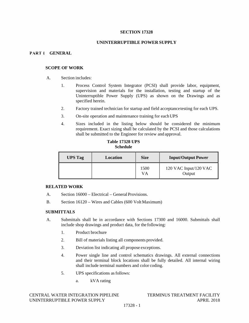
CENTRAL WATER INTEGRATION PIPELINE TERMINUS TREATMENT FACILITY UNINTERRUPTIBLE POWER SUPPLY APRIL 2018
17328 - 1
SECTION 17328
UNINTERRUPTIBLE POWER SUPPLY
GENERAL
SCOPE OF WORK
A. Section includes:
1. Process Control System Integrator (PCSI) shall provide labor, equipment, supervision and materials for the installation, testing and startup of the Uninterruptible Power Supply (UPS) as shown on the Drawings and as specified herein.
2. Factory trained technician for startup and field acceptance testing for each UPS.
3. On-site operation and maintenance training for each UPS
4. Sizes included in the listing below should be considered the minimum requirement. Exact sizing shall be calculated by the PCSI and those calculations shall be submitted to the Engineer for review and approval.
Table 17328 UPS Schedule
UPS Tag Location Size Input/Output Power
1500 VA
120 VAC Input/120 VAC Output
RELATED WORK
A. Section 16000 – Electrical – General Provisions.
B. Section 16120 – Wires and Cables (600 Volt Maximum)
SUBMITTALS
A. Submittals shall be in accordance with Sections 17300 and 16000. Submittals shall include shop drawings and product data, for the following:
1. Product brochure
2. Bill of materials listing all components provided.
3. Deviation list indicating all propose exceptions.
4. Power single line and control schematics drawings. All external connections and their terminal block locations shall be fully detailed. All internal wiring shall include terminal numbers and color coding.
5. UPS specifications as follows:
a. kVA rating
CENTRAL WATER INTEGRATION PIPELINE TERMINUS TREATMENT FACILITY UNINTERRUPTIBLE POWER SUPPLY APRIL 2018
17328 - 2
b. Input and output voltage and phase
c. Run time at full and half load.
d. Voltage (output regulation, input tolerance, unbalance, transfer/retransfer voltage, etc.).
e. Heat rejection
6. Instruction and replacement parts manuals
7. Name, address, and telephone number of the nearest service facility.
8. Battery specifications and warranty
9. Battery sizing calculations
REFERENCE STANDARDS
A. ANSI/IEEE C62.41- Recommended Practice for Surge Voltages in Low-Voltage AC Power Circuits
B. FCC (Federal Communications Commission) Rules and Regulations, Part 15, Subpart J, Class A certified compliance.
C. UL (Underwriters Laboratories) 1778 Listed (Rev. Jan 5, 2000), UL497A D. CSA
22.2, No. 107.1 M95 AND 107.2
E. IEC 62040-2 Emission and Immunity
F. IEC 62040-3 (Uninterruptible Power Systems, Part 3)
G. EN 60529 Equipment Protection
H. National Electric Code (NFPA-70)
I. ISO 9001
QUALITY ASSURANCE
A. UPS systems shall utilize a field proven design. The UPS manufacturer shall demonstrate at least ten years of continuous field operating experience with equipment of similar size and design.
B. Submit the name and address of the factory authorized service and parts organization. The manufacturer shall have a complete selection of service options that may include onsite service by factory-employed service engineers and factory depot quick-return service plan options.
C. Equipment shall be UL or ETL labeled.
D. The UPS manufacturer shall have ISO 9001 certification.
E. The system shall meet or exceed the following theoretical Mean Time Between Failures (MTBF):
1. Single module UPS operation (represents UPS module operation only): 140,000 MTBF hours
CENTRAL WATER INTEGRATION PIPELINE TERMINUS TREATMENT FACILITY UNINTERRUPTIBLE POWER SUPPLY APRIL 2018
17328 - 3
DELIVERY, STORAGE AND HANDLING
A. Refer to Section 16000.
B. Store the equipment indoors in a clean, dry, heated storage facility until ready for installation. Do not install the equipment in its final location until the facilities are permanently weather tight. Furnish, install and wire temporary electric space heaters in the equipment until the permanent heating equipment is operational. Protect the equipment at all times from exposure to moisture and chemicals.
OPERATING INSTRUCTIONS
A. After approval, during and after construction, operating manuals covering instruction and maintenance on each type of equipment shall be furnished in accordance with Sections 17300.
WARRANTY
A. Battery: In addition to the basic warranty, the UPS manufacturer shall warrant thebatteries for a period of 36 months from the date of equipment startup or 42 months from date of receipt by end user, whichever occurs first.
PRODUCTS
GENERAL REQUIREMENTS
A. External Battery Enclosure: A separate enclosure shall be provided for housing the additional batteries required to provide the minimum run time as specified. The battery enclosure shall match the main UPS enclosure in style and color.
B. All cabling required to interconnect all components of the UPS system (including but not limited to the maintenance bypass, external battery enclosure, etc) shall be provided by the UPS manufacturer.
C. Battery protection shall be provided an internal circuit breaker disconnect. Battery cabinets shall be protected by an internal circuit breaker.
D. Current limiting circuitry shall protect the inverter output under any load condition. High speed semiconductor fusing shall protect the static bypass in the event of an output short circuit.
E. The AC output neutral shall be electrically isolated from the UPS chassis. The UPS chassis shall have an equipment ground terminal. Provisions for installation of a bonding connector shall be provided.
F. The UPS shall be suitable for installation at the location as shown on the Drawings.
PERFORMANCE REQUIREMENTS
A. Subject to compliance with the Contract Documents, the following manufacturers are acceptable:
1. APS Online Smart UPS Series
B. Ratings
1. Output power: Reference Table above.
CENTRAL WATER INTEGRATION PIPELINE TERMINUS TREATMENT FACILITY UNINTERRUPTIBLE POWER SUPPLY APRIL 2018
17328 - 4
2. Battery runtime: 2 hours at constant load.
C. The UPS shall comply with the following requirements:
1. Environment:
a. Ambient temperature: 0 to 40° C.
b. Elevation: Up to 500-ft above mean sea level
c. Relative humidity: 0 to 95 percent non-condensing
2. System Input – Primary source:
a. Single input: Reference table under section 1.01.A
b. Frequency: 60 Hertz plus or minus 5 percent.
c. Input Power Factor: 0.96 lag minimum, 50 to 100 percent load.
d. Input Current Total Harmonic Distortion (THD): <33 percent.
e. Input Surge Withstand Rating: Per IEEE 587/ANSI C62.41. Category A and B, (6 kV)
3. System Output:
a. 120 VAC
b. Frequency: 60 Hertz plus or minus 3 Hertz.
c. 100 percent load with 3:1 Crest Ratio
d. Frequency Slew Rate: 1 Hz/second. (Adjustable at startup)
4. AC to AC Efficiency: (100 percent load @ rated PF): 91 percent
5. Acoustical Noise: Noise generated by the UPS under normal operation shall not exceed 65 dBA (60 dBA typical) at one meter from any surface, measured at 25 degrees C (77 degrees F) and full load.
6. EMI Suppression: The UPS shall meet FCC Rules and Regulation 47, Part 15, Subpart J, for Class A devices.
MODES OF OPERATION
A. The UPS shall operate as a double conversion on-line, fully automatic system in the following modes:
1. Normal: The critical load shall be continuously supplied with filtered and regulated AC power by the inverter. The rectifier/battery chargers shall derive power from the preferred AC source and supply DC power to the inverter while simultaneously floats charging the batteries.
2. Emergency: Upon failure of the preferred ac power source, the critical load shall continue to be supplied by the inverter. Inverter power shall be supplied without switching from the storage battery. There shall be no interruption to the critical load upon failure or restoration of the preferred ac sources. If neither AC source can be restored before the battery discharges to its low voltage dropout value, the UPS shall automatically shut itself down in an orderly manner.
3. Recharge: Upon restoration of the preferred ac source, the rectifier/battery
CENTRAL WATER INTEGRATION PIPELINE TERMINUS TREATMENT FACILITY UNINTERRUPTIBLE POWER SUPPLY APRIL 2018
17328 - 5
charger shall power the inverter and simultaneously recharges the batteries. This shall be an automatic function causing no interruption to the critical load.
4. Bypass Mode: The automatic bypass shall transfer the critical load to the commercial AC source, bypassing the UPS’ inverter/rectifier, in the case of an overload, load fault, or internal failure.
5. Maintenance Mode: If the UPS is taken out of service for maintenance or repair, the external manual bypass switch shall be operated to transfer the load to the alternate source. This transfer shall occur without interruption.
6. Downgrade: If the batteries alone are taken out of service, they shall be disconnected by battery circuit breakers. The UPS shall continue to function and meet all the performance criteria specified herein, except for the reserve time capability.
RECTIFIER/CHARGER
A. The term rectifier/charger shall denote the solid-state equipment and controls necessaryto convert incoming AC power to regulated DC power for input to the inverter and for battery charging. The rectifier/charger shall be a solid-state SCR/IGBT power transistor type with constant voltage/current limiting control circuitry.
INVERTER
A. The inverter shall include all solid-state equipment and controls to convert DC power from the rectifier/charger or battery to a regulated AC power for powering the critical load. The inverter shall use Insulated Gate Bipolar Transistors (IGBTs) in a phase- controlled, pulse width modulated (PWM) design capable of providing the specified AC output.
B. The inverter shall be capable of supplying current and voltage for overloads exceeding 100 percent. The inverter is to provide 150 percent of full load for 30 seconds and 125 percent of full load for 2 minutes. A status indicator and audible alarm shall indicate overload operation. The UPS shall transfer the load to bypass when overload capacity is exceeded.
C. The output voltage shall be maintained to within plus or minus 4 percent.
D. The output voltage total harmonic distortion shall not be greater than 5 percent for all loads. For 100 percent rated load of 3:1 crest factor nonlinear loads, the output voltage total harmonic distortion shall not be greater than 4 percent. The output rating shall not be derated in kVA or kW due to the 100 percent nonlinear load with 3:1 crest factor.
E. The inverter shall use software control to adjust the output voltage from plus or minus 5 percent of the nominal value.
BATTERIES
A. The batteries shall be VRLA (valve-regulated lead-acid), sealed, maintenance-free, high- rate discharge, lead-acid cells suitable for use indoors with no off gassing, water addition requirements. Batteries shall not require special ventilation. The battery shall consist of one or more battery banks with the number of cells required to meet the requirements of the rest of these specifications.
CENTRAL WATER INTEGRATION PIPELINE TERMINUS TREATMENT FACILITY UNINTERRUPTIBLE POWER SUPPLY APRIL 2018
17328 - 6
B. Battery Design Life: 5 years.
C. Run time operation of the UPS shall be accomplished using batteries mounted within the UPS enclosure and supplemented as required with an external battery enclosure to provide the battery runtime specified.
STATIC TRANSFER SWITCH
A. A static transfer switch and bypass circuit shall be provided as an integral part of the UPS. The static switch shall be a naturally commutated high-speed static (SCR-type) device rated to conduct full load current continuously. The switch shall have an overload rating adequate to clear a 20-ampere load branch circuit breaker.
B. The static transfer switch control logic shall contain an automatic transfer control circuit that senses the status of the inverter logic signals and operating and alarm conditions. This control circuit shall provide an uninterrupted transfer of the load to an alternate bypass source, without exceeding the transient limits specified herein, when an overload or malfunction occurs within the UPS, or for bypassing the UPS for maintenance.
C. The transfer control logic shall automatically turn on the static transfer switch, transferring the critical AC load to the bypass source, after the transfer logic senses any of the following conditions:
1. Inverter overload
2. Critical AC load over voltage or under voltage
3. Battery protection period expired
4. UPS fault condition
D. The transfer control logic shall inhibit an automatic transfer of the critical load to the bypass source if any of the following conditions are present:
1. Inverter/bypass voltage difference exceeding preset limits
2. Bypass frequency out of limits
3. Bypass out-of-synchronization range with inverter output
E. Retransfer of the critical AC load from the bypass source to the inverter output shall be automatically initiated unless inhibited by manual control. The transfer control logic shall inhibit an automatic retransfer of the critical load to the inverter if one of the following conditions exists:
1. Bypass out of synchronization range with inverter output
2. Inverter/bypass voltage difference exceeding preset limits
3. Overload condition exists in excess of inverter full load rating
4. UPS fault condition present
CENTRAL WATER INTEGRATION PIPELINE TERMINUS TREATMENT FACILITY UNINTERRUPTIBLE POWER SUPPLY APRIL 2018
17328 - 7
MAINTENANCE BYPASS
A. Internal Maintenance Bypass Switch
1. A manually operated make-before-break maintenance bypass switch shall be incorporated into the UPS cabinet to directly connect the critical load to the bypass AC input power source, bypassing the rectifier/charger, inverter, and static transfer switch.
2. All energized terminals shall be shielded to ensure that maintenance personnel do not inadvertently come in contact with energized parts or terminals. A means to de-energize the static switch shall be provided when the UPS is in the maintenance bypass mode of operation.
3. With the critical load powered from the maintenance bypass circuit, it shall be possible to check out the operation of the rectifier/charger, inverter, battery, and static transfer switch.
B. External Maintenance Bypass Switch
1. A matching external make-before-break maintenance bypass switch installed in a separate cabinet shall be provided to enable the UPS module to be completely isolated from the electrical system while the critical load is powered through the external maintenance bypass line.
2. This maintenance bypass switch shall provide make-before-break operation for transfers to and from the external maintenance bypass line with a single rotary switch.
3. The following components shall be included: input and output circuit breakers, single rotary switch with auxiliary contacts, inter-cabinet wiring, casters, and leveling feet. Voltage matching transformers and isolation transformers shall be included as required for proper system operation.
4. This matching cabinet shall bolt to the side of the UPS module with a barrier shield to separate the two cabinets. Only front access shall be required for installation and service.
MONITORING AND CONTROL
A. Microprocessor-controlled circuitry: Fully automatic operation of the UPS shall be provided through the use of a microprocessor-based controller. All operating and protection parameters shall be firmware-controlled. The logic shall include system test capability to facilitate maintenance and troubleshooting. Startup, battery charging, and transfers shall be automatic functions. The UPS shall be capable of being programmed for auto-restart.
B. Graphical Display: The UPS control panel shall utilize an LCD graphical display for all UPS control, monitoring, alarming, configuration and diagnostic functions. The graphical display shall have the following features:
1. System mimic diagram with an outlined power path and current operating mode.
2. Menu driven display with pushbutton or soft key navigation
3. Real time clock display (time and date)
CENTRAL WATER INTEGRATION PIPELINE TERMINUS TREATMENT FACILITY UNINTERRUPTIBLE POWER SUPPLY APRIL 2018
17328 - 8
4. Alarm history display (with time and date stamp) for displaying a historical log of the latest 500 system events
5. Configuration, setup and system information: Display serial communication port configuration, firmware revision and other system setup and statistic information.
C. Controls: As a minimum, the following operational controls and indicators shall be provided on the UPS control panel:
1. UPS On/Off control
2. Emergency Power Off control
3. Alarm reset control
4. Battery in operation status
5. Rectifier / charger in operation status
6. Load on Inverter status
7. Load on By-Pass status
8. UPS malfunction alarm
D. Metering: The following parameters shall be provided with 1 percent minimum accuracy metering on the UPS control panel:
1. AC input voltage (line to line)
2. AC input current (each phase)
3. AC input power (kW, kVA and power factor)
4. DC battery voltage
5. Battery current (charge and discharge)
6. AC output voltage (line to line and line to neutral)
7. AC output current (each phase)
8. AC output frequency
9. AC output power (kW, kVA and power factor)
E. Diagnostic Alarms: Specific details for all UPS alarms and status parameters shall be indicated on the graphical panel for diagnosis. As a minimum, the following parameters shall be provided in user friendly text format:
1. Input power out of tolerance
2. Battery charger problem
3. Battery failed test
4. Low battery warning
5. Low battery shutdown
6. DC bus over voltage
7. Bypass frequency out of range
CENTRAL WATER INTEGRATION PIPELINE TERMINUS TREATMENT FACILITY UNINTERRUPTIBLE POWER SUPPLY APRIL 2018
17328 - 9
8. Load transferred to bypass
9. Excessive retransfers
10. Static bypass switch failure
11. UPS output not synchronized to bypass power
12. Output under voltage
13. Output over voltage
14. Output over current
15. System overload
16. Over temperature
17. AC input current (each phase)
18. External shutdown control activated
F. Remote alarm and status indication:
1. Individual contacts shall be provided on the external service bypass panel for separate annunciation of the following alarm and status conditions as shown in the drawings:
a. Loss of Incoming Power
b. On Bypass
c. UPS on Battery
d. UPS Alarm
BATTERY RUNTIME/HEALTH MONITORING
A. Battery Runtime Monitoring: UPS shall monitor battery and provide status to end user of battery run time via front panel, serial communications, or both. Run time calculation to be based on load demand and analysis of battery health.
B. Battery Health Monitoring: UPS shall continuously monitor battery health and the UPS will provide warnings visually, audibly and/or via serial communications when battery capacity falls below 80% of original capacity. Battery testing may also be user-initiated via the front panel or serial communications.
FACTORY TESTING
A. Prior to shipment, the complete UPS system shall undergo the manufacturer’s standard factory test.
B. Certified factory tests shall be submitted for review and approval before shipment. Certified tests shall include the UPS equipment serial number.
CENTRAL WATER INTEGRATION PIPELINE TERMINUS TREATMENT FACILITY UNINTERRUPTIBLE POWER SUPPLY APRIL 2018
17328 - 10
EXECUTION
INSTALLATION
A. Install and connect the equipment in accordance with the manufacturer's instructions.
B. Remove temporary lifting angles, lugs and shipping braces.
C. Touch up damaged paint finishes.
FIELD TESTING
A. Perform the following minimum test and checks before the manufacturer's field service technician is called for testing and adjustment:
1. Verify that all connections are completed in accordance with shop drawings.
2. Verify supply voltage and phase sequence are correct.
3. Check mechanical interlocks for proper operation.
4. Test ground connections for continuity and resistance.
5. Check control circuit interlocking and continuity.
B. Submit the test plan for review and approval.
C. In the event of an equipment fault, notify the Engineer and Owner immediately. After the cause of the fault has been identified and corrected, a joint inspection of the equipment shall be conducted by the PCSI, the Construction Manager and the equipment manufacturer’s factory service technician. Repair or replace the equipment as directed by the Construction Administrator.
ADJUSTMENT
A. Make all UPS adjustments necessary for manual and automatic operation of the entire system.
CLEANING
A. Remove all rubbish and debris from inside and around the equipment. Remove dirt, dust, or concrete spatter from the interior and exterior of the equipment using brushes, vacuum cleaner, or clean, lint-free rags. Do not use compressed air.
TRAINING
A. Provide training in accordance with Section 17303.
END OF SECTION
CENTRAL WATER INTEGRATION PIPELINE TERMINUS TREATMENT FACILITY INSTRUMENT SUPPORT HARDWARE MAY 2018
17410 - 1
SECTION 17410
PROCESS INSTRUMENT SCHEDULE
PART 1 GENERAL
1.01 SCOPE OF WORK
A. This Section includes a summary of Process Instrument Schedule.
B. The Process Instrument Schedule provides a summary of the major process instrumentation requirements as utilized within the Contract Documents. Additional instruments shall be provided as required to fully implement the strategies as described in these specifications and as recommended by the process and mechanical equipment division suppliers.
C. The Process Instrument Schedule is not intended to be an inclusive listing of all elements and appurtenances to execute loop function, but is rather intended to supplement and complement the drawings and other Sections. The schedule shall be maintained and modified by the Process Control System Integrator (PCSI) as required in Section 17300.
1.02 RELATED WORK
A. Section 17300 Process Control Systems General Provisions
B. Section 17310 Flow Measurement
C. Section 17312 Level Measurement
D. Section 17314 Pressure Measurement
E. Section 17316 Temperature Measurement
F. Section 17318 Analytic Measurement
1.03 SUBMITTALS
A. Submit to the Owner and Engineer, in accordance with Division 1 and Section 17300 Process Control Systems General Provisions, the Process Instrument Schedule.
PART 2 PRODUCTS (NOT USED)
PART 3 EXECUTION
3.01 GENERAL
A. All Process Instruments listed shall be supplied as specified herein and shall be installed, field adjusted and tested as an integral part of the overall process controls system specified elsewhere in these Specifications
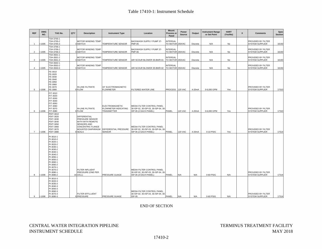
Table 17410-1: Instrument Schedule
REFDWG
NO.TAG No. QTY Description Instrument Type Location
Mount:
Process or
Panel
Power
SourceOutput
Instrument Range
or Set Point
HART
(Yes/No)X Comments
Spec
Section
1 I-1005
TSH-3705-1TSH-3705-2TSH-3705-3 3
MOTOR WINDING TEMP SWITCH TEMPERATURE SENSOR
BACKWASH SUPPLY PUMP 37-PMP-05
INTERGAL TO MOTOR 250VAC Discrete N/A No
PROVIDED BY FILTER SYSTEM SUPPLIER 16150
2 I-1005
TSH-3706-1TSH-3706-2TSH-3706-3 3
MOTOR WINDING TEMP SWITCH TEMPERATURE SENSOR
BACKWASH SUPPLY PUMP 37-PMP-06
INTERGAL TO MOTOR 250VAC Discrete N/A No
PROVIDED BY FILTER SYSTEM SUPPLIER 16150
3 I-1005
TSH-3501-1TSH-3501-2TSH-3501-3 3
MOTOR WINDING TEMP SWITCH TEMPERATURE SENSOR AIR SCOUR BLOWER 35-BWR-01
INTERGAL TO MOTOR 250VAC Discrete N/A No
PROVIDED BY FILTER SYSTEM SUPPLIER 16150
4 I-1005
TSH-3502-1TSH-3502-2TSH-3503-3 3
MOTOR WINDING TEMP SWITCH TEMPERATURE SENSOR AIR SCOUR BLOWER 35-BWR-02
INTERGAL TO MOTOR 250VAC Discrete N/A No
PROVIDED BY FILTER SYSTEM SUPPLIER 16150
5 I-1006
FE-3010FE-3020FE-3030FE-3040FE-3050FE-3060FE-3070FE-3080 8
IN-LINE FILTRATE FLOW
16" ELECTROMAGNETIC FLOWMETER FILTERED WATER LINE PROCESS 120 VAC 4-20mA 0-6,000 GPM Yes
PROVIDED BY FILTER SYSTEM SUPPLIER 17310
6 I-1006
FIT-3010FIT-3020FIT-3030FIT-3040FIT-3050FIT-3060FIT-3070FIT-3080 8
IN-LINE FILTRATE FLOW
ELECTROMAGNETIC FLOWMETER INDICATING TRANSMITTER
MEDIA FILTER CONTROL PANEL 30-ISP-02, 30-ISP-03, 30-ISP-04, 30-ISP-05 (2 EACH PANEL) PANEL 120 VAC 4-20mA 0-6,000 GPM Yes
PROVIDED BY FILTER SYSTEM SUPPLIER 17310
7 I-1006
PDIT-3010PDIT-3020PDIT-3030PDIT-3040PDIT-3050PDIT-3060PDIT-3070PDIT-3080 8
DIFFERENTIAL PRESSURE SENSOR WITH WITH REMOTE SENSORS AND CENCENTRIC FLANGE MOUNTED DIAPHRAGM SEALS
DIFFERENTIAL PRESSURE SENSOR
MEDIA FILTER CONTROL PANEL 30-ISP-02, 30-ISP-03, 30-ISP-04, 30-ISP-05 (2 EACH PANEL) PANEL 120 VAC 4-20mA 0-10 PSIG Yes
PROVIDED BY FILTER SYSTEM SUPPLIER 17314
8 I-1006
PI-3010-1PI-3010-2PI-3020-1PI-3020-2PI-3030-1PI-3030-2PI-3040-1PI-3040-2PI-3050-1PI-3050-2PI-3060-1PI-3060-2PI-3070-1PI-3070-2PI-3080-1PI-3080-2 16
FILTER INFLUENT PRESSURE (ONE PER CELL) PRESSURE GUAGE
MEDIA FILTER CONTROL PANEL 30-ISP-02, 30-ISP-03, 30-ISP-04, 30-ISP-05 (4 EACH PANEL) PANEL N/A N/A 0-60 PSIG N/A
PROVIDED BY FILTER SYSTEM SUPPLIER 17314
9 I-1006
PI-3010-3PI-3020-3PI-3030-3PI-3040-3PI-3050-3PI-3060-3PI-3070-3PI-3080-3 8
FILTER EFFLLUENT PRESSURE PRESSURE GUAGE
MEDIA FILTER CONTROL PANEL 30-ISP-02, 30-ISP-03, 30-ISP-04, 30-ISP-05 PANEL N/A N/A 0-60 PSIG N/A
PROVIDED BY FILTER SYSTEM SUPPLIER 17314
END OF SECTION
CENTRAL WATER INTEGRATION PIPELINE
INSTRUMENT SCHEDULE
17410-2
TERMINUS TREATMENT FACILITY
MAY 2018
CENTRAL WATER INTEGRATION PIPELINE TERMINUS TREATMENT FACILITY PROGRAMMABLE LOGIC CONTROLLER MAY 2018
17500 - 1
SECTION 17500
PROGRAMMABLE LOGIC CONTROLLER
GENERAL
SCOPE OF WORK
A. This section of the specifications describes the requirements for Programmable Logic Controllers (PLCs) to be furnished as listed in the related work paragraphs of this section and the Drawings.
B. Some of the PLC equipment is provided as part of an integrated control system on a vendor-supplied equipment package as shown on the Drawings. The PLC equipment used in these control systems must comply and be consistent with the requirements outlined in this document.
C. All equipment described herein shall be submitted and furnished as an integral part of Control System equipment specified herein and elsewhere within other specification sections. The PLC system configuration as described in the Contract Documents was developed to list the major elements. Some variations in the configuration will be considered provided the physical and functional constraints as intended for the various system components are met. Complete PLC system design, I/O configuration, module/rack arrangement, construction and additional coordination shall be provided by the packaged equipment manufacturer or the Process Control System Integrator (PCSI) as appropriate.
D. Provide equipment, materials, software, calibrations, training, and services required to successfully interface and interconnect the system and associated equipment that are specified or designated in drawings or provisions of these specifications for providing a fully integrated and functional control system as specified.
E. Furnish and install cabling and cable accessories, including tools necessary for connecting the system and peripherals, Programmable Logic Controllers (PLCs), data highway, and input/output devices.
F. Furnish startup, training, and system commissioning services.
G. Furnish and install all items necessary for the proper functioning of the equipment even if omitted at no additional cost to the Owner.
H. The Drawings and related Specification sections supplement this Section and provide additional details showing panel elevations, instrument device schedules, functional requirements of the system, and interaction with other equipment.
I. Coordinate and schedule all testing procedures with the General Contractor.
J. All software packages provided shall be licensed under the Owner’s name and address. The PCSI shall coordinate with the Owner for correct name and address.
RELATED WORK
A. Section 17300 Process Control Systems General Provisions
B. Section 17325 Process Control System Control Panels
CENTRAL WATER INTEGRATION PIPELINE TERMINUS TREATMENT FACILITY PROGRAMMABLE LOGIC CONTROLLER MAY 2018
17500 - 2
SUBMITTALS
A. Submittals for equipment specified herein shall be made as a part of equipment furnished under section 17300.
B. Submit catalog data for all items specified as applicable. Submittal shall include catalog data, functions, ratings, inputs, outputs, displays, etc., sufficient to confirm that the equipment provides all specified requirements. Any options or exceptions shall be clearly indicated and shall follow the terms within the General Conditions of Division 1.
C. Submit a bill of materials for each PLC clearly identifying all components and quantities.
D. Submit catalog data sheets for all software licenses provided under this specification section.
REFERENCE CODES AND STANDARDS
A. Instrumentation equipment, materials and installation shall comply with the National Electrical Code (NEC) and with the latest edition of the following codes and standards:
1. National Electrical Safety Code (NESC)
2. Underwriters Laboratories (UL)
3. UL 508, the Standard of Safety for Industrial Control Equipment
4. All equipment and installations shall conform to applicable Federal, State, and local codes.
B. All equipment shall comply with the requirements of the National Electric Code and Underwriters Laboratories (UL) where applicable.
C. Each specified device shall also conform to the standards and codes listed in the individual device paragraphs.
QUALITY ASSURANCE
A. The manufacturer of this equipment shall have produced similar equipment for a minimum period of five years. When requested by the Owner and/or Engineer, an acceptable list of installations with similar equipment shall be provided demonstrating compliance with this requirement.
B. Equipment submitted shall fit within the space or location shown on the Drawings. Equipment which does not fit within the space or location is not acceptable.
COMMUNICATIONS PROTOCOL
A. The PLC System shall communicate utilizing Ethernet/IP Protocol with the following as minimum capabilities:
1. Transfer of basic I/O data via User Datagram Protocol (UDP)-based implicit messaging
2. Uploading and downloading of parameters, set points, programs and recipes via TCP (i.e., explicit messaging.)
3. Polled, cyclic and change-of-state monitoring via UDP, such as RPI and COS in
CENTRAL WATER INTEGRATION PIPELINE TERMINUS TREATMENT FACILITY PROGRAMMABLE LOGIC CONTROLLER MAY 2018
17500 - 3
Allen Bradley's ControlLogix control systems
4. One-to-one (unicast), one-to-many (multicast), and one-to-all (broadcast) communication via TCP
5. Use of well-known TCP port number 44818 for explicit messaging and UDP port number 2222 for implicit messaging
B. The PLC shall be capable of peer-to-peer communications that provide for the direct transfer of process data between controllers on request of the controller needing a value requesting the source controller of the value to send the value without the use of gateways or servers.
PRODUCTS
PROGRAMMABLE LOGIC CONTROLLER SYSTEM
A. Subject to compliance with the Contract Documents, the following manufacturers are acceptable:
1. Rockwell Automation ControlLogix Series using Studio 5000 ENU software
2. Rockwell Automation CompactLogix Series using Studio 5000 ENU software
3. No others Approved
B. The listing of specific manufacturers above does not imply acceptance of their products that do not meet the specified ratings, features and functions. Manufacturers listed above are not relieved from meeting these specifications in their entirety.
C. Programming Languages
1. Each PLC shall support IEC Standard 61131-3 including the following programming languages:
a. Ladder (LD)
b. Function Block Diagram (FBD)
c. Sequential Functional Chart (SFC)
d. Structured Text (ST)
e. Instruction List (IL)
2. Provide one (1) copy of the manufacturer’s programming software for this class of PLC, with the highest-level capability, fully licensed in the Owner’s name. Request Owner’s contact information during the first PCSI construction meeting.
3. PLC shall support user defined functions for customization and user defined tag structures
4. PLC shall have application-specific instructions for process, drive, batch, motion and safety applications built into the controller.
D. Central Processor Unit
1. Master and DMZ PLC processors shall be Allen Bradley 1756-L72.
2. Field PLC processors shall be Allen Bradley 1769-L30ER.
CENTRAL WATER INTEGRATION PIPELINE TERMINUS TREATMENT FACILITY PROGRAMMABLE LOGIC CONTROLLER MAY 2018
17500 - 4
3. Provide hardware employing identical revisions of software and firmware as applicable.
E. Physical Construction (Rack)
1. The PLC shall be of modular construction, consisting of a back plane, plug in modules for the processor, communications modules, I/O modules and expansion modules.
2. Provide appropriate PLC I/O end cap / terminators as required.
3. Provide Allen Bradley blank filler modules in empty rack slots as required.
4. Provide the ability to monitor and override I/O.
5. Provide I/O modules in the base bid.
6. Provide the ability to preselect the failure mode of each output point in the event of CPU failure.
7. I/O modules shall support wiring interface devices that allow the removal and reinstallation of I/O modules without removing wires from terminals. All required wiring interface devices shall be included in the bid.
F. Power Supply (PS)
1. The Master PLC power supply shall be 120 Volt 60 Hz, and shall be Allen Bradley 1756- PA7x.
2. The field PLC power supply shall be 120 Volt 60 Hz, and shall be Allen Bradley 1769- PA4. Provide additional power supplies as required for specific I/O requirements.
G. Analog Input and Output Modules (AI and AO)
1. Master PLC
a. Analog Input Modules shall be Allen Bradley 1756 ControlLogix 8 Channel Analog Input Modules 1756-IF8 (Current)
1) Provide Allen Bradley Bulletin 1492 wiring system pre-wired cables and Interface Modules (IFMs) appropriate for the 1756-IF8 module.
b. Analog Output Modules shall be Allen Bradley 1756 ControlLogix 8 Channel Analog Output Modules 1756-OF8 (Current).
1) Provide Allen Bradley Bulletin 1492 wiring system pre-wired cables and Interface Modules (IFMs) appropriate for the 1756-OF8 module.
2. Field PLC
a. Analog Input Modules shall be Allen Bradley 1769 CompactLogix 8 Channel Analog Input Modules 1769-IF8 (Current).
1) Provide Allen Bradley Bulletin 1492 wiring system pre-wired cables and Interface Modules (IFMs) appropriate for the 1769-IF8 module.
CENTRAL WATER INTEGRATION PIPELINE TERMINUS TREATMENT FACILITY PROGRAMMABLE LOGIC CONTROLLER MAY 2018
17500 - 5
b. Analog Output Modules shall be Allen Bradley 1769 CompactLogix 8 Channel Analog Output Modules 1769-OF8 (Current).
1) Provide Allen Bradley Bulletin 1492 wiring system pre-wired cables and Interface Modules (IFMs) appropriate for 1769-OF8 module.
B. Discrete Input Modules (DI)
1. Master PLC
a. Discrete inputs shall be Allen Bradley 1756 16 Channel Digital DC Input Model 1756-IB16.
1) Provide Allen Bradley Bulletin 1492 wiring system pre-wired cables and Interface Modules (IFMs) appropriate for the 1756-IB16 module. Interface module should be supplied with integral channel status LEDs.
2. Field PLC
a. Discrete inputs shall be Allen Bradley 1769 Compact 32 Channel Digital DC Input Model 1769-IQ32.
1) Provide Allen Bradley Bulletin 1492 wiring system pre-wired cables and Interface Modules (IFMs) appropriate for the 1769-IQ32 module. Interface module should be supplied with integral channel status LEDs.
B. Discrete Output Modules (DO)
1. Master PLC
a. Discrete outputs shall be Allen Bradley 1756 16 Channel Digital DC Output module 1756-OB16E.
1) Provide Allen Bradley Bulletin 1492 wiring system pre-wired cables and Interface Modules (IFMs) appropriate for the 1756-OB16E module. Interface module should be supplied with integral channel status LEDs.
2. Field PLC
a. Discrete outputs shall be Allen Bradley 1769 Compact 32 Channel Digital DC Output module 1769-OB32.
1) Provide Allen Bradley Bulletin 1492 wiring system pre-wired cables and Interface Modules (IFMs) appropriate for the 1769-OB32 module. Interface module should be supplied with integral channel status LEDs.
B. Data Historian Module
1. The Data Historian module shall accept and store time-stamped data readings from plant-floor equipment. These data readings are forwarded to the FactoryTalk Historian SE servers. If the main data server WAN link is unavailable, the module shall have sufficient capacity to store the data readings until the network connection is restored.
CENTRAL WATER INTEGRATION PIPELINE TERMINUS TREATMENT FACILITY PROGRAMMABLE LOGIC CONTROLLER MAY 2018
17500 - 6
2. Data Historian module shall be Allen Bradley FactoryTalk Historian ME module.
a. Part number: 1756-HIST2G
b. Installed in ControlLogix backplane of Master PLC.
3. Coordinate configuration of data transfer with administrator of FactoryTalk Historian SE data servers. The tag license on the Historian SE servers must accommodate the number of tags configured for data transfer from the Historian ME module to the Historian SE servers.
C. Communications Modules
1. All PLCs shall include an integral Ethernet interface or a communications adapter module with at least one Ethernet interface port. Ethernet interface ports shall accept a standard Ethernet patch cable via RJ-45 connector.
a. Master PLC and DMZ PLC communications adapter module shall be Allen Bradley 1756-EN2T.
D. Active Spare Requirement
1. Provide a minimum of 20 percent wired spare I/O channels of each type furnished. All I/O points provided shall be wired to DIN rail mounted terminals.
SPARES REQUIREMENTS
A. Provide the following additional spare items for each PLC-based control panel:
1. One box replacement fuses, all types and sizes used.
2. One replacement cable of each type used
3. One of each Backplane used in the system.
4. One power supply of each type used.
5. One CPU module of each type used.
6. One I/O module of each type used.
B. Spare parts shall be boxed or packaged for long term storage. Identify each item with manufacturer’s name, description and part number on the exterior of the package.
EXECUTION
INSTALLATION
A. Install all equipment and components in accordance with the Contract Documents, approved Shop Drawings, and installation instructions furnished by the PCSI.
B. Inspect each instrument, panel and other items for damage and defects before installation. Replace deficient items.
C. PLC components, modules, etc., shall be installed such that all LED indicators and switches are readily visible with the panel door open and such that repair and/or replacement of any component can be accomplished without disconnecting any wiring or removing any other components.
CENTRAL WATER INTEGRATION PIPELINE TERMINUS TREATMENT FACILITY PROGRAMMABLE LOGIC CONTROLLER MAY 2018
17500 - 7
D. Comply with other specific installation, start-up, and testing requirements as specified in Section 17300, Instrument and Controls – General Provisions.
END OF SECTION

APPENDIX D
DRAWINGS
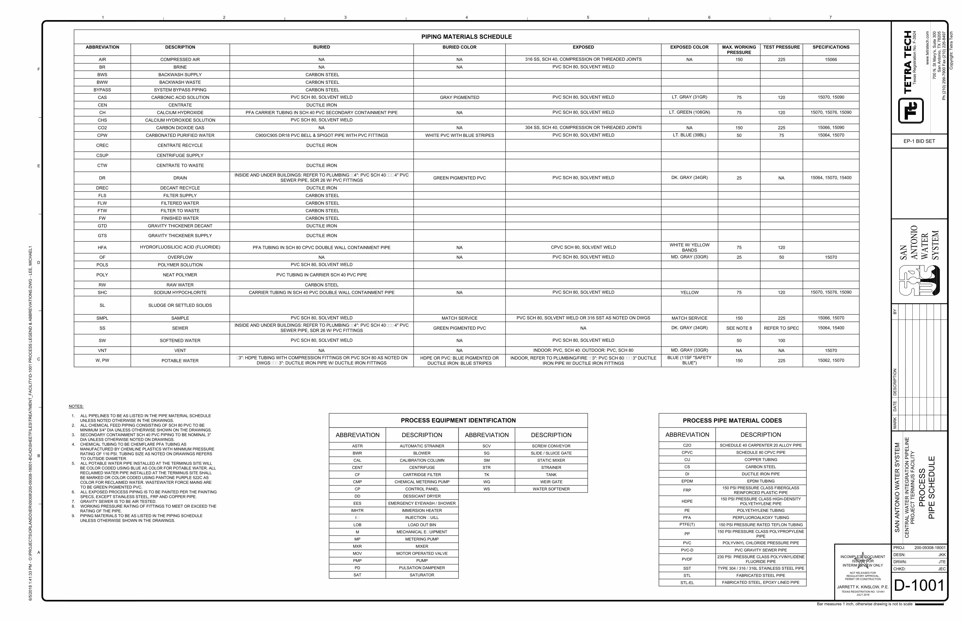
CHKD:
DRWN:
PROJ:
DESN:
ww
w.te
tra
te
ch
.co
m
MA
RK
DA
TE
DE
SC
RIP
TIO
NB
Y
6/5
/2
01
8 1
:4
1:3
3 P
M - O
:\P
RO
JE
CT
S\O
RL
AN
DO
\IE
R\0
93
08
\2
00
-0
93
08
-1
80
01
-B
\C
AD
\S
HE
ET
FIL
ES
\T
RE
AT
ME
NT
_F
AC
IL
IT
Y\D
-1
00
1 P
RO
CE
SS
L
EG
EN
D &
A
BB
RE
VIA
TIO
NS
.D
WG
- L
EE
, M
IC
HA
EL
1
1
A
B
C
D
E
F
2 3 4 5 6 7
Co
pyrig
ht: T
etra
T
ech
Bar measures 1 inch, otherwise drawing is not to scale
200-09308-18001
CE
NT
RA
L W
AT
ER
IN
TE
GR
AT
IO
N P
IP
ELIN
E
PR
OJE
CT
T
ER
MIN
US
F
AC
ILIT
Y
SA
N A
NT
ON
IO
W
AT
ER
S
YS
TE
M
70
0 N
. S
t M
ary's, S
uite
3
00
Sa
n A
nto
nio
, T
X 7
82
05
Ph
(2
10
) 2
99
-7
90
0 F
ax (2
10
) 2
26
-8
49
7
Te
xa
s R
eg
istra
tio
n N
o. F
-3
92
4
SAN
AN
TON
IOW
ATE
RSY
STEM
JARRETT K. KINSLOW, P.E.
INCOMPLETE DOCUMENT
ISSUED FOR
INTERIM REVIEW ONLY
NOT RELEASED FOR
REGULATORY APPROVAL,
PERMIT OR CONSTRUCTION
TEXAS REGISTRATION NO. 121441
JULY 2018
D-1001
PR
OC
ES
S
PIP
E S
CH
ED
ULE
JKK
JTE
JEC
EP-1 BID SET
ABBREVIATION DESCRIPTION
ASTR AUTOMATIC STRAINER
BWR BLOWER
CAL CALIBRATION COLUMN
CENT CENTRIFUGE
CF CARTRIDGE FILTER
CMP CHEMICAL METERING PUMP
CP CONTROL PANEL
DD DESSICANT DRYER
EES EMERGENCY EYEWASH / SHOWER
IMHTR IMMERSION HEATER
IQ INJECTION QUILL
LOB LOAD OUT BIN
M MECHANICAL EQUIPMENT
MP METERING PUMP
MXR MIXER
MOV MOTOR OPERATED VALVE
PMP PUMP
PD PULSATION DAMPENER
SAT SATURATOR
ABBREVIATION DESCRIPTION
SCV SCREW CONVEYOR
SG SLIDE / SLUICE GATE
SM STATIC MIXER
STR STRAINER
TK TANK
WG WEIR GATE
WS WATER SOFTENER
PROCESS PIPE MATERIAL CODES
ABBREVIATION DESCRIPTION
C2O SCHEDULE 40 CARPENTER 20 ALLOY PIPE
CPVC SCHEDULE 80 CPVC PIPE
CU COPPER TUBING
CS CARBON STEEL
DI DUCTILE IRON PIPE
EPDM EPDM TUBING
FRP
150 PSI PRESSURE CLASS FIBERGLASS
REINFORCED PLASTIC PIPE
HDPE
150 PSI PRESSURE CLASS HIGH-DENSITY
POLYETHYLENE PIPE
PE POLYETHYLENE TUBING
PFA PERFLUOROALKOXY TUBING
PTFE(T)
150 PSI PRESSURE RATED TEFLON TUBING
PP
150 PSI PRESSURE CLASS POLYPROPYLENE
PIPE
PVC POLYVINYL CHLORIDE PRESSURE PIPE
PVC-D PVC GRAVITY SEWER PIPE
PVDF
230 PSI PRESSURE CLASS POLYVINYLIDENE
FLUORIDE PIPE
SST TYPE 304 / 316 / 316L STAINLESS STEEL PIPE
STL FABRICATED STEEL PIPE
STL-ELFABRICATED STEEL, EPOXY LINED PIPE
PIPING MATERIALS SCHEDULE
ABBREVIATION DESCRIPTION BURIED BURIED COLOR EXPOSED EXPOSED COLOR MAX. WORKING
PRESSURE
TEST PRESSURE SPECIFICATIONS
AIR COMPRESSED AIR NA NA316 SS, SCH 40, COMPRESSION OR THREADED JOINTS
NA 150 225 15066
BR BRINE NA NAPVC SCH 80, SOLVENT WELD
BWS BACKWASH SUPPLY CARBON STEEL
BWW BACKWASH WASTE CARBON STEEL
BYPASS SYSTEM BYPASS PIPING CARBON STEEL
CAS CARBONIC ACID SOLUTIONPVC SCH 80, SOLVENT WELD
GRAY PIGMENTEDPVC SCH 80, SOLVENT WELD
LT. GRAY (31GR)
75 12015070, 15090
CEN CENTRATE DUCTILE IRON
CH CALCIUM HYDROXIDE PFA CARRIER TUBING IN SCH 40 PVC SECONDARY CONTAINMENT PIPE NAPVC SCH 80, SOLVENT WELD LT. GREEN (108GN)
75 12015070, 15076, 15090
CHS CALCIUM HYDROXIDE SOLUTIONPVC SCH 80, SOLVENT WELD
CO2 CARBON DIOXIDE GAS NA NA304 SS, SCH 40, COMPRESSION OR THREADED JOINTS
NA 150 22515066, 15090
CPW CARBONATED PURIFIED WATER C900/C905 DR18 PVC BELL & SPIGOT PIPE WITH PVC FITTINGS WHITE PVC WITH BLUE STRIPESPVC SCH 80, SOLVENT WELD LT. BLUE (39BL)
50 7515064, 15070
CREC CENTRATE RECYCLE DUCTILE IRON
CSUP CENTRIFUGE SUPPLY
CTW CENTRATE TO WASTE DUCTILE IRON
DR DRAIN
INSIDE AND UNDER BUILDINGS: REFER TO PLUMBING; <4": PVC SCH 40; >= 4" PVC
SEWER PIPE, SDR 26 W/ PVC FITTINGS
GREEN PIGMENTED PVCPVC SCH 80, SOLVENT WELD
DK. GRAY (34GR)
25 NA15064, 15070, 15400
DREC DECANT RECYCLE DUCTILE IRON
FLS FILTER SUPPLY CARBON STEEL
FLW FILTERED WATER CARBON STEEL
FTW FILTER TO WASTE CARBON STEEL
FW FINISHED WATER CARBON STEEL
GTD GRAVITY THICKENER DECANT DUCTILE IRON
GTS GRAVITY THICKENER SUPPLY DUCTILE IRON
HFA
HYDROFLUOSILICIC ACID (FLUORIDE)
PFA TUBING IN SCH 80 CPVC DOUBLE WALL CONTAINMENT PIPE NACPVC SCH 80, SOLVENT WELD
WHITE W/ YELLOW
BANDS
75 120
OF OVERFLOW NA NAPVC SCH 80, SOLVENT WELD MD. GRAY (33GR)
25 50 15070
POLS POLYMER SOLUTIONPVC SCH 80, SOLVENT WELD
POLY NEAT POLYMER PVC TUBING IN CARRIER SCH 40 PVC PIPE
RW RAW WATER CARBON STEEL
SHC SODIUM HYPOCHLORITE CARRIER TUBING IN SCH 40 PVC DOUBLE WALL CONTAINMENT PIPE NAPVC SCH 80, SOLVENT WELD
YELLOW 75 12015070, 15076, 15090
SL SLUDGE OR SETTLED SOLIDS
SMPL SAMPLEPVC SCH 80, SOLVENT WELD
MATCH SERVICEPVC SCH 80, SOLVENT WELD OR 316 SST AS NOTED ON DWGS
MATCH SERVICE 150 22515066, 15070
SS SEWER
INSIDE AND UNDER BUILDINGS: REFER TO PLUMBING; <4": PVC SCH 40; >= 4" PVC
SEWER PIPE, SDR 26 W/ PVC FITTINGS
GREEN PIGMENTED PVC NA
DK. GRAY (34GR)
SEE NOTE 8 REFER TO SPEC15064, 15400
SW SOFTENED WATERPVC SCH 80, SOLVENT WELD
NAPVC SCH 80, SOLVENT WELD
50 100
VNT VENT NA NAINDOOR: PVC, SCH 40; OUTDOOR: PVC, SCH 80 MD. GRAY (33GR)
NA NA 15070
W, PWPOTABLE WATER
<3": HDPE TUBING WITH COMPRESSION FITTINGS OR PVC SCH 80 AS NOTED ON
DWGS; >= 3": DUCTILE IRON PIPE W/ DUCTILE IRON FITTINGS
HDPE OR PVC: BLUE PIGMENTED OR
DUCTILE IRON: BLUE STRIPES
INDOOR, REFER TO PLUMBING/FIRE; <3": PVC SCH 80; >= 3" DUCTILE
IRON PIPE W/ DUCTILE IRON FITTINGS
BLUE (11SF "SAFETY
BLUE")
150 22515062, 15070
NOTES:
1. ALL PIPELINES TO BE AS LISTED IN THE PIPE MATERIAL SCHEDULE
UNLESS NOTED OTHERWISE IN THE DRAWINGS.
2. ALL CHEMICAL FEED PIPING CONSISTING OF SCH 80 PVC TO BE
MINIMUM 3/4" DIA UNLESS OTHERWISE SHOWN ON THE DRAWINGS.
3. SECONDARY CONTAINMENT SCH 40 PVC PIPING TO BE NOMINAL 3"
DIA UNLESS OTHERWISE NOTED ON DRAWINGS.
4. CHEMICAL TUBING TO BE CHEMFLARE PFA TUBING AS
MANUFACTURED BY CHEMLINE PLASTICS WITH MINIMUM PRESSURE
RATING OF 116 PSI. TUBING SIZE AS NOTED ON DRAWINGS REFERS
TO OUTSIDE DIAMETER.
5. ALL POTABLE WATER PIPE INSTALLED AT THE TERMINUS SITE WILL
BE COLOR CODED USING BLUE AS COLOR FOR POTABLE WATER. ALL
RECLAIMED WATER PIPE INSTALLED AT THE TERMINUS SITE SHALL
BE MARKED OR COLOR CODED USING PANTONE PURPLE 522C AS
COLOR FOR RECLAIMED WATER. WASTEWATER FORCE MAINS ARE
TO BE GREEN PIGMENTED PVC.
6. ALL EXPOSED PROCESS PIPING IS TO BE PAINTED PER THE PAINTING
SPECS, EXCEPT STAINLESS STEEL, FRP AND COPPER PIPE.
7. GRAVITY SEWER IS TO BE AIR TESTED.
8. WORKING PRESSURE RATING OF FITTINGS TO MEET OR EXCEED THE
RATING OF THE PIPE.
9. PIPING MATERIALS TO BE AS LISTED IN THE PIPING SCHEDULE
UNLESS OTHERWISE SHOWN IN THE DRAWINGS.
PROCESS EQUIPMENT IDENTIFICATION
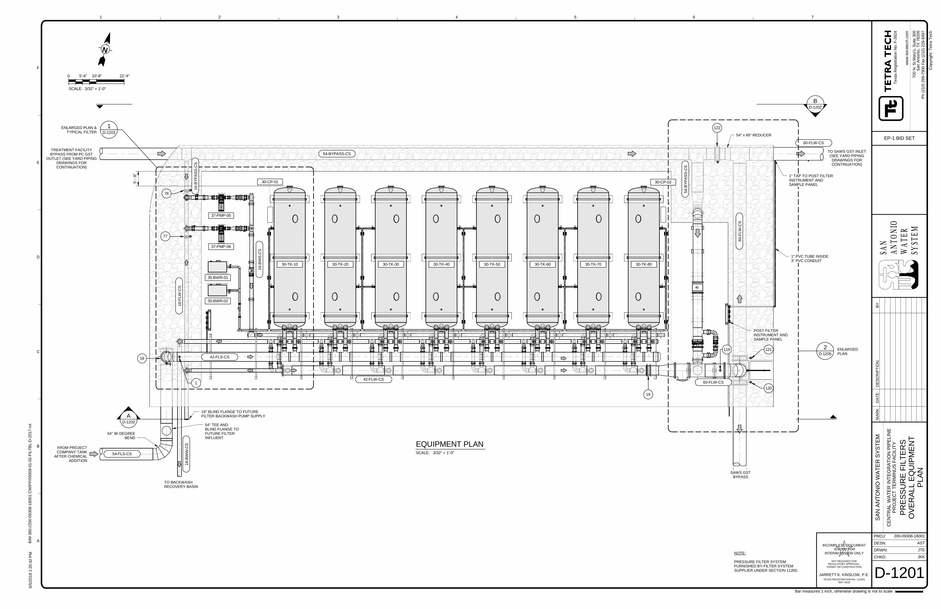
FROM PROJECTCOMPANY TANK
AFTER CHEMICALADDITION
AD-1202
TO BACKWASHRECOVERY BASIN
30-TK-10 30-TK-30 30-TK-40 30-TK-50 30-TK-60 30-TK-7030-TK-20 30-TK-80
D-1203
1
5'-
8"
ENLARGED PLAN &TYPICAL FILTER
TREATMENT FACILITYBYPASS FROM PC GST
OUTLET (SEE YARD PIPINGDRAWINGS FORCONTINUATION)
TO SAWS GST INLET(SEE YARD PIPING
DRAWINGS FORCONTINUATION)
SAWS GSTBYPASS
BD-1202
54-BYPASS-CS
16
-BW
S-C
S
16
-BY
PA
SS
-CS
54
-BY
PA
SS
-CS
60
-FLW
-CS
42-FLS-CS
42-FLW-CS
60-FLW-CS
16
-FLW
-CS
54-FLS-CS
18-B
WW
-CS
78
18
77
122
54" x 60" REDUCER
121
120
60-FLW-CS
D-1205
2
19
ENLARGEDPLAN
1" TAP TO POST FILTERINSTRUMENT ANDSAMPLE PANEL
1" PVC TUBE INSIDE3" PVC CONDUIT
POST FILTERINSTRUMENT ANDSAMPLE PANEL
37-PMP-05
37-PMP-06
35-BWR-01
35-BWR-02
54" 90 DEGREEBEND
54" TEE ANDBLIND FLANGE TOFUTURE FILTERINFLUENT
1
16" BLIND FLANGE TO FUTUREFILTER BACKWASH PUMP SUPPLY
119
30-CP-01 30-CP-02
SAN
ANTO
NIO
WATE
RSY
STEM
CHKD:
DRWN:
PROJ:
DESN:
ww
w.t
etr
ate
ch.c
om
1
A
B
C
D
E
F
2 3 4 5 6 7
Bar measures 1 inch, otherwise drawing is not to scale
Cop
yrig
ht:
Tetr
aT
ech
JARRETT K. KINSLOW, P.E.
INCOMPLETE DOCUMENT ISSUED FOR
INTERIM REVIEW ONLY
NOT RELEASED FORREGULATORY APPROVAL,
PERMIT OR CONSTRUCTION
TEXAS REGISTRATION NO. 121441MAY 2018
6/5
/201
81
:20
: 42
PM
BIM
360
://2
00
-09
30
8-1
800
1C
WIP
P/0
93
08-0
1-0
2-F
ILT
BL-D
-20
17
.rvt
200-09308-18001
AST
JTE
JKK
D-1201
SA
NA
NT
ON
IOW
AT
ER
SY
ST
EM
CE
NT
RA
LW
AT
ER
INT
EG
RA
TIO
NP
IPE
LIN
EP
RO
JEC
TT
ER
MIN
US
FA
CIL
ITY
PR
ES
SU
RE
FIL
TE
RS
OV
ER
AL
LE
QU
IPM
EN
TP
LA
N
Te
xas
Reg
istr
atio
nN
o.F
-392
4
70
0N
.S
tM
ary
's,
Su
ite30
0S
an
An
ton
io,T
X78
20
5
EP-1 BID SET
Ph
(21
0)
29
9-7
900
Fa
x(2
10
)2
26-8
49
7
SCALE: 3/32" = 1'-0"
EQUIPMENT PLAN
N
0 5'-4" 10'-8" 21'-4"
SCALE: 3/32" = 1'-0"
NOTE:
PRESSURE FILTER SYSTEMFURNISHED BY FILTER SYSTEMSUPPLIER UNDER SECTION 11200.
MA
RK
DA
TE
DE
SC
RIP
TIO
NB
Y
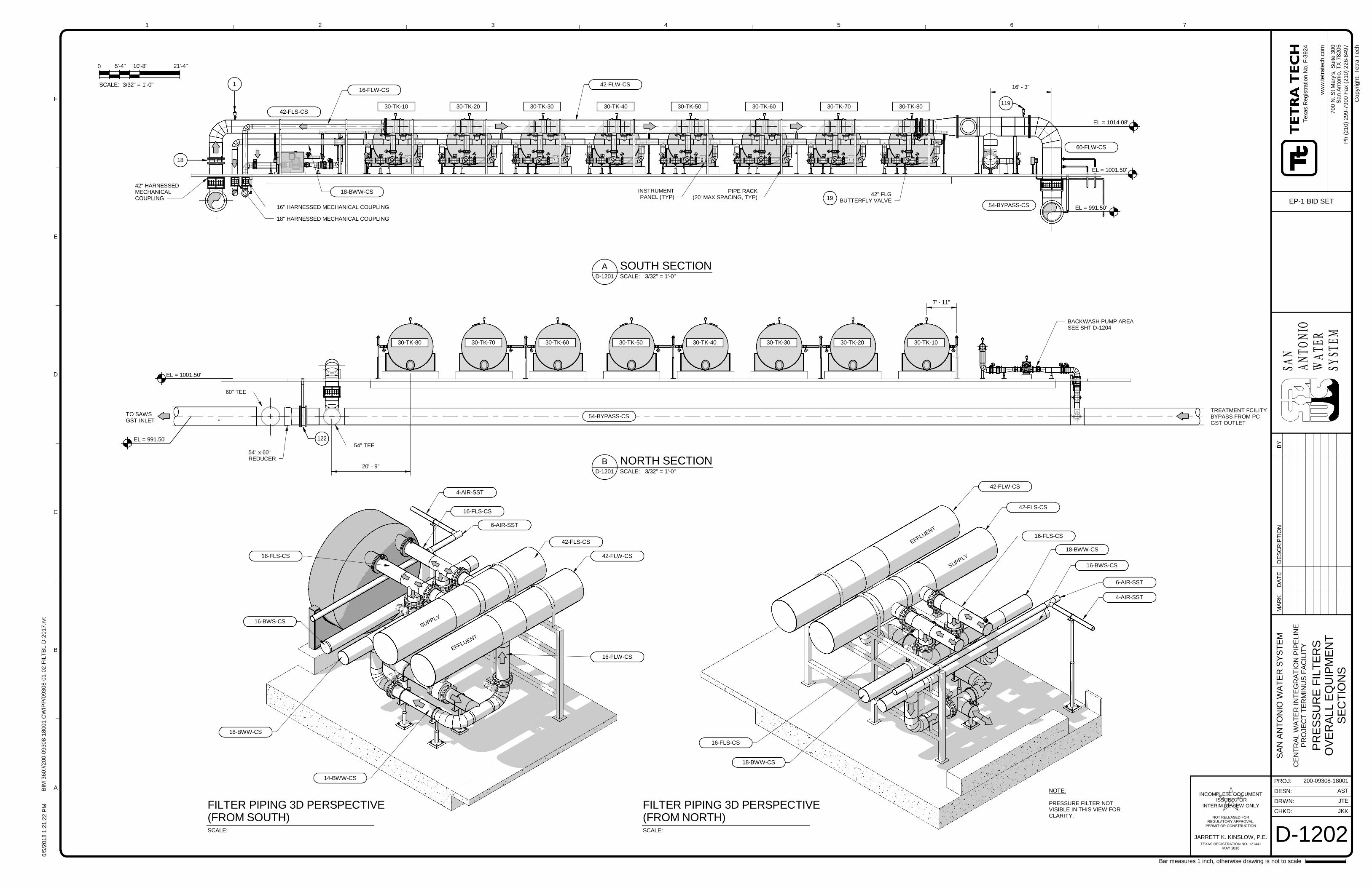
30-TK-10 30-TK-20 30-TK-30 30-TK-40 30-TK-50 30-TK-60 30-TK-70 30-TK-80
EL = 991.50'
INSTRUMENTPANEL (TYP)
42-FLS-CS
18
18-BWW-CS
16-FLW-CS16' - 3"
54-BYPASS-CS
60-FLW-CS
PIPE RACK(20' MAX SPACING, TYP)
42" HARNESSEDMECHANICALCOUPLING
16" HARNESSED MECHANICAL COUPLING
EL = 1001.50'
EL = 1014.08'
42" FLGBUTTERFLY VALVE19
42-FLW-CS1
119
18" HARNESSED MECHANICAL COUPLING
30-TK-1030-TK-2030-TK-3030-TK-4030-TK-5030-TK-6030-TK-7030-TK-80
54" TEE
60" TEE
TO SAWSGST INLET
122
54" x 60"REDUCER
54-BYPASS-CSTREATMENT FCILITYBYPASS FROM PCGST OUTLET
7' - 11"
20' - 9"
EL = 991.50'
EL = 1001.50'
BACKWASH PUMP AREASEE SHT D-1204
SAN
ANTO
NIO
WATE
RSY
STEM
CHKD:
DRWN:
PROJ:
DESN:
ww
w.t
etr
ate
ch.c
om
1
A
B
C
D
E
F
2 3 4 5 6 7
Bar measures 1 inch, otherwise drawing is not to scale
Cop
yrig
ht:
Tetr
aT
ech
JARRETT K. KINSLOW, P.E.
INCOMPLETE DOCUMENT ISSUED FOR
INTERIM REVIEW ONLY
NOT RELEASED FORREGULATORY APPROVAL,
PERMIT OR CONSTRUCTION
TEXAS REGISTRATION NO. 121441MAY 2018
6/5
/201
81
:21
: 22
PM
BIM
360
://2
00
-09
30
8-1
800
1C
WIP
P/0
93
08-0
1-0
2-F
ILT
BL-D
-20
17
.rvt
200-09308-18001
AST
JTE
JKK
D-1202
SA
NA
NT
ON
IOW
AT
ER
SY
ST
EM
CE
NT
RA
LW
AT
ER
INT
EG
RA
TIO
NP
IPE
LIN
EP
RO
JEC
TT
ER
MIN
US
FA
CIL
ITY
PR
ES
SU
RE
FIL
TE
RS
OV
ER
AL
LE
QU
IPM
EN
TS
EC
TIO
NS
Te
xas
Reg
istr
atio
nN
o.F
-392
4
70
0N
.S
tM
ary
's,
Su
ite30
0S
an
An
ton
io,T
X78
20
5
EP-1 BID SET
Ph
(21
0)
29
9-7
900
Fa
x(2
10
)2
26-8
49
7
SCALE: 3/32" = 1'-0"D-1201
A SOUTH SECTION
0 5'-4" 10'-8" 21'-4"
SCALE: 3/32" = 1'-0"
SCALE: 3/32" = 1'-0"D-1201
B NORTH SECTION
SCALE:
FILTER PIPING 3D PERSPECTIVE(FROM SOUTH)
SCALE:
FILTER PIPING 3D PERSPECTIVE(FROM NORTH)
NOTE:
PRESSURE FILTER NOTVISIBLE IN THIS VIEW FORCLARITY.
42-FLW-CS
42-FLS-CS
6-AIR-SST
16-FLS-CS
4-AIR-SST
16-FLS-CS
16-BWS-CS
18-BWW-CS
14-BWW-CS
42-FLW-CS
42-FLS-CS
6-AIR-SST
16-FLS-CS
4-AIR-SST
18-BWW-CS
16-BWS-CS
16-FLS-CS
18-BWW-CS
16-FLW-CS
EFFLUENT
SUPPLY
EFFLUENT
SUPPLY
MA
RK
DA
TE
DE
SC
RIP
TIO
NB
Y
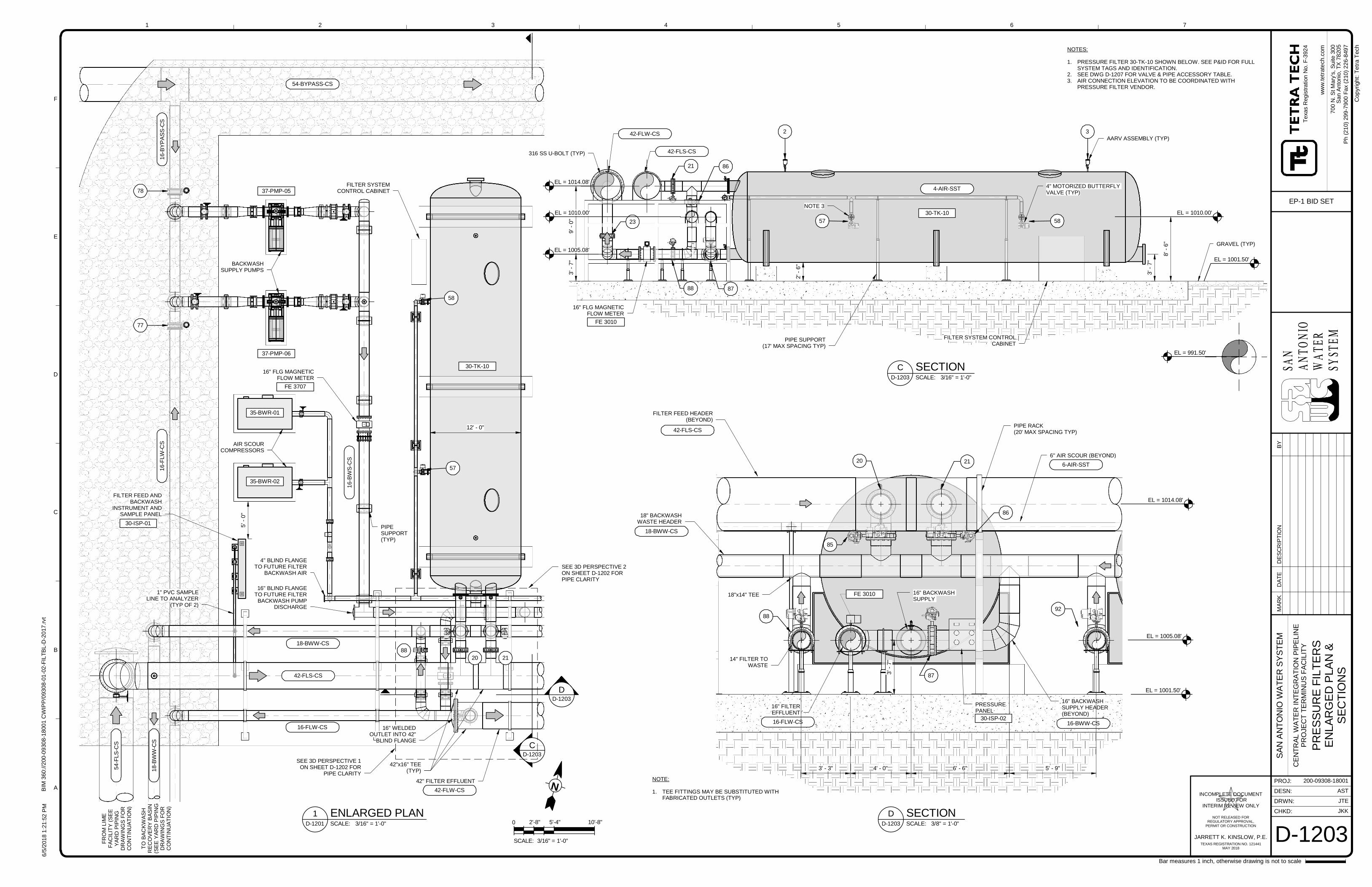
CD-1203
DD-1203
42-FLW-CS
42" FILTER EFFLUENT
88
2120
42-FLS-CS
18-B
WW
-CS
54
-FLS
-CS
16
-FLW
-CS
16-B
YP
AS
S-C
S
54-BYPASS-CS
16-B
WS
-CS
AIR SCOURCOMPRESSORS
BACKWASHSUPPLY PUMPS
78
77
37-PMP-05
37-PMP-06
35-BWR-01
35-BWR-02
TO
BA
CK
WA
SH
RE
CO
VE
RY
BA
SIN
(SE
EY
AR
DP
IPIN
GD
RA
WIN
GS
FO
RC
ON
TIN
UA
TIO
N)
FR
OM
LIM
EF
AC
ILIT
Y(S
EE
YA
RD
PIP
ING
DR
AW
ING
SF
OR
CO
NT
INU
AT
ION
)
30-TK-10
18-BWW-CS
16-FLW-CS 16" WELDEDOUTLET INTO 42"
BLIND FLANGE
42"x16" TEE(TYP)
57
58
FILTER FEED ANDBACKWASH
INSTRUMENT ANDSAMPLE PANEL
5'-
0"
1" PVC SAMPLELINE TO ANALYZER
(TYP OF 2)
FILTER SYSTEMCONTROL CABINET
16" FLG MAGNETICFLOW METER
FE 3707
30-ISP-01
SEE 3D PERSPECTIVE 2ON SHEET D-1202 FORPIPE CLARITY
SEE 3D PERSPECTIVE 1ON SHEET D-1202 FOR
PIPE CLARITY
PIPESUPPORT(TYP)
12' - 0"
4" BLIND FLANGETO FUTURE FILTER
BACKWASH AIR
16" BLIND FLANGETO FUTURE FILTER
BACKWASH PUMPDISCHARGE
4-AIR-SST
GRAVEL (TYP)
4" MOTORIZED BUTTERFLYVALVE (TYP)
AARV ASSEMBLY (TYP)
3'-
7"
9'-
0"
8'-
6"
3'-
7"
21
PIPE SUPPORT(17' MAX SPACING TYP)
42-FLW-CS
42-FLS-CS
8788
86
23
2
57 58
3
30-TK-10
FILTER SYSTEM CONTROLCABINET
EL = 991.50'
EL = 1005.08'
EL = 1014.08'
EL = 1010.00' EL = 1010.00'
EL = 1001.50'
16" FLG MAGNETICFLOW METER
FE 3010
2'-
6"
NOTE 3
316 SS U-BOLT (TYP)
42-FLS-CS
NOTE:
1. TEE FITTINGS MAY BE SUBSTITUTED WITHFABRICATED OUTLETS (TYP)
6" AIR SCOUR (BEYOND)
16" FILTEREFFLUENT
18" BACKWASHWASTE HEADER
FILTER FEED HEADER(BEYOND)
16" BACKWASHSUPPLY
PIPE RACK(20' MAX SPACING TYP)
14" FILTER TOWASTE
16" BACKWASHSUPPLY HEADER(BEYOND)
3'-
7"
88
87
85
86
20 216-AIR-SST
16-BWW-CS
PRESSUREPANEL
16-FLW-CS
18-BWW-CS
18"x14" TEE
EL = 1001.50'
EL = 1005.08'
EL = 1014.08'
92
6' - 6"4' - 0"3' - 3"
FE 3010
5' - 9"
30-ISP-02
SAN
ANTO
NIO
WATE
RSY
STEM
CHKD:
DRWN:
PROJ:
DESN:
ww
w.t
etr
ate
ch.c
om
1
A
B
C
D
E
F
2 3 4 5 6 7
Bar measures 1 inch, otherwise drawing is not to scale
Cop
yrig
ht:
Tetr
aT
ech
JARRETT K. KINSLOW, P.E.
INCOMPLETE DOCUMENT ISSUED FOR
INTERIM REVIEW ONLY
NOT RELEASED FORREGULATORY APPROVAL,
PERMIT OR CONSTRUCTION
TEXAS REGISTRATION NO. 121441MAY 2018
6/5
/201
81
:21
: 52
PM
BIM
360
://2
00
-09
30
8-1
800
1C
WIP
P/0
93
08-0
1-0
2-F
ILT
BL-D
-20
17
.rvt
200-09308-18001
AST
JTE
JKK
D-1203
SA
NA
NT
ON
IOW
AT
ER
SY
ST
EM
CE
NT
RA
LW
AT
ER
INT
EG
RA
TIO
NP
IPE
LIN
EP
RO
JEC
TT
ER
MIN
US
FA
CIL
ITY
PR
ES
SU
RE
FIL
TE
RS
EN
LA
RG
ED
PLA
N&
SE
CT
ION
S
Te
xas
Reg
istr
atio
nN
o.F
-392
4
70
0N
.S
tM
ary
's,
Su
ite30
0S
an
An
ton
io,T
X78
20
5
EP-1 BID SET
Ph
(21
0)
29
9-7
900
Fa
x(2
10
)2
26-8
49
7
SCALE: 3/16" = 1'-0"D-1201
1 ENLARGED PLAN
NOTES:
1. PRESSURE FILTER 30-TK-10 SHOWN BELOW. SEE P&ID FOR FULLSYSTEM TAGS AND IDENTIFICATION.
2. SEE DWG D-1207 FOR VALVE & PIPE ACCESSORY TABLE.3. AIR CONNECTION ELEVATION TO BE COORDINATED WITH
PRESSURE FILTER VENDOR.
SCALE: 3/16" = 1'-0"D-1203
C SECTION
SCALE: 3/8" = 1'-0"D-1203
D SECTION
N
0 2'-8" 5'-4" 10'-8"
SCALE: 3/16" = 1'-0"
MA
RK
DA
TE
DE
SC
RIP
TIO
NB
Y
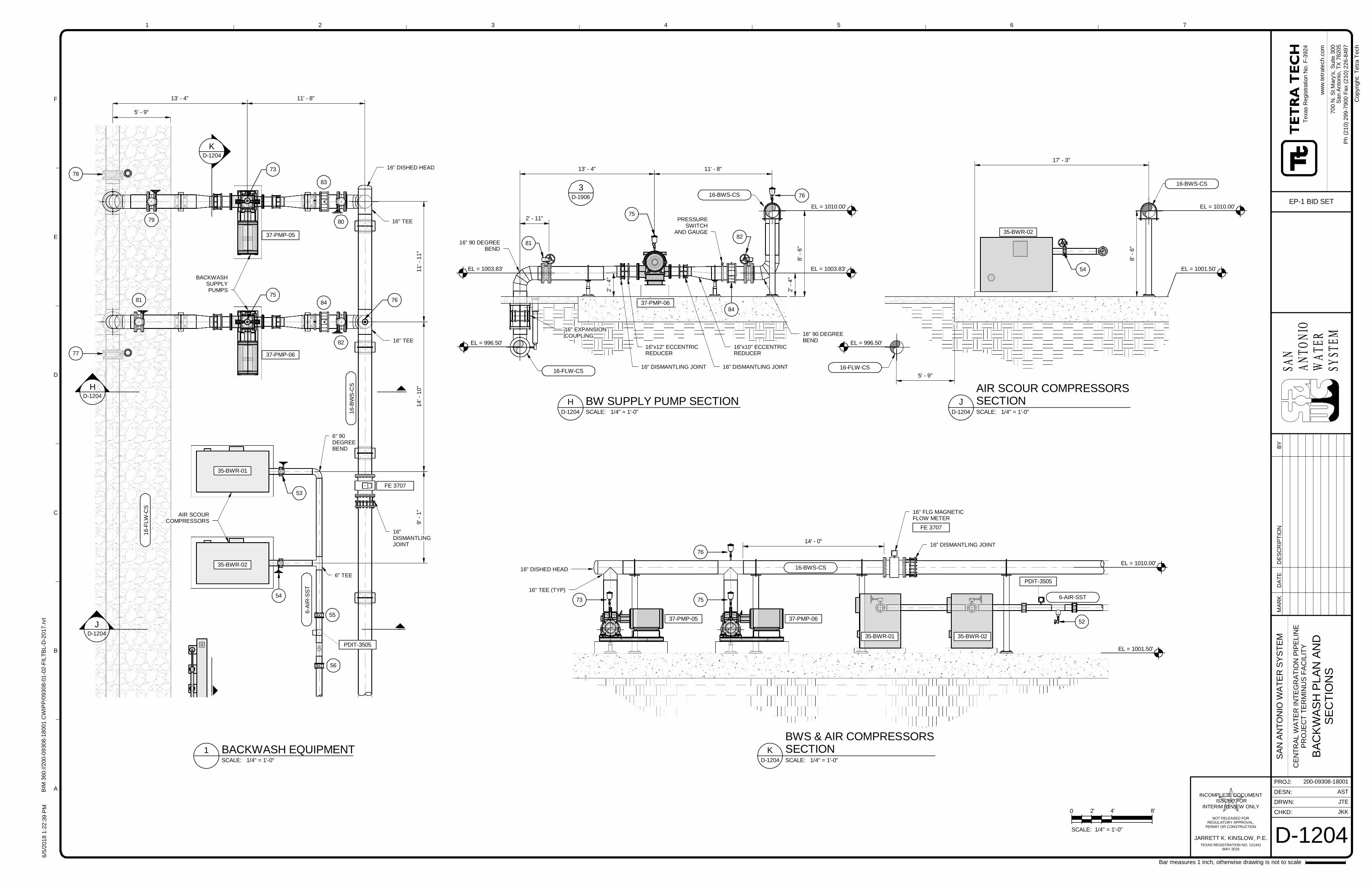
HD-1204
JD-1204
KD-1204
37-PMP-05
37-PMP-06
35-BWR-01
35-BWR-02
BACKWASHSUPPLYPUMPS
AIR SCOURCOMPRESSORS
11
'-1
1"
14
'-1
0"
9'-
1"
FE 3707
6-A
IR-S
ST
16
-BW
S-C
S
16
-FLW
-CS
77
78
79
81 84
82
83
80
53
54
16" DISHED HEAD
16" TEE
16" TEE
6" TEE
6" 90DEGREEBEND
5' - 9"
13' - 4"
55
56
11' - 8"
73
7576
PDIT-3505
16"DISMANTLINGJOINT
2'-
4"
2'-
4"
8182
8'-
6"
37-PMP-06
75
76
84
16" 90 DEGREEBEND
16"x10" ECCENTRICREDUCER
16"x12" ECCENTRICREDUCER
16" EXPANSIONCOUPLING
16" 90 DEGREEBEND
PRESSURESWITCH
AND GAUGE
16-BWS-CS
EL = 996.50'
EL = 1003.83' EL = 1003.83'
EL = 1010.00'
13' - 4" 11' - 8"
16-FLW-CS
3D-1906
2' - 11"
16" DISMANTLING JOINT16" DISMANTLING JOINT
54
8'-
6"
35-BWR-02
16-BWS-CS
EL = 1001.50'
EL = 1010.00'
5' - 9"
EL = 996.50'
17' - 3"
16-FLW-CS
6-AIR-SST
16-BWS-CS
37-PMP-05 37-PMP-06
35-BWR-01 35-BWR-02
73
76
75
16" DISHED HEAD
16" TEE (TYP)
FE 3707
EL = 1010.00'
EL = 1001.50'
16" FLG MAGNETICFLOW METER
52
PDIT-3505
16" DISMANTLING JOINT14' - 0"
SAN
ANTO
NIO
WATE
RSY
STEM
CHKD:
DRWN:
PROJ:
DESN:
ww
w.t
etr
ate
ch.c
om
1
A
B
C
D
E
F
2 3 4 5 6 7
Bar measures 1 inch, otherwise drawing is not to scale
Cop
yrig
ht:
Tetr
aT
ech
JARRETT K. KINSLOW, P.E.
INCOMPLETE DOCUMENT ISSUED FOR
INTERIM REVIEW ONLY
NOT RELEASED FORREGULATORY APPROVAL,
PERMIT OR CONSTRUCTION
TEXAS REGISTRATION NO. 121441MAY 2018
6/5
/201
81
:22
: 39
PM
BIM
360
://2
00
-09
30
8-1
800
1C
WIP
P/0
93
08-0
1-0
2-F
ILT
BL-D
-20
17
.rvt
200-09308-18001
AST
JTE
JKK
D-1204
SA
NA
NT
ON
IOW
AT
ER
SY
ST
EM
CE
NT
RA
LW
AT
ER
INT
EG
RA
TIO
NP
IPE
LIN
EP
RO
JEC
TT
ER
MIN
US
FA
CIL
ITY
BA
CK
WA
SH
PL
AN
AN
DS
EC
TIO
NS
Te
xas
Reg
istr
atio
nN
o.F
-392
4
70
0N
.S
tM
ary
's,
Su
ite30
0S
an
An
ton
io,T
X78
20
5
EP-1 BID SET
Ph
(21
0)
29
9-7
900
Fa
x(2
10
)2
26-8
49
7
SCALE: 1/4" = 1'-0"
1 BACKWASH EQUIPMENT
SCALE: 1/4" = 1'-0"D-1204
H BW SUPPLY PUMP SECTIONSCALE: 1/4" = 1'-0"D-1204
J
AIR SCOUR COMPRESSORSSECTION
SCALE: 1/4" = 1'-0"D-1204
K
BWS & AIR COMPRESSORSSECTION
0 2' 4' 8'
SCALE: 1/4" = 1'-0"
MA
RK
DA
TE
DE
SC
RIP
TIO
NB
Y
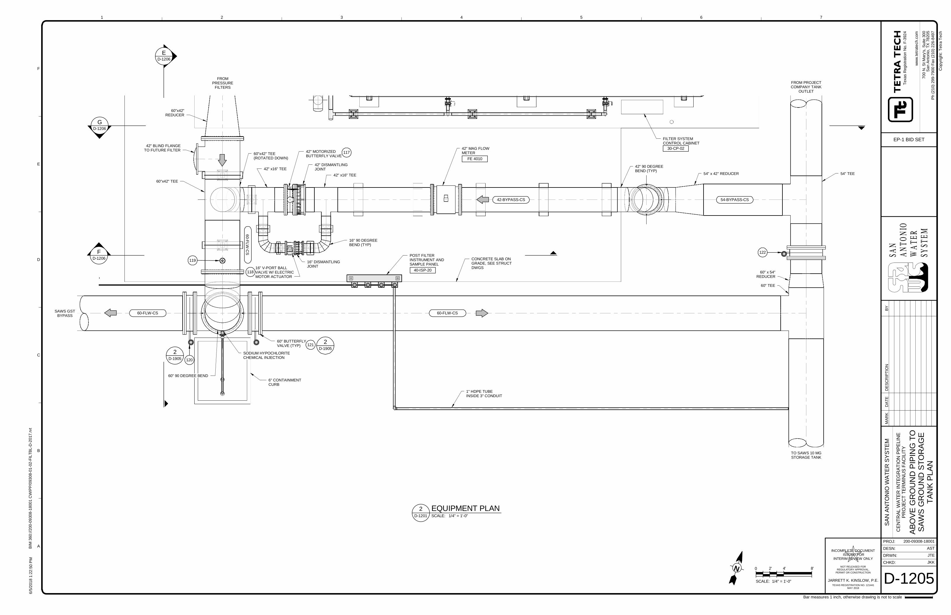
ED-1206
FD-1206
FROMPRESSURE
FILTERS
SAWS GSTBYPASS
6" CONTAINMENTCURB
16" V-PORT BALLVALVE W/ ELECTRICMOTOR ACTUATOR
SODIUM HYPOCHLORITECHEMICAL INJECTION
60-FLW-CS
CONCRETE SLAB ONGRADE, SEE STRUCTDWGS
16" DISMANTLINGJOINT
42" DISMANTLINGJOINT
42" MOTORIZEDBUTTERFLY VALVE
60"x42" TEE
60"x42"REDUCER
60" BUTTERFLYVALVE (TYP)
42" x16" TEE
42" x16" TEE
60"x42" TEE(ROTATED DOWN)
42" BLIND FLANGETO FUTURE FILTER
60" 90 DEGREE BEND
GD-1206
16" 90 DEGREEBEND (TYP)
POST FILTERINSTRUMENT ANDSAMPLE PANEL
1" HDPE TUBEINSIDE 3" CONDUIT
60
-FLW
-CS
117
118
121
120
42-BYPASS-CS
60-FLW-CS
40-ISP-20
2D-1905
2D-1905
119
42" MAG FLOWMETER
TO SAWS 10 MGSTORAGE TANK
60" TEE
60" x 54"REDUCER
122
42" 90 DEGREEBEND (TYP)
54" x 42" REDUCER 54" TEE
54-BYPASS-CS
FROM PROJECTCOMPANY TANK
OUTLET
FILTER SYSTEMCONTROL CABINET
30-CP-02
FE 4010
SAN
ANTO
NIO
WATE
RSY
STEM
CHKD:
DRWN:
PROJ:
DESN:
ww
w.t
etr
ate
ch.c
om
1
A
B
C
D
E
F
2 3 4 5 6 7
Bar measures 1 inch, otherwise drawing is not to scale
Cop
yrig
ht:
Tetr
aT
ech
JARRETT K. KINSLOW, P.E.
INCOMPLETE DOCUMENT ISSUED FOR
INTERIM REVIEW ONLY
NOT RELEASED FORREGULATORY APPROVAL,
PERMIT OR CONSTRUCTION
TEXAS REGISTRATION NO. 121441MAY 2018
6/5
/201
81
:22
: 50
PM
BIM
360
://2
00
-09
30
8-1
800
1C
WIP
P/0
93
08-0
1-0
2-F
ILT
BL-D
-20
17
.rvt
200-09308-18001
AST
JTE
JKK
D-1205
SA
NA
NT
ON
IOW
AT
ER
SY
ST
EM
CE
NT
RA
LW
AT
ER
INT
EG
RA
TIO
NP
IPE
LIN
EP
RO
JEC
TT
ER
MIN
US
FA
CIL
ITY
AB
OV
EG
RO
UN
DP
IPIN
GT
OS
AW
SG
RO
UN
DS
TO
RA
GE
TA
NK
PL
AN
Te
xas
Reg
istr
atio
nN
o.F
-392
4
70
0N
.S
tM
ary
's,
Su
ite30
0S
an
An
ton
io,T
X78
20
5
EP-1 BID SET
Ph
(21
0)
29
9-7
900
Fa
x(2
10
)2
26-8
49
7
SCALE: 1/4" = 1'-0"D-1201
2 EQUIPMENT PLAN
0 2' 4' 8'
SCALE: 1/4" = 1'-0"
N
MA
RK
DA
TE
DE
SC
RIP
TIO
NB
Y
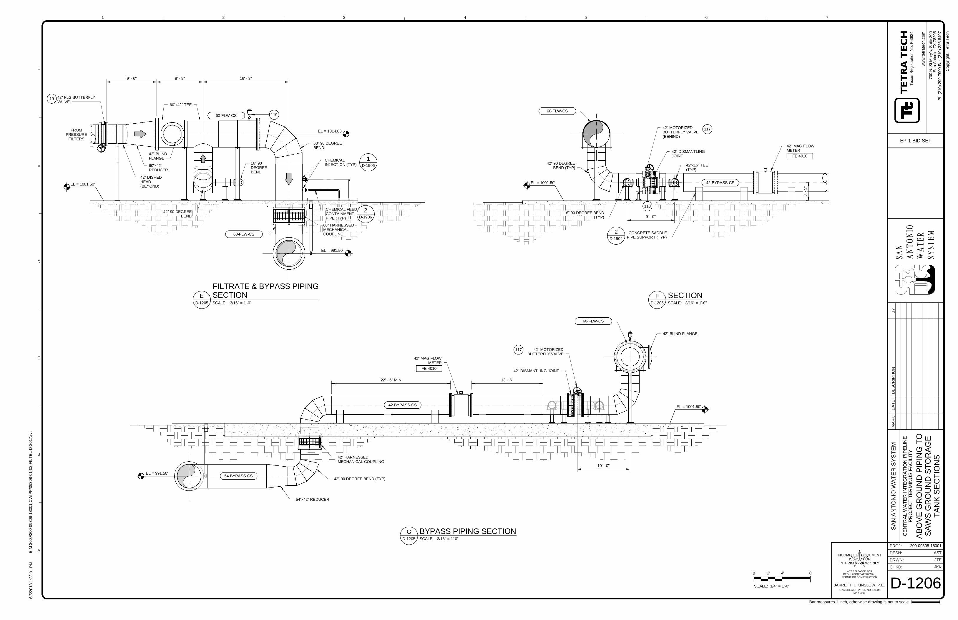
CONCRETE SADDLEPIPE SUPPORT (TYP)
2D-1904
42" DISMANTLINGJOINT
42"x16" TEE(TYP)
42" MOTORIZEDBUTTERFLY VALVE(BEHIND)
117
118
42-BYPASS-CS
16" 90 DEGREE BEND(TYP)
EL = 1001.50'
60-FLW-CS
9' - 0"
42" 90 DEGREEBEND (TYP)
42" MAG FLOWMETER
FE 4010
3'-
5"
CHEMICALINJECTION (TYP)
60"x42" TEE
60"x42"REDUCER
60" 90 DEGREEBEND
42" FLG BUTTERFLYVALVE
19
42" 90 DEGREEBEND
16" 90DEGREEBEND
60-FLW-CS
EL = 991.50'
9' - 6" 16' - 3"8' - 9"
FROMPRESSURE
FILTERS
60-FLW-CS
60" HARNESSEDMECHANICALCOUPLING
CHEMICAL FEEDCONTAINMENTPIPE (TYP)
2D-1906
119
1D-1906
42" DISHEDHEAD(BEYOND)
42" BLINDFLANGE
EL = 1014.08'
EL = 1001.50'
54"x42" REDUCER
42" MOTORIZEDBUTTERFLY VALVE
42" DISMANTLING JOINT
42" BLIND FLANGE
117
54-BYPASS-CSEL = 991.50'
EL = 1001.50'42-BYPASS-CS
60-FLW-CS
10' - 0"
42" 90 DEGREE BEND (TYP)
42" HARNESSEDMECHANICAL COUPLING
22' - 6" MIN 13' - 6"
42" MAG FLOWMETER
FE 4010
SAN
ANTO
NIO
WATE
RSY
STEM
CHKD:
DRWN:
PROJ:
DESN:
ww
w.t
etr
ate
ch.c
om
1
A
B
C
D
E
F
2 3 4 5 6 7
Bar measures 1 inch, otherwise drawing is not to scale
Cop
yrig
ht:
Tetr
aT
ech
JARRETT K. KINSLOW, P.E.
INCOMPLETE DOCUMENT ISSUED FOR
INTERIM REVIEW ONLY
NOT RELEASED FORREGULATORY APPROVAL,
PERMIT OR CONSTRUCTION
TEXAS REGISTRATION NO. 121441MAY 2018
6/5
/201
81
:23
: 01
PM
BIM
360
://2
00
-09
30
8-1
800
1C
WIP
P/0
93
08-0
1-0
2-F
ILT
BL-D
-20
17
.rvt
200-09308-18001
AST
JTE
JKK
D-1206
SA
NA
NT
ON
IOW
AT
ER
SY
ST
EM
CE
NT
RA
LW
AT
ER
INT
EG
RA
TIO
NP
IPE
LIN
EP
RO
JEC
TT
ER
MIN
US
FA
CIL
ITY
AB
OV
EG
RO
UN
DP
IPIN
GT
OS
AW
SG
RO
UN
DS
TO
RA
GE
TA
NK
SE
CT
ION
S
Te
xas
Reg
istr
atio
nN
o.F
-392
4
70
0N
.S
tM
ary
's,
Su
ite30
0S
an
An
ton
io,T
X78
20
5
EP-1 BID SET
Ph
(21
0)
29
9-7
900
Fa
x(2
10
)2
26-8
49
7
SCALE: 3/16" = 1'-0"D-1205
F SECTIONSCALE: 3/16" = 1'-0"D-1205
E
FILTRATE & BYPASS PIPINGSECTION
0 2' 4' 8'
SCALE: 1/4" = 1'-0"
SCALE: 3/16" = 1'-0"D-1205
G BYPASS PIPING SECTION
MA
RK
DA
TE
DE
SC
RIP
TIO
NB
Y
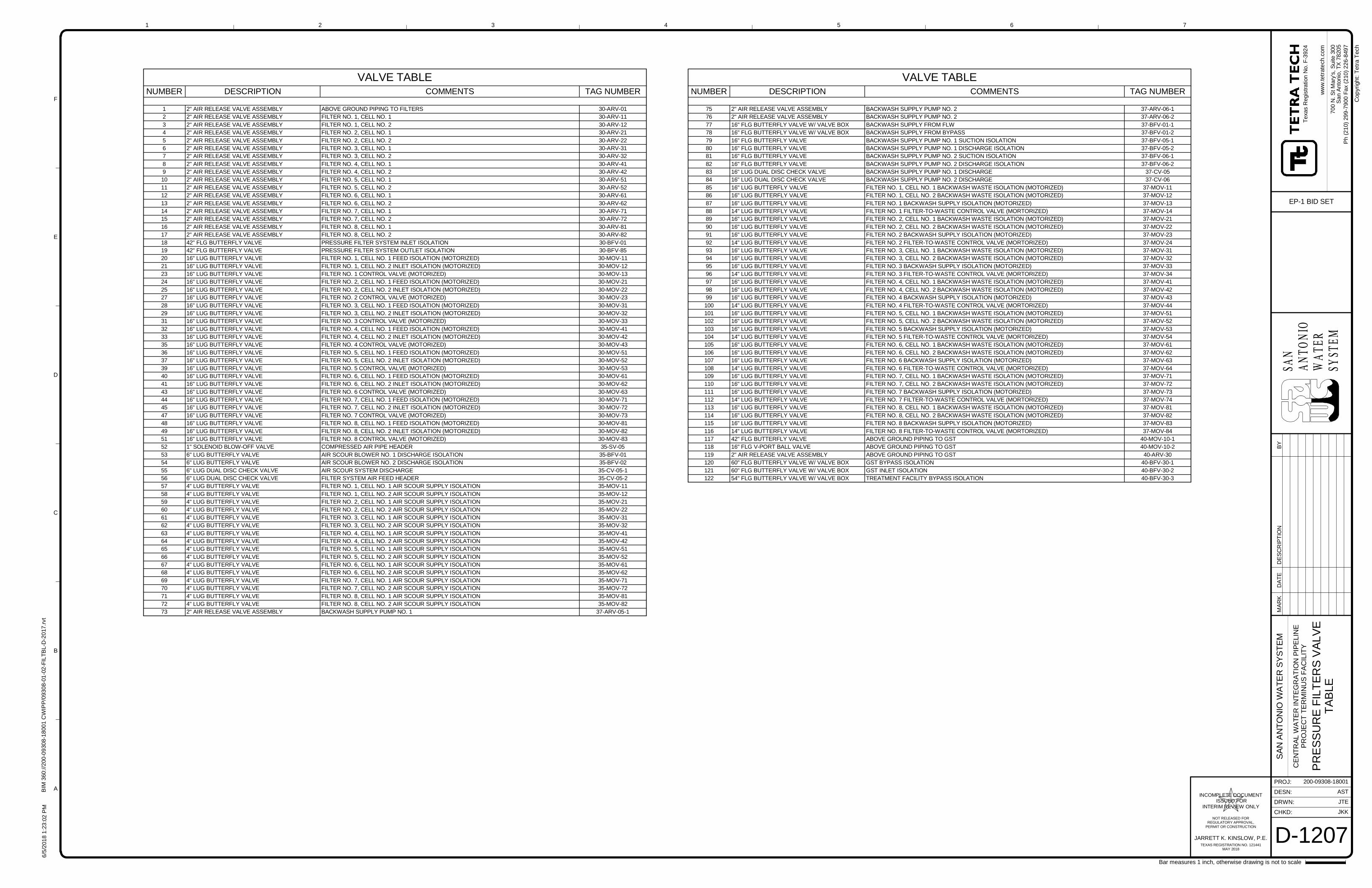
SAN
ANTO
NIO
WATE
RSY
STEM
CHKD:
DRWN:
PROJ:
DESN:
ww
w.t
etr
ate
ch.c
om
1
A
B
C
D
E
F
2 3 4 5 6 7
Bar measures 1 inch, otherwise drawing is not to scale
Cop
yrig
ht:
Tetr
aT
ech
JARRETT K. KINSLOW, P.E.
INCOMPLETE DOCUMENT ISSUED FOR
INTERIM REVIEW ONLY
NOT RELEASED FORREGULATORY APPROVAL,
PERMIT OR CONSTRUCTION
TEXAS REGISTRATION NO. 121441MAY 2018
6/5
/201
81
:23
: 02
PM
BIM
360
://2
00
-09
30
8-1
800
1C
WIP
P/0
93
08-0
1-0
2-F
ILT
BL-D
-20
17
.rvt
200-09308-18001
AST
JTE
JKK
D-1207
SA
NA
NT
ON
IOW
AT
ER
SY
ST
EM
CE
NT
RA
LW
AT
ER
INT
EG
RA
TIO
NP
IPE
LIN
EP
RO
JEC
TT
ER
MIN
US
FA
CIL
ITY
PR
ES
SU
RE
FIL
TE
RS
VA
LV
ET
AB
LE
Te
xas
Reg
istr
atio
nN
o.F
-392
4
70
0N
.S
tM
ary
's,
Su
ite30
0S
an
An
ton
io,T
X78
20
5
EP-1 BID SET
Ph
(21
0)
29
9-7
900
Fa
x(2
10
)2
26-8
49
7
VALVE TABLENUMBER DESCRIPTION COMMENTS TAG NUMBER
75 2" AIR RELEASE VALVE ASSEMBLY BACKWASH SUPPLY PUMP NO. 2 37-ARV-06-1
76 2" AIR RELEASE VALVE ASSEMBLY BACKWASH SUPPLY PUMP NO. 2 37-ARV-06-2
77 16" FLG BUTTERFLY VALVE W/ VALVE BOX BACKWASH SUPPLY FROM FLW 37-BFV-01-1
78 16" FLG BUTTERFLY VALVE W/ VALVE BOX BACKWASH SUPPLY FROM BYPASS 37-BFV-01-2
79 16" FLG BUTTERFLY VALVE BACKWASH SUPPLY PUMP NO. 1 SUCTION ISOLATION 37-BFV-05-1
80 16" FLG BUTTERFLY VALVE BACKWASH SUPPLY PUMP NO. 1 DISCHARGE ISOLATION 37-BFV-05-2
81 16" FLG BUTTERFLY VALVE BACKWASH SUPPLY PUMP NO. 2 SUCTION ISOLATION 37-BFV-06-1
82 16" FLG BUTTERFLY VALVE BACKWASH SUPPLY PUMP NO. 2 DISCHARGE ISOLATION 37-BFV-06-2
83 16" LUG DUAL DISC CHECK VALVE BACKWASH SUPPLY PUMP NO. 1 DISCHARGE 37-CV-05
84 16" LUG DUAL DISC CHECK VALVE BACKWASH SUPPLY PUMP NO. 2 DISCHARGE 37-CV-06
85 16" LUG BUTTERFLY VALVE FILTER NO. 1, CELL NO. 1 BACKWASH WASTE ISOLATION (MOTORIZED) 37-MOV-11
86 16" LUG BUTTERFLY VALVE FILTER NO. 1, CELL NO. 2 BACKWASH WASTE ISOLATION (MOTORIZED) 37-MOV-12
87 16" LUG BUTTERFLY VALVE FILTER NO. 1 BACKWASH SUPPLY ISOLATION (MOTORIZED) 37-MOV-13
88 14" LUG BUTTERFLY VALVE FILTER NO. 1 FILTER-TO-WASTE CONTROL VALVE (MORTORIZED) 37-MOV-14
89 16" LUG BUTTERFLY VALVE FILTER NO. 2, CELL NO. 1 BACKWASH WASTE ISOLATION (MOTORIZED) 37-MOV-21
90 16" LUG BUTTERFLY VALVE FILTER NO. 2, CELL NO. 2 BACKWASH WASTE ISOLATION (MOTORIZED) 37-MOV-22
91 16" LUG BUTTERFLY VALVE FILTER NO. 2 BACKWASH SUPPLY ISOLATION (MOTORIZED) 37-MOV-23
92 14" LUG BUTTERFLY VALVE FILTER NO. 2 FILTER-TO-WASTE CONTROL VALVE (MORTORIZED) 37-MOV-24
93 16" LUG BUTTERFLY VALVE FILTER NO. 3, CELL NO. 1 BACKWASH WASTE ISOLATION (MOTORIZED) 37-MOV-31
94 16" LUG BUTTERFLY VALVE FILTER NO. 3, CELL NO. 2 BACKWASH WASTE ISOLATION (MOTORIZED) 37-MOV-32
95 16" LUG BUTTERFLY VALVE FILTER NO. 3 BACKWASH SUPPLY ISOLATION (MOTORIZED) 37-MOV-33
96 14" LUG BUTTERFLY VALVE FILTER NO. 3 FILTER-TO-WASTE CONTROL VALVE (MORTORIZED) 37-MOV-34
97 16" LUG BUTTERFLY VALVE FILTER NO. 4, CELL NO. 1 BACKWASH WASTE ISOLATION (MOTORIZED) 37-MOV-41
98 16" LUG BUTTERFLY VALVE FILTER NO. 4, CELL NO. 2 BACKWASH WASTE ISOLATION (MOTORIZED) 37-MOV-42
99 16" LUG BUTTERFLY VALVE FILTER NO. 4 BACKWASH SUPPLY ISOLATION (MOTORIZED) 37-MOV-43
100 14" LUG BUTTERFLY VALVE FILTER NO. 4 FILTER-TO-WASTE CONTROL VALVE (MORTORIZED) 37-MOV-44
101 16" LUG BUTTERFLY VALVE FILTER NO. 5, CELL NO. 1 BACKWASH WASTE ISOLATION (MOTORIZED) 37-MOV-51
102 16" LUG BUTTERFLY VALVE FILTER NO. 5, CELL NO. 2 BACKWASH WASTE ISOLATION (MOTORIZED) 37-MOV-52
103 16" LUG BUTTERFLY VALVE FILTER NO. 5 BACKWASH SUPPLY ISOLATION (MOTORIZED) 37-MOV-53
104 14" LUG BUTTERFLY VALVE FILTER NO. 5 FILTER-TO-WASTE CONTROL VALVE (MORTORIZED) 37-MOV-54
105 16" LUG BUTTERFLY VALVE FILTER NO. 6, CELL NO. 1 BACKWASH WASTE ISOLATION (MOTORIZED) 37-MOV-61
106 16" LUG BUTTERFLY VALVE FILTER NO. 6, CELL NO. 2 BACKWASH WASTE ISOLATION (MOTORIZED) 37-MOV-62
107 16" LUG BUTTERFLY VALVE FILTER NO. 6 BACKWASH SUPPLY ISOLATION (MOTORIZED) 37-MOV-63
108 14" LUG BUTTERFLY VALVE FILTER NO. 6 FILTER-TO-WASTE CONTROL VALVE (MORTORIZED) 37-MOV-64
109 16" LUG BUTTERFLY VALVE FILTER NO. 7, CELL NO. 1 BACKWASH WASTE ISOLATION (MOTORIZED) 37-MOV-71
110 16" LUG BUTTERFLY VALVE FILTER NO. 7, CELL NO. 2 BACKWASH WASTE ISOLATION (MOTORIZED) 37-MOV-72
111 16" LUG BUTTERFLY VALVE FILTER NO. 7 BACKWASH SUPPLY ISOLATION (MOTORIZED) 37-MOV-73
112 14" LUG BUTTERFLY VALVE FILTER NO. 7 FILTER-TO-WASTE CONTROL VALVE (MORTORIZED) 37-MOV-74
113 16" LUG BUTTERFLY VALVE FILTER NO. 8, CELL NO. 1 BACKWASH WASTE ISOLATION (MOTORIZED) 37-MOV-81
114 16" LUG BUTTERFLY VALVE FILTER NO. 8, CELL NO. 2 BACKWASH WASTE ISOLATION (MOTORIZED) 37-MOV-82
115 16" LUG BUTTERFLY VALVE FILTER NO. 8 BACKWASH SUPPLY ISOLATION (MOTORIZED) 37-MOV-83
116 14" LUG BUTTERFLY VALVE FILTER NO. 8 FILTER-TO-WASTE CONTROL VALVE (MORTORIZED) 37-MOV-84
117 42" FLG BUTTERFLY VALVE ABOVE GROUND PIPING TO GST 40-MOV-10-1
118 16" FLG V-PORT BALL VALVE ABOVE GROUND PIPING TO GST 40-MOV-10-2
119 2" AIR RELEASE VALVE ASSEMBLY ABOVE GROUND PIPING TO GST 40-ARV-30
120 60" FLG BUTTERFLY VALVE W/ VALVE BOX GST BYPASS ISOLATION 40-BFV-30-1
121 60" FLG BUTTERFLY VALVE W/ VALVE BOX GST INLET ISOLATION 40-BFV-30-2
122 54" FLG BUTTERFLY VALVE W/ VALVE BOX TREATMENT FACILITY BYPASS ISOLATION 40-BFV-30-3
VALVE TABLENUMBER DESCRIPTION COMMENTS TAG NUMBER
1 2" AIR RELEASE VALVE ASSEMBLY ABOVE GROUND PIPING TO FILTERS 30-ARV-01
2 2" AIR RELEASE VALVE ASSEMBLY FILTER NO. 1, CELL NO. 1 30-ARV-11
3 2" AIR RELEASE VALVE ASSEMBLY FILTER NO. 1, CELL NO. 2 30-ARV-12
4 2" AIR RELEASE VALVE ASSEMBLY FILTER NO. 2, CELL NO. 1 30-ARV-21
5 2" AIR RELEASE VALVE ASSEMBLY FILTER NO. 2, CELL NO. 2 30-ARV-22
6 2" AIR RELEASE VALVE ASSEMBLY FILTER NO. 3, CELL NO. 1 30-ARV-31
7 2" AIR RELEASE VALVE ASSEMBLY FILTER NO. 3, CELL NO. 2 30-ARV-32
8 2" AIR RELEASE VALVE ASSEMBLY FILTER NO. 4, CELL NO. 1 30-ARV-41
9 2" AIR RELEASE VALVE ASSEMBLY FILTER NO. 4, CELL NO. 2 30-ARV-42
10 2" AIR RELEASE VALVE ASSEMBLY FILTER NO. 5, CELL NO. 1 30-ARV-51
11 2" AIR RELEASE VALVE ASSEMBLY FILTER NO. 5, CELL NO. 2 30-ARV-52
12 2" AIR RELEASE VALVE ASSEMBLY FILTER NO. 6, CELL NO. 1 30-ARV-61
13 2" AIR RELEASE VALVE ASSEMBLY FILTER NO. 6, CELL NO. 2 30-ARV-62
14 2" AIR RELEASE VALVE ASSEMBLY FILTER NO. 7, CELL NO. 1 30-ARV-71
15 2" AIR RELEASE VALVE ASSEMBLY FILTER NO. 7, CELL NO. 2 30-ARV-72
16 2" AIR RELEASE VALVE ASSEMBLY FILTER NO. 8, CELL NO. 1 30-ARV-81
17 2" AIR RELEASE VALVE ASSEMBLY FILTER NO. 8, CELL NO. 2 30-ARV-82
18 42" FLG BUTTERFLY VALVE PRESSURE FILTER SYSTEM INLET ISOLATION 30-BFV-01
19 42" FLG BUTTERFLY VALVE PRESSURE FILTER SYSTEM OUTLET ISOLATION 30-BFV-85
20 16" LUG BUTTERFLY VALVE FILTER NO. 1, CELL NO. 1 FEED ISOLATION (MOTORIZED) 30-MOV-11
21 16" LUG BUTTERFLY VALVE FILTER NO. 1, CELL NO. 2 INLET ISOLATION (MOTORIZED) 30-MOV-12
23 16" LUG BUTTERFLY VALVE FILTER NO. 1 CONTROL VALVE (MOTORIZED) 30-MOV-13
24 16" LUG BUTTERFLY VALVE FILTER NO. 2, CELL NO. 1 FEED ISOLATION (MOTORIZED) 30-MOV-21
25 16" LUG BUTTERFLY VALVE FILTER NO. 2, CELL NO. 2 INLET ISOLATION (MOTORIZED) 30-MOV-22
27 16" LUG BUTTERFLY VALVE FILTER NO. 2 CONTROL VALVE (MOTORIZED) 30-MOV-23
28 16" LUG BUTTERFLY VALVE FILTER NO. 3, CELL NO. 1 FEED ISOLATION (MOTORIZED) 30-MOV-31
29 16" LUG BUTTERFLY VALVE FILTER NO. 3, CELL NO. 2 INLET ISOLATION (MOTORIZED) 30-MOV-32
31 16" LUG BUTTERFLY VALVE FILTER NO. 3 CONTROL VALVE (MOTORIZED) 30-MOV-33
32 16" LUG BUTTERFLY VALVE FILTER NO. 4, CELL NO. 1 FEED ISOLATION (MOTORIZED) 30-MOV-41
33 16" LUG BUTTERFLY VALVE FILTER NO. 4, CELL NO. 2 INLET ISOLATION (MOTORIZED) 30-MOV-42
35 16" LUG BUTTERFLY VALVE FILTER NO. 4 CONTROL VALVE (MOTORIZED) 30-MOV-43
36 16" LUG BUTTERFLY VALVE FILTER NO. 5, CELL NO. 1 FEED ISOLATION (MOTORIZED) 30-MOV-51
37 16" LUG BUTTERFLY VALVE FILTER NO. 5, CELL NO. 2 INLET ISOLATION (MOTORIZED) 30-MOV-52
39 16" LUG BUTTERFLY VALVE FILTER NO. 5 CONTROL VALVE (MOTORIZED) 30-MOV-53
40 16" LUG BUTTERFLY VALVE FILTER NO. 6, CELL NO. 1 FEED ISOLATION (MOTORIZED) 30-MOV-61
41 16" LUG BUTTERFLY VALVE FILTER NO. 6, CELL NO. 2 INLET ISOLATION (MOTORIZED) 30-MOV-62
43 16" LUG BUTTERFLY VALVE FILTER NO. 6 CONTROL VALVE (MOTORIZED) 30-MOV-63
44 16" LUG BUTTERFLY VALVE FILTER NO. 7, CELL NO. 1 FEED ISOLATION (MOTORIZED) 30-MOV-71
45 16" LUG BUTTERFLY VALVE FILTER NO. 7, CELL NO. 2 INLET ISOLATION (MOTORIZED) 30-MOV-72
47 16" LUG BUTTERFLY VALVE FILTER NO. 7 CONTROL VALVE (MOTORIZED) 30-MOV-73
48 16" LUG BUTTERFLY VALVE FILTER NO. 8, CELL NO. 1 FEED ISOLATION (MOTORIZED) 30-MOV-81
49 16" LUG BUTTERFLY VALVE FILTER NO. 8, CELL NO. 2 INLET ISOLATION (MOTORIZED) 30-MOV-82
51 16" LUG BUTTERFLY VALVE FILTER NO. 8 CONTROL VALVE (MOTORIZED) 30-MOV-83
52 1" SOLENOID BLOW-OFF VALVE COMPRESSED AIR PIPE HEADER 35-SV-05
53 6" LUG BUTTERFLY VALVE AIR SCOUR BLOWER NO. 1 DISCHARGE ISOLATION 35-BFV-01
54 6" LUG BUTTERFLY VALVE AIR SCOUR BLOWER NO. 2 DISCHARGE ISOLATION 35-BFV-02
55 6" LUG DUAL DISC CHECK VALVE AIR SCOUR SYSTEM DISCHARGE 35-CV-05-1
56 6" LUG DUAL DISC CHECK VALVE FILTER SYSTEM AIR FEED HEADER 35-CV-05-2
57 4" LUG BUTTERFLY VALVE FILTER NO. 1, CELL NO. 1 AIR SCOUR SUPPLY ISOLATION 35-MOV-11
58 4" LUG BUTTERFLY VALVE FILTER NO. 1, CELL NO. 2 AIR SCOUR SUPPLY ISOLATION 35-MOV-12
59 4" LUG BUTTERFLY VALVE FILTER NO. 2, CELL NO. 1 AIR SCOUR SUPPLY ISOLATION 35-MOV-21
60 4" LUG BUTTERFLY VALVE FILTER NO. 2, CELL NO. 2 AIR SCOUR SUPPLY ISOLATION 35-MOV-22
61 4" LUG BUTTERFLY VALVE FILTER NO. 3, CELL NO. 1 AIR SCOUR SUPPLY ISOLATION 35-MOV-31
62 4" LUG BUTTERFLY VALVE FILTER NO. 3, CELL NO. 2 AIR SCOUR SUPPLY ISOLATION 35-MOV-32
63 4" LUG BUTTERFLY VALVE FILTER NO. 4, CELL NO. 1 AIR SCOUR SUPPLY ISOLATION 35-MOV-41
64 4" LUG BUTTERFLY VALVE FILTER NO. 4, CELL NO. 2 AIR SCOUR SUPPLY ISOLATION 35-MOV-42
65 4" LUG BUTTERFLY VALVE FILTER NO. 5, CELL NO. 1 AIR SCOUR SUPPLY ISOLATION 35-MOV-51
66 4" LUG BUTTERFLY VALVE FILTER NO. 5, CELL NO. 2 AIR SCOUR SUPPLY ISOLATION 35-MOV-52
67 4" LUG BUTTERFLY VALVE FILTER NO. 6, CELL NO. 1 AIR SCOUR SUPPLY ISOLATION 35-MOV-61
68 4" LUG BUTTERFLY VALVE FILTER NO. 6, CELL NO. 2 AIR SCOUR SUPPLY ISOLATION 35-MOV-62
69 4" LUG BUTTERFLY VALVE FILTER NO. 7, CELL NO. 1 AIR SCOUR SUPPLY ISOLATION 35-MOV-71
70 4" LUG BUTTERFLY VALVE FILTER NO. 7, CELL NO. 2 AIR SCOUR SUPPLY ISOLATION 35-MOV-72
71 4" LUG BUTTERFLY VALVE FILTER NO. 8, CELL NO. 1 AIR SCOUR SUPPLY ISOLATION 35-MOV-81
72 4" LUG BUTTERFLY VALVE FILTER NO. 8, CELL NO. 2 AIR SCOUR SUPPLY ISOLATION 35-MOV-82
73 2" AIR RELEASE VALVE ASSEMBLY BACKWASH SUPPLY PUMP NO. 1 37-ARV-05-1 MA
RK
DA
TE
DE
SC
RIP
TIO
NB
Y
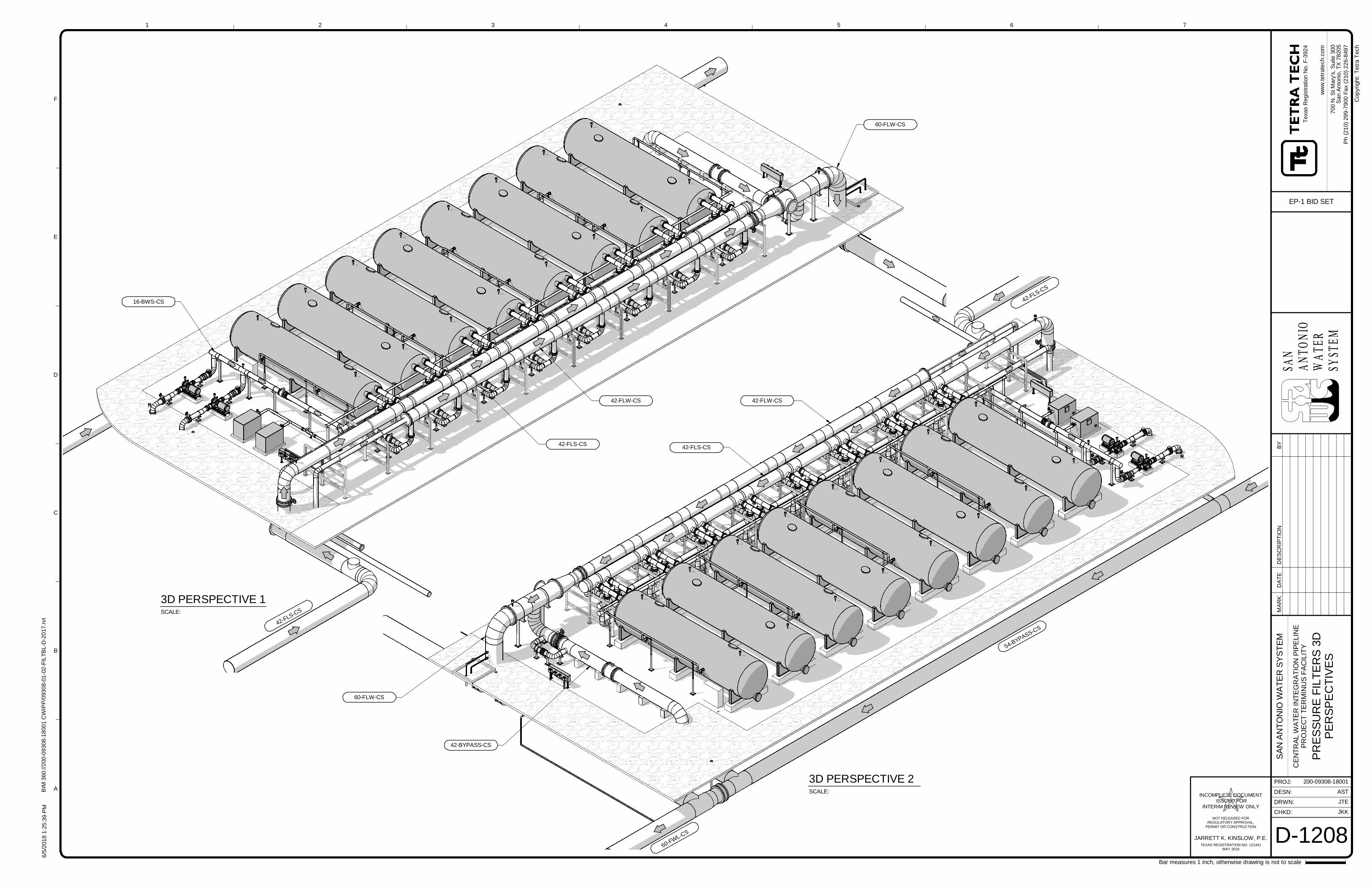
SAN
ANTO
NIO
WATE
RSY
STEM
CHKD:
DRWN:
PROJ:
DESN:
ww
w.t
etr
ate
ch.c
om
1
A
B
C
D
E
F
2 3 4 5 6 7
Bar measures 1 inch, otherwise drawing is not to scale
Cop
yrig
ht:
Tetr
aT
ech
JARRETT K. KINSLOW, P.E.
INCOMPLETE DOCUMENT ISSUED FOR
INTERIM REVIEW ONLY
NOT RELEASED FORREGULATORY APPROVAL,
PERMIT OR CONSTRUCTION
TEXAS REGISTRATION NO. 121441MAY 2018
6/5
/201
81
:25
: 39
PM
BIM
360
://2
00
-09
30
8-1
800
1C
WIP
P/0
93
08-0
1-0
2-F
ILT
BL-D
-20
17
.rvt
200-09308-18001
AST
JTE
JKK
D-1208
SA
NA
NT
ON
IOW
AT
ER
SY
ST
EM
CE
NT
RA
LW
AT
ER
INT
EG
RA
TIO
NP
IPE
LIN
EP
RO
JEC
TT
ER
MIN
US
FA
CIL
ITY
PR
ES
SU
RE
FIL
TE
RS
3D
PE
RS
PE
CT
IVE
S
Te
xas
Reg
istr
atio
nN
o.F
-392
4
70
0N
.S
tM
ary
's,
Su
ite30
0S
an
An
ton
io,T
X78
20
5
EP-1 BID SET
Ph
(21
0)
29
9-7
900
Fa
x(2
10
)2
26-8
49
7
SCALE:
3D PERSPECTIVE 1
SCALE:
3D PERSPECTIVE 2
42-FLW-CS
42-FLS-CS
42-FLS-CS
42-FLS-CS
42-FLW-CS
42-FLS-CS
16-BWS-CS
42-BYPASS-CS
60-FLW-CS
60-FLW-CS
54-BYPASS-CS
60-FWL-CS
MA
RK
DA
TE
DE
SC
RIP
TIO
NB
Y
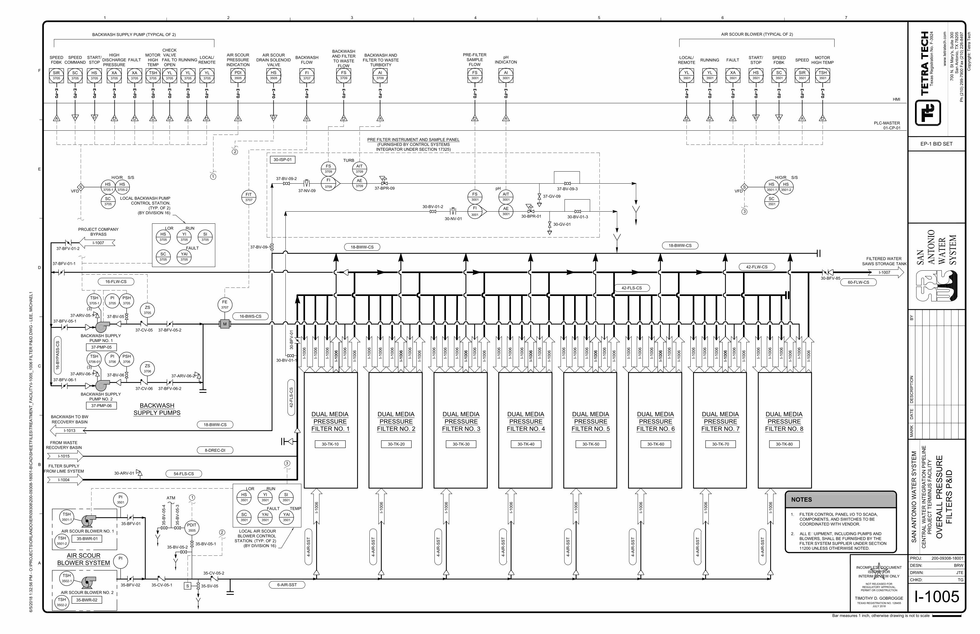
I-1004
FILTER SUPPLY
FROM LIME SYSTEM
DUAL MEDIA
PRESSURE
FILTER NO. 1
30
-B
FV
-0
1
6-AIR-SST
42-FLW-CS
16-BWS-CS
18-BWW-CS
30-TK-10 30-TK-20 30-TK-30 30-TK-40 30-TK-50 30-TK-60 30-TK-70 30-TK-80
42-FLS-CS
I-1015
FROM WASTE
RECOVERY BASIN
I-1
00
6
I-1
00
6
I-1
00
6
I-1
00
6
I-1
00
6
I-1
00
6
I-1
00
6
I-1
00
6
I-1
00
6
I-1
00
6
I-1
00
6
I-1
00
6
I-1
00
6
30-ISP-01
AE
3001
30-BV-01-2
30-NV-01
30-BV-01-3
30-GV-01
30-BPR-01
FS
3001
AIT
3001
pH
HS
3505
D
2
PDI
3505
AIR SCOUR
PRESSURE
INDICATION
A
1
AI
3001
pH
INDICATON
A
FS
3001
PRE-FILTER
SAMPLE
FLOW
D
YL
3501
LOCAL/
REMOTE
YL
3501
RUNNING
XA
3501
FAULT
HS
3501
START/
STOP
SC
3501
SPEED
FDBK
SIR
3501
SPEED
D D D A
AD
AIR SCOUR BLOWER (TYPICAL OF 2)
3
FI
3707
BACKWASH
FLOW
A
I-1
00
6
DUAL MEDIA
PRESSURE
FILTER NO. 2
DUAL MEDIA
PRESSURE
FILTER NO. 3
DUAL MEDIA
PRESSURE
FILTER NO. 4
DUAL MEDIA
PRESSURE
FILTER NO. 5
DUAL MEDIA
PRESSURE
FILTER NO. 6
DUAL MEDIA
PRESSURE
FILTER NO. 7
DUAL MEDIA
PRESSURE
FILTER NO. 8
I-1
00
6
PSH
3705
PSH
3706
AIR SCOUR BLOWER NO. 1
BACKWASH SUPPLY
PUMP NO. 1
37-BFV-05-1
37-BFV-06-1
37-CV-05 37-BFV-05-2
ZS
3705
37-CV-06 37-BFV-06-2
ZS
3706
M
35-CV-05-1
35
-B
V-0
5-3
35-BV-05-2
35-BV-05-1
PDIT
3505
ATM
35-SV-05
35-CV-05-2
S
37-BV-09-1
37-BV-06
FE
3707
BACKWASH
SUPPLY PUMPS
AIR SCOUR
BLOWER SYSTEM
30-BFV-85
35-BFV-01
37-BFV-01-1
16
-B
YP
AS
S-C
S
16-FLW-CS
18-BWW-CS
37-BFV-01-2
AIR SCOUR BLOWER NO. 2
35-BWR-01
35-BWR-02
35-BFV-02
35
-B
V-0
5-4
BACKWASH SUPPLY
PUMP NO. 2
37-PMP-05
37-PMP-06
37-BV-05
PI
3705
PI
3706
I-1007
PROJECT COMPANY
BYPASS
37-ARV-05-1
37-ARV-06-1
37-ARV-06-2
FIT
3707
YL
3705
LOCAL/
REMOTE
YL
3705
RUNNING
XA
3705
FAULT
XA
3705
HIGH
DISCHARGE
PRESSURE
HS
3705
START/
STOP
SC
3705
SPEED
COMMAND
SIR
3705
SPEED
FDBK
DDDDA
A D
BACKWASH SUPPLY PUMP (TYPICAL OF 2)
S
HS
3705-1
H/O/R
HS
3705-2
S/S
SC
3705
VFD
AI
3709
BACKWASH AND
FILTER TO WASTE
TURBIDITY
2
1
3
I-1013
BACKWASH TO BW
RECOVERY BASIN
I-1007
FILTERED WATER
SAWS STORAGE TANK
60-FLW-CS
4-A
IR
-S
ST
4-A
IR
-S
ST
4-A
IR
-S
ST
4-A
IR
-S
ST
4-A
IR
-S
ST
4-A
IR
-S
ST
4-A
IR
-S
ST
4-A
IR
-S
ST
37-BV-09-2
37-NV-09
FS
3709
AE
3709
37-BPR-09
AIT
3709
TURB
A
37-BV-09-3
37-GV-09
30-BV-01-1
42
-F
LS
-C
S
54-FLS-CS
HMI
PLC-MASTER
01-CP-01
TSH
3705
MOTOR
HIGH
TEMP
D
YL
3705
CHECK
VALVE
FAIL TO
OPEN
D
HS
3705
LOR
YI
3705
RUN
SI
3705
SC
3705
YAI
3705
FAULT
LOCAL BACKWASH PUMP
CONTROL STATION.
(TYP. OF 2)
(BY DIVISION 16)
TSH
3705-1
(3)
TSH
3706-01
(3)
TSH
3501-1
TSH
3502-1
PI
3501
PI
HS
3501
LOR
YI
3501
RUN
SI
3501
SC
3501
YAI
3501
FAULT
LOCAL AIR SCOUR
BLOWER CONTROL
STATION. (TYP. OF 2)
(BY DIVISION 16)
TSH
3501
MOTOR
HIGH TEMP
D
HS
3501-2
S/S
SC
3501
S
HS
3501-1
H/O/R
VFD
30-ARV-01
AIR SCOUR
DRAIN SOLENOID
VALVE
I-1
00
6
I-1
00
6
I-1
00
6
I-1
00
6
I-1
00
6
I-1
00
6
I-1
00
6
I-1
00
6
I-1
00
6
I-1
00
6
I-1
00
6
I-1
00
6
I-1
00
6
I-1
00
6
I-1
00
6
I-1
00
6
I-1
00
6
I-1
00
6
I-1
00
6
I-1
00
6
I-1
00
6
I-1
00
6
I-1
00
6
I-1
00
6
I-1
00
6
I-1
00
6
I-1
00
6
I-1
00
6
I-1
00
6
I-1
00
6
I-1
00
6
I-1
00
6
I-1
00
6
I-1
00
6
I-1
00
6
I-1
00
6
I-1
00
6
I-1
00
6
I-1
00
6
I-1
00
6
I-1
00
6
I-1
00
6
I-1
00
6
I-1
00
6
I-1
00
6
I-1
00
6
I-1
00
6
I-1
00
6
PRE FILTER INSTRUMENT AND SAMPLE PANEL
(FURNISHED BY CONTROL SYSTEMS
INTEGRATOR UNDER SECTION 17325)
18-BWW-CS
8-DREC-DI
FS
3709
BACKWASH
AND FILTER
TO WASTE
FLOW
D
TSH
3501-2
TSH
3502-2
YAI
3501
TEMP
FI
3001
FI
3709
CHKD:
DRWN:
PROJ:
DESN:
ww
w.te
tra
te
ch
.co
m
MA
RK
DA
TE
DE
SC
RIP
TIO
NB
Y
6/5
/2
01
8 1
:3
2:5
6 P
M - O
:\P
RO
JE
CT
S\O
RL
AN
DO
\IE
R\0
93
08
\2
00
-0
93
08
-1
80
01
-B
\C
AD
\S
HE
ET
FIL
ES
\T
RE
AT
ME
NT
_F
AC
IL
IT
Y\I-1
00
5_
10
06
F
IL
TE
R P
&ID
.D
WG
- L
EE
, M
IC
HA
EL
1
1
A
B
C
D
E
F
2 3 4 5 6 7
Co
pyrig
ht: T
etra
T
ech
Bar measures 1 inch, otherwise drawing is not to scale
200-09308-18001
CE
NT
RA
L W
AT
ER
IN
TE
GR
AT
IO
N P
IP
ELIN
E
PR
OJE
CT
T
ER
MIN
US
F
AC
ILIT
Y
SA
N A
NT
ON
IO
W
AT
ER
S
YS
TE
M
70
0 N
. S
t M
ary's, S
uite
3
00
Sa
n A
nto
nio
, T
X 7
82
05
Ph
(2
10
) 2
99
-7
90
0 F
ax (2
10
) 2
26
-8
49
7
Te
xa
s R
eg
istra
tio
n N
o. F
-3
92
4
SAN
AN
TON
IOW
ATE
RSY
STEM
TIMOTHY D. GOBROGGE
INCOMPLETE DOCUMENT
ISSUED FOR
INTERIM REVIEW ONLY
NOT RELEASED FOR
REGULATORY APPROVAL,
PERMIT OR CONSTRUCTION
TEXAS REGISTRATION NO. 128455
JULY 2018
I-1005
OV
ER
ALL P
RE
SS
UR
E
FILT
ER
S P
&ID
BRW
JTE
TG
EP-1 BID SET
NOTES
1. FILTER CONTROL PANEL I/O TO SCADA,
COMPONENTS, AND SWITCHES TO BE
COORDINATED WITH VENDOR.
2. ALL EQUIPMENT, INCLUDING PUMPS AND
BLOWERS, SHALL BE FURNISHED BY THE
FILTER SYSTEM SUPPLIER UNDER SECTION
11200 UNLESS OTHERWISE NOTED.
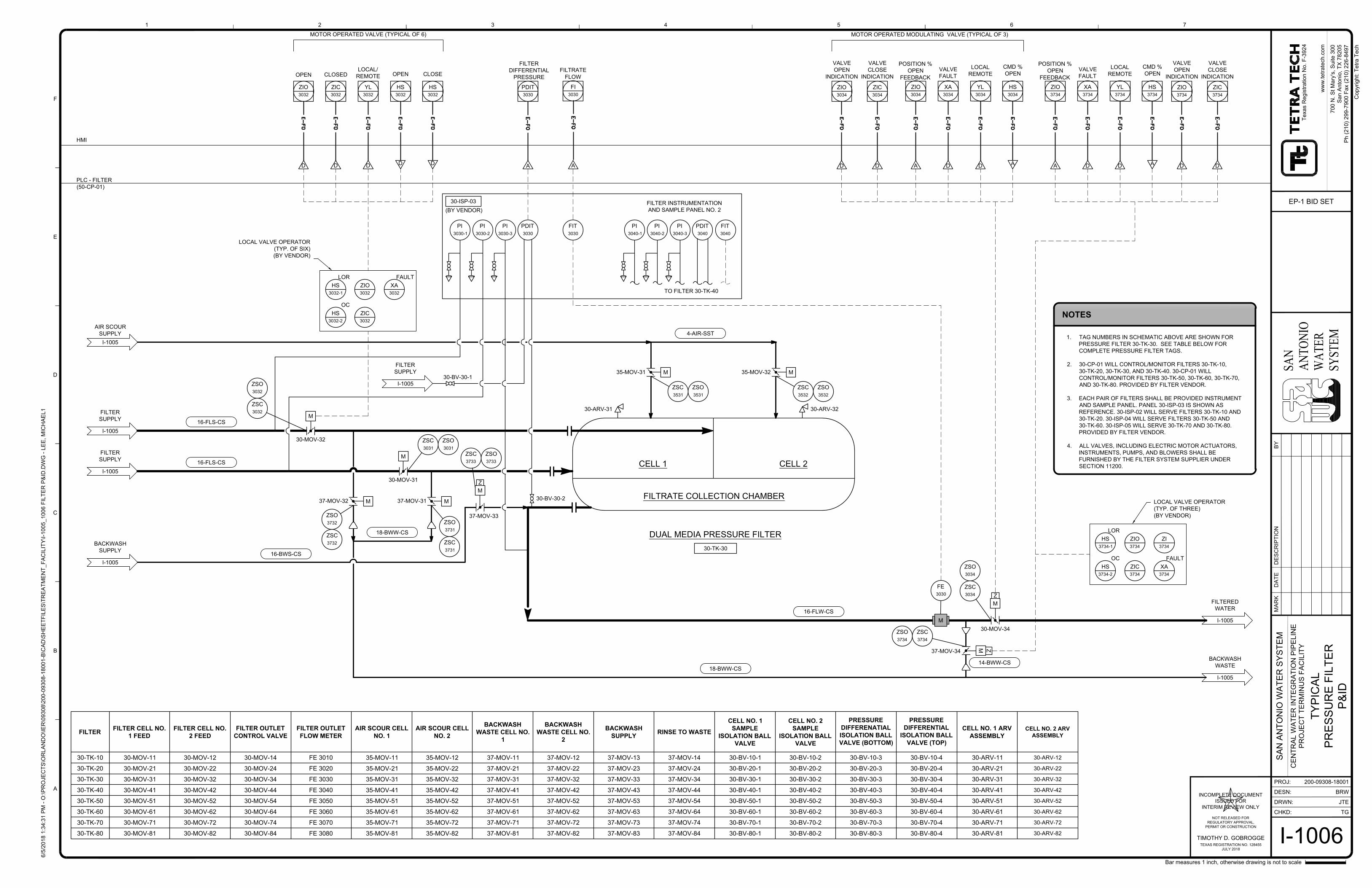
1. TAG NUMBERS IN SCHEMATIC ABOVE ARE SHOWN FOR
PRESSURE FILTER 30-TK-30. SEE TABLE BELOW FOR
COMPLETE PRESSURE FILTER TAGS.
2. 30-CP-01 WILL CONTROL/MONITOR FILTERS 30-TK-10,
30-TK-20, 30-TK-30, AND 30-TK-40. 30-CP-01 WILL
CONTROL/MONITOR FILTERS 30-TK-50, 30-TK-60, 30-TK-70,
AND 30-TK-80. PROVIDED BY FILTER VENDOR.
3. EACH PAIR OF FILTERS SHALL BE PROVIDED INSTRUMENT
AND SAMPLE PANEL. PANEL 30-ISP-03 IS SHOWN AS
REFERENCE. 30-ISP-02 WILL SERVE FILTERS 30-TK-10 AND
30-TK-20. 30-ISP-04 WILL SERVE FILTERS 30-TK-50 AND
30-TK-60. 30-ISP-05 WILL SERVE 30-TK-70 AND 30-TK-80.
PROVIDED BY FILTER VENDOR.
4. ALL VALVES, INCLUDING ELECTRIC MOTOR ACTUATORS,
INSTRUMENTS, PUMPS, AND BLOWERS SHALL BE
FURNISHED BY THE FILTER SYSTEM SUPPLIER UNDER
SECTION 11200.
30-ARV-32
30-MOV-32
30-MOV-31
37-MOV-32
37-MOV-33
I-1005
FILTER
SUPPLY
M
FE
3030
I-1005
FILTER
SUPPLY
I-1005
AIR SCOUR
SUPPLY
I-1005
BACKWASH
WASTE
I-1005
FILTERED
WATER
MM
M
M
DUAL MEDIA PRESSURE FILTER
CELL 1 CELL 2
35-MOV-31M M
PDIT
3030
FILTER
DIFFERENTIAL
PRESSURE
A
ZIO
3032
OPEN
ZIC
3032
CLOSED
YL
3032
LOCAL/
REMOTE
HS
3032
OPEN
HS
3032
CLOSE
D D D
D D
MOTOR OPERATED VALVE (TYPICAL OF 6)
16-FLS-CS
16-FLS-CS
18-BWW-CS
16-BWS-CS
18-BWW-CS
16-FLW-CS
4-AIR-SST
37-MOV-31
35-MOV-32
NOTES
30-TK-30
HMI
PLC - FILTER
(50-CP-01)
FILTRATE COLLECTION CHAMBER
30-ARV-31
I-1005
BACKWASH
SUPPLY
ZIO
3034
POSITION %
OPEN
FEEDBACK
XA
3034
VALVE
FAULT
YL
3034
LOCAL
REMOTE
HS
3034
CMD %
OPEN
A D
A
D
30-MOV-34
ZIO
3734
POSITION %
OPEN
FEEDBACK
XA
3734
VALVE
FAULT
YL
3734
LOCAL
REMOTE
HS
3734
CMD %
OPEN
A D
A
D
M
Z
37-MOV-34
30-ISP-03
HS
3032-1
LOR
ZIO
3032
XA
3032
FAULT
ZIC
3032
30-BV-30-1
30-BV-30-2
PI
3030-1
PI
3030-2
PI
3030-3
PDIT
3030
FIT
3030
PI
3040-1
PI
3040-2
PI
3040-3
PDIT
3040
FIT
3040
FI
3030
FILTRATE
FLOW
A
TO FILTER 30-TK-40
HS
3032-2
OC
ZSO
3032
ZSC
3032
LOCAL VALVE OPERATOR
(TYP. OF SIX)
(BY VENDOR)
ZSO
3031
ZSC
3031
ZSO
3732
ZSC
3732
ZSO
3731
ZSC
3731
ZSO
3733
ZSC
3733
ZSO
3531
ZSC
3531
ZSO
3532
ZSC
3532
ZSO
3734
ZSC
3734
ZSO
3034
ZSC
3034
HS
3734-1
LOR
ZIO
3734
XA
3734
FAULT
ZIC
3734
HS
3734-2
OC
LOCAL VALVE OPERATOR
(TYP. OF THREE)
(BY VENDOR)
ZI
3734
ZIO
3034
VALVE
OPEN
INDICATION
ZIC
3034
D D
VALVE
CLOSE
INDICATION
ZIO
3734
VALVE
OPEN
INDICATION
ZIC
3734
D D
VALVE
CLOSE
INDICATION
I-1005
FILTER
SUPPLY
FILTER INSTRUMENTATION
AND SAMPLE PANEL NO. 2
14-BWW-CS
(BY VENDOR)
M
Z
M
Z
MOTOR OPERATED MODULATING VALVE (TYPICAL OF 3)
CHKD:
DRWN:
PROJ:
DESN:
ww
w.te
tra
te
ch
.co
m
MA
RK
DA
TE
DE
SC
RIP
TIO
NB
Y
6/5
/2
01
8 1
:3
4:3
1 P
M - O
:\P
RO
JE
CT
S\O
RL
AN
DO
\IE
R\0
93
08
\2
00
-0
93
08
-1
80
01
-B
\C
AD
\S
HE
ET
FIL
ES
\T
RE
AT
ME
NT
_F
AC
IL
IT
Y\I-1
00
5_
10
06
F
IL
TE
R P
&ID
.D
WG
- L
EE
, M
IC
HA
EL
1
1
A
B
C
D
E
F
2 3 4 5 6 7
Co
pyrig
ht: T
etra
T
ech
Bar measures 1 inch, otherwise drawing is not to scale
200-09308-18001
CE
NT
RA
L W
AT
ER
IN
TE
GR
AT
IO
N P
IP
ELIN
E
PR
OJE
CT
T
ER
MIN
US
F
AC
ILIT
Y
SA
N A
NT
ON
IO
W
AT
ER
S
YS
TE
M
70
0 N
. S
t M
ary's, S
uite
3
00
Sa
n A
nto
nio
, T
X 7
82
05
Ph
(2
10
) 2
99
-7
90
0 F
ax (2
10
) 2
26
-8
49
7
Te
xa
s R
eg
istra
tio
n N
o. F
-3
92
4
SAN
AN
TON
IOW
ATE
RSY
STEM
TIMOTHY D. GOBROGGE
INCOMPLETE DOCUMENT
ISSUED FOR
INTERIM REVIEW ONLY
NOT RELEASED FOR
REGULATORY APPROVAL,
PERMIT OR CONSTRUCTION
TEXAS REGISTRATION NO. 128455
JULY 2018
I-1006
TY
PIC
AL
PR
ES
SU
RE
F
ILT
ER
P&
ID
BRW
JTE
TG
EP-1 BID SET
FILTER
FILTER CELL NO.
1 FEED
FILTER CELL NO.
2 FEED
FILTER OUTLET
CONTROL VALVE
FILTER OUTLET
FLOW METER
AIR SCOUR CELL
NO. 1
AIR SCOUR CELL
NO. 2
BACKWASH
WASTE CELL NO.
1
BACKWASH
WASTE CELL NO.
2
BACKWASH
SUPPLY
RINSE TO WASTE
CELL NO. 1
SAMPLE
ISOLATION BALL
VALVE
CELL NO. 2
SAMPLE
ISOLATION BALL
VALVE
PRESSURE
DIFFERENATIAL
ISOLATION BALL
VALVE (BOTTOM)
PRESSURE
DIFFERENTIAL
ISOLATION BALL
VALVE (TOP)
CELL NO. 1 ARV
ASSEMBLY
CELL NO. 2 ARV
ASSEMBLY
30-TK-10 30-MOV-11 30-MOV-12 30-MOV-14 FE 3010 35-MOV-11 35-MOV-12 37-MOV-11 37-MOV-12 37-MOV-13 37-MOV-14 30-BV-10-1 30-BV-10-2 30-BV-10-3 30-BV-10-4 30-ARV-11 30-ARV-12
30-TK-20 30-MOV-21 30-MOV-22 30-MOV-24 FE 3020 35-MOV-21 35-MOV-22 37-MOV-21 37-MOV-22 37-MOV-23 37-MOV-24 30-BV-20-1 30-BV-20-2 30-BV-20-3 30-BV-20-4 30-ARV-21 30-ARV-22
30-TK-30 30-MOV-31 30-MOV-32 30-MOV-34 FE 3030 35-MOV-31 35-MOV-32 37-MOV-31 37-MOV-32 37-MOV-33 37-MOV-34 30-BV-30-1 30-BV-30-2 30-BV-30-3 30-BV-30-4 30-ARV-31 30-ARV-32
30-TK-40 30-MOV-41 30-MOV-42 30-MOV-44 FE 3040 35-MOV-41 35-MOV-42 37-MOV-41 37-MOV-42 37-MOV-43 37-MOV-44 30-BV-40-1 30-BV-40-2 30-BV-40-3 30-BV-40-4 30-ARV-41 30-ARV-42
30-TK-50 30-MOV-51 30-MOV-52 30-MOV-54 FE 3050 35-MOV-51 35-MOV-52 37-MOV-51 37-MOV-52 37-MOV-53 37-MOV-54 30-BV-50-1 30-BV-50-2 30-BV-50-3 30-BV-50-4 30-ARV-51 30-ARV-52
30-TK-60 30-MOV-61 30-MOV-62 30-MOV-64 FE 3060 35-MOV-61 35-MOV-62 37-MOV-61 37-MOV-62 37-MOV-63 37-MOV-64 30-BV-60-1 30-BV-60-2 30-BV-60-3 30-BV-60-4 30-ARV-61 30-ARV-62
30-TK-70 30-MOV-71 30-MOV-72 30-MOV-74 FE 3070 35-MOV-71 35-MOV-72 37-MOV-71 37-MOV-72 37-MOV-73 37-MOV-74 30-BV-70-1 30-BV-70-2 30-BV-70-3 30-BV-70-4 30-ARV-7130-ARV-72
30-TK-80 30-MOV-81 30-MOV-82 30-MOV-84 FE 3080 35-MOV-81 35-MOV-82 37-MOV-81 37-MOV-82 37-MOV-83 37-MOV-84 30-BV-80-1 30-BV-80-2 30-BV-80-3 30-BV-80-4 30-ARV-8130-ARV-82