Embed Size (px)
Citation preview
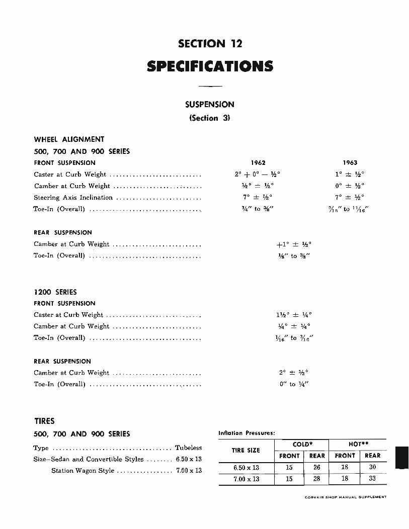
SECTION 12
SPECIFICATIONS
SUSPENSION
(Section 31
WHEEL ALIGNMENT
500, 700 AND 900 SERIES
FRONT SUSPENSION
Caster at Curb Weight . ... ....... ....•.• .. .. .. •.. .
Camber at Curb Weight ..... . ...... .. .... . . : ..... .
Steering Axis Inclination ....•..........•. •. .. ... •.
Toe-In (Overall) ... . . ... . ........ • ....... . •.... .. ..
REAR SUSPENSION
Camber at Curb Weight ............. . ........... ..
Toe-In (Overall) .................... . .•... . ....•..
1200 SERIES
FRONT SUSPENSION
Caster at Curb Weight ...... •.•.... . .. . ..•.... .... .
Camber at Curb Weight ..... .. ................... .
Toe-In (Overall) ........ .....•........•.• ... .. .•.•
REAR SUSPENSION
Camber at Curb Weight .... ... . .. . . .•. . . . ... . .....
Toe-In (Overall) . ..... ........ . • .•.• ...... . '. ' . ....
TIRES
500, 700 AND 900 SERIES
Type Tubeless
1962
2° + 0° - 'h0
'h 0 ± 'h0
7° ± lh o
1f4" to %"
Inflation Pressures:
TIRE SIZE
+1° ± 'h 0
¥a" to %"
l 1h O ± J{4 °
%0 ± %0
VI6" to o/tG"
2° ± 'h 0
0" to 1f4"
COLD-
Size-Sedan and Convertible Styles ... . .. . . 6.50 x 13 FRONT REAR
Station Wagon Style ... . ............ . 7.00 x 13 6.50 x 13 15 26
7.00 x 13 15 28
1963
1 0 ± lh o
0° ± 'h0
7° ± th o
7'1 u" to 1 !It 0"
HOT"
FRONT REAR
18 30
18 33
CORV"IR S H OP MANUAL. SUPPL.EMENT
I
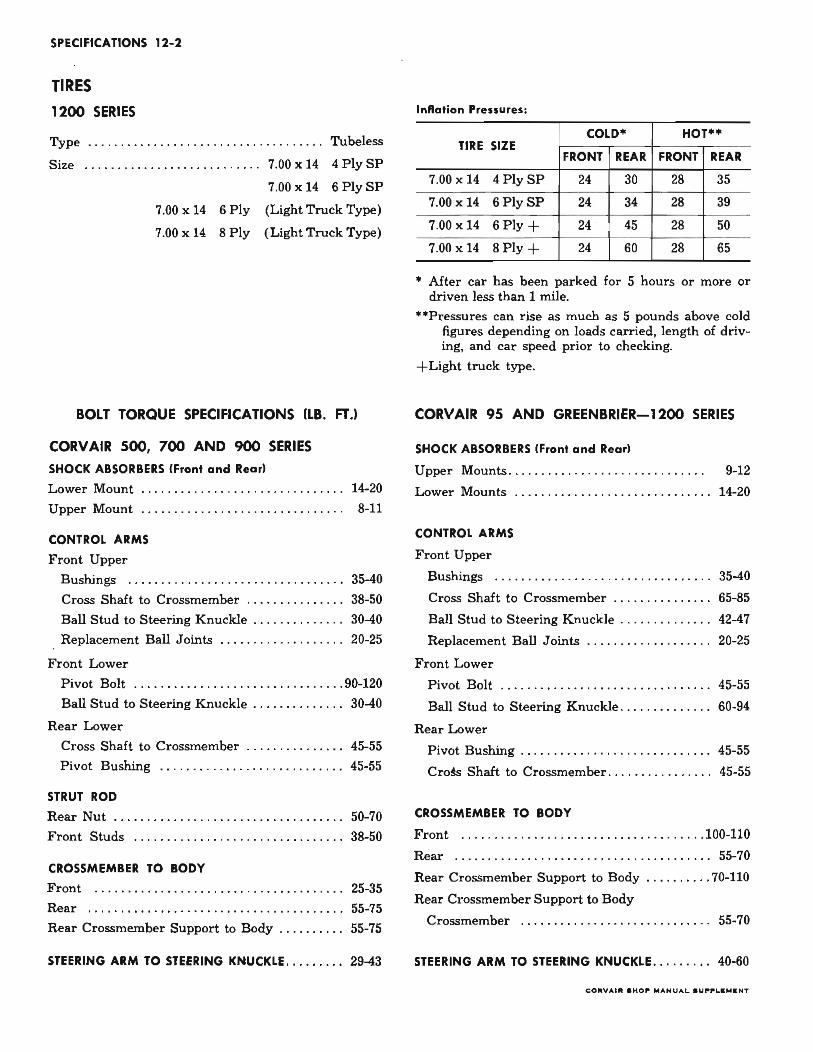
SPECIFICATIONS 12-2
TIRES
1200 SERIES
Type .. ... . .. .. •. . . .... ...•.... .... . . .... Tubeless
Size .... .. ...•.•... .... . .. . .... 7.00 x 14 4 Ply SP
7.00 x 14 6 Ply SP
7.00 x 14 6 Ply (Light Truck Type)
7.00 x 14 8 Ply (Light Truck Type)
BOLT TORQUE SPECIFICATIONS (LB. FT.)
CORVAIR 500, 700 AND 900 SERIES
SHOCK ABSORBERS (Front and Rearl
Lower Mount .. ........... .... ..... . . . . . .... 14-20
Upper Mount ........ .. . . . . .. .. .. . . . ...... .. 8-11
CONTROL ARMS
Front Upper
Bushings .. .. . ................ . . .... ... . . . 35-40
Cross Shaft to Crossmember ... ... .. .. . .... 38-50
Ball Stud to Steering Knuckle .. ..... .... . .. 30-40
Replacement Ball Joints ........ ..... . . .... 20-25
Front Lower
Pivot Bolt ........ ...... ......... . . .. ..... 90-120
Ball Stud to Steering Knuckle . . . . . . . . . . . . .. 30-40
Rear Lower
Cross Shaft to Crossmember ..... . ......... 45-55
Pivot Bushing 45-55
STRUT ROD
Rear Nut ...... . . . ... ........ .....•. ... .. ... 50-70
Front Studs .............. ....... . . ..... . .. . 38-50
CROSSMEMBER TO BODY
Front .......... ......... . . ... .. .. ... ....... 25-35
Rear .. . . ...... . .. ........ ... ......... •. •.. . 55-75
Rear Crossmember Support to Body .... ..... . 55-75
STEERING ARM TO STEERING KNUCKLE ... .... .. 29-43
InRation Pressures:
COLD' HOT" TIRE SIZE
FRONT REAR FRONT REAR
7.00 x 14 4 PlySP 24 30 28 35
7.00 x 14 6 PlySP 24 34 28 39
7.00 x 14 6Ply+ 24 45 28 50
7.00 x 14 8Ply+ 24 60 28 65
• After car has been parked for 5 hours or more or driven less than 1 mile.
··Pressures can rise as much as 5 pounds above cold figures depending on loads carried, length of driving, and car speed prior to checking.
+ Light truck type.
CORVAIR 95 AND GREENBRIER-1200 SERIES
SHOCK ABSORBERS (Front and Rear)
Upper Mounts.. .......... . ... . ........... .. 9-12
Lower Mounts ..... .. .. . ...•... • . • .......... 14-20
CONTROL ARMS
Front Upper
Bushings ........... . ............•...•.... 35-40
Cross Shaft to Crossmember .... . ...... . . .. 65-85
Ball Stud to Steering Knuckle ... .... . . .. ... 42-47
Replacement Ball Joints
Front Lower
20-25
Pivot Bolt .. ..... ....... ..... . ... •... ... .. 45-55
Ball Stud to Steering Knuckle . . . . . . . . . . . . .. 60-94
Rear Lower
Pivot Bushing . . . . . . . . . . . . . . . . . . . . • . . . . . . . . 45-55
Cro~ Shaft to Crossmember . . . . . . . . . . . . . . .. 45-55
CROSSMEMBER TO BODY
Front .. ... ................. • .. .. . ... . . ... . 100-110
Rear . .... ........ .. . ... .. . ................. 55-70
Rear Crossmember Support to Body ..... . .... 70-110
Rear Crossmember Support to Body
Crossmember .................. . ........ . . 55-70
STEERING ARM TO STEERING KNUCKLE . ........ 40-60
COIllV ...... • HO~ MANUAL SUPPLI: ... IlNT
SPECIFICATIONS 12-3
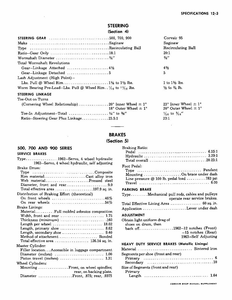
STEERING (Section 41
STEERING GEAR .. .. ....... . .. . ........ .... ..... 500, 700, 900 Corvair 95 Saginaw Recirculating Ball 20:1
Make . . .... ......... ... .. ... .... .... .. .. ..... .. Saginaw Type ... . ......... ... . . .. ..... .... . ............ Recirculating Ball Ratio- Gear Only .. ..... . ... ....... . . .. . ..... ... 18:1 Wormshaft Diameter .. .. .... . .... ... ..... .•..... %" Total Wormshaft Revolutions
Gear- Linkage Attached ....... .. . . ... . . ...... 4 'h Gear-Linkage Detached .. ... .. ........... ... . 5
Lash Adjustment (High Point) -
%"
4'h 5
Lbs. Pull @ Wheel Rim .... .... .... .......... .. l 'A1 to 1'h lbs. 1 to Ph lbs. 'h to % lb. Worm Bearing Pre-Load- Lbs. Pull @ Wheel Rim .. ~G to 1 Y,6 lbs.
STEERING LINKAGE
Toe-Out on Turns (Cornering Wheel Relationship) ....... . .•. . .... 200 Inner Wheel ± 10
180 Outer Wheel ± 10
23 0 Inner Wheel ± 10
200 Outer Wheel ± 10
Toe-In Adjustment- Total . ... . .. .. .... .. .. .... V4" to 'MI" YtG to %0" Ratio-Steering Gear Plus Linkage ...... . ...... . 23.5:1 23:1
BRAKES (Section 5)
500, 700 AND 900 SERIES SERVICE BRAKES
Type .. ............. . . 1962- Servo, 4 wheel hydraulic 1963-Servo, 4 wheel hydraulic, self adjusting
Brake Drum: Type .. .... .......... .. . . . .... . . . . .... Composite Rim material. ....... .... ...... .. .. Cast alloy iron Web material. . .... . ....... . . ... ... . Pressed steel Diameter, front and rear ...... .. .... .. .. .. .... 9.0 Total effective area ............ . ....... 197.9 sq. in.
Distribution of Braking Effort (theoretical) On front wheels ... . .... . ................ .. .46% On rear wheels .... ... ......... .. .......... 54%
Brake Linings: Material. ....... .. Full molded asbestos composition Width, front and rear .................... . .. 1.75 Thickness (minimum) ...... .. ....... . ..... .. . 160 Length per wheel ...... . . . . . . . . . . . . . . . . . . . . 18.02 Length, primary shoe .... ....... . . . . . . . . . . .. 8.62 Length, secondary shoe . . . . . . . . • . • . . . . . . . . . . . 9.40 Method of attachment. . . . . . . . . . . . . . . . . . . . Bonded Total effective area .. .. .... . ......... 126.14 sq. in.
Master Cylinder: Filler location ... Accessible in luggage compartment Diameter (inches) .. . . . ... ... . .... .. .. .. .... 1.00 Piston travel (inches) ...... . ..... . ......... . 1.31
Wheel Cylinders: Mounting .... ........... . Front, on wheel spindles;
rear, on backing plate. Diameter ... . . • . . . . ... . .... Front, .875; rear, .9375
Braking Ratio: Pedal . .................................. . 6.15:1 Hydraulic . . . . . . . . . . . . . .. . . .. . .. . .. .. .. . . . . 3.29:1 Total overall . . .. • . . . .. . .... ... ... ... ..... . 20.23:1
Foot Pedal: Type .. .. .. .. .......... . ...... . . . .. . ... Pendant Mounting .. .......... .... .... On brace under dash Line pressure @ 100 lb. pedal load .... ... ... 783 psi Travel . ..........• ...... ........ . .. ...... .. 6.00
PARKING BRAKE
Type ...... ... Mechanical pull rods, cables and pulleys operate rear service brakes.
Total Effective Lining Area . ... . . . . . . . . . . .. 60 sq. in. Application ..... . .. ... . .. ... . .. ... Lever under dash
ADJUSTMENT Obtain light uniform drag of
shoes on drum, then back off ........ . . .. . . .. .. 1962- 12 notches (Front)
-15 notches (Rear) 1963-Self Adjusting
HEAVY DUTY SERVICE BRAKES (Metallic Llnlng.1
Material . . . . . . . . . . . . . . . . . . . . . . . . . . . .. Sintered iron Segments per shoe (front and rear)
Primary ........... ........... .. .. .. ....... .. 6 Secondary . . ............ ... . .. .... ....... . .... 10
Size of Segments (front and rear) Primary
Length ..... . .. . . ... ...... ... ... . ..... . .. 1.64
COIIVAIIt .HO~ MANUAL . U~P'LIUI II:NT
SPECIFICATIONS 12-4
Width . ..... ........ . .. . .. . ... . . .. . . . . .. . 0.87 Thickness .. .... . ... .•... .. .....•.... 1962-0.21
1963-.175 Secondary Length . . . . . ..... ... . .• . •..... . . . •... . ... .. 1.64
Width . . ... .... ... ..• . •.. .. ..• . ........ .. 0.87 Thickness ..........•. .... ..... ... ... 1962-0.33
1963- 0.295 Method of attachment ........ . . Each segment welded
two places Effective Area, approximate (square inches) .... 91.31
ADJUSTMENT
Obtain light uniform drag of shoes on drum, then back off . .. . ......... . .... 1962-12 notches (front)
1200 SERIES SERVICE BRAKES
-15 notches (rear) 1963-Self Adjusting
TYpe .... .. ....... 1962- Duo-servo, 4 wheel hydraulic 1963-Duo-servo, 4 wheel hydraulic- self adjusting
Brake Drum Rim material ...... .. .. . . .. ... .. .. . Cast alloy iron Web material ...... .... . ..• .. .. .. .. . Pressed steel Diameter, front and rear .... .. . .... . .... .. .. 10.955 Total effective area .. .. . . .. .. : ... .. .. 275.33 sq. in.
Brake Linings Material . ... ... . • . . .•. • .. .. .. Full molded asbestos
Width, front and rear . . .. . ...... .. .. ... 1962-2.155 1963- 2.000
Thickness Primary facing .. .. ... . . . . . . .. . ..... .. ... . .168 Secondary facing .. . .. . ... ... . ..... . . 1962-.164
1963-.168 Method of attachment . ... .. . ........ .... . . Bonded Shoe anchor .... .. . . .. . .. ..... Peened fixed anchor Total effective area . . . . .... .. . . .. .. . . 167.10 sq. in.
Master Cylinder Diameter .. . . .... .. ..... . .. .... .. . ... ...... 1.00 Make .... ..... . .. . . .... ...... . . . ... ... . Moraine Push rod travel .... . . . . .. .... . . . . . . . . . . . . .. 1.329
Wheel Cylinder Diameter .. .... ...... . .. : .. Front, 1.125; Rear 1.00 Brake Distribution ........ . ..... Front 50% ± 2%
Rear 50% ± 2% Braking Lever Ratios
Pedal ratio ... . .. .... . . .. .. . . . . ... . .. . . . .. .. . . 6.8 Hydraulic ......... . . . ..... . . . . . . . . . . • . . . .. 4.52 Overall ...... .. .. • . . . .. . . . •... •. ... ....... 30.74
PARKING BRAKE Type . . ............ .. .. ... ... . Mechanical pull type,
cables to rear service brakes Total effective lining area .. . ....... 1962- 83.40 sq. in.
1963-83.55 sq. in. Control ...... .. ..... . ....... . .... Lever under dash
ADJUSTMENT Obtain light uniform drag of
shoes on drum, then back off .. .... 1962-12 notches 1963-Self Adjusting
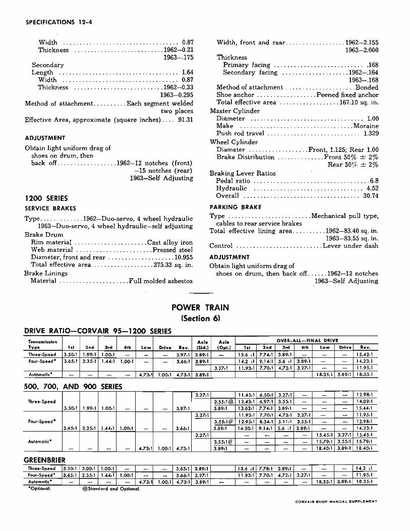
POWER TRAIN (Section 6)
DRIVE RATIO-CORVAIR 95-1200 SERIES Tranlmiuktn A.I. Axl. OVER-ALL FINAL DRIYE
Type h' 2nd 3,d •• h low Drive Rev. (Std.) (Opt.) lot 2nd 3,d •• h low Drlv. Rev.
Three-Speed 3.50,1 1.99,. 1.0011 - - - 3.9711 3 .8911 - 13.6 d 7.7411 3.89:1 15."2:1 Four·Speed· 3.65,\ 2.35,1 1."",1 1.00, \ - - 3.66,1 3.89,\ 14.2 , \ 9.14,\ 5.6 " 3.89,\ 14.23"
3 .2711 11.9311 7.70,1 .... 72:1 3.2711 11.95:1 Automatic· ".73,1 1.00:1 .... 73,1 3.89,1 18:35.1 3 .8911 18,35.1
500, 700, AND 900 SERIES 3.27, \ 11. ... 5,1 6.50,' 3.27,\ '2.98,'
Three. Speed 3.55, ' @ \2.43,\ 6 .9711 3.55,\ - - - 1".09:1 3.50,' 1.99,' 1.00:1 3.97,1 3.89, ' 13.62:1 7.7411 3.89:1 - - 15.44:1
3.27,' 11 .93:1 7.7011 4.72:1 3.27:1 - - 11.95:1 four-Speed · 3.5511@ 12.9511 8.3411 5.\',1 3.55:1 - - 12.98:1
3.6511 2.3511 1 ..... 11 1.0011 - 3.66:1 3.8911 1".20:1 9.1411 5.6 " 3.8911 - - 14.23,\
3.27,\ - - - - \5.45, ' 3.2711 \5.dS,' Automatic · 3.55,\ @ - - - \ 5.79" 3.55" 15.79:1
- - - - 4.73, \ 1.00:1 " .73:1 3.8911 - 18.40:1 3.8911 18."011
GREENBRIER Three-Speed 3.5011 2.00.1 1.0011 3.6511 3.89, \ \3.6 " 7.7811 3.89,\ '4.2 " four-Speed· 3.6511 2.35, ' 1."411 1.00,\ 3.66,' 3.2711 11.93,' 7.70,\ 4.72,' 3.27,\ 11.95,' AlIf'Omatic· 4.73:1 1.00:1 4.73, \ 3.89:1 18.35:' 3.8911 18.35,' • Optional. @ Standard and OptiOnal.
CO lilY AI III SHO .. "'ANUAL .u .... U :JllllIENT

Engine
GENERAL DATA: Horsepower @ rpm
Torque @ rpm
Type
Number of Cylinders
So,.
Stroke
Ta xable Horsepo ..... er (A.M.A.J
No. System I Left Bonk
(Reor to Front) I Right Bonk
f iring Order
Comprenion Ratio
PISTONS:
Clearance Umils Top land
Skirt
Compression Ring Groove Depth
Oil
PISTON RINGS: Width
Compronion Gop
Width Oil Ring
Gop
Expande rs
PISTON PINS l ength
Diameter
I New In Piston
I Weor limi' Cleorance
In Rod
CONNECTING RODS:
Clearance Bearing
End Play
CRANKSHAFT: End Play
End Thrust Taken by
1 & 2
Moin Beoring Journal Diameter 3&4
1 & 2
Clearance 3&4
Crankpin Journal Diameter
CAMSHAFT: Lob e Lift Measured Intake
at Push Rod Exhaust
I 1-3 Journal Diam eter I 4 Type of Drive
ENGINE (Section 6Al
Turbo~Ai,
80 @ "00
128 @ 2300
8.0,1
.209
.229
SPECIFICATIONS 12-5
Sup.r Sup.r Char.~ Monzo -P.G. Turbo-Air Spyd.r
84 @ 4400 102 @ .. OO 150 @ 4400
134 @ 210 @ 130 @ 2300 2800·3000 3200-3400
Valve-in-Head-Opposed
6
3 !I.
2,60
22.5
2·"'·6
1·3·5
1-4-5-2-3-6
9.0 ,1 9.0 :1 1 8.0,1
.022-.031
,0011 -.0015
.179-,187
.180-. 188
.077·.078
.010-.020
.1860·.1865
.010-.020
Y ••
2.630-2.650
.7999-.8002
.000IS-.0002S
.001
Press Fit
,0007-.0027
.005·.010
.002-.006
No. 1 Main
2.0978-2.0988
2.0983·2.0983
.0012·.0027
,0007·,0022
1.799·1.800
I .252
I .252
1.1995· 1.2005
1.4395·1.4405
Gear
caRVA1R SHOP "'ANUAL a UPPLI:"'ENT
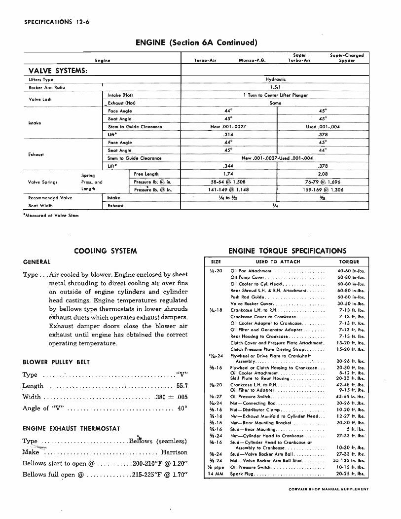
SPECIFICATIONS 12-6
ENGINE (Section 6A Continued)
Engln.
VALVE SYSTEMS: Lifters Type
Rocker Arm Ratio
Intake (Hotl Volve Lad!
.. Exhoust (Hot)
Foce Angle
Intolee Seal Angle
Stem to Guide Cleoronce
lift·
Foce Angle
Exhaust Seat Angle
Stem to Guid e Cleorance
lift·
Spring Free Length
Volve Springs Press. and P,enure lb. @ in.
Length Pressure lb. @ in.
Recommend~d Volve Intoke
Seat Width Exhoust
· Meolured at Vo l ... e Stem
COOLING SYSTEM GENERAL
Type .. . Air cooled by blower. Engine enclosed by sheet metal shrouding to direct cooling air over fins on outside of engine cylinders and cylinder head castings. Engine temperatures regulated by bellows type thermostats in lower shrouds exhaust ducts which operates exhaust dampers. Exhaust damper doors close the blower air exhaust until engine has obtained the correct operating temperature.
BLOWER PUllEY BELT
Type . . . ... ,' . . ... . . .... . . .. .. . .. . • . • .. . . .... .. "V"
Length ....... .... .. ...... ... ... ' . ... ... .. . ... . . 55.7
Width .. . . . . . . . . . . . • . • . • . . . . . . . . • . • . . .. .380 ± .005
Angle of "V" .. .. .... . . . _ . _ . . . . . . . . . . . . . . . . . .. 40°
ENGINE EXHAUST THERMOSTAT
Type .. ............ .. ....... ... . Berrows (seamless) .~
!dake ... . . ... .. . ...... . . . . ... . .... . . .. ... Harrison
Bellows start to open @ . . . . . ... . .. 200-210°F @ 1.20"
Bellows full open @ . ... .. . • . _ . . . . 215-225°F @ 1.70"
-
Sup., Sup.r-Charged Turbo-~\lr MonJ:a.P.G. Turbo-Air Spyd.r
Hydraulic
1.Sd
1 Tum to Ce nter lifter Plunger
Some
44° .5· .s. .5·
New.001 -.0027 Used ,DO 1 -.004
.314 .378
••• .5·
.s. • •• New ,OOI-,D027-Used .001-.004
.3 .... .378
1.7. 2.08
58·6' @ LS08 76·79 @ 1.696
UI-U9 @ 1.148 159-169 @ 1.306
~ to%r l\,
SIZE
1A.20
!O.-18
1~.2"
~-16
!O.
ENGINE TORQUE SPECIFICATIONS USED TO ATTACH
Oil Pan A"achment ..... .. ....... . Oil Pump Ca ... er . .......... .
Oil C~er to Cyl. Head ... .
Rear Shroud l .H. & R.H. A"amment ..... . .
Pulh Rod Guide .. . Valve' Rocker Co ... er .
Crankea.e LH. to R.H . ...............••.
Crankcase Cover to Crar~eale ... O il C~er Adapter to Crankcase ..
Oil Filter and Generator Adapter .
Rear Housing to Crankcase ....... . ..... .
Clutch Cover and Pressure Plate Attammen, . Clutch Pressure Plate Driving Strop ....... .
Flywheel or Ori .... Plate to Crankshaft Auembry .... . . ......... .
Fly ..... heel or Clutch Housing to Crankcase .. . Oil Cooler A"achment ................. . Skid Plate to Rear Housing ............ .
Crankea.e l.H. to R.H . ..........••...•.. Oil Filter to Adopter . Oil Pressure S ..... itch . ....
Nut-Connecting Rod .................. . Nut - Di.tributor Clomp .......... .
TORQUE
"0·60 in·lb •. 60·80 in·lb •.
60·80 in·lb •. 60·80 in·lb •.
60·80 in·lb •.
30·50 in·lb .. 7·13 ft. lb •.
7 · 13 ft. /b ..
7 · 13 ft. lb .. 7·13ft. lb ..
7·13ft.lb ..
15·20 ft. Ibs. 15·20 ft. lb ••
20·26 ft. lb •. 20·30 fl. lb ••
8·12 ft. lb •• 20· 30 ft. Ib ...
"2·"8 ft. lb •. 9·15 ft. lb •.
% ·16 Nut- Exhaust Manifold to Cylinder Head ...
"5·65 in. lb •• 20· 26 ft .. lb ••
10· 20 ft. Ibs.. 12·27 ft. Ib,. 20·30 ft. lb •. ~-16
%-16
~-2' %·16
~-2' ~-2'
1ft pipe 1.( MM
Nut-Rear Mounting Brockel. . .
Stud-Rear Mounting .......... . ....... . Nut-Cylinder Head to Crankea.e ..... .
Sh.ld-Cylinder Head to Crankea.e at Auembly to Crankea.e ..... .
Sh.ld-Valve Rocker Arm Ball . ... ..... . . . Nut-Val .... Rocker Arm Ball Sh.ld .. . ... • ..
Oil Pr.u",r. Swilm ... .
Spark Plug ........................ .
5 ft. Ib .. 27· 33 ft. lb.:
10-30 ft. lb •. 27·33 ft. Ib,.
55·125 In. Ib .. 10· 15 ft. lb .. 20· 25 ft. Ibs.
CORVAIR .HO~ MANUAL .U~~LI!:MI!:NT
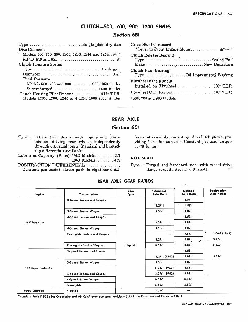
SPECIFICATIONS 12-7
CLUTCH-Soo, 700, 900, 1200 SERIES
(Section 681
Type .. .. ........ ........... . .. . Single plate dry disc Cross-Shaft Outboard Disc Diameter · Lever to Front Engine Mount .. .. .... .... %"-%"
Models 500, 700, 900, 1205, 1206, 1244 and 1254 .. 9%" R.P.O. 649 and 651 ........ .. .. .. ... .. . ...... .. 8"
Clutch Release Bearing . Type .... . ... . . .. . . ... ..... • ......... Sealed Ball
Clutch Pressure Spring . Make . . .. . .. . ...... : .. ~ .......... New Departure Type . . ... ...... .... . . . .•......... . .. Diaphragm D iameter ...... .... . ..... . .. ..... .. ... .... 9%" Total Pressure
Models 500, 700 and 900 ......... 900-1050 ft. lbs. Supercharged .... . ... . .............. 1500 ft. lbs.
Clutch Housing Pilot Runout . . . . . . . . . . .. .015" T.I.R.
Clutch Pilot Bearing Type ..... . .. .. .... ..... . Oil Impregnated Bushing
Flywheel Face Runout, Installed on Flywheel ... . . ..... . . ... . .020" T.I.R.
Flywheel O.D. Runout .. ..... . .. .... . .. .. 010" T.I.R.
Models 1205, 1206, 1244 and 1254 1000-2000 ft. lbs. *500, 700 and 900 Models
REAR AXLE
(Section 6CI
Type ... Differential integral with engine and transmission, driving rear wheels independently through universal joints. Standard and limitedslip differentials available.
Lubricant Capacity (Pints) 1962 Models .... .... .. 3.1 1963 Models .. ...... . 4'h
POSITRACTION DIFFERENTIAL . ....... . . . ..... . Constant pre-loaded clutch pack in right-hand dif-
ferential assembly, consi.;ting of 5 clutch plates, providing 5 friction surfaces. Constant pre-load torque: 50-70 ft. lbs. .
AXLE SHAFT
Type .. . Forged and hardened steel with wheel drive flange forged integral with shaft.
REAR AXLE GEAR RATIOS
Go., · Standard Optional . , •• Ifractlon Enlline Tronsmlsslon Typ. Axl. R.,lo Axlo Ratio Axle Ratl ••
3.Speed Sedans and Coup •• 3.55: )
3.2711 3.89,1
3-Speed Sta'ion Wagon 3.55,1 3.89,1
"·Speed Sedans and Coupes 3.55,1
145 Turbo-Air 3.2711 .. .. 3.8911
"· Speed Station Wag.,. 3.55,1 3.89,1
Powerglide Sedans dnd Coup •• 3.55:1 . 3.08, 1 (1~63) " .
3.27,1 3.89:1 .. ... 3.27:1,
Powerglide Station Wagon Hypoid 3.55,1 3.8911 3.55:1,
3-Speed Sedans and Coupes 3.55,1
3.27,111962) 3.89,1 3.8911
3.Speed Station Wagan 3.55:1 3.89:1
145 Super TlH'bo-Alr 3.08,1 (1963) 3.55:1
-(·Speed Sedons and Coupel 3.2711 (1962) 3.89,1
"·Speed Station Wagan 3.55:1 3.89:1
Powergllde 3.5S:1 3.89:1
Turbo Charged "-Speed 3.SS:1 -.. · Standard Ratio (1963): fOf' Greenbrier and Air Conditioner equtpp ed vehldes-3.SS: 1; for RampSide and Corvan-3.89: 1.
C O "VAn" . HO~ ,..ANUAL .U~PLt:"'I:NT
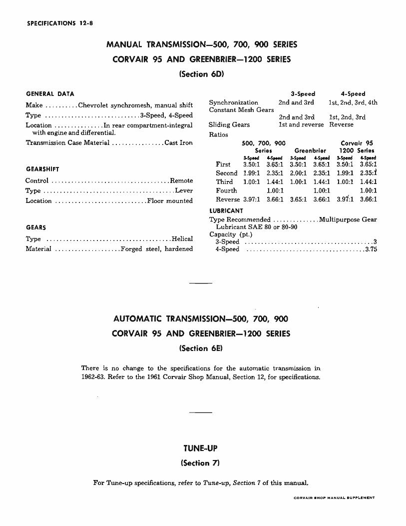
SPECIFICATIONS 12-8
MANUAL TRANSMISSION-SOO, 700, 900 SERIES
CORVAIR 9S AND GREENBRIER-1200 SERIES
(Section 601
GENERAL DATA
Make ..... . .... Chevrolet synchromesh, manual shift
Type ... ...... . .. . . .. .. . ... . ...... 3-Speed, 4-Speed
Location ...... .. ....... In rear compartment-integral with engine and differential.
Transmission Case Material . . .. . . .•. . .... . . Cast Iron
GEARSHIFT
Control . . ....... . . . ... . .... . . . .. . .... . . .. .. Remote
Type .... ...... . • . . . . . .. . ... . ...... .. .. ... . .. Lever
Location '.: ... .. ........ . .. .... .. .... Floor mounted
GEARS
Type .. .. . ... . . ... . . . . ... . .. .. .. ........ . .. Helical
Material ..... . .. . . . .... . ... . Forged steel, hardened
Synchronization Constant Mesh Gears
Sliding Gears
Ratios
3-Speed 2nd and 3rd
4-Speed 1st, 2nd, 3rd, 4th
2nd and 3rd 1st, 2nd, 3rd 1st and reverse Reverse
500, 700, 900 Corvair 95 Series Greenbrier 1200 Series
J.SpHoI CoSpHol J.SpHoI CoSpHol J.SpHoI Cospood First 3.50:1 3.65:1 3.50:1 3.65:1 3.50:1 3.65:1 Second 1.99:1 2.35:1 2.00:1 2.35:1 1.99:1 2.35:1 Third 1.00:1 1.44:1 1.00:1 1.44:1 1.00:1 1.44:1 Fourth 1.00:1 1.00:1 1.00:1 Reverse 3.97:1 3.66:1 3.65:1 3.66:1 3.97:1 3.66:1
LUBRICANT Type Recommended .. . . .. .... . ... Multipurpose Gear
Lubricant SAE 80 or 80-90 Capacity (pt.)
3-Speed . .. . ..... . .. . ... ........ . ....... .. ... .. 3 4-Speed . ........... .... ... . ..... .. . .. . . .. .. 3.75
AUTOMATIC TRANSMISSION-SOO, 700, 900
CORVAIR 9S AND GREENBRIER-1200 SERIES
(Section 6EI
There is no change to the specifications for the automatic transmission in 1962-63. Refer to the 1961 Corvair Shop Manual, Section 12, for specifications.
TUNE-UP
(Section 71
For Tune-up specifications, refer to Tune-up, Section 7 of this manual.
COItVAlit .HO," MANUAL SU,."LEMIENT
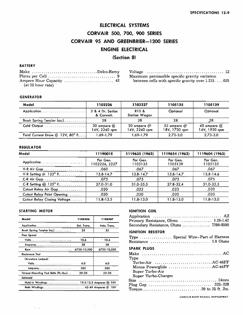
SPECIFICATIONS 12-9
ELECTRICAL SYSTEMS
CORVAIR 500, 700, 900 SERIES
CORVAIR 95 AND GREENBRIER-1200 SERIES
ENGINE ELECTRICAL
(Section 81
BATTERY
Make .... .. .. .................•.•..... Delco-Remy Plates per Cell . . . . . . . . . . . . . . . . . . . . . . . . . . . . . . . . .. 9 Ampere Hour Capacity .. . . . •. . . . . .. . ...... . .... 42
(at 20 hour rate)
GENERATOR
Model 1102226
Application .. .. ....... . . ........ .. 2 & 4 Dr. Sedan & Convert.
Brush Spring Tension (oz.) . ....•..... 28 Cold Output ........... . .......... 30 ampere @
14V, 2240 rpm Field Current Draw @ 12V, 800 F ..... 1.69·1.79
REGULATOR
Model 1119001E
Application ... .. ............ . . .. For Gen. 1102226, 2227
V·R Air Gap .. ........... ... ... . .060 V·R Selling @ 1250 F . ........... 13.8·14.7 C·R Air Gap ............ . . .... .. .075 C·R Selling @ 1250 F .... ... ..... 27.0-31.0 Cutout Relay Air Gap ...... ... . .. .020 Cutout Relay Point Opening . . .. . . . .020 Cutout Relay Closing Voltage . . .. .. 11.8-13.5
STARTING MOTOR
Model 1101306 1101307
Application ..................... . Std. Trans. Auto. Tran ..
8rvsh Spring Tension 10z.I .......... . 35 35
Fre. Speed
Volts ........................ . 10.6 . 10.6
Amperes ....... .... ..... ...•. . 58 58
Rpm .•........................ 6750·10,500 6750-10,500
Re.I,tance Test
(Armature Locked)
Volts ...................... . 4.0 4.0
Amperes . . .............•.... 280 280
Torque-Mounting Pad BoI,. IFt.-lbs.l . . 20·30 20·30
Solenoid
Hold-in Windings ................... 10.5-12.5 Amperes @ 10V
Both Windings ........• • • . . • • •••......• 42-49 Amperes @ IOV
Voltage ....... ........ ................... ...... 12 Maximum permissible specific gravity variation
between cells with. specific gravity over 1.215 .. ... 025
1102227 1105135 1105139
RIO & Optional Optional Station Wagon
28 28 ) 8 30 ampere @ 35 ampere @ 40 ampere @ 14V, 2240 rpm 14V, 1730 rpm 14V, 1930 rpm
1.69·1.79 2.73·3.0 2.73·3.0
1119635 (1962) 1119654 (1962) 1119604 (1963)
For Gen. For Gen. For Gen. 1105135 1105139 1105135
.067 .067 .067 13.8·14.7 13.8·14.7 13.8· 14.6
.075 .075 .075 31.0-35.5 27.8-32.4 31.0-35.5
.023 .023 .020
.020 .020 .020 11.8-13.0 11.8-13.0 11.8-13.0
IGNITION COIL Application ......... . ... ... .. .... • .•...... .... All Primary Resistance, Ohms ........•...... . 1.28-1.42 Secondary Resistance, Ohms . . . . . . . . . . . . . . 7200-9500
IGNITION RESISTOR Type ................ Special Wire-Part of Harness Resistance .... ............... ... .... .... 1.8 Ohms
SPARK PLUGS Make . ........... • . • ......•.•. .......... . ..... AC Type
Turbo-Air ... .. ...... .. . ... . .. .... ..... AC-46FF Monza Powerglide .... . .............. .. . AC-44FF Super Turbo-Air Super Turbo-Charger
Size .... ... . .. .............. .... . ... ........ 14mm Plug Gap ..... ... . . .. .. .... •. ............ .023-.028 Torque ...... . •............ . ......... 20 to 25 ft. lbs.
CORVAU!: .HOP MANUAL . UPPLIEMIENT
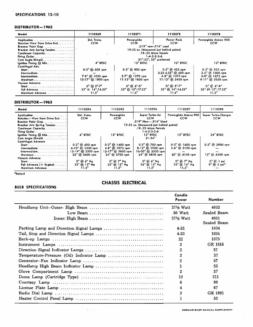
SPECIFICATIONS 12-10
DISTRIBUTOR-1962
M.del 1110269 1110271 1110272 111027'
Application . ... ........ ... . ........ Std. TraM. Powe ,glide Power Pack Pow. rgnd. MonIO 900 Rotation View from Drive End . ........ CCW CCW CCW CCW Ireak., Point Gap .......... ... . ... .019" n8w_.016· vied Ireoker Arm Spring Tension ... ... .. . ... J 9-23 OJ:. (Meosured rust behind points) (andanter Capodty .................. .18-,23 Micro farad. Firing Order .•....•. ...... ..... . .... 1-4·5·2-3-6 Com Angle (Ow_II) ......... •• ... . .... 31 °.35°, 33° preferred Ignition TIming @ Idle .... ....... . .... "0 ITDC 13° ITDC 13° ITDC 13° ITDC Centrifugal Adv.
$tart .••..•..... ..... . . . . . . . . . . . 0.20 @ 600 rpm 0_20 @ 800 rpm 0_20 @ 425 rpm 0.20 @ 925 rpm Intermediat • . . ... . . . . . . . . . . . . . . ... - - 2.25 .... 25° @ 600 rpm 3_5 ° @ 1300 rpm Intermediate ..... . . . . . . . . . . . . . . . . . 7_9° a 1050 rpm 5_7° @ 1270 rpm 6.8 ° @ 1375 rpm 6· 8 ° @ 167.5 rpm Maximum . . . . ... . ........ . .... .... 15·17°@ 1800 rpm 11·13° @ 1850 rpm 11.13°@ 2 .. 00 rpm 9-11 °@ 2050rpm
Vacuum Advance Start .......... . . . . . . . . . . . . . . . . . . 0° @ 5 ' .7' 0 ° @ 6 '-8 ' 0 ° @ 5 ' ·7' 0 ° @ 6'·8 ' Full Advance ....... . . . . . . . . . . . . . . . 23° @ 1.4 ' .16.25' 23°@ 15'-17.25' 23°@ 1.4'.1 6.25' 23° @ 15' -17.25' Maximum Advance ................. 11.5° , 1.5° 11..5° 11 .5°
DISTRIBUTOR-1963
Medel 11 1029 .. 1110295 1110296 1110297 1110298
Application . ...... ..... .. .. .... Std. Trans. Powerglide Super Turbo·Air Pawerglide Monza 900 Super Turbo·Charger Rotation - View from Drive End .. .. CCW CCW CCW CCW CCW Breaker Paint Gap . ............. .019' Hew- .016' Used Break., Arm Spring Tension ...... 19·32 az. (Measured just behind points) Condenser Copacity .. .. .. . ...... Firing Ord., ................... Ignition TIming @ Idle .... . . . . . . . " 0 aTOC Cam Angle (Dwell) ........ ...... Centrifugal Advonce
Start ...... ............... 0·2° ~ 600 rpm Intermediate . ....... ... . .. 6.10° a 1350 rpm intermediate ..... .. .. ...... 15.19° @ 2200 rpm MaJl.lmum ...... ........ . . . .. 32° @ 3600 rpm
Vacuum Advance Start ............... .... . . . . 0 ° @ 6 ' Hq Full Advance (+ Engine) ..... .. 23°@ IS' Hq Maximum Advance ...... .. . ... 11 .5 0
BULB SPECIFICATIONS
Headlamp Unit- Outer: High Beam Low Beam
Inner: High Beam
.18·.23 Micro Farads 1,"-5-2-3·6
13° aTDC 13· aTOC 31·3 .. °
0·2° @ 1 "00 rpm 0·2° @ 700 rpm ".8° @ 1975 rpm 8. 12°@ 1950 rpm
13-17°@ 2850 rpm 16.20° @ 3550 rpm 24° @ 3700 rpm 2"° @ .. aoo rpm
0 0@ 7 ' Hq 0° @ 6 ' Hq 23°@ IS' Hq 23°@ IS' Hq
11 .5° 11 .5°
CHASSIS ELECTRICAL
Parking Lamp and Direction Signal Lamps ......... .. .. ..... . .. . • .. . ... Tail, Stop and Direction Signal Lamps . .... . .. ... ................ .. .. . . Back-up Lamps .. . ....... .. .. .... . ....... . .. . . . . ........... ..... .. .. . Instrument Lamps ......... .. ............ .... ... .... .... .. .......... . Direction Signal Indicator Lamps ...................... . ......... . .. . . . Temperature-Pressure (Oil) Indicator Lamp .. .... . . .. .. .. . ... . . ...... . Generator- Fan Indicator Lamp .... ...... ...... ... .. • . . . .. ... . ... ... . . Headlamp High Beam Indicator Lamp .. . .. .. .. . ... . ... . . . ... . .... . ... . Glove Compartment Lamp ........... . .. . .. .. ....• . ..... . . .. .. .. ..... Dome Lamp (Cartridge Type) ...... .... . ... . ........ ..... . .. . .. .... .. Courtesy Lamp ...... .... ...... .. . .. .•. ... . . . .• . •.. . . .. • . . . . . ...... . . License Plate Lamp ..... . .. ... .• .• . ... ..... ...•... .. .. ........ ....•. . Radio Dial Lamp .......... ....... . .. ... ...... .. ........ ... . .. ....... . Heater Control Panel Lamp .............. .. ... .. ............ ...... .. ..
13° aTDC 2 .. ° ITDC
0·2° @ 1600 rpm 0 . 2° @ 3900 rpm 2.6°@ 2100 rpm -
- -20° @ .. 100 rpm 12° @ "SOO rpm
0 0@ 7 ' Hq 0 0@ 1 psi 23°@ 16' Hq 9 ° @ 2 psi·
11.5° -
Candle Power Number
371,2 Watt 4002 50 Watt Sealed Beam
371,2 Watt 4001 Sealed Beam
4-32 1034 4-32 1034 32 1073 3 GE 1816 2 57 2 57 2 57 1 53 2 57
12 211 6 89 4 67 2 GE 1891 1 53
COItYAIIt .HO~ "'ANUAL . U"~l.lE"'. NT
FUSES AND CIRCUIT BREAKER
A 15 ampere circuit breaker in the light control switch protects the headlamp circuit, thus eliminating one fuse.
Fuses located in the junction block beneath the dash are:
• Heater Blower Glove Compartment Lamp-3AG/AGC-I0 Amp
• Heater (Gasoline) - 3AG/AGC-20 Amp (Where Used)
• Tail and Stop Lamps, Dome Lamp Cigarette Lighter- 3AG/AGC-I0 Amp
• Heater (Total) Back-Up Lamp-3AG/AGC-20 Amp
• Radio-3AG/AGC-4 Amp
• Instrument Panel Lamp Radio Panel Lamp Heater Control Panel Lamp-3AG/AGC-3 Amp
• Windshield Wiper-3AG/AGC-20 Amp
Air Conditioner Fuses . ......... 3AG/ AGC-15 Amp. (Located in 14 GA and 12 GA gray wires in area of ignition switch.)
WIPER MOTOR Single Speed
SPECIFICATIONS 12-11
Type ... .. . .... . .. . ..... .... . .. ... .. ... Electric Crank Arm Rotation
(looking at the crank arm) .. ........ .. . ... CCW Crank Arm Speed (No Load) .. ......... .. 43 rpm Operating Voltage .. .. .. .. .... ... .. .. ... 12 VDC Current Draw (Free Speed) ..... . . . .. 3.0 amp Max.
(Dry Windshield) .. .. 3.5 amp Max. Stall Current ... . . . . . . . . . . . . . . . . . . . . . . . .. 11 amp
Two Speed Operating Volts ....... ................. 12 VDC Gear Ratio . ... . ........ . .............. . .... . 36: 1 Crank Arm Rotation (looking at Crank Arm) CCW Crank Arm Speed (RPM's) (No Load):
Lo ......... . ........... .. ..... ..... .. 34 Min. Hi .. . .. ..... . .. .... ........ • ......... 65 Min.
Current Draw: Amps No Load (Lo Speed) ........... . .. . .... ... 3.6 Installed in Car-(Dry Glass) . . .. . .• ....... 4.5
Stall .. ... .. : . .. .. . ... . . . . . . . ..... . .. ... . 12 Shunt Field Resistance ....... .. . ..... . .. ..... 24
WASHER PUMP Number of "squirts" at full pressure .. . .. ... .. 12 Pressure (PSI) ..... . .......... ...... . .. .... . 11-15 Coil Resistance (ohms) ...................... 20
COIIYAIIt .HO .. MANUAL .U .... u:MENT
SPECIFICATIONS 12-12
FUEL AND EXHAUST SYSTEMS
(Section 9)
FUEL TANK
Corvair 500, 700, 900
Location .......... . . . Under front compartment floor Capacity (gallons) ..... . .......... ... ....... . .. 14 Filler Location .. . . . .. ....... Left front fender crown Fuel Filter Type ........... .... ... ....... .. Strainer
Corvair 95 and Greenbrier-1200 Series
Location ........ ..... ...... Over front cross-member Capacity (gallons) .. . ....... .. ........ .. . . .... 18.6 Filler Location .... ....... ... .. Rear of left front door Fuel Filter Type ....................... . ... Strainer
FUEL GAUGE (Tank Unitl
Make ....... ... . . ..................•.......... AC Type .. ... ............. ... ...... .. ......... Electric
FUEL PUMP
Make .......................... .. ........... .. AC Type .... .... ..... . . .... ... .... ... ... ... Mechanical Location ... ... ..... . Mounted on engine rear housing Driver Off .. ...... .... . .. .... Rear end of crankshaft
AIR CLEANER
Type ... .... ........ . ... ...•.. . ... ...... Oil wetted Choke ................ ..... . ..... ...... . Automatic Element Material ...... . . . ... ......... Polyurethane
INTAKE MANIFOLD
Type .... ... ... ..... Cast integral with cylinder heads
CARBURETOR
ROCHESTER "H" CARTER·YH
CARBURETOR HI·Porl. s_. MOOEL P.G. Syn. (RPO·L-62) Cha,,"
lU23100 lU23101 lU23102 38!~~5 (3311S)
Float level .... 11%4 11%, llliu II Float Drop .. 1% 1% 1% 2\\ Pump Rod .. Index Une Index line Index line -Automatic Choke 2 TWos Up from I Notch
Setting ... Free ntry in Lever lean Unloader. . .250 .250 .250 ~, Fast Idle Setting .. .. .078 .078 .078 - . Bowl Vents ..... . . 3 Internal 1 Internal Choke Piston
Vacuum Break Adj .. .160" • .175" -Main Metering Jet . .. . .049 .050 .050 .0935
Metering Rod (Sizes) . . .064 - - - .070 Throttle Bore . . .. .. 1% IYo IV. 1~ Main Venturi .. I ' I ' I ' 1%6 Pump Discharge Jet. . I TWO @ .022
1 .035
Idle Speed Jet. . .025 .027 .025 .031
EXHAUST MANIFOLD
Type ........... .. ...... Shrunk fitted steel pipes into cylinder head with manifold clamped over.
Material .... ............ .. ... .. .. .... .... Cast iron
EXHAUST
Type ................. Single, diffusion and resonance Muffler .. .. . . .......... ..... ..... . . ... Reverse flow Exhaust Pipe aD ................. .. ......... 1.875
SUPERCHARGER
Inlet Pipe aD .....•. .... ..... ..•............ 1.875 Outlet Pipe aD... ..... . . . . . . . . . . . • . . . . . . . . . . . 2.50
CORVAIR SHOP MANUAL S UPPLIi!:MI!:NT
SPECIFICATIONS 12-13
HEATER AND ACCESSORIES
(Section 11)
, HEATER
Heat Output .. .. .. , . .... .... : ..... .. 20,000 btu/ hr. Thermostat Temperature Range ...... . ,. 65°F-145°F
Spark Plug Type ... . .... , , , , , , . , ...... , . ... . Single Electrode Gap .. .. ..... . .. . . .... ...... . .. ........ .070-.0S5
Breaker Points
Gap .... .. . , . . . . . . . . . . . .. • . • . . . .. .020 (Nominal) Condenser Rating ......... . .. , . . , . 15 mid ± 25%
Ignition Coli Rating
Primary ..... ,...... . .......... . . . ....... .4 olun Secondary ... . . ......... ,..... .. ... .. . 4,000 olun
Solenoid Coil Rating , .... . , . . . . . . . • . . . . . . . . . 50 olun Fuel Pressure . .... . . ...... ... ... , . ... . 4'h-5'h lbs.
AIR CONDITIONING
Compr.ssor~
Make ......... . ..•.• "' .. , ... . .. , .. ,., . .. Frigidaire Type . ............ . .. . .. . ...... . 6 Cylinder AXIAL Displacement ........ ...... . , .......... 10.S Cu. In. Rotation ..... .. . , .... , .. .. . . ... , Counter-Clockwise
Blower Motor
Cool Pack Volts. , . , ... ... . .. , . . ...... . ...... ........... 14 Amps (Cold) ... ... ... ... .. • ....... ... 9,4 (Max.) RPM (Cold) ............................... 3100
Compressor Clutch Coli
Ohms (at SO °F) . , ....... . .... ................. 3.S5 Amps (at SO°F) . . ................... 3.2 @ 12 Volts Refrigerant .. ...... . . . "' .. . "' .... . ......... Freon-12 Compressor Oil ......... ..... Frigidaire 525 Viscosity
Sy.tem Capacltle.
Cool Pack Freon-12 . . . . . . . . . . . . . . . . . . . . . . . . . . . . . . . . .. 5 lbs. 525 Viscosity Oil ....... "' . . "' . .... "' . .. . ... 11 oz.
Torque Specification.
Compressor Suction and Discharge Connector Bolt .. .. ......... . .. . . . .... 17-23 ft. lbs.
Rear Head to Shell Stud Nuts ... ........ 19-23 ft. lbs. Shaft Mounting Nut ... .. ..... ... . ...... 14-16 ft. lbs.
Fuse
Cool Pack . . .... ........ "' "' ....... "' .... 2,15 amp.
eOItYA I!!: SHOP MANUAL SUPPI..I!:MI:NT