Embed Size (px)
Citation preview
Litho in U.S.A. 3/03 #5382 (supersedes #5354)
SpecificationsTelescopic Boom Truck Crane
HTC–8670 70–ton (63.5 metric tons)
������������
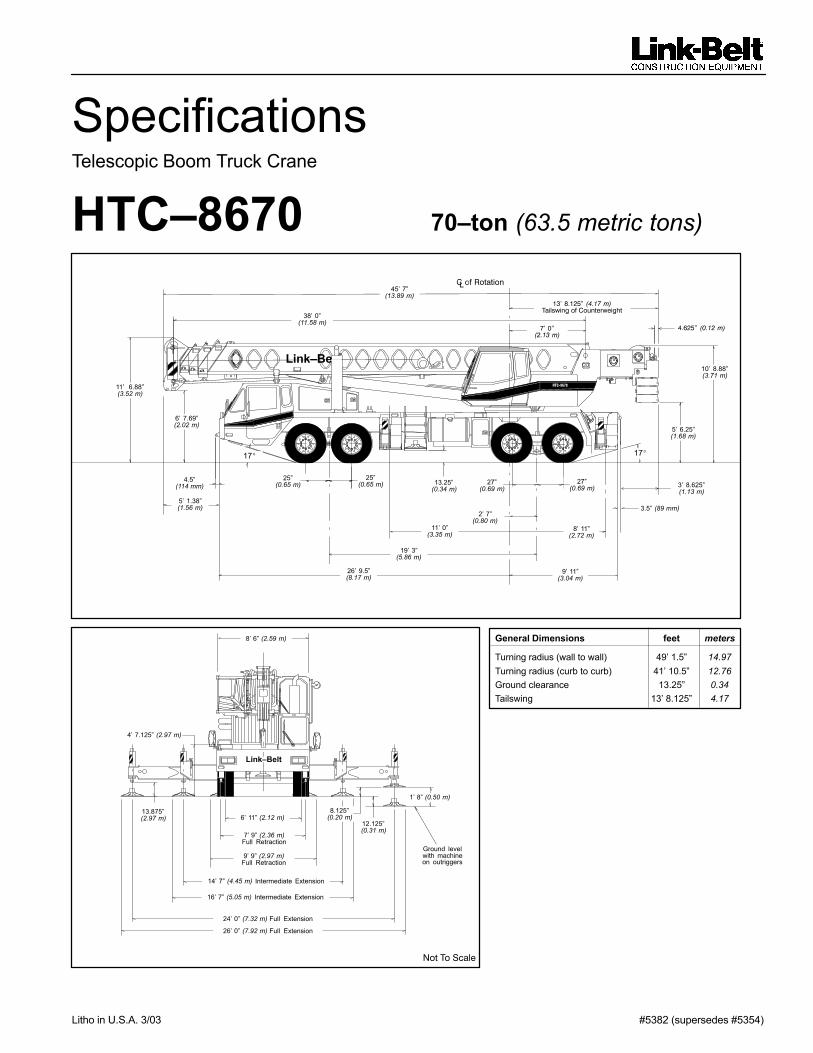
General Dimensions feet meters
Turning radius (wall to wall) 49’ 1.5” 14.97Turning radius (curb to curb) 41’ 10.5” 12.76Ground clearance 13.25” 0.34Tailswing 13’ 8.125” 4.17
�
45’ 7”(13.89 m)
38’ 0”(11.58 m)
����������� ���������� ��� ������������ ��
�������������
������� ��������
Link–Be
11’ 6.88”(3.52 m)
6’ 7.69”(2.02 m)
5’ 1.38”(1.56 m)
4.5”(114 mm)
25”(0.65 m)
25”(0.65 m)
17�
26’ 9.5”(8.17 m)
19’ 3”(5.86 m)
11’ 0”(3.35 m)
13.25”(0.34 m)
8’ 11”(2.72 m)
27”(0.69 m)
27”(0.69 m)
2’ 7”(0.80 m)
17�
9’ 11”(3.04 m)
3.5” (89 mm)
10’ 8.88”(3.71 m)
5’ 6.25”(1.68 m)
3’ 8.625”(1.13 m)
���������� ��
6’ 11” (2.12 m)
7’ 9” (2.36 m)Full Retraction
9’ 9” (2.97 m)Full Retraction
8’ 6” (2.59 m)
14’ 7” (4.45 m) Intermediate Extension
16’ 7” (5.05 m) Intermediate Extension
24’ 0” (7.32 m) Full Extension
26’ 0” (7.92 m) Full Extension
13.875”(2.97 m)
4’ 7.125” (2.97 m)
8.125”(0.20 m)
12.125”(0.31 m)
1’ 8” (0.50 m)
Ground levelwith machineon outriggers
HTC–8670
Link–Belt
��������
View thousands of Crane Specifications on FreeCraneSpecs.comView thousands of Crane Specifications on FreeCraneSpecs.com
���HTC–8670
Upper Structure� BoomPatented Design� Boom side plates have diamond shaped
impressions for superior strength to weightratio and 100,000 p.s.i. (689.5 MPa) steelangle chords for lateral stiffness.
� Boom telescope sections are supported bytop, bottom and adjustable side wearshoes to prevent metal to metal contact.
Boom� 38 – 115’ (11.58 – 35.05 m) four–section
full power boom.� Two mode boom extension� The basic mode is the full power, synchro-
nized mode of telescoping all sections pro-portionally to 115’ (35.05 m).
� The exclusive “A–max” mode (or mode‘A’) extends only the inner mid section to63’ 6” (19.39 m) offering increased capaci-ties for in–close, maximum capacity picks.
Boom Head� Five 16–1/2” (0.42 m) root diameter nylon
sheaves with a fifth nylon sheave availableto handle up to 10 parts of wire rope.
� Easily removable wire rope guards� Rope dead end lugs provided on each side
of boom head.� Boom head designed for quick reeve of
hook block.� Fly pinning alignment tool.
Boom Elevation� One Link–Belt designed hydraulic cylinder
with holding valve and bushing in each end.� Hand control for controlling boom elevation
from –3° to +78°.Optional Auxiliary Lifting Sheave� Single 16–1/2” (0.42 m) root diameter ny-
lon sheave with removable wire ropeguard, mounted to boom.
� Use with one or two parts of line off theoptional front winch.
� Does not affect erection of fly or use ofmain head sheaves for multiple reeving.
Optional� 70–ton (63.5 mt) quick reeve hook block.� 8–1/2 ton (7.7 mt) hook ball.� Boom floodlight.� Mechanical Boom Angle Indicator
� FlyOptional� 36’ 6” (11.13 m) One piece lattice fly, stow-
able, offsettable to 2°, 20° and 40°.� Lugs to allow for second section.� 36’ 6” – 61’ (11.13 – 18.59 m) Two piece
(bifold) lattice fly, stowable, offsettable to2°, 20° or 40°.
� Cab and ControlsEnvironmental Ultra–Cab�� Laminated fiborus composite material; iso-
lated from sound with acoustical fabric in-sulation.
� Windows are tinted and tempered safetyglass.
� Sliding rear and right side windows andswing–up roof window for maximum visibil-ity and ventilation.
� Slide–by–door opens to 3’ (0.91 m) width.� Six–way adjustable seat, with seat belt, for
maximum operator comfort.� Hand–held outrigger controls and sight
level bubble located on left side of cab.� Diesel cab heater� Pull–out Cabwalk� � Circulating fan� Audible swing alarm � Warning horn� Backup alarm � Dome light� Fire extinguisher � Cup holder� 12–volt accessory outlet � Sun screen� Electric windshield wiper � Hand throttle� Windshield washer � Mirrors� Top hatch window wiper � Defroster fan
Optional� Amber strobe light� Emergency steering system� Amber rotating beacon� Hydraulic heater� Air conditioning
ControlsHydraulic controls (joystick type) for:� Swing � Main winch� Optional auxiliary winch � Boom hoistFoot controls for:� Boom telescope � Swing brake� Engine throttle
Optional� Single axis controls � Auxiliary winch
Cab InstrumentationCornerpost–mounted gauges for:� Hydraulic oil temperature� Audio/Visual warning system� Tachometer � Oil pressure� Voltmeter � Fuel� Water temperature
� Rated Capacity Limiter� Microguard 434 Graphic audio–visual
warning system built into dash with anti–two block and function limiters.
Operating data available includes:� Machine configuration.� Boom length � Boom angle� Head height � Radius of load� Allowed load � Actual load� % of allowed loadPresettable alarms include:� Maximum and minimum boom angles.� Maximum tip height.� Maximum boom length.� Swing left/right positions.� Operator defined area alarm is standard.� Anti–two block weight designed for quick
reeve of hookblock.
Optional� Internal RCL light bar: Visually informs
operator when crane is approaching maxi-mum load capacity with a series of green,yellow and red lights.
� External RCL light bar: Visually informsground crew when crane is approachingmaximum load capacity kickouts and pre-settable alarms with a series of threelights; green, yellow and red.
� SwingBi–directional hydraulic swing motormounted to a planetary reducer for 360°continuous smooth swing at 1.7 r.p.m.� Swing park brake – 360°, electric over
hydraulic (spring applied, hydraulic re-leased) multi–disc brake mounted on thespeed reducer. Operated by toggle switchin overhead control console.
� Swing brake – 360°, foot operated, hy-draulic applied disc brake mounted on thespeed reducer.
� �wing lock – Standard; two position travellock operated from the operator’s cab.
� Counterweight� Standard – Pinned to upper structureframe. 12,000 lbs. (5 443 kg) three–piecedesign (4,000 lbs. each).� Optional – 16,000 lbs. (7 258 kg) fivepiece design. (Dolly required for five piecearrangement ).
� Hydraulically controlled counterweight re-moval, standard. Counterweight sectionsmay be lowered on and pinned to carrierdeck to balance axle loadings for travel.
Optional� 360� (Pawl–in–Gear) swing lock. Meets
New York City requirements.
� Hydraulic SystemMain Pump� Two gear pump with a total of five sections.� Combined pump capacity of 152 gpm (575
lpm). Powered by carrier engine with pumpdisconnect.
� Spline type pump disconnect, engaged /disengaged from carrier cab.
� Maximum system operating pressure is3,500 psi (24 133 kPa).
Pilot Pressure / Counterweight RemovalPump� Pressure compensated piston pump pow-
ered by carrier engine with pump discon-nect. Operates at 1,500 psi (10 343 kPa)maximum.
Steering / Fifth Outrigger Pump� Single gear type pump, 8 gpm (30 lpm).
Powered by carrier engine through frontgear housing. Max. pump operating pres-sure is 2,000 psi (13 790 kPa).
� Reservoir – 169 gallon (639.7 L) capacity.One diffuser for deaeration.
(continued on next page)
View thousands of Crane Specifications on FreeCraneSpecs.comView thousands of Crane Specifications on FreeCraneSpecs.com

HTC–8670–3–
(continued from page 2)Filtration� One, 10–micron filter located inside
hydraulic reservoir� Accessible for easy replacement
Control valves� Si� separate pilot operated control valves
allow simultaneous operation of all cranefunctions.
� Load Hoist SystemStandard� 2M main winch with grooved lagging.� Two–speed motor and automatic brake.
� Power up/down mode of operation.� Hoist drum cable followers.� Bi–directional piston–type hydraulic motor
driven through planetary reduction unit forpositive control under all load conditions.
� Asynchronous parallel double crossovergrooved drums minimize rope harmonicmotion.
� Winch circuit control provides balanced oilflow to both winches for smooth, simulta-neous operation.
� Rotation resistant wire rope.� Drum Rotation Indicators.
Line Pulls and Speeds� Maximum available line pull 16,506 lbs.
(7 484 kg) and maximum line speed of 513f.p.m. (156 m/min) on 16” (0.41 m) rootdiameter grooved drum.
Optional� 2M auxiliary winch with two–speed motor,
automatic brake, and winch function lock-out. Power up/down modes.
� Hoist drum cable followers.� Third wrap indicators.
Carrier� Type� 8’ 6” (2.59 m) wide, 231” (5.87 m) wheel-
base. 8 x 4 drive – standardFrame� 100,000 p.s.i. (689.5 MPa) steel, double
walled construction with integral 100,000p.s.i. steel outrigger boxes
Optional� Carrier mounted storage boxes� Pintle hook� Electric and air connections for trailers and
boom dollies
� AxlesFront� Tandem, 84.38” (2.14 m) track.
Rear� Tandem, 72.8” (1.85 m) track. 6.17 to 1.0
ratio with interaxle differential with lockout.
� SuspensionFront axle� Leaf spring suspension
Rear axle� Solid mount, bogie beam type
� WheelsStandard� Front and rear hub piloted aluminum disc
Optional� Spare tire and wheel assemblies
� TiresStandard Front� 445/65R22.5 (Load range ”L”) single tube-
less radialsStandard Rear� 12R22.5 (Load range “L”) dual tubeless
radials
� BrakesService� Full air brakes on all wheel ends with auto-
matic slack adjustors. Dual circuit withmodulated emergency brakes.� Front – 16.5 x 6 S–Cam brakes.� Rear – 16.5 x 7 S–Cam brakes.
Parking/Emergency� One spring set, air released chamber per
rear axle end.� Parking brake applied with valve mounted
on carrier dash.� Emergency brakes apply automatically
when air drops below 40 psi (275.8 kPa) inboth systems.
� Steering� Sheppard rack and pinion design.
� TransmissionStandard – Eaton RTO–14709MLL; 11speeds forward, 3 reverse.
� Electrical� Four, 12–volt batteries provide 12–volt
starting.� 2,800 cold cranking amps available.� 12–volt operating system, 130–amp alter-
nator.Lights� Four dual beam sealed headlights.� Front, side, and rear directional signals.� Stop, tail and license plate lights.� Rear and side clearance lights.� Hazard warning lights.
� Outriggers� Three position operation capability.� Four hydraulic, telescoping beam and jack
outriggers.� Vertical jack cylinders equipped with inte-
gral holding valve.� Beams extend to 24’ (7.32 m) centerline–
to–centerline and retract to within 8’ 6”(2.59 m) overall width.
� Equipped with stowable, lightweight 24”(0.61 m) diameter aluminum floats.
� Standard fifth outrigger, 14 3/4” (0.37 m)self storing steel pad is operable fromground or operator’s cab.
� Hand–held controls and sight level bubblelocated on carrier deck.
Confined Area Lifting Capacities(CALC�) System� The crane is operational in one of the
three outriggers positions and operationalin confined areas in two positions (inter-mediate and full retraction.
The three outrigger positions are:� Full extension – 24’ 0” (7.32 m).� Intermediate position – 14’ 7” (4.45 m).� Full retraction – 7’ 9” (2.36 m).� Capacities are available with the outrigger
beams in the intermediate and full retrac-tion positions.
� When the outrigger position levers (lo-cated on the outrigger beams) are en-gaged, the operator can set the crane inthe intermediate or full retraction outriggerposition without having to leave the cab.
� Carrier Cab� One–man cab of laminated fibrous com-
posite material acoustical insulation withcloth covering.
Equipped with:� Air–ride adjustable operator’s seat with
seat belt.� Tilting and locking steering wheel.� Door and windows locks.� Left–hand and right–hand rear view mirrors.� Sliding right–hand and rear tinted windows.� Roll up/down left–hand tinted window.� Desiccant–type air dryer.� Steps to upper, lower cab and rear carrier.� 120–volt electric engine block heater.� Back–up warning alarm.� Tow hooks and shackles.� Aluminum fenders and mud flaps.� Carrier mounted outrigger controls with
throttle control.� Electric windshield wiper and washer.� Rotating beacon � Travel lights� Horn � Mud flaps� Fire extinguisher � Ashtray� 36,000 BTU heater � Defroster� Dome light � Cruise control� High beam light switch
Cab instrumentation� Illuminated instrument panel speedometer.� Tachometer � Hourmeter� Fuel gauge � Fuses� Oil pressure gauge � Odometer� Turn signal indicator � Voltmeter� Water temperature gauge.� Front and rear air pressure gauges.� Audio/visual warning system.� Check engine and stop engine lights.� Automotive type ignition.� Optional – Amber strobe light.� Optional – Air conditioning
View thousands of Crane Specifications on FreeCraneSpecs.comView thousands of Crane Specifications on FreeCraneSpecs.com

���HTC–8670
� Carrier Speeds (Manual Transmission – Standard tires)
GearHigh Low Deep
reduction Hi rev. Lo rev. Deepreduction
Deep reduction@ 600 rpm
Deep reduction@ 600 rpmGear
8 7 6 5 4 3 2 1 Low LL2 LL1 Rev. Rev. Rev. LL1 LowRatio 0.73 1.00 1.38 1.95 2.77 3.79 5.23 7.41 16.30 11.85 26.08 4.15 15.76 25.21 26.08 25.21
mph 58.20 42.49 30.79 21.79 15.34 11.21 8.12 5.73 2.61 3.59 1.63 10.24 2.70 1.69 0.47 0.48Speed km/hr. 93.65 68.36 49.54 35.06 24.68 18.04 13.07 9.23 4.19 5.77 2.62 16.47 4.34 2.71 0.75 0.72
� EngineEngine Detroit Diesel Series 60 12.7 LCylinders – cycleBoreStrokeDisplacementMaximum brake hp.Peak torqueElectric systemFuel capacityAlternatorCrankcase capacity
6 / 45.12” (0.13 m)6.30” (0.16 m)778 cu. in. (12 751 cm3)365 @ 1,800 rpm; 350 @ 2,100 rpm 1,350 ft. lbs. (1 831 J) @ 1,200 rpm 12–volt neg. ground / 12 volt starting 100 gallons (378.5 L)12 volt, 130 amps 32 qts. (30 L)
� Engine brake – standard � Ether injection starting package – optional
� Axle LoadsBase machine with standard 38.5’ – 115’ (11.73 – 35.05 m) four–section boom,
�Upper Facing FrontBase machine with standard 38.5’ – 115’ (11.73 – 35.05 m) four–section boom,
2M main winch with 2–speed hoisting and power up/down, 630’ (192.02 m),G.V.W. � Front Axle Rear Axle2M main winch with 2–speed hoisting and power up/down, 630’ (192.02 m),
3/4” (19 mm) wire rope, 8 x 4, 8.5’ (2.59 m) carrier with Detroit Diesel Series 60 lbs. kg. lbs. kg. lbs. kg.3/4” (19 mm) wire rope, 8 x 4, 8.5’ (2.59 m) carrier with Detroit Diesel Series 60engine, 100 gal. (378 L) fuel and no counterweight. 76,118 34 527 34,542 15 668 41,576 18 859
Cold weather starting aids – propane and etherAluminum storage boxDriver in carrier cabPintle hook w/air and electrical hook–upsAir conditioning in carrier cabAuxiliary winch with 630’ (192.02 m) front ropeHydraulic heaterAir conditioning in upper cabOne slab of counterweight on upperTwo slabs of counterweight on upperThree slabs of counterweight on upperThree slabs of counterweight on upper plus two cheek weightsFly brackets on boom base section for fly options36.5’ (11.13 m) offsettable fly with tip lugs – stowed36.5’ to 61 ft. (11.13 – 18.59 m) two–piece fly – stowed40–ton (36.3 mt) hookblock at front bumper70–ton (63.5 mt) hookblock at front bumperHookball to front bumperAuxiliary arm
4057
20030
100855170120
4,0008,000
12,00016,000
1601,5422,248
7201,400
360125
1826911445
3887754
1 8143 6285 4437 257
72700
1 02032763516357
5716
254–12127
–2821
–4–2,140–4,281–6,421–8,561
1471,3491,7111,1752,284
587230
267
185–557
–1280.5–2
–971–1 942–2 913–3 883
68612776533
1 036266104
–1741
–5442
–271,137
169124
6,14012,28118,42124,561
11193537
–455–884–227–105
–819
–2419
–125167756
2 7855 5718 356
11 1405
88244
–206–401–103–48
Front axle Rear axleTransfer one slab of counterweight to carrier deckTransfer two slabs of counterweight to carrier deckTransfer three slabs of counterweight to carrier deck
5,33310,66615,999
2 4194 8287 257
–5,333–10,666–15,999
–2 419–4 838–7 257
� Adjust gross vehicle weight & axle loading according to component weight. Note: All weights are � 3%.
Axle Max. Load @ 65 mph. (105 km/h)Front
Rear
46,400 lbs. (21 047 kg) – Aluminum disc wheels with 445/65R22.5 tires
50,350 lbs. (22 838 kg) – Aluminum disc wheels with 12R22.5 tires
Link–Belt Construction Equipment Company Lexington, Kentucky www.linkbelt.com�Link–Belt is a registered trademark. Copyright 2003. All rights reserved. We are constantly improving our products and therefore reserve the right to change designs and specifications.
View thousands of Crane Specifications on FreeCraneSpecs.comView thousands of Crane Specifications on FreeCraneSpecs.com

Litho in U.S.A. 12/00 – 1 – #6291 (Supersedes #6219)
Lifting CapacitiesTelescopic Hydraulic Truck Crane
HTC–8670 70–ton (63.5 metric ton)
Boom and fly capacities for this machine are listed by the following sections:
Fully Extended Outriggers� Working Range Diagram (16,000 lbs. Counterweight)� 38 to 63.5 ft. (11.58 – 19.39 m) main boom capacities, A–max mode� 38 to 115 ft. (11.58 – 35.05 m) main boom capacities, Basic Mode “B”� 36.5 (11.13 m) ft. offset fly capacities, Basic Mode “B”� 36.5 to 61 ft. (11.13 – 18.59 m) two–piece offset fly capacities, Basic mode “B”
Link–BeHTC–8670
HTC–8670
CAUTION: This material is supplied for reference use only. Operator must refer toin–cab Crane Rating Manual to determine allowable machine lifting capacities andoperating procedures.

�������� ��
������������������������ ������������������������������ ����������
����������� ��� ����� ������� ���������� ������ ��������� � � ������
��������� � �� ���� ��� ������ � ��� ����������� ��� ����� �� ��
���������
OPERATING INSTRUCTIONS��������
1 . Rated lifting capacities in pounds as shown on lift chartspertain to this crane as originally manufactured and normallyequipped. Modifications to the crane or use of optionalequipment other than that specified can result in a reductionof capacity.
2 . Construction equipment can be dangerous if improperlyoperated or maintained. Operation and maintenance of thiscrane must be in compliance with the information in theOperator’s, Parts, and Safety Manuals supplied with thiscrane. If these manuals are missing, order replacementsthrough the distributor.
3 . The operator and other personnel associated with this craneshall read and fully understand the latest applicableAmerican National Standards (ASME B30.5) safetystandards for cranes.
4 . The rated lifting capacities are based on crane standinglevel on firm supporting surface.
�����
1 . The crane shall be leveled on a firm supporting surface.Depending on the nature of the supporting surface, it may benecessary to have structural supports under the outriggerpontoons or tires to spread the load to a larger bearingsurface.
2 . When making lifts on outriggers, all tires must be free ofsupporting surface. All outrigger beams must be extended tothe same length; fully retracted, intermediate extended, orfully extended. The front bumper outrigger must be properlyextended.
3 . When operating on fully retracted outriggers, do not exceed64� maximum boom angle with 16,000 lb. counterweight or71� maximum boom angle with 12,000 lb. counterweight.Loss of backward stability will occur causing a backwardtipping condition.
4 . When making lifts on tires, they must be inflated to therecommended pressure. (See Operation note 19 and TireInflation.)
5 . Before swinging boom to over side position on tires, or onfully retracted outriggers where capacities are not published,boom sections must be fully retracted and 45� boom anglemaintained.
6 . For required parts of line, see Wire Rope Capacity andWinch Performance.
7 . Before setting up on intermediate outriggers, retractedoutriggers, or tires, refer to Working Range Diagrams andrated lifting capacities to determine allowable craneconfigurations.
����������
1 . Rated lifting capacities at rated radius shall not beexceeded. Do not tip the crane to determine allowableloads. For concrete bucket operation, weight of bucket andload shall not exceed 80% of rated lifting capacities. Forclamshell bucket operation, weight of bucket and bucketcontents is restricted to a maximum weight of 7,000 poundsor 80% of rated lifting capacity, whichever is less. Formagnet operation, weight of magnet and load is restricted toa maximum weight of 7,000 pounds or 80% of rated liftingcapacity, whichever is less. For clamshell and magnetoperation, maximum boom length is restricted to 55 ft. andthe boom angle is restricted to a minimum of 35 degrees.Lifts with either fly erected is prohibited for both clam andmagnet operation.
2 . Rated lifting capacities shown on fully extended outriggersdo not exceed 85% of the tipping loads. Rated liftingcapacities shown on intermediate extended or fully retractedoutriggers are determined by the formula, rated load =(tipping load – 0.1 X load factor)/1.25. Rated liftingcapacities shown on tires do not exceed 75% of the tippingloads. Tipping loads are determined by SAE crane stabilitytest code J–765.
3 . Rated lifting capacities in the shaded areas above the boldlines, are based on structural strength or hydrauliclimitations and have been tested to meet minimumrequirements of SAEJ–1063 cantilevered boom crane structures– method of test. The rated lifting capacities below the bold lines arebased on stability ratings. Some capacities are limited by amaximum obtainable 78� boom angle.
4 . Rated lifting capacities include the weight of the hook block,hook ball, slings, bucket, magnet, and auxiliary liftingdevices. Their weights must be subtracted from the listedrated capacity to obtain the net load which can be lifted.Rated lifting capacities include the deduct for either flystowed on the base of the boom. For deducts of either flyerected, but not used, see Capacity Deductions For AuxiliaryLoad Handling Equipment.
5 . Rated lifting capacities are based on freely suspendedloads. No attempt shall be made to move a load horizontallyon the ground in any direction.
6 . Rated lifting capacities are for lift crane service only.7 . Do not operate at radii or boom lengths (minimum or
maximum) where capacities are not listed. At thesepositions, the crane can tip or cause boom failure.
8 . The maximum loads which can be telescoped are notdefinable because of variation in loadings and cranemaintenance, but it is permissible to attempt retraction andextension within the limits of the applicable load rating chart.
9 . For main boom capacities when either boom length or radiusor both are between values listed, proceed as follows:a. For boom lengths not listed, use rating for next longer boom
length or next shorter boom length, whichever is smaller.b. For load radii not listed, use rating for next larger radius.

��� ��������
10 . The user shall operate at reduced ratings to allow foradverse job conditions, such as: soft or uneven ground, outof level conditions, wind, side loads, pendulum action,jerking or sudden stopping of loads, hazardous conditions,experience of personnel, traveling with loads, electricalwires, etc. Side load on boom or fly is dangerous and shallbe avoided.
11 . Rated lifting capacities do not account for wind onsuspended load or boom. Rated capacities and boomlength shall be appropriately reduced as wind velocityapproaches or exceeds 20 mph.
12 . When making lifts with auxiliary head machinery, theeffective length of the boom increases by 2 ft.
13 . Power sections of boom must be extended in accordancewith boom mode “A” or “B”. In boom mode “B” all powersections must be extended or retracted equally.
14 . Rated lifting capacities are based on correct reeving.Deduction must be made for excessive reeving. Any reeving over minimum required (see Wire Rope Capacity) is considered excessive and must be accounted for whenmaking lifts. Use working range diagram to estimate theextra feet of rope then deduct 1 lb. for each extra foot of wire rope before attempting to lift a load.
15 . The loaded boom angle combined with the boom length give only an approximation of the operating radius. Theboom angle, before loading, should be greater to account for deflection. For main boom capacities, the loaded boomangle is for reference only. For fly capacities, the loadedradius is for reference only.
16 . For fly capacities with main boom length less than 115 ft.and greater than 95 ft., the rated capacities are determinedby the boom angle using the 115 ft. boom and fly chart. Forangles not shown use the next lower boom angle todetermine the rated capacity.
17 . For fly capacities with main boom length less than 95 ft., therated capacities are determined by the boom angle onlyusing the 95 ft. boom and fly chart. For angles not shown,use the next lower boom angle to determine the ratedcapacity.
18 . The 38 ft. boom length rated lifting capacities are based onboom fully retracted. If the boom is not fully retracted, do notexceed capacities shown for the 45 ft. boom length.
19 . Rated lifting capacities on tires depend on tire capacity,condition of tires, and tire air pressure. On tire capacitiesrequire lifting from main boom head only on a smooth andlevel surface. Pick and carry operations are restricted tomaximum speed of 1 mph. The boom must be centered overthe rear of the crane with two position travel swing lockengaged and the load must be restrained from swinging.For correct tire pressure, see “Tire Inflation”.
������������
1 . Load Radius: Horizontal distance from a projection of theaxis of rotation to the supporting surface before loading tothe center of the vertical hoist line or tackle with loadapplied.
2 . Loaded Boom Angle: The angle between the boom basesection and horizontal with freely suspended load at therated radius.
3 . Working Area: Area measured in a circular arc about thecenter line of rotation as shown on the Working AreaDiagram.
4 . Freely Suspended Load: Load hanging free with no directexternal force applied except by the hoist line.
5 . Side Load: Horizontal side force applied to the lifted loadeither on the ground or in the air.
6 . No Load Stability Limit: The radius or boom angle beyondwhich it is not permitted to position the boom because thecrane can overturn without any load on the hook.
7 . Load Factor: Load applied at the boom tip which gives thesame moment effect as the boom mass.
�������� ���
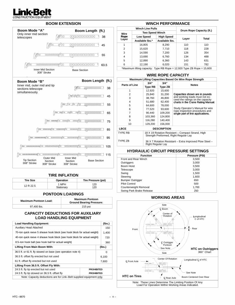
BOOM EXTENSION
Boom Mode “A”
Boom Mode “B”
Only inner mid sectiontelescopes
Inner mid, outer mid and tip sections telescope simultaneously.
Inner Mid Section308” Stroke
Base Section
Inner MidSection
308” StrokeBase Section
Outer MidSection
308” Stroke
Tip Section308” Stroke
��
�
���
Boom Length (ft.)
Boom Length (ft.)
��
�
�
�
�
�
��
��
TIRE INFLATIONTire Size Operation Tire Pressure (psi)
12 R 22.5 1 MPHStationary
120120
PONTOON LOADINGS
Maximum Pontoon Load:Maximum Pontoon
Ground Bearing Pressure:
97,400 lbs. 215 psi
CAPACITY DEDUCTIONS FOR AUXILIARY LOAD HANDLING EQUIPMENT
Load Handling Equipment: (lbs.)
Auxiliary Head Attached 150
70–ton quick reeve 5 sheave hook block (see hook block for actual weight) 1,400
40–ton quick reeve 4 sheave hook block (see hook block for actual weight) 720
8.5–ton hook ball (see hook ball for actual weight) 360
Lifting From Main Boom With: (lbs.)
36.5 ft. or 61 ft. fly stowed on base (see operation note 4) 0
36.5 ft. offset fly erected but not used 6,100
61 ft. offset fly erected but not used 7,600
Lifting From 36.5 ft. Offset Fly With:24.5 ft. fly tip erected but not used PROHIBITED
24.5 ft. fly tip stowed on 36.5 ft. offset fly PROHIBITED
Note: Capacity deductions are for Link–Belt supplied equipment only.
WINCH PERFORMANCEWinch Line Pulls
Two Speed WinchDrum Rope Capacity (ft.)
WireRope Low Speed High SpeedRopeLayer Available lbs.* Available lbs.
Layer Total
1 16,805 8,290 110 110
2 15,620 7,710 118 228
3 14,590 7,200 126 354
4 13,690 6,760 134 488
5 12,890 6,360 143 631
6 12,190 6,020 151 782
*Maximum lifting capacity: Type RB Rope = 12,920 Type ZB Rope = 15,600
WIRE ROPE CAPACITYMaximum Lifting Capacities Based On Wire Rope Strength
3/4” 3/4”Parts of Line
Type RB Type ZBNotes
1 12,920 15,6002 25,840 31,200 Capacities shown are in pounds3 38,760 46,800
Capacities shown are in poundsand working loads must not ex-
4 51,680 62,400ceed the ratings on the capacitycharts in the Crane Rating Manual.
5 64,600 78,000charts in the Crane Rating Manual.
6 77,520 93,600 Study Operator’s Manual for wire
7 90,440 109,200rope inspection procedures andsingle part of line applications.
8 103,360 124,800single part of line applications.
9 116,280 140,40010 129,200 156,000
LBCE DESCRIPTION
TYPE RB
TYPE ZB
18 X 19 Rotation Resistant – Compact Strand, HighStrength Preformed, Right Regular Lay
36 X 7 Rotation Resistant – Extra Improved Plow Steel –Right Regular Lay
HYDRAULIC CIRCUIT PRESSURE SETTINGSFunction Pressure (PSI)
Front and Rear Winch 3,500Outriggers 3,000Boom Hoist 3,500Telescope 3,000Swing 1,500Steering 1,600Bumper Outrigger 650Pilot Control 500Counterweight Removal 1,700Swing Park Brake Release 250
WORKING AREAS
C Boom
LongitudinalC of HTC
LCenter ofRotation
Note: These Lines Determine The Limiting Position Of AnyLoad For Operation Within Working Areas Indicated.
Longitudinal C of HTCL
HTC on Tires
Center Of Rotation
HTC on Outriggers
Rear
360� Chart
Front
C Outrigger Pontoon
L
See Note
See Note
Boom Centered Over Rear
Side
L
C Rear AxleL
C Front AxleL
Side

� � ��������
WORKING RANGE DIAGRAM
Working Range DiagramOn Fully Extended Outriggers
������������������� ������!"!�#������"$ ��������%&�'����"�"����!(�
��%��'������������"$��'�!)�"���''�(��%*! !�+�! �,,#��%#'!"$��!--!"$��"&!�!�"�
�������
16,000# Counterweight
� ��"���'�%!"����./0�� +1������&�2�3
���������%"&( +$������+'���"%��(��#" �%&�&,�"&!�!�"%"&,�%"�'�%"&!"$ �)� �"(!��'#--���!"$'#�(%,������&�( �,�!�"4'#*'�5#�"��%&!#'4%"&*���%"$ �,�%"$��#'�*�%,,�#"��&(�����"%-- +!"$ �%&�����6�
1020405060708090100
120
110
100
90
80
70
60
50
40
30
20
30
10
Hei
gh
t in
fee
t ab
ove
gro
un
d
Operating Radius From Axis Of Rotation In Feet
0110
130
140
130 120
150
160
170
180
170 160 150 140
38 FT. BOOM
45 FT. BOOM
55 FT. BOOM
63.6 FT. BOOM
75 FT. BOOM
85 FT. BOOM
95 FT. BOOM
105 FT. BOOM
115 FT. BOOM
61 FT. FLY+115 FT. BOOM
36.5 FT. FLY+115 FT. BOOM
65 FT. BOOM
190
61 FT. FLY+95 FT. BOOM
36.5 FT. FLY+95 FT. BOOM
BOOM ANGLE
10’ 8.5’
40� OFFSET 20� OFFSET 2� OFFSET
10�
20�
30�
40�
50�
60�
70�
CL OF ROTATION
78� MAX
MODE “B”
MODE “A”
7’–0”
MODES “A” & “B”

�������� ���
Note: Refer To Page 4 For “Capacity Deductions” Caused By Auxiliary Load Handling Equipment.
Rated Lifting Capacities In Pounds On Fully Extended Outriggers See Set Up Note 2.
Boom Mode “A”16,000 lbs. Counterweight
38 Ft. 45 Ft.
Load Radius (ft)
LoadedBoomAngle(Deg.)
360° Over Rear
LoadedBoomAngle(Deg.)
360° Over Rear
9 69.0 140,000 140,000
10 67.0 132,000 132,000 71.0 87,400 87,400
12 64.0 116,900 116,900 68.5 87,400 87,400
15 58.5 100,200 100,200 64.0 87,400 87,400
20 48.5 75,900 75,900 56.5 75,500 75,500
25 36.5 58,700 58,700 48.0 58,300 58,300
30 17.5 45,400 45,400 38.0 45,100 45,100
35 24.5 34,500 34,500
Min.Bm. 0 0Min.Bm.Ang./Cap.
0(31.0) 25,200 25,200 0
(38.0) 20,200 20,200
55 Ft. 60.3 Ft.Loaded LoadedLoad
Radius (ft)
LoadedBoom 360° Over Rear
LoadedBoom 360° Over RearRadius (ft)
Angle(Deg.)
360 Over RearAngle(Deg.)
360 Over Rear
10 75.0 85,600 85,600
12 73.0 85,600 85,600 75.5 56,300 56,300
15 69.5 85,600 85,600 73.0 56,300 56,300
20 64.0 75,000 75,000 68.0 53,000 53,000
25 57.5 57,900 57,900 63.0 44,900 44,900
30 51.0 44,400 44,400 57.5 38,700 38,700
35 43.0 34,100 34,100 51.5 33,700 33,700
40 34.5 27,000 27,000 45.5 26,700 26,700
45 22.0 21,800 21,800 38.0 21,600 21,600
50 29.0 17,700 17,700
55 16.0 14,600 14,600
Min.Bm. 0 0Min.Bm.Ang./Cap.
0(48.0) 14,100 14,100 0
(56.6) 10,400 10,400
Boom Mode “B”16,000 lbs. Counterweight
Rated Lifting Capacities In Pounds On Fully Extended Outriggers See Set Up Note 2.
35.5 Ft. 45 Ft. 55 Ft.Load
Radius(ft)
LoadedBoomAngle(Deg.)
360° OverRear
LoadedBoomAngle(Deg.)
360° OverRear
LoadedBoomAngle(Deg.)
360° OverRear
9 69.0 140,000 140,000
10 67.0 132,000 132,000 71.0 42,000 42,000 74.5 42,000 42,000
12 64.0 116,900 116,900 68.0 42,000 42,000 72.5 42,000 42,000
15 58.5 100,200 100,200 64.0 42,000 42,000 69.0 42,000 42,000
20 48.5 75,900 75,900 56.5 42,000 42,000 63.5 42,000 42,000
25 36.5 58,700 58,700 48.0 42,000 42,000 57.5 42,000 42,000
30 17.5 45,400 45,400 38.0 42,000 42,000 50.5 42,000 42,000
35 24.5 35,600 35,600 43.0 36,300 36,300
40 34.0 29,100 29,100
45 22.0 23,800 23,800
Min.Bm 0 0 0Ang./Cap.
0(31.0) 25,200 25,200 0
(38.0) 19,200 19,200 0(48.0) 13,700 13,700
65 Ft. 75 Ft. 85 Ft.Load Loaded Loaded LoadedRadius(ft)
LoadedBoom
°Over
LoadedBoom 360° Over
LoadedBoom 360° Over
(ft) Angle(Deg.)
360° Rear Angle(Deg.)
360 Rear Angle(Deg.)
360 Rear
12 75.5 42,000 42,000
15 73.0 42,000 42,000 75.5 42,000 42,000 77.5 42,000 42,000
20 68.0 42,000 42,000 71.5 42,000 42,000 74.5 42,000 42,000
25 63.5 42,000 42,000 68.0 42,000 42,000 71.0 41,800 41,800
30 58.0 42,000 42,000 63.5 42,000 42,000 67.0 36,900 36,900
35 52.5 36,600 36,600 59.0 36,800 36,800 63.5 32,900 32,900
40 46.5 29,400 29,400 54.0 29,600 29,600 59.5 29,700 29,700
45 39.5 24,300 24,300 49.0 24,500 24,500 55.0 24,600 24,600
50 31.5 20,300 20,300 43.0 20,600 20,600 50.5 20,700 20,700
55 20.0 17,200 17,200 37.0 17,500 17,500 46.0 17,600 17,600
60 29.5 15,000 15,000 40.5 15,100 15,100
65 19.0 12,900 12,900 34.5 13,100 13,100
70 27.5 11,400 11,400
75 18.0 9,900 9,900
Min.Bm 0 0 0Ang./Cap.
0(58.0) 10,100 10,100 0
(68.0) 7,600 7,600 0(78.0) 5,700 5,700
95 Ft. 105 Ft. 115 Ft.Load Loaded Loaded LoadedRadius(ft)
LoadedBoom 360° Over
LoadedBoom 360° Over
LoadedBoom 360° Over
(ft) Angle(Deg.)
360 Rear Angle(Deg.)
360 Rear Angle(Deg.)
360 Rear
20 76.5 38,600 38,600
25 73.5 33,800 33,800 75.5 30,300 30,300 77.0 24,500 24,500
30 70.0 29,800 29,800 72.5 27,000 27,000 74.5 24,500 24,500
35 67.0 26,600 26,600 69.5 24,100 24,100 72.0 22,200 22,200
40 63.5 23,900 23,900 66.5 21,700 21,700 69.5 20,000 20,000
45 60.0 21,700 21,700 63.5 19,600 19,600 66.5 18,100 18,100
50 56.0 19,800 19,800 60.5 17,900 17,900 63.5 16,300 16,300
55 52.5 17,700 17,700 57.0 16,200 16,200 61.0 14,900 14,900
60 48.0 15,200 15,200 53.5 14,900 14,900 58.0 13,600 13,600
65 43.5 13,200 13,200 50.0 13,300 13,300 54.5 12,500 12,500
70 38.5 11,600 11,600 46.0 11,600 11,600 51.5 11,600 11,600
75 33.0 10,100 10,100 41.5 10,200 10,200 48.0 10,300 10,300
80 26.5 8,800 8,800 37.0 8,900 8,900 44.0 9,000 9,000
85 17.0 7,700 7,700 31.5 7,800 7,900 40.0 7,800 7,900
90 25.5 6,800 6,900 35.5 6,900 7,000
95 16.5 5,900 6,000 30.5 6,000 6,100
100 24.5 5,200 5,400
105 16.0 4,600 4,700
Min.Bm 0 0 0Ang./Cap.
0(88.0) 4,300 4,300 0
(98.0) 3,100 3,100 0(108.0) 2,200 2,200

��� ��������
20�Offset
2� Offset
36.5 Ft. Offset Fly40� Offset
95 Ft. Main Boom
Rated Lifting Capacities In Pounds On Fully Extended Outriggers See Set Up Note 2.
Boom Mode “B”16,000 lbs. Counterweight
2� Offset 20� Offset 40� OffsetLoad Loaded Loaded Loaded
Radius(ft)
LoadedBoom 360�
LoadedBoom 360�
LoadedBoom 360�(ft) Angle
(Deg.)
360 Angle(Deg.)
360 Angle(Deg.)
360
30 76.5 16,90035 74.0 14,40040 72.0 13,700 76.5 10,20045 69.5 13,100 74.5 9,60050 67.5 12,400 72.0 9,100 76.5 6,80055 65.0 11,800 69.5 8,700 74.0 6,80060 62.5 11,200 67.0 8,300 71.5 6,60065 60.0 10,500 64.5 7,900 68.5 6,40070 57.5 9,800 62.0 7,600 66.0 6,30075 55.0 9,300 59.5 7,300 63.0 6,10080 52.0 8,700 56.5 7,000 60.0 6,00085 49.0 8,300 53.5 6,700 57.0 5,90090 46.0 7,800 50.5 6,500 53.5 5,80095 42.5 7,200 47.0 6,300 50.0 5,700
100 39.0 6,500 43.5 6,100 46.0 5,700105 35.0 5,800 39.5 6,000 41.5 5,700110 30.5 5,100 35.0 5,400115 25.0 4,600 29.5 4,800120 18.5 4,100 22.0 4,200
Min.Bm.Min.Bm.Ang./Cap. 0 1,600 0 1,700 0 1,900
61 Ft. Offset Fly
20�Offset
2� Offset40� Offset
95 Ft. Main Boom
Rated Lifting Capacities In Pounds On Fully Extended Outriggers See Set Up Note 2.
Boom Mode “B”16,000 lbs. Counterweight
2� Offset 20� Offset 40� OffsetLoad Loaded Loaded Loaded
Radius(ft)
LoadedBoom 360�
LoadedBoom 360�
LoadedBoom 360�(ft) Angle
(Deg.)360 Angle
(Deg.)360 Angle
(Deg.)360
35 77.5 9,50040 75.5 9,10045 74.0 8,50050 72.0 7,90055 70.0 7,400 77.0 5,20060 68.0 6,900 75.0 4,90065 66.0 6,400 73.0 4,60070 64.0 6,000 71.0 4,400 77.5 3,40075 62.0 5,600 69.0 4,200 75.0 3,30080 60.0 5,300 66.5 4,000 73.0 3,20085 57.5 5,000 64.5 3,900 70.5 3,10090 55.5 4,700 62.5 3,700 68.0 3,10095 53.0 4,500 60.0 3,600 65.5 3,000
100 50.5 4,200 57.5 3,400 63.0 2,900105 48.0 4,000 55.0 3,300 60.0 2,900110 45.5 3,800 52.0 3,200 57.5 2,800115 43.0 3,600 49.5 3,100 54.0 2,800120 40.0 3,500 46.5 3,000 50.5 2,800125 36.5 3,300 43.0 2,900 47.0 2,800130 33.0 3,200 39.5 2,900 42.5 2,800135 29.0 3,100 35.0 2,800140 24.5 3,000 30.0 2,800145 18.0 2,700 22.5 2,800
Min.Bm.Min.Bm.Ang./Cap. 0 700 0 800 0 1,000
115 Ft. Main Boom
20�Offset
2� Offset
40� Offset
36.5 Ft. Offset Fly
Rated Lifting Capacities In Pounds On Fully Extended Outriggers See Set Up Note 2.
Boom Mode “B”16,000 lbs. Counterweight
2� Offset 20� Offset 40� OffsetLoad Loaded- Loaded Loaded
Radius(ft)
Loaded-Boom- 360�
LoadedBoom 360�
LoadedBoom 360�(ft) Angle
(Deg.)360 Angle
(Deg.)360 Angle
(Deg.)360
35 76.5 10,50040 75.0 10,50045 73.0 10,500 77.5 9,20050 71.5 10,500 75.5 8,90055 69.5 10,500 73.5 8,600 77.5 6,80060 68.0 10,500 71.5 8,200 75.0 6,60065 66.0 10,200 69.5 8,000 73.0 6,50070 63.5 9,500 67.5 7,700 71.0 6,30075 61.5 8,700 65.5 7,400 68.5 6,20080 59.0 8,000 63.5 7,200 66.5 6,10085 57.0 7,400 61.0 7,000 64.0 6,00090 54.5 6,900 58.5 6,800 61.5 5,90095 52.0 6,400 56.0 6,500 59.0 5,800
100 49.0 5,900 53.5 6,100 56.5 5,700105 46.5 5,500 50.5 5,600 53.5 5,700110 43.5 4,900 48.0 5,200 50.5 5,400115 40.5 4,300 44.5 4,700 47.0 4,900120 37.0 3,800 41.0 4,100 43.0 4,300125 33.0 3,300 37.0 3,600130 29.0 2,900 32.5 3,100135 24.0 2,500 27.5 2,700140 17.5 2,200 20.5 2,300
Min.Bm.Min.Bm.Ang./Cap. 0 400 0 400 0 500
61 Ft. Offset Fly
20�Offset
2� Offset
40� Offset
115 Ft. Main Boom
Rated Lifting Capacities In Pounds On Fully Extended Outriggers See Set Up Note 2.
Boom Mode “B”16,000 lbs. Counterweight
2� Offset 20� Offset 40� OffsetLoad Loaded Loaded Loaded
Radius(ft)
LoadedBoom 360�
LoadedBoom 360�
LoadedBoom 360�(ft) Angle
(Deg.)
360 Angle(Deg.)
360 Angle(Deg.)
360
40 77.5 7,10045 76.5 7,10050 75.0 7,10055 73.5 7,00060 72.0 6,700 78.0* 4,90065 70.0 6,400 76.0 4,70070 68.5 6,200 74.5 4,50075 67.0 5,900 73.0 4,30080 65.0 5,600 71.0 4,200 76.5 3,30085 63.5 5,300 69.0 4,000 74.5 3,20090 61.5 5,100 67.5 3,900 72.5 3,10095 59.5 4,800 65.5 3,700 70.5 3,000
100 57.5 4,600 63.5 3,600 68.5 3,000105 55.5 4,400 61.5 3,500 66.5 2,900110 53.5 4,200 59.5 3,400 64.0 2,900115 51.5 4,000 57.0 3,300 62.0 2,800120 49.0 3,800 55.0 3,200 59.5 2,800125 46.5 3,400 52.5 3,100 57.0 2,800130 44.0 3,100 50.0 3,000 54.0 2,700135 41.5 2,900 47.5 2,900 51.0 2,700140 38.5 2,600 44.5 2,800 48.0 2,700145 35.5 2,300 41.5 2,500 44.0 2,700150 32.0 2,000 38.0 2,300155 28.0 1,700 33.5 2,000160 23.5 1,400 28.5 1,600
Do Not Lower 61 Ft. Offset Fly In Working Position Below 20 Degrees Unless Main BoomLength Is 108 Ft. Or Less, Since Loss Of Stability Will Occur Causing A Tipping Condition.
�������

�������� ���
�!"61�� ���"'��#,�!�"�5#!-��"����-%"+ ������������������ ���� ���!� ����"� Link–Belt is a registered trademark. Copyright 2000. All rights reserved. We are constantly improving our products and therefore reserve the right to change designs and specifications.