Embed Size (px)
Citation preview
1804 01T.EA275
HYDRAULIC CRAWLER CRANE
SCX800E
2
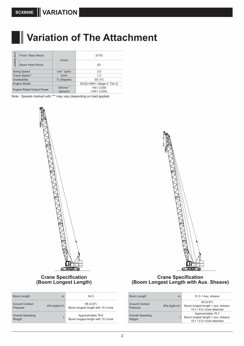
Variation of The Attachment
VARIATIONSCX800E
Line Speed *
Front / Rear Winch m/min
37/75
Boom Hoist Winch 62
Swing Speed min-1 (rpm) 3.0Travel Speed * km/h 1.3Gradeability % (Degree) 30 (17)Engine Model ISUZU 6HK1 (Stage II, Tier 2)
Engine Rated Output Power kW/min-1
(ps/rpm)140 / 2,000
(190 / 2,000)
Note : Speeds marked with "*" may vary depending on load applied.
Boom Length m 51.5 + Aux. sheave
Ground Contact Pressure kPa (kgf/cm²)
85 (0.87)Boom longest length + aux. sheave,
15 t + 6.5 t hook attached
Overall Operating Weight t
Approximately 76.7Boom longest length + aux. sheave,
15 t + 6.5 t hook attached
Crane Specification (Boom Longest Length with Aux. Sheave)
Crane Specification (Boom Longest Length)
Boom Length m 54.5
Ground Contact Pressure kPa (kgf/cm²) 85 (0.87)
Boom longest length with 15 t hook
Overall Operating Weight t Approximately 76.6
Boom longest length with 15 t hook
3
Variation of The Attachment 2
Specifications 4
Crane Specifications 5
Dimensions and Specifications ................................................................................................................5
Working Ranges .........................................................................................................................................7
Main Boom .......................................................................................................................................................... 7
Aux. Sheave ........................................................................................................................................................ 8
Gross Rated Load Table ............................................................................................................................9
Main Boom .......................................................................................................................................................... 9
Aux. Sheave ...................................................................................................................................................... 10
Main Boom with Aux. Sheave .............................................................................................................................11
Clamshell Specifications 12
Dimensions and Specifications ..............................................................................................................12
Working Ranges ................................................................................................................................................ 12
Specifications .................................................................................................................................................... 12
Clamshell Bucket ............................................................................................................................................... 12
Gross Rated Load Table .................................................................................................................................... 12
VARIATION
SPECIFICATIONS
CONTENTS SCX800E
TECHNICAL DATA
Weights and Dimensions of Disassembled Units 13
Weights and Dimensions List .................................................................................................................13
Equipment List 16
Standard and Optional Equipment .........................................................................................................16
4
Specifications
SPECIFICATIONSSCX800E
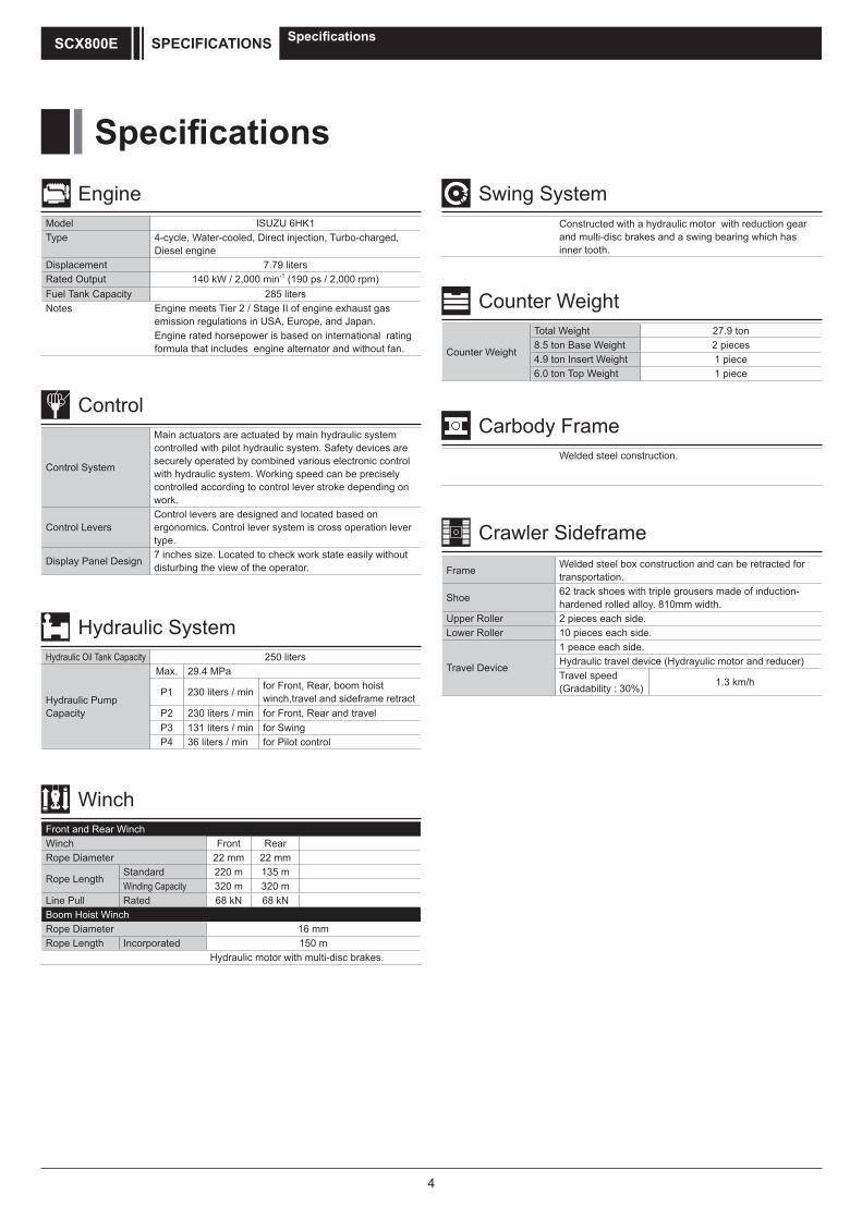
Specifications
Model ISUZU 6HK1Type 4-cycle, Water-cooled, Direct injection, Turbo-charged,
Diesel engineDisplacement 7.79 litersRated Output 140 kW / 2,000 min-1 (190 ps / 2,000 rpm)Fuel Tank Capacity 285 litersNotes Engine meets Tier 2 / Stage II of engine exhaust gas
emission regulations in USA, Europe, and Japan. Engine rated horsepower is based on international rating formula that includes engine alternator and without fan.
Engine
Control System
Main actuators are actuated by main hydraulic system controlled with pilot hydraulic system. Safety devices are securely operated by combined various electronic control with hydraulic system. Working speed can be precisely controlled according to control lever stroke depending on work.
Control LeversControl levers are designed and located based on ergonomics. Control lever system is cross operation lever type.
Display Panel Design 7 inches size. Located to check work state easily without disturbing the view of the operator.
Control
Hydraulic Oil Tank Capacity 250 liters
Hydraulic Pump Capacity
Max. 29.4 MPa
P1 230 liters / min for Front, Rear, boom hoist winch,travel and sideframe retract
P2 230 liters / min for Front, Rear and travelP3 131 liters / min for SwingP4 36 liters / min for Pilot control
Hydraulic System
Front and Rear WinchWinch Front RearRope Diameter 22 mm 22 mm
Rope LengthStandard 220 m 135 mWinding Capacity 320 m 320 m
Line Pull Rated 68 kN 68 kNBoom Hoist WinchRope Diameter 16 mmRope Length Incorporated 150 m
Hydraulic motor with multi-disc brakes.
Winch
Constructed with a hydraulic motor with reduction gear and multi-disc brakes and a swing bearing which has inner tooth.
Swing System
Counter Weight
Total Weight 27.9 ton8.5 ton Base Weight 2 pieces4.9 ton Insert Weight 1 piece6.0 ton Top Weight 1 piece
Counter Weight
Welded steel construction.
Carbody Frame
Frame Welded steel box construction and can be retracted for transportation.
Shoe 62 track shoes with triple grousers made of induction-hardened rolled alloy. 810mm width.
Upper Roller 2 pieces each side.Lower Roller 10 pieces each side.
Travel Device
1 peace each side.Hydraulic travel device (Hydrayulic motor and reducer)Travel speed(Gradability : 30%) 1.3 km/h
Crawler Sideframe
5
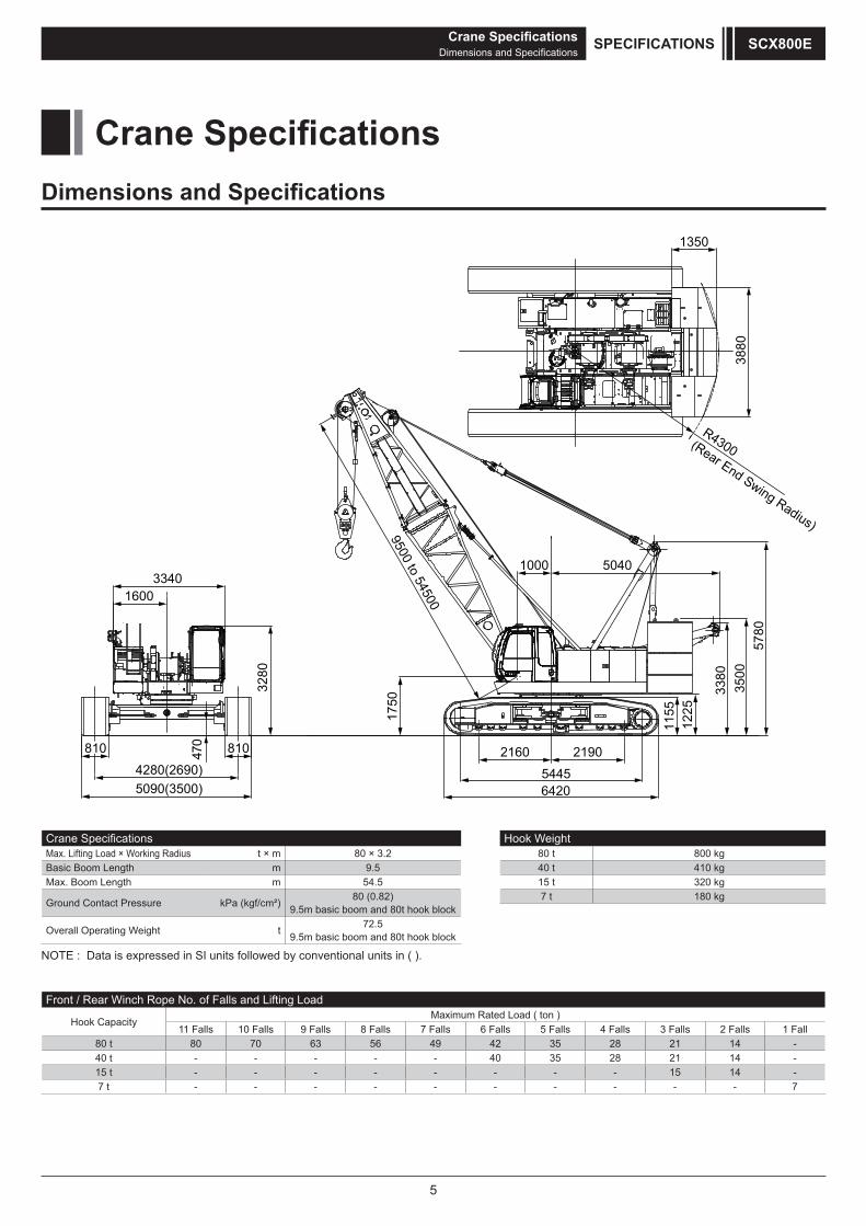
Dimensions and Specifications
R4300(Rear End Swing Radius)
3880
1350
54456420
21902160
1000
1750
5040
9500 to 54500
1155
1225
3380
3500
5780
4280(2690)5090(3500)
3280
470
16003340
810 810
Crane SpecificationsMax. Lifting Load × Working Radius t × m 80 × 3.2Basic Boom Length m 9.5Max. Boom Length m 54.5
Ground Contact Pressure kPa (kgf/cm²) 80 (0.82)9.5m basic boom and 80t hook block
Overall Operating Weight t 72.59.5m basic boom and 80t hook block
Hook Weight80 t 800 kg40 t 410 kg15 t 320 kg7 t 180 kg
Front / Rear Winch Rope No. of Falls and Lifting Load
Hook CapacityMaximum Rated Load ( ton )
11 Falls 10 Falls 9 Falls 8 Falls 7 Falls 6 Falls 5 Falls 4 Falls 3 Falls 2 Falls 1 Fall80 t 80 70 63 56 49 42 35 28 21 14 -40 t - - - - - 40 35 28 21 14 -15 t - - - - - - - - 15 14 -7 t - - - - - - - - - - 7
NOTE : Data is expressed in SI units followed by conventional units in ( ).
Crane SpecificationsDimensions and Specifications
SPECIFICATIONS SCX800E
Crane Specifications
6
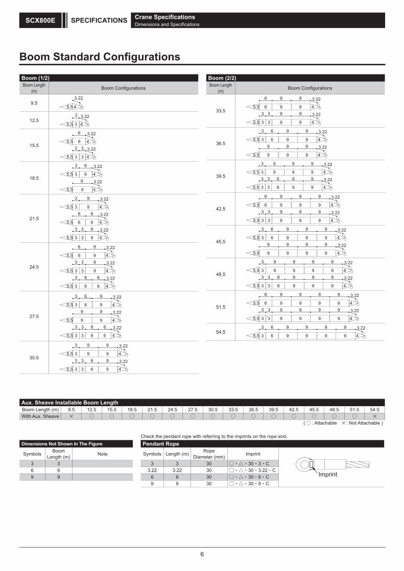
Boom (2/2)Boom Length
(m) Boom Configurations
33.55.5 4
9 3.22
9
3
3
9
9
3
3
5.5 4
9 3.22
9
9
9
6
6
36.55.5 4
9 3.22
9
9
9
5.5 4
9 3.22
9
9
9
6
63
3
9
9
39.55.5 4
9 3.22
9
9
96
6
3
3
5.5 4
9 3.22
9
9
93
3
9
9
3
3
42.55.5 4
9 3.22
9
9
9
3
3
9
9
6
6
5.5 4
9 3.22
9
9
9
9
93
3
45.55.5 4
9 3.22
9
9
9
9
9
6
63
3
5.5 4
9 3.22
9
9
9
9
9
9
9
48.55.5 4
9 3.22
9
9
9
9
93
3
5.5 4
9 3.22
9
9
9
9
9
9
96
63
3
3
3
51.55.5 4
9 3.22
9
9
9
9
9
5.5 4
9 3.22
9
9
9
9
9
9
9
3
3
3
3
6
69
9
54.55.5 4
9 3.22
9
9
9
9
9
9
9
6
63
3
Aux. Sheave Installable Boom LengthBoom Length (m) 9.5 12.5 15.5 18.5 21.5 24.5 27.5 30.5 33.5 36.5 39.5 42.5 45.5 48.5 51.5 54.5With Aux. Sheave
( : Attachable : Not Attachable )
Dimensions Not Shown In The Figure
Symbols BoomLength (m) Note
3 36 69 9
Pendant Rope
Symbols Length (m) Rope Diameter (mm) Imprint
3 3 30 □・△・30・3・C3.22 3.22 30 □・△・30・3.22・C
6 6 30 □・△・30・6・C9 9 30 □・△・30・9・C
Boom Standard Configurations
Check the pendant rope with referring to the imprints on the rope end.
Boom (1/2)Boom Length
(m) Boom Configurations
9.55.5 4
3.22
12.55.5 43
3 3.22
15.55.5 46
6 3.22
5.5 433
3.2233
18.55.5 46
6 3.22
5.5 4
3.22
3
3
9
9
21.5
5.5 4
9 3.22
3
3
5.5 4
3.22
9
6 6
6 6
5.5 4
3.22
6
6
3
3
3
3
24.5
6
5.5 4
9 3.22
9
5.5 4
9 3.22
9
5.5 4
3.22
3
3
6
3
3
3
3
6
6
6
6
27.5
6
5.5 4
9 3.22
9
5.5 4
9 3.22
9
5.5 4
3.22
3
3
6
6
6
6
6
3
3
9
9
3
3
30.5 65.5 4
9 3.22
9
6
3
3
5.5 4
9 3.22
93
3
9
9
3
3
Crane SpecificationsDimensions and Specifications
SPECIFICATIONSSCX800E
Imprint
7
Crane SpecificationsWorking Ranges
SPECIFICATIONS SCX800E
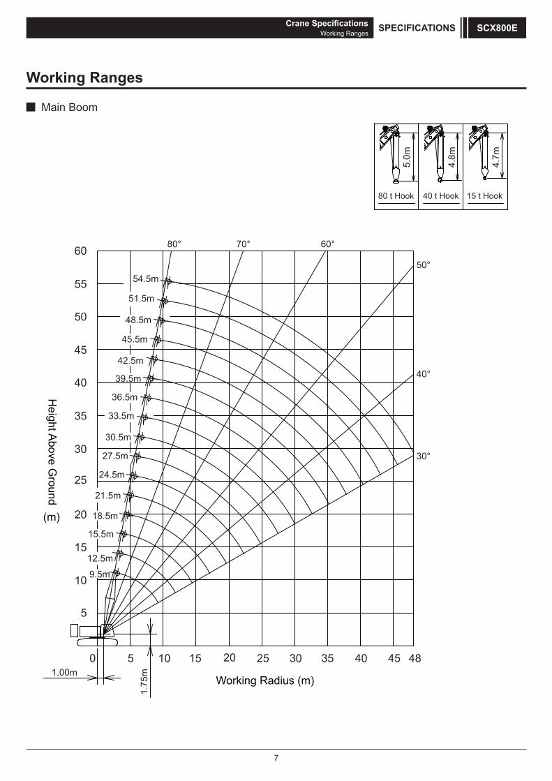
Working Ranges
Main Boom
5
10
15
20
25
30
35
40
45
50
55
60
Working Radius (m)
0 5 10 15 20 25 30 35 40 45 481.00m
1.75
m
4.7m
4.8m
5.0m
60°70°80°
30°
40°
50°54.5m
51.5m
48.5m
45.5m
42.5m
39.5m
36.5m
33.5m
30.5m
27.5m
24.5m
21.5m
18.5m
15.5m
12.5m
9.5m
Height A
bove Ground
(m)
80 t Hook 40 t Hook 15 t Hook
8
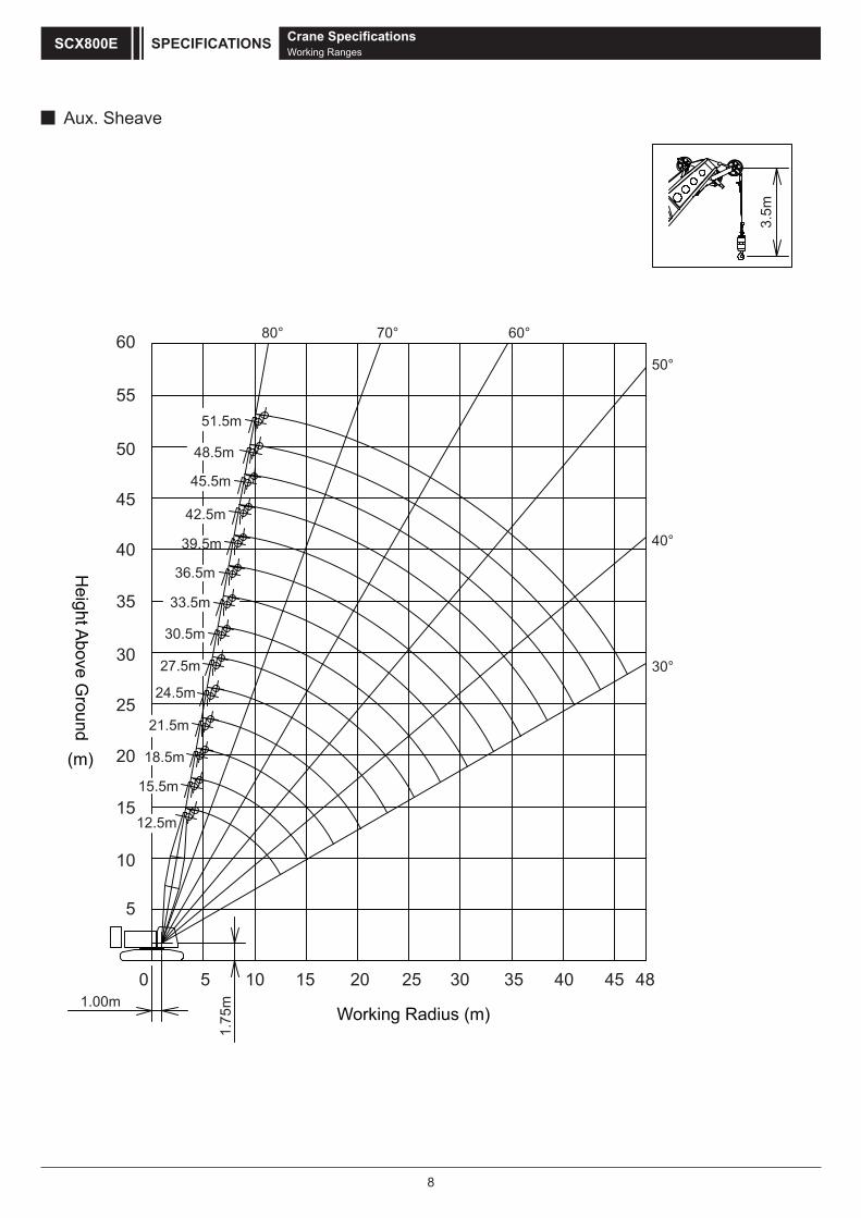
Aux. Sheave
5
10
15
20
25
30
35
40
45
50
55
60
Working Radius (m)
0 5 10 15 20 25 30 35 40 45 481.00m
1.75
m
3.5m
60°70°80°
30°
40°
50°
51.5m
48.5m
45.5m
42.5m
39.5m
36.5m
33.5m
30.5m
27.5m
24.5m
21.5m
18.5m
15.5m
12.5m
Height A
bove Ground
(m)
Crane SpecificationsWorking Ranges
SPECIFICATIONSSCX800E
9
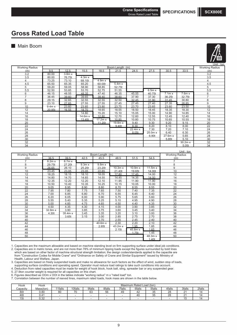
Gross Rated Load Table
Main Boom
1. Capacities are the maximum allowable and based on machine standing level on firm supporting surface under ideal job conditions.2. Capacities are in metric tones, and are not more than 78% of minimum tipping loads except the figures surrounded by bold lines which are based on other factor of machine structural strength limitation; the design codes/standards applied to the capacitie are from "Construction Codes for Mobile Crane" and "Ordinance on Safety of Crane and Similar Equipment" issued by Ministry of Health, Labour and Welfare, Japan. 3. Capacities are based on freely suspended loads and make no allowance for such factors as the effect of wind, sudden stop of loads, supporting surface conditions and operating speed. Operator must reduce load ratings to take such conditions into account.4. Deduction from rated capacities must be made for weight of hook block, hook ball, sling, spreader bar or any suspended gear.5. 27.9ton counter weight is required for all capacities on this chart.6. Figures described as OOm x OOt in the tables indicate "working radius" m x "rated load" ton.7. Correlation between the number of reeved lines, maximum rated loads, hook mass are shown in the table below.
Hook HookCapacity Mass(ton) 11falls 10falls 9falls 8falls 7falls 6falls 5falls 4falls 3falls 2falls
40t 0.41 - - - - - 40 35 28 21 1415t 0.32 - - - - - - - - 15 14
Maximum Rated Load (ton)
80t 0.80 80 70 63 56 49 42 35 28 21 14
Unit : tonWorking Radius Working Radius
(m) 9.5 12.5 15.5 18.5 21.5 24.5 27.5 30.5 33.5 (m)3.2 80.00 3.8m x 3.23.5 80.00 76.75t 4.3m x 3.54 73.25 73.10 68.10t 4.9m x 44.5 65.50 65.35 65.20 60.00t 5.4x m4.55 59.20 59.05 58.90 58.85 52.75t 5
5.5x m5.655.1557.2507.3558.3505.255.56 46.15 48.55 48.35 47.40 46.35 45.55 40.75t 7.1m x 7.6m x 67 36.45 39.60 39.65 39.40 38.60 37.90 37.30 36.25t 32.75t 78 29.15 32.65 32.55 32.55 32.50 32.45 31.90 31.45 30.80 89 23.10 27.65 27.55 27.55 27.45 27.45 27.40 27.35 26.85 910 9.4m x 23.60 23.85 23.80 23.75 23.70 23.65 23.60 23.50 1012 20.85t 16.55 18.70 18.65 18.55 18.50 18.45 18.35 18.30 12
4158.4109.4100.5150.5101.5102.5108.414116 14.6m x 12.80 12.70 12.60 12.55 12.45 12.40 16
t54.3181 17.2m x 10.85 10.80 10.75 10.65 10.55 18t02.1102 19.8m x 9.40 9.30 9.20 9.15 20
2200.801.802.803.8t04.92224 22.4m x 7.30 7.20 7.10 2426 8.05t 25.0m x 6.40 6.30 2628 6.90t 27.6m x 5.65 2830 5.85t 5.10 3032 30.2m x 3234 5.05t 34
Boom Length (m)
Unit : tonWorking Radius Working Radius
(m) 36.5 39.5 42.5 45.5 48.5 51.5 54.5 (m)7 8.2m x 8.7m x 78 29.75t 27.20t 8x m8.9x m3.99 26.65 26.10 25.20t 23.20t 10.3m x 10.9m x 11.5m x 910 23.45 23.05 23.05 22.65 21.40t 19.65t 14.00t 1012 18.25 18.15 18.10 18.05 17.80 17.45 14.00 1214 14.80 14.70 14.65 14.55 14.45 14.35 14.00 1416 12.35 12.20 12.20 12.10 11.95 11.90 11.90 1618 10.50 10.40 10.35 10.25 10.15 10.05 10.00 1820 9.05 8.95 8.90 8.80 8.70 8.55 8.55 2022 7.95 7.80 7.75 7.65 7.50 7.40 7.35 2224 7.00 6.85 6.80 6.70 6.55 6.45 6.40 2426 6.20 6.05 6.00 5.90 5.75 5.65 5.60 2628 5.55 5.40 5.35 5.25 5.10 4.95 4.90 2830 5.00 4.85 4.75 4.65 4.50 4.40 4.35 3032 4.50 4.35 4.30 4.15 4.00 3.90 3.85 3234 32.8m x 3.90 3.85 3.75 3.60 3.45 3.40 3436 4.30t 35.4m x 3.45 3.35 3.20 3.10 3.00 36
8307.257.258.200.351.3t56.3830404.254.255.207.204
42 40.6m x 2.30 2.20 2.10 42t56.244 43.2m x 1.95 1.85 44
t51.264 45.8m x 1.65 4648 1.75t 1.45 4850 48.3m x 50
1.40t
Boom Length (m)
Crane SpecificationsGross Rated Load Table
SPECIFICATIONS SCX800E
10
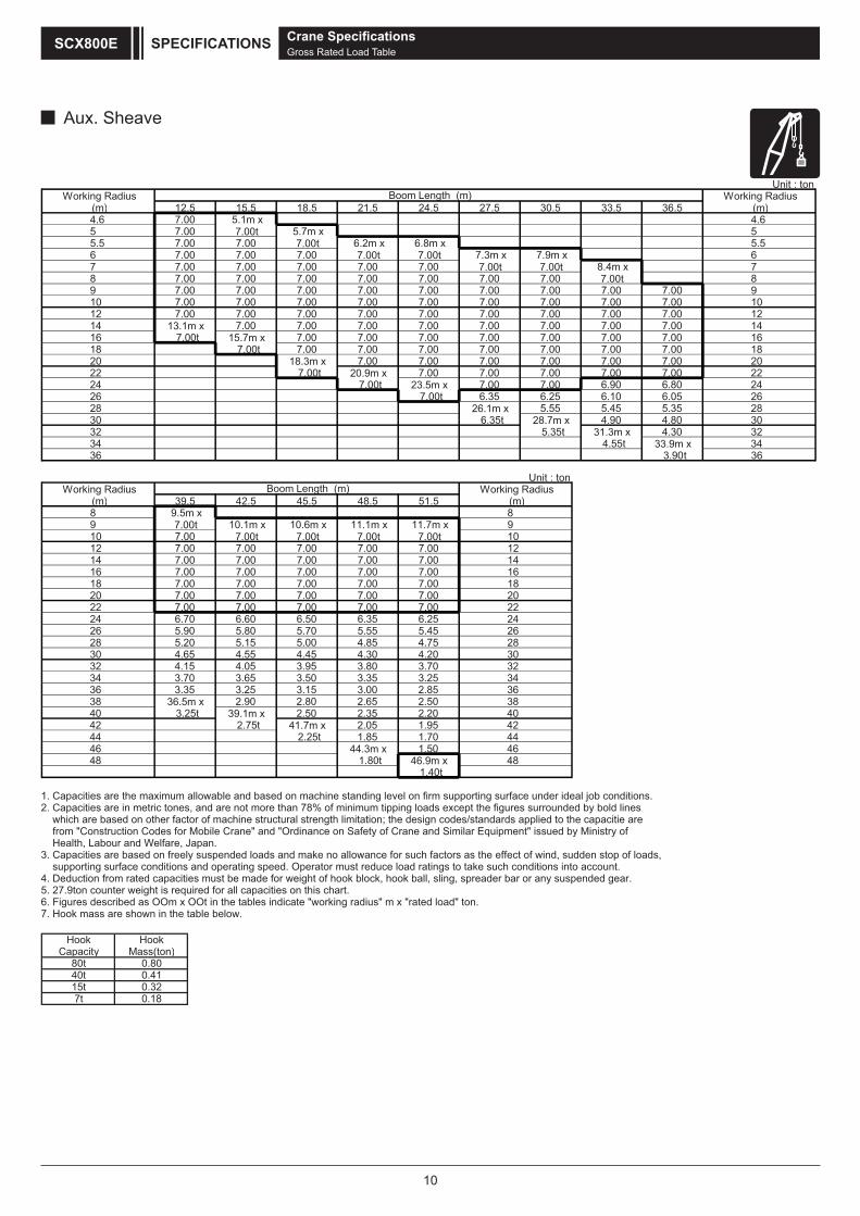
Aux. Sheave
1. Capacities are the maximum allowable and based on machine standing level on firm supporting surface under ideal job conditions.2. Capacities are in metric tones, and are not more than 78% of minimum tipping loads except the figures surrounded by bold lines which are based on other factor of machine structural strength limitation; the design codes/standards applied to the capacitie are from "Construction Codes for Mobile Crane" and "Ordinance on Safety of Crane and Similar Equipment" issued by Ministry of Health, Labour and Welfare, Japan. 3. Capacities are based on freely suspended loads and make no allowance for such factors as the effect of wind, sudden stop of loads, supporting surface conditions and operating speed. Operator must reduce load ratings to take such conditions into account.4. Deduction from rated capacities must be made for weight of hook block, hook ball, sling, spreader bar or any suspended gear.5. 27.9ton counter weight is required for all capacities on this chart.6. Figures described as OOm x OOt in the tables indicate "working radius" m x "rated load" ton.7. Hook mass are shown in the table below.
Hook HookCapacity Mass(ton)
80t 0.8040t 0.4115t 0.327t 0.18
Unit : tonWorking Radius Working Radius
(m) 12.5 15.5 18.5 21.5 24.5 27.5 30.5 33.5 36.5 (m)4.6 7.00 5.1m x 4.65 7.00 7.00t 5.7m x 55.5 7.00 7.00 7.00t 5.5x m8.6x m2.66 7.00 7.00 7.00 7.00t 7.00t 6x m9.7x m3.77 7.00 7.00 7.00 7.00 7.00 7.00t 7.00t 7x m4.88 7.00 7.00 7.00 7.00 7.00 7.00 7.00 7.00t 89 7.00 7.00 7.00 7.00 7.00 7.00 7.00 7.00 7.00 910 7.00 7.00 7.00 7.00 7.00 7.00 7.00 7.00 7.00 1012 7.00 7.00 7.00 7.00 7.00 7.00 7.00 7.00 7.00 1214 13.1m x 7.00 7.00 7.00 7.00 7.00 7.00 7.00 7.00 1416 7.00t 15.7m x 7.00 7.00 7.00 7.00 7.00 7.00 7.00 16
8100.700.700.700.700.700.700.7t00.7 8120 18.3m x 7.00 7.00 7.00 7.00 7.00 7.00 20
t00.7 22 20.9m x 7.00 7.00 7.00 7.00 7.00 22t00.742 23.5m x 7.00 7.00 6.90 6.80 24
6250.601.652.653.6t00.76228 26.1m x 5.55 5.45 5.35 2830 6.35t 28.7m x 4.90 4.80 3032 5.35t 31.3m x 4.30 3234 4.55t 33.9m x 3436 3.90t 36
Boom Length (m)
Unit : tonWorking Radius Working Radius
(m) 39.5 42.5 45.5 48.5 51.5 (m)8x m5.98
9 7.00t 10.1m x 10.6m x 11.1m x 11.7m x 910 7.00 7.00t 7.00t 7.00t 7.00t 1012 7.00 7.00 7.00 7.00 7.00 1214 7.00 7.00 7.00 7.00 7.00 1416 7.00 7.00 7.00 7.00 7.00 1618 7.00 7.00 7.00 7.00 7.00 1820 7.00 7.00 7.00 7.00 7.00 2022 7.00 7.00 7.00 7.00 7.00 2224 6.70 6.60 6.50 6.35 6.25 2426 5.90 5.80 5.70 5.55 5.45 2628 5.20 5.15 5.00 4.85 4.75 2830 4.65 4.55 4.45 4.30 4.20 3032 4.15 4.05 3.95 3.80 3.70 3234 3.70 3.65 3.50 3.35 3.25 3436 3.35 3.25 3.15 3.00 2.85 3638 36.5m x 2.90 2.80 2.65 2.50 3840 3.25t 39.1m x 2.50 2.35 2.20 40
t57.2 24 41.7m x 2.05 1.95 424407.158.1t52.244
46 44.3m x 1.50 46t08.184 46.9m x 48
1.40t
Boom Length (m)
Crane SpecificationsGross Rated Load Table
SPECIFICATIONSSCX800E
11
Crane SpecificationsGross Rated Load Table
SPECIFICATIONS SCX800E
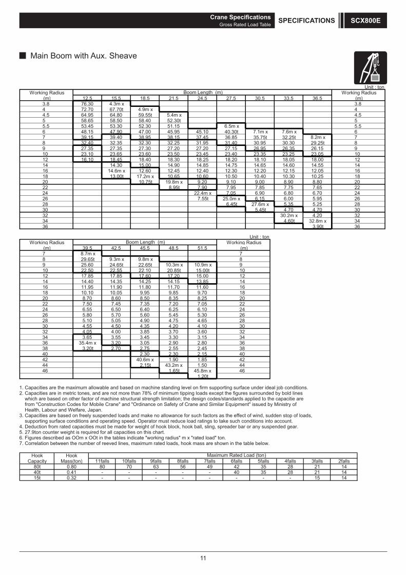
Main Boom with Aux. Sheave
1. Capacities are the maximum allowable and based on machine standing level on firm supporting surface under ideal job conditions.2. Capacities are in metric tones, and are not more than 78% of minimum tipping loads except the figures surrounded by bold lines which are based on other factor of machine structural strength limitation; the design codes/standards applied to the capacitie are from "Construction Codes for Mobile Crane" and "Ordinance on Safety of Crane and Similar Equipment" issued by Ministry of Health, Labour and Welfare, Japan. 3. Capacities are based on freely suspended loads and make no allowance for such factors as the effect of wind, sudden stop of loads, supporting surface conditions and operating speed. Operator must reduce load ratings to take such conditions into account.4. Deduction from rated capacities must be made for weight of hook block, hook ball, sling, spreader bar or any suspended gear.5. 27.9ton counter weight is required for all capacities on this chart.6. Figures described as OOm x OOt in the tables indicate "working radius" m x "rated load" ton.7. Correlation between the number of reeved lines, maximum rated loads, hook mass are shown in the table below.
Hook HookCapacity Mass(ton) 11falls 10falls 9falls 8falls 7falls 6falls 5falls 4falls 3falls 2falls
40t 0.41 - - - - - 40 35 28 21 1415t 0.32 - - - - - - - - 15 14
Maximum Rated Load (ton)
80t 0.80 80 70 63 56 49 42 35 28 21 14
Unit : tonWorking Radius Working Radius
(m) 39.5 42.5 45.5 48.5 51.5 (m)7x m7.87
8 29.65t 8x m8.9x m3.99 25.60 24.65t 22.65t 10.3m x 10.9m x 910 22.50 22.55 22.10 20.85t 15.00t 1012 17.85 17.85 17.60 17.20 15.00 1214 14.40 14.35 14.25 14.15 13.85 1416 11.95 11.90 11.80 11.70 11.60 1618 10.10 10.05 9.95 9.85 9.70 1820 8.70 8.60 8.50 8.35 8.25 2022 7.50 7.45 7.35 7.20 7.05 2224 6.55 6.50 6.40 6.25 6.10 2426 5.80 5.70 5.60 5.45 5.30 2628 5.10 5.05 4.90 4.75 4.65 2830 4.55 4.50 4.35 4.20 4.10 3032 4.05 4.00 3.85 3.70 3.60 3234 3.65 3.55 3.45 3.30 3.15 3436 35.4m x 3.20 3.05 2.90 2.80 3638 3.20t 2.70 2.75 2.55 2.45 38
0451.203.203.20442 40.6m x 1.90 1.85 42
t51.244 43.2m x 1.50 44t56.164 45.8m x 46
1.20t
Boom Length (m)
Unit : tonWorking Radius Working Radius
(m) 12.5 15.5 18.5 21.5 24.5 27.5 30.5 33.5 36.5 (m)3.8 76.30 4.3m x 3.84 72.70 67.70t 4.9m x 44.5 64.95 64.80 59.55t 5.4m x 4.55 58.65 58.50 58.40 52.30t 5
5.5x m5.651.1503.2503.3554.355.56 48.15 47.90 47.00 45.95 45.10 40.30t 6x m6.7x m1.77 39.15 39.40 38.95 38.15 37.45 36.85 35.75t 32.25t 8.2m x 78 32.40 32.35 32.30 32.25 31.95 31.40 30.95 30.30 29.25t 89 27.35 27.35 27.30 27.20 27.20 27.15 26.95 26.35 26.15 910 23.10 23.65 23.60 23.50 23.45 23.40 23.35 23.25 23.05 1012 16.10 18.45 18.40 18.30 18.25 18.20 18.10 18.05 18.00 12
4155.4106.4156.4157.4158.4109.4100.5103.414116 14.6m x 12.60 12.45 12.40 12.30 12.20 12.15 12.05 16
t00.3181 17.2m x 10.65 10.60 10.50 10.40 10.30 10.25 18t57.0102 19.8m x 9.20 9.10 9.00 8.90 8.80 20
2256.757.758.759.709.7t59.82224 22.4m x 7.05 6.90 6.80 6.70 24
t55.762 25.0m x 6.15 6.00 5.95 2628 6.45t 27.6m x 5.35 5.25 2830 5.45t 4.70 4.70 3032 30.2m x 4.20 3234 4.60t 32.8m x 3436 3.90t 36
Boom Length (m)
12
Clamshell SpecificationsDimensions and Specifications
1000
Working Radius
AC
DL
H1 H
54456420
21902160
1750
H2
H
50409500 to 18500
1155
1225
3380
3500
5780
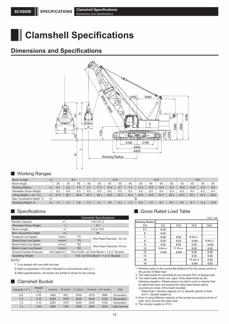
Clamshell SpecificationsBucket Capacity m3 0.8/1.0/1.2Allowable Gross Weight t 6.0Boom Length m 9.5 to 18.5Max. Excavation Depth m 36Suspend Line Speed m/min *75
Wire Rope Diameter 22 mmOpen/Close Line Speed m/min *75Boom Hoist Line Speed m/min *62
Wire Rope Diameter 16 mmBoom Lower Line Speed m/min *62Ground Contact Pressure kPa (kgf/cm²) 83.0 (0.85) (w/ 9.5m Boom + 1.2 m3 Bucket)Operating Weight t 74.6 (w/ 9.5m Boom + 1.2 m3 Bucket)
NOTE : 1.*Line speeds will vary with the load. 2.Data is expressed in Sl units, followed by conventional units in ( ). 3.Other specifications, not shown are similar to those for the cranes.
Capacity ( m3 ) Weight( t ) A (mm) B (mm) C (mm) H (mm) H1 (mm) Use
0.8 2.00 1880 970 2230 2270 2980 Excavation1.0 2.45 2020 1070 2430 2430 3150 Excavation1.2 3.10 2020 1070 2430 2430 3150 Excavation1.2 2.40 2000 1160 2650 2600 3240 Light Service
Boom Length m 9.5 12.5 15.5 18.5 Boom Angle ° 35 45 55 65 35 45 55 65 35 45 55 65 35 45 55 65Working Radius m 9.2 8.2 7.0 5.7 11.7 10.4 8.7 7.0 14.2 12.5 10.5 8.3 16.6 14.6 12.2 9.5Allowable Gross Weight t 6.0 6.0 6.0 6.0 6.0 6.0 6.0 6.0 6.0 6.0 6.0 6.0 6.0 6.0 6.0 6.0Lifting Height L (D + H2) m 37.4 38.7 39.8 40.7 39.1 40.9 42.3 43.4 40.8 43.0 44.7 46.1 42.5 45.1 47.2 48.9Max. Excavation Depth D m 36Dumping Height H2 m 1.4 2.7 3.8 4.7 3.1 4.9 6.3 7.4 4.8 7.0 8.7 10.1 6.5 9.1 11.2 12.9
Working Ranges
Specifications Gross Rated Load Table
Clamshell Bucket
1. Working radius is the horizontal distance from the swing center to the gravity of lifted load.2. The rated loads for clamshell do not exceed 70% of tipping load.3. The rated loads shown are upper limits determined by the following equation. Please select a bucket in such a manner that its rated load does not exceed the rated load shown below, according to kinds of the loads handled. Rated load = Bucket capacity (m3) x Specific gravity of load (t/m3) + Bucket weight (t)4. Even if using different capacity of the bucket according to kinds of load, don't exceed the rated load.5. The counter weight is 27.9 t.
Unit ; ton
9.5 12.5 15.5 18.55.7 6.006 6.007 6.008 6.009 6.00
10 9.2m x6.00t
6.006.006.00 6.00
6.006.006.00
6.00 6.006.00
6.00t
6.00
6.0011.7m x6.00t12
141616
Working Radius(m)
8.3m x9.5m x6.00t
14.2m x6.00t
Clamshell SpecificationsDimensions and Specifications
SPECIFICATIONSSCX800E
13
Weights and Dimensions of Disassembled UnitsWeights and Dimensions List TECHNICAL DATA SCX800E
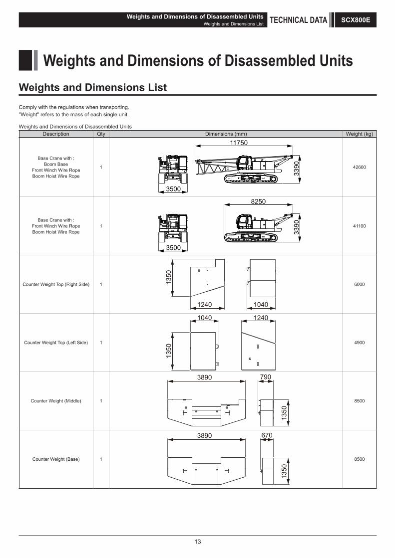
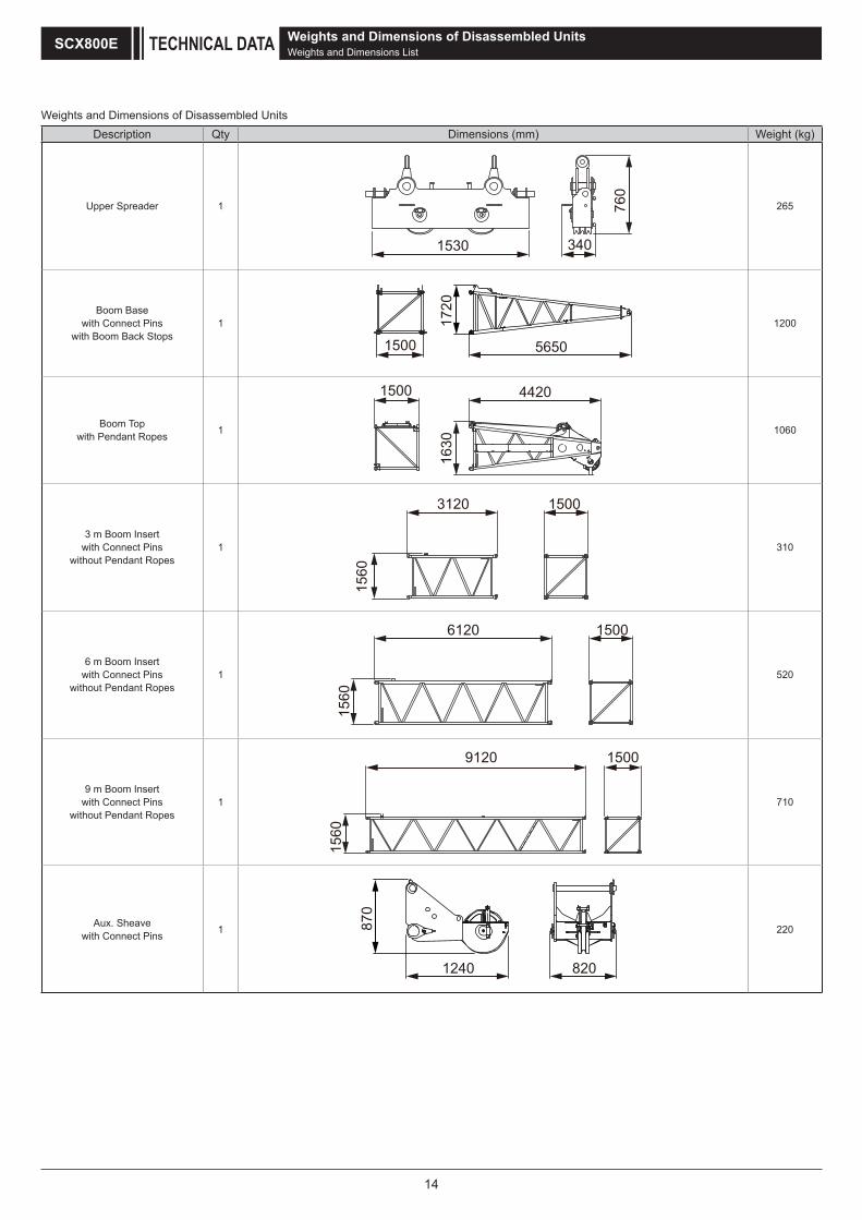
Weights and Dimensions of Disassembled UnitsDescription Qty Dimensions (mm) Weight (kg)
Base Crane with :Boom Base
Front Winch Wire RopeBoom Hoist Wire Rope
1
3500
3390
11750
42600
Base Crane with :Front Winch Wire RopeBoom Hoist Wire Rope
1
3500
3390
8250
41100
Counter Weight Top (Right Side) 1
1240 1040
1350
6000
Counter Weight Top (Left Side) 1
1350
1040 1240
4900
Counter Weight (Middle) 1
1350
3890 790
8500
Counter Weight (Base) 1
1350
3890 670
8500
Weights and Dimensions of Disassembled UnitsWeights and Dimensions ListComply with the regulations when transporting."Weight" refers to the mass of each single unit.
14
Weights and Dimensions of Disassembled UnitsDescription Qty Dimensions (mm) Weight (kg)
Upper Spreader 1 760
1530 340
265
Boom Basewith Connect Pins
with Boom Back Stops1 17
20
1500 5650
1200
Boom Topwith Pendant Ropes 1
1630
1500 4420
1060
3 m Boom Insertwith Connect Pins
without Pendant Ropes1
1560
3120 1500
310
6 m Boom Insertwith Connect Pins
without Pendant Ropes1
1560
6120 1500
520
9 m Boom Insertwith Connect Pins
without Pendant Ropes1
1560
9120 1500
710
Aux. Sheavewith Connect Pins 1 87
0
1240 820
220
Weights and Dimensions of Disassembled UnitsWeights and Dimensions ListTECHNICAL DATASCX800E
15
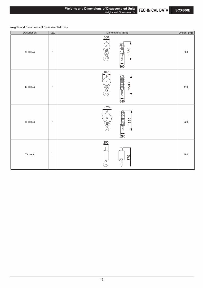
Weights and Dimensions of Disassembled UnitsWeights and Dimensions List TECHNICAL DATA SCX800E
Weights and Dimensions of Disassembled Units
Description Qty Dimensions (mm) Weight (kg)
80 t Hook 1
460
660
1850 800
40 t Hook 1
340
1590
620
410
15 t Hook 1
620
1360
290
320
7 t Hook 1
250
870 180
16
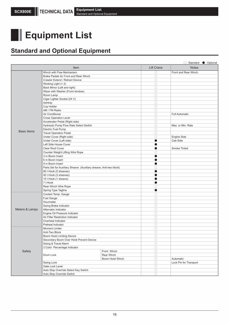
Equipment List Standard and Optional Equipment
: Standard : Optional
Item Lift Crane Notes
Basic Items
Winch with Free Mechanism ○ Front and Rear WinchBrake Pedals for Front and Rear Winch ○Crawler Extend / Retract Device ○Working Light (× 2) ○Back Mirror (Left and right) ○Wiper with Washer (Front window) ○Room Lamp ○Cigar Lighter Socket (24 V) ○Ashtray ○Cup Holder ○AM / FM Radio ○Air Conditioner ○ Full AutomaticCross Operation Lever ○Accelerator Pedal (Right side) ○Hydraulic Pump Flow Rate Select Switch ○ Max. or Min. RateElectric Fuel Pump ○Travel Operation Pedal ○Under Cover (Right side) ○ Engine SideUnder Cover (Left side) ● Cab SideLeft Side House Cover ●Clear Roof Cover ● Smoke TintedCounter Weight Lifting Wire Rope ○3 m Boom Insert ●6 m Boom Insert ●9 m Boom Insert ●Parts Set for Auxiliary Sheave (Auxiliary sheave, Anti-two block) ○80 t Hook (5 sheaves) ●40 t Hook (3 sheaves) ●15 t Hook (1 sheave) ●7 t Hook ●Rear Winch Wire Rope ○Spring Type Tagline ●
Meters & Lamps
Coolant Temp. Gauge ○Fuel Gauge ○Hourmeter ○Swing Brake Indicator ○Alternator Indicator ○Engine Oil Pressure Indicator ○Air Filter Restriction Indicator ○Overheat Indicator ○Preheat Indicator ○
Safety
Moment Limiter ○Anti-Two Block ○Boom Hoist Limiting Device ○Secondary Boom Over Hoist Prevent Device ○Swing & Travel Alarm ○3 Color Percentage Indicator ○
Drum LockFront Winch ○Rear Winch ○Boom Hoist Winch ○ Automatic
Swing Lock ○ Lock Pin for TransportGate Lock Lever ○Auto Stop Override Select Key Switch ○Auto Stop Override Switch ○
Equipment List Standard and Optional EquipmentTECHNICAL DATASCX800E

M E M O SCX800E

M E M OSCX800E


• We are constantly improving our products and therefore reserve the right to change designs and speafications without notice. • Units in this specification are shown under International System of Units; the figures in parenthesis are under Gravitational System of Units as old one.
9-3, Higashi-Ueno 6-chome, Taito-ku, Tokyo 110-0015, JapanPhone: 81-3-3845-1387 Facsimile: 81-3-3845-1394http://www.hsc-cranes.com


![NORI 160 RXL/RXS - KSB SE · 2019-09-26 · NORI 160 RXL/RXS. Dimensions and weights Dimensions and weights of NORI 160 RXL. NORI 160 RXL Dimensions [mm] and weights [kg] PN DN l](https://img.pdfslide.us/doc/110x75/5f9103d96e100657b30e7c80/nori-160-rxlrxs-ksb-se-2019-09-26-nori-160-rxlrxs-dimensions-and-weights.jpg)