Embed Size (px)
Citation preview
Maxi-StamperTM II • 90 to 300 TonsOptional FeaturesLink Motion H-Frame Wet Clutch
Specifications
The Heim Group reserves the right to change design or detail of its products without notice. Point of operation safety guarding or devices are the sole responsibility of the employer (user) of the machine as provided in ANSI B11.1 (2001) as published by the American National Standards Institute, Inc. and OSHA regulations. “Heim” and “Rousselle” are Reg. TM's; “Maxi-Stamper” and “Stamping Out Downtime” are TM’s of The Heim Group. ©Heim L.P. 2012. All Rights Reserved.
www.theheimgroup.com • 6360 West 73rd Street, Chicago, IL 60638
Sales/Service: 708-496-7400 • 800-927-9393 • Fax: 708-496-7428 • Parts Fax: 708-496-0708 • Email: [email protected]
Model Number H1-90 H1-110 H1-150 H1-200 H1-300
Capacity (U.S.) B.D.C. 90 110 150 200 300
Tonnage Rating Point .200 .200 .250 .250 .250
Bed and Bolster Area 46 x 26 46 x 26 57 x 26 57 x 30 66 X 36
Slide Area 32.75 x 20 32.75 x 20 39.25 x 20 39.25 x 24 43.25 X 28
Stroke Length 2 - 4 - 6 4 - 6 - 8 6 - 8 - 10 6 - 8 - 10 6 - 8 - 10
Die Height S.D.A.U. OVER BOLSTER 14 - 13 - 12 13 - 12 - 11 14 - 13 -12 16 - 15 -14 20 - 19 - 18
Variable Speed 70-140 50-100 35-70 50-100 35-70 35-70 35-70 30-60 25-50 35-70 30-60 25-50 30-60 25-50 20-40
Depth of Throat 14.5 14.5 16.5 16.5 18.5
Opening Thru Back 31 31 39.25 39.25 42
Slide Adjustment 4 4 4 4 4
Bolster Thickness 4 4 6 6 8
Floor to Top of Bolster 36 36 40 40 44
Main Motor HP 10HP 15HP 20HP 25HP 30HP
Floor Space (Left-to-Right x Front-to-Back) 49 x 69 49 x 69 68 x 83 68 x 86 72 X 95
Overall Height 139 139 144 144 156
Weight 19,500 21,000 30,000 33,000 55,000
Values in inches unless otherwise noted. Machines may vary slightly from those shown.
TM
Heim Maxi-Stamper IISingle PointGap Frame
SLIDE MOTION CURVE
A link connection is added to the main driveassembly. This connection creates themotion which is a slow down through theworking stroke and quick movementthrough the approach and return cycle of the press stroke. This creates a more efficient press offering increased productionspeed, consistent slide velocity during draw application, a slower speed when work iscontacted and longer die life. Additionalbenefits to the stamper are a higher quality part, less snap through shock, less noise and vibration in the press andallows for a more versatile range for stamping applications.
This optional feature permits the end user tocycle the press at higher intermittent trip rateswithout detrimental effects on the clutch andbrake unit. The clutch and brake plates are constantly lubricated and cooled in a bath of oil.The entire clutch unit is sealed from outside contaminations. Heat is effectively transferredfrom the clutch and brake plates to the oil. Theheat is dissipated and the oil cooled by specialdesign air fins on the unit.
Also known as solid frame, straight side frame is offered for users who need a more rigid framerequirement than the deflections associated witha “C” frame press. This frame has a bed deflectionof .0015” per foot of bed area. This frame design
coupled with the 8 point slide guiding system offers an extremely rigid frame with minimal deflectionand tight bed to slide parallelism for running close tolerance dies.
®
®
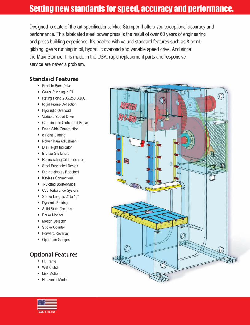
Hydraulic OverloadProtectionIncorporated in each ball seat (knuckle box)housing is a hydraulic cylinder. When an overload is encountered pressure rises in the cylinder to the setting of the relief valvecausing it to open, allowing the oil to flow from the hydraulic cylinder. Because oil can flow out of the cylinder, space becomes available for the ball seat to stroke. Thisstroking allows the press drive to continue down, while the slide stands still, thus relieving the overload condition. When an overload is sensed a signal is sent to stop the press.
Automatic LubricationThe press is furnished with an automatic oil recirculating system which keeps all major drive bearings lubricated, as well as gibs and adjusting screws. The system also continuously monitors for pump or electrical failure, low oil level and low line pressure, and stops the press if necessary.
Carbon Fiber AirCounterbalance CylindersThese ultra-rugged cylinders, an innovative Heim design, offer maximum performance with minimal component wear. Mounted to the crown structure, they counterbalance the slide, ensuring smooth operation throughthe entire stroke as well as reducing wear.
Solid State Press ControlThis solid-state device is engineered specifically for mechanical power presses. Two microprocessors perform clutch/brake control logic independently, then cross-communicate to ensure accuracy. Clutch/brake air valve power passes through three separate output relays, which are doublechecked by the dual microprocessors. A built-in motion detector and brake monitor are included in the system, as well as a user-friendly operator interface with color display and keypad.
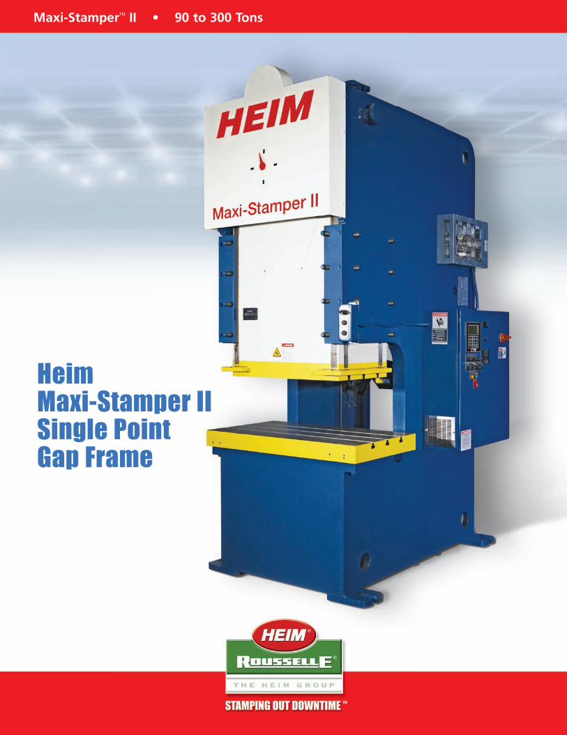
Standard Features• Front to Back Drive• Gears Running in Oil• Rating Point .200/.250 B.D.C.• Rigid Frame Deflection• Hydraulic Overload• Variable Speed Drive• Combination Clutch and Brake• Deep Slide Construction• 8 Point Gibbing• Power Ram Adjustment• Die Height Indicator• Bronze Gib Liners• Recirculating Oil Lubrication• Steel Fabricated Design• Die Heights as Required• Keyless Connections• T-Slotted Bolster/Slide• Counterbalance System• Stroke Lengths 2" to 10"• Dynamic Braking• Solid State Controls• Brake Monitor• Motion Detector• Stroke Counter• Forward/Reverse• Operation Gauges
Designed to state-of-the-art specifications, Maxi-Stamper II offers you exceptional accuracy andperformance. This fabricated steel power press is the result of over 60 years of engineering and press building experience. It's packed with valued standard features such as 8 point gibbing, gears running in oil, hydraulic overload and variable speed drive. And since the Maxi-Stamper II is made in the USA, rapid replacement parts and responsive service are never a problem.
Setting new standards for speed, accuracy and performance.
MADE IN THE USA
Optional Features• H. Frame• Wet Clutch• Link Motion• Horizontal Model
What's Inside.
Durable Construction
This compact configuration helps minimizedeflections within the rigid frame. A one-piecealloy steel driveshaft, running on anti-frictionbearings, meshes up with a spur type main gear. It drives a precision ground crankshaftwhich is solidly supported in the frame.
Quill Mounted Flywheelwith Combination AirClutch and BrakeMaxi-Stamper II's solenoid-operated air friction clutch and brake is mounted on the flywheel for easy access to parts that routinely need to be replaced, such as friction pads. This low inertia unit is designed for maximum heat dissipation, significantly reducing wear due to frequent starts and stops.
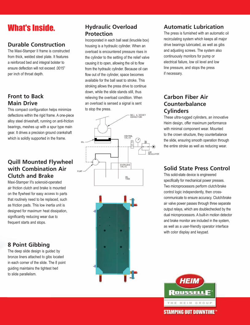
8 Point GibbingThe deep slide design is guided by bronze liners attached to gibs located in each corner of the slide. The 8 pointguiding maintains the tightest bed to slide parallelism.
®
®
TM
concomair voutduaandas wwith
brake is mounted sy access to parts be replaced, suchow inertia unit is
m heat dissipation, wear due to ps.
ingis guided by to gibs located lide. The 8 pointtightest bed
The Maxi-Stamper II frame is constructed from thick, welded steel plate. It features a reinforced bed and integral bolster to ensure deflection will not exceed .0015” per inch of throat depth.
Front to Back Main Drive
Hydraulic OverloadProtectionIncorporated in each ball seat (knuckle box)housing is a hydraulic cylinder. When an overload is encountered pressure rises in the cylinder to the setting of the relief valvecausing it to open, allowing the oil to flow from the hydraulic cylinder. Because oil can flow out of the cylinder, space becomes available for the ball seat to stroke. Thisstroking allows the press drive to continue down, while the slide stands still, thus relieving the overload condition. When an overload is sensed a signal is sent to stop the press.
Automatic LubricationThe press is furnished with an automatic oil recirculating system which keeps all major drive bearings lubricated, as well as gibs and adjusting screws. The system also continuously monitors for pump or electrical failure, low oil level and low line pressure, and stops the press if necessary.
Carbon Fiber AirCounterbalance CylindersThese ultra-rugged cylinders, an innovative Heim design, offer maximum performance with minimal component wear. Mounted to the crown structure, they counterbalance the slide, ensuring smooth operation throughthe entire stroke as well as reducing wear.
Solid State Press ControlThis solid-state device is engineered specifically for mechanical power presses. Two microprocessors perform clutch/brake control logic independently, then cross-communicate to ensure accuracy. Clutch/brake air valve power passes through three separate output relays, which are doublechecked by the dual microprocessors. A built-in motion detector and brake monitor are included in the system, as well as a user-friendly operator interface with color display and keypad.
Standard Features• Front to Back Drive• Gears Running in Oil• Rating Point .200/.250 B.D.C.• Rigid Frame Deflection• Hydraulic Overload• Variable Speed Drive• Combination Clutch and Brake• Deep Slide Construction• 8 Point Gibbing• Power Ram Adjustment• Die Height Indicator• Bronze Gib Liners• Recirculating Oil Lubrication• Steel Fabricated Design• Die Heights as Required• Keyless Connections• T-Slotted Bolster/Slide• Counterbalance System• Stroke Lengths 2" to 10"• Dynamic Braking• Solid State Controls• Brake Monitor• Motion Detector• Stroke Counter• Forward/Reverse• Operation Gauges
Designed to state-of-the-art specifications, Maxi-Stamper II offers you exceptional accuracy andperformance. This fabricated steel power press is the result of over 60 years of engineering and press building experience. It's packed with valued standard features such as 8 point gibbing, gears running in oil, hydraulic overload and variable speed drive. And since the Maxi-Stamper II is made in the USA, rapid replacement parts and responsive service are never a problem.
Setting new standards for speed, accuracy and performance.
MADE IN THE USA
Optional Features• H. Frame• Wet Clutch• Link Motion• Horizontal Model
What's Inside.
Durable Construction
This compact configuration helps minimizedeflections within the rigid frame. A one-piecealloy steel driveshaft, running on anti-frictionbearings, meshes up with a spur type main gear. It drives a precision ground crankshaftwhich is solidly supported in the frame.
Quill Mounted Flywheelwith Combination AirClutch and BrakeMaxi-Stamper II's solenoid-operated air friction clutch and brake is mounted on the flywheel for easy access to parts that routinely need to be replaced, such as friction pads. This low inertia unit is designed for maximum heat dissipation, significantly reducing wear due to frequent starts and stops.
8 Point GibbingThe deep slide design is guided by bronze liners attached to gibs located in each corner of the slide. The 8 pointguiding maintains the tightest bed to slide parallelism.
®
®
TM
concomair voutduaandas wwith
brake is mounted sy access to parts be replaced, suchow inertia unit is
m heat dissipation, wear due to ps.
ingis guided by to gibs located lide. The 8 pointtightest bed
The Maxi-Stamper II frame is constructed from thick, welded steel plate. It features a reinforced bed and integral bolster to ensure deflection will not exceed .0015” per inch of throat depth.
Front to Back Main Drive

Maxi-StamperTM II • 90 to 300 TonsOptional FeaturesLink Motion H-Frame Wet Clutch
Specifications
The Heim Group reserves the right to change design or detail of its products without notice. Point of operation safety guarding or devices are the sole responsibility of the employer (user) of the machine as provided in ANSI B11.1 (2001) as published by the American National Standards Institute, Inc. and OSHA regulations. “Heim” and “Rousselle” are Reg. TM's; “Maxi-Stamper” and “Stamping Out Downtime” are TM’s of The Heim Group. ©Heim L.P. 2012. All Rights Reserved.
www.theheimgroup.com • 6360 West 73rd Street, Chicago, IL 60638
Sales/Service: 708-496-7400 • 800-927-9393 • Fax: 708-496-7428 • Parts Fax: 708-496-0708 • Email: [email protected]
Model Number H1-90 H1-110 H1-150 H1-200 H1-300
Capacity (U.S.) B.D.C. 90 110 150 200 300
Tonnage Rating Point .200 .200 .250 .250 .250
Bed and Bolster Area 46 x 26 46 x 26 57 x 26 57 x 30 66 X 36
Slide Area 32.75 x 20 32.75 x 20 39.25 x 20 39.25 x 24 43.25 X 28
Stroke Length 2 - 4 - 6 4 - 6 - 8 6 - 8 - 10 6 - 8 - 10 6 - 8 - 10
Die Height S.D.A.U. OVER BOLSTER 14 - 13 - 12 13 - 12 - 11 14 - 13 -12 16 - 15 -14 20 - 19 - 18
Variable Speed 70-140 50-100 35-70 50-100 35-70 35-70 35-70 30-60 25-50 35-70 30-60 25-50 30-60 25-50 20-40
Depth of Throat 14.5 14.5 16.5 16.5 18.5
Opening Thru Back 31 31 39.25 39.25 42
Slide Adjustment 4 4 4 4 4
Bolster Thickness 4 4 6 6 8
Floor to Top of Bolster 36 36 40 40 44
Main Motor HP 10HP 15HP 20HP 25HP 30HP
Floor Space (Left-to-Right x Front-to-Back) 49 x 69 49 x 69 68 x 83 68 x 86 72 X 95
Overall Height 139 139 144 144 156
Weight 19,500 21,000 30,000 33,000 55,000
Values in inches unless otherwise noted. Machines may vary slightly from those shown.
TM
Heim Maxi-Stamper IISingle PointGap Frame
SLIDE MOTION CURVE
A link connection is added to the main driveassembly. This connection creates themotion which is a slow down through theworking stroke and quick movementthrough the approach and return cycle of the press stroke. This creates a more efficient press offering increased productionspeed, consistent slide velocity during draw application, a slower speed when work iscontacted and longer die life. Additionalbenefits to the stamper are a higher quality part, less snap through shock, less noise and vibration in the press andallows for a more versatile range for stamping applications.
This optional feature permits the end user tocycle the press at higher intermittent trip rateswithout detrimental effects on the clutch andbrake unit. The clutch and brake plates are constantly lubricated and cooled in a bath of oil.The entire clutch unit is sealed from outside contaminations. Heat is effectively transferredfrom the clutch and brake plates to the oil. Theheat is dissipated and the oil cooled by specialdesign air fins on the unit.
Also known as solid frame, straight side frame is offered for users who need a more rigid framerequirement than the deflections associated witha “C” frame press. This frame has a bed deflectionof .0015” per foot of bed area. This frame design
coupled with the 8 point slide guiding system offers an extremely rigid frame with minimal deflectionand tight bed to slide parallelism for running close tolerance dies.
®
®