Embed Size (px)
Citation preview

SPECIFICATIONS
SOLICITATION ISSUE
ACTIVATE BOSTON MARKET & QDOBA
Fort Drum, New York AAFES Project Number 1367-14-000007
03 JUN 2016
ACTIVATE BOSTON MARKET & QDOBA TABLE OF CONTENTS FT. DRUM, NY 1367-14-000007 00 01 10 - 1 SOLICITATION ISSUE 03 JUN 2016
00 01 10
TABLE OF CONTENTS
DIVISION 00 PROCUREMENT AND CONTRACTING REQUIREMENTS – BY EXCHANGE
00 01 01 Cover Sheet 00 01 10 Table of Contents
DIVISION 01 GENERAL REQUIREMENTS
01 10 00 Summary of Project 01 10 17 Exchange Furnished and Installed Equipment 01 10 18 Exchange Furnished Contractor Installed Equipment 01 10 60 Safety Policies and Procedures 01 10 61 Sample Safety Plan 01 13 00 Safety Regulations and Codes 01 13 01 Waste Disposal 01 14 20 Construction Phasing 01 14 50 Cutting and Patching 01 25 00 Substitution Procedures 01 31 00 Project Management and Coordination 01 32 00 Construction Progress and Documentation 01 33 00 Submittal Procedures 01 33 10 Weather Table 01 35 43 Environmental Protection 01 40 00 Quality Requirements 01 50 00 Temporary Facilities, Barriers and Controls 01 51 00 Temporary Utilities 01 71 00 Cleaning 01 74 19 Construction Waste Management and Disposal -- -- -- Form CWM-1 -- -- -- Form CWM-2 -- -- -- Form CWM-3 -- -- -- Form CWM-4 -- -- -- Form CWM-5 -- -- -- Form CWM-6 -- -- -- Form CWM-7 -- -- -- Form CWM-8 01 77 00 Project Close Out 01 78 39 Project Record Documents -- -- -- Transfer of Property Form 1354 – Form -- -- -- Transfer of Property Form 1354 – Instructions
DIVISION 02 EXISTING CONDITIONS
02 41 16 Selective Demolition
DIVISION 03 CONCRETE - NOT USED
DIVISION 04 MASONRY – NOT USED
DIVISION 05 METALS – NOT USED
ACTIVATE BOSTON MARKET & QDOBA TABLE OF CONTENTS FT. DRUM, NY 1367-14-000007 00 01 10 - 2 SOLICITATION ISSUE 03 JUN 2016
DIVISION 06 WOOD, PLASTICS, AND COMPOSITES 06 10 00 Rough Carpentry
06 40 23 Interior Architectural Woodwork 06 83 16 Fiberglas Reinforced Paneling
DIVISION 07 THERMAL AND MOISTURE PROTECTION
07 92 00 Joint Sealants
DIVISION 08 OPENINGS – NOT USED
DIVISION 09 FINISHES
09 29 00 Gypsum Board Assemblies 09 30 00 Tiling 09 51 00 Acoustical Ceilings 09 90 00 Painting and Coating
DIVISION 10 SPECIALTIES
10 26 00 Wall and Equipment Protection DIVISION 11 EQUIPMENT – NOT USED
DIVISION 12 FURNISHINGS – NOT USED
DIVISION 13 SPECIAL CONSTRUCTION – NOT USED
DIVISION 14 CONVEYING EQUIPMENT – NOT USED
DIVISION 21 FIRE SUPPRESSION 21 13 13 Wet Pipe Sprinkler System
DIVISION 22 PLUMBING 22 05 10 General Provisions - Plumbing 22 05 12 Common Work Results for Plumbing 22 05 23 General Duty Valves for Plumbing Piping 22 05 29 Hangers and Supports for Plumbing Piping and Equipment 22 07 19 Plumbing Insulation 22 11 16 Domestic Water Piping 22 13 16 Sanitary Waste and Vent Piping 22 13 19 Sanitary Waste Piping Specialties 22 16 13 Facility Natural Gas Piping
ACTIVATE BOSTON MARKET & QDOBA TABLE OF CONTENTS FT. DRUM, NY 1367-14-000007 00 01 10 - 3 SOLICITATION ISSUE 03 JUN 2016
22 42 13 Commercial Plumbing Fixtures
DIVISION 23 HEATING VENTILATING AND AIR CONDITIONING (HVAC)
23 01 00 Mechanical - General Provisions 23 05 94 Air Systems Testing, Adjusting and Balancing 23 07 00 Mechanical Insulation 23 31 13 Metal Ductwork 23 33 00 Ductwork Accessories 23 34 23 Fans 23 37 13 Air Outlets and Inlets 23 38 15 Food Service Ventilation Systems 23 55 33 Fuel Fired Heaters
DIVISION 26 ELECTRICAL
26 00 60 Electrical Demolition for Remodeling 26 05 00 Common Work Results for Electrical 26 05 19 Building Wire and Cable 26 05 26 Grounding and Bonding for Electrical Systems 26 05 33 Raceway and Boxes for Electrical Systems 26 05 53 Identification for Electrical Systems 26 27 26 Wiring Devices 26 51 00 Interior Lighting
END TABLE OF CONTENTS

ACTIVATE BOSTON MARKET & QDOBA SUMMARY OF PROJECT FT. DRUM, NY 1367-14-000007 01 10 00 - 1 SOLICITATION ISSUE 03 JUN 2016
SECTION 01 10 00
SUMMARY OF PROJECT PART 1 GENERAL 1.1 PROJECT INFORMATION
A. Project Identification: Activate Boston Market & Qdoba, Exchange Food Court
Project number: 1367-14-000007.
Project Location: Fort Drum, New York.
B. Owner: EXCHANGE.
EXCHANGE Contracting Office: Kim Bevering, Procurement Manager; PL-K-REC; Army & Air Force Exchange Service; 3911 South Walton Walker Blvd.; Dallas, TX 75236. 214.312.4831; [email protected]
C. Architect: Norman Bochenek ; The Jenkins Group, Inc.; 300 Park Boulevard, Suite 250; Itasca, IL 60143; 630.626 0900; [email protected]
D. Architect's Consultants: The Architect has retained the following design professionals who have prepared designated portions of the Contract Documents: MEP Engineer: Charlie Calvert (Mechanical/Fire Protection), Chip Fox (Electrical); McCoy & Howard Consulting Engineers; 413 Main Street; Mount Vernon, IL 62864; 618.242.0473.
E. EXCHANGE Project Manager: Daniel Watkins RE-F; Army & Air Force Exchange Service; 3911 South Walton Walker Blvd.; Dallas, TX 75236. 214.312.2405; [email protected]
1.2 STATEMENT OF WORK
A. The work covered by these specifications consists of furnishing all plant, supervision, labor, equipment, materials and incidentals necessary to perform all operations required to complete the work, all in accordance with these specifications and the applicable drawings, and subject to the terms and conditions of the contract.
B. The work to be performed is located within the Exchange Food Court/Mall, Fort Drum,
NY. C. Principal Features:
The work to be performed in connection with this project includes, but is not limited to the following: a. Demolition of existing Captain D’s and Anthony’s Pizza food court spaces wall, interior
finishes, fixtures, and equipment as indicated on drawings for new vendors, Boston Market & Qdoba. Construction of interior space to current Vendor standards including revised walls, interior finish work, installation of Vendor, Contractor and Exchange-supplied equipment/fixtures as indicated on drawings including final connections and associated mechanical, electrical, plumbing and fire protection work.
ACTIVATE BOSTON MARKET & QDOBA SUMMARY OF PROJECT FT. DRUM, NY 1367-14-000007 01 10 00 - 2 SOLICITATION ISSUE 03 JUN 2016
D. The Contractor is advised to take note of the following General Provisions of the Contract: Cleaning; Material and Workmanship; Accident Prevention; Protection of Existing Structures, Utilities and Improvements; Operation and Storage Areas; Site Investigation; Permits and Responsibilities. Copies of the General Provisions may be obtained from the Contracting Officer
1.2 SPECIAL BASE REQUIREMENTS
A. Regular business hours during the week for the Department of Public Works are 7:30AM to 4:00PM, Monday through Friday, excluding Federal Holidays.
The Food Court normal business hours of operation are Monday – Friday 7:30AM to 7:00PM; Saturday 11:00AM to 5:00PM; Sunday 11:00AM to 5:00PM. Holiday times vary. Items of work can only be performed during Food Court operational hours.
B. The Contractor is to familiarize themselves with the requirements for gaining daily access
to the base. All workers, subcontractors and material deliveries will require permits to gain site entry.
C. Ft. Drum may require special access requirements during times of heightened security
measures and/or force protection events requiring the Contractor to adjust schedules and access accordingly. Advance notice will be given to the Contractor as soon as possible in the event of such an occurrence.
1.3 UTILITIES (WATER, GAS AND ELECTRICITY)
A. Existing waterlines, gas and electrical will be used to obtain utilities for this project. The Contractor will not be charged for consumption of utilities (water, gas and electricity) refer to Section 01 51 00, “Temporary Utilities”.
1.4 LAYING OUT WORK
A. Dimensions and elevations indicated in layout of work shall be verified by the Contractor.
Discrepancies between drawings, specifications, and conditions shall be referred to the Contracting Officer in writing for adjustment before work affected is performed. Failure to make such notifications shall place responsibility upon the Contractor to carry out work in a satisfactory and workmanlike manner.
B. The Contractor shall be held responsible for the location and elevation of all the
construction contemplated by the construction documents.
C. Prior to commencing work, the Contractor shall carefully compare and check all Architectural, Structural, Mechanical, and Electrical drawings, each with the other, that in any way affect the locations of elevation of the work to be executed by him, and should any discrepancy be found, he shall immediately report the same to the Contracting Officer for verifications and adjustment. Any duplication of work made necessary by failure or neglect on the Contractor's part to comply with this function shall be done at his sole expense.
D. The drawings accompanying these specifications indicate generally the design and
arrangement of all apparatus, fixtures, accessories, etc. necessary to complete the work required. The exact location or arrangement of equipment is subject to minor changes
ACTIVATE BOSTON MARKET & QDOBA SUMMARY OF PROJECT FT. DRUM, NY 1367-14-000007 01 10 00 - 3 SOLICITATION ISSUE 03 JUN 2016
necessitated by field conditions and shall be made as required without additional cost to EXCHANGE. Measurements shall be verified by actual observations at the construction site, and the Contractor shall be responsible for all work fitting into place in a satisfactory and workmanlike manner meeting the approval of the Contracting Officer.
1.5 EXISTING OVERHEAD OR UNDERGROUND WORK
A. Carefully check the site where this project is to be erected and observe any overhead wires and equipment. Any such work shall be moved, replaced, or protected, as required, whether or not shown or specified.
B. Attention is directed to the existence of pipe and other underground improvements which
are shown on the drawings. All reasonable precautions shall be taken to preserve and protect all such improvements shown on the drawings.
C. Locations of underground lines, shown on the drawings, are based on the best available
sources, but are to be regarded as approximate only. Exercise extreme care in locating and identifying these lines before excavating in adjacent areas.
1.6 INTERRUPTION OF EXISTING UTILITIES SERVICES
A. The Contractor shall perform the work under this Contract with a minimum of outage time for all utilities. Interruption shall be by approved section of the utility. In some cases, the Contractor may be required to perform the work while the existing utility is in service. The existing utility services may be interrupted only when approved by the Contracting Officer. When it is necessary to interrupt the existing utilities, the Contractor shall notify the Contracting Officer and facilities engineer in writing at least seven days in advance of the time he desires the existing service to be interrupted. The interruption time shall be kept to a minimum. Depending upon the activities at the facility which require continuous service from the existing utility, an interruption may not be subject to schedule at the time desired by the Contractor. In such cases the interruption may have to be scheduled at a time of minimum requirement of demand for the utility. The amount of time requested by the Contractor for interruption of existing utility services shall be as approved by the Contracting Officer.
1.7 EXCAVATION
A. Prior to commencing any excavation work the Contractor shall obtain a valid Excavation Permit, from the DPW Facilities Engineers Office. It shall be the Contractor's responsibility to obtain the necessary signatures and coordination for the permit.
1.8 HOT WORK PERMIT
A. Prior to commencing any welding, the Contractor shall obtain a hot work permit from the Fort Drum Fire & Emergency Services, Fire Prevention 315-772-4702 between the hours of 0700 – 1600. 24 hour lead time is requested.
1.9 BARRICADES AND WARNING DEVICES
A. The Contractor shall provide barricades and dust barriers to protect adjacent operational spaces.
ACTIVATE BOSTON MARKET & QDOBA SUMMARY OF PROJECT FT. DRUM, NY 1367-14-000007 01 10 00 - 4 SOLICITATION ISSUE 03 JUN 2016
1.10 PROTECTION FOR OPEN FLAME DEVICES
A. When open flame and/or spark producing devices, i.e., acetylene oxygen welding equipment, electric arc welding, etc., are employed for job accomplishment, the following procedures are mandatory:
1. Inspect all surroundings and equipment to insure that combustible substances
are not present in any area where contact of metal at a temperature above the flashpoint of any compound is possible.
2. Ensure that no open containers or spills of combustible substances are present. 3. Ensure that ignition is not possible by conduction, convection, radiation, or
dispersion of molten metal. 4. Proper protection equipment and practices will be used, i.e., fireproof blankets,
wetting of surrounding area, removal o combustible materials where practicable, earth filled backing and portable fire extinguishers of proper type on hand.
5. When the above devices are being used notify the Installation Fire Department 24 hours ahead of usage.
1.11 FIRE PROTECTION
A. The Contractor shall at all times maintain good housekeeping practices to reduce the risk of fire damage. All scrap materials, rubbish, and trash shall be removed daily from in and about the building and shall not be permitted to be scattered on adjacent property.
B. Suitable storage space shall be provided 50 feet minimum outside the building area for
storing flammable materials and paints; no storage will be permitted in the building. Excess flammable liquids being used inside the building shall be kept in closed metal containers and removed from the building during unused periods.
C. A contractor shall provide a fire extinguisher at each location where cutting and welding is
being performed. Where electric or gas welding or cutting is done, interposed shields of incombustible material shall be used to protect against fire damage due to sparks and hot metal. When temporary heating devices are used, a watchman shall be present to cover periods when other workmen are not on the premises.
D. The Contractor shall provide fire extinguishers in accordance with the recommendations
of NFPA No. 10 and 241.
E. Fire Codes: The Contractor shall obey all requirements of the National Fire Codes, and Base/Post Fire Regulations, as they relate to his work on base/post.
1.12 WORK BY OTHERS (IF APPLICABLE)
A. Work not included: Except for such auxiliary work as is shown or specified or is necessary as a part of the construction, the following work is not included in the Contract:
1. Any work shown, but marked "NOT IN CONTRACT" (N.I.C.). 2. Any work indicated to be furnished and installed by the Exchange. 3. Any work indicated to be furnished and installed by the Vendors or
Concessionaires. 1.13 EXCHANGE-FURNISHED AND INSTALLED EQUIPMENT
A. See Specification Section 01 10 17: EXCHANGE Furnished and Installed Equipment.

ACTIVATE BOSTON MARKET & QDOBA SUMMARY OF PROJECT FT. DRUM, NY 1367-14-000007 01 10 00 - 5 SOLICITATION ISSUE 03 JUN 2016
1.14 EXCHANGE FURNISHED-CONTRACTOR INSTALLED EQUIPMENT
A. See Specification Section 01 10 18: EXCHANGE Furnished Contractor Installed Equipment.
1.15 LINING OF JOINTS IN FINISH MATERIALS
A. It shall be the responsibility of the Contractor to make certain in the installation of jointed floor, wall, and ceiling and pavement materials that:
1. The joints line through in a straight line and in both directions wherever possible. 2. The joints relate to all openings and breaks in the structure and be symmetrically
placed wherever possible. This includes heating registers, light fixtures, equipment, etc.
3. If, because of the non-related sizes of the various materials and locations of openings, etc., it is not possible to accomplish the above, the Contractor shall meet with the Contracting Officer to determine the most satisfactory arrangement. The Contractor shall establish center lines for all trades.
1.16 INTEGRATING WORK
A. All streets, buildings, and other improvements shall be protected from damage.
B. Contractor's operations shall be confined to the immediate vicinity of the project work and shall not in any way interfere with or obstruct the ingress or egress to and from street or adjacent property.
C. If new work is to be connected to existing work, special care shall be exercised not to
disturb or damage the existing work more than necessary. All damaged work shall be replaced, repaired, and restored to its original condition at no cost to the Exchange Service.
1.17 HEADROOM UNDER PIPES
A. All horizontal runs of plumbing and heating pipes and/or electrical conduit suspended from ceilings shall provide for a maximum headroom clearance, but in no case shall this clearance be less than 7'-0" without written consent from the Contracting Officer. Where piping or conduit is left exposed within a room, the same shall run true to plumb, horizontal or intended planes. Where possible, uniform margins are to be maintained between parallel lines and/or adjacent wall, floor, or ceiling surfaces.
1.18 PATCHING GOVERNMENT-OWNED FACILITIES
A. Government-owned structures, facilities, streets, curbs, walks, etc., that are damaged or removed due to required excavations or other construction work, shall be patched, repaired or replaced, and be left in their original state of repair by the Contractor, to the satisfaction of the Contracting Officer and of authorities having jurisdiction thereof.
1.19 LOCATION OF EQUIPMENT AND PIPING
A. Drawings showing location of equipment, piping, ductwork, etc., are diagrammatic and job conditions shall not always permit their installation in the location shown. When this situation occurs, it shall be brought to the Contracting Officer's attention immediately and
ACTIVATE BOSTON MARKET & QDOBA SUMMARY OF PROJECT FT. DRUM, NY 1367-14-000007 01 10 00 - 6 SOLICITATION ISSUE 03 JUN 2016
the relocation determined in a joint conference. The Contractor will be held responsible for the relocating of any items without first obtaining the Contracting Officer's approval. He shall remove and relocate such items at his own expense if so directed by the Contracting Officer.
1.20 OVERLOADING
A. The Contractor shall be responsible for overloading any part or parts of structures beyond their safe calculated carrying capacities by placing of materials, equipment, tools, machinery, or any other item thereon. No loads shall be placed on floors or roofs before they have attained their permanent and safe strength.
1.21 STANDARDS
A. Any material specified by reference to the number, symbol, or title of a specific standard such as Commercial Standard, a Federal Specification, a trade association standard, or other similar standard shall comply with the requirements in the latest revision thereof, and any amendment or supplement thereto, in effect on the date of invitation for proposals, except as limited to type, class, or grade, or modified in such reference, and except as otherwise indicated.
B. The standard referred to, except as modified in the specifications, shall have full force
and effect as though printed in these specifications. These standards are not furnished to bidders for the reason that the manufacturers and trades involved are assumed to be familiar with their requirements.
1. Where Federal Specifications are referred to as a measure of quality and
standard, they refer to Federal Specifications established by the Procurement Division of the United States Government and are available from the Superintendent of Documents, U.S. Government Printing Office.
2. Where Federal Specification numbers are used, they refer to the latest edition including amendments thereto.
3. Where Commercial Standards are referred to as a measure of quality, standard, and method of fabrication, they refer to Commercial Standards issued by the U.S. Department of Commerce.
4. Where ASTM Serial Numbers are used, they refer to the latest tentative specifications, standards specifications, standards methods, or standard method of testing issued by the American Society for Testing and Materials.
1.22 CERTIFICATE OF CONFORMANCE
A. Except where tests and/or inspections in connection with structural materials are specified or required by applicable laws, rules, and regulations, manufacturer's certificate covering conformance with the requirements of the above mentioned Federal Specifications and Commercial Standards may be acceptable in lieu of such items. Such certificates shall be furnished to the Contracting Officer for all items so specified.
1.23 OCCUPANCY BY THE EXCHANGE
A. EXCHANGE shall reserve the right and privilege of partial occupancy during and prior to the absolute completion of the total work. Refer to the Drawings for additional information. Access shall be allowed at all times to the Exchange and its own Contractors in the endeavor.
ACTIVATE BOSTON MARKET & QDOBA SUMMARY OF PROJECT FT. DRUM, NY 1367-14-000007 01 10 00 - 7 SOLICITATION ISSUE 03 JUN 2016
1.24 TESTS AND REPORTS
A. See Specification Section 01 40 00: Quality Requirements. 1.25 REFERENCES
A. All references to the word "Government" or “Exchange” in the specifications shall mean Army and Air Force Exchange Service (AAFES).
B. Wherever the word "provide" is used in the Contract Documents as a directive, it shall be
interpreted as meaning "provide and install completely and ready for use".
C. Definitions:
1. Vendor: Person or persons selling any material item. 2. Base, Post, Installation or Facility: Location on which Exchange is being
remodeled. 3. Concessionaire: Person who is directly responsible for the lease of and operation
of the concessions. 4. Architect-Engineer: That person or firm responsible for preparing the working
drawings and specifications. 5. AAFES or Exchange: Army and Air Force Exchange Service. 6. Inspection Agency: Project Inspector contracted by EXCHANGE.
1.26 TOXIC MATERIALS
A. Removal or disposal of toxic materials or asbestos is not included in this contract. If the Contractor encounters such materials, he shall immediately notify the Contracting Officer.
1.27 SUBMISSION OF PHOTOGRAPHS A. Contractor shall submit, to the Contracting Officer, digital photographs taken on or about the first of every month, showing the general conditions of the work as viewed from each area and phase of work. Photographs (minimum of 20) must accompany each Application for Payment. Each print shall be identified by date of exposure, project title, and Exchange Project Number, location and direction taken. The contractor may also submit a video of the above requirements as an option to photographs.
PART 2 – PRODUCTS (NOT USED)
PART 3 – EXECUTION (NOT USED) END OF SECTION 01 10 00
ACTIVATE BOSTON MARKET & QDOBA EXCHANGE FURNISHED AND INSTALLED EQUIPMENT FT. DRUM, NY 1367-14-000007 00 10 17 - 1 SOLICITATION ISSUE 03 JUN 2016
SECTION 01 10 17
EXCHANGE FURNISHED AND INSTALLED EQUIPMENT (EF/EI) PART 1 GENERAL 1.1 EXCHANGE FURNISHED AND INSTALLED PROPERTY (EF/EI)
A. Property: Property is indicated on the drawings.
B. Schedule: Contractor shall schedule early completion of designated areas for beneficial occupancy by EXCHANGE usage prior to completion of entire project.
C. EXCHANGE will furnish and install equipment as indicated on the Fixture Plan and in the
drawings.
D. Contractor's Duties:
1. Provide access for EXCHANGE personnel. 2. Coordinate work and cooperate with the installers of the property so that
installation can be accomplished in accordance with construction schedule. 3. Provide mechanical and electrical connections to equipment and building systems
where indicated on the drawings and in the specification. 4. Provide security of designated areas. 5. Schedule equipment delivery dates and installation times to coordinate with the
overall schedule. Provide EXCHANGE advance notice so equipment can be ordered on time.
E. EXCHANGE Duties:
1. Inspect designated area prior to use and issue statement of acceptance of area
for installation of property. 2. Make final mechanical and electrical connections between property and building
systems where indicated on the drawings and/or in the specifications. 3. Provide custodial services for designated areas during use after beneficial
occupancy. 1.2 DELIVERY DATE CHANGES
A. Requests by Contractor to change designated delivery dates shall be made in writing at least 30 days in advance of the designated delivery date. If the Contractor is not ready to accept delivery of EXCHANGE furnished property the Contractor shall be responsible for storage and redelivery cost. Should EXCHANGE be unable to effect the change, or should the Contractor fail to submit his request within the time stated above, the Contractor's obligation under this contract and as stated herein shall not be relieved and further, the Contractor will have no basis upon which he can file a claim under these conditions.
1.3 EXCHANGE ACTIVITIES AFFECTING PROGRESS OF WORK:
A. Serving Areas & Food Preparation Areas: Schedule date of use and possession of food preparation serving areas 30 days prior to completion of project.

ACTIVATE BOSTON MARKET & QDOBA EXCHANGE FURNISHED AND INSTALLED EQUIPMENT FT. DRUM, NY 1367-14-000007 00 10 17 - 2 SOLICITATION ISSUE 03 JUN 2016
B. Construction in each area at date scheduled for its use and possession by EXCHANGE shall be sufficiently complete, in accordance with Contract Documents, so EXCHANGE may occupy the area for the use for which it is intended. Comply with Contract Clauses titled inspection of Construction, and Use and Possession Prior to Completion.
1.4 ACCEPTANCE OF AREAS FOR BENEFICIAL OCCUPANCY
A. Inspection: Prior to acceptance by EXCHANGE of an area for beneficial occupancy, the Contracting Officer will conduct an inspection of the specific area. A list of deficiencies will be provided to the Contractor.
B. Acceptance: If the Contracting Officer determines the specific area is sufficiently
complete for beneficial occupancy by EXCHANGE, the area will be accepted in writing with the exception of the deficiencies listed. The deficiencies listed shall be completed or corrected prior to final acceptance at the completion of the project.
C. Damage: Damage resulting from EXCHANGE' use will not be considered the
Contractor's responsibility.
D. Refer to clause entitled "Final Inspection and Acceptance" of the EXCHANGE "General Provisions".
1.5 MATERIALS AND EQUIPMENT (EF/EI):
A. Equipment or material to be furnished and installed by EXCHANGE is indicated on the Drawings and as follows: 1. Shelving and storage fixtures. 2. Check-out and POS equipment. 3. Microwaves and refrigerators. 4. Telephone system equipment. 5. Food Concept Equipment as indicated.
B. See Part 3 for Final Connection information.
PART 2 – PRODUCTS – NOT USED
PART 3 - EXECUTION
3.1 FINAL CONNECTIONS:
A. Final utility connections to EXCHANGE furnished and installed equipment shall be made by the Contractor as part of the construction contract. Contractor shall construct all openings, furnish and install required sleeves and conduit, and furnish and install all reinforcing, miscellaneous supports, angles, plates, anchors, and bolts necessary to secure EXCHANGE-furnished equipment in place.
B. The Contractor shall provide for, and cooperate with, personnel installing EXCHANGE furnished materials and equipment, when overlap of work occurs.
END OF SECTION 01 10 17
ACTIVATE BOSTON MARKET & QDOBA TABLE OF CONTENTS FT. DRUM, NY 1367-14-000007 01 10 18 - 1 SOLICITATION ISSUE 03 JUN 2016
SECTION 01 10 18
EXCHANGE FURNISHED CONTRACTOR INSTALLED EQUIPMENT (EF/CI)
PART 1 GENERAL
1.1 EXCHANGE FURNISHED/CONTRACTOR INSTALLED EQUIPMENT (EF/CI):
A. EXCHANGE furnished/Contractor installed equipment shall be handled in accordance with the "Army and Air Force Exchange Service General Provisions" clause entitled "EXCHANGE Furnished Property".
B. EXCHANGE Furnished Equipment: EXCHANGE will furnish the equipment indicated for installation by the Contractor as indicted on drawings and as follows:
1. EXCHANGE Furnished/Contractor Installed Items:
a. Boston Market Equipment as indicated on drawings. b. Qdoba Equipment as indicated on drawings.
1.2 WORK INCLUDED:
A. The material noted below will be furnished by the Exchange and shall be installed by the Contractor. See drawing references to (EF/CI). The Contractor shall provide for and cooperate with personnel furnishing the designated material.
B. All food service equipment must be approved by the National Sanitation Foundation, NSF.
C. See Division 1 for General Requirements.
D. Contractor's Duties: 1. Designate required delivery date for each product. Notify the Contracting Officer in writing
at least 30 days in advance of the date that EXCHANGE furnished equipment and furnishings will be needed.
2. The equipment will be received at the job site by a representative of EXCHANGE who will jointly, with the Contractor, verify condition and quantities. The representative will then effect receipted transfer of custody of the equipment to the Contractor.
3. Unload, handle, store (on-site), protect, uncrate, assemble, install set in final position, align, join, level, and make all utility connections to all items of equipment. Installation shall be performed in accordance with the specifications, equipment plans, and schedules shown on the Drawings and the rough-in drawings provided by EXCHANGE.
4. Construct all openings, furnish and install required sleeves and furnish and install all reinforcing, miscellaneous supports, angles, plates, anchors, and bolts necessary to secure EXCHANGE furnished equipment in place.
5. Repair or replace items damaged as a result of Contractor's operations. 6. Apply finish indicated, if any. 7. The installation shall be complete in all respects, including mechanical and electrical hook
ups, and put into good operating condition.
ACTIVATE BOSTON MARKET & QDOBA TABLE OF CONTENTS FT. DRUM, NY 1367-14-000007 01 10 18 - 2 SOLICITATION ISSUE 03 JUN 2016
E. EXCHANGE Duties: 1. Deliver all EXCHANGE furnished items to the job site. Schedule delivery date with
supplier in accordance with Progress Chart. 2. Provide Contractor with installation drawings and instructions.
1.3 DELIVERY:
A. Contractor shall unload, handle, store, protect, uncrate, assemble, set in final position, align, join, and level all Exchange-Furnished material, and shall make all utility connections thereto. EXCHANGE will provide supervision for installation of the material.
B. The material will be received at the job site by a representative of the local EXCHANGE who, together with the Contractor, will jointly verify conditions and quantities. The representative of the local EXCHANGE will then affect receipted transfer of custody of the material to the Contractor. Material damaged by or during construction operations shall be replaced at no additional cost to EXCHANGE.
1.4 FAILURE TO VERIFY:
A. Failure to execute above required verification shall not relieve the Contractor of responsibility for proper installation of the material, which shall be installed without additional cost to EXCHANGE.
1.5 DELIVERY DATE CHANGES:
A. Requests by Contractor to change designated delivery dates shall be made in writing at least 60 days in advance of the designated delivery date. If the Contractor is not ready to accept delivery of EXCHANGE furnished equipment the Contractor shall be responsible for storage and delivery cost. Should EXCHANGE be unable to effect the change, or should the Contractor fail to submit his request within the time stated above, the Contractor's obligation under his contract and as stated herein shall not be relieved and further, the Contractor will have no basis upon which he can file a claim under these conditions.
PART 2 – PRODUCTS – NOT USED
PART 3 - EXECUTION
3.1 INSTALLATION
A. The Contractor shall construct openings, furnish and install required sleeves and conduit, and furnish and install reinforcing, miscellaneous supports, angles, plates, anchors, and bolts necessary to secure EXCHANGE-furnished equipment in place. Final electrical connections to EXCHANGE furnished equipment shall be made by the Contractor as part of the Construction Contract.
END OF SECTION 01 10 18
ACTIVATE BOSTON MARKET & QDOBA SAFETY POLICIES AND PROCEDURES FT. DRUM, NY 1367-14-000007 01 10 60 - 1 SOLICITATION ISSUE 03 JUN 2016
SECTION 01 10 60
SAFETY POLICIES AND PROCEDURES
PART 1 - GENERAL 1.1 SECTION INCLUDES
A. Contractor required health and safety plan.
1. Contractor is responsible for reading the Risk Assessment Plan and following the directions therein.
2. Contractor must maintain OSHA permissible exposure limits related by the risk assessment: That is, 25 ppm (170 mg/cubic meter) during any 8 hour work shift for a 40-hour week
B. Sample Safety Plan.
1.2 RELATED SECTIONS
A. Submittal Procedures - Section 01 33 00 (Construction Hazard Plan, Job Safety and Health Plan, Emergency Response Plan).
B. Project Record Documents - Section 01 78 39. C. Environmental Protection – Section 01 35 43
1.3 REFERENCES
A. The publications listed below form a part of this specification to the extent referenced. The publications are referred to in the text by the basic designation only.
1. OSHA 1910 R.E.G. - 29CFR, OSHA 1910.120 2. U.S. Army Corps of Engineers Publication. – EM 385-1-1: Safety and Health Requirements
Manual (Most current version). 1.4 SUBMITTALS
A. Submittals for EXCHANGE approval - The following items shall be submitted for EXCHANGE approval:
1. Designation of Safety Representative: The Contractor shall designate in writing a qualified
employee OSHA Trained under 1910.120 responsible for the overall supervision of all accident prevention activities. Duties shall include ensuring applicable safety requirements are incorporated into work methods and inspecting the job site to ensure that safety measures and instructions are actually being applied. This person shall be on site at all times that work is in progress.
2. The Contractor shall be trained and certified in OSHA 1910.120 procedures. All other employees performing site work will meet OSHA 1910 training requirements for their job capacity.

ACTIVATE BOSTON MARKET & QDOBA SAFETY POLICIES AND PROCEDURES FT. DRUM, NY 1367-14-000007 01 10 60 - 2 SOLICITATION ISSUE 03 JUN 2016
B. Submittals for Information Only - The following items shall be Contractor certified:
1. Job Hazard Analysis: Contractor shall develop a job hazard analysis for presentation at the pre-construction conference. The Contractor's job hazard analysis shall list potential hazards that could arise during the course of the work.
2. Job Safety and Health Plan.
a. The Contractor shall develop a Job Safety and Health Plan for presentation at the Pre-construction conference. The Contractor's Safety Plan shall make whatever provisions are necessary to conduct his work in accordance with current OSHA standards.
b. The safety and health plan must specifically address the excavation portion of construction and will be specific to perchloroethylene (tetrachloroethylene) (PCE), and incorporate decontamination procedures for personnel and equipment, continuous vapor monitoring, a prohibition against eating in proximity to the site, and a prohibition against the smoking of tobacco products in the proximity to the site.
c. The following are minimum requirements for the health and safety plan:
1. The Contractor is responsible for all compounds and degradation products addressed by the Risk Assessment Plan.
2. Specialized Designs: Specialized designs will be provided when the situation requires. Examples of such designs include, but are not limited to, vapor barriers in areas of known vapor hazard.
3. Safety Plans: Safety Plans will be the responsibility of the Contractor for construction areas identified by the installation and/or EXCHANGE as areas of known hazards only. These plans are required by 29 CFR 1910 and are the responsibility of the Contractor. This requirement will be coordinated through the Health and Safety Program of the military installation by the Contractor.
4. Minimum Requirements for the Health and Safety Plan are as follows:
(a) Must be kept on site, and must be written. (b) Will contain a hazard analysis (safety and health risk) for each
site task and operation (to be supplied by the installation). (c) Will include employee training (per paragraph (3) of 1910.120). (d) Will include personal protective equipment to be used by
employees for each of the site tasks and operations (paragraph (g) (5) of 1910.120).
(e) Will include provision for medical surveillance (paragraph (f) of 1910.120).
(f) Will include the frequency and types of air monitoring, personal monitoring, environmental sampling techniques, instruments to be used (their maintenance and calibration).
(g) Will include a site control program (per paragraph (d) of 1910.120) to be coordinated with the installation.
(h) Will include a decontamination procedure (per paragraph (k) of 1910.120).
(i) Will include an emergency response plan (per paragraph (1) of 1910.120).
(j) Will include a confined space entry procedure (per 1910.146, 147 or program equivalent).

ACTIVATE BOSTON MARKET & QDOBA SAFETY POLICIES AND PROCEDURES FT. DRUM, NY 1367-14-000007 01 10 60 - 3 SOLICITATION ISSUE 03 JUN 2016
(k) Will include provision for spill containment (per paragraph (j) of 1910.120). (l) Will include pre-entry briefings (prior to each site task activity) for
all employees involved in the task, supervision, or emergency response. (m) Written verification of adherence to the "plan" by a Safety and
Health Supervisor is required (the supervisor must meet the 1910.120 training requirements for supervisors).
(n) Deficiencies will be corrected immediately upon discovery and after consultation with the EXCHANGE Contracting Officer and Installation Safety Office.
d. Hazard Response Plan: The unplanned or non-predicted discovery of such hazards
as transite pipe, contaminated soils, and other possible hazards will be addressed within an Emergency Response Plan (EMR) by all contractors. This requirement will be coordinated through the Health and Safety Program of the military installation by the contractor (sample provided).
e. Material Safety Data Sheets will be maintained at the site for all hazardous materials in use.
1.5 MONTHLY SAFETY MEETINGS
A. The Installation will schedule subsequent safety meetings with Contractor and subcontractor personnel on a monthly basis. The Owner's representative and installation will attend periodically. Minutes of safety meetings shall be prepared and signed by the Contractor. Concurrence signed by Inspection Section and the original submitted to the Contracting Officer for inclusion in the contract file.
1.6 ACCIDENT REPORTING AND RECORD KEEPING
A. Accident reporting and record keeping shall be in accordance with Base requirements. Telephonic reports of injuries or property damage will be made as soon as possible after the incident and will be followed by a copy of an Accident Report.
1.7 LIFE OF CONTRACT REQUIREMENTS
A. The Contractor shall comply with all provisions of this section during the life of the contract. 1.8 HEAD PROTECTION (HARD HATS)
A. All work sites under this contract are designated Hard Hat Areas. The Contractor shall post the area and shall ensure that all personnel, vendors and visitors use hard hats while within the limits of the work site.
PART 2 – PRODUCTS (NOT USED)
PART 3 – EXECUTION (NOT USED)
END OF SECTION 01 10 60
ACTIVATE BOSTON MARKET & QDOBA SAMPLE SAFETY PLAN FT. DRUM, NY 1367-14-000007 01 10 61 - 1 SOLICITATION ISSUE 03 JUN 2016
SECTION 01 10 61
SAMPLE SAFETY PLAN
1. APPLICABLE PUBLICATIONS: The publications listed below form a part of this specification and
are referred to in the text by the basic designation only. 1.1 US ARMY CORPS OF ENGINEERS: EM 385-1-1 U.S. Army Corps of Engineers Safety and Health Requirements Manual 1.2 NATIONAL FIRE PROTECTION ASSOCIATION (NFPA): NFPA 70-1993 National Electric Code (NEC) 1.3 SOCIETY OF AUTOMOTIVE ENGINEERS (SAE): J 994-85 Alarm, Backup, Electric-Performance, Test, and Application, Recommended Practice. 2. GENERAL: Work safety is of paramount importance. The Contractor shall comply with the
Contract Clause in the Solicitation entitled ACCIDENT PREVENTION, including the U.S. Army Corps of Engineers Safety and Health Requirements Manual referred to therein in addition to the provisions of this specification.
3. SAFETY PROGRAM: The U.S. Army Corps of Engineers Safety and Health Requirements Manual,
EM 385-1-1, and all subsequent revisions to in the Contract Clause ACCIDENT PREVENTION of this contract, are hereby supplemented as follows:
a. The Contractor shall designate an employee responsible for overall supervision of accident
prevention activities. Such duties shall include:
1. Assuring applicable safety requirements are incorporated in work methods 2. Inspecting the work to ensure that safety measure and instructions are actually applied.
The proposed safety supervisor's name and qualifications shall be submitted in writing for approval
to the Contracting Officer's Representative. This individual must have prior experience as a safety engineer or be able to demonstrate his/her familiarity and understanding of the safety requirements over a prescribed trial period. The safety engineer shall have the authority to act on behalf of the Contractor's general management to take whatever action is necessary to assure compliance with safety requirements. The safety supervisor is required to be on the site when work is being performed.
b. Prior to commencement of any work at a job site, a preconstruction safety meeting shall be held
between the Contractor and the Corps of Engineers Area/Resident Engineer to discuss the Contractor's safety program and in particular to review the following submittals:
1. Contracts Accident Prevention Plan: An acceptable accident prevention plan, written by the
prime contractor for the specific work and implementing in detail the pertinent requirements of EM 385-1-1, shall be submitted for Government approval.
ACTIVATE BOSTON MARKET & QDOBA SAMPLE SAFETY PLAN FT. DRUM, NY 1367-14-000007 01 10 61 - 2 SOLICITATION ISSUE 03 JUN 2016
2. Activity Phase Hazard Analysis Plan: Prior to beginning each major phase of work, an
activity hazard analysis (phase plan) shall be prepared by the Contractor for that phase of work and submitted to the Contracting Officer's Representative for approval. A phase is defined as an operation involving a type of work presenting hazards not experienced in previous operations or where a new subcontractor or work crew is to perform work. The analysis shall address the hazards for each activity performed in the phase and shall present the procedures and safeguards necessary to eliminate the hazards or reduce the risk of an acceptable level.
c. Subsequent jobsite safety meetings shall be held as follows:
1. A safety meeting shall be held at least once a month for all supervisors on the project to
review past activities, to plan ahead for new or changed operations and to establish safe working procedures to anticipate hazards. An outline report of each monthly meeting shall be submitted to the Contracting Officer's Representative.
2. At least one safety meeting shall be conducted weekly, or whenever new crews begin work,
by the appropriate field supervisors or foreman for all workers. An outline report of the meeting giving date, time, attendance, subjects discussed and who conducted it shall be maintained and copies furnished the designated authority on request.
4. ACCIDENTS: Chargeable accidents are to be investigated by both Contractor personnel and the
Contracting Officer. 4.1 ACCIDENT REPORTING, ENG FORM 3394: Section I, paragraph 01.D, of EM 385-1-1 and the
Contract Clause entitled ACCIDENT PREVITION are amended as follows: The prime Contractor shall report on Eng Form 3394, supplied by the Contracting Officer, all injuries to his employees or subcontractors that result in lost time and all damage to property and/or equipment in excess of $2,000 per incident. Verbal notification of such accident shall be made to the Contracting Officer within 72 hours following such accidents. The written report shall include the following:
a. A description of the circumstances leading up to the accident, the cause of the accident, and
corrective measures taken to prevent recurrence. b. A description of the injury and name and location of the medical facility giving examination and
treatment. c. A statement as to whether or not the employee was permitted to return to work after examination
and treatment by the doctor, and if not, an estimate or statement of the number of days lost from work. If there have been days lost from work, state whether or not the employee has been re-examined and declared fit to resume work as of the date of the report.
4.2 OSHA Requirements: 4.2.1 OSHA Log: A copy of the Contractors' OSHA Log of Injuries shall be forwarded monthly to the
Contracting Officer.
A. The Contractor shall comply with all provisions of this section during the life of the contract. 4.2.2 OSHA Inspections: Contractors shall immediately notify the Contracting Officer when an OSHA
Compliance Official (Federal or State Representative) presents his/her credentials and informs the Contractor that the workplace will be inspected for OSHA compliance. Contractors shall also notify
ACTIVATE BOSTON MARKET & QDOBA SAMPLE SAFETY PLAN FT. DRUM, NY 1367-14-000007 01 10 61 - 3 SOLICITATION ISSUE 03 JUN 2016
the Contracting Officer upon determination that an exit interview will taken place upon completion of an OSHA inspection. (NABSA).
5. SUBMITTALS FOR GOVERNMENT APPROVAL: Submittals shall be in accordance with Section
01 33 00 CONTRACTOR SUBMITTAL PROCEDURES. All required submittals of items specified in this section shall be for information only, except for those items including, but not limited to, the following which shall be submitted for Government approval:
a. Written designation of safety representative. b. Written project specific accident prevention plan. c. Written activity phase hazard analysis plan.
END OF SECTION 01 10 61
ACTIVATE BOSTON MARKET & QDOBA SAFETY REGULATIONS AND CODES FT. DRUM, NY 1367-14-000007 01 13 00 - 1 SOLICITATION ISSUE 03 JUN 2016
SECTION 01 13 00
SAFETY REGULATIONS AND CODES
PART 1 - GENERAL
1.1 REQUIREMENTS INCLUDED
A. Reference Standards.
B. Licenses and Permits
C. Safety.
D. Fire Safety.
E. Affirmative Procurement Program
F. Use of Ionizing Radiation (IR).
G. Use of Lasers.
H. Use of Radioactive Materials
I. Use of Radio Frequency (RF) Radiation.
J. Use of Ultraviolet (UV) Radiation.
K. Ozone Depleting Substances.
L. Lead Base Paint.
M. Cleaning & Debris Control
N. Nuisance Dumping & Polluting Activities
O. Excavation at IRP Sites
P. Contaminated Soil
Q. Suspected Hazardous Materials
R. Oil-Filled or Impregnated Electrical Components
S. Hazardous Waste Testing
T. Hazardous Material Inventory
U. Spill Response and Reporting
V. Waste Disposal and Environmental Protection.
ACTIVATE BOSTON MARKET & QDOBA SAFETY REGULATIONS AND CODES FT. DRUM, NY 1367-14-000007 01 13 00 - 2 SOLICITATION ISSUE 03 JUN 2016
1.2 REFERENCE STANDARDS
A. Federal, State and Local Codes and Ordinances take precedence over these Specifications and Drawings where conflicts occur, unless the Drawings or Specifications call for more stringent requirements. Notify the Contracting Officer in writing of conflicts.
B. Comply with all applicable laws, building and construction codes, OSHA Safety and Health Regulations and applicable requirements of any governmental agency under whose jurisdiction this Work is being performed.
C. Obtain a copy of standards referenced in the various Specification Sections. Maintain a copy at the jobsite during execution of Work to which the standard applies.
D. Construction that is not governed by the contract specifications will be governed by the more stringent provisions of the latest published edition or statute adopted edition, of the following applicable codes, regulations and standards.
ABA Architectural Barriers Act
ADA Americans With Disabilities Act Accessibility Guidelines
AFR Air Force Regulations
ASME American Society of Mechanical Engineers
CFR Code of Federal Regulations
FAR Federal Acquisition Regulations
IBC International Building Code
IMC International Mechanical Code
IPC International Plumbing Code
NEC International Electrical Code
NFPA National Fire Code
OSHA Occupational Safety and Health Act
UFC Unified Facilities Criteria
Other applicable codes and standards as applicable or as referenced by the individual specification Sections.
1.3 LICENSES AND PERMITS
A. For the duration of this contract, Contractor shall obtain and maintain current required Federal, State and local licenses and permits.
B. License and permit fees and taxes shall be paid by the Contractor without additional cost to the Government.
ACTIVATE BOSTON MARKET & QDOBA SAFETY REGULATIONS AND CODES FT. DRUM, NY 1367-14-000007 01 13 00 - 3 SOLICITATION ISSUE 03 JUN 2016
C. Obtain required vehicle and entry permits from Installation security.
D. Obtain any additional Installation required permits from the Contracting Officer. Current permit requirements shall be provided to the Contractor at the preconstruction conference.
1.4 SAFETY
A. Comply with all Federal and State regulations concerning safety of personnel and equipment. All Contractor personnel shall wear hard hats and steel toe safety shoes while on the project site. In addition, all personnel shall wear hearing protection (ear muffs or ear plugs) when inside the power plant, excluding office areas, restrooms, break rooms and other “quiet” areas.
B. Ensure that lock out, tag out procedures are established and used as directed by 29 CFR 1910.145. Comply with the lock out, tag out procedures in use by CH&PP personnel. Ensure that contractor’s personnel on site are trained on the government’s procedures.
C. Comply with all safety, traffic and protection requirements in effect on Installation. Government will brief the Contractor on these requirements at the preconstruction conference.
D. Provide safety barriers around open excavations, openings in floors and other hazards created by the Contractor’s activities.
E. The Contracting Officer may direct the Contractor to cease activities which, in their opinion, are unsafe.
1.5 FIRE SAFETY
A. Comply with all fire safety and protection requirements in effect on Installation. Government will brief the Contractor on these requirements at the preconstruction conference.
B. Prior to beginning any welding, use of open flame device, or any activity that produces
sparks, obtain a “hot work permit” from Installation Fire Department. The permit shall be renewed each day welding or open flame devices will be used.
C. If the contract work requires numerous days of hot work, the Contractor may elect to have one of his on-site personnel designated as a Permit Authorizing Individual (PAI). The Contractor’s PAI may issue hot work permits at the work site, thus avoiding the requirement for daily permits issued by the Fire Department.
D. The Contractor’s PAI shall be the on-site superintendent, a foreman, the Contractor’s Safety Manager, or other individual with sufficient knowledge and experience to recognize unsafe work practices or conditions and having authority to stop work immediately if such unsafe practices or conditions are observed. To be designated as a PAI, a person must schedule and successfully complete PAI certification training offered by the Post Fire Department. PAI certification training is estimated to last 60 to 90 minutes.
E. Fire Department personnel may periodically visit the site to ensure the Contractor is complying with fire safety requirements. A PAI’s certification may be revoked if the PAI has failed to issue permits on days when hot work is performed, or if unsafe practices or conditions are observed.
ACTIVATE BOSTON MARKET & QDOBA SAFETY REGULATIONS AND CODES FT. DRUM, NY 1367-14-000007 01 13 00 - 4 SOLICITATION ISSUE 03 JUN 2016
F. Questions concerning these requirements may be directed to Installation Fire Chief. G. The Contractor shall notify the Post Fire Department a minimum of 48 hours before, and
again immediately prior to, temporarily closing any street or paved building access, interrupting water service to any fire hydrant or interrupting the operation of any fire detection, alarm or suppression system. The fire Department shall be immediately notified upon reopening closed areas, restoration of water service to any fire hydrant, or reactivation of any detection, alarm or suppression system. This notification requirement is in addition to other contract requirements.
H. Provide a 10 lb, ABC fire extinguisher at all work stations.
I. Report a fire: Dial 911.
1.6 AFFIRMATIVE PROCUREMENT PROGRAM
A. These standards apply to all new construction, demolition, rehabilitation, alteration, modification, repair, and maintenance of existing facilities.
B. In an effort to comply with the affirmative procurement requirements of Section 6002 of the Resource Conservation Recovery Act (RCRA) and Executive Order 13101, the government strongly promotes the use of the recycled and recovered materials and products identified in the Environmental Protection Agency’s Comprehensive Procurement Guidelines.
C. Recycled and recovered materials and products must be considered first before any other materials and products will be accepted. Recycled and recovered materials and products must be used throughout the project unless they either do not meet the requirements of this specification, delay the progress of the work, or are cost prohibitive.
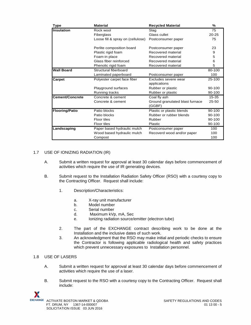
D. Examples of these materials and products are detailed below. These are recommended quantities and represent minimum compliance. The actual requirement is to use the maximum amount of recycled material possible, while meeting the performance specifications.
ACTIVATE BOSTON MARKET & QDOBA SAFETY REGULATIONS AND CODES FT. DRUM, NY 1367-14-000007 01 13 00 - 5 SOLICITATION ISSUE 03 JUN 2016
1.7 USE OF IONIZING RADIATION (IR)
A. Submit a written request for approval at least 30 calendar days before commencement of activities which require the use of IR generating devices.
B. Submit request to the Installation Radiation Safety Officer (RSO) with a courtesy copy to the Contracting Officer. Request shall include:
1. Description/Characteristics:
a. X-ray unit manufacturer b. Model number c. Serial number d. Maximum kVp, mA, Sec e. Ionizing radiation source/emitter (electron tube)
2. The part of the EXCHANGE contract describing work to be done at the Installation and the inclusive dates of such work.
3. An acknowledgment that the RSO may make initial and periodic checks to ensure the Contractor is following applicable radiological health and safety practices which prevent unnecessary exposures to Installation personnel.
1.8 USE OF LASERS
A. Submit a written request for approval at least 30 calendar days before commencement of activities which require the use of a laser.
B. Submit request to the RSO with a courtesy copy to the Contracting Officer. Request shall include:
Type Material Recycled Material %Insulation Rock wool Slag 75
Fiberglass Glass cullet 20-25Loose fill & spray on (cellulose) Postconsumer paper 75
Perlite composition board Postconsumer paper 23Plastic rigid foam Recovered material 9Foam-in place Recovered material 5Glass fiber reinforced Recovered material 6Phenolic rigid foam Recovered material 5
Wall Board Structural fiberboard 80-100Laminated paperboard Postconsumer paper 100
Carpet Polyester carpet face fiber Excludes severe wear applications
25-100
Playground surfaces Rubber or plastic 90-100Running tracks Rubber or plastic 90-100
Cement/Concrete Concrete & cement Coal fly ash 15-35Concrete & cement Ground granulated blast furnace
(GGBF)25-50
Flooring/Patio Patio blocks Plastic or plastic blends 90-100Patio blocks Rubber or rubber blends 90-100Floor tiles Rubber 90-100Floor tiles Plastic 90-100
Landscaping Paper based hydraulic mulch Postconsumer paper 100Wood based hydraulic mulch Recoverd wood and/or paper 100Compost 100
ACTIVATE BOSTON MARKET & QDOBA SAFETY REGULATIONS AND CODES FT. DRUM, NY 1367-14-000007 01 13 00 - 6 SOLICITATION ISSUE 03 JUN 2016
1. Description/Characteristics:
a. Manufacturer. b. Model. c. Number of same units. d. Serial number(s). e. Laser medium. f. Mode of operation (i.e. continuous wave (CW), single pulse, multiple
pulse). g. Maximum exposure time (train length). h. Ime (sec) & wave length. i. Energy/pulse (J) or CW power (W). j. Pulse repetition frequency. k. Pulse width. l. Beam diameter (at 1/e point). m. Beam divergence (at 1/e point).
2. The part of the EXCHANGE contract describing work to be done and the inclusive dates of such work.
3. An acknowledgment that the RSO may make initial and periodic checks to ensure the contractor is following applicable radiological health and safety practices which prevent unnecessary exposures to Installation personnel.
1.9 USE OF RADIOACTIVE MATERIALS (RAM):
A. Prior to bringing RAM onto Post property, the Contractor shall obtain permission from the RSO. To obtain approval, forward an application to the RSO, and a courtesy copy to the Contracting Officer at least 30 calendar days before the planned date for commencement of activities on the installation. Requests shall include:
A description of the proposed activities on NRC Form 241, Report of Proposed Activities in Non-Agreement States, (the 180-day limitation on the form does not apply to organizations holding an NRC license). Contractors possessing Agreement State Licenses shall also submit an NRC Form 241 to NRC in compliance with 10 CFR 150.21. Contractors requiring more than 180 days of operation per calendar year on the installation shall possess an NRC license. 1. The procedures established to ensure radiological health and safety of Post
personnel and the public while on Army or Air Force installations on site and the name of the responsible Contractor representative.
2. A current copy of the applicable NRC, or Agreement State license. Expired licenses are unacceptable. To be valid at the installation, the license must either specifically state the installation by name on the license or state approval for work at temporary job sites anywhere in the United States where the NRC or Agreement State maintains jurisdiction. DOE or DOE prime contractors must provide, in lieu of a license, written certification of their exemption from NRC licensing requirements and cite the applicable exemption of 10 CFR.
3. The part of the EXCHANGE contract describing work to be done and the inclusive dates of such work
4. An acknowledgment that the Post RSO may make periodic checks to ensure the Contractor is following applicable radiological health and safety practices which prevent unnecessary exposures to Army or Air Force personnel and prevent potential contamination of Government property.
ACTIVATE BOSTON MARKET & QDOBA SAFETY REGULATIONS AND CODES FT. DRUM, NY 1367-14-000007 01 13 00 - 7 SOLICITATION ISSUE 03 JUN 2016
1.10 USE OF RADIO FREQUENCY (RF) RADIATION
A. Prior to using equipment generating RF Radiation in excess of seven watts peak power and a frequency of 1000 MHz or greater on Installation must submit a written request for approval at least 30 calendar days before commencement of activities which require the use of the RF generating device.
B. Submit request to the RSO, with a courtesy copy to the Contracting Officer. Submittal shall include:
1. Description. 2. Nomenclature. 3. Location of emitters. 4. Quantity. 5. Frequency (Mhz). 6. Pulse width (microsec.). 7. Pulse repetition freq. (pps). 8. Peak power (kW). 9. Antenna size (feet--horizontal/vertical). 10. Antenna band width (degrees-- horizontal/vertical). 11. Antenna gain (dB). 12. Scan rate (rpm).
C. The part of the EXCHANGE contract describing work to be done at the Installation and the inclusive dates of such work.
D. An acknowledgment that the RSO may make initial and periodic checks to ensure the Contractor is following applicable radiological health and safety practices which prevent unnecessary exposures to Installation personnel.
1.11 USE OF ULTRAVIOLET (UV) RADIATION
A. Submit a written request for approval at least 30 calendar days before commencement of activities which require the use of UV generating devices on Post.
B. Submit request to the RSO, with a courtesy copy to the Contracting Officer. Request shall include:
1. The part of the EXCHANGE contract describing work to be done at the Installation and the inclusive dates of such work.
2. An acknowledgment that the RSO may make initial and periodic checks to ensure the Contractor is following applicable radiological health and safety practices which prevent unnecessary exposures to Installation personnel.
1.12 OZONE DEPLETING SUBSTANCES
A. No ozone depleting substances (refrigerants or any other compounds) shall be used in any capacity on this project unless specifically approved by the HazMart.
ACTIVATE BOSTON MARKET & QDOBA SAFETY REGULATIONS AND CODES FT. DRUM, NY 1367-14-000007 01 13 00 - 8 SOLICITATION ISSUE 03 JUN 2016
1.13 LEAD BASE PAINT
A. No paint with a lead content of 0.06 percent or greater shall be used in any capacity on this project unless specifically approved by the HazMart.
1.14 CLEANING AND DEBRIS CONTROL
A. During the term of this Contract, the Contractor shall remove any materials and equipment that are not required for the completion of the work as promptly as possible. All debris shall be removed from the site and legally disposed. The Contractor shall take particular care to eliminate any hazards created by his operations.
B. The Contractor is responsible for any damage caused by his debris without additional cost to the Government.
C. The Contractor shall maintain at all times during his work at this Project Site a strict windblown debris control program. This program shall ensure no windblown debris or other debris from his work shall contaminate or interfere with any access to or operation of any facility or any parking area, road or street.
1.15 NUISANCE DUMPING AND POLLUTING ACTIVITIES
A. Polluting, dumping, or discharging of any harmful, nuisance, or regulated materials (such as concrete truck washout, vehicle maintenance fluids, residue from saw cutting operations, solid waste or hazardous substances) into building drains, site drains, streams, waterways, holding ponds or to the ground surface is not permitted. The contractor shall be responsible for any and all damages resulting from dumping or discharges. Further, the Contractor shall conduct activities in such a fashion to avoid creating any legal nuisance, including but not limited to, suppression of noise and dust, control of erosion, and implementation of other measures as necessary to minimize off site impacts of work activities.
B. Fugitive Dust emissions (airborne dust generated by vehicles operating on unpaved surfaces, transfer or transport of dust producing materials, etc.) shall be controlled at the construction site, along haul routes and at staging areas. Water spraying shall be conducted as necessary to minimize fugitive dust generation.
1.16 CONTAMINATED SOIL
A. If unexpected contaminated soil is encountered while performing work, stop work immediately and contact the Contracting officer. Do not resume work until approved by the Contracting Officer.
1.17 SUSPECTED HAZARDOUS MATERIALS
A. Any suspect hazardous materials encountered during demolition or construction shall immediately be brought to the attention of the Contracting Officer’s representative. Work shall not resume until the Contracting Officer is satisfied that the materials are not hazardous. Should they be found to be hazardous, the contractor shall immediately take
ACTIVATE BOSTON MARKET & QDOBA SAFETY REGULATIONS AND CODES FT. DRUM, NY 1367-14-000007 01 13 00 - 9 SOLICITATION ISSUE 03 JUN 2016
steps to contain the material, so further damage and contamination does not occur. The contractor shall then submit a proposal for removal.
1.18 OIL-FILLED OR IMPREGNATED ELECTRICAL COMPONENTS
A. Notify Installation Environmental Safety Office and phone number) before demolition or installation of any oil-filled electrical equipment (for example: transformers and regulators). All transformers (both PCB and non-PCB-containing) and light ballasts (unless labeled “No PCBs”) shall be disposed through the Installation Hazardous Material and Waste Handling facility.
1.19 HAZARDOUS WASTE TESTING
A. The Contractor shall subject a representative sample of each type of hazardous waste, or potentially hazardous waste, generated to TCLP (Toxic Characteristic Leaching Procedure) testing. Sampling and testing for appropriate metals, and volatile and semi-volatile chemicals shall be performed by an independent test agency that is regularly engaged in the sampling and testing of hazardous materials and waste. Provide the test results to Installation Hazardous Waste Facility before transferring the waste to the facility. Refer to the attached Waste Disposal and Borrow Pit Worksheet for additional hazardous waste handling requirements.
1.20 HAZARDOUS MATERIAL INVENTORY
A. Contractor must submit an inventory of all hazardous materials to be used to include quantities. Inventory must be updated at completion of the project to indicate quantities used, spilled, and disposed of, etc.
B. The Contractor shall provide the Hazardous Materials Pharmacy (HazMart) a list and quantity of all hazardous materials that the Contractor intends to bring onto Government property. The Contractor shall provide the HazMart with copies of all MSDSs and an inventory for each Hazardous chemical listed in OSHA Hazard Communication Standard 29 CFR 1910.1200 intended to be used. Each MSDS shall be on file prior to use of the chemical, and shall be maintained for all chemicals. Once the hazardous material is used, its quantity of use shall be reported to the HazMart along with the disposition of the container.
C. Submit a completed Hazardous and Related Material Identification Form, and an MSDS for all materials listed on the form and brought on Installation.
D. If hazardous materials are not in their original container, the container containing the substance must be labeled.
1.21 SPILL RESPONSE AND REPORTING
A. Spills of hazardous waste, hazardous materials or non-regulated substances such as oils, antifreeze, grease, latex paint, hydraulic fluid, etc. shall immediately be reported to Department of Public Works for reporting purposes to local, state and federal agencies and proper clean-up action. If a spill occurs after normal working hours, or on a weekend

ACTIVATE BOSTON MARKET & QDOBA SAFETY REGULATIONS AND CODES FT. DRUM, NY 1367-14-000007 01 13 00 - 10 SOLICITATION ISSUE 03 JUN 2016
or holiday, report spills to the Installation Fire Department and request they contact Department of Public Works.
B. The contractor is encouraged to have a supply of absorbent pads on-site to aid in immediate clean-up of smaller spills, such as oil, coolant or hydraulic fluid leaks from vehicles or equipment.
C. Spill notification placards are to be placed on the job site (CEV or DPW) will provide format and required locations prior to construction.
D. The contractor shall develop a spill plan. The format for the plan will be provided by CEV or DPW prior to construction.
1.22 WASTE DISPOSAL AND ENVIRONMENTAL PROTECTION
A. The Contractor shall comply, and ensure that all subcontractors comply, with all Federal, State, local laws, and regulations, ordinances and standards related to environmental pollution control and abatement in effect and the specific requirements stated elsewhere in the Contract Documents.
B. All hazardous wastes as defined in 40 CFR, Part 261, shall be collected and disposed of in accordance with 40 CFR, Parts 260-268. The Contractor is responsible for properly storing, marking, labeling, securing and transporting hazardous wastes. All hazardous wastes shall be collected in contractor furnished DOT/UN approved containers and taken to Installation Hazardous Waste Facility for disposal. Call the Hazardous Waste Facility prior to transporting wastes to the facility to coordinate delivery of the waste materials. The Contractor shall not store hazardous waste on Installation for more than 30 days.
C. Any previously unidentified suspected hazardous materials encountered during performance of the work of the contract shall immediately be brought to the attention of the Contracting Officer.
D. All general construction wastes, other than those specifically allowed, or required, to be disposed of on-Installation shall be legally disposed at an off-Installation sanitary landfill.
E. Comply with the requirements of Installation Waste Disposal requirements.
PART 2 – PRODUCTS (NOT USED)
PART 3 – EXECUTION (NOT USED)
END OF SECTION 01 13 00

ACTIVATE BOSTON MARKET % QDOBA WASTE DISPOSAL FT. DRUM, NY 1367-14-000007 01 13 01 - 1 SOLICITATION ISSUE 03 JUN 2016
SECTION 01 13 01
WASTE DISPOSAL
The Contractor shall obtain all permits required by federal, state and local laws for the construction activities involved. The Contractor shall perform all work in such a manner as to minimize the polluting of air, water or land and shall, within reasonable limits, control noise and the disposal of solid waste materials, as well as other pollutants. The Contractor shall ensure that all construction, repair, maintenance operations and practices and waste disposal performed under this contract shall be in strict compliance with all applicable city, county, state and federal environmental laws and regulations.
1. Hazardous and Non-hazardous Waste Disposal: There are no known existing sources of hazardous waste involved with this project. If the Contractor generates or discovers suspected hazardous waste it shall be brought to the immediate attention of the Contracting Officer for review and direction on how to proceed with handling and disposal. As part of the proposed implementation above and prior to on-site construction, the Contractor shall submit for approval, a plan for storing, characterizing and disposing of hazardous and non-hazardous waste materials resulting from the work under this contract. Waste includes, but is not limited to, paint waste, paint equipment cleaners and used paint containers. If any waste material is dumped in unauthorized areas, the Contractor shall remove the materials and restore the area to the condition of the adjacent undisturbed areas. Where directed and approved by the Contracting Officer, contaminated ground shall be excavated, characterized, stored, disposed of and replaced with suitable fill material at the expense of the Contractor. All waste disposal shall be in strict accordance with local, state and federal requirements and regulations. Waste paint, paint equipment cleaners and used paint containers shall be disposed of off base by the Contractor, at the Contractors’ expense. Any soil contaminated through spillage shall be removed and disposed of in accordance with the requirements specified herein. Soil that is required to be removed shall be replaced by similar soil approved by the Contracting Officer.
END OF SECTION 01 13 01
ACTIVATE BOSTON MARKET & QDOBA CONSTRUCTION PHASING FT. DRUM, NY 1367-14-000007 01 14 20 - 1 SOLICITATION ISSUE 03 JUN 2016
SECTION 01 14 20
CONSTRUCTION PHASING
PART 1 - GENERAL 1.1 SECTION INCLUDES
A. Format. B. Content. C. Revisions to schedules. D. Submittals.
1.2 RELATED SECTIONS
A. Exhibit “A” - General Conditions of the EXCHANGE Contract for Construction, Article entitled: “Schedule and Progress”.
B. Section 01 10 00 - Summary C. Section 01 31 00 - Progress Management and Coordination D. Section 01 32 00 – Construction Progress Documentation E. Section 01 50 00 – Temporary Facilities, Barriers and Controls
1.3 GENERAL
A. The Construction Phasing Plans shall serve as a guide in managing the construction progress. B. In preparing this system, the scheduling of construction shall be the responsibility of the contractor.
1.4 COORDINATION
A. Construction shall be phased and coordinated with the Contracting Officer in order to keep to a minimum, any disruption of, or interference with, the operation of the existing retail facility. The Contractor shall notify the contracting officer, within 15 days of notice to proceed, if any problems concerning specified construction phasing occur. The Food Court will be in operation, throughout this contract. Contractor shall submit, in accordance with Section 01 32 00, Contractors prepared progress chart system, a detailed schedule of work. The Contractor shall keep the Contracting Officer advised of any anticipated changes in the work schedule in sufficient time to permit adjustment of store operations, without adversely affecting the ability of the Food Court to function.
B. Schedule: The Contractor must submit the schedule, for review, to the Contracting Officer within 15 days after execution of a contract. Items specified herein are complementary to work items shown on the drawings.
C. Beneficial occupancy inspection (finishes only) will be made at the end of each work item, to allow
early access for fixture installations.
ACTIVATE BOSTON MARKET & QDOBA CONSTRUCTION PHASING FT. DRUM, NY 1367-14-000007 01 14 20 - 2 SOLICITATION ISSUE 03 JUN 2016
D. Phasing: All phases shall be included in the contract performance period.
1.5 BARRIERS:
A. Building areas adjacent to areas to be renovated will not be vacated; therefore, temporary barriers shall be erected by the Contractor as work progresses. Provide temporary barriers as specified in Section 01 50 00 Temporary Facilities, Barriers and Controls in the locations as required, from floor to ceiling or from floor to underside of roof deck, to seal operational portions of the retail facility from areas of construction. Security walls, however, shall be secured up to the bottom of roof deck. Temporary barriers exposed to customer view shall be painted with two coats of color as approved by the Contracting Officer.
1.6 MATERIALS:
A. All isolation valves and temporary ductwork used to keep system on line in occupied phases for mechanical systems (air-handling units, supply piping, water lines, sprinklers, and other similar items) shall be included by the Contractor at no additional cost to the Exchange.
1.7 GENERAL:
A. Electrical Systems:
1. Install electrical distribution and telephone to existing construction. 2. All of the above work shall be completed without disruption of exchange operation
during normal business working hours.
B. Plumbing System:
1. Install all required piping and valves at the connection points. Shutdown of the plumbing systems to make necessary connections and extensions shall be accomplished at a time so as not to interfere with operation of the exchange, and shall be of minimum duration. All proposed shutdowns of the plumbing systems shall be coordinated with the exchange management.
PART 2 - PRODUCTS (NOT USED) PART 3 - EXECUTION (NOT USED) END OF SECTION 01 14 20

ACTIVATE BOSTON MARKET & QDOBA CUTTING AND PATCHING FT. DRUM, NY 1367-14-000007 01 14 50 - 1 SOLICITATION ISSUE 03 JUN 2016
SECTION 01 14 50
CUTTING AND PATCHING
PART 1 - GENERAL 1.1 SECTION INCLUDES
A. Requirements and limitations for cutting and patching of Work. 1.2 RELATED SECTIONS
A. Section 01 10 00 - Summary. B. Section 01 33 00 - Submittals. C. Individual Product Specification Sections:
1. Cutting and patching incidental to work of the section. 2. Advance notification to other sections of openings required in work of those sections. 3. Limitations on cutting structural members.
1.3 SUBMITTALS
A. Submit written request in advance of cutting or alteration which affects:
1. Structural integrity of any element of Project. 2. Integrity of weather exposed or moisture resistant element. 3. Efficiency, maintenance, or safety of any operational element. 4. Visual qualities of sight exposed elements. 5. Work of EXCHANGE or separate contractor.
B. Include in request:
1. Identification of Project. 2. Location and description of affected Work. 3. Necessity for cutting or alteration. 4. Description of proposed Work and Products to be used. 5. Alternatives to cutting and patching. 6. Effect on work of EXCHANGE or separate contractor. 7. Written permission of affected separate contractor. 8. Date and time work will be executed.
PART 2 – PRODUCTS 2.1 MATERIALS
A. Primary Products: Those required for original installation.
ACTIVATE BOSTON MARKET & QDOBA CUTTING AND PATCHING FT. DRUM, NY 1367-14-000007 01 14 50 - 2 SOLICITATION ISSUE 03 JUN 2016
PART 3 – EXECUTION 3.1 EXAMINATION
A. Examine existing conditions prior to commencing Work, including elements subject to damage or movement during cutting and patching.
B. After uncovering existing Work, assess conditions affecting performance of work. C. Beginning of cutting or patching means acceptance of existing conditions.
3.2 PREPARATION
A. Provide temporary supports to ensure structural integrity of the Work. Provide devices and methods to protect other portions of Project from damage.
B. Provide protection from elements for areas which may be exposed by uncovering work.
3.3 CUTTING
A. Execute cutting and fitting to complete the Work. B. Uncover work to install improperly sequenced work. C. Remove and replace defective or non-conforming work. D. Remove samples of installed work for testing when requested. E. Provide openings in the Work for penetration of mechanical and electrical work. F. Employ skilled and experienced installer to perform cutting for weather exposed and moisture
resistant elements, and sight exposed surfaces. G. Cut rigid materials using masonry saw or core drill. Pneumatic tools not allowed without prior
approval. 3.4 PATCHING
A. Execute patching to complement adjacent Work. B. Fit Products together to integrate with other Work. C. Execute work by methods to avoid damage to other Work, and which will provide appropriate
surfaces to receive patching and finishing. D. Employ original installer to perform patching for weather exposed and moisture resistant elements,
and sight-exposed surfaces. E. Restore work with new Products in accordance with requirements of Contract Documents. F. Fit work air tight to pipes, sleeves, ducts, conduit, and other penetrations through surfaces.

ACTIVATE BOSTON MARKET & QDOBA CUTTING AND PATCHING FT. DRUM, NY 1367-14-000007 01 14 50 - 3 SOLICITATION ISSUE 03 JUN 2016
G. At penetrations of fire rated walls, partitions, ceiling, or floor construction, completely seal voids with fire rated material, to full thickness of the penetrated element.
H. Refinish surfaces to match adjacent finish. For continuous surfaces, refinish to nearest intersection
or natural break. For an assembly, refinish entire unit.
END OF SECTION 01 14 50
ACTIVATE BOSTON MARKET & QDOBA SUBSTITUTION PROCEDURES FT. DRUM, NY 1367-14-000007 01 25 00 - 1 SOLICITATION ISSUE 03 JUN 2016
SECTION 01 25 00
SUBSTITUTION PROCEDURES
PART 1 - GENERAL
1.1 ACTION SUBMITTALS
A. Documentation:
1. Justification. 2. Coordination information. 3. Detailed comparison. 4. Product Data. 5. Samples. 6. Certificates and qualification data. 7. List of similar installations. 8. Material test reports. 9. Research reports. 10. Detailed comparison of Contractor's construction schedule. 11. Cost information. 12. Contractor's certification. 13. Contractor's waiver of rights to additional payment or time.
1.2 CONTRACTING OFFICERS APPROVAL
A. The contract is based on materials and methods described in the contract document. B. The Contracting Officer will consider proposals for substitution of materials, equipment and
methods only when such proposals are accompanied by full and complete technical data and all other information required by the Contracting Officer to evaluate the proposed substitution.
C. Do not substitute materials or equipment, unless such substitution has been specifically ap-
proved for this Work by the Contracting Officer. D. Requests for substitution must be made no less than 10 days prior to proposal closing date.
No further substitutions will be permitted after contract award.
E. Where the phrase “or equal” or “or equal as approved in advance by the Contracting Officer” occurs in the Contract Documents, do not assume that material and equipment will be approved as equal by the Contracting Officer unless the item has been specifically approved for this work by the Contracting Officer. All requests for “or equal” or “equal as approved in advance by the Contracting Officer” must be submitted 10 days prior to proposal closing date.
F. The decision of the Contracting Officer shall be final.
ACTIVATE BOSTON MARKET & QDOBA SUBSTITUTION PROCEDURES FT. DRUM, NY 1367-14-000007 01 25 00 - 2 SOLICITATION ISSUE 03 JUN 2016
1.3 SUBSTITUTIONS FOLLOWING AWARD OF CONTRACT
A. Substitutions for Cause: Not later than 15 days prior to time required for preparation and review of submittals. The submittal must include a justification explaining the rational for the requested substitution. The contractor shall be liable for costs of the Contracting Officer’s review for Contractors failure to order materials, equipment, e.g. in sufficient time.
B. Substitutions for Convenience: Not allowed after contract award.
1.4 AVAILABILITY OF SPECIFIED ITEMS
A. Verify prior to bidding that all specified items will be available in time for installation during or-derly and timely progress of the Work.
B. In the event specified item or items will not be so available, notify the Contracting Officer 10-
days prior to receipt of proposals with a recommended replacement item. C. Costs of delays because of non-availability of specified items, when such delays could have
been avoided by the Contractor, will be back-charged as necessary and shall not be borne by EXCHANGE.
PART 2 - PRODUCTS (NOT USED)
PART 3 - EXECUTION (NOT USED)
END OF SECTION 01 25 00
ACTIVATE BOSTON MARKET PROJECT MANAGEMENT AND COORDINATION FT. DRUM, NY 1367-14-000007 01 31 00 - 1 SOLICITATION ISSUE 03 JUN 2016
SECTION 01 31 00
PROJECT MANAGEMENT AND COORDINATION
PART 1 - GENERAL
1.1 REQUESTS FOR INFORMATION (RFIs)
A. RFI Forms: Software-generated form acceptable to Architect and EXCHANGE Project Manager.
B. Architect's Action: Allow seven working days for Architect's response for each RFI.
C. RFI Log: Maintain a tabular log of RFIs. Submit log weekly.
1.2 PROJECT WEB SITE
A. Use Contractor’s approved web site for project communication and documentation.
1.3 PRECONSTRUCTION MEETING
A. The Contracting Officer and/or Contracting Officer’s representative will schedule and preside at preconstruction meeting.
B. Attendance Required:
1. Contracting Officers and/or Contracting Officer’s representative and other Headquarters
EXCHANGE representatives. 2. Local and regional EXCHANGE representatives. 3. Installation representative (Engineering, Fire Marshall, Security, etc.) 4. Contractor
C. Agenda:
1. Execution of Notice to Proceed. 2. Distribution of Contract Documents. 3. Submission of list of sub-contractors. 4. Review of EXCHANGE checklist of contract requirements. 5. Discussion of Schedule. 6. Discussion of critical sequencing. 7. Designation of responsible personnel.

ACTIVATE BOSTON MARKET & QDOBA PROJECT MANAGEMENT AND COORDINATION FT. DRUM, NY 1367-14-000007 01 31 00 - 2 95% DESIGN SUBMITTAL 20 APR 2016
8. Processing of field decisions and change orders. 9. Submission of applications for payment. 10. Submittal of shop drawings. 11. Procedures for maintaining record documents. 12. Fire and safety procedures. 13. Security procedures. 14. Accident prevention and reports. 15. Housekeeping procedures. 16. Use of premises
a. Office and storage locations. b. Personnel parking.
17. Major equipment deliveries. 18. Other issues pertinent to completing the contract.
D. Meeting minutes: Minutes will be taken by the A/E and distributed to EXCHANGE, Contractor,
and Installation Engineer. 1.4 PROGRESS MEETINGS
A. The contractor shall schedule and preside at monthly progress meetings. B. The contractor shall make arrangements for meetings, prepare agenda with copies for
participants. C. Location of Meetings: Construction office, or as directed in the notice. D. Attendance Required:
1. Contractor's project manager. 2. Contractor's superintendent. 3. Major sub-contractors and suppliers. 4. EXCHANGE representative (EXCHANGE' option).
E. Agenda:
1. Review minutes of previous meetings. 2. Review of work progress. 3. Field observations, problems and decisions. 4. Identification of problems which impede planned progress. 5. Review of submittals schedule and status of submittals. 6. Review of off-site fabrication and delivery schedules. 7. Maintenance of progress schedule. 8. Corrective measures to regain projected schedules. 9. Coordination of projected progress. 10. Maintenance of quality and work standards. 11. Effect of proposed changes on progress schedule and coordination. 12. Other business relating to work.
F. Meeting Minutes: Architect/ Engineer shall record meeting minutes, and distribute copies to the
participants (including the EXCHANGE Contracting Officer, within three (3) business days of the meeting.
ACTIVATE BOSTON MARKET & QDOBA PROJECT MANAGEMENT AND COORDINATION FT. DRUM, NY 1367-14-000007 01 31 00 - 3 95% DESIGN SUBMITTAL 20 APR 2016
1.5 PROJECT MEETINGS
A. The Contractor shall schedule and preside at other project meetings when required.
B. Preinstallation Conferences: Conduct a preinstallation conference at Project site before each construction activity that requires coordination with other construction.
1. Attendees: Installer and representatives of manufacturers and fabricators involved in or affected by the installation and its coordination or integration with other materials and installations that have preceded or will follow, shall attend the meeting. Advise Architect , and EXCHANGE’ Commissioning Authority of scheduled meeting dates.
2. Agenda: Review progress of other construction activities and preparations for the particular activity under consideration, including requirements for the following:
a. Contract Documents. b. Options. c. Related RFIs. d. Related Change Orders. e. Purchases. f. Deliveries. g. Submittals. h. Review of mockups. i. Possible conflicts. j. Compatibility requirements. k. Time schedules. l. Weather limitations. m. Manufacturer's written instructions. n. Warranty requirements. o. Compatibility of materials. p. Acceptability of substrates. q. Temporary facilities and controls. r. Space and access limitations. s. Regulations of authorities having jurisdiction. t. Testing and inspecting requirements. u. Installation procedures. v. Coordination with other work. w. Required performance results. x. Protection of adjacent work. y. Protection of construction and personnel.
3. Record significant conference discussions, agreements, and disagreements, including required corrective measures and actions.
4. Reporting: Distribute minutes of the meeting to each party present and to other parties requiring information.
5. Do not proceed with installation if the conference cannot be successfully concluded. Initiate whatever actions are necessary to resolve impediments to performance of the Work and reconvene the conference at earliest feasible date.
C. Coordination Meetings: At weekly intervals, in addition to specific meetings held for other purposes.

ACTIVATE BOSTON MARKET & QDOBA PROJECT MANAGEMENT AND COORDINATION FT. DRUM, NY 1367-14-000007 01 31 00 - 4 95% DESIGN SUBMITTAL 20 APR 2016
PART 2 - PRODUCTS (NOT USED)
PART 3 - EXECUTION (NOT USED)
END OF SECTION 01 31 00
ACTIVATE BOSTON MARKET & QDOBA CONSTRUCTION PROGRESS DOCUMENTATION FT. DRUM, NY 1367-14-000007 01 32 00 - 1 SOLICITATION ISSUE 03 JUN 2016
SECTION 01 32 00
CONSTRUCTION PROGRESS DOCUMENTATION PART 1 GENERAL 1.1 SECTION INCLUDES
A. Format
B. Content
C. Revisions to schedules D. Submittals
1.2 RELATED SECTIONS
A. General Provisions of the EXCHANGE Contract for Construction, Article entitled: "Schedule and Progress"
B. Section 01 10 00 - Summary of Project
C. Section 01 33 00 - Submittals
1.4 GENERAL
A. The Contractor-prepared progress chart shall serve as a guide in managing the construc-tion progress.
B. In preparing this system, the scheduling of construction shall be the responsibility of the
Contractor. C. The schedules shall be prepared using the Critical Path Method (CPM).
1.4 FORMAT
A. Prepare schedules as a horizontal bar chart with separate bar for each major portion of work or operation, identifying first workday of each week.
B. The format shall be such to enable the Contracting Officer to evaluate the reasonable-
ness of the proposed schedule and to determine if the actual construction is on schedule. 1.5 CONTENT
A. Show complete sequence of construction by activity with dates for beginning and comple-tion of each element of construction.
B. Identify each item by specification section number.
ACTIVATE BOSTON MARKET & QDOBA CONSTRUCTION PROGRESS DOCUMENTATION FT. DRUM, NY 1367-14-000007 01 32 00 - 2 SOLICITATION ISSUE 03 JUN 2016
C. Show accumulated percentage of completion of each item and total percentage of Work completed as of the first day of each month.
D. Indicate delivery dates for EXCHANGE furnished products.
1.6 REVISIONS TO SCHEDULES
A. Indicate progress of each activity to date of submittal and projected completion date of each activity.
B. Identify activities modified since previous submittal, major changes in scope and other
identifiable changes which could affect the schedule.
C. Provide narrative report with each submittal describing work accomplished during the previous period, the work scheduled for the next period, anticipated problem areas and delays and impact on the schedule. Report corrective action taken or proposed.
1.7 SUBMITTALS
A. Submit a preliminary schedule through the Contracting Officer defining the Contractor's proposed operations for the first sixty (60) of the contract within ten (10) days after date of Notice to Proceed. Indicate the Contractor's general approach for the balance of the project. Include the cost of the activities expected to be completed or partially completed before submission and approval of the complete progress schedule.
B. Upon approval of the preliminary schedule by the Contracting Officer and within thirty
(30) calendar days after the Notice to Proceed, the Contractor shall submit the complete Progress Schedule.
C. Submit revised Progress Schedules with each monthly Application for Payment.
D. Submit the number of opaque reproductions which Contractor requires plus four (4) cop-
ies which will be retained by Contracting Officer. 1.8 DISTRIBUTION
A. Distribute copies of reviewed schedules to project site file, subcontractors, suppliers and other concerned parties.
B. Instruct recipients to promptly report in writing, problems anticipated by projections indi-
cated in schedules. PART 2 PRODUCTS (NOT USED) PART 3 EXECUTION (NOT USED)
END OF SECTION 01 32 00
ACTIVATE BOSTON MARKET & QDOBA SUBMITTAL PROCEDURES FT. DRUM, NY 1367-14-000007 01 33 00 - 1 SOLICITATION ISSUE 03 JUN 2016
SECTION 01 33 00
SUBMITTAL PROCEDURES PART 1 GENERAL 1.1 SECTION INCLUDES
A. Submittal procedures.
B. Construction progress schedules. C. Shop Drawings. D. Samples.
E. Product Data.
F. Certificates.
1.2 RELATED SECTIONS
A. Section 01 10 00 - Summary of Project.
B. Section 01 32 00 - Construction Progress Schedules
C. Section 01 78 39 - Project Record Documents. 1.3 SUBMITTAL PROCEDURES
A. Transmit each submittal with EXCHANGE Form 4450-48, Shop Drawings and Material Approval Submittal.
B. Sequentially number the transmittal form. Revise submittals with original number and a
sequential alphabetic suffix.
C. Identify Project, Contractor, subcontractor or supplier; pertinent drawing and detail num-ber, and specification section number, as appropriate.
D. Apply Contractor's stamp, signed or initialed certifying that review, approval, verification
of products required, field dimensions, adjacent construction work, and coordination of in-formation is in accordance with the requirements of the work and Contract Documents.
E. Schedule submittals to expedite the Project. Transmit submittals to Contracting Officer.
Coordinate submission of related items.
F. Identify variations from Contract Documents and Product or system limitations which may be detrimental to successful performance of the completed Work. Failure to identify such variations will not relieve the Contractor of the responsibility for completing the work in full accordance with the Contract Documents even though such submittals are approved by the Contracting Officer.
ACTIVATE BOSTON MARKET & QDOBA SUBMITTAL PROCEDURES FT. DRUM, NY 1367-14-000007 01 33 00 - 2 SOLICITATION ISSUE 03 JUN 2016
G. Prior to approval of the material/product submitted, the contractor shall include with the submittal a written certification that the material/product contains no asbestos. This certif-icate is mandatory before approval will be issued.
H. Provide space for Contractor and Contracting Officer review stamps.
I. When revised for resubmission, identify all changes made since previous submission.
J. Distribute copies of reviewed submittals as appropriate. Instruct parties to promptly re-
port any inability to comply with requirements. 1.4 CONSTRUCTION PROGRESS SCHEDULES
A. Submit preliminary Progress Schedule within ten (10) days of the Notice to Proceed.
B. Submit complete (final) Progress Schedule within thirty (30) days of the Notice to Pro-ceed.
C. Submit monthly revisions of Progress Schedule.
D. Refer to Section 01 32 00 - Construction Progress Documentation, for submittal infor-
mation. 1.5 SHOP DRAWINGS
A. Shop Drawings For Review:
1. Submitted to Contracting Officer for review for the limited purpose of checking for conformance with information given and the design concept expressed in the contract documents.
2. Shop drawings shall be prepared by a qualified detailer. 3. Minimum sheet size for shop drawings shall be 8 1/2" x 11". 4. After review, and distribute copies in accordance with Submittal Procedures arti-
cle above and for record documents purposes described in Section 01 77 00 - Project Closeout.
B. Shop Drawings For Project Close-out:
1. Submitted for the EXCHANGE's benefit during and after project completion.
C. Indicate special utility and electrical characteristics, utility connection requirements, and location of utility outlets for service for functional equipment and appliances.
1. Submit the number of opaque reproductions which Contractor requires, plus
three (four on structural, mechanical, and electrical submittals) copies which will be retained by Contracting Officer.
1.6 SAMPLES
A. Samples For Review:
1. Submitted to Contracting Officer for review for the limited purpose of checking for conformance with information given and the design concept expressed in the contract documents.

ACTIVATE BOSTON MARKET & QDOBA SUBMITTAL PROCEDURES FT. DRUM, NY 1367-14-000007 01 33 00 - 3 SOLICITATION ISSUE 03 JUN 2016
2. After review, produce duplicates and distribute in accordance with Submittal Pro-cedures article above and for record documents purposes described in Section 01 77 00 - Project Closeout.
B. Samples For Information:
1. Submitted for the Contracting Officer's knowledge as project administrator or for EXCHANGE.
C. Samples For Selection:
1. Submitted to Contracting Officer for aesthetic, color, or finish selection. 2. Submit samples of finishes from the full range of manufacturers' standard colors,
or in custom colors (if so stated in the product specification section), textures, and patterns for Contracting Officer selection.
3. After review, distribute in accordance with Submittal Procedures article above and for record documents purposes described in Section 01 77 00 - Project Closeout.
D. Submit samples to illustrate functional and aesthetic characteristics of the Product, with
integral parts and attachment devices. Coordinate sample submittals for interfacing work.
E. Include identification on each sample, with full Project information.
F. Submit the number of samples specified in individual specification sections; two of which will be retained by Contracting Officer.
G. Reviewed samples which may be used in the Work are indicated in individual specifica-
tion sections.
H. Coordinate sample submittals with respective shop drawings. 1.7 PRODUCT DATA
A. Submit Manufacturer's catalog sheets, brochures, diagrams, schedules, performance charts, specifications, illustrations, and other descriptive data.
B. Product data that relates to shop drawings or samples must be submitted with the re-
spective shop drawings or samples. 1.8 CERTIFICATES
A. When specified in individual specification sections, submit certification by the manufac-turer, installation/application subcontractor, or the Contractor to Contracting Officer, in quantities specified for Product Data.
B. Certify that material or Product conforms to or exceeds specified requirements. Submit
supporting reference data, test results, affidavits, and/or certifications as appropriate. C. Certificates may be recent or previous test results on material or Product, but must be
acceptable to Architect/Engineer.
1.9 LIMITATIONS AND CONTRACTOR’S RESPONSIBILITIES
ACTIVATE BOSTON MARKET & QDOBA SUBMITTAL PROCEDURES FT. DRUM, NY 1367-14-000007 01 33 00 - 4 SOLICITATION ISSUE 03 JUN 2016
A. Submittals will be reviewed for the limited purpose of checking for conformance with the design concept and the information shown in the drawing and specifications. These re-views shall not include review of the accuracy for completeness of details. A review shall not indicate that the reviewer has checked the entire system of which the reviewed item is a component. The reviewer shall not be required to review partial submissions.
PART 2 PRODUCTS (NOT USED) PART 3 EXECUTION (NOT USED)
END OF SECTION 01 33 00
ACTIVATE BOSTON MARKET & QDOBA WEATHER TABLE FT. DRUM, NY 1367-14-000007 01 33 10 - 1 SOLICITATION ISSUE 03 JUN 2016
SECTION 01 33 10 WEATHER TABLE PART 1 - GENERAL 1.1 INFORMATION AND DATA
A. Information and data furnished or referred to in the weather table is furnished for the Contractor's information.
1.2 CONTRACT TIME LIMITS
B. The contract time limits include weather conditions that are shown in the table listed herein.
1.3 TIME EXTENSIONS FOR UNUSUALLY SEVERE WEATHER
A. This provision specifies the procedure for the determination of time extensions for unusually severe weather affecting exterior work in accordance with the Contract. The following listing defines the monthly anticipated adverse weather for the contract period and is based on NOAA data for the geographic location of the project.
B. Weather Table:
MONTHLY ANTICIPATED ADVERSE WEATHER CALENDAR DAYS Fort Drum, New York
JAN FEB MAR APR MAY JUN JUL AUG SEPT OCT NOV DEC 7 5 4 4 6 5 7 7 4 3 4 7
This listing of anticipated adverse weather will constitute the base line monthly weather time evaluations. Throughout the contract each month, actual adverse weather days will be recorded on a calendar basis (including weekends and holidays) and compared to the monthly anticipated adverse weather in this listing. The term "actual adverse weather days" shall include days impacted by actual adverse weather. The number of actual adverse weather days affecting exterior work shall be calculated chronologically from the first to the last day in each month. Adverse weather days must prevent work for 50 percent or more of the contractor's work day and delay work critical to the timely completion of the project. If the number of actual adverse weather days exceeds the number of days anticipated in the above listing, the Contractor may submit in writing to the Contracting Officer a request for a time extension within 30 days of the adverse weather. Based upon the above NOAA data the Contracting Officer will determine if the time extension for the Contractor is warranted. The Contracting Officer will then convert any qualifying delays to calendar days and issue a modification in accordance with the contract. Any Time extensions granted under this provision will be at no cost to the EXCHANGE.
PART 2 – PRODUCTS (NOT USED) PART 3 – EXECUTION (NOT USED)
END OF SECTION
ACTIVATE BOSTON MARKET & QDOBA ENVIRONMENTAL PROTECTION FT. DRUM, NY 1367-14-000007 01 35 43 - 1 SOLICITATION ISSUE 03 JUN 2016
SECTION 01 35 43
ENVIRONMENTAL PROTECTION PART 1 - GENERAL 1.1 SECTION INCLUDES (Scope) A. The work covered by this section consists of furnishing all labor, materials, and equipment and
performing all work required for the prevention of environmental degradation during and as a result of construction operations under this contract. These requirements are in addition to any environmental protection requirements elsewhere in these specifications. For the purpose of this specification, environmental pollution is defined as the presence of chemical, physical, or biological elements or agents, not naturally occurring at the site, which adversely affect human health or welfare; unfavorably alter ecological balances important to human life; affect other species of importance to humans; or degrade the utility of the environment for aesthetic and recreational purposes. The control of environmental pollution by the contractor requires consideration of air, water, and land, and involves noise control, solid waste management and management of radiant energy and radioactive materials, as well as other pollutants. This section also requires the protection of cultural and historic resources.
B. Contractor shall coordinate the work of this section with the work called for under the various
Earthwork and Utilities sections. 1.2 CONTRACTOR'S GENERAL ENVIRONMENTAL COMPLIANCE OBLIGATIONS. Work under this contract is to be performed on a government facility. All environmental rules
applying to contractor operations elsewhere will also apply on the government facility. Contractor (and any subcontractor, agent or representative) shall comply with all Applicable Federal, State, and local laws and regulations providing for environmental protection and pollution control and abatement. These include but are not limited to: the Clean Air Act, Clean Water Act, Resource Conservation and Recovery Act, Comprehensive Environmental Response, Compensation and Liability Act, Toxic Substances Control Act, Federal Insecticide Fungicide and Rodenticide Act, Coastal Zone Management Act, Endangered Species Act, National Historic Preservation Act, Safe Drinking Water Act, Emergency Planning and Community Right-to-Know Act, Oil Pollution Act, Archeological Resources Protection Act, and Pollution Prevention Act. Contractor has the duty to determine for itself where such laws and regulations apply. Although the Contractor may request assistance from the Contracting Officer in delineating applicable environmental laws and regulations, Contractor has an independent responsibility to make its own determination and to do so in a timely fashion.
1.3 FINES OR PENALTIES FOR ENVIRONMENTAL NON-COMPLIANCE. The Contractor shall be responsible for paying any fines or penalties assessed against
EXCHANGE or the installation or the Army or the Air Force for violations of environmental laws or regulations resulting from acts or omissions of the contractor or its employees, subcontractors, or agents. This obligation is in addition to any fines or penalties that may be assessed against the contractor for the same conduct. Contractor may either reimburse these fines or penalties through the Contracting Officer, or with the consent of the Contracting Officer, the Contractor may pay such fines or penalties directly to the regulatory agency or agencies concerned.

ACTIVATE BOSTON MARKET & QDOBA ENVIRONMENTAL PROTECTION FT. DRUM, NY 1367-14-000007 01 35 43 - 2 SOLICITATION ISSUE 03 JUN 2016
1.4 CONTRACTOR'S LIABILITY FOR ENVIRONMENTAL DAMAGES Contractor agrees to hold harmless and indemnify EXCHANGE (which includes the Army, Air
Force, or other Department of Defense component, as appropriate) for any and all damages of any kind resulting from environmentally harmful activities by the contractor, contractor's employees or agents or subcontractors. "Damages" includes but is not limited to personal injury, property damage (including diminution of value), or death, environmental restoration and response costs, natural resource damages, expert witness and attorney's fees, and reimbursement of any and all expenses incurred to obtain permits as a result of Contractor's failure to identify or obtain permits for itself or EXCHANGE.
1.5 CONTACTS WITH ENVIRONMENTAL REGULATORY OFFICIALS. Contractor shall immediately advise the Contracting Officer and the installation environmental
office of the content of all contacts with federal, state, or local environmental regulators, before, during, and after the performance of this contract concerning the performance of this contract.
PART 2 - PERMITS 2.1 PERMITS FOR EQUIPMENT USED BY CONTRACTOR IN PERFORMING EXCHANGE
CONTRACTS. For equipment used in the performance of this contract, Contractor shall obtain in Contractor's
name and at no additional expense to EXCHANGE, all permits, coordinations, certifications or other regulatory authorization necessary to perform and complete the work required by this contract under applicable environmental laws and regulations. “Applicable environmental laws and regulations" includes but is not limited to: the Clean Air Act, Clean Water Act, Resource Conservation and Recovery Act, Comprehensive Environmental Response, Compensation and Liability Act (CERCLA), Toxic Substances Control Act, Federal Insecticide Fungicide and Rodenticide Act, Coastal Zone Management Act, Endangered Species Act, National Historic Preservation Act, Safe Drinking Water Act, Emergency Planning and Community Right-to-Know Act, Oil Pollution Act, and Pollution Prevention Act and State, County, and Local laws and regulations on the same subjects.
2.2 PERMITS NEEDED FOR CONSTRUCTION, EXCAVATION, MODIFICATION, RENOVATION,
DEMOLITION, INSTALLATION, OR OTHER ALTERATION OF BUILDINGS, STRUCTURES, EQUIPMENT, INSTALLATIONS, REAL PROPERTY OR SYSTEMS
Contractor shall identify all Federal, State, County, or local, permits, coordinations, certifications
or other regulatory authorization requirements under all applicable environmental laws and regulations as defined in (a.) above. Contractor shall then prepare and submit in draft all applicable permit applications, coordinations, notices, or other required filings, together with all supporting data to the contracting officer for review. Permit applications or notifications or other documents that must be submitted by EXCHANGE will be submitted by EXCHANGE, and any documents that must be submitted by the contractor will be returned after review to the contractor for submission. No work requiring permit or other written authorization shall proceed before the Contractor has the permit or authorization or a copy thereof in its possession.

ACTIVATE BOSTON MARKET & QDOBA ENVIRONMENTAL PROTECTION FT. DRUM, NY 1367-14-000007 01 35 43 - 3 SOLICITATION ISSUE 03 JUN 2016
PART 3 - MATERIALS 3.1 RECYCLED MATERIALS. Materials used in this contract shall be, to the greatest extent practicable and consistent with
financial prudence, made of recycled materials or of materials that are recyclable. Where construction debris such as concrete or asphalt or wood can be recycled, this alternative will be considered.
3.2 ASBESTOS Asbestos will not be used or included in this project. 3.3 POLYCHLORINATED BIPHENYL'S (PCBs) PCBs will not be used or included in this project. 3.4 LEAD-BASED PAINT Lead-based paint will not be used included in this project. 3.5 OZONE-DEPLETING SUBSTANCES. A. "Class I substance," as used in this clause, means any substance designated as class I by the
Environmental Protection Agency (EPA)(40 CFR Part 82), including but not limited to chlorofluorocarbons, halons, carbon tetrachloride, and methyl chloroform.
B. "Class II substance," as used in this clause, means any substance designated as class II by
EPA (40 CFR Part 82), including but not limited to, hydrochlorofluorocarbons. C. As required by 42 USC 7671j(b), c, and (d) and 40 CFR Part 82, Subpart E, the Contractor
shall label products which contain class I or class II ozone-depleting substances or are manufactured with a process that uses class I or class II ozone-depleting substances, or containers of class I or class II ozone-depleting substances, as follows:
"WARNING: Contains (or manufactured with, if applicable) _________*__________, (a) substance(s) which harm(s)public health and the environment by destroying ozone in the upper atmosphere." *The Contractor shall insert the name of the substance(s). D. The contractor shall comply with the applicable requirements of Sections 608 and 609 of the
Clean Air Act (42 USC 7671g, National Recycling and Emission Reduction Program and 7671h, Servicing of Motor Vehicle Air Conditioners) as each or both apply to the contract.
3.6 PESTICIDES Except as may be specified elsewhere in this contract, Contractor will not use or apply
pesticides (such as herbicides or weed-killers, insecticides, or rodenticides) without the specific written prior approval of the Contracting Officer.
ACTIVATE BOSTON MARKET & QDOBA ENVIRONMENTAL PROTECTION FT. DRUM, NY 1367-14-000007 01 35 43 - 4 SOLICITATION ISSUE 03 JUN 2016
PART 4 - EXECUTION (WORK PRACTICES) 4.1 GENERAL: SITE DISTURBANCE DURING CONSTRUCTION ACTIVITIES. Contractor shall use industry-recognized best management practices to avoid creation of
fugitive dust emissions and to avoid and control storm water runoff from the construction site and any temporary roads that may be used for access to it. Water sprinkling may be used to control dust. Contractor shall perform all work under this contract in such a manner that no pollutants of any kind are released into ditches, storm drains, streams, lakes, or other surface waters on or connected to the site.
4.2 PROTECTION OF WATER RESOURCES A. General: The General Contractor shall not pollute storm drainage, streams, lakes, or reservoirs
with fuels, oils, bitumens, calcium chloride, acids, construction wastes or other harmful materials or pollutants. It is the responsibility of the General Contractor to determine and comply with all applicable federal, state, regional, municipal, and other regulations.
B. Spillage: The General Contractor shall take special measures to prevent chemicals, fuels, oils,
greases, bituminous materials, waste washings, herbicides, cement, and surface drainage from entering public waters. In the event of a spill, the contractor must make all required notifications to federal, state or local authorities and will notify the Contracting Officer immediately.
C. Washing and Curing Water: Water used in aggregate processing, concrete curing, foundation,
and concrete lift clean-up and other waste water shall not be allowed to enter the storm drainage system.
4.3 PROTECTION OF LAND RESOURCES A. General: It is intended that the land resources within the project boundaries and outside the
limits of permanent work performed under this contract be preserved in their present condition or be restored to a condition after completion of construction that will appear to the natural and not detract from the appearance of the project. The General Contractor shall limit his construction activities to areas defined by the Drawings or Specifications.
B. Prevention of Landscape Defacement: Except in areas marked on the plans to be cleared, the
General Contractor shall not deface, remove, cut, injure or destroy trees or shrubs without specific written authority. Trees designated to be saved shall be protected from either excavation or filling within the root zone. No ropes, cables, or guys shall be fastened or attached to any existing trees for anchorage unless specifically authorized by the Contracting Officer. The General Contractor shall in any event be responsible for any damage resulting from such use.
C. Restoration of Landscape Damage: Any trees or other landscape features scarred or damaged
by the General Contractor's equipment or operations shall be restored as nearly as possible to the original condition at the General Contractor's expense. The Contracting Officer will decide what method of restoration shall be used, and whether damaged trees shall be treated and healed or removed and disposed of under requirements for clearing and grubbing (Section 31 10 00). All scars made on trees not designated on the plans to be removed by equipment construction operations, or by the removal of limbs larger than 1-inch in diameter shall be coated immediately with an approved tree wound dressing. All trimming or pruning shall be performed in an approved manner by experienced landscape personnel. Tree trimming with axes shall not be permitted. Trees that are to remain, either within or outside established clearing limits, that are subsequently damaged by the General Contractor and are beyond
ACTIVATE BOSTON MARKET & QDOBA ENVIRONMENTAL PROTECTION FT. DRUM, NY 1367-14-000007 01 35 43 - 5 SOLICITATION ISSUE 03 JUN 2016
saving in the opinion of the Contracting Officer, shall be immediately removed and replaced with a nursery-grown tree of the same species.
4.4 CONTROL OF AIR EMISSIONS. Contractor's actions shall conform to all federal, state, and local requirements for the control of
air emissions during work under this contract. Trucks leaving the site will be brushed or washed to remove all practicable amounts of dust or other material that may become airborne. Contractor will ensure that all internal construction vehicles and equipment used will have the lowest practicable emissions characteristics and be maintained in optimum operating condition for the reduction of air emissions. Where use of electric motors instead of internal combustion engines is feasible, electric motors will be used during construction.
PART 5 – POLLUTION PREVENTION AND WASTE DISPOSAL 5.1 POLLUTION PREVENTION The contractor should use prior planning to find those materials that will minimize the creation
of waste in general and hazardous waste in particular. Recycling should be considered and implemented at every practicable stage of the project.
5.2 WASTE DISPOSAL A. Pollution Prevention: The contractor should use prior planning to find those materials and work
practices that will minimize the creation of waste in general and hazardous waste in particular. B. Hazardous Waste Generation, Handling, and Disposal. Work done under this contract is to be
performed on a government facility. According to rules and procedures of the United States Environmental Protection Agency, the federal facility is required to have a generator identification number under the Resource Conservation and Recovery Act (RCRA) and to be responsible for wastes (as defined under RCRA) produced, managed, stored, disposed on, or transported from the facility. Accordingly, Contractor will, to the greatest extent practicable, use materials, processes, and techniques that will avoid the creation of hazardous waste. Contractor shall prepare and follow a written waste management and disposal plan for all hazardous wastes generated on the site. Prior to generation of any hazardous wastes, contractor will coordinate planned activities regarding hazardous materials and hazardous waste with the Contracting Officer. Contractor shall submit a written waste management plan, through the contracting officer, to installation environmental office. Contractor shall follow this plan once it has been approved by the contracting officer. Under no circumstances will contractor bring onto the site hazardous waste that has been generated elsewhere. All hazardous waste will be properly disposed of by the Contractor in accordance with all federal, state, and local requirements.
C. Disposal of Non-RCRA Wastes. All non-hazardous wastes generated on the site as a result of this contract must be disposed of
properly, in accordance with all federal, state and local requirements. Materials will be recycled whenever practicable. Prior to creation of such wastes, the contractor shall submit to the installation environmental management function, through the Contracting Officer, a plan for disposal of wastes. Such plan shall include the types of waste to be created, how they shall be stored, managed and disposed. Contractor shall follow this plan once it has been approved by the installation and contracting officer. Such wastes will not be created until approved by the Contracting Officer.
ACTIVATE BOSTON MARKET & QDOBA ENVIRONMENTAL PROTECTION FT. DRUM, NY 1367-14-000007 01 35 43 - 6 SOLICITATION ISSUE 03 JUN 2016
D. Construction Debris.
1. Debris from demolition of existing structures will ordinarily be removed to a location on the
installation, as designated by the installation authorities. 2. If a location on the installation is not available, other sections in this contract may require
the contractor to remove clean construction debris from the site to a location of the contractor’s choosing off the installation. (Site soil or other site media are not covered by this paragraph.) Debris will be recycled or disposed of in accordance with all applicable federal, state and local rules. Such debris must be free of all contamination, including but not limited to, lead paint, asbestos, and insecticides. Prior to removal of any construction debris, that debris must be certified by the installation to be free of contamination and of no value to the United States, and this certification must be provided to the contracting officer. To expedite work, this may be accomplished by a telecopier or other suitable electronic means, however, the original certification form must be provided to the contracting officer. No form is prescribed for this certification so long as all necessary information is provided and the document is signed by an authorized installation representative. However, an example is provided at below and this form may be used. All construction debris removed from the installation must be covered by a certification. The contractor must arrange with the installation POC whether all debris will be covered by one certification or if several certifications will be required.
E. Consolidated Waste Disposal Plans: Contractor may, at contractor’s option, submit for
approval as specified above one consolidated plan for handling hazardous and non-hazardous wastes.
F. Earthwork and Removal of Potentially Contaminated Media: 1. Unless otherwise specified elsewhere in this contract, the site has been inspected and is,
consistent with best professional judgment, free of environmental contamination or pollution. However, work under this contract will be performed on a military installation, where the history of prior military and industrial activities is not necessarily completely known. The following provisions prohibit the removal from the installation of soil or other materials found on site and are included, in an abundance of caution, for the protection of EXCHANGE, the installation, and the contractor.
2. Notwithstanding any other clause in this contract, including but not limited to all standard site work general provisions (02010-02900); no media by-product resulting from site preparation, construction or excavation shall be moved off the post, base, or installation where the construction is occurring. If the construction is off the post, base or installation, no media by-product shall be moved off the construction site.
3. The contractor shall: (1) leave the media in place at the site, subject to appropriate erosion control; or (2) haul the media to and place it at a location on the installation that has been designated either in this contract or in writing by the contracting officer; and (3) if unforeseen difficulties arise, such as excessive quantity of media is generated, the contractor shall advise the contracting officer and shall not remove media from the site without written authorization from the contracting officer.
DEFINITIONS Media - Any soil, water, or air, moved, disturbed or released from a site. The terms hazardous, waste, pollutant, contaminate, substance have the same meanings and usage here
as they commonly do in CERCLA, RCRA, FWPCA, CAA, TSCA, and SDWA respectively."

ACTIVATE BOSTON MARKET & QDOBA ENVIRONMENTAL PROTECTION FT. DRUM, NY 1367-14-000007 01 35 43 - 7 SOLICITATION ISSUE 03 JUN 2016
INSTALLATION CERTIFICATION FOR CLEAN CONSTRUCTION DEBRIS TO BE REMOVED FROM
EXCHANGE PROJECT SITE
As representative of _____________________________ Fort Drum, I am authorized to certify, and
hereby do so certify, that the construction debris to be removed from the EXCHANGE project site at the Northgate Express Store, 1105 Iraqi Freedom Drive , Fort Drum, New York has been inspected and is of no value to the United States and is free of all contamination, including but not limited to: lead paint, asbestos, PCBs, and pesticides.
CERTIFICATION: Signed: ____________________________________________________________ Date:
_________________ Printed Name, Rank or Grade, and Duty Title:
_________________________________________________________ ORIGINAL OF THIS FORM MUST BE PROVIDED TO CONTRACTING OFFICER PART 6 - UNEXPECTED SITE CONDITIONS 6.1 CONTAMINATED SOIL OR GROUNDWATER. Unless otherwise specified elsewhere in this contract, site has been inspected and is,
consistent with best professional judgment, free of environmental contamination or pollution. However, unexpected conditions can always arise. Contractor or subcontractor personnel may encounter soil or groundwater that is suspected to be contaminated, either because of odors, colors, free liquids, unexpected construction debris, or other suspicious conditions. Should this occur, contractor will immediately notify the Contracting Officer and the installation environmental office and take necessary initial measures to protect workers, the site, and other personnel.
6.2 UNEXPECTED ARTIFACTS OR RELICS Should contractor employees in the course of site preparation or other work on this contract
find unexpected historic or archeological remains, such as bones, arrow points, pottery remnants, foundations, or other evidence of previous uses of the site, contractor will cease further site-disturbing activity and immediately notify the Contracting Officer and installation environmental office.
END OF SECTION 01 35 43
ACTIVATE BOSTON MARKET & QDOBA QUALITY REQUIREMENTS FT. DRUM, NY 1367-14-000007 01 40 00 - 1 SOLICITATION ISSUE 03 JUN 2016
SECTION 01 40 00
QUALITY REQUIREMENTS
PART 1 - GENERAL 1.1 REQUIREMENTS INCLUDED
A. The Contractor shall establish a quality control system to perform sufficient inspection and tests of all items of work, including that of his subcontractor(s) to insure conformation to applicable specifications and drawings with respect to the materials, workmanship, construction, finish and functional performance. Tests of materials and/or special inspections will be made, when required by these specifications, by applicable law, rules and regulations in accordance with respective Sections of the specifications. Where required, the Contractor shall employ and pay for the services of an independent agency to perform specific services and testing.
B. The Contractor shall arrange and pay for all services and testing which are not specifically indicated
to be provided by EXCHANGE. C. If a material is not required to be field tested, the Contracting Officer may require the supplier to
furnish with each delivery of such material, a certificate bearing legal signature of said supplier, stating that such material complies with specification requirements.
D. If any work or material requiring tests and inspections is executed, enclosed or covered before tests
are made, or test reports distributed, then the Contractor shall, at his own expense, uncover such part of this work or material and keep it uncovered until such tests and inspections have been made and test reports distributed. If work or material so tested and inspected shall not be found to conform to the requirements of the Construction Documents, it shall be deemed and construed to be defective materials or faulty workmanship and the Contractor, at his own expense, shall replace work or material removed and repair all work disturbed thereby.
1.2 EXCHANGE RESPONSIBILITY A. No testing by Exchange. 1.3 CONTRACTORS RESPONSIBILITY
A. Contractor shall employ and pay for the services of an Independent Testing Agency to perform specified quality control testing during construction indicated in the following sections:
1. Testing Adjusting and Balancing for HVAC: Section 23 01 00.
ACTIVATE BOSTON MARKET & QDOBA QUALITY REQUIREMENTS FT. DRUM, NY 1367-14-000007 01 40 00 - 2 SOLICITATION ISSUE 03 JUN 2016
B. Cooperate with the Contracting Officer and laboratory personnel and provide access to work an to
manufacturer’s operations. Provide samples of materials to be tested, in required quantities. Furnish casual labor and facilities required to provide access to work to be tested; to obtain and handle samples at the site; to facilitate inspections and tests; and for laboratory’s exclusive use for storage and curing of test samples. Notify laboratory sufficiently in advance of operations to allow for its assignment of personnel and scheduling of tests.
C. The use of independent testing services shall in no way relieve the Contractor of his responsibility
to furnish materials and construction in full compliance with the plans and specifications. D. The Contractor shall coordinate testing laboratories so that the work will be inspected and tested
according to contract requirements. This coordinately includes notification of when tests should be taken, easy access to the work, and general cooperation in every way to insure proper control of the work.
E. Upon completion of the project the Contractor shall submit a signed certificate stating tests for this
work were made in accordance with provisions of these specifications and, further, all such tests and reports made were reported as required. This certificate shall list all tests and dates when work was completed.
1.4 AGENCY RESPONSIBILITIES
D. Test samples of mixes submitted by Contractor. E. Provide qualified personnel at site. Cooperate with Contracting Officer and Contractor in
performance of services. F. Perform specified sampling and testing of Products in accordance with specified standards. G. Ascertain compliance of materials and mixes with requirements of Contract Documents. H. Promptly notify Contracting Officer, and Contractor of observed irregularities or non-conformance of
Work or Products. I. Perform additional tests required by Contracting Officer. J. Provide Contracting Officer with three (3) copies of each written test report, and the Contractor each
with one copy of each test report. Each report shall include:
1. Date issued. 2. Project title and number. 3. Testing Laboratory name, address and telephone number. 4. Name and signature of laboratory inspector. 5. Date and time of sampling or inspection. 6. Record of temperature. 7. Date of test. 8. Identification of product and specification section. 9. Location of sample or test in the project. 10. Type of inspection or test. 11. Results of tests and compliance with Contract Documents. 12. Interpretation of test results, when requested by the Contracting Officer.
ACTIVATE BOSTON MARKET & QDOBA QUALITY REQUIREMENTS FT. DRUM, NY 1367-14-000007 01 40 00 - 3 SOLICITATION ISSUE 03 JUN 2016
H. Upon completion of the project, the testing agency shall prepare a certificate, certified in the presence of a Notary Public, stating testing for this work was conducted in accordance with the provisions of these specifications, and further, all tests and reports were provided for this job were reported as required.
1.5 LIMITS ON TESTING AUTHORITY
A. Agency or laboratory may not release, revoke, alter, or enlarge on requirements of Contract Documents.
B. Agency or laboratory may not approve or accept any portion of the Work. C. Agency or laboratory may not assume any duties of Contractor. D. Agency or laboratory has no authority to stop the Work.
1.6 RELATED REQUIREMENTS
A. Required Submittals Section 01 33 00. B. Related requirements and tests specified in Division 2 through 33.
PART 2 – PRODUCTS (NOT USED)
PART 3 – EXECUTION (NOT USED)
END OF SECTION 01 40 00

ACTIVATE BOSTON MARKET & QDOBA TEMPORARY FACILITIES AND CONTROLS FT. DRUM, NY 1367-14-000007 01 50 00 - 1 SOLICITATION ISSUE 03 JUN 2016
SECTION 01 50 00
TEMPORARY FACILITIES, BARRIERS AND CONTROLS
PART 1 - GENERAL
1.1 RELATED DOCUMENTS
A. Drawings and general provisions of the Contract, including General and Supplementary Conditions and other Division 01 Specification Sections, apply to this Section.
1.2 SUMMARY
A. Section includes requirements for temporary utilities, support facilities, and security and protection facilities.
B. Related Requirements:
1. Section 01 10 00 Summary of Project for work restrictions and limitations on utility interruptions.
1.3 USE CHARGES
A. General: Installation and removal of and use charges for temporary facilities shall be included in the Contract Sum unless otherwise indicated. Allow other entities to use temporary services and facilities without cost, including, but not limited to, Owner's construction forces, Architect, occupants of Project, testing agencies, and authorities having jurisdiction.
B. Water and Sewer Service from Existing System: Water from Owner's existing water system is available for use without metering and without payment of use charges. Provide connections and extensions of services as required for construction operations.
C. Electric Power Service from Existing System: Electric power from Owner's existing system is available for use without metering and without payment of use charges. Provide connections and extensions of services as required for construction operations.
1.4 INFORMATIONAL SUBMITTALS
A. Fire-Safety Program: Show compliance with requirements of NFPA 241 and authorities having jurisdiction. Indicate Contractor personnel responsible for management of fire-prevention program.
B. Dust- and HVAC-Control Plan: Submit coordination drawing and narrative that indicates the dust- and HVAC-control measures proposed for use, proposed locations, and proposed time frame for their operation. Identify further options if proposed measures are later determined to be inadequate. Include the following:
ACTIVATE BOSTON MARKET & QDOBA TEMPORARY FACILITIES AND CONTROLS FT. DRUM, NY 1367-14-000007 01 50 00 - 2 SOLICITATION ISSUE 03 JUN 2016
1. Locations of dust-control partitions at each phase of work. 2. HVAC system isolation schematic drawing. 3. Location of proposed air-filtration system discharge. 4. Waste handling procedures. 5. Other dust-control measures.
1.5 QUALITY ASSURANCE
A. Electric Service: Comply with NECA, NEMA, and UL standards and regulations for temporary electric service. Install service to comply with NFPA 70.
B. Tests and Inspections: Arrange for authorities having jurisdiction to test and inspect each temporary utility before use. Obtain required certifications and permits.
C. Accessible Temporary Egress: Comply with applicable provisions in the U.S. Architectural & Transportation Barriers Compliance Board's ADA-ABA Accessibility Guidelines.
PART 2 - PRODUCTS
2.1 MATERIALS
A. Interior Barriers for Phasing: Polyethylene Sheet: Reinforced, fire-resistive sheet, 10-mil (0.25-mm) minimum thickness, with flame-spread rating of 15 or less per ASTM E 84 and passing NFPA 701 Test Method 2, secured to temporary wood or metal framework without excess sagging or pillowing.
B. Dust-Control Adhesive-Surface Walk-off Mats: Provide mats minimum 36 by 60 inches (914 by 1624 mm).
2.2 TEMPORARY FACILITIES
A. Storage and Fabrication Sheds: Provide temporary storage sheds as necessary to accommodate weather-sensitive materials and equipment for construction operations. 1. Store combustible materials apart from building.
2.3 EQUIPMENT
A. Fire Extinguishers: Portable, UL rated; with class and extinguishing agent as required by locations and classes of fire exposures.
B. Air-Filtration Units: Primary and secondary HEPA-filter-equipped portable units with four-stage filtration. Provide single switch for emergency shutoff. Configure to run continuously.

ACTIVATE BOSTON MARKET & QDOBA TEMPORARY FACILITIES AND CONTROLS FT. DRUM, NY 1367-14-000007 01 50 00 - 3 SOLICITATION ISSUE 03 JUN 2016
PART 3 - EXECUTION
3.1 INSTALLATION, GENERAL
A. Locate facilities where they will serve Project adequately and result in minimum interference with performance of the Work.
B. Provide each facility ready for use when needed to avoid delay. Do not remove until facilities are no longer needed or are replaced by authorized use of completed permanent facilities.
3.2 TEMPORARY UTILITY INSTALLATION
A. Water Service: Install water service and distribution piping in sizes and pressures adequate for construction.
B. Water Service: Connect to Owner's existing water service facilities. Clean and maintain water service facilities in a condition acceptable to Owner. At Substantial Completion, restore these facilities to condition existing before initial use.
C. Sanitary Facilities: Provide temporary toilets, wash facilities, and drinking water for use of construction personnel. Comply with requirements of authorities having jurisdiction for type, number, location, operation, and maintenance of fixtures and facilities.
D. Isolation of Work Areas in Occupied Facilities: Prevent dust, fumes, and odors from entering occupied areas.
1. Prior to commencing work, isolate the HVAC system in area where work is to be performed according to coordination drawings.
a. Disconnect supply and return ductwork in work area from HVAC systems servicing occupied areas.
b. Maintain negative air pressure within work area using HEPA-equipped air-filtration units, starting with commencement of temporary partition construction, and continuing until removal of temporary partitions is complete.
2. Maintain dust partitions during the Work. Use vacuum collection attachments on dust-producing equipment. Isolate limited work within occupied areas using portable dust-containment devices.
3. Perform daily construction cleanup and final cleanup using approved, HEPA-filter-equipped vacuum equipment.
E. Ventilation and Humidity Control: Provide temporary ventilation required by construction activities for curing or drying of completed installations or for protecting installed construction from adverse effects of high humidity. Select equipment that will not have a harmful effect on completed installations or elements being installed. Coordinate ventilation requirements to produce ambient condition required and minimize energy consumption.
1. Provide dehumidification systems when required to reduce substrate moisture levels to level required to allow installation or application of finishes.
ACTIVATE BOSTON MARKET & QDOBA TEMPORARY FACILITIES AND CONTROLS FT. DRUM, NY 1367-14-000007 01 50 00 - 4 SOLICITATION ISSUE 03 JUN 2016
F. Electric Power Service: Connect to Owner's existing electric power service. Maintain equipment in a condition acceptable to Owner. 1. Connect temporary service to Owner's existing power source, as directed by Owner.
G. Lighting: Provide temporary lighting with local switching that provides adequate illumination for construction operations, observations, inspections, and traffic conditions.
1. Install and operate temporary lighting that fulfills security and protection requirements without operating entire system.
3.3 SUPPORT FACILITIES INSTALLATION
A. General: Comply with the following:
1. Provide construction for temporary offices, shops, and sheds located within construction area or within 30 feet of building lines that is noncombustible according to ASTM E 136. Comply with NFPA 241.
2. Maintain support facilities until Architect schedules Substantial Completion inspection. Remove before Substantial Completion. Personnel remaining after Substantial Completion will be permitted to use permanent facilities, under conditions acceptable to Owner.
B. Parking: Use designated areas of Owner's existing parking areas, if available and approved by the Exchange for construction personnel.
C. Waste Disposal Facilities: Comply with requirements specified in Section 017419 "Construction Waste Management and Disposal."
D. Waste Disposal Facilities: Provide waste-collection containers in sizes adequate to handle waste from construction operations. Comply with requirements of authorities having jurisdiction. Comply with progress cleaning requirements in Section 017300 "Execution."
E. Lifts and Hoists: Provide facilities necessary for hoisting materials and personnel.
1. Truck cranes and similar devices used for hoisting materials are considered "tools and equipment" and not temporary facilities.
3.4 SECURITY AND PROTECTION FACILITIES INSTALLATION
A. Protection of Existing Facilities: Protect existing vegetation, equipment, structures, utilities, and other improvements at Project site and on adjacent properties, except those indicated to be removed or altered. Repair damage to existing facilities.
B. Environmental Protection: Provide protection, operate temporary facilities, and conduct construction as required to comply with environmental regulations and that minimize possible air, waterway, and subsoil contamination or pollution or other undesirable effects.
1. Comply with work restrictions specified in Section 01 10 00 Summary of Project.
ACTIVATE BOSTON MARKET & QDOBA TEMPORARY FACILITIES AND CONTROLS FT. DRUM, NY 1367-14-000007 01 50 00 - 5 SOLICITATION ISSUE 03 JUN 2016
C. Temporary Fire Protection: Install and maintain temporary fire-protection facilities of types needed to protect against reasonably predictable and controllable fire losses. Comply with NFPA 241; manage fire-prevention program.
1. Prohibit smoking in construction areas. 2. Supervise welding operations, combustion-type temporary heating units, and similar
sources of fire ignition according to requirements of authorities having jurisdiction. 3. Develop and supervise an overall fire-prevention and -protection program for personnel
at Project site. Review needs with local fire department and establish procedures to be followed. Instruct personnel in methods and procedures. Post warnings and information.
4. Provide temporary standpipes and hoses for fire protection. Hang hoses with a warning sign stating that hoses are for fire-protection purposes only and are not to be removed. Match hose size with outlet size and equip with suitable nozzles.
3.5 OPERATION, TERMINATION, AND REMOVAL
A. Supervision: Enforce strict discipline in use of temporary facilities. To minimize waste and abuse, limit availability of temporary facilities to essential and intended uses.
B. Maintenance: Maintain facilities in good operating condition until removal.
C. Temporary Facility Changeover: Do not change over from using temporary security and protection facilities to permanent facilities until Substantial Completion.
D. Termination and Removal: Remove each temporary facility when need for its service has ended, when it has been replaced by authorized use of a permanent facility, or no later than Substantial Completion. Complete or, if necessary, restore permanent construction that may have been delayed because of interference with temporary facility. Repair damaged Work, clean exposed surfaces, and replace construction that cannot be satisfactorily repaired.
1. Materials and facilities that constitute temporary facilities are property of Contractor. 2. At Substantial Completion, repair, renovate, and clean permanent facilities used during
construction period. Comply with final cleaning requirements specified in Section 01 77 00 Project Closeout.
END OF SECTION 01 50 00
ACTIVATE BOSTON MARKET & QDOBA TEMPORARY UTILITIES FT. DRUM, NY 1367-14-000007 01 51 00 - 1 SOLICITATION ISSUE 03 JUN 2016
SECTION 01 51 00 TEMPORARY UTILITIES PART 1 GENERAL 1.1 SECTION INCLUDES
A. Temporary Utilities: Electricity, lighting, heat, ventilation, telephone service, water and sanitary facilities.
1.2 RELATED SECTIONS
A. Section 01 50 00 – Temporary Facilities, Barriers and Controls B. Section 01 77 00 - Project Closeout.
1.3 TEMPORARY ELECTRIC
A. The contractor shall furnish and install a complete, temporary electric service for construction needs throughout the construction period.
1. The temporary electric service shall originate from within the existing building.
The electrical contractor shall be responsible for furnishing and installing all fused cutouts, conductors, disconnects, and miscellaneous hardware.
2. The temporary electric service shall be a 120/208 volt, 3 phase, 4 wire, 200 amp service for construction operations.
3. Provide power centers, located such that all points of the construction area can be reached with extension cords no more than 100 feet long. Provide 20 amp, 120 and 208 volt grounded outlets, for use by all trades, each protected by a circuit breaker.
4. The Contractor will not be charged for a reasonable amount of electricity consumed. The contractor shall maintain strict conservation measures to prevent wasteful use of electricity.
5. Use of electric resistance heating devices is not permitted. 6. Unusually heavy electric loads, such as electric welding equipment, and other
equipment with special power requirements shall not be connected to the existing system.
B. Provide and maintain incandescent lighting for construction operations to achieve a
minimum lighting level of five (5) foot candles.
1. Provide branch wiring from power source to distribution boxes with lighting conductors, pigtails, and lamps as required.
2. Provide guarded lighting sockets and lamps. Use 100 watt lamps, minimum. Maintain 110 volts in lighting system.
3. Maintain lighting and provide routine repairs. 4. Permanent building lighting may be utilized during final stages of construction.
C. Standards: the temporary electric service shall comply with the National Electric Code. Extension cords used by any and all trades, shall be UL approved. No temporary power is to come from the building.
1.4 TEMPORARY HEATING
ACTIVATE BOSTON MARKET & QDOBA TEMPORARY UTILITIES FT. DRUM, NY 1367-14-000007 01 51 00 - 2 SOLICITATION ISSUE 03 JUN 2016
A. The Contractor may use the existing permanent heating system for temporary heat during construction, supplemented by temporary equipment if needed, under the following conditions:
1. Use of the existing permanent equipment does not spread hazardous or objectionable dust, fumes, mists, vapors, gases or odors into areas occupied by EXCHANGE or other Personnel or customers.
2. Use of the existing permanent equipment does not damage or cause excessive wear to the equipment.
3. The Contractor shall provide and pay for operation, maintenance, and replacement of filters and worn or damaged parts on the equipment used.
B. The Contractor will not be charged for a reasonable amount of fuel or energy used by the
existing permanent equipment. The Contractor shall maintain strict conservation measures to prevent waste of fuel or energy.
C. The Contractor shall pay for the fuel consumed by temporary heating devices.
D. Temporary equipment using electric resistance heating is not permitted.
1.6 TEMPORARY COOLING
A. The Contractor may utilize the existing cooling system, extend and supplement with temporary cooling devices as needed to maintain specified conditions for construction operations.
B. The Contractor will not be charged for a reasonable amount of fuel or energy consumed
by the existing system. The Contractor shall maintain strict conservation measures to prevent waste of fuel or energy.
1.7 TEMPORARY VENTILATION
A. The Contractor shall provide adequate ventilation to: 1. Aid in curing installed materials. 2. Dispersal of humidity. 3. Ventilation of temporary sanitary facilities. 4. Prevent hazardous accumulations of dust, fumes, mists, vapors, or gases in
areas occupied during construction.
B. The Contractor may use the existing, permanent ventilating equipment, supplemented by temporary equipment, if required, under the following conditions: 1. Use of the existing, permanent equipment does not spread hazardous or
objectionable dust, fumes, mists, vapors, gases, or odors into areas of the building occupied by EXCHANGE personnel or customers.
2. Use of the existing, permanent equipment does not cause damage to equipment. 3. The Contractor shall provide and pay for operation, maintenance, and
replacement of filters and worn or damaged parts on the equipment used. 1.8 TEMPORARY WATER SERVICE
A. Connect to existing water source for construction operations at time of project mobilization.
ACTIVATE BOSTON MARKET & QDOBA TEMPORARY UTILITIES FT. DRUM, NY 1367-14-000007 01 51 00 - 3 SOLICITATION ISSUE 03 JUN 2016
B. The Contractor will not be charged for a reasonable amount of water consumed for
construction purposes. The Contractor shall maintain strict conservation measures to prevent waste of water.
C. Extend branch piping with outlets located so water is available by hoses with threaded
connections. Provide temporary pipe insulation to prevent freezing. 1.9 TEMPORARY SANITARY FACILITIES
A. Provide and maintain required facilities and enclosures. Existing facility use is not permitted. Provide at time of project mobilization.
B. Furnish, install, and maintain adequate portable chemical toilets for use by construction
personnel.
C. Provide regular maintenance service to maintain clean and sanitary conditions. PART 2 PRODUCTS (NOT USED) PART 3 EXECUTION
3.1 SECURITY AND PROTECTION FACILITIES INSTALLATION
A. Temporary Barriers: Provide floor-to-ceiling dustproof barriers to limit dust and dirt migration and to separate areas occupied by EXCHANGE and tenants from fumes and noise.
1. Dust Barrier: Where dust barriers are required, provide a single layer of 6 mil fire resistant clear polyethylene fiberglass reinforced sheet as manufactured by Griffolyn, or equal. Tape all joints and provide fire resistive treated 2 x 4 wood or metal stud top and bottom runners and verticals 4 foot o.c. with polyethylene sheet wrapped and taped to the runners.
2. Opaque Dust Barrier: Where dust barriers are required and where indicated for long duration separation of construction operations from EXCHANGE and tenant spaces, provide braced metal stud framing covered on construction side with 6 mil fire resistant clear polyethylene fiberglass reinforced sheet as manufactured by Griffolyn, or equal. Tape all joints and perimeter. Provide ½ inch gypsum board, fire taped on the EXCHANGE/tenant side from floor to ceiling. Provide R-11 batt insulation for thermal separation from unconditioned construction areas and noise reduction adjacent to sales, food service or office areas.
B. Temporary Fire Protection: Install and maintain temporary fire-protection facilities of types needed to protect against reasonably predictable and controllable fire losses. Comply with NFPA 241.
1. Prohibit smoking in construction areas. 2. Supervise welding operations, combustion-type temporary heating units, and similar
sources of fire ignition according to requirements of authorities having jurisdiction. 3. Develop and supervise an overall fire-prevention and -protection program for personnel at
Project site. Review needs with local fire department and establish procedures to be followed. Instruct personnel in methods and procedures. Post warnings and information.

ACTIVATE BOSTON MARKET & QDOBA TEMPORARY UTILITIES FT. DRUM, NY 1367-14-000007 01 51 00 - 4 SOLICITATION ISSUE 03 JUN 2016
END OF SECTION 01 51 00
ACTIVATE BOSTON MARKET & QDOBA CLEANING FT. DRUM, NY 1367-14-000007 01 71 00 - 1 SOLICITATION ISSUE 03 JUN 2016
SECTION 01 71 00
CLEANING
PART 1 - GENERAL 1.1 SECTION INCLUDES
A. Progress Cleaning. B. Final Cleaning.
1.2 RELATED SECTIONS
A. General Provisions of the Contract. B. Section 01 10 00 – Summary of Project. C. Section 01 14 50 - Cutting and Patching. D. Section 01 55 00 – Temporary Facilities, Barriers and Controls. E. Individual Specification Sections - Cleaning Requirements.
1.3 SAFETY REQUIREMENTS
A. Standards: Maintain project in accordance with the following safety and insurance standards:
1. The Corps of Engineers Manual, EM 385-1-1, latest edition, entitled: "General Safety Requirements", as referred to in General Provisions, Paragraph: Accident Prevention.
B. O.S.H.A. Standards:
1. The Contractor shall be required to comply with OSHA Requirements in 29 CFR 1926 and
29 CFR in 1910. The OSHA Standards are subject to change, and such changes may affect the Contractor in his performance under the contract. It is the Contractor's responsibility to know such changes, effective dates of changes, and comply with all requirements.
C. Hazards Control:
1. Store volatile wastes in covered metal containers and remove from premises daily. 2. Prevent accumulation of wastes which create hazardous conditions. 3. Provide adequate ventilation during the use of volatile or noxious substances.
D. Conduct cleaning and disposal operations to comply with local ordinances and anti-pollution laws.
1. Do not burn or bury rubbish and waste materials on the installation. 2. Do not dispose of volatile wastes such as mineral spirits, oil, or paint thinner in storm or
sanitary drains. 3. Do not dispose of wastes into streams or waterways.
ACTIVATE BOSTON MARKET & QDOBA CLEANING FT. DRUM, NY 1367-14-000007 01 71 00 - 2 SOLICITATION ISSUE 03 JUN 2016
PART 2 - PRODUCTS 2.1 MATERIALS
A. Use only cleaning materials recommended by the manufacturer of the surface to be cleaned. B. Use cleaning materials only on surfaces recommended by cleaning material manufacturer.
PART 3 - EXECUTION 3.1 PROGRESS CLEANING
A. Execute cleaning to ensure that the building, grounds, and public properties are maintained free from accumulations of waste materials and rubbish.
B. Maintain site in a clean and orderly condition. C. Wet down dry materials and rubbish to lay dust and prevent blowing dust. D. Remove waste materials, debris, and rubbish from site and legally dispose of at public or private
dumping areas off of Government property. E. Vacuum clean interior building areas when ready to receive finish painting, and continue cleaning to
eliminate dust. F. Handle materials in a controlled manner with as few handlings as possible; do not drop or throw
materials from heights. Open free-fall chutes are not permitted. G. Schedule cleaning operations so that dust and other contaminants resulting from the cleaning
process will not fall on wet, newly painted surfaces. 3.2 FINAL CLEANING
A. Employ professional cleaners for final cleaning. B. In preparation for substantial completion or occupancy, conduct final inspection of sight-exposed
interior and exterior surfaces and of concealed spaces. C. Remove grease, dust, dirt, stains, temporary labels, fingerprints, and other foreign materials from
sight-exposed interior and exterior finished surfaces; polish surfaces so designated to shine; finish vacuum carpeted and soft surfaces.
D. Repair, patch, and touch-up marred surfaces to specified finish, to match adjacent surfaces. E. Clean all glass.
F. Replace air conditioning filters if units were operated during construction.
G. Clean ducts, blowers, and coils, if air H.V.A.C. units were operated without filters during
construction.
H. Maintain cleaning until project, or portion thereof, is occupied by EXCHANGE.
END OF SECTION 01 71 00
ACTIVATE BOSTON MARKET & QDOBA CONSTRUCTION WASTE MANAGEMENT AND DISPOSAL FT. DRUM, NY 1367-14-000007 01 74 19 - 1 SOLICITATION ISSUE 03 JUN 2016
SECTION 01 74 19
CONSTRUCTION WASTE MANAGEMENT AND DISPOSAL
PART 1 - GENERAL
1.1 RELATED DOCUMENTS
A. Drawings and general provisions of the Contract, including General and Supplementary Conditions and other Division 01 Specification Sections, apply to this Section.
1.2 SUMMARY
A. Section includes administrative and procedural requirements for the following:
1. Salvaging nonhazardous demolition and construction waste. 2. Recycling nonhazardous demolition and construction waste. 3. Disposing of nonhazardous demolition and construction waste.
B. Related Requirements:
1. Division 01 Section for coordination of responsibilities for waste management.
1.3 DEFINITIONS
A. Construction Waste: Building and site improvement materials and other solid waste resulting from construction, remodeling, renovation, or repair operations. Construction waste includes packaging.
B. Demolition Waste: Building and site improvement materials resulting from demolition or selective demolition operations.
C. Disposal: Removal off-site of demolition and construction waste and subsequent sale, recycling, reuse, or deposit in landfill or incinerator acceptable to authorities having jurisdiction.
D. Recycle: Recovery of demolition or construction waste for subsequent processing in preparation for reuse.
E. Salvage: Recovery of demolition or construction waste and subsequent sale or reuse in another facility.
F. Salvage and Reuse: Recovery of demolition or construction waste and subsequent incorporation into the Work.

ACTIVATE BOSTON MARKET & QDOBA CONSTRUCTION WASTE MANAGEMENT AND DISPOSAL FT. DRUM, NY 1367-14-000007 01 74 19 - 2 SOLICITATION ISSUE 03 JUN 2016
1.4 PERFORMANCE REQUIREMENTS
A. General: Achieve end-of-Project rates for salvage/recycling of 50 percent by weight of total non-hazardous solid waste generated by the Work. Practice efficient waste management in the use of materials in the course of the Work. Use all reasonable means to divert construction and demolition waste from landfills and incinerators. Facilitate recycling and salvage of materials, including the following:
1. Demolition Waste:
a. Asphalt paving. b. Concrete. c. Concrete reinforcing steel. d. Brick. e. Concrete masonry units. f. Wood studs. g. Wood joists. h. Plywood and oriented strand board. i. Wood paneling. j. Wood trim. k. Structural and miscellaneous steel. l. Rough hardware. m. Roofing. n. Insulation. o. Doors and frames. p. Door hardware. q. Windows. r. Glazing. s. Metal studs. t. Gypsum board. u. Acoustical tile and panels. v. Carpet. w. Carpet pad. x. Demountable partitions. y. Equipment. z. Cabinets. aa. Plumbing fixtures. bb. Piping. cc. Supports and hangers. dd. Valves. ee. Sprinklers. ff. Mechanical equipment. gg. Refrigerants. hh. Electrical conduit. ii. Copper wiring. jj. Lighting fixtures. kk. Lamps. ll. Ballasts. mm. Electrical devices. nn. Switchgear and panelboards. oo. Transformers. pp. Construction Waste: qq. Masonry and CMU. rr. Lumber.
ACTIVATE BOSTON MARKET & QDOBA CONSTRUCTION WASTE MANAGEMENT AND DISPOSAL FT. DRUM, NY 1367-14-000007 01 74 19 - 3 SOLICITATION ISSUE 03 JUN 2016
ss. Wood sheet materials. tt. Wood trim. uu. Metals. vv. Roofing. ww. Insulation. xx. Carpet and pad. yy. Gypsum board. zz. Piping. aaa. Electrical conduit. bbb. Packaging: Regardless of salvage/recycle goal indicated in "General" Paragraph
above, salvage or recycle 100 percent of the following uncontaminated packaging materials:
1) Paper. 2) Cardboard. 3) Boxes. 4) Plastic sheet and film. 5) Polystyrene packaging. 6) Wood crates. 7) Plastic pails.
1.5 ACTION SUBMITTALS
A. Waste Management Plan: Submit plan within 14 days of date established for the Notice to Proceed.
1.6 INFORMATIONAL SUBMITTALS
A. Waste Reduction Progress Reports: Concurrent with each Application for Payment, submit report. Use Form CWM-7 for construction waste and Form CWM-8 for demolition waste.
1. Material category. 2. Generation point of waste. 3. Total quantity of waste in tons (tonnes). 4. Quantity of waste salvaged, both estimated and actual in tons (tonnes). 5. Quantity of waste recycled, both estimated and actual in tons (tonnes). 6. Total quantity of waste recovered (salvaged plus recycled) in tons (tonnes). 7. Total quantity of waste recovered (salvaged plus recycled) as a percentage of total
waste.
B. Waste Reduction Calculations: Before request for Substantial Completion, submit calculated end-of-Project rates for salvage, recycling, and disposal as a percentage of total waste generated by the Work.
ACTIVATE BOSTON MARKET & QDOBA CONSTRUCTION WASTE MANAGEMENT AND DISPOSAL FT. DRUM, NY 1367-14-000007 01 74 19 - 4 SOLICITATION ISSUE 03 JUN 2016
C. Records of Donations: Indicate receipt and acceptance of salvageable waste donated to individuals and organizations. Indicate whether organization is tax exempt.
D. Records of Sales: Indicate receipt and acceptance of salvageable waste sold to individuals and organizations. Indicate whether organization is tax exempt.
E. Recycling and Processing Facility Records: Indicate receipt and acceptance of recyclable waste by recycling and processing facilities licensed to accept them. Include manifests, weight tickets, receipts, and invoices.
F. Landfill and Incinerator Disposal Records: Indicate receipt and acceptance of waste by landfills and incinerator facilities licensed to accept them. Include manifests, weight tickets, receipts, and invoices.
G. Coordinate "Qualification Data" Paragraph below with qualification requirements in Division 01 Section "Quality Requirements" and as may be supplemented in "Quality Assurance" Article.
H. Qualification Data: For waste management coordinator and refrigerant recovery technician.
I. Statement of Refrigerant Recovery: Signed by refrigerant recovery technician responsible for recovering refrigerant, stating that all refrigerant that was present was recovered and that recovery was performed according to EPA regulations. Include name and address of technician and date refrigerant was recovered.
1.7 QUALITY ASSURANCE
A. Refrigerant Recovery Technician Qualifications: Certified by EPA-approved certification program.
B. Regulatory Requirements: Comply with hauling and disposal regulations of authorities having jurisdiction.
C. Waste Management Conference: Conduct conference at Project site to comply with requirements in Division 01 Section "Project Management and Coordination." Review methods and procedures related to waste management including, but not limited to, the following:
1. Review and discuss waste management plan including responsibilities of waste management coordinator.
2. Review requirements for documenting quantities of each type of waste and its disposition.
3. Review and finalize procedures for materials separation and verify availability of containers and bins needed to avoid delays.
4. Review procedures for periodic waste collection and transportation to recycling and disposal facilities.
5. Review waste management requirements for each trade.
1.8 WASTE MANAGEMENT PLAN
A. General: Develop a waste management plan according to ASTM E 1609 and requirements in this Section. Plan shall consist of waste identification, waste reduction work plan, and
ACTIVATE BOSTON MARKET & QDOBA CONSTRUCTION WASTE MANAGEMENT AND DISPOSAL FT. DRUM, NY 1367-14-000007 01 74 19 - 5 SOLICITATION ISSUE 03 JUN 2016
cost/revenue analysis. Distinguish between demolition and construction waste. Indicate quantities by weight or volume, but use same units of measure throughout waste management plan.
B. Waste Identification: Indicate anticipated types and quantities of demolition site-clearing and construction waste generated by the Work. Use Form CWM-1 for construction waste and Form CWM-2 for demolition waste. Include estimated quantities and assumptions for estimates.
C. Waste Reduction Work Plan: List each type of waste and whether it will be salvaged, recycled, or disposed of in landfill or incinerator. Use Form CWM-3 for construction waste and Form CWM-4 for demolition waste. Include points of waste generation, total quantity of each type of waste, quantity for each means of recovery, and handling and transportation procedures.
1. Salvaged Materials for Reuse: For materials that will be salvaged and reused in this Project, describe methods for preparing salvaged materials before incorporation into the Work.
2. Salvaged Materials for Sale: For materials that will be sold to individuals and organizations, include list of their names, addresses, and telephone numbers.
3. Salvaged Materials for Donation: For materials that will be donated to individuals and organizations, include list of their names, addresses, and telephone numbers.
4. Recycled Materials: Include list of local receivers and processors and type of recycled materials each will accept. Include names, addresses, and telephone numbers.
5. Disposed Materials: Indicate how and where materials will be disposed of. Include name, address, and telephone number of each landfill and incinerator facility.
6. Handling and Transportation Procedures: Include method that will be used for separating recyclable waste including sizes of containers, container labeling, and designated location where materials separation will be performed.
D. Cost/Revenue Analysis: Indicate total cost of waste disposal as if there was no waste management plan and net additional cost or net savings resulting from implementing waste management plan. Use Form CWM-5 for construction waste and Form CWM-6 for demolition waste. Include the following:
1. Total quantity of waste. 2. Estimated cost of disposal (cost per unit). Include hauling and tipping fees and cost of
collection containers for each type of waste. 3. Total cost of disposal (with no waste management). 4. Revenue from salvaged materials. 5. Revenue from recycled materials. 6. Savings in hauling and tipping fees by donating materials. 7. Savings in hauling and tipping fees that are avoided. 8. Handling and transportation costs. Include cost of collection containers for each type of
waste. 9. Net additional cost or net savings from waste management plan.
ACTIVATE BOSTON MARKET & QDOBA CONSTRUCTION WASTE MANAGEMENT AND DISPOSAL FT. DRUM, NY 1367-14-000007 01 74 19 - 6 SOLICITATION ISSUE 03 JUN 2016
PART 2 - PRODUCTS (NOT USED)
PART 3 - EXECUTION
3.1 PLAN IMPLEMENTATION
A. General: Implement approved waste management plan. Provide handling, containers, storage, signage, transportation, and other items as required to implement waste management plan during the entire duration of the Contract.
B. Waste Management Coordinator: Engage a waste management coordinator to be responsible for implementing, monitoring, and reporting status of waste management work plan.
C. Training: Train workers, subcontractors, and suppliers on proper waste management procedures, as appropriate for the Work.
1. Distribute waste management plan to everyone concerned within three days of submittal return.
2. Distribute waste management plan to entities when they first begin work on-site. Review plan procedures and locations established for salvage, recycling, and disposal.
D. Site Access and Temporary Controls: Conduct waste management operations to ensure minimum interference with roads, streets, walks, walkways, and other adjacent occupied and used facilities.
1. Designate and label specific areas on Project site necessary for separating materials that are to be salvaged, recycled, reused, donated, and sold.
E. Waste Management in Historic Zones or Areas: Hauling equipment and other materials shall be of sizes that clear surfaces within historic spaces, areas, rooms, and openings, by 12 inches (300 mm) or more.
3.2 SALVAGING DEMOLITION WASTE
A. Salvaged Items for Reuse in the Work: Salvage items for reuse and handle as follows:
1. Clean salvaged items. 2. Pack or crate items after cleaning. Identify contents of containers with label indicating
elements, date of removal, quantity, and location where removed. 3. Store items in a secure area until installation. 4. Protect items from damage during transport and storage. 5. Install salvaged items to comply with installation requirements for new materials and
equipment. Provide connections, supports, and miscellaneous materials necessary to make items functional for use indicated.
B. Salvaged Items for Sale and Donation: Not permitted on Project site.
C. Salvaged Items for Owner's Use: Salvage items for Owner's use and handle as follows:
1. Clean salvaged items.
ACTIVATE BOSTON MARKET & QDOBA CONSTRUCTION WASTE MANAGEMENT AND DISPOSAL FT. DRUM, NY 1367-14-000007 01 74 19 - 7 SOLICITATION ISSUE 03 JUN 2016
2. Pack or crate items after cleaning. Identify contents of containers with label indicating elements, date of removal, quantity, and location where removed.
3. Store items in a secure area until delivery to Owner. 4. Transport items to Owner's storage area designated by Owner. 5. Protect items from damage during transport and storage.
D. Doors and Hardware: Brace open end of door frames. Except for removing door closers, leave door hardware attached to doors.
E. Equipment: Drain tanks, piping, and fixtures. Seal openings with caps or plugs. Protect equipment from exposure to weather.
F. Plumbing Fixtures: Separate by type and size.
G. Lighting Fixtures: Separate lamps by type and protect from breakage.
H. Electrical Devices: Separate switches, receptacles, switchgear, transformers, meters, panelboards, circuit breakers, and other devices by type.
3.3 RECYCLING DEMOLITION AND CONSTRUCTION WASTE, GENERAL
A. General: Recycle paper and beverage containers used by on-site workers.
B. Recycling Incentives: Revenues, savings, rebates, tax credits, and other incentives received for recycling waste materials shall be shared equally by Owner and Contractor.
C. Preparation of Waste: Prepare and maintain recyclable waste materials according to recycling or reuse facility requirements. Maintain materials free of dirt, adhesives, solvents, petroleum contamination, and other substances deleterious to the recycling process.
D. Procedures: Separate recyclable waste from other waste materials, trash, and debris. Separate recyclable waste by type at Project site to the maximum extent practical according to approved construction waste management plan.
1. Provide appropriately marked containers or bins for controlling recyclable waste until removed from Project site. Include list of acceptable and unacceptable materials at each container and bin.
a. Inspect containers and bins for contamination and remove contaminated materials if found.
2. Stockpile processed materials on-site without intermixing with other materials. Place, grade, and shape stockpiles to drain surface water. Cover to prevent windblown dust.
3. Stockpile materials away from construction area. Do not store within drip line of remaining trees.
4. Store components off the ground and protect from the weather. 5. Remove recyclable waste from Owner's property and transport to recycling receiver or
processor.
ACTIVATE BOSTON MARKET & QDOBA CONSTRUCTION WASTE MANAGEMENT AND DISPOSAL FT. DRUM, NY 1367-14-000007 01 74 19 - 8 SOLICITATION ISSUE 03 JUN 2016
3.4 RECYCLING DEMOLITION WASTE
A. Asphalt Paving: Grind asphalt to maximum 4-inch (100-mm) size.
1. Crush asphaltic concrete paving and screen to comply with requirements in Division 31 Section "Earth Moving" for use as general fill.
B. Asphalt Paving: Break up and transport paving to asphalt-recycling facility.
C. Concrete: Remove reinforcement and other metals from concrete and sort with other metals.
1. Pulverize concrete to maximum 4-inch (100-mm) size. 2. Crush concrete and screen to comply with requirements in Division 31 Section "Earth
Moving" for use as satisfactory soil for fill or subbase.
D. Masonry: Remove metal reinforcement, anchors, and ties from masonry and sort with other metals.
1. Pulverize masonry to maximum 1-inch (25-mm) size.
a. Crush masonry and screen to comply with requirements in Division 31 Section "Earth Moving" for use as general fill satisfactory soil for fill or subbase.
2. Clean and stack undamaged, whole masonry units on wood pallets.
E. Wood Materials: Sort and stack members according to size, type, and length. Separate lumber, engineered wood products, panel products, and treated wood materials.
F. Metals: Separate metals by type.
1. Structural Steel: Stack members according to size, type of member, and length. 2. Remove and dispose of bolts, nuts, washers, and other rough hardware.
G. Asphalt Shingle Roofing: Separate organic and glass-fiber asphalt shingles and felts. Remove and dispose of nails, staples, and accessories.
H. Gypsum Board: Stack large clean pieces on wood pallets or in container and store in a dry location. Remove edge trim and sort with other metals. Remove and dispose of fasteners.
I. Acoustical Ceiling Panels and Tile: Stack large clean pieces on wood pallets and store in a dry location.
J. Metal Suspension System: Separate metal members including trim, and other metals from acoustical panels and tile and sort with other metals.
K. Carpet and Pad: Roll large pieces tightly after removing debris, trash, adhesive, and tack strips.
1. Store clean, dry carpet and pad in a closed container or trailer provided by Carpet Reclamation Agency or carpet recycler.
L. Carpet Tile: Remove debris, trash, and adhesive.
ACTIVATE BOSTON MARKET & QDOBA CONSTRUCTION WASTE MANAGEMENT AND DISPOSAL FT. DRUM, NY 1367-14-000007 01 74 19 - 9 SOLICITATION ISSUE 03 JUN 2016
1. Stack tile on pallet and store clean, dry carpet in a closed container or trailer provided by Carpet Reclamation Agency or carpet recycler.
M. Piping: Reduce piping to straight lengths and store by type and size. Separate supports, hangers, valves, sprinklers, and other components by type and size.
N. Conduit: Reduce conduit to straight lengths and store by type and size.
3.5 RECYCLING CONSTRUCTION WASTE
A. Packaging: 1. Cardboard and Boxes: Break down packaging into flat sheets. Bundle and store in a dry
location. 2. Polystyrene Packaging: Separate and bag materials. 3. Pallets: As much as possible, require deliveries using pallets to remove pallets from
Project site. For pallets that remain on-site, break down pallets into component wood pieces and comply with requirements for recycling wood.
4. Crates: Break down crates into component wood pieces and comply with requirements for recycling wood.
B. Wood Materials:
1. Clean Cut-Offs of Lumber: Grind or chip into small pieces. 2. Clean Sawdust: Bag sawdust that does not contain painted or treated wood.
C. Gypsum Board: Stack large clean pieces on wood pallets or in container and store in a dry location.
1. Clean Gypsum Board: Grind scraps of clean gypsum board using small mobile chipper or hammer mill. Screen out paper after grinding.
3.6 DISPOSAL OF WASTE
A. General: Except for items or materials to be salvaged, recycled, or otherwise reused, remove waste materials from Project site and legally dispose of them in a landfill or incinerator acceptable to authorities having jurisdiction.
1. Except as otherwise specified, do not allow waste materials that are to be disposed of accumulate on-site.
2. Remove and transport debris in a manner that will prevent spillage on adjacent surfaces and areas.
B. Burning: Do not burn waste materials.
C. Burning: Burning of waste materials is permitted only at designated areas on Owner's property, provided required permits are obtained. Provide full-time monitoring for burning materials until fires are extinguished.
D. Disposal: Remove waste materials and dispose of at designated spoil areas on Owner's property.
ACTIVATE BOSTON MARKET & QDOBA CONSTRUCTION WASTE MANAGEMENT AND DISPOSAL FT. DRUM, NY 1367-14-000007 01 74 19 - 10 SOLICITATION ISSUE 03 JUN 2016
E. Disposal: Remove waste materials from Owner's property and legally dispose of them.
3.7 ATTACHMENTS
A. Form CWM-1 for construction waste identification.
B. Form CWM-2 for demolition waste identification.
C. Form CWM-3 for construction waste reduction work plan.
D. Form CWM-4 for demolition waste reduction work plan.
E. Form CWM-5 cost/revenue analysis of construction waste reduction work plan.
F. Form CWM-6 cost/revenue analysis of demolition waste reduction work plan.
G. Form CWM-7 for construction waste
H. Form CWM-8 for demolition waste.
END OF SECTION 01 74 19
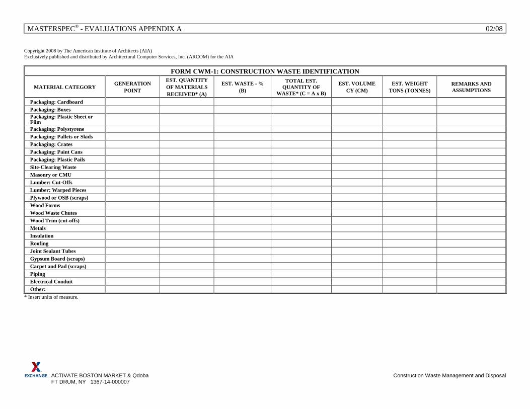
MASTERSPEC® - EVALUATIONS APPENDIX A 02/08
ACTIVATE BOSTON MARKET & Qdoba Construction Waste Management and Disposal FT DRUM, NY 1367-14-000007
Copyright 2008 by The American Institute of Architects (AIA) Exclusively published and distributed by Architectural Computer Services, Inc. (ARCOM) for the AIA
FORM CWM-1: CONSTRUCTION WASTE IDENTIFICATION
MATERIAL CATEGORY GENERATION POINT
EST. QUANTITY OF MATERIALS RECEIVED* (A)
EST. WASTE - % (B)
TOTAL EST. QUANTITY OF
WASTE* (C = A x B)
EST. VOLUME CY (CM)
EST. WEIGHT TONS (TONNES)
REMARKS AND ASSUMPTIONS
Packaging: Cardboard Packaging: Boxes Packaging: Plastic Sheet or Film
Packaging: Polystyrene Packaging: Pallets or Skids Packaging: Crates Packaging: Paint Cans Packaging: Plastic Pails Site-Clearing Waste Masonry or CMU Lumber: Cut-Offs Lumber: Warped Pieces Plywood or OSB (scraps) Wood Forms Wood Waste Chutes Wood Trim (cut-offs) Metals Insulation Roofing Joint Sealant Tubes Gypsum Board (scraps) Carpet and Pad (scraps) Piping Electrical Conduit Other:
* Insert units of measure.

MASTERSPEC® - EVALUATIONS APPENDIX A
ACTIVATE BOSTON MARKET & QDOBA Construction Waste Management and Disposal FT DRUM, NY 1367-14-000007
Copyright 2010 by The American Institute of Architects (AIA) Exclusively published and distributed by Architectural Computer Services, Inc. (ARCOM) for the AIA
FORM CWM-2: DEMOLITION WASTE IDENTIFICATION
MATERIAL DESCRIPTION EST. QUANTITY EST. VOLUME CY (CM)
EST. WEIGHT TONS (TONNES) REMARKS AND ASSUMPTIONS
Asphaltic Concrete Paving Concrete Brick CMU Lumber Plywood and OSB Wood Paneling Wood Trim Miscellaneous Metals Structural Steel Rough Hardware Insulation Roofing Doors and Frames Door Hardware Windows Glazing Acoustical Tile Carpet Carpet Pad Demountable Partitions Equipment Cabinets Plumbing Fixtures Piping Piping Supports and Hangers Valves Sprinklers Mechanical Equipment Electrical Conduit Copper Wiring Light Fixtures Lamps Lighting Ballasts Electrical Devices Switchgear and Panelboards Transformers Other:
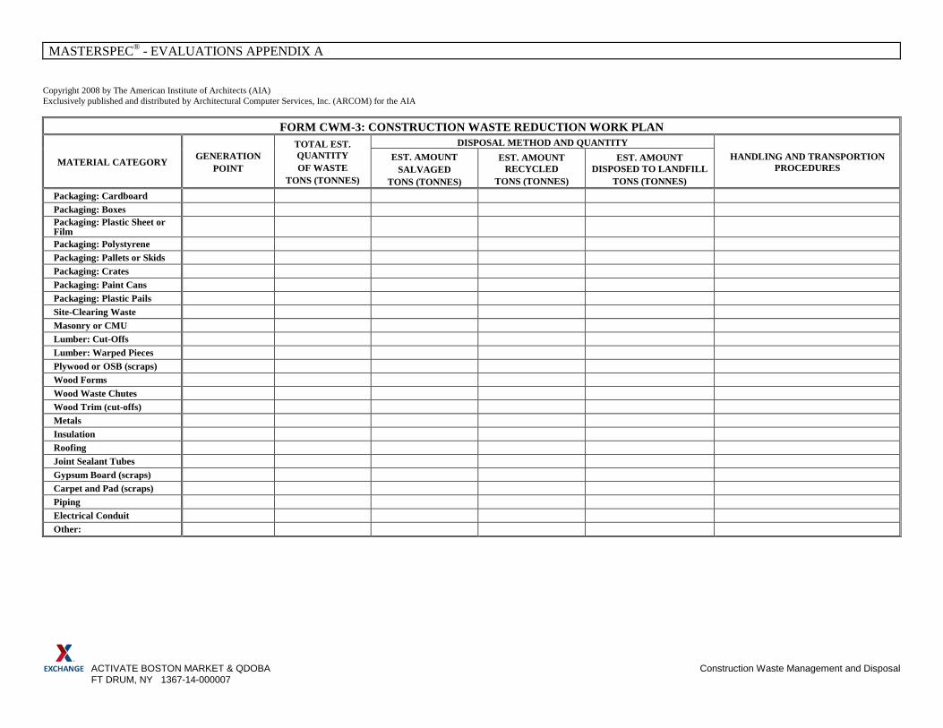
MASTERSPEC® - EVALUATIONS APPENDIX A
ACTIVATE BOSTON MARKET & QDOBA Construction Waste Management and Disposal FT DRUM, NY 1367-14-000007
Copyright 2008 by The American Institute of Architects (AIA) Exclusively published and distributed by Architectural Computer Services, Inc. (ARCOM) for the AIA
FORM CWM-3: CONSTRUCTION WASTE REDUCTION WORK PLAN
MATERIAL CATEGORY GENERATION POINT
TOTAL EST. QUANTITY OF WASTE
TONS (TONNES)
DISPOSAL METHOD AND QUANTITY HANDLING AND TRANSPORTION
PROCEDURES EST. AMOUNT
SALVAGED TONS (TONNES)
EST. AMOUNT RECYCLED
TONS (TONNES)
EST. AMOUNT DISPOSED TO LANDFILL
TONS (TONNES) Packaging: Cardboard Packaging: Boxes Packaging: Plastic Sheet or Film
Packaging: Polystyrene Packaging: Pallets or Skids Packaging: Crates Packaging: Paint Cans Packaging: Plastic Pails Site-Clearing Waste Masonry or CMU Lumber: Cut-Offs Lumber: Warped Pieces Plywood or OSB (scraps) Wood Forms Wood Waste Chutes Wood Trim (cut-offs) Metals Insulation Roofing Joint Sealant Tubes Gypsum Board (scraps) Carpet and Pad (scraps) Piping Electrical Conduit Other:

MASTERSPEC® - EVALUATIONS APPENDIX A
ACTIVATE BOSTON MARKET & QDOBA Construction Waste Management and Disposal FT DRUM, NY 1367-14-000007
Copyright 2008 by The American Institute of Architects (AIA) Exclusively published and distributed by Architectural Computer Services, Inc. (ARCOM) for the AIA
FORM CWM-4: DEMOLITION WASTE REDUCTION WORK PLAN
MATERIAL CATEGORY GENERATION POINT
TOTAL EST. QUANTITY OF WASTE
TONS (TONNES)
DISPOSAL METHOD AND QUANTITY
HANDLING AND TRANSPORTION PROCEDURES
EST. AMOUNT SALVAGED
TONS (TONNES)
EST. AMOUNT RECYCLED
TONS (TONNES)
EST. AMOUNT DISPOSED TO
LANDFILL TONS (TONNES)
Asphaltic Concrete Paving Concrete Brick CMU Lumber Plywood and OSB Wood Paneling Wood Trim Miscellaneous Metals Structural Steel Rough Hardware Insulation Roofing Doors and Frames Door Hardware Windows Glazing Acoustical Tile Carpet Carpet Pad Demountable Partitions Equipment Cabinets Plumbing Fixtures Piping Supports and Hangers Valves Sprinklers Mechanical Equipment Electrical Conduit Copper Wiring Light Fixtures Lamps Lighting Ballasts Electrical Devices Switchgear and Panelboards Transformers Other:
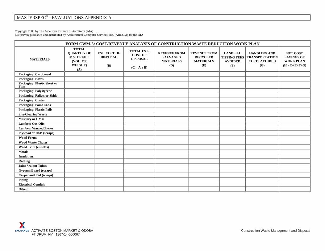
MASTERSPEC® - EVALUATIONS APPENDIX A
ACTIVATE BOSTON MARKET & QDOBA Construction Waste Management and Disposal FT DRUM, NY 1367-14-000007
Copyright 2008 by The American Institute of Architects (AIA) Exclusively published and distributed by Architectural Computer Services, Inc. (ARCOM) for the AIA
FORM CWM-5: COST/REVENUE ANALYSIS OF CONSTRUCTION WASTE REDUCTION WORK PLAN
MATERIALS
TOTAL QUANTITY OF MATERIALS
(VOL. OR WEIGHT)
(A)
EST. COST OF DISPOSAL
(B)
TOTAL EST. COST OF
DISPOSAL
(C = A x B)
REVENUE FROM SALVAGED
MATERIALS (D)
REVENUE FROM RECYCLED MATERIALS
(E)
LANDFILL TIPPING FEES
AVOIDED (F)
HANDLING AND TRANSPORTATION
COSTS AVOIDED (G)
NET COST SAVINGS OF WORK PLAN
(H = D+E+F+G)
Packaging: Cardboard Packaging: Boxes Packaging: Plastic Sheet or Film
Packaging: Polystyrene Packaging: Pallets or Skids Packaging: Crates Packaging: Paint Cans Packaging: Plastic Pails Site-Clearing Waste Masonry or CMU Lumber: Cut-Offs Lumber: Warped Pieces Plywood or OSB (scraps) Wood Forms Wood Waste Chutes Wood Trim (cut-offs) Metals Insulation Roofing Joint Sealant Tubes Gypsum Board (scraps) Carpet and Pad (scraps) Piping Electrical Conduit Other:
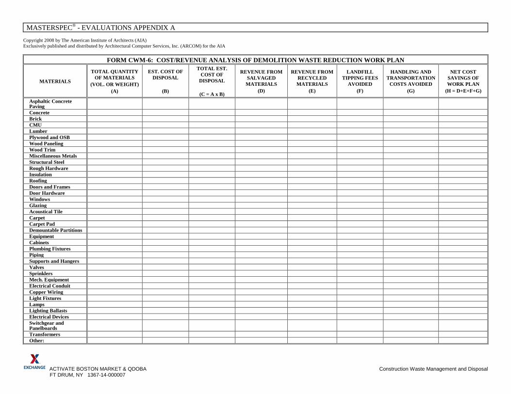
MASTERSPEC® - EVALUATIONS APPENDIX A
ACTIVATE BOSTON MARKET & QDOBA Construction Waste Management and Disposal FT DRUM, NY 1367-14-000007
Copyright 2008 by The American Institute of Architects (AIA) Exclusively published and distributed by Architectural Computer Services, Inc. (ARCOM) for the AIA
FORM CWM-6: COST/REVENUE ANALYSIS OF DEMOLITION WASTE REDUCTION WORK PLAN
MATERIALS
TOTAL QUANTITY OF MATERIALS
(VOL. OR WEIGHT) (A)
EST. COST OF DISPOSAL
(B)
TOTAL EST. COST OF
DISPOSAL
(C = A x B)
REVENUE FROM SALVAGED
MATERIALS (D)
REVENUE FROM RECYCLED MATERIALS
(E)
LANDFILL TIPPING FEES
AVOIDED (F)
HANDLING AND TRANSPORTATION
COSTS AVOIDED (G)
NET COST SAVINGS OF WORK PLAN
(H = D+E+F+G)
Asphaltic Concrete Paving
Concrete Brick CMU Lumber Plywood and OSB Wood Paneling Wood Trim Miscellaneous Metals Structural Steel Rough Hardware Insulation Roofing Doors and Frames Door Hardware Windows Glazing Acoustical Tile Carpet Carpet Pad Demountable Partitions Equipment Cabinets Plumbing Fixtures Piping Supports and Hangers Valves Sprinklers Mech. Equipment Electrical Conduit Copper Wiring Light Fixtures Lamps Lighting Ballasts Electrical Devices Switchgear and Panelboards
Transformers Other:
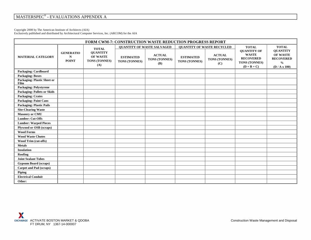
MASTERSPEC® - EVALUATIONS APPENDIX A
ACTIVATE BOSTON MARKET & QDOBA Construction Waste Management and Disposal FT DRUM, NY 1367-14-000007
Copyright 2008 by The American Institute of Architects (AIA) Exclusively published and distributed by Architectural Computer Services, Inc. (ARCOM) for the AIA
FORM CWM-7: CONSTRUCTION WASTE REDUCTION PROGRESS REPORT
MATERIAL CATEGORY GENERATIO
N POINT
TOTAL QUANTITY OF WASTE
TONS (TONNES) (A)
QUANTITY OF WASTE SALVAGED QUANTITY OF WASTE RECYCLED TOTAL QUANTITY OF
WASTE RECOVERED
TONS (TONNES) (D = B + C)
TOTAL QUANTITY OF WASTE
RECOVERED %
(D / A x 100)
ESTIMATED TONS (TONNES)
ACTUAL TONS (TONNES)
(B)
ESTIMATED TONS (TONNES)
ACTUAL TONS (TONNES)
(C)
Packaging: Cardboard Packaging: Boxes Packaging: Plastic Sheet or Film
Packaging: Polystyrene Packaging: Pallets or Skids Packaging: Crates Packaging: Paint Cans Packaging: Plastic Pails Site-Clearing Waste Masonry or CMU Lumber: Cut-Offs Lumber: Warped Pieces Plywood or OSB (scraps) Wood Forms Wood Waste Chutes Wood Trim (cut-offs) Metals Insulation Roofing Joint Sealant Tubes Gypsum Board (scraps) Carpet and Pad (scraps) Piping Electrical Conduit Other:
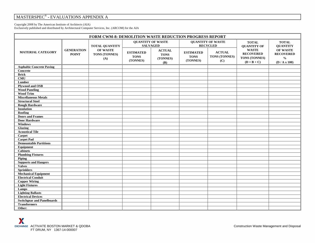
MASTERSPEC® - EVALUATIONS APPENDIX A
ACTIVATE BOSTON MARKET & QDOBA Construction Waste Management and Disposal FT DRUM, NY 1367-14-000007
Copyright 2008 by The American Institute of Architects (AIA) Exclusively published and distributed by Architectural Computer Services, Inc. (ARCOM) for the AIA
FORM CWM-8: DEMOLITION WASTE REDUCTION PROGRESS REPORT
MATERIAL CATEGORY GENERATION POINT
TOTAL QUANTITY OF WASTE
TONS (TONNES) (A)
QUANTITY OF WASTE SALVAGED
QUANTITY OF WASTE RECYCLED
TOTAL QUANTITY OF
WASTE RECOVERED
TONS (TONNES) (D = B + C)
TOTAL QUANTITY OF WASTE
RECOVERED %
(D / A x 100)
ESTIMATED TONS
(TONNES)
ACTUAL TONS
(TONNES) (B)
ESTIMATED TONS
(TONNES)
ACTUAL TONS (TONNES)
(C)
Asphaltic Concrete Paving Concrete Brick CMU Lumber Plywood and OSB Wood Paneling Wood Trim Miscellaneous Metals Structural Steel Rough Hardware Insulation Roofing Doors and Frames Door Hardware Windows Glazing Acoustical Tile Carpet Carpet Pad Demountable Partitions Equipment Cabinets Plumbing Fixtures Piping Supports and Hangers Valves Sprinklers Mechanical Equipment Electrical Conduit Copper Wiring Light Fixtures Lamps Lighting Ballasts Electrical Devices Switchgear and Panelboards Transformers Other:
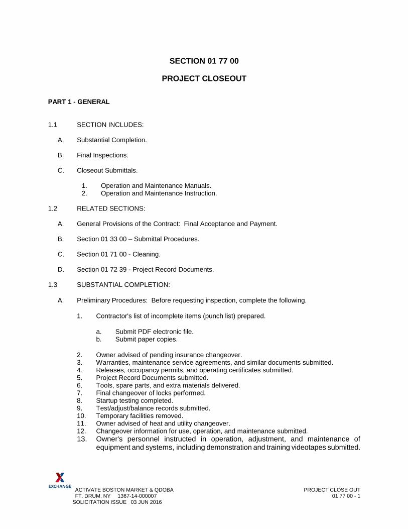
ACTIVATE BOSTON MARKET & QDOBA PROJECT CLOSE OUT FT. DRUM, NY 1367-14-000007 01 77 00 - 1 SOLICITATION ISSUE 03 JUN 2016
SECTION 01 77 00
PROJECT CLOSEOUT
PART 1 - GENERAL 1.1 SECTION INCLUDES:
A. Substantial Completion. B. Final Inspections. C. Closeout Submittals.
1. Operation and Maintenance Manuals. 2. Operation and Maintenance Instruction.
1.2 RELATED SECTIONS:
A. General Provisions of the Contract: Final Acceptance and Payment. B. Section 01 33 00 – Submittal Procedures. C. Section 01 71 00 - Cleaning.
D. Section 01 72 39 - Project Record Documents.
1.3 SUBSTANTIAL COMPLETION:
A. Preliminary Procedures: Before requesting inspection, complete the following.
1. Contractor's list of incomplete items (punch list) prepared.
a. Submit PDF electronic file. b. Submit paper copies.
2. Owner advised of pending insurance changeover. 3. Warranties, maintenance service agreements, and similar documents submitted. 4. Releases, occupancy permits, and operating certificates submitted. 5. Project Record Documents submitted. 6. Tools, spare parts, and extra materials delivered. 7. Final changeover of locks performed. 8. Startup testing completed. 9. Test/adjust/balance records submitted. 10. Temporary facilities removed. 11. Owner advised of heat and utility changeover. 12. Changeover information for use, operation, and maintenance submitted. 13. Owner's personnel instructed in operation, adjustment, and maintenance of
equipment and systems, including demonstration and training videotapes submitted.

ACTIVATE BOSTON MARKET & QDOBA PROJECT CLOSE OUT FT. DRUM, NY 1367-14-000007 01 77 00 - 2 SOLICITATION ISSUE 03 JUN 2016
B. Contractor:
1. Submit written certification to Contracting Officer that project, or designated portion of Project, is substantially complete.
2. Submit list of major items to be completed or corrected.
C. Contracting Officer will make an inspection after receipt of certification. D. Should Contracting Officer consider that work is substantially complete:
1. Contractor shall prepare, and submit to Contracting Officer, a list of items to be completed
or corrected, as determined by the inspection. 2. Contracting Officer will prepare and issue a Certificate of Substantial Completion,
containing:
a. Date of Substantial Completion. b. Contractor's list of items to be completed or corrected, verified, and amended by
Contracting Officer. c. The time within which Contractor shall complete or correct work of listed items. d. Time and date EXCHANGE will assume possession of work or designated portion
thereof. e. Responsibilities of EXCHANGE and Contractor for:
(1) Utilities. (2) Operation of mechanical, electrical, and other systems. (3) Maintenance and cleaning. (4) Security.
f. Signatures of:
(1) Contracting Officer. (2) Contractor.
3. EXCHANGE occupancy of project or designated portion of project:
a. Contractor shall:
(1) Perform final cleaning in accordance with Section 01 71 00.
b. EXCHANGE will occupy project, under provisions stated in Certificate of Substantial Completion.
4. Contractor: Complete work listed for completion or correction, within designated time.
E. Should Contracting Officer consider that work is not substantially complete:
1. Contracting Officer shall immediately notify Contractor, in writing, stating reasons. 2. Contractor: Complete work, and send second written notice to contracting officer, certifying
that project, or designated portion of project, is substantially complete. 3. Contracting Officer will reinspect work.
1.4 FINAL INSPECTION
A. Contractor shall submit written certification that:
1. Contract documents have been reviewed.
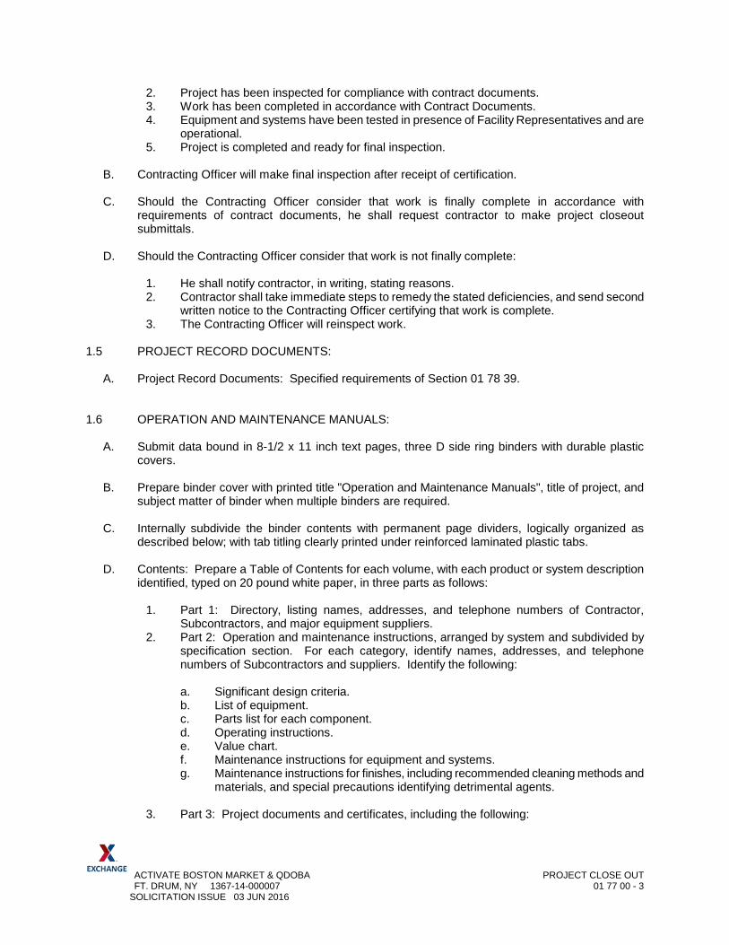
ACTIVATE BOSTON MARKET & QDOBA PROJECT CLOSE OUT FT. DRUM, NY 1367-14-000007 01 77 00 - 3 SOLICITATION ISSUE 03 JUN 2016
2. Project has been inspected for compliance with contract documents. 3. Work has been completed in accordance with Contract Documents. 4. Equipment and systems have been tested in presence of Facility Representatives and are
operational. 5. Project is completed and ready for final inspection.
B. Contracting Officer will make final inspection after receipt of certification. C. Should the Contracting Officer consider that work is finally complete in accordance with
requirements of contract documents, he shall request contractor to make project closeout submittals.
D. Should the Contracting Officer consider that work is not finally complete:
1. He shall notify contractor, in writing, stating reasons. 2. Contractor shall take immediate steps to remedy the stated deficiencies, and send second
written notice to the Contracting Officer certifying that work is complete. 3. The Contracting Officer will reinspect work.
1.5 PROJECT RECORD DOCUMENTS:
A. Project Record Documents: Specified requirements of Section 01 78 39. 1.6 OPERATION AND MAINTENANCE MANUALS:
A. Submit data bound in 8-1/2 x 11 inch text pages, three D side ring binders with durable plastic covers.
B. Prepare binder cover with printed title "Operation and Maintenance Manuals", title of project, and
subject matter of binder when multiple binders are required. C. Internally subdivide the binder contents with permanent page dividers, logically organized as
described below; with tab titling clearly printed under reinforced laminated plastic tabs. D. Contents: Prepare a Table of Contents for each volume, with each product or system description
identified, typed on 20 pound white paper, in three parts as follows:
1. Part 1: Directory, listing names, addresses, and telephone numbers of Contractor, Subcontractors, and major equipment suppliers.
2. Part 2: Operation and maintenance instructions, arranged by system and subdivided by specification section. For each category, identify names, addresses, and telephone numbers of Subcontractors and suppliers. Identify the following:
a. Significant design criteria. b. List of equipment. c. Parts list for each component. d. Operating instructions. e. Value chart. f. Maintenance instructions for equipment and systems. g. Maintenance instructions for finishes, including recommended cleaning methods and
materials, and special precautions identifying detrimental agents.
3. Part 3: Project documents and certificates, including the following:
ACTIVATE BOSTON MARKET & QDOBA PROJECT CLOSE OUT FT. DRUM, NY 1367-14-000007 01 77 00 - 4 SOLICITATION ISSUE 03 JUN 2016
a. Shop drawings and product data. b. Air and water balance reports. c. Certificates. d. Photocopies of warranties. e. Training Sessions attendance roster. f. Warrantees.
E. Submit six (6) copies of the operation and maintenance manuals to the Contracting Officer.
1.7 OPERATION AND MAINTENANCE INSTRUCTION:
A. The Contractor shall provide, at his expense, manufacturer's representatives to completely check out all mechanical and electrical systems and items covered by the drawings and specifications. This requirement shall be scheduled just prior to, and during the initial start up. After all systems are functioning properly, the representatives shall instruct Facility Maintenance Personnel in the proper operation and maintenance of each item. In addition to instructions given at the project, the Facility Maintenance Personnel shall be given a classroom instruction course on operation and maintenance of the systems. Training sessions shall be limited to four (4) continuous hours where practical. Schedule additional four (4) hour sessions as required.
1.8 DD FORM 1354:
A. Preparation of DD Form 1354 "Transfer and Acceptance of Military Real Property": At the
conclusion of the project the Contractor will compile and furnish to the Contracting Officer certain costs and quantity data of materials and systems furnished and installed. A list of items for which the costs and quantity data are required will be furnished to the Contractor. Such information will be returned to the Contracting Officer within 10 days from the receipt of the list. Form is attached at the end of Division 1.
1.9 WARRANTY AND EXTENDED WARRANTIES:
A. Upon completion of project, prior to final payment, guarantees required by technical divisions of
Specifications shall be properly executed in quadruplicate by subcontractors and submitted to Contracting Officer. Delivery of guarantees shall not relieve contractor from any obligation assumed under contract.
B. Submit guarantee covering entire project for one year. In addition, where separate guarantees, for
certain portions of work, are for longer periods, General Contractor's guarantee shall be extended to cover such longer periods.
C. Guarantees shall become valid and operative upon issuance of Certificate of Inspection and
Acceptance by EXCHANGE. Guarantees shall not apply to work where damage is a result of abuse, neglect by EXCHANGE, or his successor(s) in interest.
PART 2 – PRODUCTS (NOT USED)
PART 3 – EXECUTION (NOT USED)
END OF SECTION 01 77 00
ACTIVATE BOSTON MARKET & QDOBA PROJECT RECORD DOCUMENTS FT. DRUM, NY 1367-14-000007 01 78 39 - 1 SOLICITATION ISSUE 03 JUN 2016
SECTION 01 78 39
PROJECT RECORD DOCUMENTS
PART 1 - GENERAL 1.1 DESCRIPTION
A. Submittals: Section 01 33 00 – Submittal Procedures. 1.2 RECORD FIELD DATA
A. General: Maintain at job site, two complete sets of Contract Documents. During construction, both sets shall be marked to show all deviations in actual construction from the Contract Documents.
1. Red Markers: Indicate all additions. 2. Green Markers: Indicate all deletions.
B. Record Documents: The drawings shall show, but no be limited to, the following information:
1. Locations and description of any utility lines and other installations of any kind or description known to exist within the construction area. Include dimensions and/or survey coordinates to permanent features. 2. Locations and dimensions of any changes within the building or structure and the accurate location and dimension of all underground utilities and facilities. 3. Correct grade or alignment of roads, structures and utilities if any changes were made from Contract Drawings. 4. Correct elevations if changes were made in site grading. 5. Changes in details of design or additional information obtained from shop drawings prepared or furnished by the Contractor including, but not limited to:
a. Fabrication erection b. Installation and placing details c. Pipe sizes d. Insulation materials e. Equipment pad dimensions
6. Topography and grades of all drainage. 7. All changes or modifications from the original design. 8. Where contract drawings or specifications allow options, only the option actually used in the construction shall be shown on the Record Drawings. The option not used shall be deleted.
C. Record Field Data: All deviations shall be shown in the same general detail utilized in the Contract Documents. Marking of the documents shall continue throughout construction to keep the documents up to date.
1. Additional Data: The Contractor shall maintain the following:
a. Full size marked-up drawings.
ACTIVATE BOSTON MARKET & QDOBA PROJECT RECORD DOCUMENTS FT. DRUM, NY 1367-14-000007 01 78 39 - 2 SOLICITATION ISSUE 03 JUN 2016
b. Survey notes c. Sketches d. Nameplate data e. Pricing information f. Description and serial number of all equipment
2. Record field data shall be available for inspection by the Contracting Officer whenever requested and shall be jointly inspected for accuracy and completeness by the Contracting Officer and Contractor. Failure to keep record field data current shall be sufficient justification to withhold a retained percentage from the monthly Application for Payment.
D. Submittal of Record Field Data:
1. Submit two sets to the Contracting Officer a minimum of 20 calendar days prior to the date of final inspection. 2. The Contractor shall make all corrections identified during Contractor Officer review and resubmit corrected data within ten (10) calendar days of receipt. 3. When data is accepted as complete, one set of documents will be returned to the Contractor for completion of the Record Documents.
1.3 RECORD ELECTRONIC FILE DOCUMENTS
A. Electronic File Format: No earlier than 30 days after award, the Contracting Officer will provide one set of AutoCAD electronic file format contract drawings to be used for preparation of Record Drawings.
1. Media: ISO – 9660 CD 2. The Contractor shall verify usability of AutoCAD files and notify the Contracting Officer of any discrepancies within 30 calendar days of receipt. Any discrepancies will be corrected and files returned to the Contractor. 3. The Contractor shall incorporate all deviations from the original Contract Documents as recorded in the approved “Record Field Data” as indicated in Paragraph 1.2.C above. 4. The Contractor shall also incorporate all written modifications to the Contract Documents which were issued by amendment or contract modification. 5. All revisions and changes shall be incorporated:
a. Items marked deleted shall be deleted. b. Clouds around new items shall be removed.
B. Electronic File Submittal: Submit a complete set of Record Drawings in AutoCAD electronic file
format no later than 30 days after final acceptance. The Record Drawings shall be done in equal quality to the originals, including line work, line weights, lettering and symbols. Identify each drawing with the word “RECORD” in block letters at least 3/8” high above the title block. The date of completion and the words “Revised Record” shall be placed in the revision block above the latest revision notation.
1. Format: AutoCAD Release 2005 ‘DWG’ format. All support files required to display or plot the files in the same manner as they were developed shall be delivered along with the files, including but not limited to:
a. Font files b. Menu files
ACTIVATE BOSTON MARKET & QDOBA PROJECT RECORD DOCUMENTS FT. DRUM, NY 1367-14-000007 01 78 39 - 3 SOLICITATION ISSUE 03 JUN 2016
c. Plotter setup d. Referenced files
2. Layering: Conform to AIA Standard Document, “CAD Layer Guidelines,” latest version. An explanatory list of which layer is used at which drawing and an explanatory list of all layers which do not conform to the standard AIA CAD Layer Guidelines including any user definable fields permitted by the guidelines shall be provided with each submittal.
3. Electronic File Deliverable Media: ISO 9660 Format CD-ROM. Submit three (3) complete
sets of disks and one complete set of full size reproducible prints taken from the disks. Each disk shall have a clearly marked label stating the Contractor’s firm name, project name and location, submittal type (record) and date. Each submittal shall be accompanied by a hard copy transmittal sheet that contains the above information along with tabulated information about each file as shown below:
Electronic File Name Plate Number Drawing Title
a. Include electronic version of the table.
4. Submit one copy of the CD-Rom and one set of full-size Mylar reproducibles of the drawings to (Building Records staff person) at (Post or Base).
1.4 SUBMITTAL OF FINAL RECORD DRAWINGS
A. Complete and return the final record documents and the approved preliminary record documents to the Contracting Officer within 30 calendar days of final acceptance.
1. All drawings from the original contract documents shall be included, including drawings where no changes were made. 2. The drawings will be returned to the Contractor if corrections are necessary. 3. The Contractor shall make all corrections and shall return the drawings to the Contracting Officer within seven (7) calendar days of receipt.
1.5 RECORD DOCUMENT COST
A. All costs incurred by the Contractor in the proportion and furnishing of record documents, including electronic file format, shall be included in the contract price and no separate payment will be made for this work.
1. Approval and acceptance of the final record documents shall be accomplished before final payment is made to the Contractor.
1.6 SYSTEM ACCEPTANCE TESTING
A. Provide one set of marked-up record drawings at the time of system acceptance testing. These record drawings shall be in addition to the submittal of marked-up record drawings specified elsewhere in the contract.
ACTIVATE BOSTON MARKET & QDOBA PROJECT RECORD DOCUMENTS FT. DRUM, NY 1367-14-000007 01 78 39 - 4 SOLICITATION ISSUE 03 JUN 2016
PART 2 – PRODUCTS (NOT USED)
PART 3 – EXECUTION (NOT USED)
END OF SECTION 01 78 39
ACTIVATE BOSTON MARKET & QDOBA SELECTIVE DEMOLITION FT. DRUM, NY 1367-14-000007 02 41 16 - 1 SOLICITATION ISSUE 03 JUN 2016
SECTION 02 41 16
SELECTIVE DEMOLITION PART 1 - GENERAL
1.1 RELATED DOCUMENTS
A. Drawings and general provisions of the Contract, including General and Supplementary
Conditions and Division 1 Specification Sections, apply to this Section. 1.2 SUMMARY
A. This Section includes the following:
1. Demolition and removal of selected portions of a building. 2. Demolition and removal of selected site elements. 3. Removal of selected interior finishes in areas to be modernized. 4. Patching and repairs. 5. Salvage existing items to be reused or recycled.
B. Work by Others: Elements of selective demolition will be accomplished by EXCHANGE or the
Army Air Force Exchange Service under separate contracts:
1. Fixture removal/relocation. C. Related Sections: The following Sections contain requirements that relate to this Section:
1. Division 1 Section "Summary of Project" for use of the building and phasing
requirements. 2. Division 1 Section " Temporary Facilities, Barriers and Controls" for temporary utilities,
temporary construction and support facilities, temporary security and protection facilities, and environmental protection measures for selective demolition operations.
3. Division 21 Sections for cutting, patching, or relocating Fire Suppression items. 4. Division 22 Sections for cutting, patching, or relocating Plumbing items. 5. Division 23 Sections for cutting, patching, or relocating HVAC items. 6. Division 26 Sections for cutting, patching, or relocating Electrical items.
1.3 DEFINITIONS
A. Remove: Remove and legally dispose of items except those indicated to be reinstalled,
salvaged, or to remain EXCHANGE property. B. Remove and Salvage: Items indicated to be removed and salvaged remain EXCHANGE
property. Remove, clean, and pack or crate items to protect against damage. Identify contents of containers and deliver to EXCHANGE designated storage area.
C. Remove and Reinstall: Remove items indicated; clean, service, and otherwise prepare them
for reuse; store and protect against damage. Reinstall items in the same locations or in locations indicated.
ACTIVATE BOSTON MARKET & QDOBA SELECTIVE DEMOLITION FT. DRUM, NY 1367-14-000007 02 41 16 - 2 SOLICITATION ISSUE 03 JUN 2016
D. Existing to Remain: Protect construction indicated to remain against damage and soiling during selective demolition. When permitted by the Contracting Officer, items may be removed to a suitable, protected storage location during selective demolition and then cleaned and reinstalled in their original locations.
1.4 MATERIALS OWNERSHIP
A. Except for items or materials indicated to be reused, salvaged, reinstalled, or otherwise
indicated to remain EXCHANGE property, demolished materials shall become the Contractor's property and shall be removed from the site and legal disposed of off Installation.
1. See Section 01 13 01.
1.5 SUBMITTALS
A. General: Submit each item in this Article according to the Conditions of the Contract and
Division 1 Specification Sections, for information only, unless otherwise indicated. B. Schedule of selective demolition activities indicating the following:
1. Detailed sequence of selective demolition and removal work, with starting and ending
dates for each activity. 2. Interruption of utility services. 3. Coordination for shutoff, capping, and continuation of utility services. 4. Detailed sequence of selective demolition and removal work to ensure uninterrupted
progress of EXCHANGE' on-site operations. 5. Coordination of EXCHANGE' continuing occupancy of portions of existing building and
of EXCHANGE' partial occupancy of completed Work. 6. Locations of temporary partitions and means of egress.
C. Photographs or videotape, sufficiently detailed, of existing conditions of adjoining construction
and site improvements that might be misconstrued as damage caused by selective demolition operations.
D. Record drawings at Project close-out according to Division 1 Section "Closeout Procedures."
1. Identify and accurately locate capped utilities and other subsurface structural, electrical,
or mechanical conditions. 1.6 PROJECT CONDITIONS
A. EXCHANGE will occupy portions of the building immediately adjacent to selective demolition
area. Conduct selective demolition so that EXCHANGE' operations will not be disrupted. Provide not less than 72 hours' notice to EXCHANGE of activities that will affect EXCHANGE' operations.
B. EXCHANGE assumes no responsibility for actual condition of buildings to be selectively
demolished. 1. Conditions existing at time of inspection for bidding purpose will be maintained by
EXCHANGE as far as practical. C. Hazardous Materials: Asbestos and lead paint are not known to be present in areas of
demolition.
ACTIVATE BOSTON MARKET & QDOBA SELECTIVE DEMOLITION FT. DRUM, NY 1367-14-000007 02 41 16 - 3 SOLICITATION ISSUE 03 JUN 2016
PART 2 - PRODUCTS
2.1 REPAIR MATERIALS
A. Use repair materials identical to existing materials.
1. Where identical materials are unavailable or cannot be used for exposed surfaces, use
materials that visually match existing adjacent surfaces to the fullest extent possible. 2. Use materials whose installed performance equals or surpasses that of existing
materials. PART 3 - EXECUTION
3.1 EXAMINATION
A. Verify that utilities have been disconnected and capped. B. Survey existing conditions and correlate with requirements indicated to determine extent of
selective demolition required. C. When unanticipated mechanical, electrical, or structural elements that conflict with the
intended function or design are encountered, investigate and measure the nature and extent of the conflict. Promptly submit a written report to the Contracting Officer.
D. Survey the condition of the building to determine whether removing any element might result in
structural deficiency or unplanned collapse of any portion of the structure or adjacent structures during selective demolition.
E. Perform surveys as the Work progresses to detect hazards resulting from selective demolition
activities. 3.2 UTILITY SERVICES
A. Maintain existing utilities indicated to remain in service and protect them against damage
during selective demolition operations. 1. Do not interrupt existing utilities serving occupied or operating facilities, except when
authorized in writing by EXCHANGE and authorities having jurisdiction. Provide temporary services during interruptions to existing utilities, as acceptable to EXCHANGE and to governing authorities. a. Provide not less than 72 hours' notice to EXCHANGE if shutdown of service is
required during changeover. B. Utility Requirements: Locate, identify, disconnect, and seal or cap off indicated utility services
serving building to be selectively demolished. 1. Arrange to shut off indicated utilities with utility companies. 2. Where utility services are required to be removed, relocated, or abandoned, provide
bypass connections to maintain continuity of service to other parts of the building before proceeding with selective demolition.
ACTIVATE BOSTON MARKET & QDOBA SELECTIVE DEMOLITION FT. DRUM, NY 1367-14-000007 02 41 16 - 4 SOLICITATION ISSUE 03 JUN 2016
3. Cut off pipe or conduit in walls or partitions to be removed. Cap, valve, or plug and seal the remaining portion of pipe or conduit after bypassing.
C. Utility Requirements: Refer to Divisions 21, 22, 23, and 26 Sections for shutting off,
disconnecting, removing, and sealing or capping utility services. Do not start selective demolition work until utility disconnecting and sealing have been completed and verified in writing.
3.3 PREPARATION
A. Drain, purge, or otherwise remove, collect, and dispose of chemicals, gases, explosives, acids,
flammables, or other dangerous materials before proceeding with selective demolition operations.
B. Conduct demolition operations and remove debris to ensure minimum interference with roads,
streets, walks, and other adjacent occupied and used facilities. 1. Do not close or obstruct streets, walks, or other adjacent occupied or used facilities
without permission from EXCHANGE and authorities having jurisdiction. Provide alternate routes around closed or obstructed traffic ways if required by governing regulations.
C. Conduct demolition operations to prevent injury to people and damage to adjacent buildings
and facilities to remain. Ensure safe passage of people around selective demolition area. 1. Erect temporary protection, such as walks, fences, railings, canopies, and covered
passageways, where required by authorities having jurisdiction. 2. Protect existing site improvements, appurtenances, and landscaping to remain. 3. Erect a plainly visible fence around drip line of individual trees or around perimeter drip
line of groups of trees to remain. 4. Provide temporary weather protection, during interval between demolition and removal
of existing construction, on exterior surfaces and new construction to ensure that no water leakage or damage occurs to structure or interior areas.
5. Protect walls, ceilings, floors, and other existing finish work that are to remain and are exposed during selective demolition operations.
6. Cover and protect furniture, furnishings, and equipment that have not been removed. D. Erect and maintain dustproof partitions and temporary enclosures to limit dust and dirt
migration and to separate areas from fumes and noise. 1. Construct dustproof partitions of not less than nominal 4-inch (100-mm) studs, 5/8-inch
(16-mm) gypsum wallboard with joints taped on occupied side, and 1/2-inch (13-mm) fire-retardant plywood on the demolition side.
2. Insulate partition to provide noise protection to occupied areas. 3. Seal joints and perimeter. Equip partitions with dustproof doors and security locks. 4. Protect air-handling equipment. 5. Weatherstrip openings.
E. Provide and maintain interior and exterior shoring, bracing, or structural support to preserve
stability and prevent movement, settlement, or collapse of building to be selectively demolished. 1. Strengthen or add new supports when required during progress of selective demolition.
3.4 POLLUTION CONTROLS
ACTIVATE BOSTON MARKET & QDOBA SELECTIVE DEMOLITION FT. DRUM, NY 1367-14-000007 02 41 16 - 5 SOLICITATION ISSUE 03 JUN 2016
A. Use water mist, temporary enclosures, and other suitable methods to limit the spread of dust
and dirt. Comply with governing environmental protection regulations. 1. Do not use water when it may damage existing construction or create hazardous or
objectionable conditions, such as ice, flooding, and pollution. B. Remove and transport debris in a manner that will prevent spillage on adjacent surfaces and
areas. 1. Remove debris from elevated portions of building by chute, hoist, or other device that
will convey debris to grade level. C. Clean adjacent structures and improvements of dust, dirt, and debris caused by selective
demolition operations. Return adjacent areas to condition existing before start of selective demolition.
3.5 SELECTIVE DEMOLITION
A. Demolish and remove existing construction only to the extent required by new construction and
as indicated. Use methods required to complete Work within limitations of governing regulations and as follows: 1. Neatly cut openings and holes plumb, square, and true to dimensions required. Use
cutting methods least likely to damage construction to remain or adjoining construction. To minimize disturbance of adjacent surfaces, use hand or small power tools designed for sawing or grinding, not hammering and chopping. Temporarily cover openings to remain.
2. Cut or drill from the exposed or finished side into concealed surfaces to avoid marring existing finished surfaces.
3. Do not use cutting torches until work area is cleared of flammable materials. At concealed spaces, such as duct and pipe interiors, verify condition and contents of hidden space before starting flame-cutting operations. Maintain portable fire-suppression devices during flame-cutting operations.
4. Maintain adequate ventilation when using cutting torches. 5. Remove decayed, vermin-infested, or otherwise dangerous or unsuitable materials and
promptly dispose of off-site. 6. Remove structural framing members and lower to ground by method suitable to avoid
free fall and to prevent ground impact or dust generation. 7. Locate selective demolition equipment throughout the structure and remove debris and
materials so as not to impose excessive loads on supporting walls, floors, or framing. 8. Dispose of demolished items and materials promptly. On-site storage or sale of
removed items is prohibited. 9. Return elements of construction and surfaces to remain to condition existing before start
of selective demolition operations. B. Demolish concrete and masonry in small sections. Cut concrete and masonry at junctures
with construction to remain, using power-driven masonry saw or hand tools; do not use power-driven impact tools.
C. Break up and remove concrete slabs on grade, unless otherwise shown to remain. D. Remove resilient floor coverings and adhesive according to recommendations of the Resilient
Floor Covering Institute's (RFCI) "Recommended Work Practices for the Removal of Resilient Floor Coverings" and Addendum.
ACTIVATE BOSTON MARKET & QDOBA SELECTIVE DEMOLITION FT. DRUM, NY 1367-14-000007 02 41 16 - 6 SOLICITATION ISSUE 03 JUN 2016
1. Remove residual adhesive and prepare substrate for new floor coverings by one of the methods recommended by RFCI.
3.6 PATCHING AND REPAIRS
A. Promptly patch and repair holes and damaged surfaces caused to adjacent construction by
selective demolition operations. B. Patching is specified in Division 1 Section "Cutting and Patching." C. Where repairs to existing surfaces are required, patch to produce surfaces suitable for new
materials. D. Restore exposed finishes of patched areas and extend finish restoration into adjoining
construction to remain in a manner that eliminates evidence of patching and refinishing. E. Patch and repair floor and wall surfaces in the new space where demolished walls or partitions
extend one finished area into another. Provide a flush and even surface of uniform color and appearance. 1. Closely match texture and finish of existing adjacent surface. 2. Patch with durable seams that are as invisible as possible. Comply with specified
tolerances. 3. Where patching smooth painted surfaces, extend final paint coat over entire unbroken
surface containing the patch after the surface has received primer and second coat. 4. Remove existing floor and wall coverings and replace with new materials, if necessary,
to achieve uniform color and appearance. 5. Inspect and test patched areas to demonstrate integrity of the installation, where
feasible. F. Patch, repair, or rehang existing ceilings as necessary to provide an even-plane surface of
uniform appearance. 3.7 DISPOSAL OF DEMOLISHED MATERIALS
A. General: Promptly dispose of demolished materials. Do not allow demolished materials to
accumulate on-site. B. Burning: Do not burn demolished materials. C. Disposal: Transport demolished materials off EXCHANGE' property and legally dispose of
them. Dispose all contaminated materials to an approved disposal site. 3.8 CLEANING
A. Sweep the building broom clean on completion of selective demolition operation. B. Change filters on air-handling equipment on completion of selective demolition operations.
END OF SECTION 02 41 16
ACTIVATE BOSTON MARKET & QDOBA ROUGH CARPENTRY FT. DRUM, NY 1367-14-000007 06 10 00 - 1 SOLICITATION 3 JUNE 2016
SECTION 06 10 00
ROUGH CARPENTRY
PART 1 - GENERAL
1.1 SUMMARY
A. Section Includes:
1. Wood furring, grounds, nailers, and blocking. 2. Miscellaneous lumber.
1.2 DELIVERY, STORAGE, AND HANDLING
A. General:
1. Keep materials under cover and dry. Protect from weather and contact with damp or wet surfaces. Stack lumber, plywood, and other panels. Provide for air circulation within and around stacks and under temporary coverings.
2. For lumber and plywood pressure treated with waterborne chemicals, place spacers between each bundle to provide air circulation.
1.3 SUBMITTALS
A. Product Data:
1. For each type of process and factory-fabricated product.
a. Include data for wood-preservative and fire-retardant treatment from chemical treatment manufacturer and certification by treating plant that treated materials comply with requirements.
B. Submittal List:
Reference Submittal Item Quantity Action 1.3A Product Data X R
X Submit quantity specified in Division 01 Section Administrative Requirements. R Review each submittal, mark to indicate action taken, and return. I Submittal is for information or record purposes only. No action will be taken.

ACTIVATE BOSTON MARKET & QDOBA ROUGH CARPENTRY FT. DRUM, NY 1367-14-000007 06 10 00 - 2 SOLICITATION 3 JUNE 2016
PART 2 - PRODUCTS
2.1 LUMBER, GENERAL
A. Lumber Standards:
1. Comply with DOC PS 20, "American Softwood Lumber Standard," and with applicable grading rules of inspection agencies certified by American Lumber Standards Committee's (ALSC) Board of Review.
B. Inspection Agencies: Inspection agencies and the abbreviations used to reference them with lumber grades and species include the following:
1. RIS - Redwood Inspection Service. 2. NLGA - National Lumber Grades Authority (Canadian). 3. SPIB - Southern Pine Inspection Bureau 4. WCLIB - West Coast Lumber Inspection Bureau. 5. WWPA - Western Wood Products Association.
C. Grade Stamps: Provide lumber with each piece factory-marked with grade stamp of inspection agency evidencing compliance with grading rule requirements and identifying grading agency, grade, species, moisture content at time of surfacing, and mill.
1. For exposed lumber furnish pieces with grade stamps applied to ends or back of each piece; or omit grade stamps entirely and provide certificates of grade compliance issued by inspection agency.
D. Sizes:
1. Where nominal sizes are indicated, provide actual sizes required by DOC PS 20 for moisture content specified. Where actual sizes are indicated, they are minimum dressed sizes for dry lumber.
2. Provide dressed lumber, S4S, unless otherwise indicated. 3. Provide dry lumber with 19 percent maximum moisture content at time of dressing for 2-
inch nominal thickness or less, unless otherwise indicated.
E. Engineered Wood Products: Provide engineered wood products acceptable to authorities having jurisdiction and for which current model code research or evaluation reports exist that show compliance with building code in effect for Project.
1. Allowable Design Stresses: Provide engineered wood products with allowable design stresses, as published by manufacturer, that meet or exceed those indicated. Manufacturer's published values shall be determined from empirical data or by rational engineering analysis and demonstrated by comprehensive testing performed by a qualified independent testing agency.
2.2 WOOD-PRESERVATIVE-TREATED MATERIALS
A. General:
ACTIVATE BOSTON MARKET & QDOBA ROUGH CARPENTRY FT. DRUM, NY 1367-14-000007 06 10 00 - 3 SOLICITATION 3 JUNE 2016
1. Where lumber or plywood is indicated as preservative treated or is specified to be treated, comply with applicable requirements of AWPA C2 (lumber) - Category UC3b for exterior construction not in contact with the ground. and AWPA C9 (plywood). Mark each treated item with the Quality Mark Requirements of an inspection agency approved by ALSC's Board of Review.
2. Do not use chemicals containing chromium or arsenic.
B. Pressure Treatment:
1. Pressure treat aboveground items with waterborne preservatives to a minimum retention of 0.25 lb/cu. ft. After treatment, kiln-dry lumber and plywood to a maximum moisture content of 19 and 15 percent, respectively. Treat indicated items and the following:
a. Wood cants, nailers, curbs, equipment support bases, blocking, stripping, and similar members in connection with roofing.
b. Wood blocking, furring, stripping, and similar concealed members in contact with masonry or concrete.
C. Application: Treat items indicated on Drawings, and the following:
1. Wood cants, nailers, curbs, equipment support bases, blocking, stripping, and similar members in connection with roofing, flashing, vapor barriers, and waterproofing.
2. Wood blocking, and similar concealed members in contact with masonry or concrete. 3. Wood floor plates that are installed over concrete slabs-on-grade.
2.3 FIRE-RETARDANT-TREATED PLYWOOD
A. General:
1. Comply with performance requirements in AWPA C27 (plywood).
B. Fire-Retardant-Treated Lumber and Plywood by Pressure Process: Products with a flame spread index of 25 or less when tested according to ASTM E 84, and with no evidence of significant progressive combustion when the test is extended an additional 20 minutes, and with the flame front not extending more than 10.5 feet beyond the centerline of the burners at any time during the test.
1. Use treatment that does not promote corrosion of metal fasteners.
a. Use treatment that does not promote corrosion of metal fasteners.
2. Identify fire-retardant-treated wood with appropriate classification marking of testing and inspecting agency acceptable to authorities having jurisdiction.
3. Application: Treat items indicated on Drawings, and the following:
a. Concealed blocking. b. Plywood backing panels.
ACTIVATE BOSTON MARKET & QDOBA ROUGH CARPENTRY FT. DRUM, NY 1367-14-000007 06 10 00 - 4 SOLICITATION 3 JUNE 2016
2.4 MISCELLANEOUS LUMBER
A. General:
1. Provide lumber for support or attachment of other construction, including rooftop equipment curbs and support bases, cant strips, bucks, nailers, blocking, furring, grounds, stripping, and similar members.
2. Fabricate miscellaneous lumber from dimension lumber of sizes indicated and into shapes shown.
3. Moisture Content: 19 percent maximum for lumber items are not specified to receive wood preservative treatment.
4. Grade: For dimension lumber sizes, provide No. 3 or Standard grade lumber per ALSC's NGRs of any species. For board-size lumber, provide No. 3 Common grade per NELMA, NLGA, or WWPA; No. 2 grade per SPIB; or Standard grade per NLGA, WCLIB or WWPA of any approved species.
2.5 FASTENERS
A. General:
1. Provide fasteners of size and type indicated that comply with requirements specified in this Article for material and manufacture.
a. Where carpentry is exposed to weather, in ground contact, pressure-preservative treated, or in area of high relative humidity, provide fasteners with hot-dip zinc coating complying with ASTM A 153 or of Type 304 or Type 316 stainless steel.
B. Nails, Wire, Brads, and Staples: FS FF-N-105. ASTM F 1667.
C. Power-Driven Fasteners: NES NER-272.
D. Wood Screws: ASME B18.6.1.
E. Lag Bolts: ASME B18.2.1.
F. Bolts: Steel bolts complying with ASTM A 307, Grade A; with ASTM A 563 hex nuts and, where indicated, flat washers.
G. Expansion Anchors: Anchor bolt and sleeve assembly of material indicated below with capability to sustain, without failure, a load equal to 6 times the load imposed when installed in unit masonry assemblies and equal to 4 times the load imposed when installed in concrete as determined by testing per ASTM E 488 conducted by a qualified independent testing and inspecting agency.
1. Material: Carbon-steel components, zinc plated to comply with ASTM B 633, Class Fe/Zn 5 for interior applications.
2. Material: Stainless steel with bolts and nuts complying with ASTM F 593 and ASTM F 594, Alloy Group 1 or 2 for exterior applications.
H. Screws for Fastening to Cold-Formed Metal Framing, Unless Otherwise Indicated: ASTM C 954.
ACTIVATE BOSTON MARKET & QDOBA ROUGH CARPENTRY FT. DRUM, NY 1367-14-000007 06 10 00 - 5 SOLICITATION 3 JUNE 2016
1. Except with wafer heads and reamer wings. 2. Length as recommended by screw manufacturer for material being fastened.
PART 3 - EXECUTION
3.1 INSTALLATION
A. General:
1. Discard units of material with defects that impair quality of carpentry and that are too small to use with minimum number of joints or optimum joint arrangement.
2. Set carpentry to required levels and lines, with members plumb, true to line, cut, and fitted.
3. Fit carpentry to other construction; scribe and cope as required for accurate fit. Correlate location of furring, nailers, blocking, grounds, and similar supports to allow attachment of other construction.
4. Where wood-preservative-treated lumber is installed adjacent to metal decking, install continuous flexible flashing separator between wood and metal decking.
5. Apply field treatment complying with AWPA M4 to cut surfaces of preservative-treated lumber and plywood.
6. Securely attach carpentry work as indicated and according to applicable codes and recognized standards.
7. Countersink nail heads on exposed carpentry work and fill holes with wood filler. 8. Use fasteners of appropriate type and length. Predrill members when necessary to avoid
splitting wood.
3.2 WOOD GROUNDS, NAILERS, BLOCKING, AND SLEEPERS
A. General:
1. Install where shown and where required for screeding or attaching other work. Cut and shape to required size. Coordinate locations with other work involved.
2. Attach to substrates to support applied loading. Recess bolts and nuts flush with surfaces, unless otherwise indicated.
3. Anchor wood nailers for roofing system work as follows: a. Wood nailer to metal deck: Provide No. 10 cadmium plated sheet metal screws
with 5/8 inch diameter galvanized washers. Install in two rows. Space 2 feet 0 inches on center in each row except at corners space screws 1 foot 0 inches on center from corner for a distance of 8 feet 0 inches. Stagger spacing between rows.
b. Wood member to wood nailer: Provide 10d threaded nail by length required for 1-1/2 inches penetration into nailer. Install in two rows. Space 2 feet 0 inches on center in each row except at corners space nails 1 foot 0 inches on center from corner for a distance of 8 feet 0 inches. Stagger spacing between rows.
c. Wood nailer to metal stud: Provide No. 10 cadmium plated sheet metal screws with 5/8 inch diameter galvanized washers. Anchor 2 feet 0 inches on center except at corners space screws 1 foot 0 inches on center from corner for a distance of 8 feet 0 inches.
ACTIVATE BOSTON MARKET & QDOBA ROUGH CARPENTRY FT. DRUM, NY 1367-14-000007 06 10 00 - 6 SOLICITATION 3 JUNE 2016
3.3 WOOD FURRING
A. General:
1. Install plumb and level with closure strips at edges and openings. Shim with wood as required for tolerance of finish work.
END OF SECTION
ACTIVATE BOSTON MARKET & QDOBA INTERIOR ARCHITECTURAL WOODWORK FT. DRUM, NY 1367-14-000007 06 40 23 - 1 SOLICITATION ISSUE 03 JUN 2016
SECTION 06 40 23
INTERIOR ARCHITECTURAL WOODWORK
PART 1 - GENERAL
1.1 SUMMARY
A. Section Includes:
1. Solid-surfacing-material countertops. 2. Accessory materials.
B. Related Sections:
1. Division 6 Section "Rough Carpentry" for wood furring, blocking, shims, and hanging strips required for installing cabinets and concealed within other construction before cabinet installation.
1.2 DEFINITIONS
A. Interior architectural woodwork includes wood furring, blocking, shims, and hanging strips for installing woodwork items unless concealed within other construction prior to woodwork installation.
1.3 SUBMITTALS
A. Product Data:
1. For each type of product indicated, including cabinet hardware and accessories, and finishing materials and processes.
B. Shop Drawings:
1. Dimensioned plans, elevations, and large scale details showing location of each cabinet, attachment devices, and other components.
C. Samples For Verification:
1. Standing and running trim with transparent finish, 12 inches long, for each species and cut, finished on one side and one edge.
2. Plastic-laminate and solid-surfacing material color, pattern, and texture selected.
D. Submittal List:
Reference Submittal Item Quantity Action 1.3A Product Data X R 1.3B Shop Drawings X R
ACTIVATE BOSTON MARKET & QDOBA INTERIOR ARCHITECTURAL WOODWORK FT. DRUM, NY 1367-14-000007 06 40 23 - 2 SOLICITATION ISSUE 03 JUN 2016
1.3C Samples for Verification X R
X Submit quantity specified in Division 01 Section Administrative Requirements. R Review each submittal, mark to indicate action taken, and return. I Submittal is for information or record purposes only. No action will be taken.
1.4 QUALITY ASSURANCE
A. Fabricator Qualifications:
1. Firm experienced in producing architectural woodwork that employs skilled workers who custom fabricate products similar to that indicated for this Project and with a record of successful in-service performance, as well as sufficient production capacity to produce required units without delaying the Work.
B. Installer Qualifications:
1. Arrange for interior architectural woodwork installation by a firm that can demonstrate successful experience in installing architectural woodwork items similar in type and quality to those required for this Project.
C. Quality Standard:
1. Except as otherwise indicated, comply with the following standard:
a. “Architectural Woodwork Standards” for grades of interior architectural woodwork, construction, finishes, installation, and other requirements.
1.5 DELIVERY, STORAGE, AND HANDLING
A. Protect woodwork during transit, delivery, storage, and handling to prevent damage, soilage, and deterioration. Do not deliver woodwork until painting and similar operations that could damage, soil, or deteriorate woodwork have been completed in installation areas. If woodwork must be stored in other than installation areas, store only in areas whose environmental conditions meet requirements specified in "Project Conditions."
1.6 PROJECT CONDITIONS
A. Environmental Limitations:
1. Do not deliver or install woodwork until building is enclosed, wet-work is completed, and HVAC system is operating and will maintain temperature and relative humidity at occupancy levels during the remainder of the construction period.
B. Field Measurements:
1. Where woodwork is indicated to be fitted to other construction, check actual dimensions of other construction by accurate field measurements before fabrication, and show recorded measurements on final shop drawings. Coordinate fabrication schedule with construction progress to avoid delaying the Work. Fabricate to allow trimming at site and
ACTIVATE BOSTON MARKET & QDOBA INTERIOR ARCHITECTURAL WOODWORK FT. DRUM, NY 1367-14-000007 06 40 23 - 3 SOLICITATION ISSUE 03 JUN 2016
coordinate construction to ensure that actual dimensions correspond to established dimensions.
2. Verify locations of concealed framing, blocking, reinforcements, and furring that support woodwork by accurate field measurements before being enclosed. Record measurements on final Shop Drawings.
1.7 COORDINATION
A. General:
1. Coordinate sizes and locations of framing, blocking, furring, reinforcements, and other related units of Work specified in other Sections to ensure that interior architectural woodwork can be supported and installed as indicated.
PART 2 - PRODUCTS
2.1 MANUFACTURERS
A. Basis-of-Design Products: To establish the significant qualities related to type, function, dimension, in-service performance, physical properties, appearance, and other characteristics for purposes of evaluating comparable products of other manufacturers, a specific manufacturer's product is named and accompanied by the words "basis of design," including make or model number or other designation. Subject to compliance with requirements, provide either the named products or equal products.
2.2 MATERIALS
A. General:
1. Provide materials that comply with requirements of referenced quality standard for each type of woodwork and quality grade specified unless otherwise indicated and, where the following products are part of interior woodwork, with requirements of the referenced product standards that apply to product characteristics indicated:
a. Hardboard: AHA A135.4. b. Medium-Density Fiberboard: ANSI A208.2, Grade 130, made with binder
containing no urea formaldehyde. c. Particleboard: ANSI A208.1, Grade M-2, made with binder containing no urea
formaldehyde. d. Softwood Plywood: DOC PS 1. e. Veneer-Faced Panel Products (Hardwood Plywood): HPVA HP-1, made with
adhesive containing no urea formaldehyde.
2. Solid-Surfacing Material: Homogeneous solid sheets of filled plastic resin complying with
ISSFA-2. Nd material and performance requirements in ANSI Z124.3, for Type 5 or Type 6, without a precoated finish.
ACTIVATE BOSTON MARKET & QDOBA INTERIOR ARCHITECTURAL WOODWORK FT. DRUM, NY 1367-14-000007 06 40 23 - 4 SOLICITATION ISSUE 03 JUN 2016
2.3 ACCESSORY MATERIALS
A. General:
1. Provide accessory materials associated with interior architectural woodwork.
2. 1-1/2” S.S. Tube supports and legs with adjustable feet as indicated on drawings.
2.4 INSTALLATION MATERIALS
A. Furring, Blocking, Shims, and Hanging Strips:
1. Softwood or hardwood lumber, kiln dried to less than 15 percent moisture content.
B. Screws:
1. Select material, type, size, and finish required for each use. Comply with ASME B18.6.1 for applicable requirements. For metal framing supports, provide screws as recommended by metal-framing manufacturer.
C. Nails:
1. Select material, type, size, and finish required for each use. Comply with FS FF-N-105 for applicable requirements.
D. Anchors:
1. Select material, type, size, and finish required for each substrate for secure anchorage. Provide nonferrous metal or hot-dip galvanized anchors and inserts on inside face of exterior walls and elsewhere as required for corrosion resistance. Provide toothed steel or lead expansion bolt devices for drilled-in-place anchors.
2.5 FABRICATION, GENERAL
A. Interior Woodwork Grade:
1. Provide interior woodwork complying with the referenced quality standard and of the following grade:
a. Grade: Premium.
B. Wood Moisture Content:
1. Comply with requirements of referenced quality standard for wood moisture content in relation to relative humidity conditions existing during time of fabrication and in installation areas.
C. Fabrication:
1. Fabricate woodwork to dimensions, profiles, and details indicated. Ease edges to radius
ACTIVATE BOSTON MARKET & QDOBA INTERIOR ARCHITECTURAL WOODWORK FT. DRUM, NY 1367-14-000007 06 40 23 - 5 SOLICITATION ISSUE 03 JUN 2016
2. Complete fabrication, including assembly, finishing, and hardware application, before shipment to Project site to maximum extent possible. Disassemble components only as necessary for shipment and installation. Where necessary for fitting at site, provide ample allowance for scribing, trimming, and fitting.
3. Shop-cut openings, to maximum extent possible, to receive hardware, appliances, plumbing fixtures, electrical work, and similar items. Locate openings accurately and use templates or roughing-in diagrams to produce accurately sized and shaped openings. Smooth edges of cutouts and, where located in countertops and similar exposures, seal edges with a water-resistant coating.
2.6 SOLID-SURFACING-MATERIAL TOPS FURNISHED
A. Quality Standard:
1. Comply with requirements of referenced standard for solid-surface countertops. 2. Grade: Premium. 3. Solid-Surfacing-Material Thickness: 1/2 inch. 4. Colors, Patterns, and Finishes: Provide materials and products that result in colors of
solid-surfacing material complying with the following requirements:
a. Match color, pattern, and finish as selected in finish schedule.
B. Fabrication:
1. Fabricate tops in one or as few pieces as reasonable shop-applied edges, unless otherwise indicated. Comply with solid-surfacing-material manufacturer's written recommendations for adhesives, sealers, fabrication, and finishing.
PART 3 - EXECUTION
3.1 PREPARATION
A. General:
1. Condition woodwork to average prevailing humidity conditions in installation areas before installing.
2. Before installing architectural woodwork, examine shop-fabricated work for completion and complete work as required, including back priming and removal of packing.
3.2 INSTALLATION
A. General:
1. Quality Standard: Install interior architectural woodwork to comply with referenced quality standard for the same grade specified in Part 2 of this Section for type of woodwork involved.
2. Install woodwork plumb, level, true, and straight with no distortions. Shim as required with concealed shims. Install to a tolerance of 1/8 inch in 96 inches for plumb and level (including tops).
ACTIVATE BOSTON MARKET & QDOBA INTERIOR ARCHITECTURAL WOODWORK FT. DRUM, NY 1367-14-000007 06 40 23 - 6 SOLICITATION ISSUE 03 JUN 2016
3. Scribe and cut woodwork to fit adjoining work and refinish cut surfaces or repair damaged finish at cuts.
4. Anchor woodwork to anchors or blocking built in or directly attached to substrates. 5. Secure to grounds, stripping, and blocking with countersunk, concealed fasteners and
blind nailing as required for complete installation. Use fine finishing nails or finishing screws for exposed nailing, countersunk and filled flush with woodwork and matching final finish.
6. Tops: Anchor securely to base and other support systems as indicated. . a. Install tops with no more than 1/8 inch in 96-inch sag, bow, or other variation from
a straight line.
3.3 ADJUSTING AND CLEANING
A. General:
1. Repair damaged and defective woodwork where possible to eliminate functional and visual defects; where not possible to repair, replace woodwork. Adjust joinery for uniform appearance.
2. Clean, lubricate, and adjust hardware. 3. Clean woodwork on exposed and semiexposed surfaces. Touch up shop-applied
finishes to restore damaged or soiled areas.
3.4 PROTECTION
A. Provide final protection and maintain conditions in a manner acceptable to fabricator and Installer that ensures that woodwork is without damage or deterioration at the time of final acceptance.
END OF SECTION 06 40 23
ACTIVATE BOSTON MARKET & QDOBA FIBERGLAS REINFORCED PANELING FT. DRUM, NY 1367-14-000007 06 83 16 - 1
SOLICITATION ISSUE 03 JUN 2016
SECTION 06 83 16
FIBERGLASS REINFORCED PANELING
PART 1 - GENERAL
1.1 SUMMARY
A. Section Includes:
1. Glass-fiber reinforced plastic (FRP) wall paneling and trim accessories
1.2 SUBMITTALS
A. Product Data:
1. Manufacturer’s data sheets on each product to be used, including:
a. Preparation instructions and recommendations. b. Storage and handling requirements and recommendations. c. Installation methods.
B. Submittal List:
Reference Submittal Item Quantity Action 1.2.A Product Data X R
X Submit quantity specified in Division 01 Section Administrative Requirements. R Review each submittal, mark to indicate action taken, and return. I Submittal is for information or record purposes only. No action will be taken.
PART 2 - PRODUCTS
2.1 MANUFACTURERS
A. Basis-of-Design Products: To establish the significant qualities related to type, function, dimension, in-service performance, physical properties, appearance, and other characteristics for purposes of evaluating comparable products of other manufacturers, a specific manufacturer's product is named and accompanied by the words "basis-of-design", including make or model number or other designation. Subject to compliance with requirements, provide either the named products or equal products.
ACTIVATE BOSTON MARKET & QDOBA FIBERGLAS REINFORCED PANELING FT. DRUM, NY 1367-14-000007 06 83 16 - 2
SOLICITATION ISSUE 03 JUN 2016
2.2 WALL PANELS
A. Basis-of-Design Product:
1. Marlite, FP-100 White.
B. Materials:
1. Fiberglass reinforced polyester plastic sheets: Sheets shall comply with fire-test-response characteristics specified, be chemical and stain resistant, and be USDA acceptable for incidental food contact. Provide manufacturer's standard matching moldings and trim as indicated.
2. Size: 4 feet by 10 feet. 3. Thickness: 0.09 inch. 4. Do not furnish material in roll form.
C. Fire Classification:
1. NFPA Class A interior finish in accordance with ASTM E 84. 2. Flame spread: 0 to 25. 3. Smoke development: 0 to 450.
D. Panel Finish:
1. Exposed surface: White glossy pebbled texture. 2. Back, concealed surface: Smooth finish.
E. Accessories:
1. Moldings: Manufacturer's standard one-piece white, extruded polyvinyl chloride plastic designed to retain and cover edges of panels. Provide division bars, inside corners, outside corners, and caps as needed to conceal edges.
2. Adhesive: Manufacturer's approved adhesive for substrate to which panels are applied.
a. VOC Content: 50 g/L or less when calculated according to 40 CFR 59, Subpart D (EPA Method 24).
3. Exposed Fasteners: Nylon drive rivets recommended by panel manufacturer. 4. Sealant: Provide silicone type sealant specified in Division 07 Section Joint Sealants for
joints between panels occurring in rooms exposed to moisture.
a. VOC Content: 250 g/L or less when calculated according to 40 CFR 59, Subpart D (EPA Method 24).
PART 3 - EXECUTION
3.1 INSPECTION
A. General:
ACTIVATE BOSTON MARKET & QDOBA FIBERGLAS REINFORCED PANELING FT. DRUM, NY 1367-14-000007 06 83 16 - 3
SOLICITATION ISSUE 03 JUN 2016
1. Ensure surfaces to receive wall paneling are clean, true and free of irregularities. 2. Clean substrates of substances that could impair bond of adhesive, including oil, grease,
dirt, and dust. 3. Ensure wall surface flatness tolerance do not vary more than 1/8 inch in 10 feet. 4. Schedule installation of panels as late as possible to prevent damage during construction
and movement of materials.
3.2 WALL PANEL INSTALLATION
A. General:
1. Handle and apply wall panels in accordance with manufacturer's written instructions. 2. Install panels in a full spread of adhesive. 3. Where fasteners are required for additional support use noncorroding fasteners where
concealed and Nylon drive rivets where exposed. Install in accordance with manufacturer’s written instructions allowing for expansion and contraction of panels.
4. Install with edges inserted into moldings. Allow clearance for expansion and contraction of panels when fitting into moldings.
5. Install trim accessories with adhesive. Do not fasten through panels. 6. Apply a continuous bead of sealant into molding slots prior to insertion of panels.
3.3 CLEANING
A. Clean panels after installation with materials recommended by panel manufacturer.
END OF SECTION 06 83 16
ACTIVATE BOSTON MARKET & QDOBA JOINT SEALANTS FT. DRUM, NY 1367-14-000007 07 92 00 - 1 SOLICITATION ISSUE 03 JUN 2016
SECTION 07 92 00
JOINT SEALANTS
PART 1 - GENERAL
1.1 SUMMARY
A. Section Includes:
1. Joint sealants for the following applications, including those specified by reference to this Section:
a. Interior Joints in Vertical Surfaces and Nontraffic Horizontal Surfaces: 1) Joints in tile work..
b. Joint-sealant applications not indicated will be selected by the Contracting Officer from elastomeric products indicated in Part 2.
B. Related Sections:
1. Division 09 Section Tiling
1.2 PRECONSTRUCTION TESTING
A. Preconstruction Compatibility and Adhesion Testing:
1. Submit to joint-sealant manufacturers, for testing indicated below, samples of materials that will contact or affect joint sealants.
a. Use ASTM C 1087 to determine whether priming and other specific joint preparation techniques are required to obtain rapid, optimum adhesion of joint sealants to joint substrates.
b. Submit not fewer than eight pieces of each type of material, including joint substrates, shims, joint-sealant backings, secondary seals, and miscellaneous materials.
c. Schedule sufficient time for testing and analyzing results to prevent delaying the Work.
d. For materials failing tests, obtain joint-sealant manufacturer's written instructions for corrective measures including use of specially formulated primers.
B. Testing will not be required if joint-sealant manufacturers submit joint preparation data that are based on previous testing of current sealant products for adhesion to, and compatibility with, joint substrates and other materials matching those submitted.
1.3 SUBMITTALS
A. Product Data:
ACTIVATE BOSTON MARKET & QDOBA JOINT SEALANTS FT. DRUM, NY 1367-14-000007 07 92 00 - 2 SOLICITATION ISSUE 03 JUN 2016
1. For each joint-sealant product indicated.
B. Samples for Verification:
1. For each kind and color of joint sealant required, provide manufacturer standard bead samples, consisting of strips of actual products showing full range of colors available, for each product exposed to view.
C. Product Test Reports:
1. Based on evaluation of comprehensive tests performed by a qualified testing agency, indicating that sealants comply with specified requirements.
D. Certification by joint sealant manufacturer that sealants plus the primers and cleaners required for sealant installation comply with local regulations controlling use of volatile organic compounds.
E. Submittal List:
Reference Submittal Item Quantity Action 1.3A Product Data X R 1.3B Product Test Reports X I
X Submit quantity specified in Division 01 Section Administrative Requirements. R Review each submittal, mark to indicate action taken, and return. I Submittal is for information or record purposes only. No action will be taken.
1.4 QUALITY ASSURANCE
A. Source Limitations:
1. Obtain each kind of joint sealant through one source from a single manufacturer.
B. General:
1. Do not proceed with installation of joint sealants under the following conditions:
a. When ambient and substrate temperature conditions are outside limits permitted by joint-sealant manufacturer.
b. When joint substrates are wet. c. Where joint widths are less than those allowed by joint-sealant manufacturer for
applications indicated. d. Where Contaminants capable of interfering with adhesion have not yet been
removed from joint substrates.
ACTIVATE BOSTON MARKET & QDOBA JOINT SEALANTS FT. DRUM, NY 1367-14-000007 07 92 00 - 3 SOLICITATION ISSUE 03 JUN 2016
PART 2 - PRODUCTS
2.1 MANUFACTURERS
A. Basis-of-Design Products: To establish the significant qualities related to type, function, dimension, in-service performance, physical properties, appearance, and other characteristics for purposes of evaluating comparable products of other manufacturers, a specific manufacturer's product is named and accompanied by the words "basis of design," including make or model number or other designation. Subject to compliance with requirements, provide either the named products or equal products.
2.2 MATERIALS, GENERAL
A. Compatibility:
1. Provide joint sealants, backings, and other related materials that are compatible with one another and with joint substrates under conditions of service and application, as demonstrated by sealant manufacturer, based on testing and field experience.
B. VOC Content of Interior Sealants:
1. Provide sealants and sealant primers for use inside the weatherproofing system that comply with the following limits for VOC content when calculated according to 40 CFR 59, Part 59, Subpart D (EPA Method 24):
a. Architectural Sealants: 250 g/L. b. Sealant Primers for Nonporous Substrates: 250 g/L. c. Sealant Primers for Porous Substrates: 775 g/L
2.3 ELASTOMERIC JOINT SEALANTS
A. Elastomeric Sealants:
1. Comply with ASTM C 920 and other requirements indicated for each liquid-applied chemically curing sealant specified, including those referencing ASTM C 920 classifications for type, grade, class, and uses related to exposure and joint substrates.
B. Stain-Test-Response Characteristics:
1. Where elastomeric sealants are specified to be nonstaining to porous substrates, provide products that have undergone testing according to ASTM C 1248 and have not stained porous joint substrates indicated for Project.
C. Suitability for Contact with Food:
1. Where elastomeric sealants are indicated for joints that will come in repeated contact with food, provide products that comply with 21 CFR 177.2600.

ACTIVATE BOSTON MARKET & QDOBA JOINT SEALANTS FT. DRUM, NY 1367-14-000007 07 92 00 - 4 SOLICITATION ISSUE 03 JUN 2016
D. ES-S1 Single-Component Nonsag Neutral-Curing Surface Modified Silicone Sealant (Low dirt pick-up):
1. Basis-of-Design Product: Dow Corning Corporation; 756 SMS. 2. Type and Grade: S (single component) and NS (nonsag). 3. Class: 50. 4. Use Related to Exposure: NT (nontraffic).
E. ES-S3 Single-Component Neutral-Curing Silicone Sealant:
1. Basis-of-Design Product: Dow Corning Corporation; 790. 2. Type and Grade: S (single component) and NS (nonsag). 3. Class: 100/50. 4. Use Related to Exposure: T (traffic). 5. Stain-Test-Response Characteristics: Nonstaining to porous substrates.
F. ES-S4 Single-Component Neutral-Curing Silicone Sealant:
1. Basis-of-Design Product: Dow Corning Corporation; 795. 2. Type and Grade: S (single component) and NS (nonsag). 3. Class: 50. 4. Use Related to Exposure: NT (nontraffic). 5. Stain-Test-Response Characteristics: Nonstaining to porous substrates.
2.4 JOINT-SEALANT BACKING
A. General:
1. Provide sealant backings of material that are nonstaining; are compatible with joint substrates, sealants, primers, and other joint fillers; and are approved for applications indicated by sealant manufacturer based on field experience and laboratory testing.
B. Cylindrical Sealant Backings:
1. ASTM C 1330, Type C (closed-cell material with a surface skin), O (open-cell material), B (bicellular material with a surface skin), or any of the preceding types, as approved in writing by joint-sealant manufacturer for joint application indicated, and of size and density to control sealant depth and otherwise contribute to producing optimum sealant performance:
C. Bond-Breaker Tape:
1. Polyethylene tape or other plastic tape recommended by sealant manufacturer for preventing sealant from adhering to rigid, inflexible joint-filler materials or joint surfaces at back of joint. Provide self-adhesive tape where applicable.
2.5 MISCELLANEOUS MATERIALS
A. Primer:
ACTIVATE BOSTON MARKET & QDOBA JOINT SEALANTS FT. DRUM, NY 1367-14-000007 07 92 00 - 5 SOLICITATION ISSUE 03 JUN 2016
1. Material recommended by joint-sealant manufacturer where required for adhesion of sealant to joint substrates indicated, as determined from preconstruction joint-sealant-substrate tests and field tests.
B. Cleaners for Nonporous Surfaces:
1. Chemical cleaners acceptable to manufacturers of sealants and sealant backing materials, free of oily residues or other substances capable of staining or harming joint substrates and adjacent nonporous surfaces in any way, and formulated to promote optimum adhesion of sealants to joint substrates.
C. Masking Tape:
1. Nonstaining, nonabsorbent material compatible with joint sealants and surfaces adjacent to joints.
PART 3 - EXECUTION
3.1 EXAMINATION
A. Examine joints indicated to receive joint sealants, with Installer present, for compliance with requirements for joint configuration, installation tolerances, and other conditions affecting joint-sealant performance. Proceed with installation only after unsatisfactory conditions have been corrected.
3.2 PREPARATION
A. Surface Cleaning of Joints:
1. Clean out joints immediately before installing joint sealants to comply with joint-sealant manufacturer's written instructions and the following requirements:
a. Remove all foreign material from joint substrates that could interfere with adhesion of joint sealant, including dust, paints (except for permanent, protective coatings tested and approved for sealant adhesion and compatibility by sealant manufacturer), old joint sealants, oil, grease, waterproofing, water repellents, water, surface dirt, and frost.
b. Clean porous joint substrate surfaces by brushing, grinding, mechanical abrading, or a combination of these methods to produce a clean, sound substrate capable of developing optimum bond with joint sealants. Remove loose particles remaining after cleaning operations above by vacuuming or blowing out joints with oil-free compressed air. Porous joint substrates include the following:
1) Concrete. 2) Masonry. 3) Unglazed surfaces of ceramic tile.
c. Remove laitance and form-release agents from concrete.
ACTIVATE BOSTON MARKET & QDOBA JOINT SEALANTS FT. DRUM, NY 1367-14-000007 07 92 00 - 6 SOLICITATION ISSUE 03 JUN 2016
d. Clean nonporous joint substrate surfaces with chemical cleaners or other means that do not stain, harm substrates, or leave residues capable of interfering with adhesion of joint sealants. Nonporous joint substrates include the following:
1) Metal. 2) Glass. 3) Porcelain enamel. 4) Glazed surfaces of ceramic tile.
2. Joint Priming: Prime joint substrates, where recommended in writing by joint-sealant manufacturer - or as indicated by preconstruction joint-sealant-substrate tests or prior experience. Apply primer to comply with joint-sealant manufacturer's written instructions. Confine primers to areas of joint-sealant bond; do not allow spillage or migration onto adjoining surfaces.
3. Masking Tape: Use masking tape where required to prevent contact of sealant or primer with adjoining surfaces that otherwise would be permanently stained or damaged by such contact or by cleaning methods required to remove sealant smears. Remove tape immediately after tooling without disturbing joint seal.
3.3 INSTALLATION OF JOINT SEALANTS
A. General:
1. Comply with joint-sealant manufacturer's written installation instructions for products and applications indicated, unless more stringent requirements apply.
B. Sealant Installation Standard:
1. Comply with recommendations in ASTM C 1193 for use of joint sealants as applicable to materials, applications, and conditions indicated.
C. Sealant Backings:
1. Install sealant backings of kind indicated to support sealants during application and at position required to produce cross-sectional shapes and depths of installed sealants relative to joint widths that allow optimum sealant movement capability.
a. Do not leave gaps between ends of sealant backings. b. Do not stretch, twist, puncture, or tear sealant backings. c. Remove absorbent sealant backings that have become wet before sealant
application and replace them with dry materials.
D. Bond-Breakers:
1. Install bond-breaker tape behind sealants where sealant backings are not used between sealants and backs of joints.
E. Sealant Installation:

ACTIVATE BOSTON MARKET & QDOBA JOINT SEALANTS FT. DRUM, NY 1367-14-000007 07 92 00 - 7 SOLICITATION ISSUE 03 JUN 2016
1. Install sealants using proven techniques that comply with the following and at the same time backings are installed:
a. Place sealants so they directly contact and fully wet joint substrates. b. Completely fill recesses in each joint configuration. c. Produce uniform, cross-sectional shapes and depths relative to joint widths that
allow optimum sealant movement capability.
F. Tooling of Nonsag Sealants:
1. Immediately after sealant application and before skinning or curing begins, tool sealants according to requirements specified in subparagraphs below to form smooth, uniform beads of configuration indicated; to eliminate air pockets; and to ensure contact and adhesion of sealant with sides of joint.
a. Remove excess sealant from surfaces adjacent to joints. b. Use tooling agents that are approved in writing by sealant manufacturer and that
do not discolor sealants or adjacent surfaces. c. Provide concave joint configuration per Figure 8A in ASTM C 1193, unless
otherwise indicated. d. Provide flush joint configuration where indicated per Figure 8B in ASTM C 1193. e. Provide recessed joint configuration of recess depth and at locations indicated per
Figure 8C in ASTM C 1193.
1) Use masking tape to protect surfaces adjacent to recessed tooled joints.
3.4 CLEANING
A. Clean off excess sealant or sealant smears adjacent to joints as the Work progresses by methods and with cleaning materials approved in writing by manufacturers of joint sealants and of products in which joints occur.
3.5 PROTECTION
A. Protect joint sealants during and after curing period from contact with contaminating substances and from damage resulting from construction operations or other causes so sealants are without deterioration or damage at time of Substantial Completion. If, despite such protection, damage or deterioration occurs, cut out and remove damaged or deteriorated joint sealants immediately so installations with repaired areas are indistinguishable from original work.
END OF SECTION
ACTIVATE BOSTON MARKET & QDOBA GYPSUM BOARD ASSEMBLIES FT. DRUM, NY 1367-14-000007 09 29 00 - 1 SOLICITATION ISSUE 03 JUN 2016
SECTION 09 29 00
GYPSUM BOARD ASSEMBLIES
PART 1 - GENERAL
1.1 SUMMARY
A. Section Includes:
1. Nonload-bearing steel framing members for interior gypsum board assemblies. 2. Gypsum board assemblies attached to steel framing.
B. Related Sections:
1. Division 01 Section Sustainable Design Reporting for sealants and recycled content of products.
2. Division 05 Section Cold-Formed Metal Framing for exterior and interior load-bearing and exterior non-load-bearing wall studs; floor joists; roof rafters and ceiling joists; and roof trusses.
1.2 SUBMITTALS
1. Product Data: For each type of product.
B. Submittal List:
Reference Submittal Item Quantity Action
1.2A Product Data X R
X Submit quantity specified in Division 01 Section Administrative Requirements. R Review each submittal, mark to indicate action taken, and return. I Submittal is for information or record purposes only. No action will be taken.
1.3 DEFINITIONS
A. Gypsum Board Construction Terminology: Refer to ASTM C 11 and GA-505 for definitions of terms for gypsum board assemblies not defined in this Section or in other referenced standards.
1.4 DELIVERY, STORAGE, AND HANDLING
A. Deliver materials in original packages, containers, or bundles bearing brand name and identification of manufacturer or supplier. Store materials inside under cover and keep them dry and protected against damage from weather, direct sunlight, surface contamination, corrosion, construction traffic, and other causes. Neatly stack gypsum panels flat to prevent sagging.

ACTIVATE BOSTON MARKET & QDOBA GYPSUM BOARD ASSEMBLIES FT. DRUM, NY 1367-14-000007 09 29 00 - 2 SOLICITATION ISSUE 03 JUN 2016
1.5 PROJECT CONDITIONS
A. Environmental Conditions, General:
1. Establish and maintain environmental conditions for applying and finishing gypsum board to comply with ASTM C 840 requirements or gypsum board manufacturer's recommendations, whichever are more stringent.
B. Room Temperatures:
1. For nonadhesive attachment of gypsum board to framing, maintain not less than 40º F. Do not exceed 95 deg F when using temporary heat sources.
C. Ventilation:
1. Ventilate building spaces as required to dry joint treatment materials. Avoid drafts during hot, dry weather to prevent finishing materials from drying too rapidly.
D. Product Condition : Do not install panels that are wet, those that are moisture damaged, and those that are mold damaged. 1. Indications that panels are wet or moisture damaged include, but are not limited to,
discoloration, sagging, or irregular shape 2. Indications that panels are mold damaged include, but are not limited to, fuzzy or
splotchy surface contamination or discoloration.
PART 2 - PRODUCTS
2.1 FRAMING SYSTEMS
A. Framing Members, General:
1. Comply with ASTM C 754 for conditions indicated.
a. Steel Sheet Components: Comply with ASTM C 645 requirements for metal unless otherwise indicated.
b. Protective Coating: Manufacturer's standard rust-inhibiting coating.
2.2 STEEL FRAMING COMPONENTS FOR SUSPENDED CEILINGS
A. General:
1. Provide components complying with ASTM C 754 for materials and sizes unless otherwise indicated.
B. Wire for Hangers and Ties:
1. ASTM A 641, Class 1 zinc coating, soft temper.
a. Wire Hangers: 0.16 inch in diameter. b. Tie Wire: 0.062-inch-diameter wire, or double strand of 0.048-inch-diameter wire.
ACTIVATE BOSTON MARKET & QDOBA GYPSUM BOARD ASSEMBLIES FT. DRUM, NY 1367-14-000007 09 29 00 - 3 SOLICITATION ISSUE 03 JUN 2016
C. Channels:
1. Cold-rolled steel, 0.053 inch minimum thickness of base (uncoated) metal and 1/2 inch wide flanges, and as follows:
a. Carrying Channels: 1-1/2 inches deep. b. Furring Channels: 3/4 inch deep.
D. Steel Rigid Furring Channels:
1. ASTM C 645, hat-shaped, depth of 7/8 inch, and minimum thickness of base (uncoated) metal of 0.018 inch.
E. Grid Suspension System for Interior Gypsum Ceilings:
1. ASTM C 645, manufacturer's standard direct-hung grid suspension system composed of main beams and cross furring members that interlock.
2.3 STEEL FRAMING FOR WALLS AND PARTITIONS
A. General:
1. Provide steel framing members complying with the following requirements:
a. Component Sizes and Spacings: As indicated but not less than that required to comply with ASTM C 754.
B. Steel Studs and Runners:
1. ASTM C 645.
a. Minimum Base Metal Thickness: 0.033 inch (20 gage). b. Depth: As indicated.
C. Slip-Type Head Joints (Deflection Track) :
1. Where indicated, provide steel sheet top runner manufactured to prevent cracking of finishes applied to interior partition framing resulting from deflection of structure above; in thickness not less than indicated for studs and in width to accommodate depth of studs.
D. Fasteners for Metal Framing:
1. Provide fasteners of type, material, size, corrosion resistance, holding power, and other properties required to fasten steel framing to substrates.
2.4 INTERIOR GYPSUM BOARD
A. General:
1. Complying with ASTM C 1396.

ACTIVATE BOSTON MARKET & QDOBA GYPSUM BOARD ASSEMBLIES FT. DRUM, NY 1367-14-000007 09 29 00 - 4 SOLICITATION ISSUE 03 JUN 2016
2. Provide gypsum board of types indicated in maximum lengths available to minimize end-to-end butt joints.
a. Thickness: Provide gypsum board in thicknesses indicated or, if not otherwise indicated, in 5/8 inch thicknesses to comply with ASTM C 840 for application system and support spacing indicated.
b. Long Edges: Tapered unless otherwise indicated.
B. Types: 1. Type X Gypsum Board. 2. Ceiling Type Gypsum Board: Manufactured to have more sag resistance than regular-
type gypsum board. a. Thickness: 1/2 or 5/ 8 inch
3. Moisture and Mold-Resistant Gypsum Board a. Type X. b. Basis-of-Design Product: Georgia-Pacific Gypsum; “ToughRock” or "DensArmor
Plus Fireguard “ c. Thickness: 5/8 inch d. Mold Resistance: ASTM D 3273, score of 10.
4. Glass-Mat Interior Gypsum Board: ASTM C 1658, C1178. With fiberglass mat laminated to both sides. Specifically designed for interior use a. Type X b. Thickness : 5/8 inch. c. Mold Resistance: ASTM D 3273, score of 10. d. Microbial Resistance (ASTM D6329): Will not support microbial growth e. Basis-of-Design Product: Georgia-Pacific Gypsum; DensShield.Fireguard Tile
Backer.
2.5 TRIM ACCESSORIES
A. Accessories for Interior Installation:
1. Corner beads, edge trim, and control joints complying with ASTM C 1047 and requirements indicated below:
a. Material: Formed metal, or metal combined with paper, with metal complying with the following requirement:
1) Sheet steel coated with zinc by hot-dip or electrolytic processes, or with aluminum or rolled zinc.
b. Shapes indicated below by reference to Fig. 1 designations in ASTM C 1047. c. Cornerbead on outside corners, unless otherwise indicated. d. Bullnose bead with flanges formed to receive joint compound. Use rounded
cornerbead for vertical corner joints. e. LC-bead with both face and back flanges; face flange formed to receive joint
compound. Use LC-beads for edge trim unless otherwise indicated. f. L-bead with face flange only; face flange formed to receive joint compound. Use
L-bead where indicated. g. U-bead with face and back flanges; face flange formed to be left without
application of joint compound. Use U-bead where indicated. h. One-piece expansion (control) joint formed with V-shaped slot, with removable
strip covering slot opening.

ACTIVATE BOSTON MARKET & QDOBA GYPSUM BOARD ASSEMBLIES FT. DRUM, NY 1367-14-000007 09 29 00 - 5 SOLICITATION ISSUE 03 JUN 2016
2.6 JOINT TREATMENT MATERIALS
A. General:
1. Provide joint treatment materials complying with ASTM C 475.
B. Joint Tape for Gypsum Board:
1. Paper reinforcing tape, unless otherwise indicated.
C. Setting-Type Joint Compounds for Gypsum Board:
1. Factory-packaged, job-mixed, chemical-hardening powder products formulated for uses indicated.
a. Where setting-type joint compounds are indicated as a taping compound only or for taping and filling only, use formulation that is compatible with other joint compounds applied over it.
b. For prefilling gypsum board joints, use formulation recommended by gypsum board manufacturer for this purpose.
c. For filling joints and treating fasteners of water-resistant gypsum backing board behind base for ceramic tile, use formulation recommended by the gypsum board manufacturer for this purpose.
d. For topping compound, use sandable formulation.
2.7 MISCELLANEOUS MATERIALS
A. General:
1. Provide auxiliary materials for gypsum board construction that comply with referenced standards and recommendations of gypsum board manufacturer.
B. Steel Drill Screws:
1. Complying with ASTM C 1002 for fastening gypsum board to steel members less than 0.033 inch (22 gage) thick.
2. Complying with ASTM C 954 for fastening gypsum board to steel members from 0.033 to 0.112 inch thick.
C. Isolation Strip at Exterior Walls: Provide one of the following:
1. Asphalt-Saturated Organic Felt: ASTM D 226, Type I (No. 15 asphalt felt), nonperforated.
2. Foam Gasket: Adhesive-backed, closed-cell vinyl foam strips that allow fastener penetration without foam displacement, 1/8 inch thick, in width to suit steel stud size.
ACTIVATE BOSTON MARKET & QDOBA GYPSUM BOARD ASSEMBLIES FT. DRUM, NY 1367-14-000007 09 29 00 - 6 SOLICITATION ISSUE 03 JUN 2016
PART 3 - EXECUTION
3.1 EXAMINATION
A. Examine substrates to which gypsum board assemblies attach or abut, installed hollow metal frames, cast-in-anchors, and structural framing, with Installer present, for compliance with requirements for installation tolerances and other conditions affecting performance of assemblies specified in this Section. Do not proceed with installation until unsatisfactory conditions have been corrected.
3.2 PREPARATION
A. Ceiling Anchorages: Coordinate installation of ceiling suspension systems with installation of overhead structural assemblies to ensure that inserts and other provisions for anchorages to building structure have been installed to receive ceiling hangers that will develop their full strength and at spacing required to support ceilings.
3.3 INSTALLING STEEL FRAMING, GENERAL
A. Steel Framing Installation Standard:
1. Install steel framing to comply with ASTM C 754 and with ASTM C 840 requirements that apply to framing installation.
2. Install supplementary framing, blocking, and bracing in gypsum board assemblies to support fixtures, equipment services, heavy trim, grab bars, toilet accessories, furnishings, wall mounted door stops, and similar construction. Comply with details indicated and with recommendations of gypsum board manufacturer or, if none available, with United States Gypsum Co.'s "Gypsum Construction Handbook."
3. Isolate steel framing from building structure at locations indicated to prevent transfer of loading imposed by structural movement. Comply with details shown on Drawings.
a. Where building structure abuts ceiling perimeter or penetrates ceiling. b. Where partition framing and wall furring abut structure, except at floor.
1) Install deflection track top runner to attain lateral support and avoid axial loading.
4. Do not bridge building control and expansion joints with steel framing or furring members. Independently frame both sides of joints with framing or furring members as indicated.
3.4 INSTALLING STEEL FRAMING FOR SUSPENDED AND FURRED CEILINGS
A. Suspend ceiling hangers from building structural members and as follows:
1. Install hangers plumb and free from contact with insulation or other objects within ceiling plenum that are not part of supporting structural or ceiling suspension system. Splay hangers only where required to miss obstructions and offset resulting horizontal forces by bracing, countersplaying, or other equally effective means.
ACTIVATE BOSTON MARKET & QDOBA GYPSUM BOARD ASSEMBLIES FT. DRUM, NY 1367-14-000007 09 29 00 - 7 SOLICITATION ISSUE 03 JUN 2016
2. Where width of ducts and other construction within ceiling plenum produces hanger spacings that interfere with the location of hangers required to support standard suspension system members, install supplemental suspension members and hangers in form of trapezes or equivalent devices. Size supplemental suspension members and hangers to support ceiling loads within performance limits established by referenced standards.
3. Secure wire hangers by looping and wire-tying, either directly to structures or to inserts, eyescrews, or other devices and fasteners that are secure and appropriate for substrate, and in a manner that will not cause them to deteriorate or otherwise fail.
4. Do not attach hangers to steel deck tabs. 5. Do not attach hangers to steel roof deck. Attach hangers to structural members.
a. Do not connect or suspend steel framing from ducts, pipes, or conduit.
6. Sway-brace suspended steel framing with hangers used for support. 7. Install suspended steel framing components in sizes and at spacings indicated, but not
less than that required by the referenced steel framing installation standard.
a. Wire Hangers: 48 inches o.c. b. Carrying Channels (Main Runners): 48 inches o.c. c. Furring Channels (Furring Members): 16 inches o.c.
8. Installation Tolerances: Install steel framing components for suspended ceilings so that cross-furring or grid suspension members are level to within 1/8 inch in 12 feet as measured both lengthwise on each member and transversely between parallel members.
9. Wire-tie or clip furring members to main runners and to other structural supports as indicated.
10. Grid Suspension System: Attach perimeter wall track or angle where grid suspension system meets vertical surfaces. Mechanically join main beam and cross-furring members to each other and butt-cut to fit into wall track.
3.5 INSTALLING STEEL FRAMING FOR WALLS AND PARTITIONS
A. General:
1. Install runners (tracks) at floors, ceilings, and structural walls and columns where gypsum board stud assemblies abut other construction.
a. Where studs are installed directly against exterior walls, install asphalt felt strips between studs and wall.
2. Extend partition framing full height to structural supports or substrates above suspended ceilings, except where otherwise indicated. Continue framing over frames for doors and openings and frame around ducts penetrating partitions above ceiling to provide support for gypsum board.
3. Install steel studs and furring in sizes and at spacings indicated.
a. Single-Layer Construction: Space studs 16 inches o.c., unless otherwise indicated.
4. Install steel studs so flanges point in the same direction and leading edge or end of each gypsum board panel can be attached to open (unsupported) edges of stud flanges first.
ACTIVATE BOSTON MARKET & QDOBA GYPSUM BOARD ASSEMBLIES FT. DRUM, NY 1367-14-000007 09 29 00 - 8 SOLICITATION ISSUE 03 JUN 2016
5. Slip-Type Head Joints (Deflection Track): Where framing extends to overhead structural supports, install to produce joints at tops of framing systems that prevent axial loading of finished assemblies.
6. Frame door openings to comply with GA-219, and with applicable published recommendations of gypsum board manufacturer, unless otherwise indicated. Attach vertical studs at jambs with screws either directly to frames or to jamb anchor clips on door frames; install runner track section (for cripple studs) at head and secure to jamb studs.
a. Install 2 studs at each jamb, unless otherwise indicated.
7. Frame openings other than door openings to comply with details indicated or, if none indicated, as required for door openings. Install framing below sills of openings to match framing required above door heads.
3.6 APPLYING AND FINISHING GYPSUM BOARD, GENERAL
A. Gypsum Board Application and Finishing Standards:
1. Install and finish gypsum panels to comply with ASTM C 840 and GA-216. 2. Install sound-attenuation blankets, where indicated, prior to installing gypsum panels
unless blankets are readily installed after panels have been installed on one side. 3. Install ceiling board panels across framing to minimize the number of abutting end joints
and to avoid abutting end joints in the central area of each ceiling. Stagger abutting end joints of adjacent panels not less than one framing member.
4. Install gypsum panels with face side out. Do not install imperfect, damaged, or damp panels. Butt panels together for a light contact at edges and ends with not more than 1/16 inch of open space between panels. Do not force into place.
5. Locate both edge or end joints over supports, except in ceiling applications where intermediate supports or gypsum board back-blocking is provided behind end joints. Do not place tapered edges against cut edges or ends. Stagger vertical joints on opposite sides of partitions. Avoid joints other than control joints at corners of framed openings where possible.
6. Attach gypsum panels to steel studs so leading edge or end of each panel is attached to open (unsupported) edges of stud flanges first.
7. Attach gypsum panels to framing provided at openings and cutouts. 8. Spot grout hollow metal door frames for solid-core wood doors, hollow metal doors, and
doors over 32 inches wide. Apply spot grout at each jamb anchor clip and immediately insert gypsum panels into frames.
9. Form control and expansion joints at locations indicated and as detailed, with space between edges of adjoining gypsum panels, as well as supporting framing behind gypsum panels.
10. Cover both faces of steel stud partition framing with gypsum panels in concealed spaces (above ceilings, etc.), except in chases that are braced internally.
a. Except where concealed application is indicated or required for sound, fire, air, or smoke ratings, coverage may be accomplished with scraps of not less than 8 sq. ft. in area.
b. Fit gypsum panels around ducts, pipes, and conduits. c. Where partitions intersect structural members projecting below underside of
floor/roof slabs and decks, cut gypsum panels to fit profile formed by structural members; allow 1/4- to 3/8-inch-wide joints to install sealant.
ACTIVATE BOSTON MARKET & QDOBA GYPSUM BOARD ASSEMBLIES FT. DRUM, NY 1367-14-000007 09 29 00 - 9 SOLICITATION ISSUE 03 JUN 2016
11. Isolate perimeter of nonload-bearing gypsum board partitions at structural abutments, except floors. Provide 1/4- to 1/2-inch-wide spaces at these locations and trim edges with U-bead edge trim where edges of gypsum panels are exposed.
12. Space fasteners in gypsum panels according to referenced gypsum board application and finishing standard and manufacturer's recommendations.
13. Space fasteners in panels that are tile substrates a maximum of 8 inches o.c.
3.7 GYPSUM BOARD APPLICATION METHODS
A. Single-Layer Application:
1. Install gypsum wallboard panels as follows:
a. On ceilings, apply gypsum panels prior to wall/partition board application to the greatest extent possible and at right angles to framing, unless otherwise indicated.
b. On partitions/walls, apply gypsum panels vertically (parallel to framing), unless otherwise indicated, and provide panel lengths that will minimize end joints.
B. Wall Tile Substrates:
1. For substrates indicated to receive thin-set ceramic tile and similar rigid applied wall finishes, comply with the following:
a. Install gypsum wallboard panels with tapered edges taped and finished to produce a flat surface except at locations indicated to receive water-resistant panels.
C. Single-Layer Fastening Methods:
1. Apply gypsum panels to supports as follows:
a. Fasten with screws.
3.8 INSTALLING TRIM ACCESSORIES
A. General:
1. For trim accessories with back flanges, fasten to framing with the same fasteners used to fasten gypsum board. Otherwise, fasten trim accessories according to accessory manufacturer's directions for type, length, and spacing of fasteners.
2. Install cornerbead at external corners. 3. Install edge trim where edge of gypsum panels would otherwise be exposed. Provide
edge trim type with face flange formed to receive joint compound, except where other types are indicated.
a. Install LC-bead where gypsum panels are tightly abutted to other construction and back flange can be attached to framing or supporting substrate.
b. Install L-bead where edge trim can only be installed after gypsum panels are installed.
c. Install U-bead where indicated.
4. Install control joints according to ASTM C 840 and manufacturer's recommendations.
ACTIVATE BOSTON MARKET & QDOBA GYPSUM BOARD ASSEMBLIES FT. DRUM, NY 1367-14-000007 09 29 00 - 10 SOLICITATION ISSUE 03 JUN 2016
3.9 FINISHING GYPSUM BOARD ASSEMBLIES
A. General:
1. Treat gypsum board joints, interior angles, flanges of cornerbead, edge trim, control joints, penetrations, fastener heads, surface defects, and elsewhere as required to prepare gypsum board surfaces for decoration.
2. Prefill open joints, rounded or beveled edges, and damaged areas using setting-type joint compound.
3. Apply joint tape over gypsum board joints, except those with trim accessories having flanges not requiring tape.
4. Levels of Gypsum Board Finish: Provide the following levels of gypsum board finish per GA-214.
a. Level 1 for ceiling plenum areas and concealed areas, unless a higher level of finish is required for fire-resistance-rated assemblies and sound-rated assemblies.
1) At joints and angles, embed tape in joint compound. Finish panel surfaces free of excess joint compound, but tool marks and ridges are acceptable.
b. Level 2 where panels form substrates for tile and where indicated.
1) At joints and angles, embed tape in joint compound and apply one separate coat of joint compound over tape, fastener heads, and flanges of trim accessories. Joint compound applied on the face of the tape when the tape is embedded is considered a separate coat. Finish panel surfaces free of excess joint compound, but tool marks and ridges are acceptable.
c. Level 4 for all gypsum board exposed surfaces, unless otherwise indicated.
1) At joints and angles, embed tape in joint compound and apply three separate coats of joint compound over joints, angles, fastener heads, and flanges of trim accessories. Finish panel surfaces and joint compound smooth and free of tool marks and ridges.
5. Use the following joint compound combination as applicable to the finish levels specified:
a. Embedding and First Coat: Setting-type joint compound. b. Fill (Second) Coat: Setting-type joint compound. c. Finish (Third) Coat: Sandable, setting-type joint compound.
6. For Level 4 gypsum board finish, embed tape in joint compound and apply first, fill (second), and finish (third) coats of joint compound over joints, angles, fastener heads, and accessories. Touch up and sand between coats and after last coat as needed to produce a surface free of visual defects and ready for decoration.
7. Where Level 2 gypsum board finish is indicated, embed tape in joint compound and apply first coat of joint compound.
8. Where Level 1 gypsum board finish is indicated, embed tape in joint compound. 9. Finish water-resistant gypsum backing board forming base for ceramic tile to comply with
ASTM C 840 and gypsum board manufacturer's directions for treatment of joints behind tile.
10. Follow manufacturer finish recommendations for glass mat and mold resistant gypsum board which may be a high-hide primer for low gloss paints or a level 5 finish for glossier paints and when surface is illuminated from severe lighting angles.
ACTIVATE BOSTON MARKET & QDOBA GYPSUM BOARD ASSEMBLIES FT. DRUM, NY 1367-14-000007 09 29 00 - 11 SOLICITATION ISSUE 03 JUN 2016
3.10 CLEANING AND PROTECTION
A. Promptly remove any residual joint compound from adjacent surfaces. Provide final protection and maintain conditions, in a manner acceptable to Installer, that ensure gypsum board assemblies are without damage or deterioration at the time of final acceptance.
END OF SECTION
ACTIVATE BOSTON MARKET & QDOBA TILING FT. DRUM, NY 1367-14-000007 09 30 00 - 1 SOLICITATION ISSUE 03 JUN 2016
SECTION 09 30 00
TILING
PART 1 - GENERAL
1.1 SUMMARY
A. Section Includes:
1. Glazed wall tile. 2. Quarry tile. 3. Waterproof membrane.
B. Related Sections: 1. Division 07 Section Joint Sealants for sealing of expansion, contraction, control, and
isolation joints in tile surfaces.
1.2 DEFINITIONS
A. General: Definitions in the ANSI A108 series of tile installation standards and in ANSI A137.1 apply to Work of this Section unless otherwise specified.
B. ANSI A108 Series: ANSI A108.01, ANSI A108.02, ANSI A108.1A, ANSI A108.1B, ANSI A108.1C, ANSI A108.4, ANSI A108.5, ANSI A108.6, ANSI A108.8, ANSI A108.9, ANSI A108.10, ANSI A108.11, ANSI A108.12, ANSI A108.13, ANSI A108.14, ANSI A108.15, ANSI A108.16, and ANSI A108.17, which are contained in "American National Standard Specifications for Installation of Ceramic Tile."
C. Module Size: Actual tile size plus joint width indicated.
D. Face Size: Actual tile size, excluding spacer lugs.
1.3 PERFORMANCE REQUIREMENTS
A. Static Coefficient of Friction: For tile installed on walkway surfaces, provide products with the following values as determined by testing identical products per ASTM C 1028 1. Level Surfaces: Minimum 0.6
1.4 SUBMITTALS
A. Product Data: For each type of product indicated.
B. Samples for Verification:
ACTIVATE BOSTON MARKET & QDOBA TILING FT. DRUM, NY 1367-14-000007 09 30 00 - 2 SOLICITATION ISSUE 03 JUN 2016
1. Sample of actual tile in size to be installed.
2. Actual grout samples in specified colors or in manufacturer standard grout selector for selection and approval.
3. Actual sealant sample in specified color or in manufacturer standard sealant selector for selection and approval.
4. Metal edge strips in 6 inch lengths.
C. Submittal List:
Reference Submittal Item Quantity Action 1.3A Product Data X R 1.3B Samples for Verification X R
X Submit quantity specified in Division 01 Section Administrative Requirements. R Review each submittal, mark to indicate action taken, and return. I Submittal is for information or record purposes only. No action will be taken.
1.5 QUALITY ASSURANCE
A. Source Limitations for Tile: Obtain all tile of same type and color or finish from one source or producer.
1. Obtain tile from same production run and of consistent quality in appearance and physical properties for each contiguous area.
B. Source Limitations for Setting and Grouting Materials: Obtain ingredients of a uniform quality for each mortar, adhesive, and grout component from a single manufacturer and each aggregate from one source or producer.
C. Source Limitations for Other Products: Obtain each of the following products specified in this Section from a single manufacturer for each product: 1. Joint sealants. 2. Cementitious backer units.
1.6 DELIVERY, STORAGE, AND HANDLING
A. Deliver and store packaged materials in original containers with seals unbroken and labels intact until time of use. Comply with requirement in ANSI A137.1 for labeling sealed tile packages.
B. Store tile and cementitious materials on elevated platforms, under cover, and in a dry location.
C. Store aggregates where grading and other required characteristics can be maintained and contamination avoided.
D. Store liquid latexes and emulsion adhesives in unopened containers and protected from freezing.
ACTIVATE BOSTON MARKET & QDOBA TILING FT. DRUM, NY 1367-14-000007 09 30 00 - 3 SOLICITATION ISSUE 03 JUN 2016
E. Handle tile that has temporary protective coating on exposed surfaces to prevent coated surfaces from contacting backs or edges of other units. If coating does contact bonding surfaces of tile, remove coating from bonding surfaces before setting tile.
1.7 PROJECT CONDITIONS
A. Environmental Limitations: Do not install tile until construction in spaces is complete and ambient temperature and humidity conditions are maintained at the levels indicated in referenced standards and manufacturer's written instructions.
1.8 EXTRA MATERIALS
A. Furnish extra materials that match and are from same production runs as products installed and that are packaged with protective covering for storage and identified with labels describing contents.
1. Tile and Trim Units: Furnish quantity of full-size units equal to 2 percent of amount installed, for each type, composition, color, pattern, and size indicated. Extra stock shall be from the same production run as installed materials.
2. Grout: Furnish quantity of grout equal to 3 percent of amount installed for each type, composition, and color indicated.
PART 2 - PRODUCTS
2.1 PRODUCTS, GENERAL
A. ANSI Ceramic Tile Standard: Provide tile that complies with ANSI A137.1, "Specifications for Ceramic Tile," for types, compositions, and other characteristics indicated.
1. Provide tile complying with Standard grade requirements, unless otherwise indicated. 2. Provide Vitreous type tile complying with ASTM C373-88 for water absorption in Food
Processing areas, whether new or to match or replace existing tiles.
B. ANSI Standards for Tile Installation Materials: Provide materials complying with ANSI A108.02, ANSI standards referenced in other Part 2 articles, ANSI standards referenced by TCNA installation methods specified in tile installation schedules, and other requirements specified.
C. Factory Blending: For tile exhibiting color variations within ranges selected during Sample submittals, blend tile in factory and package so tile units taken from one package show same range in colors as those taken from other packages and match approved Samples.
D. Mounting: For factory-mounted tile, provide back- or edge-mounted tile assemblies as standard with manufacturer, unless otherwise indicated.
1. Where tile is indicated for installation in food processing areas, do not use back- or edge-mounted tile assemblies unless tile manufacturer specifies in writing that this type of mounting is suitable for installation indicated and has a record of successful in-service performance.
ACTIVATE BOSTON MARKET & QDOBA TILING FT. DRUM, NY 1367-14-000007 09 30 00 - 4 SOLICITATION ISSUE 03 JUN 2016
E. Factory-Applied Temporary Protective Coating: Where indicated under tile type, protect exposed surfaces of tile against adherence of mortar and grout by precoating with continuous film of petroleum paraffin wax, applied hot. Do not coat unexposed tile surfaces.
F. Colors, Textures, and Patterns: Where manufacturer's standard products are indicated for tile, grout, and other products requiring selection of colors, surface textures, patterns, and other appearance characteristics, provide specific products or materials complying with the following requirements:
1. As indicated by manufacturer's designations.
2.2 MANUFACTURERS
A. Basis-of-Design Products: To establish the significant qualities related to type, function, dimension, in-service performance, physical properties, appearance, and other characteristics for purposes of evaluating comparable products of other manufacturers, a specific manufacturer's product is named and accompanied by the words "basis of design", including make or model number or other designation. Subject to compliance with requirements, provide either the named products or equal products.
2.3 TILE PRODUCTS
A. Quarry Floor and Wall BaseTile: 1. See Finish Legend / Schedule on Architectural Drawings for tile description and location.
B. Ceramic Wall Tile : 1. See Finish Legend / Schedule on Architectural Drawings for tile description and location.
2.4 METAL ACCESSORIES
A. Aluminum Edging (AE) 1. See drawings for basis of design product.
2.5 WATERPROOF MEMBRANE
A. Manufacturer and Product as indicated on drawings.
B. Fabric-Reinforced, Fluid-Applied Membrane: System consisting of liquid-latex rubber or elastomeric polymer and continuous fabric reinforcement
2.6 SETTING MATERIALS
A. Latex-Portland Cement Mortar . ANSI A118.4:
1. Provide prepackaged dry-mortar mix combined with acrylic resin or styrene-butadiene-rubber liquid-latex additive at Project site.
ACTIVATE BOSTON MARKET & QDOBA TILING FT. DRUM, NY 1367-14-000007 09 30 00 - 5 SOLICITATION ISSUE 03 JUN 2016
2. For wall applications, provide nonsagging mortar that complies with Paragraph F-4.6.1 in addition to the other requirements in ANSI A118.4.
3. Provide bed depths as recommended by tile manufacturer.
2.7 GROUT MATERIALS
A. Polymer-Modified Tile Grout. ANSI A118.7.
1. Polymer Type: Acrylic resin or styrene-butadiene rubber in liquid-latex form for addition to prepackaged dry-grout mix.
a. Unsanded grout mixture for joints 1/8 inch and narrower. Color as indicated. b. Sanded grout mixture for joints 1/8 inch and wider. Color as indicated.
B. Water-Cleanable Epoxy Grout: ANSI A118.3.
1. Provide product capable of withstanding continuous and intermittent exposure to temperatures of up to 140 deg F and 212 deg F, respectively, and certified by manufacturer for intended use.
2. Use at all food handling and food processing areas where quarry or paver tile is used.
2.8 ELASTOMERIC SEALANTS
A. General: Provide sealants, primers, backer rods, and other sealant accessories that comply with the following requirements and with the applicable requirements in Division 07 Section Joint Sealants.
1. Use sealants that have a VOC content of 250 g/L or less when calculated according to 40 CFR 59, Subpart D (EPA Method 24).
2. Use primers, backer rods, and sealant accessories recommended by sealant manufacturer.
B. Colors: Provide colors of exposed sealants to match colors of grout in tile adjoining sealed joints, unless otherwise indicated.
2.9 Crack Isolation Membrane and Tile-Setting Adhesive: One-part, fluid-applied product intended for use as both a crack isolation membrane and tile-setting adhesive in a two-step process
2.10 MISCELLANEOUS MATERIALS
A. Trowelable Underlayments and Patching Compounds: Latex-modified, portland cement-based formulation provided or approved by manufacturer of tile-setting materials for installations indicated.
B. Temporary Protective Coating: Either product indicated below that is formulated to protect exposed surfaces of tile against adherence of mortar and grout; compatible with tile, mortar, and grout products; and easily removable after grouting is completed without damaging grout or tile.
ACTIVATE BOSTON MARKET & QDOBA TILING FT. DRUM, NY 1367-14-000007 09 30 00 - 6 SOLICITATION ISSUE 03 JUN 2016
1. Petroleum paraffin wax, fully refined and odorless, containing at least 0.5 percent oil with a melting point of 120 to 140 deg F per ASTM D 87.
2. Grout release in form of manufacturer's standard proprietary liquid coating that is specially formulated and recommended for use as temporary protective coating for tile.
C. Tile Cleaner: A neutral cleaner capable of removing soil and residue without harming tile and grout surfaces, specifically approved for materials and installations indicated by tile and grout manufacturers.
D. Grout Sealer: Manufacturer's standard product for sealing grout joints and that does not change color or appearance of grout.
2.11 MIXING MORTARS AND GROUT
A. Mix mortars and grouts to comply with referenced standards and mortar and grout manufacturers' written instructions.
B. Add materials, water, and additives in accurate proportions
C. Obtain and use type of mixing equipment, mixer speeds, mixing containers, mixing time, and other procedures to produce mortars and grouts of uniform quality with optimum performance characteristics for installations indicated.
PART 3 - EXECUTION
3.1 EXAMINATION
A. Examine substrates, areas, and conditions where tile will be installed, with Installer present, for compliance with requirements for installation tolerances and other conditions affecting performance of installed tile.
1. Verify that substrates for setting tile are firm, dry, clean, free of coatings that are incompatible with tile-setting materials including curing compounds and other substances that contain soap, wax, oil, or silicone; and comply with flatness tolerances required by ANSI A108.01 for installations.
2. Verify that concrete substrates for tile floors installed with adhesives or thin-set mortar comply with surface finish requirements in ANSI A108.01 for installations indicated.
a. Verify that surfaces that received a steel trowel finish have been mechanically scarified.
b. Verify that protrusions, bumps, and ridges have been removed by sanding or grinding.
3. Verify that installation of grounds, anchors, recessed frames, electrical and mechanical units of work, and similar items located in or behind tile has been completed before installing tile.
4. Verify that joints and cracks in tile substrates are coordinated with tile joint locations; if not coordinated, adjust joint locations in consultation with Contracting Officer.
ACTIVATE BOSTON MARKET & QDOBA TILING FT. DRUM, NY 1367-14-000007 09 30 00 - 7 SOLICITATION ISSUE 03 JUN 2016
B. Proceed with installation only after correcting unsatisfactory conditions.
3.2 PREPARATION
A. Fill cracks, holes, and depressions in concrete substrates for tile floors installed with adhesives or thin-set mortar with trowelable leveling and patching compound specifically recommended by tile-setting material manufacturer.
B. Where indicated on drawings, provide Waterproof Membrane. Provide per manufacturer recommendations.
C. Blending: For tile exhibiting color variations within ranges selected during Sample submittals, verify that tile has been factory blended and packaged so tile units taken from one package show same range of colors as those taken from other packages and match approved Samples. If not factory blended, either return to manufacturer or blend tiles at Project site before installing.
D. Field-Applied Temporary Protective Coating: Where indicated under tile type or needed to prevent grout from staining or adhering to exposed tile surfaces, precoat them with continuous film of temporary protective coating, taking care not to coat unexposed tile surfaces.
3.3 TILE INSTALLATION
A. Comply with TCNA's "Handbook for Ceramic Tile Installation" for TCNA installation methods specified in tile installation schedules. Comply with parts of the ANSI A108 Series "Specifications for Installation of Ceramic Tile" that are referenced in TCA installation methods, specified in tile installation schedules, and apply to types of setting and grouting materials used.
1. For the following installations, follow procedures in the ANSI A108 Series of tile installation standards for providing 95 percent mortar coverage:
a. Tile floors in food processing areas. b. Tile floors composed of tiles 8 by 8 inches or larger. c. Tile floors composed of rib-backed tiles.
B. Extend tile work into recesses and under or behind equipment and fixtures to form complete covering without interruptions, unless otherwise indicated. Terminate work neatly at obstructions, edges, and corners without disrupting pattern or joint alignments.
C. Accurately form intersections and returns. Perform cutting and drilling of tile without marring visible surfaces. Carefully grind cut edges of tile abutting trim, finish, or built-in items for straight aligned joints. Fit tile closely to electrical outlets, piping, fixtures, and other penetrations so plates, collars, or covers overlap tile.
D. Jointing Pattern: Lay tile in grid pattern, unless otherwise indicated. Lay out tile work and center tile fields in both directions in each space or on each wall area. Adjust to minimize tile cutting and the use of pieces that are less than half of a tile. Provide uniform joint widths, unless otherwise indicated.
1. For tile mounted in sheets, make joints between tile sheets same width as joints within tile sheets so joints between sheets are not apparent in finished work.

ACTIVATE BOSTON MARKET & QDOBA TILING FT. DRUM, NY 1367-14-000007 09 30 00 - 8 SOLICITATION ISSUE 03 JUN 2016
2. Where adjoining tiles on floor, base, walls, or trim are specified or indicated to be same size, align joints.
3. Where tiles are specified or indicated to be whole integer multiples of adjoining tiles on floor, base, walls, or trim, align joints unless otherwise indicated.
E. Joint Widths: Unless otherwise indicated, install tile with the following joint widths: 1. Minumum width as recommended by tile manufacturer and TCNA
F. Expansion Joints: Provide expansion joints and other sealant-filled joints, including control, contraction, and isolation joints, where indicated. Form joints during installation of setting materials, mortar beds, and tile. Do not saw-cut joints after installing tiles.
1. Unless noted otherwise, locate joints in tile surfaces directly above movement joints in concrete slab.
2. Prepare joints and apply sealants to comply with requirements in Division 07 Section "Joint Sealants."
3. Indicate expansion joints and other sealant filled joints at perimeter of floor tiles where abutting wall base and columns, including control, contraction, and isolation joints, on Drawings.
G. Grout Sealer: Apply grout sealer to cementitious grout joints in tile floors according to grout-sealer manufacturer's written instructions. As soon as grout sealer has penetrated grout joints, remove excess sealer and sealer from tile faces by wiping with soft cloth.
H. Grouting Standards: Grout tile to comply with requirements of the following tile installation standards: 1. For ceramic tile grouts (latex-portland cement grouts), comply with ANSI A108.10.
3.4 CLEANING AND PROTECTING
A. Cleaning: On completion of placement and grouting, clean all ceramic tile surfaces so they are free of foreign matter.
1. Remove latex-portland cement grout residue from tile as soon as possible. 2. Clean grout smears and haze from tile according to tile and grout manufacturer's written
instructions but no sooner than 10 days after installation. Use only cleaners recommended by tile and grout manufacturers and only after determining that cleaners are safe to use by testing on samples of tile and other surfaces to be cleaned. Protect metal surfaces and plumbing fixtures from effects of cleaning. Flush surfaces with clean water before and after cleaning.
3. Remove temporary protective coating by method recommended by coating manufacturer and that is acceptable to tile and grout manufacturer. Trap and remove coating to prevent drain clogging.
B. Protect installed tile work with kraft paper or other heavy covering during construction period to prevent staining, damage, and wear. If recommended by tile manufacturer, apply coat of neutral protective cleaner to completed tile walls and floors.
C. Prohibit foot and wheel traffic from tiled floors for at least seven days after grouting is completed.
ACTIVATE BOSTON MARKET & QDOBA TILING FT. DRUM, NY 1367-14-000007 09 30 00 - 9 SOLICITATION ISSUE 03 JUN 2016
D. Before final inspection, remove protective coverings and rinse neutral protective cleaner from tile surfaces.
3.5 INTERIOR TILE INSTALLATION SCHEDULE
A. Interior Floor Tile Installations, Concrete Subfloor:
1. Tile Installation F113: Thin-set mortar; TCNA F113 and ANSI A108.5.
a. Tile Type: Unpolished Quarry Tile. b. Thin-Set Mortar: Latex portland cement mortar. c. Grout: Polymer-modified unsanded grout. Color to match existing.
B. Interior Wall Tile Installations, Wood or Metal Studs or Furring:
1. Tile Installation W243: Thin-set mortar on gypsum board; TCNA W243 and ANSI A108.5.
a. Tile Type: Ceramic wall tile. b. Thin-Set Mortar: Latex- portland cement mortar. c. Grout: Polymer-modified unsanded grout. Color as indicated.
END OF SECTION 09 30 00
ACTIVATE BOSTON MARKET & QDOBA ACOUSTICAL PANEL CEILINGS FT. DRUM, NY 1367-14-000007 09 51 00 - 1 SOLICITATION ISSUE 03 JUN 2016
SECTION 09 51 00
ACOUSTICAL PANEL CEILINGS
PART 1 - GENERAL
1.1 SUMMARY
A. Section Includes:
1. Ceilings composed of acoustical panels and exposed suspension systems.
1.2 PERFORMANCE REQUIREMENTSs
A. Seismic Performance:
1. Acoustical ceiling system shall withstand the effects of earthquake motions determined according to ASCE/SEI 7-05, Chapter 13 as referenced by the International Building Code (IBC), Chapter 16. Specific seismic requirements for suspended ceiling are indicated in ASCE section 13.5.6.
1.3 SUBMITTALS
A. Product Data:
1. For each type of acoustical panel specified.
B. Samples for Verification: For each component indicated and for each exposed finish required, prepared on Samples of size indicated below. 1. Acoustical Panel: Set of 6-inch square minimum size Samples of each type, color,
pattern, and texture.
C. Maintenance Data
1. For finishes to include in maintenance manuals.
D. Submittal List:
Reference Submittal Item Quantity Action 1.2A Product Data X R 1.2B Qualification Data X I 1.2C Product Test Reports X I 1.2D Maintenance Data X I
X Submit quantity specified in Division 01 Section Administrative Requirements.
ACTIVATE BOSTON MARKET & QDOBA ACOUSTICAL PANEL CEILINGS FT. DRUM, NY 1367-14-000007 09 51 00 - 2 SOLICITATION ISSUE 03 JUN 2016
R Review each submittal, mark to indicate action taken, and return. I Submittal is for information or record purposes only. No action will be taken.
1.4 QUALITY ASSURANCE
A. Installer Qualifications:
1. Engage an experienced Installer who has completed acoustical panel ceilings similar in material, design, and extent to that indicated for this Project and with a record of successful in-service performance.
B. Single-Source Responsibility for Ceiling Units and Suspension System:
1. Obtain acoustical ceiling panel and suspension system from a single source with resources to provide products of consistent quality in appearance and physical properties without delaying the Work.
C. Fire-Test-Response Characteristics:
1. Provide acoustical panel ceilings that comply with the following requirements:
a. Surface-Burning Characteristics: Provide acoustical panels with the following surface-burning characteristics complying with ASTM E 1264 for Class A materials as determined by testing identical products per ASTM E 84:
1) Smoke-Developed Index: 50 or less for Class A ceiling.
D. Seismic Standard:
1. Provide acoustical panel ceilings designed and installed to withstand the effects of earthquake motions indicated in Division 01 Section Summary of Work, according to ASCE 7-05, "Minimum Design Loads for Buildings and Other Structures," Section 13, "Seismic Design Requirements for Nonstructural Components."
E. Testing Agency Qualification:
1. Qualified according to NVLAP for testing indicated.
1.5 DELIVERY, STORAGE, AND HANDLING
A. Deliver acoustical panels and suspension system components to Project site in original, unopened packages and store them in a fully enclosed space where they will be protected against damage from moisture, direct sunlight, surface contamination, and other causes. Before installing acoustical panels, permit them to reach room temperature and a stabilized moisture content. Handle acoustical panels carefully to avoid chipping edges or damaging units in any way.
ACTIVATE BOSTON MARKET & QDOBA ACOUSTICAL PANEL CEILINGS FT. DRUM, NY 1367-14-000007 09 51 00 - 3 SOLICITATION ISSUE 03 JUN 2016
1.6 PROJECT CONDITIONS
A. Space Enclosure and Environmental Limitations: Do not install acoustical panel ceilings until spaces are enclosed and weatherproof, wet-work in spaces is completed and dry, ambient temperature and humidity conditions are being maintained at the levels indicated for Project when occupied for its intended use, and work above ceilings is complete and accepted by Government.
1.7 COORDINATION
A. Coordinate layout and installation of acoustical panels and suspension system components with other construction that penetrates ceilings or is supported by them, including light fixtures, HVAC equipment, fire-suppression system components (if any), and partition assemblies (if any).
1.8 EXTRA STOCK
A. General:
1. Furnish extra materials described below that match products installed and that are packaged with protective covering for storage and identified with labels describing contents.
B. Acoustical Ceiling Panels:
1. Full-size panels equal to 1.0 percent of quantity installed and no less than 2 full panels.
C. Suspension System Components:
1. Quantity of each exposed component equal to 1.0 percent of quantity installed.
D. Seismic Clips:
1. Equal to 1.0 percent of amount installed.
1.9 WARRANTY
A. General Warranty:
1. The special warranties specified in this Article shall not deprive the Government of other rights the Government may have under other provisions of the Contract Documents and shall be in addition to, and run concurrent with, other warranties made by the Contractor under requirements of the Contract Documents.
B. Special Acoustical Panel Ceiling System Warranty:
1. Submit a written warranty executed by acoustical panel ceiling system manufacturer to repair or replace acoustical panel ceiling system that falls within the warranty period. Failures include, but are not limited to:

ACTIVATE BOSTON MARKET & QDOBA ACOUSTICAL PANEL CEILINGS FT. DRUM, NY 1367-14-000007 09 51 00 - 4 SOLICITATION ISSUE 03 JUN 2016
a. Acoustical Panels: Sagging or warping.
1) Warranty Period: Ten years from date of Substantial Completion.
b. Grid System: Rusting and manufacturing defects.
1) Warranty Period: Ten years from date of Substantial Completion.
c. Mold, Mildew, and Bacteria Resistance.
1) Warranty Period: Ten years from date of Substantial Completion.
PART 2 - PRODUCTS
2.1 MANUFACTURERS
A. Basis-of-Design Products: To establish the significant qualities related to type, function, dimension, in-service performance, physical properties, appearance, and other characteristics for purposes of evaluating comparable products of other manufacturers, a specific manufacturer's product is named and accompanied by the words "basis of design," including make or model number or other designation. Subject to compliance with requirements, provide either the named products or equal products.
2.2 ACOUSTICAL PANELS, GENERAL
A. Acoustical Panel Standard:
1. Provide manufacturer's standard panels of configuration indicated that comply with ASTM E 1264 classifications as designated by types, patterns, acoustical ratings, and light reflectances, unless otherwise indicated.
2. Mounting Method for Measuring Noise Reduction Coefficient (NRC): ASTM C 423. 3. Test Method for Ceiling Attenuation Class (CAC): Where acoustical panel ceilings are
specified to have a CAC, provide units identical to those tested per ASTM E 1414 by a qualified testing agency.
B. Acoustical Panel Colors and Patterns:
1. Match appearance characteristics indicated for each product type.
2.3 ACOUSTICAL PANELS
A. See Room Finish Schedule for location of each Acoustical Panel Ceiling (APC) type.
B. APC-1 : ( Boston Market ) :
1. Provide panels complying with ASTM E 1264 and with characteristics described below:
a. Modular Size: 24” x 48”.

ACTIVATE BOSTON MARKET & QDOBA ACOUSTICAL PANEL CEILINGS FT. DRUM, NY 1367-14-000007 09 51 00 - 5 SOLICITATION ISSUE 03 JUN 2016
b. Core: Gypsum. c. Surface: 2 mil. white, stipple-textured vinyl laminate. d. Colors: White. e. Facing: Vinyl. f. Edge/Joint Detail: Square. g. Sag resistant. h. Thickness: Manufacturer’s standard but not less than 1/2”. i. Manufacturer: National Gypsum Company, Gridstone
C. APC-2 : ( Qdoba ) : 1. Provide panels complying with ASTM E 1264 and with characteristics described below:
a. Modular Size: 24” x 48”. b. Core: Gypsum. c. Surface: Vinyl laminate. d. Colors: White. e. Edge/Joint Detail: Square. f. Sag resistant. g. Thickness: Manufacturer’s standard but not less than 1/2”. h. Manufacturer: USG, Climaplus 3270
2.4 METAL SUSPENSION SYSTEMS, GENERAL
A. Metal Suspension-System Standard
1. Provide manufacturer's standard direct-hung metal suspension systems of types, structural classifications, and finishes indicated that comply with applicable requirements in ASTM C 635.
2. Fire Class A.
B. Attachment Devices:
1. Size for five times design load indicated in ASTM C 635, Table 1, Direct Hung unless otherwise indicated. Comply with seismic design requirements.
C. Wire Hangers, Braces, and Ties:
1. Provide wires complying with the following requirements
a. Zinc-Coated, Carbon-Steel Wire: ASTM A 641, Class 1 zinc coating, soft temper. b. Size: Select wire diameter so its stress at three times hanger design load (ASTM
C 635, Table 1, Direct-Hung), will be less than yield stress of wire, but provide not less than 0.106-inch diameter wire.
2.5 METAL SUSPENSION SYSTEM
A. Wide Aluminum Capped Double-Web Steel Suspension System:
ACTIVATE BOSTON MARKET & QDOBA ACOUSTICAL PANEL CEILINGS FT. DRUM, NY 1367-14-000007 09 51 00 - 6 SOLICITATION ISSUE 03 JUN 2016
1. Main and cross-runners roll-formed from commercial-quality G-30 hot dipped galvanized steel coating. Exposed surfaces chemically cleansed, capping prefinished galvanized steel in baked polyester. 15/16-inch wide aluminum metal caps on flanges; other characteristics as follows:
a. Structural Classification: Intermediate Duty System. b. Cross Tees: Light gauge steel with rotary stitching to improve column strength and
staked-on end detail allowing easy cross tee removal and remounting. c. End Condition of Cross-Runners: Override (stepped) or butt-edge type, as
standard with manufacturer. 2. Cap Material and Finish: Aluminum sheet with baked polyester painted to match color of
panels supported. 3. Capable of withstanding cleaning / disinfecting chemicals at tested in accordance with
ASTM D5402. 4. Meets USDA/FSIS requirements for food processing conditions.
2.6 METAL EDGE MOLDINGS AND TRIM
A. Roll-Formed, Sheet-Metal Edge Moldings and Trim: Type and profile indicated or, if not indicated, manufacturer's standard moldings for edges and penetrations that comply with seismic design requirements; formed from sheet metal of same material, finish, and color as that used for exposed flanges of suspension-system runners.
1. Provide manufacturer's standard edge moldings that fit acoustical panel edge details and suspension systems indicated and that match width and configuration of exposed runners unless otherwise indicated.
2. For lay-in panels with reveal edge details, provide stepped edge molding that forms reveal of same depth and width as that formed between edge of panel and flange at exposed suspension member.
3. For circular penetrations of ceiling, provide edge moldings fabricated to diameter required to fit penetration exactly.
PART 3 - EXECUTION
3.1 EXAMINATION
A. Examine substrates and structural framing to which acoustical panel ceilings attach or abut, with Installer present, for compliance with requirements specified in this and other Sections that affect ceiling installation and anchorage. Do not proceed with installation until unsatisfactory conditions have been corrected.
3.2 PREPARATION
A. Measure each ceiling area and establish the layout of acoustical panels to balance border widths at opposite edges of each ceiling. Avoid using less-than-half-width panels at borders, and conform to the layout shown on reflected ceiling plans.

ACTIVATE BOSTON MARKET & QDOBA ACOUSTICAL PANEL CEILINGS FT. DRUM, NY 1367-14-000007 09 51 00 - 7 SOLICITATION ISSUE 03 JUN 2016
3.3 INSTALLATION
A. General:
1. Install acoustical panel ceilings to comply with publications referenced below and per manufacturer's written instructions.
a. Standard for Ceiling Suspension System Installations: Comply with ASTM C 636 and seismic design requirements indicated according to CISCA's "Ceiling Systems Handbook”.
2. Suspend ceiling hangers from building's structural members and as follows:
a. Install hangers plumb and free from contact with insulation or other objects within ceiling plenum that are not part of the supporting structure or of the ceiling suspension system.
b. Splay hangers only where required to miss obstructions; offset resulting horizontal forces by bracing, countersplaying, or other equally effective means.
c. Where width of ducts and other construction within ceiling plenum produces hanger spacings that interfere with the location of hangers at spacings required to support standard suspension system members, install supplemental suspension members and hangers in the form of trapezes or equivalent devices. Size supplemental suspension members and hangers to support ceiling loads within performance limits established by referenced standards and publications.
d. Secure wire hangers to ceiling suspension members and to supports above with a minimum of three tight turns. Connect hangers either directly to structures or to inserts, eye screws, or other devices that are secure, that are appropriate for substrate, and that will not deteriorate or otherwise fail due to age, corrosion, or elevated temperatures.
e. When steel framing does not permit installation of hanger wires at spacing required, install carrying channels or other supplemental support for attachment of hanger wires.
f. Do not attach hangers to steel deck tabs. g. Do not attach hangers to steel roof deck. Attach hangers to structural members. h. Space hangers not more than 48 inches o.c. along each member supported
directly from hangers, unless otherwise shown; and provide hangers not more than 8 inches from ends of each member.
3. Install edge moldings and trim of type indicated at perimeter of acoustical ceiling area and where necessary to conceal edges of acoustical panels.
a. Attach moldings to substrate with screws at intervals not over 16 inches o.c. and not more than 3 inches from ends, leveling with ceiling suspension system to a tolerance of 1/8 inch in 12 feet. Miter corners accurately and connect securely.
4. Install suspension system runners so they are square and securely interlocked with one another. Remove and replace dented, bent, or kinked members.
5. Install acoustical panels with undamaged edges and fitted accurately into suspension system runners and edge moldings. Scribe and cut panels at borders and penetrations to provide neat, precise fit.
ACTIVATE BOSTON MARKET & QDOBA ACOUSTICAL PANEL CEILINGS FT. DRUM, NY 1367-14-000007 09 51 00 - 8 SOLICITATION ISSUE 03 JUN 2016
a. For reveal-edged panels on suspension system runners, install panels with bottom of reveal in firm contact with top surface of runner flanges.
b. Paint the cut panel edges remaining exposed after installation; match color of exposed panel surfaces using coating recommended for this purpose by acoustical panel manufacturer.
3.4 CLEANING
A. Clean exposed surfaces of acoustical panel ceilings, including trim, edge moldings, and suspension system members. Comply with manufacturer's instructions for cleaning and touchup of minor finish damage. Remove and replace ceiling components that cannot be successfully cleaned and repaired to permanently eliminate evidence of damage.
END OF SECTION 09 51 00
ACTIVATE BOSTON MARKET & QDOBA PAINTING AND COATING FT. DRUM, NY 1367-14-000007 09 90 00 - 1 SOLICITATION ISSUE 03 JUN 2016
SECTION 09 90 00
PAINTING AND COATING
PART 1 - GENERAL
1.1 SUMMARY
A. Section Includes:
1. Surface preparation and the application of paint systems on the following substrates:
a. Interior Painting: 1) Gypsum board.
B. Related Sections:
1.2 SUBMITTALS
A. Product Data: For each type of product indicated.
B. Samples: For each finish and for each color and texture required. C. Product List: For each product indicated, include the following:
1. Printout of current "MPI Approved Products List" for each product category specified in Part 2, with the proposed product highlighted.
D. Submittal List:
Reference Submittal Item Quantity Action 1.2A Product Data X R 1.2B Samples X R 1.2C Product List X I
X Submit quantity specified in Division 1 Section Administrative Requirements. R Review each submittal, mark to indicate action taken, and return. I Submittal is for information or record purposes only. No action will be taken.
1.3 QUALITY ASSURANCE
A. MPI Standards:
1. Products: Complying with MPI standards indicated and listed in "MPI Approved Products List."
2. Preparation and Workmanship: Comply with requirements in "MPI Architectural Painting Specification Manual" for products and paint systems indicated.
3. Manufacturer: Company specializing in manufacturing the Products specified in this section with minimum five years experience.
ACTIVATE BOSTON MARKET & QDOBA PAINTING AND COATING FT. DRUM, NY 1367-14-000007 09 90 00 - 2 SOLICITATION ISSUE 03 JUN 2016
4. Applicator: Company specializing in performing the work of this section with minimum five years experience
1.4 MAINTENANCE MATERIAL SUBMITTALS
A. Furnish extra materials, from the same product run, that match products installed and that are packaged with protective covering for storage and identified with labels describing contents.
1. Paint: One gallon of each material and color applied.
1.5 DELIVERY, STORAGE, AND HANDLING
A. Store materials not in use in tightly covered containers in well-ventilated areas with ambient temperatures continuously maintained at not less than 45 deg F.
1. Maintain containers in clean condition, free of foreign materials and residue. 2. Remove rags and waste from storage areas daily. 3. Container label to include manufacturer's name, type of paint, brand name, lot number,
brand code, coverage, surface preparation, drying time, cleanup requirements, color designation, and instructions for mixing and reducing.
4. Deliver products to site in sealed and labeled containers; inspect to verify acceptability.
1.6 FIELD CONDITIONS
A. Apply paints only when temperature of surfaces to be painted and ambient air temperatures are between 50 and 95 deg F.
B. Do not apply paints in snow, rain, fog, or mist; when relative humidity exceeds 85 percent; at temperatures less than 5 deg F above the dew point; or to damp or wet surfaces.
C. Minimum Application Temperature for Varnish and Finishes: 65 degrees F (18 degrees C) for interior or exterior, unless required otherwise by manufacturer's instructions.
D. Provide lighting level of 80 ft candles (860 lx) measured mid-height at substrate surface.
PART 2 - PRODUCTS
2.1 PAINT, GENERAL
A. MPI Standards: Provide products that comply with MPI standards indicated and that are listed in its "MPI Approved Products List."
B. Material Compatibility:
1. Provide materials for use within each paint system that are compatible with one another and substrates indicated, under conditions of service and application as demonstrated by manufacturer, based on testing and field experience.
2. For each coat in a paint system, provide products recommended in writing by manufacturers of topcoat for use in paint system and on substrate indicated.
C. VOC Content: Products shall comply with VOC limits of authorities having jurisdiction and, for interior paints and coatings applied at Project site, the following VOC limits, exclusive of
ACTIVATE BOSTON MARKET & QDOBA PAINTING AND COATING FT. DRUM, NY 1367-14-000007 09 90 00 - 3 SOLICITATION ISSUE 03 JUN 2016
colorants added to a tint base, when calculated according to 40 CFR 59, Subpart D (EPA Method 24).
1. Flat Paints and Coatings: 50 g/L. 2. Nonflat Paints and Coatings: 150 g/L. 3. Clear Wood Finishes, Varnishes: VOC not more than 350 g/L. 4. Stains: VOC not more than 250 g/L. 5. Primers, Sealers, and Undercoaters: 200 g/L. 6. Anticorrosive and Antirust Paints Applied to Ferrous Metals: 250 g/L. 7. Zinc-Rich Industrial Maintenance Primers: 340 g/L. 8. Pretreatment Wash Primers: 420 g/L.
D. Chemical Components of Field-Applied Interior Paints and Coatings: Provide products that comply with the following chemical restrictions; these requirements do not apply to primers or finishes that are applied in a fabrication or finishing shop:
1. Aromatic Compounds: Paints and coatings shall not contain more than 1.0 percent by weight of total aromatic compounds (hydrocarbon compounds containing one or more benzene rings).
2. Restricted Components: Paints and coatings shall not contain any of the following:
a. Acrolein. b. Acrylonitrile. c. Antimony. d. Benzene. e. Butyl benzyl phthalate. f. Cadmium. g. Di (2-ethylhexyl) phthalate. h. Di-n-butyl phthalate. i. Di-n-octyl phthalate. j. 1,2-dichlorobenzene. k. Diethyl phthalate. l. Dimethyl phthalate. m. Ethylbenzene. n. Formaldehyde. o. Hexavalent chromium. p. Isophorone. q. Lead. r. Mercury. s. Methyl ethyl ketone. t. Methyl isobutyl ketone. u. Methylene chloride. v. Naphthalene. w. Toluene (methylbenzene). x. 1,1,1-trichloroethane. y. Vinyl chloride.
E. Colors as indicated in "Room Finish and Color Schedule."
2.2 INTERIOR PAINT PRODUCTS
A. Interior Latex Primers/Sealers:
ACTIVATE BOSTON MARKET & QDOBA PAINTING AND COATING FT. DRUM, NY 1367-14-000007 09 90 00 - 4 SOLICITATION ISSUE 03 JUN 2016
1. Interior Latex Primer/Sealer: MPI # 50.
B. Interior Latex Paints:
1. Institutional Low-Odor/VOC Latex Satin: MPI # 43 (Gloss Level 4). 2. Institutional Low-Odor/VOC Latex Eggshell MPI # 52 (Gloss Level 3). 3. Institutional Low-Odor/VOC Latex Flat / Matte MPI # 53 (Gloss Level 1).
PART 3 - EXECUTION
3.1 EXAMINATION
A. Examine substrates and conditions, with Applicator present, for compliance with requirements for maximum moisture content and other conditions affecting performance of work.
B. Maximum Moisture Content of Substrates: When measured with an electronic moisture meter as follows: 1. Gypsum Board: 12 percent.
C. Verify suitability of substrates, including surface conditions and compatibility with existing finishes and primers.
D. Primer is not required on shop-primed items that are compatible with system subsequent applied coats.
E. Provide barrier coats over incompatible primers or remove and reprime. F. Begin coating application only after unsatisfactory conditions have been corrected and surfaces
are dry. G. Beginning coating application constitutes Contractor's acceptance of substrates and conditions.
3.2 PREPARATION
A. Comply with manufacturer's written instructions and recommendations in "MPI Architectural Painting Specification Manual" applicable to substrates indicated.
B. Clean substrates of substances that could impair bond of paints, including dirt, oil, grease, and incompatible paints and encapsulants.
1. Remove incompatible primers and reprime substrate with compatible primers as required to produce paint systems indicated.
C. Remove hardware, covers, plates, and similar items already in place that are removable and are not to be painted. If removal is impractical or impossible because of size or weight of item, provide surface-applied protection before surface preparation and painting.
D. After completing painting operations, use workers skilled in the trades involved to reinstall items that were removed. Remove surface-applied protection.
ACTIVATE BOSTON MARKET & QDOBA PAINTING AND COATING FT. DRUM, NY 1367-14-000007 09 90 00 - 5 SOLICITATION ISSUE 03 JUN 2016
3.3 APPLICATION
A. Apply paints according to manufacturer's written instructions and recommendations in "MPI Manual”.
1. Use applicators and techniques suited for paint and substrate indicated. 2. Paint surfaces behind movable items same as similar exposed surfaces. Before final
installation, paint surfaces behind permanently fixed items with prime coat only. 3. Do not paint over labels of independent testing agencies or equipment name,
identification, performance rating, or nomenclature plates. 4. Primers specified in painting schedules may be omitted on items that are factory primed
or factory finished if acceptable to topcoat manufacturers. 5. Paint front and backsides of access panels, removable or hinged covers, and similar
hinged items to match exposed surfaces. 6. Do not paint over labels of independent testing agencies or equipment name,
identification, performance rating, or nomenclature plates.
B. Tint undercoats same color as topcoat, but tint each undercoat a lighter shade to facilitate identification of each coat if multiple coats of same material are to be applied. Provide sufficient difference in shade of undercoats to distinguish each separate coat.
C. If undercoats or other conditions show through topcoat, apply additional coats until cured film has a uniform paint finish, color, and appearance.
D. Apply paints to produce surface films without cloudiness, spotting, holidays, laps, brush marks, roller tracking, runs, sags, ropiness, or other surface imperfections. Cut in sharp lines and color breaks.
1. Minimum Coating Thickness: Apply paint materials no thinner than manufacturer's recommended spreading rate to achieve dry film thickness indicated. Provide total dry film thickness of the entire system as recommended by manufacturer, except as follows: a. Interior surfaces: Minimum of 3 mils.
2. Reinstall electrical cover plates, hardware, light fixture trim, escutcheons, and fittings removed prior to finishing.
3.4 CLEANING AND PROTECTION
A. At end of each workday, remove rubbish, empty cans, rags, and other discarded materials from Project site.
B. After completing paint application, clean spattered surfaces. Remove spattered paints by washing, scraping, or other methods. Do not scratch or damage adjacent finished surfaces.
C. Protect work of other trades against damage from paint application. Correct damage to work of other trades by cleaning, repairing, replacing, and refinishing, as approved by Architect, and leave in an undamaged condition.
D. At completion of construction activities of other trades, touch up and restore damaged or defaced painted surfaces.
3.5 INTERIOR PAINTING SCHEDULE
A. Gypsum Board Substrates:
ACTIVATE BOSTON MARKET & QDOBA PAINTING AND COATING FT. DRUM, NY 1367-14-000007 09 90 00 - 6 SOLICITATION ISSUE 03 JUN 2016
1. Institutional Low-Odor/VOC Latex System: MPI INT 9.2M.
a. Prime Coat: Interior latex primer/sealer, institutional low odor/VOC. b. Intermediate Coat: Institutional low-odor/VOC interior latex matching topcoat. c. Topcoat: Institutional low-odor/VOC interior latex:
1) Ceilings: As indicated on drawings. 2) Walls and Soffits: As indicated on drawings.
END OF SECTION 09 90 00

ACTIVATE BOSTON MARKET & QDOBA WALL AND EQUIPMENT PROTECTION FT. DRUM, NY 1367-14-000007 10 26 00 - 1 SOLICITATION ISSUE 03 JUN 2016
SECTION 10 26 00
WALL AND EQUIPMENT PROTECTION
PART 1 - GENERAL
1.1 SUMMARY
A. Section Includes:
1. Wall and Equipment Guards:
a. Wall –mounted jamb guards.
b. Stainless Steel Wall Panels
1.2 SUBMITTALS
A. Product Data: Include construction details, material descriptions, impact strength, dimensions of individual components and profiles, and finishes for each type of product indicated.
B. Submittal List:
Reference Submittal Item Quantity Action 1.2A Product Data X R
X Submit quantity specified in Division 01 Section Administrative Requirements. R Review each submittal, mark to indicate action taken, and return. I Submittal is for information or record purposes only. No action will be taken.
1.3 QUALITY ASSURANCE
A. Source Limitations: Obtain each type of wall and equipment guard unit through one source from a single manufacturer.
1.4 DELIVERY, STORAGE, AND HANDLING
A. Store impact-resistant wall protection units in original undamaged packages and containers inside well-ventilated area protected from weather, moisture, soiling, extreme temperatures, and humidity.
1.5 PROJECT CONDITIONS
A. Environmental Limitations: Do not deliver or install wall and equipment guards until building is enclosed and weatherproof, wet work is complete and dry, and HVAC system is operating and
ACTIVATE BOSTON MARKET & QDOBA WALL AND EQUIPMENT PROTECTION FT. DRUM, NY 1367-14-000007 10 26 00 - 2 SOLICITATION ISSUE 03 JUN 2016
maintaining temperature at 70 deg F for not less than 72 hours before beginning installation and for the remainder of the construction period.
1.6 MAINTENANCE
A. Maintenance Instructions: Provide the manufacturer's instructions for maintenance of installed work. Include recommended methods and frequency for maintaining optimum condition under anticipated traffic and use conditions. Include precautions against cleaning materials and methods that may be detrimental to finishes and performance.
B. Replacement Materials: After completion of work, deliver not less than 2 percent of each type, color, and pattern of wall surface protection materials and components. Include accessory components as required. Replacement materials shall be from the same production run as materials installed. Package replacement materials with protective covering, identified with appropriate labels.
PART 2 - PRODUCTS
2.1 JAMB GUARDS
A. Stainless-Steel Jamb Guards: Satin-finish, 0.0625-inch minimum, Type 304 stainless-steel sheet corner guards; height as indicated. Provide 90-degree turn, unless otherwise indicated; and formed edges.
1. Size: Width of wall ( with finishes) x length ( height) indicated with 1 1/2 inch return each side.
2. Height: From top of wall base to bottom of opening or as indicated on drawings. 3. Corner Radius: 1/8 inch. 4. General Location: Non-retail locations. See drawings for locations. 5. Fasteners: Provide nonmagnetic, stainless steel screws.
2.2 STAINLESS STEEL WALL PANELS
A. 18 gage (0.0500 inch) thick, Type 304 stainless steel with #4 finish, 4-inch by 4-inch quilted pattern. Perimeter edges of panel shall be turned-in against wall with 15 degree break, to increase rigidity of panel and provide tight fit against wall. Secure with construction adhesive.
2.3 FABRICATION
A. Fabricate impact-resistant wall protection units to comply with requirements indicated for design, dimensions, and member sizes, including thicknesses of components.
2.4 STAINLESS-STEEL FINISHES
A. General:

ACTIVATE BOSTON MARKET & QDOBA WALL AND EQUIPMENT PROTECTION FT. DRUM, NY 1367-14-000007 10 26 00 - 3 SOLICITATION ISSUE 03 JUN 2016
1. Provide stainless steel free from surface blemishes where exposed to view in the finished unit. Exposed-to-view surfaces exhibiting pitting, seam marks, roller marks, stains, discolorations, or other imperfections on finished units are not acceptable.
2. Remove tool and die marks and stretch lines or blend into finish. 3. Grind and polish surfaces to produce uniform, directionally textured, polished finish
indicated, free of cross scratches. Run grain with long dimension of each piece.
B. Finish: 1. Bright, Directional Satin Finish: No. 4 unless otherwise indicated. 2. When polishing is completed, rinse surfaces. Remove embedded foreign matter and
leave surfaces chemically clean.
C. Protect finishes on exposed surfaces from damage by applying a strippable, temporary protective covering before shipping.
PART 3 - EXECUTION
3.1 EXAMINATION
A. Examine substrates and wall areas, with Installer present, for compliance with requirements for installation tolerances and other conditions affecting performance of work.
B. Examine walls to which impact-resistant wall protection will be attached for blocking, grounds,
and other solid backing that have been installed in the locations required for secure attachment of support fasteners.
C. Proceed with installation only after unsatisfactory conditions have been corrected.
3.2 PREPARATION
A. Complete finishing operations, before installing wall and equipment guards, including painting, before installing impact-resistant wall protection system components.
B. Before installation, clean substrate to remove dust, debris, and loose particles.
3.3 INSTALLATION
A. General
1. Install wall and equipment guard units level, plumb, and true to line without distortions. Do not use materials with chips, cracks, voids, stains, or other defects that might be visible in the finished Work.
2. Provide splices, mounting hardware, anchors, and other accessories required for a complete installation.
3. Install wall and equipment guards and impact-resistant wall protection units in locations and at mounting heights indicated on Drawings.
ACTIVATE BOSTON MARKET & QDOBA WALL AND EQUIPMENT PROTECTION FT. DRUM, NY 1367-14-000007 10 26 00 - 4 SOLICITATION ISSUE 03 JUN 2016
3.4 CLEANING
A. Remove extraneous material from guards using methods and materials recommended by manufacturer.
END OF SECTION 10 26 00

ACTIVATE BOSTON MARKET & QDOBA WET PIPE SPRINKLER SYSTEM
FT. DRUM, NY 1367-14-000007 21 13 13 - 1 SOLICITATION 3 JUNE 2016
SECTION 21 13 13
WET PIPE SPRINKLER SYSTEM PART 1 - GENERAL 1.1 RELATED DOCUMENTS
A. Drawings and general provisions of the Contract, including General and Supplementary Conditions and
Division 1 Specification Sections, apply to this Section. 1.2 SUMMARY
A. This Section includes fire-suppression piping and equipment for the following building systems:
1. Wet-pipe, fire-suppression sprinklers, including piping, valves, specialties, and automatic sprinklers. 1.3 DEFINITIONS
A. Working Plans: Documents, including drawings, calculations, and material specifications prepared
according to NFPA 13 for obtaining approval from authorities having jurisdiction. 1.4 SYSTEM PERFORMANCE REQUIREMENTS
A. Design sprinkler system revisions and obtain approval from authorities having jurisdiction. B. Design sprinkler piping according to the following and obtain approval from authorities having jurisdiction:
1. Include 5% margin of safety for available water flow and pressure. 2. Include losses through water-service piping, valves, and backflow preventers. 3. Sprinkler Occupancy Hazard Classifications: As follows:
a. All Building Areas: Ordinary Hazard, Group 2. 4. Minimum Density for Automatic-Sprinkler Piping Design: As follows:
a. Ordinary-Hazard, Group 2 Occupancy: 0.20 GPM over 3000- SQ. FT. area.
5. Maximum Protection Area per Sprinkler: As follows: a. All Areas: 130 SQ. FT.
6. Combined Hose Stream: 500 GPM. C. Components and Installation: Capable of producing piping systems with 175-psig minimum working-
pressure rating, unless otherwise indicated. 1.5 SUBMITTALS
A. Provide sufficient copies of product data and shop drawings for review by the Post Fire Department,
AAFES Headquarters and Contracting Officer. Six 6) Copies are required for the review plus however many are required by the contractor.
B. Product Data: For the following:
1. Pipe and fitting materials and methods of joining for sprinkler piping. 2. Pipe hangers and supports. 3. Piping seismic restraints. 4. Sprinklers and escutcheons.
C. Fire-Hydrant Flow Test Report: As specified in "Preparation" Article.
ACTIVATE BOSTON MARKET & QDOBA WET PIPE SPRINKLER SYSTEM
FT. DRUM, NY 1367-14-000007 21 13 13 - 2 SOLICITATION 3 JUNE 2016
D. Approved Sprinkler Piping Drawings: Working plans, prepared according to NFPA 13, that have been approved by authorities having jurisdiction. Include hydraulic calculations.
E. Field Test Reports and Certificates: Indicate and interpret test results for compliance with
performance requirements and as described in NFPA 13 and UFC 3-600-01. Include "Contractor's Material and Test Certificate for Aboveground Piping" and "Contractor's Material and Test Certificate for Underground Piping."
F. Maintenance Data: For each type of and sprinkler specialty to include in maintenance manuals
specified in Division 1. G. Operating and Maintenance Data: Include NFPA No. 25, “Standard for the Inspection, Testing, and
Maintenance of Water-Based Fire Protection System, 1999”. 1.6 QUALITY ASSURANCE
A. Installer Qualifications: An experienced licensed State of New York sprinkler contractor who has designed and installed fire-suppression piping similar to that indicated for this project in New York and obtained design approval and inspection approval from authorities having jurisdiction.
B. Engineering Responsibility: Working plans and calculations shall be prepared by a NICET Level III
designer, overseen by a qualified registered professional fire protection engineer. Base calculations on results of fire-hydrant flow test.
C. Fire Protection Engineer Qualifications: A professional engineer who is legally qualified to practice in jurisdiction where Project is located and who is experienced in providing engineering services of the kind indicated with a minimum of 5 years experience dedicated to fire protection engineering. Engineering services are defined as those performed for installations of fire-suppression piping that are similar to those indicated for this Project in material, design, and extent.
D. Manufacturer Qualifications: Firms whose equipment, specialties, and accessories are listed by
product name and manufacturer in UL's "Fire Protection Equipment Directory" and FM's "Fire Protection Approval Guide" and that comply with other requirements indicated.
E. Sprinkler Components: Listing/approval stamp, label, or other marking by a testing agency
acceptable to authorities having jurisdiction. F. NFPA Standards: Equipment, specialties, accessories, installation, and testing complying with the
following: 1. NFPA 13, "Installation of Sprinkler Systems."
H. Military Standards: Equipment, specialties, accessories, installation, and testing complying with the
following:
1. Unified Facilities Criteria UFC-3-600-01, Design: Fire Protection Engineering for Facilities. 1.7 EXTRA MATERIALS
A. Furnish extra materials described below that match products installed and that are packaged with protective covering for storage and identified with labels describing contents.
PART 2 - PRODUCTS 2.1 MANUFACTURERS
A. Manufacturers: Subject to compliance with requirements, provide products by one of the following:
1. Sprinklers: a. Badger Fire Protection, Inc.
ACTIVATE BOSTON MARKET & QDOBA WET PIPE SPRINKLER SYSTEM
FT. DRUM, NY 1367-14-000007 21 13 13 - 3 SOLICITATION 3 JUNE 2016
b. Central Sprinkler Corp. c. Firematic Sprinkler Devices, Inc. d. Globe Fire Sprinkler Corp. e. Grinnell Corp. f. Reliable Automatic Sprinkler Co., Inc. g. Star Sprinkler Corp. h. Viking Corp.
2.2 PIPING MATERIALS
A. Refer to Part 3 "Piping Applications" Article for applications of pipe, tube, fitting, and joining materials.
2.3 PIPES AND TUBES
A. Standard-Weight Steel Pipe: ASTM A 53, ASTM A 135, or ASTM A 795; Schedule 40 in NPS 2 and smaller.
B. Schedule 10 Steel Pipe: ASTM A 135 or ASTM A 795, Schedule 10 in NPS 2-1/2 and larger and
NFPA 13 specified wall thickness in NPS 6 to NPS 10. 2.4 PIPE AND TUBE FITTINGS
A. Cast-Iron Threaded Flanges: ASME B16.1. B. Cast-Iron Threaded Fittings: ASME B16.4. C. Malleable-Iron Threaded Fittings: ASME B16.3. D. Steel, Threaded Couplings: ASTM A 865. E. Steel Welding Fittings: ASTM A 234/A 234M, ASME B16.9, or ASME B16.11. F. Steel Flanges and Flanged Fittings: ASME B16.5. G. Steel, Grooved-End Fittings: UL-listed and FM-approved, ASTM A 47, malleable iron or
ASTM A 536, ductile iron; with dimensions matching steel pipe and ends factory grooved according to AWWA C606.
2.5 JOINING MATERIALS A. Refer to Division 15 Section "Basic Mechanical Materials and Methods" for pipe-flange gasket
materials and welding filler metals.
2.6 SPRINKLERS A. Automatic Sprinklers: With heat-responsive element complying with the following:
1. UL 199, for applications except residential. B. Sprinkler Types and Categories: "Ordinary" temperature classification rating, unless otherwise
indicated or required by application. C. Sprinkler types, features, and options include the following:
1. Pendent sprinklers. 2. Pendent and sidewall, dry-type sprinklers. 3. Recessed sprinklers, including escutcheon. 4. Sidewall sprinklers. 5. Upright sprinklers.
D. Sprinkler Finishes:
1. Upright – bronze.
ACTIVATE BOSTON MARKET & QDOBA WET PIPE SPRINKLER SYSTEM
FT. DRUM, NY 1367-14-000007 21 13 13 - 4 SOLICITATION 3 JUNE 2016
2. Recessed – factory painted white. E. Sprinkler Escutcheons: Materials, types, and finishes for the following sprinkler mounting
applications. Escutcheons for concealed, flush, and recessed-type sprinklers are specified with sprinklers. 1. Ceiling Mounting: Painted white steel, two piece, with 1-inch vertical adjustment. 2. Sidewall Mounting: Painted white steel, white finish, one piece, flat.
F. Sprinkler Guards: Wire-cage type, including fastening device for attaching to sprinkler.
PART 3 - EXECUTION 3.1 PREPARATION
A. Perform fire-hydrant flow test according to NFPA 13 and NFPA 291. Use results for system design calculations required in "Quality Assurance" Article in Part 1 of this Section.
B. Report test results promptly and in writing.
3.2 PIPING APPLICATIONS
A. Do not use welded joints with galvanized steel pipe. B. Flanges, unions, and transition and special fittings with pressure ratings the same as or higher than
system's pressure rating may be used in aboveground applications, unless otherwise indicated. C. Wet-Pipe Sprinklers: Use the following:
1. NPS 2 and Smaller: Schedule 40 steel pipe with threaded ends, cast- or malleable-iron
threaded fittings, and threaded joints. 2. NPS 2-1/2 and Larger: Schedule 10 steel pipe with roll-grooved ends; steel, grooved-end
fittings; and grooved joints.
3.3 JOINT CONSTRUCTION
A. Steel-Piping, Grooved Joints: Use Schedule 10 steel pipe with roll-grooved ends; steel, grooved-end fittings; and steel, keyed couplings. Assemble joints with couplings, gaskets, lubricant, and bolts according to coupling manufacturer's written instructions. Use gaskets listed for dry-pipe service for dry piping.
B. Dissimilar-Piping-Material Joints: Construct joints using adapters or couplings compatible with both
piping materials. Use dielectric fittings if both piping materials are metal. Refer to Division 15 Section "Basic Mechanical Materials and Methods" for dielectric fittings.
3.4 PIPING INSTALLATION
A. Locations and Arrangements:
1. Deviations from approved working plans for piping require written approval from authorities
having jurisdiction. File written approval with Architect before deviating from approved working plans.
B. Use approved fittings to make changes in direction, branch takeoffs from mains, and reductions in
pipe sizes. C. Install sprinkler piping with drains for complete system drainage.
ACTIVATE BOSTON MARKET & QDOBA WET PIPE SPRINKLER SYSTEM
FT. DRUM, NY 1367-14-000007 21 13 13 - 5 SOLICITATION 3 JUNE 2016
D. Hangers and Supports: Comply with NFPA 13 for hanger materials. Install according to NFPA 13
for sprinkler piping. E. Earthquake Protection: Install piping according to NFPA 13 to protect from earthquake damage. F. Install piping with grooved joints according to manufacturer's written instructions. Construct rigid
piping joints, unless otherwise indicated. 3.5 SPRINKLER APPLICATIONS
A. General: Use sprinklers according to the following applications:
1. Rooms with Suspended Ceilings: Recessed sprinklers. 3.6 SPRINKLER INSTALLATION
A. Install sprinklers in suspended ceilings in center of acoustical panels and tiles., if possible B. Install sprinklers in suspended ceilings in center of narrow dimension of acoustical panels.
3.7 LABELING AND IDENTIFICATION A. Install labeling and pipe markers on equipment and piping according to requirements in NFPA 13.
3.8 CLEANING A. Clean dirt and debris from sprinklers. B. Remove and replace sprinklers having paint other than factory finish.
3.9 PROTECTION
A. Protect sprinklers from damage until Substantial Completion.
3.10 FIELD QUALITY CONTROL
A. Preliminary Tests: 1. Flush, hydrostatically test, and inspect sprinkler piping according to NFPA 13, "System
Acceptance" Chapter. 2. Replace piping system components that do not pass test procedures and retest to
demonstrate compliance. Repeat procedure until satisfactory results are obtained. 3. Report test results promptly and in writing to Architect and authorities having jurisdiction.
B. Formal Test and Inspection: 1. Do not submit a request for formal test and inspection until the preliminary test and
corrections are completed and approved. Submit a written request for formal inspection at least 7 days prior to inspection date. An experienced technician regularly employed by the system installer shall be present during the inspection. At this inspection, repeat any or all of the required tests as directed. Correct defects in work provided by the Contractor, and make additional tests until the systems comply with contract requirements. Furnish appliances, equipment, electricity, instruments, connecting devices, and personnel for the tests. (The Government will furnish water for the test.) Base fire chief and inspector’s will witness formal tests and approved systems before they are accepted.
END OF SECTION

ACTIVATE BOSTON MARKET & QDOBA GENERAL PROVISIONS - PLUMBING
FT. DRUM, NY 1367-14-000007 22 05 10 - 1 SOLICITATION 3 JUNE 2016
SECTION 22 05 10
GENERAL PROVISIONS - PLUMBING
PART 1 - GENERAL
1.1 WORK INCLUDES
A. General administrative and procedural requirements for the plumbing installations.
B. Related Sections:
1. General Provisions of the contract, including the Division 00 and Division 01, shall apply to Division 22 specification sections.
1.2 QUALITY CONTROL
A. The following publications form a part of this specification to the extent they are applicable.
1. All work must be performed in accordance with the requirements of local, county, state and national codes and regulations including the requirements of the following:
(a) International Building Code, 2012.
(b) National Electrical Code, 2014. (c) International Plumbing Code, 2012. (d) International Mechanical Code, 2012. (e) Occupational Safety and Health Act. of 1970.
(f) For work not specifically listed above, use standards and codes of the National Fire Protection Association.
1.3 REGULATORY REQUIREMENTS
A. All equipment, apparatus and systems shall be rated, tested, fabricated and/or installed in accordance with the applicable industry standard mentioned. The following list will serve to clarify abbreviations that appear in other sections of this specification: (1) AGA American Gas Association. (2) ARI Air Conditioning and Refrigeration Institute (3) ANSI American National Standards Institute (4) ASE Association of Safety Engineers (5) ASHRAE American Society of Heating, Refrigerating and Air Conditioning Engineer (6) ASME American Society of Mechanical Engineers (7) AWWA American Water Works Association (8) EPA Environmental Protection Agency (9) FS Federal Specifications (10) IBR Institute of Boiler and Radiator Manufacturers (11) IEEE Institute of Electrical and Electronics Engineers (12) MCAA Mechanical Contractors' Association of American (13) NEMA National Electrical Manufacturers Association (14) NFPA National Fire Protection Association (15) NSC National Safety Council (16) NSF National Sanitation Foundation (17) SBI Steel Boiler Institute Industry (18) UL Underwriters Laboratories (19) ASTM American Society for Testing and Materials.

ACTIVATE BOSTON MARKET & QDOBA GENERAL PROVISIONS - PLUMBING
FT. DRUM, NY 1367-14-000007 22 05 10 - 2 SOLICITATION 3 JUNE 2016
1.4 DEFINITIONS
A. FURNISH: The term furnish means supply and deliver to the Project Site, ready for unloading, unpacking, assembly, installation and similar operations.
B. INSTALL: The term install describes operations at the Project Site including the actual
unloading, unpacking, assembly, erecting, placing, anchoring, applying, working to dimension, finishing, curing, protecting, cleaning and similar operations.
C. PROVIDE: The term provides means to furnish and install, complete and ready for intended
use.
1.5 SHOP DRAWINGS AND SUBMITTALS
A. See Division 01 for requirements for shop drawings and product data. B. Asbestos-Free Material/Product: Prior to approval of the material/product to be used, the
manufacturer/supplier shall furnish the Architect/Engineer with written certification that the material/product contains no asbestos. This certificate is mandatory before approval will be issued. Submittals furnished without the asbestos-free certification will be returned to the Contractor with no action taken until such certification is provided.
C. See applicable sections to this Division for items requiring shop drawings.
1.6 MATERIALS AND WORKMANSHIP
A. Materials, the style, make or quality of which is specifically designated, shall be as specified. B. Contractor shall furnish necessary materials in ample quantities and as frequently as required
to avoid delay in the progress of the Work, and shall so store them as to prevent interference with other work.
1.7 DEFECTIVE WORK AND MATERIAL
A. All materials or work found to be defective or not in strict conformity with the drawings or different from requirements of the drawings and specifications or defaced or injured through negligence of Contractor or his employees, or through action of fire or weather will be rejected and shall be immediately removed from premises by Contractor and satisfactory materials and work substituted without delay.
B. All defective work or imperfect work shall be corrected immediately on notice from
Architect/Engineer. No previous inspection or certificate on account shall be held to relieve Contractor from his obligation to furnish sound materials and to perform good and satisfactory work.
1.8 COOPERATION AND COORDINATION
A. Contractor shall confer with other contractors at the site before installing his work to avoid interferences so that maximum head room and clearances may be maintained. In event that interferences develop between work of various contractors, Architect/Engineer's decision will be final and no additional compensation will be allowed for changes required.
B. Particular attention shall be paid to situations where recessed equipment, pipes and lights
occur, or where the work of several trades occurs together above suspended ceilings, in pipe shafts or in areas where space is limited.
ACTIVATE BOSTON MARKET & QDOBA GENERAL PROVISIONS - PLUMBING
FT. DRUM, NY 1367-14-000007 22 05 10 - 3 SOLICITATION 3 JUNE 2016
C. All fixtures, equipment, devices, switches, outlets, pumps, etc., shall be positioned to avoid all
interferences with and to assure proper coordination with work of all other trades, cases, partitions, wall, floor and ceiling patterns, architectural features, etc. All recessed devices, fixtures, etc., shall be coordinated with all wall, floor and ceiling patterns. Architect/Engineer will reconcile conflicts and adjustments where such adjustments are warranted.
1.9 PROTECTION OF EQUIPMENT AND SYSTEMS
A. Contractor shall keep all his respective pipe openings closed by means of plugs or caps to prevent entrance of foreign matter during construction and cover all fixtures, equipment, and apparatus as required to protect them against dirt, water, chemical or mechanical damage both before and after installation. Any such fixtures, equipment or apparatus damaged prior to final acceptance of the Work shall be restored to its original condition or replaced by Contractor at no cost to Owner.
1.10 CONTRACT DRAWINGS
A. The layout shown on the Contract Drawings is necessarily diagrammatic but shall be followed as closely as actual construction and as other work will allow. The dimensions of work as shown on the Contract Drawings are not as-built dimensions. No measurements shall be scaled from the drawings and used as definite dimensions for laying out or fitting work in place.
B. The layout of manufactured equipment as shown on the drawings shall be checked and the
exact location shall be determined from the dimensions of equipment shop drawings approved by the Architect/Engineer.
1.11 MAINTENANCE MANUAL AND OPERATING INSTRUCTIONS
A. Upon completion of the Work, Contractors shall provide the Architect/Engineer with three copies of maintenance manual for all equipment furnished and installed under his Work. Manuals shall be in substantial 3-ring binders with project name and number inscribed on face and hinged back. Manual shall include roster of all Owner training session attendees. The manual shall, however, first be approved by the Architect/Engineer.
B. The manual shall include manufacturer's lubricating and operating instructions and parts list and serial numbers for all operating machinery, including drive information, and motor horsepower, amperage, and voltage readings on all phases, valve chart, sequence of operation, index following the order listed in the specifications, warranties in the name of the Installation, and a list of manufacturers, service firms and subcontractors names and telephone numbers.
C. Training attendance rosters for each training session shall be included in manuals. Roster will identify training subject, date, attendees name, job title, office symbol, grade/rank, and telephone number.
D. All switches, controls, and safety devices shall be clearly and permanently marked with embossed or printed plates as to purpose and as to operation and shall be tested in the presence of the Architect/Engineer designated representative to ensure that he understands their function and purpose.
E. Upon completion of the Work, Contractors shall put the systems into service. Contractors shall be entirely responsible for the equipment during all testing operations including the lubricating and turning on and off of such apparatus.
ACTIVATE BOSTON MARKET & QDOBA GENERAL PROVISIONS - PLUMBING
FT. DRUM, NY 1367-14-000007 22 05 10 - 4 SOLICITATION 3 JUNE 2016
1.12 PROJECT RECORD AND CLOSEOUT DOCUMENTS
A. Refer to Division 01 Closeout procedures for requirements. The following paragraphs
supplement the requirements of Division 01. B. Mark Drawings to indicate revisions to piping and ductwork, size and location both exterior
and interior; including locations of coils, dampers and other control devices, filters, boxes, and similar units requiring periodic maintenance or repair; actual equipment locations, dimensioned for column lines; actual inverts and locations of underground piping; concealed equipment, dimensioned to column lines; mains and branches of piping systems, with valves and control devices located and numbered, concealed unions located, and with items requiring maintenance located (i.e., traps, strainers, expansion compensators, tanks, etc.); Change Orders; concealed control system devices.
C. Mark Specifications to indicate addenda, approved substitutions, change orders, actual
equipment and materials used.
1.13 DELIVERY, STORAGE AND HANDLING
A. Deliver products to project properly identified with names, model numbers, types, grades,
compliance labels, and similar information needed for distinct identifications; adequately packaged and protected to prevent damage during shipment, storage and handling.
B. Store equipment and materials at the site, unless off-site storage is authorized in writing.
Protect stored equipment and materials from damage. C. Coordinate deliveries of plumbing materials and equipment to minimize construction site
congestion. Limit each shipment of materials and equipment to the items and quantities needed for the smooth and efficient flow of installations.
PART 2 - PRODUCTS (Not Applicable)
PART 3 - EXECUTION
3.1 ACCESSIBILITY
A. Install equipment and materials to provide required access for servicing and maintenance. Coordinate the final location of concealed equipment and devices requiring access with final location of required access panels and doors. Allow ample space for removal of all parts that require replacement or servicing.
B. Extend all grease fittings to an accessible location.
C. Refer to the Division 08: Access Doors and Frames.
3.2 ROUGH-IN

ACTIVATE BOSTON MARKET & QDOBA GENERAL PROVISIONS - PLUMBING
FT. DRUM, NY 1367-14-000007 22 05 10 - 5 SOLICITATION 3 JUNE 2016
A. Verify final locations for rough-ins with field measurements and with the requirements of the actual equipment to be connected.
B. Refer to equipment specifications in Divisions 02 through 33 for rough-in requirements.
3.3 PLUMBING INSTALLATIONS
A. General: sequence, coordinate, and integrate the various elements of plumbing systems, materials, and equipment. Comply with the following requirements: (1) Coordinate plumbing equipment and materials installation with other building
components. (2) Verify all dimensions by field measurements. (3) Arrange for chases, slots, and openings in other building components to allow for
plumbing installation. (4) Coordinate the installation of required supporting devices and sleeves to be set in
poured in place concrete and other structural components, as they are constructed. (5) Sequence, coordinate and integrate installations of plumbing materials and
equipment for efficient flow of the Work. Give particular attention to large equipment requiring positioning prior to closing-in the building.
(6) Coordinate the cutting and patching of building components to accommodate the installation of plumbing equipment and materials.
(7) Where mounting heights are not detailed or dimensioned, install plumbing services and overhead equipment to provide maximum headroom possible.
(8) Install plumbing equipment to facilitate maintenance and repair or replacement of equipment components. As much as practical, connect equipment for ease of disconnecting, with minimum of interference with other installations.
(9) Coordinate the installation of plumbing materials and equipment above ceiling with suspension system, light fixtures, and other installations.
(10) Install access panel or doors where units are concealed behind finished surface. Access panels and doors are specified in Division 8 Section “Access Doors and Frames.”
(11) Install systems, materials, and equipment giving right-of-way priority to systems required to be installed at a specified slope.
(12) Coordinate connection of plumbing systems with exterior underground and overhead utilities and services. Comply with requirements of governing regulations, franchised service companies, and controlling agencies. Provide required connection for each service.
(13) Install systems, materials, and equipment to conform with approved submittal data, including coordination drawings, to greatest extent possible. Conform to arrangements indicated by the Contract Documents, recognizing that portions of the Work are shown only in diagrammatic form. Where coordination requirements conflict with individual system requirements, refer conflict to the Architect/Engineer.
(14) Install systems, materials, and equipment level and plumb, parallel and perpendicular to other building systems and components, where installed expose in finished spaces.
3.4 CUTTING AND PATCHING
A. This Article specifies the cutting and patching of mechanical equipment, components, and materials to include removal and legal disposal of selected materials, components, and equipment.
B. Refer to Section 01 7329 for general requirements for cutting and patching.
ACTIVATE BOSTON MARKET & QDOBA GENERAL PROVISIONS - PLUMBING
FT. DRUM, NY 1367-14-000007 22 05 10 - 6 SOLICITATION 3 JUNE 2016
C. Refer to Division 26 for requirements for cutting and patching electrical equipment, components, and materials.
D. Do not endanger or damage installed Work through procedures and processes of cutting and
patching. E. Arrange for repairs required to restore other work, because of damage caused as a result of
plumbing installations. F. No additional compensation will be authorized for cutting and patching Work that is
necessitated by ill-timed, defective, or non-conforming installations. G. Perform cuttings, fittings, and patching of plumbing equipment and materials required to:
(1) Uncover Work to provide for installation of ill-timed work. (2) Remove and replace defective work. (3) Remove and replace Work not conforming to requirements of the Contract
Documents. (4) Remove samples of installed Work as specified for testing. (5) Upon written instruction from the Architect/Engineer, uncover and restore Work to
provide for Architect/Engineer’s representative observation of concealed work.
H. Provide and maintain temporary partitions or dust barriers adequate to prevent the spread of dust and dirt to adjacent areas.
3.5 CLEANING A. Refer to the Division 01 for general requirements for final cleaning.
END OF SECTION
ACTIVATE BOSTON MARKET & QDOBA COMMON WORK RESULTS FOR PLUMBING FT. DRUM, NY 1367-14-000007 22 05 12 - 1 SOLICITATION 3 JUNE 2016
SECTION 22 05 12
COMMON WORK RESULTS FOR PLUMBING
PART 1 - GENERAL
1.1 WORK INCLUDES
A. This Section includes the following:
1. Piping materials and installation instructions common to most piping systems. 2. Transition fittings 3. Sleeves. 4. Escutcheons. 5. Grout. 6. Equipment installation requirements common to equipment sections. 7. Painting and finishing.
1.2 DEFINITIONS
A. Finished Spaces: Spaces other than mechanical and electrical equipment rooms, furred spaces, pipe chases, unheated spaces immediately below roof, spaces above ceilings, unexcavated spaces, crawlspaces, and tunnels.
B. Exposed, Interior Installations: Exposed to view indoors. Examples include finished occupied spaces and mechanical equipment rooms.
C. Concealed, Interior Installations: Concealed from view and protected from physical contact by building occupants. Examples include above ceilings and in chases.
D. The following are industry abbreviations for plastic materials:
1. ABS: Acrylonitrile-butadiene-styrene plastic. 2. CPVC: Chlorinated polyvinyl chloride plastic. 3. PE: Polyethylene plastic. 4. PVC: Polyvinyl chloride plastic.
E. The following are industry abbreviations for rubber materials:
1. EPDM: Ethylene-propylene-diene terpolymer rubber. 2. NBR: Acrylonitrile-butadiene rubber.
1.3 SUBMITTALS
A. Product Data: For the following: 1. Escutcheons. 2. Transition Fittings.

ACTIVATE BOSTON MARKET & QDOBA COMMON WORK RESULTS FOR PLUMBING FT. DRUM, NY 1367-14-000007 22 05 12 - 2 SOLICITATION 3 JUNE 2016
1.4 DELIVERY, STORAGE, AND HANDLING
A. Deliver pipes and tubes with factory-applied end caps. Maintain end caps through shipping, storage, and handling to prevent pipe end damage and to prevent entrance of dirt, debris, and moisture.
B. Store plastic pipes protected from direct sunlight. Support to prevent sagging and bending.
1.5 COORDINATION
A. Arrange for pipe spaces, chases, slots, and openings in building structure during progress of construction, to allow for plumbing installations.
B. Coordinate installation of required supporting devices and set sleeves in poured-in-place concrete and other structural components as they are constructed.
C. Coordinate locations and size requirements for access panels and doors for plumbing items requiring access that are concealed behind finished surfaces. Access panels and doors are specified in Division 8 Section "Access Doors and Frames."
PART 2 - PRODUCTS
2.1 MANUFACTURERS
A. In other Part 2 articles where subparagraph titles below introduce lists, the following requirements apply for product selection:
1. Subject to compliance with requirements, provide products by the manufacturers specified.
2.2 PIPE, TUBE, AND FITTINGS
A. Refer to individual Division 22 piping Sections for pipe, tube, and fitting materials and joining methods.
B. Pipe Threads: ASME B1.20.1 for factory-threaded pipe and pipe fittings.
2.3 JOINING MATERIALS
A. Refer to individual Division 22 piping Sections for special joining materials not listed below.
B. Solder Filler Metals: ASTM B 32, lead-free alloys. Include water-flushable flux according to ASTM B 813.
C. Brazing Filler Metals: AWS A5.8, BCuP Series, copper-phosphorus alloys for general-duty brazing, unless otherwise indicated.
D. Solvent Cements for Joining Plastic Piping:
1. PVC Piping: ASTM D 2564. Include primer according to ASTM F 656. 2. Comply with LEED requirements.
ACTIVATE BOSTON MARKET & QDOBA COMMON WORK RESULTS FOR PLUMBING FT. DRUM, NY 1367-14-000007 22 05 12 - 3 SOLICITATION 3 JUNE 2016
2.4 TRANSITION FITTINGS
A. Flexible Transition Couplings for Underground Nonpressure Drainage Piping: ASTM C 1173 with elastomeric sleeve, ends same size as piping to be joined, and corrosion-resistant metal band on each end.
1. Manufacturers: a. Cascade Waterworks Mfg. Co. b. Fernco, Inc. c. Mission Rubber Company. d. Plastic Oddities, Inc.
2.5 SLEEVES
A. Galvanized-Steel Sheet: 0.0239-inch minimum thickness; round tube closed with welded longitudinal joint.
B. Steel Pipe: ASTM A 53, Type E, Grade B, Schedule 40, galvanized, plain ends.
C. Cast Iron: Cast or fabricated "wall pipe" equivalent to ductile-iron pressure pipe, with plain ends and integral waterstop, unless otherwise indicated.
2.6 ESCUTCHEONS
A. Description: Manufactured wall and ceiling escutcheons and floor plates, with an ID to closely fit around pipe, tube, and insulation of insulated piping and an OD that completely covers opening.
B. One-Piece, Deep-Pattern Type: Deep-drawn, box-shaped brass with polished chrome-plated finish.
C. One-Piece, Cast-Brass Type: With set screw.
1. Finish: Polished chrome-plated and rough brass.
D. Split-Casting, Cast-Brass Type: With concealed hinge and set screw.
1. Finish: Polished chrome-plated and rough brass.
2.7 GROUT
A. Description: ASTM C 1107, Grade B, nonshrink and nonmetallic, dry hydraulic-cement grout.
1. Characteristics: Post-hardening, volume-adjusting, nonstaining, noncorrosive, nongaseous, and recommended for interior and exterior applications.
2. Design Mix: 5000-psi, 28-day compressive strength. 3. Packaging: Premixed and factory packaged.

ACTIVATE BOSTON MARKET & QDOBA COMMON WORK RESULTS FOR PLUMBING FT. DRUM, NY 1367-14-000007 22 05 12 - 4 SOLICITATION 3 JUNE 2016
PART 3 - EXECUTION
3.1 PIPING SYSTEMS - COMMON REQUIREMENTS
A. Install piping according to the following requirements and Division 22 Sections specifying piping systems.
B. Drawing plans, schematics, and diagrams indicate general location and arrangement of piping systems. Indicated locations and arrangements were used to size pipe and calculate friction loss, expansion, pump sizing, and other design considerations. Install piping as indicated unless deviations to layout are approved.
C. Install piping in concealed locations, unless otherwise indicated and except in equipment rooms and service areas.
D. Install piping indicated to be exposed and piping in equipment rooms and service areas at right angles or parallel to building walls. Diagonal runs are prohibited unless specifically indicated otherwise.
E. Install piping above accessible ceilings to allow sufficient space for ceiling panel removal.
F. Install piping to permit valve servicing.
G. Install piping at indicated slopes.
H. Install piping free of sags and bends.
I. Install fittings for changes in direction and branch connections.
J. Install piping to allow application of insulation.
K. Install piping to avoid running above electrical panels.
L. Select system components with pressure rating equal to or greater than system operating pressure.
M. Install escutcheons for penetrations of walls, ceilings, and floors according to the following:
1. New Piping: a. Piping with Fitting or Sleeve Protruding from Wall: One-piece, deep-pattern type. b. Chrome-Plated Piping: One-piece, cast-brass type with polished chrome-plated
finish. c. Bare Piping at Wall and Floor Penetrations in Finished Spaces: One-piece, cast-
brass type with polished chrome-plated finish. d. Bare Piping at Ceiling Penetrations in Finished Spaces: One-piece or split-casting,
cast-brass type with polished chrome-plated finish. e. Bare Piping in Unfinished Service Spaces: One-piece, cast-brass type with rough-
brass finish. f. Bare Piping in Equipment Rooms: One-piece, cast-brass type.
N. Sleeves are not required for core-drilled holes.
O. Install sleeves for pipes passing through concrete and masonry walls and concrete floor.

ACTIVATE BOSTON MARKET & QDOBA COMMON WORK RESULTS FOR PLUMBING FT. DRUM, NY 1367-14-000007 22 05 12 - 5 SOLICITATION 3 JUNE 2016
P. Install sleeves for pipes passing through concrete and masonry walls, gypsum-board partitions, and concrete floor and roof slabs.
1. Cut sleeves to length for mounting flush with both surfaces. a. Exception: Extend sleeves installed in floors of mechanical equipment areas or
other wet areas 2 inches (50 mm) above finished floor level. Extend cast-iron sleeve fittings below floor slab as required to secure clamping ring if ring is specified.
2. Install sleeves in new walls and slabs as new walls and slabs are constructed. 3. Install sleeves that are large enough to provide 1/4-inch annular clear space between
sleeve and pipe or pipe insulation. Use the following sleeve materials: a. Steel Pipe Sleeves: For pipes smaller than NPS 6 . b. Steel Sheet Sleeves: For pipes NPS 6 and larger, penetrating gypsum-board
partitions.
4. Except for underground wall penetrations, seal annular space between sleeve and pipe or pipe insulation, using joint sealants appropriate for size, depth, and location of joint. Refer to Division 7 Section "Joint Sealants" for materials and installation.
Q. Fire-Barrier Penetrations: Maintain indicated fire rating of walls, partitions, ceilings, and floors at pipe penetrations. Seal pipe penetrations with firestop materials. Refer to Division 7 Section "Firestopping" for materials.
R. Verify final equipment locations for roughing-in.
S. Refer to equipment specifications in other Sections of these Specifications for roughing-in requirements.
3.2 PIPING JOINT CONSTRUCTION
A. Join pipe and fittings according to the following requirements and Division 22 Sections specifying piping systems.
B. Ream ends of pipes and tubes and remove burrs. Bevel plain ends of steel pipe.
C. Remove scale, slag, dirt, and debris from inside and outside of pipe and fittings before assembly.
D. Soldered Joints: Apply ASTM B 813, water-flushable flux, unless otherwise indicated, to tube end. Construct joints according to ASTM B 828 or CDA's "Copper Tube Handbook," using lead-free solder alloy complying with ASTM B 32.
E. Brazed Joints: Construct joints according to AWS's "Brazing Handbook," "Pipe and Tube" Chapter, using copper-phosphorus brazing filler metal complying with AWS A5.8.
F. Threaded Joints: Thread pipe with tapered pipe threads according to ASME B1.20.1. Cut threads full and clean using sharp dies. Ream threaded pipe ends to remove burrs and restore full ID. Join pipe fittings and valves as follows:
1. Apply appropriate tape or thread compound to external pipe threads unless dry seal threading is specified.
2. Damaged Threads: Do not use pipe or pipe fittings with threads that are corroded or damaged. Do not use pipe sections that have cracked or open welds.
ACTIVATE BOSTON MARKET & QDOBA COMMON WORK RESULTS FOR PLUMBING FT. DRUM, NY 1367-14-000007 22 05 12 - 6 SOLICITATION 3 JUNE 2016
G. Plastic Piping Solvent-Cement Joints: Clean and dry joining surfaces. Join pipe and fittings according to the following:
1. Comply with ASTM F 402 for safe-handling practice of cleaners, primers, and solvent cements.
2. ABS Piping: Join according to ASTM D 2235 and ASTM D 2661 Appendixes. 3. CPVC Piping: Join according to ASTM D 2846/D 2846M Appendix. 4. PVC Pressure Piping: Join schedule number ASTM D 1785, PVC pipe and PVC socket
fittings according to ASTM D 2672. Join other-than-schedule-number PVC pipe and socket fittings according to ASTM D 2855.
5. PVC Nonpressure Piping: Join according to ASTM D 2855. 6. PVC to ABS Nonpressure Transition Fittings: Join according to ASTM D 3138 Appendix.
3.3 PIPING CONNECTIONS
A. Make connections according to the following, unless otherwise indicated:
1. Install unions, in piping NPS 2 and smaller, adjacent to each valve and at final connection to each piece of equipment.
2. Dry Piping Systems: Install dielectric unions and flanges to connect piping materials of dissimilar metals.
3. Wet Piping Systems: Install dielectric coupling and nipple fittings to connect piping materials of dissimilar metals.
3.4 EQUIPMENT INSTALLATION - COMMON REQUIREMENTS
A. Install equipment to allow maximum possible headroom unless specific mounting heights are not indicated.
B. Install equipment level and plumb, parallel and perpendicular to other building systems and components in exposed interior spaces, unless otherwise indicated.
C. Install plumbing equipment to facilitate service, maintenance, and repair or replacement of components. Connect equipment for ease of disconnecting, with minimum interference to other installations. Extend grease fittings to accessible locations.
D. Install equipment to allow right of way for piping installed at required slope.
3.5 PAINTING
A. Painting of plumbing systems, equipment, and components is specified in Division 9 Section "Painting."
B. Damage and Touchup: Repair marred and damaged factory-painted finishes with materials and procedures to match original factory finish.
END OF SECTION
ACTIVATE BOSTON MARKET & QDOBA GENERAL-DUTY VALVES FOR PLUMBING PIPING FT. DRUM, NY 1367-14-000007 22 05 23 - 1 SOLICITATION 3 JUNE 2016
SECTION 22 05 23
GENERAL-DUTY VALVES FOR PLUMBING PIPING
PART 1 - GENERAL
1.1 RELATED DOCUMENTS
A. General administrative and procedural requirements for the plumbing installations.
B. General Provisions of the contract, including Division 00 and Division, shall apply to Division 22 specifications sections.
1.2 WORK INCLUDES
A. Bronze ball valves.
B. Bronze swing check valves.
C. Related Sections:
1. Division 22 plumbing piping Sections for specialty valves applicable to those Sections only.
2. Division 22 Section “Facility Water Distribution Piping” for general-duty and specialty valves for site construction piping.
1.3 DEFINITIONS
A. CWP: Cold working pressure.
B. EPDM: Ethylene propylene copolymer rubber.
C. NBR: Acrylonitrile-butadiene, Buna-N, or nitrile rubber.
D. NRS: Nonrising stem.
E. OS&Y: Outside screw and yoke.
F. RS: Rising stem.
G. SWP: Steam working pressure.
1.4 SUBMITTALS
A. Product Data: For each type of valve indicated.

ACTIVATE BOSTON MARKET & QDOBA GENERAL-DUTY VALVES FOR PLUMBING PIPING FT. DRUM, NY 1367-14-000007 22 05 23 - 2 SOLICITATION 3 JUNE 2016
1.5 QUALITY ASSURANCE
A. Source Limitations for Valves: Obtain each type of valve from single source from single manufacturer.
B. ASME Compliance:
1. ASME B16.10 and ASME B16.34 for ferrous valve dimensions and design criteria. 2. ASME B31.1 for power piping valves. 3. ASME B31.9 for building services piping valves.
C. NSF Compliance: NSF 61 for valve materials for potable-water service.
1.6 DELIVERY, STORAGE, AND HANDLING
A. Prepare valves for shipping as follows:
1. Protect internal parts against rust and corrosion. 2. Protect threads, flange faces, grooves, and weld ends. 3. Set angle, gate, and globe valves closed to prevent rattling. 4. Set ball and plug valves open to minimize exposure of functional surfaces. 5. Set butterfly valves closed or slightly open. 6. Block check valves in either closed or open position.
B. Use the following precautions during storage:
1. Maintain valve end protection. 2. Store valves indoors and maintain at higher than ambient dew point temperature. If
outdoor storage is necessary, store valves off the ground in watertight enclosures.
C. Use sling to handle large valves; rig sling to avoid damage to exposed parts. Do not use handwheels or stems as lifting or rigging points.
PART 2 - PRODUCTS
2.1 GENERAL REQUIREMENTS FOR VALVES
A. Refer to valve schedule articles for applications of valves.
B. Valve Pressure and Temperature Ratings: Not less than indicated and as required for system pressures and temperatures.
C. Valve Sizes: Same as upstream piping unless otherwise indicated.
D. Valve Actuator Types:
1. Handlever: For quarter-turn valves NPS 6 and smaller except plug valves.
E. Valves in Insulated Piping: With 2-inch stem extensions and the following features:
ACTIVATE BOSTON MARKET & QDOBA GENERAL-DUTY VALVES FOR PLUMBING PIPING FT. DRUM, NY 1367-14-000007 22 05 23 - 3 SOLICITATION 3 JUNE 2016
1. Ball Valves: With extended operating handle of non-thermal-conductive material, and protective sleeve that allows operation of valve without breaking the vapor seal or disturbing insulation.
F. Valve-End Connections:
1. Solder Joint: With sockets according to ASME B16.18. 2. Threaded: With threads according to ASME B1.20.1.
2.2 BRONZE BALL VALVES
A. Two-Piece, Full-Port, Bronze Ball Valves with Bronze Trim:
1. Manufacturers: Subject to compliance with requirements, provide products by one of the following: a. American Valve, Inc. b. Conbraco Industries, Inc.; Apollo Valves. c. Crane Co.; Crane Valve Group; Crane Valves. d. Hammond Valve. e. Lance Valves; a division of Advanced Thermal Systems, Inc. f. Legend Valve. g. Milwaukee Valve Company. h. NIBCO INC. i. Red-White Valve Corporation. j. Watts Regulator Co.; a division of Watts Water Technologies, Inc.
2. Description: a. Standard: MSS SP-110. b. SWP Rating: 150 psig. c. CWP Rating: 600 psig. d. Body Design: Two piece. e. Body Material: Bronze. f. Ends: Threaded. g. Seats: PTFE or TFE. h. Stem: Bronze. i. Ball: Chrome-plated brass. j. Port: Full.
2.3 BRONZE SWING CHECK VALVES
A. Class 125, Bronze Swing Check Valves with Bronze Disc:
1. Manufacturers: Subject to compliance with requirements, provide products by one of the following: a. American Valve, Inc. b. Crane Co.; Crane Valve Group; Crane Valves. c. Crane Co.; Crane Valve Group; Jenkins Valves. d. Crane Co.; Crane Valve Group; Stockham Division. e. Hammond Valve. f. Kitz Corporation. g. Milwaukee Valve Company. h. NIBCO INC. i. Powell Valves. j. Red-White Valve Corporation.

ACTIVATE BOSTON MARKET & QDOBA GENERAL-DUTY VALVES FOR PLUMBING PIPING FT. DRUM, NY 1367-14-000007 22 05 23 - 4 SOLICITATION 3 JUNE 2016
k. Watts Regulator Co.; a division of Watts Water Technologies, Inc. l. Zy-Tech Global Industries, Inc.
2. Description: a. Standard: MSS SP-80, Type 3. b. CWP Rating: 200 psig. c. Body Design: Horizontal flow. d. Body Material: ASTM B 62, bronze. e. Ends: Threaded. f. Disc: Bronze.
PART 3 - EXECUTION
3.1 EXAMINATION
A. Examine valve interior for cleanliness, freedom from foreign matter, and corrosion. Remove special packing materials, such as blocks, used to prevent disc movement during shipping and handling.
B. Operate valves in positions from fully open to fully closed. Examine guides and seats made accessible by such operations.
C. Examine threads on valve and mating pipe for form and cleanliness.
D. Examine mating flange faces for conditions that might cause leakage. Check bolting for proper size, length, and material. Verify that gasket is of proper size, that its material composition is suitable for service, and that it is free from defects and damage.
E. Do not attempt to repair defective valves; replace with new valves.
3.2 VALVE INSTALLATION
A. Install valves with unions or flanges at each piece of equipment arranged to allow service, maintenance, and equipment removal without system shutdown.
B. Locate valves for easy access and provide separate support where necessary.
C. Install valves in horizontal piping with stem at or above center of pipe.
D. Install valves in position to allow full stem movement.
E. Install check valves for proper direction of flow and as follows:
1. Swing Check Valves: In horizontal position with hinge pin level.
3.3 ADJUSTING
A. Adjust or replace valve packing after piping systems have been tested and put into service but before final adjusting and balancing. Replace valves if persistent leaking occurs.
ACTIVATE BOSTON MARKET & QDOBA GENERAL-DUTY VALVES FOR PLUMBING PIPING FT. DRUM, NY 1367-14-000007 22 05 23 - 5 SOLICITATION 3 JUNE 2016
3.4 GENERAL REQUIREMENTS FOR VALVE APPLICATIONS
A. If valve applications are not indicated, use the following:
1. Shutoff Service: Ball valves. 2. Throttling Service: Ball valves.
B. If valves with specified SWP classes or CWP ratings are not available, the same types of valves with higher SWP classes or CWP ratings may be substituted.
3.5 DOMESTIC, HOT- AND COLD-WATER VALVE SCHEDULE
A. Pipe NPS 2 and Smaller:
1. Bronze Valves: solder ends. 2. Ball Valves: Two piece, full port, bronze with bronze trim. 3. Bronze Swing Check Valves: Class 125, nonmetallic disc.
B. Pipe NPS 2-1/2 and Larger: 1. Bronze full port two piece ball valves.
END OF SECTION

ACTIVATE BOSTON MARKET & QDOBA HANGERS AND SUPPORTS FOR PLUMBING FT. DRUM, NY 1367-14-000007 PIPING AND EQUIPMENT SOLICITATION 3 JUNE 2016 22 05 29 - 1
SECTION 22 05 29
HANGERS AND SUPPORTS FOR PLUMBING PIPING AND EQUIPMENT
PART 1 - GENERAL
1.1 RELATED DOCUMENTS
A. General administrative and procedural requirements for the plumbing installations.
B. General Provisions of the contract, including Division 00 and Division 01, shall apply to Division 22 specifications sections.
1.2 WORK INCLUDES
A. Metal pipe hangers and supports.
B. Trapeze pipe hangers.
C. Thermal-hanger shield inserts.
D. Fastener systems.
E. Pipe positioning systems.
F. Equipment supports.
G. Related Sections:
1. Division 5 Section "Metal Fabrications" for structural-steel shapes and plates for trapeze hangers for pipe and equipment supports.
1.3 DEFINITIONS
A. MSS: Manufacturers Standardization Society of The Valve and Fittings Industry Inc.
1.4 PERFORMANCE REQUIREMENTS
A. Structural Performance: Hangers and supports for plumbing piping and equipment shall withstand the effects of gravity loads and stresses within limits and under conditions indicated according to ASCE/SEI 7.
1.5 SUBMITTALS
A. Product Data: For each type of product indicated.
B. Welding certificates.
ACTIVATE BOSTON MARKET & QDOBA HANGERS AND SUPPORTS FOR PLUMBING FT. DRUM, NY 1367-14-000007 PIPING AND EQUIPMENT SOLICITATION 3 JUNE 2016 22 05 29 - 2
PART 2 - PRODUCTS
2.1 METAL PIPE HANGERS AND SUPPORTS
A. Carbon-Steel Pipe Hangers and Supports:
1. Description: MSS SP-58, Types 1 through 58, factory-fabricated components. 2. Galvanized Metallic Coatings: Pregalvanized or hot dipped. 3. Nonmetallic Coatings: Plastic coating, jacket, or liner. 4. Padded Hangers: Hanger with fiberglass or other pipe insulation pad or cushion to
support bearing surface of piping. 5. Hanger Rods: Continuous-thread rod, nuts, and washer made of carbon steel.
B. Copper Pipe Hangers:
1. Description: MSS SP-58, Types 1 through 58, copper-coated-steel, factory-fabricated components.
2. Hanger Rods: Continuous-thread rod, nuts, and washer made of copper-coated steel .
2.2 TRAPEZE PIPE HANGERS
A. Description: MSS SP-69, Type 59, shop- or field-fabricated pipe-support assembly made from structural carbon-steel shapes with MSS SP-58 carbon-steel hanger rods, nuts, saddles, and U-bolts.
2.3 THERMAL-HANGER SHIELD INSERTS
A. Manufacturers: Subject to compliance with requirements, provide products by one of the following:
1. Carpenter & Paterson, Inc. 2. Clement Support Services. 3. ERICO International Corporation. 4. National Pipe Hanger Corporation. 5. PHS Industries, Inc. 6. Pipe Shields, Inc.; a subsidiary of Piping Technology & Products, Inc. 7. Piping Technology & Products, Inc. 8. Rilco Manufacturing Co., Inc. 9. Value Engineered Products, Inc.
B. Insulation-Insert Material for Cold Piping: ASTM C 552, Type II cellular glass with 100-psig minimum compressive strength and vapor barrier.
C. Insulation-Insert Material for Hot Piping: ASTM C 552, Type II cellular glass with 100-psig minimum compressive strength.
D. For Trapeze or Clamped Systems: Insert and shield shall cover entire circumference of pipe.
E. For Clevis or Band Hangers: Insert and shield shall cover lower 180 degrees of pipe.
F. Insert Length: Extend 2 inches beyond sheet metal shield for piping operating below ambient air temperature.
ACTIVATE BOSTON MARKET & QDOBA HANGERS AND SUPPORTS FOR PLUMBING FT. DRUM, NY 1367-14-000007 PIPING AND EQUIPMENT SOLICITATION 3 JUNE 2016 22 05 29 - 3
2.4 MISCELLANEOUS MATERIALS
A. Structural Steel: ASTM A 36/A 36M, carbon-steel plates, shapes, and bars; black and galvanized.
B. Grout: ASTM C 1107, factory-mixed and -packaged, dry, hydraulic-cement, nonshrink and nonmetallic grout; suitable for interior and exterior applications.
1. Properties: Nonstaining, noncorrosive, and nongaseous. 2. Design Mix: 5000-psi (34.5-MPa), 28-day compressive strength.
PART 3 - EXECUTION
3.1 HANGER AND SUPPORT INSTALLATION
A. Metal Pipe-Hanger Installation: Comply with MSS SP-69 and MSS SP-89. Install hangers, supports, clamps, and attachments as required to properly support piping from the building structure.
B. Metal Trapeze Pipe-Hanger Installation: Comply with MSS SP-69 and MSS SP-89. Arrange for grouping of parallel runs of horizontal piping, and support together on field-fabricated trapeze pipe hangers.
1. Pipes of Various Sizes: Support together and space trapezes for smallest pipe size or install intermediate supports for smaller diameter pipes as specified for individual pipe hangers.
2. Field fabricate from ASTM A 36/A 36M, carbon-steel shapes selected for loads being supported. Weld steel according to AWS D1.1/D1.1M.
C. Thermal-Hanger Shield Installation: Install in pipe hanger or shield for insulated piping.
D. Install hangers and supports complete with necessary attachments, inserts, bolts, rods, nuts, washers, and other accessories.
E. Install hangers and supports to allow controlled thermal and seismic movement of piping systems, to permit freedom of movement between pipe anchors, and to facilitate action of expansion joints, expansion loops, expansion bends, and similar units.
F. Install lateral bracing with pipe hangers and supports to prevent swaying.
G. Install building attachments within concrete slabs or attach to structural steel. Install additional attachments at concentrated loads, including valves, flanges, and strainers, NPS 2-1/2 and larger and at changes in direction of piping. Install concrete inserts before concrete is placed; fasten inserts to forms and install reinforcing bars through openings at top of inserts.
H. Load Distribution: Install hangers and supports so that piping live and dead loads and stresses from movement will not be transmitted to connected equipment.
I. Pipe Slopes: Install hangers and supports to provide indicated pipe slopes and to not exceed maximum pipe deflections allowed by ASME B31.9 for building services piping.
J. Insulated Piping:

ACTIVATE BOSTON MARKET & QDOBA HANGERS AND SUPPORTS FOR PLUMBING FT. DRUM, NY 1367-14-000007 PIPING AND EQUIPMENT SOLICITATION 3 JUNE 2016 22 05 29 - 4
1. Attach clamps and spacers to piping. a. Piping Operating above Ambient Air Temperature: Clamp may project through
insulation. b. Piping Operating below Ambient Air Temperature: Use thermal-hanger shield
insert with clamp sized to match OD of insert. c. Do not exceed pipe stress limits allowed by ASME B31.9 for building services
piping.
2. Install MSS SP-58, Type 39, protection saddles if insulation without vapor barrier is indicated. Fill interior voids with insulation that matches adjoining insulation. a. Option: Thermal-hanger shield inserts may be used. Include steel weight-
distribution plate for pipe NPS 4 and larger if pipe is installed on rollers.
3. Install MSS SP-58, Type 40, protective shields on cold piping with vapor barrier. Shields shall span an arc of 180 degrees. a. Option: Thermal-hanger shield inserts may be used. Include steel weight-
distribution plate for pipe NPS 4 and larger if pipe is installed on rollers.
4. Shield Dimensions for Pipe: Not less than the following: a. NPS 1/4 to NPS 3-1/2: 12 inches long and 0.048 inch thick.
5. Thermal-Hanger Shields: Install with insulation same thickness as piping insulation.
3.2 METAL FABRICATIONS
A. Cut, drill, and fit miscellaneous metal fabrications for trapeze pipe hangers and equipment supports.
B. Fit exposed connections together to form hairline joints. Field weld connections that cannot be shop welded because of shipping size limitations.
C. Field Welding: Comply with AWS D1.1/D1.1M procedures for shielded, metal arc welding; appearance and quality of welds; and methods used in correcting welding work; and with the following:
1. Use materials and methods that minimize distortion and develop strength and corrosion resistance of base metals.
2. Obtain fusion without undercut or overlap. 3. Remove welding flux immediately. 4. Finish welds at exposed connections so no roughness shows after finishing and so
contours of welded surfaces match adjacent contours.
3.3 ADJUSTING
A. Hanger Adjustments: Adjust hangers to distribute loads equally on attachments and to achieve indicated slope of pipe.
B. Trim excess length of continuous-thread hanger and support rods to 1-1/2 inches.
ACTIVATE BOSTON MARKET & QDOBA HANGERS AND SUPPORTS FOR PLUMBING FT. DRUM, NY 1367-14-000007 PIPING AND EQUIPMENT SOLICITATION 3 JUNE 2016 22 05 29 - 5
3.4 PAINTING
A. Touchup: Clean field welds and abraded areas of shop paint. Paint exposed areas immediately after erecting hangers and supports. Use same materials as used for shop painting. Comply with SSPC-PA 1 requirements for touching up field-painted surfaces.
1. Apply paint by brush or spray to provide a minimum dry film thickness of 2.0 mils.
B. Touchup: Cleaning and touchup painting of field welds, bolted connections, and abraded areas of shop paint on miscellaneous metal are specified in Division 9 painting Sections.
C. Galvanized Surfaces: Clean welds, bolted connections, and abraded areas and apply galvanizing-repair paint to comply with ASTM A 780.
3.5 HANGER AND SUPPORT SCHEDULE
A. Specific hanger and support requirements are in Sections specifying piping systems and equipment.
B. Comply with MSS SP-69 for pipe-hanger selections and applications that are not specified in piping system Sections.
C. Use hangers and supports with galvanized metallic coatings for piping and equipment that will not have field-applied finish.
D. Use nonmetallic coatings on attachments for electrolytic protection where attachments are in direct contact with copper tubing.
E. Use carbon-steel pipe hangers and supports and metal trapeze pipe hangers and attachments for general service applications.
F. Use copper-plated or epoxy coated pipe hangers and attachments for copper piping and tubing.
G. Horizontal-Piping Hangers and Supports: Unless otherwise indicated and except as specified in piping system Sections, install the following types:
1. Adjustable, Steel Clevis Hangers (MSS Type 1): For suspension of noninsulated or insulated, stationary pipes.
2. Steel Pipe Clamps (MSS Type 4): For suspension of cold and hot pipes NPS 1/2 to NPS 24 if no insulation is required.
3. Pipe Hangers (MSS Type 5): For suspension of pipes NPS 1/2 to NPS 4, to allow off-center closure for hanger installation before pipe erection.
4. Adjustable, Swivel Split- or Solid-Ring Hangers (MSS Type 6): For suspension of noninsulated, stationary pipes NPS 3/4 to NPS 8 (DN 20 to DN 200).
H. Vertical-Piping Clamps: Unless otherwise indicated and except as specified in piping system Sections, install the following types:
1. Extension Pipe or Riser Clamps (MSS Type 8): For support of pipe risers NPS 3/4 to NPS 24.
2. Carbon- or Alloy-Steel Riser Clamps (MSS Type 42): For support of pipe risers NPS 3/4 to NPS 24 if longer ends are required for riser clamps.
ACTIVATE BOSTON MARKET & QDOBA HANGERS AND SUPPORTS FOR PLUMBING FT. DRUM, NY 1367-14-000007 PIPING AND EQUIPMENT SOLICITATION 3 JUNE 2016 22 05 29 - 6
I. Hanger-Rod Attachments: Unless otherwise indicated and except as specified in piping system Sections, install the following types:
1. Steel Turnbuckles (MSS Type 13): For adjustment up to 6 inches for heavy loads. 2. Steel Clevises (MSS Type 14): For 120 to 450 deg F piping installations. 3. Swivel Turnbuckles (MSS Type 15): For use with MSS Type 11, split pipe rings. 4. Malleable-Iron Sockets (MSS Type 16): For attaching hanger rods to various types of
building attachments. 5. Steel Weldless Eye Nuts (MSS Type 17): For 120 to 450 deg F (49 to 232 deg C) piping
installations.
J. Building Attachments: Unless otherwise indicated and except as specified in piping system Sections, install the following types: 1. Top-Beam C-Clamps (MSS Type 19): For use under roof installations with bar-joist
construction, to attach to top flange of structural shape.
K. Saddles and Shields: Unless otherwise indicated and except as specified in piping system Sections, install the following types:
1. Steel-Pipe-Covering Protection Saddles (MSS Type 39): To fill interior voids with insulation that matches adjoining insulation.
2. Protection Shields (MSS Type 40): Of length recommended in writing by manufacturer to prevent crushing insulation.
3. Thermal-Hanger Shield Inserts: For supporting insulated pipe.
L. Comply with MSS SP-69 for trapeze pipe-hanger selections and applications that are not specified in piping system Sections.
M. Comply with MFMA-103 for metal framing system selections and applications that are not specified in piping system Sections.
N. Use powder-actuated fasteners or mechanical-expansion anchors instead of building attachments where required in concrete construction.
END OF SECTION

ACTIVATE BOSTON MARKET & QDOBA PLUMBING INSULATION FT. DRUM, NY 1367-14-000007 22 07 19 - 1 SOLICITATION 3 JUNE 2016
SECTION 22 07 19
PLUMBING INSULATION
PART 1 - GENERAL
1.1 RELATED DOCUMENTS
A. General administrative and procedural requirements for the plumbing installations.
B. General Provisions of the contract, including Division 00 and Division 01, shall apply to Division 22 specifications sections.
1.2 WORK INCLUDES
A. Insulation of plumbing piping, including the following:
1. Insulation Materials: a. Flexible elastomeric. b. Mineral fiber.
2. Adhesives. 3. Sealants. 4. Factory-applied jackets. 5. Field-applied PVC fitting covers.
1.3 SUBMITTALS
A. Product Data: For each type of product indicated. Include thermal conductivity, thickness, and jackets (both factory and field applied, if any).
1.4 QUALITY ASSURANCE
A. Installer Qualifications: Skilled mechanics who have successfully completed an apprenticeship program or another craft training program certified by the Department of Labor, Bureau of Apprenticeship and Training.
B. Fire-Test-Response Characteristics: Insulation and related materials shall have fire-test-response characteristics indicated, as determined by testing identical products per ASTM E 84, by a testing and inspecting agency acceptable to authorities having jurisdiction. Factory label insulation and jacket materials and adhesive, mastic, tapes, and cement material containers, with appropriate markings of applicable testing and inspecting agency.
1. Insulation Installed Indoors: Flame-spread index of 25 or less, and smoke-developed index of 50 or less.
1.5 DELIVERY, STORAGE, AND HANDLING
A. Packaging: Insulation material containers shall be marked by manufacturer with appropriate ASTM standard designation, type and grade, and maximum use temperature.

ACTIVATE BOSTON MARKET & QDOBA PLUMBING INSULATION FT. DRUM, NY 1367-14-000007 22 07 19 - 2 SOLICITATION 3 JUNE 2016
1.6 COORDINATION
A. Coordinate size and location of supports, hangers, and insulation shields specified in Division 22 Section "Hangers and Supports for Plumbing Piping and Equipment."
B. Coordinate clearance requirements with piping Installer for piping insulation application and equipment Installer for equipment insulation application. Before preparing piping Shop Drawings, establish and maintain clearance requirements for installation of insulation and field-applied jackets and finishes and for space required for maintenance.
1.7 SCHEDULING
A. Schedule insulation application after pressure testing systems and, where required, after installing and testing heat tracing. Insulation application may begin on segments that have satisfactory test results.
B. Complete installation and concealment of plastic materials as rapidly as possible in each area of construction.
PART 2 - PRODUCTS
2.1 INSULATION MATERIALS
A. Comply with requirements in Part 3 schedule articles for where insulating materials shall be applied.
B. Products shall not contain asbestos, lead, mercury, or mercury compounds.
C. Products that come in contact with stainless steel shall have a leachable chloride content of less than 50 ppm when tested according to ASTM C 871.
D. Insulation materials for use on austenitic stainless steel shall be qualified as acceptable according to ASTM C 795.
E. Flexible Elastomeric: Closed-cell, sponge- or expanded-rubber materials. Comply with ASTM C 534, Type I for tubular materials and Type II for sheet materials.
1. Manufacturer: Subject to compliance with requirements, provide insulation by one of the following: a. Aeroflex USA Inc. b. Armacell LLC. c. RBX Corporation. d. Halstead.
F. Mineral-Fiber, Preformed Pipe Insulation:
1. Manufacturer: Subject to compliance with requirements, provide insulation by one of the following: a. Johns Manville. b. Knauf Insulation. c. Manson Insulation Inc. d. Owens Corning.
ACTIVATE BOSTON MARKET & QDOBA PLUMBING INSULATION FT. DRUM, NY 1367-14-000007 22 07 19 - 3 SOLICITATION 3 JUNE 2016
2. Type I, 850 deg F Materials: Mineral or glass fibers bonded with a thermosetting resin. Comply with ASTM C 547, Type I, Grade A, with factory-applied ASJ. Factory-applied jacket requirements are specified in "Factory-Applied Jackets" Article.
2.2 ADHESIVES
A. Materials shall be compatible with insulation materials, jackets, and substrates and for bonding insulation to itself and to surfaces to be insulated, unless otherwise indicated.
B. Flexible Elastomeric Adhesive: Comply with MIL-A-24179A, Type II, Class I.
1. Manufacturer: Subject to compliance with requirements, provide products by one of the following: a. Aeroflex USA Inc. b. Armacell LCC. c. Foster Products Corporation, H. B. Fuller Company. d. RBX Corporation. e. Halstead.
2. For indoor applications, use adhesive that has a VOC content of 50 g/L or less when calculated according to 40 CFR 59, Subpart D (EPA Method 24).
C. Mineral-Fiber Adhesive: Comply with MIL-A-3316C, Class 2, Grade A.
1. Manufacturer: Subject to compliance with requirements, provide products by one of the following: a. Childers Products, Division of ITW. b. Foster Products Corporation, H. B. Fuller Company. c. ITW TACC, Division of Illinois Tool Works. d. Marathon Industries, Inc. e. Mon-Eco Industries, Inc.
2. For indoor applications, use adhesive that has a VOC content of 80 g/L or less when calculated according to 40 CFR 59, Subpart D (EPA Method 24).
D. PVC Jacket Adhesive: Compatible with PVC jacket.
1. Manufacturer: Subject to compliance with requirements, provide products by one of the following: a. Dow Chemical Company. b. Johns-Manville. c. P.I.C. Plastics, Inc. d. Speedline Corporation.
2.3 SEALANTS
A. ASJ Flashing Sealants, and Vinyl, PVDC, and PVC Jacket Flashing Sealants:
1. Materials shall be compatible with insulation materials, jackets, and substrates. 2. Fire- and water-resistant, flexible, elastomeric sealant. 3. Service Temperature Range: Minus 40 to plus 250 deg F (Minus 40 to plus 121 deg C). 4. Color: White.

ACTIVATE BOSTON MARKET & QDOBA PLUMBING INSULATION FT. DRUM, NY 1367-14-000007 22 07 19 - 4 SOLICITATION 3 JUNE 2016
2.4 FACTORY-APPLIED JACKETS
A. Insulation system schedules indicate factory-applied jackets on various applications. When factory-applied jackets are indicated, comply with the following:
1. ASJ: White, kraft-paper, fiberglass-reinforced scrim with aluminum-foil backing; complying with ASTM C 1136, Type I.
2. ASJ-SSL: ASJ with self-sealing, pressure-sensitive, acrylic-based adhesive covered by a removable protective strip; complying with ASTM C 1136, Type I.
2.5 FIELD-APPLIED FITTING COVERS
A. PVC Fitting Covers: High-impact-resistant, UV-resistant PVC complying with ASTM D 1784, Class 16354-C; thickness as scheduled; roll stock ready for shop or field cutting and forming. Covers shall not exceed ASTM E-84 25 flame spread and 50 smoke developed rating.
1. Manufacturer: Subject to compliance with requirements, provide products by one of the following: a. Johns Manville. b. P.I.C. Plastics, Inc. c. Proto PVC Corporation. d. Speedline Corporation.
2. Adhesive: As recommended by jacket material manufacturer. 3. Color: White. 4. Factory-fabricated fitting covers to match jacket if available; otherwise, field fabricate.
2.6 TAPES
A. ASJ Tape: White vapor-retarder tape matching factory-applied jacket with acrylic adhesive, complying with ASTM C 1136.
1. Manufacturer: Subject to compliance with requirements, provide products by one of the following: a. Avery Dennison Corporation, Specialty Tapes Division. b. Compac Corp. c. Ideal Tape Co., Inc., an American Biltrite Company. d. Venture Tape; 1540 CW Plus, 1542 CW Plus, and 1542 CW Plus/SQ. e. 3M.
2. Width: 3 inches. 3. Thickness: 11.5 mils. 4. Adhesion: 90 ounces force/inch in width. 5. Elongation: 2 percent. 6. Tensile Strength: 40 lbf/inch in width. 7. ASJ Tape Disks and Squares: Precut disks or squares of ASJ tape.
ACTIVATE BOSTON MARKET & QDOBA PLUMBING INSULATION FT. DRUM, NY 1367-14-000007 22 07 19 - 5 SOLICITATION 3 JUNE 2016
PART 3 - EXECUTION
3.1 EXAMINATION
A. Examine substrates and conditions for compliance with requirements for installation and other conditions affecting performance of insulation application.
1. Verify that systems and equipment to be insulated have been tested and are free of defects.
2. Verify that surfaces to be insulated are clean and dry. 3. Proceed with installation only after unsatisfactory conditions have been corrected.
3.2 PREPARATION
A. Surface Preparation: Clean and dry surfaces to receive insulation. Remove materials that will adversely affect insulation application.
B. Surface Preparation: Clean and prepare surfaces to be insulated. Before insulating, apply a corrosion coating to insulated surfaces as follows: 1. Carbon Steel: Coat carbon steel operating at a service temperature between 32 and 300
deg F with an epoxy coating. Consult coating manufacturer for appropriate coating materials and application methods for operating temperature range.
C. Mix insulating cements with clean potable water; if insulating cements are to be in contact with stainless-steel surfaces, use demineralized water.
3.3 GENERAL INSTALLATION REQUIREMENTS
A. Install insulation materials, accessories, and finishes with smooth, straight, and even surfaces; free of voids throughout the length of equipment and piping including fittings, valves, and specialties.
B. Install insulation materials, forms, vapor barriers or retarders, jackets, and thicknesses required for each item of equipment and pipe system as specified in insulation system schedules.
C. Install accessories compatible with insulation materials and suitable for the service. Install accessories that do not corrode, soften, or otherwise attack insulation or jacket in either wet or dry state.
D. Install insulation with longitudinal seams at top and bottom of horizontal runs.
E. Install multiple layers of insulation with longitudinal and end seams staggered.
F. Do not weld brackets, clips, or other attachment devices to piping, fittings, and specialties.
G. Keep insulation materials dry during application and finishing.
H. Install insulation with tight longitudinal seams and end joints. Bond seams and joints with adhesive recommended by insulation material manufacturer.
I. Install insulation with least number of joints practical.
ACTIVATE BOSTON MARKET & QDOBA PLUMBING INSULATION FT. DRUM, NY 1367-14-000007 22 07 19 - 6 SOLICITATION 3 JUNE 2016
J. Where vapor barrier is indicated, seal joints, seams, and penetrations in insulation at hangers, supports, anchors, and other projections with vapor-barrier mastic.
1. Install insulation continuously through hangers and around anchor attachments. 2. For insulation application where vapor barriers are indicated, extend insulation on anchor
legs from point of attachment to supported item to point of attachment to structure. Taper and seal ends at attachment to structure with vapor-barrier mastic.
3. Install insert materials and install insulation to tightly join the insert. Seal insulation to insulation inserts with adhesive or sealing compound recommended by insulation material manufacturer.
4. Cover inserts with jacket material matching adjacent pipe insulation. Install shields over jacket, arranged to protect jacket from tear or puncture by hanger, support, and shield.
K. Apply adhesives, mastics, and sealants at manufacturer's recommended coverage rate and wet and dry film thicknesses.
L. Install insulation with factory-applied jackets as follows:
1. Draw jacket tight and smooth. 2. Cover circumferential joints with 3-inch wide strips, of same material as insulation jacket.
Secure strips with adhesive and outward clinching staples along both edges of strip, spaced 4 inches o.c.
3. Overlap jacket longitudinal seams at least 1-1/2 inches. Install insulation with longitudinal seams at bottom of pipe. Clean and dry surface to receive self-sealing lap. Staple laps with outward clinching staples along edge at 4 inches o.c. a. For below ambient services, apply vapor-barrier mastic over staples.
4. Cover joints and seams with tape as recommended by insulation material manufacturer to maintain vapor seal.
5. Where vapor barriers are indicated, apply vapor-barrier mastic on seams and joints and at ends adjacent to pipe flanges and fittings.
M. Cut insulation in a manner to avoid compressing insulation more than 75 percent of its nominal thickness.
N. Finish installation with systems at operating conditions. Repair joint separations and cracking due to thermal movement.
O. Repair damaged insulation facings by applying same facing material over damaged areas. Extend patches at least 4 inches beyond damaged areas. Adhere, staple, and seal patches similar to butt joints.
P. For above ambient services, do not install insulation to the following:
1. Vibration-control devices. 2. Testing agency labels and stamps. 3. Nameplates and data plates. 4. Manholes. 5. Handholes. 6. Cleanouts.
ACTIVATE BOSTON MARKET & QDOBA PLUMBING INSULATION FT. DRUM, NY 1367-14-000007 22 07 19 - 7 SOLICITATION 3 JUNE 2016
3.4 PENETRATIONS
A. Insulation Installation at Interior Wall and Partition Penetrations (Not Fire Rated): Install insulation continuously through walls and partitions.
B. Insulation Installation at Fire-Rated Wall and Partition Penetrations: Install insulation continuously through penetrations of fire-rated walls and partitions.
1. Comply with requirements in Division 07 Section "Penetration Firestopping" firestopping and fire-resistive joint sealers.
3.5 GENERAL PIPE INSULATION INSTALLATION
A. Requirements in this article generally apply to all insulation materials except where more specific requirements are specified in various pipe insulation material installation articles.
B. Insulation Installation on Fittings, Valves, Strainers, Flanges, and Unions:
1. Install insulation over fittings, valves, strainers, flanges, unions, and other specialties with continuous thermal and vapor-retarder integrity, unless otherwise indicated.
2. Insulate pipe elbows using preformed fitting insulation or mitered fittings made from same material and density as adjacent pipe insulation. Each piece shall be butted tightly against adjoining piece and bonded with adhesive. Fill joints, seams, voids, and irregular surfaces with insulating cement finished to a smooth, hard, and uniform contour that is uniform with adjoining pipe insulation.
3. Insulate tee fittings with preformed fitting insulation or sectional pipe insulation of same material and thickness as used for adjacent pipe. Cut sectional pipe insulation to fit. Butt each section closely to the next and hold in place with tie wire. Bond pieces with adhesive.
4. Insulate valves using preformed fitting insulation or sectional pipe insulation of same material, density, and thickness as used for adjacent pipe. Overlap adjoining pipe insulation by not less than two times the thickness of pipe insulation, or one pipe diameter, whichever is thicker. For valves, insulate up to and including the bonnets, valve stuffing-box studs, bolts, and nuts. Fill joints, seams, and irregular surfaces with insulating cement.
5. Insulate strainers using preformed fitting insulation or sectional pipe insulation of same material, density, and thickness as used for adjacent pipe. Overlap adjoining pipe insulation by not less than two times the thickness of pipe insulation, or one pipe diameter, whichever is thicker. Fill joints, seams, and irregular surfaces with insulating cement. Insulate strainers so strainer basket flange or plug can be easily removed and replaced without damaging the insulation and jacket. Provide a removable reusable insulation cover. For below ambient services, provide a design that maintains vapor barrier.
6. Insulate flanges and unions using a section of oversized preformed pipe insulation. Overlap adjoining pipe insulation by not less than two times the thickness of pipe insulation, or one pipe diameter, whichever is thicker.
7. Cover segmented insulated surfaces with a layer of finishing cement and coat with a mastic. Install vapor-barrier mastic for below ambient services and a breather mastic for above ambient services. Reinforce the mastic with fabric-reinforcing mesh. Trowel the mastic to a smooth and well-shaped contour.
8. For services not specified to receive a field-applied jacket except for flexible elastomeric install fitted PVC cover over elbows, tees, strainers, valves, flanges, and unions. Terminate ends with PVC end caps. Tape PVC covers to adjoining insulation facing using PVC tape.
ACTIVATE BOSTON MARKET & QDOBA PLUMBING INSULATION FT. DRUM, NY 1367-14-000007 22 07 19 - 8 SOLICITATION 3 JUNE 2016
C. Insulate instrument connections for thermometers, pressure gages, pressure temperature taps, test connections, flow meters, sensors, switches, and transmitters on insulated pipes, vessels, and equipment. Shape insulation at these connections by tapering it to and around the connection with insulating cement and finish with finishing cement, mastic, and flashing sealant.
3.6 FLEXIBLE ELASTOMERIC INSULATION INSTALLATION
A. Seal longitudinal seams and end joints with manufacturer's recommended adhesive to eliminate openings in insulation that allow passage of air to surface being insulated.
B. Insulation Installation on Pipe Flanges:
1. Install pipe insulation to outer diameter of pipe flange. 2. Make width of insulation section same as overall width of flange and bolts, plus twice the
thickness of pipe insulation. 3. Fill voids between inner circumference of flange insulation and outer circumference of
adjacent straight pipe segments with cut sections of sheet insulation of same thickness as pipe insulation.
4. Secure insulation to flanges and seal seams with manufacturer's recommended adhesive to eliminate openings in insulation that allow passage of air to surface being insulated.
C. Insulation Installation on Pipe Fittings and Elbows:
1. Install mitered sections of pipe insulation. 2. Secure insulation materials and seal seams with manufacturer's recommended adhesive
to eliminate openings in insulation that allow passage of air to surface being insulated.
D. Insulation Installation on Valves and Pipe Specialties:
1. Install preformed valve covers manufactured of same material as pipe insulation when available.
2. When preformed valve covers are not available, install cut sections of pipe and sheet insulation to valve body. Arrange insulation to permit access to packing and to allow valve operation without disturbing insulation.
3. Install insulation to flanges as specified for flange insulation application. 4. Secure insulation to valves and specialties and seal seams with manufacturer's
recommended adhesive to eliminate openings in insulation that allow passage of air to surface being insulated.
3.7 MINERAL-FIBER INSULATION INSTALLATION
A. Insulation Installation on Straight Pipes and Tubes: 1. Where vapor barriers are indicated, seal longitudinal seams, end joints, and protrusions
with vapor-barrier mastic and joint sealant. 2. For insulation with factory-applied jackets on above ambient surfaces, secure laps with
outward clinched staples at 6 inches (150 mm) o.c. 3. For insulation with factory-applied jackets on below ambient surfaces, do not staple
longitudinal tabs but secure tabs with additional adhesive as recommended by insulation material manufacturer and seal with vapor-barrier mastic and flashing sealant.
B. Insulation Installation on Pipe Flanges:
1. Install preformed pipe insulation to outer diameter of pipe flange.
ACTIVATE BOSTON MARKET & QDOBA PLUMBING INSULATION FT. DRUM, NY 1367-14-000007 22 07 19 - 9 SOLICITATION 3 JUNE 2016
2. Make width of insulation section same as overall width of flange and bolts, plus twice the thickness of pipe insulation.
3. Fill voids between inner circumference of flange insulation and outer circumference of adjacent straight pipe segments with mineral-fiber blanket insulation.
4. Install jacket material with manufacturer's recommended adhesive, overlap seams at least 1 inch, and seal joints with flashing sealant.
C. Insulation Installation on Pipe Fittings and Elbows:
1. Install preformed sections of same material as straight segments of pipe insulation when available.
2. When preformed insulation elbows and fittings are not available, install mitered sections of pipe insulation, to a thickness equal to adjoining pipe insulation. Secure insulation materials with wire or bands.
D. Insulation Installation on Valves and Pipe Specialties:
1. Install preformed sections of same material as straight segments of pipe insulation when available.
2. When preformed sections are not available, install mitered sections of pipe insulation to valve body.
3. Arrange insulation to permit access to packing and to allow valve operation without disturbing insulation.
4. Install insulation to flanges as specified for flange insulation application.
3.8 FINISHES
A. Exterior Flexible Elastomeric Thermal Insulation: After adhesive has fully cured, apply two coats of insulation manufacturer's recommended protective coating.
3.9 PIPING INSULATION SCHEDULE, GENERAL
A. Acceptable preformed pipe and tubular insulation materials and thicknesses are identified for each piping system and pipe size range. If more than one material is listed for a piping system, selection from materials listed is Contractor's option.
B. Items Not Insulated: Unless otherwise indicated, do not install insulation on the following: 1. Underground piping. 2. Chrome-plated pipes and fittings unless there is a potential for personnel injury.
3.10 INDOOR PIPING INSULATION SCHEDULE
A. Domestic Cold Water:
1. NPS 1 and Smaller: Insulation shall be one of the following: a. Mineral-Fiber, Preformed Pipe Insulation, Type I: 1 inch thick.
2. NPS 1-1/4 and Larger: Insulation shall be one of the following: a. Mineral-Fiber, Preformed Pipe Insulation, Type I: 1 inch thick.
3. Piping in wall spaces and chases only:
a. Flexible Elastomeric: 1 inch thick.
ACTIVATE BOSTON MARKET & QDOBA PLUMBING INSULATION FT. DRUM, NY 1367-14-000007 22 07 19 - 10 SOLICITATION 3 JUNE 2016
B. Domestic Hot and Recirculated Hot Water:
1. NPS 1-1/4 and Smaller: Insulation shall be one of the following: a. Mineral-Fiber, Preformed Pipe Insulation, Type I: 1 inch thick.
2. NPS 1-1/2 and Larger: Insulation shall be one of the following: a. Mineral-Fiber, Preformed Pipe Insulation, Type I: 1 inch thick.
3. Piping in wall spaces and chases only:
a. Flexible Elastomeric: 1 inch thick.
C. Exposed Sanitary Drain and Vent Piping in Plenum spaces:
1. All Pipe Sizes: Insulation shall be the following: a. Flexible Elastomeric: ½ inch thick.
END OF SECTION

ACTIVATE BOSTON MARKET & QDOBA DOMESTIC WATER PIPING FT. DRUM, NY 1367-14-000007 22 11 16 - 1 SOLICITATION 3 JUNE 2016
SECTION 22 11 16
DOMESTIC WATER PIPING
PART 1 - GENERAL
1.1 RELATED DOCUMENTS
A. General administrative and procedural requirements for the plumbing installations.
B. General Provisions of the contract, including Division 00 and Division 01, shall apply to Division 22 specifications sections.
1.2 WORK INCLUDES
A. Aboveground domestic water pipes, tubes, fittings, and specialties inside the building.
1.3 PERFORMANCE REQUIREMENTS
A. Seismic Performance: Domestic water piping and support and installation shall withstand effects of earthquake motions determined according to ASCE/SEI 7.
1.4 SUBMITTALS
A. Product Data: For the following products: 1. Piping. 2. Fittings.
B. Water Test Reports: Specified in "Cleaning" Article.
1.5 QUALITY ASSURANCE
A. Piping materials shall bear label, stamp, or other markings of specified testing agency.
B. Comply with NSF 61 for potable domestic water piping and components.
1.6 PROJECT CONDITIONS
A. Interruption of Existing Water Service: Do not interrupt water service to facilities occupied by Owner or others unless permitted under the following conditions and then only after arranging to provide temporary water service according to requirements indicated:
1. Notify Contracting Officer no fewer than seven days in advance of proposed interruption of water service.
2. Do not proceed with interruption of water service without Contracting Officer’s written permission.
ACTIVATE BOSTON MARKET & QDOBA DOMESTIC WATER PIPING FT. DRUM, NY 1367-14-000007 22 11 16 - 2 SOLICITATION 3 JUNE 2016
1.7 COORDINATION
A. Coordinate sizes and locations of concrete bases with actual equipment provided.
PART 2 - PRODUCTS
2.1 PIPING MATERIALS
A. Comply with requirements in "Piping Schedule" Article for applications of pipe, tube, fitting materials, and joining methods for specific services, service locations, and pipe sizes.
2.2 COPPER TUBE AND FITTINGS
A. Hard Copper Tube: ASTM B 88, Type L water tube, drawn temper.
1. Cast-Copper Solder-Joint Fittings: ASME B16.18, pressure fittings. 2. Wrought-Copper Solder-Joint Fittings: ASME B16.22, wrought-copper pressure fittings. 3. Bronze Flanges: ASME B16.24, Class 150, with solder-joint ends. 4. Copper Unions: MSS SP-123, cast-copper-alloy, hexagonal-stock body, with ball-and-
socket, metal-to-metal seating surfaces, and solder-joint or threaded ends.
2.3 PIPING JOINING MATERIALS
A. Solder Filler Metals: ASTM B 32, lead-free alloys. Include water-flushable flux according to ASTM B 813.
B. Brazing Filler Metals: AWS A5.8/A5.8M, BCuP Series, copper-phosphorus alloys for general-duty brazing unless otherwise indicated.
PART 3 - EXECUTION
3.1 PIPING INSTALLATION
A. Drawing plans, schematics, and diagrams indicate general location and arrangement of domestic water piping. Indicated locations and arrangements are used to size pipe and calculate friction loss, expansion, and other design considerations. Install piping as indicated unless deviations to layout are approved on Coordination Drawings.
B. Install domestic water piping with 0.25 percent slope downward toward drain, and plumb.
C. Install piping concealed from view and protected from physical contact by building occupants unless otherwise indicated and except in equipment rooms and service areas.
D. Install piping indicated to be exposed and piping in equipment rooms and service areas at right angles or parallel to building walls. Diagonal runs are prohibited unless specifically indicated otherwise.
E. Install piping above accessible ceilings to allow sufficient space for ceiling panel removal, and coordinate with other services occupying that space.
ACTIVATE BOSTON MARKET & QDOBA DOMESTIC WATER PIPING FT. DRUM, NY 1367-14-000007 22 11 16 - 3 SOLICITATION 3 JUNE 2016
F. Install piping adjacent to equipment and specialties to allow service and maintenance.
G. Install piping to permit valve servicing.
H. Install nipples, unions, special fittings, and valves with pressure ratings the same as or higher than system pressure rating used in applications below unless otherwise indicated.
I. Install piping free of sags and bends.
J. Install fittings for changes in direction and branch connections.
K. Install unions in copper tubing at final connection to each piece of equipment, machine, and specialty.
L. Install piping to avoid running above electric panels.
3.2 JOINT CONSTRUCTION
A. Ream ends of pipes and tubes and remove burrs.
B. Remove scale, slag, dirt, and debris from inside and outside of pipes, tubes, and fittings before assembly.
C. Brazed Joints: Join copper tube and fittings according to CDA's "Copper Tube Handbook," "Brazed Joints" Chapter.
D. Soldered Joints: Apply ASTM B 813, water-flushable flux to end of tube. Join copper tube and fittings according to ASTM B 828 or CDA's "Copper Tube Handbook."
E. Dissimilar-Material Piping Joints: Make joints using adapters compatible with materials of both piping systems.
3.3 VALVE INSTALLATION
A. General-Duty Valves: Comply with requirements in Division 22 Section "General-Duty Valves for Plumbing Piping" for valve installations.
B. Install shutoff valve close to water main on each branch and riser serving plumbing fixtures or equipment, on each water supply to equipment, and on each water supply to plumbing fixtures that do not have supply stops. Use ball valves.
C. Install drain valves for equipment at base of each water riser, at low points in horizontal piping, and where required to drain water piping. Drain valves are specified in Division 22 Section "Domestic Water Piping Specialties."
1. Hose-End Drain Valves: At low points in water mains, risers, and branches. 2. Stop-and-Waste Drain Valves: Instead of hose-end drain valves where indicated.
3.4 HANGER AND SUPPORT INSTALLATION
A. Comply with requirements in Division 22 Section "Hangers and Supports for Plumbing Piping and Equipment" for pipe hanger and support products and installation.

ACTIVATE BOSTON MARKET & QDOBA DOMESTIC WATER PIPING FT. DRUM, NY 1367-14-000007 22 11 16 - 4 SOLICITATION 3 JUNE 2016
1. Vertical Piping: MSS Type 8 or 42, clamps. 2. Individual, Straight, Horizontal Piping Runs:
a. 100 Feet and Less: MSS Type 1, adjustable, steel clevis hangers. b. Longer Than 100 Feet: MSS Type 43, adjustable roller hangers.
3. Multiple, Straight, Horizontal Piping Runs 100 Feet or Longer: MSS Type 44, pipe rolls. Support pipe rolls on trapeze.
4. Base of Vertical Piping: MSS Type 52, spring hangers.
B. Support vertical piping and tubing at base and at each floor.
C. Rod diameter may be reduced one size for double-rod hangers, to a minimum of 3/8 inch.
D. Install hangers for copper tubing with the following maximum horizontal spacing and minimum rod diameters:
1. NPS 3/4 and Smaller: 60 inches with 3/8-inch rod. 2. NPS 1 and NPS 1-1/4: 72 inches with 3/8-inch rod. 3. NPS 1-1/2 and NPS 2: 96 inches with 3/8-inch rod. 4. NPS 2-1/2: 108 inches with 1/2-inch rod.
E. Install supports for vertical copper tubing every 6 feet.
3.5 CONNECTIONS
A. Drawings indicate general arrangement of piping, fittings, and specialties.
B. Install piping adjacent to equipment and machines to allow service and maintenance.
C. Connect domestic water piping to water-service piping with shutoff valve; extend and connect to the following:
1. Water Heaters: Cold-water inlet and hot-water outlet piping in sizes indicated, but not smaller than sizes of water heater connections.
2. Plumbing Fixtures: Cold- and hot-water supply piping in sizes indicated, but not smaller than required by plumbing code. Comply with requirements in Division 22 plumbing fixture Sections for connection sizes.
3. Equipment: Cold- and hot-water supply piping as indicated, but not smaller than equipment connections. Provide shutoff valve and union for each connection. Use flanges instead of unions for NPS 2-1/2 and larger.
3.6 FIELD QUALITY CONTROL
A. Perform tests and inspections.
B. Piping Inspections:
1. Do not enclose, cover, or put piping into operation until it has been inspected and approved by authorities having jurisdiction.
2. During installation, notify authorities having jurisdiction at least one day before inspection must be made. Perform tests specified below in presence of authorities having jurisdiction:
ACTIVATE BOSTON MARKET & QDOBA DOMESTIC WATER PIPING FT. DRUM, NY 1367-14-000007 22 11 16 - 5 SOLICITATION 3 JUNE 2016
a. Roughing-in Inspection: Arrange for inspection of piping before concealing or closing-in after roughing-in and before setting fixtures.
b. Final Inspection: Arrange final inspection for authorities having jurisdiction to observe tests specified below and to ensure compliance with requirements.
3. Reinspection: If authorities having jurisdiction find that piping will not pass tests or inspections, make required corrections and arrange for reinspection.
4. Reports: Prepare inspection reports and have them signed by authorities having jurisdiction.
C. Piping Tests:
1. Fill domestic water piping. Check components to determine that they are not air bound and that piping is full of water.
2. Test for leaks and defects in new piping and parts of existing piping that have been altered, extended, or repaired. If testing is performed in segments, submit a separate report for each test, complete with diagram of portion of piping tested.
3. Leave new, altered, extended, or replaced domestic water piping uncovered and unconcealed until it has been tested and approved. Expose work that was covered or concealed before it was tested.
4. Cap and subject piping to static water pressure of 50 psig above operating pressure, without exceeding pressure rating of piping system materials. Isolate test source and allow to stand for four hours. Leaks and loss in test pressure constitute defects that must be repaired.
5. Repair leaks and defects with new materials and retest piping or portion thereof until satisfactory results are obtained.
6. Prepare reports for tests and for corrective action required.
D. Domestic water piping will be considered defective if it does not pass tests and inspections.
E. Prepare test and inspection reports.
3.7 ADJUSTING
A. Perform the following adjustments before operation:
1. Close drain valves, hydrants, and hose bibbs. 2. Open shutoff valves to fully open position. 3. Open throttling valves to proper setting. 4. Adjust balancing valves in hot-water-circulation return piping to provide adequate flow.
a. Manually adjust ball-type balancing valves in hot-water-circulation return piping to provide flow of hot water in each branch.
b. Adjust calibrated balancing valves to flows indicated.
5. Remove plugs used during testing of piping and for temporary sealing of piping during installation.
6. Remove and clean strainer screens. Close drain valves and replace drain plugs. 7. Remove filter cartridges from housings and verify that cartridges are as specified for
application where used and are clean and ready for use. 8. Check plumbing specialties and verify proper settings, adjustments, and operation.
ACTIVATE BOSTON MARKET & QDOBA DOMESTIC WATER PIPING FT. DRUM, NY 1367-14-000007 22 11 16 - 6 SOLICITATION 3 JUNE 2016
3.8 CLEANING
A. Clean and disinfect potable domestic water piping as follows:
1. Purge new piping and parts of existing piping that have been altered, extended, or repaired before using.
2. Use purging and disinfecting procedures prescribed by authorities having jurisdiction; if methods are not prescribed, use procedures described in either AWWA C651 or AWWA C652 or follow procedures described below: a. Flush piping system with clean, potable water until dirty water does not appear at
outlets. b. Fill and isolate system according to either of the following:
1) Fill system or part thereof with water/chlorine solution with at least 50 ppm of chlorine. Isolate with valves and allow to stand for 24 hours.
2) Fill system or part thereof with water/chlorine solution with at least 200 ppm of chlorine. Isolate and allow to stand for three hours.
c. Flush system with clean, potable water until no chlorine is in water coming from system after the standing time.
d. Submit water samples in sterile bottles to authorities having jurisdiction. Repeat procedures if biological examination shows contamination.
B. Prepare and submit reports of purging and disinfecting activities.
C. Clean interior of domestic water piping system. Remove dirt and debris as work progresses.
3.9 PIPING SCHEDULE
A. Transition and special fittings with pressure ratings at least equal to piping rating may be used in applications below unless otherwise indicated.
B. Flanges and unions may be used for aboveground piping joints unless otherwise indicated.
C. Aboveground domestic water piping, NPS 4 and smaller shall be the following:
1. Hard copper tube, ASTM B 88, Type L (ASTM B 88M, Type B); cast- or wrought- copper solder-joint fittings joints.
END OF SECTION

ACTIVATE BOSTON MARKET & QDOBA SANITARY WASTE AND VENT PIPING FT. DRUM, NY 1367-14-000007 22 13 16 - 1 SOLICITATION 3 JUNE 2016
SECTION 22 13 16
SANITARY WASTE AND VENT PIPING
PART 1 - GENERAL
1.1 RELATED DOCUMENTS
A. General administrative and procedural requirements for the plumbing installations.
B. General Provisions of the contract, including Division 00 and Division 01, shall apply to Division 22 specifications sections.
1.2 WORK INCLUDES
A. Soil, waste, and vent piping inside the building including the following:
1. Pipe, tube, and fittings. 2. Special pipe fittings.
1.3 DEFINITIONS
A. ABS: Acrylonitrile-butadiene-styrene plastic.
B. EPDM: Ethylene-propylene-diene terpolymer rubber.
C. LLDPE: Linear, low-density polyethylene plastic.
D. NBR: Acrylonitrile-butadiene rubber.
E. PE: Polyethylene plastic.
F. PVC: Polyvinyl chloride plastic.
G. TPE: Thermoplastic elastomer.
1.4 PERFORMANCE REQUIREMENTS
A. Components and installation shall be capable of withstanding the following minimum working pressure, unless otherwise indicated:
1. Soil, Waste, and Vent Piping: 10-foot head of water.
B. Seismic Performance: Soil, waste, and vent piping and support and installation shall be capable of withstanding the effects of seismic events determined according to ASCE 7, "Minimum Design Loads for Buildings and Other Structures."
ACTIVATE BOSTON MARKET & QDOBA SANITARY WASTE AND VENT PIPING FT. DRUM, NY 1367-14-000007 22 13 16 - 2 SOLICITATION 3 JUNE 2016
1.5 SUBMITTALS
A. Product Data: For pipe, tube, fittings, and couplings.
B. Field quality-control inspection and test reports.
1.6 QUALITY ASSURANCE
A. Piping materials shall bear label, stamp, or other markings of specified testing agency.
PART 2 - PRODUCTS
2.1 MANUFACTURERS
A. In other Part 2 articles where titles below introduce lists, the following requirements apply to product selection:
1. Manufacturers: Subject to compliance with requirements, provide products by one of the manufacturers specified.
2.2 PIPING MATERIALS
A. Refer to Part 3 "Piping Applications" Article for applications of pipe, tube, fitting, and joining materials.
2.3 PVC PIPE AND FITTINGS
A. Solid-wall PVC Pipe: ASTM D 2665, drain, waste, and vent.
1. PVC Socket Fittings: ASTM D 2665, socket type, made to ASTM D 3311, drain, waste, and vent patterns.
B. Solvent Cement and Adhesive Primer:
1. Use PVC solvent cement that has a VOC content of 510 g/L or less when calculated according to 40 CFR 59, Subpart D (EPA Method 24).
2. Use adhesive primer that has a VOC content of 550 g/L or less when calculated according to 40 CFR 59, Subpart D (EPA Method 24).
PART 3 - EXECUTION
3.1 EXCAVATION
A. Refer to Division 2 Section "Earthwork" for excavating, trenching, and backfilling.
3.2 PIPING APPLICATIONS
A. Aboveground, soil, waste and vent piping shall be the following:
ACTIVATE BOSTON MARKET & QDOBA SANITARY WASTE AND VENT PIPING FT. DRUM, NY 1367-14-000007 22 13 16 - 3 SOLICITATION 3 JUNE 2016
1. Solid wall PVC pipe, PVC socket fittings, and solvent cemented joints.
B. Underground, soil, waste, and vent piping shall be the following: 1. Solid wall PVC pipe, PVC socket fittings, and solvent-cemented joints.
3.3 PIPING INSTALLATION
A. Basic piping installation requirements are specified in Division 22 Section "Common Work Results for Plumbing."
B. Install cleanouts at grade and extend to where building sanitary drains connect to building sanitary sewers.
C. Make changes in direction for soil and waste drainage and vent piping using appropriate branches, bends, and long-sweep bends. Sanitary tees and short-sweep 1/4 bends may be used on vertical stacks if change in direction of flow is from horizontal to vertical. Use long-turn, double Y-branch and 1/8-bend fittings if 2 fixtures are installed back to back or side by side with common drain pipe. Straight tees, elbows, and crosses may be used on vent lines. Do not change direction of flow more than 90 degrees. Use proper size of standard increasers and reducers if pipes of different sizes are connected. Reducing size of drainage piping in direction of flow is prohibited.
D. Lay buried building drainage piping beginning at low point of each system. Install true to grades and alignment indicated, with unbroken continuity of invert. Place hub ends of piping upstream. Install required gaskets according to manufacturer's written instructions for use of lubricants, cements, and other installation requirements. Maintain swab in piping and pull past each joint as completed.
E. Install soil and waste drainage and vent piping at the following minimum slopes, unless otherwise indicated:
1. Horizontal Sanitary Drainage Piping 2-1/2” and smaller: 2 percent downward in direction of flow.
2. Horizontal Sanitary Drainage Piping 3” to 6”: 1 percent downward in direction of flow. 3. Horizontal Sanitary Drainage Piping 8” and larger: 1/2 percent downward in direction of
flow. 4. Vent Piping: 1 percent down toward vertical fixture vent or toward vent stack.
F. Install underground PVC soil and waste drainage piping according to ASTM D 2321.
G. Do not enclose, cover, or put piping into operation until it is inspected and approved by authorities having jurisdiction.
3.4 JOINT CONSTRUCTION
A. Basic piping joint construction requirements are specified in Division 22 Section "Common Work
Results for Plumbing”.
B. PVC Nonpressure Piping Joints: Join piping according to ASTM D 2665.
ACTIVATE BOSTON MARKET & QDOBA SANITARY WASTE AND VENT PIPING FT. DRUM, NY 1367-14-000007 22 13 16 - 4 SOLICITATION 3 JUNE 2016
3.5 HANGER AND SUPPORT INSTALLATION
A. Pipe hangers and supports are specified in Division 22 Section "Hangers and Supports for Plumbing Piping and Equipment." Install the following:
1. Vertical Piping: MSS Type 8 or Type 42, clamps. 2. Install individual, straight, horizontal piping runs according to the following:
a. MSS Type 1, adjustable, steel clevis hangers. 3. Base of Vertical Piping: MSS Type 52, spring hangers.
B. Install supports according to Division 22 Section "Hangers and Supports."
C. Support vertical piping and tubing at base and at each floor.
D. Rod diameter may be reduced 1 size for double-rod hangers, with 3/8-inch minimum rods.
E. Install hangers for PVC piping with the following maximum horizontal spacing and minimum rod diameters:
1. NPS 1-1/2 and NPS 2: 48 inches with 3/8-inch rod. 2. NPS 3: 48 inches with 1/2-inch rod. 3. NPS 4 and 5: 48 inches with 5/8-inch rod.
F. Install supports for vertical PVC piping every 48 inches.
G. Support piping and tubing not listed above according to MSS SP-69 and manufacturer's written instructions.
3.6 CONNECTIONS
A. Drawings indicate general arrangement of piping, fittings, and specialties.
B. Connect soil and waste piping to exterior sanitary sewerage piping. Use transition fitting to join dissimilar piping materials.
C. Connect drainage and vent piping to the following:
1. Plumbing Fixtures: Connect drainage piping in sizes indicated, but not smaller than required by plumbing code.
2. Plumbing Fixtures and Equipment: Connect atmospheric vent piping in sizes indicated, but not smaller than required by authorities having jurisdiction.
3. Plumbing Specialties: Connect drainage and vent piping in sizes indicated, but not smaller than required by plumbing code.
4. Equipment: Connect drainage piping as indicated. Provide shutoff valve, if indicated, and union for each connection. Use flanges instead of unions for connections NPS 2-1/2 and larger.
3.7 FIELD QUALITY CONTROL
A. During installation, notify authorities having jurisdiction at least 24 hours before inspection must be made. Perform tests specified below in presence of authorities having jurisdiction.
ACTIVATE BOSTON MARKET & QDOBA SANITARY WASTE AND VENT PIPING FT. DRUM, NY 1367-14-000007 22 13 16 - 5 SOLICITATION 3 JUNE 2016
1. Roughing-in Inspection: Arrange for inspection of piping before concealing or closing-in after roughing-in and before setting fixtures.
2. Final Inspection: Arrange for final inspection by authorities having jurisdiction to observe tests specified below and to ensure compliance with requirements.
B. Reinspection: If authorities having jurisdiction find that piping will not pass test or inspection, make required corrections and arrange for reinspection.
C. Reports: Prepare inspection reports and have them signed by authorities having jurisdiction.
D. Test sanitary drainage and vent piping according to procedures of authorities having jurisdiction or, in absence of published procedures, as follows:
1. Test for leaks and defects in new piping and parts of existing piping that have been altered, extended, or repaired. If testing is performed in segments, submit separate report for each test, complete with diagram of portion of piping tested.
2. Leave uncovered and unconcealed new, altered, extended, or replaced drainage and vent piping until it has been tested and approved. Expose work that was covered or concealed before it was tested.
3. Roughing-in Plumbing Test Procedure: Test drainage and vent piping, except outside leaders, on completion of roughing-in. Close openings in piping system and fill with water to point of overflow, but not less than 10-foot head of water. From 15 minutes before inspection starts to completion of inspection, water level must not drop. Inspect joints for leaks.
4. Finished Plumbing Test Procedure: After plumbing fixtures have been set and traps filled with water, test connections and prove they are gastight and watertight. Plug vent-stack openings on roof and building drains where they leave building. Introduce air into piping system equal to pressure of 1-inch wg. Use U-tube or manometer inserted in trap of water closet to measure this pressure. Air pressure must remain constant without introducing additional air throughout period of inspection. Inspect plumbing fixture connections for gas and water leaks.
5. Repair leaks and defects with new materials and retest piping, or portion thereof, until satisfactory results are obtained.
6. Prepare reports for tests and required corrective action.
3.8 CLEANING
A. Clean interior of piping. Remove dirt and debris as work progresses.
B. Protect drains during remainder of construction period to avoid clogging with dirt and debris and to prevent damage from traffic and construction work.
C. Place plugs in ends of uncompleted piping at end of day and when work stops.
3.9 PROTECTION
A. Exposed PVC Piping: Protect plumbing vents exposed to sunlight with two coats of water-based latex paint.
END OF SECTION
ACTIVATE BOSTON MARKET & QDOBA SANITARY WASTE PIPING SPECIALITIES FT. DRUM, NY 1367-14-000007 22 13 19 - 1 SOLICITATION 3 JUNE 2016
SECTION 22 13 19
SANITARY WASTE PIPING SPECIALTIES
PART 1 - GENERAL
1.1 RELATED DOCUMENTS
A. General administrative and procedural requirements for the plumbing installations.
B. General Provisions of the contract, including Division 00 and Division 01, shall apply to Division 22 specifications sections.
1.2 WORK INCLUDES
A. Cleanouts.
B. Floor drains.
C. Miscellaneous sanitary drainage piping specialties.
1.3 DEFINITIONS
A. ABS: Acrylonitrile-butadiene-styrene plastic.
B. FOG: Fats, oils, and greases.
C. FRP: Fiberglass-reinforced plastic.
D. HDPE: High-density polyethylene plastic.
E. PE: Polyethylene plastic.
F. PP: Polypropylene plastic.
G. PVC: Polyvinyl chloride plastic.
1.4 SUBMITTALS
A. Product Data: For each type of product indicated. Include rated capacities, operating characteristics, and accessories for the following:
1. Cleanouts. 2. Floor drains. 3. Miscellaneous sanitary drainage piping specialties.

ACTIVATE BOSTON MARKET & QDOBA SANITARY WASTE PIPING SPECIALITIES FT. DRUM, NY 1367-14-000007 22 13 19 - 2 SOLICITATION 3 JUNE 2016
1.5 QUALITY ASSURANCE
A. Drainage piping specialties shall bear label, stamp, or other markings of specified testing agency.
B. Comply with NSF 14, "Plastics Piping Components and Related Materials," for plastic sanitary piping specialty components.
1.6 COORDINATION
A. Coordinate size and location of concrete bases. Cast anchor-bolt inserts into bases. Concrete, reinforcement, and formwork requirements are specified in Division 3.
B. Coordinate size and location of roof penetrations.
PART 2 - PRODUCTS
2.1 CLEANOUTS
A. Cleanouts:
1. Manufacturers: Subject to compliance with requirements, provide products by one of the following: a. Josam Company; Josam Div. b. Smith, Jay R. Mfg. Co.; Division of Smith Industries, Inc. c. Tyler Pipe; Wade Div. d. Zurn Plumbing Products Group; Specification Drainage Operation.
2. Standard: ASME A112.36.2M for cast iron for cleanout test tee. 3. See schedule on drawings.
2.2 FLOOR DRAINS
A. Cast-Iron Floor Drains::
1. Manufacturers: Subject to compliance with requirements, provide products by one of the following: a. Josam Company; Josam Div. b. Smith, Jay R. Mfg. Co.; Division of Smith Industries, Inc. c. Tyler Pipe; Wade Div. d. Zurn Plumbing Products Group; Specification Drainage Operation.
2. Standard: ASME A112.6.3. 3. See schedule on drawings.
2.3 MISCELLANEOUS SANITARY DRAINAGE PIPING SPECIALTIES
A. Open Hub Drains:
ACTIVATE BOSTON MARKET & QDOBA SANITARY WASTE PIPING SPECIALITIES FT. DRUM, NY 1367-14-000007 22 13 19 - 3 SOLICITATION 3 JUNE 2016
1. Description: Shop or field fabricate from ASTM A 74, Service class, hub-and-spigot, cast-iron, soil-pipe fittings. Include deep seal P-trap, hub-and-spigot riser section; and where required, increaser fitting joined with ASTM C 564, rubber gaskets.
2. Size: Same as connected waste piping with increaser fitting of size indicated.
B. Deep-Seal Traps:
1. Description: Cast-iron or bronze casting, with inlet and outlet matching connected piping and cleanout trap-seal primer valve connection.
2. Size: Same as connected waste piping. a. NPS 2: 4-inch-minimum water seal. b. NPS 2-1/2 and Larger: 5-inch- minimum water seal.
PART 3 - EXECUTION
3.1 INSTALLATION
A. Refer to Division 22 Section "Common Work Results for Plumbing" for piping joining materials, joint construction, and basic installation requirements.
B. Install cleanouts in aboveground piping and building drain piping according to the following, unless otherwise indicated:
1. Size same as drainage piping up to NPS 4. Use NPS 4 for larger drainage piping unless larger cleanout is indicated.
2. Locate at each change in direction of piping greater than 45 degrees. 3. Locate at minimum intervals of 50 feet for piping NPS 4 and smaller and 100 feet for
larger piping. 4. Locate at base of each vertical soil and waste stack.
C. For floor cleanouts for piping below floors, install cleanout deck plates with top flush with finished floor.
D. For cleanouts located in concealed piping, install cleanout wall access covers, of types indicated, with frame and cover flush with finished wall.
E. Install floor drains at low points of surface areas to be drained. Set grates of drains flush with finished floor, unless otherwise indicated. Install floor sinks square with walls.
1. Position floor drains for easy access and maintenance. 2. Set floor drains below elevation of surrounding finished floor to allow floor drainage. Set
with grates depressed according to the following drainage area radii: a. Radius, 30 Inches or Less: Equivalent to 1 percent slope, but not less than 1/4-
inch total depression. b. Radius, 30 to 60 Inches: Equivalent to 1 percent slope. c. Radius, 60 Inches or Larger: Equivalent to 1 percent slope, but not greater than 1-
inch total depression.
3. Install floor-drain flashing collar or flange so no leakage occurs between drain and adjoining flooring. Maintain integrity of waterproof membranes where penetrated.
4. Install individual traps for floor drains connected to sanitary building drain, unless otherwise indicated.
ACTIVATE BOSTON MARKET & QDOBA SANITARY WASTE PIPING SPECIALITIES FT. DRUM, NY 1367-14-000007 22 13 19 - 4 SOLICITATION 3 JUNE 2016
F. Assemble open hub drain fittings and install with top of hub 1 inch above floor.
G. Install deep-seal traps on floor drains and other waste outlets, where indicated.
H. Install traps on plumbing specialty drain outlets. Omit traps on indirect wastes unless trap is indicated.
I. Install escutcheons at wall, floor, and ceiling penetrations in exposed finished locations and within cabinets and millwork. Use deep-pattern escutcheons if required to conceal protruding pipe fittings.
3.2 CONNECTIONS
A. Piping installation requirements are specified in other Division 22 Sections. Drawings indicate general arrangement of piping, fittings, and specialties.
B. Install piping adjacent to equipment to allow service and maintenance.
3.3 PROTECTION
A. Protect drains during remainder of construction period to avoid clogging with dirt or debris and to prevent damage from traffic or construction work.
B. Place plugs in ends of uncompleted piping at end of each day or when work stops.
END OF SECTION

ACTIVATE BOSTON MARKET & QDOBA FACILITY NATURAL-GAS PIPING FT. DRUM, NY 1367-14-000007 22 16 13 - 1 SOLICITATION 3 JUNE 2016
SECTION 22 16 13
FACILITY NATURAL-GAS PIPING
PART 1 - GENERAL
1.1 RELATED DOCUMENTS
A. General administrative and procedural requirements for the plumbing installations.
B. General Provisions of the contract, including Division 00 and Division 01, shall apply to Division 22 specifications sections.
1.2 WORK INCLUDES
A. Natural gas piping including the following:
1. Pipes, tubes, and fittings. 2. Piping specialties. 3. Piping and tubing joining materials. 4. Valves. 5. Pressure regulators.
1.3 DEFINITIONS
A. Finished Spaces: Spaces other than mechanical and electrical equipment rooms, furred spaces, pipe and duct shafts, unheated spaces immediately below roof, spaces above ceilings, unexcavated spaces, crawlspaces, and tunnels.
B. Exposed, Interior Installations: Exposed to view indoors. Examples include finished occupied spaces and mechanical equipment rooms.
C. Exposed, Exterior Installations: Exposed to view outdoors or subject to outdoor ambient temperatures and weather conditions. Examples include rooftop locations.
D. Natural Gas Piping: Piping that conveys natural gas from point of delivery to natural gas utilization equipment in or on building including line and equipment regulators, gas valves, and specialities.
1.4 PERFORMANCE REQUIREMENTS
A. Minimum Operating-Pressure Ratings:
1. Piping and Valves: 100 psig minimum unless otherwise indicated.
B. Natural-Gas System Pressures within Buildings: Two pressure ranges. Primary pressure is more than 2 psig but not more than 5 psig, and is reduced to secondary pressure of less than 7” W.C. at equipment.
ACTIVATE BOSTON MARKET & QDOBA FACILITY NATURAL-GAS PIPING FT. DRUM, NY 1367-14-000007 22 16 13 - 2 SOLICITATION 3 JUNE 2016
1.5 SUBMITTALS
A. Product Data: For each type of the following:
1. Piping specialties. 2. Valves. Include pressure rating, capacity, settings, and electrical connection data of
selected models. 3. Pressure regulators. Indicate pressure ratings and capacities.
B. Welding certificates.
C. Field quality-control reports.
D. Operation and Maintenance Data: For motorized gas valves, pressure regulators and service meter to include in emergency, operation, and maintenance manuals.
1.6 QUALITY ASSURANCE
A. Steel Support Welding Qualifications: Qualify procedures and personnel according to AWS D1.1/D1.1M, "Structural Welding Code - Steel."
B. Pipe Welding Qualifications: Qualify procedures and operators according to ASME Boiler and Pressure Vessel Code.
C. Electrical Components, Devices, and Accessories: Listed and labeled as defined in NFPA 70, by a qualified testing agency, and marked for intended location and application.
1.7 DELIVERY, STORAGE, AND HANDLING
A. Handling Flammable Liquids: Remove and dispose of liquids from existing natural-gas piping according to requirements of authorities having jurisdiction.
B. Deliver pipes and tubes with factory-applied end caps. Maintain end caps through shipping, storage, and handling to prevent pipe end damage and to prevent entrance of dirt, debris, and moisture.
C. Store and handle pipes and tubes having factory-applied protective coatings to avoid damaging coating, and protect from direct sunlight.
D. Protect stored PE pipes and valves from direct sunlight.
1.8 PROJECT CONDITIONS
A. Perform site survey, research base utility records, and verify existing utility locations. Contact utility-locating service for area where Project is located.
1.9 COORDINATION
A. Coordinate sizes and locations of concrete bases with actual equipment provided.
B. Coordinate requirements for access panels and doors for valves installed concealed behind finished surfaces. Comply with requirements in Division 8 Section "Access Doors and Frames."
ACTIVATE BOSTON MARKET & QDOBA FACILITY NATURAL-GAS PIPING FT. DRUM, NY 1367-14-000007 22 16 13 - 3 SOLICITATION 3 JUNE 2016
PART 2 - PRODUCTS
2.1 PIPES, TUBES, AND FITTINGS
A. Steel Pipe: ASTM A 53/A 53M, black steel, Schedule 40, Type E or S, Grade B.
1. Malleable-Iron Threaded Fittings: ASME B16.3, Class 150, standard pattern. 2. Wrought-Steel Welding Fittings: ASTM A 234/A 234M for butt welding and socket
welding. 3. Unions: ASME B16.39, Class 150, malleable iron with brass-to-iron seat, ground joint,
and threaded ends. 4. Forged-Steel Flanges and Flanged Fittings: ASME B16.5, minimum Class 150, including
bolts, nuts, and gaskets of the following material group, end connections, and facings: a. Material Group: 1.1. b. End Connections: Threaded or butt welding to match pipe. c. Lapped Face: Not permitted underground. d. Gasket Materials: ASME B16.20, metallic, flat, asbestos free, aluminum o-rings,
and spiral-wound metal gaskets. e. Bolts and Nuts: ASME B18.2.1, carbon steel aboveground and stainless steel
underground.
2.2 PIPING SPECIALTIES
A. Appliance Flexible Connectors:
1. Indoor, Movable-Appliance Flexible Connectors: Comply with ANSI Z21.69. 2. Operating-Pressure Rating: 0.5 psig. 3. End Fittings: Zinc-coated steel. 4. Threaded Ends: Comply with ASME B1.20.1. 5. Maximum Length: 72 inches (1830 mm).
B. Quick-Disconnect Devices: Comply with ANSI Z21.41.
1. Copper-alloy convenience outlet and matching plug connector. 2. Nitrile seals. 3. Hand operated with automatic shutoff when disconnected. 4. For indoor or outdoor applications. 5. Adjustable, retractable restraining cable.
2.3 JOINING MATERIALS
A. Joint Compound and Tape: Suitable for natural gas.
B. Welding Filler Metals: Comply with AWS D10.12/D10.12M for welding materials appropriate for wall thickness and chemical analysis of steel pipe being welded.
2.4 MANUAL GAS SHUTOFF VALVES
A. See “Aboveground Manual Gas Shutoff Valve Schedule" Articles for where each valve type is applied in various services.
B. General Requirements for Metallic Valves, NPS 2 and Smaller: Comply with ASME B16.33.
1. CWP Rating: 125 psig.

ACTIVATE BOSTON MARKET & QDOBA FACILITY NATURAL-GAS PIPING FT. DRUM, NY 1367-14-000007 22 16 13 - 4 SOLICITATION 3 JUNE 2016
2. Threaded Ends: Comply with ASME B1.20.1. 3. Tamperproof Feature: Locking feature for valves indicated in "Underground Manual Gas
Shutoff Valve Schedule" and "Aboveground Manual Gas Shutoff Valve Schedule" Articles.
4. Listing: Listed and labeled by an NRTL acceptable to authorities having jurisdiction for valves 1 inch and smaller.
5. Service Mark: Valves 1-1/4 inches to NPS 2 shall have initials "WOG" permanently marked on valve body.
C. Two-Piece, Full-Port, Bronze Ball Valves with Bronze Trim: MSS SP-110.
1. Manufacturers: Subject to compliance with requirements, provide products by one of the following: a. BrassCraft Manufacturing Company; a Masco company. b. Conbraco Industries, Inc.; Apollo Div. c. Lyall, R. W. & Company, Inc. d. McDonald, A. Y. Mfg. Co. e. Perfection Corporation; a subsidiary of American Meter Company.
2. Body: Bronze, complying with ASTM B 584. 3. Ball: Chrome-plated bronze. 4. Stem: Bronze; blowout proof. 5. Seats: Reinforced TFE; blowout proof. 6. Packing: Threaded-body packnut design with adjustable-stem packing. 7. Ends: Threaded, flared, or socket as indicated in "Underground Manual Gas Shutoff
Valve Schedule" and "Aboveground Manual Gas Shutoff Valve Schedule" Articles. 8. CWP Rating: 600 psig. 9. Listing: Valves NPS 1 and smaller shall be listed and labeled by an NRTL acceptable to
authorities having jurisdiction. 10. Service: Suitable for natural-gas service with "WOG" indicated on valve body.
2.5 PRESSURE REGULATORS
A. General Requirements:
1. Single stage and suitable for natural gas. 2. Steel jacket and corrosion-resistant components. 3. Elevation compensator. 4. End Connections: Threaded for regulators NPS 2 and smaller; flanged for regulators
NPS 2-1/2 and larger.
B. Line Pressure Regulators: Comply with ANSI Z21.80.
1. Manufacturers: Subject to compliance with requirements, provide products by one of the following: a. Actaris. b. American Meter Company. c. Eclipse Combustion, Inc. d. Fisher Control Valves and Regulators; Division of Emerson Process Management. e. Invensys. f. Maxitrol Company. g. Richards Industries; Jordan Valve Div.
2. Body and Diaphragm Case: Cast iron or die-cast aluminum. 3. Springs: Zinc-plated steel; interchangeable.
ACTIVATE BOSTON MARKET & QDOBA FACILITY NATURAL-GAS PIPING FT. DRUM, NY 1367-14-000007 22 16 13 - 5 SOLICITATION 3 JUNE 2016
4. Diaphragm Plate: Zinc-plated steel. 5. Seat Disc: Nitrile rubber resistant to gas impurities, abrasion, and deformation at the
valve port. 6. Orifice: Aluminum; interchangeable. 7. Seal Plug: Ultraviolet-stabilized, mineral-filled nylon. 8. Single-port, self-contained regulator with orifice no larger than required at maximum
pressure inlet, and no pressure sensing piping external to the regulator. 9. Pressure regulator shall maintain discharge pressure setting downstream, and not
exceed 150 percent of design discharge pressure at shutoff. 10. Overpressure Protection Device: Factory mounted on pressure regulator. 11. Atmospheric Vent: Factory- or field-installed, stainless-steel screen in opening if not
connected to vent piping. 12. Maximum Inlet Pressure: 5 psig.
C. Appliance Pressure Regulators: Comply with ANSI Z21.18.
1. Manufacturers: Subject to compliance with requirements, provide products by one of the following: a. Canadian Meter Company Inc. b. Eaton Corporation; Controls Div. c. Harper Wyman Co. d. Maxitrol Company. e. SCP, Inc.
2. Body and Diaphragm Case: Die-cast aluminum. 3. Springs: Zinc-plated steel; interchangeable. 4. Diaphragm Plate: Zinc-plated steel. 5. Seat Disc: Nitrile rubber. 6. Seal Plug: Ultraviolet-stabilized, mineral-filled nylon. 7. Factory-Applied Finish: Minimum three-layer polyester and polyurethane paint finish. 8. Regulator may include vent limiting device, instead of vent connection, if approved by
authorities having jurisdiction. 9. Maximum Inlet Pressure: 5 psig.
2.6 DIELECTRIC FITTINGS
A. Dielectric Unions:
1. Manufacturers: Subject to compliance with requirements, provide products by one of the following: a. Capitol Manufacturing Company. b. Central Plastics Company. c. Hart Industries International, Inc. d. McDonald, A. Y. Mfg. Co. e. Watts Regulator Co.; Division of Watts Water Technologies, Inc. f. Wilkins; Zurn Plumbing Products Group.
2. Minimum Operating-Pressure Rating: 150 psig. 3. Combination fitting of copper alloy and ferrous materials. 4. Insulating materials suitable for natural gas. 5. Combination fitting of copper alloy and ferrous materials with threaded, brazed-joint,
plain, or welded end connections that match piping system materials.
B. Dielectric Flanges:

ACTIVATE BOSTON MARKET & QDOBA FACILITY NATURAL-GAS PIPING FT. DRUM, NY 1367-14-000007 22 16 13 - 6 SOLICITATION 3 JUNE 2016
1. Manufacturers: Subject to compliance with requirements, provide products by one of the following: a. Capitol Manufacturing Company. b. Central Plastics Company. c. Watts Regulator Co.; Division of Watts Water Technologies, Inc. d. Wilkins; Zurn Plumbing Products Group.
2. Minimum Operating-Pressure Rating: 150 psig. 3. Combination fitting of copper alloy and ferrous materials. 4. Insulating materials suitable for natural gas. 5. Combination fitting of copper alloy and ferrous materials with threaded, brazed-joint,
plain, or welded end connections that match piping system materials.
C. Dielectric-Flange Kits:
1. Manufacturers: Subject to compliance with requirements, provide products by one of the following: a. Advance Products & Systems, Inc. b. Calpico Inc. c. Central Plastics Company. d. Pipeline Seal and Insulator, Inc.
2. Minimum Operating-Pressure Rating: 150 psig. 3. Companion-flange assembly for field assembly. 4. Include flanges, full-face- or ring-type neoprene or phenolic gasket, phenolic or PE bolt
sleeves, phenolic washers, and steel backing washers. 5. Insulating materials suitable for natural gas. 6. Combination fitting of copper alloy and ferrous materials with threaded, brazed-joint,
plain, or welded end connections that match piping system materials.
PART 3 - EXECUTION
3.1 EXAMINATION
A. Examine roughing-in for natural-gas piping system to verify actual locations of piping connections before equipment installation.
B. Proceed with installation only after unsatisfactory conditions have been corrected.
3.2 PREPARATION
A. Close equipment shutoff valves before turning off natural gas to premises or piping section.
B. Inspect natural-gas piping according to NFPA 54 to determine that natural-gas utilization devices are turned off in piping section affected.
C. Comply with NFPA 54 requirements for prevention of accidental ignition.
3.3 OUTDOOR PIPING INSTALLATION
A. Comply with NFPA 54 for installation and purging of natural-gas piping.

ACTIVATE BOSTON MARKET & QDOBA FACILITY NATURAL-GAS PIPING FT. DRUM, NY 1367-14-000007 22 16 13 - 7 SOLICITATION 3 JUNE 2016
3.4 INDOOR PIPING INSTALLATION
A. Comply with NFPA 54 for installation and purging of natural-gas piping.
B. Drawing plans, schematics, and diagrams indicate general location and arrangement of piping systems. Indicated locations and arrangements are used to size pipe and calculate friction loss, expansion, and other design considerations. Install piping as indicated unless deviations to layout are approved on Coordination Drawings.
C. Arrange for pipe spaces, chases, slots, sleeves, and openings in building structure during progress of construction, to allow for mechanical installations.
D. Install piping in concealed locations unless otherwise indicated and except in equipment rooms and service areas.
E. Install piping indicated to be exposed and piping in equipment rooms and service areas at right angles or parallel to building walls. Diagonal runs are prohibited unless specifically indicated otherwise.
F. Install piping above accessible ceilings to allow sufficient space for ceiling panel removal.
G. Locate valves for easy access.
H. Install natural-gas piping at uniform grade of 2 percent down toward drip and sediment traps.
I. Install piping free of sags and bends.
J. Install fittings for changes in direction and branch connections.
K. Verify final equipment connection locations for roughing-in.
L. Comply with requirements in Sections specifying gas-fired appliances and equipment for roughing-in requirements.
M. Drips and Sediment Traps: Install drips at points where condensate may collect, including service-meter outlets. Locate where accessible to permit cleaning and emptying. Do not install where condensate is subject to freezing.
1. Construct drips and sediment traps using tee fitting with bottom outlet plugged or capped. Use nipple a minimum length of 3 pipe diameters, but not less than 3 inches long and same size as connected pipe. Install with space below bottom of drip to remove plug or cap.
N. Extend relief vent connections for service regulators, line regulators, and overpressure protection devices to outdoors and terminate with weatherproof vent cap.
O. Conceal pipe installations in walls, pipe spaces, utility spaces, above ceilings, below grade or floors, and in floor channels unless indicated to be exposed to view.
P. Concealed Location Installations:
1. Above Accessible Ceilings: Natural-gas piping, fittings, valves, and regulators may be installed in accessible spaces without containment conduit.
ACTIVATE BOSTON MARKET & QDOBA FACILITY NATURAL-GAS PIPING FT. DRUM, NY 1367-14-000007 22 16 13 - 8 SOLICITATION 3 JUNE 2016
Q. Use eccentric reducer fittings to make reductions in pipe sizes. Install fittings with level side down.
R. Connect branch piping from top or side of horizontal piping.
S. Install unions in pipes NPS 2 and smaller, adjacent to each valve, at final connection to each piece of equipment. Unions are not required at flanged connections.
T. Do not use natural-gas piping as grounding electrode.
3.5 VALVE INSTALLATION
A. Install manual gas shutoff valve for each gas appliance ahead of corrugated stainless-steel tubing, aluminum, or copper connector.
B. Install regulators and overpressure protection devices with maintenance access space adequate for servicing and testing.
3.6 PIPING JOINT CONSTRUCTION
A. Ream ends of pipes and tubes and remove burrs.
B. Remove scale, slag, dirt, and debris from inside and outside of pipe and fittings before assembly.
C. Threaded Joints:
1. Thread pipe with tapered pipe threads complying with ASME B1.20.1. 2. Cut threads full and clean using sharp dies. 3. Ream threaded pipe ends to remove burrs and restore full inside diameter of pipe. 4. Apply appropriate tape or thread compound to external pipe threads unless dryseal
threading is specified. 5. Damaged Threads: Do not use pipe or pipe fittings with threads that are corroded or
damaged. Do not use pipe sections that have cracked or open welds.
D. Welded Joints:
1. Construct joints according to AWS D10.12/D10.12M, using qualified processes and welding operators.
2. Bevel plain ends of steel pipe. 3. Patch factory-applied protective coating as recommended by manufacturer at field welds
and where damage to coating occurs during construction.
E. Flanged Joints: Install gasket material, size, type, and thickness appropriate for natural-gas service. Install gasket concentrically positioned.
3.7 HANGER AND SUPPORT INSTALLATION
A. Comply with requirements for pipe hangers and supports specified in Division 22 Section "Hangers and Supports."
B. Install hangers for horizontal steel piping with the following maximum spacing and minimum rod sizes:

ACTIVATE BOSTON MARKET & QDOBA FACILITY NATURAL-GAS PIPING FT. DRUM, NY 1367-14-000007 22 16 13 - 9 SOLICITATION 3 JUNE 2016
1. NPS 1 and Smaller: Maximum span, 96 inches; minimum rod size, 3/8 inch. 2. NPS 1-1/4: Maximum span, 108 inches; minimum rod size, 3/8 inch. 3. NPS 1-1/2 and NPS 2: Maximum span, 108 inches; minimum rod size, 3/8 inch. 4. NPS 2-1/2 to NPS 3-1/2: Maximum span, 10 feet; minimum rod size, 1/2 inch. 5. NPS 4 and Larger: Maximum span, 10 feet; minimum rod size, 5/8 inch.
3.8 CONNECTIONS
A. Install natural-gas piping electrically continuous, and bonded to gas appliance equipment grounding conductor of the circuit powering the appliance according to NFPA 70.
B. Install piping adjacent to appliances to allow service and maintenance of appliances.
C. Connect piping to appliances using manual gas shutoff valves and unions. Install valve within 72 inches of each gas-fired appliance and equipment. Install union between valve and appliances or equipment.
D. Sediment Traps: Install tee fitting with capped nipple in bottom to form drip, as close as practical to inlet of each appliance.
3.9 PAINTING
A. Comply with requirements in Division 9 painting Sections for painting interior and exterior natural-gas piping.
B. Paint exposed, exterior metal piping, valves, service regulators, service meters and meter bars, earthquake valves, and piping specialties, except components, with factory-applied paint or protective coating.
1. Alkyd System: MPI EXT 5.1D. a. Prime Coat: Alkyd anticorrosive metal primer. b. Intermediate Coat: Exterior alkyd enamel matching topcoat. c. Topcoat: Exterior alkyd enamel flat. d. Color: Gray.
C. Damage and Touchup: Repair marred and damaged factory-applied finishes with materials and by procedures to match original factory finish.
3.10 FIELD QUALITY CONTROL
A. Perform tests and inspections.
B. Tests and Inspections:
1. Test, inspect, and purge natural gas according to NFPA 54 and authorities having jurisdiction.
C. Natural-gas piping will be considered defective if it does not pass tests and inspections.
D. Prepare test and inspection reports.
ACTIVATE BOSTON MARKET & QDOBA FACILITY NATURAL-GAS PIPING FT. DRUM, NY 1367-14-000007 22 16 13 - 10 SOLICITATION 3 JUNE 2016
3.11 INDOOR AND OUTDOOR PIPING SCHEDULE FOR SYSTEM PRESSURES LESS THAN 5 PSIG
A. Aboveground piping shall be the following:
1. Steel pipe NPS 2” and smaller: Malleable-iron fittings and threaded joints. 2. Steel pipe NPS 2-1/2” and larger: Wrought-steel fittings and welded joints.
3.12 ABOVEGROUND MANUAL GAS SHUTOFF VALVE SCHEDULE
A. Piping valves for pipe sizes NPS 2 and smaller shall be bronze plug valve.
B. Piping valves for pipe sizes NPS 2-1/2 and larger shall be cast-iron, lubricated plug valve.
C. Valves in branch piping for single appliance shall be one of the following: 1. Two-piece, regular-port, bronze ball valves with bronze trim. 2. Bronze plug valve.
END OF SECTION
ACTIVATE BOSTON MARKET & QDOBA COMMERICAL PLUMBING FIXTURES FT. DRUM, NY 1367-14-000007 22 42 13 - 1 SOLICITATION 3 JUNE 2016
SECTION 22 42 13
COMMERICAL PLUMBING FIXTURES
PART 1 - GENERAL
1.1 RELATED DOCUMENTS
A. General administrative and procedural requirements for the plumbing installations.
B. General Provisions of the contract, including Division 00 and Division 01, shall apply to Division 22 specifications sections.
1.2 WORK INCLUDES
A. Faucets for lavatories, showers and sinks.
B. Fixture supports.
C. Lavatories.
D. Kitchen sinks.
E. Owner-furnished fixtures.
F. Related Sections include the following: 1. Division 22 Section "Plumbing Specialties" for backflow preventers, floor drains, and
specialty fixtures not included in this Section.
1.3 DEFINITIONS
A. ABS: Acrylonitrile-butadiene-styrene plastic.
B. Accessible Fixture: Plumbing fixture that can be approached, entered, and used by people with disabilities.
C. Cast Polymer: Cast-filled-polymer-plastic material. This material includes cultured-marble and solid-surface materials.
D. Cultured Marble: Cast-filled-polymer-plastic material with surface coating.
E. Fitting: Device that controls the flow of water into or out of the plumbing fixture. Fittings specified in this Section include supplies and stops, faucets and spouts, shower heads and tub spouts, drains and tailpieces, and traps and waste pipes. Piping and general-duty valves are included where indicated.
F. FRP: Fiberglass-reinforced plastic.
G. PMMA: Polymethyl methacrylate (acrylic) plastic.
ACTIVATE BOSTON MARKET & QDOBA COMMERICAL PLUMBING FIXTURES FT. DRUM, NY 1367-14-000007 22 42 13 - 2 SOLICITATION 3 JUNE 2016
H. PVC: Polyvinyl chloride plastic.
I. Solid Surface: Nonporous, homogeneous, cast-polymer-plastic material with heat-, impact-, scratch-, and stain-resistance qualities.
1.4 SUBMITTALS
A. Product Data: For each type of plumbing fixture indicated. Include selected fixture and trim, fittings, accessories, appliances, appurtenances, equipment, and supports. Indicate materials and finishes, dimensions, construction details, and flow-control rates.
B. Operation and Maintenance Data: For plumbing fixtures to include in emergency, operation, and maintenance manuals.
C. Warranty: Special warranty specified in this Section.
1.5 QUALITY ASSURANCE
A. Source Limitations: Obtain plumbing fixtures, faucets, and other components of each category through one source from a single manufacturer.
1. Exception: If fixtures, faucets, or other components are not available from a single manufacturer, obtain similar products from other manufacturers specified for that category.
B. Regulatory Requirements: Comply with requirements in ICC A117.1, "Accessible and Usable Buildings and Facilities"; Public Law 90-480, "Architectural Barriers Act"; and Public Law 101-336, "Americans with Disabilities Act"; for plumbing fixtures for people with disabilities.
C. Regulatory Requirements: Comply with requirements in Public Law 102-486, "Energy Policy Act," about water flow and consumption rates for plumbing fixtures.
D. NSF Standard: Comply with NSF 61, "Drinking Water System Components--Health Effects," for fixture materials that will be in contact with potable water.
E. Select combinations of fixtures and trim, faucets, fittings, and other components that are compatible.
F. Comply with the following applicable standards and other requirements specified for plumbing fixtures:
1. Enameled, Cast-Iron Fixtures: ASME A112.19.1M. 2. Porcelain-Enameled, Formed-Steel Fixtures: ASME A112.19.4M. 3. Slip-Resistant Bathing Surfaces: ASTM F 462. 4. Solid-Surface-Material Lavatories and Sinks: ANSI/ICPA SS-1. 5. Stainless-Steel Commercial, Handwash Sinks: NSF 2 construction. 6. Vitreous-China Fixtures: ASME A112.19.2M. 7. Water-Closet, Flush Valve, Tank Trim: ASME A112.19.5. 8. Water-Closet, Flushometer Tank Trim: ASSE 1037.
G. Comply with the following applicable standards and other requirements specified for lavatory and sink faucets:

ACTIVATE BOSTON MARKET & QDOBA COMMERICAL PLUMBING FIXTURES FT. DRUM, NY 1367-14-000007 22 42 13 - 3 SOLICITATION 3 JUNE 2016
1. Backflow Protection Devices for Faucets with Side Spray: ASME A112.18.3M. 2. Backflow Protection Devices for Faucets with Hose-Thread Outlet: ASME A112.18.3M. 3. Diverter Valves for Faucets with Hose Spray: ASSE 1025. 4. Faucets: ASME A112.18.1. 5. Hose-Connection Vacuum Breakers: ASSE 1011. 6. Hose-Coupling Threads: ASME B1.20.7. 7. Integral, Atmospheric Vacuum Breakers: ASSE 1001. 8. NSF Potable-Water Materials: NSF 61. 9. Pipe Threads: ASME B1.20.1. 10. Sensor-Actuated Faucets and Electrical Devices: UL 1951. 11. Supply Fittings: ASME A112.18.1. 12. Brass Waste Fittings: ASME A112.18.2.
H. Comply with the following applicable standards and other requirements specified for miscellaneous fittings:
1. Atmospheric Vacuum Breakers: ASSE 1001. 2. Brass and Copper Supplies: ASME A112.18.1. 3. Manual-Operation Flushometers: ASSE 1037. 4. Plastic Tubular Fittings: ASTM F 409. 5. Brass Waste Fittings: ASME A112.18.2. 6. Sensor-Operation Flushometers: ASSE 1037 and UL 1951.
I. Comply with the following applicable standards and other requirements specified for miscellaneous components:
1. Flexible Water Connectors: ASME A112.18.6. 2. Floor Drains: ASME A112.6.3. 3. Grab Bars: ASTM F 446. 4. Hose-Coupling Threads: ASME B1.20.7. 5. Off-Floor Fixture Supports: ASME A112.6.1M. 6. Pipe Threads: ASME B1.20.1. 7. Plastic Toilet Seats: ANSI Z124.5. 8. Supply and Drain Protective Shielding Guards: ICC A117.1.
PART 2 - PRODUCTS
2.1 PLUMBING FIXTURES
A. Schedule: See schedule on drawings.
PART 3 - EXECUTION
3.1 EXAMINATION
B. Examine roughing-in of water supply and sanitary drainage and vent piping systems to verify actual locations of piping connections before plumbing fixture installation.
C. Examine cabinets, counters, floors, and walls for suitable conditions where fixtures will be installed.
ACTIVATE BOSTON MARKET & QDOBA COMMERICAL PLUMBING FIXTURES FT. DRUM, NY 1367-14-000007 22 42 13 - 4 SOLICITATION 3 JUNE 2016
D. Proceed with installation only after unsatisfactory conditions have been corrected.
3.2 AAFES FURNISHED CONTRACTOR INSTALLED EQUIPMENT
A Provide rough-ins and final connections to all Exchange furnished equipment including shut off valves, piping, traps, etc. necessary to connect up equipment after it has be installed in place.
B. Install all faucets, sinks drains, tailpieces, overflows, traps, etc. furnished loose with all Ex-
change furnished equipment. C. All exposed piping readily visible for Exchange furnished equipment shall be chrome plated red
brass pipe and fittings. Braces for support of exposed piping shall be chrome plated. D. Pending installation of Exchange furnished equipment, all service lines shall be suitably
capped, plugged and protected. All water lines shall be valved. E. Furnish vacuum breakers, pressure regulators solenoid valves, traps, piping, etc. as required
for installation of equipment.
3.3 INSTALLATION
A. Assemble plumbing fixtures, trim, fittings, and other components according to manufacturers' written instructions.
B. Install off-floor supports, affixed to building substrate, for wall-mounting fixtures.
1. Use carrier supports with waste fitting and seal for back-outlet fixtures. 2. Use carrier supports without waste fitting for fixtures with tubular waste piping. 3. Use chair-type carrier supports with rectangular steel uprights for accessible fixtures.
C. Install back-outlet, wall-mounting fixtures onto waste fitting seals and attach to supports.
D. Install floor-mounting fixtures on closet flanges or other attachments to piping or building substrate.
E. Install wall-mounting fixtures with tubular waste piping attached to supports.
F. Install floor-mounting, back-outlet water closets attached to building floor substrate and wall bracket and onto waste fitting seals.
G. Install counter-mounting fixtures in and attached to casework.
H. Install fixtures level and plumb according to roughing-in drawings.
I. Install water-supply piping with stop on each supply to each fixture to be connected to water distribution piping. Attach supplies to supports or substrate within pipe spaces behind fixtures. Install stops in locations where they can be easily reached for operation.
1. Exception: Use ball, gate, or globe valves if supply stops are not specified with fixture.
J. Install trap and tubular waste piping on drain outlet of each fixture to be directly connected to sanitary drainage system.
ACTIVATE BOSTON MARKET & QDOBA COMMERICAL PLUMBING FIXTURES FT. DRUM, NY 1367-14-000007 22 42 13 - 5 SOLICITATION 3 JUNE 2016
K. Install tubular waste piping on drain outlet of each fixture to be indirectly connected to drainage system.
L. Install faucet-spout fittings with specified flow rates and patterns in faucet spouts if faucets are not available with required rates and patterns. Include adapters if required.
M. Install water-supply flow-control fittings with specified flow rates in fixture supplies at stop valves.
N. Install faucet flow-control fittings with specified flow rates and patterns in faucet spouts if faucets are not available with required rates and patterns. Include adapters if required.
O. Install traps on fixture outlets. 1. Exception: Omit trap on fixtures with integral traps. 2. Exception: Omit trap on indirect wastes, unless otherwise indicated.
P. Install escutcheons at piping wall ceiling penetrations in exposed, finished locations and within cabinets and millwork. Use deep-pattern escutcheons if required to conceal protruding fittings. Escutcheons are specified in Division 22.
Q. Set service basins in leveling bed of cement grout. Grout is specified in Division 22.
R. Seal joints between fixtures and walls, floors, and countertops using sanitary-type, one-part, mildew-resistant silicone sealant. Match sealant color to fixture color. Sealants are specified in Division 7 Section "Joint Sealants."
3.4 CONNECTIONS
A. Piping installation requirements are specified in other Division 22 Sections. Drawings indicate general arrangement of piping, fittings, and specialties.
B. Connect fixtures with water supplies, stops, and risers, and with traps, soil, waste, and vent piping. Use size fittings required to match fixtures.
3.5 FIELD QUALITY CONTROL
A. Verify that installed plumbing fixtures are categories and types specified for locations where installed.
B. Check that plumbing fixtures are complete with trim, faucets, fittings, and other specified components.
C. Inspect installed plumbing fixtures for damage. Replace damaged fixtures and components.
D. Test installed fixtures after water systems are pressurized for proper operation. Replace malfunctioning fixtures and components, then retest. Repeat procedure until units operate properly.
3.6 ADJUSTING
A. Operate and adjust faucets and controls. Replace damaged and malfunctioning fixtures, fittings, and controls.
ACTIVATE BOSTON MARKET & QDOBA COMMERICAL PLUMBING FIXTURES FT. DRUM, NY 1367-14-000007 22 42 13 - 6 SOLICITATION 3 JUNE 2016
B. Adjust water pressure at faucets and flushometer valves to produce proper flow and stream.
C. Replace washers and seals of leaking and dripping faucets and stops.
3.7 CLEANING
A. Clean fixtures, faucets, and other fittings with manufacturers' recommended cleaning methods and materials. Do the following:
1. Remove faucet spouts and strainers, remove sediment and debris, and reinstall strainers and spouts.
2. Remove sediment and debris from drains.
B. After completing installation of exposed, factory-finished fixtures, faucets, and fittings, inspect exposed finishes and repair damaged finishes.
3.8 PROTECTION
A. Provide protective covering for installed fixtures and fittings.
B. Do not allow use of plumbing fixtures for temporary facilities unless approved in writing by Owner.
END OF SECTION
ACTIVATE BOSTON MARKET & QDOBA MECHANICAL – GENERAL PROVISIONS
FT. DRUM, NY 1367-14-000007 23 01 00 - 1 SOLICITATION 3 JUNE 2016
SECTION 23 01 00
MECHANICAL - GENERAL PROVISIONS
PART 1 - GENERAL
1.1 WORK INCLUDES
A. General Provisions of the contract, including the following, shall apply to Division 23 Specification Sections: Solicitation Documents and Division 00 and Division 01 of the specifications.
B. The Work to be performed under this Division shall include all labor, materials,
equipment, transportation, construction plant, and facilities necessary to provide a complete and satisfactory system ready to use. Wherever the words "the Contractor" or "this Contractor" appears in this Division, they refer to the Contractor for the work specified in that Section. This Contractor shall examine all Drawings and all Sections of the Specifications and shall be responsible for ascertaining to what extent other Drawings and Sections affect the Work herein specified.
1.2 CODES, REGULATIONS, AND STANDARDS
A. All work must be performed in accordance with the requirements of local, county, state and national codes and regulations including the requirements of the following:
1. 2012 International Building Code. 2. 2014 National Electrical Code. 3. 2012 International Plumbing Code. 4. 2012 International Mechanical Code. 5. Occupational Safety and Health Act. of 1970 6. Ft. Drum, NY Regulations. 7. Life Safety Code, N.F.P.A. No. 101. 8. For work not specifically listed above, use standards and codes of the National
Fire Protection Association.
B. All equipment, apparatus and systems shall be rated, tested, fabricated and/or installed in accordance with the applicable industry standard mentioned. The following list will serve to clarify abbreviations that appear in other sections of this specification: 1. AABC Associated Air Balance Council 2. ADC Air Diffusion Council 3. AGA American Gas Association. 4. AMCA Air Moving and Conditioning Association 5. ARI Air Conditioning and Refrigeration Institute 6. ANSI American National Standards Institute 7. ASE Association of Safety Engineers 8. ASHRAE American Society of Heating, Refrigerating and Air Conditioning
Engineer 9. ASME American Society of Mechanical Engineers 10. AWWA American Water Works Association 11. EPA Environmental Protection Agency 12. FS Federal Specifications 13. IBR Institute of Boiler and Radiator Manufacturers
ACTIVATE BOSTON MARKET & QDOBA MECHANICAL – GENERAL PROVISIONS
FT. DRUM, NY 1367-14-000007 23 01 00 - 2 SOLICITATION 3 JUNE 2016
14. IEEE Institute of Electrical and Electronics Engineers 15. MCAA Mechanical Contractors' Association of American 16. NEMA National Electrical Manufacturers Association 17. NSC National Safety Council 18. NSF National Sanitation Foundation 19. SBI Steel Boiler Institute Industry 20. SMACNA Sheet Metal and Air Conditioning Contractors National
Association 21. UL Underwriters Laboratories 22. ASTM American Society for Testing and Materials. 23. NEBB National Environmental Balancing Bureau. 24. NEC National Electric Code (NFPA 70).
1.3 DEFINITIONS
A. FURNISH: The term furnish means supply and deliver to the Project Site, ready for unloading, unpacking, assembly, installation and similar operations.
B. INSTALL: The term install describes operations at the Project Site including the actual
unloading, unpacking, assembly, erecting, placing, anchoring, applying, working to dimension, finishing, curing, protecting, cleaning and similar operations.
C. PROVIDE: The term provides means to furnish and install, complete and ready for
intended use.
1.4 SHOP DRAWINGS AND SUBMITTALS
A. See Division 01 for requirements for shop drawings and product data.
B. Asbestos-Free Material/Product: Prior to approval of the material/product to be used, the manufacturer/supplier shall furnish the Contracting Officer with written certification that the material/product contains no asbestos. This certificate is mandatory before approval will be issued. Submittals furnished without the asbestos-free certification will be returned to the Contractor with no action taken until such certification is provided.
C. See applicable sections to this Division for items requiring shop drawings.
1.5 MATERIALS AND WORKMANSHIP
A. Materials, the style, make or quality of which is specifically designated, shall be as specified.
B. Contractor shall furnish necessary materials in ample quantities and as frequently as
required to avoid delay in the progress of the Work, and shall so store them as to prevent interference with other work.
1.6 DEFECTIVE WORK AND MATERIAL
A. All materials or work found to be defective or not in strict conformity with the drawings or different from requirements of the drawings and specifications or defaced or injured through negligence of Contractor or his employees, or through action of fire or weather will be rejected and shall be immediately removed from premises by Contractor and
ACTIVATE BOSTON MARKET & QDOBA MECHANICAL – GENERAL PROVISIONS
FT. DRUM, NY 1367-14-000007 23 01 00 - 3 SOLICITATION 3 JUNE 2016
satisfactory materials and work substituted without delay.
B. All defective work or imperfect work shall be corrected immediately on notice from Architect/Engineer. No previous inspection or certificate on account shall be held to relieve Contractor from his obligation to furnish sound materials and to perform good and satisfactory work.
1.7 COOPERATION AND COORDINATION
A. Contractor shall confer with other contractors at the site before installing his work to avoid interferences so that maximum head room and clearances may be maintained. In event that interferences develop between work of various contractors, Architect/Engineer’s decision will be final and no additional compensation will be allowed for changes required.
B. Particular attention shall be paid to situations where recessed equipment, pipes and lights
occur, or where the work of several trades occurs together above suspended ceilings, in pipe shafts or in areas where space is limited.
C. All fixtures, equipment, devices, switches, outlets, pumps, etc., shall be positioned to
avoid all interferences with and to assure proper coordination with work of all other trades, cases, partitions, wall, floor and ceiling patterns, architectural features, etc. All recessed devices, fixtures, etc., shall be coordinated with all wall, floor and ceiling patterns.
1.8 PROTECTION OF EQUIPMENT AND SYSTEMS
A. Contractor shall keep all his respective pipe openings closed by means of plugs or caps to prevent entrance of foreign matter during construction and cover all fixtures, equipment, and apparatus as required to protect them against dirt, water, chemical or mechanical damage both before and after installation. Any such fixtures, equipment or apparatus damaged prior to final acceptance of the Work shall be restored to its original condition or replaced by Contractor at no cost to Owner.
1.9 CONTRACT DRAWINGS
A. The layout shown on the Contract Drawings is necessarily diagrammatic but shall be followed as closely as actual construction and as other work will allow. The dimensions of work as shown on the Contract Drawings are not as-built dimensions. No measurements shall be scaled from the drawings and used as definite dimensions for laying out or fitting work in place.
B. The layout of manufactured equipment as shown on the drawings shall be checked and
the exact location shall be determined from the dimensions of equipment shop drawings.
1.10 MAINTENANCE MANUAL AND OPERATING INSTRUCTIONS
A. Upon completion of the Work, Contractors shall provide with three copies of maintenance manual for all equipment furnished and installed under his Work. Manuals shall be in substantial 3-ring binders with project name and number inscribed on face and hinged back.
B. The manual shall include manufacturer's lubricating and operating instructions and parts
list and serial numbers for all operating machinery, including drive information, and motor
ACTIVATE BOSTON MARKET & QDOBA MECHANICAL – GENERAL PROVISIONS
FT. DRUM, NY 1367-14-000007 23 01 00 - 4 SOLICITATION 3 JUNE 2016
horsepower, amperage, and voltage readings on all phases, valve chart, sequence of operation, index following the order listed in the specifications, warranties in the name of the Installation, and a list of manufacturers, service firms and subcontractors names and telephone numbers.
C. Training attendance rosters for each training session shall be included in manuals.
Roster will identify training subject, date, attendees name, job title, office symbol, grade/rank, and telephone number.
D. All switches, controls, and safety devices shall be clearly and permanently marked with
embossed or printed plates as to purpose and as to operation and shall be tested in the presence of the Owner designated representative to ensure that he understands their function and purpose.
E. Upon completion of the Work, Contractors shall put the systems into service. Contractors
shall be entirely responsible for the equipment during all testing operations including the lubricating and turning on and off of such apparatus.
1.11 PROJECT RECORD AND CLOSEOUT DOCUMENTS
A. See Division 01 for red lining of all documents during construction to reflect "as-built" conditions.
END OF SECTION
ACTIVATE BOSTON MARKET & QDOBA AIR SYSTEMS TESTING, ADJUSTING AND BALANCING
FT. DRUM, NY 1367-14-000007 23 05 94 - 1 SOLICITATION 3 JUNE 2016
SECTION 23 05 94
AIR SYSTEMS TESTING, ADJUSTING AND BALANCING
PART 1 - GENERAL 1.1 RELATED DOCUMENTS
A. Drawings and general provisions of the Contract, including General and Supplementary Conditions and Division 01 Specification Sections, apply to this Section.
1.2 SUMMARY
A. Contractor provide:
1. Test, adjust and balance of air systems as indicated on the drawings. 2. Any changes in pulleys, belts and dampers or the addition of dampers as required
for correct balance of the system as recommended by TAB Agency, at no cost to AAFES.
1.3 JOB CONDITIONS
A. Heating, ventilating, air conditioning equipment shall be completely installed and in continuous operation to accomplish the testing, adjusting and balancing work specified. Complete air balancing prior to piping systems balancing.
B. Perform testing, adjusting and balancing when outside conditions approximate design
conditions for heating and cooling functions or when the system is operating at design capacity.
C. The Architect's Representative will be present during testing and balancing to verify that
specified procedures are followed. 1.4 QUALITY ASSURANCE
A. Employ only qualified personnel to perform testing and balancing work.
B. Submit evidence that the personnel who will perform the testing and balancing of the project systems are qualified personnel for review and approval by the Architect prior to performing the work.
C. Submit a list of completed projects successfully tested and balanced by the submitted
qualified personnel for review and approval, by the Architect, prior to performing the work.
D. When the Contractor does not have qualified personnel on his staff he shall employ them from other firms or subcontract the work to a test and balance firm for this type of work.
E. Perform all corrective measures caused by faulty installation. Retest, readjust and rebalance
systems until satisfactory results are achieved. 1.5 DEFINITION
A. Qualified personnel are:
ACTIVATE BOSTON MARKET & QDOBA AIR SYSTEMS TESTING, ADJUSTING AND BALANCING
FT. DRUM, NY 1367-14-000007 23 05 94 - 2 SOLICITATION 3 JUNE 2016
1. Personnel who have been certified by one of the following organizations.
a. AABC - Associated Air Balance Council. b. NEBB - National Environmental Balancing Bureau, Illinois Chapter.
1.6 SUBMITTALS
A. Submit Data Sheet on each item of testing equipment for Architect's approval. Include name of device, manufacturer's name, model number, latest date of calibration, and correction factors.
B. Submit a report containing all test data and other related information recorded during testing
and balancing, placed on appropriate forms for Architect's review and approval. Reports shall certify that the methods used and results achieved are as specified.
1.7 REVERIFICATION
A. During Substantial Completion Inspection, a percentage (not more than 5%) of the recorded data will be subject to reverification by the Architect/Engineer. Take instrument readings as directed. Test points will be in normally accessible locations and randomly selected by the Architect.
PART 2 - PRODUCTS 2.1 AIR BALANCE INSTRUMENTS: (Ranges shown are guides. Actual ranges used are subject to
Architect's approval)
A. Velometer with probes and pitot tube.
B. Rotating vane anemometer.
C. ASHRAE Standard pitot tubes, stainless steel 5/16 in. outside diameter, lengths 18" and 36".
D. Magnehelic differential air pressure gages, 0 to 0.5", 0 to 1.0" and 0 to 5.0" water pressure ranges, each arranged as a portable unit for use with a standard Pitot tube.
E. Combination inclined-vertical portable manometer, range 0 to 5.0" water.
F. Portable type hook gage, range 0 to 12" water.
G. Portable flexible U-tube manometer, magnetic mounting clips, range 0 to 18" water.
H. Static pressure probe for induction Unit.
I. Conical or pyramidal shaped hood.
2.2 SYSTEM PERFORMANCE MEASURING INSTRUCTIONS
A. Insertion thermometers, with graduations at 0.5 F.
B. Sling psychrometer.
C. Tachometer, centrifugal type.
ACTIVATE BOSTON MARKET & QDOBA AIR SYSTEMS TESTING, ADJUSTING AND BALANCING
FT. DRUM, NY 1367-14-000007 23 05 94 - 3 SOLICITATION 3 JUNE 2016
D. Revolution counter.
E. Clamp-On volt-ammeter.
F. Portable recorders for temperature and humidity.
PART 3 - EXECUTION 3.1 AIR SYSTEMS: Test, adjust and balance systems in accord with the following:
A. Preliminary:
1. Identify and list size, type and manufacturer of all equipment to be tested, including air terminals. Inspect all system components for proper installation and operation.
2. Use manufacturers' ratings for all equipment to make calculations except where field test shows ratings to be impractical.
3. Verify that all instruments are accurately calibrated and maintained. 4. Install clean filters.
B. Central System:
1. Test, adjust and record supply fan RPM to design requirements within the limits of
mechanical equipment provided. 2. Test and record motor voltage and running amperes including motor nameplate data
and starter heater ratings. 3. Make pitot tube traverse of main supply, exhaust and return ducts, determine and
record cfm at fans and adjust fans to design cfm. 4. Test and record system static pressure, suction and discharge. 5. Test and adjust system for design outside air, cfm. 6. Test and adjust systems for design recirculated air, cfm.
C. Distribution: Adjust zones or branch ducts to proper design cfm, supply and return.
D. Air Terminals:
1. Identify each air terminal from reports as to location and determine required flow
reading. 2. Test and adjust each air terminal to within 10% of design requirement. 3. Test procedure on air terminals shall include comparison of specified fpm velocity
and observed velocity, adjustment of terminal, and comparison of specified cfm and observed cfm after adjustment.
4. Adjust flow patterns from air terminal units to minimize drafts to extend design and equipment permits.
E. Verification:
1. Prepare summation of readings of observed cfm for each system, compare with
specified cfm and verify that duct losses are within specified allowable range. Determine coil and filter static pressure drops.
2. Verify design cfm at fans as described in 3.01.B.3 above. 3.2 AUTOMATIC CONTROL SYSTEM
A. The ventilating contractor shall set and adjust automatically operated devices to achieve
ACTIVATE BOSTON MARKET & QDOBA AIR SYSTEMS TESTING, ADJUSTING AND BALANCING
FT. DRUM, NY 1367-14-000007 23 05 94 - 4 SOLICITATION 3 JUNE 2016
specified sequence of operations.
B. Testing organization shall verify all controls for proper calibration and list those controls requiring adjustment by the contractor.
3.3 REPORT SUBMITTAL
A. Fill in test results on appropriate forms.
B. Submit three certified copies of test reports to the Architect for approval.
C. Include in report a list of instruments used and last date of calibration.
END OF SECTION
ACTIVATE BOSTON MARKET & QDOBA MECHANICAL INSULATION
FT. DRUM, NY 1367-14-000007 23 07 00 - 1 SOLICITATION 3 JUNE 2016
SECTION 23 07 00
MECHANICAL INSULATION
PART 1 - GENERAL
1.1 RELATED DOCUMENTS
A. Drawings and general provisions of the Contract, including General and Supplementary Conditions and Division 1 Specification Sections, apply to this Section.
1.2 WORK INCLUDES
A. External insulation of ductwork, where indicated and specified.
1.3 DEFINITIONS
A. Dual-Temperature Surfaces: Normal operating temperatures that vary from hot to cold.
1.4 SUBMITTALS
A. General: Submit the following according to Division 1 requirements.
B. Product data for each type of mechanical insulation identifying k-value, thickness, and accessories.
1.5 QUALITY ASSURANCE
A. Fire Performance Characteristics: Conform to the following characteristics for insulation including facings, cements, and adhesives, when tested according to ASTM E 84, by UL or other testing or inspecting organization acceptable to the authority having jurisdiction. Label insulation with appropriate markings of testing laboratory.
1. Interior Insulation: Flame spread rating of 25 or less and a smoke developed rating
of 50 or less.
1.6 SEQUENCING AND SCHEDULING
A. Schedule insulation application after testing of piping and duct systems.
PART 2 - PRODUCTS
2.1 MANUFACTURERS

ACTIVATE BOSTON MARKET & QDOBA MECHANICAL INSULATION
FT. DRUM, NY 1367-14-000007 23 07 00 - 2 SOLICITATION 3 JUNE 2016
A. Manufacturers: Subject to compliance with requirements, provide products by one of the following:
1. Glass Fiber:
a. Certain Teed Corporation. b. Knauf Fiberglass GmbH. c. Johns-Manville. d. Owens-Corning Fiberglass Corporation.
2.2 GLASS FIBER
A. Materials: Inorganic glass fibers, bonded with a thermosetting resin.
B. Jacket: All-purpose, factory-applied, laminated glass-fiber-reinforced, flame-retardant kraft paper and aluminum foil having self-sealing lap.
C. Blanket: ASTM C 553, Type II, Class F-1, jacketed flexible blankets.
1. Thermal Conductivity: 0.32 average maximum, at 75 deg F. mean temperature.
D. Adhesive: Produced under the UL Classification and follow up service.
1. Type: Non-flammable, solvent-based. 2. Service Temperature Range: Minus 20 to 180 deg F.
2.3 JACKETS
A. General: ASTM C 921, Type 1, except as otherwise indicated.
B. Foil and Paper Jacket: Laminated glass-fiber-reinforced, flame-retardant kraft paper and aluminum foil.
1. Water Vapor Permeance: 0.02 perm maximum, when tested according to ASTM E
96. 2. Puncture Resistance: 50 beach units minimum, when tested according to ASTM D
781. 2.4 SEALING COMPOUNDS
A. Vapor Barrier Compound: Water-based, fire-resistive composition:
1. Water Vapor Permeance: 0.08 perm maximum. 2. Temperature Range: Minus 20 to 180 deg F.
PART 3 - EXECUTION
3.1 PREPARATION
A. Surface Preparation: Clean, dry, and remove foreign materials such as rust, scale, and dirt.
ACTIVATE BOSTON MARKET & QDOBA MECHANICAL INSULATION
FT. DRUM, NY 1367-14-000007 23 07 00 - 3 SOLICITATION 3 JUNE 2016
B. Mix insulating cements with clean potable water. Mix insulating cements contacting stainless-steel surfaces with demineralized water. 1. Follow cement manufacturers printed instructions for mixing and portions.
3.2 INSTALLATION, GENERAL
A. Refer to schedules at the end of this Section for materials, forms, jackets, and thicknesses required for each mechanical system.
B. Select accessories compatible with materials suitable for the service. Select accessories that
do no corrode, soften, or otherwise attack the insulation or jacket in either the wet or dry state.
C. Install vapor barriers on insulated pipes, ducts, and equipment having surface operating
temperatures below 60 deg. F.
D. Apply insulation material, accessories, and finishes according to the manufacturers printed instructions.
E. Install insulation with smooth, straight, and even surfaces.
F. Seal joints and seams to maintain vapor barrier on insulation requiring a vapor barrier.
G. Seal penetrations for hangers, supports, anchors, and other projections in insulation requiring
a vapor barrier.
H. Seal Ends: Except for flexible elastomeric insulation, taper ends at 45 degree angle and seal with lagging adhesive. Cut ends of flexible elastomeric cellular insulation square and seal with adhesive.
I. Apply adhesives and coatings at manufacturers recommended coverage-per-gallon rate.
J. Keep insulation materials dry during application and finishing.
K. Item Not Insulated: Unless otherwise indicated do not apply insulation to the following
systems, materials, and equipment.
1. Metal ducts with duct liner. 2. Factory-insulated flexible ducts. 3. Factory-insulated plenums, casings, terminal boxes, and filter boxes and sections. 4. Flexible connectors for ducts and pipes. 5. Vibration control devices. 6. Testing laboratory labels and stamps. 7. Nameplates and data plates. 8. Access panels and doors in air distribution systems. 9. Piping specialties including air chambers, unions, plug valves, and flow regulators.
3.3 DUCT INSULATION
A. Blanket Insulation: Install tight and smooth. Secure to ducts having long sides or diameters as follows:
ACTIVATE BOSTON MARKET & QDOBA MECHANICAL INSULATION
FT. DRUM, NY 1367-14-000007 23 07 00 - 4 SOLICITATION 3 JUNE 2016
1. Smaller Than 24 Inches: Bonding adhesive applied in 6 inch wide transverse strips on 12 inch centers.
2. 24 Inches and Larger: Anchor pins spaced 12 inches apart each way. Apply bonding adhesive to prevent sagging of the insulation.
3. Overlap joints 3 inches. 4. Seal joints, breaks, and punctures with vapor barrier compound.
3.4 APPLICATIONS
A. General: Materials and thicknesses are specified in schedules at the end of this Section.
B. Duct Systems: Unless otherwise indicated, insulate the following duct systems:
1. Interior concealed rigid supply air ductwork.
3.5 DUCT SYSTEMS INSULATION SCHEDULE
A. INTERIOR CONCEALED RIGID HVAC SUPPLY OUTSIDE AIR DUCTS AND PLENUMS
THICKNESS VAPOR FIELD- MATERIAL FORM IN BARRIER APPLIED
INCHES REQ’D JACKET
Glass Fiber Blanket 2 Yes None
END OF SECTION
ACTIVATE BOSTON MARKET & QDOBA METAL DUCTWORK
FT. DRUM, NY 1367-14-000007 23 31 13 - 1 SOLICITATION 3 JUNE 2016
SECTION 23 31 13
METAL DUCTWORK
PART 1 – GENERAL
1.1 RELATED DOCUMENTS
A. Drawings and general provisions of the Contract, including General and Supplementary Conditions and Division 01 Specification Sections, apply to this Section.
1.2 WORK INCLUDES
A. Sheet metal ductwork for air distribution systems including accessories.
1.3 QUALITY ASSURANCE
A. Codes and Standards:
1. SMACNA Standards: Comply with SMACNA's "HVAC Duct Construction Standards, Metal and Flexible" for fabrication and installation of metal ductwork.
2. ASHRAE Standards: Comply with ASHRAE Handbook, Equipment Volume, Chapter 1 "Duct Construction", for fabrication and installation of metal ductwork.
3. NFPA Compliance: Comply with NFPA 90A "Standard for the Installation of Air Conditioning and Ventilating Systems" and NFPA 90B "Standard for the Installation of Warm Air Heating and Air Conditioning Systems". Comply with NFPA-96 for installation of exhaust hood ductwork.
B. Field Reference Manual: Have available for reference at project field office, copy of
SMACNA "HVAC Duct Construction Standards, Metal and Flexible".
1.4 SUBMITTALS
A. Product Data: Submit manufacturer's technical product data and installation instructions for metal ductwork materials and products in accord with Division 01.
1.5 DELIVERY, STORAGE, AND HANDLING
A. Protection: Protect shop-fabricated and factory-fabricated ductwork, accessories and purchased products from damage during shipping, storage and handling. Prevent end damage and prevent dirt and moisture from entering ducts and fittings.
B. Storage: Where possible, store ductwork inside and protect from weather. Where necessary
to store outside, store above grade and enclose with waterproof wrapping.
PART 2 - PRODUCTS
2.1 DUCTWORK MATERIALS
ACTIVATE BOSTON MARKET & QDOBA METAL DUCTWORK
FT. DRUM, NY 1367-14-000007 23 31 13 - 2 SOLICITATION 3 JUNE 2016
A. Sheet Metal: Except as otherwise indicated, fabricate ductwork from galvanized sheet steel
complying with ASTM A 527, lockforming quality; with G 90 zinc coating in accordance with ASTM A 525; and mill phosphatized for exposed locations.
B. Black Steel: Exhaust hood ductwork shall be constructed of 16 gage black steel with all joints welded liquid-tight.
2.2 MISCELLANEOUS DUCTWORK MATERIALS
A. General: Provide miscellaneous materials and products of types and sizes indicated and, where not otherwise indicated, provide type and size required to comply with ductwork system requirements including proper connection of ductwork and equipment.
B. Fittings: Provide radius type fittings fabricated of multiple sections with maximum 15 degree
change of direction per section. Unless specifically detailed otherwise, use 45 degree laterals and 45 degree elbows for branch takeoff connections. Where 90 degree branches are indicated, provide conical type tees.
C. Duct Sealant: Non-hardening, non-migrating mastic or liquid elastic sealant, type applicable
for fabrication/installation detail, as compounded and recommended by manufacturer specifically for sealing joints and seams in ductwork.
D. Duct Cement: Non-hardening migrating mastic or liquid neoprene based cement, type
applicable for fabrication/installation detail, as compounded and recommended by manufacturer specifically for cementing fitting components, or longitudinal seams in ductwork.
E. Ductwork Support Materials: Except as otherwise indicated, provide hot-dipped galvanized
steel fasteners, anchors, rods, straps, trim and angles for support of ductwork.
2.3 FABRICATION
A. Shop fabricate ductwork in 4, 8, 10 or 12-ft. lengths, unless otherwise indicated or required to complete runs. Preassemble work in shop to greatest extent possible, so as to minimize field assembly of systems. Disassemble systems only to extent necessary for shipping and handling. Match-mark sections for reassembly and coordinated installation.
B. Shop fabricate ductwork of gages and reinforcement complying with SMACNA "HVAC Duct
Construction Standards".
C. Fabricate duct fittings to match adjoining ducts, and to comply with duct requirements as applicable to fittings. Except as otherwise indicated, fabricate elbows with center-line radius equal to associated duct width; and fabricate to include turning vanes in elbows where shorter radius is necessary. Limit angular tapers to 30 deg. for contracting tapers and 20 deg. for expanding tapers.
D. Fabricate ductwork with accessories installed during fabrication to the greatest extent
possible. Refer to Division 23 section "Ductwork Accessories" for accessory requirements.
PART 3 - EXECUTION

ACTIVATE BOSTON MARKET & QDOBA METAL DUCTWORK
FT. DRUM, NY 1367-14-000007 23 31 13 - 3 SOLICITATION 3 JUNE 2016
3.1 INSPECTION
A. General: Examine areas and conditions under which metal ductwork is to be installed. Do not proceed with work until unsatisfactory conditions have been corrected in manner acceptable to Installer.
3.2 INSTALLATION OF METAL DUCTWORK
A. General: Assemble and install ductwork in accordance with recognized industry practices which will achieve air-tight (5% leakage for systems rated 3" and under; 1% for systems rated over 3") and noiseless (no objectionable noise) systems, capable of performing each indicated service. Install each run with minimum number of joints. Align ductwork accurately at connections, within 1/8" misalignment tolerance and with internal surfaces smooth. Support ducts rigidly with suitable ties, braces, hangers and anchors of type which will hold ducts true-to-shape and to prevent buckling. Support vertical ducts at every floor.
B. Field Fabrication: Complete fabrication of work at project as necessary to match
shop-fabricated work and accommodate installation requirements.
C. Routing: Locate ductwork runs, except as otherwise indicated, vertically and horizontally and avoid diagonal runs wherever possible. Locate runs as indicated by diagrams, details and notations or, if not otherwise indicated, run ductwork in shortest route which does not obstruct useable space or block access for servicing building and its equipment. Hold ducts close to walls, overhead construction, columns, and other structural and permanent enclosure elements of building. Limit clearance to 1/2" where furring is shown for enclosure or concealment of ducts, but allow for insulation thickness, if any. Where possible, locate insulated ductwork for 1" clearance outside of insulation. Wherever possible in finished and occupied spaces, conceal ductwork from view, by locating in mechanical shafts, hollow wall construction or above suspended ceilings. Do not encase horizontal runs in solid partitions, except as specifically shown. Coordinate layout with suspended ceiling and lighting layouts and similar finished work.
D. Penetrations: Where ducts pass through interior partitions and exterior walls, conceal space
between construction opening and duct or duct insulation with sheet metal flanges of same gage as duct. Overlap opening on 4 sides by at least 1-1/2". Fasten to duct and substrate.
E. Coordination: Coordinate duct installations with installation of accessories, dampers, coil frames, equipment, controls and other associated work of ductwork system.
F. Installation: Install metal ductwork in accordance with SMACNA HVAC Duct Construction
Standards.
3.3 EQUIPMENT CONNECTIONS
A. General: Connect metal ductwork to equipment as indicated, provide flexible connection for each ductwork connection to equipment mounted on vibration isolators, and/or equipment containing rotating machinery. Provide access doors as indicated.
3.4 ADJUSTING AND CLEANING
A. Clean ductwork internally, unit by unit as it is installed, of dust and debris. Clean external surfaces of foreign substances which might cause corrosive deterioration of metal or, where
ACTIVATE BOSTON MARKET & QDOBA METAL DUCTWORK
FT. DRUM, NY 1367-14-000007 23 31 13 - 4 SOLICITATION 3 JUNE 2016
ductwork is to be painted, might interfere with painting or cause paint deterioration.
B. Temporary Closure: At ends of ducts which are not connected to equipment or air distribution
devices at time of ductwork installation, provide temporary closure of polyethylene film or other covering which will prevent entrance of dust and debris until time connections are to be completed.
END OF SECTION
ACTIVATE BOSTON MARKET & QDOBA DUCTWORK ACCESSORIES
FT. DRUM, NY 1367-14-000007 23 33 00 - 1 SOLICITATION 3 JUNE 2016
SECTION 23 33 00
DUCTWORK ACCESSORIES
PART 1 - GENERAL
1.1 RELATED DOCUMENTS
A. Drawings and general provisions of the Contract, including General and Supplementary Conditions and Division 01 Specification Sections, apply to this Section.
1.2 WORK INCLUDES
A. Ductwork accessories.
1.3 QUALITY ASSURANCE
A. Manufacturer's Qualifications: Firms regularly engaged in manufacture of ductwork accessories, of types and sizes required, whose products have been in satisfactory use in similar service for not less than 3 years.
B. Codes and Standards:
1. SMACNA Compliance: Comply with applicable portions of SMACNA "HVAC Duct Construction Standards, Metal and Flexible".
2. Industry Standards: Comply with ASHRAE recommendations pertaining to construction of ductwork accessories, except as otherwise indicated.
3. UL Compliance: Construct, test, and label fire dampers in accordance with UL Standards 555 "Fire Dampers and Ceiling Dampers" and 555S "Standard For Safety-Leakage Rated Dampers For Use In Smoke Control Systems."
4. NFPA Compliance: Comply with applicable provisions of NFPA 90A "Air Conditioning and Ventilating Systems", pertaining to installation of ductwork accessories.
1.4 SUBMITTALS
A. General: Submit the following in accord with Division 01.
B. Product Data: Submit manufacturer's technical product data for each type of ductwork accessory, including dimensions, capacities, and materials of construction; and installation instructions.
C. Maintenance Data: Submit manufacturer's maintenance data including parts lists for each
type of duct accessory. Include this data, product data, and shop drawings in maintenance manual; in accordance with Division 01.
PART 2 - PRODUCTS
ACTIVATE BOSTON MARKET & QDOBA DUCTWORK ACCESSORIES
FT. DRUM, NY 1367-14-000007 23 33 00 - 2 SOLICITATION 3 JUNE 2016
2.1 DAMPERS
A. Low Pressure Manual Dampers: Provide dampers of single blade type or multiblade type, constructed in accordance with SMACNA "HVAC Duct Construction Standards".
B. Manufacturer: Subject to compliance with requirements, provide dampers of one of the
following:
1. Air Balance, Inc. 2. Nailor. 3. American Warming & Ventilating, Inc. 4. Arrow Louver and Damper. 5. Greenheck. 6. National Controlled Air. 7. Ruskin Mfg. Co. 8. Leader.
2.2 DUCT HARDWARE
A. General: Provide duct hardware, manufactured by one manufacturer for all items on project, for the following:
1. Test Holes: Provide in ductwork at fan inlet and outlet, and elsewhere as indicated, duct test holes, consisting of slot and cover, for instrument tests.
2. Quadrant Locks: Provide for each damper, quadrant lock device on one end of shaft; and end bearing plate on other end for damper lengths over 12". Provide extended quadrant locks and end extended bearing plates for externally insulated ductwork.
B. Manufacturer: Subject to compliance with requirements, provide duct hardware of one of the
following:
1. Ventfabrics, Inc. 2. Young Regulator Co. 3. Duro Dyne Corp.
2.3 FLEXIBLE CONNECTIONS
A. General: Provide flexible duct connections wherever ductwork connects to vibration isolated equipment. Construct flexible connections of neoprene-coated flameproof fabric crimped into duct flanges for attachment to duct and equipment. Make airtight joint. Provide adequate joint flexibility to allow for thermal, axial, transverse, and torsional movement, and also capable of absorbing vibrations of connected equipment.
B. Manufacturer: Subject to compliance with requirements, provide flexible connections of one
of the following:
1. American/Elgen Co.; Energy Div. 2. Duro Dyne Corp. 3. Flexaust (The) Co. 4. Ventfabrics, Inc.
PART 3 - EXECUTION
ACTIVATE BOSTON MARKET & QDOBA DUCTWORK ACCESSORIES
FT. DRUM, NY 1367-14-000007 23 33 00 - 3 SOLICITATION 3 JUNE 2016
3.1 INSPECTION
A. Examine areas and conditions under which ductwork accessories will be installed. Do not proceed with work until unsatisfactory conditions have been corrected in manner acceptable to Installer.
3.2 INSTALLATION OF DUCTWORK ACCESSORIES
A. Install ductwork accessories in accordance with manufacturer's installation instructions, with applicable portions of details of construction as shown in SMACNA standards, and in accordance with recognized industry practices to ensure that products serve intended function.
B. Coordinate with other work, including ductwork, as necessary to interface installation of
ductwork accessories properly with other work.
C. Install manual damper at each branch duct take-off.
3.3 FIELD QUALITY CONTROL
A. Operate installed ductwork accessories to demonstrate compliance with requirements. Test for air leakage while system is operating. Repair or replace faulty accessories, as required to obtain proper operation and leakproof performance.
3.4 ADJUSTING AND CLEANING
A. Adjusting: Adjust ductwork accessories for proper settings, install fusible links in fire dampers and adjust for proper action.
1. Label access doors in accordance with Division-23 section "Mechanical Identification".
2. Final positioning of manual dampers is specified in Division-23, Section "Testing, Adjusting, and Balancing".
B. Cleaning: Clean factory-finished surfaces. Repair any marred or scratched surfaces with
manufacturer's touch-up paint.
END OF SECTION
ACTIVATE BOSTON MARKET & QDOBA FANS
FT. DRUM, NY 1367-14-000007 23 34 23 - 1 SOLICITATION 3 JUNE 2016
SECTION 23 34 23
FANS
PART 1 - GENERAL
1.1 RELATED DOCUMENTS
A. Drawings and general provisions of the Contract, including General and Supplementary Conditions and Division 01 Specification Sections, apply to this Section.
1.2 WORK INCLUDES
A. All materials, equipment, tools, labor, etc. required to complete the installation of the fans as shown on the drawings and as specified.
1.3 SUBMITTALS
A. General: Submit the following in accord with Division 01.
B. Product data for selected models, including specialties, accessories; and the following:
1. Certified fan performance curves with system operating conditions indicated. 2. Certified fan sound power ratings. 3. Motor ratings and electrical characteristics plus motor and fan accessories. 4. Materials gages and finishes, including color charts. 5. Dampers, including housings, linkages, and operators.
C. Maintenance data for fans, for inclusion in Operation and Maintenance Manual specified in
Division 01.
1.4 QUALITY ASSURANCE
A. UL Compliance: Fans and components shall be UL listed and labeled.
B. Nationally Recognized Testing Laboratory and NEMA Compliance (NRTL): Fans and components shall be NRTL listed and labeled. The term "NRTL" shall be as defined in OSHA Regulation 1910.7.
C. NEMA Compliance: Motors and electrical accessories shall comply with NEMA standards.
D. Electrical Component Standard: Components and installation shall comply with NFPA 70
"National Electrical Code."
1.5 DELIVERY, STORAGE AND HANDLING
A. Lift and support units with the manufacturer's designated lifting or supporting points.
B. Disassemble and reassemble units as required for movement into the final location following manufacturer's written instructions.

ACTIVATE BOSTON MARKET & QDOBA FANS
FT. DRUM, NY 1367-14-000007 23 34 23 - 2 SOLICITATION 3 JUNE 2016
C. Deliver fan units as a factory-assembled unit to the extent allowable by shipping limitations,
with protective crating and covering.
1.6 SEQUENCING AND SCHEDULING
A. Coordinate the installation of roof curbs, equipment supports, and roof penetrations specified in Division 07.
B. Coordinate the size and location of structural steel support members.
PART 2 - PRODUCTS
2.1 MANUFACTURERS
A. Subject to compliance with requirements, provide products by one of the following.
1. Cook (Loren) Co. 2. Greenheck Fan Corp.
2.2 FANS, GENERAL
A. General: Provide fans that are factory fabricated and assembled, factory tested, and factory finished, with indicated capacities and characteristics.
B. Fans and Shafts: Statically and dynamically balanced and designed for continuous operation
at the maximum rated fan speed and motor horsepower.
1. Fan Shafts: Turned, ground, and polished steel designed to operate at no more than 70 percent of the first critical speed at the top of the speed range of the fan's class.
C. Belt Drives: Factory mounted, with final alignment and belt adjustment made after installation.
1. Service Factor: 1.4.
D. Belts: Oil-resistant, nonsparking, and nonstatic. E. Motors and Fan Wheel Pulleys: Adjustable pitch for use with motors through 15 HP; fixed
pitch for use with motors larger than 15 HP. Select pulley so that pitch adjustment is at the middle of the adjustment range at fan design conditions.
1. Belt Guards: Provide steel belt guards for motors mounted on the outside of the fan cabinet.
F. Shaft Bearings: Provide type indicated, having a median like "Rating Life" (AFBMA L) of
200,000 calculated in accordance with AFBMA Standard 9 for ball bearings and AFBMA Standard 11 for roller bearings.
2.3 CENTRIFUGAL ROOF VENTILATORS
A. Description: Belt-driven centrifugal fans consisting of housing, wheel, fan shaft, bearings, motor and disconnect switch, drive assembly, and accessories.

ACTIVATE BOSTON MARKET & QDOBA FANS
FT. DRUM, NY 1367-14-000007 23 34 23 - 3 SOLICITATION 3 JUNE 2016
B. Housing: Heavy-gage, removable, spun-aluminum, dome top and outlet baffle; venture inlet cone.
C. Fan Wheel: Aluminum hub and wheel with backward-inclined blades. D. Belt-Driven Drive Assembly: Resiliently mounted to housing, with the following features:
1. Fan Shaft: Turned, ground, and polished steel; keyed to wheel hub. 2. Shaft Bearings: permanently lubricated, permanently sealed, self-aligning ball
bearings. 3. Pulleys: Cast iron, adjustable pitch motor pulley. 4. Fan and motor isolated from exhaust airstream.
E. Accessories:
1. Disconnect Switch: Nonfusible type, with thermal overload protection mounted inside fan housing, factory wired through internal aluminum conduit.
2. Bird Screens: Removable, ½ inch mesh, aluminum or brass wire. 3. Dampers: Counterbalanced, parallel blade, backdraft dampers mounted in wall
sleeve; factory set to close when fan stops. 4. Roof Curbs: Prefabricated galvanized steel curbs with internal insulation. 5. Exhaust Hood Fans: Provide UL-762 listed fans with accessories scheduled and as
required for compliance with NFPA-96.
PART 3 - EXECUTION
3.1 EXAMINATION
A. Examine areas and conditions, with Installer present, for compliance with requirements for installation tolerances, housekeeping pads, and other conditions affecting performance of fans.
B. Do not proceed until unsatisfactory conditions have been corrected.
3.2 INSTALLATION, GENERAL
A. Install fans level and plumb, in accordance with manufacturer's written instructions. Support units as described below, using the vibration control devices indicated. Vibration control devices are specified in Division 23.
1. Secure roof-mounted fans to roof curbs with stainless steel hardware.
B. Arrange installation of units to provide access space around air handling units for service and
maintenance.
3.3 CONNECTIONS
A. Duct installations and connections are specified in other Division 23 sections. Make final duct connections with flexible connections.
B. Electrical Connections: The following requirements apply:
ACTIVATE BOSTON MARKET & QDOBA FANS
FT. DRUM, NY 1367-14-000007 23 34 23 - 4 SOLICITATION 3 JUNE 2016
1. Electrical power wiring is specified in Division 26. 2. Temperature control wiring and interlock wiring are specified in Section 23 0900. 3. Grounding: Connect unit components to ground in accordance with the National
Electrical Code. 3.4 ADJUSTING, CLEANING, AND PROTECTING
A. Adjust damper linkages for proper damper operation.
B. Clean unit cabinet interiors to remove foreign material and construction dirt and dust. Vacuum clean fan wheel and cabinet.
END OF SECTION

ACTIVATE BOSTON MARKET & QDOBA AIR OUTLETS AND INLETS
FT. DRUM, NY 1367-14-000007 23 37 13 - 1 SOLICITATION 3 JUNE 2016
SECTION 23 37 13
AIR OUTLET AND INLET
PART 1 - GENERAL
1.1 RELATED DOCUMENTS
A. Drawings and general provisions of the Contract, including General and Supplementary Conditions and Division 01 Specification Sections, apply to this Section.
1.2 WORK INCLUDES
A. All grilles, registers, and diffusers.
1.3 QUALITY ASSURANCE
A. Manufacturer's Qualifications: Firms regularly engaged in manufacture of air outlets and inlets of types and capacities required, whose products have been in satisfactory use in similar service for not less than 5 years.
B. Codes and Standards:
1. ARI Compliance: Test and rate air outlets and inlets in accordance with ARI 650
"Standard for Air Outlets and Inlets". 2. ASHRAE Compliance: Test and rate air outlets and inlets in accordance with
ASHRAE 70 "Method of Testing for Rating the Air Flow Performance of Outlets and Inlets".
3. ADC Compliance: Test and rate air outlets and inlets in certified laboratories under requirements of ADC 1062 "Certification, Rating and Test Manual".
4. ADC Seal: Provide air outlets and inlets bearing ADC Certified Rating Seal. 5. AMCA Compliance: Test and rate louvers in accordance with AMCA 500 "Test
Method for Louvers, Dampers and Shutters". 6. AMCA Seat: Provide louvers bearing AMCA Certified Rating Seal. 7. NFPA Compliance: Install air outlets and inlets in accordance with NFPA 90A
"Standard for the Installation of Air Conditioning and Ventilating Systems".
1.4 SUBMITTALS
A. General: Submit the following in accord with Division 01.
B. Product Data: Submit manufacturer's technical product data for air outlets and inlets including the following:
1. Schedule of air outlets and inlets indicating drawing designation, room location, number furnished, model number, size, and accessories furnished.
2. Data sheet for each type of air outlet and inlet, and accessory furnished; indicating construction, finish, and mounting details.
3. Performance data for each type of air outlet and inlet furnished, including aspiration ability, temperature and velocity traverses, throw and drop, and noise criteria ratings. Indicate selections on data.
ACTIVATE BOSTON MARKET & QDOBA AIR OUTLETS AND INLETS
FT. DRUM, NY 1367-14-000007 23 37 13 - 2 SOLICITATION 3 JUNE 2016
1.5 PRODUCT DELIVERY, STORAGE AND HANDLING
A. Deliver air outlets and inlets wrapped in factory-fabricated fiber-board type containers. Identify on outside of container type of outlet or inlet and location to be installed. Avoid crushing or bending and prevent dirt and debris from entering and settling in devices.
B. Store air outlets and inlets in original cartons and protect from weather and construction work
traffic. Where possible, store indoors; when necessary to store outdoors, store above grade and enclose with waterproof wrapping.
PART 2 - PRODUCTS
2.1 GRILLES, REGISTERS, AND DIFFUSERS
A. General: Units are scheduled on the drawings.
B. Finish Compatibility: Provide with border styles that are compatible with adjacent finish systems. Refer to general construction drawings and specifications for types of finish systems which will contain each type of air device.
C. Manufacturer: Subject to compliance with requirements, provide air devices of one of the
following:
1. Krueger. 2. Price. 3. Titus.
PART 3 - EXECUTION
3.1 INSPECTION
A. Examine areas and conditions under which air outlets and inlets are to be installed. Do not proceed with work until unsatisfactory conditions have been corrected.
3.2 INSTALLATION
A. General: Install air outlets and inlets in accordance with manufacturer's written instructions and in accordance with recognized industry practices to insure that products serve intended functions.
B. Coordinate with other work, including ductwork and duct accessories, as necessary to
interface installation of air outlets and inlets with other work.
C. Locate ceiling air diffusers, registers, and grilles, as indicated on general construction "Reflected Ceiling Plans". Unless otherwise indicated, locate units in center of acoustical ceiling modules.
END OF SECTION
ACTIVATE BOSTON MARKET & QDOBA FOOD SERVICE VENTILATION SYSTEMS
FT. DRUM, NY 1367-14-000007 233815 - 1 SOLICITATION 3 JUNE 2016
SECTION 23 38 15
FOOD SERVICE VENTILATION SYSTEMS
PART 1 - GENERAL 1.1 RELATED DOCUMENTS
A. Drawings and general provisions of the Contract, including General and Supplementary Conditions and Division 1 Specification Sections, apply to this Section.
1.2 SUMMARY
A. Provide:
1. Complete Food Service Ventilating systems including canopy, filters, lights, ductwork, extinguishing systems, and control panels for exhaust fans.
2. Extinguishing system shall be factory installed. 1.3 QUALITY ASSURANCE
A. Regulatory Requirements:
1. National Fire protection Association, NFPA: a. 90A: Installation of Air Conditioning and Ventilating Systems. b. 96: Installation of Equipment for the Removal of Smoke and Grease-
Laden Vapor from Commercial Cooking Equipment. c. 17A: Wet Chemical Extinguishing Systems.
2. National Sanitary Foundation, NSF:
a. Seal of approval.
3. Underwriter's Laboratories, UL: a. UL listed and labeled components.
1.4 SUBMITTALS
A. Submit in accordance with 01300.
B. Product Data:
1. Submit manufacturer's product data and installation instructions.
C. Shop Drawings:
1. Submit layout of entire extinguishing system including nozzles, piping, and fused links.
PART 2 - PRODUCTS 2.1 ACCEPTABLE MANUFACTURERS

ACTIVATE BOSTON MARKET & QDOBA FOOD SERVICE VENTILATION SYSTEMS
FT. DRUM, NY 1367-14-000007 233815 - 2 SOLICITATION 3 JUNE 2016
A. Exhaust Hoods:
1. Captiveaire. 2. Greenheck. 3. Halton.
B. Extinguishing System:
1. Ansul.
2.2 CANOPY HOODS:
A. Construction:
1. 18 gauge stainless steel, Type 304. 2. Canopy internal supports consisting of angles and channels to reinforce and
prevent vibration and fatigue. 3. Canopy fabricated as one piece and shipped as one piece.
B. Filter:
1. Canopy filter housing of same material as canopy liner, complete with UL
classified extractor type aluminum grease filters full length. 2. Filter shall provide constant pressure drop. 3. Filter housing shall terminate at bottom with pitched drip tray full length of canopy
and shall be equipped with grease cup for easy removal and daily cleaning. 4. Filter shall be large enough for air to strike it at all temperatures.
C. Lights:
1. Vapor-proof lights with plastic coated glass lens spaced on 3 foot centers, where
scheduled and wired to J-box on top of canopy; provide bulb for fixture.
D. Extinguishing System:
1. System shall protect range hoods, exhaust ducts, filters and appliances. 2. Automatic operation initiated by fusible metallic links with temperature ratings in
accordance with below referenced installation manual. 3. Piping:
a. Pipe: Standard weight, Schedule 40; black steel; chrome-sleeved where exposed.
b. Fittings: Malleable-iron, ductile-iron, steel or cast-iron; of standard weight.
c. Pipe reamed and cleaned before assembly and after assembly. 4. Provide manual release station, located as indicated on drawings, for each
extinguishing system. Provide permanent plastic laminate tag at each pull station, clearly indicating hood served.
5. Provide set of dry contacts for contacts for fire alarm system.
PART 3 - EXECUTION
ACTIVATE BOSTON MARKET & QDOBA FOOD SERVICE VENTILATION SYSTEMS
FT. DRUM, NY 1367-14-000007 233815 - 3 SOLICITATION 3 JUNE 2016
3.1 INSPECTION
A. General: Examine areas and conditions under which exhaust hoods are to be installed. Do not proceed with work until unsatisfactory conditions have been corrected.
3.2 INSTALLATION OF HOODS
A. Install hoods and extinguishing systems as indicated on Drawings and in accord with NFPA 96 and 17A.
B. Provide all miscellaneous framing, anchors, and brackets necessary to properly support
hoods.
C. Install piping and extinguishing systems in compliance with manufacturers requirements and recommendations.
3.3 FIELD QUALITY CONTROL
A. Start-Up:
1. Provide start-up supervision. 2. Provide instruction to AAFES Personnel on system operation. 3. Provide field certification by system manufacturer. 4. Provide acceptance test observed by Base Fire Department personnel. Test
extinguishing system in conjunction with fire alarm tests. Contractor to provide all material and labor to conduct the test(s).
END OF SECTION
ACTIVATE BOSTON MARKET & QDOBA FUEL FIRED HEATERS
FT. DRUM, NY 1367-14-000007 23 55 33 - 1 SOLICITATION 3 JUNE 2016
SECTION 23 55 33
FUEL FIRED HEATERS
PART 1 - GENERAL 1.1 RELATED DOCUMENTS
A. Drawings and General Provisions of the Contract, including General and Supplementary
Conditions and Division 01 Specification Sections, apply to this Section. 1.2 SUMMARY
A. Provide:
1. Gas fired packaged heaters. 2. Control panels and thermostats for heaters. 3. Control wiring between heaters and thermostats and control panels.
1.3 REFERENCES
A. ASHRAE 103 - Heating Seasonal Efficiency of Central Furnaces and Boilers, Methods of Testing.
B. NEMA MG 1 - Motors and Generators. C. NFPA 54 (AGA Z223.1) - National Fuel Gas Code. D. NFPA 70 - National Electrical Code. E. NFPA 90B - Installation of Warm Air Heating and Air Conditioning Systems.
1.4 SUBMITTALS
A. Submit in accordance with 01300. B. Product Data: Provide manufacturer's literature and data indicating rated capacities, weights,
accessories, electrical nameplate data, and wiring diagrams. C. Shop Drawings: Indicate assembly, required clearances, and locations and sizes of field
connections.
D. Manufacturer's Instructions: Indicate rigging, assembly, and installation instructions. E. Operation and Maintenance Data: Include manufacturer's descriptive literature, operating
instructions, maintenance and repair data, and parts listing. See Division 1. F. Warranty: Submit manufacturers warranty and ensure forms have been filled out in Owners
name and registered with manufacturer. 1.5 QUALITY ASSURANCE
A. Manufacturer Qualifications: Company specializing in manufacturing the Products specified in this section with minimum three years experience.

ACTIVATE BOSTON MARKET & QDOBA FUEL FIRED HEATERS
FT. DRUM, NY 1367-14-000007 23 55 33 - 2 SOLICITATION 3 JUNE 2016
1.6 REGULATORY REQUIREMENTS
A. Products Requiring Electrical Connection: Listed and classified by Underwriters Laboratories Inc., as suitable for the purpose specified and indicated.
1.7 WARRANTY
A. Provide ten year manufacturer’s warranty for package heater heat exchangers.
PART 2 - PRODUCTS 2.1 GAS FIRED PACKAGE HEATERS
A. Manufacturer: Package heaters subject to compliance with requirements, provide by one of the following:
1. Hastings 2. Modine 3. Trane 4. Airedale
B. Units: Self-contained, packaged, factory assembled, pre-wired unit consisting of cabinet,
supply fan, burner, controls, and air filter. C. Cabinet: Galvanized steel with baked enamel finish, easily removed and secured access
doors, glass fiber insulation and reflective liner.
D. Supply Fan: Centrifugal type with belt drive, variable pitch motor pulley.
1. Motor shall be VSD rated. E. Filter: Two inch thick pleated glass fiber throw-away type, 30% efficient, located to filter air
before fan. F. Intake:
1. Dampers: Outside air dampers with damper operator and control package to
automatically open outside air damper when supply fan operates. Outside air damper shall fail to closed position.
2. Gaskets: Tight fitting dampers with edge gaskets, maximum leakage 5 percent at 2 inches pressure differential.
3. Damper Operator: 24 volt with gear train sealed in oil.
G. Gas Burner:
1. Indirect combustion type with separated combustion air supply. 2. Modulating gas valve provide 100 percent safety gas shut-off; 24 volt combining
pressure regulation, safety pilot, manual set (On-Off), pilot filtration, automatic electric valve.
3. Electronic pilot ignition, with igniter. 4. Heat exchanger, burner, and drip pan shall be stainless steel.
H. Gas Burner Safety Controls:
ACTIVATE BOSTON MARKET & QDOBA FUEL FIRED HEATERS
FT. DRUM, NY 1367-14-000007 23 55 33 - 3 SOLICITATION 3 JUNE 2016
1. Thermocouple Sensor: Prevents opening of gas valve until pilot flame is proven and
stops gas flow on ignition failure. 2. Flame Rollout Switch: Installed on burner box and prevents operation.
I. Burner Operating Controls:
1. Duct Thermostat: Modulates burner to maintain supply air temperature setting of 64
degrees. 2. High Limit Control: Fixed stop at maximum permissible setting, de-energizes burner
on high temperature and re-energizes when temperature drops to lower value.
J. Performance:
1. Refer to Schedule.
K. Starter and Disconnect Switch: Provide factory mount starter and disconnect switch on equipment.
L. Remote Panel: Monitoring panel by unit manufacturer with following items:
1. Blower light. 2. Burner light. 3. Dirty filter light. 4. Remote adjustment of discharge temperature.
M. Roof curb 14” high prefabricated with internal insulation.
PART 3 - EXECUTION 3.1 EXAMINATION
A. Verify that space is ready for installation of units and openings are as indicated on shop drawings.
B. Verify that proper power supply is available.
C. Verify that proper fuel supply is available for connection.
3.2 INSTALLATION
A. Install gas fired units in accordance with NFPA 54. B. Provide and install gas vent and combustion air piping systems and termination in
compliance with manufacturers’ requirements and recommendations. C. Provide connection to electrical power systems. Refer to Division 26. D. Install remote panels and associated wiring for package heaters. E. Install roof curb in compliance with existing roof warranty.
END OF SECTION

ACTIVATE BOSTON MARKET & QDOBA Electrical Demolition FT. DRUM, NY 1367-14-000007 26 00 60 - 1 SOLICITATION 3 JUNE 2016
SECTION 26 00 60
ELECTRICAL DEMOLITION FOR REMODELING
PART 1 - GENERAL
1.1 SECTION INCLUDES
A. Interior demolition, removal and abandonment of interior electrical systems, including communications and special systems including fire alarm and telephone.
B. Cleaning and repair of existing equipment to remain.
1.2 RELATED SECTIONS
A. Section 01 - Selective Demolition.
PART 2 - PRODUCTS
2.1 MATERIALS AND EQUIPMENT
A. Materials and equipment for patching work: As specified in individual Sections.
PART 3 - EXECUTION
3.1 EXAMINATION
A. Verify field measurements and circuiting arrangements are as shown on Drawings.
B. Verify that abandoned wiring and equipment serve only abandoned facilities.
C. Demolition Drawings are based on casual field observation and existing record documents. Report discrepancies to Contracting Officer before disturbing existing installation.
D. Beginning of demolition means installer accepts existing conditions.
E. Contractor shall verify and or test ballasts, transformers, and other devices or equipment to be removed do not contain and PCB or other hazardous materials requiring special disposal. Contractor is responsible for all testing and disposal costs.
3.2 PREPARATION
A. Disconnect electrical systems in walls, floors, and ceilings scheduled for removal.
B. Coordinate any utility service outages with store manager minimum of 14 days in advance.
ACTIVATE BOSTON MARKET & QDOBA Electrical Demolition FT. DRUM, NY 1367-14-000007 26 00 60 - 2 SOLICITATION 3 JUNE 2016
C. Provide temporary wiring and connections to maintain existing systems in service during all phases of construction.
D. Existing Fire Alarm System: Existing system to remain in service. Disable system only to make switchovers and connections. Notify Contracting Officer and local fire department at least 7 days before partially or completely disabling system. Minimize outage duration. Make temporary connections to maintain service in areas adjacent to work area.
F. Existing Telephone System: Existing system to remain in service. Disable system only to make switchovers and connections. Notify Contracting Officer and base NEC at least 7 days before partially or completely disabling system. Minimize outage duration. Make temporary connections to maintain service in areas adjacent to work area.
G. Existing Intrusion Detection System: Existing system to remain in service. Disable system only to make switchovers and connections. Notify Store Manager and base security office at least 7 days before partially or completely disabling system. Minimize outage duration. Make temporary connections to maintain service in areas adjacent to work area.
3.3 DEMOLITION EXISTING ELECTRICAL WORK
A. Demolish existing electrical work under provisions of Section 01, and this Section.
B. Remove existing installations to accommodate requirements for new construction.
C. Remove abandoned wiring to source of supply or next active device to remain.
D. Remove exposed abandoned conduit, including abandoned conduit above accessible ceiling finishes. Cut conduit flush with walls and floors, and patch surfaces.
E. Disconnect abandoned outlets and remove devices. Remove abandoned outlets if conduit servicing them is abandoned and removed. Provide blank cover for abandoned outlets which are not removed.
F. Disconnect and remove abandoned panelboards and distribution equipment.
G. Disconnect and remove electrical devices and equipment serving utilization equipment that has been removed.
H. Disconnect and remove abandoned luminaires. Remove brackets, stems, hangers, and other accessories.
I. Disconnect and remove certain parking lot pole mounted luminaires. Remove concrete bases completely.
J. Repair adjacent construction and finishes damaged during demolition work.
K. Maintain access to existing electrical installations which remain active. Modify installation or provide access panel as appropriate.
3.4 CLEANING AND REPAIR
A. Clean and repair existing materials and equipment which remain or are to be reused.
ELECTRICAL DEMOLITION FOR REMODELING 16060-3
B. Panelboards: Clean exposed surfaces and check tightness of electrical connections. Replace damaged circuit breakers and provide closure plates for vacant positions. Provide typed circuit directory showing revised circuiting arrangement.
END OF SECTION
ACTIVATE BOSTON MARKET & QDOBA COMMON WORK RESULTS FOR ELECTRICAL FT. DRUM, NY 1367-14-000007 26 05 00 - 1 SOLICITATION 3 JUNE 2016
SECTION 26 05 00
COMMON WORK RESULTS FOR ELECTRICAL
PART 1 - GENERAL
1.1 SUMMARY
A. Section Includes:
1. Supporting devices for electrical components. 2. Electrical demolition. 3. Cutting and patching for electrical construction. 4. Touchup painting.
1.2 QUALITY ASSURANCE
A. Electrical Components, Devices, and Accessories: Listed and labeled as defined in NFPA 70, Article 100, by a testing agency acceptable to authorities having jurisdiction, and marked for intended use.
B. Comply with NFPA 70.
1.3 COORDINATION
A. Coordinate chases, slots, inserts, sleeves, and openings with general construction work and arrange in building structure during progress of construction to facilitate the electrical installations that follow.
1. Set inserts and sleeves in poured-in-place concrete, masonry work, and other structural components as they are constructed.
B. Sequence, coordinate, and integrate installing electrical materials and equipment for efficient flow of the Work. Coordinate installing large equipment requiring positioning before closing in the building.
PART 2 - PRODUCTS
2.1 SUPPORTING DEVICES
A. Material: Cold-formed steel, with corrosion-resistant coating acceptable to authorities having jurisdiction.
B. Metal Items for Use Outdoors or in Damp Locations: Hot-dip galvanized steel.
C. Slotted-Steel Channel Supports: Flange edges turned toward web, and 9/16 inch diameter slotted holes at a maximum of 2 inches o.c., in webs.

ACTIVATE BOSTON MARKET & QDOBA COMMON WORK RESULTS FOR ELECTRICAL FT. DRUM, NY 1367-14-000007 26 05 00 - 2 SOLICITATION 3 JUNE 2016
D. Slotted-Steel Channel Supports: Comply with Division 05 Section Metal Fabrications for slotted channel framing.
1. Channel Thickness: Selected to suit structural loading. 2. Fittings and Accessories: Products of the same manufacturer as channel supports.
E. Raceway and Cable Supports: Manufactured clevis hangers, riser clamps, straps, threaded C-clamps with retainers, ceiling trapeze hangers, wall brackets, and spring-steel clamps or click-type hangers.
F. Pipe Sleeves: ASTM A 53, Type E, Grade A, Schedule 40, galvanized steel, plain ends.
G. Cable Supports for Vertical Conduit: Factory-fabricated assembly consisting of threaded body and insulating wedging plug for nonarmored electrical cables in riser conduits. Plugs have number and size of conductor gripping holes as required to suit individual risers. Body constructed of malleable-iron casting with hot-dip galvanized finish.
H. Expansion Anchors: Carbon-steel wedge or sleeve type.
I. Toggle Bolts: All-steel springhead type.
J. Powder-Driven Threaded Studs: Heat-treated steel.
2.2 TOUCHUP PAINT
A. For Equipment: Equipment manufacturer's paint selected to match installed equipment finish.
B. Galvanized Surfaces: Zinc-rich paint recommended by item manufacturer.
PART 3 - EXECUTION
3.1 ELECTRICAL EQUIPMENT INSTALLATION
A. Headroom Maintenance: If mounting heights or other location criteria are not indicated, arrange and install components and equipment to provide the maximum possible headroom.
B. Materials and Components: Install level, plumb, and parallel and perpendicular to other building systems and components, unless otherwise indicated.
C. Equipment: Install to facilitate service, maintenance, and repair or replacement of components. Connect for ease of disconnecting, with minimum interference with other installations.
D. Right of Way: Give to raceways and piping systems installed at a required slope.
3.2 ELECTRICAL SUPPORTING DEVICE APPLICATION
A. Damp Locations: Hot-dip galvanized materials or nonmetallic, U-channel system components.
B. Dry Locations: Steel materials.
ACTIVATE BOSTON MARKET & QDOBA COMMON WORK RESULTS FOR ELECTRICAL FT. DRUM, NY 1367-14-000007 26 05 00 - 3 SOLICITATION 3 JUNE 2016
C. Selection of Supports: Comply with manufacturer's written instructions.
D. Strength of Supports: Adequate to carry present and future loads, times a safety factor of at least four; minimum of 200 pound design load.
3.3 SUPPORT INSTALLATION
A. Install support devices to securely and permanently fasten and support electrical components.
B. Install individual and multiple raceway hangers and riser clamps to support raceways. Provide U-bolts, clamps, attachments, and other hardware necessary for hanger assemblies and for securing hanger rods and conduits.
C. Support parallel runs of horizontal raceways together on trapeze- or bracket-type hangers.
D. Size supports for multiple raceway installations so capacity can be increased by a 25 percent minimum in the future.
E. Support individual horizontal raceways with separate, malleable-iron pipe hangers or clamps.
F. Install 1/4 inch diameter or larger threaded steel hanger rods, unless otherwise indicated.
G. Arrange supports in vertical runs so the weight of raceways and enclosed conductors is carried entirely by raceway supports, with no weight load on raceway terminals.
H. Simultaneously install vertical conductor supports with conductors.
I. Separately support cast boxes that are threaded to raceways and used for fixture support. Support sheet-metal boxes directly from the building structure or by bar hangers. If bar hangers are used, attach bar to raceways on opposite sides of the box and support the raceway with an approved fastener not more than 24 inches from the box.
J. Install metal channel racks for mounting cabinets, panelboards, disconnect switches, control enclosures, pull and junction boxes, transformers, and other devices unless components are mounted directly to structural elements of adequate strength.
K. Install sleeves for cable and raceway penetrations of concrete slabs and walls unless core-drilled holes are used. Install sleeves for cable and raceway penetrations of masonry and fire-rated gypsum walls and of all other fire-rated floor and wall assemblies. Install sleeves during erection of concrete and masonry walls.
L. Securely fasten electrical items and their supports to the building structure, unless otherwise indicated. Perform fastening according to the following unless other fastening methods are indicated:
1. Wood: Fasten with wood screws or screw-type nails. 2. Masonry: Toggle bolts on hollow masonry units and expansion bolts on solid masonry
units. 3. New Concrete: Concrete inserts with machine screws and bolts. 4. Existing Concrete: Expansion bolts. 5. Instead of expansion bolts, threaded studs driven by a powder charge and provided with
lock washers may be used in existing concrete. 6. Steel: Welded threaded studs or spring-tension clamps on steel.
ACTIVATE BOSTON MARKET & QDOBA COMMON WORK RESULTS FOR ELECTRICAL FT. DRUM, NY 1367-14-000007 26 05 00 - 4 SOLICITATION 3 JUNE 2016
a. Field Welding: Comply with AWS D1.1.
7. Welding to steel structure may be used only for threaded studs, not for conduits, pipe straps, or other items.
8. Light Steel: Sheet-metal screws. 9. Fasteners: Select so the load applied to each fastener does not exceed 25 percent of its
proof-test load.
3.4 DEMOLITION
A. Accessible Work: Remove exposed electrical equipment and installations, indicated to be demolished, in their entirety.
B. Abandoned Work: Cut and remove buried raceway and wiring, indicated to be abandoned in place, 2 inches below the surface of adjacent construction. Cap raceways and patch surface to match existing finish.
C. Remove demolished material from Project site.
D. Remove, store, clean, reinstall, reconnect, and make operational components indicated for relocation.
3.5 CUTTING AND PATCHING
A. Cut, channel, chase, and drill floors, walls, partitions, ceilings, and other surfaces required to permit electrical installations. Perform cutting by skilled mechanics of trades involved.
B. Repair and refinish disturbed finish materials and other surfaces to match adjacent undisturbed surfaces. Install new fireproofing where existing firestopping has been disturbed. Repair and refinish materials and other surfaces by skilled mechanics of trades involved.
3.6 FIELD QUALITY CONTROL
A. Inspect installed components for damage and faulty work, including the following:
1. Supporting devices for electrical components. 2. Electricity-metering components. 3. Concrete bases. 4. Electrical demolition. 5. Cutting and patching for electrical construction. 6. Touchup painting.
B. Test Owner's electricity-metering installation for proper operation, accuracy, and usability of output data.
1. Connect a load of known kW rating, 1.5 kW minimum, to a circuit supplied by the metered feeder.
2. Turn off circuits supplied by the metered feeder and secure them in the "off" condition. 3. Run the test load continuously for eight hours, minimum, or longer to obtain a
measurable meter indication. Use a test load placement and setting that ensure continuous, safe operation.

ACTIVATE BOSTON MARKET & QDOBA COMMON WORK RESULTS FOR ELECTRICAL FT. DRUM, NY 1367-14-000007 26 05 00 - 5 SOLICITATION 3 JUNE 2016
4. Check and record meter reading at end of test period and compare with actual electricity used based on test load rating, duration of test, and sample measurements of supply voltage at the test load connection. Record test results.
5. Repair or replace malfunctioning metering equipment or correct test setup; then retest. Repeat for each meter in installation until proper operation of entire system is verified.
3.7 REFINISHING AND TOUCHUP PAINTING
A. Refinish and touch up paint. Paint materials and application requirements are specified in Division 09 Section Painting and Coating.
1. Clean damaged and disturbed areas and apply primer, intermediate, and finish coats to suit the degree of damage at each location.
2. Follow paint manufacturer's written instructions for surface preparation and for timing and application of successive coats.
3. Repair damage to galvanized finishes with zinc-rich paint recommended by manufacturer.
4. Repair damage to PVC or paint finishes with matching touchup coating recommended by manufacturer.
3.8 CLEANING AND PROTECTION
A. On completion of installation, including outlets, fittings, and devices, inspect exposed finish. Remove burrs, dirt, paint spots, and construction debris.
B. Protect equipment and installations and maintain conditions to ensure that coatings, finishes, and cabinets are without damage or deterioration at time of Substantial Completion.
END OF SECTION
ACTIVATE BOSTON MARKET & QDOBA LOW-VOLTAGE ELECTRICAL POWER CONDUCTORS AND CABLES FT. DRUM, NY 1367-14-000007 26 05 19 - 1 SOLICITATION 3 JUNE 2016
SECTION 26 05 19
LOW-VOLTAGE ELECTRICAL POWER CONDUCTORS AND CABLES
PART 1 - GENERAL
1.1 SUMMARY
A. Section Includes:
1. Building wires and cables and associated connectors, splices, and terminations for wiring systems rated 600 V and less.
1.2 SUBMITTALS
A. Product Data: For each type of product indicated.
B. Field Quality-Control Test Reports: From Contractor.
1.3 QUALITY ASSURANCE
A. Electrical Components, Devices, and Accessories: Listed and labeled as defined in NFPA 70, Article 100, by a testing agency acceptable to authorities having jurisdiction, and marked for intended use.
B. Comply with NFPA 70.
PART 2 - PRODUCTS
2.1 MANUFACTURERS
A. In other Part 2 articles where subparagraph titles below introduce lists, the following requirements apply for product selection:
1. Available Manufacturers: Subject to compliance with requirements, manufacturers offering products that may be incorporated into the Work include, but are not limited to, the manufacturers specified.
2.2 CONDUCTORS AND CABLES
A. Available Manufacturers:
1. American Insulated Wire Corp.; a Leviton Company. 2. General Cable Corporation. 3. Southwire Company.
ACTIVATE BOSTON MARKET & QDOBA LOW-VOLTAGE ELECTRICAL POWER CONDUCTORS AND CABLES FT. DRUM, NY 1367-14-000007 26 05 19 - 2 SOLICITATION 3 JUNE 2016
B. Refer to Part 3 "Conductor and Insulation Applications" Article for insulation type, cable construction, and ratings.
C. Conductor Material: Copper complying with NEMA WC 70; solid or stranded conductor for No. 10 AWG and smaller, stranded for No. 8 AWG and larger.
D. Conductor Insulation Types: Type THHN-THWN complying with NEMA WC 70.
2.3 CONNECTORS AND SPLICES
A. Available Manufacturers:
1. AFC Cable Systems, Inc. 2. AMP Incorporated/Tyco International. 3. Hubbell/Anderson. 4. O-Z/Gedney; EGS Electrical Group LLC. 5. 3M Company; Electrical Products Division.
B. Description: Factory-fabricated connectors and splices of size, ampacity rating, material, type, and class for application and service indicated.
C. For connections of stranded conductors No. 10 AWG and smaller to screw terminals, provide open end spade lug connectors crimped onto ends of conductors.
PART 3 - EXECUTION
3.1 CONDUCTOR AND INSULATION APPLICATIONS
A. Feeders AND Branch Circuits: Type THHN-THWN, single conductors in raceway.
B. Class 1 Control Circuits: Type THHN-THWN, in raceway.
C. Unless otherwise noted, conductor sizes given on the drawings are for Type THWN 167 deg F copper conductors in ambient temperature not exceeding 86 deg F. Install not more than 3 current carrying conductors larger than No. 10 AWG in a single raceway without written approval of the Contracting Officer on advice of the engineer. Install not more than 9 current carrying conductors No. 10 AWG or smaller in a single raceway
3.2 INSTALLATION
A. Conceal raceways in finished walls and ceilings unless otherwise indicated.
B. Use manufacturer-approved pulling compound or lubricant where necessary; compound used must not deteriorate conductor or insulation. Do not exceed manufacturer's recommended maximum pulling tensions and sidewall pressure values.
C. Use pulling means, including fish tape, cable, rope, and basket-weave wire/cable grips, that will not damage cables or raceway.
D. Support raceways according to Division 26 Section Common Work Results for Electrical.

ACTIVATE BOSTON MARKET & QDOBA LOW-VOLTAGE ELECTRICAL POWER CONDUCTORS AND CABLES FT. DRUM, NY 1367-14-000007 26 05 19 - 3 SOLICITATION 3 JUNE 2016
E. Identify and color-code conductors and cables according to Division 26 Section Identification for Electrical Systems.
3.3 CONNECTIONS
A. Tighten electrical connectors and terminals according to manufacturer's published torque-tightening values. If manufacturer's torque values are not indicated, use those specified in UL 486A and UL 486B.
B. Make splices and taps that are compatible with conductor material and that possess equivalent or better mechanical strength and insulation ratings than unspliced conductors.
C. Wiring at Outlets: Install conductor at each outlet, with at least 6 inches of slack.
3.4 FIELD QUALITY CONTROL
A. Testing: Perform the following field quality-control testing:
1. After installing conductors and cables and before electrical circuitry has been energized, test for compliance with requirements.
2. Perform each electrical test and visual and mechanical inspection stated in NETA ATS, Section 7.3.1. Certify compliance with test parameters.
B. Test Reports: Prepare a written report to record the following:
1. Test procedures used. 2. Test results that comply with requirements. 3. Test results that do not comply with requirements and corrective action taken to achieve
compliance with requirements.
END OF SECTION
ACTIVATE BOSTON MARKET & QDOBA GROUNDING AND BONDING FOR ELECTRICAL SYSTEMS FT. DRUM, NY 1367-14-000007 26 05 26 - 1 SOLICITATION 3 JUNE 2016
SECTION 26 05 26
GROUNDING AND BONDING FOR ELECTRICAL SYSTEMS
PART 1 - GENERAL
1.1 SUMMARY
A. Section Includes:
1. Grounding of electrical equipment.
1.2 SUBMITTALS
A. Product Data: For each type of product specified.
PART 2 - PRODUCTS
2.1 GROUNDING CONDUCTORS
A. For insulated conductors, comply with Division 26 Section Low-Voltage Electrical Power Conductors and Cables.
B. Material: Copper.
C. Equipment Grounding Conductors: Insulated with green-colored insulation.
PART 3 - EXECUTION
3.1 APPLICATION
A. In raceways, use insulated equipment grounding conductors.
3.2 EQUIPMENT GROUNDING CONDUCTORS
A. Comply with NFPA 70, Article 250, for types, sizes, and quantities of equipment grounding conductors, unless specific types, larger sizes, or more conductors than required by NFPA 70 are indicated.
B. Install equipment grounding conductors in all feeders and branch circuits.
ACTIVATE BOSTON MARKET & QDOBA GROUNDING AND BONDING FOR ELECTRICAL SYSTEMS FT. DRUM, NY 1367-14-000007 26 05 26 - 2 SOLICITATION 3 JUNE 2016
3.3 CONNECTIONS
A. Equipment Grounding Conductor Terminations: For No. 8 AWG and larger, use pressure-type grounding lugs. No. 10 AWG and smaller grounding conductors may be terminated with winged pressure-type connectors.
B. Tighten screws and bolts for grounding and bonding connectors and terminals according to manufacturer's published torque-tightening values. If manufacturer's torque values are not indicated, use those specified in UL 486A.
END OF SECTION
ACTIVATE BOSTON MARKET & QDOBA RACEWAY AND BOXES FOR ELECTRICAL SYSTEMS FT. DRUM, NY 1367-14-000007 26 05 33 - 1 SOLICITATION 3 JUNE 2016
SECTION 26 05 33
RACEWAY AND BOXES FOR ELECTRICAL SYSTEMS
PART 1 - GENERAL
1.1 SUMMARY
A. Section Includes: Raceways, fittings, boxes, enclosures, and cabinets for electrical wiring.
B. Related Sections:
1. Division 26 Section Common Work Results for Electrical for supports, anchors, and identification products.
2. Division 26 Section Wiring Devices for devices installed in boxes. 3. Division 26 Section Low-Voltage Power Conductors and Cables for maximum number of
conductors allowed per raceway.
1.2 DEFINITIONS
A. EMT: Electrical metallic tubing.
B. FMC: Flexible metal conduit.
C. LFMC: Liquid-tight flexible metal conduit.
1.3 SUBMITTALS
A. Product Data: For raceways, fittings, and outlet boxes.
1.4 QUALITY ASSURANCE
A. Electrical Components, Devices, and Accessories: Listed and labeled as defined in NFPA 70, Article 100, by a testing agency acceptable to authorities having jurisdiction, and marked for intended use.
B. Comply with NFPA 70.
1.5 COORDINATION
A. Coordinate layout and installation of raceways, boxes, enclosures, cabinets, and suspension system with other construction that penetrates ceilings or is supported by them, including light fixtures and partition assemblies.

ACTIVATE BOSTON MARKET & QDOBA RACEWAY AND BOXES FOR ELECTRICAL SYSTEMS FT. DRUM, NY 1367-14-000007 26 05 33 - 2 SOLICITATION 3 JUNE 2016
PART 2 - PRODUCTS
2.1 MANUFACTURERS
A. In other Part 2 articles where subparagraph titles below introduce lists, the following requirements apply for product selection:
1. Available Manufacturers: Subject to compliance with requirements, manufacturers offering products that may be incorporated into the Work include, but are not limited to, the manufacturers specified.
2.2 METAL CONDUIT AND TUBING
A. Available Manufacturers:
1. AFC Cable Systems, Inc. 2. Alflex Inc. 3. Anamet Electrical, Inc.; Anaconda Metal Hose. 4. Electri-Flex Co. 5. Grinnell Co./Tyco International; Allied Tube and Conduit Div. 6. LTV Steel Tubular Products Company. 7. Manhattan/CDT/Cole-Flex. 8. O-Z Gedney; Unit of General Signal. 9. Wheatland Tube Co.
B. EMT and Fittings: ANSI C80.3.
1. Fittings: Set-screw or compression type.
C. FMC: Zinc-coated steel or aluminum.
D. LFMC: zinc coated steel with PVC jacket.
E. Fittings: NEMA FB 1; compatible with conduit and tubing materials.
2.3 BOXES, ENCLOSURES, AND CABINETS
A. Available Manufacturers:
1. Cooper Crouse-Hinds; Div. of Cooper Industries, Inc. 2. Emerson/General Signal; Appleton Electric Company. 3. Erickson Electrical Equipment Co. 4. Hoffman. 5. Hubbell, Inc.; Killark Electric Manufacturing Co. 6. O-Z/Gedney; Unit of General Signal. 7. RACO; Division of Hubbell, Inc. 8. Robroy Industries, Inc.; Enclosure Division. 9. Scott Fetzer Co.; Adalet-PLM Division. 10. Spring City Electrical Manufacturing Co. 11. Thomas & Betts Corporation. 12. Walker Systems, Inc.; Wiremold Company (The).
ACTIVATE BOSTON MARKET & QDOBA RACEWAY AND BOXES FOR ELECTRICAL SYSTEMS FT. DRUM, NY 1367-14-000007 26 05 33 - 3 SOLICITATION 3 JUNE 2016
13. Woodhead, Daniel Company; Woodhead Industries, Inc. Subsidiary.
B. Sheet Metal Outlet and Device Boxes: NEMA OS 1.
2.4 FACTORY FINISHES
A. Finish: For raceway, enclosure, or cabinet components exposed in finished spaces, provide manufacturer's standard prime-coat finish ready for field painting.
B. Finish: For raceway, enclosure, or cabinet components in other than finished spaces, provide manufacturer's standard gray paint applied to factory-assembled surface raceways, enclosures, and cabinets before shipping.
PART 3 - EXECUTION
3.1 RACEWAY APPLICATION
A. Indoors:
1. Exposed: EMT; 2. Concealed: EMT. 3. Connection to Lights: FMC 4. Direct connection to equipment: LFMC.. 5. Boxes and Enclosures: NEMA 250, Type 1
B. Minimum Raceway Size: 3/4-inch trade size.
C. Raceway Fittings: Compatible with raceways and suitable for use and location.
3.2 INSTALLATION
A. Keep raceways at least 6 inchesaway from parallel runs of flues and steam or hot-water pipes. Install horizontal raceway runs above water and steam piping.
B. Complete raceway installation before starting conductor installation. Plan raceways so that no more than 9 current-carrying conductors (including neutrals) No. 10 AWG or smaller will be enclosed in any single conduit.
C. Support raceways as specified in Division 26 Section Common Work Results for Electrical.
D. Provide pull boxes as required to facilitate pulling in conductors.
E. Install temporary closures to prevent foreign matter from entering raceways.
F. Make bends and offsets so ID is not reduced. Keep legs of bends in the same plane and keep straight legs of offsets parallel, unless otherwise indicated.
G. Conceal conduit and EMT within finished walls and ceilings.
ACTIVATE BOSTON MARKET & QDOBA RACEWAY AND BOXES FOR ELECTRICAL SYSTEMS FT. DRUM, NY 1367-14-000007 26 05 33 - 4 SOLICITATION 3 JUNE 2016
1. Install concealed raceways with a minimum of bends in the shortest practical distance, considering type of building construction and obstructions, unless otherwise indicated.
H. Install exposed raceways parallel or at right angles to nearby surfaces or structural members and follow surface contours as much as possible.
1. Run parallel or bank raceways together on common supports where possible. 2. Make parallel bends in parallel or banked runs. Use factory elbows only where elbows
can be installed parallel; otherwise, provide field bends for parallel raceways. Take care that all conduits of a parallel circuit are of equal length from source to load.
I. Join raceways with fittings designed and approved for that purpose and make joints tight.
1. Use insulating bushings to protect conductors.
J. Tighten set screws of threadless fittings with suitable tools.
K. Terminations:
1. Where raceways are terminated with locknuts and bushings, align raceways to enter squarely and install locknuts with dished part against box. Use two locknuts, one inside and one outside box.
L. Flexible Connections: Use maximum of 72 inches of flexible conduit for lighting track connections. Install separate ground conductor across flexible connections.
3.3 PAINTING
A. Paint exposed conduits and boxes to match the surrounding surfaces. Coordinate colors and painting with other related trades.
3.4 PROTECTION
A. Provide final protection and maintain conditions that ensure coatings, finishes, and cabinets are without damage or deterioration at time of Substantial Completion.
1. Repair damage to galvanized finishes with zinc-rich paint recommended by manufacturer.
2. Repair damage to PVC or paint finishes with matching touchup coating recommended by manufacturer.
3.5 CLEANING
A. After completing installation of exposed, factory-finished raceways and boxes, inspect exposed finishes and repair damaged finishes.
END OF SECTION

ACTIVATE BOSTON MARKET & QDOBA IDENTIFICATION FOR ELECTRICAL SYSTEMS FT. DRUM, NY 1367-14-000007 26 05 53 - 1 SOLICITATION 3 JUNE 2016
SECTION 26 05 53
IDENTIFICATION FOR ELECTRICAL SYSTEMS
PART 1 - GENERAL
1.1 SUMMARY
A. Section Includes: Electrical identification materials and devices required to comply with ANSI C2, NFPA 70, OSHA standards, and Authorities Having Jurisdiction.
1.2 SUBMITTALS
A. Product Data: For each electrical identification product indicated.
1.3 QUALITY ASSURANCE
A. Comply with ANSI C2.
B. Comply with NFPA 70.
C. Comply with ANSI A13.1 and NFPA 70 for color-coding.
PART 2 - PRODUCTS
2.1 CABLE LABELS
A. Adhesive Labels: Preprinted, flexible, self-adhesive vinyl with legend overlaminated with a clear, weather- and chemical-resistant coating.
B. Colored Adhesive Tape: Self-adhesive vinyl tape not less than 3 mils thick by 1 to 2 inches wide.
C. Tape Markers: Vinyl or vinyl-cloth, self-adhesive, wraparound type with preprinted numbers and letters.
2.2 NAMEPLATES AND SIGNS
A. Safety Signs: Comply with 29 CFR, Chapter XVII, Part 1910.145.
B. Engraved Plastic Nameplates and Signs: Engraving stock, melamine plastic laminate, minimum 1/16 inchthick for signs up to 20 sq. in.and 1/8 inchthick for larger sizes.
1. Engraved legend with black letters on white face. 2. Punched or drilled for mechanical fasteners.
ACTIVATE BOSTON MARKET & QDOBA IDENTIFICATION FOR ELECTRICAL SYSTEMS FT. DRUM, NY 1367-14-000007 26 05 53 - 2 SOLICITATION 3 JUNE 2016
C. Baked-Enamel Signs for Interior Use: Preprinted aluminum signs, punched or drilled for fasteners, with colors, legend, and size required for the application. 1/4 inchgrommets in corners for mounting.
D. Fasteners for Nameplates and Signs: Self-tapping, stainless-steel screws or No. 10/32, stainless-steel machine screws with nuts and flat and lock washers.
2.3 MISCELLANEOUS IDENTIFICATION PRODUCTS
A. Cable Ties: Fungus-inert, self-extinguishing, one-piece, self-locking, Type 6/6 nylon cable ties.
1. Minimum Width: 3/16 inch. 2. Tensile Strength: 50 lbminimum. 3. Temperature Range: Minus 40 to plus 185 deg F. 4. Color: According to color-coding.
B. Paint: Formulated for the type of surface and intended use.
1. Primer for Galvanized Metal: Single-component acrylic vehicle formulated for galvanized surfaces.
2. Primer for Concrete Masonry Units: Heavy-duty-resin block filler. 3. Primer for Concrete: Clear, alkali-resistant, binder-type sealer. 4. Enamel: Silicone-alkyd or alkyd urethane as recommended by primer manufacturer.
PART 3 - EXECUTION
3.1 INSTALLATION
A. Identification Materials and Devices: Install at locations for most convenient viewing without interference with operation and maintenance of equipment.
B. Lettering, Colors, and Graphics: Coordinate names, abbreviations, colors, and other designations with corresponding designations in the Contract Documents or with those required by codes and standards. Use consistent designations throughout Project.
C. Sequence of Work: If identification is applied to surfaces that require finish, install identification after completing finish work.
D. Self-Adhesive Identification Products: Clean surfaces before applying.
E. Install painted identification according to manufacturer's written instructions and as follows:
1. Clean surfaces of dust, loose material, and oily films before painting. 2. Prime surfaces using type of primer specified for surface. 3. Apply one intermediate and one finish coat of enamel.
F. Caution Labels for Indoor Boxes and Enclosures for Power and Lighting: Install pressure-sensitive, self-adhesive labels identifying system voltage with black letters on orange background. Install on exterior of door or cover.
ACTIVATE BOSTON MARKET & QDOBA IDENTIFICATION FOR ELECTRICAL SYSTEMS FT. DRUM, NY 1367-14-000007 26 05 53 - 3 SOLICITATION 3 JUNE 2016
G. Color-Coding of Feeder and Branch Circuit Phase Conductors: Use the following colors for service, feeder and branch-circuit phase conductors:
1. 208/120-V Conductors: a. Phase A: Black. b. Phase B: Red. c. Phase C: Blue.
2. 480/277-V Conductors: a. Phase A: Yellow. b. Phase B: Brown. c. Phase C: Orange.
3. Factory apply color the entire length of conductors, except the following field-applied, color-coding methods may be used instead of factory-coded wire for sizes larger than No. 10 AWG: a. Colored, pressure-sensitive plastic tape in half-lapped turns for a distance of 6
inchesfrom terminal points and in boxes where splices or taps are made. Apply last two turns of tape with no tension to prevent possible unwinding. Use 1-inch-wide tape in colors specified. Adjust tape bands to avoid obscuring cable identification markings.
b. Colored cable ties applied in groups of three ties of specified color to each wire at each terminal or splice point starting 3 inchesfrom the terminal and spaced 3 inchesapart. Apply with a special tool or pliers, tighten to a snug fit, and cut off excess length.
H. Apply identification to conductors as follows:
1. Conductors to Be Extended by Other Trades: Indicate source and circuit numbers. 2. Multiple Power or Lighting Circuits in the Same Enclosure: Identify each conductor with
source, voltage, circuit number, and phase. Use color-coding to identify circuits' voltage and phase.
I. Apply warning, caution, and instruction signs as follows:
1. Warnings, Cautions, and Instructions: Install to ensure safe operation and maintenance of electrical systems and of items to which they connect. Install engraved plastic-laminated instruction signs with approved legend where instructions are needed for system or equipment operation. Install metal-backed butyrate signs for outdoor items.
J. Equipment Identification Labels: Engraved plastic laminate. Install on each unit of equipment, including central or master unit of each system. This includes power, lighting, communication, signal, and alarm systems, unless units are specified with their own self-explanatory identification. Unless otherwise indicated, provide a single line of text with 1/2 inch high lettering on 1-1/2 inchhigh label; where two lines of text are required, use labels 2 inches. Use black lettering on white field. Apply labels for each unit of the following categories of equipment using mechanical fasteners:
1. Panelboards, 2. Control devices.
END OF SECTION
ACTIVATE BOSTON MARKET & QDOBA WIRING DEVICES FT. DRUM, NY 1367-14-000007 26 27 26 - 1 SOLICITATION 3 JUNE 2016
SECTION 26 27 26
WIRING DEVICES
PART 1 - GENERAL
1.1 SUMMARY
A. Section Includes: 1. Switches. 2. Receptacles 3. Device wall plates.
1.2 SUBMITTALS
A. Product Data: For each type of product indicated.
1.3 QUALITY ASSURANCE
A. Electrical Components, Devices, and Accessories: Listed and labeled as defined in NFPA 70, Article 100, by a testing agency acceptable to authorities having jurisdiction, and marked for intended use.
B. Comply with NFPA 70.
PART 2 - PRODUCTS É
2.1 STRAIGHT BLADE RECEPTACLES
A. Convenience Receptacles, 125 V, 20 A: Comply with NEMA WD 1, NEMA WD 6 configuration 5-20R, and UL 498. Specification grade. 1. Products: Subject to compliance with requirements, provide one of the following:
a. Cooper; 5351 (single), 5352 (duplex). b. Hubbell; HBL5351 (single), CR5352 (duplex). c. Leviton; 5891 (single), 5352 (duplex). d. Pass & Seymour; 5381 (single), 5352 (duplex).
2.2 GFCI RECEPTACLES
A. General Description: Straight blade, feed-through type. Comply with NEMA WD 1, NEMA WD 6, UL 498, and UL 943, Class A, and include indicator light that is lighted when device is tripped.
B. Duplex GFCI Convenience Receptacles, 125 V, 20 A:
ACTIVATE BOSTON MARKET & QDOBA WIRING DEVICES FT. DRUM, NY 1367-14-000007 26 27 26 - 2 SOLICITATION 3 JUNE 2016
1. Products: Subject to compliance with requirements, provide one of the following: a. Cooper; GF20. b. Pass & Seymour; 2084. c. Hubbel; GF8300GY d. Leviton; 8380GY
2.3 SPECIAL RECEPTACLES
A. Provide special receptacles as indicated on plans: 1. Products: Subject to compliance with requirements, provide one of the following:
a. Cooper b. Hubbell c. Leviton d. Pass & Seymour
2.4 SNAP SWITCHES
A. Comply with NEMA WD 1 and UL 20.
B. Switches, 120/277 V, 20 A: 1. Products: Subject to compliance with requirements, provide one of the following:
a. Cooper; 2221 (single pole), 2223 (three way), 2224 (four way). b. Hubbell; CS1221 (single pole), CS1223 (three way), CS1224 (four way). c. Leviton; 1221-2 (single pole), 1223-2 (three way), 1224-2 (four way). d. Pass & Seymour; 20AC1 (single pole), 20AC3 (three way), 20AC4 (four way).
2.5 WALL PLATES
A. Single and combination types to match corresponding wiring devices. 1. Plate-Securing Screws: Metal with head color to match plate finish. 2. Material for Finished Spaces: flexible nylon, color to match wiring device..
B. Material for Unfinished Spaces: Galvanized steel.
PART 3 - EXECUTION
3.1 INSTALLATION
A. Flush mount switches in existing hollow partition. Install devices and assemblies level, plumb, and square with building lines.
B. Arrangement of Devices: Unless otherwise indicated, mount flush, with long dimension vertical.
C. Remove wall plates and protect devices and assemblies during painting.
3.2 IDENTIFICATION
A. Comply with Division 26 Section Identification for Electrical Systems.
ACTIVATE BOSTON MARKET & QDOBA WIRING DEVICES FT. DRUM, NY 1367-14-000007 26 27 26 - 3 SOLICITATION 3 JUNE 2016
3.3 CONNECTIONS
A. Ground equipment according to Division 26 Section Grounding and Bonding for Electrical Systems.
B. Connect wiring according to Division 26 Section Low-Voltage Electrical Power Conductors and Cables. Provide open-end spade lug type connectors crimped onto ends of conductors where stranded conductors are connected to device screw terminals.
C. Tighten electrical connectors and terminals according to manufacturer's published torque-tightening values. If manufacturer's torque values are not indicated, use those specified in UL 486A and UL 486B.
3.4 FIELD QUALITY CONTROL
A. Perform the following field tests and inspections and prepare test reports:
1. After installing wiring devices and after electrical circuitry has been energized, test for proper polarity, ground continuity, and compliance with requirements.
2. Test GFCI operation with both local and remote fault simulations according to manufacturer's written instructions.
B. Remove malfunctioning units, replace with new units, and retest as specified above.
END OF SECTION
ACTIVATE BOSTON MARKET & QDOBA INTERIOR LIGHTING FT. DRUM, NY 1367-14-000007 26 51 00 - 1 SOLICITATION 3 JUNE 2016
SECTION 26 51 00
INTERIOR LIGHTING
PART 1 - GENERAL
1.1 SUMMARY
A. Section Includes:
1. Interior lighting fixtures with lamps and ballasts.
B. Related Sections:
1. 26 27 26 - Wiring Devices for light switches.
1.2 DEFINITIONS
A. Retain abbreviations that remain after this Section has been edited.
B. BF: Ballast factor. Ratio of light output of a given lamp(s) operated by the subject ballast to the light output of the same lamp(s) when operated on an ANSI reference circuit.
C. CRI: Color rendering index.
D. CU: Coefficient of utilization.
E. LER: Luminaire efficiency rating, which is calculated according to NEMA LE 5. This value can be estimated from photometric data using the following formula:
1. LER is equal to the product of total rated lamp lumens times BF times luminaire efficiency, divided by input watts.
F. RCR: Room cavity ratio.
1.3 SUBMITTALS
A. Product Data: For each type of lighting fixture scheduled, arranged in order of fixture designation. Include data on features, accessories, finishes, photometric performance data, and the following: 1. Fluorescent ballasts.
a. Fluorescent: for each specific lamp / ballast system used, provide system lumens, input watts, ballast factor, efficacy and minimum starting temperature. range.
2. Lamps (Full data - Include ANSI Code, initial and mean lumens, rated life, CRI).
B. Warranties: Special warranties specified in this Section.

ACTIVATE BOSTON MARKET & QDOBA INTERIOR LIGHTING FT. DRUM, NY 1367-14-000007 26 51 00 - 2 SOLICITATION 3 JUNE 2016
1.4 QUALITY ASSURANCE
A. Electrical Components, Devices, and Accessories: Listed and labeled as defined in NFPA 70, Article 100, by a testing agency acceptable to authorities having jurisdiction, and marked for intended use.
B. Comply with NFPA 70.
C. NFPA 101 Compliance: Comply with visibility and luminance requirements for exit signs.
1.5 WARRANTY
A. Special Warranty for Fluorescent Ballasts and Standby Ballasts: Manufacturer's standard form in which ballast manufacturer agrees to repair or replace ballasts that fail in materials or workmanship within specified warranty period.
1. Warranty Period for Electronic Ballasts: 5 years full warranty from date of Substantial Completion.
2. Warranty Period for Standby Ballasts: 2 years full warranty from date of Substantial Completion. 8 years pro-rata warranty.
PART 2 - PRODUCTS
2.1 MANUFACTURERS
A. In other Part 2 articles where titles below introduce lists, the following requirements apply to product selection:
1. Available Products: Subject to compliance with requirements, products that may be incorporated into the Work include, but are not limited to, products specified.
2.2 FIXTURES AND COMPONENTS, GENERAL
A. Fluorescent Fixtures: Comply with UL1598.
B. Metal Parts: Free of burrs and sharp corners and edges.
C. Sheet Metal Components: Steel, unless otherwise indicated. Form and support to prevent warping and sagging.
D. Doors, Frames, and Other Internal Access: Smooth operating, free of light leakage under operating conditions, and designed to permit relamping without use of tools. Designed to prevent doors, frames, lenses, diffusers, and other components from falling accidentally during relamping and when secured in operating position.
E. Reflecting surfaces shall have minimum reflectance as follows, unless otherwise indicated:
1. White Surfaces: 85 percent.
F. Diffusers, Covers, and Globes:
ACTIVATE BOSTON MARKET & QDOBA INTERIOR LIGHTING FT. DRUM, NY 1367-14-000007 26 51 00 - 3 SOLICITATION 3 JUNE 2016
1. Acrylic Lighting Diffusers: 100 percent virgin acrylic plastic. High resistance to yellowing and other changes due to aging, exposure to heat, and UV radiation. a. Lens Thickness: At least 0.125 inch minimum unless different thickness is
scheduled. b. UV stabilized.
2.3 FLUORESCENT LAMP BALLASTS
A. Description: Include the following features, unless otherwise indicated:
1. Designed for type and quantity of lamps indicated at full light output
B. Ballasts shall include the following features, unless otherwise indicated:
1. Power Factor: 90 percent, minimum. 2. Ballast factor: 0.87 or higher. 3. THD: less than 10%. 4. Maximum input wattage: 101 watts.
2.4 FLUORESCENT LAMPS
A. Low-Mercury Lamps: Comply with Federal toxic characteristic leaching procedure test, and yield less than 0.2 mg of mercury per liter, when tested according to NEMA LL 1.
B. Characteristics of Fluorescent Lamps: CRI 85 (minimum), color temperature 3500K, average rated life of 30,000 hours at 3 hours operation per start, unless otherwise indicated.
2.5 FIXTURE SUPPORT COMPONENTS
A. Aircraft Cable Seismic Support: Use cable, anchorages, and intermediate supports recommended by fixture manufacturer. Provide one per corner, four per fixture.
2.6 FINISHES
A. Fixtures: Manufacturers' standard, unless otherwise indicated.
1. Paint Finish: Applied over corrosion-resistant treatment or primer, free of defects.
PART 3 - EXECUTION
3.1 INSTALLATION
A. Set fixtures flush in ceiling grid. Install seismic hanger wires. Insure lenses are properly seated in door frame.
ACTIVATE BOSTON MARKET & QDOBA INTERIOR LIGHTING FT. DRUM, NY 1367-14-000007 26 51 00 - 4 SOLICITATION 3 JUNE 2016
3.2 CONNECTIONS
A. Tighten electrical connectors and terminals according to manufacturer's published torque-tightening values. If manufacturer's torque values are not indicated, use those specified in UL 486A and UL 486B.
3.3 FIELD QUALITY CONTROL
A. Inspect each installed fixture for damage. Replace damaged fixtures and components.
B. Verify normal operation of each fixture after installation.
C. Prepare a written report of tests, inspections, observations, and verifications indicating and interpreting results. If adjustments are made to lighting system, retest to demonstrate compliance with standards.
END OF SECTION
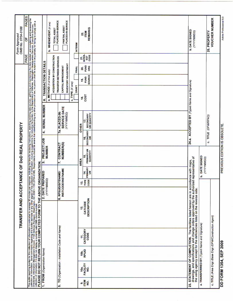
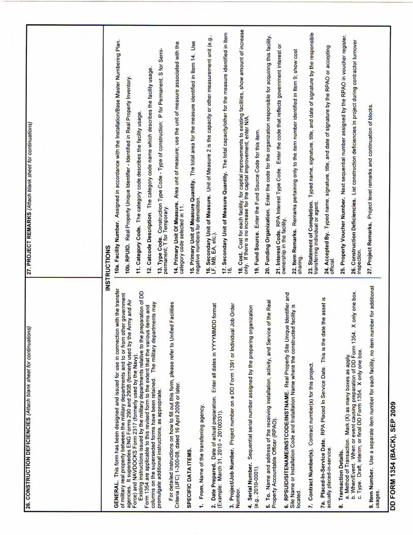
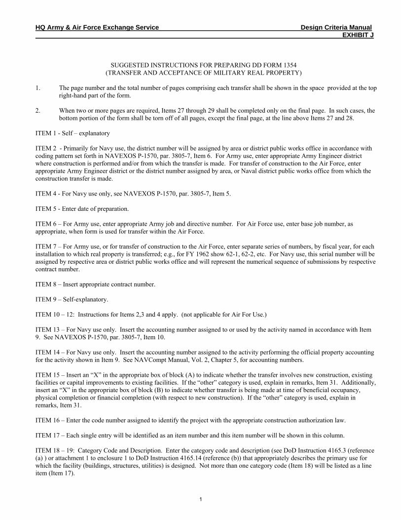
HQ Army & Air Force Exchange Service Design Criteria Manual EXHIBIT J
SUGGESTED INSTRUCTIONS FOR PREPARING DD FORM 1354 (TRANSFER AND ACCEPTANCE OF MILITARY REAL PROPERTY)
1. The page number and the total number of pages comprising each transfer shall be shown in the space provided at the top
right-hand part of the form. 2. When two or more pages are required, Items 27 through 29 shall be completed only on the final page. In such cases, the
bottom portion of the form shall be torn off of all pages, except the final page, at the line above Items 27 and 28. ITEM 1 - Self – explanatory ITEM 2 - Primarily for Navy use, the district number will be assigned by area or district public works office in accordance with coding pattern set forth in NAVEXOS P-1570, par. 3805-7, Item 6. For Army use, enter appropriate Army Engineer district where construction is performed and/or from which the transfer is made. For transfer of construction to the Air Force, enter appropriate Army Engineer district or the district number assigned by area, or Naval district public works office from which the construction transfer is made. ITEM 4 - For Navy use only, see NAVEXOS P-1570, par. 3805-7, Item 5. ITEM 5 - Enter date of preparation. ITEM 6 – For Army use, enter appropriate Army job and directive number. For Air Force use, enter base job number, as appropriate, when form is used for transfer within the Air Force. ITEM 7 – For Army use, or for transfer of construction to the Air Force, enter separate series of numbers, by fiscal year, for each installation to which real property is transferred; e.g., for FY 1962 show 62-1, 62-2, etc. For Navy use, this serial number will be assigned by respective area or district public works office and will represent the numerical sequence of submissions by respective contract number. ITEM 8 – Insert appropriate contract number. ITEM 9 – Self-explanatory. ITEM 10 – 12: Instructions for Items 2,3 and 4 apply. (not applicable for Air For Use.) ITEM 13 – For Navy use only. Insert the accounting number assigned to or used by the activity named in accordance with Item 9. See NAVEXOS P-1570, par. 3805-7, Item 10. ITEM 14 – For Navy use only. Insert the accounting number assigned to the activity performing the official property accounting for the activity shown in Item 9. See NAVCompt Manual, Vol. 2, Chapter 5, for accounting numbers. ITEM 15 – Insert an “X” in the appropriate box of block (A) to indicate whether the transfer involves new construction, existing facilities or capital improvements to existing facilities. If the “other” category is used, explain in remarks, Item 31. Additionally, insert an “X” in the appropriate box of block (B) to indicate whether transfer is being made at time of beneficial occupancy, physical completion or financial completion (with respect to new construction). If the “other” category is used, explain in remarks, Item 31. ITEM 16 – Enter the code number assigned to identify the project with the appropriate construction authorization law. ITEM 17 – Each single entry will be identified as an item number and this item number will be shown in this column. ITEM 18 – 19: Category Code and Description. Enter the category code and description (see DoD Instruction 4165.3 (reference (a) ) or attachment 1 to enclosure 1 to DoD Instruction 4165.14 (reference (b)) that appropriately describes the primary use for which the facility (buildings, structures, utilities) is designed. Not more than one category code (Item 18) will be listed as a line item (Item 17).
1
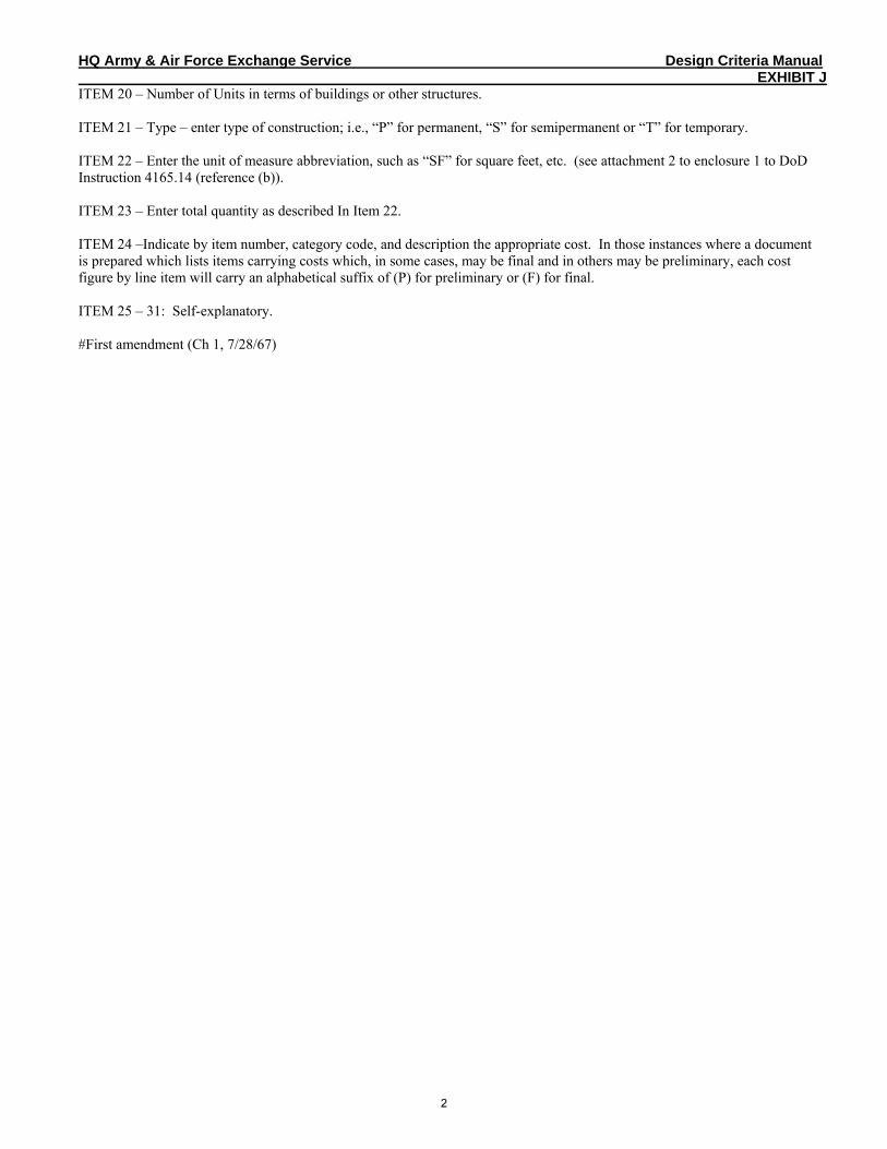
HQ Army & Air Force Exchange Service Design Criteria Manual EXHIBIT J
ITEM 20 – Number of Units in terms of buildings or other structures. ITEM 21 – Type – enter type of construction; i.e., “P” for permanent, “S” for semipermanent or “T” for temporary. ITEM 22 – Enter the unit of measure abbreviation, such as “SF” for square feet, etc. (see attachment 2 to enclosure 1 to DoD Instruction 4165.14 (reference (b)). ITEM 23 – Enter total quantity as described In Item 22. ITEM 24 –Indicate by item number, category code, and description the appropriate cost. In those instances where a document is prepared which lists items carrying costs which, in some cases, may be final and in others may be preliminary, each cost figure by line item will carry an alphabetical suffix of (P) for preliminary or (F) for final. ITEM 25 – 31: Self-explanatory. #First amendment (Ch 1, 7/28/67)
2
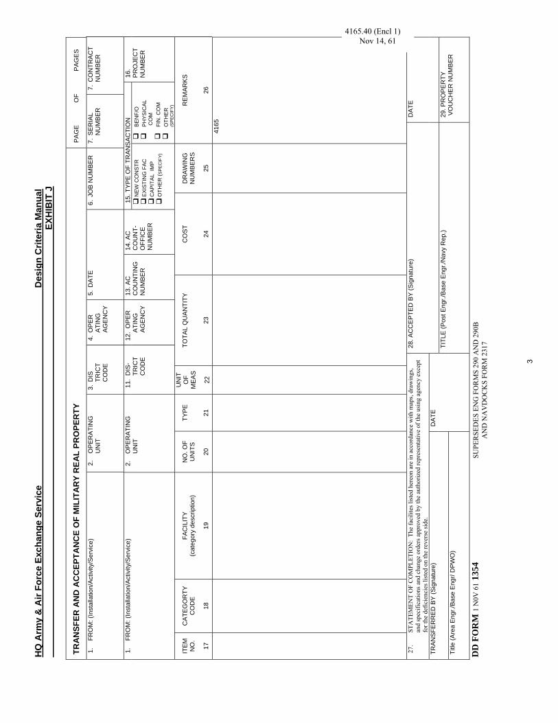
HQ
Arm
y &
Air
Forc
e Ex
chan
ge S
ervi
ce
D
esig
n C
riter
ia M
anua
l
EX
HIB
IT J
TRA
NSF
ER A
ND
AC
CEP
TAN
CE
OF
MIL
ITA
RY
REA
L PR
OPE
RTY
P
AG
E O
F P
AG
ES
1.
FRO
M: (
Inst
alla
tion/
Act
ivity
/Ser
vice
) 2.
O
PE
RA
TIN
G
UN
IT
3. D
IS
TRIC
T C
OD
E
4. O
PE
R
ATI
NG
AG
ENC
Y
5. D
ATE
6.
JO
B N
UM
BE
R
7. S
ER
IAL
NU
MBE
R
7. C
ON
TRAC
T N
UM
BER
15. T
YPE
OF
TRAN
SA
CTI
ON
1.
FR
OM
: (In
stal
latio
n/A
ctiv
ity/S
ervi
ce)
2.
OP
ER
ATI
NG
U
NIT
11
. D
IS-
TRIC
T C
OD
E
12.
OP
ER
A
TIN
G
AGEN
CY
13. A
C
CO
UN
TIN
GN
UM
BER
14. A
C
CO
UN
T-O
FFIC
E N
UM
BER
NEW
CO
NST
R
EXIS
TIN
G F
AC
C
AP
ITA
L IM
P
OTH
ER
(SPE
CIF
Y)
B
EN
F/O
PH
YSIC
AL
CO
M
FI
N. C
OM
OTH
ER
(S
PEC
IFY)
16.
PRO
JEC
T N
UM
BER
ITE
M
NO
.
17
CAT
EGO
RTY
C
OD
E
18
FAC
ILIT
Y (c
ateg
ory
desc
riptio
n)
19
NO
. OF
UN
ITS
20
TYPE
21
UN
IT
OF
ME
AS
22
TOTA
L Q
UAN
TITY
23
CO
ST
24
DR
AWIN
G
NU
MBE
RS
25
REM
ARKS
26
41
65
27.
STA
TEM
ENT
OF
CO
MPL
ETIO
N:
The
faci
lites
list
ed h
ereo
n ar
e in
acc
orda
nce
with
map
s, dr
awin
gs,
and
spec
ifica
tions
and
cha
nge
orde
rs a
ppro
ved
by th
e au
thor
ized
repr
esen
tativ
e of
the
usin
g ag
ency
exc
ept
for t
he d
efic
ienc
ies l
iste
d on
the
reve
rse
side
.
28. A
CC
EP
TED
BY
(Sig
natu
re)
DA
TE
TRA
NS
FER
RE
D B
Y (S
igna
ture
)
Title
(Are
a E
ngr./
Base
Eng
r/ D
PWO
)
DAT
E TI
TLE
(Pos
t Eng
r./B
ase
Eng
r./N
avy
Rep
.) 29
. PR
OP
ER
TY
VO
UC
HER
NU
MBE
R
DD
FO
RM
1 N
0V 6
1 135
4
SUPE
RSE
DES
EN
G F
OR
MS
290
AN
D 2
90B
AN
D N
AV
DO
CK
S FO
RM
231
7
4165.40 (Encl 1) Nov 14, 61
3

HQ Army & Air Force Exchange Service Design Criteria Manual EXHIBIT J
30. CONSTRUCTION DEFICIENCIES
31. REMARKS
This form has been designed and issued for use in connection with the transfer of military real property between the military departments and to or form other government agencies. It supersedes ENG Forms 290 and 290B (formerly used by the Army and Air Force) and NAVDOCKS Form 2317 (formerly used by the Navy). Existing instruction issued by the military departments relative to the preparation of the three superseded forms are applicable to this form to the extent that the various items and
columns on the superseded forms have been retained. Additional instructions, as appropriate, will be promulgated by the military departments in connection with any new items appearing hereon. With the issuance of this DD form, it is not intended that the department shall revise and reprint manuals and directives simply to show the number of this DD form. Such action can be accomplished through the normal course of revision for other reasons.
4
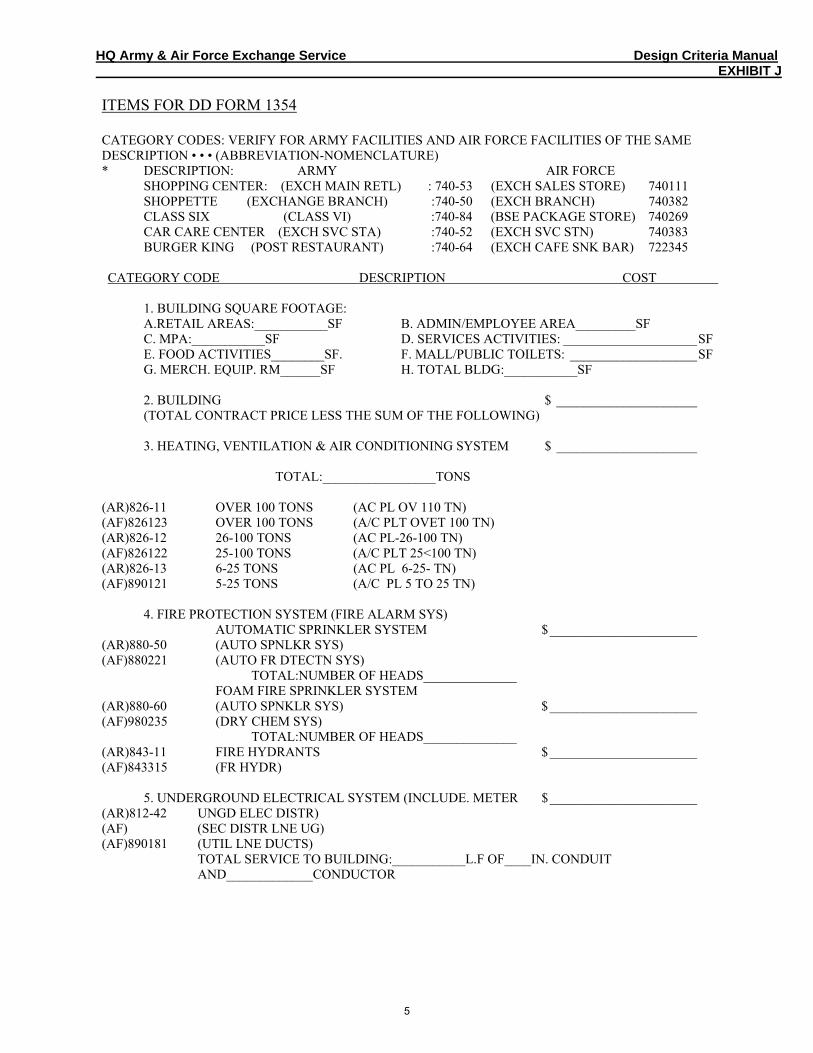
HQ Army & Air Force Exchange Service Design Criteria Manual EXHIBIT J
ITEMS FOR DD FORM 1354 CATEGORY CODES: VERIFY FOR ARMY FACILITIES AND AIR FORCE FACILITIES OF THE SAME DESCRIPTION • • • (ABBREVIATION-NOMENCLATURE) * DESCRIPTION: ARMY AIR FORCE SHOPPING CENTER: (EXCH MAIN RETL) : 740-53 (EXCH SALES STORE) 740111 SHOPPETTE (EXCHANGE BRANCH) :740-50 (EXCH BRANCH) 740382 CLASS SIX (CLASS VI) :740-84 (BSE PACKAGE STORE) 740269 CAR CARE CENTER (EXCH SVC STA) :740-52 (EXCH SVC STN) 740383 BURGER KING (POST RESTAURANT) :740-64 (EXCH CAFE SNK BAR) 722345 CATEGORY CODE DESCRIPTION COST
1. BUILDING SQUARE FOOTAGE: A.RETAIL AREAS:___________SF B. ADMIN/EMPLOYEE AREA_________SF C. MPA:___________SF D. SERVICES ACTIVITIES: ____________________SF E. FOOD ACTIVITIES________SF. F. MALL/PUBLIC TOILETS: ___________________SF G. MERCH. EQUIP. RM______SF H. TOTAL BLDG:___________SF
2. BUILDING $ _____________________ (TOTAL CONTRACT PRICE LESS THE SUM OF THE FOLLOWING) 3. HEATING, VENTILATION & AIR CONDITIONING SYSTEM $ _____________________ TOTAL:_________________TONS
(AR)826-11 OVER 100 TONS (AC PL OV 110 TN) (AF)826123 OVER 100 TONS (A/C PLT OVET 100 TN) (AR)826-12 26-100 TONS (AC PL-26-100 TN) (AF)826122 25-100 TONS (A/C PLT 25<100 TN) (AR)826-13 6-25 TONS (AC PL 6-25- TN) (AF)890121 5-25 TONS (A/C PL 5 TO 25 TN)
4. FIRE PROTECTION SYSTEM (FIRE ALARM SYS) AUTOMATIC SPRINKLER SYSTEM $______________________
(AR)880-50 (AUTO SPNLKR SYS) (AF)880221 (AUTO FR DTECTN SYS) TOTAL:NUMBER OF HEADS______________ FOAM FIRE SPRINKLER SYSTEM (AR)880-60 (AUTO SPNKLR SYS) $______________________ (AF)980235 (DRY CHEM SYS) TOTAL:NUMBER OF HEADS______________ (AR)843-11 FIRE HYDRANTS $______________________ (AF)843315 (FR HYDR)
5. UNDERGROUND ELECTRICAL SYSTEM (INCLUDE. METER $______________________ (AR)812-42 UNGD ELEC DISTR) (AF) (SEC DISTR LNE UG) (AF)890181 (UTIL LNE DUCTS) TOTAL SERVICE TO BUILDING:___________L.F OF____IN. CONDUIT AND_____________CONDUCTOR
5
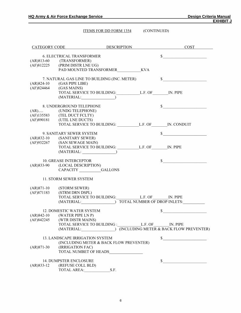
HQ Army & Air Force Exchange Service Design Criteria Manual EXHIBIT J
ITEMS FOR DD FORM 1354 (CONTINUED)
CATEGORY CODE DESCRIPTION COST 6. ELECTRICAL TRANSFORMER $______________________
(AR)813-60 (TRANSFORMER) (AF)812225 (PRIM DISTR LNE UG) PAD MOUNTED TRANSFORMER____________KVA
7. NATURAL GAS LINE TO BUILDING (INC. METER) $______________________ (AR)824-10 (GAS PIPE LIBE) (AF)824464 (GAS MAINS) TOTAL SERVICE TO BUILDING:____________L.F. OF________IN. PIPE (MATERIAL:_________________)
8. UNDERGROUND TELEPHONE $______________________ (AR)..... (UNDG TELEPHONE) (AF)135583 (TEL DUCT FCLTY) (AF)890181 (UTIL LNE DUCTS) TOTAL SERVICE TO BUILDING: ___________L.F. OF________IN. CONDUIT
9. SANITARY SEWER SYSTEM $______________________ (AR)832-10 (SANITARY SEWER) (AF)932267 (SAN SEWAGE MAIN) TOTAL SERVICE TO BUILDING: ___________L.F. OF________IN. PIPE (MATERIAL: _________________)
10. GREASE INTERCEPTOR $______________________ (AR)833-90 (LOCAL DESCRIPTION) CAPACITY ___________GALLONS
11. STORM SEWER SYSTEM
(AR)871-10 (STORM SEWER) (AF)871183 (STRM DRN DSPL) TOTAL SERVICE TO BUILDING:____________L.F. OF________IN. PIPE (MATERIAL:_________________) TOTAL NUMBER OF DROP INLETS:___________
12. DOMESTIC WATER SYSTEM $______________________ (AR)842-10 (WATER PIPE LN P) (AF)842245 (WTR DISTR MAINS) TOTAL SERVICE TO BUILDING :____________L.F. OF________IN. PIPE (MATERIAL:_________________) (INCLUDING METER & BACK FLOW PREVENTER)
13. LANDSCAPE IRRIGATION SYSTEM $______________________ (INCLUDING METER & BACK FLOW PREVENTER) (AR)871-30 (IRRIGATION FAC) TOTAL NUMBET OF HEADS_________________
14. DUMPSTER ENCLOSURE $______________________ (AR)833-12 (REFUSE COLL BLD) TOTAL AREA:_____________S.F.
6
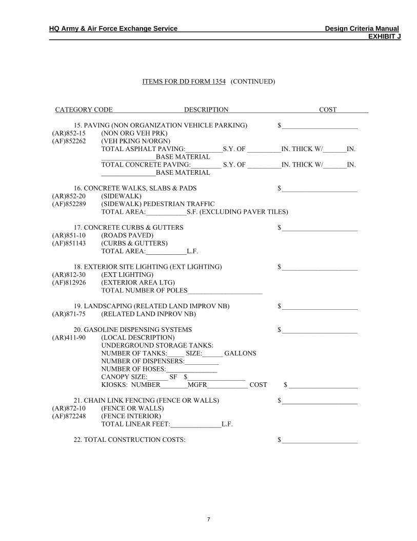
HQ Army & Air Force Exchange Service Design Criteria Manual EXHIBIT J
ITEMS FOR DD FORM 1354 (CONTINUED)
CATEGORY CODE DESCRIPTION COST 15. PAVING (NON ORGANIZATION VEHICLE PARKING) $______________________
(AR)852-15 (NON ORG VEH PRK) (AF)852262 (VEH PKING N/ORGN) TOTAL ASPHALT PAVING:___________S.Y. OF __________IN. THICK W/_______IN. ________________BASE MATERIAL TOTAL CONCRETE PAVING:_________ S.Y. OF __________IN. THICK W/_______IN. ________________BASE MATERIAL
16. CONCRETE WALKS, SLABS & PADS $______________________ (AR)852-20 (SIDEWALK) (AF)852289 (SIDEWALK) PEDESTRIAN TRAFFIC TOTAL AREA:____________S.F. (EXCLUDING PAVER TILES)
17. CONCRETE CURBS & GUTTERS $______________________ (AR)851-10 (ROADS PAVED) (AF)851143 (CURBS & GUTTERS) TOTAL AREA:____________L.F.
18. EXTERIOR SITE LIGHTING (EXT LIGHTING) $______________________ (AR)812-30 (EXT LIGHTING) (AF)812926 (EXTERIOR AREA LTG) TOTAL NUMBER OF POLES______________________
19. LANDSCAPING (RELATED LAND IMPROV NB) $______________________ (AR)871-75 (RELATED LAND INPROV NB)
20. GASOLINE DISPENSING SYSTEMS $______________________ (AR)411-90 (LOCAL DESCRIPTION) UNDERGROUND STORAGE TANKS: NUMBER OF TANKS:_____ SIZE:______ GALLONS NUMBER OF DISPENSERS:__________ NUMBER OF HOSES:_______________ CANOPY SIZE:______ SF $_________________ KIOSKS: NUMBER________MGFR____________ COST $ ____________________
21. CHAIN LINK FENCING (FENCE OR WALLS) $______________________ (AR)872-10 (FENCE OR WALLS) (AF)872248 (FENCE INTERIOR) TOTAL LINEAR FEET:_______________L.F.
22. TOTAL CONSTRUCTION COSTS: $______________________
7
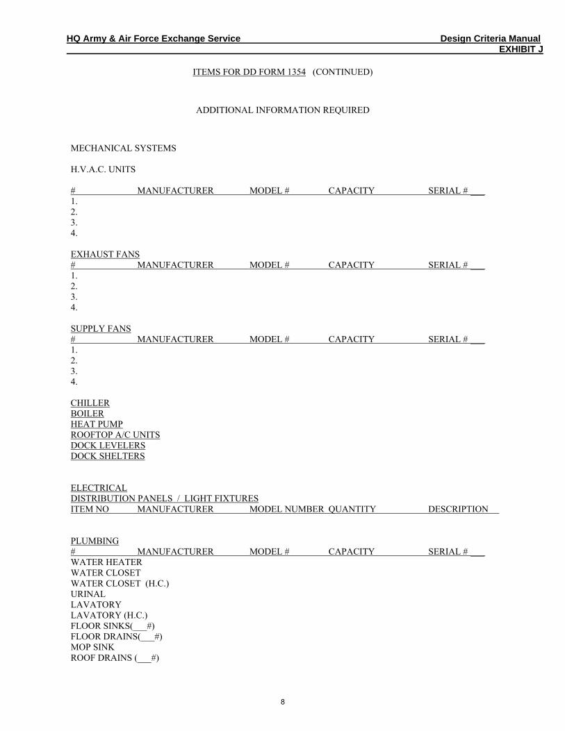
HQ Army & Air Force Exchange Service Design Criteria Manual EXHIBIT J
ITEMS FOR DD FORM 1354 (CONTINUED)
ADDITIONAL INFORMATION REQUIRED
MECHANICAL SYSTEMS H.V.A.C. UNITS # MANUFACTURER MODEL # CAPACITY SERIAL # ___ 1. 2. 3. 4. EXHAUST FANS # MANUFACTURER MODEL # CAPACITY SERIAL # ___ 1. 2. 3. 4. SUPPLY FANS # MANUFACTURER MODEL # CAPACITY SERIAL # ___ 1. 2. 3. 4. CHILLER BOILER HEAT PUMP ROOFTOP A/C UNITS DOCK LEVELERS DOCK SHELTERS ELECTRICAL DISTRIBUTION PANELS / LIGHT FIXTURES ITEM NO MANUFACTURER MODEL NUMBER QUANTITY DESCRIPTION PLUMBING # MANUFACTURER MODEL # CAPACITY SERIAL # ___ WATER HEATER WATER CLOSET WATER CLOSET (H.C.) URINAL LAVATORY LAVATORY (H.C.) FLOOR SINKS(___#) FLOOR DRAINS(___#) MOP SINK ROOF DRAINS (___#)
8
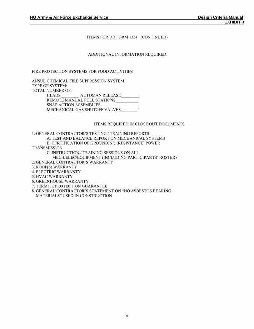
HQ Army & Air Force Exchange Service Design Criteria Manual EXHIBIT J
ITEMS FOR DD FORM 1354 (CONTINUED)
ADDITIONAL INFORMATION REQUIRED
FIRE PROTECTION SYSTEMS FOR FOOD ACTIVITIES ANSUL CHEMICAL FIRE SUPPRESSION SYSTEM TYPE OF SYSTEM:____________ TOTAL NUMBER OF: HEADS_________ AUTOMAN RELEASE_________ REMOTE MANUAL PULL STATIONS___________ SNAP ACTION ASSEMBLIES__________________ MECHANICAL GAS SHUTOFF VALVES________’
ITEMS REQUIRED IN CLOSE OUT DOCUMENTS 1. GENERAL CONTRACTOR’S TESTING / TRAINING REPORTS: A. TEST AND BALANCE REPORT ON MECHANICAL SYSTEMS B. CERTIFICATION OF GROUNDING (RESISTANCE) POWER TRANSMISSION C. INSTRUCTION / TRAINING SESSIONS ON ALL MECH/ELEC/EQUIPMENT (INCLUDING PARTICIPANTS’ ROSTER) 2. GENERAL CONTRACTOR’S WARRANTY 3. ROOF(S) WARRANTY 4. ELECTRIC WARRANTY 5. HVAC WARRANTY 6. GREENHOUSE WARRANTY 7. TERMITE PROTECTION GUARANTEE 8. GENERAL CONTRACTOR’S STATEMENT ON “NO ASBESTOS BEARING MATERIALS” USED IN CONSTRUCTION
9