Embed Size (px)
Citation preview
SPECIFICATION
For
HOT COILED HELICAL SPRINGS
USED ON
MAINLINE COACHES, EMU AND FREIGHT STOCK
No. WD-01-HLS-94 (Rev.3)
Issued by:
RESEARCH DESIGNS AND STANDARDS ORGANISATION
MINISTRY OF RAILWAYS
MANAK NAGAR, LUCKNOW - 226011
JANUARY 2009 Rs. 2700/=
WD-01-HLS-94 (Rev.3)
(2)
INDEX S.NO. DESCRIPTION PAGE NO.
0.0 SCOPE 4
1.0 REFERENCE DOCUMENTS & STANDARDS 4
2.0 RAW MATERIAL 7
2.1 General 7
2.2 Quality of spring steel round 7
2.3 Inspection 8
2.4 Sampling 9
2.5 Rejection 10
3.0 MANUFACTURE OF SPRINGS 10
3.1 General 10
3.2 Straightening 10
3.3 Peeling & Centreless grinding 10
3.4 End Tapering 11
3.5 Stamping 11
3.6 Coiling and Heat Treatment 12
3.7 End Grinding 14
3.8 Scragging 14
3.9 Crack Detection 14
3.10 Shot Peening 14
3.11 Grouping and Colour coding 14
4.0 GEOMETRICAL CHARACTERISTICS 15
4.1 General 15
4.2 Dimensional Accuracy 15
4.3 Pitching 16
4.4 Lateral Deflection 16
5.0 LOAD TESTING 16
6.0 FATIGUE TESTING 16
6.1 Test Setup 16
6.2 Test & Measurements 16
6.3 Test Report 17
7.0 HANDLING OF SPRINGS 17
8.0 INSPECTION OF SPRINGS 17
8.1 General 17
8.2 Stage I - Raw Material 18
8.3 Stage II- During Manufacturing 18
8.4 Stage III- Finished Springs 18
9.0 REJECTION 20
10.0 PROTECTION AGAINST CORROSION 20
11.0 PACKING 20
12.0 GUARANTEE 20

WD-01-HLS-94 (Rev.3)
(3)
LIST OF ANNEXURES
ANNEXURE NO. DESCIPTION PAGE NO.
I Drawing Code of springs for main line coaches. 21
II Drawing codes of spring for milk vans. 22
III Drawing codes of springs for EMU Coaches. 23-24
IV Drawing codes of springs for container flats. 25
V BG, MG & NG Freight Stock Coil Springs drawing codes. 26-27
WD-01-HLS-94 (Rev.3)
(4)
TECHNICAL SPECIFICATION FOR HOT COILED HELICAL SPRINGS USED ON
MAINLINE COACHES,EMU STOCK AND
FREIGHT STOCK
0.0 SCOPE
0.1 This Specification is applicable for high performance helical springs used in the suspension
system of Main line Coaches, EMU Stock and Freight Stock on the Indian Railways. This
standard covers springs which are to be manufactured out of circular section bars.
0.2 This specification is intended to cover general requirements of heavy duty helical springs of
Coaching Stock, EMU Stock and Freight Stock which call for stricter control in raw material
quality, manufacturing processes and testing standards to improve the reliability and life of
springs.
0.3 It also applies to all springs which are comparable to the above by virtue of their functional or
dimensional characteristics.
1.0 REFERENCE DOCUMENTS AND STANDARDS
1.1 The manufacture of springs covered by this specification is to be entrusted only to spring
Manufacturers previously approved by RDSO.
For infrastructure manufacturing, testing and quality control requirements for hot coiled helical
springs, the suppliers should comply latest IL-17-2000 issued by QA/Mech. Directorate of
RDSO.
1.2 Procurement of spring steel shall be done only from reputed manufacturers previously
approved by RDSO. Only spring steel bars duly inspected and passed by RDSO shall be used
for manufacture of springs.
For infrastructure manufacturing, testing and quality control requirements for spring steel
rounds to RDSO Specification No. WD-01-HLS-94 (Rev.3 of Jan 08), the suppliers should
comply latest IL-16-2000 issued by QA/Mech. Directorate of RDSO.
1.3 This Specification requires references to the following ASTM/IS/UIC Specifications:-
i) IS: 4748 -Standard Test Method for Determining average grain size. ii) IS: 11371 -Standard Method of Macroetch Testing, Inspection and Rating
Steel Products, Comprising Bars, Billets, Blooms and Forgings.
iii) IS:228 -Methods of Chemical Analysis of the steel.
iv) IS:1500 -Methods for Brinell Hardness Test for steel.
v) IS:2074 -Ready mixed paint air drying red oxide zinc chrome priming.
vi) IS:2932 -Specification for Enamel Synthetic exterior type I
undercoating (b) finishing colour as required.
WD-01-HLS-94 (Rev.3)
(5)
vii) IS:3073 - Assessment of Surface Roughness.
viii) IS:3195 - Specification for steel for the manufacture of volute and helical springs
(for freight, coaching, EMUs and Locomotive Stock).
ix) IS:3703 - Code of practice for Magnetic particle Flaw Detection.
x) IS:3848-1981 - Method of End Quench Tests for Hardenability.
xi) IS:4163 - Methods for determination of inclusion content in steel by
Microscopic Method.
xii) IS:6396 - Methods of measuring decarburized depth of steel.
xiii) IS:7001 - Methods for shot peening and test for shot- peened ferrous
metal parts.
xiv) IS:7739 - Code of practice for preparation of Metallographic Specimens.
xv) IS:7906
(Part v) - Specification for hot coiled springs made from circular section bars.
(Part vii) -Quality requirements for cylindrical coil compression springs used
mainly as Vehicle Suspension Springs.
(Part viii) - Method of Inspection of Hot Coiled Compression Springs made from
circular section bars.
xvi) UIC-822 -Technical Specification for the supply of Helical Compression
Springs, hot coiled, for tractive and trailing stock.
xvii) ASTM A 304-90 - Specification for hardenability Band
(Fig. 71 of 92060 H)
1.4 The reference to the IS specifications (paragraph 1.3 above) are as tabulated below:
S.No. IS Superseding Reaffirmed Amendment
1 IS: 4748-1988 IS: 2853-1964 2003 NIL
2 IS: 11371-1985 NIL 2003 NIL
3.1 IS: 228:Part 1:1987 NIL 2002 NIL
3.2 IS: 228:Part 2:1987 NIL 2002 NIL
3.3 IS: 228:Part 3:1987 NIL 2002 NIL
3.4 IS: 228:Part 4:1987 NIL 2002 NIL
3.5 IS: 228:Part 5:1987 NIL 2002 NIL
3.6 IS: 228:Part 6:1987 NIL 2002 NIL
3.7 IS: 228:Part 7:1990 NIL 2006 NIL
3.8 IS: 228:Part 8:1989 NIL 2004 NIL
3.9 IS: 228:Part 9:1989 NIL 2004 NIL
WD-01-HLS-94 (Rev.3)
(6)
3.10 IS: 228:Part 10:1989 NIL 2004 NIL
3.11 IS: 228:Part 11:1990 NIL 2004 NIL
3.12 IS: 228:Part 12:2001 NIL 2004 NIL
3.13 IS: 228:Part 13:1982 NIL 2002 NIL
3.14 IS: 228:Part 14:1988 NIL 2004 NIL
3.15 IS: 228:Part 15:1992 NIL 2004 NIL
3.16 IS: 228:Part 16:1992 NIL 2004 NIL
3.17 IS: 228:Part 17:1998 NIL 2005 NIL
3.18 IS: 228:Part 18:1998 NIL 2006 NIL
3.19 IS: 228:Part 19:1998 NIL 2005 NIL
3.20 IS: 228:Part 20:2003 NIL ----- NIL
3.21 IS: 228:Part 21:2003 NIL ----- NIL
3.22 IS: 228:Part 22:2003 NIL ----- NIL
3.23 IS: 228:Part 23:2003 NIL ----- NIL
3.24 IS: 228:Part 24:2003 NIL ----- NIL
4 IS: 1500:2005 NIL ------ NIL
5 IS: 2074:1992 NIL 2002 NIL
6 IS: 2932:2003 NIL ------- NIL
7 IS: 3073:1967 NIL 2006 Incorporating 1,2,3 and 4
8 IS: 3195:1992 NIL 2001 Incorporating 1 and 2
9 IS: 3703:2004 NIL ------ NIL
10 IS: 3848:1981 NIL 2003 NIL
11 IS: 4163:2004 NIL ------ NIL
12 IS: 6396:2000 NIL 2003 NIL
13 IS: 7001:1989 IS: 7377:1974 2004 NIL
14.1 IS: 7739:Part 1: 1975 NIL 2003 NIL
14.2 IS: 7739:Part 2: 1975 NIL 2003 NIL
14.3 IS: 7739:Part 3: 1975 NIL 2003 NIL
14.4 IS: 7739:Part 4: 1975 NIL 2003 NIL
14.5 IS: 7739:Part 5: 1975 NIL 2003 NIL
14.6 IS: 7739:Part 6: 1975 NIL 2003 NIL
14.7 IS: 7739:Part 7: 1975 NIL 2003 NIL
14.8 IS: 7739:Part 8: 1975 NIL 2003 NIL
14.9 IS: 7739:Part 9: 1975 NIL 2003 NIL
14.10 IS: 7739:Part 10: 1975 NIL 2003 NIL
14.11 IS: 7739:Part 11: 1976 NIL 2003 NIL
15.1 IS: 7906 (Part 5): 2004 NIL ------- NIL
15.2 IS: 7906 (Part 7): 1989 NIL 2004 NIL
15.3 IS: 7906 (Part 8): 1989 NIL 2004 NIL
[Above position is as on 31-January-2009.
1.5 Specific provisions in this Specification will over ride those in the above ASTM/IS/UIC
Specifications where these are not in conformity with one another.
1.6 Any special requirements given in the drawings will over ride this specification.
WD-01-HLS-94 (Rev.3)
(7)
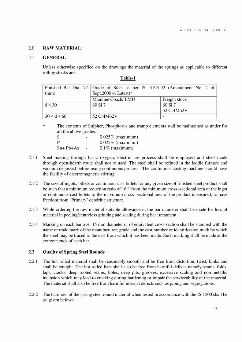
2.0 RAW MATERIAL:
2.1 GENERAL
Unless otherwise specified on the drawings the material of the springs as applicable to different
rolling stocks are: -
Table-1
Finished Bar Dia. ‘d’
(mm)
Grade of Steel as per IS: 3195-92 (Amendment No. 2 of
Sept.2000 or Latest)*
Mainline Coach/ EMU Freight stock
d ≤ 30 60 Si 7
60 Si 7
52 Cr4Mo2V
30 < d ≤ 60 52 Cr4Mo2V -
* The contents of Sulpher, Phosphorus and tramp elements stall be maintained as under for
all the above grades: -
S - 0.025% (maximum)
P - 0.025% (maximum)
Sn+ Pb+As - 0.1% (maximum)
2.1.1 Steel making through basic oxygen, electric are process shall be employed and steel made
through open-hearth route shall not to used. The steel shall be refined in the laddle furnace and
vacuum degassed before using continuous process. The continuous casting machine should have
the facility of electromagnetic stirring.
2.1.2 The size of ingots, billets or continuous cast billets for any given size of finished steel product shall
be such that a minimum reduction ratio of 16:1 from the minimum cross -sectional area of the ingot
or continuous cast billets to the maximum cross- sectional area of the product is ensured, to have
freedom from "Primary" dendritic structure.
2.1.3 While ordering the raw material suitable allowance in the bar diameter shall be made for loss of
material in peeling/centreless grinding and scaling during heat treatment.
2.1.4 Marking on each bar over 15 mm diameter or of equivalent cross-section shall be stamped with the
name or trade mark of the manufacturer, grade and the cast number or identification mark by which
the steel may be traced to the cast from which it has been made. Such marking shall be made at the
extreme ends of each bar.
2.2 Quality of Spring Steel Rounds
2.2.1 The hot rolled material shall be reasonably smooth and be free from distortion, twist, kinks and
shall be straight. The hot rolled bars shall also be free from harmful defects namely seams, folds,
laps, cracks, deep rooted seams, holes, deep pits, grooves, excessive scaling and non-metallic
inclusion which may lead to cracking during hardening or impair the serviceability of the material.
The material shall also be free from harmful internal defects such as piping and segregations.
2.2.2 The hardness of the spring steel round material when tested in accordance with the IS:1500 shall be
as given below:-
WD-01-HLS-94 (Rev.3)
(8)
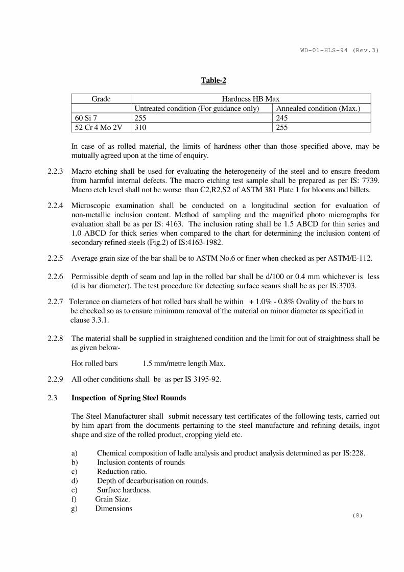
Table-2
Grade Hardness HB Max
Untreated condition (For guidance only) Annealed condition (Max.)
60 Si 7 255 245
52 Cr 4 Mo 2V 310 255
In case of as rolled material, the limits of hardness other than those specified above, may be
mutually agreed upon at the time of enquiry.
2.2.3 Macro etching shall be used for evaluating the heterogeneity of the steel and to ensure freedom
from harmful internal defects. The macro etching test sample shall be prepared as per IS: 7739.
Macro etch level shall not be worse than C2,R2,S2 of ASTM 381 Plate 1 for blooms and billets.
2.2.4 Microscopic examination shall be conducted on a longitudinal section for evaluation of
non-metallic inclusion content. Method of sampling and the magnified photo micrographs for
evaluation shall be as per IS: 4163. The inclusion rating shall be 1.5 ABCD for thin series and
1.0 ABCD for thick series when compared to the chart for determining the inclusion content of
secondary refined steels (Fig.2) of IS:4163-1982. 2.2.5 Average grain size of the bar shall be to ASTM No.6 or finer when checked as per ASTM/E-112.
2.2.6 Permissible depth of seam and lap in the rolled bar shall be d/100 or 0.4 mm whichever is less
(d is bar diameter). The test procedure for detecting surface seams shall be as per IS:3703.
2.2.7 Tolerance on diameters of hot rolled bars shall be within + 1.0% - 0.8% Ovality of the bars to
be checked so as to ensure minimum removal of the material on minor diameter as specified in
clause 3.3.1.
2.2.8 The material shall be supplied in straightened condition and the limit for out of straightness shall be
as given below-
Hot rolled bars 1.5 mm/metre length Max.
2.2.9 All other conditions shall be as per IS 3195-92.
2.3 Inspection of Spring Steel Rounds
The Steel Manufacturer shall submit necessary test certificates of the following tests, carried out
by him apart from the documents pertaining to the steel manufacture and refining details, ingot
shape and size of the rolled product, cropping yield etc.
a) Chemical composition of ladle analysis and product analysis determined as per IS:228.
b) Inclusion contents of rounds
c) Reduction ratio.
d) Depth of decarburisation on rounds.
e) Surface hardness.
f) Grain Size.
g) Dimensions
WD-01-HLS-94 (Rev.3)
(9)
h)
(i) Test results of End Quench Hardenability (Jominy band) for each heat / cast are
compulsorily required to be submitted by the manufacturer. IS:3848- 1981 is the
specification for `Method of End Quench Hardenability’ of steel for this purpose:-
a) Specification for Hardenability Band- ASTM A 304-90 (Fig 71 of 9260 H )
material may be referred to as guidance as it is the nearest equivalent.
b) Distance from quench end-4 (in terms of 1/16 of an inch).
c) Hardness value range- Min. 53 HRc and Max. 64 HRc.
(ii) Submission of test certificate for chemical composition including the contents of
Tramp elements in the ladle and product analysis shall be mandatory.
2.3.1 While carrying out inspection of rolled bars the RDSO Inspector would pay special attention to:
a) Size of ingots/billets used as verified from the records of the steel manufacturer.
b) Dressing of complete billet by general surface grinding and freedom from surface defects.
c) Discarding of end portions at both ends of each billet and freedom from piping.
d) The size of ingot used shall be checked, recorded and verified that minimum reduction
ratio 16:1 is ensured for the rolled bars offered for inspection.
2.3.2 The RDSO Inspector shall carry out the following minimum checks as per sampling given in
Clauses 2.3.2.1, 2.3.2.2 and 2.4 and maintain records. He may draw any additional number of
samples and carry- out tests at his discretion. He shall also have the right to cross check any of
the above parameters by actual tests at his discretion and at the cost of the spring manufacturer.
2.3.2.1 Examine various registers and records maintained by the steel manufacture to verify heat wise
checks carried out on various parameters and manufacturing practices like production of ingots
with wide end up and hot top cropping of each ingot/primary rolled billet etc.
2.3.2.2 All other aspects specified in Clause 2.0 and 2.2(i.e. from Clause 2.2.1 to 2.2.9) shall also be
checked.
2.3.3 In case, the spring manufacturer want to stock raw material, approval should be taken from the
office of DG(QA/Mech)/ RDSO. In such case, inspection charges (1% of the value of goods
inspected) will be realised from the firms as the raw material procured will not be against any
Railway Order.
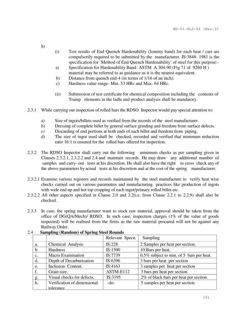
2.4 Sampling (Random) of Spring Steel Rounds
Relevant Specn.
Sampling
a. Chemical Analysis IS:228 2 Samples per heat per section.
b. Hardness IS:1500 10 Bars per heat.
c. Macro Examination IS:7739 0.5% subject to min. of 5 bars per heat.
d. Depth of Decarburisation IS:6396 3 bars per heat per section
e. Inclusion Content. IS:4163 3 samples per heat per section
f. Grain size. ASTM-E112 3 bars per heat per section
g. Visual checks for defects. IS:3195 2% of black bars per heat per section.
h.
Verification of dimensional
tolerance
-do-
5 samples per heat per section.
WD-01-HLS-94 (Rev.3)
(10)
2.4.1 Records for all the above tests shall be made available for scrutiny of Inspector. Samples of the
above test shall be preserved for atleast 3 months for counter check by Inspector, if he so desires.
2.4.2 RDSO Inspector may pick up two samples per 1000 tonnes of material offered and send the same
to approved agency for confirmatory test for chemical and metallurgical properties at Spring Steel
Manufacturer's expense. This test should not form part of purchase acceptance test but will only
serve as a counter check on Spring Steel Manufacturer's quality control practice.
2.5 Rejection
In case the material offered for inspection fails to meet any of the requirements laid down in para
2.1, 2.2 & 2.3 twice the size of the original sample shall be drawn and tested for the parameters in
which the original sample had failed. If one or both the retest sampled fail, the complete lot shall be
treated as failed. The manufacturer shall then undertake to render the lot unserviceable for
Railways’ use.
3.0 MANUFACTURE OF HELICAL SPRINGS
3.1 General
Springs shall be made of bars of fine grained special quality spring steel to IS:3195. The spring
manufacturer before taking up manufacturing of springs, shall inspect and check all steel rounds for
conformance with the requirements for the raw material as given in this specification. Only when
the raw material is found to be within the specific standards, it will be taken up for manufacture of
the springs. It will be the responsibility of the spring manufacture to ensure quality of spring steel
rounds.
3.1.1 Generally the steel manufacturers supply the spring steel rounds to the specified lengths ordered by
the Spring Manufacturers hence, no cropping of the rounds is necessary at this stage. In case of
multiple lengths/excess lengths, rods may be cut to length by shearing/cutting carefully so as to
prevent cracking at the ends. Flame (Gas) cutting is prohibited.
3.2 Straightening
The bars shall be straightened in the bar straightening machine.
3.3 Peeling and Centreless Grinding
3.3.1 The straightened bar should be peeled and centreless ground. Centreless grinding of peeled bars
before coiling is mandatory and the surface finish of the ground bar shall be 5 microns(µm)Ra
values in terms of IS: 3073 or better. The reduction in the bar diameter after peeling and centreless
grinding shall be 3% of nominal bar diameter or 1mm, whichever is higher.
The tolerances on centreless ground bars diameter shall be within + 0.05 mm.
The limit for out of straightness for peeled and centreless ground bars shall be 1 mm/metre length
max.
3.3.2 Centreless ground bars having tool marks, grooves either shallow or deep, dent marks or black
spots due to non-uniform grinding shall be rejected.
WD-01-HLS-94 (Rev.3)
(11)
3.3.3 100% of the peeled and ground bars shall be subjected to Magnetic particle testing by fluorescent
wet method. The test procedure for detecting surface and sub surface defects should be as
per IS:3703. Open seams are not acceptable and sub surface seams i.e. closed seams upto a depth
of 1.0 mm from the surface are not acceptable. Eddy current testing method, as an alternative
is not permitted.
3.3.4 Magnetic particle testing facilities should be such that 6.0M length of spring bars can be
accommodated for testing in one setting and the bars can be rotated with a suitable device in
position to facilitate testing of entire surface of the bars in one setting. Magnetic particle Testing
Machine should be calibrated before testing of spring bars with standard blocks for comparing the
depth of sub-surface defects.
3.3.5 No trace of arc burns or spots on the centreless ground bars due to the passage of electric current
following Magnetic particle testing shall be permitted.
3.4 End Tapering
3.4.1 Both the ends of the ground bar shall be tapered by taper rolling machine to give the finished spring
about 75% firm bearing. The tapered faces are to be grounded & grinding operation shall be
performed perpendicular to the axis of the spring helix in such a way that microscopic cracks or
blue burn marks are not formed during this operation. It must be ensured that the tip thickness is
maintained within the prescribed limit and the grinding coverage is uniform in the spring. The
tapered faces should not have steps/pits or cracks due to hammer blows, as line contact with the
effective coils is required under load.
3.4.2 The tip thickness of the tapered ends of the Bar after end grinding should not be less than 1/4th of
nominal bar dia upto 33 mm and 1/5th beyond 33 mm. It is to be ensured that the tip thickness of
the finished spring does not in any way affect the load test requirement given in the drawing.
3.4.3 The ends of the peeled and centreless ground bars be heated in an oil fired or electric indirectly
heating furnace equipped with temperature controllers and recorders. The temperature to which
the ends of the ground bars be heated should be pre-determined according to chemical
composition of the material.
3.5 Stamping
3.5.1 The following material code shall be followed for stamping:-
CM:- Chrome Moly
SM:- Silico Manganese
The material code shall be legibly hot stamped on both tapered ends of each spring in such a way
that the particulars are visible on the outer surface of the ineffective coils and they do not get
erased during end grinding or interfere with the performance of the spring. The size of letters shall
be 5mm. on bars having wire dia. above 20 mm and 3 mm for bars having wire dia. 20 mm or less.
WD-01-HLS-94 (Rev.3)
(12)
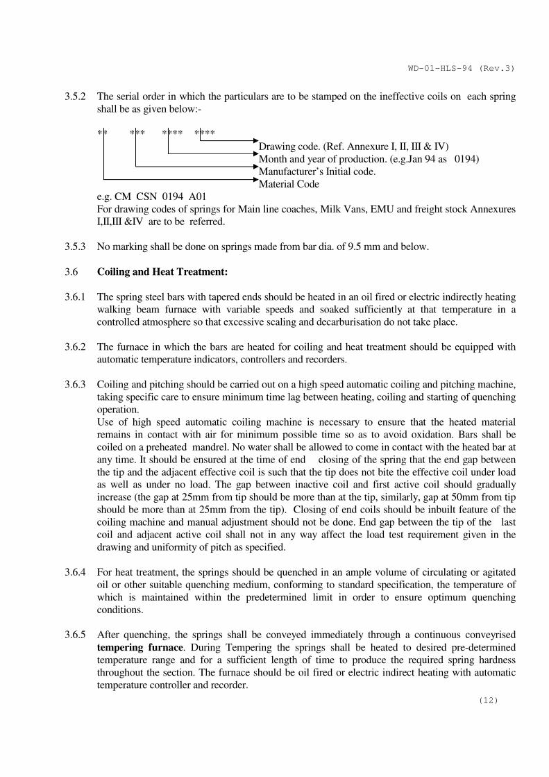
3.5.2 The serial order in which the particulars are to be stamped on the ineffective coils on each spring
shall be as given below:-
** *** **** ****
Drawing code. (Ref. Annexure I, II, III & IV)
Month and year of production. (e.g.Jan 94 as 0194)
Manufacturer’s Initial code.
Material Code
e.g. CM CSN 0194 A01
For drawing codes of springs for Main line coaches, Milk Vans, EMU and freight stock Annexures
I,II,III &IV are to be referred.
3.5.3 No marking shall be done on springs made from bar dia. of 9.5 mm and below.
3.6 Coiling and Heat Treatment:
3.6.1 The spring steel bars with tapered ends should be heated in an oil fired or electric indirectly heating
walking beam furnace with variable speeds and soaked sufficiently at that temperature in a
controlled atmosphere so that excessive scaling and decarburisation do not take place.
3.6.2 The furnace in which the bars are heated for coiling and heat treatment should be equipped with
automatic temperature indicators, controllers and recorders.
3.6.3 Coiling and pitching should be carried out on a high speed automatic coiling and pitching machine,
taking specific care to ensure minimum time lag between heating, coiling and starting of quenching
operation.
Use of high speed automatic coiling machine is necessary to ensure that the heated material
remains in contact with air for minimum possible time so as to avoid oxidation. Bars shall be
coiled on a preheated mandrel. No water shall be allowed to come in contact with the heated bar at
any time. It should be ensured at the time of end closing of the spring that the end gap between
the tip and the adjacent effective coil is such that the tip does not bite the effective coil under load
as well as under no load. The gap between inactive coil and first active coil should gradually
increase (the gap at 25mm from tip should be more than at the tip, similarly, gap at 50mm from tip
should be more than at 25mm from the tip). Closing of end coils should be inbuilt feature of the
coiling machine and manual adjustment should not be done. End gap between the tip of the last
coil and adjacent active coil shall not in any way affect the load test requirement given in the
drawing and uniformity of pitch as specified.
3.6.4 For heat treatment, the springs should be quenched in an ample volume of circulating or agitated
oil or other suitable quenching medium, conforming to standard specification, the temperature of
which is maintained within the predetermined limit in order to ensure optimum quenching
conditions.
3.6.5 After quenching, the springs shall be conveyed immediately through a continuous conveyrised
tempering furnace. During Tempering the springs shall be heated to desired pre-determined
temperature range and for a sufficient length of time to produce the required spring hardness
throughout the section. The furnace should be oil fired or electric indirect heating with automatic
temperature controller and recorder.
WD-01-HLS-94 (Rev.3)
(13)
3.6.6 In order to ensure the uniform heating of spring steel bars, it is recommended that each zone of the
furnace should be provided with independent pyrometer for temperature control. The temperature
shall be controlled within +100
C in each zone of the furnace. The temperature of the tempering
furnace should also be maintained within this range of variation.
In order to ensure the proper heat treatment of spring steel bars the following table shall be used
for guidance:-
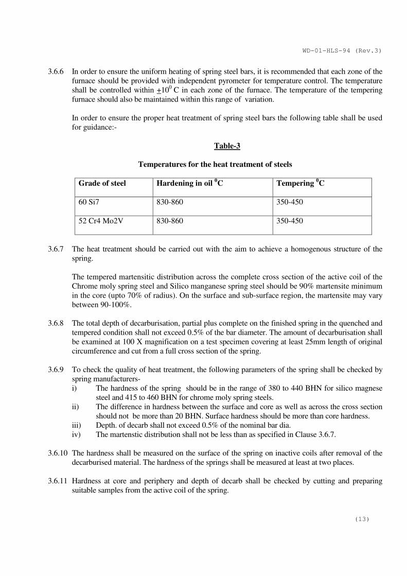
Table-3
Temperatures for the heat treatment of steels
Grade of steel Hardening in oil 0C Tempering
0C
60 Si7 830-860 350-450
52 Cr4 Mo2V 830-860 350-450
3.6.7 The heat treatment should be carried out with the aim to achieve a homogenous structure of the
spring.
The tempered martensitic distribution across the complete cross section of the active coil of the
Chrome moly spring steel and Silico manganese spring steel should be 90% martensite minimum
in the core (upto 70% of radius). On the surface and sub-surface region, the martensite may vary
between 90-100%.
3.6.8 The total depth of decarburisation, partial plus complete on the finished spring in the quenched and
tempered condition shall not exceed 0.5% of the bar diameter. The amount of decarburisation shall
be examined at 100 X magnification on a test specimen covering at least 25mm length of original
circumference and cut from a full cross section of the spring.
3.6.9 To check the quality of heat treatment, the following parameters of the spring shall be checked by
spring manufacturers-
i) The hardness of the spring should be in the range of 380 to 440 BHN for silico magnese
steel and 415 to 460 BHN for chrome moly spring steels.
ii) The difference in hardness between the surface and core as well as across the cross section
should not be more than 20 BHN. Surface hardness should be more than core hardness.
iii) Depth. of decarb shall not exceed 0.5% of the nominal bar dia.
iv) The martenstic distribution shall not be less than as specified in Clause 3.6.7.
3.6.10 The hardness shall be measured on the surface of the spring on inactive coils after removal of the
decarburised material. The hardness of the springs shall be measured at least at two places.
3.6.11 Hardness at core and periphery and depth of decarb shall be checked by cutting and preparing
suitable samples from the active coil of the spring.
WD-01-HLS-94 (Rev.3)
(14)
3.7 End Grinding
Both the end faces of the spring should be ground to ensure square seating of the spring. The sharp
edges of the ends should be ground and have no burrs. The actual ground end surface shall be at
least 75% of the mean coil circumference of the spring and the ends should not bite the effective
coil. The end faces of the spring should not have blue marks due to end grinding as the same leads
to temper brittleness.
3.8 Scragging
Each and every spring should be scragged 3 times in quick succession. Scragging load/height
should be as laid down in the drawing. In case there is no indication in the drawing, the spring
should be scragged home. The scragging load in such cases should not exceed 1.5 times the
theoretical axial load, corresponding to block length.
3.8.1 Long duration scragging is to be introduced as a process check at regular intervals and necessary
documentation of the test results are to be maintained. For long duration scragging, the spring shall
be compressed three times holding it at the home load for 2 minutes in the first two strokes and for
48 hours at the last stroke.
3.8.2 The scragged spring should not show further permanent set on subsequent loading.
3.8.3 Type testing of newly designed springs (Fatigue Testing) shall be done if mentioned on drawing.
The test scheme shall be provided by the concerned Design Directorate.
3.9 Crack Detection
100% of the springs shall be tested for crack detection in accordance with Appendix 'B' of
Specification UIC-822, for both longitudinal and transverse crack. After crack detection, the spring
shall suitably be demagnetised.
3.10 Shot Peening
All the springs shall be shot peened in a continuous type shot peening machine, preferably with
self- sieving arrangement in accordance with IS:7001 to improve fatigue life of the spring. During
shot peening it should be ensured that the springs are shot peened uniformly over the entire area of
the springs. The intensity and coverage should be checked with the help of almen strip in
accordance with IS: 7001. Almen intensity should be checked minimum two times per shift of
production. The minimum coverage (When checked visually) should be 90% and intensity when
checked with Almen strip Type- A in accordance with IS: 7001 should be minimum 0.40 mm
(0.016").
3.11 Grouping and Colour Coding:
100% of the springs shall be compressed with specified working load and the loaded height of the
individual springs shall be measured in spring testing machine. The working height of the spring
shall be within the tolerances specified in the drawing. The springs shall be grouped and painted
with suitable colour code for identification as specified in the drawing/tender document. Any
spring which is found to be defective or which does not confirm to the test and other requirements
of the specification should be rejected.
WD-01-HLS-94 (Rev.3)
(15)
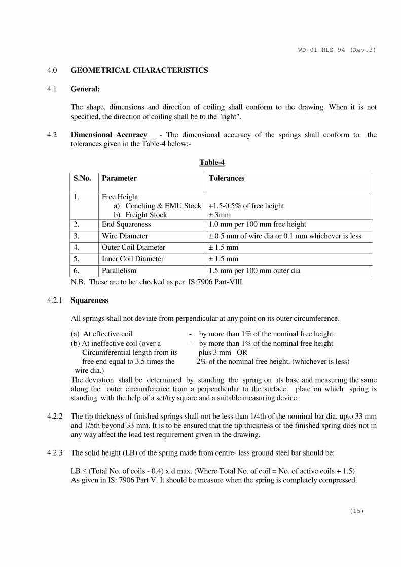
4.0 GEOMETRICAL CHARACTERISTICS
4.1 General:
The shape, dimensions and direction of coiling shall conform to the drawing. When it is not
specified, the direction of coiling shall be to the "right".
4.2 Dimensional Accuracy - The dimensional accuracy of the springs shall conform to the
tolerances given in the Table-4 below:-
Table-4
S.No.
Parameter Tolerances
1. Free Height
a) Coaching & EMU Stock
b) Freight Stock
+1.5-0.5% of free height
± 3mm
2. End Squareness 1.0 mm per 100 mm free height
3. Wire Diameter ± 0.5 mm of wire dia or 0.1 mm whichever is less
4. Outer Coil Diameter ± 1.5 mm
5. Inner Coil Diameter ± 1.5 mm
6. Parallelism 1.5 mm per 100 mm outer dia
N.B. These are to be checked as per IS:7906 Part-VIII.
4.2.1 Squareness
All springs shall not deviate from perpendicular at any point on its outer circumference.
(a) At effective coil - by more than 1% of the nominal free height.
(b) At ineffective coil (over a - by more than 1% of the nominal free height
Circumferential length from its plus 3 mm OR
free end equal to 3.5 times the 2% of the nominal free height. (whichever is less)
wire dia.)
The deviation shall be determined by standing the spring on its base and measuring the same
along the outer circumference from a perpendicular to the surface plate on which spring is
standing with the help of a set/try square and a suitable measuring device.
4.2.2 The tip thickness of finished springs shall not be less than 1/4th of the nominal bar dia. upto 33 mm
and 1/5th beyond 33 mm. It is to be ensured that the tip thickness of the finished spring does not in
any way affect the load test requirement given in the drawing.
4.2.3 The solid height (LB) of the spring made from centre- less ground steel bar should be:
LB ≤ (Total No. of coils - 0.4) x d max. (Where Total No. of coil = No. of active coils + 1.5)
As given in IS: 7906 Part V. It should be measure when the spring is completely compressed.
WD-01-HLS-94 (Rev.3)
(16)
4.3 PITCHING - The Pitch of the coils shall be sufficiently uniform so that when the spring is
compressed to a height representing a deflection of 85% of nominal free to solid deflection, none
of the coils shall be in contact with one another, excluding the inactive end coils. It should be
ensured that as and when contact between the ineffective coils and the adjacent effective coils is
made, it should occur over a minimum length of 1/3rd of the mean coil dia. of the spring.
Under 85% deflection the maximum spacing between any two adjacent active coils shall not
exceed 40% of the nominal free coil spacing. The nominal free coil spacing is equivalent to the
specified total travel divided by the number of active turns. When the spring is designed to provide
lateral stiffness also, the above requirement of not exceeding 40% do not apply.
4.4 Lateral Deflection - When prescribed on the drawing, the lateral deflection characteristics shall be
checked by means of suitable device approved by the Purchaser.
5.0 LOAD TESTING
5.1 The spring shall be tested on a spring testing machine, as per load chart of the drawing. Each load
is maintained till the load is stabilised after which the corresponding height of the spring (under
load) is determined. The tolerance on the height of the spring under static load shall be as indicated
on the drawing or in the absence thereof, should not be more than ±3% design deflection value at
nominal working load and + 6% / -4% of design deflection value at other loads.
5.2.1 The spring stiffness shall be within + 3.4% upto bar dia.18mm and + 5% beyond 18 mm of the
design value. It should be determined by dividing the difference of load between 70% and 30% of
the designed home load by the difference of measured deflection between these two loads.
6.0 FATIGUE TESTING
The purpose of fatigue testing of hot coiled helical spring is to ascertain that the springs meet the
expected life during service. Fatigue testing of the springs shall be done during the initial approval
of a manufacturer for the spring by RDSO. It shall subsequently be done in first lot of each type of
spring supplied in every alternate year.
6.1 Test Setup –
The test setup primarily consists of a fatigue test machine and spring fixture. The machine
should have the facility to record deflection as well as load simultaneously. The springs can be
tested as a single spring or together with other spring in the fixture. The fixture should be
designed in such a way that both the ends of the spring remain parallel and perpendicular to the
loading direction. The end plates of the fixture should not allow spring to move sideways.
6.2 Test and Measurements
6.2.1 All spring samples should be marked before commencing the fatigue test.
6.2.2 The following parameters of the springs are to be measured before and after the fatigue test.
a) Free height of spring.
b) Actual load at static (working) height as per RDSO drawing.
c) Load verses height graph from free height to static height and free height to solid height.
WD-01-HLS-94 (Rev.3)
(17)
6.2.3 The fatigue test is to be displacement controlled from the static height of the spring. The
displacement of the test is + 30% of the static deflection of the spring.
6.2.4. The frequency of the test should be maximum obtainable safely as per actual displacement and
fatigue test machine capability. (But not less than 2Hz). The frequency at which spring is fatigue
tested should be recorded.
6.2.5. The springs shall be fatigue tested for two million cycles. Test set up should be monitored at
least once a day to ensure the setup is performing well. Actual height of spring at static load
should be recorded at every 2.5 lakh cycles.
6.2.6. After completion of fatigue testing, spring shall be checked by magnaflux testing for any
crack/indication of cracks.
6.3 Test Report
The test report shall be furnished that includes the data of spring before fatigue test, during
fatigue test and after the fatigue test. It should also include the failure analysis of the spring
failed during fatigue test.
7.0 HANDLING OF SPRINGS
The springs should be properly handled during manufacture. Springs should not be thrown on floor
or roll at any stage of manufacture to avoid any damage to the springs.
8.0 INSPECTION OF HELICAL SPRINGS
8.1 General
The material to be used in the manufacture of springs and the finished springs shall be subjected to
inspection by the Purchaser’s Inspector to ascertain the quality of the material and the
characteristics of the finished springs. He shall be permitted to carryout all the checks necessary to
ensure that all the conditions specified for the manufacture of the material and of the springs are
adhered to.
8.1.1 The Inspecting Officer or the Purchaser shall have free access to the works of the manufacturer at
all reasonable times. He shall be at liberty to inspect the manufacture of the springs at any stage
and to reject any material that does not conform to the Specification.
8.1.2 The manufacturer shall provide the Inspecting Officer, free of charge, all reasonable facilities by
way of labour, appliances and necessary assistance for such tests as may be carried out on his
premises in accordance with this specification. Where facilities are not available at manufacturer's
works, the Manufacturer shall bear the cost of carrying out such tests elsewhere.
8.1.3 The finished spring shall be presented for inspection in batches of not more than 1000. The
springs shall be presented for inspection after the application of the protective coating against
corrosion. The Inspector is free to have the sample springs shot peened for various tests.
WD-01-HLS-94 (Rev.3)
(18)
8.2 Stage-I(Raw Material)- Shall be done as per Clauses 2.3, 2.4 and 2.5 of this Specification.
8.3 Stage-II During Manufacture
The manufacturer shall carryout all necessary checking of all the centreless ground bars for
minimum material removal surface finish, crack detection, the depth of decarburisation of springs
during the heat treatment, surface hardness etc. and maintain records for each tests as per QAP.
These records must be presented to the Inspecting official during the purchase inspection.
8.4 Stage-III Finished Spring
For each batch of finished springs or part thereof presented for inspection the following tests shall
be made out of springs selected at random by the Inspecting official:-
8.4.1 Checking of records for quality verification of raw materials used by the firm.
The inspecting official shall check the records and ensure that verification has been done by the
firm on the spring material used before commencing the manufacture of springs as per checks
specified in this specification.
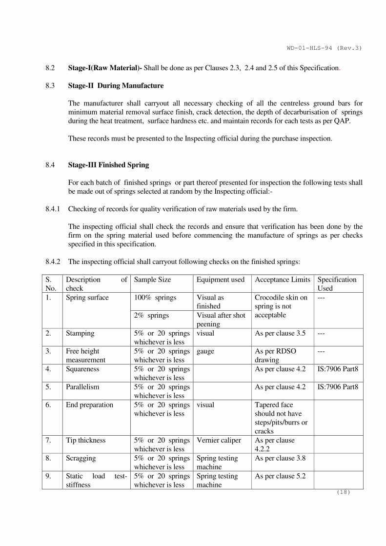
8.4.2 The inspecting official shall carryout following checks on the finished springs:
S.
No.
Description of
check
Sample Size Equipment used Acceptance Limits Specification
Used
1. Spring surface 100% springs Visual as
finished
Crocodile skin on
spring is not
acceptable
---
2% springs Visual after shot
peening
2. Stamping 5% or 20 springs
whichever is less
visual As per clause 3.5 ---
3. Free height
measurement
5% or 20 springs
whichever is less
gauge As per RDSO
drawing
---
4. Squareness 5% or 20 springs
whichever is less
As per clause 4.2 IS:7906 Part8
5. Parallelism 5% or 20 springs
whichever is less
As per clause 4.2 IS:7906 Part8
6. End preparation 5% or 20 springs
whichever is less
visual Tapered face
should not have
steps/pits/burrs or
cracks
7. Tip thickness 5% or 20 springs
whichever is less
Vernier caliper As per clause
4.2.2
8. Scragging 5% or 20 springs
whichever is less
Spring testing
machine
As per clause 3.8
9. Static load test-
stiffness
5% or 20 springs
whichever is less
Spring testing
machine
As per clause 5.2
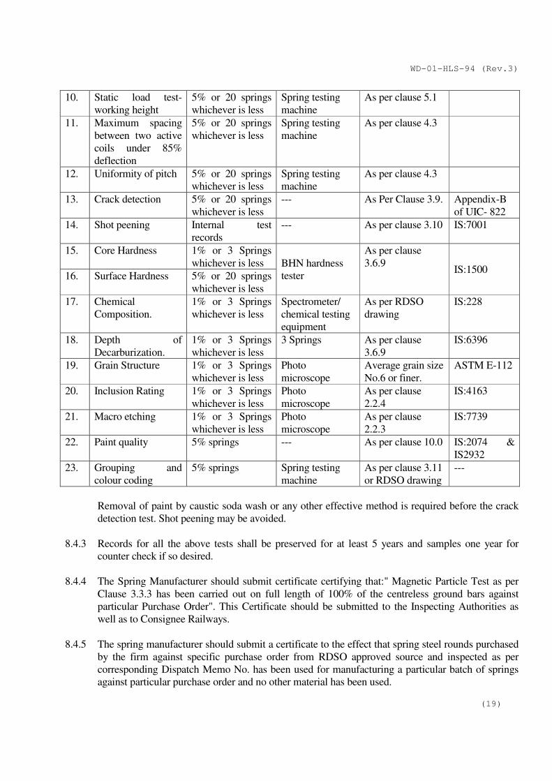
WD-01-HLS-94 (Rev.3)
(19)
10. Static load test-
working height
5% or 20 springs
whichever is less
Spring testing
machine
As per clause 5.1
11. Maximum spacing
between two active
coils under 85%
deflection
5% or 20 springs
whichever is less
Spring testing
machine
As per clause 4.3
12. Uniformity of pitch 5% or 20 springs
whichever is less
Spring testing
machine
As per clause 4.3
13. Crack detection 5% or 20 springs
whichever is less
--- As Per Clause 3.9. Appendix-B
of UIC- 822
14. Shot peening Internal test
records
--- As per clause 3.10 IS:7001
15. Core Hardness 1% or 3 Springs
whichever is less BHN hardness
tester
As per clause
3.6.9 IS:1500
16. Surface Hardness 5% or 20 springs
whichever is less
17. Chemical
Composition.
1% or 3 Springs
whichever is less
Spectrometer/
chemical testing
equipment
As per RDSO
drawing
IS:228
18. Depth of
Decarburization.
1% or 3 Springs
whichever is less
3 Springs As per clause
3.6.9
IS:6396
19. Grain Structure 1% or 3 Springs
whichever is less
Photo
microscope
Average grain size
No.6 or finer.
ASTM E-112
20. Inclusion Rating 1% or 3 Springs
whichever is less
Photo
microscope
As per clause
2.2.4
IS:4163
21. Macro etching 1% or 3 Springs
whichever is less
Photo
microscope
As per clause
2.2.3
IS:7739
22. Paint quality 5% springs --- As per clause 10.0 IS:2074 &
IS2932
23. Grouping and
colour coding
5% springs Spring testing
machine
As per clause 3.11
or RDSO drawing
---
Removal of paint by caustic soda wash or any other effective method is required before the crack
detection test. Shot peening may be avoided.
8.4.3 Records for all the above tests shall be preserved for at least 5 years and samples one year for
counter check if so desired.
8.4.4 The Spring Manufacturer should submit certificate certifying that:" Magnetic Particle Test as per
Clause 3.3.3 has been carried out on full length of 100% of the centreless ground bars against
particular Purchase Order". This Certificate should be submitted to the Inspecting Authorities as
well as to Consignee Railways.
8.4.5 The spring manufacturer should submit a certificate to the effect that spring steel rounds purchased
by the firm against specific purchase order from RDSO approved source and inspected as per
corresponding Dispatch Memo No. has been used for manufacturing a particular batch of springs
against particular purchase order and no other material has been used.
WD-01-HLS-94 (Rev.3)
(20)
9.0 REJECTION
9.1 During the sampling inspection if any spring is found to be defective, another sample of twice the
size of the earlier sample should be selected for inspection. If there is any rejection in this sample,
the whole batch stands rejected. After inspection, the Inspecting Officer shall affix his stamp/seal
on each spring as a token of the spring having been passed by him.
9.2 The rejected springs shall be either gas cut or cross marked on one of the effective coils with the
help of grinding cutter so that the rejected springs do not get mixed up with good springs at any
stages. This should be done in the presence of the Inspecting Officer immediately after the spring
batch has been rejected.
10.0 PROTECTION AGAINST CORROSION
Finished springs shall be given one coat of zinc chromate primer to IS:2074 followed by one coat
of Black Synthetic Enamel to IS:2932 or as specified in the drawing, for protection against
corrosion.
11.0 PACKING OF SPRINGS FOR TRANSPORTATION
The springs are one of the most stressed components of the vehicle suspension. Hence, they
should be suitably packed to ensure their safe transportation.
For packing the springs, a seamless polythene sleeve of minimum 500 micron thickness and
appropriate diameter (matching the finished spring bar diameter) should be slide on the finished
spring wire/bar and sealed from both the ends. The whole spring bar should then be wrapped
with a thick jute strip such that no portion of the spring is exposed open. Transportation of
spring in wooden boxes / pallets shall be preferable. Any other precaution in packing as may be
deemed fit for safe transportation should be taken by the spring manufacturer to avoid damage
during transportation.
12.0 GUARANTEE FOR SPRINGS
The spring shall be guaranteed for a period of five years against any defect imputable to
manufacture from the date of delivery of the spring, as indicated by stamping of month and year of
manufacture on the tapered ends of the spring vide Para 3.5.2 of this Specification or for a period of
four years from the date of actual fitment on Main Line Coach/EMU Stock/Freight Stock
whichever is earlier. Springs that show, during the guarantee period, defects making them either
unfit for service or reduce the effectiveness of the life and which defects may be imputable to
manufacture, shall be replaced free of cost by the Manufacturers.
WD-01-HLS-94 (Rev.3)
(21)
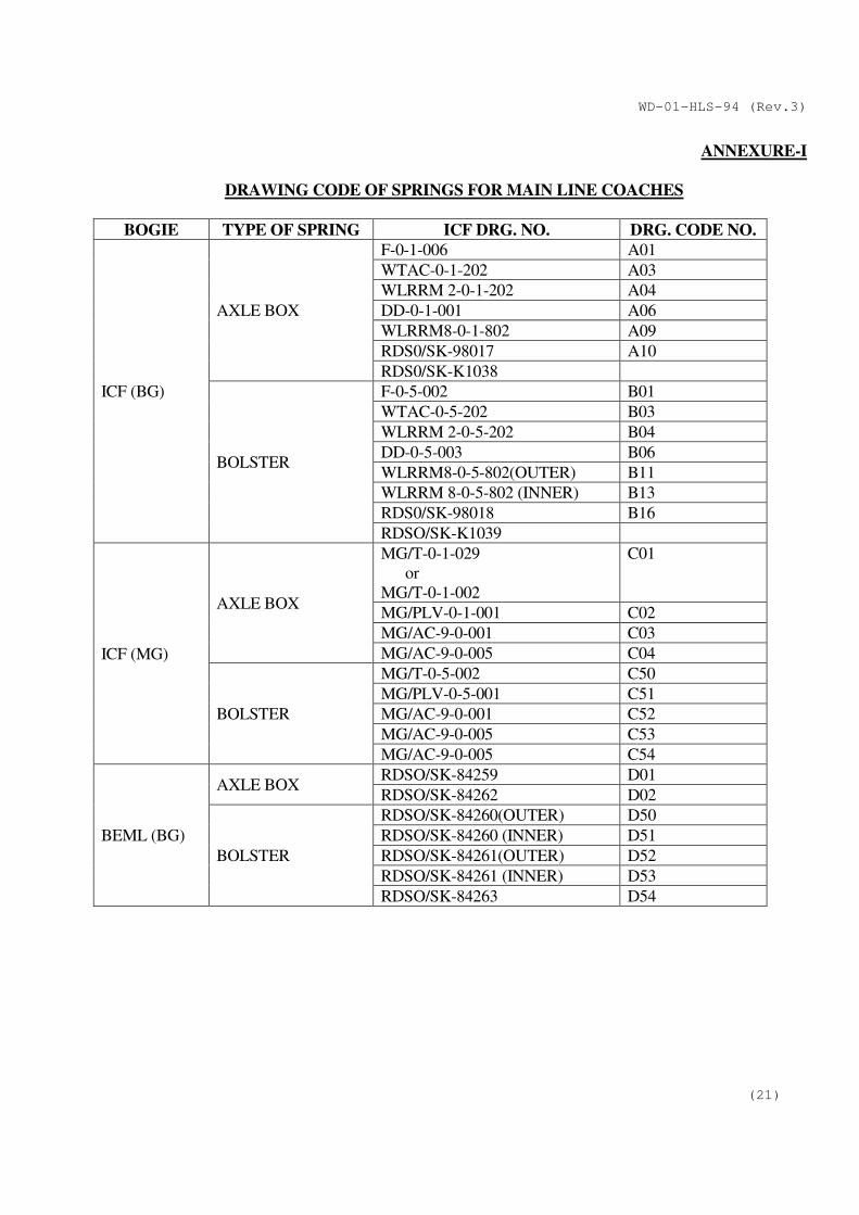
ANNEXURE-I
DRAWING CODE OF SPRINGS FOR MAIN LINE COACHES
BOGIE TYPE OF SPRING ICF DRG. NO. DRG. CODE NO.
ICF (BG)
AXLE BOX
F-0-1-006 A01
WTAC-0-1-202 A03
WLRRM 2-0-1-202 A04
DD-0-1-001 A06
WLRRM8-0-1-802 A09
RDS0/SK-98017 A10
RDS0/SK-K1038
BOLSTER
F-0-5-002 B01
WTAC-0-5-202 B03
WLRRM 2-0-5-202 B04
DD-0-5-003 B06
WLRRM8-0-5-802(OUTER) B11
WLRRM 8-0-5-802 (INNER) B13
RDS0/SK-98018 B16
RDSO/SK-K1039
ICF (MG)
AXLE BOX
MG/T-0-1-029
or
MG/T-0-1-002
C01
MG/PLV-0-1-001 C02
MG/AC-9-0-001 C03
MG/AC-9-0-005 C04
BOLSTER
MG/T-0-5-002 C50
MG/PLV-0-5-001 C51
MG/AC-9-0-001 C52
MG/AC-9-0-005 C53
MG/AC-9-0-005 C54
BEML (BG)
AXLE BOX RDSO/SK-84259 D01
RDSO/SK-84262 D02
BOLSTER
RDSO/SK-84260(OUTER) D50
RDSO/SK-84260 (INNER) D51
RDSO/SK-84261(OUTER) D52
RDSO/SK-84261 (INNER) D53
RDSO/SK-84263 D54
WD-01-HLS-94 (Rev.3)
(22)
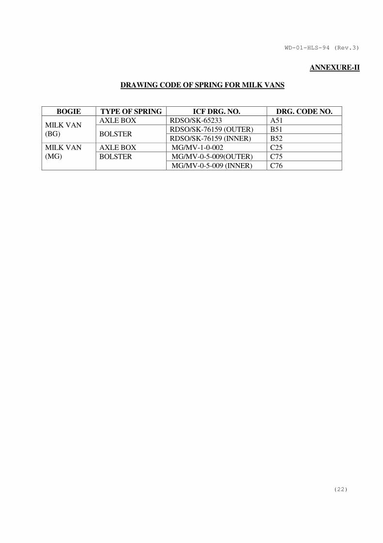
ANNEXURE-II
DRAWING CODE OF SPRING FOR MILK VANS
BOGIE TYPE OF SPRING ICF DRG. NO. DRG. CODE NO.
MILK VAN
(BG)
AXLE BOX RDSO/SK-65233 A51
BOLSTER RDSO/SK-76159 (OUTER) B51
RDSO/SK-76159 (INNER) B52
MILK VAN
(MG)
AXLE BOX MG/MV-1-0-002 C25
BOLSTER MG/MV-0-5-009(OUTER) C75
MG/MV-0-5-009 (INNER) C76
WD-01-HLS-94 (Rev.3)
(23)
ANNEXURE-III
DRAWING CODE OF SPRING FOR EMU COACHES
S.No. Drg. No. Stock Type No. of/
coach
Code
1 DC/EMU-0-1-002 DC/EMU/TC, EMU/TC,
DMU/TC & DTC,
MEMU/TC
Primary 16 H25
2 DC/EMU/M-0-1-002 DC/EMU/M Primary 16 H06
3 DC/EMU-0-5-005/2 DC/EMU/TC, EMU/TC Secondary (outer) 8 H60
4 DC/EMU-0-5-005/1 DC/EMU/TC, EMU/TC Secondary (inner) 8 H61
5 DC/EMU/M-0-5-008/1 DC/EMU/M Secondary (outer) 8 K46
6 DC/EMU/M-0-5-008/2 DC/EMU/M Secondary (inner) 8 K45
7 DC/EMU/H2-0-5-202/1 DC/EMU/TC (HCC) Secondary (outer) 8 H66
8 DC/EMU/H2-0-5-202/2 DC/EMU/TC (HCC) Secondary (inner) 8 H65
9 DC/EMU-0-5-008/2 DC/EMU/TC Secondary (outer) 8 H67
10 DC/EMU-0-5-008/1 DC/EMU/TC Secondary (Inner) 8 H68
11 DC/EMU2-0-1-203 DC/EMU/T/ASR,
AC/EMU/C/ASR,
AC EMU/D/ASR
Primary 16 H26
12 DC/EMU/M2-0-1-203 DC/EMU/M2, AC/ EMU
/M/ASR, AC/DC
EMU/M2, AC/DC
EMU/C2, AC/DC
EMU/D2, AC/DC
EMU/D2/HC,
DC/EMU/M, DC/EMU
M/ASR
Primary 16 H07
13 EMU/M-0-5-049/1 EMU/M Secondary (outer) 8 K41
14 EMU/M-0-5-049/2 EMU/M Secondary (inner) 8 K40
15 EMU/M-0-1-024 EMU/M, DHMU/DPC,
DHTC/SAN, ARTV
Primary 16 K01
16 EMU/M-0-5-050/1 EMU/M Secondary (outer) 8 K42
17 EMU/M-0-5-050/2 EMU/M Secondary (inner) 8 K43
18 EMU/M-0-5-004/1 EMU/M, DD Secondary (outer) 8 K48
19 EMU/M-0-5-004/2 EMU/M, DD Secondary (inner) 8 K47
20 J9A/B 2446 Jessop/EMU/TC Primary 16 J25
21 J7A/B 1923/A Jessop/EMU/TC Secondary (outer) 8 J66
22 J7A/B 1923/B Jessop/EMU/TC Secondary (inner) 8 J65
23 J7B/B 1981A Jessop/EMU/MC Secondary (outer) 8 J46
24 J7B/B 1981/B Jessop/EMU/MC Secondary (inner) 8 J45
25 J9B/B 2498 Jessop/EMU/MC Primary 16 J06
26 MEMU/TC-0-5-006/1 MEMU/TC & DTC &
DMU/TC & DTC
Secondary (outer) 8 G57
27 MEMU/TC-0-5-006/2 MEMU/TC & DTC &
DMU/TC & DTC
Secondary (inner) 8 G58
WD-01-HLS-94 (Rev.3)
(24)
28 MEMU/DMC-0-1-002,
RDSO/SK-92006
MEMU/DMC Primary 16 G01
29 MEMU/DMC-0-5-02/1,
RDSO SK-92007
MEMU/DMC Secondary (outer) 8 G51
30 MEMU/DMC-0-5-
002/2 RDSO/SK-92007
MEMU/DMC Secondary (inner) 8 G52
31 MEMU/TC2-0-1-201 MEMU/TC Primary 16 G07
32 MEMU/TC2-0-5-201/1 MEMU/TC Secondary (outer) 8 G60
33 MEMU/TC2-0-5-201/2 MEMU/TC Secondary (inner) 8 G59
34 MEMU/DMC-0-1-001 MEMU/DMC Primary 16 G02
35 DMU/DPC-0-1-001 DMU/DPC (700hp) Primary 16 G13
36 DMU/DPC-0-5-004/1 DMU/DPC (700hp) Secondary (inner) 8 G63
37 DMU/DPC-0-5-004/2 DMU/DPC (700hp) Secondary (outer) 8 G64
38 DMU/DPC5-0-1-501 HP DMU/DPC Primary 16 G14
39 DETC-0-5-001/1 DETC, DHMU/DPC Secondary (inner) 8 G87
40 DETC-0-5-001/2 DETC, DHMU/DPC Secondary (outer) 8 G88
41 MG/EMU-0-1-005 MG/EMU/TC Primary 16 L25
42 MG/EMU/M-0-1-002 MG/EMU/M Primary 16 L06
43 MG/EMU/M2-0-1-203 MG/EMU/M Primary 16 L07
44 MG/EMU-0-5-002 MG/EMU/TC Secondary 8 L65
45 MG/EMU/M-0-5-002 MG/EMU/M2 Secondary 8 L45
46 MG/EMU/M2-0-5-203 MG/EMU/M Secondary 8 L46
47 MG/EMU/M2-0-5-
204/1
MG/EMU/M2 Secondary(outer) 8 L48
48 MG/EMU/M2-0-5-
204/2
MG/EMU/M2 Secondary(inner) 8 L47
WD-01-HLS-94 (Rev.3)
(25)
ANNEXURE-IV
DRAWINGS CODES OF SPRINGS FOR CONTAINER FLATS
S.N. TYPE OF BOGIE LOCATION OF
SPRING
TYPE DRG. NO. CODE
1 LCCF-20( C) BOLSTER OUTER CONTR-9404/S-7 ITEM-1 CF01
2 LCCF-20( C) BOLSTER INNER CONTR-9404/S-7 ITEM-2 CF02
3 LCCF-20( C) BOLSTER SNUBBER CONTR-9404/S-7 ITEM-3 CF03
4 LCCF-20( C) SIDE BEARER CONTR-9404/S-15 ITEM-3 CF04
WD-01-HLS-94 (Rev.3)
(26)
ANNEXURE-V
BG,MG & NG FREIGHT STOCK COIL SPRINGS DRAWING CODES
B.G.
S.N. TYPE OF BOGIE LOCATION OF
SPRING TYPE DRG. NO. COD
E
1
CASNUB BOGIE BOLSTER
OUTER WD-83069-S/1 ITEM-1 X01
2 INNER WD-83069-S/1 ITEM-2 X02
3 SNUBBER WD-83069-S/1 ITEM-3 X03
4 16.25t CAST STEEL/
DIA MOND FRAME
BOGIE
BOLSTER OUTER W/BE-606 ITEM-1 X04
5 INNER W/BE-607 ITEM-2 X05
6
DRAFT
BUFFER
SPRING
OUTER W/BD-357 R01
7 INNER W/BD-365 R02
8 OUTER W/BD-366 R03
9 INNER W/BD-373 R04
10 LH W/BD-409 R05
11 RH W/BD-457 R06
12 RECOIL
SPRING
W/BD-430 R07
13 OUTER W/BD-372 R08
14 OUTER W/BD-375 R09
15 INNER W/BD-377 R10
16 OUTER W/BD-376 R11
17 FRICTION
DRAFT SPG.
W/BD-463 R12
18 W/BD-464 R13
19 CASNUB –22 HS
BOGIE BOLSTER
OUTER WD-92058-S/5 ITEM-1 X06
20 INNER WD-92058-S/5 ITEM-2 X07
21 SNUBBER WD-92058-S/5 ITEM-3 X08
22
IRF-102 BOGIE
BOLSTER
OUTER SK.VF-059 ITEM-1 X10
23 INNER SK.VF-059 ITEM-2 X11
24 SNUBBER SK.VF-059 ITEM-3 X12
25 SIDE BEARER
OUTER SPG. SK.VF-061 ITEM-13 X13
26 INNER SPG. SK.VF-061 ITEM-14 X14
27 CASNUB 22 HS
BOGIE / IRF-108 HS
BOGIE
SIDE BEARER
OUTER WD-92093-S/1 ITEM- 9 X15
28 INNER WD-92093-S/1 ITEM-10 X16
29 IRF-106 HS BOGIE BOLSTER
OUTER WD-97030-S/8 ITEM-1 X17
30 SNUBBER WD-97030-S/8 ITEM-2 X18
31
IRF-108 HS BOGIE BOLSTER
OUTER WD-98014-S/3 ITEM-1 X19
32 INNER WD-98014-S/3 ITEM-2 X20
33 SNUBBER WD-98014-S/3 ITEM-3 X21
34 BVZI
BOLSTER - WD-00039-S/11 ITEM-5 X24
35 AXLE BOX - WD-00039-S/11 ITEM -4 T01
36 CASNUB 22 HS
(MOD-I) BOGIE BOLSTER
OUTER WD-04017-S/4 ITEM-1 X25
37 INNER WD-04017-S/4 ITEM-2 X26
38 SNUBBER WD-04017-S/4 ITEM-3 X27
WD-01-HLS-94 (Rev.3)
(27)
ANNEXURE-V
BG,MG & NG FREIGHT STOCK COIL SPRINGS DRAWING CODES
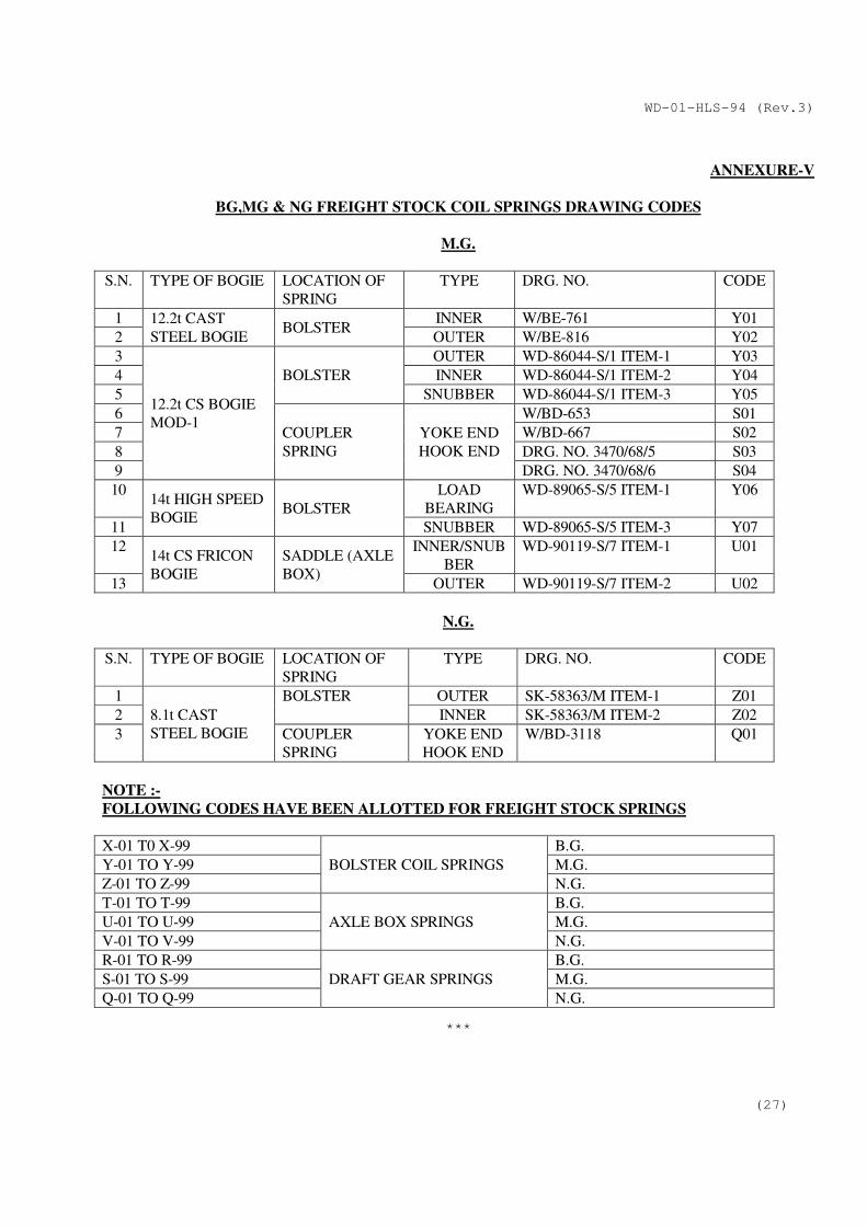
M.G.
S.N. TYPE OF BOGIE LOCATION OF
SPRING
TYPE DRG. NO. CODE
1 12.2t CAST
STEEL BOGIE BOLSTER
INNER W/BE-761 Y01
2 OUTER W/BE-816 Y02
3
12.2t CS BOGIE
MOD-1
BOLSTER
OUTER WD-86044-S/1 ITEM-1 Y03
4 INNER WD-86044-S/1 ITEM-2 Y04
5 SNUBBER WD-86044-S/1 ITEM-3 Y05
6
COUPLER
SPRING
YOKE END
HOOK END
W/BD-653 S01
7 W/BD-667 S02
8 DRG. NO. 3470/68/5 S03
9 DRG. NO. 3470/68/6 S04
10 14t HIGH SPEED
BOGIE BOLSTER
LOAD
BEARING
WD-89065-S/5 ITEM-1 Y06
11 SNUBBER WD-89065-S/5 ITEM-3 Y07
12 14t CS FRICON
BOGIE
SADDLE (AXLE
BOX)
INNER/SNUB
BER
WD-90119-S/7 ITEM-1 U01
13 OUTER WD-90119-S/7 ITEM-2 U02
N.G.
S.N. TYPE OF BOGIE LOCATION OF
SPRING
TYPE DRG. NO. CODE
1
8.1t CAST
STEEL BOGIE
BOLSTER OUTER SK-58363/M ITEM-1 Z01
2 INNER SK-58363/M ITEM-2 Z02
3 COUPLER
SPRING
YOKE END
HOOK END
W/BD-3118 Q01
NOTE :-
FOLLOWING CODES HAVE BEEN ALLOTTED FOR FREIGHT STOCK SPRINGS
X-01 T0 X-99
BOLSTER COIL SPRINGS
B.G.
Y-01 TO Y-99 M.G.
Z-01 TO Z-99 N.G.
T-01 TO T-99
AXLE BOX SPRINGS
B.G.
U-01 TO U-99 M.G.
V-01 TO V-99 N.G.
R-01 TO R-99
DRAFT GEAR SPRINGS
B.G.
S-01 TO S-99 M.G.
Q-01 TO Q-99 N.G.
***