Embed Size (px)
Citation preview


POWERTEK MC140 Multifunction Calibrator
Specification v15 2
Specification Uncertainties include long-term stability, temperature coefficient, linearity, load and line regulation and the traceability of factory and National calibration standards. Specified accuracy is valid after one hour warm up in temperature range 23 ± 2
oC. Specified accuracy is one year accuracy.
Calibrator Voltage Summary range DCV: 0 µV - 1000 V Summary range ACV: 1 mV – 1000 V Internal ranges: 20 mV, 200 mV, 2 V, 20 V, 240 V, 1000 V Frequency range: 20 Hz to 50 kHz bellow 20 V
20 Hz to 10 kHz bellow 200 V 20 Hz to 1000 Hz bellow 1000 V Frequency uncertainty: 0.005 % DCV uncertainty
range % value + % range max. current mA
0 µV - 20 mV 0.03 + 0.0 + 10 µV 5 20 mV - 200 mV 0.01 + 0.0 + 15 µV 5
200 mV - 2 V 0.003 + 0.0008 30 2 V - 20 V 0.003 + 0.0005 30
20 V – 240 V 0.003 + 0.0005 30 240 V - 1000 V 0.005 + 0.005 2
*2 value of the range for uncertainty calculation is 200 V
ACV uncertainty range % value + % range max. current mA % value + % range max. current mA
20 Hz - 10 kHz 20 Hz - 10 kHz 10 kHz - 50 kHz 10 kHz - 50 kHz
1 mV - 20 mV 0.2 + 0.05 + 20 µV 5 0.20 + 0.10 + 20 µV 5 20 mV - 200 mV 0.1 + 0.03+ 20 µV 5 0.15 + 0.05 + 20 µV 5
200 mV - 2 V 0.025 + 0.005 30 0.05 + 0.01 10 2 V - 20 V 0.025 + 0.005 30 0.05 + 0.03 10
20 V – 240 V *2 0.025 + 0.010 30 - - 240 V – 1000 V 0.03 + 0.02 *1 2 - -
*1 valid for f < 1000 Hz *2 value of the range for uncertainty calculation is 200 V, in the range 200 to 240 V is frequency limited to 1 kHz.
range % value+ % range max. current mA
50 kHz - 100 kHz 50 kHz - 100 kHz
1 mV - 20 mV 1.0 + 0.10 + 20 µV 3 20 mV - 200 mV 0.3 + 0.05 + 20 µV 3
200 mV - 2 V 0.2 + 0.05 5 2 V - 20 V 0.2 + 0.05 5
20 V – 240 V - - 240 V – 1000 V - -
Auxiliary parameters
range 20mV 200mV 2V 20V 200V 1000V THD*2 *3 0,05% + 200 uV 0,05% + 300 uV 0,05% 0,05% 0,05% 0,2%
output impedance < 10 mΩ < 10 mΩ < 10 mΩ < 10 mΩ < 100 mΩ < 100 mΩ maximal capacitance
load 500 pF 500 pF 500 pF 500 pF 300 pF 150 pF
*2 parameter includes non-linear distortion and non-harmonic noise *3 valid for frequencies to 10 kHz

POWERTEK MC140 Multifunction Calibrator
Specification v15 3
Function Shape Voltage range: 1 mV to 200 V Wave form: square, positive, negative, symmetrical, ramp A, ramp B, triangle
truncated sin with THD 13,45 % Peak value uncertainty: 0.3 % + 50 uV Displayed values: peak, effective Minimum frequency for squarewave signals is 0.1 Hz, for all others 20 Hz. Current Summary range DCI: 0 - 20 A (with adapter 130-50 to 500 A) Summary range ACI: 1 µA - 20 A (with adapter 130-50 to 500 A) Internal ranges: 200 µA, 2 mA, 20 mA, 200 mA, 2 A, 20 A Frequency range: 20 Hz to 5 kHz bellow 200 mA 20 Hz to 1000 Hz bellow 20 A Frequency uncertainty: 0.005 %
DCI uncertainty
range % value + % range max. voltage V
0 µA - 200 µA 0.05 + 0.0 + 20 nA 3 200 µA - 2 mA 0.02 + 0.005 3 2 mA - 20 mA 0.01 + 0.003 3
20 mA - 200 mA 0.01 + 0.003 3 200 mA - 2 A 0.015 + 0.005 3
2 A - 20 A 0.02 + 0.010 1.5
ACI uncertainty
range % value + % range max voltage Vef % value + % range max voltage Vef
20 Hz - 1 kHz 1 kHz – 5 kHz
1 µA - 200 µA 0.15 + 0.0 + 20 nA 3 0.30 + 0.10 + 20 nA 3 200 µA - 2 mA 0.07 + 0.01 3 0.20 + 0.05 3 2 mA - 20 mA 0.05 + 0.005 3 0.20 + 0.05 3
20 mA – 200 mA 0.05 + 0.005 3 0.20 + 0.05 3 200 mA – 2 A 0.05 + 0.005 3 - - - -
2 A - 20 A 0.10 + 0.03 1.5 - - - -
range % value + % range max voltage Vef
5 kHz – 10 kHz
1 µA - 200 µA - - - - 200 µA - 2 mA 0.50 + 0.07 2 2 mA - 20 mA 0.50 + 0.07 2
20 mA - 200 mA 0.50 + 0.07 2 200 mA - 2 A - - - -
2 A - 20 A - - - -
Note: When option 140-50 Current Coil is used, add uncertainty 0.3% of the set current to the value specified in above table. Output current is multiplied by factor 50.
Auxiliary parameters
range 200 uA 2 mA 20 mA 200 mA 2 A 10 A maximal inductive load 400 uH 400 uH 400 uH 400 uH 200 uH 100 uH
THD*1 0,2% 0,2% 0,2% 0,2% 0,2% 0,3% *1 parameter includes non-linear distortion and non-harmonic noise
Function Shape Current range: 100 uA to 2 A Wave forms: square, positive, negative, symmetrical, ramp A, ramp B, triangle
truncated sin with THD 13,45 % Peak value uncertainty: 0.3 % + 500 nA Displayed values: peak, effective Minimum frequency for squarewave signals is 0.1 Hz, for all others 20 Hz.

POWERTEK MC140 Multifunction Calibrator
Specification v15 4
Resistance Summary range: 0 Ω to 50 MΩ
Resistance uncertainty
resistance range uncertainty of value [%] current range
0 Ω - 100 Ω 0.03 + 10 mΩ 1 mA - 40 mA 100 Ω - 400 Ω 0.015 400 µA - 20 mA 400 Ω - 2 kΩ 0.015 100 µA - 4 mA 2kΩ - 10 kΩ 0.015 20 µA - 1 mA
10 kΩ - 40 kΩ 0.015 4 µA - 200 µA 40 kΩ - 200 kΩ 0.015 1 µA - 40 µA 200kΩ -1 MΩ 0.05 0.2 µA - 10 µA 1 MΩ - 4 MΩ 0.1 40 nA – 2 µA 4 MΩ - 20MΩ 0.2 10 nA – 500 nA
20 MΩ - 50MΩ 0.5 4 nA – 150 nA
Note: Maximal allowed voltage on output terminals is 8 Vpp. Uncertainty is valid for four-terminal connection with use of Option 70 or Option 140-41 Cable adapters. For two-wire connection from the terminals Hi-Lo na the front panel add to the specified uncertainty next +10 mOhm. Capacitance Summary range: 0.9 nF to 50 µF
Capacitance uncertainty range uncertainty of value [%] max. frequency
900 pF - 2.5 nF 0.5 + 15 pF 1000 Hz 2.5 nF - 10 nF 0.5 + 5 pF 1000 Hz 10 nF - 50 nF 0.5 1000 Hz
50 nF – 250 nF 0.5 1000 Hz 250 nF - 1 µF 0.5 500 Hz 1 µF – 2.5 µF 1 300 Hz 2.5 µF - 5 µF 1 300 Hz 5 µF – 10 µF 1.5 300 Hz 10 µF - 50 µF 2.0 300 Hz
Note: Maximal allowed voltage on output terminals is 8 Vpp.
AC and DC power/energy Summary voltage range: 0.2 V to 240 V Current capability of voltage output: depends on the voltage range Summary current range: 2 mA to 10 A Maximal voltage on current output: depends on the current range Power range: 0.0004 to 2.4 kVA Time period range: 1.1 s to 1999 s Frequency range: DC, 40 Hz to 400 Hz DCV uncertainty See table of DCV uncertainty.
DCI uncertainty
range % value + % range max. voltage [V] 2 mA - 20 mA 0.05 + 0.010 3
20 mA - 200 mA 0.05 + 0.005 3 200 mA - 2 A 0.05 + 0.005 3
2 A – 10 A 0.05 + 0.010 1.5 DC POWER uncertainty Uncertainty of DC power can be calculated from the following formula:
d P = √ ( dU2 + dI2 + 0.012 ) [%]

POWERTEK MC140 Multifunction Calibrator
Specification v15 5
where dP is uncertainty of output power [%] dU is uncertainty of set voltage [%] dI is uncertainty of set current [%]
DC ENERGY uncertainty Depends on voltage, current, time values. The best uncertainty is 0.016 %. ACV uncertainty See table of ACV uncertainty. ACI uncertainty
range % value + % range max. voltage [V] 2 mA – 20 mA 0.05 + 0.010 3
20 mA – 200 mA 0.05 + 0.005 3 200 mA - 2 A 0.05 + 0.005 3
2 A – 10 A 0.05 + 0.010 1.5 PHASE uncertainty
frequency range [Hz] phase uncertainty dϕϕϕϕ [°°°°] 40 – 200 0.15 200 – 400 0.25
AC POWER uncertainty Uncertainty of AC power can be calculated from the following formula:
for active power d P = √ ( dU2 + dI2 + dPF2 + 0.032) [%] for reactive power d P = √ ( dU2 + dI2 + dPF*2 + 0.032) [%] for apparent power d P = √ ( dU2 + dI2 + 0.032) [%]
where dP is uncertainty of power [%] dU is uncertainty of set voltage [%] dI is uncertainty of set current [%]
dPF is uncertainty of power factor (cosϕ) [%] For calculation of dPF is valid following formula:
dPF = (1 – cos (ϕ+dϕ)/cos ϕ) * 100 [%] where ϕ is set phase shift between voltage and current outputs dϕ is uncertainty of set phase shift in table above dPF* is uncertainty of of sinϕ [%]
For dPF* is valid following formula:
dPF* = (1 – sin (ϕ+dϕ)/sin ϕ) * 100 [%]
Example: Set parameters: U = 100 V, I = 10 A, cos ϕ = 0.5, f = 50 Hz, displayed value of active power in W Output voltage uncertainty: dU = 0.025 % value + 0.010 % range = 0.045 % Output current uncertainty: dI = 0.10 % value + 0.03 % range = 0.7 % Uncertainty due the set phase shift: PF 0.5 corresponds phase shift 60 ° dPF = (1 – cos (60+0.15)/cos 60) * 100 = (1 – 0.4977/0.5) * 100 = 0.45 % Output power uncertainty: dP = √ ( 0.0452 + 0.72 + 0.452 + 0.032) = 0.95 %

POWERTEK MC140 Multifunction Calibrator
Specification v15 6
POWER FACTOR (PF) range: -1.0 to +1.0 PF uncertainty can be calculated for any set value of output voltage, current and PF from following formula: dPF = (1 – cos (ϕ+dϕ)/cos ϕ) * 100 [%]
where ϕ is set phase shift between voltage and current dϕ is uncertainty of set phase shift form the above table
AC ENERGY uncertainty It depends on set value of voltage, current, time and PF. The best uncertainty is 0.07% for apparent energy. Frequency Summary range: 0.1 Hz to 20 MHz Frequency uncertainty: 0.005 % Output: BNC connector located on the front panel Modes: - PWM square wave output with calibrated duty cycle ratio, frequency and amplitude - HF square wave output with calibrated frequency and amplitude
Mode PWM Frequency range: 0.1 Hz to 100 kHz Voltage range: 1 mV to 10 V Duty cycle ratio range: 0.01 to 0.99 Wave form: square, symmetrical– positive – negative Duty cycle ratio uncertainty: 0.05 % Signal noise (20 Hz – 1 MHz): < 2 mV from 0.1Hz to 10 kHz < 10 mV from 10kHz to 100 kHz
Amplitude uncertainty (average top/bottom square signal level)
range % value + V % value + mV 0.1 Hz to 10 kHz 10kHz to 100 kHz
1.00000 mV – 20.00000 mV 0.2 + 0.02 mV 0.2 + 0.1 mV 20.0001 mV – 200.0000 mV 0.1 + 0.02 mV 0.1 + 0.1 mV 0.200001 mV – 2.000000 V 0.1 + 0.02 mV 0.1 + 0.1 mV
2.00001 V – 10.00000 V 0.1 + 0.02 mV 0.1 + 0.1 mV
Mode HF Frequency range: 0.1 Hz to 20 MHz Output impedance: 50 Ω Wave form: square symmetrical, duty cycle ratio 1:1 Amplitude: 4 V pk-pk Output amplitude range: 0, -10, -20, -30 dB +/- 1 dB Amplitude uncertainty: 10 % Rise/fall time: < 3 ns

POWERTEK MC140 Multifunction Calibrator
Specification v15 7
Temperature sensors simulation Temperature scale: ITS 90, PTS 68 Types of sensors: RTD, TC A. RTD (resistance) sensors Types: Pt 1.385, Pt 1.392, Ni Range of R0 setting: 20 Ω to 2 kΩ Temperature range: -200 to +850 oC Temperature uncertainty: 0.04 oC to 0.5 oC (see table bellow)
Ranges and uncertainties of RTD sensor simulation
type range –200 – 250 oC range 250 – 850 oC Pt100 0.1 oC 0.3 oC
Pt200 0.1 oC 0.2 oC Pt1000 0.2 oC 0.4 oC Ni100 0.07 oC *1 - -
*1 Valid in range –60 to +180 oC. Uncertainties in the table are maximal uncertainties of RTD sensor simulation. Actual uncertainty for each set value of simulated temperature is determined by uncertainty of relevant resistance. Actual temperature uncertainty is displayed on the calibrator display. Actual uncertainties are always lower than those in above table. B. TC sensors: Types: K, N, R, S, B, J, T, E Temperature range: -250 to +1820 oC according to the type Temperature uncertainty: 0.4 to 4.3 oC (see table bellow)
Ranges and uncertainties of TC sensor simulation (with function AUTOCAL ON)
R range [oC] -50 - 0 0 - 400 400 – 1000 1000 – 1767 uncertainty [oC] 3.2 2.1 1.4 1.7
S range [oC] -50 - 0 0 - 250 250 – 1400 1400 – 1767 uncertainty [oC] 2.7 2.1 1.7 2.0
B range [oC] 400 – 800 800 - 1000 1000 – 1500 1500 – 1820 uncertainty [oC] 2.8 1.8 1.6 1.8
J range [oC] -210 - -100 -100 - 150 150 – 700 700 – 1200 uncertainty [oC] 0.9 0.5 0.6 0.7
T range [oC] -200 - -100 -100 - 0 0 – 100 100 – 400 uncertainty [oC] 0.9 0.5 0.4 0.4
E range [oC] -250 - -100 -100 - 280 280 – 600 600 – 1000 uncertainty [oC] 1.6 0.4 0.5 0.5
K range [oC] -200 - -100 -100 - 480 480 – 1000 1000 – 1372 uncertainty [oC] 1.0 0.6 0.7 0.8
N range [oC] -200 - -100 -100 - 0 0 – 580 580 – 1300 uncertainty [oC] 1.2 0.7 0.6 0.8
Uncertainties in the table are maximal uncertainties of TC sensor simulation. Actual uncertainty for each set value of simulated temperature is determined by uncertainty of relevant resistance. Actual temperature uncertainty is displayed on the calibrator display. Actual uncertainties are always lower than those in above table.
POWERTEK MC140 Multifunction Calibrator
Specification v15 8
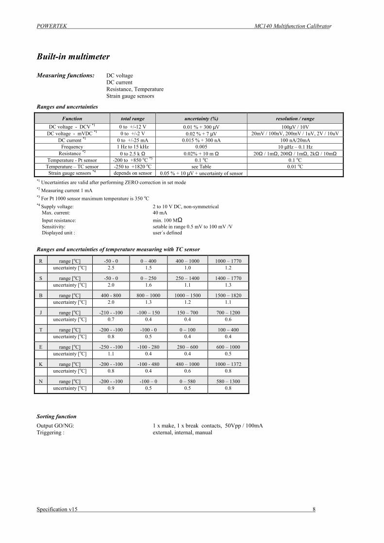
Built-in multimeter
Measuring functions: DC voltage DC current Resistance, Temperature Strain gauge sensors
Ranges and uncertainties
Function total range uncertainty (%) resolution / range DC voltage - DCV *1 0 to +/-12 V 0.01 % + 300 µV 100µV / 10V
DC voltage - mVDC *1 0 to +/-2 V 0.02 % + 7 µV 20mV / 100nV, 200mV / 1uV, 2V / 10uV DC current *1 0 to +/-25 mA 0.015 % + 300 nA 100 nA/20mA
Frequency 1 Hz to 15 kHz 0.005 10 µHz – 0.1 Hz Resistance *2 0 to 2.5 k Ω 0.02% + 10 m Ω 20Ω / 1mΩ, 200Ω / 1mΩ, 2kΩ / 10mΩ
Temperature - Pt sensor -200 to +850 oC *3 0.1 oC 0.1 oC Temperature – TC sensor -250 to +1820 oC see Table 0.01 oC
Strain gauge sensors *4 depends on sensor 0.05 % + 10 µV + uncertainty of sensor *1 Uncertainties are valid after performing ZERO correction in set mode *2 Measuring current 1 mA *3 For Pt 1000 sensor maximum temperature is 350 oC *4 Supply voltage: 2 to 10 V DC, non-symmetrical Max. current: 40 mA Input resistance: min. 100 MΩ Sensitivity: setable in range 0.5 mV to 100 mV /V Displayed unit : user´s defined
Ranges and uncertainties of temperature measuring with TC sensor
R range [oC] -50 - 0 0 – 400 400 – 1000 1000 – 1770 uncertainty [oC] 2.5 1.5 1.0 1.2
S range [oC] -50 - 0 0 – 250 250 – 1400 1400 – 1770 uncertainty [oC] 2.0 1.6 1.1 1.3
B range [oC] 400 - 800 800 – 1000 1000 – 1500 1500 – 1820 uncertainty [oC] 2.0 1.3 1.2 1.1
J range [oC] -210 - -100 -100 – 150 150 – 700 700 – 1200 uncertainty [oC] 0.7 0.4 0.4 0.6
T range [oC] -200 - -100 -100 - 0 0 – 100 100 – 400 uncertainty [oC] 0.8 0.5 0.4 0.4
E range [oC] -250 - -100 -100 - 280 280 – 600 600 – 1000 uncertainty [oC] 1.1 0.4 0.4 0.5
K range [oC] -200 - -100 -100 - 480 480 – 1000 1000 – 1372 uncertainty [oC] 0.8 0.4 0.6 0.8
N range [oC] -200 - -100 -100 – 0 0 – 580 580 – 1300 uncertainty [oC] 0.9 0.5 0.5 0.8
Sorting function Output GO/NG: 1 x make, 1 x break contacts, 50Vpp / 100mA Triggering : external, internal, manual


![Operating instructions for operators and installers - EI2GB-6 D GB F NL I SK – tg: [ ] max. allowable gas temperature range t g [min. value, max. value] – tsp: specified centre](https://img.pdfslide.us/doc/110x75/60a4b7cdeff9fd6efd24e620/operating-instructions-for-operators-and-installers-ei2-gb-6-d-gb-f-nl-i-sk-a.jpg)
![Optimal PID Controller Design for AVR System · optimal robot arm PID control [2]. Some simulation re- ... where sK Kjj j() max min is a range value for the searching range KK Kjj](https://img.pdfslide.us/doc/110x75/5f4fcdff05202b5e6a60538c/optimal-pid-controller-design-for-avr-system-optimal-robot-arm-pid-control-2.jpg)