Embed Size (px)
Citation preview

HUGGINS BROMAGE FERGUSON LTD
CHARTERED ARCHITECTS AND PRINCIPLE DESIGNERS
SPECIFICATION OF WORKS
RE-ESTABLISHMENT OF KNIGHTSMEAD SCHOOL, EXTENSION TO CONNECT TO SOMERS HEATH SCHOOL AND INTERNAL ALTERATIONS, FOYLE DRIVE, SOUTH OCKENDON, ESSEX, RM15 5LX
FOR
Thurrock Council
ARCHITECTS: HUGGINS BROMAGE FERGUSON LTD 109 Orsett Road Grays, Essex, RM17 5HA JANUARY 2016 Ref: 5498

Specification; EXTENSIONS AND ALTERATIONS; KNIGHTSMEAD/SOMERS HEATH SCHOOLS Section; 1.0 Preambles Date; January 2016 REF; 5498
Page | 1
CONTENTS SECTION 1 CONTRACT PARTICULARS AND PRELIMINARIES (TO BE PRICED) SECTION 2 SPECIFICATION OF MATERIALS AND
WORKMANSHIP SECTION 3 WORKS TO BE DONE (TO BE PRICED) APPENDIX
UNDER SEPARATE COVER SECTION 4 PRE-CONTRACT HEALTH AND SAFETY PLAN SECTION 5 MECHANICAL AND ELECTRICAL PERFORMANCE SPECIFICATIONS
Prepared by

Specification; EXTENSIONS AND ALTERATIONS; KNIGHTSMEAD/SOMERS HEATH SCHOOLS Section; 1.0 Preambles Date; January 2016 REF; 5498
Page | 2
SECTION 1 CONTRACT PARTICULARS AND PRELIMINARIES General Notes This section of the Specification applies to the whole of the works comprised in the contract, and shall be deemed to have been priced accordingly. This contract will be FIRM PRICE. Description of the Works RE-ESTABLISHMENT OF KNIGHTSMEAD SCHOOL, EXTENSION TO CONNECT TO SOMERS HEATH SCHOOL AND INTERNAL ALTERATIONS, FOYLE DRIVE, SOUTH OCKENDON, ESSEX, RM15 5LX Link extension, internal alterations, mechanical and electrical alterations and external works. THIS PROJECT IS ‘FAST-TRACK’ The internal alterations works Knightsmead Building are to be completed by the end of August 2016. The works to link Knightsmead and Somers heath can finish later.
Site Conditions The school building will be occupied from 8 am to 6 pm during term times. There is housing to the west, north and east of the site which will be occupied 24 hours and day, seven days a week. No nuisance or obstruction of any kind to local residents to be caused or occasioned by the Contractor or his employees or any sub-contractor or vehicles conveying goods or men to and from site. The Contractor is advised to visit site and ascertain the nature of the works to be executed prior to submitting the tender. In order to inspect the properties the Contractor must first contact the Contract Administrator to make a suitable appointment. The extension and refurbishment work areas will be vacated during the contract but the Contractor is to assume that the surrounding school areas will be occupied. The contractor is to allow for working around operational parts of the school where internal alterations take place in or near the existing buildings. The access to the site is limited and the Contractor must visit the site to ensure that access can be achieved and satisfy themselves that delivery of all necessary materials can also be achieved in order to complete the project. Initially access will be via the rear (Fortin Close) and then via Foyle Drive to the later parts of the contract. Material deliveries are expected to be via Foyle Drive.
On completion of the works the Contractor is to remove all rubbish, waste materials whatsoever from site. Where skips are to be placed on the Highway a permit must be obtained from Thurrock Council. The siting of these skips must be approved by the Contract Administrator or his representative. It cannot be over emphasised that the working on working school premises necessitates an extremely responsible approach by the Contractor. In particular, any works that may cause structure borne sound should be conducted at a time when the sound generated will disturb the minimum number of people. Contractors Working Area The final details of the contractor’s compound are to be agreed. The compound will be accessed from both entrances. The contractor will need to consider the security of the compound before storing any materials. The contractor is to take all necessary steps to protect the existing paving areas and grassed areas from damage and make good any damage caused during the contract.

Specification; EXTENSIONS AND ALTERATIONS; KNIGHTSMEAD/SOMERS HEATH SCHOOLS Section; 1.0 Preambles Date; January 2016 REF; 5498
Page | 3
The contractors is to provide solid Heras fencing panels to the entire perimeter of the extension works to secure the work area; suggested work areas are hatched in purple of the tender drawings. Site toilets/ Office The contractor is to provide portable building for their site accommodation, toilets, restrooms etc. Car Parking Contractor’s car parking will be in the existing turning area accessed off Fortin Close. Car parking in Fortin Close and in the main school car park (access off Foyle Drive) is forbidden The Contractors car parking must not inconvenience any of the neighbouring buildings users. The Contractor must satisfy themselves that car parking arrangements are suitable to complete the project.
Site Security The Contractor must take all suitable measures to secure there working area during the contract period. The Contractor is to allow for all necessary temporary blocking or boarding up of doors, windows or other openings for security during the progress of the contract and for clearing away all blockings and boarding up on completion. Particular care should be taken to safeguard children. All deep excavations, manholes etc. should be very securely covered / locked out of hours.
Risk to Health and Safety The nature and condition of the site/building cannot be fully and certainly ascertained before it is opened up. The Contractor must ascertain for himself any information he may require to ensure the safety of all persons and the works. See Pre-construction information pack prepared by Peardon Safety. Completion of Works The Contractor is to allow for all of works necessary for the due and proper performance of the contract and to enable the new works to be ready for occupation. Otherwise it will be understood that the Contractor has allowed in the tender for all works necessary for the due and proper performance and completion of the contract. Contract dates/ period The contract dates are to be agreed. The client proposes that the works are to commence on the 15th of April 2016. The Contractor is to state their preferred duration of the contract. However, the school have a requirement for the Knightsmead refurbishment (containing all new classrooms) to be ready for Occupation by the end of August 2016. The employer will consider a phased handover, but tendering contractors should confirm that they are able to complete the classroom works to avoid invalidating their tender. Time for Completion The work is to be commenced on site promptly upon acceptance of tender and to the dates indicated above, and the works are to be completed within the agreed contract period. Programming and Progressing of the Contract The Contractor is to provide a detailed programme with their tender return. The programme should show the sequence of operations and start and completion dates of each operation. This programme, once approved by the Contract Administrator, will be incorporated in the contract documents. A copy of the programme is to be kept on site throughout the contract period and progress is to be updated at weekly intervals. The programme must show the following:- (i) Dates for commencement and completion; (ii) The timing of the individual trades and their main activities,

Specification; EXTENSIONS AND ALTERATIONS; KNIGHTSMEAD/SOMERS HEATH SCHOOLS Section; 1.0 Preambles Date; January 2016 REF; 5498
Page | 4
Including sub-contractors, where practical. (iii) Phased completion dates where applicable. Having regard to the Contractor's stated programme of dates for possession and handover, the Contractor shall make all necessary prior arrangements with his suppliers and sub-contractors and co-ordinate the works so that these dates can be met. The Contractor must also indicate the approximate times at which information will be required from the Contract Administrator concerning nominated Sub-Contractors and suppliers and any further specific instructions for the progress of the work which are not given in the Contract Documents. Regular progress meetings will be held throughout the duration of the Contract and a principal representative of the Contractor will be required to attend in addition to his senior staff and if requested by the Contract Administrator representatives of any sub-contractors and principal material suppliers. Cash-flow Forecast The contractor will also be required to provide a cash-flow forecast which is linked to the programme so that the client can arrange for suitable funds to be available for each Valuation/ Payment Certificate.
A20 THE CONTRACT 910 AGREEMENT FOR: JCT STANDARD FORM (WITHOUT QUANTITIES) SBC/XQ 2011 Allow for all obligations, liabilities and services described within this contract. CONDITIONS The Works may be commenced promptly upon execution of the JCT Agreement and shall be completed within the agreed contract period. Liquidated damages: £2000 per week. Defects liability period/ rectification period: twelve months. Retention percentage: 5 % Penultimate certificate percentage: 97.5 % Final Certificate Period for supply of documentation: 3 months Contribution, levy and tax changes This clause to be deleted. Value Added Tax: Clause B1.1 of the Supplementary Memorandum applies Injury or damage to property Insurance cover to be not less than £ 10,000,000:00 Insurance of the Works by Contractor - Fire etc. This sub clause will not be deleted if the Contractor has in force an All Risk policy which insures the works against loss or damage provided the Policy recognises the Employer as a joint insured with the Contractor in respect of the works and the policy is maintained. Insurance of the Works and any existing structures by Employer - Fire etc. THE CONTRACTOR’S DESIGN LIABILITY INSURANCE The Employer requires that the design liability of the Contractor under Clause 2.5 of the Conditions of Contract shall be insured by means of an acceptable Professional Indemnity Policy covering the Contractor’s legal liability for neglect omission or error in the exercise of the professional functions equivalent to those which would normally fall to the Architect or Engineer or similar consultant. The Contractor will be required to produce an annual renewable Professional Indemnity Insurance Policy which provides protection in respect of his design activities covering all work undertaken during the year of insurance and, provided the Contractor renews it annually, fully retroactive in effect.
Specification; EXTENSIONS AND ALTERATIONS; KNIGHTSMEAD/SOMERS HEATH SCHOOLS Section; 1.0 Preambles Date; January 2016 REF; 5498
Page | 5
Any Consultant engaged by the Contractor will be required to have and provide evidence of equivalent and uniform Professional Indemnity Insurance to that required of the Contractor. The insurance cover under the policy is to operate fully during the construction period as well as twelve years thereafter and shall indemnity the Contractor for liability arising from the professional error of any party to whom he may decide to sub-let design work. The limit of indemnity under the policy should be £1,500,000.00 in the aggregate. The Contractor shall, whenever so required by the Employer, produce a certificate signed by or on behalf of the Contractor’s insurers/brokers stating that the foregoing insurance is in force, the period for which it has been taken out and disclosing any exclusions or conditions which restrict cover and are imposed on the Contractor by the policy. Should the Contractor make default in insuring or in continuing to insure as provided for above, the Employer will themselves insure against the design liability and will deduct a sum or sums equivalent to that amount paid or payable in respect of premiums for any monies due or to become due to the Contractor or such amount shall be recoverable by the Employer from the Contractor as a debt. Employer Thurrock Council, Civic Offices, New Road, Grays, Essex, RM17 6SL.
Contractor The Contractor shall mean the individual or firm or company undertaking the works and shall include the legal personal representative of such individual or of the persons comprising such firms or company and the permitted assigns of such individual or firm or company. Architect Huggins Bromage Ferguson Ltd. Chartered Architects 109 Orsett Road, Grays, Essex, RM17 5HA. Contract Administrator/ Cost Consultant As Architect. Principle Designer As Architect. Assisted by Peardon Health and Safety 14 North Road, South Ockendon, Essex, RM15 6QL
Structural/ Civil Engineers Building Design Consultants Station Court, Radford Way, Billericay, Essex, CM12 0DZ Daywork No daywork will be allowed without written approval by the Contract Administrator. Where daywork is approved vouchers of time and materials for the work executed are to be signed by the Foreman and submitted to the Contract Administrator not later than the end of the week following that in which the work was executed. The Contractor will be allowed the prime cost of such work calculated in accordance with the "Definition of Prime Cost of Daywork carried out under a Building Contract" last before issued by the Royal Institution of Chartered Surveyors and the National Federation of Building Trades Employers, together with such percentage editions to each section of the prime cost as the Contractor shall insert on the Schedule attached to the Form of Tender, as follows:-

Specification; EXTENSIONS AND ALTERATIONS; KNIGHTSMEAD/SOMERS HEATH SCHOOLS Section; 1.0 Preambles Date; January 2016 REF; 5498
Page | 6
Prime Cost and Provisional Sums Prime Cost Sums for work carried out by Nominated Sub Contractors shall be deemed to include a discount of 2.5% to the Contractor, for cash payment within fourteen days of Certificate. Work for Statutory Undertakers will be priced nett. The Contractor is to allow for all attendance unloading and storage of materials, return of cases, etc. All provisional sums are to be priced nett without any profit allowance. Mechanical Plant All mechanical plant used in the works shall be acceptable within the requirements of the Control of Pollution Act 1960 with reference to the control of noise. Safeguard Materials & Plant Allow for safeguarding the works, materials and plant, against damage or theft.
Foreman The Contractor is to allow for and keep constantly on the site during the Contract a competent General Foreman and any instructions given to the Foreman shall be held to be given to the Contractor. Water for Works Provide for all water for the works, including that of Sub-Contractors, allow for temporary plumbing and storage and clear away on completion. Pay all charges due to the appropriate authority for the use of water for building purposes. Temporary Lights and Power Provide where necessary all temporary electric lighting and power hand tools, including for use of Sub-Contractors. Provide all temporary wiring, protect supply against overload and pay all charges. Protect Paving etc. Concrete or mortar are NOT to be mixed on the ground or paving’s, public or private which are to be protected against such or other damage during the period of the contract and reinstated and made good to the entire satisfaction of the C/A on completion. Serve Notices Serve all statutory or other notices to local authority or other utility undertakings required by law before excavating in or on roads etc or making connections for services etc. Pay all necessary charges. Clear Site On completion of the Contract clear the site of all, rubbish, surplus materials etc whatsoever and leave tidy and clean to the satisfaction of the C/A. Drawings The work to be carried out in accordance with the following drawings and such other drawings as may be issued during the works.

Specification; EXTENSIONS AND ALTERATIONS; KNIGHTSMEAD/SOMERS HEATH SCHOOLS Section; 1.0 Preambles Date; January 2016 REF; 5498
Page | 7
Architects Drawings:-
5498/01 T1 Existing Ground floor plans/ site plan; 1:200/ 1:1250 5498/02 T1 Proposed Ground floor plans/ site plan; 1:200/ 1:1250 5498/03 T1 Existing and Proposed First floor plans; 1:200 5498/04 T1 Existing and Proposed Elevations; 1:200 5498/05 T1 Existing M&E layout (Knightsmead); 1:100 5498/06 T1 Existing M&E layout (Somers Heath); 1:100 5498/07 T1 Proposed dimensioned Ground Floor plan, Sheet 1; 1:100 5498/08 T1 Proposed dimensioned Ground Floor plan, Sheet 2; 1:100 5498/09 T1 Sections A-A, B-B, C-C, D-D & E-E; 1: 100 5498/10 T1 Proposed M&E plan, Sheet 1; 1:100 5498/11 T1 Proposed M&E plan, Sheet 2; 1:100 5498/12 T1 Finished Schedules Nts 5498/13 T1 Door Schedules and details 1:5, 1:20, 1:50 5498/14 T1 Window Schedule and Notes 1:50 Structural Engineers Drawings:-
15032/ GN001 T1 GENERAL NOTES 15032/ 0001 T1 EXISTING STRUCTURAL LAYOUT 15032/ 0002 T1 PROPOSED STRUCTURAL WORKS 15032/ 0005 T1 CANOPY DETAILS 15032/ DE400 T1 PROPOSED STRUCTURAL DETAILS 15032/ CL01 T1 GA DRAINAGE 15032/ CL02 T1 EXTERNAL WORKS 15032/ CL03 T1 CONSTRUCTION DETAILS SHT 1 OF 2 15032/ CL04 T1 CONSTRUCTION DETAILS SHT 2 OF 2 Building Regulations The whole of the works are to comply with the Building Regulations including all amendments to date. If any works specified or shown on the drawings are found to conflict with the requirements of the Regulations these are to be brought to the notice of the CA. The contractor is to notify Building control/ approved inspector at commencement of works and ascertain from the building Inspector when he would like to make inspections. Pricing The works section of this specification must be fully priced in black or blue ink and submitted with the form of tender. The Tenderer is to clearly indicate in the column provided the individual price for each item included in the works section of the Specification. Block prices for groups of items will not be accepted. The works section should not be regarded as a complete statement of everything included in the contract and the Tenderer must include for all works described, apparent or that can be reasonably inferred as being necessary for the complete and proper execution of the works. The Tenderer shall allow for all costs that may be incurred by the detailed requirements of all Suppliers, statutory authorities and supply undertakings. Before tendering it is recommended that the Tenderer visit the site and take note of the general conditions of the building. He should also take all necessary measurements and ascertain any local conditions, restrictions etc which are likely to affect the execution and pricing of the works. No claims arising from failure to do so will be considered. Costs relating to items in the works section which are not priced will be deemed to have been included in the tender. Should any alterations or qualifications to tender documents be made without the written consent of the Contract Administrator they may not be recognised.

Specification; EXTENSIONS AND ALTERATIONS; KNIGHTSMEAD/SOMERS HEATH SCHOOLS Section; 1.0 Preambles Date; January 2016 REF; 5498
Page | 8
Tenders must remain open for acceptance for not less than 90 days from the date fixed for the submission of tenders and thereafter until withdrawn in writing. The Tenderer is to note that the Employer reserves the option of accepting any Tender it deems worthy of being chosen. Determination by Contractor If the employer does not pay to the Principal Contractor monies due and continue such default for seven days after receipt of written notice (by hand, Registered Post or Recorded Delivery) the Principal Contractor shall have the right to determine this contract, provided that such notice shall not be given unreasonably or vicariously. The foregoing shall not prejudice any other rights and remedies due to the Principal Contractor. Determination by the Employer Without prejudice to any other rights and remedies which the Employer may possess, this contract may be determined by notice in writing signed by the any Director and delivered to the Principal Contractor by Registered Post or Recorded Delivery where: a) In the opinion of the client works required under this contract are not being executed in a proper and workmanlike manner, are not being executed with reasonable diligence, or as required by this schedule. b) If the Principal Contractor commits an act of bankruptcy or being a company entered into liquidation whether compulsory or voluntary, except liquidation for the purposes of reconstruction, in either of the cases for which the two preceding paragraphs provide, the following shall be the respective rights and duties of the Employer and Contractor, viz. The Principal Contractor shall remove from the site of any works as and when required, within such reasonable time, as the client may (without being responsible for any loss or damage) remove and sell any such property of the Principal Contractor, holding the proceeds less all costs incurred to the credit of the Principal Contractor. Dismissal of Incompetent Persons The Principal Contractor shall employ in and about the execution of the works only such persons as are suitably careful, skilled and experienced. Any person employed by the Principal Contractor, who misconducts himself or is incompetent or negligent in the proper performance of his duties shall be removed from site, at the written request of the Contract Administrator. Any such persons shall not again be employed upon the works without the written permission of the contract Administrator. Artists and Tradesmen The Employer has responsibility to maintain properties in the Contract, and in the execution of his duty other Contractors and Tradesmen may be present or visit the sites to carry out the Work. Access is to be provided and it will not be considered to vary this contract in any way. Site Cleanliness The Principal Contractor shall keep all roads, paving, floors, walls, directly adjacent to the site of any works clear of materials, rubbish and mud and be responsible for the cost of making good any damage to the satisfaction of the Employer Equipment Materials and Workmanship All materials, unless otherwise stated, shall comply with the relevant and current British Standards and shall be in accordance with the manufacturer’s instructions and the requirements contained in any relevant British Standards. The Principal Contractor is to carry out all works in accordance with current, relevant Codes of Practice and Regulations. Site Meetings The Principal Contractor shall be available at all reasonable times, to attend site meetings when required to do so by the Contract Administrator. Welfare Conditions The Principal Contractor shall allow for all costs incurred in complying with the Code of Welfare Conditions for the Building Industry as agreed by the National Joint Council and fulfilling requirements of the Factories Act 1961, Health and Safety at Work etc Act, 1974, Construction Regulations 1961, the Construction (Health and Welfare) Regulations 1966, Redundancy Payments Act 1965, Industrial Training Act 1964, Control of Pollution Act 1974, Construction (Design and Management)

Specification; EXTENSIONS AND ALTERATIONS; KNIGHTSMEAD/SOMERS HEATH SCHOOLS Section; 2.0 Materials and Workmanship Date; January 2016 REF; 5498
Page | 9
SECTION 2 SPECIFICATION OF MATERIALS AND WORKMANSHIP OF WORKS TO BE CARRIED OUT, GENERALLY Materials All materials used in works shall comply with the relative British Standard Specification. Workmanship All workmanship and practice within the individual trades will be in accordance with the requirements of the relative British Standard Code of Practice. Where no such code exists the workmanship will be in accordance with good practice within the Industry and to the satisfaction of the Architects. Compliance All work is to comply with the relevant sections of the National Building Specification Sections.
A20 THE CONTRACT The form of contract will be The Joint Contracts Tribunal Limited titled ‘JCT STANDARD FORM (WITHOUT QUANTITIES) SBC/XQ 2011. Allow for all obligations, liabilities and services described within the contract.
A22 CONSIDERATE CONTRACTORS SCHEME
Before work commences the successful Contractor is to register the project with: Considerate Constructors Scheme, PO Box 75, Ware, Hertfordshire SG12 0YX. Telephone: 01920 485959 or go to www.ccscheme.org.uk
A30 TENDERING/SUBLETTING/SUPPLY
MAIN CONTRACT TENDERING 110 SCOPE: These conditions are supplementary to those stated in the invitation to tender and on the Form of Tender. 120 TENDERING PROCEDURE will be in accordance with the principles of the 'Code of Procedure for Single Stage
Selective Tendering' 1996.
160 EXCLUSIONS: If the Contractor cannot tender for any part(s) of the work as defined in the tender documents he must inform the CA as soon as possible, defining the relevant part(s) and stating the reason(s) for his inability to tender.
170 ACCEPTANCE OF TENDER: The Employer and his representatives: - Offer no guarantee that the lowest or any tender will be recommended for acceptance or accepted. - Will not be responsible for any cost incurred in the preparation of any tender. PRICING/SUBMISSION OF DOCUMENTS 210 PRELIMINARIES IN THE SPECIFICATION: The Preliminaries/General conditions sections (A10-A55 inclusive) have
been prepared in accordance with SMM7.
240 PRICING OF PERFORMANCE SPECIFIED WORK: - Tenders must include for all associated and ancillary work shown or clearly apparent as being necessary to
meet the requirements for the Performance Specified Work and its completion and proper integration with the Works generally.
- Tenderers must price on the work and quantities which they intend to provide and will be responsible for any error therein. Where provided, quantities are indicative only.
310 SPECIFICATION WITHOUT QUANTITIES: Where and to the extent that quantities are not included in the
specification, tenders must include for all work shown or described in the tender documents as a whole or clearly apparent as being necessary for the complete and proper execution of the Works.
320 PRICING OF SPECIFICATION: Alterations and qualifications to the specification must not be made without the
written consent of the CA. Tenders containing unauthorised alterations or qualifications may be rejected. Costs

Specification; EXTENSIONS AND ALTERATIONS; KNIGHTSMEAD/SOMERS HEATH SCHOOLS Section; 2.0 Materials and Workmanship Date; January 2016 REF; 5498
Page | 10
relating to items in the specification which are not priced will be deemed to have been included elsewhere in the tender.
340 ERRORS IN THE PRICED SPECIFICATION will be dealt with in accordance with the 'Code of Procedure for Single
Stage Selective Tendering' 1994, 460 A CONTRACT SUM ANALYSIS must be submitted SUBLETTING/SUPPLY
631 DOMESTIC SUBCONTRACTS; - Where these do not involve design, comply with the NJCC 'Code of Procedure for the Letting and
Management of Domestic Subcontract Works' 1989. - Where these involve design, follow in principle the NJCC 'Code of Procedure for Selective Tendering for
Design and Build' and use the current edition of Domestic Subcontract DOM/2.
A31 PROVISION, CONTENT AND USE OF DOCUMENTS DEFINITIONS AND INTERPRETATIONS 120 CA shall mean the person named in the contract as Contract Administrator or his authorised representative. 130 IN WRITING: When required to notify, inform, instruct, agree, confirm, obtain information, obtain approval or obtain
instructions do so in writing. 140 APPROVAL (and words derived there from) means the approval in writing of the CA unless specified otherwise. 180 CROSS-REFERENCES TO THE SPECIFICATION: - Where a numerical cross-reference to a specification section or clause is given on drawings or in any other
document the Contractor must verify its accuracy by checking the remainder of the annotation or item description against the terminology used in the referred to section or clause.
- Where a numerical cross-reference is not given the relevant section(s) and clause(s) of the specification will apply, cross-reference thereto being by means of related terminology.
- Where a cross-reference for a particular type of work, feature, material or product is given, relevant clause(s) elsewhere in the referred to specification section dealing with general matters, ancillary products and workmanship also apply.
- The Contractor must, before proceeding, obtain clarification or instructions in relation to any discrepancy or ambiguity which he may discover.
200 EQUIVALENT PRODUCTS: - Where the specification permits substitution of a product of different manufacture to that specified and
such substitution is desired, before ordering the product notify the CA and, when requested, submit for verification documentary evidence that the alternative product is equivalent in respect of material, safety, reliability, function, compatibility with adjacent construction, availability of compatible accessories and, where relevant, appearance. Submit certified English translations of any foreign-language documents.
- Any proposal for use of an alternative product must also include proposals for substitution of compatible accessory products and variation of details as necessary, with evidence of equivalent durability, function and appearance of the construction as a whole. If such substitution is sanctioned, and before
225 REFERENCES TO BSI DOCUMENTS are to the versions and amendments listed in the BSI Standards Catalogue
current at the date of tender. 230 MANUFACTURER AND REFERENCE: Where used in this combination:
- “Manufacturer” means the firm under whose name the particular product is marketed.
- “Reference” means the proprietary brand name and/or reference by which the particular product is identified.
231 MANUFACTURER’S RECOMMENDATIONS: means the manufacturer’s recommendations or instructions, printed
or in writing and current at the date of issue. 232 OR OTHER APPROVED: means that the commodities of a different manufacturer may be substituted if prior
approval has been obtained for these. The rates or prices will be held to be based on the commodity or commodities specified.
270 SIZES: Unless otherwise stated: - Products are specified by their co-ordinating sizes. - Cross section dimensions of timber shown on drawings are nominal sizes before any required planeing. 280 FIX ONLY means all labours in unloading, handling, storing and fixing in position, including use of all plant.

Specification; EXTENSIONS AND ALTERATIONS; KNIGHTSMEAD/SOMERS HEATH SCHOOLS Section; 2.0 Materials and Workmanship Date; January 2016 REF; 5498
Page | 11
290 SUPPLY AND FIX: Unless stated otherwise all items given in the schedule of work and/or on the drawings are to be supplied and fixed complete. TERMS USED IN ALTERATIONS 311 REMOVE means disconnect, dismantle as necessary and remove the stated element, work or component and all
associated accessories, fastenings, supports, linings and bedding materials, and dispose of unwanted materials. It does not include removing associated pipework, wiring, ductwork or other services.
321 KEEP FOR REUSE means: - During removal prevent damage to the stated components or materials, and clean off bedding and jointing
materials. - Stack neatly, adequately protect and store until required by the Employer or for use in the Works as
instructed. 331 REPLACE means: - Remove the stated existing components, features and finishes. - Provide and fit in lieu new components, features or finishes which, unless specified otherwise, must match
those which have been removed. - Make good as necessary. 341 REPAIR means carry out local remedial work to components, features and finishes as found in the existing
building, re-secure or re-fix as necessary and leave in a sound and neat condition. It does not include: - Replacement of components or parts of components. - Redecoration. 351 MAKE GOOD (and words derived there from) means making good to match existing work, around, through, into, up
and over new openings, items and the like, and the proper joining to existing structures, fabric and finishes. 361 EASE means make minor adjustments to moving parts of the stated component to achieve good fit in both open
and closed positions and ensure free movement in relation to fixed surrounds. Make good as necessary. 371 TO MATCH EXISTING means use products, materials and methods to match closely all visual characteristics and
features of the existing work, with joints between existing and new work as inconspicuous as possible, all to approval of appearance.
DOCUMENTS PROVIDED ON BEHALF OF EMPLOYER 410 ADDITIONAL COPIES OF DRAWINGS: Two copies of drawings (not counting any certified copy of the Contract
Drawings) will be issued to the Contractor. 430 ADDITIONAL COPIES OF SPECIFICATION: After execution of the Contract, two copies of the Specification will be
issued to the Contractor in accordance with the Contract. 440 DIMENSIONS: The accuracy of dimensions scaled from the drawings is not guaranteed. Obtain from the CA any
dimensions required but not given in figures on the drawings nor calculable from figures on the drawings. 460 THE SPECIFICATION: All sections of the specification must be read in conjunction with Main Contract
Preliminaries/General conditions. 470 MECHANICAL AND ELECTRICAL PERFORMANCE SPECIFICATIONS: All sections of the specification must be read
in conjunction with Main Contract Preliminaries/General conditions and the specification. DOCUMENTS PROVIDED BY CONTRACTOR 510 CONTRACTOR'S DESIGN: DESIGN AND PRODUCTION INFORMATION: - When preparing the master programme make reasonable allowance for completing design/production
information, including submission to the Planning Supervisor for comment, inspection by the CA, and any subsequent amendment(s), resubmission(s) and re-inspection(s).
- During the Contract submit to CA the required number of copies of design/production information. The CA will note his comments on one copy, then return to the Contractor.
- Ensure that any necessary amendments are made without delay. Unless and until the CA confirms that resubmission is not required, submit copies of amended drawings etc. to CA, and ensure incorporation of necessary amendments all as before.
- If submitted design/production information differs from the Employer's Requirements, each such difference must be the subject of a request for substitution or Change, supported by all relevant information.
- Should any amendment required by the CA be considered to involve a Change which has not already been acknowledged as a Change by the CA, notify the CA without delay and in any case within 7 days, and do not

Specification; EXTENSIONS AND ALTERATIONS; KNIGHTSMEAD/SOMERS HEATH SCHOOLS Section; 2.0 Materials and Workmanship Date; January 2016 REF; 5498
Page | 12
proceed with ordering, fabrication, erection or installation until subsequently instructed. Claims for the extra cost of such work, if made after it has been carried out, may not be allowed.
- Complete final version of all design/production information and submit to the CA the number of copies required by him.
711 TECHNICAL LITERATURE: The Contractor is required to keep copies of the following on site, readily accessible for
reference by all supervisory personnel: - Manufacturers' current technical literature relating to all products to be used in the Works. - Those parts of BS8000 'Workmanship on Building Sites' which are invoked in the specification. 720 MAINTENANCE INSTRUCTIONS AND GUARANTEES:
Retain copies delivered with components and equipment (failing which, obtain), register with manufacturer as necessary and hand over to CA on or before Practical Completion.
A32 MANAGEMENT OF THE WORKS 120 INSURANCES: Before starting work on site submit documentary evidence and/or policies and receipts for the
insurances required by the Conditions of Contract. 130 INSURANCE CLAIMS: If any event occurs which may give rise to any claim or proceeding in respect of loss or
damage to the Works or injury or damage to persons or property arising out of the Works, forthwith give notice in writing to the Employer, the CA and the Insurers. Indemnify the Employer against any loss which may be caused by failure to give such notice.
150 OWNERSHIP: Materials arising from the alteration work are to become the property of the Contractor except
where otherwise stated. Remove from site as work proceeds. 212 PROGRAMME: - As soon as possible and before starting work on site prepare in an approved form a programme for the Works, which must make allowance for all: - Planning and mobilisation by the Contractor - Subcontractor's work - Running in, adjustment and testing of engineering services. - Work resulting from instructions issued in regard to the expenditure of provisional sums - Work by others concurrent with the Contract - Submit two copies to CA. 261 CA'S SITE MEETINGS: - The CA in conjunction with the Trust’s representative will hold site meetings to review progress and other
matters. Meetings will normally be held monthly. - The CA will chair the meetings and take and distribute minutes. 290 NOTICE OF COMPLETION: Give CA at least 4 weeks’ notice of the anticipated dates of Practical Completion of the
whole or parts of the Works. 420 EXISTING WORK: The extent and location of renewal of existing work must be agreed, at least on a provisional
basis, with the CA before the work is started. Remove existing work in ways which will reasonably minimise the amount of removal and renewal.
430 ESTIMATED COST OF VARIATIONS: If the CA issues details of a proposed instruction with a request for an
estimate of cost, submit such an estimate without delay and in any case within 7 days. 461 INTERIM VALUATIONS: At least 7 days before the established dates for interim valuations submit to the CA details
of amounts due under the Contract together with all necessary supporting information. A33 QUALITY STANDARDS/CONTROL MATERIALS AND WORK GENERALLY 110 GOOD PRACTICE: Where an - Of a standard appropriate to the Works and suitable for the functions stated in or reasonably to be inferred
from the project documents, and - In accordance with good building practice. 121 GENERAL QUALITY OF PRODUCTS: - Products to be new unless otherwise specified. - For products specified to a British or European Standard obtain certificates of compliance from
manufacturers when requested.

Specification; EXTENSIONS AND ALTERATIONS; KNIGHTSMEAD/SOMERS HEATH SCHOOLS Section; 2.0 Materials and Workmanship Date; January 2016 REF; 5498
Page | 13
- Where a choice of manufacturer or source is allowed for any particular product, the whole quantity required must be of the same type, manufacture and/or source unless otherwise approved. Produce written evidence of sources of supply when requested.
- Ensure that the whole quantity of each product required is of consistent kind, size, quality and overall appearance.
- Where consistency of appearance is desirable ensure consistency of supply from the same source. Do not use different colour batches where they can be seen together.
- If products are prone to deterioration or have a limited shelf life, order in suitable quantities to a programme and use in appropriate sequence. Do not use if there are any signs of deterioration, setting or other unsatisfactory condition.
131 PROPRIETARY PRODUCTS: - Handle, store, prepare and use or fix each product in accordance with its manufacturer's current printed or
written recommendations. Inform CA if these conflicts with any other specified requirement. Submit copies when requested.
- The tender will be deemed to be based on the products specified and recommendations on their use given in the manufacturers' literature current at the date of tender.
- Where British Board of Agrement certified products are used, comply with the limitations, recommendations and requirements of the relevant valid certificates.
141 CHECKING COMPLIANCE OF PRODUCTS:
Check all documentation and the products themselves to ensure compliance with the project documents. Where different types of any product are specified, check to ensure that the correct type is being used in each location. In particular, check that:
- The sources, types, qualities, finishes and colours are correct, and match any approved samples. - All accessories and fixings which should be supplied with the products have been supplied. - Sizes are correct. Where tolerances are critical, measure a sufficient quantity to ensure compliance. - The delivered quantities are correct, to ensure that shortages do not cause delays in the work. - The products are clean, undamaged and in good condition. - Products which have a limited shelf life are not out of date. 151 PROTECTION OF PRODUCTS: - Prevent over-stressing, distortion and other damage. - Keep clean and free from contamination. Prevent staining, chipping, scratching or other disfigurement,
particularly of products exposed to view in the finished work. Keep dry to prevent premature setting, moisture movement and similar defects. Where appropriate store off the ground and allow free air movement between stored products.
- Prevent excessively high or low temperatures and rapid changes of temperature in the products. - Protect adequately from rain, damp, frost, sun and other elements as appropriate. Ensure that products are
at a suitable temperature and moisture content at time of use. - Ensure that sheds and covers are of ample size, in good weatherproof condition and well secured. - Keep different types and grades of products separately and adequately identified. - Keep products in their original wrappings, packings or containers until immediately before they are used.
Wherever possible retain protective wrappings after fixing and until shortly before Practical Completion. - Ensure that protective measures are fully compatible with and not prejudicial to the products/materials. 161 SUITABILITY OF RELATED WORK AND CONDITIONS: Provide all trades with necessary details of related types of
work. Before starting each type of work, ensure that: - Previous work is appropriately complete, in accordance with the project documents, to a suitable standard
and in a suitable condition to receive the new work. fixings, damp proofing, priming and sealing. - The environmental conditions are suitable, particularly that the building is suitably weathertight. 171 GENERAL QUALITY OF WORKMANSHIP: - Operatives must be appropriately skilled and experienced for the type and quality of work. - Take all necessary precautions to prevent damage to the work from frost, rain and other hazards . - Inspect components and products carefully before fixing or using and reject any which are defective. - Fix or lay securely, accurately and in alignment. - Where not specified otherwise, select fixing and jointing methods and types, sizes and spacings of fastenings
in compliance with section Z20. - Provide suitable packing’s at screwed and bolted fixings to take up tolerances and prevent distortion. Do not
over-tighten. - Adjust location and fixing of components and products so that joints which are open to view are even and
regular. - Ensure that all moving parts operate properly and freely. Do not cut, grind or plane pre-finished components
and products to remedy binding or poor fit without approval.

Specification; EXTENSIONS AND ALTERATIONS; KNIGHTSMEAD/SOMERS HEATH SCHOOLS Section; 2.0 Materials and Workmanship Date; January 2016 REF; 5498
Page | 14
181 BS 8000: BASIC WORKMANSHIP: - Where BS 8000 gives recommendations on working methods, compliance will be deemed to be a matter of
industry good practice and not a requirement of the CA. - If there is any conflict or discrepancy between the recommendations of BS 8000 on the one hand and the
project documents on the other, the latter will prevail. WORK AT OR AFTER COMPLETION 611 GENERALLY: - Make good all damage consequent upon the work. - Remove all temporary markings and protective coverings. - Clean the works thoroughly inside and out including all accessible ducts and voids, remove all splashes,
deposits, efflorescence, rubbish and surplus materials. - Cleaning materials and methods to be as recommended by manufacturers of products being cleaned, and to
be such that there is no damage or disfigurement to other materials. - Obtain COSHH dated data sheets for all materials used for cleaning and ensure they are used only as
recommended by their manufacturers. - Touch up minor faults in newly painted/repainted work, carefully matching colour. Repaint badly marked
areas back to suitable breaks or junctions. 650 MAKING GOOD DEFECTS: Make arrangements with the Architect and give reasonable notice of the precise dates
for access to the various parts of the Works for purposes of making good defects. Inform CA when remedial works to the various parts of the Works are completed.
A34 SECURITY/SAFETY/PROTECTION GENERALLY 110 THE PRE-TENDER HEALTH AND SAFETY PLAN is integral with the project Preliminaries, including but not
restricted to the sections set out below. Nature of the project: Sections A10 and A13. The existing environment: Section A12. Existing drawings: Section A11 and A12. The design: Section A34. Construction materials: Section A34. Site-wide elements: Section A12. Overlap with client's undertaking: Sections A34 and A36. Site Rules: Sections A34 and A35. Continuing liaison: Section A31. 114 CONSTRUCTION HAZARDS arising from the design of the project include those identified in the risk Assessment
document. Commonplace hazards which should be controlled by good management and good site practices are not listed.
117 HEALTH HAZARDS arising from the specified construction materials include those identified in the risk
Assessment document. Commonplace hazards which should be controlled by good management and good site practices are not listed.
120 THE CONSTRUCTION PHASE HEALTH AND SAFETY PLAN, developed from the Outline Construction Phase Health
and Safety Plan (see section A30) must be submitted to the CA not less than 2 weeks before the proposed date for start of construction work. Do not start construction work until the Employer has confirmed in writing that in his view the Construction Phase Health and Safety Plan includes the procedures and arrangements required by CDM Regulation 15(4).
125 HSE APPROVED CODES OF PRACTICE: Comply with the following: - Management of health and safety at work. - Managing construction for health and safety. - SEPT’s Local Safety Policy and Procedures. 130 SECURITY: Adequately safeguard the site, the Works, products, materials, plant, and any existing buildings affected
by the Works from damage and theft. Take all reasonable precautions to prevent unauthorised access to the site, the Works and adjoining property.
PROTECT AGAINST THE FOLLOWING: 221 NOISE: - Comply generally with BS 5228. - Do not use pneumatic drills and other noisy appliances without consent of the CA.
Specification; EXTENSIONS AND ALTERATIONS; KNIGHTSMEAD/SOMERS HEATH SCHOOLS Section; 2.0 Materials and Workmanship Date; January 2016 REF; 5498
Page | 15
- Do not use or permit employees to use radios or other audio equipment in ways or at times which may cause nuisance.
231 POLLUTION: Take all reasonable precautions to prevent pollution of the site, the Works and the general
environment including streams and waterways. 240 NUISANCE: Take all necessary precautions to prevent nuisance from smoke, dust, rubbish, vermin and other
causes. 260 FIRE: Take all necessary precautions to prevent personal injury, death, and damage to the Works or other
property from fire. Comply with Joint Code of Practice 'Fire Prevention on Construction Sites' published by the Building Employers Confederation, the Loss Prevention Council and the National Contractors' Group.
265 BURNING ON SITE: of material arising from the work will not be permitted 290 WASTE: - Remove rubbish, debris, surplus material and spoil regularly and keep the site and Works clean and tidy. PROTECT THE FOLLOWING: 410 WORK IN ALL SECTIONS: Adequately protect all types of work and all parts of the Works, including work carried
out by others, throughout the Contract. Wherever work is of an especially vulnerable nature or is exposed to abnormal risks provide special protection to ensure that damage does not occur.
460 EXISTING WORK: Prevent damage to existing property undergoing alteration or extension and make good to
match existing any defects so caused. 470 EXISTING FURNITURE, FITTINGS AND EQUIPMENT: Prevent damage to any furniture, fittings or equipment left in
the existing property. Move as necessary to enable the Works to be executed, cover and protect as necessary and replace in original positions.
A35 SPECIFIC LIMITATIONS ON METHOD/SEQUENCE/TIMING 190 WORKING HOURS: To be agreed with the Employer and to enable the building to remain operational. The main
times when work can be carried out are between 8.00am and 6pm, Monday to Friday. A36 FACILITIES/TEMPORARY WORK/SERVICES GENERALLY 110 LOCATIONS: Inform CA of the intended siting of all spoil heaps, temporary works and services. 120 MAINTAIN, alter, adapt and move temporary works and services as necessary. Remove when no longer required
and make good. ACCOMMODATION 210 ROOM FOR MEETINGS: Provide suitable temporary accommodation for site meetings, adequately heated and lit,
with table and chairs for 8 people. The room may be part of the Contractor's own site offices. 281 EXISTING ACCOMMODATION: The existing property may be used as temporary accommodation. TEMPORARY WORK 360 NAME BOARD: Obtain approval for and provide a suitable temporary name board displaying: - Title of project. - Name of Employer. - Name of Architects and Structural Engineers - If the Contractor wishes, names of Contractor and Subcontractors. SERVICES AND FACILITIES 410 LIGHTING: During finishing work and inspection provide temporary lighting, the intensity and direction of which
closely resembles that provided by the permanent installation. 420 LIGHTING AND POWER: Electricity supply from the Employer's mains may be used. (avoidable waste excepted) 430 WATER from the Employer's mains may be used for the Works (avoidable waste excepted)

Specification; EXTENSIONS AND ALTERATIONS; KNIGHTSMEAD/SOMERS HEATH SCHOOLS Section; 2.0 Materials and Workmanship Date; January 2016 REF; 5498
Page | 16
432 WATER, LIGHTING AND POWER supplies will be available for the contractors use. All temporary plumbing and wiring for the works to be supplied by the contractor (at his own risk and cost) including removal on completion and payment of all charges arising.
441 TELEPHONES: Provide as soon as practicable after the Date of Possession a temporary on site telephone
installation for use by the Contractor and Subcontractors, and pay all charges. Make arrangements (e.g. an external bell) to ensure that incoming calls are answered reasonably promptly.
500 METER READINGS: Where charges for service supplies need to be apportioned ensure that meter readings are
taken by relevant authority at possession and/or completion as appropriate. Ensure that copies of readings are supplied to interested parties.
281 EXISTING ACCOMMODATION: The existing property may be used as temporary accommodation. C10 DEMOLISHING STRUCTURES To be read with Preliminaries/General conditions. GENERAL REQUIREMENTS 110 SURVEY: Before starting work, examine all available information, carry out a survey of the structure(s), site and
surrounding area, and submit a survey report and method statement to the CA covering all relevant matters listed below and in the Health and Safety Executive Guidance Note GS29/1 paragraph 32:
- The form, condition and demolition methods of the structure(s). - The form, location and removal methods of any toxic or hazardous materials. - The type and location of adjoining of surrounding premises which may be adversely affected by noise,
vibration, dust or removal of structure. - The identification and location of services above and below ground. 120 EXTENT OF DEMOLITION: Subject to the retention of features, facades, structures, retaining walls, etc., specified
elsewhere, demolish/ remove part of existing structure(s) down to levels detailed. SERVICES AFFECTED BY DEMOLITION 210 SERVICES REGULATIONS: Any work carried out to or which affects new or existing services must be in accordance
with the byelaws or regulations of the relevant statutory authority. 220 LOCATION OF SERVICES: Locate and mark the positions of services affected by the work. Arrange with the
appropriate authorities for the location and marking of the positions of mains services. 230 DISCONNECTION OF SERVICES: Before starting demolition arrange with the appropriate authorities for the
disconnection of services and removal of fittings and equipment. 240 DISCONNECTION OF DRAINS: Locate and disconnect all disused drain connections. Seal within the site to approval. 250 DRAINS IN USE: Protect drains, manholes, gullies, vent pipes and fittings still in use and ensure that they are kept
free of debris at all times. Make good any damage arising from demolition work and leave clean and in working order at completion.
260 BYPASS CONNECTIONS: Provide as necessary to maintain continuity of services to occupied areas of the same
and adjoining properties. Give a minimum 72 hours notice to occupiers if shutdown is necessary during changeover.
270 SERVICES WHICH ARE TO REMAIN: Notify the CA and service authority or owner of any damage. Make all
arrangements for repair to the satisfaction of the CA and service authority or owner. Bear any costs arising. DEMOLITION WORK 310 WORKMANSHIP GENERALLY: - Demolish structure(s) in accordance with BS 6187 and Health and Safety Executive Guidance Notes
GS29/1, 3 and 4. The Contractor is to make reference to the client commissioned refurbishment/ demolition asbestos survey (formerly known as type 3), See Section 3 and Pre-contract health and safety plan.
- Operatives must be appropriately skilled and experienced for the type of work and hold or be training to obtain relevant CITB Certificates of Competence.
- Site staff responsible for supervision and control of the work is to be experienced in the assessment of the risks involved and in the methods of demolition to be used.
320 GAS OR VAPOUR RISKS: Take adequate precautions to prevent fire or explosion caused by gas or vapour. Ensure
that operatives have confined space training where necessary.

Specification; EXTENSIONS AND ALTERATIONS; KNIGHTSMEAD/SOMERS HEATH SCHOOLS Section; 2.0 Materials and Workmanship Date; January 2016 REF; 5498
Page | 17
340 HEALTH HAZARDS: Take adequate precautions to protect site operatives and the general public from health
hazards associated with dangerous fumes and dust arising during the course of the Works. 360 STRUCTURE(S) TO BE RETAINED: - Adequately protect parts of existing structure(s) which are to be kept in place. - Cut away and strip out the minimum necessary and with care to reduce the amount of making good to a
minimum. - Prevent debris from overloading any part of the structure which is not to be demolished. 391 ASBESTOS BASED MATERIALS: Report immediately to the CA any suspected asbestos based materials
discovered during demolition work. Avoid disturbing such materials. Agree with the CA methods for safe removal. 410 UNKNOWN HAZARDS: Inform the CA of any unrecorded voids, tanks, chemicals, etc. discovered during demolition
work. Agree with the CA, methods for safe removal, filling, etc. 441 COMPLETION: - Clear away all debris and leave the site in a tidy condition on completion. - Grade the site to follow the levels of adjacent areas as agreed with the CA. MATERIALS ARISING 511 OWNERSHIP: Components and materials which are to remain the property of the Employer shall be carefully
removed and stored on site where directed. Protect until removed by the Employer, reused in the works, or end of the Contract.
520 HARDCORE: Brick, stone and concrete rubble or other hard materials arising from demolition work may be reused
as hardcore subject to compliance with section D20. D20 EXCAVATING AND FILLING To be read with Preliminaries / General Conditions. GENERALLY / THE SITE 110 SITE INVESTIGATION
- A Site Investigation report for the site is included within the contract documents. 150 EXISTING SERVICES, FEATURES AND STRUCTURES
- Services: Refer to Statutory service provider maps included with the contract documents. - Details of all existing buildings and known services are shown on Architects drawings.
CLEARANCE / EXCAVATING 168 SITE CLEARANCE
- Timing: Before topsoil stripping, if any. - General: Clear site of rubbish, debris and vegetation. Do not compact topsoil. - Treatment: N/A.
170 REMOVING SMALL TREES, SHRUBS, HEDGES AND ROOTS
- Identification: Clearly mark trees to be removed. - Small trees, shrubs and hedges: Cut down - Roots: Grub up and dispose of without undue disturbance of soil and adjacent areas - Safety: Comply with HSE/ Arboriculture and Forestry Advisory Group safety leaflets.
220 STRIPPING TOPSOIL
- General: Before beginning general excavation or filling, strip topsoil from areas where there will be regrading, buildings, pavings and other areas shown on drawings. - Depth: - Remove to an average depth of 300mm - Give notice where the depth of topsoil is difficult to determine. - Handling: Handle topsoil for reuse or sale in accordance with clause 225. - Around trees: Do not remove topsoil from below the spread of trees to be retained. - Site storage: Permitted if required.
221 TREATING TOPSOIL
- Treatment: Apply a suitable trans-located non-residual herbicide. - Timing: Not less than two weeks before excavating topsoil.

Specification; EXTENSIONS AND ALTERATIONS; KNIGHTSMEAD/SOMERS HEATH SCHOOLS Section; 2.0 Materials and Workmanship Date; January 2016 REF; 5498
Page | 18
225 HANDLING TOPSOIL - Standard: To BS 3882. - Aggressive weeds: - Species: Included in the Weeds Act, section 2 or the Wildlife and Countryside Act, Schedule 9, part II. - Give notice: Obtain instructions before moving topsoil. - Contamination: Do not mix topsoil with: - Subsoil, stone, hardcore, rubbish or material from demolition work. - Other soil or material containing aggressive weeds, sharps, plastics and non soil forming materials and notifiable animal or plant diseases. - Oil, fuel, cement or other substances harmful to plant growth. - Other classifications of topsoil. - Multiple handling: Keep to a minimum. Use topsoil immediately after stripping.
240 ADJACENT EXCAVATIONS
- Requirement: Where an excavation encroaches below a line drawn at an angle from the nearest formation level of another higher excavation, the lower excavation, all work within it and backfilling thereto, must be completed before the higher excavation is made. - Angle of line below horizontal: 45 deg. - Backfill material: Lean mix concrete under new extension
250 PERMISSIBLE DEVIATIONS FROM FORMATION LEVELS
- Beneath mass concrete foundations: ±25 mm. - Beneath ground bearing slabs and r.c. foundations: ±15 mm. - Embankments and cuttings: ±50 mm. - Ground abutting external walls: ±50 mm, but such as to ensure that finished level is not less than 150 mm below dpc.
255 ACCURACY - LINEAR DIMENSIONS - Permissible deviations from linear dimensions generally: +/- 75mm
260 INSPECTING FORMATIONS
- Give notice: Make advance arrangements for inspection of formations for raft. - Notice (minimum): 48 hrs . - Preparation: Just before inspection remove the last 150 mm of excavation. - Trim to required profiles and levels. - Loose material: Soft spots and any clay bound material to be removed for a depth of 450mm and filled with well compacted granular material or lean mix concrete. - Seal: Within 4 hours of inspection, seal formations with blinding.
270 FOUNDATIONS GENERALLY - Give notice if: - A natural bearing formation of undisturbed subsoil is not obtained at the depth shown on the drawings. - The formation contains soft or hard spots or highly variable material. 275 FOUNDATION BEARING
- Requirement: Foundations are designed to bear on: - Strata: Hard well compacted stone, gravel sand and chalk
310 UNSTABLE GROUND
- Generally: Ensure that the excavation remains stable at all times. - Give notice: Without delay if any newly excavated faces are too unstable to allow earthwork support to be inserted. - Take action: If instability is likely to affect adjacent structures or roadways, take appropriate emergency action.
320 RECORDED FEATURES
- Recorded foundations, beds, drains, manholes, etc.: - Contaminated earth: Remove and disinfect as required by local authority.
330 UNRECORDED FEATURES
- Give notice: If unrecorded foundations, beds, voids, basements, filling, tanks, pipes, cables, drains, manholes, watercourses, ditches, etc. not shown on the drawings are encountered.
335 NEW FOUNDATIONS CROSSING OLD FOUNDATIONS OR WALLS
- All existing Foundations to be removed as part of demolition.
Specification; EXTENSIONS AND ALTERATIONS; KNIGHTSMEAD/SOMERS HEATH SCHOOLS Section; 2.0 Materials and Workmanship Date; January 2016 REF; 5498
Page | 19
337 OLD FOUNDATIONS OR WALLS BENEATH NEW GROUND SUPPORTED SLAB
- All existing Foundation to be removed as part of demolition.
360 EXCESS EXCAVATION
- Excavation taken wider than required: - Backfill: With hardcore as clause 710 or good virgin excavated soli at Engineers approval. - Excavation taken deeper than required: - Backfill: With well grade granular material or hardcore as clause 710 or good virgin excavated soil at Engineers approval.
370 UNDERGROUND STRUCTURES IN LANDSCAPE AREAS - Generally: Remove walls, roads, foundations, disused services, drains, manholes and the like to minimum depth. - Minimum depth below finished levels: - Grass, ground cover and perennial planting: 500 mm. - Shrub planting: 750 mm. - Within 2 m of tree planting: 1000 mm. - Walls and slabs remaining: In every 10 m² of wall or slab, make a drainage hole at least 600 mm diameter.
DISPOSAL OF MATERIALS 410 EXCAVATED TOPSOIL STORAGE
- Storage: Stockpile in temporary storage heaps permitted if required.
450 WATER
- Generally: Keep all excavations free from water until: - Formations are covered. - Below ground constructions are completed. - Drainage: Form surfaces of excavations and fill to provide adequate falls. - Removal of water: Provide temporary drains, sumps and pumping as necessary. Do not pollute watercourses with silt laden water.
454 GROUND WATER LEVEL, SPRINGS OR RUNNING WATER
- Give notice: If it is considered that the excavations are below the water table. - Springs/ Running water: Give notice immediately if encountered.
FILLING 500 PROPOSED FILL MATERIALS
- Details: Submit full details of proposed fill materials to demonstrate compliance with specification, including: - Type and source of imported fill. - Proposals for processing and reuse of material excavated on site. - Test reports as required elsewhere. - Timing: 2 weeks
510 HAZARDOUS, AGGRESSIVE OR UNSTABLE MATERIALS
General: Do not use fill materials which would, either in themselves or in combination with other materials or ground water, give rise to a health hazard, damage to building structures or instability in the filling, including material that is: - Frozen or containing ice. - Organic. - Contaminated or noxious. - Susceptible to spontaneous combustion. - Likely to erode or decay and cause voids. - With excessive moisture content, slurry, mud or from marshes or bogs. - Clay of liquid limit exceeding 80 and/or plasticity index exceeding 55. - Unacceptable, class U2 as defined in the Highways Agency ‘Specification for highway works’, clause 601.
520 FROST SUSCEPTIBILITY
- General: Except as allowed below, fill must be non frost-susceptible as defined in Highways Agency ‘Specification for highway works’, clause 801.8. - Test reports: If the following fill materials are proposed, submit a laboratory report confirming they are non frost-susceptible: - Fine grained soil with a plasticity index less than 20%. - Coarse grained soil or crushed granite with more than 10% retained on a 0.063 mm sieve.
Specification; EXTENSIONS AND ALTERATIONS; KNIGHTSMEAD/SOMERS HEATH SCHOOLS Section; 2.0 Materials and Workmanship Date; January 2016 REF; 5498
Page | 20
- Crushed chalk. - Crushed limestone fill with average saturation moisture content in excess of 3%. - Burnt colliery shale.
525 TESTING OF SUITABILITY OF FILL MATERIALS BEFORE START OF FILLING
- Laboratory: UKAS & NAMAS accredited laboratory. - Submit report to: Two copies to structural engineers. - Timing: 21 days before starting filling. - Samples: Deliver to laboratory as required. - Additional requirements None. - Tests: To be agreed. - Frequency: To be agreed.
530 PLACING FILL
- Surfaces of excavations and areas to be filled: Free from loose soil, topsoil, organic material, rubbish and standing water. - Freezing conditions: Do not place fill on frozen surfaces. Remove material affected by frost. Replace and recompact if not damaged after thawing. - Adjacent structures, membranes and buried services: - Do not overload, destabilise or damage. - Submit proposals for temporary support necessary to ensure stability during filling. - Allow 14 days (minimum) before backfilling against in situ concrete structures. - Layers: Place so that only one type of material occurs in each layer. - Earthmoving equipment: Vary route to avoid rutting.
535 COMPACTION GENERALLY
- General: Compact fill not specified to be left loose as soon as possible after placing. - After compaction: Surface of each layer must be well closed, showing no movement under compaction plant, and without cracks, holes, ridges, loose material and the like. - Defective areas: Remove and re-compact to full thickness of layer using new material.
540 BENCHING IN FILL
- Adjacent areas: If, during filling the difference in level between adjacent areas of filling exceeds 600 mm, cut into edge of higher filling to form benches 600 mm minimum width and height equivalent to depth of a layer of compacted filling. - New filling: Spread and compact to ensure maximum continuity with previous filling.
617 HIGHWAYS AGENCY TYPE 1 UNBOUND MIXTURE
- Fill: To Highways Agency ‘Specification for highway works’, clauses 801 and 803: - Crushed rock (other than argillaceous rock). - Crushed concrete. - Recycled aggregates. - Crushed non-expansive slag. - Well-burned non-plastic colliery shale. - Filling: To Highways Agency ‘Specification for highway works’, clause 802.
618 HIGHWAYS AGENCY TYPE 2 UNBOUND MIXTURE
- Fill: To Highways Agency ‘Specification for highway works’, clauses 801 and 804: - Crushed rock (other than argillaceous rock). - Crushed concrete. - Crushed non-expansive slag. - Well-burned non-plastic colliery shale. - Natural gravel. - Natural sand. - Filling: To Highways Agency ‘Specification for highway works’, clause 802.
620 SUBGRADE IMPROVEMENT LAYER (CAPPING)
- Fill: To Highways Agency ‘Specification for highway works’, Table 6/1, Class 6F1 or 6F2. - Filling: Place and compact to Highways Agency ‘Specification for highway works’, Table 6/1, clause 612 and clause 613.3, 613.9 and 613.10.
650 PROTECTION OF COMPACTED FILLING
- Temporary protective filling: Before allowing construction traffic, raise level of compacted cohesive soil filling at least 150 mm above formation level using properly compacted temporary filling. - Removal: Remove temporary protective filling from site before permanent construction.

Specification; EXTENSIONS AND ALTERATIONS; KNIGHTSMEAD/SOMERS HEATH SCHOOLS Section; 2.0 Materials and Workmanship Date; January 2016 REF; 5498
Page | 21
700 BACKFILLING AROUND FOUNDATIONS
- Under oversite concrete and pavings: Hardcore. - Under grassed or soil areas: Material excavated from the trench, laid and compacted in 300 mm maximum layers.
710 HARDCORE FILLING
- Fill: Granular material, free from excessive dust, well graded, all pieces less than 75mm in any direction, minimum 10% fines value of 50kN when tested in soaked condition to BS 812-111, and in any one layer only one of the following: - crushed rock ( other than argillaceous rock) or quarry waste with not more binding material. - crushed concrete, crushed brick or tile, free from plaster, timber and metal. - crushed non-expansive slag. - gravel or hoggin with not more clay content than is required to bind the material together, and with no large lumps of clay - well-burned non-plastic colliery shale. - natural gravel. - natural sand. - Filling : Spread and level in 150mm maximum layers. Thoroughly compact each layer.
730 BLINDING
- Surfaces to receive sheet overlays or concrete: - Blind with: - Concrete where shown on drawings.
TOPSOIL AREAS 810 GRADE SUBSOIL to smooth flowing contours and to achieve the specified finished levels of the topsoil. Excavate locally as necessary for areas of thicker topsoil. Small planting beds located in general landscape areas may be excavated separately at a later date. 860 SPREAD TOPSOIL over prepared subsoil in layers not exceeding 150 mm and firm each layer before spreading the next. At the time of laying, both the material and the weather must be reasonably dry. E05 IN SITU CONCRETE CONSTRUCTION GENERALLY To be read with Preliminaries/ General Conditions. NB: All Structural Concrete to be in accordance with National Structural Concrete Specification (NSCS) and the following standard NBS clauses and as specified by the structural engineers. 215 CONTRACTOR DETAILING OF REINFORCEMENT
- Extent: Upstands and edge details to raft. - Requirement: Complete the detailing and scheduling of the reinforcement. - Standards: - Design: To BS EN 1992-1-1. - Drawings: To BS EN 1992-1-1. - Reinforcement schedules: To BS 8666 - Design information: - Designed reinforcement: BS 8666 - Additional reinforcement: Control of cracking: Provide additional reinforcement and adjust spacing of reinforcement as design standard requirements for the control of cracking. - Finished product: To comply with the requirements of design standard.
222 EUROCODES
- United Kingdom National Annexes: Deemed to be included. Nationally determined parameters shall apply. 225 TEMPERATURE RECORDS
- Requirement: Throughout period of concrete construction record: - Daily: Temperature at intervals of four hours ( maximum) - Under adverse temperature conditions: Temperature at commencement and end of placing. - Equipment: Contractors choice. - Location: In the shade, close to the structure.
235 OPENINGS, INSERTS AND FIXINGS
- Requirement: Collate all information. - Submit: Details where openings, inserts and fixings can only be accommodated by adjustments to reinforcement. - Locate reinforcement: To ensure specified minimum cover at openings and inserts and to be clear of fixing positions.

Specification; EXTENSIONS AND ALTERATIONS; KNIGHTSMEAD/SOMERS HEATH SCHOOLS Section; 2.0 Materials and Workmanship Date; January 2016 REF; 5498
Page | 22
250 STRUCTURAL TESTING
- Requirement: Identity testing to confirm compliance with Mix design. - Method/ standard: Cube sampling and testing 3 / batch - Timing: At point of delivery - Report: To be provided to the engineer at 7, 28 and 56 days. - Submission: Within 5 working days of testing.
290 ACCURACY OF CONSTRUCTION
- Reference system: To BS 5964-1 - Element shape and position: To BS 5606 and Section 7 of the National Structural Concrete Specification for Building Construction. - Substitution of alternative requirements: None.
E10 MIXING/ CASTING/ CURING IN SITU CONCRETE To be read with Preliminaries/ General conditions. CONCRETE 101 SPECIFICATION
- Concrete generally: To BS 8500-2. - Exchange of information: Provide concrete producer with information required by BS 8500-1, clauses 4 and 5. Refer to structural engineers drawings regarding concrete mixes.
105 DESIGNATED CONCRETE FOR GENERAL USE ( Blinding, kerb bedding and backing/0
- Designation RC16/20. - Fibres: Unreinforced - Aggregates: - Size (maximum): 20mm. - Coarse recycled aggregates: No special requirements. - Additional aggregate requirements: None. - Special requirements for cement/ combinations: None. - Consistence class: S3. - Chloride class Cl 0.40 except for concrete made with SRPC conforming to BS 4027, which should be specified as chloride class Cl 0.20. - Admixtures: Concrete producer’s choice. - Additional mix requirements: Sulphate class is DC-3.
110 BASIC DESIGNATED CONCRETE FOR INTERNAL USE
- Designation: C28/35 - Coarse recycled aggregates Not permitted. - Consistence class: S3. - Additional requirements: Submit proposals.
132 DESIGNED CONCRETE FOR RAFT
- Embedded metal: Carbon steel reinforcement and structural steel - Compressive strength class (cylinder/ cube minimum): C32/40 - Target density (oven-dry): Normal. - Aggregates: - Size (maximum): 20mm. - Type/ Density: Normal weight. - Coarse recycled aggregates Not permitted. - Additional aggregate requirements None. - Design chemical class: DC-1. - Limiting values for composition: - Water: cement ratio (maximum): 0.50. - Cement/ combination content (minimum): 380. - Cement/ combination content (maximum): 500. - Consistence class: S3. - Permitted cement/ combinations: IIIA+SR, IIIB+SR, SRPC, IVB-V. - Chloride class: Cl 0.40 except for concrete made with SRPC conforming to BS 4027 which should be specified as chloride class Cl 0.20. - Admixtures: Concrete producer’s choice. - Additional mix requirements: None.
Specification; EXTENSIONS AND ALTERATIONS; KNIGHTSMEAD/SOMERS HEATH SCHOOLS Section; 2.0 Materials and Workmanship Date; January 2016 REF; 5498
Page | 23
MATERIALS, BATCHING AND MIXING 215 READY-MIXED CONCRETE
- Production plant: Currently certified by a body accredited by UKAS to BS EN 45011 for product conformity certification of ready-mixed concrete. - Source of ready-mixed concrete: Obtain from one source if possible. Otherwise, submit proposals. - Name and address of depot: Submit before any concrete is delivered. - Delivery notes: Retain for inspection. - Declarations of nonconformity from concrete producer: Notify immediately.
221 INFORMATION ABOUT PROPOSED CONCRETES
- Submit when requested: - Details listed in BS 8500-1, clause 5.2. - Additional information: None.
225 CHANGES TO SPECIFICATION
- Changes to specification of fresh concrete (outside concrete producer's responsibility):Not permitted. 230 INTERRUPTION OF SUPPLY DURING CONCRETING
- Elements without joints: Where elements are detailed to be cast in a single pour without joints, make prior arrangements for a back-up supply of concrete. - Elsewhere: - Preparation: Manage pour to have a full face, and have materials available to form an emergency construction joint while concrete can still be worked. - Before pour is completed: Submit location and details of joint, make proposals for joint preparation.
415 ADMIXTURES - Calcium chloride and admixtures containing calcium chloride: Do not use. 490 PROPERTIES OF FRESH CONCRETE
- Adjustments to suit construction process: Determine with concrete producer. Maintain conformity to the specification.
PROJECT TESTING/ CERTIFICATION 505 PROJECT TESTING OF CONCRETE – GENERAL
- Testing: To BS 8500-1 - Nonconformity: Obtain instructions immediately. - Recording: Maintain complete correlated records including: - Concrete designation. - Sampling, site tests, and identification numbers of specimens tested in the laboratory. - Location of the parts of the structure represented by each sample. - Location in the structure of the batch from which each sample is taken.
508 REGULAR PROJECT TESTING OF CONCRETE
- Tests: Compressive strength. - Sampling: - Point: At point of discharge from delivery track. - Rate: One sample per 60m3. - Other requirements: Cubes to be stored under same conditions as the concrete in the members.
520 TESTING LABORATORY
- Laboratory: Accredited by UKAS or other national equivalent. - Name and UKAS reference number: Submit well in advance of making trial mixes or concrete for use in the works.
530 TESTS RESULTS
- Submission of reports: Within one day of completion of each test. - Number of copies: 2 copies to engineers. - Reports on site: A complete set, available for inspection.
Specification; EXTENSIONS AND ALTERATIONS; KNIGHTSMEAD/SOMERS HEATH SCHOOLS Section; 2.0 Materials and Workmanship Date; January 2016 REF; 5498
Page | 24
550 BROKEN CUBES FROM FAILED STRENGTH TESTS
- Nonconformity: Keep separately the pieces of each cube which fail to meet the conformity requirements for individual results. - Period for keeping cubes: Obtain instructions.
PLACING/ COMPACTING/ CURING AND PROTECTING 610 CONSTRUCTION/ SEQUENCE/ TIMING REQUIREMENTS
- To be agreed to suit sequence and designed reinforcement and splice connections. 620 TEMPERATURE OF CONCRETE
- Application: Raft. - Objective: Limit maximum temperature of concrete to minimize cracking during placing, compaction and curing. Take account of: - High temperatures and steep temperature gradients: Prevent build-up during first 24 hours after casting. Prevent coincidence of maximum heat gain from cement hydration with high air temperature and/ or solar gain. - Rapid changes in temperature: Prevent during the first seven days after casting. - Proposals for meeting objective: Submit.
630 PREMATURE WATER LOSS
- Requirement: Prevent water loss from concrete laid on absorbent substrates. - Underlay: Polyethylene sheet: 250 micrometres thick. - Installation: Lap edges 150 mm.
635 CONSTRUCTION JOINTS NOT PERMITTED WITHOUT PRIOR AGREEMENT. 640 CONSTRUCTION JOINTS
- Location of joints: To be agreed. - Preparation of joint surfaces: Remove surface laitance and expose aggregate by lightly brushing and spraying. Joint surface to be clean and damp immediately before placing fresh concrete.
648 DIVERSE TEMPERATURE CONDITIONS
- Requirement: Submit proposals for protecting concrete when predicted ambient temperatures indicate risk of concrete freezing or overheating.
650 SURFACES TO RECEIVE CONCRETE
- Cleanliness of surfaces immediately before placing concrete: Clean with no debris, tying wire clippings, fastenings or free water.
660 INSPECTION OF SURFACES
- Notice: Give notice to allow inspections of reinforcement and surfaces before each pour of concrete. - Period of notice: Obtain instructions. - Timing of inspections: When reinforcement and formwork are ready for concreting, but allowing sufficient time before concreting to rectify any deficiencies.
670 TRANSPORTING
- General: Avoid contamination, segregation, loss of ingredients, excessive evaporation and loss of workability. Protect from heavy rain. - Entrained air: Anticipate effects of transport and placing methods in order to achieve specified air content.
680 PLACING
- Records: Maintain for time, date and location of all pours. - Timing: Place as soon as practicable after mixing and while sufficiently plastic for full compaction. - Temperature limitations for concrete: 30°C (maximum) and 5°C (minimum), unless otherwise specified. Do not place against frozen or frost covered surfaces. - Continuity of pours: Place in final position in one continuous operation up to construction joints. Avoid formation of cold joints. - Discharging concrete: Prevent uneven dispersal, segregation or loss of ingredients or any adverse effect on the formwork or formed finishes. - Thickness of layers: To suit methods of compaction and achieve efficient amalgamation during compaction. - Poker vibrators: Do not use to make concrete flow horizontally into position, except where necessary to achieve full compaction under void formers and cast-in accessories and at vertical joints.

Specification; EXTENSIONS AND ALTERATIONS; KNIGHTSMEAD/SOMERS HEATH SCHOOLS Section; 2.0 Materials and Workmanship Date; January 2016 REF; 5498
Page | 25
690 COMPACTING
- General: Fully compact concrete to full depth to remove entrapped air. Continue until air bubbles cease to appear on the top surface. - Areas for particular attention: Around reinforcement, under void formers, cast-in accessories, into corners of formwork and at joints. - Consecutive batches of concrete: Amalgamate without damaging adjacent partly hardened concrete. - Methods of compaction: To suit consistence class and use of concrete.
720 VIBRATORS
- General: Maintain sufficient numbers and types of vibrator to suit pouring rate, consistency and location of concrete. - External vibrators: Obtain approval for use.
730 PLASTIC SETTLEMENTS
- Settlement cracking: Inspect fresh concrete closely and continuously wherever cracking is likely to occur, including the top of deep sections and at significant changes in the depth of concrete sections. - Timing: During the first few hours after placing and whilst concrete is still capable of being fluidized by the vibrator. - Removal of cracks: Re-vibrate concrete.
810 CURING GENERALLY
- Requirement: Keep surface layers of concrete moist throughout curing period, including perimeters and abutments, by either restricting evaporation or continuously wetting surfaces of concrete. - Surfaces covered by formwork: Retain formwork in position and, where necessary to satisfy curing period, cover surfaces immediately after striking. - Top surfaces: Cover immediately after placing and compacting. If covering is removed for finishing operations, replace it immediately afterwards. - Surface temperature: Maintain above 5°C throughout the specified curing period or four days, whichever is longer. - Records: Maintain details of location and timing of casting of individual batches, removal of formwork and removal of coverings. Keep records on site, available for inspection.
811 COVERINGS FOR CURING
- Sheet coverings: Suitable impervious material. - Curing compounds: Selection criteria: - Curing efficiency: Not less than 75% or for surfaces exposed to abrasion 90%. - Colouring: Fugitive dye. - Application to concrete exposed in the finished work: Readily removable without disfiguring the surface. - Application to concrete to receive bonded construction/ finish: No impediment to subsequent bonding. - Interim covering to top surfaces of concrete: Until surfaces are in a suitable state to receive coverings in direct contact, cover with impervious sheeting held clear of the surface and sealed against draughts at perimeters and junctions.
812 PREVENTING EARLY AGE THERMAL CRACKING
- Deep lifts or large volume pours: Submit proposals for curing to prevent early age thermal cracking, taking account of: - Temperature differentials across sections. - Coefficient of thermal expansion of the concrete. - Strain capacity of the concrete mix (aggregate dependent). - Restraint.
815 ADDITIONAL CURING REQUIREMENT – WATER CURING
- Commencement of water curing: As soon as practicable after placing and compacting concrete. - Surfaces covered by formwork: Expose to water curing as soon as practicable. - Top surfaces: Cover immediately with impermeable sheeting to prevent evaporation before commencement of water curing. - Water curing: Wet surfaces continuously throughout curing period. - Select methods from: Mist spray. Wet hessian covered with impermeable sheeting.
818 CURING PERIODS GENERALLY
- Minimum periods: When not otherwise indicated, to BS; 8110-1, Table 6.1.

Specification; EXTENSIONS AND ALTERATIONS; KNIGHTSMEAD/SOMERS HEATH SCHOOLS Section; 2.0 Materials and Workmanship Date; January 2016 REF; 5498
Page | 26
840 PROTECTION
- Prevent damage to concrete, including: - Surfaces generally: From rain, indentation and other physical damage. - Surfaces to exposed visual concrete: From dirt, staining, rust marks and other disfiguration. - Immature concrete: From thermal shock, physical shock, overloading, movement and vibration. - In cold weather: From entrapment and freezing expansion of water in pockets, etc.
E30 REINFORCEMENT FOR IN SITU CONCRETE To be read with Preliminaries/ General conditions. REINFORCEMENT 110 QUALITY ASSURANCE OF REINFORCEMENT
- Standards: - Reinforcement: To BS 4449, BS 4482, BS 4483 or BS 6744. - Cutting and bending: To BS 8666. - Source of reinforcement: Companies holding valid certificates of approval for product conformity issued by the UK Certification Authority for Reinforcing Steels (CARES).
150 RIBBED BAR REINFORCEMENT
- Standard: To BS 4449. - Strength grade: minimum B500B
210 STANDARD FABRIC REINFORCEMENT
- Standard: To BS 4483. - Strength grade: minimum B500B
245 PREFABRICATED REINFORCEMENT
- Prefabricated elements – Ground beam cages may be prefabricated. - Source: Obtain from a manufacturer holding valid certification of approval for welded fabrications issued by the UK Certification Authority for Reinforcing Steels (CARES). - Certification required: Achievement of CARES appendix 6 for tack welding and appendix 10 for semi-structural/ structural welding.
WORKMANSHIP 310 CUTTING AND BENDING REINFORCEMENT
- General: To schedules and to BS 8666. - Bending on site, including minor adjustments: Permitted – to be agreed with the engineer.
320 PROTECTION OF REINFORCEMENT
- Dropping from height, mechanical damage and shock loading: Prevent. - Cleanliness of reinforcement at time of pouring concrete: Free from corrosive pitting, loose millscale, loose rust and contaminants which may adversely affect the reinforcement, concrete, or bond between the two.
410 LAPS OR SPLICES
- Details not shown on drawings: Obtain instructions. 425 LAPS NOT DETAILED ON DRAWINGS
- Laps in bar reinforcement (minimum): 40x bar dia - Laps in fabric reinforcement (minimum): 30x bar dia. - Laps at corners: Avoid four layer build-up.
451 FIXING REINFORCEMENT
- Standard: To BS 7973-1 and -2. - Installation: In addition to any spacers and chairs shown on drawings or schedules, provide adequate support, tie securely and maintain the specified cover. - Tying: - Wire type: 16 gauge black annealed. Use stainless steel wire for stainless steel reinforcement.

Specification; EXTENSIONS AND ALTERATIONS; KNIGHTSMEAD/SOMERS HEATH SCHOOLS Section; 2.0 Materials and Workmanship Date; January 2016 REF; 5498
Page | 27
- Ends of tying wire: Prevent intrusion into the concrete cover. Remove loose ends. - Compatibility of metals: Prevent contact between ordinary carbon steel and stainless or galvanized reinforcement.
470 TOLERANCES ON COVER
- Tolerance (maximum): +/-5mm - Checking specified cover dimensions: Before concreting check that cover dimensions will be achieved.
480 NOMINAL COVER TO REINFORCEMENT
- Top face: refer to drawings - Formed faces: refer to drawings
510 RUST STAINING
- Staining of surfaces of concrete which will be exposed to view in the finished work: Prevent.
521 COVER METER FOR USE BY OTHERS
- Type of cover meter: Provide a magnetic induction digital display type selected to suit arrangement and type of reinforcement. - Availability: Calibrate and maintain ready for use by others as instructed. - Periods/ time: as required. - Results: Submit. Notify immediately where specified cover has not been achieved.
E41 WORKED FINISHES TO IN SITU CONCRETE To be read with Preliminaries/General conditions. 150 TIMING: Carry out all finishing operations at optimum times in relation to the setting and hardening of the concrete. Do
not wet surfaces of concrete to assist surface working. Do not sprinkle cement on to surface. 210 TAMPED FINISH: Tamp surface with edge of a board or beam to give an even texture of parallel ribs. 310 SMOOTH FLOATED FINISH Use a hand float, skip float or power float to give an even surface with no ridges or steps. 320 TROWELLED FINISH - Float concrete to an even surface with no ridges or steps, then immediately commence curing as specified in section
E10. - When the concrete is suitably stiff, hand or power trowel to give a uniform smooth but not polished surface, free
from trowel marks and other blemishes, and suitable to receive the specified flooring material. - Resume specified curing without delay. - Protect the surface from construction traffic until flooring material is laid. - If, because of inadequate finishing or protection, the surface of the concrete is not suitable to receive the specified
flooring material, it must be made good by application of a smoothing compound by and to the satisfaction of the flooring subcontractor. Allow for the cost of any such making good.
330 POWER FLOATED FINISH - power float concrete finish as indicated on structural engineers drawings. 510 SURFACE HARDENER: Not less than three weeks after casting, clean surface of concrete by wetting with soap suds and
scrubbing with wire brush and fine steel wool. Mop up and scrub with fibre brush and clean water. Allow to dry thoroughly for several days then apply an approved proprietary chemical surface hardener to manufacturer's recommendations.
F10 BRICK/BLOCK WALLING To be read with Preliminaries/General conditions. TYPE(S) OF WALLING 110 CLAY FACING BRICKWORK - Bricks: To BS 3921. - Mortar: As section Z21. - Bricks Ibstock or similar approved (0870) 903 4000. Two brick colours as indicate on elevation drawings.

Specification; EXTENSIONS AND ALTERATIONS; KNIGHTSMEAD/SOMERS HEATH SCHOOLS Section; 2.0 Materials and Workmanship Date; January 2016 REF; 5498
Page | 28
310 CLAY COMMON BRICKWORK (FLETTONS) - Bricks: To BS 3921. - Mortar: As section Z21. 330 CALCIUM SILICATE COMMON BRICKWORK - Bricks: To BS 187, Class 4 below Dpc - Mortar: As section Z21. 350 CONCRETE COMMON BLOCKWORK - Blocks: Concrete to BS 6073: Part 1. Manufacturer and reference: Durox Supabloc lightweight blockwork as indicated on the construction drawings. - Mortar: As section Z21. - Strength; Min 7N strength, refer to structural engineers details. 380 ENGINEERING BRICKWORK - Bricks: To BS 3921, Engineering Class A and B as specified - Mortar: As section Z21. - Joints: Flush. WORKMANSHIP GENERALLY 420 SITE STORAGE: Store bricks/blocks in stable stacks clear of the ground and clearly identified by type, strength, grade, etc.
Protect from adverse weather and keep clean and dry. 430 CONDITIONING OF BRICKS: - Do not use clay bricks or calcium silicate bricks when still warm from the manufacturing process. - In dry warm weather wet the surfaces of very absorbent bricks slightly to reduce suction. Do not soak. 460 MORTAR GROUPS: Where mortar is specified by group number, select any mortar in that group as set out below. Mix
proportions are by volume. Use the same mortar throughout any one type of facing work. ____________________________________________________________ Mortar group 1 2 3 4 ____________________________________________________________ Cement: lime: 1:0-0.25:3 1:.5:4-4.5 1:1:5-6 1:2:8-9 sand ____________________________________________________________ Cement: premixed lime & sand 1:3 1:4-4.5 1:5-6 1:8-9 (Proportion of (1:12) (1:9) (1:6) (1:4.5) lime to sand given in brackets) ____________________________________________________________ Cement: sand & air entrainer - 1:3-4 1:5-6 1:7-8 ____________________________________________________________ Masonry cement: sand - 1:2.5-3.5 1:4-5 1:5.5-6.5 ____________________________________________________________ 500 LAYING GENERALLY: - Lay bricks/blocks on a full bed of mortar; do not furrow. Fill all cross joints and collar joints; do not tip and tail. - Build walls in stretching half lap bond when not specified otherwise. - Plumb perpends of facework every third or fifth cross joint along a course and even out the joint widths in between. 520 ACCURACY: Keep courses level and true to line. Accurately plumb all wall faces, angles and features. Unless otherwise
specified, build brickwork/blockwork within the following permissible deviations: _________________________________________________ Dimension Permissible deviation (mm) _________________________________________________ Position in plan of any point or specified fair face in relation to the nearest building grid line at the same level +/-10 _________________________________________________ Length (unless otherwise defined by adjacent construction): Up to 5 m +/-15 5 to 10 m +/-20 10 to 20 m +/-25

Specification; EXTENSIONS AND ALTERATIONS; KNIGHTSMEAD/SOMERS HEATH SCHOOLS Section; 2.0 Materials and Workmanship Date; January 2016 REF; 5498
Page | 29
Over 20 m +/-30 _________________________________________________ Height: Up to 3 m +/-15 3 to 6 m +/-20 Over 6 m +/-25 _________________________________________________ Level of bed joints: Up to 5 m long +/-10 5 to 10 m long +/-15 Over 10 m long +/-25 _________________________________________________ Straightness in any 5 m length +/-10 _________________________________________________ Vertically: In any 3 m height +/-10 In o/a height of building exceeding 6 m +/-20 _________________________________________________ Thickness: Overall thickness of walls or width of piers (subject to the following) +/-15 Difference in thickness of a wall or width of a pier at any two points 3 m apart +/-10 _________________________________________________ 535 HEIGHT OF LIFTS: - Rack back when raising quoins and other advance work. Do not use toothing. - Raise no portion of the work more than 1.2 m above another at any time. - In facework, complete each lift in one period of operation. - Do not carry up any one leaf more than 1.5 m in one day unless permitted by the CA. 545 LEVELLING OF SEPARATE LEAVES: Bring both leaves of cavity walls to the same level at: - Every course containing vertical twist type ties or other rigid ties - Every third tie course for double triangle/butterfly ties - Courses in which lintels are to be bedded. 560 COURSING: Gauge brick courses four to 300 mm including joints. 580 FROGGED BRICKS: Lay single frogged bricks with frog uppermost; lay double frogged bricks with deeper frog uppermost.
In either case completely fill frogs with mortar. 595 LINTEL BEARINGS: Carefully predetermine setting out to ensure that full length masonry units occur below lintel ends. 635 JOINTING: When not specified otherwise, finish joints neatly to the specified profile(s) as the work proceeds. 665 POINTING: External facings and fair faced work: neat weather joints unless specified otherwise. 670 FIRE STOPPING: Fill joints around joist ends built into cavity walls with mortar to seal cavities from interior of building. 671 FIRE STOPPING: Ensure a tight fit between brickwork and cavity barriers to prevent fire and smoke penetration. 680 HOLES, RECESSES AND CHASES IN BRICK/BLOCK WALLING: Comply with the relevant clause in section P31. 690 ADVERSE WEATHER: - Do not use frozen materials. - Do not lay bricks/blocks when the air temperature is at or below 3 degC unless mortar has a minimum
temperature of 4 degC when laid and walling is protected. Do not lay mortar on frozen surfaces. - Maintain temperature of the work above freezing until mortar has fully hardened. - Rake out and replace mortar damaged by frost. When instructed, rebuild damaged work. - Protect newly erected walling against rain and snow by covering when precipitation occurs, and at all times when the
work is not proceeding. ADDITIONAL REQUIREMENTS FOR FACEWORK 710 THE TERM FACEWORK, where used in this specification, applies to all brick/block walls finished fair. Where any facework
is to be painted, the only specification requirement to be waived is that relating to colour.
Specification; EXTENSIONS AND ALTERATIONS; KNIGHTSMEAD/SOMERS HEATH SCHOOLS Section; 2.0 Materials and Workmanship Date; January 2016 REF; 5498
Page | 30
750 COLOUR MIXING: - Agree with manufacturer and CA methods for ensuring that the supply of facing bricks/blocks is of a consistent,
even colour range, batch to batch and within batches. - Check each delivery for consistency of appearance with previous deliveries and with approved samples or reference
panels; do not use if variation is excessive. - Mix units from different packs and deliveries which vary in colour to avoid patches, horizontal stripes and racking
back marks in the finished work. 760 APPEARANCE: - Select bricks/blocks with un-chipped arises. Cut with a masonry saw where cut edges will be exposed to view. - Set out and lay bricks to match appearance of relevant approved reference panel(s). - Keep courses evenly spaced using gauge rods. Set out carefully to ensure satisfactory junctions and joints with
adjoining or built-in elements and components. - Protect facework against damage and disfigurement during the course of the works, particularly arises of openings
and corners. 780 GROUND LEVEL: Facework to start not less than 150 mm below finished level of external paving or soil except where
shown otherwise. 790 PUTLOG SCAFFOLDING to facework will not be permitted. 800 TOOTHED BOND: Except where a straight vertical joint is specified, new and existing facework in the same plane to be
bonded together at every course to give a continuous appearance. 820 BRICK SILLS/CAPPINGS: Bed solidly in mortar with vertical joints completely filled. Press mortar firmly into exposed joints
and finish neatly. 830 CLEANLINESS: Keep facework clean during construction and thereafter until Practical Completion. Turn back scaffold
boards at night and during heavy rain. If, despite precautions, mortar marks are deposited on the face of masonry units, leave to dry then remove with a stiff brush. Rubbing to remove marks or stains will not be permitted.
F30 ACCESSORIES/SUNDRY ITEMS FOR BRICK/BLOCK/STONE WALLING To be read with Preliminaries/General conditions. CAVITIES 110 CONCRETE FILL: Fill cavities with concrete up to 225 mm below ground level dpc. Concrete mix to BS 5328, Designated
mix GEN 3 or Standard mix ST4, high workability. 120 CLEANLINESS: Clean off surplus mortar from joints on cavity faces as the work proceeds. Keep cavities, ties and dpcs free
from mortar and debris with laths or other suitable means. 132 WEEP HOLES: - Form with plastics perpend units to manufacturer's recommendations at 900 mm centres immediately above base
of cavity, external openings and stepped dpcs. Provide not less than two weep holes over openings. 150 PARTIAL FILL CAVITY INSULATION: - Insulation: 47mm Celotex CG5000 insulation - Minimum 50mm clear cavity Size to suit wall tie spacing, thickness: - Store, handle and install to BS 6676: Part 2, clauses 4 and 5, ensuring that no gaps are left in the insulation layer.
Keep insulation dry and free from mortar droppings, grout and other debris during the course of construction. 160 AIR BRICKS: - To BS 493, Class 1, built in as the work proceeds. Manufacturer and reference: Upvc by Willan Glidevale, colour to match new face brickwork.
180 CAVITY CLOSERS FOR CAVITY WALLS Thermbate cavity closers (100mm) manufactured by Rmc panel products. REINFORCING/FIXING ACCESSORIES

Specification; EXTENSIONS AND ALTERATIONS; KNIGHTSMEAD/SOMERS HEATH SCHOOLS Section; 2.0 Materials and Workmanship Date; January 2016 REF; 5498
Page | 31
228 FIXING TIES IN MASONRY CAVITY WALLS WITH FULL FILL CAVITY INSULATION: - Bed not less than 50 mm into bed joint of each leaf. - Slope downwards towards outer leaf with drip centred in the cavity and pointing downwards. Do not bend ties to suit
coursing. - Evenly space at 900 mm centres horizontally, staggered in alternate courses, and 450 mm centres vertically,
unless specified otherwise. - Provide additional ties beneath the lowest row of insulation batts, and within 225 mm of reveals of un-bonded
openings. - Install to BS 800 pt3 clause 3.43 241 WALL STARTERS/CONNECTORS: - Manufacturer and reference: Catnic ‘Stronghold’ wall connectors Material/finish: Stainless steel Size(s): full height of walls to be connected - Sealant to external vertical joint: Suitable mastic on compressible filler Colour: to match mortar colour. Prepare joint and apply sealant as section Z22. 270 JOINT REINFORCEMENT FOR - Width: Approximately 40-50 mm less in width than wall or leaf. - Lay on an even bed of mortar in a continuous strip with 225 mm laps at joints and full laps at angles. Keep back 20
mm from face of external work, 12 mm back from face of internal work and finish mortar joint to normal thickness. FLEXIBLE DAMP PROOF COURSES/CAVITY TRAYS 310 DAMP PROOF COURSE: Bitumen based to BS 6398 320 DAMP PROOF COURSE: Polyethylene to BS 6515. 340 FLEXIBLE SHEET CAVITY TRAYS: Bitumen based dpc material to BS 6398 390 JUNCTIONS/STOP ENDS FORMED IN SITU: - Where preformed junction cloaks/stop ends are not specified form three dimensional changes of shape in dpcs
and/or cavity trays carefully and neatly to ensure a fully watertight installation, using folds wherever possible to achieve the required shape.
- Seal all laps using adhesive/mastic/ torching in accordance with manufacturer's recommendations. - Preformed junction cloaks/stop ends may be used in lieu, subject to approval. INSTALLATION OF DPCS/CAVITY TRAYS 415 HORIZONTAL DPCS: - Lay in continuous lengths on a full even bed of fresh mortar, with 100 mm laps at joints and full laps at angles. - Width of dpc to be at least full width of masonry leaf unless otherwise specified. Do not cover edges of dpc with
mortar. - Where there are separate dpcs in each leaf of a cavity wall, ensure that edges do not project into the cavity. - Immediately lay at least one further course of masonry on a thin even bed of fresh mortar. Keep finished joint
thickness as close to normal as practicable. 425 GROUND LEVEL DPCS: Ensure continuity of dpc with damp proof membrane. 455 COPING/CAPPING DPCS: - Bed dpcs and copings/ cappings in one operation to ensure maximum bond between masonry units, mortar and
dpc. - Provide rigid support for dpcs in cavity walls.
Specification; EXTENSIONS AND ALTERATIONS; KNIGHTSMEAD/SOMERS HEATH SCHOOLS Section; 2.0 Materials and Workmanship Date; January 2016 REF; 5498
Page | 32
475 CAVITY TRAYS FORMED IN SITU: Dpcs which span cavities to prevent the downward ingress of water to be: - Accurately formed to the profiles shown on drawings, and firmly secured. - In un-jointed lengths wherever possible, otherwise lapped at least 100 mm and sealed using
adhesive/mastic/torching in accordance with manufacturer's recommendations to ensure a fully watertight installation.
- Fully supported over the cavity, when horizontal, by a cavity closer. - Prevented from sagging when stepped up towards the inner leaf. - Carefully cleaned to remove debris and mortar droppings before they set. - Carefully protected from perforation and other damage. 560 VERTICAL DPCS to be in one piece wherever possible; otherwise overlap by not less than 100 mm with upper piece
outermost. 570 JAMB DPCS: Ensure that dpcs to jambs of openings: - Fully lap behind cavity tray/lintel at head and over horizontal dpc at sill. - Project not less than 25 mm into cavity. - Are in full contact with frames. 580 JAMB DPCS: Fix to back of frames which are to be built in, using galvanized clout nails or staples. JOINTS 610 MOVEMENT JOINTS WITH SEALANT - Build in as the work proceeds ensuring no projections into cavities and correct depth of joint to receive sealant
system. Thickness of filler to match design width of joint. - Location of movement joints as indicated on the engineers drawings drawing and to be in accordance with brick/
block manufacturers recommendations. Movement joints to blockwork to be within 3m from corners and at maximum 6m centres and for Brickwork joints to be at maximum 12m centres.
- Prepare joints and apply sealant as section Z22. 630 CONTRACTION JOINTS which will not be exposed to view to be close-butt joints formed as the work proceeds. 650 POINTING IN FLASHINGS: Remove dust, lightly wet and neatly point with mortar specified for walling. Ensure joint is
completely filled and finish flush. PROPRIETARY SILLS/LINTELS/COPINGS/DRESSINGS 750 PREFABRICATED STEEL LINTELS: - To BS 5977: Part 2. Manufactured by Catnic as indicated on the contract drawings - Bed on mortar used for adjacent work with bearing of not less than 150 mm unless specified otherwise. MISCELLANEOUS ITEMS 830 BUILDING IN FRAMES: Adequately support and protect frames permitted to be built in, to prevent distortion and damage.
Remove horns from frames and fully bed cramps in mortar. 840 TEMPLATES: Where frames are not to be built in (specified elsewhere) form openings using rigid templates accurately
fabricated to the required size. G10 STRUCTURAL STEEL FRAMING To be read with Preliminaries/ General conditions. NB: All Structural Concrete to be in accordance with National Structural Steelwork Specification (NSSS) and the following standard NBS clauses. Refer to structural engineers details for structural steelwork. GENERAL REQUIREMENTS/ INFORMATION

Specification; EXTENSIONS AND ALTERATIONS; KNIGHTSMEAD/SOMERS HEATH SCHOOLS Section; 2.0 Materials and Workmanship Date; January 2016 REF; 5498
Page | 33
110 DESIGN OF STEELWORK
- Design concept: Beams designed as simply supported under dead, and imposed loads cross braced for stability. - Design standard: The structural steelwork has been designed to BS 5950-1. - Supplementary requirements: None. - Completion of design: Detail steelwork and design and detail joints to BCSA publications 207 and 212 standard details as appropriate. - Loading requirements: As noted on drawings. - Design parameters: Bolts generally category A, but category B or C in joints where load reversal will occur. - Fixings to foundations/ walls: - Design and detail fixings to concrete as ETAG 001, Annex C. - Demonstrate adequacy of fixings to masonry by site testing (if any). - Other requirements: - All steelwork exposed into cavity of external wall to be protected with two-coat of bituminous paint. - Use full end plates and stiffeners.
115 DESIGN CONSTRAINTS – GENERAL
- Members forming bracing systems or girders of lattice construction: Unless detailed or instructed otherwise, position so that their lines of action intersect at a point.
- Bolts: - Diameter (minimum): M16. (U.N.O) - Number per connection (minimum): Four, unless otherwise indicated. - Other requirements: None. - Punching of bolt holes: Not permitted. - Welds: Full profile fillet welds, minimum 6mm, and full strength butt welds where sections formed are to be
continuous. - Other constraints: None.
120 DRAWINGS AND CALCULATIONS
- Information required: Calculations of all connections are by the Contractor - Requirement: Before preparing detailed fabrication drawings, submit: to Engineer for approval - General arrangement drawings with individual steel members clearly identified. - Calculations/ selected standard joint detail for major connections.
125 SPECIFICATION STANDARD
- Standard: Comply with latest edition of National Structural Steelwork Specification (NSSS). - Document availability: For the duration of the work, at fabrication shop and on site.
130 GENERAL STEEL SECTIONS AND PLATES - Standard: BS EN 10025-2. - Grade: S275JR for internal use and S275J0 for external use (including within cavity of external walls). - Options: None. - Source: Obtain steel from a source accredited to a national or internationally accepted quality standard. - Other requirements: None.
135 HOLLOW STEEL SECTIONS
- Standard: BS EN 10210-1. - Grade: S355JR for internal use and S355J0 for external use (including within cavity of external walls). - Options: None. - Source: Obtain steel from a source accredited to a national or internationally accepted quality standard. - Other requirements: - Hollow sections used externally or within cavity of external walls require full filling with foam insulation (or equivalent) and allow for drain hole at its base. - Other requirements: BS EN 10088 for stainless steel of grade 304 (1.4301).
145 METSEC PRODUCTS
- Refer to structural engineers designs and details - Installation; In accordance with manufacturers recommendations. - Sizes; tbc
180 PRECAST STAIRS: - Manufacturer by specialist steel fabricator - Finish; Galvnised steel - Checker plate non-slip treads - 280mm going, 150mm riser.

Specification; EXTENSIONS AND ALTERATIONS; KNIGHTSMEAD/SOMERS HEATH SCHOOLS Section; 2.0 Materials and Workmanship Date; January 2016 REF; 5498
Page | 34
- Handrails height to be between 900 and 1000mm measured to the top of the handrail from the pitch line or floor and 1100mm on landings. Min, headroom to be 2000mm measured vertically above pitch line, max. 99mm between balusters.
FABRICATION 180 NOTIFICATION OF COMMENCEMENT
- Notice: Give notice before fabrication is due to start. - Period of notice (minimum): 2 weeks 190 MARKING - Identifying and recording materials and components: Submit details of proposed methods. - Location of marks: - Generally: Visible for checking after erection. - Weathering steel: On surfaces not exposed to open view in the completed work. - Steel to be blast cleaned, pickled, metal sprayed or galvanized: Marked so that subsequent treatment cannot obliterate the marking.
195 HARD STAMPING - Usage: Not permitted except as indicated on drawings. 210 END CONNECTIONS
- Generally: End plate type connections throughout for simply supported members. 215 HOLLOW SECTIONS
- Insides of sections: Debris and moisture removed before sealing ends and openings. 220 ACCESS/ VENTILATION HOLES IN BASE PLATES
- Base plates larger than 1 m²: Make 25 mm diameter holes as necessary for pressure grouting, escape of entrapped air or direct compaction of filling/ bedding material.
235 SHOP INSPECTION
- Give notice: Before fabricating exposed steelwork. - Period of notice (minimum): Ten working days.
WELDING 255 SITE WELDING
- Usage: Permitted only where indicated on drawings. - Working conditions: Suitable and safe. Do not weld when surfaces are wet or when ambient temperature is below 0°C.
270 ADDITIONAL WELDS
- Welds (including tack welds) not indicated on drawings: Not permitted without approval. BOLT ASSEMBLIES 302 NON-PRELOADED BOLT ASSEMBLIES
- Designation: Black bolts to BS 4190, grade 8.8. - Threading: To suit design criteria. - Nuts and washers: To suit grade of bolt, as NSSS, clause 2.3. - Coating applied by manufacturer: Galvanised, unless exposed to external environment or within external wall cavity then it should be sherardized. - Other requirements: For sections less than 4mm thick, provide washers under both head and nut.
335 SPRING WASHERS
- Standard: To BS 4464. 390 SEALED HOLLOW SECTIONS
- Holes: Sealed to prevent access of moisture. - Method of sealing: Submit proposals for approval.

Specification; EXTENSIONS AND ALTERATIONS; KNIGHTSMEAD/SOMERS HEATH SCHOOLS Section; 2.0 Materials and Workmanship Date; January 2016 REF; 5498
Page | 35
ERECTION 405 OUTLINE METHOD OF ERECTION
- To be submitted to the Engineer 7 days prior to erection on site 410 PRE-ERECTION CHECKS
- Scope: At least 14 days before proposed erection start date, check the following: - Existing dimensions and setting out to be checked on site - Inaccuracies and defects: Report without delay. - Permission to commence erection: Obtain from client
420 SETTING OUT
- Permissible deviations: In addition to the requirements of the NSSS, comply with the following: Type of dimension and location Permissible Deviation Between columns ±5 mm
425 MODIFICATIONS
- Steelwork: Do not modify without approval. - Temporary fabrication/ erection attachments: May remain when they will not interfere with subsequent work, and will be completely hidden by finishes; otherwise, remove.
432 TEMPORARY SUPPORT
- Permanent bracing system: - Vertical: - Longitudinal stability provided by steel cross bracing as detailed. - Transverse stability provided by combination of moment connections between beams and columns and Horizontal: Steel roof bracing as detailed on drawings. - Temporary bracing/ restraints: Provide as necessary until permanent bracing system is complete and sufficiently mature to carry loads and all connections have been made to the permanent system. - Elements to be supported: Columns, posts and frames. - Forces and moments in temporary supports: Make an independent assessment.
440 COLUMN BASES
- Levels: Adjust using steel shims or folding wedges no larger than necessary. - Location of shims/ wedges: Position symmetrically around perimeter of base plate. Do not use a single central pack. - Give notice: If space beneath any column base is outside specified limits for bedding thickness. - Accuracy of erection: Check, and correct errors before filling and bedding beneath bases and carrying out other adjacent work.
441 MORTAR FILLING/ BEDDING OF COLUMN BASES
- Bolt pockets: Completely filled with neat cement slurry. - Spaces beneath base plates: Completely filled as follows: - Spaces 0–25 mm deep: Obtain instructions. - Spaces 25–50 mm deep: 1:1 cement: sand mortar, just fluid enough to pour. Tamped well as filling proceeds. Provide temporary shuttering as necessary. - Spaces 50–80 mm deep: 1:2 cement: sand mortar, just damp, tamped well against properly fixed supports as filling proceeds. - Cement: Portland cement BS EN 197-1 – CEM I 42.5 or 52.5. - Sand: To BS EN 12620, grade 0/4 or 0/2 (MP).
TESTING 465 TESTING
- It is considered that all welding by steelwork fabricator are by fully qualified and certified own welders. 467 EXCEPTIONS TO NSSS REQUIREMENTS FOR WELD TESTING: None 470 SITE TESTING OF ANCHORS TO CONCRETE
- Standard: To BS 5080. - Preliminary tests: 5 No. tests for tensile loading to failure in locations that will be hidden in completed structure. - Proof tests: 1.5 times the working load. - Test results: Report failures and seek instructions.

Specification; EXTENSIONS AND ALTERATIONS; KNIGHTSMEAD/SOMERS HEATH SCHOOLS Section; 2.0 Materials and Workmanship Date; January 2016 REF; 5498
Page | 36
475 PRODUCTS
- Steel: Submit test certificates. PROTECTIVE COATING SYSTEMS 640 SHOP PAINTING WITH ZINC PHOSPHATE EPOXY PRIMER
- Use/ location: All new internal steelwork, external steelwork to be galvanised and polyester powder coated. - Paint manufacturer: TBC by contractor - Shop preparation: - Generally: Blast cleaning to BS EN ISO 8501-1, preparation grade SA 2 1/2 - Shop primer: Zinc phosphate epoxy primer - Dry film thickness: 80 microns
PREPARATION FOR PAINTING 710 OFFSITE PREPARATION AND PAINTING
- Working area: Covered and properly lit, heated and ventilated. - Sequence of working: Select from the following and submit proposals: - Fabricate, blast clean, prime. - Blast clean, fabricate, remove flash rust with a light overall sweep blast, prime. - Blast clean, apply weldable prefabrication primer, fabricate, prime. - Prefabrication primer (option 3): Type recommended by manufacturer of post fabrication primer. - Thickness of post fabrication primer coat: May be reduced if and as recommended by manufacturer. - Surfaces inaccessible after assembly: Apply full treatment and coating system including, if necessary, local application of site coatings.
725 MANUAL CLEANING OF NEW STEELWORK
- Preparation: Remove fins, burrs, sharp edges, weld spatter, loose rust and loose scale. - Surface finish: Clean but unpolished to BS EN ISO 8501-1, grade St 2. - Finishing: Thoroughly degrease and clean down. Remove any consequent rusting back to grade St 2. Prime without delay.
740 BOLTED JOINTS (OTHER THAN FRICTION GRIP JOINTS)
- Steelwork to be shop painted: Apply full shop specification to joint faces. - Steelwork to be erected with mill finish then site painted: Before erection, prepare and prime joint faces and allow to dry. - Bolted joints in externally exposed steelwork: - Immediately before assembling, apply a further coat of primer and bring surfaces together while still wet. - After assembling and before applying site coatings, seal crevices to bolts and joint perimeters with a compatible sealant.
765 SITE PREPARATION OF SHOP PAINTED STEELWORK
- Preparation: Touch in shop coats, as necessary, and allow to dry. Before applying site coats (when specified), abrade surfaces or wash down or both, as recommended by paint manufacturer.
770 SITE PREPARATION OF GALVANIZED SURFACES FOR PAINTING
- Preparation: Thoroughly degrease. Remove white corrosion products. Wash off and allow to dry before applying etching wash or primer.
G20 CARPENTRY/TIMBER FRAMING/FIRST FIXING To be read with Preliminaries/General conditions. GENERAL INFORMATION/REQUIREMENTS 150 STRESS GRADING OF TIMBER:
- To be carried out by companies currently registered under a third party quality assurance scheme operated by any of the certification bodies approved by the UK Timber Grading Committee.
- Timber of a basic thickness less than 100 mm and not specified for wet exposure to be stress graded at an average moisture content not exceeding 20% with no reading being in excess of 24% and clearly marked as 'DRY' or 'KD' (kiln dried).
- Timber graded un-dried (green) and specified for wet exposure conditions to be clearly marked as 'WET' or GRN'.

Specification; EXTENSIONS AND ALTERATIONS; KNIGHTSMEAD/SOMERS HEATH SCHOOLS Section; 2.0 Materials and Workmanship Date; January 2016 REF; 5498
Page | 37
- Structural timber members cut from large graded sections to be re-graded to approval and marked accordingly.
TYPE(S) OF TIMBER 210 GRADED SOFTWOOD FOR - Stress graded to BS 4978 or other national equivalent and so marked. Strength class to BS 5268:Part 2: As detailed. - Preservative treatment: As section Z12 and British Wood Preserving and Damp-proofing Association
Commodity Specification CCA Type/desired service life: 40 Years - Moisture content at time of erection: As clause 450. 250 GRADED HARDWOOD - Stress graded to BS 5756, Grade HS and so marked. Strength class to BS 5268:Part 2: as detailed - Preservative treatment: As section Z12 and British Wood Preserving and Damp-proofing Association
Commodity Specification Type/desired service life: 40 years - Moisture content at time of erection: As clause 450. 270 UNGRADED SOFTWOOD - Free from decay, insect attack (except pinhole borers) and with no knots wider than half the width of the
section. - Preservative treatment: As section Z12 and British Wood Preserving and Damp-proofing Association
Commodity Specification Type/desired service life: 40 Years - Moisture content at time of erection: As clause 450. 275 WROT TIMBER - Quality of timber and fixing: To BS 1186:Part 3. - Moisture content at time of fixing: 13 to 19%. - Preserving treatment: As section Z12 and British Wood Preserving and Damp-proofing Association
Commodity Specification C5. 310 PLYWOOD - Manufactured to the relevant national standards and quality control procedures specified in BS 5268: Part
2, and so marked. - Preservative treatment: As section Z12 and British Wood Preserving and Damp-proofing Association
Commodity Specification. 320 HARDBOARD To BS 1142, Type THE. 330 MDF - Manufactured to the relevant national standards and quality control procedures specified in BS 5268: Part
2, and so marked. WORKMANSHIP GENERALLY 410 CROSS SECTION DIMENSIONS OF TIMBER shown on drawings are basic sizes unless stated otherwise. Maximum permitted deviations from basic sizes to be as stated in BS 4471 for softwoods and BS 5450 for
hardwoods. 415 REDUCTION TO FINISHED SIZES of planed/regularized timber to be to BS 4471 for softwoods and BS 5450 for
hardwoods. 420 WARPING OF TIMBER:
The limits set down in BS 4978 for the amount of bow, spring, twist and cup in a piece of timber must not be exceeded.
430 SELECTION AND USE OF TIMBER: - Do not use timber members which are damaged, crushed or split beyond the limits permitted by their
grading. - Ensure that notches and holes are not so positioned in relation to knots or other defects that the strength of
members will be reduced. - Do not use scarf joints, finger joints or splice plates without approval.

Specification; EXTENSIONS AND ALTERATIONS; KNIGHTSMEAD/SOMERS HEATH SCHOOLS Section; 2.0 Materials and Workmanship Date; January 2016 REF; 5498
Page | 38
440 PROCESSING TREATED TIMBER: - Carry out as much cutting and machining as possible before treatment. - Retreat all treated timber which is sawn along the length, ploughed, thicknessed, planed or otherwise
extensively processed. - Treat timber surfaces exposed by minor cutting and drilling with two flood coats of a solution recommended
for the purpose by main treatment solution manufacturer. 450 MOISTURE CONTENT of timber at time of erection to be not more than: Under cover in generally unheated spaces: 24% Under cover in generally heated spaces: 21% Internal in continuously heated spaces: 19% 510 PROTECTION: - Keep timber dry and do not overstress, distort or disfigure sections or components during transit, storage,
lifting, erection or fixing. - Store timber and components under cover, clear of the ground and with good ventilation. Support on
regularly spaced, level bearers on a dry, firm base. Open pile to ensure free movement of air through the stack.
- Arrange sequence of construction and cover timber as necessary during and after erection to ensure that specified moisture content is not exceeded.
- Keep trussed rafters vertical during handling and storage. JOINTING TIMBER 570 JOINTING/FIXING GENERALLY: Where not specified otherwise, select fixing and jointing methods and types, sizes
and spacings of fastenings in compliance with section Z20. Fastenings to comply with relevant British Standards. 600 BLACK BOLTS AND NUTS: To BS 4190. 610 BLACK CUP AND COUNTERSUNK HEAD BOLTS AND NUTS: To BS 4933. 620 WASHERS: - Plain to BS 4320, spring to BS 4464. Material and finish to match bolts. - Dimensions when seated directly on timber surfaces, unless specified otherwise: Diameter/side length: not less than 3 times bolt diameter. Thickness: not less than 0.25 times bolt diameter. 630 BOLTED JOINTS: - Locate holes accurately and drill to diameters as close as practical to the nominal bolt diameter and not
more than 2 mm larger. - Place washers under all bolt heads and nuts which bear directly on timber. Use spring washers in locations
which will be hidden or inaccessible in the completed building. - Tighten bolts so that washers just bite the surface of the timber and at least one complete thread protrudes
from the nut. - Check at agreed regular intervals up to Practical Completion and tighten as necessary to prevent slackening
of joints. 640 BOLTED JOINTS WITH CONNECTORS: - Connectors: To BS 1579, type(s) and size(s) as shown on drawings. - Set out with centres of bolt holes not more than 2 mm from specified positions. Assemble joints without
crushing timber, deforming washers or overstressing bolts. 650 GLUED JOINTS: - Obtain manufacturer's confirmation that adhesive is compatible with preservative/fire retardant treatment. - Fabricate glued structural components to BS 6446 in clean, controlled workshop conditions. 670 ANTICORROSIVE FINISH(ES) specified for fastenings to be: - Galvanizing to BS 729, or - Sherardizing to BS 4921, Class 1, or - Zinc plating to BS 7371:Part 3. - Passivated after treatment and internal threads tapped (unless sherardized).
Specification; EXTENSIONS AND ALTERATIONS; KNIGHTSMEAD/SOMERS HEATH SCHOOLS Section; 2.0 Materials and Workmanship Date; January 2016 REF; 5498
Page | 39
ERECTION AND INSTALLATION 770 ADDITIONAL SUPPORTS: - Where not shown on drawings, position and fix additional studs, noggings or battens for appliances, fixtures,
edges of sheets, etc., in accordance with manufacturers' recommendations. - All additional studs, noggings or battens to be of adequate size and have the same treatment, if any, as
adjacent timber supports. 775 BEARINGS: - Timber surfaces which are to transmit loads to be finished to ensure close contact over the whole of the
designed bearing area. - Packings, where necessary, to cover the whole of the designed bearing area, to have a crushing strength not
less than the timber being supported and, in external locations, to be rot and corrosion proof. - Fix additional batten for under eaves course. - Fix eaves tiles with clips recommended by tile manufacturer and project tails to align with centre of gutter. H20 TRESPA PANEL CLADDING/COVERING To be read with Preliminaries/General conditions. 120 TRESPA METEON - Installed and fixed in accordance with manufacturers details.
WORKMANSHIP 210 CONTROL SAMPLE: Complete an area of the cladding in an approved location and obtain approval of appearance before proceeding. 220 BREATHER MEMBRANE: - Wapour permeable membrane to Trespa’s specification - Fix carefully and neatly to provide a complete barrier to water, snow and wind blown dust. - Fix with galvanized, sherardized or stainless steel large head nails or stainless steel staples. - Horizontal laps to be 100 mm, vertical laps 150 mm and staggered, to shed water away from substrate and
structure. - Ensure that membrane extends below lowest timber member and into reveals of openings. 230 TIMBER BATTENS: - Regularized softwood free from decay, insect attack (except pinholes borers) and with no knots wider than
half the width of the section. - Preservative treatment: CCA as section Z12 and British Wood Preserving and Damp-proofing Association
Preservative Treatment Commodity Specification C8. - Moisture content at time of fixing: Not exceeding 24%. 240 TREATED TIMBER: Treat surfaces exposed by minor cutting and drilling with two flood coats of a solution
recommended for the purpose by main treatment solution manufacturer. 250 SURFACE TREATMENT: Before fixing sheets, apply first coat of specified finish to all surfaces ensuring liberal
application to all edges. 260 FIXING SHEETS: - Set out sheets with joints accurately aligned, of constant width and parallel to perimeter edges. - Securely fix sheets to each support without distortion and true to line and level. - Fastenings to be evenly spaced in straight lines, in pairs across joints and sufficient distance from edge of
sheet to prevent damage. - Protect sheets from dirt, stains and damage until Practical Completion. 270 COVER STRIPS: Straight runs to be formed in single lengths wherever possible. Location and method of forming
running joints to be approved by CA where not detailed. H71 LEAD SHEET COVERINGS/FLASHINGS To be read with Preliminaries/General conditions. 210 LEAD GUTTER LINING: - Underlay: Waterproof building paper to BS 1521 class A - Type of lead: as clause 550, code 5 - 321 COVER FLASHINGS - Lead: Code 4 in lengths not exceeding 1500 mm.

Specification; EXTENSIONS AND ALTERATIONS; KNIGHTSMEAD/SOMERS HEATH SCHOOLS Section; 2.0 Materials and Workmanship Date; January 2016 REF; 5498
Page | 40
- End to end joints: Laps of not less than 100 mm. - Dimensions: Overlap to upstand: Not less than 150 mm. Cover to roof: Not less than 150 mm. - Fixing: Lead wedges into bed joint and clips to bottom edge at laps at 500mm centres. 329 SOAKERS AND STEP FLASHINGS Lead: Code 3 cut and dressed to shape for fixing by roofer. Dimensions: Length: Slate/tile gauge + lap + 25 mm. Upstand: Not less than 75 mm. Under-lap: Not less than 100 mm. - Step flashings: End to end joints: Laps of not less than 100 mm. Cover : Overlap to soaker upstands of not less than 65 mm. Fixing: Lead wedges at every course. 340 STEP AND COVER FLASHINGS - Lead: Code 4 in lengths not exceeding 1500 mm. - End to end joints: Laps of not less than 100 mm. - Dimensions: Upstand: Not less than 150 mm. Cover to roof: Not less than 150 mm. - Fixing: Lead wedges at every course and clips as clause 720 at not more than 500 mm centres along free edge. GENERAL REQUIREMENTS/PREPARATORY WORK 510 WORKMANSHIP GENERALLY: - Cut, joint and dress lead neatly and accurately, to provide fully waterproof coverings/flashings, free from ripples,
kinks, buckling and cracks. - Comply with BS 6915 and current good practice as described in the latest editions of 'The Lead Sheet Manual'
published by the Lead Sheet Association, unless specified or agreed otherwise. - Do not use scribers or other sharp instruments to mark out lead. - Use solder only where specified. - Ensure that finished lead-work is fully supported, adequately fixed to resist wind uplift but also able to accommodate
thermal movement without distortion or stress. 515 INSITU LEAD WELDING: will not be permitted. 610 SUITABILITY OF BASES: - Bases to be dry and free of dust, debris, grease and other deleterious matter. - Laying of lead will be taken as joint acceptance by the Main Contractor and Subcontractor of the suitability of bases. 650 TIMBER FOR USE WITH LEADWORK: - Planed, free from wane, pitch pockets, decay and insect attack except pinhole borers. - Moisture content: Not more than 22% at time of covering. - Preservative treatment: CCA as section Z12 and British Wood Preserving Association Commodity Specification C8. FIXING/JOINTING LEAD 715 FIXINGS: - Where not specified otherwise, fix lead sheet to timber substrates with:
Copper clout nails to BS 1202: Part 2, table 2, with annular ring, helical ring or serrated shank, length not less than 20 mm, shank diameter not less than 3.35 mm and head diameter not less than 8 mm, or Stainless steel (austenitic) clout nails with annular ring, helical ring or serrated shank, length not less than 19 mm, hank diameter not less than 2.65 mm and head diameter not less than 8 mm.
- Where not specified otherwise, fix lead sheet to concrete or masonry substrates with: Brass or stainless steel screws to BS 1210, table 3, length not less than 19 mm and diameter not less than 3.35 mm, with washers of the same material and plastics plugs of length and diameter to suit screws.
720 CLIPS: - Generally 50 mm wide where not specified to be continuous, length to suit detail. - Lead clips to be cut from sheets of same code as sheet being secured. - Copper clips to be cut from 4 mm thick sheet to BS 2870, temper grade 1/4H, dipped in solder if exposed to view. - Unless specified otherwise fix each clip with two fastenings not more than 50 mm from edge of lead sheet. Clips
welted around edges of sheets to be turned over 25 mm. 770 WELTED JOINTS: - Form with a 50 mm overlap, 25 mm under-lap and copper or stainless steel clips as clause 720 at not more than
450 mm centres. - Welt overlap and clips around under-lap, loosely turn over and lightly dress down.

Specification; EXTENSIONS AND ALTERATIONS; KNIGHTSMEAD/SOMERS HEATH SCHOOLS Section; 2.0 Materials and Workmanship Date; January 2016 REF; 5498
Page | 41
820 WEDGE FIXING INTO JOINTS/CHASES: - Carefully rake out joint/chase to a depth of not less than 25 mm. - Dress lead into joint/chase and fix with lead wedges at not more than 450 mm centres, at every change of direction
and with at least two for each piece of lead. - Prepare joint/chase and apply sealant as section Z22. 830 WEDGE FIXING INTO DAMP PROOF COURSE JOINTS: - Carefully rake/cut out joint under damp proof course to a depth of not less than 25 mm. - Dress lead into joint and fix with lead wedges at not more than 450 mm centres, at every change of direction and
with at least two for each piece of lead. - Prepare joint and apply sealant as section Z22. 880 FINISHING: As soon as practical, apply a smear coating of patination oil, evenly in one direction and in dry conditions. J40 FLEXIBLE SHEET TANKING/DAMP PROOF MEMBRANES To be read with Preliminaries/General conditions. 110 HARDCORE BEDS: Blind with not less than 12 mm of soft sand or pulverised fuel ash and consolidate to provide a smooth
bed free of sharp projections. 120 POLYETHYLENE DAMP PROOF MEMBRANE: To PIFA standard 6/83A and Agrement certificate Thickness/gauge: 1200 gauge - Lay sheets neatly and tuck well into angles to prevent bridging. - Joint sheets with continuous strips of mastic between overlaps of not less than 150 mm and seal with tape along
the edge of the upper sheet, leaving no gaps. Ensure that sheets are clean and dry at time of jointing. Use mastic and tape recommended for the purpose by sheet manufacturer.
- If sheets cannot be kept dry, double welted joints may be used provided they are temporarily weighted to hold the folds in position prior to laying concrete.
- Form folded welts at corners in upstands. 310 WORKMANSHIP GENERALLY: - Apply materials carefully to provide a completely impervious, continuous membrane. - Ensure that surfaces to be covered are clean, dry, smooth and free from voids, sharp protrusions and frost. - Protect finished sheeting adequately to prevent puncturing during following work. - Cover sheeting with permanent overlying construction as soon as possible. Immediately prior to covering check for
damage and repair as necessary. 360 JUNCTIONS WITH DPCS/CAVITY TRAYS: - Identify position of adjoining damp proof courses and expose to view where concealed. - Thoroughly clean away all mortar, debris and dirt from vicinity of dpcs, including any projecting portions of dpcs. - Dpcs which project from the wall: Fully lap and fully bond/seal sheeting to dpc. - Dpcs which do not project from the wall: Extend sheeting 50 mm past dpc and fully bond to wall. J41 BUILT-UP FELT ROOF COVERINGS To be read with Preliminaries/General conditions. TYPE OF COVERING 110 ROOF COVERING- OVERLAYING EXISTING ROOF - Substrate: Existing Bituminous felt - Preparation: to be clean and free from debris, any lose repairs to be removed to with all large blisters re-worked
and flattened. - Roof covering: - Manufacturer: Carlisle Construction Materials Ltd Lancaster House Concorde Way Mansfield NG19 7DW Phone +44 (0) 1623 627 285 Fax +44 (0) 1623 652 741 Email: [email protected] Web: www.resitrix.com - Lower protective layer (loose laid): None. - Vapour control layer: None.

Specification; EXTENSIONS AND ALTERATIONS; KNIGHTSMEAD/SOMERS HEATH SCHOOLS Section; 2.0 Materials and Workmanship Date; January 2016 REF; 5498
Page | 42
- Separating layer (loose laid): None. - Waterproof membrane: Resitrix SKW Thickness: 2.5mm. Colour: Black Attachment: Self-adhered onto fully primed substrate. - Upper protective layer (loose laid): None 120 WARM ROOF COVERING - Substrate: 18mm exterior plywood - Preparation: fixed to engineers specification - Roof covering: - Manufacturer: Carlisle Construction Materials Ltd Lancaster House Concorde Way Mansfield NG19 7DW Phone +44 (0) 1623 627 285 Fax +44 (0) 1623 652 741 Email: [email protected] Web: www.resitrix.com - Lower protective layer (loose laid): None. - Vapour control layer: ALUTRIX 600. Laying: Fully adhered using FG35. - Insulation: CCM Thermal Insulation T Attachment: CCM PU insulation adhesive. - Separating layer (loose laid): None. - Waterproof membrane: RESITRIX SR/ SKW Thickness: 2.5mm. Colour: Mid-Grey/ Black Attachment: Self-adhered onto primed substrate. - Upper protective layer (loose laid): None.
Accessories: where required, RESITRIX parapet outlets, RESITRIX drop outlets, pipe collars, walkway membrane, lightning conductor pads
160 PROJECT REGISTRATION AND APPROVAL FORM. - The RESITRIX project registration and approval form must be completed prior to commencement of all projects. PERFORMANCE 210 ROOF PERFORMANCE - General: Secure, free draining and completely weathertight. PRODUCTS 310 ANCILLIARY PRODUCTS AND ACCESSORIES - Types: Recommended by waterproof membrane manufacturer. 320 PRIMER - Type: Bitumen based. - Manufacturer: Carlisle Construction Materials Ltd Lancaster House Concorde Way Mansfield NG19 7DW Phone +44 (0) 1623 627 285 Fax +44 (0) 1623 652 741 Email: [email protected] Web: www.resitrix.com Product reference: FG-35 395 VAPOUR CONTROL LAYER (WARM ROOF) - Type: Self-adhered aluminium faced - Manufacturer: Carlisle Construction Materials Ltd Lancaster House Concorde Way Mansfield NG19 7DW Phone +44 (0) 1623 627 285 Fax +44 (0) 1623 652 741

Specification; EXTENSIONS AND ALTERATIONS; KNIGHTSMEAD/SOMERS HEATH SCHOOLS Section; 2.0 Materials and Workmanship Date; January 2016 REF; 5498
Page | 43
Email: [email protected] Web: www.resitrix.com Product reference: ALUTRIX 600 - Thickness: 0.6mm - Vapour resistance: 4,310 MNs/g. 420 RIGID URETHANE FOAM WARM ROOF INSULATION - Material: Polyurethane. - Manufacturer: CCM Thermal Insulation T Product reference: Mineral impregnated glass fibre tissue facing. - Thickness: to achieve the specified U value as drawing EXECUTION GENERALLY 510 ADVERSE WEATHER - Laying: Do not lay membrane in wet or damp conditions or at temperatures below 5°C. - Unfinished areas of roof: Keep dry. - Work in severe or continuously wet weather: Suspend or provide effective temporary cover over working area. - Unavoidable wetting: Minimise and make good any damage. - Incomplete areas of membrane: Protect from wind action. 520 INCOMPLETE WORK - End of working day: Provide temporary seal to prevent water infiltration. - On resumption of work: Cut away tail of membrane from completed area and remove from roof. 530 APPLYING PRIMERS - Application rate: 250g/m². - Surface coverage: Even and full. - Coats: Fully bonded. Allow volatiles to dry off thoroughly between coats. SUBSTRATES/ VAPOUR CONTROL LAYERS/ WARM ROOF INSULATION 610 SUITABILITY OF SUBSTRATE - Surfaces to be covered: Firmly fixed, clean, dry, smooth, free from frost, contaminants, voids and protrusions. - Preliminary work: Complete (including formation of upstands, kerbs, box gutters, sumps, grooves, chases,
expansion joints and fixing of battens, fillets, anchoring plugs/ strips, etc.). - Moisture content and stability of substrate: Must not impair integrity of roof. 670 LAYING VAPOUR CONTROL LAYER - Laying: Sheets loose, flat and without wrinkles. - Laps: Seal using materials and method recommended by membrane manufacturer. - Upstands, kerbs and other penetrations: Enclose edges of insulation. Fully seal at abutment by bonding or taping. 680 INSTALLING WARM ROOF INSULATION - Setting out: - Long edges: Fully support. - End edges: Adequately support. - Joints: Butt together. - End joints: Stagger. - Mechanical fixing: As per manufacturer’s recommendations. - Completion: Boards must be in good condition, well fitting and with no springing, flexing or rocking. WATERPROOF COVERINGS/ ACCESSORIES 720 ADHESIVE BONDING OF WATERPROOF MEMBRANE - Laying membrane: - On a continuous even coating of primer. - Do not wrinkle or stretch. - Condition at completion: - Fully bonded with no air pockets. - Surface: Smooth. 730 WELDED JOINTING - Side and end joints: - Laps (minimum): 50mm. - Preparation: Clean and dry surfaces for full width of joint. - Sealing: Weld together. - Condition at completion: Fully sealed, watertight and free draining.
Specification; EXTENSIONS AND ALTERATIONS; KNIGHTSMEAD/SOMERS HEATH SCHOOLS Section; 2.0 Materials and Workmanship Date; January 2016 REF; 5498
Page | 44
760 PERIMETER OF MEMBRANE - General: Secure membrane at roof edge conditions, changes of plane, curb flashings, upstands to roof lights, etc. 765 PERIMETER DETAILS - Up stands to be completed using SKW full bond fully adhered and dressed under existing lead cover flashing. - Roof membrane: dressed up all upstands to min 150mm where possible . - Sealing: Weld together. 910 INSPECTION - Interim and final roof inspections: Submit roof covering manufacturer’s reports. 920 920 ELECTRONIC ROOF INTEGRITY TEST - Testing authority: As Approved by Carlisle CM Ltd. - Timing of test: Prior to sign off. - Condition of roof prior to testing: - Roof to be tested using wet test - Waterproof membrane complete to a stage where integrity can be tested. - Surface: Clean. - Test results and waterproof integrity certificate: Submit on completion of testing.
940 COMPLETION - Roof areas: Clean. - Outlets: to be checked and replaced where required, contractors choice of compatible outlets - Work necessary to provide a weathertight finish: Complete. - Storage of materials on finished surface: Not permitted. - Completed membrane: Do not damage. Protect against damage from traffic and adjacent or high level working. If you require technical drawings or advice please contact the Carlisle CM Ltd Technical Services Department. TEL: 01623 627285 FAX: 01623 052741 Email: [email protected] Web: www.resitrix.com K10 PLASTERBOARD DRY LININGS/PARTITIONS To be read with Preliminaries/General conditions. 115 METAL STUD PARTITIONS - Stud configuration: 70mm metal stud at 600mm centres. - Strength to BS 5234: Part 2: - Fire resistance of complete partition assembly to BS 476: Parts 20 and 22: Integrity/insulation (minutes): 60 minutes - Framing: As recommended for the purpose by the board manufacturer, fabricated from galvanized mild
steel sheet to BS EN 10142 designation Fe PO2 G Z 275 Plasterboard: 2 layers of 15mm wall board.
Fixing: As clause 610, using standard plasterboard screws. - Acoustic sealant: As clause 515. - Finishing: 3mm finish coat smooth trowelled. 127A METAL STUD PARTITION(S) - Manufacturer: British Gypsum, East Leake, Loughborough, Leicestershire LE12 6HX Website: www.british-
gypsum.com Tel: 0844 800 1991 Fax: 0844 561 8816 E-mail: [email protected]. Product reference: GypWall CLASSIC.
Nominal thickness (excluding finishes): varies, see contract drawings - Performance criteria: - Fire resistance to BS EN 1364-1: 60 minutes. - Sound insulation: Rw 50 dB min. - Partition duty to BS 5234: Parts 1 and 2: Severe - Timber sole plate: 38mm (nominal) x varies mm, if required. - Framing: - Studs: Gypframe at 600mm centres - Fixing T: Gypframe GFT1 to support horizontal joints of single layer board linings. - Fixing strap: Gypframe GFS1 to support horizontal joints in face layer of double layer board linings, or as an
alternative to fixing T for single layer board linings.

Specification; EXTENSIONS AND ALTERATIONS; KNIGHTSMEAD/SOMERS HEATH SCHOOLS Section; 2.0 Materials and Workmanship Date; January 2016 REF; 5498
Page | 45
Fixing: As clause 591A. - Cavity insulation: 25mm ‘Isover APR 1200’ - Finishing: Skim coat plaster as clause 681A
GENERALLY/PREPARATION 345 ADDITIONAL SUPPORTS FOR PARTITION HEADS: Provide or ensure provision of accurately positioned and
securely fixed framing to receive partition heads running parallel with, but offset from main structural supports. 355 ADDITIONAL SUPPORTS FOR FIXTURES AND FITTINGS: Provide or ensure provision of accurately positioned and
securely fixed framing to support fixtures, fittings and services. After fixing boards, mark positions of framing for following trades.
365 ADDITIONAL SUPPORTS FOR BOARD EDGES AND PERIMETERS: Provide or ensure provision of additional framing,
accurately positioned and securely fixed, to give full support to board edges and lining perimeters in accordance with board manufacturer's recommendations.
375 NEW WET LAID BASES: Provide or ensure provision of a continuous strip of bituminous felt DPC or other
approved material under partitions/freestanding wall linings, cut to the full width of the partition/lining. 385 SERVICE PENETRATIONS: The dry lining contractor must liaise with the Main Contractor and other contractors to
ensure that fire resistance and other specified performance requirements are not impaired by service penetrations.
In particular: - Form framed openings accurately for grouped services, ducts, etc. allowing for associated fire barriers. - Provide insulation backings to recessed electrical outlets and switches as recommended by the plasterboard
manufacturer.
405 PLASTERBOARD GENERALLY: To BS 1230: Part 1, types 1 to 5 with exposed surface and edge profiles suitable to receive the specified finish.
FIXING/FINISHING 435 DRY LINING GENERALLY: - Fixing, jointing and finishing materials and accessories, where not specified otherwise, to be as
recommended by the board manufacturer. - Handle and store materials in accordance with BS 8212, section 5. Do not use damaged boards. - Use operatives properly trained for dry lining work and who have attended a recognised training scheme. - Fix boards only in areas which have been made weathertight. Prevent frost damage. - Cut boards neatly and accurately without damage to core or tearing of paper facing. Keep cut edges to a
minimum and position at internal angles wherever possible. Mask with bound edges of adjacent boards at external corners.
- Fix boards securely and firmly to suitably prepared and accurately levelled backgrounds. Set heads of fastenings in a depression; do not break paper or gypsum core. Finish neatly to give flush, smooth, flat surfaces free from bowing and abrupt changes of level.
455A METAL STUD FRAMING: - Install using components, accessories and methods recommended by the board manufacturer. - Set out floor/head channels and perimeter studs to give a framework which is accurately aligned with a true
vertical plane. Fix securely at all perimeters at not more than 600mm centres. - Position studs at equal centres to suit specified linings, maintaining sequence across openings. Provide
additional studs as necessary to ensure support to all vertical edges of boards. - Accurately form openings to receive doorsets using Gypframe metal studs and suitable timber framing or
Gypframe metal studs sleeved with Gypframe channel as necessary to achieve the strength grade requirements of the framing assembly and adequately support the weight of the door.
467A BRITISH GYPSUM METAL STUD PARTITIONS: Fix Gypframe 94 and 148mm wide floor/head channels, and
Gypframe 92 and 146mm perimeter abutment studs using two rows of staggered fixings, each at 600mm centres.
495 MINERAL WOOL INSULATION TO METAL STUD PARTITIONS/LININGS: - Fit securely with closely butted joints, leaving no gaps. Unless the insulation is of a self supporting slab type
fitted between studs, fix at head of frame using timber battens or proprietary clips. 516A ACOUSTIC SEALANT: - Manufacturer and reference: British Gypsum, Gyproc Sealant. - Location: At junctions with adjoining structure, and at other airpaths. - Apply as a continuous bead to clean, dry, dust-free surfaces, leaving no gaps. - After application of sealant, bulk fill gaps between floor and underside of plasterboard using Gyproc joint
compound.

Specification; EXTENSIONS AND ALTERATIONS; KNIGHTSMEAD/SOMERS HEATH SCHOOLS Section; 2.0 Materials and Workmanship Date; January 2016 REF; 5498
Page | 46
526A CAVITY BARRIERS (SINGLE FRAME PARTITION): - Maintain continuity of fire barrier formed by perimeter channels using short lengths of close fitting
plasterboard screwed into the web across joints in channel sections and around service holes, except where: - The partitions abut plasterboard linings or masonry. - Timber sole or head plates are fitted.
- Form continuous vertical barriers using lengths of close fitting plasterboard screwed into the web of individual studs or channels.
555A FIRE STOPPING: Seal any gaps at junctions of linings and cavity barriers with perimeter abutments, service
penetrations, etc. using tightly packed stone mineral wool or fire resisting / intumescent sealant, to prevent penetration of smoke and flame.
560A JOINTS BETWEEN BOARDS: - Gyproc plasterboards: Lightly butt boards together. - Square edged Gyproc plasterboards to be finished with Artex textured compound: 3mm gap. - Glasroc F fibre reinforced gypsum boards: Lightly butt boards together. 565 VERTICAL JOINTS: - Centre joints on studs. For partitions, ensure that joints on opposite sides of studs are staggered. - For two layer boarding, stagger joints between layers. 570A HORIZONTAL JOINTS: - Horizontal joints will not be permitted in surfaces exposed to view except where the height of partition/lining
exceeds the maximum available length of board. Agree positions of joints where not specified. - For two layer boarding, stagger joints between layers by at least 600mm. If previous layer of plank
plasterboard, stagger joints between layers by 300mm. - Ensure that edges of boards are supported by additional framing. For two layer boarding framing must
support the outer layer. 591A FIXING PLASTERBOARD TO METAL SUPPORTS: - Partitions/linings/casings: - Face layer: Fix securely to all supports at maximum 300mm centres (reduced to 200mm at external angles
where recommended by the board manufacturer). - Previous layer of plank plasterboard: Install with long edges at right angles to studs, and fix securely to each
stud using two screws. - Other previous layers: Fix securely to supports around the perimeter of each board at maximum 300mm
centres. - Ceilings: Fix securely to all supports at maximum 230mm centres (reduced to 150mm at board ends and at
lining perimeters where recommended by the board manufacturer). - Fix working from the centre of each board. Position screws not less than 13mm from cut edges and 10mm
from bound edges of boards. Set heads in a depression; do not break paper or gypsum core. 595 DEFLECTION HEADS: Do not fix boards to head channels when a deflection head is specified. 681A SKIM COAT PLASTER FINISH: - Manufacturer and reference: British Gypsum, Thistle Board Finish or Thistle Multi-Finish. Thickness: 2-3mm. - Reinforcement: Joints/gaps/internal corners: Thistle ProTape FT50 or FT100, or any gaps exceeding 3mm pre-filled and
reinforced using Gyproc Joint Tape. External corners: Thistle Thin Coat Angle Bead or Thin Coat Mini Mesh Bead. Edges: Thistle Thin Coat Plaster Stop Bead to all door and window surrounds. - Fill and tape all joints except where coincident with metal beads. - Trowel/float to a tight, matt, smooth surface with no hollows, abrupt changes of level or trowel marks.
695 BEADS/STOPS GENERALLY: - Cut neatly using mitres at return angles. Fix securely using longest possible lengths, plumb, square and true
to line and level, ensuring full contact of wings with background. - After joint compounds/plasters have been applied, remove surplus material while still wet from surfaces of
beads which are exposed to view.
K11 PLASTERBOARD DRY LININGS/ CEILINGS To be read with Preliminaries/General conditions.
TYPE(S) OF DRY LINING 226A SUSPENDED CEILING ON METAL FRAMING - Manufacturer: British Gypsum, East Leake, Loughborough, Leicestershire LE12 6HX
Specification; EXTENSIONS AND ALTERATIONS; KNIGHTSMEAD/SOMERS HEATH SCHOOLS Section; 2.0 Materials and Workmanship Date; January 2016 REF; 5498
Page | 47
Website: www.british-gypsum.com Tel: 0844 800 1991 Fax: 0844 561 8816 E-mail: [email protected]. Product reference: CasoLine MF.
- Suspension system: Hangers: Gypframe Primary grid: Gypframe MF7 channels and hangers to manufacturers recommendations. Perimeters: Gypframe MF6 channel. Fixing: As clause 591A. - Finishing: Skim coat plaster as clause 681A. GENERALLY/PREPARATION 355 ADDITIONAL SUPPORTS FOR FIXTURES AND FITTINGS: Provide or ensure provision of accurately positioned and
securely fixed framing to support fixtures, fittings and services. After fixing boards, mark positions of framing for following trades.
365 ADDITIONAL SUPPORTS FOR BOARD EDGES AND PERIMETERS: Provide or ensure provision of additional framing,
accurately positioned and securely fixed, to give full support to board edges and lining perimeters in accordance with board manufacturer's recommendations.
385 SERVICE PENETRATIONS: The dry lining contractor must liaise with the Main Contractor and other contractors to
ensure that fire resistance and other specified performance requirements are not impaired by service penetrations. In particular:
- Form framed openings accurately for grouped services, ducts, etc. allowing for associated fire barriers. - Provide insulation backings to recessed electrical outlets and switches as recommended by the plasterboard
manufacturer. 405 PLASTERBOARD GENERALLY: To BS 1230: Part 1, types 1 to 5 with exposed surface and edge profiles suitable
to receive the specified finish. FIXING/FINISHING 435 DRY LINING GENERALLY: - Fixing, jointing and finishing materials and accessories, where not specified otherwise, to be as
recommended by the board manufacturer. - Handle and store materials in accordance with BS 8212, section 5. Do not use damaged boards. - Use operatives properly trained for dry lining work and who have attended a recognised training scheme. - Fix boards only in areas which have been made weather-tight. Prevent frost damage. - Cut boards neatly and accurately without damage to core or tearing of paper facing. Keep cut edges to a
minimum and position at internal angles wherever possible. Mask with bound edges of adjacent boards at external corners.
- Fix boards securely and firmly to suitably prepared and accurately levelled backgrounds. Set heads of fastenings in a depression; do not break paper or gypsum core. Finish neatly to give flush, smooth, flat surfaces free from bowing and abrupt changes of level.
445 CEILINGS: Fix boards to ceilings before walls and partitions. Fix boards with bound edges at right angles to
supports and with ends staggered in adjacent rows. 485 METAL SUSPENDED CEILING FRAMING: - Install using components, accessories and methods recommended by the board manufacturer. - Set out perimeter channels, hangers and sections to give a framework which is accurately aligned and level.
Fix securely with additional framing and stiffening at upstands, partition heads, access hatches, etc. to give a stable ceiling.
500 MINERAL WOOL INSULATION ACROSS METAL SUSPENDED CEILING FRAMING: - Use widest practical widths of insulation. Fit securely with closely butted joints, leaving no gaps. - Cut and fit neatly around any electrical fittings, etc. Do not cover electrical cables (unless they have been
sized accordingly). 516A ACOUSTIC SEALANT: - Manufacturer and reference: British Gypsum, Gyproc Sealant. - Location: At junctions with adjoining structure, and at other airpaths. - Apply as a continuous bead to clean, dry, dust-free surfaces, leaving no gaps. - After application of sealant, bulk fill gaps between floor and underside of plasterboard using Gyproc joint
compound. 531D ACCESS PANELS (CASOLINE MF): - Manufacturer and reference: British Gypsum, Gyproc Profilex FR1 Ceiling Panel. Frame profile: Beaded. Locking arrangement: anti-ligature - Trim to form aperture in MF frame and install access panels as recommended by panel manufacturer.

Specification; EXTENSIONS AND ALTERATIONS; KNIGHTSMEAD/SOMERS HEATH SCHOOLS Section; 2.0 Materials and Workmanship Date; January 2016 REF; 5498
Page | 48
545 CAVITY BARRIERS WITHIN CEILING VOIDS: - Fire resistance to BS 476: Part 20: Integrity/insulation 60 mins - Unless shown otherwise, install barriers to subdivide the ceiling void into areas not exceeding 20 m run.. - Fix securely at perimeters and joints, ensuring permanent stability and continuity with no gaps, to provide a
complete barrier to smoke and flame. 555A FIRE STOPPING: Seal any gaps at junctions of linings and cavity barriers with perimeter abutments, service
penetrations, etc. using tightly packed stone mineral wool or fire resisting / intumescent sealant, to prevent penetration of smoke and flame.
560A JOINTS BETWEEN BOARDS: - Gyproc plasterboards: Lightly butt boards together. - Square edged Gyproc plasterboards to be finished with Artex textured compound: 3mm gap. - Glasroc F fibre reinforced gypsum boards: Lightly butt boards together. 572A CEILING JOINTS: For multi-layer boarding, stagger joints between layers by at least 600mm. 591A FIXING PLASTERBOARD TO METAL SUPPORTS: - Partitions/linings/casings: - Face layer: Fix securely to all supports at maximum 300mm centres (reduced to 200mm at external angles
where recommended by the board manufacturer). - Previous layer of plank plasterboard: Install with long edges at right angles to studs, and fix securely to each
stud using two screws. - Other previous layers: Fix securely to supports around the perimeter of each board at maximum 300mm
centres. - Ceilings: Fix securely to all supports at maximum 230mm centres (reduced to 150mm at board ends and at
lining perimeters where recommended by the board manufacturer). - Fix working from the centre of each board. Position screws not less than 13mm from cut edges and 10mm
from bound edges of boards. Set heads in a depression; do not break paper or gypsum core. 593A BOARD END SUPPORTS (CASOLINE MF): The specified MF5 channel centres are the maximum permitted. Closer
centres may be used for some board lengths to ensure end joints are fully supported; alternatively, cut boards to a co-ordinating length.
681A SKIM COAT PLASTER FINISH: - Manufacturer and reference: British Gypsum, Thistle Board Finish or Thistle Multi-Finish. Thickness: 2-3mm. - Reinforcement: Joints/gaps/internal corners: Thistle ProTape FT50 or FT100, or any gaps exceeding 3mm
pre-filled and reinforced using Gyproc Joint Tape. External corners: Thistle Thin Coat Angle Bead or Thin Coat Mini Mesh Bead. Edges: Thistle Thin Coat Plaster Stop Bead to all door and window surrounds. - Fill and tape all joints except where coincident with metal beads. - Trowel/float to a tight, matt, smooth surface with no hollows, abrupt changes of level or trowel marks. 695 BEADS/STOPS GENERALLY: - Cut neatly using mitres at return angles. Fix securely using longest possible lengths, plumb, square and true
to line and level, ensuring full contact of wings with background. - After joint compounds/plasters have been applied, remove surplus material while still wet from surfaces of
beads which are exposed to view. K40 SUSPENDED CEILINGS To be read with Preliminaries/General conditions. TYPE(S) OF SUSPENDED CEILING 105 SUSPENDED CEILING - Manufactured by; Armstong Ltd. Ceiling tiles to match existing. - Structural integrity: The suspended ceiling assembly must safely support all loads including services fittings. Maximum deflection of grid between hangers: 3 mm when tested to BS 8290: Part 2, Appendix A. - Fire resistance of suspended ceiling assembly to BS 476: Parts 21, 22 and 23 as relevant: - Airborne sound insulation of suspended ceiling assembly: To BS 2750: Parts 3, 4 or BS EN 20140-9 as
relevant. - Suspension system: To include all hangers, fixings, main runners, cross members, primary channels,
perimeter trims, splices, noggings, clips, bracing, bridging, etc., which are necessary to complete the installation and achieve the performance

Specification; EXTENSIONS AND ALTERATIONS; KNIGHTSMEAD/SOMERS HEATH SCHOOLS Section; 2.0 Materials and Workmanship Date; January 2016 REF; 5498
Page | 49
GENERALLY/PREPARATION 205 SUSPENDED CEILINGS GENERALLY: Unless specified otherwise, comply with the relevant recommendations and
performance requirements of BS 8290 for the selection and assembly of components and materials. 220 ENVIRONMENTAL CONDITIONS: - Areas for storage and installation must be clean, dry, well ventilated and free from excessive and/or rapid
variations of temperature and humidity. - Do not install membrane material until the building is weather tight and wet trades have finished their work.
Before, during and after installing, ensure that temperature and humidity are maintained at levels similar to those which will prevail after building is occupied.
- Notwithstanding the above, delivery of materials and installation of the suspended ceiling will be taken as joint acceptance by the Main Contractor and Ceiling Contractor of the suitability of the environmental conditions.
240 COORDINATION WITH OTHERS: The Ceiling Contractor must liaise with the Main Contractor and other
contractors to ensure: - Related work within the void (services, partitions, fire barriers, fire stopping, painting, etc.) is at a suitable
stage of completion to enable ceiling installation to proceed without damage or disfigurement to the ceiling system.
- Fixtures around which the ceiling is to be installed are completed and that services, fire barriers, etc. are in the correct position relative to the ceiling grid.
- Hangers do not press against services, etc. and are installed vertically. Where obstructions prevent vertical installation, brace hangers against lateral movement or provide rigid bridging structures across obstructions.
- Services integrated within the ceiling membrane are positioned accurately, supported adequately and aligned and levelled in relation to the membrane and suspension system.
INSTALLATION 305 WORKMANSHIP GENERALLY: - Handle, store and fix suspended ceiling materials and accessories in accordance with manufacturers'
recommendations, BS 8290 Part 3 and design/performance requirements. - Set out accurately to give level soffits free from undulations, lipping and distortions in grid members. - Fix securely with additional bracing and stiffening as necessary at upstands, access hatches, partition heads,
etc. to give a stable system resistant to wind induced uplift and other specified design loads and pressures. - Do not use cartridge or powder activated methods for top fixings or rivets for bottom fixings of hangers. 315 PROTECTION: - No part of the suspension system must be subjected to loads for which it is not designed, including lateral
loads from ladders, tower scaffolds, etc. - Membrane materials must be handled carefully, kept clean and removed and replaced correctly using special
tools and clean gloves, etc. as appropriate. 325 SETTING OUT: Unless shown otherwise, set out ceilings so that: - Edges of tiles/panels are never less than half in width or length. Position grid to suit tile/panel size(s),
allowing for permitted deviations from nominal size(s). - All lines and joints are straight and parallel to walls unless specified otherwise. Where surrounding walls or
other building elements and features to which the suspended ceilings relate are not square, straight or level, obtain instructions on setting out.
360 WIRE HANGERS: - Straighten before use and install vertically without bends or kinks. Do not allow hangers to press against any
fittings within the void. - Tie securely at top and bottom with tight bends to loops to prevent any vertical movement. 380 JOINTING OF PERIMETER TRIMS to be carried out neatly and accurately without lipping or twisting using: - Mitred joints at all external and internal corners. - The longest lengths of trim available from manufacturer to keep intermediate butt joints to a minimum. 390 OPENINGS IN MEMBRANE MATERIALS to be formed accurately and neatly to suit sizes and edge details of fittings,
using methods recommended by the manufacturer and without causing damage or distortion. 395 SUPPORT OF SMALL FITTINGS VIA MEMBRANE MATERIALS: - Fittings must be adequately supported without causing damage or distortion to the membrane, by the use of
rigid backing boards or other suitable means. - Surface spread of flame rating of additional supporting material must match that of the ceiling membrane
material. 500 ELECTRICAL CONTINUITY AND EARTH-BONDING: - All substantial conductive parts of the suspended ceiling system including integrated electrical equipment and
fittings, are to be electrically continuous and fully earth bonded in accordance with BS 7671 (The IEE Wiring Regulations).
Specification; EXTENSIONS AND ALTERATIONS; KNIGHTSMEAD/SOMERS HEATH SCHOOLS Section; 2.0 Materials and Workmanship Date; January 2016 REF; 5498
Page | 50
- Ensure that earth bonding is completed as soon as possible after completion of each independent area of suspension system.
- After completion of the ceiling installation, associated services and fittings, arrange for tests to demonstrate that the ceiling is electrically continuous and fully earth bonded in accordance with BS 8290:Part 3.
- Notify the CA to enable the testing to be witnessed. Submit a test report to the CA. 530 SPARES: Provide the following and hand over to the Employer at Practical Completion: - 10 spare ceiling tiles. 540 POST INSTALLATION VISIT: After completion of services and associated work by others: - Thoroughly inspect the ceiling installation for defects. Prepare a schedule of outstanding defects and submit
a copy to the CA. - Check that tiles, integrated luminaries, diffusers, etc. are correctly fitted, aligned and clean.
L1- WINDOWS/ROOFLIGHTS/SCREENS/LOUVRES To be read with Preliminaries/General conditions.
PRELIMINARY INFORMATION/REQUIREMENTS 110 EVIDENCE OF PERFORMANCE: Provide independently certified evidence that all specified variants of components
comply with specified performance requirements. 120 SITE DIMENSIONS must be taken and recorded on shop drawings before starting to make windows/ doors/
screens
COMPONENTS 220 POWDER COATED ALUMINIUM WINDOWS - Manufactured by Comar or similar approved. in accordance with current British Standards and safety glass
kite-marked to sizes indicated on the contract drawings. - Finish as delivered: Extruded aluminium profiles of aluminium alloy to BS 1474. Glazing
- Doors designed to accept automatic door opening devices. - Doors to have anti-finger-trap hinges. - Door specification to comply fully with the new building regulation requirements and to be as indicted on the
construction notes on the contract drawings. - Glazing gaskets and seals are extruded from EPDM. - Silver/Bronze/Black anodising to BS:1615 or BS 3987 - Liquid organic coating to BS 4842 - Polyester powder coating to BS 6496 - Glazing details: double glazing to comply to BS:6262-4 - Ironmongery: anti-ligature ironmongery, final details to be agreed with CA. - Perimeter seals: Comar Brush Seals - ramp drained threshold
- Fixings to be 150-250mm from each end of the jamb, adjacent to each hanging point of opening lights, but no closer than 150mm to a transom or mullion, and at a maximum of 400mm centres.
- Automated doors to comply with current DDA and Approved document part M requirements. 510 TIMBER GLAZED SCREENS: - Materials generally: To BS 1186:Part 1. Timber species: hadwood - Joinery workmanship: As section Z10. Adhesive: PVA or similar approved - Accuracy: Permissible deviations: Height and width: +/- 2 mm. Straightness of members measured in the plane of the screen or at right angles: Up to 1200 mm long: 3 mm Up to 2400 mm long: 5 mm Difference in length of diagonals when frame length plus height is: Up to 1800 mm: 3 mm Over 1800 mm up to 3000 mm: 5 mm Over 3000 mm: 10 mm - Special features: all sharp edges removed - Glazing details: Pilkingtons 15mm Pyrostop glass, see details - Finish: Gloss decorated. - Fixings to be 150-250mm from each end of the jamb, adjacent to each hanging point of opening lights, but
no closer than 150mm to a transom or mullion, and at a maximum of 400mm centres.
Specification; EXTENSIONS AND ALTERATIONS; KNIGHTSMEAD/SOMERS HEATH SCHOOLS Section; 2.0 Materials and Workmanship Date; January 2016 REF; 5498
Page | 51
INSTALLATION 710 PROTECTION OF COMPONENTS: Do not deliver to site components which cannot be put immediately into suitable
clean, dry, floored and covered storage. Stack near vertical on level bearers, separated with spacers to prevent damage by and to projecting ironmongery, beads, etc.
765 WINDOW INSTALLATION: - Install windows into prepared openings, maintaining a maximum gap as detailed by manufacturers between
the frame edge and the surrounding construction. - Install windows without twist or diagonal racking. 770 PREPARED OPENINGS: Ensure that dpcs are positioned correctly in relation to frames and are not displaced
during fixing operations. 820 IRONMONGERY: Assemble and fix carefully and accurately using fastenings with matching finish. Prevent damage
to ironmongery and adjacent surfaces. At completion check, adjust and lubricate as necessary to ensure correct functioning. windows are to have high security lockable levers.
L2- DOORS To be read with Preliminaries/General conditions. PRELIMINARY INFORMATION/REQUIREMENTS 110 EVIDENCE OF PERFORMANCE
- Certification: Provide independently certified evidence that all incorporated components comply with specified performance requirements.
130 FIRE RESISTANCE: The specified performance is to be the minimum period attained when tested for integrity in accordance with BS 476:Part 8 or BS 476:Part 22.
150 SITE DIMENSIONS - Procedure: Before starting work on designated items take site dimensions, record on shop drawings and use to ensure accurate fabrication.
COMPONENTS 220 POWDER COATED ALUMINIUM DOORS - Manufactured by Comar or similar approved. in accordance with current British Standards and safety glass
kite-marked to sizes indicated on the contract drawings. - Finish as delivered: Extruded aluminium profiles of aluminium alloy to BS 1474. Glazing
- Doors designed to accept automatic door opening devices. - Doors to have anti-finger-trap hinges. - Door specification to comply fully with the new building regulation requirements and to be as indicted on the
construction notes on the contract drawings. - Glazing gaskets and seals are extruded from EPDM. - Silver/Bronze/Black anodising to BS:1615 or BS 3987 - Liquid organic coating to BS 4842 - Polyester powder coating to BS 6496 - Glazing details: double glazing to comply to BS:6262-4 - Ironmongery: anti-ligature ironmongery, final details to be agreed with CA. - Perimeter seals: Comar Brush Seals - ramp drained threshold
- Fixings to be 150-250mm from each end of the jamb, adjacent to each hanging point of opening lights, but no closer than 150mm to a transom or mullion, and at a maximum of 400mm centres.
- Automated doors to comply with current DDA and Approved document part M requirements.
270 TIMBER DOORS: SPECIAL MADE SOLID CORE PLYWOOD FACED DOORS - Materials generally: To BS 1186:Part 1. - Doors in accordance with the contract drawings. - Preservative treatment: Organic solvent as section Z12 and British Wood Preserving and Damp-proofing
Association Commodity Specification C5. Desired service life: 40 years - Joinery workmanship: As section Z10. - Accuracy: To BS 4787:Part 1. 330 TIMBER DOOR FRAMES/ LININGS - Timber to BS 1186:Part 1. - Frames and Linings in accordance with schedules and Details on Drawing

Specification; EXTENSIONS AND ALTERATIONS; KNIGHTSMEAD/SOMERS HEATH SCHOOLS Section; 2.0 Materials and Workmanship Date; January 2016 REF; 5498
Page | 52
4721/12 - Preservative treatment: Organic solvent as section Z12 and British Wood Preserving and Damp-proofing
Association Commodity Specification C5. Desired service life: 40 years - Joinery workmanship: As section Z10. INSTALLATION 710 PROTECTION OF COMPONENTS: Do not deliver to site components which cannot be put immediately into suitable
dry, floored and covered storage. Stack on bearers, separated with spacers to prevent damage by and to projecting ironmongery, beads, etc.
720 MOISTURE CONTENT: During delivery, storage, fixing and thereafter to Practical Completion maintain conditions of
temperature and humidity to suit specified moisture content(s) of timber components. When instructed by CA, test components with an approved electrical moisture meter used in accordance with manufacturer's recommendations.
730 PRIMING/SEALING: Before fixing components ensure that surfaces of timber which will be inaccessible after
installation are primed or sealed as specified. 780 PREPARED OPENINGS: Ensure that dpcs are positioned correctly in relation to frames and prevent displacement
during fixing operations. 790 FIXING CENTRES FOR TIMBER FRAMES: When not predrilled or specified otherwise, position fixings 150 mm from
each end of jamb, adjacent to each hanging point and at 600 mm maximum centres. 830 IRONMONGERY: Assemble and fix carefully and accurately using fastenings with matching finish supplied by
ironmongery manufacturer. Prevent damage to ironmongery and adjacent surfaces. At completion check, adjust and lubricate as necessary to ensure correct functioning.
L40 GENERAL GLAZING To be read with Preliminaries/General conditions. 150 WORKMANSHIP GENERALLY: - Glazing generally: to BS 6262. - The glazing must be wind and watertight under all conditions with full allowance made for deflections and
other movements. - Panes/sheets to be accurately sized, with clean, un-disfigured surfaces and undamaged edges. - Avoid contact between glazing panes/units and alkaline materials such as cement and lime. - Keep materials dry until fixed. Keep insulating glass units and plastics glazing sheets protected from the sun
and away from heat sources. - Ensure that glass/plastics, surround materials, sealers primers and paints/clear finishes to be used
together are compatible. Comply with glazing and sealant manufacturers' recommendations. 152 PREPARATION: Clean surrounds, rebates, grooves and beads, and prepare as specified before installing glazing. 155 GLASS: Generally to BS 952 and the relevant part(s) of BS EN 572, free from scratches, bubbles, cracks, rippling,
dimples and other defects. 160 DIRECTIONALLY PATTERNED/WIRED GLASS: - Fix with pattern/wires parallel to surround. - Align in adjacent panes where seen together at close quarters. 165 Toughened glass to provided in all critical locations as specified in Part N of the Building Regulations and certified
to prove its performance. 181 BEAD FIXING WITH SCREWS: Space screws evenly at not more that 225 mm centres, and within 75 mm of each
corner. M20 PLASTERED/RENDERED/ROUGHCAST COATINGS To be read with Preliminaries/General conditions. TYPE(S) OF COATING 200 GYPSUM PLASTER ON CEMENT BASED UNDERCOAT(S): - Undercoat(s): One of the following mixes, in each case using sand to BS 1199, type A: - Cement: lime: sand, using Portland cement and ready-mixed lime: sand to BS 4721.
Specification; EXTENSIONS AND ALTERATIONS; KNIGHTSMEAD/SOMERS HEATH SCHOOLS Section; 2.0 Materials and Workmanship Date; January 2016 REF; 5498
Page | 53
- Cement: sand and plasticizer, using Portland cement and an air entraining admixture to BS 4887: Part 1. - Masonry cement: sand. - Thickness (excluding dubbing out): 12mm - Final coat: Gypsum plaster to BS 1191: Part 1, Class B. Thickness: 3 mm 210 LIGHTWEIGHT GYPSUM PLASTER: Premixed lightweight plaster to BS 1191: Part 2. - Final coat: Premixed lightweight finish plaster to BS 1191: Part 2. Thickness: 3 mm Finish: Smooth as clause 780. 280 BOARD FINISH PLASTER - Plasterboard backing: - Skim coat(s): Board finish plaster to BS 1191: Part 1, Class B. Thickness: 3 mm Finish: Smooth as clause 780. GENERAL REQUIREMENTS FOR WORKMANSHIP 410 BASIC WORKMANSHIP: Comply with the clauses of BS 8000: Part 10 which are relevant to this section. 450 CEMENT: As specified in the type of coating clause(s). - Where Portland cement is specified Portland blast-furnace cement or Portland pulverized-fuel ash cement
may be used as an alternative. - Where Portland cement, Portland blast-furnace cement, Portland pulverized-fuel ash cement or Sulphate-
resisting Portland cement is specified use Class 42.5 or 52.5 materials as defined by the appropriate British Standard.
- All cements must comply with the appropriate British Standard and be licensed under the BSI Kitemark scheme for cement.
475 ADMIXTURES: Do not use, other than air-entraining and water- retaining admixtures, unless specified or approved. 480 MIXING: - Proportions of specified mixes are by volume and for damp sand. Adjust proportions if dry or saturated sand
is used. - Do not use mortar-mill type mixers for mixing gypsum plasters. 490 SCAFFOLDING: use independent scaffolding to avoid putlog holes and other breaks in coatings. PREPARING BACKGROUNDS
510 KEYING/BONDING: Prepare backgrounds as specified for the type of coating to be applied. Where not specified, comply with BS 8000:Part 10, clause 2.2.2.2. Methods other than those specified may be submitted for approval.
BACKINGS/BEADS/JOINTS/FEATURES 640 BEADS/STOPS GENERALLY: - Provide beads/stops at all external angles and stop ends except where specified otherwise. - Cut neatly, form mitres at return angles and remove sharp edges, swarf and other potentially dangerous
projections. - Fix securely, using the longest possible lengths, plumb, square and true to line and level, ensuring full contact
of wings with background. Use mechanical fixings for external beads/stops. - After coatings have been applied, remove coating material while still wet from surfaces of beads/stops
which are to be exposed to view. 645 DISSIMILAR SOLID BACKGROUNDS: Where not shown otherwise on drawings, continue coatings without break
across joints between dissimilar solid backgrounds which are in the same plane, reinforcing with lathing as BS 8000: Part 10, clause 2.2.2.3.
650 MOVEMENT JOINTS: Form joints in coatings to coincide with movement joints in background. 655 CONDUITS bedded in undercoat to be covered with 90 mm wide jute scrim bedded in finishing coat mix, pressed
flat and trowelled in. Do not lap ends of scrim. 685 SOLID PLASTER MOULDINGS: - Bed solid in final coat plaster, true to line and level, with neatly mitred junctions. Fill all joints and finish flush
and smooth to correct profile.

Specification; EXTENSIONS AND ALTERATIONS; KNIGHTSMEAD/SOMERS HEATH SCHOOLS Section; 2.0 Materials and Workmanship Date; January 2016 REF; 5498
Page | 54
PLASTERING 710 APPLICATION GENERALLY: - Apply each coating firmly to achieve good adhesion and in one continuous operation between angles and
joints. - All coatings to be not less than the thickness specified, firmly bonded, of even and consistent appearance,
free from rippling, hollows, ridges, cracks and crazing. - Finish surfaces to a true plane, to correct line and level, with all angles and corners to a right angle unless
specified otherwise, and with walls and reveals plumb and square. - Prevent excessively rapid or localised drying out. 720 DUBBING OUT: If necessary to correct inaccuracies, dub out in thicknesses of not more than 10 mm in same mix
as first coat. Allow each coat to set before the next is applied. Cross scratch surface of each dubbing out coat immediately after set.
740 THIN COAT PLASTER: Before applying single coat plaster of less than 2 mm thickness, prepare surface by filling
holes, scratches and voids with finishing plaster. 770 DISSIMILAR BACKGROUNDS: Where scrim or lathing or beads are not specified, cut through plaster with a fine
blade in a neat, straight line at junctions of: - Plastered rigid sheet and plastered solid backgrounds - Dissimilar solid backgrounds. 780 SMOOTH FINISH: Trowel or float to produce a tight, matt, smooth surface with no hollows, abrupt changes of level
or trowel marks. Do not use water brush and avoid excessive trowelling and over polishing. UNDERCOAT RENDERING 810 APPLICATION GENERALLY: - Apply each coating firmly to achieve good adhesion and in one continuous operation between angles and
joints. - All coatings to be not less than the thickness specified, firmly bonded, of even and consistent appearance,
free from rippling, hollows and ridges. - Finish surfaces to a true plane, to correct line and level, with all angles and corners to a right angle unless
specified otherwise, and with walls and reveals plumb and square. - Prevent excessively rapid or localised drying out. 870 KEYING as specified in BS 8000:Part 10, clause 3.3.2.4 is to be carried out with a suitable comb to produce
evenly spaced wavy horizontal lines. M40 STONE/CONCRETE/QUARRY/CERAMIC TILING/MOSAIC To be read with Preliminaries/General conditions. GENERALLY 210 SUITABILITY OF BACKGROUNDS/BASES: Before starting work ensure that backgrounds/bases:
- Are such as to permit specified flatness/regularity of finished surfaces, bearing in mind the permissible minimum and maximum thicknesses of the bedding material.
- Have been allowed to dry out by exposure to the air. 380 NEW PLASTER: Ensure plaster is dry, solidly bedded, free from dust and friable matter. Apply plaster primer if
recommended by the adhesive manufacturer and allow to dry before tiling. 390 PLASTERBOARD BACKGROUNDS: Ensure that sheets are dry, securely fixed and rigid with no protruding fixings
and the face intended to receive the decorative finish is exposed. 460 SMOOTHING UNDERLAYMENT: - A type recommended by the adhesive manufacturer. - Apply to the base and allow to dry before fixing tiles. FIXING 510 FIXING GENERALLY: - Check that there are no unintended colour/shade variations within the tiles for use in each area/room.
Thoroughly mix variegated tiles. - Check that adhesive is compatible with background/base. Use a primer where recommended by the
adhesive manufacturer. - Cut tiles neatly and accurately.

Specification; EXTENSIONS AND ALTERATIONS; KNIGHTSMEAD/SOMERS HEATH SCHOOLS Section; 2.0 Materials and Workmanship Date; January 2016 REF; 5498
Page | 55
- Unless specified otherwise fix tiles so that there is adhesion over the whole of the background/base and tile backs.
- Before bedding material sets make adjustments necessary to give true, regular appearance to tiles and joints when viewed under final lighting conditions.
- Clean surplus bedding material from joints and face of tiles without disturbing tiles. 530 SETTING OUT: - Joints to be true to line, continuous and without steps. - Joints on walls to be truly horizontal, vertical and in alignment round corners. - Joints in floors to be parallel to the main axis of the space or specified features. - Cut tiles/slabs to be kept to the minimum, as large as possible and in unobtrusive locations. - Joints in walls and floors to be in alignment. - Where positions of movement joints are not specified they are to be agreed with the CA. 550 FLATNESS/REGULARITY OF TILING: Sudden irregularities not permitted. When checked with a 2 m straight edge
with 3 mm feet at each end, placed anywhere on the surface, the straightedge should not be obstructed by the tiles and no gap should be greater than 6 mm.
560 LEVEL OF TILING ACROSS JOINTS: Maximum deviation between tile or slab surfaces either side of a joint, including movement joints to be: 1 mm for joints less than 6 mm wide. 2 mm for joints 6 mm or greater in width. MOVEMENT JOINTS/GROUTING/COMPLETION 805 SEALANT MOVEMENT JOINTS WITH METAL EDGINGS Fixing: Bed in 1:3 cement: sand to exact finished level of floor. Fix securely to base. - Ensure that joints coincide with any movement joints in the base. - Prepare joints and apply sealant as section Z22. 875 GROUTING: - Grout tiles as soon as possible after bedding has set sufficiently to prevent disturbance of tiles. - Ensure that joints are 6 mm deep (or the depth of the tile if less), and are free from dust and debris. - Fill joints completely, tool to an approved profile, clean off surface and leave free from blemishes. - Polish wall tiling with a dry cloth when joints are hard. 885 COLOURED GROUT: Check the potential risk of staining by applying the grout to a few tiles in a small trial area. If
discolouration occurs apply a protective sealer to the tiles and repeat the trial. 910 PROTECTION GENERALLY: Adequately protect and keep clean all completed areas. Clean off any droppings
immediately. M50 RUBBER/PLASTICS/CORK/LINO/CARPET TILING/SHEETING To be read with Preliminaries/General conditions. TYPE(S) OF COVERING
150 VINYL FLOORING - Location: as indicated on Finishes schedule. - Base: Self levelling compound. Preparation: as manufacturers recommendations Manufacturer and reference: Altro and Polyflor Thickness: 2.5 mm - Adhesive: as manufacturers recommendations (high tack) - Seam welding: to all joints of vinyl - Instillation to B.S. 8203 GENERALLY 210 WORKMANSHIP GENERALLY: - All bases must be rigid, dry, sound, smooth and free from grease, dirt and other contaminants before
coverings are applied. - Finished coverings must be accurately fitted, tightly jointed, securely bonded, smooth and free from air
bubbles, rippling, adhesive marks and stains. 250 LAYOUT: Agree setting out of seams before ordering materials for sheeting type.

Specification; EXTENSIONS AND ALTERATIONS; KNIGHTSMEAD/SOMERS HEATH SCHOOLS Section; 2.0 Materials and Workmanship Date; January 2016 REF; 5498
Page | 56
330 COMMENCEMENT: Do not lay materials until wet trades have finished their work, the building is well dried out, all paintwork is finished and dry, and floor service outlets, duct covers and other fixtures around which the materials are to be cut have been fixed. Inform CA not less than 48 hours before commencing laying.
340 CONDITIONING: Before laying commences thoroughly condition materials by unpacking and spreading out in the
spaces where they are to be laid. Minimum time and temperature to be as recommended by manufacturer. 350 ENVIRONMENT: Before, during and after laying, maintain temperature and humidity approximately at levels which
will prevail after the building is occupied. PREPARING BASES 410 SUITABILITY OF NEW BASES AND CONDITIONS: Laying of coverings will be taken as joint acceptance by the Main
Contractor and Subcontractor of the suitability of the bases and conditions within any given area. 430 DAMPNESS: Where coverings are to be laid on new wet-laid bases: - Ensure that drying aids have been turned off for not less than 4 days, then - Test for moisture content using an accurately calibrated hygrometer in accordance with BS 5325, Appendix
A or BS 8203, Appendix A. - Take readings in all corners, along edges, and at various points over the area being tested. - Do not lay coverings until all readings show 75% relative humidity or less. 440 SUBSTRATES: The specification for trowelled finishes to receive thin floor coverings require: - A uniform, smooth surface free from trowel marks and other blemishes, and suitable to receive the specified
floor finish material. - Adequate protection from construction traffic. - Allowance for making good by application of a smoothing compound by and to the satisfaction of the flooring
subcontractor in the event of the surface being unsuitable due to inadequate finishing or protection. LAYING COVERINGS 640 ADHESIVE FIXING GENERALLY: - Adhesive: when not specified otherwise, type to be as recommended by covering manufacturer or, in the
absence of such recommendation, type to be approved. - Use a primer where recommended by adhesive manufacturer. Allow to dry thoroughly before applying
adhesive. - Spread adhesive evenly and lay covering, pressing down firmly and rolling (if recommended) to ensure full
contact and a good bond overall. - Remove all surplus adhesive from exposed faces of coverings as the work proceeds. - Trowel ridges and high spots caused by particles on the substrate will not be accepted. 660 SEAMS to be cut in to ensure a tight joint, without gaps. 680 SEAM WELDING: - Do not commence welding of coverings until adhesive has completely set. - Form a neat, smooth, strongly bonded joint, flush with finished surface. 740 EDGINGS/COVER STRIPS: - Manufacturer and reference(s):’Gradus’ as indicated on Finishes Schedule. - Fix securely (using matching fastenings where exposed to view) ensuring that edge of covering is firmly
gripped. 770 COVE FORMER SKIRTINGS: - Manufacturer and reference(s): ‘Gradus’ as indicated on Finishes Schedule. - Securely bond with top edge straight and parallel with floor. Accurately mitre at corners. COMPLETION 810 CLEANING GENERALLY: Remove all scrap, dust and dirt. Carefully remove adhesive and other marks from
coverings and adjacent surfaces, using approved cleaning agents and methods.
870 PROTECTION: Cover flooring with clean dust sheets, hardboard or other suitable material to prevent damage from dirt and traffic prior to Practical Completion.
880 WASTE: Retain spare covering material suitable for patching. On completion hand over to Employer pieces
selected by CA. M60 PAINTING/CLEAR FINISHING To be read with Preliminaries/General conditions.

Specification; EXTENSIONS AND ALTERATIONS; KNIGHTSMEAD/SOMERS HEATH SCHOOLS Section; 2.0 Materials and Workmanship Date; January 2016 REF; 5498
Page | 57
GENERALLY 220 COMPATIBILITY: - Check that all materials to be used are recommended by their manufacturers for the particular surface and
conditions of exposure, and that they are compatible with each other. - Where surfaces have been treated with preservatives or fire retardants, check with treatment manufacturer
that coating materials are compatible with the treatment and do not inhibit its performance. - Inform CA of any discrepancy in specification of coatings and obtain instructions before proceeding with
application. 230 ANCILLARY SURFACES: The descriptions of areas to be coated given in schedules, etc. are of necessity simplified.
All ancillary exposed surfaces and features are to be coated to match similar or adjacent materials or areas except where a fair faced natural finish is required or items are completely pre-finished. In cases of doubt obtain instructions before proceeding.
PREPARATION 400 PREPARATION GENERALLY: - Comply with BS 8000:Part 12, Section 2 and additional requirements in this specification. - When removing or partially removing coatings, use methods which will not damage the substrate or adjacent
surfaces or adversely affect subsequent coatings. - Materials used in preparation to be types recommended by their manufacturers and the coating
manufacturer for the situation and surfaces being prepared. - Apply oil based stoppers/fillers after priming. Apply water based stoppers/fillers before priming unless
recommended otherwise by manufacturer. Patch prime water based stoppers/fillers when applied after priming.
- Ensure that doors and opening windows, etc., are 'eased' as necessary before coating. Prime any resulting bare areas.
410 SUITABILITY OF SURFACES AND CONDITIONS: Application of coatings will be taken as joint acceptance by the
Main Contractor and Subcontractor of the suitability of surfaces and conditions within any given area to receive the specified coatings.
APPLICATION 600 PAINTING GENERALLY: Comply with BS 8000:Part 12, Section 3.2 and additional requirements in this
specification. 610 PRIMING JOINERY: - Before priming preservative treated timber ensure that any cut surfaces have been retreated. - Liberally coat all end grain, allow to soak in and then recoat. 621 CONCEALED JOINERY SURFACES: After priming, apply one undercoat to all concealed surfaces of joinery
components before fixing. 650 VARNISHING: Thin first coat with white spirit in accordance with manufacturer's recommendations. Brush well in
avoiding aeration and lay off. Apply further coats of varnish, rubbing down lightly between coats along the grain. 672 BEAD GLAZING: Joinery which is to be painted must have the primer and one undercoat applied to rebates and
beads before glazing. 690 GLAZING: Protect etched, sand blasted and ground glass from attack by oily constituents of coating materials by: - Treating edges before coating. - Cleaning surfaces after coating. 750 COMPLETION: Ensure that opening lights and other moving parts move freely. Remove all masking tape and
temporary coverings. 110 Fixtures/Furnishings/Equipment N10 GENERAL FIXTURES/FURNISHINGS/EQUIPMENT To be read with Preliminaries/General conditions. COMPONENTS 110 Fixtures/Furnishings/Equipment - Timber and timber based materials: To BS 1186: Part 1.

Specification; EXTENSIONS AND ALTERATIONS; KNIGHTSMEAD/SOMERS HEATH SCHOOLS Section; 2.0 Materials and Workmanship Date; January 2016 REF; 5498
Page | 58
Adhesive: Synthetic resin to BS 1204 Joinery workmanship: As section Z10. - Metalwork materials and workmanship: As section Z11. INSTALLATION 710 MOISTURE CONTENT: During delivery, storage, fixing and thereafter to practical completion maintain conditions of
temperature and humidity to suit specified moisture content(s) of timber components. When instructed by CA, test components with an approved moisture meter to manufacturer's recommendations.
720 INSTALLATION GENERALLY: Methods of fixing and fastenings to be as section Z20 unless specified otherwise. 740 TAPS: Fix securely, making a watertight seal with the appliance. Place hot tap to left of cold tap as viewed by user
of appliance. 750 WASTES/OVERFLOWS: Bed in waterproof jointing compound and fix with resilient washer between appliance and
backnut. 760 SEALANT POINTING: - Sealant: Silicone based to BS 5889, Type B with fungicide. Colour: to approval - Application: As section Z22. 770 TRIMS: Wherever possible to be in un-jointed lengths between angles or ends of runs. Where running joints are
unavoidable obtain approval of location and method of jointing. Mitre angle joints unless otherwise specified. 780 COMPLETION: - Ensure that doors and drawers are accurately aligned and do not bind. Adjust as necessary to ensure
smooth operation. - Check, adjust and lubricate ironmongery as necessary to ensure correct functioning.
P20 UNFRAMED ISOLATED TRIMS/SKIRTINGS/SUNDRY ITEMS To be read with Preliminaries/General conditions. 120 TRIMS/SKIRTINGS/SUNDRY ITEMS - Quality of timber and fixing: To BS 1186:Part 3. - Preservative treatment: Organic solvent as section Z12 and British Wood Preservation and Damp-proofing
Association Commodity Specification C5. 200 MEDIUM DENSITY FIBRE BOARD - Type: to BS 1142. 230 BLOCKBOARD/ LAMINBOARD - Type: to BS 240 PLYWOOD - Appearance class to BS EN 635: - Bond quality to BS EN 314:Part 2: 250 WOOD CHIPBOARD - To BS 5669:Part 2, 270 PLASTICS VENEERS - To BS 4965. 350 PINBOARD: - Medium board to BS 1142, 510 INSTALLATION GENERALLY: - Joinery workmanship to be as section Z10 unless specified otherwise. - Methods of fixing and fastenings to be as section Z20 unless specified otherwise. - Straight runs to be formed in single lengths wherever possible. Location and method of forming running
joints to be approved by the CA where not detailed. - All joints at angles to be mitred unless specified otherwise. - Moisture content of timber and wood based boards to be maintained during storage and installation within
the range specified for the component.
Specification; EXTENSIONS AND ALTERATIONS; KNIGHTSMEAD/SOMERS HEATH SCHOOLS Section; 2.0 Materials and Workmanship Date; January 2016 REF; 5498
Page | 59
P21 IRONMONGERY To be read with Preliminaries/General conditions. GENERALLY 110 GENERAL REQUIREMENTS: - Detailed requirements and locations of ironmongery as indicated on Ironmongery Schedule. - Fixing is specified in section L1-. 120 IRONMONGERY RANGES: - Ironmongery supplied by Primera Ltd unless specified otherwise, select ironmongery from one coordinated
range so far as possible. Where particular items are unavailable within the range, alternatives compatible in performance, design, style, material, colour and finish may be submitted for approval.
- Inform CA of selected range, manufacturer and/or supplier. - Finish: Brushed stainless steel HANGING DEVICES 310 HINGES: - To BS 7352 and marked accordingly. Unless specified otherwise, select strength class to suit door weight,
duty, number of hinges and other factors as recommended in BS 7352, Appendix C. - Corrosion protection: Unless specified otherwise: CP 24 for internal use CP 48 for damp internal and unpolluted external use CP 96 for polluted atmospheres. - Finish: Brushed stainless steel 330 NUMBER OF HINGES: Provide three number heavy duty butt hinges to each leaf unless specified otherwise. OPERATING DEVICES
470 ELECTROMAGNETIC HOLD OPEN DEVICES: - Manufacturer and reference: Dorma - The device must be activated by the alarm system and/or failure of the power supply to release the door and
allow it to close. - A test switch must be located in a convenient position adjacent to the door. - Override latches and/or door seals when fitted - Hold unlatched doors shut under normal working conditions. SECURING 510 LOCKS - To BS 3621 and Kitemarked. 540 LATCHES: - To BS 5872. - Latch springs must be strong enough to prevent un-sprung lever handles drooping. 550 LOCKS/LATCHES FOR FIRE RESISTING DOORS: - Must not compromise the fire performance of the door and must be approved for the purpose by the door
leaf manufacturer. - Components critical to the retention of the door in a closed position must not have a melting point lower than
800 degC. 560 ESCAPE LOCKS: Locks specified for security purposes on escape routes must be fitted with a means of
withdrawing the bolt without use of a key.
P31 HOLES/CHASES/COVERS/SUPPORTS FOR SERVICES To be read with Preliminaries/General conditions. 110 CO-ORDINATION: Liaise with subcontractors to establish locations and dimensions of all holes and chases required
for services. Submit details to CA for checking before proceeding with the work. 150 HOLES AND CHASES IN SITU CONCRETE to be cast in. Do not cut hardened concrete or drill holes larger than 10
mm diameter without permission. 160 HOLES AND CHASES IN PRECAST CONCRETE: Do not cut or drill precast concrete without permission. 170 HOLES IN STRUCTURAL STEELWORK: Do not cut or drill structural steelwork without permission.
Specification; EXTENSIONS AND ALTERATIONS; KNIGHTSMEAD/SOMERS HEATH SCHOOLS Section; 2.0 Materials and Workmanship Date; January 2016 REF; 5498
Page | 60
185 HOLES, RECESSES AND CHASES IN MASONRY: - Holes, recesses and chases to be in locations which will least affect the strength, stability and sound
resistance of the construction, and to be of the smallest practicable size. - Holes must not exceed 300 mm square. - Do not cut chases in walls of hollow or cellular blocks without approval. - In walls of other materials: - Vertical chases must be not deeper than one third of the single leaf thickness. - Horizontal or raking chases must be not longer than 1 m and not deeper than one sixth of the single leaf
thickness. - Do not set chases or recesses back to back; offset by a clear distance not less than the wall thickness.
Where sockets, etc. are shown on drawings as nominally back to back, obtain instructions. - Do not cut until mortar is fully set. Cut carefully and neatly, avoiding spalling, cracking or other damage to
surrounding structure. Do not cut chases with mechanical or hand impact tools. 220 PREFORMED HOLES IN MASONRY: Submit proposals for bridging over holes for ducts, pipes, etc. 230 NOTCHES AND HOLES IN STRUCTURAL TIMBER: - To be avoided wherever possible and to be the minimum sizes needed to accommodate services. - Do not position near knots or other defects in the same cross section which would significantly affect
strength of timber. - Notches and holes in the same joist to be at least 100 mm apart horizontally. - Notches in joists to be at the top, located between 0.07 and 0.25 of span from support, not deeper than
0.125 x depth of joist and to be formed by sawing down to a drilled hole. - Holes in joists to be on the neutral axis, with diameter not more than 0.25 x depth of joist, spaced at centres
not less than 3 x diameter of largest hole and located between 0.25 and 0.4 of span from support. - Notches in roof rafters, struts and columns will not be permitted. - Holes in struts and columns to be on the neutral axis, with diameters not exceeding 0.25 x minimum width of
member, located between 0.25 and 0.4 of length from end and spaced at centres not less than 3 x diameter of largest hole.
310 PIPE SLEEVES - Sleeves to extend through full thickness of wall/floor and be accurately positioned to give a minimum
clearance around service of 20 mm or diameter of service, whichever is the least. - Sleeves, whether built in or installed in preformed holes, to be bedded solid. - Seal annular space between service and sleeve. - Where exposed to view, finish bedding and sealing neatly to approval. Q10 STONE/CONCRETE/BRICK KERBS/EDGINGS/CHANNELS To be read with Preliminaries/General conditions. TYPE(S) OF KERB/EDGING/CHANNEL 110 PRECAST CONCRETE - To BS 7263:Part 1. Method of manufacture: Wet press process. LAYING
210 LAYING GENERALLY: - Where necessary cut units neatly and accurately with a masonry saw and without spalling to give neat
junctions. - Bed units in mortar, true to line and level along top and front faces, on accurately cast foundations and
secure with a continuous haunching of concrete. Allow bedding to set before placing haunching. - Keep exposed faces of units clean and free from concrete and mortar droppings. 220 ADVERSE WEATHER: Do not cast foundations, lay units or place haunching if the temperature is below 3 degC on
a falling thermometer or 1 degC on a rising thermometer. Adequately protect foundations, bedding and haunching against frost and rapid drying by sun and wind.
230 CONCRETE FOR FOUNDATIONS AND HAUNCHING: To BS 5328, Designated mix not less than GEN 1 or Standard
mix not less than ST1, very low workability. 240 MORTAR BEDDING: As section Z21. - Mix: 1:3 Portland cement, Class 42.5: BS 882 sand, grading M or F. - Bed thickness: 10 mm minimum to 40 mm maximum. 310 ACCURACY: Maximum deviations: Level: +/- 6 mm

Specification; EXTENSIONS AND ALTERATIONS; KNIGHTSMEAD/SOMERS HEATH SCHOOLS Section; 2.0 Materials and Workmanship Date; January 2016 REF; 5498
Page | 61
Horizontal and vertical alignment: 3 mm in 3 m.
Q20 GRANULAR SUB-BASES TO ROADS/PAVINGS To be read with Preliminaries/General conditions. 120 CHECKING CBR OF SUB-GRADE: The specified thicknesses of sub- bases are based on an assumed sub-grade with
an assumed CBR. If the sub-grade material appears to be different from this, or if there are extensive soft spots, test CBR of sub-
grade, report results to CA, and if different from the assumed CBR obtain instructions before proceeding with laying sub-base.
130 HERBICIDE: Apply an approved type of herbicide in accordance with manufacturer's recommendations. 140 COMPACTION OF SUB-GRADE: - Defer final excavation to formation level until immediately before compaction of subgrade. - Soft spots must be brought to the attention of the CA. Obtain instructions before proceeding. - Sub-grade must be relatively dry at time of compaction. - Where use of a roller is impracticable use a suitable mechanical rammer. - Where local excavation and backfilling has taken place make additional passes of the roller. 160 SUB-GRADE FOR PEDESTRIAN AREAS: Immediately before placing sub- base thoroughly compact sub-grade with a
roller weighing not less than 2.5 tonnes or equivalent other plant. 211 GRANULAR MATERIAL: Free from harmful matter and excessive dust, well graded, passing a 75 mm BS sieve and
in any one layer only one of the following: - Crushed hard rock or quarry waste (other than chalk), with not more binding material than is required to
help hold the stone together - Crushed concrete, crushed brick or tile, free from plaster, timber or metal - Gravel or hoggin with not more clay content than is required to bind the material together, and with no large
lumps of clay - Sound blast-furnace slag (other than from steelmaking foundries) - Un-burnt colliery spoil (minestone). 220 FROST SUSCEPTIBLE GRANULAR MATERIAL, as defined by Department of Transport Specification for highway
works clause 705.5 must not be used with 450 mm of the final surface of the paving. Test materials used if required by CA and supply certificate(s).
230 PLACING GRANULAR MATERIAL GENERALLY: - Ensure that sub-grade is free from loose soil, rubbish and standing water. - Take all necessary precautions to ensure stability of adjacent structures. Place and compact material
against or over structures, membranes or buried services in a sequence and manner which will ensure stability and avoid damage.
250 LAYING GRANULAR SUB-BASES FOR PEDESTRIAN AREAS: Spread and level and, as soon as possible thereafter,
compact with a roller weighing not less than 2.5 tonnes or other equivalent plant. 320 BLINDING: Surfaces to receive interlocking brick or block paving to section Q24 to have sufficient sand, fine gravel,
PFA or other approved fine material applied and surface vibrated to provide a close and smooth surface. 330 COLD WEATHER WORKING: - Do not use frozen materials containing ice. - Do not lay materials on frozen surfaces. 340 PROTECTION: - Cover sub-bases as soon as practicable with subsequent layers, specified elsewhere. - Prevent damage to sub-grades and sub-bases from construction traffic, construction operations and
inclement weather.
R11 FOUL DRAINAGE ABOVE GROUND To be read with Preliminaries/General conditions. TYPE(S) OF PIPEWORK 110 PVC-U PIPEWORK FOR FOUL AND SURFACE WATER DRAINS - Pipes, fittings and accessories: PVC-U to BS 4514, Kitemark certified. - Pipework manufactured by Wavin Building products, Osma-drain, PVC-u suitable for the purpose. - See Osma details.

Specification; EXTENSIONS AND ALTERATIONS; KNIGHTSMEAD/SOMERS HEATH SCHOOLS Section; 2.0 Materials and Workmanship Date; January 2016 REF; 5498
Page | 62
270 RODDING EYES - Rodding eyes manufactured by Wavin Building products, Osma-drain, PVC-u suitable for the purpose. - See Osma details and drawings INSTALLATION 510 PERFORMANCE CRITERIA: Install pipework, fittings and accessories to ensure that: - Appliances drain quickly, quietly and completely at all times without nuisance or risk to health. - Discharge is conveyed without crossflow, backfall, leakage or blockage. - Air from the drainage system does not enter the building. - Pressure fluctuations in pipework do not vary by more than +/- 38 mm water gauge and traps retain a
water seal of not less than 25 mm. - The system can be adequately tested, cleaned and maintained. 520 INSTALLATION GENERALLY: - Before commencing work specified in this section, ensure that any specified painting of surfaces which will be
concealed or inaccessible is completed. - Install pipes, fittings and accessories in accordance with BS 5572. - Obtain all components for each type of pipework from the same manufacturer unless specified otherwise. - Provide access fittings and rodding eyes as necessary in convenient locations to permit adequate cleaning
and testing of pipework. - Avoid contact between dissimilar metals and other materials which would result in electrolytic corrosion. - Do not bend plastics or galvanized steel pipes. - Adequately protect pipework from damage and distortion during construction. Fit purpose made temporary
caps to prevent ingress of debris. Fit all access covers, cleaning eyes and blanking plates as the work proceeds.
- Where not specified otherwise use plated, sherardized, galvanized or nonferrous fastenings, suitable for the purpose and background, and compatible with the material being fixed.
530 BUILDERS WORK: Restrictions on the cutting of holes, chases, notches, etc., installation of pipe sleeves and
stopping are specified in section P31. 540 PIPE ROUTES to be the shortest practical, with as few bends as possible and no bends in wet portion of soil stacks,
unless specified otherwise. Pipe routes not shown on drawings to be approved before commencing work. 550 FIXING PIPEWORK: - Fix securely at specified centres plumb and/or true to line. - Make changes in direction of pipe runs only where shown on drawings unless otherwise approved. - Fix branches and low gradient sections with uniform and adequate falls to drain efficiently. - Fix externally socketed pipes/fittings with sockets facing upstream. - Provide additional supports as necessary to support junctions and changes in direction. - Fix every length of pipe at or close below the socket collar or coupling. - Provide a load bearing support for vertical pipes at not less than every storey level. Tighten fixings as the
work proceeds so that every storey is self supporting and undue weight is not imposed on fixings at the base of the pipe.
- Isolate from structure where passing through walls or floors and sleeve pipes as specified in section P31. - Provide for thermal and building movement when fixing and jointing, and ensure that clearances are not
reduced as fixing proceeds. - Fix expansion joint pipe sockets rigidly to the building; elsewhere use fixings that allow the pipe to slide. 560 JOINTING PIPEWORK: - Joint using materials, fittings and techniques that will make effective and durable connections. - Joint differing pipework systems with adaptors recommended by manufacturer(s). - Cut ends of pipes to be clean and square with burrs and swarf removed. Chamfer pipe ends before inserting
into ring seal sockets. - Ensure that jointing or mating surfaces are clean, and where necessary lubricated, immediately before
assembly. - Form junctions using fittings intended for the purpose ensuring that jointing material does not project into
bore of pipes, fittings and appliances. - Remove surplus flux/solvent/cement/sealant from joints. 730 IDENTIFICATION OF INTERNAL FOUL DRAINAGE PIPEWORK: To BS 1710 using self-adhesive bands or
identification clips located at junctions, at both sides of each slab, bulkhead and wall penetration, and elsewhere as directed.
800 ACCESS FOR TESTING AND MAINTENANCE: - Install pipework with adequate clearance to permit testing, cleaning and maintenance. - Position access fittings and rodding eyes so that they are not obstructed by other pipework, framing, etc. 810 TESTING GENERALLY: - Inform CA sufficiently in advance to give him a reasonable opportunity to observe tests.
Specification; EXTENSIONS AND ALTERATIONS; KNIGHTSMEAD/SOMERS HEATH SCHOOLS Section; 2.0 Materials and Workmanship Date; January 2016 REF; 5498
Page | 63
- Check that all sections of installation are securely fixed and free from obstruction and debris. - Ensure that all traps are filled with clean water. - Carry out tests as specified. After testing, locate and remedy all defects without delay and retest as
instructed. Do not use smoke to trace leaks. - Keep a record of all tests and provide a copy of each to CA. 820 PIPEWORK TEST: - Temporarily seal open ends of pipework with plugs. - Connect a U tube water gauge and air pump to the pipework via a plug or through the trap of an appliance. - Pump air into pipework until gauge registers 38 mm. - Allow a period for temperature stabilisation, after which the pressure of 38 mm is to be maintained without
loss for not less than 3 minutes. R12 DRAINAGE BELOW GROUND To be read with Preliminaries/General conditions. GENERALLY 100 EXISTING DRAINS: - Before starting work, check invert levels and positions of existing drains, sewers, inspection chambers and
manholes against information shown on drawings and report any discrepancies to CA. - Adequately protect existing drains and maintain normal operation during construction. 106 IN SITU CONCRETE: - Unless specified otherwise, in situ concrete for use in drainage below ground to be to BS 5328, or an equivalent
or better mix subject to approval. - Different mixes may be used for different parts of the drainage work.
TYPE(S) OF PIPELINE 151 PLASTICS PIPELINES - Pipes, bends and junctions: PVC-U to BS 4660 or BS 5481, with flexible joints, Kitemark certified. - Pipework manufactured by Wavin Building products, Osma-drain, PVC-u suitable for the purpose. - See Osma details. Bends and fittings: Agrement certified. EXCAVATING/BACKFILLING 205 EXCAVATED MATERIAL: Unless otherwise specified, set aside turf, topsoil, hardcore, etc. for use in reinstatement. 210 LOWER PART OF TRENCH: From bottom up to 300 mm above crown of pipe the trench must have vertical sides
and be of a width as small as practicable but not less than external diameter of pipe plus 300 mm or larger dimension if specified.
220 LOWER PART OF TRENCH: Where the depth of cover exceeds the transition depth for the size of pipe, trench
width up to 300 mm above crown of pipe to be not more than: Nominal pipe size DN 100 150 225 300 Transition depth (m) 6.0 5.4 4.0 2.9 Maximum trench width (mm) 600 700 800 900 230 ASSUMED TYPE OF SUBSOIL: Where the type of subsoil at the level of the crown of the pipe differs from that
stated for the type of pipeline, obtain instructions before proceeding. 240 FORMATION FOR BEDS GENERALLY: - Excavate to formation immediately before laying beds or pipes. - Remove mud, rock projections, boulders and hard spots and replace with consolidated bedding material. - Harden local soft spots by tamping in bedding material. - Inform CA in advance to give him reasonable opportunity to inspect excavated formation for each section of the
work. 260 TRENCH SUPPORTS: Remove trench supports and other obstacles sufficiently to permit compacted filling of all
spaces. 270 BACKFILLING TO PIPELINES GENERALLY: Unless specified otherwise, backfill from top of specified surround or
protective cushion with material excavated from the trench, compacted in layers not exceeding 300 mm thick. Do not use heavy compactors before there is 600 mm of material over pipes.
280 BACKFILLING UNDER ROADS AND PAVINGS: Backfill from top of specified surround or protective cushion up to
formation level with Granular Sub-base Material Type 1 to DOT Specification for Highway Works, Clause 803, laid and compacted in 150 mm layers.

Specification; EXTENSIONS AND ALTERATIONS; KNIGHTSMEAD/SOMERS HEATH SCHOOLS Section; 2.0 Materials and Workmanship Date; January 2016 REF; 5498
Page | 64
281 BACKFILLING OVER CONCRETE: Do not start backfilling within 24 hours of placing concrete. Do not use heavy
compactors and prevent imposition of traffic loads within 72 hours of placing concrete. BEDDING/JOINTING 310 INSTALLATION GENERALLY: - Obtain pipes and fittings for each pipeline from the same manufacturer unless otherwise specified. Joint
differing pipes and fittings with adaptors recommended by pipe manufacturer. - Lay pipes to true line and regular gradient on an even bed for the full length of the barrel with sockets (if any)
facing up the gradient. - Joint using recommended lubricants, leaving recommended gaps at ends of spigots to allow for movement. - Adequately protect pipelines from damage and ingress of debris. Seal all exposed ends during construction. - Arrange the work to minimise time between laying and testing. Backfill after successful testing. 360 CLASS N AS-DUG MATERIAL BED: - Material: As-dug material with a compaction fraction of not more than 0.3, or all-in aggregate, nominal size 10
mm, or fine aggregate to BS 882. - Lay and compact to a thickness not less than 50 mm for sleeve jointed pipes, 100 mm for socket jointed pipes,
over full width of trench. Where trench bottom is uneven due to hard spots or other reason, increase depth by 100 mm. Scoop out locally at couplings/sockets and lay pipes digging slightly into bed and resting uniformly on their barrels. Adjust to line and gradient.
- After initial testing, backfill to 150 mm (250 mm for adoptable sewers) above crown of pipe with a protective cushion of selected fill, free from vegetable matter, rubbish, frozen soil and material retained on a 40 mm sieve. Compact by hand in 100 mm layers.
451 CLASS Y CONCRETE SURROUND FOR SHALLOW PIPES UNDER BUILDINGS: - Where crown of pipe is less than 300 mm below underside of slab, encase pipe in concrete of same mix as slab
and cast integrally with the slab. Extend length of concrete surround to within 150 mm of next nearest flexible joint.
- Excavate trench after hardcore has been laid and compacted. - Lay concrete blinding, 25 mm thick over full width of trench and allow to set. - Lay pipes on blinding on folding wedges of compressible board not less than 100 mm above blinding. Anchor the
pipeline or fill with water, if necessary, to prevent flotation. 512 PIPELINES PASSING THROUGH STRUCTURES: - Where pipelines must be cast in or fixed to structures (including manholes, catch-pits and inspection chambers)
provide short length or rocker pipes near each external face, with flexible joint at each end: Pipe size (DN) Distance to first joint Short length (mm) from structure (mm) 100 & 150 150 600 225 225 600 - Where pipelines need not be cast in or fixed to structures (e.g. walls to footings) provide either: - short length or rocker pipes as specified above, or - openings in the structures to give 50 mm minimum clearance around the pipeline and closely fit a rigid sheet to
each side of opening to prevent ingress of fill or vermin. 570 FLEXIBLE COUPLINGS: - To BS EN 295-4, WIS 4-41-01, or Agrement certified. - Ensure that the ends of pipes to be joined are cleanly cut and square. - Ensure that outer surfaces of pipes to be joined are clean and smooth. Where necessary, e.g. on concrete or
iron pipes, smooth out mould lines and/or apply a cement grout over the sealing area. MANHOLES/CHAMBERS/SOAKAWAYS/TANKS 710 BRICK MANHOLES/INSPECTION CHAMBERS: - Bases: 150 mm thick plain concrete, mix as specified under Generally. - Brickwork: with frogs facing upwards. - Steps: Galvanised steel to BS 1247. Bed in joints to all chambers over 900 mm deep at 300 mm vertical centres staggered 300 mm horizontally,
with lowest step not more than 300 mm above benching and top step not more than 450 mm below top of cover.
- Cover slabs: Precast or in situ concrete at Contractors discretion. If precast, bed solid in 1:3 cement: sand mortar to brickwork.
Openings to suit required access covers. Concrete mix as specified under Generally. Reinforcement: Steel fabric to BS 4483 Access covers and seating: to contractors discretion. 730 CONCRETE INSPECTION CHAMBERS: - In situ concrete bases as recommended by manufacturer - Inspection chambers: To BS 5911: Part 2, Kitemark certified, all components from the same manufacturer.

Specification; EXTENSIONS AND ALTERATIONS; KNIGHTSMEAD/SOMERS HEATH SCHOOLS Section; 2.0 Materials and Workmanship Date; January 2016 REF; 5498
Page | 65
Manufacturer and reference: Milton Ltd or similar approved - Joints: as recommended by chamber manufacturer. 740 PLASTICS INSPECTION CHAMBERS - Inspection Chambers manufactured by Wavin Building products, Osma-drain, PVC-u suitable for the purpose. - See Osma details and drawings 760 CONVENTIONAL CHANNEL(S), BRANCHES AND BENCHING: - Bed main channel solid in 1:3 cement: sand mortar. Connect branches to channel, preferably at half pipe level,
so that discharge flows smoothly in direction of main flow. Connect branches greater than nominal size 150 mm with the soffit level with that of the main drain. Where the connecting angle is more than 45 degrees to direction of flow use three-quarter section channel bends.
- Use clips or ensure adequate mechanical key when bedding plastics channels on to mortar. - Form benching in concrete, mix as specified under Generally, to rise vertically from top of main channel to a level
not lower than soffit of outlet pipe, then slope upwards at 10% to walls. Within 3 hours float with coat of 1:3 cement: sand mortar and finish smooth with steel trowel.
762 PREFORMED PLASTICS CHANNEL(S), BRANCHES AND BENCHING: - Manufacturer and reference: Wavin Building products, Osma-drain, PVC-u suitable for the purpose. - See Osma details and drawings Sizes and integral branches to suit each manhole. - Remove temporary caps as necessary and make pipework connections. Bed component on base in 1:3 cement:
sand mortar. Form concrete benching, mix as specified under Generally, with 10% fall from manhole walls to component rim. Within 3 hours float with coat of 1:3 cement: sand mortar and finish smooth with steel trowel.
811 ACCESS COVERS AND SEATING: - Covers: Grey iron or ductile iron to BS EN 124. - Covers manufactured by Wavin Building products, Osma-drain, PVC-u suitable for the purpose. - See Osma details and drawings - Seating: Make up in engineering bricks to BS 3921, Class B, laid in 1:3 cement: sand mortar, or precast concrete cover frame units, Type 1 or Type 2 to suit cover
shape. - Bed and haunch frame solidly in 1:3 cement: sand mortar over its whole area, centrally over opening, top level
and square with joints in surrounding finishes. Cut back top of haunching to 30 mm below top of surface material.
835 LIFTING KEYS: Provide suitable lifting keys for each type of access cover and hand over to the Employer at
Practical Completion. 861 CONNECTIONS TO SEWERS: Connect new pipework to existing adopted sewer(s) to the requirements of the
Sewerage Authority or its agent. CLEANING/TESTING/INSPECTION 900 CLEANING: - Flush out the whole of the installation with water to remove all silt and debris before final testing, before CCTV
inspection if specified and immediately before handover. - Safely dispose of washings and any detritus without discharging them into sewers or watercourses. 910 TESTING/INSPECTION GENERALLY: - Give CA advance notice to allow the opportunity to attend all tests and inspections. - Give the Statutory Authority appropriate notice to enable pipelines to be inspected and tested as required. - Provide water, assistance and apparatus as required. - All lengths of drain, manholes and inspection chambers must pass the tests specified. If permitted test loss or
infiltration is exceeded, remedy defect(s) before retesting after an appropriate period. 920 WATER/AIR TESTING OF GRAVITY DRAINS AND PRIVATE SEWERS UP TO DN 300: - To ensure that pipelines are sound and properly installed, air test short lengths to BS 8301, paragraph 25.6.3
immediately after completion of bedding/surround. - For final checking and statutory authority approval, water test to BS 8301, paragraph 25.6.2 all lengths of
pipeline from terminals and connections to manholes/chambers and between manholes/chambers. 940 WATER TESTING OF MANHOLES/INSPECTION CHAMBERS: Before backfilling test each manhole or chamber in
accordance with BS 8301, paragraph 25.7 for: - Exfiltration: Drop in water level to be not more than relevant dimension in Table 9. - Infiltration: Inflow to be not more than 5 litres per hour per manhole. Z10 PURPOSE MADE JOINERY To be read with Preliminaries/General conditions.

Specification; EXTENSIONS AND ALTERATIONS; KNIGHTSMEAD/SOMERS HEATH SCHOOLS Section; 2.0 Materials and Workmanship Date; January 2016 REF; 5498
Page | 66
110 FABRICATION GENERALLY: - Fabricate joinery components to BS 1186:Part 2. - Form sections out of the solid when not specified otherwise. Carefully machine timber to accurate lengths
and profiles, free from twist and bowing. After machining, surfaces to be smooth and free from tearing, wooliness, chip bruising and other machining defects.
- Assemble with tight, close fitting joints to produce rigid components free from distortion. - Screw heads to be countersunk not less than 2 mm below timber surfaces which will be visible in completed
work. All screws to have clearance holes. Screws of 8 gauge or more and all screws into hardwood to have pilot holes.
120 CROSS SECTION DIMENSIONS of timber shown on drawings are nominal sizes unless stated otherwise. Reduction
to finished sizes to be to BS 4471 for softwoods and BS 5450 for hardwoods. Deviation from the stated sizes will not be permitted unless prior approval is given.
130 PRESERVATIVE TREATED TIMBER: - Carry out as much cutting and machining as possible before treatment. - Retreat all timber which is sawn along the length, ploughed, thicknessed, planed or otherwise extensively
processed. - Treat surfaces exposed by minor cutting and drilling with two flood coats of a solution recommended for the
purpose by main treatment solution manufacturer. 140 MOISTURE CONTENT of timber and wood based sheets to be maintained during manufacture and storage, within
the range specified for the component. 210 LAMINATED PLASTICS VENEERS: - Apply sheets in accordance with 'Recommendations for the fabrication of decorative laminated sheets'
published jointly by the British Plastics Federation and the British Laminated Plastics Fabricators' Association.
- Condition sheets before bonding. When not otherwise specified, apply to the reverse side of flat boards a balancing veneer of similar construction to the decorative veneer and from the same manufacturer.
- Bond in presses whenever possible. - Finished components to be free from bow, twist, scratches, chipping, cracks, pimpling, depressions, glue spill,
staining, defects in colour and pattern and the like. - All joints exposed to view in the finished work to be tight butted and true with no lipping. Chamfer edges at all
external angles. 220 WOOD VENEERS: - Condition core material and veneers before bonding. When not otherwise specified, apply to the reverse side
of flat boards a balancing veneer with the same moisture and temperature movement characteristics as the facing veneer.
- Set out veneers so that features and pattern are aligned and in regular, uniform symmetry unless specified otherwise. Apply veneers with edges tight butted, no gaps or other open defects and no lipping.
- Bond in presses whenever possible. - Finished components to be free from bow, twist, scratches, chipping, pimpling, depressions, glue spill,
staining and the like. - Sand to a fine, smooth finish free from sanding marks. 250 FINISHING AND PROTECTING: - Sand all joinery to give smooth, flat surfaces suitable to receive specified finishes. Arrises to be eased unless
specified otherwise. - Before assembly, seal all end grains for external components with primer or sealer as specified in section
M60 and allow to dry. - Protect completed joinery against damage, dirt, moisture and other deleterious substances. Z20 FIXINGS/ADHESIVES To be read with Preliminaries/General conditions. 110 FIXING GENERALLY: Use fixing and jointing methods and types, sizes, quantities and spacings of fastenings which
are suitable having regard to: - Nature of and compatibility with product/material being fixed and fixed to, - Recommendations of manufacturers of fastenings and manufacturers of components, products or materials
being fixed and fixed to, - Materials and loads to be supported, - Conditions expected in use, - Appearance, this being subject to approval. 130 FASTENINGS for materials and components: - Forming part of external construction but not directly exposed to the weather to be of corrosion resistant
material or have a corrosion resistant finish.

Specification; EXTENSIONS AND ALTERATIONS; KNIGHTSMEAD/SOMERS HEATH SCHOOLS Section; 2.0 Materials and Workmanship Date; January 2016 REF; 5498
Page | 67
- Directly exposed to the weather to be of corrosion resistant material. 140 FIXING THROUGH FINISHES: Ensure that fastenings and plugs (if used) have ample penetration into the backing. 150 PACKINGS: - Provide suitable, tight packings at fixing points to take up tolerances and prevent distortion. - Use non-compressible, rot proof, non-corrodible materials positioned adjacent to fixing points. - Ensure that packings do not intrude into zones which are to be filled with sealants. 160 CRAMP FIXING: - Fix with stainless or galvanized steel strip cramps as BS 1243 vertical twist ties except with no twist, split
one end only and once bent. - Position cramps 150 mm from each end of jambs and at 600 mm maximum centres. - Secure cramps to frames with two sherardized screws and fully bed in mortar. 170 NAILING: - Nails: To BS 1202. - In joints, use not less than two nails and opposed skew nailing unless specified otherwise. - Drive nails fully in without splitting or crushing the material being fixed. - Punch nail heads below surfaces which will be visible in the completed work. 180 MASONRY NAILS: Do not use without approval. 220 SCREW FIXING: ALL SCREWS ARE TO BE ANTI-TAMPER - Screws: To BS 1210. - All screws to have clearance holes. Screws of 8 gauge or more and all screws into hardwood to have pilot
holes about half the diameter of the shank. - Before using brass, aluminium or other soft metal wood screws pre-cut the thread with a matching steel
wood screw. - Do not hammer screws unless specifically designed to be hammered. - Countersink screw heads not less than 2 mm below timber surfaces which will be visible in completed work
unless specified otherwise. - Washers and screw cups, where specified, to be of the same material as the screw. 230 PELLETING: Countersink screw heads 6 mm below timber surface and glue in grain-matched pellets not less than
6 mm thick, cut from matching timber. Finish off flush with face. 510 ADHESIVES: - Adhesive types: As specified in the relevant section. - Surfaces to receive adhesive to be sound, unfrozen, free from dust, grease and any other contamination likely
to affect bond. Where necessary, clean surfaces using methods and materials recommended by adhesive manufacturer.
- Surfaces to be of sufficient smoothness and evenness to suit gap filling and bonding characteristics of adhesive. Adjust as necessary.
- Ensure that operatives observe manufacturer's and statutory requirements for storage and safe usage of adhesives.
- Do not use adhesives in unsuitable environmental conditions or beyond the manufacturer's recommended time period.
- Apply adhesives using recommended spreaders/applicators to ensure correct coverage. Bring surfaces together within recommended time period and apply pressure evenly over full area of contact surfaces to ensure full bonding.
- Remove surplus adhesive using methods and materials recommended by adhesive manufacturer and without damage to affected surfaces.
Z22 SEALANTS To be read with Preliminaries/General conditions 110 SEALANT TYPES: As specified in the relevant section. - One part polysulphide based sealant to BS 5215 - Two part polysulphide based sealant to BS 5254 - One part high modulus polyurethane based sealant to BS 5254 and 5889 - One part silicone based sealant to BS 5889 - Acrylic solvent based sealant to BS 5889 - Hot poured joint sealant to BS 2499 120 SUITABILITY OF JOINTS: Before commencing, check that: - Joint dimensions are within limits specified for the sealant. - Surfaces are smooth and undamaged. - Preparatory work which must be done before assembly of the joint has been carried out Inform CA if joints are not suitable to receive sealant and submit proposals for rectification

Specification; EXTENSIONS AND ALTERATIONS; KNIGHTSMEAD/SOMERS HEATH SCHOOLS Section; 2.0 Materials and Workmanship Date; January 2016 REF; 5498
Page | 68
130 PREPARING JOINTS: - Clean surfaces to which sealant must adhere using methods and materials recommended by sealant
manufacturer. - Remove all temporary coatings, tapes, loosely adhering material, dust, oil, grease and other contaminants
which may affect bond. - Keep joints clean and protect from damage until sealant is applied. - Backing strip, bond breaker, primer: Types recommended for the purpose by sealant manufacturer. - Insert backing strips and/or bond breaker tape into joint leaving no gaps. - Cover adjacent surfaces with masking tape to prevent staining and protect surfaces which would be difficult
to clean if smeared with primer or sealant. 160 APPLYING SEALANTS: - Ensure that operatives observe manufacturer's and statutory requirements for storage and safe usage of
sealants. - Use equipment and methods recommended by sealant manufacturer and apply within the recommended
application life of primer and sealant, and the recommended air and substrate temperature ranges. - Do not apply to damp surfaces (unless recommended otherwise), to surfaces affected by ice or snow or
during inclement weather. Do not heat joints to dry them or raise the temperature. - Fill joints completely, leaving no gaps, excluding all air and ensuring firm adhesion of sealant to required joint
surfaces. Tool the sealant to a neat, slightly concave profile unless specified otherwise. - Protect until cured.

Specification; EXTENSIONS AND ALTERATIONS; KNIGHTSMEAD/SOMERS HEATH SCHOOLS Section; 3.0 Works to be Carried Out Date; January 2016 REF; 5498
Page | 69
SECTION 3 WORKS TO BE CARRIED OUT SPECIAL NOTES OCCUPIED ADJOINING PREMISES For the entire duration of the proposed works, all of the surrounding school buildings and circulation spaces will be occupied. The tendering contractors are to allow for allow necessary liaison work and additional planning to allow the project to run smoothly and without significant disruption. SUPERVISION OF WORK The supervisor has several duties 1) To liaise with school staff 2) To ensure the safety of children, staff and parents 3) To ensure the safety of all workmen 4) Act as fire monitor
PROJECT PROGRAMME The internal alterations works to the Knightsmead Building are to be completed by the end of August 2016. The extension to link Knightsmead and Somers heath can finish later. Tendering contractors are to allow for phased completion of the works and to move the contractor’s compound from the rear (Fortin Close entrance) to the front (Foyle Drive) of the site when the Knightsmead building is handed to the client.
OUT OF HOURS It will be necessary to undertake some of the works ‘out of hours’ (before and after the school day) to avoid risk to the school. In particular all noisy works are likely to cause disruption to the surrounding teaching spaces. The tendering contractors are to allow for sufficient out of hours to complete the works. It is accepted that it is very difficult to fully assess the programming and out of hours requirements at tendering stage. Allow for at least 10% of all the works to be undertaken out of hours. ACCESS AND MEANS OF ESCAPE The contractor is to carefully consider how the proposed works will affect the means of escape and fire safety of the school buildings. The contractor is to compile a ‘fire risk assessment’ as part of their ‘construction phase health and safety plan’ Mobile fire extinguishers are to be deployed where the contractor’s works could start a fire. The contractor is to self-certify ‘hot works’ permits when required. Allow a general contingency for unforeseen extra works. Refer to ‘Works pricing Schedule’ for Contingency and Provisional Sum values.
GENERAL NOTES 1. As this is a specification and not a bill of quantities the Contractor shall measure all quantities and include for all
materials and works necessary to complete the work in accordance with good practice and as shown and as can be reasonably implied from the construction drawings.
2. Allow for all necessary scaffolding, hoists, handling and transport etc to complete works. 3. Generally allow for all work shown on drawings (listed below) which may not described in detail in the schedule of
work. 4. Carry out all snagging works (including minor shrinkage cracks) and provide two copies of Health & Safety
Maintenance File to Employer/ School on Completion.
5. The employer requires the proposed classrooms to be ready for occupation by the end of August 2016 and the successful contractor must agree to work to these dates as a condition of their appointment.
6. Allow for ordering all materials as early as possible to ensure availability before the end of each phase.

Specification; EXTENSIONS AND ALTERATIONS; KNIGHTSMEAD/SOMERS HEATH SCHOOLS Section; 3.0 Works to be Carried Out Date; January 2016 REF; 5498
Page | 70
7. Price all items separately as some items may be omitted.
8. Before work commences the successful Contractor is to register the project with: Considerate Constructors Scheme, PO Box 75, Ware, Hertfordshire SG12 0YX. Telephone: 01920 485959 or www.ccscheme.org.uk
9. Allow for an air test for both the existing building envelope and the new extension. Allow for all attendance etc. 10.0 Allow for all contractors set-up cost, welfare facilities, office accommodation and management cost described
elsewhere in the specifications and pre-contract health and safety plan. Provide a wheel wash facility as required by the planning conditions.
Planning Approval The planning approval decision notice will be forwarded when available. Tendering contractors are to comply with planning conditions affecting their works. In particular the contractor should incorporate/ adopt the following documents within their site procedures. § Construction Management Plan.
§ Control of Dust Method Statement.
§ Detailed Site Waste Management Plan.
§ Highway Management Plan.
Architects Drawings:-
5498/01 T1 Existing Ground floor plans/ site plan; 1:200/ 1:1250 5498/02 T1 Proposed Ground floor plans/ site plan; 1:200/ 1:1250 5498/03 T1 Existing and Proposed First floor plans; 1:200 5498/04 T1 Existing and Proposed Elevations; 1:200 5498/05 T1 Existing M&E layout (Knightsmead); 1:100 5498/06 T1 Existing M&E layout (Somers Heath); 1:100 5498/07 T1 Proposed dimensioned Ground Floor plan, Sheet 1; 1:100 5498/08 T1 Proposed dimensioned Ground Floor plan, Sheet 2; 1:100 5498/09 T1 Sections A-A, B-B, C-C, D-D & E-E; 1: 100 5498/10 T1 Proposed M&E plan, Sheet 1; 1:100 5498/11 T1 Proposed M&E plan, Sheet 2; 1:100 5498/12 T1 Finished Schedules Nts 5498/13 T1 Door Schedules and details 1:5, 1:20, 1:50 5498/14 T1 Window Schedule and Notes 1:50 Structural Engineers Drawings:-
15032/ GN001 T1 GENERAL NOTES 15032/ 0001 T1 EXISTING STRUCTURAL LAYOUT 15032/ 0002 T1 PROPOSED STRUCTURAL WORKS 15032/ 0005 T1 CANOPY DETAILS 15032/ DE400 T1 PROPOSED STRUCTURAL DETAILS 15032/ CL01 T1 GA DRAINAGE 15032/ CL02 T1 EXTERNAL WORKS 15032/ CL03 T1 CONSTRUCTION DETAILS SHT 1 OF 2 15032/ CL04 T1 CONSTRUCTION DETAILS SHT 2 OF 2

Specification; EXTENSIONS AND ALTERATIONS; KNIGHTSMEAD/SOMERS HEATH SCHOOLS Section; 3.0 Works to be Carried Out Date; January 2016 REF; 5498
Page | 71
Building Regulations A building regulation application has been made to Thurrock Council Building Control. All works are to comply with the building regulations and approved drawings. Contact details Stuart Fyffe Bsc (Hons) Building Surveying C.Build E MCABE Building Control Team Leader I Planning and Transportation [email protected] www.thurrock.gov.uk l t +44 (0) 1375 652165 l Thurrock Council, Civic Offices, New Road, Grays, Essex RM17 6SL Allow a Provisional Sum for Building Regulation revisions. Refer to ‘Works pricing Schedule’ for Provisional Sum values. Survey Information There are both topographical and ground radar surveys produced by Randall’s Surveys included in the tender documents. The Tender drawings also record the existing surface mounted mechanical and electrical layouts. Record photographs Refer to photographs included in the tender documents.
1.0 REMOVE EXISTING WALLS/ FURNITURE
1.1 REMOVE WALLS The existing buildings are a mix of constructions. The floors are all believed to be ground bearing slabs/ rafts, the walls are brick/ block cavity, block/ block cavity and all the roofs are flat roof construction. The internal walls are a mix of masonry and studwork. Windows and doors are powder-coated aluminium. Refurbishment and demolition asbestos survey reports for both buildings are included within the tender documents. Take all reasonable precautions to avoid exposure to asbestos. Allow a Provisional Sum for the removal of asbestos. Refer to ‘Works pricing Schedule’ for Provisional Sum values.
A detailed assessment of load-bearing capacities and construction methods has be made by the structural engineers, but the contractor is advised to take due care when making structural alterations. Remove existing internal walls shown dotted on the proposed plans and as can be inferred from differences between the proposed and existing floor plans. It is assumed that the majority of the internal walls to be removed are non load bearing, but the contractor is to make a visual inspection prior to the removal of any walls or forming of openings. The contractor is to report any instances where it is considered that there may be asbestos in the existing buildings. DO NOT REMOVE ANY STEEL FRAME MEMBERS WITHOUT PRIOR PERMISSION FROM THE CA AND THE STRUCTURAL ENGINEER. Remove sections of the existing external walls to form new openings as indicated on the contract drawings. Allow for carting away all materials from demolition works. Assume walls to be masonry for pricing purposes.
Allow a Provisional Sum for additional lintels/ steel beams where walls to be removed are found to be load bearing. Refer to ‘Works pricing Schedule’ for Provisional Sum values.
1.2 DEMOLITIONS Demolish part of existing kitchen store area and part of existing reception office and part of existing hall wall ready for ne raft foundation, see engineer details. 1.3 REMOVE EXISTING M&E INSTALLATIONS. Remove all redundant mechanical and electrical services as a result of the proposed alteration works in the existing building that can be inferred from differences between the proposed and existing floor plans.

Specification; EXTENSIONS AND ALTERATIONS; KNIGHTSMEAD/SOMERS HEATH SCHOOLS Section; 3.0 Works to be Carried Out Date; January 2016 REF; 5498
Page | 72
Refer also to mechanical and electrical performance specification. Allow for making good fixing holes etc. ready for decorations. 1.4 REMOVE EXISTING SANITARYWARE/CUBICLES Remove all redundant sanitaryware and cubicles shown dotted on the proposed plans and as can be inferred from differences between the proposed and existing floor plans. The proposals include a significant replacement of existing stone cubicles. Allow for removing existing cubicles where new cubicles are shown in blue on the proposed plans. Allow for carting away all materials from demolition works. Allow for capping off existing services and making any necessary adaptations to leave ready for new sanitaryware. Cap off existing drains where required to do so. Cart away all removed materials. Make good fixing holes ready for decorations. 1.5 REMOVE FLOOR FINISHES/ SKIRTINGS Remove existing floor finishes where new finishes are specified and cart away. Remove existing timber and vinyl skirtings where new skirtings are specified. Leave sub-floors and walls ready for new vinyl, cap and cove skirtings and timber skirtings. Cart away all materials. 1.6 REMOVE CEILINGS Remove all redundant plasterboard and suspended ceilings where new finishes are specified. Cart away all removed materials. The majority of the existing ceilings in the Knightsmead Building have already been removed. 1.7 REMOVE DOORS Remove existing doors shown dotted on the proposed plans and as can be inferred from differences between the proposed and existing floor plans and as indicated on the door schedule. Make good finishes where appropriate. Allow for carting away all removed doors and door linings. 1.8 REMOVE EXTERNAL WINDOWS AND DOORS Remove existing external doors and windows as can be inferred from differences between the proposed and existing floor plans. This occurs typically where the new extensions internalise existing openings. Allow for carting away all materials from demolition works. 1.9 REMOVE WALL FURNITURE Remove all existing wall furniture, signs, pin-boards, shelving etc. Allow for offering furniture to client (for re-use) before carting away. Make good fixing holes ready for decorations. 1.10 REMOVE EXISTING KITCHEN/ UTILITY EQUIPMENT Remove all redundant kitchen/ utility equipment, including hob, oven, base and wall units shown dotted on the proposed plans and as can be inferred from differences between the proposed and existing floor plans. Allow for carting away all materials from demolition works. Allow for capping off existing services and making any necessary adaptations to leave ready for new sanitaryware. Cap off existing drains where required to do so. Cart away all removed materials. Make good fixing holes ready for decorations.
1.11 REMOVE EXISTING CURTAINS/ BLINDS Remove existing blinds and curtains in all rooms where existing windows are to be removed make good fixing holes ready for decorations. 1.12 WALL PADDING Remove existing wall padding in Sensory Room EX/94. 1.13 EXTERNAL REMOVALS Remove all trees and vegetation affected by the proposals as shown dotted on the proposed plans and as can be inferred from differences between the proposed and existing floor plans. Tree removals and protection are shown on Judith Moore’s details. (Tree Constraints Plan). Remove all tarmac, paving, topsoil, fencing, street furniture etc. which will be located under the proposed extension and reduce levels ready for the proposed ground floor constructions specified by the structural engineer.

Specification; EXTENSIONS AND ALTERATIONS; KNIGHTSMEAD/SOMERS HEATH SCHOOLS Section; 3.0 Works to be Carried Out Date; January 2016 REF; 5498
Page | 73
Remove all tarmac, paving, topsoil, fencing, street furniture etc. which will be located under the proposed car park extensions, road widening, new footpaths and ramps. Reduce the levels ready for the proposed new surfaces.
Remove existing fencing where affected by the new footpath and car park.. Carefully remove front climbing frame and offer to the school. Allow for carting away all removed materials. 2.0 NEW STUD WALLS, OVER-BOARDING AND BOXINGS 2.1 INTERNAL WALLS
Construct new metal stud walls forming room alterations in the Knightsmead building and to block up existing openings as indicated on the contract drawings. Metal stud walls constructed out of 70mm ‘Gyproc’ metal stud framing fixed to existing walls, floors and taken all the way up and fixed to the soffit of the ceiling above. (Approximately 2.7 m high). See section details on the contract drawings. NOTE; All internal walls in the proposed extension are to be blockwork construction, see below. Allow for a 100mm block skin to the outside of the plant room as indicated on the structural engineers details (but not shown on the architects plans) Line stud walls both sides with 2 layers of 15mm wall board, with staggered joints. Lay 25mm ‘Isover APR 1200’ in cavity. (49 dB sound attenuation). Line studwork internally with plywood in areas where sanitaryware is to be installed. All fixings and installation are to be in accordance with British Gypsum’s standard details and details on the contract drawings. Agree setting out of internal walls with CA. In particular set out external windows before setting out internal walls so that any discrepancy of the window setting out doesn’t conflict with the internal wall layout.
2.2 OVER-CLADDING OF EXISTING INTERNAL WALLS Overboard the existing brickwork/ blockwork external walls which are internalised by the proposed works. Overboard with 15mm standard plasterboard on dabs or timber battens and skim coat plastered. 2.3 OVER-BOARD CORRIDOR WALLS IN KNIGHTSMEAD SCHOOL Over-board the limited number of retained internal walls creating corridors in Knightsmead school to ensure adequate fire separation. Walls over boarded with one layer of 15mm plasterboard.
2.4 WALL SOUND PROOFING/ FIRE STOPPING Allow for cutting new metal stud walls around the existing structure and new services. The plasterboard is to be neatly cut around the services and fire/ sound proofed with intumescent expanding foam. SEALING OF GAPS AROUND SERVICES IS ESSENTIAL FOR FIRE SAFETY AND FOR CONFIDENTIALITY BETWEEN ROOMS! 2.5 WALLS OVER CORRIDOR DOORS The walls over the new corridor doors are to be constructed in metal stud framing as above. The walls over the doors are to be suitably robust to support the new fire doors which have top pivot hinges. 2.6 PIPE BOXINGS Conceal all new copper pipe supply drops within service voids or if none are available within slim MDF boxing. Use 32 x 32 prepared framing with 12mm MDF screwed to battens. Make good all fixings and leave ready to decorate. Obtain CA permission before constructing MDF boxings. Allow for access points as required by the Mechanical contractor. MDF boxings to be clad with good quality UPVC foamboard with carefully mitre angle trims. Mastic point the abutment with boxing and walls and floors. See mastic note.
3.0 STRUCTURAL ALTERATIONS/ PROPOSED EXTENSION 3.1 FORM NEW OPENINGS/ STEELWORK Form new opening in existing walls, removed sections of walls shown dotted on the proposed plans and as can be inferred from differences between the proposed and existing floor plans as indicated on the contract drawings.
Supply and install all new steelwork; RHS steel post, columns and steel beams/ framing forming opening and to support first floor and roof constructions as indicated on the structural engineer’s details.

Specification; EXTENSIONS AND ALTERATIONS; KNIGHTSMEAD/SOMERS HEATH SCHOOLS Section; 3.0 Works to be Carried Out Date; January 2016 REF; 5498
Page | 74
Supply and install wind posts to the structural engineer’s details. Supply and install spreader beams/ padstones as specified. Supply and install new steel beams to replace existing downstand lattice beams as structural engineers ‘Detail 2’ and allow for boxing in new beam downstand in blockwork. Provide fabrication drawings for approval by engineer and CA before manufacture of the steel frame. Allow for all steelwork, connections, bolts, plates etc. Also allow for crane/ lifting of steel frame members. Allow for all temporary propping of existing structure whilst forming new openings. Refer to structural engineers drawings. All new steelwork is to be treated with in intumescent paint to give 60 minutes fire protection. The Contractor is to provide test certificates to demonstrate compliance. Exposed rhs post in link corridor are to be intumescent painted and gloss decorated. Refer to structural engineer’s details for new supporting steel lintels/ prefabricated lintels etc. Also refer to structural engineer’s general notes regarding steelwork. 3.2 FOUNDATIONS Construct raft foundations in accordance with structural engineer’s designs and as shown on the contract drawings. Allow excavations and reinforcement to be inspected by building control. All details are to be finally agreed with Building Control. Reduce levels as required including grubbing out existing foundations and removing existing concrete slabs, paving etc. Note; Randall’s surveys show the existing drainage as well as radar scans of buried services. Take note of these survey drawings before commencing excavations. Allow for all excavations, concrete, trench-work support, steel reinforcement, sub bases as specified. Allow for providing “day joints” to the concrete in accordance with engineers details. Refer to soil investigation included within the contract documents to determine depths and typed of sub-soil strata. It is the contractors responsibility to ensure that the installed foundation comply with the engineers design. Refer to structural engineer’s general notes for Piling, Concrete and reinforcement. Drains are to pass above or below ground beams or will require a special detail from the structural engineers. Allow a Provisional Sum for Additional foundation works. Refer to ‘Works pricing Schedule’ for Provisional Sum values. 3.3 SUN CANOPY/ CYCLE SHELTER BASES In addition to the foundations shown on the structural engineers drawings construct for 2 number 8 m x 8 m x 250mm thick concrete bases to the new sunshades. Allow 100 kg of steel reinforcement/cubic metre of concrete. Refer to item 15 below. Bases constructed on min 200mm well compacted MOT type 1 sub-base on Terram geotextile sheet. Also construct 2 number 5m x 2m x 125mm thick concrete bases to the proposed cycle shelters. Reinforce bases with A393 mesh. Bases constructed on min 200mm well compacted MOT type 1 sub-base on Terram geotextile sheet. 3.4 FLOOR FINISH Floor finishes over raft foundation to be 75mm screed on 500 gauge vapour control layer on 150mm Celotex FR5000 insulation on 1200 gauge dpm. Dpm is to be lapped up and tucked under new and existing dpc’s. Dpm’s/ Dpc’s to be installed in accordance with manufacturer’s recommendations. Lay 25mm Celotex TB4000 insulation turned up wall at perimeter of all new cavity walls to prevent thermal bridging.
3.5 EXTERNAL WALLS Cavity walls to be 300mm block/block cavity wall clad with Trespa panels and rendered as indicated on sections and elevations. 300mm block/block cavity walls consisting of 100 mm 'Durox Supablock' , 100mm cavity insulated with 47mm Celotex CG5000 insulation built in as work proceeds with 50mm cavity to outer face of insulation and taken down to finish at ground level all in accordance with manufacturers recommendations and 100mm 'Durox Supablock' inner skin Insulation blocks to B.S. 6073. Blockwork strengths to be a minimum of 7N. Trespa Cladding to be installed in accordance with manufacturers details.

Specification; EXTENSIONS AND ALTERATIONS; KNIGHTSMEAD/SOMERS HEATH SCHOOLS Section; 3.0 Works to be Carried Out Date; January 2016 REF; 5498
Page | 75
Cavity walls to first floor extension (Near Classbase 5) are to be rendered to match existing. Outer blockwork skin is to be 100mm 'Topblock Hemelite Standard' blockwork. Render is to be 20mm thick sand cement render 20mm render applied in two coats to BS.5262:1976 and C.P.221. Below ground cavity walls built up off raft foundations in frost resistant semi-engineering brick as illustrated; with high-load Dpcs at finished floor level.
Refer to structural engineers details for steel beams/ lintels forming new window openings in external walls. Also refer to structural engineer’s general notes for sub-structure masonry, superstructure masonry and wall tile locations diagram. Provide a 450mm cavity tray dpm’s over the specified lintels. Supply and install cavity trays at all abutments of new cavity walls and flat roofs (new and existing) Line blockwork internal skins with 12mm hardwall plaster and 2-3mm skim coat plaster, all in accordance with plaster manufacturer’s recommendations. Cavity walls to be tied together with stainless steel wall ties at 600mm centres horizontally and 450mm centres vertically increased to 225mm centres within 200mm of cavity closings and around openings. All cavities to be closed at jambs using Thermabate 100mm insulated cavity closers. (RMC Panel Products Ltd.). Bed on to each skin Hyload d.p.c. with outer skin min 150mm above ground level. Allow for all weep-hole vents, cavity trays etc. to NHBC standard for cavity wall constructions.
3.6 ADDITIONAL TRESPA PANELS Allow for the supply and fitting of 20 number additional blue Trespa panels (1 sq m each panel, final locations and sizes to be confirmed) to be fitted to the existing building. 3.7 MOVEMENT JOINTS Form movement joints to external cavity walls and between new and existing footings all in accordance with structural engineer’s details. Joints to be filled with 10mm expanded foam joint filler finished with a polysulphide sealant finish to joint. Provide each side of joint wall ties at 225mm centres vertically in cavity wall joints. Form expansion joints every 12m in external brickwork for blockwork form expansion joints every 6m and 3m of corners. All movement joints are to be in accordance with structural engineers recommendations. 3.8 BLOCKWORK INTERNAL WALLS (IN THE PROPOSED EXTENSIONS) Construct 100mm internal blockwork walls to all internal walls in the proposed extension as indicated of the contract drawings and as specified by the structural engineer. New blockwork wall are to be minimum 7N strength where they support first floor and roof joist loads. Refer to structural engineer’s general notes regarding superstructure masonry and loading requirements for blockwork. Construct blockwork cavity wall and blockwork to fill existing openings as indicated on the contract drawings. 3.9 WARM-DECK FLAT ROOF CONSTRUCTION Construct new flat-roofs to extensions in RESITRIX SR/ SKW flat roofing felt laid on 140mm Celotex TD 4000 insulation boards on 19mm external grade plywood, all in accordance with Celotex and Resitrix's technical details. Allow for 400 sq m of new flat-roofing to proposed extensions. There are three new flat-roof areas, refer to the roof plan of the contract drawings. Flat roofing is to be laid on traditional timber joists as specified by the structural engineers. Allow for all joists, connections, bolts, plates, hangers, straps, wall plates etc. Lay 70-200mm slopping pieces, external grade plywood to lay flat roof to fall to new rainwater pipe locations shown on the contract drawings. 50 x 100mm treated softwood wall plate held down with vertical 30 x 5 x 900mm Mild Steel Straps once bend at max. 2000mm centres.
Flat roofs to fall to outside wall and drained through the wall using Wade WF 023 Cast Iron Parapet Outlet and Wade WF 203 Cast Gunmetal Downspout nozzles at rainwater pipe locations shown on structural engineers details.

Specification; EXTENSIONS AND ALTERATIONS; KNIGHTSMEAD/SOMERS HEATH SCHOOLS Section; 3.0 Works to be Carried Out Date; January 2016 REF; 5498
Page | 76
3.10 RE-ROOFING Supply and fix new flat roofing felt to the existing roofs of Knightsmead School. Existing roof over-laid with RESITRIX SKW flat roof to manufacturer’s recommendations. Allow for 1200 sq m of re-roofing with 100mm thickness of insulation. Allow for trimming around 5 roof tanks, 20 existing roof light kerbs upstands and dressing into 20 internal downpipes. Renewal flat-roofs to satisfy building controls requirements for consequential improvements. Allow for patching existing flat roof where new roof light over kitchen is to be installed.
3.11 FLAT ROOF EAVES DETAIL The eaves constructions to the majority of the flat roofs are to have overhanging eaves details. Supply and install ‘Royal- blue’ Upvc fascia’s to all new flat roof areas as indicated on the section details. Allow for supplying all matching materials, fixing, joint trims, corner trims, plywood linings etc. http://fascias.com/Fascias-and-Soffits/Royal-Blue-Ash-Effect-Fascias-and-Soffits 3.12 FIRST FLOOR CONSTRUCTION Construct new first floor construction (near Classbase 5) as indicated on the contract drawing and to structural engineer’s details. Finish floor with 22mm green chipboard flooring on joists with 100mm Rockwool between the joists. Underside of the joists are to be lined with 2 layers of 15mm plasterboard and skin coat.
4.0 WINDOWS, DOORS AND GLAZED SCREENS 4.1 NEW WINDOWS Supply and fit new double glazed powder-coated windows as indicated on the contract drawings and window schedule. Windows are to be in accordance with current Building Regulations and NHBC Technical Standards. Take site dimensions and obtain drawings for approval by CA before commencing the manufacturing process. Windows and doors to achieve an insulation standard of 1.5 W/M sq. deg C with low e' glass min 20mm gap and argon filled. Windows are to be BFRC approved. Ensure that safety glass is provided in all ‘critical locations’ in accordance with Approved Document part N (diagram 1), see below. Supply and fix manifestation to large areas of glass using opaque adhesive to comply with Approved Document Part N. Manifestation is to be fitted at two heights 850-1000mm and 1400-1600mm from finished floor level. All windows to have trickle ventilation and lockable fasteners and are to be restricted to 100mm opening. First floor windows to have MOE restrictors. Toilet windows are to have stippolite obscured glazing. Trickle ventilation to Habitable Rooms to equal at least 1/20th floor area with some part at least 1.7 m above floor level. 10000 sq. mm trickle vents to windows. Allow for mastic pointing to the perimeter of the new window frames internally and externally. 4.2 ROOF LIGHTS Supply and install 1 number 1000 x 1000mm Coxdome triple glazed clear domed roof lights over the existing kitchen. Allow for forming new opening to structural engineer details, kerb upstand and all alterations to the existing roof to leave roof fully weathered. See product details below;

Specification; EXTENSIONS AND ALTERATIONS; KNIGHTSMEAD/SOMERS HEATH SCHOOLS Section; 3.0 Works to be Carried Out Date; January 2016 REF; 5498
Page | 77
http://www.jjroofingsupplies.co.uk/coxdome-trade-range-opening-flat-roof-dome/?infinity=ict2~net~gaw~ar~55403032314~kw~~mt~~cmp~B3%20%7C%20Shopping%20%7C%20Roof%20Windows~ag~Coxdome%20Roof%20Windows&gclid=CNyUhNSLsskCFYoBwwodilAGFw
4.3 NEW EXTERNAL DOORS Supply and fit new double glazed powder-coated aluminium doors to all new classroom doors and new entrance doors as indicated on the contract drawings. Doors are to be in accordance with current Building Regulations and NHBC Technical Standards and to achieve an insulation standard of 1.5 W/M sq. deg C with low e' glass min 20mm gap and argon filled. Take site dimensions and obtain drawings for approval by CA before commencing the manufacturing process. Allow for additional transoms to accommodate door closers/ openers and access control installations. Supply and fit panic bars to new fire exit doors. Supply and install suitable flush threshold weather bars/ ironmongery to protect level threshold entrance door from driving rain. Allow for mastic pointing to the perimeter of the new door frames internally and externally. Take site dimensions and obtain drawings for approval by CA before commencing the manufacturing process. 4.4 NEW INTERNAL DOORS Supply and fit new special made solid timber core doors as indicated on the door schedule. (New doors have ND/ references). Site measure all door opening before ordering, especially doors fitted into existing openings.
FD30 doors are to be 44 mm thick paint grade solid timber core construction. Flax core doors will not be permitted.
New fire resisting doors to have intumescent strips/ seals fixed to the door linings. 4.5 DOOR PROTECTION/ DOOR REINFORCEMENT Supply and fit SAA door protection/ kick plates to both sides of all new doors as illustrated on the contract drawings. The Edges of door protection to have no sharp edges, fixings are to be countersunk. 4.6 IRONMONGERY Allow for supply and installation of suitable ironmongery to all new internal doors. Ironmongery is to be supplied by Ironmongery Direct Ltd or similar approved. Refer to door schedule and details on contract drawings. Tendering contractors are to allow for all ironmongery necessary to complete the internal door installation. All new internal doors are to be locked with Euro-cylinders which are to be 'keyed-alike'. All new doors are to be hung on three quality 102mm fire rated door hinges, see link below. http://www.ironmongerydirect.co.uk/products/hinges/fire_door_hinges/213001/stainless_steel_twin_ball_race_hinge_bs_en_grade_13_60min_fire_rated Overhead door closer to all FD 30 rated doors, see link below; http://www.ironmongerydirect.co.uk/products/door_closers_and_controls/overhead_door_closers/3597/dorma_ts71_closer/310889 Pull plates to one side of all new pairs of corridor doors, cupboard doors and toilet doors (both doors) see link below; http://www.ironmongerydirect.co.uk/products/door_furniture/entrance_handles_and_push_plates/1811/altro_engraved_pull_handles_on_plates_stainless_steel/650190 Push plates to one side of all new pairs of doors and new toilet doors (both doors) to be as link below; http://www.ironmongerydirect.co.uk/Products/Door_Furniture/Entrance_Handles_and_Push_Plates/31709/Altro_Stainless_Steel_Finger_Plates_Push/891088 Flush bolt to be fitted top and bottom of one leaf of all new pairs of doors, see link below; http://www.ironmongerydirect.co.uk/products/bolts_stops_and_accessories/flush_bolts/12238/lever_action_flush_bolt/937536 Door levers to all single doors (except for toilet doors) (both sides), see link below.

Specification; EXTENSIONS AND ALTERATIONS; KNIGHTSMEAD/SOMERS HEATH SCHOOLS Section; 3.0 Works to be Carried Out Date; January 2016 REF; 5498
Page | 78
http://www.ironmongerydirect.co.uk/products/door_furniture/lever_handles_on_backplate/2520/altro_20mm_return_to_door_lever_satin_aluminium/982218 Allow for all sash-locks and latches to suit the specified lever handles. Allow for bathroom variant to lever handles. Escutcheons to euro-cylinders to all new doors with push/ pull plates, see link below. http://www.ironmongerydirect.co.uk/products/bolts_stops_and_accessories/escutcheons/1786/altro_escutcheon_satin_stainless/136821 Supply and install 200mm SAA kick plates to both sides of all new internal doors Supply and install mechanical keypad locks to both staff room doors, reception office and three other doors, location to be confirmed. See link below. http://www.ironmongerydirect.co.uk/products/locks_latches_and_security/code_operated_locks/1378/codelocks_510515_lock_mechanical/916540?vat=1&shopping=true&gclid=CJ3s5qPdsMkCFU-6GwodjpEM7w&gclsrc=aw.ds 4.7 WALL MOUNTED DOOR STOPS Supply and fix wall mounted stops to all new doors as link below. Fixings behind black rubber in-lay to be anti-tamper. http://www.homebits.co.uk/acatalog/ARKITUR_SMALL_PROJECTION_WALL_MOUNTED_SATIN_CHROME_DOOR_STOPhtml 4.8 DOOR VISION PANELS Supply and fix 7 mm Pyrodur vision panels to internal doors as indicated on the door schedule.
4.9 GLAZED SCREENS Supply and install new glazed screens as indicated on the contract drawings. Glass in screens is to be 7-10mm Pilkington Pyrostop or similar approved to suit opening size. Frames are to be hardwood with intumescent gaskets and detailing to manufacturers details. gs 01 Reception corridor doors 900 x 2040mm high gs 02 Back office 700 x 1050mm high gs 03 Somers Heath School hall 2375 x 2250 mm high gs 04 Site Mangers room 1800 x 600mm high gs 05 Conference room side wall 865 x 1200mm high gs 06 Conference room door 1800 x 2040mm high gs 07 Knightsmead Hall 1800 x 2040mm high gs 08 First floor landing 900 x 2040mm high
5.0 FLOOR ADJUSTMENTS AND RAMPS 5.1 FLOOR ADJUSTMENTS Allow for excavating existing floors in the Knightsmead Building to accommodate the proposed drainage shown on the structural engineer’s drawings. Also excavate existing floors to run new radiator supplies and to cap-off existing radiator supplies. Also allow for modifying existing floor screeds at abutment of new and existing floor and where existing masonry walls are removed. Allow for all excavations/ breaking out of floor screed, making good of floor screed, latex etc. to leave ready for new flooring
5.2 EXTERNAL RAMPS Construct ramped approaches in tarmac paving to all new doors as illustrated on the contract drawings. Refer elsewhere in this specification regarding Aco channel drains and flush threshold to the entrance doors. Tarmac ramps to have a fall of 1:20 or shallower avoiding the need for handrails.
Specification; EXTENSIONS AND ALTERATIONS; KNIGHTSMEAD/SOMERS HEATH SCHOOLS Section; 3.0 Works to be Carried Out Date; January 2016 REF; 5498
Page | 79
6.0 MECHANICAL INSTALLATIONS 6.1 GENERALLY All mechanical works specified are to be carried out by qualified mechanical engineers in accordance with current regulations. Mechanical installations are also to be in accordance with the contract drawings.
The Contractor is to design, supply and install all heating alterations, hot and cold water plumbing services, above ground drainage, air conditioning installation and extract/ ventilation fans and provide all necessary electrical control. Include for all works described, apparent or that can be reasonably inferred from the contract drawings for the complete and proper execution of the works. Refer to the record drawings included with the tender documents. Existing services may be re-used if appropriate to do so. Also refer to the statutory service provided maps included within the tender documents. Refer to the design requirements stipulated in the Electrical Performance Specification (Section 5) Also refer to clients Room Data requirements document produced by HBF Architects. Read all documents in conjunction with each other and include for all the described requirements.
All works are to be carried out in accordance with all current bye laws and legislations to comply with – gas, water, heating and hot water services installation. Any approvals or notifications are to be complied with before work commences. All current certification are to be available for inspection. Allow for all necessary builders’ work and all work necessary for the complete operation of the hot and cold water services and wastes. On completion provide two copies of operating and maintenance manuals and certificates 6.2 MANAGEMENT OF LEGIONELLA Take all reasonable precautions to prevent exposure to Legionella contamination during the works. The proposals include extensive alterations to the existing mechanical services and the Principle Contractor should consider carefully how to avoid contamination of both new and existing systems.
The contractor must leave the completed installation free of any Legionella risk. Existing Pipework can be re-used provided that it is in a sound condition and are included in the chlorination process. After satisfactory completion of pipework testing and immediately prior to handover sterilise all water service, tanks etc. and drinking water supplies with a solution of chlorinating agent. Provide test certificates to CA.
6.3 HEATING ALTERATIONS The existing school buildings are currently served by 1 central boiler room location. The proposals are to re-use the existing heating system and to replace one boiler and re-use and adapt existing pipework where possible. All refurbished areas in the Knightsmead building and extensions are to be heated by hot water fed LST fan convectors in the locations shown on the contract drawings (shown in purple). Radiators are to be appropriately sized and thermostatically controlled to achieve the design temperatures. Refer to the Mechanical Performance Specification prepared by ‘Planned Environmental Services’ for design requirements for heating. 6.4 HOT AND COLD WATER SUPPLIES
Install all hot and cold water feeds to all new sanitaryware and sinks (shown in blue) and kitchen installations (new areas shown in pink) as indicated on the contract drawings. Refer to Mechanical Performance Specification prepared by ‘Planned Environmental Services’ for design requirements for hot and cold water supplies. The cold water supplies to sinks and drinking fountains are to be Potable (mains) Fit Service valves to be on each item of sanitaryware. Hot water to children areas is to be blended to 42 degrees to avoid scoldings.
6.5 ABOVE GROUND DRAINAGE
Supply and Install all above ground drainage to all new sanitaryware and sinks (shown in blue) and kitchen installations (new areas shown in pink) as indicated on the contract drawings. Refer to the Mechanical Performance Specification prepared by ‘Planned Environmental Services’ for design requirements for above ground drainage.
Specification; EXTENSIONS AND ALTERATIONS; KNIGHTSMEAD/SOMERS HEATH SCHOOLS Section; 3.0 Works to be Carried Out Date; January 2016 REF; 5498
Page | 80
Allow for all necessary 110 mm UPVC stub stacks, air admittance valves and wastes for the new toilets, 40 mm and 50 mm UPVC wastes for the basins, sinks etc. and trapped gulley’s to showers. Supply all necessary reducers, bosses etc. and ensure that all drains can be rodded. Above ground drainage is to be designed in accordance with manufacturer’s recommendations, the Building Regulations and the latest codes of practice and standards. Wherever possible drainage is to be above ground to avoid excessive excavation of existing floor slabs. Where existing sanitaryware is to be renewed allow for making any necessary adaptations and providing suitable pipe/ waste connections from imperial to metric sizes. Allow for diamond core drilling and cutting as required. 6.6 EXTRACT FANS/ FRESH AIR SUPPLIES
Provide new high capacity extract fan to all new toilets, showers, kitchen, utility, and internal rooms (without windows) as illustrated on the contract drawings. New Fans are to be ducted to outside air.
Refer to the Mechanical Performance Specification prepared by ‘Planned Environmental Services’ for design requirements for extract/ fresh-air supplies.
Provide all necessary power supplies and switching to complete the fan installation. Fans are to have an isolator switch near the fans at high level. Fans in a room with a WC are to be switched using PIR switches located within the room. Allow for all diamond core drilling for ductwork, weathering, flashings, grills, gratings etc. Provide fresh air installation to provide balanced air supplies to all toilets, Kitchens and internal rooms where extract fans are shown. All to be in compliance with Building Regulations and statutory requirements.
7.0 ELECTRICAL INSTALLATIONS 7.1 GENERALLY All electrical work to be carried out by IEE qualified electricians in accordance with current regulations. All fittings are to be manufactured to the current British Standard and to be fit for the purpose for which they are to be used. Include for all works described, apparent or that can be reasonably inferred from the contract drawings for the complete and proper execution of the works.
All existing redundant wiring, switches sockets etc are to be stripped out and removed. Supply and fit all electrical installations indicated on the contract drawings. Refer to ‘As built’ drawings supplied with this tender. Existing services may be re-used if appropriate to do so. Also refer to the statutory service provided maps included within the tender documents. Refer to the design requirements stipulated in the Electrical Performance Specification (Section 5) Also refer to clients Room Data requirements document produced by HBF Architects. Read all documents in conjunction with each other and include for all the described requirements. All wiring is to be of suitable thickness for new applications and to be concealed. Allow for all necessary earth bonding in accordance with current regulations. Allow for all necessary chasings and cutting holes for cables. No surface mounted cables or trunking will be allowed On completion provide two copies of operating and maintenance manuals.
Install earth bonding in accordance with current regulations. Allow for all necessary chasings and cutting holes for cables. On completion provide two copies of operating and maintenance manuals and all test certificates.
7.2 POWER SUPPLIES/ DISTRIBUTION BOARD The existing building power supplies are to be re-used and adapted. Refer to the Electrical Performance Specification prepared by ‘Planned Environmental Services’ for design requirements for power supplies and distribution boards. All new installations are to be separated and wired in the same manner as the existing system. Changes to the system principles will only be permitted by prior consent form the CA

Specification; EXTENSIONS AND ALTERATIONS; KNIGHTSMEAD/SOMERS HEATH SCHOOLS Section; 3.0 Works to be Carried Out Date; January 2016 REF; 5498
Page | 81
The electrical sub-contractor is to check the capacity of the existing power supply and re-position/ provide new sub-distribution boards as required to complete the installation. Allow for all power supplies required by the contract including power supplies to all mechanical installations, lift etc.
7.3 DOUBLE SOCKET OUTLETS/ FUSED SPURS Provide all the necessary wiring and provide double socket outlets as indicated on the contract drawings. New sockets to be M&K white. Allow for all necessary concealed vertical drops and cutting in of sockets. Allow for all the necessary wiring and provide fused spur outlets with neon indicator lights as indicated on the contract drawings. Supply and install MK dado trunking as illustrated on contract drawings. Refer to the Electrical Performance Specification prepared by ‘Planned Environmental Services’ for design requirements for socket outlets and fused spurs.
7.4 LIGHT FITTINGS/ SWITCHES Supply and Install new LED light fittings and light switches shown on the contract drawings. New light fittings are shown in blue and fitting types are shown on the ‘Proposed Mechanical and Electrical Installations’ Legend. Include for new light fittings shown in replacement ceiling areas.
Refer to the Electrical Performance Specification prepared by ‘Planned Environmental Services’ for design requirements for lighting systems. The contractor design is to ensure that the lighting levels are fit for purpose and to comply with CIBSE ‘Code for Interior Lighting’ and BS EN 12464-1:2002). As part of the contractors design, the lamp brightness and number of fitting is to be reviewed and adjusted as required. Allow for profit and overheads. Supply and fix all necessary wiring, lamps, control gear and switching necessary for the correct operation of the light fittings. All fittings, wiring, switches, builders work etc. to complete the lighting installation. Allow a Provisional Sum for the replacement of existing light fittings with new LED fittings. Refer to ‘Works pricing Schedule’ for Provisional Sum values. Supply all switching required operating the illustrated light fittings. Provide PIR switches to toilets and cupboards. In larger rooms lights are to be switched in maximum banks of 6 light fittings. All classrooms are to have PIR light switching with a ‘fish-tale over-ride switch. All Lamps to be colour 840 also known as cool white Any re-used light switch positions are to have new face plates/ switches. 7.5 EXTERNAL LIGHTING Supply and install 10 number external lighting bollards final locations to be confirmed. Allow for 25m cable/ ductwork between each fitting. Bollards are to be as link below. http://www.exteriorlightsuk.co.uk/product/ledifice-commercial-led-dusk-to-dawn-bollard-light-photocell-with-professional-root-mount-system-0-6m-0-8m-1m-green-or-black Construct a 400mm cube of concrete under each lighting bollard location and rawl bolt the light fitting to the concrete base in accordance with manufactures recommendations. Light fitting power cables are to be ducted through the base. Allow for all power supplies, 75mm below ground ducting etc. to complete the installation. Supply and install 40 number external wall light as indicated on the contract drawings. Wall lights are to be as link below, in white aluminium, emergency light versions with ‘dusk till dawn sensors’. http://www.amp-electrical.co.uk/section.php?xSec=691&xPage=2&jssCart=c0b7a3c9e1f850fe4fc038e3b582afea 7.6 EMERGENCY LIGHTING Supply and install 3 hours self-maintained emergency light fitting as indicated on the contract drawings. The emergency light fittings are to be installed to fitting suffixed with an ‘e’. Emergency lighting is to be in accordance to current standards.
Specification; EXTENSIONS AND ALTERATIONS; KNIGHTSMEAD/SOMERS HEATH SCHOOLS Section; 3.0 Works to be Carried Out Date; January 2016 REF; 5498
Page | 82
Refer to the Electrical Performance Specification prepared by ‘Planned Environmental Services’ for design requirements for emergency lighting. Emergency lighting is to be in compliance with BS 5266
7.7 SMOKE DETECTION/ FIRE ALARM Supply and install a new open protocol fire alarm to ‘L1’ standard in accordance with BS 5839-1:2003 to all new extended areas. Allow for all power supplies, builders work, profit and overheads. Existing fire alarm components are to link to new fire alarm as satellite systems. Refer to the Electrical Performance Specification prepared by ‘Planned Environmental Services’ for design requirements for fire alarm systems.
Supply and fit new Break glasses to existing classrooms as illustrated.
7.8 FIRE ALARM SYSTEM DURING THE WORKS The contractor is to leave a skeleton fire alarm in operation during the works. Smoke heads to be covered during dusty operations. Allow for suitable early warning procedures where the smoke detectors are covered and may not detect a fire caused during the work. The contractor should take all reasonable precautions to avoid false activation of the fire alarm. The fire brigade charge for their call-outs and the contractor may be surcharged if a fire alarm activation could have been avoided. 7.9 COMMUNICATION/ IT POINTS Supply dual outlet RJ45 points as indicated on the contract drawings. Supply and install Cat 6 wiring from the Comms Cabinet to the new RJ45 points. Connect the Cat 6 wiring to the outlets and into 16 way patch panels in the server cabinets. The contractor is to run the cables and connect at both ends. Final patching in is to be carried out by the schools IT installer but within the tender as part of the contract. Allow for profit and attendance. Allow a Provision Sum for wireless overlay and patching in by the schools IT Installer. Refer to ‘Works pricing Schedule’ for Provisional Sum values. 7.10 TV AERIALS Supply and install coaxial television points as indicated on the contract drawings. Supply suitable signal booster and connect to existing external aerial. Allow for all power supplies, TV aerial, pole, pole fixing etc. 7.11 ACCESS CONTROLLED DOORS /HOLD OPEN DOORS DEVICES
Supply and install digital keypad access controls to two pairs of internal corridor doors and two single doors to the new reception areas as indicated on the contract drawings. Allow for all power supplies, magnetic holding devices, door plates, builders work, profit and overheads. Supply and install digital keypad access controls to three entrance doors as indicated on the contract drawings. Allow for all power supplies, magnetic holding devices, door plates, builders work, profit and overheads. Supply and install 12 number magnetic hold open devices to corridor pairs of doors/ locations to be confirmed. Allow for all power supplies, magnetic holding devices, door plates, builders work, profit and overheads. All access control and hold open devices to be linked to fire alarm and are to ‘fail safe’ open in the event of the fire alarm sounding. 7.12 AUTOMATIC OPENING DOORS Supply and install automatic door openers to two pairs of entrance doors. Automatic openers are to be by Tormax Uk Ltd. or similar approved and are to be installed in accordance with manufacturers recommendations. Door to be controlled by push ‘paddles’ on both sides. All automatic door openers are to be linked to fire alarm and are to ‘fail safe’ open in the event of the fire alarm sounding.
7.13 CCTV INSTALLATION Allow a Provisional Sum for CCTV alterations. Refer to ‘Works pricing Schedule’ for Provisional Sum values. Allow for profit and attendance and for liaising with manufacturer and their sub-contractors for the entire works described in their quotation and as described on the contract drawings and specification below. All cables and wiring are to be concealed, generally above the existing suspended ceiling and concealed in the stud walls.

Specification; EXTENSIONS AND ALTERATIONS; KNIGHTSMEAD/SOMERS HEATH SCHOOLS Section; 3.0 Works to be Carried Out Date; January 2016 REF; 5498
Page | 83
7.14 LIGHTNING PROTECTION Lightning protection system is to be installed by a specialist installer. Allow for all earth rods, tape etc. to current standards.
7.15 WATER HEATERS Supply and install 3 number Zip hot water boilers, one in the kitchen and two in the new staff room, see link below http://www.hygienesuppliesdirect.com/products/prod145837-zip-hs505-econoboil-5l-2-4kw-instant Allow for all power supplies, mains water supplies, hidden expansion drain pipe etc. to complete the installation. 7.16 DIMPLEX OVER-DOOR FAN Supply and install 4 number new high level wall mounted over-door fan by Dimplex, AC3N as the link below. Warm air fans to be installed over new entrance doors, final positions to be confirmed. Allow for profit and overhead, all labour costs, electrical control wiring, power supplies etc. See link below. http://www.airconcentre.co.uk/products/Shop+By+Brand/Dimplex+Store/Dimplex+Over+Door+Heaters%2FAir+Curtains/Dimplex+Standard+Air+Curtains/Dimplex+AC3N+3kW+Air+Curtain+Over+Door+Heater/2993585416?kw=&fl=1000&ci=78200558718&network=pla&gclid=CJyS752Rs8kCFWITwwodHfQIuQ 7.17 INTERACTIVE TELEVISIONS Allow a Provisional Sum for new interactive televisions in 14 classrooms, staff room and large group room NR 64. Refer to ‘Works pricing Schedule’ for Provisional Sum values. In addition to the provisional sum allow for the illustrated power sockets, data points, and TV point. Also allow for 5 number 1000 x 700mm MDF backboards securely fixed to the wall behind interactive televisions fixed to stud walls. 7.18 INTRUDER ALARM Supply and fix a new standalone intruder alarm system to the Refurbished Knightsmead Building and the new extension. Refer to the Electrical Performance Specification prepared by ‘Planned Environmental Services’ for design requirements for the intruder alarm. 7.19 SCHOOL BELL Extend the school bell system and provide 8 number additional bells, 6 on the ground floor and two on the first floor. The final location is to be agreed. The bell must be heard in all rooms. 7.20 INFORMATION BOARDS The proposals indicate 2 number information boards. Allow for an external grade power supply to each location taken from a nearby building under-ground to the display board. Also allow for a 1500 x 300mm x 300mm deep concrete base to each information board. Display boards to be installed by others. 7.21 AIR CONDITIONING INSTALLATIONS Allow a Provisional Sum for air-conditioning install
8.0 JOINERY 8.1 BASE/WALL UNIT Butler sink back worktops Supply and install 10 number 3.3 m worktop as indicated on the contact drawings. Supply and fix one number 300mm wide x 750 high base unit at either end of the worktop (20 number 300mm base units) Supply and fix 10 number cut down base unit end panels. Nursery Kitchen Supply and install (x 2) 1000mm base units 2 m length of 600mm wide worktop

Specification; EXTENSIONS AND ALTERATIONS; KNIGHTSMEAD/SOMERS HEATH SCHOOLS Section; 3.0 Works to be Carried Out Date; January 2016 REF; 5498
Page | 84
Franke single bowl stainless steel sink (cut into worktop) High gloss white doors to base units (x 1) high gloss white end panel to base units (x 2) 1000mm wall units High gloss white doors to wall units (x 1) high gloss white end panel to base units Staff Room Kitchenette Supply and install (x 1) 900 x 900mm corner base units (x 6) 1000mm base units 9 m length of 600mm wide worktop Franke single bowl stainless steel sink (cut into worktop) High gloss white doors to base units (x 1) high gloss white end panel to base units (x 6) 1000mm wall units (x 1) 600 x 600 corner wall unit High gloss white doors to wall units (x 1) high gloss white end panel to base units Conference Room Supply and install (x 4) 1000mm base units 4 m length of 600mm wide worktop Franke single bowl stainless steel sink (cut into worktop) High gloss white doors to base units (x 4) 1000mm wall units High gloss white doors to wall units Existing Classrooms Replace existing worktop and supply and fix stainless steel sinks in Classbase 1,2 5 and 6. Allow for 16 m length of worktop spread across all 4 Classbases and 16 number 1000mm base units under with high gloss doors. Kitchen units are to be supplied by Howden’s Joinery Ltd or similar approved in the configuration shown on the contract drawings. Supply and install fmk 220 ccll elbow action long lever deck mixer taps swan neck spout to all new stainless steel sinks. http://www.fitmykitchen.co.uk/p-20427-arley-793515-21-elbow-action-long-lever-deck-mixer-taps-swan-neck-spout.html?gclid=CM638_6Rs8kCFQjlwgodUh8BMA Allow for a complete site measure and liaising with Howden’s to obtain there revised details for the CA approval. Also allow for all contractors profit and attendance. All doors are to be fitted with cabinet locks. Allow for the installation of all base units, wall units, doors, door handles, hinges, plinths, stainless steel sink and taps, wastes, blanking pieces, end panels, worktops and worktop edgings to complete the installations.
All worktops are to be manufactured by Duropal worktops. Colour to be confirmed. http://www.duropal.co.uk/decors/ Allow for providing mastic seals to all worktops and sinks and at abutments with wall and where plinth meets floor vinyl. See mastic note. Allow a Provisional Sum for integrated appliances. Refer to ‘Works pricing Schedule’ for Provisional Sum values. 8.2 RECEPTION DESK/ WORKTOP DESKING Construct new reception desk and reception worktop desking as the detail illustrated on the contract drawings. Reception Desk formed out of 40mm Duropal worktop (900mm roll top cut down to size) with joiner’s mitred joints See details on the contract drawing. Colour of worktop to be agreed. Fit Hafele 50mm diameter chrome legs, cable outlet and mastic point between worktops and walls. Hafele cable outlet fitted @1.2m centres. Colour of mastic to be agreed. Form 500mm deep leg-well for wheelchair patients with shaped low level stud wall, Frame and architrave to be hardwood to match door veneers.

Specification; EXTENSIONS AND ALTERATIONS; KNIGHTSMEAD/SOMERS HEATH SCHOOLS Section; 3.0 Works to be Carried Out Date; January 2016 REF; 5498
Page | 85
Supply and fit 10mm laminate safety glass and hardwood lining and glazing beads as illustrated on the Reception Desk section/ elevation. 8.3 SHOE / BAG TIDIES Allow a Provisional Sum for the construction/ purchase of shoe/ bag tidies in each classroom and pidgeon holes to staff room. Refer to ‘Works pricing Schedule’ for Provisional Sum values.
8.4 SHELVING Supply and install new worktop shelving (constructed out of 40mm Duropal worktop) in storage cupboards in locations shown in green on the contract drawings. Allow for 5 number 400mm deep in each location. Shelves are to be cut from island worktop. Shelves fixed to 50 x 50 prepared battens with vertical worktop cut to length mid span on worktop runs in excess of 2m. In addition to the above shelving, Allow a Provisional Sum for new shelving. Refer to ‘Works pricing Schedule’ for Provisional Sum values. 9.0 SANITARYWARE AND CUBICLES 9.1 SANITARYWARE Supply and install 7 number 914 mm x 465 mm ‘Shaws’ butler sinks to new ground floor classroom, see link below. Allow for suitable slotted waste and metal butler sink stands/ frames and fixing brackets. https://www.bradfordbathroomcompany.com/belfast-sinks/classic-belfast-sinks/belfast-sinks-shaws-of-darwen-36-x-18-x-10-or-915-x-460-x-255?cPath=1531_1532& Supply and install 7 number fmk 220 ccll elbow action long lever deck mixer taps swan neck spout fitted onto butler sink back worktops to new classrooms. http://www.fitmykitchen.co.uk/p-20427-arley-793515-21-elbow-action-long-lever-deck-mixer-taps-swan-neck-spout.html?gclid=CM638_6Rs8kCFQjlwgodUh8BMA Supply and install 2 number butler sinks in new cleaner’s cupboards on the ground and first floors as link below. http://www.mytub.co.uk/product_information.php?product=98029 Supply wall mounted taps as link below http://www.mytub.co.uk/product_information.php?product=101062 Allow for all necessary work and mechanical installations to fit the sanitaryware listed above.
Allow a Provisional Sum for the supply only of sanitaryware to the proposed toilets areas. Refer to ‘Works pricing Schedule’ for Provisional Sum values. Allow for all necessary work and mechanical installations to fit the illustrated sanitaryware shown in blue on the contract drawings. Allow for all necessary wastes, traps and supply components, fixing brackets etc... Allow for mastic pointing around all sanitaryware in white mastic. See mastic note. All valves are to be easily accessible (not behind the basin/ toilets). Ensure that all manufacturers’ labels are removed from the sanitaryware to prevent infection control risks. 9.2 TOILET CUBICLES Supply and install solid grade laminate toilet cubicle to new toilet areas shown in cyan on the contract drawings. A quotation has been obtained for toilet cubicles and is included with the tender documents. Tendering contractors may use this quotation or another supplier of their choosing. The quotation obtained should be regarded as the minimum standard for the proposed cubicles. It is the contractor’s responsibility to check the included quotation for completeness. Allow for all fixing, accessories etc. to complete the installation. Cubicle colours are to be confirmed by CA. 9.3 BABY CHANGE Supply and install two number new baby change unit in DDA toilets, see link below. Allow for profit and overheads, delivery and heavy duty fixings.
Specification; EXTENSIONS AND ALTERATIONS; KNIGHTSMEAD/SOMERS HEATH SCHOOLS Section; 3.0 Works to be Carried Out Date; January 2016 REF; 5498
Page | 86
http://www.washwareessentials.co.uk/washroom-accessories/wall-mounted-baby-changing-table?gclid=CPDJxJ3Hs8kCFVQaGwod_aMEjg 10.0 DOORS/ DOOR LININGS, STOPS, ARCHITRAVES, SKIRTINGS AND WINDOW BOARDS 10.1 NEW DOORS/ DOOR LININGS Supply and fix new softwood door lining to match wall widths to all new doors. Gloss decorate doors and door linings as indicated on the finishes/ door schedules, colour TBC. Fill all fixing holes and leave ready to decorate. Gloss decorations to have one primer coat, one undercoat and three full bodied coats of gloss paint. 10.2 DOOR ARCHITRAVES Supply and fix new matching 19 x 50mm MDF gloss decorated architraves both sides of all new doors. Fill all fixing holes and leave ready to decorate. Tops of architraves must be decorated. Gloss decorations to have one mist cost and three full bodied coats of gloss paint. 10.3 DOOR STOPS Supply and fix 12 x 32mm door stops to all new doors. Fill all fixing holes and leave ready to decorate. Gloss decorations to have one mist cost and three full bodied coats of gloss paint. 10.4 VINYL SKIRTINGS Supply and fit Gradus cap and cove to all new floor vinyl, see finishes schedule. Caps are to be colour coded, black caps will not be accepted ! All joints welded (including internal and external corner vertical joints and mitres. Colours of capping are to be confirmed. Allow for running a mastic bead along the entire top edge of the flooring capping to seal the open gap. See mastic note. Alternatively, cap to be stuck with a stronger adhesive to give a tighter finished top edge Allow for laser-levelling of top edge of capping. Supply and install new floor vinyl to both sets of existing stairs. Allow for DDA compliant contrasting nosing’s and stair string skirting as required. Allow for additional labour associated with vinyl finish to the multiple internal manholes In Knightsmead. Refer to Randall’s survey drawing for details. 10.5 MDF SKIRTINGS Provide new matching 19 x 100mm MDF gloss decorated skirtings as indicated on the finishes schedule Fill all fixing holes and leave ready to decorate... Gloss decorations to have one mist cost and three full bodied coats of gloss paint. 10.6 WINDOW BOARDS Supply and fix 25mm bull-nosed MDF window boards to all new window openings. Window boards to overhang plaster finished by 25mm. Fill all fixing holes and leave ready to decorate. Gloss decorations to have one mist cost and three full bodied coats of gloss paint. 11.0 DECORATIONS, FINISHES AND CEILINGS 11.1 PLASTERING WALLS Plaster all new blockwork walls with 12mm Hardwall plaster and 2-3mm skim coat finish plaster. Provide all necessary plaster beads, joint tape, grounds etc. Also plaster all new internal stud walls and over-boarding with 2-3mm skim coat plaster. Prepare background on existing painted walls with PVA or other treatment to ensure effective adhesion
Specification; EXTENSIONS AND ALTERATIONS; KNIGHTSMEAD/SOMERS HEATH SCHOOLS Section; 3.0 Works to be Carried Out Date; January 2016 REF; 5498
Page | 87
Allow for breaking out loose/ damaged areas and for repairing with plaster or filler as appropriate to leave a seamless repair. Allow for additional plastering requirements up to the high level ceilings level ceiling in the reception, reception office, head and deputy head offices, staff room, large Group Room NR 64 and first floor classrooms 11.2 WALL/ CEILING DECORATIONS Paint walls and ceilings in the rooms as indicated on the finishes schedule on the contract drawings. Plastered ceilings are to be painted with one mist coat and three full bodied coats of Dulux Diamond Matt emulsion. Allow for filling smooth any significant imperfections and scabbling out any loose plaster and refilling smooth. New plastered walls to be painted with water-based eggshell paint with one mist coat and three full bodied coats of water based eggshell paint. Allow for filling smooth any significant imperfections and scabbling out any loose plaster and refilling smooth. Allow for four wall colour choices, colours to be confirmed. Decorations and finishes to be as the Finish Schedule on the contract drawings and as described below. Final paint colours are to be confirmed by Contract Administrator. Colour to be DDA complaint (30 unit’s difference between elements) and agreed with building control. 11.3 GLOSS DECORATIONS Gloss decorate all new and existing MDF boxing and bulkheads in the areas that are to be decorated. Colour match to wall colour.
Gloss decorate all new doors both sides. Price the decoration of existing doors separately as this work may be omitted. Gloss decorate door linings, door stops, architraves, skirting and window boards as described above. Gloss decoration to be one primer, one undercoat and three full bodied coats of Gloss paint. Allow for filling smooth any significant imperfections and scabbling out any loose plaster and refilling smooth. Also allow for the gloss decoration of both school hall ceiling supporting lattice beams, colour to be confirmed. Allow for all preparation, towers etc. to complete these works.
11.4 WHITEROCK WALLS Supply and fix new Altro ‘Whiterock’ (or similar scratch resistant anti-bacterial sheet product) to all new walls in the proposed kitchen extensions and to all walls in the Kitchen in Knightsmead. Allow for 60 sq m over –cladding. Install the Whiterock cladding in accordance with manufacturer’s recommendation. Ensure that all joint are fully hot welded with all appropriate edgings and corner cover pieces. Allow for mastic pointing all open joints and to the entire perimeter at the base and top of the cladding panels. See mastic note. Install ‘H’ trim at the intersection of the lapping up floor vinyl and the wall cladding. Trims are to be stuck to wall to avoid a ligature risk. 11.5 WALL TILING Supply and install 450mm high tile splash backs in 150 x 150mm high gloss wall tiles to the following areas… § Entire perimeter of staff room kitchenette worktop (7.4 m run) § Entire perimeter of conference room worktop (6m run) § 10 number butler sink back worktops (3.3 m run x 10) § Entire perimeter of Nursery kitchen worktop (3m run) § 30 number hand-wash basins (0.6 m sq x 30) § 16 m run x 450mm high to existing classroom worktop replacements
11.6 CEILINGS
Supply and Install new Armstrong 600 x 600 tegular suspended ceiling tiles to the refurbished Knightsmead building and all new extension areas (except the toilet and kitchen areas) as indicated in the contract drawings. Ceiling to have 24mm tegular grid with 600 x 600mm Academy Diploma ceiling tiles to comply with BB 93 (control of sound reverberation). Armstrong Bioguard ceiling tiles are to be installed in all new kitchen and toilet areas. Allow for additional labour requirements to fit high level ceilings in the reception and reception office.

Specification; EXTENSIONS AND ALTERATIONS; KNIGHTSMEAD/SOMERS HEATH SCHOOLS Section; 3.0 Works to be Carried Out Date; January 2016 REF; 5498
Page | 88
Mastic point in white mastic to the entire perimeter of all new ceilings. 11.7 VINYL FLOORS FINISHES Prepare all the floors ready for new floor vinyl so that floors are flush and level. Latex the floor and sand smooth as necessary to avoid trowel lines showing through the floor vinyl. Floor vinyl to be laid in accordance with manufactures instructions with fully welded joints. Allow for three different colour finishes. TOILES/ KITCHEN FLOOR VINYL ETC. Polysafe Corona PUR, colours to be confirmed http://www.polyflor.com/jh/products.nsf/products!open&prodcode=fxsc150 CORRIDORS, CLASSROOMS ETC. Polyflor Forest FX PUR, colours to be confirmed http://www.polyflor.com/jh/products.nsf/products!open&family=het&prodcode=fmiwr56 Refer also to item 10.4 regarding vinyl skirtings. 11.8 CARPET FLOOR FINISHES Prepare all the floors ready for new floor carpet so that floors are flush and level. Latex the floor and sand smooth as necessary to avoid trowel lines showing through the floor vinyl. Carpet Tiles are to be laid in accordance with manufactures instructions with fully welded joints. Allow for two different colour finishes. OFFICES, PART CLASSROOMS ETC. Carpet is to be Heckmondwyke Supacord, colours to be confirmed. http://www.heckmondwike-fb.co.uk/products/fibre-bonded-carpet-carpet-tiles/supacord/ ENTRANCE AREAS Matwell Carpet finished are to be Zenoprotect Protect Super, colours to be confirmed https://www.zeno-protect.nl/en/product/protect-super-3061 11.9 FLOOR TRANSITIONS
Allow for Gradus TA6 floor trims at transition of carpet and floor vinyl. 11.10 FLOOR ADAPTATIONS. Adjust and make good floor levels with additional coats of latex where walls are removed and where new door openings are formed. Repair existing floor screed/ finish where stud walls etc. where screwed to the floor. 11.11 MASTIC POINTING (SUMMARY) Mastic point the following- no clear mastic will be allowed. Mastic to be colour coded to match finish colours. • To all edges of Upvc cladding boxing in toilets • To window and door frames internally and externally • To all edges and internal corners of reception desk and reception worktop desking • Internal and external corners of cap and cove flooring (colour tbc) • Top edge of cap and cove at abutment of wall (colour tbc) • Around all edges of sanitaryware (white) • Vertical edges of toilet cubicles, both sides at abutment with wall. (colour tbc) • Around perimeter of stainless steel sinks (grey) • Outer perimeter of door architraves (colour tbc) – all new architraves • To perimeter of Whiterock cladding (base and head) (colour tbc) • To perimeter of new worktops (colour tbc) • Abutment of base/wall units and wall(colour tbc) • Abutment of base unit plinth and floor(colour tbc) • Entire perimeter of new suspended ceiling grid. Allow for mastic pointing all joints to give a complete ‘infection control compliant’ seal. 12.0 BLINDS/ OBSCURED FILM/ PADDED WALLS 12.1 BLINDS/ CURTAINS All new windows are to be fitted with window blinds.

Specification; EXTENSIONS AND ALTERATIONS; KNIGHTSMEAD/SOMERS HEATH SCHOOLS Section; 3.0 Works to be Carried Out Date; January 2016 REF; 5498
Page | 89
Allow a Provisional Sum for blinds manufactured and installed by a blind specialist. Refer to ‘Works pricing Schedule’ for Provisional Sum values. Allow all necessary attendance, and provide for battens to fix the privacy curtains to the suspended ceilings and make good decorations after fitting. 12.2 OBSCURED FILM Supply and fix 2m x 2m of obscured film to 4 number existing windows, locations are to be confirmed. 12.3 PADDED WALLS Allow a Provisional Sum for padding to ‘Chill-out Room’. 13.0 FURNITURE AND FITTINGS 13.1 COAT HOOKS Supply and install 250 number Altro Astra coat hooks. Coat hooks are to be fixed with toggle fixings, positions to be confirmed. See link below. Colour to be confirmed. http://www.ironmongerydirect.co.uk/products/bolts_stops_and_accessories/hooks/1846/altro_astra_colour_coated_coat_hooks/3276565 Coat hooks are to be fitted at 200mm centres on 18 x 200mm boards with chamfered edges and gloss decorated. Allow for 60 m of board. 13.2 NOTICE BOARDS Supply and install 10 number 1.2 x 1.8m fire retardant lockable notice board. Final positions and colours to be confirmed. Allow for fixing in accordance with manufacture recommendations, min 6 number fixing per board. http://www.displayboardsdirect.co.uk/notice-boards/aluminium-framed-lockable-notice-boards/tamperproof-lockable-notice-boards-in-fire-retardant-grey-felt/FlameShield-Tamperproof-Fire-Retardant-Lockable-Noticeboard-Grey-1800-x-1200-details.html 13.3 WHITE BOARDS Supply and install 25 number Magnetic Coated Steel Drywipe Whiteboard 1700 mm x 800mm. Final positions and colours to be confirmed. Allow for all profit and overhead, delivery charges and assembly. http://www.displayboardsdirect.co.uk/whiteboards/magnetic-whiteboards/Magnetic-Coated-Steel-Drywipe-Whiteboard-1700mm-x-800mm-details.html 13.4 SUNDEALA PINBOARDS Supply and install 10 (per classroom) 1.8 x 1.2 m Sundeala FRB pinboards (mounted vertically) to all new classrooms. Allow for 70 boards, refer to link below. Final positions and colours to be confirmed. Allow a further 30 number 1.8 x 1.2 m Sundeala FRB pinboards to be fitted in staff room, conference room, meeting rooms etc. Final location to be confirmed and colours to be confirmed. http://www.sundeala.co.uk/product-detail/?id=11 Supply and install one engine (large) and five carriages (large) Sundeala ‘shapes pinboards and five animals shapes (large) to Reception classroom, refer to link below. Colours to be confirmed. http://www.sundeala.co.uk/product-detail-shapes/ Allow for fixing boards with 6 number brass cup and screw per board and 4 fixing for ‘shapes’. Allow for all profit and overheads, delivery charges etc. 13.5 LOCKERS Supply 20 number 3 compartment lockers, ref to link below. Allow for all profit and overhead, delivery charges and assembly. https://www.safe.co.uk/products/probe-three-door-deep-black-locker.html

Specification; EXTENSIONS AND ALTERATIONS; KNIGHTSMEAD/SOMERS HEATH SCHOOLS Section; 3.0 Works to be Carried Out Date; January 2016 REF; 5498
Page | 90
13.6 MIRRORS Supply and install 450 x 600 impact resistant polycarbonate mirrors above all new basins (30). Also supply and install 6 number 500 x 1300 mm impact resistant polycarbonate mirrors. Allow for all necessary fixing screws etc. Final positions to be agreed. Mirrors to be supplied by Clarkes Safely Mirrors or similar approved. See link below. Allow for all labour to install and carriage.
http://www.csmirrors.co.uk/polycarbonate.asp?pageID=polycarbonate 13.7 SIGNAGE GENERALLY Allow a Provisional sum for signage. Refer to ‘Works pricing Schedule’ for Provisional Sum values.
13.8 FIRE FIGHTING EQUIPMENT/ SIGNS Allow a Provisional Sum for the supply and fixing of fire extinguishers and extinguisher signage. Refer to ‘Works pricing Schedule’ for Provisional Sum values. Fire exit signage and fire extinguisher to be agreed with Building Control, Essex Fire Brigade. Fire exit signage is to be to BS 5499 13.9 FIXING DISPENSERS Fix free issue dispensers; one per basin and one per toilet and one hand-dryer roller towel dispenser per toilet). Allow for all screw fixing, labour etc. 13.10 WALL PROTECTION All corridor walls to be protected with a 19 x 200mm gloss decorated MDF impact protection strip fixed directly to the stud walls. MDF strip to have 5mm stop chamfers top and bottom. Gloss colour to be confirmed. Also allow for the supply and installation of 50 number Gradus 50 x 50 corner protectors 1200mm high. Colour to be agreed. Allow for all labour, fixing etc. Refer to link below. http://www.gradusworld.com/50mm-90%C2%BA-standard-corner-guard 13.11 FINGER GUARDS Provide finger guards to 10 number doors in nursery area, location to be confirmed. Refer to link below. http://www.screwfix.com/p/little-fingers-rear-hinge-protector/62459?kpid=62459&cm_mmc=Google-_-Product%20Listing%20Ads-_-Sales%20Tracking-_-sales%20tracking%20url&cm_mmc=Google-_-Shopping%20-%20Ironmongery-_-Shopping%20-%20Ironmongery&gclid=CNO_nJqAtMkCFQGhGwod7TYGmw 13.12 FLOOR SAFE Allow a Provisional Sum for the supply and fixing of a floor safe in the back-office and 2 no. portable audio loops. 13.13 FIRE SHUTTERS Supply and install a new fire shutter to the existing kitchen servery window. Allow for all for power supplies, warning siren and flashing light and fire alarm relay 13.14 CLOCK Allow a Provisional Sum for the supply and fixing a clock supplied by Hawkins Clocks or similar approved. 14.0 DRAINAGE 14.1 BELOW GROUND DRAINAGE
Construct new foul and surface water drainage works as indicated on the contract documents and in accordance structural engineer’s details.
The existing floor slabs are solid insitu-concrete. Allow for excavating existing floor slabs sufficiently to lay new drains and for making good existing dpm’s slabs, screed etc. ready to receive new flooring. Allow for all necessary alterations to existing drainage and manholes, excavations, carting away, backfilling etc. Trace the existing drains before starting excavations. Set out drainage prior to starting work. Where new drains connect onto existing drains, the drains are to be exposed to confirm their invert.

Specification; EXTENSIONS AND ALTERATIONS; KNIGHTSMEAD/SOMERS HEATH SCHOOLS Section; 3.0 Works to be Carried Out Date; January 2016 REF; 5498
Page | 91
Note; Randall’s surveys show the existing drainage as well as radar scans of buried services. Take note of these survey drawings before commencing excavations. Reinstate removed paving externally.
In addition to the drainage shown on the structural engineer’s drawings, supply and install Aco drainage channels to all new entrance doors. Aco channel to connect to nearby surface water drains. Allow a Provisional sum for cctv surveys of existing drainage. Refer to ‘Works pricing Schedule’ for Provisional Sum values.
14.2 ABOVE GROUND DRAINAGE See Item 6.5 above 14.3 RAINWATER GOODS The existing flat roofs to both Somers Heath and Knightsmead school drain through internal drain pipes. Allow for the complete replacement of existing internal downpipes and flat roof outlets in Knightsmead school. Downpipes are to be 110mm diameter Upvc with glued and sealed joints to the roof outlets, and existing below ground drainage. New flat roofs are to be laid to fall to the outside of the roofs and are to drain into new Upvc hoppers and downpipes as indicated on the contract drawings. Allow for patch repairs to existing roof to fit new outlets. Replace existing Upvc gutters and downpipes to both existing school halls. Ensure that rainwater goods are fully watertight and secured to the building. 15.0 EXTERNAL WORKS
15.1 EXTERNAL PAVING
Allow for constructing all external works as shown and implied on the tender drawing.
Construct new tarmacadam footpaths and car park areas shown hatched and as details on the structural engineers details, Lay 254 x 125 kerbs to new perimeter of extended car park and to form new raised footpaths in car park. Allow for cutting existing tarmac to lay kerbs at correct height and to raise footpath 100mm above the car park level. Allow for all kerbs, edgings and sub-base required to complete the works. Allow for removing trees and shrubs affected by the works, refer to Item 1.11. Allow to re-bed 10 number manhole covers to new raised tarmac levels. Allow for 4 road gulley’s in new car park area connecting to nearby surface water drainage. Final details to be agreed. Allow a budget cost for this work.
15.2 TARMAC OVERLAY In addition to the works described on the engineers drawings allow for overlaying all existing tarmac with 30mm tarmac wearing course to give a new appearance. Allow for 2450 q m. 15.3 WHITE LINING ‘White-line’ new and existing car parking spaces including DDA bays. Agree setting out prior to installation. Also ‘yellow-line’ double yellow line curves to both sides of the main car park entrance. Allow 30 m run of double lines 15.4 TOPSOIL/ TURF AREA Allow to supply and lay/ re-grade 40 tonnes of topsoil on existing flower beds/ grassed area etc. Also allow to supply and lay 100 sq m of turf. Final locations for this work are to be confirmed.
15.5 GATES AND BARRIERS Allow a Provisional Sum for gate alterations, gate access control, and barrier to new entrance and new fire gate to rear access of the site. Refer to ‘Works pricing Schedule’ for Provisional Sum values.
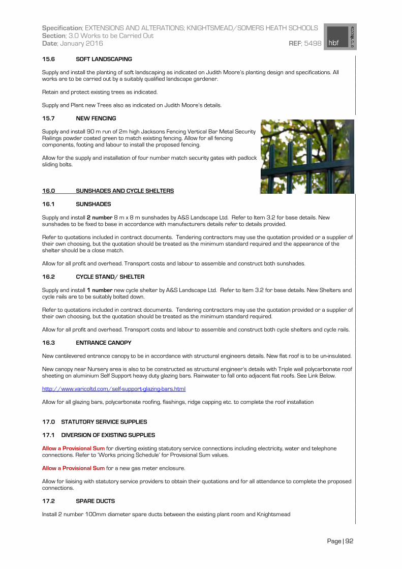
Specification; EXTENSIONS AND ALTERATIONS; KNIGHTSMEAD/SOMERS HEATH SCHOOLS Section; 3.0 Works to be Carried Out Date; January 2016 REF; 5498
Page | 92
15.6 SOFT LANDSCAPING Supply and install the planting of soft landscaping as indicated on Judith Moore’s planting design and specifications. All works are to be carried out by a suitably qualified landscape gardener.
Retain and protect existing trees as indicated. Supply and Plant new Trees also as indicated on Judith Moore’s details. 15.7 NEW FENCING Supply and install 90 m run of 2m high Jacksons Fencing Vertical Bar Metal Security Railings powder coated green to match existing fencing. Allow for all fencing components, footing and labour to install the proposed fencing. Allow for the supply and installation of four number match security gates with padlock sliding bolts.
16.0 SUNSHADES AND CYCLE SHELTERS 16.1 SUNSHADES Supply and install 2 number 8 m x 8 m sunshades by A&S Landscape Ltd. Refer to Item 3.2 for base details. New sunshades to be fixed to base in accordance with manufacturers details refer to details provided.
Refer to quotations included in contract documents. Tendering contractors may use the quotation provided or a supplier of their own choosing, but the quotation should be treated as the minimum standard required and the appearance of the shelter should be a close match. Allow for all profit and overhead. Transport costs and labour to assemble and construct both sunshades.
16.2 CYCLE STAND/ SHELTER Supply and install 1 number new cycle shelter by A&S Landscape Ltd. Refer to Item 3.2 for base details. New Shelters and cycle rails are to be suitably bolted down. Refer to quotations included in contract documents. Tendering contractors may use the quotation provided or a supplier of their own choosing, but the quotation should be treated as the minimum standard required. Allow for all profit and overhead. Transport costs and labour to assemble and construct both cycle shelters and cycle rails.
16.3 ENTRANCE CANOPY New cantilevered entrance canopy to be in accordance with structural engineers details. New flat roof is to be un-insulated. New canopy near Nursery area is also to be constructed as structural engineer’s details with Triple wall polycarbonate roof sheeting on aluminium Self Support heavy duty glazing bars. Rainwater to fall onto adjacent flat roofs. See Link Below. http://www.varicoltd.com/self-support-glazing-bars.html Allow for all glazing bars, polycarbonate roofing, flashings, ridge capping etc. to complete the roof installation 17.0 STATUTORY SERVICE SUPPLIES 17.1 DIVERSION OF EXISTING SUPPLIES Allow a Provisional Sum for diverting existing statutory service connections including electricity, water and telephone connections. Refer to ‘Works pricing Schedule’ for Provisional Sum values. Allow a Provisional Sum for a new gas meter enclosure. Allow for liaising with statutory service providers to obtain their quotations and for all attendance to complete the proposed connections.
17.2 SPARE DUCTS Install 2 number 100mm diameter spare ducts between the existing plant room and Knightsmead