Embed Size (px)
Citation preview
Specification of Modular Data Center
Architecture
Revision 2
by Neil Rasmussen
White Paper 160
There is a growing consensus that conventional legacy data center design will be superseded by modular scalable data center designs. Reduced total cost of ownership, increased flexibility, reduced deployment time, and improved efficiency are all claimed benefits of modular scalable designs. Yet the term “modular”, when and where modularity is appropriate, and how to specify modularity are all poorly defined. This paper creates a framework for modular data center architecture and describes the various ways that modularity can be implemented for data center power, cooling, and space infrastructure and explains when the different approaches are appropriate and effective.
Executive summary >
by Schneider Electric White Papers are now part of the Schneider Electric white paper library produced by Schneider Electric’s Data Center Science Center [email protected]
Specification of Modular Data Center Architecture
Schneider Electric – Data Center Science Center Rev 2 2
Modularity is loosely defined as a technique that builds large systems out of smaller subsys-tems, where the subsystems have well defined rules for interfacing to each other. Modularity also suggests a simplified approach to installation or replacement, ideally with “plug in” of modular elements that require simplified commissioning. Recent reports by Gartner reflect the growing realization that “The first two generations of data center designs are no longer appropriate for current and future needs. New data centers should be perceived less as a static structure and more as an agile, living organism that evolves as the server and storage infrastructure changes.” In response, Gartner suggests operators should “Include flexible, modular, virtualized design principles in new data center designs1.” Major suppliers of data center equipment and complete data center solutions are promoting the benefits of their modular solutions. Yet the definition of modularity remains vague and can be applied to a single device, such as a UPS, or it can be applied to complete data center buildings. In the case of so-called containerized data centers, the data center itself is can be viewed as a module. Data center operators are faced with a confusing number of poorly defined terms describing modularity including terms like pods, containers, clusters, zones, rows, rooms, busses, etc. Clearly, modularity within a data center does not refer to one specific ideal design, but rather to an approach that can yield many different types of design. Furthermore, while some data centers may be said to be “more modular” than others, there is no threshold where a data center becomes modular. When a modular approach is chosen, the degree to which the data center is cut up into modules must also be considered. Should a specific subsystem in a data center have three modules or forty-seven modules? Modularity does have some costs, so making everything as modular as possible is not always effective. A recent analysis by Tier 1 Research2 validates the advantages of modularity for data centers but suggests that the industry impact of modularity will only be maximized when modules become “industrialized” and standardized to reduce their costs and speed the supply chain. In this paper, we will define what is meant by modularity and define terms used for describing and specifying modularity in relation to the physical infrastructure of data center including space, power and cooling. Modularity in relation to the IT architecture or IT hardware is not discussed in this paper. A graphical method for describing a modular architecture will be presented. The feasibility of standardizing and industrializing modularity will be examined. We will show how data center modularity can be effectively applied and specified, and how the approach should vary with the application. Modularity is of interest to all data center operators because it has the potential to solve a number of problems at the same time. Almost every type of data center, large or small, of different availability requirements, benefits from modularity. Table 1 shows a partial list of problems that modular design has been shown to successfully address.
1 “ The Data Center as a Living Organism: Why history is not a good guide to the future”, by Rakesh Kumar and Phillip Dawson, Gartner Research 2 “Data Center 2.0: The Industrial Revolution” by Jason Schafer, Tier 1 Research/451 Group, Septem-
ber 2011
Introduction
Problems solved by modularity
Specification of Modular Data Center Architecture
Schneider Electric – Data Center Science Center Rev 2 3
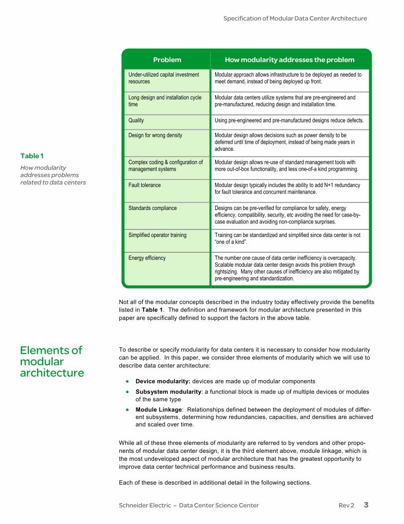
Problem How modularity addresses the problem
Under-utilized capital investment resources
Modular approach allows infrastructure to be deployed as needed to meet demand, instead of being deployed up front.
Long design and installation cycle time
Modular data centers utilize systems that are pre-engineered and pre-manufactured, reducing design and installation time.
Quality Using pre-engineered and pre-manufactured designs reduce defects.
Design for wrong density Modular design allows decisions such as power density to be deferred until time of deployment, instead of being made years in advance.
Complex coding & configuration of management systems
Modular design allows re-use of standard management tools with more out-of-box functionality, and less one-of-a kind programming.
Fault tolerance Modular design typically includes the ability to add N+1 redundancy for fault tolerance and concurrent maintenance.
Standards compliance Designs can be pre-verified for compliance for safety, energy efficiency, compatibility, security, etc avoiding the need for case-by-case evaluation and avoiding non-compliance surprises.
Simplified operator training Training can be standardized and simplified since data center is not “one of a kind”.
Energy efficiency The number one cause of data center inefficiency is overcapacity. Scalable modular data center design avoids this problem through rightsizing. Many other causes of inefficiency are also mitigated by pre-engineering and standardization.
Not all of the modular concepts described in the industry today effectively provide the benefits listed in Table 1. The definition and framework for modular architecture presented in this paper are specifically defined to support the factors in the above table. To describe or specify modularity for data centers it is necessary to consider how modularity can be applied. In this paper, we consider three elements of modularity which we will use to describe data center architecture: • Device modularity: devices are made up of modular components
• Subsystem modularity: a functional block is made up of multiple devices or modules of the same type
• Module Linkage: Relationships defined between the deployment of modules of differ-ent subsystems, determining how redundancies, capacities, and densities are achieved and scaled over time.
While all of these three elements of modularity are referred to by vendors and other propo-nents of modular data center design, it is the third element above, module linkage, which is the most undeveloped aspect of modular architecture that has the greatest opportunity to improve data center technical performance and business results. Each of these is described in additional detail in the following sections.
Table 1 How modularity addresses problems related to data centers
Elements of modular architecture
Specification of Modular Data Center Architecture
Schneider Electric – Data Center Science Center Rev 2 4
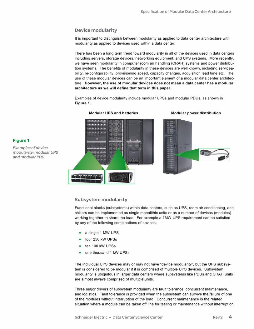
Device modularity It is important to distinguish between modularity as applied to data center architecture with modularity as applied to devices used within a data center. There has been a long term trend toward modularity in all of the devices used in data centers including servers, storage devices, networking equipment, and UPS systems. More recently, we have seen modularity in computer room air handling (CRAH) systems and power distribu-tion systems. The benefits of modularity in these devices are well known, including servicea-bility, re-configurability, provisioning speed, capacity changes, acquisition lead time etc. The use of these modular devices can be an important element of a modular data center architec-ture. However, the use of modular devices does not mean a data center has a modular architecture as we will define that term in this paper. Examples of device modularity include modular UPSs and modular PDUs, as shown in Figure 1. Modular UPS and batteries Modular power distribution
Subsystem modularity Functional blocks (subsystems) within data centers, such as UPS, room air conditioning, and chillers can be implemented as single monolithic units or as a number of devices (modules) working together to share the load. For example a 1MW UPS requirement can be satisfied by any of the following combinations of devices: • a single 1 MW UPS
• four 250 kW UPSs
• ten 100 kW UPSs
• one thousand 1 kW UPSs
The individual UPS devices may or may not have “device modularity”, but the UPS subsys-tem is considered to be modular if it is comprised of multiple UPS devices. Subsystem modularity is ubiquitous in larger data centers where subsystems like PDUs and CRAH units are almost always comprised of multiple units. Three major drivers of subsystem modularity are fault tolerance, concurrent maintenance, and logistics. Fault tolerance is provided when the subsystem can survive the failure of one of the modules without interruption of the load. Concurrent maintenance is the related situation where a module can be taken off line for testing or maintenance without interruption
Figure 1 Examples of device modularity: modular UPS and modular PDU
Specification of Modular Data Center Architecture
Schneider Electric – Data Center Science Center Rev 2 5
of the load. Logistics of moving devices within a facility makes it highly beneficial when an individual module is small enough to be moved via a passenger elevator, shipped via an enclosed truck, and moved through doorways and over interior flooring surfaces without difficulty. These factors drive data center designs away from huge monolithic subsystems, and toward subsystems comprised of multiple modules, especially if the subsystems are deployed indoors. Although subsystem modularity is common for many device types within a data center, many of the devices used in these subsystems have not achieved the ideal modular condition of “plug-in” installation. For example, adding an additional 60kW CRAH unit in a data center still requires significant planning, engineering, plumbing, control programming, and commission-ing. The vendors of these products continue to work on improving their products and simplifying this process in order to achieve the benefits of “plug-in” modularity in the subsys-tem. As in the case of device modularity, subsystem modularity is often an important element in a modular data center design, but subsystem modularity does not, by itself, mean a data center has a modular architecture. To have a modular architecture, the design must specify how the different subsystems are deployed together. Module linkage To deploy a unit of IT requires a combination of physical space, power, cooling, connectivity, fire suppression, and lighting. Therefore, the linkage of modularity across subsystem types within the data center is a key concept in modular data center architecture. In principle, a complete set of balanced and integrated subsystems could be deployed as a standard unit of modular data center capacity. This would clearly be a modular data center architecture. All of the data center subsystems would be linked together into a module. Miniature complete independent data centers could be added at a site over time. This can be said to be the most “pure” form of modular data center architecture. However, while this is a simple idea, it is impractical today, for the following reasons: • It is not practical to manage every module of data center capacity as a separate data
center
• Some subsystems are much more cost effective when deployed at a larger scale than the desired module size
• Achieving redundancy across a set of modules is often much less expensive and more efficient than implementing redundancy in every module
• Isolating capacities such as power and cooling to a data center module can create situations of stranded unusable capacity
• Module sizes should be chosen to be as small as practical for maximum flexibility, but many device types like generators and chillers are extremely ineffective at small mod-ule size.
Although linking all of the subsystems together into complete independent data center modules is impractical, a modular data center architecture must have some approach to group the subsystems so they can be deployed in a logical and coherent way. Module linkage is a property of the data center architecture that defines how the deployments of different subsystems relate to each other. As an example of module linkage, consider the deployment of equipment racks and rack power strips. In this simple case we can define a 1 for 1 deployment. Now consider the deployment of PDUs and racks. In this case we might define a rule linking 1 PDU to every 20 racks. We could continue defining relationships such as 1 generator for every 500 racks, one
Specification of Modular Data Center Architecture
Schneider Electric – Data Center Science Center Rev 2 6
CRAH for every 40 racks, one data acquisition system for every 200 racks, etc. We refer to rules relating these deployments as “linkages” of the modularity of the different subsystems. These linkages may be as simple as rules of deployment, or they can be enforced by pre-engineered and pre-manufactured skids, containers, or “kits” of deployment. In legacy data center design, linkage is vaguely comprehended in the overall design to establish the overall capacities for the data center, such as total chiller capacity, square footage, CRAH capacity, etc. Frequently, the complete data center design is developed and the data center is often completely built out to the maximum design rating without any modular architecture. Often, some devices are omitted during the early phases of the data center as a way to defer investment. For example, a system designed for five diesel genera-tor sets in an N+1 configuration might be built out with switchgear, infrastructure, and pads for five diesel generators but only three are installed in the initial build. Such a data center can be said to have implemented subsystem modularity of the generator sets, with some of the benefits of modularity, but without any formal linkage of the different subsystems, this is not an example of a modular data center architecture. Given the elements of device modularity, subsystem modularity, and module linkage as defined above, we can now define the concept of a modular data center architecture, and what it looks like in practice. An effective modular data center architecture has the following attributes: • It defines a set of modules from which data centers are deployed.
• It defines the modules as sets of subsystems that are linked together to the maximum practical extent in order to minimize complexity of deployment.
• It is comprised of rules, tools, and devices that together prescribe how modules are deployed over time to support the growth plan for the data center.
• The system is engineered to minimize the planning, installation, configuration, and programming work required to deploy a module.
• The characteristics of the deployed system, such as capacity, efficiency, density, weight, etc are well defined in advance without further analysis.
• The level or “granularity” of module sizes has been established to be an effective tradeoff between simplicity, cost, and rightsizing.
• It ideally allows for future options related to availability (redundancy) and power densi-ty.
• It is an open architecture that can accommodate new infrastructure products and de-vices from multiple vendors.
It is important to understand that a modular data center architecture, as defined above, is not just a list of parts, but is itself a system that requires a significant amount of engineering and testing. While a modular architecture can be developed and defined for a specific data center, it is much more useful and efficient if standard architectures are defined in the industry. If a data center adopts a pre-existing standard architecture, then a consider-able amount of engineering, specifying, planning, and testing cost (and time) can be avoided. As more data centers adopt standard architectures, industry cost reductions and quality improvements will occur. Although the concept of units of data center capacity sound simple, such units can actually be deployed at many hierarchical levels. As an extreme example, we can consider a separate unit of data center capacity, or a miniature independent data center, for every individual IT device. At the opposite extreme, we can consider dropping in complete prefab-ricated data center buildings of 40 MW IT capacity as a single unit. In defining a modular
Defining modular architecture for data centers
Specification of Modular Data Center Architecture
Schneider Electric – Data Center Science Center Rev 2 7
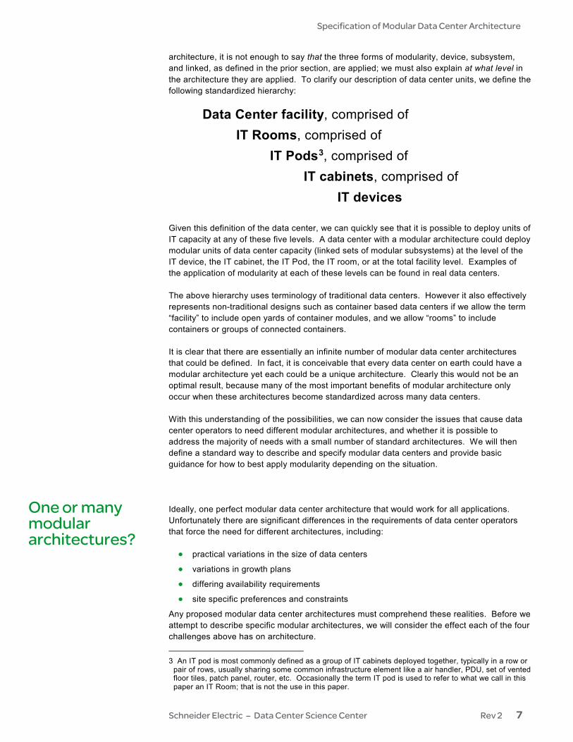
architecture, it is not enough to say that the three forms of modularity, device, subsystem, and linked, as defined in the prior section, are applied; we must also explain at what level in the architecture they are applied. To clarify our description of data center units, we define the following standardized hierarchy:
Data Center facility, comprised of IT Rooms, comprised of IT Pods3, comprised of IT cabinets, comprised of IT devices
Given this definition of the data center, we can quickly see that it is possible to deploy units of IT capacity at any of these five levels. A data center with a modular architecture could deploy modular units of data center capacity (linked sets of modular subsystems) at the level of the IT device, the IT cabinet, the IT Pod, the IT room, or at the total facility level. Examples of the application of modularity at each of these levels can be found in real data centers. The above hierarchy uses terminology of traditional data centers. However it also effectively represents non-traditional designs such as container based data centers if we allow the term “facility” to include open yards of container modules, and we allow “rooms” to include containers or groups of connected containers. It is clear that there are essentially an infinite number of modular data center architectures that could be defined. In fact, it is conceivable that every data center on earth could have a modular architecture yet each could be a unique architecture. Clearly this would not be an optimal result, because many of the most important benefits of modular architecture only occur when these architectures become standardized across many data centers. With this understanding of the possibilities, we can now consider the issues that cause data center operators to need different modular architectures, and whether it is possible to address the majority of needs with a small number of standard architectures. We will then define a standard way to describe and specify modular data centers and provide basic guidance for how to best apply modularity depending on the situation. Ideally, one perfect modular data center architecture that would work for all applications. Unfortunately there are significant differences in the requirements of data center operators that force the need for different architectures, including: • practical variations in the size of data centers
• variations in growth plans
• differing availability requirements
• site specific preferences and constraints
Any proposed modular data center architectures must comprehend these realities. Before we attempt to describe specific modular architectures, we will consider the effect each of the four challenges above has on architecture.
3 An IT pod is most commonly defined as a group of IT cabinets deployed together, typically in a row or
pair of rows, usually sharing some common infrastructure element like a air handler, PDU, set of vented floor tiles, patch panel, router, etc. Occasionally the term IT pod is used to refer to what we call in this paper an IT Room; that is not the use in this paper.
One or many modular architectures?
Specification of Modular Data Center Architecture
Schneider Electric – Data Center Science Center Rev 2 8
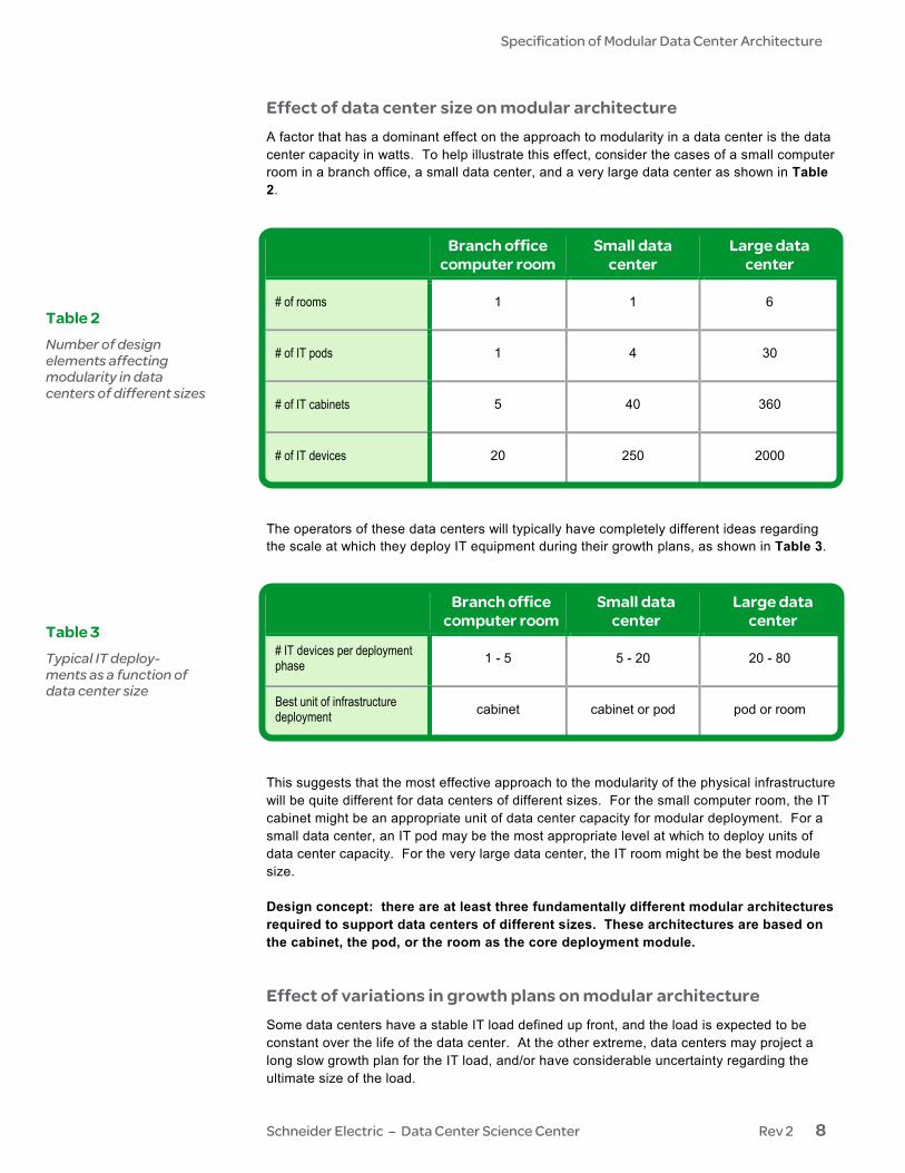
Effect of data center size on modular architecture A factor that has a dominant effect on the approach to modularity in a data center is the data center capacity in watts. To help illustrate this effect, consider the cases of a small computer room in a branch office, a small data center, and a very large data center as shown in Table 2.
Branch office computer room
Small data center
Large data center
# of rooms 1 1 6
# of IT pods 1 4 30
# of IT cabinets 5 40 360
# of IT devices 20 250 2000
The operators of these data centers will typically have completely different ideas regarding the scale at which they deploy IT equipment during their growth plans, as shown in Table 3.
Branch office computer room
Small data center
Large data center
# IT devices per deployment phase 1 - 5 5 - 20 20 - 80
Best unit of infrastructure deployment cabinet cabinet or pod pod or room
This suggests that the most effective approach to the modularity of the physical infrastructure will be quite different for data centers of different sizes. For the small computer room, the IT cabinet might be an appropriate unit of data center capacity for modular deployment. For a small data center, an IT pod may be the most appropriate level at which to deploy units of data center capacity. For the very large data center, the IT room might be the best module size. Design concept: there are at least three fundamentally different modular architectures required to support data centers of different sizes. These architectures are based on the cabinet, the pod, or the room as the core deployment module. Effect of variations in growth plans on modular architecture Some data centers have a stable IT load defined up front, and the load is expected to be constant over the life of the data center. At the other extreme, data centers may project a long slow growth plan for the IT load, and/or have considerable uncertainty regarding the ultimate size of the load.
Table 2 Number of design elements affecting modularity in data centers of different sizes
Table 3 Typical IT deploy-ments as a function of data center size
Specification of Modular Data Center Architecture
Schneider Electric – Data Center Science Center Rev 2 9
In a data center with a well defined constant load, there is no penalty for a complete up-front build out of the infrastructure, and it is actually required. In this case, the scalability benefits of a modular architecture are irrelevant. However, many other benefits of modular design are still attractive, such as reduced engineering effort, the quality benefits resulting from the use of proven designs, and reduced lead time. When the IT load is constant and well defined, modular architectures tend toward large module sizes and centralized plants for many subsystems. In the case of a data center with slow growth and an uncertain growth plan, the benefits of scalability are a dominant factor in the design. There are huge potential penalties for a complete up-front build out: large investments in unused or underutilized capital equipment, maintenance costs associated with assets providing no value, unnecessary waste of energy due to over-provisioning, or even the possibility of writing down a large capital asset if the facility is abandoned partway through its life. In these cases, the ability to scale the data center infrastructure to match the IT load can dramatically affect the TCO of the data center and therefore the return on the investment. Modular data center architectures that minimize the upfront build out and maximize the modularization of the subsystems are the best choice in these cases. Design concept: Data centers with stable predictable loads will benefit from modular architectures based on central plants and large module sizes that are typically de-ployed all up front. Data centers with uncertain future loads and long growth plans will benefit from modular architectures centered around decentralized infrastructure and smaller module sizes. These are conflicting requirements requiring different architec-tural approaches. Effect of availability requirements on modular architecture Many data center designs include some level of redundancy in order to achieve fault toler-ance and to allow for maintenance without shutdown. Redundancy implies that subsystems are comprised of multiple elements, some of which are designated as redundant. Therefore, any data center with redundancy must have at least a crude approach to modularity. In conventional data center design it can be complex to analyze and predict the performance of redundant systems over the course of the lifetime of the data center. This is just one more reason why building out a conventional data center to full capacity up front is a common practice. An effective modular data center architecture must explicitly describe and provide a clear way to deploy modules of IT capacity while maintaining the desired redundancy of the data center. The desired redundancy must be maintained as the data center is scaled. Ideally, a modular data center architecture would provide the option to target different levels of redundancy to different parts of the data center in order to provide the most cost effective support of differing IT requirements. There is no single way to implement redundancy in data centers. Various redundancy levels such as N+1, 2N, or System plus System are commonly described, but these descriptions are incomplete because there are many ways to implement these redundancy levels; for example in the case of an N+1 UPS system, the redundancy can be implemented within the UPS device, it could be achieved through paralleling of UPS devices, it could be achieved through a tri-redundant or “ring” architecture, or it could be achieved through use of a so-called “catcher” design with static transfer switches. These types of variations give rise to distinct architectures, with different approaches to modularity. An effective modular architecture optimizes module sizes taking redundancy goals into consideration. In an N+1 architecture, smaller module sizes allow the “+1” module to be
Specification of Modular Data Center Architecture
Schneider Electric – Data Center Science Center Rev 2 10
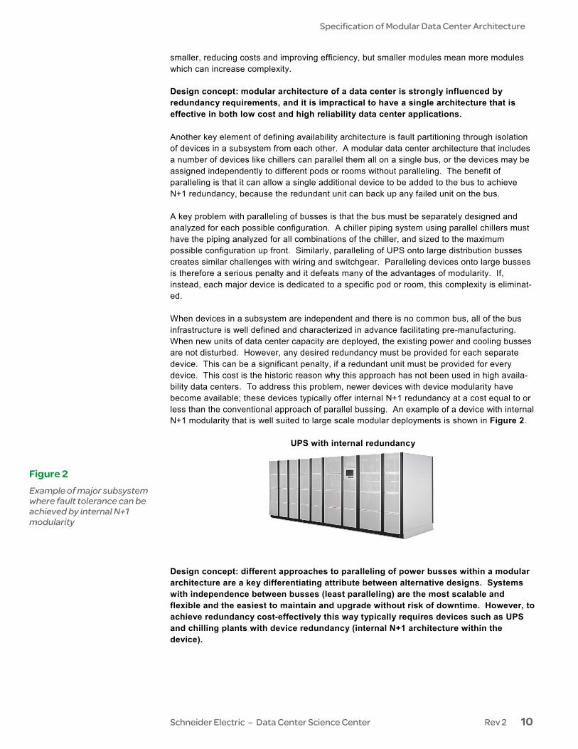
smaller, reducing costs and improving efficiency, but smaller modules mean more modules which can increase complexity. Design concept: modular architecture of a data center is strongly influenced by redundancy requirements, and it is impractical to have a single architecture that is effective in both low cost and high reliability data center applications. Another key element of defining availability architecture is fault partitioning through isolation of devices in a subsystem from each other. A modular data center architecture that includes a number of devices like chillers can parallel them all on a single bus, or the devices may be assigned independently to different pods or rooms without paralleling. The benefit of paralleling is that it can allow a single additional device to be added to the bus to achieve N+1 redundancy, because the redundant unit can back up any failed unit on the bus. A key problem with paralleling of busses is that the bus must be separately designed and analyzed for each possible configuration. A chiller piping system using parallel chillers must have the piping analyzed for all combinations of the chiller, and sized to the maximum possible configuration up front. Similarly, paralleling of UPS onto large distribution busses creates similar challenges with wiring and switchgear. Paralleling devices onto large busses is therefore a serious penalty and it defeats many of the advantages of modularity. If, instead, each major device is dedicated to a specific pod or room, this complexity is eliminat-ed. When devices in a subsystem are independent and there is no common bus, all of the bus infrastructure is well defined and characterized in advance facilitating pre-manufacturing. When new units of data center capacity are deployed, the existing power and cooling busses are not disturbed. However, any desired redundancy must be provided for each separate device. This can be a significant penalty, if a redundant unit must be provided for every device. This cost is the historic reason why this approach has not been used in high availa-bility data centers. To address this problem, newer devices with device modularity have become available; these devices typically offer internal N+1 redundancy at a cost equal to or less than the conventional approach of parallel bussing. An example of a device with internal N+1 modularity that is well suited to large scale modular deployments is shown in Figure 2.
UPS with internal redundancy
Design concept: different approaches to paralleling of power busses within a modular architecture are a key differentiating attribute between alternative designs. Systems with independence between busses (least paralleling) are the most scalable and flexible and the easiest to maintain and upgrade without risk of downtime. However, to achieve redundancy cost-effectively this way typically requires devices such as UPS and chilling plants with device redundancy (internal N+1 architecture within the device).
Figure 2 Example of major subsystem where fault tolerance can be achieved by internal N+1 modularity
Specification of Modular Data Center Architecture
Schneider Electric – Data Center Science Center Rev 2 11
Effect of site-specific preferences and constraints on modular archi-tecture Ideally, a standard data center architecture would be chosen, and then a building would be built to accommodate the modular building blocks present in the architecture. While this is the optimal approach, it is frequently not possible. In the majority of data center projects, there is an existing building. Constraints may include physical sizes of IT spaces, existing central chiller plant or ventilation systems, existing electrical service, headroom in the IT space, or some existing data center power and cooling devices. To be usable in these cases, a modular architecture must have some means to accommodate these constraints. In addition, a data center operator may have preferences that have an impact on the design. For example, there may be a requirement that a data center be set up to receive frequent tours by guests, a requirement to cage or separate groups of IT equipment, or there may be certain data cabling preferences that impact airflow or power distribution. Over time, an organization may have adopted a considerable list of standards related to data center design, which are then specified as inputs to the design. In general, a standard architecture will not be able to accommodate all of these types of preferences. A modular data center architecture may have the flexibility to provide some options within the architecture to accommodate common site preferences and constraints. Custom adaptations of an architecture are always possible but may defeat or impair some of the advantages of a standardized modular architecture. Design concept: A better result is achieved when the site specific preferences and constraints are reviewed and adjusted to suit a desired architecture, rather than to attempt to force an architecture into a pre-conceived specification. The most common constraint of a data center is the size and shape of a pre-existing room(s), and a practical modular data center architecture will have a method to accommodate varia-tions in room size and shape. When all of the above factors are considered, it is clear that the vast majority of data center applications can be addressed with a handful of different standardized data center architec-tures, primarily differing in module size increments and redundancy features. It is not necessary to have tens or hundreds of different architectures. This suggests that industry standard data center architectures are a practical possibility in the near future. With a basic understanding of what a modular data center architecture includes, we can now describe a method to document any specific architecture. This paper introduces the concept of documenting a modular data center architecture with three basic elements:
• a modularity chart showing how modularity is deployed and linked across the various subsystems
• a specification of key technical attributes of the architecture
• a set of diagrams showing the footprints of the various modules for layout purposes
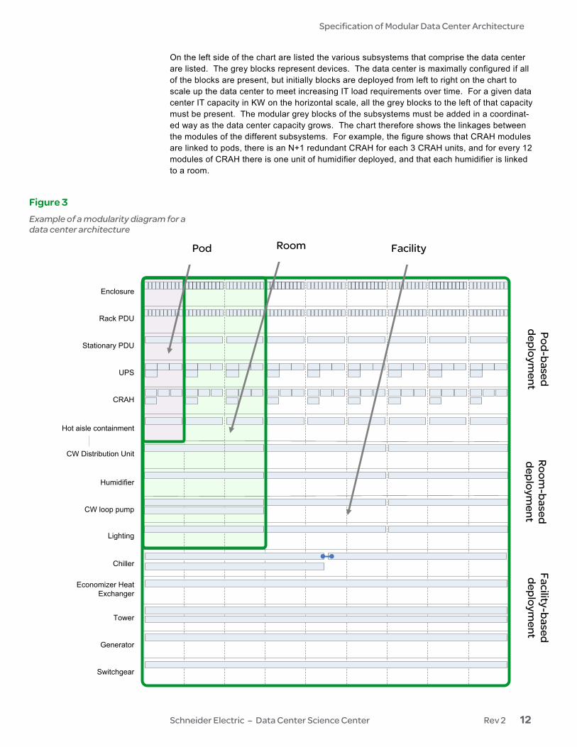
Modularity chart for data center architecture Figure 3 shows an example of a modularity chart for a data center architecture. In this figure we can see all the different forms of modularity – device, subsystem, and module linkage – deployed at the level of the pod, the room, and the facility. This chart conveys a considerable amount of information about the architecture, which will now be explained.
Documenting a modular data center architecture
Specification of Modular Data Center Architecture
Schneider Electric – Data Center Science Center Rev 2 12
On the left side of the chart are listed the various subsystems that comprise the data center are listed. The grey blocks represent devices. The data center is maximally configured if all of the blocks are present, but initially blocks are deployed from left to right on the chart to scale up the data center to meet increasing IT load requirements over time. For a given data center IT capacity in KW on the horizontal scale, all the grey blocks to the left of that capacity must be present. The modular grey blocks of the subsystems must be added in a coordinat-ed way as the data center capacity grows. The chart therefore shows the linkages between the modules of the different subsystems. For example, the figure shows that CRAH modules are linked to pods, there is an N+1 redundant CRAH for each 3 CRAH units, and for every 12 modules of CRAH there is one unit of humidifier deployed, and that each humidifier is linked to a room.
Enclosure
Stationary PDU
Rack PDU
UPS
CRAH
CW Distribution Unit
Humidifier
Hot aisle containment
Chiller
CW loop pump
Tower
Economizer Heat Exchanger
Lighting
Generator
Switchgear
Pod Room Facility
Pod-based deploym
ent Room
-based deploym
ent Facility-based
deployment
Figure 3 Example of a modularity diagram for a data center architecture
Specification of Modular Data Center Architecture
Schneider Electric – Data Center Science Center Rev 2 13
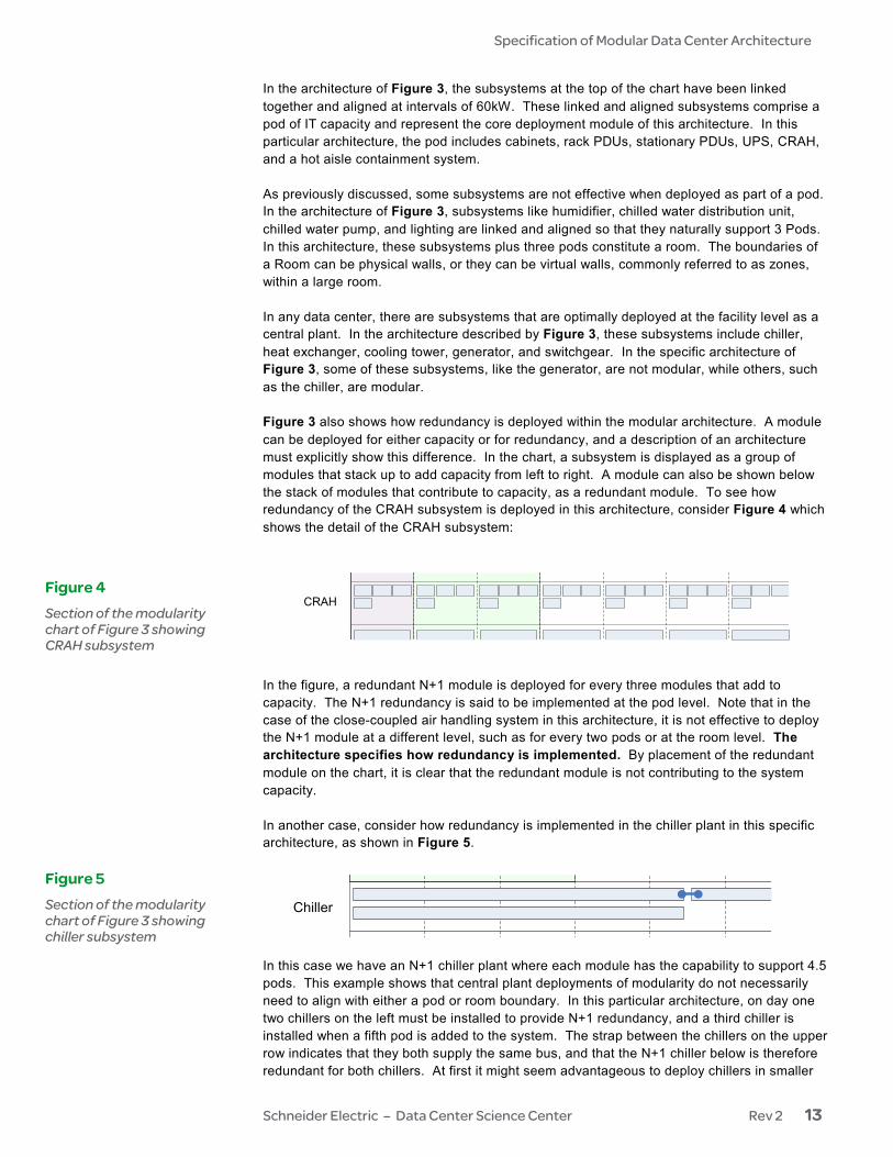
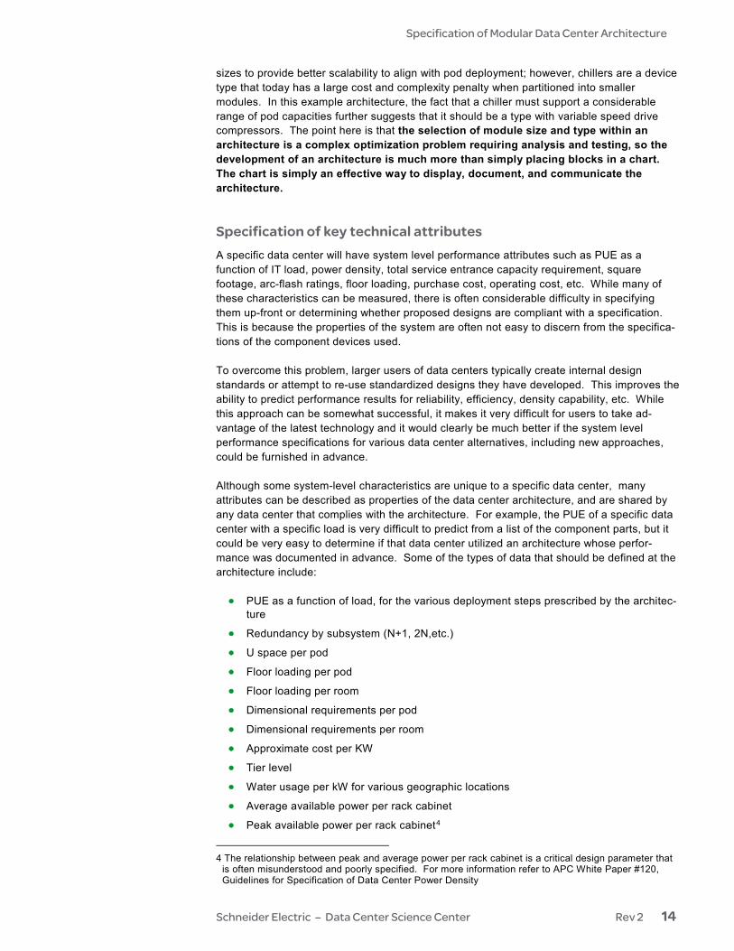
In the architecture of Figure 3, the subsystems at the top of the chart have been linked together and aligned at intervals of 60kW. These linked and aligned subsystems comprise a pod of IT capacity and represent the core deployment module of this architecture. In this particular architecture, the pod includes cabinets, rack PDUs, stationary PDUs, UPS, CRAH, and a hot aisle containment system. As previously discussed, some subsystems are not effective when deployed as part of a pod. In the architecture of Figure 3, subsystems like humidifier, chilled water distribution unit, chilled water pump, and lighting are linked and aligned so that they naturally support 3 Pods. In this architecture, these subsystems plus three pods constitute a room. The boundaries of a Room can be physical walls, or they can be virtual walls, commonly referred to as zones, within a large room. In any data center, there are subsystems that are optimally deployed at the facility level as a central plant. In the architecture described by Figure 3, these subsystems include chiller, heat exchanger, cooling tower, generator, and switchgear. In the specific architecture of Figure 3, some of these subsystems, like the generator, are not modular, while others, such as the chiller, are modular. Figure 3 also shows how redundancy is deployed within the modular architecture. A module can be deployed for either capacity or for redundancy, and a description of an architecture must explicitly show this difference. In the chart, a subsystem is displayed as a group of modules that stack up to add capacity from left to right. A module can also be shown below the stack of modules that contribute to capacity, as a redundant module. To see how redundancy of the CRAH subsystem is deployed in this architecture, consider Figure 4 which shows the detail of the CRAH subsystem: In the figure, a redundant N+1 module is deployed for every three modules that add to capacity. The N+1 redundancy is said to be implemented at the pod level. Note that in the case of the close-coupled air handling system in this architecture, it is not effective to deploy the N+1 module at a different level, such as for every two pods or at the room level. The architecture specifies how redundancy is implemented. By placement of the redundant module on the chart, it is clear that the redundant module is not contributing to the system capacity. In another case, consider how redundancy is implemented in the chiller plant in this specific architecture, as shown in Figure 5. In this case we have an N+1 chiller plant where each module has the capability to support 4.5 pods. This example shows that central plant deployments of modularity do not necessarily need to align with either a pod or room boundary. In this particular architecture, on day one two chillers on the left must be installed to provide N+1 redundancy, and a third chiller is installed when a fifth pod is added to the system. The strap between the chillers on the upper row indicates that they both supply the same bus, and that the N+1 chiller below is therefore redundant for both chillers. At first it might seem advantageous to deploy chillers in smaller
Figure 4 Section of the modularity chart of Figure 3 showing CRAH subsystem
Stat o a y U
ac U
U S
CRAH
Cooling Distribution Unit
Humidifier
Hot aisle containment
Figure 5 Section of the modularity chart of Figure 3 showing chiller subsystem
Chiller
Specification of Modular Data Center Architecture
Schneider Electric – Data Center Science Center Rev 2 14
sizes to provide better scalability to align with pod deployment; however, chillers are a device type that today has a large cost and complexity penalty when partitioned into smaller modules. In this example architecture, the fact that a chiller must support a considerable range of pod capacities further suggests that it should be a type with variable speed drive compressors. The point here is that the selection of module size and type within an architecture is a complex optimization problem requiring analysis and testing, so the development of an architecture is much more than simply placing blocks in a chart. The chart is simply an effective way to display, document, and communicate the architecture. Specification of key technical attributes A specific data center will have system level performance attributes such as PUE as a function of IT load, power density, total service entrance capacity requirement, square footage, arc-flash ratings, floor loading, purchase cost, operating cost, etc. While many of these characteristics can be measured, there is often considerable difficulty in specifying them up-front or determining whether proposed designs are compliant with a specification. This is because the properties of the system are often not easy to discern from the specifica-tions of the component devices used. To overcome this problem, larger users of data centers typically create internal design standards or attempt to re-use standardized designs they have developed. This improves the ability to predict performance results for reliability, efficiency, density capability, etc. While this approach can be somewhat successful, it makes it very difficult for users to take ad-vantage of the latest technology and it would clearly be much better if the system level performance specifications for various data center alternatives, including new approaches, could be furnished in advance. Although some system-level characteristics are unique to a specific data center, many attributes can be described as properties of the data center architecture, and are shared by any data center that complies with the architecture. For example, the PUE of a specific data center with a specific load is very difficult to predict from a list of the component parts, but it could be very easy to determine if that data center utilized an architecture whose perfor-mance was documented in advance. Some of the types of data that should be defined at the architecture include: • PUE as a function of load, for the various deployment steps prescribed by the architec-
ture
• Redundancy by subsystem (N+1, 2N,etc.)
• U space per pod
• Floor loading per pod
• Floor loading per room
• Dimensional requirements per pod
• Dimensional requirements per room
• Approximate cost per KW
• Tier level
• Water usage per kW for various geographic locations
• Average available power per rack cabinet
• Peak available power per rack cabinet4
4 The relationship between peak and average power per rack cabinet is a critical design parameter that
is often misunderstood and poorly specified. For more information refer to APC White Paper #120, Guidelines for Specification of Data Center Power Density
Specification of Modular Data Center Architecture
Schneider Electric – Data Center Science Center Rev 2 15
• Average power density across the white space area
• Requirements for installation plumbing and wiring
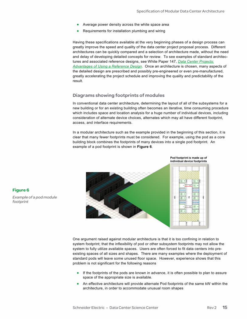
Having these specifications available at the very beginning phases of a design process can greatly improve the speed and quality of the data center project proposal process. Different architectures can be quickly compared and a selection of architecture made, without the need and delay of developing detailed concepts for review. To see examples of standard architec-tures and associated reference designs, see White Paper 147, Data Center Projects: Advantages of Using a Reference Design. Once an architecture is chosen, many aspects of the detailed design are prescribed and possibly pre-engineered or even pre-manufactured, greatly accelerating the project schedule and improving the quality and predictability of the result. Diagrams showing footprints of modules In conventional data center architecture, determining the layout of all of the subsystems for a new building or for an existing building often becomes an iterative, time consuming procedure which includes space and location analysis for a huge number of individual devices, including consideration of alternate device choices, alternates which may all have different footprint, access, and interface requirements. In a modular architecture such as the example provided in the beginning of this section, it is clear that many fewer footprints must be considered. For example, using the pod as a core building block combines the footprints of many devices into a single pod footprint. An example of a pod footprint is shown in Figure 6.
Pod footprint is made up of individual device footprints
One argument raised against modular architecture is that it is too confining in relation to system footprint; that the inflexibility of pod or other subsystem footprints may not allow the system to fully utilize available spaces. Users are often forced to fit data centers into pre-existing spaces of all sizes and shapes. There are many examples where the deployment of standard pods will leave some unused floor space. However, experience shows that this problem is not significant for the following reasons • If the footprints of the pods are known in advance, it is often possible to plan to assure
space of the appropriate size is available.
• An effective architecture will provide alternate Pod footprints of the same kW within the architecture, in order to accommodate unusual room shapes
Figure 6 Example of a pod module footprint
Specification of Modular Data Center Architecture
Schneider Electric – Data Center Science Center Rev 2 16
• The IT equipment density for pod designs is typically much higher than the efficiency of packing IT devices using traditional methods, because access-ways and power density are optimized; Pod based designs often pack in more IT equipment, and operate it more efficiently, than a traditional design that appears to eliminate all unused space.
The information provided in the previous sections suggests the following standardized approach to choosing an optimal modular architecture for a modular data centers for a given situation: • Define the overall design in terms of the key design parameters of power capacity,
availability, growth plan, and power density
• Use the IT parameters to help select an available standard architecture that best suits that set of requirements (using prescribed tools, methods, or selector guides)
• Identify special constraints of the project (existing physical space, power or cooling subsystems)
• Given the constraints and chosen architecture, identify the set of modules and any options needed to achieve the IT parameters.
• Verify that the modules can be deployed within the constraints of the project
• If the constraints result in a sub-optimized design concept with the selected architec-ture, consider options within the architecture, alternate architectures, or attempt to ad-just the constraints
• Specify or select the final architecture
• Establish the data center design specification, which includes the module set required to implement the IT requirements
• Commence detailed design
Note that the planning process described above can often be completed (including an expected cost projection) in a matter of hours, while in a traditional approach it can take months. This is because standardized architectures allow rapid visualization of optimized alternative design concepts. This discussion has used traditional room based data centers for illustration of the concepts. However, the techniques and terminology used here can be applied to any kind of deploy-ment or technology. The diagramming and specification methods are particularly well suited for describing data centers based on IT containers and modular power and cooling plants. Furthermore, data centers using mixed approaches are readily and very effectively described using the techniques illustrated here.
Specifying a data center project using modular methods
Containers, skids, and other form factors
Specification of Modular Data Center Architecture
Schneider Electric – Data Center Science Center Rev 2 17
The benefits of modular architecture are becoming widely recognized. This paper has only briefly summarized these benefits. The move toward modular data center is inevitable because the overwhelming improvements in performance and TCO that accrue. This form of advancement can be seen in many industries such as the automotive industry and the IT equipment industry. For data centers the only questions are how quickly this transformation will occur and what form it will take. This paper defines what is meant by modular data center architecture, so that operators, engineering firms, construction firms, and suppliers can begin to have productive conversa-tions about modular data center design using a common language. This paper has also gone further in describing how modular architecture can be formally specified. The industry will only obtain the benefits of modular data center architecture when the standard specification system described here, or one like it, becomes a commonly accepted way for vendors to describe data center offers, and for customers to use in requesting quotations.
Conclusion
Neil Rasmussen is a Senior VP of Innovation for Schneider Electric. He establishes the technology direction for the world’s largest R&D budget devoted to power, cooling, and rack infrastructure for critical networks. Neil holds 19 patents related to high-efficiency and high-density data center power and cooling infrastructure, and has published over 50 white papers related to power and cooling systems, many published in more than 10 languages, most recently with a focus on the improvement of energy efficiency. He is an internationally recognized keynote speaker on the subject of high-efficiency data centers. Neil is currently working to advance the science of high-efficiency, high-density, scalable data center infrastructure solutions and is a principal architect of the APC InfraStruXure system. Prior to founding APC in 1981, Neil received his bachelors and masters degrees from MIT in electrical engineering, where he did his thesis on the analysis of a 200MW power supply for a tokamak fusion reactor. From 1979 to 1981 he worked at MIT Lincoln Laboratories on flywheel energy storage systems and solar electric power systems.
About the author
Specification of Modular Data Center Architecture
Schneider Electric – Data Center Science Center Rev 2 18
Data Center Projects: Advantages of Using a Reference Design White Paper 147
© 20
17 S
chne
ider E
lectri
c. Al
l righ
ts re
serve
d.
For feedback and comments about the content of this white paper: Data Center Science Center [email protected] If you are a customer and have questions specific to your data center project: Contact your Schneider Electric representative at www.apc.com/support/contact/index.cfm
Contact us
Resources
Browse all white papers whitepapers.apc.com
Browse all TradeOff Tools™ tools.apc.com