Embed Size (px)
Citation preview

Specification of Detector Logic Operation Guidelines for Developing

Roads and Traffic Authority www.nsw.rta.gov.au
Title: Specification of Detector Logic Operation – Guidelines for Developing
Document no: TS-TN-020
Version: 1.0
Date: 26 May 2009
Approved by: P. Margison, General Manager Traffic Management
Copyright © 2009 Roads and Traffic Authority of NSW
This work is copyright. Apart from any fair use as permitted under the Copyright Act 1968, no part may be reproduced in any way without prior written consent from the Roads and Traffic Authority of NSW.
Disclaimer and Conditions For Use
This Specification has been prepared by the Roads and Traffic Authority of New South Wales (referred to herein as RTA) for use, insofar as it is applicable, in the State of New South Wales for equipment supplied under an RTA procurement order or contract, or under a procurement order or contract from another party that is required in writing by the RTA to use this Specification.
The use of this RTA Specification other than by those parties stated above and in the manner stated above is not recommended by the RTA. Any such use is entirely the decision of the user alone. The RTA disclaims all responsibilities arising whether directly or indirectly from any such use. The RTA does not warrant that this Specification is error free, nor does RTA warrant the suitability, fitness or otherwise of this Specification for any stated or implied purposes expressed or implied in this Specification or other documents. By using this Specification, the user agrees to indemnify the RTA against the full amount of all expenses, losses, damages and costs (on a full indemnity basis and whether or not incurred by or awarded against the RTA) which may be suffered by any person or the RTA in connection with or arising out of the use of this Specification in any manner.
The RTA is not under any duty to inform you of any errors in or changes to the Specification.
Revision history
Version Date Details
Roads and Traffic Authority of New South Wales Traffic Management Branch PO Box 1927 Strawberry Hills NSW 2012 Australia
Telephone: +61 2 8396 1602 Facsimile: +61 2 8396 1600
Page 2 of 54 Uncontrolled when printed TS-TN-020, Version 1.0
Specification of Detector Logic Operation
TS-TN-020, Version 1.0 Uncontrolled when printed Page 3 of 54
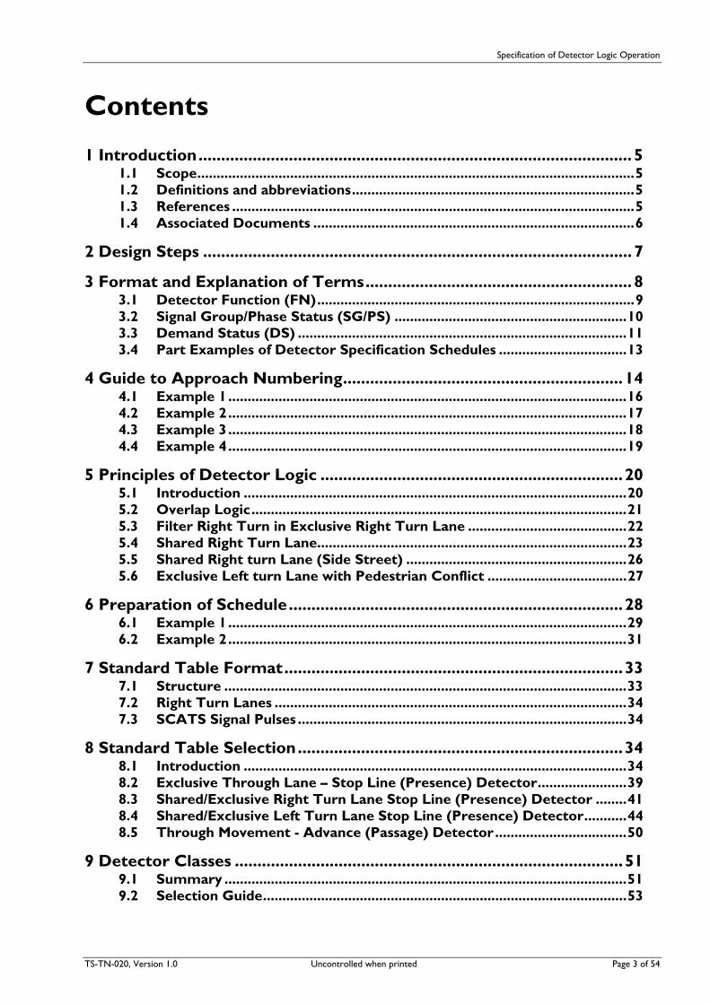
Contents
1 Introduction................................................................................................ 5 1.1 Scope.................................................................................................................5 1.2 Definitions and abbreviations.........................................................................5 1.3 References ........................................................................................................5 1.4 Associated Documents ...................................................................................6
2 Design Steps ............................................................................................... 7
3 Format and Explanation of Terms........................................................... 8 3.1 Detector Function (FN)..................................................................................9 3.2 Signal Group/Phase Status (SG/PS) ............................................................10 3.3 Demand Status (DS) .....................................................................................11 3.4 Part Examples of Detector Specification Schedules .................................13
4 Guide to Approach Numbering..............................................................14 4.1 Example 1.......................................................................................................16 4.2 Example 2.......................................................................................................17 4.3 Example 3.......................................................................................................18 4.4 Example 4.......................................................................................................19
5 Principles of Detector Logic ...................................................................20 5.1 Introduction ...................................................................................................20 5.2 Overlap Logic.................................................................................................21 5.3 Filter Right Turn in Exclusive Right Turn Lane .........................................22 5.4 Shared Right Turn Lane................................................................................23 5.5 Shared Right turn Lane (Side Street) .........................................................26 5.6 Exclusive Left turn Lane with Pedestrian Conflict ....................................27
6 Preparation of Schedule..........................................................................28 6.1 Example 1.......................................................................................................29 6.2 Example 2.......................................................................................................31
7 Standard Table Format...........................................................................33 7.1 Structure ........................................................................................................33 7.2 Right Turn Lanes ...........................................................................................34 7.3 SCATS Signal Pulses .....................................................................................34
8 Standard Table Selection........................................................................34 8.1 Introduction ...................................................................................................34 8.2 Exclusive Through Lane – Stop Line (Presence) Detector.......................39 8.3 Shared/Exclusive Right Turn Lane Stop Line (Presence) Detector ........41 8.4 Shared/Exclusive Left Turn Lane Stop Line (Presence) Detector...........44 8.5 Through Movement - Advance (Passage) Detector..................................50
9 Detector Classes ......................................................................................51 9.1 Summary ........................................................................................................51 9.2 Selection Guide..............................................................................................53

Specification of Detector Logic Operation
TS-TN-020, Version 1.0 Uncontrolled when printed Page 4 of 54
Table of Figures Figure 1 Preliminary Steps ....................................................................................................................8 Figure 2 A-B2 Detector ......................................................................................................................21 Figure 3 Exclusive Right Turn Lane ..................................................................................................22 Figure 4 Shared Right Turn ................................................................................................................24 Figure 5 Filter Right turn Movement on Side Street....................................................................26 Figure 6 Filter Right turn Movement on Side Street....................................................................27 Figure 7 Exclusive Through Lane Detector Logic Selection.......................................................40 Figure 8 Right turn Detector Logic Selection................................................................................42 Figure 9 Right turn Detector Logic Selection (cont’d)................................................................43 Figure 10 Left turn Detector Logic Selection..................................................................................46 Figure 11 Left turn Detector Logic Selection (cont’d)..................................................................47 Figure 12 Left turn Detector Logic Selection (cont’d)..................................................................48 Figure 13 Left turn Detector Logic Selection (cont’d)..................................................................49 Figure 14 Through Movement Passage (Advance) Detector Logic Selection .........................50
Table of Tables Table 1 Standard Table 6 ....................................................................................................................22 Table 2 Standard Table 5 ....................................................................................................................23 Table 3 Standard Table 4 ....................................................................................................................25 Table 4 Standard Table 20..................................................................................................................27 Table 5 Standard Table 7 ....................................................................................................................28

Specification of Detector Logic Operation
TS-TN-020, Version 1, 0 Uncontrolled when printed Page 5 of 54
1 Introduction This document provides a description of the method to be adopted in specifying the function of detectors at signalled locations. It replaces the Standard for Detector Specification Schedule [1].
In addition, a set of standard detector logic tables has been established to assist in the selection of the detector function in the preparation of the intersection design plan. The benefits of such a set of standards are significant with regard to design and the adaptive engineering required to translate that design into a controller personality.
The basic functions of a detector are to demand, extend and/or increment the phase(s) appropriate to the traffic in an approach lane. The schedule defines in detail the conditions applying to the function of each detector, or group of detectors.
An abbreviated symbolic language is used to define:
(a) the period during which the function occurs,
(b) any other conditions affecting the function.
The schedule is to be initiated at the design stage of an intersection and included on all signal design plans, except simple two phase, standard “Single Diamond” and standard “Double Diamond” overlap designs.
It should be noted that Split Approach Timing is normally specified in this Schedule. However, where separate lane timing is required at any location, a note to this effect should be added to the design plan.
Within the traffic signal controller pushbutton demands are recognised as part of the series of inputs which are termed detectors. Detector operation and specification are described in this document. Pushbutton demands, and hence pedestrian movements, are special types of detectors and are dealt with in Specification of Pedestrian Movement Operation, [10].
1.1 Scope This document supports vehicle group labelling of signal groups not phase labelling of signal groups. Detectors are labelled in accordance with Traffic Signals Practice [7].
1.2 Definitions and abbreviations Term Meaning
EPD Example Personality Data
LM Library Macro
OD Operational Description
RTA Roads and Traffic Authority of NSW
TAE Typical Application Example
TMB Traffic Management Branch of RTA
1.3 References [1] VD018-10, Standard for Detector Specification Schedule, 23 December 1988 (also titled Standard
Tables for Detector Logic, RTA Standard Personality, 24 November 1988)
[2] VD018-5, Standard for Single Diamond Overlap Design
[3] VD018-6, Standard for Double Diamond Overlap Design
[4] VD018-8, Standard for Signal Group Displays
[5] VD018-14, Standard for Single Diamond Overlap Phasing with Filter Option

Specification of Detector Logic Operation
Page 6 of 54 Uncontrolled when printed TS-TN-020, Version 1.0
[6] TS-QA-156, Personality Standard Tables Management – Standard Operating Procedure
[7] Traffic Signals Practice, Design – RTA, February 2008
[8] RTA-TC-106, Traffic Signal Operation, Version 1.1, October 2000
1.4 Associated Documents [9] TS-TN-019, Specification of Vehicle Group Operation – Guidelines for Developing
[10] TS-TN-021, Specification of Pedestrian Movements Operation – Guidelines for Developing
[11] TS-TN-022, Specification of Ancillary Operation – Guidelines for Developing
[12] TS-TN-023, Layout of Macros for Standard Tables – Guidelines
[13] TS-TN-026, Standard for Single Diamond Overlap Phasing
[14] TS-TN-027, Standard for Double Diamond Overlap Phasing
[15] RTA-TC-185, RTA Standard Personality Reference Manual (Phases)
[16] RTA-TC-305, RTA Standard Personality User Manual

Specification of Detector Logic Operation
TS-TN-020, Version 1, 0 Uncontrolled when printed Page 7 of 54
2 Design Steps 1. Prepare a sketch of the intersection including lane markings, pedestrian crossings and detector
locations. Make sure to distinguish between shared and exclusive lanes.
2. Prepare a sketch of the movements permitted in each phase (one sketch per phase) with arrows indicating the direction of movement.
3. Determine what signal groups are required in accordance with TS-TN-019 [9], TS-TN-026 [13] or TS-TN-027 [14], as appropriate.
4. Add the primary lanterns for each signal group to the sketch.
5. Add signal group labelling to the lanterns.
6. Label each detector with the phase(s) it demands or extends.
7. To distinguish the approach or where detector functions differ within the same approach (e.g. the detectors are used for different lane movements), a numerical suffix is added to the phase label. The numerical suffix is allocated in a clockwise direction from the controller for each phase label (e.g. A-B1 and A-B2, C1 and C2). Each alpha-numeric is a detector group.
8. Where there is more than one detector with the same alpha-numeric, add a lane position labels (L, C, R – see Figure 1) for each detector in the group.
9. Assign a unique number to each detector based on its alpha-numeric label, and its lane position (left to right).
10. Amend the movement diagrams so that there is one movement arrow for each detector group.
11. Add approach numbers to the movement diagrams for each movement which uses the waste, gap or headway timers (see Figure 1 and section 4).
12. Determine the detector logic for each detector.
13. Draw a detector specification schedule as described in sections 3 and 6.

Specification of Detector Logic Operation
Figure 1 Preliminary Steps
3 Format and Explanation of Terms The specification is to be set out in a schedule as follows:
Detector Specification
FN
SG/PS
DS
Where:
Term Meaning
FN Is the Detector Function
SG/PS Is the Signal Group or Phase Status
Page 8 of 54 Uncontrolled when printed TS-TN-020, Version 1.0

Specification of Detector Logic Operation
TS-TN-020, Version 1, 0 Uncontrolled when printed Page 9 of 54
Term Meaning
DS Is the Demand Status or other conditions affecting the function
The detector label is placed in the left box of the schedule and symbols are used in the columns to specify the Detector Function, Signal Group/Phase Status and Demand Status.
Symbol Meaning
A dot (.) Placed between symbols means “and”
A plus (+) Placed between symbols means “or”
A bar (–) Placed over a symbol means the opposite or inverse of the same symbol without a bar
The following is an outline of the rows to be completed (downwards) in each column.
3.1 Detector Function (FN) The detector function is to be specified as – X(Y), where X is the phase demanded, extended or incremented and Y (in brackets) is the actual function.
e.g. A(L) means actuation of this detector registers a locked demand for A phase.
The following is a list of functions and their meanings. (This is not an exhaustive list and may be expanded as new functions are required.)
3.1.1 Demand Functions
Symbol Meaning Function
L Locked Demand The Detector places a demand for the specified phase. The demand is not cancelled if the detector is vacated.
NL Non Locked Demand The detector places a demand for the specified phase. The demand is cancelled if the detector is vacated.
PR Presence Timed Demand The detector places a demand for the specified phase upon expiry of the presence timer associated with the detector. The demand is cancelled if the detector is vacated.
CL Conditionally Locked Demand
The detector places a conditionally locked demand for the specified phase, upon non expiry of the gap or waste timer for approach n.
CCn Conditional Demand The detector places a demand for the specified phase upon expiry of the gap or waste timer for approach n, (and this detector actuated).
PB Pedestrian Demand The pedestrian demand places a demand for the specified phase.
In all cases - the demand is cancelled by the conditions specified in the SG/PS and DS entries.
For the sake of brevity, two demand functions can be combined with an “and” symbol in the detector specification schedule if the SG/PS and DS are the same, e.g. A(L).B(L). However, they cannot be combined with an “or” symbol, e.g. A(L)+B(L) is illegal.
3.1.2 Extension Functions
Symbol Meaning Function
En Extend Approach The detector extends approach n for the specified phase. That is, the detector provides normal gap, headway and waste timing for approach n.
IN Increments Provides increment counting for the detector for the specified phase. Used only for approaches with advance detectors and with

Specification of Detector Logic Operation
Page 10 of 54 Uncontrolled when printed TS-TN-020, Version 1.0
Symbol Meaning Function
no stop line detectors on the same approach. Vehicles crossing the detector when the signal group is “not green” are counted as increments.
NOTE: Gn and Wn do not occur in the standard Detector Logic Tables.
Extension functions cannot be combined at all.
3.1.3 Examples of commonly used detector functions
Symbol Meaning (Function)
A(L) Registers a locked demand for A phase.
A(NL) Registers a non-locked demand for A phase.
B(PR) Registers a non-locked demand for B phase subject to expiry of presence timer.
C(PB) Registers a demand for pedestrian demand for C phase.
C(E2) Operates extension timers for (i.e. “extends”) approach 2 of C phase.
3.2 Signal Group/Phase Status (SG/PS) This entry specifies the period during which the detector function (FN) may (or may not) occur.
The phase during which the detector function applies is specified by a single letter, e.g. A for A phase, etc. Similarly, a detector function may be qualified by the status of a signal group. In this case the signal group designation is specified in the SG/PS entry, e.g. V2 for a signal group which is green in A and B phase and may overlap.
The above method provides a concise means for specifying the duration for commonly used functions. Brevity has taken precedence over clarity, and the exact meaning of the SG/PS entry should be interpreted in the appropriate manner for each function type and detector type. This is illustrated by the following examples:
3.2.1 Demand Functions (Stop Line Presence Detectors)
FN A(L)
SG/PS _ A A
DS -
For a single letter SG/PS entry is interpreted as “not during A phase. That is, not during any interval in A phase, including the Yellow and All-Red intervals. The phase demand is cancelled during the entire phase.
FN A(L)
SG/PS ___ V2 A-B1
DS -
For a single group SG/PS entry is interpreted as, “not while the V2 signal group is displaying green or yellow”. That is, the phase demand is cancelled when the signal group is displaying green or yellow.
3.2.2 Demand Functions (Advance Detectors)
FN A(L)
SG/PS _ A A
DS -
SG/PS entry is interpreted as “not during A phase green intervals”. Thus a detection in the A phase Yellow or All Red intervals would register a locked demand for A phase. That is, the phase demand is cancelled during the phase’s green intervals.

Specification of Detector Logic Operation
TS-TN-020, Version 1, 0 Uncontrolled when printed Page 11 of 54
FN A(L)
SG/PS ___ V2 A-B1
DS -
SG/PS entry is interpreted as “not while the V2 signal group is displaying green”. That is, the phase demand is cancelled when the signal group is displaying green.
3.2.3 Extension Function (Advance or Stop Line Detectors)
FN A(En)
SG/PS A A
DS -
SG/PS entry is interpreted as “during A phase green intervals” since the phase can only be extended during the phase’s green intervals.
FN A(En)
SG/PS V2 A-B1
DS -
SG/PS entry is interpreted as “while V2 signal group is displaying green”.
In some instances it is necessary to specify the duration of the function in a rigorous manner. In such cases a parameter in brackets is appended to the SG/PS entry to accurately specify the phase intervals or the signal group colours. For example, the duration of the A phase pedestrian walk signal is specified by the entry, A(WALK). The following list of symbols describes those currently in use.
Symbol Meaning
LS Late start interval
MIN Minimum green interval
ECG Early cut off green interval
Y Yellow interval
AR All-red interval
I Intergreen interval, ie Early cut off Green, Yellow and All Red
WALK Walk interval
CL Clearance interval (flashing don’t walk)
W&CL Walk & Clearance intervals
EXT Extension green interval
VIG Variable initial green interval
The function is cancelled when the condition specified in the SG/PS entry is no longer true. The function may also be cancelled by conditions specified in the Demand Status (DS) entry, as described below.
3.3 Demand Status (DS) This entry specifies any extra conditions which apply to the detector function. Boolean logic is used to combine the conditions into a compound entry. The following list of symbols, with associated meanings, details the conditions currently in use. This list may be expanded as new conditions are required.
Symbol Meaning (Function)
A Presence of a phase demand, (specified by the phase letter, A phase in this case).
A(NEXT) The next phase to follow the running phase, (A phase in this case).

Specification of Detector Logic Operation
Page 12 of 54 Uncontrolled when printed TS-TN-020, Version 1.0
Symbol Meaning (Function)
A (PB) Presence of a pushbutton demand, (for A phase in this case).
A(PR) Expiry of presence timer, (for A detector in this case).
A(NG) No expiry of the gap timer (for A detector in this case).
A(DET) Demand registered from specified detector (for A detector in this case).
Z- Masterlink/Flexilink Z- special facility signal.
Z+ Masterlink/Flexilink Z+ special facility signal.
XSFn Masterlink/Flexilink XSF bit n special facility signal.
Z5 Masterlink Z5 special facility signal.
Q- Masterlink/Flexilink Q- special facility signal.
Q+ Masterlink/Flexilink Q+ special facility signal.
MLINK Masterlink mode of operation.
FLEXI Flexilink mode of operation.
ISOL Isolated mode of operation.
V1(VEH RUN) Vehicle signal group has run during this cycle.
P1(PED RUN) Pedestrian movement 1 has run during this cycle.
A(PHASE RUN) Phase has run during this cycle.
The complement of a condition is expressed by placing a line above the particular condition. The method of combining conditions is illustrated in the example below.
Note that a dash, “–” , is used for the DS entry if there are no extra conditions.
3.3.1 Examples of Demand Status:
Symbol Meaning
A A phase demanded.
Ā A phase not demanded.
B+C B or C phase demanded.
B.C B and C phase (both) demanded. _ _ B.C No demand for B phase and no demand for C phase. _ B+P2(PB) No demand for B phase, or a push-button demand for P2 pedestrian.
B1(NG) No expiry of gap timer on B1 detector.
Z+ Masterlink/Flexilink Z+ signal is present.

Specification of Detector Logic Operation
TS-TN-020, Version 1, 0 Uncontrolled when printed Page 13 of 54
3.4 Part Examples of Detector Specification Schedules
FN A(L)
SG/PS _ A A1
DS -
A1 In the case of an advance detector the detector demands A phase during any period except the A phase green. In the case of a stop line detector the detector demands A phase during any period except A phase.
FN A(E2)
SG/PS A A2
DS -
A2 The detector extends A phase (i.e. operates gap and waste/headway timers) for approach 2 during the A phase green.
FN B(E1)
SG/PS B B1
DS _______ C(NEXT)
B1 The detector extends B phase (i.e. operates gap and waste/headway timers) for approach 1 during the B phase green period providing C phase is not the next phase.
FN D(CC2)
SG/PS C D1
DS -
D1 The detector demands D phase during the C phase green period if the gap or waste timers for approach 2 have expired.
FN B(PR)
SG/PS A A-B1
DS -
A-B1 The detector demands B phase during A phase if the presence timer has expired.
FN F(CL)
SG/PS E E-F2
DS E-F2(NG)
E-F2 The detector demands F phase during E phase providing there is no expiry of the gap timer for the E-F2 detector. The demand is cancelled during phases other than E phase.
FN A(L).B(L)
SG/PS ___ V2 A-B2
DS -
A-B2 The detector (stop line) demands both A and B phases except when the V2 signal group is displaying green or yellow.
FN A(E2)
SG/PS A A-B2
DS _______ B(NEXT)
A-B2 The detector extends approach 2 during A phase except when B phase is to follow A phase. (Another column is required in this case to specify the extension function during B phase).
Specification of Detector Logic Operation
Page 14 of 54 Uncontrolled when printed TS-TN-020, Version 1.0
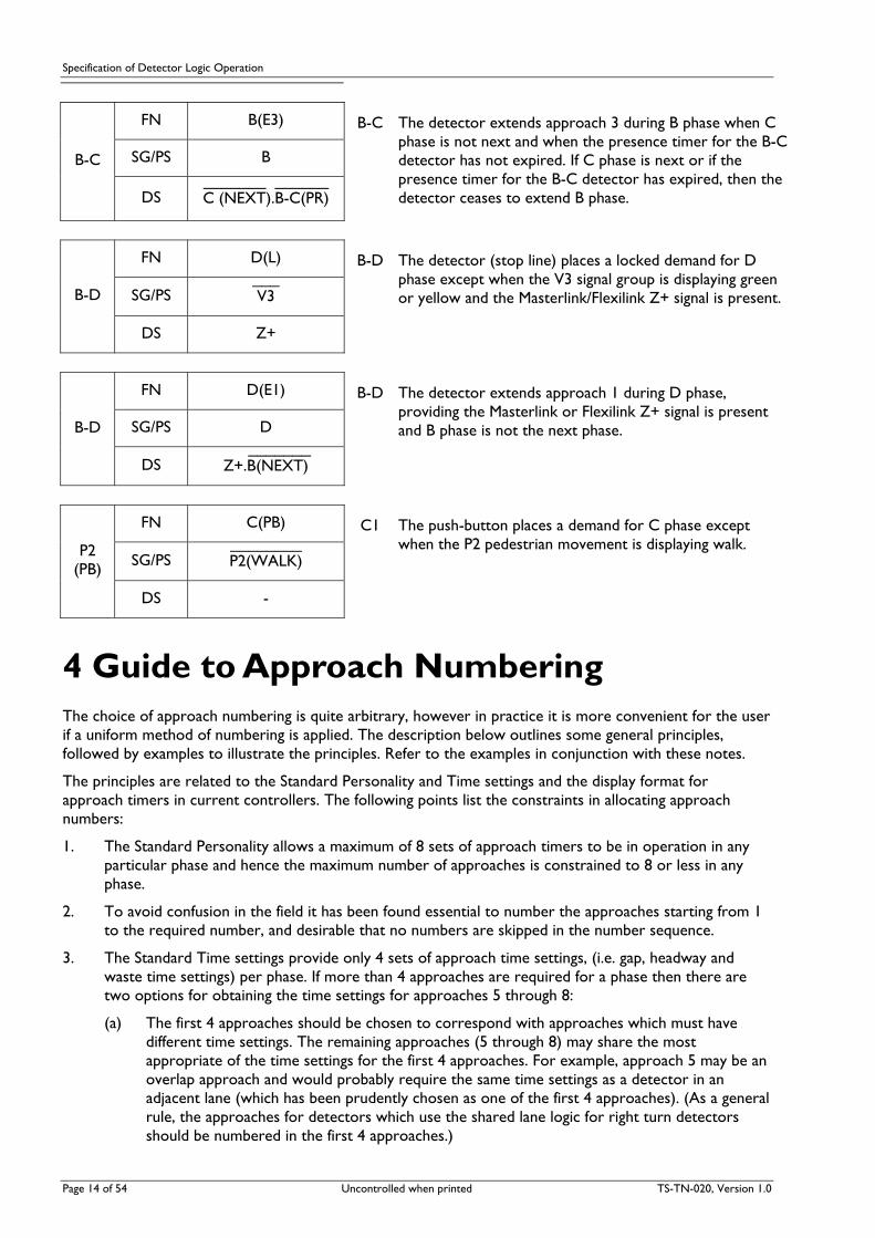
FN B(E3)
SG/PS B B-C
DS _______ ______ C (NEXT).B-C(PR)
B-C The detector extends approach 3 during B phase when C phase is not next and when the presence timer for the B-C detector has not expired. If C phase is next or if the presence timer for the B-C detector has expired, then the detector ceases to extend B phase.
FN D(L)
SG/PS ___ V3 B-D
DS Z+
B-D The detector (stop line) places a locked demand for D phase except when the V3 signal group is displaying green or yellow and the Masterlink/Flexilink Z+ signal is present.
FN D(E1)
SG/PS D B-D
DS _______ Z+.B(NEXT)
B-D The detector extends approach 1 during D phase, providing the Masterlink or Flexilink Z+ signal is present and B phase is not the next phase.
FN C(PB)
SG/PS ________ P2(WALK)
P2 (PB)
DS -
C1 The push-button places a demand for C phase except when the P2 pedestrian movement is displaying walk.
4 Guide to Approach Numbering The choice of approach numbering is quite arbitrary, however in practice it is more convenient for the user if a uniform method of numbering is applied. The description below outlines some general principles, followed by examples to illustrate the principles. Refer to the examples in conjunction with these notes.
The principles are related to the Standard Personality and Time settings and the display format for approach timers in current controllers. The following points list the constraints in allocating approach numbers:
1. The Standard Personality allows a maximum of 8 sets of approach timers to be in operation in any particular phase and hence the maximum number of approaches is constrained to 8 or less in any phase.
2. To avoid confusion in the field it has been found essential to number the approaches starting from 1 to the required number, and desirable that no numbers are skipped in the number sequence.
3. The Standard Time settings provide only 4 sets of approach time settings, (i.e. gap, headway and waste time settings) per phase. If more than 4 approaches are required for a phase then there are two options for obtaining the time settings for approaches 5 through 8:
(a) The first 4 approaches should be chosen to correspond with approaches which must have different time settings. The remaining approaches (5 through 8) may share the most appropriate of the time settings for the first 4 approaches. For example, approach 5 may be an overlap approach and would probably require the same time settings as a detector in an adjacent lane (which has been prudently chosen as one of the first 4 approaches). (As a general rule, the approaches for detectors which use the shared lane logic for right turn detectors should be numbered in the first 4 approaches.)

Specification of Detector Logic Operation
(b) If more than 4 different sets of approach time settings are required for a particular phase, then special tables can be included in the Standard Personality to allow unused approach time settings from another phase to be used for approaches 5 through 8. This method is quite acceptable, but requires very clear documentation to avoid confusion in the field.
4. Current controllers display only 2 sets of approach timers (gap, headway and waste timers) at a time, although it is a simple matter to quickly step the display to another pair of approach timers. To assist the field staff it is desirable to maintain the same approach number for a particular detector in all phases in which the detector is controlling the approach. In practice this is not always possible, however it is usually possible to make the approach number always odd or always even in each phase in which the approach is timing. This allows the operator the minimum disorientation at a phase change.
A table technique is used in the examples below to assist in choosing the approach numbers. The steps for the table technique are:
1. List each detector in a column. Detectors with “approach” and “departure” sections require a separate entry for each section. In practice the “departure” section is equivalent to the entire 11 metre loop.
2. Separate columns are required for each of the used phases.
Steps 1 and 2 PhaseDetector
PhaseDetector
A B C
A
B
A-B
B-C
C
3. For each detector in turn, a cross is marked in each column corresponding to a phase in which the approach is required to time.
4. Optionally a further row can be provided to sum the maximum number of approaches which must time in each phase.
Steps 3 and 4 PhaseDetector
PhaseDetector
A B C
A X
B X
A-B X X
B-C X X
C X
TOTAL 2 3 2
5. To achieve the goals outlined in the principles above, the approach numbers should be allocated such that the same approach number is used for all the entries in a particular row. If this is not possible, then the entries in a row should be chosen to be only odd values or only even values. It is recommended that detectors using the shared lane logic should have approach numbers in the range 1 to 4. Numbers should not be skipped in the numbering sequence.
Steps 5
TS-TN-020, Version 1, 0 Uncontrolled when printed Page 15 of 54

Specification of Detector Logic Operation
PhaseDetector
PhaseDetector
A B C Step 6
A X
B X
A-B X X
B-C X X
C X
TOTAL 2 3 2
6. Once the approach numbers have been selected, they should be added to the relevant movement
diagrams on the design plan. (It is not necessary to show the selection table on the design plan.)
Note: In most cases, alternative numbering to the following examples is possible using the above method. However if the above principles are retained, approach numbering will remain consistent.
4.1 Example 1
Page 16 of 54 Uncontrolled when printed TS-TN-020, Version 1.0

Specification of Detector Logic Operation
DETECTOR A APPROACHES
B APPROACHES
C APPROACHES
D APPROACHES
A X1
A-B X2 X2 X2
B X3 X3
B-C X1 X1 X1
C X2
TOTAL APPROACHES 2 3 2 3
NOTE: This example illustrates a 3 phase design. For the 4 phase design with a repeat right turn movement, approach numbers for D phase are the same as B phase.
4.2 Example 2
TS-TN-020, Version 1, 0 Uncontrolled when printed Page 17 of 54
Specification of Detector Logic Operation
DETECTOR A APPROACHES
B APPROACHES
C APPROACHES
D APPROACHES
A X1
A-B1 DEP
A-B1 APP X3 X3 X3
A-B2 X2 X2 X2
B-C X1 X1 X1
C X2
TOTAL APPROACHES
3 3 2 3
NOTE: This example illustrates a 3 phase design. For the 4 phase design with a repeat right turn movement, approach numbers for D phase are the same as B phase.
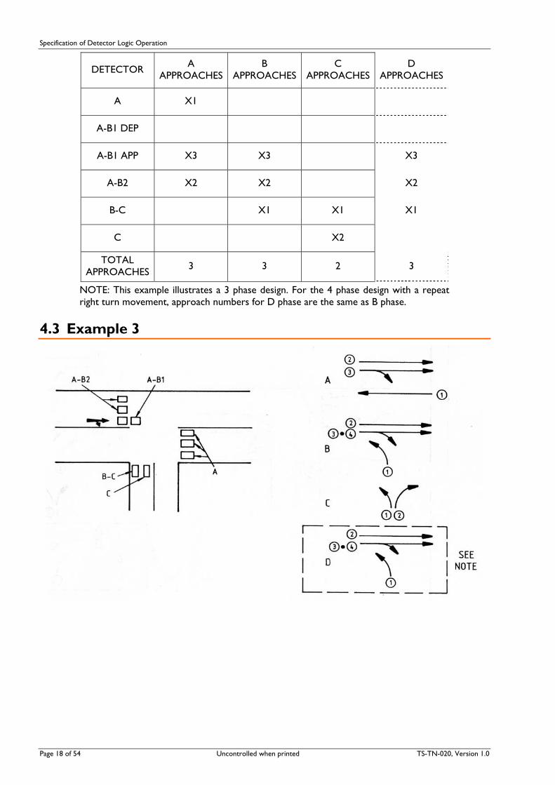
4.3 Example 3
Page 18 of 54 Uncontrolled when printed TS-TN-020, Version 1.0

Specification of Detector Logic Operation
DETECTOR A APPROACHES
B APPROACHES
C APPROACHES
D APPROACHES
A X1
A-B1 DEP X4 X4
A-B1 APP X3 X3 X3
A-B2 X2 X2 X2
B-C X1 X1 X1
C X2
TOTAL APPROACHES
3 4 2 4
NOTE: This example illustrates a 3 phase design. For the 4 phase design with a repeat right turn movement, approach numbers for D phase are the same as B phase.
4.4 Example 4
TS-TN-020, Version 1, 0 Uncontrolled when printed Page 19 of 54

Specification of Detector Logic Operation
Page 20 of 54 Uncontrolled when printed TS-TN-020, Version 1.0
DETECTOR A APPROACHES
B APPROACHES
C APPROACHES
D APPROACHES
A X1
A-B1 DEP X4 X4
A-B1 APP X3 X3 X3
A-B2 X2 X2 X2
B X5 X5
B-C X1 X1 X1
C X2
TOTAL APPROACHES 3 5 2 5
NOTE: This example illustrates a 3 phase design. For the 4 phase design with a repeat right turn movement, approach numbers for D phase are the same as B phase.
5 Principles of Detector Logic 5.1 Introduction The operation of an at-grade intersection would be considered ideal if there were no delays to the traffic using the intersection. In practice this is an unrealistic goal, however the efficiency of the intersection can be optimised by careful design of the phase movements and the detector functions. The specification of the detector functions is loosely termed as the “Detector Logic” for the intersection.
The basic aim of detector logic is to minimise the cycle time of the controller while satisfying all the traffic and safety needs for the intersection.
The aim is achieved by:
(a) avoiding the unnecessary introduction of phases, by only registering and maintaining demands which are actually required,
(b) avoiding unnecessary extension of a phase by vehicles which may continue to flow during the next phase,
(c) minimising the variable initial green time by only allowing detectors to increment when a queue is forming.
The detector logic should be designed to provide efficient operation regardless of the phase sequence. This is particularly important for SCATS controlled intersections since, under Masterlink operation, the phase sequence is determined by the plan data stored in the SCATS master. Also, in Flexilink operation, it is common to have a normal and an alternate phase sequence. Undemanded phases are skipped over in the phase sequence, regardless of the controller operating mode. Thus it is imperative that the detector logic is designed to provide efficient operation for any sequence of phases at the intersection.
The following sections provide an introduction to the detector logic currently used in the standard detector logic tables. (Refer to Sections 7 and 9.)

Specification of Detector Logic Operation
5.2 Overlap Logic If a movement is permitted in more than one phase then the detector logic for the detectors on that movement can be designed for optimum efficiency.
Consider the case of the A-B2 detector in Figure 2 below.
Figure 2 A-B2 Detector
5.2.1 Demand Function
Since the V2 overlap signal group is green in both A and B phases, the A-B2 detector should demand either A or B phases (or both) to satisfy traffic waiting at the red signal during C phase. It is apparent that this detector should not place a demand for any phase when the V2 signal group is displaying green, otherwise moving traffic would place an unnecessary demand for another phase.
The matter that needs consideration is which phase, or phases, should be demanded by the A-B2 detector to provide efficient operation for all phase sequences. The most appropriate choice is for the A-B2 “overlap” detector to place a demand for the “through” phase rather than the “right turn” phase. If the overlap detector placed a demand for the right turn phase then, for the sequences B-A-C, the leading right turn would be demanded in every cycle whether it was required or not. The addition of the unnecessary phase would thus reduce the operating efficiency of the intersection. Therefore the overlap detector only demands green for the “through” phase.
The above reasoning relies on the assumption that there is a reasonable traffic flow for the overlap movement and for the flow in the reverse direction. If in fact the traffic volume for the right turn movement is large, and the volume for the opposing A movement is almost negligible, then it would be more appropriate for the overlap detector to demand B phase rather than A phase. In this (rare) case it is probable that A phase would not be required in the cycle, since the A movement has a very low volume.
Note that the phase demand is cleared when the V2 signal group is displaying green, that is during A or B phase.
5.2.2 Extension Function
When the V2 signal group is displaying green, the traffic crossing the A-B2 detector should extend the duration of the green signal. Since the signal display is green for both A and B phases it is appropriate to use some form of detector logic to avoid extending either phase unnecessarily if the signal group will continue to display green in the next phase.
Generally, it is inappropriate to make the extension function for a detector in an overlap approach conditional on phase demands since the logic fails if a different phase sequence is used. That is, different detector logic would be required for the sequences A-B-C and A-C-B if the logic used phase demands for controlling the extension function.
However, it is possible to provide logic which is always appropriate by making the extension function conditional on the next phase to be introduced. The A-B2 detector on the overlap approach in the above example is not required to extend the running phase unless the overlap signal group will be red in the next
TS-TN-020, Version 1, 0 Uncontrolled when printed Page 21 of 54

Specification of Detector Logic Operation
phase. (Note that when the controller is operating in the isolated mode, the available maximum green time for the overlap movement may now be less than the sum of the maximum green times for the overlap phases since the traffic on the overlap approach effectively does not extend the first phase of the overlap. If the volume for the overlap approach is much greater than the volumes for the right turn and the opposing movement (e.g. tidal flow), then it is essential to specify transfer of unused maximum time between the overlap phases.)
5.2.3 Detector Logic Specification
The complete detector logic specification for the A-B2 detector in Figure 2 is expressed symbolically in Table 1.
FN A(L) A(En) B(En)
SG/PS ___ V2 A B A-B2
DS - _______ B(NEXT)
_______ A(NEXT)
Table 1 Standard Table 6
5.3 Filter Right Turn in Exclusive Right Turn Lane For the case of a filter right turn movement there is a need to avoid demanding the right turn phase unnecessarily if the right turn vehicles are able to filter through the opposing flow. The particular case of an exclusive right turn lane is considered in Figure 3.
Figure 3 Exclusive Right Turn Lane
5.3.1 Demand Function
During A phase, right turn vehicles are permitted to filter. It is apparent that the demand for the right turn phase should be cancelled if all the right turn vehicles are able to filter. A single vehicle which is able to filter without delay must cross the detector loop, but it is undesirable for the vehicle to place a demand for the right turn phase. To prevent unwanted demands for the right turn phase, it is necessary to distinguish between waiting vehicles and vehicles passing over the detection zone. This is achieved by using a presence timer. The timer commences timing when a vehicle is present in the detection zone, but a demand is not registered for the right turn phase until the presence timer has expired. The presence timer setting would typically be set in the range 2 to 3 seconds.
It is necessary to maintain a continuous demand for the right turn phase when there is a queue of vehicles, regardless of whether vehicles are able to filter or not. This requires that a vehicle must always be in the detection zone while the vehicles are filtering. It is possible to calculate the length of the detection zone for a given speed of filtering traffic to ensure that there is always occupancy in the detection zone while there are right turning vehicles. In practice, a standard loop length of 11 metres has been adopted for the right turn detector, rather than treating each case individually. Once the detection zone has been vacated, further vehicles do not register a demand until the presence timer has expired.
Page 22 of 54 Uncontrolled when printed TS-TN-020, Version 1.0

Specification of Detector Logic Operation
TS-TN-020, Version 1, 0 Uncontrolled when printed Page 23 of 54
In practice the 11 metre detection zone is achieved by two loop sections, each with its own detector. The loop sections are known as the “approach” (APP) and “departure” (DEP) sections, and the outputs of the two detectors are combined by internal software or a diode to provide a single output for the 11 metre loop (APP & DEP). The output of the approach detector only is available as a separate output for providing extension functions and additional demand functions.
When right turn vehicles arrive at a red signal there is no need for the demand to be subject to the presence delay time. For normal traffic conditions the right turn detector should demand the right turn phase, (B phase in the above example), for the case where the right turn phase precedes the “through” phase in the sequence. In light traffic conditions there is more benefit in demanding the “through” phase, for the case where the “through” phase precedes the right turn phase. In light traffic conditions right turn vehicles would have no difficulty in filtering, so it is preferable to introduce the “through” phase rather than the right turn vehicle phase. Thus, when the overlap signal group is red, a right turn vehicle places an immediate demand for both the “through” and right turn phases. Both demands are cleared when the overlap signal group displays green.
5.3.2 Extension Function
The output of the approach detector is used to provide the extension function for the case of an exclusive right turn lane.
It is evident that right turn vehicles should unconditionally extend the right turn phase.
Since right turn vehicles may filter in the “through” phase, it is appropriate that right turn vehicles extend the through phase. If vehicles are not able to filter then the extension function for the through phase should be cancelled. This condition is detected by expiry of the presence timer for the right turn detector.
Also, right turn vehicles should not extend the “through” phase if the right turn phase will be the next phase to follow.
5.3.3 Detector Logic Specification
The complete detector logic specification for the A-B1 detector in Figure 3 is expressed symbolically in Table 2.
FN B(PR)
SG/PS A
A-B1
DEPARTURE &
APPROACH DS -
FN A(L).B(L) A(En) B(En)
SG/PS ___ V2 A B
A-B1
APPROACH DS -
_______ _______ A-B1(PR) . B(NEXT) -
Table 2 Standard Table 5
5.4 Shared Right Turn Lane A right turn lane which is shared with through traffic presents difficulties when the right turn phase precedes the through phase. In particular, there is a need to distinguish between right turn vehicles and through vehicles using the shared lane, otherwise through vehicles would unnecessarily extend the right turn phase.
The particular case of a shared right turn lane is considered in Figure 4.
Note that the logic described applies regardless of whether right turn vehicles are permitted to filter or not.

Specification of Detector Logic Operation
Figure 4 Shared Right Turn
5.4.1 Demand Function
The combined outputs for the A-B1 APPROACH and A-B1 DEPARTURE detectors (i.e. the 11 metre loop) provide a presence timed demand for B phase during A phase. That is, the presence timed demand for the right turn phase is placed only while the through phase is running.
The A-B1 APPROACH detector places a locked demand for both A and B phase provided the V2 overlap signal group is displaying red. Note that the demand for B phase is not subject to the presence timer in this case. The locked demands for both phases are cleared when the V2 overlap signal displays green.
The above detector logic caters for operation in both the trailing and the leading turn sequences. In particular, when the right turn movement precedes the through phase, an approaching right turn vehicle is not required to wait the presence delay time before placing a demand for the turning phase. A vehicle which arrives at the red signal late in the running phase will thus be guaranteed that the turning movement will be included in the current cycle.
The presence timed demand for the right turn movement is in fact only required to operate during the through phase. Right turn vehicles are permitted to filter during the through phase, the demand for the turning movement is cancelled if the 11 metre loop is vacated. The presence delay thus ensures that through vehicles crossing the 11 metre loop do not place false demands for the right turn movement.
5.4.2 Extension Function
The A-B1 APPROACH detector:
1. Extends A phase (the through phase) except when:
(a) B phase is next (i.e. B phase is the next demanded phase in the sequence); or
(b) the presence timer for the 11 metre loop is expired, i.e. a vehicle is stationary on the loop and is unable to filter, causing the lane to be blocked to through traffic.
2. Extends B phase (the right turn phase) except when A phase is next (i.e. A phase is the next demanded phase in the sequence).
The combined A-B1 APPROACH and A-B1 DEPARTURE detectors (i.e. the 11 metre loop) extend B phase when A phase is next (i.e. A phase is the next demanded phase in the sequence). These combined detectors thus extend the (leading) right turn phase when the through phase is to follow. The approach timing is set up in an unusual manner in this case, with time settings as follows:
(a) Gap Timer: typically 3.0 seconds
(b) Headway Timer: typically 0.1 seconds or as small as possible
(c) Waste Timer: typically 3-4 seconds
For this special approach, the 3 second Gap Timer setting caters for the case in which there is a long space between vehicles in the shared right turn lane. The phase would normally be terminated by the Waste Timer when there are through vehicles using the lane since these would accumulate Waste time. The Gap
Page 24 of 54 Uncontrolled when printed TS-TN-020, Version 1.0

Specification of Detector Logic Operation
TS-TN-020, Version 1, 0 Uncontrolled when printed Page 25 of 54
and Waste settings are approximately the same and so a long space would in most cases allow the Waste Timer to expire before the Gap Timer.
The Headway Timer is set to expire whenever there is a momentary break in the occupancy of the 11 metre loop. If the vehicles in the shared lane are all turning right, then these vehicles would normally be closely spaced, prevent expiry of the Headway Timer and thus inhibiting Waste timing. This will also be true for the case where there is an occasional through vehicle interposed in the queue, since the right turn vehicles are slower moving vehicles and will thus govern the speed of the queue. The spacing (distance) between vehicles is such that the 11 metre loop is still occupied in this case also. When the vehicles in the shared lane are predominantly through traffic, then the vehicle speeds are greater with greater headways between vehicles. In this case the Headway Timer expires, enabling Waste timing. Since the Waste time is set at 3-4 seconds, the right turn phase is terminated efficiently when the shared lane is not being used by turning vehicles.
5.4.3 Detector Logic Specification
The complete detector logic specification for the A-B1 detector in Figure 4 is expressed symbolically in Table 3.
FN B(PR) B(Em)
SG/PS A B
A-B1
DEPARTURE +
APPROACH DS - A(NEXT)
FN A(L).B(L) A(En) B(En)
SG/PS ___ V2 A B
A-B1
APPROACH DS -
_______ _______ A-B1(PR) . B(NEXT)
_______ A(NEXT)
Table 3 Standard Table 4
5.4.4 Theory of Operation
The efficient termination of a leading right turn phase (which has a shared right turn lane) requires a means of differentiating between the utilisation of the shared lane by right turn vehicles and by through vehicles. Usually this means some form of speed detection by the loop detectors in the shared lane and various techniques have been used with small success.
Another method has been to use a loop positioned in the intersection which is actuated by right turn vehicles but not by through vehicles. This technique presents problems in selecting appropriate Gap time settings to cater for a mixture of through and turning vehicles in the shared lane. Typically the Gap time setting must be set at 8-9 seconds which does not produce efficient operation.
The present method is in fact a speed detection technique, which relies on the empirical relationship between vehicle speed and the spaces between vehicles. For right turn vehicles, the speed is normally sufficiently low that the space between vehicles does not exceed 11 metres. That is, a queue of right turning vehicles provides continuous occupancy over an 11 metre loop in the right turn lane.
Together with this is the recognition that the speed of a queue of vehicles (measured over a loop at the stop line) is determined by the slowest vehicle in the queue, which in this case is the right turn vehicle. The queue speed can thus be used as the criterion for establishing the presence of right turn vehicles, and hence the continuing requirement for the right turn phase.
When the right turn vehicles have been cleared from the front of the queue then the queue speed will increase. This is detected by the increase in spaces between vehicles crossing the 11 meter loop at the stop line. The right turn phase can thus be efficiently terminated by the Waste Timer when the queue speed increases by selecting a very small Headway time setting.

Specification of Detector Logic Operation
Note that every vehicle in the shared lane extends the turn phase. The turn phase is thus terminated by the Waste Timer not the Gap Timer, except under light traffic conditions.
5.5 Shared Right turn Lane (Side Street) The following logic is a special case which applies only to a filter right turn movement on the side street. Note that the logic below was one of the early attempts for a leading right turn movement with filtering. This method, although included in the standard tables, is now superseded by the logic described above in Section 5.4 (Standard Table 4). The logic is described for the particular example in Figure 5.
Figure 5 Filter Right turn Movement on Side Street
5.5.1 Demand Function
The output of the departure detector (i.e. 11 metre loop) is subject to a presence timer. During the through phase (C phase in the above example), the departure detector places a demand for the right turn phase upon expiry of the presence timer. If the right turn phase follows the through phase (sequence A-C-B), then the demand for the right turn phase is the normal demand subject to presence timer. If, however, the right turn phase precedes the through phase (sequence A-B-C), then the demand for the right turn phase is locked at the termination of the through phase. That is, for this sequence, the right turn phase is demanded only if a vehicle was waiting to make the right turn at the termination of the previous through phase.
For the case of the leading right turn, the intention is to avoid demanding the right turn phase unless a vehicle was unable to filter on the previous through phase. In practice, the on-street performance from this logic is very poor. In heavy traffic conditions right turn vehicles are unable to filter and thus effectively block the shared lane for the through phase. If vehicles are able to filter, it is usually late in the phase. If the queue of vehicles in the shared lane is slow to move onto the detector then the presence timer must expire again before the demand can be registered for the right turn phase. The result is that the right turn phase is quite often demanded on alternate cycles even when there is a heavy demand for the right turn movement. The conclusion is that this form of detector logic is quite inappropriate except when the volume of right turn traffic is very light.
Vehicles in the shared lane arriving at a red signal place a locked demand for the through phase, not subject to a presence timer. The demand is cancelled when the overlap signal group displays green.
5.5.2 Extension Function
The approach detector extends the right turn phase unconditionally. Hence the sequence A-B-C (leading right turn) is particularly inefficient since through vehicles in the shared lane extend the right turn phase. Since the logic described above is only suitable for low volumes of right turn traffic, it is appropriate to use a very small maximum time for the right turn phase, thus minimising the inefficiency.
Page 26 of 54 Uncontrolled when printed TS-TN-020, Version 1.0
Specification of Detector Logic Operation
The approach detector also extends the through phase except when the right turn phase is the next phase to follow. If the right turn phase follows the through phase then it may be appropriate to transfer unused maximum time from the through phase to the right turn phase.
5.5.3 Detector Logic Specification
The complete detector logic specification for the B-C1 detector in Figure 5 is expressed symbolically in Table 4.
FN B(CL)
SG/PS C
B-C1
DEPARTURE &
APPROACH DS -
FN C(L) C(En) B(En)
SG/PS ___ V6 C B
B-C1
APPROACH DS -
_______ B(NEXT) -
Table 4 Standard Table 20
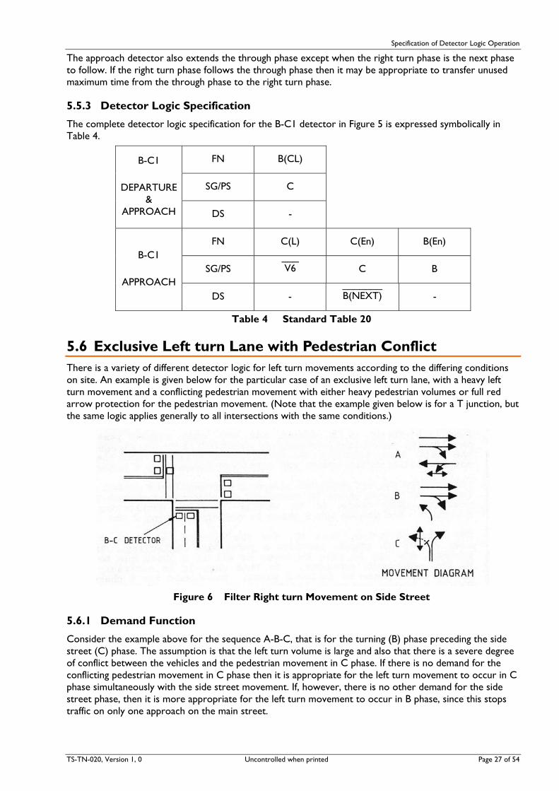
5.6 Exclusive Left turn Lane with Pedestrian Conflict There is a variety of different detector logic for left turn movements according to the differing conditions on site. An example is given below for the particular case of an exclusive left turn lane, with a heavy left turn movement and a conflicting pedestrian movement with either heavy pedestrian volumes or full red arrow protection for the pedestrian movement. (Note that the example given below is for a T junction, but the same logic applies generally to all intersections with the same conditions.)
Figure 6 Filter Right turn Movement on Side Street
5.6.1 Demand Function
Consider the example above for the sequence A-B-C, that is for the turning (B) phase preceding the side street (C) phase. The assumption is that the left turn volume is large and also that there is a severe degree of conflict between the vehicles and the pedestrian movement in C phase. If there is no demand for the conflicting pedestrian movement in C phase then it is appropriate for the left turn movement to occur in C phase simultaneously with the side street movement. If, however, there is no other demand for the side street phase, then it is more appropriate for the left turn movement to occur in B phase, since this stops traffic on only one approach on the main street.
TS-TN-020, Version 1, 0 Uncontrolled when printed Page 27 of 54

Specification of Detector Logic Operation
Page 28 of 54 Uncontrolled when printed TS-TN-020, Version 1.0
Also, if there is a demand for the side street phase and the conflicting pedestrian movement is demanded, then it is appropriate for the left turn movement to occur in B phase, since the pedestrian movement effectively blocks the left turn movement in C phase.
Accordingly the B-C detector places a presence timed demand for B phase. The demand for B phase is cancelled if there is a demand for C phase, provided that there is no demand for the conflicting pedestrian movement. The demand for B phase is cancelled during B and C phases.
The sequence A-C-B, that is, for the turning (B) phase following the side street (C) phase, provides a particular difficulty. The left turn movement may not be able to occur at all in C phase due to obstruction by the pedestrian movement. In this case it is necessary to place a demand for B phase to follow C phase. The demand for B phase is cleared during C phase and so an artificial means is required for restoring the demand. This is achieved by monitoring the gap timer for the B-C detector. If the gap timer is expired in C phase then it is unnecessary to demand B phase. If the gap timer is unexpired at the termination of C phase then it is certain that there is a requirement for B phase. Thus, during C phase, the condition for demanding B phase is that there is “NO GAP” on the B-C detector.
5.6.2 Extension Function
The B-C detector extends B phase (the turning phase) unless C phase is the next phase to follow. If there is a demand for the conflicting C phase pedestrian movement, then the B-C detector extends B phase regardless of whether C phase is the next phase to follow or not.
The B-C detector extends C phase unless B phase is the next phase to follow.
5.6.3 Detector Logic Specification
The complete detector logic specification for the B-C detector in Figure 6 is expressed symbolically in Table 5.
FN B(PR) B(CL) B(En) C(En)
SG/PS _ _ B.C C B C B-C
DS _ C + P2(PB) B-C(NG)
_______ C(NEXT)+P2(PB)
_______ B(NEXT)
Table 5 Standard Table 7
6 Preparation of Schedule 1. Consider each detector in sequence (A, B, C, etc.) and determine specification as follows.
2. Each detector class (i.e. group of detectors which have exactly the same function) is to be separately listed.
Note The two detectors forming an 11 metre detector are treated as a single detector class, but require separate entries in the detector specification schedule for the approach detector and the combined approach & departure detectors.
3. Demand Functions
(a) On the “FN” line specify, in correct order which phase is demanded and the type of demand (L, NL etc.). One vertical column is to be used for each function, except “demand and cancel” function [e.g. A(L).B(L)] which may be included together in one column for detectors on an overlap approach.
(b) On the “SG/PS” line, specify the period(s) during which the above function may or may not occur.
(c) On the “DS” line, specify any demand status or other condition which affects the above demand function of the detector.

Specification of Detector Logic Operation
4. Extension Functions
(a) On the “FN” line, specify which phase(s) is extended and by what means. List type of timer (E) and approach numbers. One column is to be used for each function.
(b) On the “SG/PS” line, specify the period during which the above extension function occurs (or does not occur).
(c) On the “DS” line, specify any demand status or other condition which affects the above extension function.
Following are two complete examples of the Detector Specification Schedule format. This does not need to be shown on simple two phase signal design plans. For more complex intersections with single and double diamond turns with alternative overlaps, refer to the Standard for Single Diamond Overlap Phasing [13] and the Standard for Double Diamond Overlap Phasing [14] respectively.
The logic shown applies to either A-B-C or A-C-B sequence and should be specified unless there is documented evidence that different detector logic would be more efficient.
6.1 Example 1 THREE PHASE (Adaptable to either sequence A-B-C or A-C-B)
Exclusive lane and filtering right turn
Short Red Arrow Protection for P1 Pedestrian movement.
A DETECTOR
(i) Demands A phase during B phase and C phase.
(ii) Extends A phase.
A-B1 DETECTOR
(i) Demands A phase and B phase during C phase.
(ii) Demands B phase during A phase if the presence timer has expired.
(iii) Extends A phase during A phase if the presence timer on the A-B1 detector has not expired and B phase is not next.
(iv) Extends B phase during B phase.
A-B2 DETECTOR
(i) Demands A phase during C phase.
(ii) Extends A phase during A phase when B phase is not next.
(iii) Extends B phase during B phase when A phase is not next.
B-C DETECTOR TS-TN-020, Version 1, 0 Uncontrolled when printed Page 29 of 54

Specification of Detector Logic Operation
Where the left turn is heavy and there is a heavy pedestrian flow for the P1 pedestrian movement.
(i) Demands B phase during A phase if the presence timer has expired and if there is no C phase vehicle demand or if there is a P1 pedestrian demand.
(ii) Demands B phase during C phase if there is no gap on the B-C detector.
(iii) Extends B phase during B phase when C phase is not next or there is a P1 pedestrian demand.
(iv) Extends C phase during C phase when B phase is not next.
C DETECTOR
(i) Demands C phase during A phase and B phase.
(ii) Extends C phase during C phase.
P1(PB) DETECTOR
(i) Demands C phase when the P1 WALK is not green.
(ii) Demands A phase during C phase when the P1 WALK is not green and there is no demand for A phase or B phase.
DETECTOR SPECIFICATION
FN A(L) A(E1)
SG/PS _ A A
A (TABLE 1)
DS - -
FN B(PR)
SG/PS A
A-B1 APPROACH & DEPARTURE
(TABLE 5) DS -
FN A(L).B(L) A(E3) B(E3)
SG/PS ___ V2 A B
A-B1 APPROACH (TABLE 5)
DS - ______ _______ A-B1(PR).B(NEXT) -
FN A(L) A(E2) B(E2)
SG/PS ___ V2 A B
A-B2 (TABLE 6)
DS - _______ B(NEXT)
_______ A(NEXT)
B-C (TABLE 7)
FN B(PR) B(CL) B(E1) C(E1)
Page 30 of 54 Uncontrolled when printed TS-TN-020, Version 1.0

Specification of Detector Logic Operation
SG/PS _ _ B.C C B C
DS _
C+P1(PB) B-C(NG) _______ C(NEXT)+P1(PB)
_______ B(NEXT)
FN C(L) C(E2)
SG/PS _ C C
C (TABLE 1)
DS - -
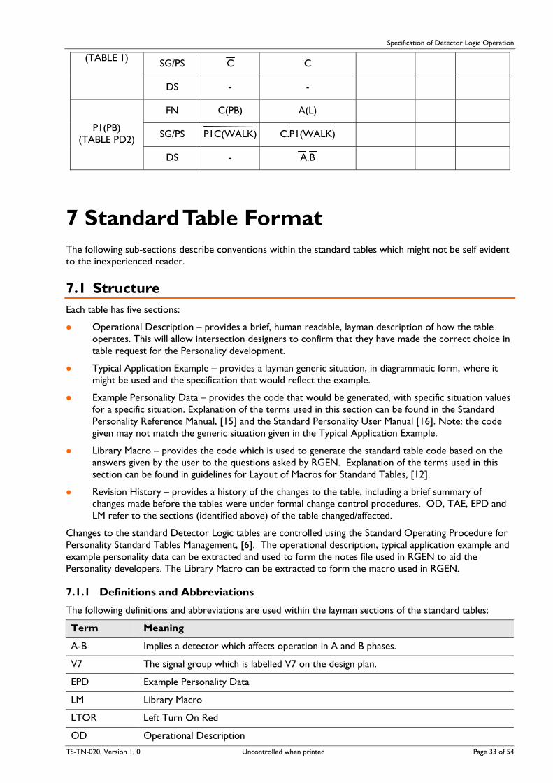
FN C(PB) A(L)
SG/PS ________ P1(WALK)
_______ C.P1(WALK)
P1(PB) (TABLE PD2)
DS - _ _ A.B
6.2 Example 2 THREE PHASE (Adaptable to either sequence A-B-C or A-C-B)
Shared through and right turn lane and filtering right turn.
A DETECTOR
(i) Demands A phase during B phase and C phase.
(ii) Extends A phase during A phase.
A-B1 DETECTOR
(i) Demands A phase and B phase during C phase.
(ii) Demands B phase during A phase if the presence timer has expired.
(iii) Extends A phase during A phase if the presence timer has not expired and B phase is not next.
(iv) Extends B phase during B phase (with one set of approach timers if A phase is not next and a different set of approach timers if A phase is next).
A-B2 DETECTOR
(i) Demands A phase during C phase.
(ii) Extends A phase during A phase when B phase is not next.
(iii) Extends B phase during B phase when A phase is not next.
B-C DETECTOR
Where left turn is light and there is a light P1 pedestrian volume.
TS-TN-020, Version 1, 0 Uncontrolled when printed Page 31 of 54

Specification of Detector Logic Operation
(i) Demands B phase during A phase if the presence timer has expired and there is no C phase demand.
(ii) Extends B phase during B phase when C phase is not next.
(iii) Extends C phase during C phase when B phase is not next.
C DETECTOR
(i) Demands C phase during A phase and B phase.
(ii) Extends C phase during C phase.
P1(PB) DETECTOR
(i) Demands C phase WALK when the P1 WALK is not green.
(ii) Demands A phase during C phase when the P1 WALK is not green and there is no demand for A phase or B phase.
DETECTOR SPECIFICATION
FN A(L) A(E1)
SG/PS Ā A A
(TABLE 1)
DS - -
FN B(PR) B(E4)
SG/PS A B
A-B1 APPROACH & DEPARTURE
(TABLE 4) DS - A(NEXT)
FN A(L).B(L) A(E3) B(E3)
SG/PS V2 A B A-B1
APPROACH (TABLE 4)
DS - A-B1(PR).B(NEXT) A(NEXT)
FN A(L) A(E2) B(E2)
SG/PS V2 A B A-B2
(TABLE 6)
DS - B(NEXT) A(NEXT)
FN B(PR) B(E1) C(E1)
SG/PS B.C B C B-C
(TABLE 8)
DS C C(NEXT) B(NEXT)
C FN C(L) C(E2)
Page 32 of 54 Uncontrolled when printed TS-TN-020, Version 1.0
Specification of Detector Logic Operation
SG/PS C C (TABLE 1)
DS - -
FN C(PB) A(L)
SG/PS P1C(WALK) C.P1(WALK) P1(PB)
(TABLE PD2)
DS - A.B
7 Standard Table Format The following sub-sections describe conventions within the standard tables which might not be self evident to the inexperienced reader.
7.1 Structure Each table has five sections:
Operational Description – provides a brief, human readable, layman description of how the table operates. This will allow intersection designers to confirm that they have made the correct choice in table request for the Personality development.
Typical Application Example – provides a layman generic situation, in diagrammatic form, where it might be used and the specification that would reflect the example.
Example Personality Data – provides the code that would be generated, with specific situation values for a specific situation. Explanation of the terms used in this section can be found in the Standard Personality Reference Manual, [15] and the Standard Personality User Manual [16]. Note: the code given may not match the generic situation given in the Typical Application Example.
Library Macro – provides the code which is used to generate the standard table code based on the answers given by the user to the questions asked by RGEN. Explanation of the terms used in this section can be found in guidelines for Layout of Macros for Standard Tables, [12].
Revision History – provides a history of the changes to the table, including a brief summary of changes made before the tables were under formal change control procedures. OD, TAE, EPD and LM refer to the sections (identified above) of the table changed/affected.
Changes to the standard Detector Logic tables are controlled using the Standard Operating Procedure for Personality Standard Tables Management, [6]. The operational description, typical application example and example personality data can be extracted and used to form the notes file used in RGEN to aid the Personality developers. The Library Macro can be extracted to form the macro used in RGEN.
7.1.1 Definitions and Abbreviations
The following definitions and abbreviations are used within the layman sections of the standard tables:
Term Meaning
A-B Implies a detector which affects operation in A and B phases.
V7 The signal group which is labelled V7 on the design plan.
EPD Example Personality Data
LM Library Macro
LTOR Left Turn On Red
OD Operational Description
TS-TN-020, Version 1, 0 Uncontrolled when printed Page 33 of 54
Specification of Detector Logic Operation
Page 34 of 54 Uncontrolled when printed TS-TN-020, Version 1.0
Term Meaning
TAE Typical Application Example
(n) Implies the approach marked by n in the phase diagrams.
7.2 Right Turn Lanes In section 5, Principles of Detector Logic, right turn lanes make use of an 11 metre loop comprising an “approach” (APP) and “departure” (DEP) section, and within the standard tables the loop detectors and their operation are referred to as the:
long detector – the combination of the departure and approach sections; and
approach detector – the approach section.
7.3 SCATS Signal Pulses The Personality can be structured as to provide different modes of operation dependent on the presence, or not, of a signal from SCATS. In the Detector Logic standard tables use is made of the Z- (ZNEG), Z+ (ZPOS) and XSF signals.
Generally, the presence of the:
Z- signal is used to allow filtering at intersections where it can be useful to stop filtering at certain times of the day, and
Z+ is used to include a repeat phase in the operation of the intersection.
An XSF signal can be used for either of the above, or to introduce a special facility or phase.
8 Standard Table Selection
8.1 Introduction
8.1.1 Applicability of Flowcharts
Four flowcharts are provided to give assistance in selecting the correct standard table for detector logic. The flowcharts are not intended to be universally applicable and the user is cautioned against applying the flowcharts for any “one-off special cases”. The applicability of each flowchart is detailed in tabular form preceding the flowchart. Particular cases for which the flow chart is not applicable are also detailed.
In some cases, the flowcharts do not lead the user to a table number, but rather to the statement “NO STANDARD TABLE”. In such cases the user must derive the appropriate detector logic from first principles. (Refer to Sections D and E.) In many cases, reference to the standard tables for similar situations may yield some insight in deriving the required detector logic.
The flow charts for stop line (presence) detectors cover the following lane disciplines:
Through Lanes - Vehicles may only proceed straight ahead (i.e. vehicles may not turn either left or right from these lanes).
Right Turn Lanes - Vehicles may only turn right (i.e. exclusive right turn lane); or Vehicles may proceed straight ahead or turn right (i.e. shared right turn lane).
Note that in the stem of a T-junction vehicles, may turn left or right from a shared lane. This case is covered by the flowchart for Left Turn lanes, not the flowchart for Right Turn lanes.
Left Turn Lanes - Vehicles may only turn left (i.e. exclusive left turn lane); or Vehicles may proceed straight ahead or turn left (i.e. shared left turn lane); or Vehicles may turn either left or right (i.e. shared left turn lane).

Specification of Detector Logic Operation
TS-TN-020, Version 1, 0 Uncontrolled when printed Page 35 of 54
One flow chart is provided for advance (passage) detectors. It is of limited application, and is included only as a guide for simple cases.
8.1.2 Glossary of Questions on Flowcharts
A glossary of the questions on the flowcharts is provided below together with an explanation of the meaning of each question. This has been provided to avoid any confusion or misunderstanding since the questions must, of necessity be brief in the limited space available on the flowcharts
8.1.2.1 Flowchart for Stop Line (Presence) Detector in an Exclusive Through Lane
(a) “Movement permitted in more than one phase?”
A through movement may only proceed on a green signal. Thus the movement is permitted in more than one phase only if the controlling signal group displays green in more than one phase.
Example: At a 3 phase intersection, the V2 signal group displays green in A and B phases and red in C phase. The controlled through movement is thus permitted in more than one phase.
(b) “Movement permitted in two phases only?”
This is similar to (i) above, but in this case the movement must be permitted in exactly two phases to produce a “YES” answer.
(c) “Movement permitted in three phases only?”
This is similar to (i) above, but in this case the movement must be permitted in exactly three phases to produce a “YES” answer.
(d) “Conditional on pedestrian movement?”
The signal group controlling the through movement may be conditional upon a pedestrian movement. That is, the signal group displays red during the pedestrian walk and clearance, but displays green following the termination of the pedestrian movement. The signal group also displays green if the pedestrian movement was not demanded. In such a case, the through movement is conditional on a pedestrian movement.
(e) “Repeat phase?”
The purpose of this question is to differentiate between whether the controlling signal group is an overlap signal group or a signal group which displays green more than once in a cycle by virtue of a “repeat” phase.
An overlap signal displays green in two or more phases, with the characteristic that once the green signal has been introduced, it is maintained through the subsequent phase(s). (It is sufficient for the detector logic to place a demand for only one of the overlap phases.)
The signal group displays green more than once in the cycle if there is a “repeat” phase. A “repeat” phase usually means that the movements in one phase are repeated again in another phase in the cycle (e.g. D phase may be a repeat of B phase). In some cases, the repeat phase may not provide a repeat of a pedestrian movement, and thus the movements may differ in the repeat phase. (In the case of repeat phases, it is necessary for the detector logic to place demands for both phases, since the movements do not provide an overlap in normal operation.)
8.1.2.2 Flowchart for Stop Line (Presence) Detector in a Right Turn Lane
(a) “R.T. movement permitted in more than one phase?”
The movement may be permitted in one or more phases by a green arrow or may be permitted as a filter movement by a full green signal.
Example: A right turn movement is permitted in A phase by a full green signal and in B phase by a green arrow and not permitted in any other phase. The movement is thus permitted in more than one phase.
(b) “R.T. green arrow?”
Specification of Detector Logic Operation
Page 36 of 54 Uncontrolled when printed TS-TN-020, Version 1.0
The answer is “YES” if there is a right turn green arrow controlling the right turn movement in any phase.
(c) “Shared R.T. lane?”
The lane is a shared lane if vehicles may proceed straight ahead or turn right from the lane.
(Note that in the stem of a T-junction, vehicles may turn left or right from a shared lane. This case is covered by the flowchart for Left turn lanes, not the flowchart for Right turn lanes.)
(d) “Non-filter R.T. movement only?”
The right turn movement is a non-filter movement if the right turn vehicles are held by a red arrow in phases other than the right turn green arrow phase(s).
(e) “R.T. filter by special facility?”
The right turn movement is permitted to filter by the presence of a Masterlink or Flexilink special facility signal (usually Z-). If the special facility signal is not present or if the controller is operating in the isolated mode, the right turn movement is not permitted to filter, that is, the right turn movement is held by a red arrow in phases other than the right turn green arrow phase(s).
(f) “Repeat or overlap R.T. phase(s)?”
The purpose of this question is to determine whether the right turn green arrow is displayed in more than one phase. If this is the case, then the answer to the question is “YES”.
(g) “Repeat R.T. phase?”
The purpose of this question is to differentiate between whether the controlling signal group is an overlap signal or a signal which displays green more than once in the cycle by virtue of a “repeat” phase.
An overlap signal displays green in two or more phases with the characteristic that once the green signal has been introduced, it is maintained through the subsequent phase(s). (It is sufficient for the detector logic to place a demand for only one of the overlap phases.)
The signal group displays green more than once in the cycle if there is a “repeat” phase. A “repeat” phase usually means that the movements in one phase repeated again in another phase in the cycle (e.g. D phase may be a repeat of B phase). In some cases, the repeat phase may not provide a repeat of a pedestrian movement and thus the movements may differ in the repeat phase. (In the case of repeat phases, it is necessary for the detector logic to place demands for both phases, since the movements do not provide an overlap in normal operation.)
(h) “Repeat R.T. phase by special facility?”
The repeat phase may be conditionally included in the cycle by the presence of a Masterlink or Flexilink special facility signal (Z+). If the special facility signal is not present or if the controller is operating in isolated mode, the repeat phase is not included in the cycle.
8.1.2.3 Flowchart for Stop Line (Presence) Detector in a Left turn Lane
(a) “L.T.O.R?”
Is Left turn on Red permitted after stopping?
(b) “Controlled slip lane?”
Is the left turn lane a slip lane controlled by a signal group?
(c) “L.T.G.A?”
Is there a left turn green arrow controlling the left turn movement?
(d) “L.T. on green signal in one phase only?”
The left turn is permitted by a full green signal only. Is the green roundel displayed in more than one phase?
(e) “L.T. from side street to main street?”
Specification of Detector Logic Operation
TS-TN-020, Version 1, 0 Uncontrolled when printed Page 37 of 54
Is traffic permitted to turn left onto the main street from the side street by Left turn on Red?
(f) “Green signal in one phase only?”
Does the signal group controlling the left turn display green in only one phase?
(g) “Repeat phase?”
The purpose of this question is to differentiate between whether the controlling signal group is an overlap signal or a signal which displays green more than once in the cycle by virtue of a “repeat” phase.
An overlap signal displays green in two or more phases with the characteristic that once the green signal has been introduced, it is maintained through the subsequent phase(s). (It is sufficient for the detector logic to place a demand for only one of the overlap phases.)
The signal group displays green more than once in the cycle if there is a “repeat” phase. A “repeat” phase usually means that the movements in one phase are repeated again in another phase in the cycle (e.g. D phase may be a repeat of B phase). In some cases, the repeat phase may not provide a repeat of a pedestrian movement and thus the movements may differ in the repeat phase. (In the case of repeat phases, it is necessary for the detector logic to place demands for both phases, since the movements do not provide an overlap in normal operation.)
(h) “Overlap movement in 2 phases only?”
The controlling signal group is an overlap signal. Does the signal display green in 2 phases only and overlap the green between phases?
(i) “Overlap movement in 3 phases only?”
The controlling signal group is an overlap signal. Does the signal display green in 3 phases only and overlap the green between phases?
(j) Exclusive left turn lane?”
Is traffic only permitted to turn left from this lane?
(k) “Repeat L.T.G.A. phase?”
Is the left turn green arrow displayed more than once in the cycle by virtue of a “repeat” phase? (Refer to “Repeat Phase” above).
(l) “Repeat L.T.G.A. phase by special facility?”
Is the repeat left turn green arrow phase conditional on a Masterlink or Flexilink special facility signal (Z+)?
(m) “Pedestrian conflict with left turn?”
Is there a pedestrian movement in conflict with the left turn movement?
(n) “Full pedestrian protection?”
Is the left turn movement held by a red arrow during the walk and clearance of the conflicting pedestrian movement?
(o) “Very light left turn demand?”
Is the left turn flow always less than (typically) 100 vehicles per hour?
(p) “Heavy pedestrian flow?”
Are there sufficient pedestrians to prevent the left turn traffic from filtering through the pedestrian movement?
(q) “High proportion of left turn vehicles?”
Does a high proportion of vehicles in the shared lane turn left? (The proportion of left turn vehicles should not be less than 50% of the total approach flow for the lane.)

Specification of Detector Logic Operation
Page 38 of 54 Uncontrolled when printed TS-TN-020, Version 1.0
8.1.2.4 Flowchart for Advance (Passage) Detector
(a) “Green in more than one phase?”
Does the controlling signal group display green in more than one phase?
(b) “Associated stop line detector?”
Is there a stop line presence detector on the same approach?

Specification of Detector Logic Operation
TS-TN-020, Version 1, 0 Uncontrolled when printed Page 39 of 54
8.2 Exclusive Through Lane – Stop Line (Presence) Detector
Cases for Consideration
(a) Movement permitted in one phase only.
(b) Repeat phase by special facility signal Z+.
(c) Repeat phase conditional on pedestrian movement in one phase.
(d) Overlap in two phases only.
(e) Overlap in three phases only.
Cases where Flowchart does not apply
(a) Single diamond overlap design.
(b) Double diamond overlap design.
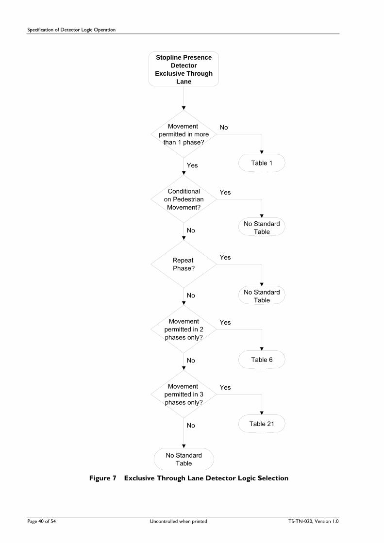
Specification of Detector Logic Operation
Page 40 of 54 Uncontrolled when printed TS-TN-020, Version 1.0
Stopline Presence Detector
Exclusive Through Lane
Movement permitted in more
than 1 phase?
Conditionalon PedestrianMovement?
Repeat Phase?
Movementpermitted in 2phases only?
Movement permitted in 3phases only?
No StandardTable
Table 1
No StandardTable
Table 6
No StandardTable
Table 21
No
Yes
No
Yes
No
Yes
No
Yes
No
Yes
Figure 7 Exclusive Through Lane Detector Logic Selection

Specification of Detector Logic Operation
TS-TN-020, Version 1, 0 Uncontrolled when printed Page 41 of 54
8.3 Shared/Exclusive Right Turn Lane Stop Line (Presence) Detector
Cases for Consideration
(a) R.T. on full green only (i.e. R.T. by filter only) e.g. 2 phase.
(b) R.T. on full green only with repeat by special facility signal Z+ e.g. 2 phase double cycled.
(c) Split approach.
(d) Non filter R.T. with single R.T.G.A. phase.
(e) Non filter R.T. with overlap R.T.G.A. phases.
(f) Non filter R.T. with repeat R.T.G.A. phase by special facility signal Z+
(g) Non filter R.T. with repeat R.T.G.A. phase independent of special facility signal Z+.
(h) Filter R.T. with single R.T.G.A. phase.
(i) Filter R.T. with overlap R.T.G.A. phases
(j) Filter R.T. with repeat R.T.G.A. phase by special facility signal Z+.
(k) Filter R.T. with repeat R.T.G.A. phase independent of special facility signal Z+.
(l) Non filter R.T. with single R.T.G.A. phase and filter by special facility signal Z-.
(m) Non filter R.T. with overlap R.T.G.A. phase and filter by special facility signal Z-.
(n) Non filter R.T. with repeat by Z+ and filter by special facility signal Z-.
(o) Non filter R.T. with repeat and filter independent of special facility signal.
Cases where Flowchart does not apply
(a) Single diamond overlap design.
(b) Double diamond overlap design.

Specification of Detector Logic Operation
Stopline Presence Detector
Right Turn Lane
R.T.Movement permitted in more than 1
phase?
R.T. Green Arrow?
Shared R.T. Lane?
Repeat or Overlap R.T.
phases?
RepeatR.T. phase?
Table 15
Table 1
No StandardTable
Table 4
NonFilter R.T. Movement
Only?
No StandardTable
No
Yes
Yes
No
Yes
No
Yes
No
Yes
No
RepeatR.T. phase bySpec. Facility?
Table 36(e.g. Z+)
No
Yes
Repeat orOverlap R.T.
phases?
RepeatR.T. phase?
RepeatR.T. phase bySpec. Facility?
Table 13
1
Table1
No Standard Table
Table 34
e.g. Split Approache.g. Non Filter R.T. with single R.T.G.A. phase
No
Yes
No
Yes
No
Yes
No
Yes
(e.g. Z+)
Figure 8 Right turn Detector Logic Selection
Page 42 of 54 Uncontrolled when printed TS-TN-020, Version 1.0

Specification of Detector Logic Operation
Repeat or Overlap R.T.
phases?
RepeatR.T. phase?
Table 14
Table 16
No StandardTable
R.T. phase bySpec. Facility?
(e.g. Z+)
1
RepeatR.T. phase bySpec. Facility?
Table 35
Repeat or Overlap R.T.
phases?
RepeatR.T. phase?
Table 5
No StandardTable
(e.g. Z+)
RepeatR.T. phase bySpec. Facility?
Table 33
No
Yes
No
Yes
No
Yes
No
Yes
No
Yes
No
Yes
No
Table 12
Yes
(e.g. Z-)
Figure 9 Right turn Detector Logic Selection (cont’d)
TS-TN-020, Version 1, 0 Uncontrolled when printed Page 43 of 54

Specification of Detector Logic Operation
Page 44 of 54 Uncontrolled when printed TS-TN-020, Version 1.0
8.4 Shared/Exclusive Left Turn Lane Stop Line (Presence) Detector
Cases for Consideration
(a) Left turn on Red.
(b) Filter left turn only on green roundel.
(c) Controlled slip lane.
(d) Left turn with no conflicting pedestrian movement.
(e) Left turn with short protection for conflicting pedestrian movement.
(f) Left turn with full protection for conflicting pedestrian movement.
(g) Repeat left turn green arrow phase.
(h) Overlap left turn green arrow phases.
Cases where Flowchart does not apply
(a) Single diamond overlap design.
(b) Double diamond overlap design.
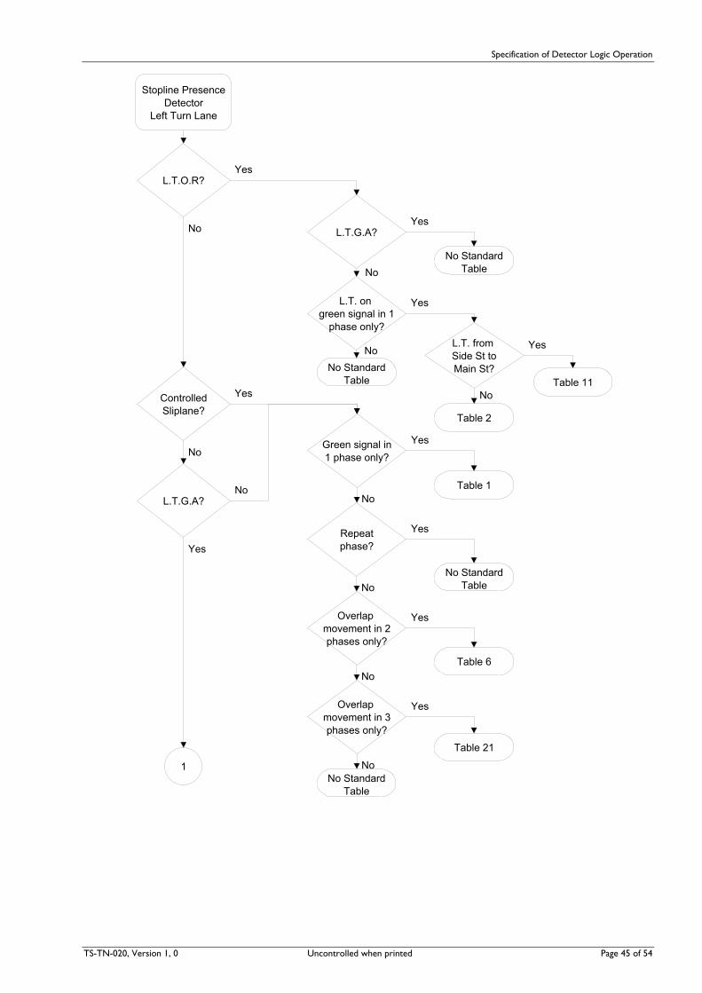
Specification of Detector Logic Operation
Stopline Presence Detector
Left Turn Lane
L.T.O.R?
L.T.G.A?
L.T. on green signal in 1
phase only?
No Standard Table
Green signal in1 phase only?
Repeatphase?
Overlap movement in 2 phases only?
Overlap movement in 3 phases only?
No Standard Table
Controlled Sliplane?
L.T.G.A?
1
L.T. from Side St toMain St?
No Standard Table
Table 11
Table 2
Table 1
No Standard Table
Table 6
Table 21
No
Yes
No
Yes
No
Yes
Yes
No
Yes
No
Yes
No
Yes
No
Yes
No
Yes
No
Yes
No
TS-TN-020, Version 1, 0 Uncontrolled when printed Page 45 of 54

Specification of Detector Logic Operation
Stopline Presence Detector
Left Turn Lane
L.T.O.R?
L.T.G.A?
L.T. on green signal in 1
phase only?
No Standard Table
Green signal in1 phase only?
Repeatphase?
Overlap movement in 2 phases only?
Overlap movement in 3 phases only?
No Standard Table
Controlled Sliplane?
L.T.G.A?
1
L.T. from Side St toMain St?
No Standard Table
Table 17
Table 2
Table 1
No Standard Table
Table 6
Table 21
No
Yes
No
Yes
No
Yes
Yes
No
Yes
No
Yes
No
Yes
No
Yes
No
Yes
No
Yes
No
Figure 10 Left turn Detector Logic Selection
Page 46 of 54 Uncontrolled when printed TS-TN-020, Version 1.0

Specification of Detector Logic Operation
TS-TN-020, Version 1, 0 Uncontrolled when printed Page 47 of 54
Exclusive Left Turn
Lane? RepeatL.T.G.A. phase
by specialfacility?
RepeatL.T.G.A. phase?
Table 26
Full Ped. Protection?
Very light Left Turndemand?
Very light Left Turndemand?
Heavy Ped. Volume?
Table 8
Ped conflict withLeft Turn?
Full Ped.Protection?
Ped.conflict withLeft Turn?
Table 27
Table 27
Table 8
Table 7
Table 24
Table 24
Table 7
Heavy Ped. Volume?
Heavy Ped. Volume?
Heavy PedVolume?
1
3
2
Table 25
No
Yes
No
Yes
No
Yes
No
Yes
No
Yes
No
Yes
No
Yes
No
Yes
Table 26
Table 25
No
Yes
No
Yes
No
Yes
No
YesNo
Yes
Figure 11 Left turn Detector Logic Selection (cont’d)
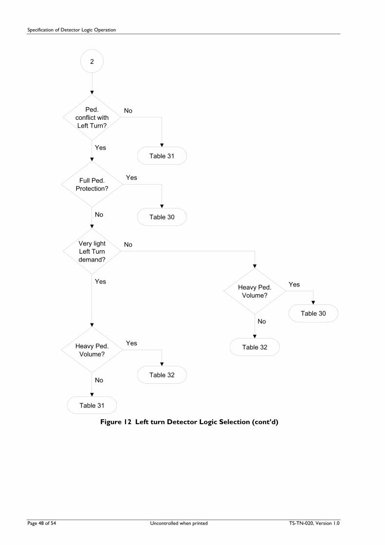
Specification of Detector Logic Operation
Page 48 of 54 Uncontrolled when printed TS-TN-020, Version 1.0
Ped.conflict withLeft Turn?
Full Ped.Protection?
Table 32Heavy Ped. Volume?
Table 31
Very lightLeft Turndemand?
Table 30
Table 31
Table 30
Table 32
Heavy Ped. Volume?
2
No
Yes
No
Yes
No
Yes
No
Yes
No
Yes
Figure 12 Left turn Detector Logic Selection (cont’d)
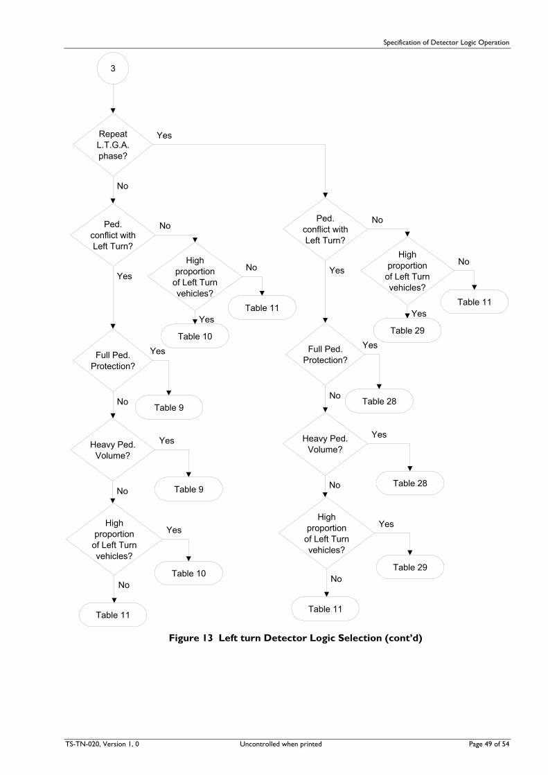
Specification of Detector Logic Operation
TS-TN-020, Version 1, 0 Uncontrolled when printed Page 49 of 54
RepeatL.T.G.A.phase?
Ped.conflict withLeft Turn?
Table 10
Highproportion
of Left Turnvehicles?
Table 11
Full Ped.Protection?
Table 11
Table 9
Table 10
Highproportion
of Left Turnvehicles?
3
Heavy Ped. Volume?
Table 9
Ped.conflict withLeft Turn?
Table 29
Highproportion
of Left Turnvehicles?
Table 11
Full Ped.Protection?
Table 11
Table 28
Table 29
Highproportion
of Left Turnvehicles?
Heavy Ped. Volume?
Table 28
No
Yes
No
YesNo
Yes
No
Yes
No
Yes
No
Yes
No
YesNo
Yes
No
Yes
No
Yes
No
Yes
Figure 13 Left turn Detector Logic Selection (cont’d)

Specification of Detector Logic Operation
8.5 Through Movement - Advance (Passage) Detector
Cases for Consideration
(a) Associated Presence (Stop Line) Detector.
(b) No Associated Presence (Stop Line) Detector.
Cases where Flowchart does not apply
(a) Single diamond overlap design.
(b) Double diamond overlap design.
(c) Movements which can occur in more than one phase.
Passage (Advance) Detector
Green in morethan 1 phase?
AssociatedStoplinedetector?
Table 3
No Standard Table
Table 1
No
Yes
No
Yes
Figure 14 Through Movement Passage (Advance) Detector Logic Selection
Page 50 of 54 Uncontrolled when printed TS-TN-020, Version 1.0

Specification of Detector Logic Operation
TS-TN-020, Version 1, 0 Uncontrolled when printed Page 51 of 54
9 Detector Classes Detectors are handled in terms of detector classes. Each class corresponds, (usually), to a single row of a detector specification schedule. A vehicle detector can only be in one class. Dummy classes having no detectors are also possible. Use these where demand functions are used which do not have related detectors, for example in Diamond Overlap designs.
A class consists of all the detectors having the same basic name, (for example, “A-B2”), and also the same, or strongly interrelated logic. If the class has more than one detector then each detector within the class also has a position name, such as “L”, “CL”, “C”, “CR” or “R”.
9.1 Summary The presently defined Standard Detector Tables are:
Table 1 Stop Line Presence Detector Locked Demand
Table 2 Stop Line Presence Detector Non-locked Demand
Table 3 Advanced Passage Detector No stop line detector
Table 4 Shared Right turn Lane
Table 5 Exclusive Right turn Lane Filtering permitted
Table 6 Stop Line Presence Detector Overlap Approach, Locked Demand
Table 7 Exclusive Left turn Lane Heavy Left turn, Full Pedestrian Protection or Heavy Pedestrian Volume
Table 8 Exclusive Left turn Lane No Conflicting Pedestrian, or Short Protection
Table 9 Shared Left turn Lane Heavy Pedestrian Volume, or Full Pedestrian Protection
Table 10 Shared Left turn Lane High Proportion Left turn, No Conflicting Pedestrian, or Short Protection
Table 11 Shared Left turn Lane Low Proportion of Left turn Vehicles
Table 12 Exclusive Right turn Lane Repeat Turn by Z+, Filtering permitted
Table 13 Exclusive Right turn Lane Repeat Turn by Z+, Non-Filter
Table 14 Exclusive Right turn Lane Repeat Turn by Z+, Filter/Non-Filter with Z-
Table 15 Shared Right turn Lane Repeat Turn by Z+
Table 16 Exclusive Right turn Lane Filter/Non-Filter option with Z-
Table 17 Stop Line Presence Detector Presence Timed Demand
Table 18 Stop Line Presence Detector Overlap Approach, Non-locked Demand
Table 19 Stop Line Presence Detector Overlap Approach, Presence Timed Demand
Table 20 Shared Right turn Lane Filter, with special Conditional-Locked Demand
Table 21 Stop Line Presence Detector Repeat Phase, Overlap Approach, Locked Demand
Table 22 Stop Line Presence Detector Repeat Phase, Overlap Approach, Non-locked Demand
Table 23 Stop Line Presence Detector Repeat Phase Overlap Approach, Presence Timed Demand
Table 24 Exclusive Left turn Lane Heavy Left turn, Short Pedestrian Protection

Specification of Detector Logic Operation
Page 52 of 54 Uncontrolled when printed TS-TN-020, Version 1.0
Table 25 Exclusive Left turn Lane Repeat Turn by Z+, Heavy Left turn, Full Pedestrian Protection or Heavy Pedestrian Volume
Table 26 Exclusive Left turn Lane Repeat Turn by Z+, No Conflicting Pedestrian, or Short Protection
Table 27 Exclusive Left turn Lane Repeat Turn by Z+, Heavy Left turn, Short Pedestrian Protection
Table 28 Shared Left turn Lane Repeat Turn, Heavy Pedestrian Volume, or Full Pedestrian Protection
Table 29 Shared Left turn Lane Repeat Turn, High Proportion Left turn, No Conflicting Pedestrian, or Short Protection
Table 30 Exclusive Left turn Lane Repeat Turn (Not by Z+), Heavy Left turn, Full Pedestrian Protection or Heavy Pedestrian Volume
Table 31 Exclusive Left turn Lane Repeat Turn (Not by Z+), No Conflicting Pedestrian, or Short Protection
Table 32 Exclusive Left turn Lane Repeat Turn (Not by Z+), Heavy Left turn, Short Pedestrian Protection
Table 33 Exclusive Right turn Lane Repeat Turn (Not by Z+), Filtering permitted
Table 34 Exclusive Right turn Lane Repeat Turn (Not by Z+), Non-Filter
Table 35 Exclusive Right turn Lane Repeat Turn (Not by Z+), Filter/Non-Filter with Z-
Table 36 Shared Right turn Lane Repeat Turn (Not by Z+)

Specification of Detector Logic Operation
TS-TN-020, Version 1, 0 Uncontrolled when printed Page 53 of 54
9.2 Selection Guide
1. Left turn On Red (a) Single Phase Stop Line Presence Detector - Table 2 Non-locked Demand - Table 11 Presence Timed Demand
(b) Overlap Approach Stop Line Presence Detector (1) Normal Overlap Approach
- Table 18 Non-locked Demand - Table 19 Presence Timed Demand
(2) Overlap Approach with Repeat Phase - Table 22 Non-locked Demand - Table 23 Presence Timed Demand
2. Exclusive Left turn Lane (a) Single turn phase (1) No conflicting pedestrian movement
- Table 8 Light or heavy left turn (2) Conflicting pedestrian movement with full protection
- Table 7 Light or heavy left turn (3) Short protection with heavy pedestrian volumes
- Table 7 Heavy left turn - Table 24 Light left turn
(4) Short protection with light pedestrian volumes - Table 24 Heavy left turn - Table 8 Light left turn
(b) Repeat turn phase by Z+ (1) No conflicting pedestrian movement
- Table 26 Light or heavy left turn (2) Conflicting pedestrian movement with full protection
- Table 25 Light or heavy left turn (3) Short protection with heavy pedestrian volumes
- Table 25 Heavy left turn - Table 27 Light left turn
(4) Short protection with light pedestrian volumes - Table 27 Heavy left turn - Table 26 Light left turn
(c) Repeat turn phase (Not by Z+) (1) No conflicting pedestrian movement
- Table 31 Light or heavy left turn (2) Conflicting pedestrian movement with full protection
- Table 30 Light or heavy left turn (3) Short protection with heavy pedestrian volumes
- Table 30 Heavy left turn - Table 32 Light left turn
(4) Short protection with light pedestrian volumes - Table 32 Heavy left turn - Table 31 Light left turn
3. Shared Left turn Lane (a) Single turn phase (1) No conflicting pedestrian movement
- Table 10 High proportion of left turn vehicles - Table 11 Low proportion of left turn vehicles
(2) Conflicting pedestrian movement with full protection

Specification of Detector Logic Operation
Page 54 of 54 Uncontrolled when printed TS-TN-020, Version 1.0
- Table 9 High proportion of left turn vehicles - Table 9 Low proportion of left turn vehicles
(3) Short protection with heavy pedestrian volumes - Table 9 High proportion of left turn vehicles - Table 9 Low proportion of left turn vehicles
(4) Short protection with light pedestrian volumes - Table 10 High proportion of left turn vehicles - Table 11 Low proportion of left turn vehicles
(b) Repeat turn phase (1) No conflicting pedestrian movement
- Table 29 High proportion of left turn vehicles - Table 11 Low proportion of left turn vehicles
(2) Conflicting pedestrian movement with full protection - Table 28 High proportion of left turn vehicles - Table 28 Low proportion of left turn vehicles
(3) Short protection with heavy pedestrian volumes - Table 28 High proportion of left turn vehicles - Table 28 Low proportion of left turn vehicles
(4) Short protection with light pedestrian volumes - Table 29 High proportion of left turn vehicles - Table 11 Low proportion of left turn vehicles
4. Exclusive Right turn Lane (a) Single right turn phase - Table 1 Non-filter - Table 5 Filter - Table 16 Filter/Non-filter option by Z-
(b) Repeat right turn phase by Z+ - Table 13 Non-filter - Table 12 Filter - Table 14 Filter/Non-filter option by Z-
(c) Repeat right turn phase (Not by Z+) - Table 34 Non-filter - Table 33 Filter - Table 35 Filter/Non-filter option by Z-
5. Shared Right turn Lane (a) Single right turn phase - Table 4
(b) Repeat right turn phase by Z+ - Table 15
(c) Repeat right turn phase (Not by Z+) - Table 36
6. Through Movement Stop Line Presence Detectors
(a) Single Phase Stop Line Presence Detector - Table 1 Locked Demand cleared by phase
(b) Overlap Approach Stop Line Presence Detector (1) Normal Overlap Approach
- Table 6 Locked Demand cleared by signal group
(2) Overlap Approach with Repeat Phase - Table 21 Locked Demand cleared by signal
group
7. Through Movement Advanced Detectors
(a) With no stop line presence detectors - Table 3 Incrementing detectors
(b) With stop line presence detectors - Table 1 Non-Incrementing detectors

[Inside rear cover – provided for double sided printing purposes only]

For further enquirieswww.rta.nsw.gov.au13 22 13
July 2009
Roads and Traffic Authority