Embed Size (px)
Citation preview

Riverside County Perris, California
SPECIFICATION NO. 1329 OMC Laboratory Modification Project Work Order # 413801 A PUBLIC WORKS PROJECT
Volume 1 of 2
Contents: Specifications | Notice Inviting Bids | Bidding Requirements | Bid Forms | Contract Forms |
Conditions of Contract Paul D. Jones, II, P.E. - General Manager Safety is of paramount and overriding importance to Eastern Municipal Water District
Visit our website at www.emwd.org to view currently advertised projects
Navigate to Construction Construction Bid Opportunities

[PAGE LEFT INTENTIONALLY BLANK]
00010-1 Table of Contents
TABLE OF CONTENTS
VOLUME 1
BIDDING REQUIREMENTS PAGE 00000 Title Page 00010 Table of Contents 00012 Notice Inviting Bids NIB-1 thru NIB-6 00014 Bid Opening Map 00016 Bid Walk-thru map/directions 00018 Instructions to Bidders B-1 thru -6 00020 Bidding Sheets & Equipment & Material List (submit with bid) BS-1 thru -8 00024 Proposal (7 day) (submit with bid) C3-1 thru -2
00027 Bidder’s Experience Record & Resumes (submit with bid) BR-1 thru -2 00028 Designation of Subcontractors (submit with bid) C5a thru e 00030 Contractor's Licensing Statement (submit with bid) C6-1 thru -2 00032 Non-Collusion Declaration (submit with bid) C7-1 thru -2 00034 Agreement C8a thru d 00036 Performance Bond C9-1 thru -4 00038 Payment Bond C10-1 thru -4 00040 Bid Bond (submit with bid) BB-1 00042 Worker’s Compensation Insurance Certificate C11-1 thru -2 00044 Certificate of Insurance Sample C12 00046 Iran Contracting Act Certification (submit with bid if over $1million) C13-1 thru -4 00050 Cal-OSHA form 300A (submit with bid) C16-1 thru -2 00052 Contractor’s Cal Osha Compliance History and SIC Code (submit with bid) C17-1 thru -2 00056 Employee Safety & Health Training Records C19-1 thru -2 00057 Contractor Registration Extract(s) (submit with bid) C22-1 thru -2 GENERAL CONDITIONS PAGE 00062 Section E, Inspection & Tests E-1 thru E-2 00064 Section F, Labor & Construction F-1 thru F-58
Includes Exhibit A – Escrow Agreement 00066 Section H, Permits H-1 thru H-2 SPECIAL CONDITIONS PAGE 00100 Special Conditions SC-1 thru SC-24
CONTRACT DRAWINGS 00200 Section P Standard & Construction Drawings (list) P-1 thru P-4
00010-2 Table of Contents
EMWD DETAILED PROVISIONS 01000 General Safety Requirements 1 thru 8 01026 Schedule of Values 1 thru 8 01310 Project Control Schedule 1 thru 12 01381 Pre-Const. Audio Video Taping Above Ground Facilities 1 thru 4 01612 Product Delivery Requirements (Custom) 1 thru 2 01614 Product Storage and Handling Requirements (Custom) 1 thru 2 01820 Demonstration and Training (Custom) 1 thru 6 02050 Demolition and Salvage 1 thru 2 02201 Construction Methods and Earthwork 1 thru 26 03150 Formwork for Cast-in-Place Concrete 1 thru 6 03200 Reinforcing 1 thru 6 03300 Cast-in-Place Concrete 1 thru 38 05100 Structural Metals 1 thru 6 05600 Standards for Aluminum Work 1 thru 8 06100 Carpentry Work 1 thru 8 08711 Locksets and Hardware 1 thru 2 16040 Short Circuit Arc Flash Study 1 thru 26 17310 Site Access System 1 thru 14
CUSTOM TECHNICAL SPECIFICATIONS DIVISION 07 – THERMAL AND MOISTURE PROTECTION 07 2100 Building Insulation 07 92 00 Sealants DIVISION 08 - OPENINGS 08 11 00 Metal Doors and Frames 08 21 00 Wood Doors and Frames 08 71 00 Finish Hardware DIVISION 09 – FINISHES 09 25 00 Gypsum Wallboard 09 51 00 Acoustic Ceilings 09 65 00 Resilient Flooring 09 67 23 Resinous Flooring 09 68 00 Carpet 09 90 00 Painting
DIVISION 10 – SPECIALTIES 10 40 00 Identifying Devices 10 52 00 Fire Fighting Equipment DIVISION 11 – EQUIPMENT 11 53 10 Laboratory Casework and Other Furnishings 11 53 13 Fume Hood and Other Air Containment Units

00010-3 Table of Contents
11 53 43 Laboratory Service Fittings and Fixtures 11 53 50 Laboratory Equipment VOLUME 2
CUSTOM TECHNICAL SPECIFICATIONS (Continued) DIVISION 21 – FIRE SUPPRESSION – Refer to Simplex Grinnell Proposal DIVISION 22 – PLUMBING 22 05 48 Vibration and Seismic Controls for Plumbing Piping and Equipment 22 07 19 Plumbing Piping Insulation 22 20 00 Laboratory Plumbing DIVISION 23 – HEATING, VENTILATING & AIR CONDITIONING 23 05 00 Mechanical General Requirements 23 05 19 Meters and Gages for HVAC Piping 23 05 23 Valves for HVAC Piping 23 05 29 Hangers and Supports for HVAC Piping and Equipment 23 05 48 Vibration and Seismic Controls for HAVC 23 05 53 Identification for HVAC Piping and Equipment 23 05 93 Testing, Adjusting and Balancing for HVAC 23 07 13 Duct Insulation 23 07 19 HVAC Piping Insulation 23 09 13 Instrumentation and Control for HVAC 23 09 24 Laboratory Air Terminal and Control System 23 09 93 Sequence of Operations for HVAC Controls 23 11 23 Facility Natural-Gas Piping 23 21 13 Hydronic Piping 23 31 13 Metal Ducts 23 33 00 Air Duct Accessories 23 34 16 Centrifugal HVAC Fans 23 36 00 Air Terminal Units 23 37 13 Air Diffusers, Registers and Grilles 23 51 23 Gas Vents 23 73 10 Custom Air Handling Units DIVISION 26 – ELECTRICAL 26 05 00 Basic Electrical Requirements 26 05 19 Wire and Cable 26 05 26 Grounding and Bonding 26 05 29 Hangers and Supports for Electrical Systems 26 05 33 Raceways 26 05 34 Boxes 26 05 36 Cable Tray

00010-4 Table of Contents
26 05 75 Acceptance Testing 26 09 23 Occupancy Sensors 26 09 43 Lighting Controls 26 24 16 Panelboards 26 27 26 Wiring Devices and Connectors 26 28 16 Circuit and Motor Disconnects 26 51 00 Interior Lighting 26 60 00 Laboratory Electrical Requirements DIVISION 28 – COMMUNICATIONS – Refer to Simplex Grinnell Proposal
APPENDICES
Appendix A Contractor Access, Laydown, and Staging Areas Appendix B Existing Laboratory Layout and Photos Appendix C 3D Illustration of the Proposed OMC Lab Modification and the New Laboratory Color
Schemes Appendix D HVAC and Exhaust System Control and Integration Proposal (Climatec) Appendix E Fire Suppression System – Alarm and Sprinklers Proposals (Simplex Grinnell) Appendix F Security System Proposal (Maxim Security Systems) Appendix G Network System Proposal (GA Technical Services) Appendix H District Communication Equipment Specification for Construction (New and Replacement) Appendix I Copy Machine Rental Proposal (Xerox) Appendix J Ground Penetrating Radar Systems Report Appendix K OMC Laboratory Environmental Hazards Test Report Appendix L Existing OMC Building As-Built References (Provided on DVD)

NIB-1 00012 Notice Inviting Bid
EASTERN MUNICIPAL WATER DISTRICT SPECIFICATION NO. 1329
OMC LABORATORY MODIFICATION PROJECT 2018 NOTICE INVITING BID NIB-1. Receipt of Bids. Sealed proposals (bids) for this project will be received and time-stamped by Eastern Municipal Water District no later than 10:00 a.m., TUESDAY, SEPTEMBER 25, 2018 (from time stamp clock) at which time and place they will be publicly opened. Hand deliver/Fed Ex your bid to: EMWD, 2270 Trumble Road, Perris, CA, 92570 Mail your bid to: EMWD, P O Box 8300, Perris, CA 92572-8300 Bids are received at the Operations and Maintenance Center lobby only. Please follow the VENDORS/BIDDERS signs to the Operations and Maintenance parking lot, enter the lobby, and have your bids time-stamped by the Receptionist. All bids submitted will become the property of EMWD and subject to disclosure under the Public Records Act. All bids will be posted on the website www.emwd.org approximately 10 days from bid opening. NIB-2. Contract Documents. The contract documents, which include instructions to bidders, plans and specifications, are available at www.emwd.org. To view and download these documents, navigate to Construction and select Construction Bid Opportunities. If obtaining the contract documents online, please complete the Planholder Registration form to receive email notification of addenda issued. Bidders shall use full size drawings to prepare bid. To purchase a CD of the contract documents, mail your request and a check in the amount of $5.00 (includes sales tax; non-refundable) as follows: Eastern Municipal Water District, Field Engineering, Attn: Valerie Wimberly Regular or Express mail: P.O. Box 8300, Perris, CA 92572-8300 UPS or Federal Express: 2270 Trumble Road, Perris, CA 92570 For faster service, please provide your Federal Express account number Plans and Specifications may also be viewed at the District's office, 2270 Trumble Road, Perris, CA. A limited number of CD’s will be available for purchase at the pre-bid walk-through meeting. Please bring checks only. NIB-3. Location and Description of Work. The work to be constructed is located at District’s Operation and Maintenance Center (OMC), 2270 Trumble Road, Perris, CA 92572.

NIB-2 00012 Notice Inviting Bid
The work comprises of construction and modification of District’s OMC Laboratory and its supporting Utility Room. Building work includes but not limited to, demolition of the OMC Laboratory and Utility Room; modify concrete floor slab and install drains; modify existing exterior and interior wall, furnish and install new interior walls; furnish and install exterior and interior doors and framings, motorized rollup door, hardware and appurtenances; salvage and reinstall existing windows and framings; furnish and install acoustic ceiling system and drywall ceiling; furnish and install interior finishes to walls, floor, and ceilings; furnish and install exterior wall opening structural framings and solar tubes; furnish and install safety shower, eyewash stations, and associated safety alarms and controls; relocate and reinstall mechanical and floor-standing laboratory equipment and fittings; furnish and install cabinetry and countertops; furnish and install laboratory grade casework, cabinetry, countertops, wall shelving, islands, supports and appurtenances; furnish and install HVAC and exhaust systems, controls, ductwork and appurtenances; furnish, install and modify laboratory mechanical, plumbing and utility connections, including fittings, fixtures, and appurtenances; furnish and install electrical system, raceways, conduits, wirings, receptacles and switches, and appurtenances; furnish and install ceiling and task lighting systems, controls, fixtures, conduits, wirings, switches, and appurtenances; furnish, install, modify and integrate fire suppression system and controls, piping and fittings and appurtenances; furnish, install modify and integrate security and public address system and controls, components, conduits, wirings, and appurtenances; furnish, install, modify and integrate network system, cables and cable trays, conduits, network connections, and appurtenances; and all systems and appurtenances for a complete and fully functional OMC Laboratory in accordance with the Contract Drawings and Specifications. NIB-4. Mandatory Pre-Bid Walk-Through will be conducted by EMWD on WEDNESDAY, SEPTEMBER 5, 2018 at 9:00 a.m., meeting at 2270 Trumble Road, Perris, CA, Thomas Guide Page 808 Grid C6. Please arrive promptly! All bidders must have an employee of their firm sign-in and attend the mandatory pre-bid walk-through meeting. Failure to do so shall deem your bid non-responsive. Personal Protective Equipment (PPE). For your safety, attendees shall bring and wear hard hats, safety vests, and close-toed shoes, if construction is present. QUESTIONS: All questions must be submitted in writing by 5:00 p.m. on MONDAY, SEPTEMBER 10, 2018 to Mr. William Chen c/o Val Wimberly; EMAIL: [email protected] & [email protected]. Questions received after this time may not be responded to.

NIB-3 00012 Notice Inviting Bid
NIB-5. Contract Bonds. All bonds shall be executed by admitted surety insurers, as defined in Code of Civil Procedure section 995.120. Each proposal must be accompanied by a certified check or satisfactory surety bond (by utilizing the District’s Bid Bond form BB-1) for not less than 10% of the bidder's total contract price as a guarantee that the bidder shall, within seven (7) days after the mailing of a notice of acceptance of bid by the District to the bidder, enter into the written contract supplied by the District. The District shall return the bid bond, upon request. The Contractor shall furnish a faithful performance bond in an amount equal to 100% of the amount of the contract and a labor payment bond in an amount equal to 100% of the contract amount.
Pursuant to Section 995.660(a) of the Code of Civil Procedure, the Contractor shall submit the following documents with the performance and payment bonds:
(1) The original, or a certified copy, of the unrevoked appointment, power of attorney, bylaws, or other instrument entitling or authorizing the person who executed the bond to do so;
(2) A certified copy of the certificate of authority of the insurer issued by the State of California’s Insurance Commissioner; and
(3) Copies of the insurer's most recent annual and quarterly statements filed with the Department of Insurance.
NO PAYMENT SHALL BE MADE UNTIL THE BONDS ARE APPROVED BY THE DISTRICT NIB-6. Safety. Safety of all activities in connection with the work is of paramount and overriding importance to the District. The District is recognized by the California Occupational Safety and Health Administration (Cal OSHA) as an active participant in the California Voluntary Protection Program (Cal VPP). The District is designated a Cal STAR site due to our high-level commitment to safety. Bidders on this project will be required to comply with and meet all applicable Cal OSHA requirements of Title 8 of the California Code of Regulations, including their current Injury and Illness Prevention Plan, T8 CCR Section 3203. All bidders shall complete the C-16 Annual Summary of Work Related Injuries and Illness (Cal/OSHA Form 300A) and the C-17 Contractor’s Cal/OSHA Compliance History and SIC Code form. Failure to fully divulge, complete and submit these forms may deem your bid non-responsive A safety conference shall be scheduled prior to the preconstruction conference to review the experience modification rating, the respective safety requirements, and to discuss implementation of all health and safety provisions related to this project.

NIB-4 00012 Notice Inviting Bid
NIB-7. Contract Time. No bid or bid security may be withdrawn for seventy-five (75) calendar days after the date bids are received. The successful bidder shall, within seven (7) calendar days after the District mails a notice of acceptance of bid, return the signed agreement and bonds, and attend the pre-construction conference at the District office. The contract period shall commence seven (7) calendar days from the date of the Notice-of-Acceptance-of-Proposal. The Contractor shall complete all work, including testing and commissioning, within three hundred and sixty four (364) calendar days.
NIB-8. Contractor Classification. Bidders on this work will be required to be licensed by the State of California as Classification A – General Engineer and/or Classification B - General Building Contractor at the time of the bid and at the time of award as such license is defined in Section 7056 and/or Section 7058 of the Business and Professional Code and Section 732 of the California Administrative Code.
NIB-9. Non-Discrimination. Bidders on this work will be required to comply with the provisions of the California Labor Code and with the President's Executive Order No. 11246 and supplements thereto. The requirements for bidders and contractors under this order are explained in the specifications. NIB-10. Minimum Wages. In accordance with the provisions of the California Labor Code, the Director of Industrial Relations has ascertained the general prevailing rates of wages and the general prevailing rates for legal holiday and overtime work in Riverside County (refer to Section F-General Conditions). Copies of said rates are on file at the office of the District, which copies shall be made available for review to any interested party on request. The successful bidder shall post a copy of such determinations at the jobsite. NIB-11. Public Works Requirements California Administrative Code, Title 8, Group 3, Section 16100 apply, which are/include:
A. all applicable requirements of sections 1771, 1774 - 1776, 1813, and 1815. B. the appropriate number of apprentices are on the job site, as set forth in Labor Code
Section 1777.5. C. workers' compensation coverage, set forth in Labor Code Sections 1860 and 1861. D. to keep accurate records of the work performed on the public works project, as set
forth in Labor Code Section 1812. E. inspection of payroll records pursuant to Labor Code Section 1776, and as set forth in
Section 16400 (e) of these regulations. F. and other requirements imposed by law.
NIB-12. Public Works Contractor and Subcontractor Registration. This project is subject to compliance monitoring and enforcement by the Department of Industrial Relations.
NIB-6 00012 Notice Inviting Bid
[PAGE LEFT INTENTIONALLY BLANK]

Q
FH
GA
TE
4
GA
TE
2
MAPES ROAD
TR
UM
BLE
R
OA
D
GATE
3
Building B (OMC)
Building A (ADMIN)
MAPES RD
TR
UM
BLE
RD
STATE HWY 74 EAST
VENDORS
PUBLIC
SHIPPING/RECEIVING
EMWD
Perris, Ca 92570
2270 Trumble Rd
N
S
EW
EASTERN MUNICIPAL WATER DISTRICTADMINISTRATIVE, OPERATIONS AND MAINTENANCE CENTER
N
S
EW
RIVERSIDE COUNTY, CALIFORNIA
To Reach the Main Office:
Take HWY 74 West to PerrisTurn Right (North) onto Trumble Rd.
From I-215 (North)...
Take HWY 74 East Exit to HemetTurn Left (North) onto Trumble Rd.
From I-215 (South)...
Take HWY 74 East Exit to HemetTurn Left (North) onto Trumble Rd.
From Hemet area...
FROM I - 215
TAKE STATE
HWY 74 EAST
OMCParking Lot
ADMINParking Lot
OMCLobby
C. REBER EMWD 11-27-2017
NOT TO SCALE
Vendor Bid Check-in Map 01
VENDOR “BID” CHECK-IN
AND PARKING
LOCATION
Please follow the sign(s) to theVENDORS entrance (Gate 3) and park
your vehicle in the Operations andMaintenance (OMC) parking lot.Please enter through the OMC
Lobby.
Take your BID to the Receptionistand have your BID stamped in
IMMEDIATELY

[PAGE LEFT INTENTIONALLY BLANK]

00016 Pre-Bid Walk-Thru Map/Directions
Mandatory Pre-Bid Walk-thru Map and Directions
From I-215: Exit Highway 74 East and head east. Turn left on Trumble Road. Meeting shall take place at EMWD’s headquarters in the Community Room located at 2270 Trumble Road, Perris, California 92570. Please enter the facility from the vendor’s entrance.
CCoonnttrraaccttoorrss mmuusstt ffiirrsstt cchheecckk iinn aatt tthhee LLoobbbbyy

00016 Pre-Bid Walk-Thru Map/Directions
[PAGE LEFT INTENTIONALLY BLANK]

Rev:04/11/16 B-1 00018 Instructions to Bidders
INSTRUCTIONS TO BIDDERS
B-01. Form of Proposal and Signature. The proposal shall be submitted on the form provided by the District and shall be enclosed in a sealed envelope marked and addressed as hereinafter directed. The Bidder shall state in words and figures the unit prices or the specific sums as the case may be, for which he proposes to supply the labor, materials, supplies, or machinery, and perform the work required by the specifications and drawings. In case words and figures do not agree, the words shall govern and the figures shall be disregarded. If the unit price and the total amount named by a Bidder for any item are not in agreement, the unit price alone will be considered as representing the Bidder's intention and totals will be corrected to conform thereto. The District reserves the right to correct any arithmetical errors. If the proposal is made by an individual it shall be signed and his full name and address shall be given; if it is made by a Firm it shall be signed with the co-partnership name by a member of the firm, who shall also sign his own name, and the name and address of each member shall be given; and if it is made by a corporation the name of the corporation shall be signed by its duly authorized officer or officers, and the names and titles of all officers of the corporation shall be given. No telegraphic proposal or telegraphic modification of a proposal will be considered.
B-02. Preparation of the Proposal. Blank spaces in the proposal shall be properly filled. The phraseology of the proposal must not be changed and no additions shall be made to the items mentioned therein. Conditions, limitations or provisos attached to a proposal will cause its rejection. Alterations by erasure or interlineation must be explained or noted in the proposal over the signature of the Bidder. Alternative proposals will not be considered unless specifically provided for in the Bidding Sheet. A Bidder may withdraw his proposal before the hour fixed for opening bids, without prejudice to himself, by submitting a written request to the General Manager of the District for its withdrawal, and his proposal will be returned to him unopened when reached in the procedure of opening bids without rendering the accompanying certified or cashier's check or bond subject to forfeiture as liquidated damages in like manner as in the case of failure to execute contract after award, as hereinafter provided. No proposal received after the time named or at any place other than the place stated in the Notice Inviting Bids (or Bidding Information sheet) will be considered. All bids will be opened and declared to be present at the opening. The District reserves the right to waive any informality in any bid, to reject any or all proposals, to reject one part of a proposal and accept the other, and to make award to the lowest responsible Bidder as the interest of the District may require.
The Non-Collusion Declaration, Subcontractor’s List naming each subcontractor who will perform work or labor or render service to the Contractor in an amount in excess of one-half of one percent (1/2 of 1%) of the Contractor's total bid, and Bid Bond or Certified or Cashier’s Check, and all required forms shall be submitted with the proposal at time of bid. Pursuant to the Iran Contracting Act of 2010 (Pub. Cont. Code § 2200-2208), contracts of one million dollars ($1,000,000) or more shall require bidder to submit the Iran Contract Act Certification with the proposal at time of bid. Where bonds are required, the Bidder shall name in his proposal the surety or sureties, which have agreed to furnish said bonds.

B-2 00018 Instructions to Bidders
B-03. Lowest Responsible Bidder. In selecting the lowest responsible Bidder, consideration will be given to the general competency of the Bidder for the performance of the work covered by the proposal, and the bidder’s financial standing, if requested. To receive favorable consideration, a bidder must present evidence satisfactory to the District that he or his associates are personally competent to manage the proposed undertaking and to carry it forward to a successful conclusion. Professional integrity and honesty of purpose shall be essential requirements.
A showing of adequate financial resources may be requested by the District, but will not alone determine whether a bidder is competent to undertake the proposed work. Each bidder must furnish a record of past performance and experience in the form required. To this end, each proposal, except as noted below, shall be supported by a statement of the bidder's experience on the form provided. This form, completely filled out, must be submitted along with the proposal. Incomplete or false statements submitted in connection with a proposal may, at the option of the Board of Directors of the District, be sufficient cause for its rejection. The District shall be the final authority with regard to whether a bid is responsive to the call for bids and as to whether a bidder is a responsible bidder under the conditions of his bid.
B-04. Equalizing Factors. Whenever applicable, equalizing elements or factors not specifically mentioned or provided for herein, such as costs of transportation, inspection (including salaries and travel and subsistence expenses), installation, and operation, or any other factor or element in addition to that of price which would affect the total cost or value to the District will be taken into consideration in comparing bids for award of contract.
B-05. Certified or Cashier's Check or Bond. As a guarantee of good faith, each bidder shall submit with his proposal an unconditional certified or cashier's check drawn on a solvent state or national bank, or he may furnish a bond, utilizing the District’s Bid Bond form BB-1, with a company acceptable to the District in the sum stated in the Notice Inviting Bids, payable to the Eastern Municipal Water District, said check or bond to be held uncollected until it becomes subject to disposal as herein provided. Any condition or limitation placed upon said check or bond may render it informal and may, at the option of the Board result in the rejection of the proposal under which such check is submitted. Original Bid Bond (BB-1) must include Notary Public Acknowledgement for Surety and Contractor. If a Bidder to whom an award is made fails or refuses to execute the contract and furnish the required bond, all within the time stated in Section B-6 hereof, said check or bond and the monies represented thereby shall be and remain the property of the District and shall be subject to deposit with the Treasurer of the District as other monies belonging to the District, the amount thereof being agreed to by the Bidder as liquidated damages due the District on account of the delay in the execution of the contract and bond, and in the performance of the work thereunder, resulting from such failure or refusal. Original Bid bond (BB-1) shall remain on file at the District with the original bid proposal and be returned upon written request only. Certified checks shall be returned at the expiration of 60 days from the date of opening bids.

B-3 00018 Instructions to Bidders
B-06. Execution of Contract. A Bidder to whom the award is made shall execute and return a written contract with the District on the form of Agreement attached hereto and furnish good and approved bond as required in the following paragraph, all in accordance with the provisions hereof and within the time stated in the Notice Inviting Bids (or Bidding Information sheet) or such additional time as may be allowed by the Engineer. The District will return a copy of the fully executed contract upon completion by the General Manager.
If a Bidder to whom the award is made fails or refuses to enter into contract as herein provided, or to conform to any of the stipulated requirements in connection therewith, his check shall become the property of the District as provided in Section B-5 hereof, the award will be annulled, and in the discretion of the District an award may be made to the Bidder whose proposal is next most acceptable to the District; and such Bidder shall fulfill every stipulation embraced herein as if he were the party to whom the first award was made. A corporation to which an award is made will be required, before the contract is finally executed, to furnish evidence of its corporate existence and of the authority of the officer signing the contract and bond for the corporation to so sign.
B-07. Bond
(a) A Bidder to whom contract is awarded shall within the time mentioned in the preceding paragraph furnish a bond with a responsible corporate surety or corporate sureties conditioned upon the faithful performance by the said Bidder of all covenants and stipulations in the contract. Said bond shall be in the amount stipulated in the Notice Inviting Bids (or Bidding Information sheet). Bonds in amounts of $1,000 or less shall be made in multiples of $100; in amounts exceeding $1,000 but not exceeding $5,000 in multiples of $500; in amounts exceeding $5,000 in multiples of $1,000; provided, that the amount of the bond shall be fixed at the lowest sum that fulfills all conditions of the contract.
(b) The surety or sureties on the bond furnished must be satisfactory to the Board. The required bond shall be furnished by the Bidder to whom contract has been awarded at his own cost and expense.
(c) Attention is invited to the provisions of the Insurance Code of the State of California with reference to the writing of insurance policies and bonds covering risks located in this State, and the premiums and commissions thereon. A Bidder to whom contract is awarded shall furnish at the time his bond is submitted for approval, satisfactory evidence that the requirements of said code have been observed.
(d) The bond furnished by the surety shall agree to acceptance by the surety of arbitration of disputes, where selected in accordance with Section F, Arbitration.

Rev:04/11/16 B-4 00018 Instructions to Bidders
B-08. Address and Marking of Proposal. The envelope enclosing a proposal MUST be sealed and addressed as follows:
MAIL: General Manager STREET: General Manager Eastern Municipal Water District Eastern Municipal Water District Attn: Field Engineering Department Attn: Field Engineering Department P O Box 8300 2270 Trumble Road Perris, CA 92572-8300 Perris, CA 92570 The envelope MUST be plainly marked in the upper left hand with the name and address of the bidder, and bear the words:
Proposal For: (specification number) (name of project (date and hour)
The statement of Bidder's experience and financial condition, when required, if not already on file in the District Office, and a certified or cashier's check, or bond, should be enclosed in the same envelope with the proposal.
B-09. Complete Specifications and Drawings. It shall be the responsibility of the Bidder to verify the completeness of his set of specifications and drawings and neither the District nor any of its officers shall be held responsible for any omission therefrom unless such omission has been called to the attention of the District prior to the submission of bids. Bidders shall use full size drawings to prepare said bid.
B-10. Addenda and/or Letter of Clarification. Bidder shall be responsible for verifying that any addenda or letter of clarification issued by the District has been investigated and received. By submitting a bid, Bidder certifies that any addenda and letters of clarification issued to these specifications, whether acknowledged or not on the Bidding Sheets, shall be made a part of the contract. Bidder further agrees to perform all labor and services and furnish all materials, tools and appliances necessary for completing the work called out in the addenda or letter of clarification at no additional cost to the District.
B-11. Improperly Balanced Proposals. Any proposal which in the opinion of the Engineer is so unbalanced between the various contract items as to be detrimental to the interests of the District will be rejected.

B-5 00018 Instructions to Bidders
B-12. Local Conditions. Bidders shall read the specifications, any background material, examine the drawings, and make their own estimates of the existing facilities and the difficulties which will attend the execution of the work called for by the proposed contract, including local conditions, uncertainty of weather, and all other contingencies. The District will identify for Bidders the location of existing utilities located on the site of construction which require removal, relocation or protection. AN EMPLOYEE ON THE COMPANY’S PAYROLL MUST HAVE INSPECTED THE SITE OF THE PROPOSED WORK TO BE CONSIDERED A RESPONSIVE BIDDER. Bidders shall satisfy themselves by personal examination of the locations of the proposed work, and by such other means as they may choose as to actual conditions and requirements and as to the accuracy of the quantities stated in the Bidding Sheet. Information derived from the maps, plans, specifications, profiles, or drawings, or from the Engineer or his assistants, shall not relieve the bidder of this responsibility, and the interpretation of the data disclosed by borings or other preliminary investigations is not guaranteed by the District.
The quantities of work or materials stated in the unit price items of the Bidding Sheet are given only as a basis for the comparison of bids and the District does not expressly or by implication agree that the actual amount of work or material will correspond therewith, but reserves the right to increase or decrease the amount of any unit price item of the work as may be deemed necessary or expedient by the Engineer.
Bidders shall not at any time after the submission of a bid make or have any claim for damages or anticipated profits or loss of profit or otherwise because of any difference between the quantities of work actually done and material furnished and those stated in said unit price items of the Bidding Sheet.
B-6 00018 Instructions to Bidders
Pursuant to Public Contract Code section 7104, any public works contract of a local public entity which involves digging trenches or other excavations that extend deeper than four feet below the surface shall provide for the following: (a) That the contractor shall promptly, and before the following conditions are disturbed, notify the public entity, in writing, of any: (1) Material that the contractor believes may be material that is hazardous waste, as defined in Section 25117 of the Health and Safety Code, that is required to be removed to a Class I, Class II, or Class III disposal site in accordance with provisions of existing law. (2) Subsurface or latent physical conditions at the site differing from those indicated by information about the site made available to bidders prior to the deadline for submitting bids. (3) Unknown physical conditions at the site of any unusual nature, different materially from those ordinarily encountered and generally recognized as inherent in work of the character provided for in the contract. (b) That the public entity shall promptly investigate the conditions, and if it finds that the conditions do materially so differ, or do involve hazardous waste, and cause a decrease or increase in the contractor's cost of, or the time required for, performance of any part of the work shall issue a change order under the procedures described in the contract. (c) That, in the event that a dispute arises between the public entity and the contractor whether the conditions materially differ, or involve hazardous waste, or cause a decrease or increase in the contractor's cost of, or time required for, performance of any part of the work, the contractor shall not be excused from any scheduled completion date provided for by the contract, but shall proceed with all work to be performed under the contract. The contractor shall retain any and all rights provided either by contract or by law which pertain to the resolution of disputes and protests between the contracting parties.
B-13. Insurance. Attention is invited to the requirements set forth in SPECIFICATION - GENERAL CONDITIONS, Art. F-04 Contractor's and Subcontractor's Insurance and the Special Conditions.

BS-1 00020 Bidding Sheets
EASTERN MUNICIPAL WATER DISTRICT SPECIFICATION NO. 1329
OMC LABORATORY MODIFICATION BIDDING SHEETS The Contractor shall construct the project under these Specifications all in conformance with the Contract Drawings listed in Section P and these Specifications. The District reserves the right to:
A. Accept or reject any or all bids on this specification; B. Award Contract to the lowest qualified bidder, based on the total bid price: C. Waive any defects and informalities.
The District shall be the final authority with regard to whether a bid is responsive to the call for bids and to whether a bidder is a responsible bidder under the conditions of his bid, or for any reason. The total contract price shall include all work, materials and equipment needed to complete the project as defined in the General Conditions, Section F. The bidder shall include costs for such other items in the most appropriate category (bid item). TO BE INSTALLED: The District will furnish the following item(s) to be installed by the Contractor: 8-ft wide fume hood and supporting base cabinets 3-ft wide floor standing Autoclave and hood The Contractor shall coordinate with Lab to relocate, store, install and startup all furnished items.

BS-2 00020 Bidding Sheets
BASIS OF AWARD: Additive Bid Item(s) Included in Total Bid Price. Public Contract Code 20103.8(b) provides for basis of award as follows: b) The lowest bid shall be the lowest total of the bid prices on the base contract and those
additive or deductive items that were specifically identified in the bid solicitation as being used for the purpose of determining the lowest bid price.
Public Contract Code 20103.8 does not preclude the District from adding to or deducting any of the additive or deductive items after the lowest responsible bidder has been determined. Failure to provide a cost for the additive or deductive bid items may deem your bid non-responsive.
EASTERN MUNICIPAL WATER DISTRICT SPECIFICATION NO. 1329
OMC LABORATORY MODIFICATION
BIDDING SHEETS
Unit Total Bid
Item
Qty
Unit Description
(Unit Price Written in Words) Price
(Figures) Amount
(Figures)
BS-3 00020 Bidding Sheets
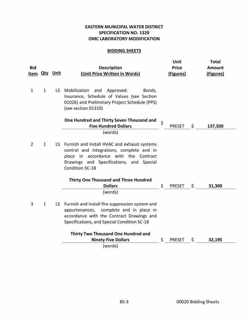
1 1 LS Mobilization and Approved: Bonds, Insurance, Schedule of Values (see Section 01026) and Preliminary Project Schedule (PPS) (see section 01310)
One Hundred and Thirty Seven Thousand and
Five Hundred Dollars
$
PRESET
$
137,500 (words)
2 1 LS Furnish and install HVAC and exhaust systems control and integrations, complete and in place in accordance with the Contract Drawings and Specifications, and Special Condition SC-18
Thirty One Thousand and Three Hundred
Dollars $
PRESET
$
31,300
(words)
3 1 LS Furnish and install fire suppression system and appurtenances, complete and in place in accordance with the Contract Drawings and Specifications, and Special Condition SC-18
Thirty Two Thousand One Hundred and
Ninety Five Dollars $
PRESET
$
32,195
(words)

EASTERN MUNICIPAL WATER DISTRICT SPECIFICATION NO. 1329
OMC LABORATORY MODIFICATION
BIDDING SHEETS
Unit Total Bid
Item
Qty
Unit Description
(Unit Price Written in Words) Price
(Figures) Amount
(Figures)
BS-4 00020 Bidding Sheets
4 1 LS Furnish and install security system and appurtenances, complete and in place in accordance with the Contract Drawings and Specifications, and Special Condition SC-18
Thirty One Thousand Two Hundred and Ninety One Dollars $
PRESET
$
31,291
(words)
5 1 LS Furnish and install network system and appurtenances, complete and in place in accordance with the Contract Drawings and Specifications, and Special Condition SC-18
Forty Six Thousand Two Hundred and Ten Dollars $
PRESET
$
46,210
(words)
6 1 LS Perform additional environmental hazards abatement work per applicable federal and state regulations, complete and in place in accordance with the Contract Drawings and Specifications, and Special Condition SC-38
Fifty Thousand Dollars $ PRESET $ 50,000 (words)
7 1 LS Furnish and install all work and appurtenances related to the OMC Laboratory Modification, complete and in place in accordance with the Contract Drawings and Specifications
$
Lump Sum
$
(words)

EASTERN MUNICIPAL WATER DISTRICT SPECIFICATION NO. 1329
OMC LABORATORY MODIFICATION
BIDDING SHEETS
Unit Total Bid
Item
Qty
Unit Description
(Unit Price Written in Words) Price
(Figures) Amount
(Figures)
BS-5 00020 Bidding Sheets
8 1 LS ADDITION OR DEDUCTION Circle one (If applicable):
Addition (+)
Deduction(-)
$
(words)
Additive Bid Item A1 1 LS Furnish and install epoxy flooring and
appurtenances in the Laboratory and vestibule area, in lieu of the proposed tile flooring, complete and in place in accordance with the Contract Drawings and Specifications
$
Lump Sum
$
(words)
TOTAL BID (Basis of award)
$________________________
EASTERN MUNICIPAL WATER DISTRICT SPECIFICATION NO. 1329
OMC LABORATORY MODIFICATION
BIDDING SHEETS
BS-6 00020 Bidding Sheets
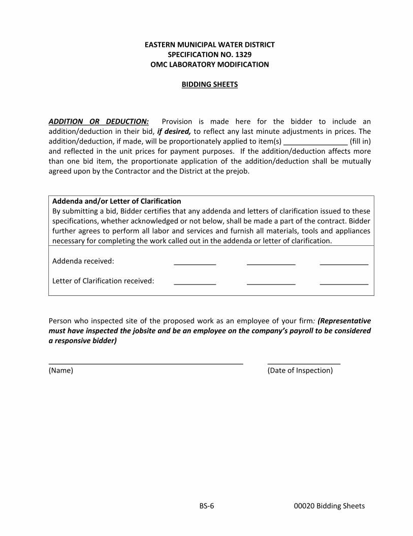
ADDITION OR DEDUCTION: Provision is made here for the bidder to include an addition/deduction in their bid, if desired, to reflect any last minute adjustments in prices. The addition/deduction, if made, will be proportionately applied to item(s) (fill in) and reflected in the unit prices for payment purposes. If the addition/deduction affects more than one bid item, the proportionate application of the addition/deduction shall be mutually agreed upon by the Contractor and the District at the prejob. Addenda and/or Letter of Clarification By submitting a bid, Bidder certifies that any addenda and letters of clarification issued to these specifications, whether acknowledged or not below, shall be made a part of the contract. Bidder further agrees to perform all labor and services and furnish all materials, tools and appliances necessary for completing the work called out in the addenda or letter of clarification. Addenda received: Letter of Clarification received:
Person who inspected site of the proposed work as an employee of your firm: (Representative must have inspected the jobsite and be an employee on the company’s payroll to be considered a responsive bidder) (Name) (Date of Inspection)

BS-7 00020 Bidding Sheets
EQUIPMENT AND MATERIAL No substitution will be permitted without written justification and the approval of the District prior to the bid opening.
PRODUCTS OF MANUFACTURERS LISTED AS EQUALS TO THOSE SPECIFIED IN THE CONTRACT DOCUMENTS MUST BE SUBMITTED FOR REVIEW AND APPROVAL BY THE DISTRICT NO LATER THAN THE TENTH (10TH) DAY PRECEDING THE DATE SET FOR RECEIPT OF BIDS.

BS-8 00020 Bidding Sheets
[PAGE LEFT INTENTIONALLY BLANK]

C3-1 00024 Proposal (7 day)
P R O P O S A L The undersigned hereby declares, as Bidder, that the only persons or parties interested in this proposal as principals are those named herein; that no director or any other officer or employee of the Eastern Municipal Water District is in any manner interested directly or indirectly in this proposal or in the profits to be derived from the contract proposed to be taken; that this bid is made without any connection with any person or persons making a bid for the same purpose; that the bid is in all respects fair and without collusion or fraud; that he has read the Notice Inviting Bids (or Bidding Information), Insurance Requirements and the Instructions to Bidders and agrees to all the stipulations contained herein; that he proposes and agrees that if his bid as submitted in the attached sheets, be accepted he will contract in the form so approved and furnish all items called for in accordance with the provisions of said approved form of Agreement, Insurance Requirements and the Specifications and to deliver the same within the time stipulated therein; and that he will accept in full payment therefore the prices named in said Bid Sheet. The Bidder further agrees, that upon receipt of written notice of the acceptance of this proposal within 60 days after the day of opening bids (unless otherwise specified in the Notice Inviting Bids or Bidding Information) he will execute and return the Contract in accordance with the proposal as accepted and furnish the required bond(s) within SEVEN (7) days from the date of mailing the Notice of Acceptance of Proposal to him at his address given below, or within such time as allowed by the Engineer; and that upon his failure or refusal to do so within the said time, then the certified or cashier's check or bond accompanying this bid shall become the property of and be retained by the Eastern Municipal Water District as liquidated damages for such failure or refusal, and shall be deposited with the Treasurer of said Eastern Municipal Water District as monies belonging to the Eastern Municipal Water District; provided, that if said Bidder shall execute the Contract and furnish the required bond within the time aforesaid, his check or bond shall be returned to him thereafter. The Bidder further declares that the surety or sureties named in the attached sheet have agreed to furnish bond in form and amount set forth in the accompanying Notice Inviting Bids (or Bidding Information) and paragraph B-6 of the Instructions to Bidders, in the event contract is awarded on basis of this proposal. Company: Address: Date: By: (Print Name) (Name should appear below) (Signature of Owner or Officer required)
Name(s) and Title of Member of Firm or Office of Corporation authorized to enter into a binding Contract: Name Title
Address (if different from above)
For further details on this proposal, please contact:
Name: Address: Email Address: Telephone:

C3-2 00024 Proposal (7 day)
[PAGE LEFT INTENTIONALLY BLANK]
BR-1 00027 Bidder’s Experience/Resumes
EASTERN MUNICIPAL WATER DISTRICT SPECIFICATION NO. 1329
OMC LABORATORY MODIFICATION
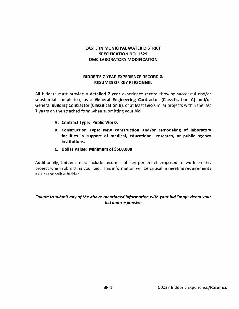
BIDDER’S 7-YEAR EXPERIENCE RECORD & RESUMES OF KEY PERSONNEL
All bidders must provide a detailed 7-year experience record showing successful and/or substantial completion, as a General Engineering Contractor (Classification A) and/or General Building Contractor (Classification B), of at least two similar projects within the last 7 years on the attached form when submitting your bid.
A. Contract Type: Public Works
B. Construction Type: New construction and/or remodeling of laboratory facilities in support of medical, educational, research, or public agency institutions.
C. Dollar Value: Minimum of $500,000
Additionally, bidders must include resumes of key personnel proposed to work on this project when submitting your bid. This information will be critical in meeting requirements as a responsible bidder.
Failure to submit any of the above-mentioned information with your bid “may” deem your
bid non-responsive

00027 Bidder’s Experience/Resumes
PAGE LEFT INTENTIONALLY BLANK
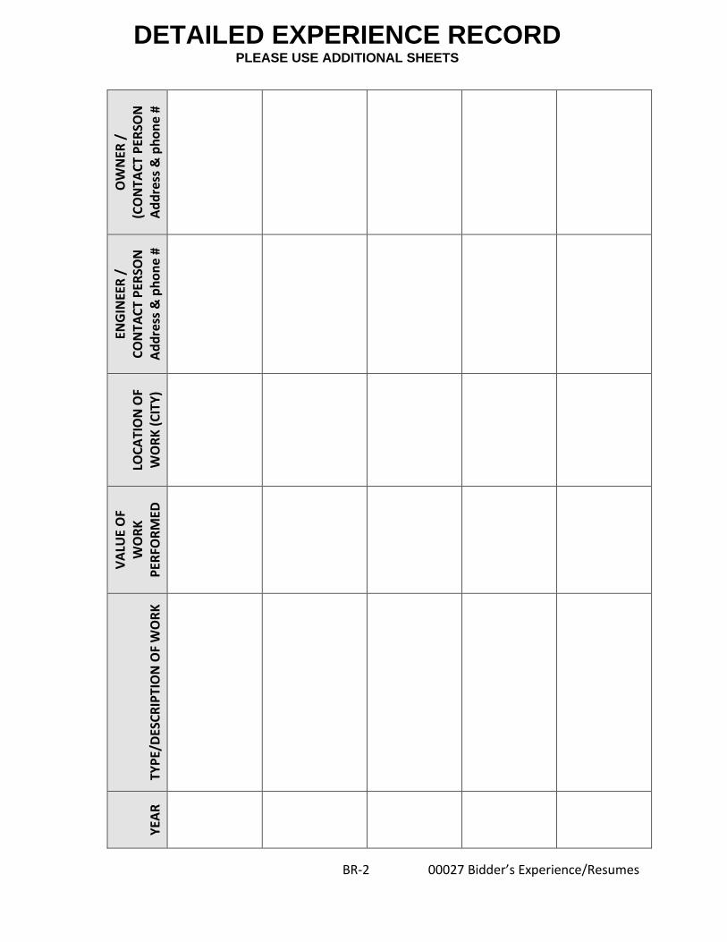
YEAR
TY
PE/D
ESCR
IPTI
ON
OF
WO
RK
VALU
E O
F W
ORK
PE
RFO
RMED
LO
CATI
ON
OF
WO
RK (C
ITY)
ENG
INEE
R /
CON
TACT
PER
SON
Ad
dres
s & p
hone
#
OW
NER
/
(CO
NTA
CT P
ERSO
N
Addr
ess &
pho
ne #
DETAILED EXPERIENCE RECORD PLEASE USE ADDITIONAL SHEETS
BR-2 00027 Bidder’s Experience/Resumes

PA
GE L
EFT
INTE
NTI
ON
ALLY
BLA
NK

00027 Bidder’s Experience/Resumes
RESUMES OF KEY PERSONNEL (ATTACH HERE)

00027 Bidder’s Experience/Resumes
PAGE LEFT INTENTIONALLY BLANK
C-5(a) 00028 Designation of Subcontractors
DESIGNATION OF SUBCONTRACTORS In compliance with the provisions of Sec. 4100-4111, inclusive, of the Public Contract Code of the State of California, and any amendments thereof, each bidder shall set forth below: (a) The name and the location of the place of business of each subcontractor who will perform work or labor or render service to the Contractor in or about the construction of the work or improvement in an amount in excess of one-half of one percent (1/2 of 1%) of the Contractor's total bid; and (b) the portion of the work which will be done by each such subcontractor.
Each subcontractor shall possess, both at the time the bid is submitted and at all times when work is performed, a valid contractor's license for the appropriate classification necessary to perform the work for which that subcontractor is listed. Each subcontractor shall be registered with the Department of Industrial Relations at time of bid and during the performance of the Contract. If the Contractor fails to specify a subcontractor for any portion of the work to be performed under the contract in excess of one-half of one percent (1/2 of 1%) of the Contractor's total bid, he agrees that he is fully qualified to perform that work himself, and that he shall perform that work himself, and that he shall perform that portion himself. The Contractor shall not, without the consent of the District, or unless, either: (a) Substitute any person as subcontractor in place of the subcontractor designated in the original bid; (b) Permit any such subcontract to be assigned or transferred or allow it to be performed by anyone other than the original subcontractor listed in the bid; or (c) Sublet or subcontract any portion of the work in excess of one-half of one percent (1/2 of 1%) of the Contractor's total bid as to which his original bid did not designate a subcontractor. In the following instances, the District may consent to the substitution of another subcontractor:
(1) When the subcontractor listed in the bid after having a reasonable opportunity to do so fails or refuses to execute the written contract which is based upon the general terms, conditions, plans and specifications of the involved project or the terms of the subcontractor's written bid when it is presented to the subcontractor by the prime subcontractor;
(2) When the listed subcontractor becomes bankrupt or insolvent;
(3) When the listed subcontractor fails or refuses to perform his or her subcontract;
(4) When the listed subcontractor fails or refuses to meet the bond requirements of the prime Contractor to furnish a bond guaranteeing prompt and faithful performance of the subcontract and the payment of all claims for labor and materials furnished or used pursuant to Public Contract Code 4108;
(5) When the prime Contractor demonstrates to the District, as set forth in Public Contract Code 4107.5 that the name of the subcontractor was listed as the result of an inadvertent clerical error;

C-5(b) 00028 Designation of Subcontractors
As a condition to assert claim of clerical error, the Contractor must give written notice of the inadvertent clerical error to the District with copies to both the listed and intended subcontractor within two (2) working days of the time of the prime bid opening. The District shall consent to the substitution if the prime Contractor and both subcontractor listed in error and the intended subcontractor each submit an affidavit to the District within eight (8) working days of the time of the prime bid opening indicating that an inadvertent clerical error was made. The District shall also consent to the substitution of the intended Contractor if affidavits are filed by both the prime Contractor and the intended Subcontractor within six (6) working days and the subcontractor claimed to be listed in error does not submit within six (6) working days a written objection to the claim to both the District and the Contractor. However, if the listed subcontractor submits a written objection to the Contractor's claim of inadvertent clerical error within six (6) working days from the time of the prime bid opening, the District shall investigate the claims of the parties and shall hold a public hearing as described herein to determine the validity of those claims.
Any declarations submitted must be submitted under penalty of perjury by all three (3) parties and supported by testimony under oath and subject to cross-examination.
(6) When the listed Contractor is not licensed pursuant to the Contractor's license law;
(7) When the District determines that the work performed by the listed subcontractor is substantially unsatisfactory and not in substantial accordance with the plans and specifications, or that the subcontractor is substantially delaying or disrupting the progress of the work. Prior to any substitution of a subcontractor, the District shall give notice in writing to the listed subcontractor of the request to substitute subcontractors and the reasons for the request. The notice shall be served by registered or certified mail to the last known address of the subcontractor. The listed subcontractor who has been so notified shall have five (5) working days within which to submit written objections to the substitution to the District. Failure to file these written objections shall constitute the listed subcontractor's consent to the substitution. If written objections are filed, the District shall give notice in writing of at least five (5) working days to the listed subcontractor of a hearing by the District on the Contractor's request for substitution. The original bid need not designate a subcontractor for the performance of any change orders. No subletting or subcontracting of any portion of the work in excess of one-half of one percent (1/2 of 1%) of the prime Contractor's total bid shall be permitted except in cases of public emergency or necessity and then only after a written finding is made by the District as a public record setting forth the facts constituting the emergency or necessity. As used in this designation, the term subcontractor means only those subcontractors who contract directly with the prime Contractor.

C-5(c) 00028 Designation of Subcontractors
If the Contractor violates any of the provisions of this section, it is deemed to have violated and breached this contract, and the District may exercise the option in its own discretion of: (1) canceling the contract; or (2) assessing the contract or a penalty in an amount of not more than ten percent (10%) of the amount of the subcontract involved, and this penalty shall be deposited in the fund out of which the prime contract is awarded. The Contractor shall be entitled to a public hearing in five (5) days notice of the time and place of the hearing.

C-5(d) 00028 Designation of Subcontractors
LIST OF DESIGNATED SUBCONTRACTORS
SPEC #:
PROJECT TITLE:
NAME OF CONTRACTOR:
In compliance with the provisions of Sec. 4100-4111, inclusive, of the Public Contract Code of the State of California, and any amendments thereof, each bidder shall set forth: the name, location of the place of business, license number, portion of the work which will be done by each subcontractor who will perform work or labor or render service to the Contractor in or about the construction of the work or improvement in an amount in excess of one-half of one percent (1/2 of 1%) of the Contractor's total bid. Each portion of Subcontracted work noted in the below table must be specific and contain all major activities associated with completion of the project, outside of the services provided by the bidding Contractor. Ambiguous and/or incomplete Subcontracted work information may deem the bid nonresponsive. Each subcontractor shall possess, both at the time the bid is submitted and at all times when work is performed, a valid contractor's license for the appropriate classification necessary to perform the work for which that subcontractor is listed.
BIDDER SHALL PROVIDE THE FOLLOWING INFORMATION: Company Name, Business Address, Email Address, License No., Contractor Registration No.,
Subcontract Work, and % Of Total Bid
* PLEASE WRITE LEGIBLY*
LICENSED SUBCONTRACTOR’S NAME, BUSINESS ADDRESS, & EMAIL ADDRESS
LICENSE # SUBCONTRACT WORK
(Be Specific)
% OF TOTAL BID CONTRACTOR
REGISTRATION #
Company Name:
License #:
-------------------------- DIR Registration #:
Address:
Email Address:
Company Name:
License #:
-------------------------- DIR Registration #:
Address:
Email Address:

C-5(e) 00028 Designation of Subcontractors
LICENSED SUBCONTRACTOR’S NAME, BUSINESS ADDRESS, & EMAIL ADDRESS
LICENSE # SUBCONTRACT WORK
(Be Specific)
% OF TOTAL BID
Company Name:
License #:
-------------------------- DIR Registration #:
Address:
Email Address:
Company Name:
License #:
-------------------------- DIR Registration #:
Address:
Email Address:
Company Name:
License #:
-------------------------- DIR Registration #:
Address:
Email Address:
Company Name:
License #:
--------------------------- DIR Registration #:
Address:
Email Address:
Company Name:
License #:
--------------------------- DIR Registration #:
Address:
Email Address:
(Do not list alternative subcontractors for the same work) (Use additional pages if needed)

[PAGE LEFT INTENTIONALLY BLANK]

C6-1 00030 Contractors Licensing Statement
CONTRACTOR'S LICENSING STATEMENT The undersigned is licensed in accordance with the laws of the State of providing for the registration of contractors. The representations made herein and in the proposal documents are made under penalty of perjury. The undersigned is hereby representing that he is properly licensed both at the time that he submits a bid as well as at the time the contract is awarded, if the contract is awarded to the undersigned. CONTRACTOR'S CLASSIFICATION LICENSE NUMBER TYPE EXPIRATION DATE A. INDIVIDUAL CONTRACTOR
NAME OF INDIVIDUAL CONTRACTOR:
BUSINESS ADDRESS:
PHONE NUMBER:
SIGNATURE OF OWNER:
B. FIRM OR PARTNERSHIP
NAME OF FIRM OR PARTNERSHIP:
BUSINESS ADDRESS:
PHONE NUMBER:
SIGNATURE(S) & TITLE OF MEMBERS SIGNING ON BEHALF OF THE PARTNERSHIP:
SIGNATURE: TITLE:
SIGNATURE: TITLE:
SIGNATURE: TITLE:
C. CORPORATION
NAME OF CORPORATION:
BUSINESS ADDRESS:
PHONE NUMBER:
SIGNATURE OF AUTHORIZED OFFICER OF CORPORATION:
SIGNATURE: TITLE:

C6-2 00030 Contractors Licensing Statement
[PAGE LEFT INTENTIONALLY BLANK]
C7-1 00032 Non-Collusion Declaration
NON-COLLUSION DECLARATION
TO BE EXECUTED BY BIDDER AND SUBMITTED WITH BID The undersigned declares: I am the of ,
the party making the foregoing bid.
The bid is not made in the interest of, or on behalf of, any undisclosed person, partnership, company, association, organization, or corporation. The bid is genuine and not collusive or sham. The bidder has not directly or indirectly induced or solicited any other bidder to put in a false or sham bid. The bidder has not directly or indirectly colluded, conspired, connived, or agreed with any bidder or anyone else to put in a sham bid, or to refrain from bidding. The bidder has not in any manner, directly or indirectly, sought by agreement, communication, or conference with anyone to fix the bid price of the bidder or of any other bidder, or to fix any overhead, profit, or cost element of the bid price, or of that of any other bidder. All statements contained in the bid are true. The bidder has not, directly or indirectly, submitted his or her bid price or any breakdown thereof, or the contents thereof, or divulged information or data relative thereto, to any corporation, partnership, company, association, organization, bid depository, or to any member or agent thereof, to effectuate a collusive or sham bid, and has not paid, and will not pay, any person or entity for such purpose. Any person executing this declaration on behalf of a bidder that is a corporation, partnership, joint venture, limited liability company, limited liability partnership, or any other entity, hereby represents that he or she has full power to execute, and does execute, this declaration on behalf of the bidder. I declare under penalty of perjury under the laws of the State of California that the foregoing is true and correct and that this declaration is executed on ____________[date], at ___________________[city], ____________________[state] Signed: Name: (Print Name Here)

C7-2 00032 Non-Collusion Declaration
[PAGE LEFT INTENTIONALLY BLANK]

Rev: 06/12/17 C8(a) 00034 Agreement
AGREEMENT
THIS AGREEMENT, effective this day of ,
in the year , by and between the EASTERN MUNICIPAL WATER DISTRICT,
hereinafter designated as the "District", party of the first part, and
hereinafter designated as the Contractor, party of the second part,
WITNESSETH: That in consideration of the mutual covenants herein contained and other valuable
consideration, the parties hereto agree as follows, to wit:
ARTICLE I. For and in consideration of the payments and agreements hereinafter mentioned to be
made and performed by the District, the Contractor agrees with the District to perform the following
work:
as set forth in Specification No. and to perform and complete in a good and workmanlike manner all the work pertaining thereto shown on the drawings and described in the specifications
hereto attached and by this reference made a part thereof, to furnish at his own proper cost and
expense all tools, equipment, labor and materials necessary therefor, except such materials as in the said specifications are stipulated to be furnished by the District, and to do everything required by
this Agreement and the said specifications and drawings.
ARTICLE II. The District will pay and the Contractor shall receive in full compensation therefor the
prices named in
for of the bidding sheet of the proposal hereto attached for
furnishing all said materials and labors, furnishing and removing all plants, temporary works or
structures, tools and equipment, and doing all the work contemplated and embraced in this
Agreement; also for all loss and damage arising out of the nature of the work aforesaid, or from the
action of the elements, or from any unforeseen difficulties which may arise or be encountered in the
prosecution of the work until its acceptance by the District, and for all risks of every description
connected with the work; also for all expenses incurred by or in consequence of the suspension or discontinuance of work; except such as in the said specifications are expressly stipulated to be
borne by the District; and for well and faithfully completing the work and the whole thereof, in the
manner shown and described in the said drawings and specifications and in accordance with the
requirements of the Engineer under them.

Rev: 06/12/17 C8(b) 00034 Agreement
ARTICLE III. The District hereby promises and agrees with the said Contractor to employ, and does
hereby employ the said Contractor to provide the materials and to do the work according to the
terms and conditions herein contained and referred to, for the prices aforesaid, and hereby
contracts to pay the same at the time, and in the manner and upon the conditions set forth in the
specifications; and the said parties for themselves, their heirs, executors, administrators,
successors, and assigns, do hereby agree to the full performance of the covenants herein
contained.
ARTICLE IV. The Notice Inviting Bids, the Instructions to Bidders, the Proposal, Addenda, the
Specifications, and the Drawings mentioned therein, all of which are hereto attached, are hereby
incorporated in and made a part of this Agreement.
ARTICLE V. “Dispute Resolution (Per Public Contract Code § 9204) Upon receipt by District of a
claim by Contractor for a time extension or payment, sent by registered mail or certified mail with
return receipt requested, District shall, within 45 days, review the claim and provide Contractor a
written statement indicating what portion of the claim is disputed and what portion is undisputed.
Contractor shall furnish reasonable documentation to support the claim, and, upon mutual
agreement, this time period may be extended.
If District requires Board approval to issue its written statement to Contractor, and the Board does
not meet within the 45 days or mutually agreed upon time extension, District shall have 3 days after
its next regular Board meeting following the expiration of the 45-day period or extension to provide
Contractor with its written statement.
Any payments owed Contractor on undisputed portions of its claim shall be made by District within
60 days of issuance of its written statement.
If Contractor disputes District’s written response, or if District fails to provide a written response,
Contractor may demand an informal settlement conference. Such demand shall be made in writing,
sent by registered mail or certified mail, return receipt requested, and District shall schedule the
settlement conference within 30 days of receiving demand.
Within 10 days following any settlement conference, District shall issue a second written statement
indicating which portions of the claim are disputed and which portions are undisputed.

Rev: 06/12/17 C8(c) 00034 Agreement
Any payments owed for undisputed portions of the claim shall be made within 60 days of District’s
written statement.
Any remaining disputed portions of the claim shall be submitted to non-binding arbitration. If the
Parties cannot agree on a mediator within 10 days after the disputed portion has been identified,
each Party shall select a mediator, and those mediators shall select a neutral to conduct the
mediation.
If mediation is unsuccessful, the portions of the claim remaining in dispute shall be subject to
applicable procedures provided by law. If the matter is litigated, the mediation conducted pursuant
to this provision shall satisfy the Parties’ obligations under section 20104.4 to mediate after
litigation has commenced.
Failure by District to comply with this provision shall result in the claim being denied in its entirety.
The procedures set forth in this provision shall apply to subcontractors and lower tier
subcontractors, who may request that Contractor submit a claim to District on their behalf. If such
a request is made, Contractor shall notify the requesting subcontractor within 45 days whether
Contractor submitted the claim to District, and if not, the reasons therefor.”

Rev: 06/12/17 C8(d) 00034 Agreement
IN WITNESS WHEREOF: The parties hereto have caused this contract to be executed the day and
year first above written.
EASTERN MUNICIPAL WATER DISTRICT
Date: By: Paul D. Jones, II, P.E., General Manager
ATTEST:
By:
Sheila Zelaya, Board Secretary
CONTRACTOR
(Company Name) Date: By:
(Signature)
(Print or Type Name & Title)
Rev: 04/11/16 Page C9-1 00036 Performance Bond
Eastern Municipal Water District Bond No.
PERFORMANCE BOND Any singular reference to Contractor, Surety, Owner or other party shall be considered plural where
applicable.
KNOW ALL BY THESE PRESENTS: that (Here insert full name and address of CONTRACTOR)
as Principal, hereinafter called Principal; and (Here insert full name and address of SURETY)
as Surety, hereinafter Surety, are held and firmly bound unto (Full name and address of OWNER)
Eastern Municipal Water District P O Box 8300 Perris, CA 92572-8300
as Obligee, hereinafter called Owner, for the use and benefit of claimants as herein below defined, in the amount of: $ (Amount written in words) for the payment whereof Principal and Surety bind themselves, their heirs, executors, administrators, successors and assigns, jointly and severally, firmly by these presents. WHEREAS, Principal has by written agreement entered into a contract with Owner in accordance with the Drawings, Specifications and Addenda for:
CONSTRUCTION CONTRACT
Date:
Spec Number:
Project Name:
Project Location: which contract is by reference made a part hereof, and is hereinafter referred to as the Construction Contract.
Rev: 04/11/16 Page C9-2 00036 Performance Bond
1 The Contractor and the Surety, jointly and severally, bind themselves, their heirs, executors, administrators, successors and assigns to the Owner for the performance of the Construction Contract, which is incorporated herein by reference. 2 If the Contractor performs the Construction Contract, the Surety and the Contractor shall have no obligation under this Bond, except to participate in conferences as provided in Subparagraph 3.1. 3 The Surety’s obligation under this Bond shall arise after:
3.1 The Owner has notified the Contractor and the Surety at its address described in Paragraph 10 below of the Owner's intention to terminate the Construction Contract and has requested and attempted to arrange a conference with the Contractor and the Surety to be held not later than ten days after service of such notice to discuss methods of performing the Construction Contract. If the Owner, the Contractor and the Surety agree, the Contractor shall be allowed a reasonable time to perform the Construction Contract, but such an agreement shall not waive the Owner’s right, if any, subsequently to declare a Contractor Default; and 3.2 The Owner has declared a Contractor Default and formally terminated the Contractor’s right to complete the contract. Such Contractor Default shall not be declared earlier than ten days after the Contractor and the Surety have been served notice as provided in Subparagraph 3.1; and 3.3 The Owner has agreed to pay the Balance of the Contract Price to the Surety in accordance with the terms of the Construction Contract or to a contractor selected to perform the Construction Contract in accordance with the terms of the contract with the Owner.
4 When the Owner has satisfied the conditions of Paragraph 3, the Surety shall promptly and at the Surety’s expense take one of the following actions:
4.1 Arrange for the Contractor, with consent of the Owner in the Owner's sole discretion, to perform and complete the Construction Contract; or 4.2 Undertake to perform and complete the Construction Contract itself, through its agents or through independent contractors; or 4.3 Obtain bids or negotiated proposals from qualified contractors acceptable to the Owner for a contract for performance and completion of the Construction Contract, arrange for a contract to be prepared for execution by the Owner and the contractor selected with the Owner’s concurrence, to be secured with performance and payment bonds executed by a qualified surety equivalent to the bonds issued on the Construction Contract, and pay to the Owner the amount of damages as described in Paragraph 6 in excess of the Balance of the Contract Price incurred by the Owner resulting from the Contractor’s default; or 4.4 Waive its right to perform and complete, arrange for completion, or obtain a new contractor and with reasonable promptness under the circumstances:

Rev: 04/11/16 Page C9-3 00036 Performance Bond
.1 After investigation, determine the amount for which it may be liable to the Owner and, as soon as practicable after the amount is determined, tender payment therefor to the Owner; or
.2 Deny liability in whole or in part and
notify the Owner citing reasons therefor.
5 If the Surety does not proceed as provided in Paragraph 4 with reasonable promptness, the Surety shall be deemed to be in default on this Bond fifteen days after receipt of an additional written notice from the Owner to the Surety demanding that the Surety perform its obligations under this Bond, and the Owner shall be entitled to enforce any remedy available to the Owner. If the Surety proceeds as provided in Subparagraph 4.4, and the Owner refuses the payment tendered or the Surety has denied liability, in whole or in part, without further notice the Owner shall be entitled to enforce any remedy available to the Owner. 6 After the Owner has terminated the Contractor’s right to complete the Construction Contract, and if the Surety elects to act under Subparagraph 4.1, 4.2, or 4.3 above, then the responsibilities of the Surety to the Owner shall not be greater than those of the Contractor under the Construction Contract, and the responsibilities of the Owner to the Surety shall not be greater than those of the Owner under the Construction Contract. To the limit of the amount of this Bond, but subject to commitment by the Owner of the Balance of the Contract Price to mitigation of costs and damages on the Construction Contract, the Surety is obligated without duplication for:
6.1 The responsibilities of the Contractor for correction of defective work and completion of the Construction Contract; 6.2 Additional legal, design professional and delay costs resulting from the Contractor’s Default, and resulting from the actions or failure to act of the Surety under Paragraph 4; and 6.3 Liquidated damages, or if no liquidated damages are specified in the Construction Contract, actual damages caused by delayed performance or non-performance of the Contractor.
7 The Surety shall not be liable to the Owner or others for obligations of the Contractor that are unrelated to the Construction Contract, and the Balance of the Contract Price shall not be reduced or set off on account of any such unrelated obligations. No right of action shall accrue on this Bond to any person or entity other than the Owner or its heirs, executors, administrators or successors. 8 The Surety hereby waives notice of any change, including changes of time, to the Construction Contract or to related subcontracts, purchase orders and other obligations. 9 Any proceeding, legal or equitable, under this Bond shall be instituted in the Superior Court of the County of Riverside, State of California, The parties expressly consent to the jurisdiction of said court and agree that said court shall be a proper venue for any such action. This Bond shall be governed by and interpreted in accordance with the laws of the State of California, excluding any choice of law provisions.

Rev: 04/11/16 Page C9-4 00036 Performance Bond
10 Notice to the Surety, the Owner or the Contractor shall be mailed or delivered to the address shown on the signature page. 11 When this Bond has been furnished to comply with a statutory or other legal requirement in the location where the construction was to be performed, any provision in this Bond conflicting with said statutory or legal requirement shall be deemed deleted herefrom and provisions conforming to such statutory or other legal requirement shall be deemed incorporated herein. The intent is that this Bond shall be construed as a statutory bond and not as a common law bond. 12 DEFINITIONS 12.1 Balance of the Contract Price: The total amount payable by the Owner to the Contractor under the Construction Contract after all proper adjustments have been made,
including allowance to the Contractor of any amounts received or to be received by the Owner in settlement of insurance or other claims for damages to which the Contractor is entitled, reduced by all valid and proper payments made to or on behalf of the Contractor under the Construction Contract and by all amounts withheld by the Owner in response to stop notices served upon the Owner, unless and until such stop notices are released. 12.2 Construction Contract: The agreement between the Owner and the Contractor identified on the signature page, including all Contract Documents and changes thereto.
12.3 Contractor Default: Failure of the Contractor, which has neither been remedied nor waived, to perform or otherwise to comply with the terms of the Construction Contract.
Signed and sealed this day of ,
CONTRACTOR AS PRINCIPAL SURETY
Company: Company: (Corporate Seal)
Signature: Signature:
Name: Name:
Title: Title: Attorney-in-Fact
Notary Public Acknowledgment required for Surety and Contractor

Rev: 02/24/15 Page C10-1 00038 Payment Bond
Eastern Municipal Water District Bond No.
PAYMENT BOND This bond is issued simultaneously with performance bond in favor of the Owner conditioned on the full and faithful performance of the contract. Any singular reference to Contractor, Surety, Owner or
other party shall be considered plural where applicable.
KNOW ALL BY THESE PRESENTS: that (Here insert full name and address of CONTRACTOR)
as Principal, hereinafter called Principal; and (Here insert full name and address of SURETY)
as Surety, hereinafter called Surety, are held and firmly bound unto (Full name and address of OWNER)
Eastern Municipal Water District P O Box 8300 Perris, CA 92572-8300
as Obligee, hereinafter called Owner, for the use and benefit of claimants as herein below defined, in the amount of:
$ (Amount written in words) for the payment whereof Principal and Surety bind themselves, their heirs, executors, administrators, successors and assigns, jointly and severally, firmly by these presents. WHEREAS, Principal has by written agreement entered into a contract with Owner in accordance with the Drawings, Specifications and Addenda for: CONSTRUCTION CONTRACT
Date:
Spec Number:
Project Name:
Project Location: which contract is by reference made a part hereof, and is hereinafter referred to as the Contract.
Rev: 02/24/15 Page C10-2 00038 Payment Bond
NOW, THEREFORE, THE CONDITION OF THIS OBLIGATION is such that, if Principal shall promptly (1) make payment to all claimants as hereinafter defined, for all labor and material used or reasonably required for use in the performance of the Contract, and (2) pay all amounts due under the California Unemployment Insurance Code with respect to work or labor performed under the Contract, and (3) pay for any amounts required to be deducted, withheld, and paid over to the California Employment Development Department from the wages of employees of the Principal and subcontractors pursuant to Section 13020 of the California Unemployment Insurance Code with respect to the work and labor, then this obligation shall be void; otherwise it shall remain in full force and effect, subject, however, to the following conditions: 1 A claimant is defined as any of the persons named in Section 3181 of the California Civil Code. 2 The above-named Principal and Surety hereby jointly and severally agree with the Owner that every claimant as herein defined, or its assign, who has not been paid in full before the expiration of a period of ninety (90) days after the date on which the last of such claimant's work or labor was done or performed, or materials were furnished by such claimant, may sue on this bond for the use of such claimant, prosecute the suit to final judgment for such sum or sums as may be justly due claimant, including reasonable attorney's fees to be fixed by the court, and have execution thereon. The Owner shall not be liable for the payment of any costs or expenses of any such suit.
3 No suit or action shall be commenced hereunder by any claimant:
a) Unless written notice has been given in compliance with California Civil Code section 3252.
b) After the expiration of one (1) year following the date on which Principal ceased Work on said Contract, it being understood, however, that if any limitation embodied in this bond is prohibited by any law controlling the construction hereof such limitation shall be deemed to be amended so as to be equal to the minimum period of limitation permitted by such law.
c) Other than in a state court of
competent jurisdiction in and for the county or other political subdivision of the state in which the Project, or any part thereof, is situated, or in the United States District Court for the district in which the Project, or any part thereof, is situated, and not elsewhere.
4 The amount of this bond shall be reduced by and to the extend of any payment or payments made in good faith hereunder, inclusive of the payment by Surety of mechanics’ liens which may be filed of record against said improvement, whether or not claim for the amount of such lien be presented under and against this bond.

Rev: 02/24/15 Page C10-3 00038 Payment Bond
Signed and sealed this day of ,
CONTRACTOR AS PRINCIPAL SURETY
Company: Company: (Corporate Seal)
Signature: Signature:
Name: Name:
Title: Title: Attorney-in-Fact
Notary Public Acknowledgment required for Surety and Contractor

Rev: 02/24/15 Page C10-4 00038 Payment Bond
[PAGE LEFT INTENTIONALLY BLANK]

Rev:04/06/16 BB-1 00040 Bid Bond
EASTERN MUNICIPAL WATER DISTRICT BID BOND
Bid Bond No.
KNOW ALL MEN BY THESE PRESENTS, that we
(Here insert full name and address or legal title of Contractor)
as Principal, hereinafter called the Principal, and
(Here insert full name and address or legal title of Surety)
a corporation duly organized under the laws of the State of as Surety, hereinafter called the Surety, are held and firmly bound unto Eastern Municipal Water District. Obligee, hereinafter called the Obligee, in the sum of ________________________ Dollars (___________________), for the payment of which sum well and truly to be made, the said Principal and the said Surety, bind ourselves, our heirs, executors, administrators, successors and assigns, jointly and severally firmly by these presents.
WHEREAS, the Principal has submitted a bid, dated , 20 , for (Here insert full name, address and description of Project)
NOW, THEREFORE, if the Obligee shall accept the bid of the Principal and the Principal shall enter into a Contract with the Obligee in accordance with the terms of such bid, and give such bond or bonds as may be specified in the bidding of Contract Documents with good and sufficient surety for the faithful performance of such Contract and for the prompt payment of labor and material furnished in the prosecution thereof, or in the event of the failure of the Principal to enter such Contract and give such bond or bonds, if the Principal shall pay to the Obligee the difference not to exceed the penalty hereof between the amount specified in said bid and such larger amount for which the Obligee may in good faith contract with another party to perform the Work covered by said bid, then this obligation shall be null and void, otherwise to remain in full force and effect.
In the event suit is brought upon this Bond by Obligee and judgement is recovered, the Surety shall pay all costs incurred by Obligee in such suits to be fixed by the court.
Signed and sealed this day of ,
CONTRACTOR AS PRINCIPAL SURETY
Company: Company: (Corporate Seal)
Signature: Signature:
Name: Name:
Title: Title: Attorney-in-Fact
This Bid Bond (BB-1) form shall be submitted to be considered a responsive bid Notary Public Acknowledgment required for Surety and Contractor

[PAGE LEFT INTENTIONALLY BLANK]

Rev:11/15 C11-1 00042 Worker’s Compensation Certificate
Specification No/Project Title:
WORKERS’ COMPENSATION INSURANCE CERTIFICATE The Contractor shall execute the following form as required by the California Labor Code, Sections 1860 and 1861:
I am aware of the provisions of Section 3700 of the Labor Code which require
every employer to be insured against liability for workers’ compensation or to
undertake self-insurance in accordance with the provisions of that code, and I
will comply with such provisions before commencing the performance of the
work of this contract.
Date: (Contractor)
By: (Signature)
(Title)

C11-2 00042 Worker’s Compensation Certificate
[PAGE LEFT INTENTIONALLY BLANK]

CERTIFICATE OF LIABILITY INSURANCE DATE (MM/DD/YYYY) Month/Date/Year
PRODUCER Insurnce Agent/Broker Name Insurnce Agent/Broker Street Address or P.O. Box Insurnce Agent/Broker City, State & Zip Code Contact & Phone Number
THIS CERTIFICATE IS ISSUED AS A MATTER OF INFORMATION ONLY AND CONFERS NO RIGHTS UPON THE CERTIFICATE HOLDER. THIS CERTIFICATE DOES NOT AMEND, EXTEND OR ALTER THE COVERAGE AFFORDED BY THE POLICIES BELOW.
INSURERS AFFORDING COVERAGE NAIC # INSURED
Contractor's Name Street Address or P.O. Box City, State & Zip Code
INSURER A: Name of Insurance Company Enter NAIC# INSURER B: All Carriers must be rated A- VIII or better
INSURER C: in current AM Best Rating Guide
INSURER D:
INSURER E:
COVERAGES: THE POLICIES OF INSURANCE LISTED BELOW HAVE BEEN ISSUED TO THE INSURED NAMED ABOVE FOR THE POLICY PERIOD INDICATED. NOTWITHSTANDING ANY REQUIREMENT, TERM OR CONDITION OF ANY CONTRACT OR OTHER DOCUMENT WITH RESPECT TO WHICH THIS CERTIFICATE MAY BE ISSUED OR MAY PERTAIN, THE INSURANCE AFFORDED BY THE POLICIES DESCRIBED HEREIN IS SUBJECT TO ALL THE TERMS, EXCLUSIONS AND CONDITIONS OF SUCH POLICIES. AGGREGATE LIMITS SHOWN MAY HAVE BEEN REDUCED BY PAID CLAIMS.
TYPE OF INSURANCE POLICY NUMBER POLICY EFFECTIVE
DATE (MM/DD/YY) POLICY EXPIRATION
DATE (MM/DD/YY) LIMITS
A GENERAL LIABILITY
COMMERICAL GENERAL LIABILITY
CLAIMS MADE OCCUR
GEN’L AGGREGATE LIMIT APPLIES PER:
POLICY PROJECT LOC
See NOTE #1 & 2
Enter Policy # Enter Effective Date
Enter Expiration Date
EACH OCCURENCE $ 2,000,000 DAMAGE TO RENTED PREMISES (Ea occurrence) $ 50,000 MED EXP (Any one person) $ 5,000 PERSONAL & ADV INJURY $ 2,000,000 GENERAL AGGREGATE $ 5,000,000 PRODUCTS - COMP/OP AGG $ 5,000,000
B AUTOMOBILE LIABILITY
ANY AUTO
ALL OWNED AUTOS
SCHEDULED AUTOS
HIRED AUTOS
NON-OWNED AUTOS
Enter Policy # Enter Effective Date
Enter Expiration Date
COMBINED SINGLE LIMIT (Each Occurrence) $ 2,000,000
BODILY INJURY (Per person)
BODILY INJURY (Per accident)
PROPERTY DAMAGE (Per accident)
GARAGE LIABILITY
ANY AUTO
AUTO ONLY - EA ACCIDENT
OTHER THAN AUTO ONLY:
EA ACC AGG
A EXCESS/UMBRELLA LIABILITY
OCCUR CLAIMS MADE
DEDUCTIBLE
RETENTION
See NOTE #4
Enter Policy # Enter Effective Date
Enter Expiration Date
EACH OCCURRENCE $Enter Limit AGGREGATE $Enter Limit
C WORKERS COMPENSATION AND EMPLOYERS’ LIABILITY ANY PROPRIETOR/PARTNER/EXECU-TIVE OFFICER/MEMBER EXCLUDED? If yes, describe under SPECIAL PROVISIONS below
See NOTE #3
Enter Policy # Enter Effective Date
Enter Expiration Date
WC STATU-
TORY LIMITS OTH-ER
E.L. EACH ACCIDENT $ 1,000,000 E.L. DISEASE - EA EMPLOYEE $ 1,000,000 E.L. DISEASE - POLICY LIMIT $ 1,000,000
D • Builder’s Risk • Equipment Floater
(Inland Marine) • Pollution Liability • Fidelity Bond
Deductible: $1,000 Enter Policy # Enter Policy # Enter Policy #
Builder’s Risk Policy =
Equipment Floater = Pollution Liability = Fidelity Bond =
Contract Value Scheduled Equipment $2million $500,000
DESCRIPTION OF OPERATIONS / LOCATIONS / VEHICLES / EXCLUSIONS ADDED BY ENDORSEMENT / SPECIAL PROVISIONS Include Project Name & Spec Number here. NOTE #1: EMWD & others (See Section H & Special Conditions) named as additional insured per CG2010 (11/85) OR CG2010 (10/01) WITH CG2037 (10/01). NOTE #2: Per Project Aggregate limits per CG2503 (3/97). NOTE #3: Waiver of Subrogation endorsement to Worker’s Compensation in favor of EMWD. Endorsements must be attached. NOTE #4: Excess/Umbrella liability can be used in connection with primary liability insurance to equal amounts required. CERTIFICATE HOLDER CANCELLATION
EASTERN MUNICIPAL WATER DISTRICT Attn: Field Engineering Department P O Box 8300 Perris, CA 92572-8300
SHOULD ANY OF THE ABOVE DESCRIBED POLICIES BE CANCELLED BEFORE THE EXPIRATION DATE THEREOF, THE INSURER AFFORDING COVERAGE WILL ENDEAVOR TO MAIL 30 DAYS WRITTEN NOTICE TO THE CERTIFICATE HOLDER NAMED TO THE LEFT, BUT FAILURE TO DO SO SHALL IMPOSE NO OBLIGATION OR LIABILITY OF ANY KIND UPON THE INSURER, ITS AGENTS OR REPRESENTATIVES.
AUTHORIZED REPRESENTATIVE
ACORD 25 (2001/08) © ACORD CORPORATION 1988 00044_C-12_$2$5$5_BR + Pollution + Fidelity Bond
INSR LTR
ADD’L INSRD
IMPORTANT
If the certificate holder is an ADDITIONAL INSURED, the policy(ies) must be endorsed. A statement on this certificate does not confer rights to the certificate holder in lieu of such endorsement(s).
If SUBROGATION IS WAIVED, subject to the terms and conditions of the policy, certain policies may require an endorsement. A statement on this certificate does not confer rights to the certificate holder in lieu of such endorsement(s).
DISCLAIMER
The Certificate of Insurance on the reverse side of this form does not constitute a contact between the issuing insurer(s), authorized representative or producer, and the certificate holder, nor does it affirmatively or negatively amend, extend or alter the coverage afforded by the policies listed thereon.
ACORD 25 (2001/08)

POLICY NUMBER: COMMERCIAL GENERAL LIABILITY
THIS ENDORSEMENT CHANGES THE POLICY. PLEASE READ IT CAREFULLY.
CG 20 10 11 85 Copyright, Insurance Services Office, Inc., 1984 Page 1 of 1 ��
ADDITIONAL INSURED – OWNERS, LESSEES ORCONTRACTORS – (FORM B)
This endorsement modifies insurance provided under the following:
COMMERCIAL GENERAL LIABILITY COVERAGE PART.
SCHEDULEName of Person or Organization:
(If no entry appears above, information required to complete this endorsement will be shown in the Declarationsas applicable to this endorsement.)
WHO IS AN INSURED (Section II) is amended to include as an insured the person or organization shown in theSchedule, but only with respect to liability arising out of "your work" for that insured by or for you.
Eastern Municipal Water District to be named on Additional Insured Endorsement Form
See Special Conditions and Section H-Permits for listing of others to be named asadditional insured.
Policy Number to be included

POLICY NUMBER: COMMERCIAL GENERAL LIABILITY CG 20 10 10 01
THIS ENDORSEMENT CHANGES THE POLICY. PLEASE READ IT CAREFULLY.
ADDITIONAL INSURED – OWNERS, LESSEES ORCONTRACTORS – SCHEDULED PERSON OR
ORGANIZATION This endorsement modifies insurance provided under the following:
COMMERCIAL GENERAL LIABILITY COVERAGE PART
SCHEDULE Name of Person or Organization:
(If no entry appears above, information required to complete this endorsement will be shown in the Declarations as applicable to this endorsement.) A. Section II – Who Is An Insured is amended to
include as an insured the person or organization shown in the Schedule, but only with respect to li-ability arising out of your ongoing operations per-formed for that insured.
B. With respect to the insurance afforded to these additional insureds, the following exclusion is added:2. Exclusions
This insurance does not apply to "bodily injury" or "property damage" occurring after:
(1) All work, including materials, parts or equipment furnished in connection with such work, on the project (other than service, maintenance or repairs) to be performed by or on behalf of the addi-tional insured(s) at the site of the cov-ered operations has been completed; or
(2) That portion of "your work" out of which the injury or damage arises has been put to its intended use by any person or organization other than another contractor or subcontractor engaged in performing operations for a principal as a part of the same project.
CG 20 10 10 01 © ISO Properties, Inc., 2000 Page 1 of 1 �
Policy Number to be included
Eastern Municipal Water District to be named on Additional Insured Endorsement FormSee Special Conditions and Section H-Permits for listing of others to be named asadditional insured.

POLICY NUMBER: COMMERCIAL GENERAL LIABILITY CG 20 37 10 01
THIS ENDORSEMENT CHANGES THE POLICY. PLEASE READ IT CAREFULLY.
ADDITIONAL INSURED – OWNERS, LESSEES ORCONTRACTORS – COMPLETED OPERATIONS
This endorsement modifies insurance provided under the following:
COMMERCIAL GENERAL LIABILITY COVERAGE PART
SCHEDULE Name of Person or Organization:
Location And Description of Completed Operations:
Additional Premium:
(If no entry appears above, information required to complete this endorsement will be shown in the Declarations as applicable to this endorsement.) Section II – Who Is An Insured is amended to include as an insured the person or organization shown in the Schedule, but only with respect to liability arising out of "your work" at the location designated and described in the schedule of this endorsement performed for that insured and included in the "products-completed operations haz-ard". CG 20 37 10 01 © ISO Properties, Inc., 2000 Page 1 of 1 �
Policy Number to be included
Eastern Municipal Water District to be named on Additional Insured Endorsement FormSee Special Conditions and Section H-Permits for listing of others to be named asadditional insured.
Project location and name to be listed here

Policy Number must be included
Project Name to be listed here


Policy Number to be included
Waiver of Subrogation form is always in favor of the Worker's Compensation.Endorsement to list EMWD and project.
Effective date must be specified
Name of Insured (per contract)
Signature
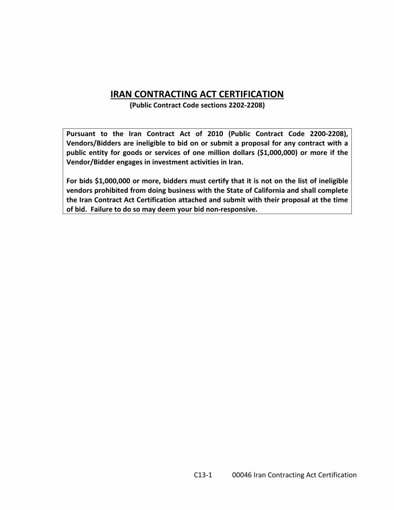
C13-1 00046 Iran Contracting Act Certification
IRAN CONTRACTING ACT CERTIFICATION (Public Contract Code sections 2202-2208)
Pursuant to the Iran Contract Act of 2010 (Public Contract Code 2200-2208), Vendors/Bidders are ineligible to bid on or submit a proposal for any contract with a public entity for goods or services of one million dollars ($1,000,000) or more if the Vendor/Bidder engages in investment activities in Iran. For bids $1,000,000 or more, bidders must certify that it is not on the list of ineligible vendors prohibited from doing business with the State of California and shall complete the Iran Contract Act Certification attached and submit with their proposal at the time of bid. Failure to do so may deem your bid non-responsive.

C13-2 00046 Iran Contracting Act Certification
[Page Left Intentionally Blank]

C13-3 00046 Iran Contracting Act Certification
IRAN CONTRACTING ACT CERTIFICATION Pursuant to the Iran Contract Act of 2010 (Public Contract Code 2200-2208), Vendors/Bidders are ineligible to bid on or submit a proposal for any contract with a public entity for goods or services of one million dollars ($1,000,000) or more if the Vendor/Bidder engages in investment activities in Iran.
MUST BE SUBMITTED WITH BID PROPOSAL IF BID AMOUNT IS $1,000,000 OR MORE
Prior to bidding on, submitting a proposal, or executing a contract or renewal for a public entity contract for goods or services of $1,000,000 or more, a vendor must either: a) certify it is not on the current list of persons engaged in investment activities in Iran created by the California Department of General Services (“DGS”) pursuant to Public Contract Code section 2203(b) and is not a financial institution extending $20,000,000 or more in credit to another person, for 45 days or more, if that other person will use the credit to provide goods or services in the energy sector in Iran and is identified on the current list of persons engaged in investment activities in Iran created by DGS; or b) demonstrate it has been exempted from the certification requirement for that solicitation or contract pursuant to Public Contract Code section 2203(c) or (d).
To comply with this requirement, please insert your vendor or financial institution name and Federal ID Number (if available) and complete one of the options below. Please note: California law establishes penalties for providing false certifications, including civil penalties equal to the greater of $250,000 or twice the amount of the contract for which the false certification was made, contract termination, and three-year ineligibility to bid on contracts. (Pub. Cont. Code § 2205.)
OPTION #1 - CERTIFICATION I, the official named below, certify I am duly authorized to execute this certification on behalf of the vendor/financial institution identified below, and the vendor/financial institution identified below is not on the current list of persons engaged in investment activities in Iran created by DGS and is not a financial institution extending twenty million dollars ($20,000,000) or more in credit to another person/vendor, for 45 days or more, if that other person/vendor will use the credit to provide goods or services in the energy sector in Iran and is identified on the current list of persons engaged in investment activities in Iran created by DGS.
I certify (or declare) under penalty of perjury under the laws of the State of California that the foregoing is true and correct. Vendor Name/Financial Institution (Printed)
Federal ID Number (or n/a)
By (Authorized Signature) Printed Name and Title of Person Signing
Date Executed

C13-4 00046 Iran Contracting Act Certification
OPTION #2 – EXEMPTION Pursuant to Public Contract Code sections 2203(c) and (d), a public entity may permit a vendor/financial institution engaged in investment activities in Iran, on a case-by-case basis, to be eligible for, or to bid on, submit a proposal for, or enters into or renews, a contract for goods and services. If you have obtained an exemption from the certification requirement under the Iran Contracting Act, please fill out the information below, and attach documentation demonstrating the exemption approval. Vendor Name/Financial Institution (Printed)
Federal ID Number (or n/a)
By (Authorized Signature) Printed Name and Title of Person Signing
Date Executed

C16-1 00050 CalOsha form 300A
Cal/OSHA Form 300A
Annual Summary of Work-Related Injuries and Illnesses
Bidders shall provide the most current, completed Cal/OSHA Form 300A with their bid (blank form attached)
Failure to submit this form “may” deem your bid non-responsive

00050 CalOsha form 300A
[PAGE LEFT INTENTIONALLY BLANK]
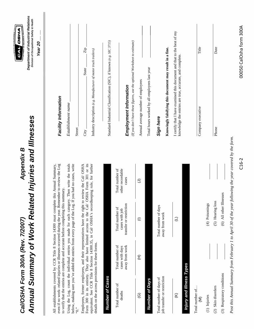
Cal
/OSH
A F
orm
300
A (R
ev. 7
/200
7)
App
endi
x B
A
nnua
l Sum
mar
y of
Wor
k R
elat
ed In
jurie
s an
d Ill
ness
es
D
epar
tmen
t of I
ndus
tria
l Rel
atio
ns
Div
isio
n of
Occ
upat
iona
l Saf
ety
& H
ealth
Year
20
__ _
_
C1
6-2
0005
0 Ca
lOsh
a fo
rm 3
00A
All
esta
blis
hmen
ts c
over
ed b
y C
CR
Titl
e 8
Sect
ion
1430
0 m
ust c
ompl
ete
this
Ann
ual S
umm
ary,
ev
en if
no
wor
k- re
late
d in
jurie
s or i
llnes
ses o
ccur
red
durin
g th
e ye
ar. R
emem
ber t
o re
view
the
Log
to v
erify
that
the
entri
es a
re c
ompl
ete
and
accu
rate
bef
ore
com
plet
ing
this
sum
mar
y.
Usi
ng t
he L
og,
coun
t th
e in
divi
dual
ent
ries
you
mad
e fo
r ea
ch c
ateg
ory.
The
n w
rite
the
tota
ls be
low
, mak
ing
sure
you
’ve
adde
d th
e en
tries
from
eve
ry p
age
of th
e Lo
g. If
you
had
no
case
s, w
rite
“0.”
Em
ploy
ees,
form
er e
mpl
oyee
s, an
d th
eir
repr
esen
tativ
es h
ave
the
right
to r
evie
w th
e C
al/ O
SHA
Fo
rm 3
00 i
n its
ent
irety
. Th
ey a
lso
have
lim
ited
acce
ss t
o th
e C
al/
OSH
A F
orm
301
or
its
equi
vale
nt.
See
CC
R T
itle
8 Se
ctio
n 14
300.
35,
in C
al/
OSH
A’s
rec
ordk
eepi
ng r
ule,
for
fur
ther
de
tails
on
the
acce
ss p
rovi
sion
s for
thes
e fo
rms.
Num
ber o
f Cas
es
To
tal n
umbe
r of
deat
hs
To
tal n
umbe
r of
case
s with
day
s aw
ay fr
om w
ork
To
tal n
umbe
r of
case
s with
job
trans
fer o
r res
trict
ion
To
tal n
umbe
r of
othe
r rec
orda
ble
case
s
(G
)
(H)
(I)
(J)
N
umbe
r of D
ays
Tota
l num
ber o
f day
s of
job
trans
fer o
r res
trict
ion
To
tal n
umbe
r of d
ays
away
from
wor
k
(K
)
(L)
In
jury
and
Illn
ess
Type
s To
tal n
umbe
r of…
(M
)
(1)
Inju
ries
(4)
Pois
onin
gs
(2)
Skin
diso
rder
s
(5
) H
earin
g lo
ss
(3)
Res
pira
tory
con
ditio
ns
(6)
All
othe
r Illn
esse
s
Post
this
Ann
ual S
umm
ary
from
Feb
ruar
y 1
to A
pril
30 o
f the
yea
r fol
low
ing
the
year
cov
ered
by
the
form
. Faci
lity
Info
rmat
ion
Esta
blis
hmen
t nam
e
St
reet
City
S
tate
Z
ip
In
dust
ry d
escr
iptio
n (e
.g. M
anuf
actu
rer o
f mot
or tr
uck
traile
rs)
St
anda
rd In
dust
rial C
lass
ifica
tion
(SIC
), if
know
n (e
.g. S
IC 3
715)
Empl
oym
ent I
nfor
mat
ion
(If
you
don
’t ha
ve th
ese
figur
es, u
se th
e op
tiona
l Wor
kshe
et to
esti
mat
e)
Ann
ual a
vera
ge n
umbe
r of e
mpl
oyee
s
____
_ To
tal h
ours
wor
ked
by a
ll em
ploy
ees l
ast y
ear
__
___
Sign
her
e K
now
ingl
y fa
lsify
ing
this
doc
umen
t may
res
ult i
n a
fine.
I c
ertif
y th
at I
have
exa
min
ed th
is do
cum
ent a
nd th
at to
the
best
of m
y kn
owle
dge
the
entri
es a
re tr
ue, a
ccur
ate,
and
com
plet
e.
Com
pany
exe
cutiv
e Ti
tle
Phon
e D
ate

0005
0 Ca
lOsh
a fo
rm 3
00A
[P
AGE
LEFT
INTE
NTI
ON
ALLY
BLA
NK]

C-17 Contractor’s Cal/OSHA Compliance History and SIC Code
THIS DOCUMENT IS TO BE SUBMITTED WITH THE PROPOSAL PACKAGE AT TIME OF BID
C17-1 00052 CalOsha Compliance History & SIC Code
Bidders shall complete and submit the attached C-17 form with the Proposal Package at time of bid
Failure to fully divulge, complete and submit this form “may” deem your bid
non-responsive

C17 00052 CalOsha Compliance History & SIC Code
[PAGE LEFT INTENTIONALLY BLANK]
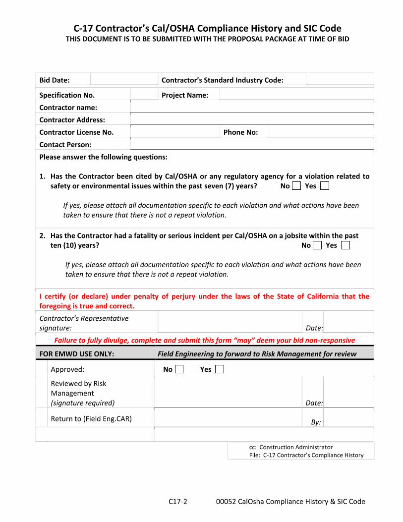
C-17 Contractor’s Cal/OSHA Compliance History and SIC Code THIS DOCUMENT IS TO BE SUBMITTED WITH THE PROPOSAL PACKAGE AT TIME OF BID
C17-2 00052 CalOsha Compliance History & SIC Code
Bid Date: Contractor’s Standard Industry Code:
Specification No. Project Name:
Contractor name:
Contractor Address:
Contractor License No. Phone No:
Contact Person:
Please answer the following questions: 1. Has the Contractor been cited by Cal/OSHA or any regulatory agency for a violation related to
safety or environmental issues within the past seven (7) years? No Yes
If yes, please attach all documentation specific to each violation and what actions have been taken to ensure that there is not a repeat violation.
2. Has the Contractor had a fatality or serious incident per Cal/OSHA on a jobsite within the past ten (10) years? No Yes
If yes, please attach all documentation specific to each violation and what actions have been taken to ensure that there is not a repeat violation.
I certify (or declare) under penalty of perjury under the laws of the State of California that the foregoing is true and correct.
Contractor’s Representative signature:
Date:
Failure to fully divulge, complete and submit this form “may” deem your bid non-responsive
FOR EMWD USE ONLY: Field Engineering to forward to Risk Management for review
Approved: No Yes
Reviewed by Risk Management (signature required)
Date:
Return to (Field Eng.CAR) By:
cc: Construction Administrator File: C-17 Contractor’s Compliance History

C17 00052 CalOsha Compliance History & SIC Code
[PAGE LEFT INTENTIONALLY BLANK]

C19-1 00056 Safety Training Records
C-19 Employee Safety & Health Training Records
Documentation (spreadsheet) of safety and health training are required by Cal-Osha standards for each employee. The documentation must specifically include employee name or other identifier, training dates, type(s) of training and the name of the training provider. These records must be kept for at least one year, except that training records of employees who have worked for less than one year for the employer need not be retained beyond the term of employment if they are provided to the employee upon termination of employment.
General Contractor shall provide Employee Safety & Health Training Records for the past 12 months
(to be submitted on or after the Preconstruction Conference)

C19-2 00056 Safety Training Records
[PAGE LEFT INTENTIONALLY BLANK]

Rev:11/23/15 C22-1 00057 Contractor Registration
PUBLIC WORKS CONTRACTOR REGISTRATION (Pursuant to SB 854)
This project is subject to compliance monitoring and enforcement by the Department of Industrial Relations. Pursuant to Section 1771.1 of the Labor Code, no contractor or subcontractor shall be qualified to bid on, be listed in a bid proposal pursuant to Section 4104 of the Public Contract Code, or engage in the performance of any contract for public work unless currently registered to perform public work pursuant to Section 1725.5 of the Labor Code. It shall not be a violation of this section for an unregistered contractor to submit a bid that is authorized by Section 7029.1 of the Business and Professions Code or by Sections 10164 or 20103.5 of the Public Contract Code, provided the contactor is registered to perform public work pursuant to Section 1725.5 at the time the contract is awarded.
BIDDERS AND THEIR SUBCONTRACTORS (listed on the Designation of Subcontractors List C-05) are to provide an extract (pdf) at time of bid showing active registration from the Public Works Contractor Registration online registration at https://efiling.dir.ca.gov/PWCR/Search
******************************************************************************************************** SUBMIT BIDDER & SUBCONTRACTORS CONTRACTOR REGISTRATION
EXTRACTS WITH BID PROPOSAL ********************************************************************************
Example: Legal Name Registration Number County City Registration Date Expiration Date
Contractors Name 0000000000 RIVERSIDE Temecula 06/01/2015 06/30/2016

Rev:11/23/15 C22-2 00057 Contractor Registration
PAGE LEFT INTENTIONALLY BLANK
00062 General Conditions Section E - Inspection and Tests
E–1
Rev:08/31/15
GENERAL CONDITIONS
Section E - Inspection and Tests E-01. This section of the specifications supplements that paragraph of the General Conditions of this
specification entitled "Inspection and Testing of Materials".
A. Progress Reports. The Contractor shall furnish the District full information as to the progress of the work in its various parts and shall give the District timely notice of the Contractor's readiness for inspection. The District reserves the right to charge to the Contractor any additional cost of inspection and test when articles or materials are not ready at the time inspection is requested by the Contractor.
B. Inspection at Mill. Inspection will be made during manufacture of material. If the inspection or test, whether preliminary or final, is made on the premises of the Contractor, the Contractor shall furnish, without additional charge, all reasonable facilities and assistance for the safe and convenient inspection and test required by the Engineer.
C. Mill Test Reports. Whenever required by the Engineer the District shall be furnished promptly with complete certified copies of mill test reports showing chemical and physical properties of the materials to be furnished under the contract and also copies of rolling mill reports.
D. Samples or Test Specimens. Samples or test specimens of all materials, appliances, and fittings for delivery under these specifications or for incorporation in the products manufactured or fabricated hereunder shall be prepared at the Contractor's expense, except as otherwise specified herein, and shall be furnished to the Engineer, carriage prepaid, in such quantities and sizes as may be required by him for proper examination and in ample time for completion of all necessary tests or analyses before the time in which the Contractor desires to deliver or make use of same. Chemical tests and analyses, except those furnished by the Contractor under sub-paragraph (c) hereof, will be made by, or at the expense of, the District.
E. Inspection of Materials Not Locally Produced. When the Contractor intends to purchase materials, fabricated products, or equipment from sources located more than 100 miles outside the geographical limits of EMWD’s main office, the contractor will be responsible for the actual costs incurred for one inspector (EMWD staff or consultant employed by EMWD) to inspect the materials, equipment or process. The actual cost shall include $1,000/day for staff salary and the expenses incurred for airfare, vehicle rental, hotel, meals, etc.
00062 General Conditions Section E - Inspection and Tests E–2
This approval shall be obtained before producing any material or equipment. The inspector shall judge the materials by the requirements of the plans and specifications. The Contractor shall forward reports required by the Engineer. No materials or equipment shall be shipped nor shall any processing, fabrication or treatment of such materials be done without proper inspection. Approval shall not relieve the Contractor of responsibility for complying with the contract requirements.
END OF SECTION E

GENERAL CONDITIONS
Section F - Labor & Construction
C O N T E N T S
GENERAL CONDITIONS F-01. DEFINITIONS .................................................................................................................................. 1 F-02. CONTRACT DOCUMENTS ; GOVERNING LAW ; JURISDICTION ; VENUE ............................................. 2 INSURANCE & BONDS ................................................................................................................................................... 3 F-03. CONTRACT SECURITY ...................................................................................................................... 3 F-04. CONTRACTOR'S AND SUBCONTRACTOR'S INSURANCE..................................................................... 4 F-05. ADDITIONAL SURETY ...................................................................................................................... 7 GENERAL REQUIREMENTS ............................................................................................................................................ 8 F-06. AUTHORITY OF THE DISTRICT .......................................................................................................... 8 F-07. PROTESTS ...................................................................................................................................... 8 F-08. REPORTS, RECORDS AND DATA ....................................................................................................... 8 F-09. TIME AND ORDER OF WORK ........................................................................................................... 9 F-10. CONSTRUCTION SCHEDULE AND PERIODIC ESTIMATES .................................................................. 10 F-11. LEGAL ADDRESS OF CONTRACTOR ................................................................................................ 13 F-12. MUTUAL RESPONSIBILITY OF CONTRACTORS ................................................................................ 13 F-13. GENERAL GUARANTEE .................................................................................................................. 13 F-14. OBLIGATIONS OF CONTRACTOR .................................................................................................... 14 F-15. PERSONAL ATTENTION ................................................................................................................. 18 F-16. ASSIGNMENT OF RIGHTS. PURSUANT TO THE REQUIREMENTS OF CALIFORNIA GOVERNMENT CODE
SECTION 4552: ............................................................................................................................. 18 F-17. SUBCONTRACTS ........................................................................................................................... 19 F-18. PATENTS ...................................................................................................................................... 20 F-19. PERMITS ...................................................................................................................................... 20 F-20. ENVIRONMENTAL COMPLIANCE ................................................................................................... 21 F-21. ADDITIONAL RIGHTS-OF-WAY ....................................................................................................... 21 F-22. PROTECTION AND PRESERVATION OF CULTURAL RESOURCES ....................................................... 21 F-23. RIGHT OF THE DISTRICT TO TERMINATE CONTRACT ....................................................................... 22 F-24. NOTICE AND SERVICE THEREOF ..................................................................................................... 23 F-25. UTILITIES AND SUBSTRUCTURES ................................................................................................... 24 F-26. USE OF MATERIALS FOUND ON WORK SITE ................................................................................... 25 WORK .......................................................................................................................................................................... 26 F-27. LINES, GRADES AND MEASUREMENTS .......................................................................................... 26 F-28. PLANS AND SPECIFICATIONS ......................................................................................................... 26 F-29. EQUIPMENT AND MATERIAL ITEMS .............................................................................................. 27 F-30. CHANGES IN WORK AND EXTRAS .................................................................................................. 35 F-31. MATERIALS, WORKMANSHIP AND TESTS ...................................................................................... 39 F-32. DELAYS ........................................................................................................................................ 41 F-33. INSPECTION AND TESTING OF MATERIALS .................................................................................... 43 F-34. DEFECTIVE WORK OR MATERIAL ................................................................................................... 43 F-35. ACCESS TO WORK ......................................................................................................................... 44 F-36. TIME FOR COMPLETION AND FOR DAMAGES FOR LATE COMPLETION ........................................... 44 PAYMENT TO CONTRACTOR....................................................................................................................................... 44 F-37. QUANTITIES OF ESTIMATE ............................................................................................................ 44 F-38. CLAIMS ........................................................................................................................................ 45 F-39. ARBITRATION ............................................................................................................................... 49

F-40. RETENTION .................................................................................................................................. 49 F-41. PAYMENT FOR EQUIPMENT .......................................................................................................... 50 F-42. MEASUREMENT AND PAYMENT ................................................................................................... 50 F-43. DISTRICT'S RIGHT TO WITHHOLD CERTAIN AMOUNTS AND MAKE APPLICATION THEREOF ............. 50 F-44. FINAL ESTIMATE AND PAYMENT ................................................................................................... 51 F-45. PAYROLLS OF CONTRACTORS AND SUBCONTRACTORS .................................................................. 52 F-46. PREVAILING RATES OF WAGES ...................................................................................................... 52 F-47. COMPLETION AND ACCEPTANCE ................................................................................................... 53 F-48. FINAL PAYMENT DECLARATION .................................................................................................... 53 F-49. PAYMENT ONLY IN ACCORDANCE WITH CONTRACT ...................................................................... 54 F-50. SUBSTANTIAL COMPLETION.......................................................................................................... 54 F-51. MONIES MAY BE RETAINED .......................................................................................................... 54 F-52. UNPAID CLAIMS ........................................................................................................................... 54 F-53. EIGHT HOUR LAW ......................................................................................................................... 54 F-54. OVERTIME - NO EXTRA COMPENSATION ....................................................................................... 55 F-55. POSTING MINIMUM WAGE RATES ................................................................................................ 55 PERSONNEL ................................................................................................................................................................. 55 F-56. ACCIDENT PREVENTION - PUBLIC SAFETY ...................................................................................... 55 F-57. CHARACTER OF WORKERS ............................................................................................................ 56 F-58. EMPLOYMENT .............................................................................................................................. 56 F-59. NONDISCRIMINATION IN EMPLOYMENT ....................................................................................... 56 F-60. ENFORCEMENT OF ORDER ............................................................................................................ 56 F-61. SAFETY, SANITARY AND MEDICAL REQUIREMENTS ........................................................................ 56 F-62. SANITATION ................................................................................................................................. 57 F-63. FIRST AID AND PROTECTIVE FACILITIES ......................................................................................... 57 Exhibit A – Escrow Agreement for Security Deposits in Lieu of Retention

00064 General Conditions Section F - Labor & Construction
F-1
GENERAL CONDITIONS SECTION F - LABOR & CONSTRUCTION
GENERAL CONDITIONS F-01. DEFINITIONS
A. Wherever the words defined in this article, or pronouns used in their stead, occur in these specifications or in any of the other contract documents they shall have the meanings here given:
B. The word DISTRICT and OWNER shall mean the Eastern Municipal Water District
represented by the General Manager or his designee. All references to District and OWNER shall include Eastern Municipal Water District, the Board of Directors and each member of the Board, the officers and agents of the District, and the District’s consultants.
C. The words BOARD OF DIRECTORS or BOARD shall mean the Board of Directors of the Eastern
Municipal Water District.
D. The word AGENT or ENGINEER shall mean one who represents the District in dealings with third persons and acts on behalf and subject to the control of the District.
E. The word CONSULTANT shall mean a consulting firm rendering services to the
District under contract.
F. The word CONTRACTOR or PRIME CONTRACTOR shall mean a firm, duly licensed as a contractor by the State of California, entering into contract with the District for the performance of work required by these specifications, and the legal representatives of said firm, or the agent appointed to act for said firm in the performance of the work. Said firm is referred to throughout the contract documents as if of the singular number and masculine gender.
G. The word SUBCONTRACTOR shall mean a contractor who will perform work or labor or
render service to the prime contractor or a contractor licensed by the State of California who, under subcontract to the prime contractor, specially fabricates and installs a portion of the work or improvement according to detailed drawings contained in the plans and specifications.
H. The word INSPECTOR shall mean a person who observes the work assigned for
conformance with the approved design plans and specifications.
00064 General Conditions Section F - Labor & Construction F-2
I. The word CONSTRUCTION ADMINISTRATOR shall mean a person who administers construction project contracts, researches and plans for a variety of capital construction, and maintenance/improvement programs, and performs related duties.
J. The word WORK shall mean that which is proposed to be constructed or done under the
contract, including the furnishing of all labor, materials, equipment, and services.
K. Whenever in the specifications or upon the PLANS the words DIRECTED, REQUIRED, PERMITTED, ORDERED, DESIGNATED, PRESCRIBED, or words of like import are used, it shall be understood that the direction, requirement, permission, order, designation, or prescription of the District is intended, and similarly the words APPROVED, ACCEPTABLE, SATISFACTORY, or words of like import shall mean approved or acceptable to, or satisfactory to the District, unless otherwise expressly stated.
L. EXTRA WORK shall mean additions in the work being performed when the District
determines, in writing, that it is not covered by contract unit prices or stipulated unit prices.
M. FORCE ACCOUNT shall mean work conducted by the District, as opposed to a third party.
Said work is performed by employees or other agents of the District.
N. The word PLAN(s) shall mean DRAWING(s) and STANDARD DETAIL(s).
O. The word SPECIFICATION(s) shall mean TECHNICAL SPECIFICATION(s), PRE-NEGOTIATED SCOPES OF WORK, SPECIAL PROVISIONS, DETAILED PROVISIONS and/or GENERAL CONDITIONS and related Contract Documents.
F-02. CONTRACT DOCUMENTS ; GOVERNING LAW ; JURISDICTION ; VENUE
A. Contract Documents. The Notice Inviting Bids, the Instructions to Bidders, the Proposal, the Notice-of-Acceptance-of-Proposal, Addenda, the Specifications, and the Plans, together with the Agreement, constitute THE CONTRACT, and what is called for in any one shall be as binding as if called for in all. The intention of the documents is to require a complete and finished piece of work including all labor, materials, equipment, and transportation necessary for the proper execution of the work. Anything shown in the plans and not in the specifications, or in the specifications and not in the plans, shall be performed by the Contractor as though shown in both the plans and the specifications.

00064 General Conditions Section F - Labor & Construction
F-3
B. Specification Precedence. In resolving conflicts resulting from errors or discrepancies in any of the Contract Documents, the order of precedence shall be as follows:
1. Special Conditions Revised by Addenda 2. Special Conditions 3. Permit Requirements 4. Addenda 5. Plans 6. Specifications 7. General Conditions
With reference to the drawings, the order of precedence shall be as follows:
1. Figures, such as coordinates or dimensions, govern over scaled dimensions 2. Detail drawings govern over general drawings 3. Addenda/Change Order drawings govern over Drawings 4. Drawings govern over standard drawings
C. Governing Law. The Contract, all Contract Documents, and all Work performed hereunder
shall be governed by and interpreted in accordance with the laws of the State of California, excluding any choice of law provisions. Notwithstanding any other provisions contained in any other documents, this paragraph shall take precedence over any such documents and may not be modified, altered, or changed in any manner whatsoever except by a written instrument duly executed by the District which refers specifically to this paragraph.
D. Jurisdiction; Venue. Any action taken to enforce this Contract shall be maintained in the
Superior Court of Riverside County, California. The parties expressly consent to the jurisdiction of said court and agree that said court shall be the proper venue for any such action. Notwithstanding any other provisions contained in any other documents, this paragraph shall take precedence over any such documents and may not be modified, altered, or changed in any manner whatsoever except by a written instrument duly executed by the District which refers specifically to this paragraph.
INSURANCE & BONDS F-03. CONTRACT SECURITY The Contractor shall furnish a performance bond in an amount at least equal to one hundred percent (100%) of the contract price as security for the faithful performance of this contract. A payment bond shall be furnished in an amount not less than one hundred percent (100%) of the contract price as security for the payment of all persons performing labor and/or furnishing materials or other supplies under this contract. All bonds shall be executed by admitted surety insurers, as defined in Code of Civil Procedure section 995.120.

00064 General Conditions Section F - Labor & Construction F-4 Pursuant to Section 995.660(a) of the Code of Civil Procedure, the Contractor shall submit the following documents with the performance and payment bonds:
A. The original, or a certified copy of the unrevoked appointment, power of attorney, bylaws,
or other instrument entitling or authorizing the person who executed the bond to do so; B. A certified copy of the certificate of authority of the insurer issued by the State of
California’s Insurance Commissioner; and C. Copies of the insurer’s most recent annual and quarterly statements filed with the
Department of Insurance. The Contractor shall take out and maintain performance and payment bonds at his sole cost and expense at all times during the life of this contract, including the entire time of the Contractor's guarantee, with surety carriers admitted to transact business in the State of California.
The following provision shall be added to and made a part of the bond agreement:
"Surety agrees to the acceptance of arbitration as to any controversy or claim affecting its obligation where agreed to by the contracting parties pursuant to Arbitration of the Contract Conditions."
F-04. CONTRACTOR'S AND SUBCONTRACTOR'S INSURANCE The Contractor shall not commence work under this Contract until he has obtained and submitted all policies of insurance (including all endorsements) acceptable to the District, nor shall he allow any subcontractor to commence work until all policies of insurance of the subcontractor have been obtained (by the Contractor), as required hereunder.
The Contractor and his subcontractors shall take out and maintain insurance, with coverage acceptable to the District, at his sole cost and expense at all times during the life of this Contract, including the entire time of the Contractor's guarantee.
Each such policy of insurance shall:
A. Be issued by insurance carriers that are:
1. Rated no less than A-, Class VIII or better by the A. M. Best Company
2. Licensed to transact insurance business in the State of California
3. Captive and Risk Retention groups are not acceptable unless rated no less than A-,
VIII or better by the A. M. Best Company

00064 General Conditions Section F - Labor & Construction
F-5
4. Self Insured Retention (SIR) greater than $10,000 is not acceptable on any policy.
Any insurance carrier, which is strategically affiliated with a parent insurance company or insurance group, must disclose the name of the parent company or group in any certificate of insurance documentation provided to the District.
Non-admitted/Surplus Lines insurance carriers (carriers not licensed in the State of California) may be acceptable to the District under certain conditions. The District reserves the right to disqualify a non-admitted insurer without cause.
Non-admitted insurance carriers providing any form of insurance coverage must be:
1. Domiciled in the United States
2. Listed as an approved insurance carrier on the California Department of
Insurance L.E.S.L.I. list
3. Rated no less than “A-, Class VIII” or better by the A.M. Best Company
4. Captive and Risk Retention groups are not acceptable unless rated no less than A, VIII or better by the A. M. Best Company
B. Name and list the District, Agent(s), and other personals and entities as required and specified in
the special conditions, and/or all permittors listed in Section H – Permits, as additional insured, by utilizing “CG 2010 11/85" endorsement form or similar, to include completed-operations up to 5 years beyond the completion date. If CG 20 10 11/85 is not available, then additional insured endorsement CG 20 10 10/01 along with CG 20 37 10/01 (Additional Insured-Completed Operations) endorsements executed by the Insurance Company naming the District and others listed above shall be utilized.
C. The insurance contract should state that it is intended for the transferee’s policy to apply on a
primary basis, as would standard ISO form CG 00 01 10 01, on behalf of the additional insured and that it will be modified, if necessary, to provide coverage in this manner.
D. Require all deductibles be the sole responsibility of the Contractor, including the deductible for
any builders risk insurance policy procured by the District.
E. Not be canceled, reduced in coverage or limits until thirty (30) days after receipt by the District of a written notice of such cancellation including a ten (10) day notice for non-payment of premium, as evidenced by receipt of a registered letter
F. Otherwise be in form satisfactory to District.

00064 General Conditions Section F - Labor & Construction F-6
G. Any and all losses connected with the insurance policies in force for the District shall
require cooperation of the Contractor in determining the cause of loss, the repair process, and the securing of information to determine settlement of said claim. Failure to comply with the adjuster’s request or insurance carriers requests to settlement in a timely manner, will result in breach of contract.
The Contractor and his subcontractors shall take out and maintain the following policies of "occurrence form"-type insurance with coverage acceptable to the District:
H. Workers’ Compensation Insurance. In accordance with the provisions of Section 3700 of
the Labor Code of the State of California, Contractor shall secure, at all times during the life of this contract, the payment of compensation to his employees; and the Contractor shall require all subcontractors similarly to provide such compensation insurance for all of the latter's employees. Such policy shall contain an endorsement which waives all right of subrogation against those persons and entities designated in the policy.
I. Commercial Liability Insurance. The Contractor shall procure and maintain at all times
during the life of this contract, Commercial Liability Insurance in amounts not less than the following amounts unless otherwise specified in the Special Conditions:
$2,000,000 per each occurrence $5,000,000 General Aggregate Limit $5,000,000 Products-Completed Operations Aggregate Limit $2,000,000 Personal & Advertising injury limit
THE POLICY IS TO BE ENDORSED FOR THE AGGREGATE LIMIT TO APPLY TO THIS PROJECT by utilizing endorsement form “CG 25 03 03 97” (or similar), executed by the insurance carrier. An aggregate limit (cap) is not allowed.
Where excess liability insurance is used in connection with primary liability insurance, the combination of such must allow total limits of liability to be in amounts not less than the above-specified amount.
J. Automobile Liability Insurance. The Contractor shall procure and maintain at all times
during the life of this contract, Automobile Liability insurance in amount not less than the following amount unless otherwise specified in the Special Conditions:
$2,000,000 combined single limit
K. Installation Floater. The Contractor shall maintain or cause to be maintained at all times
during the life of this contract, an Installation Floater in the amount of the total contract value.
The installation floater policy shall not contain a deductible higher than $1,000.00 per claim unless first approved by the District.

00064 General Conditions Section F - Labor & Construction
F-7
L. Contractors Equipment Floater (aka Commercial Inland Marine). The Contractor shall maintain or cause to be maintained at all times during the life of this contract, an equipment floater to cover all tools, equipment, supplies and materials on the jobsite.
If specified in the Special Conditions, the Contractor shall provide the following coverage(s):
M. Builders Risk, Flood and Earthquake Insurance. The Contractor and his subcontractors
shall maintain or cause to be maintained at all times during the life of this contract, builders' risk "All Risk" completed value insurance, to include, at the option of the District, loss or damage caused by fire, earthquake and/or flood, insuring completed work, work in progress, material, supplies and equipment of the work site, in storage or in transit, in an amount equal to the full replacement cost thereof. Such insurance shall include the interests of the District, Contractor, all tiers of subcontractors, suppliers and materialmen, with deductible amounts, if any, for the sole account of and payable by Contractor. Loss under such insurance shall be adjusted with and payable to the District for the interest of all parties. The amount of property insurance shall be sufficient to protect against such loss or damage in full until the work is accepted by the District. EMWD must be named as “loss payee” on the certificate for Builder’s Risk policy.
Builder’s “All Risk” insurance policy, if obtained by the Contractor, shall contain a deductible not higher than $1,000 unless otherwise approved by the District.
Flood Insurance policy, if obtained by the Contractor, shall contain a deductible not higher than $100,000.00 unless otherwise approved by the District.
Earthquake insurance policy, if obtained by the Contractor, shall contain a deductible not higher than 10% of the total insurable value unless otherwise approved by the District.
Builder’s Risk, Flood and Earthquake Insurance by District. If specified in the Special Conditions, Builder’s “All Risk” Insurance may be provided by the District. The Contractor is responsible for any and all deductibles per Section F-04 subsection D. Financial considerations to determine viability of such deductible remains at the District’s discretion. Deductibles will be fully disclosed at the time of issuance of the Builder’s Risk contract.
F-05. ADDITIONAL SURETY If during the continuance of the contract any of the sureties upon the faithful performance bond is no longer sufficient under Code of Civil Procedure section 995.660(b), District may require additional sureties which the Contractor shall furnish to the satisfaction of the District within fifteen (15) days after notice, and in default thereof the contract may be suspended and the work completed as provided in section titled Right of the District to Terminate Contract.
00064 General Conditions Section F - Labor & Construction F-8
GENERAL REQUIREMENTS F-06. AUTHORITY OF THE DISTRICT The District shall give all orders, lines, grades, and directions contemplated under the contract; shall determine the adequacy of the Contractor's methods, plant, and appurtenances; shall determine in all cases the amount, quality, acceptability, and fitness of the several kinds of work and materials which are to be incorporated in the work; and shall decide in all cases every question which may arise relative to the fulfillment of this contract on the part of the Contractor.
Should any discrepancy appear or any misunderstanding arise as to the import of anything contained in the specifications or plans, the matter shall be referred to the District, which shall decide the same in accordance with the true intent and meaning as construed by the District, and the District’s decision shall be binding on the Contractor. Any difference or conflict which may arise between the Contractor and any other contractors of the District in regard to their work shall be adjusted and determined by the District. The District’s estimates and decisions shall be final and conclusive, except as herein otherwise expressly provided.
F-07. PROTESTS If the Contractor considers any work demanded of him to be outside the requirements of the contract, or if he considers any record or ruling of the District to be unfair, he shall immediately upon such work being demanded or such record or ruling being made, ask for written instructions or decisions, upon the receipt of which he shall proceed without delay to perform the work or conform to the record or ruling. In the event the Contractor finds such instructions or decisions unsatisfactory, he shall, within ten (10) days after receipt of same, file a written protest with the District, stating clearly and in detail his objections and the reasons therefore. Except for such grounds of protest or objections as made of record in the manner specified and within the time stated herein, the Contractor hereby waives all grounds of protest or objections to the records, rulings, instructions, or decisions of the District, and hereby agrees that as to all matters not included in such protests the records, instructions, and decisions of the District shall be final and conclusive.
F-08. REPORTS, RECORDS AND DATA
A. General. The Contractor shall submit to the District such of his schedules and schedules of each of his subcontractors as the District may request concerning work performed or to be performed under this contract, including schedules of quantities and costs, progress schedules, payrolls, reports, estimates, records, and other data.

00064 General Conditions Section F - Labor & Construction
F-9
Before proceeding with construction, the Contractor shall furnish the District with information, plans and prints for all structures, articles, machinery or fabricated materials to be entered into permanent construction which are by these specifications and/or plans to be furnished by the Contractor and of which detailed plans are not furnished by the District. Such information, plans and prints shall be submitted to the District for approval and shall become the property of the District.
B. Asbuilt Project Record Documents. The Contractor shall maintain, at the job site, one
complete set of Contract Specifications, Addenda, Change Orders and other directions, approved submittals, including one set of full size plans marked to show any deviations which have been made from the plans or approved shop drawings, including buried or concealed construction and utility features which are revealed during the course of construction. Special attention shall be given to recording the horizontal and vertical location of all buried utilities that differ from the locations indicated or which were not indicated on the plans. Said record drawings shall be supplemented by any detailed sketches as necessary or directed, to indicate fully the work as actually constructed.
Current Asbuilt record drawings shall be accessible to the District at all times during the construction period. They shall be reviewed with the District at regular intervals.
Asbuilt Record Plans and Specifications shall be clearly and correctly annotated by the Contractor to show all changes made during the construction process at the time the changed Work is installed.
Upon completion and prior to final inspection of the Work, the Contractor shall submit the Record Plans and Specifications to the District for review, and shall make such revisions or corrections as may be necessary for them to be a true, complete, and accurate record of the Work in the opinion of the District. When approved, the Contractor shall deliver the Asbuilt Record Drawings and Specifications to the District. If requested by the District, transparencies shall be furnished for record drawings of piping, electrical, and instrumentation information.
F-09. TIME AND ORDER OF WORK
Immediately upon receipt of Notice of Acceptance of his Proposal, the Contractor shall schedule material orders for all material required under the contract, and notify the District of the anticipated dates of the availability of that material.
The contract time and construction period shall be as indicated in the Notice Inviting Bids except as otherwise superseded by Addendum or Change Order, or as otherwise defined in the Special Conditions.

00064 General Conditions Section F - Labor & Construction F-10 No extension of time shall be made for ordinary delays and accidents and the occurrence of such shall not relieve the Contractor from the necessity of maintaining the required progress. In case of an extension by the District of the time for the completion of the contract, as hereinafter provided, a revised Construction Progress Schedule and/or Project Control Schedule may be required in accordance with such extension of time.
The time in which the various portions and the whole of the contract are to be performed, and the work is to be completed, is of the essence of this contract.
F-10. CONSTRUCTION SCHEDULE AND PERIODIC ESTIMATES
A. Required Forms. The Contractor shall deliver to the District at the Pre-Construction Conference or within such additional time as may be allowed by the District, the following: (Additional forms may be required as called out in Standard form EN-48)
Forms supplied by the District
1. Insurance Certificate(s);
2. EN-29 or Schedule of Values: Breakdown of the Contract Price showing sizes and
quantities of equipment items;
3. EN-61: Satisfactory evidence of placement of orders for all materials;
4. EN-57: Shoring Plan, including Cal OSHA form 421-2 Activity Notification;
5. Contractor’s Financial Qualification form;
6. Authorized Signatures;
7. C-11: Workers’ Compensation Certificate;
8. EN-183: Verification of pre-approved materials list;
9. EN-84: Specific Operating Safety Procedure - Exhibit “B” of Section 01000- General Safety Requirements;
10. EN-2: 24-hour emergency telephone numbers;
11. EN-146: Certified Payroll Form;
12. Prevailing Wage Rate;
13. C-13: Certificate by Single Instrument Supplier (if applicable)

00064 General Conditions Section F - Labor & Construction
F-11
14. Employee Safety & Health Training Records
15. Subcontractors List/Worker Classification of all subcontractors, including tiered subcontractors, performing work on the project.
16. Contractor’s Financial Qualification Form
17. Maintenance Bond for Pumping Equipment (if applicable)
Contractor's Forms
1. Project Control Schedule
2. DOSH Permit (copy); (Dept. of Occupational Safety & Health)
3. Injury & Illness Prevention Program;
4. Other documentation, as required
The costs provided in the EN-29, Breakdown of Contract Price will be used only for determining the basis of partial payments and will not be considered as fixing a basis for additions to or deductions from the contract price. In lieu of the EN-29, the Schedule of Values (refer to Section 01026) shall be the basis for payment of contract work and will be used to establish payment for any “extra work” i.e., work requested which is beyond the scope of the original contract.
The Contractor shall, prior to mobilizing or commencing any contract work, submit and receive District approval of Proof of Insurance, Injury and Illness Prevention Program, and EN-84, Specific Operating Safety Procedure.
The Contractor shall be responsible to submit and receive District approval of the EN-29 Breakdown of Contract Price or Schedule of Values (see Section 01026, if applicable) by the 10th of the month for processing of the monthly pay estimate. Submittal and approval of the EN-29 or Schedule of Values beyond the 10th of the month will result in the pay estimate to be processed the following month.
The Contractor shall revise and update the Project Control Schedule as scheduling changes occur, and shall supply the District and his subcontractors with copies of the Project Control Schedule and its updates. District acceptance of revised Project Control Schedules shall be subject to the conditions of paragraph below.

00064 General Conditions Section F - Labor & Construction F-12
B. Contractor’s Project Control Schedule. The Contractor’s Project Schedule shall consist of a simple Critical Path Method analysis in chart form reflecting workable logic, and showing proper duration, expected methods, and mile posts, and shall conform to the work and time set forth in the contract. It shall clearly indicate all construction activities, sub-activities, and mile posts on a time-oriented basis, with the critical path fully identified. The following minimum information shall be included for each activity and critical path item:
1. Date of initial submittal, as applicable. 2. Ordering dates for long lead-time items. 3. Dates for materials on the site. 4. Start-work dates. 5. Complete-work dates. 6. Testing and clean-up dates. 7. Final contract completion date.
The schedule shall show a maximum of three critical paths, with only enough points or items to present the above information. Partial schedules will not be accepted without the approval of the District. The Contractor to submit a CD with 4 copies of each submitted schedule, using Primavera P6 (or later version) or Suretrak Project Manager.
Treatment plant, lift station and pump station charts shall be updated and resubmitted monthly; pipeline and other projects shall be updated and resubmitted monthly or as necessary to reflect changes in scheduling. All slippages and missed mile posts shall be flagged, with a narrative attached describing proposed corrective actions.
Payment Withheld. Payments due the Contractor shall be withheld until the Project Control Schedule is submitted by the Contractor and accepted by the District. Acceptance by the District of the baseline schedule submission shall be recognition of the Contractor’s good faith submission, and is solely for the purpose of releasing these monies. The District shall not unreasonably withhold its’ acceptance, however, acceptance shall not constitute approval. The District shall accept the Project Control Schedule only after all corrections and other issues have been fully resolved.
The applicable monies listed in the following table shall be withheld from that owed the Contractor each and every month an updated progress control schedule submission is not timely received in a condition acceptable to the District and conforming to the contract documents.
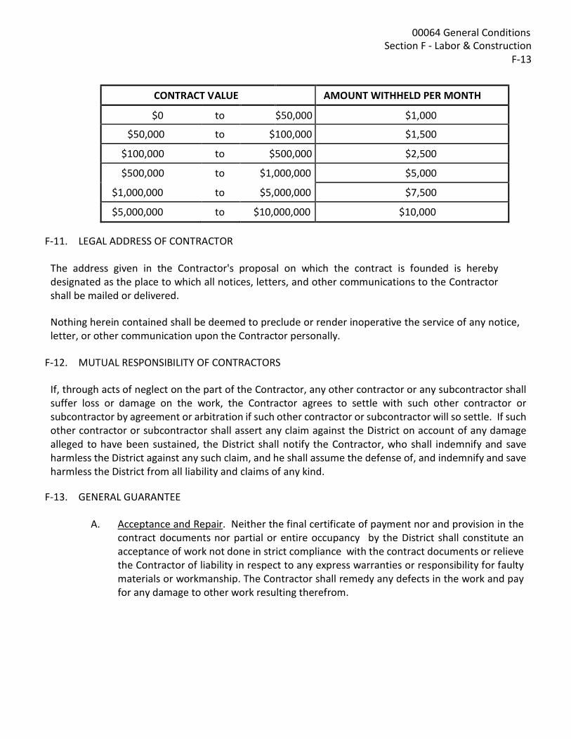
00064 General Conditions Section F - Labor & Construction
F-13
CONTRACT VALUE AMOUNT WITHHELD PER MONTH
$0 to $50,000 $1,000
$50,000 to $100,000 $1,500
$100,000 to $500,000 $2,500
$500,000 to $1,000,000 $5,000
$1,000,000 to $5,000,000 $7,500
$5,000,000 to $10,000,000 $10,000 F-11. LEGAL ADDRESS OF CONTRACTOR
The address given in the Contractor's proposal on which the contract is founded is hereby designated as the place to which all notices, letters, and other communications to the Contractor shall be mailed or delivered.
Nothing herein contained shall be deemed to preclude or render inoperative the service of any notice, letter, or other communication upon the Contractor personally.
F-12. MUTUAL RESPONSIBILITY OF CONTRACTORS
If, through acts of neglect on the part of the Contractor, any other contractor or any subcontractor shall suffer loss or damage on the work, the Contractor agrees to settle with such other contractor or subcontractor by agreement or arbitration if such other contractor or subcontractor will so settle. If such other contractor or subcontractor shall assert any claim against the District on account of any damage alleged to have been sustained, the District shall notify the Contractor, who shall indemnify and save harmless the District against any such claim, and he shall assume the defense of, and indemnify and save harmless the District from all liability and claims of any kind.
F-13. GENERAL GUARANTEE
A. Acceptance and Repair. Neither the final certificate of payment nor and provision in the contract documents nor partial or entire occupancy by the District shall constitute an acceptance of work not done in strict compliance with the contract documents or relieve the Contractor of liability in respect to any express warranties or responsibility for faulty materials or workmanship. The Contractor shall remedy any defects in the work and pay for any damage to other work resulting therefrom.

00064 General Conditions Section F - Labor & Construction F-14
The Contractor's warranty and guarantee shall include the entire Work and all parts thereof, including that performed and constructed by Subcontractors, Sub-subcontractors, and others employed directly or indirectly on and for the Work, against faulty or defective materials, equipment, or workmanship for a period of one (1) year from the date of the District's written final acceptance of the Work or such longer period of time as may be prescribed by the terms of any special guarantee or warranty required by the Contract Documents, or by law. The only exception to this guarantee shall be the equipment, which shall be guaranteed for one (1) year from the date each item of equipment, itself, is placed in service. The District will give notice of observed defects with reasonable promptness.
F-14. OBLIGATIONS OF CONTRACTOR
A. Percentage of Work by Contractor. The Contractor shall perform, with his own organization, contract work amounting to at least 50 percent of the contract. When an entire item is subcontracted, the value of work subcontracted will be based on the contract unit price. When a portion of an item is subcontracted, the value of work subcontracted will be based on the estimated percentage of the contract unit price. This will be determined from information submitted by the Contractor and subject to approval by the District.
B. General. The Contractor at his sole cost and expense shall perform all labor and services
and furnish all the materials, tools and appliances, except as hereinafter otherwise specifically provided, necessary or proper for performing and completing the work required by these specifications, in the manner and within the time stipulated in the Special Conditions and Detailed Provisions. He shall furnish, erect, maintain, and remove the construction plant and such temporary works as may be required. If at any time before the commencement or during the progress of the work or any part of it, the Contractor's methods or appliances appear to the District to be unsafe, or inadequate for securing the safety of the workers, or the quality of work required, the District may notify the Contractor to correct any deficiencies. The Contractor shall respond to such notifications at his own expense, but the making of such notifications shall not relieve the Contractor of his obligations to secure the safe conduct of the work, the quality of work required and the rate of progress stipulated in the contract.
The Contractor alone shall be responsible for the safety, efficiency, and adequacy of his plant, appliances, and methods, and for any damage, which may result from their failure or their improper construction, maintenance, or operation. All the labor, services, and materials shall be performed and furnished strictly pursuant to, and in conformity with the contract documents. The Contractor shall complete the entire work to the satisfaction of the District, and in accordance with the contract documents herein mentioned and with approved changes in the work.

00064 General Conditions Section F - Labor & Construction
F-15
1. Contractor’s Responsibility for the Work and Materials. Until the acceptance of the contract, the Contractor shall have the charge and care of the work and of the materials to be used therein (including materials for which the Contractor has received partial payment or materials which have been furnished by the District) and shall bear the risk of injury, loss or damage to any part thereof by the action of the elements or from any other cause, whether arising from the execution or from the non-execution of the work. The Contractor shall rebuild, repair, restore, and make good all injuries; losses or damages to any portion of the work or the materials occasioned by any cause before its completion and acceptance and shall bear the expense thereof. Where necessary to protect the work or materials from damage, the Contractor shall, at the Contractor’s expense, provide suitable drainage of the roadway and erect those temporary structures that are necessary to protect the work or materials from damage. The suspension of the work from any cause whatever shall not relieve the Contractor of the responsibility for the work and materials as herein specified.
If ordered by the Engineer, the Contractor shall, at the Contractor’s expense, properly store materials, which have been partially paid for by the District or which have been furnished by the District. Storage by the Contractor shall be on behalf of the District and the District shall at all times be entitled to the possession of the materials, and the Contractor shall promptly return the materials to the site of the work when requested. The Contractor shall not dispose of any of the materials so stored except on written authorization from the Engineer.
2. Disposal of Excavated Materials. All materials removed from the excavations in
excess of that stored temporarily as above specified shall be immediately hauled away and used in backfilling elsewhere, or, if not used, shall be disposed of by the Contractor. The disposal area shall be acquired by the Contractor. No materials shall be disposed of either temporarily or permanently on privately or publicly owned property unless the Contractor shall first obtain permission therefore from the owner or agency concerned. The Contractor shall be responsible for all damages and claims that may arise in connection therewith. The Contractor shall provide a release form obtained from the property owner(s) releasing the District from any liability. Said written release shall be submitted and approved by the District prior to Contractor moving materials onto said property.
C. Temporary Facilities. The Contractor shall provide all temporary facilities and utilities
required for prosecution of the work, protection of employees and the public, protection of the work from damage by fire, weather or vandalism and such other facilities as may be specified or required by any legally applicable law, ordinance, rule or regulation.

00064 General Conditions Section F - Labor & Construction F-16
1. Electricity. The Contractor shall arrange with the local utility to provide adequate temporary electrical service at a mutually agreeable location. The Contractor shall then provide adequate job site distribution facilities conforming to applicable codes and safety regulations. The Contractor shall provide at his own cost all electric power required for construction, testing, general and security lighting, and all other purposes whether supplied through temporary or permanent facilities, until the substantial completion of the project.
2. Lighting. The Contractor shall provide temporary lighting in all work areas sufficient
to maintain a lighting level during working hour’s not less than lighting level required by California OSHA standards. As permanent lighting facilities are completed they may be used in lieu of temporary facilities, provided however, that any facilities so used shall be re-lamped prior to substantial completion. The temporary lighting surrounding the facility shall be designed, arranged and installed so as to confine direct rays onto the premises.
D. Equipment Testing. All items of mechanical equipment, including equipment
furnished by the District, shall be tested by the Contractor after installation for proper operation, efficiency and capacity. The Contractor shall furnish all personnel, power, water, chemicals, fuel, oil, grease, and all other necessary facilities for conducting the Contractor's test operations.
E. Preconstruction Safety Meeting. Safety of all activities in connection with the work is of
paramount and overriding importance to the District. A safety conference shall be scheduled prior to the preconstruction conference to review the respective safety requirements and to discuss implementation of all health and safety provisions to the project.
F. Preconstruction Conference and Progress Meetings. The District shall arrange for a
preconstruction conference to be attended by the Contractor's Superintendent and representatives of utilities, permit agencies, major subcontractors, and others whose input may be desired.
The purpose of this conference shall be to establish a working understanding between the parties and to discuss the construction schedule, shop drawing submittals and approvals, cost breakdown of major lump sum items, applications for payment and their processing, and such other subjects and submittals as may be pertinent to the project.
The District shall arrange and conduct periodic progress meetings as required. These meetings shall be attended by the Contractor's Superintendent, the District, and representatives of all subcontractors, utilities, etc., that are active on the project site. The purpose of these meetings shall be to resolve conflicts, ensure that the Contractor is monitoring the work progress, and coordinating and expediting the operation of all organizations active at the project site.

00064 General Conditions Section F - Labor & Construction
F-17
G. Project Site Maintenance. Daily throughout all phases of construction until final acceptance of project work, the contractor shall keep the work-site clean and free of graffiti, rubbish, and debris. The Contractor shall abate dust nuisance by spraying water, sweeping, or other means as necessary to the satisfaction of the District.
H. Defense and Indemnity. Contractor will defend, indemnify, and hold and save District
harmless from any and all actions, claims, damages to persons or property, penalties, obligations, or liabilities that may be asserted or claimed by any person, firm, entity, corporation, political subdivision or other organization arising out of or in connection with the work, operation, or activities of Contractor, its agents, employees, subcontractors, or invitees provided for herein, whether or not caused in part by any act or omission ( passive or comparative negligence included) of the District, excepting the active negligence of the District.
1. Contractor will defend any action or actions filed in connection with any of said
claims, damages, penalties, obligations or liabilities and will pay all costs and expenses, including attorneys' fees incurred in connection therewith.
2. Contractor will promptly pay any judgment rendered against Contractor or District
covering such claims, damages, penalties, obligations and liabilities arising out of or in connection with such work, operations, or activities of Contractor hereunder and Contractor agrees to save and hold District harmless therefrom.
3. In the event District, without the fault of District, is made a party to any action or
proceeding filed or prosecuted against Contractor for damages or other claims arising out of or in connection with the work, operation or activities of Contractor hereunder, Contractor agrees to pay to District any and all costs and expenses incurred by District in such action or proceeding together with the reasonable attorneys' fees.
So much of the money due to the Contractor under and by virtue of the Contract as shall be considered necessary by the District may be retained by the District until disposition has been made of such actions or claims for damages as aforesaid.
The Contractor shall not be responsible for actions, claims, damages to persons or property, penalties, obligations or liabilities arising from the sole negligence or willful misconduct of District.

00064 General Conditions Section F - Labor & Construction F-18
F-15. PERSONAL ATTENTION The Contractor shall give his personal attention constantly to the faithful prosecution of the work, and shall be present continually, either in person or by a duly authorized and competent representative, on the site of the work, during its progress, to give directions or receive instructions from the District Inspector. This duly authorized representative shall not be replaced without ten days written notice to the District except under extraordinary circumstances. The Contractor's representative at the site shall have the authority to act on behalf of the Contractor. All communications, instructions, and directions given to the representative shall be as binding as if given to the Contractor. Whenever the Contractor or the representative is not present on a part of the Work where the District wishes to give orders or directions, the orders or directions shall be received and obeyed by the foreman in charge of that part of the Work the same as if the order or direction had been given to the Contractor or to his representative. Any order or direction given by the District not otherwise required to be in writing will be given or confirmed in writing upon request of the Contractor.
F-16. ASSIGNMENT OF RIGHTS. PURSUANT TO THE REQUIREMENTS OF CALIFORNIA GOVERNMENT CODE SECTION 4552: In submitting a bid to the District, the Contractor offers and agrees that if the bid is accepted, he will assign to the District all rights, title, and interest in and to all causes of action he may have under Section 4 of the Clayton Act (15 U.S.C. Sec. 15) or under the Cartwright Act (Chapter 2 (commencing with Section 16700) of Part 2 of Division 7 of the Business and Professions Code), arising from purchases of goods, services, or materials pursuant to the bid. Such assignment shall be made and become effective at the time the District tenders final payment to the Contractor.
The Contractor shall not assign, transfer, convey, sublet, or otherwise dispose of this contract, or of his right, title or interest in or to the same or any part thereof, to other than the District without previous consent in writing. He shall not assign, by power of attorney or otherwise, any of the monies to become due and payable under the contract, unless by and with the like consent signified in like manner. If the Contractor shall without some previous written consent, assign, transfer, convey, sublet, or otherwise dispose of the contract, or of his right, title or interest therein, or of any of the monies to become due under the contract, to any other person, company, or other corporation, the contract may at the option of the District, be terminated, revoked and annulled. In such case, the District shall thereupon be relieved and discharged from any and all liability and obligations growing out of the contract, and no right to any money to become due hereunder, shall be asserted against the District in law or equity by reason of any so-called assignment of any monies to become due hereunder, unless authorized as aforesaid by the written consent of the District.
In case the Contractor assigns all or any part of any monies due or to become due under this contract, the instrument of assignment shall contain a clause substantially to the effect that it is agreed that the right of the assignee in and to any monies due or to become due to the Contractor shall be subject to prior claims of all persons, firms and corporations for services rendered or materials supplied for the performance of the work called for in this contract.

00064 General Conditions Section F - Labor & Construction
F-19 F-17. SUBCONTRACTS
A. Extent. At the discretion of the District, and subject to the provisions of subsection c. hereof, subcontracts may be permitted to such extent, and only to such extent, as shall be shown to be necessary or definitely advantageous to the principal contractor in the prosecution of the work, and without injury to the interests of the District. The re-subletting of work by a subcontractor shall be subject to the same limitations as an original subletting. In general, the brokering of work will not be favored, and the subletting of the entire contract, or of substantial complete units of it, will be permitted only upon adequate showing of necessity, involving some new condition not reasonably foreseeable at the time of proposal. No subcontract will be permitted which has the effect of avoiding the residence or wage requirements or any other provisions of the main contract. Individual subcontractors, or members of contracting or subcontracting organizations, personally engaged upon the work, shall be subject to all the requirements of the paragraphs of the General Provisions of this specification, and to all other conditions of these specifications applicable to employees working for wages.
B. Subcontractors Listing; Subletting and Subcontracting Fair Practices Act.
Reference is hereby made to the provisions of Public Contract 4100, et. seq. As required by these provisions, each bidder shall set forth in his proposal the name, the location of the place of business, and the California contractor license number of each subcontractor who will perform work or labor or render service to the general contractor in or about the construction of the work or improvement in an amount in excess of one-half of one per cent (1/2 of 1%) of the general contractor's total bid, as well as the portion of the work which will be done by each subcontractor.
Each subcontractor shall possess, both at the time the bid is submitted and at all times when work is performed, a valid contractor's license for the appropriate classification necessary to perform the work for which that subcontractor is listed.
Each subcontractor shall be registered with the Department of Industrial Relations at time of bid and during the performance of the Contract.
Any information requested by the District concerning any subcontractor who the prime contractor is required to list, other than the subcontractor’s name and location of business, may be submitted by the general contractor up to 24 hours after the deadline established by the District for receipt of bids.
C. Contract Provisions. Before the work of any subcontractor is started, the
Contractor shall submit, at the preconstruction conference, a Subcontractors List and Worker Classification form giving the name, business, license number, email address, and worker classification for each subcontractor who will perform work on the project. Contractor shall update and resubmit the Subcontractors List and Worker Classification as required.

00064 General Conditions Section F - Labor & Construction F-20
Each subcontract shall provide for its annulment by the Contractor at the order of the District if in the District’s opinion the subcontractor fails to comply with the requirements of the principal contract insofar as the same may be applicable to his work. Nothing herein contained shall create any contractual relation between any subcontractor and the District, or relieve the Contractor of any liability or obligation hereunder.
The Contractor shall cause appropriate provisions to be inserted in all subcontracts relative to the work to bind subcontractors to the Contractor by the terms of the Specifications and other Contract Documents insofar as applicable to the work of subcontractors and to give the Contractor the same power as regards to terminating any subcontract that the District may exercise over the Contractor under any provisions of the Contract Documents. The Contractor shall be as fully responsible to the District for the acts and omissions of his subcontractors, and of persons either directly or indirectly employed by them, as he is for the acts and omissions of persons directly employed by him.
F-18. PATENTS The Contractor shall hold and save harmless the District from liability of any nature or kinds, including costs and expenses, for, or on account of any patented or unpatented invention, process, article, or appliance manufactured or used in the performance of the contract, including its use by the District, unless otherwise specifically stipulated in the Contract Documents.
If the Contractor uses any design, device or materials covered by letters, patent or copyright, he shall provide for such use by suitable agreement with the Owner of such patented or copyrighted design, device or material. It is mutually agreed and understood that, without exception, the contract prices shall include all royalties or costs arising from the use of such design, device or materials, in any way involved in the work.
The Contractor and/or his sureties shall indemnify and save harmless the District from any and all claims for infringement by reason of the use of such patented or copyrighted design, device or materials or any trademark or copyright in connection with work agreed to be performed under this contract, and shall indemnify the District for any cost, expense or damage which it may be obliged to pay by reason of such infringement at any time during the prosecution of the work or after completion of the work.
F-19. PERMITS
All required permits, easements, land and rights-of-way necessary for the work under this specification will be acquired by the District insofar as the District may acquire these permits.

00064 General Conditions Section F - Labor & Construction
F-21
All provisions of any permit included as a part of these specifications by incorporation in the Contract Documents shall be assumed by the Contractor as if written in these specifications. In the event the Contractor, subsequent to issuance of such permit, to perform work in a manner approved by the District but different than anticipated by the permit, he shall assume any and all costs or permit fees that result from that departure from the permit provisions. (For example, if the Contractor elects to slope his trench walls when the encroachment permit has been issued for a vertical wall trench, the permit fee for pavement replacement could increase.) In the event a performance bond is required by the provisions of a permit, a Dual Obligee Rider to the District Performance Bond, naming also the Permitting Agency, will be acceptable to the District.
F-20. ENVIRONMENTAL COMPLIANCE
The contractor shall comply with all requirements of applicable Federal, State and local environmental rules and regulations. Any infractions of said rules and regulations by the Contractor during the term of the contract, which result in penalties, will be the responsibility of the Contractor.
The District operates under a number of environmental permits issued by various agencies. If due to an action, inaction or negligence by the Contractor the District becomes subject to non- compliance penalties, the cost of such penalties shall be borne by the Contractor.
F-21. ADDITIONAL RIGHTS-OF-WAY
Should the Contractor find it advantageous to use any land in addition to that provided by the District for his construction yard or for other purposes during the construction of the work, he shall provide the use of such lands at his own expense and shall be solely responsible for acquisition of the appropriate title or other interest for said land.
F-22. PROTECTION AND PRESERVATION OF CULTURAL RESOURCES
In accordance with the National Historic Preservation Act of 1966, as amended through 2000 (16 U.S.C. 470) and PPM 75-27, the following procedures are implemented to insure historic preservation and fair compensation to the Contractor for delays attendant to cultural resources investigations.
In the event potential historical, architectural, archaeological, or cultural resources (hereinafter cultural resources) are discovered during subsurface excavation at the site of construction, the following procedures shall be instituted:
A. The District shall issue a "Stop Work Order" directing the Contractor to cease all
construction operations at the location of such potential cultural resources find.
B. Such "Stop Work Order" shall be effective until such time as a qualified archaeologist designated by the District has been able to assess the value of these potential cultural resources and make recommendations. Any "Stop Work Order" shall contain the following:
00064 General Conditions Section F - Labor & Construction F-22
1. A clear description of the work to be suspended;
2. Any instructions regarding issuance of further orders by the Contractor for material services;
3. Guidance as to action to be taken on subcontracts;
4. Any suggestions to the Contractor as to minimization of this cost;
5. Estimated duration of the temporary suspension.
If the archaeologist determines that the potential find is a bona fide cultural resource, the District shall extend the duration of the "Stop Work Order" in writing, and the Contractor shall suspend work at all locations of the find.
Equitable adjustments of the construction contract shall be made in the following manner:
A. Time Extension. If the work temporarily suspended is on the "critical path", the
total number of days for which the suspension is in effect shall be added to the number of allowable contract days.
B. Additional Compensation. If, as a result of a suspension of the work, the
Contractor sustains a loss which could not have been avoided by his judicious handling of forces, equipment, or redirection of forces or equipment to perform other work on the contract, the District shall provide for a fair and reasonable compensation for the Contractor's actual loss in accordance with Section pertaining to Changes in Work and Extras.
F-23. RIGHT OF THE DISTRICT TO TERMINATE CONTRACT
A. Contract Termination for Breach/Default. In the event that any of the provisions of this contract are violated by the Contractor or by any of his subcontractors, the District may serve written notice upon the Contractor and the Surety of its intention to terminate the contract. Such notice to contain the reasons for such intention to terminate the contract, and unless within ten (10) days after the serving of such notice upon the Contractor, such violation or delay shall cease and satisfactory arrangement of correction is made, the contract shall, upon the expiration of said ten (10) days, cease and terminate.
In the event of any such termination, the District shall immediately serve notice thereof upon the Surety and the Contractor, and the Surety shall have the right to take over and perform the contract.

00064 General Conditions Section F - Labor & Construction
F-23 If the Surety does not commence performance thereof within five (5) days from the date of mailing to such Surety of notice of termination, the District may take over the work and prosecute the same to completion by contract or by force account for the account and at the expense of the Contractor. The Contractor and his surety shall be liable to the District for any excess cost occasioned the District thereby, and in such event the District may take possession of and utilize in completing the work, such materials, appliances, and plant as may be on the site of the work and necessary therefore.
B. Contract Termination Based on the Best Interests of the District. The District reserves the
right to terminate this contract at any time upon a determination by the District, in its sole and absolute discretion, that termination of this contract is in the best interests of the District. If the District elects to terminate this contract, the termination of the contract and the total compensation to be paid to the Contractor shall be determined by the Following procedure:
1. The District shall deliver to the Contractor a written notice stating that the contract
is to be terminated, the terms and conditions for said termination, and the date to be deemed the termination date. Said notice shall also include an explanation or other reference to the determination that has been made by the District that the best interests of the District will require termination under this section.
2. On or before the termination date, the Contractor shall complete or perform, to the
satisfaction of the District in its discretion, the actions required of the Contractor as set forth in the notice.
3. Acceptance of the termination of this contract as herein specified shall not relieve
the Contractor of responsibility for damage, usefulness, or other warranties in regard to materials. The Contractor shall continue to be responsible for damage/warranty of materials after issuance of the notice of termination.
4. When the District determines that the Contractor has completed the work under
this contract directed to be completed prior to termination, the District will accept the work.
5. The total compensation to be paid to the Contractor shall be as follows: The
Contractor shall be paid his actual costs for that portion of the work performed prior to the termination date and for costs of termination, including demobilization and any termination charges by vendors and subcontractors, plus four percent (4%) of all such costs for overhead and profit.
F-24. NOTICE AND SERVICE THEREOF Any notice to the Contractor from the District relative to any part of this contract shall be in writing and considered delivered and the service thereof completed, when said notice is posted by registered mail, to the Contractor at his last given address, or delivered in person to the Contractor or his authorized representative on the work.
00064 General Conditions Section F - Labor & Construction F-24 F-25. UTILITIES AND SUBSTRUCTURES
A. Locating. The indication of the type and approximate location of existing utilities and substructures in the Contract Documents represents a diligent search of known records, but the accuracy and completeness of such indications are not warranted by the District and utility structures and services not so indicated may exist.
Before commencing any excavations, the Contractor shall notify Underground Service Alert (USA) at (800) 227-2600, and all permit agencies. The Contractor shall verify in the field all utilities and substructures indicated on the plans. The cost for this verification shall be included in the bid items and no additional compensation will be due. If the Contractor encounters utilities and/or underground structures which are not shown on the plans or which are in substantially different locations and these utilities and/or substructures materially affect the Work and/or the Contractor’s operation, the Contractor shall be compensated for the extra work, unless the Contractor has failed to exercise reasonable care. If the unmarked or mismarked utilities or underground structures cause a change in the critical path as shown on the schedule submitted by the Contractor, the Contractor shall be entitled to additional time as verified by the Contractor and the District.
B. Unforeseen Conditions Related to Hazardous Waste. In the event the Contractor
encounters on the site materials he reasonably believes to be hazardous material or hazardous waste, the Contractor shall immediately cease work in the area affected, cordon off the area, and report the condition to the District in writing.
The definition of hazardous material and hazardous waste shall include, but not be limited to, heavy metals, asbestos, or any other material or waste where liability and removal is governed by the applicable Federal or State law.
The District will promptly investigate the reported condition, and if applicable will notify the appropriate Federal, State or local agency.
If the District finds that the reported condition will have a material effect on the cost and/or the duration of the contract, the District shall issue a change order.
The change order may instruct the Contractor to remediate the problem, setting price and time therefore. Alternatively, if the District determines that the reported condition will have a substantial effect on the contract, the change order may remove the problem area from the contract, to be dealt with as a separate issue under a different contract.
00064 General Conditions Section F - Labor & Construction
F-25 The District shall be responsible for any hazardous material or waste uncovered or revealed at the work site which was not shown or indicated in the contract documents to be within the scope of the work. The District shall not be responsible for any such material or waste brought to the work site by the Contractor, subcontractors, or anyone else for whom the Contractor is responsible.
C. Maintenance of Facilities. Insofar as practical during the progress of the work the
property of any owner of a public utility pipeline or conduit, sewer, culvert, storm drain, drainage ditch, flood control channel, overhead wires or cables, or underground wires or cables, or any other structure or facility shall not be disturbed but shall be supported and protected against injury and maintained in good operating condition at the expense of the Contractor. In no case shall any such property be disturbed or removed without the consent of the owner and approval of the District.
The Contractor shall install temporary pipes of adequate size to carry off sewage from any sewer facilities cut off by construction operations.
Installation of temporary pipes shall be made immediately upon cutting of an existing sewer facility, and no sewage shall be allowed to flow from any severed facility upon the ground surface or in the trench excavation. Pipe used in temporary sewers may be clay, metal, concrete, or plastic. Before completion of Work, the Contractor shall replace all severed connections and restore to operating order the existing sanitary facilities with matching materials and construction.
D. Rights-of-Way and Private Properties. Coordination with other companies and
private parties is generally provided elsewhere in the Special Conditions and/or the technical provisions. The Contractor shall be responsible for making good all damage due to his operations.
F-26. USE OF MATERIALS FOUND ON WORK SITE The Contractor may be permitted to use soil, stone, or other natural materials discovered on the work site upon prior written consent of the District if said materials meet the requirements of these specifications. Ownership of all such materials shall remain with the District throughout any use or installation thereof.

00064 General Conditions Section F - Labor & Construction F-26
WORK F-27. LINES, GRADES AND MEASUREMENTS All lines and grades will be given by the District, and the Contractor shall provide such materials and give such assistance as may be required. The Contractor shall carefully preserve all bench marks, monuments, survey markers, and stakes, so far as possible. SHOULD ANY STAKES OR POINTS BE REMOVED OR DESTROYED UNNECESSARILY BY ANY ACT OF THE CONTRACTOR OR HIS EMPLOYEES THEY SHALL BE RESET AT THE CONTRACTOR'S EXPENSE. The Contractor shall inform the District within 48 hours in advance of the times and places at which he intends to work in order that lines and grades may be furnished, that inspection may be provided, and that necessary measurements for records and payments may be made with minimum inconvenience.
All work shall conform to lines, elevations and grades shown on the construction plans. Three consecutive points set on the same slope shall be used together so that any variation from a straight grade can be detected. Any such variations shall be reported to the District Engineer or Inspector. In the absence of such report, the contractor shall be responsible for any error in the grade of the finished work.
No direct payment shall be made for the cost to the Contractor of any of the work for delay occasioned by giving lines and grades, or making other necessary measurements, or by inspection.
F-28. PLANS AND SPECIFICATIONS The Contractor shall keep on the work site a copy of the plans and specifications and shall at all times give the District access thereto. The Contractor shall check all dimensions and quantities on the drawings or schedules herein contained or given to him by the District, and shall notify the District of all errors therein which may be discovered. He shall not take advantage of any error or omission in these specifications or in the plans or schedules, because full instructions will be furnished by the District should such error or omission be discovered, and the Contractor shall carry out such instructions as if originally specified.
Where bore holes are shown pictorially on the plans, they are for the convenience of the Contractor, reflecting the information contained in the soils report of borings obtained and on file in the District office. The District assumes no responsibility for the accuracy of the information presented as it may affect the project at other than those specific locations, and directs the Contractor to investigate the soils conditions independently, as required for his use.
00064 General Conditions Section F - Labor & Construction
F-27 F-29. EQUIPMENT AND MATERIAL ITEMS
A. National Sanitation Foundation (NSF) Requirements. Per Title 22 Chapter 16 of the California Code of Regulations, any and all materials (pipe, valves, tanks, etc.) that come into contact with potable drinking water, either directly or indirectly, shall be certified by NSF in accordance with NSF/ANSI Standard 61 for potable water contact. Contractor shall include documentation with material submittals demonstrating conformance with NSF 61 certification as required.
B. Listed on Proposal. Equipment and material items to be furnished which are
required to be listed on the Proposal, with the name of the manufacturer, shall be new items of new manufacture unless specified otherwise. Award of a contract under this proposal (bid) will not imply approval by the District of a manufacturer listed by the bidder. However, if a manufacturer is acceptable to the District, the successful bidder shall furnish the items from the manufacturer indicated. Any manufacturer listed in the contract may be substituted, changed, or omitted by the successful bidder, subject to the approval of the District, without subjecting the District to any liability for the substitution, change or omission.
The listing of any manufacturer in the contract does not, and is not intended to, grant any right, title or interest in the contract for the benefit of the named manufacturer. Each contracting bidder shall inform in writing each named manufacturer that the so named is listed for information purposes only and may be substituted, changed, or omitted by the successful bidder, subject to the approval of the District, without subjecting the District to any liability for the substitution, change or omission.
The successful bidder shall reimburse the District for any expenses incurred by the District as a result of the successful bidder's failure to so notify each named manufacturer or supplier.
C. Requests for Substitutions or Equals. References in the Contract Documents to
any material, item of equipment, or type of construction by manufacturer's name, make, catalog number, or other proprietary identification shall be interpreted as establishing a standard of quality and shall not be construed as limiting competition in those instances where "or approved equal" is specified. Bids shall be based on the products or types of construction so referred to and identified in the Contract Documents, or, in those instances allowing "approved equal", on substitute or equal items approved by the District prior to the receipt of bids. Bidders wishing to propose substitute or equal materials, equipment items, or types of construction shall, not later than the tenth day preceding the date set for receipt of bids, submit a written request fully and technically describing each proposed item and its intended use, and setting forth all variations in costs pertaining to the application. Manufacturers may use the same procedure. Bidders will be notified of approved substitute or equal items by Addendum only.

00064 General Conditions Section F - Labor & Construction F-28
After receipt of bids, if the Contractor wishes to propose a substitute or equal item for any specified use by brand or trade name, he shall, as soon as this intent is known, furnish his written request and all required data to substantiate the proposed substitution or equal, and setting forth all variations in costs pertaining to the application. If, in the opinion of the District, there is sufficient time to review the submitted data, it will decide if the item is in fact equal in quality and utility to the specified item. No proposed substitute or equal shall be ordered or installed without the written approval of the District, and it shall be understood and agreed that the decision of the District in this matter shall be final and binding.
D. Submittals
1. General. Unless otherwise specified or directed by the District, the
Contractor shall submit to the District for its review and approval all shop drawings, samples, materials lists, equipment data, instructions manuals, record documents, manufacturers' equipment manuals, and other submittals required by the Contract Documents. Submittals and their contents shall be properly prepared, identified, and transmitted as provided herein. Except for record documents and instructional manuals for operation and maintenance, submittals shall be reviewed and accepted before the material or equipment covered by the submittal is delivered to the site.
The Project Control Schedule required under section titled Construction Schedule and Periodic Estimates shall be coordinated to this requirement.
2. Method of Submittal. The Contractor shall deliver submittals by means of
dated and signed “Contractor’s Submittal Transmittal Form” (EN-50) identifying as to initial or resubmittal status, and fully describing the submittal contents. Submittals are not acceptable directly from subcontractors, suppliers or manufacturers. Submittals shall be numbered as prescribed by the District at the preconstruction conference. In each transmittal the Contractor shall state the Drawing Numbers and Specification Sections, Articles, and paragraphs to which the submittal pertains. Accompanying data sheets, catalogs, and brochures shall be identified in the same manner. Where several types or models are included the Contractor shall delete non-applicable portions or specifically indicate which portions are intended and applicable.
Each submittal shall include 4 sets of black-line printed copies and 4 CDs in the latest version of Adobe Acrobat, consolidated to one portable document file (PDF) format, searchable from Table of Contents and Bookmarks. No copies shall be returned to the contractor, only the EN-14 Shop Drawing Transmittal form noting review comments and submittal status.
00064 General Conditions Section F - Labor & Construction
F-29 3. Deviations. The Contractor shall verify on the “Contractor’s Submittal
Transmittal Form” (EN-50) either that the submittal meets all the requirements specified, or that the submittal deviates from the requirements specified. The deviation shall be clearly indicated or described including all other changes required to correlate the Work. The Contractor shall state in writing all variation in costs. The Contractor shall be liable for any such deviation not so submitted, and for any deviation not approved by the District in writing.
4. Schedule of Submittals. The Project Control Schedule required under section
titled Construction Schedule and Periodic Estimates shall allow not less than fifteen (15) working days for the review of submittals, not including the time necessary for delivery or mailing of the printed copies and CDs, and shall cause no delay in the Work or the work of any other contractor. Extension of the Contract Time will not be granted because of the Contractor's failure to make timely and correctly prepared and presented submittals with allowance for the checking and review periods.
The Contractor shall include the submittal process in the Project Control Schedule.
5. Contractor's Review and Approval. Every submittal of shop drawings,
samples, materials lists, equipment data, instruction manuals and other submittals upon which the proper execution of the Work is dependent shall bear the Contractor's review and approval stamp meaning that the Contractor: a) has reviewed, checked and approved the submittal and has
coordinated the contents with requirements of the Work and the Contract Documents including related work;
b) has determined and verified all quantities, field measurements, field
construction criteria, materials, equipment catalog numbers, and similar data;
c) has verified the Work covered by the submittal and guarantees
that the intent of the contract documents will fully apply thereto. The Contractor's stamp shall be dated and signed by the Contractor in every case.
6. Incomplete Submittals. Incomplete submittals, including those not
correctly transmitted, not correctly titled and identified, or not bearing the Contractor's review and approval stamp, may be returned to the Contractor without review.

00064 General Conditions Section F - Labor & Construction F-30
7. Corrections and Resubmittals. The Contractor shall make all required corrections and shall resubmit 4 copies and 4 CDs in the latest version of Adobe Acrobat, consolidated to one portable document file (Smart PDF) format, searchable from Table of Contents and Bookmarks of each submittal until found in conformance with design concept of the project and in general compliance with the plans and specifications. The Contractor shall direct specific attention in writing to revisions other than corrections called for on previous submittals, and shall state in writing all variations in costs and his assumption of the cost of related changes the same as is required for in subsection titled Method of Transmittal.
Costs incurred by the District as a result of additional reviews of a particular submittal after the second time it has been reviewed shall be borne by the Contractor. Reimbursement to the District will be made by deducting such costs from the Contractor’s subsequent partial payments. This reimbursement will be calculated based on a flat work rate of $120/hour.
8. Check of Reviewed Comments. The Contractor shall check and review the
EN-14 Shop Drawing Transmittal form for correction and ascertain if the corrections result in extra cost to him above that included under the Contract Documents and shall give written notice to the District within five days if, in his opinion, such extra costs result from corrections. By failing to so notify the District or by starting any Work covered by a submittal, the Contractor waives all claims for extra costs resulting from required corrections.
9. Review and Acceptance. Submittals will be reviewed only for conformance
with the design concept of the Project and with the information given in the Contract Documents. Shop drawings and submittals shall be provided, at the Contractor’s expense, when required by the plans or specification, or requested by the District.
Materials shall not be furnished or fabricated, nor any work done for which shop drawings or submittals are required, before those shop drawings or submittals have been reviewed. Neither review nor approval of shop drawings or submittals by the District shall relieve the Contractor from the responsibility for errors, omissions, or deviations from the Contract Documents, unless such deviations were specifically called to the attention of the District in the letter of transmittal. The Contractor shall be responsible for the correctness of the submittals and shop drawings, including shop fits, field connections, and results obtained by use of such drawings.
10. Conformance. Work shall conform to the accepted submittals and all other
requirements of the Contract Documents unless subsequently revised by an appropriate modification, in which case the Contractor shall prepare and submit revised submittals as may be required.
The Contractor shall not proceed with any related Work which may be

00064 General Conditions Section F - Labor & Construction
F-31 affected by the Work covered under submittals until the applicable submittals have been submitted and reviewed, particularly where piping, machinery, and equipment and the required arrangements and clearances are involved.
11. Interrelated Submittals. Except where the preparation of a submittal is
dependent upon the acceptance of a prior submittal, all submittals pertaining to the same class or portion of the Work shall be submitted simultaneously.
12. Shop Drawings
a) Complete Data. Shop drawings shall contain details and information fully outlining the pertinent Contract Document requirements and such other information as may be specified or required for review. Each submittal shall be complete with respect to dimensions, design criteria, materials, connections, bases, foundations, anchors, and the like, and shall be accompanied by technical and performance data as necessary to fully illustrate the information in the shop drawings. Unless the required data are included in instruction manuals or equipment data submitted prior to or with the shop drawings, the Contractor shall submit with the shop drawings complete catalog and technical data for all manufactured products, materials, machinery, and equipment covered by the shop drawing submittal. The following information shall be included:
(i) Manufacturer's specifications and details. (ii) Applicable technical data and performance curves. (iii) Preparation, assembly, and installation instructions with
allowable tolerances. (iv) Connection requirements. (v) Pre-startup servicing and operating methods. (vi) Other data and information necessary to demonstrate that
the proposed items conform to the Contract Documents.
b) Title Block and Identification. On each shop drawing submittal, the Contractor shall provide a space for the District's representative's acceptance or correction stamp and a title block showing:
(i) Name and address of the Work. (ii) Name and address of Contractor.

00064 General Conditions Section F - Labor & Construction F-32
(iii) Name and address of subcontractor manufacturer, supplier, or distributor, as applicable.
(iv) Name and address of District. (v) Date, scale of drawings, and identification number. (vi) Contractor's review and approval stamp.
13. Samples.
a) General. When specified or otherwise required for clarity, each submittal shall include two sets of samples. One set of accepted samples and all unaccepted samples will be returned to the Contractor. Samples of value retained by the District will be returned to the Contractor after completion of the Work if the Contractor's first transmittal for the sample requests its return.
b) Paints and Coatings. Submit samples of field-applied paint and coating
finishes, colors, and covering at least 60 days prior to start of such finishing operations.
14. Materials Furnished Under Approved Materials List. The Contractor may
provide materials listed on EMWD’s Approved Materials List by listing the materials by description, manufacturer and model number. The description must be the same as listed in the Approved Materials List included in the appendix section of the Specifications and must include paragraph number and page number on which the item appears on the List.
The Contractor would not be required to make a formal submittal on any
material listed in this manner with the exception of pipe. The District requires a formal submittal on pipe whether or not it is on EMWD’s Approved Materials List.
15. Operations and Maintenance.
a) General. The Contractor shall obtain data from the various manufacturers and submit 1 hard copy plus 3 CDs (in Smart PDF format) in the form of instruction and mechanical systems manuals covering all mechanical equipment and machinery installed in the Work. These submittals will be reviewed by the District and revised and resubmitted as deemed necessary.
b) Contents. Each manual shall have an index listing the contents.
Information in the manuals shall include but not be limited to:

00064 General Conditions Section F - Labor & Construction
F-33 (i) general, introduction and overall equipment description,
purpose, functions, and simplified theory of system operation; specifications;
(ii) installation instructions, procedures, sequences, and
precautions including tolerances for level, horizontal, and vertical alignment;
(iii) grouting requirement including grout spaces and materials;
(iv) list showing lubricants for each item of mechanical equipment, approximate quantities needed per year, and recommended lubrication intervals; where possible, types of lubricants shall be consolidated with equipment manufacturers' approval to minimize the number of different lubricants required for plant maintenance;
(v) startup and beginning operation
procedures; (vi) operational procedures;
(vii) shut down procedures; (viii) short and long term inactivation procedures; (ix) maintenance, calibration, and repair
instruction; (x) parts lists and spare parts recommendations; (xi) lists of all special tools, instruments, accessories, and special
lifting and handling devices required for periodic maintenance, repair, adjustment, and calibration;
(xii) MSDS for each item as appropriate; and (xiii) other information as may be specified or required for
approval.
c) Format and Organization (i) Use drawings and pictorials to illustrate the printed text
as necessary to fully present the information.

00064 General Conditions Section F - Labor & Construction F-34
(ii) Where information covers a family of similar items of
equipment, identify the applicable portions by heavy weighted arrows, boxes or circles, or strike-out the inapplicable information.
Nonconforming data are not acceptable and will be returned for
rework and resubmittal. (iii) Contractor shall incorporate into books all Manufacturers'
Equipment Manuals including those specified in pertinent Sections of the Specifications. The books shall be organized by Equipment Class in same manner and sequence as the Specifications, i.e., Mechanical, Electrical, Instrumentation, etc.
(iv) Within each book or manual, provide a Table of Content
d) Manual Binding. Bind all books in sturdy hard covers fastened to
provide full view of contents on each page, and ease of making content additions or replacements. No book shall be more than four inches thick.
Permanently label face of cover and bound edge of each book "MANUFACTURERS' INSTRUCTION MANUAL," and indicate Class of Equipment, i.e., Mechanical, Electrical, Instrumentation, etc., or name specific equipment unit, number books consecutively BOOK I, BOOK II, etc. If more than one Class of Equipment is contained in a book, separate each class with a tabbed stiff divider insert page.
e) Manual Submittals. Contractor shall submit 1 copy of each manual
plus 3 CDs in Smart PDF format. The EN-14 Shop Drawing submittal transmittal shall provide the required corrections, or acceptance.
When accepted, the Contractor shall deliver final manuals; 1 hard copy plus 3 CDs in Smart PDF format to the District, unless otherwise specified, bound in 3-ring binders to make a complete manual. Individual manuals shall be inserted into each binder chronologically by Specification Section Number. Each binder or Volume of the final manual shall have a complete table of contents.

00064 General Conditions Section F - Labor & Construction
F-35 F-30. CHANGES IN WORK AND EXTRAS
A. Authority. No changes in the Work covered by the approved Contract Documents shall be made without having prior written approval of the District, unless otherwise directed through field orders. Without invalidating the Contract Agreement and without notice to sureties or insurers, the District may, at any time or from time to time, order additions, deletions, or revisions in the Work. The Contractor shall comply promptly with requirements of all executed Change Orders, Proceed Change Orders, or responses to Requests for Information. If any directive causes an increase or decrease in the Contract Price or an extension or shortening of the Contract Time, an equitable adjustment will be made and included in a Change Order.
Additional or extra Work performed by the Contractor without authorization, will not entitle the Contractor to an increase in the Contract Price or an extension of the Contract Time.
Charges or credits for the work covered by the approved change shall be determined by one or more, or a combination of the following methods:
1. Unit bid prices previously approved. The performance of any extra work or
furnishing of any extra material which is of like character to and susceptible of classification under the items of the Contract as specified shall, if the order of the District so provides, be paid for at the unit price named for such work in the Bidding Sheet.
The District may change the plans and specifications, character of the work,
or quantity of work provided the total arithmetic dollar value of all such changes, both additive and deductive, does not exceed 25 percent of the contract price. Should it become necessary to exceed this limitation, the change shall be by written supplemental agreement between the Contractor and District, unless both parties agree to proceed with the change by Change Order.
If a change is ordered in an item of work covered by a contract unit price, and
such change does not involve a substantial change in character of the work from that shown on the plans or included in the specifications, then an adjustment in payment will be made. This adjustment will be based upon the increase or decrease in quantity and the contract unit price.
00064 General Conditions Section F - Labor & Construction F-36
In case of such an increase or decrease in a major bid item, the use of this basis for the adjustment of payment will be limited to that portion of the change, which together with all previous changes to that item, is not in excess of 25 percent of the total cost of such item based on the original quantity and contract unit price. If a change is ordered in an item of work covered by a contract unit price, and such change does involve a substantial change in the character of the work from that shown on the plans or included in the specifications, an adjustment in payment will be made between the Contractor and District. If unable to reach agreement, the District may direct the Contractor to proceed on the basis of Extra Work.
Should any contract item be deleted in its entirety, payment will be made
only for actual costs incurred prior to notification of such deletion. 2. An agreed lump sum. Extra work and material will ordinarily be paid for at a
lump sum or unit price agreed on in writing by the Contractor and District before the extra work shall be authorized. If the estimated cost of such extra work shall be more than that previously authorized by the Board, such extra work shall be approved by the Board.
3. Time and Material. When extra work is to be paid for on a time and material
basis, the labor, materials and equipment used in the performance of such work shall be subject to the approval of the District and compensation will be determined as specified in the State of California, Department of Transportation Standard Specifications Section 9-1.03, “Force Account Payment”. The direct costs shall not include any labor or office costs pertaining to the Contractor, his superintendents, his office staff and office facilities, nor insurance nor the cost or rental of small tools as all such indirect costs form a part of the Contractor's overhead expense.
4. Daily Record of Extra Work. The Contractors Field Representative shall on a
daily basis complete a District Form, EN-73 as to the hours for personnel, listed by craft, equipment listed by make and model per Cal Trans Labor Surcharge and Equipment Rental Rates, and any materials used. The Contractors Representative and the Districts Inspector shall both sign the EN-73 noting agreement or disagreement of the indicated information. The Contractor shall then extend the costs on the EN-73 per section titled Changes in Work and Extras, paragraph a., and provide any invoices for material or equipment and submit to the District for review.
00064 General Conditions Section F - Labor & Construction
F-37 5. Idle Time Resulting From Suspension in Work Ordered by District shall be
compensated as follows.
a) Idle Time of Equipment. Compensation for equipment idle time will be determined on a force account (time and materials) basis, and shall include the cost of extra moving of equipment and rental loss. The right-of-way delay factor for each classification of equipment shown in the California Department of Transportation publication entitled Equipment Rental Rates and the California Department of Industrial Relations General Prevailing Wage Rates, will be applied to any equipment rental rates.
b) Idle Time of Labor. Compensation for idle time of workers will be
determined by the District as "Labor" less an actual productivity factor of this portion of the work force.
c) Increased Costs of Labor and Materials. Increased costs of labor and
materials will be compensated only to the extent such increase was in fact caused by the suspension, as determined by the District.
Compensation for actual loss due to idle time of either equipment or labor shall not include markup for profit.
The hours for which compensation will be paid will be the actual normal working time during which such delay condition exists, but will in no case exceed eight hours per day. The days for which compensation will be paid shall be full or partial calendar days excluding Saturdays, Sundays, and Legal Holidays.
B. Extra Work. Any extra work performed hereunder shall be subject to all of the provisions of the contract and the Contractor's sureties shall be bound with reference thereto as under the original contract.
The Contractor shall notify his sureties and the carriers of the insurance furnished and maintained by him of any changes affecting the general scope of the Work or change in the Contract Price, and the amount of the applicable Bonds and the coverage of the insurance shall be adjusted accordingly. The Contractor shall furnish proof of such adjustments to the District.

00064 General Conditions Section F - Labor & Construction F-38
C. Forms. District forms to be utilized in the contract administration which may or may
not result in changes as aforesaid shall consist of the following:
1. Request for Information (RFI) - to be initiated by the Contractor as far in advance as possible to avoid delays in receiving answers and processing the required additional documents. RFI’s shall be submitted electronically in Word and PDF format, including 1 hard copy. RFI’s may be initiated by the District to transmit clarifying information to the Contractor or Inspector. The District shall allow not more than 15 working days for responding to RFI’s, not including the time necessary for delivery or mailing.
2. Change Order - a formal written order to the Contractor signed by the District
ordering and authorizing an addition, deletion, or revision in the work, or an adjustment in the contract price or the contract time.
3. Proceed Change Order - an informal written order signed by the District ordering and
authorizing change order work when there is insufficient time to process a formal Change Order, or when costs aren't known.
Interim payments will be made for work done under a Proceed Change Order. Work ordered by time and material will require extra work tickets (see section titled Changes of Work and Extras, paragraph a., 4.) and invoices approved by District before any payment made. Time and material work will be based on an estimated dollar value; actual costs may be reconciled through a formal Change Order if required. Negotiated sums will be paid on a percentage basis for the work completed.
4. Change Order Proposal - It is initiated by the District, and may result in a Change
Order, if the proposal is acceptable. A Change Order Proposal, in itself, authorizes no work, revision or adjustment to the contract, nor does it imply that a formal Change Order will be written.
5. Change Order Request – It is initiated by the Contractor, and may result in a Change
Order, if the request is acceptable. A Change Order Request, in itself, authorizes no work, revision or adjustment to the contract, nor does it imply that a formal Change Order will be written
6. Field Orders - Emergency actions or minor changes consistent with the overall intent
of the Contract Documents that do not involve any adjustment in the contract price or an extension of the contract time may be authorized by the District inspector. Such orders may be written or verbal (confirmed in writing), and shall be binding on the Contractor, who shall carry out such orders promptly. In the event the Contractor believes a field order entitles him to an increase in contract price or an extension of contract time, he may make a claim therefore as herein provided.
00064 General Conditions Section F - Labor & Construction
F-39 7. Periodic Estimate for Partial Payment – will be initiated by the District after the
Contractor's representative and the District inspector have met on the jobsite to determine the items and quantities for payment purposes. After its execution by both the Contractor and the District, payment to the Contractor will be processed by the District.
F-31. MATERIALS, WORKMANSHIP AND TESTS All work shall be done and completed in conformance with these plans and specifications.
A. Contractor to Furnish. The Contractor shall submit samples, specimens, or test
pieces of such materials to be furnished or used in the work as the District may require. All materials must be of the specified quality and equal to approve sample, if samples have been submitted.
The Contractor shall furnish without cost to the District such quantities of concrete, concrete aggregates, and other construction materials as may be required for test purposes, and shall place at the District's disposal all available facilities for and cooperate in the sampling and testing of all materials and workmanship. A temporary concrete test cylinder curing cabinet conforming to ASTM C31 shall be furnished and located as directed by the District. EN-29 Breakdown of Contract Price or Schedule of Values (from section 01026), whichever is required, shall be submitted and approved by the District prior to the tenth (10th) of the month for a monthly pay estimate to be processed.
B. Overloading. No part of the Work on new and existing structures, scaffolding,
shoring, sheeting, construction machinery and equipment, or other permanent and temporary facilities shall be loaded with weights or subjected to stresses or pressures that result in an overloading condition. The Contractor shall bear the cost of correcting damage caused by overloading or excessive stresses or pressures.
C. Use of Explosives. The Contractor shall comply with all laws, ordinances,
regulations, codes, and orders governing the transportation, storage and use of explosives. The Contractor shall exercise extreme care not to endanger life or property, and shall be responsible for all injury or damage resulting from the use of explosives for or on the Work.
No blasting shall be done in the vicinity of existing structures above or below the ground without prior written consent of the owner thereof and the District. This consent shall not relieve the Contractor of his responsibility for injury or damage resulting from the use of explosives for or on the Work.

00064 General Conditions Section F - Labor & Construction F-40
D. Verification of Installed Work. The Contractor shall correct all defects in installed Work of
the Contract before subsequent related or connected Work is applied or installed. Where the Contract Documents require a material or item of equipment to be applied or installed under the supervision, inspection, or direction of the supplier or manufacturer, or his representative, the supplier, manufacturer, or his representative shall inspect the applicable installed Work and issue a letter to the District stating the corrections required to or approval of the installed Work.
E. Manufacturers' Instructions. Unless otherwise provided in the Contract Documents, the
Contractor shall apply, install, erect, connect, use, clean, condition, and operate manufactured articles, materials, and equipment in accordance with the various manufacturers' instructions including those in the instruction manuals. The Contractor shall compare the requirements of the various manufacturers' instructions with the requirements of the Contract Documents, shall promptly notify the District in writing of any difference between such requirements, and shall not proceed with any of the Work affected by such differences until an interpretation or clarification is issued. The Contractor shall bear all costs for any error in the Work resulting from his failure to so compare the various requirements and notify the District of any such differences.
F. Field Office for Use by District. If called for in the Special Conditions, Contractor shall
furnish and maintain a field office of minimum 200 sq. ft. floor area, located as directed, and furnish and pay for utilities and services for the office. In addition to any requirements set forth in the Special Conditions, the office shall contain the following. The office shall be of finished weather-tight insulated construction and have at least 3 screened windows, lockable doors, resilient tile flooring, uniform lighting, grounded duplex convenience receptacles, heating, and an air conditioner. The office shall be equipped with not less than one standard office desk, one desk chair, three office chairs, one 6-slot vertical plan rack, one 36 in. by 72 in. reference table, one full height nominal 9 sq. ft. closet with six adjustable shelves and lockable door, and one 4-drawer legal size lockable metal file cabinet. A telephone shall be furnished with outside telephone bell. Bottled drinking water and adequate sanitary facilities shall be furnished and maintained. All foregoing facilities and equipment shall be installed and connected before work on site is started, at the sole cost and expense of the Contractor.
G. Mechanical Equipment and Testing. After all equipment is installed and all facilities
are ready to operate, all equipment shall be tested for a period not to exceed seven (7) days by operating either under actual or simulated operating conditions before final acceptance is given. All defects of material or workmanship which appear during this test period shall be corrected by the Contractor. After such corrections are made, the 7-day test may be run again before final acceptance, required by the District.

00064 General Conditions Section F - Labor & Construction
F-41
The Contractor will supply all power, oil, grease, and auxiliaries required for this final test operation. The District will supply water and operating personnel. On certain items of equipment, the final adjustments and inspections shall be made by factory-trained service personnel other than sales representatives, who shall also supervise the test operation.
This requirement will be stated under the Detailed Specifications for the particular piece or pieces of equipment in these Specifications. The District shall provide the service of factory-trained service personnel for equipment furnished by it; however, the Contractor shall be responsible for the coordination of all equipment testing and total system testing. Each manufacturer who furnishes any piece of equipment calling for factory trained service personnel shall supply, and the Contractor shall include in his bid allowance for, factory-trained service personnel as described above to adjust all of the said equipment supplied by him until this equipment has been tested by the Contractor and the results of these tests have been approved by the District.
The Contractor shall not install any item of machinery or process equipment until he has delivered to the District a copy of the manufacturer's installation instructions. This includes equipment furnished by the District. Prior to final acceptance, the Contractor shall furnish to the District six complete bound sets of Operating Instructions, Maintenance Instructions, and Parts Lists for all such equipment.
After all acceptance tests have been completed by the Contractor and District, including existing equipment and equipment furnished by the District, but prior to final acceptance, the Contractor shall recheck all equipment for proper alignment and adjustment, check oil levels, re-lubricate all bearings and wearing points, and in general, assure that all equipment is in proper condition for regular continuous operation.
F-32. DELAYS
A. General. If delays are caused by unforeseen events beyond the control of the Contractor, such delays will entitle the Contractor to an extension of time as provided herein, but the contractor will not be entitled to damages or additional payment due to such delays, except as provided for in paragraph c. Such unforeseen events may include: war, government regulations, labor disputes, strikes, fires, floods, adverse weather or elements necessitating cessation of work, inability to obtain specific events as may be further described in the specifications. No extension of time will be granted for a delay caused by the Contractor’s inability to obtain materials unless the Contractor furnishes to the District documentary proof. The proof must be provided in a timely manner in accordance with the sequence of the contractor’s operations and the approved construction schedule. Delays in obtaining materials due to priority of filling orders will not constitute a shortage of materials.
00064 General Conditions Section F - Labor & Construction F-42
If delays beyond the Contractor’s control are caused by events other than those mentioned above, the District may grant an extension of time. The contractor will not be entitled to damages or additional payment due to such delays, except as provided for in paragraph c.
B. Time Extensions. Extensions of time, when granted, will be based upon the effect of delays
to the Work. Time extensions will not be granted for delays which do not affect the project’s critical path; a delay that was concurrent with a contractor– caused delay or a delay that could have been absorbed by float. Permitting the Contractor to continue and finish the Work, or any part of it, after the date to which the time fixed for its completion may have been extended, shall under no circumstances operate as a waiver on the part of the District of any of its rights under this contract.
C. Payment for Delays to Contractor. The Contractor will be compensated for damages
incurred due to delays for which the District is responsible. Such actual costs will be determined by the District. The District will not be liable for damages which the Contractor could have avoided by any reasonable means, such as judicious handling of forces, equipment, or plant. The determination of what damages the Contractor could have avoided will be made by the District.
D. Written Notice of Delay. In order to have the best opportunity to mitigate cost and time
impacts of delays, it is necessary for the District to have knowledge of potential delays as early as possible. Therefore the Contractor shall provide written notice to the District as soon as the potential delay is identified, but in no case later than three work days after identification of the potential delay. Said written notice shall be labeled “Notice of Delay” in the reference line and shall describe the nature and cause of the delay Any request for additional compensation and/or extension of contract time as a result of the delay shall be made within 30 calendar days of the date of the Notice of Delay and shall include a detailed calculation of claimed time and cost, and all supporting documentation. Failure to provide notice of any delay within the time and in the manner specified above shall constitute a waiver of any claim arising out of that delay.
E. Liquidated Damages. Failure of the Contractor to complete the Work within the time
allowed will result in damages being sustained by the District. Such damages are, and will continue to be, impracticable and extremely difficult to determine. For each consecutive calendar day in excess of the time specified for the completion of Work, the Contractor shall pay to the District, or have withheld from monies due him, a sum specified in the Specifications as liquidated damages, unless otherwise provided in the Special Conditions. The District shall maintain on file information to substantiate the calculation of the specified sum. Said substantiation may include, but is not limited to, data regarding extended staffing costs and the cost of potential regulatory fines and penalties.
Execution of the Contract shall constitute agreement by the District and the Contractor that the specified daily sum of liquidated damages is the minimum value of the costs and actual damage caused by the failure of the Contractor to complete the Work within the allotted time. Such sum is liquidated damages and shall not be construed as a penalty, and may be deducted from payment due the Contractor if such delay occurs.
00064 General Conditions Section F - Labor & Construction
F-43 Liquidated damages may also be applied to compensate the District for undue delays in the completion of punch list items, site clean-up, demobilization, and miscellaneous contract obligations after a notice of Substantial Completion has been filed. The cost to the District for administration, inspection, mileage, and other similar items would be extremely difficult to determine and, for that reason, additional liquidated damages, known as Administrative Delay Liquidated Damages, in the amount of $100 per day shall be imposed, effective following 30 days, unless otherwise specified in the Special Conditions, after filing of the notice of Substantial Completion until notice of a Final Completion is issued.
F-33. INSPECTION AND TESTING OF MATERIALS
A. Accepted Standards. All materials and equipment used in construction of the project shall be subject to inspection and testing in accordance with these contract documents. The laboratory or inspection agency shall be selected by the District. The District will pay for all laboratory inspection service direct and not as a part of the Contract.
B. Inspection. All materials furnished and all work done under these specifications shall be
subject to inspection. Work done in the absence of prescribed inspection may be required to be torn out and replaced under the proper inspection, and the entire cost of tearing out and replacement, including the cost of all materials furnished by the District and used in the work torn out, shall be borne by the Contractor, whether the work torn out is found to be defective or not.
F-34. DEFECTIVE WORK OR MATERIAL The inspection of the work shall not relieve the Contractor of any of his obligations to fulfill his contract as herein prescribed. If the work, or any part thereof, shall be found defective at any time before the final acceptance of the whole work, the Contractor shall forthwith make good such defect without compensation in a manner satisfactory to the District.
If any materials furnished and brought to the work site by the Contractor for use in the work or selected for the same by him, are not in conformity with the specifications, the Contractor shall remove them from the job site.
If the Contractor shall fail or neglect to make ordered repairs of defective work or to remove unsuitable materials from the work within ten (10) days after service by the District of any order to do such repair work or remove such materials, the District may make the ordered repairs or remove the unsuitable materials and deduct the cost thereof from any monies due the Contractor.
The District may accept defective Work instead of requiring its correction or removal and replacement. In such case, if acceptance occurs prior to the making of final payment, a Change Order will be issued incorporating the necessary revisions in the Contract Documents, including appropriate reduction in the Contract Price covering the value of such accepted defective Work and the additional costs the District may incur on account of such defective Work.

00064 General Conditions Section F - Labor & Construction F-44
F-35. ACCESS TO WORK The District shall at all times and for any purpose have access to the work and the premises used by the Contractor, and the Contractor shall provide safe and proper facilities therefore. The District shall, at all times, have access to all places of manufacture where machinery or materials are being manufactured, produced, or fabricated for use under these specifications. The Contractor shall, whenever so requested, give the District access to the proper invoices, bills of lading, etc., and shall provide scales and assistance for weighing, or assistance for measuring any of the materials.
F-36. TIME FOR COMPLETION AND FOR DAMAGES FOR LATE COMPLETION
A. General. It is hereby understood and mutually agreed, by and between the Contractor and the District, that the date of beginning, rate of progress, and the time for completion of the work to be done hereunder are ESSENTIAL CONDITIONS of this Contract; and it is further mutually understood and agreed that the Work embraced in the Contract shall be commenced on the date specified in the Notice of Acceptance of Proposal.
The Contractor agrees that said work shall be prosecuted regularly, diligently and uninterruptedly at such rate of progress as will insure full completion thereof within the time specified.
B. Repair of Damage by "Acts of God". The Contractor shall not be responsible for the cost of repairing or restoring damage to the Work, which damage is determined to have been proximately caused by an act of God, in excess of five percent (5%) of the contracted amount, provided, that the work damaged is built in accordance with accepted and applicable building standards and the Contract Plans and Specifications.
In the event damage for said act of God exceeds 5%, the District shall be allowed, at its sole discretion, to terminate the Contract.
"Acts of God" shall include only the following occurrences or conditions and effects: earthquakes in excess of a magnitude of 3.5 on the Richter Scale with its epicenter within five (5) miles of the project site.
PAYMENT TO CONTRACTOR F-37. QUANTITIES OF ESTIMATE
A. The estimated quantities of work to be done and materials to be furnished under this Contract shown in any of the documents including the Proposal, are given only for use in comparing bids and to indicate approximately the total amount of the Contract. The right is reserved except as herein otherwise specifically limited to increase or decrease the estimated quantities as may be deemed reasonably necessary or desirable by the District to complete the Work. Any such increase or decrease shall not give cause for claims or liability for damages.

00064 General Conditions Section F - Labor & Construction
F-45 The Contractor shall furnish an itemized breakdown of the Contract price of all lump sum bid items for the District’s approval. The breakdown shall include quantities, unit prices and any other information required, in sufficient detail, to enable it to be used by the District in preparing monthly progress estimates.
Unit prices for pipelines may be broken down as allowed by the specification section for the installation of the pipeline. All other costs not specifically shown by an item shall be prorated among the applicable items listed. No progress payments will be made until this breakdown is submitted by the Contractor pursuant to section titled Construction Schedule and Periodic Estimates and approved by the District. EN-29, Breakdown of Contract Price or Schedule of Values (from Section 01026), whichever is required, shall be submitted by the Contractor and approved by the District by the tenth (10th) of the month to allow processing of the monthly pay estimate. Submittal and approval of EN-29 or Schedule of Values beyond the tenth (10th) of the month will result in the pay estimate being processed the following month. Payment for pipe delivery shall be based on submitted verifiable invoices for the pipe from the pipe manufacturer.
B. No Payment for Temporary Works. Compensation for all temporary works and/or
services, facilities, equipment, or material necessary or required to execute the work in accordance with the provisions of the Contract shall be considered as having been included in the prices stipulated for the appropriate items of work.
F-38. CLAIMS
The Contractor shall not be entitled to the payment of any additional compensation for any act, or failure to act, by the District, including failure or refusal to issue a change order, or for the happening of any event, thing, occurrence, or other cause, unless the Contractor shall have given the District due written notice of potential claim as hereinafter specified.
The written notice of potential claim shall be submitted to the District prior to the time that the Contractor performs the work giving rise to the potential claim for additional compensation, if based on an act or failure to act by the District, or in all other cases within 3 days after the happening of the event, thing, occurrence, or other cause, giving rise to the potential claim.
The notice shall set forth the facts and contractual basis for which the Contractor believes additional compensation will or may be due and the nature of the costs involved. Unless the amount of the potential claim has been stated in the written notice, the Contractor shall, within 7 days of submitting the notice, furnish an estimate of the cost of the affected work and impacts, if any, on project completion. The estimate of costs may be changed or updated by the Contractor when conditions have changed. When the affected work is completed, the Contractor shall submit substantiation of the Contractor’s actual costs. Failure to provide the District with the information as detailed above and within the timeframes described shall be sufficient cause for denial of any claim subsequently filed on the basis of the notice of potential claim.
00064 General Conditions Section F - Labor & Construction F-46
It is the intention of this section that differences between the parties arising under and by virtue of the contract be brought to the attention of the District at the earliest possible time in order that the matters may be settled, if possible, or other appropriate action promptly taken. The Contractor hereby agrees that the Contractor shall have no right to additional compensation for any claim that may be based on any act, failure to act, event, thing or occurrence for which no written notice of potential claim as herein required was filed.
Should the District require the Contractor’s records of the project, as deemed by the District to be pertinent to the potential claim, all documents requested shall be made available to the District for inspection and copying upon immediate request.
Disputes of Construction Claims.
A. Upon receipt by District of a claim by Contractor for a time extension or payment, sent by registered mail or certified mail with return receipt requested, District shall, within 45 days, review the claim and provide Contractor a written statement indicating what portion of the claim is disputed and what portion is undisputed. Contractor shall furnish reasonable documentation to support the claim, and, upon mutual agreement, this time period may be extended. If District requires Board approval to issue its written statement to Contractor, and the Board does not meet within the 45 days or mutually agreed upon time extension, District shall have 3 days after its next regular Board meeting following the expiration of the 45-day period or extension to provide Contractor with its written statement. Any payments owed Contractor on undisputed portions of its claim shall be made by District within 60 days of issuance of its written statement. If Contractor disputes District’s written response, or if District fails to provide a written response, Contractor may demand an informal settlement conference. Such demand shall be made in writing, sent by registered mail or certified mail, return receipt requested, and District shall schedule the settlement conference within 30 days of receiving demand. Within 10 days following any settlement conference, District shall issue a second written statement indicating which portions of the claim are disputed and which portions are undisputed. Any payments owed for undisputed portions of the claim shall be made within 60 days of District’s written statement. Any remaining disputed portions of the claim shall be submitted to non-binding arbitration. If the Parties cannot agree on a mediator within 10 days after the disputed portion has been identified, each Party shall select a mediator, and those mediators shall select a neutral to conduct the mediation. If mediation is unsuccessful, the portions of the claim remaining in dispute shall be subject to applicable procedures provided by law. If the matter is litigated, the mediation conducted pursuant to this provision shall satisfy the Parties’ obligations under section 20104.4 to mediate after litigation has commenced. Failure by District to comply with this provision shall result in the claim being denied in its entirety.

00064 General Conditions Section F - Labor & Construction
F-47 The procedures set forth in this provision shall apply to subcontractors and lower tier subcontractors, who may request that Contractor submit a claim to District on their behalf. If such a request is made, Contractor shall notify the requesting subcontractor within 45 days whether Contractor submitted the claim to District, and if not, the reasons therefor.”
B. Pursuant to Section 20104, et seq. of the Public Contract Code, this article applies to all public works claims of three hundred seventy-five thousand dollars ($375,000) or less which arise between a Contractor and the District. This article shall not apply to any claims resulting from this contract when the District has elected to resolve any disputes pursuant to the arbitration procedures set forth in section titled Arbitration.
“Claim” means a separate demand by the contractor for (A) a time extension, (B) payment of money or damages arising from work done by, or on behalf of the Contractor, pursuant to the contract for a public work and payment of which is not otherwise expressly provided for, or the Contractor is not otherwise entitled to, or (C) an amount the payment of which is disputed by the District.
The claim shall be in writing and include the documents necessary to substantiate the claim. Claims must be filed on or before the date of final payment. Nothing in this subdivision is intended to extend the time limit or supersede notice requirements otherwise provided by contract for the filing of claims.
For claims of less than fifty thousand dollars ($50,000), the District shall respond in writing to any written claim within 45 days of receipt of the claim, or may request, in writing, within 30 days of receipt of the claim, any additional documentation supporting the claim or relating to defenses to the claim the District may have against the Contractor.
If additional information is thereafter required, it shall be requested and provided pursuant to this subdivision, upon mutual agreement of the District and the Contractor.
The District’s written response to the claim, as further documented, shall be submitted to the Contractor within 15 days after receipt of further documentation or within a period of time no greater than that taken by the Contractor in producing the additional information, whichever is greater.
For claims greater than or equal to fifty thousand dollars ($50,000) and less than or equal to three hundred seventy-five thousand dollars ($375,000), the District shall respond in writing to all written claims within 60 days of receipt of the claim, or may request, in writing, within 30 days of receipt of the claim any additional documentation supporting the claim or relating to defenses to the claim the District may have against the Contractor. If additional information is thereafter required, it shall be requested and provided pursuant to this subdivision, upon mutual agreement of the District and the Contractor.
The District’s written response to the claim, as further documented, shall be submitted to the Contractor within 30 days after receipt of further documentation or within a period of time no greater than that taken by the Contractor in producing the additional information, whichever is greater.

00064 General Conditions Section F - Labor & Construction F-48
If the Contractor disputes the District’s written response, or the District fails to respond within the time prescribed, the Contractor may so notify the District, in writing, either within 15 days of receipt of the District’s response or within 15 days of the District’s failure to respond within the time prescribed, respectively, and demand an informal conference to meet and confer for settlement of the issues in dispute. Upon a demand, the District shall schedule a meet and confer conference within 30 days for settlement of the dispute.
Following the meet and confer conference, if the claim or any portion remains in dispute, the Contractor may file a claim as provided in Section 900 et seq., and Section 910 et seq. of the Government Code. For purposes of those provisions, the running of the period of time within which a claim must be filed shall be tolled from the time the Contractor submits his written claim pursuant to subdivision (a) until the time that claim is denied as a result of the meet and confer process, including any period of time utilized by the meet and confer process. These provisions of the Public Contract Code do not apply to tort claims and nothing in this article is intended nor shall be construed to change the time periods for filing tort claims or actions specified by Section 900 et seq. and Section 910 et seq. of the Government Code.
Following the meet and confer conference and the applicable claims procedure, any civil action filed to resolve such a claim shall be subject to the following procedures. Within 60 days, but no earlier than 30 days, following the filing or responsive pleadings, the court shall submit the matter to nonbinding mediation unless waived by mutual stipulation of both parties. The mediation process shall provide for the selection within 15 days by both parties of a disinterested third person as mediator, shall be commenced within 30 days of the submittal, and shall be concluded within 15 days from the commencement of the mediation unless a time requirement is extended upon a good cause showing to the court or by stipulation of both parties. If the parties fail to select a mediator within the 15 day period, any party may petition the court to appoint the mediator.
If the matter remains in dispute, the case shall be submitted to judicial arbitration pursuant to Section 1141.10 et seq, of the Code of Civil Procedure, notwithstanding Section 1141.11 of that code. Section 2016, et seq. of the Code of Civil Procedure shall apply to any proceeding brought under this subdivision consistent with the rules pertaining to judicial arbitration.
Notwithstanding any other provision of law, upon stipulation of the parties, arbitrators appointed for purposes of this article shall be experienced in construction law, and, upon stipulation of the parties, mediators and arbitrators shall be paid necessary and reasonable hourly rates of pay not to exceed their customary rate, and such fees and expenses shall be paid equally by the parties, except in the case of arbitration where the arbitrator, for good cause, determines a different division. In no event shall these fees or expenses be paid by state or county funds.
In addition to Chapter 2.5 (commencing with Section 1141.10) of Title 3 of Part 3 of the Code of Civil Procedure, any party who after receiving an arbitration award requests a trial de novo but does not obtain a more favorable judgment shall, in addition to payment of costs and fees under that chapter, pay the attorney’s fees of the other party arising out of the trial de novo.
The court may, upon request by any party, order any witnesses to participate in the mediation or arbitration process.

00064 General Conditions Section F - Labor & Construction
F-49 F-39. ARBITRATION Any controversy or claim arising out or relating to this Contract, or the breach thereof, may upon prior written agreement by all parties, be submitted to and settled by arbitration in accordance with the Construction Industry Arbitration Rules of the American Arbitration Association, and judgment upon the award rendered by the Arbitrator(s) may be entered in any court having jurisdiction thereof. Either party, upon agreeing to arbitration, shall have the right to require continuous sessions.
The Arbitrator's fee and scope of work shall be agreed upon in writing by all parties to the arbitration and fixed prior to the appointment of the Arbitrator(s). Either party shall have the right to require in writing from the Arbitrator(s) the reasons for the decision rendered by the Arbitrator(s) in the form of a “conclusions of law/written decision/Findings of Fact” with the elements set forth below.
An award against the District reached through an arbitrated settlement must be presented in writing and include the following elements:
A. Legal "Findings of Fact" established by the Arbitrator.
B. A specific breakdown of the dollar amounts allocated for each issue under
arbitration.
C. The Arbitrator's "Conclusions of Law." D.
A summary of the evidence.
D. Reasons underlying the Arbitrator's award. F-40. RETENTION Not later than fifteen (15) calendar days following receipt from the Contractor of a duly certified and approved periodic estimate of the work performed prior to the twentieth (20th) day of the preceding calendar month, the District will make a partial payment to the Contractor on the basis of that estimate. To ensure the proper performance of this Contract from each progress estimate, 5 percent will be deducted and retained by the District, and payment of the remainder less the amount of all previous payments will be made. No progress payment made to the Contractor or its sureties will constitute a waiver of liquidated damages or any other damages or legal remedies that may arise under this Contract.
A. Substitution of Securities
1. Escrow Agreement. If Contractor, pursuant to Public Contract Code Sec.
22300, elects to deposit securities with an Escrow Agent as a substitute for contract retention required, he shall enter into an Escrow Agreement in the following form per attached Exhibit A entitled Escrow Agreement for Security Deposits.

00064 General Conditions Section F - Labor & Construction F-50
2. Eligible Securities. Securities eligible for investment under this section shall include those listed in Section 16430 of the Government Code, bank or savings and loan certificates of deposit, interest bearing demand deposit accounts, standby letters of credit, or any other security mutually agreed to by the Contractor and the District.
F-41. PAYMENT FOR EQUIPMENT
In preparing estimates the material delivered on the site and preparatory work done may be taken into consideration. Payment in advance of installation for materials or equipment received at the site and properly stored and protected for future installation under the contract will be made only on major items, as determined by the District.
F-42. MEASUREMENT AND PAYMENT
Payment shall not relieve the Contractor from his obligations under the contract; nor shall such payment be construed as the transfer of ownership of any equipment or materials to the District. Responsibility of ownership shall remain with the Contractor who shall be obligated to store any fully or partially completed work or structure for which payment has been made; or replace any materials or equipment required to be provided under the contract which may be damaged, lost, stolen or otherwise degraded in any way prior to acceptance of the Work.
Payment for safety, sanitary and medical requirements shall be considered in the contract unit or lump sum prices paid for various items of work, and no additional allowance will be made therefore, unless a separate bid item for this work is included in the proposal.
Payment for maintenance of traffic and detours and for conforming to all of the provisions of these Specifications shall be considered to be included in the Contract unit or lump sum prices paid for various items of work where maintenance of traffic and detours is required, and no additional allowance will be made therefore, unless a separate bid item for this work is included in the proposal.
Preset Bid Item No. 1. A pre-determined lump sum bid item is included in the Proposal form for supplying Bonds, Insurance, Breakdown of Contract Price or Schedule of Values, and a Preliminary Project Schedule which is subject to the conditions and limitations in the Specifications.
Mobilization payment shall be paid on the first periodic estimate, provided that the bonds, insurance, EN-29, Breakdown of Contract Bid Items or Schedule of Values, and the Preliminary Project Schedule have been approved by the District.
F-43. DISTRICT'S RIGHT TO WITHHOLD CERTAIN AMOUNTS AND MAKE APPLICATION THEREOF
The Contractor agrees that he will indemnify and save the District harmless from all claims growing out of the lawful demands of subcontractors, laborers, workmen, mechanics, materialmen, and furnishers of machinery and parts thereof, equipment, power tools, and all supplies, incurred in the furtherance of the performance of this Contract.

00064 General Conditions Section F - Labor & Construction
F-51 The Contractor shall furnish satisfactory evidence that all obligations of the nature hereinabove designated have been paid, discharged, or waived. If the Contractor fails to do so then the District may, after having served written notice on the said Contractor, either pay unpaid bills, of which the District has written notice, direct, or withhold from the Contractor's unpaid compensation a sum of money deemed reasonably sufficient to pay any and all such lawful claims until satisfactory evidence is furnished that all liabilities have been fully discharged, whereupon payment to the Contractor shall be resumed, in accordance with the terms of this Contract, but in no event shall the provisions of this sentence be construed to impose any obligations upon the Contractor or his surety. In paying any unpaid bills of the Contractor, the District shall be deemed the agent of the Contractor, and any payment so made by the District shall be considered as a payment made under the Contract by the District to the Contractor, and the District shall not be liable to the Contractor for any such payment made in good faith. At the option of the District, monies may be retained to cover properly executed claims from subcontractors, materialmen or suppliers indicating lack of payment by the Contractor for subcontracts, materials or equipment for which the Contractor has previously been paid by the District.
Implementation of this provision shall only be in accordance with the intent of the District to protect sufficient monies to complete the Contract and/or secure equipment warranties in the event of default of the Contract by the Contractor.
If, within the time fixed by law, a properly executed notice to stop payment is filed with the District, due to the Contractor’s failure to pay for labor or materials used in the Work, 125% of all money due for such labor or materials will be withheld from payment to the Contractor in accordance with the applicable laws.
After the date of acceptance of the Work, or as prescribed by law, the amount deducted from the final estimate and retained by the District will be paid to the Contractor except such amounts as are required by law to be withheld by properly executed and filed notices to stop payment, or as may be authorized by the contract to be further retained.
F-44. FINAL ESTIMATE AND PAYMENT
Whenever, in the opinion of the District, the Contractor shall have completely performed the Work required in the Contract Documents, the District shall cause to be filed, a Notice of Acceptance of the Work in the County Recorder’s office. After the filing of the Notice of Acceptance of the Work, the District shall pay to the Contractor the amount remaining net of all outstanding disputes, claims or liens. All prior certificates, upon which partial payments may have been made, being merely estimates, shall be subject to correction in the final certificate.
The requirements set forth in Section 7107 of the Public Contract Code shall be applicable to the project in regard to disbursement of retention proceeds withheld from any payment to the prime contractor.

00064 General Conditions Section F - Labor & Construction F-52
F-45. PAYROLLS OF CONTRACTORS AND SUBCONTRACTORS
The regulations of the Secretary of Labor applicable to contractors and subcontractors (29 CFR Part 3), made pursuant to the Copeland Act, as amended (40 U.S.C. 276c) and to aid in the endorsement of the Anti-Kickback Act (18 U.S.C. 874) are made a part of this Contract by reference. The Contractor and each of his subcontractors shall prepare his payrolls on forms prescribed and in accordance with instructions to be furnished by the District. Within ten (10) days after regular payment date of the payroll, the Contractor shall deliver to the District a certified legible copy or copies of each such payroll.
Each payroll shall be sworn to in accordance with the Federal Regulations made pursuant to the "Kick-Back Statute." In the event of noncompliance with this requirement following ten (10) days specific written notice, the Contractor shall, pursuant to Section 1776 of the California Labor Code, forfeit as a penalty one hundred dollars ($100.00) for each calendar day, or portion thereof, for each worker, until strict compliance is effectuated. Upon request of the Division of Apprenticeship Standards or the Division of Labor Standards Enforcement, these penalties shall be withheld from the progress payments due. Responsibility for compliance shall rest with the prime Contractor. A Contractor is not subject to a penalty assessment pursuant to this section due to the failure of a subcontractor to comply with this section.
Each Contractor or subcontractor shall preserve his weekly payroll records for a period of three (3) years from the date of completion of the Contract. The payroll records shall set out accurately and completely the name, occupational classification, and hourly wage rate of each employee, hours worked by him during the payroll period, and full weekly wages earned by him, any deductions made from such weekly wages, and the actual weekly wages paid to him. Such payroll records shall be submitted to the Department of Industrial Relations Electronic Certified Payroll Records system, be made available for inspection by the District or its authorized representatives, and shall be furnished to the District or others upon request, pursuant to the provisions of the California Labor Code.
F-46. PREVAILING RATES OF WAGES In accordance with the provisions of the California Labor Code, the Director of Industrial Relations has ascertained the general prevailing wage rates in the locality in which the work is to be performed, for each craft or type of workman needed to execute the contract, and said wage rates are on file at the District office and will be made available to any interested party on request. The Contractor must pay prevailing wages.
The Contractor shall comply with the applicable provisions of the Labor Code including, but not limited to, the following.
The Contractor shall forfeit as a penalty to the District two-hundred dollars ($200.00) for each calendar day, or portion thereof, for each workman paid less than the said stipulated prevailing rates for any work done under the contract by him, or by any subcontractor under him, in violation of the provisions of the California Labor Code, for transmittal to the State Treasurer ninety (90) days after acceptance of the work. This penalty shall be in addition to any shortfall in wages paid.
00064 General Conditions Section F - Labor & Construction
F-53 There shall be paid each laborer or mechanic of the Contractor or subcontractor engaged in work on the project under this contract in the trade or occupation listed by the Director of the California Department of Industrial Relations, not less than the hourly wage rate or holidays or overtime wage rate for the same, regardless of any contractual relationship which may be alleged to exist between the Contractor or any subcontractor and such laborers and mechanics.
The foregoing specified wage rates are minimum rates only, and the District will not consider any claims for additional compensation made by the Contractor because of payment by the Contractor of any wage rate in excess of the applicable rate contained in this contract. Increased costs resulting from increases in ascertained wage rates subsequent to the contract advertisement or award shall be borne solely by the Contractor.
Upon request of the Division of Apprenticeship Standards or the Division of Labor Standards Enforcement, penalties shall be withheld from progress payments due. The Contractor agrees that, in case of underpayment of wages to any worker on the project under this Contract by the Contractor or any subcontractor, the District shall withhold from the Contractor out of payments due, an amount sufficient to pay such worker the difference between the wages required to be paid under this Contract and the wages actually paid such worker for the total number of hours worked and that the District may disburse such amount so withheld by it for and on account of the Contractor to the employee to whom such amount is due. The Contractor further agrees that the amount to be withheld pursuant to this paragraph may be in addition to the percentages to be retained by the District pursuant to other provisions of this Contract.
F-47. COMPLETION AND ACCEPTANCE
The Work will be inspected by the District for acceptance upon receipt of the Contractor’s written representation that the Work has been completed.
If, in the District’s judgment, the Work has been completed and is ready for acceptance, it will so certify the completion of the work.
All work shall be guaranteed by the Contractor against defective workmanship and materials furnished by the Contractor for a period of 1 year from the date the Work was completed. The Contractor shall replace or repair any such defective work in a manner satisfactory to the District, after notice to do so from the District, and within the time specified in the notice. If the Contractor fails to make such replacement or repairs within the time specified in the notice, the District may perform this work and the Contractor’s sureties shall be liable for the cost thereof.
F-48. FINAL PAYMENT DECLARATION
Prior to final payment, the Contractor shall provide a declaration certifying that all labor and material has been paid for, together with releases from all subcontractors and materialmen, or documenting all outstanding obligations. Contractor shall also, in writing, waive all claims by the Contractor against the District, or document all outstanding claims.
00064 General Conditions Section F - Labor & Construction F-54
F-49. PAYMENT ONLY IN ACCORDANCE WITH CONTRACT
The Contractor shall not demand nor be entitled to receive payment for the Work or materials, nor any portion thereof, except in the manner set forth in the Contract.
F-50. SUBSTANTIAL COMPLETION
At the discretion of the District, part or all of the project may be placed into operation prior to full completion of the work. If applicable, the District may not assess liquidated damages to that portion of the work, after the date of substantial completion.
F-51. MONIES MAY BE RETAINED
The District may retain any monies which would otherwise be payable at any time hereunder, and apply the same, or so much as may be necessary therefore, to the payment of any expenses, losses, or damages, as determined by the District, incurred by the District, for which the Contractor is liable under the Contract.
F-52. UNPAID CLAIMS Persons providing labor, equipment, materials or services toward performance of this Contract, and who claim to have not been paid for work done or items furnished, shall comply with the applicable provisions of California Civil Code for the filing of a Preliminary Notice and Stop Notice. In the discretion of the District, the Contractor may be permitted to file a bond, pursuant to Civil Code section 3196. The filing of such a bond will result in no further withholding on account of the stop notice.
F-53. EIGHT HOUR LAW Pursuant to the provisions of the California Labor Code, including Section 1810 to Section 1815 inclusive, eight (8) hours labor shall constitute a legal day's work and the time of service of any worker employed on the work shall be limited and restricted to eight (8) hours during any one calendar day, except in cases of extraordinary emergency, caused by fire, flood, or danger to life or property. The Contractor shall forfeit as a penalty to the District twenty-five dollars ($25.00) for each worker employed in the execution of this Contract by him or by any subcontractor under him, for each calendar day during which such worker is required or permitted to labor more than eight (8) hours in any one calendar day and forty (40) hours in any one calendar week in violation of the provisions of said Labor Code.
The Contractor shall be bound by and comply with applicable provisions of the Labor Code and Federal, State, and local laws related to labor. The Contractor shall strictly adhere to the provisions of the Labor Code regarding minimum wages; the 8 hour day and 40 hour work week; overtime; Saturday, Sunday, and holiday work.

00064 General Conditions Section F - Labor & Construction
F-55
F-54. OVERTIME - NO EXTRA COMPENSATION Overtime work, i.e., work in excess of forty (40) hours in any work week, or work performed on a Sunday or other legal holiday shall not entitle the Contractor to any compensation for any contract items in addition to that stipulated in the Contract for the kind of work performed, even though such overtime or legal holiday work may be required under emergency conditions, and may be ordered by the District in writing. In case of extra work ordered by the District under the provisions of paragraph titled Changes in Work and Extras hereof, no additional payment will be made to the Contractor because of the payment by him of overtime or legal holiday rates for such work unless the use of overtime or legal holiday work in connection with such extra work is specifically ordered in writing by the District, and then only to such extent as extra payment is regularly being made by the Contractor to his employees for overtime or legal holiday work of a similar nature in the same locality.
F-55. POSTING MINIMUM WAGE RATES The Contractor shall post at appropriate conspicuous points at the site of the project a copy of the applicable state wage rates, in addition to Federal Wage Determinations when specifically required, for the various classes of laborers and mechanics to be engaged in work on the project under this Contract and all deductions, if any, required by law to be made from unpaid wages actually earned by the laborers and mechanics so engaged.
PERSONNEL F-56. ACCIDENT PREVENTION - PUBLIC SAFETY
Precaution shall be exercised at all times for the protection of persons (including employees) and property, and hazardous conditions shall be guarded against or eliminated. The Contractor shall make adequate provisions, subject to the approval of the District, to protect the project and the Contractor's facilities from fire, flooding, theft, and vandalism, and the public from exposure to injury.
During the performance of the Work the Contractor shall erect and maintain temporary fences, bridges, railings, and barriers and shall take all other necessary precautions and place proper guards for the prevention of accidents; shall put up and keep suitable and sufficient lights and other signals. The Contractor shall indemnify and save harmless the District from all damages and costs to which it may be put by reason of injury to person or property resulting from the Contractor's negligence or carelessness in the performance of the work, or in guarding the same, or from any improper materials, implements, or appliances used in its construction, or by or on account of any act or omission of the Contractor or his agents.
Nothing in this section shall be construed to impose tort liability on the District.

00064 General Conditions Section F - Labor & Construction F-56
F-57. CHARACTER OF WORKERS
None but skilled workers shall be employed on work requiring special qualifications. When required in writing by the District, the Contractor or any subcontractor shall discharge any person who is, in the opinion of the District, incompetent, unfaithful, disorderly or otherwise unsatisfactory, and shall not again employ such discharged person on the Work except with the consent of the District. Such discharge shall not be the basis of any claim for compensation or damages against the District.
F-58. EMPLOYMENT
No convict labor shall be directly employed by the Contractor or any subcontractor in the performance of any work done under this Contract.
In the employment of labor in the performance of this contract, the District desires that the Contractor and all subcontractors shall, wherever possible, give first consideration to residents of the District.
F-59. NONDISCRIMINATION IN EMPLOYMENT
Pursuant to the requirements of Federal and State law, including, but not limited to, California Labor Code Section 1735 and 29 U.S.C. 623, the Contractor shall not discriminate in the employment of persons because of the race, religious creed, color, national origin, ancestry, physical handicap, medical condition, marital status, sex or age of such persons.
F-60. ENFORCEMENT OF ORDER The Contractor shall be responsible for maintaining good order at all locations where work is performed under this contract and to that end shall employ such guards or other persons as may be required. Unauthorized persons shall be excluded from the site of the Work. The Contractor shall not sell, nor shall he permit the introduction or use of, intoxicating liquors or narcotics upon the works described in these specifications or upon any of the grounds occupied or controlled by him in connection with such works.
F-61. SAFETY, SANITARY AND MEDICAL REQUIREMENTS
A. General. The Contractor shall abide by Labor Code Section 6401.7 which requires him to establish, implement and maintain an Injury and Illness Protection Program. The Contractor and his subcontractors and employees shall promptly and fully carry out the safety, sanitary, and medical requirements as hereinafter stated or as may from time to time be prescribed by the District, to the end that proper work shall be done, and the safety and health of the employees and of the local communities may be preserved and safeguarded. The Contractor shall dismiss and shall not engage except with the written consent of the District any employee who violates the safety, or medical requirements.

00064 General Conditions Section F - Labor & Construction
F-57
B. Trench Shoring. Pursuant to the provisions of Section 6500, et . seq. of the California Labor Code, the Contractor planning excavation or trench work is required to obtain a permit for such work from the Division of Occupational Safety and Health. The Contractor is required to submit a detailed plan, which shall be accepted by the District, in advance of any excavation. The detailed plan must show the design of shoring, bracing, sloping, or other provisions to be made for worker protection from the hazard of caving ground during the excavation of such trench or trenches. If such plan varies from the shoring system standards, the plan shall be prepared by a registered civil or structural engineer.
C. Safety Officer. The Contractor shall designate a responsible member of his organization at
the site whose duty shall be the prevention of hazards and accidents. This person shall be the Contractor's Superintendent unless otherwise designated in writing by the Contractor to the District.
D. Representatives for Emergencies. The Contractor shall file with the District a written list
giving the names, addresses, and telephone numbers of a least two of his representatives who can be contacted at any time in case of emergency, not limited to working hours. The representatives shall be fully authorized and equipped to correct unsafe or inconvenient conditions on short notice. The Contractor shall promptly notify the District of all changes in the listing.
F-62. SANITATION All parts of the Work shall be maintained in a neat, clean and sanitary condition. Fixed and portable toilets shall be provided wherever needed for use of employees and their use shall be strictly enforced. All waste and refuse from sanitary facilities provided by the Contractor or from any other source related to the Contractor's operations shall be taken care of in a sanitary manner satisfactory to the District and in accordance with the laws and regulations pertaining thereto. The Contractor shall furnish all the facilities and means for the proper sanitation of the work and shall protect and save harmless the District.
F-63. FIRST AID AND PROTECTIVE FACILITIES First Aid facilities and supplies shall be kept on the Work and instructions in first aid shall be given as required by the State Regulations, and the Contractor shall provide and maintain all measures required by said regulations for the safety and protection of employees.
End of Section F

00064 General Conditions Section F - Labor & Construction F-58
[Page Left Intentionally Blank]

Rev: 04/2018 00064 Exhibit A
1
Exhibit A
ESCROW AGREEMENT FOR SECURITY DEPOSITS
IN LIEU OF RETENTION
Pursuant to Section 22300, payment of retentions earned shall be deposited in a trust account with a federally chartered bank or savings association.
THIS ESCROW AGREEMENT is made and entered into by and between EASTERN MUNICIPAL WATER
DISTRICT, whose address is P.O. Box 8300, Perris, California 92572-8300 (hereinafter called
"DISTRICT");
whose address is
(hereinafter
called CONTRACTOR"); and whose address is
(hereinafter called
"escrow agent").
FOR CONSIDERATION HEREINAFTER SET FORTH, THE DISTRICT,
CONTRACTOR, AND ESCROW AGENT AGREE AS FOLLOWS:
1. Pursuant to Section 22300 of the Public Contract Code of the State of California, the
CONTRACTOR has the option to deposit securities with the escrow agent as a substitute for
retention earnings required to be withheld by the DISTRICT pursuant to the Construction Contract
entered into between the DISTRICT and CONTRACTOR for
in the amount of dated (hereinafter
referred to as the "Contract"). Alternatively, on written request of the CONTRACTOR, the DISTRICT
shall make payments of the retention earnings directly to the escrow agent.

00065 Exhibit A
2
When the CONTRACTOR deposits the securities as a substitute for Contract earnings, the escrow
agent shall notify the DISTRICT within ten days of the deposit. The market value of the securities
at the time of the substitution shall be at least equal to the cash amount then required to be
withheld as retention under the terms of the Contract between the DISTRICT and the
CONTRACTOR. Securities shall be held in the name of EASTERN MUNICIPAL WATER DISTRICT, and
shall designate the CONTRACTOR as the beneficial owner.
2. The DISTRICT shall make progress payments to the CONTRACTOR for those funds which
otherwise would be withheld from progress payments pursuant to the Contract provisions,
provided that the escrow agent holds securities in the form and amount specified above.
3. When the DISTRICT makes payment of retentions earned directly to the escrow agent, the
escrow agent shall hold them for the benefit of the CONTRACTOR until such time as the escrow
created under this contract is terminated. The CONTRACTOR may direct the investment of the
payments into securities. All terms and conditions of this agreement and the rights and
responsibilities of the parties shall be equally applicable and binding when the DISTRICT pays the
escrow agent directly.
4. The CONTRACTOR shall be responsible for paying all fees for the expenses incurred by
escrow agent in administering the Escrow Account and all expenses of the DISTRICT. These
expenses and payment terms shall be determined by the DISTRICT, the CONTRACTOR and escrow
agent.
5. The interest earned on the securities or the money market accounts held in escrow and all
interest earned on that interest shall be for the sole account of CONTRACTOR and shall be subject
to withdrawal by CONTRACTOR at any time and from time to time without notice to the DISTRICT.

00065 Exhibit A
3
6. The CONTRACTOR shall have the right to withdraw all or any part of the principal in the
Escrow Account only by written notice to the Escrow Agent accompanied by written authorization
from the DISTRICT to the Escrow Agent that the DISTRICT consents to the withdrawal of the
amount sought to be withdrawn by CONTRACTOR.
7. The DISTRICT shall have a right to draw upon the securities in the event of default by the
CONTRACTOR. Upon seven days' written notice to the escrow agent from the DISTRICT of the
default, the escrow agent shall immediately convert the securities to cash and shall distribute the
cash as instructed by the DISTRICT.
8. Upon receipt of written notification from the DISTRICT certifying that the Contract is final
and complete, and that the CONTRACTOR has complied with all requirements and procedures
applicable to the Contract, the escrow agent shall release to the CONTRACTOR all securities and
interest on deposit less escrow fees and charges of the Escrow Account. The escrow shall be
closed immediately upon disbursement of all monies and securities on deposit and payments of
fees and charges.
9. The escrow agent shall rely on the written notifications from the DISTRICT and the
CONTRACTOR pursuant to Sections (5) to (8), inclusive, of this Agreement and the DISTRICT and
CONTRACTOR shall hold escrow agent harmless from escrow agent's release, conversion and
disbursement of the securities and interest as set forth above.
10. The names of the persons who are authorized to give written notice or to receive written
notice on behalf of the DISTRICT and on behalf of CONTRACTOR in connection with the foregoing,
and exemplars of their respective signatures are as follows:
00065 Exhibit A
4
On behalf of District: On behalf of Contractor:
Director of Finance
Title Title Charles Turner
Name Name
Signature Signature P.O. Box 8300, Perris, CA 92572
Address Address OR Controller Title Wilma T. Garriz, CPA
Name
Signature P.O. Box 8300, Perris, CA 92572
Address On behalf of escrow agent:
Title
Name Signature
At the time the Escrow Account is opened, the DISTRICT and CONTRACTOR shall deliver to
the escrow agent a fully executed counterpart of this Agreement.
IN WITNESS WHEREOF, the parties have executed this Agreement by their proper officers
on the date first set forth above.

00065 Exhibit A
5
DISTRICT CONTRACTOR
Title Title
Name Name
Signature Signature

00065 Exhibit A
6
[PAGE LEFT INTENTIONALLY BLANK]
H-1 00066 Section H - Permits
EASTERN MUNICIPAL WATER DISTRICT SPECIFICATION NO. 1329
OMC LABORATORY MODIFICATION SECTION H - PERMITS The Contractor shall procure all permits and licenses; the District will reimburse the Contractor of all charges, fees and taxes; and the Contractor shall give all notices necessary and incidental to the due and lawful prosecution of the work; except as follows: Permit Review received by the District and included in Construction Drawings are: PERMITS/LICENSE AGENCY
Building Permit Courtesy Review City of Perris The District is the main point of contact for District acquired permits. If required by the permitting agency, Contractor shall pull a duplicate permit. It is the responsibility of the Contractor to contact the above agency and to make himself knowledgeable and responsible to all of their approval and construction requirements. Contractor shall, at no additional charge to the District, construct the work in strict accordance with the above listed agencies. The Contractor shall coordinate with all jurisdictions to protect and replace, if necessary, survey monuments, property corners, TBM’s, etc. encountered during construction. A subsequent corner record shall be filed appropriately for the replacement of any damaged monument that has been destroyed, damaged, covered, obscured, or otherwise obliterated by construction. The liability insurance required under Section F-04 under General Conditions and stated in the Special Conditions shall include as additional insureds EMWD and the above listed agencies.

H-2 00066 Section H - Permits
[Page Left Intentionally Blank]

SC-1 00100 Special Conditions
EASTERN MUNICIPAL WATER DISTRICT SPECIFICATION NO. 1329
OMC LABORATORY MODIFICATION PROJECT
SECTION SC - SPECIAL CONDITIONS SPECIAL PROVISIONS
SC-01. Safety. Safety of all activities in connection with the work is of paramount and overriding importance. See Section 01000 - General Safety Requirements for details. A preconstruction safety conference shall be scheduled prior to the preconstruction conference to review the respective safety requirements and to discuss implementation of all health and safety provisions related to this project. The Contractor and District representatives shall be present. Please note that the District reserves the right to suspend the work wholly or in part, for any time period as the District representative deems necessary, due to unresolved safety disputes. See Section 01000 - 1.04. No additional compensation or contract time will be allowed for the period the work is wholly or in part suspended. Should the contractor continue with the disputed work after having received a written notice of suspension, any work performed by the Contractor during the suspension shall be considered as having been done by the Contractor at the Contractor's own risk as a volunteer, and shall not entitle the Contractor to compensation or any other rights under the contract. The Contractor shall submit an Injury and Illness Prevention Program and a Project Specific Safety Plan to the District at the pre-construction conference. The Contractor shall not begin work until the above referenced documents have been accepted by the District. The Contractor shall conform to all applicable occupational safety and health standards, rules, regulations and orders established by local agencies, State of California, and California Division of Occupational Safety and Health Construction Safety Regulations (Cal Osha), including obtaining permits required by California Code of Regulations, Title 8, Sections 341 and 341 (a).

SC-2 00100 Special Conditions
SC-02. Scope of Work. The work comprises of construction and modification of District’s OMC Laboratory and its supporting Utility Room. Building work includes but not limited to, demolition of the OMC Laboratory and Utility Room; modify concrete floor slab and install drains; modify existing exterior and interior wall, furnish and install new interior walls; furnish and install exterior and interior doors and framings, motorized rollup door, hardware and appurtenances; salvage and reinstall existing windows and framings; furnish and install acoustic ceiling system and drywall ceiling; furnish and install interior finishes to walls, floor, and ceilings; furnish and install exterior wall opening structural framings and solar tubes; furnish and install safety shower, eyewash stations, and associated safety alarms and controls; relocate and reinstall mechanical and floor-standing laboratory equipment and fittings; furnish and install cabinetry and countertops; furnish and install laboratory grade casework, cabinetry, countertops, wall shelving, islands, supports and appurtenances; furnish and install HVAC and exhaust systems, controls, ductwork and appurtenances; furnish, install and modify laboratory mechanical, plumbing and utility connections, including fittings, fixtures, and appurtenances; furnish and install electrical system, raceways, conduits, wirings, receptacles and switches, and appurtenances; furnish and install ceiling and task lighting systems, controls, fixtures, conduits, wirings, switches, and appurtenances; furnish, install, modify and integrate fire suppression system and controls, piping and fittings and appurtenances; furnish, install modify and integrate security and public address system and controls, components, conduits, wirings, and appurtenances; furnish, install, modify and integrate network system, cables and cable trays, conduits, network connections, and appurtenances; and all systems and appurtenances for a complete and fully functional OMC Laboratory in accordance with the Contract Drawings and Specifications. SC-03. Construction Period and Requirements. The contract time is set forth in the Notice Inviting Bids. The following documents shall be accepted by the District prior to any construction: A. Insurance Certificate(s) and all required endorsements B. Injury and Illness Prevention Program C. EN-84: Specific Operating Safety Procedure (see section 01000) D. Best Management Practices (BMP) E. Preliminary Project Schedule (PPS) (see section 01310) Before any work of any subcontractor is started, the Contractor shall submit, at the preconstruction conference, a Subcontractors List and Worker Classification form giving the name, business, license number, email address, and worker classification for each subcontractor who will perform work on the project. Contractor shall update and resubmit the Subcontractors List and Worker Classification as required. (see Section F-General Conditions, F-17, Subcontracts, c. Contract Provisions).
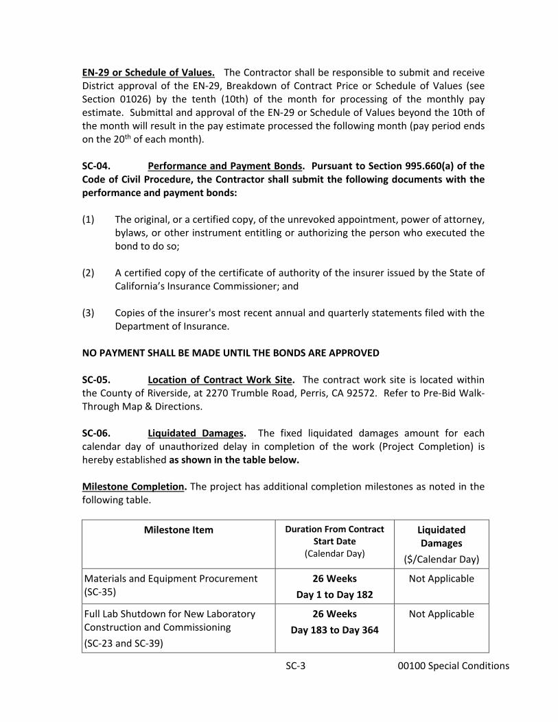
SC-3 00100 Special Conditions
EN-29 or Schedule of Values. The Contractor shall be responsible to submit and receive District approval of the EN-29, Breakdown of Contract Price or Schedule of Values (see Section 01026) by the tenth (10th) of the month for processing of the monthly pay estimate. Submittal and approval of the EN-29 or Schedule of Values beyond the 10th of the month will result in the pay estimate processed the following month (pay period ends on the 20th of each month). SC-04. Performance and Payment Bonds. Pursuant to Section 995.660(a) of the Code of Civil Procedure, the Contractor shall submit the following documents with the performance and payment bonds: (1) The original, or a certified copy, of the unrevoked appointment, power of attorney,
bylaws, or other instrument entitling or authorizing the person who executed the bond to do so;
(2) A certified copy of the certificate of authority of the insurer issued by the State of
California’s Insurance Commissioner; and (3) Copies of the insurer's most recent annual and quarterly statements filed with the
Department of Insurance. NO PAYMENT SHALL BE MADE UNTIL THE BONDS ARE APPROVED SC-05. Location of Contract Work Site. The contract work site is located within the County of Riverside, at 2270 Trumble Road, Perris, CA 92572. Refer to Pre-Bid Walk-Through Map & Directions. SC-06. Liquidated Damages. The fixed liquidated damages amount for each calendar day of unauthorized delay in completion of the work (Project Completion) is hereby established as shown in the table below. Milestone Completion. The project has additional completion milestones as noted in the following table.
Milestone Item Duration From Contract Start Date
(Calendar Day)
Liquidated Damages
($/Calendar Day)
Materials and Equipment Procurement (SC-35)
26 Weeks Day 1 to Day 182
Not Applicable
Full Lab Shutdown for New Laboratory Construction and Commissioning (SC-23 and SC-39)
26 Weeks Day 183 to Day 364
Not Applicable

SC-4 00100 Special Conditions
Substantial Completion for a Fully Functional New Laboratory
From Day 365 $7,000
Administrative Delay Liquidated Damages. Liquidated damages may also be applied to compensate the District for undue delays in the completion of punch list items, site clean-up, demobilization, and miscellaneous contract obligations after a notice of Substantial Completion has been filed. The cost to the District for administration, inspection, mileage, and other similar items would be extremely difficult to determine. For that reason, additional liquidated damages, known as Administrative Delay Liquidated Damages shall be imposed in the amount of $500 per day, effective 30 days after the Substantial Completion date is filed or the Revised Completion date is reached, whichever is later. Charges will be assessed until the Final Completion date is issued by the Inspector. SC-07. Construction Water. For work under this specification, the Contractor can obtain water, free of charge, upon proper arrangements for metering its use from the Districts Resident Inspector from selected locations onsite. Contractor shall provide all necessary piping and appurtenances, including pumps, to convey water to the work site. Arrangements for water from sources other than EMWD shall be the sole responsibility of the Contractor, and no additional compensation will be allowed. SC-08. Insurance. At all times during the life of this contract, Contractor and his subcontractors shall procure and maintain Commercial Liability, Automobile Liability, Workers Compensation, Equipment Floater and Installation Floater per Section F – General Conditions, F-04. Contractor’s and Subcontractor's Insurance. Refer to Section F-04 for complete details, including required insurance limits, deductibles, and endorsements. Note: An Aggregate limit (cap) or Professional Employer Organization (PEO), or Self Insurance Plan is not acceptable. In addition to the requirements noted above and found in Section F-04, the following shall apply to this project: Additional Insureds. The liability insurance required under Section F-04 under General Conditions shall include EMWD, City of Perris, and all agencies listed in Section H-Permits as additional insured. Refer to Section F-04 for additional requirements pertaining to this section Pollution Liability Coverage. The Contractor shall procure Pollution Liability Coverage in amounts not less than the following: $2,000,000 per each occurrence

SC-5 00100 Special Conditions
Builders Risk Insurance. The Contractor and his subcontractors shall maintain or cause to be maintained at all times during the life of this contract, builders' risk "All Risk" completed value insurance, to include, at the option of the District, loss or damage caused by fire, insuring completed work, work in progress, material, supplies and equipment of the work site, in storage or in transit, in an amount equal to the full replacement cost thereof. Such insurance shall include the interests of the District, Contractor, all tiers of subcontractors, suppliers and materialmen, with deductible amounts, if any, for the sole account of and payable by Contractor. Loss under such insurance shall be adjusted with and payable to the District for the interest of all parties. The amount of property insurance shall be sufficient to protect against such loss or damage in full until the work is accepted by the District. EMWD must be named as “loss payee” on the certificate for Builder’s Risk policy.
Builder’s “All Risk” insurance policy shall contain a deductible not higher than $1,000 unless otherwise approved by the District. Fidelity Bond Insurance (aka Commercial Crime Insurance). The Contractor and his subcontractors shall maintain or cause to be maintained at all times during the life of this contract a Fidelity Bond in the amount of $500,000 against theft or loss of District property, either monetary or physical, caused by its employees' fraudulent or dishonest actions. SC-09. Compliance with Storm Water Regulations (NPDES) for Discharge of Storm Water Runoff Associated with Construction Activity Order No. 2009-0009 DWQ (NPDES General Permit No. CAS000002). Construction projects under 1 acre do not require coverage under the General Permit or preparation of a Storm Water Pollution Protection Plan (SWPPP), but will require Best Management Practices (BMPs) to control and reduce discharges of pollutants associated with construction into storm drains and receiving waters. The contractor shall prepare, implement and maintain a BMP Plan showing location and type of BMPs to be implemented for the project. The contractor shall alter the plan, implementation and maintenance as necessary for the duration of the project. SC-10. Preconstruction Conference. A Pre-job conference shall be scheduled prior to the start of the project. District representatives, Permit agencies, and the Contractor shall be present. A pre-construction coordination conference shall be held a minimum of two months after Notice to Proceed to begin construction preparation work. A construction coordination conference shall be held at a minimum of two months prior to the full shutdown of the OMC Laboratory. Meeting attendees shall include District representatives, contractor, and sub-contractors performing work for each discipline.
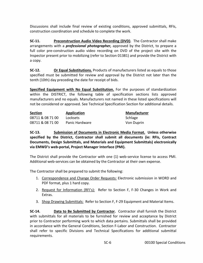
SC-6 00100 Special Conditions
Discussions shall include final review of existing conditions, approved submittals, RFIs, construction coordination and schedule to complete the work. SC-11. Preconstruction Audio Video Recording (DVD). The Contractor shall make arrangements with a professional photographer, approved by the District, to prepare a full color pre-construction audio video recording on DVD of the project site with the Inspector present prior to mobilizing (refer to Section 01381) and provide the District with a copy. SC-12. Or Equal Substitutions. Products of manufacturers listed as equals to those specified must be submitted for review and approval by the District not later than the tenth (10th) day preceding the date for receipt of bids.
Specified Equipment with No Equal Substitution. For the purposes of standardization within the DISTRICT, the following table of specification sections lists approved manufacturers and no equals. Manufacturers not named in these listed specifications will not be considered or approved. See Technical Specification Section for additional details.
Section Application Manufacturer 08711 & 08 71 00 Locksets Schlage 08711 & 08 71 00 Panic Hardware Von Duprin SC-13. Submission of Documents in Electronic Media Format. Unless otherwise specified by the District, Contractor shall submit all documents (ie: RFIs, Contract Documents, Design Submittals, and Materials and Equipment Submittals) electronically via EMWD’s web-portal, Project Manager Interface (PMI). The District shall provide the Contractor with one (1) web-service license to access PMI. Additional web-services can be obtained by the Contractor at their own expense. The Contractor shall be prepared to submit the following:
1. Correspondence and Change Order Requests: Electronic submission in WORD and PDF format, plus 1 hard copy.
2. Request for Information (RFI’s): Refer to Section F, F-30 Changes in Work and Extras.
3. Shop Drawing Submittals: Refer to Section F, F-29 Equipment and Material Items. SC-14. Data to Be Submitted by Contractor. Contractor shall furnish the District with submittals for all materials to be furnished for review and acceptance by District prior to Contractor performing work to which data pertains. Submittals shall be provided in accordance with the General Conditions, Section F-Labor and Construction. Contractor shall refer to specific Divisions and Technical Specifications for additional submittal requirements.

SC-7 00100 Special Conditions
Prior to beginning construction, Contractor shall submit emergency telephone numbers for the construction superintendent, construction foreman, and all company principals. SC-15. Markups for Negotiated Change Order Work.
NEGOTIATED CHANGE ORDER WORK:
Labor Markup = 20% Material Markup = 15% Equipment Markup = 15% Contractor Markup for Subcontractor Work = 5% or $250 (Whichever is greater) Bonds = Actual premium (Separate Line Item) Contractor shall provide backup
documentation of the actual rate Note: The cost associated with the project superintendent and pricing of the proposal shall be considered part of the Overhead and Profit percentages previously noted. SC-16. Pipeline Connection and Disinfection. The Contractor shall notify the District one (1) week in advance of the planned pipeline connections and also provide 48-hour and 24-hour advance confirmation of when the work will be performed. The Contractor shall be responsible for dewatering the trench excavations as necessary. Contractor shall be responsible for dewatering, dechlorination, and disposal of all water from pipeline testing/flushing activities. Discharge of all water must abide by the District’s NPDES permit, which limits total residual chlorine to a maximum concentration of 0.1 mg/l. Contractor shall also protect existing water pipelines from contamination during connection procedures. Contractor shall disinfect all new pipelines, pipeline connection closure materials and the existing pipeline at connection points per AWWA Section C-651. All costs associated with connections to existing water pipelines shall be included in the appropriate bid item. Contractor must comply with Custom Technical Specifications 22 20 00 for all Laboratory Piping and fittings installation, connections, testing and approval prior to putting laboratory utilities back into operation. Contractor shall furnish and install valves and connections at the new Utility Room for the use of purging and disinfecting utilities. SC-17. Reference to District’s Standard Drawings and Detailed Provisions. Any and all referenced Standard Drawings and Detailed Provisions shall be considered part of the contract drawings and specifications. All referenced Standard Drawings and Detailed Provisions of the District are available from the District upon request.

SC-8 00100 Special Conditions
The Contractor shall not be entitled to any compensation due to referenced documents not included in the Specifications and Contract Drawings. SC-18. Pre-selected Specialty Contractors: Contractor shall include in his bid the services of pre-selected specialty contractors for this project. The pre-selected specialty contractors were involved with the project design and their proposed scope of work and fees are located in Appendices. Contractor shall direct, coordinate with, and schedule work for the following pre-selected specialty contractors:
1. Climatec – HVAC and exhaust system controls, programming and integrations. Scope of work and fees are located in Appendix D.
2. Simplex Grinnell – Fire suppression system, control and alarm system. Scope of work and fees are located in Appendix E.
3. Maxim Security System – Security system and control, system programming and integration. Scope of work and fees are located in Appendix F.
4. GA Technical Services – Network System infrastructure including network and fiber optics cables and connections. Scope of work and fees are located in Appendix G, per District Communication and Equipment Specification for Construction located in Appendix H.
5. Power Engineering Services, Inc. – Supplemental arc flash study of the new Laboratory electrical system as part of the comprehensive AC/OMC Building arc flash study.
The specialty contractor proposals were received prior to bidding, and will not be valid by the time this construction contract is awarded. Contractor is responsible for obtaining the most current pricing and verifying the proposed work at the time of bidding, and shall include any changes in pricing as part of the bid. The specialty contractor proposals contain exclusions of installation, labor, and materials for a complete and functional systems and controls. Contractor is responsible for all work and material required in support of building the complete, fully integrated, and functional HVAC/exhaust, fire suppression, security and access, and network systems, controls and infrastructures that conform to applicable code requirements. SC-19. Coordination – Maintenance and Construction. The Contractor should take note that other work will be taking place simultaneously at the jobsite. It shall be the Contractor's responsibility to coordinate his activities with District’s maintenance staff and all the other contractors performing work in the project area and to cooperate with District’s maintenance staff and all other contractors within reasonable and professional norms so that all maintenance and construction may be completed in a timely manner. In the event a scheduling conflict arises between contractors performing work on the job site and if both parties are unable to reach an agreement, the District shall be the final authority in resolving said scheduling conflict.

SC-9 00100 Special Conditions
No additional compensation will be allowed due to conflicts with other construction in the area. SC-20. Coordination – Laboratory Operation. The Contractor should take note that Laboratory operation will be ceased and moved out prior to the start of the construction work. District’s Facilities and Grounds Maintenance staff will provide its own storage bins for storing removed laboratory supplies, sensitive instruments and equipment. Laboratory staff also will assist with the organizing and moving of laboratory supplies and instruments. SC-21. Coordination – Inter-discipline. Contractor shall retain the service of a Mechanical and Electrical Coordinator who is responsible for the coordination between HVAC/mechanical/plumbing, electrical, fire suppression, network system, security/public address system work, and with work of other disciplines including the District’s specialty contractors as defined in SC-18, lab instrument relocations and setup, and cubicle and office furniture system work. Special coordination of mechanical and electrical construction with respect to finished ceilings, structural components and other building elements shall be considered. Contractor shall employ and pay for services of individual or firm for duration of construction qualified and experienced in field coordination for disciplines included in this Project. Minimum qualifications include performance of similar task for the construction of a publically accessible space while maintaining operation such as a hospital, school, or administration building for a public agency with a value exceeding one million ($1,000,000) dollars. Coordinate Work of mechanical and electrical Divisions with Work of other Divisions. Coordination shall include progress schedules, including dates for submittals and delivery of products, and meetings among subcontractors, separate contractors, and others concerned with Work to establish and maintain coordination and schedules. Any coordination issues shall be brought to the District’s attention immediately for resolution. Precedence Of Services For Coordination: In event of conflicts involving location and layout of work; use following priority to resolve disputes:
1. Structure and partitions have highest priority
2. Equipment location and access
3. Support systems
4. Gravity drainage lines
5. High pressure ductwork and devices
6. Large pipe mains, valves and devices
7. Compressed air, Lab gas and natural gas piping and fittings

SC-10 00100 Special Conditions
8. Low pressure ductwork, diffusers, registers, grilles, HVAC equipment
9. Ceiling system and recessed light fixtures
10. Fire protection piping, devices and heads
11. Small piping, tubing, electrical conduit, and devices
a. Conduits installed in corridors shall be maintained at least 9-in above finished ceiling Conduits shall be grouped within a 12-in width
b. The space utilized for conduit shall be selected to allow access to all devices which normally require adjustment, repair, resetting, etc.
12. Casework and countertops SC-22. Field Investigations of Existing Underground and Above Ground Utilities, and Steel Reinforcements. Unless otherwise indicated on the plans or directly by the District, all utilities shall be protected in place and service maintained as described in Section 02201 Part 1.02 of the Specifications. Existing underground and above ground utilities have been identified and located on the plans based on the best information available. The Contractor is responsible for performing exploratory field investigations throughout the construction area. The Contractor shall field verify the elevation and location of utilities, including tie-in points, and provide the information to the District’s inspector a minimum of four weeks ahead of construction to permit design revisions should a conflict arise. Contractor shall review all existing conditions, drawings and other documents for proper coordination between new and existing construction. Refer to Appendix L for additional as-built documentation. Active utilities whose locations are unknown to District are suspected to exist. If they are encountered, immediately report to District for resolution. The Contractor is responsible for performing X-ray of the Lab floor area and exterior wall, around the cutting extents of the concrete slabs and panels. This work shall confirm location and depth of existing underground utilities and rebars, and establish connection requirements to existing utilities. The Contractor is also responsible for performing field verification of all above ground utilities and connections throughout the construction area inside and outside of the Lab, including the utility room and plenum area. All associated costs with utility and rebar verifications shall be included in the Schedule of Values and no additional compensation will be allowed. Damages to existing structures, utilities and other items which are caused by Contractor’s operations shall be repaired or replaced to their original conditions by Contractor at Contractor’s expense.

SC-11 00100 Special Conditions
SC-23. Shutdown Requirements and Operations Coordination. Contractor shall coordinate the shutdown operation of existing Laboratory and its utilities with the District’s Inspector. No work shall be performed without four (4) and two (2) weeks prior notice followed by forty-eight (48) hour prior and twenty-four (24) hour confirmation notices to the District. Contractor shall not perform any utility shutdowns and construction work that affect the OMC building without a District representative present. For all temporary shutdown to modify and/or cut over utilities, District staff will perform shutdown coordination and full-time inspection until Contractor restores affected utilities back into operation. Contractor shall not cut into existing utilities without first verifying with District that service has been correctly identified, and isolated per District’s lock-out/tag-out policy. Daily hot work permits shall be required for each utility tie-in operation and shall follow the District’s standard operating procedure (SOP). Operation of existing valves, switches, etc., to affect service shutdown will be completed by District, unless arranged otherwise. Maintain utilities or other service, indicated to be abandoned, in service or provide alternate means of service until new facilities are provided, tested, and put in operation. Full Lab Shutdown Durations. The full Lab shutdown is from Day 183 to Day 364 of the contract. Prior to the start of full Lab shutdown, the following milestones must be completed and verified:
1. Contractor must complete all necessary construction preparation work and material procurement, including necessary safety equipment onsite and staff capable of handling environmental hazards and demolition of Laboratory and lab equipment.
2. District will coordinate and schedule for a final walk-through of the laboratory on Day 180, to review the status of turning over the Laboratory to the Contractor and current site conditions. After the final walk-through is completed and as approved by the District, the laboratory will be turned over to the Contractor to begin work on Day 183.
Utility Shutdowns that Affect the OMC Building: All shutdowns without proper notifications and coordination with District’s Construction and Inspection Department, Laboratory, Operation and Maintenance Department will be rejected. Contractor shall schedule all work at such time, including after-hour and nighttime work, and in such a manner to minimize interference and inconvenience to public, staff and District’s operations. The Existing as-built drawings of the various utility systems are located in Appendix L. The existing OMC Building will be affected by the shutdown of the following utility systems in support of the Lab construction work:
1. Electrical System – Existing Switchboard “SB-1” provides the power to the OMC Building, including the District’s Integrated Operation Center (IOC). As a critical facility, IOC operates and controls and District’s water, wastewater, and recycled water distribution system and facilities.
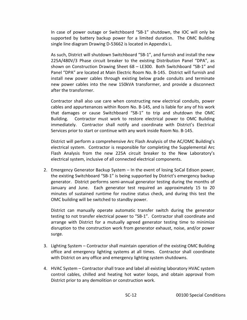
SC-12 00100 Special Conditions
In case of power outage or Switchboard “SB-1” shutdown, the IOC will only be supported by battery backup power for a limited duration. The OMC Building single line diagram Drawing D-53662 is located in Appendix L.
As such, District will shutdown Switchboard “SB-1”, and furnish and install the new 225A/480V/3 Phase circuit breaker to the existing Distribution Panel “DPA”, as shown on Construction Drawing Sheet 68 – LE300. Both Switchboard “SB-1” and Panel “DPA” are located at Main Electric Room No. B-145. District will furnish and install new power cables through existing below grade conduits and terminate new power cables into the new 150kVA transformer, and provide a disconnect after the transformer.
Contractor shall also use care when constructing new electrical conduits, power cables and appurtenances within Room No. B-145, and is liable for any of his work that damages or cause Switchboard “SB-1” to trip and shutdown the OMC Building. Contractor must work to restore electrical power to OMC Building immediately. Contractor shall notify and coordinate with District’s Electrical Services prior to start or continue with any work inside Room No. B-145.
District will perform a comprehensive Arc Flash Analysis of the AC/OMC Building’s electrical system. Contractor is responsible for completing the Supplemental Arc Flash Analysis from the new 225A circuit breaker to the New Laboratory’s electrical system, inclusive of all connected electrical components.
2. Emergency Generator Backup System – In the event of losing SoCal Edison power, the existing Switchboard “SB-1” is being supported by District’s emergency backup generator. District performs semi-annual generator testing during the months of January and June. Each generator test required an approximately 15 to 20 minutes of sustained runtime for routine status check, and during this test the OMC building will be switched to standby power.
District can manually operate automatic transfer switch during the generator testing to not transfer electrical power to “SB-1”. Contractor shall coordinate and arrange with District for a mutually agreed generator testing time to minimize disruption to the construction work from generator exhaust, noise, and/or power surge.
3. Lighting System – Contractor shall maintain operation of the existing OMC Building office and emergency lighting systems at all times. Contractor shall coordinate with District on any office and emergency lighting system shutdowns.
4. HVAC System – Contractor shall trace and label all existing laboratory HVAC system control cables, chilled and heating hot water loops, and obtain approval from District prior to any demolition or construction work.

SC-13 00100 Special Conditions
For all modification to the existing chilled and heating hot water piping systems, Contractor shall coordinate and schedule with the District for the shutdown of the AC and OMC building’s HVAC System. Contractor shall schedule this construction work only during low chilled water usage and after-hours period. Contractor shall purge, refill, test the modified chilled and heating hot water piping systems, and put both piping systems back into operation.
For all other HVAC system work, the existing AC and OMC Building HVAC system must be protected in-place and remain in operation at all times during the demolition and the construction of the Laboratory HVAC system. Contractor shall complete, integrate, document, and test the new Laboratory HVAC system.
5. Exhaust System – The existing exhaust stacks have separate controls and localized alarms, and its shutdown will not affect OMC building operation. Contractor shall shutdown all exhaust stacks during the demolition and construction work to prevent odor and dust from being vented into the adjacent courtyard area. Contractor shall obtain approval from District prior to restart any exhaust stacks.
6. Fire Suppression System – Contractor shall maintain operation of the remaining fire protection and fire alarm systems at all times within existing OMC building. Fire suppression system and fire alarm shutdowns shall be coordinated with District staff. District staff will perform a fire watch during shutdown of fire sprinkler and fire alarm system.
7. Security System – Contractor shall trace and label all existing laboratory security system equipment, cables, and appurtenances, and obtain approval from District prior to any demolition or construction work. The existing AC and OMC Building security system must be protected in-place and remain in operation at all times during the demolition and the construction of the Laboratory security system. Contractor shall complete, integrate, document, and test the new Laboratory security system.
8. Network System – Contractor shall trace and label all existing Laboratory network sub-system equipment, cables, jacks, and appurtenances located inside Room No. B-144 and the Laboratory, and obtain approval from District’s Network Administrator prior to any demolition or construction work. The Laboratory network sub-system supports lab instruments, computer terminals, office phones, and lab security system’s micro-controllers.
The OMC Building’s main network system must be protected in-place and remain in operation at all times during the demolition and the construction of the Laboratory network sub-system. Contractor shall complete, document, certify, and test the new Laboratory network sub-system per District standards.

SC-14 00100 Special Conditions
9. Public Address (PA) System – Contractor shall trace and label all existing laboratory PA system equipment, cables, and appurtenances, and obtain approval from District prior to any demolition or construction work.
The existing AC and OMC Building PA system must be protected in-place and remain in operation at all times during the demolition and the construction of the Laboratory PA system.
10. Drainage System – The drinking fountain next to Human Resources Department must be lockout and tag-out during drain line modification.
For all utility shutdowns to be performed during the construction work, Contractor shall comply with Shutdown Coordination requirements for shutdown types, notifications and durations:

SC-15 00100 Special Conditions
Contractor shall provide detailed shutdown schedules and types for District review and approval, to coordinate for the utilities shutdown of single or multiple lab support systems, components, and equipment. SC-24. Working Days and Hours. Work is allowed to be conducted in the designated access areas seven days a week, twenty-four hours a day after mobilization. The District and Laboratory’s normal business hours are defined as Monday through Friday, 6:30 A.M to 6:00 P.M. Contractor must notify District’s inspector forty-eight (48) hours in advance of any work performed outside of this time. SC-25. Contractor Site Use and Restrictions. As identified in Appendix A, Figures 1 and 2, the area outside the limit of the proposed construction area shall not be disturbed without written approval of District. Contractor shall obtain written approval from District at least seven (7) calendar days in advance when scheduling Work outside limits of construction. Provide District an estimate of time needed to perform Work outside limits of construction. Cutting, capping, and reconnecting utility systems outside limits of construction shall be performed by Contractor, unless otherwise noted. Existing roads, streets, drives, parking lots, entrances and required fire exit ways shall be kept clear and available at all times for their intended use. Do not use these areas for parking, staging or storage without District’s written approval. District is providing separate areas allocated to the Contractor for parking, staging, storage, materials and contractor employee access, and field office. Contractor Laydown Areas. Contractor shall have access to laydown and staging areas as listed in the Appendix A, Figure 1. The Contactor shall vacate the laydown area once the Work Area has been completed. The use of these areas shall not create an unsightly condition and shall be fenced as to restrict access by the public or District staff. Contractor shall provide a fence around laydown areas separate and apart from existing site fencing. Contractor shall coordinate with District, and provide alternate routes for public and District access if normal routes are affected. Do not unreasonably encumber site with equipment, materials or vehicles. Return all improvements on or about site and adjacent property, which are not shown to be altered, removed or otherwise changed; to conditions that existed before starting performance under Contract. Contractor’s Field Office Usage and Requirements. Contractor shall have access to a field office as listed in the Appendix A, Figure 2. District will provide a room with utilities that is close to the construction work area as contractor’s field office within thirty (30) days after the Notice to Proceed is issued.
SC-16 00100 Special Conditions
The utilities provided are wireless internet connection, ceiling lights, 120V electrical receptacles to power office machines and office equipment, and HVAC heating/cooling control of the room. Hard-wired phone jack and phone service will not be provided. Contractor shall contracts with District’s copy machine service provider, Xerox, for copy/fax machine rental, servicing, and copier supplies during construction. The Xerox proposal is shown in Appendix I. Contractor shall protect and maintain field office’s entire system and finishes during use, including glass door and panels, window coverings, HVAC system, control and ductwork, and repair or replace any damaged components of system and finishes, and clean all finishes. This field office room must be return to the District in its original condition and functionality as shown in the pre-construction video. Sanitation. For the entire period of construction, Contractor shall provide portable toilets, wash facilities, and trash bins for his personnel at the project site. The location of these facilities shall not create an unsightly condition at public entrances and shall not readily be accessible by the public. Prohibitions and Other Requirements: Audio devices and radios are prohibited, except two-way radios needed for Contractor’s operations. Use of two-way radios within occupied facilities shall be limited, so not to disrupt occupants. Use of District toilet facilities, washrooms, drinking fountains, telephones, copy machines within existing facility or occupied areas shall not be allowed. Dining and gym areas are not to be used by construction personnel. Coordinate construction operations to assure that operations are carried out with consideration given to conservation of energy, water, and materials. Contractor shall maintain existing building in a weather tight condition throughout construction period and repair damage and leaks caused by construction operations. Take all precautions necessary to protect building and its occupants during construction period. Make every effort to keep noise, dust, and vibration to a minimum in construction operations. Jackhammer will not be permitted to use within the existing building during the District’s normal business hours without District’s consent. SC-26. Equipment and Material Storage. The project site shall have unobstructed access at all times. EMWD shall be indemnified from any loss, liability and/or injury. Contractor shall not store materials or equipment including spoil materials on private or public property without written permission approving such use from the property District(s). Said written permission shall be submitted and approved by the District prior to Contractor moving materials or equipment onto said property. In addition, all spoils shall be hauled offsite to an approved disposal area through the County of Riverside or City of Perris. Location for placement of all materials shall be approved in advance by District.

SC-17 00100 Special Conditions
SC-27. Site Restoration. All work sites shall be restored to pre-job conditions and shall meet the requirements of District. The Contractor shall repair or replace damaged improvements as directed by District. The District is obligated to keep visual impact of the work sites to a minimum; therefore, Contractor is required to restore all areas altered by construction to pre-existing conditions, unless shown otherwise on the Drawings. Such areas shall include, but shall not be limited to areas used for travel, parking, and storage of vehicles, equipment and materials or adjacent areas impacted by facilities construction. Contractor shall be responsible for the proper disposal of all waste materials resulting from project operations, including rubbish, packaging materials, discarded equipment parts, and damaged construction materials, in a manner and at locations suitable to the District. All removed concrete and rebar shall be hauled offsite to an approved disposal area through the County. Contractor shall protect in place or remove and replace all existing utilities and those improvements specified to be removed per contract drawings and specifications. If said facilities are undermined or disturbed as determined by District, said facilities shall be removed and replaced. Contractor shall correct or replace any damaged utilities or improvements as part of the contract work at no additional cost to the District. Certain existing improvements are specified on the Construction Drawings to be protected in place or removed and replaced.
1. Daily Restoration. Contractor shall, as a minimum, have accomplished by the end of each work period, the following: A. Remove all debris, construction materials, and equipment from District
property.
B. Clean all work areas including, but not limited to, sweeping all areas of construction, laydown, staging, and accesses, and removing all trash. Contractor shall sweep work areas more than once a day if requested by District.
SC-28. Air Quality. The Contractor shall comply with all applicable requirements of the South Coast Air Quality Management District (SCAQMD) and California Air Resources Board (CARB). Contractor shall conduct work in a manner that indoor air quality levels meet industry standards for an occupied space.

SC-18 00100 Special Conditions
Contractor shall block off work areas including ceiling space to prevent dust from travelling to Laboratory, electrical rooms, corridors, and occupied spaces of the building. SC-29. Site Security. The Contractor shall only perform work during normal business working hours specified in SC-24. For all after-hour shutdowns to construct necessary utilities modifications, District will retain the services of a Security Service to allow contractor access to the site. District staff will perform as-needed inspection and construction coordination.
SC-30. Security Protocol. All full or part-time construction personnel under the Contractor and Subcontractors shall be required to undergo background investigations prior to work on the project. All background investigations shall be “nationwide” and include civil litigation.
The Contractor shall supply the District with written proof that individuals have passed the background screening process. File documentation shall be kept onsite and available for reviewing upon request.
All other part-time personnel, upper management, vendors, and/or suppliers are not required to undergo background investigations, but must be accompanied by a representative of the Contractor as a requirement to enter the project site. The guard at the entrance shall be provided with a list of all employees permitted to enter the site.
SC-31. Occupancy of Work Areas. Work will be performed within the District facilities that must maintain continuous operations. District will occupy facilities surrounding work area. Contractor must obtain approval of District before starting any work within any existing area of building. Contractor shall install a temporary construction wall at the limits of the Contractor’s designated work area to identify interior work area boundaries. Contractor shall access work areas using only approved access routes. Contractor shall be limited to the use of designated pathways for work and shall not enter other areas of the facility without an approved escort. Limit use and operation within existing facilities to areas indicated for construction Work and as required to perform Work. Other areas within facility shall not be disturbed or disrupted. Contractor shall perform Work so as not to interfere or inconvenience public, staff and District’s operation. Do not load structure with weights that will endanger structure. Contractor shall control nuisance dust from work activities for each Work Area of work to maintain the health and safety of District staff. Contractor shall minimize odors and provide adequate ventilation for the duration of the work.

SC-19 00100 Special Conditions
SC-32. Work Performed by District. In support of the Laboratory Construction, District staff and our service contractors (third party) will perform certain construction work and activities within the work area. Contractor shall include District’s work into their work sequence, schedule, and the New Laboratory Utilization Training per SC-40. District or third party will perform the following work:
1. New electrical system from the 225A/480V/3 Phase circuit breaker on the existing Distribution Panel “DPA” to new disconnect adjacent to the new 150kVA transformer
2. OMC Building preventive maintenance activities, including the semi-annual generator testing
3. Temporary Lab receiving area and office trailer
4. Relocation of sensitive laboratory instruments and equipment, lab supplies, office equipment and workstations
5. New office furniture and equipment, cubicle panels, and chairs
6. The setup and calibration of lab instrumentations and components
All materials, services, and work performed under these separate service contracts will have third party warranty.
SC-33. Quality Assurance. Contractor shall monitor quality assurance and control over suppliers, manufacturers, products, services, site conditions, and workmanship, to produce Work of specified quality. Manufacturers' installation instructions shall be adhered to at each step in sequence. Should manufacturer's instructions conflict with Contract Documents, Contractor shall request clarification before proceeding. Comply with specified standards as a minimum quality for Work except when more stringent tolerances, codes, or specified requirements indicate higher standards or more precise workmanship. Verify that field measurements are as indicated on approved shop drawings or as instructed by manufacturer of product. Secure products in place with positive anchorage devices designed and sized to withstand stresses, vibration, physical distortion or disfigurement. Materials shall be compatible with one another and with other materials with which they may come in contact. Contractor shall be solely responsible for, and have control over, construction means, methods, techniques, sequences and procedures and for coordinating all portions of Work under the Contract, unless Contract Documents give other specific instructions concerning these matters.

SC-20 00100 Special Conditions
Whether or not Contract Documents give specific instructions concerning construction means, methods, techniques, sequences or procedures, the Contractor shall review, substantiate, and comply with current industry execution standards and manufacturer's current execution instructions and evaluate jobsite safety thereof and shall be fully and solely responsible for jobsite safety of such means, methods, techniques, sequences or procedures. Contractor shall be responsible to District for acts and omissions of Contractor’s employees, Subcontractors and their agents and employees, and other persons or entities performing portions of Work for, or on behalf of Contractor or any of its Subcontractors. Tolerances: Monitor fabrication and installation tolerance control of Products to produce approved Work. Contractor shall not permit tolerances to accumulate. Should manufacturers' tolerances conflict with Contract Documents, notify District immediately. SC-34. Records of Construction. Contractor shall keep and maintain, at the job site, one record set of Construction Drawings as specified in the General Conditions, Section F-Labor and Construction, F-08 "Reports, Records, and Data". SC-35. Provisions for Payment for Stored Material. All materials and equipment shall be in accordance with the design drawings and specifications. As part of the construction preparation work, Contractor must take delivery and store all materials and equipment in a secured storage prior to the begin work on Day 183. It is the contractor’s responsibility to ensure that all materials and equipment are in accordance with the provisions of this project and Sections 01612 and 01614. District reserves the right to inspect all materials and equipment, and the contractor shall be responsible to replace any materials or equipment that is found to be not in accordance with the provisions of this project at the contractor’s sole expense. Only the off-the-shelf material and equipment that readily are available for same day pickup can be procured during construction. The payment schedule for the stored material and equipment is as below:
Payment Milestone
% of Payment Description of Payment Milestone
1 15% Contractor pays 15% of the purchase price plus applicable sales taxes upon submittal approval

SC-21 00100 Special Conditions
Additional requirements:
1. Contractor shall be responsible for payment of all sales tax, interest on outstanding invoices, at no additional cost to the District. The District shall not provide Contractor compensation for sales taxes that are not included within their bid.
2. The Contractor shall include the cost of all handling, receiving and storage of the material within their bid.
The Contractor shall incorporate the above-listed payment schedule within the Schedule of Values.
SC-36. Limitations on the use of 3D Model illustration. The 3D illustration of the OMC Lab Modification project is to be used solely to facilitate the visualization of the completed construction work, and for bidding purposes only. This illustration is not to scale, and cannot be used for materials and dimension takeoffs.
SC-37. Air Handler Unit Selection and Restrictions. The current basis of design is Daikin Model OAH025GDHC, a modular air handler unit with an air volume capacity of 10,730CFM. Contractor shall provide HVAC submittals for approval per Custom Technical Specifications, Division 23 requirements. The approved air handler unit may be dimensionally different from the basis of design, which may require different sizes of equipment pad, wall openings and support framings, ductwork, transitions, and appurtenances. At no cost to the District, contractor shall modify design and construct the approved air handler unit, ductwork and appurtenances. SC-38. Environmental Hazards. The existing Laboratory was tested for environmental hazards of mold, lead and heavy metals, and asbestos at representative locations. The resulting test report, located at Appendix K, is not a comprehensive evaluation of all the area under construction, but it is the basis of the bid for this project. The Contractor shall be responsible for performing the handling and disposal of environmental hazards in accordance with federal, state, and local requirements during demolition and preparation of the site for new construction. The Contractor shall include within their bid the handling and disposal costs based on the data provided by the District. After the award of the contract, the Contractor shall perform a comprehensive investigation to characterize the environmental hazards within the construction area. The cost of the comprehensive field investigation for hazardous materials shall be included within the contractor’s bid. Contractor shall coordinate and schedule with the District, and provide a minimum of one-week notification to the District prior to start this investigation.
SC-22 00100 Special Conditions
Contractor shall provide a comprehensive environmental hazards test report and work schedule for District’s review and approval, prior to start the additional abatement work. The District has included a preset bid item as an allowance for added work based on the Contractor’s comprehensive site assessment. This allowance is reserved for work that could not reasonably be identified at the time of bidding. Per applicable federal, state and local regulations, Contractor is responsible for providing safe and effective environmental hazards abatement. The construction area is within an occupied building, thus, Contractor shall install required barriers and protections to seal off the construction area from the occupied office spaces. Contractor shall provide certified and experienced workers with the required trainings, personal protective equipment (PPE) and equipment to perform all hazardous waste abatement work. Contractor shall also provide safe handling, transportation, and waste disposal at approved landfills and/or treatment facilities. SC-39. Demolition of Laboratory. Unless noted otherwise, District will remove all chemicals, lab gases such as Argon, laboratory supplies, lab instrumentations and equipment, workstations, office equipment, personal artifacts, and other non-stationary laboratory equipment and supplies. Chemicals used for the Water Quality testing were stored in various location throughout the lab, and they are on file with Riverside County Environmental Health, Hazardous Materials Division. For reference, Contractor can request for a copy of District’s chemical disclosure list through the District’s Safety, Risk and Emergency Management Department. District will coordinate and schedule for a final walk-through of the laboratory on Day 180, to review the status of turning over the Laboratory to the Contractor and current site conditions. After the final walk-through is completed and as approved by the District, the laboratory will be turned over to the Contractor to begin work on Day 183. Contractor is required to apply all necessary safety trainings, techniques and equipment, and PPE for the demolition work, where chemical residues and vapors may still be present within the casework, walk-in refrigerator, ductwork and inside the work area. The Contractor shall cut, remove, and properly dispose the complete laboratory, including the fume hoods, casework and walk-in refrigerator as shown in the construction drawings. Decontamination and Demolition of Fume Hoods and Exhaust Ductwork. Contractor is required to hire a specialty subcontractor with appropriate PPEs, apply safety precautions and trainings to decontaminate seven (7) chemical and one (1) biological fume hoods, including chemical storage cabinets and the associated ductwork connected to the roof-mounted exhaust stacks prior to their demolition and disposal. Contractor shall notify and provide District with a list of chemicals for the use of decontaminating fume hoods and associated appurtenances. The Contractor must lock-out/tag-out of all fume hoods utilities, and perform all decontamination work only within the existing laboratory area.

SC-23 00100 Special Conditions
Contractor shall utilize elevated platforms to decontaminate all the fume hoods exhaust ductwork connected to the roof-mounted exhaust stacks. Only after completing the decontamination, the specialty subcontractor can then cut and remove, and properly dispose of the fume hoods, chemical storage cabinets, exhaust ductwork and appurtenances. To cut, remove, and bag fume hoods and the associated ductwork and appurtenances for direct disposal to a hazardous landfill site is not acceptable. Also as part of this decontamination and demolition work, the specialty subcontractor will relocate one (1) decontaminated 8-ft fume hood into District’s storage. The Contractor will need to move it out of storage, install and connect all its utilities as part of new Laboratory Startup and Testing work. SC-40. Laboratory Startup and Testing, Commissioning, and Onsite Training. As part of the Laboratory Startup and Testing Work, Contractor is required to demonstrate all utilities, utility hookups and terminations, constructed work and equipment are in place, completed per drawings and specification, and are fully operational. In addition, Contractor must have completed all punchlist items that are necessary for a successful commissioning and onsite training. Onsite Training. In conjunction with RFD, District, and specialty contractors, the Contractor shall schedule, coordinate, and conduct an 8-hour OMC Laboratory Utilization Training day to cover the required topics and equipment in Section 01820. Unless noted otherwise, only District staff will be permitted to move and set all its stored lab instrumentations and equipment, workstations, and office equipment into the newly completed Laboratory and the adjacent office area prior to the start of this Training. Laboratory Instruments Calibration and Startup. Immediately after completing the training, District will connect Laboratory instruments and equipment to the new utilities, move in chemicals and supplies, setup and calibrate all instruments. This work will take approximately one week to complete. As part of the startup and commissioning work, contractor shall correct all deficiencies immediately to ensure the new Laboratory can be occupied and put into full operation by the end of this one-week duration. After the newly constructed Laboratory is tested, approved and accepted by the District, the warranty period for the constructed work and equipment shall begin per General Conditions, General Guarantee F-13. SC-41. Standard Color Schemes and Finishes. District uses standard schemes and finishes for the AC and OMC Buildings, as found in Appendix C. Unless otherwise noted in the specification and drawings, all the furnished ceilings, wall, doors, flooring, kitchen cabinetry and countertop material in this Project shall conform to the District Standard. In addition, all door hardware provided by Contractor shall match in kind with existing.
SC-24 00100 Special Conditions
SC-42. Existing Ceiling Light Fixtures. Per construction drawings, Contractor is to salvage, recondition and reinstall existing light fixtures. The basis of bid for this project is to demolish, furnish and install all new light fixtures for the suspended acoustic and drywall ceilings. All ceiling light fixtures furnished by Contractor shall match District’s standard ceiling light fixtures.

P-1 00200 Section P Contract Drawings
EASTERN MUNICIPAL WATER DISTRICT SPECIFICATION NO. 1329
OMC LABORATORY MODIFICATION
SECTION P - CONTRACT DRAWINGS P-01. General. The location of the work, its general nature and extent, the outline of the land owned or controlled by the District and the form and general dimensions of the facilities (ie. pipelines, appurtenances, etc.) are as shown on the drawings attached and made a part of this Specification as listed below.
P-02. Construction Drawings. Drawing Number Drawing Title D-54386 Title Sheet D-54387 General Notes, Project Information D-54388 2013 California Green Building Standard Code D-54389 2013 California Green Building Standard Code D-54390 2013 California Green Building Standard Code D-54391 Site Plan D-54392 Exiting Plan D-54393 Floor Plan - Demolition D-54394 Reflected Ceiling Plan - Demolition D-54395 Floor Plan - New D-54396 Exterior Elevation – Demo and New D-54397 Reflected Ceiling Plan - New D-54398 Interior Elevations and Details D-54399 Door, Window and Finish Schedules

P-2 00200 Section P Contract Drawings
D-54400 Finish Floor Plan D-54401 Details D-54402 Details D-54403 Structural Details D-54404 Laboratory Furnishings General Notes and Legends D-54405 Furniture Menu D-54406 Fitting Schedule D-54407 Casework Menu D-54408 Floor Plan Existing D-54409 Floor Plan D-54410 Interior Elevations D-54411 Interior Elevations D-54412 Interior Elevations D-54413 Details D-54414 Details D-54415 Details D-54416 Details D-54417 Details D-54418 Details D-54419 Details D-54420 Details D-54421 Mechanical General Notes, Symbols & Legend

P-3 00200 Section P Contract Drawings
D-54422 Schedules D-54423 Zone Pressure Map D-54424 Demolition Floor Plan D-54425 Floor Plan D-54426 Demolition Hydronic Piping Floor Plan D-54427 Hydronic Piping Floor Plan D-54428 Airflow Schematic D-54429 Details D-54430 Details D-54431 Details D-54432 Details D-54433 Control Diagrams D-54434 Control Diagrams D-54435 Plumbing General Notes, Legend, Schedules D-54436 Demolition Below Grade Floor Plan D-54437 Below Grade Floor Plan D-54438 Demolition Floor plan D-54439 Floor Plans D-54440 Details D-54441 Details D-54442 Details D-54443 Electrical Notes Sheet

P-4 00200 Section P Contract Drawings
D-54444 Fixture Schedule D-54445 Title 24 D-54446 Title 24 D-54447 Title 24 - Power D-54448 Lighting Plan Lab Area - Existing D-54449 Lighting Plan Lab Area - New D-54450 Power & Signal Plan Lab Area - Existing D-54451 Power & Signal Plan Lab Area - New D-54452 Cable Tray Plan Lab Area - New D-54453 Single Line Diagram D-54454 Single Line Diagram D-54455 Single Line Diagram D-54456 Panel Schedules D-54457 Details D-54458 Details D-54459 FA-000 Simplex Grinnell Fire Alarm Plan D-54460 FA-101 Simplex Grinnell Fire Alarm Plan D-54461 SP-101 Simplex Grinnell Fire Sprinkler Plan

Rev:10/08/13
SPECIFICATIONS - DETAILED PROVISIONS Section 01000 - General Safety Requirements
C O N T E N T S
1.01 RESPONSIBILITY ......................................................................................................................... 1 1.01A SAFETY AND HEALTH ................................................................................................................. 1 1.02 OTHER CODES AND STATUTES .................................................................................................. 2 1.03 SUBCONTRACTS ........................................................................................................................ 2 1.04 DIFFERING OPINIONS ................................................................................................................ 3 1.05 PRECONSTRUCTION SAFETY MEETING ..................................................................................... 3 1.06 SAFETY PROGRAMS ................................................................................................................... 4 1.07 SAFETY PROGRAM REVIEW ....................................................................................................... 4 1.08 JOINT SAFETY POLICY MEETING ................................................................................................ 4 1.09 SAFETY PERSONNEL .................................................................................................................. 4 1.10 SAFETY INSPECTION .................................................................................................................. 5 1.11 ACCIDENT/INJURY/ILLNESS INVESTIGATION AND REPORTING ................................................ 5 1.12 INVESTIGATION/REPORTING .................................................................................................... 6 1.13 MONTHLY ACCIDENT STATISTICAL REPORT .............................................................................. 6 1.14 HOUSEKEEPING ......................................................................................................................... 7 1.15 HAZARDOUS MATERIALS AND HAZARDOUS WASTE ................................................................ 7 1.16 GENERAL ................................................................................................................................... 7 1.17 CERTIFICATION .......................................................................................................................... 7 1.18 EMWD LOCKOUT/TAGOUT PROCEDURE .................................................................................. 7 1.19 EXPERIENCE MODIFICATION RATING ....................................................................................... 7 1.20 WORKERS COMPENSATION RECORDS ...................................................................................... 8 1.21 CONFINED SPACE ENTRY REQUIREMENTS ............................................................................... 8 ATTACHMENTS ..................................................................................................................................... 8 • EXHIBIT “A” – (EN-87) NOTICE OF UNSAFE CONDITION • EXHIBIT “B” – (EN-84) SPECIFIC OPERATING SAFETY PROCEDURE • EXHIBIT “C” – (EN-85) REPORT OF INJURY • EXHIBIT “D” – (EN-89) CONTRACTOR MONTHLY SUMMARY OF OCCUPATIONAL
INJURIES/ILLNESSES EXPENSE • EXHIBIT “E” - EMWD CONFINED SPACE ENTRY POLICY

[PAGE LEFT INTENTIONALLY BLANK]
General Safety Requirements Section 01000 – 1
SECTION 01000 GENERAL SAFETY REQUIREMENTS
1.01 RESPONSIBILITY
The contractor is responsible for ensuring that all activities in connection with the work including, but not limited to, labor, materials, and equipment, conform fully with the standards referenced herein. This requirement applies to all activities performed, operated, maintained or constructed by the contractor, sub-contractor, supplier, or any other agent of the contractor performing work. Further, the contractor, his subcontractor, suppliers, and any other agents shall not require any employee, or other worker in connection with the performance of the contract, to engage in work under conditions which are unsanitary, hazardous, dangerous to an employee’s health or safety or otherwise in violation of any applicable federal, state, or local law or regulation in regard to occupational safety.
1.01A SAFETY AND HEALTH
The Contractor shall conform to all applicable occupational safety and health standards, rules, regulations and orders established by local agencies, State of California, and California Division of Occupational Safety and Health Construction Safety Regulations (Cal OSHA), including obtaining permits required by California Code of Regulations, Title 8, Section 341 and 341 (a). §1527. Washing Facilities, Food Handling, and Temporary Sleeping Quarters. WASHING FACILITIES
A. GENERAL. Washing facilities shall be provided as follows: A minimum of one washing station shall be provided for each twenty employees or fraction thereof. Washing stations provided to comply with this requirement shall at all times: 1. Be maintained in a clean and sanitary condition;
2. Have an adequate supply of water for effective washing;
3. Have a readily available supply of soap or other suitable cleansing agent;
4. Have a readily available supply of single-use towels or a warm-air blower;
5. Be located and arranged so that any time a toilet is used, the user can readily
wash; 6. When provided in association with a nonwater carriage toilet facility in
accordance with Section 1526(c),

General Safety Requirements Section 01000 – 2
7. Provide a sign or equivalent method of notice indicating that the water is intended for washing; and
8. Be located outside of the toilet facility and not attached to it.
B. EXCEPTION to subsection (a)(1)(F)(2.): Where there are less than 5 employees, and only one toilet facility is provided, the required washing facility may be located inside of the toilet facility.
C. EXCEPTION to subsection (a)(1): Mobile crews having readily available transportation to a nearby toilet and washing facility.
D. WASHING FACILITIES FOR HAZARDOUS SUBSTANCES. Where employees are engaging in the application of paints, or coatings, or in other operations involving substances which may be harmful to the employees, washing facilities shall be provided in near proximity to the worksite and shall be so equipped as to enable employees to remove such substances. Facilities provided to comply with this requirement shall at all times: 1. Be maintained in a clean and sanitary condition;
2. Have an adequate supply of water sufficient for effective removal of the
hazardous substance from skin surfaces; and
3. Have a readily available supply of soap, and where necessary to effect removal, special cleansing compounds designed specifically for removal of the hazardous substance from skin surfaces; and
4. Have a readily available supply of single use towels or a warm-air blower.
1.02 OTHER CODES AND STATUTES
In addition to the standards and requirements detailed herein, contractors and subcontractors shall comply with applicable provisions of Federal, State, and municipal safety, health, and sanitation statutes and codes. In the event there is a conflict between the provisions of the Safety and Health Regulations for Construction promulgated by the U.S. Department of Labor in Title 29 CFR Part 1926, Occupational Safety and Health Act (OSHA), or the California Occupational Safety and Health Act regulations in the California Labor Code Section 6300 et seq. (Cal. OSHA), the more stringent provision shall prevail.
1.03 SUBCONTRACTS
Contractors shall include provisions for compliance with the health and safety requirements, as referenced in this Section 01000, in the terms and conditions of all contracts, subcontracts, supply contracts, and all other contractor arrangements for performance of the work.

General Safety Requirements Section 01000 – 3
1.04 DIFFERING OPINIONS
Differing opinions between the contractor and District on adequacy of existing or proposed protective measures, equipment, procedures, or devices shall be resolved as follows:
A. Upon receipt of a written notice from the District regarding an issue in question, (see
Standard Form Exhibit “A”), the contractor shall not start or continue the measure, procedure, equipment, or devices, or expose employees to associated hazards until the differences have been resolved.
B. Upon resolution of the differing opinions, either with or without input from an independent professional safety engineer, Certified Safety Professional (CSP), or other safety expert, the questionable measure, procedure, equipment, or device shall be brought into conformance with the written agreed-upon solution. Only personnel required to complete remedial work shall be exposed to the associated hazard, and then only in a manner conforming to all safety requirements.
C. Obtaining engineering data or retaining the services of an independent professional engineer to assist in resolving the issue(s) remains a contractor responsibility.
1.05 PRECONSTRUCTION SAFETY MEETING
Representatives of the contractor shall meet with the District prior to the start of construction to review the respective safety requirements and to discuss implementation of all health and safety provisions pertinent to the work under contract, including safety training status of equipment operators, etc. The contractor shall be prepared to discuss, in detail, the measures he intends to take to control the possible hazards incident to the major phases of the work under contract and to comply with contractual obligations. This meeting will be devoted to discussing the manner in which the contractor intends to administer his health and safety program and delegate the responsibilities for implementing the program. A Specific Operating Safety Procedure (EN-84) and an Injury & Illness Prevention Program must be submitted to the District at the Pre-Construction conference for acceptance by the District prior to the start of construction. The Contractor shall identify any safety organization, safety team, or safety person within the Contractor’s organization, complete with contact name and telephone number. For assistance in preparing your Injury and Illness Prevention Program, go to http://www.dir.ca.gov/dosh/etools/09-031/index.htm The Injury & Illness Prevention Program shall be submitted in Electronic Format as follows: Provide all information on a CD in searchable PDF format; PC compatible using Windows XP operating system. All information provided shall be consolidated to one portable document file (PDF) in the latest version of Adobe Acrobat, with a Table of Contents and Bookmarks for each major section.

General Safety Requirements Section 01000 – 4
1.06 SAFETY PROGRAMS The prime contractor shall prepare a comprehensive written safety program covering all aspects of onsite construction operations and activities associated with each respective contract. Further, unless adequately covered in the original plan, a supplementary detailed plan will be submitted prior to start of each major phase of work or when requested by the District. In no case will onsite work commence until the program or appropriate supplementary submittals have been approved by the District. Initial and supplementary submittals shall include a timetable for completing the required, detailed, and specific operating procedures with hazard analysis. Approval by the District of initial and supplementary programs submitted by contractor only signifies that the submittals generally conform to the requirements contained and referenced herein, and shall not constitute any acceptance or other obligation of the District for the contractor’s responsibilities for said programs. Said approval does not relieve the contractor of the responsibility of providing employees with a safe and healthful work environment, or complying fully with all the above requirements. For a project- specific safety plan outline for Contractor’s use, see Exhibit “B” (Specific Operating Procedure - including Hazard Analysis).
1.07 SAFETY PROGRAM REVIEW
Following the above preconstruction safety meeting and development of the Safety Program, a second meeting shall be held to review the contractor’s written safety program. The contractor’s principal onsite representative, the general superintendent, and his safety representative shall attend this meeting.
1.08 JOINT SAFETY POLICY MEETING
The District, the contractor’s principal onsite representative, and designated staff members shall participate in scheduled monthly safety meetings. These meetings shall be used to review the effectiveness of the contractor’s safety effort, to resolve health and safety problems relating to current operations, and to provide a forum for planning safe future construction activities. Meeting minutes shall be prepared by the Contractor and maintained in a manner prescribed by the District.
1.09 SAFETY PERSONNEL
When the contract does not require the services of a full-time safety engineer, the contractor shall designate a competent and dependable supervisory employee, acceptable to the District, to administer this safety program. However, should the contractor’s safety effort be considered inadequate, the District has the option to require the contractor to employ a full-time qualified safety engineer in lieu of a safety representative. The hiring of a full-time safety engineer shall be at the sole cost and expense of contractor and said hiring shall not entitle contractor to additional compensation.

General Safety Requirements Section 01000 – 5
1.10 SAFETY INSPECTION
The contractor shall provide for weekly safety inspections of the worksites, materials, and equipment by competent employees. Detailed written inspection records shall be maintained and available for review by the District. Prior to the use of any gauges which monitor atmospheric hazards, the contractor’s competent person will verify that the gauge is in current calibration. This will be documented on the District’s resident inspector’s daily report form.
1.11 ACCIDENT/INJURY/ILLNESS INVESTIGATION AND REPORTING
DEFINITIONS:
A. Serious Accidents/Incidents Any occurrence of a job-related nature including, but not limited to, suicide or homicide attempts, heart attacks, and occupational injuries or diseases which result in: 1. An employee or agent of District, contractor, subcontractor, or supplier suffering
death, permanent total disability, complete and/or permanent loss of an eye, hand, foot, or major organ.
2. Hospitalization for five or more days of an employee or agent of District and/or contractor, subcontractor, or supplier, or one or more employees in critical condition.
3. Fires or property damage resulting in a loss of $25,000 or more.
4. Third party injuries, death, or substantial property losses that result or could result in claims against the District.
B. Nonserious Accidents/Incidents All other personal and/or property damage accidents/incidents except first aid cases and property damage losses below $2,500.
C. Potential Serious Accidents/Incidents Accidental occurrences or near misses with the potential to be a serious accident/incident such as major equipment failures, contact with high voltage lines, spills of or personal contacts with excessive amounts of toxic or hazardous materials, slides, cave-ins, etc.

General Safety Requirements Section 01000 – 6
1.12 INVESTIGATION/REPORTING
A. Serious accident/incidents shall be reported immediately to the District and appropriate contractor field supervisor. Providing or obtaining appropriate medical and emergency assistance and notification of coroner, safety, and law enforcement agencies, and family members remain a contractor responsibility. Except for rescue and emergency measures, the scene of the accident/incident shall not be disturbed or the operation resumed until authorized by District. The contractor shall assist and cooperate fully with the District in conducting the investigations of the accident/incident and assure availability of all information, personnel, and data pertinent to the investigation. The contractor shall, when ordered by the District, conduct or have conducted a separate and complete independent investigation of the accident/incident, and submit a comprehensive report of findings and recommendations to the District. The contractor shall arrange and be financially responsible for the independent investigation and any equipment or material inspections or tests, or diagnostic studies required by the District or contractor investigators. Further, Contractor’s Report of Recordable Injury/Illness (See Exhibit “C”) shall be completed and submitted to the District for each injured person.
B. Nonserious accident/incidents will be reported immediately to the contractor’s supervisor delegated authority to arrange for medical assistance and/or investigate the accident/incidents. Immediately following arrangements for required medical assistance, the responsible supervisor will investigate the accident/incident. Within three working days following the accident/incident, the contractor will submit to the District, a completed Contractor’s Report of Recordable Injury/Illness (see Exhibit “C”) for all personal injuries, and a comprehensive narrative report for property damage accidents.
C. Potentially serious accident/incidents shall be reported immediately to the District. The contractor’s involved equipment and/or worksite shall remain secured until the contractor has completed an acceptable comprehensive investigation. Within five days following the investigation, a detailed written investigation report will be submitted to the District.
1.13 MONTHLY ACCIDENT STATISTICAL REPORT
The contractor shall submit by the first day of each month a completed standard form entitled Contractor Monthly Summary of Occupational Injuries/Illnesses Experience (See Exhibit “D”) or equivalent form acceptable to the District. Statistical cutoff dates can coincide with pay periods as long as the ending date of the current report is the beginning date of the following report.

General Safety Requirements Section 01000 – 7
1.14 HOUSEKEEPING
Good housekeeping, including provision and facilities for routine scrap removal, shall be maintained in all areas within the contractor’s scope of operation.
1.15 HAZARDOUS MATERIALS AND HAZARDOUS WASTE
The Contractor shall supply a Safety Data Sheet (SDS) for each chemical to be used in or during construction. Handling, storage, use, and disposal of toxic materials of any nature shall be carried out in a manner so as not to contaminate or pollute water supplies, rivers, lakes, reservoirs, streams, or the atmosphere. Handling, storage, use and disposal of all such materials, including waste, garbage, and sewage, shall comply with Federal, State, and local regulations.
1.16 GENERAL
Intoxicating beverages and narcotics shall not be permitted or used on construction sites. Persons under the influence of alcohol of narcotics shall not be permitted on the site. Firearms shall not be permitted on the construction site without prior approval of the District.
1.17 CERTIFICATION
Design of major critical facilities, equipment, support structures, or systems, embankments, shoring systems, formwork (falsework) built or provided by the contractor for his use shall be certified as structurally suitable for the use intended under the specifications. This certification shall be made in writing by the manufacturer or a registered professional engineer competent in these fields and shall be submitted to the District prior to erection or use of such facilities, equipment or support systems.
1.18 EMWD LOCKOUT/TAGOUT PROCEDURE
The Contractor shall make himself familiar with the District’s lockout/tagout procedure to isolate energy sources (mechanical, pneumatic, electrical, hydraulic, physical or chemical). The Contractor MUST coordinate through a qualified District representative (Inspector) a minimum of forty-eight (48) hours prior to requiring a lockout/tagout. The District Representative (Inspector) will arrange to have any energy source as described above locked out by an authorized employee in accordance with the District’s procedure. In case there is any violation of the District’s lockout/tagout procedure the Contractor will be directed to cease operations related to the unsafe condition, measure, procedure, equipment or device and will be issued a Notice of Unsafe Condition.
1.19 EXPERIENCE MODIFICATION RATING
The Contractor shall, prior to the Pre-Construction Safety Meeting, submit a current copy of the Experience Modification Rating for himself and any listed sub-contractor. This information will be reviewed at the Pre-Construction Safety Meeting.

General Safety Requirements Section 01000 – 8
1.20 WORKERS COMPENSATION RECORDS
The Contractor shall submit Workers Compensation Records for the past 2 years (Log and Summary of Occupational Injuries and Illnesses). This information will be reviewed at the Pre-Construction Safety Meeting.
1.21 CONFINED SPACE ENTRY REQUIREMENTS
When working in, or connecting to existing systems in operation, the required safety provisions for work in an operating system will be enforced, including provisions for working in confined air spaces. Contractor shall comply with EMWD’s Confined space Entry Policy attached hereto (see Exhibit E).
END OF SECTION 01000
ATTACHMENTS
• EXHIBIT “A” – (EN-87) NOTICE OF UNSAFE CONDITION
• EXHIBIT “B” – (EN-84) SPECIFIC OPERATING SAFETY PROCEDURE
• EXHIBIT “C” – (EN-85) REPORT OF INJURY
• EXHIBIT “D” – (EN-89) CONTRACTOR MONTHLY SUMMARY OF OCCUPATIONAL INJURIES/ILLNESSES EXPENSE
• EXHIBIT “E” – EMWD CONFINED SPACE ENTRY POLICY

EN-87
Exhibit “A”
NOTICE OF UNSAFE CONDITION
TO CONTRACTOR OF EMWD PROJECT: Spec. Number C.O. Number As set forth in Section 01000 - General Safety Requirements, Eastern Municipal Water District standards require compliance with all applicable laws, ordinances and regulations, including orders pertaining to safety. Your attention is directed to the unsafe condition prevailing at the following described site and your responsibility to utilize procedures in accordance with the applicable federal and state Construction Safety Orders, laws, and regulations. Site and/or condition:
You are again directed to comply with all safety orders by making an immediate and proper response or correction.
You are directed to immediately cease operations related to the unsafe condition, measure, procedure, equipment or device(s). Furthermore, you shall not expose employees to associated hazards until a solution to these safety issues has been agreed upon (see Section 01000-1.04).
Issued by: Date: Name and Title Time: cc: Construction Administrator Project File

[PAGE LEFT INTENTIONALLY BLANK]

EN-8
4
Ex
hibi
t “B”
SPEC
IFIC
OPE
RATI
NG
SAF
ETY
PRO
CEDU
RE
(INCL
UDI
NG
HAZA
RD A
NAL
YSIS
)
PRO
JECT
:
SPEC
. NO
.
SPEC
IFIC
OPE
RATI
NG
PRO
CEDU
RE N
O.
OPE
RATI
ON
:
PAGE
OF
GEN
ERAL
INST
RUCT
ION
S:
DATE
:
PERS
ON
NEL
REQ
UIR
ED:
NO
TE: S
EE R
EVER
SE S
IDE
FOR
ADDI
TIO
NAL
INFO
RMAT
ION
SAFE
TY E
QU
IPM
ENT
AND
APPA
REL:
PRO
CEDU
RE D
EVEL
OPE
D BY
:
APPO
VED
BY:

OPE
RATI
ON
SEQ
UEN
CE
ASSO
CIAT
ED
HAZA
RD
EQU
IPM
ENT,
TO
OLS
O
R FA
CILI
TIES
SP
ECIA
L IN
STRU
CTIO
NS
OR
LIM
ITAT
ION
S RE
FERE
NCE

EN-84
1. GENERAL: Specific operating procedures (SOP) are designed as a planning tool. They are most
effective when developed jointly by the supervisor and employees engaged in the specific activity and/or operation. They provide excellent reference material for toolbox meetings and for instructing new employees on respective assignments and responsibility.
Their effectiveness in reducing accidents and improving job performance is directly related to the efforts expended in their development and timely revision.
2. ASSOCIATED HAZARDS: For each job step, ask yourself what accidents could happen to the
person doing the job step. You can get the answer by (1) observing the job, (2) discussing it with the operator, (3) recalling past accidents, or (4) a combination of the three. Ask yourself: can he be struck by or contacted by anything? can he strike against or come in contact with anything? can he be caught in, on, or between anything? can he fall? can he overexert? is he exposed to anything injurious, such as gas, radiation, welding rays, etc? (for example, acid, burns, fumes, dust).
3. EQUIPMENT, TOOLS, AIDS, OR FACILITIES: List type and number of tools and materials to be
used, i.e., two jack hammers, one compressor, two 2" diameter hoses, 100 feet in length, etc. 4. SPECIFIC INSTRUCTIONS OR LIMITATIONS: For each potential accident or hazard, ask yourself
how should the worker do the job step to avoid the potential accident, or what should he do or not do to avoid the accident. You can get your answers by (1) observing the job for leads, (2) discussing precautions with experienced job operators, (3) drawing on your experience, or (4) a combination of the three. Be sure to describe specifically the precautions a man must take. Don’t leave out important details. Number each separate recommended precaution with the same number you gave the potential accident (see appropriate column) that the precaution seeks to avoid. Use simple do or don’t statements to explain recommended precautions as if you were talking to the person.
For example: Only wirecore lifelines shall be used in highscaling operations. Block cable supported crane booms before removing section pins. Avoid such generalities as “Be careful,” “Be alert,” “Take caution,” etc.
5. REFERENCES: Reference specific material i.e., a SOP on highscaling should reference “Safety
Belts and Hardware,” and “Lifelines,” describe how to use a “Scaler’s Hitch,” etc.
6. SAFETY EQUIPMENT AND APPAREL: Specifically required safety equipment, devices, and apparel need to be listed, i.e., hard hat, eye and face protection, respirator protection, safety shoes, wearing apparel, hoist safety devices, air hose safety devices, etc.

[PAGE LEFT INTENTIONALLY BLANK]

EN-8
4
SAM
PLE
OF
PIPE
LIN
E SP
ECIF
IC O
PERA
TIN
G SA
FETY
PRO
CEDU
RE
SPEC
IFIC
OPE
RATI
NG
SAF
ETY
PRO
CEDU
RE
(INCL
UDI
NG
HAZA
RD A
NAL
YSIS
)
PRO
JECT
: (P
roje
ct T
itle)
SP
EC. N
O.
XXX
SPEC
IFIC
OPE
RATI
NG
PRO
CEDU
RE N
O.
(Spe
cify
)
OPE
RATI
ON
: (S
peci
fy)
PAGE
OF
GEN
ERAL
INST
RUCT
ION
S:
(Con
trac
tor’s
Nam
e) w
ill su
perv
ise
and
be re
spon
sibl
e fo
r pre
vent
ing
cont
act w
ith ra
w
Sew
er o
r any
oth
er h
azar
dous
mat
eria
l and
will
als
o m
onito
r and
con
firm
min
imum
requ
ired
tren
ch sl
opes
per
OSH
A
Requ
irem
ents
. Al
l soi
l typ
es a
nd tr
ench
slop
es w
ill b
e de
cide
d by
our
fiel
d fo
rem
an w
ho is
ons
ite c
ompe
tent
per
son.
DATE
: (T
oday
’s D
ate)
PE
RSO
NN
EL R
EQU
IRED
: (S
peci
fy H
ere)
NO
TE: S
EE R
EVER
SE S
IDE
FOR
ADDI
TIO
NAL
INFO
RMAT
ION
SAFE
TY E
QU
IPM
ENT
AND
APPA
REL:
(Sp
ecify
)
PRO
CEDU
RE D
EVEL
OPE
D BY
: (S
igna
ture
) AR
RPO
VED
BY:
(Sig
natu
re)
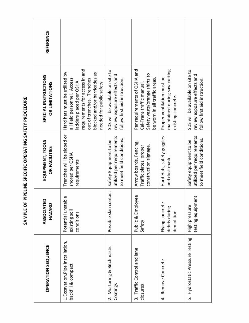
SAM
PLE
OF
PIPE
LIN
E SP
ECIF
IC O
PERA
TIN
G SA
FETY
PRO
CEDU
RE
OPE
RATI
ON
SEQ
UEN
CE
ASSO
CIAT
ED
HAZA
RD
EQU
IPM
ENT,
TO
OLS
O
R FA
CILI
TIES
SP
ECIA
L IN
STRU
CTIO
NS
OR
LIM
ITAT
ION
S RE
FERE
NCE
1.Ex
cava
tion,
Pipe
Inst
alla
tion,
ba
ckfil
l & c
ompa
ct
Pote
ntia
l uns
tabl
e ex
istin
g so
il co
nditi
ons
Tren
ches
will
be
slope
d or
sh
ored
per
OSH
A re
quire
men
ts
Hard
hat
s mus
t be
utili
zed
by
all f
ield
per
sonn
el.
Acce
ss
ladd
ers p
lace
d pe
r OSH
A re
quire
men
ts fo
r acc
ess i
n an
d ou
t of t
renc
hes.
Tre
nche
s bl
ocke
d an
d/or
bar
ricad
es a
s ne
eded
for p
ublic
safe
ty.
2. M
orta
ring
& B
itchm
astic
Co
atin
gs
Poss
ible
skin
con
tact
Sa
fety
Equ
ipm
ent t
o be
ut
ilize
d pe
r req
uire
men
ts
to m
eet f
ield
con
ditio
ns.
SDS
will
be
avai
labl
e on
site
to
revi
ew e
xpos
ure
effe
cts a
nd
follo
w fi
rst a
id in
stru
ctio
n.
3. T
raffi
c Co
ntro
l and
lane
cl
osur
es
Publ
ic &
Em
ploy
ee
Safe
ty
Arro
w b
oard
s, F
enci
ng,
Traf
fic p
late
s, p
rope
r co
nstr
uctio
n sig
nage
.
Per r
equi
rem
ents
of O
SHA
and
Cal-T
rans
traf
fic m
anua
l.
Safe
ty v
ests
/ora
nge
shirt
s to
be w
orn
in a
ll tr
affic
are
as.
4. R
emov
e Co
ncre
te
Flyi
ng c
oncr
ete
debr
is du
ring
dem
oliti
on
Hard
Hat
s, sa
fety
gog
gles
an
d du
st m
ask.
Pr
oper
ven
tilat
ion
mus
t be
mai
ntai
ned
durin
g sa
w c
uttin
g ex
istin
g co
ncre
te.
5. H
ydro
stat
ic P
ress
ure
Test
ing
High
pre
ssur
e te
stin
g eq
uipm
ent
Safe
ty e
quip
men
t to
be
utili
zed
per r
equi
rem
ents
to
mee
t fie
ld c
ondi
tions
.
SDS
will
be
avai
labl
e on
site
to
revi
ew e
xpos
ure
effe
cts a
nd
follo
w fi
rst a
id in
stru
ctio
n.

EN-8
4
OPE
RATI
ON
SEQ
UEN
CE
ASSO
CIAT
ED
HAZA
RD
EQU
IPM
ENT,
TO
OLS
O
R FA
CILI
TIES
SP
ECIA
L IN
STRU
CTIO
NS
OR
LIM
ITAT
ION
S RE
FERE
NCE
6. C
hlor
inat
ion
Poss
ible
skin
con
tact
Sa
fety
equ
ipm
ent t
o be
ut
ilize
d pe
r req
uire
men
ts
to m
eet f
ield
con
ditio
ns.
SDS
will
be
avai
labl
e on
site
to
revi
ew e
xpos
ure
effe
cts a
nd
follo
w fi
rst a
id in
stru
ctio
n.
Mai
ntai
n ad
equa
te v
entil
atio
n.
7. A
spha
lt Pa
ving
Bu
rns
Safe
ty e
quip
men
t to
be
utili
zed
per r
equi
rem
ents
to
mee
t fie
ld c
ondi
tions
.
SDS
will
be
avai
labl
e on
site
to
revi
ew e
xpos
ure
effe
cts a
nd
follo
w fi
rst a
id in
stru
ctio
n.
Mon
itor a
ll pa
ving
act
iviti
es
and
impl
emen
t saf
ety
requ
irem
ent p
er fi
eld
cond
ition
s for
bot
h em
ploy
ees
and
publ
ic sa
fety
.
8. C
oncr
ete
repa
ir Po
ssib
le sk
in c
onta
ct
& a
ir bo
rne
conc
rete
w
hile
chi
ppin
g
Safe
ty e
quip
men
t to
be
utili
zed
per r
equi
rem
ents
to
mee
t fie
ld c
ondi
tions
.
SDS
will
be
on si
te to
revi
ew
expo
sure
effe
cts a
nd fo
llow
fir
st a
id in
stru
ctio
n. M
aint
ain
adeq
uate
ven
tilat
ion.
9. D
ust c
ontr
ol &
saw
cut
ting
Visio
n Im
paire
d Ho
ses &
cor
ds k
ept t
o a
min
imum
leng
th.
Wea
r du
st m
asks
and
safe
ty
glas
ses.
SDS
will
be
avai
labl
e on
site
to
revi
ew e
xpos
ure
effe
cts a
nd
follo
w fi
rst a
id in
stru
ctio
n.
Mai
ntai
n ad
equa
te v
entil
atio
n.
10.
Cutt
ing
torc
hes
Expl
osiv
e/Ga
ses/
Fire
Fi
re E
xtin
guish
er
Fire
wat
ch/L
abor
er

OPE
RATI
ON
SEQ
UEN
CE
ASSO
CIAT
ED
HAZA
RD
EQU
IPM
ENT,
TO
OLS
O
R FA
CILI
TIES
SP
ECIA
L IN
STRU
CTIO
NS
OR
LIM
ITAT
ION
S RE
FERE
NCE
11.
Site
Cle
anne
ss
Trip
ping
Ke
ep to
ols o
rgan
ized
and
conc
entr
ated
En
d of
wor
k da
y pi
ck u
p ev
eryt
hing
12.
Emer
genc
y Ve
hicl
es
Gett
ing
to lo
catio
ns
Not
ify e
mer
genc
y se
rvic
es p
rior t
o co
nstr
uctio
n
Inst
ruct
all
empl
oyee
s on
proc
edur
es fo
r em
erge
ncy
traf
fic.

EN-85
Exhibit “C”
REPORT OF INJURY CONTRACTOR’S REPORT OF RECORDABLE INJURY/ILLNESS
Each work related fatality, injury/illness, first aid cases accepted, shall be reported on this form. The completed form will be submitted to the District within 3 working days from the date of the incident or onset of illness. Responsibility for completion and submission of this form for all onsite injury/illness to contractor, subcontractor, or supplier forces rests with the general contractor. All form terms are as defined on the reverse side.
CONTRACT SPECIFICATION (Number and Title) DATE OF THIS REPORT
EMPLOYER
EMWD Resident Inspector
INJURED EMPLOYEE’S NAME OCCUPATION
AGE DATE EMPLOYED DATES OF PREVIOUS INJURIES
DESCRIBE INJURY/ILLNESS
DATE OF INJURY TIME ATTENDING PHYSICIAN INJURY CLASSIFICATION
STARTED LOSING TIME (Never Date of Injury)
DID INJURY RESULT IN DEATH OR PROBABLY PERMANENT DISABILITY?
RETURN TO WORK (Date)* DATE OF DEATH
WORKDAYS LOST TIME* DAYS OF RESTRICTED WORK OR TRANSFER TO OTHER JOB
* Estimate date of return to full duty to avoid delay in submitting report (See reverse side for estimating instructions).
DESCRIBE ACCIDENT (Include Who, What, Where, & How)

EN-85
SUPERVISORY
OPINION
HOW COULD ACCIDENT HAVE BEEN PREVENTED?
(Signature) FOREMAN OR IMMEDIATE SUPERVISOR
NOTE: Information in this report is to be used for the prevention of accidents and is not intended as a basis for injury claims. Recordable injuries/illnesses and workdays lost and injury classification shall be as defined on reverse side of this form. Information in this report shall also be recorded on CAL-OSHA form 200.

EN-85
Work-related Injury/Illness: All injuries/illnesses to contractor, subcontractor, or supplier employees that result from an event or exposure on any contractor controlled worksite associated with the respective contract. Medical Cases: Injuries/illnesses are defined as medical cases if: (1) they can be treated only by a physician or licensed medical personnel, (2) they result in damage or harm to physical structure of a nonsuperficial nature (e.g., hairline fractures), (3) they impair bodily functions (i.e., normal use of senses, limbs, etc.), (4) they involve complications requiring follow-up medical treatment. The following are generally considered medical treatment: • Treatment of INFECTION • Application of ANTISEPTICS during second
or subsequent visits to medical personnel • Treatment of SECOND OR THIRD DEGREE
BURN(S) • Application of BUTTERFLY ADHESIVE
DRESSING(S) or STERISTRIPS in lieu of sutures
• Application of SUTURES (stitches) • Removal of FOREIGN BODIES EMBEDDED
IN EYE • Removal of FOREIGN BODIES from wound;
if procedure is COMPLICATED because of depth of embedment, size, or location
• Use of PRESCRIPTION MEDICATIONS (except a single dose administered on first visit for minor injury or discomfort)
• Use of hot or cold SOAKING THERAPY during second or subsequent visit to medical personnel
• Application of hot or cold COMPRESS(ES) during second or subsequent visit to medical personnel
• CUTTING AWAY DEAD SKIN (surgical debridement)
• Application of HEAT THERAPY during second or subsequent visit of medical personnel
• Use of WHIRLPOOL BATH THERAPY during second or subsequent visit of medical personnel
• POSITIVE X-RAY DIAGNOSIS (fractures, broken bones, etc.)
ADMISSION TO A HOSPITAL or equivalent medical facility for treatment or prolonged observation First Aid Cases: Cases (1) limited to one-time treatment and subsequent observation and (2) involve treatment of only minor injuries, not emergency treatment of serious injuries. Further, any one-time treatment and follow up visit for the sole purpose of observation of minor scratches, cuts, burns, splinters and so forth which do not ordinarily require medical care are classified as first aid treatment. Such one-time treatment and follow up visit for the purpose of observation is considered first aid even though provided by a physician or registered professional personnel. Visits to a doctor for an examination or other diagnostic procedure to determine whether the employee has an injury is classified as a first aid case if no injury is discovered or medical treatment is rendered. Conversely, if treatment is described and medical care is provided even by someone other than a physician or registered medical personnel, injury is classified as medical.
DEFINITION OF TERMS
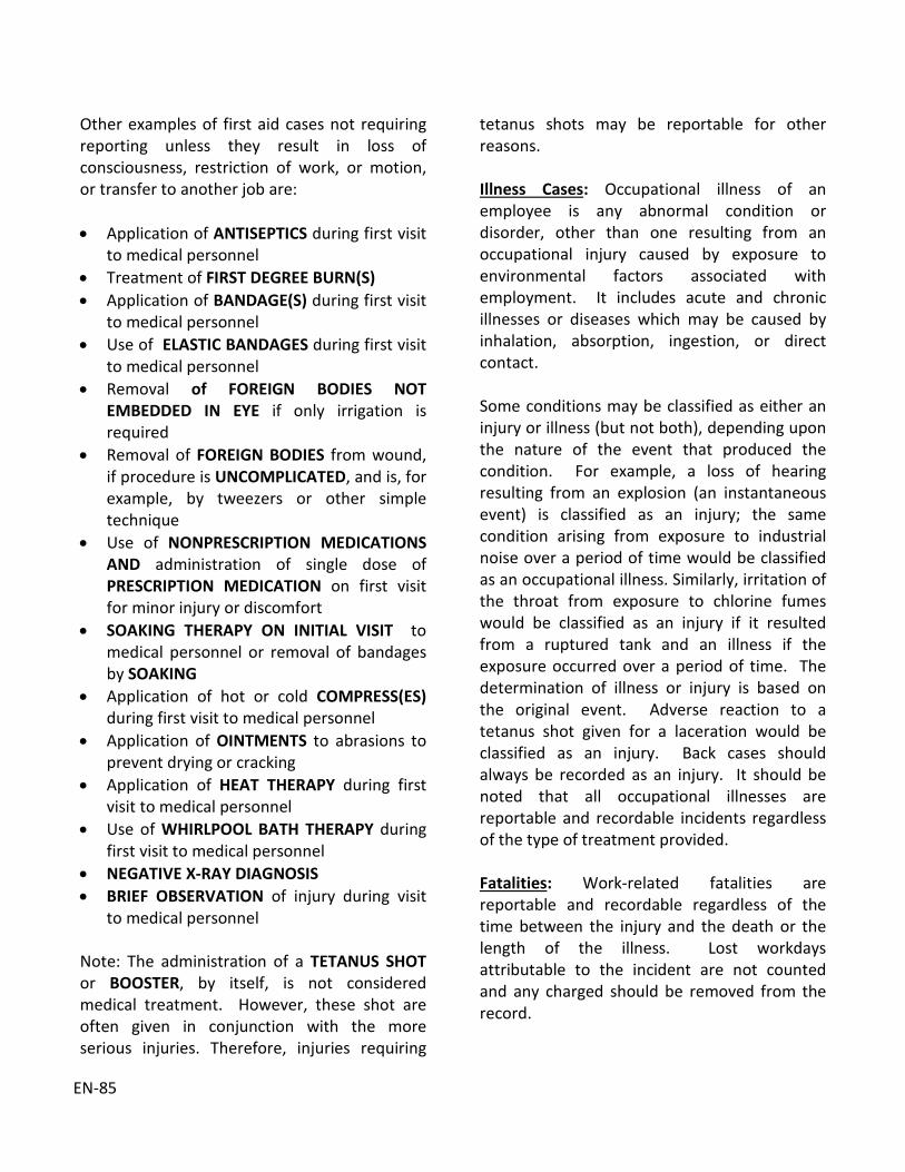
EN-85
Other examples of first aid cases not requiring reporting unless they result in loss of consciousness, restriction of work, or motion, or transfer to another job are: • Application of ANTISEPTICS during first visit
to medical personnel • Treatment of FIRST DEGREE BURN(S) • Application of BANDAGE(S) during first visit
to medical personnel • Use of ELASTIC BANDAGES during first visit
to medical personnel • Removal of FOREIGN BODIES NOT
EMBEDDED IN EYE if only irrigation is required
• Removal of FOREIGN BODIES from wound, if procedure is UNCOMPLICATED, and is, for example, by tweezers or other simple technique
• Use of NONPRESCRIPTION MEDICATIONS AND administration of single dose of PRESCRIPTION MEDICATION on first visit for minor injury or discomfort
• SOAKING THERAPY ON INITIAL VISIT to medical personnel or removal of bandages by SOAKING
• Application of hot or cold COMPRESS(ES) during first visit to medical personnel
• Application of OINTMENTS to abrasions to prevent drying or cracking
• Application of HEAT THERAPY during first visit to medical personnel
• Use of WHIRLPOOL BATH THERAPY during first visit to medical personnel
• NEGATIVE X-RAY DIAGNOSIS • BRIEF OBSERVATION of injury during visit
to medical personnel Note: The administration of a TETANUS SHOT or BOOSTER, by itself, is not considered medical treatment. However, these shot are often given in conjunction with the more serious injuries. Therefore, injuries requiring
tetanus shots may be reportable for other reasons. Illness Cases: Occupational illness of an employee is any abnormal condition or disorder, other than one resulting from an occupational injury caused by exposure to environmental factors associated with employment. It includes acute and chronic illnesses or diseases which may be caused by inhalation, absorption, ingestion, or direct contact. Some conditions may be classified as either an injury or illness (but not both), depending upon the nature of the event that produced the condition. For example, a loss of hearing resulting from an explosion (an instantaneous event) is classified as an injury; the same condition arising from exposure to industrial noise over a period of time would be classified as an occupational illness. Similarly, irritation of the throat from exposure to chlorine fumes would be classified as an injury if it resulted from a ruptured tank and an illness if the exposure occurred over a period of time. The determination of illness or injury is based on the original event. Adverse reaction to a tetanus shot given for a laceration would be classified as an injury. Back cases should always be recorded as an injury. It should be noted that all occupational illnesses are reportable and recordable incidents regardless of the type of treatment provided. Fatalities: Work-related fatalities are reportable and recordable regardless of the time between the injury and the death or the length of the illness. Lost workdays attributable to the incident are not counted and any charged should be removed from the record.

EN-85
Lost Workdays: Lost workdays are defined as the number of workdays (consecutive or not), beyond the day of injury or onset of illness, the employee was away from work or limited to restricted work activity. The number of days away from work or days of restricted work activity does not include the day of injury or onset of illness or any days on which the employee would not have worked even though able to work, e.g., vacation days, days off, or holidays are not counted. Termination of employment may stop the count of lost workdays if unrelated to the employee’s injury or illness. If termination is related to injury/illness, an estimate of actual workdays lost shall be made. Retirements unrelated to injury or illness stop the count of lost workdays. Otherwise days lost are estimated. Lost workday counts cease when injury or illness is determined as totally disabling. Lost workday count stops when position employee was in when injured is abolished due to work completion, e.g., a dozer operator lost workdays count would not continue beyond last day of dozer operations on the project even if the operator still could not perform the operator functions. Restricted work: The number of workdays on which because of injury or illness: (1) the employee was assigned to another job on a temporary basis; or (2) the employee worked at a permanent job less than full time; Or (3) the employee worked at a permanently assigned job but could not perform all duties normally connected with it. Lost workday count stops when employee is permanently transferred to another permanently established position.
Contractor Controlled Worksite Associated with the Contract. The following and similar locations are considered contractor controlled worksites: All areas within the boundaries of the construction site including shops, plants, storage areas, haul roads, borrow and fill areas. All offsite locations (plants, shops, rock quarries, borrow areas, erection sites, etc.) used exclusively for supporting construction activities. All roads where traffic control is a contractor responsibility.


EN-8
9
Exhi
bit “
D”
CON
TRAC
TOR
MO
NTH
LY S
UM
MAR
Y O
F O
CCU
PATI
ON
AL IN
JURI
ES/I
LLN
ESSE
S EX
PEN
SE
The
cont
ract
or w
ill s
ubm
it th
is co
mpl
eted
form
to th
e Di
stric
t by
the
first
day
of e
ach
mon
th.
Incl
uded
on
the
form
will
be
the
cont
ract
ors,
subc
ontr
acto
rs, a
nd su
pplie
rs o
nsite
inju
ry/il
lnes
s exp
erie
nce
for t
he p
revi
ous r
epor
ting
perio
d. R
epor
ting
perio
d cu
t off
date
s can
coi
ncid
e w
ith a
ppro
pria
te p
ay p
erio
ds a
s lo
ng a
s th
e en
ding
dat
e of
this
curr
ent r
epor
t is
the
begi
nnin
g da
te o
f the
nex
t rep
ort.
All
form
term
s ar
e de
fined
on
the
back
of t
his f
orm
.
REPO
RTIN
G PE
RIO
D ST
ARTI
NG
ENDI
NG
CON
TRAC
TOR
SUBC
ON
TRAC
TOR
SUPP
LIER
– S
PEC.
NO
TY
PE O
F CO
NST
RUCT
ION
N
O.
EMPL
OYE
ES
MAN
-HO
URS
EX
POSU
RE
LOST
W
ORK
DAYS
RE
CORD
ABLE
CA
SES
INCI
DEN
T RA
TES
TOTA
L DE
ATHS
LOST
W
ORK
DAY
CASE
S TO
TAL
CASE
S
DEAT
H AN
D LO
ST
WO
RKDA
Y CA
SES
LOST
W
ORK
DAY
1 2
3 4
5 6
7 8
9 10
11
GEN
ERAL
CO
NTR
ACTO
R
NAM
E
SPEC
. NO
.
SUBC
ON
TRAC
TORS
SUPP
LIER
S
TOTA
L
CUM
MU
LATI
VE T
OTA
L

EN-8
9
[PAG
E LE
FT IN
TEN
TIO
NAL
LY B
LAN
K]

Column 1. Name of General Contractor and General Specification No. only. Combine all
subcontractor and/or supplier data under respective headings. Cumulative totals start from first day of onsite work under the specification.
Column 2. Major classification or type of work for contractor (Water pipeline, sewer pipeline, pump station, treatment plant, lift station, etc.). Minor classification for supplier or subcontractor (concrete work, earthwork, repair work, etc.).
Column 3. Average number of employees during reporting period. Include only onsite personnel. Number of subcontractor or supplier employees can be estimated by dividing number of estimated man-hours by 8 x number days of reporting period.
(Number of man-hours) (8 x number days of reporting period)
Column 4. Actual man-hours of onsite exposure. Do not include vacation time, holidays, down periods, etc.
Column 5. Lost workdays include actual days from work, restricted work days and days worked in another assigned position. (For detailed explanation of lost workdays and restricted work, see back of Exhibit “C”).
Column 6. Total of fatalities, lost workday cases, restricted work cases or transfer to other job cases, and medical cases reported on all forms “Contractor’s Report of Recordable Injury/Illness,” submitted during the reporting period covered by this form.
Column 7. Fatalities are charged to date of injury or onset of illness regardless of date of death.
Column 8. Includes all cases submitted during this reporting period of form “Contractors Report of Recordable Injury/Illness,” that show figures under headings entitled, “lost time, or restricted work or transfer to other job.” (see back of Exhibit “C”).
Columns 9, 10, 11
Incident rates are define as the number of injuries/illnesses or lost workdays related to a common exposure base-100 full-time workers or 200,000 man-hours (100 workmen x 40 hrs/week x 50 weeks/year = 200,000). These rates are calculated as follows:
Total Cases (column 9) = Total cases (column 6) x 200,000
Man-hours of Exposure (column 4)
Death and lost workday cases (column 10) =
Deaths (column 7) and lost workday cases (column 8) x 200,000
Man-hours of Exposure (column 4)
Lost workdays = Lost workdays (column 5) x 200,000
Man workdays of exposure (column 4)

EN-89
[PAGE LEFT INTENTIONALLY BLANK]

Confined Space Entry Procedure
Prepared By:
Safety, Risk and Emergency Management
Revision Date:
12/01/2017
Reviewed By:
Safety Committee
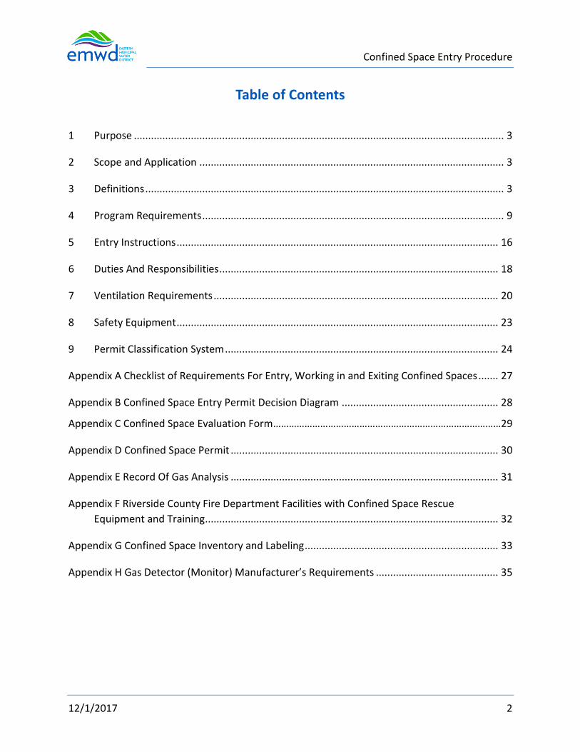
Confined Space Entry Procedure
12/1/2017 2
Table of Contents
1 Purpose .................................................................................................................................. 3
2 Scope and Application ........................................................................................................... 3
3 Definitions .............................................................................................................................. 3
4 Program Requirements .......................................................................................................... 9
5 Entry Instructions ................................................................................................................. 16
6 Duties And Responsibilities .................................................................................................. 18
7 Ventilation Requirements .................................................................................................... 20
8 Safety Equipment ................................................................................................................. 23
9 Permit Classification System ................................................................................................ 24
Appendix A Checklist of Requirements For Entry, Working in and Exiting Confined Spaces ....... 27
Appendix B Confined Space Entry Permit Decision Diagram ....................................................... 28
Appendix C Confined Space Evaluation Form……………………………………………………………………………29
Appendix D Confined Space Permit .............................................................................................. 30
Appendix E Record Of Gas Analysis .............................................................................................. 31
Appendix F Riverside County Fire Department Facilities with Confined Space Rescue
Equipment and Training ....................................................................................................... 32
Appendix G Confined Space Inventory and Labeling .................................................................... 33
Appendix H Gas Detector (Monitor) Manufacturer’s Requirements ........................................... 35
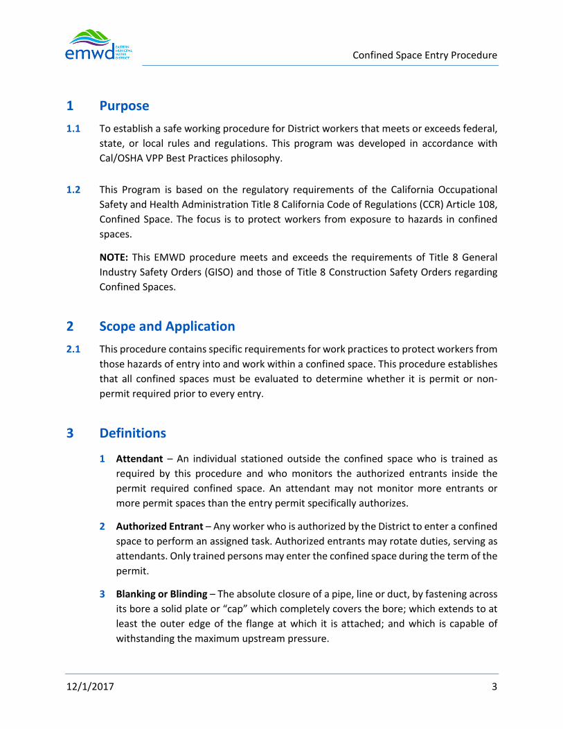
Confined Space Entry Procedure
12/1/2017 3
1 Purpose
1.1 To establish a safe working procedure for District workers that meets or exceeds federal,
state, or local rules and regulations. This program was developed in accordance with
Cal/OSHA VPP Best Practices philosophy.
1.2 This Program is based on the regulatory requirements of the California Occupational
Safety and Health Administration Title 8 California Code of Regulations (CCR) Article 108,
Confined Space. The focus is to protect workers from exposure to hazards in confined
spaces.
NOTE: This EMWD procedure meets and exceeds the requirements of Title 8 General
Industry Safety Orders (GISO) and those of Title 8 Construction Safety Orders regarding
Confined Spaces.
2 Scope and Application
2.1 This procedure contains specific requirements for work practices to protect workers from
those hazards of entry into and work within a confined space. This procedure establishes
that all confined spaces must be evaluated to determine whether it is permit or non-
permit required prior to every entry.
3 Definitions
1 Attendant – An individual stationed outside the confined space who is trained as
required by this procedure and who monitors the authorized entrants inside the
permit required confined space. An attendant may not monitor more entrants or
more permit spaces than the entry permit specifically authorizes.
2 Authorized Entrant – Any worker who is authorized by the District to enter a confined
space to perform an assigned task. Authorized entrants may rotate duties, serving as
attendants. Only trained persons may enter the confined space during the term of the
permit.
3 Blanking or Blinding – The absolute closure of a pipe, line or duct, by fastening across
its bore a solid plate or “cap” which completely covers the bore; which extends to at
least the outer edge of the flange at which it is attached; and which is capable of
withstanding the maximum upstream pressure.

Confined Space Entry Procedure
12/1/2017 4
4 Biological Hazards – Microbial agents presenting a risk or potential risk to the
wellbeing of humans through inhalation, ingestion, skin absorption, or injection.
5 Bump Test – Testing an atmospheric monitoring device with a known concentration
of gases that the monitor is intended to test. The test is used to verify that the monitor
is within calibration parameters.
6 Calibration – A manual or electronic adjustment of an atmospheric monitoring device
to ensure testing parameter requirements of the manufacturer are met or exceeded.
7 Confined Space – A location must have all three of the following definitions to be a
“Confined Space.”
Is large enough and so configured that an worker can bodily enter and perform
assigned work; and
Has limited or restricted means for entry or exit for example but not limited to:
tanks, vessels, silos, storage bins, hoppers, vaults, pits, and ladder entry into
pumping plants or subgrade facilities are spaces that may have limited means of
entry; and
Is not designed for continuous worker occupancy. (Its primary function is other
than human occupancy.)
8 Double Block And Bleed – A method used to isolate a confined space from a line, duct
or pipe by physically closing two main valves on a piping system, and opening a
“vented to atmosphere” valve between them.
9 Emergency – Any occurrence, including a failure of monitoring device or hazard
control, internal or external to the confined space, which could endanger the entrant
or other workers.
10 Engulfment – The surrounding and effective capture of a person by a liquid or solid
substance.
11 Entry – An act by which a person intentionally passes through an opening into a
confined space. The entrant is considered to have entered as soon as any part of the
entrant’s body breaks the plane of an opening into the space.
12 Entry Permit – A document established by the District, the content of which is based
on the District’s hazard identification and evaluation for a confined space and is the
instrument by which the District can verify that all precautions have been met prior
to entry.

Confined Space Entry Procedure
12/1/2017 5
13 Entry Permit System – The written or printed document established by EMWD. The
permit will be signed by the Entry Supervisor and posted at the entrance to the
confined space.
The entry permit will include the name of the Attendant(s), the authorized Entrant(s),
the work to be performed, the tools and equipment being taken into the confined
space, the specific types of personal protective equipment to be used by the Entrants,
air monitoring readings, the date of entry, time of entry, time the permit is issued and
time the permit is scheduled to expire and be closed. Other information that the
Attendant and/or Entry Supervisor deems to be necessary will be written on the
permit.
14 Entry Supervisor – An appropriately trained worker who has been assigned the
responsibility of ensuring a safe confined space entry. (An entry supervisor shall not
enter the confined space as an entrant to perform work.)
15 Evacuation – An unaided emergency exit out of a confined space. This action may
result from the entrant’s own decision or by a command from outside the space by
the Attendant.
16 Fall Arrest/Rescue Device – A winch-type device that will quickly arrest a worker’s fall
and absorb much of the free fall energy. The fallen worker may then be winched to
safety using the hand crank system of the device. The cable from this device will attach
to the safety harness. The type(s) of fall protection equipment, including personnel
winches, will be determined by the Attendant and Entry Supervisor. The entrants will
use the fall protection equipment when there is an exposure of a worker falling during
entry or while exiting the confined space.
17 Gas Detector (Monitor) – Direct reading, four-gas monitor which measures oxygen
content, LEL, carbon monoxide, and hydrogen sulfide. This also includes specialty
monitors used to measure specific hazards (photo ionization detectors, metal oxide
probes, radiation detectors, etc.).
18 Hazardous Atmosphere – An atmosphere which exposes workers above established
exposure guidelines, to risk of death, incapacitation, injury or acute illness from one
or more of the following causes:
A flammable gas, vapor, or mist in excess of 10% of its lower explosive limit (LEL).
Atmospheres that read >0% LEL up to 10% can still present a hazard and the source
of the atmospheric reading must be determined and addressed;

Confined Space Entry Procedure
12/1/2017 6
An airborne combustible dust at a concentration over the permissible exposure
limit or that presents an explosion hazard by being above the minimum explosible
concentration (estimated by visual observation as completely obscuring vision at
a distance of 5 feet or less);
An atmospheric oxygen concentration below 19.5% or above 23.5%;
Carbon monoxide in excess of 25 PPM;
Hydrogen sulfide in excess of 10 PPM;
An atmospheric concentration of any substance for which a Cal OSHA permissible
exposure limit is exceeded and could result in worker exposure in excess of the
permissible exposure limit. When an air contaminant for which OSHA or Cal/OSHA
has not determined a permissible exposure limit which may be present in the
permit space atmosphere, the District shall consult other sources of information,
such as Safety Data Sheets which comply with the Hazard Communication
Standard guidance in establishing the acceptable environmental conditions for
entry by their workers; and
Any atmospheric condition recognized as immediately dangerous to life or health
(IDLH).
19 Hot Work Permit – The District’s written authorization to perform operations which
could produce a source of ignition, such as riveting, welding, cutting, use of abrasive
tools, burning, or heating.
20 Immediately Dangerous To Life or Health (IDLH) – Immediately dangerous to life or
health (IDLH) means any condition which poses an immediate threat of loss of life;
may result in irreversible injury and/or immediate-severe health effects; may result in
eye damage; irritation or other conditions which could impair escape from the permit
space.
21 Immediate-Severe Health Effects – Any acute clinical sign(s) of a serious, exposure-
related reaction manifested immediately or within 72 hours after exposure.
22 Large Enough And So Configured That A Worker Can Bodily Enter – The entryway
and space is large enough for any part of the worker’s body to enter in a manner that
could cause harm. The entire body of a worker does not need to enter for harm to
occur.
23 LEL – UEL – LEL: Lower Explosive Limit. Minimum concentration of a particular gas or
vapor necessary to support its combustion in air.

Confined Space Entry Procedure
12/1/2017 7
UEL: Upper Explosive Limit. Maximum concentration of a particular gas or vapor
necessary to support its combustion in air.
24 Non-Entry Condition – Any condition or set of conditions whose hazard potential
exceeds the limits stated in the entry permit.
25 Non-Entry Rescue Team – A group of two or more workers designated and trained to
perform non-entry rescues at confined spaces within the District.
26 Non-Permit Confined Space (NPCS) – A confined space that does not contain or, with
respect to atmospheric hazards, would not normally contain any hazard capable of
causing death or physical harm, and where all other serious hazards have been
controlled.
Before declaring a confined space, a NPCS, the confined space is to be treated as a
Permit Required Confined Space, including testing of the atmosphere in the confined
space.
27 Oxygen Deficient Atmosphere – An atmosphere containing less than 19.5% oxygen
by volume.
28 Oxygen Enriched Atmosphere – An atmosphere containing more than 23.5% oxygen
by volume.
29 Permissible Exposure Limit (PEL) – PELs are the allowable 8-hour time-weighted
average air contaminant concentrations established by the U.S. Department of Labor,
Occupational Safety and Health Administration, and Cal/OSHA regulations, or
adopted by Cal OSHA
30 Permit Required Confined Spaces (PRCS) – A confined space which must include one
or more of the following conditions:
Contains or has a known potential to contain a hazardous atmosphere;
Contains a material with the potential for engulfment of an entrant;
Has an internal configuration such that an entrant could be trapped or asphyxiated
by inwardly converging walls, or a floor, which slopes downward and tapers to a
smaller cross-section; and/or
Contains any other recognized serious safety or health hazard.
31 Rescue Service – Third party personnel designated to rescue workers from permit
spaces. It may include rescuer entry into the confined space. District personnel shall
not perform entry rescue.

Confined Space Entry Procedure
12/1/2017 8
32 Retrieval – Aided assistance in exiting the confined space not requiring entry by a
rescuer or attendant. Non-entry rescue.
33 Retrieval Line – An approved line or rope secured at one end of the worker by a full-
body harness, and with its other end secured to either a lifting (or other retrieval)
device, or to an anchor point located outside the entry portal.
34 Safety Line – A line secured at one end of the worker by a full-body harness with the
other end secured to a “fall arrest” device. The main function is to prevent injury in
the event of a fall.
35 Shall – Denotes a mandatory requirement.
36 Supervisor – An individual who has the job title as an EMWD Manager or Supervisor.
Or, an individual who is assigned to work with the Attendant during a confined space
entry and has the authority to authorize a confined space entry or terminate a
confined space entry.
37 Threshold Limit Values (TLV) – TLVs are the worker exposure levels of chemical and
physical agents to which it is believed an average worker may be exposed day after
day for a working lifetime and result in no adverse effect. TLVS are set adopted by the
American Conference of Governmental Industrial Hygienists (ACGIH). The TLVs are
based on an 8-hour Time Weight Average (TWA) of 5-day 40-hour work week.
38 Toxic Atmosphere – An atmosphere containing a concentration of a substance above
the published or otherwise known safe levels that is capable of causing harm to a
worker.
39 Vertical Rescue – Methodology to move the entrant to safety while all or a portion of
the entrant’s weight is supported by life-safety rope or wire. This methodology would
include Diagonal Rescue where a portion of the entrant’s weight is supported by a
surface within the space.
40 Warning Barriers – A physical system that prevents or provides adequate notice that
entry into area is prohibited by non-authorized workers or members of the public.
Acceptable barriers include cones, saw horses, delineators, temporary fencing, etc.

Confined Space Entry Procedure
12/1/2017 9
4 Program Requirements
4.1 Pre-Entry Evaluation To Determine Confined Space Status
The Entry Supervisor shall evaluate all structures and openings that meet confined space
criteria, and identify and record the potential hazards associated with each one prior to
all entry operations. This information will be made available to affected workers, their
representatives and supervisors. Appendix B is the Confined Space Evaluation Form that
may be used at the discretion of a particular department.
4.2 Hazard Identification and Basic Requirements
The District has established an entry permit program to ensure that entrants are
protected from confined space hazards. Under the entry permit program, each
department that issues entry permits shall:
4.2.1 Hazard Identification
Identify and evaluate each hazard of the permit space(s), including determination of
severity.
4.2.2 Hazard Control
Implement the means, procedures and practices by which the confined spaces can be
entered safely according to this procedure.
4.2.3 Worker Training
Ensure that workers attend required training prior to performing confined space entries.
4.2.4 Equipment
Provide, maintain, and ensure the proper use of the equipment necessary for safe entry,
including testing, monitoring, communication, rescue, and personnel protective
equipment.
4.2.5 Non-Entry Rescue
Ensure that the procedures and equipment necessary to perform non-entry rescues from
confined spaces are implemented and provided.
4.2.6 Protection from External Hazards
Ensure that all pedestrians, vehicles or other barriers necessary to protect entrants from
external hazards are provided.

Confined Space Entry Procedure
12/1/2017 10
4.3 Permit System
The District shall use a permit(s) in a standardized form through which the issuing
department identifies all conditions that must be evaluated to ensure safe entry into any
confined space. Departments who authorize entry into a permit space shall include the
following information on the checklist portion of the permit:
4.3.1 Actual or potential hazards of the permit space;
4.3.2 Methods for isolation, lock-out/block-out, purging, blocking or blinding, inerting,
ventilating, cooling, and flushing to remove or control hazards;
4.3.3 Maintenance of acceptable environmental conditions by the entry supervisor through
verification, testing and monitoring equipment, and procedures;
4.3.4 Non-Entry Rescue equipment to be provided on-site which includes: communication
procedures, equipment, and personal protective equipment such as harnesses, safety
lines, and retrieval device.
4.3.5 The identity of permit space, location, purpose, date of entry, and duration.
4.3.6 A list of authorized entrants, eligible attendants, and individuals eligible to be in charge
of entry along with an entry supervisor’s signature, verifying that all actions or conditions
for safe entry have been met.
4.3.7 Upon completion of the entry covered by the permit, and after all entrants have exited,
the permit space and all work has been performed, the permit shall be signed off as
complete and further entry closed out.
4.3.8 All hot work in confined spaces will require a hot work permit before an entry permit is
issued. The hot work permit is a part of the WELDING AND CUTTING SAFETY PROCEDURE.
4.4 Department Requirements
Each affected Department shall be required to become familiar with this procedure and
ensure all aspects of the procedure are implemented and followed by their workers. The
following items are found in the District’s procedure and shall be implemented by the
individual departments to fit each specific application:
4.4.1 Evaluation of each facility within the department’s jurisdiction for the purpose of
establishing its confined space designation prior to every entry.

Confined Space Entry Procedure
12/1/2017 11
4.4.2 Document each pre-entry evaluation. Documentation shall include a site description,
location, configuration, initial gas detector readings, and initial classification (i.e., permit
required or non-permit required confined space). Please see Appendix B for the Confined
Space Evaluation Form;
4.4.3 Prepare and maintain an inventory of confined spaces using the format in Appendix F.
4.4.4 Determine site/type specific confined space entry and rescue procedures for each type of
confined space without regard to confined space classification; and
4.4.5 Ensure that each worker required to work within the procedure is thoroughly trained as
required.
4.5 Entering and Inspection of Confined Spaces
These precautions must be reviewed by workers working in confined spaces to ensure
safe entry:
4.5.1 Always test atmosphere with gas detector prior to opening or removing access cover.
4.5.2 Use appropriate tools or hoist when removing access covers to confined spaces to avoid
injury from lifting heavy covers in awkward postures.
4.5.3 Prevent injuries by following written procedures.
4.5.4 Ensure proper PPE is identified and available for personnel working in confined space.
4.5.5 Always clean sand and dirt from the edge of access cover rim so it does not accidentally
fall and enter the eyes of entrants and allows for ease in replacing the cover after work is
complete.
4.5.6 Before entering a confined space, always visually inspect the condition of the steps or
rungs (if applicable).
4.5.7 Set up tripod/fall retrieval device.
4.5.8 Enter the confined space slowly and cautiously.
4.5.9 Test each step or rung with a gradual application of weight.
4.5.10 Do not carry tools or other objects when entering or exiting a confined space.
4.5.11 Always be careful not to look up.

Confined Space Entry Procedure
12/1/2017 12
4.5.12 Never drop tools or supplies into a confined space. Pass by hand if possible, or tie object
to a hand line, or place in a bucket. Use half hitches to prevent objects from falling from
bucket.
4.5.13 Never clutter access area to prevent objects from falling, bouncing, being pushed, or
dragged into opening.
4.6 Contractors Entry Into Confined Spaces
When contractor workers (not under the District’s direct supervision) enter PRCS, ensure
the following:
4.6.1 Inform the contractor that the workplace contains confined spaces and that confined
space entry must be in compliance with EMWD Confined Space Entry Procedure as well
as that of the contractor.
4.6.2 Apprise the contractor of the characteristics of the confined space, including the known
hazards, access/egress, and any experiences with the space;
4.6.3 Coordinate entry operations with the contractor, when both District personnel and
contractor personnel will be working in or near a confined space (the contractor shall
have procedures for coordinating such entry operations, to prevent endangerment of the
workers of any other employer); and
4.6.4 Debrief the contractor at the conclusion of the entry operations regarding any hazards
confronted or created in the confined space during entry operations.
4.7 Recordkeeping
4.7.1 A written record must be made of the results of each atmospheric test performed. Utilize
the form in Appendix D.
4.7.2 If used, Confined Space Evaluation form (Appendix B) shall be kept at the site for the
duration of the work, and made accessible to entrants, attendants, supervisors, other
affected workers, and their representatives.
4.7.3 A copy of the Confined Space Entry Permit shall be posted or readily available at the job
site during confined space operations.
4.7.4 The above documentation must be kept on file by respective departments for a minimum
of three years.

Confined Space Entry Procedure
12/1/2017 13
4.8 Training
4.8.1 All workers involved in confined space operations (including entrants, attendants, and
confined space entry supervisors) must receive training in the appropriate procedures
and requirements described in this program. No person shall enter a confined space
unless trained and qualified to do so.
4.8.2 Supervisors shall also be trained in the following:
The possible toxic materials, lockout block out, flammable atmosphere conditions,
oxygen deficiencies or enrichment, and other actual or potential hazards in confined
spaces into which personnel must enter;
Be knowledgeable of the type of operations workers will be performing in a confined
space and of their impact on air quality, flammability, and/or availability of oxygen,
and ensure that workers take appropriate precautions;
Provide appropriate approved equipment; and
Ensure necessary forms are available to record the confined space activities; review
completed records; ensure the records are filed; and provide affected workers and/or
their representatives access to review them and record testing results.
4.9 Joint Use Facilities
Prior to entry by District personnel into confined spaces, such as manholes which may be
jointly owned or shared with another entity, the entry supervisor shall coordinate entry
operations with other affected users or owners so that workers or operations of one
employer do not endanger another employer’s personnel.
4.10 Entry Supervisor Review
NOTE: Entry Supervisors may contact Safety and Risk Management during the planning
phase of such operations to provide guidance on safe entry conditions, hazard control,
and personal protective equipment.
Before the start of work, the supervisor must:
4.10.1 Review the work assignment with workers, indicating any potential hazards involving the
confined space(s);
4.10.2 Describe the scope of work, equipment and materials needed, and any operating
instructions required to complete the job.

Confined Space Entry Procedure
12/1/2017 14
4.10.3 Identify any potential health risks and/or physical hazards or conditions, such as the
history of spills, fall hazard, the use of solvents, welding operations or flooding within the
work area, and methods to control those hazards;
4.10.4 Coordinate confined space entry activities with other employers, such as contractors or
sub-contractors so that no workers of any employer will be endangered during confined
space operations.
NOTE: Examples of methods to control hazards are lockout and blockout points, clearance
points, fall protection or ventilation.
4.11 Attendant/Entrant Review
An attendant and entrant is responsible for:
4.11.1 Understanding the nature of all actual or potential hazards that may be encountered
during entry into a confined space. If anything is not clearly understood, an
attendant/entrant shall ask questions;
4.11.2 Inspecting the safety equipment for confined space entry to ensure that it is in
operational condition;
4.11.3 Ensure that the atmospheric monitoring instruments (e.g., for oxygen, LEL, carbon
monoxide, hydrogen sulfide) are maintained in an operational status. Instruments shall
be tested and calibrated according to the manufacturer’s specifications or more
frequently. A daily bump test shall be performed against all gases or vapors for which an
instrument is configured
4.11.4 When the space is located such that work may encroach upon a public street or highway,
establish a safe work area by erecting barricades, cones, warning signs and wearing
appropriate reflective clothing;
4.11.5 The communication system between the Attendants and the facility, and between the
Attendants and the authorized Entrants must be checked prior to entry;
4.11.6 Energy sources (except for those necessary to perform the work at hand) that could
present a hazard to those in a confined space shall be locked out and blocked out in
accordance with the EMWD Lockout/Blockout Procedure.
4.11.7 The space shall be isolated and ventilated to prevent dangerous gases or chemical
substances from entering the confined space; and
Confined Space Entry Procedure
12/1/2017 15
4.11.8 All non-permit required, and permit-required confined spaces shall be considered to have
unacceptable atmospheres until proven safe by atmospheric testing. Ventilation must be
maintained at all times.
4.12 Atmospheric Testing
4.12.1 Prior to any confined space entry, the atmosphere shall be tested with an appropriate,
tested / calibrated direct reading instrument in accordance with the manufacturer’s
requirements, see Appendix G.
Testing for atmospheric hazards shall be in the following order:
Oxygen content;
Flammable gases & vapors; and
Potential toxic air contaminants.
4.12.2 Testing of Manholes and Other Spaces Prior to Opening
Prior to fully opening a confined space, insert the probe into an available opening and
draw a sample of the atmosphere into the meter, allowing sufficient time to obtain a
representative sample.
If the space opening has no hole, open the space only enough to insert a non-sparking
item, such as a piece of wood or brass, then insert the probe.
If atmospheric conditions are acceptable, then fully opening the confined space.
4.12.3 Test Atmosphere from Top to Bottom of Space:
Testing of the confirmed or potential confined spaces shall be conducted throughout
the entire portion of the space to be occupied. Some airborne contaminants may be
heavier or lighter than air and can collect at the bottom or top of spaces. It is required
that testing shall be done before ventilation and after the prescribed ventilation
period. Testing shall continue for the duration of the entry.
4.13 Sampling
4.13.1 For testing, insert the probe into the top of the confirmed, potential, or non-permit
confined space, and draw a sample of the atmosphere into the meter allowing sufficient
time to allow the meter to register and analyze. This may vary depending upon the type
of meter and length of sample tubing. Sample collection procedures shall follow the
manufacturer’s recommended procedure that is summarized in Appendix G
Confined Space Entry Procedure
12/1/2017 16
4.13.2 When monitoring for entries involving a descent into atmospheres which may be
stratified, the atmospheric envelope should be tested a distance of approximately four
(4) feet in the direction of travel and to each side.
4.13.3 If a sampling probe is used, the entrant’s rate of progress shall be slowed to accommodate
the sampling speed and detector response time.
4.14 Acceptable Atmosphere
If testing indicates an acceptable atmosphere, continuous ventilation is required prior to
and during any entry. Be sure to place the blower where fresh uncontaminated air is
drawn into the structure. The ventilation shall remain in operation during the complete
entry.
4.15 Unacceptable Atmosphere
If after any needed ventilation, testing continues to indicate atmospheric contaminants
outside of acceptable entry levels, the space shall not be entered. Refer to Permit
Required Confined Space Entry Procedure section for additional information.
4.16 Guarding The Opening
When covers are removed, a railing, temporary cover, or temporary barrier that will
prevent an accidental fall through the opening and protect each worker working in the
space from foreign objects entering the space shall guard the opening.
5 Entry Instructions
5.1 When operations are to be conducted which may impact air quality (such as welding,
spray coating, abrasive blasting, or use of chemicals), additional precautions are to be
taken. Consideration shall be given to safe entry conditions, hazard control and personal
protective equipment during the planning phase of such operations.
5.2 Prior to any entry into a PRCS, the Entry Supervisor shall assure that all provisions of a
Confined Space Permit (Appendix C) have been completed and the following specific
provisions have been met:
5.2.1 Supervisor Review of Hazards
5.2.2 Equipment Inspection

Confined Space Entry Procedure
12/1/2017 17
5.2.3 Instrument Bump Test and Calibration
5.2.4 Work Area Preparation
5.2.5 Lockout and Isolation
5.2.6 Atmospheric Testing
5.2.7 Ventilation
5.2.8 Check “List of Requirements for Entry, Working In, and Exiting Confined Space” (Appendix
A)
NOTE: The supervisor of the workers may be the Entry Supervisor, or the responsibility of
the Entry Supervisor may be delegated.
5.2.9 Assemble and test the retrieval equipment before entry into a PRCS.
5.2.10 The Entry Supervisor is to check that the appropriate entries have been made on the
Permit, that the Permit specified tests have been conducted, and that the specified
procedures and equipment are in place before endorsing the Permit and allowing entry
to begin.
5.2.11 When the Permit is signed, the authorized entrant(s) may enter the PRCS.
NOTE: Following the information specified in the Entry Permit, the Attendant
continuously maintains an accurate count of authorized entrants in the confined space.
5.2.12 If the PRCS poses no actual or potential atmospheric hazards, and if all serious safety and
health hazards within the space are eliminated without entry into the space, the Permit
Required Confined Space (PRCS) may be re-classified as a Non-Permit Confined Space
(NPCS) for as long as the hazards remain eliminated. Reclassification of a space requires
use of the evaluation form in *Appendix B. Ventilation is still required.
NOTE: Control of atmospheric hazards through forced air ventilation does not constitute
elimination of the hazards. For example, carbon monoxide may still be generated in a
space while being controlled by ventilation.
5.2.13 The Entry Supervisor shall document the basis for determining that all hazards in a permit
space have been eliminated, through a certification on the permit that contains the date,
the location of the space, and the signature of the person making the determination. The
permit will then remain posted for the duration of the entry.

Confined Space Entry Procedure
12/1/2017 18
5.2.14 If hazards arise within a PRCS that has been reclassified as an NPCS, each worker in the
space shall exit the space. The Entry Supervisor shall then reclassify the entry as a PRCS
and a new permit shall be initiated.
6 Duties and Responsibilities
6.1 Authorized Entrants
The authorized entrants are required to:
6.1.1 Understand the hazards that may be encountered during entry, including information on
the mode, signs or symptoms, and consequences of exposure. Know methods of hazard
mitigation
6.1.2 Properly inspect and use equipment as required by the permit.
6.1.3 Follow responsibilities identified in entry instructions.
6.1.4 Maintain communications with the Attendant.
6.1.5 Alert the Attendant whenever:
The entrant recognizes any warning sign or symptom of exposure; or
A prohibited condition is detected.
6.1.6 Exit the permit space whenever:
An order to evacuate is given by the Attendant;
There is a warning sign or symptom of exposure;
A prohibited condition is detected; or
An alarm is activated.
6.2 Attendants
The Attendants are required to:
6.2.1 Know the hazards that may be faced during entry, including information on the mode,
signs or symptoms, and consequences of the exposure.
6.2.2 Be aware of possible behavioral effects of hazard exposure on authorized entrants.

Confined Space Entry Procedure
12/1/2017 19
6.2.3 Continuously maintain an accurate count of authorized entrants in the permit space and
ensure that the permit accurately identifies who is in the permit space.
6.2.4 Remain immediately outside the permit space during entry operations until relieved by
another attendant.
6.2.5 Communicate with authorized entrants as necessary to monitor entrant status and alert
entrants of the need to evacuate the space.
6.2.6 Monitor activities inside and outside the space to determine if it is safe for entrants to
remain in the space and order the authorized entrants to evacuate the permit space
immediately under any of the following conditions:
If the Attendant detects a prohibited condition;
If the Attendant detects the behavioral effects of hazard exposure in an authorized
entrant;
If the Attendant detects a situation outside the space that could endanger the
authorized entrants; or
If the Attendant cannot effectively and safely perform all the duties required under
the permit.
6.2.7 Summon rescue and other emergency services as soon as the Attendant determines that
authorized entrants may need egress assistance from permit spaces.
Perform non-entry rescues as determined during pre-job planning; and
Perform no duties that might interfere with the Attendant’s primary duty to monitor
and protect the authorized entrants.
6.3 Entry Supervisors
The Entry Supervisors are required to:
6.3.1 Understand the hazards that may be faced during entry, including information on the
mode, signs or symptoms, and consequences of exposure to hazardous conditions,
materials or atmospheres;
6.3.2 Determine when to terminate the entry and cancel the permit;
6.3.3 Determine, whenever responsibility for a permit space entry operation is transferred and
at intervals dictated by the hazards and operations performed within the space, that entry

Confined Space Entry Procedure
12/1/2017 20
operations remain consistent with terms of the entry permit and that acceptable entry
conditions are maintained;
6.3.4 Verify, by checking that the appropriate entries have been made on the permit, that all
tests specified by the permit have been conducted and that all procedures and equipment
specified by the permit are in place before endorsing the permit and allowing entry to
begin;
6.3.5 Verify for high hazard confined space entries that rescue services—other than self-rescue
or non-entry rescue—are available and that the means for summoning them are
operable; and
6.3.6 Remove unauthorized individuals who enter or who attempt to enter the permit space
during entry operations.
6.4 Rescue Duties
Departments are responsible to ensure that these procedures are followed when workers
are working in a confined space:
6.4.1 Recognition of actual or potential emergencies;
6.4.2 Notification of EMS and/or Central Control/IOC of rescues;
6.4.3 Request for additional workers if needed. NOTE: Workers may come from any
department;
6.4.4 Proper use of safety equipment;
6.4.5 Required First Aid/CPR training; and
6.4.6 Non-Entry Rescue Methods.
6.4.7 High hazard permit required confined space entries may require the use of a standby
rescue team at the site. Contact Safety, Risk and Emergency Management for all high
hazard entries.
7 Ventilation Requirements
Ventilation is one of the most important rules of safety concerning confined space entry.
Though ventilation can provide good quality make up air, it cannot reduce other hazards
Confined Space Entry Procedure
12/1/2017 21
that are associated with permit space(s). The ventilation requirements that must be met
prior to entry are as follows:
7.1 Pre-Entry Requirements
7.1.1 Various sizes of permit spaces are located through the District. When initial air sampling
determines a hazardous atmosphere is present, forced air ventilation shall be performed
until the hazard within the space has been eliminated. A continuous supply of fresh air
shall be provided while entrant(s) is/are in the confined space. The confined space must
have ten (10) complete air changes before sampling the air inside the confined space
again.
To determine how long it will take to achieve ten (10) complete air changes in the
confined space, the following information must be known:
The cubic feet of space inside the confined space; and
The cubic feet per minute (CFM) the ventilator is rated for.
NOTE: Multiple bends in the ventilation hose will reduce the actual CFM capacity of the
ventilating blower (each 90º bend reduces the rated CFM capacity of a ventilation blower
by up to 50%).
To determine the cubic feet of space inside the confined space for square or rectangular
spaces:
Multiply the Length x Width x Height. EXAMPLE: A confined space is 20’ x 15’ x 30’.
20’ x 15’ x 30’ = 9,000 cubic feet
The rating of the ventilator shows the cubic feet of air the blower will discharge.
For this example, let’s assume the ventilator has a rating of 1,500 CFM.
To find out how long it will take to make one complete air change inside the
confined space, divide 9,000 cubic feet by 1,500 CFM. The answer is 6. Therefore,
it will take 6 minutes to make one complete air change inside the confined space.
Ten (10) air changes are required. Multiply 6 minutes by 10, the required number
of air changes in the confined space:
10 x 6 = 60. It will take 60 minutes to achieve 10 complete air changes.

Confined Space Entry Procedure
12/1/2017 22
If the confined space is round, multiply π (3.14) times the radius squared, times the length
of the cylinder (pipe, tunnel, etc.) = cubic feet of space. 𝜋r2h=volume
EXAMPLE: 𝜋 (3.14) x radius2 x length of cylinder or height of tank (pipe, tunnel,
etc.) = cubic feet of space. Assume a pipe has a 3’ diameter and is 30’ long. One-
half of the 3’ diameter is 1.5 feet (the radius). 1.52 (1.5 x 1.5) = 2.25 square feet.
To simplify: 3.14 x 2.25 = 7.07 square feet. (The actual number is 7.0686, but we
rounded up.)
7.07 square feet x 30’ (the length of the cylinder) = 212 cubic feet.
To find out how long it will take to make one complete air change inside the
confined space, divide 212 cubic feet by 1,500 cfm. The answer is, 0.14 minutes
for one complete air change.
Ten (10) complete air changes are required. Therefore, 10 x 0.14 minutes per air
change = 1.4 minutes.
Round up and let the ventilator push fresh air into the confined space for 2
minutes before testing the atmosphere inside the confined space again.
To achieve a greater efficiency of air exchanges, when it is possible, move the end
of the hose around by using a rope. Pull the end to the hose up into the upper
corners of the confined space. Also move the end of the hose around near the
bottom of the confined space to move the gases or air around so it will be diluted
or exhausted out of the confined space.
After 10 complete (or near complete) air changes have been made, lower the hose
on the air monitor into the confined space and sample the air at different levels.
The end of the air monitor hose shall be lowered 2 to 4 feet each time to sample
the air at different levels inside the confined space.
A continuous supply of fresh air shall be provided while entrant(s) is/are in the
confined space.
7.2 Work in Progress
7.2.1 A continuous supply of fresh air shall be provided while entrant(s) is/are in the confined
space.
7.2.2 Entrant must exit confined space if blower stops.

Confined Space Entry Procedure
12/1/2017 23
7.2.3 All blowers shall be at a minimum of 1,500 cfm.
7.2.4 Five (5) air exchanges per hour for a permit space are suggested.
7.3 Recordkeeping
The Entry Supervisor shall document the time that the blower was started and when the
blower was shut-off on the permit.
8 Safety Equipment
No worker shall perform or order to be performed, any work in a permit space unless all the
necessary safety equipment is available and all proper safety procedures are followed.
Requirements for safety equipment and use are as follows:
8.1 Fall / Retrieval Device and Approved Support Device
A fall/retrieval device and tripod or other adequate anchorage shall be required for all
top-opening entries into a permit space.
8.1.1 Tripod
The tripod shall be capable of set-up on surfaces that are not level.
The tripod shall be capable of locking in place with safety chains attached to base of
legs.
Non-slip feet on legs of tripod.
It is recommended that tripods are adjustable up to 9 feet tall.
8.1.2 Other anchorage points used shall be capable of supporting a 5000 pound static load and
the means of attachment shall be rated for fall protection and retrieval hoist loads.
8.1.3 Fall/Retrieval Device
Fall/retrieval device may have a “fall-arrest” capability.
Additional block to tackle hoist may be added for retrieval purposes.
Self-Retracting Lifelines (SRL) shall be the required fall protection device used in
conjunction with permit required confined space entry. Certain spaces may require
the use of a winch type retrieval device as a primary means of extraction with an SRL
as a secondary means of retrieval.

Confined Space Entry Procedure
12/1/2017 24
8.2 Personal Protective Equipment
8.2.1 A hard hat shall be worn at all times in a confined space.
8.2.2 To provide as much body protection as possible, coverall or uniforms shall be worn when
working in a confined space.
8.2.3 Special safety equipment such as boots, waders, dry suit, gloves, safety goggles/glasses
and ear protection shall be worn as needed.
8.2.4 A fall/retrieval device or other approved devices shall be provided for lifting worker(s) out
of top opening confined spaces.
8.2.5 Rescue lifelines or wristlets may be utilized in certain permit required confined spaces
where the use of a fall retrieval device is not possible.
8.2.6 A full body harness will be required with this program. This harness must meet ANSI
Standard A10.14 and EMWD Fall Protection Procedure guidelines.
8.2.7 Intrinsically safe electrical equipment is required for confined spaces.
8.2.8 Respiratory protection equipment will be required as necessary based on an evaluation
of potential contaminants in the space.
8.3 Equipment Inspection
8.3.1 All equipment needed for working in a permit space shall be periodically inspected and
repaired or replaced if necessary. It must also be inspected prior to each entry into a
confined space by both the Entry Supervisor and the Entrant(s).
8.3.2 If a necessary piece of equipment is in questionable condition, work shall halt until the
equipment is repaired or replaced.
8.3.3 Manufacturer recommendations shall be followed for all equipment.
9 Permit Classification System
The “permit classification system” is based on existing or potential hazards relative to the
confined space. The classification is based upon the characteristics and configuration of
the space, oxygen level, flammability, and toxicity. The classification shall be determined
Confined Space Entry Procedure
12/1/2017 25
by the most hazardous condition of entering, working in, and exiting a confined space.
Refer to checklist of requirements for entry.
9.1 Permit Required Confined Space
Permit Required Confined Space (PRCS) is one that presents a situation that may be
immediately dangerous to life or health (IDLH) or may cause serious injury or illness to an
entrant.
9.1.1 These include, but are not limited to, oxygen deficiency, explosive or flammable
atmospheres, physical hazards, and/or concentrations of toxic substances.
9.1.2 Special requirements for PRCS are as follows:
Two (2) Attendants required outside PRCS at all times. The Entry Supervisor may act
as the second attendant.
One (1) Attendant must maintain communication with entrant at all times (i.e., at
manhole, hatch, opening, etc.);
Second Attendant must remain onsite in the area of the permit required confined
space entry; and
Entrant shall utilize approved safety harness and lifeline/retrieval device.
Common types of PRCS are sewer manholes, sewer lines, Lift Station wells, junction
structures, valve vaults, meter vaults, pumping plant wet wells, vats, pits, large pipe and
ducts, and various types of storage tanks. Situations may arise that make Non-Permit
Confined Space (NPCS) a PRCS.
9.2 Non-Permit Required Confined Space
A Non-Permit Required Confined Space (low hazard) is one in which the potential hazard
would not require any special modification of the work procedure except for the
following:
9.2.1 If no Attendant is used, Central Control will be notified of location, entry time, estimated
working time, and interval for safety checks. They will also be notified when work is
completed.
9.2.2 Entrant will have constant and reliable communications with Central Control (via hand-
held radio).
9.2.3 Entrant will have safe, a stable means of entry and exit (ladder, etc.).

Confined Space Entry Procedure
12/1/2017 26
9.2.4 Atmospheric testing, monitoring and ventilation are required.
9.3 Special Consideration Spaces
9.3.1 Any below grade facility or area with restricted access (i.e., ladder access, entry
configuration hazard) that is ventilated full time, has the potential to become a confined
space and shall be entered after a worksite hazard analysis has been conducted. These
sites shall be treated as confined spaces until the hazard has been removed or mitigated
via a JSA conducted by a qualified person.
9.3.2 Trenches and other earthworks are normally not considered confined spaces. Situations
can arise, however, which would make these structures confined spaces. A broken gas
main, force main or sewer main may need to be classified as a confined space if a
determination has been made that atmospheric hazards are present.
9.3.3 Any confined space that cannot be entered according to the strict provisions and
requirements of this procedure can only be entered once a site-specific written
procedure has been developed. This procedure shall include the development of a JSA
and must identify all hazards and the alternative measures of personal protection that
will be utilized to protect the entrants in the confined space. The written procedure
must be reviewed and approved by the Safety, Risk and Emergency Management
Department prior to entry operations.
9.3.4 All sewer manholes within the District’s boundaries shall be considered permit required
confined spaces and entered based off an evaluation of all hazards present.
Facilities with an engineered means of ingress/egress (stairwell into lower levels, entry
points that would allow self-rescue) which may be ventilated full time are to be
considered workplaces with the potential for a hazardous atmosphere. Examples of these
sites would be sewer lift station drywells and wet wells with engineered stairwells and
influent pump station/head works buildings with multiple entry/exit points. These
facilities shall not be considered confined spaces, but shall be evaluated for worker
exposures through a worksite hazard analysis (JSA, SOP) conducted by the department
seeking access.

Confined Space Entry Procedure
12/1/2017 27
APPENDIX A
CHECKLIST OF REQUIREMENTS FOR ENTRY,
WORKING IN AND EXITING CONFINED SPACES
CHECK PRCS NPCS
PRE-ENTRY EVALUATION X X
PERMIT X O
ATMOSPHERIC MONITORING X X
MONITORING X X
TRAINING OF PERSONNEL X X
LABELING AND POSTING X X
ISOLATE / LOCK-OUT/BLOCK-OUT X O
PURGE / VENTILATE X X
CLEANING PROCESSES O O
SPECIAL EQUIPMENT / TOOLS X O
SITE SAFETY BRIEFING X X
ATTENDANT X O
COMMUNICATIONS / OBSERVATION X X
NON-ENTRY RESCUE PLAN X X
HEAD PROTECTION X X
HEARING PROTECTION O O
HAND PROTECTION O O
FOOT PROTECTION O O
BODY PROTECTION O O
RESPIRATORY PROTECTION O N/A
TRIPOD X O
HARNESS X O
LIFELINE X O
RESCUE EQUIPMENT X O
RECORDKEEPING X X
X = REQUIRED
O = OPTIONAL – Determination to be made based on entry requirements.
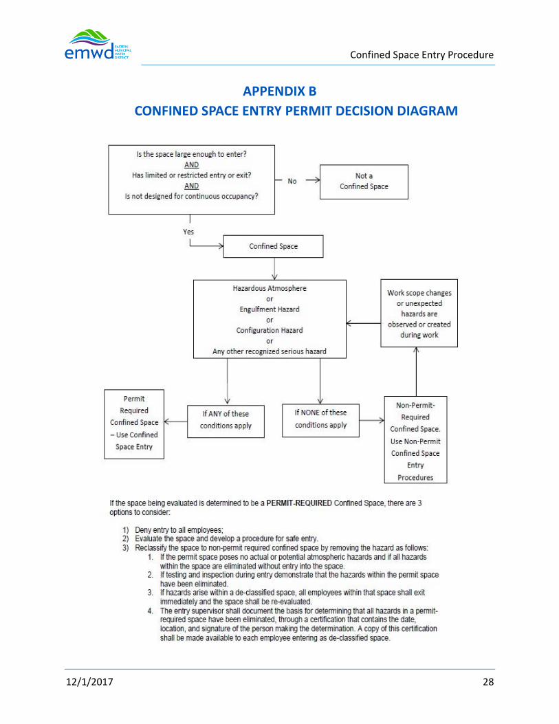
Confined Space Entry Procedure
12/1/2017 28
APPENDIX B
CONFINED SPACE ENTRY PERMIT DECISION DIAGRAM

Confined Space Entry Procedure
12/1/2017 29
APPENDIX C CONFINED SPACE EVALUATION FORM

Confined Space Entry Procedure
12/1/2017 30
APPENDIX D
CONFINED SPACE PERMIT

Confined Space Entry Procedure
12/1/2017 31
APPENDIX E
RECORD OF GAS ANALYSIS
Location Date
Gas Read Time (15 Min. Increments)
Worker Taking Read O2 Lel H2s Co
Entrant(S) Name And Employee Number
Time In
Time Out

Confined Space Entry Procedure
12/1/2017 32
APPENDIX F
RIVERSIDE COUNTY FIRE DEPARTMENT FACILITIES WITH CONFINED
SPACE RESCUE EQUIPMENT AND TRAINING
Station #2 – Moreno Valley 24935 Hemlock Moreno Valley CA, 92557 (951) 242-3101 Hazardous Materials Station
Station #34 – Winchester
32655 Haddock Street Winchester, CA 92596
(951) 926-6430
Station #73 – Rancho California
27415 Enterprise Circle West
Temecula, CA 92590
(951) 699-0351
Station #76 – Menifee Lakes
29950 Menifee Road
Menifee, CA 92584
(951) 679-2241
Station #97 – Rosetta Canyon
41725 Rosetta Canyon Drive
Lake Elsinore, CA 92530
(951) 245-0420

Confined Space Entry Procedure
12/1/2017 33
APPENDIX G
CONFINED SPACE INVENTORY AND LABELING
Inventory
Each department having responsibilities over a District facility shall develop and maintain a
confined space inventory that includes at least the information shown in the table below. Area
refers to the general unit or section of a plant or facility. Location is the specific place where the
confined spaces entry point is located. It may be designated on a map, using Maximo asset
numbers, P&ID reference numbers, name of equipment, or any other specific method.
Description is the type of opening such as manway, manhole, duct, ladder, hatchway, tank top,
etc.
The hazards of each space shall be described by as many of the Hazard Code designations as exist
and/or for which there is a potential to exist in the confined space. The confined space evaluation
form (Appendix B) shall be used as reference and/or this inventory used to aid in filling the
evaluation form in Appendix B. Hazard code 4 has several categories which shall be used as 4a,
4b, 4c, etc.
The Special Considerations column may be used as needed for notes or to describe issues related
to the space, its entry or hazards.
To be included in the inventory:
Tanks, sewers, basins, pits, electrical vaults, piping/valve vaults, large diameter pipe or duct, vats,
vessels, silos, storage bins, hoppers, and ladder entry into pumping plants or subgrade facilities
or other spaces that may have limited means of entry,
# AREA LOCATION DESCRIPTION HAZARD CODE SPECIAL CONSIDERATIONS
1 East of Chlorine Contact
West of Fence Line Manhole - Drain 1, 2, & 4c,b
2 Contact Basin Contact Basin Contact Basin # 3 1, 2, & 4c,b
3 Contact Basin Contact Basin Contact Basin # 2 1, 2, & 4c,b
Hazard Codes
1 Contains or has the potential to contain a hazardous atmosphere—toxic or oxygen <19.5%
or > 23.5%.
Confined Space Entry Procedure
12/1/2017 34
2 Contains a material that has the potential for engulfing an entrant including cave-in of
excavations.
3 Has an internal configuration such that an entrant could be trapped or asphyxiated by
inwardly converging walls or by a floor that slopes downward and tapers to a smaller cross-
section.
4 Contains any other recognized serious safety or health hazard.
a Electrical
b Moving parts
c Surface chemical
d Hot temperature or hot surface
e Biological hazard (including microbiological, insect, or animal)
Labeling and Signage
Confined spaces shall be labeled to provide a reasonable warning for workers to keep out unless they have a permit. A sign reading “DANGER -- PERMIT-REQUIRED CONFINED SPACE, DO NOT ENTER” and using an additional sign with similar language when appropriate would satisfy the requirement for a sign. In areas such as aeration basins where confined spaces exist in sub-walking surface in a large area, perimeter signs may be used as well as designated access point such as hatchways or ladder swing gates. Perimeter sign wording shall be considered for each area and shall describe the access point of confined space entry. Example: “All basins below pedestrian grating are considered confined spaces—DO NOT ENTER.” Signs shall be legible and maintained to address weathering or work environments that cause deterioration. Signs shall be placed so they remain visible while confined space operations are under way. Sign placement on the entry doors, covers or hatchways shall be avoided since they would no longer be visible when the doors, covers or hatchways are removed during confined space operations.

Confined Space Entry Procedure
12/1/2017 35
APPENDIX H
GAS DETECTOR (MONITOR) MANUFACTURER’S REQUIREMENTS
Industrial Scientific
Ventis MX4
Zero, Calibration, and, Bump testing
Gas detection instruments are potentially life-saving devices. When completed regularly, the
procedures defined below help to maintain proper instrument functionality and enhance
operator safety.
Procedures
Configuration – The configuration process allows qualified personnel to review and adjust a
unit’s settings.
Bump Test – (or “functional test”). Bump testing checks for sensor and alarm functionality. The
installed sensors are briefly exposed to expected concentrations of calibration gases that are
greater than the sensors’ low alarm set points. When one or more sensors “pass” the test, they
are “functional” and the unit will alarm. Each sensor’s “pass” or “fail” result is indicated on the
unit’s display.
Note: a bump test does not measure for sensor accuracy (see “Calibration”).
Zero – Zeroing sets each installed sensor to recognize the ambient air as clean air. If the ambient
air is not truly clean air, any gasses that are present and relevant to the installed sensor types will
be measured and displayed as zero. Readings will be inaccurate until the unit is correctly zeroed
in truly fresh air or with a zero-air cylinder.
Calibration – All sensors gradually degrade over time. This diminishes a sensor’s ability to
measure gas concentrations accurately; however, regular calibrations adjust the instrument to
compensate for this decline in sensitivity. During calibration, the installed sensors are exposed to
expected concentrations of calibration gases and, when needed, the instrument will self-adjust
to ensure the accurate measurement and display of gas concentration values.
Note: When a sensor has degraded beyond an acceptable level, no further adjustment is possible
and the sensor will no longer pass calibration.
Peak Readings – The instrument stores the highest detected gas readings, the “peak readings”
or “peaks”. Bump testing and calibration will often register new peak readings. Therefore, the
clearing of the peak readings should follow each calibration. The instrument operator may also

Confined Space Entry Procedure
12/1/2017 36
wish to clear the peak readings after a bump test, before a change in location, or after an alarm
is addressed and cleared.
Note: The peak readings and the data log readings are stored independently of one another;
therefore, clearing the peak reading does not affect the data log. Powering the instrument off or
changing its battery does not affect the peak reading. These checks and balances help promote
operator safety, and serve to contain the peak readings in a “black-box” manner. In the event of
a gas- related incident, this black-box record can be useful to the safety team or a prospective
investigator.
Recommendations
Industrial Scientific Corporation (ISC) minimum frequency recommendations for each procedure
are summarized in the table below. These recommendations are based on field data, safe work
procedures, industry best practices, and regulatory standards to help ensure worker safety.
Industrial Scientific is not responsible for setting safety practices and policies. These policies may
be affected by the directives and recommendations of regulatory groups, environmental
conditions, operating conditions, instrument use patterns and exposure to gas, and other factors.
Procedure ISC Recommended minimum frequency
Configuration Before first use and as needed thereafter.
Calibration Before first use and monthly thereafter.
Bump test Prior to each day’s use.
Between regular calibrations, ISC also recommends a calibration be performed immediately
following each of these incidences: the unit falls, is dropped, or experiences another significant
impact; is exposed to water; fails a bump test; or has been repeatedly
Remote Sampling
Aspirated monitor
In confined space, an air sample should be taken in four-foot (1.22 m) intervals.
Guidelines for using a motorized pump and sampling line
When sampling with a motorized pump and sampling line, Industrial Scientific recommends the
following:
Choose the tubing type based on the target gases. If the target gases are known, use Teflon-
lined tubing when sampling for these gases: chlorine (Cl2), chlorine dioxide (ClO2), hydrogen
chloride (HCl), and volatile organic compounds (VOCs). For other known target gases,
urethane tubing or Teflon-lined tubing may be used.
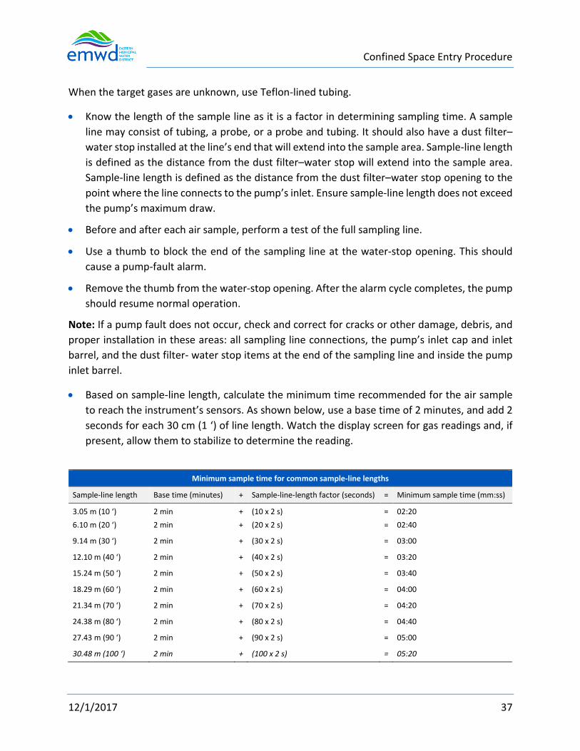
Confined Space Entry Procedure
12/1/2017 37
When the target gases are unknown, use Teflon-lined tubing.
Know the length of the sample line as it is a factor in determining sampling time. A sample
line may consist of tubing, a probe, or a probe and tubing. It should also have a dust filter–
water stop installed at the line’s end that will extend into the sample area. Sample-line length
is defined as the distance from the dust filter–water stop will extend into the sample area.
Sample-line length is defined as the distance from the dust filter–water stop opening to the
point where the line connects to the pump’s inlet. Ensure sample-line length does not exceed
the pump’s maximum draw.
Before and after each air sample, perform a test of the full sampling line.
Use a thumb to block the end of the sampling line at the water-stop opening. This should
cause a pump-fault alarm.
Remove the thumb from the water-stop opening. After the alarm cycle completes, the pump
should resume normal operation.
Note: If a pump fault does not occur, check and correct for cracks or other damage, debris, and
proper installation in these areas: all sampling line connections, the pump’s inlet cap and inlet
barrel, and the dust filter- water stop items at the end of the sampling line and inside the pump
inlet barrel.
Based on sample-line length, calculate the minimum time recommended for the air sample
to reach the instrument’s sensors. As shown below, use a base time of 2 minutes, and add 2
seconds for each 30 cm (1 ‘) of line length. Watch the display screen for gas readings and, if
present, allow them to stabilize to determine the reading.
Minimum sample time for common sample-line lengths
Sample-line length Base time (minutes) + Sample-line-length factor (seconds) = Minimum sample time (mm:ss)
3.05 m (10 ‘)
6.10 m (20 ‘)
2 min
2 min
+
+
(10 x 2 s)
(20 x 2 s)
=
=
02:20
02:40
9.14 m (30 ‘) 2 min + (30 x 2 s) = 03:00
12.10 m (40 ‘) 2 min + (40 x 2 s) = 03:20
15.24 m (50 ‘) 2 min + (50 x 2 s) = 03:40
18.29 m (60 ‘) 2 min + (60 x 2 s) = 04:00
21.34 m (70 ‘) 2 min + (70 x 2 s) = 04:20
24.38 m (80 ‘) 2 min + (80 x 2 s) = 04:40
27.43 m (90 ‘) 2 min + (90 x 2 s) = 05:00
30.48 m (100 ‘) 2 min + (100 x 2 s) = 05:20

[PAGE LEFT INTENTIONALLY BLANK]
Rev:10/23/14
SPECIFICATIONS - DETAILED PROVISIONS
Section 01026 - Schedule of Values
TABLE OF C O N T E N T S
PART 1 - GENERAL ............................................................................................................................. 1 1.01 SUMMARY ................................................................................................................................. 1 1.02 PREPARATION ........................................................................................................................... 1 1.03 SUBMITTAL ................................................................................................................................ 1
PART 2 - EXECUTION ......................................................................................................................... 2 2.01 SAMPLE SCHEDULE OF VALUES ................................................................................................ 2

[PAGE LEFT INTENTIONALLY BLANK]

Schedule of Values 01026-1
SECTION 01026
SCHEDULE OF VALUES
PART 1 - GENERAL
1.01 SUMMARY
A. Section Includes: Preparation, format, and submittal of Schedule of Values.
B. The Schedule of Values will establish unit prices for individual items of work.
C. The Schedule of Values will be the basis for payment of contract work and will be used to establish payment for any “extra work” i.e., work requested which is beyond the scope of the original contract.
1.02 PREPARATION
A. Prepare satisfactory Schedule of Values identifying costs of items of work shown in sample included at the end of the Section.
B. Assign unit prices to items of work and calculate total prices, which aggregate the Contract Price. Base unit prices on costs associated with scheduled activities for each item of work. For any bid item broken down into unit prices, Contractor shall verify that the unit cost of the items does not extend beyond two decimal places and that the unit cost when multiplied by the unit quantity equals the exact bid item value with no remainder.
1.03 SUBMITTAL
A. Submit preliminary Schedule of Values at the preconstruction meeting to the District for review and approval. DO NOT SUBMIT THE SCHEDULE OF VALUES WITH YOUR BID PACKAGE.
B. Submit corrected Schedule of Values within ten (10) days upon receipt of reviewed or rejected Schedule of Values for approval by the District.
C. Upon request, support prices with data which will substantiate their correctness.

Schedule of Values 01026-2
PART 2 - EXECUTION
2.01 SAMPLE SCHEDULE OF VALUES The following is a sample and acceptable form for Schedule of Values. The District may request additional detail as necessary to adequately represent the Scope of Work. The contractor may provide an additional breakdown of any of the items listed below. THE CONTRACTOR SHALL VERIFY ALL QUANTITIES AND ITEMS OF WORK PRIOR TO SUBMITTAL.
SCHEDULE OF VALUES
Item No. Qty Unit Description Unit Cost Total Cost
1 1 LS Mobilization and Approved: Bonds, Insurance, Schedule of Values, and Preliminary Project Schedule (PPS) Preset $137,500
2 1 LS Furnish, install, modify, program and integrate HVAC and exhaust systems controls and appurtenances, including but not limited to controls of variable air volume boxes, air handler unit, return and exhaust fans, motorized dampers, air and valves, complete and in place per Contract Drawings and Specifications, and Special Condition SC-18 Preset $31,300
3 1 LS Furnish, install, modify and adjust fire suppression system and components, including but not limited to fire sprinklers, smoke alarms, strobes and horns, sensors, pull stations, pipe and fittings, cables, wirings, and appurtenances, complete and in place per Contract Drawings and Specifications, and Special Condition SC-18
Preset
$32,195

Schedule of Values 01026-3
Item No. Qty Unit Description Unit Cost Total Cost
4 1 LS Furnish, install, modify, adjust and integrate security system and components, including but not limited to card readers, intercom and video terminal, surveillance cameras, cables and wirings, equipment supports and appurtenances, complete and in place per Contract Drawings and Specifications, and Special Condition SC-18
Preset
$31,291
5 1 LS Furnish, install, modify network and communication system, including but not limited to cables and cable trays, conduit, terminations, network connections, supports, and appurtenances, complete and in place per Contract Drawings and Specifications, and Special Condition SC-18 Preset $46,210
6 1 LS Perform additional environmental hazards abatement work per applicable federal and state regulations, complete and in place in accordance with the Contract Drawings and Specifications, and Special Condition SC-38 Preset $50,000
7 1 LS Demolition of existing Laboratory, Utility Room, decontaminated fume hoods and exhaust ductwork, utility systems and appurtenances, complete and in place as noted in the Plans and Specifications
Lump Sum $ _____________
8
1 LS Furnish, install, modify, adjust and integrate components, equipment and appurtenances required for the coordination work and control interface of electrical and lighting systems, HVAC and exhaust systems, fire suppression and alarm systems, security systems, network system and micro-controllers, public address system, Laboratory utilities and drainage, safety shower and eyewashes, complete and in place as noted in the Plans and Specifications
Lump Sum $ _____________
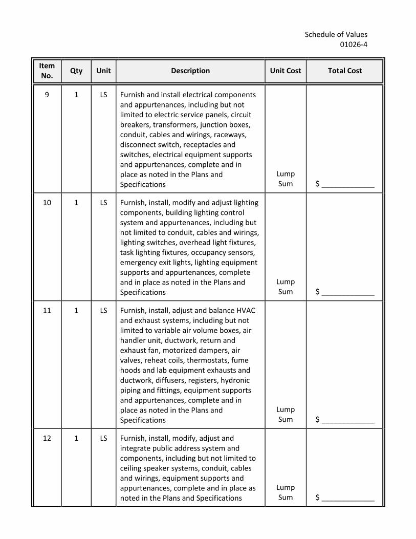
Schedule of Values 01026-4
Item No. Qty Unit Description Unit Cost Total Cost
9 1 LS Furnish and install electrical components and appurtenances, including but not limited to electric service panels, circuit breakers, transformers, junction boxes, conduit, cables and wirings, raceways, disconnect switch, receptacles and switches, electrical equipment supports and appurtenances, complete and in place as noted in the Plans and Specifications
Lump Sum
$ _____________
10 1 LS Furnish, install, modify and adjust lighting components, building lighting control system and appurtenances, including but not limited to conduit, cables and wirings, lighting switches, overhead light fixtures, task lighting fixtures, occupancy sensors, emergency exit lights, lighting equipment supports and appurtenances, complete and in place as noted in the Plans and Specifications
Lump Sum $ _____________
11 1 LS Furnish, install, adjust and balance HVAC and exhaust systems, including but not limited to variable air volume boxes, air handler unit, ductwork, return and exhaust fan, motorized dampers, air valves, reheat coils, thermostats, fume hoods and lab equipment exhausts and ductwork, diffusers, registers, hydronic piping and fittings, equipment supports and appurtenances, complete and in place as noted in the Plans and Specifications
Lump Sum $ _____________
12 1 LS Furnish, install, modify, adjust and integrate public address system and components, including but not limited to ceiling speaker systems, conduit, cables and wirings, equipment supports and appurtenances, complete and in place as noted in the Plans and Specifications
Lump Sum $ _____________
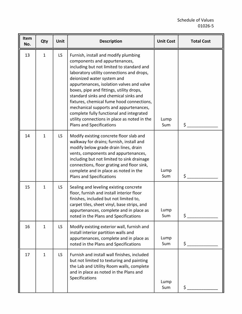
Schedule of Values 01026-5
Item No. Qty Unit Description Unit Cost Total Cost
13 1 LS Furnish, install and modify plumbing components and appurtenances, including but not limited to standard and laboratory utility connections and drops, deionized water system and appurtenances, isolation valves and valve boxes, pipe and fittings, utility drops, standard sinks and chemical sinks and fixtures, chemical fume hood connections, mechanical supports and appurtenances, complete fully functional and integrated utility connections in place as noted in the Plans and Specifications
Lump Sum
$ _____________
14 1 LS Modify existing concrete floor slab and walkway for drains; furnish, install and modify below grade drain lines, drain vents, components and appurtenances, including but not limited to sink drainage connections, floor grating and floor sink, complete and in place as noted in the Plans and Specifications
Lump Sum $ _____________
15 1 LS Sealing and leveling existing concrete floor, furnish and install interior floor finishes, included but not limited to, carpet tiles, sheet vinyl, base strips, and appurtenances, complete and in place as noted in the Plans and Specifications
Lump Sum
$ _____________
16 1 LS Modify existing exterior wall, furnish and install interior partition walls and appurtenances, complete and in place as noted in the Plans and Specifications
Lump Sum $ _____________
17 1 LS Furnish and install wall finishes, included but not limited to texturing and painting the Lab and Utility Room walls, complete and in place as noted in the Plans and Specifications
Lump Sum
$ _____________

Schedule of Values 01026-6
Item No. Qty Unit Description Unit Cost Total Cost
18 1 LS Furnish and install exterior and interior doors and framings, included but not limited to single door, double acting doors, motorized rollup door, hardware and appurtenances, complete and in place as noted in the Plans and Specifications
Lump Sum $ _____________
19 1 LS Salvage and reinstall lab windows and framings complete and in place as noted in the Plans and Specifications
Lump Sum $ _____________
20 1 LS Furnish and install ceiling system and finishes, included but not limited to acoustic ceiling tiles, ceiling supports, suspended drywall ceiling with framing and painting, HVAC control valves access, and appurtenances, complete and in place as noted in the Plans and Specifications
Lump Sum $ _____________
21 1 LS Furnish and install miscellaneous structure, safety equipment and appurtenances, included but not limited to temporary construction walls, exterior wall openings supports, solar tubes, concrete pads for air handler unit, air compressor and water heater and appurtenances, safety shower and eyewash stations, hardware, plumbing and fittings, activation alarms and appurtenances, complete and in place as noted in the Plans and Specifications
Lump Sum
$ _____________
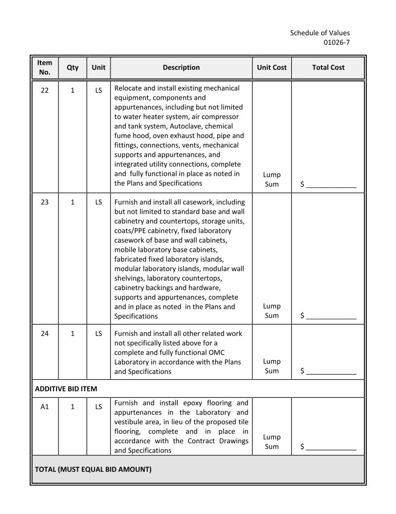
Schedule of Values 01026-7
Item No. Qty Unit Description Unit Cost Total Cost
22 1 LS Relocate and install existing mechanical equipment, components and appurtenances, including but not limited to water heater system, air compressor and tank system, Autoclave, chemical fume hood, oven exhaust hood, pipe and fittings, connections, vents, mechanical supports and appurtenances, and integrated utility connections, complete and fully functional in place as noted in the Plans and Specifications
Lump Sum
$ _____________
23 1 LS Furnish and install all casework, including but not limited to standard base and wall cabinetry and countertops, storage units, coats/PPE cabinetry, fixed laboratory casework of base and wall cabinets, mobile laboratory base cabinets, fabricated fixed laboratory islands, modular laboratory islands, modular wall shelvings, laboratory countertops, cabinetry backings and hardware, supports and appurtenances, complete and in place as noted in the Plans and Specifications
Lump Sum
$ _____________
24 1 LS Furnish and install all other related work not specifically listed above for a complete and fully functional OMC Laboratory in accordance with the Plans and Specifications
Lump Sum
$ _____________
ADDITIVE BID ITEM
A1 1 LS Furnish and install epoxy flooring and appurtenances in the Laboratory and vestibule area, in lieu of the proposed tile flooring, complete and in place in accordance with the Contract Drawings and Specifications
Lump Sum $ _____________
TOTAL (MUST EQUAL BID AMOUNT)

Schedule of Values 01026-8
DO NOT SUBMIT THE SCHEDULE OF VALUES
WITH YOUR PROPOSAL PACKAGE
END OF SECTION 01026
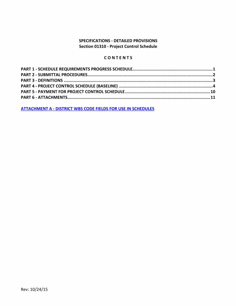
Rev: 10/24/15
SPECIFICATIONS - DETAILED PROVISIONS Section 01310 - Project Control Schedule
C O N T E N T S
PART 1 - SCHEDULE REQUIREMENTS PROGRESS SCHEDULE ................................................................ 1 PART 2 - SUBMITTAL PROCEDURES .................................................................................................... 2 PART 3 - DEFINITIONS ....................................................................................................................... 3 PART 4 - PROJECT CONTROL SCHEDULE (BASELINE) ........................................................................... 4 PART 5 - PAYMENT FOR PROJECT CONTROL SCHEDULE .................................................................... 10 PART 6 - ATTACHMENTS .................................................................................................................. 11 ATTACHMENT A - DISTRICT WBS CODE FIELDS FOR USE IN SCHEDULES


Project Control Schedule Section 01310 – 1
SECTION 01310 PROJECT CONTROL SCHEDULE
PART 1 - SCHEDULE REQUIREMENTS PROGRESS SCHEDULE The work specified in this section includes planning, scheduling and reporting required by the CONTRACTOR. It is expressly understood and agreed that the time of beginning, the rate of progress, and the time of completion of the work are essential elements of this CONTRACT.
A. The Project Control Schedule (PCS) shall be prepared and maintained by the CONTRACTOR as described in this section.
B. The PCS shall be the CONTRACTOR'S working schedule and will be used by the CONTRACTOR to plan, organize, and execute the work, record and report actual performance and physical progress, and to show how the CONTRACTOR plans to complete all remaining work as of the beginning of each progress report period (data date).
C. In addition, the PCS shall provide the DISTRICT with a tool to monitor and follow the progress of all phases of the work. The PCS shall comply with the various limits imposed by the scope of the work, contractually specified milestones and completion dates included in the contract.
D. The PCS shall be a Critical Path Method (CPM) schedule, utilizing the Precedence Diagramming Method (PDM).
E. The PCS must clearly show the sequence and interdependence of activities required for complete performance of the work, beginning with the Contract Start Date (CSD) and concluding with the Contract Completion Date (CCD). The maximum duration of any physical work activity shall not exceed twenty (20) working days unless approved by the DISTRICT.
F. The CONTRACTOR shall use a scheduling system capable of handling, processing, printing and plotting data to satisfy all requirements of this section. The scheduling system must be capable of producing project reports and other digital (electronic) data that can be directly read and interpreted by the DISTRICT'S scheduling system, without conversion by the DISTRICT, and without error. The DISTRICT uses the latest version of the Primavera Project Planner software.
Project Control Schedule Section 01310 – 2
PART 2 - SUBMITTAL PROCEDURES The DISTRICT will schedule and conduct a Preconstruction Conference within fifteen (15) calendar days after the issuance of the Notice of Acceptance of Proposal. At this meeting, the requirements of this section, as they apply to the contract, will be reviewed with the CONTRACTOR. The CONTRACTOR shall be prepared to review and discuss methodology for the schedule and sequence of operations and labor, equipment and material constraints.
A. PROJECT CONTROL SCHEDULE (PCS)(PRELIMINARY) - within fifteen (15) working days after the Preconstruction Conference, the CONTRACTOR shall submit to the DISTRICT the Preliminary Project Schedule (PPS), which shall be the basis of the PROJECT CONTROL SCHEDULE (BASELINE), and which will be used to schedule early activities of the project. The PPS shall include a detailed plan of operations for the first sixty (60) calendar days from the Contract Start Date. The PPS shall be a network diagram or bar chart, utilizing the DISTRICT'S WORK BREAKDOWN STRUCTURE (WBS) Example Format (Attachment A), showing in detail: 1. Notice of Acceptance of Proposal.
2. Pre-Construction Conference.
3. Contract start date.
4. Mobilization.
5. Submission and approval of key submittals.
6. Procurement of key materials and equipment.
7. All activities occurring or starting within the first sixty (60) calendar days.
8. Milestones and other contractual dates.
9. Contract completion date.
B. Submittal and acceptance of the Preliminary Project Schedule is a condition precedent
to the issuance of and payment of Initial Mobilization payments.

Project Control Schedule Section 01310 – 3
C. PROJECT CONTROL SCHEDULE (BASELINE) - within sixty (60) calendar days of the CSD,
the CONTRACTOR shall submit, for acceptance by the DISTRICT, the Project Control Schedule (Baseline). The PCS-Baseline shall represent the CONTRACTOR'S complete plan for the execution of the CONTRACT in accordance with the BID and CONTRACT documents. Although limited technical assistance is available to the CONTRACTOR from the DISTRICT upon written request and prior to any formal review and/or finalization of the baseline schedule, it is the responsibility of the CONTRACTOR to employ or engage the services of a technically qualified scheduler on this project. The PCS-WBS shall be similar to the DISTRICT-WBS (Attachment A).
D. PROJECT CONTROL SCHEDULE (UPDATES) - Once each month, or more often if deemed necessary by the DISTRICT, the CONTRACTOR shall review and update the PCS to incorporate all current information, including progress, approved adjustments of time and logic, and proposed changes in sequence and logic. All copies of the updated PCS submitted to the DISTRICT, shall be signed and dated by the CONTRACTOR.
E. PROJECT CONTROL SCHEDULE (AS-BUILT) - The last PCS update submitted shall be identified as the "As-Built Schedule", and is a condition precedent to issuance of Final Acceptance of the CONTRACT by the DISTRICT.
PART 3 - DEFINITIONS The principles and definitions of the terms used herein shall be as set forth in the Associated General Contractors of America (AGC) publication "The Use of CPM in Construction," copyright 1976. Additional definitions are set forth as follows:
A. Critical Path(s) - shall be defined as the longest path of activities from the Contract Start
Date (CSD) to the Contract Completion Date (CCD).
B. Near Critical Path - shall be defined as those paths of activities having a total float value equal to the total float value of the defined critical path (longest path) plus ten (10) working days.
C. Activity Codes - are values assigned to schedule activities to organize the Schedule Activities into manageable groups for updating, analyzing, reporting, plotting, and summarizing.
D. WBS - (Work Breakdown Structure) is a definition of project related activity codes, to be used by the CONTRACTOR to organize the CONTRACTOR'S Project Control Schedule in a manner that facilitates the DISTRICT'S use of the PCS information.
E. Constraint - is a restriction imposed on the start, finish or duration of an activity.

Project Control Schedule Section 01310 – 4
F. Data Date - (DD) The date used as the starting point for schedule calculations. For Baselines, the DD is the first day of the project, the CSD date. For subsequent schedule updates, the DD is the first workday of the remainder of the schedule, normally the first calendar day after the schedule close-out date (usually month end).
G. Total Float - is the amount of time that the start or finish of an activity can be delayed without impacting the Contract Completion Date. Total float is a CALCULATED value.
H. Free Float - is the amount of time that the start or finish of an activity can be delayed without impacting the early start or finish of a successor activity. Free float is a CALCULATED value.
I. Lag - is an offset or delay from an activity to it's successor, or from it's predecessor. Lag is physically defined by the scheduler. Lag is NOT CALCULATED.
J. Open End - is an activity that has either no predecessor or no successor relationships.
K. Out of Sequence Progress - means that all or a portion of an activity has been completed before the predecessors to the activity are complete.
L. Percent Complete - the portion of an activity that is complete based on physical measurement of the scope of work included in the activity that has been completed by the CONTRACTOR and accepted by the DISTRICT.
M. Target (Baseline) - a different version of the project schedule that can be compared to as the basis for measuring differences between the versions of the project schedule.
PART 4 - PROJECT CONTROL SCHEDULE (BASELINE) The CONTRACTOR shall be responsible for assuring that all work sequences are logical and the network shows a coordinated plan for the complete performance of the CONTRACT. Failure of the CONTRACTOR to include any element of the work required for the performance of the CONTRACT in the network shall not relieve the CONTRACTOR from completing all work within the time specified for the completion of the CONTRACT. In the event the CONTRACTOR fails to define any element of the work in the network, when the omission or error is discovered by either the CONTRACTOR or DISTRICT, it shall be corrected by the CONTRACTOR at the next scheduled update or submittal.
Project Control Schedule Section 01310 – 5
A. The PCS Baseline shall be organized to clearly define separate groups of activities
detailing: 1. key submittals,
2. procurement of major materials and equipment,
3. delivery of DISTRICT furnished materials and equipment,
4. approvals required by regulatory agencies or other third parties,
5. plans for all major subcontract work,
6. access to and availability of all work areas,
7. identification of interfaces and dependencies with preceding, concurrent, and
follow-on contractors,
8. tests and inspections,
9. identification of any manpower, material or equipment restrictions. Additionally, the PCS Baseline shall utilize for example the DISTRICT-WBS (Attachment A) to facilitate the organization of the CONTRACTOR'S PCS Baseline in relation to the DISTRICT-WBS.
B. Relationships shall be defined between the CONTRACTOR'S activities based on the following criteria. PHYSICAL - relationships occur when a successor activity cannot physically start (or finish) until a predecessor activity completes (or starts). example: forming before pouring SAFETY - defined relationships exist when a successor activity cannot start until a predecessor activity (which may be creating a safety hazard for the successor activity), completes allowing for the start of the successor in a safe environment. example: completing overhead work before starting work underneath RESOURCE - driven relationships occur when a successor activity cannot start until a predecessor activity completes and releases it's resources to work on the successor. example: form slab # 1 before forming slab # 2 when allocating one crew to a job PREFERENTIAL - logic occurs when a contractor prefers to perform the work in a given sequence. example: completing painting before starting finished flooring
Project Control Schedule Section 01310 – 6
NOTE: The basis of Safety, Resource and Preferential logic requirements for all critical or near critical activities shall be documented in the Baseline Schedule Narrative or as requested by the DISTRICT.
C. The basis of constraints and lags utilized in the PCS-BASELINE and subsequent UPDATES must be documented in an accompanying schedule narrative.
D. The CONTRACTOR shall not utilize float suppression techniques or artificial restraints, constraints, lags or durations to lessen or control the amount of total or free float contained in the network.
E. Float shall not be considered as time for the exclusive use of or benefit of either the DISTRICT or the CONTRACTOR. Float shall be considered as a resource available to both parties for the benefit of the project.
F. Early Completion An early completion schedule is one which anticipates completion of the work ahead of the corresponding Contract Time. Since Total Float is measured to the Contract Completion Date (CCD), and belongs to the Project, the CONTRACTOR shall not be entitled to any extension in Contract Time, or recovery for any delay incurred because of extensions in an early completion date, until all total float is used or consumed and performance or completion of the WORK extends beyond the corresponding Contract Time.
G. Project Schedule Reports shall be submitted to the DISTRICT as follows: Graphics - 24" x 36" (D size) 1. Time Scaled Logic Diagram based on early dates, organized by DISTRICT-WBS
Codes with the longest (critical) path printed in red. (Attachment A.)
2. Bar chart, organized by DISTRICT-WBS Codes, indicating early and late date bars with critical path printed in red.
Graphics – 8½" x 11" (A size)
3. Detailed Bar Chart, Grouped by DISTRICT-WBS, Codes (Attachment A)
4. Estimated Cash Flow Histogram (if cost loaded) with planned value per period (bar) and cumulative to date (curve).
Tabular Reports – 8½" x 11" (A size)

Project Control Schedule Section 01310 – 7
5. Predecessor / Successor listing including relationship type and lag value, organized
by Activity ID.
6. Tabular activity listing, sorted by Activity ID, with Early and Late Dates, Total and Free Float values.
7. Tabular activity listing, Grouped by Responsible party, sorted by Early Start, with Early Dates, Total and Free Float values.
8. Listing of all schedule constraints and open ends with explanation of each.
9. Identification of all lags contained in relationships and explanation of each.
10. Narrative report explaining the key "basis and assumptions" of the Project Control Schedule Baseline schedule.
11. Submittal / Procurement Status Report - A P3 Activity Matrix Report detailing for each submittal item, the Planned Dates for each step in the submittal/ procurement process.
12. Bid Item Listing.
H. Submittal 1. Six (6) sets of all graphics
2. Six (6) sets of all tabular reports
3. Computer diskette containing files compatible with "P3 Backup" format, capable
of being restored directly into DISTRICT'S Primavera Project Planner software with no conversion or error from enclosed graphics and reports. Any errors encountered when loaded by the DISTRICT will be corrected by the CONTRACTOR. Errors encountered when loading the CONTRACTOR'S P3 Backup files may result in rejection of the CONTRACTOR'S PCS submittal.
I. Acceptance
1. The DISTRICT may accept the PCS-Baseline submittal and subsequent updates as
having been submitted in accordance with the Contract Specifications. The DISTRICT will review and make comments on the PCS. Meetings may be held between the DISTRICT and the CONTRACTOR, and all SUBCONTRACTORS and SUPPLIERS whom the CONTRACTOR may desire to invite or whom the DISTRICT may request be present.

Project Control Schedule Section 01310 – 8
2. The PCS submittal must meet in all respects the time and order of work requirements of the contract. The work shall be executed in the sequence indicated in the accepted baseline and subsequent accepted updates and revisions. If the CONTRACTOR changes the sequence of work, a baseline revision submittal will be required in accordance with Section 4.10.
3. Comments made by the DISTRICT on the PCS or any subsequent updates and revisions, will not relieve the CONTRACTOR from compliance with requirements of the Contract Documents.
4. If requested by the DISTRICT at any time during the project, the CONTRACTOR shall provide detailed, short term schedules for specific items of the work.
J. Baseline Schedule Revisions 1. No change shall be made to the accepted Project Control Schedule Baseline
without the prior written authorization of the DISTRICT.
2. If the CONTRACTOR desires, or the DISTRICT requests that the PCS Baseline be revised to reflect specific ISSUES of the current project plan, the CONTRACTOR shall prepare a detailed analysis of the time related impacts of the specific ISSUE, demonstrating how the CONTRACTOR proposes to incorporate the ISSUE into the PCS Baseline.
3. Each time impact analysis shall be submitted prior to approval of any change in the contract to facilitate the incorporation of the impact in the next schedule submittal by the CONTRACTOR.
4. Time extensions will be granted only to the extent that equitable time adjustments for the activity or activities affected exceed the remaining total float along the path of activities impacted by the ISSUE.
5. When an authorized revision is made to the PCS Baseline, the revised baseline shall be identified by a Revision Number, giving the revised Baseline a distinct identification separate from all previous or subsequent Baseline Revisions.
K. Schedule Updates
1. The CONTRACTOR shall submit the Project Control Schedule - Update to the DISTRICT each month, on a date assigned by the DISTRICT. The Update submittal shall include all information available up to the Data Date established by the DISTRICT.
Project Control Schedule Section 01310 – 9
2. The PCS-Update submittal shall be reviewed jointly (if necessary) with the
DISTRICT for the purpose of verifying update information. The DISTRICT may request key SUBCONTRACTORS or SUPPLIERS to participate in the review with the CONTRACTOR. Information to verify includes but is not limited to:
a) Actual start / finish dates for activities started or finished in the current
period.
b) Activity Percent Complete for activities that are currently in progress.
c) Remaining durations or expected finish dates for activities that are currently in progress.
d) Revised logic (as-built and projected) and changes in activity durations.
e) Impacts of Issues identified by the CONTRACTOR or DISTRICT.
f) Incorporation of DISTRICT approved time extensions.
3. The CONTRACTOR may not make changes to any actual events previously entered in prior updates without written concurrence by the DISTRICT.
4. PCS-Update submittals shall be prepared as follows: Graphics - 24" x 36" (D size)
a) Timescaled Logic Diagram of early dates, organized by EMWD-WBS Codes with the calculated critical path printed in red. (Attachment A)
b) Bar chart, organized by DISTRICT-WBS Codes, indicating early and late dates with critical path printed in red, with Target (Baseline) Bar. Graphics - 8½” x 11" (A size)
c) Detailed Bar Chart , Grouped by DISTRICT-WBS, with Target (Baseline) Bar. (Attachment A) Tabular Reports - 8½" x 11" (A size)
d) Tabular activity listing, sorted by Activity ID, with Early and Late Dates, with Total and Free Float values.

Project Control Schedule Section 01310 – 10
e) Tabular activity listing, sorted by Early Start, with Current Early and Current Baseline dates and Variance between Current Early and Current Baseline Finish Dates.
f) Tabular activity listing, Grouped by Responsible party, sorted by Early Start, with Early Dates, Total and Free Float values.
g) Listing of any NEW or DELETED schedule constraints and open ends with explanation of each.
h) Identification of all NEW or DELETED lags contained in relationships and explanation of each.
i) Identification of all NEW or DELETED activities and an explanation of each.
j) Narrative report including description of problem areas, current and anticipated delaying factors, and their expected impact, and an explanation of current actions taken or proposed. In addition, alternative for possible schedule recovery to mitigate any potential delay and/or cost increases should be included in the monthly narrative by the CONTRACTOR.
k) Submittal/Procurement Status Report.
l) Bid Item Listing Report.
m) If the CONTRACTOR fails to submit any of the PCS update submittal deliverables, the DISTRICT may withhold approval of progress payment estimates until such time as the CONTRACTOR submits the required update submittal.
PART 5 - PAYMENT FOR PROJECT CONTROL SCHEDULE
A. Project Control Schedule will be paid for at a lump sum price, as bid by the CONTRACTOR.
B. The lumps sum price paid for the Project Control Schedule shall include full compensation for furnishing all labor, materials (including computer and software), tools, equipment and incidentals, and for doing all of the work involved in preparing, furnishing, updating, statusing and revising the Project Control Schedule.
C. Payments for Project Control Schedule will be based on the lump sum value bid for this item and will be made as follows:

Project Control Schedule Section 01310 – 11
1. Submittal and Acceptance of Preliminary Project Control Schedule 10%
2. Submittal and Acceptance of Project Control Schedule Baseline 40%
3. The remaining 50% shall be prorated equally over the remaining months of the
project from the Acceptance Date of the Project Control Schedule Baseline to the Contract Completion Date. (CCD).
PART 6 - ATTACHMENTS
A. DISTRICT-WBS (Project Specific)
B. Example Reports
4.7 .A Time Scaled Logic Diagram - D Size .B Bar Chart - D Size .C Bar Chart - A Size .D Histogram - A Size .E Predecessor/Successor Report .F Activity Listing by Activity ID .G Activity Listing by Responsibility .H Constraints and Open Ends Listing .I Identification of Lags .J Narrative Reports .K Submittal/Procurement Status Report .L Bid Item Listing
4.11 .D.5 Target Comparison Report
END OF SECTION 01310

Project Control Schedule Section 01310 – 12
[PAGE LEFT INTENTIONALLY BLANK]

PRIMAVERA PROJECT PLANNER -----ACTIVITY CODES DICTIONARY-----
SECTION 01310 - PROJECT CONTROL SCHEDULE SPECIFICATIONS
ATTACHMENT A - DISTRICT WBS CODE FIELDS FOR USE IN SCHEDULES
EXAMPLE
CODE VALUE TITLE SEQUENCE
Date:
Project: Activity Codes: PROJ Specification # 99999 DISTRICT contract Specification Number FUND Const Order # 99999 DISTRICT Construction Order Number BITM Bid Item 999 Contract Bid Item Number
(Each activity in the contractor’s schedule should be coded to their appropriate Contract Bid Item)
CPKG Constr Package GENCN General Conditions & Milestones 1 MOB Mobilization 2 SUBM Submittals 3 PROC Procurement 4 CONST Construction 5 TEST Testing 6 REST Restoration 7 CLOSE Closeout & De-mobilize
(These codes represent the DISTRICT’S Construction Work Packages incorporated in the DISTRICT-wide Master Schedule. Contractor’s activities should be coded to their appropriate Construction Work Packages as defined by this Attachment.)
8
RESP Responsible Party DIST Eastern Municipal Water District 1 CONT Contractor
(These codes are used to identify responsibility for different activities)
2
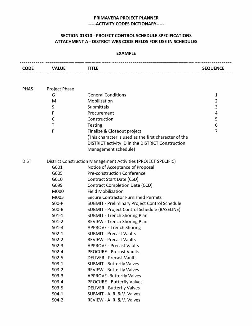
PRIMAVERA PROJECT PLANNER -----ACTIVITY CODES DICTIONARY-----
SECTION 01310 - PROJECT CONTROL SCHEDULE SPECIFICATIONS
ATTACHMENT A - DISTRICT WBS CODE FIELDS FOR USE IN SCHEDULES
EXAMPLE
CODE VALUE TITLE SEQUENCE
PHAS Project Phase G General Conditions 1 M Mobilization 2 S Submittals 3 P Procurement 4 C Construction 5 T Testing 6 F Finalize & Closeout project
(This character is used as the first character of the DISTRICT activity ID in the DISTRICT Construction Management schedule)
7
DIST District Construction Management Activities (PROJECT SPECIFIC) G001 Notice of Acceptance of Proposal G005 Pre-construction Conference G010 Contract Start Date (CSD) G099 Contract Completion Date (CCD) M000 Field Mobilization M005 Secure Contractor Furnished Permits S00-P SUBMIT - Preliminary Project Control Schedule S00-B SUBMIT - Project Control Schedule (BASELINE) S01-1 SUBMIT - Trench Shoring Plan S01-2 REVIEW - Trench Shoring Plan S01-3 APPROVE - Trench Shoring S02-1 SUBMIT - Precast Vaults S02-2 REVIEW - Precast Vaults S02-3 APPROVE - Precast Vaults S02-4 PROCURE - Precast Vaults S02-5 DELIVER - Precast Vaults S03-1 SUBMIT - Butterfly Valves S03-2 REVIEW - Butterfly Valves S03-3 APPROVE -Butterfly Valves S03-4 PROCURE - Butterfly Valves S03-5 DELIVER - Butterfly Valves S04-1 SUBMIT - A. R. & V. Valves S04-2 REVIEW - A. R. & V. Valves

PRIMAVERA PROJECT PLANNER -----ACTIVITY CODES DICTIONARY-----
SECTION 01310 - PROJECT CONTROL SCHEDULE SPECIFICATIONS
ATTACHMENT A - DISTRICT WBS CODE FIELDS FOR USE IN SCHEDULES
EXAMPLE
CODE VALUE TITLE SEQUENCE
S04-3 APPROVE - A. R. & V. Valves S04-4 PROCURE - A. R. & V. Valves S04-5 DELIVER - A. R. & V. Valves S05-1 SUBMIT - Blow-Off Assembly S05-2 REVIEW - Blow-Off Assembly S05-3 APPROVE - Blow-Off Assembly S05-4 PROCURE - Blow-Off Assembly S05-5 DELIVER -Blow-Off Assembly S06-1 SUBMIT - Steel Casing for Bores S06-2 REVIEW - Steel Casing for Bores S06-3 APPROVE - Steel Casing for Bores S06-4 PROCURE - Steel Casing for Bores S06-5 DELIVER - Steel Casing for Bores S07-1 SUBMIT - Concrete & Rock Sources S07-2 REVIEW - Concrete & Rock Sources S07-3 APPROVE - Concrete & Rock Sources S08-1 SUBMIT - Pipe Joint Details S08-2 REVIEW - Pipe Joint Details S08-3 APPROVE - Pipe Joint Details S09-1 SUBMIT - Pipe Lay Sheets S09-2 REVIEW - Pipe Lay Sheets S09-3 APPROVE - Pipe Lay Sheets S10-1 SUBMIT - Fittings S10-2 REVIEW - Fittings S10-3 APPROVE - Fittings S10-4 PROCURE - Fittings S10-5 DELIVER - Fittings S11-1 SUBMIT - Traffic Control Plan S11-2 REVIEW - Traffic Control Plan S11-3 APPROVE - Traffic Control Plan S12-1 SUBMIT -Cathodic Protection Materials S12-2 REVIEW - Cathodic Protection Materials S13-4 PROCURE - 30" Dia Pipe S13-5 DELIVER - 30" Dia Pipe S13-4 PROCURE - 54" Dia Pipe S13-5 DELIVER - 54" Dia Pipe C001 Clear & Grub

PRIMAVERA PROJECT PLANNER -----ACTIVITY CODES DICTIONARY-----
SECTION 01310 - PROJECT CONTROL SCHEDULE SPECIFICATIONS
ATTACHMENT A - DISTRICT WBS CODE FIELDS FOR USE IN SCHEDULES
EXAMPLE
CODE VALUE TITLE SEQUENCE
C010 Unload & String Pipe C015 Trench, Lay & B fill Pipe - Sta 82+40 to 102+20 C020 Jack & Bore Pipe - Sta 102+20 to 102+60 C025 Trench, Lay & B fill Pipe - Sta 102+60 to 162+00 C030 T, L & B=fill Drop Pipe @ Sta 162+00 to 163+00 C035 Trench, Lay & B=fill Pipe - Sta 163+00 to 185+88 C040 Jack & Bore Pipe - Sta 185+88 to 186+48 C045 Trench, Lay & B=fill Ppe - Sta 186+48 to 210+00 C050 Jack & Bore Pipe - Sta 210+00 to 210+45 C055 Trench, Lay & B=fill Pipe - Sta 210+45 to 264+30 C060 Jack & Bore Pipe - Sta 264+30 to 267+50 C065 Trench, Lay & B=fill Pipe - Sta 267+50 to 305+80 C070 Jack & Bore Pipe - Sta 264+30 to 267+50 C075 Trench, Lay & B=fill Pipe - Sta 308+50 to 332+90 C080 Trench, Lay & B=fill Pipe - Sta 332+90 to 355+00 C085 Trench, Lay & B=fill Pipe - Sta 344+10 to 346+80 C087 Steel Casing - Sta 344+10 to 346+80 C090 Trench, Lay & B=fill Pipe - Sta 346+80 to 353+00 C095 Conc Enc Pipe @ Sta 332+90 to 353+00 C100 T,L,B=fill Pipe & Tie-in Pipe @ Sta 353+00 to 353+93 C105 Install Blow-off Assemblies C110 Install Valves C115 Landscape Restoration C120 Pavement Restoration C125 Clean-up & Punch List T130 Hydrostatic Testing M135 De-mobilize

Rev: 01/28/10
SPECIFICATIONS - DETAILED PROVISIONS
Section 01381 - Pre-Construction Audio Video Recording Above Ground Facilities
C O N T E N T S
PART 1 - GENERAL ............................................................................................................................. 1
1.01 SCOPE OF WORK ....................................................................................................................... 1 PART 2 - PRODUCTS .......................................................................................................................... 1 PART 3 - EXECUTION ......................................................................................................................... 1
3.01 COLOR AUDIO VIDEO SURVEY .................................................................................................. 1 3.02 AUDIO AND VIDEO .................................................................................................................... 2


Pre-Construction Audio Video Recording Section 01381 – 1
SECTION 01381 PRE-CONSTRUCTION AUDIO VIDEO RECORDING
ABOVE GROUND FACILITIES
PART 1 - GENERAL
1.01 SCOPE OF WORK
A. Furnish all labor, materials and equipment to furnish color audio video recording of the project site as specified herein.
B. Furnish to the DISTRICT an original and one copy of a continuous color audio video recording of the entire area within fifty (50) feet of the construction area. The recording shall be taken prior to any construction activity.
C. The DISTRICT reserves the right to reject the audio video recording because of poor quality, unintelligible audio, or uncontrolled pan or zoom. Any recording rejected by the DISTRICT shall be rerecorded at no cost to the DISTRICT. Under no circumstances shall construction begin until the DISTRICT has received and accepted the audio video DVD(s).
D. The recording shall be performed by a qualified, established audio video recording firm knowledgeable in construction practices which has a minimum of one year of experience in the implementation of established inspection procedures.
E. The audio video recording firm shall submit three letters of recommendation from municipalities, and/or engineering firms indicating previous experience and ability to perform the work described in this contract. Data substantiating qualifications must be submitted and accepted prior to performing the survey.
PART 2 - PRODUCTS
(NONE THIS SECTION)
PART 3 - EXECUTION
3.01 COLOR AUDIO VIDEO SURVEY
A. Furnish a continuous color audio-video recording of the entire area within fifty (50) feet of construction.

Pre-construction Audio Video Recording Section 01381 – 2
B. Complete coverage shall include all surface features within 50' of the work area to be utilized by CONTRACTOR and shall be supported by appropriate audio description made simultaneously with video coverage. Such coverage shall include, but not be limited to, all existing driveways, sidewalks, curbs, ditches, roadways, landscaping, trees, culverts, headwalls, and retaining walls, equipment, structures, pavements, manholes, vaults, handrails, etc. located within the aforementioned work zone. Video coverage shall extend to the maximum height of all structures within this zone.
C. All recording shall be done during times of good visibility. No recording shall be done during periods of visible precipitation, or when more than ten percent of the ground area is covered with standing water, unless otherwise authorized by Owner.
3.02 AUDIO AND VIDEO
A. Contractor shall furnish continuous color, audio-video DVD(s) of professional quality.
B. Each DVD shall begin with the Owner's name, Contract name and number, CONTRACTOR's name, date and location information such as street name, direction of travel, viewing side, etc.
C. Information appearing on the DVD must be continuous and run simultaneously by computer generated transparent digital information. No editing or overlaying of information at a later date will be acceptable.
D. Digital information to appear in the upper left corner shall be as follows: 1. Name of CONTRACTOR
2. Day, date and time
3. Name of Project & Specification Number
E. Time must be accurate and continuously generated.
F. Written documentation must coincide with the information on the DVD so as to make easy retrieval of locations sought for at a later date.
G. The video system shall have the capability to transfer individual frames of video electronically into hard copy prints or photographic negatives.
H. Audio shall be recorded at the same time as the video recording and shall have the same information as on the viewing screen. Special commentary shall be given for unusual conditions of buildings, sidewalks and curbing, foundations, trees and shrubbery, structures, equipment, pavement, etc.

Pre-Construction Audio Video Recording Section 01381 – 3
I. All DVDs and boxes shall bear labels with the following information: 1. DVD Number
2. Owner's Name
3. Date of Recording
4. Project Name and Number
5. Location and Standing Limit of DVD
J. Prior to commencement of audio video recording, CONTRACTOR shall notify the Engineer in writing when and where the audio video recording will begin. The Engineer may provide a designated representative to accompany and oversee coverage of all recording operations. Audio video recording completed without an Engineering representative present will be unacceptable unless specifically authorized by the Engineer.
END OF SECTION 01381

Pre-construction Audio Video Recording Section 01381 – 4
[PAGE LEFT INTENTIONALLY BLANK]

Product Delivery Requirements Section 01612-1
SECTION 01612 PRODUCT DELIVERY REQUIREMENTS
1. SCOPE. This section covers packaging and shipping of materials and equipment. 2. PREPARATION FOR SHIPMENT. All equipment shall be suitably packaged to facilitate handling and to protect against damage during transit and storage. All equipment shall be boxed, crated, or otherwise completely enclosed and protected during shipment, handling, and storage. All equipment shall be protected from exposure to the elements and shall be kept dry at all times. Painted and coated surfaces shall be protected against impact, abrasion, discoloration, and other damage. Painted and coated surfaces which are damaged prior to acceptance of equipment shall be repainted to the satisfaction of Engineer. Grease and lubricating oil shall be applied to all bearings and similar items. 3. SHIPPING. Before shipping each item of equipment shall be tagged or marked as identified in the delivery schedule or on the Shop Drawings. Complete packing lists and bills of material shall be included with each shipment.
End of Section 01612

Product Delivery Requirements Section 01612-2
[PAGE LEFT INTENTIONALLY BLANK]
Product Storage and Handling Requirements Section 01614-1
SECTION 01614 PRODUCT STORAGE AND HANDLING REQUIREMENTS
1. SCOPE. This section covers delivery, storage, and handling of materials and equipment. 2. DELIVERY. Contractor shall bear the responsibility for delivery of equipment, spare parts, special tools, and materials to the site and shall comply with the requirements specified herein and shall provide required information concerning the shipment and delivery of the materials specified in this Contract. These requirements also apply to any subsuppliers making direct shipments to the Site. Contractor shall, either directly or through contractual arrangements with others, accept responsibility for the safe handling and protection of the equipment and materials furnished under this Contract before and after receipt at the port of entry. Acceptance of the equipment shall be made after it is installed, tested, placed in operation and found to comply with all the specified requirements. All items shall be checked against packing lists immediately on delivery to the site for damage and for shortages. Damage and shortages shall be remedied with the minimum of delay. Delivery of portions of the equipment in several individual shipments shall be subject to review of Engineer before shipment. When permitted, all such partial shipments shall be plainly marked to identify, to permit easy accumulation, and to facilitate eventual installation. 3. STORAGE. Upon delivery, all equipment and materials shall immediately be stored inside covered storage and/or weather tight structures, and protected until installed in the Work. Stacked items shall be suitably protected from damage by spacers or load distributing supports that are safely arranged. No metalwork (miscellaneous steel shapes and reinforcing steel) shall be stored directly on the ground. Masonry products shall be handled and stored in a manner to hold breakage, chipping, cracking, and spalling to a minimum. Cement, lime, and similar products shall be stored off the ground on pallets and shall be covered and kept completely dry at all times. All Laboratory piping systems, fittings, and valves must be stored indoors and placed on wooden blocking. PVC pipe, geomembranes, plastic liner, and other plastic materials shall be stored off the ground on pallets and protected from direct sunlight.

Product Storage and Handling Requirements Section 01614-2
Pumps, motors, electrical equipment, and all equipment with antifriction or sleeve bearings shall be stored in weathertight structures maintained at a temperature above 60°F [16°C]. Electrical equipment, controls, and insulation shall be protected against moisture and water damage. All space heaters furnished in equipment shall be connected and operated continuously. Equipment having moving parts, such as gears, bearings, and seals, shall be stored fully lubricated with oil, grease, etc., unless otherwise instructed by the manufacturer. Manufacturer's storage instructions shall be carefully followed by Contractor. When required by the equipment manufacturer, moving parts shall be rotated a minimum of twice a month to ensure proper lubrication and to avoid metal to metal "welding". Upon installation of the equipment, Contractor shall, at the discretion of Engineer, start the equipment at one-half load for an adequate period of time to ensure that the equipment does not deteriorate from lack of use. When required by the equipment manufacturer, lubricants shall be changed upon completion of installation and as frequently as required thereafter during the period between installation and acceptance. New lubricants shall be put into the equipment by Contractor at the time of acceptance. Equipment and materials shall not show any pitting, rust, decay, or other deleterious effects of storage when installed in the Work. In addition to the protection specified for prolonged storage, the packaging of spare units and spare parts shall be for export packing and shall be suitable for long-term storage in a damp location. Each spare item shall be packed separately and shall be completely identified on the outside of the container. 4. HANDLING. Stored items shall be laid out to facilitate their retrieval for use in the Work. Care shall be taken when removing the equipment for use to ensure the precise piece of equipment is removed and that it is handled in a manner that does not damage the equipment. During handling, carbon steel constructed material including chains, straps, and forks on lifting equipment shall not directly contact any equipment or material constructed of stainless steel. It shall be the Contractor’s responsibility to correct any carbon steel contamination of stainless steel.
END OF SECTION 01614

Demonstration and Training Section 01820-1
SECTION 01820 DEMONSTRATION AND TRAINING
PART 1 - GENERAL 1.01 DESCRIPTION. This section contains requirements for training the District’s Operation and Maintenance (O&M), and Laboratory personnel in the proper operation and maintenance of the equipment, mechanical/electrical/plumbing (MEP) systems installed under this contract. 1.02 GENERAL. Where indicated in the Equipment Schedule section and as required by the specifications, the manufacturer’s representative shall provide on-the-job training of the District’s personnel. The training session shall be conducted by qualified, experienced, factory trained representatives of the various equipment manufacturers. Training shall include instruction in both operation and maintenance of the subject equipment. The Contractor shall coordinate with Research Facilities Design (RFD), the Engineer of Record, to schedule and conduct a one day Laboratory Utilization Training for O&M and Laboratory personnel to familiarize the various systems installed under this contract. 1.03 SUBMITTALS. The following information shall be submitted to the Engineer in accordance with the provisions of the Submittals section. The material shall be submitted not less than 4 weeks prior to the provision of training.
1. Lesson plans, training manuals, handouts, visual aids, and other reference materials for each training session to be conducted by the manufacturer’s representatives.
2. Subject of each training session, identity and qualifications of individuals to be
conducting the training, and tentative date and time of each training session.
PART 2 – PRODUCTS 2.01 GENERAL. Where specified, the Contractor shall conduct training sessions for the District’s personnel to instruct staff on the proper operation, care, and maintenance of the equipment and systems installed under this contract. Training shall take place at the site of the work and under the conditions specified in the following paragraphs. The approved O&M manuals shall be available at least 30 days prior to the date schedule for the individual training session.

Demonstration and Training Section 01820-2
2.02 LOCATION. Training session shall take place at District’s Training Classroom and the new Office and Laboratory area, located at 2270 Trumble Road, Perris, CA. 2.03 LESSON PLANS. Formal written lesson plans shall be prepared for each training session. Lesson plans shall contain an outline of the material to be presented along with a description of the visual aids to be utilized during the sessions. Each plan shall contain time allocation for each subject. One complete set of originals of the lesson plans, training manuals, handouts, visual aids and reference materials shall be the property of the Disrict and shall be suitable bound for proper organization and easy reproduction. The Contractor shall provide to all attendees the necessary training manuals, handouts, visual aids, and reference materials at least 1 week prior to each training session. In conjunction with RFD, District, and specialty contractors, the Contractor shall schedule, coordinate, and conduct an 8-hour OMC Laboratory Utilization Training day to cover the following topics and equipment:
ARCHITECTURAL AND STRUCTURAL 1. Introduction to the New Laboratory
a. Overview of the new office layout b. Overview of the new laboratory floor plan c. Overview of the new utility rooms layout d. Overview of the finishes and materials
i. Ceiling ii. Walls and windows
iii. Interior and exterior doors iv. Floor coverings
ACCESS, SAFETY AND SECURITY 2. General and Restricted Access to the Laboratory
a. Secured and non-secured lab access protocol i. Card reader locations
ii. Normal business hours for walk-ins iii. After-hour operation
b. Control and operation of the motorized rollup door at Sample Receiving c. Security cameras, doorbell, and intercom
3. Laboratory Access and Safety a. Emergency exit lighting b. Emergency evacuation route c. Emergency eyewash stations d. Safety shower and alarms e. First aid and fire extinguisher locations f. Fire blankets g. Lab coats and PPE protocols
4. Fire Suppression and Public Address System
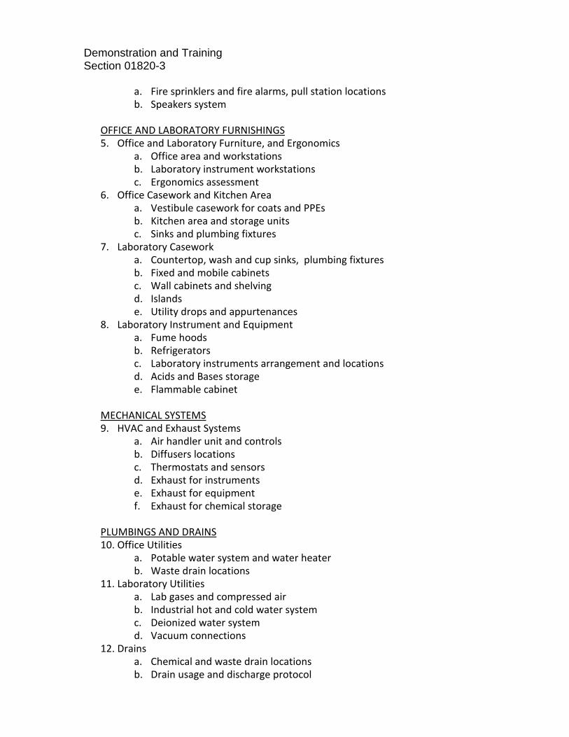
Demonstration and Training Section 01820-3
a. Fire sprinklers and fire alarms, pull station locations b. Speakers system
OFFICE AND LABORATORY FURNISHINGS 5. Office and Laboratory Furniture, and Ergonomics
a. Office area and workstations b. Laboratory instrument workstations c. Ergonomics assessment
6. Office Casework and Kitchen Area a. Vestibule casework for coats and PPEs b. Kitchen area and storage units c. Sinks and plumbing fixtures
7. Laboratory Casework a. Countertop, wash and cup sinks, plumbing fixtures b. Fixed and mobile cabinets c. Wall cabinets and shelving d. Islands e. Utility drops and appurtenances
8. Laboratory Instrument and Equipment a. Fume hoods b. Refrigerators c. Laboratory instruments arrangement and locations d. Acids and Bases storage e. Flammable cabinet
MECHANICAL SYSTEMS 9. HVAC and Exhaust Systems
a. Air handler unit and controls b. Diffusers locations c. Thermostats and sensors d. Exhaust for instruments e. Exhaust for equipment f. Exhaust for chemical storage
PLUMBINGS AND DRAINS 10. Office Utilities
a. Potable water system and water heater b. Waste drain locations
11. Laboratory Utilities a. Lab gases and compressed air b. Industrial hot and cold water system c. Deionized water system d. Vacuum connections
12. Drains a. Chemical and waste drain locations b. Drain usage and discharge protocol

Demonstration and Training Section 01820-4
ELECTRICAL, LIGHTING, NETWORK SYSTEMS 13. Electrical System
a. Main electrical panel DP-1 b. Electrical panels R1A, R1B, R1C c. Lighting panel and 240V panel RL1
14. Lighting System and Solar Tubes a. Emergency exit lighting b. Overhead and task lighting c. Solar tubes natural lighting d. Illumination ratings e. Lighting controls f. Light switches and after-hour over-rides
15. Network System a. Network system layout b. Network connection and jack locations c. Cable tray arrangement d. Laboratory dashboard display
UTILITY ROOMS AND UTILITIES 16. Mechanical Equipment
a. Air compressor and tank b. Water heater and recirculation pump c. Deionized water system d. Drains e. Gas connections
17. Electrical Equipment a. HVAC control panel b. Network system equipment
2.04 FORMAT AND CONTENT. Each training session shall include classroom and time at the location of the subject equipment or system. As a minimum, training sessions shall cover the following subjects for each item of equipment or system:
1. Familiarization
a. Review catalog, parts lists, drawings, etc., which have been previously provided for the plan files and operation and maintenance manuals.
b. Guided inspection of the subject equipment. c. Demonstration of the subject equipment and how operation in
accordance with the specified requirements.
2. Safety
a. Review and demonstration of safety procedures and related documentation.
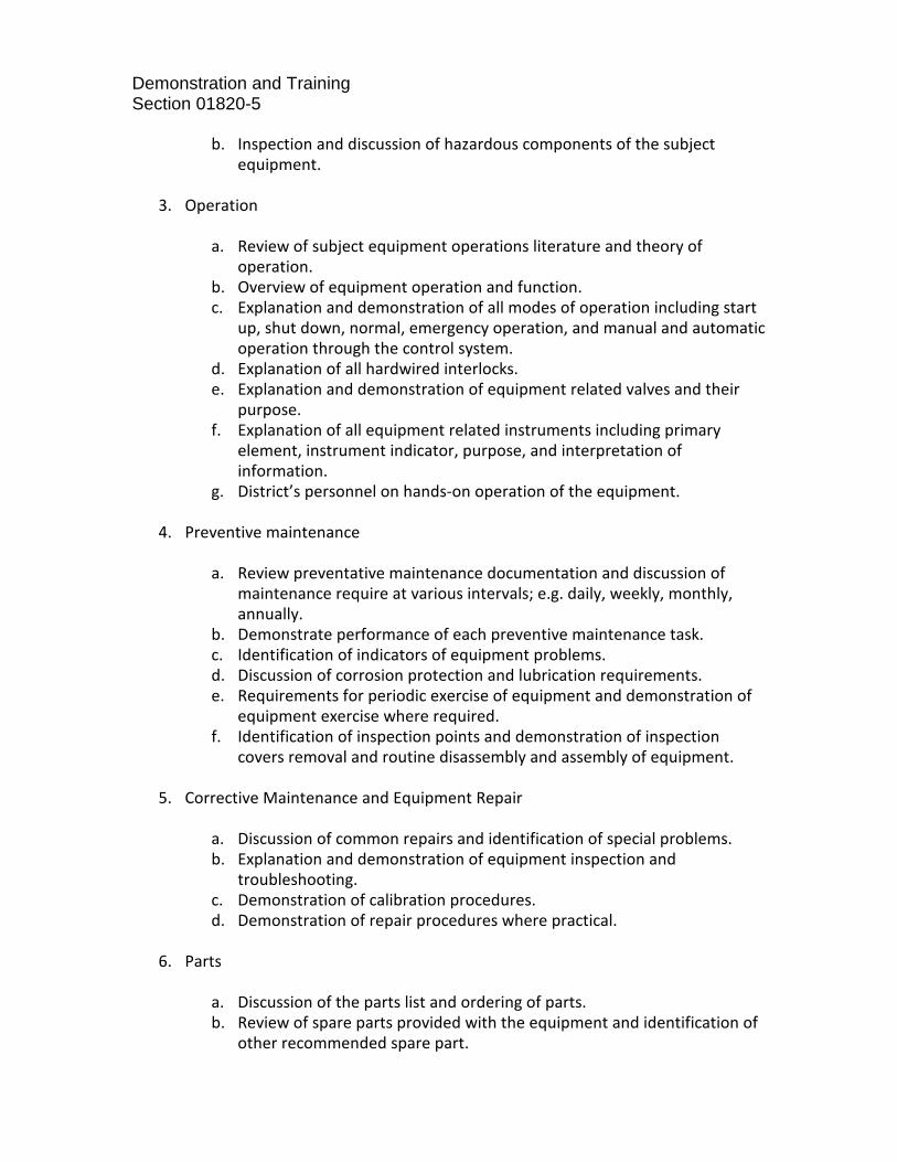
Demonstration and Training Section 01820-5
b. Inspection and discussion of hazardous components of the subject equipment.
3. Operation
a. Review of subject equipment operations literature and theory of
operation. b. Overview of equipment operation and function. c. Explanation and demonstration of all modes of operation including start
up, shut down, normal, emergency operation, and manual and automatic operation through the control system.
d. Explanation of all hardwired interlocks. e. Explanation and demonstration of equipment related valves and their
purpose. f. Explanation of all equipment related instruments including primary
element, instrument indicator, purpose, and interpretation of information.
g. District’s personnel on hands-on operation of the equipment.
4. Preventive maintenance
a. Review preventative maintenance documentation and discussion of maintenance require at various intervals; e.g. daily, weekly, monthly, annually.
b. Demonstrate performance of each preventive maintenance task. c. Identification of indicators of equipment problems. d. Discussion of corrosion protection and lubrication requirements. e. Requirements for periodic exercise of equipment and demonstration of
equipment exercise where required. f. Identification of inspection points and demonstration of inspection
covers removal and routine disassembly and assembly of equipment.
5. Corrective Maintenance and Equipment Repair
a. Discussion of common repairs and identification of special problems. b. Explanation and demonstration of equipment inspection and
troubleshooting. c. Demonstration of calibration procedures. d. Demonstration of repair procedures where practical.
6. Parts
a. Discussion of the parts list and ordering of parts. b. Review of spare parts provided with the equipment and identification of
other recommended spare part.

Demonstration and Training Section 01820-6
7. Local Representatives
a. Name, address, telephone of local representative. b. Review of contact information for providers of routine and emergency
repair and operational assistance.
8. Operation and Maintenance Manuals
a. Review of O&M manual content and organization. b. Update O&M material as required. c. Discuss electronic O&M manual structure and access
PART 3 – EXECUTION Training shall be conducted in conjunction with the operational testing and commissioning periods. Classes shall be scheduled so that training is performed when equipment is available for operation. The Contractor shall arrange and schedule the training with no more than 8 hours of class time. Concurrent training of different disciplines will not be permitted.
END OF SECTION 01820

Rev: 07/94
SPECIFICATIONS - DETAILED PROVISIONS Section 02050 - Demolition and Salvage
C O N T E N T S
PART 1 - GENERAL ............................................................................................................................. 1
1.01 SCOPE OF WORK ....................................................................................................................... 1 PART 2 - PRODUCTS .......................................................................................................................... 1 PART 3 - EXECUTION ......................................................................................................................... 1
3.01 STRUCTURE DEMOLITION ......................................................................................................... 1 3.02 PIPING AND EQUIPMENT DEMOLITION .................................................................................... 1 3.03 SITEWORK DEMOLITION. .......................................................................................................... 1 3.04 SALVAGE .................................................................................................................................... 1


Demolition and Salvage Section 02050 – 1
SECTION 02050 DEMOLITION AND SALVAGE
PART 1 - GENERAL
1.01 SCOPE OF WORK
A. This section covers the demolition of existing structures, equipment and sitework, and the salvage of existing materials and equipment as set forth herein.
B. All areas and facilities within the boundaries of the property described in the Notice Inviting Bids are to be demolished as described in Section 3, following. Contractor's work shall not create inconvenience to adjacent property owners, nor shall any adjacent property be disturbed during this contract. Blasting will not be permitted.
PART 2 - PRODUCTS (NONE THIS SECTION)
PART 3 - EXECUTION
3.01 STRUCTURE DEMOLITION All structures within the boundaries of District-owned property shall be demolished and the debris shall be removed from the jobsite.
3.02 PIPING AND EQUIPMENT DEMOLITION All piping and equipment on the user's side of the respective utility purveyor's meters shall be removed and shall become the property of the Contractor. Contractor is responsible to make proper arrangements with each affected utility prior to disconnection.
3.03 SITEWORK DEMOLITION. Sitework demolition shall include the removal of all concrete, slabs on grade, driveways, sheds, trees and shrubs within the property boundary.
3.04 SALVAGE
A. All existing materials and equipment shall be removed by the Contractor, shall become the property of the Contractor, and shall be removed from the jobsite.

Demolition and Salvage Section 02050 – 2
B. Removal and salvage of any item of equipment or facility shall include removal and salvage of all accessories, piping, wiring, supports and all other appurtenances.
END OF SECTION 02050

Rev: 04/22/15
SPECIFICATIONS - DETAILED PROVISIONS Section 02201 - Construction Methods & Earthwork
C O N T E N T S
PART 1 - GENERAL ............................................................................................................................. 1
1.01 REQUIREMENT .......................................................................................................................... 1 1.02 STRUCTURE PROTECTION ......................................................................................................... 2 1.03 JOB CONDITIONS ....................................................................................................................... 4 1.04 GUARANTEE .............................................................................................................................. 7
PART 2 - PRODUCTS .......................................................................................................................... 7 2.01 MATERIALS ................................................................................................................................ 7
PART 3 - EXECUTION ......................................................................................................................... 8 3.01 WEATHER LIMITATIONS ............................................................................................................ 8 3.02 PREPARATION ........................................................................................................................... 9 3.03 CONSTRUCTION ...................................................................................................................... 10 3.04 FIELD QUALITY CONTROL ........................................................................................................ 23


Construction Methods & Earthwork Section 02201 – 1
SECTION 02201
CONSTRUCTION METHODS & EARTHWORK
PART 1 - GENERAL
1.01 REQUIREMENT
A. Verification of Existing Conditions It shall be the responsibility of the Contractor to examine the site of the work and to make all investigation necessary, both surface and sub-surface, to determine the character of materials to be encountered and all other existing conditions affecting the work.
B. Site Grading The entire site within the area affected by construction shall be cleared and bladed. All surfaces to receive compacted fill shall be cleared of existing vegetation, debris, or other unsuitable material. Surfaces shall be cut or filled to the extent indicated by finish grade stakes set by the Engineer. Finish surfaces shall slope uniformly between spot elevations or finish contour lines shown on the drawings and away from structures. Subgrade for finished surfaces, concrete, asphalt, etc., the grading tolerance will be plus or minus .05 feet from surface elevations indicated. Rough Site Grading. All requirements of Site Grading shall be adhered to, with the exception that in unpaved areas and areas which do not have gradient restraints to allow for proper drainage, the grading tolerance will be plus or minus 0.20 feet from surface elevations indicated. Rough site grading in areas of future pavement shall have grading tolerance of plus or minus 0.10 feet from surface elevations.
C. Lines, Grades and Measures All lines and grades will be established by the Engineer, and the Contractor shall provide him with such assistance and materials as may be required. The Contractor shall carefully preserve all survey stakes and reference points. SHOULD ANY STAKES OR POINTS BE REMOVED OR DESTROYED BY ANY ACT OF THE CONTRACTOR OR HIS EMPLOYEES THEY MAY BE RESET AT THE CONTRACTOR'S EXPENSE. All work shall conform to lines, elevations and grades shown on the construction plans. Three consecutive points set on the same slope shall be used together so that any variation from a straight grade can be detected. Any such variations shall be reported to the District Engineer or Inspector. In the absence of such report, the contractor shall be responsible for any error in the grade of the finished work.
Construction Methods & Earthwork Section 02201 – 2
Stakes for video taping of project alignment will be provided by the District at 300' intervals and angle points. Grade stakes for buildings, sidewalks, pump bases, engine bases, utility services and paving shall be furnished by the Contractor. Grade stakes for water system construction will be at 100' stations except as directed by the Engineer for specific applications, and at fire hydrant, blow-off, air valve, water meter locations, and valves. Grade stakes for sewer system construction will be furnished at 25' stations and at locations of appurtenances.
D. Compliance with Regulations
The Contractor shall familiarize himself, and comply with all applicable federal, state, county and municipal rules and regulations pertaining to sanitation, fire protection, and safety.
E. Contractor's Equipment The Contractor shall provide such modern plant and equipment as may be necessary in the opinion of the Engineer to perform in a satisfactory and acceptable manner, and in accordance with the specifications, all the work required of the Contractor.
F. Representatives for Emergencies The Contractor shall file with the District a written list giving the names, addresses, and telephone numbers of at least two (2) of his representatives who can be contacted at any time in case of emergency. The representatives shall be fully authorized and equipped to correct unsafe or inconvenient conditions on short notice. The Contractor shall promptly notify the District of all changes in the listing.
G. Power and Water Supply The Contractor shall provide at his own expense all necessary power required for his operations under the contract. The Contractor shall provide and maintain in good order such modern power equipment as shall be adequate in the opinion of the Engineer to perform in a safe and satisfactory manner the work required by the contract. The Contractor may obtain water for work under this specification from the sources as stated in the Special Provisions and Requirements of this specification.
1.02 STRUCTURE PROTECTION

Construction Methods & Earthwork Section 02201 – 3
A. Contract Drawings The drawings identify the various pipes, conduits, and other existing utility structures as they are supposed to exist in construction areas, but no error or omission on said drawings shall be construed to relieve the Contractor from the responsibility of protecting any such pipe, conduit, or other existing utility structures. When deemed necessary by the Engineer, revisions of the contract drawings and additional detailed drawings will be issued to the Contractor during the progress of the work.
B. Notification of Underground Service Alert of Southern California When performing underground work, the Contractor shall call Underground Service Alert (USA), the one-call underground facility locating service two (2) working days prior to making an excavation. Contractor shall be responsible for such notification of sub-contractor's work, or shall require sub-contractor to assume this responsibility.
C. Operation of Utilities
No District valves or appurtenances of other utility facilities shall be operated by the Contractor without approval and/or instruction from the District or the utility, as appropriate.
D. Maintenance of Utilities Insofar as practical during the progress of the work, the property of any owner of a public utility pipeline or conduit, sewer, culvert, storm drain, drainage ditch, flood control channel, overhead wires or cables, or underground wires or cables, or any other structure or facility shall not be disturbed but shall be supported and protected against injury and maintained in good operating condition at the expense of the Contractor. In no case shall any such property be disturbed or removed without the consent of the owner and approval of the Engineer. The Contractor shall be responsible for making good all damage due to his operations and the provisions of this section shall not be abated even in the event such damage occurs after backfilling, or is not discovered until after completion of backfilling. The Contractor shall explore the location and depth of underground facilities, sewers, and storm drains sufficiently in advance of pipe laying or other construction operations so that changes in line or grade, or both, can be made in the pipeline without delay of the Contractor's construction schedule, without relaying or reconstructing previously installed pipe or other facilities and to avoid wherever possible moving, altering, or reconstruction of the obstructing underground facilities, sewers, or storm drains. The locations of existing underground utilities and structures, insofar as they are known from information furnished by the respective utility companies and agencies and other sources, have been shown on the drawings.

Construction Methods & Earthwork Section 02201 – 4
It shall be the responsibility of the Contractor to verify the location of these obstructions and to locate any other underground utilities and structures which might necessitate a change in the line and grade of the new work. If the Contractor, while performing the work of construction, discovers utility facilities not identified by the District in contract plans or specifications, he shall immediately notify the District in writing. In no case shall any utility that has been damaged, whether shown or not shown on the plans, be backfilled without the Contractor notifying the utility company of the damage. Pursuant to Section 4215 of the Government Code, the District shall compensate the Contractor for the costs of locating, repairing damage not due to the failure of the Contractor to exercise reasonable care, and removing or relocating main or trunkline utility facilities not indicated in the plans and specifications with reasonable accuracy, and for equipment on the project necessarily idled during such work. The Contractor shall not be assessed liquidated damages for delay in completion of the project, when such delay was caused by the failure of the District or the owner of the utility to provide for said removal or relocation of such utility facilities. Nothing herein shall be deemed to require the District to indicate the presence of existing service laterals or appurtenances whenever the presence of such utilities can be inferred from the presence of other visible facilities, such as buildings, meter and junction boxes, on or adjacent to the site of the construction.
E. Utility Construction If the work requires, as shown on the drawings or as specified, or as required for the Contractor's convenience, that the surface and overhead facilities, underground facilities, sewers and storm drains should be moved, altered, relocated, reconstructed, or temporarily supported, in order that the facilities included in the contract can be constructed, the Contractor shall make all arrangements therefore with the respective owners and shall bear all expenses for moving, altering, relocating, or temporarily supporting the facilities. In addition, the District may require the moving, altering, or reconstructing of obstructing underground facilities, sewers, or storm drains, and compensation therefore will come under extra work where such work is ordered in writing by the Engineer. Pipelines determined to be abandoned may be destroyed if conflicting with the contract work and properly disposed of. Exposed ends of abandoned pipelines shall be plugged for watertightness as approved by the Engineer.
1.03 JOB CONDITIONS
A. Rights-of-Way
Construction Methods & Earthwork Section 02201 – 5
The District will provide right-of-way for the pipelines to be constructed under the contract. Neither the terms hereof nor anything shown on the drawings in connection with the right-of-way provided by the District shall be construed to entitle the Contractor to conduct operations in said right-of-way in violation of any public agency ordinance or regulation restricting interference with water courses and drainage channels, road, alley, or street, until he has obtained permits therefore from the proper authorities. In all of the streets in which his work may interfere with ingress or egress of the occupants of the abutting property or of their vehicles, the Contractor shall maintain temporary practical means of ingress and egress or shall make satisfactory arrangements with the occupants for the obstructing of ways to their properties for the duration of the interference. Such arrangements shall be made in writing and a copy submitted to the Engineer. Nothing herein shall be construed to entitle the Contractor to the exclusive use of any public street or way during performance of the contract work, and he shall so conduct his operations as not to interfere unnecessarily with the authorized work of other agencies in such streets and ways. Fences on the right-of-way shall be removed by the Contractor where necessary for the performance of the work, but, where required, shall be maintained until the work is completed or their removal is authorized. Where the Contractor removes existing fences to facilitate the work, temporary fence protection for lands adjacent to the right-of-way shall be provided at all times during the continuation of the contract. Such temporary fence protection shall be adequate to prevent livestock from straying from or onto adjacent lands and shall be constructed complete with gates and/or cattle guards. The cost of all work described in this paragraph shall be included in the prices bid for other items of work and no separate payment shall be made therefore. Where pipelines are to be constructed through and adjacent to tracts of improved property, the Contractor shall, where practical, confine his operations within a 30-foot wide right-of-way or such other width right-of-way as may be designated on the drawings or in the Special Provisions. If the Contractor's operations are such as to require additional space, the Contractor shall arrange for and secure at his own expense any additional right-of-way required. The Contractor shall enter into written agreements with the landowners and copies of the agreements shall be furnished to the Engineer. Where the pipeline is to be constructed through cultivated fields not in public road rights-of-way, the District will obtain and pay for damage to crops over a total overall width of 30' or such other width as may be designated. Any damage to crops outside of the designated right-of-way shall be paid for by the Contractor.
Construction Methods & Earthwork Section 02201 – 6
B. Safeguarding Excavations and Property Excavations shall be adequately shored and braced so that the earth will not slide or settle and so that all existing improvements of any kind will be fully protected from damage. Any damage resulting from a lack of adequate shoring and bracing shall be the responsibility of the Contractor. The Contractor shall effect all necessary repairs or reconstructions at the Contractor's own expense as directed by the Engineer and shall bear all other expenses resulting from such damage.
C. Safety Measures Each bid proposal submitted under these specifications for the construction of a pipeline, sewer, sewage disposal system, boring and jacking pits, or similar trenches or open excavations, or the use of such a trench or open excavation, shall include in appropriate bid items for such work the costs necessary to provide adequate sheeting, shoring, and bracing, or equivalent method for the protection of life or limb, which shall conform to applicable safety orders, including the Construction Safety Orders of the California Division of Occupational Safety and Health, in accordance with the requirements of the California Occupational Safety and Health Act. When working in, or connecting to, existing systems in operation, the required safety provisions for work in an operating system will be enforced, including provisions for working in confined air spaces when appropriate. Nothing in this requirement shall be construed to impose tort liability on the awarding body or any of its employees.
D. Trench Shoring Approval Any contract for public works involving an estimated expenditure in excess of twenty-five thousand dollars ($25,000) for the excavation of any trench or trenches 5' or more in depth, shall require submission by the Contractor and acceptance by the awarding body or by a registered civil or structural engineer to whom authority to accept has been delegated, in advance of excavation, of a detailed plan showing the design of shoring, bracing, sloping, or other provisions to be made for worker protection from the hazard of caving ground during the excavation of such trench or trenches. If such plan varies from the shoring system standards, the plan shall be prepared by a registered civil or structural engineer. Nothing in this section shall be deemed to allow the use of a shoring, sloping, or protective system less effective than that required by the Construction Safety Orders. Nothing in this section shall be construed to impose tort liability on the awarding body or any of its employees.
E. Trench Permit

Construction Methods & Earthwork Section 02201 – 7
Prior to commencing any work in the construction or use of trenches or excavations which are 5' or deeper and into which a person will be required to descend, the Contractor shall apply to the California Division of Occupational Safety and Health, and secure a permit therefore, and shall furnish the District with a copy thereof prior to commencing any excavation.
F. Safety Officer The Contractor shall designate a responsible member of his organization at the site whose duty shall be the prevention of hazards and accidents. This person shall be the Contractor's Superintendent unless otherwise designated in writing by the Contractor to the District.
G. Right to Occupy Completed Portions of Work The District may wish to occupy or place in service portions of the completed work before final completion of the contract work and shall be at liberty to do so, but such occupancy or placing in service of any completed portion of the work shall not void the contract nor relieve the Contractor of his responsibility of protection and care of all work until final completion and acceptance of the entire work, provided, however, that expense directly attributable to operation and placing in service the portions of the work shall not be chargeable to the Contractor.
1.04 GUARANTEE The Contractor hereby guarantees that the entire work constructed by him under the contract will fully meet all the requirements thereof as to quality of workmanship, and of materials furnished by him. The Contractor hereby agrees to make at his own expense any repairs or replacements made necessary by defective materials or workmanship supplied by him which have become evident within one (1) year, or other guarantee period elsewhere specified, after date of notice of completion and acceptance of the work is filed, and to restore to full compliance with the requirements of these specifications including the test requirements, any part of the facilities or appurtenant works which during said guarantee period is found to be deficient with respect to any provision of this specification. Replacement of backfill where it has settled below the lines established by the Engineer shall be considered part of such repair work. The Contractor shall make all repairs and replacements promptly upon receipt of written orders for same from the Engineer. If the Contractor fails to make the repair and replacements promptly, the District may do the work, and the Contractor and his surety shall be liable to the District for the cost thereof.
PART 2 - PRODUCTS
2.01 MATERIALS
A. Select Backfill Material, and Special Bedding and Backfill

Construction Methods & Earthwork Section 02201 – 8
Select backfill material shall be selected from the excavated material or imported when not available from the excavated material. In either case, it shall be provided at the Contractor's expense, and shall be included in the costs proposed for pipeline installation on the bidding sheets. Where called for on the plans or in these specifications, and not covered by a separate bid item, special bedding or backfill shall be included in pipeline construction costs on the bidding sheets. Where required by the governing agency or by the District to meet compaction requirements of these specifications or requirements of these specifications for bedding or for select granular backfill, special bedding or imported backfill and disposal of excavated spoil shall be provided at the Contractor's expense. The requirements for special bedding and backfill at the Contractor's expense as described herein as a part of the Special Conditions or as shown on the Contract Drawings shall supersede and take precedence over any and all other requirements for measurement and/or payment for special bedding or backfill found elsewhere in these specifications. Bedding is defined herein to include sand, rock or concrete base, cradle, or encasement. Backfill material is defined herein to include backfill for both trench backfill and pipe bedding (or pipe zone backfill). Special bedding or backfill not called for on the plans or in these specifications, but required by the Engineer over and above the requirements of this specification shall be constructed at additional cost, at prices reflecting current material costs as evidenced by paid vouchers, plus 50% to cover all costs of installation and overhead. The encounter of ground water not anticipated in engineering reports made available for this contract, and the required over-excavation and construction of a stable base as determined necessary by the Engineer shall be considered over and above the requirements of this specification, and the required base shall be paid for at the above stipulated prices.
PART 3 – EXECUTION
3.01 WEATHER LIMITATIONS Excavating and grading shall be performed only when the weather conditions do not adversely affect the quality of the finished product. Any graded or excavated areas that are damaged by the effect of rain, or other weather conditions, during any phase of the construction, shall be re-excavated, regraded, and recompacted to conform to the herein specified requirements, without additional cost to the District.

Construction Methods & Earthwork Section 02201 – 9
3.02 PREPARATION
A. Dust Abatement The Contractor shall furnish all labor, equipment and means required and shall carry out protective measures wherever and as often as necessary in the opinion of the Engineer to prevent his operations from producing dust in amounts damaging to property or causing nuisance. The Contractor shall be responsible for any damage resulting from dust originating from his operations. The Contractor shall also make himself knowledgeable of Southern California Air Quality Management District's Rule 403-Fugitive Dust and comply with these requirements. The dust abatement measures shall be continued until all required resurfacing is completed or until the Contractor has completed arrangements with the proper authorities whereby he is relieved of further responsibility. Such arrangements shall be approved by the Engineer prior to their completion. All compensation to be received for dust abatement shall be included in the prices named for appropriate items of the bidding sheet.
B. Utilities and Substructures The indication of the type and approximate location of existing utilities and substructures in the Contract Documents represents a diligent search of known records, but the accuracy and completeness of such indications are not warranted by the District and utility structures and services not so indicated may exist. Before commencing any excavations, the Contractor shall investigate, determine the actual locations, and protect the indicated utilities and structures, shall determine the existence, position, and ownership of other utilities and substructures in the site or where the work is to be performed by communication with such owners, search of records, or otherwise, and shall protect all such utilities and substructures.
C. Control of Water The Contractor shall acquire such permits and take such measures as may be required, and shall furnish, install, and operate such pumps or other devices as may be necessary to remove any seepage, storm water, or sewage that may be found or may accumulate in the excavations during the progress of the work. The Contractor shall keep all excavations entirely free from water at all times during the construction of the work and until the Engineer gives permission to cease pumping. He shall keep the complete work reasonably free from accumulations of water and sewage, and shall free it entirely at such times as may be required by the Engineer for inspection or other purposes. Any accumulated water or sewage thus pumped shall be disposed of in accordance with good practice and local ordinances. The Contractor shall provide an adequate dewatering system for the control of surface and groundwater seepage into the excavations as may be required during the construction period. The proposed plan of this dewatering system shall be submitted to the Engineer for concept approval prior to the installation of the system.

Construction Methods & Earthwork Section 02201 – 10 3.03 CONSTRUCTION
A. Excavation The Contractor shall perform all excavation necessary or required for the construction of the facilities covered by these specifications. Excavations may be performed by either hand or machine methods and shall be of sufficient size to provide adequate space for working in accordance with safety regulations and practice and the Contract Drawings. Excavations shall include the removal and disposal of all materials of whatever nature and quantity including water, rock, decomposed granite, or any other type of soil or material, subsurface obstructions and also overhead obstructions which may interfere with the operation of equipment used on the work, for no additional compensation. Excavation shall immediately precede subsequent construction, and shall not remain open longer than necessary for construction. Excavation for foundations shall be made only after construction of subgrade, as hereinafter described, has been completed. Over-excavation for foundations shall be filled with concrete. 1. Seismic Investigation. In suspected or known fault areas, Contractor shall make
his trench or excavation available to the property owner or his geologist for seismic investigations as required under the Alquist-Priolo Geologic Hazard Zones Act. Such investigation shall involve no delay to the Contractor.
2. Trench Excavation. Unless otherwise specified in the Special Conditions or on the Contract Drawings, pipeline trenches and clearances shall be per Standard Drawing SB-158 for sewer pipeline installations and B-286B for water pipeline installations. The sides of the trench shall be parallel to and at equal distance on each side of the centerline of the pipe. The maximum length of trench which shall be opened or partially opened at any one time shall be limited to 500' for sewer lines and one-half mile for water pipelines, except where governed by other agencies or approved by the Engineer. See Section 3.04. J, "Clean-up During Construction" for maximum trench length without restoration. Bell holes or depressions shall be dug by hand at the proper locations of sufficient size to adequately work the joints, but no larger than is required. When the trench is excavated to the line and grade as shown on the drawings, and the bedding material encountered is rock, the trench shall be excavated an additional depth of at least 4" below the grade for the bottom of the pipe, and the bottom of the trench shall be refilled with approved material, moistened and compacted by tamping or by other approved method to the satisfaction of the Engineer.

Construction Methods & Earthwork Section 02201 – 11
Where ground water is encountered and the native material does not afford a solid foundation for pipe subgrade as specified above, the Contractor shall excavate to such depth below subgrade as determined necessary by the Engineer and shall construct a stable base by placing crushed rock bedding upon which subgrade can be prepared. Crushed rock for bedding shall be one and one-half inch (1 1/2") maximum size. When the trench has been inadvertently excavated below the designed grade, at the Contractor's expense, the bottom of the trench shall be refilled with approved material, well compacted into place in an approved manner and to the satisfaction of the Engineer.
3. New Subdivision Construction. Where pipelines are to be constructed in new subdivision developments, it is anticipated, unless otherwise stated, that sewers will be installed after grading is completed to subgrade in streets and proposed paved areas, and to final grade in other areas; then curbs will be constructed prior to water system construction. Only after water system construction will other utilities, roadway base, and paving be placed.
4. Excavated Materials. Shall be piled neatly along the side of the trench and adjacent to manhole excavations in such a manner as to be of as little inconvenience as possible to the public traffic or the occupants of the adjacent property, and be in compliance with safety standards and soils report recommendations. Through all cultivated areas, topsoil removed from excavations shall be replaced as backfill in the uppermost part of the excavation to a depth as it existed previous to excavation, not exceeding 18". Where topsoil replacement is required, excavated topsoil shall be stored separately from other materials and in general shall be replaced as backfill in the same parcel of land from which it came.
5. Manhole Excavations. Shall be made to the depths as indicated on the drawings, with sufficient side clearances to provide adequate working space for the construction of the manhole structure. When unsatisfactory soil bearing conditions, such as soft mud, quicksand, or other unstable materials are encountered at the elevation of the bottom of the manhole, the base shall be made firm and solid by removing said unstable material to sufficient depth and replacing same with crushed rock, gravel, or other approved material, well compacted into place in a manner approved by the Engineer.

Construction Methods & Earthwork Section 02201 – 12
6. Blasting. The use of explosives on the work shall be subject to the approval of the Engineer. All operations involving the handling and storage and use of explosives shall be conducted with every precaution prescribed by the Construction Safety Orders of the Division of Occupational Safety and Health of the State of California and by local laws and regulations. Only competent, reliable men working under experienced supervision shall be permitted to use explosives. The Contractor will be held responsible for and shall make good any damage caused by blasting or otherwise resulting from disposition or use of explosives on the work.
7. Cutting. In cutting or breaking up street surfacing, the Contractor shall use equipment acceptable to the authorities concerned. The pavement to remain in place shall be trimmed with an approved cutting device in such manner as to leave a vertical face with sound, unfractured pavement. All pieces of pavement resulting from cutting or breaking up street surfacing shall be removed from the trench area prior to trenching.
8. Disposal of Excavated Materials. Insofar as space is available in the right-of-way, such space may be used for temporary storage of excavated material, to be used for backfill, provided that no material shall be stored or deposited in violation of any ordinance or regulation prohibiting the filling or obstructing of water courses in drainage channels. Storage of excavated material in any street or highway shall conform to the regulations of the public authority having jurisdiction there over. All materials removed from the excavations in excess of that stored temporarily as above specified shall be immediately hauled away and used in backfilling elsewhere, or, if not used, shall be disposed of by the Contractor. The disposal area shall be acquired by the Contractor. No materials shall be disposed of either temporarily or permanently on privately or publicly owned property unless the Contractor shall first obtain permission therefore from the owner or agency concerned. The Contractor shall furnish satisfactory evidence to the Engineer that such consent has been obtained and shall be responsible for all damages and claims that may arise in connection therewith.
9. Bracing and Shoring. The Contractor shall furnish, place and maintain such bracing and shoring as may be required to support the side of the excavations for the proper protection of workmen, to facilitate the work and prevent damage to the pipes and manholes being constructed, and to prevent damage to adjacent structures or facilities. Upon completion of the work, all bracing and shoring shall be removed unless otherwise directed or permitted by the Engineer. Site conditions that alter shoring submittals such as blasting, groundwater, differing soils, etc., must be reviewed for adequate shoring by Contractor or his Engineer.

Construction Methods & Earthwork Section 02201 – 13
10. Bridges. Foot bridges of approved construction, not less than 4' in width, and provided with hand rails and uprights of dressed lumber, shall be installed over the trenches at all crosswalk intersections and at such other points where, in the opinion of the Engineer, traffic conditions make it advisable. Substantially constructed bridges, adequate for handling all vehicular traffic, shall be installed over any trench or other excavation in a street intersection whenever such excavation is in excess of half the width of the street crossing. Adequate bridges shall be provided to make possible the safe and full use of all driveways or roadways used to move vehicles from the public street onto private property. All bridges required to be installed shall be maintained in place as long as the condition of the work requires their use for the safety or convenience of the public, except that when necessary for the proper prosecution of the work in the immediate vicinity of a bridge, said bridge shall be relocated to take care of the traffic requirements, or may be temporarily removed for such period or periods of time, at the Contractor's risk, as the Engineer may approve.
B. Installation 1. Pipe. The pipe manufacturer shall send a field representative to answer any
questions on installation procedures, within 48 hours of request, as coordinated by and through the Engineer.
2. Concrete Encasement. Where required on the Contract Drawings, concrete cradles and encasements shall be constructed in accordance with the requirements stated thereon. Whenever the maximum allowable width of trench as specified elsewhere in these specifications or in the construction plans or the standard drawings, is exceeded for any reason except as provided for in the plans or special conditions or by the written direction of the Engineer, and where the resulting effect of the exceeded trench width would place loads upon the pipeline exceeding the maximum loads recommended by the pipe manufacturer, the Engineer may require, at his discretion, that the Contractor, at his own expense for all labor and materials cradle the pipe in Class "C" concrete, as described in this specification.
C. Fill, Backfill and Grading Fill, Backfill and Grading shall include all scarifying, moistening, compacting, and other manipulations of the soil necessary to obtain the required densities, cross sections, lines, grades and surface finish indicated or specified Backfill shall not be placed in trenches or excavations until the pipelines and structures in the particular section involved have been inspected and approved for backfilling by the Engineer.

Construction Methods & Earthwork Section 02201 – 14
Backfill shall be placed, insofar as practical, as the work progresses, allowing time for concrete (if used) to attain sufficient strength. All excavations outside the completed pipelines and structures shall be backfilled with compacted material to the level of the original ground surface unless otherwise shown on the drawings or ordered by the Engineer. The materials used for backfill shall be imported, selected material, or approved selected excavated materials and shall be placed as directed by the Engineer. All materials placed within 6" of the pipe or structure shall be free from rocks or boulders larger than 1 1/2" maximum dimension, and from unbroken masses of earthy materials which might lodge and thereby cause unfilled pockets in the excavation. Unsuitable material encountered at the surface upon which the bedding material is to be placed shall be removed to a depth as determined in the field by the Engineer. Unsuitable material shall be as determined by the Engineer. If not otherwise specified, removal of material and additional bedding so ordered over and above the amount required will be paid for in accordance with the specifications unless, however, the necessity for such additional bedding materials has been occasioned by an act or failure to act on the part of the Contractor, in which event the Contractor shall bear the expense of the additional excavation and backfill to the required depth. The Contractor's attention is called "dewatering" procedures to ensure that an otherwise stable foundation will not be rendered unfit due to accumulation of water in the trench excavation. However, the Contractor has the responsibility to reasonably ascertain the soil conditions prior to bid. The cost of removing the unsuitable materials should have been known prior to bid and be included in the bid price. Imported materials (if any) required for fill or backfill shall be provided by the Contractor from areas outside the site at his own expense. Such material shall be as herein specified and must be approved by the District before delivery to the site. 1. Structure Backfill. The Contractor shall place all backfill about structures to the
original ground level, or to the lines shown on the drawings or prescribed by the Engineer. Fill materials shall be of earth only, and be free from debris, vegetation, alkali, or other deleterious substances. All backfill about structures shall be placed in layers not more than 6" thick prior to compaction, which shall be obtained by moistening to optimum moisture content prior to placing and compacting to maximum compaction by use of suitable equipment approved by the Engineer. The Contractor shall take all necessary precautions to protect the structure and underground facilities during the placement, compacting or consolidating, and grading of backfill.

Construction Methods & Earthwork Section 02201 – 15
2. Pipeline Backfill. Full-time observation and testing will be required during all backfill and compaction activities on pipelines by a District approved soils firm. Except as otherwise required by the construction plans or the standard drawings, the material used in backfilling to 1' above the pipe shall be granular material approved by the Engineer and in accordance with the manufacturers requirements, sandy, or sandy gravel material obtained from required excavation or from approved borrow areas, as shown on the Contract Drawings or as directed by the Engineer. This material shall be carefully placed and compacted to provide a firm continuous bedding and encasement for the pipe. Pipe shall be shaded the same day it is laid to protect it from possible damage and/or thermal expansion. Pipe zone backfill may be consolidated by careful flooding to saturation only if the soil has a Sand Equivalent of 30 or better and no more than 10% fines (particles passing the no. 200 sieve), otherwise mechanical compaction will be required or as specified elsewhere in these specifications. Variations to the foregoing pipeline backfill requirement, when recommended by the pipe manufacturer or requested by the Contractor, shall be submitted for approval by the District prior to the commencement of such pipe installation. The method of compaction shall then be proven before backfilling more than the footage of pipe allowed by the contract specification. In lieu of a specific contract requirement, not more than 1000' of pipe shall be laid and backfilled prior to proving the method of compaction. The remaining trench backfill shall consist of select backfill material from the excavation, when available, free from stones or lumps exceeding 3" in greatest dimension, and free from vegetable matter or other unsatisfactory material. This select material as defined herein and elsewhere in these specifications shall be placed in layers not exceeding 2' in depth, unless otherwise directed by the Engineer. Excavated soils that have excessive moisture must be dried, mixed, or replaced with suitable material that will meet the compaction requirements at no additional cost to EMWD. Each lift shall be consolidated in such a manner that the backfill will meet the requirements of these specifications. Care shall be taken not to disturb the backfill previously placed, and the Contractor shall at all times protect the pipe against flotation. Material placed between successful test and failed test shall be tested at one-fifth (1/5) the distance intervals until a passing test is achieved. All material from failed test to successful test shall be removed, recompacted and retested.
3. Sewer Line Backfill. Backfill shall not be placed in trenches or excavations until the sewer lines and manholes in the particular section involved have been inspected and approved for backfilling by the Engineer.

Construction Methods & Earthwork Section 02201 – 16
For all sewer pipe, select granular backfill having a Sand Equivalent of 30 and less than 10% fines (particles passing the no. 200 sieve) shall be used up to an elevation 12" above the top of pipe, imported whenever the Engineer determines that native material is not satisfactory. Material for this purpose shall conform to the requirements as set forth herein. The pipe zone backfill shall be carefully packed under the haunches of the pipe and brought up simultaneously on both sides, to the full specified depth, so as to prevent any displacement of the pipe from its true alignment. In compacting by flooding, no ponding of water above the surface of the sand will be permitted.
4. Water Line Backfill. Prior to backfilling, all pipe 30" in diameter and larger shall be either filled with water under pressure or braced with stulls sufficiently to prevent distortion while placing, consolidating and compacting back fill. Prior to backfilling, all trench supports shall be removed unless otherwise approved by the Engineer.
5. Gravel Fill. Gravel fill shall be placed where specified, indicated on the plans, or designated by the Engineer to meet special conditions encountered. Where gravel fill is required, crushed rock may be substituted or added. Crushed rock for foundations shall be as defined for pipe bedding which is described elsewhere in this specification. The percentage composition by weight of gravel fill shall conform to the following grading when determined by Test Method No. Calif. 202:
Sieve Sizes Percentage Passing Sieves 1” ¾" No. 4 No. 30 No. 200
100 85-100 35-55 10-30 2-9
6. Compacting and Surfacing. Except as otherwise specifically required by the
encroachment permit or elsewhere in these specifications, the following requirements will apply: The upper portion of the final lift will be backfilled with selected material from the excavation, moistened to optimum moisture content and compacted by mechanical tamping to meet the requirements of the District standards. All backfill in public roads shall be consolidated and surfacing shall be placed to meet State of California and Riverside County requirements as stated in the respective permit, whether or not required by the inspector for that particular agency - unless otherwise approved by the Engineer.

Construction Methods & Earthwork Section 02201 – 17
Where backfill is in areas not within public roads, it shall be consolidated and tested to meet the requirements of these specifications, except as otherwise approved by the Engineer. Minimum acceptable field densities specified in District standards shall be determined in accordance with the testing procedures set forth elsewhere in these specifications. Where sand material of an approved grade is used for backfilling, mechanical compaction may be eliminated and compaction obtained by jetting. Except as otherwise required by a specific permit, where pavement is being replaced, an approved plant mixed surfacing shall be placed to a minimum thickness of 3" when compacted. Surfacing in streets shall be maintained to original street grade after laying and any settlement filled with plant mix surfacing. The edges of trenches which are broken down during the making of subgrade shall be removed and trimmed neatly before refilling or resurfacing. When the backfill is complete and excess material removed, the surface will be graded and a layer of approved decomposed granite will be placed with a minimum thickness of 4" when compacted at optimum moisture content by rolling and to a grade to conform to the original roadway section. All pavements outside the paylines damaged by the Contractor shall be trimmed and repaired. If the edge of the excavated trench when trimmed is within 2' of the edge of the roadway pavement, then the pavement shall be completely removed to the edge of the roadway and replaced with the replacement of the trench pavement. Except as otherwise directed by the Engineer, after a period of not less than 30 days or more than 60 days, any settlement shall be filled with decomposed granite. The top 2½" shall then be road mixed where allowed, with a minimum of 1½ gallons liquid asphalt binder of grade SC3 or 4 (as directed) per square yard and compacted to the original roadway section. Each phase shall be approved by the Engineer before proceeding to the next operation. Where allowed, the road-mixed surfacing operation shall conform to the Standard Specifications of the State of California Department of Transportation. Pavement, curbs, gutters and walks removed, cut or damaged during the construction of facilities shall be replaced or restored to their original condition, or as otherwise specified. Local ordinances governing such replacement shall be adhered to in all respects.

Construction Methods & Earthwork Section 02201 – 18
Removal and/or replacement of pavement where pavement now exists, as well as removal and/or replacement of any other obstructions, will be included in the item cost for the particular installation, unless specifically itemized separately on the bidding sheet.
D. Paving Where not required otherwise by specific contract requirements or permit requirements incorporated in the contract, the Contractor shall construct new asphalt concrete paving as indicated on the Contract Drawings and as specified herein. All paving proposals and operations shall be subject to the approval of the Engineer. Where this work is included in a lump sum bid item, it is the Contractor's responsibility to satisfy himself as to the exact lengths and/or dimensions of new roads and pavements. Terminals of all surfacing indicated on the Contract Drawings shall join any existing surfaces in a smooth juncture. 1. Sub-base
a) Preparation. The upper 12" of sub-base in any area to be paved shall be compacted to not less than 95% of maximum compaction, as determined by currently adopted ASTM D-1557 and procedure C.
b) Weed Killer. After the sub-base has been prepared, a weed killer shall be applied to the entire sub-base. Weed killer shall be OUST XP as manufactured by DUPONT, or approved equal. The weed killer shall be applied according to the manufacturer's published instructions.
2. Aggregate Base Course. Shall be Class II aggregate base. The aggregate base
course shall be the thickness shown on the plans and shall be placed in maximum 4" lifts. Aggregate base course shall be compacted to 95% of maximum compaction, as specified by ASTM D-1557. Aggregate base course shall be furnished, spread and compacted, as specified for Class II Aggregate Base Course in the Standard Specifications, State of California, Department of Transportation, latest edition. A spreader box will not be required but care shall be taken to prevent segregation during placement.
3. Asphalt Concrete a) Asphalt Concrete shall conform to the requirements of Caltrans Standard
Specifications Section 39, for Type "B". Aggregate will conform to a grading for 1/2" maximum aggregate with paving grade asphalt PG 64-10 (Section 92) unless otherwise directed by the Engineer.

Construction Methods & Earthwork Section 02201 – 19
b) Proportioning, Mixing, Spreading and Compacting. The proportioning and mixing of aggregates and asphalt, and the spreading and compacting of the asphalt concrete to make up the asphalt pavement, shall be in accordance with the Standard Specifications, State of California, Department of Transportation, latest edition. The paving machine shall have a self-screening spreader unless approved otherwise by the Engineer.
c) Tack Coat. Tack coat shall be Type SS1H grade Anionic Asphaltic Emulsion as per Caltrans Standard Specification 94.
d) Prime Coat. When indicated on the Plans or in the Special Provisions, a prime coat consisting of Grade SC-250 liquid asphalt shall be applied in accordance with Caltrans Standard Specification Sections 39 and 93.
e) Paving. The asphalt concrete pavement shall be no less than the thickness as shown on the plans and shall be applied in two (2) lifts. The first lift shall be the leveling course and the second lift shall be the wearing course not less than 1" thick and shall bring the pavement to full thickness. The finished surface shall be free from depressions exceeding 1/4" as measured with a 10-foot straightedge in any direction, except where the drawings show a grade break.
f) Seal Coat. Seal coat shall be a Bituminous Fog Seal in accordance with Caltrans Standard Specification Section 37.
g) Joining Existing Pavement. Existing paving which is to be joined by new paving shall be saw-cut to provide straight true neat joints.
h) Paving Headers. Edges of paving shall be bounded by 2 x 6 net new rough cut redwood unless otherwise shown on the plans.
i) Asphalt Curbs. Automatic curbing machines shall be used to construct asphalt curbs. The curb cross section used shall be as shown on the drawings or as approved by the District.
j) Paving Removal. Where paving is shown to be removed on the drawings, it shall mean that all asphaltic concrete and aggregate base shall be removed.
Construction Methods & Earthwork Section 02201 – 20
4. Removal and Replacement a) General. Replacement of street, driveway, alley entrance, and other type
pavements shall be of the same material as the existing pavement, constructed in accordance with the applicable drawings and specifications.
The Contractor shall install temporary asphalt pavement of the first course of permanent replacement immediately following backfilling and compaction of trenches that have been cut through pavement. Except as otherwise provided, this preliminary pavement shall be maintained in a safe and reasonably smooth condition until required backfill compaction is obtained and final pavement replacement is ordered by the Engineer. Temporary paving removed shall be hauled from the job site and disposed of at the Contractor's expense. Where a longitudinal trench is partly in pavement, the pavement shall be replaced to the original pavement edge, on a straight line, parallel to the centerline of the roadway. Where no part of a longitudinal trench is in the pavement, surfacing replacement will only be required where existing surfacing materials have been removed or damaged. When the trench cut is in aggregate surfaced areas, the replacement shall be of aggregate base course material compacted to 95% of its maximum compaction.
b) Asphalt Pavement Replacement. Asphalt pavement replacement shall be of the same thickness as the adjacent pavement and shall match as nearly as possible the adjacent pavement in texture. Existing asphalt pavements to be removed for trenches or other underground construction or repair shall be cut by a wheel cutter, clay spade, or other device without damaging adjacent pavement that is not to be removed. The Engineer's decision as to the acceptability of the cutting device and its manner of operation shall be final. The existing pavement shall be cut and trimmed after placement of required ABC and just prior to placement of asphalt concrete for pavement replacement, and the trimmed edges shall be painted with a light coating of asphalt cement or emulsified asphalt immediately prior to constructing the new abutting asphalt pavements. No extra payment shall be provided for these items, and all costs incurred in performing this work shall be incidental to pipe laying or pavement replacement.

Construction Methods & Earthwork Section 02201 – 21
Asphalt pavement replacement shall conform to the contour of the original pavement. A 10-foot straightedge shall be laid parallel to the centerline of the trench when the trench is running parallel to the street and across the pavement replacement when the trench crosses the street at an angle. Any deviation in the cut pavement replacement and the old pavement greater than 1/4" in 10 feet (10-foot straightedge) shall be removed and corrected.
c) Portland Cement Concrete Pavement Replacement. Where trenches lie within the portland cement concrete section of streets, alleys, driveways, sidewalks, etc., such concrete shall be saw-cut (to a depth of not less than 1½") to neat, vertical, true lines in such a manner that the adjoining surfaces will not be damaged. The pavement replacement shall be Class "A" concrete placed to the dimension as shown on the drawings. Expansion joints shall match the existing expansion joints in the old pavement. The surface shall be wood float finish with no greater variance than 1/4" in a 10-foot straightedge either across the pavement replacement or longitudinal with the centerline of the ditch. Any greater variance than the above 1/4" shall be cause for rejection of the pavement replacement. Before placing the concrete replacement, the edges of the old pavement shall be thoroughly cleaned and given a wash of neat cement and water.
d) Curb, Gutter, and Sidewalk Replacement. Where any concrete curb, gutter, or sidewalk has been removed or displaced, the same shall be replaced to the nearest construction joints with new asphalt or concrete to the same dimensions, material, and finish as the original construction that was removed. Expansion joints shall be the same spacing and thickness as on the original construction.
e) Expansion Joints. Expansion joints shall be constructed in curb, walk, and gutter as shown on the plans or as specified herein. Such joints shall be filled with premolded joint filler. No such joints shall be constructed in crossgutters, alley intersections or driveways except as may be approved by the Engineer. One-half inch (13 mm) joints shall be constructed in curb and gutter at the end of all returns except where crossgutter transitions extend beyond the curb return, in which case they shall be placed at the ends of the crossgutter transition. No joints shall be constructed in returns.

Construction Methods & Earthwork Section 02201 – 22
Where monolithic curb and gutter is constructed adjacent to concrete pavement, no expansion joints will be required except at EC and BC of curb returns. Expansion joint filler 1/4" (6 mm) thick shall be placed in walk at the EC and BC of all walk returns, around all utility poles which may project into the concrete along the line of the work, and in walk returns between the walk and the back of curb returns when required by the Engineer. At the EC and BC and around utility poles, the joint filler strips shall extend the full depth of the concrete being placed. Joint filler strips between walk and curb shall be the depth of the walk plus 1" (25 mm) with the top set flush with the specified grade of the top of curb. All expansion joint filler strips shall be installed vertically, and shall extend to the full depth and width of the work in which they are installed, and be constructed perpendicular to straight curb or radially to the line of the curb constructed on a curve. Expansion joint filler materials shall completely fill these joints to within 1/4" (6 mm) of any surface of the concrete. Excess filler material shall be trimmed off to the specified dimension in a neat and workmanlike manner. During the placing and tamping of the concrete, the filler strip shall be held rigidly and securely in proper position.
f) Weakened Plane Joints. (i) General. Weakened plane joints shall be straight and constructed in
accordance with Subsections "Control Joint" and "Plastic Control Joint" below, unless otherwise shown on the drawings. In walk, joints shall be tranverse to the line of work and at regular intervals not exceeding 10' (3 m). At curves and walk returns, the joints shall be radial. In gutter, including gutter integral with curb, joints shall be at regular intervals not exceeding 20' (6 m). Where integral curb and gutter is adjacent to concrete pavement, the joints shall be aligned with the pavement joints where practical.
(ii) Control Joints. After preliminary troweling, the concrete shall be parted to a depth of 2" (50 mm) with a straightedge to create a division in the coarse aggregate. The concrete shall then be refloated to fill the parted joint with mortar. Headers shall be marked to locate the weakened plane for final joint finishing, which shall be accomplished with a jointer tool having a depth of ½" (13 mm) and a radius of 1/8" (3 mm). The finished joint opening shall not be wider than 1/8” (3 mm).

Construction Methods & Earthwork Section 02201 – 23
(iii) Plastic Control Joints. The joint material shall be a T-shaped plastic strip at least 1" (25 mm) deep, having suitable anchorage to prevent vertical movement, and having a removable stiffener with a width of at least 3/4" (20 mm). After preliminary troweling, the concrete shall be parted to a depth of 2" (50 mm) with a straightedge. The plastic strip shall be inserted in the impression so that the upper surface of the removable stiffener is flush with the concrete. After floating the concrete to fill all adjacent voids, the removable stiffener shall be stripped. During final troweling, the edges shall be finished to a radius of 1/8" (3 mm) using a slit jointer tool.
3.04 FIELD QUALITY CONTROL
A. Contractor's Responsibility for Safety The Contractor shall be responsible for initiating, maintaining, and supervising all safety precautions and programs in connection with the work. This requirement will apply continuously 24 hours a day every day until final acceptance of the work and shall not be limited to normal working hours.
B. Warnings and Barricades The Contractor shall provide and maintain barricades, guards, temporary bridges and walkways, watchmen, night lights and danger signals illuminated from sunset to sunrise, and all other necessary appliances and safeguards to protect the work, life, property, the public, excavations, equipment, and materials. Barricades shall be of substantial construction and shall be painted such as to increase their visibility at night. Suitable warning signs shall be so placed and illuminated at night as to show in advance where construction, barricades, or detours exist. Guard rails shall be provided for bridges and walkways over or adjoining excavations, shafts, and other openings and locations where injury may occur.
C. Fire Prevention The Contractor's Safety Officer shall inspect the entire work and site, including storage areas, at frequent intervals to verify that fire prevention measures are constantly enforced.
D. Fire Extinguishers and Hoses The Contractor shall furnish and maintain fully charged fire extinguishers of the appropriate type, supplements with temporary fire hoses wherever an adequate water supply exists, at the places where burning, welding, or other operations that may cause a fire are being performed.

Construction Methods & Earthwork Section 02201 – 24
E. Flammable or Toxic Materials Only a working supply of flammable or toxic materials shall be permitted on or on any of the permanent structures and improvements, and shall be removed therefrom at the end of each day's operations. The Contractor shall store flammable or toxic materials and waste separate from the work and stored materials for the work in a manner that prevents spontaneous combustion or dispersion, and none shall be placed in any sewer or drain piping nor buried on the site.
F. Safety Helmets, Clothing, and Equipment The Contractor shall not permit any person for whom he is responsible or liable to enter or remain on the site of the work unless the person is equipped with and wearing a safety helmet and other protective clothing and safety equipment conforming to the requirements of the District or regulatory agencies, and shall discharge from the site all persons not so equipped. The Contractor shall post conspicuous signs at appropriate locations warning the public and persons engaged upon the work of this requirement. The Contractor shall furnish for their temporary use such safety helmets, protective clothing, and safety equipment as the Engineer may request of him.
G. Hazardous Areas The Contractor shall not permit or allow any person or persons to enter any pipe or space containing hazardous or noxious substances or gases, or where there is an insufficient amount of oxygen to sustain life and consciousness, or any other hazardous area unless equipped with lawful and appropriate safety equipment and life-supporting apparatus, and unless those entering are continually monitored and guarded by and in communication with other persons outside the space or area who are equipped in the same way, can give an alarm to others for assistance, and initiate immediate rescue operations in the event of mishap.
H. Work During an Emergency
The Contractor shall perform any and all operations and shall furnish any materials and equipment necessary during an emergency endangering life or property and, in all cases, shall notify the District of the emergency as soon as practical, but shall not wait for instruction before proceeding to properly protect both life and property. Any additional compensation or extension of contract time claimed by the Contractor on account of an emergency shall be applied for as provided in the specifications.
I. Compaction Tests All compaction tests required by either the governing agency having jurisdiction over the right-of-way or by the District shall be performed by the District or its agent at District expense. However, in the event these tests prove the compaction to be unacceptable to either the governing agency or the District, all subsequent tests required by the governing agency or the District shall be performed at the Contractor's expense.

Construction Methods & Earthwork Section 02201 – 25
Tests will be scheduled within 24 hours of the Contractor's request for tests, at locations to be selected by the District and/or the governing agency. However, tests shall not be scheduled until a minimum 4-hours work is available for the testing laboratory, as determined by the Engineer. Results of these tests shall then be available within 48 hours. In-place soil densities shall be determined by the sand cone method of test in accordance with currently adopted ASTM Standard D-1556, or by the nuclear method of test in accordance with ASTM Standard D-2922. Optimum soil moisture-compaction relations shall be determined by the method of test specified in ASTM Standard D-1557, except as otherwise specified in the Special Conditions. Soils testing provided by EMWD to determine compliance with the requirements of this specification does not relieve the Contractor of his/her responsibility. In accordance with provisions for guarantee of the work, the Contractor shall return at his expense to correct any backfill conditions subsequently found to be substandard by either failure or more extensive testing. The Contractor shall provide all labor and equipment necessary to prepare for all tests and to assist the soils engineer in taking the tests, as directed by the Engineer.
J. Clean-up During Construction The Contractor shall keep the premises occupied by him in a neat and clean condition, and free from unsightly accumulation of rubbish. Upon completion of the work and before the final estimate is submitted, the Contractor shall, at his own cost and expense, satisfactorily dispose of or remove from the vicinity of the work all plants, buildings, rubbish, rock, unused and excavated materials belonging to him or used under his direction during the construction, and in the event of his failure to do so, the same may be removed and disposed of by the District at the Contractor's expense. Contractor's responsibility shall include satisfactory disposal of all debris or protective material resulting from material delivery such as plastic wrappings, pipe stulls, etc., whether or not the Contractor furnished such material. The Contractor shall carry on his operations in such sequence and in such manner as to interfere as little as possible with other improvements. When the construction is adjacent to or on residential property or cultivated fields or orchards, disposal of material and backfill operations shall be performed in such manner as to restore the properties to their original condition as nearly as practical as determined by the Engineer. Topsoil shall be carefully removed, stockpiled, and replaced after the backfill is placed.

Construction Methods & Earthwork Section 02201 – 26
As a part of the clean-up operation on facilities in private right-of-way, the Contractor shall restore the soil the full width of the right-of-way to a mechanical condition equivalent to that which existed at the time of the construction operations on such areas, by thoroughly loosening the soil with subsoilers, or other acceptable means and by discing and leveling if necessary, any stones, gravel, or other deleterious material left in spoil banks. On such lands debris shall be removed by the Contractor before his final preparation of the soil and shall bedisposed of as required for excavated materials. In unimproved areas the finish surfaces over pipelines shall be graded to drain surface water away from the center line of the actual trench and provide drainage away from all the structures. No ponding of surface water will be allowed within the construction right-of-way. Contractor shall complete total trench restoration (original condition or better) within 1,320 feet of trench heading or within 10 working days of construction, whichever represents the least amount of time. Failure of the contractor to comply with the Engineer's cleanup orders may result in an order to suspend work until the condition is corrected. No additional compensation will be allowed as a result of such suspension.
END OF SECTION 02201
Rev: 10/24/96
SPECIFICATIONS - DETAILED PROVISIONS Section 03150 – Formwork for Cast-in-Place Concrete
C O N T E N T S
PART 1 - GENERAL ............................................................................................................................. 1
1.01 DESCRIPTION ............................................................................................................................. 1 1.02 QUALITY ASSURANCE ................................................................................................................ 1 1.03 SUBMITTALS .............................................................................................................................. 2
PART 2 - PRODUCT ............................................................................................................................ 2 2.01 FORM COATING ........................................................................................................................ 2 2.02 LUMBER ..................................................................................................................................... 2 2.03 PLYWOOD.................................................................................................................................. 2 2.04 METAL FORMS .......................................................................................................................... 3 2.05 ROUND COLUMN FORMS ......................................................................................................... 3 2.06 METAL FORM TIES ..................................................................................................................... 3 2.07 FORM JOINT SEALERS ............................................................................................................... 3 2.08 MOLDS ...................................................................................................................................... 3
PART 3 - EXECUTION ......................................................................................................................... 3 3.01 FORM TYPES .............................................................................................................................. 3 3.02 SHORING AND FALSEWORK ...................................................................................................... 4 3.03 FORM CONSTRUCTION ............................................................................................................. 4 3.04 EMBEDDED PIPING AND ROUGH HARDWARE .......................................................................... 5 3.05 FIELD QUALITY CONTROL .......................................................................................................... 5 3.06 REMOVAL OF FORMS AND SHORING ....................................................................................... 6


Formwork for Cast-in-Place Concrete Section 03150 – 1
SECTION 03150
FORMWORK FOR CAST-IN-PLACE CONCRETE
PART 1 - GENERAL
1.01 DESCRIPTION Provide formwork for cast-in-place concrete as indicated, specified, and required.
A. Work Included in This Section. Principal items are: 1. Furnishing, erection, and removal of forms.
2. Shoring and bracing of formwork.
3. Setting of embedded items, and in non-waterbearing locations setting of pipe
sleeves for mechanical and electrical work under direction of respective trade requiring holes for passage of pipe or conduit.
B. Related Work Not Included in This Section.
1. Furnishing embedded items with setting instruction. (Section 03300)
2. Reinforcement. (Section 03200)
3. Concrete mixing, placing and finishing. (Section 03300)
4. Waterstops. (Section 03300)
1.02 QUALITY ASSURANCE
A. Requirements of Regulatory Agencies. The requirements of California Construction Safety Orders Section 1717 apply to the Work of this Section, and the Contractor shall prepare and maintain at least one copy of the required drawings at the site. The District will not approve the drawings and the Contractor shall submit evidence to the California Division of Occupational Health and Safety to justify the formwork and shoring designs. Design of the structures shown on the Drawings does not include any allowance or consideration for imposed construction loads. Three (3) copies of the Contractor's shoring and formwork drawings shall be filed with the District for record purposes only and not for review or approval. Forms, shoring and falsework shall be adequate for imposed live and dead loads, including equipment, height of concrete drop, concrete and foundation pressures, stresses, lateral stability, and other safety factors during construction.

Formwork for Cast-in-Place Concrete Section 03150 – 2
B. Standards and Tolerances. Formwork shall comply with ACI 347R-88 Recommended
Practice for Concrete Formwork, except as exceeded by the requirements of regulatory agencies or as otherwise indicated or specified. Except as such other requirements mandate more rigid tolerances, formwork shall be designed and constructed to produce finished concrete conforming to tolerances given in ACI 117-90.
1.03 SUBMITTALS Concrete construction joints and expansion joints shall be of the types and locations indicated. Submit shop drawings showing sequence of forming and concrete placing operations, and location and type of required construction of any proposed expansion joints not shown on the Drawings. Submit shop drawings at least fifteen (15) working days in advance of form fabrication.
PART 2 - PRODUCT
2.01 FORM COATING Non-grain-raising and non-staining resin or polymer type that will not leave residual matter on surface of concrete or adversely affect bonding to concrete of paint, plaster, mortar, protective coatings, waterproofing or other applied materials. Coatings containing mineral oils, paraffins, waxes, or other non-drying ingredients are not permitted. For concrete surfaces contacting potable stored water, the coatings and form-release agents shall be completely non-toxic.
2.02 LUMBER WWPA No. 1 Structural Light Framing or No. 1 Structural Joists and Planks, or equal. Board forms, if used, shall be No. 2 Common or better, T&G or shiplap, S1S2E or better.
2.03 PLYWOOD Plywood shall conform to U.S. Product Standard PS-1 and shall bear APA or DFPA grade mark.
A. General Use. Exterior type, Grade B-B Plyform, Class I, minimum 5/8" thickness.
Mill-oiling is not permitted.
B. Special Use. Use one or more of the following materials, or equal: 1. HDO coating two sides on Plyform, Class I, Exterior.
2. Exterior Type Grade B-B Plyform, Class I, having 1/8" thick fully adhesive bonded
facing on one side of tempered structural hardboard.

Formwork for Cast-in-Place Concrete Section 03150 – 3
3. Birch hardwood plywood, all plies of Arctic white birch, panel faces on both sides
phenolic plastic impregnated and faced with phenolic plastic by the hot press process, panel edges factory sealed, bearing manufacturer's logo in lieu of grade mark.
2.04 METAL FORMS True to detail, good condition, clean, free from dents, bends, rust and oil, and of adequate size as approved by the Engineer.
2.05 ROUND COLUMN FORMS Structural quality fiberboard, metal tubes as specified for metal forms, or fibrous glass reinforced plastic.
2.06 METAL FORM TIES Prefabricated rod, snap-off, or threaded internal disconnecting type of tensile strength to resist all imposed loads. Ties shall leave no metal within 1½" of concrete surfaces after removal. Snap-off type ties shall have integral washer spreaders of diameter to fully close tie holes in forms. In waterbearing structures, ties shall be equipped with an integral waterstop which shall remain in place.
2.07 FORM JOINT SEALERS For joints between form panels, use resilient foam rubber strips, nonhardening plastic type caulking compound free of oil, or waterproof pressure-sensitive plastic tape of minimum 8-mil thickness and 2" width. For form tie holes, use rubber plugs, plastic caulking compound, or equal.
2.08 MOLDS For grooves, drips, rebates, profiles, chamfers, and similar items, use smooth milled pine or douglas fir coated with specified form coating, or standard product extruded polymer plastic units of the indicated or required shapes.
PART 3 - EXECUTION
3.01 FORM TYPES
A. Smooth Surface Concrete. Use specified plywood or metal forms, as approved, for interior and exterior exposed concrete and all formed concrete in contact with liquids, waterproofing and protective coatings. Metal forms shall be lined with plywood.
B. General Concrete. Use either plywood or board forms for concealed surfaces, or form as specified for smooth surface concrete. Metal forms for general concrete need not be lined with plywood.

Formwork for Cast-in-Place Concrete Section 03150 – 4
C. Approval. Metal forms shall be furnished to the jobsite sufficiently in advance of construction for detailed inspection by the Engineer. Forms showing evidence of worn connections of tie-holes, damaged or warped surfaces, or any other unsatisfactory feature shall be ordered removed from the jobsite by the Contractor, and shall not be returned to the jobsite. Metal forms, faced forms, and other forms shall be maintained in good condition through the construction period, and when in the opinion of the Engineer this is no longer the case, the unsatisfactory material will be removed from the jobsite. 1. Refer to Section 03300 for approval of form placement.
3.02 SHORING AND FALSEWORK Distribute loads properly over base area on which shoring is erected, either concrete slabs or ground; if on ground, protect against undermining or settlement, particularly against wetting of soils.
A. Alignment. Construct forms to produce in finished structure all lines, grades, and camber as required.
B. Camber. Provide jacks, wedges, or similar means to induce camber and to take any settlement in formwork which may occur either before or during placing of concrete. Camber for beams and slabs shall be as and where indicated. Perform screening in such manner as to maintain beam depths and slab thicknesses.
3.03 FORM CONSTRUCTION Build forms to exact shapes, sizes, lines, and dimensions as required to obtain accurate alignment, location and grades, and level and plumb work in finished structures. Provide for openings, offsets, keyways, recesses, moldings, reglets, chamfers, blocking, joint screeds, bulkheads, anchorages, and other required features. Make forms easily removable without hammering or prying against concrete. Use metal spreaders to provide accurate spreading of forms. Construct forms so that no sagging, leakage, or displacement occurs during and after pouring of concrete. Coat forms with specified coating material only prior to placement of reinforcing steel; do not allow coating to contact reinforcing bars. Provide l-foot minimum clear opening over form for finishing concrete.
A. Chamfers. Provide 3/4 inch x 3/4 inch chamfer strips for all exposed concrete corners and edges unless otherwise indicated.
B. Recesses, Drips and Profiles. Provide types shown and required.
C. Form Joints and Tie Holes. Seal joints between form panels with specified foam plastic strips, caulking compound, or tape. Unless form tie spreaders fully seal tie holes in forms, seal around ties with specified materials and prevent leakage of concrete mortar.

Formwork for Cast-in-Place Concrete Section 03150 – 5
D. Form Windows. Provide windows in forms wherever directed or necessary for access
for concrete placement and vibration. Windows shall be of size adequate for tremies and vibrators, spaced at maximum 6 foot centers, horizontally. Windows shall be tightly closed and sealed before placing next lift of concrete.
E. Cleanouts and Cleaning. Provide temporary openings in wall and column forms for cleaning and inspection. Prior to pouring, clean all forms and surfaces to receive concrete.
F. Reglets and Rebates. Properly form all required reglets and rebates to receive flashing, frames, and other equipment. Dimensions, details, and precise positions of all such reglets and rebates shall be ascertained from the trades whose work is related to or contingent upon same, and the concrete work formed accordingly.
G. Re-use. Clean and recondition form material before each re-use. Unsatisfactory material shall be rejected and removed from the site.
3.04 EMBEDDED PIPING AND ROUGH HARDWARE All trades which require openings for the passage of pipes, conduits, and other inserts shall be consulted and the necessary pipe sleeves, anchors, or other required inserts shall be properly and accurately installed. Openings required by other trades shall be reinforced as indicated and required. Conduits or pipes shall be located so as not to reduce the strength of the construction, and in no case shall pipes other than conduits be placed in a slab 4½” or less in thickness. Conduit embedded in a concrete slab shall not have an outside diameter greater than one-third of the thickness of the slab nor be placed below bottom reinforcing steel or over top reinforcing steel. Conduits may be embedded in walls provided they are not larger in outside diameter than one-third the thickness of the wall, are not spaced closer than three diameters on center, and do not impair the strength of the structure. All conduit, piping and other wall penetrations or reinforcements shall be subject to District's policy and approval.
3.05 FIELD QUALITY CONTROL
A. Inspection of Forms. Refer to Article 3.01 C for approval requirements for forms prior to use, and to Article 3.05 B for requirements during concrete pours. Refer to Section "Cast-In-Place Concrete" for approval requirements for placement of forms.
B. Control During Concrete Placement. Devices of the tell-tale type shall be installed on supported forms and elsewhere as required to detect formwork movements and deflection during concrete placement; plumb-bobs shall be utilized on forms for all walls and columns eight (8) feet or more in height. Required slab and beam cambers shall be checked and correctly maintained as concrete loads are applied on forms. Workmen shall be assigned to check forms during concrete placement and to promptly seal all mortar leaks.

Formwork for Cast-in-Place Concrete Section 03150 – 6
3.06 REMOVAL OF FORMS AND SHORING Do not remove forms or shoring until concrete has attained sufficient strength to support its own weight and all imposed construction and permanent loads. Any damage to the work resulting from early removal of forms or shoring or early imposed loading shall be corrected at no added expense to the District.
A. Form Removal. Minimum times for removal after concrete placement are as follows: Beam sides (but not shoring) .................................................................... 3 days Column forms and wall forms ................................................................... 2 days Forms for supported roof or floor slabs (but not shoring) ..................... 14 days Forms for slabs on grade........................................................................... 2 days
B. Shoring and Falsework Removal. Do not remove shoring and falsework until twenty-one (21) days after concrete placement or until concrete has attained at least 90 percent of the twenty-eight (28) day design compressive strength as demonstrated by control test cylinders, whichever is earlier, but not sooner than fourteen (14) days.
C. Restriction. Do not impose construction, equipment, or permanent loads on columns, supported slabs, or supported beams until concrete has attained the twenty-eight (28) day design compressive strength.
D. Concrete Curing During Removals. Concrete shall be thoroughly wetted as soon as forms are first loosened and shall be kept wet during the removal operations and until curing media is applied. Potable water supply with hoses shall be ready at each removal location before removal operations are commenced. Contractor shall bear costs and delays caused by any damage resulting from early removal of forms or shoring. Refer to Section "Cast-In-Place Concrete" for curing requirements.
END OF SECTION 03150
Rev: 08/01/99
SPECIFICATIONS - DETAILED PROVISIONS Section 03200 - Reinforcing
C O N T E N T S
PART 1 - GENERAL ............................................................................................................................. 1
1.01 DESCRIPTION ............................................................................................................................. 1 1.02 QUALITY ASSURANCE ................................................................................................................ 1 1.03 SUBMITTALS .............................................................................................................................. 2
PART 2 - PRODUCTS .......................................................................................................................... 3 2.01 REINFORCING ............................................................................................................................ 3 2.02 WELDED WIRE MESH ................................................................................................................ 3 2.03 TIE WIRE .................................................................................................................................... 3 2.04 COUPLER SPLICE DEVICES ......................................................................................................... 3 2.05 SUPPORTS AND ACCESSORIES .................................................................................................. 3 2.06 DOWELS .................................................................................................................................... 3 2.07 FABRICATION AND DELIVERY .................................................................................................... 3
PART 3 - EXECUTION ......................................................................................................................... 4 3.01 PLACING .................................................................................................................................... 4


Reinforcing Section 03200 – 1
SECTION 03200 REINFORCING
PART 1 - GENERAL
1.01 DESCRIPTION Provide reinforcing work, complete as indicated, specified and required.
A. Work Included in This Section. Principal items are: 1. Furnishing and placing bar and mesh reinforcing for cast-in-place concrete
including dowels for masonry work.
2. Furnishing reinforcing steel bars for masonry, including delivery to the site.
B. Related Work Not Included in This Section. 1. Installation of reinforcing in masonry (Section 04220).
2. Formwork (Section 03l50).
3. Cast-in-Place Concrete (Section 03300).
1.02 QUALITY ASSURANCE
A. Code Requirements. Unless otherwise specified, all work specified herein and as shown on the drawings shall conform to the applicable requirements of Chapter 26 of the Uniform Building Code, latest edition.
B. Testing. Materials shall be tested as hereinafter specified and unless specified otherwise, all sampling and testing shall be performed by a District-approved Testing Laboratory with cost borne by the Contractor. 1. Test Samples. Bars, ties, and stirrups shall be selected by Testing Laboratory
representative from material at the site or from place of distribution. Selection shall include at least two (2) pieces, each 18" long, of each sampling.
2. Required Tests. a) Identified Bars. Testing will not be required if reinforcement is taken from
bundles as delivered from the mill, identified as to heat number

Reinforcing Section 03200 – 2
and accompanied by certified mill analyses and certified mill test reports, and is properly tagged with Identification Certificate so as to be readily identified, unless otherwise directed by the Engineer.
b) Unidentified Bars. When positive identification cannot be made or when random samples are taken, tests shall be made from each five (5) tons or fraction thereof for each size. One tensile and one bend test shall be made from specimens of each size of reinforcement. Contractor shall bear costs and delays caused by testing unidentified bars.
C. Standard. Reinforcing steel installations shall conform to the specification requirements
of the Concrete Reinforcing Steel Institute "Manual of Standard Practice" (herein referred to as the CRSI Manual) except as otherwise indicated or specified.
D. Field Quality Control. Continuous inspections, where required by the Special Conditions, shall be performed by the "Special Inspector" qualified and approved by Governing Building Code Authority or Inspector as otherwise qualified and approved by the District. 1. Inspection of Reinforcing. Provide twenty-four (24) hour advance notice to permit
inspection of in-place reinforcement prior to closing forms, and refer to applicable requirements of Section 03300, "Cast-In-Place Concrete".
2. Concreting Operations. During concrete placing, assign construction personnel to inspect reinforcement and maintain bars in correct positions at each pour location.
3. Welding Inspection. Where allowed, perform shop and field welding of reinforcing steel under continuous inspection of the District's Inspector or an Inspector representative of the Testing Laboratory approved by the District. Notify District at least twenty-four (24) hours in advance of any procedure involving the welding of reinforcement.
1.03 SUBMITTALS Submit the following in advance of fabrication in conformance with applicable requirements of General Conditions.
A. Shop Drawings. Submit six (6) sets of shop drawings for reinforcing steel prepared in accordance with ACI 315, "Manual of Standard Practice for Detailing Reinforced Concrete Structures". Show layouts, bending diagrams, assembly diagrams, dimensioned types and locations of all bar laps and splices, and shapes, dimensions, and details of bar reinforcing and accessories. Include layout plans for bar supports and chairs, with typical details. District's review shall be general, and acceptance will not relieve Contractor of responsibility for accuracy.

Reinforcing Section 03200 – 3
B. Samples. Submit two (2) 12" long samples of each bar support and two (2) samples of each individual type chair, with catalog data.
PART 2 - PRODUCTS
2.01 REINFORCING Use deformed bars conforming to ASTM A615, Grade 60 Type "S". Where welding of reinforcing is required, use deformed bars conforming to ASTM A706 unless otherwise specifically designated on Drawings.
2.02 WELDED WIRE MESH Conform to ASTM A185.
2.03 TIE WIRE Annealed steel, 16 gage minimum.
2.04 COUPLER SPLICE DEVICES Reinforcing bar coupler/splice devices which bear current I.C.B.O. Research Recommendation Approval, and which develop at least 125 percent of bar yield strength in tension may be used in lieu of lapped bar type splices. Submit for District's approval in each instance.
2.05 SUPPORTS AND ACCESSORIES Use no aluminum, galvanized steel, plastic or stainless steel supports or accessories. Supports shall conform to CRSI Manual of Standard Practice, Chapter 3, for Types SB, BB, BC, JC, HC, CHC, and others of standard types as required, or precast concrete block supports (DOBIES) with embedded wire ties or dowels. Metal chairs shall be Class "1" plastic coated chairs and spacers.
2.06 DOWELS Where and as designated on Structural Drawings, provide reinforcing bar dowels in new work and for anchorage to existing concrete.
2.07 FABRICATION AND DELIVERY Conform to CRSI Manual Chapters 6 and 7 except as otherwise indicated or specified. Bundle reinforcement and tag with suitable identification to facilitate sorting and placing, and transport and store at site so as not to damage material. Keep a sufficient supply of tested, approved, and proper reinforcement at site to avoid delays.

Reinforcing Section 03200 – 4
A. Bending and Forming. Fabricate bars of indicated size and accurately form to shapes and lengths indicated and required by methods not injurious to materials. Do not heat reinforcement for bending. Bars with kinks or bends not scheduled will be rejected. Field bend NO bars that are partially embedded in concrete, except as shown on the plans or specifically approved by the Engineer.
B. Reinforcing Bars for Masonry. Bars shall be detailed and fabricated at the shop, ready for installation by masons.
PART 3 - EXECUTION
3.01 PLACING Unless otherwise indicated or specified, conform to CRSI Manual Chapter 8 including placement tolerances, except no reduction of concrete cover is allowable for bars at concrete surfaces exposed in liquid or water-containing structures.
A. Cleaning. Before placing reinforcing, and again before concrete is placed, clean reinforcement of loose mill scale, oil, or other coating that might destroy or reduce bond. Do not allow form coatings, release agents, bond breaker, or curing compound to contact reinforcement.
B. Concrete Coverage. Concrete coverage over reinforcing bars shall be as indicated on the Drawings. The coverage shall be to the outer edge of ties, stirrups, bar spacers, hangers, and like items, and the reinforcing shall be detailed and fabricated accordingly. Refer to Structural General Note requirements of the Drawings.
C. Securing in Place. Accurately place reinforcement and securely wire tie in precise position at all points where bars cross. Tie stirrups to bars at both top and bottom. Bend ends of binding wires inward allowing no encroachment on the concrete cover; exercise special care at surfaces to remain exposed and unpainted. Support bars in accordance with CRSI Manual Chapter 3, Specifications for Placing Bar Supports, using approved chairs and supports. Ties or supports for reinforcing bars and mesh properly placed and tied into position are not to be removed or dislodged for the convenience of other crafts or for the purpose of crawl holes.
D. Splices. Splices shall be wired contact lap splices unless otherwise indicated or approved. Splices shall conform to ACI 318, (Class A) (Class C) top bars and Typical Structural Details, except where lap length is indicated on the Drawings.
1. Vertical Bars. Splicing of vertical bars in concrete is not permitted except at the
indicated or approved horizontal construction joints or as otherwise specifically detailed.

Reinforcing Section 03200 – 5
2. Horizontal Bars. Unless otherwise shown, make lap splices with at least one
continuous bar between adjacent splices. Splices in any one run of bar shall be spaced at least twenty (20) feet apart with splices in adjacent bars offset at least ten (10) feet. Where double mats of bars occur in walls, lap splices in opposite mats shall be offset at least five (5) feet.
E. Welding. Welding of reinforcing bars is not permitted unless indicated or approved in
each case, with continuous inspection as hereinbefore required. Welds for securing crossing bars are not allowed. Perform welding in shop or field by direct electric arc process, with thoroughly trained and experienced certified operators qualified in accordance with AWS Code. Conform all welding to AWS "Structural Welding Code - Reinforcing Steel". Use low-hydrogen electrodes. Welds shall develop at least 125 percent of the yield strength of the connected bars. 1. Preparation. Clean surfaces to be welded of loose scale and all foreign material.
Clean welds each time electrode is changed. Chip burned edges clean before welds are deposited.
2. Characteristics of Welds. When brushed with wire brushes, completed welds shall exhibit uniform section, smoothness of welded metal, feather edges without undercuts or overlays, freedom from porosity and clinkers, and good fusion with penetration into base metal. Cut out welds or parts of welds found defective with chisel and replace with proper workmanship; cutting torch for removing defective welding is not acceptable.
F. Additional Reinforcing. Provide additional reinforcing bars at sleeves and openings as
indicated or required. Where additional bars are not shown for such locations, obtain Engineer's instructions and provide additional bars as directed, at no extra cost to the District.
G. Welded Wire Mesh. Install necessary supports and chairs to hold in place during concrete pours. Straighten mesh to lay in flat plane and bend mesh as shown or required to fit work. Laps shall be no less than one complete mesh unless otherwise detailed. Tie every other wire at laps.
H. Dowels. For anchorage where shown or required to existing construction, use non-shrink epoxy type grout or deferred bolting devices as approved in each instance and conforming to "Product" Article requirements of Section 03300, "Cast-In-Place Concrete". Holes for epoxying dowels in place in existing concrete shall provide l/2" minimum clearance on all sides of dowel bar.
END OF SECTION 03200

Reinforcing Section 03200 – 6
[PAGE LEFT INTENTIONALLY BLANK]

Rev: 08/07/12
SPECIFICATIONS - DETAILED PROVISIONS
Section 03300 - Cast-In-Place Concrete
C O N T E N T S PART 1 - GENERAL ............................................................................................................................. 1
1.01 DESCRIPTION ............................................................................................................................. 1 1.02 REFERENCE STANDARDS ........................................................................................................... 3 1.03 SOURCE QUALITY CONTROL ..................................................................................................... 3 1.04 CONCRETE MIX DESIGNS AND PRELIMINARY TESTS ................................................................. 4 1.05 PRODUCT DELIVERY, STORAGE, AND HANDLING ..................................................................... 7 1.06 PAYMENT .................................................................................................................................. 7
PART 2 - PRODUCT ............................................................................................................................ 8 2.01 MATERIALS. ............................................................................................................................... 8 2.02 CONCRETE MIXES .................................................................................................................... 13 2.03 CONCRETE MIXING ................................................................................................................. 17
PART 3 - EXECUTION ....................................................................................................................... 19 3.01 PREPARATION BEFORE PLACING ............................................................................................ 19 3.02 WATERSTOPS .......................................................................................................................... 20 3.03 JOINTS IN CONCRETE .............................................................................................................. 20 3.04 CONVEYING AND PLACING CONCRETE ................................................................................... 22 3.05 CURING FORMED CONCRETE .................................................................................................. 29 3.06 PLACING GROUT ..................................................................................................................... 29 3.07 ANCHORS, SLEEVES, STAIR NOSINGS, ETC .............................................................................. 29 3.08 EQUIPMENT BASES ................................................................................................................. 30 3.09 FINISHING FORMED CONCRETE .............................................................................................. 30 3.10 FINISHING SLABS AND FLATWORK ......................................................................................... 32 3.11 CURING SLABS AND FLATWORK ............................................................................................. 34 3.12 FORMED STAIRS AND TREADS ................................................................................................ 34 3.13 CHAMFERS AND FILLETS ......................................................................................................... 35 3.14 JOINTS WITH SEALANT ............................................................................................................ 35 3.15 INSTALLATION OF PIPELINES THROUGH CONCRETE STRUCTURES ........................................ 36 3.16 FIELD QUALITY CONTROL ........................................................................................................ 36 3.17 WATERTIGHTNESS OF CONCRETE STRUCTURES ..................................................................... 37 3.18 ALTERATIONS AND REWORK .................................................................................................. 37 3.19 REMOVAL OF EXISTING CONCRETE, MASONRY, OR GROUT .................................................. 38 3.20 QUALITY OF WORK .................................................................................................................. 38


Cast-In-Place Concrete Section 03300 – 1
SECTION 03300 CAST-IN-PLACE CONCRETE
PART 1 - GENERAL
1.01 DESCRIPTION Provide cast-in-place concrete work, complete as indicated, specified and required, including all appurtenant work as indicated.
A. Work Included in This Section. Principal items are: 1. All cast-in-place concrete including bases for mechanical and electrical equipment.
2. Concrete standards, materials, mixes and tests, placement, finishing, patching,
grouting, and crack repair.
3. Embedded waterstops for cast-in-place concrete.
4. Concrete curing.
5. Sealing of joints in liquid-containing structures and elsewhere shown.
6. Treatment of concrete surfaces.
B. Related Work Not Included in This Section: 1. Formwork (Section 03150).
2. Reinforcing work (Section 03200).
3. Concrete Unit Masonry (Section 04220).
4. Architectural finishing
5. Sealers, coatings, and waterproofing for treating concrete surfaces.
6. Pre-stressed concrete.

Cast-In-Place Concrete Section 03300 – 2
C. Definitions: 1. Water-Bearing Structure shall be construed to mean any structure any part of
which contains water or process liquids, or which protects spaces from groundwater.
2. Definitions of surface treatments of concrete structures: Waterproofing. The Division 7 material to be applied, or the application of Division 7 material, to either earth-supporting below-grade surfaces or water-bearing surfaces of either existing or new walls common to occupied areas (i.e. galleries, pump rooms, etc.), for the purpose of making such walls impervious to water or sewage. Damp-proofing. The Division 7 material to be applied, or the application of Division 7 material to either earth-supporting below-grade surfaces or water-bearing surfaces of either existing or new walls common to occupied areas (i.e. galleries, pump rooms, etc.), for the purpose of retarding the passage or absorption of water or water vapor. An alternate specified method of damp-proofing might be the addition of a suitable admixture or treated cement to the concrete. Coating. The Division 9 material or system, or application of Division 9 material or system, to protect or paint concrete surfaces. Sealer. A coating applied to seal the pores in an uncoated surface. The sealer for surfaces to be painted in the prime or first coat of a Division 9 painting system. The sealer for surfaces to be left unpainted is a clear transparent waterproof coating. Seal Coat. A layer of Division 2 bituminous material applied to seal the concrete surface. Sealant or Sealing Compound. A Division 7 impervious material for the purpose of excluding water by sealing or caulking joints in water-bearing surfaces or traffic surfaces, for the purpose of excluding moisture or sound by sealing or caulking joints in surfaces or partitions, or for the purpose of providing a bond breaker.

Cast-In-Place Concrete Section 03300 – 3
1.02 REFERENCE STANDARDS Except herein modified, concrete work shall conform to the latest requirements/edition of ACI 301, Specifications for Structural Concrete for Buildings, and to requirements of ACI Standards and ACI Recommended Practices as contained therein.
1.03 SOURCE QUALITY CONTROL
A. Code Requirements. Unless more stringent requirements are specified herein and/or shown on the Drawings, all work shall conform to the applicable requirements of the Uniform Building Code, latest edition.
B. Testing. Materials shall be tested as hereinafter specified and unless specified otherwise all sampling and testing shall be performed by District approved Testing Laboratory with cost borne by the Contractor. 1. Portland Cement. Submit notarized Mill Certificates, provided by the cement
manufacturer, including full compliance with requirements specified. In the absence of certificates, Testing Laboratory shall perform tests for each 250 barrels of cement at Contractor's expense, tests made in accordance with ASTM C150 with tensile strength test made at 7 days. Cement shall be tagged for identification at location of sampling.
2. Stone Aggregate for Concrete. Test aggregate before and after concrete mix is established and whenever character or source of material is changed. Include a sieve analysis to determine conformity with limits of gradation. In accordance with ASTM C75, take samples of aggregates at source of supply or at the ready-mix concrete plant. Submit certified test results.
a) Sieve Analysis. ASTM C136.
b) Organic Impurities. ASTM C40. Fine aggregate shall develop a color not darker than reference standard color.
c) Soundness. ASTM C88. Loss resulting therefrom, after 5 cycles, shall not
exceed 8% of coarse aggregate, 10% for fine aggregate.
d) Abrasion of Concrete Aggregate. ASTM C131; loss shall not exceed 10 % after 100 revolutions, 42% after 500 revolutions.
e) Deleterious Materials. ASTM C33.
f) Materials Finer Than 200 Sieve. ASTM C117; not to exceed 1% for gravel,
1.5% for crushed aggregate per ASTM C33.

Cast-In-Place Concrete Section 03300 – 4
g) Reactivity Potential. ASTM C289. Ratio of silica released to reduction in alkalinity shall not exceed 1.0.
h) Cleanliness and Sand Equivalent. For all aggregate, not less than 75 for
average of 3 samples tested according to Test Method No. California 217E (Materials Manual, Testing and Control Procedures - Materials and Research Department, State of California).
C. Applicator. The applicator of waterproofing, damp-proofing, coatings, sealers, seal
coats, or sealants shall be approved by the manufacturer of the material.
1.04 CONCRETE MIX DESIGNS AND PRELIMINARY TESTS At Contractor's expense, Testing Laboratory shall prepare mix designs for all cast-in-place concrete to have the required 28-day compressive strengths, and shall perform preliminary testing in accordance with the following requirements. Test results shall be submitted to the District. Contractor may furnish EMWD mixes in Part 2.02 in lieu of trial batches where appropriate.
A. Mix Designs 1. Strength Requirements. Design concrete mixes for use in various locations, for
minimum 28-day compressive strengths and maximum aggregate sizes required by Structural Drawings and these Specifications, as follows, except as otherwise specified in the Special Conditions:
a) Class "AA", 4,000 psi Concrete. Class "AA" concrete shall be provided throughout except as specified hereinafter, or in the Special Conditions.
b) Class "A", 3,000 psi Concrete. Standard Specifications for Public work
Construction Class 560-C-3250, 3250 psi concrete. Class "A" 3,000 psi concrete or Class 560-C-3250 shall be provided for concrete used in:
(i) all reinforced concrete, interior and exterior, not otherwise specified; (ii) anchors and anchor walls; (iii) pipe cradles, encasements, and beam supports; (iv) reinforced valve supports; (v) concrete for grout topping (with reduced-sized aggregate as directed); (vi) paving; (vii) sewer manhole bases and collars; (viii) sewer tree lateral clean-out supports; (ix) sewer chimney lateral supports.
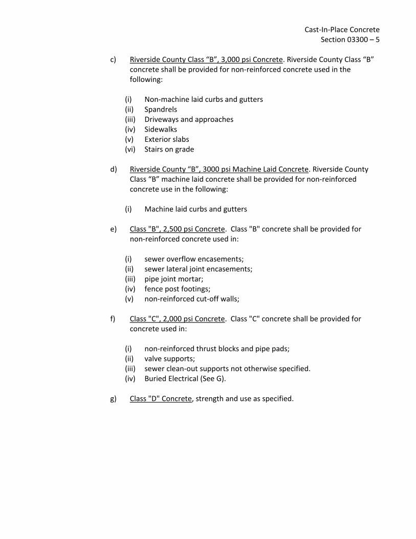
Cast-In-Place Concrete Section 03300 – 5
c) Riverside County Class “B”, 3,000 psi Concrete. Riverside County Class “B”
concrete shall be provided for non-reinforced concrete used in the following:
(i) Non-machine laid curbs and gutters (ii) Spandrels (iii) Driveways and approaches (iv) Sidewalks (v) Exterior slabs (vi) Stairs on grade
d) Riverside County “B”, 3000 psi Machine Laid Concrete. Riverside County Class “B” machine laid concrete shall be provided for non-reinforced concrete use in the following:
(i) Machine laid curbs and gutters
e) Class "B", 2,500 psi Concrete. Class "B" concrete shall be provided for non-reinforced concrete used in:
(i) sewer overflow encasements; (ii) sewer lateral joint encasements; (iii) pipe joint mortar; (iv) fence post footings; (v) non-reinforced cut-off walls;
f) Class "C", 2,000 psi Concrete. Class "C" concrete shall be provided for concrete used in:
(i) non-reinforced thrust blocks and pipe pads; (ii) valve supports; (iii) sewer clean-out supports not otherwise specified. (iv) Buried Electrical (See G).
g) Class "D" Concrete, strength and use as specified.

Cast-In-Place Concrete Section 03300 – 6
(i) Basis for Mix Designs. Design concrete mixes for workability of mix and durability of concrete. Concrete mixes shall be rigidly controlled in accordance with laboratory trial batch method or combinations of materials previously evaluated as required by Sections 5.3, respectively, Standard Building Code Requirements for Reinforced Concrete (ACI 318, latest edition), of the American Concrete Institute and to satisfy herein specified concrete strength requirements. When, in the opinion of the Engineer, it becomes necessary to increase the cement content to gain the required strength, such adjustment shall be made at the Contractor's expense.
(ii) Water/Cement Ratios. Mixes for normal weight aggregate concrete shall be designed within the following maximum water/cement ratios when concrete is to be used in the various locations: For 4,000 psi water-bearing structural concrete limit water/cement
ratios by weight as follows: Freshwater-bearing structures 0.48 maximum Sewage-bearing structures 0.45 maximum
For all other concrete, water/cement ratios shall be no greater than 0.53, except EMWD mixes and Riverside County mixes listed in Section 2.02.
B. Preliminary Strength Tests. In laboratory, prepare nine (9) compression test cylinders
for each concrete mix design (unless more tests are required for an earlier age). Fabricate and cure cylinders in accordance with ASTM C3l. Use concrete, aggregates and admixtures proposed for the concrete work. In accordance with ASTM C39, test three sets of two cylinders at 28-day age. For each mix, no individual strength test result shall fall below the required fc'.
C. Drying Shrinkage Tests. For each mix design used for preliminary strength tests, using same concrete materials including admixtures, prepare three (3) test specimens for drying shrinkage testing. Specimens shall be 4 inch by 4 inch by 11 inch prisms fabricated, cured, and tested in accordance with ASTM C157, using 10 inch effective gauge length. Measurements shall be taken at one (1) day, seven (7) days, fourteen (14) days and twenty-one (21) days of curing. Zero measurement shall be the one day reading when determining shrinkage. The measurements after 7, 14, and 21 days of drying shall be taken and reported separately. The average drying shrinkage of each set of test specimens after two (2) days of drying shall not exceed 0.036% for concrete in all portions of water-bearing structures and not exceed 0.05% for all other structural concrete, except concrete for footings, piles and pile caps will not require drying shrinkage tests. Single specimens shall be within a tolerance of 25% of said maximum percentage.

Cast-In-Place Concrete Section 03300 – 7
D. Reports. File three (3) copies of each mix design, preliminary strength test report, and drying shrinkage test report with District for review and approval. Contractor shall submit a letter of certification by an approved testing laboratory that the concrete materials, mixes, properties, and work conform to the requirements indicated and specified.
1.05 PRODUCT DELIVERY, STORAGE, AND HANDLING Deliver materials in a timely manner to insure uninterrupted progress of work. Store materials in a manner that will preclude damage and permit ready access for inspection and identification.
A. Materials for treatment of concrete surfaces. The contractor shall deliver sealers, coatings, waterproofing, or other surface treatment materials to the site in their original, unopened containers with the manufacturer's labels intact, describing contents and manufacturer. Stored materials shall be kept covered and precautions shall be taken for the prevention of fire. Empty containers and soiled or oily rags shall be removed from the site at the end of each day's work.
1.06 PAYMENT Payment for cast-in-place concrete shall be based upon concrete poured and found acceptable upon the removal of forms and performance of required finishing. Under no conditions will more than 90% payment be made for concrete formed and poured until required finishing is completed. On large structures requiring construction over multiple payment periods, consideration may be given by the Engineer for payment as follows:
A. Forms and rebar in place and accepted for concrete pour - 50% maximum of concrete price per cubic yard.
B. Concrete poured and forms stripped, and found acceptable to the stage of construction - 35% maximum of concrete price per cubic yard.
C. Concrete finished and found acceptable - 15% of concrete price per cubic yard.
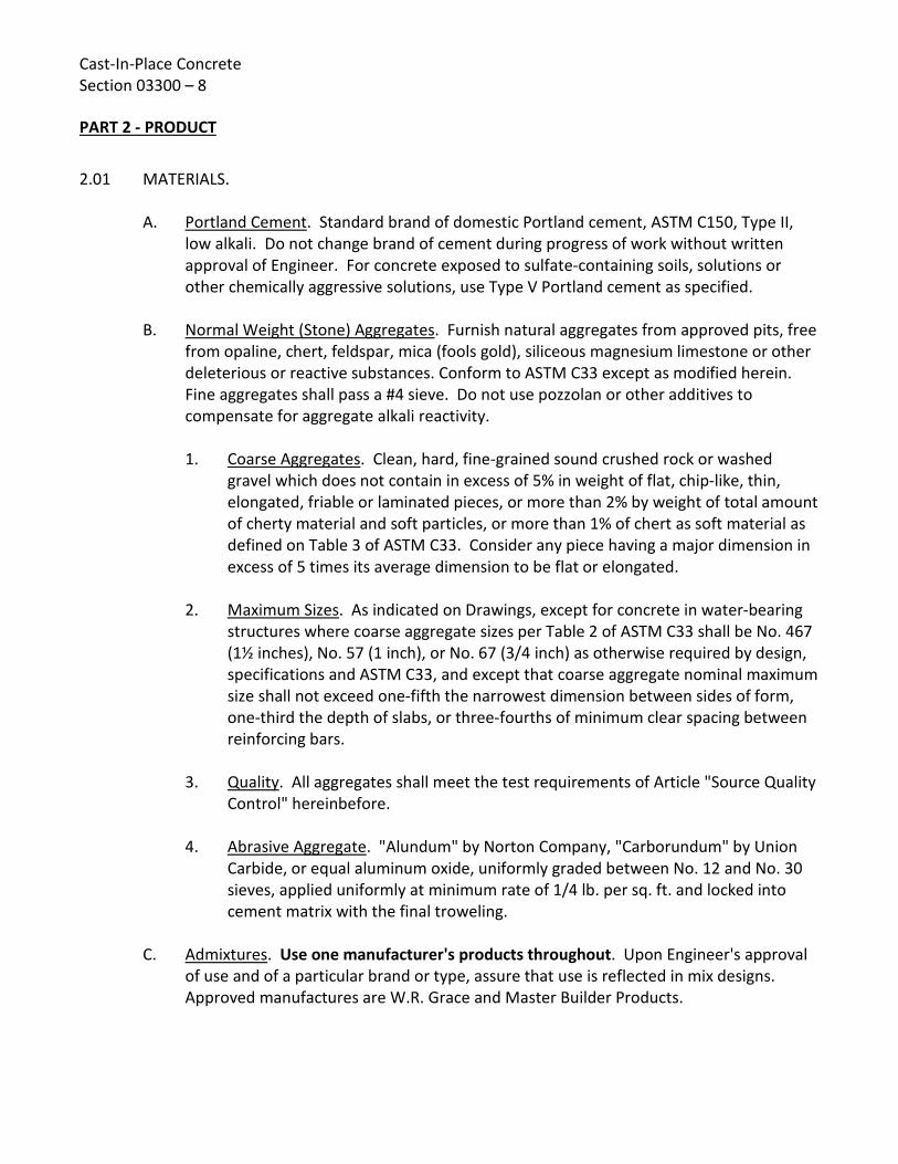
Cast-In-Place Concrete Section 03300 – 8 PART 2 - PRODUCT
2.01 MATERIALS.
A. Portland Cement. Standard brand of domestic Portland cement, ASTM C150, Type II, low alkali. Do not change brand of cement during progress of work without written approval of Engineer. For concrete exposed to sulfate-containing soils, solutions or other chemically aggressive solutions, use Type V Portland cement as specified.
B. Normal Weight (Stone) Aggregates. Furnish natural aggregates from approved pits, free from opaline, chert, feldspar, mica (fools gold), siliceous magnesium limestone or other deleterious or reactive substances. Conform to ASTM C33 except as modified herein. Fine aggregates shall pass a #4 sieve. Do not use pozzolan or other additives to compensate for aggregate alkali reactivity. 1. Coarse Aggregates. Clean, hard, fine-grained sound crushed rock or washed
gravel which does not contain in excess of 5% in weight of flat, chip-like, thin, elongated, friable or laminated pieces, or more than 2% by weight of total amount of cherty material and soft particles, or more than 1% of chert as soft material as defined on Table 3 of ASTM C33. Consider any piece having a major dimension in excess of 5 times its average dimension to be flat or elongated.
2. Maximum Sizes. As indicated on Drawings, except for concrete in water-bearing structures where coarse aggregate sizes per Table 2 of ASTM C33 shall be No. 467 (1½ inches), No. 57 (1 inch), or No. 67 (3/4 inch) as otherwise required by design, specifications and ASTM C33, and except that coarse aggregate nominal maximum size shall not exceed one-fifth the narrowest dimension between sides of form, one-third the depth of slabs, or three-fourths of minimum clear spacing between reinforcing bars.
3. Quality. All aggregates shall meet the test requirements of Article "Source Quality Control" hereinbefore.
4. Abrasive Aggregate. "Alundum" by Norton Company, "Carborundum" by Union Carbide, or equal aluminum oxide, uniformly graded between No. 12 and No. 30 sieves, applied uniformly at minimum rate of 1/4 lb. per sq. ft. and locked into cement matrix with the final troweling.
C. Admixtures. Use one manufacturer's products throughout. Upon Engineer's approval
of use and of a particular brand or type, assure that use is reflected in mix designs. Approved manufactures are W.R. Grace and Master Builder Products.
Cast-In-Place Concrete Section 03300 – 9
1. General. Use no admixture containing chlorides or triethanolamine. Admixtures
used in combination shall be physically and chemically compatible and shall be so certified by each admix manufacturer and by Testing Laboratory that prepared respective mix designs.
2. Retarding-Densifier Admixture. In all Class "AA", Class "A", and Class "B" Concrete use a hydroxylated carboxylic acid type admixture in the amounts recommended by the manufacturer. The admixture shall provide the following, and Contractor shall provide proof thereof at time of request for approval:
a) Decrease drying shrinkage.
b) Increase compressive strength at all ages up to and including five (5) years.
c) Increase flexural strength, modulus of elasticity, and abrasive resistance.
d) The water/cement ratio and required strengths shall be maintained as scheduled (cement factor for a cubic yard of concrete, reduced proportionately).
e) There shall be no loss of workability resulting from reduction in slump. If
the admixture is of liquid type, it must be considered in proportioning water.
3. Air Entrainment. Use air entrainment additive conforming to ASTM C260 as
approved by the District.
a) For normal weight aggregate concrete subject, after curing, to freezing temperature while wet shall contain air entrainment within limits of Table 4.2.1 of ACI 318, latest edition and Table 4.2.2.4 of ACI 301, latest edition.
b) Air Entrainment in Water-bearing Concrete Structures, as determined in
accordance with ASTM C231 or C173, shall provide air contents as follows for mixes with the following coarse aggregate sizes:
(i) 5% + 1% for Size 467 (1½ inch nominal size) (ii) 6% + 1% for Sizes 57 or 67 (1 inch or 3/4 inch nominal sizes)
D. Water. From a domestic potable source.
E. Expansion Joint Material. Type I, preformed sponge neoprene expansion joint filler
conforming to AASHTO Designation M-153.

Cast-In-Place Concrete Section 03300 – 10
F. Bituminous Mastic. For fills at specific designated locations (such as fills at precast panel lift-eyes and dowel hole fills in precast concrete panels) use either Hot-Applied Type Joint Sealer, ASTM D1190 or Cold-Applied Type Joint Sealant, ASTM D1850. Material shall bond to concrete, prevent moisture infiltration and when set, shall be non-tracking at summer temperatures.
G. Waterstops. Waterstops shall be produced by an extrusion process in such a manner that any cross section shall be dense, homogeneous and free from porosity and other imperfections. They shall be symmetrical in cross-sectional shape and uniform along their length. The manufacturer must certify in writing that all waterstops are extruded from elastomeric polyvinyl chloride compound and that this compound shall be virgin PVC compound and not contain any scrap or reprocessed materials whatsoever. The manufacturer must also certify in writing that all waterstops meet or exceed the physical properties requirements set forth in the U.S. Corps of Engineers' CRD-C572-74 specification and furnish a copy of certified independent laboratory test data showing compliance. All waterstop intersections (ells, tees, crosses, etc.) shall be fabricated by the manufacturer and these shall have 2 ft. long legs to facilitate field butt splicing. Where field dimensions are encountered which will not accommodate the specified waterstop, waterstop of reduced dimension may be approved by the Engineer for a specific application.
H. Concrete Joint Sealants. For sealing joints in nonwater-bearing concrete surfaces, use materials conforming with requirements specified in Section 07920, "Sealants and Caulking". For sealing concrete joints which will be immersed or intermittently immersed in water or sewage-bearing surfaces, use: Karlee Company's "Lastex M" 100 percent solids polyurethane sealant; Mameco International's Vulkem 227, Vulkem 45, or Vulkem 245 contingent upon need for self-leveling, non-sag and atmospheric humidity at time of usage; Hunt's Seal Flex 227-U Special Reservoir Grade polyurethane sealant; or equal. 1. Primer. Use primer produced and/or recommended by sealant manufacturer.
2. Back-up Preformed Joint Filler. Use closed-cell polyethylene foam or equal
impervious, compatible, compressible foam material recommended for retaining sealant depth in expansion joints while curing. Use no bitumen or oil saturated material.

Cast-In-Place Concrete Section 03300 – 11
3. Bond Breakers. Bond breakers, where required, shall be polyethylene tape or
equal as recommended by sealant manufacturer to prevent adherence of sealant to back-up material.
I. Dry Pack Mortar. Dry pack mortar shall consist of by volume one part special cement, three parts sand and water. The special cement and sand shall be combined in the proper proportions and then thoroughly mixed with the required amount of water. The dry pack mortar shall contain only enough water to permit placing and packing and shall be mixed for the time limit as indicated by the manufacturer in advance of use. The dry pack mortar shall be placed against thoroughly wet concrete and shall be cured by water, fog spray, spray-on membranes, sisal kraft paper, or other curing method acceptable to the District.
J. Grout. Grout to be applied to the concrete surface shall consist of one part Portland Cement to three parts dry, washed sand to sufficient water to allow placement, screening, and finishing.
K. Rich Grout. Rich grout shall consist of by volume one part Portland Cement, two parts sand and water. The rich grout shall be mixed and cured in the same manner as required for dry pack mortar.
L. Neat Grout. Neat grout shall consist of Portland Cement, flyash, water and optional admixtures. Neat grout is intended to be injected under low pressure to backfill the annular space between steel casing pipes and carrier pipes.
M. Nonshrink Grout. Nonshrink grout shall be made with the following proportions:
One part Type II Portland Cement (one sack); One part Nonshrink Aggregate (100 lbs.); One part clean, well graded concrete sand (100 lbs.); Approximately 5.5 gallons of water per sack of cement 1. In all locations where the surface of the grout will be exposed to view, the
nonshrink grout shall be recessed approximately one-half inch back of the exposed surface and the recessed area filled with cement mortar grout.
N. Nonshrink Concrete. All nonshrink concrete shall contain one pound of nonshrink
aggregate per pound of water that is in excess of two gallons per sack of cement. Recess surface exposed to field as specified for nonshrink grout above.
O. Nonshrink Aggregate. Nonshrink aggregate shall be non-metallic as produced by Master Builders, an equivalent product of Sonneborn, or a product by any other manufacturer that will meet the same ASTM requirements and equal performance.

Cast-In-Place Concrete Section 03300 – 12
P. Epoxy. Epoxies for grouting, crack repair, patching, bonding or other uses shall be as follows as manufactured by Adhesive Engineering Company, Sika Chemical Company, or equal by other manufacturer. Throughout, use products of single manufacturer. 1. All epoxy mixing, surface preparation and application shall be made in
conformance with manufacturer's printed specifications, as approved by the Engineer.
2. For bonding new concrete to old concrete and for grouting metal anchors, use Sika's "Sikadur Hi-Mod", Adhesive Engineering Company's Concresive 1001-LPL, except Concresive 1170 or 1422 shall be used as recommended by manufacturer to satisfy entailed project temperature and surface moisture variations at time of application; or equal.
3. For patching concrete surfaces, making high strength epoxy concrete or grout, and grouting metal anchors, use Sika's "Sikadur Hi-Mod LV"; Adhesive Engineering Company's "Concresive 1180"; or equal.
4. For pressure injection or gravity-feed grouting, use Sika's "Hi-Mod LV"; Adhesive Engineering Company's "Concresive Structural Concrete Bonding Process System" as recommended by manufacturer and approved by Engineer; or equal.
Q. Liquid Curing Compound. Use "TLF" or "Clear 225 TU" by Hunt Process Company, Burke
"Rez-X", or equal conforming to ASTM C309 and providing no detrimental affects with deferred finishes. On surfaces within reservoirs or other concrete structures containing potable water, use nontoxic materials which are free of odor and taste. Provide supporting technical data. Floor hardener treated floors shall use materials only as recommended in writing by hardener manufacturer.
R. Sheet Curing Materials. ASTM C171, waterproof paper, polyethylene film or white burlap-polyethylene sheet, non-staining.
S. Vapor Barrier Membrane. Under interior on-grade slabs of occupied areas provide lapped and sealed vapor barrier membrane using Fortiber "Moistop", "Damproof XX" by Nicolet of California, Incorporated, or equal with manufacturer's recommended polyethylene pressure sensitive tape sealant used continuously at lapped joints, penetrations and at perimeter walls or footing surfaces. Throughout, use products and system of single manufacturer.
Cast-In-Place Concrete Section 03300 – 13
T. Gasket Seal for Manhole and Wet Well Precast Concrete Members. Provide gasket seals
at mating joint of precast concrete sections. Size gaskets to suit joint dimensions, surface conditions and to assure watertight completed installation. Seal shall consist of either compressible closed-cell neoprene rods with compatible bonding agent recommended by material manufacturer; of No. 95 extruded butyl rod and No. 2 Primer each produced by General Sealants, Incorporated, City of Industry, California; or equal non-bituminous joint sealing compressible gaskets.
U. Synthetic Sponge Rubber Filler. Synthetic rubber filler shall be an expanded closed-cell sponge rubber, manufactured from a synthetic polymer neoprene base. The material shall be No. 750.3 Ropax Road Stock as manufactured by the Presstite Division of Interchemical Corporation; Bondtex as manufactured by Rubatex Corporation; or approved equal. The size of the material shall be 25% greater in diameter than the nominal joint width. The manufacturer's instructions for surface preparation and application shall be used as a guide for installation, except that the material shall not be installed by stretching beyond its normal length.
V. Expansion Joint Filler. Bituminous fiber expansion joint filler shall be in accordance with ASTM D1751. Bituminous expansion joint material shall not be used in joints to be sealed with synthetic rubber sealing compound.
W. Concrete Expansion Bolts/Deferred Bolting Device (D.B.D.). Except as otherwise specified, where expansion bolts are called for on the Drawings, Parabolt Concrete Anchors as manufactured by the Molly Company, Kwik-Bolts as manufactured by McCulloch Industries, Incorporated, or a concrete anchor by any other manufacturer that shall meet the same Federal Specification requirements and shall equal the performance, shall be used. All bolts thus furnished and used on this project shall be manufactured of stainless steel.
2.02 CONCRETE MIXES
A. 28-Day Compressive Strength. It shall be the sole responsibility of the Contractor to mix, place, and cure concrete which shall be of 150 lb./cu.ft. nominal density and which shall attain the compressive strengths at 28 days as designated on Structural Drawings or in these specifications for use in various locations. 110695
B. Maximum Aggregate Size. Conform to Article 2.01 B.2. For Class "AA" concrete use 1½ inch maximum size aggregate unless otherwise designated; for Class "A" and Class "B" use 1 inch maximum size aggregate; for Class "C" and Class "D" use 3/4 inch maximum size aggregate. In no case shall the size of the coarse aggregate exceed 75% of the horizontal space between reinforcing bars or between reinforcing bars and forms.
Cast-In-Place Concrete Section 03300 – 14
C. Mix Designs. Conform with requirements of Article 1.04 "Concrete Mix Designs and Preliminary Tests". At least 60 days before any Class concrete is to be placed, the Contractor shall submit for approval for each proposed mix a mix design made by a Civil Engineer registered in California or a Testing Laboratory approved by the District.
1. In lieu of a submittal from the Contractor for a required mix design, upon approval
of the Engineer the following mixes may be used with a slump of 4 to 5 inches: EMWD Mix #9 (Class "A" structural concrete)
Cement: 5.5 sacks/c.y., 517 lbs./c.y. Water: 32-34 gal./c.y. Aggregate: 1985 lbs./c.y. - #3 (3/4 inch to 1 inch max.) Sand: 1359 lbs./c.y. Admixture: Master Builders: 4
300-N W.R. Grace: 5 oz/100 lbs. cement WRDA-79, or 3 oz/100 lb. cement WRDA-64 or other water-reducing admixture meeting ASTM C-494 Type A (21 fl. oz/c.y.).
Standard Specifications for Public Work Construction Class 560-C-3250 (Optional mix for Class “A” structural concrete)
Cement: 5.96 sacks/c.y., 560 lbs./c.y. Water: 38 gal./c.y Aggregate: 1478 lbs./c.y. - # 3 (3/4 inch to 1 inch max)
246 lbs./c.y. - # 4 (3/8 inch max) Sand: 1355 lbs./c.y. Admixture: Master Builders: 4 + 1 fl. ozs./100 lbs. of cement, Pozzolith Type
300-N W.R. Grace: 5 oz/100 lbs. cement WRDA-79, or 3 oz/100 lb. cement WRDA-64 or other water-reducing admixture meeting ASTM C-494 Type A (21 fl. oz/c.y.).
The combined aggregate grading shall be per Standard Specifications for Public Work Construction Section 201- 1.3.2 as shown below:
Sleve size Percent Passing
1½" 100 1" 95-100
3/4" 77-93 3/8" 50-70
Cast-In-Place Concrete Section 03300 – 15
No. 4 39-51 No. 8 31-41
No. 16 22-32 No. 30 12-22 No. 50 3-9
No. 100 0-3 No. 200 0-2
EMWD Mix #6 (Class "B" concrete)
Cement: 4.7 sacks/c.y., 441.8 lbs./c.y. Water: 30-32 gal./c.y. Aggregate: 415 lbs./c.y. - #4 (3/8 inch max.)
795 lbs./c.y. - #3 (3/4 inch to 1 inch max.) 1006 lbs./c.y. - #2 (1½ inch max.)
Sand: 1230 lbs./c.y. Admixture: Master Builders: 4
300-N W.R. Grace: 5 oz/100 lb. cement WRDA-79, or 3 oz/100 lb. cement WRDA-64 or other water-reducing admixture meeting ASTM C-494 Type A (18 fl. oz/c.y.).
Riverside County Class “B” Concrete
Cement: 5.5 sacks/c.y., 517 lbs./c.y. Water: 36.5 Gal./c.y. Course Agg. 1" x #4: 1559 lbs./c.y. Course Agg. 3/8" x #8: 226 lbs./c.y. Sand: 1434 lbs./c.y. Water Cement Ratio: 0.59 max. Slump: 4" max.
Course aggregate shall meet the grading requirements of ASTM C33. The combined aggregate grading shall be per Caltrans Standard Specification 90-3.04(1"max), as shown below:
Sleve size Percent Passing
1½" 100 1" 95-100
3/4" 55-100

Cast-In-Place Concrete Section 03300 – 16
3/8" 45-75 No. 4 35-60 No. 8 27-45
No. 16 20-35 No. 30 12-25 No. 50 5-15
No. 100 1-8 No. 200 0-4
Riverside County Class “B” Machine Laid Concrete
Cement: 5.5 sacks/c.y., 517 lbs./c.y. Water: 34.0 Gal./c.y. Course Agg. 1" x #4: 1388 lbs./c.y. Course Agg. 3/8" x #8: 295 lbs./c.y. Sand: 1589 lbs./c.y Water Cement Ratio: 0.55 max. Slump: 2" max
Course aggregate shall meet the grading requirements of ASTM C33. The combined aggregate grading shall be per Caltrans Standard Specification 90-3.04(1"max), as shown below:
Sleve size Percent Passing
1½" 100 1" 95-100
3/4" 55-100 3/8" 45-75 No. 4 35-60 No. 8 27-45
No. 16 20-35 No. 30 12-25 No. 50 5-15
No. 100 1-8 No. 200 0-4

Cast-In-Place Concrete Section 03300 – 17
EMWD Mix #10 (Class "C" concrete)
Cement: 4.5 sacks/c.y., 423 lb./c.y. Water: 32-34 gal./c.y. Aggregate: 1903 lb./c.y. Sand: 1480 lb./c.y. Admixture: None
2.03 CONCRETE MIXING Concrete shall be ready-mixed, supplied from an off-site commercial ready-mix plant approved by District, each load accompanied by a bonded weighmaster's certificate listing the quantity of each concrete ingredient, admixture quantity, water content and slump, and time of loading and departure from ready-mix plant. Also include notations to indicate equipment was checked and found to be free of contaminants prior to batching.
A. Ready-Mixed Concrete. Unless approved otherwise in advance of batching, all concrete of a single design mix for any one day's pour shall be from a single batch plant of a single supplier. Conform to ASTM C94, except materials, testing and mix design shall be as specified herein. Use transit mixers equipped with automatic devices for recording number of revolutions of drum. All applicable mixing requirements specified herein for concrete mixed at the site shall govern transit-mixed concrete and the District shall have free access to the batching plant at all times. For concrete mixed in top-loading truck mixers, each batch shall be turned not less than 40 and not more than 300 revolutions of the mixer drum at mixing speed when the fine and coarse aggregate are charged into the mixer simultaneously (cement and water may be charged separately). When the fine and coarse aggregate are charged into the mixer separately, each batch shall be turned not less than 60 and not more than 300 revolutions of the drum at mixing speeds. For concrete mixed in end-loading truck mixers, each batch shall be turned not less than 60 and not more than 300 revolutions of the mixer drum at mixing speed when the mixer is loaded in excess of 50 percent of the gross drum volume as provided hereinafter. When the mixer is loaded (not to exceed 50 percent of the gross drum volume) the provisions specified for top-loading truck mixers will apply. Truck mixers shall be loaded in accordance with manufacturer's capacity ratings, but in no case shall the volume of mixed concrete exceed 50 percent of the gross volume of the drum for top-loading mixers and 58 percent of the gross volume of the drum for end-loading truck mixers.

Cast-In-Place Concrete Section 03300 – 18
Mixing speed shall be in accordance with manufacturer's recommendations, but in no case shall the speed be less than 4 revolutions per minute or greater than a speed resulting in a peripheral velocity of the drum of 225 feet per minute. The power unit shall be equipped with a governor to insure constant speed. Each truck mixer shall be equipped with a device for counting the number of revolutions of the drum, which device shall be interlocked so as to prevent the discharge of concrete from the drum before the required number of turns. After the drum is once started, it shall be revolved continuously until it has completely discharged its batch. Water shall not be admitted to the mix until the drum has started revolving. The right is reserved to increase the required minimum number of revolutions or to decrease the designated maximum number of revolutions allowed, if necessary, to obtain satisfactory mixing, and the Contractor will not be entitled to additional compensation because of such increase or decrease.
B. Mixing Water Limitations. If water is added at the batching plant, ready-mixed concrete shall not be held in the mixer for more than one and one-half hours from the time the water is added. When temperature of concrete is 85°F or above, reduce holding time to 45 minutes. Do not deliver ready-mixed concrete to job with total specified amount of water incorporated therein. Without 2½ gallons of water per cubic yard, then incorporate in mix before concrete is discharged from mixer truck. If no water is added at the batching plant, measured quantities of water shall be added at the site and a minimum of fifteen minutes mixing given, or mixing to overcome segregation. Adding of water shall be under observation of Inspector. Each mixer truck shall arrive at the job site with its water container full. In event container is not full or concrete tests to a greater slump than specified, the load is subject to rejection.
C. Job Mixed Concrete. Contractor shall obtain the approval of the District for equipment and procedures proposed for job mixed concrete.
D. Consistency and Slump. Adjust quantity of water so concrete does not exceed maximum slumps specified when placed or specified water/cement ratio; use minimum necessary for workability required by the part of the structure being cast. Measure consistency of concrete in accordance with ASTM C143. Concrete exceeding maximum slump will be rejected. Part of Structure Maximum Slump
Footings and mass concrete not reinforced 3 inches
Slabs, and floors and reinforced footings 2 to 3 inches
Columns, walls over 8 inches thick 3 to 4 inches
Walls up to 8 inches thick 3 ½ to 4 inches
Equipment bases 3 to 5 inches

Cast-In-Place Concrete Section 03300 – 19
PART 3 - EXECUTION
3.01 PREPARATION BEFORE PLACING Remove excess water from forms before concrete is deposited. Divert any flow of water without washing over freshly deposited concrete. Remove hardened concrete, debris, and foreign materials from interior of forms and from inner surfaces of mixing and conveying equipment.
A. Forms. Prior to placing concrete, forms shall meet the requirements of Section 03150, as approved by the Engineer. Concrete to be poured on earthwork such as slabs or stairs on grade shall meet the same requirements for approval prior to pouring as above specified for the approval of forms.
B. Reinforcement. Reinforcement shall have been secured under work of Sections 03150 and 03200, and inspected and approved. Embedded metal shall be free of old mortar, oils, mill scale, and other encrustations or coatings that might reduce bond. Wheeled concrete-handling equipment shall not be wheeled over reinforcing nor shall runways be supported on reinforcing. "Break-out" bars or dowels bent for forming, for subsequent straightening prior to adjacent pour, will be allowed with bars of #5 maximum size, only where specifically called out on the Drawings, and only where kinks or breaks are not likely as a result of straightening. This does not imply approval of cold joints where none designed, or any deviation from construction joint requirements elsewhere in these specifications.
C. Wetting. Wet wood forms sufficiently to tighten up cracks. Wet other materials sufficiently to reduce suction and maintain concrete workability.
D. Earth Subgrade. Lightly dampened 24 hours in advance of concrete placing, but not muddied. Reroll as necessary for smoothness, and remove all loose materials.
E. Aggregate Fill Base. Prepare same as earth subgrade. Center 30-mil plastic sheeting or roofing cap sheet on base course under indicated waterstop joints to retain mix fines within mix and prevent their percolation into base course.

Cast-In-Place Concrete Section 03300 – 20 3.02 WATERSTOPS Heat fuse joints and connections in strict compliance with manufacturer's instructions including heating tools and devices. Waterstops shall be continuous in joints, following offsets and angles in joints until spliced to waterstops at intersecting joints, completely sealing the structure. Waterstops shall be aligned and centered in joints. Secure flanges of waterstops to reinforcing bars with 18 gage wire ties spaced maximum 18 inch center. All waterstops, splices, joints, intersections, and welds shall be tested with an approved holiday spark tester before concrete is placed. The contract drawings do not indicate every location that is to have waterstop. Waterstop shall be located in all water bearing structure walls and slabs. Waterstop shall be positioned correctly during installation and all splices in length or at intersections shall be performed by heat sealing and in accordance with manufacturer's recommendations. Waterstop joints shall conform to Drawing requirements, if requirements are shown on the Drawings, and, whether or not requirements are shown on the Drawings, shall be properly heat-spliced at ends and crosses to preserve continuity. All splicing shall be done using mitered joints. Forms for construction joints shall be constructed in such manner as to prevent injury to waterstops. Waterstops shall be securely held in position in the construction joints by wire ties. In narrow walls requiring both rebar and waterstop, the rebar shall be offset to one side and the keyway and/or waterstop shall be offset to the opposite side sufficiently to allow placement of both rebar and waterstop without contact. In order to accommodate such an offset, double curtain steel may be replaced by one properly designed larger bar upon approval by the Engineer. All in-place waterstop installations including locations and joints shall be approved by District prior to placement of concrete.
3.03 JOINTS IN CONCRETE Locate joints in concrete where indicated unless otherwise approved. Obtain approval of points of stoppage of any pour, prior to scheduling of pour.
A. Construction Joints. Unless otherwise shown, all construction joints shall be provided with suitable keyways or other keying methods. Clean and roughen contact surfaces of construction joints by removing entire surface and exposing clean aggregate solidly embedded in mortar matrix. Use mechanical chipping, sandblasting, or application of surface mortar retarder followed by washing and scrubbing with stiff broom. Cover and protect waterstops and other inserts from damage. The hardened concrete shall be watered and kept wet for at least 24 hours before placing new concrete. Where construction joints are not indicated on the Drawings, provide slabs and walls with construction joints at intervals not greater than 30 feet. Starter walls shall be used unless detailed otherwise. Where utilized, starter walls shall extend a minimum of 3½ inches.

Cast-In-Place Concrete Section 03300 – 21
Where "break-out" bars are required by the contract drawings for future structure extensions, except where other methods are specifically set forth on the contract drawings a required mortar-tight enclosure of the reinforcing dowels shall be provided by installing the break-out bars in capped PVC pipe embedded 1 inch minimum into the structural concrete.
B. Expansion Joints. Provide where indicated, ½ inch width unless otherwise detailed. Except where synthetic rubber (sealant) sealed joints are shown or specified, provide expansion joint filler and joint sealer, filler head down ½ inch to 3/4 inch and sealer finished flush with surface. At synthetic rubber sealed joints, hold filler down ½ inch unless otherwise shown, ready to receive sealant. 1. Location of joints in interior slabs on grade shall be as detailed on the Drawings.
Sawed control joints shall be as approved by the Engineer
2. Control joints in exterior slabs shall be located as indicated on the Drawings, or as follows if not noted:
a) Provide bond breaker with ½ inch expansion joint material at junction of walls, bases, columns, etc.
b) Provide ½ inch expansion joints at changes in direction of slabs, or abrupt
changes in width and not greater than twenty (20) feet apart on slabs without control joints.
c) Control joints in exterior slabs shall be sealed with the specified sealer.
C. Roof and Floor Slabs. Pour slabs in alternating checkerboard fashion between indicated
construction joints, as approved. Slabs in place shall be cured as required elsewhere in these specifications a minimum of seven (7) days before adjoining slabs are cast.
D. Intermediate Screed Strips. Intermediate screed strips shall be required for all slab pours unless otherwise approved. Such approval for the omission of intermediate screeds shall be for each individual pour and no blanket approval shall be given.
E. Gasket Seals. At joints between precast concrete manhole and/or wet well units, clean mating surfaces of both members. Then within groove, place and lay continuous rod of specified compressible gasket to provide watertight installation after placement of matching tongued concrete member and compression of the gasket.
F. Joining Existing Structures. Where a construction joint to an existing structure requires a waterstop and none is found in the existing structure, Contractor shall join the old structure by chamfering the new concrete at the joint and filling the chamfer with specified epoxy sealant.
Cast-In-Place Concrete Section 03300 – 22
Where required reinforcing is not found protruding from the existing structure, required reinforcing shall be placed by drilling and placing dowels of the proper size and spacing. Where required waterstop and reinforcing is found in the existing structure, joints shall be treated as other construction joints under Articles 3.01 and 3.02.
G. Concrete for Buried Electrical. Buried electrical ducts, conduits & similar type items are to be encased in Class C red colored concrete as disignated below. Aggregate for Class C Concrete for Encasement of Electrical Conduits: 1. Graded as specified in ASTM C 33, Size Number 8. 2. Provide concrete utilizing this aggregate equal to Class C concrete in all other
respects. 3. Manufacturers: Frank D. Davis Company, Red Oxide Number 1117 or equal.
3.04 CONVEYING AND PLACING CONCRETE
A. Do not pour concrete until reinforcing steel and forms have been inspected and approved. Notify District not less than one full working day in advance of readiness for inspection of forms and reinforcing. Specific approval of individual forms by the Engineer shall be obtained before ordering of concrete. The Contractor shall give the Engineer a minimum of 24 hours notice of a scheduled concrete pour following the completion of forming. Upon inspection of the forms, reinforcing, waterstop placement, etc., the Engineer will immediately issue a written approval to pour concrete showing approval of the scheduled pour or disapproval. In the event of disapproval, the Engineer will show the Contractor the specific deficiencies, for correction within the 24 hour period prior to the scheduled pour. Upon notification by the Contractor of correction of deficiencies and reinspection and approval by the Engineer, the pour may proceed as scheduled. In the event required corrections are not made, or are not approved, the disapproval of the pour shall stand and the pour shall not proceed as scheduled, but shall be rescheduled. Any concrete not in accordance with these specifications, out of line, level, or plumb; or showing cracks, rock pockets, voids, stalls, honeycombing, exposure of reinforcing, or any other damage which will be detrimental to the work will be considered defective and must be corrected and replaced as directed by the Engineer at no additional cost to the District. Any concrete work that is not formed as indicated; is not true within 1/250th of the span; is not true to intended alignment; is not plumb or level where so intended; is not true to intended grades and levels; has voids or honeycombs that have been cut, resurfaced or filled, unless under the direction of the Engineer; has any

Cast-In-Place Concrete Section 03300 – 23
sawdust, shavings, wood or embedded debris; or does not fully conform to the contract provisions, shall be deemed to be defective and shall be removed from the site. 1. Handle or pump no concrete utilizing aluminum equipment.
2. Delivery tickets shall show the following:
a) Batch number.
b) Mix by compressive strength with maximum aggregate size.
c) Types and amount of admixtures included.
d) Air content.
e) Slump.
f) Time of loading and discharge.
g) Amount of water put in at batch plant.
h) Location in the work.
i) Specification class of concrete.
j) Date of delivery.
3. If any water is added at the job site, it shall be approved by the Engineer and the
delivery ticket noted as to the amount of water added. One copy of each delivery ticket shall be submitted daily to the Engineer.
B. Weather. Do not place concrete during rain or freezing weather unless approved
measures are taken to prevent damage to concrete. Concrete placed during periods of dry winds, low humidity, high temperatures, and other conditions causing rapid drying shall be initially cured with a fine fog spray of water applied immediately after finishing and maintained until final curing operations are started. Also under hot weather conditions, steps shall be taken to reduce concrete temperatures and water evaporation by proper attention to ingredients, production methods, handling, placing, protection, and curing.

Cast-In-Place Concrete Section 03300 – 24
1. Preventative measures taken for concrete placement during hot or cold weather shall be approved by the Engineer. There shall be no placing of concrete when ambient temperatures are below 35°F or above 100°F, or when such will be the case within 24 hours of the pour. Any concrete previously placed shall be protected from freezing.
C. Conveying. Do not drop concrete from its point of release at mixer, hopper, tremies, or
conveyances more than 6 feet, nor through reinforcing bars in a manner that causes segregation. Provide form windows, tremies, elephant trunks, and equivalent devices as required. The use of chutes for conveying or depositing concrete is not allowed except for small isolated portions of the work and only with prior approval. Deposit concrete directly into conveyances and from conveyances to final points of repose. Deposit concrete so that the surface is kept level throughout, a minimum being permitted to flow from one portion to another.
D. Placing Concrete. Concrete shall be placed and compacted within 90 minutes after water is first added to the mix, and no concrete shall be placed after there is evidence of initial set. This placing time shall be reduced to 45 minutes when the temperature of the concrete is 85°F or above. Retempering of concrete is not allowed. 1. Horizontal Construction Joints. Horizontal surfaces of previously placed and
hardened concrete shall be wet and covered with a 6 inch thick layer of concrete of the design mix with 50% of coarse aggregate omitted just before balance of concrete is placed.
2. Lifts. Pour concrete into forms immediately after mixing in a manner that will prevent separation of ingredients. Except as interrupted by joints, all formed concrete shall be placed in continuous, approximately horizontal layers, the depths of which generally shall not exceed 18 inches.
a) Walls and Slabs. In order to minimize the effects of shrinkage, concrete
shall be placed in units bounded by construction joints. The placing of units shall be done by placing alternate units in a manner such that each unit placed shall have cured at least 7 days for hydraulic structures and 3 days for all other structures before the contiguous unit or units are placed. The exception is corner sections of vertical walls, which shall not be placed until the adjacent wall panels have cured at least 14 days for hydraulic structures and 4 days for all other structures.
b) Beams and Slabs. Pouring of all beams and slabs must be continuous and monolithic with the floor system where so shown on the Drawings. At least two (2) hours must elapse after depositing concrete in walls or columns before pouring beams, etc. supported thereon.

Cast-In-Place Concrete Section 03300 – 25
3. Pumping Concrete. No increase in the specified slumps will be allowed and
required water/cement ratios shall be maintained for concrete pumping. Aluminum tubes are not acceptable for conveying concrete. Equipment shall be capable of maintaining the specified pour rates. Conform with requirements of ACI 304.2R-96, except as more stringent requirements are specified herein. Minimum conduit (tube) diameter shall be 4 inches.
4. Pour Rates.
a) Vertical Elements. Place concrete in lifts as specified at a rate that does not overstress forms nor allows the top of a lift to begin to harden before the next lift is placed. Cold joints are not acceptable.
b) Slabs. Place concrete at a rate that ensures all deposits are joined to
concrete that is still plastic and within 10 minutes of the previous pour. Concrete adjoining alternate slabs shall not be placed until the adjoining concrete has cured as required elsewhere in this specification for at least seven days unless otherwise approved by the Engineer.
5. Field Tests. During the progress of construction, the District will have tests made
to determine whether the concrete, as being produced, complies with the standards of quality specified herein. These tests will be made in accordance with ASTM C3l and ASTM C39. Each test will consist of a minimum of four cylinders, and the District, at his discretion, may take such tests as frequently as necessary to prove the quality of the concrete. In no case shall less than one test be made of each day's pour or of each 50 yards of concrete. The Contractor shall furnish the concrete for such tests but the remaining testing expense will be borne by the District. Specimens will be cured under job conditions. For all concrete, the standard age of test will be 28 days, but the 7-day test may be used provided that the relation between the 7 and 28 strengths of the concrete is established by tests for the materials and proportions used. Slump tests will be in accordance with ASTM Cl43. Enforcement of Strength Requirement. Concrete is expected to reach a higher compressive strength than that indicated as minimum compressive strength. At least the specified minimum cement shall be used, and more cement shall be used, if necessary, to meet all minimum and maximum requirements shown in the table. Failure to meet these conditions shall be considered failure of the concrete.

Cast-In-Place Concrete Section 03300 – 26
One test shall consist of the results of testing three (3) standard specimens in accordance with ASTM C3l and C39, except that if one specimen in a test shows manifest evidence of improper sampling, molding, or testing, it shall be discarded and the remaining two strengths averaged. Should more than one specimen presenting a given test show defects due to improper sampling, molding, or testing, the entire test shall be discarded. If the concrete fails to meet the specifications in the preceding paragraph, the District shall have the right to ask for additional curing of the affected portion followed by cores taken in accordance with ASTM C42 all at the Contractor's expense. If the additional curing does not bring the average of three cores taken in the affected area to at least the strength specified, the District may require strengthening of the affected portions of the structures by means of additional concrete or steel, or he may require replacement of these affected portions, all at the Contractor's expense. Core tests for below-strength concrete shall be paid for by the Contractor even though such core tests indicate the concrete has obtained the required minimum compressive strength.
E. Compaction. Effective compaction shall be obtained by vibration, agitation, spading,
and rodding until the concrete is free from voids, air bubbles, or rock pockets. Vibrators shall not be used to transport concrete within the forms. No less than one spare vibrator for each two vibrators in use on a pour, each in good working condition shall be kept on the job during pours. One experienced workman shall be assigned to the operation of each vibrator as his only duty. Operations not deemed to be satisfactory by the District shall be immediately corrected. 1. Vibration. All concrete, with the exception of concrete slabs 4 inches or less in
depth, shall be compacted with high frequency, internal mechanical vibrating equipment supplemented by hand spading and tamping. Concrete slabs 4 inches or less in depth shall be consolidated by wood or metal grid tampers, spading and settling with a heavy leveling straight edge. Carefully vibrate concrete around waterstops and ensure the waterstops are not bent or damaged.
a) Vibrators. Vibrators shall be designed to operate with vibratory element submerged in the concrete, and shall have a frequency of not less than 7,000 impulses per minute when submerged. The vibrating equipment shall be adequate at all times in number of units and power of each unit to consolidate the concrete to the maximum practicable density so that it is free from air pockets, honeycomb, entrapped air and so it closes snugly against all surfaces of forms and embedded items.
Cast-In-Place Concrete Section 03300 – 27
b) Operation of Vibrators. Do not allow vibrators to contact forms or
reinforcing. In vibrating a freshly placed layer of concrete, the vibrator shall be inserted vertically through the preceding layers that are still completely plastic and slowly withdrawn, producing the maximum obtainable density in the concrete without creating voids. Under no circumstances shall the vibrator enter or disturb concrete that has stiffened or partially set. The interval of vibrator placing shall not exceed two-thirds the effective visible vibration diameter of the submerged vibrator. Avoid excessive vibration that causes concrete segregation or causes an inordinant amount of entrained air to move to the face of the forms, which shall be causes for rejection of the concrete pour.
c) Re-Vibration of Retarded Concrete. Concrete containing retarding
admixture for structural walls and columns shall be placed by a schedule that allows each layer of concrete to be in place and compacted for at least 30 minutes before the next layer of concrete is placed. Bleed water on the surface of the concrete shall be removed before additional concrete is placed and the concrete in place re-vibrated before the next lift is placed. At tops of walls and columns concrete containing excess water or fine aggregate caused by vibration shall be removed while plastic, and the space filled with compacted concrete of the correct proportions, vibrated in place.
F. Slabs. Set screeds at maximum 8 foot centers, as approved, and verify correct
elevations with instrument level, and consideration for any camber in the form. Compact and tamp concrete to bring 3/8 inch mortar to surface, and wood float to straightedges and screeds. Make finished surfaces level or sloped as detailed, with maximum deviation of 1/4 inch from 10 feet straightedge for exposed finishes, and there shall be no low spots to impound water. Do not use steel or plastic floats of any kind of initial floating operations. Unless otherwise specified, do not apply hereinafter specified finishes until surface water disappears and surface is sufficiently hardened. Remove all bleed water and laitance as it appears.
G. Tolerances 1. Forms, sleeves, and inserts shall be set, and concrete shall be cast, to the lines and
grades indicated on the plans and as detailed in these specifications. The maximum deviation from true line and grade shall not exceed the tolerances listed in the following table.

Cast-In-Place Concrete Section 03300 – 28
Item Maximum Tolerance Sleeves and inserts +1/8 inch -1/8 inch
Projected ends of anchor bolts +1/4 inch -0.0 inch
Anchor bolt setting +1/16 inch -1/16 inch 2. Formed surface tolerances for concrete shall meet requirements for ACI surface
classes as follows, unless otherwise specified herein or in the Special Provisions. Class "A". Exposed interior and exterior concrete to be coated or painted.
Abrupt irregularities must meet a modified requirement of 1/16 inch maximum.*
Class "B". Coarse textured concrete intended to receive plaster, stucco or
wainscoting. Class "C". Exposed interior and exterior concrete not requiring coating or
painting. Class "D". Permanently concealed surfaces below permanent ground level
or operating water surface.
Permitted Irregularities in Formed Surfaces Checked with a 5-foot Template
Type of Irregularity
ACI Surface Tolerance Class of Surface
A B C D
Gradual 1/8 inch 1/4 inch ½ inch 1 inch
Abrupt *1/16 inch 1/4 inch 1/4 inch 1 inch
3. Deviation in alignment of slabs or walls shall not exceed a rate of l/8 inch in l0 feet
within the tolerances specified.
4. Slabs shall be uniformly sloped to drain.
5. Regardless of the tolerances listed herein, it shall be the responsibility of the Contractor to limit deviations in line and grade to tolerances which will permit proper installation and operation of mechanical equipment and piping.

Cast-In-Place Concrete Section 03300 – 29
3.05 CURING FORMED CONCRETE Maintain forms containing concrete in a thoroughly wet condition until forms are removed. Maintain all concrete in a continuously moist condition for not less than 7 consecutive days after pouring (14 days on projects subject to Federal Wage Determination). Keep concrete moist with fine fog spray until protected by curing materials. Use water curing method, specified liquid membrane-forming compound, or concrete curing paper or mats, all subject to approval for each specific use. Vertical surfaces shall not be cured by sprinkling method unless specifically approved by the Engineer.
3.06 PLACING GROUT
A. Grout all steel bearing plates, columns, and other structural parts set to hardened concrete using nonshrink grout. Use an approved premixed grout, adding only water in the amount recommended by the manufacturer.
B. Generally, use driest practicable mix and pack into place so no voids remain between steel and the supporting concrete.
C. When necessary, use sufficient water to produce a flowable mixture, and pour, first forming sand dams to retain the grout until partially set. When sufficient set is attained, remove dams and pack grout to refusal on all four sides, to eliminate voids; fill any resulting edge voids with drier mix.
D. In all locations where the surface of the grout will be exposed to view or in an area of high humidity, nonshrink grout shall be recessed to approximately one-half inch back of the exposed surface and the recessed area filled with cement mortar grout.
3.07 ANCHORS, SLEEVES, STAIR NOSINGS, ETC
A. Install in forms, in accordance with layout information provided by their suppliers, all necessary anchors, anchorage inserts, sleeves, slots, etc., required for fastening or passing the work of other Sections; also all such surface items as edge angles, manhole frames and other castings, trench cover frames or gratings, access panels, expansion joint covers, stair nosings, etc., having anchorage features requiring that they be installed before concrete is placed.
B. All such items shall be accurately located, carefully plumbed and leveled, securely fastened in place so that alignment and level will not be disturbed during concreting, and protected from damage until concreting is completed.
C. Provide all openings and chases in concrete, shown on the Drawings or as otherwise required.

Cast-In-Place Concrete Section 03300 – 30 3.08 EQUIPMENT BASES Provide all concrete bases or foundations shown for equipment or fixtures included in other Sections of the work unless the Drawings or Specifications indicate that bases are to be furnished as part of the equipment.
A. Material. In general, use Class "A" or Class "B" concrete as required by Article 1.04, unless otherwise specified on the Drawing.
B. Installation of Nuts and Bolts. Work from approved setting Drawings. Use steel or plywood templates and apply nuts above and below, to hold bolts in vertical position. During the course of the placement of any concrete, the Contractor shall have sufficient personnel, of whatever skill or trade required, available to check the location of all embedded anchor bolts, edge angles for grating, or any other item which may be deemed appropriate by the Engineer. This check shall be made immediately after the work has progressed to a point such that the item shall not be subject to disturbance and prior to the concrete having obtained sufficient set such that adjustment of the items, if necessary, cannot be made with unacceptable damage to the concrete. If the operation is such that repeated checks are required, they shall be made.
C. Size. Generally, the size indications and dimensions of bases shown on Drawings are approximate. The actual size, in all cases, shall be determined from the equipment furnished. Work from approved equipment supplier's drawings.
3.09 FINISHING FORMED CONCRETE
A. Within 5 days following the removal of forms, the following finishing operations shall be performed. No other finishing operations are required for permanently concealed concrete (i.e., concrete below permanent ground surface or operating water level). When specifically approved by the Engineer, finishing of concrete may be performed by units, (i.e. a complete wall, a complete structure, etc.), in which case 10% minimum concrete payment shall be retained for the finishing operation. Finishing operations to be performed:
1. Remove projections and offsets.
2. Saturate form tie holes with water and fill voids with mortar of same mix as
concrete (less coarse aggregate), cure and dry; white bonding glue manufactured for this purpose may be added to the mix in accordance with the manufacturer's instructions.

Cast-In-Place Concrete Section 03300 – 31
3. Patch all damaged areas due to spalling, voids, rock pockets and bleeding of
cement (generally caused by form leaks) with mortar over a concrete adhesive bonding agent manufactured for this purpose and applied in accordance with the manufacturer's instructions. Cut out all rock pockets to sound concrete, edges square to the surface and back beveled, and patch with tempered mortar applied over an approved epoxy concrete adhesive. Large areas (as determined by the Engineer), and all other damaged areas over ½ inch in depth shall be repaired similarly. Other damaged areas less than ½ inch in depth shall be similarly repaired, but an approved white concrete bonding agent may be used in place of epoxy concrete adhesive.
4. Finish patches flush with adjoining surfaces and cure the same as the original concrete. Attention is directed to the need for properly curing the repair patches, and for utilizing the proper bonding agent for a given situation (i.e., below operating water level). Information regarding the manufacturer's recommended use shall be furnished to the Engineer for his evaluation. Pursuant to the specifications, all concrete must be cured for seven (7) days after pouring or patching, including sacked concrete, except concrete sacked after 7 days following pouring or patching needs no further curing.
5. Small air holes may be considered those which would be covered over by sacking, and need not be repaired on external walls being waterproofed or other areas not required to be sacked under the specifications. Air holes larger than this shall be considered voids. Minor cement paste leaks are those not exposing aggregate and which can be covered over by sacking, and should be treated similarly to small air holes. Anything larger shall be considered a rock pocket or a bleed hole, depending upon the condition. Some small bleed holes may, at the discretion of the Engineer, not need to be chipped out, but may be merely sandblasted to sound concrete prior to patching.
Cast-In-Place Concrete Section 03300 – 32
B. All exposed interior and exterior formed concrete (i.e., concrete not permanently concealed from direct visible exposure under facility operating conditions, including gallery and equipment room walls and ceilings), and all concrete to be coated in the finished structure shall, in addition to the foregoing, be Brush-Off Blast Cleaned (SSPC-SP7-63) to open all paste and air holes and to remove curing compound and dust. It shall then be rubbed with cement of consistent color and burlap and/or with brick and water to eliminate pockets and produce reasonable smooth surfaces suitable for painting. A reasonable smooth surface shall be defined as a surface with no projections or form marks greater than 1/16 of an inch and no indentations after finishing. Chamfers and fillets shall be made straight and true, and uniform. Concrete to be temporarily concealed until facility is expanded shall be considered exposed concrete.
C. All formed concrete within water bearing structures and not subject to Item 3.09.B shall be brush-off cleaned (SSPC-SP7) to open all paste and air holes and to remove curing compound and dust. Alternatively, a high-pressure water spray may be used if the method is demonstrated by the Contractor to be effective in removing the curing compound and opens all defects. The high-pressure water spray alternative must be approved by the Inspector.
All defects greater than ¼ inch in depth are to be filled. Prep defects by applying by brush, a neat cement/water/latex bonding agent paste. Defects shall then be filled by immediately applying and scrubbing in a thick 60-grit sand/cement mortar paste with a sponge rubber float. The mortar is to fill defects only and all excess material shall be cut from the surface with the edge of a steel trowel. Apply curing compound to all repairs.
3.10 FINISHING SLABS AND FLATWORK As specified above, initially compact, bring 3/8 inch mortar to surface and float surfaces. Finished surfaces shall be "puddle-free" and level or sloped as indicated to above specified maximum deviation limits. Surfaces which are not within these limits shall be removed and replaced at no additional cost to District; patching is not acceptable. Keep surface moist with fine fog spray of water to prevent drying during finishing operations and until curing media is applied. Dusting with cement or sand during finishing operations is not permitted.
A. Precautions. Slabs have not been designed for heavy construction loads. Contractor shall repair or replace damaged slabs resulting from his use of heavy equipment or loadings as directed by the Engineer.
B. Rough Slabs. Broom surfaces of slab after initial set of concrete leaving coarse aggregate slightly exposed. Apply on following areas and surfaces: 1. Concrete to receive deferred concrete, grout or mortar.

Cast-In-Place Concrete Section 03300 – 33
2. Tops of footings for masonry.
C. Monolithic Trowel Finish. For all floor, slab, and flatwork surfaces not otherwise indicated or specified. After surface water disappears and floated surface is sufficiently hardened, steel trowel and retrowel to smooth surface. After concrete has set enough to ring trowel, retrowel to a smooth uniform finish free of trowel marks or other blemishes. Avoid excessive troweling that produces burnished areas.
D. Steel Float Finish. Same as monolithic trowel finish, except omit second retroweling. Apply on following area and surfaces: 1. Apply on floor slab surfaces in water-bearing structures.
2. Areas scheduled to receive resilient floor coverings.
E. Swirl Non-Slip Finish. Prepare same as steel float finish, then perform final troweling with circular motion and slightly lift trowel to produce uniform swirl (sweat trowel) non-slip finishes matching sample selected by District from Contractor-prepared 2-foot square sample panels. Unless otherwise specified, provide uniform coarse texture on exterior walking surfaces.
F. Wood Float Finish. Float to screeds. When ready, finish with wood floats to a uniformly textured surface. Apply on following areas and surfaces: 1. Exterior walking surfaces exceeding 1:10 slope.
G. Floor Hardener Application 1. Floor hardener shall be applied by dust-on method to all interior exposed concrete
floors, and to other specifically designated floors using specified materials and rates of coverage.
2. Prior to application, the Contractor shall consult with the manufacturer's field representative in regard to application of floor hardener under prevailing job conditions.
3. Float and trowel floor hardener into the surface of freshly floated concrete floors shall be in strict accordance with the manufacturer's printed instructions.
4. Cure as work progresses using method conforming to hardener manufacturer's printed directions.

Cast-In-Place Concrete Section 03300 – 34 3.11 CURING SLABS AND FLATWORK Apply curing media as soon as feasible after finishing operations without marring surfaces, and in any case on same day. Keep surfaces moist until curing is applied. Upon approval of liquid compounds, apply in strict accordance with material manufacturer's published application rates; apply two (2) spray coats, second coat sprayed at right angle direction from first coat. Carefully mask and protect adjoining surfaces where compound is used.
A. Curing Period and Protection. Maintain curing materials in proper sealed condition for minimum of 7 days (14 days on projects subject to Federal Wage Determination) after application. Keep traffic on curing surfaces to the minimum possible, and completely off liquid compound cured surfaces. Immediately restore any damaged or defective curing media.
B. Restriction. Do no use liquid membrane-forming curing compound within water-bearing structures, or on surfaces to receive deferred concrete or masonry, or on surfaces to receive fluid-applied protective coatings or waterproofing.
C. Liquid Membrane-Forming Curing Compound. Upon approval, and except as restricted above, use liquid curing compound for all slabs, floors, and flatwork. On slabs having floor hardener treatment, cure such slabs in strict conformance with printed recommendations of floor hardener manufacturer. Other special precautions may be required if concrete is exposed to freezing or otherwise adverse weather conditions during the curing period.
D. Sheet Curing. Use concrete curing sheet material on surfaces where liquid curing is not permitted, and on all joints sealed with pressure sensitive tape; immediately repair any tears during curing period. Verify that surfaces remain damp for full curing period; if necessary or directed, lift sheeting and wet surfaces with clean water, and replace sheeting.
E. Water Curing. Alternate to either liquid curing compound or sheet curing method where approved. Keep concrete continuously wet by ponding, sprinklers, or equivalent for entire curing period.
3.12 FORMED STAIRS AND TREADS Stair nosings are required on all stairs. Accurately place cast abrasive nosings and screed tread surface flush and level. Cut riser back as indicated. At exterior and wet interior locations, apply coarse textured swirl non-slip abrasive finish on surface of treads and landings. Strip protective tape from the nosings on completion of cement finishing operations.

Cast-In-Place Concrete Section 03300 – 35
3.13 CHAMFERS AND FILLETS Unless otherwise shown on the drawings or directed by the Engineer, exposed edges of formed concrete structure shall be provided with a 45°, 3/4 inch x 3/4 inch chamfer. Where fillets are shown on the drawings, they shall be formed with a 45°, 3/4 inch x 3/4 inch form chamfer, formed with a 3/8 inch radius form, or tooled with a 3/4 inch radius rounding tool. Where project is an expansion of an existing facility, chamfer selected shall be compatible with chamfer of existing facility.
3.14 JOINTS WITH SEALANT Sandblast joints to clean sound concrete, using oil-free air to provide surfaces free of oil, foreign materials, and moisture. Mix and place primer, and sealant in accordance with manufacturer's printed instructions. Install foam backing in joints so sealant depth is between one-half and two-thirds of joint width. Isolate backing from sealant using a bond breaker such as polyethylene tape, aluminum foil, or wax paper.
A. Manufacturer's Supervision. A technical representative of the sealant manufacturer shall be present at the time sealant operations are started to supervise and approve preparation, sealant mixing, and sealant applications procedures and applicators. The representative shall make frequent visits to the site to ensure that sealant installations conform to the manufacturer's instructions, and shall issue a written report to District covering each visit.
B. Crack Sealing. Before and after backfilling of the tanks, all cracks over 0.01 inch wide in concrete surfaces of tanks and other water-containing structures shall be cutout as detailed and the groove filled with backing, primer, and sealant.
C. Joint Sealer. Unless specified otherwise, IGAS type joint sealer shall be used where joint depth is equal to or greater than twice the joint width. Colma type joint sealer shall be used where the depth to width ratio is less than 2:1.
D. Sealant. All sealant shall be placed in strict accordance with the manufacturer's printed specifications by a firm specializing in this type of work for not less than five (5) years, or by the Contractor under direct supervision of the manufacturer's representative.
E. Sealant Locations. All locations where sealant is placed must be cleaned by sandblasting and be free from oil, foreign materials, and moisture. Lower surfaces of joints shall be isolated with a bond breaker such as polyethylene, wax paper, aluminum foil or polyethylene tape.

Cast-In-Place Concrete Section 03300 – 36
3.15 INSTALLATION OF PIPELINES THROUGH CONCRETE STRUCTURES
A. Whenever a pipeline or any material terminates or extends at or through a structural wall or sump, the Contractor shall install in advance of pouring the concrete the fitting or special casting required for the particular installation. Otherwise, prepare and submit shop/erection drawings of other installation methods and obtain approvals in advance of commencement of work.
B. Whenever any run of pipe is installed per approved shop/erection drawings subsequent to placing of concrete, the Contractor shall accurately position the opening in the concrete for such pipelines. Unless otherwise required, all pipes penetrating fluid containing or earth-supporting portions of the structure shall be ring flanged. 1. Opening shall be of sufficient size to permit a perfect final alignment of pipelines
and fittings without deflection of any part and to allow adequate space for satisfactory packing where pipe passes through wall to insure watertightness around openings so formed.
2. The boxes or cores shall be provided with continuous keyways to hold the filling material in place and to insure a watertight joint.
3. Boxes or cores shall be filled with nonshrink grout or nonshrink concrete.
3.16 FIELD QUALITY CONTROL
A. Concrete Tests. At District's expense, District's selected Testing Laboratory shall perform the concrete tests: 1. Compression Tests. Make one set of at least four standard test cylinders from
each day's placing and each 50 cubic yards, or fraction thereof, for each class of concrete. Date cylinder, number and tab, indicating location in structure from which sample was taken. Indicate slump test result of sample. Do not make more than one set of test cylinders from any one location or batch of concrete.
2. Test Cylinders. Provide for testing by District or Testing Laboratory to take test cylinders at the job in accordance with ASTM C31. Test specimens in accordance with ASTM C39 at the age of 7 and 28 days. Contractor shall furnish labor and assistance for casting test cylinders, and shall furnish moist curing cabinets, as required, conforming to ASTM C31 at the site.

Cast-In-Place Concrete Section 03300 – 37
3. Core Tests. Should strength of concrete, as indicated by tests, fall below required
minimum, then additional tests of concrete which the unsatisfactory samples represent may be required by District. Testing Laboratory will make such test in accordance with ASTM C42. Contractor shall fill the holes made by cutting cores with dry pack concrete. Tests for below-strength concrete shall be paid for by the Contractor even though such tests indicate the concrete has obtained the required minimum compressive strength.
4. Air Content. At time that compression test cylinders are cast, test a sample of the same concrete for air content in accordance with ASTM C231.
3.17 WATERTIGHTNESS OF CONCRETE STRUCTURES
A. All concrete structures designed to contain or convey fluid shall be tested for watertightness by the Contractor by filling with water to levels approximating what will be attained during operation and measuring the drop in level due to leakage, if any. These tests shall be made under the direction of the District, and if necessary, the tests shall be repeated until watertightness is insured.
B. Rate of filling shall be limited to minimize shock-effect to new concrete c+onstruction. Water shall be held under each condition long enough to satisfy the District that the structures are watertight. Structures shall be free of internal or external water leakage.
C. The total loss of water-level in any basin or flume shall not exceed 1/2 inch depth in 24 hours. Leakage shall be located and stopped and the structure again tested until this requirement is met. If the structure does not meet the test, the Contractor shall repair or replace at his own expense, such part of the work as may be necessary to secure the desired results, as approved by the District.
D. Regardless of the rate of leakage, there shall be no visible leakage from any concrete structure.
3.18 ALTERATIONS AND REWORK Existing concrete surfaces to receive new concrete shall be heavily sandblasted to expose coarse aggregate and produce clean coarse textured surface. Such prepared surfaces shall be coated with epoxy bonding compound immediately prior to placing concrete. The compound shall be an approved equivalent to Sika Chemical Company's "Sikastix Adhesive", Hunt Process Company's "HB Series Epoxy Mortar", or equal of type, mix and application in strict accordance with manufacturer's printed recommendations and directions for various conditions.
Cast-In-Place Concrete Section 03300 – 38
3.19 REMOVAL OF EXISTING CONCRETE, MASONRY, OR GROUT Contractor shall utilize necessary equipment and techniques to remove specified concrete, masonry, and grout without damaging or affecting the integrity of the remaining material. Upon removal to the specified limits, any exposed reinforcing steel, anchor bolts, or other embedded items, shall be chipped, cut, or ground to not less than 2 inch depth from the remaining surface. Remaining holes and cavities shall be repaired as follows:
A. Perimeter of holes or cavities shall be cut back to trueline a minimum depth of 1/2 inch. Edges shall be feathered.
B. Surfaces of holes or cavities shall be roughened by mechanical means to provide an aggregate-fractured surface with a 1/4 inch (minimum) profile and cleaned of a loose material and dust.
C. A bonding agent shall be applied to all hole or cavity surfaces immediately prior to filling with repair mortar. The bonding agent shall be Sika Corporation's "Armatec 110", Hunt Process Company's "HB Series Epoxy Mortar", or equal.
D. Holes and cavities shall be filled with Sika Corporation's "MonoTop 611" mortar, or equal. For placement greater than 3 inches in depth, 3/8 inch aggregate shall be added to the mortar to create a repair concrete. Vertical surfaces shall be formed. Horizontal surfaces, including slab overlays, shall be hand trolled and finished to match adjacent concrete.
E. Bonding agent and repair mortar/concrete shall be mixed and installed in strict accordance with the manufacturer's printed instructions.
3.20 QUALITY OF WORK Concrete work which is found to be in any way defective or out of tolerance may be ordered by the District to be removed and replaced. Should this occur, all costs shall be paid by the Contractor.
END OF SECTION 03300

Rev: 10/24/05
SPECIFICATIONS - DETAILED PROVISIONS Section 05100 - Structural Metals
C O N T E N T S
PART 1 - GENERAL ............................................................................................................................. 1
1.01 DESCRIPTION ............................................................................................................................. 1 1.02 QUALITY ASSURANCE ................................................................................................................ 1 1.03 SUBMITTALS .............................................................................................................................. 2
PART 2 - PRODUCTS .......................................................................................................................... 2 2.01 GENERAL ................................................................................................................................... 2 2.02 STRUCTURAL STEEL ................................................................................................................... 2 2.03 STEEL PIPE ................................................................................................................................. 2 2.04 CAST IRON ................................................................................................................................. 2 2.05 BLACK STEEL .............................................................................................................................. 2 2.06 STAINLESS STEEL ....................................................................................................................... 2 2.07 BOLTS ........................................................................................................................................ 3 2.08 WELDING ELECTRODES ............................................................................................................. 3 2.09 SHOP PRIME PAINT ................................................................................................................... 3 2.10 GALVANIZING ............................................................................................................................ 3
PART 3 - EXECUTION ......................................................................................................................... 3 3.01 FABRICATION ............................................................................................................................ 3 3.02 ERECTION .................................................................................................................................. 5


Structural Metals Section 05100 – 1
SECTION 05100 STRUCTURAL METALS
PART 1 - GENERAL
1.01 DESCRIPTION Requirements specified in the Conditions of the Contractors Division 1 form a part of this Section. Provide structural metal work as indicated, specified, and required.
A. Work Included in This Section. Principal items are: 1. Structural steel members.
2. Plates and connections.
B. Related Work Not included in This Section. 1. Steel reinforcement.
2. Steel decking.
3. Miscellaneous metal work.
1.02 QUALITY ASSURANCE Unless otherwise specified all work specified herein and shown on the drawings shall conform to the applicable requirements of the following specifications and codes:
A. Fabrication and Erection of Structural Steel shall be in accordance with the latest edition
of the AISC “Specification for the Design, Fabrication and Erection of Structural Steel for Buildings,” and "Code of Standard Practice for Steel Buildings and Bridges."
B. Structural Metals Other than Steel shall conform to applicable “state of the art” codes.
Structural Metals Section 05100 – 2 1.03 SUBMITTALS
A. Shop Drawings. Submit shop drawings for approval before fabrication of any of the work. Show complete fabrication details with material and specification lists. Show all welds, fabrication and finish details, and shop painting. In approving shop drawings, the District does not assume responsibility for accuracy of the work relative to other components as constructed. Also refer to applicable requirements hereafter specified in paragraph “Substitutions.”
B. Test Reports. Furnish notarized certified physical and chemical mill test reports for material used for major structural members such as beams, joists, columns, and their connectors. Perform all tests in accordance with applicable ASTM standards.
C. Shop Painting Data. In coordinated manner with requirements for Painting and Protective Coatings specified in applicable Section 09870 and 09871, Contractors shall submit product list with product data sheets of intended shop coats which for compatibility shall be the same products and manufacturer as those of deferred field-applied systems intended to be used in work of Division 9.
PART 2 - PRODUCTS
2.01 GENERAL Materials shall be new, sound, and of best commercial quality available.
2.02 STRUCTURAL STEEL Fabricated from steel conforming to the latest edition of ASTM Designation for A-36.
2.03 STEEL PIPE Where used for columns or other structural purposes, pipe shall conform to ASTM Designation A-53, Grade B, seamless.
2.04 CAST IRON Conform to ASTM A-48 Class 40B.
2.05 BLACK STEEL Conform to ASTM A-569.
2.06 STAINLESS STEEL Type 316 or, where specifically authorized, Type 304, non-magnetic.

Structural Metals Section 05100 – 3
2.07 BOLTS
A. Common. Conform to ASTM Designation A-307.
B. High Tensile. Conform to ASTM Designation A-325.
C. Stainless Steel. Type 316 stainless steel with nuts and washers of similar material.
2.08 WELDING ELECTRODES Conform to the requirements of the American Welding Society, “Specifications for Iron and Steel Arc Welding Electrodes,” latest edition.
2.09 SHOP PRIME PAINT To assure compatibility with deferred field-applied paint or coating system on ferrous metals, use shop prime paint product and manufacture as specified for systems intended for field application in applicable Section 09870 or 09871. Portions of work immediately adjacent to intended field welds and portions intended for embedment shall not be shop primed.
2.10 GALVANIZING All metal work shown or specified to be galvanized shall be zinc coated after fabrication at the rate of 1.25 oz./s.f. in conformity with “Specifications for Zinc Coatings on structural steel shapes, plates, and bars and their products,” ASTM Designation A-123. Galvanized coatings marred or damaged during erection or fabrication shall be repaired by use of DRYGALV as manufactured by the American Solder and Flux Company, Galvalloy, Galvion, or equal, applied in accordance with the manufacturer’s instructions.
PART 3 - EXECUTION
3.01 FABRICATION Workmanship shall conform to AISC specifications, latest edition. Work shall conform to drawings and approved shop drawings. Work shall be performed in the shop of any approved fabricator, except field welding, when approved, shall be as specified hereinafter.
A. Connections
1. Standard AISC, latest edition, specifications shall be used in determining the
connections (unless otherwise shown on the drawings), including the number of bolts and spacing required. In addition to the AISC specifications, the best shop practices shall be followed for shearing, punching, diameter of bolt holes, spacing, welding, etc.

Structural Metals Section 05100 – 4
2. Shop connections shall be welded, or bolted unless otherwise indicated.
3. Insofar as possible, fit all work and assemble in shop ready for erection.
B. Members 1. All members shall be free from twists, kinks, buckles, or open joints.
2. All members, holes, and their spacing shall be so accurately made that when
assembled the parts shall come together and bolt without distortion.
3. Parts assembled with bolts shall be in close contact, except where separators are required. Where unlike metals are in contact, insulate as necessary to prevent corrosion.
4. Provide bolt holes to secure special items to structural members.
5. Bearing surfaces shall be planed to true beds. Abutting surfaces shall be closely fitted. Steel requiring accurate alignment shall be provided with slotted holes and/or washers for aligning the steel.
6. All materials shall be delivered in the order in which they will be required so as to avoid all delay in completion of the project.
C. Welding
1. Welding in shop and field shall be done by operators who have previously
qualified by tests, as prescribed in the American Welding Society, "Standard Qualification Procedure." Welding of steel shall be in accordance with latest edition of the AWS "Code for Fusion Welding and Gas Cutting in Building Construction." All welds shall exhibit characteristics required by AWS D1.1 and its current revisions.
2. Make all welds with E70-XX classification mild or low-alloy steel covered arc-welding electrodes conforming to AWA A5.1 and A5.5 specifications for filler metal, except as otherwise designated on structural drawings and except as otherwise recommended by AWS and AISC for welding high strength steel alloys other than ASTM A-36 and A-53 steels. All steel before being fabricated shall be thoroughly wire brushed, clean of all scale and rust, and thoroughly straightened by approved methods that will not injure the materials being worked on. Welding shall be continuous along the entire line of contact except where tack or intermittent welding is permitted. Where exposed, welds shall be cleaned of flux and slag and ground smooth.

Structural Metals Section 05100 – 5
3.02 ERECTION
A. Erection shall include the installation and erection of all structural steel as called for in this section. The Contractor shall verify correctness before starting erection. Erection shall be performed in conformance with the latest edition of AISC Code of Standard Practice.
B. As erection progresses, the work shall be securely bolted up to take care of all dead-load, wind, and erection stresses.
C. No final bolting or welding shall be done until each portion of the structure has been properly aligned and plumbed.
D. Bolts shall be drawn up tight and threads set so that nuts cannot become loose.
E. Damaged Members. During erection, members which are bent, twisted, or damaged shall be straightened or replaced as directed. If heating is required in straightening, a heating method shall be used which will insure uniform temperature throughout the entire member. Members, which in the opinion of the District are damaged to an extent impairing their appearance, strength, or serviceability, shall be removed and replaced with new members.
F. Anchor Bolts and Anchors. Anchor bolts and anchors shall be properly located and built into connection work. Bolts and anchors shall be preset by the use of templates or such other methods as may be required to locate the anchors and anchor bolts accurately. Embedded anchor bolts that are submerged in process water or sludge, or are in enclosed tanks or spaces exposed to process gas or moisture, shall be Type 316 stainless steel with nuts of same material. To such stainless steel bolts apply a non-oxidizing lubricant grease before bolting using a molybdenum disulfide grease compound or a NO-OX-10 type compound.
G. Bearing Plates. Provide bearing plates under beams and columns resting on walls or footings. Bearing plates may be attached or loose and aligned on steel wedges or shims. After the supported members have been plumbed and properly positioned and the anchor nuts tightened, the entire bearing area under the plate shall be dry-packed solidly with bedding mortar. Wedges and shims shall be cut off flush with edge of bearing plate, and shall be left in place.

Structural Metals Section 05100 – 6
H. Substitutions. Unless otherwise directed, the exact sections, shapes, thicknesses, sizes, weights, and the details of construction shown for the structural steelwork shall be furnished, provided however that the Contractor, because of his stock or shop practices, may suggest changes if the net area of section is not thereby reduced, if the section properties are at least equivalent and if the overall dimensions are not exceeded. All substitutions or other deviations from drawings and/or specifications shall be specifically noted or "clouded" on the shop drawing submittals.
I. Flame Cutting. Flame cutting by the use of a gas cutting torch in the field for correcting fabrication errors will not be permitted on any major member in the structural framing. The use of as flame-cutting torch will be permitted only on minor members, when the member is not under stress, and then only after the approval of the District has been obtained.
J. Storage of Materials. Structural material, either plain or fabricated, shall be stored above ground upon platforms, skids, or other supports. Materials shall be kept free from dirt, grease, and other foreign matter and shall be protected from corrosion.
END OF SECTION 05100
Rev: 02/11/98
SPECIFICATIONS - DETAILED PROVISIONS Section 05600 - Standards for Aluminum Work
C O N T E N T S
PART 1 - GENERAL ............................................................................................................................. 1
1.01 SCOPE ........................................................................................................................................ 1 1.02 GENERAL REQUIREMENTS ........................................................................................................ 1 1.03 QUALITY ASSURANCE ................................................................................................................ 2
PART 2 - PRODUCTS .......................................................................................................................... 3 2.01 COORDINATION OF MATERIALS ............................................................................................... 3 2.02 MATERIALS ................................................................................................................................ 3 2.03 ALUMINUM FINISHES ............................................................................................................... 3
PART 3 - EXECUTION ......................................................................................................................... 5 3.01 GENERAL ................................................................................................................................... 5 3.02 JOINTING AND CONNECTIONS .................................................................................................. 5 3.03 FINISHING .................................................................................................................................. 6 3.04 ERECTION .................................................................................................................................. 6 3.05 PROTECTION AND CLEANING ................................................................................................... 7

Standards for Aluminum Work Section 05600 – 1
SECTION 05600 STANDARDS FOR ALUMINUM WORK
PART 1 - GENERAL
1.01 SCOPE Requirements of Division I apply to this Section. This Section contains specifications for materials, fabrication, finishing, erection, isolation, protection and cleaning pertaining to aluminum work, and forms a part of other Sections wherein aluminum work is specified to conform to requirements of this Section.
1.02 GENERAL REQUIREMENTS Refer to Division l for requirements pertaining to submittals, including preparation, transmittals, and guarantees.
A. Samples. Submit triplicate Samples of aluminum items specified under other Sections to
be finished in accordance with this Section. 1. Finish Samples. Submit samples of alloy or alloys, each with finish as specified,
clearly marked as to type of pretreatment, anodizing process, alloy, and coating thickness, color, sealing, protective coating, and identified as to which portion of the Work that the sample represents. Samples must be actual production sections of both extrusions and sheets, of size sufficient that comparisons can be made to establish allowable color range. Work provided must be within the approved color range, not to exceed 3 Delta Units. Promptly submit additional samples to replace any rejected samples, at no extra cost to Owner. Delay the processing of aluminum until Owner's approval has been obtained.
2. Approved Samples, returned to Contractor in duplicate, shall be used for control purposes during production finishing.
B. Testing
1. Test Methods. Coating thickness, ASTM B244; coating weight, ASTM Bl37; stain-
resistance, ASTM Bl36; and sealing test, ASTM B457.
2. Color Control Standard. Delta units referred to herein for color control of anodized finishes shall be as defined in National Bureau of Standards Circular C-429, "Photo-Electric Tri-Stimulus Colorimetry".
3. Production Tests. Make random production tests by above test methods.

Standards for Aluminum Work Section 05600 – 2
4. Tests By Owner. At its expense, Owner may perform above specified tests on
finished Work. Contractor shall reimburse Owner for costs of tests and retesting caused by failure of materials to pass specified tests, and shall replace unsatisfactory Work with approved conforming Work.
C. Certificates. Deliver to Owner a notarized certificate stating that anodized finishes
provided conform to these Specifications. With certificate, deliver finisher(s) test reports of tests made on random production samples, each test report certified.
D. Guarantee. Contractor and manufacturers shall jointly furnish written guarantees to Owner covering aluminum finishing performed in accordance with this Section for a period of one year from date of final acceptance of project by the Owner. 1. Defects. Guarantee shall cover all defects, including fading, corrosion, pitting,
blistering, and changes in surface appearance and characteristics. Abuse or physical damage after final acceptance of project is not considered a defect.
2. Removal and Rework. Guarantee shall also cover all costs incidental to removal, rework, refinishing and reinstallation of aluminum members showing any of the above described finish failures within the guarantee period; and all costs incidental to the removal, rework, reinstallation and refinishing of other work to enable performance of these guarantee requirements; and all costs incidental to protection of other work, building contents, occupants and equipment from damage, loss or injury.
E. Cleaning and Maintenance Instruction: Provide printed or typewritten detailed
instructions for Owner's cleaning and maintenance of anodized aluminum surfaces during life of the structure. Also provide precautions for cleaning of glass or adjacent surfaces to prevent damage to anodized finishes and members.
1.03 QUALITY ASSURANCE Unless otherwise specified, all Work specified herein and shown on the Drawings shall conform to the applicable requirements of the following specification and codes:
A. Fabricate and erect aluminum Work in conformance with applicable requirements of Chapter 28 of the UBC and herein referenced standards of the Aluminum Association.

Standards for Aluminum Work Section 05600 – 3
PART 2 - PRODUCTS
2.01 COORDINATION OF MATERIALS In writing, Contractor shall instruct the various subcontractors, suppliers and manufacturers for aluminum Work of materials to be used to ensure compliance with specified requirements, especially with respect to alloys for color anodized work. Submit to Owner one copy of each written instruction as evidence that materials have been properly coordinated.
A. Alloys and Tempers for various members where not otherwise designated shall be as required for proper forming and fabrication to meet or exceed structural requirements, and shall be of alloys specially produced to best achieve specified color anodized finishes. Provide supporting printed recommendations from parent aluminum producer. For sheet fabricated members use only homogenous aluminum products and no clad products.
2.02 MATERIALS Materials shall be new, sound and shall conform to the following:
A. All plate, pipe and structural shapes shall be new and shall conform to ASTM B209
(Plate), B308 (Shapes)), B429 (Pipe and Tubing), B2ll (Bar Stock) and applicable Federal Specifications for 606l-T6 alloy, unless otherwise noted.
B. Aluminum pipe rail shall be of 6061-T6 alloy and be Schedule 40 or greater.
C. Alloys and tempers for various members where not otherwise designated, shall be as required for proper forming and fabrication to meet or exceed structural requirements, and shall be of alloys specially produced to best achieve specified color anodized finishes. Provide supporting printed recommendations from parent aluminum producer. For sheet fabricated members use only homogenous aluminum products and no clad products.
D. Contingent upon alloys being welded, use only inert gas shielded arc or resistance welding process with filler alloys as specified in the UBC. Use no process requiring a welding flux.
2.03 ALUMINUM FINISHES Finishes are defined by, and shall conform to, Aluminum Association "Standards for Anodically Coated Aluminum Alloys for Architectural Applications". Pretreatments and finishes to be used for various items of Work are specified in other Sections, and shall conform to requirements herein.

Standards for Aluminum Work Section 05600 – 4
A. Pretreatments. Clean per AA-Cl2 prior to pretreatments. As Fabricated AA-Ml2, mill finish
Etched AA-C2l, C22 or C23, chemical matte etch as required to produce selected texture matching approved samples
Directional Textured AA-M3l, fine satin finish
Buffed AA-M2l, smooth specular
B. Clear Anodized Finishes. Natural aluminum color. 1. Class I. AA-A4l, Architectural Class I clear anodized finish having 0.0007" coating
thickness, 27 mg/sq inch coating weight, and 2.32 g/cc apparent density as minimums. For exterior and interior clear anodized work unless otherwise specified.
2. Class II. AA-A3l, Architectural Class II clear anodized finish having 0.0004" coating thickness, l5.5 mg/sq inch coating weight, and 2.3 g/cc apparent density as minimums. For interior clear anodized work only where specified.
C. Color Anodized Finishes
1. Type. AA-A42, Architectural Class I integral color coating having 0.0007" (0.0l8mm)
coating thickness, 32 mg/sq inch coating weight, and 2.55 g/cc apparent density as minimums.
2. Color. Equivalent to Kawneer's "Permanodic" Dark Bronze, as approved. This
paragraph specifies required color only, not alloys to be used. Refer to Paragraph "Coordination of Materials" hereinbefore. Perform color anodic finishing in strict accordance with procedures established by parent aluminum manufacturer whose finishing system is used, and such finishing shall be performed by finisher licensed by said parent aluminum manufacturer. Provide written certification of compliance with each.
D. Clear Protective Coating. In addition to sealing, exposed anodized surfaces shall be
treated with spray-applied clear water-white methacrylate lacquer applied to minimum 0.0005" total thickness. Allow to completely harden and cure prior to handling. Do not apply on surfaces to contact caulking or sealants.
E. Usages. Unless otherwise indicated on Drawings or specified within respective trade Sections, provide the following finishes:

Standards for Aluminum Work Section 05600 – 5
1. All Aluminum Work, except as hereinafter specified, shall be uniformly finished
with bronze colored anodic hardcoat AA-Ml2C22A42 finish of thickness not less than 0.0007" (0.0l8mm) and in uniform color matching Kawneer's Dark Bronze "Permanodic". Matching and approved equal Alcoa "Duranodic" or Kaiser's "Kalcolor" finishes are acceptable.
2. Acoustical Louver Assemblies. Aluminum surfaces of these assemblies at Compressor Building shall be finished in conformance with requirements specified in Section "Wall Louvers" to provide uniform color and specular finish match with above specified bronze colored anodic hardcoat finish.
3. Aluminum Rail and Railing Assemblies. Uniformly finish with bronze colored anodic hardcoat finish AA-M3lA42 consisting of fine satin directional texture and specified Dark Bronze Permanodic or matching and approved equal Duranodic or Kalcolor.
4. Aluminum Gratings. Aluminum Associations AA-Ml2A4l finish consisting of an as-fabricated cleaned surface with uniform clear anodic coating.
PART 3 - EXECUTION
3.01 GENERAL Accurately form and fit metal to dimensions, shapes and details shown on Drawings, approved shop drawings, and manufacturer's details of approved items. Furnish brake-formed and molded members with true, straight, sharp lines and angles, free of fractures or flaws. Brake-formed sections may not be substituted for required extruded shapes. Do not use scratched, gouged, twisted, dented or otherwise defective materials.
3.02 JOINTING AND CONNECTIONS Accurately cope and join connecting members to a hair-line fit unless otherwise detailed or approved. Except at required offsets, construct exposed surfaces with flush joints.
A. Mechanically Assembled Joints. Provide concealed reinforcing shapes and accessories,
of type and design to equal or exceed the strength of the strongest member connected. Use aluminum, non-magnetic stainless steel, or zinc-coated steel that is carefully isolated as specified hereinafter.
Standards for Aluminum Work Section 05600 – 6
B. Welded Joints. Perform welding by inert gas shielded arc method, or fluxless resistance welding method in accordance with parent metal manufacturer's published recommendations and requirements herein. Unless otherwise shown or approved, place welds on concealed surfaces and take precautions to minimize heat discoloration of exposed surfaces. Make welds of size and type to develop at least twice the strength of the connected members, except where more stringent requirements are shown, specified, or are standard with item manufacturer. Preheat and anneal as necessary to relieve residual stresses. Finish exposed welds to match adjoining surfaces. No welding will be permitted unless prior approval has been granted. 1. Welding Assemblies To Be Anodized. Construct members so faying surfaces are
free rinsing and do not trap anodizing solutions. Where weld metal is exposed, use filler rods of composition recommended by manufacturer or member to be welded.
2. Assemblies Anodized Prior to Welding. Clean areas of fusion free of anodic film prior to welding. Parts may be masked during anodizing, or sanded clean in weld area. Heat crazing or discoloring of anodic film on exposed surfaces is not acceptable.
3. Rejected Welds. Repair by re-welding only. Remove defective welds by chipping or grinding. Gas cutting is prohibited.
C. Fasteners. Unless shown, specified, or approved, do not use screws or other fasteners
on exposed surfaces. Where used, provide countersunk exposed fasteners with Phillips type flat heads. On clear anodized work, use aluminum or non-magnetic stainless steel. On color anodized work, use aluminum alloy fasteners finished to match adjoining surfaces. Provide fasteners of suitable sizes, located and spaced to securely connect work and resist imposed loads, and as may be required under other Sections, all subject to approval.
3.03 FINISHING Perform anodized finishing in plant of finisher approved and licensed by parent metal manufacturer. Exposed Work shall be free of finger marks, stains, scratches and other undesirable marks or flaws, and gripper or rack marks. Perform finishing after fabrication and forming operations are completed. Finishes shall be uniform on exposed surfaces including edges of members.
3.04 ERECTION By skilled mechanics in accordance with Code requirements, Drawings and approved Shop Drawings, plumb, level, square, true to line or curvature as required, in alignment with Work of other trades, free from waves, buckles, sags or other defects. Provide secure anchorage for all parts of Work. Drill new or existing Work as required. Coordinate with related trades to ensure proper mating and connecting of all Work.

Standards for Aluminum Work Section 05600 – 7
A. Color Anodized Work. Control and erect to maintain uniform color and appearance within one Delta unit range, with no abrupt or noticeable changes in color in adjoining pieces. Mismatching work, as determined by Architect, is subject to rejection even though individual pieces are within allowable color and one Delta unit range.
B. Isolation. Isolate aluminum from contact with dissimilar metals and materials, other than stainless steel, as follows: 1. Metals. Apply on contact surfaces a heavy brush coat of approved zinc chromate
primer made with a synthetic resin vehicle, followed by two brush coats of approved aluminum metal and masonry paint; or apply a heavy coat of approved alkali-resistant bituminous paint; or separate surfaces with a non-absorptive tape or gasket.
2. Masonry, Concrete or Plaster. Apply a heavy brush coat of approved alkali-resistant bituminous paint, or separate surfaces with non-absorptive tape or gasket.
3. Moisture-absorbent Materials and Preservatively Treated Wood. Paint such absorbent materials with two coats of approved aluminum house paint and protect aluminum contact surfaces with bituminous paint.
3.05 PROTECTION AND CLEANING
A. Protection. Provide and be responsible for protection and repair of adjacent surfaces and areas which may become damaged as a result of Work of this Section. Protect Work performed hereunder until completion and final acceptance of project by Owner. Repair or replace all damaged or defective Work to original specified condition, at no additional cost to the Owner. 1. Deliver, handle and store materials in manner to prevent damage due to stains,
discolorations, abrasions, scratches, dirt or other damaging causes. Store indoors in clean, dry, protected location.
2. Provide approved compatible, strippable, pressure-sensitive coverings or other approved protective coverings. Perform removal of strippable protective coatings immediately before acceptance of the completed building.
B. Cleaning. Maintain Work clean as Work progresses. After installation, and after danger
of subsequent damage or staining has passed, remove protective coverings from exposed surfaces, and clean all surfaces of soil and discoloration. Cleaning shall be in accordance with recommendations in Aluminum Association's Publication entitled "Care of Aluminum". All cleaners shall be acceptable to the aluminum manufacturer.

Standards for Aluminum Work Section 05600 – 8
C. Clean-up. Contractor shall keep his Work and the adjacent areas affected, free and clear
from all debris caused by the Work of this Section. During and upon completion of Work herein specified, remove from building and site all debris, unused materials and equipment caused by Work of this Section, and leave Work in a clean, acceptable condition. 1. Immediately prior to final acceptance of project, thoroughly clean all Work
provided under this Section unless instructed to do so sooner by Owner. Use no abrasive or damaging cleaning agents or procedures.
END OF SECTION 05600

Rev: 09/10/08
SPECIFICATIONS - DETAILED PROVISIONS Section 06100 - Carpentry Work
C O N T E N T S
PART 1 - GENERAL ............................................................................................................................. 1
1.01 DESCRIPTION ............................................................................................................................. 1 1.02 QUALITY STANDARDS................................................................................................................ 1 1.03 SUBMITTALS .............................................................................................................................. 2 1.04 VERIFICATION OF CONDITIONS ................................................................................................ 2 1.05 COORDINATION AND COOPERATION ....................................................................................... 3 1.06 PROTECTION ............................................................................................................................. 3
PART 2 - PRODUCTS .......................................................................................................................... 3 2.01 MATERIALS ................................................................................................................................ 3
PART 3 - EXECUTION ......................................................................................................................... 5 3.01 INSTALLATION ........................................................................................................................... 5 3.02 BAFFLE ERECTION ..................................................................................................................... 7 3.03 INSTALLATION OF FINISH HARDWARE...................................................................................... 7 3.04 REPAIRS AND REPLACEMENT .................................................................................................... 8 3.05 CLEAN UP AND DISPOSAL ......................................................................................................... 8

[PAGE LEFT INTENTIONALLY BLANK]

Carpentry Work Section 06100 – 1
SECTION 06100 CARPENTRY WORK
PART 1 - GENERAL
1.01 DESCRIPTION Provide carpentry work, complete as indicated, specified and required.
A. Work Included in This Section. Principal items are: 1. Rough bucks, blocking, curbs, and nailers.
2. Wood baffles.
3. Utility Backboards.
4. Miscellaneous wood framing and rough carpentry work.
5. Installation of finish hardware and hinged doors.
B. Related Work Not Included in This Section. 1. Formwork. (Section 03150)
2. Concrete unit Masonry. (Section 04220)
3. Insulation.
1.02 QUALITY STANDARDS Without limiting the generality of other requirements of these Specifications, all work specified herein shall conform to or exceed the applicable requirements of the referenced portions of the following publications to the extent that the requirements therein specified are not in conflict with the provisions of this Section:
A. Governing Building Code. Except as more stringent requirements are designed or
specified work of this section shall conform with applicable requirements of Chapter 23 of the UBC, latest edition.

Carpentry Work Section 06100 – 2
B. Lumber Standard. For each use, provide lumber complying with Product Standard PS 20 "American Softwood Lumber Standard" by National Bureau of Standards (NBS). Nominal sizes are indicated, provide actual sizes complying with the minimum size requirements of PS 20 for the moisture content specified for each use.
C. Plywood Standard. For each use specified under this Section, provide plywood complying with Product Standard PS 1 "Softwood Plywood/Construction and Industrial" by NBS.
D. Lumber and Plywood Grade Marking. Factory mark each piece of lumber and plywood with type, grade, mill and grading agency identification; except omit marking from surfaces to receive transparent finish, and submit mill certificate that material has been inspected and graded in accordance with requirements if it cannot be marked on a concealed surface. Certificates of Inspection and Grading by recognized agency may be submitted with each shipment of lumber and plywood, in lieu of factory marking at Contractor's option.
1.03 SUBMITTALS
A. Material Certificates - Wood Frame Construction. Where dimension lumber is provided to comply with minimum allowable unit stresses, indicate species and grade selected for each use, and submit evidence of compliance with specified requirements. Compliance may be in the form of a signed copy of the applicable portion of the lumber producer's grading rules showing design values for each selected specie and grade. Design values shall be as approved by the Board of Review of American Lumber Standards Committee.
B. Wood Treatment Data. For information only, submit two (2) copies of chemical treatment manufacturer's instructions for proper use of each type of treated material. Indicate by transmittal form that copy of each instruction has been distributed to the Installer. 1. Pressure Treatment. For each type specified, include certification by treating
plant stating chemicals and process used, net amount of salts retained and conformance with applicable standards.
1.04 VERIFICATION OF CONDITIONS Verify all dimensions at the job, especially when fabricated materials are required to conform to and fit adjacent walls and building surfaces. Contractor shall acquaint himself with work of all other crafts whose work abuts, adjoins, or is in any manner affected by work under this Section. He shall consult with Drawings and other Subcontractors, and shall expedite and coordinate materials and labor with them to avoid omissions and delays. Correlate location of furring, nailers, blocking, grounds, and similar supports so that attached work will comply with design requirements.

Carpentry Work Section 06100 – 3
1.05 COORDINATION AND COOPERATION Perform work of this Section in a fully coordinated and cooperative manner with work of other related trades to provide completed installation as detailed and specified in most expeditious manner without delay to job progress and to provide freedom of operation of completed operative members.
1.06 PROTECTION Protect all work of other trades, Owner's equipment, and work of this Section from any damage in performance of work of this Section. At all times, protect and preserve all materials, supplies, and equipment of every description. Any damage or loss caused in performance of this work shall be repaired or paid for without additional expense to the Owner.
A. Carpentry Materials. Keep carpentry materials dry during delivery, storage and
handling. Store lumber and plywood in stacks with provision for air circulation within stacks. Protect bottom of stacks against contact with damp surfaces. Protect exposed materials against weather.
B. Storing of Materials. Store materials for which a maximum moisture content is specified, only in areas where relative humidity has been reduced to a level where specified moisture can be maintained with a tolerance of plus or minus 1%.
PART 2 - PRODUCTS
2.01 MATERIALS Conform with the following, except as more stringent requirements are designated on the Drawings.
A. Lumber and Plywood Grade Marking. Factory mark each piece of lumber and plywood with type, grade, mill and grading agency identification; except omit marking from surfaces to receive transparent finish, and submit mill certificate that material has been inspected and graded in accordance with requirements if it cannot be marked on a concealed surface.
B. Lumber. Unless otherwise indicated or specified, Douglas Fir S4S manufactured and grades in accordance with latest edition of Standard Grading and Dressing Rules of WCLIB, or in accordance with "Grading Rules for Western Lumber", published by Western Wood Products Association as referenced herein. Moisture content at time of installation shall not exceed 19 percent nor be less than 7 percent as measured by surface meter method. Each piece of lumber shall bear the official grade mark of recognized grading agencies using the above-mentioned grading rules. The association standards for grading and grade marking of the lumber will be acceptable to the Owner.

Carpentry Work Section 06100 – 4
1. Light Framing Lumber. Where framing lumber from 2 inches through 4 inches thick and 4 inches or less wide is shown or scheduled on the Structural drawings, provide lumber complying with the specified requirements for dimension lumber.
2. Structural Framing Lumber. Where framing lumber 6 inches and wider, and from 2 inches through 4 inches thick is shown or scheduled, provide lumber complying with notes on Structural Drawings.
3. Timbers. a) General. Where solid wood framing of 5 inches by 5 inches or larger nominal
size is shown, provide lumber dressed S4S to minimum green size requirements of PS 20.
b) Where members of timber size are shown, provide Select Structural Grade,
beams and Stringers.
4. Miscellaneous Lumber. Provide wood for support or attachment of other work such as nailers, blocking, furring, grounds, stripping and similar members. Provide lumber of the sizes shown or specified, worked to shapes shown, and as follows: a) Moisture Content. 15% maximum for lumber items not specified to receive
wood preservative treatment.
b) Sills, Cants and Nailers for Fascia or Coping. Preservative pressure-treated Number 2 Douglass Fir or better.
c) Roof Nailer. Use preservative pressure-treated Number 2 Douglass Fir or
better nailers for gravel stops at edges of roof and at roof expansion joints. Match thickness of nailers and roof insulation.
5. Lumber for Baffles. Select Heart Redwood in accordance with California Redwood
Association (CRA) grading rules.
C. Plywood. Provide Douglas Fir Plywood, APA grade-marked, of the following types and grades or better conforming to U.S. Product Standard PSI-74: 1. For Sheathing. Unless otherwise indicated, Structural 1 or C-D with Exterior glue.
2. For Utility Backboards. A-D or better grade with "A" face exposed, Interior type,
except at exterior and "wet" interior locations where Exterior type shall be used.
D. Rough Hardware
Carpentry Work Section 06100 – 5
1. General. Nails, bolts, screws, washers, shields, inserts, etc., sizes as required,
American Commercial Standard type. Galvanize items where used in wet areas, exterior locations.
2. Connectors Into Concrete. Bolts and expansion shields, sleeved cinch anchors, drilled and bolted shells or other approved device, galvanized or stainless steel where exposed. Concrete nails and powder-driven fasteners are not acceptable.
3. Special Fabrication Rough Hardware and Connectors. Furnish under Section "Miscellaneous Metals", and installed under this Section.
4. Standard Product Hardware. As manufactured by Simpson or Arch Rib of the catalog designations indicated or approved equal.
5. Galvanizing or Ferrous Metal Items. Items shall be hot-dip galvanized in accordance with the requirements of ASTM Designation A 123 for shapes, plates and bars, and A 153 for hardware.
E. Building Paper. Asphalt saturated felt, 15-lb. non-perforated, complying with ASTM
D226.
PART 3 - EXECUTION
3.01 INSTALLATION
A. General 1. Discard units of material which are unsound, warped, bowed, twisted, improperly
treated, not adequately seasoned or too small to fabricate the work with a minimum of joints or the optimum jointing arrangement.
2. Closely fit and accurately set wood framing to required lines and levels. Provide framing members of sizes and on spacings shown, openings as shown. But, join and tightly fit framing around other work. Do not splice structural members between supports unless otherwise detailed. Members shall not be cut, notched, or bored more than one quarter (1/4) of their depth without adequate and approved reinforcing. Horizontal members shall be set with crown edge up. Completed framing shall be acceptable to receive work of other trades.
3. Securely attach rough carpentry in accordance with governing Building Code unless more stringent requirements are designated.

Carpentry Work Section 06100 – 6
a) Provide washers under bolt heads and nuts in contact with wood. Countersink to prevent interference with other work.
b) Countersink nail heads on exposed carpentry work.
4. Firestop concealed spaces with wood blocking of nominal two (2) inch thickness,
unless blocked by other framing members.
5. Provide sill plates where wood framing is supported by concrete or masonry walls or piers. Anchor to embedded bolts as shown.
B. Fasteners. Use common wire nails, except as otherwise shown or specified herein. Use
finishing nails for exposed work. Do not wax or lubricate fasteners that depend on friction for holding power. Select fasteners of size that will not penetrate members where opposite side will be exposed to view or will receive finish materials. Make tight connections between members. Install fasteners without splitting of wood; predrill as required. Do not drive threaded friction type fasteners; turn into place. Tighten bolts and lag screws at installation and retighten as required for tight connections prior to closing in or at completion of work. 1. Bolts. Drill holes 1/32 inch to 1/16 inch larger than bolts, bored true to line. Draw
nuts up tight when installed and again just before being enclosed.
2. Lag Screws. Lag screws shall be screwed and not driven into place, with anchorage embedment in piece lagged of not less than six-tenths (0.6) of the screw length or eight (8) diameters. All lag screws shall be fitted with standard malleable iron or steel plate washers under the head. A hole shall first be bored of same diameter and depth as shank. Holes for threaded portion of screw shall be bored with a bit not larger than the base of thread.
3. Common Wire Nails or Spikes. Use common wire nails or spikes of such length that, where joining one piece of lumber or timber to another, the penetration into the second or furthest piece shall not be less than one-half (1/2) length of the nail, provided, however, that 16d nails may be used to connect pieces of two (2) inch net thickness. Nails shall not be closer than one-half (1/2) their length, nor closer to the edge of the timber than one-quarter (1/4) their length. Where necessary to prevent splitting, bore holes for nails or spikes, diameter of hole to be smaller than diameter of nail or spike.
C. Wood Nailers, Blocking and Backing. Provide wherever shown and where required for
attachment of other work. Form to shapes as shown and cut as required for true lines and level of work to be attached. 1. Coordinate location with other work; refer to Shop Drawings of such work, if any.

Carpentry Work Section 06100 – 7
2. Attach to substrates securely with anchor bolts or other attachment devices as shown and as required to support applied loading. Countersink bolts and nuts flush with surfaces where shown. Build into masonry as work progresses, cutting to fit masonry unit size involved. Anchor to formwork before concrete placement.
D. Wood Furring. Install plumb and level with closure strips at edges and openings. Shim
with wood as required.
E. Wood and Plywood Backing. As indicated or required to complete the Work, provide securely attached and accurately positioned wood and plywood backing to receive plumbing and or electrical, instrumentation fixtures and equipment; other fixed equipment, cabinets, toilet room accessories and door stops.
3.02 BAFFLE ERECTION At each location, use single length boards accurately fitted to permit ease of installation and/or removal without possible inadvertent slipping out of concrete notches.
3.03 INSTALLATION OF FINISH HARDWARE In accordance with manufacturer's recommendations, install finish hardware furnished under Section "Finish Hardware", except items specified to be installed under other Sections. After installation and fitting, remove all finish hardware, tag and box, and reinstall after completion of painting. Adjust and leave in perfect working condition.
A. Adjustments and Inspections. During installation, a periodic inspection in company with the Inspector, shall be made by the Architectural Hardware Supplier or his agent, as a representative of the Owner. Any hardware improperly installed shall be removed and reinstalled at the Contractor's expense. At the completion of the work, a final inspection shall be made by the Architectural Hardware Supplier or his agent. Make any and all adjustments recommended by the Architectural Hardware Supplier or his agent.
B. Save all adjusting wrenches, instructions, keys and templates furnished with hardware and deliver to Owner or maintenance representative of the Owner.
C. Protection. Contractor shall be responsible for protecting all finishing hardware from damage during the progress of the Work. Upon completion of the Project, the Contractor shall see that all finishing hardware is properly cleaned and that any damaged parts are promptly replaced so that all hardware will be in perfect working order.
D. Guarantee. All hardware shall be guaranteed for a period of two (2) years from date of acceptance of the work. Defects in materials and workmanship occurring during the guarantee period shall be corrected to the complete satisfaction of the Owner.

Carpentry Work Section 06100 – 8 3.04 REPAIRS AND REPLACEMENT Repair, or remove and replace, defective work as directed upon completion of installation and/or during erection.
3.05 CLEAN UP AND DISPOSAL The Contractor shall maintain the site in a neat and orderly condition, to the satisfaction of the Owner, throughout the construction period, free from litter, trash and waste material. Upon completion of all work, the Contractor shall remove falsework, temporary structures and equipment used in execution of the work and he shall dispose of all rubbish, debris, and excess materials off the site.
END OF SECTION 06100

Rev: 05/15
SPECIFICATIONS - DETAILED PROVISIONS Section 08711 - Locksets and Hardware
C O N T E N T S
PART 1 - GENERAL ............................................................................................................................. 1
1.01 MATERIAL SELECTION ............................................................................................................... 1 1.02 LOCK UNIFORMITY .................................................................................................................... 1
PART 2 - PRODUCTS .......................................................................................................................... 1 2.01 LOCKSETS .................................................................................................................................. 1 2.02 LOCK STRIKES ............................................................................................................................ 1 2.03 DOOR SHOES ............................................................................................................................. 2 2.04 THRESHOLD ............................................................................................................................... 2 2.05 PANIC BARS ............................................................................................................................... 2


Locksets and Hardware Section 08711 – 1
SECTION 08711 LOCKSETS AND HARDWARE
PART 1 - GENERAL
1.01 MATERIAL SELECTION Stainless steel shall be selected for use in conjunction with sewage facilities; steel (not stainless steel) shall be selected for all other uses.
1.02 LOCK UNIFORMITY All locksets, latchsets, padlocks, cylinders, and component parts as specified hereinafter, shall be compatible with District key system.
PART 2 - PRODUCTS
2.01 LOCKSETS Manufacturer shall be Schlage, L Series, Heavy Duty Mortise locks with 06 Lever Design. Cylinders: Number of Pins: 6 pin, “F” keyway, “O” bitted. Cases: Steel, cylindrical Mortise or rim cylinder. Interior Parts: Non-corrosive with non-plastic, non-die-cast, non-aluminum mechanisms. Accessibility to Key-in-knob Type Cylinders: Not requiring removal of lockset from door. Plugs: Extruded brass bar material fully round without flattened areas. Cores: Single cork, non-removable and no control keys.
2.02 LOCK STRIKES Except as otherwise specified, lock strikes shall be Schlage, boxed with lock material and shall match lockset.

Locksets and Hardware Section 08711 – 2
2.03 DOOR SHOES Except as otherwise specified, door shoes shall be PEMKO 216A extruded aluminum for 1-3/4 inch doors.
2.04 THRESHOLD Unless otherwise specified, thresholds shall be PEMKO 218A.
2.05 PANIC BARS Panic bars shall be installed on all facility doors, no exceptions. They shall be UL labeled, touch bar exit devices capable of opening a door even when locked. Panic bars shall be provided with mortise lock devices and auxiliary bolt for deadlocking, and shall be constructed of corrosion-resistant hardware. Panic bars shall be manufactured by Von Duprin, Inc., Sargent, or approved equal.
END OF SECTION 08711

Revised 04/14/16
SPECIFICATIONS - DETAILED PROVISIONS Section 16040 – Short-Circuit/Coordination Study
and Arc-Flash Hazard Study
C O N T E N T S
PART 1 - GENERAL ............................................................................................................. 1 1.01 SUMMARY ........................................................................................................ 1 1.02 DESCRIPTION OF THE WORK .............................................................................. 1 1.03 RELATED SECTIONS............................................................................................ 3 1.04 REFERENCE STANDARDS AND CODES .................................................................. 3 1.05 SUBMITTALS ..................................................................................................... 5 1.06 QUALIFICATIONS ............................................................................................... 7
PART 2 – PRODUCTS .......................................................................................................... 7 2.01 GENERAL REQUIREMENTS ................................................................................. 7 2.02 DATA COLLECTION ............................................................................................ 8 2.03 SINGLE LINE DIAGRAM .................................................................................... 10 2.04 SHORT-CIRCUIT AND PROTECTIVE DEVICE EVALUATION STUDY .......................... 10 2.05 PROTECTIVE DEVICE COORDINATION STUDY ..................................................... 12 2.06 ARC-FLASH HAZARD STUDY .............................................................................. 15 2.07 STUDY DATA ................................................................................................... 17 2.08 IMPLEMENTATION OF STUDY RESULTS ............................................................. 20 2.09 ARC-FLASH AND SHOCK HAZARD LABELS .......................................................... 20
PART 3 - EXECUTION ........................................................................................................ 23 3.01 PROTECTIVE DEVICE SELECTION AND SETTING .................................................. 23 3.02 ARC-FLASH AND SOCK HAZARD LABEL INSTALLATION ........................................ 24 3.03 FIELD REPORT ................................................................................................. 24
ARC-FLASH LABEL EXAMPLES ........................................................................................... 25

Short-Circuit/Coordination Study and Arc-Flash Hazard Study
Section 16040 - 1
SECTION 16040 SHORT-CIRCUIT/COORDINATION STUDY AND
ARC-FLASH HAZARD STUDY PART 1 - GENERAL 1.01 SUMMARY
A. Contractor shall provide a Short-Circuit and Protective Device Evaluation Study, a Protective Device Coordination Study, and an Arc-Flash Hazard Study, as specified herein.
B. The studies shall be performed for the purposes of estimating the worst case
available short-circuit current values and arc-flash incident energy. The studies shall be generated based on information obtained from electrical equipment submittals, actual conductor sizes and lengths for all feeders, utility short circuit current value at the main service switchboard, and information obtained from field reconnaissance of existing equipment/material (if applicable).
C. Contractor shall obtain the short circuit current value at the main service
switchboard for the specific project location from the utility. Contractor shall bear all costs associated with obtaining the available short circuit current value.
D. Contractor shall adjust all required protective device settings based on the
results of the Protective Device Coordination Study and Arc-Flash Hazard Study. E. Contractor shall install Arc-Flash and Shock Hazard labels on all electrical
equipment, as specified herein. 1.02 DESCRIPTION OF THE WORK
A. Short-Circuit and Protective Device Evaluation Study
1. Contractor shall provide a Short-Circuit and Protective Device Evaluation Study to verify the proposed equipment ratings and protective device ratings.
Short-Circuit/Coordination Study and Arc-Flash Hazard Study Section 16040 - 2
2. Unless specified otherwise, the scope of the study shall include all proposed distribution equipment supplied under this Contact, as well as all directly affected existing distribution equipment at the District's facility. The study shall include all portions of the existing and proposed electrical distribution system from the electric utility power source(s) and emergency power source(s) down to and including each switchboard, distribution panel, transfer switch (automatic or manual), motor control center, variable frequency drive, distribution panelboard, branch circuit panelboard, busway, enclosed circuit breaker and fused disconnect switch.
B. Protective Device Coordination Study
1. Contractor shall provide a Protective Device Coordination Study to
determine and coordinate the selective tripping of protective devices for the proposed equipment.
2. Unless specified otherwise, the scope of the study shall include all
proposed distribution equipment supplied under this Contact, as well as all directly affected existing distribution equipment at the District's facility. The study shall include all portions of the existing and proposed electrical distribution system from the electric utility power source(s) and emergency power source(s) down to and including the smallest adjustable trip circuit breaker and fused disconnect switch in the system.
C. Arc-Flash Hazard Study
1. Contractor shall provide an Arc-Flash Hazard Study to determine
potential arc-flash incident energies, arc-flash boundaries, shock hazard boundaries; required personal protective equipment (PPE) for all energized electrical equipment; and arc-flash and shock hazard warning labels.
2. Unless specified otherwise, the study shall include all electrical circuits
from the electric utility power source(s) and emergency power source(s) to and including all electrical equipment and panelboards rated 208 V and greater.
3. Wherever possible, the proposed electrical equipment shall be designed,
manufactured, and supplied to limit the potential arc-flash incident energy to 8 cal/sq cm or less (PPE Category 2). The firm performing the studies shall coordinate with Contractor, the District, and the electrical equipment manufacturers to assist in achieving this requirement.

Short-Circuit/Coordination Study and Arc-Flash Hazard Study
Section 16040 - 3
D. Field Verification
Contractor shall provide the services of an independent testing consultant or firm performing the studies to field verify that all protective devices are set in accordance with the accepted short-circuit/coordination study requirements and recommendations. In addition, the consultant or firm shall verify that all arc-flash and stock hazard labels have been installed.
1.03 RELATED SECTIONS
A. The Contract Documents are a single integrated document, and as such all Specification Sections apply. It is the responsibility of the Contractor and its subcontractors to review all Sections and ensure a complete and coordinated project.
B. Related Specification Sections include, but are not limited to, the following:
1. Division 11 – Equipment 2. Division 16 – Electrical
1.04 REFERENCE STANDARDS AND CODES
Unless specified otherwise, all calculations, analyses, and studies, including application of same to equipment and settings shall meet or exceed the applicable requirements of the following standards and codes (latest edition):
A. Institute of Electrical and Electronics Engineers, Inc. (IEEE):
1. IEEE 141 – Recommended Practice for Electric Power Distribution for Industrial Plants
2. IEEE 142 – Recommended Practice Grounding of Industrial and
Commercial Power Systems 3. IEEE 241 – Recommended Practice for Electric Power Systems in
Commercial Buildings 4. IEEE 242 – Recommended Practice for Protection and Coordination of
Industrial and Commercial Power Systems 5. IEEE 399 – Recommended Practice for Industrial and Commercial Power
System Analysis

Short-Circuit/Coordination Study and Arc-Flash Hazard Study Section 16040 - 4
6. IEEE 551 – Recommended Practice for Calculating Short-Circuit Currents in Industrial and Commercial Power Systems
7. IEEE 1015 – Recommended Practice for Applying Low-Voltage Circuit Breakers Used in Industrial and Commercial Power Systems
8. IEEE 1584 - Guide for Performing Arc-Flash Hazard Calculations.
B. American National Standards Institute (ANSI): 1. ANSI C37.010 – Standard Application Guide for AC High-Voltage Circuit
Breakers Rated on a Symmetrical Current Basis 2. ANSI C37.13 – Standard for Low-Voltage AC Power Circuit Breakers Used
in Enclosures 3. ANSI C37.41 – Standard Design Tests for High-Voltage Fuses, Fuse and
Disconnecting Cutouts, Distribution Enclosed Single-Pole Air Switches, Fuse Disconnecting Switches, and Fuse Links and Accessories Used with These Devices.
4. ANSI C57.12.00 – Standard General Requirements for Liquid-Immersed
Distribution, Power, and Regulating Transformers
C. Code of Federal Regulations:
1. CFR 29, Subpart R, Part 1910.269, Occupational Safety and Health Standards - Electric Power Generation, Transmission, and Distribution.
2. CFR 29, Subpart S, Part 1910.301 through 1910.399, Occupational Safety
and Health Standards - Electrical.
D. The National Fire Protection Association (NFPA):
1. NFPA 70 - National Electrical Code, latest edition 2. NFPA 70E – Standard for Electrical Safety in the Workplace
Short-Circuit/Coordination Study and Arc-Flash Hazard Study
Section 16040 - 5
1.05 SUBMITTALS
All submittals shall be in accordance with the General Conditions and requirements specified herein.
A. Computer Software Information
Submit product literature/brochure for computer software to be utilized for the studies. Submit computer software statement of compliance with IEEE, ANSI, and NFPA 70E standards and requirements.
B. Qualification Information
Submit qualification information for firm and individual(s) specified in Part 1.06 herein.
C. Utility Information
Submit letter from utility with available short circuit current value at the main service switchboard. As a minimum, the utility letter shall include the following: project address, service voltage and configuration, main service switchboard amperage, short circuit current (3-phase and phase-ground), 3-phase and phase-ground X/R ratios, service transformer kVA and impedance, and service conductor size, number, and length.
D. Study Results and Report
The results of the Short-Circuit and Protective Device Evaluation Study, Protective Device Coordination Study, and Arc-Flash Hazard Study shall be summarized in a well-organized, comprehensive report. The report shall address all study requirements specified in Part 2 herein. A sample outline for the report is provided below: 1. Section 1 - Executive Summary 2. Section 2 - Short-Circuit and Protective Device Evaluation Study
2.1 Short-Circuit Analysis Objectives 2.2 System Modeling 2.3 Short-Circuit Results 2.4 Equipment, Material, and Protective Device Evaluation

Short-Circuit/Coordination Study and Arc-Flash Hazard Study Section 16040 - 6
3. Section 3 - Protective Device Coordination Study
3.1 General Description and Protection Philosophy 3.2 Codes and Standards 3.3 Coordination Objectives 3.4 Coordination Results 3.5 Coordination Recommendations 3.6 Time-Current Characteristic Plots
4. Section 4 - Recommended Protective Device Settings 5. Section 5 - Short-Circuit Analysis Computer Reports
5.1 Report Interpretation 5.2 Short-Circuit Input Data Report 5.3 Short-Circuit Analysis Results Report - Utility Source 5.4 Short-Circuit Analysis Results Report - Generator Source 5.5 Short-Circuit Analysis Results Report - Single-Phase
6. Section 6 - Arc-Flash Hazard Study
6.1 General Description 6.2 Analysis Procedure 6.3 Arc-Flash Analysis Results 6.4 Arc-Flash Analysis Recommendations 6.5 Arc-Flash Labels and Location Drawings
7. Section 7 - Single Line Diagrams
7.1 Power System Study Diagram 7.2 Reference Drawing Single Line Diagrams
Unless specified otherwise, Contractor shall provide all computer software project study files to the District in electronic format. In addition, a copy of the computer analysis software viewer program shall be provided with the electronic project files, to allow the District to review all aspects of the project and print single line diagrams, arc-flash labels, etc.
Short-Circuit/Coordination Study and Arc-Flash Hazard Study
Section 16040 - 7
E. Coordination of Studies and Equipment Submittals The Short-Circuit and Protective Device Coordination Studies shall be submitted to the District prior to receiving final acceptance of the related equipment shop drawings and prior to equipment fabrication. If formal completion of the studies may cause delay in equipment fabrication and delivery, approval from the District may be obtained for preliminary submittal of sufficient study data to ensure that the proposed equipment ratings and protective device selection/characteristics will be satisfactory.
1.06 QUALIFICATIONS
A. The firm and individual(s) performing the specified studies shall be experienced in the application of computer software used for power system studies, and shall have performed studies of similar magnitude on electrical systems using similar equipment and devices.
B. The short-circuit, protective device coordination, and arc-flash hazard studies
shall be conducted under the direct supervision and control of a Registered Professional Electrical Engineer skilled in performing and interpreting the power system studies. Each study report shall be signed and stamped by the Registered Professional Electrical Engineer.
C. Credentials and background of the firm and individual(s) performing the study
shall be submitted to the District for approval prior to commencing the work. A minimum of five (5) years of experience in power system analysis is required for the engineer in charge of the project.
PART 2 – PRODUCTS 2.01 GENERAL REQUIREMENTS
A. Short-Circuit and Protective Device Evaluation Study, Protective Device Coordination Study, and Arc-Flash Hazard Study shall be performed by the same entity.
B. The studies shall be submitted to the District prior to fabrication of any electrical
distribution equipment. District's written approval will be required prior to equipment fabrication.
C. Contractor shall be responsible for supplying pertinent electrical system
information for proposed equipment/material and existing equipment/material (if applicable).
Short-Circuit/Coordination Study and Arc-Flash Hazard Study Section 16040 - 8
D. The studies shall include all portions of the electrical system including the electric utility power source and emergency power sources, and contributions from inductive loads on the medium voltage (if applicable) and low voltage (480V) distribution system.
E. All induction motors greater than 50 HP shall be included individually with
associated starters and feeder impedance. Unless specified otherwise, all induction motors 50 HP or less and fed from the same bus may be grouped together.
F. Normal system connections and those which result in maximum fault conditions
shall be adequately evaluated in the studies. G. The studies shall be performed using the latest version of the SKM Systems
Analysis software (no substitutes). Software shall comply with all applicable IEEE, ANSI, and NFPA 70E standards and requirements.
2.02 DATA COLLECTION
A. Contractor shall be responsible to collect all data as required for the power system studies.
B. The firm performing the system studies shall furnish the Contractor with a listing
of the required data immediately after award of the contract and the Contractor shall expedite collection of the data to assure completion of the studies prior to final approval of the distribution equipment shop drawings and/or release of the equipment for manufacture.
C. As a minimum, the following input data shall be collected and tabulated:
1. Product data for overcurrent protective devices involved in overcurrent
protective device coordination studies. Use equipment names/tags that are consistent with electrical distribution system diagrams, overcurrent protective device submittals, input and output data, and recommended device settings.
Short-Circuit/Coordination Study and Arc-Flash Hazard Study
Section 16040 - 9
2. Minimum and maximum fault contribution, impedance, and X/R ratio of the electric power utility service transformer. Rating, type, and settings of the primary overcurrent protective device that protects the service transformer. Conductor data from the protective device to the service transformer. Contractor shall obtain the required electrical service information directly from the electric power utility. Contactor shall be responsible for all coordination and costs associated with obtaining the utility information.
3. Ampacity and interrupting rating in amperes RMS symmetrical for all
switchboards, motor control centers, and panelboards. 4. Circuit breaker and fuse current ratings and types within each
switchboard, motor control center, panelboard, variable frequency drive, and equipment control panel.
5. Manufacturer, frame size, interrupting rating in amperes RMS
symmetrical, ampere or current sensor rating, long-time adjustment range, short-time adjustment range, and instantaneous adjustment range for circuit breakers.
6. Manufacturer and type, ampere-tap adjustment range, time-delay
adjustment range, instantaneous attachment adjustment range, and current transformer ratio for overcurrent relays.
7. Time-current-characteristic curves of protective devices indicated to be
coordinated. 8. Distribution system transformer characteristics, including primary
protective device, magnetic inrush current, and overload capability. 9. Standby generator kVA, size, voltage, source impedance, and thermal-
damage curve. 10. Conductors: conduit material, sizes of conductors, number of conductors
per phase, conductor material, insulation, and length. 11. Motor horsepower and code letter designation according to NEMA MG 1.
Motor full-load current, locked rotor current, service factor, starting time, type of start, and thermal-damage curve.
D. Contractor shall obtain required existing equipment data as necessary to satisfy
the study requirements.
Short-Circuit/Coordination Study and Arc-Flash Hazard Study Section 16040 - 10
2.03 SINGLE LINE DIAGRAM
A. A single line diagram of the electrical distribution system shall be prepared in hard-copy and electronic-copy formats.
B. As a minimum, the single line diagram shall show the following:
1. All individual switchboard, switchgear, motor control center, and panelboard equipment buses with voltage, bus ampere ratings, and short-circuit current ratings.
2. Circuit breaker and fuses with current ratings, amperes interrupting
ratings, and types. 3. Motors labeled with horsepower and code letter designation according
to NEMA MG 1. 4. Conductor and bus connections between the equipment. 5. Conductor sizes, number of conductors per phase, conductor material
and insulation, conductor length, and conduit material. 6. Transformers labeled with size (kVA), voltage, configuration, impedance,
and X/R ratio. 7. Generators labeled with size (kVA), voltage, and source impedance. 8. Transfer switches labeled with ampere rating and short-circuit current
rating. 2.04 SHORT-CIRCUIT AND PROTECTIVE DEVICE EVALUATION STUDY
A. Use actual conductor impedances if known. If unknown, use typical conductor impedances based on IEEE Standard 141.
B. Transformer design impedances shall be used when test impedances are not
available. C. As a minimum, provide the following:
1. Calculation methods and assumptions 2. Selected base per unit quantities
Short-Circuit/Coordination Study and Arc-Flash Hazard Study
Section 16040 - 11
3. Source impedance data, including electric power utility system and motor fault contribution characteristics
4. Tabulations of input data per Part 2.02 and calculated quantities,
including fault impedance, X/R ratios, asymmetry factors, motor contributions, generator contributions (if applicable), and symmetrical and asymmetrical fault currents
5. Single line diagram of the system being evaluated with available fault at
each bus, and interrupting rating of devices noted 6. Results, conclusions, and recommendations.
D. Calculate short-circuit momentary and interrupting duties for a three-phase bolted fault at each:
1. Electric power utility’s supply termination point 2. Incoming switchgear 3. Unit substation primary and secondary terminals 4. Low voltage switchgear and/or switchboard 5. Motor control center 6. Distribution panelboard 7. Branch circuit panelboard 8. Variable frequency drive 9. Standby generator and automatic transfer switch 10. Equipment control panels 11. Other significant locations throughout the system.
E. For grounded systems, provide a bolted line-to-ground fault current study for areas as defined for the three-phase bolted fault short-circuit study.

Short-Circuit/Coordination Study and Arc-Flash Hazard Study Section 16040 - 12
F. Equipment, Material, and Protective Device Evaluations:
1. Evaluate equipment and protective devices and compare to proposed short-circuit ratings.
2. Evaluate adequacy of switchgear, switchboard, motor control center, and
panelboard bus bars/bracing to withstand short-circuit stresses. 3. Evaluate adequacy of transformer windings to withstand short-circuit
stresses. 4. Evaluate conductors and busways for ability to withstand short-circuit
heating. 5. Identify any existing circuit protective devices improperly rated for the
calculated available fault current. 6. Tabulate all evaluation results.
2.05 PROTECTIVE DEVICE COORDINATION STUDY
A. Perform the protective device study using the approved computer software program. Utilize the results of the short-circuit analysis. Coordination study shall be performed in compliance with IEEE 399. 1. Model 1/2 cycle network (sub-transient network), 1.5 to 4 cycle network
(transient), and 30 cycle network (steady-state network). Calculate 1/2 cycle, 1.5 to 4 cycle, and 30 cycle balanced and unbalanced faults for 3-phase, L-G, L-L, and L-L-G.
2. Calculate the maximum and minimum 1/2 cycle short-circuit currents. 3. Calculate the maximum and minimum interrupting duty (5 cycles to 2
seconds) short-circuit currents. 4. Calculate the maximum and minimum ground-fault currents.
B. Fault currents and time intervals shall comply with IEEE 241 recommendations.
Short-Circuit/Coordination Study and Arc-Flash Hazard Study
Section 16040 - 13
C. Protect conductors against damage from fault currents according to Insulated Cable Engineers Association (ICEA) Publication P-32-382, ICEA P-45-482, and conductor melting curves in IEEE 242. Demonstrate that equipment withstands the maximum short-circuit current for a time equivalent to the tripping time of the primary relay protection or total clearing time of the fuse. To determine temperatures that damage insulation, use curves from cable manufacturers or from listed standards indicating conductor size and short-circuit current.
D. Protect transformers against damage from through-fault currents according to
ANSI C57.109, IEEE C57.12.00, and IEEE 242. E. Provide computer software generated time-current characteristic (TCC) plots of
all overcurrent protective devices on log-log sheets graphically indicating the coordination for all of the key systems.
F. Perform a sequence of operation that evaluates, verifies, and confirms the
operation and selectivity of the protective devices for various types of faults via normalized TCC plots and the single-line diagram. Provide adequate time margins between device characteristics such that selective operation is provided, while providing proper protection.
G. Establish settings and/or ratings of overcurrent protective devices to achieve
selective coordination between devices. Graphically illustrate that adequate time separation exists between devices installed in series, including electric power utility's upstream devices. Prepare separate sets of plots for the switching schemes and for emergency periods where the power source is via the emergency standby generator(s).
H. On each TCC plot, include reference voltage, a complete title, and single line
diagram with legend identifying the specific portion of the system covered. I. Identify the device associated with each curve by device designation/tag,
manufacturer, type, and function. Terminate the protective device characteristic curves at a point reflecting maximum symmetrical or asymmetrical fault current to which the device will be exposed.
J. The electric power utility's relay, fuse, or protective device shall be plotted with
all load protective devices at the same voltage. K. Transformer primary protective device, transformer magnetic inrush,
transformer ANSI withstand points, secondary voltage fuse or circuit breaker and largest feeder fuse or circuit breaker shall be plotted at the secondary voltage.
L. Fuse curves shall include no damage, melting, and clearing curves as applicable.

Short-Circuit/Coordination Study and Arc-Flash Hazard Study Section 16040 - 14
M. Circuit breaker curves shall include complete operating bands, terminating with the appropriate available short-circuit current.
N. When the main circuit breaker is provided with an arc-flash reduction
maintenance system to reduce the arc fault level, both settings shall be included in the study.
O. Low voltage circuit breakers with adjustable overcurrent protection shall have
instantaneous, short delay, and long-time pick-up identified on the plot. Low voltage circuit breakers with ground fault protection shall have ground fault trip settings, ground fault ampere, and time delay settings identified on the plot. Sensor or monitor rating shall be stated for each circuit breaker. All regions of the circuit breaker curve shall be identified.
P. Feeder circuit breakers shall have the time-damage curve of the feeder
conductors plotted to indicate protection of the conductor insulation at the total clearing time of the circuit breaker or fuse. This time-damage point shall be calculated for the specific parameters of conductor insulation used, with average 3 phase RMS asymmetrical amperes at 1/2 cycle calculated using actual resistance and reactance values of the source plus all motor contributions which exist at the load end of the feeder conductors. Conductor initial temperature and conductor maximum transient temperature for short-circuits, as recommended by ICEA, shall be indicated.
Q. The coordination plots shall include significant motor starting characteristics and
large motor protective devices. R. As a minimum, TCC coordination plots shall be provided for the following:
1. Electric power utility’s overcurrent protective device 2. Medium voltage equipment overcurrent relays 3. Medium and low voltage fuses including manufacturer’s minimum melt,
total clearing, tolerance, and damage bands 4. Low voltage circuit breakers and fuses, including manufacturer’s
tolerance bands 5. Transformer full-load and 150, 400, or 600 percent currents, magnetizing
inrush current, and ANSI through-fault protection curves 6. Conductor damage curves

Short-Circuit/Coordination Study and Arc-Flash Hazard Study
Section 16040 - 15
7. Ground fault protective devices, as applicable 8. Pertinent motor starting characteristics and motor damage points. For
motor control circuits, show motor control center full-load current plus symmetrical and asymmetrical of the largest motor starting current and time to ensure protective devices will not trip during major or group start operation.
9. Pertinent generator short-circuit decrement curve and generator damage
point, where applicable. Provide phase and ground coordination of the generator protective devices. Obtain the required input information from the generator manufacturer and include the generator actual impedance value, time constants, and current boost data in the study. Do not use typical values for the generator.
10. Other system load protective devices, including branch circuits and
feeder circuit breakers in each motor control center, and main circuit breaker in each branch panelboard.
S. A summary tabulation shall be provided listing the designation/tag,
manufacturer, and type for all overcurrent and ground fault protective devices, and all recommended settings of each adjustable band included for each device.
T. Provide an evaluation of the degree of system protection and service continuity
possible with the overcurrent devices supplied. 2.06 ARC-FLASH HAZARD STUDY
A. The arc-flash hazard study shall be performed according to the IEEE 1584 guidelines and equations presented in NFPA 70E-2015, Annex D. The analysis shall be performed in conjunction with the Short-Circuit and Protective Device Evaluation Study, and the Protective Device Coordination Study.
B. The flash-protection boundary and the incident energy shall be calculated at all
equipment locations in the electrical distribution system where work could be performed on energized parts, including, but not limited to, the following: switchboards, switchgear, motor control centers, panelboards, busway and splitters, and equipment control panels.
C. The Arc-Flash Hazard Study shall include all medium voltage, locations, all 480V
locations, and all 240V and/or 208V locations. In addition, the Arc-Flash Hazard Study shall include all DC locations of 50V or greater.

Short-Circuit/Coordination Study and Arc-Flash Hazard Study Section 16040 - 16
D. Safe working distances shall be based upon the calculated arc-flash boundary considering an incident energy of 1.2 cal/sq cm.
E. When appropriate, the short-circuit calculations and the clearing times of the
overcurrent protective devices shall be retrieved from the short-circuit and protective device coordination study model. Ground overcurrent relays should not be taken into consideration when determining the clearing time when performing incident energy calculations.
F. The short-circuit calculations and the corresponding incident energy calculations
for multiple system scenarios shall be compared, and the greatest incident energy shall be uniquely reported for each equipment location. Calculations shall be performed to represent the maximum and minimum contributions of fault current magnitude for all normal and emergency operating conditions. The minimum calculation shall assume that the electric power utility contribution is at a minimum and shall assume a minimum motor contribution (all motors off). Conversely, the maximum calculation shall assume a maximum contribution from the electric power utility and shall assume the maximum amount of motors to be operating under full-load conditions. Calculations shall take into consideration the parallel operation of synchronous generators with the electric power utility, where applicable.
G. The incident energy calculations shall consider the accumulation of energy over
time when performing arc-flash calculations on buses with multiple sources. Iterative calculations shall take into account the changing current contributions, as the sources are interrupted or decremented with time. Fault contribution from motors and generators shall be decremented as follows:
1. Fault contribution from induction motors should not be considered
beyond 3-5 cycles. 2. Fault contribution from synchronous motors and generators should be
decayed to match the actual decrement of each as closely as possible (e.g. contributions from permanent magnet generators will typically decay from 10 per unit to 3 per unit after 10 cycles).
H. For each equipment location with a separately enclosed main device (where
there is adequate separation between the line side terminals of the main protective device and the work location), calculations for incident energy and flash-protection boundary shall include both the line and load side of the main breaker.
Short-Circuit/Coordination Study and Arc-Flash Hazard Study
Section 16040 - 17
I. When performing incident energy calculations on the line side of a main breaker (as required per above), the line side and load side contributions shall be included in the fault calculation.
J. Mis-coordination shall be checked amongst all devices within the branch
containing the immediate protective device upstream of the calculation location and the calculation shall utilize the fastest device to compute the incident energy for the corresponding location.
K. Arc-flash calculations shall be based on actual overcurrent protective device
clearing time. Maximum clearing time will be capped at 2 seconds based on IEEE 1584, Section B.1.2. Where it is not physically possible to move outside of the flash-protection boundary in less than 2 seconds during an arc-flash event, a maximum clearing time based on the specific location shall be utilized.
L. Determine incident energy and arc-flash PPE requirements for each equipment
location. For main circuit breakers with arc-flash reduction maintenance systems, determine two (2) incident energies (one for normal duty and one for maintenance duty).
M. Calculate shock hazard approach boundaries (limited approach boundary and
restricted approach boundary) for each equipment location. N. Provide recommendations to reduce arc-flash hazard energy and exposure. O. Coordinate with manufacturers/suppliers of the electrical equipment.
2.07 STUDY DATA
The results of all study calculations, analyses, evaluations, and determinations specified in Part 2 herein shall be presented in a detailed, comprehensive report. In addition, data from the computer software analyses shall be included in the study report along with data evaluation and recommendations. Computer analysis data, data evaluation, and recommendations shall include, but not be limited to, the following:
A. Study Input Data
1. Feeder input data including feeder type (cable or bus), size, length, number per phase, conduit type (magnetic or non-magnetic) and conductor material (copper or aluminum).
2. Transformer input data, including winding connections, secondary
neutral-ground connection, primary and secondary voltage ratings, kVA rating, impedance, percent taps and phase shift.

Short-Circuit/Coordination Study and Arc-Flash Hazard Study Section 16040 - 18
3. Reactor data, including voltage rating, and impedance. 4. Generation contribution data, (synchronous generators and electric
power utility), including short-circuit reactance (X”d), rated MVA, rated voltage, three-phase and single-line to ground contribution (for electric power utility sources) and X/R ratio.
5. Motor contribution data (induction motors and synchronous motors),
including short-circuit reactance, rated horsepower or kVA, rated voltage, and X/R ratio.
B. Short-Circuit Study
1. Low Voltage Fault Report shall include a section for three-phase and unbalanced fault calculations and shall show the following information for each applicable location:
a. Voltage (600V and less) b. Calculated fault current magnitude and angle c. Fault point X/R ratio d. Equivalent impedance
2. Momentary (First Half-Cycle) Duty Report shall include a section for three-phase and unbalanced fault calculations and shall show the following information for each applicable location:
a. Voltage (greater than 600V) b. Calculated symmetrical fault current magnitude and angle c. Fault point X/R ratio d. Calculated asymmetrical fault currents
• Based on fault point X/R ratio • Based on calculated symmetrical value multiplied by 1.6 • Based on calculated symmetrical value multiplied by 2.7
e. Equivalent impedance

Short-Circuit/Coordination Study and Arc-Flash Hazard Study
Section 16040 - 19
3. Interrupting Duty Report shall include a section for three-phase and unbalanced fault calculations and shall show the following information for each applicable location:
a. Voltage (greater than 600V) b. Calculated symmetrical fault current magnitude and angle c. Fault point X/R ratio d. No AC decrement (NACD) ratio e. Equivalent impedance f. Multiplying factors for 2, 3, 5 and 8 cycle circuit breakers rated on
a symmetrical basis g. Multiplying factors for 2, 3, 5 and 8 cycle circuit breakers rated on
a total basis.
C. Protective Device Coordinating Study: 1. Recommendations for Phase and Ground Relays:
a. Current transformer ratio b. Current setting c. Time setting d. Instantaneous setting e. Recommendations on improved relaying systems, if applicable.
2. Recommendations for Circuit Breakers:
a. Adjustable pickups and time delays (long time, short time,
ground) b. Adjustable time-current characteristic c. Adjustable instantaneous pickup d. Recommendations on improved trip systems, if applicable.
Short-Circuit/Coordination Study and Arc-Flash Hazard Study Section 16040 - 20
D. Arc-Flash Hazard Study: 1. Incident Energy Calculations:
a. Arcing fault magnitude b. Protective device clearing time c. Duration of arc d. Incident energy
2. Arc-Flash Protection Boundary Calculations and Recommendations:
a. Arc-flash boundary b. Shock hazard approach boundaries c. Personal protective equipment d. Recommendations for arc-flash energy reduction.
2.08 IMPLEMENTATION OF STUDY RESULTS
Prior to fabrication, Contractor shall coordinate the study results with the manufacturers and suppliers of electrical equipment to incorporate the recommendations and modifications therein.
2.09 ARC-FLASH AND SHOCK HAZARD LABELS
A. General 1. Labels shall be 4" x 6" thermal transfer type labels of UV resistant high
adhesion polyester. Labels shall be machine printed, with no field markings.
2. Labels shall comply with the requirements of the NEC, NPFA 70E, and
ANSI Z535.4. 3. All labels shall be based on recommended overcurrent protective device
settings and shall be provided after the results of the analyses have been accepted by the District and after any system changes, upgrades or modifications have been incorporated into the system.
Short-Circuit/Coordination Study and Arc-Flash Hazard Study
Section 16040 - 21
4. In general, the arc-flash labels shall be based on the maximum calculated incident energies for the worst case operating scenario. However, where arc-flash reduction maintenance systems are specified, provide two (2) sets of arc-flash labels (one for normal duty and one for maintenance duty).
5. The firm performing the Study shall provide all labels. Equipment
elevations drawings showing the location of each label shall be prepared by the firm performing the Study.
6. For outdoor electrical panels with interior enclosures and outer NEMA 3R
wrappers, labels shall be provided on both outer and inner doors, as follows:
a. For incident energy levels less than 40 cal/sq cm, each outer door
section shall be provided with a warning label stating "WARNING, ARC-FLASH AND SHOCK HAZARD, APPROPRIATE PPE REQUIRED". The label color scheme shall match the inner arc-flash warning label.
b. For incident energy levels greater than 40 cal/sq cm, each outer
door section shall be provided with a danger label stating "DANGER, ARC-FLASH AND SHOCK HAZARD, NO SAFE PPE EXISTS, ENERGIZED WORK PROHIBITED". The label color scheme shall match the inner arc-flash danger label.
c. Inner doors shall be provided with arc-flash labels as specified in
Parts B and C below. 7. Labels shall be provided for each switchboard, distribution panel, transfer
switch (automatic or manual), motor control center, variable frequency drive, distribution panelboard, branch circuit panelboard, busway, enclosed circuit breaker and disconnect switch in a readily visible location in accordance with NEC and OSHA requirements.
8. Where incident energy levels vary across a panel line-up, such as a motor
control center, a separate label shall be provided for each section or compartment with a different incident energy level. As a minimum, labels shall be installed every four feet.
B. Warning Labels
1. Warning labels shall be white with an orange stripe and black letters. A sample warning label is presented at the end of this Section.

Short-Circuit/Coordination Study and Arc-Flash Hazard Study Section 16040 - 22
2. Warning labels shall include the following information:
a. "WARNING, ARC-FLASH AND SHOCK HAZARDS, APPROPRIATE PPE REQUIRED".
b. Arc-flash hazard boundary. c. Available incident energy (cal/sq cm) and working distance. d. Recommended (minimum) PPE from NFPA Table 70E H.3(b) e. Maximum available fault current (Isc). f. Shock hazard when cover is removed. g. Glove class. h. Limited approach distance. i. Restricted approach distance. j. Equipment description and location. k. Protective device description. l. Operating scenario. m. Firm identification (prepared by). n. Label preparation date.
C. Danger Labels 1. Danger labels shall be white with a red warning stripe and black letters.
A sample danger label is presented at the end of this Section. 2. Danger labels shall include the following information:
a. "DANGER, ARC-FLASH AND SHOCK HAZARDS, ENERGIZED WORK PROHIBITED".
b. Arc-flash hazard boundary. c. Available incident energy (cal/sq cm) and working distance.

Short-Circuit/Coordination Study and Arc-Flash Hazard Study
Section 16040 - 23
d. No safe PPE exists – Do not work on equipment while energized. e. Available fault current (Isc). f. Shock hazard when cover is removed. g. Glove class. h. Limited approach distance. i. Restricted approach distance. j. Equipment description and location. k. Protective device description. l. Operating Scenario. m. Firm identification (prepared by). n. Label preparation date.
PART 3 - EXECUTION 3.01 PROTECTIVE DEVICE SELECTION AND SETTING
A. Field setting of the protective devices shall be performed as required to place the equipment in final operating condition. The settings shall be in accordance with the approved short-circuit study, protective device evaluation study, and protective device coordination study. Confirmation of protective device selection and performance of device field setting shall be witnessed and verified by the testing consultant performing electrical system testing (reference Specification Section 16010) or by the firm performing the studies.
B. Contractor shall set all relays, overcurrent devices and ground fault protection
devices, and confirm selection of fuse overcurrent devices as follows:
1. Relays: Reset all adjustable relay settings from factory defaults settings to the settings recommended in the studies specified herein.
2. Circuit Breakers: Reset all adjustable trip settings from factory default
settings to the settings recommended in the studies specified herein.
Short-Circuit/Coordination Study and Arc-Flash Hazard Study Section 16040 - 24
3. Ground Fault Protection Devices: Reset all adjustable device settings from the factory defaults settings to the settings recommended in the studies specified herein.
4. Fuses: Confirm that fuse types installed on the project are as
recommended in the studies specified herein. C. Necessary field adjustments of devices and minor modifications to equipment to
accomplish conformance with the approved studies shall be performed at no additional cost to the District.
D. Contractor shall verify the proper short-circuit duty and amperage rating of all
protective devices and bussing. Equipment short-circuit duty and amperage ratings shall be in accordance with the Drawings and equipment specifications, and shall meet or exceed the ratings recommended in the studies specified herein.
3.02 ARC-FLASH AND SOCK HAZARD LABEL INSTALLATION
A. Affix arc-flash and shock hazard labels to all electrical equipment as required by NFPA 70 and NFPA 70E.
B. Install labels in accordance with the approved label location drawings and as
specified herein. 3.03 FIELD REPORT
The firm witnessing the confirmation of protective device selection and performance of device field setting shall provide a detailed report showing that selections and settings of protective devices are in compliance with the studies and requirements specified herein. In addition, the report shall include a photographic record of all installed arc-flash labels, including locations. The report shall be submitted to the District for acceptance as a submittal document.

Short-Circuit/Coordination Study and Arc-Flash Hazard Study
Section 16040 - 25
ARC-FLASH LABEL EXAMPLES
Qualified Persons Only Arc-Flash and Shock Hazards
Appropriate PPE Required REVIEW SAFE WORK PRACTICES PRIOR TO WORK
44 in Arc-Flash Hazard Boundary 7.1 cal/cm2 Arc-Flash Incident Energy at Work Distance: 18 inches 5.85 kA Maximum Available Fault Current Recommended (Minimum) PPE: Arc-rated long sleeve shirt and arc-rated pants, or arc-rated coverall and/or arc-flash suit. Arc-rated arc-flash suit hood, arc-rated gloves, arc-rated jacket, parka, or rainwear. Hard hat, arc-rated hard hat liner, safety glasses, hearing protection, arc-rated gloves, and leather footwear. 480 VAC Shock Hazard when Cover
is Removed 00 Glove Class
42 in Limited Approach 12 in Restricted Approach
Equipment/Device Name: MCC-2A Feed From: MDP-1 Scenario 2 - Normal Power
Study Performed by: ACME Flash, Inc. Prepared: 02/12/16
Arc-Flash and Shock Hazards Energized Work Prohibited
207 in Arc-Flash Hazard Boundary 65 cal/cm2 Arc-Flash Incident Energy at Work Distance: 18 inches 43.8 kA Maximum Available Fault Current Recommended (Minimum) PPE: No Safe PPE Exists - Do Not Work On Equipment
While Energized!
480 VAC Shock Hazard when Cover is Removed
00 Glove Class
42 in Limited Approach 12 in Restricted Approach
Equipment/Device Name: Main CB Feed From: Service Switchboard Scenario 2 - Normal Power
Study Performed by: ACME Flash, Inc. Prepared: 02/12/16
END OF SECTION
WARNING
DANGER

Short-Circuit/Coordination Study and Arc-Flash Hazard Study Section 16040 - 26
[PAGE LEFT INTENTIONALLY BLANK]

Revised 04/14/16
SPECIFICATIONS - DETAILED PROVISIONS Section 17310 - Site Access System
C O N T E N T S
PART 1 - GENERAL ....................................................................................................................... 1
1.01 DESCRIPTION ...........................................................................................................................................1 1.02 PROJECT SPECIFIC REQUIREMENTS ........................................................................................................1 1.03 RELATED SECTIONS .................................................................................................................................1 1.04 STANDARDS AND CODES ........................................................................................................................2 1.05 SUBMITTALS ............................................................................................................................................2 1.06 QUALITY ASSURANCE ..............................................................................................................................4 1.07 WARRANTY .............................................................................................................................................5
PART 2 - PRODUCTS ..................................................................................................................... 5 2.01 AUTOMATIC SLIDE GATE OPERATOR ......................................................................................................5 2.02 AUTOMATIC SWING GATE OPERATOR ...................................................................................................7 2.03 ACCESSORIES .........................................................................................................................................10
PART 3 – EXECUTION ................................................................................................................. 12 3.01 FACTORY INSPECTION AND TESTING ....................................................................................................12 3.02 INSTALLATION .......................................................................................................................................12 3.03 STARTUP AND TESTING .........................................................................................................................13 3.04 INSTRUCTION ........................................................................................................................................14

Site Access System Section 17310 – 1
SECTION 17310
SITE ACCESS SYSTEM PART 1 - GENERAL 1.01 DESCRIPTION Contractor shall furnish, and install the site access system and all appurtenant materials and
equipment. Site access system shall be suitable for the services listed, complete and operable in accordance with the requirements of the Contract Documents and in conformance with the manufacturer’s recommendations.
1.02 PROJECT SPECIFIC REQUIREMENTS
Contractor shall furnish and install the site access system as shown on the Drawings, as specified in Section 17310.1, Detailed Site Access System, and as specified herein. Section 17310.1 shall be utilized in conjunction with this Specification. Gate operator location, type, and appurtenances shall be as specified in Section 17310.1, and as shown on the Drawings.
1.03 RELATED SECTIONS
A. The Contract Documents are a single integrated document, and as such all Specification Sections apply. It is the responsibility of the Contractor and its subcontractors to review all Sections and ensure a complete and coordinated project.
B. Related Specification Sections include, but are not limited to, the following:
1. Division 2 – Fencing 2. Division 3 – Concrete 3. Division 5 – Metals 4. Division 16 – Electrical

Site Access System Section 17310 - 2 1.04 STANDARDS AND CODES
All equipment and materials, including installation of same, shall meet or exceed the applicable requirements of the following standards and codes (latest edition):
A. Underwriters Laboratories (UL)
1. UL325: Standard for Door, Drapery, Gate, Louver, and Window Operators and
Systems. 2. UL991: Standard for Testing of Safety-Related Controls Employing Solid-State
Devices.
B. National Fire Protection Association 1. NFPA 70 - National Electrical Code (NEC)
1.05 SUBMITTALS
A. Shop Drawings
Contractor shall prepare and submit complete and organized information, drawings, and technical data for all equipment and components. All drawings shall be legible and reduced to a maximum size of 11” x 17” for inclusion within the submittal. Shop drawings shall include, but not be limited to, the following:
1. Manufacturer product literature, specifications, features and accessories,
materials of construction, and data in sufficient detail to demonstrate compliance with Specification requirements. Manufacturer’s literature and data shall be marked to clearly delineate all applicable information and crossing out all inapplicable information.
2. Detailed drawings for each gate operator showing layout and dimensions of
gate, gate operator, connections to gate, gate operator support foundation, vehicle sensor system, gate operator entry system, and conduit/wiring for gate operator and accessories. Drawings shall clearly show the precise location of each vehicle detector loop and lead-in cable, loop dimensions, number of detector loop cable turns, slot width and depth, and placement of cable within the slot.
3. Written confirmation that each proposed operator unit is adequate for the
specified gate (size, weight, and required pull force).

Site Access System Section 17310 – 3
4. Manufacturer requirements for gate operator support foundation(s), including
minimum dimensions, concrete strength, and reinforcing steel. Manufacturer requirements for gate operator frame anchorage, including anchor bolt locations, size, and embedment depth.
5. Complete wiring connection diagram for each gate operator and accessories. 6. Gate operator safety literature and required warning signs. Warning signs shall
be in compliance with requirements of UL325. 7. Copy of proposed equipment warranty, as specified in Part 1.07 herein.
B. Operation and Maintenance Manual
Contractor shall submit a detailed Operation and Maintenance (O&M) Manual for all equipment and components specified herein and incorporated into the Work. The O&M Manual shall be provided in accordance with the requirements of the District's General Conditions, Section 01430, and as specified herein. The O&M Manual shall include, but not be limited to, the following: 1. Equipment Performance Data and Drawings
a. Detailed Bill of Materials for all equipment, components, and appurtenances, listing: manufacturer's name, quantity, description, and model/part number.
b. Manufacturer's product literature, specifications, performance
capabilities, features and accessories, materials of construction, and illustrations.
c. Manufacturer’s data and drawings showing dimensions, physical
configurations, installation and mounting details, and wiring schematics. d. Control diagrams and wiring interconnect diagrams for all equipment,
associated field devices, and controls.
2. Equipment Installation Requirements
a. Complete, detailed installation instructions for all equipment, components, and appurtenances.

Site Access System Section 17310 - 4
3. Equipment Operation Data
a. Complete and detailed instructions for adjusting all equipment settings, including: input power, motor current settings, torque settings, status and alarm signals, etc.
b. Complete and detailed user manuals and operating instructions, including
setup parameters for all controllers. c. Printed list of all final setup parameters for each controller, including
factory settings and any field modifications to factory settings.
4. Equipment Service and Maintenance Data
a. Maintenance data shall include all information and instructions required by District's personnel to keep equipment adjusted and calibrated so that it functions properly under the full range of operating conditions.
b. Explanation with illustrations as necessary for each maintenance task. c. Recommended schedule of maintenance tasks. d. Troubleshooting instructions. e. List of maintenance tools and equipment. f. Recommended spare parts list. g. Names, addresses and phone numbers of all manufacturers and
manufacturer's local service representatives. 5. Manufacturer Warranties
1.06 QUALITY ASSURANCE
A. All equipment furnished shall be of current design and manufacture that has been utilized in similar applications and environments.
B. Automatic gate operators shall be as manufactured by LiftMaster, DoorKing, or equal.
Site Access System Section 17310 – 5
1.07 WARRANTY
Gate operators shall be warranted by the manufacturer for a period of two (2) years from date of acceptance by the District against defects in materials or workmanship. Defective part(s) shall be repaired or replaced at no charge, at the manufacturer’s option. The warranty shall be in printed form and shall be included in the Operation and Maintenance Manual.
PART 2 - PRODUCTS 2.01 AUTOMATIC SLIDE GATE OPERATOR
A. General
1. Contractor shall furnish and install automatic vehicular slide gate operators as specified in Part 1.02 (herein) and as shown on the Drawings. Each vehicular slide gate operator shall be provided complete with all drive and electrical components. Gate operators shall be heavy-duty industrial slide type openers, Model SL585 as manufactured by LiftMaster, or equal.
2. Vehicular slide gate operator unit shall automatically open and close V-track
(roller) gates to provide convenience and security. Operator unit shall function with standard features, options, and accessories including, but not limited to: inherent primary and secondary entrapment protection devices; connection of contact or non-contact entrapment protection devices, radio controls, single and three button control stations, digital keypads, coded cards, vehicle detector loops, telephone entry systems, and revenue control equipment.
3. Unless specified otherwise, each gate operator unit shall operate on 115 VAC,
single phase, 60 Hz power. 4. Unless specified otherwise, the gate operator shall be controlled by a card
reader system. Card readers shall be provided by the Security System Subcontractor.
B. Design Criteria
1. Operator unit shall be sized as required for the specified V-track rolling gate and site conditions. Operator unit shall be completely assembled, pre-wired, and tested in the factory.
Site Access System Section 17310 - 6
2. Contractor and operator unit manufacturer shall coordinate with gate manufacturer to insure that the selected operator and accessories will be suitable for the proposed gate. Operator unit shall open/close the gate at a rate not greater than 11 inches per second. Operator unit shall provide a minimum pull force of 75 pounds.
3. Operator unit supplier shall provide all required operator accessories and
appurtenances, including vehicle sensing loops, entry system, and entrapment protection sensors, to ensure compatibility between accessories and operator and to provide sole source responsibility.
C. Mechanical Features and Components
Standard mechanical features and components shall include as a minimum:
1. Weather-resistant galvannealed steel cabinet with automotive type powder coat finish.
2. Lockable access panel for manual disconnect and adjustable limit switches. 3. Heavy duty worm gear operator with oil bath lubrication. 4. 1-inch diameter (minimum) solid steel output drive shaft with heavy-duty ball
bearings. 5. Roller chain and drive sprocket with chain guide(s) and gate attachment
brackets. 6. Disconnect/release for manual operation of gate.
D. Electrical Features and Components Standard electrical features and components shall include as a minimum:
1 High-starting torque, continuous duty 1/2 HP (minimum) motor, 115 VAC, 60 Hz, single phase with thermal overload protection.
2. Solid state controller with adjustable timers, LED indicators, and self-diagnostics. 3. Adjustable motor current sensing to detect obstructions, with separate
adjustments for opening and closing directions. 4. Adjustable motor RPM sensing to detect obstructions, with separate
adjustments for open and closing directions.

Site Access System Section 17310 – 7
5. Allow connection of external devices such as access control systems. 6. Integral detector loop inputs compatible with exit, shadow, and interrupt loops. 7. Controller housed in separate control box. 8. Power input "On/Off" switch. 9. Built-in 120 VAC duplex power receptacle for accessories. 10. Transformer for low voltage power. Fuse protected 24 VAC and 24 VDC
secondary power shall be available on a terminal strip to power accessory devices.
11. Adjustable precision snap-action type limit switches to control gate position. 12. Contacts for opening, closing, and reversing accessories, as well as contact and
non-contact obstruction sensing devices. In addition, a dry contact for the gate in a closed position shall be provided for remote indication. The dry contact shall be rated for 5A at 120 VAC and shall be pre-wired to a terminal strip.
E. Entrapment Protection Devices
Each gate operator shall be provided with inherent entrapment protection devices which comply with Class III of UL Standard 325. Unless specified otherwise, the primary entrapment protection device shall be adjustable motor RPM sensing and the secondary entrapment protection device shall be adjustable motor current sensing.
2.02 AUTOMATIC SWING GATE OPERATOR
A. General
1. Contractor shall furnish and install automatic vehicular swing gate operators as specified in Part 1.02 (herein) and as shown on the Drawings. Each vehicular swing gate operator shall be provided complete with all drive and electrical components. Gate operators shall be heavy-duty industrial swing type openers, Model SW490 as manufactured by LiftMaster, or equal.

Site Access System Section 17310 - 8
2. Vehicular swing gate operator unit shall automatically open and close swing gates to provide convenience and security. Operator unit shall function with standard features, options, and accessories including, but not limited to: inherent primary and secondary entrapment protection devices; connection of contact or non-contact entrapment protection devices, radio controls, single and three button control stations, digital keypads, coded cards, vehicle detector loops, telephone entry systems, and revenue control equipment. Unit shall operate on 115 VAC, single phase, 60 Hz power.
3. Unless specified otherwise, the gate operator shall be controlled by a card
reader system. Card readers shall be provided by the Security System Subcontractor.
B. Design Criteria
1. Operator unit shall be sized as required for the specified swing gate and site conditions. Operator unit shall be completely assembled, pre-wired, and tested in the factory.
2. Contractor and operator unit manufacturer shall coordinate with gate
manufacturer to insure that the selected operator and accessories will be suitable for the proposed gate. Operator unit shall open/close the gate at a rate not greater than 7 degrees per second. Operator unit shall provide a minimum pull force of 75 pounds.
3. Operator unit supplier shall provide all required operator accessories and
appurtenances, including vehicle sensing loops, entry system, and entrapment protection sensors, to ensure compatibility between accessories and operator and to provide sole source responsibility.
C. Mechanical Features and Components
Standard mechanical features and components shall include as a minimum:
1. Weather-resistant galvannealed steel cabinet with automotive type powder coat finish.
2. Lockable access panel for manual disconnect and adjustable limit switches.
3. Cold rolled solid steel output drive shaft with heavy-duty ball bearings.
4. Gate operator arms and gate attachment brackets.
5. Disconnect/release for manual operation of gate.

Site Access System Section 17310 – 9
D. Electrical Features and Components Standard electrical features and components shall include as a minimum:
1 High-starting torque, continuous duty 0.5 HP (minimum) motor for single leaf gate, or two (2) 0.5 HP (minimum) motors for double leaf gates, 115 VAC, 60 Hz, single phase with thermal overload protection.
2. Solid state controller with adjustable timers, LED indicators, and self-diagnostics.
3. Adjustable motor current sensing to detect obstructions, with separate
adjustments for opening and closing directions. 4. Adjustable motor RPM sensing to detect obstructions, with separate
adjustments for open and closing directions. 5. Allow connection of external devices such as access control systems. 6. Integral detector loop inputs compatible with exit, shadow, and interrupt loops.
7. Controller housed in separate control box.
8. Power input "On/Off" switch.
9. Built-in 120 VAC duplex power receptacle for accessories.
10. Transformer for low voltage power. Fuse protected 24 VAC and 24 VDC
secondary power shall be available on a terminal strip to power accessory devices.
11. Adjustable precision snap-action type limit switches to control gate position.
12. Contacts for opening, closing, and reversing accessories, as well as contact and
non-contact obstruction sensing devices. In addition, a dry contact for the gate in a closed position shall be provided for remote indication. The dry contact shall be rated for 5A at 120 VAC and shall be pre-wired to a terminal strip.
E. Entrapment Protection Devices
Each gate operator shall be provided with inherent entrapment protection devices which comply with Class III of UL Standard 325. Unless specified otherwise, the primary entrapment protection device shall be adjustable motor RPM sensing and the secondary entrapment protection device shall be adjustable motor current sensing.

Site Access System Section 17310 - 10 2.03 ACCESSORIES
A. Card Readers (By Others)
1. Contractor shall provide card readers as specified in Part 1.02 (herein) and as shown on the Drawings. Each card reader shall be pedestal mounted for operation of an automatic gate operator at each entry point as shown on the Drawings. Card readers shall be suitable for outdoor exposure.
2. Card readers shall be furnished by the Security System Subcontractor. Card
readers shall be suitable to read existing magnetic cards for District personnel. Card reader access control system shall be connected to a microwave radio communication system to permit card reader recognition from District's central computer system.
B. Vehicle Sensor System
Unless specified otherwise, each gate operator shall be provided with a vehicle sensor system. Each vehicle sensor system shall consist of in-ground vehicle detectors loops for entrance and exit, lead-in cables, appurtenances, and gate operator integral control inputs for detector loops. 1. Detector loop cable shall be #14 AWG (minimum), stranded copper, single
conductor, with cross-linked polyethylene insulation and suitable for direct burial. Loop size and number of turns shall be as determined by the gate operator manufacturer for vehicles ranging in size from small automobiles to large high bed trucks. A sufficient turns shall be provided to ensure the loop functions properly with the gate operator detector loop controls. The detector loop cable shall be continuous (no splices).
2. Lead-in cable shall be #16 AWG, stranded tinned copper, twisted pair, with
aluminum/polyester shield, tinned copper drain, and polyethylene insulation. Lead-in cable shall be twisted four times per foot, minimum.
C. Photoelectric Entrapment Protection Sensors
1. Where specified, non-contact photoelectric sensors for entrapment protection shall be provided.
2. Photoelectric sensors shall include separate transmitter and receiver units,
mounting arms, wiring, and appurtenances. Sensors shall prevent gate closure on obstructions (pedestrians and vehicles) within its path.

Site Access System Section 17310 – 11
D. Card Reader Pedestals
1. Where specified, one (1) or two (2) tiered free standing pedestals shall be provided for card readers. Card reader pedestal location(s) shall be as shown on the Drawings.
2. Pedestals shall be constructed of 2" x 4" rectangular steel tubing with an 8"
square base plate with integral conduit stub-up hole centered in steel tubing to conceal conductors. A steel base plate cover shall be provided to conceal anchor bolts. Each pedestal arm shall be provided with a stainless steel open sided housing for a mounting card reader, as specified herein. Each card reader housing shall be provided with solid back plate sized to accommodate the proposed card reader, and solid top and sides to shield the card reader from direct sunlight exposure.
3. The single tiered pedestal arm and lower arm of the two (2) tiered pedestal shall
be a suitable height for a standard pickup truck. The upper arm of the two (2) tiered pedestal shall be a suitable height for a large service truck.
4. Contractor shall coordinate pedestal design, fabrication, and construction with
Security System Subcontractor. Prior to pedestal fabrication, Contractor shall confirm card reader housing heights with District. Pedestal shall be provided with a factory baked on powder coating. Color shall be as selected by District. Pedestal and card reader housings shall be as manufactured by Engineered Parking Systems, or equal.
E. Building Emergency Access Boxes
1. Where specified, provide an emergency access box located outside of the
building, as shown on the Drawings. 2. The emergency access box shall be wall mounted directly adjacent to the
designated building door. The emergency access box shall be Knox Box Series 3200, Hinged Door Model as manufactured by the Knox Company (no substitutes).
3. Manufacturer information and location for the emergency access box (Knox Box)
shall be submitted by the Contractor to the City or County Fire Department (as applicable) for approval.
F. Site Emergency Access Switches
1. Where specified, provide a site emergency access switch located outside of the automatic gate, as shown on the Drawings.
Site Access System Section 17310 - 12
2. The emergency access switch shall be directly wired to the gate operator to automatically open and close the gate. In addition, the switch shall be wired to the security control panel provided by the Security System Subcontractor to indicate alarm/status. The emergency access switch shall be Knox Key Switch 3500 Series, Model 3502 as manufactured by the Knox Company (no substitutes).
3. Manufacturer information and location for the emergency access switch (Knox
Key Switch) shall be submitted by the Contractor to the City or County Fire Department (as applicable) for approval.
PART 3 – EXECUTION 3.01 FACTORY INSPECTION AND TESTING
A. Manufacturer shall inspect and test each automatic gate operator at the factory to assure smooth, quiet operation.
B. Manufacturer shall test all gate operator control inputs and safety features to ensure
proper function. 3.02 INSTALLATION
Contractor shall install the site access system, including gate operators and accessories in accordance with manufacturer's written installation instructions and approved shop drawings, UL Standards, and as indicated on the Drawings and specified herein. Contractor shall connect all necessary electrical power and control wiring, including furnishing of all necessary materials in addition to that provided with the specified equipment. Wiring materials and installation shall be in accordance with the requirements of Section 16050 and as shown on the Drawings.
A. Contractor shall provide a NEMA 4X stainless steel junction box directly adjacent to gate
operator for supply power and remote communication conduits, as shown on the Drawings. Provide PVC coated flexible conduit between junction box and gate operator.
B. Contractor shall install entrance and exit vehicle sensor system detector loops for each
gate operator. Unless specified otherwise, detector loops shall be placed in slots saw cut into the pavement. Detector loop location and dimensions shall be in accordance with the manufacturer's approved shop drawings. Slot width and depth shall be as determined by the gate operator manufacturer. Detector loop cable shall be placed into the slots and filled with epoxy in accordance with the manufacturer's written instructions.

Site Access System Section 17310 – 13
Transition from detector loop cable to lead-in cable shall be in a precast concrete handhole located directly adjacent to the driveway. Lead-in cable shall be installed in PVC-RGS conduit from the handhole to the gate operator foundation. Conduit shall be stubbed up through the foundation, directly beneath the gate operator and aligned with the operator terminal box.
C. Contractor shall install a 3/4" diameter x 10' long copper clad ground rod extending
through the gate operator support foundation for operator unit grounding. The operator cabinet enclosure shall be bonded to the ground rod with a #6 AWG bare copper conductor.
D. Contractor shall install photoelectric sensors (where specified) per manufacturer's
written instructions. E. Contractor shall install all warning signs securely with stainless steel fasteners and
within view of both sides of the gate, as required by the manufacturer and UL 325. F. Contractor shall coordinate locations of card reader mounting pedestals with District.
The final location of each card reader mounting pedestal shall be confirmed in the field with the District’s Inspector.
G. Prior to equipment operation, Contractor shall provide initial lubrication of all
mechanical components, check all belts/chains and other moving parts for alignment and tolerances in accordance with the manufacturer's written instructions.
3.03 STARTUP AND TESTING
A. Contractor shall arrange for a qualified representative of the manufacturer to inspect the installation and perform start-up of the equipment and demonstrate required performance to the satisfaction of the District.
B. Manufacturer's representative shall adjust the gate operator and accessories in
accordance with the equipment installation manual and shall test the adjustments to verify correct settings for the installation. Each entrapment protection provision shall be tested separately and independently with the other entrapment protection provisions defeated.
Site Access System Section 17310 - 14 3.04 INSTRUCTION After the equipment has been installed, adjusted, tested, and placed in satisfactory operating
condition, the equipment manufacturer shall provide instruction of District personnel in the use and maintenance of the equipment. Contractor shall give the District formal written notice of the proposed instruction period at least two weeks prior to commencement of the instruction period. Scheduled training shall be at a time acceptable to the District and the manufacturer. During this instruction period, the manufacturer shall address details of operation, routine maintenance, repair, and special equipment features. Manufacturer shall thoroughly address all items in the equipment operation and maintenance manual. Unless specified otherwise, one (1) hour of instruction shall be provided.
END OF SECTION 17310

Eastern Municipal Water District OMC Laboratory Modification Project
Section 07 21 00 - Insulation Research Facilities Design / Michael Merrill Architecture
SECTION 07 21 00
BUILDING INSULATION
PART 1 - GENERAL
1.01 DESCRIPTION A. Work included:
1. Building insulation system for roof/ceiling areas and interior partitions,
where indicated in drawings, and described in these specifications.
1.02 PRODUCT HANDLING A. Protection
1. Use all means necessary to protect materials of this section before,
during and after installation, and to protect work and materials of other trades.
B. Delivery and Storage 1. Deliver materials to project site, store in safe, dry place with intact,
legible labels at time of installation.
PART 2 - PRODUCTS
2.01 MATERIALS A. Interior Partitions & Demising Walls Sound Control
1. At locations indicated in drawings, Type I unfaced fiberglass batts with R-
13 Value (4” stud walls) & R-19 (6” stud walls).
2.02 OTHER MATERIALS

Eastern Municipal Water District OMC Laboratory Modification Project
Section 07 21 00 - Insulation Research Facilities Design / Michael Merrill Architecture
A. Other materials, not specifically described, but required for completion and proper installation of work of this section, will be selected by the Contractor and approved by the Architect.
PART 3 – EXECUTION
3.01 INSPECTION A. Examine areas and conditions under the section of work that will be installed.
Correct conditions detrimental to proper and timely completion of the work.
3.02 INSTALLATION A. Unless otherwise directed by the Architect, comply with the manufacturer's
instructions for particular conditions of the installation in each case.
B. Install baffles around light fixtures, fan housings, and other heat-generating, electrical devices to prevent damage to devices.
3.03 VERIFICATION
A. Upon completion of installation in each area, visually inspect and verify that
insulation is complete and properly installed.
Eastern Municipal Water District OMC Laboratory Modification Project
Section 07 92 00 - Sealants Research Facilities Design/Michael Merrill Architecture
SECTION 07 92 00
SEALANTS
PART 1 - GENERAL
1.01 SUBMITTALS
A. Comply with pertinent provisions of Section 01300.
B. Product Data: Submit the following:
1. Material list of items proposed to be provided under this section.
2. Manufacturer's specifications and other data needed to prove compliance with the specified requirements.
3. Manufacturer's recommended installation procedures which will become the basis for accepting or rejecting actual installation procedures used on the work.
4. Color charts showing colors and finishes available from the proposed manufacturer in the specified products.
5. Samples of each item, color, and finish available in specified grades from the proposed manufacturers.
6. Certification that materials conform with the requirements of this specification section.
1.02 QUALITY ASSURANCE
A. Use adequate numbers of skilled workers who are thoroughly trained and experienced in the necessary crafts and who are completely familiar with the specified requirements and the methods needed for proper performance of the work of this section.
B. Qualifications of Installers:
1. Proper installation of sealants require that installers be thoroughly trained and experienced in the necessary skills and thoroughly familiar with the specified requirements.

Eastern Municipal Water District OMC Laboratory Modification Project
Section 07 92 00 - Sealants Research Facilities Design/Michael Merrill Architecture
2. For installation of sealants throughout the work, use only personnel who have been specifically trained in such procedures and who are completely familiar with the joint details shown on the drawings and the installation requirements called for in this section.
1.03 DELIVERY, STORAGE AND HANDLING
A. Comply with pertinent provisions of Section 01600.
B. Deliver to the job site in unopened containers or cartons, each bearing product name and color.
C. Store materials in waterproof, dry sheds. Do not permit material to be stacked in such a way as to cause damage to the containers.
1.04 WARRANTY
A. Upon completion of this portion of the work, and as a condition of its acceptance, deliver to the Architect two copies of a warranty signed by the Contractor and co-signed by the subcontractor for the work of this section. It shall agree to replace and reinstall all work of this section found defective in material or workmanship within a period of two years from the date of substantial completion.
PART 2 - PRODUCTS
2.01 MATERIALS
A. Sealant Standard: Provide manufacturer's standard sealant of type indicated, complying with ASTM C 920 requirements.
B. Type "A" Sealant: Multi-part nonsag, urethane sealant, "Vulkem 227", by Mameco International, Inc., "Dynatred", by Pecora Corp., "Sikaflex 2c NS", by Sika Corp.
C. Type "B" Sealant: One-part nonsag urethane sealant, "Vulkem 116" or Vulkem 921", by Mameco International, Inc., "Dynatrol I", by Pecora Corp., "Sikaflex 1a" or "Sikaflex 15LM", by Sika Corp.
D. Type "C" Sealant: Multi-part, pourable, urethane sealant, "Vulkem 245", by Mameco International, Inc., "Sonalastic Paving Joint Sealant", by Sonneborn Building Division, "Sikaflex 2c SL", by Sika Corp.

Eastern Municipal Water District OMC Laboratory Modification Project
Section 07 92 00 - Sealants Research Facilities Design/Michael Merrill Architecture
E. Type "D" Sealant: Butyl Sealant, "PTI 757", by Protective Treatments, Inc., "BC-158", by Pecora Corp., "Tremco Butyl Sealant", by Tremco, Inc.
F. Type "E" Sealant: One-part mildew-resistant silicone sealant, "Dow Corning 786", by Dow Corning Corp., "SCS 1702 Sanitary", by General Electric Co., "863 No. 345 White," by Pecora Corp.
G. Type "F" Sealant: One-part nonacid-curing silicone sealant, "Dow Corning 790", by Dow Corning Corp., "Silpruf SCS 2000," by General Electric Co., "864," by Pecora Corp.
H. Acoustic Sealant: "BA-98", by Pecora Corp., "Tremco Acoustical Sealant," by Tremco Inc., "PTI 404," by Protective Treatments, Inc.
I. Acoustic Tape Sealant: "Extru-Seal Tape", by Pecora Corp., "PTI 606," by Protective Treatments, Inc., "Tremco 440 Tape," by Tremco.
J. Primer: As recommended by sealant manufacturer, where required for adhesion of sealant to joint substrates.
K. Sealant Backings: Nonstaining, compatible with joint substrates, sealants, primers and other joint fillers, and approved for applications indicated by sealant manufacturer.
L. Bond Breaker Tape: Polyethylene tape or other plastic tape as recommended by sealant manufacturer for preventing bond between sealant and joint filler or other materials at back of joint.
M. Solvents or cleaning agents shall be as recommended by the sealant manufacturer.
N. Colors: Provide colors of exposed joint sealers indicated or, if not otherwise indicated, as selected by the Architect from the manufacturer's standard colors.
2.02 OTHER MATERIALS
A. Provide other materials, not specifically described, but required for a complete and proper installation, as selected by the Contractor; subject to the approval of the Architect.

Eastern Municipal Water District OMC Laboratory Modification Project
Section 07 92 00 - Sealants
Research Facilities Design/Michael Merrill Architecture
PART 3 - EXECUTION
3.01 SURFACE CONDITIONS
A. Examine the areas and conditions under which work of this section will be performed. Correct conditions detrimental to timely and proper completion of the work. Do not proceed until unsatisfactory conditions are corrected.
1. Commencement of installation of any products of this section shall be considered as acceptance of the substrate and conditions as being satisfactory for proper installation of products of this section.
3.02 INSTALLATION
A. Coordinate as required with other work to assure proper and adequate provision in other work for interface with the work of this section.
B. Install the work of this section in strict accordance with the original design, the approved shop drawings, pertinent requirements of governmental agencies having jurisdiction, and the manufacturer's recommended installation procedures.
C. As work progresses, immediately remove sealant that may be adhered to adjacent materials.
3.03 JOINT DIMENSIONS
A. Joint dimension shall be as shown on the drawings. In joints up to 1/4 inch in width the depth of the sealant shall be the same as the joint width.
B. In open joints over 1/4 inch wide, the depth of the sealant shall be approximately one-half the width of the joint, but in no case less than 1/4 inch deep.
C. When open joints exceed the depth requirements, insert backup material to the necessary depth stated above. If not, place bond breaker tape in bottom of joint.
D. When perimeter joints around frames that are to be sealed do not have built-in stops, insert back-up material to provide a joint with a minimum depth of 1/4 inch and a maximum depth of 1/2 inch.
Eastern Municipal Water District OMC Laboratory Modification Project
Section 07 92 00 - Sealants
Research Facilities Design/Michael Merrill Architecture
3.04 APPLICATION
A. Back-up Material: Install in clean dry joints at the proper depth to provide sealant dimensions as specified earlier.
B. Masking: If required, shall be applied in continuous strips aligned with joint edge. Remove tape immediately after joints have been tooled.
C. Primer: Apply where recommended by the sealant manufacturer.
D. Sealant: Shall be applied under pressure to clean, dry joint, using hand or power guns, or other approved methods.
1. Nozzles shall be of the proper size and shape to form the required bead and completely fill the joint. Joint shall be filled from the bottom, making sure air bubbles are not left in the joint.
2. Joints shall be tooled as directed or approved, using lubricants recommended by the manufacturer. Joint shall be slightly concave and recessed at least 1/8" from the top of the joint.
3.05 SEALANT APPLICATION SCHEDULE
A. Type "A" Sealant: In general, at exterior or perimeters of openings in exterior walls such as concrete-to-concrete, metal-to-metal, metal-to-concrete, masonry, or stucco.
B. Type "B" Sealant: In general, at interior or perimeters of openings in exterior walls such as metal-to-metal, metal-to-concrete, masonry, or stucco.
C. Type "C" Sealant: In general, for use on areas subject to foot or vehicle traffic.
D. Type "D" Sealant: In general, for interior wall penetrations for piping or conduit which are to be covered by escutcheon or other trim or plate.
E. Type "E" Sealant: In general, for interior wall penetrations for piping or conduit which are to be covered by escutcheon or other trim or plate in wet areas where mildew would form.
F. Type "F" Sealant: For use in conjunction with fluorpolymer coatings.
G. Acoustic Sealant and Tape Sealant: In general, for sound retardant sealant at sound-rated partitions or partitions with sound-retardant material therein.

Eastern Municipal Water District OMC Laboratory Modification Project
Section 07 92 00 - Sealants
Research Facilities Design/Michael Merrill Architecture
3.06 MISCELLANEOUS SEALING WORK
A. The entire extent of sealing work is not necessarily fully or individually described herein. Sealing shall be provided wherever required to prevent light leakage, as well as moisture leakage. Refer to drawings for conditions and related parts of the work.
3.07 CLEANING
A. At the completion of this work, all surfaces adjoining joints shall be cleaned of all excess sealant and left in a neat condition; subject to the approval of the Architect.
END OF SECTION

Eastern Municipal Water District OMC Laboratory Modification Project
Section 08 11 00 – Metal Doors & Frames Research Facilities Design/Michael Merrill Architecture
SECTION 08 11 00
METAL DOORS AND FRAMES
PART 1 - GENERAL
1.01 SUBMITTALS
A. Comply with pertinent provisions of Section 01300.
B. Product Data: Submit the following:
1. Material list of items proposed to be provided under this section.
2. Manufacturer's specifications and other data needed to prove compliance with the specified requirements.
3. Manufacturer's recommended installation procedures which will become the basis for accepting or rejecting actual installation procedures used on the work.
1.02 QUALITY ASSURANCE
A. Use adequate numbers of skilled workers who are thoroughly trained and experienced in the necessary crafts and who are completely familiar with the specified requirements and the methods needed for proper performance of the work of this section.
B. Qualifications of Manufacturer: Products used in the work of this section shall be produced by manufacturers regularly engaged in the manufacture of similar items and with a history of successful production acceptable to the Architect.
C. Comply with "Recommended Specifications, Standard Steel Doors and Frames," SDI 100, by the Steel Door Institute.
1.03 DELIVERY, STORAGE AND HANDLING
A. Comply with pertinent provisions of Section 01600.
PART 2 - PRODUCTS
2.01 MATERIALS

Eastern Municipal Water District OMC Laboratory Modification Project
Section 08 11 00 – Metal Doors & Frames Research Facilities Design/Michael Merrill Architecture
A. Manufacturer: Amweld Building Products, Inc., Ceco Corp., Steelcraft Manufacturing Co.
B. Hot-Rolled Steel Sheets and Strip: Commercial quality carbon steel, pickled and oiled, complying with ASTM A 569 and ASTM a 568.
C. Cold-Rolled Steel Sheets: Commercial quality carbon steel, complying with ASTM A 366 and ASTM A 568.
D. Galvanized Steel Sheets: Zinc-coated carbon steel sheets of commercial quality, complying with ASTM A 526, or drawing quality, ASTM A 642, hot-dipped galvanized in accordance with ASTM A 525, with A60 or G60 coating designation, mill phosphatized.
E. Supports and Anchors: Fabricate of not less than 18-gage sheet steel; galvanized where used with galvanized frames.
F. Shop Applied Primer: Rust-inhibitive enamel or paint, either air-drying or baking, suitable as a base for specified finish paints complying with ANSI A224.1.
2.02 FABRICATION
A. Fabricate units to be rigid, neat in appearance, and free from defects, warp or buckle. Weld exposed joints continuously, grind, dress, and make smooth, flush and invisible.
B. Prepare steel doors and frames to receive mortised and concealed finish hardware, including cut-outs, reinforcing, drilling and tapping, complying with ANSI A 115 "Specifications for Door and Frame Preparation for Hardware."
1. Reinforce units to receive surface-applied finish hardware to be field applied.
2. Locate finish hardware as indicated or, if not indicated, per DHI "Recommended Locations for Builder's Hardware."
C. Doors: SDI grades and models specified below or as indicated on drawings or schedules.
1. Exterior Doors: ANSI/SDI-100, Grade III, extra heavy-duty, Model 4, minimum 16-gage galvanized steel faces in compliance with SDI 112.

Eastern Municipal Water District OMC Laboratory Modification Project
Section 08 11 00 – Metal Doors & Frames Research Facilities Design/Michael Merrill Architecture
D. Frames: Comply with ANSI/SDI-100, of the types and styles indicated, for materials quality, metal gages, and construction details.
1. Provide standard hollow metal frames for doors and other openings as indicated.
2. Fabricate frames with mitered, coped, or welded corners for exterior applications and knocked down for field assembly of interior applications.
3. Prepare frames to receive 2 silencers on strike jambs of single-door frames and on heads of double-door frames.
4. Provide 26-gage steel plaster guards welded to frame, at back of hardware cut-outs where installed in plaster openings.
5. Form exterior frames from 16-gage galvanized steel.
2.03 OTHER MATERIALS
A. Provide other materials, not specifically described, but required for a complete and proper installation, as selected by the Contractor; subject to the approval of the Architect.
PART 3 - EXECUTION
3.01 SURFACE CONDITIONS
A. Examine the areas and conditions under which work of this section will be performed. Correct conditions detrimental to timely and proper completion of the work. Do not proceed until unsatisfactory conditions are corrected.
3.02 INSTALLATION
A. Coordinate as required with other work to assure proper and adequate provision in other work for interface with the work of this section.
B. Install the work of this section in strict accordance with the original design, the approved shop drawings, pertinent requirements of governmental agencies having jurisdiction, and the manufacturer's recommended installation procedures.

Eastern Municipal Water District OMC Laboratory Modification Project
Section 08 11 00 – Metal Doors & Frames Research Facilities Design/Michael Merrill Architecture
C. Install hollow-metal units in accordance with manufacturer's instructions and final shop drawings (if any).
D. Fit doors to frames and floors with clearances specified in ANSI/SDI-100.
E. Install frames in accordance with SDI 105.
F. Finish hardware is specified in Section 08710.
3.03 ADJUST AND CLEAN
A. Final Adjustments: Check and readjust operating finish hardware items in hollow metal work just prior to final inspection. Leave work in complete and proper operating condition. Remove and replace defective work, including doors or frames which are warped, bowed or otherwise damaged.
B. Prime Coat Touch-Up: Immediately after erection, sand smooth all rusted or damaged areas of prime coat and apply touch-up of compatible air-drying primer
END OF SECTION

Eastern Municipal Water District OMC Laboratory Modification Project
Section 08 21 00 – Wood Doors & Frames Research Facilities Design / Michael Merrill Architecture
Section 08 21 00
Wood Doors & Frames
PART 1 - GENERAL
1.01 SUBMITTALS
A. Comply with pertinent provisions of Section 01300.
B. Product Data: Submit the following:
1. Material list of items proposed to be provided under this section.
2. Manufacturer's specifications and other data needed to prove compliance with the specified requirements.
3. Shop drawings in sufficient detail to show fabrication, installation, anchorage, and interface of the work of this section with the work of other sections.
4. Manufacturers recommended installation procedures which will become the basis for accepting or rejecting actual installation procedures used on the work.
1.02 QUALITY ASSURANCE
A. Use adequate numbers of skilled workers who are thoroughly trained and experienced in the necessary crafts and who are completely familiar with the specified requirements and the methods needed for proper performance of the work of this section.
B. Qualifications of Manufacturer: Products used in the work of this section shall be produced by manufacturers regularly engaged in the manufacture of similar items and with a history of successful production acceptable to the Architect.
C. Standards:
1. National Wood Windows and Door Association, “Wood Flush Doors”, NWWDA I.S.1.
2. Product Standard, PS-32.
1.03 DELIVERY, STORAGE AND HANDLING
A. Comply with pertinent provisions of Section 01600.
Eastern Municipal Water District OMC Laboratory Modification Project
Section 08 21 00 – Wood Doors & Frames Research Facilities Design / Michael Merrill Architecture
B. Protect wood doors during transit, storage and handling to prevent damage, soiling and deterioration.
C. Comply with the “On-site Care” recommendations of NWWDA pamphlet “Care and Finishing of Wood Doors” and with manufacturer’s recommendations.
1.04 WARRANTY
A. Upon completion of this portion of the work, as a condition of its acceptance, deliver to the Architect two copies of written agreement on door manufacturer’s standard form signed by the manufacturer, installer and Contractor, agreeing to repair and replace defective doors which have warped (bow, cup or twist) or which show telegraphing of core construction below the face veneers, or do not conform to tolerance limitations of NWMA and WIC within a period of two years from the date of substantial completion.
PART 2 - PRODUCTS
2.01 MATERIALS
A. Match existing doors and frames.
B. OTHER MATERIALS
C. Provide other materials, not specifically described, but required for a complete and proper installation, as selected by the Contractor, subject to the approval of the Architect.
PART 3 - EXECUTION
3.01 SURFACE CONDITIONS
A. Examine the areas and conditions under which work of this section will be performed. Correct conditions detrimental to timely and proper completion of the work. Do not proceed until unsatisfactory conditions are corrected.
3.02 INSTALLATION
3.03 Coordinate as required with other work to assure proper and adequate provision in other work for interface with the work of this section.
3.04 Install the work of this section in strict accordance with the original design, the approved shop drawings, pertinent requirements of governmental agencies having jurisdiction, and the manufacturers recommended installation procedures.
3.05 Condition doors to average prevailing humidity in installation area prior to hanging.

Eastern Municipal Water District OMC Laboratory Modification Project
Section 08 21 00 – Wood Doors & Frames Research Facilities Design / Michael Merrill Architecture
3.06 Clearance: For non-rated doors, provide clearances of 1/8” at jambs and heads; 1/8” at meeting stiles for pairs of doors and ½” from bottom of door to top of decorative floor finishing or covering. Where threshold is shown or scheduled, provide ¼” clearance from bottom of door to top of threshold.
3.07 Finish hardware is specified in Section 08 71 00.
3.08 ADJUST AND CLEAN
A. Final Adjustments: Check and readjust operating finish hardware items just prior to final inspection. Leave work in complete and proper operating condition. Remove and replace defective work, including doors or frames which are warped, bowed or otherwise damaged.
B. Operation: Re-hang or replace doors which do no swing or operate freely.
C. Refinish or replace doors damaged during installation.
END OF SECTION


Eastern Municipal Water District OMC Laboratory Modification Project
Section 08 71 00 – Finish Hardware Research Facilities Design /Michael Merrill Architecture
SECTION 08 71 00
FINISH HARDWARE
PART 1 - GENERAL
1.01 SUBMITTALS
A. Comply with pertinent provisions of Section 01300.
B. Product Data: Submit manufacturers technical product data for each item of hardware. Include whatever information may be necessary to show compliance with requirements, and include instructions for installation and for maintenance of operating parts and finish.
C. Schedules:
1. Submit a “Door Schedule” listing all doors in the work, and all other locations requiring finish hardware, and assigning a “Hardware Group” to each such door and other location.
2. Develop and submit a “Finish Hardware Schedule” listing each of the proposed “Hardware Groups” and defining in detail the proposed contents of each hardware group. Check door thickness, details of trim, clearance for hinges, strikes, closers, fastener requirements, and fire rating requirements before preparing schedule.
a. Show the quantity of each type of item proposed to be supplied within each hardware group.
b. Show the dimension, when pertinent, and the manufacturer’s catalog number.
c. Show the finish of each item.
d. Show the manufacturer’s name by a suitable legend.
e. Submit catalog cuts of each item.
f. Submit keying schedule.
3. Review of the schedule by the Architect shall not be construed as certifying the schedule as being complete.

Eastern Municipal Water District OMC Laboratory Modification Project
Section 08 71 00 – Finish Hardware Research Facilities Design /Michael Merrill Architecture
D. Templates: Furnish hardware templates to each fabricator of doors, frames and other work to be factory-prepared for the installation of hardware.
1.02 QUALITY ASSURANCE
A. Provide the services of an AHC to:
1. Develop “Finish Hardware Schedule” listing each of the proposed “Hardware Groups”.
2. Be available for consultation with the architect at no additional cost to the owner during progress of construction.
3. Be present at completion of construction and;
a. Inspect installation of all finish hardware items.
b. Make minor adjustments as required.
c. Report to the architect on completeness of the installation.
4. The hardware consultant may be an employee of the supplier.
B. Manufacturer: Obtain each type of hardware (latch and lock sets, hinges, closers, etc.) from a single manufacturer, although several may be indicated as offering products complying with requirements.
C. Fire-Rated Openings: Provide hardware for fire-rated openings in compliance with NFPA Standard No. 80 and building code requirements. Provide only hardware which has been tested and listed by UL or FM for types and sizes of doors required and which comply with requirements of door and door frame labels.
1. Where emergency exit devices are required on fire-rated doors (with supplementary marking on doors' UL or FM labels indicating "Fire Door to be Equipped with Fire Exit Hardware") provide UL or FM label on exit devices indicating "Fire Exit Hardware."
D. Items of hardware not definitely specified herein but necessary for completion of the work shall be provided. Such items shall be of type and quality suitable to the service required and comparable to adjacent hardware. Where size or shape of members is such as to prevent the use of types specified, hardware shall be furnished of suitable types; having nearly as practicable the same operation and quality as the type specified.

Eastern Municipal Water District OMC Laboratory Modification Project
Section 08 71 00 – Finish Hardware Research Facilities Design /Michael Merrill Architecture
E. Maximum effort to operate doors shall not exceed 8-1/2 pounds for exterior doors and 5 pounds for interior doors, such pull or push effort being applied at right angles to hinged doors and at the center plane of sliding or folding doors. When fire doors are required, the maximum effort to operate the door may be increased, not to exceed 15 pounds.
F. Exit doors shall open from the inside without the use of key or any special knowledge or effort.
1.03 DELIVERY, STORAGE AND HANDLING
A. Comply with pertinent provisions of Section 01600.
PART 2 - PRODUCTS
2.01 MATERIALS
A. Finish and base material designations shall be US26D or equivalent in accordance with ANSI A156.18 or the nearest traditional U.S. commercial finish.
1. Aluminum entrance hardware finish shall match aluminum finish.
B. Hinges and Pivots:
1. Manufacturers of Butts: Hager, Lawrence, McKinney, Henry Soss, Stanley, or equal.
2. Provide full mortise type hinges on each door, except as otherwise indicated, and except as otherwise needed for proper support and operation of doors. Provide stainless steel pins, except steel pins with steel hinges; non-removable for exterior and public interior exposure, non-rising for non-security exposure, flat button with matching plugs.
a. Ball-bearing Function: Swaged, inner leaf beveled, square corners.
b. Plain-bearing Function: Swaged, inner leaf beveled, rounded corners; except provide ball-bearing for doors equipped with closers.
C. Locks, Latches and Bolts:
1. Manufacturers of Lock/Latch Sets, Including Cylinders: Arrow, Corbin, Falcon, Kwikset, Russwin, Sargent, Schlage, Yale, or equal.

Eastern Municipal Water District OMC Laboratory Modification Project
Section 08 71 00 – Finish Hardware Research Facilities Design /Michael Merrill Architecture
2. Manufacturers of Exit Devices: Adams-Rite, Corbin, Jackson Exit Device, Monarch, Sargent, Von Duprin, Yale, or equal.
3. Manufacturers of Door Bolts: Builders Brass Works, Ives, Russwin, Sargent, Stanley.
4. Strikes: Wrought box strikes, with extended lip for latch bolts, except open strike plates may be used in wood frames. Provide dust-proof strikes for foot bolts.
5. Equip exit devices with dogging devices where door has closer, except when door is fire rated.
6. Locks: Equip lock sets with 6-pin tumbler type lock cylinders, in a master key system, to be designated by the architect.
a. Construction Locks: Either temporary cylinders for construction period, or temporary construction keying, which is automatically voided through use of owner’s keys.
b. Provide 3 change keys for each lock, plus 5 master keys for each master key system. Stamp keys “DO NOT DUPLICATE”.
D. Push/Pull Units:
1. Manufacturers of Push/Pull Units: Baldwin, Brookline, Builders Brass Works, Cipco, Hiawatha, Liberty, Russwin, Triangle Brass.
E. Door Control Devices:
1. Manufacturers of Overhead Closers: Corbin, Dorma, LCN, Norton, S. Parker, Rixson-Firemark, Russwin, Sargent, Yale.
2. Manufacturers of Floor Closers: Dorma, LCN, Rixson-Firemark.
3. Manufacturers of Holders, Stops, Bumpers: Baldwin, Brookline, Builders Brass Works, Cipco, Corbin, Door Controls Int’l., Glynn-Johnson, Ives, Liberty, S. Parker, Quality, Sargent, Stanley, or Triangle Brass.
a. Provide grey rubber exposed resilient parts.
4. Finish exposed metal to match hardware, except finish floor plates to match thresholds or floor finish.

Eastern Municipal Water District OMC Laboratory Modification Project
Section 08 71 00 – Finish Hardware Research Facilities Design /Michael Merrill Architecture
5. Size and mount units indicated or, if not indicated, to comply with manufacturers recommendations for the exposure conditions. Reinforce the substrate as recommended.
a. Where parallel-arm closers are required, provide units on size larger than recommended for standard arm units.
6. Silencers: Provide silencers in metal door frames, unless not permitted for fire rating, or unless bumper-type weatherstripping is provided; 3 per single-door frame, 4 per double-door frame.
7. Coordinators: Provide coordinator device for pairs of doors with closers, wherever there is the possibility of leaves closing in the wrong sequence.
F. Miscellaneous Door Hardware:
1. Manufacturers of Miscellaneous Hardware: Provide plates, trim, letter box, viewers, knockers, bells and similar units as indicated, produced by A-J Mfg. Co., Baldwin, Brookline, Builders Brass Works, Cipco, Ives, Triangle Brass.
2. Fabricate plates and edge trim units 1/16” to 1/2” smaller than actual door dimension. Install with self tapping screws.
G. Weatherstripping:
1. Manufacturers of Weatherstripping: Combo Alum. Products, K.N. Crowder, Liberty, A.J. May, National Guard, Pemko, Reese, Zero.
2. Provide manufacturer’s standard weatherstripping of type, size and profile indicated, continuous at head and jamb edges of each exterior door opening. Provide non-corrosive fasteners.
H. Thresholds:
1. Manufacturers of Thresholds: Combo Alum. Products, K.N. Crowder, A.J. May, National Guard, Pemko, Reese, Zero.
2. Provide extruded aluminum threshold of type, design and profile indicated, complete with replaceable resilient vinyl wiper-type insert. Provide non-corrosive fasteners.
2.02 OTHER MATERIALS

Eastern Municipal Water District OMC Laboratory Modification Project
Section 08 71 00 – Finish Hardware Research Facilities Design /Michael Merrill Architecture
A. Provide other materials, not specifically described but required for a complete and proper installation, as selected by the contractor subject to the approval of the architect.
PART 3 - EXECUTION
3.01 SURFACE CONDITIONS
A. Examine the areas and conditions under which work of this section will be performed. Correct conditions detrimental to timely and proper completion of the work. Do not proceed until unsatisfactory conditions are corrected.
3.02 INSTALLATION
A. Coordinate, as required, with other work to assure proper and adequate provision in other work for interface with the work of this section.
B. Install the work of this section in strict accordance with the original design, the approved shop drawings, pertinent requirements of governmental agencies having jurisdiction, and the manufacturer's recommended installation procedures.
C. Mount hardware units at heights indicated in " Recommended Locations for Builders Hardware for Standard Steel Doors and Frames" by the Door and Hardware Institute, except as specifically indicated or required to comply with governing regulations.
D. Install each hardware item in compliance with the manufacturer's instructions and recommendations. Wherever cutting and fitting is required to install hardware onto or into surfaces which are later to be painted or finished in another way, coordinate removal, storage and reinstallation or application of surface protection with finishing work specified in the Division-9 sections. Do not install surface-mounted items until finishes have been completed on the substrate.
E. Set unit levels, plumb and true to line and location. Adjust and reinforce the attachment substrate as necessary for proper installation and operation.
F. Drill and countersink units which are not factory-prepared for anchorage fasteners. Space fasteners and anchors in accordance with industry standards.
3.03 ADJUST AND CLEAN
Eastern Municipal Water District OMC Laboratory Modification Project
Section 08 71 00 – Finish Hardware Research Facilities Design /Michael Merrill Architecture
A. Adjust and check each operating item of hardware and each door, to ensure proper operation or function of every unit. Replace units which cannot be adjusted to operate freely and smoothly as intended for the application.
B. Final Adjustment: Wherever hardware installation is made more than one month prior to acceptance of occupancy of a space or area, return to the work during the week prior to acceptance or occupancy, and make final check and adjustment of all hardware items in each space or area. Clean operating items as necessary to restore proper function and finish of hardware and doors. Adjust door control devices to compensate for final operation of heating and ventilating equipment.
C. Instruct Owner's personnel in proper adjustment and maintenance of hardware and hardware finishes, during the final adjustment of hardware.
END OF SECTION

[PAGE LEFT INTENTIONALLY BLANK]

Eastern Municipal Water District OMC Laboratory Modification Project
Section 09 25 00 – Gypsum Wallboard Research Facilities Design / Michael Merrill Architecture
SECTION 09 25 00
GYPSUM WALLBOARD
PART 1 - GENERAL
1.01 SUBMITTALS
A. Comply with pertinent provisions of Section 01300.
B. Product Data: Submit the following:
1. Material list of items proposed to be provided under this section.
2. Manufacturer's specifications and other data needed to prove compliance with the specified requirements.
3. Manufacturer's recommended installation procedures which will become the basis for accepting or rejecting actual installation procedures used on the work.
C. Provide certification that materials meet these specifications.
D. Provide samples of texture finishes for approval.
1.02 QUALITY ASSURANCE
A. Use adequate numbers of skilled workmen who are thoroughly trained and experienced in the necessary crafts and who are completely familiar with the specified requirements and the methods needed for proper performance of the work of this section.
1.03 PROJECT CONDITIONS
A. Do not install wallboard products, unless installation areas comply with minimum temperature and ventilation requirements recommended by the manufacturer. As a minimum, provide temperatures above 50 degrees F. during and after installation.
B. Under slow drying conditions, allow additional drying time between coats of joint treatment.
C. Protect installed materials from drafts during hot, dry weather.
1.04 DELIVERY, STORAGE AND HANDLING

Eastern Municipal Water District OMC Laboratory Modification Project
Section 09 25 00 – Gypsum Wallboard Research Facilities Design / Michael Merrill Architecture
A. Comply with pertinent provisions of Section 01600.
B. Deliver materials in manufacturer's unopened containers, packages or bundles identified with manufacturer's name, brand, type, and grade clearly marked.
C. Store in dry areas and protect from dampness and deterioration.
D. Protect ready-mixed products from freezing.
E. Protect metal products from rusting.
F. Deliver fire-rated materials bearing testing agency label and required fire classification number.
PART 2 - PRODUCTS
2.01 MATERIALS
A. Manufacturers: United States Gypsum, Georgia Pacific, or equal.
B. Gypsum Board:
1. Standard: ASTM C 36; or Fed. Spec. SS-L-30, Type III, Grade R, Class I; 5/8 inch thick, tapered edges, ends square cut, maximum permissible lengths.
2. Fire-Rated: ASTM C 36 Type X; or Fed. Spec. SS-L-30, Type III, Grade X, Class I; 5/8 inch thick as required, tapered edges, ends square cut, maximum permissible lengths.
3. Water-Resistant: ASTM C 630, Grade X, 5/8 inch thick, tapered edges, ends square cut, maximum permissible lengths.
C. Gypsum Wallboard Accessories:
1. Provide gypsum wall board accessories in accordance with Gypsum Association GA-216, and as shown on drawingsand specified.
2. Provide all accessories such as corner beads and edge trim as metal fabrications.
3. Plastic materials will not be acceptable.
D. Furring Channels: Provide hat or Z-type furring channels fabricated from minimum 22 gage galvanized steel.
E. Joint Treatment:

Eastern Municipal Water District OMC Laboratory Modification Project
Section 09 25 00 – Gypsum Wallboard Research Facilities Design / Michael Merrill Architecture
1. Tape: Perforated, conforming to ASTM C 475 or Fed. Spec. SS-J-570, Type II.
2. Compound: Powdered or ready-mixed conforming to ASTM C 475 or Fed. Spec. SS-J-570, Type I. Taping and topping joint compound or all-purpose joint compound may be used.
F. Texture Compound: "Texture Compound," by U.S. Gypsum, or equal.
2.02 OTHER MATERIALS
A. Provide other materials, not specifically described, but required for a complete and proper installation, as selected by the Contractor; subject to the approval of the Architect.
PART 3 - EXECUTION
3.01 SURFACE CONDITIONS
A. Examine the areas and conditions, under which, work of the section will be performed. Correct conditions detrimental to timely and proper completion of the work. Do not proceed until unsatisfactory conditions are corrected.
1. Commencement of installation of any products of this section shall be considered as acceptance of the substrate and conditions as being satisfactory for proper installation of products of this section.
3.02 INSTALLATION
A. Coordinate, as required, with other work to assure proper and adequate provision in other work for interface with the work of this section.
1. Coordinate installation of bucks, anchors, blocking, electrical and mechanical work which is to be placed in or behind framing and gypsum wallboard. Allow such items to be installed after framing is completed.
B. Install the work of this section in strict accordance with the original design, the approved shop drawings, pertinent requirements of governmental agencies having jurisdiction, and the manufacturer's recommended installation procedures.
3.03 GYPSUM BOARD INSTALLATION

Eastern Municipal Water District OMC Laboratory Modification Project
Section 09 25 00 – Gypsum Wallboard Research Facilities Design / Michael Merrill Architecture
A. Install gypsum board in accordance with Gypsum Association GA-216 recommendations.
B. Erect gypsum board in the direction most practical and across studs with ends and edges occurring over continuous firm bearing.
C. Erect fire-rated assembly vertically, with edges and ends occurring over continuous firm bearing.
D. Use screws or nails when fastening gypsum board to framing.
E. Treat cut edges and holes in moisture-resistant gypsum board with sealant.
F. Place corner beads and trim/molds as shown or required. Use longest practical lengths. Place edge trim and molds where gypsum board abutts dissimilar materials and at all boards terminations exposed to view.
G. Construct tight fitting joints in exposed ceiling members, continuously around openings and obstructions.
H. All joints and interior angles shall have tape embedded in joint compound and three separate coats of joint compound applied over all joints, angles, fasteners, heads and accessories. A smooth surface may be achieved by lightly sanding or wiping joint compound with a dampened sponge. Care shall be exercised to ensure that the nap of the gypsum board facing is not raised during sanding operations.
I. A thin skim coat of joint compound, or a material manufactured especially for this purpose, shall be applied to the entire surface. The surface shall be smooth and free of tool marks and ridges. The prepared surface shall be coated with a primer/sealer prior to application of finish paint.
J. Remove and correct or replace defective work in a manner acceptable to the Architect.
3.04 TEXTURE FINISH
A. Prepare drywall and other surfaces in strict accordance with texture finish per manufacturer's instructions.
Eastern Municipal Water District OMC Laboratory Modification Project
Section 09 25 00 – Gypsum Wallboard Research Facilities Design / Michael Merrill Architecture
B. Mix and apply finish to drywall and other surfaces indicated to receive finish in strict accordance with manufacturer's instructions to produce a uniform texture without starved spots or other evidence of thin application, and free of application patterns. Finish shall be a fog texture. Orangepeel texture will not be accepted.
C. Remove any texture droppings or overspray from door frames, windows and other adjoining work.
3.05 CLEANING
A. Use all necessary care during execution of this portion of the work to prevent scattering gypsum wallboard scraps and dust and to prevent tracking of joint and finishing compound onto floor surfaces. At completion of each segment of installation in a room or space, promptly pick-up and remove from the working area all scraps, debris, and surplus material of this section.
END OF SECTION


Eastern Municipal Water District OMC Laboratory Modification Project
Section 09 51 00 – Acoustic Ceilings Research Facilities Design / Michael Merrill Architecture
Section 09 51 00
ACOUSTICAL CEILINGS
PART 1 - GENERAL
1.01 SUBMITTALS
1.02 Comply with pertinent provisions of Section 01300.
A. Submit shop drawings indicating grid layout, related dimensioning, junctions with other work or ceiling finishes, and interrelation of mechanical and electrical systems.
1. Reproduction of contract drawings as the basis of shop drawings for the work of this section is not acceptable.
2. Field check existing walls and ceiling conditions before making layout so that shop drawings reflect the existing conditions.
B. Submit product data, specifications and manufacturer’s installation instructions.
C. Submit samples as follows:
1. Submit three (3) Twelve inch long samples of main tees, cross tees and perimeter molding. Provide certification that materials meet these specifications.
2. Submit three (3) 12”x12” samples of each type of acoustical board used in the work.
D. Extra Stock: Provide the owner with an additional five percent of each type of acoustic panel and ceiling grid in unbroken packages for use in repairs and replacements.
1.03 QUALITY ASSURANCE
A. Regulatory Requirements: Comply with applicable provisions of the following codes and standards, unless modified by the specifications or drawings.
1. Uniform Building Code, Current Edition.
2. ASTM C635 – Metal Suspension Systems for Acoustical Tile and Lay-in panel Ceilings.
3. ASTM C 636 – Installation of Metal Ceiling Suspension Systems for Acoustical Tile and Lay-in Paneling.
Eastern Municipal Water District OMC Laboratory Modification Project
Section 09 51 00 – Acoustic Ceilings Research Facilities Design / Michael Merrill Architecture
1.04 PROJECT CONDITIONS
A. Do not install acoustical ceilings until building is enclosed, sufficient heat is provided, dust generating activities have terminated, and overhead mechanical work is completed, tested and approved.
B. Permit wet work to dry prior to commencement of installation
C. Maintain uniform temperatures of minimum 60 degrees Fahrenheit and humidity of 20 to 40 percent prior to, during and after installation.
1.05 DELIVERY, STORAGE AND HANDLING
A. Comply with pertinent provisions of Section 01600.
B. Deliver materials in manufacturer's unopened containers, packages or bundles identified with manufacturer's name, brand, type, and grade clearly marked.
C. Store in dry areas and protect from dampness and deterioration.
PART 2 - PRODUCTS
2.01 MATERIALS
A. Suspension System:
1. Manufacturers: Armstrong World Industries or equivalent conforming to ASTM C 635, heavy duty system.
2. Grid: Non-rated exposed “T”, all components die cut and interlocking
3. Accessories: Stabilizer bars, compression struts, furring clips, splices and edge moldings as required to complete an complement suspended ceiling grid system.
4. Materials / Finish: Commercial quality cold rolled steel with galvanized coating; white baked-on vinyl finish on exposed surfaces.
5. Carrying Channels and Hangers: Galvanized steel; Size and type to suit application and to rigidly secure the complete acoustic unit ceiling system, with maximum deflection of 1/360.

Eastern Municipal Water District OMC Laboratory Modification Project
Section 09 51 00 – Acoustic Ceilings Research Facilities Design / Michael Merrill Architecture
B. Acoustic Panels:
1. Ceiling: Match existing ceiling tile: Armstrong World Industries Square Edge Lay-in, 24” x 48” x 5/8” Georgian Series #763D, “White”.
2.02 OTHER MATERIALS
A. Provide other materials, not specifically described, but required for a complete and proper installation, as selected by the Contractor; subject to the approval of the Architect.
PART 3 - EXECUTION
3.01 SURFACE CONDITIONS
A. Examine the areas and conditions, under which, work of the section will be performed. Correct conditions detrimental to timely and proper completion of the work. Do not proceed until unsatisfactory conditions are corrected.
1. Commencement of installation of any products of this section shall be considered as acceptance of the substrate and conditions as being satisfactory for proper installation of products of this section.
3.02 INSTALLATION
A. Coordinate, as required, with other work to assure proper and adequate provision in other work for interface with the work of this section.
B. Install the work of this section in strict accordance with the original design, the approved shop drawings, pertinent requirements of governmental agencies having jurisdiction, and the manufacturer’s recommended installation procedures.
C. Install acoustical ceiling systems in accordance with UBC, current edition and ASTM C363 to produce finished ceiling true to lines and levels and free from warped, soiled or damaged grid or lay-in tiles.
D. Provide all necessary bracing to comply with requirements for later resistance.
E. Install ceiling systems in a manner capable of supporting all superimposed loads, with maximum permissible deflection of 1/360 or span and maximum surface deviation of 1/8” in 10’-0”.

Eastern Municipal Water District OMC Laboratory Modification Project
Section 09 51 00 – Acoustic Ceilings Research Facilities Design / Michael Merrill Architecture
F. Install after major above-ceiling work is complete. Coordinate the location of hangers with other work. Ensure the layout of hangers and carrying channels are located to accommodate fittings and units of equipment which are to be placed after the installation of ceiling grid systems.
G. Where ducts or other equipment prevent the regular spacing of hangers, reinforce the nearest adjacent hangers and related carrying channels as required to span the required distance.
H. Supply hangers or inserts for installation to the respective section in ample time and with clear instructions for their correct placements. Provide additional hangers and inserts as required.
I. Hang independently of walls, columns, ducts, pipes and conduit. Where carrying members are spliced, avoid visible displacement of the longitudinal axis or face plane of adjacent members.
J. Center ceiling system on room axis leaving equal border pieces, unless indicated otherwise.
K. Do not support fixtures from or on main runners or cross runners if weight of the fixture causes the total dead load to exceed the deflection capability. In such cases, support fixture loads by supplementary hangers located within 6 inches of each corner, or support the fixture independently.
L. Do not install fixtures so that main runners and cross runners will be eccentrically loaded. Where fixture installation would produce rotation of runners, provide stabilizer bars.
M. Install edge moldings at intersection of ceiling and vertical surfaces, using maximum lengths, straight, true to line and level. Miter corners. Provide edge moldings at junctions with other ceiling finishes. Where bullnose corners occur, provide pre-formed closer to match edge molding.
N. Fit acoustic lay-in panels in place, free from damaged edges or other defects detrimental to appearance and function. Fit border units neatly against abutting surfaces.
O. Install lay-in panels level, in uniform plane and free from twist, warp and dents.
3.03 ADJUSTMENTS AND CLEANING
A. Adjust any sags or twists that develop in the ceiling system and replace any part which is damaged or faulty.
Eastern Municipal Water District OMC Laboratory Modification Project
Section 09 51 00 – Acoustic Ceilings Research Facilities Design / Michael Merrill Architecture
B. Clean exposed surfaces of acoustical ceilings, including trim, edge moldings, and suspension members; comply with manufacturer’s instructions for cleaning and touch up of minor finish damage. Remove and replace work that cannot be successfully cleaned or repaired.
END OF SECTION

Eastern Municipal Water District OMC Laboratory Modification Project
Section 09 65 00 - Resilient Flooring Research Facilities Design /Michael Merrill Architecture
Section 09 65 00
RESILIENT FLOORING
PART 1 - GENERAL
1.01 SUBMITTALS
A. Comply with pertinent provisions of Section 01300.
B. Product Data: Submit the following:
1. Material list of items proposed to be provided under this section.
2. Manufacturer's specifications and other data needed to prove compliance with the specified requirements.
3. Manufacturer’s recommended installation procedures which will become the basis for accepting or rejecting actual installation procedures used on the work.
4. Color charts showing colors and finishes available from the proposed manufacturer in the specified products.
5. Three (3) samples of each item, color and finish available in specified grades from the proposed manufacturers.
1.02 QUALITY ASSURANCE
A. Use adequate numbers of skilled workmen who are thoroughly trained and experienced in the necessary crafts and who are completely familiar with the specified requirements and the methods needed for proper performance of the work of this section.
1.03 PROJECT CONDITIONS
A. Do not install resilient flooring products, unless installation areas comply with minimum temperature and ventilation requirements recommended by the manufacturer. As a minimum, provide temperatures above 60 degrees Fahrenheit during and after installation.
1.04 DELIVERY, STORAGE AND HANDLING
A. Comply with pertinent provisions of Section 01600.

Eastern Municipal Water District OMC Laboratory Modification Project
Section 09 65 00 - Resilient Flooring Research Facilities Design /Michael Merrill Architecture
B. Deliver materials in manufacturer's unopened containers, packages or bundles identified with manufacturer's name, brand, type, and grade clearly marked.
C. Store in dry areas and protect from dampness and deterioration.
D. Protect ready-mixed products from freezing.
PART 2 - PRODUCTS
2.01 MATERIALS
A. Adhesives: As recommended by Manufacturer.
B. Rubber Base: 4” Rubber Cove Base by Burke Flooring, Type TS, Color #523 “Black/Brown”
C. Vinyl Composition Tile - Office Area: Armstrong Premium Excelon, 12” x 12”, #55805 “Cocoa”
D. Vinyl Composition Tile – Lab Area: Armstrong Premium Excelon, 12” x 12”, #J8308 “Rock Dust”
2.02 OTHER MATERIALS
A. Provide other materials, not specifically described, but required for a complete and proper installation, as selected by the Contractor; subject to the approval of the Architect.
PART 3 - EXECUTION
3.01 SURFACE CONDITIONS
A. Examine the areas and conditions, under which, work of the section will be performed. Correct conditions detrimental to timely and proper completion of the work. Do not proceed until unsatisfactory conditions are corrected.
1. Commencement of installation of any products of this section shall be considered as acceptance of the substrate and conditions as being satisfactory for proper installation of products of this section.
B. Surface shall be smooth, level, at the required finish elevation, without more than 1/8” in 10’-0” variation from level or slopes shown.

Eastern Municipal Water District OMC Laboratory Modification Project
Section 09 65 00 - Resilient Flooring Research Facilities Design /Michael Merrill Architecture
3.02 INSTALLATION
A. Coordinate, as required, with other work to assure proper and adequate provision in other work for interface with the work of this section.
B. Install the work of this section in strict accordance with the original design, the approved shop drawings, pertinent requirements of governmental agencies having jurisdiction, and the manufacturer’s recommended installation procedures.
C. Preparation:
1. Subfloors: Prior to start of laying flooring, broom clean or vacuum all surfaces to be covered.
2. Concrete Primer: Apply concrete slab primer if recommended by flooring manufacturer prior to application of the adhesive. Apply in compliance with manufacturer’s recommendations.
3.03 SHEET VINYL INSTALLATION
A. Lay flooring to provide no seams with economical use of materials.
B. Adhere flooring to substrates using method approved by flooring manufacturer for type of flooring and substrate condition indicated.
C. Use conventional full spread adhesive method unless otherwise indicated.
3.04 BASE INSTALLATION
A. Fit joints tight and vertical. Maintain minimum measurement of 18 inches between joints.
B. Miter internal corners. Use pre-molded sections for external corners and exposed ends.
C. Install base on solid backing. Adhere tightly to wall and floor surface.
D. Scribe and fit to door frames and other obstructions.
E. Install straight and level to a variation of plus or minus 1/8” over 10’-0”.

Eastern Municipal Water District OMC Laboratory Modification Project
Section 09 65 00 - Resilient Flooring Research Facilities Design /Michael Merrill Architecture
3.06 CLEANING AND PROTECTION
A. Remove excess adhesive or other surface blemishes from flooring, using neutral type cleaners recommended by the flooring manufacturer. Protect installed flooring from damage until acceptance by the owner.
B. After completion of the work, and just prior to final inspection, thoroughly clean resilient flooring and accessories. Apply wax and buff, with the type of wax, number of coats, and buffing procedures recommended by the flooring manufacturer.
END OF SECTION

Eastern Municipal Water District OMC Laboratory Modification Project
Section 09 67 23 - Resinous Flooring (Alternate) Research Facilities Design /Michael Merrill Architecture
Section 09 67 23
RESINOUS FLOORING
PART 1 - GENERAL
1.1 SUMMARY
A. Work Included: Provide and install multi-part epoxy resin floor system, complete, as shown on Drawings and as specified, including:
1. Locations: Areas as indicated by the Plan finish schedule.
2. Provide preparation of substrate as recommended by the resinous flooring manufacturer.
3. Provide and install cove base with trims and accessories as specified in this
Section. 4. Provide and install multi-part resinous floor system as specified in this Section. 5. Provide and install sealant joint material for the Work of this Section as
specified in this Section.
B. Related Work Specified Elsewhere:
1. Division 03 30 00 – Cast-In-Place Concrete
1.2 SUBMITTALS
A. Comply with provisions of Section 01 30 00 – Project Submittals.
B. Product Data: Submit manufacturer's technical data, installation instructions, and general recommendations for each resinous flooring material required.
1. Include certification that indicates compliance of materials with requirements.
C. Samples: Submit, for verification purposes, 5-inch square samples of each type of
resinous flooring required, applied to a rigid backing, in color and finish indicated. 1. For initial selection of colors and finishes, submit manufacturer's color charts
showing full range of colors and finishes available.
D. Certificates: By manufacturer of resinous flooring; upon completion of Work, written statement that technical support to applicator and field supervision was sufficient to assure proper application of materials and that installation is acceptable.
Eastern Municipal Water District OMC Laboratory Modification Project
Section 09 67 23 - Resinous Flooring (Alternate) Research Facilities Design /Michael Merrill Architecture
E. Maintenance Instructions: Submit manufacturer's written instructions for recommended maintenance practices.
1.3 QUALITY ASSURANCE
A. Qualifications of the Applicator: Licensed or approved by the manufacturer of the coating system and has successfully completed 5 projects of similar size and complexity.
B. Single Source Responsibility: Obtain primary resinous flooring materials including primers, resins, hardening agents, finish or sealing coats from a single manufacturer with not less than ten years of successful experience in manufacturing and installing principal materials described in this Section.
C. Special Requirements: Regulatory Agencies: Use materials for Work of this Section which comply with volatile organic compound limitations and other regulations of local Air Quality Management District and other local, state, and federal agencies having jurisdiction.
D. ISO 9001: All materials, including primers, resins, curing agents, finish coats, aggregates and sealants are manufactured and tested under an ISO 9001 registered quality system.
1.4 PRE-INSTALLATION CONFERENCE
A. Comply with requirements of Section 01 20 00 – Project Meetings.
B. Arrange a conference at the job site to coordinate resinous flooring and critical finish systems, to be attended by the General Contractor, Architect/Owner’s Representative and personnel involved in the actual manufacture as well as the installation of the Work in this Section and of the following Sections:
1. Section 03 30 00 – Cast-In-Place Concrete
1.5 PROJECT CONDITIONS
A. Type 1 concrete shall be properly cured for a minimum of 30 days.
B. Utilities, including electric, water, heat (air temperature between 60 and 85oF/16 and 30oC) and finished lighting to be supplied by General Contractor.
C. Job area to be free of other trades during, and for a period of 24 hours, after floor installation.
D. Protection of finished floor from damage by subsequent trades shall be the responsibility of the General Contractor.

Eastern Municipal Water District OMC Laboratory Modification Project
Section 09 67 23 - Resinous Flooring (Alternate) Research Facilities Design /Michael Merrill Architecture
1.6 DELIVERY, STORAGE AND HANDLING
A. Material shall be delivered to job site and checked by flooring contractor for completeness and shipping damage prior to job start.
B. All materials used shall be factory pre-weighed and pre-packaged in single, easy to manage batches to eliminate on site mixing errors.
1. No on site weighing or volumetric measurements allowed.
C. Material shall be stored in a dry, enclosed area protected from exposure to moisture.
1. Temperature of storage area shall be maintained between 60 and 85-degrees F.
1.7 WARRANTY
A. Manufacturer shall furnish a single, written warranty covering both material and workmanship for a period of one (1) one full years from date of installation, or provide a joint and several warranty signed on a single document by material manufacturer and applicator jointly and severally warranting the materials and workmanship for a period of (1) one full year from date of installation. A sample warranty letter must be included with bid package or bid may be disqualified.
1. Resinous manufacturer representative shall return to project within 6 months to conduct inspection of resinous floor area.
PART 2 - PRODUCTS
2.1 RESINOUS FLOORING
A. Colors:
1. As selected by the Architect from manufacturer’s standard colors.
B. Resinous Flooring
1. Basis of Design: Stontec ERF at 2mm total thickness a three component undercoat, brightly colored, flake broadcast, and two applications of a two-component, UV light resistant, high performance, clear epoxy sealer as manufactured and installed by Stonhard, Contact: Geremy Mendelson, 619-886-4265 [email protected]
C. System Components: Manufacturer's standard components that are compatible with each other and are as follows:

Eastern Municipal Water District OMC Laboratory Modification Project
Section 09 67 23 - Resinous Flooring (Alternate) Research Facilities Design /Michael Merrill Architecture
1. Epoxy Primer with Broadcast Aggregate (Standard Primer and Stonshield Aggregate):
a. Resin: Epoxy b. Formulation Description: Two-component, epoxy primer with Stonshield
Aggregate c. Type: Clear d. Application Method: Rubber squeegee and medium nap roller broadcast
with Stonshield Aggregate e. Finish: N/A f. Number of Coats: 1
2. Under Coat (Stonshield Undercoat):
a. Resin: Epoxy
b. Formulation Description: Three-component, free flowing epoxy formulation consisting of resin, curing agent and fine aggregate.
c. Type: Clear d. Application Method: Squeegee and medium nap roller e. Finish: Gloss f. Number of Coats: 1
3. Broadcast Flake (Stontec Decorative Flake):
a. Resin: N/A b. Formulation Description: Brightly colored flake c. Type: Multi-Color d. Application Method: Hand e. Finish: N/A f. Number of Coats: 1
4. Sealer (Stonshield Sealer):
a. Resin: Epoxy b. Formulation Description: Two-component, high performance, UV resistant,
epoxy c. Type: Clear d. Finish: Gloss e. Number of Coats: 2
D. Surface Texture:
1. Stontec Standard
Eastern Municipal Water District OMC Laboratory Modification Project
Section 09 67 23 - Resinous Flooring (Alternate) Research Facilities Design /Michael Merrill Architecture
a. Surface texture shall match sample submittal approved by the Architect.
E. Expansion/Isolation Joint Sealant Materials:
1. Stonflex MP7: Two-component, pourable polyurethane sealant.
F. Coved Base:
1. Stonclad GS Cove with Stontec ERF: Three-component, epoxy cove base mortar applied to the height indicated on Drawings and Finish Schedule.
2. Cove Strip: “L” shaped extruded metal; dimensions 1/8” x ½”.
PART 3 - EXECUTION
3.1 EXAMINATION
A. General: Examine substrate to receive resinous flooring; give written notification of deficiencies. Do not proceed until unsatisfactory conditions are corrected.
1. Substrate must be dry and free of all wax, grease, oils, fats, soil, loose or foreign materials and laitance.
a. Laitance and unbonded cement particles must be removed by abrasive blasting, scarifying.
b. Other contaminants may be removed by scrubbing with a heavy-duty industrial detergent, “Stonkleen DG9”, or equal; and rinsing with clean water.
c. The surface must show open pores throughout and have a sandpaper texture.
3.2 PREPARATION
A. Surface Preparation: Concrete preparation shall be by mechanical means and include use of a scabbler, scarifier or shot blast machine for removal of bond inhibiting materials such as curing compounds or laitance.
B. Moisture Testing: Test horizontal substrates to determine acceptable dryness.
1. Perform anhydrous calcium chloride test, ASTM F 1869. Proceed with application only after substrates have maximum moisture-vapor-emission rate of 3 lb per 1,000 sq. ft. per 24 hours.

Eastern Municipal Water District OMC Laboratory Modification Project
Section 09 67 23 - Resinous Flooring (Alternate) Research Facilities Design /Michael Merrill Architecture
2. Perform additional moisture tests recommended by manufacturer. Proceed with application of resinous flooring only after substrates pass testing and/or directed by manufacturer in writing.
3. Provide and install Osmotic Pressure Resistant Grout (Stonfil OP2) only if moisture-vapor-emission rates exceed 3 lb per 1,000 sf. ft. per 24 hours.
3.3 MIXING
A. General: Mix components only in amounts that can be applied within recommended application life.
1. Discard materials not used within application life.
3.4 SYSTEM APPLICATION
A. General: Apply each component of resinous flooring system in compliance with manufacturer's written directions to produce a uniform monolithic wearing surface of thickness indicated, uninterrupted except at divider strips, sawn joints or other types of joints (if any), indicated or required.
B. Osmotic Pressure Resistant Grout (If needed due to high moisture vapor emission rate):
1. Primer: Mix and primer over properly prepared concrete with strict adherence to manufacturer’s installation procedure and coverage rates.
2. Polymer Grout: Mix and apply immediately after mixing with V-notched rake at a 1/8” thickness with strict adherence to manufacturer’s installation procedures and coverage rates.
C. Resinous Flooring:
1. Primer: Mix and apply primer over properly prepared substrate with strict adherence to manufacturer's installation procedures and coverage rates
2. Under Coat: Remove any surface irregularities by lightly abrading and vacuuming the floor surface. Mix and apply undercoat with strict adherence to manufacturer's installation procedures and coverage rates.
3. Broadcast: Immediately broadcast flake into the undercoat using manufacturer's specially designed spray caster. Strict adherence to manufacturer's installation procedures and coverage rates is imperative.

Eastern Municipal Water District OMC Laboratory Modification Project
Section 09 67 23 - Resinous Flooring (Alternate) Research Facilities Design /Michael Merrill Architecture
4. First Sealer: Remove excess un-bonded flakes by lightly sanding and vacuuming the floor surface. Mix and apply sealer with strict adherence to manufacturer's installation procedures.
5. Second Sealer: After first sealer coat has cured, lightly sand surface. Vacuum and apply second sealer in the same manner as the first.
C. Cove Base:
1. Mix and apply cove base mortar at the height indicated on Drawings and/or Finish Schedule.
D. Surface Texture:
1. Apply Sealer at a rate to achieve a surface that matches samples submitted.
E. Stonflex MP7:
1. Sealant: Mix and apply sealant to properly prepared cut joints (if any). The use of a polyethylene backer rod should be used in expansion and/or isolation joints.
3.5 FIELD QUALITY CONTROL
A. The right is reserved to invoke the following material testing procedure at any time, and any number of times during period of flooring application.
1. The Owner will engage service of an independent testing laboratory to sample materials being used on the job site. Samples of material will be taken, identified and sealed, and certified in presence of Contractor.
2. Testing laboratory will perform tests for any of characteristics specified, using applicable testing procedures referenced herein, or if none referenced, in manufacturer's product data.
3. If test results show materials being used do not comply with specified requirements, Contractor may be directed by the Owner to stop work; remove non-complying materials; pay for testing; reapply flooring materials to properly prepared surfaces which had previously been coated with unacceptable materials.
3.6 PROTECTION OF ADJACENT WORK

Eastern Municipal Water District OMC Laboratory Modification Project
Section 09 67 23 - Resinous Flooring (Alternate) Research Facilities Design /Michael Merrill Architecture
A. General: Resinous floor system will be installed in locations where other adjacent finish materials, including ornamental metal, lath and plaster, and other finish assemblies may already be in place. Protect all adjacent surfaces during installation and finishing.
1. Installed adjacent finishes shall be completely isolated from epoxy coating system installation. Provide Plastic ("Visqueen") wrap and mask all edges.
2. Provide constant supervision and immediate clean up throughout resinous floor system installation.
3. After resinous floor system has fully cured, remove protection from adjacent surfaces and wipe down surfaces using clean, cotton towels.
3.7 CURING, PROTECTION AND CLEANING
A. Cure resinous flooring materials in compliance with manufacturer's directions, taking care to prevent contamination during stages of application and prior to completion of curing process.
1. Close area of application for a minimum of 24 hours.
B. Protect resinous flooring materials from damage and wear during construction operation.
1. Where temporary covering is required for this purpose, comply with manufacturer's recommendations for protective materials and method of application.
2. General Contractor is responsible for protection and cleaning of surfaces after final coats.
C. Cleaning:
1. Remove temporary covering and clean resinous flooring just prior to final inspection.
2. Use cleaning materials and procedures recommended by resinous flooring manufacturer.
END OF SECTION

Eastern Municipal Water District OMC Laboratory Modification Project
Section 09 68 00 – Carpet Research Facilities Design/Michael Merrill Architecture
SECTION 09 68 00
CARPET
PART 1 - GENERAL
1.01 SUBMITTALS
A. Comply with pertinent provisions of Section 01300.
B. Product Data: Submit the following:
Material list of items proposed to be provided under this section.
1. Manufacturer's specifications and other data needed to prove compliance with the specified requirements.
2. Manufacturer’s recommended installation procedures which will become the basis for accepting or rejecting actual installation procedures used on the work.
3. Samples: Submit samples for each of the following products and for each color and texture required. Label each sample with manufacturer’s name, material description, color, pattern and designation indicated on drawings and schedules.
a. Carpet – Three (3) 24” x 24” samples
4. Product schedule: Use same room and product designations indicated on drawings and schedules.
5. Maintenance Data: For carpet to include in maintenance manuals specified in Section 01730. Include the following;
a. Methods for maintaining carpet, including cleaning and stain-removal products and procedures and manufacturer’s recommended maintenance schedule.
b. Precautions for cleaning materials and methods that could be detrimental to carpet.
1.02 QUALITY ASSURANCE
A. Use adequate numbers of skilled workmen who are thoroughly trained and experienced in the necessary crafts and who are completely familiar with the specified requirements and the methods needed for proper performance of the work of this section.
Eastern Municipal Water District OMC Laboratory Modification Project
Section 09 68 00 – Carpet Research Facilities Design/Michael Merrill Architecture
B. Installer Qualifications: An experienced installer who is certified by the Floor Covering Installation Board or who can demonstrate compliance with its certification program requirements.
1.03 PROJECT CONDITIONS
A. Comply with CRI 104, Section 5, “Storage and Handling”.
B. Do not install carpet until wet work in spaces is complete and dry, and ambient temperature and humidity conditions are maintained at the levels indicated for project when occupied for its intended use.
C. Do not install carpet over concrete slabs until slabs have cured and are sufficiently dry to bond with adhesive and concrete slabs have a pH range recommended by carpet manufacturer.
D. Where demountable partitions or other items are indicated for installation on top of carpet, install carpet before installing these items.
1.04 DELIVERY, STORAGE AND HANDLING
A. Comply with pertinent provisions of Section 01600.
B. Comply with CRI 104, Section 5, “Storage and Handling”.
C. Deliver materials in manufacturer's unopened containers, packages or bundles identified with manufacturer's name, brand, type, and grade clearly marked.
D. Store in dry areas and protect from dampness and deterioration.
E. Protect ready-mixed products from freezing.
1.05 WARRANTY
A. General Warranty: Special warranty specified in this Article shall not deprive Owner of other rights Owner may have under other provisions of the Contract Documents and shall be in addition to, and run concurrent with, other warranties made by Contractor under requirements of the contract Documents.
Eastern Municipal Water District OMC Laboratory Modification Project
Section 09 68 00 – Carpet Research Facilities Design/Michael Merrill Architecture
B. Special Carpet Warranty: Written warranty, signed by carpet manufacturer agreeing to replace carpet that does not comply with requirements or that fails within specified warranty period. Warranty does not include deterioration or failure of carpet due to unusual traffic, failure of substrate, vandalism or abuse. Failures include, but are not limited to, more than 10 percent loss of face fiber, edge raveling, snags, runs and delamination.
1. Warranty Period: 10 years from date of Substantial Completion.
C. Special Carpet Cushion Warranty: Written warranty, signed by carpet cushion manufacturer agreeing to replace carpet cushion that does not comply with requirements or that fails within specified warranty period. Warranty does not include deterioration or failure of carpet due to unusual traffic, failure of substrate, vandalism or abuse. Failures include, but are not limited to, indention or compression.
1. Warranty Period: 10 years from date of Substantial Completion.
PART 2 - PRODUCTS
2.01 MATERIALS
A. Carpet: Patcraft “Thought Perception” Modular Carpet Tile, #10290, 24” x 24” tile.
B. Installation Accessories:
1. Trowelable Leveling and Patching Compounds: Latex-modified, hydraulic-cement based formulation provided by or recommended by the following;
a. Carpet Manufacturer
C. Adhesives: Water-resistant, mildew resistant, non-staining type to suit products and subfloor conditions indicated, that complies with flammability requirements for installed carpet and that is recommended by carpet manufacturer.
D. Metal Edge Strips: Extruded aluminum with mill finish of width shown, of height required to protect exposed edge of carpet, and of maximum lengths to minimize running joints.
2.02 OTHER MATERIALS
A. Provide other materials, not specifically described, but required for a complete and proper installation, as selected by the Contractor; subject to the approval of the Architect.

Eastern Municipal Water District OMC Laboratory Modification Project
Section 09 68 00 – Carpet Research Facilities Design/Michael Merrill Architecture
2.03 EXTRA MATERIALS
A. Furnish extra materials described below, before installation begins, that match products installed and that are packaged with protective covering for storage and identified with labels describing contents.
1. Carpet: Five percent (5%) of amount installed for each type indicated, but not less than 5 sq. yd.
PART 3 - EXECUTION
3.01 SURFACE CONDITIONS
A. Examine substrates, areas, and conditions for compliance with requirements for maximum moisture content, alkalinity range, installation tolerances, and other conditions affecting carpet performance. Verify that substrates and conditions are satisfactory for carpet installation and comply with requirements specified.
B. Concrete Subfloors: Verify that concrete slabs comply with ASTM F 710 and the following:
1. Slab substrates are dry and free of curing compounds, sealers, hardeners and other materials that may interfere with adhesive bond. Determine adhesion and dryness characteristics by performing bond and moisture tests recommended by the Carpet and Carpet Cushion manufacturers.
C. Proceed with installation only after unsatisfactory conditions have been corrected.
3.02 PREPARATION
A. General: Comply with CRI 104, Section 6.2 “Site Conditions; Floor Preparation”, and carpet manufacturer’s written installation instructions for preparing substrates indicated to receive carpet.
B. Use trowelable leveling and patching compounds, according to manufacturer’s written instructions to fill cracks, holes and depressions in substrates.
C. Remove coatings, including curing compounds and other substances that are incompatible with adhesives and that contain soap, wax, oil or silicone without using solvents. Use mechanical methods recommended in writing by the Carpet and Carpet Cushion manufacturers.

Eastern Municipal Water District OMC Laboratory Modification Project
Section 09 68 00 – Carpet Research Facilities Design/Michael Merrill Architecture
D. Broom and vacuum clean substrates to be covered immediately before installing carpet. After cleaning examine substrates for moisture, alkaline salts, carbonation or dust. Proceed with installation only after unsatisfactory conditions have been corrected.
3.03 INSTALLATION
A. Direct Glue-down Installation: Comply with CRI 104, Section 8,“Direct Glue-down Installation”.
B. Double Glue-down Installation: Comply with CRI 104, Section 9,“Double Glue-down Installation”.
C. Carpet with attached cushion Installation: Comply with CRI 104, Section 10,“Attached Cushion”.
D. Carpet with pre-applied Adhesive Installation: Comply with CRI 104, Section 10.4, Pre-applied Adhesive Systems (Peel and Stick)”.
E. Hook-and-Loop Installation: Comply with CRI 104, Section 10.5, “Hook and Loop Technology”.
F. Stretch-in Installation: comply with CRI 104, Section 11,“Stretch-in Installation”.
G. Comply with carpet manufacturer’s written recommendations for seam locations and direction of carpet; maintain uniformity of carpet direction and lay of pile. At doorways, center seams under the door in the closed position.
1. Bevel adjoining border edges at seams with hand shears.
2. Level adjoining border edges.
H. Do not bridge building expansion joints with carpet.
I. Cut and fit carpet to butt tightly to vertical surfaces, permanent fixtures and built-in furniture including cabinets, pipes, outlets, edgings, thresholds and noseings. Bind or seal cut edges as recommended by carpet manufacturer.
J. Extend carpet into toe spaces, door reveals, closets, open-bottomed obstructions, removable flanges, alcoves and similar openings.
K. Maintain reference markers, holes and openings that are in place or marked for future cutting by repeating on finish flooring a marked on subfloor. Use non-permanent, non-staining marking device.

Eastern Municipal Water District OMC Laboratory Modification Project
Section 09 68 00 – Carpet Research Facilities Design/Michael Merrill Architecture
L. Install pattern parallel to walls and borders.
M. Install carpet cushion seams at 90 degree angle to carpet seams.
3.04 CLEANING AND PROTECTION
A. Perform the following operations immediately after installing carpet:
1. Remove excess adhesive, seam sealer and other surface blemishes using cleaner recommended by carpet manufacturer.
2. Remove yarns that protrude from carpet surface.
3. Vacuum carpet using commercial machine with face-beater element.
B. Protect installed carpet to comply with CRI 104, Section 15,“Protection of Indoor Installations”.
C. Protect carpet against damage from construction operations and placement of equipment and fixtures during the remainder of the construction period. Use protection methods indicated or recommended in writing by carpet manufacturer.

Eastern Municipal Water District OMC Laboratory Modification Project
Section 09 90 00 - Painting Research Facilities Design /Michael Merrill Architecture
SECTION 09 90 00
PAINTING
PART 1 - GENERAL
1.01 WORK INCLUDED
A. The work includes furnishing of materials and equipment, preparation of surfaces and completion of the painting and finishing of all surfaces as required by the drawings and specified herein.
1.02 RELATED WORK
A. Factory, pre-finished items as specified in various sections.
B. Shop painting specified in respective sections.
C. Architectural woodworking.
D. Surfaces not to be painted:
1. Pre-finished wall, ceiling and floor coverings.
2. Items with factory-applied final finish.
3. Concealed ducts, pipes and conduit.
4. Surface specifically scheduled or noted on the drawings not to be painted.
1.03 SUBMITTALS
A. Product Data:
1. Not less than thirty (30) days before beginning the work, submit a complete list of materials proposed for use, together with manufacturer's specifications.
2. Paint materials and products shall be subject to the architect's approval.
B. Color samples:
1. Prepare all color and finishes on samples, 8-1/2" x 11" in size.
Eastern Municipal Water District OMC Laboratory Modification Project
Section 09 90 00 - Painting Research Facilities Design /Michael Merrill Architecture
2. Samples shall be submitted as requested until required sheen, color and texture is achieved.
3. Prepare wood samples on type and quality of wood specified for use on project.
4. Label and identify each sample as to location and application.
1.04 DELIVERY, STORAGE AND HANDLING
A. Deliver paint materials in sealed original labeled containers bearing manufacturer's name, type of paint, stock number, color and instructions for reducing or mixing, where applicable.
B. Paint materials and equipment.
1. Store only acceptable project materials on site.
2. Store in a suitable location.
3. Restrict storage to paint materials and related materials.
4. Comply with health and fire regulations.
1.05 PROJECT CONDITIONS
A. Comply with manufacturer's recommendations as to environmental conditions under which coatings and coating systems can be applied. Do not apply varnish or paint when temperature is below 55 degrees Fahrenheit. Do not apply exterior paint in damp or rainy weather. Ensure that the surface has dried thoroughly before proceeding.
B. Do not apply finish in areas where dust is being generated.
PART 2 - PRODUCTS
2.01 MATERIALS
A. All exterior cement plaster shall be painted with Elastomeric paint.
B. Products specified are as manufactured by the Frazee Paint Company. Paints of same type and quality as specified by Sinclair Paint Company or Dunn-Edwards Corporation may be acceptable. All other manufacturers to conform to materials listed and be approved by architect.
Eastern Municipal Water District OMC Laboratory Modification Project
Section 09 90 00 - Painting Research Facilities Design /Michael Merrill Architecture
C. Materials selected for coating systems for each type surface shall be the product of a single manufacturer.
D. Accessory materials such as turpentine, thinner, linseed oil, putty and shellac shall be of the highest quality and by approved manufacturer.
E. All paints shall be ready-mixed, except field catalyzed coatings. Mix only in metal pails.
F. Finish coats shall not be thinned without architect's approval.
G. Unsuitability of Specified Products: Claims concerning unsuitability of any material specified (or the inability to satisfactorily produce the work) will not be entertained, unless such claim is made in writing to the architect before the work is started.
H. Number of coats scheduled is minimum. Additional coats shall be applied at no additional cost if necessary to completely hide base materials, produce uniform color and provide satisfactory finish result.
I. All submitted paint products shall be in compliance with all current local, state and federal air quality mandates.
2.02 COLORS
A. All colors are to be selected or approved by the architect and actual color chips shall be supplied to the contractor for matching. All undercoats shall be tinted to approximate the finish.
B. Approval of Final Colors: Final coat of paint shall not be applied until colors have been approved by the architect.
C. The number of colors to be used shall be as determined by the architect. Architect reserves the right to vary colors throughout the project.
PART 3 - EXECUTION
3.01 INSPECTION

Eastern Municipal Water District OMC Laboratory Modification Project
Section 09 90 00 - Painting Research Facilities Design /Michael Merrill Architecture
A. Examine surfaces scheduled to receive paint and finishes for conditions that will adversely affect execution, permanence or quality of work, and which cannot be put into acceptable condition through preparatory work as included in Article 3.02 "Preparation of Surfaces". The contractor shall notify the general contractor and architect in writing of any defects or conditions which will prevent a satisfactory installation.
B. Do not proceed with surface preparation or coating application until conditions are suitable.
C. Commencement of installation construed as acceptance of surfaces.
3.02 PREPARATION OF SURFACES
A. All surfaces to receive paint shall be clean, dry, smooth and dust-free before application of any materials. Prepare surfaces as follows:
1. Wood: Sand smooth and remove dust. Fill open joints, cracks, nail holes and other pits or depressions flush and smooth with putty or wood dough after priming. Color putty to match finish paint coat. Touch up knots or sap streaks with shellac or other approved sealer before priming.
2. Concrete: Remove all foreign matter, efflorescence and encrustations. Use a stiff fiber brush to remove loose particles. Fill all depressions and remove all fins and projections not inherent in the base material.
3. Primed Ferrous Metal: Remove all foreign matter. Touch up abrasions with ferrous metal primer.
4. Unprimed Ferrous Metal: Remove all rust, mill scale and foreign matter by wire brushing, scraping, sandblasting or solvent as required to provide a clean, smooth surface.
5. Galvanized Metal: Remove all foreign matter and clean entire surface with mineral spirits. Pretreat with phosphoric acid, etch or vinyl wash. Apply primer the same day as pretreatment is applied.
6. Gypsum Board: Remove all foreign matter. Fill all pits flush and smooth with spackle.
7. Plaster: Fill hairline cracks, small holes and imperfections on plaster surfaces with patching plaster. Smooth off to match adjacent surfaces. Wash and neutralize high alkali surfaces where they occur.

Eastern Municipal Water District OMC Laboratory Modification Project
Section 09 90 00 - Painting Research Facilities Design /Michael Merrill Architecture
B. Surfaces which cannot be prepared or painted as specified shall be immediately brought to the attention of the architect in writing.
1. Starting of work without such notification will be considered acceptance by contractor of surfaces involved.
2. The contractor shall replace unsatisfactory work caused by improper or defective surfaces as directed by the architect at no additional cost to the owner.
3.03 APPLICATION
A. Do not apply initial coating until moisture content of surface is within limitations recommended by the paint manufacturer.
B. Application:
1. Apply paint with suitable brushes, rollers or spraying equipment.
2. Apply stain in accordance with manufacturer's recommendations.
3. Rate of application shall not exceed that as recommended by the paint manufacturer for surface involved.
C. Comply with recommendations of product manufacturer for drying time between succeeding coats.
D. Leave all parts of molding and ornaments clean and true to details with no undue amount of paint in corners and depressions.
E. Make edges of paint adjoining other material or color clean and sharp with no overlapping.
F. Refinish whole wall where portion of finish is not acceptable.
G. All materials shall be applied evenly with proper film thickness and free of runs, sags, skips and other defects. Enamel and varnishes shall be sanded lightly between coats, dusted and cleaned before recoating.
H. Hardware, hardware accessories, plates, lighting fixtures and similar items in place shall be removed prior to painting and replaced upon completion of each space.
Eastern Municipal Water District OMC Laboratory Modification Project
Section 09 90 00 - Painting Research Facilities Design /Michael Merrill Architecture
I. Heating and other equipment adjacent to walls shall be disconnected, using workmen skilled in appropriate trades, and moved to permit wall surfaces to be painted. Following completion of painting, they shall be expertly replaced and reconnected.
J. Paint visible surfaces behind vents, registers or grilles flat black.
1. Wash exposed metal with solvent, then prime and paint as scheduled.
2. Spray paint wherever practical.
K. Do not paint over Underwriters' labels, fusible links or sprinkler heads.
L. Exposed Plumbing and Mechanical Items: Items without factory finish, such as conduits, pipes, access panels and items of similar nature be finished to match adjacent wall and ceiling surfaces, unless otherwise directed.
3.04 CLEAN UP
A. Upon completion of the work, the contractor will remove all equipment, excess material and debris, remove all paint splatters and leave his area in a neat and orderly condition.
END OF SECTION

Eastern Municipal Water District OMC Laboratory Modification Project
Section 10 40 00 – Identifying Devices Research Facilities Design / Michael Merrill Architecture
SECTION 10 40 00
IDENTIFYING DEVICES
PART 1 - GENERAL
1.01 SUBMITTALS
A. Comply with pertinent provisions of Section 01300.
B. Product Data: Submit the following:
1. Materials list of items proposed to be provided under this section.
2. Manufacturer's specifications and other data needed to prove compliance with the specified requirements.
3. Shop drawings in sufficient detail to show fabrication, installation, anchorage, and interface of the work of this section with the work of other sections.
4. Manufacturer's recommended installation procedures which will become the basis for accepting or rejecting actual installation procedures used on the work.
5. Color charts showing colors and finishes available from the proposed manufacturer in the specified products.
6. Samples of each item, color and finish available in specified grades from the proposed manufacturers.
1.02 QUALITY ASSURANCE
A. Use adequate numbers of skilled workmen who are thoroughly trained and experienced in the necessary crafts and who are completely familiar with the specified requirements and the methods needed for proper performance of the work of this section.
1.03 DELIVERY, STORAGE AND HANDLING
A. Comply with pertinent provisions of Section 01600.

PART 2 - PRODUCTS
2.01 MATERIALS
A. Building Address: Anodized aluminum, 12" letters, text, font and color to be selected by Architect, by Best Manufacturing Sign Systems, or approved equal.
B. Provide suite numbers on all suite doors in 3" while vinyl letters centered on glass, per door schedule.
C. Provide 2” black vinyl suite numbers and other miscellaneous identification signage on doors per door schedule.
D. Provide handicap door signage, site signage, fire department “fire lane” signage as required and shown on plans.
2.02 OTHER MATERIALS
A. Provide other materials, not specifically described but required for a complete and proper installation, as selected by the contractor subject to the approval of the architect.
PART 3 - EXECUTION
3.01 SURFACE CONDITIONS
A. Examine the areas and conditions under which work of this section will be performed. Correct conditions detrimental to timely and proper completion of the work. Do not proceed until unsatisfactory conditions are corrected.
3.02 INSTALLATION
A. Coordinate as required with other work to assure proper and adequate provision in other work for interface with the work of this section.
B. Install the work of this section in strict accordance with the original design, the approved shop drawings, pertinent requirements of governmental agencies having jurisdiction, and the manufacturer's recommended installation procedures.
C. Install handicapped parking signs and fire lane signs on pipe supports.
D. Install exterior building signs in locations indicated.
END OF SECTION

Eastern Municipal Water District OMC Laboratory Modification Project
Section 10 52 00 – Fire Fighting Equipment Research Facilities Design/ Michael Merrill Architecture
SECTION 10 52 00
FIRE FIGHTING EQUIPMENT
PART 1 - GENERAL
1.01 SUBMITTALS
A. Comply with pertinent provisions of Section 01300.
B. Product Data: Submit the following:
1. Materials list of items proposed to be provided under this section.
2. Manufacturer’s specifications and other data needed to prove compliance with the specified requirements.
3. Shop drawings in sufficient detail to show fabrication, installation, anchorage, and interface of the work of this section with the work of other sections.
4. Manufacturer’s recommended installation procedures which will become the basis for accepting or rejecting actual installation procedures used on the work.
5. Color charts showing colors and finishes available from the proposed manufacturer in the specified products.
6. Samples of each item, color, and finish available in specified grades from the proposed manufacturers.
1.02 QUALITY ASSURANCE
A. Use adequate numbers of skilled workmen who are thoroughly trained and experienced in the necessary crafts and who are completely familiar with the specified requirements and the methods needed for proper performance of the work of this section.
1.03 DELIVERY, STORAGE AND HANDLING
A. Comply with pertinent provisions of Section 01600.
PART 2 - PRODUCTS
2.01 MATERIALS
A. Fire Extinguishers: Type 2A-10-BC, Model MP 5, by Larsen Manufacturing Co., or equal, one in each tenant suite and additional extinguishers as indicated on plans.
2.02 OTHER MATERIALS
A. Provide other materials, not specifically described but required for a complete and proper installation, as selected by the contractor subject to the approval of the architect.
PART 3 - EXECUTION
3.01 SURFACE CONDITIONS
A. Examine the areas and conditions under which work of this section will be performed. Correct conditions detrimental to timely and proper completion of the work. Do not proceed until unsatisfactory conditions are corrected.
3.02 INSTALLATION
A. Coordinate as required with other work to assure proper and adequate provision in other work for interface with the work of this section.
B. Install the work of this section in strict accordance with the original design, the approved shop drawings, pertinent requirements of governmental agencies having jurisdiction, and the manufacturer’s recommended installation procedures.
C. Provide approved identification to meet Fire Marshal’s requirements.
END OF SECTION

Eastern Municipal Water District OMC Laboratory Modification Project
Section 11 53 10 – Laboratory Casework and Other Furnishings Research Facilities Design
SECTION 11 53 10
LABORATORY CASEWORK AND OTHER FURNISHINGS
PART 1 GENERAL
1.01 Section Includes
A. Metal Laboratory Casework, Tables, and Casework Systems
1. Metal Laboratory Casework and Tables
2. Mobile Work Stations
B. Cabinet Hardware
C. Laboratory Work Surfaces
D. Wall Hung Benchtop
E. Shelving Assemblies
F. Pipe Drop Enclosure
G. Drying Rack
H. Cable / Vacuum Line Through Port
I. Task Light Fixtures
J. Metal Fabrications
K. Stainless Steel Fabrications
1. Equipment Enclosure Panels
2. Canopy Hoods
L. Slotted Channel Framing (Strut)
M. Sealant
1.02 Related Sections
A. Division 09 – Flooring (wall base)
B. Section 11 53 13 – Fume Hoods and Other Air Containment Units
C. Section 11 53 43 – Laboratory Service Fittings and Fixtures
D. Division 22 – Plumbing
E. Division 23 – Heating, Ventilated, and Air-Conditioning
F. Division 26 – Electrical
G. Division 27 - Communications

Eastern Municipal Water District OMC Laboratory Modification Project
Section 11 53 10 – Laboratory Casework and Other Furnishings Research Facilities Design
1.03 References
A. Builders Hardware Manufacturers Association: ANSI/BHMA A156.18-2006 American National Standard for Materials and Finishes, 2006.
B. Scientific Equipment and Furniture Association: SEFA 2 Recommended Practices for the Installation of Scientific Laboratory Furniture and Equipment.
C. Scientific Equipment and Furniture Association: SEFA 3 Recommended Practices for Work Surfaces.
D. Scientific Equipment and Furniture Association: SEFA 8-M Recommended Practices for Laboratory Grade Metal Casework.
E. Scientific Equipment and Furniture Association: SEFA 10 Adaptable Laboratory Furniture Systems Recommended Practices.
F. Underwriters Laboratory: UL61010A-1 Electrical Equipment for Laboratory Use.
1.04 Bid Submittals
A. Certification of Compliance: All bidders (including those listed in 2.01-A) must submit a compliance certification statement indicating that their bid includes products and installation which comply with every requirement of the project specifications and drawings (accounting for any RFI responses received during the bidding phase).
B. Certification of Qualifications: All bidders must submit a certification of compliance with the Qualifications requirements outlined below. List specific project experience as evidence of compliance.
C. Substitution Requests: All substitution requests for this scope of work in this section must be made during the bidding phase. No substitution requests will be considered post-bid.
1.05 Submittals
A. Refer to General Conditions and Division 1 “Submittal Procedures” for submittal requirements. In addition to these requirements, provide submittal requirements specified herein.
B. Submittal requirements:
1. Submittal shall be prepared individually for this specification section. Arrange product data, drawings and information for submission in a complete set for this specification section.
a. Shop drawings and product data as applicable for required mockups may be submitted separately and should be expedited for submittal as soon as the contract is awarded.
Eastern Municipal Water District OMC Laboratory Modification Project
Section 11 53 10 – Laboratory Casework and Other Furnishings Research Facilities Design
2. Submittal shall contain complete data for all items of this specification section. Periodic or partial submittals of individual components within this specification section will be returned as incomplete and rejected.
3. Submittals shall be organized by specification sequence with section and paragraph number identified.
4. Equipment and components being proposed shall be clearly labeled with all options and accessories indicated and shall be for this specific project. All non-applicable items shall be deleted or struck.
5. Product data submittals provided in PDF format shall consist of fully collated PDF files allowing for collated printing from a single file.
C. Materials List/Product Data: Submit complete materials list, including catalogue data, of all materials, equipment, and products for work in this section.
1. Product data shall not be duplicative or redundant with shop drawings. Do not include drawings in the product data submittal that are included in the shop drawings.
D. Shop Drawings: Submit complete shop fabrication and installation drawings, including plans, elevations, sections, details and schedules.
1. Show relationship to adjoining materials and construction.
2. Show seaming pattern layout of all joints in work surfaces.
3. Shop Drawings shall be in the form of reproducible, PDF files, or photocopies, to scale, sheet size not to exceed 11 inches x 17 inches (A3).
4. Shop drawing submittals provided in PDF format shall consist of fully collated files allowing for collated printing from a single file. Blueline prints are not acceptable.
E. Approved Substitution/Approved Equal: In addition to the items required in Division 1, all substitution requests shall include item-by-item comparison of the proposed substitution to this project specification. A copy of the project specification shall be submitted, with each item and subsection of the project specification marked as “Comply” or “Not Comply.” In any cases where “Not Comply” is indicated, an explanation of the relative advantages of the proposed design shall be provided.
F. Submit detailed anchorage and attachment drawings and calculations provided by a licensed Structural Engineer complying with the Uniform Building Code Earthquake Regulations and the California Administrative Code, Title 24 Seismic Restraint requirements.

Eastern Municipal Water District OMC Laboratory Modification Project
Section 11 53 10 – Laboratory Casework and Other Furnishings Research Facilities Design
G. Samples: Accompanying Materials List, submit for Architect's approval two (2) samples of each type of specified finish and color range available for casework, laboratory work surfaces, painted steel fabrications, cabinet hardware, and shelving.
H. Certifications/ Test Data: Submit certifications and test data as required elsewhere in this section, including SEFA structural performance test reports, and finish performance test reports.
I. Operations/Maintenance Manuals: At project close-out, submit for Architect's review and Owner's use, complete operating and maintenance manuals that describe proper operating procedures, maintenance and replacement schedules, components parts list, and closest factory representative for components and service.
J. Warranty: Submit manufacturer’s warranty including any additional certifications as needed to meet the requirements specified.
1.06 Mockup
A. Provide and install products within this scope of work as part of the laboratory mockup.
B. Scope of mockup:
1. One Wet Chemistry Lab Island, including fixed center portion and two mobile workstations, and one mobile cabinet.
C. Location of mockup:
1. In on-site location in the vicinity of the project, provided by the Owner.
D. Disposition of mockup:
1. Mockup items may be incorporated into the final project subject to approval and/or corrections as identified in the mockup review.
E. The mockup will be reviewed and appropriate comments documented. The mockup – and the associated comments - will become a quality sample against which the remainder of the product installation will be compared.
F. Coordinate delivery, installation, and review of the mockup with the contractor. The mockup should be complete and reviewed prior to fabrication of the remainder of the project. To the extent that the subcontractor elects to fabricate the project prior to review and approval of the mockup, it is understood that this is “at risk” and items may require re-fabrication to address issues that arise from the mockup review.

Eastern Municipal Water District OMC Laboratory Modification Project
Section 11 53 10 – Laboratory Casework and Other Furnishings Research Facilities Design
1.07 Product Handling
A. Protection: Use all means necessary to protect work of this section before, during and after installation including installed work and materials of other trades.
B. Replacement: Any damaged work shall be replaced, repaired and restored to original condition to the approval of the Architect at no additional cost or inconvenience to the Owner.
1.08 Qualifications
A. Work in this section shall be manufactured by and installed by a company/companies having a minimum of eight years documented experience providing and installing products similar to those specified in laboratory applications; an established organization; and production facilities including all tools, equipment and special machinery necessary for specializing in the fabrication and installation of the type of products specified, with skilled personnel, factory trained workmen and an experienced engineering department. Each shall have the demonstrated knowledge, ability and the proven capability to produce the specified work of the required quality and the proven capacity to complete an installation of this size and type within the required time limits.
1.09 Warranty
A. All products will be warranted to be free from defects in materials and workmanship for a period of two years following substantial completion. The manufacturer/dealer/subcontractor shall repair or replace any products (or parts thereof) that are found to be defective. Replacement will include any parts, labor, shipping, and travel expenses involved. Warranty replacement work must be scheduled in coordination with the client’s academic/research schedule and may therefore require evening and/or weekend work.
PART 2 PRODUCTS
2.01 Metal Laboratory Casework, Tables and Casework Systems
A. Manufacturers: Products complying with this specification may be provided by the following manufacturers. All products specified in this section shall be the provided by a single manufacturer. Corrosive and flammable liquid/solvent storage cabinets may also be provided by the manufacturers listed with their descriptions.
1. Laboratory Casework:
a. Bedcolab Ltd, 2305 Francis Hughes Avenue, Laval, Quebec, Canada H7S 1H5 Tel 514 384-2820.
b. Kewaunee Scientific Corporation, P O Box 1842, Statesville, NC 28687 Tel: 704 873-7202.
Eastern Municipal Water District OMC Laboratory Modification Project
Section 11 53 10 – Laboratory Casework and Other Furnishings Research Facilities Design
c. Mott Manufacturing Ltd., 452 Hardy Road, P. O. Box 1120, Brantford, ON, Canada N3T 5T3 Tel: 519 752-7825
d. No substitutions.
B. Metal Laboratory Casework
1. Design Requirements:
a. Door and drawer front design: Full flush overlay metal construction with door and drawer fronts overlaying the case unit ends, top and bottom rails.
b. Full-flush overlay design requirements:
1). Applied panels may be required in areas such as sink cabinets and knee spaces with pencil drawers to complete the flush construction.
2). Reveals shall be within the ranges indicated below – however, they shall be consistent across a given project.
a). Reveal from top of door/drawer fronts to top of cabinet: 3/32 inch to ¼ inch.
b). Reveal from bottom of door/drawer fronts to bottom of cabinet bottom panel: Flush.
c). Horizontal and vertical reveals between door and drawer fronts: 3/32 inch to 3/16 inch.
d). Vertical reveal between side of door and drawer fronts and the side of the cabinet: one-half of the typical horizontal and vertical reveal.
3). All filler panels shall be flush with the door/drawer faces.
4). Provide end panels where knee openings occur adjacent to walls.
c. Pulls on doors shall be mounted vertically and on drawers horizontally.
d. All tall cases shall be provided with toe space to match base units.
e. All cabinets shall be constructed and finished to be suitable for use as stand-alone units and to permit future rearrangement without the need for additional parts or finish.
f. Widths of drawers in knee opening rails shall not be less than 24 inches (600 mm) or the width of the rail whichever is the lesser.

Eastern Municipal Water District OMC Laboratory Modification Project
Section 11 53 10 – Laboratory Casework and Other Furnishings Research Facilities Design
g. Cabinets below fume hoods that conflict with ductwork, cup sinks, or waste connections shall be 19 inches deep to accommodate any obstructions.
2. Materials:
a. Steel: Cold-rolled furniture stock sheet steel, prime grade, roller leveled.
1). Steel shall be treated at the mill to be free of scale, ragged edges, deep scratches, or other injurious effects.
2). All gauges indicated are to be U.S. standard.
b. Glass: Framed glass doors:
1). 1/8 inch (3mm) to 7/32 inch (5.5 mm) nominal tempered glass.
2). Without imperfections or marred surfaces.
3). All glass should have etched safety information, readable from outside the cabinet.
3. Base, Wall, Upper, and Tall Cabinets:
a. General:
1). Exterior corners: shall be spot and arc welded with heavy back up reinforcement at exterior corners. All face joints shall be arc welded and ground smooth to provide a continuous flat plane.
2). All units shall have a cleanable smooth interior. Front and rear posts, reinforcing members or channel uprights shall be enclosed full heights on all cabinet openings.
3). End Uprights shall be formed into not less than a channel formation at top, bottom, back and front.
4). The edge of the vertical uprights shall be formed to provide a strike for doors and drawers, and shall be perforated for the support of drawer channels, intermediate rails and hinge screws.
5). An upright filler shall be screwed in place in all cupboard units to close the back of the channel at front of the upright and to provide a smooth interior for the cupboard to facilitate cleaning.
6). The upright filler shall be perforated with shelf adjustment holes at no more than ½ inch (12.7 mm) centers.

Eastern Municipal Water District OMC Laboratory Modification Project
Section 11 53 10 – Laboratory Casework and Other Furnishings Research Facilities Design
7). The inside front of the upright shall be further reinforced with a full height 14 gauge (2.0 mm thick) hinge reinforcement angle.
8). Die Formed Gussets: shall be furnished in each bottom corner of base units to insure rigidity, and a 3/8 inch (10 mm) -16 leveling bolt, 3 inches (75 mm) long, shall engage a clinch nut in each gusset. Each leveling bolt and gusset shall be capable of supporting 500 lbs (225 kg). (Each unit shall support 2000 lbs. (900 kg) uniformly distributed on a work top.) Provide caps at all penetrations provided to access leveling devices.
b. Cabinet Base:
1). Case bottom and bottom rail shall be formed of one piece of metal except in corner units and shall have both sides and back formed up or down and shall be offset in front to provide a door and drawer recess rabbet.
2). Toe Space Rail: shall extend up and forward to engage bottom rail to form a smooth surfaced toe space, 3 inches (75 mm) deep and 4 inches (100 mm) high. Whenever the base is omitted for units to be set on building bases or separate metal bases, the toe space rail shall extend back 4½ inches (115 mm).
c. Cabinet Back, Unexposed: Cabinet back shall consist of a top and bottom rail, channel formed for maximum strength and welded to back and top flange of end uprights, with space between left open for access to plumbing lines. All units shall be provided with removable back panels.
1). Sink units shall be provided with fixed half-height backs to allow plumbing lines to enter and exit the cabinet through the open area.
d. Shelves: shall be full depth formed down ¾ inch (19 mm), back 7/8 inch (22 mm) and up ¼ inch (6 mm) at front and rear and formed down at ends ¾ inch (19 mm). Shelves over 36 inches (914 mm) in length shall be additionally reinforced by a flanged channel shaped member electro-welded to underside of shelf. Shelves shall be adjustable. Full-depth is defined as a shelf whose front edge is within ½ inch (13mm) of the face of the cabinet when the shelf is fully back in the cabinet.
Eastern Municipal Water District OMC Laboratory Modification Project
Section 11 53 10 – Laboratory Casework and Other Furnishings Research Facilities Design
1). Restraint: At open shelf units, provide retainer rail as specified elsewhere in this section and detailed on drawings.
e. Doors: shall be readily removable and hinges easily replaceable. Hinges shall be applied to the case and door with screws. Welding of hinges to either case or door will not be acceptable.
f. Door and Drawer Heads:
1). Metal, Flush Overlay: shall be a two-piece sheet steel assembly of ¾ inch (19 mm) overall thickness to consist of an inner pan, an outer pan having a channel formation on all four sides, and the interior space filled with sound deadening at the time of assembly. Door Pans and Drawer Heads shall be painted inside and out prior to assembly.
a). All four corners of door and drawer heads shall be welded closed and ground smooth to eliminate exposure of raw edges and open gaps.
b). Glazed Hinged Door Contruction: Glazed swinging doors shall be 3/4 inch thick and consist of an inner and outer door pan welded to form a single unit. Outer door pan shall be 18 gauge steel, formed into a channel or flanged shape at all four sides. It shall be pierced and formed to create a 3 inches wide frame with a beveled edge around the glass opening in the center of the door. Inner door pan shall be 18 gauge steel, flanged at all four sides, pierced for a glass opening in center of the door, with 16 gauge hinge reinforcements welded in place. Glazing shall be held in place by a rubber or vinyl gasket around the entire edge of the glass. Outer door pan shall be prepared as necessary to accept attachment of pulls as specified elsewherein this section.
g. Drawer Construction:
1). Drawer bodies shall be made in one-piece construction including the bottom, two sides, back and inner front. They shall be fully coved at interior bottom on all four sides for easy cleaning. Sides shall be full height with ½ inch (13 mm) clearance to frame opening. Drawers shall be a minimum of 18 inches front to back.
2). Drawer Suspension: Refer to Drawer Slides under Hardware section.
Eastern Municipal Water District OMC Laboratory Modification Project
Section 11 53 10 – Laboratory Casework and Other Furnishings Research Facilities Design
3). Drawer stops: shall be provided to insure smooth, quiet operation at point of contact with cabinet front.
h. Top Horizontal Rail: Provide on base cabinets such that rail shall interlock within the flange at top of end panels for strength. Reinforcements shall be provided at all front corners for additional welded strength between vertical and horizontal case members.
i. Intermediate Rails: Provide on base cabinets such that rails shall be provided between doors and drawers, but shall not be provided between drawers unless made necessary by locks in drawers. When required, intermediate rails shall be recessed behind doors and drawer fronts, and designed so that security panels may be added as required.
j. Intermediate Vertical Uprights: shall be furnished to enclose cupboards when used in a unit in combination with a half width bank of drawers. However, to allow storage of large or bulky objects, no upright of any type shall be used at the center of double door cupboard units.
k. Security Panels: Provide security panels in frames between drawers and cabinets within a cabinet where keyed different locks are indicated.
l. Knee Space Service Strip Cover Panels where specified, shall be 18 gauge (1.3 mm thick) steel, of the same finish as cabinets, and shall be furnished at open spaces under counter top where no cabinets occur. They shall be easily removable and shall cover piping from underside of top of service ledge to floor.
m. Wall cabinets shall be configured and prepared for installation of task light fixtures. Refer to additional detail in this section.
n. Provide filler panels where required between cabinets, at corner intersections of cabinets, between cabinets and walls and wherever else required for a complete finished installation. For tall cabinets, filler panels shall be provided for vertical face and top. For wall cabinets, filler panels shall be provided for vertical face, top and bottom. Filler panels shall follow the profile of toe kicks.
4. Metal-Framed Laboratory Tables
a. Tops: Refer to Laboratory Furnishing drawings for worktop materials, described in the Laboratory Work Surfaces section of this specification.
b. Leveling Glides and Leg Shoes:
Eastern Municipal Water District OMC Laboratory Modification Project
Section 11 53 10 – Laboratory Casework and Other Furnishings Research Facilities Design
1). Each leg other than those fitted with casters and adjustable-height legs, shall have leg shoes: Black coved vinyl or rubber leg shoe, 2 inches (50 mm) in height.
c. Construction:
1). Table rails, legs, and spreader rails shall be fully welded into a single-piece table frame structure. No mechanical joints between members are permitted.
d. Rails: Not less than 1½ inch x 4½ inch 16 gauge (38 x 114 x 1.6 mm) channel steel sections, reinforced as necessary for leg attachment.
e. Legs: Not less than 2 inch x 2 inch 16 gauge (50 x 50 x 1.6 mm) square tubular steel sections.
f. Leg rails and spreader rail: Not less than 1¼ inch x 2½ inch 16 gauge (32 x 63 x 1.6 mm) steel sections, reinforced as necessary for leg attachment.
g. Materials and Finish: Refer to Metal Fabrications specifications in this Section for material and finish requirements.
5. Aprons and leg assemblies:
a. Apron: Not less than 1½ inch (38 mm) x 4 inch (114 mm) 16 gauge (x 1.6 mm thick) channel steel sections, reinforced as necessary for leg attachment.
b. Legs: Not less than 2 inch (50 mm) x 2 inch (50 mm) 16 gauge (x 1.6 mm thick) square tubular steel sections.
c. Leg rails: Not less than 1¼ inch (32 mm) x 2½ inch (63 mm) 16 gauge (x 1.6 mm thick) steel sections, reinforced as necessary for leg attachment. Each leg shall have a recessed leveling screw and a black, coved vinyl or rubber leg shoe, 2 inches (50 mm) in height.
6. Special Assemblies:
a. Microbiology Lab Island shall be framed with welded steel-tube system to support cantilevered worksurfaces on all four sides of island. Maximize size of welded subsections, coordinated with installation access limitation. Assembly to be anchored to the floor. Back of continuous knee opening shall be fabricated from removable metal closure panels. Provide fixed portion at toe kick height for installation of wall base.
b. Laminar Flow Hood: Base cabinets at vertical laminar flow hood shall be provided by the hood manufacuter to provide a coordinated and neat installation.

Eastern Municipal Water District OMC Laboratory Modification Project
Section 11 53 10 – Laboratory Casework and Other Furnishings Research Facilities Design
c. Undercounter Glassware Washers: Provide stainless-steel trim panels matching finish and profile of unit on both sides of equipment to create a complete assembly.
7. Fume Hood Cabinets:
a. Purpose-designed metal cabinet with fixed panel above door to conceal cup sink and plumbing.
b. Provide metal fume hood cabinets where adjacent cabinetry below a fume hood is also metal.
8. Corrosives Storage Cabinets:
a. Manufacturers:
1). Manufacturers of metal laboratory casework.
2). Justrite Manufacturing Company, 2454 Dempster St., Suite 300, Des Plaines, IL 60016 Tel: 800 798-9250.
3). Approved substitution.
b. Purpose-designed lined metal cabinet using one of the two following systems:
1). Lining: Cabinet shall be complete lined with a polypropylene or polyethylene liner with sealed or seamless intersections between panels. Liner shall be the full depth of the cabinet. No metal of any type shall be exposed within the lined interior of the cabinet. Screw-heads, if required, shall be covered with hinged-type (not snap-on) plastic screw-head covers.
a). Shelf: Removable full-depth polypropylene or polyethylene shelf. Full-depth is defined as a shelf whose front edge is within ½ inch (13mm) of the face of the cabinet when the shelf is fully back in the cabinet.
2). Lining: All interior surfaces of the cabinet shall be coated with a 100% seamless non-porous flame-coated thermoplastic liner. Liner shall be applied to all interior walls, ceiling, sump, door interiors, and shelving. Basis of design: Justrite Chemcor. No known equal.
a). Shelf: Removable adjustable full-depth metal shelf coated with lining material. Full-depth is defined as a shelf whose front edge is within ½ inch (13mm) of the face of the cabinet when the shelf is fully back in the cabinet.

Eastern Municipal Water District OMC Laboratory Modification Project
Section 11 53 10 – Laboratory Casework and Other Furnishings Research Facilities Design
c. Label: "CORROSIVES" in conspicuous silk-screened lettering. Stick-on decals are not acceptable. Size and style of lettering shall match the Flammable Liquid/Solvent Storage Cabinet label. Lettering shall be 2 ½ inches tall. Color of lettering shall be red. If cabinet color is red, lettering shall be yellow.
d. Locks: Cabinet doors shall be lockable. Lock shall have not metal parts exposed within the lined interior.
e. Venting:
1). Cabinets below or adjacent to fume hoods: Provide and install 2 inch (50 mm) diameter schedule 40 PVC vent pipe and PVC fittings. Termination of vent pipe maybe one of the following:
a). Extend vent pipe 4 inches (100 mm) above dished worktop, behind the baffle in the hood, as shown on the drawings. Provide hole through fume hood work surface above the corrosive storage cabinet to accommodate 2 inch (50 mm) diameter vent pipe. Seal gap around penetration with clear silicone sealant.
b). Extend vent pipe up within the fume hood side wall and vent through the hood side wall liner behind the upper portion of the fume hood baffle.
2). Cabinets not below or adjacent to fume hoods: Vent connection to exhaust duct system shall be by Division 23. Provide hole in back of cabinet to accept exhaust connection.
f. Seismic Anchor: Provide seismic anchor for freestanding cabinets and cabinets located below fume hoods designated to be removable for access for persons with disabilities. Seismic anchors may be floor or wall attachments, but shall not attach to adjacent casework or work surfaces. Seismic anchors shall be accessible without removal of laboratory casework, furnishings, or equipment.
9. Flammable Liquid/Solvent Storage Cabinets:
a. Manufacturers:
1). Manufacturers of metal laboratory casework.
2). Eagle Manufacturing Company, 2400 Charles St., Wellsburg, WV 26070 Tel: 304 737-3171.

Eastern Municipal Water District OMC Laboratory Modification Project
Section 11 53 10 – Laboratory Casework and Other Furnishings Research Facilities Design
3). Justrite Manufacturing Company, 2454 Dempster St., Suite 300, Des Plaines, IL 60016 Tel: 800 798-9250.
4). Approved substitution.
b. Purpose-designed double-walled metal cabinet for the storage of flammable, combustible and solvent liquids.
c. Cabinet doors: Well-fitting, metal, self-closing and self-latching with fusible lead links and door sequencer.
d. Label: "FLAMMABLE - KEEP FIRE AWAY" in conspicuous silk-screened lettering. Stick-on decals are not acceptable. Size and style of lettering shall match that of the Corrosive Storage Cabinet label. “FLAMMABLE” lettering shall be 2 ½ inches tall. “KEEP FIRE AWAY” lettering shall be 2 inches tall. Color of lettering shall be red. If cabinet color is red, lettering shall be yellow.
e. Locks: Cabinet doors shall be lockable.
f. Floor pan: Provide a 2 inch (50 mm) deep liquid tight pan to cover the entire bottom of the cabinet to contain liquid leaks and spills.
g. Shelves: Provide heavy-duty full-depth metal shelves using pan-type construction to create a liquid-tight containment tray.
h. Standards:
1). Comply with the requirements of OSHA and NFPA 30.
2). Comply with the requirements of Uniform Fire Code and the International Fire Code with with UL 1275 and FM 6050 labels.
i. Flammable liquid/solvent storage (base) cabinets shall not be vented. Seal vent openings with bungs as provided by manufacturer.
j. Electrical grounding:
1). Provide each flammable liquid / solvent storage cabinet with an externally mounted grounding conductor screw terminal for up to #8 AWG conductor, mounted at the top of the cabinet.
2). Connection from the equipment grounding bus at the lab branch circuit panel to the storage cabinet terminal shall be by Division 26.
k. Seismic Anchor: Provide seismic anchor for freestanding cabinets and cabinets located below fume hoods designated to be removable for access for persons with disabilities. Seismic anchors may be floor or wall attachments, but shall not attach to adjacent

Eastern Municipal Water District OMC Laboratory Modification Project
Section 11 53 10 – Laboratory Casework and Other Furnishings Research Facilities Design
casework or work surfaces. Seismic anchors shall be accessible without removal of laboratory casework, furnishings, or equipment. Anchor attachment shall not void UL listing.
10. Vacuum Pump Cabinets:
a. Label: "VACUUM PUMP" in conspicuous silk-screened lettering. Stick-on decals are not acceptable. Size and style of lettering shall match the Flammable Liquid/Solvent Storage Cabinet lettering. Lettering shall be 2 ½ inches tall. Color of lettering shall be red. If cabinet color is red, lettering shall be yellow.
b. Venting:
1). Exhaust connection will be by mechanical contractor. Provide flange for interface with exhaust duct.
2). Provide air intake grille as specified elsewhere in this section.
c. Acoustical Lining: Cabinet shall be provided with sound absorption and thermal heat reflecting quilted liner on door back, interior cabinet top, and interior cabinet sides, and interior cabinet back.
1). Acoustical Solutions product ABBC-13, no known equal.
2). Attach along perimeter at 6 inches on center, typical.
d. Cable/ vacuum line through port: Provide as specified elsewhere in this section.
e. Pump Support: Stainless-steel pull out tray supported by 150 pound full extension drawer slides, with a watertight polypropylene pan insert. Vibration isolation shall be provided between tray and watertight pan insert.
f. Electrical: Provide receptacles mounted to inside back of cabinet installed by Division 11 with final connection by Division 26.
1). Provide lit switch on fascia panel on front of cabinet to control each receptacle.
11. Mobile Metal Cabinets:
a. Mobile metal cabinets to comply with all requirements indicated for typical base cabinets.
b. Provide special hardware as specified below.
c. Provide fully-finished sides and back appropriate to be exposed to view.
d. Top of mobile metal base cabinets shall be 5/8 inch thick phenolic resin.

Eastern Municipal Water District OMC Laboratory Modification Project
Section 11 53 10 – Laboratory Casework and Other Furnishings Research Facilities Design
12. Metal Casework Construction Performance: Base cabinets shall be constructed to support a uniformly distributed load of 200 lbs. minimum per square foot (1000 kg/m²) of cabinet top area (total maximum of 2000 lbs. (900 kg)), including working surface without objectionable distortion or interference with door and drawer operation.
a. Base cabinet corner gussets with leveling bolts shall support 500 lbs. (225 kg) per corner, at 1½ inch (38 mm) projection of the leveling bolt below the gusset.
b. Each adjustable and fixed shelf 4 feet (1219 mm) or shorter in length shall support an evenly distributed load of 40 lbs. per square foot (200 kgf/m²) up to a maximum of 200 lbs. (90 kg), with nominal temporary deflection, but no permanent set.
c. Drawer assemblies shall automatically maintain alignment in cabinet opening and shall not bind during opening or closing of the drawer so as to minimize glass breakage and damage to fragile parts.
d. Swinging doors mounted on base units shall support a 250 lb. (113 kg) load located at a test point 14 inches (356 mm) measured horizontally from hinge along the top edge of door through a swing of 180 degrees. Weight test shall allow nominal temporary deflection, but no permanent distortion. Door assembly shall be twist- resistant and rigid, and shall close in a flat plane against the cabinet to permit the door catch at top of door to function properly.
C. Mobile Work Stations (MWS).
1. Description: A modular, manufactured, dimensioned system of movable F-frame-style SEFA-10 Class 8 laboratory casework units, as shown on the drawings.
2. System requirements:
a. The system shall consist of a fully-welded L-shaped vertical framework with slotted uprights to support work surface table frames and shelving components.
b. System to be self-supporting and independent of the building structure.
c. All welds shall be continuous and ground smooth.
d. The vertical height of work surfaces shall be adjustable from 30 inches high to 37 inches high, in 1 inch increments.
e. The upper shelving units shall be adjustable in 1 inch increments.

Eastern Municipal Water District OMC Laboratory Modification Project
Section 11 53 10 – Laboratory Casework and Other Furnishings Research Facilities Design
f. The bench system shall ship complete with minimal final assembly. Assembly shall be accomplished with simple hand tools.
3. Vertical Framework: Support structure for worksurface table frames and shelves.
a. Vertical framework shall be fabricated as one fully-welded assembly and painted as one piece.
b. Frames exceeding 36 inches in width shall have a center top vertical support to accommodate split shelving.
c. Fully welded caps shall be provided at the top and bottom of the vertical support members, with penetrations only as required for levelers and for service connections as indicated.
d. Uprights shall have tapped holes to allow for attachment of worksurface table frames. The uprights shall incorporate machined inserts at these locations for stability and durability.
e. Upright to have slots punched on 1 inch increments starting at nominal 55 inches above the floor to the top of the uprights. Pattern shall match Knape & Vogt 85 ANO series uprights.
f. Upper and lower horizontal cross rails shall be 11 gauge for single frames and 14 gauge for shared frames.
1). Lower horizontal cross rail shall serve as an integral power raceway with removable bottom cover. Bottom cover shall be held in place with screws. Provide metal dividers within raceway between power and data cabling compartments.
4. Provide power at each unit as shown on the drawings.
a. Electrical power devices shall comply with the requirements of Division 26.
1). The units shall be UL61010A-1 tested and labeled.
2). Provide factory pre-wired plug mold as shown on drawings.
3). Pre-wire units for task lighting. Talk lighting shall be on a separate circuit from plug mold receptacles, run to a separate cord and plug.
4). Power services shall each have a restrained cord and plug extending 4 foot below the work surface for connection to receptacles on adjacent fixed casework core. Coordinate plugs with receptacles as shown on the drawings.
5. Worksurface Table Frames: Table framework units that attach to the vertical framework units to support work surfaces.

Eastern Municipal Water District OMC Laboratory Modification Project
Section 11 53 10 – Laboratory Casework and Other Furnishings Research Facilities Design
a. Worksurface table frames shall be fabricated as one fully-welded assembly and painted as one piece.
b. Worksurface frame shall be 11 gauge formed steel. Rear corners shall have 2 ¼ inch diameter X 6 inch high 11 gauge collar. The front half of the collar shall be welded to the worksurface frame with supporting gussets and the back half mechanically fastened to the rear uprights with socket head button cap and bolt.
c. A back stop angle with full length rubber bumper shall be located under the worksurface frame so that the mobile base cabinets units are aligned 1 inch behind the front edge of the worksurface. Back stop angle shall overlap mobile cabinets vertically by no more than 3 inches.
6. Casters: Units shall be on four heavy-duty Zambus Carrymaster AC-Series casters sized to meet the load rating of the system.
7. Load rating:
a. SEFA 10 Loading Category 3
1). Worksurface: 1,000 Pounds.
2). Shelves shall have a load capacity of 40 pounds per square foot, up to a maximum of 200 pounds per shelf.
8. Work Surfaces:
a. As specified elsewhere in this section.
9. Adjustable Shelving
a. Metal shelving as specified elsewhere in this section.
b. Shelf depth: 12 inches, unless otherwise indicated. Shelf must extend to the back edge of the system uprights so that no gap exists at back-to-back units.
c. Shelf Brackets: 11 gauge (1.6 mm thick) bookend type, as detailed on drawings.
d. Safety edging:
1). Front and Rear Edges: Retainer rail.
10. Task lighting:
a. Purchase and install task lights, as specified in the Laboratory Electrical documents, under the bottom shelf.
b. Refer to requirements above for wiring of task lights.
11. Finish: As specified for metal laboratory casework.
12. Standards:

Eastern Municipal Water District OMC Laboratory Modification Project
Section 11 53 10 – Laboratory Casework and Other Furnishings Research Facilities Design
a. UL 61010A-1: Electrical Equipment for Laboratory Use; Part 1: General Requirements
b. SEFA 10-2013: Adaptable Laboratory Furniture Systems Recommended Practices
D. Hardware: As specified elsewhere in this Section.
E. Metal Casework Color: As selected by the Architect from manufacturer's full color line and complying with finish requirements described below.
F. Metal Casework Finish Requirements:
1. Paint finish for steel laboratory products shall utilize a dry coating process with minimal waste generation. Liquid-applied coatings shall not be acceptable. Manufacturer shall supply documentation that waste generated during the painting process, is a solid, non-hazardous material.
a. Pretreatment: Finish process shall incorporate a phosphate conversion coating during the pretreatment/cleaning operation.
b. Operator Protection: The painting process shall be cleanly contained, have no solvent odor and be performed in an air-conditioned room.
c. VOC (Volatile Organic Compounds) emissions shall not exceed 0.29 lbs per gallon (35 g/L).
d. Offgasing: No further emissions or “Offgasing/Decomposition” vapors shall occur at room temperature from installed finished parts.
2. Preparation: After the units have been completely welded together and before finishing, they shall be given a pre-paint treatment to provide excellent adhesion of the finish to the metal and to aid in the prevention of corrosion. Physical and chemical cleaning of the metal shall be accomplished by washing with an alkaline cleaner, followed by a spray treatment with a heated cleaner/phosphate solution and pretreated with iron phosphate spray followed by a neutral final seal prior to application of final finish. The strength of each solution shall be monitored by filtration to insure consistent quality. All treated parts shall be immediately dried in heated ovens and gradually cooled before application of the finish. Treated metal parts shall be clean and properly prepared to provide optimum adhesion of finish and resistance to corrosion.
3. Application: Electrostatically apply powder coat of selected color and bake in controlled high temperature oven to assure a smooth, hard satin finish. Surfaces shall have a chemical resistant, high grade laboratory furniture quality finish of the following thicknesses:

Eastern Municipal Water District OMC Laboratory Modification Project
Section 11 53 10 – Laboratory Casework and Other Furnishings Research Facilities Design
a. All surfaces, exterior or interior, exposed to view, shall receive sufficient powder coat to achieve an average 1.5 mil (38 µm) film thickness with a minimum 1.2 mil (30 µm) film thickness and shall have smooth satin luster.
b. Backs of cabinets and other surfaces not exposed to view shall have sufficient powder coat to achieve an average 1.0 mil (25 µm) film thickness.
4. All drawer bodies to be finished in matching color or in a uniform neutral color.
5. Concealed interior parts shall receive corrosion-resistant treatment.
6. Finish must be UV stable.
G. Metal Finish Performance Requirements:
1. Manufacturer shall submit metal finish performance testing results. Testing to be performed by independent testing agency.
2. Chemical resistance:
a. Test procedure: Place samples on a flat surface, clean with soap and water and blot dry. Condition the panel for 48-hours at 73+ 3F (23(+ 2(C) and 50+ 5% relative humidity, or the currently accepted guideline set by ASTM. Test the samples for chemical resistance using forty-nine different chemical reagents by one of the following methods. For both methods, leave the reagents on the sample for a period of one hour. Wash off the sample with water, clean with detergent and naptha, and rinse with deionized water. Dry with a towel and evaluate after 24-hours at 73± 3°F (23°± 2°C) and 50± 5% relative humidity, or the currently accepted guideline set by ASTM
1). Method A: Test volatile chemicals by placing a cotton ball saturated with reagent in the mouth of a 1-oz. (29.574cc) bottle and inverting the bottle on the surface of the sample. The cotton ball shall remain in contact with the sample for the duration of the test.
2). Method B: Test non-volatile chemicals by placing five drops of the reagent on the surface of the sample and covering with a 24mm watch glass, convex side down.
b. Rating System: Evaluations shall use the following rating system:
Level 0 No detectable change. Level 1 Slight change in color or gloss. Level 2 Slight surface etching or severe staining. Level 3 Pitting, cratering, swelling, or erosion of coating.
Obvious and significant deterioration.
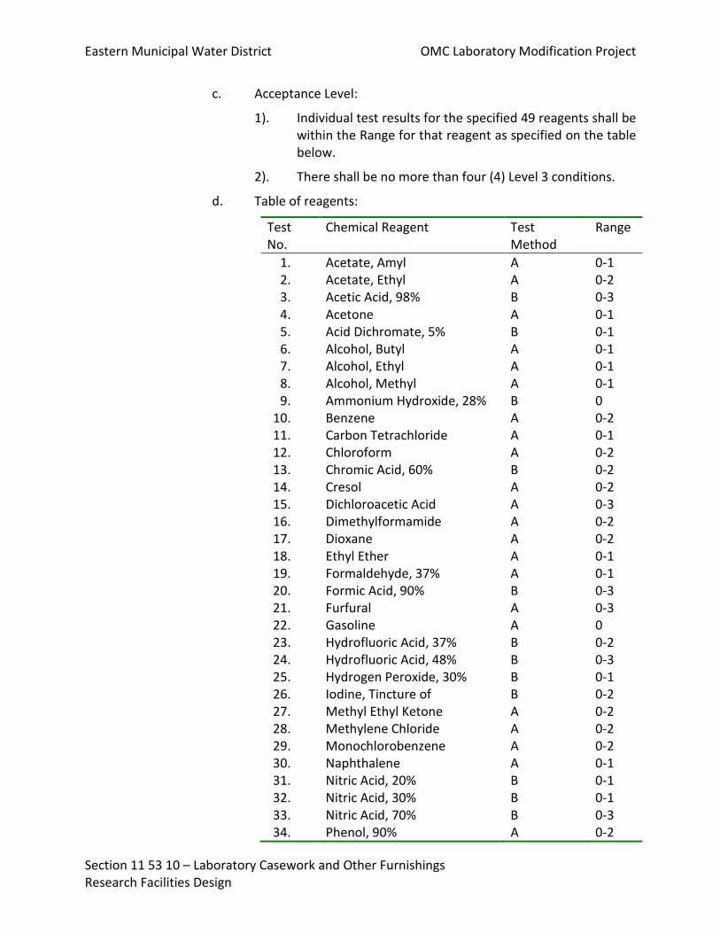
Eastern Municipal Water District OMC Laboratory Modification Project
Section 11 53 10 – Laboratory Casework and Other Furnishings Research Facilities Design
c. Acceptance Level:
1). Individual test results for the specified 49 reagents shall be within the Range for that reagent as specified on the table below.
2). There shall be no more than four (4) Level 3 conditions.
d. Table of reagents:
Test No.
Chemical Reagent Test Method
Range
1. Acetate, Amyl A 0-1 2. Acetate, Ethyl A 0-2 3. Acetic Acid, 98% B 0-3 4. Acetone A 0-1 5. Acid Dichromate, 5% B 0-1 6. Alcohol, Butyl A 0-1 7. Alcohol, Ethyl A 0-1 8. Alcohol, Methyl A 0-1 9. Ammonium Hydroxide, 28% B 0
10. Benzene A 0-2 11. Carbon Tetrachloride A 0-1 12. Chloroform A 0-2 13. Chromic Acid, 60% B 0-2 14. Cresol A 0-2 15. Dichloroacetic Acid A 0-3 16. Dimethylformamide A 0-2 17. Dioxane A 0-2 18. Ethyl Ether A 0-1 19. Formaldehyde, 37% A 0-1 20. Formic Acid, 90% B 0-3 21. Furfural A 0-3 22. Gasoline A 0 23. Hydrofluoric Acid, 37% B 0-2 24. Hydrofluoric Acid, 48% B 0-3 25. Hydrogen Peroxide, 30% B 0-1 26. Iodine, Tincture of B 0-2 27. Methyl Ethyl Ketone A 0-2 28. Methylene Chloride A 0-2 29. Monochlorobenzene A 0-2 30. Naphthalene A 0-1 31. Nitric Acid, 20% B 0-1 32. Nitric Acid, 30% B 0-1 33. Nitric Acid, 70% B 0-3 34. Phenol, 90% A 0-2

Eastern Municipal Water District OMC Laboratory Modification Project
Section 11 53 10 – Laboratory Casework and Other Furnishings Research Facilities Design
Test No.
Chemical Reagent Test Method
Range
35. Phosphoric Acid, 85% B 0-1 36. Silver Nitrate Saturated B 0 37. Sodium Hydroxide 10% B 0 38. Sodium Hydroxide 20% B 0 39. Sodium Hydroxide 40% B 0-1 40. Sodium Hydroxide Flake B 0 41. Sodium Sulfide Saturated B 0 42. Sulfuric Acid, 33% B 0 43. Sulfuric Acid, 77% B 0 44. Sulfuric Acid, 96% B 2-3 45. Sulfuric Acid 77% & Nitric Acid
70% equal parts B 1-3
46. Toluene A 0-1 47. Trichloroethylene A 0-1 48. Xylene A 0-1 49. Zinc Chloride, Saturated B 0
3. Hot Water Test
a. Test Procedure: 190°F to 205°F (88°C to 96°C) hot water shall be allowed to trickle (with a steady stream and at a rate of not less than 6 ounces (177.5 cc) per minute) on the finished surface, which shall be set at an angle of 45°, for a period of 5 minutes.
b. Acceptance Level: After cooling and wiping dry, the finish shall show no visible effect from the hot water.
4. Paint Adhesion on Steel Test
a. Test Procedure: Test shall be based on ASTM D2197-86 “Standard Method of Test for Adhesion of Organic Coating.” Two sets of eleven parallel lines 1/16 inch (1.587 mm) apart shall be cut with a razor blade to intersect at right angles thus forming a grid to 100 squares. The cuts shall be made just deep enough to go through the coating, but not into the substrate. Brush surface lightly with a soft brush for one minute. Examine under 100 fc (1076 lux) of illumination.
b. Acceptance Level: Ninety or more of the squares shall show finish intact.
5. Impact Test
a. Test Procedure: Drop a 1 lb (0.4536 kg) ball (approximately 2 inch (50.8 mm) diameter from a distance of 12 inches (305 mm) onto a flat horizontal surface, coated to manufacturer’s standard manufacturing method.

Eastern Municipal Water District OMC Laboratory Modification Project
Section 11 53 10 – Laboratory Casework and Other Furnishings Research Facilities Design
b. Acceptance Level: No visual evidence to the naked eye of cracks in the finish due to impact.
6. Paint Hardness on Steel Test
a. Test Procedure: Paint film shall be tested with pencils of various hardnesses. Pencils shall have a wide, sharp edge. Pencils shall be pushed across surface in a chisel-like manner.
b. Acceptance Level: Finish film shall not rupture from a sharpened 4H pencil.
2.02 Cabinet Hardware
A. General: Special cabinets, such as corrosives storage or flammable liquid and solvent storage, may be provided with the manufacturer’s standard hardware.
1. All door and drawer pulls shall match, regardless of type of casework, except for:
a. Flammable liquid/ solvent storage cabinets, which should use manufacturer’s standard latch handles as required to satisfy requirements of regulatory approvals.
2. All hardware shall be compliant with the ADA Standards for Accessible Design (28 CFR Part 36).
B. Drawer and Hinged Door Pulls:
1. Drawer and door pulls shall attach to door or drawer with machine screws. Two (2) pulls shall be furnished on drawers wider than 28 inches (711 mm). Plastic pulls or other types subject to breakage are not acceptable.
2. Type: Pulls shall be round “wire.”
a. Material and Finish:
1). Stainless steel with finish as follows.
2). BHMA 630 Satin (Previously US32D).
b. Size:
1). Length: 4 inches (100 mm) center to center of screw holes.
2). Diameter: ¼ inch (6 mm).
C. Hinges:
1. General: Hinges shall be attached to both door and case with three screws through each leaf. Provide two hinges for doors up to 48 inches (1219 mm) high; three hinges for doors over 48 inches (1219 mm) high.
2. Type: Institutional with a five-knuckle bullet-type barrel. Characteristics:
a. Height: 2½ inches (63 mm), nominal.

Eastern Municipal Water District OMC Laboratory Modification Project
Section 11 53 10 – Laboratory Casework and Other Furnishings Research Facilities Design
b. Material: Stainless steel with stainless steel screws.
1). Finish:
a). BHMA 630 Satin (Previously US32D).
2). Manufacturers:
a). Rockford Process Control, Inc. 202 Seventh St., Rockford, IL 61104 Tel: 815 966-2000.
b). Approved substitution.
D. Shelf Hardware:
1. Shelf Supports:
a. Adjustable shelf supports: Adjustable plastic shelf support with lockdown clips.
2. Manufacturers:
a. Bainbridge Manufacturing, Inc., P. O. Box 487, 237 W 3rd, Waterville, WA 98858 Tel: 800 255-4702.
b. The Engineered Products Company (Epco), P. O. Box 108, Flint, MI 48501 Tel: 313 767-2050.
c. Knape & Vogt Manufacturing CO., 2700 Oak Industrial Dr. NE, Grand Rapids, MI 49505 Tel: 616 459-7620.
d. Sugatsune America, Inc. 221 East Selandia Lane, Carson, CA 90746 Tel: 310 329-6373.
e. Approved substitution.
E. Catches:
1. Roller Catches:
a. Types and Materials: Roller catches shall be one of the following types. All-plastic or knuckle-type catches are not acceptable, except at corrosive storage cabinets.
1). Tension ball catches consisting of a case with an adjustable-tension ball catch and a matching strike. Components shall be either stainless steel, chrome plated zinc alloy, or chrome-plated brass.
2). Nylon roller housed in a steel case, which catches on a steel strike plate. Steel components shall be zinc finished.
3). At metal casework base cupboard, catches may consist of a two-piece heavy-duty cam action positive catch positioned near the pivoting edge of door which provides a clean unobstructed opening. Main body of the catch shall be
Eastern Municipal Water District OMC Laboratory Modification Project
Section 11 53 10 – Laboratory Casework and Other Furnishings Research Facilities Design
confined within an integral cabinet divider rail, while latching post shall be mounted on the hinge side of door.
4). At corrosive storage cabinets, catches shall be non-metallic.
b. Application: Provide roller catches at top of all non-locked cabinet doors.
c. Manufacturers:
1). The Engineered Products Company (Epco), P. O. Box 108, Flint, MI 48501 Tel: 313 767-2050.
2). Sugatsune America, Inc. 221 East Selandia Lane, Carson, CA 90746 Tel: 310 329-6373.
3). Approved substitution.
2. Elbow catches: Heavy-duty, adjustable, spring-type elbow catch and strike plate.
a. Material: Brass or steel with bright chromium plated finish.
b. Application: Elbow catches shall be used on left hand doors of locked double door cabinets, including tall cabinets.
1). At tall cabinets, elbow catch shall latch to fixed center shelf. Latching devices using chains or strings are not acceptable.
c. Manufacturers:
1). The Engineered Products Company (Epco), P. O. Box 108, Flint, MI 48501 Tel: 313 767-2050.
2). Approved substitution.
F. Drawer slides:
1. Typical: Ball bearing slides:
a. Material:
1). Clear, zinc-coated steel.
b. Full extension, 100 lb/pr. (45 kg/pr.) capacity: Accuride 3832, Fulterer FR5000, or equal.
c. File drawers shall be equipped with rail mounted with overtravel, 150 lb/pr. (68 kg/pr.) capacity: Accuride 4034, Fulterer 5755, or equal.
d. Pull-out shelf suspension: 100 lb/pr. (45 kg/pr.) capacity pull-out shelf slide: Accuride 322, or equal.
e. Keyboard shelves or trays: 3/4 extension 75 lb/pr. (34 kg/pr.) capacity keyboard shelf slide: Accuride 2009, or equal.
Eastern Municipal Water District OMC Laboratory Modification Project
Section 11 53 10 – Laboratory Casework and Other Furnishings Research Facilities Design
f. Pull-out writing boards: 110 lb/pr. Capacity lock-out slide with 20 inches of travel: Accuride 340-247, or equal.
g. Manufacturers:
1). Accuride, 12311 Shoemaker Ave., Santa Fe Springs, CA 90670 Tel: 562 903-0200.
2). Hettich America LLP, 6225 Shiloh Road, Alpharetta, Georgia 30005 Tel: 770 887-3733.
3). Fulterer USA, 542 Townsend Ave., High Point, NC 27263 Tel: 800 395-4646.
4). Waterloo Furniture Components Inc., 501 Manitou Dr., Kitchener, Ontario, Canada N2C 1L2 Tel: 519 748-5060.
5). Approved substitution.
G. Special Hardware Requirements for Mobile Cabinets:
1. Mobile cabinets shall be engineered by the manufacturer to avoid overturning (tipping) when drawers are loaded to their design load, and opened to the specified glide opening.
2. The top drawer of mobile cabinets shall have an opening restricted to ¾ full open.
3. Mobile cabinets shall be provided with a rod-based drawer interlock glide system to prevent multiple drawers from being opened simultaneously. Accuride 3641 with companion slides Accuride 3642, Fulterer FR5218 with companion slides FR5019, or similar.
4. Mobile cabinets may additionally be provided with a counter weight system, consisting of galvanized steel plates securely attached to the cabinet bottom or inside the cabinet back. The weights shall not be visible when the cabinet is in the normal, upright position.
H. Drawer Stops: All regular drawers shall be equipped with integral stops to prevent drawer head impact with cabinet body.
I. Door Stops: Provide door stops for any cabinet door, which will strike an obstruction when opened between 90° and 135°.
1. Stop to be either:
a. Sash chain, #30 zinc-plated steel.
1). Terminations: Zinc chromate wire screw eyes. Open eye as required to attach stop with screws. Through-bolting not allowed.
b. Coated cable.

Eastern Municipal Water District OMC Laboratory Modification Project
Section 11 53 10 – Laboratory Casework and Other Furnishings Research Facilities Design
1). Seven-strand, 7-wire-per-strand, stainless steel cable with clear nylon coating.
2). Wire diameter: 0.047 inches.
3). Composite diameter with coating: 0.063 inches.
4). Terminations: Number 10 stake eye on both ends. Attach to door/cabinet with screws. Through-bolting not allowed.
5). McMaster Carr part number 30345T3 or equivalent.
2. Engineer stop to length to allow door to open 1 ½ inch (40 mm) from obstruction.
J. Hanging File Suspension System: Hangers shall be fastened and secured to drawer construction and shall not be freestanding units set inside the drawer. Provide in all file drawers.
1. Basis of Design: Blum Metafile Hanging File Frame Kit.
2. Manufacturers:
a. Julius Blum, Inc. 7733 Old Plank Rd., Stanley, NC 28164 Tel: 800 438-6788.
b. Hettich America L. P., 6225 Shiloh Rd., Alpharetta, GA 30005 Tel: 800 438-8424.
c. Approved substitution.
K. Label holders: Provide label holders, pinned in place. Stick-on holders not acceptable. Label holders shall be provided at all file drawers, and elsewhere as shown on drawings.
1. Size:
a. Minimum Size: 1 inch (25mm) x 2 inches (50mm)
b. Maximum Size: 2 inches (50mm) x 3 ½ inches (90mm)
2. Material and finish:
a. Steel with matt chrome finish.
3. Basis of Design Product:
a. 704ANO Label Holder by Knape & Voght, 2700 Oak Industrial Drive NE, Grand Rapids, MI 49505 Tel: 800 253-1561.
b. Approved substitution.
L. Number Plates: Provide 5/8 inch (16 mm) x 1 ¼ inches (32 mm) aluminum number plates with black numbers, pinned in place. Stick-on holders not acceptable. Number plates shall be provided at all drawers where indicated on the plans. Number drawers sequentially in each laboratory.

Eastern Municipal Water District OMC Laboratory Modification Project
Section 11 53 10 – Laboratory Casework and Other Furnishings Research Facilities Design
M. Locks:
1. General: Provide locks on all file cabinet drawers. Provide locks at other locations as indicated on the drawings.
2. Lock type: Deadbolt-type lock.
a. Disc-tumbler-type locks and/or cam-type locks will not be accepted.
b. Framed sliding door locks shall be plunger type.
c. Refer to Elbow Catches section, above, for requirements at two-swinging-door cabinets.
3. Testing requirements:
a. Locks shall comply with ANSI/BHMA standard E07121.
b. Lock shall be cycle tested per ANSI/BHMA A156.11 Grade 1.
4. Include spacers, adapters, fasteners, and strikes.
a. All locks shall strike into metal material. Striking directly into wood is not acceptable.
5. Barrel length shall be coordinated with specific conditions.
6. Finish: Locks shall have satin nickel or satin chrome finish.
7. Keying:
a. Key quantities: Provide two keys per lock. Provide four copies of any master/ grand master keys.
b. Key system:
1). Key system shall support a minimum of 2000 different keys.
2). Key system shall support up to three levels of master keys (grand-master keys, master keys, and sub-master keys) in addition to individual keys.
c. Key cylinder type:
1). Coordinate key type with owner.
d. Key schedule: Coordinate key schedule with Owner.
8. Key engraving:
a. Keys to be engraved with an identification number corresponding to the layout of unique keys on the project. All identical keys shall be engraved with the same number.
9. Manufacturers:
a. Swinging Doors and Drawers:

Eastern Municipal Water District OMC Laboratory Modification Project
Section 11 53 10 – Laboratory Casework and Other Furnishings Research Facilities Design
1). Illinois Lock Company, 301 West Hintz Rd., Wheeling, IL 60090 Tel: 847 537-1800.
2). National Cabinet Lock, 200 Old Mill Rd., P. O. Box 200, Mauldin, South Carolina 29662 Tel: 864 297-6655.
3). Olympus Lock, Inc. 18424 Highway 99, Lynnwood, Washington 98037 Tel: 206 362-3290.
4). Approved substitution.
N. Glides: Non-marring material, 1 inch (25 mm) diameter, minimum, with at least 5/8 (16 mm) vertical adjustment. Provide on movable tables, unless otherwise indicated.
O. Leveling devices: Provide each table leg with 3/8 inch (10 mm) minimum diameter leveling bolt and floor clip.
P. Leg shoes: Leg shoes shall be provided on all legs and table legs to conceal leveling devices, except for tables with casters. Shoes shall be 2 ½ (63 mm) inch high and of black rubber or pliable black vinyl material. Use of a leg shoe which does not conceal leveling device is not acceptable.
Q. Floor clips: Provide leg assemblies and fixed table legs with floor clips securely fastened to the floor after shimming.
R. Casters: Where indicated on Laboratory Furnishing drawings, provide sets of 3 ½ inch (89 mm) diameter wheels with self-lubricating bearing, rated to carry 250 pounds (113 kg) minimum each. Each caster must swivel and have a locking brake. Wheel shall be of molded polyurethane tread mechanically locked to a polyolefin core.
1. Material: Caster shall be heavy gauge stainless steel.
2. Manufacturers:
a. Acorn Industrial Products Co., 7 Union Hill Dr., W. Conshohocken, PA 19428 Tel: 800 523-5474.
b. Caster Technology Corporation, 3265 Whipple Rd., Union City, CA 94587, Tel: 510 429-6727.
c. Hamilton Caster & Mfg. Co., 1637 Dixie Highway, Hamilton, OH 45011 Tel: 888 699-7164.
d. Approved substitution.
S. Support Struts and Service Ledging: Refer to specifications for slotted channel framing in this Section.
2.03 Laboratory Work Surfaces
A. Epoxy Resin:

Eastern Municipal Water District OMC Laboratory Modification Project
Section 11 53 10 – Laboratory Casework and Other Furnishings Research Facilities Design
1. Manufacturers: Products complying with this specification may be provided by the following manufacturers.
a. American Epoxy Scientific, 500 East 16th Street, Mountain Home, AR 72653 Tel: 870-425-7777.
b. Durcon Laboratory Tops, Inc., 206 Allison Drive, Taylor, TX 76574 Tel: 512 595-8000.
c. Kewaunee Scientific Corporation, P O Box 1842, Statesville, NC 28687 Tel: 704 873-7202.
d. No substitutions.
2. Thickness:
a. Typical work surface: 1 inch (25 mm).
b. Fume hood work surfaces: Tops shall be 1¼ (32 mm) inches thick at outer edge, indented minimum ¼ inch (6 mm) to provide a raised rim around all exposed edges 1 inch (25 mm) wide, minimum, or as to allow for the fume hood sash. The front top edge of the raised rim and exposed vertical corners of the top shall be rounded or chamfered to a 1/8 inch (3 mm) radius. The juncture between the raised rim and the top surface shall be coved or chamfered to a ¼ inch (6 mm) radius.
c. Curbs and Splashes: 1 inch (25 mm).
3. Color:
a. Color to be selected from manufacturer’s full product line (note that color will not be white).
b. Color sample to be approved by Architect before work is put in hand.
4. Description:
a. Monolithic filled epoxy resin work surface consisting of a polymerized cast resin material oven-cured in molds.
b. Drip Grooves: Provide under all work surface exposed edges, unless noted otherwise on the Laboratory Furnishing Drawings. Drip grooves shall be ½ inch (13 mm) from the front edge where the top overhangs 1 inch (25 mm) and ¼ inch (6 mm) from the edge where the edge overhangs ½ inch (13 mm).
c. Edge profile: For all exposed upper edges and corners:
1). Radius eased: ¼ inch (6 mm) machined radius with blended radius corners.
Eastern Municipal Water District OMC Laboratory Modification Project
Section 11 53 10 – Laboratory Casework and Other Furnishings Research Facilities Design
d. Marine edges: Where indicated on the Laboratory Furnishing Drawings, shall be 1 inch (25 mm) wide and ¼ inch (6 mm) high with chamfered or radiused transition to and be an integral part of the work surface.
e. Indented areas: Where indicated on the Laboratory Furnishing Drawings, shall be ¼ inch (6 mm) deep with chamfered or radiused sides. Internal and external corners shall have ¼ inch to ½ inch (6 to 13 mm) radius. Marine edges formed around indented areas shall not be less than 1 inch (25 mm) wide.
f. Drain grooves: Where indicated on the Laboratory Furnishing Drawings, shall be 3/8 inch (9mm) wide, 2 inches (50mm) on-center, and shall slope at 1/8 inch (3mm) per foot towards the sink.
g. Raised rib drain board: Where indicated on the Laboratory Furnishing Drawings, provide ¼ inch (6mm) high, ¼ inch (6mm) wide raised radiused ribs at ¾ inch (18mm) on center. Slope worksurface to sink at 1/8 inch (3mm) per foot.
h. Sink Mounting:
1). Drop-in Sink Cutouts: Cutouts shall be profiled to provide support for the sink, and to ensure that the rim of the installed sink is 1/8 inch (3 mm) below the surrounding work surface level or bottom of drain grooves, if present. The top edge of the cutout shall have 1/8 inch (3 mm) bevel. Ensure that there shall be no gaps between the installed sink rim and work surface.
i. Curbs and Splashes:
1). Height: 4 inches (100 mm), unless noted otherwise on Laboratory Furnishing Drawings.
2). Bonded to the surface of the top to form a square joint.
j. Provide all holes and cutouts as required for built-in equipment and mechanical and electrical service fixtures. Verify size of opening with actual size of equipment to be used prior to making openings. Form inside corners to a radius of not less than 1/8 inch (3 mm). After sawing, rout and file cutouts to ensure smooth, crack-free edges. Seal exposed edges after cutting with a waterproofing material recommended by the manufacturer.
k. Provide full-length, one-piece tops and backsplashes wherever possible, and keep field joints to an absolute minimum.
5. Physical Properties:
a. Chemical resistance:

Eastern Municipal Water District OMC Laboratory Modification Project
Section 11 53 10 – Laboratory Casework and Other Furnishings Research Facilities Design
1). Organic solvents: A cotton ball, saturated with the test chemical, is placed in a one ounce bottle with a reservoir of liquid above the ball. The container is inverted on the test material surface for a period of 24 hours. Test temperature: 23°C ±2°C.
2). Other test chemicals: Five drops (1/4 cc) of the test chemical are placed on the test material surface. The chemical is covered with a 1 inch diameter watch glass for a period of 24 hours. Test temperature: 23°C ±2°C.
3). Evaluation: After 24 hours exposure, exposed areas are washed with water, then a detergent solution, finally with naphtha, then rinsed with distilled water, dried with a cloth, and rated as follows:
0 No effect No detectable change in the material surface.
1 Excellent Slight detectable change in color or gloss but no change in function or life of the surface.
2 Good A clearly discernable change in color or gloss but no significant impairment of surface life or function.
3 Fair Objectionable change in appearance due to discoloration or etch, possibly resulting in deterioration of function over an extended period of time.
4 Failure Pitting, cratering, or erosion of the surface. Obvious and significant deterioration.
4). Test results:
Test chemical Conc
entr
atio
n
Blac
k
Dark
gra
y
Ligh
t gra
y
Beig
e
Chromic acid 40% 3 2 2 2 Hydrochloric acid 10% 0 0 0 0 Hydrochloric acid (conc.) 37% 0 0 0 0 Nitric acid 40% 0 0 0 0 Nitric acid (conc.) 70% 0 0 0 0 Sulfuric acid 60% 0 0 0 0 Sulfuric acid (conc.) 96% 4 4 4 4
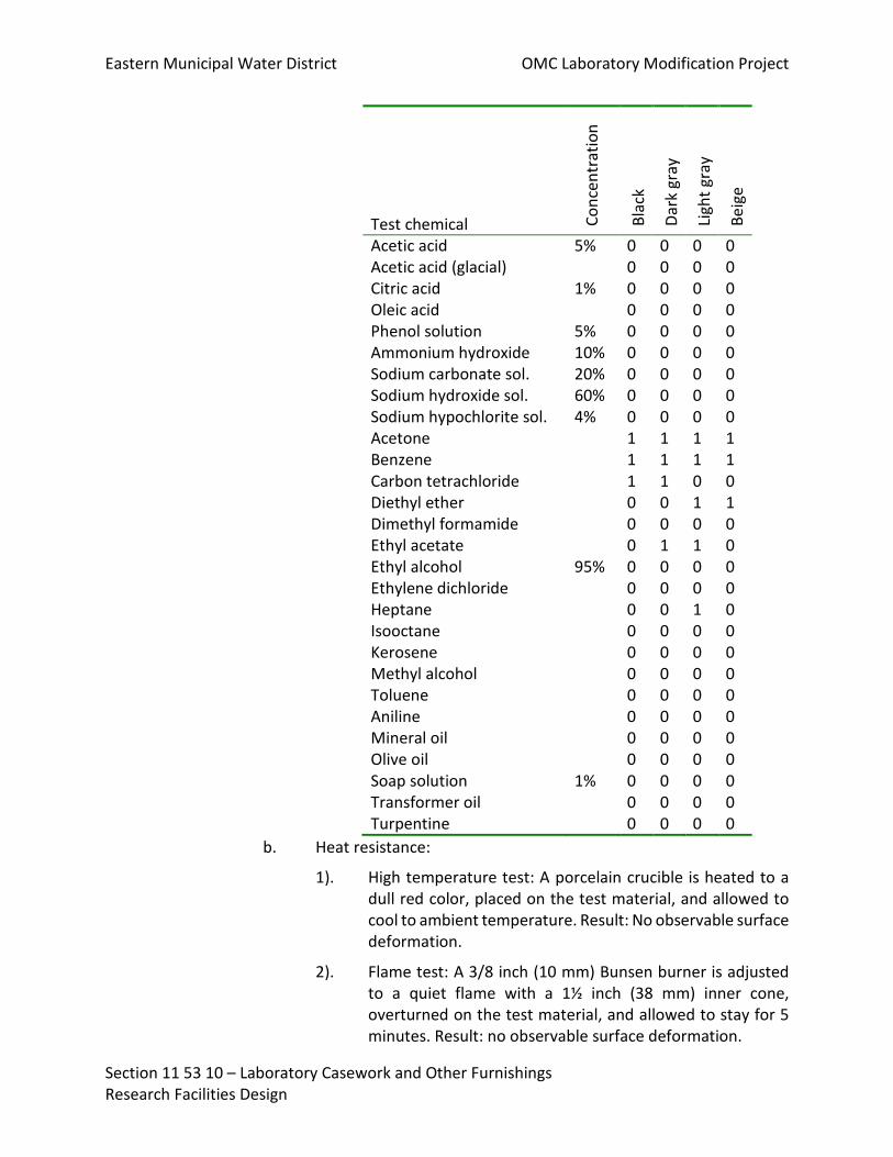
Eastern Municipal Water District OMC Laboratory Modification Project
Section 11 53 10 – Laboratory Casework and Other Furnishings Research Facilities Design
Test chemical Conc
entr
atio
n
Blac
k
Dark
gra
y
Ligh
t gra
y
Beig
e
Acetic acid 5% 0 0 0 0 Acetic acid (glacial) 0 0 0 0 Citric acid 1% 0 0 0 0 Oleic acid 0 0 0 0 Phenol solution 5% 0 0 0 0 Ammonium hydroxide 10% 0 0 0 0 Sodium carbonate sol. 20% 0 0 0 0 Sodium hydroxide sol. 60% 0 0 0 0 Sodium hypochlorite sol. 4% 0 0 0 0 Acetone 1 1 1 1 Benzene 1 1 1 1 Carbon tetrachloride 1 1 0 0 Diethyl ether 0 0 1 1 Dimethyl formamide 0 0 0 0 Ethyl acetate 0 1 1 0 Ethyl alcohol 95% 0 0 0 0 Ethylene dichloride 0 0 0 0 Heptane 0 0 1 0 Isooctane 0 0 0 0 Kerosene 0 0 0 0 Methyl alcohol 0 0 0 0 Toluene 0 0 0 0 Aniline 0 0 0 0 Mineral oil 0 0 0 0 Olive oil 0 0 0 0 Soap solution 1% 0 0 0 0 Transformer oil 0 0 0 0 Turpentine 0 0 0 0
b. Heat resistance:
1). High temperature test: A porcelain crucible is heated to a dull red color, placed on the test material, and allowed to cool to ambient temperature. Result: No observable surface deformation.
2). Flame test: A 3/8 inch (10 mm) Bunsen burner is adjusted to a quiet flame with a 1½ inch (38 mm) inner cone, overturned on the test material, and allowed to stay for 5 minutes. Result: no observable surface deformation.

Eastern Municipal Water District OMC Laboratory Modification Project
Section 11 53 10 – Laboratory Casework and Other Furnishings Research Facilities Design
c. Physical properties:
Compressive strength ASTM D695 31,400 psi (216 MPa)
Tensile strength ASTM D638 8,000 psi (55 MPa) Flexural strength ASTM D790 11,700 psi (81 MPa) Rockwell hardness “M” ASTM D785 105-110 Specific density ASTM D792 122.4 lb/ft³ (1960
kg/m³) Water absorption ASTM D570 0.01% Fire Resistance ASTM D635 ATB (sec)=0 Heat deflection @ 264 psi (1.82 MPa)
ASTM D648 205°F (172°C)
B. Solid Phenolic Resin
1. Manufacturers: Products complying with this specification may be provided by the following manufacturers.
a. Durcon Laboratory Tops, Inc., 206 Allison Drive, Taylor, TX 76574 Tel: 512 595-8000.
b. Fundermax NA, Inc. 2015 Ayrsley Town Boulevard, Charlotte, NC 28273 Tel: 980 505-4030.
c. Trespa North America, Ltd., Greene Street Ground Floor, New York, NY 10012 Tel: 800 487-3772.
d. No substitutions.
2. Basis of design: Acid Resistant Grade - Trespa TOPLAB Plus, or Durcon SPC Chemical Resistant, equal. Panels shall be of material specifically designed for laboratory work surfaces with a hardened acrylic surface.
3. Thickness: Material shall have uniform thickness (+0.03 inch (0.76 mm)) and flatness (maximum difference of 0.03 inch (0.76 mm)) for 10 foot (3 m) span.
a. Work surface on top of mobile cabinets: 5/8 inch (16 mm).
4. Color
a. To be selected from manufacturer’s full product line.
b. Color sample to be approved by Architect prior to fabrication.
5. Description:
a. Edge Profile: All exposed edges shall be sanded to a smooth finish and rounded to a ¼ inch (6 mm) radius at front top edge and at vertical corners, except as indicated

Eastern Municipal Water District OMC Laboratory Modification Project
Section 11 53 10 – Laboratory Casework and Other Furnishings Research Facilities Design
b. Fix work surface panels with blind fastenings into the back or underside of the panel. Use #10, type A sheet metal screws sized to stop at least 1/8 inch (3 mm) short of the finished face. Pre-drill panel with an 11/64 inch (4.4 mm) diameter high-speed drill bit aligned with 7/32 inch (5.6 mm) clearance holes in the supporting structure.
6. Physical Properties:
a. Modulus of elasticity: 1.5 x 10⁶ psi (10.3 GPa) minimum.
b. Shear strength: 2000 psi (14 MPa) minimum.
c. Compressive strength: 24000 psi (165 MPa) minimum.
d. Weight: 93 lb/ft3 (1490 kg/m³) maximum.
e. Flame spread (ASTM E-84): Class I/A (25).
f. Water absorption: 3% maximum.
g. Service temperature: 350°F (177°C) maximum.
h. Non-porous surface and edges.
i. Will not support micro-organic growth.
j. Chemical resistance: The work surface shall sustain contact with the following chemical concentrations for 24 hours with no detectable stain, loss of gloss or change.
1). Test Procedure: Cover five drops of each reagent with a 25 mm watch glass convex side up to duplicate the trapping of a reagent under a dispensing container. Test all volatiles by using a one ounce (30 mL) bottle stuffed with saturated cotton. After a 24 hour exposure, flush reagents off with water, clean with naphtha and detergent, rinse and wipe dry.
2). Evaluation Ratings:
0 No effect No detectable change. 1 Excellent Slight detectable change in color or
gloss. 2 Good A clearly discernable change in color or
gloss but no significant impairment of surface life or function.
3 Fair Slight surface etching or severe staining.
4 Failure Pitting, cratering, or erosion of coating. Obvious and significant deterioration.

Eastern Municipal Water District OMC Laboratory Modification Project
Section 11 53 10 – Laboratory Casework and Other Furnishings Research Facilities Design
3). Test results shall not be lower than the following on black material:
Reagent
Conc
entr
atio
n
Ratin
g
Amyl acetate 0 Ethyl acetate 0 Acetic acid 98% 0 Acetone 0 Acid dichromate 5% 0 Butyl alcohol 0 Ethyl alcohol 0 Methyl alcohol 0 Ammonium hydroxide 28% 0 Benzene 0 Carbon tetrachloride 0 Chloroform 0 Chromic acid 60% 0 Cresol 0 Dichloroacetic acid 0 Dimethylformamide 0 Dioxane 0 Ethyl ether 0 Formaldehyde 37% 0 Formic acid 90% 0 Furfural 0 Gasoline 0 Hydrochloric acid 37% 0 Hydrofluoric acid 48% 3 Hydrogen peroxide 3% 0 Tincture of iodine 0 Methyl ethyl ketone 0 Methylene chloride 0 Mono chlorobenzene 0 Naphthalene 0 Nitric acid 20% 0 Nitric acid 30% 0 Nitric acid 70% 0 Phenol 90% 0 Phosphoric acid 85% 0

Eastern Municipal Water District OMC Laboratory Modification Project
Section 11 53 10 – Laboratory Casework and Other Furnishings Research Facilities Design
Reagent
Conc
entr
atio
n
Ratin
g
Silver nitrate 0 Sodium hydroxide 10% 0 Sodium hydroxide 20% 0 Sodium hydroxide 40% 0 Sodium hydroxide 0 Sodium hydroxide, flake 0 Sodium sulfide, saturated 0 Sulfuric acid 33% 0 Sulfuric acid 77% 0 Sulfuric acid 96% 1 50% Sulfuric acid/50% Nitric acid 77%/7
0% 0
Toluene 0 Trichloroethylene 0 Xylene 0 Saturated Zinc chloride 0 Aqua regia 0 Betadine (Providone iodine) 10% 0
2.04 Wall Hung Benchtop
A. Framing Channel, Fittings, and End Caps: Stainless steel slotted channel framing as specified elsewhere on this Section and as indicated on the drawings.
B. Benchtop material shall be as indicated on the drawings and as specified elsewhere in this Section.
C. Unit shall be designed to support 200 pounds per square foot (10 kPa), completely wall supported with no legs or support members extending to the floor. Coordinate with wall or partition framing for blocking.
2.05 Shelving Assemblies
A. Metal Shelving:
1. Provide 18 gauge steel shelves with integral seismic lip and hat-section stiffener.
2. Provide 16 gauge bookend brackets. Rear of bracket shall be profiled to fit into slots of shelf support. Refer to detail on Laboratory Furnishings Drawings.

Eastern Municipal Water District OMC Laboratory Modification Project
Section 11 53 10 – Laboratory Casework and Other Furnishings Research Facilities Design
3. Bottom shelves shall be prepared for task lights. Refer to additional requirements elsewhere in this section.
B. Safety Edges:
1. Types:
a. Retainer Rail: ¼ inch (6 mm) diameter stainless steel retainer rail, as indicated on the drawings.
b. Integral Retainer Lips: Metal shelving to fold up 2 inches (50mm) to form an integral retainer lip.
2. Refer to the description of each system below for locations of each type.
C. Adjustable Wall Shelves:
1. Shelving: Metal shelving as specified above.
2. Double Slot Shelf Standards:
a. Manufacturers: Products complying with this specification may be provided by the following manufacturers. All products specified in this section shall be the provided by a single manufacturer.
1). Knape & Vogt Manufacturing Company, 2700 Oak Industrial Drive NE, Grand Rapids, MI 49505 Tel: 616 459-3311.
2). Approved substitution.
b. Basis of Design: Knape & Vogt 85 ANO series uprights, or equal. Length as indicated on the drawings.
3. Shelf Brackets: 16 gauge (1.6 mm) bookend type, as detailed on drawings.
4. Safety edging:
a. Front Edge:
1). Retainer rail.
b. Rear edge:
1). Integral folded metal shelf safety lip.
5. Load capacity: System shall support a minimum of 35 pounds per square foot applied at all shelves simultaneously. Maximum deflection shall be 0.35 inches (9mm) under load.
6. Finish: Factory finish standards and brackets with epoxy powder coating. Color to be selected by the Architect.
D. Stainless Steel Shelving System
1. Manufacturers: Products complying with this specification may be provided by the following manufacturers. All products specified in this section shall be the provided by a single manufacturer.

Eastern Municipal Water District OMC Laboratory Modification Project
Section 11 53 10 – Laboratory Casework and Other Furnishings Research Facilities Design
a. InterMetro Industries Corporation, 651 North Washington St., Wilkes-Barre, PA 18705 Tel: 800 992-1776. Manufacturer of Metro product range.
b. Eagle Group, 100 Industrial Blvd., Clayton, DE 19938 Tel: 302 653-3000.
c. Nexel Industries Inc., March Equipment Inc., US Highway 206, Box 18, Flanders, NJ 07836 Tel: 973 584-4269.
d. Approved substitution.
2. Carts
a. Basis of Design: Metro Metro-Max stainless steel shelf system, or equivalent.
b. Posts: steel, grooved at 1 inch (25 mm) increments and numbered at 2 inch (50 mm) increments for shelf adjustment, Metro PS series or equal. Post length to be coordinated with caster size and counter hight so that carts fit under counter structure with 1 inch (25mm) clearance.
c. Shelves:
1). Open-grid polymer shelf components supported by an epoxy-coated steel frame.
2). Provide three shelves per cart, one of which will be the top of the cart.
3). Shelves to be 18 inches by 36 inches typically. Coordinate with casework clearances.
d. Accessories:
1). Label Holders: Dark grey snap-on plastic, Metro No. 9990P or equal.
2). Shelf Ledges:
a). 1 inch (25 mm) high stainless steel wire, Metro No. LxxN-1S or equal, sized to match shelf.
3). Donut bumpers: 3 ½ inch (89 mm) diameter resilient bumper, Metro No. 999DB or equal, on each post.
4). Casters: 5 Inch (127 mm) diameter, cart-washable, stainless steel swivel stem caster with brake and polyurethane wheel, Metro No. 5MPBGSA or equal.

Eastern Municipal Water District OMC Laboratory Modification Project
Section 11 53 10 – Laboratory Casework and Other Furnishings Research Facilities Design
2.06 Wall Pass-Through Sleeve
A. Manufacturers: Products complying with this specification may be provided by the following manufacturers. All products specified in this section shall be the provided by a single manufacturer.
1. Scientific Plastics Inc., 1016 SW Boulevard, Kansas City, Kansas 66103 Tel: 913 432-0322.
2. Approved substitution.
B. Straight pass-through fabricated from polyethylene, for mounting into wall construction.
C. Conform to ASTM 1412 for corrosion resistance.
D. Coordinate length and installation with framing/ drywall subcontractor.
E. Diameter: 3-inch diameter unless otherwise noted.
F. Cap: Gasketed caps at both ends.
2.07 Pipe Drop Enclosure
A. Fabricate pipe drop enclosures from minimum 18 gauge (1.3 mm thick) galvanized steel, per details shown on the Laboratory Furnishing drawings, except as noted.
B. Seal all joints between dissimilar metals and at all panel seams with clear silicone sealant.
C. Materials and finish shall be as specified under Metals Fabrications in this Section.
2.08 Drying Rack
A. Epoxy Drying Rack:
1. Comply with requirements for molded epoxy resin specified under Laboratory Tops in this Section and as described herein.
2. Drying rack bodies shall be of one inch (25 mm) thick black epoxy with a 3/16 inch to ¼ inch (5 to 6 mm) radius on all edges and corners. Each rack shall be of the size and with the peg arrangement shown on the Laboratory Furnishing drawings.
3. Pegs shall be of injection molded white polypropylene. Pegs shall not be bonded into the body, but shall be held in position by mechanical design.
4. Provide a drip trough of Type 304 stainless steel with a 16 gauge (1.6 mm thick), Type 304 stainless steel screen of 14 x 14 (1.8 x 1.8 mm) mesh, .02 (0.05 mm) wire.
5. Provide stainless steel fixing screws of appropriate type for attachment to support structure.
6. Provide clear, tight-fitting hose to drain from drip tray into sink.
Eastern Municipal Water District OMC Laboratory Modification Project
Section 11 53 10 – Laboratory Casework and Other Furnishings Research Facilities Design
2.09 Cable / Vacuum Line Through Port
A. Provide 3 inch (75 mm) diameter wire or cable access through ports of Type 304 stainless steel with No. 4 finish at bench tops as located and detailed on the Laboratory Furnishings drawings.
2.10 Grommets and Accessories
A. Grilles
1. Air intake grilles: Perforated metal mesh in a metal frame.
2. Sizes: As shown on drawings.
3. Mesh Pattern: Mesh 1.
4. Color: Factory-applied powder-coat paint to match casework color.
5. Basis of Design Model: Doug Mockett & Co., Inc. GT Series Grilles.
6. Manufacturer: Doug Mockett & Co., Inc. P.O. Box 3333, Manhattan Beach, CA 90266 Tel 800 523-1269 or approved equal.
2.11 Task Light Fixtures
A. Task lights to be located under all bottom shelves at mobile work stations; under all wall cabinets; and under bottom shelf at all wall shelving locations.
B. Task lights are specified on the laboratory electrical documents.
C. Laboratory casework subcontractor shall purchase and install task light fixtures within the laboratory spaces.
D. Task lights will be wired by the electrical contractor.
2.12 Metal Fabrications
A. Applicability: This section applies to metal fabrications, including, but not limited to, pipe drop enclosures, radioisotope storage cabinets, shelving support systems, metal-framed laboratory tables, metal-framed balance tables, cylinder racks, utility ceiling tiles, and other miscellaneous brake-formed and shop fabricated components and trim, such as required for overhead service carriers.
B. Manufacturers: Products complying with this specification may be provided by the following manufacturers, and/or other manufacturers that may be listed under individual products within this specification.
1. Karan and Associates, Inc., 2647 Bonnie Brae Ave., Claremont CA 91711 Tel: 909-967-1104
2. Kumar Industries, 4775 Chino Avenue, Chino, CA 91710 Tel: 909 591-0722.
3. Approved substitution.
C. Materials:
1. Steel: Cold-rolled furniture stock sheet steel, prime grade, roller leveled.

Eastern Municipal Water District OMC Laboratory Modification Project
Section 11 53 10 – Laboratory Casework and Other Furnishings Research Facilities Design
a. Steel shall be treated at the mill to be free of scale, ragged edges, deep scratches, or other injurious effects.
b. All gauges indicated are to be U.S. standard.
D. Finish Requirements:
1. Paint finish for steel laboratory products shall utilize a dry coating process with minimal waste generation. Liquid-applied coatings shall not be acceptable. Manufacturer shall supply documentation that waste generated during the painting process, is a solid, non-hazardous material.
a. Pretreatment: Finish process shall incorporate a phosphate conversion coating during the pretreatment/cleaning operation.
b. Operator Protection: The painting process shall be cleanly contained, have no solvent odor and be performed in an air-conditioned room.
c. VOC (Volatile Organic Compounds) emissions shall not exceed 0.29 lbs per gallon (35 g/L).
d. Offgasing: No further emissions or “Offgasing/Decomposition” vapors shall occur at room temperature from installed finished parts.
2. Preparation: After the units have been completely welded together and before finishing, they shall be given a pre-paint treatment to provide excellent adhesion of the finish to the metal and to aid in the prevention of corrosion. Physical and chemical cleaning of the metal shall be accomplished by washing with an alkaline cleaner, followed by a spray treatment with a heated cleaner/phosphate solution and pretreated with iron phosphate spray followed by a neutral final seal prior to application of final finish. The strength of each solution shall be monitored by filtration to insure consistent quality. All treated parts shall be immediately dried in heated ovens and gradually cooled before application of the finish. Treated metal parts shall be clean and properly prepared to provide optimum adhesion of finish and resistance to corrosion.
3. Application: Electrostatically apply powder coat of selected color and bake in controlled high temperature oven to assure a smooth, hard satin finish. Surfaces shall have a chemical resistant, high grade laboratory furniture quality finish of the following thicknesses:
a. All surfaces, exterior or interior, exposed to view, shall receive sufficient powder coat to achieve an average 1.5 mil (38 µm) film thickness with a minimum 1.2 mil (30 µm) film thickness and shall have smooth satin luster.

Eastern Municipal Water District OMC Laboratory Modification Project
Section 11 53 10 – Laboratory Casework and Other Furnishings Research Facilities Design
b. Backs of cabinets and other surfaces not exposed to view shall have sufficient powder coat to achieve an average 1.0 mil (25 µm) film thickness.
4. All drawer bodies to be finished in matching color.
5. Concealed interior parts shall receive corrosion-resistant treatment.
6. Finish must be UV stable.
7. Color: As selected by the Architect.
E. Finish Performance Requirements:
1. Manufacturer shall submit metal finish performance testing results. Testing to be performed by independent testing agency.
2. Chemical Resistance:
a. Test procedure: Place samples on a flat surface, clean with soap and water and blot dry. Condition the panel for 48-hours at 73+ 3F (23(+ 2(C) and 50+ 5% relative humidity, or the currently accepted guideline set by ASTM. Test the samples for chemical resistance using forty-nine different chemical reagents by one of the following methods. For both methods, leave the reagents on the sample for a period of one hour. Wash off the sample with water, clean with detergent and naptha, and rinse with deionized water. Dry with a towel and evaluate after 24-hours at 73± 3°F (23°± 2°C) and 50± 5% relative humidity, or the currently accepted guideline set by ASTM
1). Method A: Test volatile chemicals by placing a cotton ball saturated with reagent in the mouth of a 1-oz. (29.574cc) bottle and inverting the bottle on the surface of the sample. The cotton ball shall remain in contact with the sample for the duration of the test.
2). Method B: Test non-volatile chemicals by placing five drops of the reagent on the surface of the sample and covering with a 24mm watch glass, convex side down.
b. Rating System: Evaluations shall use the following rating system:
Level 0 No detectable change. Level 1 Slight change in color or gloss. Level 2 Slight surface etching or severe staining. Level 3 Pitting, cratering, swelling, or erosion of coating.
Obvious and significant deterioration. c. Acceptance Level:

Eastern Municipal Water District OMC Laboratory Modification Project
Section 11 53 10 – Laboratory Casework and Other Furnishings Research Facilities Design
1). Individual test results for the specified 49 reagents shall be within the Range for that reagent as specified on the table below.
2). There shall be no more than four (4) Level 3 conditions.
d. Table of reagents:
Test No.
Chemical Reagent Test Method
Range
1. Acetate, Amyl A 0-1 2. Acetate, Ethyl A 0-2 3. Acetic Acid, 98% B 0-3 4. Acetone A 0-1 5. Acid Dichromate, 5% B 0-1 6. Alcohol, Butyl A 0-1 7. Alcohol, Ethyl A 0-1 8. Alcohol, Methyl A 0-1 9. Ammonium Hydroxide, 28% B 0
10. Benzene A 0-2 11. Carbon Tetrachloride A 0-1 12. Chloroform A 0-2 13. Chromic Acid, 60% B 0-2 14. Cresol A 0-2 15. Dichloroacetic Acid A 0-3 16. Dimethylformamide A 0-2 17. Dioxane A 0-2 18. Ethyl Ether A 0-1 19. Formaldehyde, 37% A 0-1 20. Formic Acid, 90% B 0-3 21. Furfural A 0-3 22. Gasoline A 0 23. Hydrofluoric Acid, 37% B 0-2 24. Hydrofluoric Acid, 48% B 0-3 25. Hydrogen Peroxide, 30% B 0-1 26. Iodine, Tincture of B 0-2 27. Methyl Ethyl Ketone A 0-2 28. Methylene Chloride A 0-2 29. Monochlorobenzene A 0-2 30. Naphthalene A 0-1 31. Nitric Acid, 20% B 0-1 32. Nitric Acid, 30% B 0-1 33. Nitric Acid, 70% B 0-3 34. Phenol, 90% A 0-2 35. Phosphoric Acid, 85% B 0-1

Eastern Municipal Water District OMC Laboratory Modification Project
Section 11 53 10 – Laboratory Casework and Other Furnishings Research Facilities Design
Test No.
Chemical Reagent Test Method
Range
36. Silver Nitrate Saturated B 0 37. Sodium Hydroxide 10% B 0 38. Sodium Hydroxide 20% B 0 39. Sodium Hydroxide 40% B 0-1 40. Sodium Hydroxide Flake B 0 41. Sodium Sulfide Saturated B 0 42. Sulfuric Acid, 33% B 0 43. Sulfuric Acid, 77% B 0 44. Sulfuric Acid, 96% B 2-3 45. Sulfuric Acid 77% & Nitric Acid
70% equal parts B 1-3
46. Toluene A 0-1 47. Trichloroethylene A 0-1 48. Xylene A 0-1 49. Zinc Chloride, Saturated B 0
3. Hot Water Test
a. Test Procedure: 190°F to 205°F (88°C to 96°C) hot water shall be allowed to trickle (with a steady stream and at a rate of not less than 6 ounces (177.5 cc) per minute) on the finished surface, which shall be set at an angle of 45°, for a period of 5 minutes.
b. Acceptance Level: After cooling and wiping dry, the finish shall show no visible effect from the hot water.
4. Paint Adhesion on Steel Test
a. Test Procedure: Test shall be based on ASTM D2197-86 “Standard Method of Test for Adhesion of Organic Coating.” Two sets of eleven parallel lines 1/16 inch (1.587 mm) apart shall be cut with a razor blade to intersect at right angles thus forming a grid to 100 squares. The cuts shall be made just deep enough to go through the coating, but not into the substrate. Brush surface lightly with a soft brush for one minute. Examine under 100 fc (1076 lux) of illumination.
b. Acceptance Level: Ninety or more of the squares shall show finish intact.
5. Impact Test
a. Test Procedure: Drop a 1 lb (0.4536 kg) ball (approximately 2 inch (50.8 mm) diameter from a distance of 12 inches (305 mm) onto a flat horizontal surface, coated to manufacturer’s standard manufacturing method.

Eastern Municipal Water District OMC Laboratory Modification Project
Section 11 53 10 – Laboratory Casework and Other Furnishings Research Facilities Design
b. Acceptance Level: No visual evidence to the naked eye of cracks in the finish due to impact.
6. Paint Hardness on Steel Test
a. Test Procedure: Paint film shall be tested with pencils of various hardnesses. Pencils shall have a wide, sharp edge. Pencils shall be pushed across surface in a chisel-like manner.
b. Acceptance Level: Finish film shall not rupture from a sharpened 4H pencil.
2.13 Stainless Steel Fabrications
A. Applicability: This section applies to stainless steel fabrications, including, but not limited to, equipment enclosure panels, and other miscellaneous brake-formed and shop fabricated stainless steel components and trim as shown on the drawings.
B. Manufacturers:
1. The Diamond Group, 895 Munch Street, Laval, Quebec H7S 1A9 Canada Tel: 450 668-0330.
2. Inter Dyne Systems, Inc., 676 Ellis Road, Norton Shores, MI 49441 Tel: 231 799-8760.
3. Kloppenberg & Co., 2627 West Oxford Avenue, Englewood, CO 80110 Tel: 303 761-1615.
4. Approved substitution.
C. Materials and Finishes:
1. Unless otherwise noted stainless steel shall be Type 304 and shall be of gauge indicated on Laboratory Furnishing drawings or this specification.
2. All fabrications shall have exposed surfaces ground and polished to a Number 4 satin finish.
3. All stainless steel nuts, screws, bolts, and rivets, etc., shall be of the same type stainless as in the sheet material and shall have a tumbled finish closely resembling that of a Number 4 finish.
4. All stainless steel welding material shall be of type similar to the sheet material or a richer quality. All welds shall be made without discoloration and shall be ground, polished, and passivated to blend harmoniously with a Number 4 satin finish. All joints in stainless steel tops and work surfaces shall be welded.

Eastern Municipal Water District OMC Laboratory Modification Project
Section 11 53 10 – Laboratory Casework and Other Furnishings Research Facilities Design
D. Equipment Enclosure Panels:
1. Description: System of custom-designed, engineered, rigid, self-supporting pre-fabricated wall panels installed around equipment locations, creating closure to surrounding construction. Provide at perimeter of pass-through refrigerator.
2. Configuration: Enclosure panels shall be full-height (from floor to the ceiling) and full-width (wall to wall), including panels at locations above pieces of equipment, to create a full and complete wall area.
a. System overall thickness to be 1 inch to 3 inches.
b. Where both sides of the enclosure panel walls are exposed to working rooms, the system shall be a double-sided system with both sides finished as required for an exposed condition.
c. Joints between panels to be tight (approximately 1/16 inch) and uniform.
d. Construction: Sheet gauges and reinforcing details should be engineered as necessary to prevent "oil-canning" or deflection of panels between supports.
e. Panels shall be assembled with rivets located on the non-visible edges of the panel.
f. Exposed Side of Panel System: There shall be no visible fastening methods on the exposed face(s) of the panel system This requirement does not apply to faces within areas intended solely for equipment maintenance.
g. Insulation: Fire-retardant expanding polyurethane foam shall be used within the panel construction. Insulation shall fill all dead spaces within each panel, increasing panel rigidity. It shall be classed with an R Value between 6.2-7.4 per inch.
3. Special Conditions:
a. Equipment Openings: Frame around equipment locations and accessory panels with 18 gauge stainless steel angle. Coordinate all openings with equipment manufacturer requirements.
E. Canopy Hood:
1. Existing canopy hood to remain in place.
2. Upon award, inspect unit. Report any issues.
3. Document existing condition with photographs. Submit for record.
4. Protect unit from damage during demolition and construction activities.

Eastern Municipal Water District OMC Laboratory Modification Project
Section 11 53 10 – Laboratory Casework and Other Furnishings Research Facilities Design
5. De-install and re-install unit if required for construction activities. Store and protect unit.
6. Clean and polish unit to an as-new condition.
2.14 Slotted Channel Framing
A. Manufacturers: Products complying with this specification may be provided by the following manufacturers. All products specified in this section shall be the provided by a single manufacturer.
1. Unistrut, 35660 Clinton Street, Wayne, MI 48184 Tel: 800 521-7730.
2. Power Engineering Co. (Powerstrut), 420 Boston Turnpike, Shrewsbury, MA Tel: 800 274-1303.
3. Kumar Industries (Nu-Strut), 4881 Chino Ave., Chino, CA 91710 Tel: 909 591-0722.
4. Cooper B-Line Inc. (B-Line), 509 West Monroe St., Highland, IL 62249 Tel: 618 654-2184.
5. Approved substitution.
B. Materials: Channel and framing members shall be fabricated from steel conforming to the following requirements:
1. Framing Members:
a. Concealed Framing Members and Fittings: ASTM A570 GR 33.
b. Exposed Framing Members and Fittings: ASTM A446 GR A with zinc coating conforming to ASTM A525.
c. Stainless Steel Framing Members and Fittings: ASTM A240 (Type 304), where indicated.
2. Fittings:
a. Concealed Fittings: Fabricate from steel satisfying the requirements of ASTM A570 GR 33, and conform to the following ASTM specifications: A575, A576, A36, or A635. Nuts shall conform to ASTM A576 GR 1015 and screws shall conform to SAE J429 GR 2 and ASTM A307.
b. Exposed Fittings: Fabricate from steel satisfying the requirements of ASTM A570 GR 33, and conform to the following ASTM specifications: A575, A576, A36, or A635. Nuts shall conform to ASTM A576 GR 1015 and screws shall conform to SAE J429 GR 2 and ASTM A307. Exposed fittings shall receive zinc coating conforming to ASTM A525.

Eastern Municipal Water District OMC Laboratory Modification Project
Section 11 53 10 – Laboratory Casework and Other Furnishings Research Facilities Design
c. Stainless Steel Fittings and Hardware: Sintered Nuts shall be of ASTM B783 (Type 316N2-33) stainless steel and fittings shall be of ASTM A240 (Type 304) stainless steel. Stainless steel fittings and hardware shall be used with stainless steel framing members, or where indicated.
3. Thickness: 12 gauge, unless noted otherwise.
4. Size: 1 5/8 inch x 1 5/8 inch cross-section, unless noted otherwise.
C. Components:
1. The following components shall be provided, unless otherwise noted:
a. Framing Channel: 1 5/8 inch x 1 5/8 inch x 12 gauge: Unistrut P1000, Powerstrut PS 200, Kumar Industries N-200, B-Line Systems, Inc. B22, or equal.
b. Suspended Framing Channel, 3 ¼ inch x 1 5/8 inch x 12 gauge: Unistrut P5000, Powerstrut PS 100, Kumar Industries N-150, B-Line Systems, Inc. B11, or equal.
c. 90° Angle Fitting: 4 1/8 inch x 3½ inch x ¼ inch with two holes, each leg: Unistrut P1325, Powerstrut PS 607, Kumar Industries N-1123, B-Line Systems, Inc. B104, or equal.
d. 135° Angle Fitting: 3 inch x 2 5/16 inch x ¼ inch with one hole, each leg: Unistrut P1546, Powerstrut PS 633-45°, Kumar Industries N-1425, B-Line Systems, Inc. B154, or equal.
e. T-Shaped Flat Plate Fitting: 5 3/8 inch x 3½ inch x ¼ inch plate, T-shaped, with four holes: Unistrut P1031, Powerstrut PS 714, Kumar Industries N-1022, B-Line Systems, Inc. B133, or equal.
f. Wing Shape Fitting, 9 5/32 inch x 3 7/8 inch ten holes, two holes in each wing section and two holes in each of three channel section sides: Unistrut P2347, Powerstrut PS 913, B-Line Systems, Inc. B273.
g. Vertical Posts: 3¼ inch x 1 5/8 inch x 12 gauge, double channel section: Unistrut P1001, Powerstrut PS 200 2T3, Kumar Industries N-200-A, B-Line Systems, Inc. B22A, or equal.
h. Horizontal Support Members: 1 5/8 inch x 1 5/8 inch x 12 gauge framing channel with 13/32 inch x 3 inch slotted holes, 4 inches on center: Unistrut P1000 SL, Powerstrut P 200 S, Kumar Industries N-200-SL, B-Line Systems, Inc. B22S, or equal.

Eastern Municipal Water District OMC Laboratory Modification Project
Section 11 53 10 – Laboratory Casework and Other Furnishings Research Facilities Design
i. Slotted Hole Framing Channel, 1 5/8 inch x 1 5/8 inch x 12 gauge framing channel with 13/32 inch x 3 inch slotted holes, 4 inches on center: Unistrut P1000 SL, Powerstrut P 200 S, Kumar Industries N-200-SL, B-Line Systems, Inc. B22S.
j. Slotted Framing Channel for installation in Chemical Fume Hoods, 1 5/8 inch x 13/16 inch x 16 gauge Type 316 stainless steel framing channel: Unistrut P4000 SS, Powerstrut PS 560 SS, Kumar Industries, B-Line Systems, Inc.
1). Attach channel to side of fume hood with 2 5/8 inch x 1 7/8 inch x 1/8 inch, 4 hole, stainless steel 90º fitting: Unistrut P6325 SS, Powerstrut, Kumar Industries, B-Line Systems, Inc.
k. Diagonal Brace Supports: Framing Channel, 1 5/8 inch x 1 5/8 inch x 12 gauge: Unistrut P1000, Powerstrut PS 200, Kumar Industries N-200, B-Line Systems, Inc. B22, or equal.
l. Closure Strip: 0.04 inches thick snap-in cover for framing channel: Unistrut P3184, Powerstrut PS 6152, Kumar Industries N-1920, B-Line Systems, Inc. B217-24, or equal. Provide closure strips over all exposed vertical post sections.
m. End Caps: 0.06 inches thick for framing channel: Unistrut P1280, Powerstrut PS 707, Kumar Industries N-2500, B-Line Systems, Inc. B205, or equal. Provide end caps for all exposed horizontal framing channels.
n. Ceiling Escutcheon: Provide 18 gauge steel, finished to match framing members, as indicated on the Laboratory Furnishing drawings, at ceiling penetrations.
o. Other components, hardware, and fasteners, as required for a complete assembly and as indicated on the drawings.
2. Service Struts and Ledging:
a. 16 gauge, 13/16 inch x 1 5/8 inch cold-formed framing uprights: Unistrut P4000, Powerstrut PS 560, Kumar Industries N-400, B-Line Systems, Inc. B56, or equal. Uprights shall be provided at 48 inches, maximum, and fastened top and bottom by two adjustable U-shaped spreaders.
b. U-shaped spreaders: 12 gauge by 1½ inch (45 mm) wide by length required, galvanized steel.
c. Locations:

Eastern Municipal Water District OMC Laboratory Modification Project
Section 11 53 10 – Laboratory Casework and Other Furnishings Research Facilities Design
1). Provide to support tops at pipe service chase space, support drain troughs, under fume hood superstructures, and other abnormal loads.
2). Support struts with U-shaped spreaders shall be provided at 48 inches (1220 mm) on center below island and peninsula benches, as indicated on drawings. Support struts shall be provided along wall 48 inches (1220 mm) on center below island and peninsula benches. Struts will be used to support piped and electrical services installed under Divisions 22, 26, and 27. Provide all bolts, expansion sleeves, and fastening devices for a complete assembly. Pipe and conduit hangers shall be provided by Division 22, 26, and 27 installers.
3. Finish:
a. Provide finish coating for all cold-formed framing components, except for stainless steel components.
b. Concealed Framing Members and Fittings: Rust inhibiting acrylic enamel paint applied by electrostatic deposition, after cleaning and phosphating, and thoroughly baked. Finish shall withstand a minimum of 400 hours salt spray when tested in accordance with ASTM B117. Color: Green.
c. Exposed Framing Members and Fittings: Factory applied epoxy powder coat. Color: To be selected by the Architect.
2.15 Sealant
A. Manufacturers: Products complying with this specification may be provided by the following manufacturers.
1. Dow Corning Corporation, P.O. Box 994, Midland, MI 48686 Tel: 989 496-7881.
2. General Electric Company, 260 Hudson River Rd., Waterford, NY 12188 Tel: 800 255-8886.
3. Approved substitution.
B. Basis of Design: Dow Corning 732 Multi-Purpose Sealant, GE Silicones RTV 100 Series, or equal.
C. Characteristics:
1. Type: One-part silicone rubber, MIL-A-46106.
2. Physical form: Non-slumping paste.
3. Cure: Cures at room temperature on exposure to water vapor in the air.

Eastern Municipal Water District OMC Laboratory Modification Project
Section 11 53 10 – Laboratory Casework and Other Furnishings Research Facilities Design
4. Authorizations:
a. FDA Regulation No. 21 CFR 177.2600.
b. USDA Rating P1.
c. NSF Rating C2.
d. UL 150 C Rating, File No. E40195(N).
5. Properties:
a. Tack Free Time: 45 minutes, maximum.
b. Durometer, Shore A Hardness: 20, minimum.
c. Tensile Strength: 220 pounds per square inch, minimum.
d. Elongation: 350 percent, minimum.
e. Extrusion Rate: 220 to 525 grams per minute.
PART 3 EXECUTION
3.01 Site Conditions
A. Inspection:
1. Prior to installation of the work of this Section, carefully inspect the installed work specified in other Sections and verify that all such work is complete to the point where this installation may properly commence.
2. Verify that all work may be installed in complete accordance with the original design, reviewed submittals, and the manufacturer's recommendations.
3. Where floor conditions require shimming or leveling of more than ¾ inch at any point, do not install casework in those locations. Notify the contractor and design team that remedial measures will be required to bring the floors closer to a level situation.
B. Discrepancy: In the event of discrepancy, immediately notify the Architect.
C. Flooring: Coordinate installation of casework with sequence of flooring installation.
3.02 Installation
A. Coordinate work with any Owner furnished and/or installed components indicated on drawings.
B. General: Assemble units into one integral unit with joints flush, tight, and uniform. Align similar adjoining units to a tolerance of 1/16 inch (1.5 mm).
C. Cabinets:
1. Install cabinets to create a plumb, level, true and straight installation.

Eastern Municipal Water District OMC Laboratory Modification Project
Section 11 53 10 – Laboratory Casework and Other Furnishings Research Facilities Design
2. Installation of metal casework fixed cabinets shall utilize the internal leveling devices. Do not use shims.
3. Installation shall maintain the required height of countertops, but in all cases must stay within the range required by the ADA regulations.
4. Securely fasten wall units to solid supporting material, not plaster, lath, or wallboard. Anchor, adjust, and align wall cabinets as specified for base cabinets. Verify that all required backing and reinforcement necessary to support wall-mounted units is in place, secure, and accurately located.
D. Installation materials:
1. Installation of metal casework shall use spacers, cleats, and straps of galvanized steel, epoxy-coated steel, or stainless steel. No wood materials of any sort shall be part of the permanent installation of metal casework.
E. Laboratory Tops:
1. Scribe tops as necessary for close and accurate fit.
2. Field Joints: Factory-prepared and identical to factory joints, locate only where indicated on approved Shop Drawings. Field processing of top and edge surfaces is not acceptable, except as described by manufacturer in approved Submittal Data. Provide full length, one-piece tops and backsplashes wherever possible, and keep field joints to an absolute minimum.
3. Abut top and edge surface in one true plane, with internal supports placed to prevent any deflection. Joints in top units shall be flush and the narrowest for the respective materials of construction. Cement joint in accordance with the manufacturers’ specifications.
4. All joints in stainless steel work surfaces shall be field-welded, ground smooth, and polished on-site to create a continuous work surface.
F. Sealant:
1. Caulk edges of tops, backsplashes and side splashes to adjacent wall surface with silicone sealant.
3.03 Destructive Testing
A. The Owner, Architect, and/or Contractor may, at their own cost, elect to perform destructive testing on casework cabinet components (such as fronts, sides, etc.) to confirm compliance with the requirements of this specification. The casework manufacturer/installer should account for the de-installation, repair, and reinstallation, or replacement of one cabinet that may be selected for destructive testing.

Eastern Municipal Water District OMC Laboratory Modification Project
Section 11 53 10 – Laboratory Casework and Other Furnishings Research Facilities Design
3.04 Cleaning and Protection
A. Repair or remove and replace defective work as approved by the Architect at no additional cost to the Owner.
B. Clean finished units, touch up as required, and remove and refinish damaged or soiled areas.
C. Cover tops with kraft paper or polyethylene sheeting after installation for protection against scratching, soiling, and deterioration during remainder of construction period. Remove protection prior to final cleaning.
D. Clean counter tops with diluted dishwashing liquid and water leaving tops free of all grease and streaks. Use no wax or oils.
END OF SECTION

Eastern Municipal Water District OMC Laboratory Modification Project
Section 11 53 13 – Fume Hoods and Other Air Containment Units Research Facilities Design
SECTION 11 53 13
FUME HOODS AND OTHER AIR CONTAINMENT UNITS
PART 1 GENERAL
1.01 Section Includes
A. Chemical Fume Hoods, including relocated owner-furnished contractor-installed bench mounted hoods.
B. Vertical Laminar Flow Hoods
C. Canopy Hood
D. Ceiling Exhaust Ports
1.02 Related Sections
A. Section 11 53 10: Laboratory Casework and Other Furnishings
B. Section 11 53 43: Laboratory Service Fittings and Fixtures
C. Division 22: Plumbing
D. Division 23: HVAC
E. Division 26: Electrical
1.03 References
A. Chemical fume hoods:
1. ASHRAE 110, Method of Testing Performance of Fume Hoods.
2. Conform to the recommended practices for laboratory fume hoods published by the Scientific Equipment and Furniture Association: SEFA 1 Recommended Practices for Fume Hoods.
1.04 Description
A. Provide equipment complete with accessories as described herein and shown on Laboratory Furnishings drawings.
1.05 Submittals
A. Refer to the General Conditions and Division 1 “Submittal Procedures” for submittal requirements. In addition to these requirements, provide submittal requirements specified herein.
B. Submittal requirements:
1. Submittal shall be prepared individually for this specification section. Arrange product data, drawings and information for submission in a complete set for this specification section.
Eastern Municipal Water District OMC Laboratory Modification Project
Section 11 53 13 – Fume Hoods and Other Air Containment Units Research Facilities Design
2. Submittal shall contain complete data for all items of this specification section. Periodic or partial submittals of individual components within this specification section will be returned as incomplete and rejected.
3. Submittals shall be organized by specification sequence with section and paragraph number identified.
4. Equipment and components being proposed shall be clearly labeled with all options and accessories indicated and shall be for this specific project. All non-applicable options, items and components shall be deleted or struck.
C. Materials List/Product Data: Submit complete materials list, including catalog data of all materials, equipment, and products for Work specified in this Section. Include chemical resistance finish performance test results for any products specified in this section.
D. Shop Drawings: Submit complete shop fabrication and installation drawings, including plans, elevations, sections, details and schedules. Show relationship to adjoining materials and construction. Shop Drawings shall be in the form of reproducibles or photocopies, not to exceed 11 inches x 17 inches (A3) in size. Blueline prints are not acceptable.
E. Submit detailed anchorage and attachment drawings and calculations provided by a licensed Structural Engineer complying with the International Building Code Earthquake Regulations and the California Code of Regulations, Title 24 Seismic Restraint requirements.
F. Samples: Submit two (2) samples of each type of specified finish and color range available.
G. Test Reports: Submit the following performance test reports.
1. “As Manufactured” (AM) Fume Hood Testing in Manufacturing Facility: Provide certification that each type and size of fume hood has passed Flow Visualization and Face Velocity tests, and achieved an AM performance rating equal or better than 0.05 ppm with 4.0 Lpm tracer gas release rate when tested in accordance with ASHRAE 110-2016.
2. Fume Hood Sound Level Certification: Provide certification of fume hood compliance with design criteria for maximum allowable noise within laboratories.
a. At project design operating conditions for sash height and face velocity, test data of octave band analysis verifying hood is capable of a 50 NC or lower value when connected to a 50 NC (minimum) HVAC source. Measurements shall be taken 36 inches (915 mm) in front of open sash.
Eastern Municipal Water District OMC Laboratory Modification Project
Section 11 53 13 – Fume Hoods and Other Air Containment Units Research Facilities Design
3. Fume Hood Certification: Submit “As Installed” (AI) test report as described elsewhere in this section.
H. Operations/Maintenance Manuals: Submit under provisions of Section 017800 /01700. Submit for Owner's use, complete operating and maintenance manuals that describe proper operating procedures, maintenance and replacement schedules, component parts list, and closest factory representative for components and service.
1.06 Qualifications
A. Work in this Section shall be performed by a firm having a minimum eight years documented experience, and an established organization and production facilities including all tools, equipment and special machinery necessary for specializing in the fabrication and installation of the type of equipment required with skilled personnel, factory trained workmen and an experienced engineering department. Each shall have the demonstrated knowledge, ability and the proven capability to produce the specified equipment of the required quality and the proven capacity to complete an installation of this size and type within the required time limits.
1.07 Coordination
A. Work of this Section requires close coordination with Work of Divisions 22, 23 and 26 as well as Work specified in other Sections. Sequence all Work to ensure an orderly progress in the project without removal of previously installed Work and so as to prevent damage to finishes and products.
B. Coordinate, furnish, and install chemical fume hoods designed for variable air volume (VAV) or constant air volume (CAV) operation as indicated in the mechanical drawings. The designed exhaust airflow control method (VAV or CAV) shall be confirmed and coordinated prior to submission and shall be clearly indicated in the submittal product documentation.
1.08 Substitutions
A. Approved Substitution/Approved Equal: In addition to the items required in Division 1, all substitution requests shall include item-by-item comparison of the proposed substitution to this project specification. A copy of the project specification shall be submitted, with each item and subsection of the project specification marked as “Comply” or “Not Comply.” In any cases where “Not Comply” is indicated, an explanation of the relative advantages of the proposed design shall be provided.
B. Substitution shall not affect dimensions shown on Drawings.
C. The Contractor shall pay for changes to the building design, including engineering design, detailing, utility and service requirements, and construction costs caused by the requested substitution.

Eastern Municipal Water District OMC Laboratory Modification Project
Section 11 53 13 – Fume Hoods and Other Air Containment Units Research Facilities Design
D. Substitutions shall have no adverse effect on other trades, the construction schedule, or specified warranty requirements.
E. Maintenance and service parts shall be locally available for the proposed substitution.
1.09 Warranty
A. Refer to the General Conditions and Division 1 “Product Requirements” for warranty requirements. In addition to these requirements, all products will be warranted to be free from defects in materials and workmanship for a minimum period of two years following substantial completion. The manufacturer/ dealer/ subcontractor shall repair or replace any products (or parts thereof) that are found to be defective. Replacement will include any parts, labor, shipping, and travel expenses involved.
PART 2 PRODUCTS
2.01 Chemical Fume Hoods
A. Remove, store, and protect existing eight-foot chemical fume hood.
B. Provide new worksurface, as specified in Section 115310.
C. If the drawings show utilities that differ from those in the existing unit, modify the existing unit to provide utilities as shown.
D. Modify unit as necessary to accept new fume hood control system.
E. Thoroughly clean unit.
F. Provide new ceiling enclosure assembly flush with face of hood body. Ceiling enclosure to have access panel to allow for changing of fume hood light lamp.
G. Reinstall unit per the requirements of Part 3 of this specification.
2.02 Vertical Laminar Flow Hoods
A. Manufacturers: Products complying with this specification may be provided by the following manufacturers. All products specified in this section shall be the provided by a single manufacturer.
1. NuAire, Inc., 2100 Fernbrook Lane, Plymouth, MN 55447 Tel: 800 328-3352.
2. Approved substitution (no known equal).
B. Style: Vertical laminar flow polypropylene fume hood, console type with vented base storage cabinets, appropriate for trace metals analysis; designed for personnel and product protection.
1. Design:

Eastern Municipal Water District OMC Laboratory Modification Project
Section 11 53 13 – Fume Hoods and Other Air Containment Units Research Facilities Design
a. Single pass flow through (total exhaust) in which all HEPA filtered downflow work zone air and work access inflow air is drawn into an exhaust plenum under the work surface via front and rear perforated grilles and up the rear duct/exhaust ductwork via a remotely located exhaust blower.
C. Basis for design: NuAire FumeGard NU-156, or equal, as specified herein.
1. Interior Depth: 24 inches (610 mm).
2. Design fume hoods for consistent and safe air flow through the hood face. Negative variations of face velocity shall not exceed 20% of the average face velocity at any designated measuring point as defined in this section.
a. Fume hoods shall be designed to operate safely at face velocities of 100 feet per minute (0.51 m/s) for a 10 inch (254 mm) sash opening.
3. Materials:
a. Polypropylene: 100%, flame retardant, stress-relieved, white polypropylene with seam welded construction.
b. Viewscreen: ¼ inch polycarbonate with Marguard. Viewscreen shall not be etched with manufacturer’s name, logo, or any other permanent markings.
c. Fasteners: All exposed fasteners shall be non-metallic.
4. Construction:
a. Metal-free construction.
b. The cabinet shall be constructed to permit maintenance to be performed from the front of the cabinet.
c. Shell and base cabinet:
1). Stress relieved, fully seam welded ½ inch (12.7 mm) polypropylene, with flush access panels, and ¼ inch (6.35 mm) polypropylene doors.
2). Base storage cabinets shall be an integral part of the cabinet construction, recessed 3 inches from the front with a large object storage area on one side and a ½ inch fixed polypropylene shelf on the other side.
3). Provide a plenum under the work surface constructed of ½ inch polypropylene and sloped toward the rear to effect 100% drainage. A ½ inch polypropylene ball valve shall be provided to drain the plenum into the base cabinet large storage area. Vent tubes shall be provided from the storage area to the plenum.

Eastern Municipal Water District OMC Laboratory Modification Project
Section 11 53 13 – Fume Hoods and Other Air Containment Units Research Facilities Design
4). All cabinet seals/access panels and positive pressure plenums shall be held at vacuum or be surrounded by a vacuum under all operating conditions to absolutely preclude leaks to the ambient.
5). Access Panels: Flush access panels of ¼ inch (6.35 mm) polypropylene shall be provided for service access to piping, and sash components. Access panels shall be attached with non-metallic fasteners.
6). Provide leg levelers.
7). Refer to Section 11 53 10 for Polypropylene Casework specifications.
d. Fume hood sash (Vertical): Full-view, frameless type with clear, unobstructed, side-to-side view of fume hood interior and service fixture connections.
1). Counter balance system: Single PVC weight, polypropylene cable (rope) and PVC pulleys, counter balance system to prevent sash tilting and permit ease of operation at any point along full width pull. Maximum 7 pounds (3 kg) pull required to raise or lower sash throughout its full length of operating sash opening. Design system to hold sash at any position without creep and to prevent sash drop in the event of suspension system failure.
2). Sash Opening: Refer to the Laboratory Equipment Exhaust Schedule on the Laboratory Furnishings drawings for vertical access height clearance.
3). Sash Stop: To allow manual override with automatic reset for an 18 inch (457 mm) sash opening.
4). Airfoil: Sill shall be radiused or chamfered on front edge.
e. View screen:
1). PVC screen wiper.
2). Access Opening Alarm: Provide audible alarm to sound when viewscreen is opened above 12 inches (130 mm).
f. Work surface: Fully perforated (10% open) reinforced ¼ inch polypropylene, removable except where a sink is installed.
g. Ceiling Closure Panels: Provide polypropylene enclosure from top of hood to the ceiling. Enclosure panels shall include simple-to-operate means of access to hood lighting fixture that does not require tools.

Eastern Municipal Water District OMC Laboratory Modification Project
Section 11 53 13 – Fume Hoods and Other Air Containment Units Research Facilities Design
Closure panel shall conceal view of the sash when the sash is in the open position. Provide sash pocket if required to allow correct operation of the bypass.
1). Finish shall match superstructure exterior.
5. Ventilation:
a. HEPA Filter/Blower:
1). Provide polypropylene blower/HEPA filter module. Blower shall have PTFE-coated, backward-inclined, high-capacity, motorized impeller, including PTFE hardware.
2). Provide PVC supply diffuser.
3). The blower/motor shall automatically compensate for airflow as the filter loads with particulate to achieve a fan delivery fall off of no more than10 percent for an 80 percent increase in pressure drop across the filter.
4). Filter:
a). Metal-free (ie. no aluminum) separatorless supply 99.99% effective HEPA filter at 0.3 µm particles.
b). Filter shall be front-loading without requiring viewscreen removal.
b. Exhaust Collar: Provide ¼ inch (6.35 mm) round polypropylene exhaust collar, including transition piece if necessary, to receive circular exhaust duct connection by Division 23.
c. Airflow Rate Alarm: Provide audible and visual alarm if the mass airflow in the duct should decrease below the set rate.
d. Exhaust: Refer to Exhaust Schedule on drawings.
6. Piped Services and Fixtures:
a. Piping: All piping lines shall be housed in a plumbing chase formed by the outer cabinet wall and inter-cabinet work space. Piping material shall be as specified for the respective systems under Division 22. Piping shall be pre-piped to a point of connection 6 inches above the hood.
b. Cup Sink: Oval polypropylene with raised rim, color to match work surface, sizes in accordance with drawings. Comply with Section 11 53 43 requirements.
1). Raised Rim Height: ½ inch (12.7 mm).

Eastern Municipal Water District OMC Laboratory Modification Project
Section 11 53 13 – Fume Hoods and Other Air Containment Units Research Facilities Design
7. Service Fittings: As shown on Laboratory Furnishings Drawings and specified in Section 11 53 43, factory-installed and complete with all gaskets, grommets and sleeves. All service fittings shall be polypropylene, except for natural (laboratory) gas.
8. Control/Alarm Panel:
a. Alarm: Coordinate cut out for fume hood alarm to be provided under Division 23. All cut outs for alarm shall be made in the factory; field cutting is not acceptable.
b. Blower motor switch.
c. Reset switches for circuit breakers (receptacles and blower).
d. Adjustable motor speed control.
e. Light switch.
9. Electrical:
a. Electrical Junction Box: Provide PVC electrical junction box at the top of the hood.
b. Electrical Receptacles:
1). PVC, flush mounting, 120V/20A duplex type, single gang, NEMA 5-20R, 3-wire, grounding type receptacle, one per side, or as indicated on the Laboratory Furnishings Drawings, with PVC cover plate.
2). PVC, flush mounting, 208V/20A single gang, NEMA 6-20R, 3-wire, grounding type receptacle, one per side, or as indicated on the Laboratory Furnishings Drawings, with PVC cover plate.
3). Receptacles shall have a non-metallic, corrosive resistant, vapor tight gasketed cover, sealed in place with a gasketed screw, and have removable plastic insert to seal outlet contacts when not in use.
4). Cabinet shall be internally wired with one circuit for the motors and lighting, and one circuit for electrical receptacles. Each circuit shall have separate protection with a circuit breaker, and each function shall have its own on/off switch.
c. Interior Hood Lighting:
1). Lighting within hood shall be provided by a serviceable, polypropylene, UL approved protected LED light fixture operated by an exterior switch with PVC cover plate.
Eastern Municipal Water District OMC Laboratory Modification Project
Section 11 53 13 – Fume Hoods and Other Air Containment Units Research Facilities Design
2). Provide Lexan® panel cemented and sealed to the hood roof.
3). Light level: Average light level on the work surface shall be 80 foot candles (860 lux), minimum.
10. Safety label: Provide self-adhesive polyester label, as described on the drawings. Labels shall indicate safe operating conditions with respect to fume hood sash position. Labels solely indicating 100 fpm face velocity sash position are not acceptable. Manufacturer: Lab Safety Supply Inc., P. O. Box 1368, Janesville, WI 53547 Tel: 800 356-0783, or approved substitution.
D. Required Options:
1. Magnehelic gauge to monitor supply plenum; housed in polypropylene with a Lexan® window.
2. Seismic restraint.
2.03 Canopy Hood
A. Refer to Section 11 53 10, Stainless Steel Fabrications.
2.04 Ceiling Exhaust Ports
A. Provide and install an exhaust arm mount at each ceiling exhaust port location, for future installation by Owner of exhaust arms.
B. Manufacturer: Movex Inc., 104 Commerce Drive, Suite C, Northampton, PA 18067 Tel: 610 440-0478.
C. Compatibility: Mounts shall be compatible with Movex Terfu three-inch-diameter exhaust arms.
D. Type: Ceiling mount, supported from structure above and/or bracketed off wall. Movex part MTI.
E. Length: Length to be coordinated with specific site conditions and support configurations.
F. Escutcheon: Provide escutcheon at each unit to trim ceiling penetration.
G. Duct Connection: Duct connection above ceiling at each location by Division 23.
PART 3 EXECUTION
3.01 Site Conditions
A. Prior to installation of the Work of this Section, carefully inspect the installed Work specified in other sections and verify that all such Work is complete to the point where this installation may properly commence.

Eastern Municipal Water District OMC Laboratory Modification Project
Section 11 53 13 – Fume Hoods and Other Air Containment Units Research Facilities Design
B. Verify that all Work has been installed in complete accordance with the original design, received submittals, and the manufacturer's recommendations.
C. In the event of discrepancy, immediately notify the Architect. Do not proceed with installation in areas of discrepancy until all such discrepancies have been fully resolved.
3.02 Installation
A. Work in this Section requires close coordination with Work specified in Division 22, Division 23 and Division 26, as well as installation by Owner of Owner furnished components. Coordinate all Work to ensure an orderly process in the Project, without removal of previously installed Work, and so as to prevent damage to finishes and products.
B. Coordinate location and alignment of fume hoods and cabinets for proper connection of all piping and duct work.
C. Install all equipment in accordance with applicable codes and regulations, accepted Shop Drawings, and as necessary for a complete operating system.
3.03 Field Testing
A. Chemical Fume Hoods:
1. Fume hood field tests shall be performed by a qualified independent testing company on each hood.
2. All laboratory supply, general exhaust, and fume exhaust HVAC systems shall be operational during testing.
3. Test and certify each fume hood in accordance with ASHRAE Standard 110-2016 for Section 6.1 Flow Visualization, Section 6.2 Face Velocity Measurements, Section 6.3 Test Method for VAV Fume Hoods, Section 6.4 VAV Response Test, and Section 7 Tracer Gas Test Procedure testing requirements.
4. Flow Visualization: Fume hood shall provide complete containment of the smoke generated within the hood.
5. Face Velocity Measurements: Fume hoods shall be tested at the design operating condition sash opening height indicated in the Chemical Fume Hood Schedule.
a. Fume hoods shall achieve the scheduled design operating condition average face velocity within ±5 fpm.
b. Individual face velocity readings shall not vary by more than 20% of the mean between measurement grid locations.
6. Test Method for VAV Fume Hoods (Not Applicable to CAV Hoods): Perform this test to confirm VAV controls are properly calibrated. Average and
Eastern Municipal Water District OMC Laboratory Modification Project
Section 11 53 13 – Fume Hoods and Other Air Containment Units Research Facilities Design
individual face velocity reading should meet the performance criteria indicated for Section 6.2 Face Velocity Measurements above.
7. VAV Response Test (Not Applicable to CAV Hoods): Perform this test to verify VAV controls are responding accurately to the opening of the fume hood sash. The time it takes from the start of the sash movement until the face velocity stabilizes shall be less than 5 seconds.
8. Tracer Gas Test Procedure: Fume hoods shall achieve an As-Installed (AI) performance rating equal or better than 0.10 ppm with 4.0 Lpm tracer gas release rate.
9. Cross Drafts: Fume hood testing shall also include measuring and documenting the vertical and horizontal cross-drafts at the face of the hood. Cross-drafts shall not exceed half of the fume hood face velocity.
10. Balancing of the HVAC systems is in the scope of work of Division 23.
3.04 Cleaning and Protection
A. Repair or remove and replace defective work as approved by the Architect upon completion of installation.
B. Adjust all moving or operating part to function within their design parameters.
C. Clean equipment, touch up as required.
D. Protect all units before, during, and after installation. Damaged materials due to improper protection shall be cause for rejection.
END OF SECTION

[PAGE LEFT INTENTIONALLY BLANK]

Eastern Municipal Water District OMC Laboratory Modification Project
Section 11 53 43 – Laboratory Service Fittings and Fixtures Research Facilities Design
SECTION 11 53 43
LABORATORY SERVICE FITTINGS AND FIXTURES
PART 1 GENERAL
1.01 Section Includes
A. Laboratory service fittings, valves, and related components.
B. Laboratory emergency plumbing fixtures.
C. Laboratory sink units.
1.02 Related Sections
A. Division 22: Plumbing
B. Division 23: Heating, Ventilated, and Air-Conditioning
C. Section 22 20 00: Laboratory Plumbing
D. Division 26: Electrical
1.03 References
A. Conform to SEFA 2-2010 Recommended Practices for Installation and SEFA 7-2010 Recommended Practices for Laboratory Fixtures as published by the Scientific Equipment and Furniture Association.
1.04 Description
A. Work includes but is not necessarily limited to furnishing to the project site for installation by Division 22, all laboratory fixtures, fittings, and emergency plumbing fixtures described herein and shown on the Laboratory Furnishings Drawings.
1.05 Submittals
A. Refer to General Conditions and Division 1 “Submittal Procedures” for submittal requirements. In addition to these requirements, provide submittal requirements specified herein.
B. Submittal requirements:
1. Submittal shall be prepared individually for this specification section. Arrange product data, drawings and information for submission in a complete set for this specification section.
2. Submittal shall contain complete data for all items of this specification section. Periodic or partial submittals of individual components within this specification section will be returned as incomplete and rejected.
3. Submittals shall be organized by specification sequence with section and paragraph number identified.
Eastern Municipal Water District OMC Laboratory Modification Project
Section 11 53 43 – Laboratory Service Fittings and Fixtures Research Facilities Design
4. Equipment and components being proposed shall be clearly labeled with all options and accessories indicated and shall be for this specific project.
C. Materials List/Product Data: Submit complete materials list, including catalogue data, of all materials, equipment, and products for Work in this Section.
D. Shop Drawings: Submit complete shop fabrication and installation drawings, including plans, elevations, sections, details and schedules. Show relationship to adjoining materials and construction. Shop Drawings shall be in the form of reproducibles or photocopies, not to exceed 11inches x 17 inches (A3) in size. Blueline prints are not acceptable.
E. Approved Substitution/Approved Equal: In addition to the items required in Division 1, all substitution requests shall include item-by-item comparison of the proposed substitution to this project specification. A copy of the project specification shall be submitted, with each item and subsection of the project specification marked as “Comply” or “Not Comply.” In any cases where “Not Comply” is indicated, an explanation of the relative advantages of the proposed design shall be provided.
1. Substitution shall not affect dimensions shown on Drawings.
2. The Contractor shall pay for changes to the building design, including engineering design, detailing, utility and service requirements, and construction costs caused by the requested substitution.
3. Substitutions shall have no adverse affect on other trades, the construction schedule, or specified warranty requirements.
4. Maintenance and service parts shall be locally available for the proposed substitution.
F. Samples: Submit two (2) samples of each type of specified finish and color specified.
G. Certifications: As a condition of acceptance, submit certification stating that equipment is complete and ready for intended function.
H. Operations/Maintenance Manuals: Accompanying certification, submit for Architect's review and Owner's use, complete operating and maintenance manuals that describe proper operating procedures, maintenance and replacement schedules, components parts list, and closest factory representative for components and service.
1.06 Product Handling
A. Protection: Use all means necessary to protect work of this section before, during and after installation including installed work and materials of other trades.

Eastern Municipal Water District OMC Laboratory Modification Project
Section 11 53 43 – Laboratory Service Fittings and Fixtures Research Facilities Design
B. Replacement: Any damaged work shall be replaced, repaired and restored to original condition to the approval of the Architect at no additional cost or inconvenience to the Owner.
1.07 Qualifications
A. Work in this section shall be performed by a company having a minimum of eight years documented experience, and an established organization and production facilities including all tools, equipment and special machinery necessary for specializing in the fabrication and installation of the type of equipment required, with skilled personnel, factory trained workmen and an experienced engineering department. Each shall have the demonstrated knowledge, ability and the proven capability to produce the specified equipment of the required quality and the proven capacity to complete an installation of this size and type within the required time limits.
B. Work in this Section requires close coordination with Work in electrical and mechanical Sections. Coordinate all Work to assure an orderly progress in the Project, without removal of previously installed Work, and so as to prevent damage to finishes and products.
C. Review conditions of installation, procedures and coordination with related Work.
D. Carefully inspect the installed Work specified in other Sections and verify that all such Work is complete and ready for the installation of this Work to properly commence.
E. Verify that all Work may be installed in complete accordance with the original design, reviewed submittals and manufacturer's recommendations.
1.08 Warranty
A. All products will be warranted to be free from defects in materials and workmanship for a period of one year following substantial completion. The manufacturer/dealer/subcontractor shall repair or replace any products (or parts thereof) that are found to be defective. Replacement will include any parts, labor, shipping, and travel expenses involved. Warranty replacement work must be scheduled in coordination with the College’s academic schedule and may therefore require evening and/or weekend hours.
PART 2 PRODUCTS
2.01 General
A. All service fittings and emergency plumbing fixtures shall be specifically designed for laboratory use.
B. Service fittings, emergency fixtures, sinks, etc. specified in this Section shall be furnished and delivered to point of use for installation as specified in Division 22.

Eastern Municipal Water District OMC Laboratory Modification Project
Section 11 53 43 – Laboratory Service Fittings and Fixtures Research Facilities Design
C. All service fittings shall be factory pre-assembled including the assembly of valves to turrets, mounting shanks to turrets, etc., and individually factory tested.
D. All laboratory service fittings shall be the product of one service fitting manufacturer to assure ease of replacement and maintenance.
E. All service valves, fittings, turrets, flange and accessories shall be forged brass with a minimum copper content of 85%.
F. Provide fittings as shown in laboratory fitting details for all laboratory equipment at locations shown on the Laboratory Furnishings drawings. See Service Fitting Schedule.
G. Assembly components and operating parts such as valve stems, renewable units, packing nuts, outlet nozzles and straight serrated hose ends shall be made from solid brass stock.
H. Replaceable seats, needle cones, valve disc screws and other accessories shall be Monel or stainless steel alloys especially selected for use intended.
I. Fittings shall be factory tested and shall be supplied with nipples, lock nuts, shanks, etc.
J. Serrated tip fittings shall be threaded with the hose end being tapered.
K. Turrets shall be brass drop forging of design indicated in details shown elsewhere in the Section and shall be one or two-way, as required, with 3/8 inch (9.525 mm) IPS female inlet thread for connections. Units shall be furnished with brass shanks, brass locknuts, and washers.
L. Fittings located on the same plane shall have their handles project the same distance from the plane of reference to present a uniform related appearance, regardless of valve type construction.
M. Flanges shall be brass forging of approved design with 3/8 inch (9.525 mm) IPS female inlet and outlet.
N. All goosenecks shall provide full thread for attachment of aerator or serrated hose ends.
O. Hot water/cold water gooseneck mixers and wall-mounted cold water goosenecks shall swivel. Swivel point shall be above valve body or at valve level if wall mounted. Swing joints shall have heavy Teflon type packings; "0" rings will not be permitted. Cold water goosenecks at cup sinks shall be rigid.
P. All fittings shall have plastic colored service index buttons as specified in this Section.
Q. Flow stop shut-off valve with lever handle on compressed air (AIR60-100) fittings are not acceptable and shall not be required at wall/panel mounted conditions.
R. Provide approved backflow preventers at hand held drench hoses. See details on Laboratory Furnishings drawings.

Eastern Municipal Water District OMC Laboratory Modification Project
Section 11 53 43 – Laboratory Service Fittings and Fixtures Research Facilities Design
S. Provide durable 1inch x 3 inch (25 x 75 mm) sign “NONPOTABLE WATER, DO NOT DRINK” at each bench mounted industrial water fitting, see details on Laboratory Furnishings drawings.
T. Provide plug and socket (2-piece) quick connect service fittings for all compressed air (AIR60-100) fittings and processed chilled water supply and return fittings.
U. Fittings and fixtures designated to be accessible to persons with disabilities (ADA) with operable parts shall be operable with one hand and shall not require tight grasping, pinching, or twisting of the wrist. The force required to activate operable parts shall be 5 pounds (22.2 N), maximum.
2.02 Laboratory Service Fittings
A. Manufacturers:
1. Products, which comply with this specification section as judged and approved by the Architect, may be provided by the following manufacturers. All products specified in this section shall be provided by a single manufacturer.
a. Water Saver Faucet Co., 701 West Erie Street, Chicago, IL 60610 Tel: (312) 666-5500.
b. T&S Brass and Bronze Works, Inc., 2 Saddleback Cove, P. O. Box 1088, Travelers Rest, SC 29690 Tel: (800) 476-4103.
c. Broen, Inc., 2820 Commerce Blvd., Birmingham, AL 35210 Tel: (800) 446-7326.
d. No substitutions.
B. Cylindrical Pattern:
1. All service fittings shall have WaterSaver Standard turret style (not ColorTech) as the basis of design.
C. Handles:
1. Faucets designated to be accessible to persons with disabilities (ADA): provide 4 inch “wrist-blade” handles with color coded screw-on index (identification) discs. Wrist-blade handles to be installed in the vertical position (off).
2. Other fittings shall be fitted with four arm handles and color coded screw-on index discs.
D. Finish: As described elsewhere in this section.
E. Water Valves:
1. Water valves shall include a renewable unit containing all the working parts which are subject to wear, including stainless steel or monel seat, monel screw and heavy duty seat disk and Teflon packing.

Eastern Municipal Water District OMC Laboratory Modification Project
Section 11 53 43 – Laboratory Service Fittings and Fixtures Research Facilities Design
2. Volume control at deck mounted water faucets:
a. Compression unit with integral adjustable volume control to regulate size of inlet port of valve.
3. Volume control at fume hood water outlets: Serrated hose end shall have a 0.5 GPM removable flow restrictor insert to allow a perfect flow out of the outlet and eliminate any splashing or wide pattern spray.
4. Goosenecks: Unit shall be capable of being readily converted from compression to self-closing, and vice versa, without disturbing faucet body and shall also be capable of being readily converted from water construction to needle valve or steam valve construction having outside packing gland without disturbing faucet body.
5. Unit shall be sealed in valve body with special composition gasket. Metal-to-metal or ground joint type of sealing is not acceptable.
6. Water fixtures shall be fully assembled and factory tested at 80 psi (0.55 MPa) water pressure.
F. Needle Valves: Fully assembled and factory tested at 225 psi (1.55 MPa) air pressure. Gas, air, vacuum and steam needle valve fittings shall have stainless steel replaceable floating cone that is precision ground and self-centering which shall seat against a stainless steel or monel renewable valve seat. Action of valve shall be slow compression for fine control under pressure up to 150 psi (1.03 MPa) and shall have subject-to-wear parts easily replaceable. Provide pressure regulators designed for use with the appropriate service at locations indicated on the Laboratory Furnishing drawings. Needle valves for natural (laboratory) gas service shall be certified for use with natural gas by the Canadian Standards Association under ANSI Z21.15-2009/CGA 9.1-2009. Needle valves in fume hoods shall be mounted on the front panel of the fume hood, with all components subject to wear accessible from the exterior face of the hood.
G. Laboratory Ball Valves: Suitable for laboratory gas, air and vacuum and be supplied fully assembled and factory tested at 125 psi (0.86 MPa) air pressure. Ball valves shall be of quarter-turn (closed to fully open) design, be fitted with lever handle requiring less than 5 lbf (22 N) force to operate, and shall have subject-to-wear parts easily replaceable. Ball valves for natural (laboratory) gas service shall be certified for use with natural gas by the Canadian Standards Association under ANSI Z21.15-2009/CGA 9.1-2009.
H. High Purity Water Valves: Suitable for purified water and provided with polypropylene liner. Valve stem and bonnet shall be brass.

Eastern Municipal Water District OMC Laboratory Modification Project
Section 11 53 43 – Laboratory Service Fittings and Fixtures Research Facilities Design
I. Service Fitting Color Index:
Service Name Disc Color Letters Letter Color
Lab Air Orange LA Black Compressed Air Orange A60,A90,A100 Black Gas Dark Blue GAS White Industrial Cold Water Dark Green ICW White Industrial Hot Water Red IHW White Cold Water (Potable) Dark Green CW White Hot Water (Potable) Red HW White Deionized Water White DI Black Argon Violet AR White
2.03 Laboratory Emergency Plumbing Fixtures
A. Manufacturers:
1. Products, which comply with this specification section as judged and approved by the Architect, may be provided by the following manufacturers. All products specified in this section shall be the provided by a single manufacturer.
a. Water Saver Faucet Co., 701 West Erie Street, Chicago, IL 60610 Tel: 312 666-5500.
b. Guardian Equipment, 1104N North Branch St., Chicago, IL 60642 Tel: 312 447-8100.
c. Haws Corporation, 1455 Kleppe Lane, Sparks, NV 89431 Tel: 775 359-4712.
d. No substitutions.
B. All emergency plumbing fixtures shall comply with requirements of ANSI/ISEA Standard Z358.1-2014: American National Standard for Emergency Eyewash and Shower Equipment.
C. All emergency plumbing fixtures shall be accessible to persons with disabilities in compliance with the requirements of the federal Americans with Disabilities Act (ADA), ADA Accessibility Guidelines (ADAAG), and state accessibility regulations.
D. Barrier-free safety station with emergency shower actuation valve in stainless steel cabinet for recess mounting and wall-mounted eyewash with stainless steel skirt: Water Saver Model No. SSBF670-721, or equal, with the following characteristics or modifications.
1. Ceiling-mounted exposed showerhead. Nipple length shall be as required for a complete installation; verify finished ceiling height.
2. Exposed piping, showerhead, nipple, and escutcheon shall be stainless steel.
Eastern Municipal Water District OMC Laboratory Modification Project
Section 11 53 43 – Laboratory Service Fittings and Fixtures Research Facilities Design
3. Safety shower actuating arm shall be stainless steel.
4. Showerhead shall have perforated stainless steel spreader.
5. Safety shower actuating arm shall be mounted in a flanged, recessed-mounted 18 gauge (1.3 mm) stainless steel cabinet with No. 4 finish.
6. Flag/paddle shall be epoxy-coated cast aluminum or stainless steel.
7. Eyewash heads shall be ABS plastic with float-off dust covers.
8. Stainless steel skirt shall have No. 4 finish.
9. Safety shower stay-open brass ball valve concealed behind stainless steel/access panel housing. Eyewash stay open brass ball valve concealed behind skirt.
10. Fixture shall be furnished with green plastic flag-style sign with graphic symbol for safety shower/eyewash. Coordinate mounting location with Owner.
E. Barrier-free eye/face wash, swing-down unit in stainless steel cabinet for recess mounting: Water Saver Model No. FEBF735DP, or equal, with the following characteristics or modifications.
1. Exposed piping shall be chrome-plated brass or stainless steel.
2. Eyewash heads shall be ABS plastic.
3. Eyewash flow shall be activated by swing-down actuation valve connected to eyewash piping.
4. Eyewash components shall be mounted in a recess-mounted stainless steel cabinet with No. 4 finish.
5. Stay-open brass ball valve shall be concealed behind stainless steel or chrome-plated housing.
6. Fixture shall be furnished with green plastic sign with graphic symbol for eyewash.
F. Alarm horn: Provide wall-mounted combination strobe light/horn with remote sensing flow switch assembly and horn silencing switch mounted in a recessed stainless steel cabinet at every emergency shower and eyewash unit location to sound when the safety shower and/or the eyewash unit is activated. Provide additional contacts for wiring to a remote monitoring system. Water Saver Model No. AP280-237, or equal.
G. Modesty curtain: Provide and install modesty curtain at safety station to screen disrobed user with the following characteristics or modifications. Basis of WaterSaver AP250-065 or equivalent.

Eastern Municipal Water District OMC Laboratory Modification Project
Section 11 53 43 – Laboratory Service Fittings and Fixtures Research Facilities Design
1. (2) Nylon curtains, 72 inches wide x 72 inches high with tie-back so it can be neatly stored when not in use, with stainless steel snap hooks. Interior pocket for smock storage.
2. Stainless steel curtain track and supports.
3. Curtain assembly shall be designed for use with respective safety shower in installation as shown on drawings.
2.04 Emergency Shower Tempering System
A. No tempering systems are required. Units will be fed with potable cold water per direction of the Owner.
2.05 Finishes
A. Service Fittings:
1. Satin (AISI No. 6 brushed finish) chrome with clear, acid-resistant coating:
a. Chrome finish: All exposed surfaces shall be polished and buffed, then electroplated with one layer of nickel and one layer of chrome. Each layer of plating shall completely cover all visible areas. Total plating thickness shall be not less than 0.4 mil (10 µm).
b. Clear epoxy coating: Following plating, clear epoxy coating shall be applied to all exposed surfaces and then baked to permit curing. Surfaces shall have a minimum coating thickness of 2 mils (50 µm).
B. Service Fittings at Fume Hoods and Laminar Flow Hoods:
1. Preparation: Surfaces to be coated shall be polished or sandblasted to produce a uniform fine-grained surface and immersed in a phosphoric acid cleaning solution to remove thoroughly all oil, grease and other foreign substances.
2. Epoxy finish: Following cleaning, coating material shall be electrostatically applied to all exposed surfaces. After application, coating shall be fully baked to permit curing. Coating material shall be free-flowing epoxy powder with particle size of 1.4 to 2.8 mils (35 to 70 µm). Surfaces shall have a minimum finished coating thickness of 2 mils (50 µm).
3. Color:
a. Fittings inside fume hoods shall have a colored finish color-coded to match the fitting service index color.
C. Performance requirements for coated finishes:
1. Chemical resistance:
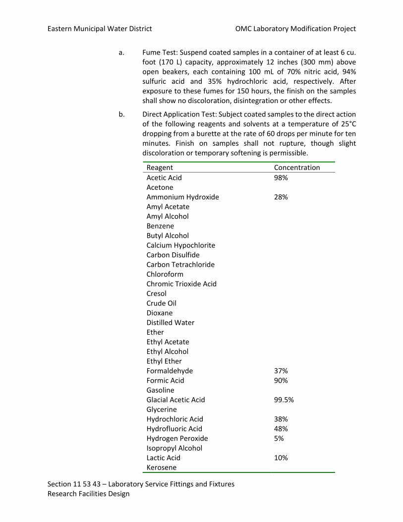
Eastern Municipal Water District OMC Laboratory Modification Project
Section 11 53 43 – Laboratory Service Fittings and Fixtures Research Facilities Design
a. Fume Test: Suspend coated samples in a container of at least 6 cu. foot (170 L) capacity, approximately 12 inches (300 mm) above open beakers, each containing 100 mL of 70% nitric acid, 94% sulfuric acid and 35% hydrochloric acid, respectively. After exposure to these fumes for 150 hours, the finish on the samples shall show no discoloration, disintegration or other effects.
b. Direct Application Test: Subject coated samples to the direct action of the following reagents and solvents at a temperature of 25°C dropping from a burette at the rate of 60 drops per minute for ten minutes. Finish on samples shall not rupture, though slight discoloration or temporary softening is permissible.
Reagent Concentration Acetic Acid 98% Acetone Ammonium Hydroxide 28% Amyl Acetate Amyl Alcohol Benzene Butyl Alcohol Calcium Hypochlorite Carbon Disulfide Carbon Tetrachloride Chloroform Chromic Trioxide Acid Cresol Crude Oil Dioxane Distilled Water Ether Ethyl Acetate Ethyl Alcohol Ethyl Ether Formaldehyde 37% Formic Acid 90% Gasoline Glacial Acetic Acid 99.5% Glycerine Hydrochloric Acid 38% Hydrofluoric Acid 48% Hydrogen Peroxide 5% Isopropyl Alcohol Lactic Acid 10% Kerosene

Eastern Municipal Water District OMC Laboratory Modification Project
Section 11 53 43 – Laboratory Service Fittings and Fixtures Research Facilities Design
Reagent Concentration Methanol Methyl Alcohol Methyl Ethyl Ketone Methylene Chloride Mineral Oil Monochlor Benzene N-Hexane Naphthalene Nitric Acid 70% Perchloric Acid 70% Phenol Phosphoric Acid 75% Sea Water Silver Nitrate 30% Sodium Bichromate Saturated Sodium Carbonate 10% Sodium Chloride 20% Sodium Hydroxide 50% Sodium Hypochlorite Sodium Sulfide Sulfuric Acid 87% Toluene Trichlorethylene Turpentine Urea Saturated Xylene Zinc Chloride Saturated
2. Mar and abrasion resistance: Coating material shall have a pencil hardness of 2H – 4H with adhesion substantial enough to withstand both direct and reverse impacts of 160 inch-pounds (18 Nm). Coating shall have excellent mar resistance and be capable of withstanding scuffing, marring and other ordinary wear.
3. Repairability: Scratches and other localized surface damage shall be field-repairable.
2.06 Laboratory Sinks
A. Epoxy Resin:
1. Manufacturer: Manufacturer shall be the manufacturer of epoxy resin work surfaces specified in Section 11 53 10.
2. Laboratory Sinks:

Eastern Municipal Water District OMC Laboratory Modification Project
Section 11 53 43 – Laboratory Service Fittings and Fixtures Research Facilities Design
a. Drop-in Type: Drop-in installation by Division 11 in epoxy resin work surface, sizes as indicated on drawings. Color to match work surface.
b. Comply with the requirements of Section 11 53 10 for epoxy resin.
c. All exposed edges shall be radiused not less than 1/4 inch (6 mm).
d. Drain grooves in top: Sink shall be set 1/8 inch (3 mm) below the lowest drain groove level.
e. Tops without drain grooves: Sink shall be set 1/8 inch (3 mm) below the level of the adjacent surface.
f. Provide epoxy resin sink outlet in color to match sink with strainer, stopper and open-end overflow, and install in sink with continuous bead of silicone sealant.
1). At black epoxy resin sinks, outlet shall be black polypropylene.
2). Where Garbage Disposers occur, provide outlet opening to match disposer’s sink flange mounting assembly.
g. Provide tailpiece compatible with waste piping system for all sinks unless otherwise specified. Refer to Division 22 for piping requirements.
B. Molded Plastic:
1. Manufacturers:
a. Products, which comply with this specification section as judged and approved by the Architect, may be provided by the following manufacturers. All products specified in this section shall be the provided by a single manufacturer.
1). Scientific Plastics Company, Inc., P.O. Box 642, Waukesha, WI 53187 Tel: 800 548-0448.
2). Orion Fittings, Inc., 613 N. 5th St., Kansas City, KS 66117 Tel: 913 342-1653.
3). Approved substitution.
2. Cup Sinks:
a. Fume Hood Locations: Provide cup sinks at fume hoods as described in Section 11 53 13.
b. Laboratory Work Surface Installations: Color to match work surface, sizes as indicated on drawings, with integral threaded tailpiece.

Eastern Municipal Water District OMC Laboratory Modification Project
Section 11 53 43 – Laboratory Service Fittings and Fixtures Research Facilities Design
c. Provide strainer and integrally-molded threaded tailpiece and outlet. Tailpiece shall be compatible with waste piping system for all sinks unless otherwise specified. Refer to Division 22 for piping requirements.
d. Provide mounting bracket for wall-mounted cup sinks.
3. Wall-Mounted Sinks:
a. Manufacturers:
1). Products, which comply with this specification section as judged and approved by the Architect, may be provided by the following manufacturers. All products specified in this section shall be the provided by a single manufacturer.
a). Just Manufacturing Company, 9233 King St., Franklin Park, IL 60131 Tel: 847 678-5150.
b). Elkay, 2222 Camden Ct., Oak Brook, IL 60523 Tel: 630 574-8484.
c). Approved substitution.
b. Hand Wash Sink: Just Model No. A-544-912, or equal.
1). Material: Type 304 stainless steel with No. 4 finish.
2). Material Thickness: 20 gauge (1.0 mm).
3). Underside of sink shall be provided with sound deadening coating.
4). Provide all necessary mounting hardware required for wall-mounted installation.
5). Faucet hole punches to be coordinated with specified faucet.
PART 3 EXECUTION
3.01 Site Conditions
A. Inspection:
1. Prior to installation of fittings specified in Section 11 53 43, carefully inspect the installed Work specified in other Sections and verify that all such Work is complete to the point where this installation may properly commence.
2. Verify that all Work has been installed in complete accordance with the original design, approved submittals, and the manufacturer's recommendations.

Eastern Municipal Water District OMC Laboratory Modification Project
Section 11 53 43 – Laboratory Service Fittings and Fixtures Research Facilities Design
B. Discrepancy:
1. In the event of discrepancy, immediately notify the Architect.
3.02 Packing and Delivery
A. Deliver all fittings and fixtures to job site in recommended packaging, with each fitting individually packaged, marked, and scheduled for point of use.
B. Inventory fittings, at job site, verify that type and quantity are correct, and re-package until installed.
C. Store in clean, dry location.
3.03 Installation
A. Set internal volume control on all cup sink water fittings so water does not splash out of sink.
END OF SECTION
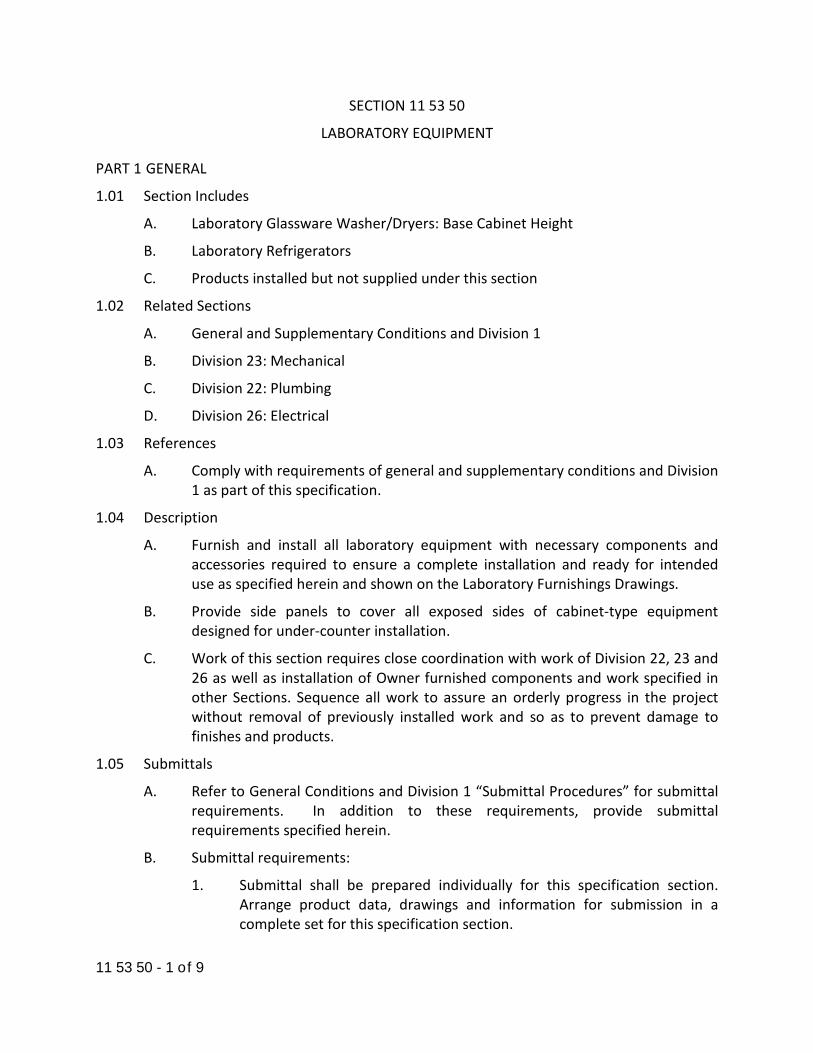
11 53 50 - 1 of 9
SECTION 11 53 50
LABORATORY EQUIPMENT
PART 1 GENERAL
1.01 Section Includes
A. Laboratory Glassware Washer/Dryers: Base Cabinet Height
B. Laboratory Refrigerators
C. Products installed but not supplied under this section
1.02 Related Sections
A. General and Supplementary Conditions and Division 1
B. Division 23: Mechanical
C. Division 22: Plumbing
D. Division 26: Electrical
1.03 References
A. Comply with requirements of general and supplementary conditions and Division 1 as part of this specification.
1.04 Description
A. Furnish and install all laboratory equipment with necessary components and accessories required to ensure a complete installation and ready for intended use as specified herein and shown on the Laboratory Furnishings Drawings.
B. Provide side panels to cover all exposed sides of cabinet-type equipment designed for under-counter installation.
C. Work of this section requires close coordination with work of Division 22, 23 and 26 as well as installation of Owner furnished components and work specified in other Sections. Sequence all work to assure an orderly progress in the project without removal of previously installed work and so as to prevent damage to finishes and products.
1.05 Submittals
A. Refer to General Conditions and Division 1 “Submittal Procedures” for submittal requirements. In addition to these requirements, provide submittal requirements specified herein.
B. Submittal requirements:
1. Submittal shall be prepared individually for this specification section. Arrange product data, drawings and information for submission in a complete set for this specification section.

11 53 50 - 2 of 9
2. Submittal shall contain complete data for all items of this specification section. Periodic or partial submittals of individual components within this specification section will be returned as incomplete and rejected.
3. Submittals shall be organized by specification sequence with section and paragraph number identified.
4. Equipment and components being proposed shall be clearly labeled with all options and accessories indicated and shall be for this specific project.
C. Shop Drawings: Submit complete shop fabrication and installation drawings, including plans, elevations, sections, details and schedules. Show relationship to adjoining materials and construction. Shop Drawings shall be in the form of reproducibles or photocopies, not to exceed 11 inches x 17 inches (A3) in size. Blueline prints are not acceptable.
D. Submit detailed anchorage and attachment drawings and calculations provided by a licensed Structural Engineer to show compliance with the applicable Building Code seismic restraint requirements.
E. Samples: Submit for Architect's approval two (2) samples of each type of specified finish and color range available.
F. Certifications: As a condition of acceptance, submit certification stating that equipment is complete and ready for intended function.
G. Operations/Maintenance Manuals: Accompanying certification, submit for Architect's review and Owner's use, complete operating and maintenance manuals that describe proper operating procedures, maintenance and replacement schedules, components parts list, and closest factory representative for components and service.
1.06 Qualifications
A. Contractor for work in this section shall have an established organization and production facilities including all tools, equipment and special machinery necessary for specializing in the fabrication and installation of the type of equipment specified, with skilled personnel, factory trained workmen and an experienced engineering department. Each shall have the demonstrated knowledge, ability and the proven capability to produce the specified equipment of the required quality and the proven capacity to complete an installation of this size and type within the required time limits.
1.07 Coordination
A. Work of this Section requires close coordination with Work of Divisions 22, 23 and 26 and Work specified in other Sections. Sequence all Work to ensure an orderly progress in the project without removal of previously installed Work and so as to prevent damage to finishes and products.

11 53 50 - 3 of 9
1.08 Substitutions
A. Approved Substitution/Approved Equal: In addition to the items required in Division 1, all substitution requests shall include item-by-item comparison of the proposed substitution to this project specification. A copy of the project specification shall be submitted, with each item and subsection of the project specification marked as “Comply” or “Not Comply.” In any cases where “Not Comply” is indicated, an explanation of the relative advantages of the proposed design shall be provided.
B. Substitution shall not affect dimensions shown on Drawings.
C. The Contractor shall pay for changes to the building design, including engineering design, detailing, utility and service requirements, and construction costs caused by the requested substitution.
D. Substitutions shall have no adverse effect on other trades, the construction schedule, or specified warranty requirements.
E. Maintenance and service parts shall be locally available for the proposed substitution.
F. Regulatory: Specified products, materials, or systems for Project may include engineering or on file standards required by the Regulatory Agency. Contractor’s substitution of products, materials or systems may require additional engineering, testing, reviews, approvals, assurances, or other information for compliance with Regulatory Agency requirements or both. Contractor shall provide all Agency approvals or other additional information required and pay additional costs for required Architect’s services made necessary by the substitution at no increase in Contract Sum or schedule time, and as a part of substitution proposal
1.09 Product Handling
A. Protection: Use all means necessary to protect work of this section before, during and after installation including installed work and materials of other trades.
B. Replacement: Any damage as a result of this contractors work will be replaced, repaired and restored to original condition to the approval of the Architect at no additional cost or inconvenience to the Owner.
1.10 Warranty
A. Refer to the General Conditions and Division 1 “Product Requirements” for warranty requirements. In addition to these requirements, all products will be warranted to be free from defects in materials and workmanship for a minimum period of one year following substantial completion.

11 53 50 - 4 of 9
The manufacturer/ dealer/ subcontractor shall repair or replace any products (or parts thereof) that are found to be defective. Replacement will include any parts, labor, shipping, and travel expenses involved.
PART 2 PRODUCTS
2.01 Laboratory Glassware Washer/Dryers: Base Cabinet Height
A. Manufacturers/Models: Products, as listed below, which comply with this specification section as judged and approved by the Architect, may be provided by the following manufacturers, listed in alphabetical order:
1. Lancer USA, http://www.lancer.com.
a. Model: 820LX
2. Miele Professional, http://www.miele-pro.com.
a. Model: G7883CD
3. Steelco, http://steelcospa.com.
a. Model: Lab500 CL
4. Approved equal.
B. Description: Microprocessor-controlled laboratory glassware washer/dryer with purified water rinsing and with at least 9 automatic wash programs, capable of accepting optional inserts such as open baskets and spindles/injectors for open or injection cleaning of laboratory glassware on two rack levels.
C. Size:
1. Minimum Chamber Dimensions: 20½ inches wide x 18½ inches high x 20 inches deep.
2. Minimum Chamber Volume: 4.5 cubic feet.
3. Maximum Overall Dimensions: 35½ inches wide x 34¼ inches high x 27½ inches deep.
D. Door Configuration: Bottom-hinged, fold-down door with safety interlock.
1. Provide door with view window if available as an option from the selected manufacturer.
E. Product Characteristics:
1. Construction:
a. Insulated, fully cabinet-enclosed unit to allow for freestanding or under-counter installation. See Laboratory Furnishing drawings for location.
b. Chamber and door:
1). Walls and ceiling, type 304 or 316 stainless steel

11 53 50 - 5 of 9
2). Floor and door, type 304 or 316 stainless steel.
c. Exterior: Type 304 stainless steel.
2. Control System: Control panel with LCD display or soft touch full glass panel to indicate cycle times, temperature, and error messages.
3. Operation/ Performance:
a. Dual pump system with separate pumps for circulation and draining.
b. Water softener with adjustable water hardness control.
c. Rotating upper and lower wash arm(s).
d. Circulation pump: Rated at a minimum of 92 gpm.
e. Minimum Heater rating: 2 kW.
f. Wash water temperature: Unit shall be capable of attaining a wash temperature of 199°F (93°C).
g. Final rinse temperature: Unit shall be capable of attaining a final purified water rinse temperature of 199°F (93°C).
h. Easily-removable filter system to catch debris at bottom of the chamber.
i. Drying system: HEPA-filtered forced-air drying system which dries both the chamber and also dries glassware through the spindles/injectors.
j. Integrated steam condenser.
k. Detergents: Unit shall be capable of operating with both detergent and neutralizer. Dispensing of liquid detergent and neutralizer shall be automatic using dosing pumps to extract chemicals from containers located integral to the washer body.
l. Noise Level: Unit shall operate at a noise level not exceeding 70 dBA.
F. Utility Requirements:
1. Contractor to coordinate utility requirements with selected manufacturer’s installation guide. The utility requirements below are intended to be able to accommodate any of the specified units.
2. Hot water: Minimum incoming temperature: 120°F (49°C). Maximum incoming temperature 158°F (70°C). Input pressure 29 to 87 psig.
3. Cold water: Input pressure 29 to 87 psig.
4. DI rinse water: Input pressure 29 to 60 psig.
5. Electric: 208 V, 60 Hz, single-Phase, 12-34 A. Provide washer with cord and plug to match electrical receptacle.
6. Drain: Connect to sink tailpiece, standpipe, or into adjacent floor sink. Refer to drawings for details. Maximum flow rates: 10.5 gpm.

11 53 50 - 6 of 9
G. Listing:
1. Unit shall carry an ETL mark signifying certification to UL Standard 3101-1/61010-1 or CAN/CSA C22.2 No. 1010.1.
H. Accessories required:
1. Drain water cool-down kit.
2. Provide an initial set of detergent and neutralizer chemicals, sufficient for a minimum of 50 washes, per unit.
3. Glassware accessories:
a. Lower rack with a minimum of 19 spindles to provide for injection cleaning for narrow-neck glassware.
b. Utensil basket(s) of approximately 512 cubic inch capacity with lid/cover(s).
2.02 Laboratory refrigerators
A. Floor-Mounted Units:
1. Manufacturers: Thermo Fisher Scientific, or similar.
2. Style: Glass door units with stainless-steel insulated cabinets. Quantity of doors varies depending on size of unit.
3. Size: Refer to LF drawings and coordinate with Owner.
4. Electrical: Provide units that operate on 120V power.
5. Cooling: Provide air-cooled units.
6. Refrigerant: Units to use non-CFC refrigerants.
7. Provide and install units in locations shown on plans.
B. Pass-Through Unit
1. Pass-Thru Combination Half Front/Solid Rear Swing Doors Refrigerator
2. Basis of Design: True Spec Series STR1RPT-1HG/1HS-1S-HC.
3. True Food Service Equipment, Inc. 2001 East Terra Lane, O’Fallon, Missouri 63366 Tel 636.240.2400.
4. Exterior: Stainless steel door, front and sides.
5. Cabinet Structure: Foamed-in-place using high-density polyurethane insulation.
6. Interior: Stainless steel side walls, back, floor, door liner, and ceiling.
7. Doors: Stainless-steel, typical. Glass-half door using low-E double-pane thermal insulating glass.

11 53 50 - 7 of 9
8. Shelving: One Interior kit option included per full section.
9. Dimensions: 27-1/2 inch wide, 36 1/8 inch deep, 77 ¾ inch tall.
10. Lighting: LED interior lighting.
11. Power: 120 volt, 60 hertz, single phase, 3.8 amps, NEMA 5-15P plug.
12. Refrigeration System: Self-contained, capillary tube system using R290 hydrocarbon refrigerant.
a. Electronically commutated evaporator and condenser fan motors.
b. Top mounted refrigeration system with evaporator positioned out of storage zone to maximize capacity.
13. Temperature Control: Unit to maintain cabinet temperatures of 33°F to 38°F (.5°C to 3.3°C).
14. Optional Features:
a. Security package.
b. Seismic/flanged legs.
15. Coordinate wall opening with contractor.
16. Provide and install in location shown on plans.
2.03 products installed but not provided under this section
A. Existing small autoclave
1. Test autoclave for correct operation prior to disconnecting. Notify the Owner of any issues.
2. Document condition of unit with photographs of all sides of unit. Submit these for record.
3. Disconnect, salvage and protect unit.
4. Clean unit for reinstallation.
5. Install in new location as specified in Part 3 of this section.
6. Startup and test unit as specified in Part 3 of this section.
7. Cleanup and protect unit as specified in Part 3 of this section.
PART 3 EXECUTION
3.01 Site Conditions
A. Inspection: Prior to installation of laboratory equipment, carefully inspect the installed work specified in other Sections and verify that all such work is complete to the point where this installation may properly commence.
B. Discrepancies: In the event of discrepancy, immediately notify the Architect.
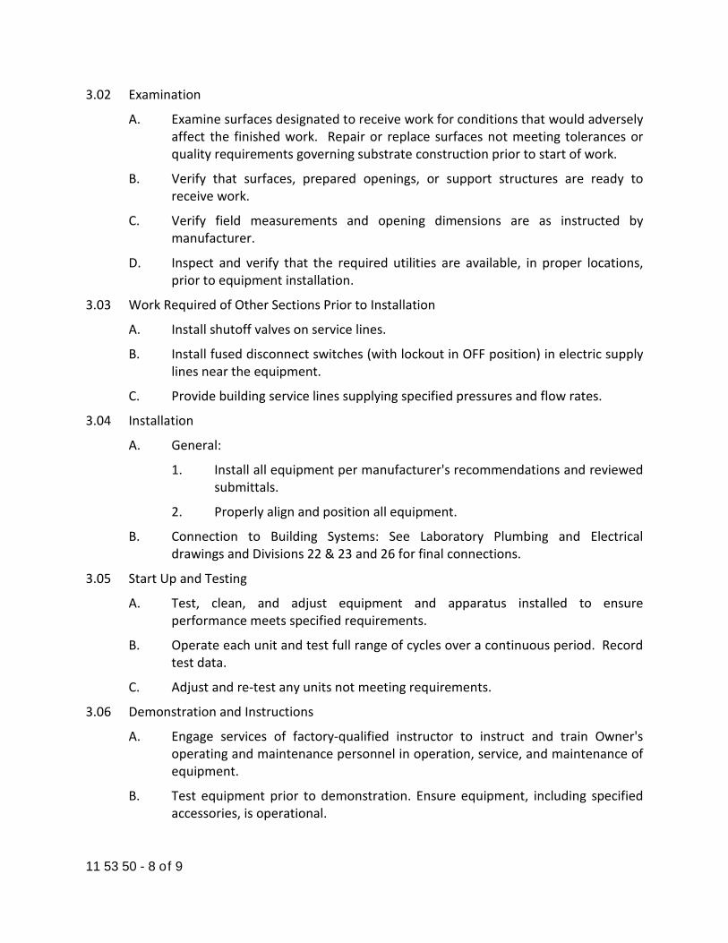
11 53 50 - 8 of 9
3.02 Examination
A. Examine surfaces designated to receive work for conditions that would adversely affect the finished work. Repair or replace surfaces not meeting tolerances or quality requirements governing substrate construction prior to start of work.
B. Verify that surfaces, prepared openings, or support structures are ready to receive work.
C. Verify field measurements and opening dimensions are as instructed by manufacturer.
D. Inspect and verify that the required utilities are available, in proper locations, prior to equipment installation.
3.03 Work Required of Other Sections Prior to Installation
A. Install shutoff valves on service lines.
B. Install fused disconnect switches (with lockout in OFF position) in electric supply lines near the equipment.
C. Provide building service lines supplying specified pressures and flow rates.
3.04 Installation
A. General:
1. Install all equipment per manufacturer's recommendations and reviewed submittals.
2. Properly align and position all equipment.
B. Connection to Building Systems: See Laboratory Plumbing and Electrical drawings and Divisions 22 & 23 and 26 for final connections.
3.05 Start Up and Testing
A. Test, clean, and adjust equipment and apparatus installed to ensure performance meets specified requirements.
B. Operate each unit and test full range of cycles over a continuous period. Record test data.
C. Adjust and re-test any units not meeting requirements.
3.06 Demonstration and Instructions
A. Engage services of factory-qualified instructor to instruct and train Owner's operating and maintenance personnel in operation, service, and maintenance of equipment.
B. Test equipment prior to demonstration. Ensure equipment, including specified accessories, is operational.

11 53 50 - 9 of 9
C. Provide demonstration of equipment operation and instruction of Owner's personnel.
D. Demonstrate operating capability of equipment and systems. Include control and safety features, and service and maintenance procedures.
3.07 Cleaning and Protection
A. All equipment shall be protected before, during and after installation. Damage to material due to improper protection shall be cause for rejection.
B. Packaging and debris and other waste resulting from installation of equipment will be removed.
C. Repair or remove and replace defective Work as directed by the Architect upon completion of installation.
D. Clean finished equipment, touch up as required and remove and refinish damaged or soiled areas.
E. Prior to final acceptance by the customer, equipment that has become damaged will be repaired or replaced according to the terms of the warranty and any external soiled surfaces will be cleaned.
END OF SECTION

[PAGE LEFT INTENTIONALLY BLANK]


![Geo-Congress [978-0-7844-1329-6.001]](https://img.pdfslide.us/doc/110x75/55cf8f1f550346703b99245f/geo-congress-978-0-7844-1329-6001.jpg)

