Embed Size (px)
Citation preview

AUGUST 2011
NGN/SP/NP/14/E
SPECIFICATION FOR
THE DESIGN OF SYSTEM EXTENSIONS, CONNECTIONS AND SERVICES TO BELOW 7BAR NGN SYSTEMS (EXTERNAL VERSION)


NGN/SP/NP/14/E
- i -
CONTENTS
Page
FOREWORD 1
1. SCOPE 1
2. PURPOSE 1
3. ASSUMPTIONS 1
4 SPECIFICATION 1
APPENDICES
A STANDARD DESIGN TABLES 4
B SPECIFICATION FOR THE DESIGN OF PIPES 12
C EVALUATION AND DESIGN OF CONNECTIONS TO NON-TYPICAL DEMANDS 20
D SPECIFICATION FOR STANDARD PIPE CODE TABLE FOR NEW LAY PIPES 28

NGN/SP/NP/14/E
- ii -
FOREWORD
This document was approved by GNSEC for use by managers, engineers and supervisors throughout Northern Gas Networks Limited (NGN).
NGN documents are revised, when necessary, by the issue of new editions. Users should ensure that they are in possession of the latest edition by referring to the NGN Register of safety and engineering documents available on the company Intranet.
Compliance with this safety and engineering document does not confer immunity from prosecution for breach of statutory or other legal obligations.
DISCLAIMER
This safety and engineering document is provided for use by NGN and such of its contractors as are obliged by the terms and conditions of their contracts to comply with this document. Where this document is used by any other party it is the responsibility of that party to ensure that this document is correctly applied.
MANDATORY AND NON-MANDATORY REQUIREMENTS
In this document:
must: indicates a mandatory requirement.
should: indicates best practice and is the preferred option. If an alternative method is used then a suitable and sufficient risk assessment must be completed to show that the alternative method delivers the same, or better, level of protection.
BRIEF HISTORY
Originally published as a management procedure
01/03/2004 T/PM/NP/14
Re-badged & updated into a suitable NGN format
13/03/2006 NGN/PM/NP/14
Re-written, reviewed and approved as a specification
29/05/2007 NGN/SP/NP/14
Amended into an official external version
22/11/2007 NGN/SP/NP/14E
Reviewed and Approved by GNSEC Table 8 updated/amended
25/03/2010 NGN/SP/NP/14E
Reviewed and Approved by GNSEC
August 2011 NGN/SP/NP/14E

NGN/SP/NP/14/E
- iii -


NGN/SP/NP/14/E
- 1 -
SPECIFICATION FOR THE DESIGN OF SYSTEM EXTENSIONS, CONNECTIONS AND SERVICES TO BELOW 7 BAR NORTHERN GAS NETWORKS’ SYSTEMS 1. SCOPE This Specification is for use in:
• The design of all new mains, services and mains risers • The review of designs submitted by third parties for evaluation • The evaluation of new or increased loads where there are no new pipes to be installed.
2. PURPOSE The purpose of this specification is to provide a consistent and defensible approach to the sizing of services, connections and the quotation of design pressures. 3. ASSUMPTIONS This document defines how the physical design of any pipe, subject to a new or modified demand, which is to be connected to a Northern Gas Networks* parent main, must be undertaken. *hereafter referred to as NGN The connection for all demands, including Condition 16 (C16) loads, is to be designed in accordance with this document. Interruptible supply requests should be evaluated in accordance with NGN/PR/NP/3. All figures provided in kW are based on a planning CV of 39mj/m³. The Scmh is the definitive value. 4. SPECIFICATION This Specification consists of a number of Appendices. Explanatory notes are contained in all Appendices to guide the Responsible and Competent person, however the purpose of this section is to provide an overview of when to use any particular Appendix for a specific activity. 4.1 Requirement for Network Analysis All requests received for new loads or increased loads must be assessed to determine if network analysis is required at the quotation stage. Refer to Appendix A Tables A.1 and A.2a. If the request falls outside the scope of the tables it must be referred for network analysis e.g. if the load is to be taken from the IP system or is a non-typical demand.
Standard or guaranteed pressures have been developed, to avoid the need to undertake network analysis at the quotation stage The scope of guaranteed capacity extends to all LP and MP requests up to 1733kW/160scmh with the exception of non typical loads and those LP requests >921kW <=1733kW off <=2” mains. Refer to Appendix A, Tables A.2a and A.3.
Post acceptance security of supply assessment may be required when standard pressures have been taken from Tables A.2a and A.3. Security of supply checks that require referral to network analysis are necessary when the load exceeds the threshold for network analysis using Appendix A, Table A.1 The security of supply check must be carried out to ensure that capacity is available to support the load increase. Any shortfall in capacity should be met, at NGN’s cost, before the load can be connected. The process for undertaking post acceptance security of supply checks, and notifying the customer of

NGN/SP/NP/14/E
- 2 -
any lead times for provision of capacity, must be in accordance with connections and planning policies/procedures.
4.1.1 Minimum parent main pressures for LP networks The values in Table A.2a represent the minimum pressures to be quoted where a multiple meter point connection is subject to network analysis as part of the quotation process
4.1.2 Minimum parent main pressures for MP networks The values in Table A.3 represent the minimum pressures to be quoted where a multiple meter point connection is subject to network analysis as part of the quotation process
4.2 Design of Services Wherever possible services should be sized in accordance with standard tables. Standard sizes do not preclude the reduction of nominal diameter for pipework and fittings at the service termination location. In these circumstances it is not necessary to check the design in approved design tools.
All services must be designed in accordance with Appendix B.
Pipe codes used in design tools must be in accordance with Appendix D
Additional or simplified requirements for specific areas of service design activities are outlined in the following sub sections.
4.2.1 New LP services Standard service sizes, for the range <=1083kW and <=60m, must be quoted in accordance with the values shown in Appendix A Table A.5
Above ground domestic service laterals <=15m must be sized in accordance with Appendix A, Table A.6
4.2.2 Increased loads to existing LP services Existing services, subject to a load increase, are permitted a maximum pressure drop of up to 5mbar where sufficient mains pressure is available.
The total revised load should be assessed against Table A.1 to determine any requirement for network analysis. To assess whether a standard mains pressure can be utilised, reference must be made to Appendix A, Table A.2a, by comparing the total revised load (new plus existing) against mains size. If the total revised load request is <=1083kW and the length <=50m Appendix A Table A.8 should be used to determine if the existing service needs to be replaced. Where the table indicates the service is not suitable to accommodate the increased load the result should be confirmed by checking with an approved design tool. If the design tool confirms the service as adequate the increased load can be taken. 4.2.3 Replacement of services not subject to a load increase. Where an existing service is identified for replacement due to condition or policy, the process defined within the relevant management procedure should be used to identify the size of pipe to be installed. 4.2.4 New MP services Standard service sizes, in the range <=1083kW and <=60m, must be sized in accordance with Appendix A Table A.7 4.3 Design of Mains Mains must be designed in accordance with Appendix B, and the pipe code table used in design tools must be in accordance with Appendix D
NGN/SP/NP/14/E
- 3 -
Additional or simplified requirements for specific areas of mains design activities are outlined in the following sub sections. 4.3.1 Standard LP/MP mains connection design sizes for UIP/GT connections Where the connected load is <10833kW the standard connection, corresponding to the load size, must be found in Appendix A Table A.4
4.3.2 Approved mains connections for all pressure tiers and work types Manifold connections must not be used. Mains connections to an existing system should use a NGN Approved, manufacturer’s standard tee or fitting.
The method for connection must be in accordance with Appendix A, Tables A.9 and A.10
4.4 Non typical demands A non-typical demand is a demand with a non-typical seasonal and/or daily profile for the customer type. Customers using compressors or boosters fall into this category.
It is important that sufficient information is gathered from the customer to properly assess the impact of non-typical demands on the upstream and downstream system network. Network analysis, including the use of such tools as Compass (or equivalent tool) where necessary must be carried out.
Refer to Appendix C
NGN/SP/NP/14/E
- 4 -
APPENDIX A
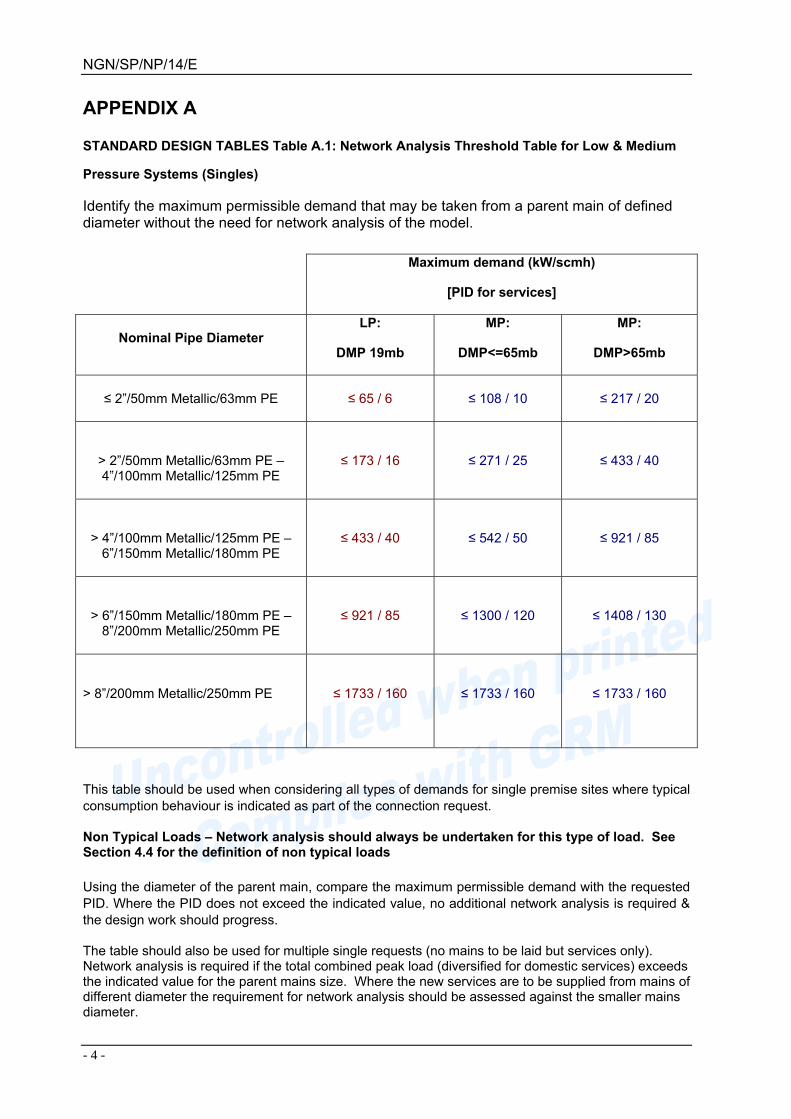
STANDARD DESIGN TABLES Table A.1: Network Analysis Threshold Table for Low & Medium
Pressure Systems (Singles)
Identify the maximum permissible demand that may be taken from a parent main of defined diameter without the need for network analysis of the model.
Maximum demand (kW/scmh)
[PID for services]
Nominal Pipe Diameter LP:
DMP 19mb
MP:
DMP<=65mb
MP:
DMP>65mb
≤ 2”/50mm Metallic/63mm PE
≤ 65 / 6 ≤ 108 / 10 ≤ 217 / 20
> 2”/50mm Metallic/63mm PE – 4”/100mm Metallic/125mm PE
≤ 173 / 16 ≤ 271 / 25 ≤ 433 / 40
> 4”/100mm Metallic/125mm PE – 6”/150mm Metallic/180mm PE
≤ 433 / 40 ≤ 542 / 50 ≤ 921 / 85
> 6”/150mm Metallic/180mm PE – 8”/200mm Metallic/250mm PE
≤ 921 / 85 ≤ 1300 / 120 ≤ 1408 / 130
> 8”/200mm Metallic/250mm PE
≤ 1733 / 160
≤ 1733 / 160
≤ 1733 / 160
This table should be used when considering all types of demands for single premise sites where typical consumption behaviour is indicated as part of the connection request.
Non Typical Loads – Network analysis should always be undertaken for this type of load. See Section 4.4 for the definition of non typical loads Using the diameter of the parent main, compare the maximum permissible demand with the requested PID. Where the PID does not exceed the indicated value, no additional network analysis is required & the design work should progress.
The table should also be used for multiple single requests (no mains to be laid but services only). Network analysis is required if the total combined peak load (diversified for domestic services) exceeds the indicated value for the parent mains size. Where the new services are to be supplied from mains of different diameter the requirement for network analysis should be assessed against the smaller mains diameter.

NGN/SP/NP/14/E
- 5 -
Table A.2a: Connection Point Pressures for Low Pressure Systems (Multiples)
Minimum pressure to be supplied for a given level of demand and parent main diameter – the segment within the box defined by the solid blue boundary line should be used to identify the supply pressure without reference to the network analysis model.
Max. Permissible Demand
(kW/scmh)
Nominal Diameter
≤173 /≤16
≤433 /≤40
≤921 /≤85
≤1733 /≤160
≤2167 /≤200
≤3250 /≤300
≤4333 / ≤400
≤5417 / ≤500
>5417 / >500
≤ 2”/50mm Metallic/63mm PE
23 23 23 23 25 26 26 26
Supply pressure to be agreed by negotiation w
ith the customer (or their representative). The
values in the previous column m
ust be used as a start point and the agreed values must allow
the efficient developm
ent of the overall system.
> 2”/50mm Metallic/63mm PE – 4”/100mm
Metallic/125mm PE
23 24 24 24 25 26 26 26
> 4”/100mm Metallic/125mm PE –
6”/150mm Metallic/180mm PE
23 24 25 25 25 26 26 26
> 6”/150mm Metallic/180mm PE –
8”/200mm Metallic/250mm PE
23 24 25 25 25 26 26 26
> 8”/200mm Metallic/250mm PE
23
24
25
25
25
26
26
26
Note: When considering discrete systems designed post December 1995, add 1.75mb to the stated values This table should be used when considering all types of demands for multiple premise sites where typical consumption behaviour is indicated as part of the connection request. Non Typical Loads – Network analysis should always be undertaken for this type of load. See Section 4.4 for the definition of non typical loads The pressures within the solid blue boundary define the guaranteed standard connection point pressures for multiple meter point requests.

NGN/SP/NP/14/E
- 6 -
The pressures outside the solid blue boundary represent the minimum pressures to be quoted where a multiple meter point connection is subject to network analysis as part of the quotation process. The cell pressures can be used as available pressure for new service designs ≥180mm diameter, (see note2 within Table B.1), and other service designs involving a mains element. In the case of alternative to reinforcement deep connection points the minimum pressure relates to the pressure at the customer’s (downstream) end of the system extension. Where reinforcement is needed the cell pressures are to be used for charging point purposes – See Appendix I. Loads falling within the red shaded cells will be subject to a post-Acceptance capacity check to ensure security of supply. For demands >5417kW / >500scmh the charging point pressure is 26mb. In some situations NGN may choose to re-negotiate the table pressures in order to develop overall lower costs of reinforcement and connection.
Table A.2b Maximum length of 63mm main
This table identifies the maximum length of 63mm LP main that can be laid without the need for a bespoke design.
Maximum Length of 63mm main (metres) Pressure
Drop 16scmh 25scmh 40scmh
2mbar 170 80 34 3mbar 255 118 52

NGN/SP/NP/14/E
- 7 -
Table A.3: Connection Point Design Pressure (loads <1733kW/160scmh) and Minimum Supply Pressure for all MP mains extensions. The values within this table represent the design pressure that should be used as the start pressure for the design of any connection that:
• Is for a load less than 160scmh including services, that is not subject to network
analysis. • Provides the minimum design supply pressure from the NGN parent main for a mains
system extension
Pressure
Tier (DMP)
Minimum parent main
supply pressure
Design Minimum
mains pressure
Max service pressure
drop
MP = 270mb 450mb 350mb 70mb
MP = 180mb 350mb 250mb 70mb
MP = 105mb 240mb 140mb *35mb/70mb
MP = 65mb 150mb 100mb 35mb
MP = 35mb 95mb 70mb 35mb
*Dependant upon the Operating Pressure of the network Maximum velocity criteria should also be adhered to when designing mains and services. Mains – 40m/sec or 20m/sec (dusty networks), Services – 15m/sec. The system Design Minimum Pressure (DMP) is dependant on the Medium Pressure tier. The relevant tier information is available from NGN on request. The Minimum parent main pressures will be provided as the ‘source’ pressure for the design of the mains extension. However, they do NOT infer actual mains pressures to be maintained i.e. NGN may choose, post-Acceptance to modify the pipe(s) to meet operational requirements of the system, and will fund any subsequent changes.
When dealing with a UIP submission, any mains that NGN is requested to adopt must be designed to ensure the minimum mains pressure, as stated in the middle column, is maintained. Similarly, any service that NGN is to take ownership should be designed in accordance with the maximum pressure drops shown within Table B.1 and which have been included for easy reference in the right hand column above. The pressures represent the minimum to be available during peak demand conditions. The pressure may be less than that indicated at off-peak times. The minimum pressure will be identified for inclusion within the quotations document. The minimum parent main supply pressures will also be the minimum design pressures to be provided for mains extensions, when network analysis is carried out for loads in excess of 160scmh.

NGN/SP/NP/14/E
- 8 -
The cell pressures represent the minimum design pressures to be provided for mains extensions, and/or used for charging point purposes for all load sizes, where reference to the analysis model identifies the indicated pressure is not available. Charging point pressures should be in line with Appendix I. For systems with a Maximum Operating Pressure >700 mb this shall be 140mb; for those systems with a Maximum Operating Pressure <700mb this shall be 70mb. NGN may choose to negotiate the upsizing of mains to be laid by a third party which will subsequently be adopted by NGN where it is beneficial to the development of the network. Additional costs will be funded by NGN. Post acceptance security of supply checks must be carried out when the load/mains size combination would require network analysis in accordance with Table A.1. Table A.4: Standard Connection Diameter for Multiple Premises Sites (Final connection for GT/UIP requests) NGN will provide the default connection pipe diameter shown to supply multiple premises sites for the indicated maximum demand.
Max Permissible Demand (kW/Scmh)
LP: Diameter
(mm)
MP: DMP≤65mb Diameter
(mm)
MP: DMP > 65mb and
≤105mb Diameter (mm)
MP: DMP>105mb
Diameter (mm)
<=325 / 30 63 63 63 63 <=758 / <=70 90 63 63 63
<=1083 / <=100 90 63 63 63 <=1625 / <=150 125 90 63 63 <=2167 / <=200 125 90 63 63 <=3250 / <=300 125 90 63 63 <=4333 / <=400 180 125 63 63 <=5417 / <=500 180 125 90 63
<=10833 /<=1000 180 125 90 90 >10833 / >1000 By Negotiation
The table values are the diameters to be used for quotation unless requested otherwise (note the value shown is the nominal diameter and may be subject to substitution with a material of similar effective diameter). Diameters greater than the value shown may be provided subject to additional cost. The table values are the minimum values that will be accepted as a UIP design. See Table A.9 & A.10 for list of approved connection types that must be used. Table A.5: Standard service designs for LP networks
Allowable Length
PID
<= 10m <= 15m <=23m <=30m <= 50m <= 60m
<= 32.5kW 32mm 32mm 32mm 32mm 32mm 32mm <=50kW 32mm 32mm 32mm 32mm 32mm 63mm
<= 65kW (U6) 32mm 32mm 32mm 32mm 63mm 63mm <= 173kW (U16) 63mm 63mm 63mm 63mm 63mm 63mm <= 271kW (U25) 63mm 63mm 63mm 63mm 63mm 63mm <= 433kW (U40) 63mm 63mm 63mm 90mm 90mm 90mm <= 704kW (U65) 90mm 90mm 90mm 90mm 90mm 90mm
<= 1083kW (U100) 90mm 90mm 90mm 90mm 125mm 125mm

NGN/SP/NP/14/E
- 9 -
Note: The values indicated can be replaced by the equivalent nominal diameter for an alternative material. Note: An allowance has been made for the presence of standard connection & termination fittings To be used for service connections to LP mains only, using a standard manufacturer’s connection (see Table A.9 & A.10) The lengths indicated represent the allowable plan length from parent main to meter point or to the base of a riser (where appropriate).
Table A.6: Above Ground Standard Service Laterals to Domestic Premises (LP only)
LengthPID <=7m <=15m
<=32.5kW ¾”St ¾”St
<=65kW (U6) ¾”St 1”St
To be used when designing above ground service laterals and laterals to be connected to an above ground riser. Service laterals with a nominated demand in excess of 6scmh should be designed in accordance with the process defined within Appendix B, taking account of the individual fittings to be used. The lengths indicated represent the allowable plan length from parent (riser) main to meter point. Laterals in excess of the lengths indicated should only be installed with the Approval of the Responsible Person. Table A.7: Default service design for MP270/180/105 systems
MP270/180/105 MP Systems
<=25m <=50m <=75m <=100m
<=173kW (U16) 32mm 32mm 32mm 32mm
<=1083kW (U100) 63mm 63mm 63mm 63mm
Requests that fall outside of the above load/length combinations, or any request on MP65/MP35 systems should be subject to a bespoke design. Services more than 60m in length should be designed in accordance with the process defined within Appendix B. Service Isolation valves (SIVs) and Service excess flow valves (SEFVs) should be fitted on all MP domestic services where the PID ≤6scmh (65kW). All other MP services should be provided with service isolation valves.

NGN/SP/NP/14/E
- 10 -
Table A.8: Maximum length of pipe to be retained where a large pressure drop (>2mb) is available to be used
Maximum Pressure
Drop 5mbݩ 4mbݩ 3mbݩ
Length (m) Demand
<=10m <=25m <=50m <=10m <=25m <=50m <=10m <=25m <=50m
<=32.5kW 20mm 25mm 25mm 20mm 25mm 25mm 20mm 25mm 25mm
<=65kW (U6) 25mm 32mm 32mm 25mm 32mm 32mm 25mm 32mm 32mm
<=173kW (U16) 63mm 63mm 63mm 63mm 63mm 63mm 32mm 63mm 63mm
<=271kW (U25) 63mm 63mm 63mm 63mm 63mm 63mm 63mm 63mm 63mm
<=433kW (U40) 63mm 63mm 90mm 63mm 63mm 63mm 63mm 63mm 63mm
<=704kW (U65) 63mm 90mm 90mm 63mm 90mm 90mm 63mm 63mm 90mm
<=1083kW (U100) 90mm 90mm 90mm 90mm 90mm 90mm 90mm 90mm 90mm
Note: The values indicated can be replaced by the equivalent nominal diameter, e.g. 63mmPE is equivalent to 2” metallic. This Table should be used to evaluate the design or retention of LP services in conjunction with Table A.2 to avoid the need for Network Analysis to evaluate new demands where:
• It is proposed to retain an existing service pipe subject to an increased demand • It is proposed to install a new service pipe with a pressure drop >2mb (where original design
results in a pipe of ≥6” NB) The minimum service diameter for all new services (including replacement of existing services where insertion cannot be used) is 32mm, irrespective of the pressure drop used for its design. The use of a smaller pipe for new services is prohibited.

NGN/SP/NP/14/E
- 11 -
Table A.9: Approved connections for PE mains to PE mains Note: Where there is more than one way of installing an approved type of connection, the least cost method will form the basis of any quotation. Only standard manufacturer’s proprietary fittings should be used to provide connection to a NGN system i.e. the use of multiple fittings to provide adequate capacity is prohibited. Some of these techniques are not applicable for PE100 pipe.
Parent
Connection
63mm 90mm 125mm 180mm 250mm 315mm >315mm
63mm 63mm top outlet ‘Service’ tee – a high volume tee should be used to connect along
the length of a pipe & a coupler used to connect to the end of a pipe for continuations
90mm
63m
m x
63m
m C
ut o
ut te
e &
Red
ucer
Cut out tee
Branch Saddle Connection
125mm 90
x 9
0 C
ut o
ut T
ee &
Red
ucer
(s) Cut out
tee Branch Saddle Connection
180mm 12
5 x
125
Cut
out
Tee
&
Red
ucer
(s)
Cut out tee Branch Saddle Connection
250mm
180
x 18
0 C
ut o
ut T
ee
& R
educ
er(s
)
Cut out tee
Branch Saddle Connection
315mm
250
x 25
0 C
ut o
ut
tee
& re
duce
r(s) Cut out
tee Cut out
equal tee
>315mm
315 x 315 Cut out Tee
& reducer
Cut out tee
Table A.10: Approved connections for PE / Metallic to Metallic mains
Parent
Connection
2” 3” 4” 6” 8” 10” >10”
<= 63mm / <= 2” Encirclement Tee 63mm or 2” Metallic Top Tee
<= 90mm / <= 3”
2” x
2” E
ncirc
lem
ent T
ee &
redu
cer(
s)
Encirclement Tee & reducer(s)
<=125mm / <= 4”
3” x
3” E
ncirc
lem
ent T
ee &
re
duce
r(s)
Encirclement Tee & reducer(s)
<= 180mm / <= 6”
4” x
4” E
ncirc
lem
ent T
ee &
re
duce
r(s)
Encirclement Tee & reducer(s)
<= 250mm / <= 8”
6” x
6” E
ncirc
lem
ent
Tee
& re
duce
r(s)
Encirclement Tee & reducer(s)
<= 315mm / <= 10”
8” x
8”
Enc
ircle
men
t Te
e &
re
duce
r(s)
Encirclement Tee & reducer(s)
>315mm / > 10”
10” x
10”
En
circ
lem
ent T
ee &
re
duce
r(s)
Enci
rcle
men
t Tee
&
redu
cer(
s)
When considering the provision of a connection for a pipe >16” nominal diameter, a risk assessment should be undertaken. Further information is available from NGN Network Controller.
For parent mains sizes of 63mm/2”, please refer to responsible manager.

NGN/SP/NP/14/E
- 12 -
APPENDIX B SPECIFICATION FOR THE DESIGN OF PIPES General Requirements Wherever practicable, the design of a new pipe should be carried out using the relevant “Standard Design Tables” from Appendix A. This will avoid carrying out a bespoke design if the demand and the mains system support the use of a standard design. This Appendix describes the rules to be used where this is not appropriate. The responsible person should ensure that all pipe design, or design evaluation, is carried out with regard to the requirements of NGN/PL/NP/16, NGN/PL/NP/18, and Connections Policy. Reference should be made to the NGN/SP/NP/10 to identify the instances where a supply pipe should be considered to comprise a main, a service pipe or a riser. Once identified, the sections below should be used to design the pipe in an appropriate manner. The following rules assume that no reinforcement of the existing system is required for the post acceptance design. In cases where reinforcement is required reference should be made to Appendix E “Assessing the Impact with Reference to the Network Analysis Model”. General design considerations A main is a below ground pipe, or exceptionally an exposed pipe (e.g. bridge crossing) laid as an extension of, or change to, the system that supplies, or has the capability to supply, more than 2 primary meter installations A service is a pipe from a main up to and including the outlet of the 1st ECV to an individual meter installation. This definition may occasionally include a dual service, supplying up to two primary meter installations in one or two buildings, with no other potential connections. A mains riser is any above ground horizontal or vertical arrangement of pipes that supplies more than two primary meter installations in an individual premises or building. A service riser is any above ground horizontal or vertical arrangement of pipes that supplies up to two primary meter installations. A lateral is a term in current use to describe an above ground pipe connecting a riser to a single primary meter installation Length - The length of the pipe should be identified using the relevant mapping system or the customer’s site plan. Velocity - For all new services operating at pressures not exceeding 7 bar the design gas velocity must not exceed 15m/s. For all new mains operating at pressures not exceeding 7 bar the design gas velocity should not exceed 40 m/s. Pipe Code Table - The pipe code tables given in Appendix D should be used for the design of all new system extensions to the NGN network. Under the direction of the Responsible Person, other pipe sizes and efficiencies will be used when incorporating existing, or non-standard, pipes within a new design. Route planning - the route should be planned in accordance with the recommendations and guidance given in IGE/TD/3, IGE/TD/4, IGE/GL/1 and IGE/GL/2. Note: it is NGN policy to terminate services at meter positions in external meter boxes on the front face of a building or not more than 2m up the gable; or to internal meter positions where the entry is on the front face of a building or not more than 2m up the gable and terminates within 2m of the point of entry.

NGN/SP/NP/14/E
- 13 -
Non-typical demands - Reference should be made to Appendix C for details of the design requirements for these demands. Table B.1 Maximum design pressure drop Note: The following values should be used for the design of all services; and they must not be exceeded.
Description / Pressure Tier Description Maximum Design Pressure Drop
LP (DMP 19mb) New 2mb or <=5mb¹ ²
Non-Insertion replacement 2mb or <=5mb¹ ² Insertion replacement <=5mb³
MP (DMP <=65mb) All 35mb MP (DMP >65mb) All 70mb
IP All 20% of available pressure drop (capped minimum of 140mb)
The design must include an allowance for connection & termination fittings and must remain within the defined maximum pressure drop value Notes: 1 Where the new service contains a pipe >=180mm (nominal) diameter & reference to network analysis confirms the design pressure to be used 2 For loads that fall within the Scope of Table A.2a, the assumed parent mains pressure will be taken from the appropriate cell 3 Where the parent main pressure has been confirmed as acceptable B.1 Design of Mains B.1.1 Pipe and Fittings The impact of minor fittings (connections, bends, valves etc.) should be managed within the design tool through a reduction in the hydraulic efficiency of the pipe system, so no allowance should be made in the design for any fittings associated with the mains connection. However, if the Responsible Person directs that a non-standard connection (less than the nominal diameter of the extension) be used, the fitting (in the form of an extension of the pipe equivalent to the length shown within Appendix B, Tables B2 & B3) should be added to the network model. The minimum supply pressure (defined within Appendix A, Table A.2a), for multiple premises sites, is the pressure to be supplied at the outlet of the NGN system i.e. at the outlet face of the valve or “pup” fitting provided to allow connection to the main. The pressure loss across this fitting should not exceed more than 10% of the available pressure for the design of the system extension. B.1.2 Mains extension designs arising from request for supply to individual premises B.1.2.1 Pre-Acceptance Design For a single premises design where a main is to be provided, the main should be designed using the pressure indicated within Table A.2a or A.3 as the source pressure. If Appendix A, Table A.2a or A.3, cannot be used, reference should be made to Network Analysis to identify the allowable pressure drop. The pipe should be designed as a single diameter and should not be less than 63mm PE in diameter (or equivalent for steel pipes).

NGN/SP/NP/14/E
- 14 -
B.1.2.2 Post-Acceptance Design Upon receipt of an Acceptance, reference should be made to Network Analysis to identify the allowable pressure drop. The “Industry least cost” solution should be identified and installed; the main should not be less than 63mm PE in diameter (or equivalent for steel pipes). Where a C16 demand is required, the pressure to be supplied to the future connection point of this potential demand should be identified – this may be part way along, or at the end of the main. See Appendix A, Table A.2a or A.3 for the required pressure at that future connection point for LP and MP/IP systems. B.1.3 Design of mains extensions to sites with multiple premises B.1.3.1 Demands Post-acceptance, the mains should be designed to supply the requested demand and any C16 potential demand identified by NGN, see Section B.1.2.2. B.1.3.2 Connection Point Pressures Where the level of demand does not exceed the value in Appendix A, Table A.2a or A.3 for the diameter of supply pipe, the indicated supply pressure should be used. Where the requested demand exceeds these maximum values, the connection pressure on the parent main should be obtained through network analysis using the appropriate forecast year model (subject to the minimum value shown within Appendix A, Tables A.2a or A.3). B.2. Services B.2.1 Pipe and Fittings As indicated in the Assumptions, an allowance should be made in the design for all fittings used as part of the service installation. This should be done using the equivalent length of pipe associated with each fitting component, as shown within Appendix B, Table B.2 & B.3, for any pressure tier. The calculations should be carried out to ensure that pressure drop within the pipe does not exceeded the maximum value shown in Appendix B, Table B.1. B.2.2 Design new service B.2.2.1 Pressure The service should be designed using the pressure drop shown in Appendix B, Table B.1 and minimum pressure associated with the relevant pressure tier. B.2.2.2 Pipe Diameter and fittings The minimum diameter used for all new services is 32mm PE or equivalent. Figure B.1 details the rules when a composite pipe should be considered. Services up to 60m long should be designed as a single diameter. B.2.2.3 Design of composite pipes for use in new services Composite pipes should be designed using two diameters only, with the larger diameter as the connection pipe, and the smaller as the termination, taking into account the pressure losses arising from the equivalent lengths of fittings. Fittings should be designed to be the same size as the service pipe to which they are connected.

NGN/SP/NP/14/E
- 15 -
Xm
Ym
Figure B.1 Design single diameter or composite pipe
Length Criteria Service Configuration
Xm <= 60m N/A Single Diameter
Xm > 60m Where Y <= 30% X Single Diameter pipe
Where Y > 30% X Composite pipe
Service should not be designed as a composite service where the length of one part is very small (<30% of the total length). Consideration can still be given to reduce the termination down one size. For example on domestic installations, it is anticipated a ¾” x 25mm house entry tee will normally be used; however this change in size should not be considered to constitute a composite pipe. The equivalent lengths for fittings are to be used within composite pipe calculations are defined within Appendix B, Tables B.2 & B.3. B.2.2.4 Remote pressure reduction Services from MP and IP mains may be designed with the pressure reduction unit remote from the meter unit. Figure B.2: Service with Remote Pressure Reduction
Where this is the case, the full pressure drop between the outlet of the pressure reduction unit and the normal pressure required at the ECV should be used in the service design. In such installations, the pressure drop associated with the LP service may exceed the standard value shown within Table B.1, and the limiting design criterion may be the gas velocity.
Governor
Max. V = 15m/sMin. P = 21.5mb
ServiceMain
ECV

NGN/SP/NP/14/E
- 16 -
Table B.2: Equivalent lengths of standard service components
Fitting Description
Pipe diameter <=32mm
or <=1” St.
<=63mm or
<=2” St.
<=90mm or
<=3” St.
<=125mm or
<=4” St.
<=180mm or
<=6” St.
<=250mm or
<=8” St.
<=315mm or
<=10” St.
<=355mm or
<=12” St.
>35mm or
>12” St.
Elbow 0.5m 1m 1.5m 2.5m 3.5m 5.0m 7.0m 10.5m 14.5m
Tee – flow straight through
0.5m 1m 1.5m 2.5m 3.5m 5.0m 7.0m 10.5m 14.5m
Tee – flow through branch
1.5m 3m 4.5m 7.5m 10.5m 14.5m 19.0m 25.0m 31.0m
Swept bend 0.3m 0.45m n/a n/a n/a n/a n/a n/a n/a
All valves 0.45m 0.68m 1.0m 1.8m 2.7m 4.2m 6.0m 8.0m 10.5m
Meter box entries 0.5m
Table B.3: Service components - specific fittings
Description of connection fitting Equivalent length Equivalent Diameter
32 Tee off any PE Diameter 2.0m 32mm PE 63 Tee off any PE Diameter 4.0m 63mm PE
1½” x 2” Flex Top Tee 4.0m 1½” Steel 1” Metallic Top Tee 4.0m 1” Steel
Reduced branch tee Length of “Tee – flow through branch” Use diameter of Branch pipe
Figure B3: Pressure loss components associated with an equal or branch tee.
B.2.3 Increase demand in existing service For the purposes of this document, an existing service should be assumed to exist where there is a live service identifiable in the relevant NGN system. Where there is no record of an existing "live" service, unless a site visit identifies otherwise, it should be assumed that any existing pipe is not suitable for use to transport gas. In such circumstances, a new service design should be undertaken.
tee - flow through branch
tee - flow straight through
Equal or branch tee Direction of flow
This should be used to identify the pressure loss associated with
full bore Tee, metallic UPT, & PE branch saddles

NGN/SP/NP/14/E
- 17 -
B.2.3.1 Evaluation of the configuration of an existing service Where possible, the configuration (length and diameter) of the service should be identified from Network "as laid" records. In the absence of this information, it should be assumed that the service is constructed in one pipe diameter, with a standard connection and termination configuration. B.2.3.2 Assessment of Existing Design The connection and termination fittings should be taken into account when calculating the pressure drop associated with the total increased demand. Where the identified pressure drop exceeds that given for the relevant pressure tier in Appendix B, Table B.1, the existing service should be replaced, with the service being designed to meet this defined pressure drop limit. B.2.3.3 Velocity Following an increase in demand, an existing service should not be replaced because of the maximum velocity being exceeded. B.3 Riser design and premises with banks of meters B.3.1 Pressure The pressure at the extremity of a mains riser should be the same as the system minimum mains design pressure. B.3.2 Design of riser and associated approach main B.3.2.1 Designs connecting to LP mains The approach main and above ground mains riser should be designed as a single unit and be based on the available pressure drop in the parent main or, where appropriate, the standard pressure taken from Appendix A, Table A.2a. B.3.2.2 Designs connecting to MP or IP mains Approach mains should be designed as a single unit using the available pressure drop. The available pressure drop should be the difference between the outlet of the pressure reduction unit and the minimum pressure at the extremity of the riser. B.3.2.3 Fittings No allowance should be made in the design of the mains riser or the approach main for the presence of fittings. B.3.2.4 Lateral Design Where the use of Appendix A, Table A.6 is not possible, for example the demand or length exceeds the values, individual laterals should be designed using the service calculator, with a maximum pressure drop of 2mbar. Laterals should be designed as single diameter pipes, with an allowance made for the presence of fittings.

NGN/SP/NP/14/E
- 18 -
B.3.3 Design of above ground rails (also known as above ground manifolds) This Table should be used for the design of single column above ground risers, when used with standard design above ground service laterals. It should also be used for the design of manifolds i.e. blocks of flats with ground floor banks of meters. Table B.4: Standard designs for single column risers and manifolds
Length Maximum Design Demand
<=15m <=23m <=30m <=50m
<=65kW 32mm / 1” St 32mm / 1” St 32mm / 1” St 63mm / 2” St <=173kW 63mm / 2” St 63mm / 2” St 63mm / 2” St 63mm / 2” St <=271kW 63mm / 2” St 63mm / 2” St 63mm / 2” St 63mm / 2” St <=433kW 63mm / 2” St 63mm / 2” St 90mm / 2” St 90mm / 2” St <=704kW 90mm / 2” St 90mm / 2” St 90mm / 2” St 90mm / 2” St <=1083kW 90mm / 2” St 90mm / 2” St 90mm / 2” St N/A
• To be used to design single column above ground risers and multiple, above ground manifolds connected to LP mains
• Assumed that the nominal mains connection fitting is not less than the downstream pipe • The lengths indicated represent the total length from parent main to end of “main”, the mix of
below/above ground pipe work is not considered significant. • Total diversified demand is assumed to be at end of “main”
Figure B.4: LP above ground rail, meters at separate locations– typical configuration
Service laterals should be designed in accordance with the requirements of Appendix A, Table A.6.

NGN/SP/NP/14/E
- 19 -
B.3.3.1 Bespoke Design Where it is not possible to design the rail using this approach, it should be designed in accordance with Appendix B, Section B.3.2.1 B.4 Design of connections to a NGN parent main Refer to Tables a.9 and A.10. Where a GT has stipulated a connection diameter less than that given in Appendix A, Table A.4, the GT should be asked to confirm the requirement before a quotation is issued. Where a UIP indicates a diameter less than the value within the Tables, the design should be evaluated to confirm they are suitable, and should be rejected where appropriate. The Responsible Person should ensure that C16 demands are taken into account before conforming that connection should progress.

NGN/SP/NP/14/E
- 20 -
APPENDIX C EVALUATION AND DESIGN OF CONNECTIONS TO NON-TYPICAL DEMANDS Where necessary, the relevant demand profile / gas use information should be provided to allow the provision of a practical design solution. Where, at the outset of the design process this information is incomplete, a number of simplifying assumptions may be applied resulting in a sub-optimal design solution and additional assessment as the type and nature of the installation becomes clear. The information that is required is shown in Appendix C, Tables C.1 and C.2. Table C.1: Where a non-typical demand profile is identified The details in this table represent the basis for discussion with the end-user or his representative. To identify the proposed profile of gas use, it is necessary to understand the time(s) of day and year at
which the gas demand is required and if the demand varies from this level at the other key times/conditions of the day and year.
Please complete the following boxes as is appropriate for the demand.
Period Please indicate with a tick the times of the day and year when the peak demand may occur
0600-1000 1000-1600 1600-2000 2000-0600 Beginning Oct – End Mar Beginning Jun – End Aug Other periods of the year

NGN/SP/NP/14/E
- 21 -
Table C.2: Where a compressor or booster is identified as being installed
Peak Instantaneous Demand to be compressed and the pressure required: ……………….…kW/m3/hr ……………….mbar/bar
Compressor Types (Reciprocating/Fan/Screw/Booster/Other):
……………………………………………………………
Number of Compressors/Boosters and the Peak Instantaneous Demand to each excluding standby:
No.:
Flow: Plant 1 …………kW/m3/hr Plant 2………… kW/m3/hr Plant 3….………kW/m3/hr
Time taken to achieve full load from start up Time taken ……………….. seconds
Profile provided for non linear start up profile Y/N/NA
Number of burners to be installed?
Will burners be operated in parallel? Y/N/NA
Typical burner stages
Start up / Pre-purge Pilot fire Low fire High fire
Flow as % of burner’s PID – burner 1
Minimum time for each stage (s) – burner 1
Flow as % of burner’s PID – burner 2
Minimum time for each stage (s) – burner 2
Flow as % of burner’s PID – burner 3
Minimum time for each stage (s) – burner 3
Where the customer has identified a non-typical demand, it will be assessed using network analysis and, where appropriate, NGN’s design assessment tool or approved equivalent. The following description refers to the use of Compass (or equivalent tool), but it is assumed that the same principle will be used where an equivalent and approved tool is used. C.1 Assessment of individual non-typical demands Where a demand is to be used at a specified off-peak period only, its impact will be assessed, using the relevant model, against the specified period. The limited period identified will be clearly stated on all quotations correspondence as a condition of supply. For low pressure networks or other networks where source pressures are reduced at off-peak conditions, the impact of the demand should be assessed against the four standard conditions see Appendix C, Table C.3.

NGN/SP/NP/14/E
- 22 -
Table C.3: Conditions to be modelled for non-typical off-peak demands on LP networks and direct fed MP demands
Source Settings Standard Conditions Scale for Demand Types Domestic Commercial Industrial
Winter Day Peak Hour, Peak Day Pressure 100% 100% 100%
Winter Night Minimum Hour, Peak Day Pressure 40% 40% 100%
Summer Day Peak Hour, Minimum Day Pressure 20% 20% 100%
Summer Night Minimum Hour, Minimum Day Pressure 10% 10% 100%
• The figures shown in this table must be used to ensure consistent design output is provided.
No additional demand modifications should be made to model demands being absent, or present, for the time the analysis being carried out.
• Any “Commercial” demand should be assumed to be temperature sensitive and any “Industrial”
demand as being constant throughout the day and across the year.
• For MP networks assume downstream demand is per the domestic tag For the design of single and composite pipes and mains, see Appendix B. C.2 Supplies to elevated pressure demands Contact should be made with any consumers requesting an elevated pressure to identify when this pressure is required. Where a specific period is specified, analysis should be undertaken to identify how it can be provided. Where the customer is not able to define a period the range of pressures associated with the point of connection should be identified using the settings shown in Appendix A, Table A.6 C.3 Supplies to CSEPs containing non-typical demands Where a CSEP site includes a non-typical demand or a demand that has downstream compressor or booster or has requested specific off-peak pressures, the GT should be requested to supply either:
• The demands it anticipates at the four standard conditions (see Appendix C, Table C.3), or • The demands it anticipates at specific times requested.
These demand levels should be applied to the relevant model(s) and the GT provided with the resultant pressures at the ISEP connection. Where a GT is unable to specify the demand details, the demand types should be assumed to be non-temperature sensitive attached to a reciprocating compressor. The assumption must be stated within the quotation. The demands should be scaled for the four standard conditions in accordance with the scaling factors given in Appendix C, Table C.3. Additionally, where a GT has identified that the CSEP site includes a supply to a compressor or booster, the four standard pressures should be quoted. The GT should be requested, as part of the Quotation, to confirm the supply pressures are adequate, and the impact of the demand at the worst-case condition will not materially affect the parent system. Where higher, peak or off-peak, pressures are required by the GT than are indicated as being available, reinforcement should be evaluated in accordance with the requirements of this document and quoted in accordance with Connections Policy.

NGN/SP/NP/14/E
- 23 -
The off-peak demand data should be retained for future modelling off-peak conditions and maintenance of the required pressures. The connection to the GT site should be designed in accordance with Appendix B, or as requested by the GT. C.4 Assessment of supplies using Compass (or equivalent tool) Appendix C, Table C.4 identifies the types of demand for which Compass (or equivalent tool), is required. Table C.4: Demand Types for use with Compass (or equivalent tool)
Demand Type Compass (or equivalent tool) assessment required?
Non-typical consumption profile to individual demand No
Non-typical consumption profile to CSEP No
Downstream compression to individual demand Yes
Downstream boosting to individual demand Yes
Elevated pressure to individual demand No
Downstream compression or boosting to CSEP In agreement with GT
For connections to all pressure tiers below 7bar, when using Compass (or equivalent tool), network analysis of the appropriate forecast year models and the relevant conditions should be undertaken to derive the steady state pressures available in the network. Appendix B, Table C.5 identifies the typical periods when the network is likely to experience maximum pressures under shut down conditions and minimum pressures under start up conditions. Reference to the table ensures that the level of demand which causes a rapid change and the service design will not give rise to unacceptable pressures in the network at these times. Note: This list is not comprehensive and the Competent Person should ensure that the “worst case” condition is understood and account taken of it i.e. the condition may depend upon the network and the type of pressure management implemented.

NGN/SP/NP/14/E
- 24 -
Table C.5: Typical worst-case pressure conditions for assessment in Compass (or equivalent tool)
Assessment Type of network pressure management Source Setting Condition
Start-up
Fixed Winter Day Peak Hour, Peak Day Pressure
Clocked Pressure Winter Day Peak Hour, Peak Day Pressure
Computer managed (closed loop control or pressure profiling) Variable Min Hour, Min Day Pressure
Shut-down
Fixed Summer Night Min Hour, Min Day Pressure
Clocked Pressure Winter Night Min Hour, Peak Day Pressure
Computer managed (closed loop control or pressure profiling) Variable Peak Hour, Peak Day
Pressure
C.4.1 Demand factors for use in Compass (or equivalent tool) To evaluate the impact of the specific compressor, the appropriate factor, as shown in Appendix C, Table C.6, should be applied to the steady state flow when using Compass (or equivalent tool): Table C.6: Factors for use in Compass (or equivalent tool)
Type Factor
Booster 0
Reciprocating Compressor 2.3
All other compressor types 1.0
Applying this factor takes account of the different ways that the equipment operates, and ensures that its impact is known. C.4.2 Pipes for input into Compass (or equivalent tool) Wherever possible the mains and service assessment option of Compass (or equivalent tool) should be used to ensure that the impact on the parent main is taken into account. This allows the maximum benefit of the dissipation of the wave to be assessed and lessens the distance to any critical point in the network where there is a constraint on the pressure required. Rules for the ratio of service length to mains length are detailed below and should be applied unless specifically directed by the Responsible Person. Where the application of these rules is not possible, the impact on the service alone should be evaluated. C.4.2.1 Ratio of Service Length to Mains Length The following constraints should be taken into account when using Compass (or equivalent tool) to evaluate the impact of a compressor / booster. The maximum length of the main, upstream and downstream from the service, should be as far into the mains system as possible, but not greater than 10 times the length of the service.
• The minimum length of the main, upstream and downstream from the service, is not less than the length of the service.
• The cut off points for the main are a change in pipe diameter / material, or a pipe junction / connection.

NGN/SP/NP/14/E
- 25 -
• Where the service connection is supplied from a number of directions, the direction of flow should be taken to be the one with the greatest supply volume.
• Where the minimum length of the main, upstream or downstream from the service, is less than the length of the service, the Compass (or equivalent tool) “service” option should be used.
• Where the direction of the flow of gas to the service is from both directions, the Compass (or equivalent tool) “service” option should be used.
C.4.3. Transient pressure constraints for the assessment of non-typical demands The maximum permissible transient pressure constraints, shown in Table C.6, should not be exceeded when evaluating the impact of a non-typical demand. These values should be used within Compass (or equivalent tool) in the appropriate boxes. Table C.7: Transient Pressure for the Assessment of Non-Typical Demands
Constraint Pressure Tier Pressure Level
Transient pressure at
connection point
Maximum pressure
LP 75mbar
MP 2bar
IP 7bar
Minimum pressure
LP – highest of: 21mbar¹ 22.75mbar²
MP Minimum 6-minute mains design pressure IP
Transient pressure at meter
point
Maximum pressure
LP 75mbar
MP 2bar
IP 7bar
Minimum pressure
LP 19mbar¹ 20.75mbar²
MP Minimum 6-minute system design pressure³ IP
Notes: 1 – Systems designed pre 1997.
2 – Discrete systems designed post 1996. 3 – See Appendix A Table 10 - LOP.
C.4.4 Service design for supplies to demands requiring Compass (or equivalent tool) assessment The following rules should be applied to the design of the service: C.4.4.1 The service should be designed using the PID identified by the customer, and include the sum of any compressed demand plus all other demands. C.4.4.2 The diameter of the service must not exceed the diameter of the main from which the connection is taken. The table below represents the standard approved PE & steel design pipes associated with Compass (or equivalent tool). Pipes other than those shown are not approved for use and must not be employed for quotations purposes. The equivalent nominal diameters in each row represent the maximum size of the parent main to which connection can be made, whilst meeting the requirements of this Instruction.

NGN/SP/NP/14/E
- 26 -
It has been assumed that only metric equivalent steel pipe will be used for service installation in the column showing the maximum permissible service diameter Table C.8 Standard pipe diameters – comparison table To ensure that the relevant non-PE diameters are clearly understood, reference may be made to the following table. Standard design pipe nominal diameters – default comparison
PE (mm) Metallic (Metric) Metallic (Imperial) Maximum service
diameter PE / Metallic
16 - - - 20 - ½” - 25 20mm ¾” - 32 25mm 1” - 63 50mm 2” 63 / 50 90 80mm 3” 90 / 80 125 114mm 4” 125 / 114 180 168mm 6” 180 / 168 250 219mm 8” 250 / 219 315 273mm 10” 315 / 273 355 324mm 12” 355 / 324 400 406mm 15” 400 / 406 450 425mm 16” 450 / 425 500 440mm 17” 500 / 440
- 457mm 18” 457 - 508mm 20” 508 - 610mm 24” 610
C.4.4.3 The initial service should be designed using the service design criteria for the relevant pressure tier. The rules for the use of single and composite pipes should be adhered to, see Appendix A. C.4.4.4 The resulting service layout should be input into Compass (or equivalent tool), together with the appropriate mains. Where the assessment of this design results in system constraints being violated, the diameter(s) of the service should be increased and the results reassessed. Where modifying the service pipe diameter (bearing in mind the constraints on size of service) does not provide an acceptable solution, the provision of supply from a higher-pressure tier(s) should be considered. Where this is not possible, the customer should be advised that the supply couldn’t be provided without control being provided for the start up and/or shut down of the compressor. C.4.4.5 Reference should be made to Tables A.9 & A.10 for the details of the acceptable connection fittings and methods to be used. C.4.4.6 Where changing the diameter of the service does not prevent in the system constraints being violated, and a feasible higher pressure tier connection is not available, the “ramp rate” will be identified and the

NGN/SP/NP/14/E
- 27 -
customer advised as one of the conditions of supply (the original service design (Item 4.4.1) will be quoted when defining a “ramp rate”). The ramp rate is a coarse term to describe the cycle that starts with the booster turning on to pressurise the downstream pipework to 100% burner flow. For conventional burner type appliances e.g. boilers there are typically 4 stages, booster on to pressurise pipework (<1% flow), burner start-up / pre-purge (<1% flow), burner pilot (<20% flow), burner low fire (<40% flow) and burner high fire (100% flow) Each stage can be modelled in Compass (or equivalent tool) providing the information is available. The ramp rate can be calculated from the formula:
T = 0.436*D, Where T is the ramp rate time (seconds) & D = upstream mains diameter (mm)
For example, for a 250mm PE SDR17 pipe (ID 220.75mm), the Ramp Rate = 0.436*221 = 96 seconds
Therefore, where a constant ramp rate is maintained for at least 96 seconds, no additional control is required to overcome the start-up/shut down affect. Note: the “ramp rate” is, generally, only affective on compressors which are not feeding a burner i.e. process loads / NGV filling stations etc. C.4.4.7 “Snubbers” or other short length increases in pipe diameter should not be used to mitigate the impact of compressors or boosters, as they are not considered effective in dissipating the transient wave. C.5 Quotation All assumptions made during the assessment of non-typical demands will be recorded and made clear in any quotation to the customer.

NGN/SP/NP/14/E
- 28 -
APPENDIX D SPECIFICATION FOR STANDARD PIPE CODE TABLE FOR NEW LAY PIPES When undertaking the design of new system extensions, or the review of a 3rd party submissions to be connected to a NGN network, the following pipe parameters should be used. As appropriate, NGN may allow supplementary pipes to be added to the list, i.e. where a UIP proposes to use a non-standard pipe size, which is considered suitable for adoption. Table D.1: PE PIPES
Nominal Diameter
Material Internal Diameter
SDR Pipe Efficiency Factor
Electro fused &
Butt fused De-beaded
Butt fused Non de-beaded
6
Butt fused Non de-beaded
12 16 PE 11.15 7 0.97 - - 20 PE 15.15 9 0.97 - - 25 PE 20.15 11 0.97 - - 32 PE 25.75 11 0.97 - - 63 PE 50.9 11 0.97 - - 90 PE 79.2 17 0.97 - - 125 PE 101.3 11 0.97 0.89 0.93 125 PE 110.3 17 0.97 0.89 0.93 180 PE 145.95 11 0.97 0.89 0.93 180 PE 158.75 17 0.97 0.89 0.93 250 PE 202.95 11 0.97 0.89 0.93 250 PE 220.75 17 0.97 0.89 0.93 250 PE 226.2 21 0.97 0.89 0.93 315 PE 255.75 11 0.97 0.89 0.93 315 PE 278.25 17 0.97 0.89 0.93 315 PE 285 21 0.97 0.89 0.93 355 PE 288.1 11 0.97 0.89 0.93 355 PE 313.5 17 0.97 0.89 0.93 355 PE 321.19 21 0.97 0.89 0.93 400 PE 327.27 11 0.97 0.89 0.93 400 PE 353.2 17 0.97 0.89 0.93 400 PE 361.90 21 0.97 0.89 0.93 450 PE 407.14 21 0.97 0.89 0.93 500 PE 409.09 11 0.97 0.89 0.93 500 PE 441.7 17 0.97 0.89 0.93 500 PE 452.38 21 0.97 0.89 0.93
The above values are common for both the design of new, and review of existing, PE pipes.

NGN/SP/NP/14/E
- 29 -
Table D.2: STEEL PIPES
Nominal Diameter
Material Internal Diameter
Pipe Efficiency Factor Mains or Service Design
Fillet Welded Screwed
Butt Welded
0.5 ST 19.93 0.86 - S 0.75 ST 19.67 0.86 - S
1 ST 26 0.86 - M 1.25 ST 33.92 0.86 - M 1.5 ST 38.67 0.86 - M 2 ST 49.86 0.97 0.97 M
2.5 ST 65.43 - 0.97 M 3 ST 78.13 - 0.97 M 4 ST 103.53 - 0.97 M 6 ST 157.51 - 0.97 M 8 ST 206.38 - 0.97 M 10 ST 260.35 - 0.97 M 12 ST 311.15 - 0.97 M 16 ST 390.55 - 0.97 M 18 ST 441.35 - 0.97 M 20 ST 492.15 - 0.97 M 24 ST 593.75 - 0.97 M 30 ST 739.75 - 0.97 M 32 ST 793.75 - 0.97 M 36 ST 889 - 0.97 M 42 ST 1066.8 - 0.97 M 48 ST 1225.55 - 0.97 M


![[PPT]NGN Management Specifications - Internet · Web viewAnnex 2 to NGN Management Specification Roadmap NGN Management Specifications Annex 2 to NGNMFG-OD-013-R2, NGN](https://img.pdfslide.us/doc/110x75/5aa1f8287f8b9a1f6d8c9bec/pptngn-management-specifications-internet-viewannex-2-to-ngn-management.jpg)