Embed Size (px)
Citation preview

Specification for Road Works Series 500 - Drainage and
Service Ducts
CC-SPW-00500
March 2015

TRANSPORT INFRASTRUCTURE IRELAND (TII) PUBLICATIONS
Page i
About TII
Transport Infrastructure Ireland (TII) is responsible for managing and improving the country’s national road and light rail networks.
About TII Publications
TII maintains an online suite of technical publications, which is managed through the TII Publications website. The contents of TII Publications is clearly split into ‘Standards’ and ‘Technical’ documentation. All documentation for implementation on TII schemes is collectively referred to as TII Publications (Standards), and all other documentation within the system is collectively referred to as TII Publications (Technical).
Document Attributes
Each document within TII Publications has a range of attributes associated with it, which allows for efficient access and retrieval of the document from the website. These attributes are also contained on the inside cover of each current document, for reference.
TII Publication Title Specification for Road Works Series 500 - Drainage and Service Ducts
TII Publication Number CC-SPW-00500
Activity Construction & Commissioning (CC)
Document Set Standards
Stream Specification for Works (SPW)
Publication Date March 2015
Document Number
00500 Historical Reference
Series 500
TII Publications Website
This document is part of the TII publications system all of which is available free of charge at http://www.tiipublications.ie. For more information on the TII Publications system or to access further TII Publications documentation, please refer to the TII Publications website.
TII Authorisation and Contact Details
This document has been authorised by the Director of Professional Services, Transport Infrastructure Ireland. For any further guidance on the TII Publications system, please contact the following:
Contact: Standards and Research Section, Transport Infrastructure Ireland
Postal Address: Parkgate Business Centre, Parkgate Street, Dublin 8, D08 DK10
Telephone: +353 1 646 3600
Email: [email protected]
TII Publications CC-SPW-00500 Specification for Road Works Series 500 - Drainage and Service Ducts March 2015
Page ii
Updates to TII Publications resulting in changes to
Specification for Road Works Series 500 - Drainage and Service Ducts CC-SPW-00500
Date: September 2017
Page No: 39
Section No: Clause 524 – Pipes for Ducts
Amendment Details:
The following minor amendment has been incorporated into the March 2015 version of this Standard:
a) Clause 524 – Reference to IS EN 50086-2-4 has been deleted as this Standard has been withdrawn.

TII Publications CC-SPW-00500 Specification for Road Works Series 500 - Drainage and Service Ducts March 2015
1
National Roads Authority
Manual of Contract Documents for Road Works
(NRA MCDRW)
AMENDMENT No. 1 (May 2015) to NRA Specification for Road
Works Series 500 - Drainage & Service Ducts Dated March 2015
The NRA Specification for Road Works (NRA MCDRW), Series 500 - Drainage & Service Ducts, dated
March 2015 is amended as follows:-
1. Page 7, Sub-clause 504.4
Delete text ‘tested in accordance with sub-Clause 509.7 and shall be British Standard joints or non-
British Standard joints’ from first line and insert text ‘joined in accordance with the manufacturer’s
instructions’ in the first line.
2. Page 10, Sub-clause 506.1
Delete text ‘507.18’ and insert text ‘507.14’ in the third line.
3. Page 13, Sub-clause 507.15
Delete text ‘Sub-clause 17’ and insert text ‘Sub-clause 13’ in the fifth line.
4. Page 14, Sub-clause 508.4
Delete text ‘507.7’ and insert text ‘507’ in the second line.
5. Page 14, Sub-clause 508.5
Delete text ‘507.17’ and insert text ‘507.13’ in the third line.
6. Page 14, Sub-clause 508.7
Delete text ‘507.18’ and insert text ‘507.14’ in the second line.
7. Page 14, Sub-clause 508.8
Delete text ‘507.17’ and insert text ‘507.13’ in the fifth line.
8. Page 17, Sub-clause 513.1
Delete the following text;

TII Publications CC-SPW-00500 Specification for Road Works Series 500 - Drainage and Service Ducts March 2015
2
“1 Permeable backing shall consist of one of the following materials:
(i) A minimum thickness of 300mm of granular material in accordance with Clause 505.
(ii) Geocomposite drains.”
and insert the following text in the first line;
“1 Permeable backing shall consist of one of the following materials:
(i) A minimum thickness of 300 mm of granular material of 20mm nominal size, satisfying
the following criteria:
Piping ratio, defined as
15 per cent size of the drainage material , < 5 85 per cent size of the backfill material
Permeability ratio, defined as
15 per cent size of the drainage material , < 5 15 per cent size of the backfill material
where the per cent size of a material is the size of particle corresponding to the given per cent ordinate of the particle size distribution graph.
(ii) Porous no-fines concrete, cast in situ 225 mm thick complying with the requirements of the requirements of the 2600 Series.
(iii) Precast hollow concrete blocks complying with IS EN 772-2 & 3 laid in stretcher bond with dry joints in 225 mm thick walling with holes vertical.”
9. Page 18, Sub-clause 514.6
Delete text ‘4(v)’ from the first line of item (i) and insert text ‘5(v)’.
10. Page 18, Sub-clause 514.6
Delete text ‘Sub-clause 13’ from the third line of item (i), part (b) and insert text ‘Sub-clause 14’.
11. Page 19, Sub-clause 514.7
Delete text ‘5(ii)’ from the second line of the second paragraph and insert text ‘5(v)’.
12. Page 23, Sub-clause 514.16
Delete text ’14 (vi)’ from the second line of item (a) and insert text ‘14’.
13. Page 23, Sub-clause 514.17
Delete text ’13, 14 and 15’ from the first line and insert text ’14, 15 and 16’.
TII Publications CC-SPW-00500 Specification for Road Works Series 500 - Drainage and Service Ducts March 2015
3
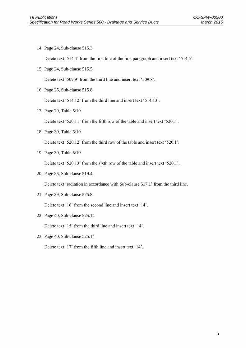
14. Page 24, Sub-clause 515.3
Delete text ‘514.4’ from the first line of the first paragraph and insert text ‘514.5’.
15. Page 24, Sub-clause 515.5
Delete text ‘509.9’ from the third line and insert text ‘509.8’.
16. Page 25, Sub-clause 515.8
Delete text ‘514.12’ from the third line and insert text ‘514.13’.
17. Page 29, Table 5/10
Delete text ‘520.11’ from the fifth row of the table and insert text ‘520.1’.
18. Page 30, Table 5/10
Delete text ‘520.12’ from the third row of the table and insert text ‘520.1’.
19. Page 30, Table 5/10
Delete text ‘520.13’ from the sixth row of the table and insert text ‘520.1’.
20. Page 35, Sub-clause 519.4
Delete text ‘radiation in accordance with Sub-clause 517.1’ from the third line.
21. Page 39, Sub-clause 525.8
Delete text ‘16’ from the second line and insert text ‘14’.
22. Page 40, Sub-clause 525.14
Delete text ‘15’ from the third line and insert text ‘14’.
23. Page 40, Sub-clause 525.14
Delete text ‘17’ from the fifth line and insert text ‘14’.
TII Publications CC-SPW-00500 Specification for Road Works Series 500 - Drainage and Service Ducts March 2015
1
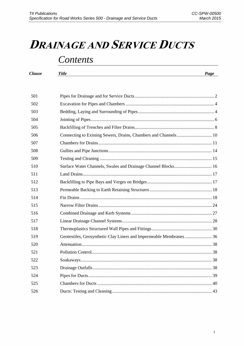
DRAINAGE AND SERVICE DUCTS Contents
Clause
Title
Page
501 Pipes for Drainage and for Service Ducts ...................................................................... 2
502 Excavation for Pipes and Chambers .............................................................................. 4
503 Bedding, Laying and Surrounding of Pipes ................................................................... 4
504 Jointing of Pipes ............................................................................................................. 6
505 Backfilling of Trenches and Filter Drains ...................................................................... 8
506 Connecting to Existing Sewers, Drains, Chambers and Channels ............................... 10
507 Chambers for Drains .................................................................................................... 11
508 Gullies and Pipe Junctions ........................................................................................... 14
509 Testing and Cleaning ................................................................................................... 15
510 Surface Water Channels, Swales and Drainage Channel Blocks ................................. 16
511 Land Drains .................................................................................................................. 17
512 Backfilling to Pipe Bays and Verges on Bridges ......................................................... 17
513 Permeable Backing to Earth Retaining Structures ....................................................... 18
514 Fin Drains .................................................................................................................... 18
515 Narrow Filter Drains .................................................................................................... 24
516 Combined Drainage and Kerb Systems ....................................................................... 27
517 Linear Drainage Channel Systems ............................................................................... 28
518 Thermoplastics Structured Wall Pipes and Fittings ..................................................... 30
519 Geotextiles, Geosynthetic Clay Liners and Impermeable Membranes ........................ 36
520 Attenuation ................................................................................................................... 38
521 Pollution Control .......................................................................................................... 38
522 Soakaways.................................................................................................................... 38
523 Drainage Outfalls ......................................................................................................... 38
524 Pipes for Ducts ............................................................................................................. 39
525 Chambers for Ducts ..................................................................................................... 40
526 Ducts: Testing and Cleaning ........................................................................................ 43
TII Publications CC-SPW-00500 Specification for Road Works Series 500 - Drainage and Service Ducts March 2015
2
Drainage and Service Ducts
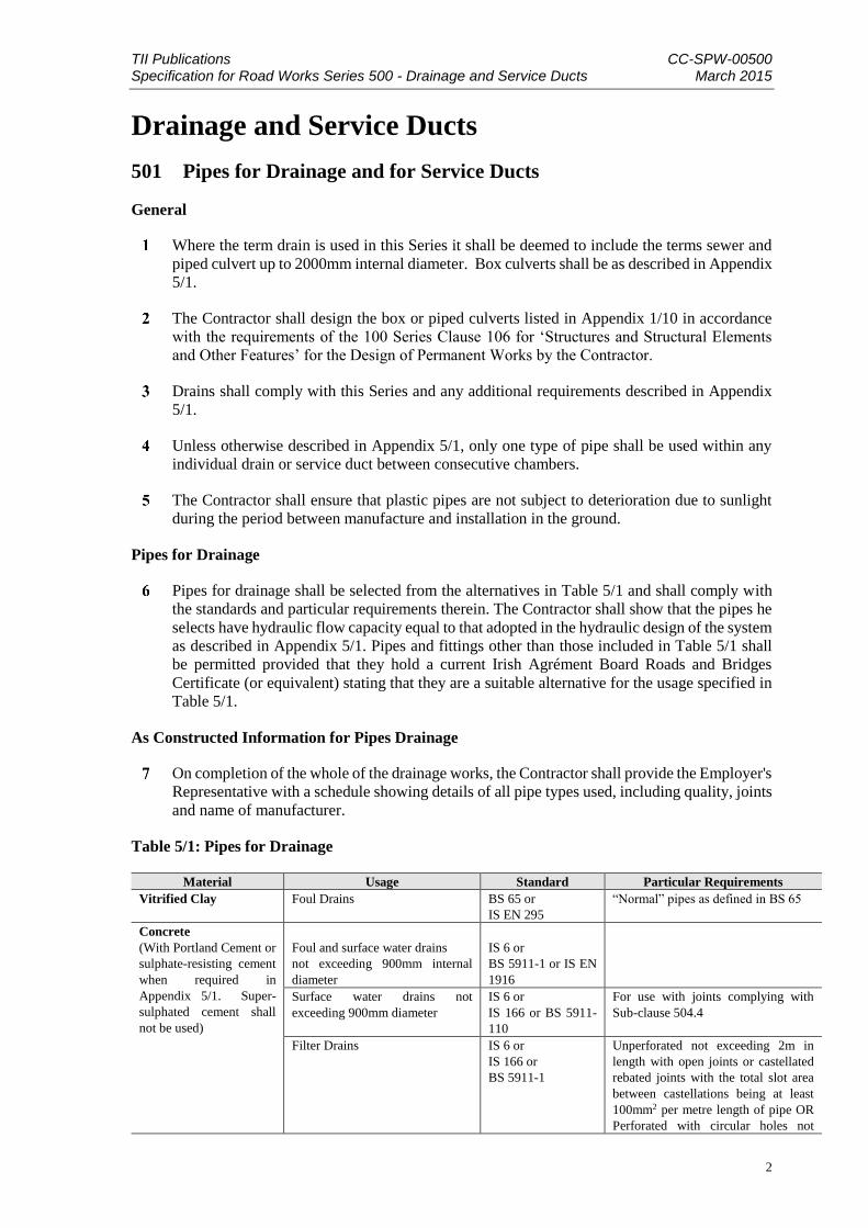
501 Pipes for Drainage and for Service Ducts
General
Where the term drain is used in this Series it shall be deemed to include the terms sewer and
piped culvert up to 2000mm internal diameter. Box culverts shall be as described in Appendix
5/1.
The Contractor shall design the box or piped culverts listed in Appendix 1/10 in accordance
with the requirements of the 100 Series Clause 106 for ‘Structures and Structural Elements
and Other Features’ for the Design of Permanent Works by the Contractor.
Drains shall comply with this Series and any additional requirements described in Appendix
5/1.
Unless otherwise described in Appendix 5/1, only one type of pipe shall be used within any
individual drain or service duct between consecutive chambers.
The Contractor shall ensure that plastic pipes are not subject to deterioration due to sunlight
during the period between manufacture and installation in the ground.
Pipes for Drainage
Pipes for drainage shall be selected from the alternatives in Table 5/1 and shall comply with
the standards and particular requirements therein. The Contractor shall show that the pipes he
selects have hydraulic flow capacity equal to that adopted in the hydraulic design of the system
as described in Appendix 5/1. Pipes and fittings other than those included in Table 5/1 shall
be permitted provided that they hold a current Irish Agrément Board Roads and Bridges
Certificate (or equivalent) stating that they are a suitable alternative for the usage specified in
Table 5/1.
As Constructed Information for Pipes Drainage
On completion of the whole of the drainage works, the Contractor shall provide the Employer's
Representative with a schedule showing details of all pipe types used, including quality, joints
and name of manufacturer.
Table 5/1: Pipes for Drainage
Material Usage Standard Particular Requirements
Vitrified Clay Foul Drains BS 65 or
IS EN 295
“Normal” pipes as defined in BS 65
Concrete
(With Portland Cement or
sulphate-resisting cement
when required in
Appendix 5/1. Super-
sulphated cement shall
not be used)
Foul and surface water drains
not exceeding 900mm internal
diameter
IS 6 or
BS 5911-1 or IS EN
1916
Surface water drains not
exceeding 900mm diameter
IS 6 or
IS 166 or BS 5911-
110
For use with joints complying with
Sub-clause 504.4
Filter Drains IS 6 or
IS 166 or
BS 5911-1
Unperforated not exceeding 2m in
length with open joints or castellated
rebated joints with the total slot area
between castellations being at least
100mm2 per metre length of pipe OR
Perforated with circular holes not

TII Publications CC-SPW-00500 Specification for Road Works Series 500 - Drainage and Service Ducts March 2015
3
Material Usage Standard Particular Requirements
greater than 10mm or less than 3mm in
diameter
Drains exceeding 900mm
diameter
IS 6 or IS 166 or BS
5911-1 and IS EN
1916
Pipes having a concrete mix meeting
the following requirements (Testing in
accordance with the relevant BS and
sampling in accordance with Clause
509):
A total chloride ion content as
described in Appendix 1/10 AND
A 28-day minimum works cube
strength of not less than 50 N/mm2
Iron Foul and surface water drains BS 437
(Cast Iron)
IS EN 598
(Ductile Iron)
Unplasticised polyvinyl-
chloride (UPVC)
Foul and surface water drains IS EN 1401 or
BS 4660 or
BS 5481 or
IS EN 13476 or IS
EN 13598-1
Filter Drains IS EN 1401 or
BS 5481
Perforated with not less than 100mm2
of holes per metre length of pipe. The
perforations shall not reduce the pipe
stiffness by more than 5%.
Circular perforations not greater than
10mm or less than 3mm in diameter or
rectangular slots not greater than 4mm
or less than 0.6mm in width.
Plastics Surface water drains IS EN 13476 or
Irish Agrément
Board Roads and
Bridges Certificate
(or equivalent)
Unperforated with watertight joints
and with a pipe stiffness and impact
resistance as described in Appendix
5/1
Filter drains Irish Agrément
Board Roads and
Bridges Certificate
(or equivalent)
Perforated and with a pipe stiffness
and impact resistance as described in
Appendix 5/1.
Subsoil field drains BS 4962
TII Publications CC-SPW-00500 Specification for Road Works Series 500 - Drainage and Service Ducts March 2015
4
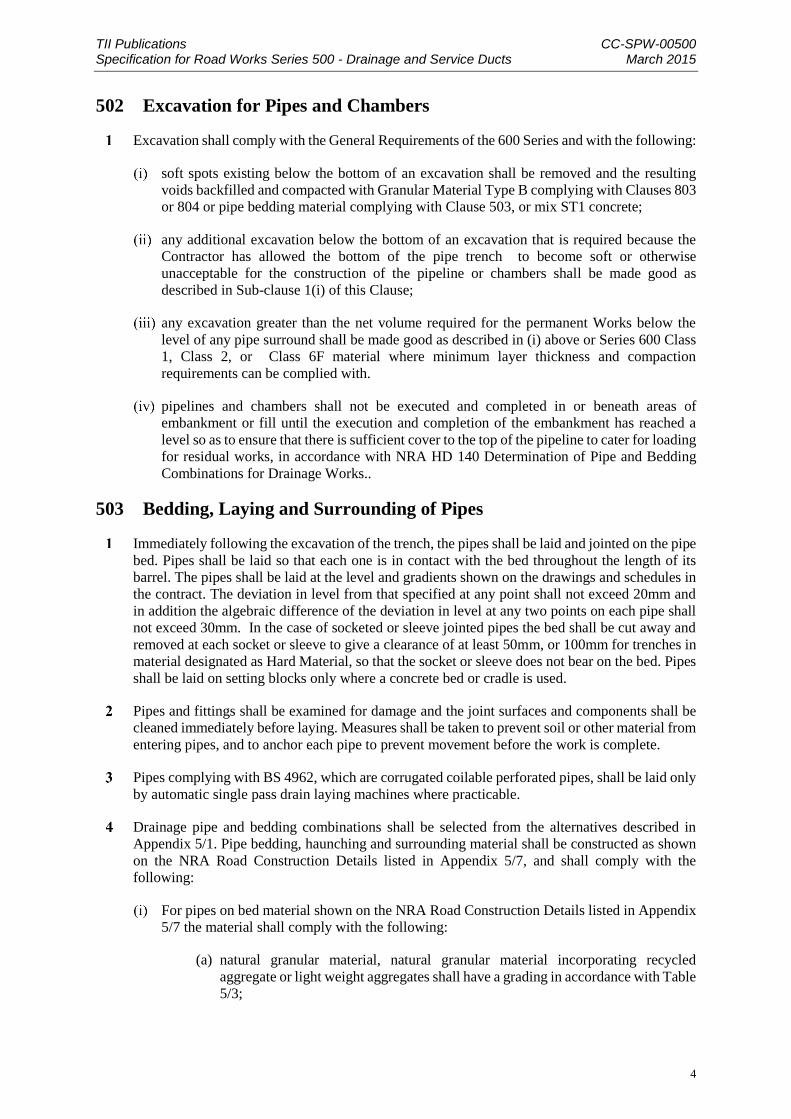
502 Excavation for Pipes and Chambers
Excavation shall comply with the General Requirements of the 600 Series and with the following:
soft spots existing below the bottom of an excavation shall be removed and the resulting
voids backfilled and compacted with Granular Material Type B complying with Clauses 803
or 804 or pipe bedding material complying with Clause 503, or mix ST1 concrete;
any additional excavation below the bottom of an excavation that is required because the
Contractor has allowed the bottom of the pipe trench to become soft or otherwise
unacceptable for the construction of the pipeline or chambers shall be made good as
described in Sub-clause 1(i) of this Clause;
any excavation greater than the net volume required for the permanent Works below the
level of any pipe surround shall be made good as described in (i) above or Series 600 Class
1, Class 2, or Class 6F material where minimum layer thickness and compaction
requirements can be complied with.
pipelines and chambers shall not be executed and completed in or beneath areas of
embankment or fill until the execution and completion of the embankment has reached a
level so as to ensure that there is sufficient cover to the top of the pipeline to cater for loading
for residual works, in accordance with NRA HD 140 Determination of Pipe and Bedding
Combinations for Drainage Works..
503 Bedding, Laying and Surrounding of Pipes
Immediately following the excavation of the trench, the pipes shall be laid and jointed on the pipe
bed. Pipes shall be laid so that each one is in contact with the bed throughout the length of its
barrel. The pipes shall be laid at the level and gradients shown on the drawings and schedules in
the contract. The deviation in level from that specified at any point shall not exceed 20mm and
in addition the algebraic difference of the deviation in level at any two points on each pipe shall
not exceed 30mm. In the case of socketed or sleeve jointed pipes the bed shall be cut away and
removed at each socket or sleeve to give a clearance of at least 50mm, or 100mm for trenches in
material designated as Hard Material, so that the socket or sleeve does not bear on the bed. Pipes
shall be laid on setting blocks only where a concrete bed or cradle is used.
Pipes and fittings shall be examined for damage and the joint surfaces and components shall be
cleaned immediately before laying. Measures shall be taken to prevent soil or other material from
entering pipes, and to anchor each pipe to prevent movement before the work is complete.
Pipes complying with BS 4962, which are corrugated coilable perforated pipes, shall be laid only
by automatic single pass drain laying machines where practicable.
Drainage pipe and bedding combinations shall be selected from the alternatives described in
Appendix 5/1. Pipe bedding, haunching and surrounding material shall be constructed as shown
on the NRA Road Construction Details listed in Appendix 5/7, and shall comply with the
following:
For pipes on bed material shown on the NRA Road Construction Details listed in Appendix
5/7 the material shall comply with the following:
(a) natural granular material, natural granular material incorporating recycled
aggregate or light weight aggregates shall have a grading in accordance with Table
5/3;

TII Publications CC-SPW-00500 Specification for Road Works Series 500 - Drainage and Service Ducts March 2015
5
(b) natural granular material, natural granular material incorporating recycled
aggregate or light weight aggregates shall have a water-soluble sulphate content
of less than 0.38% of sulphate (as SO3) when tested in accordance with IS EN
1744-1, Clause 10;
(c) concrete shall be mix ST4, backfilling shall not be carried out until after a visual
assessment has been undertaken by the designer in order to establish if the concrete
has cured sufficiently to receive backfill material.
For pipes on beds specified in Appendix 5/1 the granular material shall comply either with
Sub-clause 3(i) of this Clause or with Table 5/4, with the water soluble sulphate content
complying with (i) above.
Except for filter drains any Class 1 or Class 2 material above the bed, haunch and surround
described above, shall be provided to a height of 300 mm above the top of the surround in
compliance with the 600 Series, with the maximum particle size of the fill material no more
than two thirds of the compacted layer thickness except that lumps of clay and cobbles
having an equivalent diameter or more than 150mm shall not be deposited.
Unless otherwise described in Appendix 5/1 the materials used for the bedding, haunching
and surrounding of filter drains shall comply with the appropriate bedding, haunching and
surrounding materials specified in Sub-clauses 503.3.(i) to 503.3.(iv) and with the
requirements for backfilling specified in Sub-clause 505.3.
Table 5/3: IS EN 13242, Coarse aggregate for pipe bedding, haunching and surrounding material
IS EN 13242, Coarse aggregate
Category for general grading
requirements
Gc 80-20
Category for tolerances at mid-size
sieves
GTNR (no requirements)
Category for maximum values of
fines content
Gravel- f1.5 Crushed rock, recycled
Aggregate – f4
LA Abrasion (LA) LA50
Water Soluble Sulfate (SS) as SO3 % SS0.38
Nominal pipe diameter, mm Aggregate size, mm
Graded Single sized
Not exceeding 140 - 4/10
Exceeding 140 but not exceeding 400 2/14 or 4/20 4/10, 6/14 or
10/20
Exceeding 400 2/10, 4/20
or 4/40
4/10, 6/14,
10/20 or 20/40
TII Publications CC-SPW-00500 Specification for Road Works Series 500 - Drainage and Service Ducts March 2015
6
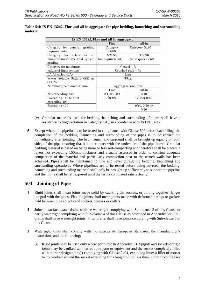
Table 5/4: IS EN 13242, Fine and all-in aggregate for pipe bedding, haunching and surrounding
material
IS EN 13242, Fine and all-in aggregate
Fine All-in
Category for general grading
requirements
Category
GF80
Category GA80
Category for tolerances on
manufacturer’s declared typical
grading
GTFNR
(no requirement)
GTANR
(no requirement)
Category for maximum
values of fines content
Gravel – f3
Crushed rock – f11
LA Abrasion (LA) LA50
Water Soluble Sulfate (SS) as
SO3 %
SS0.38
Nominal pipe diameter, mm Aggregate size, mm
Fine All-in
Not exceeding 140 0/1, 0/2, 0/4
Or 0/6
0/10
Exceeding 140 but not
exceeding 400
0/10 or 0/20
Exceeding 400 0/10, 0/20 or
0/40
Granular materials used for bedding, haunching and surrounding of pipes shall have a
resistance to fragmentation in Category LA50 in accordance with IS EN 13242.
Except where the pipeline is to be tested in compliance with Clause 509 before backfilling, the
completion of the bedding, haunching and surrounding of the pipes is to be carried out
immediately after jointing. The bed, haunch and surround shall be brought up equally on both
sides of the pipe ensuring that it is in contact with the underside of the pipe barrel. Granular
bedding material is based on being more or less self-compacting and therefore shall be placed in
layers not exceeding 150mm thickness and visually assessed in order to confirm adequate
compaction of the material and particularly compaction next to the trench walls has been
achieved. Pipes shall be maintained to line and level during the bedding, haunching and
surrounding operations. Where pipelines are to be tested before being covered, the bedding,
haunching and surrounding material shall only be brought up sufficiently to support the pipeline
and the joints shall be left exposed until the test is completed satisfactorily.
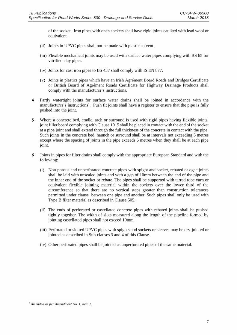
504 Jointing of Pipes
Rigid joints shall mean joints made solid by caulking the sockets, or bolting together flanges
integral with the pipes. Flexible joints shall mean joints made with deformable rings or gaskets
held between pipe spigots and sockets, sleeves or collars.
Joints in surface water drains shall be watertight complying with Sub-clause 3 of this Clause or
partly watertight complying with Sub-clause 4 of this Clause as described in Appendix 5/1. Foul
drains shall have watertight joints. Filter drains shall have joints complying with Sub-clause 6 of
this Clause.
Watertight joints shall comply with the appropriate European Standards, the manufacturer’s
instructions and the following:
Rigid joints shall be used only where permitted in Appendix 5/1. Spigots and sockets of rigid
joints may be caulked with tarred rope yarn or equivalent and the socket completely filled
with mortar designation (i) complying with Clause 2404, excluding lime; a fillet of mortar
being worked around the socket extending for a length of not less than 50mm from the face
TII Publications CC-SPW-00500 Specification for Road Works Series 500 - Drainage and Service Ducts March 2015
7
of the socket. Iron pipes with open sockets shall have rigid joints caulked with lead wool or
equivalent.
Joints in UPVC pipes shall not be made with plastic solvent.
Flexible mechanical joints may be used with surface water pipes complying with BS 65 for
vitrified clay pipes.
Joints for cast iron pipes to BS 437 shall comply with IS EN 877.
Joints in plastics pipes which have an Irish Agrément Board Roads and Bridges Certificate
or British Board of Agrément Roads Certificate for Highway Drainage Products shall
comply with the manufacturer’s instructions.
Partly watertight joints for surface water drains shall be joined in accordance with the
manufacturer’s instructions1. Push fit joints shall have a register to ensure that the pipe is fully
pushed into the joint.
Where a concrete bed, cradle, arch or surround is used with rigid pipes having flexible joints,
joint filler board complying with Clause 1015 shall be placed in contact with the end of the socket
at a pipe joint and shall extend through the full thickness of the concrete in contact with the pipe.
Such joints in the concrete bed, haunch or surround shall be at intervals not exceeding 5 metres
except where the spacing of joints in the pipe exceeds 5 metres when they shall be at each pipe
joint.
Joints in pipes for filter drains shall comply with the appropriate European Standard and with the
following:
Non-porous and unperforated concrete pipes with spigot and socket, rebated or ogee joints
shall be laid with unsealed joints and with a gap of 10mm between the end of the pipe and
the inner end of the socket or rebate. The pipes shall be supported with tarred rope yarn or
equivalent flexible jointing material within the sockets over the lower third of the
circumference so that there are no vertical steps greater than construction tolerances
permitted under clause between one pipe and another. Such pipes shall only be used with
Type B filter material as described in Clause 505.
The ends of perforated or castellated concrete pipes with rebated joints shall be pushed
tightly together. The width of slots measured along the length of the pipeline formed by
jointing castellated pipes shall not exceed 10mm.
Perforated or slotted UPVC pipes with spigots and sockets or sleeves may be dry-jointed or
jointed as described in Sub-clauses 3 and 4 of this Clause.
Other perforated pipes shall be jointed as unperforated pipes of the same material.
1 Amended as per Amendment No. 1, item 1.

TII Publications CC-SPW-00500 Specification for Road Works Series 500 - Drainage and Service Ducts March 2015
8
505 Backfilling of Trenches and Filter Drains
Backfilling shall be undertaken immediately after the specified operations preceding it have been
completed. The material as described in the Contract shall be deposited in layers, compacted in
accordance with requirements specified in Clause 601.8 of the 600 Series. Care should be taken
to compact the material evenly without dislodging or damaging pipes. Power rammers are not to
be used within 300mm of any part of the pipe or joint.
Except where otherwise described in Appendix 5/1, trenches other than filter drain trenches shall
be backfilled above the pipe surround material described in Clause 503 with Class 1 or 2 general
fill material complying with the requirements of the 600 Series. Backfill of trenches, other than
in carriageways and other paved areas, shall be brought up to ground level. Where the ground
surface on the line of the trench consists of topsoil, the upper section of the backfill shall be
topsoil of the thickness described, or of the same thickness and quality of soil as the surrounding
ground. For trenches in carriageways or other paved areas the backfill shall be brought up to
formation level, or sub-formation level where capping is required, unless a lower level is
described in Appendix 5/1.
Trenches for Filter drains shall be backfilled as described in Appendix 5/1 and in accordance with
the NRA Road Construction Details listed in Appendix 5/7. Filter materials for backfilling shall
be selected from Table 5/5 and shall comply with the following:
Hardness (Los Angeles Coefficient): Shape (flakiness index): geometrical requirements in
accordance with Table 5/5 and IS EN 13242;
Resistance to fragmentation in Category LA50 in accordance with IS EN 13242;
Chemical Resistance: water-soluble sulphate content of less than 0.38% of sulphate (as SO3)
when tested in accordance with IS EN 1744-1, Clause 10;
Plasticity: be non-plastic when tested in accordance with BS 1377: Part 2.
The filter material shall be deposited in layers each not exceeding 225mm loose depth and each
layer shall be visually assessed in order to confirm adequate compaction of the material and
particularly compaction next to the trench walls has been achieved.
Filter Drain Surface Stabilisation using a Geo-Synthetic Grid
The inclusion of a geo-synthetic grid shall be specified in accordance with RCD/500/20 at the
locations that are likely to be subjected to vehicular overrun. As a minimum geogrid shall be
specified at the following locations :
(i) where the hard shoulder or hard strip is less than 2.5m
(ii) lay-bys extended 30m either side of lay-by
(iii) approaches to slip roads extended 50m prior to approach;
(iv) toll plazas.
The geosynthetic grid locks the aggregate particles together forming a stable surface that
enables fully loaded heavy goods vehicles (HGVs) to be driven into and out of the drain,
reducing the risk of the wheels sinking into the drain and the vehicle becoming stranded.
The geo-synthetic grid shall be in accordance with Clause 519 of this series
TII Publications CC-SPW-00500 Specification for Road Works Series 500 - Drainage and Service Ducts March 2015
9
The Type B backfill shall be stopped approximately 150mm to 200mm below the top of the filter
drain. The Type B material shall be lightly compacted in accordance with Sub-clauses 1 and 4
of this clause. Care should be taken not to crush the material as this could result in small pieces
of aggregate and a consequent reduction in the effectiveness of the reinforcement. A layer of
Type A material should be spread over the compacted surface to provide interlock and the geo-
synthetic grid placed over this.
The geo-synthetic grid shall be placed flat over the full width of the drain and shall be between
100mm and 150mm below the surface of the filter drain. The drain shall be brought up to surface
level with Type A material as shown on the NRA Road Construction Details listed in Appendix
5/7.
The minimum overlap at joints in the geo-synthetic grid shall be 300mm.
Following filling, the final surface of the drain shall be compacted with a plate compactor with
an operating weight less than 150kg to lock the aggregate and reinforcement.
TII Publications CC-SPW-00500 Specification for Road Works Series 500 - Drainage and Service Ducts March 2015
10
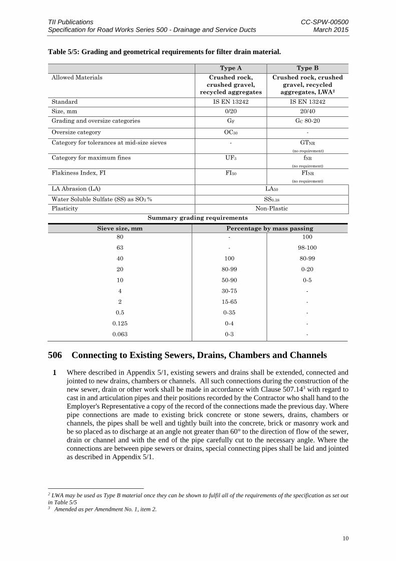
Table 5/5: Grading and geometrical requirements for filter drain material.
Type A Type B
Allowed Materials Crushed rock,
crushed gravel,
recycled aggregates
Crushed rock, crushed
gravel, recycled
aggregates, LWA2
Standard IS EN 13242 IS EN 13242
Size, mm 0/20 20/40
Grading and oversize categories GF GC 80-20
Oversize category OC30 -
Category for tolerances at mid-size sieves - GTNR
(no requirement)
Category for maximum fines UF3 fNR
(no requirement)
Flakiness Index, FI FI50 FINR
(no requirement)
LA Abrasion (LA) LA50
Water Soluble Sulfate (SS) as SO3 % SS0.38
Plasticity Non-Plastic
Summary grading requirements
Sieve size, mm Percentage by mass passing
80
63
40
20
10
4
2
0.5
0.125
0.063
-
-
100
80-99
50-90
30-75
15-65
0-35
0-4
0-3
100
98-100
80-99
0-20
0-5
-
-
-
-
-
506 Connecting to Existing Sewers, Drains, Chambers and Channels
Where described in Appendix 5/1, existing sewers and drains shall be extended, connected and
jointed to new drains, chambers or channels. All such connections during the construction of the
new sewer, drain or other work shall be made in accordance with Clause 507.143 with regard to
cast in and articulation pipes and their positions recorded by the Contractor who shall hand to the
Employer's Representative a copy of the record of the connections made the previous day. Where
pipe connections are made to existing brick concrete or stone sewers, drains, chambers or
channels, the pipes shall be well and tightly built into the concrete, brick or masonry work and
be so placed as to discharge at an angle not greater than 60° to the direction of flow of the sewer,
drain or channel and with the end of the pipe carefully cut to the necessary angle. Where the
connections are between pipe sewers or drains, special connecting pipes shall be laid and jointed
as described in Appendix 5/1.
2 LWA may be used as Type B material once they can be shown to fulfil all of the requirements of the specification as set out
in Table 5/5 3 Amended as per Amendment No. 1, item 2.

TII Publications CC-SPW-00500 Specification for Road Works Series 500 - Drainage and Service Ducts March 2015
11
Before entering or breaking into an existing sewer or drain, the Contractor shall give notice of
his intention to do so to the authority responsible for the pipeline to which the connection is to be
made. Risk assessments shall be completed and all work required to be carried out within
confined spaces identified for which specific confined space entry procedures and method
statements shall be completed and submitted to the Employers Representative prior to work
commencing.
Existing sewers or drains no longer required shall, as required by Appendix 5/1, be:
sealed with mix ST2 concrete,
removed and replaced with acceptable fill material deposited in layers and compacted in
accordance with the requirements of the 600 Series or
grouted with a 1:10, cement: PFA mix. The grout shall use the minimum quantity of water
to ensure the fluidity necessary to render it capable of being pumped to the ends of the pipe.
It shall be used within one hour of mixing but when the mix contains a retarding admixture
this time may be extended in accordance with the manufacturer's instructions. The cement
shall be CEM I Portland cement complying with IS EN 197 : Part 1 and the pulverised-fuel
ash (PFA) with BS 3892: Part 2, fineness to Zone B and sulphate content not exceeding
1.5%.
All existing foul and surface water drainage shall be maintained until the permanent drainage for
the execution and completion of the Works shall have been executed, completed and functioning
satisfactorily including its discharge to approved outfalls
Ground profiles shall at all times be maintained to shed surface water efficiently and directly into
the nearest drain and to prevent penetration of water into or below existing pavements
Existing drainage retained in the execution and completion of the Works shall be flushed and
cleared of debris and all repairs carried out to ensure drains shall fulfil the requirements of the
Contract. The clearing and repair of any existing drainage shall not have any negative impact on
local watercourses.
Prior to any connection to the existing drainage system, the Contractor shall carry out a CCTV
survey, to the requirements of Series 2900 of the Specification, of the existing system for a
minimum length of 300 metres downstream of the connection. The Contractor shall submit a
report on the condition of the existing pipe network to the Employer's Representative for
Approval, prior to the commencement of Construction of any Works.
507 Chambers for Drains
Chambers for Drains shall include manholes, catchpits, inspection chambers and walled
soakaways. Chambers shall be of the type specified in Appendix 5/1, constructed in accordance
with the NRA Road Construction Details listed in Appendix 5/7 as appropriate to that type and
identified as chambers being within the carriageway or chambers located elsewhere, e.g. verge.
Access chambers shall have an internal diameter not less than 1050 millimetres. All ST concrete
referred to in this Clause shall comply with the requirements of Concrete for Ancillary Purposes
in the 2600 Series unless otherwise described in Appendix 5/1.
Foundations to chambers shall be of mix ST4 concrete. Channels for chambers shall be formed
and finished smooth in the foundation concrete or constructed of preformed half circle channels,
with sides benched in mix ST4 concrete, or mortar designation (i) complying with the
requirements of the 2400 Series excluding lime.

TII Publications CC-SPW-00500 Specification for Road Works Series 500 - Drainage and Service Ducts March 2015
12
Brickwork and Blockwork shall comply with the 2400 Series and be built with mortar designation
(i) in English bond. The joints of brickwork where exposed shall be finished as specified for
unpointed joints in the 2400 Series. The ends of all pipes shall be neatly built into the brickwork
and finished flush with mortar designation (i).
Precast concrete chambers and riser sections shall comply with BS 5911-3, IS EN 1917, IS 420
and the particular requirements described in Appendix 5/1. Cast insitu concrete chambers shall
be constructed of mix ST4 concrete complying with Clause 2602 and the particular requirements
described in Appendix 5/1.
Access ladders and/or step irons, shall only be provided from the first intermediate landing slab
down to pipe invert for Type E chambers. Hand/footholds shall be provided for access into all
pipe inverts from the benching for large diameter pipes as shown in the Road Construction
Details. Manhole steps complying with IS EN 13101 shall be built in accordance with the NRA
Road Construction Details listed in Appendix 5/7. Steelwork used for ladders, handholds and
other fittings shall comply with IS EN 10084 and be galvanised in compliance with the
requirements of the 1900 Series after fabrication. Threaded components shall also be galvanised
in compliance with the requirements of the 1900 Series. Glass Reinforced Plastic used for ladders
and step irons shall conform to EN13706 for structural pultruded profiles.
Excavation around chambers, except those described in Sub-clause 6 of this Clause, shall be
backfilled with general fill material as described in Table 6/1 and compacted in compliance with
the requirements of the 600 Series. Where mechanical compaction is impracticable, the
excavation shall be backfilled with mix ST2 concrete. Where there are precast concrete access
shafts to precast concrete chambers, the shafts shall be surrounded by a minimum thickness of
150 mm of mix ST4 concrete, and the remaining excavation backfilled with general fill material
as described in Table 6/1 compacted in compliance with Clause 612.
Chamber covers, gratings and frames shall be as described in Appendix 5/1 and shall comply
with IS EN 124 and Sub-clauses 7 to 14 of this Clause. Gratings and frames are required to be
locked in accordance with Clause 508.4, the minimum size of the locking bolt shall be M16 and
it shall be manufactured from stainless steel to prevent corrosion.
Permitted Classes of cover and frame shall comply with IS EN124 from the following:
Group 1: Class A15 Pedestrian Traffic Only
Group 2: Class B125 Footways, pedestrian areas
Group 3: Class C250 Gullys in road side channels
Group 4: Class D400 Carriageway, hard shoulders, hardstrips, car parks
Class D400 units shall incorporate a permanent non-rock feature either triangular point
suspension, machined faces or cushioned or wedged seating.
Permitted clear access for openings shall be either:
Minimum 600mm diameter circular access cover and frame for general use,
Minimum 750mm or 900mm circular access cover and frame where required for chambers
deeper than 2m as specified in Appendix 5/1
Requirements for special duty covers for use in carriageways in accordance with IS EN124 Group
5: Class E600 or Group 6: Class F900 shall be as described in Appendix 5/1.

TII Publications CC-SPW-00500 Specification for Road Works Series 500 - Drainage and Service Ducts March 2015
13
Gratings for catch-pit chambers shall have a minimum waterway area as described in Appendix
5/1.
Two sets of lifting keys shall be delivered to the Employer's Representative for each type of cover
supplied. At least two keyways shall be provided in each complete cover, one in each segment
for segmental covers. A recess for a prising bar shall be incorporated in manhole covers unless
other means of loosening the cover from the frame are provided.
Frames for chamber covers and gratings shall be set in cement mortar designation (i) complying
with Clause 2404 or a proprietary quick setting mortar of equivalent strength.
Covers and gratings located within the carriageway, hardshoulder or hardstrip shall be set in a
mortar with the following properties:
The material shall be non-shrink
The material shall have a minimum workable life of 15 minutes
The compressive strength of the material shall exceed 30N/mm2 in 3 hours
The tensile strength of the material shall exceed 5N/mm2 in 3 hours.
Frames shall be identified in Appendix 5/1 as being Plain Seated where unsealed or either single
or double seal when required to be sealed. Covers shall be specified in Appendix 5/1 as being:
Watertight, Pressure Tight or Ventilated
For all pipelines the nearest joint to any chamber shall be not more than 500mm from the inner
face of the wall and shall not be restricted by any concrete. Between this and the next joint, the
length of the articulated pipe shall be in accordance with Table 5/6 and as shown on Road
Construction Detail RCD/500/14
Table 5/6: Length of Articulated ‘(Rocker)’ Pipe.
Nominal Pipe Diameter (mm) Length of Pipe ‘Y’ (mm)
450 and less 500 to 750
Greater than 450 750 to 1000
Where the adjustment or replacement of existing chamber frames and covers is required, the units
shall be taken up and refixed or replaced with new units complying with Sub-clauses 9 to 15 of
this Clause or such other specification as required by the authority responsible for the utility to
which the cover provides access. The frames and covers or gratings shall be laid on a mortar bed
complying with Sub-clause 134 of this Clause. The finished thickness of the mortar bed shall be
between 10mm and 25mm. Unless otherwise described in Appendix 5/1 covers in grassed verges
shall typically be set 20 to 30mm lower than the verge level, and adjusted or replaced chamber
frames and covers or gratings shall be set flush with the new surface. Any additional adjustments
shall be by modifying the brickwork or precast concrete or insitu concrete riser in compliance
with Sub-clauses 507.3 or 507.4 or by using a frame of a suitable depth.
Covers in verge locations shall receive a 300mm wide ST4 concrete apron in accordance with
National Roads Authority Road Construction Details.
4 Amended as per Amendment No. 1, item 3.

TII Publications CC-SPW-00500 Specification for Road Works Series 500 - Drainage and Service Ducts March 2015
14
508 Gullies and Pipe Junctions
Permitted gully types shall be either trapped or untrapped and shall be described in Appendix 5/1,
and be in accordance with the NRA Road Construction Details listed in Appendix 5/7.
Gullies shall be constructed so that no part of the spout or trap has a cross-sectional area less than
2/3rd that of the outlet. The depth of water seal in trapped gullies shall be not less than 50mm.
Precast concrete gullies shall comply with BS 5911-6. Insitu concrete gullies shall be constructed
of mix ST4 concrete or concrete blockwork of 225mm minimum thickness and be as described
in Appendix 5/1
Where insitu concrete gullies are formed with permanent shuttering, such shuttering shall have a
current Irish Agrément Board Roads and Bridges Certificate or equivalent.
Cast iron and cast steel gully gratings shall comply with IS EN 124, Sub-clauses 10 to 16 of
Clause 5075 and shall be in accordance with the NRA Road Construction Details listed in
Appendix 5/7. They shall be of the classes and sizes described in Appendix 5/1. All gully gratings
shall be fitted with a durable, non-rust locking device.
The manufactured upper surface of gully gratings shall be flat unless otherwise described in
Appendix 5/1. Slots in gratings or between gratings and frames shall not be orientated parallel to
the direction of traffic. Frames shall be bedded on mortar complying with Sub-clause 507.136.
Brickwork shall comply with Sub-clause 507.3.
Backfilling to precast gullies shall be carried out up to sub-formation level with general fill
material Class 1, as described in Table 6/1 compacted in compliance with the requirements of the
600 Series. Where mechanical compaction is impracticable, the backfilling shall be in mix ST4
concrete. The remainder of the backfilling shall be in appropriate capping and road pavement
materials except that where mechanical compaction of capping or granular sub-base is
impracticable mix ST2 concrete shall be used.
Gully connection pipes shall be either flexible or rigid not exceeding 0.7m in length with flexible
joints for a distance of 2m from the gully and shall be in accordance with Sub-clause 507.147
when entering chambers. Junction pipes shall be manufactured of the same type and class of
material as the remainder of the pipes in the run. Junction pipes which are laid but not
immediately connected, shall be fitted with temporary stoppers or seals and the position of all
such junctions shall be clearly defined by means of stakes or tracing wires properly marked or
labelled. Saddles may be used to form junctions only where permitted in Appendix 5/1. No
internal projections greater than 5mm will be permitted. Saddles for plastics pipes shall be
installed in accordance with the manufacturer’s recommendations. Saddles with clay pipes shall
be jointed with mortar designation (i) complying with Clause 2404, excluding lime. Saddles and
pipes shall be surrounded with mix ST2 concrete.
Where the adjustment or replacement of existing frames and gratings or kerb type gully covers is
required, the units shall be taken up and refixed or replaced with new units complying with Sub-
clauses 4 and 5 of this Clause or such other specification required by the Road Authority at a
level, unless otherwise described in Appendix 5/1, 6mm below the adjoining road surface on a
mortar bed complying with Sub-clause 507.138. The thickness of the mortar bed shall be between
5 Amended as per Amendment No. 1, item 4. 6 Amended as per Amendment No. 1, item 5. 7 Amended as per Amendment No. 1, item 6. 8 Amended as per Amendment No. 1, item 7.
TII Publications CC-SPW-00500 Specification for Road Works Series 500 - Drainage and Service Ducts March 2015
15
10mm and 25mm. Any additional adjustment shall be made by modifying the brickwork in
compliance with Sub-clause 507.3 or by using a frame of suitable depth.
Gullies shall not be located at pedestrian crossings, where practicable. Where gully spacings
coincide with pedestrian crossing locations, the nearest gully shall be positioned immediately
adjacent to the higher side of the pedestrian crossing. Where a sag point occurs at a pedestrian
crossing, a single gully shall be positioned on either side of the crossing point.
509 Testing and Cleaning
Drains required in Appendix 5/1 to have watertight joints shall be tested as described in Appendix
1/5 in sections, e.g. between chambers, by means of the air test described in Sub-clause 2 of this
Clause. If a pipeline is rejected because of a failed air test, as part of the rectification work, a
water test as described in Sub-clause 3 of this Clause may be carried out as an alternative
acceptability test. Before testing, the ends of the pipeline to be tested, including those of short
branches, shall be plugged and sealed.
For the pipeline air test, air shall be pumped in by suitable means until a stable pressure of 100mm
head of water is indicated in a U-tube connected to the system. The air pressure shall not fall to
less than 75mm head of water during a period of 5 minutes without further pumping, after an
initial period to allow stabilisation. Drains with traps shall be tested to 50mm head of water and
the permissible loss shall then be no more than 13mm head of water in 5 minutes without further
pumping after the initial stabilising period.
For the pipeline water test, the pipes shall be filled with water under a head of not less than 1.2m
above the crown of the pipe at the high end and not more than 6m above the pipe at the low end.
Steeply graded pipelines shall be tested in sections so that the above maximum is not exceeded.
The test shall commence two hours after filling the test section at which time the level of water
at the vertical feed pipe shall be made up to produce the required 1.2m minimum test head. The
loss of water over a 30 minute period shall be measured by adding water at regular 10 minute
intervals to restore the original water level and recording the amounts so added. The drain will
have passed the test if the volume of water added does not exceed one litre per hour per linear
metre of drain per metre of nominal internal diameter.
All pipelines less than 350mm diameter, excluding service ducts shall be checked by drawing
through each completed length of pipe a spherical mandrel of a diameter 10mm less than the
smallest internal pipe diameter permitted by the tolerances specified for the pipes being tested.
During the progress of the Works all existing chambers, gullies and rodding eyes shall be kept
clean and free from obstruction. On completion of the whole of the Works, all chambers, gullies
and drains including verge / surface water drains and filter drains but excluding all fin and narrow
filter drains shall be flushed from end to end with water and left free from obstructions. Unless
otherwise required in Appendix 5/9 all carrier, foul and filter drains shall be surveyed by Closed
Circuit Television (CCTV) in accordance with the relevant requirements of the 2900 Series.
Catch-pit chambers shall be left clean and free from silt.
The pipes and filter material of filter drains shall at all times be left clean and free from silt and
obstruction.
The Contractor shall carry out trial holes upon completion of filter drain trenches as directed by
the Employer’s Representative to demonstrate that the filter material has not become clogged
with other material during construction. If the filter material is clogged then the Contractor shall
replace it with clean material.
Permeability tests shall be as described in Appendix 5/1.

TII Publications CC-SPW-00500 Specification for Road Works Series 500 - Drainage and Service Ducts March 2015
16
510 Surface Water Channels, Swales and Drainage Channel Blocks
Insitu Concrete Surface Water Channels
Insitu Concrete Surface water channels (CSWC), Grassed Surface Water Channels (GSWC) and
drainage channel blocks shall be constructed as described in Appendix 5/3.
Insitu Concrete Surface water channels shall comply with the requirements of the 1100 Series for
Insitu Channels and NRA Road Construction Detail RCD/500/22 and Clause 510.5 of this Series
with regard to intermediate, terminal and weir outlet chambers. Channels shall be either triangular
or trapezoidal in cross section.
Precast Concrete Drainage Channel Blocks
Drainage channel blocks shall comply with the requirements of the 1100 Series for Precast
Channels.
Grassed Surface Water Channels
Grassed surface water channels shall be either triangular or trapezoidal in section with a
maximum side slope angle of 1(v):5(h). They shall comprise 300mm minimum depth of granular
unbound subsoil material in accordance with either Clause 803, 804 or 807. Topsoil shall be
placed and seeded with dwarf grass varieties in accordance with in accordance with Series 600
Clause 618 to a maximum depth of 100mm. Grassed Surface Water Channels shall comply with
Clause 510.5 of this Series with regard to intermediate, terminal and weir outlet chambers.
Swales
Swales shall be in accordance with National Roads Authority Road Construction Detail
RCD/500/25.
Chambers for Surface Water Channels
Intermediate, terminal and overflow chambers shall be constructed in accordance with NRA Road
Construction Details.

TII Publications CC-SPW-00500 Specification for Road Works Series 500 - Drainage and Service Ducts March 2015
17
511 Land Drains
Existing land drains which are permanently severed by the Works shall be located and connected
into a new drain, pipe or ditch all as described in Appendix 5/1. The lengths remaining within the
Works shall be cleaned out from the new drain trench face as necessary. Any pipe disturbed by
the Works shall be re-laid to ensure a free discharge into the new drain. Disused ends of
intercepted land drains be adequately sealed with mix ST2 concrete in compliance with the
requirements of the 2600 Series for Concrete for Ancillary Purposes.
Where an existing land drain is exposed and severed by temporary trench excavation, the
Contractor shall mark the position of the drain and record it. The drain shall be diverted into an
existing drain or watercourse. Alternatively, the normal functioning of the drain shall be
continued by the construction of a pipeline or channel adequately supported across the
excavation, until permanent restoration is made on the original line.
The Contractor shall notify the Employer's Representative of any land drain which is blocked or
is otherwise defective when the drain is first exposed.
512 Backfilling to Pipe Bays and Verges on Bridges
Unless otherwise described in Appendix 5/1, filling to pipe bays and verges on bridges shall be
well graded granular material not exceeding 20mm size containing not more than 3% of material
passing the 63 micron sieve and with a uniformity coefficient of more than 5. It shall be laid and
compacted in compliance with Clause 505. The material shall meet the sulphate requirement
described in Sub-clause 503.3.
Table 5/7: Sampling Rates
No of
Pipes
In Batch
Sample
Size
If All
Pass
If 2 or
more
Fail
If 1 Fails
take a
Further
Sample
of
If 1 or more
of the further
Sample Fails
<40
41-60
61-80
80-100
101+
2
3
4
5
5 per batch
of 100
ACCEPT
REJECT or
test ALL
remaining
pipes in
batch,
failing pipes
to be
rejected
2
3
4
5
5
REJECT or test
ALL remaining
pipes in batch,
failing pipes to
be rejected

TII Publications CC-SPW-00500 Specification for Road Works Series 500 - Drainage and Service Ducts March 2015
18
513 Permeable Backing to Earth Retaining Structures9
Permeable backing shall consist of one of the following materials:
A minimum thickness of 300 mm of granular material of 20mm nominal size, satisfying the
following criteria.
Piping ratio, defined as
15 per cent size of the drainage material , < 5
85 per cent size of the backfill material
Permeability ratio, defined as
15 per cent size of the drainage material , < 5
15 per cent size of the backfill material
where the per cent size of a material is the size of particle corresponding to the given per
cent ordinate of the particle size distribution graph.
Porous no-fines concrete, cast in situ 225 mm thick complying with the requirements of the
requirements of the 2600 Series.
Precast hollow concrete blocks complying with IS EN 772-2 & 3 laid in stretcher bond with
dry joints in 225 mm thick walling with holes vertical.
514 Fin Drains
General
Fin drains shall comply with this Clause and the special requirements described in Appendix 5/4.
The terms thickness, width, height and core shall have the meanings indicated on NRA Road
Construction Details listed in Appendix 5/7 unless otherwise described in Appendix 5/4.
Drain Types 5 and 6 shall be as show on the NRA Road Construction Details listed in Appendix
5/7
The term fin drain shall mean a planar geocomposite structure designed to perform the same
function as a narrow filter drain.
Where fin drains are designed for lateral entry of water from one side only the requirements for
flow rates in Sub-clauses 4 and 5 of this Clause shall apply to the face or plane designed to admit
or transmit water.
9 Amended as per Amendment No. 1, item 8.

TII Publications CC-SPW-00500 Specification for Road Works Series 500 - Drainage and Service Ducts March 2015
19
The materials of which the drain is made shall be treated so that they are protected from the
deleterious effects of short term exposure to ultraviolet light, and shall be resistant to degradation
by acids, alkalis, common chemicals, bacteria, fungi and moulds occurring in soils and road
construction materials. After exposure to ultraviolet light the Employer’s Representative may
require evidence that the materials still comply with the requirements of this Clause. The drain
shall be protected from damage and ultraviolet light and be labelled to identify the grade and
manufacturer or supplier.
Where necessary, the side intended for entry of water and the direction of in-plane flow shall be
identified.
Geotextile
The geotextile shall:
in both machine and cross-machine directions, sustain a tensile load of not less than 5.0 N/m
at break and have a minimum failure strain of 10% when determined in accordance with IS
EN ISO 10319;
have a minimum puncture resistance of 1200 N when determined in accordance with IS EN
ISO 12236;
have a minimum tear resistance of 200 N when determined in accordance with ASTM
Standard D4533-91 (1996);
have a size distribution of pore openings such that the apparent opening size O90 when
determined in accordance with IS EN ISO 12956, or other appropriate test, is as stated in
Appendix 5/4;
allow water to flow through it, in either direction, normal to its principal plane at a rate of
not less than that stated in Appendix 5/4 under a constant head of water of 100mm and a
maximum breakthrough head of 50mm when determined in accordance with IS EN ISO
12958.
Composite Drain
The composite drain shall:
have a flow rate through each face of the drain of more than 75% of the value specified in
Sub-clause 5(v)10 of this Clause on the side or sides where inflow occurs. This value may
be found by either:
(a) direct measurement of the composite drain using IS EN ISO 12958; or
(b) calculation based on the flow rate obtained by the standard test in IS EN ISO
12958 and the percentage contact area of the drainage core obtained in accordance
with Sub-clause 1411 of this Clause;
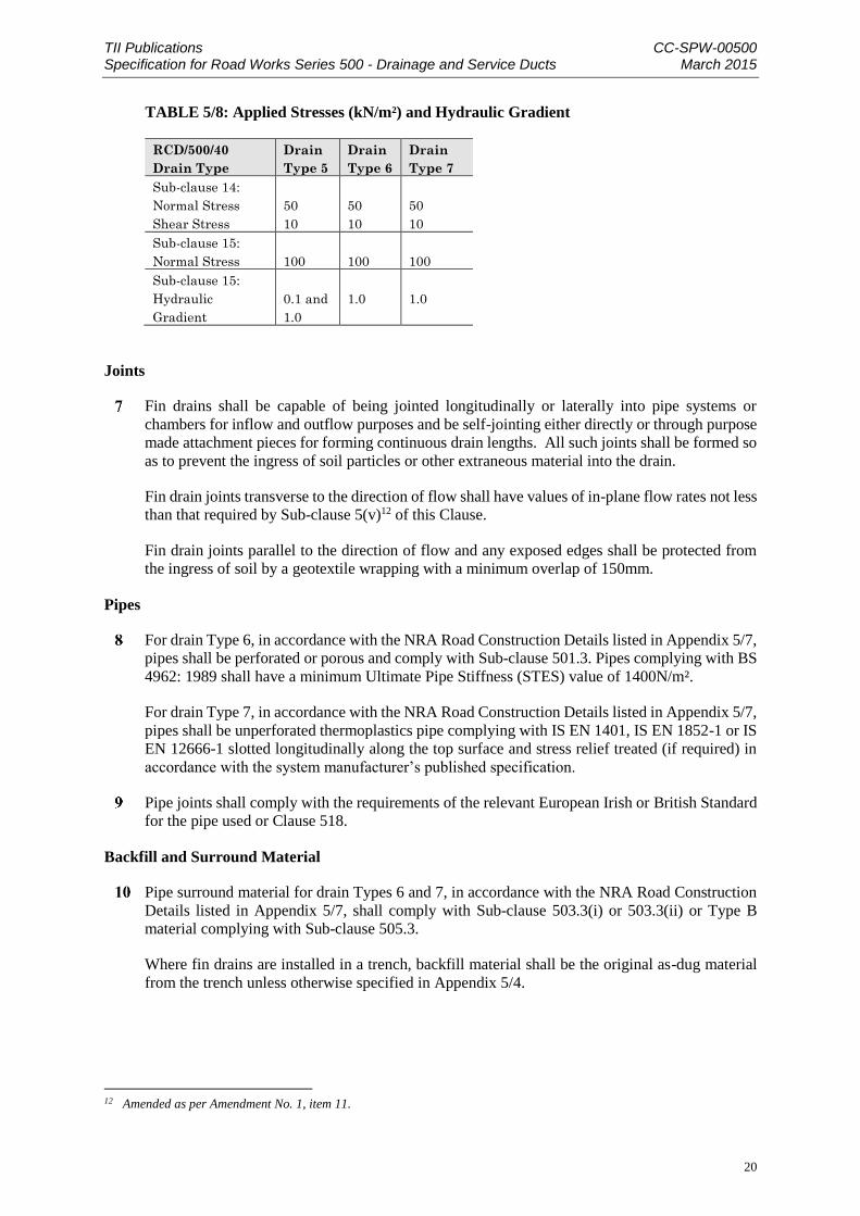
have values of long term in-plane flow rates as stated in Appendix 5/4 when determined in
accordance with Sub-clauses 14 and 15 of this Clause. The values of hydraulic gradient and
minimum applied stresses shall be as given in Table 5/8.
10 Amended as per Amendment No. 1, item 9. 11 Amended as per Amendment No. 1, item 10.
TII Publications CC-SPW-00500 Specification for Road Works Series 500 - Drainage and Service Ducts March 2015
20
TABLE 5/8: Applied Stresses (kN/m²) and Hydraulic Gradient
RCD/500/40
Drain Type
Drain
Type 5
Drain
Type 6
Drain
Type 7
Sub-clause 14:
Normal Stress
Shear Stress
50
10
50
10
50
10
Sub-clause 15:
Normal Stress
100
100
100
Sub-clause 15:
Hydraulic
Gradient
0.1 and
1.0
1.0
1.0
Joints
Fin drains shall be capable of being jointed longitudinally or laterally into pipe systems or
chambers for inflow and outflow purposes and be self-jointing either directly or through purpose
made attachment pieces for forming continuous drain lengths. All such joints shall be formed so
as to prevent the ingress of soil particles or other extraneous material into the drain.
Fin drain joints transverse to the direction of flow shall have values of in-plane flow rates not less
than that required by Sub-clause 5(v)12 of this Clause.
Fin drain joints parallel to the direction of flow and any exposed edges shall be protected from
the ingress of soil by a geotextile wrapping with a minimum overlap of 150mm.
Pipes
For drain Type 6, in accordance with the NRA Road Construction Details listed in Appendix 5/7,
pipes shall be perforated or porous and comply with Sub-clause 501.3. Pipes complying with BS
4962: 1989 shall have a minimum Ultimate Pipe Stiffness (STES) value of 1400N/m².
For drain Type 7, in accordance with the NRA Road Construction Details listed in Appendix 5/7,
pipes shall be unperforated thermoplastics pipe complying with IS EN 1401, IS EN 1852-1 or IS
EN 12666-1 slotted longitudinally along the top surface and stress relief treated (if required) in
accordance with the system manufacturer’s published specification.
Pipe joints shall comply with the requirements of the relevant European Irish or British Standard
for the pipe used or Clause 518.
Backfill and Surround Material
Pipe surround material for drain Types 6 and 7, in accordance with the NRA Road Construction
Details listed in Appendix 5/7, shall comply with Sub-clause 503.3(i) or 503.3(ii) or Type B
material complying with Sub-clause 505.3.
Where fin drains are installed in a trench, backfill material shall be the original as-dug material
from the trench unless otherwise specified in Appendix 5/4.
12 Amended as per Amendment No. 1, item 11.

TII Publications CC-SPW-00500 Specification for Road Works Series 500 - Drainage and Service Ducts March 2015
21
Dimensions
Unless otherwise described in Appendix 5/4 the dimensions of the fin drain shall be as shown on
the NRA Road Construction Details listed in Appendix 5/7. The pipe diameter shall be as stated
in Appendix 5/4. The drain slope angle (x) as shown on the NRA Road Construction Details
listed in Appendix 5/7 shall be not greater than 15% from the vertical unless otherwise stated in
Appendix 5/4.
Installation and Handling
Installation of fin drains shall be as shown on the NRA Road Construction Details listed in
Appendix 5/7. Where fin drains are assembled on site the assembly area shall be clean and dry
and free of wind-borne pollutants. Any material which becomes contaminated must be replaced.
No geotextile or core material shall be exposed to daylight (or any source of ultraviolet radiation)
for a period exceeding a cumulative total of 50 hours. Any geotextile or core material exposed to
daylight (or any source of ultraviolet light) for a period exceeding a cumulative total of 50 hours
shall be replaced unless it can be demonstrated that the materials of the drain still comply with
the requirements of this Clause.
Where fin drains are laid in trench, the trench bottom shall be free of irregularities and to the
required levels given in Appendix 5/4. Rock and other hard protuberances shall be removed and
any excess cut in the trench bottom filled and compacted back to the required grade with suitable
excavated or imported material.
The drain shall be laid with the appropriate face against the side of the trench adjacent to the
carriageway and in the appropriate direction. This side of the trench shall have walls sufficiently
clean to enable the fin drain to come into close contact with the wall when the trench is backfilled
and compacted. Compaction shall be in accordance with Clause 612. Fin drains installed as part
of the permanent Works shall be protected from surface water, contamination, and accidental
damage during construction.
The fin drain, pipe surround and backfill shall be installed so as to cause no damage to the fin
drain. Where any damage does occur, the damaged materials shall be replaced by new material.
After the installation of the fin drain has been completed a marker tape shall be laid approximately
75mm above the fin drain in the position shown on the NRA Road Construction Details listed in
Appendix 5/7. The tapes shall be green self-coloured PVC or polythene plastic not less than 0.1
mm thick and 150mm wide.
Identification
The Contractor shall obtain and make available the following information for each separate
consignment of fin drain delivered to Site:
geotextile and core name, grade/number and mass per unit area;
names and addresses of system producer, and geotextile, core and pipe manufacturers;
manufacturing characteristics and constituents of geotextile and core. This shall include
composition and type of constituent filaments, threads, fibres, films, tapes and other
components;
consignment number and delivery date;
a copy of the site delivery note.

TII Publications CC-SPW-00500 Specification for Road Works Series 500 - Drainage and Service Ducts March 2015
22
Test Method for the Percentage Contact Area of Drainage Core
The test determines the area of one face of a drainage core which will be in contact with a
geotextile filter as a percentage.
The apparatus required is as follows:
(a) loading device able to apply a compressive load of at least 2kN and having a flat
steel base;
(b) flat steel loading plate 200mm x 200mm;
(c) printers ink and roller (or pad);
(d) sheet of thin compressible rubber;
(e) planimeter.
The test procedure shall be as follows. Cut three representative test specimens 200mm x
200mm (±2mm). Apply ink to one 200mm x 200mm face of a specimen and cover with a
sheet of plain paper and a thin compressible rubber sheet. Place the prepared specimen in to
the loading device and gradually apply the load of 2kN and maintain for 5 minutes. Release
the load and remove the specimen and separate it from the paper. Using the planimeter find
the total area of the paper which has received an imprint. Repeat for all specimens.
The percentage contact area = total area of imprint x 100 area of test specimen.
The report shall include:
(a) reference to this method;
(b) sample identification details;
(c) individual and mean percentage contact areas;
(d) details of any deviation from the specified test procedure.
Alternative methods of determining the percentage contact area may be employed with the
prior approval of the Employer’s Representative.
Test Method for Determining the Thickness of Fin Drains Under Specified Normal and Shear
Stresses
The test determines the thickness of the fin drain under sustained normal and shear stresses.
A long term thickness (at 100,000 hours) is calculated by extrapolation and a short term
equivalent normal load which produces the long term thickness is determined.
The apparatus required is as follows:
(a) a suitable compression testing machine, which shall have a vertical travel at least
the nominal thickness of the specimen. It shall be capable of sustaining the
necessary loads to within 1% accuracy for the duration of the test;

TII Publications CC-SPW-00500 Specification for Road Works Series 500 - Drainage and Service Ducts March 2015
23
(b) the compression testing apparatus, which shall include a fixed base plate and
parallel moveable top plate with flat steel surface with sufficient friction to permit the
development of the required shear forces;
(c) a means of measuring the mean thickness of the specimen to an accuracy of
0.01mm.
As an alternative to (a) and (b), an appropriate inclined plane and kentledge system may be
employed to produce the normal and shear loads.
The test procedure shall be as follows:
Cut six representative specimens of minimum size 100mm x 100mm symmetrically about
the core design. Three specimens shall be tested in accordance with (v) below and three in
accordance with (vi) below.
The test specimen shall be placed symmetrically on the base plate and covered by the top
plate. The means of measuring thickness shall be attached and the initial thickness measured.
Apply the load smoothly and as quickly as possible to the top plate. The full load (normal
and shear) shall be applied in less than 20 seconds and sustained for at least 1000 hours. The
applied stresses shall be those given in Table 5/8. At least four measurements of thickness
shall be made during each unit of logarithmic time after the first minute. Determine the long
term thickness of the specimen as the thickness of the specimen at 1000 hours reduced by
2T where T is the difference in thicknesses of the specimen thickness recorded at 100 hours
and 1000 hours. Repeat the test on the two other specimens. The test specimens shall be
maintained at a constant temperature of 20°C ± 2°C throughout the test period.
Apply increasing increments of normal load to the specimen. Determine the short term
equivalent load which shall be the load which when applied for a period of 20±5 minutes
produces a specimen thickness equal (within an accuracy of ±0.05mm) to the long term
thickness of the specimen obtained at (v) above. Repeat the test on the other two specimens.
The report shall include:
(a) a reference to this method;
(b) sample identification details;
(c) the initial thickness of the sample;
(d) the applied load;
(e) the thickness of each sample at 100 and 1000 hours and the mean of the three
results;
(f) a plot of percentage reduction in thickness against logarithmic time;
(g) the mean long term thickness;
(h) the mean short term equivalent load;
(i) any deviations from the specified test procedure.
TII Publications CC-SPW-00500 Specification for Road Works Series 500 - Drainage and Service Ducts March 2015
24
Determining In-plane Flow Under Compressive Loading
In-plane flow shall be determined in accordance with IS EN ISO 12958 except that the following
conditions shall apply:
(a) the applied normal stress shall be the greater of the value given in Table 5/8 (for Sub-
clause 15) or the mean short term equivalent stress as determined in Sub-clause 1413 of
this Clause;
(b) the sample shall be tested such that the measured flow (or flows) is in the same direction
as the principal flow (or flows) when the fin drain is in service;
(c) the foam rubber option of the test procedure shall be used (details of the foam rubber
to be used may be obtained from the Employer’s Representative);
(d) the hydraulic transmissivity shall be reported for each of the hydraulic gradients
employed.
Test Methods
Notwithstanding the requirements of Sub-clauses 14, 15 and 1614 of this Clause, variations in the
test methods specified therein shall be made where deemed necessary by the Irish Agrément
Board following consultation with the manufacturer. All such variations shall be recorded in the
report. Alternatively the manufacturers published technical data and testing information for these
parameters may be used.
Certification
Fin drains and constituent materials shall have a current Irish Agrément Board Certificate for
Roads and Bridges or equivalent certifying the appropriate physical properties when tested in
accordance with this Clause.
515 Narrow Filter Drains
General
Narrow filter drains shall comply with this Clause and the special requirements described in
Appendix 5/4.
The term narrow filter drain refers to drain Types 8 or 9 indicated in NRA Road Construction
Details listed in Appendix 5/7. They consist of a porous or perforated pipe laid in a narrow trench
surrounded by granular material where the granular material and/or the pipe is enclosed by a layer
of geotextile filter. Narrow filter drains and fin drains perform the same function.
13 Amended as per Amendment No. 1, item 12. 14 Amended as per Amendment No. 1, item 13.

TII Publications CC-SPW-00500 Specification for Road Works Series 500 - Drainage and Service Ducts March 2015
25
Materials
The geotextile materials used in the drain shall be stored so that they are protected from the
deleterious effects of short term exposure to ultraviolet light, and shall be resistant to degradation
by acids, alkalis, common chemicals, bacteria, fungi and moulds occurring in soils and road
construction materials.
After exposure to ultraviolet light the Employer’s Representative may require evidence that the
materials still comply with the requirements of this Clause. They shall be protected from damage
and ultraviolet light and be labelled to identify the grade and manufacturer or supplier.
The geotextile used in narrow filter drains shall comply with all requirements of Sub-clause
514.515 for geotextiles used in fin drains.
For drain Type 8, in accordance with the NRA Road Construction Details listed in Appendix 5/7,
the geotextile surround to the pipe shall consist of a prefabricated continuous close fitting sock.
Alternatively the pipe shall be firmly wrapped in a single layer of geotextile with an overlap of
between 50 and 75mm and secured around the pipe in a manner so as to prevent the ingress of
soil particles or other extraneous material and without affecting the permeability of the wrapped
material. Splices between lengths of sock or layer shall have overlaps within these dimensions
and be securely tied.
For drain Type 9, in accordance with the NRA Road Construction Details listed in Appendix 5/7,
the geotextile surround to the granular material shall have a minimum overlap of 250mm
including 100mm down-tuck. Splicing of lengths of geotextile shall consist of minimum 600mm
overlap secured with pins or mechanical ties. Where an outlet pipe passes through the geotextile
a separate piece of geotextile shall be wrapped round the outlet pipe, flared against the geotextile
in the filter drain and secured. Where drain lengths are terminated at chambers, the geotextile
shall be secured against the chamber walls by suitable means so as to prevent the ingress of soil
particles or other extraneous material into the drain.
Pipes and fittings shall comply with Sub-clauses 514.7 and 514.8. Where coilable pipes to BS
4962:1989 are used they shall be capable of being straightened so as to lie flat without restraint
in the trench bottom before backfilling.
The granular material used for trench infill shall comply with the requirements for non-plasticity,
LA category and sulphate content of Sub-clause 505.3 and have a grading within the limits of
Table 5/9. The material when tested in accordance with Sub-clause 509.816 shall meet the
permeability requirements described in Appendix 5/4.
15 Amended as per Amendment No. 1, item 14. 16 Amended as per Amendment No. 1, item 15.

TII Publications CC-SPW-00500 Specification for Road Works Series 500 - Drainage and Service Ducts March 2015
26
TABLE 5/9: Narrow Filter Drain: Trench Infill Grading Requirements
RCD Drain
Type
Type 8 Type 9
Maximum
Particle
Size mm
40 40
D5 Size mm >0.125 >0.125
D15 Size mm As stated in
Appendix 5/4
D85 Size mm - > Hole
Diameter or
1.2 Times
Width of Slot
in Pipe
Uniformity
Coefficient
(Cu) D60/D10
5 to 12 5 to 12 or if
Cu<5
D5>1mm
Dn = Sieve size passing n% by weight of material
Dimensions
Unless otherwise described in Appendix 5/4 the dimensions of the narrow filter drain shall be as
shown on the NRA Road Construction Details listed in Appendix 5/7. The pipe diameter shall be
as stated in Appendix 5/4. The drain slope angle (x), as shown on the NRA Road Construction
Details listed in Appendix 5/7, shall be not greater than 15% from the vertical unless otherwise
stated in Appendix 5/4.
Installation and Handling
Narrow filter drains shall be installed as shown on the NRA Road Construction Details listed in
Appendix 5/7. Before during and after installation the geotextile shall be protected from
contamination, damage and exposure to ultraviolet radiation in accordance with Sub-clause
514.3.
The excavated trench bottom shall be free of irregularities and to the required levels given in
Appendix 5/4. Rock and other hard protuberances shall be removed and any excess cut in the
trench bottom filled and compacted back to the required grade with suitable excavated or
imported material. Drain Type 9, in accordance with the NRA Road Construction Details listed
in Appendix 5/7, shall have trench walls sufficiently clean to enable the geotextile to come into
close contact with the wall when the granular material is placed inside it. The deposition and
compaction of infill shall be in accordance with Sub-clause 505.4 for filter drains.
Narrow filter drains installed as part of the permanent Works shall not be used for the disposal of
surface water run-off during construction. Narrow filter drains exposed to surface water ingress
shall be temporarily protected.
The Contractor shall obtain and make available the information required in Sub-clause 514.1317
in respect of the geotextile and pipe type used in narrow filter drains.
17 Amended as per Amendment No. 1, item 16.

TII Publications CC-SPW-00500 Specification for Road Works Series 500 - Drainage and Service Ducts March 2015
27
Certification
The geotextile shall have a current Irish Agrément board Certificate certifying the appropriate
physical properties when tested in accordance with this Clause.
516 Combined Drainage and Kerb Systems
The Contractor shall design the combined drainage and kerb systems listed in Appendix 1/11 in
accordance with IS EN 1433 and the design requirements given in Appendix 5/5.
Combined drainage and kerb systems shall permit lateral entry of surface water from the channel
either continuously or at intervals not exceeding 1m.
Combined drainage and kerb systems shall be suitable for their intended application and place of
installation in the Works. The Contractor shall submit evidence of such suitability for purpose to
the Employer's Representative.
Proprietary systems shall have a current Irish Agrément Board Roads and Bridges Certificate (or
equivalent) and shall be laid and jointed in accordance with the manufacturer’s written
instructions.
Design flows given in Appendix 5/5 shall be accommodated without surcharge within the main
combined drainage and kerb system and beneath the underside of any inlet slot sections.
Combined drainage and kerb systems shall be designed to ensure a self-cleansing velocity of
0.75m/s in the design flow.
Where applicable, the width and depth of the combined drainage and kerb system units shall not
exceed the dimensions given in Appendix 5/5.
When used adjacent to porous asphalt surfacing materials, units shall incorporate side entry inlets
to permit drainage of water held within the porous asphalt. Inlets shall comply with the
requirements of Appendix 5/5 and shall have the capacity to drain porous asphalt.
Combined drainage and kerb systems, excluding insitu system, shall be classified as follows
according to their intended use and shall be as stated in Appendix 5/5:
C250; or
D400; or
In exceptional circumstances where combined kerb and drainage units are to be located in
areas subjected to large numbers of high speed heavy goods vehicles, Class E600 combined
kerb and drainage units shall be considered.
Adjacent carriageway, footway, verge or central reserve construction shall not take place until a
visual inspection has been completed by the designer regarding: bedding, backing, surrounding
or jointing of combined drainage and kerb units. The visual assessment shall be supported by an
assessment of the concrete suppliers data presented as a graph showing strength gain against time
for the particular concrete mix.
Joints between units and between the channel and units, shall be designed to avoid leakage of
surface water. Joints between bridge deck waterproofing and component parts passing through
the waterproofing shall be watertight. Sealants shall be compatible with the waterproofing
system.
TII Publications CC-SPW-00500 Specification for Road Works Series 500 - Drainage and Service Ducts March 2015
28
Junctions, connecting pipes and other fittings comprising the combined drainage and kerb system
shall comply with Sub-clause 501.3 and shall be as described in Appendix 5/5. The combined
drainage and kerb system shall incorporate measures to enable rodding of the outfall pipework
and adequate access for jetting by water jetting equipment of the system.
The system shall be cleaned out by high pressure water jetting or other appropriate means on
completion of the Works. The system shall be left clean and free from all obstruction.
517 Linear Drainage Channel Systems
General
The linear drainage channel systems listed in Appendix 1/11 shall be treated as other features to
be designed by the Contractor. The insitu linear drainage channel systems shall conform, where
applicable, to Sub-clauses 517.2 to 517.17 and the requirements in Appendix 5/6 and Appendix
1/11 as appropriate. The prefabricated linear drainage channel systems, where applicable, shall
conform to IS EN 1433 and with the other requirements in Appendix 1/5.
Linear drainage channel systems shall be suitable for their intended use and place of installation
in the Works. The Contractor shall submit evidence of such suitability to the Employers
Representative in accordance with Appendix 1/5.
Design flows given in Appendix 5/6 shall be accommodated without surcharge within the main
channel section and beneath the underside of any inlet slot sections.
Where applicable, the width and depth of linear drainage channel system units shall not exceed
the dimensions given in Appendix 5/6.
Dimensions of inlet slots shall comply with IS EN 1433.
When used adjacent to porous asphalt surfacing materials, units shall also incorporate side entry
inlets to permit drainage of water held within the porous asphalt. Inlets shall comply with the
requirements of Appendix 5/6 and shall have the capacity to drain porous asphalt.
Weathering Resistance
Linear drainage channel systems shall be marked in accordance with IS EN 1433 according to
the grade of weathering resistance for drainage channels as stated in Appendix 5/6.
Classification
Linear drainage channel systems shall be classified as follows according to their intended use and
shall be as stated In Appendix 5/6:
C 250; or
D 400; or
In exceptional circumstances where linear drainage channel systems have to be located in
areas subjected to large numbers of high speed heavy goods vehicles, Class E 600 linear
drainage channel systems shall be considered.
TII Publications CC-SPW-00500 Specification for Road Works Series 500 - Drainage and Service Ducts March 2015
29
Watertightness
Joints between units comprising the system and between adjacent construction and the system
shall be designed to avoid leakage of surface water. Where applicable, joints between bridge deck
waterproofing and component parts passing through the waterproofing shall be watertight.
Sealants shall also be compatible with the waterproofing system.
Junctions, connecting pipes and other fittings comprising the linear drainage system shall comply
with the Sub-clause 501.3 and shall be as described in Appendix 5/6. The linear drainage channel
system shall incorporate measures to enable rodding of the outfall pipework and adequate access
for jetting by water jetting equipment into the system.
Cleaning
The system shall be cleaned out by high pressure water jetting or other appropriate means on
completion of the Works. The system shall be left clean and free from all obstruction.
Manufactured Systems
Manufactured systems shall conform to IS EN 1433 and to the following:
Products shall be designed and developed within an IS EN ISO 9001 system that has been
assessed by a relevant recognised certification body. A relevant certification body shall have
IS EN 45011 and IS EN ISO/IEC 17021 within its scope.
Products shall be type tested by a third party testing laboratory/organisation that has been
accredited to IS EN ISO/IEC 17021 and has IS EN1433 within its scope.
The certification process shall be overseen or audited by a single relevant accredited
certification body meeting the requirements in (i) and (ii) above.
Copies of all certificates shall be forwarded to the Employers Representative along with
audited product test reports.
All documentation must be furnished in English or Irish.
Insitu Systems
Insitu systems shall comply with the requirements of the 1100 Series except that the concrete
shall be considered as plain concrete within the terms of this Sub-clause, irrespective of the
inclusion of reinforcement.
Insitu systems shall be slip formed except for sections at gullies which shall be hand formed. Full
depth joints shall be constructed at the interface at each side of gullies with a 25mm thick filler
board complying with the requirements of the 1000 Series for Joint Filler Board. Joints shall be
prepared and sealed in accordance with the 1000 Series.
The central void may be formed by an inflated tube which is then removed, or by an insitu suitable
pipe or similar former fit for the purpose. At gully positions the inner former shall be pre-sleeved
with a suitable pipe of similar former fit for the purpose which shall be of sufficient length to
overlap the two joins on either side of the gully.
The central void shall be checked in accordance with Sub-clause 509.4. Verification of slot
widths shall be determined by suitable templates.

TII Publications CC-SPW-00500 Specification for Road Works Series 500 - Drainage and Service Ducts March 2015
30
Reinforcement shall comply with the 1700 Series. Concrete cover shall be not less than 75mm.
Trial lengths and testing of insitu channels shall be undertaken in accordance with Clauses 6 and
8.6 of BS 5931 and the relevant paragraphs of Clause 9 of IS EN 1433 respectively.
518 Thermoplastics Structured Wall Pipes and Fittings
General
Thermoplastics structured wall pipe shall comply with this Clause and the special requirements
described in Appendix 5/1. The term structured wall pipe shall mean all types of smooth bore
pipe except solid wall homogeneous pipe. Typical forms of construction classified as structured
wall pipes include: single wall externally structured smooth bore, twin wall, foamed core and
spirally wound. The term fitting shall mean a product used in conjunction with the pipe to form
the system but excluding gullies manhole chambers, inspection chambers and access chambers.
Materials
The materials from which the pipe and fittings are made, shall be treated so that they are protected
from the deleterious effects of short term exposure to ultraviolet light, and shall be resistant to
degradation by acids, alkalis, common chemicals, bacteria, fungi and moulds occurring in soil,
road construction materials and road drainage systems. In addition, the materials from which the
pipe and fittings are made, shall not incorporate any additives in quantities sufficient to cause
microbiological degradation or to impair the conformity to the chemical, physical and mechanical
properties or impact resistance requirements given in Sub-clause 5 of this Clause.
The specification of the raw material shall be agreed between the certification body, as defined
in Sub-clause 15 of this Clause, and the manufacturer and may incorporate re-processable and/or
recyclable material. The agreed specification shall incorporate tolerances for each of the relevant
characteristics defined in the appropriate clause of IS EN 13476. The Contractor shall submit,
prior to commencement of the Works, completed information sheets in accordance with
Appendix 5/8.
Dimensions
Systems for carrier drainage shall be between 150mm and 900mm nominal internal diameter.
Pipes for narrow filter drains shall be 110mm or 150mm nominal internal diameter. Pipes for
sub-soil drainage shall incorporate slots or holes with a minimum cross sectional area of 1000
mm2 per metre run of pipe. The bore of the pipe and fittings shall be in accordance with the
standard tolerances for nominal bores given in IS EN 476.
Appearance
The system shall have a smooth internal bore and be free from any burs, flash or other
inconsistencies that could have a detrimental effect on the performance of the system. Pipes and
fittings for drainage shall be externally coloured either terracotta or black.
Structured Wall Pipe
The structured wall pipe shall have the properties defined in Table 5/10
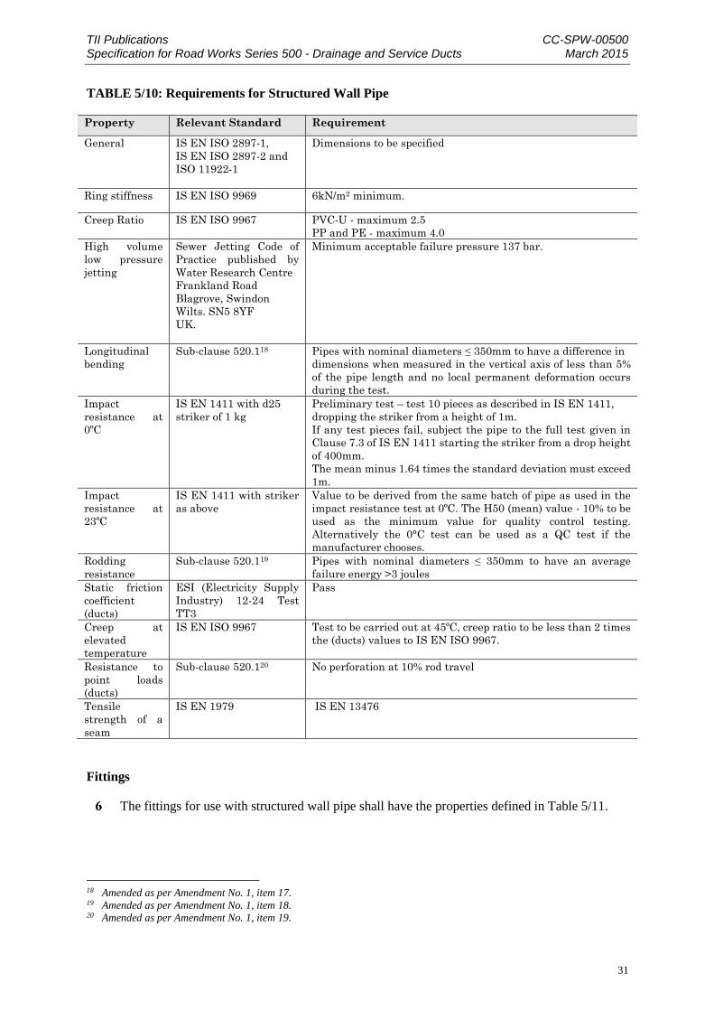
TII Publications CC-SPW-00500 Specification for Road Works Series 500 - Drainage and Service Ducts March 2015
31
TABLE 5/10: Requirements for Structured Wall Pipe
Property Relevant Standard Requirement
General IS EN ISO 2897-1,
IS EN ISO 2897-2 and
ISO 11922-1
Dimensions to be specified
Ring stiffness IS EN ISO 9969 6kN/m2 minimum.
Creep Ratio IS EN ISO 9967 PVC-U - maximum 2.5
PP and PE - maximum 4.0
High volume
low pressure
jetting
Sewer Jetting Code of
Practice published by
Water Research Centre
Frankland Road
Blagrove, Swindon
Wilts. SN5 8YF
UK.
Minimum acceptable failure pressure 137 bar.
Longitudinal
bending
Sub-clause 520.118 Pipes with nominal diameters ≤ 350mm to have a difference in
dimensions when measured in the vertical axis of less than 5%
of the pipe length and no local permanent deformation occurs
during the test.
Impact
resistance at
0ºC
IS EN 1411 with d25
striker of 1 kg
Preliminary test – test 10 pieces as described in IS EN 1411,
dropping the striker from a height of 1m.
If any test pieces fail, subject the pipe to the full test given in
Clause 7.3 of IS EN 1411 starting the striker from a drop height
of 400mm.
The mean minus 1.64 times the standard deviation must exceed
1m.
Impact
resistance at
23ºC
IS EN 1411 with striker
as above
Value to be derived from the same batch of pipe as used in the
impact resistance test at 0ºC. The H50 (mean) value - 10% to be
used as the minimum value for quality control testing.
Alternatively the 0°C test can be used as a QC test if the
manufacturer chooses.
Rodding
resistance
Sub-clause 520.119 Pipes with nominal diameters ≤ 350mm to have an average
failure energy >3 joules
Static friction
coefficient
(ducts)
ESI (Electricity Supply
Industry) 12-24 Test
TT3
Pass
Creep at
elevated
temperature
IS EN ISO 9967 Test to be carried out at 45ºC, creep ratio to be less than 2 times
the (ducts) values to IS EN ISO 9967.
Resistance to
point loads
(ducts)
Sub-clause 520.120 No perforation at 10% rod travel
Tensile
strength of a
seam
IS EN 1979 IS EN 13476
Fittings
The fittings for use with structured wall pipe shall have the properties defined in Table 5/11.
18 Amended as per Amendment No. 1, item 17. 19 Amended as per Amendment No. 1, item 18. 20 Amended as per Amendment No. 1, item 19.

TII Publications CC-SPW-00500 Specification for Road Works Series 500 - Drainage and Service Ducts March 2015
32
TABLE 5/11: Requirements for Fittings
Property Relevant Standard Requirement
General IS EN ISO 2897-1,
IS EN ISO 2897-2 and
ISO 11922-1
Dimensions to be specified
Ring stiffness (excluding
couplers)
ISO/DIS 13967 6kN/m2 minimum
Rodding resistance Sub-clause 520.12 Fittings with nominal diameters ≤ 350mm
to have an average failure energy >3 joules
Strength and flexibility of
fabricated fittings
IS EN 12256 IS EN 12256
Impact resistance (drop test) Drop Test to IS EN
12061: 1999
Fall height 1000mm at a temperature of
0ºC. Product less than ND 300 shall show
‘no damage’. Others may fail but must be
identified as ‘handle with care’
Watertightness of fabricated
fittings
IS EN 1053 0.5 bar for 1 minute
Pipe and Fittings
The pipe and fittings shall have the properties defined in Table 5/12.
TABLE 5/12 Requirements of the Systems
Property Relevant Standard Requirement
Leak-tightness of joints –
diameter distortion (watertight
joints)
IS EN 1277 Method 4
Condition B Temperature
(23 ± 2)°C
Use default values from ISEN
1277
Leak-tightness of joints – angular
deflection (watertight joints)
IS EN 1277 Method 4
Condition C Temperature
(23 ± 2)°C
Use default values from
IS EN 1277
Leakage rate from partially-
watertight joints
Sub-clause 509.7 Less than 20 times the square of
the internal diameter of the pipe
in metres shall flow through the
joint in litres per minute
Resistance to wheel loads IS EN 1437 adapted to suit NRA
loading conditions
Less than 5% deformation when
loaded to 100kN (for unequal
branches only)
Bedding, Backfill and Surround Material
All systems shall be installed in accordance with the pipe and bedding combinations given in
NRA HD 140. Other combinations shall be supported by calculations in accordance with IS EN
1295-1. Bedding, backfill and surround materials are classified in Clause 503 and Clause 505.
Installation and Handling
The bedding, surround and backfill shall be installed so as to cause no damage to the pipes and
fittings. Installation of the pipe and fittings, particularly, procedures for preparation and execution
of jointing operations, shall be in accordance with the manufacturer’s instructions.

TII Publications CC-SPW-00500 Specification for Road Works Series 500 - Drainage and Service Ducts March 2015
33
Identification
The Contractor shall obtain and make available records with the following information for each
separate consignment of structured wall pipe or fittings delivered to Site:
system name, ring stiffness grade / number and size;
name and address of the system manufacturer;
consignment number and delivery date; and
a copy of the site delivery note.
Test Method for Longitudinal Bending
The test specimen shall be a six metre length of pipe or the maximum length available from
the manufacturer (if less than six metres).
The apparatus shall include:
(a) two level support blocks at least 250mm wide and of sufficient height to allow the
pipe to sag over its length without touching the ground;
(b) a means of measuring the vertical distance between the pipe at the centre of the
span and a fixed point of reference to an accuracy of ±0.5mm.
The test procedure shall be as follows:
(a) condition the specimen for at least 1 hour at 23°C ± 2°C;
(b) set the supports at a distance apart equal to the length of pipe minus 500mm;
(c) place the pipe symmetrically on the supports;
(d) measure the distance between the top of the supports and the fixed point of
reference, in the vertical axis through the centre line of the pipe;
(e) after a period of two minutes measure the distance between the underside of the
pipe at mid span and the fixed point of reference;
(f) record the difference in readings as a percentage of pipe length.
Test Method for Rodding Resistance (Internal Puncture)
The test specimens shall be:
(a) twenty specimens cut from the structured wall pipe, each specimen to be 242mm
to 246mm in length and a quarter section of the circumference or;
(b) twenty specimens cut from a number of identical fittings.
The apparatus shall include:
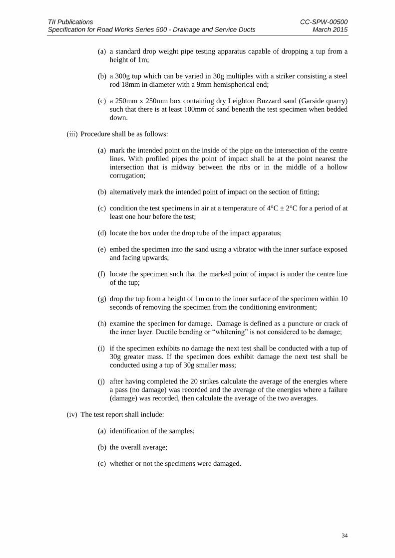
TII Publications CC-SPW-00500 Specification for Road Works Series 500 - Drainage and Service Ducts March 2015
34
(a) a standard drop weight pipe testing apparatus capable of dropping a tup from a
height of 1m;
(b) a 300g tup which can be varied in 30g multiples with a striker consisting a steel
rod 18mm in diameter with a 9mm hemispherical end;
(c) a 250mm x 250mm box containing dry Leighton Buzzard sand (Garside quarry)
such that there is at least 100mm of sand beneath the test specimen when bedded
down.
Procedure shall be as follows:
(a) mark the intended point on the inside of the pipe on the intersection of the centre
lines. With profiled pipes the point of impact shall be at the point nearest the
intersection that is midway between the ribs or in the middle of a hollow
corrugation;
(b) alternatively mark the intended point of impact on the section of fitting;
(c) condition the test specimens in air at a temperature of 4°C ± 2°C for a period of at
least one hour before the test;
(d) locate the box under the drop tube of the impact apparatus;
(e) embed the specimen into the sand using a vibrator with the inner surface exposed
and facing upwards;
(f) locate the specimen such that the marked point of impact is under the centre line
of the tup;
(g) drop the tup from a height of 1m on to the inner surface of the specimen within 10
seconds of removing the specimen from the conditioning environment;
(h) examine the specimen for damage. Damage is defined as a puncture or crack of
the inner layer. Ductile bending or “whitening” is not considered to be damage;
(i) if the specimen exhibits no damage the next test shall be conducted with a tup of
30g greater mass. If the specimen does exhibit damage the next test shall be
conducted using a tup of 30g smaller mass;
(j) after having completed the 20 strikes calculate the average of the energies where
a pass (no damage) was recorded and the average of the energies where a failure
(damage) was recorded, then calculate the average of the two averages.
The test report shall include:
(a) identification of the samples;
(b) the overall average;
(c) whether or not the specimens were damaged.

TII Publications CC-SPW-00500 Specification for Road Works Series 500 - Drainage and Service Ducts March 2015
35
Test Method for Resistance to Sharp Objects
Test specimens shall be three samples of duct each 300mm long.
The apparatus shall include:
(a) a compression testing machine;
(b) a 4.7mm diameter steel rod with an hemispherical end;
(c) and a 120° steel vee block at least 300mm long.
The test method shall be as follows:
(a) condition the test specimens for at least 1 hour at 23°C ± 2°C;
(b) insert the steel rod in the jaws of the moveable platen of the compression testing
machine so that the hemispherical end protrudes at least 15% of the nominal pipe
diameter;
(c) position the specimen in the vee block and placed directly below the steel rod, for
twin-walled pipe the specimen shall be positioned firstly so that the rod strikes on
the corrugation or rib, and secondly in the valley (where possible);
(d) set the machine to lower at a rate of 5mm/min;
(e) allow the rod to travel into the pipe a distance equal to 10% of the nominal internal
diameter of the pipe (T10mm) or until the pipe wall is perforated. When the outer
skin of a twin wall pipe is perforated before 10% is attained, the rod travel up to
the point of failure shall be recorded (Tf mm) and the rod allowed to travel to the
inner wall. The rod travel shall be continued to a total of 10% (i.e. T10 - Tf) or
until complete penetration occurs.
For each test specimen: pipe size, reference, maximum load and rod travel shall be recorded.
Notwithstanding the requirements of Sub-clauses 11, 12 and 13 of this Clause, variations in the
test methods specified therein shall be made where deemed necessary by the Irish Agrément
Board following consultation with the manufacturer and in agreement with the National Roads
Authority. All such variations shall be recorded in the report.
Certification
Pipes and fittings shall have a current Irish Agrément Board Roads and Bridges Certificate
certifying the appropriate physical properties when tested in accordance with this Clause.
TII Publications CC-SPW-00500 Specification for Road Works Series 500 - Drainage and Service Ducts March 2015
36
519 Geotextiles, Geosynthetic Clay Liners and Impermeable Membranes
Geotextiles
The geotextile materials used in filter drains shall be stored so that they are protected from the
deleterious effects of short term exposure to ultraviolet light, and shall be resistant to degradation
by acids, alkalis, common chemicals, bacteria, fungi and moulds occurring in soils and road
construction materials. After exposure to ultraviolet light the Employer's Representative may
require evidence that the materials still comply with the requirements of this Clause. They shall
be protected from damage and ultraviolet light and be labelled to identify the grade and
manufacturer or supplier.
The geotextile for filter drains shall:
sustain a tensile load of not less than 5.0kN/m at break and have a minimum failure strain
of 10% when determined in accordance with IS EN ISO 10319;
have a minimum puncture resistance of 1200 N when determined in accordance with IS EN
ISO 12236;
have a size distribution of pore openings such that the apparent opening size 090 when
determined in accordance with IS EN ISO 12956, or other appropriate test, is less than 300
microns, unless otherwise specified in Appendix 5/4;
allow water to flow through it, in either direction, normal to its principal plane at a rate of
not less than 10 l/m²/s, unless otherwise specified in Appendix 5/4, under a constant head of
water of 100mm and a maximum breakthrough head of 50mm when determined in
accordance with IS EN ISO 12958.
Geotextile joints shall consist of minimum 300mm overlap and shall be secured with pins or
mechanical ties where required to ensure lap length is achieved. Where an outlet pipe passes
through the geotextile a separate piece of geotextile shall be wrapped round the outlet pipe, flared
against the geotextile in the filter drain and secured. Where drain lengths are terminated at
chambers, the geotextile shall be secured against the chamber walls by suitable means so as to
prevent the ingress of soil particles or other extraneous material into the drain.
Installation and Handling
Filter drains shall be installed as shown on the NRA Road Construction Detail listed in Appendix
5/7. Before, during and after installation the geotextile shall be protected from contamination,
damage and exposure to ultraviolet21. No geotextile shall be exposed to daylight (or any source
of ultraviolet radiation) for a period exceeding a cumulative total of 50 hours. Any geotextile
exposed to daylight (or any source of ultraviolet light) for a period exceeding a cumulative total
of 50 hours shall be replaced unless it can be demonstrated that the geotextile still complies with
the requirements of this Clause.
Trench walls shall be sufficiently clean to enable the geotextile to come into close contact with
the wall when the granular material is placed inside it. The deposition and compaction of infill
shall be in accordance with Sub-clause 505.4 for filter drains.
21 Amended as per Amendment No. 1, item 20.

TII Publications CC-SPW-00500 Specification for Road Works Series 500 - Drainage and Service Ducts March 2015
37
Geosynthetic Clay Liner
Geosynthetic clay liner shall:
Sustain a tensile load of determined in accordance with IS EN ISO 10319;
Where geosynthetic clay liners and clay liners are proposed within the Works, such liners
shall have a maximum permeability of 1 x 10-11 metres per second.
Installation and Handling
Jointing and splicing: Shall be strictly in accordance with the manufacturer’s instructions
Installation: Shall be strictly in accordance with the manufacturer’s instructions
Storage: The Geosynthetic Clay Liner shall be stored under cover in clean dry conditions elevated
above ground level, protected from mechanical and chemical damage and exposure to extreme
temperatures and direct sunlight.
Repairs shall be permitted in accordance with the manufacturers requirements. Where the use of
bentonite powder is permitted for repairs and jointing it shall be the same granular bentonite as
used in the production of the Geosynthetic Clay Liner.
Impermeable Membranes
The Contractor shall ensure that all impermeable membranes used in the Works shall be
chemically inert and shall not biologically degrade. Such impermeable membranes shall have a
minimum life expectancy of 25 years and shall meet the requirement for geotextiles in Appendix
C of CIRIA C697.
Installation and Handling
Jointing and splicing: Shall be strictly in accordance with the manufacturer’s instructions.
Installation: Shall be strictly in accordance with the manufacturer’s instructions.
Storage: The membrane shall be stored under cover in clean dry conditions, protected from
mechanical and chemical damage and exposure to extreme temperatures and direct sunlight.
Repairs: Shall only be allowed strictly in accordance with the manufacturer’s requirements.
Geogrid
Geogrid shall:
The geo-synthetic grid shall have either an Irish Agrément Board Roads or Bridges
Certificate or British Board of Agrément certification.
The geo-synthetic grid shall be high density polyethylene or polypropylene, have a nominal
ultimate tensile strength in each direction of 30kNm
Installation and Handling
Jointing and splicing: Shall be strictly in accordance with the manufacturer’s instructions.

TII Publications CC-SPW-00500 Specification for Road Works Series 500 - Drainage and Service Ducts March 2015
38
Installation: Shall be strictly in accordance with the manufacturer’s instructions: The design
drawings shall identify the correct orientation of the geogrids.
Storage: The geogrid shall be stored under cover in clean dry conditions, protected from
mechanical and chemical damage and exposure to extreme temperatures and direct sunlight.
520 Attenuation
Where attenuation ponds are to be provided as part of the design they shall comply with the
special requirements described in Appendix 5/9.
Proprietary prefabricated buried modular systems shall be constructed and backfilled strictly in
accordance with the manufacturer’s instructions.
521 Pollution Control
Where pollution control is to be provided as part of the design it shall comply with the special
requirements described in Appendix 5/9.
Prefabricated Petrol / Oil Interceptors shall be capable of treating design flows stated and shall
be identified as being either a full retention or bypass interceptor. They shall be installed and
backfilled strictly in accordance with the manufacturer’s instructions.
522 Soakaways
Where soakaways are to be provided as part of the design they shall comply with the special
requirements described in Appendix 5/9.
Where soakaways are being provided, a geotechnical risk assessment shall be undertaken by the
Contractor to determine the impact on Structure foundations or embankments in the vicinity of
such measures.
The Contractor shall provide results for infiltration tests, undertaken as described in BRE Digest
365, at the proposed invert level of all infiltration areas.
The invert of soakaways shall not be situated on bedrock and shall be at least 1 metre above the
seasonal high groundwater table level.
Where Geotextile liner is required it shall comply with the requirements of Clause 519 of this
Series.
Proprietary prefabricated buried modular systems shall be constructed and backfilled strictly in
accordance with the manufacturer’s instructions.
523 Drainage Outfalls
Discharge from the drainage systems shall be controlled or attenuated and shall not increase the
discharge rate, flow velocity, the risk of erosion or the risk of flooding to any downstream
watercourses, pipes, culverts or static water bodies which receive water from an outfall to the
extent that the return period for flooding is affected.
The Design and Construction of all outfalls shall cause minimum disruption to the existing
watercourse at the outfall

TII Publications CC-SPW-00500 Specification for Road Works Series 500 - Drainage and Service Ducts March 2015
39
The Design and Construction shall provide erosion protection, as shown on National Roads
Authority Road Construction Detail RCD/500/50, for all outfall locations of surface water into
open watercourses. Material for erosion protection shall be either;
crushed rock in accordance with Series 600, with a grading designed and included within
Appendix 5/1; or
comply with Series 600 for Clause 6B material
Further details are contained in Road Construction Detail RCD/500/50.
Where required by the design Geotextile to Clause 519 shall be identified in Appendix 5/1 and
all material shall be placed on a slope not exceeding 1(v):2(h) or benching as stated in Appendix
5/1.
Where drainage outfall require non return valves these may include:
flap gates
positive pressure flexible check valves.
524 Pipes for Ducts
Pipes for service ducts, excluding those in use in motorway communications installations, shall
be selected from the alternatives in Table 5/2 and shall comply with the standards and particular
requirements therein and also where applicable with the requirements of IS EN 61386. Pipes for
use in motorway communications installations shall comply with the 1500 series. Pipes for
service ducts shall have a smooth internal bore without any sharp edges to the ends of pipes. They
shall comply with any additional requirements described in Appendix 5/2, and be of 100mm
internal diameter unless otherwise described therein. Their alignment shall be tested in
accordance with Sub-clause 509.9. The use of pipes and fittings other than those included in
Table 5/2 shall be permitted provided that they hold a current Irish Agrément Board Roads and
Bridges Certificate (or equivalent) stating that they are a suitable alternative to those listed in
Table 5/2. Notwithstanding the above they shall comply with all other relevant requirements of
the NRA Specification for Road Works.
Each duct shall be fitted with a pigmented, stranded polypropylene or approved equivalent rot-
proof material draw rope of 5kN breaking load and having a design life of not less than 20 years,
the ends of which shall be made fast to marker blocks as shown on the NRA Road Construction
Details listed in Appendix 5/7. The ends of a duct shall be either sealed by removable stoppers
immediately after it has been laid, or terminated in chambers of the type specified in Appendix
5/2.
Duct construction shall comply with the requirements of Appendix 5/2.
Ducts need not have watertight joints unless otherwise described in Appendix 5/2.

TII Publications CC-SPW-00500 Specification for Road Works Series 500 - Drainage and Service Ducts March 2015
40
Joints in pipes for service ducts shall comply with the appropriate European Standard and with
the following:
Pipes for ducts shall be jointed so that no silt, grit, grout or concrete surround is able to enter
the duct. Pipes with push-fit joints shall have a register to ensure that the pipe is fully pushed
into the joint.
Joints in pipes to BS 3505 and IS EN 1452 shall comply with IS EN 1452-1 to 5 as
appropriate.
The position of service ducts shall be marked when the trenches are backfilled and permanent
marker blocks and location posts provided as described in Appendix 5/2.
Pipes for service ducts shall have nominal internal diameters of between 50mm and 150mm.
The colour of ducting pipes shall be in accordance with the UK National Joint Utilities Group
publication “Guidelines on the Positioning and Colour Coding of Utilities’ Apparatus”. Any
variation in the colour shall be described in Appendix 5/2.
Table 5/2: Pipes for Ducts
Material Standard Particular
Requirements
Iron IS EN 598
(Ductile iron)
Unplasticised
polyvinyl-
chloride
(UPVC)
IS EN 1401 or BS
4660 or
BS 5481 or
BS 3506 (Class C)
or
IS EN 1452
When pipes to BS
3506 (Class C) are
used, joints shall
comply with BS
4346: Part 2
Pipes for use in motorway communications installations
shall comply with the 1500 Series
525 Chambers for Ducts
Chambers for Ducts, other than those used in motorway communications installations, shall
include manholes, catch-pits, inspection chambers, draw pits and walled soakaways. Chambers
shall be of the type specified in Appendix 5/1, constructed in accordance with the NRA Road
Construction Details listed in Appendix 5/7 as appropriate to that type. Inspection chambers not
exceeding 1.3 metres in depth to invert, complete plastics units or other units in equivalent
material surrounded by 150 mm of mix ST4 concrete may be used.
Chambers for use in motorway communications installations shall comply with the 1500 Series
and Appendix 5/2. All ST concrete referred to in this Clause shall comply with the requirements
of Concrete for Ancillary Purposes in the 2600 Series unless otherwise described in Appendix
5/1.
Foundations to chambers shall be of mix ST4 concrete.

TII Publications CC-SPW-00500 Specification for Road Works Series 500 - Drainage and Service Ducts March 2015
41
Brickwork and Blockwork shall comply with the 2400 Series and be built with mortar designation
(i) in English bond. The joints of brickwork where exposed shall be finished as specified for
unpointed joints in the 2400 Series. The ends of all pipes shall be neatly built into the brickwork
and finished flush with mortar designation (i).
Precast concrete chambers shall comply with BS 5911-3, IS EN 1917, IS 420 and the particular
requirements described in Appendix 5/1. Cast insitu concrete chambers shall be constructed of
mix ST4 concrete complying with Clause 2602 and the particular requirements described in
Appendix 5/1.
Inverts and benchings shall have a screeded, ridged finish and shall have a smooth, high-strength
concrete topping (minimum thickness 20mm) applied with a steel trowel before the concrete has
set. The topping shall be produced, laid and finished in accordance with the relevant provisions
of BS 8204: Part 2 and the following approximate mix proportions by weight shall be used: 1
part cement, 1 part natural sand and 2 parts single – sized coarse aggregate.
Where the depth of invert of chambers exceeds 900mm below the finished surface of the carriage-
way or the adjacent ground, manhole steps complying with IS EN 13101 shall be built in
accordance with the NRA Road Construction Details listed in Appendix 5/7. Steelwork used for
ladders, handholds and other fittings shall comply with IS EN 10084 and be galvanised in
compliance with the requirements of the 1900 Series after fabrication. Threaded components shall
also be galvanised in compliance with the requirements of the 1900 Series.
Excavation around chambers, except those described in Sub-clause 6 of this Clause, shall be
backfilled with general fill material as described in Table 6/1 and compacted in compliance with
the requirements of the 600 Series. Where mechanical compaction is impracticable, the
excavation shall be backfilled with mix ST2 concrete. Where there are precast concrete access
shafts to precast concrete chambers, the shafts shall be surrounded by a minimum thickness of
150mm of mix ST4 concrete, and the remaining excavation backfilled with general fill material
as described in Table 6/1 compacted in compliance with Clause 612.
Chamber covers, gratings and frames shall be as described in Appendix 5/1 and shall comply
with IS EN 124 and Sub-clauses 10 to 1422 of this Clause.
Products shall be designed and developed within an IS EN ISO 9001 system that has been
assessed by a relevant recognised certification body. A relevant certification body shall have
IS EN 45011 and IS EN ISO/IEC 17021 within its scope.
Products shall be type tested by a third party testing laboratory/organisation that has been
accredited to IS EN ISO/IEC 17025 and has IS EN124 within its scope.
The certification process shall be overseen or audited by a single relevant accredited
certification body meeting the requirements in (i) and (ii) above.
Copies of all certificates shall be forwarded to the Employers Representative along with
audited product test reports.
All documentation must be furnished in English or Irish.
Where gratings and frames are required to be locked the minimum size of the locking bolt
shall be M16 and it shall be manufactured from stainless steel to prevent corrosion.
22 Amended as per Amendment No. 1, item 21.

TII Publications CC-SPW-00500 Specification for Road Works Series 500 - Drainage and Service Ducts March 2015
42
Class D400 units shall incorporate a permanent non-rock feature either triangular point
suspension, machined faces or cushioned or wedged seating.
Bolts supplied for loosely coupling separate sections of covers and gratings shall be steel hexagon
headed, complying with the requirement of IS EN ISO 4016, 4018 and 4034 and be galvanised
in compliance with the requirements of the 1900 Series. They shall not be less than M16 complete
with hexagon nut and shall be provided with means to prevent undue tightening of unit sections.
Requirements for special duty covers for use in carriageways shall be as described in Appendix
5/1.
Two sets of lifting keys shall be delivered to the Employer's Representative for each type of cover
supplied. At least two keyways shall be provided in each complete cover, one in each segment
for segmental covers. A recess for a prising bar shall be incorporated in manhole covers unless
other means of loosening the cover from the frame are provided.
Frames for chamber covers and gratings shall be set in cement mortar designation (i) complying
with Clause 2404 or a proprietary quick setting mortar of equivalent strength.
Covers and gratings located within the carriageway, hardshoulder or hardstrip shall be set in a
mortar with the following properties:
The material shall be non-shrink;
The material shall have a minimum workable life of 15 minutes;
The compressive strength of the material shall exceed 30N/mm² in 3 hours;
The tensile strength of the material shall exceed 5N/mm² in 3 hours.
Where the adjustment or replacement of existing frames and covers or gratings is required, the
units shall be taken up and refixed or replaced with new units complying with Sub-clauses 9 to
1423 of this Clause, or such other specification as required by the authority responsible for the
utility to which the cover provides access. The frames and covers or gratings shall be laid on a
mortar bed complying with Sub-clause 1424 of this Clause. The finished thickness of the mortar
bed shall be between 10mm and 25mm. Unless otherwise described in Appendix 5/1 adjusted or
replaced chamber frames and covers or gratings shall be set flush with the new surface. Any
additional adjustments shall be by modifying the brickwork in compliance with Sub-clause 507.3
or by using a frame of a suitable depth.
23 Amended as per Amendment No. 1, item 22. 24 Amended as per Amendment No. 1, item 23.
TII Publications CC-SPW-00500 Specification for Road Works Series 500 - Drainage and Service Ducts March 2015
43
526 Ducts: Testing and Cleaning
Service ducts shall be checked by drawing a wooden mandrel, as shown on the NRA Road
Construction Details listed in Appendix 5/7, through as the ducts are laid but where a set has to
be given to the line of ducts the wooden mandrel shall be replaced by an iron mandrel 250mm
long but of the same diameter as the wooden version.