Embed Size (px)
Citation preview
CLASSIFICATION Einstufung
PRODUCT SPECIFICATION Produktspezifikation
No. DS-1x55-2400-102
REV. 1.10
SUBJECT Thema
CLASS 2 BLUETOOTH MODULE Bluetooth Modul der Klasse 2
PAGE Seite
1 of 34
CUSTOMER’S CODE PAN1455/1555
PANASONIC’S CODE ENW89815CxKF/ENW89815AxKF
DATE Datum
27.06.2011
PANASONIC ELECTRONIC DEVICES
EUROPE GMBH High Frequency Products Business Group
- Wireless Modules -
APPROVED genehmigt
CHECKED geprüft
DESIGNED erstellt
Specification for Production
Panasonic Electronic Devices Europe GmbH Zeppelinstrasse 19 21337 Lüneburg
Applicant / Manufacturer Hardware
Germany
Stollmann Entwicklungs- und Vertriebs-GmbH Mendelssohnstrasse 15 D 22761 Hamburg
Applicant / Manufacturer Software
Germany Supported Bluetooth Profiles BlueRS , SPP, HDP, HID, OPP, HDP/SPP Contents Approval for Mass Production
Customer
By signing this document, you acknowledge that you are the legal representative for your company and that you understand and accept the validity of the contents herein . CHECKED / APPROVED:
DATE: NAME: SIGNATURE:
NOTE: AT LEAST ONE SET OF APPROVED SPECIFICATIONS SHOULD BE RETURNED TO THE ADDRESS OF THE ISSUING PARTY.
CLASSIFICATION Einstufung
PRODUCT SPECIFICATION Produktspezifikation
No. DS-1x55-2400-102
REV. 1.10
SUBJECT Thema
CLASS 2 BLUETOOTH MODULE Bluetooth Modul der Klasse 2
PAGE Seite
2 of 34
CUSTOMER’S CODE PAN1455/1555
PANASONIC’S CODE ENW89815CxKF/ENW89815AxKF
DATE Datum
27.06.2011
PANASONIC ELECTRONIC DEVICES EUROPE GMBH www.pedeu.pansonic.de
TABLE OF CONTENTS
1. Key Features...................................................................................................................4 2. Applications for the Module.............................................................................................4 3. Description for the Module ..............................................................................................5 4. Scope of this Document ..................................................................................................6 5. History for this Document................................................................................................6 6. Terminal Layout ..............................................................................................................7
6.1. General Pin Assignment ........................................................................................8 6.2. Application Specific Pin Description ......................................................................9
6.2.1. SPP configuration DCE Mode ..................................................................9 7. Terminal Specifics.........................................................................................................10
7.1. RF-Interface - ANT ..............................................................................................10 7.2. Power Supply.......................................................................................................10 7.3. Power-On-Reset ..................................................................................................10 7.4. UART Interface – TXD, RXD, CTS, RTS.............................................................11 7.5. 3-wire Serial Interface..........................................................................................12 7.6. USB Interface,......................................................................................................12
7.6.1. USB_DP, USB_DN ................................................................................12 7.7. GPIO Interface.....................................................................................................12 7.8. ADC .....................................................................................................................12 7.9. DAC .....................................................................................................................12 7.10. PCM Interface......................................................................................................12
8. Key Parts List ................................................................................................................13 9. Test Conditions .............................................................................................................14 10. Absolute Maximum Ratings (1).......................................................................................14 11. Electrical Requirements ................................................................................................14 12. I/O Operating Characteristics........................................................................................15 13. USB Interface................................................................................................................15 14. Typical Current Consumption........................................................................................16
14.1. SPP Configuration ...............................................................................................16 14.1.1. Deep Sleep State ...................................................................................16 14.1.2. Power Down State..................................................................................16 14.1.3. Idle State ................................................................................................16
14.2. Power Consumption ............................................................................................16 14.3. Power-up time......................................................................................................17
15. Electrical RF-Characteristics.........................................................................................17 16. Mechanical Requirements.............................................................................................18 17. Soldering Temperature-Time Profile (for reflow soldering) ...........................................19
17.1. For lead solder.....................................................................................................19 17.2. For leadfree solder...............................................................................................19
CLASSIFICATION Einstufung
PRODUCT SPECIFICATION Produktspezifikation
No. DS-1x55-2400-102
REV. 1.10
SUBJECT Thema
CLASS 2 BLUETOOTH MODULE Bluetooth Modul der Klasse 2
PAGE Seite
3 of 34
CUSTOMER’S CODE PAN1455/1555
PANASONIC’S CODE ENW89815CxKF/ENW89815AxKF
DATE Datum
27.06.2011
PANASONIC ELECTRONIC DEVICES EUROPE GMBH www.pedeu.pansonic.de
18. Module Dimension ........................................................................................................20 19. Recommended Foot Pattern .........................................................................................21 20. Labelling Drawing..........................................................................................................23 21. Software........................................................................................................................24
21.1. SPP Software ......................................................................................................24 21.2. HDP Software ......................................................................................................24 21.3. HID Software .......................................................................................................24 21.4. HDP/SPP Software..............................................................................................24 21.5. Other Profiles are available on request. ..............................................................24
22. Cautions........................................................................................................................24 22.1. Design Notes .......................................................................................................24 22.2. Installation Notes .................................................................................................25 22.3. Usage Conditions Notes ......................................................................................25 22.4. Storage Notes......................................................................................................25 22.5. Safety Cautions ...................................................................................................26 22.6. Other cautions .....................................................................................................27
23. Packaging .....................................................................................................................28 23.1. Embossed tape / Blistergurt.................................................................................28 23.2. Component direction............................................................................................29 23.3. Reel dimension ....................................................................................................30 23.4. Package...............................................................................................................30
24. Ordering Information .....................................................................................................31 25. RoHS Declaration .........................................................................................................31 26. Data Sheet Status.........................................................................................................31 27. Regulatory Information..................................................................................................32
27.1. FCC Notice ..........................................................................................................32 27.2. Caution ................................................................................................................32 27.3. Labeling Requirements........................................................................................32 27.4. Antenna Warning .................................................................................................33 27.5. Approved Antenna List ........................................................................................33 27.6. RF Exposure PAN1455/PAN1555 .......................................................................33 27.7. Industry Canada Certification ..............................................................................33
28. Related Documents.......................................................................................................34 29. General Information ......................................................................................................34 30. Life Support Policy ........................................................................................................34
CLASSIFICATION Einstufung
PRODUCT SPECIFICATION Produktspezifikation
No. DS-1x55-2400-102
REV. 1.10
SUBJECT Thema
CLASS 2 BLUETOOTH MODULE Bluetooth Modul der Klasse 2
PAGE Seite
4 of 34
CUSTOMER’S CODE PAN1455/1555
PANASONIC’S CODE ENW89815CxKF/ENW89815AxKF
DATE Datum
27.06.2011
PANASONIC ELECTRONIC DEVICES EUROPE GMBH www.pedeu.pansonic.de
1. KEY FEATURES Schlüsseleigenschaften
• Bluetooth specification v2.0 + EDR (Enhanced Data Rate) • CSR BlueCore6-ROM inside • Complete Co-location and Co-existence with IEEE 802.11 (AWMA, AFH and SFH) • Fast Connection Setup • Extended SCO Link • RF output power class 2 with power control • Supply Voltage 3.0V to 3.6V • Internal crystal oscillator (26MHz, 14.7456 MHz and 32 kHz for deep sleep) • Surface mount type
• PAN1455: 13.5 x 18.75 x 2.85 mm • PAN1555: 13.5 x 22.75 x 2.85 mm
• Built-in shielding to be compliant to FCC • Full Bluetooth data rate up to 2178kbps asymmetric • Support for all Bluetooth power saving modes (Park, Sniff, Hold) • Support for very low-power modes (deep sleep and power down) • Otional support for ultra-low-power mode. Standby with Battery-Backup • PCM Interface Master / Slave supporting 13 or 16 bit linear, 8 bit µ-law or A-law Codecs
and CVSD transcoders on up to 3 SCO channels • Full 8- to 128-bit encryption • High sensitivity design (-86 dBm typ.) • 3 UART, USB, I2C and SPI Interface • 18 GPIO’s for individual usage for your embedded software • 3 Channel ADC and 1 Channel DAC • Cortex-M3 ST32F103 core for embedded profiles or application software • Manufactured in conformance with RoHS
2. APPLICATIONS FOR THE MODULE Applikationen für das Modul All Embedded Wireless Applications
• Access Points • Cable Replacement • Printer Adapters • Personal Digital Assistants
(PDAs) • Printers • Access Points • Scanners • Computers and Peripherals • Wireless Sensors • Industrial Control Applications
CLASSIFICATION Einstufung
PRODUCT SPECIFICATION Produktspezifikation
No. DS-1x55-2400-102
REV. 1.10
SUBJECT Thema
CLASS 2 BLUETOOTH MODULE Bluetooth Modul der Klasse 2
PAGE Seite
5 of 34
CUSTOMER’S CODE PAN1455/1555
PANASONIC’S CODE ENW89815CxKF/ENW89815AxKF
DATE Datum
27.06.2011
PANASONIC ELECTRONIC DEVICES EUROPE GMBH www.pedeu.pansonic.de
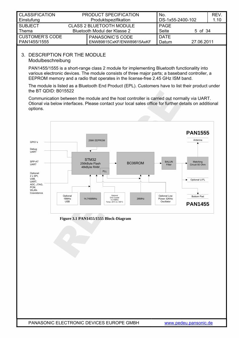
3. DESCRIPTION FOR THE MODULE Modulbeschreibung PAN1455/1555 is a short-range class 2 module for implementing Bluetooth functionality into various electronic devices. The module consists of three major parts; a baseband controller, a EEPROM memory and a radio that operates in the license-free 2.45 GHz ISM band.
The module is listed as a Bluetooth End Product (EPL). Customers have to list their product under the BT QDID: B015522
Communication between the module and the host controller is carried out normally via UART. Otional via below interfaces. Please contact your local sales office for further details on additional options.
STM32256kByte Flash48kByte RAM
26MHz
BC06ROM
14,7456MHz
256K EEPROM
BALUNFilter
Antenna
Bottom PadOptionalOne Crystal14,75MHz
Temp -25°C to +85°C
Optional16MHzUSB
PLL
Optional Low Power 32KHz
Oscillator
Optional U.FL
PAN1555
PAN1455
MatchingCircuit 50 Ohm
Optional:2 x SPI, USB, UART, ADC, JTAG, PCM, WLAN-Coexistence
SPP-ATUART
DebugUART
GPIO´s
AN1455/1555
Figure 3.1 P Block-Diagram
CLASSIFICATION Einstufung
PRODUCT SPECIFICATION Produktspezifikation
No. DS-1x55-2400-102
REV. 1.10
SUBJECT Thema
CLASS 2 BLUETOOTH MODULE Bluetooth Modul der Klasse 2
PAGE Seite
6 of 34
CUSTOMER’S CODE PAN1455/1555
PANASONIC’S CODE ENW89815CxKF/ENW89815AxKF
DATE Datum
27.06.2011
PANASONIC ELECTRONIC DEVICES EUROPE GMBH www.pedeu.pansonic.de
4. SCOPE OF THIS DOCUMENT Umfang dieses Dokumentes This product specification applies to the class 2 bluetooth module ENW8 . The different characters indicates different versions (refer to chapter
9815CxKF/ENW89815AxKF24 Ordering Information)
The used bluetooth chip is the BlueCore6 from the company CSR. (www.csr.com).
Diese Produktionsunterlagen beziehen sich auf das Class 2 Bluetooth Modul .
Die unterschiedlichen Zeichen bezeichnen verschiedene Versionen (Erklärung im Kapitel ENW89815CxKF/ENW89815AxKF
24 Ordering Information) Der verwendete Bluetooth Chip ist der BlueCore6 der Firma CSR.
5. HISTORY FOR THIS DOCUMENT Versionsverwaltung dieses Dokumentes
Revision Version
Date Datum
Modification / Remarks Änderungen / Bemerkungen
0.90 06.03.2009 Preliminary release.
0.91 30.03.2009 Add FCC Notice
0.92 04.05.2009 Include RF-Performance and current consumption
0.93 06.05.2009 Do minor changes in formatting, content links now included.
0.94 29.05.2009 Include final tables and Interface description
0.95 28.08.2009 SW-Status updated
1.00 01.02.2011 Power update for min values, add foot note from CSR, addd CSR datasheet in appendix, add HDP Partnumbers, add link to Stollmann SW support page. Include BT Listing QDID information.
1.10 27.06.2011 Updated laser label information in chapter 20 Labelling Drawing.
CLASSIFICATION Einstufung
PRODUCT SPECIFICATION Produktspezifikation
No. DS-1x55-2400-102
REV. 1.10
SUBJECT Thema
CLASS 2 BLUETOOTH MODULE Bluetooth Modul der Klasse 2
PAGE Seite
7 of 34
CUSTOMER’S CODE PAN1455/1555
PANASONIC’S CODE ENW89815CxKF/ENW89815AxKF
DATE Datum
27.06.2011
PANASONIC ELECTRONIC DEVICES EUROPE GMBH www.pedeu.pansonic.de
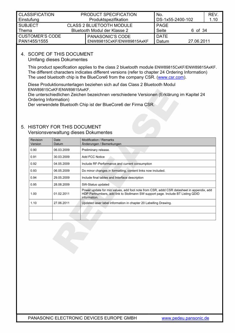
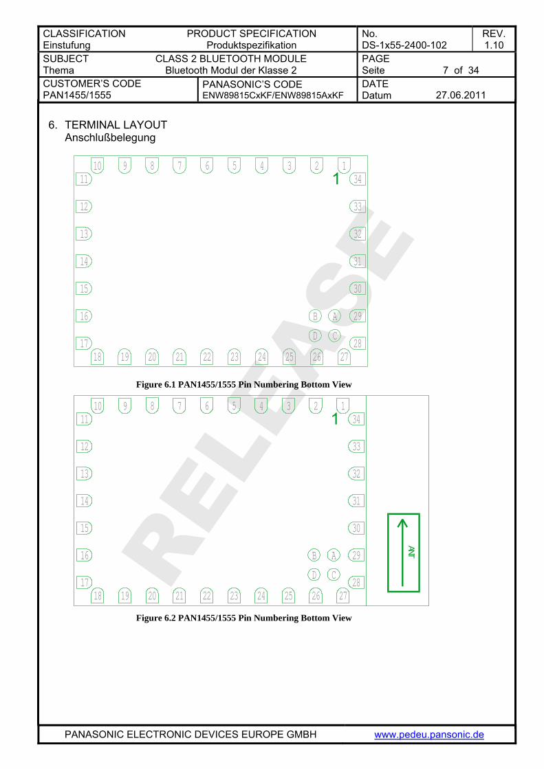
6. TERMINAL LAYOUT Anschlußbelegung
1
13
33
32
11
12
14
15
16
34
31
30
29
28242019
AB
C17
5678910 34 2 1
23 25 26
D
27222118
Figure 6.1 P Pin Numbering Bottom View AN1455/1555
1
ANT
13
33
32
11
12
14
15
16
34
31
30
29
28242019
AB
C17
5678910 34 2 1
23 25 26
D
27222118
Figure 6.2 P Pin Numbering Bottom View AN1455/1555
CLASSIFICATION Einstufung
PRODUCT SPECIFICATION Produktspezifikation
No. DS-1x55-2400-102
REV. 1.10
SUBJECT Thema
CLASS 2 BLUETOOTH MODULE Bluetooth Modul der Klasse 2
PAGE Seite
8 of 34
CUSTOMER’S CODE PAN1455/1555
PANASONIC’S CODE ENW89815CxKF/ENW89815AxKF
DATE Datum
27.06.2011
PANASONIC ELECTRONIC DEVICES EUROPE GMBH www.pedeu.pansonic.de
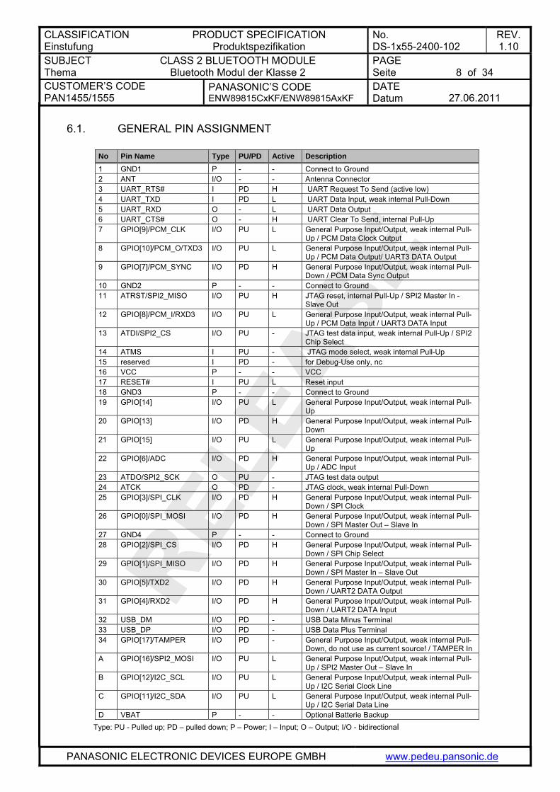
6.1. GENERAL PIN ASSIGNMENT
No Pin Name Type PU/PD Active Description 1 GND1 P - - Connect to Ground 2 ANT I/O - - Antenna Connector 3 UART_RTS# I PD H UART Request To Send (active low) 4 UART_TXD I PD L UART Data Input, weak internal Pull-Down 5 UART_RXD O - L UART Data Output 6 UART_CTS# O - H UART Clear To Send, internal Pull-Up 7 GPIO[9]/PCM_CLK I/O PU L General Purpose Input/Output, weak internal Pull-
Up / PCM Data Clock Output 8 GPIO[10]/PCM_O/TXD3 I/O PU L General Purpose Input/Output, weak internal Pull-
Up / PCM Data Output/ UART3 DATA Output 9 GPIO[7]/PCM_SYNC I/O PD H General Purpose Input/Output, weak internal Pull-
Down / PCM Data Sync Output 10 GND2 P - - Connect to Ground 11 ATRST/SPI2_MISO I/O PU H JTAG reset, internal Pull-Up / SPI2 Master In -
Slave Out 12 GPIO[8]/PCM_I/RXD3 I/O PU L General Purpose Input/Output, weak internal Pull-
Up / PCM Data Input / UART3 DATA Input 13 ATDI/SPI2_CS I/O PU - JTAG test data input, weak internal Pull-Up / SPI2
Chip Select 14 ATMS I PU - JTAG mode select, weak internal Pull-Up 15 reserved I PD - for Debug-Use only, nc 16 VCC P - - VCC 17 RESET# I PU L Reset input 18 GND3 P - - Connect to Ground 19 GPIO[14] I/O PU L General Purpose Input/Output, weak internal Pull-
Up 20 GPIO[13] I/O PD H General Purpose Input/Output, weak internal Pull-
Down 21 GPIO[15] I/O PU L General Purpose Input/Output, weak internal Pull-
Up 22 GPIO[6]/ADC I/O PD H General Purpose Input/Output, weak internal Pull-
Up / ADC Input 23 ATDO/SPI2_SCK O PU - JTAG test data output 24 ATCK O PD - JTAG clock, weak internal Pull-Down 25 GPIO[3]/SPI_CLK I/O PD H General Purpose Input/Output, weak internal Pull-
Down / SPI Clock 26 GPIO[0]/SPI_MOSI I/O PD H General Purpose Input/Output, weak internal Pull-
Down / SPI Master Out – Slave In 27 GND4 P - - Connect to Ground 28 GPIO[2]/SPI_CS I/O PD H General Purpose Input/Output, weak internal Pull-
Down / SPI Chip Select 29 GPIO[1]/SPI_MISO I/O PD H General Purpose Input/Output, weak internal Pull-
Down / SPI Master In – Slave Out 30 GPIO[5]/TXD2 I/O PD H General Purpose Input/Output, weak internal Pull-
Down / UART2 DATA Output 31 GPIO[4]/RXD2 I/O PD H General Purpose Input/Output, weak internal Pull-
Down / UART2 DATA Input 32 USB_DM I/O PD - USB Data Minus Terminal 33 USB_DP I/O PD - USB Data Plus Terminal 34 GPIO[17]/TAMPER I/O PD - General Purpose Input/Output, weak internal Pull-
Down, do not use as current source! / TAMPER In A GPIO[16]/SPI2_MOSI I/O PU L General Purpose Input/Output, weak internal Pull-
Up / SPI2 Master Out – Slave In B GPIO[12]/I2C_SCL I/O PU L General Purpose Input/Output, weak internal Pull-
Up / I2C Serial Clock Line C GPIO[11]/I2C_SDA I/O PU L General Purpose Input/Output, weak internal Pull-
Up / I2C Serial Data Line D VBAT P - - Optional Batterie Backup
Type: PU - Pulled up; PD – pulled down; P – Power; I – Input; O – Output; I/O - bidirectional
CLASSIFICATION Einstufung
PRODUCT SPECIFICATION Produktspezifikation
No. DS-1x55-2400-102
REV. 1.10
SUBJECT Thema
CLASS 2 BLUETOOTH MODULE Bluetooth Modul der Klasse 2
PAGE Seite
9 of 34
CUSTOMER’S CODE PAN1455/1555
PANASONIC’S CODE ENW89815CxKF/ENW89815AxKF
DATE Datum
27.06.2011
PANASONIC ELECTRONIC DEVICES EUROPE GMBH www.pedeu.pansonic.de
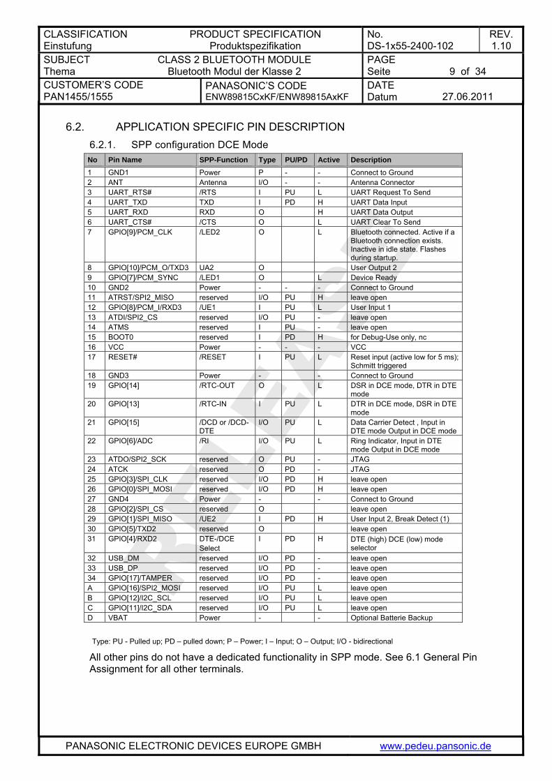
6.2. APPLICATION SPECIFIC PIN DESCRIPTION 6.2.1. SPP configuration DCE Mode
No Pin Name SPP-Function Type PU/PD Active Description 1 GND1 Power P - - Connect to Ground 2 ANT Antenna I/O - - Antenna Connector 3 UART_RTS# /RTS I PU L UART Request To Send 4 UART_TXD TXD I PD H UART Data Input 5 UART_RXD RXD O H UART Data Output 6 UART_CTS# /CTS O L UART Clear To Send 7 GPIO[9]/PCM_CLK /LED2 O L Bluetooth connected. Active if a
Bluetooth connection exists. Inactive in idle state. Flashes during startup.
8 GPIO[10]/PCM_O/TXD3 UA2 O User Output 2 9 GPIO[7]/PCM_SYNC /LED1 O L Device Ready 10 GND2 Power - - - Connect to Ground 11 ATRST/SPI2_MISO reserved I/O PU H leave open 12 GPIO[8]/PCM_I/RXD3 /UE1 I PU L User Input 1 13 ATDI/SPI2_CS reserved I/O PU - leave open 14 ATMS reserved I PU - leave open 15 BOOT0 reserved I PD H for Debug-Use only, nc 16 VCC Power - - - VCC 17 RESET# /RESET I PU L Reset input (active low for 5 ms);
Schmitt triggered 18 GND3 Power - - Connect to Ground 19 GPIO[14] /RTC-OUT O L DSR in DCE mode, DTR in DTE
mode 20 GPIO[13] /RTC-IN I PU L DTR in DCE mode, DSR in DTE
mode 21 GPIO[15] /DCD or /DCD-
DTE I/O PU L Data Carrier Detect , Input in
DTE mode Output in DCE mode 22 GPIO[6]/ADC /RI I/O PU L Ring Indicator, Input in DTE
mode Output in DCE mode 23 ATDO/SPI2_SCK reserved O PU - JTAG 24 ATCK reserved O PD - JTAG 25 GPIO[3]/SPI_CLK reserved I/O PD H leave open 26 GPIO[0]/SPI_MOSI reserved I/O PD H leave open 27 GND4 Power - - Connect to Ground 28 GPIO[2]/SPI_CS reserved O leave open 29 GPIO[1]/SPI_MISO /UE2 I PD H User Input 2, Break Detect (1) 30 GPIO[5]/TXD2 reserved O leave open 31 GPIO[4]/RXD2 DTE-/DCE
Select I PD H DTE (high) DCE (low) mode
selector 32 USB_DM reserved I/O PD - leave open 33 USB_DP reserved I/O PD - leave open 34 GPIO[17]/TAMPER reserved I/O PD - leave open A GPIO[16]/SPI2_MOSI reserved I/O PU L leave open B GPIO[12]/I2C_SCL reserved I/O PU L leave open C GPIO[11]/I2C_SDA reserved I/O PU L leave open D VBAT Power - - Optional Batterie Backup Type: PU - Pulled up; PD – pulled down; P – Power; I – Input; O – Output; I/O - bidirectional
All other pins do not have a dedicated functionality in SPP mode. See 6.1 General Pin Assignment for all other terminals.
CLASSIFICATION Einstufung
PRODUCT SPECIFICATION Produktspezifikation
No. DS-1x55-2400-102
REV. 1.10
SUBJECT Thema
CLASS 2 BLUETOOTH MODULE Bluetooth Modul der Klasse 2
PAGE Seite
10 of 34
CUSTOMER’S CODE PAN1455/1555
PANASONIC’S CODE ENW89815CxKF/ENW89815AxKF
DATE Datum
27.06.2011
PANASONIC ELECTRONIC DEVICES EUROPE GMBH www.pedeu.pansonic.de
7. TERMINAL SPECIFICS Interfacebeschreibungen 7.1. RF-INTERFACE - ANT
The PAN1455 presents a 50Ω impedance on the antenna pin. If you need antenna support please e-mail to [email protected] or use the PAN1555 with integrated ceramic antenna.
7.2. POWER SUPPLY PAN1455/1555 require a power supply with the following characteristics: Typical : 3.3VDC, min.: 3.0VDC – max.: 3.6VDC, low noise (≤10mV), >80mA peak Due to the technological requirements and the pulsed radio transmission the supply needs to be fed by an ultra fast (response time ≤20µs) linear regulator placed as close as possible to the VSUP pin (16). Functionality has been verified with the following types: TOREX: XC6204x332xx or XC6401xx42xx It is also recommended to place a low ESR capacitor with at least 10µF as close as possible to the VSUP pin (16). NOTE: You must ensure that during operation the supply voltage never drops below 2.8 VDC. Otherwise the flash contents (firmware and/or configuration data) can get lost.
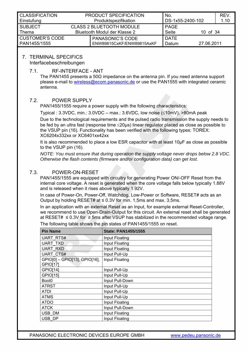
7.3. POWER-ON-RESET PAN1455/1555 are equipped with circuitry for generating Power ON/-OFF Reset from the internal core voltage. A reset is generated when the core voltage falls below typically 1.88V and is released when it rises above typically 1.92V. In case of Power-On, Power-Off, Watchdog, Low-Power or Software, RESET# acts as an Output by holding RESET# at ≤ 0.3V for min. 1,5ms and max. 3,5ms. In an application with an external Reset as an Input, for example external Reset-Controller, we recommend to use Open-Drain-Output for this circuit. An external reset shall be generated at RESET# ≤ 0.3V for ≥ 5ms after VSUP has stabilized in the recommended voltage range. The following table shows the pin states of PAN1455/1555 on reset. Pin Name State: PAN1455/1555 UART_RTS# Input Floating UART_TXD Input Floating UART_RXD Input Floating UART_CTS# Input Pull-Up GPIO[0] – GPIO[13], GPIO[16], GPIO[17]
Input Floating
GPIO[14] Input Pull-Up GPIO[15] Input Pull-Up Boot0 Input Pull-Down ATRST Input Pull-Up ATDI Input Pull-Up ATMS Input Pull-Up ATDO Input Floating ATCK Input Pull-Down USB_DM Input Floating USB_DP Input Floating
CLASSIFICATION Einstufung
PRODUCT SPECIFICATION Produktspezifikation
No. DS-1x55-2400-102
REV. 1.10
SUBJECT Thema
CLASS 2 BLUETOOTH MODULE Bluetooth Modul der Klasse 2
PAGE Seite
11 of 34
CUSTOMER’S CODE PAN1455/1555
PANASONIC’S CODE ENW89815CxKF/ENW89815AxKF
DATE Datum
27.06.2011
PANASONIC ELECTRONIC DEVICES EUROPE GMBH www.pedeu.pansonic.de
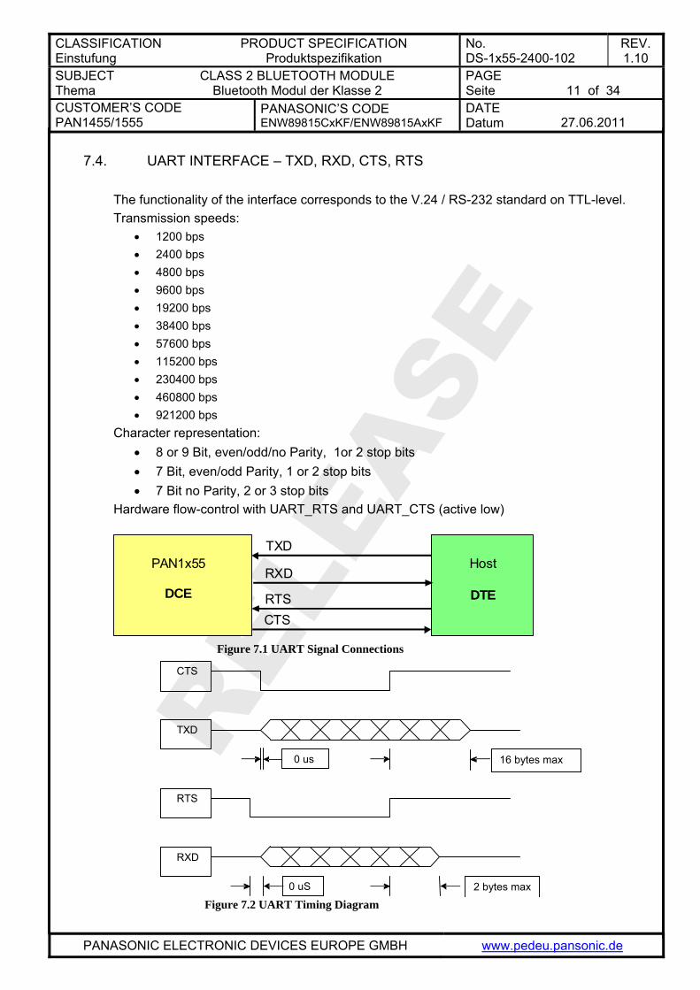
7.4. UART INTERFACE – TXD, RXD, CTS, RTS The functionality of the interface corresponds to the V.24 / RS-232 standard on TTL-level. Transmission speeds:
• 1200 bps • 2400 bps • 4800 bps • 9600 bps • 19200 bps • 38400 bps • 57600 bps • 115200 bps • 230400 bps • 460800 bps • 921200 bps
Character representation: • 8 or 9 Bit, even/odd/no Parity, 1or 2 stop bits • 7 Bit, even/odd Parity, 1 or 2 stop bits • 7 Bit no Parity, 2 or 3 stop bits
Hardware flow-control with UART_RTS and UART_CTS (active low)
PAN1x55
DCE
Host
DTE
TXD
RXD
RTSCTS
Figure 7.1 UART Signal Connections
CTS
TXD
16 bytes max 0 us
RTS
RXD
2 bytes max 0 uS Figure 7.2 UART Timing Diagram
CLASSIFICATION Einstufung
PRODUCT SPECIFICATION Produktspezifikation
No. DS-1x55-2400-102
REV. 1.10
SUBJECT Thema
CLASS 2 BLUETOOTH MODULE Bluetooth Modul der Klasse 2
PAGE Seite
12 of 34
CUSTOMER’S CODE PAN1455/1555
PANASONIC’S CODE ENW89815CxKF/ENW89815AxKF
DATE Datum
27.06.2011
PANASONIC ELECTRONIC DEVICES EUROPE GMBH www.pedeu.pansonic.de
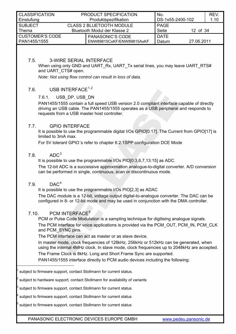
7.5. 3-WIRE SERIAL INTERFACE
When using only GND and UART_Rx, UART_Tx serial lines, you may leave UART_RTS# and UART_CTS# open. Note: Not using flow control can result in loss of data.
7.6. USB INTERFACE1,2 7.6.1. USB_DP, USB_DN PAN1455/1555 contain a full speed USB version 2.0 compliant interface capable of directly driving an USB cable. The PAN1455/1555 operates as a USB peripheral and responds to requests from a USB master host controller.
7.7. GPIO INTERFACE It is possible to use the programmable digital I/Os GPIO[0:17]. The Current from GPIO[17] is limited to 3mA max. For 5V tolerant GPIO´s refer to chapter 6.2.1 SPP configuration DCE Mode
7.8. ADC3 It is possible to use the programmable I/Os PIO[0:3,6,7,13:15] as ADC. The 12-bit ADC is a successive approximation analogue-to-digital converter. A/D conversion can be performed in single, continuous, scan or discontinuous mode.
7.9. DAC4 It is possible to use the programmable I/Os PIO[2,3] as ADAC The DAC module is a 12-bit, voltage output digital-to-analogue converter. The DAC can be configured in 8- or 12-bit mode and may be used in conjunction with the DMA controller.
7.10. PCM INTERFACE5 PCM or Pulse Code Modulation is a sampling technique for digitising analogue signals. The PCM interface for voice applications is provided via the PCM_OUT, PCM_IN, PCM_CLK and PCM_SYNC pins. The PCM interface can act as master or as slave device. In master mode, clock frequencies of 128kHz, 256kHz or 512kHz can be generated, when using the internal 4MHz clock. In slave mode, clock frequencies up to 2048kHz are accepted. The Frame Clock is 8kHz. Long and Short Frame Sync are supported. PAN1455/1555 interface directly to PCM audio devices including the following:
1 subject to firmware support, contact Stollmann for current status. 2 subject to hardware support, contact Stollmann for availability of variants 3 subject to firmware support, contact Stollmann for current status 4 subject to firmware support, contact Stollmann for current status 5 subject to firmware support, contact Stollmann for current status
CLASSIFICATION Einstufung
PRODUCT SPECIFICATION Produktspezifikation
No. DS-1x55-2400-102
REV. 1.10
SUBJECT Thema
CLASS 2 BLUETOOTH MODULE Bluetooth Modul der Klasse 2
PAGE Seite
13 of 34
CUSTOMER’S CODE PAN1455/1555
PANASONIC’S CODE ENW89815CxKF/ENW89815AxKF
DATE Datum
27.06.2011
PANASONIC ELECTRONIC DEVICES EUROPE GMBH www.pedeu.pansonic.de
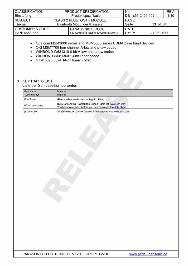
• Qualcom MSM3000 series and MSM5000 series CDMA base band devices • OKI MSM7705 four channel A-law and µ-law codec • WINBOND W681310 8-bit A-law and µ-law codec • WINBOND W681360 13-bit linear codec • STW 5093 5094 14-bit linear codec
8. KEY PARTS LIST Liste der Schlüsselkomponenten
Part Name Teilenummer
Material Material
P.W.Board Glass cloth epoxide resin with gold plating
BT-IC part name BC63B239A04Q (Cambridge Silicon Radio Ltd www.csr.com) You have to register, before you can download the data sheet.
µ-Controller ST32F103xxxx (Cortex baseed STMiroelectronics www.stm.com)
CLASSIFICATION Einstufung
PRODUCT SPECIFICATION Produktspezifikation
No. DS-1x55-2400-102
REV. 1.10
SUBJECT Thema
CLASS 2 BLUETOOTH MODULE Bluetooth Modul der Klasse 2
PAGE Seite
14 of 34
CUSTOMER’S CODE PAN1455/1555
PANASONIC’S CODE ENW89815CxKF/ENW89815AxKF
DATE Datum
27.06.2011
PANASONIC ELECTRONIC DEVICES EUROPE GMBH www.pedeu.pansonic.de
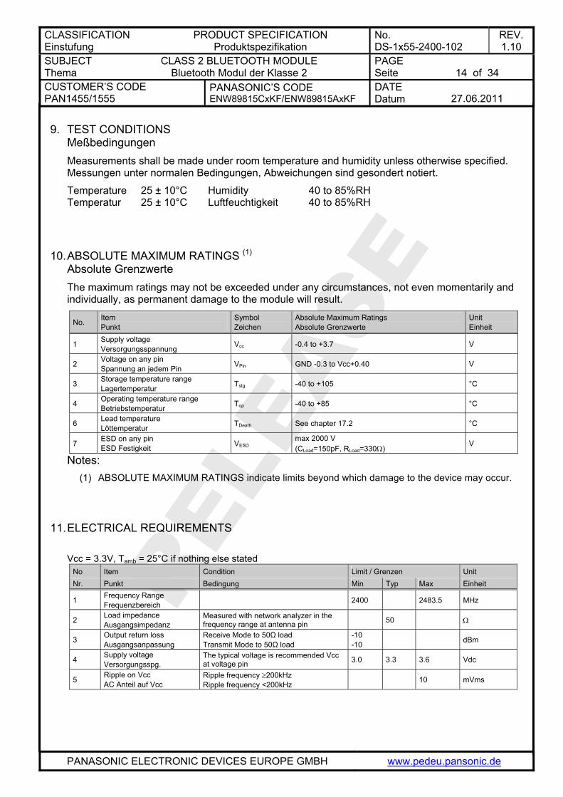
9. TEST CONDITIONS Meßbedingungen Measurements shall be made under room temperature and humidity unless otherwise specified. Messungen unter normalen Bedingungen, Abweichungen sind gesondert notiert.
Temperature 25 ± 10°C Humidity 40 to 85%RH Temperatur 25 ± 10°C Luftfeuchtigkeit 40 to 85%RH
10. ABSOLUTE MAXIMUM RATINGS (1) Absolute Grenzwerte The maximum ratings may not be exceeded under any circumstances, not even momentarily and individually, as permanent damage to the module will result.
No. Item Punkt
Symbol Zeichen
Absolute Maximum Ratings Absolute Grenzwerte
Unit Einheit
1 Supply voltage Versorgungsspannung Vcc -0.4 to +3.7 V
2 Voltage on any pin Spannung an jedem Pin VPin GND -0.3 to Vcc+0.40 V
3 Storage temperature range Lagertemperatur Tstg -40 to +105 °C
4 Operating temperature range Betriebstemperatur Top -40 to +85 °C
6 Lead temperature Löttemperatur TDeath See chapter 17.2 °C
7 ESD on any pin ESD Festigkeit VESD
max 2000 V (CLoad=150pF, RLoad=330Ω)
V
Notes: (1) ABSOLUTE MAXIMUM RATINGS indicate limits beyond which damage to the device may occur.
11. ELECTRICAL REQUIREMENTS Vcc = 3.3V, Tamb = 25°C if nothing else stated
No Item Condition Limit / Grenzen Unit Nr. Punkt Bedingung Min Typ Max Einheit
1 Frequency Range Frequenzbereich 2400 2483.5 MHz
2 Load impedance Ausgangsimpedanz
Measured with network analyzer in the frequency range at antenna pin 50 Ω
3 Output return loss Ausgangsanpassung
Receive Mode to 50Ω load Transmit Mode to 50Ω load
-10 -10 dBm
4 Supply voltage Versorgungsspg.
The typical voltage is recommended Vcc at voltage pin 3.0 3.3 3.6 Vdc
5 Ripple on Vcc AC Anteil auf Vcc
Ripple frequency ≥200kHz Ripple frequency <200kHz
10 mVms
CLASSIFICATION Einstufung
PRODUCT SPECIFICATION Produktspezifikation
No. DS-1x55-2400-102
REV. 1.10
SUBJECT Thema
CLASS 2 BLUETOOTH MODULE Bluetooth Modul der Klasse 2
PAGE Seite
15 of 34
CUSTOMER’S CODE PAN1455/1555
PANASONIC’S CODE ENW89815CxKF/ENW89815AxKF
DATE Datum
27.06.2011
PANASONIC ELECTRONIC DEVICES EUROPE GMBH www.pedeu.pansonic.de
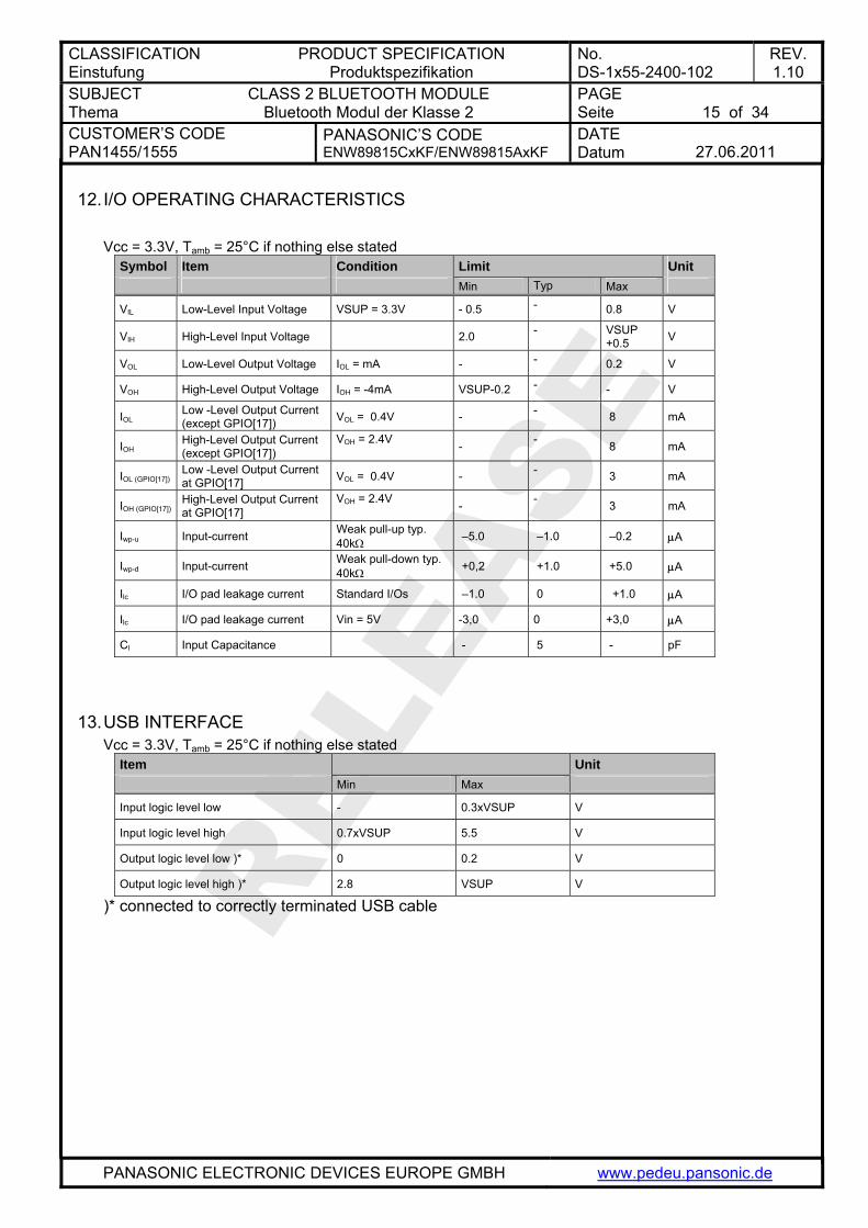
12. I/O OPERATING CHARACTERISTICS Vcc = 3.3V, Tamb = 25°C if nothing else stated
Symbol Item Condition Limit Unit Min Typ Max
VIL Low-Level Input Voltage VSUP = 3.3V - 0.5 - 0.8 V
VIH High-Level Input Voltage 2.0 - VSUP +0.5 V
VOL Low-Level Output Voltage IOL = mA - - 0.2 V
VOH High-Level Output Voltage IOH = -4mA VSUP-0.2 - - V
IOL Low -Level Output Current (except GPIO[17]) VOL = 0.4V - - 8 mA
IOH High-Level Output Current (except GPIO[17])
VOH = 2.4V - - 8 mA
IOL (GPIO[17]) Low -Level Output Current at GPIO[17] VOL = 0.4V - - 3 mA
IOH (GPIO[17]) High-Level Output Current at GPIO[17]
VOH = 2.4V - - 3 mA
Iwp-u Input-current Weak pull-up typ. 40kΩ –5.0 –1.0 –0.2 μA
Iwp-d Input-current Weak pull-down typ. 40kΩ +0,2 +1.0 +5.0 μA
Ilc I/O pad leakage current Standard I/Os –1.0 0 +1.0 μA
Ilc I/O pad leakage current Vin = 5V -3,0 0 +3,0 μA
Cl Input Capacitance - 5 - pF
13. USB INTERFACE Vcc = 3.3V, Tamb = 25°C if nothing else stated
Item Unit Min Max
Input logic level low - 0.3xVSUP V
Input logic level high 0.7xVSUP 5.5 V
Output logic level low )* 0 0.2 V
Output logic level high )* 2.8 VSUP V
)* connected to correctly terminated USB cable
CLASSIFICATION Einstufung
PRODUCT SPECIFICATION Produktspezifikation
No. DS-1x55-2400-102
REV. 1.10
SUBJECT Thema
CLASS 2 BLUETOOTH MODULE Bluetooth Modul der Klasse 2
PAGE Seite
16 of 34
CUSTOMER’S CODE PAN1455/1555
PANASONIC’S CODE ENW89815CxKF/ENW89815AxKF
DATE Datum
27.06.2011
PANASONIC ELECTRONIC DEVICES EUROPE GMBH www.pedeu.pansonic.de
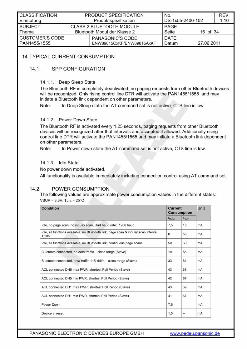
14. TYPICAL CURRENT CONSUMPTION
14.1. SPP CONFIGURATION
14.1.1. Deep Sleep State The Bluetooth RF is completely deactivated, no paging requests from other Bluetooth devices will be recognized. Only rising control line DTR will activate the PAN1455/1555 and may initiate a Bluetooth link dependent on other parameters. Note: In Deep Sleep state the AT command set is not active, CTS line is low.
14.1.2. Power Down State The Bluetooth RF is activated every 1.25 seconds, paging requests from other Bluetooth devices will be recognized after that intervals and accepted if allowed. Additionally rising control line DTR will activate the PAN1455/1555 and may initiate a Bluetooth link dependent on other parameters. Note: In Power down state the AT command set is not active, CTS line is low.
14.1.3. Idle State No power down mode activated. All functionality is available immediately including connection control using AT command set.
14.2. POWER CONSUMPTION The following values are approximate power consumption values in the different states: VSUP = 3.3V, Tamb = 25°C
Current Consumption
Condition
IMEAN IPEAK
Unit
Idle, no page scan, no inquiry scan, Uart baud rate: 1200 baud 7,5 15 mA
Idle, all functions available, no Bluetooth link, page scan & inquiry scan interval 1,28s 8 56 mA
Idle, all functions available, no Bluetooth link, continuous page scans 50 60 mA
Bluetooth connected, no data traffic – close range (Slave) 10 56 mA
Bluetooth connected, data traffic 115 kbit/s – close range (Slave) 33 61 mA
ACL connected DH5 max PWR, shortest Poll Period (Slave) 43 68 mA
ACL connected DH5 min PWR, shortest Poll Period (Slave) 42 67 mA
ACL connected DH1 max PWR, shortest Poll Period (Slave) 43 69 mA
ACL connected DH1 min PWR, shortest Poll Period (Slave) 41 67 mA
Power Down 7,5 -- mA
Device in reset 1,5 -- mA
CLASSIFICATION Einstufung
PRODUCT SPECIFICATION Produktspezifikation
No. DS-1x55-2400-102
REV. 1.10
SUBJECT Thema
CLASS 2 BLUETOOTH MODULE Bluetooth Modul der Klasse 2
PAGE Seite
17 of 34
CUSTOMER’S CODE PAN1455/1555
PANASONIC’S CODE ENW89815CxKF/ENW89815AxKF
DATE Datum
27.06.2011
PANASONIC ELECTRONIC DEVICES EUROPE GMBH www.pedeu.pansonic.de
14.3. POWER-UP TIME The time until the PAN1455/1555 is able to accept link requests or serial data depends on the firmware version and the software parameters RSTTIM and RSTMSG. In the SPP firmware version 1.001 the module is command ready after at least 0,3s (RSTTIM=3 / RSTMSG=0) and 2,16s (RSTTIM=40 / RSTMSG=1) maximum. Bluetooth links are accepted 2,3s after reset.
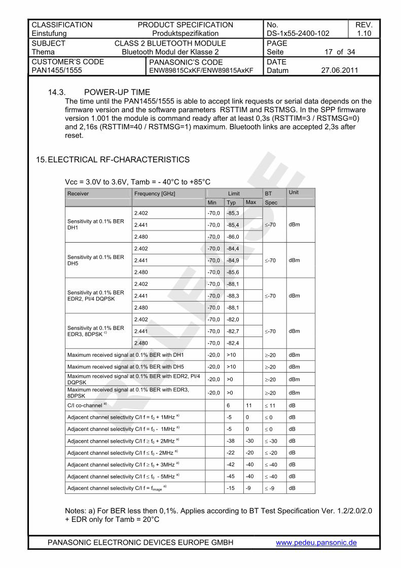
15. ELECTRICAL RF-CHARACTERISTICS
Vcc = 3.0V to 3.6V, Tamb = - 40°C to +85°C Receiver Frequency [GHz] Limit BT Unit
Min Typ Max Spec
2.402 -70,0 -85,3
2.441 -70,0 -85,4 Sensitivity at 0.1% BER DH1
2.480 -70,0 -86,0
≤-70 dBm
2.402 -70,0 -84,4
2.441 -70,0 -84,9 Sensitivity at 0.1% BER DH5
2.480 -70,0 -85,6
≤-70 dBm
2.402 -70,0 -88,1
2.441 -70,0 -88,3 Sensitivity at 0.1% BER EDR2, PI/4 DQPSK
2.480 -70,0 -88,1
≤-70 dBm
2.402 -70,0 -82,0
2.441 -70,0 -82,7 Sensitivity at 0.1% BER EDR3, 8DPSK c)
2.480 -70,0 -82,4
≤-70 dBm
Maximum received signal at 0.1% BER with DH1 -20,0 >10 ≥-20 dBm
Maximum received signal at 0.1% BER with DH5 -20,0 >10 ≥-20 dBm
Maximum received signal at 0.1% BER with EDR2, PI/4 DQPSK -20,0 >0 ≥-20 dBm
Maximum received signal at 0.1% BER with EDR3, 8DPSK -20,0 >0 ≥-20 dBm
C/I co-channel a) 6 11 ≤ 11 dB
Adjacent channel selectivity C/I f = f0 + 1MHz a) -5 0 ≤ 0 dB
Adjacent channel selectivity C/I f = f0 - 1MHz a) -5 0 ≤ 0 dB
Adjacent channel selectivity C/I f ≥ f0 + 2MHz a) -38 -30 ≤ -30 dB
Adjacent channel selectivity C/I f ≤ f0 - 2MHz a) -22 -20 ≤ -20 dB
Adjacent channel selectivity C/I f ≥ f0 + 3MHz a) -42 -40 ≤ -40 dB
Adjacent channel selectivity C/I f ≤ f0 - 5MHz a) -45 -40 ≤ -40 dB
Adjacent channel selectivity C/I f = fimage a) -15 -9 ≤ -9 dB
Notes: a) For BER less then 0,1%. Applies according to BT Test Specification Ver. 1.2/2.0/2.0 + EDR only for Tamb = 20°C
CLASSIFICATION Einstufung
PRODUCT SPECIFICATION Produktspezifikation
No. DS-1x55-2400-102
REV. 1.10
SUBJECT Thema
CLASS 2 BLUETOOTH MODULE Bluetooth Modul der Klasse 2
PAGE Seite
18 of 34
CUSTOMER’S CODE PAN1455/1555
PANASONIC’S CODE ENW89815CxKF/ENW89815AxKF
DATE Datum
27.06.2011
PANASONIC ELECTRONIC DEVICES EUROPE GMBH www.pedeu.pansonic.de
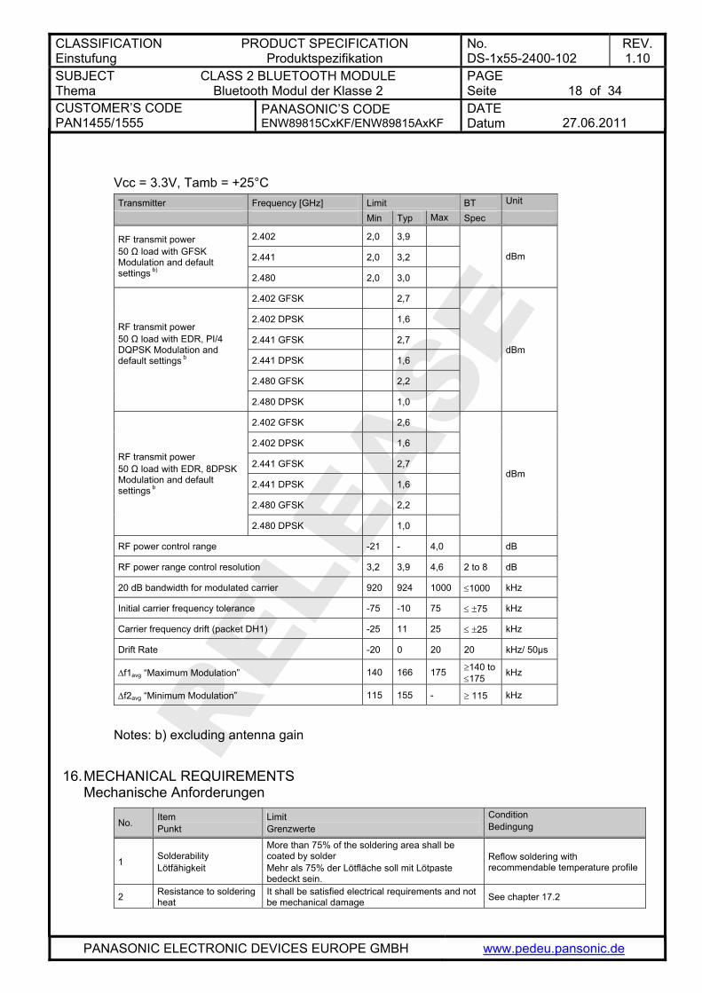
Vcc = 3.3V, Tamb = +25°C Transmitter Frequency [GHz] Limit BT Unit
Min Typ Max Spec
2.402 2,0 3,9
2.441 2,0 3,2
RF transmit power 50 Ω load with GFSK Modulation and default settings b) 2.480 2,0 3,0
dBm
2.402 GFSK 2,7
2.402 DPSK 1,6
2.441 GFSK 2,7
2.441 DPSK 1,6
2.480 GFSK 2,2
RF transmit power 50 Ω load with EDR, PI/4 DQPSK Modulation and default settings b
2.480 DPSK 1,0
dBm
2.402 GFSK 2,6
2.402 DPSK 1,6
2.441 GFSK 2,7
2.441 DPSK 1,6
2.480 GFSK 2,2
RF transmit power 50 Ω load with EDR, 8DPSK Modulation and default settings b
2.480 DPSK 1,0
dBm
RF power control range -21 - 4,0 dB
RF power range control resolution 3,2 3,9 4,6 2 to 8 dB
20 dB bandwidth for modulated carrier 920 924 1000 ≤1000 kHz
Initial carrier frequency tolerance -75 -10 75 ≤ ±75 kHz
Carrier frequency drift (packet DH1) -25 11 25 ≤ ±25 kHz
Drift Rate -20 0 20 20 kHz/ 50µs
Δf1avg “Maximum Modulation” 140 166 175 ≥140 to ≤175 kHz
Δf2avg “Minimum Modulation” 115 155 - ≥ 115 kHz
Notes: b) excluding antenna gain
16. MECHANICAL REQUIREMENTS Mechanische Anforderungen
No. Item Punkt
Limit Grenzwerte
Condition Bedingung
1 Solderability Lötfähigkeit
More than 75% of the soldering area shall be coated by solder Mehr als 75% der Lötfläche soll mit Lötpaste bedeckt sein.
Reflow soldering with recommendable temperature profile
2 Resistance to soldering heat
It shall be satisfied electrical requirements and not be mechanical damage See chapter 17.2
CLASSIFICATION Einstufung
PRODUCT SPECIFICATION Produktspezifikation
No. DS-1x55-2400-102
REV. 1.10
SUBJECT Thema
CLASS 2 BLUETOOTH MODULE Bluetooth Modul der Klasse 2
PAGE Seite
19 of 34
CUSTOMER’S CODE PAN1455/1555
PANASONIC’S CODE ENW89815CxKF/ENW89815AxKF
DATE Datum
27.06.2011
PANASONIC ELECTRONIC DEVICES EUROPE GMBH www.pedeu.pansonic.de
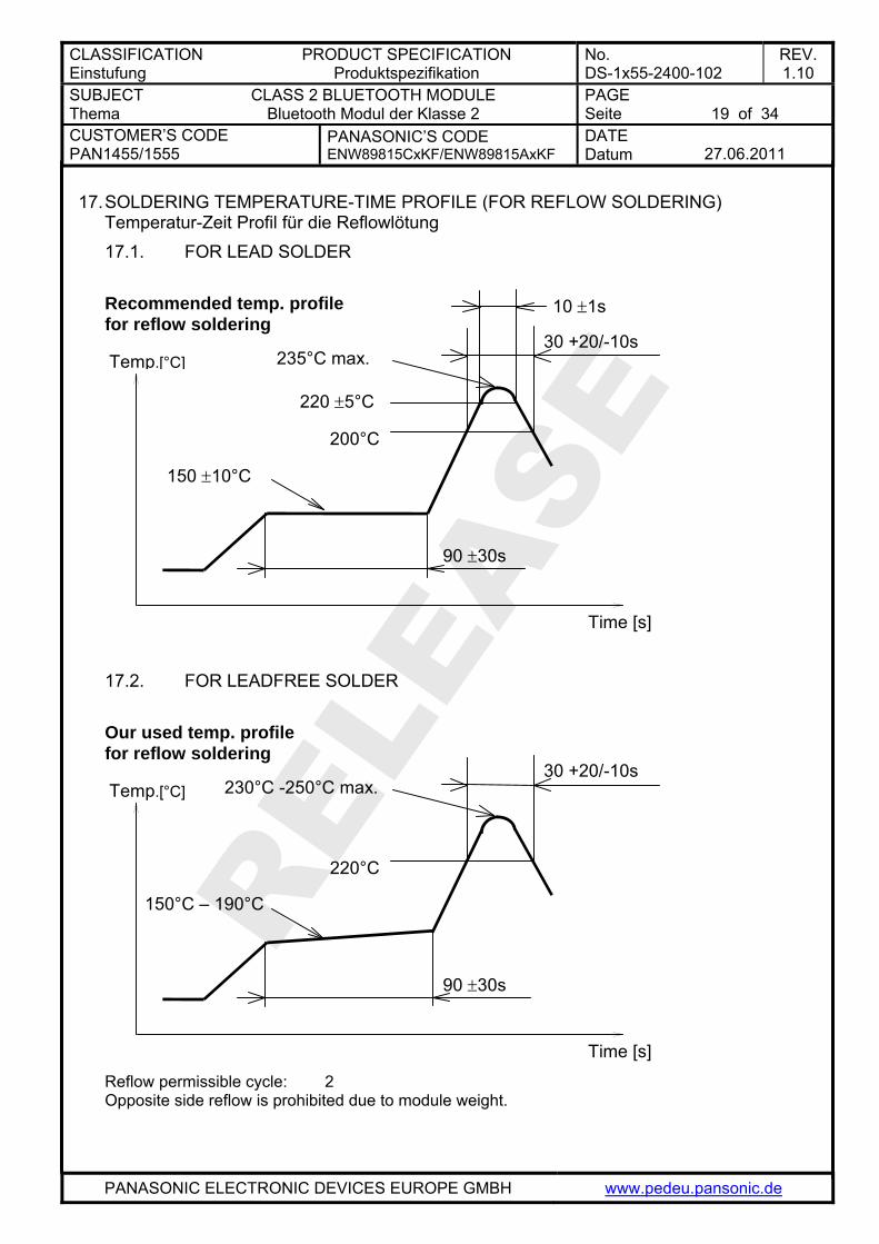
17. SOLDERING TEMPERATURE-TIME PROFILE (FOR REFLOW SOLDERING) Temperatur-Zeit Profil für die Reflowlötung 17.1. FOR LEAD SOLDER
Recommended temp. profile for reflow soldering
Temp.[°C]
Time [s]
235°C max.
220 ±5°C
200°C
150 ±10°C
90 ±30s
10 ±1s
30 +20/-10s
17.2. FOR LEADFREE SOLDER
Our used temp. profile for reflow soldering
Temp.[°C]
Time [s]
230°C -250°C max.
220°C
150°C – 190°C
90 ±30s
30 +20/-10s
Reflow permissible cycle: 2 Opposite side reflow is prohibited due to module weight.
CLASSIFICATION Einstufung
PRODUCT SPECIFICATION Produktspezifikation
No. DS-1x55-2400-102
REV. 1.10
SUBJECT Thema
CLASS 2 BLUETOOTH MODULE Bluetooth Modul der Klasse 2
PAGE Seite
20 of 34
CUSTOMER’S CODE PAN1455/1555
PANASONIC’S CODE ENW89815CxKF/ENW89815AxKF
DATE Datum
27.06.2011
PANASONIC ELECTRONIC DEVICES EUROPE GMBH www.pedeu.pansonic.de
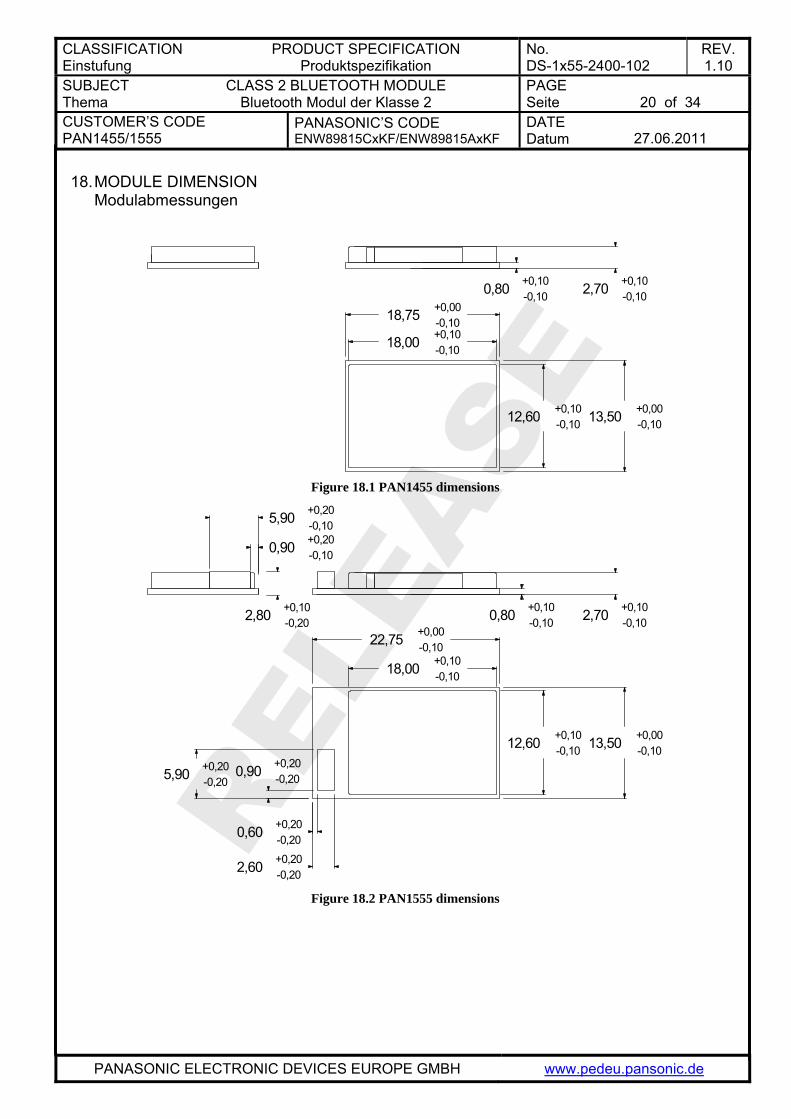
18. MODULE DIMENSION Modulabmessungen
18,00 +0,10-0,10
12,60 +0,10-0,10 13,50 +0,00
-0,10
2,70 +0,10-0,100,80 +0,10
-0,10
18,75 +0,00-0,10
Figure 18.1 PAN1455 dimensions
18,00 +0,10-0,10
22,75 +0,00-0,10
12,60 +0,10-0,10 13,50 +0,00
-0,10
0,90 +0,20-0,205,90 +0,20
-0,20
2,60 +0,20-0,20
0,60 +0,20-0,20
2,70 +0,10-0,100,80 +0,10
-0,102,80 +0,10-0,20
0,90 +0,20-0,10
5,90 +0,20-0,10
Figure 18.2 PAN1555 dimensions
CLASSIFICATION Einstufung
PRODUCT SPECIFICATION Produktspezifikation
No. DS-1x55-2400-102
REV. 1.10
SUBJECT Thema
CLASS 2 BLUETOOTH MODULE Bluetooth Modul der Klasse 2
PAGE Seite
21 of 34
CUSTOMER’S CODE PAN1455/1555
PANASONIC’S CODE ENW89815CxKF/ENW89815AxKF
DATE Datum
27.06.2011
PANASONIC ELECTRONIC DEVICES EUROPE GMBH www.pedeu.pansonic.de
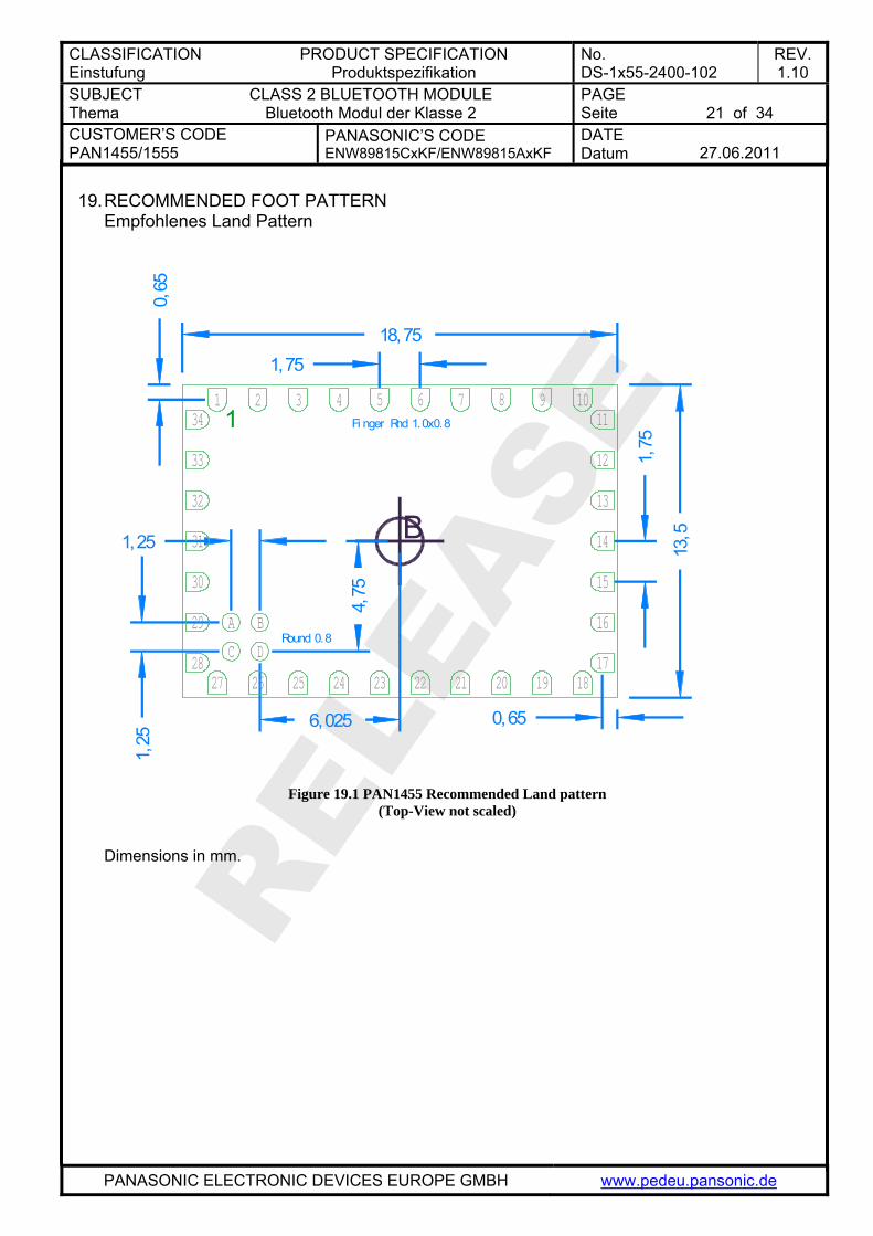
19. RECOMMENDED FOOT PATTERN Empfohlenes Land Pattern
0,65
18,751,75
1
B
4,75
6,025
1,25
1,25
0,65
1,75
13,5
Fi nger Rnd 1.0x0.8
Round 0.8
13
33
32
11
12
14
15
16
34
31
30
29
2824 20 19
A B
C17
5 6 7 8 9 103 421
232526
D
27 22 21 18
Figure 19.1 PAN1455 Recommended Land pattern
(Top-View not scaled)
Dimensions in mm.
CLASSIFICATION Einstufung
PRODUCT SPECIFICATION Produktspezifikation
No. DS-1x55-2400-102
REV. 1.10
SUBJECT Thema
CLASS 2 BLUETOOTH MODULE Bluetooth Modul der Klasse 2
PAGE Seite
22 of 34
CUSTOMER’S CODE PAN1455/1555
PANASONIC’S CODE ENW89815CxKF/ENW89815AxKF
DATE Datum
27.06.2011
PANASONIC ELECTRONIC DEVICES EUROPE GMBH www.pedeu.pansonic.de
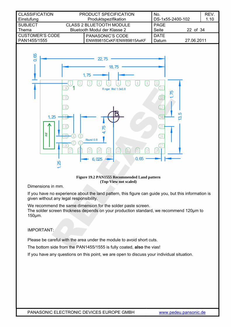
B
1,25
18,75
22,75
4,75
6,025
1,25
1,75
1,75
0,65
0,65
13,5
Fi nger Rnd 1.0x0.8
Round 0.8
13
33
32
11
12
14
15
16
34
31
30
29
2824 20 19
A B
C17
5 6 7 8 9 103 421
23252627 22 21 18
D
1
ANT
Figure 19.2 PAN1555 Recommended Land pattern
(Top-View not scaled) Dimensions in mm.
If you have no experience about the land pattern, this figure can guide you, but this information is given without any legal responsibility.
We recommend the same dimension for the solder paste screen. The solder screen thickness depends on your production standard, we recommend 120µm to 150µm.
IMPORTANT: Please be careful with the area under the module to avoid short cuts.
The bottom side from the P is fully coated, also the vias! AN1455/1555
If you have any questions on this point, we are open to discuss your individual situation.
CLASSIFICATION Einstufung
PRODUCT SPECIFICATION Produktspezifikation
No. DS-1x55-2400-102
REV. 1.10
SUBJECT Thema
CLASS 2 BLUETOOTH MODULE Bluetooth Modul der Klasse 2
PAGE Seite
23 of 34
CUSTOMER’S CODE PAN1455/1555
PANASONIC’S CODE ENW89815CxKF/ENW89815AxKF
DATE Datum
27.06.2011
PANASONIC ELECTRONIC DEVICES EUROPE GMBH www.pedeu.pansonic.de
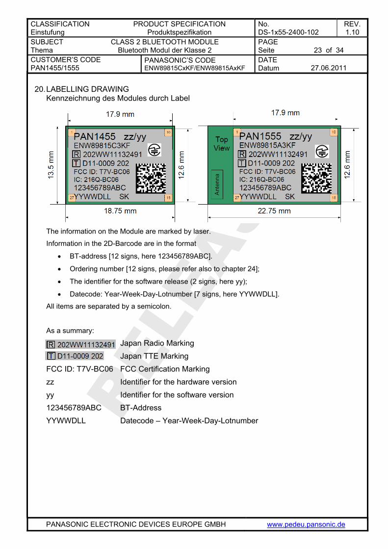
20. LABELLING DRAWING Kennzeichnung des Modules durch Label
The information on the Module are marked by laser.
Information in the 2D-Barcode are in the format
• BT-address [12 signs, here 123456789ABC].
• Ordering number [12 signs, please refer also to chapter 24];
• The identifier for the software release (2 signs, here yy);
• Datecode: Year-Week-Day-Lotnumber [7 signs, here YYWWDLL].
All items are separated by a semicolon.
As a summary: Japan Radio Marking Japan TTE Marking FCC ID: T7V-BC06 FCC Certification Marking zz Identifier for the hardware version yy Identifier for the software version 123456789ABC BT-Address YYWWDLL Datecode – Year-Week-Day-Lotnumber
CLASSIFICATION Einstufung
PRODUCT SPECIFICATION Produktspezifikation
No. DS-1x55-2400-102
REV. 1.10
SUBJECT Thema
CLASS 2 BLUETOOTH MODULE Bluetooth Modul der Klasse 2
PAGE Seite
24 of 34
CUSTOMER’S CODE PAN1455/1555
PANASONIC’S CODE ENW89815CxKF/ENW89815AxKF
DATE Datum
27.06.2011
PANASONIC ELECTRONIC DEVICES EUROPE GMBH www.pedeu.pansonic.de
21. SOFTWARE Software Standard platforms of PAN1455/1555 are avaialble with several popular Bluetooth profiles, many other profiles are availalble on request. Before starting production, be certain to carefully review that the software meets your requirements.
21.1. SPP SOFTWARE Serial Port Profile Customized variants are available on request. Please refer to Reference [1] .
21.2. HDP SOFTWARE The Health Device Profile Please refer to Reference [1] .
21.3. HID SOFTWARE The Human Inteface Device Software Please refer to Reference [1] .
21.4. HDP/SPP SOFTWARE The combined HDP and SPP Profile enables customers to use both versions (SPP/HDP) in parallel. Please refer to Reference [1] .
21.5. OTHER PROFILES ARE AVAILABLE ON REQUEST.
22. CAUTIONS Warnungen Failure to do so may result in degrading of the product’s functions and damage to the product.
22.1. DESIGN NOTES Designhinweise (1) Please follow the condition written in this specification, especially the control
signals of this module. (2) The supply voltage has to be free of ac ripple voltage, as for example from a
battery or a low noise regulator output. For noisy supply voltages provide a decoupling circuit as for example a ferrite in series connection and a blocking capacitor to ground of at least 47uF directly at the module.
(3) This product should not be stressed when installed. (4) Heat is the major cause of shortening the life of these products. Please keep this
product away from heat. Avoid assembly and use of the target equipment in conditions where the products' temperature may exceed the maximum allowable.
(5) The supply voltage should not be exceeding or reverse, and should not carry noise and spike.
(6) Please keep this product away from other high frequency circuits.
CLASSIFICATION Einstufung
PRODUCT SPECIFICATION Produktspezifikation
No. DS-1x55-2400-102
REV. 1.10
SUBJECT Thema
CLASS 2 BLUETOOTH MODULE Bluetooth Modul der Klasse 2
PAGE Seite
25 of 34
CUSTOMER’S CODE PAN1455/1555
PANASONIC’S CODE ENW89815CxKF/ENW89815AxKF
DATE Datum
27.06.2011
PANASONIC ELECTRONIC DEVICES EUROPE GMBH www.pedeu.pansonic.de
22.2. INSTALLATION NOTES Verarbeitungshinweise (1) Reflow soldering is possible for twice on the condition in chapter 15.
Please set up the temperature at the soldering portion of this product according to this reflow profile.
(2) Carefully position the products so that their heat will not burn into printed circuit boards or affect the other components that are susceptible to heat.
(3) Carefully locate these products so that their temperatures will not increase due to the effects of heat generated by neighboring components.
(4) If a vinyl-covered wire comes into contact with the products, then the cover will melt and generate toxic gas, damaging the insulation. Never allow contact between the cover and these products to occur.
(5) This product should not be stressed or vibrated when reflowed. (6) Keep the following conditions when you install this product for reparation by hand
soldering. (7) Do not wash this product. (8) Refer to the recommended pattern when designing a board. (9) Pressing on parts of the metal cover or fastening objects to the metal cover is not
allowed.
22.3. USAGE CONDITIONS NOTES Benutzerhinweise (1) Take measure against static electricity.
If pulses or other transient loads (a large load applied in a short time) are applied to the products, then before use, check and evaluate their operation when assembled on your products.
(2) Do not use the fallen product. (3) Do not put on damage and dirt to the pin , and don't touch the electric components. (4) Be certain to follow the condition written in the ratings , about the power supply
instruments applied to this product. (5) Electrode peeling strength: Do not add pressure of more than 4.9N when soldered
on PCB (6) Pressing on parts of the metal cover or fastening objects to the metal cover is not
allowed. (7) These products are intended for general purpose and standard use in general
electronic equipment, such as home appliances, office equipment, information and communication equipment.
22.4. STORAGE NOTES Lagerhinweise (1) The module may not be stressed mechanically during storage. (2) Do not store these products in the following conditions or the performance
characteristics of the product, such as RF performance will be adversely affected: • Storage in salty air or in an environment with a high concentration of corrosive
gas, such as Cl2, H2S, NH3, SO2, or NOX • Storage in direct sunlight • Storage in an environment where the temperature may be outside the range of
5°C to 35°C range, or where the humidity may be outside the 45 to 85% range.
CLASSIFICATION Einstufung
PRODUCT SPECIFICATION Produktspezifikation
No. DS-1x55-2400-102
REV. 1.10
SUBJECT Thema
CLASS 2 BLUETOOTH MODULE Bluetooth Modul der Klasse 2
PAGE Seite
26 of 34
CUSTOMER’S CODE PAN1455/1555
PANASONIC’S CODE ENW89815CxKF/ENW89815AxKF
DATE Datum
27.06.2011
PANASONIC ELECTRONIC DEVICES EUROPE GMBH www.pedeu.pansonic.de
• Storage of the products for more than one year after the date of delivery at your company if the avoidance all the above conditions (1) to (3) have been met.
(3) Storage period: Please check the adhesive strength of the embossed tape and soldering after 6 months of storage.
(4) Please keep this product away from water, poisonous gas and corrosive gas. (5) This product should not be stressed or shocked when transported. (6) Please follow the specification when piling up the packed crate ( max. 10).
22.5. SAFETY CAUTIONS Sicherheitshinweise These specifications are intended to preserve the quality assurance of products as individual components. Before use, check and evaluate their operation when mounted on your products. Abide by these specifications, without deviation when using the products. These products may short-circuit. If electrical shocks, smoke, fire, and/or accidents involving human life are anticipated when a short circuit occurs, then at least, provide the following failsafe functions, as a minimum. (1) Ensure the safety of the whole system by installing a protection circuit and a
protection device. (2) Ensure the safety of the whole system by installing a redundant circuit or another
system to prevent a single fault causing an unsafe status.
CLASSIFICATION Einstufung
PRODUCT SPECIFICATION Produktspezifikation
No. DS-1x55-2400-102
REV. 1.10
SUBJECT Thema
CLASS 2 BLUETOOTH MODULE Bluetooth Modul der Klasse 2
PAGE Seite
27 of 34
CUSTOMER’S CODE PAN1455/1555
PANASONIC’S CODE ENW89815CxKF/ENW89815AxKF
DATE Datum
27.06.2011
PANASONIC ELECTRONIC DEVICES EUROPE GMBH www.pedeu.pansonic.de
22.6. OTHER CAUTIONS Weitere Hinweise (1) This specification sheet is copyrighted. Please do not open it to the third party. (2) Do not use this product of our company for another purpose. (3) Be sure to provide an appropriate fail-safe function on your product to prevent a
second damage that may be caused by the abnormal function or the failure of our product.
(4) This product has not been manufactured with any ozone chemical controlled under the Montreal Protocol.
(5) These products are not intended for other uses, other than under the special conditions shown below. Before using these products under such special conditions, check their performance and reliability under the said special conditions carefully to determine whether or not they can be used in such a manner.
• In liquid, such as water, salt water, oil, alkali, or organic solvent, or in places where liquid may splash.
• In direct sunlight, outdoors, or in a dusty environment • In an environment where condensation occurs. • In an environment with a high concentration of harmful gas (e.g. salty air, HCl,
Cl2, SO2, H2S, NH3, and NOX) (6) If an abnormal voltage is applied due to a problem occurring in other components
or circuits, replace these products with new products because they may not be able to provide normal performance even if their electronic characteristics and appearances appear satisfactory.
(7) When you have any question or uncertainty , both of you and Panasonic sincerely cope with it.
CLASSIFICATION Einstufung
PRODUCT SPECIFICATION Produktspezifikation
No. DS-1x55-2400-102
REV. 1.10
SUBJECT Thema
CLASS 2 BLUETOOTH MODULE Bluetooth Modul der Klasse 2
PAGE Seite
28 of 34
CUSTOMER’S CODE PAN1455/1555
PANASONIC’S CODE ENW89815CxKF/ENW89815AxKF
DATE Datum
27.06.2011
PANASONIC ELECTRONIC DEVICES EUROPE GMBH www.pedeu.pansonic.de
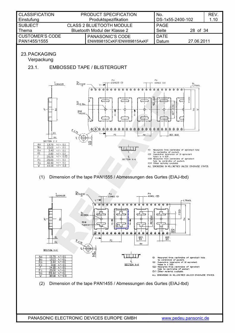
23. PACKAGING Verpackung 23.1. EMBOSSED TAPE / BLISTERGURT
(1) Dimension of the tape PAN1555 / Abmessungen des Gurtes (EIAJ-tbd)
(2) Dimension of the tape PAN1455 / Abmessungen des Gurtes (EIAJ-tbd)
CLASSIFICATION Einstufung
PRODUCT SPECIFICATION Produktspezifikation
No. DS-1x55-2400-102
REV. 1.10
SUBJECT Thema
CLASS 2 BLUETOOTH MODULE Bluetooth Modul der Klasse 2
PAGE Seite
29 of 34
CUSTOMER’S CODE PAN1455/1555
PANASONIC’S CODE ENW89815CxKF/ENW89815AxKF
DATE Datum
27.06.2011
PANASONIC ELECTRONIC DEVICES EUROPE GMBH www.pedeu.pansonic.de
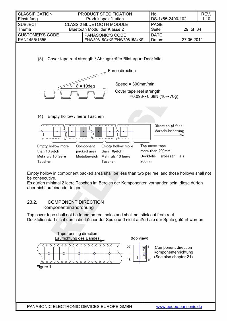
(3) Cover tape reel strength / Abzugskräfte Blistergurt Deckfolie
Force direction
Speed = 300mm/min.
Cover tape reel strength =0.098~0.68N (10~70g)
θ= 10deg
(4) Empty hollow / leere Taschen
Empty hollow in component packed area shall be less than two per reel and those hollows shall not be consecutive. Es dürfen minimal 2 leere Taschen im Bereich der Komponenten vorhanden sein, diese dürfen aber nicht aufeinander folgen.
Empty hollow more
than 10 pitch
Mehr als 10 leere
Taschen
Component
packed area
Modulbereich
Empty hollow more
than 10pitch
Mehr als 10 leere
Taschen
Top cover tape
more than 200mm
Deckfolie groesser als
200mm
Direction of feed
Vorschubrichtung
23.2. COMPONENT DIRECTION Komponentenanordnung
Top cover tape shall not be found on reel holes and shall not stick out from reel. Deckfolien darf nicht durch die Löcher der Spule und nicht außerhalb der Spule geführt werden.
(top view
10
1 27
18
Part N
o.
Tape running direction Laufrichtung des Bandes )
Component direction Komponentenrichtung (See also chapter 21)
Figure 1
CLASSIFICATION Einstufung
PRODUCT SPECIFICATION Produktspezifikation
No. DS-1x55-2400-102
REV. 1.10
SUBJECT Thema
CLASS 2 BLUETOOTH MODULE Bluetooth Modul der Klasse 2
PAGE Seite
30 of 34
CUSTOMER’S CODE PAN1455/1555
PANASONIC’S CODE ENW89815CxKF/ENW89815AxKF
DATE Datum
27.06.2011
PANASONIC ELECTRONIC DEVICES EUROPE GMBH www.pedeu.pansonic.de
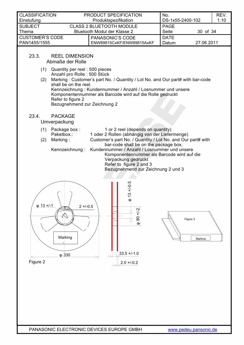
23.3. REEL DIMENSION Abmaße der Rolle (1) Quantity per reel : 500 pieces
Anzahl pro Rolle : 500 Stück (2) Marking : Customer’s part No. / Quantity / Lot No. and Our part# with bar-code
shall be on the reel. Kennzeichnung : Kundennummer / Anzahl / Losnummer und unsere Komponentennummer als Barcode wird auf die Rolle gedruckt Refer to figure 2 Bezugnehmend zur Zeichnung 2
23.4. PACKAGE
Umverpackung (1) Package box : 1 or 2 reel (depends on quantity)
Paketbox.: 1 oder 2 Rollen (abhängig von der Liefermenge) (2) Marking : Customer’s part No. / Quantity / Lot No. and Our part# with
bar-code shall be on the package box. Kennzeichnung : Kundennummer / Anzahl / Losnummer und unsere Komponentennummer als Barcode wird auf die Verpackung gedruckt Refer to figure 2 and 3 Bezugnehmend zur Zeichnung 2 und 3
φ 13 +/-1 2 +/-0.5
φ 330
Marking ?
33.5 +/-1.0
2.0 +/-0.2
φ13
+/-0
.5
φ80
+/-2
Figure 2
Marking
Figure 3
CLASSIFICATION Einstufung
PRODUCT SPECIFICATION Produktspezifikation
No. DS-1x55-2400-102
REV. 1.10
SUBJECT Thema
CLASS 2 BLUETOOTH MODULE Bluetooth Modul der Klasse 2
PAGE Seite
31 of 34
CUSTOMER’S CODE PAN1455/1555
PANASONIC’S CODE ENW89815CxKF/ENW89815AxKF
DATE Datum
27.06.2011
PANASONIC ELECTRONIC DEVICES EUROPE GMBH www.pedeu.pansonic.de
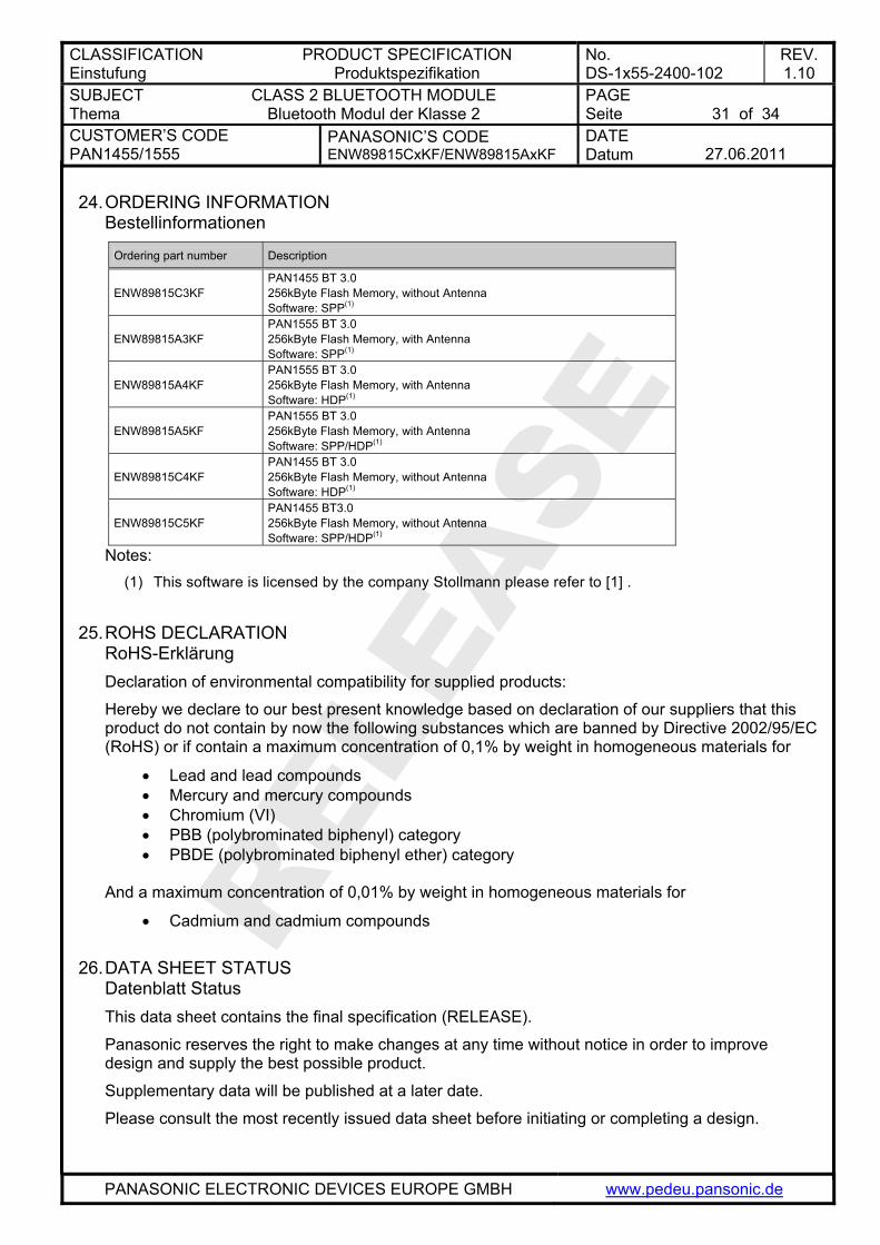
24. ORDERING INFORMATION Bestellinformationen
Ordering part number Description
ENW89815C3KF PAN1455 BT 3.0 256kByte Flash Memory, without Antenna Software: SPP(1)
ENW89815A3KF PAN1555 BT 3.0 256kByte Flash Memory, with Antenna Software: SPP(1)
ENW89815A4KF PAN1555 BT 3.0 256kByte Flash Memory, with Antenna Software: HDP(1)
ENW89815A5KF PAN1555 BT 3.0 256kByte Flash Memory, with Antenna Software: SPP/HDP(1)
ENW89815C4KF PAN1455 BT 3.0 256kByte Flash Memory, without Antenna Software: HDP(1)
ENW89815C5KF PAN1455 BT3.0 256kByte Flash Memory, without Antenna Software: SPP/HDP(1)
Notes: (1) This software is licensed by the company Stollmann please refer to [1] .
25. ROHS DECLARATION RoHS-Erklärung Declaration of environmental compatibility for supplied products:
Hereby we declare to our best present knowledge based on declaration of our suppliers that this product do not contain by now the following substances which are banned by Directive 2002/95/EC (RoHS) or if contain a maximum concentration of 0,1% by weight in homogeneous materials for
• Lead and lead compounds • Mercury and mercury compounds • Chromium (VI) • PBB (polybrominated biphenyl) category • PBDE (polybrominated biphenyl ether) category
And a maximum concentration of 0,01% by weight in homogeneous materials for
• Cadmium and cadmium compounds
26. DATA SHEET STATUS Datenblatt Status This data sheet contains the final specification (RELEASE).
Panasonic reserves the right to make changes at any time without notice in order to improve design and supply the best possible product.
Supplementary data will be published at a later date.
Please consult the most recently issued data sheet before initiating or completing a design.
CLASSIFICATION Einstufung
PRODUCT SPECIFICATION Produktspezifikation
No. DS-1x55-2400-102
REV. 1.10
SUBJECT Thema
CLASS 2 BLUETOOTH MODULE Bluetooth Modul der Klasse 2
PAGE Seite
32 of 34
CUSTOMER’S CODE PAN1455/1555
PANASONIC’S CODE ENW89815CxKF/ENW89815AxKF
DATE Datum
27.06.2011
PANASONIC ELECTRONIC DEVICES EUROPE GMBH www.pedeu.pansonic.de
27. REGULATORY INFORMATION 27.1. FCC NOTICE
The device PAN1555, including the ceramic antenna and also the SMD type PAN1455, including with the antennas, which are listed in 27.5, complies with Part 15 of the FCC Rules. The device meets the requirements for modular transmitter approval as detailed in FCC public Notice DA00-1407.transmitter Operation is subject to the following two conditions: (1) This device may not cause harmful interference, and (2) This device must accept any interference received, including interference that may cause undesired operation.
27.2. CAUTION The FCC requires the user to be notified that any changes or modifications made to this device that are not expressly approved by Panasonic Electronic Devices Europe GmbH may void the user's authority to operate the equipment. This equipment has been tested and found to comply with the limits for a Class B digital device, pursuant to Part 15 of the FCC Rules. These limits are designed to provide reasonable protection against harmful interference in a residential installation. This equipment generates, uses and can radiate radio frequency energy and, if not installed and used in accordance with the instructions, may cause harmful interference to radio communications. However, there is no guarantee that interference will not occur in a particular installation. If this equipment does cause harmful interference to radio or television reception, which can be determined by turning the equipment off and on, the user is encouraged to try to correct the interference by one or more of the following measures: • Reorient or relocate the receiving antenna. • Increase the separation between the equipment and receiver. • Connect the equipment into an outlet on a circuit different from that to which the
receiver is connected. • Consult the dealer or an experienced radio/TV technician for help
27.3. LABELING REQUIREMENTS The Original Equipment Manufacturer (OEM) must ensure that FCC labeling requirements are met. This includes a clearly visible label on the outside of the OEM enclosure specifying the appropriate Panasonic FCC identifier for this product as well as the FCC Notice above. The FCC identifier are FCC ID: T7V-BC06. This FCC identifier is valid for all versions, for details, please see the chapter 24. Ordering Information. In any case end product must be labelled exterior with "Contains FCC ID: T7V-BC06"
CLASSIFICATION Einstufung
PRODUCT SPECIFICATION Produktspezifikation
No. DS-1x55-2400-102
REV. 1.10
SUBJECT Thema
CLASS 2 BLUETOOTH MODULE Bluetooth Modul der Klasse 2
PAGE Seite
33 of 34
CUSTOMER’S CODE PAN1455/1555
PANASONIC’S CODE ENW89815CxKF/ENW89815AxKF
DATE Datum
27.06.2011
PANASONIC ELECTRONIC DEVICES EUROPE GMBH www.pedeu.pansonic.de
27.4. ANTENNA WARNING The related part number for this device is PAN1455 with SMD pad). For details, please see the chapter 24. Ordering Information. This device are tested with a standard SMA connector and with the antennas listed below. When integrated in the OEMs product, these fixed antennas require installation preventing end-users from replacing them with non-approved antennas. Any antenna exceeding 2dBi not in the following table must be tested to comply with FCC Section 15.203 for unique antenna connectors and Section 15.247 for emissions. The FCC identifier for this device with the antenna listed in item 1 are the same (FCC ID: T7V-BC06).
27.5. APPROVED ANTENNA LIST Note: We are able to qualify your antenna and will add to this list as that process is completed.
Item Part Number Manufacturer Frequency Band Type Gain (dBi)
1 WIMO17010.10 Wimo 2.4GHz ROD +2
2 2450AT42B100 Johanson 2.4GHz SMD -1.5
27.6. RF EXPOSURE PAN1455/PAN1555
To comply with FCC RF Exposure requirements, the Original Equipment Manufacturer (OEM) must ensure that the approved antenna in the previous table must be installed. The preceding statement must be included as a CAUTION statement in manuals for products operating with the approved antennas in the previous table to alert users on FCC RF Exposure compliance. Any notification to the end user of installation or removal instructions about the integrated radio module is not allowed. The radiated output power of PAN1455 with mounted ceramic antenna (FCC ID: T7V-BC06) is far below the FCC radio frequency exposure limits. Nevertheless, the PAN1455 shall be used in such a manner that the potential for human contact during normal operation is minimized. End users may not be provided with the module installation instructions. OEM integrators and end users must be provided with transmitter operating conditions for satisfying RF exposure compliance.
27.7. INDUSTRY CANADA CERTIFICATION PAN1455/PAN1555 comply with the regulatory requirements of Industry canada (IC), license:
IC: 216Q-BC06 Manufacturers of mobile, fixed or portable devices incorporating this module are advised to clarify any regulatory questions and ensure compliance for SAR and/or RF exposure limits. Users can obtain Canadian information on RF exposure and compliance from www.ic.gc.ca This device has been designed to operate with the antenna listed in section 27.5 above, having a maximum gain of 2.0 dBi. Antennas not included in this list or having a gain greater than 2.0 dBi are strictly prohibited for use with this device. The required antenna impedance is 50 ohms. The antenna used for this transmitter must not be colocated or operating in conjunction with any other antenna or transmitter.
CLASSIFICATION Einstufung
PRODUCT SPECIFICATION Produktspezifikation
No. DS-1x55-2400-102
REV. 1.10
SUBJECT Thema
CLASS 2 BLUETOOTH MODULE Bluetooth Modul der Klasse 2
PAGE Seite
34 of 34
CUSTOMER’S CODE PAN1455/1555
PANASONIC’S CODE ENW89815CxKF/ENW89815AxKF
DATE Datum
27.06.2011
PANASONIC ELECTRONIC DEVICES EUROPE GMBH www.pedeu.pansonic.de
28. RELATED DOCUMENTS Mitgeltende Dokumente [1] Stollmann Firmware updates/support:
http://www.stollmann.de/de/support/downloads/bluetooth-adapter/bluemod-p2xg2.html
29. GENERAL INFORMATION Allgemeine Informationen © Panasonic Electronic Devices Europe GmbH 2009. All rights reserved. This product description does not lodge the claim to be complete and free of mistakes. Please contact the related product manager in every case. If we deliver ES samples to the customer, these samples have the status Engineering Samples. This means, the design of this product is not yet concluded. Engineering Samples may be partially or fully functional, and there may be differences to be published Data Sheet. Engineering Samples are not qualified and are not to be used for reliability testing or series production. Disclaimer: Customer acknowledges that samples may deviate from the Data Sheet and may bear defects due to their status of development and the lack of qualification mentioned above. Panasonic rejects any liability or product warranty for Engineering Samples. In particular, Panasonic disclaims liability for damages caused by
• the use of the Engineering Sample other than for Evaluation Purposes, particularly the installation or integration in an other product to be sold by Customer,
• deviation or lapse in function of Engineering Sample, • improper use of Engineering Samples.
Panasonic disclaimes any liability for consequential and incidental damages. In case of any questions, please contact your local sales partner or the related product manager.
30. LIFE SUPPORT POLICY Politik für Lebenserhaltungssysteme This Panasonic product is not designed for use in life support appliances, devices, or systems where malfunction can reasonably be expected to result in a significant personal injury to the user, or as a critical component in any life support device or system whose failure to perform can be reasonably expected to cause the failure of the life support device or system, or to affect its safety or effectiveness. Panasonic customers using or selling these products for use in such applications do so at their own risk and agree to fully indemnify Panasonic for any damages resulting.