Embed Size (px)
Citation preview

Specification for Power Station

Specification for Power Station Version 1.0
SP-1118 Page 1 30/06/1999
Authorised For Issue October 2004
Signed : ...........................................................
CFDH, Electrical Engineering
The following is a brief summary of the 4 most recent revisions to this document. Details of all
revisions prior to these are held on file by the issuing department.
Version No. Date Author Scope / Remarks
Version 0 Dec 97 BEB/4 Original issued as ERD-65-04
Version 1.0 June 99 Harith Al Amry,
A/TTE/2
Converted to Specification as per PDO Policy
Cascade & minor changes to the text
Version 2.0 Oct-04 Harith Al Amry,
TTE/5
Minor changes
Version 1.0 Specification for Power Station
30/06/1999 Page 2 SP-1118
Contents
1. Introduction ............................................................................................. 5
1.1 PURPOSE ............................................................................................................ 5
1.2 APPLICABLE STANDARDS, SPECIFICATIONS AND CODES ................... 5 1.2.1 PDO Standards...................................................................................................... 5
1.2.2 SIOP/SIEP Standards ............................................................................................ 7
1.2.3 International Standards ....................................................................................... 11
1.3 COMPLIANCE WITH STANDARDS ............................................................. 12 1.3.1 Language and Units of Measurement .................................................................. 12
1.4 PRODUCT/ASSET WARRANTY ................................................................... 12 1.4.1 PDO System ........................................................................................................ 12
2. Scope ....................................................................................................... 14
2.1 PLANT LAYOUT ............................................................................................. 14 2.1.1 General 14
2.1.2 Plant Orientation ................................................................................................. 14
2.1.3 Equipment Spacing ............................................................................................. 14
2.1.4 Piping and Cable Routing ................................................................................... 15
2.1.5 Hazardous Areas ................................................................................................. 15
2.2 GAS TURBINE GENERATOR AND AUXILIARY EQUIPMENT ............... 15 2.2.1 General Requirements ......................................................................................... 15
2.2.2 Duty and Conditions of Operation ...................................................................... 16
2.2.3 Extent of Supply ................................................................................................. 16
2.2.4 Design and Construction Requirements .............................................................. 16
2.2.5 Pipework and Fittings ......................................................................................... 23
2.2.6 Fire and Gas Detection and Protection Equipment ............................................. 23
2.2.7 Doors .................................................................................................................. 24
2.2.8 Heaters and Ventilators ....................................................................................... 24
2.2.9 Thermal Insulation .............................................................................................. 24
2.2.10 Generator and Excitation System ........................................................................ 25
2.2.11 Wiring and Terminal Boxes ................................................................................ 29
2.2.12 Temperature Classification of Electrical Equipment .......................................... 29
2.3 EMERGENCY DIESEL GENERATING SET ................................................. 30 2.3.1 General ................................................................................................................ 30
2.3.2 Duty .................................................................................................................... 30
2.3.3 Location .............................................................................................................. 30
2.3.4 Diesel Engine ...................................................................................................... 31
2.3.5 Fuel System ......................................................................................................... 31
2.3.6 Generator ............................................................................................................ 32
2.3.7 Controls, Protections and Instrumentation .......................................................... 32
2.3.8 Starting ................................................................................................................ 33
2.3.9 Fire Protection .................................................................................................... 33
2.4 GAS TREATMENT PLANT ............................................................................ 33 2.4.1 General ................................................................................................................ 33
2.4.2 Scope of Supply .................................................................................................. 33
2.4.3 Gas Supply and Analysis .................................................................................... 34
2.4.4 Design Criteria .................................................................................................... 34
2.4.5 Fuel Gas and Condensate Pipelines .................................................................... 34
2.4.6 Gas Treatment Skid ............................................................................................ 34
2.4.7 Water Bath Heater .............................................................................................. 35
2.4.8 Pressure Reducing Station .................................................................................. 35
2.4.9 Fuel Gas Knock Out Vessel ................................................................................ 35
2.4.10 Pipeline Filters .................................................................................................... 36
2.4.11 Filter Separators .................................................................................................. 36
Specification for Power Station Version 1.0
SP-1118 Page 3 30/06/1999
2.4.12 Drains and Condensate Disposal ......................................................................... 36
2.4.13 Pressure Vessels .................................................................................................. 37
2.4.14 Purge Connections and Sampling Points ............................................................. 37
2.4.15 Material Selection ............................................................................................... 37
2.4.16 Emergency and Process Shut-Down (ESD & PSD) Valves ................................ 37
2.4.17 Electrical Equipment Requirements .................................................................... 38
2.4.18 Instrumentation and Control ................................................................................ 39
2.4.19 Vent System ........................................................................................................ 39
2.4.20 Flow Metering and Computation ......................................................................... 39
2.5 INSTRUMENT AIR SYSTEM .......................................................................... 39 2.5.1 Instrument Air Package ....................................................................................... 39
2.5.2 Gas Turbine Generator Air Requirements ........................................................... 40
2.5.3 Instrument Air Distribution Pipework ................................................................. 40
2.6 FIRE ALARM AND PROTECTION SYSTEM ................................................ 40 2.6.1 General ................................................................................................................ 40
2.6.2 Description and Scope of Work .......................................................................... 40
2.6.3 Fire Detectors ...................................................................................................... 41
2.6.4 Combustible Gas Detectors ................................................................................. 41
2.6.5 Manual Break Glass Call Points .......................................................................... 41
2.6.6 Automatic Actions and Alarms ........................................................................... 41
2.6.7 Audible Alarm ..................................................................................................... 42
2.6.8 System Monitor and Alarm Panel ....................................................................... 42
2.6.9 Cabling ................................................................................................................ 42
2.6.10 Fire Protection and Safety ................................................................................... 42
2.6.11 Station Evacuation Alarm ................................................................................... 43
2.6.12 Interfaces with Other Systems ............................................................................. 43
2.7 PAINTING AND SURFACE PROTECTION ................................................... 43 2.7.1 General ................................................................................................................ 43
2.7.2 Control Building and Sunshades ......................................................................... 43
2.7.3 Gas Turbine Generator ........................................................................................ 44
2.7.4 Auxiliary Equipment ........................................................................................... 44
2.7.5 Gas Treatment Plant ............................................................................................ 44
2.7.6 Piping .................................................................................................................. 44
2.8 ELECTRICAL SYSTEM ................................................................................... 44 2.8.1 General Requirements and Philosophy................................................................ 44
2.8.2 Transformers ....................................................................................................... 45
2.8.3 132kV System ..................................................................................................... 46
2.8.4 MV/LV Switchgear ............................................................................................. 46
2.8.5 Electrical Motors ................................................................................................. 47
2.8.6 DC UPS System .................................................................................................. 47
2.8.7 AC UPS Systems ................................................................................................. 48
2.8.8 Relays .................................................................................................................. 48
2.8.9 Cables .................................................................................................................. 49
2.8.10 Earthing and Lightning Protection System .......................................................... 49
2.8.11 Lighting and Small Power System ...................................................................... 50
2.9 INSTRUMENTATION, CONTROL AND MONITORING SYSTEMS .......... 51 2.9.1 General ................................................................................................................ 51
2.9.2 Control and Operation Philosophy ...................................................................... 51
2.9.3 Gas Turbine Generator Instrumentation .............................................................. 53
2.9.4 Generator Control Panel ...................................................................................... 54
2.9.5 Dedicated Remote Control System ..................................................................... 54
2.9.6 SCADA ............................................................................................................... 55
2.9.7 Metering .............................................................................................................. 55
2.10 EMERGENCY SHUTDOWN SYSTEM........................................................... 55 2.10.1 General ................................................................................................................ 55
2.10.2 PSD ..................................................................................................................... 56
2.10.3 ESD ..................................................................................................................... 56
2.10.4 Resetting After A PSD Or ESD .......................................................................... 56

Version 1.0 Specification for Power Station
30/06/1999 Page 4 SP-1118
2.11 ENVIRONMENTAL CONSIDERATIONS ..................................................... 56
2.12 CIVIL WORKS ................................................................................................. 56
APPENDICES
APPENDIX 1 : STANDARD DRAWINGS ................................................................................... 57
APPENDIX A : GLOSSARY OF DEFINITIONS, TERMS AND ABBREVIATIONS ................ 58
SP USER-COMMENT FORM ........................................................................................................ 60
Specification for Power Station Version 1.0
SP-1118 Page 5 30/06/1999
1. Introduction
1.1 PURPOSE
Design engineering, supply, installation, testing and commissioning of Gas Turbine Power
Stations in the range of 25MW to 60 MW in PDO system shall be governed by this SP. The
Power Station shall be governed by, but not limited to, the provisions specified, and shall be
undertaken to the highest standards of engineering, material supply and workmanship to give
the most reliable system. For any specific application additional information and data will be
necessary to define the particular requirement for that case.
This Standard shall be utilised with one or more of the referenced SPs and international
standards to complete the PDO requirement.
1.2 APPLICABLE STANDARDS, SPECIFICATIONS AND CODES
The following Standards, specifications and codes should be consulted when applying the
requirement of this Standard. All listed documents shall be latest issue except those
documents prescribed by date.
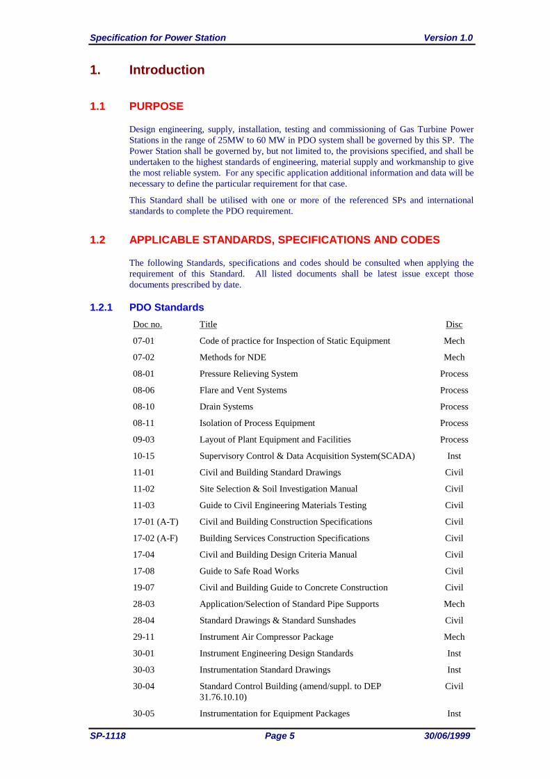
1.2.1 PDO Standards
Doc no. Title Disc
07-01 Code of practice for Inspection of Static Equipment Mech
07-02 Methods for NDE Mech
08-01 Pressure Relieving System Process
08-06 Flare and Vent Systems Process
08-10 Drain Systems Process
08-11 Isolation of Process Equipment Process
09-03 Layout of Plant Equipment and Facilities Process
10-15 Supervisory Control & Data Acquisition System(SCADA) Inst
11-01 Civil and Building Standard Drawings Civil
11-02 Site Selection & Soil Investigation Manual Civil
11-03 Guide to Civil Engineering Materials Testing Civil
17-01 (A-T) Civil and Building Construction Specifications Civil
17-02 (A-F) Building Services Construction Specifications Civil
17-04 Civil and Building Design Criteria Manual Civil
17-08 Guide to Safe Road Works Civil
19-07 Civil and Building Guide to Concrete Construction Civil
28-03 Application/Selection of Standard Pipe Supports Mech
28-04 Standard Drawings & Standard Sunshades Civil
29-11 Instrument Air Compressor Package Mech
30-01 Instrument Engineering Design Standards Inst
30-03 Instrumentation Standard Drawings Inst
30-04 Standard Control Building (amend/suppl. to DEP
31.76.10.10)
Civil
30-05 Instrumentation for Equipment Packages Inst
Version 1.0 Specification for Power Station
30/06/1999 Page 6 SP-1118
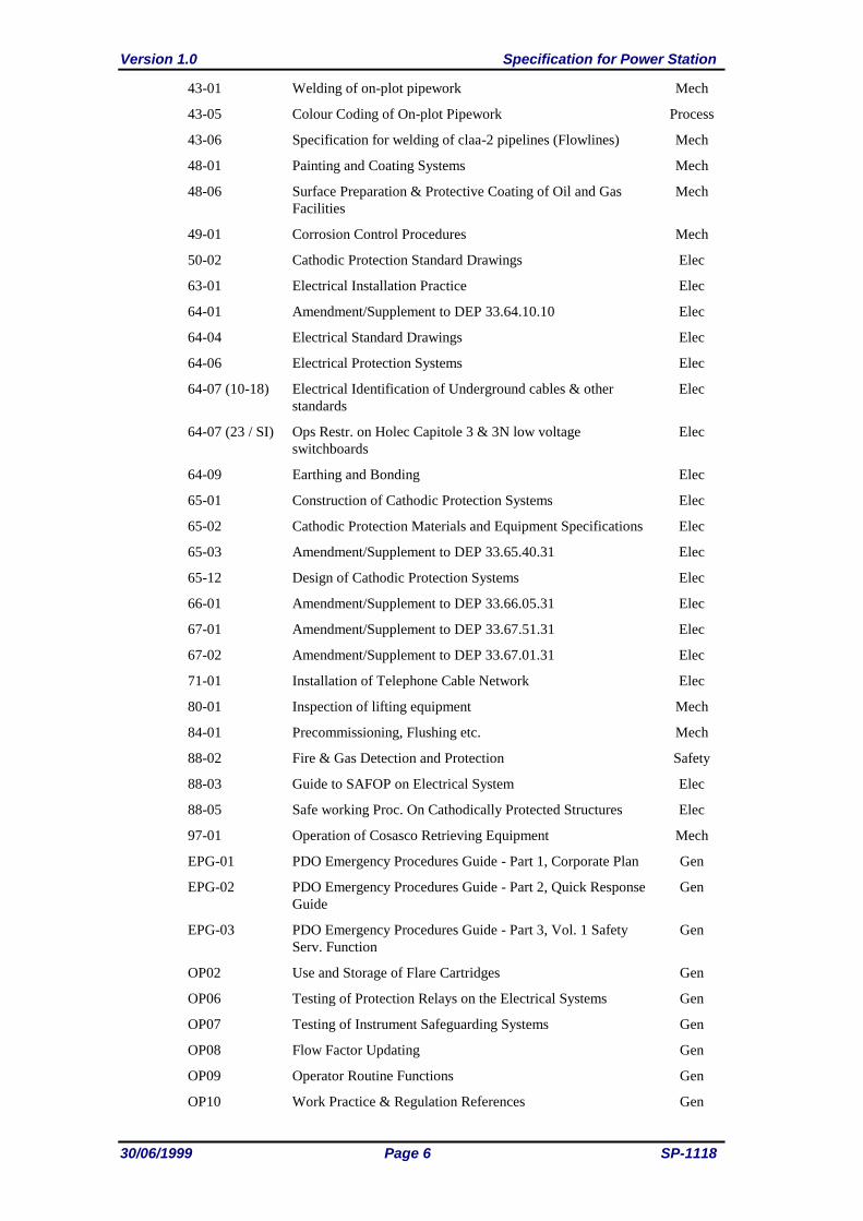
43-01 Welding of on-plot pipework Mech
43-05 Colour Coding of On-plot Pipework Process
43-06 Specification for welding of claa-2 pipelines (Flowlines) Mech
48-01 Painting and Coating Systems Mech
48-06 Surface Preparation & Protective Coating of Oil and Gas
Facilities
Mech
49-01 Corrosion Control Procedures Mech
50-02 Cathodic Protection Standard Drawings Elec
63-01 Electrical Installation Practice Elec
64-01 Amendment/Supplement to DEP 33.64.10.10 Elec
64-04 Electrical Standard Drawings Elec
64-06 Electrical Protection Systems Elec
64-07 (10-18) Electrical Identification of Underground cables & other
standards
Elec
64-07 (23 / SI) Ops Restr. on Holec Capitole 3 & 3N low voltage
switchboards
Elec
64-09 Earthing and Bonding Elec
65-01 Construction of Cathodic Protection Systems Elec
65-02 Cathodic Protection Materials and Equipment Specifications Elec
65-03 Amendment/Supplement to DEP 33.65.40.31 Elec
65-12 Design of Cathodic Protection Systems Elec
66-01 Amendment/Supplement to DEP 33.66.05.31 Elec
67-01 Amendment/Supplement to DEP 33.67.51.31 Elec
67-02 Amendment/Supplement to DEP 33.67.01.31 Elec
71-01 Installation of Telephone Cable Network Elec
80-01 Inspection of lifting equipment Mech
84-01 Precommissioning, Flushing etc. Mech
88-02 Fire & Gas Detection and Protection Safety
88-03 Guide to SAFOP on Electrical System Elec
88-05 Safe working Proc. On Cathodically Protected Structures Elec
97-01 Operation of Cosasco Retrieving Equipment Mech
EPG-01 PDO Emergency Procedures Guide - Part 1, Corporate Plan Gen
EPG-02 PDO Emergency Procedures Guide - Part 2, Quick Response
Guide
Gen
EPG-03 PDO Emergency Procedures Guide - Part 3, Vol. 1 Safety
Serv. Function
Gen
OP02 Use and Storage of Flare Cartridges Gen
OP06 Testing of Protection Relays on the Electrical Systems Gen
OP07 Testing of Instrument Safeguarding Systems Gen
OP08 Flow Factor Updating Gen
OP09 Operator Routine Functions Gen
OP10 Work Practice & Regulation References Gen
Specification for Power Station Version 1.0
SP-1118 Page 7 30/06/1999
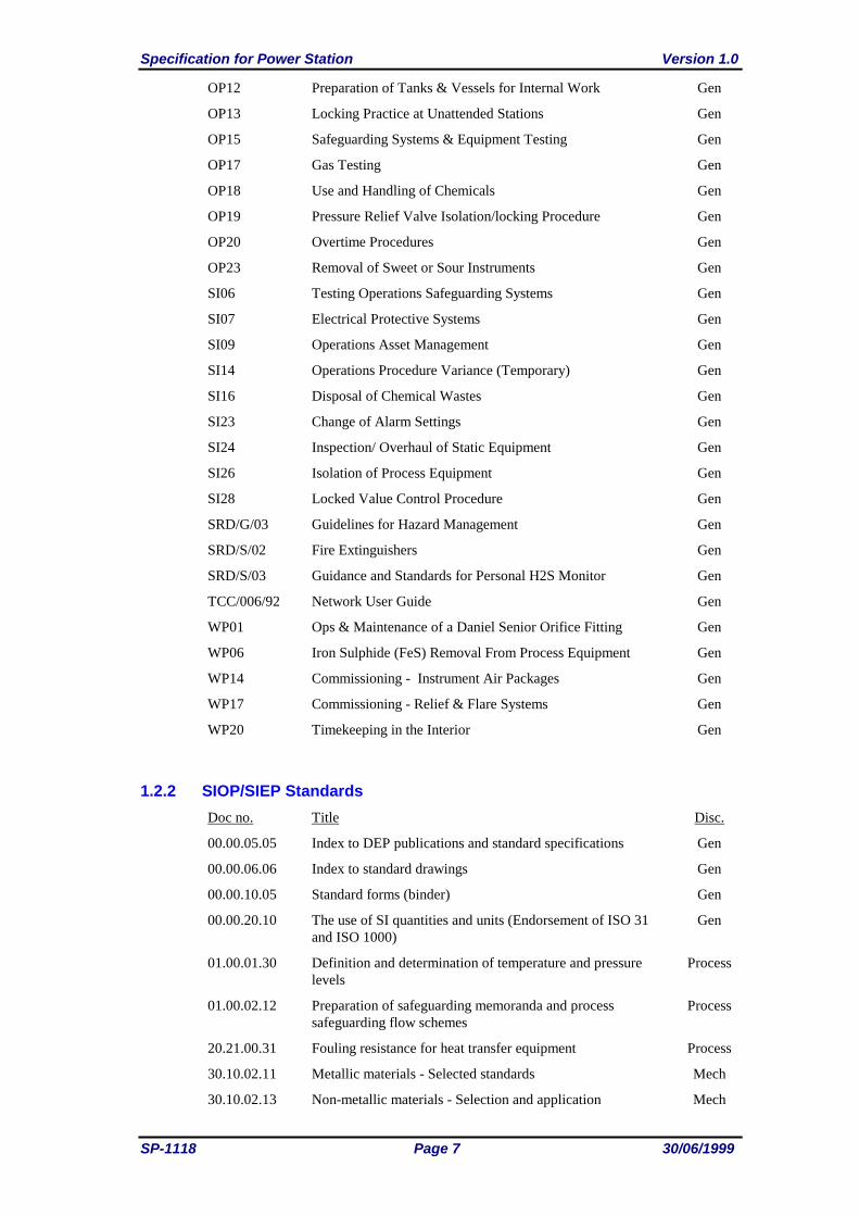
OP12 Preparation of Tanks & Vessels for Internal Work Gen
OP13 Locking Practice at Unattended Stations Gen
OP15 Safeguarding Systems & Equipment Testing Gen
OP17 Gas Testing Gen
OP18 Use and Handling of Chemicals Gen
OP19 Pressure Relief Valve Isolation/locking Procedure Gen
OP20 Overtime Procedures Gen
OP23 Removal of Sweet or Sour Instruments Gen
SI06 Testing Operations Safeguarding Systems Gen
SI07 Electrical Protective Systems Gen
SI09 Operations Asset Management Gen
SI14 Operations Procedure Variance (Temporary) Gen
SI16 Disposal of Chemical Wastes Gen
SI23 Change of Alarm Settings Gen
SI24 Inspection/ Overhaul of Static Equipment Gen
SI26 Isolation of Process Equipment Gen
SI28 Locked Value Control Procedure Gen
SRD/G/03 Guidelines for Hazard Management Gen
SRD/S/02 Fire Extinguishers Gen
SRD/S/03 Guidance and Standards for Personal H2S Monitor Gen
TCC/006/92 Network User Guide Gen
WP01 Ops & Maintenance of a Daniel Senior Orifice Fitting Gen
WP06 Iron Sulphide (FeS) Removal From Process Equipment Gen
WP14 Commissioning - Instrument Air Packages Gen
WP17 Commissioning - Relief & Flare Systems Gen
WP20 Timekeeping in the Interior Gen
1.2.2 SIOP/SIEP Standards
Doc no. Title Disc.
00.00.05.05 Index to DEP publications and standard specifications Gen
00.00.06.06 Index to standard drawings Gen
00.00.10.05 Standard forms (binder) Gen
00.00.20.10 The use of SI quantities and units (Endorsement of ISO 31
and ISO 1000)
Gen
01.00.01.30 Definition and determination of temperature and pressure
levels
Process
01.00.02.12 Preparation of safeguarding memoranda and process
safeguarding flow schemes
Process
20.21.00.31 Fouling resistance for heat transfer equipment Process
30.10.02.11 Metallic materials - Selected standards Mech
30.10.02.13 Non-metallic materials - Selection and application Mech
Version 1.0 Specification for Power Station
30/06/1999 Page 8 SP-1118
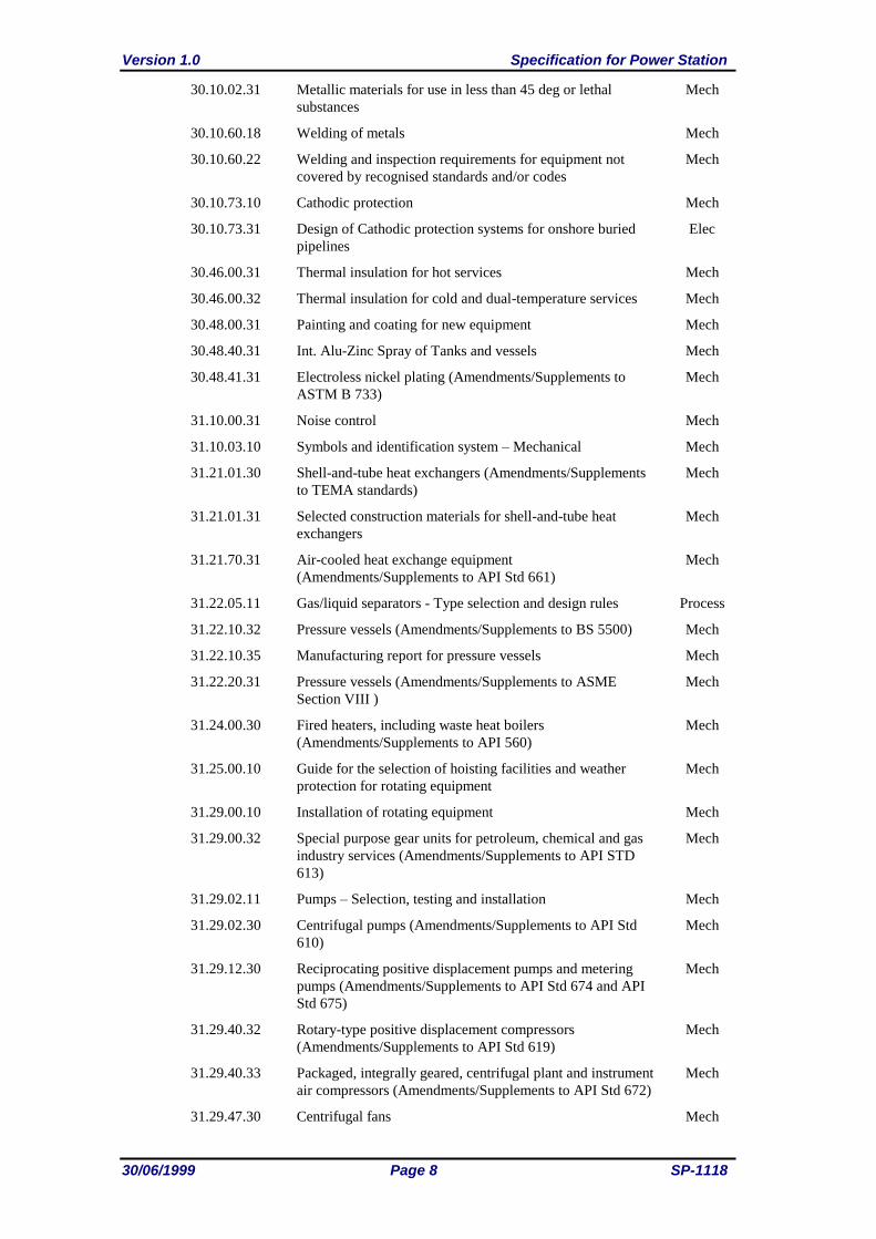
30.10.02.31 Metallic materials for use in less than 45 deg or lethal
substances Mech
30.10.60.18 Welding of metals Mech
30.10.60.22 Welding and inspection requirements for equipment not
covered by recognised standards and/or codes
Mech
30.10.73.10 Cathodic protection Mech
30.10.73.31 Design of Cathodic protection systems for onshore buried
pipelines
Elec
30.46.00.31 Thermal insulation for hot services Mech
30.46.00.32 Thermal insulation for cold and dual-temperature services Mech
30.48.00.31 Painting and coating for new equipment Mech
30.48.40.31 Int. Alu-Zinc Spray of Tanks and vessels Mech
30.48.41.31 Electroless nickel plating (Amendments/Supplements to
ASTM B 733)
Mech
31.10.00.31 Noise control Mech
31.10.03.10 Symbols and identification system – Mechanical Mech
31.21.01.30 Shell-and-tube heat exchangers (Amendments/Supplements
to TEMA standards)
Mech
31.21.01.31 Selected construction materials for shell-and-tube heat
exchangers
Mech
31.21.70.31 Air-cooled heat exchange equipment
(Amendments/Supplements to API Std 661)
Mech
31.22.05.11 Gas/liquid separators - Type selection and design rules Process
31.22.10.32 Pressure vessels (Amendments/Supplements to BS 5500) Mech
31.22.10.35 Manufacturing report for pressure vessels Mech
31.22.20.31 Pressure vessels (Amendments/Supplements to ASME
Section VIII )
Mech
31.24.00.30 Fired heaters, including waste heat boilers
(Amendments/Supplements to API 560)
Mech
31.25.00.10 Guide for the selection of hoisting facilities and weather
protection for rotating equipment
Mech
31.29.00.10 Installation of rotating equipment Mech
31.29.00.32 Special purpose gear units for petroleum, chemical and gas
industry services (Amendments/Supplements to API STD
613)
Mech
31.29.02.11 Pumps – Selection, testing and installation Mech
31.29.02.30 Centrifugal pumps (Amendments/Supplements to API Std
610)
Mech
31.29.12.30 Reciprocating positive displacement pumps and metering
pumps (Amendments/Supplements to API Std 674 and API
Std 675)
Mech
31.29.40.32 Rotary-type positive displacement compressors
(Amendments/Supplements to API Std 619)
Mech
31.29.40.33 Packaged, integrally geared, centrifugal plant and instrument
air compressors (Amendments/Supplements to API Std 672)
Mech
31.29.47.30 Centrifugal fans Mech
Specification for Power Station Version 1.0
SP-1118 Page 9 30/06/1999
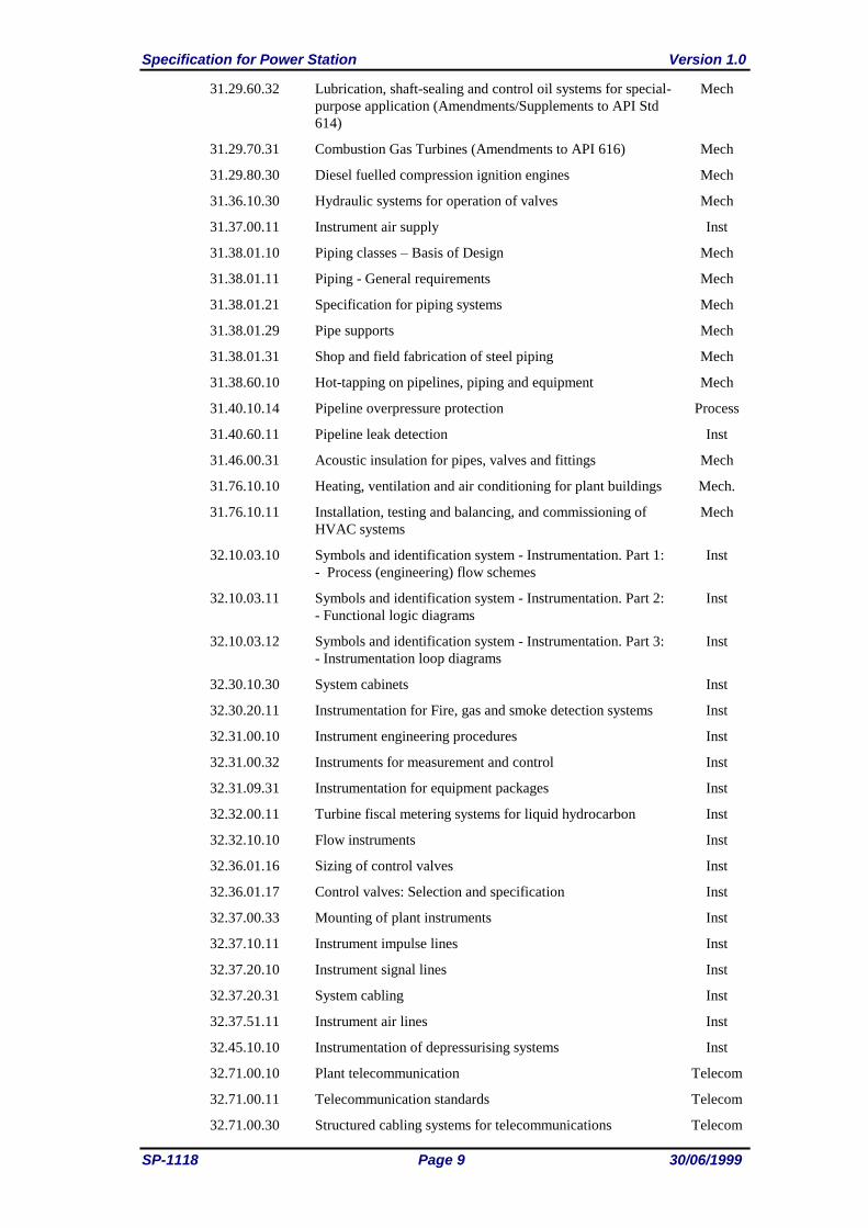
31.29.60.32 Lubrication, shaft-sealing and control oil systems for special-
purpose application (Amendments/Supplements to API Std
614)
Mech
31.29.70.31 Combustion Gas Turbines (Amendments to API 616) Mech
31.29.80.30 Diesel fuelled compression ignition engines Mech
31.36.10.30 Hydraulic systems for operation of valves Mech
31.37.00.11 Instrument air supply Inst
31.38.01.10 Piping classes – Basis of Design Mech
31.38.01.11 Piping - General requirements Mech
31.38.01.21 Specification for piping systems Mech
31.38.01.29 Pipe supports Mech
31.38.01.31 Shop and field fabrication of steel piping Mech
31.38.60.10 Hot-tapping on pipelines, piping and equipment Mech
31.40.10.14 Pipeline overpressure protection Process
31.40.60.11 Pipeline leak detection Inst
31.46.00.31 Acoustic insulation for pipes, valves and fittings Mech
31.76.10.10 Heating, ventilation and air conditioning for plant buildings Mech.
31.76.10.11 Installation, testing and balancing, and commissioning of
HVAC systems
Mech
32.10.03.10 Symbols and identification system - Instrumentation. Part 1:
- Process (engineering) flow schemes
Inst
32.10.03.11 Symbols and identification system - Instrumentation. Part 2:
- Functional logic diagrams
Inst
32.10.03.12 Symbols and identification system - Instrumentation. Part 3:
- Instrumentation loop diagrams
Inst
32.30.10.30 System cabinets Inst
32.30.20.11 Instrumentation for Fire, gas and smoke detection systems Inst
32.31.00.10 Instrument engineering procedures Inst
32.31.00.32 Instruments for measurement and control Inst
32.31.09.31 Instrumentation for equipment packages Inst
32.32.00.11 Turbine fiscal metering systems for liquid hydrocarbon Inst
32.32.10.10 Flow instruments Inst
32.36.01.16 Sizing of control valves Inst
32.36.01.17 Control valves: Selection and specification Inst
32.37.00.33 Mounting of plant instruments Inst
32.37.10.11 Instrument impulse lines Inst
32.37.20.10 Instrument signal lines Inst
32.37.20.31 System cabling Inst
32.37.51.11 Instrument air lines Inst
32.45.10.10 Instrumentation of depressurising systems Inst
32.71.00.10 Plant telecommunication Telecom
32.71.00.11 Telecommunication standards Telecom
32.71.00.30 Structured cabling systems for telecommunications Telecom
Version 1.0 Specification for Power Station
30/06/1999 Page 10 SP-1118
32.80.10.10 Classification and implementation of instrumented protective
functions
Inst
33.10.03.10 Symbols and identification system - Electrical Elec
33.64.10.10 Electrical engineering guidelines Elec
33.65.11.31 Synchronous AC generators 1250 kVA and above Elec
33.65.11.32 Packaged unit AC generator sets Elec
33.65.40.31 Power transformers (Amendments/Supplements to IEC 76
and IEC
Elec
33.65.50.31 Static DC uninterruptible power supply unit (Static DC UPS
unit)
Elec
33.65.50.32 Static AC uninterruptible power supply unit (Static AC UPS
unit)
Elec
33.66.05.31 Electric motors - Cage-induction and synchronous type Elec
33.66.05.33 Electrical variable speed drive systems Elec
33.67.01.31 Low-voltage switchgear and controlgear assemblies
(Amendments/Supplements to IEC 439-1)
Elec
33.67.51.31 High-voltage switchgear and controlgear assembles
(Amendments/Supplements to IEC 298)
Elec
33.68.30.32 Electrical trace heating Elec
34.00.01.30 Minimum requirements for structural design and engineering Civil
34.11.00.10 Site investigations Civil
34.11.00.11 Site preparation and earthworks Civil
34.11.00.12 Geotechnical and foundation engineering Civil
34.13.20.31 Roads, paving, surfacing, slope protection and fencing Civil
34.14.20.31 Drainage and primary treatment facilities Civil
34.17.00.32 Minimum requirements for design and engineering of
buildings
Civil
34.17.10.30 Reinforced control buildings/Field auxiliary rooms Civil
34.18.51.10 Minimum requirements for the construction and maintenance
of tank foundations, bund walls and drainage systems for
small storage installations
Civil
34.19.20.11 Fire hazards and fireproofing/cold splash protection of steel
structures
Civil
34.19.20.31 Reinforced concrete foundations and structures Civil
34.24.26.31 Steel stacks (Amendments/Supplements to CICIND Model
Code)
Civil
34.28.00.31 Steel structures Civil
44.24.90.31 Refractory bricks and shapes Mech
61.10.08.11 Field inspection prior to commissioning of mechanical
equipment
Mech
61.38.10.10 Shop and field fabrication of orifice meter runs Mech
61.40.20.30 Welding of pipelines and related
facilities(Amendments/Supplements to ANSI/API)
Mech
62.10.08.11 Field inspection and testing of instruments and instrument
systems
Inst
Specification for Power Station Version 1.0
SP-1118 Page 11 30/06/1999
62.10.09.11 Factory inspection and testing of instruments and instrument
systems
Inst
62.37.10.12 Instrument installation procedures Inst
63.10.08.11 Field commissioning and maintenance of electrical
installations and equipment
Elec
64.24.32.30 Insulating and dense refractory concrete linings Mech
70.08.10.10 Equipment and tools for maintenance and inspection. Part 1:
Inspection - Tools and NDT instruments
Mech
70.08.10.11 Equipment and tools for maintenance and inspection. Part 2:
- Mechanical maintenance - Equipment, tools and bolt
tensioning
Mech
70.08.10.13 Equipment and tools for maintenance and inspection. Part 4:
- Electrical workshop - Test equipment and tools
Mech
70.08.10.14 Equipment and tools for maintenance and inspection. Part 5:-
Instrument technical centre and workshop - Equipment and
tools
Mech
70.10.70.11 The preservation of old and new equipment and piping
standing idle
Mech
70.10.80.11 Cleaning of equipment Mech
70.10.90.11 Spare parts Mech
80.00.10.10 Area classification (amendments/supplements to IP 15) Process
80.45.10.10 Pressure relief and flare system Process
80.46.30.11 Interlocking systems for safety/relief valves Mech
80.47.10.10 Fire-fighting agents Safety
80.47.10.30 Assessment of the fire safety of onshore installations Safety
80.47.10.31 Active fire protection systems and equipment for onshore
facilities
Safety
80.47.10.32 Portable and mobile equipment for fire-fighting Safety
A-4-1 Fuel systems Mech
L-5-1/2/3 External fusion-bonded epoxy powder coating for line pipe Mech
W-5-1/2/3 Repair by welding of aluminium and aluminium-alloy
castings
Mech
W-6-1/2/3 Equipment made of 2.25 Cr - 1 Mo steel in quenched and
tempered condition
Mech
W-7-1/2/3 Aluminium-bronze sand castings (Amendments/Supplements
to ASTM B 148)
Mech
T.2.238.761 Integrated motor control system Elec
EP 92-0980 Guidelines for Manual Sampling and Analysis of
Hydrocarbon Fluids
Process
ERD
1.2.3 International Standards
All relevant international standards as referred to in the individual DEP/SP shall be
applicable.
Version 1.0 Specification for Power Station
30/06/1999 Page 12 SP-1118
1.3 COMPLIANCE WITH STANDARDS
All requirements of this Specification shall apply except where equipment manufacturer's
standards are more stringent, then the latter shall apply.
The user shall obtain the written approval from the technical authority within PDO for any
deviations from this Specification. The appropriate technical authorities are set out in ERD-
00-02.
In all cases the Company shall determine the adequacy of Works executed by the Contractor
in accordance with this Specification.
1.3.1 Language and Units of Measurement
The English language and the SI system of units shall be used through out for all the
documentation and drawings. Where necessary for a specific application, alternative units
may be indicated in brackets behind the SI units.
1.4 PRODUCT/ASSET WARRANTY
The entire power station package and all individual equipment forming part of it shall be
guaranteed to meet specified technical particulars listed in this Specification and all referred
standards and codes. It shall have an expected technical lifetime of at least 20 years.
Clarification to how this requirement will be met shall be provided in the quotation, in
particular giving attention to the redundancy and availability of spare parts.
If the guaranteed performance of the power station and all equipment forming part of it is
not met and/or if any equipment fails to comply with the specification requirement in any
respect whatsoever at any stage of manufacture, test or erection, the Company 's
Representative may reject the package, or defective equipment thereof, whichever he
considers necessary, and after adjustment or modification as directed by the Company's
Representative, the Contractor shall conduct further inspection and/or test.
All repair procedures shall not be performed without the prior approval of the Company's
Representative. In the event of a defect on any equipment/component being of such a nature
that the specification requirements cannot be fulfilled by adjustment or modification, such
item shall be replaced by the Contractor, at his own expense to the entire satisfaction of the
Company's Representative. Any equipment/component of the power station package repaired
to an approved procedure shall not be accepted as a part of the Works as a permanent
solution or replacement unless the Contractor guarantees in writing that the repaired
equipment shall have the same service lifetime and efficiency as the equipment/ component
originally manufactured.
The Contractor shall also warrant all equipment and component parts forming the power
station package against defective material, design and /or workmanship. Contractor shall
assume single point of responsibility for equipment warranty and performance guarantee for
all equipment forming this power station package.
The approval of the Company's Representative of inspection and/or test results will not
prejudice the right of the Company's Representative to reject whole or part of the package if
it does not comply with the contract document when erected or prove completely satisfactory
in service.
Product/asset warranty shall further refer to the requirement as specified in the commercial
package of the contract document.
1.4.1 PDO System
PDO electrical system is one electrical network covering the operational areas of PDO in
north and south Oman. North Oman and South Oman electrical systems are interconnected
with a single 132kV overhead line. Refer to the single line diagrams EFD 4 0252 001 E1
and EFD 4 0252 002 E1 for the North Oman and South Oman systems respectively.
Specification for Power Station Version 1.0
SP-1118 Page 13 30/06/1999
The electrical system consists of Gas Turbine generators stations (maximum generator set
size of 30 MW at approximately 50C (Frame - 6)), interconnected with a 132kV electrical
transmission network and a distribution electrical network of 33kV.
The Generating stations are unattended and are remotely controlled from the Dedicated
Remote Control System located at Yibal using GE’s SMART REMOTE system for North
Oman and using DMACS control system for South Oman. SCADA Master Control Centres
located at Yibal and slave Control Centre at Marmul act as a standby system for the
Dedicated Remote Control Systems. However, the requirement is now to have all North and
South Power Stations controlled from Yibal Central Control Room.
Version 1.0 Specification for Power Station
30/06/1999 Page 14 SP-1118
2. Scope
2.1 PLANT LAYOUT
2.1.1 General
The Gas Turbine Power Station shall be designed for accommodating upto three numbers
Gas Turbines of the specified capacity. All the common facilities and plant layout shall be
designed for the ultimate configuration of three units, unless stated otherwise..
The plant configuration of simple cycle Frame 6 power plants is well established in PDO.
The enclosed plant layout Drg. STD-3-1800-001 shows a typical 3 x 30 MW plant
configuration. As PDO have yet to install gas turbine units larger than 30 MW there are no
existing design references but in principle the plant layout requirements will be similar to the
smaller 30 MW units. The larger 60 MW gas turbines may have additional off base
auxiliaries compared to the smaller unit.
Gas turbine units shall be installed parallel to each other, except when the proposed site is
suitable only for gas turbine generators placed in line.
2.1.2 Plant Orientation
The power plant is divided into four distinct areas
Gas supply, treatment and venting
Gas turbine generators
Control building and station auxiliaries
Electrical export
The typical layout drawing STD-3-1800-001 shall be referred for the locations for the site
utilities such as water, air, fuel and oil.
The content of these areas will be to some extent project specific as gas treatment
requirements and electrical interconnection will vary from project to project. The orientation
will be developed to suit the dimensions of the land available, direction of incoming gas
supplies and best route for electrical export, wind direction, location of existing facilities
with respect to the Power Plant site.
The gas treatment plant and electrical equipment shall not be situated besides each other.
The preferred orientation is with the gas treatment facilities on one side of the gas turbines
and the electrical and control systems on the other side. This arrangement simplifies the
plant layout and minimises common areas.
The control building shall be a minimum of 15 metres from the Power Island consisting of
the Gas turbine, generator and the generator transformer.
The vent area shall be located to suit prevailing wind conditions and to minimise the risk of
any release from the vent blowing towards the power plant or adjacent facilities.
The emergency diesel generator, if specified in the Project specifications, shall be positioned
adjacent to the control room, but no nearer than 15 metres to the building. The emergency
generator and the station instrument air package can be located under a common sunshade.
The sunshade shall include an additional covered area for storage.
2.1.3 Equipment Spacing
The plant spacing should generally be in compliance with ERD 09-03. The gas turbine
generator, generator transformer, control compartment and off base auxiliaries are
considered as one Module.
Specification for Power Station Version 1.0
SP-1118 Page 15 30/06/1999
The minimum distance between 30 MW gas turbine centre lines is 30 metres. The minimum
gas turbine spacing for sites which will have Waste Heat Recovery Units (WHRUs) or plan
to have WHRUs in the future shall be 65 metres between gas turbine centre lines, based on
the WHRU being positioned at 90 degrees to the gas turbine axis. This spacing could be
reduced if small WHRUs are to be installed or the WHRU is placed in parallel to the gas
turbine.
For larger gas turbines with cold-end drive with provision for WHRUS, the WHRU shall be
placed on the same centreline as the gas turbine.
The gas treatment plant for a single gas turbine unit may consist of several skid mounted
packages but shall be considered as one HP Module. The distance between unit modules
shall be 30 metres.
The vent stack area shall normally be 40 metres by 40 metres. If the radiation of the ignited
vent or gas dispersal calculations indicate a larger area requirement the height of the stack
shall be increased in the first instance up to a maximum vent height of 30 metres. Only if the
increase in stack height does not provide a solution should the vent sterile area be increased.
2.1.4 Piping and Cable Routing
2.1.4.1 Piping
Piping in the gas treatment plant and vent stack area shall be located above ground.
Pipework around the gas turbine area should be buried to provide clear access for
maintenance.
2.1.4.2 Cabling
The cabling around the gas turbine and between the adjacent gas turbine auxiliaries shall be
placed in concrete trenches with concrete covers. Cabling between the gas turbine and the
control room may be direct buried.
2.1.5 Hazardous Areas
All the equipment in the gas treatment plant and vent stack areas are to be considered as a
Zone 2 Hazardous area in accordance with IP 15. The gas turbine gas compartment/module
vent shall be considered as a Zone 2 hazardous area. The exact gas and temperature
groupings shall be to match the gas composition available for the individual project.
2.2 GAS TURBINE GENERATOR AND AUXILIARY EQUIPMENT
2.2.1 General Requirements
The gas turbine generator unit shall be supplied complete with all auxiliary equipment
necessary for its safe and efficient operation with the specified fuel and shall be designed for
outdoor installation in a packaged enclosure suitable for the specified climatic conditions.
The unit shall be capable of continuous operation. The gas turbine shall be of the heavy duty
Industrial type to the manufacturers latest standard
Unless otherwise specified the gas turbine shall be designed to fire natural gas using a single
combustion system.
Version 1.0 Specification for Power Station
30/06/1999 Page 16 SP-1118
2.2.2 Duty and Conditions of Operation
The power station will be required to operate satisfactorily at any load up to its peak load
rating in parallel with the existing electrical system under any ambient or climatic conditions,
which may occur.
The site base load rating shall be the equivalent of the ISO standard base load rating as
defined in ISO 3977 Section 7.3.
The unit shall have the capability to operate for limited periods of time at a peak rating equal
to at least 110% of the base load rating.
2.2.3 Extent of Supply
The gas turbine unit shall be complete with all equipment and accessories necessary for the
safe, efficient and reliable operation of the plant including but not necessarily limited to the
following:
Skid mounted, packaged gas turbine and generator, complete with auxiliaries, gearbox,
driven coupling etc.
Starting system
Barring gear
Lubricating oil system which shall provide the lubrication requirements for the gas
turbine, gearbox and generator, complete with all pumps, filters, coolers, controls etc.
Fuel system for operation on the specified fuel complete with all ancillary equipment
and controls.
Inlet air system complete with self cleaning filtration system, silencer, ducting, trash
screens, plenum and all necessary ancillary equipment and controls. A similar system for
alternator cooling air shall be provided.
A mist eliminator shall be installed in the inlet air system.
Complete ancillary cooling systems
Offline Compressor blade cleaning equipment for inter-connection to water wash skid.
All interconnecting pipework, valves, drains, vents and supports for all equipment.
Acoustic and thermal insulation
Interconnecting cabling and switchgear
Separate Microprocessor based control and machine monitoring system.
Fire and gas detection system
Special tools and cleaning equipment
2.2.4 Design and Construction Requirements
2.2.4.1 General
The design of the gas turbine and all auxiliary equipment shall have been fully proven by
extensive successful operation in commercial service.
The gas turbine generator unit shall be designed to ensure that the base load continuous
operating period between major overhauls is not less than 72000 hours, combustion
inspection every 12000 hours,hot gas path inspection every 36000 hours when operating on
the specified fuel and under the specified climatic conditions. This figure may be modified
by an agreed formula to take account of peak load operation and number of starts. Formula
Specification for Power Station Version 1.0
SP-1118 Page 17 30/06/1999
to determine the number of equivalent base load hours to take into consideration peak fired
hours and the number of starts shall be submitted.
2.2.4.2 Hazardous Area Classification
The areas adjacent to the gas turbine and fuel system shall be given a hazardous area
designation according to the requirements of IP 15 taking into account the nature of the fuel.
Only one flanged connection adjacent to the gas turbine for hydrocarbon services is
permitted. Other flange connections for temporary filters, etc. shall be located adjacent to
the fuel gas treatment plant.
2.2.4.3 Package Enclosures
The Gas turbine Generator unit shall be of the packaged type suitable for outdoor installation
in the specified site climatic conditions. The gas turbine generator enclosure shall be
fire/explosion protected and consist of several interconnected compartments forming a
weather protective housing constructed of steel and structurally attached to each
compartment base. Each enclosure compartment shall provide thermal insulation, acoustical
attenuation and fire extinguishing media containment. Each compartment shall be designed
to provide adequate access for operation and maintenance purposes and for easy removal of
all major items of equipment.
The Generator and exciter shall be housed in a single acoustic enclosure allowing free access
to all parts of the equipment.
Each enclosure compartment shall be provided with fluorescent lighting and adequate
number of switched socket outlets to facilitate the use of power tools and inspection
equipment during maintenance and overhaul operations.
2.2.4.4 Compressor
The Compressor shall be designed to operate at speed corresponding to system frequencies
of 47.5 Hz to 52.5Hz with sufficient margin from its surge line characteristic such that it is
unconditionally stable at all conditions of load and ambient temperature and to allow for
reasonable amounts of blade fouling. Provision shall be made for accurately measuring
mean compressor delivery temperature and static delivery pressure.
The variable inlet guide vanes shall be supplied to the latest material specification.
2.2.4.5 Combustion System
Combustion efficiency shall be sufficiently high to ensure a colourless exhaust. A dry low
NOX combustion system shall be provided capable of achieving NOX and CO emissions of
25 ppm and 15 ppm respectively, at full load.
2.2.4.6 Skid
The skids for the gas turbine and generator shall be of substantial continuously welded
construction and have floor plate covering the top surface with cut-outs for supports.
The primary members shall be adequately crossbraced to prevent flexing or distortion of skid
during transporting and installation. Equipment mounted on the skid shall not be considered
as bracing the skid.
Minimum metal thickness at point of equipment bolting shall be 10 mm.
Pad-eye or equal lifting lugs, designed for minimum load factor of 2.0, for lifting sling
attachments and one point pickup using spreader beams, shall be attached to facilitate
loading and unloading.
Each skid unit shall be stiff enough to absorb loads experienced during lifting and transit
over unmade roads without permanent deformation and without damage occurring to any
component part of the package. Skids shall have shock recorders installed to monitor transit
loading shocks.
Each skid shall be provided with two earth connection points for connecting to the main
station earthing system. All non-current carrying metalwork on the skid, which is not
Version 1.0 Specification for Power Station
30/06/1999 Page 18 SP-1118
permanently welded, to the skid base shall be bonded to the base using adequately sized
earth cables.
2.2.4.7 Unit Fuel System
The acceptable limits for variations in the physical properties and constituents, which are
consistent with satisfactory operation of the gas turbine up to its maximum peak load rating,
shall be defined by the manufacturer. In particular, the maximum acceptable levels of
sulphur and metallic compounds, or combinations of these compounds, in the fuel delivered
to the fuel nozzles shall be defined. Analysis of samples of the specified fuel to confirm its
suitability for satisfactory operation of the gas turbine shall be carried out by the supplier.
The fuel control system shall be capable of providing speed control for manual and
automatic synchronising purposes such that the generator frequency can be varied and
maintained within + 0.5% between 45 Hz (full load) and 52 Hz (no load) with a nominal 4%
full load droop.
2.2.4.8 Ventilation and Air Conditioning
The GT unit auxiliary control cabin shall be environmentally controlled by means of 2 x
100% capacity, heavy duty air conditioning systems supplied by PDO approved vendors,
designed to maintain a dry bulb temperature within the range 22ºC to 25ºC and a relative
humidity between 45% and 55% under all ambient conditions. The design of the equipment
shall take into account the maximum heat load from all sources particularly solar gain,
personnel occupancy, lighting and any other heat releasing media.
The Gas turbine-generator enclosure shall be provided with a forced ventilation system
designed to:
Remove sufficient heat at the maximum ambient temperatures specified, to provide an
acceptable internal environment for all equipment installed inside the compartment,
without the need to reduce the output when one fan is running.
Dilute the concentration of any gas leaking from equipment.
The accessory and turbine compartments shall be ventilated by means of 2 x 100% fans (one
operating and one standby) taking suction from the main air inlet duct to the gas turbine
(filtered air). Each fan shall be able to be selected for operating or standby mode manually.
Each fan shall be provided with a outlet damper and differential pressure measurement,
which shall automatically start the standby fan on failure of the operating fan (low
differential pressure). The ventilation and other equipment mounted on the roof of the gas
turbine package shall be accessible by stairs and walkways.
The generator and load gear compartments shall be ventilated by the generator cooling air.
Special attention to reduce the temperature inside the load gear compartment shall be given.
Options to be considered are the use of a back to front flow pattern or a modified barrier wall
on the turbine exhaust side.
2.2.4.9 Turbine
The turbine casings, ducting and moving and stationary blading shall be designed to
withstand the maximum temperature scatter which may occur in service under adverse
combustion conditions, with the machine running at the design maximum mean turbine inlet
temperature. The casings, blading and ducts shall withstand, without premature failure, the
thermal shock associated with repeated starting and loading.
If bolts are to be tightened under heat or by extension by hydraulic or mechanic means, one
full set of the necessary equipment shall be supplied.
Hot gas path inspection shall be possible via suitable plugged openings to introduce
borescope-type equipment
All instrumentation required to measure gas turbine exhaust temperatures shall be provided
and this shall show any imbalance in the temperature distribution in relation to the first stage
blades.
2.2.4.10 Governor
Specification for Power Station Version 1.0
SP-1118 Page 19 30/06/1999
A solid state electro/hydraulic or mechanical/hydraulic speed sensing governor shall be
provided which is capable of stable control of the ac generator frequency, when operating as
an independent unit, and of the fuel energy input to the turbine and AC generator load when
operating in parallel with an existing supply system, in accordance with ISO.3977.
The Governor controls shall have facility for selection of automatic change over between
peak load mode and base load mode, when the GT experiences a sudden load change.
The governor shall be capable of control in either of the pre-selected mode namely., speed
droop or isochronous mode. The speed droop characteristic shall be adjustable on site from
0% to 10% in increments no greater than 0.5% but shall not be directly accessible to the unit
operator. The control range of speed control loop shall have a no load speed adjustment
from 96% of rated speed to an upper limit compatible with the above specified range of
speed droop characteristic.
The means for adjustment of the speed control shall be provided both on the Generator
control panel, SCADA system and on the Dedicated Remote Control system. Means shall
also be provided on the Unit Control Panel to manually override the governor and/or speed
control so that controlled no load testing of the overspeed trips can be made.
Upon an instantaneous full load rejection, the governor and associated control equipment
shall maintain the transient speed of the unit within acceptable limits, at least 2% below the
overspeed trip point when operating within its design capability.
The control systems shall be capable of retarding the rate of load acceptance to within
permissible limits, irrespective of any action on the part of the operator.
2.2.4.11 Overspeed Trips
Duplicate overspeed trips shall be provided which will shut down the machine in the event of
overspeed exceeding 10%.
Both trips are to sense shaft speed and either shall cause the fuel supply to be cut off by an
independent method.
The means of cutting off the fuel supply shall be fail-safe, i.e. depressurising a hydraulic
signal or, if not entirely mechanical in action by de-energising electrical devices not vice
versa.
2.2.4.12 Dynamics and Shaft Assembly
i) General
The vibration equipment shall be selected from the PDO’s approved vendor list or include
the manufacturers standard system and this shall be used for protection of the train. In
addition, displacement probes and key phasor shall be installed for condition monitoring and
alarm purposes. Galvanic isolators shall be in accordance with ERD-30-01. The vibration
limits specified below are mandatory:
ii) Factory tests
At all times after run-up until shut-down (i.e. 100% operating speed including warm-up and
cool-down), the vibration level shall not exceed 5 mm/s peak to peak.
iii) Field tests
The performance testing of the GTG shall be carried out at peak, full and half loads in
accordance with ISO 3977.
Load acceptance and load rejection tests for 100% load shall be carried out, when possible.
Gas samples shall be tested by an independent body.
At all times after run-up until shut-down (i.e. 100% operating speed including warm-up and
cool-down), the vibration level shall not exceed 6.4 mm/s 0-peak, except during the warm-up
period where a peak level of 8 mm/s 0-peak is acceptable.
Balancing in the field to achieve the above vibration levels is not acceptable.
A full vibration signature, which includes frequency analysis, run-up/shut-down, bode plots,
run out and orbit measurements shall be made during the factory tests.
Version 1.0 Specification for Power Station
30/06/1999 Page 20 SP-1118
A full report of lateral and torsional dynamic behaviour is to be prepared and submitted,
including model applied to verify bearing wear behaviour, overhang weight influences etc.
iv) Lateral Critical Speed
The first and second critical speeds shall be at least 10 percent below or 20 percent above the
operating speed range.
The critical speed below 105 percent of operating speed shall be determined during a
mechanical running test if it has not been established by previous tests.
v) Torsional Critical Speeds
No torsional critical speed shall be within less than 10 percent of the first or second harmonic
of the rotational frequency in the operating speed range.
No torsional critical speeds shall be within 10 percent of load-gear tooth-passing frequencies
within the operating speed range, except where a node exists at this gear teeth.
The system of turbine, load gear and generator with base plate, anchor bolts and foundations
shall be checked for sensitivity and shall be stable for a three-phase short-circuit effect.
vi) Vibration and Balance
Individual shafts, discs and couplings shall be dynamically balanced before assembly so that
the security of vibration of the complete unit during operation does not exceed the specified
margins.
2.2.4.13 Main Load Gearbox and Auxiliary Geared Drive
The main load gearbox and auxiliary geared drive shall be of proven design and specifically
designed for continuous operation. A sump type gearbox is preferred.
The main gearbox shall be capable of transmitting the maximum power developed by the gas
turbine under any condition of operation and also to withstand the short circuit torque and
the maximum torque generated by the alternator during faulty synchronisation. It shall also
be capable of withstanding 20% overspeed for 5 minutes.
Service factor for gearing shall not be less than 1.5. Gearbox design shall be in accordance
with AGMA 420 and 421, as applicable.
All high speed gears shall be provided with hydro-dynamic white metal journal and thrust
bearings, which together with the gear teeth shall be lubricated from the gas turbine
lubricating oil system. The complete kinematic chain, including all couplings, shall be
dynamically balanced.
All gearing shall be totally enclosed in a fabricated steel housing, dust and oil proof,
horizontally split to allow easy inspection of all internal components without breaking the
alignment. All casing mating steel surfaces shall be "stone ground" to ensure that no oil
leakages occur during operation.
2.2.4.14 Couplings
Couplings shall be of a type not requiring routine maintenance or inspection between periods
of major overhaul.
Couplings of an all metal flexible element design are preferred.
The couplings shall be designed to withstand, without damage, the torque that would be
imposed upon them during generator short circuit conditions.
2.2.4.15 Compressor Cleaning Equipment
To prevent build-up of deposits on the compressor blading a permanently installed off-load
compressor washing system shall be provided such that the compressor can be efficiently
cleaned without the necessity for opening up or dismantling any part of the machine.
The Compressor bellmouth shall be fitted with a ring pipe manifold and nozzles for injection
of the water/detergent mixture while the machine is cold cranked. Isolating valves shall be
provided on the cooling and sealing air lines to ensure that the effluent is directed to the
casing drains.
Specification for Power Station Version 1.0
SP-1118 Page 21 30/06/1999
A compressor washing skid shall be supplied which shall include the following:
Galvanised steel water storage vessel complete with motor driven pump, electric
immersion heater, level gauge, temperature and level switches.
All necessary valves and interconnecting piping
All necessary controls and instrumentation
Structural steel base
All equipment necessary for the storage and handling of the cleaning agent shall be provided
including suitable water storage facilities on the site.
2.2.4.16 Rotor Turning Device
A rotor turning device consisting of an electro-hydraulic ratchet system, supplied by a DC
driven pump and torque converter, shall be provided to turn the shaft during the cool down
period.
2.2.4.17 Starting System
i) General
It shall be possible to run the gas turbine continuously in the unfired condition for
compressor cleaning purposes.
The gas turbine start-up sequence shall be automatic in operation.
ii) Diesel Engine or Electro-Hydraulic Starting
The starting of the gas turbine shall be either by means of diesel engine or electro-hydraulic
starting as specified in the individual project specifications.
Where diesel engine is specified, the diesel engine shall be capable of "black starting" and
shall be rated so that at least six immediate consecutive "blackstarts" can be attempted.
The diesel engine starting system shall be complete with all equipment including self
contained oil system, jacket water cooling system, dc starter motor, dry type filter, batteries
and charger system, fuel system and tank, hydraulic torque converter and hydraulically
operated, solenoid-valve controlled jaw clutch with automatic disengagement at turbine self-
sustaining speed.
2.2.4.18 Lubricating Oil System
i) General
The lubricating provisions for the turbine, generator, main gearbox and accessory gearbox
shall be incorporated in a common lubrication system. The lubrication system shall be
vented to atmosphere and shall include, but not necessarily be limited to, the following
equipment:
Main lubrication oil pump shaft driven from the accessory gearbox.
Oil reservoir integral with the turbine base
Full flow AC motor driven auxiliary lubrication oil pump
Partial flow DC motor driven emergency lubrication oil pump
Full flow AC motor driven auxiliary hydraulic oil pump
Lubrication oil heater
Pressure relief valve in the main pump discharge
Dual full flow 5 micron filters with changeover valve for lubrication and trip oil systems
plus dual 5 micron filters for hydraulic oil system.
Bearing header pressure regulator
Air blast cooler for direct cooling of the oil
Version 1.0 Specification for Power Station
30/06/1999 Page 22 SP-1118
The tank vent and all bearing vents, (including the generator) shall be piped to the turbine
exhaust gas outlet such that oil vapour is entrained into the exhaust gas efflux. The vent
pipework shall be designed such that no oil drips back along the outside of the pipework.
The complete lube oil system including off skid pipework and cooler tubes/headers shall be
manufactured from 316 SS except for the lube oil storage tank, which may be carbon steel.
ii) Cooling System
Lubricating oil coolers shall be of the air blast type cooling the oil directly and shall comply
with the requirements of this specification and API 661 as modified by DEP 31.21.70.31.
The lubricating oil cooling system shall include thermostatically operated bypass valves and
fans to maintain oil temperature within safe operating limits.
The number of fan units provided shall be such that peak load can be maintained under the
most adverse ambient conditions with one fan unit out of service.
The cooling system shall be designed for ambient air conditions of 60ºC and 50% RH with a
10% margin in heat transfer surface.
Single speed fans shall be provided and shall be of the forced draught type located below the
cooler. The fans shall be driven by suitably designed "V" belts and pulleys. V belts shall be
designed for transmitting the maximum load at the design ambient conditions.
Any greasing points shall be accessible from ground level without the need to dismantle
guards etc. A central greasing point is preferred.
The fans and coolers shall be protected against foreign objects by means of non sparking bolt
on screens constructed from 8 SWG 50 mm square galvanised wire mesh.
All valves and instrumentation shall be accessible from ground level and provided with
suitable platforms and walkways. The lowest point of the cooler/fan assembly shall be a
minimum of 2.3 metres above ground level.
iii) Flushing Procedure
The entire lubrication oil system shall be flushed with the bearings and other lubricated items
by-passed for as long as necessary to obtain a thoroughly clean system.
All flushing oil, temporary pipework, strainers and any other equipment required shall be
supplied.
2.2.4.19 Air Intake and Exhaust System
i) Air Intake System
The intake system shall comprise of self cleansing filtration equipment, mist separator,
silencing, ducting, trash screens, guidevanes, internal lighting and all necessary support
structures, walkways, ladders and fittings. The minimum filtration efficiency shall be 95%
for 10 micrometre particle size as defined by the NBS weight method.
All ladders, platforms and special lifting and handling devices necessary for access to, and
maintenance of the filtration equipment shall be included. Air tight inspection doors shall be
provided in such number and position as to allow access to all parts of the intake works for
inspection and maintenance. In particular, it shall be possible to carry out a close-up visual
inspection of the first blade rows of the gas turbine compressor. All doors shall be provided
with locks. Refer to PDO standard drawing 23003 A, type A.
The design shall assume a maximum 3 second wind gust velocity of 47 m/s from any
direction. The intake structure shall be arranged at a suitable height above ground level to
prevent undue ingress of dust and in any event shall have a minimum ground clearance of 3.5
m.
All ductwork shall have a minimum thickness of 5 mm. Automatic bypass doors are not
required.
The self cleaning inlet filtration system shall utilise single stage high efficiency media filters,
which shall be automatically cleaned of accumulated dust thereby maintaining the inlet
pressure drop below a pre-set upper limit.
Specification for Power Station Version 1.0
SP-1118 Page 23 30/06/1999
The air filtration system offered shall be capable of operating under any possible
combination of adverse site conditions that occur (such as high atmospheric dust loading
together with high humidity) without adversely affecting the gas turbine, the filtration system
or the effectiveness of the filter cleaning process.
The air supply for the filter cleaning system shall be a 'bled' air from the gas turbine
compressor. The air shall be cooled and dried by means of desiccant dryer units, which shall
be of the "heatless" twin vessel type suitable for continuous operation. The capacity of the
bled air system and the quality of the air shall be suitable for the pulse cleaning requirements
of two gas turbine and generators inlet air filtration systems. As a back-up supply and for
off-load cleaning the system shall be connected to the station air supply via a normally closed
valve.
A fully automatic sequential system shall be provided, operating a series of solenoid-
operated valves, each of which shall control the cleaning of a small number of filters. The
sequential system shall be controlled by:
Filter differential pressure
Timer Control
Manual initiation
A differential pressure gauge and associated switch be provided for monitoring high
differential pressure and similar equipment for monitoring low pressure and or for low
pressure in the pulse cleaning air supply.
All air distribution pipework shall be manufactured from stainless steel.
The filter elements are required to have a guaranteed life of two years.
Lifting equipment and access trolleys to assist in the replacement of filters and for
maintenance of the air inlet filtration system shall be provided.
ii) Exhaust Gas System
The exhaust gas system shall be complete with all necessary gas-tight ducting, expansion
joints, turning vanes, stack, supporting steelwork, flanges, inspection doors, silencers and
any other equipment required to complete the system.
The height above ground level of the exhaust stacks shall be such to ensure that the 24 hour
concentration of sulphur dioxide (SO2) does not exceed 300 micrograms per cubic metre, but
a minimum of 15 metres above grade level shall be maintained.
2.2.5 Pipework and Fittings
Pipework inside the gas turbine package can be to the manufacturer’s standard but as a
minimum shall be based on a recognised International standard and suitable for the specified
fuel gas, suitable for the medium specified. (E-g) sour gas NACE standards.
All pipework and fittings shall comply with DEP's 31.38.01.10, 31.38.01.11 and 31.38.01.15
for equipment outside the gas turbine package.
Pipework joints shall be welded wherever possible subject to the requirements for site
installation and maintenance. All pipes and fittings shall be suitably cleaned and protected
prior to delivery and the ends suitably protected.
2.2.6 Fire and Gas Detection and Protection Equipment
2.2.6.1 General
The system supplied shall be complete in all respects and integrated into the Station Fire
Protection System. The system shall comply with the requirements of PDO standard ERD
No. PDO-ES-DE-88-02 "Fire and Gas Detection and Protection". Microprocessor based fire
alarm systems are acceptable if provided in accordance with DEP 32.30.20.11.
2.2.6.2 Fixed Fire Protection System
Version 1.0 Specification for Power Station
30/06/1999 Page 24 SP-1118
A fixed fire protection system shall be provided within the Gas Turbine/Generator acoustic
enclosure to meet the requirements of PDO standard ERD No. 88-02 "Fire and Gas
Detection and Protection".
The fire protection medium shall not be piped to the GT unit auxiliary control cabin.
Safety signs shall be provided in accordance with Section 5.8 of PDO standard ERD No. 88-
02 "Fire and Gas Detection and Protection".
A facility to inhibit the release of the extinguisher shall be provided adjacent to each
compartment on each side of the Gas turbine package and shall consist of a lockable two
position switch complete with local and remote indications of isolation. A suitable door
interlock to inhibit release of the extinguisher when the compartment door is open shall be
provided.
2.2.6.3 Fire and Gas Detectors
A minimum of four Ultra Violet (UV) detectors shall be provided for each of the following
gas turbine enclosures:
GT unit Auxiliary cabin.
Turbine compartment.
Gearbox compartment
Generator and exciter compartment
The detectors shall preferably be located on the inside of the enclosure doors to facilitate
maintenance without having to enter the turbine compartment or shut-down the machine.
In addition, the turbine compartment and any other compartment in which a fire risk exists
shall be provided with a minimum of three heat detectors of fixed temperature, rate
compensated type.
A minimum of three gas detectors shall be installed in the discharge ventilation air ductwork
of the gas turbine enclosure. If there are other separate compartments where fuel gas could
escape then each associated ventilation ductwork shall contain a minimum of 3 units. The
detectors shall be located at a convenient location to enable maintenance to be performed
without shutting down the gas turbine.
The end of line resistors shall be outside the hot enclosures.
Manual alarm call points, break glass type or equivalent, shall be provided and located near
enclosure access doors.
2.2.7 Doors
Hinged personnel access doors to the compartments shall be provided and designed so that
they can be opened by a pushknob on the inside. On no account shall it be possible to lock
the doors to prevent such exit.
Each access door shall be provided with a suitable lock, lockable from the outside only, and
capable of being quickly overridden from the inside if the door should be locked whilst the
enclosure is occupied.
2.2.8 Heaters and Ventilators
Electrically operated heaters and/or fans shall be provided to ensure that air circulation in the
machine and duct air space is maintained so as to prevent condensation and corrosion during
periods of shutdown. Such heaters shall be automatic in operation with thermostats and shall
be interlocked with the machine start-up and shut-down sequences that they do not operate
when the machine is running.
2.2.9 Thermal Insulation
Specification for Power Station Version 1.0
SP-1118 Page 25 30/06/1999
All external thermal insulation with the exception of the exhaust ducting, shall be of the
blanket type and be capable of removal and replacement for overhaul purposes without
damage. Thermal insulation shall be provided, where appropriate, to prevent adjacent
concrete surfaces from reaching excessive temperatures and for personnel protection.
Non-asbestos, chemically inert, thermal insulation shall be applied to all normally accessible
exposed surfaces of equipment which may exceed a temperature of 65ºC, when the ambient
temperature is 50ºC.
The insulation shall be encased by metal cladding or other approved means. Where the
cladding is readily accessible to personnel during the unit operation its surface temperature
shall not exceed 65ºC. If this is not practical additional guarding or warning notices shall be
provided.
2.2.10 Generator and Excitation System
2.2.10.1 Generator
Generator shall comply with DEP 33.65.11.31 and shall meet the specific requirements of
this SP.
At the rated speed the Generator shall have sufficient capacity to continuously match the
rated output of the gas turbine at a lagging power factor of 0.8 under the ambient
conditions specified. Further the generator capacity shall match the turbine output at 0.8 PF
lag without exceeding class B temperature limits at site conditions for the ambient
temperature range of - 5ºC to 50ºC at site conditions with the cooling system operating
normally and shall match the peak load output of gas turbine without exceeding the Class F
temperature limits
The generator shall be capable of supplying its rated output at rated voltage and rated power
factor at a frequency which may vary between 1.02 pu and 0.96 pu. The supplier shall
guarantee the lead power factor capability under the condition when the automatic AVR
channel is not in operation and the machine is under manual control. The generator shall be
capable of absorbing 10MVAR when the HV system voltage is 10% higher than the nominal
voltage.
The short circuit ratio shall be based on the no-load excitation current at rated generator
voltage and the short-circuit excitation current at rated generator current. It shall be not less
than allowed by IEC-34.3.
The generator shall be totally enclosed, degree of protection IP54 having brushless excitation
with main and pilot exciters.
Generator and exciter shall be provided with anti-condensation heaters.
2.2.10.2 Excitation System
The generator excitation shall comply with the requirements for IEC 34-3. The excitation
system shall be of the rotating field exciter type with a rotating diode rectifier, thus providing
a completely brushless form of excitation. The AC source for the excitation shall be derived
from a separate AC pilot exciter mounted on the generator shaft. The excitation system shall
be suitable for control by the static type of automatic voltage regulator.
Provision shall be made for testing the excitation equipment without the operation of the
main generator. The equipment shall be complete in every respect and designed for the
highest degree of reliability and minimum maintenance requirements.
2.2.10.3 Exciter
i) General
The nominal exciter response as defined in Appendix A, of IEC 34-3, shall not be less than
1.0. The continuous rated current and voltage of the main exciter at the maximum specified
ambient temperature, shall not be less than 110% of the generator excitation current and
voltage required to maintain rated output at the terminals of the generator.
Version 1.0 Specification for Power Station
30/06/1999 Page 26 SP-1118
The ceiling voltage shall not be less than 120% of the machine excitation voltage. The
exciter shall be enclosed to degree of protection IP54 and cooled by means of cooling air
taken from and returned to the generator cooling system.
ii) Rectifier for A.C.Exciters
The rectifier bridge shall comprise a simple three phase full wave configuration. The silicon
diodes shall be mounted on heat sinks suitable for providing adequate heat transfer to the
cooling medium. Each bridge arm shall consist of two or more diodes in parallel per arm
with suitable protection incorporated.
The maximum reverse voltage appearing across the rectifier bridge shall be determined from
a calculation of the induced voltage following a faulty synchronisation. The provision of
inverse voltage suppression is not acceptable. The total capacity of the diodes in the rectifier
bridge should be such as to provide a reserve capability of at least 20%.
The diodes shall be continuously rated such that at generator full load, field forcing and fault
conditions can be carried with one failed device per bridge section. Diode failure indication
in the operating condition shall be provided.
2.2.10.4 Voltage Regulation
i) General
The system shall be capable of either automatic or manual operation and should incorporate
appropriate auto/manual changeover facilities.
The system shall include suitable limit control features, fault detection and protection
features including transformer overfluxing protection. Excitation limiter shall be ambient
temperature compensated.
The voltage regulation and main exciter field suppression equipment shall be supplied as part
of the Generator Control Panel and shall be a high standard of quality and reliability and
fully suitable for the control and protection of the generator.
ii) Automatic Voltage Control
The automatic voltage regulator shall be of the continuously acting type with no dead bands
enabling control of the excitation over the whole generator operating characteristic.
The AVR shall be capable of maintaining the generator terminal voltage within 1.0% of the
set value for any voltage deviation over the whole load range of the generator.
Stabilising adjustment facilities, gain and feedback adjustments shall be graduated and
secured from interference.
The voltage response characteristic shall be given for AVR damping control at normal,
maximum and minimum setting respectively. At normal position of the stabilising control
the generator voltage response times for a 10% step-change on open-circuit shall not exceed
a recovery time t = 0.5 seconds and a settling time t = 2.0 seconds. The value of the
overshoot voltage shall not exceed 50% of the step-change applied or 10% of rated voltage
under the most extreme condition of field forcing.
iii) Protective Devices
A minimum excitation limit device shall be incorporated to prevent the AVR reducing the
generator excitation below a value, which might endanger power system stability limits. The
limit unit shall be arranged to provide an alarm and interlock in the event of extreme low
excitation when operating under either automatic or manual excitation control.
The characteristic of the VAR-limiter shall be adjustable and facilities shall be provided so
that the VAR-limiter operating characteristic can be adjusted to any setting within the range.
Over-excitation protection shall be incorporated to ensure that if excessive excitation is
sustained beyond an adjustable preset current/time limit, the excitation is automatically
ramped down. The current/time setting shall be such that no damage will be caused to any
part of the AVR or the excitation system.
The AVR shall in addition include the following protective devices, which shall trip the AVR
and change to manual control and/or initiate appropriate alarms:
Specification for Power Station Version 1.0
SP-1118 Page 27 30/06/1999
Over voltage protection
Overcurrent protection
V.T. fuse failure protection
AVR failure protection
Overfluxing protection (volts/Hz protection)
AVR power supply failure protection
The overfluxing protection shall be part of the excitation control system and shall be
operative during both automatic and manual modes of excitation control. The protection
shall prevent the transformer magnetic flux from rising to a value at which the
voltage/frequency ratio, pre-set within the range 1.00 to 1.24, would be exceeded. This
protection shall ensure that generator and unit auxiliary transformer V/Hz withstand
capability is not exceeded.
iv) Manual Control
Facility for manually controlling the excitation shall be provided, primarily for generator
commissioning and maintenance purposes. Control shall be possible from approximately
30% rated voltage at no-load to a maximum of 115% rated voltage at full load.
Means for both local and remote operation of the manual control shall be provided. An
auto/manual balance indicator and change-over facility shall be provided at the Generator
Control Panel (GCP) however, remote changeover shall be inhibited when the local control
is in use.
A follow-up device shall be provided to automatically adjust the standby excitation control
so that in the event of a changeover from automatic to manual control there will be a
minimum change in the level of excitation
An automatic limiter shall stop the automatic follow-up device or the manual voltage
controller, from reducing the manual voltage regulator setting below the prescribed safe
limits of excitation for the generator when under manual control. The characteristics of the
limiter shall have the same range of adjustment as the VAR limiter of the AVR channel, but
when commissioned shall be set for less leading conditions than the VAR limiter.
v) Current Compounding
Quadrature droop compensation shall be provided to ensure correct sharing of reactive
power in accordance with generator rating.
The compensation shall have an adjustable compounding range of +10% and shall be so
connected that the compounding can readily be taken out of service. The current transformer
required for compounding shall be included as part of the excitation equipment.
2.2.10.5 Generator and Exciter Field Suppression Equipment
Generator field suppression equipment shall be provided for minimising as much as possible
the damage caused by the certain internal generator and excitation system faults i.e. those
faults, which cannot be switched off by tripping the generator breaker.
The exciter field suppression equipment shall be provided and may be accommodated within
the AVR cubicle. The field switches shall be capable of making and breaking the circuits
under the most onerous fault conditions. The switches shall be suitable for local and remote
as well as automatic operation. The generator field switch shall also be suitable for manual
operation.
Means shall be provided for indicating locally and remotely whether the switches are in the
open or closed position. The field suppression resistor shall be non-inductive and rated to
suppress maximum field current as quickly as possible.
2.2.10.6 Generator Cooling
Generator cooling shall be of the protected ventilated type with a filtered ambient air supply
through a ductwork system and circulated by fans on the rotor. The exhaust air shall be
ducted to atmosphere. The inlet filtration system shall consist of a pulse air cleaning system,
of the same design and make as the gas turbine air intake system.
Version 1.0 Specification for Power Station
30/06/1999 Page 28 SP-1118
2.2.10.7 Generator Temperature Measurement Equipment
Temperature detectors and indicators of approved type shall be provided for measuring the
maximum internal temperature of the generator and the cooling medium temperatures.
Provision shall be made for the following minimum requirements:
(a) Stator windings, between coils in slot 9 positions
(b) Stator core 3 positions
(c) Ambient air inlet 2 positions
(d) Hot air outlet 2 positions
(e) Spare on terminal board for test purposes 2 positions
Each indicator shall have adjustable contacts for initiating a high temperature alarm, which
shall be independent of the multipoint temperature scanner.
The leads from the temperature detectors shall be brought out to a terminal box on the
generator in such a position, which is accessible during normal operation of the unit. All
temperature detectors shall have the same characteristics. A multi-point temperature scanner
scaled 0 to 150ºC with selector switch shall be provided in the Generator Control Panel.
2.2.10.8 Parallel Operation
The generator shall operate satisfactorily as a single unit or in parallel with all or any other
units under all normal working conditions. Unit/parallel selection shall be automatic with
manual override. It may be assumed that the other units run satisfactorily in parallel with
each other and have no abnormal characteristics. The Generators will be operating in
parallel with other Generators in the PDO system. Study to ensure that no system
oscillations develop should be carried out and, if required, means of damping these
oscillations by power system stabiliser shall be provided.
2.2.10.9 Neutral Earthing
The generator star point shall be earthed through the primary winding of a earthing
transformer with an unbreakable grid type resistor connected across its secondary winding.
Means of disconnecting and isolating the generator star point shall be provided.
The distribution transformer shall be of the air cooled type with cast resin Class H insulation.
The equipment shall be located within the generator enclosure.
2.2.10.10 Main Terminals
Busbars and connections shall generally comply with BS 159 and shall be of electrolytic
copper.
Outgoing line terminals shall be brought out into a separate terminal box and in order to
enable the outgoing connections to be made. The terminals and the leads from the winding
to the terminals shall be suitably insulated and rigidly supported. The design shall be such as
to reduce the probability of a phase to phase or three phase fault. Earthing points shall be
provided at outgoing line terminals for applying maintenance earth.
The star point terminals shall be brought out and connected together for earthing. The
arrangement shall incorporate current transformer with terminal boxes for connecting the
secondary connections to the outgoing multicore cables.
The spacing of the terminals and accommodation within the terminal boxes shall be
verminproof with adequate clearances.
The phase ends shall be appropriately marked and painted red, yellow and blue respectively,
in the order of their phase sequence.
The insulation of busbars and their connections shall be capable of withstanding without
damage the thermal and magnetic effects of a short-duration solid phase to earth, or phase to
phase fault at the stator terminals.
A line side cubicle shall be provided where all the line terminals shall be brought out through
bushings. This cubicle shall be suitable for external cable termination or busduct connection.
Specification for Power Station Version 1.0
SP-1118 Page 29 30/06/1999
Access to busbars and associated connections shall be gained only by the removal of bolted
or screwed access covers or doors, which shall be indelibly, marked "DANGER HIGH
VOLTAGE". Two suitable earth terminals shall be provided on the stator frame.
2.2.11 Wiring and Terminal Boxes
All electric wiring on the skid shall be 1000 volt grade and fire resistant. Wiring not
protected by metal conduit or covers shall be by means of steel wire armoured cables. All
cable glands, plugs and sockets shall be flameproof and waterproof type.
All terminal boxes shall be accessible when the machine is in operation.
One or more separate terminal boxes shall be provided for each of the following:
Generator Line
Generator Neutral
Stator Winding Temperature Detectors
Stator and Exciter Heaters
Main Exciter terminations
Pilot Exciter terminations
Temperature and Pressure Switches etc.
Gas Turbine D.C. connections.
Gas Turbine A.C. connections.
Gas Turbine thermocouples.
All spares cable cores shall be terminated using a separate terminal for each core.
2.2.12 Temperature Classification of Electrical Equipment
Hazardous area classification shall be as per IP Code 1P 15.
For each enclosure of the gas turbine and other enclosures the maximum final temperature
attained at the maximum rated load at the maximum ambient temperature conditions shall be
determined during the design phase. The Temperatures determined shall include any
temperature rise which may occur due to a complete cycle of peak load duty at maximum
specified ambient temperature which is following by the rated base load operation at
specified maximum ambient temperature. All the equipment inside the enclosure including
but not limited to cables, terminal blocks, lighting, etc. shall be designed and certified to
work in the temperatures determined in the design phase.
Version 1.0 Specification for Power Station
30/06/1999 Page 30 SP-1118
2.3 EMERGENCY DIESEL GENERATING SET
2.3.1 General
An auxiliary diesel generator shall be provided at the Power Station to facilitate ‘black start’,
supply certain essential loads during periods of non-availability of the units and supply
critical station auxiliaries during prolonged shutdowns.
The diesel generator shall be a skid mounted, packaged unit and shall be complete with the
following:
Controls
Cooling System
Lubrication System
Fuel Supply System
Exhaust System
Starting System
Enclosure suitable for external location
The complete package to be located under a Sunshade.
The diesel engine shall comply with the requirements stipulated in DEP’s 33.65.11.32 and
31.29.80.30.
2.3.2 Duty
The diesel generator set shall be continuously rated at a site ambient air temperature of 50ºC
and pressure of 98 kPa(a). Reference shall be made to SP-1103 Appendix 2 as regards the
ambient temperature to be considered for the selection of electrical equipment. The diesel
engine shall be provided with a jacket water heater to enable quick starting and loading
capability. The sizing shall consider a total of three gas turbines in the Power Station.
During periods when the power station is under total black-out, the diesel generator shall
supply the following loads :
All equipment and panel heaters
Fuel gas treatment electric water bath heater
All battery systems at boost charge rateAll loads connected to the DC systems and load
of one battery set on boost charge
Essential instrument supplies
GT Package enclosure lighting, ventilation and air-conditioning
Instrument air compressor package
Control building small power requirements, lighting, ventilation and air conditioning
Emergency lighting of outdoor areas.
Any other loads identified during the design phase as “essential load”.
The generator sizing calculation shall allow for a 15% margin.
2.3.3 Location
The diesel engine set shall be provided in a packaged enclosure. The enclosure shall be
suitable for the environmental conditions at site and shall be designed to prevent the ingress
of dust, sand and moisture.
Specification for Power Station Version 1.0
SP-1118 Page 31 30/06/1999
2.3.4 Diesel Engine
The diesel engine shall be of the four-stroke type and may be either naturally aspirated or
turbo-charged and shall operate at a nominal speed of 1500 rev/min or less.
Cooling shall be by means of a radiator mounted on the engine skid and an engine driven fan
and water pump. The radiator shall be fitted with a duct flange and ductwork so that the
cooling air will be exhausted outside the enclosure. An automatic, thermostatically
controlled jacket water heater shall be provided to maintain the jacket water temperature
during periods of shutdown.
Combustion air shall be drawn via an inlet air filter.
The exhaust shall be routed via a flexible connection and silencer to the outside and arranged
to discharge at a high level.
Oil breathers etc. shall not discharge into the enclosure but shall be routed to an external
source.
All rotating parts shall be adequately guarded.
2.3.5 Fuel System
The fuel will be locally available diesel oil equivalent to Class A2.
A header tank shall be provided, sized to hold sufficient fuel for 12 hours operation of the
diesel generator when operating at 100% MCR and shall be complete with the following:
Access ladder
Cover to enable internal inspection
Overflow and drain with valve
Outlet valve
Filling nozzle and semi rotary filling pump
Return nozzle
Vent with flame arrestor
Level gauge
Separate concrete bund for the fuel tank
Level alarms
All interconnecting pipework between the tank and the diesel engine shall be provided and
the engine shall be fitted with a fuel filter. No screwed or socket welded connections are
permitted.
The fuel supply line shall be fitted with a solenoid operated ESD Valve which shall be
integrated with the fire protection system.
2.3.5.1 Fuel Supply Pipework
Inlet connection shall be a 50 mm NB (BSP) connection with brass cap.
Materials for pipework, valves and fittings shall be according to PDO DEP 31.38.01.15.
The pipework shall be separate from the supply to the Gas Turbine starting diesel tank.
2.3.5.2 Fuel Loading
A quick connection coupling (PDO approved type) and a flexible hose filling point to enable
filling of diesel storage tank shall be provided.
The filling point shall be located inside the station boundary in an area suitable for filling by
road tanker. Provision shall be made for earthing the tanker during unloading with a flexible
earthing cable reel. The cable is to be stored in a weatherproof container adjacent to the
filling point.
Version 1.0 Specification for Power Station
30/06/1999 Page 32 SP-1118
2.3.6 Generator
The generator shall have a continuous maximum net rating to match the peak load output of
the diesel engine between 5C and 50C at 0.8 power factor (lagging) without exceeding
temperature rise limits specified for Class B insulation. Generator shall be Class F insulated.
Generator shall conform to IEC-34. The rated voltage shall be 415V at a rated frequency of
50Hz. The enclosure shall be drip-proof screen protected and cooled by means of open
circuit air cooling. The unit will be required to operate in parallel with the station auxiliary
power system for maintenance purposes. Synchronising facilities required to achieve this
shall be provided on station LV board.
The generator shall be provided with a rotating brushless excitation system based on a full
wave rotating rectifier assembly with AC exciter. Means shall be provided for both manually
and automatically controlling the excitation. The automatic voltage regulator shall be of the
solid state type.
The generator stator shall be star connected with the neutral brought out for connection to the
system earth via a motor operated earth switch with suitable interlocks. The neutral shall be
isolated from the station LV board when the generator breaker is off.
Suitable anti-condensation heaters shall be provided which shall be energised automatically
when the generator is shutdown.
2.3.7 Controls, Protections and Instrumentation
All necessary controls and safety devices shall be provided, which shall be housed in a
combined diesel generator and instrument air package control panel located in the control
room. All interconnecting wiring shall be provided.
The diesel generator shall be arranged for automatic starting by a single manual initiation at
the control panel or on loss of voltage to the 415V Station Auxiliaries Switchboard and auto
restoration when mains supply is restored. The starting cycle shall include a prelubrication
or cranking period to ensure proper lubricating oil circulation before the machine is fired.
The generator shall be capable of being synchronised to the station LV board for routine load
testing.
It shall be possible to lock the start pushbutton to prevent unauthorised starting.
The following indications and control functions shall be provided on the
instrumentation/control panel.
Auto/Off/Manual selector switch - Keylock operation
Unmanned/manned selection switch - Keylock operation
Start pushbutton
Stop pushbutton
Emergency stop pushbutton
Voltmeter/Ammeter phase selection switch, Power factor meter, Frequency meter, kW
meter and kWh meter.
Speed raise/lower pushbutton
Excitation raise/lower
Trip reset pushbutton
All individual trip indications.
The Generator electrical protection shall be in accordance with the drawing STD-4-6101-02-
3-A (protection Scheme - 2 of LV Generators).
Normal shutting down of the unit shall include a cool down running period if required to suit
the diesel engine. Initiation of shut-down using the emergency stop pushbutton shall cause
the machine to shut-down immediately.
Specification for Power Station Version 1.0
SP-1118 Page 33 30/06/1999
2.3.8 Starting
Starting shall be by batteries, which shall be sized for at least 6 consecutive start attempts. A
battery charger with float/boost selection shall also be provided. The batteries and battery
charger shall preferably be mounted on the package skid.
A supply to the battery charger shall be provided from the Station 415V switchboard.
The diesel generator set shall be capable of starting without any external electrical supplies
being available.
2.3.9 Fire Protection
A fixed dry powder or water mist fire protection system shall be provided for the enclosure.
2.4 GAS TREATMENT PLANT
2.4.1 General
Each gas turbine shall have its own gas treatment plant. The complete fuel gas supply and
treatment system shall be designed to supply the gas turbine from the terminal points as
defined by the Company. The design of the gas supply and treatment system shall be such
that it is capable of supplying the gas turbine with clean gas at the correct pressure and at a
temperature that will avoid any danger of condensate and debris entering the gas turbine.
The design and scope of the gas treatment facilities described in this section are typical of
PDO’s preferred design for power plant gas treatment facilities. Variations in fuel gas
source, supply and composition may require modification to the proposed design.
The PEFS of the gas treatment system are typical of the plants installed and should only be
used as a guideline. The configuration of the plant shall be designed to suit the properties and
composition of the selected fuel gas.
2.4.2 Scope of Supply
The scope of supply for each gas treatment plant shall normally include, but not be limited to
the following:
Liquid Knock-out vessel
Water bath type electrical heater
2 x 100% Pressure reducing station
Condensate collection system, including drain tank and condensate transfer pumps
2 x 100 % Filter Separators
Flow metering
All pipework, valves, controls and instrumentation necessary for the safe and efficient
operation of the fuel gas supply system.
Vent stack and sterile area.
If a dry fuel gas is to be used then the knock-out vessel should be replaced or supplemented
with a upstream strainer for dust removal.
The scope of the fuel gas supply and condensate return system may include off-plot pipeline
requirements, if specified by the Company in the individual project scope.
Version 1.0 Specification for Power Station
30/06/1999 Page 34 SP-1118
2.4.3 Gas Supply and Analysis
The Company will provide the best available fuel gas analysis including supply pressure and
temperature. However, this shall be verified by carrying out the gas composition analysing
and reviewing available Company data. The worst case data (Sample analysis or Historical)
should be applied for design.
Variations in Wobbe index greater than 5 percent when firing a variety of gases could result
in instability or the need to install a second burner system.
2.4.4 Design Criteria
The gas turbine will be required to operate on any combination of the specified fuel gases.
The system shall be arranged in such a way as to facilitate easy and quick removal of the
filter elements for cleaning or replacement.
The layout of the pipework to the gas treatment skids should be carefully designed to ensure
that no liquid slugs are carried over to the gas turbine following a period of extended
shutdown.
The onplot gas supply piping from the terminal points up to the fuel gas treatment plant area
shall be the same size as the offplot fuel gas supply pipeline to avoid future bottlenecking
should the plant be extended in the future.
Each fuel treatment plant shall be designed to meet the maximum peak load requirements of
the gas turbine supplied at all site ambient air temperatures between 5ºC and 50ºC.
All carbon steel pipework and pressure vessels shall have a corrosion allowance of at least
3mm.
The main inlet valve to the treatment skid shall be provided with a bypass for pressure
equalisation. If the pressure reduction is accomplished in two stages then there shall be
adequate length of pipe between two stages to secure minimum turbulence.
The capacity of the condensate collection system shall be sufficient to continue to operate at
full load for 24 hours from the time of the liquid high level alarm, without being able to
export condensate. Failure of any part of the condensate system shall not result in a
complete shut down of the plant.
Means shall be provided to directly export condensate under its own pressure without the use
of pumping from the collection tanks.
2.4.5 Fuel Gas and Condensate Pipelines
The offplot fuel gas and condensate pipelines between the power plant and facilities, shall be
designed in accordance with ANSI B31.4 AND B31.8, except where modified by DEP
31.40.00.10. Carbon steel pipelines shall have a corrosion allowance of 3mm.
The Company shall advise either the size of the pipelines or the number of generating units
the pipeline shall be sized for.
Both pipelines shall be buried and cathodically protected, unless specified otherwise. The
pipelines shall be constructed in accordance with PDO pipeline specification PCS 1.
Where pipeline cleaning is required, the launcher and receiver shall be designed in
accordance with the relevant SP.
2.4.6 Gas Treatment Skid
A skid mounted gas treatment plant shall be provided capable of removing contaminants
from the fuel gas to achieve the required quality for the gas turbine unit, and supplying the
required quantity of gas at the specified conditions.
Specification for Power Station Version 1.0
SP-1118 Page 35 30/06/1999
The gas treatment plant shall normally consist of a K.O. Vessel, water bath type heater,
pressure reducing station and filter separator unit.
All plant and equipment necessary for the safe and efficient operation of the plant shall be
provided.
All automatic valves shall be pneumatically operated. Instrument air requirements shall be
supplied from the compressed air system.
Screwed connections or socket welded fittings on any part of the fuel gas supply, drain or
vent systems are not acceptable.
2.4.7 Water Bath Heater
One 100% duty indirect type gas heater shall be provided in the fuel gas plant. All plant and
equipment necessary for safe and efficient automatic operation is to be included.
The heater coil is to be designed in accordance with API 12K and the electric heater is to be
BASEEFA certified.
The capacity of the heater shall be adequate to ensure that the temperature of the fuel gas to
the burner is sufficiently high. A gas temperature of at least 28oC higher than the gas dew
point temperature shall be achieved (downstream of the unit pressure control valve) under all
operating conditions.
The heater shall be of the water bath type with two 100% (duty/standby) electric immersion
heaters. The heater shall preferably be fitted with an expansion dome suitable for supply of
make-up water from the existing station water storage and supply system. Each heater
element shall be split into 2 x 50% steps to provide a step control for heating.
When the gas turbine is out of service for an extended period the heater shall automatically
shutdown.
Precautions necessary to inhibit scaling inside the heater vessel shall be taken. The heater
shall be fitted with inspection manholes, vent, drains and safety devices. A manually
operated bypass shall be fitted and shall be capable of being positively isolated.
2.4.8 Pressure Reducing Station
A pressure reducing station shall be provided to regulate the supply gas pressure to the gas
turbine (note final pressure regulation will be undertaken by the gas turbine pressure control
valve).
The pressure reducing station shall consist of 2 x 100% pressure let-down lines each
consisting of two pressure regulating valves in series such that should one valve fail in the
open position the other shall be able to accept the total pressure drop. The pressure reducing
control valves shall be of the pneumatic type controlled by downstream pressure (measured
by means of pressure transmitters). The use of gas as the control medium is not permitted.
The pressure reducing valves shall not be considered as fail-safe protection against over
pressure. It shall be ensured that, with both valves failed in the open position, the relief
valves and vent system will protect the downstream pipework from over pressure.
2.4.9 Fuel Gas Knock Out Vessel
A single vertically mounted 100% duty liquid knock-out vessel shall be provided. It shall be
complete with all inspection manholes, demister, vents and automatic and manual drains.
The vessel and its internal components shall be essentially maintenance free for continuous
unattended operation.
The vessel shall be sized in accordance with the DEP 31.22.05.11.Gen. liquid holding
requirements and installation of level alarms are to be reviewed and consideration should be
given to the unmanned status of the site.
Version 1.0 Specification for Power Station
30/06/1999 Page 36 SP-1118
It shall be ensured that adequate safeguarding facilities are provided to prevent gas blow-by,
liquid carryover and liquid overfilling. The mechanical integrity of the vessel is to be
maintained under all circumstances (i.e. fire).
All vessel nozzles shall be provided with weldneck flanges. The minimum nozzle size shall
be 50 mm.
2.4.10 Pipeline Filters
Pipeline filters are to be installed in pipelines, when pipeline dust is likely to be encountered.
Two 100% duty filters shall be provided upstream of the pressure reducing station, complete
with access cover, vents, drains and instrumentation.
The 2 x 100% filters shall be provided with pressure differential switches and actuated
changeover valves. Increase in the backpressure on the duty filter shall result in automatic
changeover to the standby unit, without interruption to the fuel gas supply. Filter high
differential pressure shall be repeated as an alarm to the control room.
The filters shall be of a high efficiency type with removable filter elements that can be
cleaned without the use of any additional lifting equipment. The filters, changeover valves
and instrumentation shall be mounted on a single skid and to allow access for maintenance
and filter element cleaning. Access covers shall be interlocked to prevent accidental opening
while in operation. Filter elements shall preferably be manufactured from stainless steel but
alternatives may be considered dependent on particle size, composition and flowrate.
In the event of actuator supply failure, the actuator shall stay in its current position.
The pipeline dust collected in the filter is often pyrophoric, erosive and corrosive. To
prevent ignition when opening the filter it shall be first dampened with water. The design
shall include the above provisions.
The Company will advise the likely mass flowrate, composition and particle size of the
pipeline dust/debris so that the filter and element can be adequately sized.
2.4.11 Filter Separators
Two 100% duty two stage filter separator units shall be provided on the skid. The first stage
shall be Fibreglass filter-coalescer elements working on the agglomeration principle. This
filter pack shall collect all relatively large liquid droplets and most of the solid particles. The
second stage shall be a mist eliminator preferably of the vane impingement type with the high
separation efficiency for smaller liquid and solid particles.
The agglomeration section and the second stage mist eliminators shall be arranged in such a
way as to facilitate easy and quick removal of the elements for cleaning or replacement.
An adequately sized liquid collection zone shall be provided at the bottom of the tank. Liquid
droplets collected in the coalescer elements as well as in the mist eliminator shall eventually
drain into this collection zone.
Duplicate automatic drains shall be provided, one for each stage. A "fail-safe" liquid level
control mechanism to prevent the escape of gas during normal operation shall be provided on
the vessel.
2.4.12 Drains and Condensate Disposal
The drains from each item of plant shall be fitted with a manual isolating and non-return
valves. The drains from the gas treatment skid shall be grouped and connected to a common
drains header. Drain lines shall be sized to conform to PDO standards and must take into
consideration the flashing of the liquids on pressure reduction through the level control
valves. The minimum pipe size for condensate drains shall be 40 mm.
Adequate drainage liquid handling facilities must be installed, to cater for liquid disposal
when the plant is shutdown for maintenance etc. and for normal "continuous" liquids
Specification for Power Station Version 1.0
SP-1118 Page 37 30/06/1999
disposal from the knock-out vessel and Filter/Coaleser Separators. Due consideration of the
system pressures and flashing nature of the hydrocarbon liquids must be provided.
The condensate collection tank shall be buried.
2.4.13 Pressure Vessels
The knock-out vessel, gas filters/separators shell and the heater shell shall be designed as
pressure vessels in accordance with BS 5500 or ASME as amended by the latest issue of
DEP 21.22.10.32. The minimum nozzle size for process and instrumentation connections
shall be 1½ inches.
Holes required to form the dished head shall not be sealed with a screwed plug.
If required, the vessel size shall be increased beyond the volumes calculated to satisfy the
process design to accept PDO vessel instrumentation requirements.
2.4.14 Purge Connections and Sampling Points
Sufficient valved connections and vents shall be provided to permit the gas system to be
purged with an inert gas and checked both after erection and for subsequent maintenance.
Purging and test connections shall be valved with blank flanges.
A manually operated sampling point shall be provided upstream and downstream of the
treatment plant.
2.4.15 Material Selection
All materials shall be in accordance with the SP’s and DEP’s. Piping materials shall be in
accordance with the piping classes shown on the PEFS. Alternative specifications shall be
considered only where the specified material is in conflict with the process requirements.
Requirements for low temperature materials on the relief systems shall be reviewed.
All fuel gas pipework between the fuel gas treatment plant and the gas turbine fuel nozzle
shall be 316 SS.
Asbestos materials or gaskets shall not be used.
If a gas containing H2S is to be used, all materials for the fuel gas system shall be selected on
the basis of sour service in accordance with PDO ERD 08-02, Material Selection for Sour
Service, but as a minimum all material in contact with the process medium shall comply with
NACE MR-01-75 latest issue and all process pipework shall use the sour gas piping classes.
Pipeline dust is both corrosive and erosive and can rapidly deteriorate valve seating. Valve
materials for use under these conditions shall be carefully reviewed.
A material selection report shall be prepared to verify the selection of the materials to be
used for the gas treatment plant and pipelines.
2.4.16 Emergency and Process Shut-Down (ESD & PSD) Valves
As a minimum pneumatically operated valves shall be provided in the following locations:
Incoming fuel gas supplies to the gas treatment plant
Downstream of gas treatment plant
Vent valve downstream of gas treatment plant
Condensate return
All the above valves shall be designed to fail in the closed position except the vent valve,
which shall fail in the open position.
Version 1.0 Specification for Power Station
30/06/1999 Page 38 SP-1118
Other ESD valves may be required at facilities other than the power plant. These will be
independent of the power plant ESD system but will be connected to the existing ESD logic
at that facility.
All pneumatic actuators shall be selected from the PDO’s list of approved vendors and shall
be with the following features:
Direct coupled position indicator
second closing time
All accessories such as filter regulators, solenoid valves bolted to a stainless steel
mounting plate fixed to the actuator.
Minimum tube size of 3/8" OD. Minimum wall thickness of 0.065 inch for mounting
plate. Larger sizes as required.
Only SWAGELOCK compression fittings to be used.
Actuator shall be without hand wheel
Equipment certified as a minimum for use in a flammable atmosphere, Zone 1 Gas
Group II B, Temperature Class T3, BASEEFA, CENELEC or PTB certifying authorities
only is acceptable.
Ingress protection Class of IP 54 (IEC S29)
Solenoid valve with stainless steel body 3/8" NPTF screwed connections and Viton 'O'
sect/ring seals.
Quick exhaust valve, Pneutrol or equivalent with aluminium body and 3/8" NPTF
screwed connections.
Dust excluder, VERSA type DE-4 or equivalent.
Hermetically sealed snap acting limit switches with type EEX(d) protection.
Norgren or Masoneilan instrument air filters with SS316 filter bowls. Plastic filter
bowls are not acceptable.
The actuator shall be able to hold the ESD valve in its normal position at an air supply
pressure of 450 kPa(g) and be able to withstand the maximum air supply pressure.
Actuators shall be sized to provide sufficient torque to fully stroke the valve against the
specified maximum process differential pressure.
ESD valve actuators shall be sized to provide sufficient torque to fully stroke (open and
close) the valve with maximum process pressure on one side and atmospheric pressure on the
other. The required safety factor between the delivered actuator torque and the required
valve torque shall be as indicated hereafter:
"Actuator design torque" shall be based on new valves (shelf condition), handling non-
lubricating process fluids and shall be equal to the valve torque required for the specified
maximum differential pressure, in addition to the valve static (friction) torque.
"Actuator Operating torque" shall be twice the Actuator design torque.
The "maximum process pressure" is the maximum pressure permitted for that piping class.
The stroking time shall be 3 seconds and is defined as being the time taken between signal
activation and full valve travel position being reached with the corresponding air supply
pressure and with all accessories fitted.
2.4.17 Electrical Equipment Requirements
Due account shall be taken of the hazardous nature of the fuel and shall design all electrical
systems in accordance with the IP Code of practice. All electrical equipment associated with
the fuel treatment plant shall be suitable for installation in a Zone 1 hazardous area. The
hazardous area classification shall be in line with IP Part 15.
Specification for Power Station Version 1.0
SP-1118 Page 39 30/06/1999
2.4.18 Instrumentation and Control
The fuel gas supply and treatment plant shall be provided with all instrumentation and alarms
necessary for unattended, remote, fail safe operation.
All instruments shall be provided with isolating valves, vent and drain connections. Isolation
valves shall allow instruments to be removed from services while the plant is in operation.
Stainless steel tubing shall be used for all instrumentation and control pneumatic lines. PVC
or nylon tubing is not acceptable.
The instrumentation and controls provided on the fuel gas skid shall be either pneumatically
operated or suitable for a Zone 1 hazardous area in accordance with IP Part 15. The use of
the fuel gas as a pneumatic control medium is not permitted. All equipment shall be suitable
for the outdoor environment at station sites. Reliability and minimum maintenance are of
vital importance. Instruments shall be provided with adequate protection, including
sunshades.
All instrument connections shall be provided with MONOFLANGE valves for instrument
isolation.
2.4.19 Vent System
Facilities shall be designed to route the surplus gas and emergency relief to a 'local'
independent vent located inside the Power Station plot.
Interconnection to an existing flare system can be considered only if the operation and
shutdown requirement of the two plants have been studied.
Vent height and sterile area shall be verified by gas dispersion calculations for the gas
turbine units to ensure that there is no risk of a flammable mixture existing beyond the sterile
area or in the case of H2S gases, an unsafe percentage at operator level at any location.
Radiation calculations shall be undertaken to ensure conformance to the SP criteria in the
event that the vent ignites. The minimum vent height shall be 10 metres and the minimum
sterile area radius for the vent shall be 20 metres. These dimensions would have to be
increased if necessary for H2S gas compositions.
2.4.20 Flow Metering and Computation
A fuel gas flow metering unit shall be installed downstream of the filter separators. The unit
shall monitor the fuel gas flow, pressure, temperature and density for eventual computation
of corrected volumetric flow. Transmitters shall be used as the interface between the points
of measurement and the computation rack located on the instrumentation panel within the
control building.
2.5 INSTRUMENT AIR SYSTEM
2.5.1 Instrument Air Package
The instrument air package shall be in accordance with ERD 29-11, and located under a
sunshade.
The capacity of the system shall be determined such as to provide, all compressed/instrument
air requirements for the gas turbines, gas treatment plant, an allowance for system losses and
auxiliary equipment, plus 10% of the total as a contingency.
The package shall be sized for the installation of three gas turbines and all auxiliaries as a
minimum.
Version 1.0 Specification for Power Station
30/06/1999 Page 40 SP-1118
For up to and including 3 generating units the pulse cleaning air consumption from only one
gas turbine generator need be considered. For four or more units simultaneous cleaning of
two units shall be considered when determining the capacity of the package.
Power plant instrument air packages are normally classified as non-critical services, and
consequentially only one air drier set need be provided.
The following Instrument air package indications shall be provided on the combined diesel
generator/instrument air package control panel located in the control room:
Low pressure alarm
Compressor temperature high
Compressor inlet pressure low
Differential pressure high
Drier running and alarms
Compressor running/standby/stopped indication
Dewpoint Alarm
The package drain header shall be routed to a soakaway.
2.5.2 Gas Turbine Generator Air Requirements
A connection shall be provided between the Instrument air system and the gas turbine inlet
air filtration system and the generator filtration system. During normal operation of the gas
turbine the connection shall be isolated as the filter cleaning air requirements will be
supplied by “bled air” from the gas turbine compressor. During periods of gas turbine
outage the instrument air system shall be available for filter cleaning.
2.5.3 Instrument Air Distribution Pipework
Where the instrument air system has been sized for a future unit, a branch to supply the
compressed air requirements for the additional gas turbine and its auxiliaries shall be
provided, complete with isolation valve and spectacle blind.
Each take-off point shall be provided with an isolation valve location at the edge of the
equipment skid.
Instrument air piping shall be in accordance with the piping classes given in DEP
31.38.01.11.
2.6 FIRE ALARM AND PROTECTION SYSTEM
2.6.1 General
This section of the Specification covers the fire and flammable gas detection and alarm
system for the gas turbine power plant:
All equipment, other than that forming part of the monitoring and alarm panel and power
supplies, must be suitable for the desert environment and be certified by a nationally
recognised authority.
All systems shall meet the requirements of PDO Specification ERD 88-02 entitled "Fire and
Gas Detection and Protection".
2.6.2 Description and Scope of Work
A fire and gas panel shall be provided. The panel shall be designed and equipped with
adequate spare capacity to accommodate up to 3 gas turbines including all auxiliaries.
The station will be divided into the following Fire Zones as a minimum:-
Specification for Power Station Version 1.0
SP-1118 Page 41 30/06/1999
Fuel Gas skid (One zone per unit)
Emergency Diesel Generator
Individual rooms in the control building (one zone per room)
Gas Turbine unit Auxiliary Control cabin (one zone per unit)
Gas Turbine Enclosure (one zone per unit)
Generator Enclosure (one zone per unit)
Switchyard (if applicable)
Possible additional fire zones may be required if additional plant is installed (such as a
WHRU).
2.6.3 Fire Detectors
2.6.3.1 Combustion (Smoke) Detectors
Combustion (smoke) detectors shall be provided in the following zones.
Gas Turbine Unit Auxiliary Control Cabin
A minimum of 2 detectors in each room of the control building
2.6.3.2 Ultra Violet Detectors
Ultra violet detectors for the gas turbine generators are covered in section 2.2.6.3.
If other separate enclosed areas that are fire risk zones are identified, then a minimum of 4
detectors shall be provided for each of these additional zones. A voting system shall be
employed.
2.6.3.3 Heat Detectors (Fixed Temperature Rate Compensated Type)
The heat detection system shall be designed to act totally independently and as a back-up for
the UV detection system as applicable and shall be provided in the following Zones.
Gas Turbine Generator Enclosure (min. 4)
Gas Treatment plant water bath heaters
All other areas not monitored by the UV detectors.
If other separate compartments that are fire risk zones are provided, then a minimum of 4
detectors shall be provided for these additional compartments.
2.6.4 Combustible Gas Detectors
Gas detectors shall be installed in the discharge ventilation air ductwork of Gas Turbine
Enclosure (min. 3).
If other separate compartments where fuel gas could escape then each associated ventilation
discharge ductwork shall contain a minimum of 3 units.
2.6.5 Manual Break Glass Call Points
Manual call alarm points shall be located at all personnel escape doors, gates and distributed
around the plant.
2.6.6 Automatic Actions and Alarms
i) Detection of a fire in a building shall trip the associated ventilation and/or air
conditioning systems as appropriate.
ii) Detection of combustible gas or fire in any zone shall initiate the station audible alarm
system.
Version 1.0 Specification for Power Station
30/06/1999 Page 42 SP-1118
iii) Activation of two UV detectors in the same zone or one heat detector shall initiate
executive action in accordance with Table 3 of PDO Specification ERD 88-02.
iv) Detection of combustible gas within the discharge ventilation air ductwork of Gas
Turbine Enclosure shall initiate executive action in accordance with Table 3 of PDO
Specification ERD 88-02.
v) An automatic CO2 total flooding system shall be installed within the turbine enclosure
and in any other adjacent auxiliary equipment enclosures provided, with the exception of
the generator enclosure. Detection of a fire shall initiate the flood system, which shall
discharge into all protected sections of the enclosure simultaneously. A CO2 activated
alarm shall be provided.
2.6.7 Audible Alarm
A two tone electronic sounders shall be provided in the following zones:
Gas turbine enclosure
Fuel gas treatment plant
All rooms within the control building
Sufficient number of sounders in each location to meet the requirements of ERD 88-02 shall
be provided.
2.6.8 System Monitor and Alarm Panel
The Fire and Gas Panel (FGP) shall be located in the Power Station Control Room.
The capacity of the fire & gas panel shall be such as to incorporate:
Fire zones as detailed in Section 2.6.2 including future requirements
4 off spare zones.
Fire alarm logic shall be executed in solid state or micro-processor system mounted in 19 in.
subracks.
A mimic diagram outlining the site layout and defining the individual zones shall be provided
on the FGP. An LED shall be provided for each separate zone and activation shall indicate a
fire or gas hazard in the particular zone.
Indication of Fire and Gas Panel override facilities shall be provided. A "charge on"
indicating light shall be provided on FGP. A lamp test facility shall be provided.
The power supply and panel layout shall be such as to allow unhindered operation of one gas
turbine unit, while maintenance is being carried out on the equipment in the panel related to
another unit.
2.6.9 Cabling
The fire system detectors and audible alarm units shall be connected to the Fire and Gas
Panel using Pirelli cable type FP200 or equivalent. Cables used externally shall be steel wire
armoured.
2.6.10 Fire Protection and Safety
2.6.10.1 General
Adequate number of fire extinguishers suitable for the plant shall be provided considering
the following list as being minimum requirements:
a) LV Switchgear room 3 off 5.5 kg. Dry powder
Specification for Power Station Version 1.0
SP-1118 Page 43 30/06/1999
b) Control Room 6 off 5.5 kg. Dry powder
c) Unit Gas Treatment Skid/Lube
oil/Air coolers
6 off 12 kg. Dry powder
d) External Transformer 1 off 75 kg. Dry powder trolley
e) Gas Turbine 1 off 75 kg. Dry powder trolley
f) GT Unit Auxiliary control cabin 2 off 5.5 kg. Dry powder or CO2
g) Battery room 2 off 5.5 Kg. Dry powder or CO2
2.6.10.2 Portable Fire Extinguishers
All internal extinguishers used inside buildings shall be wall mounted in the vertical position
and all supporting brackets. Outdoor units shall be mounted on PDO standard design
supports.
Externally mounted extinguishers shall be suitable for the site ambient conditions to which
they are exposed and shall be installed in supporting cubicles.
2.6.10.3 Mobile Trolley Extinguisher
The Unit shall be of the fully tropicalised type and fitted with a sunshade.
2.6.10.4 Resuscitation Unit
A St. John's Ambulance resuscitation unit shall be provided in the LV switchroom. Each unit
shall be mounted on an aluminium base and have both Arabic and English inscriptions.
2.6.10.5 First Aid Box
Two (2) nos. fully equipped first aid boxes shall be provided.
2.6.11 Station Evacuation Alarm
A manually activated evacuation alarm pushbutton shall be provided and shall have the
following features incorporated:
It shall initiate the station audible fire alarm system provided.
The siren shall be silenced manually by an "acknowledge button" or automatically, by a
timing circuit, after 15 minutes.
2.6.12 Interfaces with Other Systems
A common fire alarm signal and CO2 discharged alarm shall be generated within the system
and repeated to the turbine control locally and to the dedicated remote control system to the
Yibal or Marmul control room.
2.7 PAINTING AND SURFACE PROTECTION
2.7.1 General
In general, equipment shall be painted in accordance with ERD 48-01, though manufacturers
painting systems will be considered where indicated.
2.7.2 Control Building and Sunshades
Version 1.0 Specification for Power Station
30/06/1999 Page 44 SP-1118
The painting, surface protection and finishes shall be in accordance with PDO standard
requirements for building and civil works. PDO standard colour schemes shall be adhered
to.
Sunshades shall be painted in accordance with PDO standard requirements.
2.7.3 Gas Turbine Generator
The gas turbine and generator and supporting steelwork may be finished in the manufacturers
standard colour scheme provided the paint system is suitable for the ambient and
environmental conditions.
2.7.4 Auxiliary Equipment
Individual standard items of manufacturers equipment, such as the emergency generator and
instrument air compressors may use the manufacturers painting system provided it is suitable
for use in the plant. However, equipment skids, piping, air receivers, etc. shall be painted in
accordance with PDO’s requirements.
2.7.5 Gas Treatment Plant
The complete gas treatment plant shall be painted in accordance with PDO requirements.
2.7.6 Piping
2.7.6.1 Onplot Piping
Onplot buried pipework shall be cathodically protected, where it is required based on the
design.
All pipework shall be protected in accordance with ERD-48-06 and other related DEPs and
SPs.
2.7.6.2 Offplot Piping
All offplot buried pipework shall be cathodically protected. All piping shall be installed in
accordance with pipeline Construction Specification PCS-1.
All pipework shall be protected in accordance with ERD-48-06 and other related DEPs and
SPs.
2.8 ELECTRICAL SYSTEM
2.8.1 General Requirements and Philosophy.
2.8.1.1 Unit System
Each generator shall have a dedicated generator transformer for stepping up the power to
33kV or 132kV as specified in the individual project specification. The generator shall be
connected to the generator transformer through cables or busduct for a current rating up to
2500A and through a busduct for current ratings above 2500A . The type of busduct shall be
subject to approval by PDO.
Each generator shall be provided with a dedicated unit auxiliary transformer and unit
auxiliary LV switchgear . The unit auxiliary transformer shall be connected to the generator
terminals directly.
Each generator shall have a Unit auxiliary control cabin which shall house the following:
Specification for Power Station Version 1.0
SP-1118 Page 45 30/06/1999
The Unit auxiliary LV switchgear
The Unit DC system
2.8.1.2 Station System
The Power station shall be provided with a station auxiliary LV power supply system with 2
X 100% rated station auxiliary transformers. The station auxiliary transformers and the LV
board shall be designed for feeding all the station auxiliary loads for the ultimate
configuration of three units and the auxiliary load of one Gas Turbine generator.
2.8.2 Transformers
2.8.2.1 General
This section covers the requirements of Generator Transformers, Unit, Station Auxiliary
Transformers and the Generator Neutral Earthing Transformers.
For specific requirements of the transformer, the individual project specification shall be
referred.
i) General
The Transformer shall be suitable for outdoor installation in the ambient conditions stated in
this Specification and shall comply with IEC-76 and DEP-33-65-40-31 including the
amendments and supplements to DEP (SP-1117). Generator Neutral Earthing Transformers
shall be housed within the Generator enclosure.
ii) Cooling
The type of cooling shall be ONAN or ONAF. Where an ONAF unit is supplied, the
transformer shall be capable of operating under the ONAN condition up to at least 75% of
full rated load.
Generator Transformer shall be fitted with two coolers or two banks of radiators each
capable of dissipating 50 per cent of the losses at continuous maximum rating.
Failure of one fan in each group of blowers shall not reduce the continuous maximum rating
of the transformer.
2.8.2.2 Continuous Maximum Rating
Transformers shall have the rating stated in Appendix 1 and shall comply with the
requirements as regards temperature rise and overload on all taps irrespective of the direction
of power flow and with the voltage of the lower voltage winding at the normal voltage.
Unit auxiliary transformers shall be rated to carry the full load auxiliary requirements of the
unit plus 25 per cent. The transformer shall be ONAN cooled and may be installed adjacent
to the gas turbine skid.
The Sstation auxiliary transformer shall be rated to carry the maximum of the following loads
in addition to the cool down load of the gas turbine generator and maximum station load of
the station services load plus 25%, with a minimum rating of 1600 kVA.
a) Coasting down/cool down loads, whichever is higher, of two gas turbine generators
Or
b) Start-up loads of one generator plus coasting down/cool downs, which ever is higher, of
one gas turbine
Highest load of either (a) or (b) condition of above shall be taken into account.
Generator transformers shall be rated to carry gas turbine peak load continuously at all
ambient temperatures with a margin of 10% minimum.
Rating of generator neutral earthing transformer (and associated resistor) shall be based on
the following criteria.
Version 1.0 Specification for Power Station
30/06/1999 Page 46 SP-1118
The effective neutral resistance as seen from the earthing transformer primary side shall
not be greater than the 1/3 of the total phase to earth capacitance of the generator stator
windings, the LV winding of the Generator transformer and the cables between the
generator and the generator transformer.
The transformer rated primary voltage shall not be less than 1.3 times the generator line
voltage. Rated secondary voltage shall be less than 500V.
The transformer shall be rated for 5 minute duty cycle.
The resistor shall have 10 second rating.
The transformer and resistor shall additionally dissipate losses due to 3rd harmonic
currents.
2.8.2.3 Ability to Withstand Short Circuit
All Transformers shall be capable of withstanding, on any tapping and without damage the
thermal and dynamic effects of external short circuits as per the system fault levels indicated
in Appendix-1 under the conditions stated in IEC 76 part 5.
2.8.2.4 Generator Neutral Earthing Resistor
The neutral earthing resistor shall be of metal grid type with drip proof enclosure giving a
degree of protection of IP21. The framework and enclosure shall be of galvanised steel.
The grids shall be adequately supported on steel rods and porcelain insulators and be
designed to withstand the currents flowing under fault conditions.
Adequate barriers shall be provided to prevent internal flashover.
A removable bolted link shall be provided in the high voltage connection to the resistor for
testing purposes. The link shall be located between the cable box and the resistor. The
neutral earthing resistor shall conform to the requirements of IEEE - 32.
2.8.3 132kV System
The 132kV substation, if applicable, shall be designed as per SP-1113. Switchyard
equipment shall conform to the Company standard SP-1113.
2.8.4 MV/LV Switchgear
2.8.4.1 MV Switchgear(11 & 33kV)
The MV Switchgear and Control gear shall comply with the requirements of DEP
33.67.51.31-Gen. and SP-1120.
2.8.4.2 415V Switchgear
i) General
The 415V switchgear shall comply with DEP 33.67.01.31, PDO SP-1121. The protection
required for switchboards shall be as per PDO Standard drawings SP-1104. In addition
under-voltage protection shall be provided.
In addition for operational reasons, all AC switchboards shall include a common (or
individual per circuit) second stage two-element type no-volt relays with adjustable time
delayed operation for tripping any motor contactor or circuit breaker otherwise left closed
during a sustained failure of supply to the associated AC switchboard.
Separate compartments shall be provided for each function e.g. starter and protective devices
in one compartment. Access to each compartment shall be by separate doors. The motor
circuits shall be in accordance with Shell Standard Drawings S 67004.
ii) Station Auxiliary Board
A 415V Station Auxiliary Switchboard shall be provided for the Power Station. This board
shall supply lighting, ventilation, air conditioning, air compressor and other station loads,
Specification for Power Station Version 1.0
SP-1118 Page 47 30/06/1999
which cannot be assigned uniquely to the gas turbine generator. This board shall have
synchronising facilities to parallel auxiliary diesel generator for load test purposes.
All the incoming and bus coupler breakers shall be provided with facility for momentary
paralleling for live transfer of entire load on to one station auxiliary transformer.
The system shall also provide for detecting the loss of voltage on any generator phase during
running and initiate automatic opening of the Unit auxiliary breaker and closing of the stand
by supply breaker.
During start-up the auxiliary loads of the Gas Turbine generators will be fed from the station
auxiliary LV board. After the Gas Turbine generator reaches a pre-determined speed, the
auxiliary loads shall be transferred to the unit auxiliary transformer through an auto-
changeover scheme. This system shall be on a break before make basis.
iii) 415V A.C. Unit LV Board
The 415V Unit Auxiliary Switchboard shall be used to supply the auxiliary loads associated
uniquely with the gas turbine generator.
It shall be in the form of a floor mounted, metal-clad enclosure, and shall be installed in the
Generator Unit Auxiliary Cabin.
The standby supply breaker (The feeder from the Station auxiliary board) shall be
electrically interlocked with the Unit Auxiliary Transformer secondary breaker such that both
supplies cannot be connected to the Unit LV board at the same time. In addition a voltage
sensing relay with time delay with shall initiate automatic tripping of the standby supply
breaker when the generator has reached a pre determined speed and closing of the Unit
Auxiliary breaker when generator volts are detected on start-up. This system shall be on a
break before make basis.
The relay shall also detect the loss of voltage on any generator phase and initiate automatic
opening of the Unit auxiliary breaker and closing of the stand by supply breaker. Provision
shall be made for changeover of supplies such that all drives shall ride through any
momentary loss of voltage without tripping.
In addition essential instrumentation shall be provided with a safe supply so that no mal-
operation or tripping of the turbine generator shall occur during such transients. Manual
override of the above transfer scheme shall be provided to allow manual transfer from the
Unit Auxiliary Transformer supply to the station supply when the gas turbine is running.
2.8.5 Electrical Motors
All AC and DC motors supplied for the Power station shall comply with the requirements of
DEP 33.66.05.31 & SP-1119.
2.8.6 DC UPS System
2.8.6.1 General
This section covers the general requirements of the DC system.
The system shall comply with the requirements of DEP 33.65.50.31. Specific requirements
of DC system for the Power Station are covered under this section.
The DC System shall include the following:
For each gas turbine unit one 110V (or 125V) DC battery system shall be provided. The
battery system shall comprise 1x 100% batteries, 2 x 100% float & boost chargers and 1
x 100% Distribution Board. The gas turbine unit DC system shall be located in the GT
unit auxiliary cabin.
Two sets of 24V DC batteries (2 x 100% capacity) and 2 x 100% capacity battery
chargers and DC Distribution Board shall be provided for the station auxiliary DC
requirements (Control/relay panels, LV Switchgear, etc.). The station DC system shall
be located in the Power Station Control Building. Where the tie up is at 33kV level with
Version 1.0 Specification for Power Station
30/06/1999 Page 48 SP-1118
new 33kV switchgear line up, 110V DC system shall be provided as above instead of
24V DC for the 33kV Switchgear, LV Switchgear and control panels.
Two sets of 48V DC batteries (2 x 100% capacity) and 2 x 100% capacity battery
chargers and DC Distribution Board shall be provided for the Telecommunication
System, where applicable. The DC system shall be located in the Power Station control
building.
The gas turbine DC system shall be capable of supplying the DC supply load, with batteries
fully charged for two abortive starts followed by a successful start, one hour's running and
then a normal shut down (or emergency shut-down if more onerous) of gas turbine
generating set.
The gas turbine battery chargers and ancillary distribution boards and controls shall be
located in the GT Unit auxiliary Cabin. Batteries shall be mounted in adequately ventilated
enclosure in this cabin.
2.8.6.2 Type of Batteries
The batteries shall be of the high performance nickel cadmium pocket plate type complying
with IEC 623. Electrolyte shall be potassium hydroxide conforming to BS 5633.
2.8.6.3 Battery Duties
The rating of each battery shall be determined to meet the requirements of the duty cycle as
under :
Gas Turbine Generator unit dc system - 8 Hours
Station dc system - 8 Hours
Telecommunication DC system - 10 Hours.
Except for the GT unit DC system, all the DC systems shall be designed for the ultimate
configuration of three GTs. GT unit batteries shall be designed for 8 hours duty cycle for
supplying normal load, including emergency lighting load, in addition to the duty described
under section 2.8.6.1. Additionally the batteries shall have a design provision of 25 % of the
capacity for future loads.
2.8.7 AC UPS Systems
UPS systems as described below shall be provided.
An AC UPS system shall be provided at the remote operator station for the dedicated remote
control system, if it is found that the existing facilities are inadequate.
An AC UPS system shall be provided to meet all the AC control supply requirements at the
Power station.
The AC UPS shall comply with DEP 33.65.50.32
2.8.8 Relays
2.8.8.1 General
The electrical protection systems shall be in accordance with PDO Specification, SP-1107
2.8.8.2 Generator Protection
Generator protection schemes shall be as per PDO Specification, SP-1107 and Standard
drawing STD-4-6100-01-3-D.
The Single Line Diagrams show the maximum number of functions that can be grouped in a
single multi-function relay. If the multi-function protection relay can offer more number of
functions in a relay (e.g. LGPG of GEC Alsthom or equivalent), then two relays shall be
offered providing a 100% redundancy.
Specification for Power Station Version 1.0
SP-1118 Page 49 30/06/1999
2.8.8.3 Synchronising Facility
i) Generator Synchronising - Manual
The manual synchronising facility for the generator shall include a synchroscope, check
synchronising relay, double voltmeter, double frequency meter, Synchronisation in progress
lamp and raise/lower controls for voltage and speed.
The synchronism check relays shall include functions to check the voltage, slip and phase
displacement and to allow for either the incoming or running circuits to be dead as may be
necessary to allow full flexibility of normal start-up and emergency operation. A separate
dead bus bar close check relay and/or dead line close check relay, shall be provided and this
shall monitor the condition once the selection is made.
ii) Generator Synchronising - Auto
Automatic synchronising facilities shall be provided for the generator and this when initiated
shall regulate the speed of associated generator prime mover and also adjust the automatic
voltage regulator to obtain the correct incoming generator voltage to match the running
frequency and voltage. When synchronising conditions are correct the equipment shall close
the associated generator circuit breaker. The automatic synchronising relay shall be
supervised with a separate sync. check relay to ensure that the circuit breaker is not closed
due to a wrong permissive signal of a failed auto synchronising relay.
2.8.8.4 Other Protections
All other protection schemes shall be as per PDO Specification, SP-1107.
2.8.9 Cables
2.8.9.1 General
The cables and other accessories shall be as specified in DEP-33-64-10-10-Gen and as
amended by SP-1103.
All HV cables shall be rated such that each conductor and the metal sheath/screen shall be
capable of carrying the maximum fault current expected for 1 second and its final
temperature shall not exceed 250ºC.
Any screening and cable segregation shall be as per the requirements of DEP's 33.64.10.10-
Gen, DEP-32-37.00.31-Gen, & DEP.33.71.00-31-Gen as amended by relevant SP's to
prevent spurious signals being induced into the cables.
2.8.9.2 Cable Installation
Cables, other than those within buildings, shall be laid direct in the ground. All electrical
installation work including cable installation shall be as per PDO Specification document
SP-1099 and DEP 33-64.10.10-GEN and PDO standard drawing SP1105.
2.8.9.3 Instrumentation Cables/Junction Boxes
Instrumentation cables shall be supplied as per PDO Standard ERD 30-03, DEP 32.37.20.10
and ERD 30.01.
Separate junction boxes shall be provided for volt-free signals, SOV signals and 4-20 mA
signals.
2.8.10 Earthing and Lightning Protection System
The earthing system to be provided shall be in accordance with SP-1103, SP-1109, DEP 33-
64.10.10-GEN, SP-1099 and SP-1105 (standard drawings). The earthing of all equipment
and the provision of earthing systems, electrical connections for the outdoor substations shall
be in accordance with the recommendations in the "Guide for Safety in Sub-station
grounding" IEEE No.80 and SP-1113.
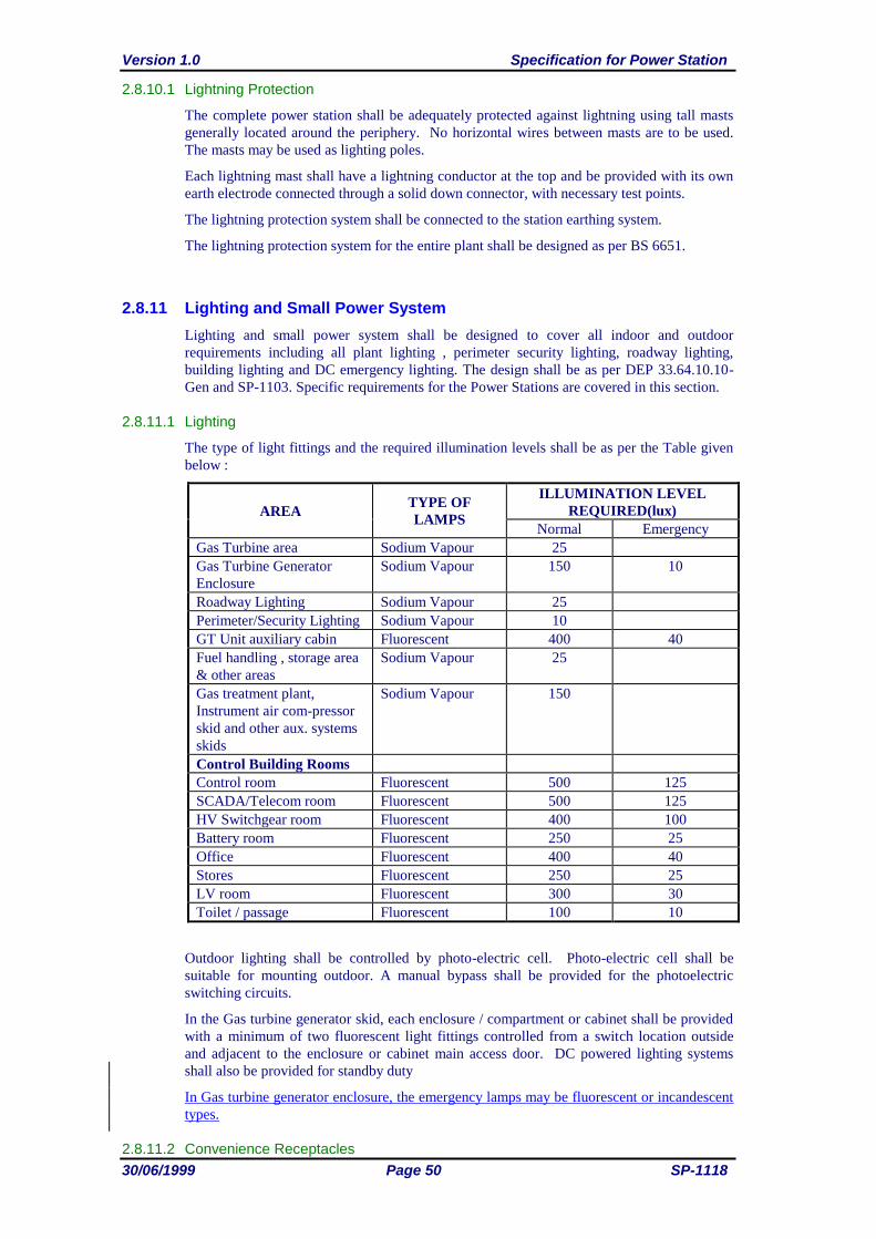
Version 1.0 Specification for Power Station
30/06/1999 Page 50 SP-1118
2.8.10.1 Lightning Protection
The complete power station shall be adequately protected against lightning using tall masts
generally located around the periphery. No horizontal wires between masts are to be used.
The masts may be used as lighting poles.
Each lightning mast shall have a lightning conductor at the top and be provided with its own
earth electrode connected through a solid down connector, with necessary test points.
The lightning protection system shall be connected to the station earthing system.
The lightning protection system for the entire plant shall be designed as per BS 6651.
2.8.11 Lighting and Small Power System
Lighting and small power system shall be designed to cover all indoor and outdoor
requirements including all plant lighting , perimeter security lighting, roadway lighting,
building lighting and DC emergency lighting. The design shall be as per DEP 33.64.10.10-
Gen and SP-1103. Specific requirements for the Power Stations are covered in this section.
2.8.11.1 Lighting
The type of light fittings and the required illumination levels shall be as per the Table given
below :
AREA TYPE OF
LAMPS
ILLUMINATION LEVEL
REQUIRED(lux)
Normal Emergency
Gas Turbine area Sodium Vapour 25
Gas Turbine Generator
Enclosure
Sodium Vapour 150 10
Roadway Lighting Sodium Vapour 25
Perimeter/Security Lighting Sodium Vapour 10
GT Unit auxiliary cabin Fluorescent 400 40
Fuel handling , storage area
& other areas
Sodium Vapour 25
Gas treatment plant,
Instrument air com-pressor
skid and other aux. systems
skids
Sodium Vapour 150
Control Building Rooms
Control room Fluorescent 500 125
SCADA/Telecom room Fluorescent 500 125
HV Switchgear room Fluorescent 400 100
Battery room Fluorescent 250 25
Office Fluorescent 400 40
Stores Fluorescent 250 25
LV room Fluorescent 300 30
Toilet / passage Fluorescent 100 10
Outdoor lighting shall be controlled by photo-electric cell. Photo-electric cell shall be
suitable for mounting outdoor. A manual bypass shall be provided for the photoelectric
switching circuits.
In the Gas turbine generator skid, each enclosure / compartment or cabinet shall be provided
with a minimum of two fluorescent light fittings controlled from a switch location outside
and adjacent to the enclosure or cabinet main access door. DC powered lighting systems
shall also be provided for standby duty
In Gas turbine generator enclosure, the emergency lamps may be fluorescent or incandescent
types.
2.8.11.2 Convenience Receptacles
Specification for Power Station Version 1.0
SP-1118 Page 51 30/06/1999
Sockets with plugs of rating 30A(TPN) and 60A(TPN) shall be provided at various places in
the Plant area and control building .The sockets shall be distributed in such a way that from
any point the nearest socket shall be accessible within 30M.200A (TPN) sockets with plugs
shall be provided for each Generator Transformer and one near the Station auxiliary
transformer for oil filtration.
15A sockets shall be provided for single phase loads inside the control building.
2.8.11.3 Poles
Lighting poles shall be as per the PDO standard design and drawings SP-1105, Group-1 for
lighting system.
2.8.11.4 Emergency Lighting
The emergency lighting system may be obtained by separate luminaries or normal luminaries
supplied by batteries and arranged to automatically switch on upon mains failure. Self
contained luminaries shall incorporate sealed nickel cadmium batteries with internal charger.
Charging shall take place during periods of normal supply with a recharge period of not more
than 24 hours. The emergency lighting shall provide the required lighting for three hours.
All exits shall be fitted with self contained luminaries and mounted above all doors and
maintained ‘on’ at all times.
2.9 INSTRUMENTATION, CONTROL AND MONITORING SYSTEMS
2.9.1 General
The gas turbine generator shall be suitable for Start-up, shutdown, monitoring and
controlling from the Power Station control building by microprocessor based
turbine/generator control system dedicated for each unit from Yibal OR Marmul Master
Control Centres. In addition, limited control and monitoring facilities are provided through
the electrical SCADA system located at the Yibal and Marmul Master Control centres. The
instrumentation and control system shall be reliable, require minimum maintenance and be
capable of starting (including black start by auxiliary diesel generator), running up to full
speed, synchronising, loading, shutdown (normal and emergency) and preparation for re-start
from the remote control room without personnel in attendance at the Site.
2.9.2 Control and Operation Philosophy
2.9.2.1 General
Facilities for automatic and semi-automatic starting, synchronising, loading and shutting
down of the gas turbine generator unit together with comprehensive supervisory equipment
and alarms shall be provided for the Power Station. Turbine/Generator control system shall
be with triple redundancy facility.
Control shall normally be executed from the Dedicated Remote Control System at Remote
Station (Yibal or Marmul). A shrouded emergency stop red mushroom headed push button
shall be provided adjacent to the Turbine Control System operator interface at the Remote
Station.
Auto/manual synchronising facilities shall be provided for the circuit breakers.
2.9.2.2 Gas Turbine Generator Control
The main logic including the sequencing, should be of electronic design utilising solid state
components / microprocessor based systems mounted in withdrawable circuit cards.
Suitable means shall be provided for testing all control circuits, trip cards, on load including
overspeed, without initiating a machine trip. Provision shall also be included for testing all
Version 1.0 Specification for Power Station
30/06/1999 Page 52 SP-1118
trips with the machine running (at no-load) by simulating the trip initiating signal where
necessary.
An electrical protection schemes covering the generator, generator transformer and unit
transformer as shown in the standard drawing shall be located in the Generator Control
Panels/Relay.
Regulated duplicate power supplies shall be provided in the Gas Turbine Control Panel. Fail
safe features shall be provided which shall come into operation in the event of a power
supply failure. No supply failure in a single channel shall cause unit shut down.
The use of timers in the control system shall be avoided wherever possible. Where the use of
timers unavoidable they shall possess inherent fail-safe features.
Protective trip devices shall not be fitted on the emergency dc lubricating oil pumps, or (if
required) dc barring motor. However overload alarm shall be provided. The Gas Turbine
control panel shall be provided with all necessary items to monitor the healthiness of all the
equipment which are required for the safe shutdown of the turbo-generator, but are not
running during normal operation, such that their failure or non-availability initiates an alarm.
The Switchgear/control relay panels shall be provided with all necessary contacts and
terminals for transmitting and receiving the necessary signals for the remote control,
supervision and SCADA facilities.
2.9.2.3 Start-up, Loading and Shutdown
The Turbine/Generator Control equipment shall be capable of effecting set operation as
follows:
Start and automatic run up to minimum governor speed following single manual action
including all necessary interlocks and protection devices for the safe, reliable and
efficient operation of the unit.
Start and automatic run up to synchronous speed, synchronise with other sets (or close
onto a dead system) and load generator (maximum 5%) following single manual action
(an automatic synchronising unit shall be included for the set).
Power turbine speed governor control by manual adjustment and isochronous/droop
selection.
Unit/parallel selection.
AVR datum, MVAR adjustment and AVR/balance/MVAR selection.
Normal controlled shut-down, including gradual off loading and circuit breaker trip
initiation following single manual action.
Emergency trip including circuit breaker trip initiation, following single manual action at
the Turbine control panel or a remote station or a remote automatic trip initiating device.
Compressor cranksoak water wash initiation by single manual action.
Run up to firing speed only without initiating a firing sequence.
Any other facility for safe operation of the plant.
The various facilities for semi automatic operation shall be arranged in a logical manner on
the panel to correspond with the order of the various steps in the starting sequence and the
necessary indications shall be in a logical position relative to the associated controls.
Automatic control of the rate of fuel admission in relation to maximum allowable turbine
inlet temperature and rate of temperature rise during starting and loading shall be provided.
It shall be possible to select base or peak load and rapid or normal start and the controls shall
ensure that the machine is not operated beyond the permitted range.
On automatic synchronising, the unit shall be automatically loaded to 5% of its base load
rating on the closure of the circuit-breaker. Additional loading can be carried out manually,
the necessary facilities being available in the Turbine Control panel and/or via the remote
control system (Dedicated Remote Control System as well as SCADA).
Specification for Power Station Version 1.0
SP-1118 Page 53 30/06/1999
Failure during a start sequence shall be annunciated such that the particular cause of failure is
known.
2.9.2.4 Load Limiting
A maximum load limiting device shall be provided which will override the speed/load
governor and reduce the fuel flow to the combustion system. In order to maintain the mean
turbine exhaust temperature below a set limit determined according to the selected duty (i.e.
either base or peak load).
The limiting device shall operate from a signal derived from the turbine exhaust temperature
and an alarm shall be provided to indicate when the set limit is reached.
Provision shall be made in the design to facilitate the checking of temperature signal as
sensed by the load limiter.
If, in addition to the limiting parameter of turbine exhaust temperature any other parameters
requires limiting at any operating condition, the necessary limiting device shall be provided
together with an alarm to indicate that it is in operation.
The gas turbine shall automatically switch to peak load operation on falling frequency. This
shall be alarmed to remote. Also an override for this facility shall be provided.
2.9.2.5 Alarm and Trip Annunciations
A turbine alarm and trip annunciation scheme shall be designed and provided such that
specified alarms and trips, and all others which are necessary or considered desirable for the
safe and efficient operation of the plant shall be included.
All the necessary equipment shall be provided so that alarms and trip indications, shall be
repeated to the Dedicated Remote Control System and SCADA system. The local alarm
reset facility shall also cancel the remote alarms where applicable. The audible alarm on the
Generator Control and shall be operative only when the unit is under local control.
Alarm and trip initiating devices and systems shall be segregated from control circuits.
The equipment provided shall be capable of accepting either "fleeting" or "maintained"
initiation signals with provision for changeover to either.
For the purposes of the annunciation scheme the various fault conditions shall be grouped
into the following categories:-
Trip indicates shut down on fault condition
Pre-Alarm to indicate a fault condition, which, if corrective action is not taken will result
in a shutdown.
The first level shall initiate a category (b) Alarm followed by a category (a) Alarm and Trip.
In the event of a mechanical trip the system shall be designed so as to trip the unit shutdown
valve.
First-up facilities for fault diagnosis are required.
2.9.3 Gas Turbine Generator Instrumentation
The gas turbine instrumentation is to be reliable, of high quality, suitable for the outdoor,
remote location of the Site. All items of instrumentation are to be rated for the full ambient
temperature range and suitably protected by cooling air and/or sunshades. All
instrumentation is to be located to provide easy access for maintenance. Each item
interfacing with the process shall be supplied with isolating valves and/or manifolds,
arranged for easy connection of test instruments for calibration. Instrument mountings
should be designed so that removal and replacement can be accomplished in minimum time.
Instrument locations should be arranged so that testing and calibration can be performed
without having to shutdown the machine.
Vibration monitoring of the machine bearings shall be measured in both horizontal and
vertical planes. This shall be selected from the PDO’s approved vendor list and shall be used
Version 1.0 Specification for Power Station
30/06/1999 Page 54 SP-1118
for protection of the train. Intrinsic safety philosophy shall be implemented with Pepperl +
FUCHS galvanic isolation barriers type ICHD3-1vR/EX126 Part No. 71661.
Calibration and testing of instruments shall be carried out according to DEP's 62.10.08.11
and 62.10.09.11
Generator control panel and Turbine control Speedtronic Mark V control system or
equivalent shall be an integral part of the equipment used during factory acceptance tests of
the gas turbine unit.
All instrumentation shall be in accordance with latest revision of the following PDO SP’s
and Shell DEP’s referred in section 1.2.1 and 1.2.2 respectively.
The inspection and testing shall be in accordance with the DEP’s referred in section 1.2.2
2.9.4 Generator Control Panel
The Generator shall be provided with its own self-contained protection, instrumentation,
monitoring, synchronisation and excitation control system. The Control Panel shall be
mounted adjacent to the Turbine control Panel and shall be identical in general style and
size. The panels shall cover all requirements for local control and monitoring of each gas
turbine generator set.
The front of panel equipment shall include the following:
Auto start and stop - pushbutton
Manual start and stop - pushbutton
Emergency trip-pushbutton (shrouded).
Compressor clean start-pushbutton
Control supply isolating switch
Manual/auto/no-load/selector switch
Key operated electrical override
Manual excitation on - pushbutton
Excitation raise/lower - switch
AVR null balance meter
Base/peak operation selector switch.
Rapid/normal start selector switch.
Synchronising selector switch auto/manual/dead bus close.
Generator Circuit breaker close/neutral/trip control switch.
Synchronising instruments. (synchroscope, dual voltage/dual frequency meter.)
Indications, alarms and metering
At least 10% spare panel space shall be available and be evenly distributed over the panel
face.
2.9.5 Dedicated Remote Control System
Full control and diagnostic facilities shall be assured by incorporating the gas turbine on the
Dedicated Remote Control System. While ‘GE’ make ‘SMART REMOTE’ has been used as
the Dedicated Remote Control System for the existing facilities in North Oman, DMACS
system is being used as the Dedicated Remote Control System for the existing facilities in
South Oman. The facilities to be provided for the gas turbine generator on the Dedicated
Remote Control System shall be at least equivalent to the existing system The controls to be
provided shall include :
Auto start and stop.
Emergency trip
Base/peak operation selection
Rapid start selection
Specification for Power Station Version 1.0
SP-1118 Page 55 30/06/1999
Excitation raise/lower
Load raise/lower
Synchronising selector switch inhibit release
Generator Circuit Breaker control
Auto-manual dead bar-off indicates synchronising mode selection.
Select isochronous or droop mode
The information for remote control of the machine via Dedicated Remote Control System
shall have to be transferred between the Power Station and the remote control room through
the microwave system.
2.9.5.1 Mimic
The existing remote control room mimics at Yibal or Marmul shall be modified to reflect the
changes in the system. The modification shall utilise similar materials to the existing
equipment, so that the modifications shall appear as an integral part of the existing facilities
in style, colour and size.
2.9.5.1i) Dynamic Mimic
The existing dynamic mimic shall be extended and shall include the following facilities:
MW power flow in the lines
Load on each machine
Frequency of the machine
PS station common alarm indication
ii) Static Mimic
The existing static mimic shall be extended to cover the system expansion. This is an artwork
modification only.
2.9.6 SCADA
Power Station shall be provided with a new SCADA system where there is no SCADA
already existing or else extension of the existing SCADA system shall be made.
The SCADA system shall fully comply with SP-1116.
Transmitting of SCADA signals from the Power Station to the remote control room shall be
via two alternative routes formed with a combination of PLCC, microwave and fibre optic
systems.
2.9.7 Metering
Energy flows from each generator and each outgoing feeder to PS auxiliary system shall have
to be measured at the PS by precision (“Commercial Billing”) grade energy meters. The
energy meters shall be provided with pulse transmitting contacts for SCADA.
Check metering facility (duplication of meters) is generally not required. However, all the
metering CT and VT shall be designed (burdens) such that check metering facility can be
added at a later date.
2.10 EMERGENCY SHUTDOWN SYSTEM
2.10.1 General
The Station safeguarding system shall be designed for high integrity and unmanned
operation.
Version 1.0 Specification for Power Station
30/06/1999 Page 56 SP-1118
The safe shutdown of equipment in an emergency shall be evaluated against the need to
maintain high electrical availability therefore, a total station ESD is to be considered in only
the most serious incidence. Preference will be given to Process Shutdown (PSD's).
It is proposed that an ESD of the total facility can only be manually initiated. The ESD can
be activated from either the power plant or remote control centres (Yibal or Marmul).
PSD's can be activated automatically or manually.
When an installation is extended with additional unit, the safe-guarding system of the old and
new unit shall be integrated and a combined cause and effect drawing shall be made.
2.10.2 PSD
The GT 'process train' in terms of a PSD, includes the associated gas treatment plant,
generator transformer and switchgear
In the event a PSD of one gas turbine train shutting down, the following should occur :-
Gas Treatment plant ESDVs would close isolating and depressurising the gas system.
GT would trip and Generator breaker open.
If a PSD was initiated by a fire alarm then automatic fire protection systems, where provided,
should activate in the alarmed fire zone.
The tripping of the gas turbine or electrical system should not automatically result in the
depressurisation of the gas treatment plant. Only an emergency shutdown or fire in the gas
turbine or associated electrical equipment should cause the gas system to depressurise.
2.10.3 ESD
An ESD would result in all PSD areas activating.
2.10.4 Resetting After A PSD Or ESD
It shall not be possible to reset the ESD or PSD systems and valves remotely from any
location. The operator is required to go to the site and confirm that the plant is safe before
locally resetting the PSD or ESD systems.
2.11 ENVIRONMENTAL CONSIDERATIONS
The Company is required to submit an Environmental Impact Statement (EIS) for new power
plants and extensions to existing plants. The Company will submit an EIS to Ministry of
Regional Municipalities & Environment (MRME) who will issue an Environmental Permit
with a list of requirements. These requirements are to be strictly complied with.
Key issues will be SO2 ground level concentrations, releases of compounds to the
atmosphere and disposal of wastes. The Company has standardised on a minimum gas
turbine stack height of 15 metres for 30 MW gas turbines. This aspect shall be critically
reviewed by the supplier. The use of low NOX gas turbine combustion systems is mandatory.
2.12 CIVIL WORKS
All civil works shall be as per the relevant SPs and DEPs listed under Clause 1.2.1.
Specification for Power Station Version 1.0
SP-1118 Page 57 30/06/1999
APPENDIX 1 : STANDARD DRAWINGS
STD-1-1700-001-1-0 - Power Station - PEFS Knock Out Vessel/Strainer
STD-1-1700-002-1-0 - Power Station - PEFS Electric Water Bath Heater
STD-1-1700-003-1-0 - Power Station - PEFS Pressure Reduction Skid
STD-1-1700-004-1-0 - Power Station - PEFS Filter Separator Skid
STD-1-1700-005-1-0 - Power Station - PEFS Metering Skid
STD-1-1700-006-1-0 - Power Station - PEFS Condensate Drain Vessel
STD-1-1701-001-1-0 - Power Station - UEFS Instrument Air System
STD-1-1701-002-1-0 - Power Station - UEFS Instrument Air System
STD-1-1701-003-1-0 - Power Station - UEFS Instrument Air System
STD-1-1701-004-1-0 - Power Station - UEFS Auxiliary Generator Fuel System
STD-1-1701-005-1-0 - Power Station - UEFS Make Up Water System
STD-1-1702-001-1-0 - Power Station - PFS Fuel Gas Treatment Plant
STD-3-1800-001-1-0 - Power Station - Site Layout
STD-4-2310-001-1-0 - Power Station - Key Single Line Diagram
STD-4-2311-001-1-0 - Power Station - Equipment Layout Control Building (Alternative - 1)
STD-4-2311-002-1-0 - Power Station - Equipment Layout Control Building (Alternative - 2)
STD-4-2312-001-1-0 - Power Station - Area Layout Classification
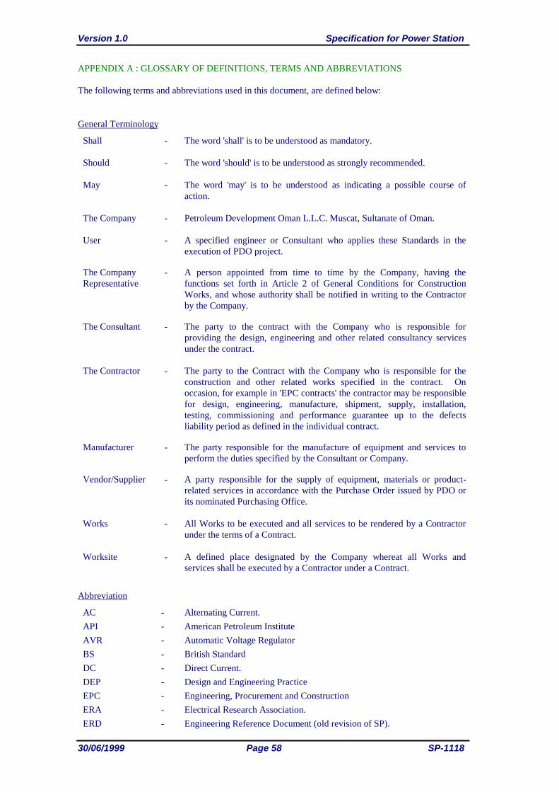
Version 1.0 Specification for Power Station
30/06/1999 Page 58 SP-1118
APPENDIX A : GLOSSARY OF DEFINITIONS, TERMS AND ABBREVIATIONS
The following terms and abbreviations used in this document, are defined below:
General Terminology
Shall - The word 'shall' is to be understood as mandatory.
Should - The word 'should' is to be understood as strongly recommended.
May - The word 'may' is to be understood as indicating a possible course of
action.
The Company - Petroleum Development Oman L.L.C. Muscat, Sultanate of Oman.
User - A specified engineer or Consultant who applies these Standards in the
execution of PDO project.
The Company -
Representative
A person appointed from time to time by the Company, having the
functions set forth in Article 2 of General Conditions for Construction
Works, and whose authority shall be notified in writing to the Contractor
by the Company.
The Consultant - The party to the contract with the Company who is responsible for
providing the design, engineering and other related consultancy services
under the contract.
The Contractor - The party to the Contract with the Company who is responsible for the
construction and other related works specified in the contract. On
occasion, for example in 'EPC contracts' the contractor may be responsible
for design, engineering, manufacture, shipment, supply, installation,
testing, commissioning and performance guarantee up to the defects
liability period as defined in the individual contract.
Manufacturer - The party responsible for the manufacture of equipment and services to
perform the duties specified by the Consultant or Company.
Vendor/Supplier - A party responsible for the supply of equipment, materials or product-
related services in accordance with the Purchase Order issued by PDO or
its nominated Purchasing Office.
Works - All Works to be executed and all services to be rendered by a Contractor
under the terms of a Contract.
Worksite - A defined place designated by the Company whereat all Works and
services shall be executed by a Contractor under a Contract.
Abbreviation
AC - Alternating Current.
API - American Petroleum Institute
AVR - Automatic Voltage Regulator
BS - British Standard
DC - Direct Current.
DEP - Design and Engineering Practice
EPC - Engineering, Procurement and Construction
ERA - Electrical Research Association.
ERD - Engineering Reference Document (old revision of SP).
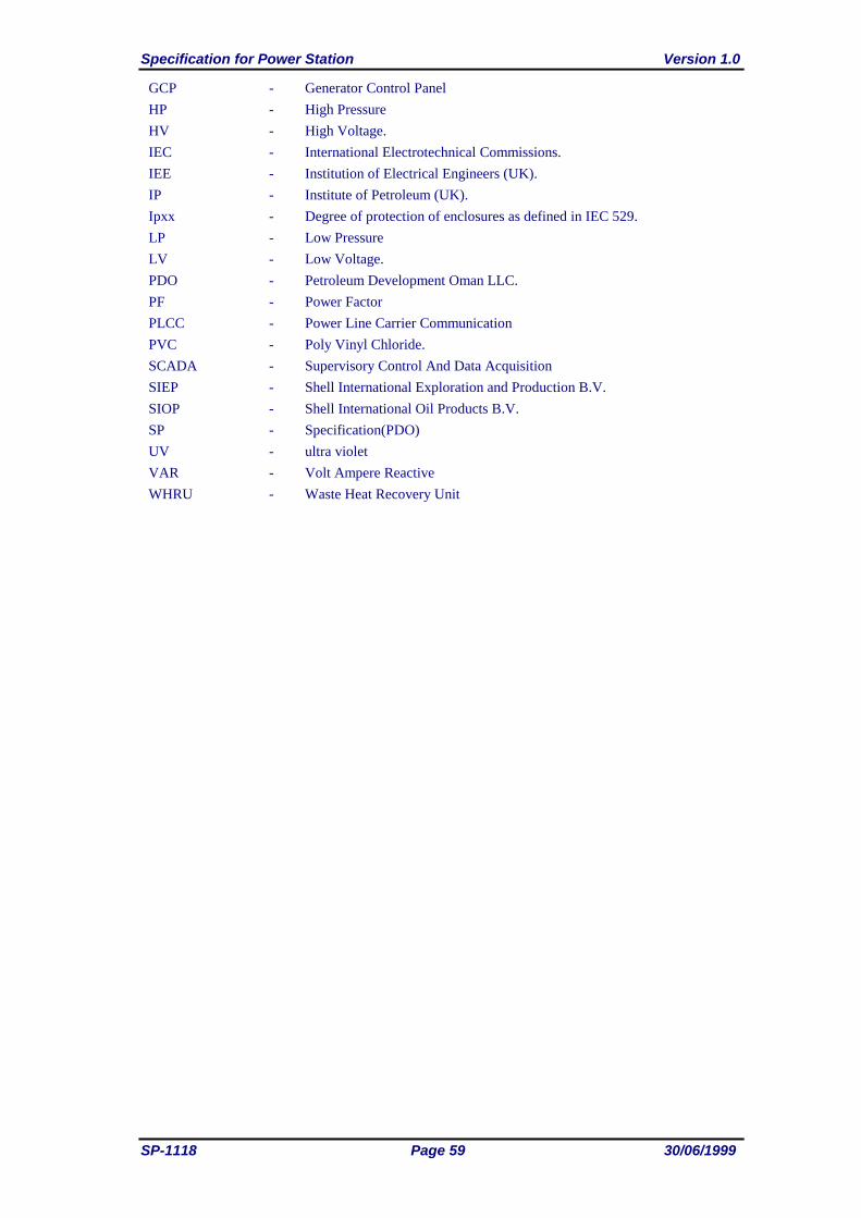
Specification for Power Station Version 1.0
SP-1118 Page 59 30/06/1999
GCP - Generator Control Panel
HP - High Pressure
HV - High Voltage.
IEC - International Electrotechnical Commissions.
IEE - Institution of Electrical Engineers (UK).
IP - Institute of Petroleum (UK).
Ipxx - Degree of protection of enclosures as defined in IEC 529.
LP - Low Pressure
LV - Low Voltage.
PDO - Petroleum Development Oman LLC.
PF - Power Factor
PLCC - Power Line Carrier Communication
PVC - Poly Vinyl Chloride.
SCADA - Supervisory Control And Data Acquisition
SIEP - Shell International Exploration and Production B.V.
SIOP - Shell International Oil Products B.V.
SP - Specification(PDO)
UV - ultra violet
VAR - Volt Ampere Reactive
WHRU - Waste Heat Recovery Unit
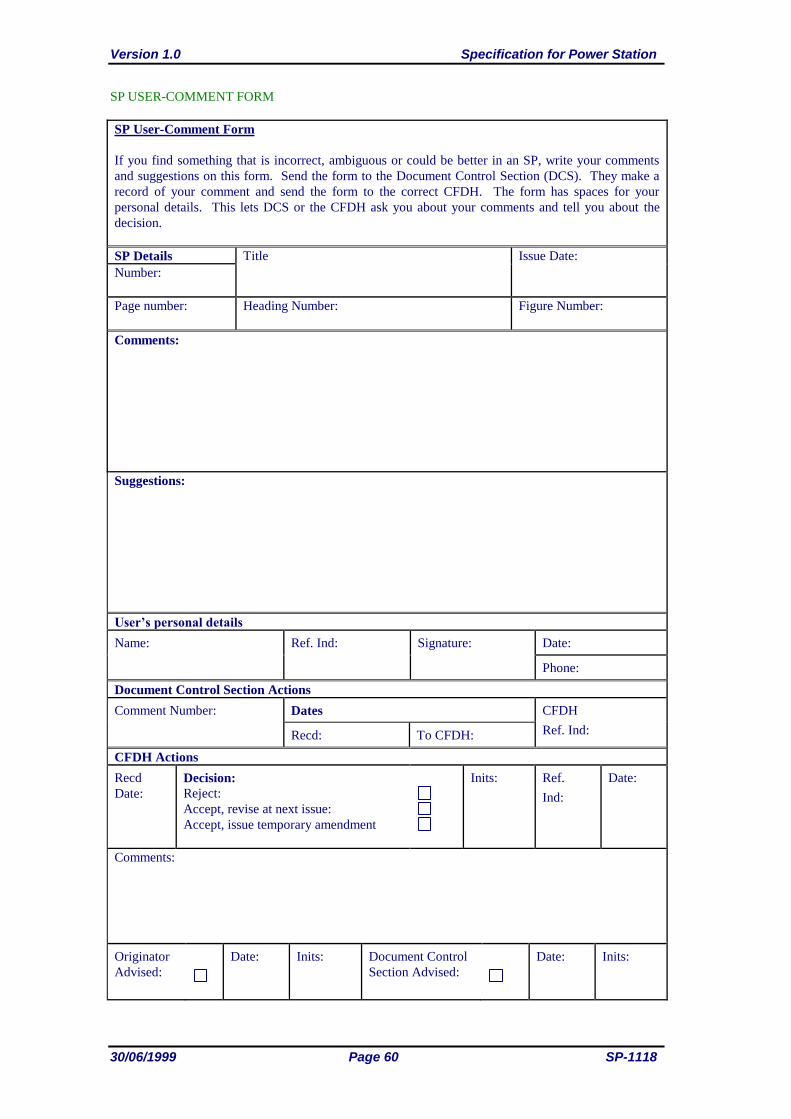
Version 1.0 Specification for Power Station
30/06/1999 Page 60 SP-1118
SP USER-COMMENT FORM
SP User-Comment Form
If you find something that is incorrect, ambiguous or could be better in an SP, write your comments
and suggestions on this form. Send the form to the Document Control Section (DCS). They make a
record of your comment and send the form to the correct CFDH. The form has spaces for your
personal details. This lets DCS or the CFDH ask you about your comments and tell you about the
decision.
SP Details Title Issue Date:
Number:
Page number: Heading Number: Figure Number:
Comments:
Suggestions:
User’s personal details
Name:
Ref. Ind: Signature: Date:
Phone:
Document Control Section Actions
Comment Number: Dates CFDH
Ref. Ind: Recd: To CFDH:
CFDH Actions
Recd
Date:
Decision:
Reject:
Accept, revise at next issue:
Accept, issue temporary amendment
Inits: Ref.
Ind:
Date:
Comments:
Originator
Advised:
Date: Inits: Document Control
Section Advised:
Date: Inits: