Embed Size (px)
Citation preview

SP/SP28: 061102 Page 1 of 18
SPECIFICATION FOR MAINTENANCE AND INSTALATION OF INDUCTIVE LOOPS AT TRAFFIC MONITORING SITES
TNZ P/28: November 2006
SPECIFICATION FOR MAINTENANCE AND INSTALLATION OF INDUCTIVE LOOPS AT
TRAFFIC MONITORING SITES CONTENTS 1.0 SCOPE 2.0 RELATED DOCUMENTS 3.0 APPLICATION 4.0 SITE SELECTION CRITERIA
4.1 Working Life 4.2 Pavement Life Requirements 4.3 Road Geometry 4.4 Traffic Behaviour Characteristics 4.5 Safety Criteria 4.6 Utilities - for continuous telemetry sites only 4.7 Other Considerations
5.0 INSTALLATION
5.1 General Requirements 5.2 Layout 5.3 Loop Wire 5.4 Sealant 5.5 Traffic Management and Safety 5.6 Utilities and services 5.7 Permission from other parties 5.8 Loop and Loop Feeder Installation 5.9 Toby Installation 5.10 Cabinet Installation 5.11 Telemetry Site Requirements 5.12 Testing, Commissioning and Reporting
6.0 WARRANTY 7.0 INSPECTION AND PAYMENT APPENDICES – Drawing
• Inductive Loop Layout Drawing 1 • Section Detail Drawing 2

TNZ P/28: November 2006
SP/SP28: 061102 Page 2 of 18
SPECIFICATION FOR MAINTENANCE AND INSTALATION OF INDUCTIVE LOOPS AT TRAFFIC MONITORING SITES
• Toby Detail Drawing 3 • Cabinet Detail Drawing 4 • Layout for Other Lane Configurations Drawing 5

TNZ P/28: November 2006
SP/SP28: 061102 Page 3 of 18
SPECIFICATION FOR MAINTENANCE AND INSTALATION OF INDUCTIVE LOOPS AT TRAFFIC MONITORING SITES
1.0 SCOPE This specification sets out the requirements for the selection of sites and the installation of inductive loops at traffic monitoring sites located on state highways. 2.0 RELATED DOCUMENTS
• Transit New Zealand Manual “Traffic Monitoring for State Highways SM052”
• Code of Practice for Temporary Traffic Monitoring COPTTM • Vehicle Loop Detector Sensors – Australian Standard AS 2703 – 1987 • Draft State Highway Geometric Design Manual
3.0 APPLICATION This specification applies to all permanent traffic monitoring inductive loops installed on State Highways. It is applicable to new installations and existing installations requiring maintenance. 4.0 SITE SELECTION CRITERIA The following is guidance on site selection for both count and classification, however compromises may have to be made on a site-by-site basis. The Transit New Zealand (TNZ) project manager shall approve the final position of any new loops. This is not suitable for the selection of speed sites.
4.1 Working Life
The target working life for an inductive loop installation site is ten years minimum uninterrupted operation.
4.2 Pavement Life Requirements
Pavement structural integrity for longevity • The road pavement at the selected site shall have no history of
rutting, shoving, cracking or flushing.
Future works • There shall be no works proposed in 10 year forward works
programme or any other works which will compromise the viability or longevity of the site. Reseals may be accepted as an appropriate site treatment provided there are no proposed pre-seal treatments that would affect the integrity of the loops.

TNZ P/28: November 2006
SP/SP28: 061102 Page 4 of 18
SPECIFICATION FOR MAINTENANCE AND INSTALATION OF INDUCTIVE LOOPS AT TRAFFIC MONITORING SITES
Surfacing thickness • At least 40 millimetres thick bituminous surfacing layer.
Surface thickness can be from multiple seal layers or thin asphaltic concrete. A new surface should not be established just for the loop site that is inconsistent with the surface friction requirements of the whole treatment length, inclusive of the site.
4.3 Road Geometry
• Road sections in the middle of horizontal and vertical curves are to be avoided as a loop installation location.
4.4 Traffic Behaviour Characteristics
The proposed site shall be assessed against the following traffic behaviour characteristics:
• Lane discipline (wheel tracking to be within lanes) • Accelerating and decelerating traffic to be avoided • Queuing traffic areas to be avoided • Overtaking manoeuvres to be minimal • Vehicle parking areas to be avoided
4.5 Safety Criteria
The Consultant shall ensure the following safety criteria are met: • The positioning of the cabinets shall comply with TNZ’s
current standards for above ground utility structures and roadside hazards.
• The cabinet location must be on boundary or behind safety barrier wherever possible. The road users visibility is not to be impeded by cabinet structure.
• The bottom of any post-mounted cabinet shall be no higher than 300 millimetres above the ground finishing level.
• A standard TNZ hazard identification marker must also be added to the side of the cabinet facing oncoming traffic.
4.6 Utilities - for continuous and telemetry sites only The Consultant shall ensure the following utility services are available:
• 240 volts AC electricity (continuous and/or telemetry only); and • Reliable and TNZ compatible communications service, (telemetry
only).

TNZ P/28: November 2006
SP/SP28: 061102 Page 5 of 18
SPECIFICATION FOR MAINTENANCE AND INSTALATION OF INDUCTIVE LOOPS AT TRAFFIC MONITORING SITES
4.7 Other Considerations
The Consultant shall take into consideration the following considerations when assessing the appropriateness of a count site location:
• Intersections and passing lanes to be avoided • Areas susceptible to flooding are to be avoided. • The distance from loops to cabinet must not exceed 25 metres.
Although distances up to 200 metres can be achieved, this requires confirmation that equipment is also capable of working under these conditions.
• High voltage installations or high voltage overhead/underground power cables are to be avoided.
• The site MUST be in the specified traffic link. Refer to TNZ document “Traffic Monitoring for State Highways” for more information on traffic links.
5.0 INSTALLATION This specification is to be read in conjunction with the following appended Drawings.
• Inductive Loop Layout Drawing 1 • Section Detail Drawing 2 • Toby Detail Drawing 3 • Cabinet Detail Drawing 4 • Layout for Other Lane Configurations Drawing 5
This specification shall apply to all new traffic monitoring sites, which are to use inductive loops, and where loops are to be installed in either chip seal or AC pavements. Relevant components of this specification shall also apply to the maintenance or repair of existing sites. 5.1 General Requirements
The Consultant shall ensure that the loops are constructed such that no damage is caused to the surrounding pavement and that the finished installation shall be waterproof, so the integrity of the existing pavement is not compromised.
5.2 Layout
Site layouts shall be in accordance with Drawing No. 1 in the appendices.
TNZ P/28: November 2006
SP/SP28: 061102 Page 6 of 18
SPECIFICATION FOR MAINTENANCE AND INSTALATION OF INDUCTIVE LOOPS AT TRAFFIC MONITORING SITES
5.3 Loops Wire
Only wire that has been specifically manufactured for traffic loops shall be used in loop installations. The Consultant shall provide documented evidence that all proposed loop wire meets this requirement and Australian Standard ‘AS 2703 – 1987 Vehicle Loop Detector Sensors’ before installations commence.
Only approved Loop and Feeder Wire types may be used in loop installations. Suitable wire types are as follows:
• Suitable loop wire
General Cable Ltd (NZ) Traffic Loop 1 (25007016) or equivalent / superior product approved by Transit New Zealand Product Approval System, detailed at www.transit.govt.nz/technical information.
• Suitable feeder wire
General Cable Ltd (NZ) Traffic Loop 2 (25035016) or equivalent / superior product approved by Transit New Zealand Product Approval System, detailed at www.transit.govt.nz/technical information.
5.4 Sealant
The Consultant is responsible for effectively sealing the inductive loops once the wires have been inserted. The sealant to be inserted shall be a rubberised bitumen adhesive sealant and inserted within 2 hours of the saw cut being made. The sealant shall be finished flush to the road surface. Only approved Sealant types may be used in loop installations. Suitable sealant types are as follows:
• Suitable sealant Flintkote Tixophalte or equivalent or superior products approved by Transit New Zealand produced approval system, detailed at www.transit.govt.nz/technical information.
5.5 Traffic Management and Safety
Installations of loops will require lane closures (either stop/go or lane shifts) and possibly pedestrian control. This work shall be carried out within the requirements of an approved TMP (Traffic Management Plan) in accordance with the requirements of Transit New Zealand’s Code of Practice for Temporary Traffic Management (COPTTM).

TNZ P/28: November 2006
SP/SP28: 061102 Page 7 of 18
SPECIFICATION FOR MAINTENANCE AND INSTALATION OF INDUCTIVE LOOPS AT TRAFFIC MONITORING SITES
5.6 Utilities and services
The Consultant shall ensure all underground utilities and services are located prior to any works commencing. The utility and service locations must also be included in the documentation stored within the cabinets.
5.7 Permission from other parties
Where installations encroach on areas maintained by other authorities, their permission shall be obtained by the Consultant and/or Contractor, prior to works commencing at the site.
5.8 Loop and Loop Feeder Installation
The installation shall be in accordance with the following appended drawings:
o Inductive Loop Layout Drawing 1 o Section Detail Drawing 2 o Toby Detail Drawing 3 o Layout for Other Lane Configurations Drawing 5
• Chip Seal Pavements. Saw cuts in the pavement shall not overlap on
corners to produce triangular “islands”, as this creates a weak point in the seal, which can lead to future potholing. If loops are to be chip sealed over, location measurements and As Built drawings MUST be updated and completed before sealing takes place.
• Asphalt Pavements. Saw cuts in the pavement shall be rectangular
and then the corners blunted using a chisel to remove any sharp edges.
• New Pavements. Installation in new pavements is only possible where the minimum cover to loop wires can be achieved without cutting into the base course. Where this is not achievable, consideration should be given to the following:
The saw cuts are to be between 4mm and 6mm wide.
If the new pavement is surfaced with asphaltic concrete, then the thickness of the asphaltic concrete must be increased in this area so that the specification can be adhered to.
If the new pavement is chip seal, then apply a 40 millimetres layer of asphaltic concrete first and cut the loops into this prior to the sealing being carried out. In this situation, careful design of the chip seal and asphaltic concrete is necessary to prevent flushing or rutting problems. Also, the construction needs to be done so that the final surfacing is level, contiguous and free from transition “bumps”. Appended Drawing No. 1 shows the required extent of this pre-treatment. It is preferable to identify
TNZ P/28: November 2006
SP/SP28: 061102 Page 8 of 18
SPECIFICATION FOR MAINTENANCE AND INSTALATION OF INDUCTIVE LOOPS AT TRAFFIC MONITORING SITES
such areas prior to tender so that necessary items can be incorporated into the pavement construction contract.
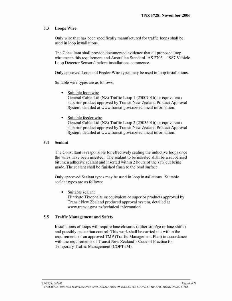
• Loop feeders (Toby box to cabinet). If the distance from the Toby to the Cabinet is less than 5m, then the feeder cable can be omitted. However, in this case, the loop tails need to be twisted from the Toby to the cabinet with 10 twists per metre.
o If loop feeder is ������������������ 25metres, the loop feeder wire may be Traffic Loop 1 with twisted pairs (10 twists per metre) or Traffic Loop 2. Note: Traffic Loop 2 is shielded and does not require twisting.
o If the loop feeder is greater than 25metres and less than 200metres the loop feeder wire must be Traffic Loop 2. Note: Traffic Loop 2 is shielded and does not require twisting.
Loop feeder wires are to be colour coded and permanently labelled with loop number at the connection in the Toby box and at the termination in the cabinet.
Loop tails (loop to Toby box) are to be installed to avoid crosstalk. Twisting should not be necessary if specified wire is used. Pairs are to be permanently labelled with loop number at the connection in the Toby box.
Typical Completed Loop

TNZ P/28: November 2006
SP/SP28: 061102 Page 9 of 18
SPECIFICATION FOR MAINTENANCE AND INSTALATION OF INDUCTIVE LOOPS AT TRAFFIC MONITORING SITES
5.9 Toby Installation
Tobys shall be pre cast concrete with a robust cast iron lid. The Consultant shall locate Toby boxes as close as practicable to the trafficable areas and footpaths. Toby boxes are to be mounted flush with the surrounding surface and are to be bedded on 100 millimetres of free draining material, surrounded by a 150 millimetres deep by 150 millimetres wide concrete haunching. The junction box lid and concrete shall be set flush with the surrounding ground level. The Consultant shall ensure the completed structure is able to withstand heavy traffic wheel loading. Installation shall be in accordance with appended Drawings No. 3.
Typical Toby Box Installation
5.10 Cabinet Installation
The Consultant shall ensure that the cabinet installation is in accordance with appended Drawing No. 4.
All cabinets shall be weather proof, vermin and insect proof, securable and be dimensionally sufficient to accommodate any proposed equipment. Cabinets are to have powder coated tan or green surface treatment. The Consultant shall ensure that a brass padlock and matching keys are supplied with these cabinets. These padlocks should have matching keys for all cabinets in that contract. This is at the discretion of Transit’s project manager.

TNZ P/28: November 2006
SP/SP28: 061102 Page 10 of 18
SPECIFICATION FOR MAINTENANCE AND INSTALATION OF INDUCTIVE LOOPS AT TRAFFIC MONITORING SITES
Typical Harding 2002 Cabinet Typical Montrose Cabinet Continuously Powered Sites Non - Continuously Powered Sites
• Continuously Powered Sites.
For all sites requiring a continuous power supply, the Consultant shall use Harding 2002 Traffic Cabinets or similar approved mounted on a cast in-situ concrete base.
If there is no barrier protection at the required location of a cabinet, the Consultant shall locate the cabinet as far from the road edge line as possible, within the State Highway boundary.
The minimum distances are as follows:
Minimum Distance from Edgeline (No Barrier)
Annual Average Daily Traffic
Straight Curve
>10,000 9m 9m 1,000 – 10,000 5m 9m
<1,000 4m 9m
If compliance to the above is not possible, either a barrier is to be provided, or an alternative location investigated.
If there is barrier protection available at the required location of a cabinet, the Consultant shall position the cabinet at least one metre behind the barrier’s posts, if a boundary location is not possible. This dimension can be reduced, as long as compliance with the State Highway Geometric Design Manual, Table 7.2: Typical Design Deflections for Longitudinal Barriers, is maintained.

TNZ P/28: November 2006
SP/SP28: 061102 Page 11 of 18
SPECIFICATION FOR MAINTENANCE AND INSTALATION OF INDUCTIVE LOOPS AT TRAFFIC MONITORING SITES
• Non- Continuously Powered Sites.
The Consultant shall ensure that all non-continuously powered sites use cast aluminium Montrose Foundry cabinets, sheet aluminium cabinets or similar approved, mounted on timber posts.
The timber posts are to be:
o Rough-sawn tanalised H4 and painted white. o Posts size shall be 100 millimetres x 150 millimetres (150
millimetres face to be perpendicular to the cabinet face) o Embedded to a depth of 600 millimetres minimum, in cast in-situ, f
'c = 17.5 Mpa concrete. A 150 millimetres thick concrete pad is desired between posts.
o Drilled with a 35 millimetres diameter hole, 100 millimetres above ground level and parallel to the road edge to ensure the posts are frangible and the correct shear mechanism is maintained.
As the timber posts to the cabinet are frangible, the location requirements for non-continuously power sites are more flexible. The Consultant shall locate cabinet with frangible posts to provide the minimum probability of vehicular impact. It should be a minimum of 3 metres from the edge of pavement seal.
5.11 Telemetry Site Requirements
The installation of the telephone service and power supply shall be organised, by the Consultant, in advance and coordinated to be carried out during installation of the other equipment.
Where mains power supply is required, the Consultant shall ensure the relevant Electrical Regulations are adhered to and appropriate compliance certificates obtained.
The Consultant shall ensure that all continuous telemetry sites have suitable high voltage surge protection on all loop circuits; telephone circuit and power supply circuits.

TNZ P/28: November 2006
SP/SP28: 061102 Page 12 of 18
SPECIFICATION FOR MAINTENANCE AND INSTALATION OF INDUCTIVE LOOPS AT TRAFFIC MONITORING SITES
5.12 Testing, Commissioning and Reporting
The Consultant shall ensure that each loop is tested at the cabinet terminals. This testing is recommended prior to the loops being sealed. The resulting measurements shall be recorded and be within the following ranges and those specified in Australian Standard AS 2703 – 1987 Vehicle Loop Detector Sensors:
Loop inductance 50 – 200 micro henries Maximum loop resistance 13 Ohms Minimum loop resistance to ground 20 mega Ohms
In addition, the Consultant shall ensure that an commissioning check is completed by ensuring that a loop counter or loop classifier is connected (and calibrated if necessary) to test record data at 15minute intervals and that the installation is performed correctly.
The consultant is required to provide 15minute visual survey forms.
The Consultant shall ensure a detailed commissioning report of each installation is produced and forwarded to the Transit New Zealand Project Manager, within one week of the commissioning of the count site. The commissioning report shall include:
o Precise As Built Drawings; o Materials specifications (loops wire, sealant etc); o General photos of the site and specific; o Detailed photos of each loop, Toby and cabinet; o Results of electrical measurements; o Site route position (+/- 5 metres); o Proposed Traffic Monitoring System (TMS) site reference; o Results of the site commissioning checks; o 15minute visual survey form with accuracy details.
6.0 Warranty
The Consultant shall provide a 12-month maintenance warranty for all work.
7.0 Inspection and Payment
The client or the client’s representative may inspect the site to ensure compliance with this specification before any payment is made.

TNZ P/28: November 2006
SP/SP28: 061102 Page 13 of 18
SPECIFICATION FOR MAINTENANCE AND INSTALATION OF INDUCTIVE LOOPS AT TRAFFIC MONITORING SITES
APPENDICES
DRAWINGS

TNZ P/28: November 2006
SP/SP8: 061102 SPECIFICATION FOR MAINTENANCE AND INSTALATION OF INDUCTIVE LOOPS AT TRAFFIC MONITORING SITES Page 14 of 18
Boundary Fence
Cabinet (see Drawing 4)
Edge of Trafficable Shoulder
Toby Box (See Drawing 3)
Increasing Direction
2.A (see Dwg 2)
1.6m
0.6m Max
2.0m Typical
0.8m from edge of trafficable lane
Hatching shows extent of AC pre treatment required
200mm x 200mm Chamfer
X1 X2 X1
Loops centred in traffic lane
INDUCTIVE LOOP LAYOUT DRAWING 1 VERSION 1
Notes: 1. For speed and or length classification, install loops 1,2,3 & 4 2. For Count only install loops 1 & 4 3. Position Toby Box and loops 3 & 4 to avoid interference between loop tails 3 & 4 and loops 1 & 2 4. Any excavated ground should be reinstated to original.
Loops Spacing
Speed Environment X1 X2 X2
(T) >70kph 2m 2m 4m <= 70 kph or Queuing 1m 1m 1m
(T) = Telemetry Sites Only
2.C (see Dwg 2)
2.B (see Dwg 2)
TNZ P/28: November 2006
SP/SP8: 061102 SPECIFICATION FOR MAINTENANCE AND INSTALATION OF INDUCTIVE LOOPS AT TRAFFIC MONITORING SITES Page 15 of 18
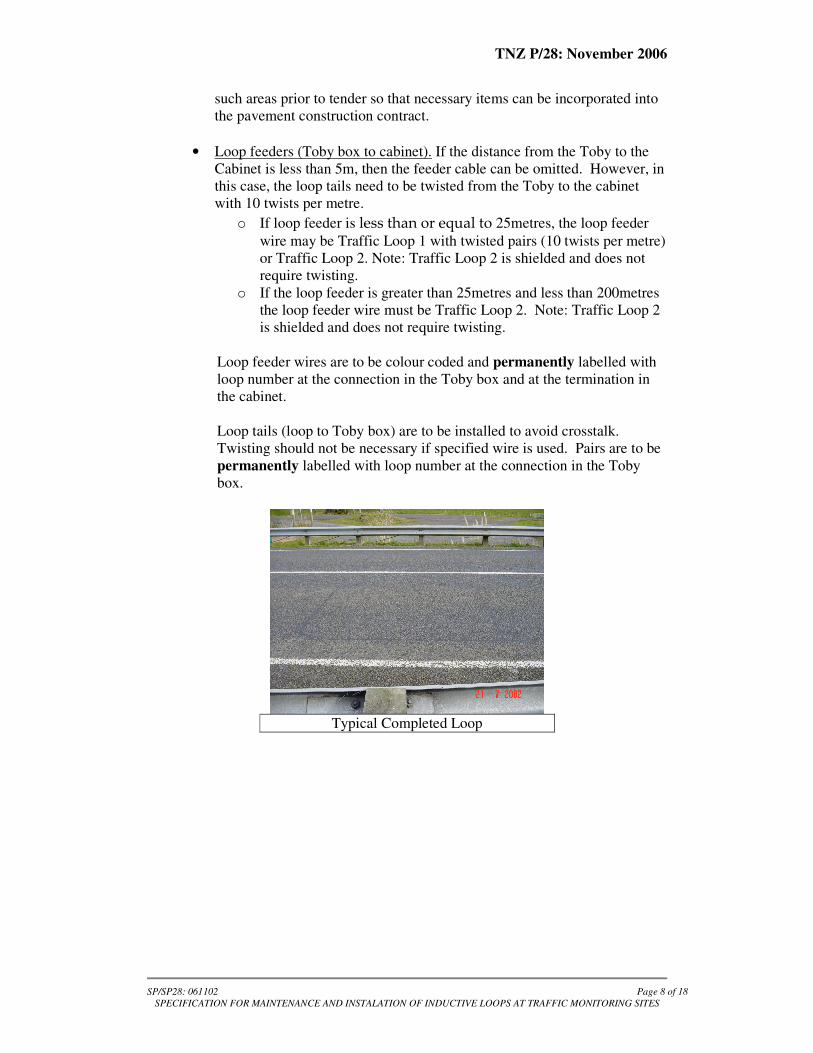
SECTION DETAIL DRAWING 2 VERSION 1
SECTION 2.A
SECTION 2.B SECTION 2.C
Surface to be reinstated to original. Trench width to suit conduit diameter. Backfilled and compacted with excavated material.
Red warning tape placed midway between surface and conduit. 300mm
Min Trench Depth (500mm Typical)
PVC electrical conduit, diameter to suit.
Twisted or shielded pairs, refer to Drawing 1
Sand
Loop wires (3 turns per loop)
4-6mm wide saw cut
Sealant
4-6mm wide saw cut Loop Tails
30mm min 50mm max Saw cut must not Cut into base course
TNZ P/28: November 2006
SP/SP8: 061102 SPECIFICATION FOR MAINTENANCE AND INSTALATION OF INDUCTIVE LOOPS AT TRAFFIC MONITORING SITES Page 16 of 18
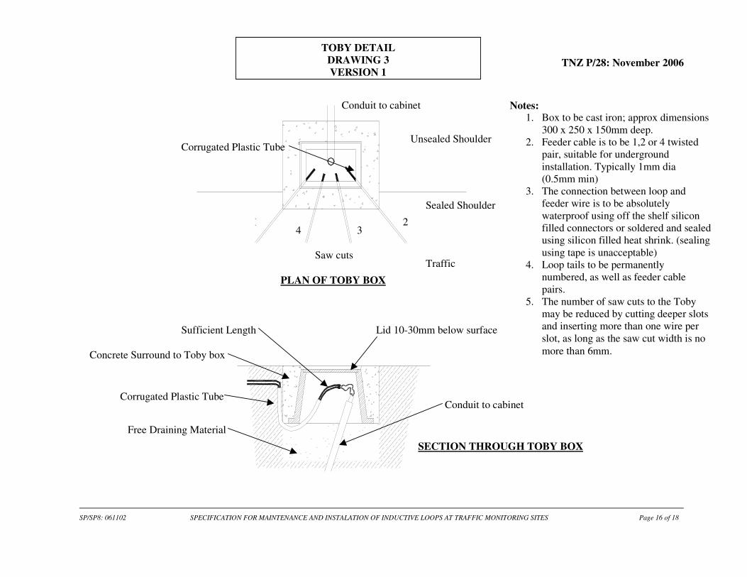
Conduit to cabinet
Corrugated Plastic Tube
Saw cuts
Unsealed Shoulder
Sealed Shoulder
Traffic
1 2 3 4
Conduit to cabinet
Lid 10-30mm below surface
Concrete Surround to Toby box
Sufficient Length
Free Draining Material
Corrugated Plastic Tube
SECTION THROUGH TOBY BOX
PLAN OF TOBY BOX
TOBY DETAIL DRAWING 3 VERSION 1
Notes: 1. Box to be cast iron; approx dimensions
300 x 250 x 150mm deep. 2. Feeder cable is to be 1,2 or 4 twisted
pair, suitable for underground installation. Typically 1mm dia (0.5mm min)
3. The connection between loop and feeder wire is to be absolutely waterproof using off the shelf silicon filled connectors or soldered and sealed using silicon filled heat shrink. (sealing using tape is unacceptable)
4. Loop tails to be permanently numbered, as well as feeder cable pairs.
5. The number of saw cuts to the Toby may be reduced by cutting deeper slots and inserting more than one wire per slot, as long as the saw cut width is no more than 6mm.

TNZ P/28: November 2006
SP/SP8: 061102 SPECIFICATION FOR MAINTENANCE AND INSTALATION OF INDUCTIVE LOOPS AT TRAFFIC MONITORING SITES Page 17 of 18
CABINET DETAILS DRAWING 4 VERSION 1
HARDINGS 2002 or Equivalent Mains power supply
MONTROSE or Equivalent Without mains power supply
600mm min
Door side
300mm 600mm typical
150mm min
300mm max
Drilled holes 100mm above ground
Concrete Base
Height to be above flood level
Concrete Base
Power
Loop feeders
Phone
Notes: 1. Montrose 2002 and other
mains power cabinets shall be connected to the concrete base using 4 M12 bolts.
2. A safety connector shall be used for the power supply, at the base of the cabinet, if permitted by the power company.
Posts painted white

TNZ P/28: November 2006
SP/SP8: 061102 SPECIFICATION FOR MAINTENANCE AND INSTALATION OF INDUCTIVE LOOPS AT TRAFFIC MONITORING SITES Page 18 of 18
LOOP LAYOUT FOR OTHER LANE CONFIGURATIONS DRAWING 5 VERSION 1
Decreasing
Increasing
Underground trusted cable
Cabinet (See Dwg 4) Boundary Fence
Toby (See Dwg 3)
Notes: 1 For loop spacing and other details, see drawing 1.
Median Barrier