Embed Size (px)
Citation preview

SPECIFICATION FOR LOW-VOLTAGE MOLDED
CASE CIRCUIT BREAKERS (MCCB) FOR SERVICE
CONNECTIONS
Saudi Electricity Company
37-SDMS-01
REV. 04 (11-07-2018)

37-SDMS-01 REV.04
2
1. SCOPE ............................................................................................................................................................ 3
2. CROSS REFERENCES TO OTHER SEC STANDARDS ........................................................................................... 3
3. APPLICABLE CODES AND STANDARDS ........................................................................................................... 3
4. SERVICE AND SYSTEM CONDITIONS............................................................................................................... 3
5. MATERIAL, DESIGN AND CONSTRUCTION REQUIREMENTS ........................................................................... 4
GENERAL ......................................................................................................................................................... 4 5.1.
CASING ........................................................................................................................................................... 4 5.2.
TERMINALS ...................................................................................................................................................... 4 5.3.
TERMINAL COVERS ............................................................................................................................................ 5 5.4.
OPERATING MECHANISM .................................................................................................................................... 6 5.5.
BREAKER CONTACTS ........................................................................................................................................... 6 5.6.
MOUNTING SCREWS .......................................................................................................................................... 6 5.7.
RELEASES (OVER-CURRENT RELEASES) ................................................................................................................... 7 5.8.
MAINTENANCE ................................................................................................................................................. 7 5.9.
DIMENSIONS .................................................................................................................................................... 7 5.10.
6. ELECTRICAL REQUIREMENTS ......................................................................................................................... 7
7. MARKING ...................................................................................................................................................... 8
8. TESTING AND INSPECTION ............................................................................................................................. 9
9. PACKING AND SHIPPING .............................................................................................................................. 10
10. GUARANTEE ............................................................................................................................................ 10
11. SUBMITTALS ............................................................................................................................................ 11
12. TECHNICAL DATA SCHEDULE ................................................................................................................... 12
13. DRAWINGS .............................................................................................................................................. 15

37-SDMS-01 REV.04
3
1. SCOPE
This specification defines the minimum technical requirements for design, engineering,
manufacture, testing, inspection and performance of molded-case circuit breakers (MCCB)
for indoor and outdoor installation in an enclosure and intended to be used for service
connections in the low-voltage distribution system of Saudi Electricity Company (SEC) in
Saudi Arabia.
2. CROSS REFERENCES TO OTHER SEC STANDARDS
This specification shall always be read in conjunction with SEC General Specification No.
01-SDMS-01 (latest revision) titled "General Requirements for all Equipment/Materials,"
which shall be considered as an integral part of this specification. It shall also be read in
conjunction with SEC purchase order and/or contract schedules, and scope of work/technical
specifications for projects, as applicable.
3. APPLICABLE CODES AND STANDARDS
The latest revision of the following codes and standards shall be applicable for the
equipment/materials covered in this specification. In case of any deviation, the
vendor/manufacturer may propose equipment/materials conforming to alternate codes or
standards. However, the provisions of SEC standards shall supersede the provisions of these
alternate standards in case of any difference.
Table 1: List of applicable standards
Standard # Title
IEC 60947-1 Low-Voltage Switchgear and Controlgear – Part 1: General Rules
IEC 60947-2 Low-Voltage Switchgear and Controlgear – Part 2: Circuit-Breakers
ASTM B633 Specification for Electrodeposited Coatings of Zinc on Iron and Steel
4. SERVICE AND SYSTEM CONDITIONS
The MCCBs shall be suitable for operation under the service conditions specified in the latest
revision of SEC specification 01-SDMS-01.

37-SDMS-01 REV.04
4
All fittings and attachments of the MCCBs shall be capable of withstanding the effects of
direct solar radiation at their installed locations. The temperature of surfaces exposed to direct
solar radiation shall be regarded as 75°C plus the effect of any internal heating.
The MCCBs shall be suitable for installation in a system with the following parameters:
Table 1: Low-voltage system parameters
System Condition Low-Voltage System
Frequency 60 Hz
Wiring Configuration 3-Phase, 4-Wire
Voltage Level 230/133 ±5%
400/230 ±5%
Grounding System Solidly Grounded
5. MATERIAL, DESIGN AND CONSTRUCTION REQUIREMENTS
GENERAL 5.1.
5.1.1 The MCCBs shall be 3-pole, with thermal and magnetic releases, arc
suppression device, operating handle, lock and key system, and encased
in a sealed cover permanently attached to the base. The incoming and
outgoing terminal shall be provided with terminal covers, as applicable.
5.1.2 Thermal interaction shall not affect the performance of any component
of the MCCBs.
5.1.3 All bolted electrical joints shall be secured with corrosion-proof steel
nuts and bolts. All bolts, nuts and washers are Type-II plated per ASTM
B633.
CASING 5.2.
5.2.1 Casings shall be molded from high-grade, virgin materials, strong heat-
resistance resin, with a sturdy sealed cover that is attached permanently
to the base.
TERMINALS 5.3.
5.3.1 All terminals of the MCCBs shall be made of tinned copper, with a
minimum coating thickness of 5µm.
37-SDMS-01 REV.04
5
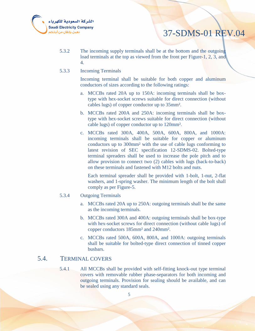
5.3.2 The incoming supply terminals shall be at the bottom and the outgoing
load terminals at the top as viewed from the front per Figure-1, 2, 3, and
4.
5.3.3 Incoming Terminals
Incoming terminal shall be suitable for both copper and aluminum
conductors of sizes according to the following ratings:
a. MCCBs rated 20A up to 150A: incoming terminals shall be box-
type with hex-socket screws suitable for direct connection (without
cables lugs) of copper conductor up to 35mm².
b. MCCBs rated 200A and 250A: incoming terminals shall be box-
type with hex-socket screws suitable for direct connection (without
cable lugs) of copper conductor up to 120mm².
c. MCCBs rated 300A, 400A, 500A, 600A, 800A, and 1000A:
incoming terminals shall be suitable for copper or aluminum
conductors up to 300mm² with the use of cable lugs conforming to
latest revision of SEC specification 12-SDMS-02. Bolted-type
terminal spreaders shall be used to increase the pole pitch and to
allow provision to connect two (2) cables with lugs (back-to-back)
on these terminals and fastened with M12 bolts and nuts.
Each terminal spreader shall be provided with 1-bolt, 1-nut, 2-flat
washers, and 1-spring washer. The minimum length of the bolt shall
comply as per Figure-5.
5.3.4 Outgoing Terminals
a. MCCBs rated 20A up to 250A: outgoing terminals shall be the same
as the incoming terminals.
b. MCCBs rated 300A and 400A: outgoing terminals shall be box-type
with hex-socket screws for direct connection (without cable lugs) of
copper conductors 185mm² and 240mm².
c. MCCBs rated 500A, 600A, 800A, and 1000A: outgoing terminals
shall be suitable for bolted-type direct connection of tinned copper
busbars.
TERMINAL COVERS 5.4.
5.4.1 All MCCBs shall be provided with self-fitting knock-out type terminal
covers with removable rubber phase-separators for both incoming and
outgoing terminals. Provision for sealing should be available, and can
be sealed using any standard seals.
37-SDMS-01 REV.04
6
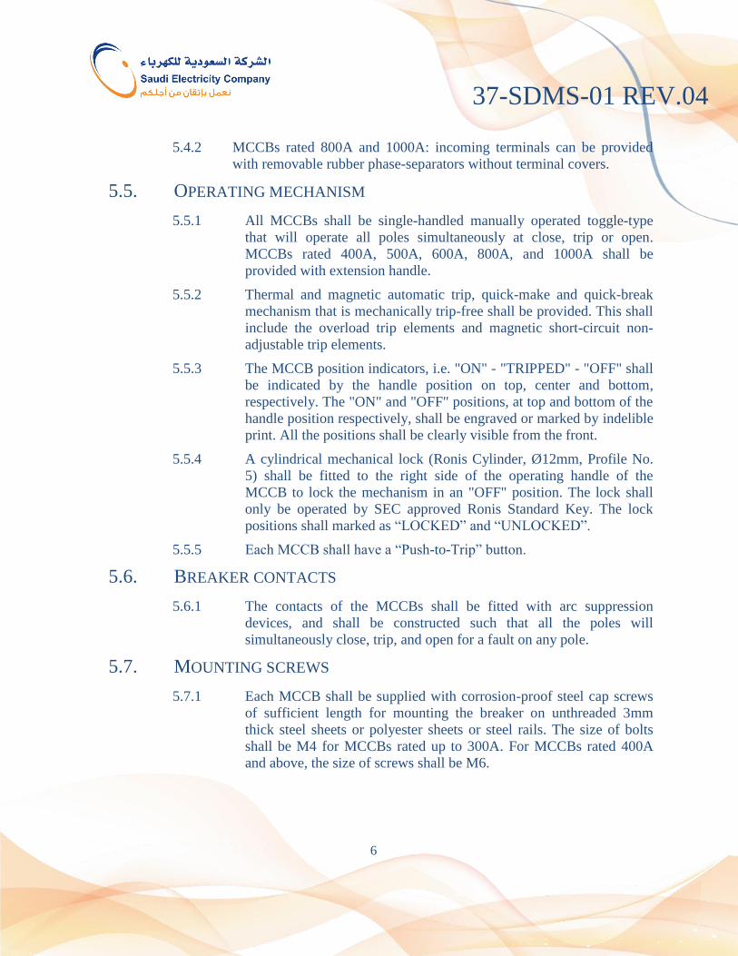
5.4.2 MCCBs rated 800A and 1000A: incoming terminals can be provided
with removable rubber phase-separators without terminal covers.
OPERATING MECHANISM 5.5.
5.5.1 All MCCBs shall be single-handled manually operated toggle-type
that will operate all poles simultaneously at close, trip or open.
MCCBs rated 400A, 500A, 600A, 800A, and 1000A shall be
provided with extension handle.
5.5.2 Thermal and magnetic automatic trip, quick-make and quick-break
mechanism that is mechanically trip-free shall be provided. This shall
include the overload trip elements and magnetic short-circuit non-
adjustable trip elements.
5.5.3 The MCCB position indicators, i.e. "ON" - "TRIPPED" - "OFF" shall
be indicated by the handle position on top, center and bottom,
respectively. The "ON" and "OFF" positions, at top and bottom of the
handle position respectively, shall be engraved or marked by indelible
print. All the positions shall be clearly visible from the front.
5.5.4 A cylindrical mechanical lock (Ronis Cylinder, Ø12mm, Profile No.
5) shall be fitted to the right side of the operating handle of the
MCCB to lock the mechanism in an "OFF" position. The lock shall
only be operated by SEC approved Ronis Standard Key. The lock
positions shall marked as “LOCKED” and “UNLOCKED”.
5.5.5 Each MCCB shall have a “Push-to-Trip” button.
BREAKER CONTACTS 5.6.
5.6.1 The contacts of the MCCBs shall be fitted with arc suppression
devices, and shall be constructed such that all the poles will
simultaneously close, trip, and open for a fault on any pole.
MOUNTING SCREWS 5.7.
5.7.1 Each MCCB shall be supplied with corrosion-proof steel cap screws
of sufficient length for mounting the breaker on unthreaded 3mm
thick steel sheets or polyester sheets or steel rails. The size of bolts
shall be M4 for MCCBs rated up to 300A. For MCCBs rated 400A
and above, the size of screws shall be M6.

37-SDMS-01 REV.04
7
RELEASES (OVER-CURRENT RELEASES) 5.8.
5.8.1 All MCCBs shall be equipped with fixed-setting thermal and
magnetic releases, with inverse time-delay characteristics.
MAINTENANCE 5.9.
5.9.1 All MCCBs shall not be openable and do not require any routine
maintenance.
DIMENSIONS 5.10.
5.10.1 The maximum overall dimensions of the MCCBs are given in the
table below:
Table 2: Maximum allowable dimensions of MCCBs
MCCB Ratings Width,
mm
Length, mm Depth,
mm w/o Terminal
Cover
w/ Terminal
Cover
20A to 250A 110 165 210 140
300A & 400A 140 260 400 140
500A & 600A 210 300 500 175
800A & 1000A 210 330 500 205
6. ELECTRICAL REQUIREMENTS
ELECTRICAL PERFORMANCE RATING 6.1.
The MCCBs shall conform to the following minimum requirements:
6.2.1 Rated Operational Voltage, Ue = 230V and/or 400V (3-Pole)
6.2.2 Rated Operational Current at 55°C, Ie
20A, 30A, 40A, 50A, 70A, 100A, 125A, 150A, 200A, 250A, 300A,
400A, 500A, 600A, 800A, and 1000A.
6.2.3 Rated Duty = Uninterrupted Duty
6.2.4 Rated Insulation Voltage, Ui = 1000V
6.2.5 Rated Impulse Withstand Voltage, Uimp = 8kV
6.2.6 Rated Frequency, f = 60Hz

37-SDMS-01 REV.04
8
6.2.7 Rated Short-Circuit Breaking Capacity, Icn
a. At 230V (3-Pole) rated voltage:
25kA for MCCBs rated 20A up to 400A
65kA for MCCBs rated 500A up to 1000A
b. At 400V (3-Pole) rated voltage:
20kA for MCCBs rated 20A up to 400A
40kA for MCCBs rated 500A up to 1000A
7. MARKING
The rated current shall be marked using indelible ink or engraved on the operating handle or
suitable location that can be viewed readily from the front and through the MCCB window
of the meterboxes.
Each MCCB shall have a clear nameplate engraved or laser printed on the left-side of the
front cover. The nameplate shall bear the following information:
a. Manufacturer and Model/Type
b. MCCB Electrical Requirements per Clause 6 above, as applicable
c. Conformance Standard, i.e. IEC 60947-2
d. Serial Number
e. Year of Manufacture
f. Origin
g. SEC Issued PO Number
h. Vendor Name
i. Reference SEC Specification
j. SEC Monogram
The front cover shall be laser printed showing the hex-socket size and the maximum torque
of the terminal screws.
The operating handle shall have position indicators in “OPEN” and “CLOSE” position. This
can be achieved either by making indelible markings or using strong printed adhesive
stickers. The “CLOSE” position shall be marked using bold black font typed “ON” in red
background, and the “OPEN” position shall be marked using black bold font typed “OFF” in
green background.

37-SDMS-01 REV.04
9
8. TESTING AND INSPECTION
The MCCBs shall be tested in conformance with the applicable requirements of the latest
version of IEC 60947-2.
SEC reserves the right to optionally carryout testing either through its own in-house
laboratory or in 3rd
-party laboratories to verify the performance of the supplied MCCBs.
This shall be performed by randomly selecting 10% samples of any batch delivered to each
SEC warehouses. The batch shall be assumed rejected should more than three (3) MCCBs
are found faulty.
ROUTINE TESTS 8.1.
Routine tests in conformance with the applicable clauses of IEC 60947-2 shall be
performed on all MCCBs. Electronic copies of the test reports shall be submitted
to SEC in USB thumb drive for each batch to be delivered prior to issuance of the
releases.
TYPE TESTS 8.2.
Type test shall be performed in complete conformance with the applicable clauses
of IEC 60947-2. It shall be performed at SEC approved laboratories.
SEC reserves the right to attend and witness the tests.
SEC reserves the right to request the supplier/manufacturer to repeat the type test
every five (5) years, or as needed should the supplied MCCBs have frequent faults
and failures.
SAMPLE INSPECTION 8.3.
Samples together with actual CAD drawings and routine test reports shall be
submitted for inspection/evaluation prior to issuance of approval for mass
production. The following attributes shall be checked:
a. Dimensional verification
b. Engraved or laser print markings
c. Compliance of Lock and Keys
d. Operation
e. Torque requirements of the terminal screws, as applicable
f. Finishing
g. Packaging
37-SDMS-01 REV.04
10
9. PACKING AND SHIPPING
Packing and shipping requirement shall generally be as per latest revision of SEC General
Requirements for Equipment/Materials, 01-SDMS-01 or as per purchase order requirements.
Each MCCB with all its accessories shall be packed in a box as a complete unit/assembly
and shall be delivered ready for use. Keys should be supplied collectively in a separate box
and must not be included in each MCCB box. A minimum of one (1) key should be provided
for every 50 units of MCCB supplied.
Packing shall protect the MCCBs against damage during shipment and site handling.
Each MCCB shall be packed to ensure that no dust, dirt, or foreign matter will enter in the
MCCB mechanisms.
Suppliers should coordinate with SEC Warehousing Department for additional packing,
handling, and or shipping instructions, as applicable.
Each box shall be printed with the following information:
a. Purchase Order Number / Tender Number
b. MCCB Rated Current
c. Manufacturer’s Name and Model/Type
d. Year of Manufacture
e. SEC Item Code
10. GUARANTEE
The supplier/manufacturer shall guarantee the products against all defects arising out of
faulty design or manufacturing defects or defective materials for a period of five (5) years
from the date of delivery.
The supplier shall guarantee the uniformity of the products delivered with the approved
samples.

37-SDMS-01 REV.04
11
11. SUBMITTALS
SUBMITTALS REQUIRED WITH TENDER/INQUIRY 11.1.
10.1.1 Summary in table form with the following information: list of items
offered, manufacturer, origin, catalogue number, and quantity
10.1.2 Clause-by-clause compliance with the latest revision of SEC
specification 37-SDMS-01.
10.1.3 Manufacturer’s Catalogue
10.1.4 Certificate stating that the raw material has been sampled, tested and
inspected in accordance with relevant standard specifications.
10.1.5 Product type test reports and certificates carried out from SEC
approved laboratories
10.1.6 Filled-up technical data schedule on each of the items offered
10.1.7 Manufacturer CAD drawings for each of the items offered
10.1.8 USB Flash Drive containing e-copy of all the documents mentioned
above
SUBMITTALS REQUIRED FOLLOWING AWARD OF CONTRACT 11.2.
10.2.1 Samples in compliance with Clause 8.3 of this specification
10.2.2 Quality assurance tests
10.2.3 Manufacturing and routine test schedules
10.2.4 Special tests, if applicable
37-SDMS-01 REV.04
12
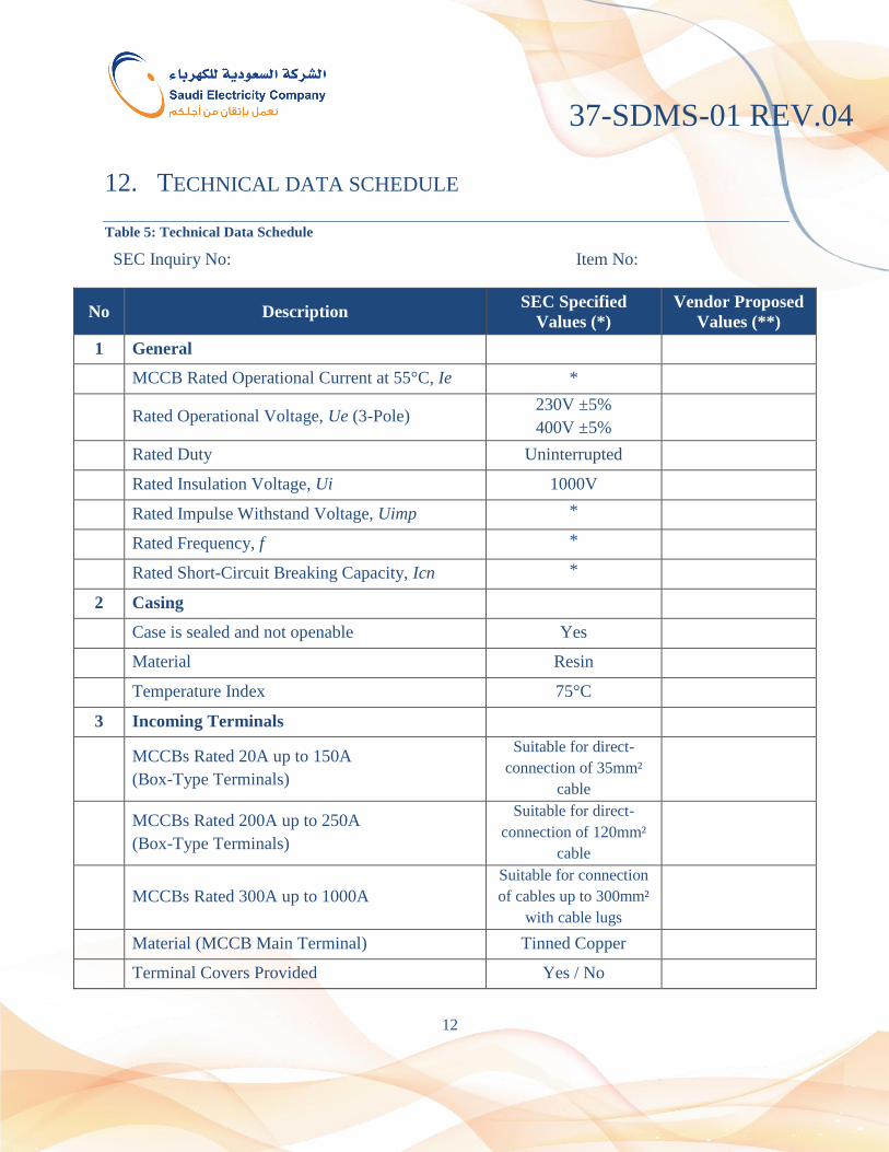
12. TECHNICAL DATA SCHEDULE
Table 5: Technical Data Schedule
SEC Inquiry No: Item No:
No Description SEC Specified
Values (*)
Vendor Proposed
Values (**)
1 General
MCCB Rated Operational Current at 55°C, Ie *
Rated Operational Voltage, Ue (3-Pole) 230V ±5%
400V ±5%
Rated Duty Uninterrupted
Rated Insulation Voltage, Ui 1000V
Rated Impulse Withstand Voltage, Uimp *
Rated Frequency, f *
Rated Short-Circuit Breaking Capacity, Icn *
2 Casing
Case is sealed and not openable Yes
Material Resin
Temperature Index 75°C
3 Incoming Terminals
MCCBs Rated 20A up to 150A
(Box-Type Terminals)
Suitable for direct-
connection of 35mm²
cable
MCCBs Rated 200A up to 250A
(Box-Type Terminals)
Suitable for direct-
connection of 120mm²
cable
MCCBs Rated 300A up to 1000A
Suitable for connection
of cables up to 300mm²
with cable lugs
Material (MCCB Main Terminal) Tinned Copper
Terminal Covers Provided Yes / No
37-SDMS-01 REV.04
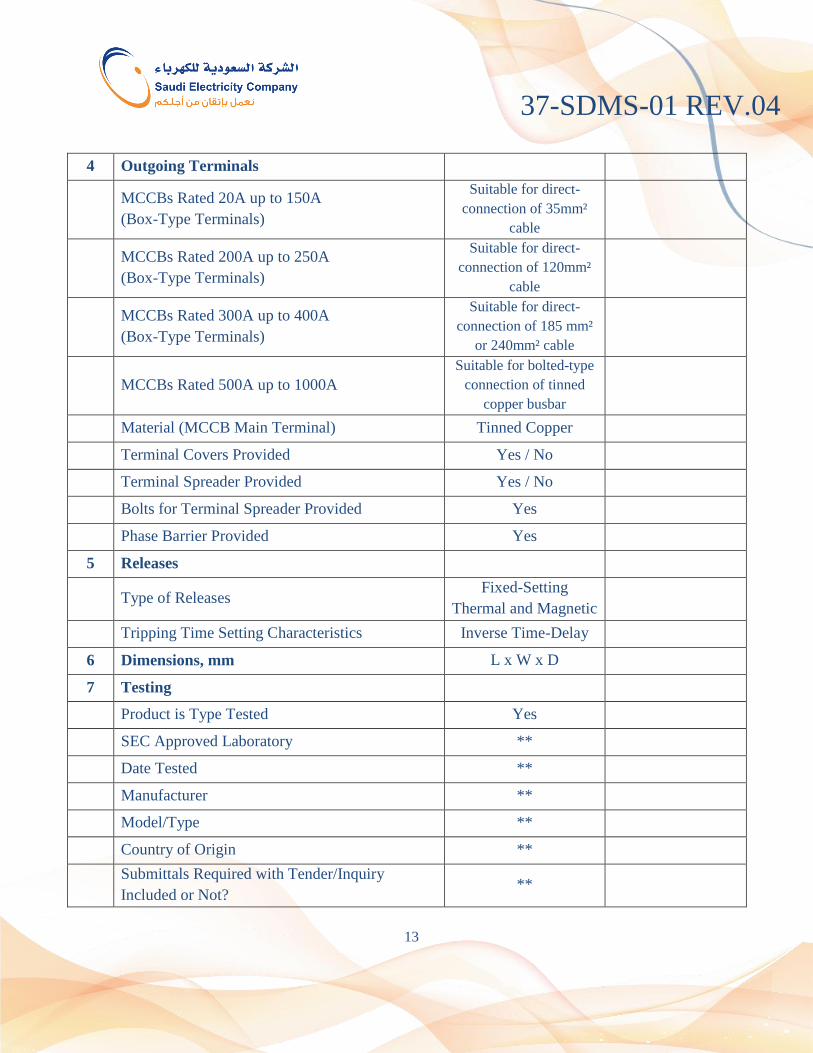
13
4 Outgoing Terminals
MCCBs Rated 20A up to 150A
(Box-Type Terminals)
Suitable for direct-
connection of 35mm²
cable
MCCBs Rated 200A up to 250A
(Box-Type Terminals)
Suitable for direct-
connection of 120mm²
cable
MCCBs Rated 300A up to 400A
(Box-Type Terminals)
Suitable for direct-
connection of 185 mm²
or 240mm² cable
MCCBs Rated 500A up to 1000A
Suitable for bolted-type
connection of tinned
copper busbar
Material (MCCB Main Terminal) Tinned Copper
Terminal Covers Provided Yes / No
Terminal Spreader Provided Yes / No
Bolts for Terminal Spreader Provided Yes
Phase Barrier Provided Yes
5 Releases
Type of Releases Fixed-Setting
Thermal and Magnetic
Tripping Time Setting Characteristics Inverse Time-Delay
6 Dimensions, mm L x W x D
7 Testing
Product is Type Tested Yes
SEC Approved Laboratory **
Date Tested **
Manufacturer **
Model/Type **
Country of Origin **
Submittals Required with Tender/Inquiry
Included or Not? **

37-SDMS-01 REV.04
14
Molded-Case Circuit Breaker (MCCB)
SEC Inquiry No: Item No:
Additional Technical Information or Features Specified by SEC
Additional Supplementary Data or Features Proposed by Bidder/Vendor/Supplier.
Other Particulars to be filled-up by the Bidder/Vendor/Supplier.
List of Deviations and Clauses to which exception is taken by the
Bidder/Vendor/Supplier. (Use separate sheet, if necessary).
Description Manufacturer of
Material/Equipment Vendor/Supplier
Name of Company
Location and Office Address
Name and Signature of Authorized
Representative with Date
Official Seal / Stamp
37-SDMS-01 REV.04
15
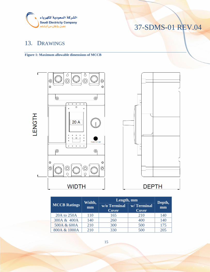
13. DRAWINGS
Figure 1: Maximum allowable dimensions of MCCB
MCCB Ratings Width,
mm
Length, mm Depth,
mm w/o Terminal
Cover
w/ Terminal
Cover
20A to 250A 110 165 210 140
300A & 400A 140 260 400 140
500A & 600A 210 300 500 175
800A & 1000A 210 330 500 205
37-SDMS-01 REV.04
16
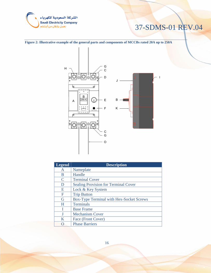
Figure 2: Illustrative example of the general parts and components of MCCBs rated 20A up to 250A
Legend Description
A Nameplate
B Handle
C Terminal Cover
D Sealing Provision for Terminal Cover
E Lock & Key System
F Trip Button
G Box-Type Terminal with Hex-Socket Screws
H Terminals
I Base Frame
J Mechanism Cover
K Face (Front Cover)
O Phase Barriers

37-SDMS-01 REV.04
17
Figure 3: Illustrative example of the general parts and components of MCCBs rated 300A up to 400A
Legend Description
A Nameplate
B Handle
C Terminal Cover
D Sealing Provision for Terminal Cover
E Lock & Key System
F Trip Button
G Box-Type Terminal with Hex-Socket Screws
H Terminals
I Base Frame
J Mechanism Cover
K Face (Front Cover)
L Hex-Head or Hex-Socket Bolts
M Terminal Spreaders
N Bolt w/ 2-Flat Washers, 1-Spring Washer & 1-Nut, M12
O Phase Barriers

37-SDMS-01 REV.04
18
Figure 4: Illustrative example of the general parts and components of MCCBs rated 500A up to 1000A
Legend Description
A Nameplate
B Handle
C Terminal Cover
D Sealing Provision for Terminal Cover
E Lock & Key System
F Trip Button
G Box-Type Terminal with Hex-Socket Screws
H Terminals
I Base Frame
J Mechanism Cover
K Face (Front Cover)
L Hex-Head or Hex-Socket Bolts
M Terminal Spreaders
N Bolt w/ 2-Flat Washers, 1-Spring Washer & 1-Nut, M12
O Phase Barriers
P Direct Bolted-Type Connection to Tinned Copper
Busbar

37-SDMS-01 REV.04
19
Figure 5: Calculation of minimum length of bolts for the spreader terminals
NOTE:
S - Palm thickness of cable lugs (see Figure-1 and Figure-2 per latest revision of 12-SDMS-02
for copper and aluminum lugs, respectively).