Embed Size (px)
Citation preview
VISAKH MARKETING INSTALLATION RESITEMENT
PROJECT - WHITE OIL TERMINAL
Doc No: 254624 - 400 - SP -
PPL - 001 Rev: A Page 1 of 29
ABCABCABCABC
P:\Andheri\Projects\254624 HPCL- White Oil Terminal\03 Piping\Pipeline\Pipeline Specifications\001 Specification for
Linepipe (ERW)\Latest\254624-400-SP-PPL-001 REV A.doc
SPECIFICATION FOR ELECTRIC
RESISTANCE WELDED (ERW)
LINE PIPE (ONSHORE)
abcabcabcabc
Mott MacDonald Consultants (India) Pvt. Ltd.
Kothari House, CTS No. 185
Off Andheri - Kurla Road
Andheri (East)
Mumbai 400 059
Hindustan Petroleum Corporation Ltd
Visakha Dispatch Station
VR-ATP Area, Naval Base Post
Visakhapatnam - 530 014
Andhra Pradesh
VISAKH MARKETING INSTALLATION RESITEMENT
PROJECT - WHITE OIL TERMINAL
Doc No: 254624 - 400 - SP -
PPL - 001 Rev: A Page 3 of 29
ABCABCABCABC
P:\Andheri\Projects\254624 HPCL- White Oil Terminal\03 Piping\Pipeline\Pipeline Specifications\001 Specification for
Linepipe (ERW)\Latest\254624-400-SP-PPL-001 REV A.doc
List of Content Page No
1 Introduction 6
1.1 General 6
1.2 Project Description 6
1.3 Abbreviation and Definition 7
1.3.1 Abbreviation 7
1.3.2 Definitions 7
1.4 Product Specification Level (PSL) 7
1.5 Grades 7
1.6 Dimensions 7
2 References 8
3 Process of Manufacture and Material 8
3.1 Process of Manufacture 8
3.2 Cold Expansion 8
3.3 Material 8
3.4 Heat Treatment 9
4 Material Requirements 9
4.1 Chemical Properties 9
4.1.1 Chemical Composition 9
4.1.2 Elements Analyzed 9
4.1.3 Carbon Equivalent 9
4.2 Mechanical Properties 9
4.2.1 Tensile Properties 9
4.2.2 Flattening Test Acceptance Criteria 9
4.2.3 Fracture Toughness Tests 9
4.2.4 Metallographic Examination 10
4.2.5 Reverse Bend Test 10
5 Dimensions, Weights, Lengths, Defects and End Finishes 11
5.1 Diameter 11
5.2 Wall Thickness 11
5.3 Length 11
5.4 Straightness 12
5.5 Jointers 12
5.6 Workmanship and Defects 12
5.6.1 Dents 12
5.6.2 Offset of Plate Edges 12
VISAKH MARKETING INSTALLATION RESITEMENT
PROJECT - WHITE OIL TERMINAL
Doc No: 254624 - 400 - SP -
PPL - 001 Rev: A Page 4 of 29
ABCABCABCABC
P:\Andheri\Projects\254624 HPCL- White Oil Terminal\03 Piping\Pipeline\Pipeline Specifications\001 Specification for
Linepipe (ERW)\Latest\254624-400-SP-PPL-001 REV A.doc
5.6.3 Height of Flash of Electric Welded Pipe 12
5.6.4 Trim of Inside Flash of Electric Welded Pipe and Trim of Inside Weld12
5.6.5 Hard Spots 12
5.6.6 Cracks, Sweats and Leaks 12
5.6.7 Laminations 12
5.6.8 Arc Burns 12
5.6.9 Other Defects 13
5.7 Pipe Ends 13
5.7.1 General 13
5.7.2 Plain End 13
5.7.3 Bevel Protectors 13
6 Inspection and Testing 13
6.1 Testing Of Chemical Composition 13
6.1.1 Heat Analysis 13
6.1.2 Product Analysis 13
6.2 Testing Of Mechanical Properties 14
6.2.1 Tensile Tests 14
6.2.2 Fracture Toughness Tests 14
6.3 Hydrostatic Tests 14
6.3.1 Hydrostatic Test Requirements 14
6.3.2 Verification of Hydrostatic Test 14
6.3.3 Test Pressure 15
6.4 Dimensional Testing 15
6.5 Non Destructive Inspection 15
6.5.1 Purchaser Inspection 15
6.5.2 Qualification of Personnel 15
6.5.3 Methods of Inspection 15
6.5.4 Ultrasonic and Electromagnetic Inspection 16
6.6 Disposition of Pipe Containing Defects 17
6.7 Retests 17
6.7.1 Recheck Analysis 17
6.7.2 Charpy Retests 17
7 Marking 17
8 Coating and Protection 17
9 Documents 17
9.1 Certification 17
9.2 Retention of Records 18
9.3 Production Report 18
9.4 Line Pipe Traceability Data 18
VISAKH MARKETING INSTALLATION RESITEMENT
PROJECT - WHITE OIL TERMINAL
Doc No: 254624 - 400 - SP -
PPL - 001 Rev: A Page 5 of 29
ABCABCABCABC
P:\Andheri\Projects\254624 HPCL- White Oil Terminal\03 Piping\Pipeline\Pipeline Specifications\001 Specification for
Linepipe (ERW)\Latest\254624-400-SP-PPL-001 REV A.doc
10 Inspection of Field Tests & Warranty 19
11 Guarantee 19
12 Pipe Loading 19
Appendix-A: - Purchaser Inspection 21
Appendix-B: - Marking Instructions for API Licensees 22
Appendix-C: - Repair of Defects by Welding. 23
Appendix-D: - Table of Compliance. 24
Appendix-E: - Basic Pipeline Design Data. 26
VISAKH MARKETING INSTALLATION RESITEMENT
PROJECT - WHITE OIL TERMINAL
Doc No: 254624 - 400 - SP -
PPL - 001 Rev: A Page 6 of 29
ABCABCABCABC
P:\Andheri\Projects\254624 HPCL- White Oil Terminal\03 Piping\Pipeline\Pipeline Specifications\001 Specification for
Linepipe (ERW)\Latest\254624-400-SP-PPL-001 REV A.doc
1 Introduction
1.1 General
This Specification establishes the minimum requirements for the manufacture of Longitudinal
Seam Electric Resistance Welded (ERW) carbon steel line pipe in accordance with the
requirements laid down in this specification.
1.2 Project Description
HPCL has plans to modernize Visakh refinery and marketing infrastructure. HPCL has
committed to production and marketing of EURO IV standard products in Automobile Fuel
quality by 2010 and is also adding delayed Coker Unit (DCU)to improve the yield of middle
distilleries. Further, Visakh refinery has plans to expand its refining capacity to 15 MMT from
current installed 7.5 MMT by 2015, on the basis of market demand.
All white oil products, except MTO and Hexane, will be received through cross country
pipelines from ATP to white oil Terminal located opposite INS Dega. If there is a shortfall in
Refinery input, it will be made up by input from ship parcels received through cross-country
pipelines from OR1/OR2 and sunken ship Jetties. It is dispatched through ships at OR1/OR2 or
Sunken Ship Jetties through cross-country pipelines. MTO will be received through cross-
country pipeline from refinery to new white oil terminal. Hexane will be received by Tank
Trucks. White oils are also dispatched to other marketing companies (OMC) viz. IOC, BPC
through cross-country pipelines. However, the scope of this project is limited to isolation valves
in the valve pit located in INS Dega. Further line routing will be carried out by the respective
OMC.
Cross Country pipe lines will be running from the refinery and the ATP area to the new
marketing terminal located opposite INS Dega area and from OR1/OR2 and Sunken ship Jetties
to new White Oil Terminal opposite INS Dega (Plot-2).
Due to space constraint in the route between INS Dega & Sunken Ship Jetty, and considering
maximum usage of existing lines, the following lines are recommended.
Usability of any existing pipeline shall be judged only after performing proper assessment by
professional survey agency.
• 1 No. of 16” pipeline for import and export of MS from ATP Area to the new White Oil
Terminal.
• 1 No. of 16” pipeline for import and export of ATF from ATP Area to the new White Oil
Terminal.
• 1 No. of 16” pipeline for import and export of HSD from ATP Area to the new White Oil
Terminal.
• 1 No. of 14” pipeline for import and export of Naphtha from ATP Area to the new White
Oil Terminal.
• 1 No. of 12” pipeline for import and export of Soft SKO from the new White Oil Terminal
to ATP Area.
• 1 No. of 10” pipeline for import and export of ATF from ATP Area to the new White Oil
Terminal.
• 1 No. of new 24”common Piggable pipeline for import and export of White Oil between
White oil Terminal and OR1/OR2/ jetties.
• 1 No. of 24” SKO/HSD non-Piggable pipeline from ATP to White Oil, which is extension
of 24” existing HSD & SKO pipeline from sunken ship jetty.
VISAKH MARKETING INSTALLATION RESITEMENT
PROJECT - WHITE OIL TERMINAL
Doc No: 254624 - 400 - SP -
PPL - 001 Rev: A Page 7 of 29
ABCABCABCABC
P:\Andheri\Projects\254624 HPCL- White Oil Terminal\03 Piping\Pipeline\Pipeline Specifications\001 Specification for
Linepipe (ERW)\Latest\254624-400-SP-PPL-001 REV A.doc
1.3 Abbreviation and Definition
1.3.1 Abbreviation
API American Petroleum Institute
ASTM American Society for Testing and Materials
CS Carbon Steel
EW Electric Welded
HAZ Heat Affected Zone
HPCL Hindustan Petroleum Corporation Limited
ID Inside Diameter
ISO International Organization for Standardization
NDT Non Destructive Testing
NPS Nominal Pipe Size
NB Nominal Bore
OD Outside Diameter, Specified
PSL Product Specification Level
QCP Quality Control Plan
WT Wall Thickness, Specified
LPT Liquid Penetration test
1.3.2 Definitions
The following terms are used in this specification:
Manufacturer shall mean the manufacturer or supplier of the
materials covered by this Specification.
Purchaser shall mean HPCL or its authorised agent.
Shall shall indicate a mandatory requirement.
1.4 Product Specification Level (PSL)
Line pipe supplied to this specification shall conform to Product Specification Level PSL 2.
1.5 Grades
This specification is applicable to API 5L Grade B PSL 2 Line Pipe.
1.6 Dimensions
This specification shall be applied to line pipe of size 10” to 14”.
VISAKH MARKETING INSTALLATION RESITEMENT
PROJECT - WHITE OIL TERMINAL
Doc No: 254624 - 400 - SP -
PPL - 001 Rev: A Page 8 of 29
ABCABCABCABC
P:\Andheri\Projects\254624 HPCL- White Oil Terminal\03 Piping\Pipeline\Pipeline Specifications\001 Specification for
Linepipe (ERW)\Latest\254624-400-SP-PPL-001 REV A.doc
2 References
The latest editions (edition enforced at the time of issue of enquiry) of following additional
references are included in this specification:
OISD –141 (2003) Oil industry safety Directorate Standard for Design and Construction
Requirements for Cross country Hydrocarbon Pipeline.
API Spec 5L (2007) Specification for Line Pipe
ASME B31.4 (2006) Pipeline Transportation System for Liquid Hydrocarbons and Other
Liquids
ASTM E112 (1996) Standard Test for Determining Average Grain Size
3 Process of Manufacture and Material
3.1 Process of Manufacture
Following paragraphs of API Spec 5L shall be applicable to the line pipe manufactured as per
this specification:
Welding Process : Electric Welding as per Para 4.16
Type of Pipe : Electric Welded Pipe as per Para 4.14
Type of Seam Weld : Electric Weld as per Para 4.15
PSL 2 Electric Welded Pipe
Electric welding shall be performed with a minimum welder frequency of 200 kHz. The
welding system shall have an integrated control in which following data as a minimum shall
be monitored:
- Time
- Welding speed
- Current and Voltage
- Heat treatment temperature
The weld seam and the entire Heat Affected Zone (HAZ) shall be heat treated so as to
stimulate a normalizing heat treatment in order to control the structure so that no untempered
martensite remain in the weld seam and the HAZ, and the mechanical properties of heat
treated zone approximate that of the parent metal.
3.2 Cold Expansion
Pipes furnished to this specification shall be non-expanded.
3.3 Material
Line pipe furnished to this specification shall be made from steel produced in basic oxygen or
electric furnace processes. The steel used for manufacture of pipe shall be fully killed and fine
grained with a grain size of 7 or lesser in accordance with ASTM E112. Steel shall be made
by continuous casting only. The material used shall conform to API Spec 5L Para 8.3.
VISAKH MARKETING INSTALLATION RESITEMENT
PROJECT - WHITE OIL TERMINAL
Doc No: 254624 - 400 - SP -
PPL - 001 Rev: A Page 9 of 29
ABCABCABCABC
P:\Andheri\Projects\254624 HPCL- White Oil Terminal\03 Piping\Pipeline\Pipeline Specifications\001 Specification for
Linepipe (ERW)\Latest\254624-400-SP-PPL-001 REV A.doc
3.4 Heat Treatment
The pipes shall be produced from skelp which shall be quenched and tempered or controlled
rolled or combined controlled rolled and accelerated cooled to impart uniformly fine ferritic
grain structure to the finished steel. Other types of heat treatment shall be agreed upon
between Purchaser and Manufacturer.
4 Material Requirements
4.1 Chemical Properties
4.1.1 Chemical Composition
The chemical composition of each heat of steel on product analysts shall be in accordance
with Table 5 of API Spec 5L
If alloying elements other than those specified in Table 5 are added to the steel, the limits of
the additional components shall be agreed upon between the Purchaser and Manufacturer.
4.1.2 Elements Analyzed
For heat analysis and product analysis, all the elements listed in Table 5 of API Spec 5L shall
be analyzed and reported, even if those are not purposely added but are present as residuals
only.
4.1.3 Carbon Equivalent
Calculation shall be performed as per API Spec 5L Para 9.2.4 and 9.2.5, acceptance limits as
per Table 5 of API Spec 5L.
4.2 Mechanical Properties
4.2.1 Tensile Properties
The finished pipe (after all heat treatment and expansion or sizing operations) shall conform to
the requirements of Table 7 of API Spec 5L.
The ultimate tensile strength of the weld shall be equal to or better than the specified
minimum ultimate tensile strength of the base metal.
The minimum elongation of base metal shall be determined in accordance with the formula
given in the foot note (f) of Table-7 of API Spec 5L. However elongation in no case shall be
less than 20%.
4.2.2 Flattening Test Acceptance Criteria
Dye penetrate testing may be used to positively confirm the presence of crack, break or
opening in accordance with API Spec 5L Para 9.6 .
4.2.3 Fracture Toughness Tests
4.2.3.1 Charpy Impact Tests for PSL 2
For all pipe sizes and specified wall thickness, fracture toughness requirements as per API
Spec 5L Para 9.8 shall be applicable for body, weld and heat affected zone.
VISAKH MARKETING INSTALLATION RESITEMENT
PROJECT - WHITE OIL TERMINAL
Doc No: 254624 - 400 - SP -
PPL - 001 Rev: A Page 10 of 29
ABCABCABCABC
P:\Andheri\Projects\254624 HPCL- White Oil Terminal\03 Piping\Pipeline\Pipeline Specifications\001 Specification for
Linepipe (ERW)\Latest\254624-400-SP-PPL-001 REV A.doc
4.2.4 Metallographic Examination
4.2.4.1 A test specimen for metallographic & hardness examination shall be taken transverse to the
longitudinal weld, from one finished pipe from each lot of 50 pipes per heat or at least once
per operating shift (12 hrs maximum) which ever is occurring more frequently and whenever
changes of grade, diameter or wall thickness are made and whenever significant excursions
from operating heat treatment conditions are encountered. The specimen shall be suitably
ground, polished and etched to reveal the macro-structure. The specimen shall be visually
examined using a minimum 10X magnification to provide evidence that heat treatment of
weld zone is adequate and there is no untempered marten site left. In case imperfections or
defects are observed, it will become a cause for re-evaluation of welding parameters and heat
treatment as deemed necessary by Purchaser's Representative.
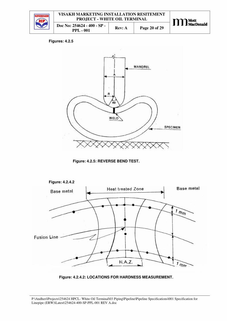
4.2.4.2 Vickers hardness tests shall be carried out on each specimen taken for metallographic
examination in accordance with ASTM E-92, at locations indicated in Fig. 4.2.4.2 of this
specification. Indentation in the Heat Affected Zone (HAZ) shall start as close to the fusion
line as possible. The resulting Vickers hardness value at any point shall not exceed 248 HV10.
The maximum difference in hardness between (the base metal and any reading taken on the
weld or heat affected zone shall be less than 80 HV10. Modalities of retest shall be in
accordance with Para 10.2.12 of API Spec. 5L.
4.2.5 Reverse Bend Test
4.2.5.1 Reverse bend test shall be executed with the some number of tests and retests specified for
flattening test in Para 9.6 of API Spec 5L. Ring Specimen of width 100 mm to 115 mm shall
be taken from the pipe and tested in accordance with the procedure given below and Fig. 4.2.5
of this specification.
4.2.5.2 Selection of Mandrel
The reverse bend test shall be carried out with a mandrel, whose radius (R), or width (A) shall
be calculated for any combination of diameter, wall thickness and grade with the following
formula:
1.4(D-t) t
A= 2R= - t
e (D-2t)-1.4t
Where
D - Specified outside diameter of pipe, mm
t - Specified wall thickness of pipe, mm
1.4 - Peaking factor
e - Strain
Minimum value of 'e' for Gr. B shall be 0.1425
4.2.5.3 Procedure
The mandrel shall be plunged into the specimen, with the weld in contact with the mandrel, to
such a depth that the angle of engagement between mandrel and specimen reaches 60° (Ref.
Fig 4.2.5 of this specification). If the combination of diameter and wall thickness of pipe and
radius of mandrel is such that the angle of engagement does not reach 60° the mandrel shall be
plunged into the specimen until opposite walls of the specimen meet.
VISAKH MARKETING INSTALLATION RESITEMENT
PROJECT - WHITE OIL TERMINAL
Doc No: 254624 - 400 - SP -
PPL - 001 Rev: A Page 11 of 29
ABCABCABCABC
P:\Andheri\Projects\254624 HPCL- White Oil Terminal\03 Piping\Pipeline\Pipeline Specifications\001 Specification for
Linepipe (ERW)\Latest\254624-400-SP-PPL-001 REV A.doc
4.2.5.4 Acceptance Criteria
A specimen which fractures completely prior to the specified engagement of mandrel and
specimen, or which reveals cracks or ruptures in the weld or heat affected zone longer than 4
mm, shall be rejected. Cracks less than 6 mm long at the edges of the specimen shall not be
cause for rejection. Dye penetrant testing may be used to positively confirm cracks or
openings.
5 Dimensions, Weights, Lengths, Defects and End Finishes
5.1 Diameter
Pipe Body
Except as allowed by Annexure C. Para 2.3 of API Spec 5L the diameter shall be within the
tolerance given in Table 10 of API Spec 5L
Pipe Ends
Diameter tolerances for the pipe ends indicated in API Spec 5L Table-10 shall be applicable
on the inside diameter for pipe sizes ≥ 14 and on outside diameter for pipe sizes ≤12”. The
inside diameter, based on circumferential measurement, over a length of 100 mm from the end
shall comply with the tolerances specified in API Spec 5L, Inside diameter is defined as ID =
(OD-2WT.) where ID, OD & WT are the inside diameter, specified outside diameter and
specified wall thickness respectively.
Out of Roundness
Out of Roundness i.e., the difference between the maximum and minimum diameter (inside
for pipe size ≥ 14 and outside for pipe size ≤ 12) at pipe ends shall comply with the limits in
accordance with Table 10 of API Spec 5L.
Out of roundness tolerance apply to maximum and minimum diameters as measured with a
bar gauge, calliper or device measuring actual maximum and minimum diameter.
Each pipe shall be measured for conformance to above requirements. All dimensions and
tolerances shall be measured and recorded at least 3 times per operating shift (12 hrs
maximum).
5.2 Wall Thickness
The wall thickness of each pipe shall be checked along the circumference at both ends and at
the mid location of pipe body at 12 o'clock, 3 o'clock, 6 o'clock and 9 o'clock positions. The
wall thickness tolerance shall comply with the requirements of API Spec 5L Table 11. Wall
thickness shall be measured and recorded at least 3 times per operating shift (12 hours
maximum).
5.3 Length
All pipes shall be supplied with length between 11.5m & 12.5m. However pipe with length
between 10.0m & 11.5m can also be accepted for a maximum of 5% of the ordered quantity.
The tolerance for lengths shall be as per Table 12 of API Spec 5L. The minimum average
length of the entire ordered quantity in any case shall be 12.0. Overall length tolerance shall
be (-) Zero and (+) One pipe length to complete the ordered quantity.
Each pipe shall be measured for conformance to above requirements and all measurements
shall be recorded.
VISAKH MARKETING INSTALLATION RESITEMENT
PROJECT - WHITE OIL TERMINAL
Doc No: 254624 - 400 - SP -
PPL - 001 Rev: A Page 12 of 29
ABCABCABCABC
P:\Andheri\Projects\254624 HPCL- White Oil Terminal\03 Piping\Pipeline\Pipeline Specifications\001 Specification for
Linepipe (ERW)\Latest\254624-400-SP-PPL-001 REV A.doc
5.4 Straightness
The tolerance for straightness shall be as per Para 9.11.3.4 of API Spec 5L. Each pipe shall be
checked for conformance to this requirement. Straightness shall be measured & recorded at
least 3 times per operating shift (12 hours maximum).
5.5 Jointers
Jointers on pipes are not permitted.
5.6 Workmanship and Defects
5.6.1 Dents
Allowable dent size shall be as per Para 9.10.5 of API Spec 5L. Disposition of dents shall be
carried out in accordance with API Spec 5L Annexure E Para 10. Dents on weld and heat
affected zone (HAZ) are not acceptable.
5.6.2 Offset of Plate Edges
All pipes shall be checked for offset of skelp edges. Offset shall be measured and recorded at
least 3 times per operating shift (12 hours maximum). Acceptable tolerances shall be followed
as per Para 9.13.1 of API Spec 5L
5.6.3 Height of Flash of Electric Welded Pipe
Each pipe shall be checked for conformance of height of flash. Height of flash shall be
measured and recorded at least 3 times per operating shift (12 hours maximum). Acceptable
tolerances shall be followed as per Para 9.13.2 of API Spec 5L
5.6.4 Trim of Inside Flash of Electric Welded Pipe and Trim of Inside Weld
Each pipe shall be checked for conformance of depth of trim in accordance with Para 9.13.2
of API Spec 5L. Depth of trim shall be measured and recorded at least 3 times per operating
shift (12 hours maximum).
5.6.5 Hard Spots
Any hard spot having a minimum dimension greater than 2 in. (50.8 mm) in any direction and
a hardness greater than the values as per Para 9.10.6 of API Spec 5L shall be rejected. The
section of pipe containing the hard spot shall be removed as a cylinder.
5.6.6 Cracks, Sweats and Leaks
Sections of the pipe containing cracks, sweats and leaks shall he cut off as per the requirement
of API Spec 5L Annexure C Para 2 or Para 3.
5.6.7 Laminations
Laminations or inclusions extending into the face or bevel of the pipe and having a visually
determined length in the circumferential direction > 6.4 mm (0.250 in) shall be classified as
defects. Pipes that contain such defects shall be rejected or cut back until no such lamination
or inclusion is present at the pipe ends.
5.6.8 Arc Burns
Arc burns produced during the manufacturing of pipes are injurious defects and shall be
disposed off in accordance with the requirements of API Spec 5L Annexure C Para 2 or 3.
Contact marks, which are intermittent marks adjacent to the weld line of EW pipe resulting
from electrical contact between the electrodes supplying the welding current and the pipe
surface, are treated in accordance with API Spec 5L 9.10.7.
VISAKH MARKETING INSTALLATION RESITEMENT
PROJECT - WHITE OIL TERMINAL
Doc No: 254624 - 400 - SP -
PPL - 001 Rev: A Page 13 of 29
ABCABCABCABC
P:\Andheri\Projects\254624 HPCL- White Oil Terminal\03 Piping\Pipeline\Pipeline Specifications\001 Specification for
Linepipe (ERW)\Latest\254624-400-SP-PPL-001 REV A.doc
As a reference method for conforming the existence of an arc burn, the area shall be buffed
with wire brush or sanding disc and etched with 5 percent nital solution.
5.6.9 Other Defects
Any imperfection (measured from the surface) with a depth greater than 5 % of the specified
thickness of the pipe shall be considered a defect and shall be repaired in accordance with API
Spec 5L Annexure C Para 2 or 3.
5.7 Pipe Ends
5.7.1 General
Pipe shall be furnished with plain ends & shall be free from burrs.
5.7.2 Plain End
Unless otherwise agreed, the end faces of plain-end pipe with t > 3.2 mm (0.125 in) shall be
bevelled for welding. The angle of the bevel measured from a line drawn perpendicular to the
axis of the pipe, shall be 30° with a tolerance of +5° to 0°, and the width of the root face of the
bevel shall be 1,6 mm (0.063 in), with a tolerance of ± 0.8 mm (0.031 in).
In removing the inside burrs at the pipe ends, care shall be taken not to remove excess metal
and not to form an inside cavity or bevel. Removal of excess metal beyond the minimum wall
thickness shall be a cause for re-bevelling. In case root face of bevel is less than that specified,
the pipe ends shall be re-bevelled and rectification by filing or grinding shall not be done.
5.7.3 Bevel Protectors
Both pipe ends of each pipe shall be provided with metallic or high impact plastic bevel
protectors as per Manufacturer's standard. Material used should be inert to the material of the
pipe.
6 Inspection and Testing
6.1 Testing Of Chemical Composition
6.1.1 Heat Analysis
Where the steel mill is not a part of an integrated pipe mill, heat analysis shall be reported by
the Manufacturer prior to start of pipe production.
6.1.2 Product Analysis
6.1.2.1 Sampling Frequency
Two pipes per inspection lot shall be analyzed. Inspection lot shall be 100 pipes per heat.
Pipes selected shall be such that one at the beginning of the heat and one at the end of the heat
are also represented.
6.1 2.2 Sampling Method
Welded Pipe
Samples used for product analysis shall be taken from finished pipes. Samples for product
analysis from skelp may be used provided the traceability of samples is guaranteed.
VISAKH MARKETING INSTALLATION RESITEMENT
PROJECT - WHITE OIL TERMINAL
Doc No: 254624 - 400 - SP -
PPL - 001 Rev: A Page 14 of 29
ABCABCABCABC
P:\Andheri\Projects\254624 HPCL- White Oil Terminal\03 Piping\Pipeline\Pipeline Specifications\001 Specification for
Linepipe (ERW)\Latest\254624-400-SP-PPL-001 REV A.doc
6.2 Testing Of Mechanical Properties
6.2.1 Tensile Tests
Tensile properties shall be determined from specimen removed from pipe which has been
subjected to all mechanical and heat treatment operations.
6.2.1.1 Tensile Testing Frequency
Frequency of inspection shall be as per table 18 of API Spec 5L.
6.2.1.2 Longitudinal Tensile Tests
Longitudinal tensile tests shall be carried out on a strip specimen.
6.2.1.3 Transverse Tensile Tests
The transverse tensile tests shall be carried out on flattened rectangular specimen.
6.2.1.4 Weld Tensile Tests
Inside and outside flash of weld in excess of pipe wall thickness shall be removed from the
specimen either by grinding or machining. Specimen shall be tested for ultimate tensile
strength only.
6.2.2 Fracture Toughness Tests
6.2.2.1 Charpy Test Specimens
In addition to the specimen taken from the body of the pipe, three transverse specimens with
weld in middle and three transverse specimens with Heat Affected Zone (HAZ) in the middle
shall also be taken. When either full size or sub-size transverse specimen as per API Spec 5L,
Table 22 is not possible to obtain, transverse specimen of either Size 1/3 or 1/4 Size,
whichever is maximum possible, may be obtained.
When such sub-size specimens are used, the acceptance of the individual / average absorbed
energy values shall be established as per API Spec 5L Para 9.8.1.1.
6.2.2.2 Charpy Testing Frequency
The minimum test frequency shall be one test (a set of three specimens each for body, weld
and HAZ) per heat per lot of 100 pipes per combination of pipe size and specified wall
thickness.
Individual test value for any specimen shall not be less than 80% of the required minimum
average absorbed energy value as per this specification.
6.3 Hydrostatic Tests
6.3.1 Hydrostatic Test Requirements
Test pressure shall be held for a minimum period of 15 seconds for all sizes and grades of
pipes.
6.3.2 Verification of Hydrostatic Test
The pressure gauge used for hydrostatic testing shall have a minimum range of 1.5 times and
maximum range of 4 times the test pressure. The pressure gauge shall be calibrated by means
of a "Dead Weight" tester only and record shall be maintained.
VISAKH MARKETING INSTALLATION RESITEMENT
PROJECT - WHITE OIL TERMINAL
Doc No: 254624 - 400 - SP -
PPL - 001 Rev: A Page 15 of 29
ABCABCABCABC
P:\Andheri\Projects\254624 HPCL- White Oil Terminal\03 Piping\Pipeline\Pipeline Specifications\001 Specification for
Linepipe (ERW)\Latest\254624-400-SP-PPL-001 REV A.doc
6.3.3 Test Pressure
The test pressure for all sizes and grades of pipe shall be such that hoop stress (fibre stress)
generated is at least 95% of SMYS, computed based on the formula mentioned in API Spec 5
L Para 10.2.6.5.
6.4 Dimensional Testing
The measuring equipment requiring calibration or verification under the provisions of API
Spec 5L shall be calibrated with manual instruments at least once per operating shift (12 hours
maximum). Such calibration records shall be furnished to Purchaser's Representative on
request.
6.5 Non Destructive Inspection
6.5.1 Purchaser Inspection
The Purchaser reserves the right to depute its Representative(s) to perform inspection and
witness tests in all phases of manufacturing and testing starting from steel making to finished
line pipe ready for shipment. Manufacturer shall comply with the provisions regarding
inspection notice, plant access, compliance and rejection mentioned in Appendix A of this
specification. The Manufacturer shall give the Purchaser reasonable notice of the starting date
of normal production and the work schedule. Any action or omission on part of Purchaser's
Representative shall not relieve the Manufacturer of his responsibility and obligation to supply
material in strict accordance with this specification.
6.5.2 Qualification of Personnel
All personnel performing NDT activities shall be qualified in the technique applied, in
accordance with latest edition of ISO 11484 or ASNT No. ASNT-TC-1A or equivalent. All
NDT shall be performed in accordance with written procedures. These procedures shall have
prior approval of the Purchaser.
Inspector Qualification
Acceptable qualification for NDT inspectors shall be as specified below:
(i) For UT
For UT, at least one level III qualified inspector shall be available to the mill for overall
supervision. A level II inspector is required for shift supervision, manual weld inspection
and calibration of all systems (both manual and automated).
(ii) For all other NDT methods
Non-destructive inspection shall be conducted by Level I, II or III personnel.
Evaluation of indications shall be performed by Level II or III personnel, or by Level I
personnel under the supervision of Level 2 or 3 personnel.
6.5.3 Methods of Inspection
Location of NDT equipment in the manufacturer's facility shall be such that final inspection of
Weld seam of pipe shall be performed after hydro testing.
Plate/Skelp Inspection
Each plate/skelp shall be ultrasonically tested for laminations using an oscillating or straight
running pattern of probes, so as to provide inspection coverage of at least 20% of the
plate/skelp surface uniformly spread over the area. Alternatively the pipe may be tested after
welding of the longitudinal seam by rotary ultrasonic testing of the pipe body.
VISAKH MARKETING INSTALLATION RESITEMENT
PROJECT - WHITE OIL TERMINAL
Doc No: 254624 - 400 - SP -
PPL - 001 Rev: A Page 16 of 29
ABCABCABCABC
P:\Andheri\Projects\254624 HPCL- White Oil Terminal\03 Piping\Pipeline\Pipeline Specifications\001 Specification for
Linepipe (ERW)\Latest\254624-400-SP-PPL-001 REV A.doc
The longitudinal edges of the plate/skelp shall be 100% ultrasonically tested over a width of at
least 25 mm from the trimmed plate/skelp edge. This may be performed either before or after
pipe forming. In case UT is performed after pipe forming, at least 25mm on either side of the
longitudinal weld seam shall be 100% ultrasonically tested.
Locations showing indications above the acceptance limits may be re-examined by manual
ultrasonic method. If no defects are located during re-examination, the original findings may
be ignored. Additional scanning may be requested by Purchaser's Representative to check
questionable areas.
Pipe Ends Inspection
The full circumference of both ends of each pipe after bevelling shall be 100% ultrasonically
tested for laminations from inside over a circumferential band of at least 25 mm width.
Alternatively the pipe may be tested from outside prior to bevelling, in which case a band of at
least 50 mm wide shall be tested to include the eventual bevelled area.
Bevel Inspection
Bevel face of all pipes shall be inspected by magnetic particle or LPT method to detect
defects.
Weld Inspection
Electric welds shall be inspected by ultrasonic methods using automatic ultrasonic equipment
in accordance with API Spec 5L Annexure E Table E.1., & Para E.3.2.
6.5.4 Ultrasonic and Electromagnetic Inspection
6.5.3.1 Equipment
All automatic ultrasonic equipment shall have an alarm device, which continuously monitors
the effectiveness of the coupling. The equipment for the automatic inspection shall allow the
localization of both longitudinal and transverse defects corresponding to the signals exceeding
the acceptance limits of the reference standard. The equipment shall be fitted with a paint
spray or automatic marking device and alarm device for areas giving unacceptable ultrasonic
indications. All ultrasonic testing equipment shall be provided with recording device. In
addition, an automatic weld tracking system shall be provided for correct positioning of the
probes with respect to weld centre. The equipment shall also conform to the requirements of
API Sec 5L Annexure E Para E.5.1.
6.5.3.2 Ultrasonic and Electromagnetic Inspection Reference Standards
Each reference standard (calibration pipe) shall have the same specified diameter and wall
thickness as specified for the production pipe being inspected and shall be of sufficient length
to permit calibration of ultrasonic inspection equipment at the speed to be used in normal
production. The reference standard (calibration pipe) shall also be of the same material, type
and have the same surface finish, made by the same pipe manufacturing process, from the
same heat, under the same manufacturing conditions and heat treatment as the pipe being
inspected. The reference indicators shall be as per API Spec 5L Annexure E Table 7.
The calibration shall be performed in accordance with the requirements of API Spec 5L
Annexure E Para E.5.3.2.
If during the above calibration verification, it is found that the equipment has not functioned
satisfactorily in the opinion of the Purchaser's Representative, all the pipes or skelp already
inspected after the previous verification shall be inspected again at Manufacturer's cost.
6.5.3.3 Acceptance Limits
The acceptance limits shall be in accordance with API Spec 5L Annexure E Para E.5.5.
VISAKH MARKETING INSTALLATION RESITEMENT
PROJECT - WHITE OIL TERMINAL
Doc No: 254624 - 400 - SP -
PPL - 001 Rev: A Page 17 of 29
ABCABCABCABC
P:\Andheri\Projects\254624 HPCL- White Oil Terminal\03 Piping\Pipeline\Pipeline Specifications\001 Specification for
Linepipe (ERW)\Latest\254624-400-SP-PPL-001 REV A.doc
6.5.3.4 Residual Magnetism
The average of the four readings taken 90° apart around the circumference of each end of pipe
shall not exceed 30Gs when measured with a Hall Effect gauss meter. All residual
requirements shall be recorded. Additional requirements shall be in accordance with API Spec
5L Annexure E Para E.7.
6.6 Disposition of Pipe Containing Defects
The repaired area shall be 100% rechecked by magnetic particle or ultrasonic inspection to
ensure complete removal of defects. However for repair of cosmetic type of defects, MPI may
not be conducted if so directed by Purchaser's Representative on case to case basis. The pipes
having a thickness less than the minimum allowed in accordance with this specification, after
repair by grinding shall be treated for disposition in accordance with API Spec 5L Annexure E
Para 10. Repair welding shall be in accordance with API Spec 5L and as modified in
Appendix - C of this specification.
6.7 Retests
6.7.1 Recheck Analysis
Modalities of recheck analysis shall be as per API Spec. 5L Para 10.2.12 as applicable to the
lot being tested. However, during individual testing, each pipe shall be fully analysed to meet
the requirements of Table 5 of API Spec 5L.
6.7.2 Charpy Retests
In the event that a set of Charpy test specimen fails to meet the acceptance criteria, the
manufacturer may elect to replace the lot of material involved or alternatively to test two more
lengths from that lot. If both the new tests meet the acceptance criteria, then all pipes in that
lot, with the exception of the original selected length, shall be considered to meet the
requirement.
7 Marking
Marking specified in API Paragraphs and otherwise specified in the Purchase Order shall be in
English language and international System (SI) of units. Marking shall comply with Para 11 of
API Spec 5L and as modified in this specification.
8 Coating and Protection
The pipe shall be supplied with a temporary external coating to provide protection as per API
Spec 5L Para 12.1.2. The coating shall be free of any trace of oil, stain, grease or paint. Bevels
shall be free of any coating.
9 Documents
9.1 Certification
Manufacturer shall furnish to Purchaser a certificate of compliance stating that the material
has been manufactured, sampled, tested, and inspected in accordance with this specification
and has been found to meet the requirements.
VISAKH MARKETING INSTALLATION RESITEMENT
PROJECT - WHITE OIL TERMINAL
Doc No: 254624 - 400 - SP -
PPL - 001 Rev: A Page 18 of 29
ABCABCABCABC
P:\Andheri\Projects\254624 HPCL- White Oil Terminal\03 Piping\Pipeline\Pipeline Specifications\001 Specification for
Linepipe (ERW)\Latest\254624-400-SP-PPL-001 REV A.doc
9.2 Retention of Records
In addition to the records indicated in API Spec 5L Para 13, the Manufacturer shall retain the
records of all additional tests\Retests and calibration records mentioned in this specification
including the hard copy records of ultrasonic testing carried out on pipe/skelp as well as pipe
ends.
9.3 Production Report
The Manufacturer shall provide six copies of production report in English language indicating
at least the following for each pipe. International System of units (SI) shall be adopted.
- Pipe number
- Heat number from which pipe is produced
- Pipe length and weight.
- Pipe material grade
The Manufacturer shall provide six copies of acceptance certificates which shall include the
results of all tests required as per this specification and performed on delivered material giving
details of, but not limited to, the following:
- All test certificates as per API Spec 5L Para 13.
- Certified reports of dimensional, workmanship and defects inspection.
- Data on test failures, rejected heats/lots, etc.
- All other reports and results required as per this specification.
The certificates shall be valid only when signed by the Purchaser's Representative. Only those
pipes, which have been certified by the Purchaser's Representative, shall be dispatched from
the pipe mill.
9.4 Line Pipe Traceability Data
The manufacturer shall establish and follow procedures for maintaining heat and lot identity
of all pipes as per API Spec. 5L Para 8.13.2. The specific data to be recorded shall include,
but not limited to the following.
- All marking information.
- Data of skelp & pipe manufacture.
- All mechanical properties from test results.
- All dimensional records.
- All workmanship and defects inspection records.
- Final inspection and release date.
- Description and disposition of repairs.
- Load out/ Dispatch date.
VISAKH MARKETING INSTALLATION RESITEMENT
PROJECT - WHITE OIL TERMINAL
Doc No: 254624 - 400 - SP -
PPL - 001 Rev: A Page 19 of 29
ABCABCABCABC
P:\Andheri\Projects\254624 HPCL- White Oil Terminal\03 Piping\Pipeline\Pipeline Specifications\001 Specification for
Linepipe (ERW)\Latest\254624-400-SP-PPL-001 REV A.doc
10 Inspection of Field Tests & Warranty
Purchaser shall be reimbursed by Manufacturer for any pipe furnished on this order that fails
under field hydrostatic test if such failure is caused by a material/manufacturing defect in the
pipe. The reimbursement cost shall include pipe, labour and equipment rental for finding,
excavating, cutting out and installation of replaced pipe in position. The field hydrostatic test
pressure will not exceed that value which will cause a calculated hoop stress equivalent to 95
percent of specified minimum yield strength. In case Manufacturer so desires, he will be
advised at least two weeks in advance so that his Representative may witness the hydrostatic
test in field, however, the testing and leak (if any) finding and repair operation shall not be
postponed because of absence of the Manufacturer's Representative. In no case shall any
action of purchaser or his inspectors shall relieve the manufacturer of his responsibility for
material, design and quality of pipes. Inspection & tests performed / witnessed by the
purchaser shall in no way relieve the manufacturer’s obligation to perform the required
inspection and test.
11 Guarantee
The supplies shall be fully guaranteed against any manufacturing defects/poor
workmanship/inferior design or quality for a period of 12 months from the date of
commissioning or 18 months from the date of last delivery, whichever is earlier. Defects
observed during this period shall be rectified or the defective items replaced by the
manufacturer at his cost.
12 Pipe Loading
The manufacturer shall prepare & follow loading diagrams that detail how the pipe is to be
arranged, protected and secured on trucks, railcars, barges or ocean going vessels and other
requirements as mentioned in API Spec 5L Para 14. The manufacturer shall repair any damage
to the pipe prior to loading onboard the vessel.
VISAKH MARKETING INSTALLATION RESITEMENT
PROJECT - WHITE OIL TERMINAL
Doc No: 254624 - 400 - SP -
PPL - 001 Rev: A Page 20 of 29
ABCABCABCABC
P:\Andheri\Projects\254624 HPCL- White Oil Terminal\03 Piping\Pipeline\Pipeline Specifications\001 Specification for
Linepipe (ERW)\Latest\254624-400-SP-PPL-001 REV A.doc
Figures: 4.2.5
Figure: 4.2.5: REVERSE BEND TEST.
Figure: 4.2.4.2
Figure: 4.2.4.2: LOCATIONS FOR HARDNESS MEASUREMENT.
VISAKH MARKETING INSTALLATION RESITEMENT
PROJECT - WHITE OIL TERMINAL
Doc No: 254624 - 400 - SP -
PPL - 001 Rev: A Page 21 of 29
ABCABCABCABC
P:\Andheri\Projects\254624 HPCL- White Oil Terminal\03 Piping\Pipeline\Pipeline Specifications\001 Specification for
Linepipe (ERW)\Latest\254624-400-SP-PPL-001 REV A.doc
Appendix-A: - Purchaser Inspection
QAP/QCP/Inspection Test Plan:
Detailed quality assurance/control plan indicating all specified requirements shall be
generated by manufacturer and same shall be submitted to purchaser for review and approval
immediately after award of purchase order/LOI with NDT, Heat treatment and other relevant
procedures.
Inspection Notice
Where the inspector representing the purchaser desires to inspect pipe or witness tests,
reasonable notice shall be given of the time at which the run is to be made.
Plant Access
The inspector representing the purchaser shall have unrestricted access, at all times while
work on the contract of the purchaser is being performed, to all parts of the manufacturer’s
works that will concern the manufacture of the pipe ordered. The manufacturer shall afford the
inspector all reasonable facilities to satisfy the inspector that the pipe is being manufactured in
accordance with this specification. All inspections should be made at the place of manufacture
prior to shipment, unless otherwise specified on the purchase order, and shall be so conducted
as not to interfere unnecessarily with the operation of the works.
Compliance
The manufacturer is responsible for complying with all of the provisions of this specification.
The purchaser may make any investigation necessary to be satisfied of compliance by the
manufacturer and may reject any material that does not comply with this specification.
Rejection
If Purchaser Representative rejects pipes repeatedly for any recurring cause, this shall be
adequate reason to refuse final inspection of subsequent pipes until the cause has been
investigated and corrective action taken by the Manufacture
VISAKH MARKETING INSTALLATION RESITEMENT
PROJECT - WHITE OIL TERMINAL
Doc No: 254624 - 400 - SP -
PPL - 001 Rev: A Page 22 of 29
ABCABCABCABC
P:\Andheri\Projects\254624 HPCL- White Oil Terminal\03 Piping\Pipeline\Pipeline Specifications\001 Specification for
Linepipe (ERW)\Latest\254624-400-SP-PPL-001 REV A.doc
Appendix-B: - Marking Instructions for API Licensees
1.1 General
1.1.1 Marking shall also include API monogram, Purchase Order number, item number, wall
thickness (mm), pipe number, heat number and weight.
1.2 Location of Markings
Marking shall be paint stencilled on length of the pipe at right angles to the pipe axis. Stencil
marking shall be placed on the inside surface length except that on pipe size smaller than 16,
marking may either be placed on inside or outside. Paint used for stencil marking shall
withstand a temperature up to 250degC expected to be experienced during further external
anti-corrosion coating operations of line pipe by coating applicator.
1.3 Sequence of Marking
1.4 Specified Dimensions
Actual pipe weight in kg shall also be marked.
1.5 Grade and Class
A colour code band shall be marked on inside surface of finished pipe for identification of
pipes of same diameter but different wall thickness, as indicated in the Purchase Order. The
colour code band shall be 50 mm wide and shall be marked at a distance of 150 mm from the
pipe ends.
1.6 Length
Actual length shall be marked in metres.
1.7 Die Stamping
Additionally, the pipe number shall be placed by cold rolling or low stress dot marking on the
outside surface of the pipe at an approximate distance of 50 mm from both ends. In case of
non-availability of either cold rolling or low stress dot marking facility in pipe mill, an
alternative marking scheme of a permanent nature may be proposed by the Manufacturer.
VISAKH MARKETING INSTALLATION RESITEMENT
PROJECT - WHITE OIL TERMINAL
Doc No: 254624 - 400 - SP -
PPL - 001 Rev: A Page 23 of 29
ABCABCABCABC
P:\Andheri\Projects\254624 HPCL- White Oil Terminal\03 Piping\Pipeline\Pipeline Specifications\001 Specification for
Linepipe (ERW)\Latest\254624-400-SP-PPL-001 REV A.doc
Appendix-C: - Repair of Defects by Welding.
Repair of defects by welding shall conform to the requirement of Annexure D of API Spec 5L
and as specified below.
o No repair of weld seam is permissible at pipe ends up to a length of 300mm.
o Cumulative length of weld seam repair on one pipe length shall not exceed 10%
of the pipe length. Maximum 2 repairs per pipe are allowed.
o No repair of repaired weld is permitted.
The manufacturer shall also maintain a record of repairs carried out. The record shall include
number, pipe identification number, welding procedure applicable and NDT details.
VISAKH MARKETING INSTALLATION RESITEMENT
PROJECT - WHITE OIL TERMINAL
Doc No: 254624 - 400 - SP -
PPL - 001 Rev: A Page 24 of 29
ABCABCABCABC
P:\Andheri\Projects\254624 HPCL- White Oil Terminal\03 Piping\Pipeline\Pipeline Specifications\001 Specification for
Linepipe (ERW)\Latest\254624-400-SP-PPL-001 REV A.doc
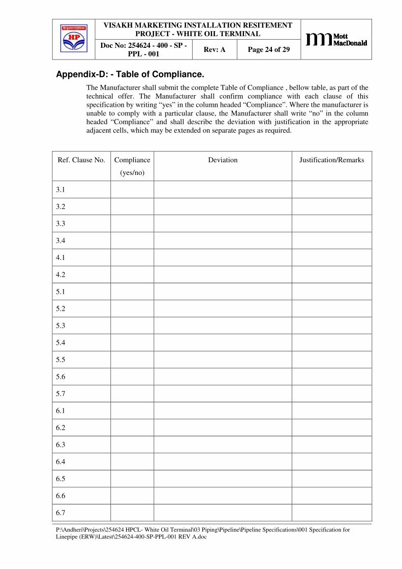
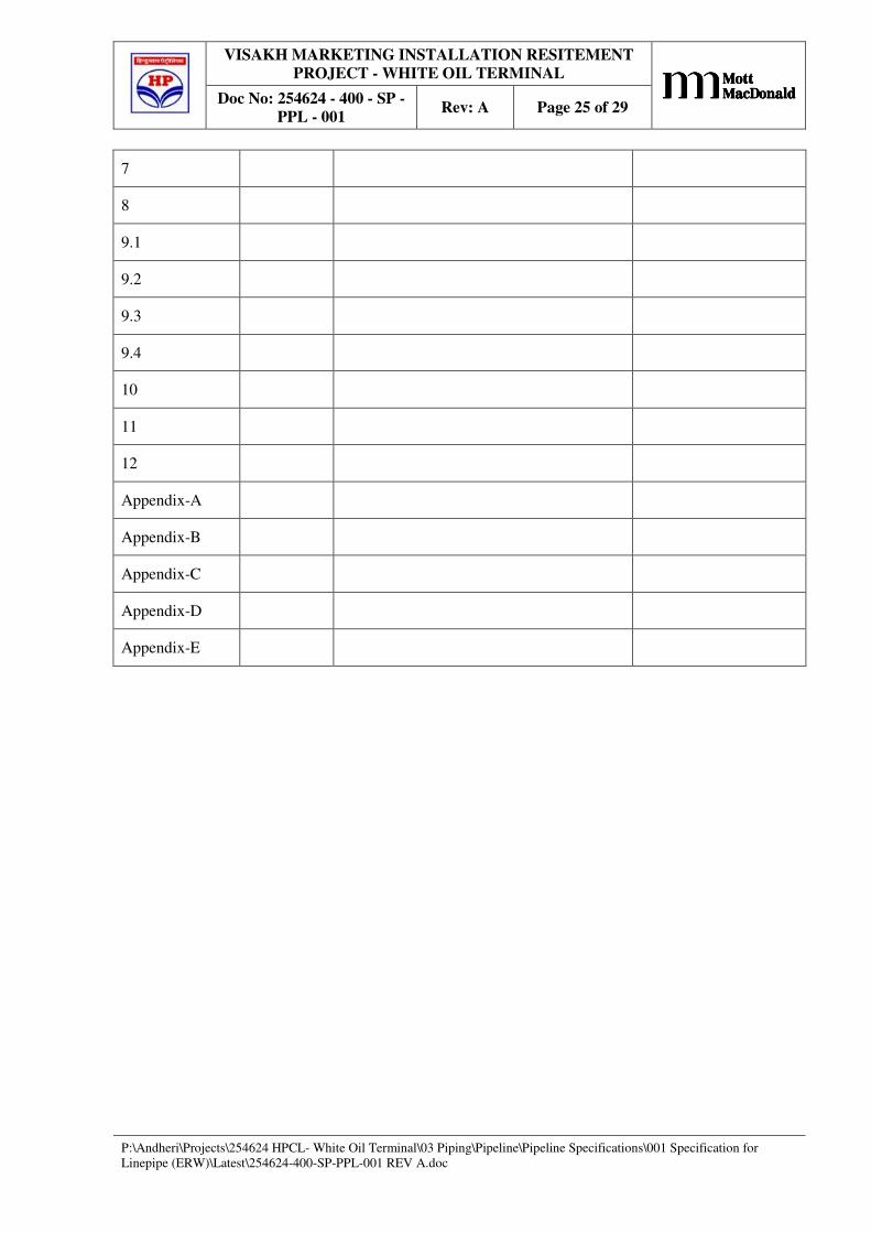
Appendix-D: - Table of Compliance.
The Manufacturer shall submit the complete Table of Compliance , bellow table, as part of the
technical offer. The Manufacturer shall confirm compliance with each clause of this
specification by writing “yes” in the column headed “Compliance”. Where the manufacturer is
unable to comply with a particular clause, the Manufacturer shall write “no” in the column
headed “Compliance” and shall describe the deviation with justification in the appropriate
adjacent cells, which may be extended on separate pages as required.
Ref. Clause No. Compliance
(yes/no)
Deviation Justification/Remarks
3.1
3.2
3.3
3.4
4.1
4.2
5.1
5.2
5.3
5.4
5.5
5.6
5.7
6.1
6.2
6.3
6.4
6.5
6.6
6.7
VISAKH MARKETING INSTALLATION RESITEMENT
PROJECT - WHITE OIL TERMINAL
Doc No: 254624 - 400 - SP -
PPL - 001 Rev: A Page 25 of 29
ABCABCABCABC
P:\Andheri\Projects\254624 HPCL- White Oil Terminal\03 Piping\Pipeline\Pipeline Specifications\001 Specification for
Linepipe (ERW)\Latest\254624-400-SP-PPL-001 REV A.doc
7
8
9.1
9.2
9.3
9.4
10
11
12
Appendix-A
Appendix-B
Appendix-C
Appendix-D
Appendix-E
VISAKH MARKETING INSTALLATION RESITEMENT
PROJECT - WHITE OIL TERMINAL
Doc No: 254624 - 400 - SP -
PPL - 001 Rev: A Page 26 of 29
ABCABCABCABC
P:\Andheri\Projects\254624 HPCL- White Oil Terminal\03 Piping\Pipeline\Pipeline Specifications\001 Specification for
Linepipe (ERW)\Latest\254624-400-SP-PPL-001 REV A.doc
Appendix-E: - Basic Pipeline Design Data.
VISAKH MARKETING INSTALLATION RESITEMENT
PROJECT - WHITE OIL TERMINAL
Doc No: 254624 - 400 - SP -
PPL - 001 Rev: A Page 27 of 29
ABCABCABCABC
P:\Andheri\Projects\254624 HPCL- White Oil Terminal\03 Piping\Pipeline\Pipeline Specifications\001 Specification for
Linepipe (ERW)\Latest\254624-400-SP-PPL-001 REV A.doc
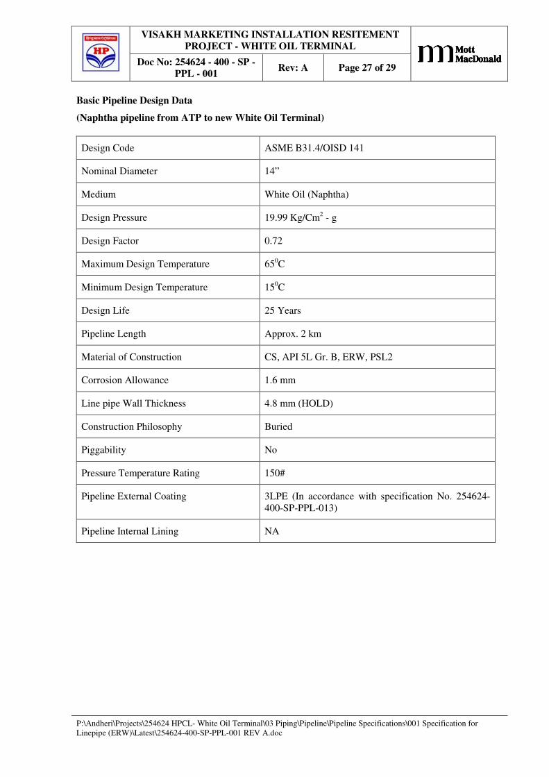
Basic Pipeline Design Data
(Naphtha pipeline from ATP to new White Oil Terminal)
Design Code ASME B31.4/OISD 141
Nominal Diameter 14”
Medium White Oil (Naphtha)
Design Pressure 19.99 Kg/Cm2 - g
Design Factor 0.72
Maximum Design Temperature 650C
Minimum Design Temperature 150C
Design Life 25 Years
Pipeline Length Approx. 2 km
Material of Construction CS, API 5L Gr. B, ERW, PSL2
Corrosion Allowance 1.6 mm
Line pipe Wall Thickness 4.8 mm (HOLD)
Construction Philosophy Buried
Piggability No
Pressure Temperature Rating 150#
Pipeline External Coating 3LPE (In accordance with specification No. 254624-
400-SP-PPL-013)
Pipeline Internal Lining NA
VISAKH MARKETING INSTALLATION RESITEMENT
PROJECT - WHITE OIL TERMINAL
Doc No: 254624 - 400 - SP -
PPL - 001 Rev: A Page 28 of 29
ABCABCABCABC
P:\Andheri\Projects\254624 HPCL- White Oil Terminal\03 Piping\Pipeline\Pipeline Specifications\001 Specification for
Linepipe (ERW)\Latest\254624-400-SP-PPL-001 REV A.doc
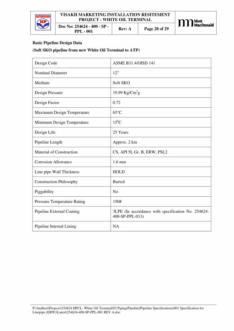
Basic Pipeline Design Data
(Soft SKO pipeline from new White Oil Terminal to ATP)
Design Code ASME B31.4/OISD 141
Nominal Diameter 12”
Medium Soft SKO
Design Pressure 19.99 Kg/Cm2g
Design Factor 0.72
Maximum Design Temperature 65°C
Minimum Design Temperature 150C
Design Life 25 Years
Pipeline Length Approx. 2 km
Material of Construction CS, API 5L Gr. B, ERW, PSL2
Corrosion Allowance 1.6 mm
Line pipe Wall Thickness HOLD
Construction Philosophy Buried
Piggability No
Pressure Temperature Rating 150#
Pipeline External Coating 3LPE (In accordance with specification No. 254624-
400-SP-PPL-013)
Pipeline Internal Lining NA
VISAKH MARKETING INSTALLATION RESITEMENT
PROJECT - WHITE OIL TERMINAL
Doc No: 254624 - 400 - SP -
PPL - 001 Rev: A Page 29 of 29
ABCABCABCABC
P:\Andheri\Projects\254624 HPCL- White Oil Terminal\03 Piping\Pipeline\Pipeline Specifications\001 Specification for
Linepipe (ERW)\Latest\254624-400-SP-PPL-001 REV A.doc
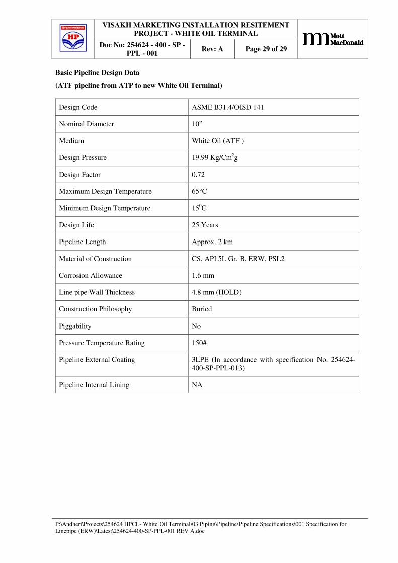
Basic Pipeline Design Data
(ATF pipeline from ATP to new White Oil Terminal)
Design Code ASME B31.4/OISD 141
Nominal Diameter 10”
Medium White Oil (ATF )
Design Pressure 19.99 Kg/Cm2g
Design Factor 0.72
Maximum Design Temperature 65°C
Minimum Design Temperature 150C
Design Life 25 Years
Pipeline Length Approx. 2 km
Material of Construction CS, API 5L Gr. B, ERW, PSL2
Corrosion Allowance 1.6 mm
Line pipe Wall Thickness 4.8 mm (HOLD)
Construction Philosophy Buried
Piggability No
Pressure Temperature Rating 150#
Pipeline External Coating 3LPE (In accordance with specification No. 254624-
400-SP-PPL-013)
Pipeline Internal Lining NA


![Index [tenders.hpcl.co.in]tenders.hpcl.co.in/tenders/tender_prog/tenderfiles/5786/Tender... · hindustan petroleum tital corporation limited chkd drwn dsgn name sign date drawing](https://img.pdfslide.us/doc/110x75/5aa1a4447f8b9ada698be578/index-petroleum-tital-corporation-limited-chkd-drwn-dsgn-name-sign-date-drawing.jpg)


![EM02 Electric Circuit - kotze223.files.wordpress.com · Factors affecting resistance [HKCEE] ... 7 Internal resistance of battery ... EM02 Electric Circuit.jnt Author: kotze223](https://img.pdfslide.us/doc/110x75/5b0815e87f8b9a3d018bafba/em02-electric-circuit-affecting-resistance-hkcee-7-internal-resistance-of.jpg)


![Index [tenders.hpcl.co.in]tenders.hpcl.co.in/tenders/tender_prog/tenderfiles/4500/Tender/50/... · index • buffer strip wall ... * retaining wall shall be provided incase of level](https://img.pdfslide.us/doc/110x75/5ab964937f8b9ac1058dcdb7/index-buffer-strip-wall-retaining-wall-shall-be-provided-incase-of.jpg)