Embed Size (px)
Citation preview
Michael Skoller, National Structural Engineering, Inc. 1
FPA-SC-11 Presentation 9 Jan 08
SPECIFICATION AND APPLICATION OF VOIDSPACES BELOW CONCRETE FOUNDATIONS
Document no: FPA-SC-11
Developed by: FPA Structural Committee
Committee chairs: Main Committee - Ron Kelm, P.E.Subcommittee - Michael Skoller, P.E.
Subcommittee: Mike Turner, Mohamed Moussaoui, Mari Mes,Al Maceiras, Jim Austin, Karl Breckon
Presented by: Michael Skoller, P.E., National Structural Engineering, Inc.
Presented to : Foundation Performance Association
Presented on: 9 January 2008
2
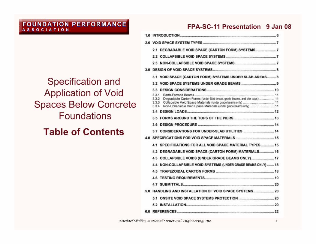
Specification andApplication of Void
Spaces Below Concrete Foundations
Table of Contents
FPA-SC-11 Presentation 9 Jan 08
Michael Skoller, National Structural Engineering, Inc.

3
PRESENTATION OUTLINE1. INTRODUCTION
2. VOID SPACE SYSTEM TYPES
3. ADVANTAGES/DISADVANTAGES OF VOIDSPACE SYSTEMS
4. DESIGN CONSIDERATIONS
5. DESIGN PROCEDURE
6. ONSITE PROTECTION & INSTALLATION
7. PHOTOGRAPHS
FPA-SC-11 Presentation 9 Jan 08
Michael Skoller, National Structural Engineering, Inc.
4
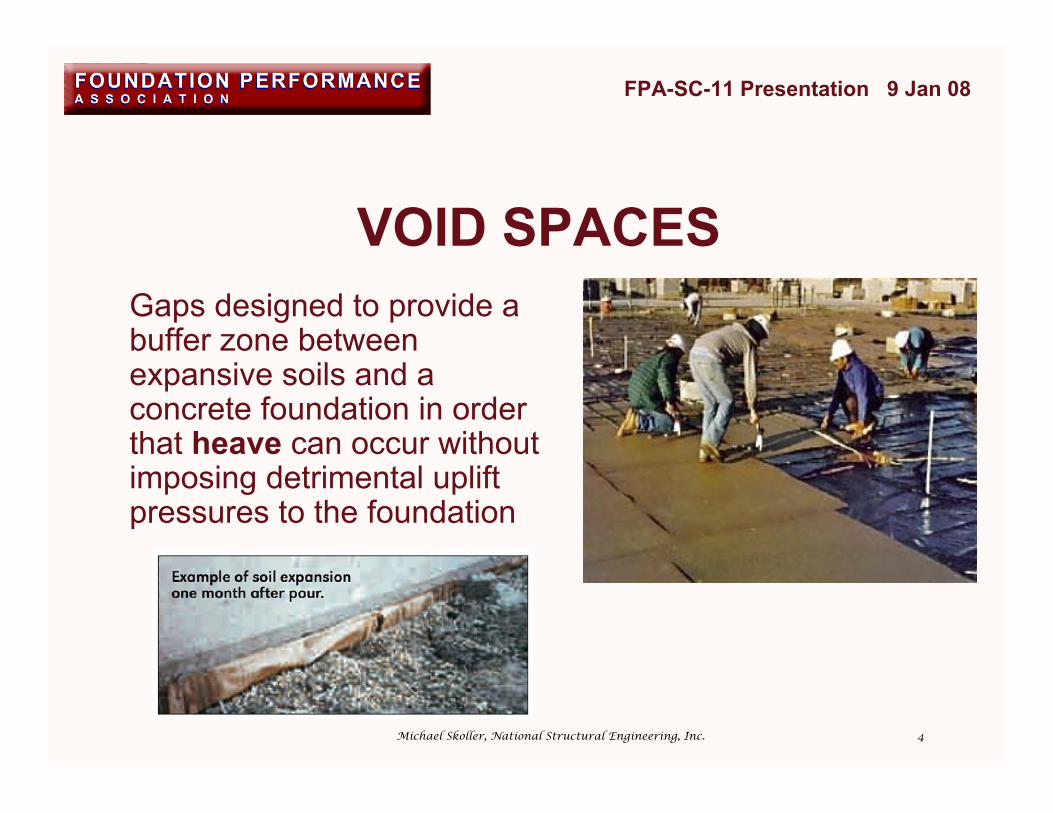
VOID SPACESGaps designed to provide abuffer zone betweenexpansive soils and aconcrete foundation in orderthat heave can occur withoutimposing detrimental upliftpressures to the foundation
FPA-SC-11 Presentation 9 Jan 08
Michael Skoller, National Structural Engineering, Inc.
5
HEAVE….The upward movement of an underlying supporting
soil stratum due to the addition of water to anunsaturated expansive soil within the moistureactive zone.
Commonly occurs within clayey soils with anavailable moisture source.
Without a void space, this movement may bedetrimental to foundations and superstructures.
FPA-SC-11 Presentation 9 Jan 08
Michael Skoller, National Structural Engineering, Inc.

6
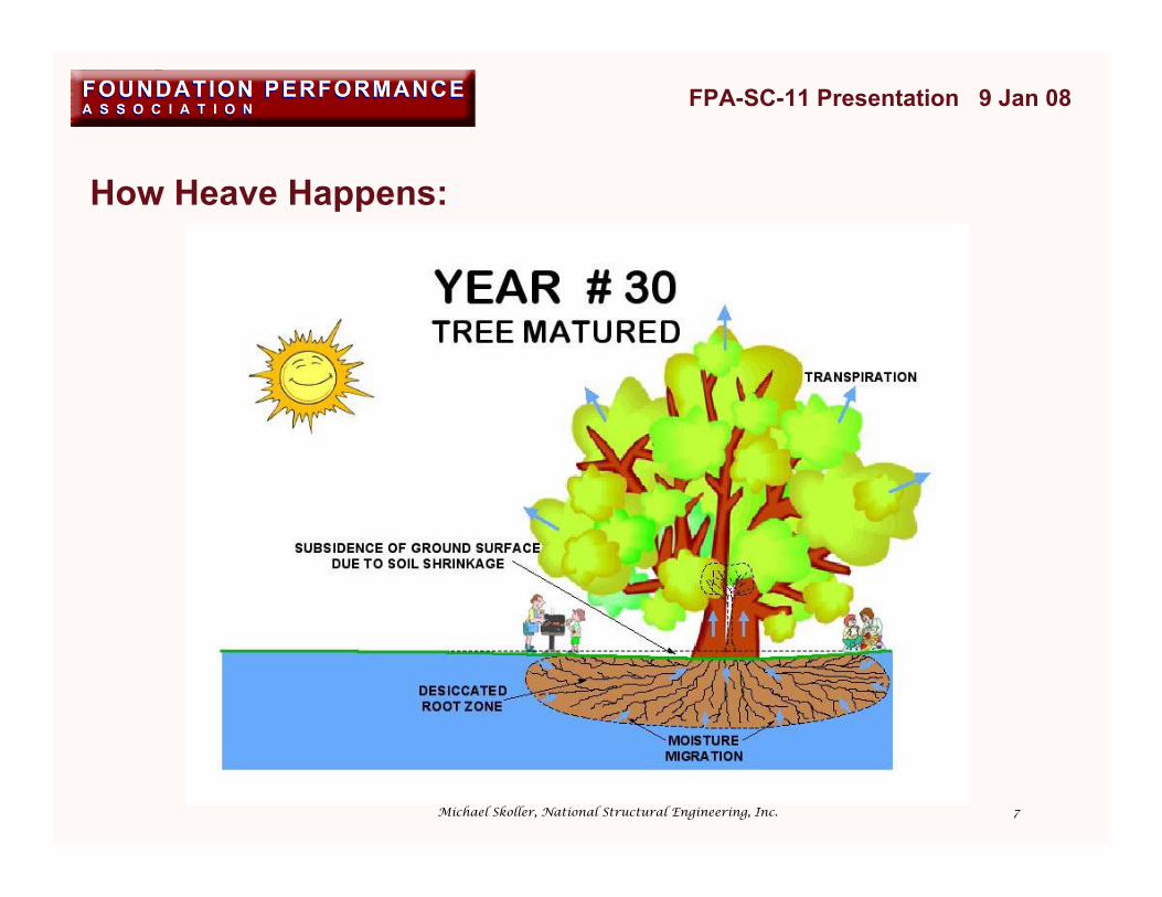
How Heave Happens:
FPA-SC-11 Presentation 9 Jan 08
Michael Skoller, National Structural Engineering, Inc.
7
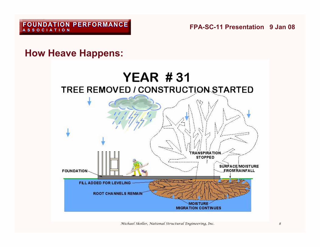
How Heave Happens:
FPA-SC-11 Presentation 9 Jan 08
Michael Skoller, National Structural Engineering, Inc.
8
How Heave Happens:
FPA-SC-11 Presentation 9 Jan 08
Michael Skoller, National Structural Engineering, Inc.

9
How Heave Happens:
FPA-SC-11 Presentation 9 Jan 08
Michael Skoller, National Structural Engineering, Inc.
10
FPA-SC-11 Presentation 9 Jan 08
Michael Skoller, National Structural Engineering, Inc.
1. INTRODUCTION2. VOID SPACE SYSTEM TYPES3. ADVANTAGES/DISADVANTAGES OF VOID SPACE SYSTEMS4. DESIGN CONSIDERATIONS5. DESIGN PROCEDURE6. ONSITE PROTECTION & INSTALLATION7. PHOTOGRAPHS

11
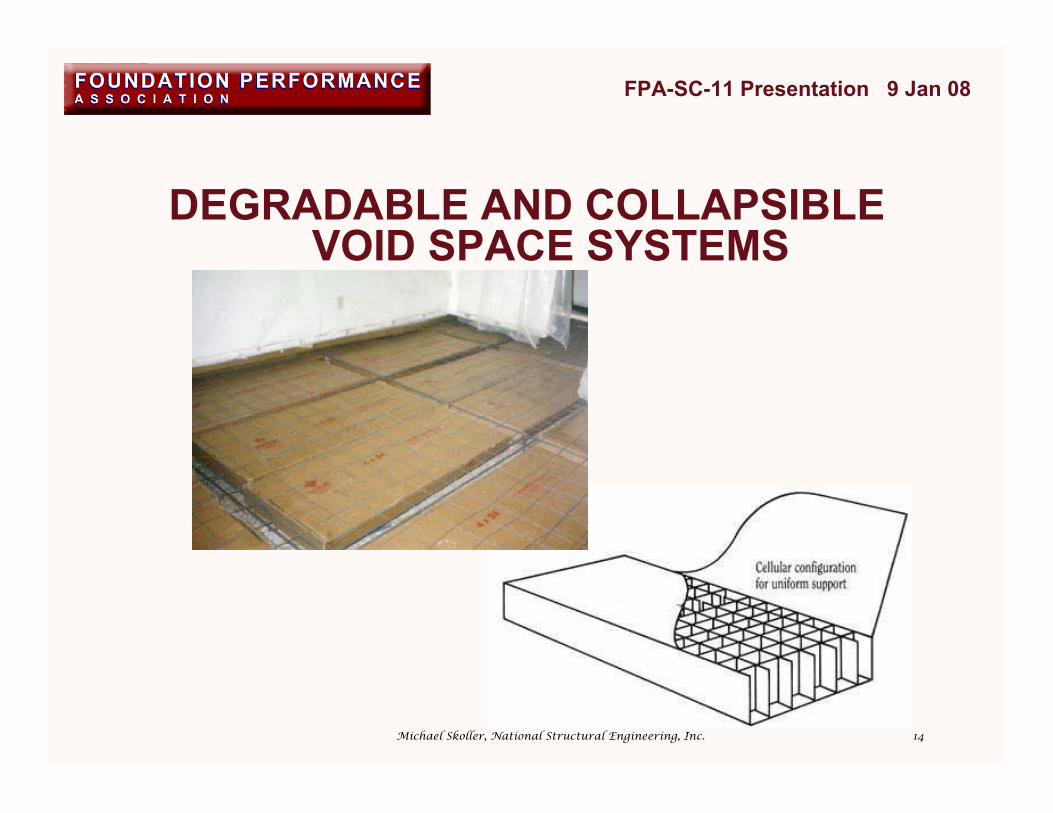
VOID SPACE SYSTEM TYPESDEGRADABLE VOID SPACE SYSTEMS• Only type to be used under slab areas
• Wax coated; will gradually absorb ground moistureand lose strength or degrade over a period of time
• Soil can heave into the resulting void space
• Material, such as gravel or plastic sheathing, undercarton forms should not be used because a capillarybreak may occur preventing moisture migration to thedegradable carton forms.
COLLAPSIBLE VOID SPACE SYSTEMSNON-COLLAPSIBLE VOID SPACE SYSTEMS
FPA-SC-11 Presentation 9 Jan 08
Michael Skoller, National Structural Engineering, Inc.

12
VOID SPACE SYSTEM TYPESDEGRADABLE VOID SPACE SYSTEMS
COLLAPSIBLE VOID SPACE SYSTEMS• Non-degradable material designed to collapse under
heave pressures greater than the weight of thefoundation and superstructure dead loads
• Will not collapse during foundation make-up andplacement
• Not to be used under slab areas.
NON-COLLAPSIBLE VOID SPACE SYSTEMS
FPA-SC-11 Presentation 9 Jan 08
Michael Skoller, National Structural Engineering, Inc.

13
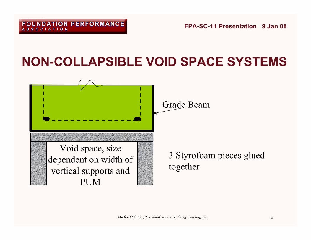
VOID SPACE SYSTEM TYPESDEGRADABLE VOID SPACE SYSTEMSCOLLAPSIBLE VOID SPACE SYSTEMSNON-COLLAPSIBLE VOID SPACE SYSTEMS• Non-collapsible material designed to maintain its
original structural integrity throughout life of thefoundation
• Built-in void space• Materials include fully wax impregnated corrugated
paper, Styrofoam, plastics and other non-degradableproducts
• Use under grade beams only
FPA-SC-11 Presentation 9 Jan 08
Michael Skoller, National Structural Engineering, Inc.
14
DEGRADABLE AND COLLAPSIBLEVOID SPACE SYSTEMS
FPA-SC-11 Presentation 9 Jan 08
Michael Skoller, National Structural Engineering, Inc.
15
NON-COLLAPSIBLE VOID SPACE SYSTEMS
FPA-SC-11 Presentation 9 Jan 08
Grade Beam
Void space, sizedependent on width ofvertical supports and
PUM
3 Styrofoam pieces gluedtogether
Michael Skoller, National Structural Engineering, Inc.
16
FPA-SC-11 Presentation 9 Jan 08
Michael Skoller, National Structural Engineering, Inc.
1. INTRODUCTION2. VOID SPACE SYSTEM TYPES3. ADVANTAGES/DISADVANTAGES OF VOID SPACE SYSTEMS4. DESIGN CONSIDERATIONS5. DESIGN PROCEDURE6. ONSITE PROTECTION & INSTALLATION7. PHOTOGRAPHS

17
VOID SPACE SYSTEM(DEGRADABLE CARTON FORMS) UNDER SLAB AREAS
• Reduces foundation heave• Elevated slab areas are less affected by
surface water prior to concrete placement
FPA-SC-11 Presentation 9 Jan 08
Advantages
Michael Skoller, National Structural Engineering, Inc.

18
VOID SPACE SYSTEM(DEGRADABLE CARTON FORMS) UNDER SLAB AREAS
• Creates path for water to migrate below slab• Termites may be attracted to carton forms
when paper products are used• Increases design and construction cost• Concrete may enter carton form during
placement if grade stakes are driven throughcarton forms
FPA-SC-11 Presentation 9 Jan 08
Disadvantages
Michael Skoller, National Structural Engineering, Inc.

19
VOID SPACE SYSTEMS UNDERGRADE BEAMS
• Allows total isolation of the upperfoundation from the active soils
• Potential Upward Movement of foundationwill be reduced, assuming sufficient voidspace is maintained and deeply supportedfoundations are founded below the moistureactive zone.
FPA-SC-11 Presentation 9 Jan 08
Advantages
Michael Skoller, National Structural Engineering, Inc.
20
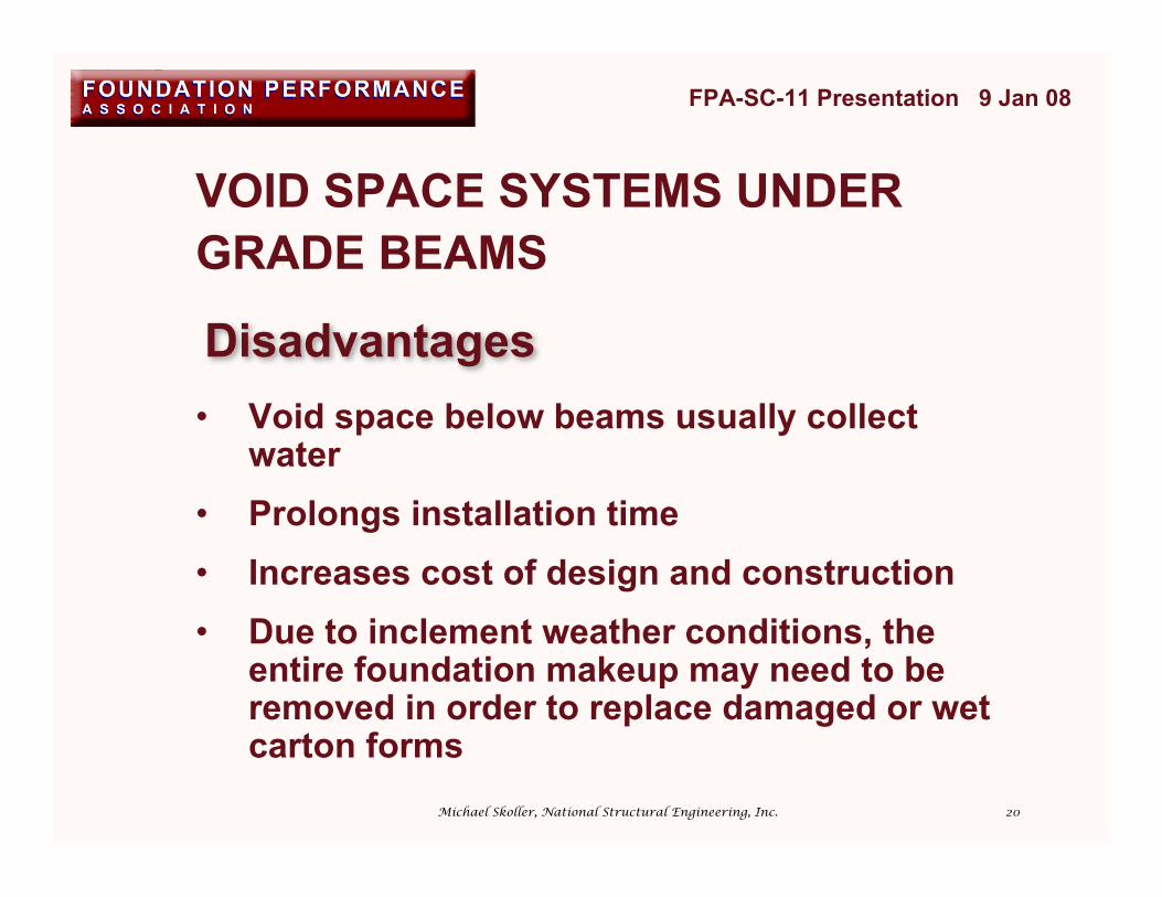
VOID SPACE SYSTEMS UNDERGRADE BEAMS
• Void space below beams usually collectwater
• Prolongs installation time• Increases cost of design and construction• Due to inclement weather conditions, the
entire foundation makeup may need to beremoved in order to replace damaged or wetcarton forms
FPA-SC-11 Presentation 9 Jan 08
Disadvantages
Michael Skoller, National Structural Engineering, Inc.

21
NO VOID SPACE UNDER GRADE BEAMS
Design procedure:
a) Determine the maximum uplift forces of the soil andcompare the capacity of the grade beams with thatforce applied to the bottom of the grade beams. Ifthe dead load on the beam is equal to or greaterthan the uplift force, no additional design isnecessary. If the uplift force is greater, the gradebeams need to be designed for this upward forceminus the dead load, and the piers should then bedesigned for the proper depth below the moistureactive zone to resist this uplift.
FPA-SC-11 Presentation 9 Jan 08
Michael Skoller, National Structural Engineering, Inc.
22
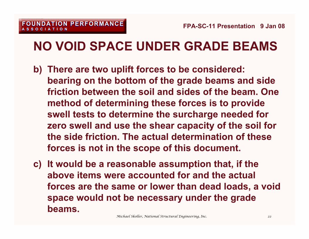
NO VOID SPACE UNDER GRADE BEAMS
b) There are two uplift forces to be considered:bearing on the bottom of the grade beams and sidefriction between the soil and sides of the beam. Onemethod of determining these forces is to provideswell tests to determine the surcharge needed forzero swell and use the shear capacity of the soil forthe side friction. The actual determination of theseforces is not in the scope of this document.
c) It would be a reasonable assumption that, if theabove items were accounted for and the actualforces are the same or lower than dead loads, a voidspace would not be necessary under the gradebeams.
FPA-SC-11 Presentation 9 Jan 08
Michael Skoller, National Structural Engineering, Inc.
23
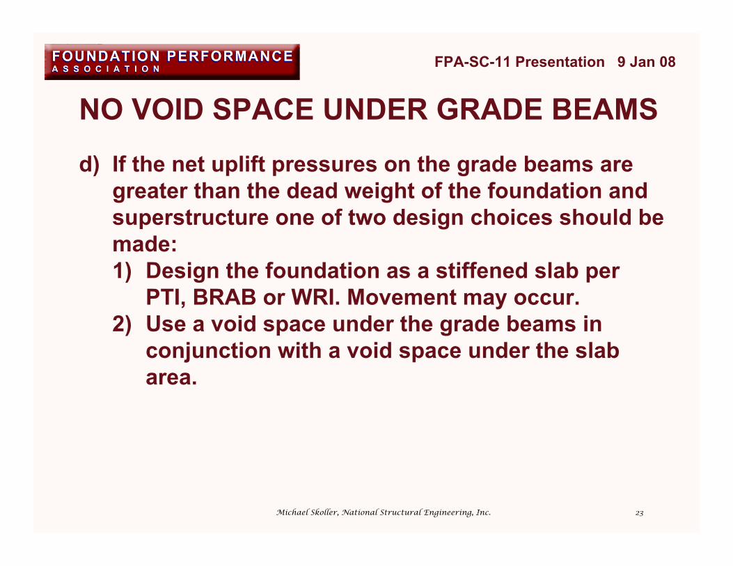
NO VOID SPACE UNDER GRADE BEAMS
d) If the net uplift pressures on the grade beams aregreater than the dead weight of the foundation andsuperstructure one of two design choices should bemade:1) Design the foundation as a stiffened slab per
PTI, BRAB or WRI. Movement may occur.2) Use a void space under the grade beams in
conjunction with a void space under the slabarea.
FPA-SC-11 Presentation 9 Jan 08
Michael Skoller, National Structural Engineering, Inc.
24
FPA-SC-11 Presentation 9 Jan 08
Michael Skoller, National Structural Engineering, Inc.
1. INTRODUCTION2. VOID SPACE SYSTEM TYPES3. ADVANTAGES/DISADVANTAGES OF VOID SPACE SYSTEMS4. DESIGN CONSIDERATIONS5. DESIGN PROCEDURE6. ONSITE PROTECTION & INSTALLATION7. PHOTOGRAPHS
25
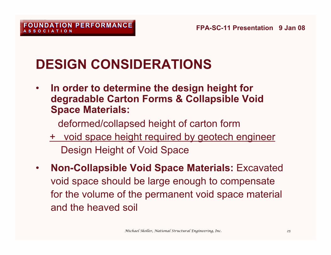
DESIGN CONSIDERATIONS• In order to determine the design height for
degradable Carton Forms & Collapsible VoidSpace Materials:
deformed/collapsed height of carton form + void space height required by geotech engineer Design Height of Void Space
• Non-Collapsible Void Space Materials: Excavatedvoid space should be large enough to compensatefor the volume of the permanent void space materialand the heaved soil
FPA-SC-11 Presentation 9 Jan 08
Michael Skoller, National Structural Engineering, Inc.
26
FPA-SC-11 Presentation 9 Jan 08
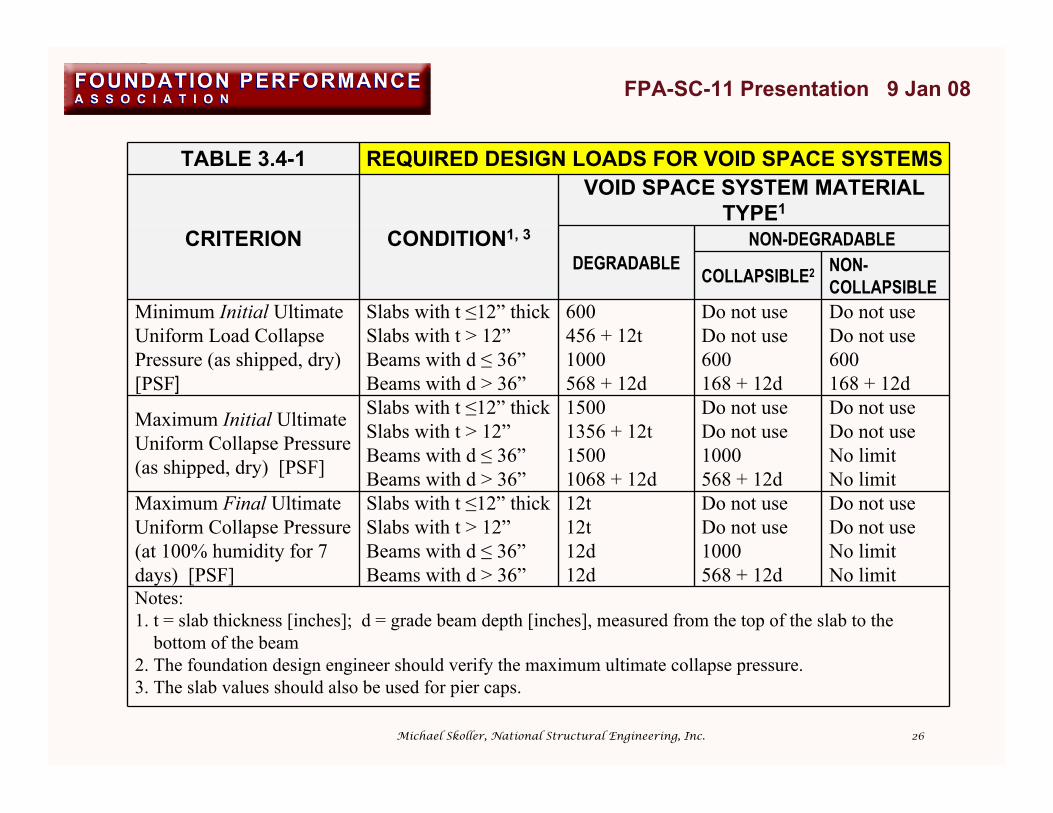
TABLE 3.4-1 REQUIRED DESIGN LOADS FOR VOID SPACE SYSTEMSVOID SPACE SYSTEM MATERIAL
TYPE1
CRITERION CONDITION1, 3 NON-DEGRADABLEDEGRADABLE
COLLAPSIBLE2 NON-COLLAPSIBLE
Minimum Initial UltimateUniform Load CollapsePressure (as shipped, dry)[PSF]
Slabs with t ≤12” thick 600 Do not use Do not useSlabs with t > 12” 456 + 12t Do not use Do not useBeams with d ≤ 36” 1000 600 600Beams with d > 36” 568 + 12d 168 + 12d 168 + 12d
Maximum Initial UltimateUniform Collapse Pressure(as shipped, dry) [PSF]
Slabs with t ≤12” thick 1500 Do not use Do not useSlabs with t > 12” 1356 + 12t Do not use Do not useBeams with d ≤ 36” 1500 1000 No limitBeams with d > 36” 1068 + 12d 568 + 12d No limit
Maximum Final UltimateUniform Collapse Pressure(at 100% humidity for 7days) [PSF]
Slabs with t ≤12” thick 12t Do not use Do not useSlabs with t > 12” 12t Do not use Do not useBeams with d ≤ 36” 12d 1000 No limitBeams with d > 36” 12d 568 + 12d No limit
Notes:1. t = slab thickness [inches]; d = grade beam depth [inches], measured from the top of the slab to the bottom of the beam2. The foundation design engineer should verify the maximum ultimate collapse pressure.3. The slab values should also be used for pier caps.
Michael Skoller, National Structural Engineering, Inc.
27
DESIGN CONSIDERATIONSFOR THE FORMS AROUND
THE TOPS OF PIERS
FPA-SC-11 Presentation 9 Jan 08
Michael Skoller, National Structural Engineering, Inc.

28
FORMS AROUND THE TOPS OF PIERS
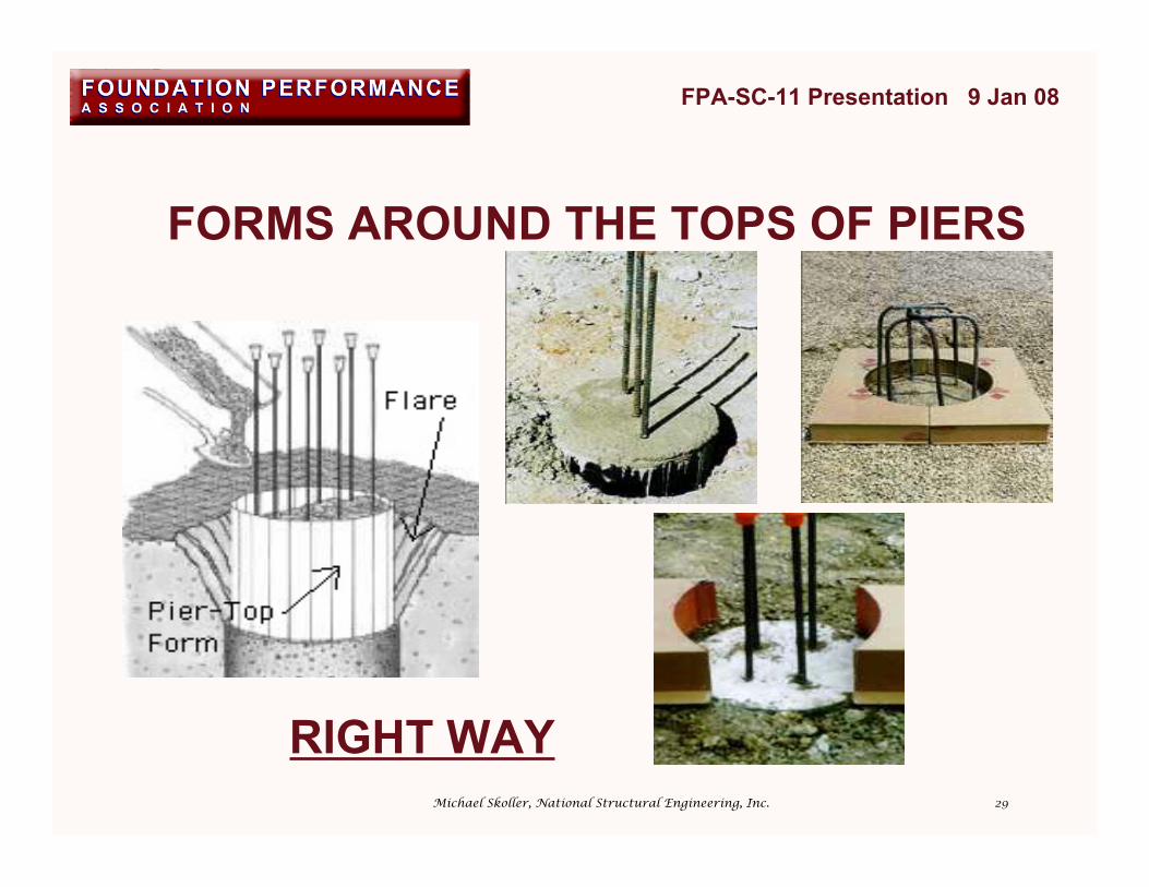
• Reducing contact area between top of pier andsoil reduces potential uplift pressures
• Less concrete waste
• Additional cost of materials• Additional labor to install
FPA-SC-11 Presentation 9 Jan 08
Advantages
Disadvantages
Michael Skoller, National Structural Engineering, Inc.
29
FORMS AROUND THE TOPS OF PIERS
FPA-SC-11 Presentation 9 Jan 08
RIGHT WAYMichael Skoller, National Structural Engineering, Inc.
30
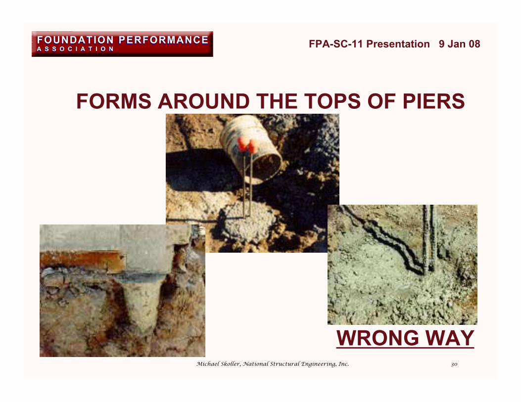
FORMS AROUND THE TOPS OF PIERS
FPA-SC-11 Presentation 9 Jan 08
WRONG WAYMichael Skoller, National Structural Engineering, Inc.

31
FORMS AROUND THE TOPS OF PIERS
FPA-SC-11 Presentation 9 Jan 08
Michael Skoller, National Structural Engineering, Inc.

32
VOID SPACE SYSTEMMANUFACTURER TESTING
FPA-SC-11 Presentation 9 Jan 08
Michael Skoller, National Structural Engineering, Inc.

33
VOID SPACE SYSTEM TESTINGFor a void space system to be considered acceptable underthis document, it should be tested by an independent laboratoryin accordance with the following minimum requirements:
a) Minimum of 3 randomly selected test samplesb) Minimum length = 2 times depth of test samplec) Repetitive cell pattern of at least two adjacent cells in each
horizontal directiond) Test pressure at failure is pressure where either deflection
increases without additional pressure, or total verticaldeformation > 5% of original vertical dimension
e) All samples fail at pressure ±10% of average failure pressuref) Test pressure shall be uniformly applied to test sample
FPA-SC-11 Presentation 9 Jan 08
Michael Skoller, National Structural Engineering, Inc.

34
FPA-SC-11 Presentation 9 Jan 08
Michael Skoller, National Structural Engineering, Inc.
1. INTRODUCTION2. VOID SPACE SYSTEM TYPES3. ADVANTAGES/DISADVANTAGES OF VOID SPACE SYSTEMS4. DESIGN CONSIDERATIONS5. DESIGN PROCEDURE6. ONSITE PROTECTION & INSTALLATION7. PHOTOGRAPHS
35
VOID SPACE SYSTEM DESIGN PROCEDURE
a) A geotechnical investigation and report should be inaccordance with the requirements of Document No.FPA-SC-04, Recommended Practice forGeotechnical Explorations and Reports and / or otherguidelines acceptable to the foundation designengineer.
b) The foundation design engineer decides whether ornot to utilize a Void Space System based onrecommendations from the geotechnical report anddiscussions with the client.
FPA-SC-11 Presentation 9 Jan 08
Michael Skoller, National Structural Engineering, Inc.

36
VOID SPACE SYSTEM DESIGN PROCEDURE
c) The geotechnical report shall includerecommendations needed by the foundation designengineer to design the Void Space System, inparticular the net height of Void Space (PUM)required below the bottom of the slab and gradebeams.
d) The foundation design engineer specifies the VoidSpace height and Void Space System on the designdrawings and / or specifications based onrecommendations of the net height of Void Space(PUM) recommended by the geotechnical engineer.
FPA-SC-11 Presentation 9 Jan 08
Michael Skoller, National Structural Engineering, Inc.
37
CONSIDERATIONS FORUNDER-SLAB UTILITIES
FPA-SC-11 Presentation 9 Jan 08
Michael Skoller, National Structural Engineering, Inc.

38
FPA-SC-11 Presentation 9 Jan 08
Rebar or Cable
Pipe
Pipe Hanger
Assembly
Not to ScaleSoil
Slab and beams
Degradable
Void Space
System
material
Form board
UNDER-SLAB UTILITY CONSIDERATION--Piping must remain stationary with respect to the slab--
Michael Skoller, National Structural Engineering, Inc.

39
UNDER-SLAB UTILITY CONSIDERATION--Piping must remain stationary with respect to the slab--
FPA-SC-11 Presentation 9 Jan 08
Rebar or Cable
Pipe
Not to Scale
Slab and beams
Soil
Form board
Degradable
Void Space
System
Material
Floor Drain
and Pipe
Pipe Hanger
Assembly
Piping May Be Subjected To
Bending
Michael Skoller, National Structural Engineering, Inc.

40
TRAPEZOIDAL CARTON FORMS
FPA-SC-11 Presentation 9 Jan 08
Michael Skoller, National Structural Engineering, Inc.

41
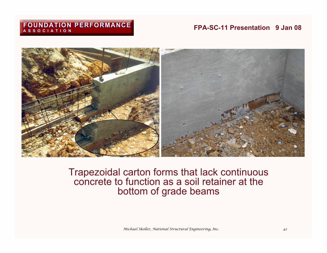
TRAPEZOIDAL CARTON FORMS
• Inappropriate for void space system• Designed to resist lateral pressures, but as
concrete on the sides is often thin andunreinforced, pressures are not resisted
• Lack sufficient interior vertical supports
FPA-SC-11 Presentation 9 Jan 08
Michael Skoller, National Structural Engineering, Inc.
42
Trapezoidal carton forms that lack continuousconcrete to function as a soil retainer at the
bottom of grade beams
FPA-SC-11 Presentation 9 Jan 08
Michael Skoller, National Structural Engineering, Inc.
43
FPA-SC-11 Presentation 9 Jan 08
Michael Skoller, National Structural Engineering, Inc.
1. INTRODUCTION2. VOID SPACE SYSTEM TYPES3. ADVANTAGES/DISADVANTAGES OF VOID SPACE SYSTEMS4. DESIGN CONSIDERATIONS5. DESIGN PROCEDURE6. ONSITE PROTECTION &
INSTALLATION7. PHOTOGRAPHS
44
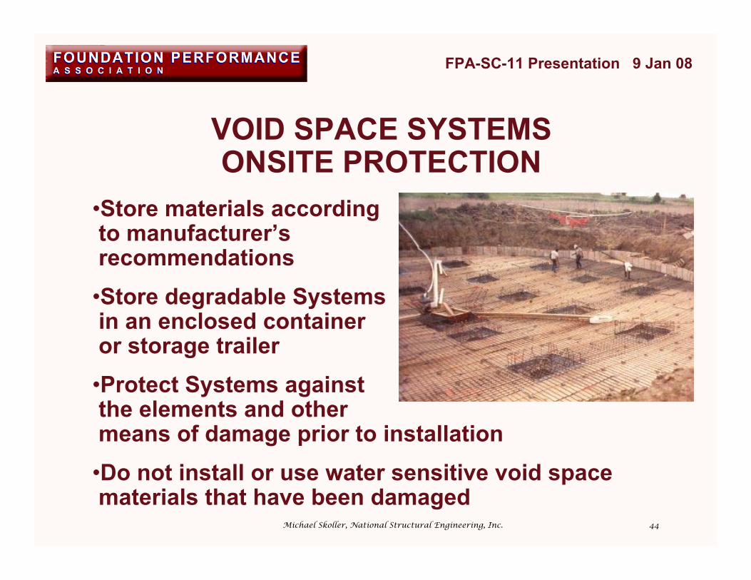
VOID SPACE SYSTEMSONSITE PROTECTION
FPA-SC-11 Presentation 9 Jan 08
•Store materials according to manufacturer’s recommendations•Store degradable Systems in an enclosed container or storage trailer•Protect Systems against the elements and other means of damage prior to installation•Do not install or use water sensitive void space materials that have been damaged
Michael Skoller, National Structural Engineering, Inc.
45
VOID SPACE SYSTEMS INSTALLATION
FPA-SC-11 Presentation 9 Jan 08
a) Assemble products as recommended by the manufacturer todevelop designed strengths.
b) Degradable carton forms should have access to moisture inorder to properly deteriorate. Do not wrap degradable forms inpolyethylene. A moisture retarder (polyethylene) should not beused below degradable carton forms because this may not allowdeterioration from the subgrade below.
c) Place a protective covering over Void Space Systems asnecessary to distribute working load, bridge small gaps, andprotect the materials from puncture and other damage duringconcrete placement. A protective fiberboard may be used on topof all Void Space Systems, which helps distribute concentratedconstruction loads from rebar bolsters, personnel, etc. Do notuse protective fiberboard less than 1/8”, plywood or OSB board.
Michael Skoller, National Structural Engineering, Inc.
46
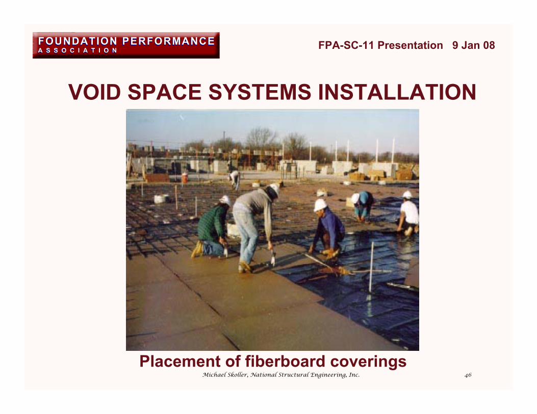
VOID SPACE SYSTEMS INSTALLATION
FPA-SC-11 Presentation 9 Jan 08
Placement of fiberboard coverings
Michael Skoller, National Structural Engineering, Inc.
47
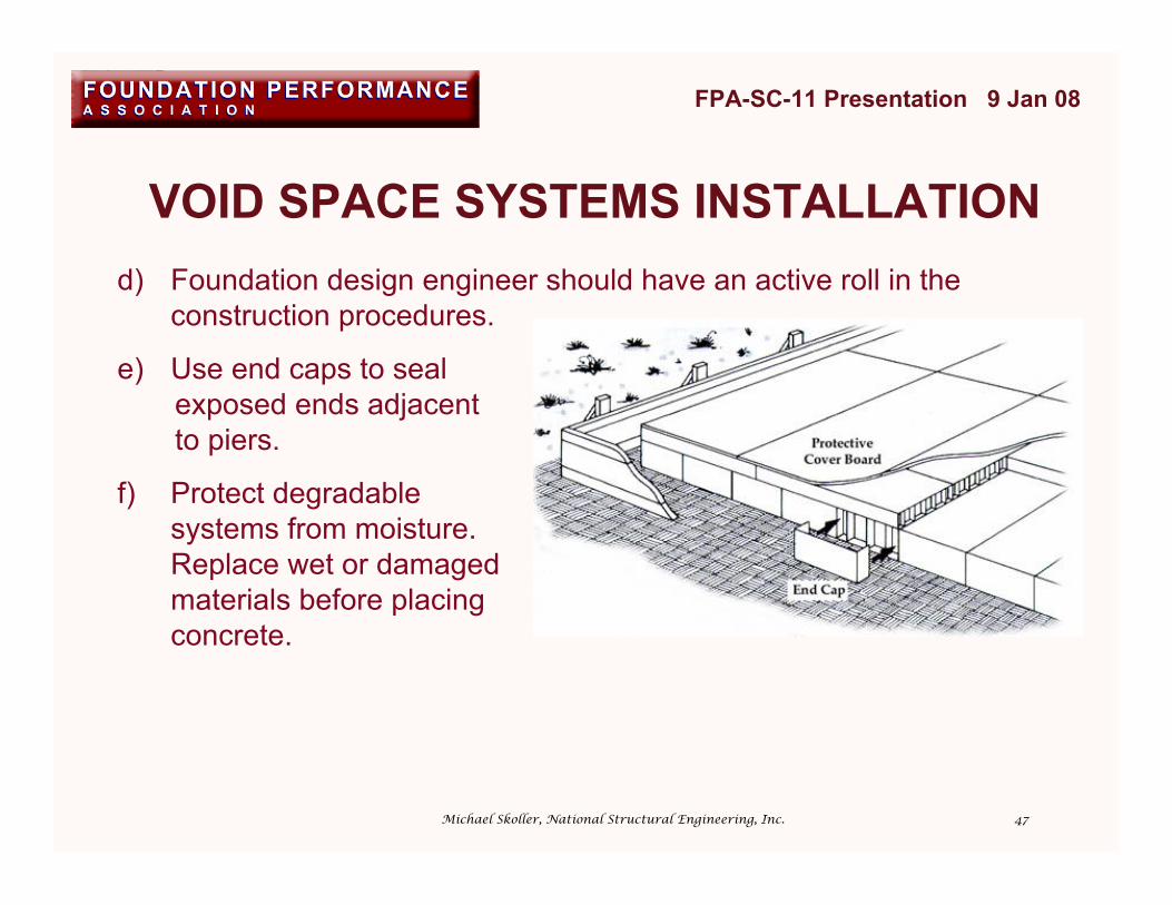
VOID SPACE SYSTEMS INSTALLATION
FPA-SC-11 Presentation 9 Jan 08
d) Foundation design engineer should have an active roll in theconstruction procedures.
e) Use end caps to seal exposed ends adjacent to piers.
f) Protect degradablesystems from moisture.Replace wet or damagedmaterials before placingconcrete.
Michael Skoller, National Structural Engineering, Inc.

48
VOID SPACE SYSTEMS INSTALLATION
FPA-SC-11 Presentation 9 Jan 08
g) Ensure positive drainage away from the foundation
h) Systems should be properly placed and anchored
i) Moisture retarder may beplaced over top of carton
forms. Collapsible void systems may be wrapped with moisture retarder as long as the entrapped air has a method of escaping.
Michael Skoller, National Structural Engineering, Inc.
49
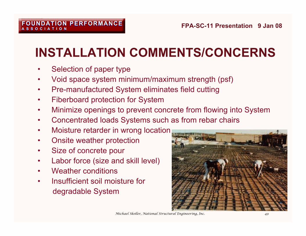
INSTALLATION COMMENTS/CONCERNS
FPA-SC-11 Presentation 9 Jan 08
• Selection of paper type• Void space system minimum/maximum strength (psf)• Pre-manufactured System eliminates field cutting• Fiberboard protection for System• Minimize openings to prevent concrete from flowing into System• Concentrated loads Systems such as from rebar chairs• Moisture retarder in wrong location• Onsite weather protection• Size of concrete pour• Labor force (size and skill level)• Weather conditions• Insufficient soil moisture for degradable System
Michael Skoller, National Structural Engineering, Inc.

50
FPA-SC-11 Presentation 9 Jan 08
Michael Skoller, National Structural Engineering, Inc.
1. INTRODUCTION2. VOID SPACE SYSTEM TYPES3. ADVANTAGES/DISADVANTAGES OF VOID SPACE SYSTEMS4. DESIGN CONSIDERATIONS5. DESIGN PROCEDURE6. ONSITE PROTECTION & INSTALLATION7. PHOTOGRAPHS

51
CARTON FORMS BENEATH BEAMS
FPA-SC-11 Presentation 9 Jan 08
Michael Skoller, National Structural Engineering, Inc.

52
CARTON FORMS BENEATH BEAMS
FPA-SC-11 Presentation 9 Jan 08
Michael Skoller, National Structural Engineering, Inc.
53
CARTON FORMS BENEATH WALL
FPA-SC-11 Presentation 9 Jan 08
Michael Skoller, National Structural Engineering, Inc.
54
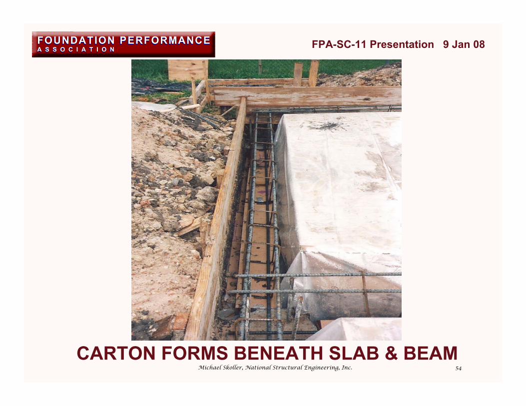
CARTON FORMS BENEATH SLAB & BEAM
FPA-SC-11 Presentation 9 Jan 08
Michael Skoller, National Structural Engineering, Inc.

55
PRE-MANUFACTURED RADIAL CARTONFORM AT PIER INTERSECTION
FPA-SC-11 Presentation 9 Jan 08
Michael Skoller, National Structural Engineering, Inc.

56ONE-PIECE PIER CARTON FORM
FPA-SC-11 Presentation 9 Jan 08
Michael Skoller, National Structural Engineering, Inc.

57TWO-PIECE PIER CARTON FORM
FPA-SC-11 Presentation 9 Jan 08
Michael Skoller, National Structural Engineering, Inc.

58
FPA-SC-11 Presentation 9 Jan 08
RADIAL SHAPES ARE FIELD-CUT AND PATCHEDMichael Skoller, National Structural Engineering, Inc.
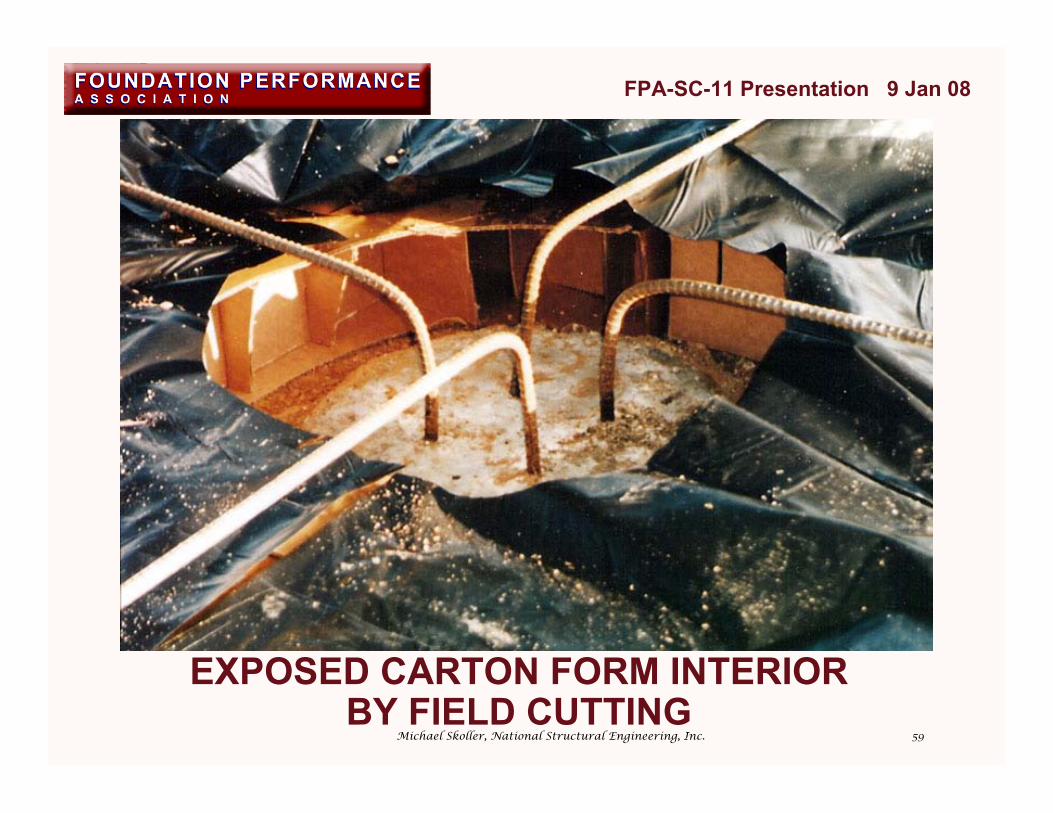
59
FPA-SC-11 Presentation 9 Jan 08
EXPOSED CARTON FORM INTERIORBY FIELD CUTTING
Michael Skoller, National Structural Engineering, Inc.

60
FPA-SC-11 Presentation 9 Jan 08
FIELD-CUT PIECES AROUND PIERMichael Skoller, National Structural Engineering, Inc.

61
FPA-SC-11 Presentation 9 Jan 08
WASTED CARTON FORM MATERIALMichael Skoller, National Structural Engineering, Inc.

62
FPA-SC-11 Presentation 9 Jan 08
Michael Skoller, National Structural Engineering, Inc.
FIELD-CUT CARTON FORMS RANDOMLY PLACED AROUND PIER

63
FPA-SC-11 Presentation 9 Jan 08
Michael Skoller, National Structural Engineering, Inc.PIER PERIMETER STUFFED WITH PAPER SCRAP
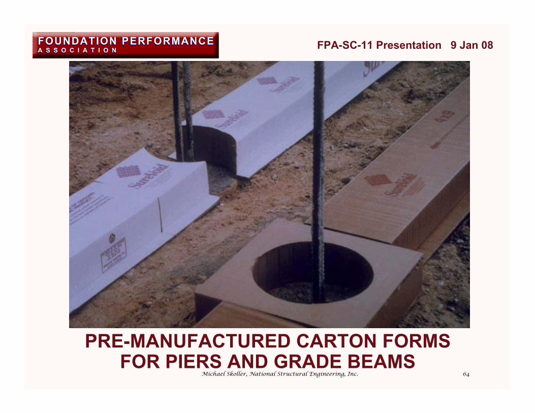
64
FPA-SC-11 Presentation 9 Jan 08
Michael Skoller, National Structural Engineering, Inc.
PRE-MANUFACTURED CARTON FORMSFOR PIERS AND GRADE BEAMS

65
FPA-SC-11 Presentation 9 Jan 08
Michael Skoller, National Structural Engineering, Inc.SLAB AND PIER CARTON FORMS

66
FPA-SC-11 Presentation 9 Jan 08
Michael Skoller, National Structural Engineering, Inc.SLAB AND PIER CARTON FORMS
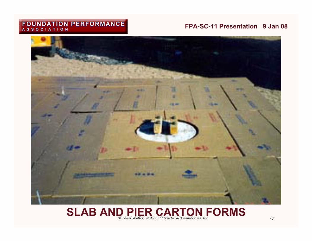
67
FPA-SC-11 Presentation 9 Jan 08
Michael Skoller, National Structural Engineering, Inc.SLAB AND PIER CARTON FORMS
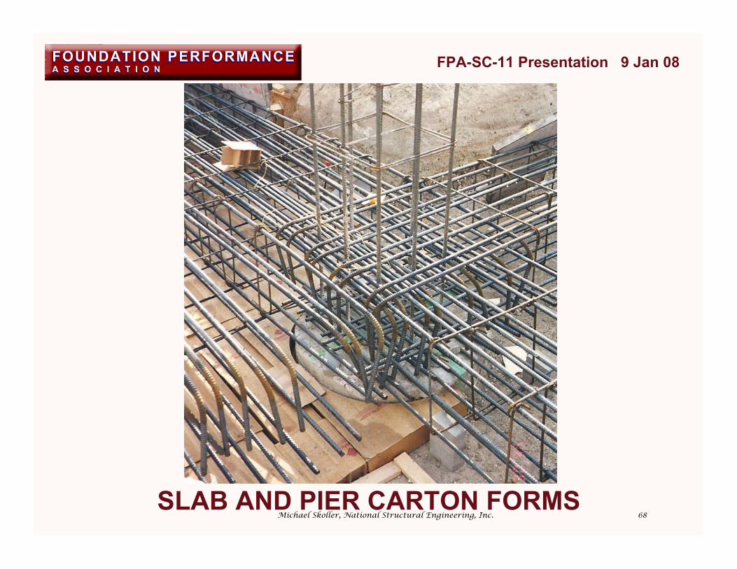
68
FPA-SC-11 Presentation 9 Jan 08
Michael Skoller, National Structural Engineering, Inc.SLAB AND PIER CARTON FORMS

69
VOIDED BASEMENT SLAB WITH FIBERBOARD
FPA-SC-11 Presentation 9 Jan 08
Michael Skoller, National Structural Engineering, Inc.
70
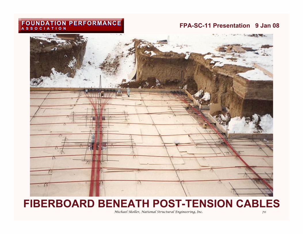
FIBERBOARD BENEATH POST-TENSION CABLES
FPA-SC-11 Presentation 9 Jan 08
Michael Skoller, National Structural Engineering, Inc.

71
FIBERBOARD BENEATH POST-TENSION CABLES
FPA-SC-11 Presentation 9 Jan 08
Michael Skoller, National Structural Engineering, Inc.

72
FIBERBOARD BENEATH POST-TENSION CABLES
FPA-SC-11 Presentation 9 Jan 08
Michael Skoller, National Structural Engineering, Inc.

73
VOIDED SLAB SECTIONSCOVERED WITH FIBERBOARD
FPA-SC-11 Presentation 9 Jan 08
Michael Skoller, National Structural Engineering, Inc.
74
VOIDED SLAB SECTIONS COVERED WITHFIBERBOARD AND MOISTURE RETARDER
FPA-SC-11 Presentation 9 Jan 08
Michael Skoller, National Structural Engineering, Inc.

75
VOIDED SLAB SECTIONS COVERED WITHMOISTURE RETARDER
FPA-SC-11 Presentation 9 Jan 08
Michael Skoller, National Structural Engineering, Inc.
76
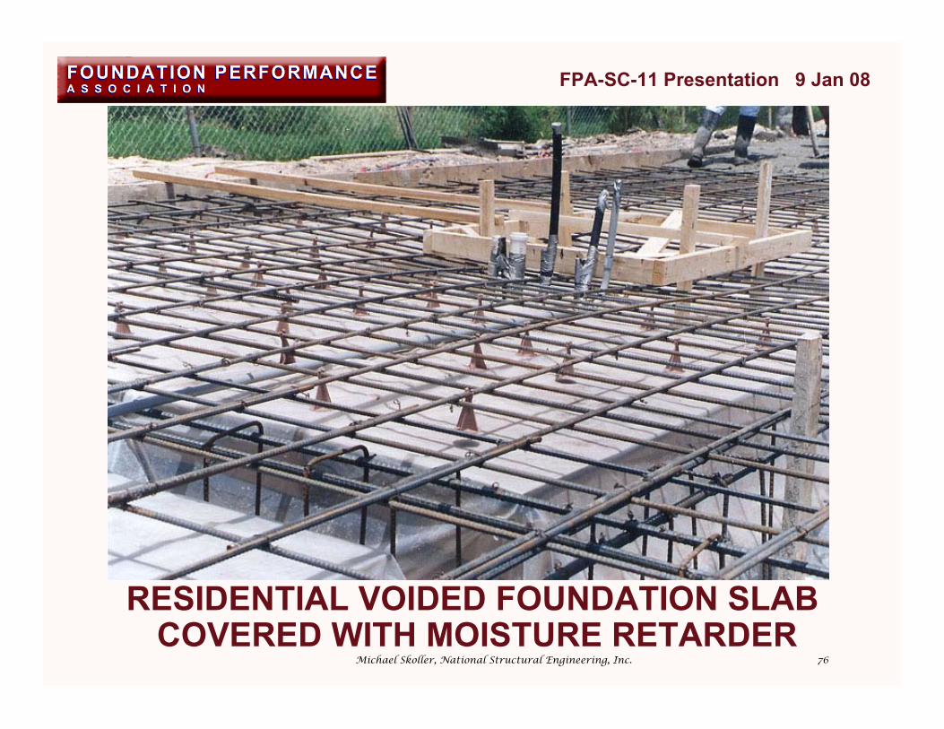
RESIDENTIAL VOIDED FOUNDATION SLAB COVERED WITH MOISTURE RETARDER
FPA-SC-11 Presentation 9 Jan 08
Michael Skoller, National Structural Engineering, Inc.

77
DEGRADABLE CARTON FORMS AND TRAILERFOR STORAGE OF FORMS PRIOR TO USE
FPA-SC-11 Presentation 9 Jan 08
Michael Skoller, National Structural Engineering, Inc.
78
IN CONCLUSION• USE VOID SPACE SYSTEMS WHEN HEAVE
IS A CONCERN• GEOTECHNICAL AND STRUCTURAL ENGINEERS BOTH RESPONSIBLE FOR THE DESIGN
OF VOID SPACE SYSTEMS• SPECIFY CARTON FORMS THAT HAVE BEEN
INDEPENDENTLY TESTED ACCORDING TO THEPROCEDURES IN THIS PAPER
• KEEP DEGRADABLE FORMS DRY AND ALL FORMSPROTECTED UNTIL USE
• REPLACE ANY DEGRADABLE FORMS THAT GET WET PRIOR TO CONCRETE PLACEMENT• COVER CARTON FORMS WITH A
PROTECTIVE BOARD PRIOR TO CONCRETEPLACEMENT
FPA-SC-11 Presentation 9 Jan 08
Michael Skoller, National Structural Engineering, Inc.

79
REFERENCESSAVWAY Carton Forms
http://www.savwaycartonforms.com/
SureVoid Products Inc.http://www.surevoid.com
VoidForm International Ltd.http://www.voidforminternational.com/
FPA-SC-12 Presentationhttp://www.foundationperformance.org/committee_papers.cfm
Michael Skoller, National Structural Engineering, Inc.
FPA-SC-11 Presentation 9 Jan 08

80
QUESTIONS?
Download “Specification and Application of Void Spaces Below Concrete Foundations” at:
http://www.foundationperformance.org/committee_papers.cfm
Michael Skoller, National Structural Engineering, Inc.


![Confidential Information - HbbTV...Interface”, V1.3 (2011-01). [15] VOID [16] VOID [17] VOID [18] ETSI EN 300 468 “Specification for Service Information (SI) in DVB systems”,](https://img.pdfslide.us/doc/110x75/60e7c3eee60dd16c9e0351a4/confidential-information-hbbtv-interfacea-v13-2011-01-15-void-16.jpg)