Embed Size (px)
Citation preview
IAEA-TECDOC-1540
Specification and AcceptanceTesting of Radiotherapy Treatment
Planning Systems
April 2007
IAEA-TECDOC-1540
Specification and Acceptance Testing of Radiotherapy Treatment
Planning Systems
April 2007

The originating Section of this publication in the IAEA was:
Dosimetry and Medical Radiation Physics Section International Atomic Energy Agency
Wagramer Strasse 5 P.O. Box 100
A-1400 Vienna, Austria
SPECIFICATION AND ACCEPTANCE TESTING OF RADIOTHERAPY TREATMENT PLANNING SYSTEMS
IAEA, VIENNA, 2007 IAEA-TECDOC-1540 ISBN 92–0–102707–9
ISSN 1011–4289 © IAEA, 2007
Printed by the IAEA in Austria April 2007
FOREWORD
Quality assurance (QA) in the radiation therapy treatment planning process is essential to ensure accurate dose delivery to the patient and to minimize the possibility of accidental exposure. The computerized radiotherapy treatment planning systems (RTPSs) are now widely available in industrialized and developing countries and it is of special importance to support hospitals in Member States in developing procedures for acceptance testing, commissioning and QA of their RTPSs. Responding to these needs, a group of experts developed an IAEA publication with such recommendations, which was published in 2004 as IAEA Technical Reports Series No. 430. This report provides a general framework and describes a large number of tests and procedures that should be considered by the users of new RTPSs. However, small hospitals with limited resources or large hospitals with high patient load and limited staff are not always able to perform complete characterization, validation and software testing of algorithms used in RTPSs. Therefore, the IAEA proposed more specific guidelines that provide a step-by-step recommendation for users at hospitals or cancer centres how to implement acceptance and commissioning procedures for newly purchased RTPSs.
The current publication was developed in the framework of the Coordinated Research Project on Development of Procedures for Quality Assurance for Dosimetry Calculations in Radiotherapy and uses the International Electrotechnical Commission (IEC) standard IEC 62083, Requirements for the Safety of Radiotherapy Treatment Planning Systems as its basis. The report addresses the procedures for specification and acceptance testing of RTPSs to be used by both manufacturers and users at the hospitals. Recommendations are provided for specific tests to be performed at the manufacturing facility known as type tests, and for acceptance tests to be performed at the hospital known as site tests. The purpose of acceptance testing is to demonstrate to the user at the hospital that the RTPS meets the specifications as defined by the user and/or the manufacturer, and that the results with the hardware and software as installed at the user’s site are consistent with the type tests performed previously by the manufacturer at the factory. The RTPSs input data for beam modelling and test case results are attached to this report on a separate CD-ROM. In spite of the specific scope of the report, it is useful to the purchasers of RTPSs in any country although performing tests beyond those described in this report may be required to meet the needs of specialized techniques that have not been addressed here.
This publication was prepared by J. Van Dyk (Canada), G. Ibbott (United States of America), R. Schmidt (Germany), and J. Welleweerd (Netherlands). The IAEA wishes to express its gratitude to J. Venselaar and H. Welleweerd for the test data package for 6 MV, 10 MV and 18 MV photon beams, to D. Georg and his colleagues for their assistance in preparing the test data package for the Co-60 beam and to the IEC for permission to reproduce information from its Standard IEC 62083. The IAEA officer responsible for the preparation of this publication was S. Vatnitsky from the Division of Human Health.
EDITORIAL NOTE
The use of particular designations of countries or territories does not imply any judgement by the publisher, the IAEA, as to the legal status of such countries or territories, of their authorities and institutions or of the delimitation of their boundaries.
The mention of names of specific companies or products (whether or not indicated as registered) does not imply any intention to infringe proprietary rights, nor should it be construed as an endorsement or recommendation on the part of the IAEA.
The IAEA wishes to express its gratitude to the International Electrotechnical Commission (IEC), Geneva, Switzerland, for granting permission to reproduce information from its International Standard IEC 62083. Such extracts are the copyright of the IEC, all rights reserved. The IEC assumes no responsibility for the accuracy or context in which the extracts are used. Further information on the IEC is available on www.iec.ch.

CONTENTS
1. BACKGROUND.................................................................................................................................1
2. SCOPE AND PURPOSE ....................................................................................................................3
3. HOW TO USE THIS REPORT ..........................................................................................................4
4. DATA SOURCES...............................................................................................................................5
5. TYPE TESTS......................................................................................................................................6
6. SITE TESTS......................................................................................................................................21
7. OPTIONAL SITE TESTS.................................................................................................................26
APPENDIX A. TESTS OF THE ACCURACY OF DOSIMETRIC CALCULATION TO BE PERFORMED DURING TYPE TESTING. ................................................................27
APPENDIX B. TESTS OF THE ACCURACY OF DOSIMETRIC CALCULATIONS TO BE PERFORMED DURING SITE TESTING...................................................................35
APPENDIX C. OPTIONAL TESTS OF THE ACCURACY OF DOSIMETRIC CALCULATIONS TO BE PERFORMED DURING ACCEPTANCE TESTING. .........................................................................................41
APPENDIX D. GRAPHICAL REPRESENTATION OF THE DOSIMETRIC TEST CASES............47
REFERENCES.......................................................................................................................................53
GLOSSARY...........................................................................................................................................55
CONTRIBUTORS TO DRAFTING AND REVIEW............................................................................61

1. BACKGROUND
Radiation treatment planning is a vital and essential component of the total radiation treatment process. Radiation treatment planning systems (RTPSs) are an indispensable tool for radiation treatment planning. It is through the use of these systems that specific treatment procedures are developed for individual patients. Such procedures include the specification of beam energy, beam direction, beam shaping, beam modifiers and other specifications associated with developing an optimized treatment procedure that maximizes the dose to target tissues and minimizes the probability of normal tissue complications. In recent years, several reports have been developed addressing issues related to the commissioning and quality assurance (QA) of RTPSs. The most comprehensive of these reports include: the report of Task Group 53 (TG53) of the American Association of Physicists in Medicine (AAPM) [1], the report by the IAEA, Technical Reports Series No. 430 [2], the report by the European Society of Therapeutic Radiation Oncology (ESTRO) [3] and the report by the Netherlands Commission on Radiation Dosimetry (NCS) [4].
Each of these reports provides a detailed description of how to bring a newly purchased RTPS into clinical use and how to maintain an on-going QA program after it has been placed in clinical service. They provide a general framework for how to design a QA program for all kinds of RTPSs, both for external photon and electron beams, as well as for brachytherapy. They describe a large number of tests and procedures that should be considered by the users of new RTPSs. However, due to the complexity of such systems as well as the variation in software design when comparing one system to another, none of these reports provides a simple protocol that could be used with a step-by-step description for a user at a hospital or cancer centre to implement for the acceptance, commissioning and QA of a newly purchased RTPS.
One of the areas of significant difficulty in the implementation of a new RTPS into a clinical environment is the component that deals with the acceptance testing of such a system. Acceptance testing relates to the evaluation by the purchaser of a new RTPS that the RTPS meets the specifications as defined by the user and/or the manufacturer. While acceptance testing is a well-defined and standardized process for the purchase of other radiation therapy equipment, it is not nearly as clear-cut for RTPSs. For example, with the purchase of a linear accelerator, the purchaser and manufacturer agree on a set of specifications (frequently defined by the manufacturer), and then the manufacturer installs the linear accelerator.1 Prior to the machine being signed off and handed over to the purchaser, a detailed set of tests is performed to demonstrate to the purchaser that the machine complies with all the specifications agreed to prior to the purchase. For RTPSs, this process is complicated by the fact that the clinical implementation of an RTPS involves the user to obtain, usually by measurement, very specific data that are needed by the RTPS for the proper functioning of the dose calculation algorithm for the radiation therapy machine that is used to treat patients in the user’s clinic. Thus, a true assessment of the capabilities and limitations of the dose calculation algorithm cannot be performed until the user has performed these measurements and entered them into the RTPS. Because of the length of time it takes to commission a
1 Note that throughout this protocol the term “manufacturer” will be used in referring to the company that designs, produces or builds the product, “vendor” as the company or individual that sells the product, and “installer” ss the company or individual that installs the product at the user’s site. In some cases, the installer, vendor, and manufacturer could be the same company. In other cases, the manufacturer could contract the sale and installation to third party individuals or companies. Thus, the terms “manufacturer, “vendor”, installer” will be used purposefully through this report. Similarly, the terms “purchaser” or “customer” refer to the organization or individual that purchases the product and “user” refers to the individual who actually uses the product. Again the purchaser, customer, and user could be the same individual or it could refer to separate individuals or companies.
1
specific photon or electron beam, proper acceptance cannot be performed until long after the vendor has installed the RTPS and left the user’s facility. As a result, acceptance of an RTPS has evolved into a simple process of cataloguing that the hardware and software components of the treatment planning system have been delivered and installed at the user’s site and a testing of the system to demonstrate that the various components of the software are operational. This process does not provide evidence that the software meets the specifications that have been defined either by the manufacturer or by the user at the hospital or by both.
In 2000, the International Electrotechnical Commission (IEC) developed a standard primarily intended for manufacturers of RTPSs, IEC 62083 [5]. To quote from the Introduction of IEC 62083: “The output of an RTPS is used by appropriately QUALIFIED PERSONS as important information in RADIOTHERAPY TREATMENT PLANNING. Inaccuracies in the input data, the limitations of the algorithms, errors in the TREATMENT PLANNING process, or improper use of output data, may represent a SAFETY HAZARD to PATIENTS should the resulting data be used for treatment purposes. This standard defines requirements to be complied with by MANUFACTURERS in the design and construction of an RTPS in order to provide protection against the occurrence of such HAZARDS.” 2 Although this standard has existed for 6 years already, at the present time there is frequently no clear evidence provided to the purchasers of RTPSs that manufacturers have actually complied with this standard or that RTPSs actually comply with the specifications set out by the manufacturers. As a result there has been no easy mechanism for the user to have full confidence that the RTPS purchased actually complies with the specifications set out by the manufacturer or that it complies with the standard defined by IEC 62083. In 2003, an IAEA consultants meeting reviewed documents associated with procedures for QA for dosimetry calculations in radiation therapy [6]. The report of this consultants meeting proposed a coordinated research project (CRP) that would develop a number of practical procedures associated with the QA of RTPSs. One of the components of the CRP included on-site acceptance tests. To quote from the consultants report:
“The consultants recommend that the procedure for acceptance testing of treatment planning systems should be made more similar to that of other equipment used in a radiotherapy department. After installation of a planning system in a hospital, the vendor should perform a series of tests, together with the user, to demonstrate that the system performs according to its specifications. Such a procedure implies that the vendor should make available to the customer a document describing the correct functioning of the system. The vendor also should include an acceptance test guide that describes the tests to be performed and provides for formal acceptance by the customer. Recommendations for the contents of this guide document are to be made by the CRP.”
The Coordinated Research Project on Development of Procedures for Quality Assurance for Dosimetry Calculations in Radiotherapy started in 2004. Two consultants meetings were held in Vienna and during these meetings the consultants decided on a set of tests for specification and acceptance of RTPs.
2 Note that the capitalized terms within IEC standards refer to terms specifically defined by the IEC either within the relevant standard or in other IEC documents. All terms defined by the IEC that are used in this report are included in the glossary.
2
2. SCOPE AND PURPOSE
In view of the difficulties associated with acceptance testing of RTPSs by the user and the general lack of a formal process for giving the user confidence that the manufacturer has informed the purchaser of the capabilities and limitations of the RTPS, this publication serves as a protocol to be used by both manufacturers and users for the specification and acceptance testing of RTPSs. Recommendations are provided in this report for specific tests to be performed at the manufacturing facility and acceptance tests to be performed at the user’s site.
This report uses the IEC 62083 standard as its basis for defining the specifications and acceptance tests of RTPSs. While this report uses the IEC 62083 standard as its basis, it is emphasized that what follows in this publication is the result of the IAEA interpretation of the IEC standard and may not necessarily reflect the true original intent of the IEC standard. However, the IAEA has done its best to adhere as closely as possible to the apparent intent of the IEC 62083 standard. Only with respect to the dose calculation tests does this IAEA report go beyond the requirements specified by the IEC.
In developing this report, the IAEA has placed a specific emphasis on the needs of the developing world. As such the specifications and acceptance tests addressed in this publication are primarily intended for “basic” treatment planning systems. A basic treatment planning system is defined as one that has either or both two-dimensional (2-D) and three-dimensional (3-D) calculation and display capabilities. To quote from IAEA-Technical Reports Series No. 430 [2]: “It is not always easy to characterize a TPS as 3-D or 2-D, as many systems include some but not all 3-D capabilities. However, a fully 3-D system will have: (a) The option to reconstruct, from an image data set, views orthogonal and oblique to the
original images. (b) The ability to represent structures and dose distributions in a 3-D view, as well as a
beam’s eye view (BEV), of the anatomy. (c) No restrictions on beam directions and orientations, other than those of the specific
treatment unit. In particular, the system will support couch rotation. (d) A dose calculation algorithm that takes into account 3-D patient anatomy, with respect to
both the primary and scattered radiation.
Additional functionality in a 3-D system includes support for conformal beam shaping, DRRs (digitally reconstructed radiographs) and DVHs (dose-volume histograms). Most 3-D TPSs now offer virtual simulation with DRRs.
For 2-D planning, only a limited number of contours on parallel slices need to be entered, and beam axes are parallel with these planes. Calculation algorithms assume that each of these contours is invariant over the length of the volume, and may not explicitly consider scattered radiation. Imaging requirements for such a system are minimal.
A 3-D system should also support simple 2-D planning, with manual entry of contours, as even in larger centres there is still a significant proportion of plans that do not warrant a 3-D approach.” Issues related to intensity modulated radiation therapy (IMRT) or other specialized techniques such as stereotactic radiosurgery are not addressed in this acceptance testing report. While recognizing the specific scope of this report, purchasers of RTPSs in any country will find this
3
report useful but they may have to perform tests beyond those described in this report to meet the needs of specialized techniques that have not been addressed in this report. In developing these recommendations, the IAEA has made extensive use of specific measured data sets from different sources. These data sets are to be used by the manufacturers and RTPS users only for acceptance testing purposes. The originators of these data sets, their institutions, and the IAEA, cannot be held legally responsible for the use and application of these data sets. Furthermore, the IAEA emphasizes that these data are intended for comparison purposes only and are NOT INTENDED TO BE USED FOR CLINICAL TREATMENT PLANNING in any department other than the institution where the data were originally generated.
3. HOW TO USE THIS REPORT
This report refers heavily to IEC 62083 [5] since it is a specific standard for manufacturers of RTPSs. This IAEA report uses the description of the tests directly from the IEC 62083 standard and the terms “type test” and “site test” as defined by the IEC in IEC TR 60788 [7]:
Type test: “For a particular design of device or EQUIPMENT, a TEST by the MANUFACTURER to establish compliance with specified criteria.”
Site test: “After installation, TEST of an individual device or EQUIPMENT to establish compliance with specified criteria.” “Note: The recommended replacement is ACCEPTANCE TEST.”
Section 5 of this report includes the type tests that are summarized by IEC 62083 and that are to be performed by the manufacturer prior to the delivery of the RTPS to the purchaser’s institution. However, at the time of acceptance testing, the manufacturer must demonstrate with appropriate documentation as outlined in Section 5 that these tests have been performed including the corresponding results of these tests where relevant. As a part of acceptance testing the user should inspect the completed Section 5 and the accompanied documentation provided by the manufacturer.
Section 6 of this report is a subset of tests from Section 5, which need to be performed with the user’s RTPS at the time of its acceptance testing in the user’s department. These tests serve two important purposes. Firstly, the tests will provide an educational opportunity for the user to participate in the operation of the RTPS. Secondly, the tests will demonstrate to the user that the results using the hardware and software as installed at the user’s site are consistent with the type tests performed by the manufacturer at the factory. Section 6 represents a set of tests that must be performed by the installer and the user at the hospital together to ensure acceptability of the RTPS.
Section 7 provides an additional/optional set of tests that can be performed at the user’s site. However, the specific optional tests should be defined in advance of the acceptance testing process, ideally as part of the purchase process, to avoid debate about the number of tests that are to be performed at the time of acceptance testing.
While Section 5 summarizes the sources of data available for testing, the user should test only those components of the RTPS or beam energies that are most relevant to the user’s facility. In other words, if cobalt-60 is the only external beam treatment unit available and if the user does not have access to CT scanning, there is no point in testing high-energy X rays nor is the
4
user able to test for CT connectivity. Furthermore, this report is limited to photon beam treatment considerations only, i.e. electron beam acceptance testing procedures are not provided in this publication but might become an independent future consideration.
It should be noted that the testing proposed by this IAEA report in Sections 5, 6, and 7 on “Accuracy of algorithms” (i.e. IEC clause 11.2) is considerably more detailed than described in IEC 62083. This is to aid the user at the hospital in performing specific tests with beam data pre-entered by the manufacturer using measured data from sources recommended by the IAEA.
4. DATA SOURCES
Sections 5, 6, and 7 list multiple tests that are to be performed including dose calculation tests. The dose calculation tests are based on a set of test configurations originally developed by the AAPM TG23 [8] for purposes of testing RTPS photon dose calculation algorithms. However, the AAPM TG23 radiation data were measured on linear accelerators (4 MV X rays from a Varian Clinac-4 and 18 MV X rays from an AECL Therac-20) during the mid 1980s and are presently outdated and not relevant for today’s radiation treatment machines. Furthermore, while the TG23 measured data were used as input data for RTPS algorithms relevant in the 1980s, they are not sufficient to satisfy the input needs of today’s RTPSs. As a consequence, new sets of data for 6 MV, 10 MV, and 18 MV X ray beams from Elekta linear accelerators have been measured by Venselaar and Welleweerd [9]. They have used their measured data to evaluate specific test cases for 7 different RTPSs. The input data and test case results from [9] are attached to this publication on a separate CD-ROM as these experimenters used best efforts to generate consistency between the experimental input data and the resulting test cases for high-energy X rays. As a starting point they used the AAPM TG23 test package but added a number of scenarios to account for “missing tissue” geometry, asymmetric collimator settings and asymmetric wedged beams. Some of these tests from TG23 were revised and the details of the changes are described in reference [9]. The data from reference [9] have been adopted by the NCS in their report on the commissioning and QA of treatment planning systems [4].
Recognizing that cancer centres in the developing world make significant use of cobalt-60 gamma ray beams, a further similar data set has been produced for cobalt-60 radiation by the IAEA in collaboration with the Allgemeines Krankenhaus (AKH), Vienna and the input data and test case results following the original AAPM TG23 are also attached to this report on the CD-ROM. A consortium of researchers funded by the US National Cancer Institute is in the process of producing benchmark data sets for the assessment of RTPSs. The work will largely will follow a report by AAPM Task Group 67 [unpublished TG67 report] which describes the generation of such data sets and methods for measuring a series of test cases for validation of photon beam dose calculation algorithms. Data are being measured for 6 MV and 18 MV X ray beams on accelerators from three different manufacturers. A set of data will be measured for 10 MV photon beams from one of the three accelerators used for the 6 and 18 MV data sets. IMRT deliveries will be addressed by measuring a series of small field segments. Dynamic IMRT will not be included. There may also be supplemental data acquisitions in the future to account for changes in delivery technology or changes in algorithms. It is possible that once the data are generated according to the AAPM TG67 proposal that these data will be incorporated into modified recommendations of this IAEA report. However, until such data
5
become available, this report recommends the use of the data produced for cobalt-60 gamma ray beams, and 6 MV, 10 MV and 18 MV X ray beams as described above.
With the evolution of Monte Carlo calculations to the point that they are becoming practical in the clinical environment, it may also be possible that in the future benchmark data may be generated using the Monte Carlo method for specific energies and specific radiation therapy machines.
5. TYPE TESTS
Type tests refer to those tests that are to be done by the manufacturer to establish compliance with specified criteria. These tests are normally done at the factory. In some of the type tests, the vendor needs to provide the documentation as indicated in the table below by “ACCOMPANYING DOCUMENTS”. Usually these documents will be provided as part of the user’s manual; however, if they are not provided in the user’s manual, the installer should provide these documents at the time of acceptance. As indicated in Section 2, this report uses the IEC 62083 standard as its basis for defining the specifications and acceptance tests of RTPSs. The IAEA has done its best to adhere as closely as possible to the apparent intent of the IEC 62083 standard. Only with respect to the dose calculation tests does this IAEA publication provide more detail than described in the IEC 62083. Note on type tests
Note that IEC 62083 clause 5.1 requires the manufacturer to retain the compliance statement at the factory as a permanent record; however, this IAEA report requires that the results of tests performed in IEC 62083 clause 11.2 be provided to the user at the time of installation (see Appendix A). Also, within clause 11.2, the IAEA provides the details of the specific tests to be performed during installation (see Appendices B and C). The description of type tests is given below where the manufacturer needs to state compliance or the lack thereof by the “yes” or “no” answers. A copy of Section 5 with the type tests is attached to this report on a CD-ROM and should be used for documenting the testing results and signing by the manufacturer and the user at the hospital.
6
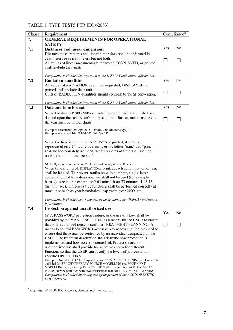
TABLE 1. TYPE TESTS PER IEC 62083∗
Clause Requirement Compliance? 7. 7.1
GENERAL REQUIREMENTS FOR OPERATIONAL SAFETY Distances and linear dimensions Distance measurements and linear dimensions shall be indicated in centimeters or in millimeters but not both. All values of linear measurements requested, DISPLAYED, or printed shall include their units. Compliance is checked by inspection of the DISPLAY and output information.
Yes
□
No
□
7.2 Radiation quantities All values of RADIATION quantities requested, DISPLAYED or printed shall include their units. Units of RADIATION quantities should conform to the SI convention. Compliance is checked by inspection of the DISPLAY and output information.
Yes
□ No
□
7.3 Date and time format When the date is DISPLAYED or printed, correct interpretation shall not depend upon the OPERATOR's interpretation of format, and a DISPLAY of the year shall be in four digits. Examples acceptable: "03 Apr 2005", "03/04/2005 (dd/mm/yyyy) ". Examples not acceptable: "03/04/05", "03 Apr 05". When the time is requested, DISPLAYED or printed, it shall be represented on a 24-hour clock basis, or the letters "a.m." and "p.m." shall be appropriately included. Measurements of time shall include units (hours, minutes, seconds). NOTE By convention, noon is 12:00 p.m. and midnight is 12:00 a.m. When time is entered, DISPLAYED or printed, each denomination of time shall be labeled. To prevent confusion with numbers, single-letter abbreviations of time denomination shall not be used (for example h, m, s). Acceptable examples: 2.05 min; 1 hour 33 minutes; 1:43:15 (hr: min: sec). Time-sensitive functions shall be performed correctly at transitions such as year boundaries, leap years, year 2000, etc. Compliance is checked by testing and by inspection of the DISPLAY and output information.
Yes
□ No
□
7.4 Protection against unauthorized use (a) A PASSWORD protection feature, or the use of a key, shall be provided by the MANUFACTURER as a means for the USER to ensure that only authorized persons perform TREATMENT PLANNING. A means to control PASSWORD access or key access shall be provided to ensure that these may be controlled by an individual designated by the USER. The technical description shall describe how protection is implemented and how access is controlled. Protection against unauthorized use shall provide for selective access for different functions so that the USER can specify the levels of protection for specific OPERATORS. Examples: Not all OPERATORS qualified for TREATMENT PLANNING are likely to be qualified for BRACHYTHERAPY SOURCE MODELLING and EQUIPMENT MODELLING; also, viewing TREATMENT PLANS, or printing out TREATMENT PLANS, may be permitted with fewer restrictions than for TREATMENT PLANNING. Compliance is checked by testing and by inspection of the ACCOMPANYING DOCUMENTS.
Yes
□
No
□
∗ Copyright © 2000, IEC, Geneva, Switzerland. www.iec.ch
7
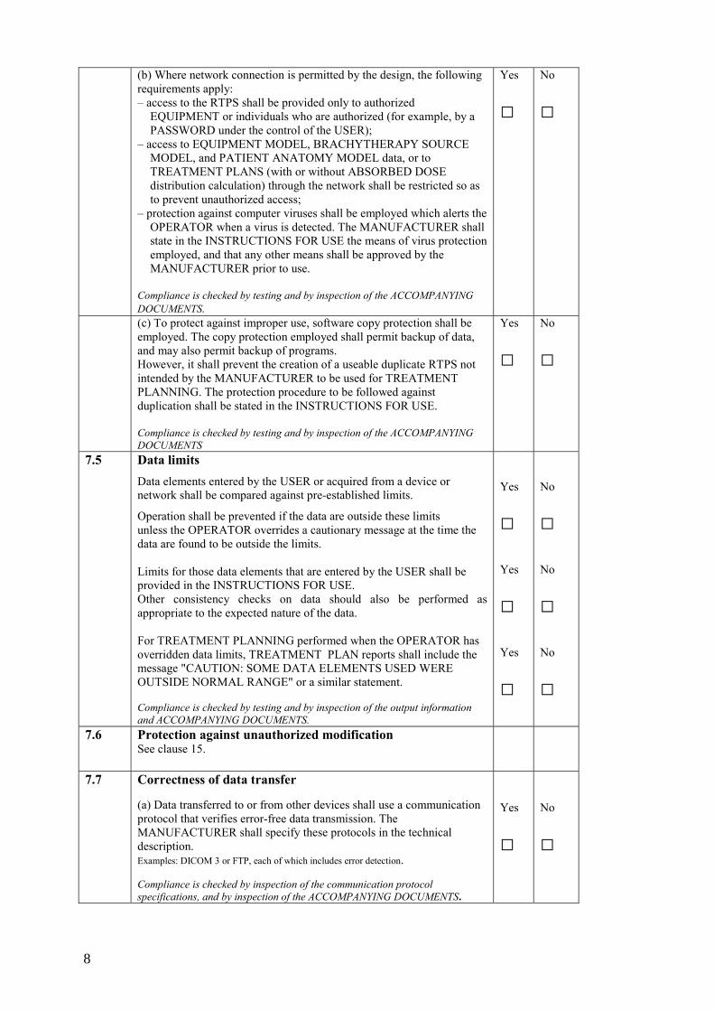
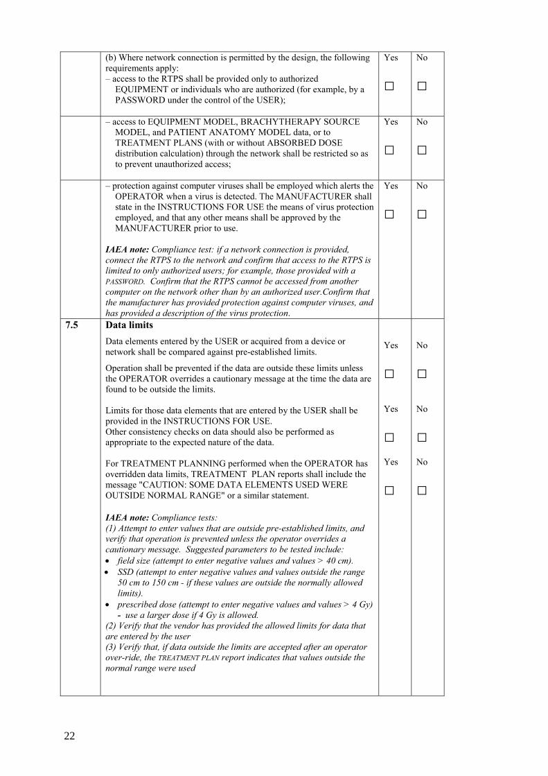
(b) Where network connection is permitted by the design, the following requirements apply: – access to the RTPS shall be provided only to authorized
EQUIPMENT or individuals who are authorized (for example, by a PASSWORD under the control of the USER);
– access to EQUIPMENT MODEL, BRACHYTHERAPY SOURCE MODEL, and PATIENT ANATOMY MODEL data, or to TREATMENT PLANS (with or without ABSORBED DOSE distribution calculation) through the network shall be restricted so as to prevent unauthorized access;
– protection against computer viruses shall be employed which alerts the OPERATOR when a virus is detected. The MANUFACTURER shall state in the INSTRUCTIONS FOR USE the means of virus protection employed, and that any other means shall be approved by the MANUFACTURER prior to use.
Compliance is checked by testing and by inspection of the ACCOMPANYING DOCUMENTS.
Yes
□ No
□
(c) To protect against improper use, software copy protection shall be employed. The copy protection employed shall permit backup of data, and may also permit backup of programs. However, it shall prevent the creation of a useable duplicate RTPS not intended by the MANUFACTURER to be used for TREATMENT PLANNING. The protection procedure to be followed against duplication shall be stated in the INSTRUCTIONS FOR USE. Compliance is checked by testing and by inspection of the ACCOMPANYING DOCUMENTS
Yes
□ No
□
7.5 Data limits Data elements entered by the USER or acquired from a device or network shall be compared against pre-established limits.
Operation shall be prevented if the data are outside these limits unless the OPERATOR overrides a cautionary message at the time the data are found to be outside the limits. Limits for those data elements that are entered by the USER shall be provided in the INSTRUCTIONS FOR USE. Other consistency checks on data should also be performed as appropriate to the expected nature of the data. For TREATMENT PLANNING performed when the OPERATOR has overridden data limits, TREATMENT PLAN reports shall include the message "CAUTION: SOME DATA ELEMENTS USED WERE OUTSIDE NORMAL RANGE" or a similar statement. Compliance is checked by testing and by inspection of the output information and ACCOMPANYING DOCUMENTS.
Yes
□ Yes
□ Yes
□
No
□ No
□ No
□
7.6 Protection against unauthorized modification See clause 15.
7.7 Correctness of data transfer (a) Data transferred to or from other devices shall use a communication protocol that verifies error-free data transmission. The MANUFACTURER shall specify these protocols in the technical description. Examples: DICOM 3 or FTP, each of which includes error detection. Compliance is checked by inspection of the communication protocol specifications, and by inspection of the ACCOMPANYING DOCUMENTS.
Yes
□
No
□
8
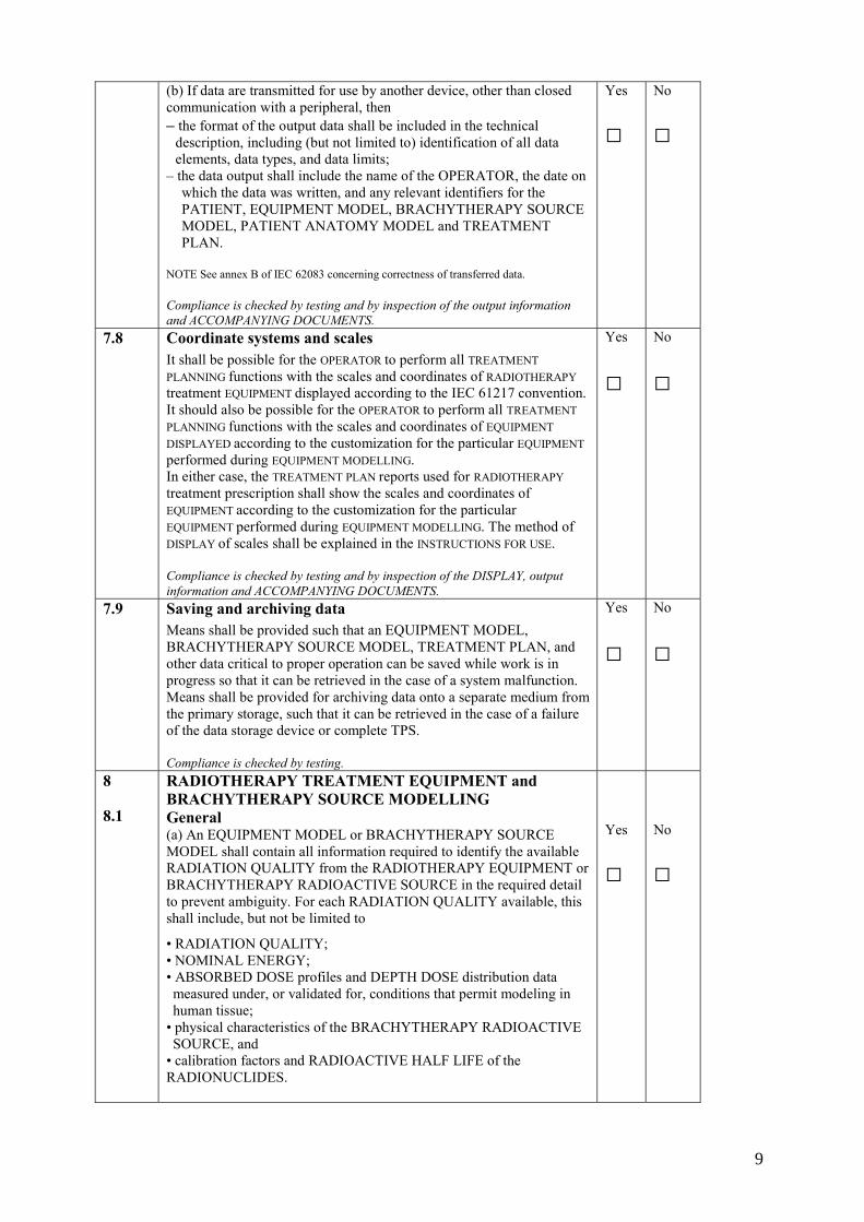
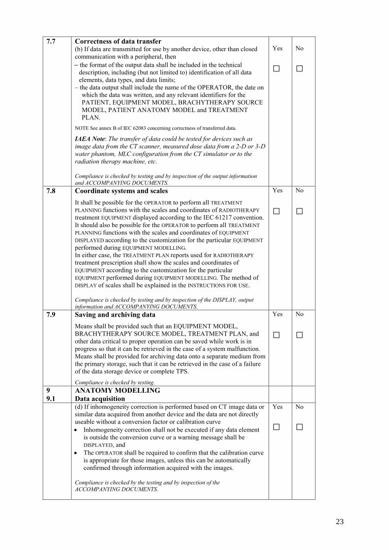
(b) If data are transmitted for use by another device, other than closed communication with a peripheral, then – the format of the output data shall be included in the technical
description, including (but not limited to) identification of all data elements, data types, and data limits;
– the data output shall include the name of the OPERATOR, the date on which the data was written, and any relevant identifiers for the PATIENT, EQUIPMENT MODEL, BRACHYTHERAPY SOURCE MODEL, PATIENT ANATOMY MODEL and TREATMENT PLAN.
NOTE See annex B of IEC 62083 concerning correctness of transferred data. Compliance is checked by testing and by inspection of the output information and ACCOMPANYING DOCUMENTS.
Yes
□ No
□
7.8 Coordinate systems and scales It shall be possible for the OPERATOR to perform all TREATMENT PLANNING functions with the scales and coordinates of RADIOTHERAPY treatment EQUIPMENT displayed according to the IEC 61217 convention. It should also be possible for the OPERATOR to perform all TREATMENT PLANNING functions with the scales and coordinates of EQUIPMENT DISPLAYED according to the customization for the particular EQUIPMENT performed during EQUIPMENT MODELLING. In either case, the TREATMENT PLAN reports used for RADIOTHERAPY treatment prescription shall show the scales and coordinates of EQUIPMENT according to the customization for the particular EQUIPMENT performed during EQUIPMENT MODELLING. The method of DISPLAY of scales shall be explained in the INSTRUCTIONS FOR USE. Compliance is checked by testing and by inspection of the DISPLAY, output information and ACCOMPANYING DOCUMENTS.
Yes
□
No
□
7.9 Saving and archiving data Means shall be provided such that an EQUIPMENT MODEL, BRACHYTHERAPY SOURCE MODEL, TREATMENT PLAN, and other data critical to proper operation can be saved while work is in progress so that it can be retrieved in the case of a system malfunction. Means shall be provided for archiving data onto a separate medium from the primary storage, such that it can be retrieved in the case of a failure of the data storage device or complete TPS. Compliance is checked by testing.
Yes
□
No
□
8 8.1
RADIOTHERAPY TREATMENT EQUIPMENT and BRACHYTHERAPY SOURCE MODELLING General (a) An EQUIPMENT MODEL or BRACHYTHERAPY SOURCE MODEL shall contain all information required to identify the available RADIATION QUALITY from the RADIOTHERAPY EQUIPMENT or BRACHYTHERAPY RADIOACTIVE SOURCE in the required detail to prevent ambiguity. For each RADIATION QUALITY available, this shall include, but not be limited to
• RADIATION QUALITY; • NOMINAL ENERGY; • ABSORBED DOSE profiles and DEPTH DOSE distribution data measured under, or validated for, conditions that permit modeling in human tissue;
• physical characteristics of the BRACHYTHERAPY RADIOACTIVE SOURCE, and
• calibration factors and RADIOACTIVE HALF LIFE of the RADIONUCLIDES.
Yes
□
No
□
9
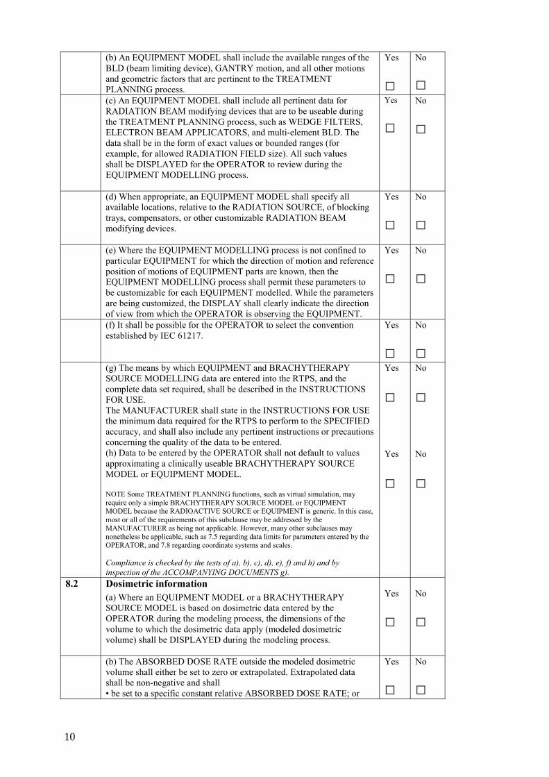
(b) An EQUIPMENT MODEL shall include the available ranges of the BLD (beam limiting device), GANTRY motion, and all other motions and geometric factors that are pertinent to the TREATMENT PLANNING process.
Yes
□ No
□ (c) An EQUIPMENT MODEL shall include all pertinent data for
RADIATION BEAM modifying devices that are to be useable during the TREATMENT PLANNING process, such as WEDGE FILTERS, ELECTRON BEAM APPLICATORS, and multi-element BLD. The data shall be in the form of exact values or bounded ranges (for example, for allowed RADIATION FIELD size). All such values shall be DISPLAYED for the OPERATOR to review during the EQUIPMENT MODELLING process.
Yes
□ No
□
(d) When appropriate, an EQUIPMENT MODEL shall specify all available locations, relative to the RADIATION SOURCE, of blocking trays, compensators, or other customizable RADIATION BEAM modifying devices.
Yes
□ No
□ (e) Where the EQUIPMENT MODELLING process is not confined to
particular EQUIPMENT for which the direction of motion and reference position of motions of EQUIPMENT parts are known, then the EQUIPMENT MODELLING process shall permit these parameters to be customizable for each EQUIPMENT modelled. While the parameters are being customized, the DISPLAY shall clearly indicate the direction of view from which the OPERATOR is observing the EQUIPMENT.
Yes
□ No
□
(f) It shall be possible for the OPERATOR to select the convention established by IEC 61217.
Yes
□ No
□ (g) The means by which EQUIPMENT and BRACHYTHERAPY
SOURCE MODELLING data are entered into the RTPS, and the complete data set required, shall be described in the INSTRUCTIONS FOR USE. The MANUFACTURER shall state in the INSTRUCTIONS FOR USE the minimum data required for the RTPS to perform to the SPECIFIED accuracy, and shall also include any pertinent instructions or precautions concerning the quality of the data to be entered. (h) Data to be entered by the OPERATOR shall not default to values approximating a clinically useable BRACHYTHERAPY SOURCE MODEL or EQUIPMENT MODEL. NOTE Some TREATMENT PLANNING functions, such as virtual simulation, may require only a simple BRACHYTHERAPY SOURCE MODEL or EQUIPMENT MODEL because the RADIOACTIVE SOURCE or EQUIPMENT is generic. In this case, most or all of the requirements of this subclause may be addressed by the MANUFACTURER as being not applicable. However, many other subclauses may nonetheless be applicable, such as 7.5 regarding data limits for parameters entered by the OPERATOR, and 7.8 regarding coordinate systems and scales. Compliance is checked by the tests of a), b), c), d), e), f) and h) and by inspection of the ACCOMPANYING DOCUMENTS g).
Yes
□ Yes
□
No
□ No
□
8.2 Dosimetric information (a) Where an EQUIPMENT MODEL or a BRACHYTHERAPY SOURCE MODEL is based on dosimetric data entered by the OPERATOR during the modeling process, the dimensions of the volume to which the dosimetric data apply (modeled dosimetric volume) shall be DISPLAYED during the modeling process.
Yes
□
No
□
(b) The ABSORBED DOSE RATE outside the modeled dosimetric volume shall either be set to zero or extrapolated. Extrapolated data shall be non-negative and shall • be set to a specific constant relative ABSORBED DOSE RATE; or
Yes
□ No
□
10
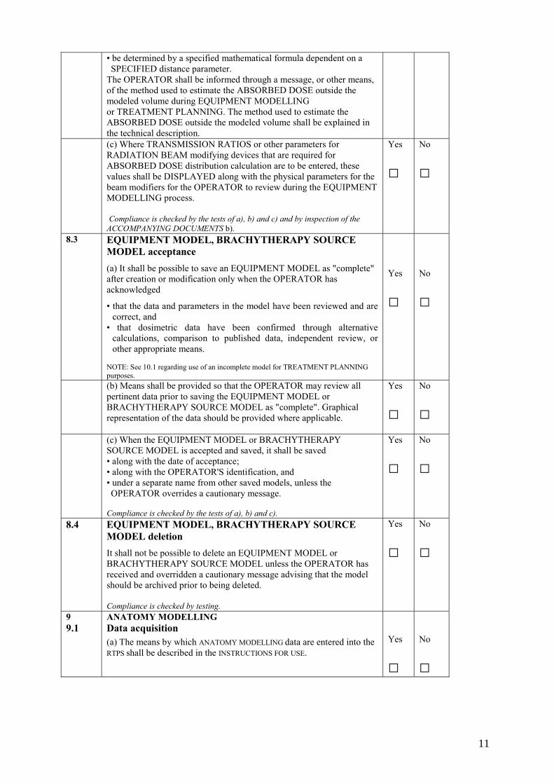
• be determined by a specified mathematical formula dependent on a SPECIFIED distance parameter.
The OPERATOR shall be informed through a message, or other means, of the method used to estimate the ABSORBED DOSE outside the modeled volume during EQUIPMENT MODELLING or TREATMENT PLANNING. The method used to estimate the ABSORBED DOSE outside the modeled volume shall be explained in the technical description.
(c) Where TRANSMISSION RATIOS or other parameters for RADIATION BEAM modifying devices that are required for ABSORBED DOSE distribution calculation are to be entered, these values shall be DISPLAYED along with the physical parameters for the beam modifiers for the OPERATOR to review during the EQUIPMENT MODELLING process. Compliance is checked by the tests of a), b) and c) and by inspection of the ACCOMPANYING DOCUMENTS b).
Yes
□
No
□
8.3 EQUIPMENT MODEL, BRACHYTHERAPY SOURCE MODEL acceptance (a) It shall be possible to save an EQUIPMENT MODEL as "complete" after creation or modification only when the OPERATOR has acknowledged
• that the data and parameters in the model have been reviewed and are correct, and
• that dosimetric data have been confirmed through alternative calculations, comparison to published data, independent review, or other appropriate means.
NOTE: See 10.1 regarding use of an incomplete model for TREATMENT PLANNING purposes.
Yes
□
No
□
(b) Means shall be provided so that the OPERATOR may review all pertinent data prior to saving the EQUIPMENT MODEL or BRACHYTHERAPY SOURCE MODEL as "complete". Graphical representation of the data should be provided where applicable.
Yes
□
No
□
(c) When the EQUIPMENT MODEL or BRACHYTHERAPY SOURCE MODEL is accepted and saved, it shall be saved • along with the date of acceptance; • along with the OPERATOR'S identification, and • under a separate name from other saved models, unless the OPERATOR overrides a cautionary message.
Compliance is checked by the tests of a), b) and c).
Yes
□
No
□
8.4 EQUIPMENT MODEL, BRACHYTHERAPY SOURCE MODEL deletion It shall not be possible to delete an EQUIPMENT MODEL or BRACHYTHERAPY SOURCE MODEL unless the OPERATOR has received and overridden a cautionary message advising that the model should be archived prior to being deleted. Compliance is checked by testing.
Yes
□
No
□
9 9.1
ANATOMY MODELLING Data acquisition (a) The means by which ANATOMY MODELLING data are entered into the RTPS shall be described in the INSTRUCTIONS FOR USE.
Yes
□
No
□
11
(b) When image data are acquired from an imaging device (CT, MRI, etc.), and there are adjustments on the imaging device that affect the suitability for use of the images for TREATMENT PLANNING, then for each such parameter one of the following shall apply: (1) if the parameter is acquired with the images, then the parameter shall be checked for each image; if it is not acceptable, then
• the RTPS shall provide a means of compensating for the parameter, or
• the use of the images for TREATMENT PLANNING shall not be permitted.
(2) if the parameter is not acquired with the images, the operator shall be required to confirm the correctness of the parameter by other means. Examples: Images with varying slice thickness are to be rejected if slice thickness compensation is not part of the RTPS design; CT scanner aperture tilt for which no correction is made is either confirmed as being in the zero position for all images through information in the image header, or the OPERATOR is required to confirm the zero position by other means (PATIENT data sheet, etc.).
Yes
□
No
□
(c) Images or other PATIENT data acquired from another device shall be confirmed by the OPERATOR as belonging to a particular PATIENT, and as being otherwise acceptable for use. Automatic acceptance based on the PATIENT name shall not be used, as it may not be unique.
Yes
□
No
□
(d) If inhomogeneity correction is performed based on CT image data or similar data acquired from another device and the data are not directly useable without a conversion factor or calibration curve • inhomogeneity correction shall not be executed if any data element
is outside the conversion curve or a warning message shall be DISPLAYED, and
• the OPERATOR shall be required to confirm that the calibration curve is appropriate for those images, unless this can be automatically confirmed through information acquired with the images.
Compliance is checked by the tests of b), c) and d) and by inspection of the ACCOMPANYING DOCUMENTS a).
Yes
□
No
□
9.2 Coordinate systems and scales
(a) The positions of applied RADIATION BEAMS, BRACHYTHERAPY RADIOACTIVE SOURCES, and dosimetric information shall be DISPLAYED in relation to a PATIENT coordinate system, such as the convention illustrated in ICRU report 42. An illustration of the PATIENT coordinate system shall be given in the INSTRUCTIONS FOR USE.
NOTE At the time this standard was created, IEC 61217 did not include a PATIENT coordinate system, although inclusion of one had been proposed. It is expected that the next edition of this standard will refer to IEC 61217 for the PATIENT coordinate system which will have been included in its revision.
Yes
□
No
□
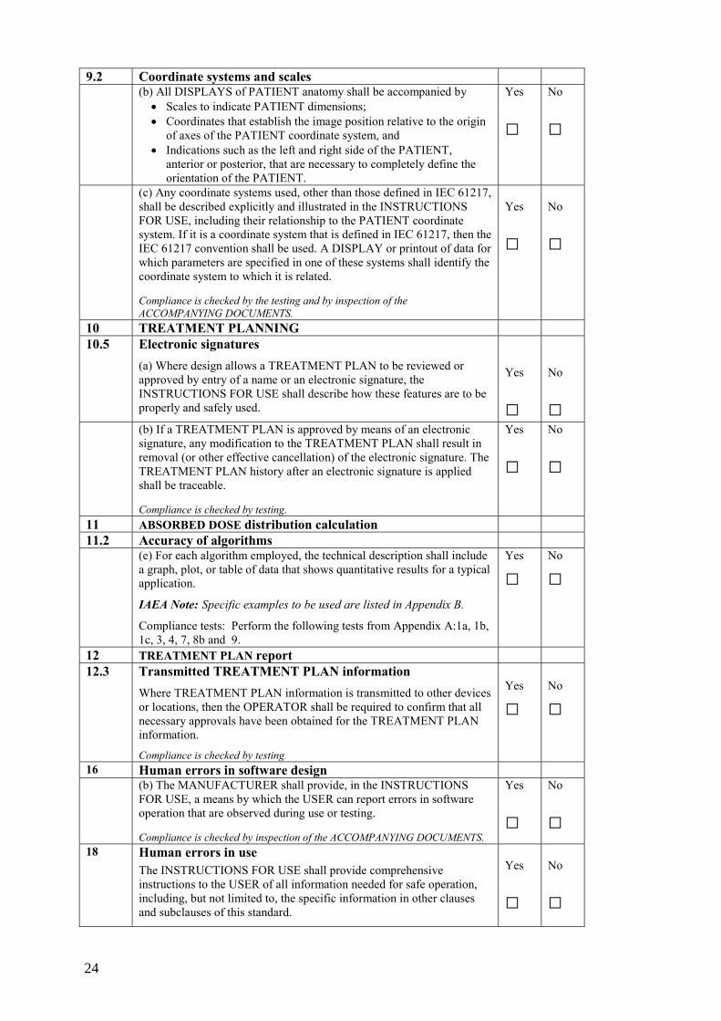
(b) All DISPLAYS of PATIENT anatomy shall be accompanied by • scales to indicate PATIENT dimensions; • coordinates that establish the image position relative to the origin
of axes of the PATIENT coordinate system, and • indications such as the left and right side of the PATIENT,
anterior or posterior, that are necessary to completely define the orientation of the PATIENT.
Yes
□
No
□
(c) Any coordinate systems used, other than those defined in IEC 61217, shall be described explicitly and illustrated in the INSTRUCTIONS FOR USE, including their relationship to the PATIENT coordinate system. If it is a coordinate system that is defined in IEC 61217, then the IEC 61217 convention shall be used. A DISPLAY or printout of data for which parameters are specified in one of these systems shall identify the coordinate system to which it is related.
Yes
□
No
□
12
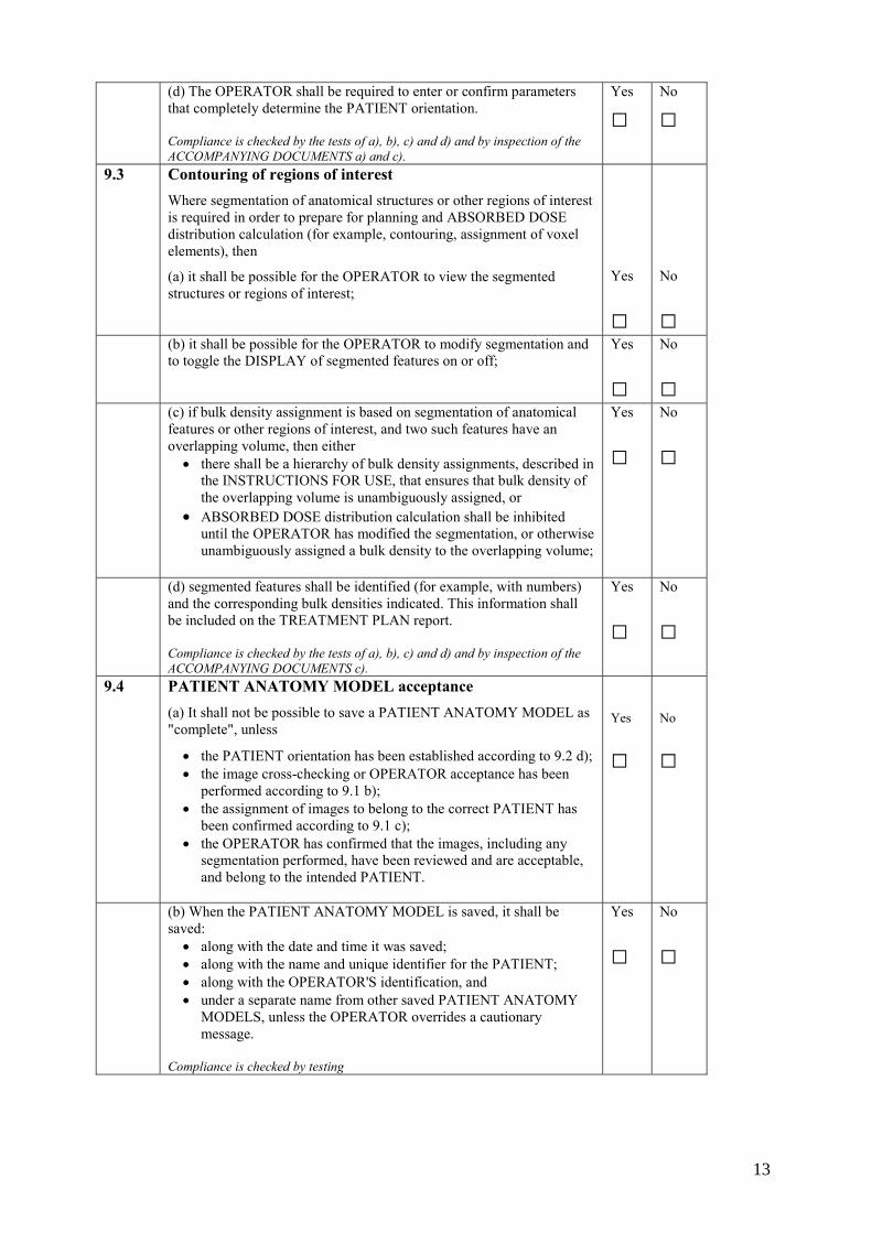
(d) The OPERATOR shall be required to enter or confirm parameters that completely determine the PATIENT orientation. Compliance is checked by the tests of a), b), c) and d) and by inspection of the ACCOMPANYING DOCUMENTS a) and c).
Yes
□
No
□
9.3 Contouring of regions of interest Where segmentation of anatomical structures or other regions of interest is required in order to prepare for planning and ABSORBED DOSE distribution calculation (for example, contouring, assignment of voxel elements), then
(a) it shall be possible for the OPERATOR to view the segmented structures or regions of interest;
Yes
□
No
□ (b) it shall be possible for the OPERATOR to modify segmentation and
to toggle the DISPLAY of segmented features on or off; Yes
□
No
□ (c) if bulk density assignment is based on segmentation of anatomical
features or other regions of interest, and two such features have an overlapping volume, then either • there shall be a hierarchy of bulk density assignments, described in
the INSTRUCTIONS FOR USE, that ensures that bulk density of the overlapping volume is unambiguously assigned, or
• ABSORBED DOSE distribution calculation shall be inhibited until the OPERATOR has modified the segmentation, or otherwise unambiguously assigned a bulk density to the overlapping volume;
Yes
□
No
□
(d) segmented features shall be identified (for example, with numbers) and the corresponding bulk densities indicated. This information shall be included on the TREATMENT PLAN report. Compliance is checked by the tests of a), b), c) and d) and by inspection of the ACCOMPANYING DOCUMENTS c).
Yes
□
No
□
9.4 PATIENT ANATOMY MODEL acceptance (a) It shall not be possible to save a PATIENT ANATOMY MODEL as "complete", unless
• the PATIENT orientation has been established according to 9.2 d); • the image cross-checking or OPERATOR acceptance has been
performed according to 9.1 b); • the assignment of images to belong to the correct PATIENT has
been confirmed according to 9.1 c); • the OPERATOR has confirmed that the images, including any
segmentation performed, have been reviewed and are acceptable, and belong to the intended PATIENT.
Yes
□
No
□
(b) When the PATIENT ANATOMY MODEL is saved, it shall be saved: • along with the date and time it was saved; • along with the name and unique identifier for the PATIENT; • along with the OPERATOR'S identification, and • under a separate name from other saved PATIENT ANATOMY
MODELS, unless the OPERATOR overrides a cautionary message.
Compliance is checked by testing
Yes
□
No
□
13
9.5 PATIENT ANATOMY MODEL deletion It shall not be possible to delete a PATIENT ANATOMY MODEL until the OPERATOR has received and overridden a cautionary message advising that the PATIENT ANATOMY MODEL should be archived prior to deletion.
Compliance is checked by testing.
Yes
□
No
□
10 10.1
TREATMENT PLANNING General requirements (a) When an incomplete EQUIPMENT MODEL, BRACHYTHERAPY SOURCE MODEL or PATIENT ANATOMY MODEL is in use, the OPERATOR shall be required to override a cautionary message that states that the model is incomplete.
Yes
□
No
□
(b) If it is possible for the OPERATOR to specify a RADIATION BEAM dimension or position that is not within the available range specified for the BEAM LIMITING DEVICE, BEAM APPLICATOR, or RADIATION BEAM modifying device as specified in the selected EQUIPMENT MODEL, then an additional message or parameter shall be provided so that it is clear to the OPERATOR that the maximum size has been exceeded, and to what extent. Examples: exceeding these limits may be desirable for a large-field "beam’s-eye view" or for a large-field digitally reconstructed RADIOGRAM. NOTE If the limits in b) are to be exceeded, such as for an extended "beam's-eye view", an additional parameter will need to be specified so that it is clear to the OPERATOR that the maximum available RADIATION BEAM dimension has been exceeded, and to what extent. Compliance is checked by testing
Yes
□
No
□
10.2 TREATMENT PLAN preparation (a) The MANUFACTURER shall specify in the INSTRUCTIONS FOR USE the maximum number of RADIATION BEAMS, BRACHYTHERAPY RADIOACTIVE SOURCES, or other RADIATION-generating EQUIPMENT, that should not be exceeded in any one TREATMENT PLAN. These limiting numbers should be either hard-coded to prevent operation outside of these bounds, or result in cautionary DISPLAY. NOTE Although there may be no theoretical limit to some of these items, the requirement ensures that the MANUFACTURER establishes a bound for testing and communicates this to the USER. Flexibility is provided so that the limits can be conveniently increased based on further testing.
Yes
□
No
□
(b) Where two or more TREATMENT PLANS are combined, the combined TREATMENT PLANS shall use the identical PATIENT ANATOMY MODEL, or the OPERATOR shall be requested to confirm that the PATIENT ANATOMY MODELS are compatible. The algorithm for combining TREATMENT PLANS shall meet the requirements of 11.2. Compliance is checked by the tests of a) and b) and by inspection of the ACCOMPANYING DOCUMENTS a).
Yes
□
No
□
14
10.3 TREATMENT PLAN identification When a TREATMENT PLAN is saved, it shall be saved – along with the time and date when it was saved; – along with the OPERATOR'S identification; – along with the identifier of the EQUIPMENT MODEL or
BRACHYTHERAPY SOURCE MODEL used; – along with the version number of the software under which it was
created; – along with the identifier of the PATIENT and the PATIENT
ANATOMY MODEL used, and – under a separate name from other saved TREATMENT PLANS,
unless the OPERATOR overrides a cautionary message. Compliance is checked by testing.
Yes
□
No
□
10.4
TREATMENT PLAN deletion It shall not be possible to delete a TREATMENT PLAN unless the OPERATOR has received and overridden a cautionary message advising that the TREATMENT PLAN should be archived prior to deletion. Compliance is checked by testing.
Yes
□
No
□
10.5 Electronic signatures (a) Where design allows a TREATMENT PLAN to be reviewed or approved by entry of a name or an electronic signature, the INSTRUCTIONS FOR USE shall describe how these features are to be properly and safely used.
Yes
□
No
□
(b) If a TREATMENT PLAN is approved by means of an electronic signature, any modification to the TREATMENT PLAN shall result in removal (or other effective cancellation) of the electronic signature. The TREATMENT PLAN history after an electronic signature is applied shall be traceable.
Compliance is checked by testing of a). and b).
Yes
□
No
□
11 11.1
ABSORBED DOSE distribution calculation Algorithms used (a) All algorithms used for calculation of ABSORBED DOSE distributions shall be included in the technical description. This shall include a description of the factors accounted for by the algorithm, the mathematical equations forming the basis of the calculation, and the limits applied to all variables used in the equations. References to literature shall be provided for published algorithms. NOTE "All algorithms" in this subclause includes supplemental calculations such as digitally reconstructed RADIOGRAMS, BRACHYTHERAPY RADIATION SOURCE reconstruction algorithms, and optimization algorithms. It also includes all algorithms that affect calculation through identification of the TARGET VOLUME or other structures, such as automatic contouring or other automatic structure identification techniques, and automatic margining of a region of interest. (b) Where a choice of algorithms is provided for a particular calculation, the INSTRUCTIONS FOR USE shall discuss the relative advantages and disadvantages of the different algorithms with respect to clinical situations. Compliance is checked by inspection of the ACCOMPANYING DOCUMENTS IAEA Note: For example, for algorithms related to calculation of absorbed dose distributions for 2-D planning, only a limited number of contours on parallel slices need to be entered and beam axes are parallel to these planes. Calculation algorithms assume that each of these contours is invariant over the length of the volume, and may not explicitly consider scattered radiation.
Yes
□ Yes
□
No
□ No
□
15
11.2 Accuracy of algorithms (a). For each algorithm used, the technical description shall state the accuracy of the algorithm relative to measured data for at least one set of pre-defined conditions. The pre-defined conditions shall be chosen to simulate the conditions for NORMAL USE. Where pre-defined conditions are available in a published report or standard, these should be used. IAEA Note: The pre-defined conditions are described in Appendix A.
Yes
□
No
□
The technical description shall include all descriptions and data necessary for the USER to reproduce the pre-defined conditions, or suitable references if these conditions are publicly available. It shall also include test procedures that permit convenient testing by the USER to show that the expected results are achieved with the provided input data. IAEA Note: The test procedures are described in Appendix A
Yes
□
No
□
The technical description shall include a description of how all BLDs are modeled during calculation. This description shall include both calculation of TRANSMISSION through RADIATION BEAM modifiers and calculation in the PENUMBRA region. IAEA Note: If described in Section 11.1 a) then there is no need to repeat here.
Yes
□
No
□
(b) Each algorithm shall be implemented in such a way that it will not produce a mathematically incorrect result under the most extreme allowed ranges of input variables. NOTE The intention of this requirement is not to ensure that the result will produce the desired clinical outcome, but rather that the algorithm produces the mathematically correct result under the most extreme conditions of input variables.
IAEA Note: Appropriate documentation should be provided.
Yes
□
No
□
(c) Where dose estimation is based on values at specific points from which the dosimetric values at other points are interpolated or extrapolated, then the theoretical dosimetric error introduced by the interpolation or extrapolation shall be described in the technical description for typical TREATMENT PLANNING conditions. Where the OPERATOR can make choices that will increase or decrease this effect, the choices made by the OPERATOR shall be DISPLAYED and shall be included in the TREATMENT PLAN report. Cautionary notices shall also be provided in the INSTRUCTIONS FOR USE concerning the importance of making appropriate choices. EXAMPLES Variable grid spacing for calculation for which intervening values will be interpolated, or calculations using an OPERATOR-selectable set of fixed RADIATION BEAMS for approximation. IAEA Note: For estimation of these effects in low dose gradient regions dose estimation should be used and in high-dose gradient regions distance to agreement should be used.
Yes
□
No
□
(d) The INSTRUCTIONS FOR USE shall provide cautionary notes for the OPERATOR concerning the limitations of accuracy of the ABSORBED DOSE distribution calculations for situations where the expected level of accuracy may not apply. EXAMPLES ABSORBED DOSE close to a BRACHYTHERAPY RADIOACTIVE SOURCE; ABSORBED DOSE in the vicinity of very dense material. NOTE 1 Accuracy includes ABSORBED DOSE relative to an expected value, usually expressed in per cent, and also spatial accuracy in regions of high ABSORBED DOSE gradient, usually expressed in millimeters. NOTE 2 Special cautionary notes are not meant to imply that the MANUFACTURER can anticipate all such situations, nor absolve the USER from the responsibility of performing confirmatory checks before using any TREATMENT PLAN.
Yes
□
No
□
16
(e) For each algorithm employed, the technical description shall include a graph, plot, or table of data that show quantitative results for a typical application.
Compliance is checked by the tests of b) and by inspection of the ACCOMPANYING DOCUMENTS a), c), d) and e).
IAEA Note: Specific examples to be used are listed in Appendix A
Yes
□
No
□
12 12.1
TREATMENT PLAN report Incomplete TREATMENT PLAN report If a TREATMENT PLAN report is generated from, or using, an EQUIPMENT MODEL, BRACHYTHERAPY SOURCE MODEL, or PATIENT ANATOMY MODEL that has not been saved as "complete", then the message "EQUIPMENT MODEL incomplete", "BRACHYTHERAPY SOURCE MODEL incomplete", or "PATIENT ANATOMY MODEL incomplete", shall be included in the TREATMENT PLAN report. Compliance is checked by testing.
Yes
□
No
□
12.2 Information on the TREATMENT PLAN report In addition to all applicable ABSORBED DOSE distributions, isodose lines, DOSE MONITOR UNITS and IRRADIATION TIME information, each TREATMENT PLAN report shall include as a minimum – the version number of the RTPS software; – the PATIENT name and his/her unique identifier; – the unique identifier of the EQUIPMENT or BRACHYTHERAPY
RADIOACTIVE SOURCE and its RADIATION QUALITY; – the unique identifier of the EQUIPMENT MODEL, BRACHYTHERAPY
SOURCE MODEL, PATIENT ANATOMY MODEL, and TREATMENT PLAN; – the date and time that the TREATMENT PLAN was saved; – all parameters, such as RADIATION FIELD size and GANTRY angle,
required to define the characteristics of size, shape, and position of each RADIATION BEAM DISPLAYED on the TREATMENT PLAN report;
– the identifier, dimension and dosimetric parameters of all WEDGE FILTERS, ELECTRON BEAM APPLICATORS, RADIATION BEAM shaping blocks, compensators, or other BLD in addition to the primary BLDs, multi-element BLDs, dynamic WEDGE FILTER;
– the messages, if applicable, required by 7.5 and 12.1; – the contour and bulk density identifiers, if applicable, required by 9.3; – the method of RADIATION BEAM weighting, isodose distribution
normalization, and the reference point selected; – the chosen calculation algorithm, if a choice was available; – the choices made by the OPERATOR that affect calculation accuracy as
required by 11.2; – the OPERATOR identification; – the reviewer's name or electronic signature, if the design permits or
requires review or approval of TREATMENT PLANS electronically, and a signature block for the approver's name, signature and date.
Key identifying elements shall be included on each page of the TREATMENT PLAN report. These shall include, as a minimum, the PATIENT name, PATIENT identifier, the date and time of the TREATMENT PLAN generation. NOTE Required elements on this list may be deleted if they are inherently not available in the TREATMENT PLAN design. The MANUFACTURER is also expected to add elements to the list where these are needed for effective use, such as identification of the PATIENT, and of the TREATMENT PLAN, and clarity of information on the TREATMENT PLAN. Compliance is checked by inspection of the output information
Yes
□
No
□
17
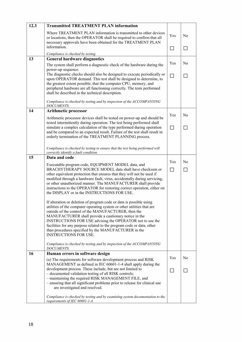
12.3 Transmitted TREATMENT PLAN information Where TREATMENT PLAN information is transmitted to other devices or locations, then the OPERATOR shall be required to confirm that all necessary approvals have been obtained for the TREATMENT PLAN information.
Compliance is checked by testing
Yes
□
No
□
13 General hardware diagnostics The system shall perform a diagnostic check of the hardware during the power-up sequence. The diagnostic checks should also be designed to execute periodically or upon OPERATOR demand. This test shall be designed to determine, to the greatest extent possible, that the computer CPU, memory, and peripheral hardware are all functioning correctly. The tests performed shall be described in the technical description. Compliance is checked by testing and by inspection of the ACCOMPANYING DOCUMENTS.
Yes
□
No
□
14 Arithmetic processor Arithmetic processor devices shall be tested on power-up and should be tested intermittently during operation. The test being performed shall simulate a complex calculation of the type performed during operation and be compared to an expected result. Failure of the test shall result in orderly termination of the TREATMENT PLANNING process.
Compliance is checked by testing to ensure that the test being performed will correctly identify a fault condition.
Yes
□
No
□
15 Data and code Executable program code, EQUIPMENT MODEL data, and BRACHYTHERAPY SOURCE MODEL data shall have checksum or other equivalent protection that ensures that they will not be used if modified through a hardware fault, virus, accidentally during servicing, or other unauthorized manner. The MANUFACTURER shall provide instructions to the OPERATOR for restoring correct operation, either on the DISPLAY or in the INSTRUCTIONS FOR USE. If alteration or deletion of program code or data is possible using utilities of the computer operating system or other utilities that are outside of the control of the MANUFACTURER, then the MANUFACTURER shall provide a cautionary notice in the INSTRUCTIONS FOR USE advising the OPERATOR not to use the facilities for any purpose related to the program code or data, other than procedures specified by the MANUFACTURER in the INSTRUCTIONS FOR USE. Compliance is checked by testing and by inspection of the ACCOMPANYING DOCUMENTS.
Yes
□
No
□
16 Human errors in software design (a) The requirements for software development process and RISK MANAGEMENT as defined in IEC 60601-1-4 shall apply during the development process. These include, but are not limited to – documented validation testing of all RISK controls; – maintaining the required RISK MANAGEMENT FILE, and – ensuring that all significant problems prior to release for clinical use
are investigated and resolved. Compliance is checked by testing and by examining system documentation to the requirements of IEC 60601-1-4.
Yes
□
No
□
18
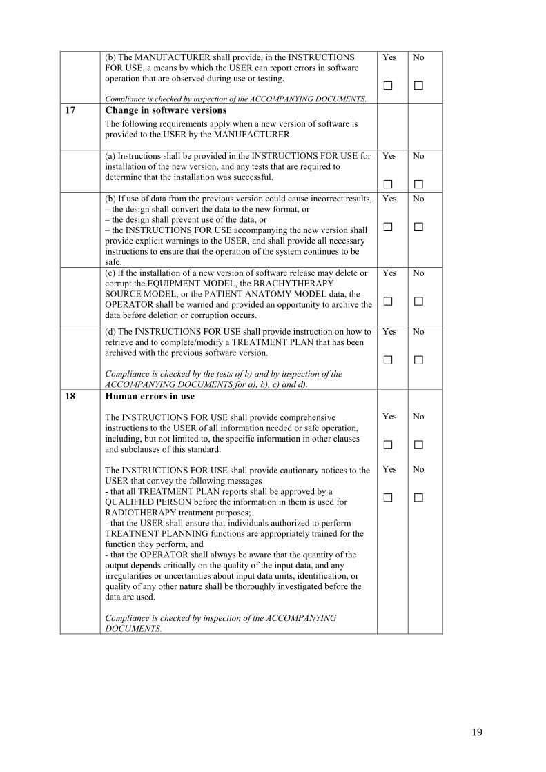
(b) The MANUFACTURER shall provide, in the INSTRUCTIONS FOR USE, a means by which the USER can report errors in software operation that are observed during use or testing. Compliance is checked by inspection of the ACCOMPANYING DOCUMENTS.
Yes
□
No
□
17 Change in software versions The following requirements apply when a new version of software is provided to the USER by the MANUFACTURER.
(a) Instructions shall be provided in the INSTRUCTIONS FOR USE for installation of the new version, and any tests that are required to determine that the installation was successful.
Yes
□
No
□ (b) If use of data from the previous version could cause incorrect results,
– the design shall convert the data to the new format, or – the design shall prevent use of the data, or – the INSTRUCTIONS FOR USE accompanying the new version shall provide explicit warnings to the USER, and shall provide all necessary instructions to ensure that the operation of the system continues to be safe.
Yes
□
No
□
(c) If the installation of a new version of software release may delete or corrupt the EQUIPMENT MODEL, the BRACHYTHERAPY SOURCE MODEL, or the PATIENT ANATOMY MODEL data, the OPERATOR shall be warned and provided an opportunity to archive the data before deletion or corruption occurs.
Yes
□
No
□
(d) The INSTRUCTIONS FOR USE shall provide instruction on how to retrieve and to complete/modify a TREATMENT PLAN that has been archived with the previous software version. Compliance is checked by the tests of b) and by inspection of the ACCOMPANYING DOCUMENTS for a), b), c) and d).
Yes
□
No
□
18 Human errors in use The INSTRUCTIONS FOR USE shall provide comprehensive instructions to the USER of all information needed or safe operation, including, but not limited to, the specific information in other clauses and subclauses of this standard. The INSTRUCTIONS FOR USE shall provide cautionary notices to the USER that convey the following messages - that all TREATMENT PLAN reports shall be approved by a QUALIFIED PERSON before the information in them is used for RADIOTHERAPY treatment purposes; - that the USER shall ensure that individuals authorized to perform TREATNENT PLANNING functions are appropriately trained for the function they perform, and - that the OPERATOR shall always be aware that the quantity of the output depends critically on the quality of the input data, and any irregularities or uncertainties about input data units, identification, or quality of any other nature shall be thoroughly investigated before the data are used. Compliance is checked by inspection of the ACCOMPANYING DOCUMENTS.
Yes
□ Yes
□
No
□ No
□
19
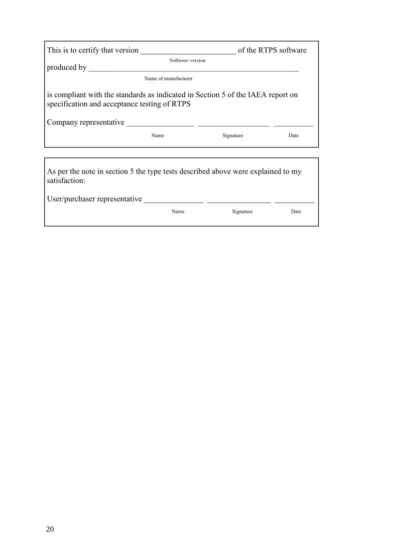
This is to certify that version ________________________ of the RTPS software
produced by _____________________________________________________ is compliant with the standards as indicated in Section 5 of the IAEA report on specification and acceptance testing of RTPS Company representative _________________ __________________ __________
As per the note in section 5 the type tests described above were explained to my satisfaction: User/purchaser representative _______________ ________________ __________
Software version
Name of manufacturer
Name Signature Date
Name Signature Date
20
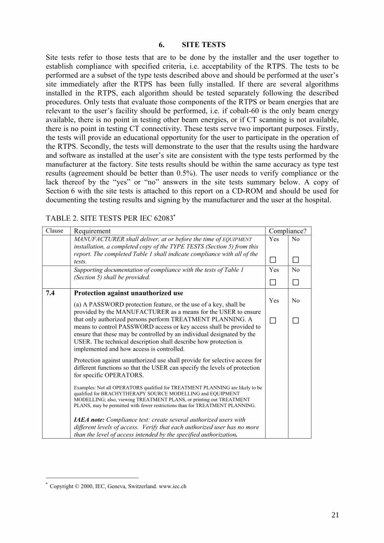
6. SITE TESTS Site tests refer to those tests that are to be done by the installer and the user together to establish compliance with specified criteria, i.e. acceptability of the RTPS. The tests to be performed are a subset of the type tests described above and should be performed at the user’s site immediately after the RTPS has been fully installed. If there are several algorithms installed in the RTPS, each algorithm should be tested separately following the described procedures. Only tests that evaluate those components of the RTPS or beam energies that are relevant to the user’s facility should be performed, i.e. if cobalt-60 is the only beam energy available, there is no point in testing other beam energies, or if CT scanning is not available, there is no point in testing CT connectivity. These tests serve two important purposes. Firstly, the tests will provide an educational opportunity for the user to participate in the operation of the RTPS. Secondly, the tests will demonstrate to the user that the results using the hardware and software as installed at the user’s site are consistent with the type tests performed by the manufacturer at the factory. Site tests results should be within the same accuracy as type test results (agreement should be better than 0.5%). The user needs to verify compliance or the lack thereof by the “yes” or “no” answers in the site tests summary below. A copy of Section 6 with the site tests is attached to this report on a CD-ROM and should be used for documenting the testing results and signing by the manufacturer and the user at the hospital. TABLE 2. SITE TESTS PER IEC 62083∗ Clause Requirement Compliance? MANUFACTURER shall deliver, at or before the time of EQUIPMENT
installation, a completed copy of the TYPE TESTS (Section 5) from this report. The completed Table 1 shall indicate compliance with all of the tests.
Yes
□
No
□ Supporting documentation of compliance with the tests of Table 1
(Section 5) shall be provided.
Yes
□
No
□ 7.4 Protection against unauthorized use
(a) A PASSWORD protection feature, or the use of a key, shall be provided by the MANUFACTURER as a means for the USER to ensure that only authorized persons perform TREATMENT PLANNING. A means to control PASSWORD access or key access shall be provided to ensure that these may be controlled by an individual designated by the USER. The technical description shall describe how protection is implemented and how access is controlled.
Protection against unauthorized use shall provide for selective access for different functions so that the USER can specify the levels of protection for specific OPERATORS. Examples: Not all OPERATORS qualified for TREATMENT PLANNING are likely to be qualified for BRACHYTHERAPY SOURCE MODELLING and EQUIPMENT MODELLING; also, viewing TREATMENT PLANS, or printing out TREATMENT PLANS, may be permitted with fewer restrictions than for TREATMENT PLANNING. IAEA note: Compliance test: create several authorized users with different levels of access. Verify that each authorized user has no more than the level of access intended by the specified authorization.
Yes
□
No
□
∗ Copyright © 2000, IEC, Geneva, Switzerland. www.iec.ch
21
(b) Where network connection is permitted by the design, the following requirements apply: – access to the RTPS shall be provided only to authorized
EQUIPMENT or individuals who are authorized (for example, by a PASSWORD under the control of the USER);
Yes
□
No
□
– access to EQUIPMENT MODEL, BRACHYTHERAPY SOURCE MODEL, and PATIENT ANATOMY MODEL data, or to TREATMENT PLANS (with or without ABSORBED DOSE distribution calculation) through the network shall be restricted so as to prevent unauthorized access;
Yes
□
No
□
– protection against computer viruses shall be employed which alerts the OPERATOR when a virus is detected. The MANUFACTURER shall state in the INSTRUCTIONS FOR USE the means of virus protection employed, and that any other means shall be approved by the MANUFACTURER prior to use.
IAEA note: Compliance test: if a network connection is provided, connect the RTPS to the network and confirm that access to the RTPS is limited to only authorized users; for example, those provided with a PASSWORD. Confirm that the RTPS cannot be accessed from another computer on the network other than by an authorized user.Confirm that the manufacturer has provided protection against computer viruses, and has provided a description of the virus protection.
Yes
□
No
□
7.5 Data limits Data elements entered by the USER or acquired from a device or network shall be compared against pre-established limits.
Operation shall be prevented if the data are outside these limits unless the OPERATOR overrides a cautionary message at the time the data are found to be outside the limits. Limits for those data elements that are entered by the USER shall be provided in the INSTRUCTIONS FOR USE. Other consistency checks on data should also be performed as appropriate to the expected nature of the data. For TREATMENT PLANNING performed when the OPERATOR has overridden data limits, TREATMENT PLAN reports shall include the message "CAUTION: SOME DATA ELEMENTS USED WERE OUTSIDE NORMAL RANGE" or a similar statement. IAEA note: Compliance tests: (1) Attempt to enter values that are outside pre-established limits, and verify that operation is prevented unless the operator overrides a cautionary message. Suggested parameters to be tested include: • field size (attempt to enter negative values and values > 40 cm). • SSD (attempt to enter negative values and values outside the range
50 cm to 150 cm - if these values are outside the normally allowed limits).
• prescribed dose (attempt to enter negative values and values > 4 Gy) - use a larger dose if 4 Gy is allowed.
(2) Verify that the vendor has provided the allowed limits for data that are entered by the user (3) Verify that, if data outside the limits are accepted after an operator over-ride, the TREATMENT PLAN report indicates that values outside the normal range were used
Yes
□ Yes
□ Yes
□
No
□ No
□ No
□
22
7.7 Correctness of data transfer (b) If data are transmitted for use by another device, other than closed communication with a peripheral, then – the format of the output data shall be included in the technical
description, including (but not limited to) identification of all data elements, data types, and data limits;
– the data output shall include the name of the OPERATOR, the date on which the data was written, and any relevant identifiers for the PATIENT, EQUIPMENT MODEL, BRACHYTHERAPY SOURCE MODEL, PATIENT ANATOMY MODEL and TREATMENT PLAN.
NOTE See annex B of IEC 62083 concerning correctness of transferred data.
IAEA Note: The transfer of data could be tested for devices such as image data from the CT scanner, measured dose data from a 2-D or 3-D water phantom, MLC configuration from the CT simulator or to the radiation therapy machine, etc. Compliance is checked by testing and by inspection of the output information and ACCOMPANYING DOCUMENTS.
Yes
□
No
□
7.8 Coordinate systems and scales It shall be possible for the OPERATOR to perform all TREATMENT PLANNING functions with the scales and coordinates of RADIOTHERAPY treatment EQUIPMENT displayed according to the IEC 61217 convention. It should also be possible for the OPERATOR to perform all TREATMENT PLANNING functions with the scales and coordinates of EQUIPMENT DISPLAYED according to the customization for the particular EQUIPMENT performed during EQUIPMENT MODELLING. In either case, the TREATMENT PLAN reports used for RADIOTHERAPY treatment prescription shall show the scales and coordinates of EQUIPMENT according to the customization for the particular EQUIPMENT performed during EQUIPMENT MODELLING. The method of DISPLAY of scales shall be explained in the INSTRUCTIONS FOR USE. Compliance is checked by testing and by inspection of the DISPLAY, output information and ACCOMPANYING DOCUMENTS.
Yes
□
No
□
7.9 Saving and archiving data Means shall be provided such that an EQUIPMENT MODEL, BRACHYTHERAPY SOURCE MODEL, TREATMENT PLAN, and other data critical to proper operation can be saved while work is in progress so that it can be retrieved in the case of a system malfunction. Means shall be provided for archiving data onto a separate medium from the primary storage, such that it can be retrieved in the case of a failure of the data storage device or complete TPS.
Compliance is checked by testing.
Yes
□
No
□
9 9.1
ANATOMY MODELLING Data acquisition
(d) If inhomogeneity correction is performed based on CT image data or similar data acquired from another device and the data are not directly useable without a conversion factor or calibration curve • Inhomogeneity correction shall not be executed if any data element
is outside the conversion curve or a warning message shall be DISPLAYED, and
• The OPERATOR shall be required to confirm that the calibration curve is appropriate for those images, unless this can be automatically confirmed through information acquired with the images.
Compliance is checked by the testing and by inspection of the ACCOMPANYING DOCUMENTS.
Yes
□
No
□
23
9.2 Coordinate systems and scales (b) All DISPLAYS of PATIENT anatomy shall be accompanied by
• Scales to indicate PATIENT dimensions; • Coordinates that establish the image position relative to the origin
of axes of the PATIENT coordinate system, and • Indications such as the left and right side of the PATIENT,
anterior or posterior, that are necessary to completely define the orientation of the PATIENT.
Yes
□
No
□
(c) Any coordinate systems used, other than those defined in IEC 61217, shall be described explicitly and illustrated in the INSTRUCTIONS FOR USE, including their relationship to the PATIENT coordinate system. If it is a coordinate system that is defined in IEC 61217, then the IEC 61217 convention shall be used. A DISPLAY or printout of data for which parameters are specified in one of these systems shall identify the coordinate system to which it is related. Compliance is checked by the testing and by inspection of the ACCOMPANYING DOCUMENTS.
Yes
□
No
□
10 TREATMENT PLANNING 10.5 Electronic signatures
(a) Where design allows a TREATMENT PLAN to be reviewed or approved by entry of a name or an electronic signature, the INSTRUCTIONS FOR USE shall describe how these features are to be properly and safely used.
Yes
□
No
□ (b) If a TREATMENT PLAN is approved by means of an electronic
signature, any modification to the TREATMENT PLAN shall result in removal (or other effective cancellation) of the electronic signature. The TREATMENT PLAN history after an electronic signature is applied shall be traceable. Compliance is checked by testing.
Yes
□
No
□
11 ABSORBED DOSE distribution calculation 11.2 Accuracy of algorithms (e) For each algorithm employed, the technical description shall include
a graph, plot, or table of data that shows quantitative results for a typical application.
IAEA Note: Specific examples to be used are listed in Appendix B.
Compliance tests: Perform the following tests from Appendix A:1a, 1b, 1c, 3, 4, 7, 8b and 9.
Yes
□
No
□
12 TREATMENT PLAN report 12.3 Transmitted TREATMENT PLAN information
Where TREATMENT PLAN information is transmitted to other devices or locations, then the OPERATOR shall be required to confirm that all necessary approvals have been obtained for the TREATMENT PLAN information.
Compliance is checked by testing.
Yes
□
No
□
16 Human errors in software design (b) The MANUFACTURER shall provide, in the INSTRUCTIONS
FOR USE, a means by which the USER can report errors in software operation that are observed during use or testing. Compliance is checked by inspection of the ACCOMPANYING DOCUMENTS.
Yes
□
No
□
18 Human errors in use The INSTRUCTIONS FOR USE shall provide comprehensive instructions to the USER of all information needed for safe operation, including, but not limited to, the specific information in other clauses and subclauses of this standard.
Yes
□
No
□
24
The INSTRUCTIONS FOR USE shall provide cautionary notices to the USER that convey the following messages:
– that all TREATMENT PLAN reports shall be approved by a QUALIFIED PERSON before the information in them is used for RADIOTHERAPY treatment purposes;
Yes
□
No
□
– that the USER shall ensure that individuals authorized to perform TREATMENT PLANNING functions are appropriately trained for the functions they perform, and
Yes
□
No
□ – that the OPERATOR shall always be aware that the quality of the
output depends critically on the quality of the input data, and any irregularities or uncertainties about input data units, identification, or quality of any other nature shall be thoroughly investigated before the data are used. Compliance is checked by inspection of the ACCOMPANYING DOCUMENTS.
Yes
□
No
□
This is to certify that version ________________________ of the RTPS software
produced by _____________________________________________________ has passed the acceptance tests as described in Section 6 of the IAEA report on specification and acceptance testing of RTPS Company representative _______________ _______________ __________
User/purchaser representative _________________ __________________ __________
Software version
Name of manufacturer
Name Signature Date
Name Signature Date
25
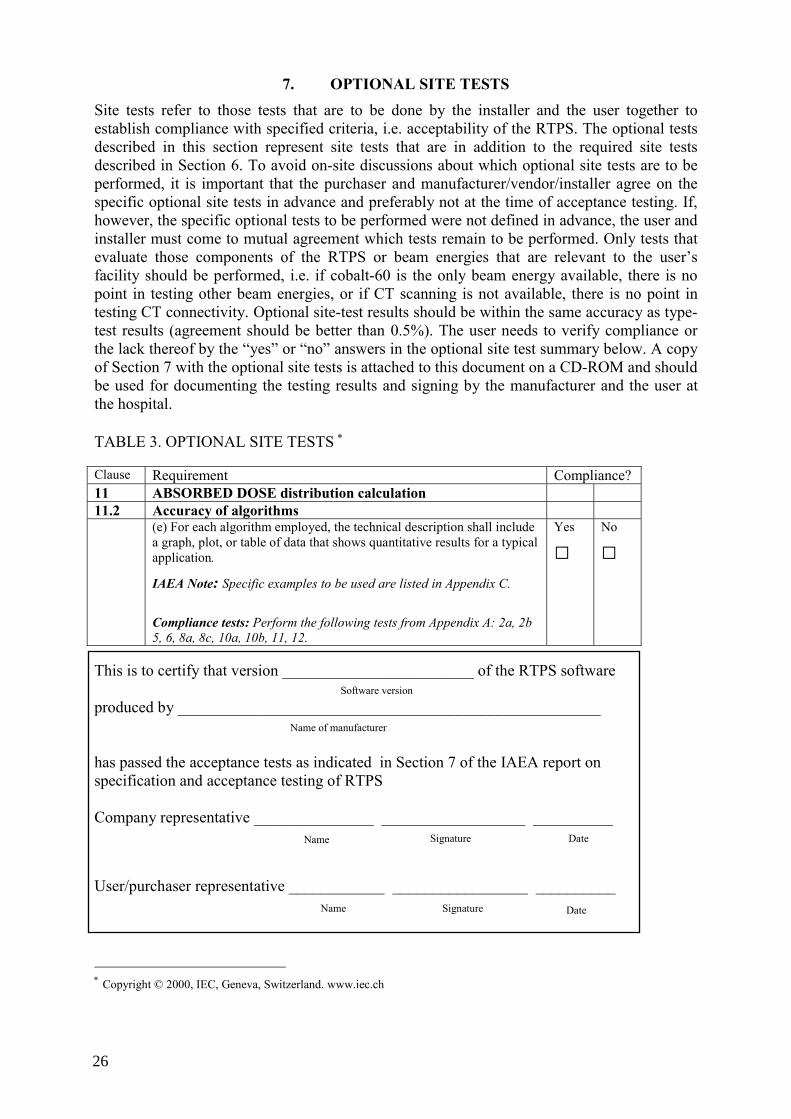
7. OPTIONAL SITE TESTS Site tests refer to those tests that are to be done by the installer and the user together to establish compliance with specified criteria, i.e. acceptability of the RTPS. The optional tests described in this section represent site tests that are in addition to the required site tests described in Section 6. To avoid on-site discussions about which optional site tests are to be performed, it is important that the purchaser and manufacturer/vendor/installer agree on the specific optional site tests in advance and preferably not at the time of acceptance testing. If, however, the specific optional tests to be performed were not defined in advance, the user and installer must come to mutual agreement which tests remain to be performed. Only tests that evaluate those components of the RTPS or beam energies that are relevant to the user’s facility should be performed, i.e. if cobalt-60 is the only beam energy available, there is no point in testing other beam energies, or if CT scanning is not available, there is no point in testing CT connectivity. Optional site-test results should be within the same accuracy as type-test results (agreement should be better than 0.5%). The user needs to verify compliance or the lack thereof by the “yes” or “no” answers in the optional site test summary below. A copy of Section 7 with the optional site tests is attached to this document on a CD-ROM and should be used for documenting the testing results and signing by the manufacturer and the user at the hospital. TABLE 3. OPTIONAL SITE TESTS ∗ Clause Requirement Compliance? 11 ABSORBED DOSE distribution calculation 11.2 Accuracy of algorithms (e) For each algorithm employed, the technical description shall include
a graph, plot, or table of data that shows quantitative results for a typical application.
IAEA Note: Specific examples to be used are listed in Appendix C.
Compliance tests: Perform the following tests from Appendix A: 2a, 2b 5, 6, 8a, 8c, 10a, 10b, 11, 12.
Yes
□
No
□
This is to certify that version ________________________ of the RTPS software produced by _____________________________________________________ has passed the acceptance tests as indicated in Section 7 of the IAEA report on specification and acceptance testing of RTPS Company representative _______________ __________________ __________
User/purchaser representative ____________ _________________ __________
∗ Copyright © 2000, IEC, Geneva, Switzerland. www.iec.ch
Software version
Name of manufacturer
Name Signature Date
Name Signature Date
26
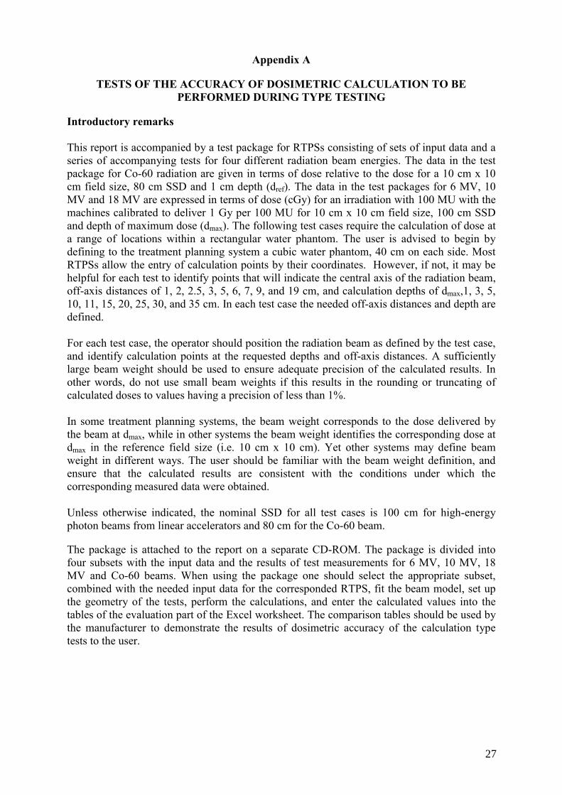
Appendix A
TESTS OF THE ACCURACY OF DOSIMETRIC CALCULATION TO BE PERFORMED DURING TYPE TESTING
Introductory remarks
This report is accompanied by a test package for RTPSs consisting of sets of input data and a series of accompanying tests for four different radiation beam energies. The data in the test package for Co-60 radiation are given in terms of dose relative to the dose for a 10 cm x 10 cm field size, 80 cm SSD and 1 cm depth (dref). The data in the test packages for 6 MV, 10 MV and 18 MV are expressed in terms of dose (cGy) for an irradiation with 100 MU with the machines calibrated to deliver 1 Gy per 100 MU for 10 cm x 10 cm field size, 100 cm SSD and depth of maximum dose (dmax). The following test cases require the calculation of dose at a range of locations within a rectangular water phantom. The user is advised to begin by defining to the treatment planning system a cubic water phantom, 40 cm on each side. Most RTPSs allow the entry of calculation points by their coordinates. However, if not, it may be helpful for each test to identify points that will indicate the central axis of the radiation beam, off-axis distances of 1, 2, 2.5, 3, 5, 6, 7, 9, and 19 cm, and calculation depths of dmax,1, 3, 5, 10, 11, 15, 20, 25, 30, and 35 cm. In each test case the needed off-axis distances and depth are defined. For each test case, the operator should position the radiation beam as defined by the test case, and identify calculation points at the requested depths and off-axis distances. A sufficiently large beam weight should be used to ensure adequate precision of the calculated results. In other words, do not use small beam weights if this results in the rounding or truncating of calculated doses to values having a precision of less than 1%. In some treatment planning systems, the beam weight corresponds to the dose delivered by the beam at dmax, while in other systems the beam weight identifies the corresponding dose at dmax in the reference field size (i.e. 10 cm x 10 cm). Yet other systems may define beam weight in different ways. The user should be familiar with the beam weight definition, and ensure that the calculated results are consistent with the conditions under which the corresponding measured data were obtained. Unless otherwise indicated, the nominal SSD for all test cases is 100 cm for high-energy photon beams from linear accelerators and 80 cm for the Co-60 beam. The package is attached to the report on a separate CD-ROM. The package is divided into four subsets with the input data and the results of test measurements for 6 MV, 10 MV, 18 MV and Co-60 beams. When using the package one should select the appropriate subset, combined with the needed input data for the corresponded RTPS, fit the beam model, set up the geometry of the tests, perform the calculations, and enter the calculated values into the tables of the evaluation part of the Excel worksheet. The comparison tables should be used by the manufacturer to demonstrate the results of dosimetric accuracy of the calculation type tests to the user.
27
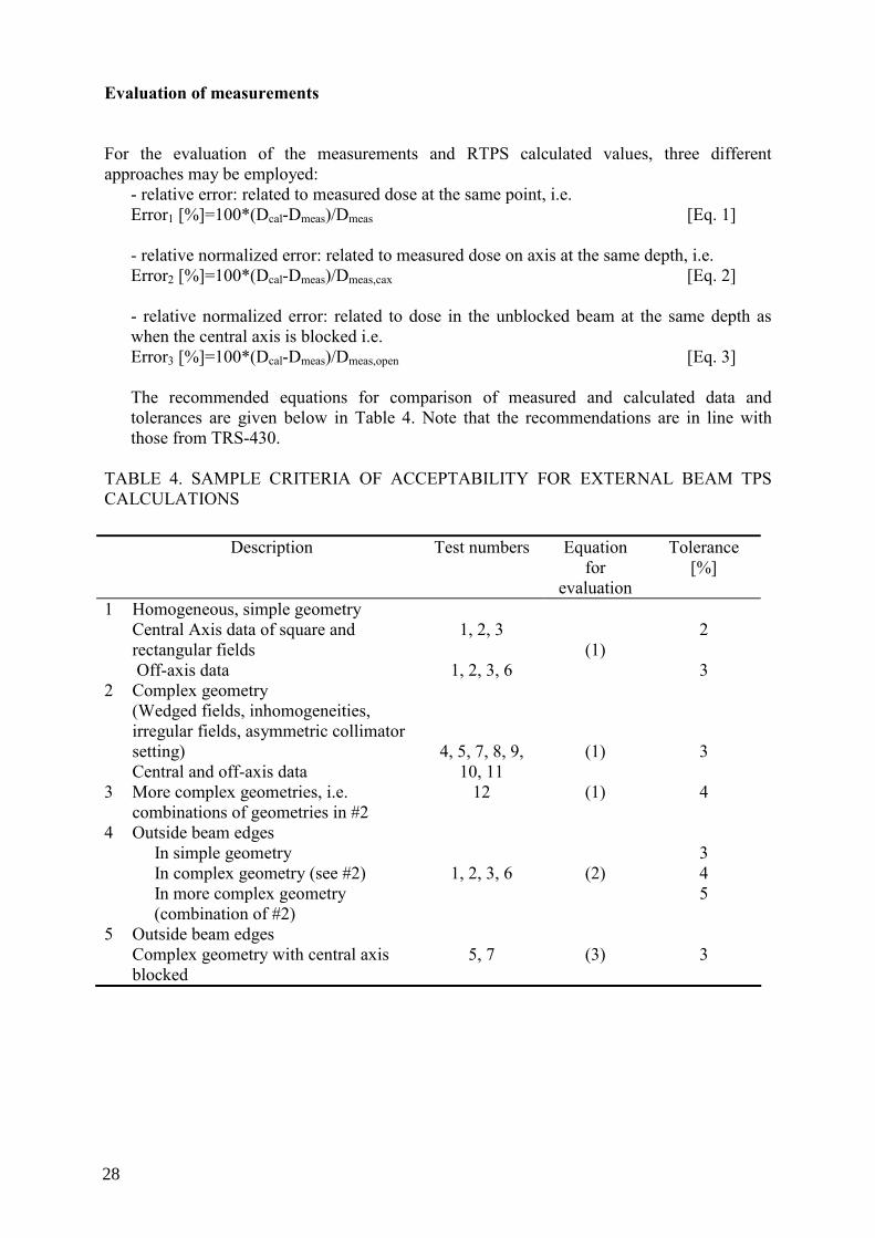
Evaluation of measurements
For the evaluation of the measurements and RTPS calculated values, three different approaches may be employed:
- relative error: related to measured dose at the same point, i.e. Error1 [%]=100*(Dcal-Dmeas)/Dmeas [Eq. 1]
- relative normalized error: related to measured dose on axis at the same depth, i.e. Error2 [%]=100*(Dcal-Dmeas)/Dmeas,cax [Eq. 2] - relative normalized error: related to dose in the unblocked beam at the same depth as when the central axis is blocked i.e. Error3 [%]=100*(Dcal-Dmeas)/Dmeas,open [Eq. 3] The recommended equations for comparison of measured and calculated data and tolerances are given below in Table 4. Note that the recommendations are in line with those from TRS-430.
TABLE 4. SAMPLE CRITERIA OF ACCEPTABILITY FOR EXTERNAL BEAM TPS CALCULATIONS
Description Test numbers Equation
for evaluation
Tolerance [%]
1 Homogeneous, simple geometry Central Axis data of square and rectangular fields Off-axis data
1, 2, 3
1, 2, 3, 6
(1)
2 3
2 Complex geometry (Wedged fields, inhomogeneities, irregular fields, asymmetric collimator setting) Central and off-axis data
4, 5, 7, 8, 9, 10, 11
(1)
3
3 More complex geometries, i.e. combinations of geometries in #2
12 (1) 4
4 Outside beam edges In simple geometry In complex geometry (see #2) In more complex geometry (combination of #2)
1, 2, 3, 6
(2)
3 4 5
5 Outside beam edges Complex geometry with central axis blocked
5, 7
(3)
3
28
Coordinate system
The following coordinate system is defined relative to the water phantom for clarification of beam data and test case geometry. The phantom coordinate system is consistent with the fixed system defined by IEC 61217:
The origin is at the treatment unit isocenter. For all tests except the isocentric test, the phantom surface is positioned at the isocenter. The Z-axis is perpendicular to the upper surface of the water phantom and directed upward from the phantom. With the exception of the oblique entry test case, the Z-axis coincides with the beam central axis and is directed toward the source. The X-axis is directed to the right of the Z-axis and the X-Z plane is perpendicular to the axis of rotation of the treatment unit. The Y-axis coincides with the treatment unit gantry axis of rotation and is directed toward the gantry. With the exception of test case 9, all calculations are done at points in the X-Z plane (Y = 0).
Test cases
The tests 1-9 are from the AAPM TG23, and the tests10-12 form the extension of the AAPM TG23 test package. Graphical representation of the test geometries for all tests is given in Appendix D.
1a) 5 cm x 5 cm Open Field Test Case Using the cubic water phantom described earlier, create a 5 cm x 5 cm square field and position the beam with the central axis normal to and at the center of the upward face of the cubic water phantom. In other words, the gantry angle is 0° and aligned with the phantom Z-axis. The beam central axis should align with any reference marks made when the water phantom was created, to facilitate the positioning of the calculation points. Set a suitable beam weight, and ensure that there are no beam modifiers in the beam (wedges, trays, etc.). Instruct the computer to calculate the dose distribution and report the doses at depths of 1, 3, 5, 10, 15, 20, 25, and 35 cm. Compare the calculated data to the measurements.
Doses should also be calculated at points located 1 cm from the beam central axis. This off-axis distance is intended to place the calculation points approximately midway between the central axis and the field edge. However, all the calculation points should be located at X = 1 cm; do not use a diverging ray. Additional calculation points should be placed at X = 5 cm off axis. This distance places the calculation points well outside the field edge, in the tail of the penumbra. The dose rates at these locations will only be a few percent of the dose rates at the same depths on the central axis.
1b) 10 cm x 10 cm Open Field Test Case Repeat test case 1a, this time using a 10 cm x 10 cm open field. Note that the calculated dose per MU at dmax should be 1.00 cGy/MU (or, for example, 1.00 Gy/min – for Co-60 beam) if this field corresponds to the calibration reference conditions. The off-axis distances for this test case are 3 cm and 9 cm.
29
1c) 25 cm x 25 cm Open Field Test Case Repeat test case 1a, this time using a 25 cm x 25 cm open field. The off-axis distances for this test case are 9 cm and 19 cm.
2a) 5 cm x 25 cm Open Field Test Case
This test is designed to evaluate the performance of the treatment planning system when calculating in an elongated field. The smaller field dimension is aligned with the patient’s transverse axis (the X-axis) while the longer field dimension is aligned with the patient’s longitudinal axis (the Y-axis). Calculation should be performed as described in test case 1a, on the central axis, at 1 cm off axis, and at 5 cm off axis. The off-axis measurements are in the direction of the smaller field dimension, so that the 5 cm off-axis points fall outside the field edge.
2b) 25 cm x 5 cm Open Field Test Case
This test case also evaluates the performance of the treatment planning system for elongated fields. However, in this test case the longer dimension field dimension is aligned with the patient’s transverse axis (X-axis). Calculations of doses are to be made on the central axis, at 9 cm off axis, and at 19 cm off axis.
3) 10 cm x 10 cm Open Field Under Isocentric Conditions
This test simulates an isocentric treatment using a 10 cm x 10 cm field with the isocenter placed at 15 cm depth (10 cm depth for Co-60). The field size is defined at the isocenter. Doses are to be calculated on the central axis, at 2.5 cm off axis and at 7 cm off axis. Note that the calculated dose per MU at dmax should be greater than 1.00 cGy/MU (or for example 1.00 Gy/min – for Co-60 beam) by approximately the inverse square of the change in distance.
4) 9 cm x 9 cm Wedge Test Case
Calculations are to be performed for a 9 cm x 9 cm field into which a 45-degree wedge has been placed (Co-60 beam). A 60-degree wedge is used for 6 MV, 10 MV and 18 MV beams. The wedge is oriented with the thin end of the wedge toward the left-hand side of the radiation field (the negative X axis). Calculations are to be performed on the central axis, at X = -2.5 cm (to the left of the central axis), and at X = +2.5 cm (to the right of the central axis).
5) Central Block Test Case
This test case evaluates the performance of the treatment planning system in determining doses under a narrow block. Set a 16 cm x 16 cm field at the nominal SSD that is modified by including an untapered (rectangular) alloy shielding block. The test case for Co-60 was performed with the block 1 cm wide, 6 cm thick and 4 cm long (physical size). The block is mounted on a standard plastic tray (source to tray distance 54.5 cm) and centered on the beam axis. The long dimension (4 cm) is orthogonal to the calculation plane (i.e. aligned with the Y axis). Test cases for 6 MV, 10 MV and 18 MV beams were performed with the block 2 cm wide , 7 cm long (projected size at the isocenter) and 8 cm thick. Calculations are to be performed at points on the central axis and at 4 cm off-axis distance.
6) Off Center Plane Test Case Doses are to be calculated at locations in an off-center plane separated by 4 cm (Y = 4 cm)
from the central plane of a 10 cm x 10 cm field at the nominal SSD. Doses are all relative to the dose on the central axis of the 10 cm x 10 cm reference field at the nominal SSD, dmax. Doses are to be calculated at the depths defined in test case 1a, but in the off-center
30
plane. Therefore, doses are to be calculated for values of Y = +4 cm and for X = 0 cm, 3 cm, and 8 cm, for the depths defined earlier.
7) Irregular Field Test Case
Doses are to be calculated for an irregular L-shaped field made by removing a 12 cm x 12 cm portion from one corner of a 16 cm x 16 cm open field by means of a tapered alloy block. The calculation plane is orthogonal to one segment of the L and through the beam central axis. In other words, the center of the original 16 cm x 16 cm field is on the Z-axis and the measurement plane is the XZ plane (the open part of the field is on the right, and the calculation points should be at X = +6 – for Co-60 beam and X=+7 for 6 MV, 10 MV and 18 MV beams). Doses are to be calculated on the central axis at the depths defined in test case 1a, under the block. Doses are also to be calculated 6 cm off axis, in the unblocked portion of the field, at the depths defined in test case 1a. Doses are relative to the dose on the central axis of the 10 cm x 10 cm open reference field at the nominal SSD, dmax.
8a) Lung Inhomogeneity Test Case This test case is calculated only for 6, 10 and 18 MV photons beams on the Y = 0 plane of
a 6 cm x 6 cm field at 100 cm SSD. A cylinder of lung-equivalent material is to be placed in the water phantom. The lung-equivalent cylinder is 6 cm in diameter and 12 cm long. The long axis of the cylinder is parallel to the surface and to the Y-axis of the phantom, at 8 cm depth, and centered on the beam central axis. The material is muscle-equivalent in composition and has a density of 0.20 g/cm3. Calculations are to be performed on the central axis, at 2 cm off axis and at 5 cm off axis. Calculation depths are 11, 15, 20, 25 and 35 cm. Calculated doses are relative to the dose on the central axis of the 10 cm x 10 cm reference field at 100 cm SSD, dmax.
8b) Lung Inhomogeneity Test Case This test case is calculated on the Y = 0 plane of a 16 cm x 16 cm field at the nominal
SSD. A cylinder of lung-equivalent material is to be placed in the water phantom. The lung-equivalent cylinder is 6 cm in diameter and 12 cm long. The long axis of the cylinder is parallel to the surface and to the Y-axis of the phantom, at 8 cm depth, and centered on the beam central axis. The material is muscle-equivalent in composition and has a density of 0.20 g/cm3. Calculations are to be performed on the central axis, at 2 cm off axis and at 5 cm off axis. Calculation depths are 11, 15, 20, 25 and 35 cm. Calculated doses are relative to the dose on the central axis of the 10 cm x 10 cm reference field at the nominal SSD, dmax.
8c) Bone Inhomogeneity Test Case
This test case is calculated on the central plane of a 16 cm x 16 cm field at the nominal SSD. A cylinder of bone-equivalent material is to be placed in the water phantom. The bone-equivalent cylinder is 2 cm in diameter and 12 cm long. The long axis of the cylinder is parallel to the surface and to the Y-axis of the phantom, at 6 cm depth, and centered on the beam central axis. The material is bone-equivalent in composition and has a density of 1.8 g/cm3. Calculations are to be performed on the central axis, at 2 cm off axis and at 4 cm off axis. Calculation depths are 7.5, 8.0, 10.0, 20.0, 25.0 and 35.0 cm. Calculated doses are relative to the dose on the central axis of the 10 cm x 10 cm reference field at the nominal SSD, dmax.
9) Oblique Incidence Test Case A 10 cm x 10 cm field is to be positioned on the water phantom at a 45 degree angle of incidence. In other words, the isocenter is positioned at the phantom surface, with a gantry angle of 45 degrees. The test will be facilitated if the isocenter is positioned at X = +10
31
cm, y = 0 cm, and z = 0 cm. Calculations are to be performed at the depths prescribed here, as measured perpendicular to the surface of the phantom (rather than parallel to the beam central axis). Calculation depths are 1, 3, 5, 10, 15 and 20 cm. Calculations should be made on the central axis, at the defined depths. Additional calculations should be performed at the defined depths at 3 cm to the right of the central axis and at 3 cm to the left of the central axis. Off axis distances are measured parallel to the surface (rather than perpendicular to the beam central axis). For example, if as suggested the phantom surface is at isocenter (Z = 0) and the central axis is shifted to the right 10 cm (X = 10 cm, Y = 0 cm), at a depth of 3 cm, the central axis calculation point at 3 cm depth will have the coordinates X = 7, Y = 0, Z = -3. The calculation point at 3 cm depth, and 3 cm off axis to the right will have the coordinates X = 10, Y = 0, Z = -3, while the point at 3 cm off axis to the left will have the coordinates X = 4, Y = 0, Z = -3.
10ab) Missing Tissue Test Case
In this test case, two fields were used with field sizes of 10 cm x 10 cm and 20 cm x 20 cm. The central axis coincides with the side of the phantom. Only half of the beam hits the phantom. Points were at 1.0 cm, 2.5 cm, and 4.0 cm from the phantom side wall for the smaller field, and at 1.0 cm, 5.0 cm and 9.0 cm from the phantom side wall in the larger field.
11) Asymmetric open half and quarter fields.
This test case uses an open field of 15 cm x 15 cm. The central beam axis is set first at the symmetrical position (0,0), and subsequently shifted to position (0 cm, +7.5 cm); (+7.5 cm, 0 cm); and (+7.5 cm,+7.5 cm) from the collimator rotation axis. Calculation points are used at +6.0 cm, 0.0 cm and –6.0 cm from the field center.
12) Asymmetric open half and quarter wedged fields.
This test case uses an open field of 15 cm x 15 cm with a 60 degree wedge. The central beam axis is set first at the symmetrical position (0,0), and subsequently shifted to position (0 cm, +7.5 cm); (+7.5 cm, 0 cm); and (+7.5 cm,+7.5 cm) from the collimator rotation axis. Calculation points are used at +6.0 cm, 0.0 cm and –6.0 cm from the field center.
Summary
The summary of the dosimetric accuracy calculation tests to be performed during Type Testing is given below in Table 5. Tests 1–12 should be performed as type tests for high-energy X ray beams, tests 1–9 only should be performed for Co-60 beams.
32
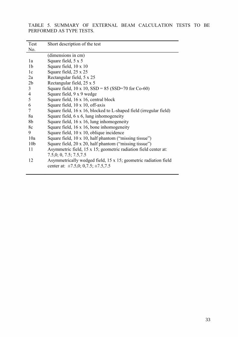
TABLE 5. SUMMARY OF EXTERNAL BEAM CALCULATION TESTS TO BE PERFORMED AS TYPE TESTS. Test No.
Short description of the test
(dimensions in cm) 1a Square field, 5 x 5 1b 1c
Square field, 10 x 10 Square field, 25 x 25
2a Rectangular field, 5 x 25 2b Rectangular field, 25 x 5 3 Square field, 10 x 10, SSD = 85 (SSD=70 for Co-60) 4 Square field, 9 x 9 wedge 5 Square field, 16 x 16, central block 6 Square field, 10 x 10, off-axis 7 Square field, 16 x 16, blocked to L-shaped field (irregular field) 8a Square field, 6 x 6, lung inhomogeneity 8b Square field, 16 x 16, lung inhomogeneity 8c Square field, 16 x 16, bone inhomogeneity 9 Square field, 10 x 10, oblique incidence 10a Square field, 10 x 10, half phantom (“missing tissue”) 10b Square field, 20 x 20, half phantom (“missing tissue”) 11 Asymmetric field, 15 x 15; geometric radiation field center at:
7.5,0; 0, 7.5; 7.5,7.5 12 Asymmetrically wedged field, 15 x 15; geometric radiation field
center at: ±7.5,0; 0,7.5; ±7.5,7.5
33

Appendix B
TESTS OF THE ACCURACY OF DOSIMETRIC CALCULATIONS TO BE PERFORMED DURING SITE TESTING
Introductory remarks
The following test cases are a subset of the tests described in Appendix A. The data in the test package for the Co-60 beam are given in terms of dose relative to the dose for a 10 cm x 10 cm field size, 80 cm SSD and 1 cm depth (dref). The data in the test package for 6 MV, 10 MV and 18 MV are expressed in terms of dose (cGy) for an irradiation with 100 MU with the machine calibrated to deliver 1 Gy per 100 MU for 10 cm x 10 cm field size, 100 cm SSD and depth of maximum dose (dmax). The following test cases require the calculation of dose at a range of locations within a rectangular water phantom. The user is advised to begin by defining the treatment planning system a cubic water phantom, 40 cm on each side. Most RTPS allow the entry of calculation points by their coordinates. However, if not, it may be helpful for each test to identify points that will indicate the central axis of the radiation beam, off-axis distances of 1, 2, 2.5, 3, 5, 6, 7, 9 and 19 cm, and calculation depths of dmax,1, 3, 5, 10, 11, 15, 20, 25, 30 and 35 cm depth. In each test case the needed off-axis distances and depth are defined. For each test case, the operator is to position the radiation beam as defined by the test case, and identify calculation points at the requested depths and off-axis distances. A sufficiently large beam weight should be used to ensure adequate precision of the calculated results. In other words, do not use small beam weights if this results in the rounding or truncating of calculated doses to values having a precision of less than 1%. In some treatment planning systems, the beam weight corresponds to the dose delivered by the beam at dmax, while in other systems the beam weight identifies the corresponding dose at dmax in the reference field size (i.e. 10 x 10 cm). Yet other systems may define beam weight in different ways. The user should be familiar with the beam weight definition, and ensure that the calculated results are consistent with the conditions under which the corresponding measured data were obtained. Unless otherwise indicated, the nominal SSD for all test cases is 100 cm for high-energy photon beams from linear accelerators and 80 cm for the Co-60 beam. The package is attached to the report on a separate CD-ROM. The package is divided into four subsets with the input data and results of test measurements for 6 MV, 10 MV, 18 MV and Co-60 beams. When using the package, one should select the appropriate subset, combine the needed input data for the corresponding RTPS, fit the beam model, set up the geometry of the tests and perform the calculations and enter the calculated values into the tables of the evaluation part of the Excel worksheet. The comparison tables should be used by the manufacturer to demonstrate the results of dosimetric accuracy of the calculation type tests to the user.
35
Evaluation of measurements For the evaluation of the measurements and RTPS calculated values, three different approaches may be employed:
- relative error: related to measured dose, i.e. Error1 [%]=100*(Dcal-Dmeas)/Dmeas [Eq. 1]
- relative normalized error: related to dose on axis at the same depth, i.e. Error2 [%]=100*(Dcal-Dmeas)/Dmeas,cax [Eq. 2] - relative normalized error: related to dose in the unblocked beam point at the same depth as when the central axis is blocked i.e. Error3 [%]=100*(Dcal-Dmeas)/Dmeas,open [Eq. 3] The recommended equations for comparison of measured and calculated data and tolerances are given below in Table 6. Note that the recommendations are in line with those from TRS-430.
TABLE 6. SAMPLE CRITERIA OF ACCEPTABILITY FOR EXTERNAL BEAM TPS CALCULATIONS
Description Test numbers Equation
for evaluation
Tolerance [%]
1 Homogeneous, simple geometry Central Axis data of square and rectangular fields Off-axis data
1, 3
1, 3
(1)
2 3
2 Complex geometry (Wedged fields, inhomogeneities, irregular fields) Central and off-axis data
4, 7, 8b, 9
(1)
3
3 4
Outside beam edges In simple geometry In complex geometry (see #2) Outside beam edges Complex geometry with central axis blocked
1, 3
7
(2)
(3)
3 4 3
Coordinate system The following coordinate system is defined relative to the water phantom for clarification of beam data and test case geometry. The phantom coordinate system is consistent with the fixed system defined by IEC 61217.
The origin is at the treatment unit isocenter. For all tests except the isocentric test, the phantom surface is positioned at the isocenter.
36
The Z-axis is perpendicular to the upper surface of the water phantom and directed upward from the phantom. With the exception of the oblique entry test case, the Z-axis coincides with the beam central axis and is directed toward the source. The X-axis is directed to the right of the Z-axis and the X-Z plane is perpendicular to the axis of rotation of the treatment unit. The Y-axis coincides with the treatment unit gantry axis of rotation and is directed toward the gantry. With the exception of test case 9, all calculations are done at points in the X-Z plane (Y = 0).
Test cases The tests 1–9 are from the AAPM TG23. Graphical representation of the test geometries for all tests is given in Appendix D.
1a) 5 cm x 5 cm Open Field Test Case Using the cubic water phantom described earlier, create a 5 cm x 5 cm square field and
position the beam with the central axis normal to and at the center of the upward face of the cubic water phantom. In other words, the gantry angle is 0° and aligned with the phantom Z-axis. The beam central axis should align with any reference marks made when the water phantom was created, to facilitate the positioning of the calculation points. Set a suitable beam weight, and ensure that there are no beam modifiers in the beam (wedges, trays, etc.). Instruct the computer to calculate the dose distribution and report the doses at depths of 1, 3, 5, 10, 15, 20, 25 and 35 cm. Compare the calculated data to the measurements.
Doses should also be calculated at points located 1 cm from the beam central axis. This off-axis distance is intended to place the calculation points approximately midway between the central axis and the field edge. However, all of the calculation points should be located at X = 1 cm; do not use a diverging ray. Additional calculation points should be placed at X = 5 cm off axis. This distance places the calculation points well outside the field edge, in the tail of the penumbra. The doses at these locations will only be a few percent of the doses at the same depths on the central axis.
1b) 10 cm x 10 cm Open Field Test Case
Repeat test case 1a, this time using a 10 cm x 10 cm open field. Note that the calculated dose per MU at dmax should be 1.00 cGy/MU (or, for example, 1.00 Gy/min – for Co-60 beam) if this field corresponds to the calibration reference conditions. The off-axis distances for this test case are 3 cm and 9 cm.
1c) 25 cm x 25 cm Open Field Test Case
Repeat test case 1a, this time using a 25 cm x 25 cm open field. The off-axis distances for this test case are 9 cm and 19 cm.
3) 10 cm x 10 cm Open Field Under Isocentric Conditions
This test simulates an isocentric treatment using a 10 cm x 10 cm field with the isocenter placed at 15 cm depth (10 cm depth for Co-60). The field size is defined at the isocenter. Doses are to be calculated on the central axis, at 2.5 cm off axis and at 7 cm off axis. Note that the calculated dose per MU at dmax should be greater than 1.00 cGy/MU (or for example, 1.00 Gy/min for Co-60 beam) by approximately the inverse square of the change in distance.
37
4) 9 cm x 9 cm Wedge Test Case Calculations are to be performed for a 9 cm x 9 cm field into which a 45-degree wedge has been placed (Co-60 beam). A 60-degree wedge is used for 6 MV, 10 MV and 18 MV beams. The wedge is oriented with the thin end of the wedge toward the left-hand side of the radiation field (the negative X axis). Calculations are to be performed on the central axis, at X = -2.5 cm (to the left of the central axis), and at X = +2.5 cm (to the right of the central axis).
7) Irregular Field Test Case
Doses are to be calculated for an irregular L-shaped field made by removing a 12 cm x 12 cm portion from one corner of a 16 cm x 16 cm open field by means of a tapered alloy block. The calculation plane is orthogonal to one segment of the L and through the beam central axis. In other words, the center of the original 16 cm x 16 cm field is on the Z-axis and the measurement plane is the XZ plane (the open part of the field is on the right, and the calculation points should be at X = +6 cm for Co-60 beam and X=+7 cm for 6 MV, 10 MV and 18 MV beams). Doses are to be calculated on the central axis at the depths defined in test case 1a, under the block. Doses are also to be calculated 6 cm off axis, in the unblocked portion of the field, at the depths defined in test case 1a. Doses are relative to the dose on the central axis of the 10 cm x 10 cm open reference field at the nominal SSD, dmax.
8b) Lung Inhomogeneity Test Case This test case is calculated on the Y = 0 plane of a 16 cm x 16 cm field at the nominal
SSD. A cylinder of lung-equivalent material is to be placed in the water phantom. The lung-equivalent cylinder is 6 cm in diameter and 12 cm long. The long axis of the cylinder is parallel to the surface and to the Y-axis of the phantom, at 8 cm depth, and centered on the beam central axis. The material is muscle-equivalent in composition and has a density of 0.20 g/cm3. Calculations are to be performed on the central axis, at 2 cm off axis and at 5 cm off axis. Calculation depths are 11, 15, 20, 25 and 35 cm. Calculated doses are relative to the dose on the central axis of the 10 cm x 10 cm reference field at the nominal SSD, dmax.
9) Oblique Incidence Test Case
A 10 cm x 10 cm field is to be positioned on the water phantom at a 45 degree angle of incidence. In other words, the isocenter is positioned at the phantom surface, with a gantry angle of 45 degrees. The test will be facilitated if the isocenter is positioned at X = +10 cm, y = 0 cm, and z = 0 cm. Calculations are to be performed at the depths prescribed here, as measured perpendicular to the surface of the phantom (rather than parallel to the beam central axis). Calculation depths are 1, 3, 5, 10, 15 and 20 cm. Calculations should be made on the central axis, at the defined depths. Additional calculations should be performed at the defined depths at 3 cm to the right of the central axis and at 3 cm of the left of the central axis. Off axis distances are measured parallel to the surface (rather than perpendicular to the beam central axis). For example, if as suggested the phantom surface is at isocenter (Z = 0) and the central axis is shifted to the right 10 cm (X = 10 cm, Y = 0 cm), at a depth of 3 cm, the central axis calculation point at 3 cm depth will have the coordinates X = 7 cm, Y = 0, Z = -3 cm. The calculation point at 3 cm depth, and 3 cm off axis to the right will have the coordinates X = 10 cm, Y = 0, Z = -3 cm, while the point at 3 cm off-axis to the left will have the coordinates X = 4 cm, Y = 0, Z = -3 cm.
38
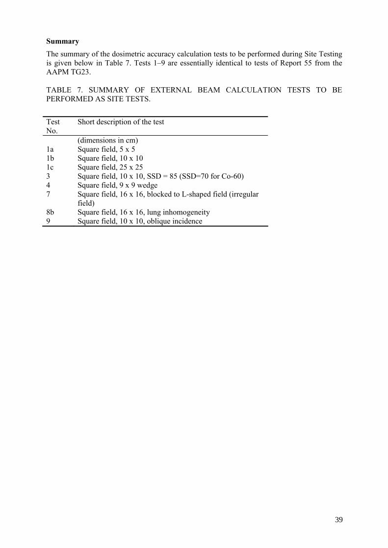
Summary The summary of the dosimetric accuracy calculation tests to be performed during Site Testing is given below in Table 7. Tests 1–9 are essentially identical to tests of Report 55 from the AAPM TG23. TABLE 7. SUMMARY OF EXTERNAL BEAM CALCULATION TESTS TO BE PERFORMED AS SITE TESTS.
Test No.
Short description of the test
(dimensions in cm) 1a Square field, 5 x 5 1b 1c
Square field, 10 x 10 Square field, 25 x 25
3 Square field, 10 x 10, SSD = 85 (SSD=70 for Co-60) 4 7
Square field, 9 x 9 wedge Square field, 16 x 16, blocked to L-shaped field (irregular field)
8b Square field, 16 x 16, lung inhomogeneity 9 Square field, 10 x 10, oblique incidence
39

Appendix C
OPTIONAL TESTS OF THE ACCURACY OF DOSIMETRIC CALCULATIONS TO BE PERFORMED DURING ACCEPTANCE TESTING
Introductory remarks The optional tests described in this section represent site tests that are in addition to the required site tests described in Section 6 and Appendix B. The purchaser and manufacturer/vendor/installer should agree on the specific optional site tests in advance and preferably not at the time of acceptance testing. Optional site-test results should be within the same accuracy as type-test results (agreement should be better than 0.5%). The data in the test package for the Co-60 beam are given in terms of dose relative to the dose for a 10cm x 10 cm field size, 80 cm SSD and 1 cm depth (dref). The data in the test packages for 6 MV, 10 MV and 18 MV are expressed in terms of dose (cGy) for an irradiation with 100 MU with the machines calibrated to deliver 1 Gy per 100 MU for 10cm x 10 cm field size, 100 cm SSD and depth of maximum dose (dmax). The following test cases require the calculation of dose at a range of locations within a rectangular water phantom. The user is advised to begin by defining the treatment planning system, a cubic water phantom, 40 cm on each side. Most RTPS allow the entry of calculation points by their coordinates. However, if not, it may be helpful for each test to identify points that will indicate the central axis of the radiation beam, off-axis distances of 1, 2, 2.5, 3, 5, 6, 7, 9 and 19 cm, and calculation depths of dmax,1, 3, 5, 10, 11, 15, 20, 25, 30 and 35 cm depth. In each test case the needed off-axis distances and depth are defined. For each test case, the operator is to position the radiation beam as defined by the test case, and identify calculation points at the requested depths and off-axis distances. A sufficiently large beam weight should be used to ensure adequate precision of the calculated results. In other words, do not use small beam weights if this results in the rounding or truncating of calculated doses to values having a precision of less than 1%. In some treatment planning systems, the beam weight corresponds to the dose delivered by the beam at dmax, while in other systems the beam weight identifies the corresponding dose at dmax in the reference field size (i.e. 10 x 10 cm). Yet other systems may define beam weight in different ways. The user should be familiar with the beam weight definition, and ensure that the calculated results are consistent with the conditions under which the corresponding measured data were obtained. Unless otherwise indicated, the SSD for all test cases is 100 cm for high-energy photon beams from linear accelerators and 80 cm for the Co-60 beam. Detailed description of the package with the input data for RTPS and test measurement results are given in the attached Excel file. The package is divided into four subsets with the input data and results of test measurements for 6 MV, 10 MV, 18 MV and Co-60 beams. When using the package one should select the appropriate subset, combine the needed input data for the corresponding RTPS, fit the beam model, set up the geometry of the tests and perform the calculations, enter the calculated values into the tables of the evaluation part of the Excel worksheet. The comparison tables should be used by the manufacturer to demonstrate the results of dosimetric accuracy of the calculation type tests to the user.
41
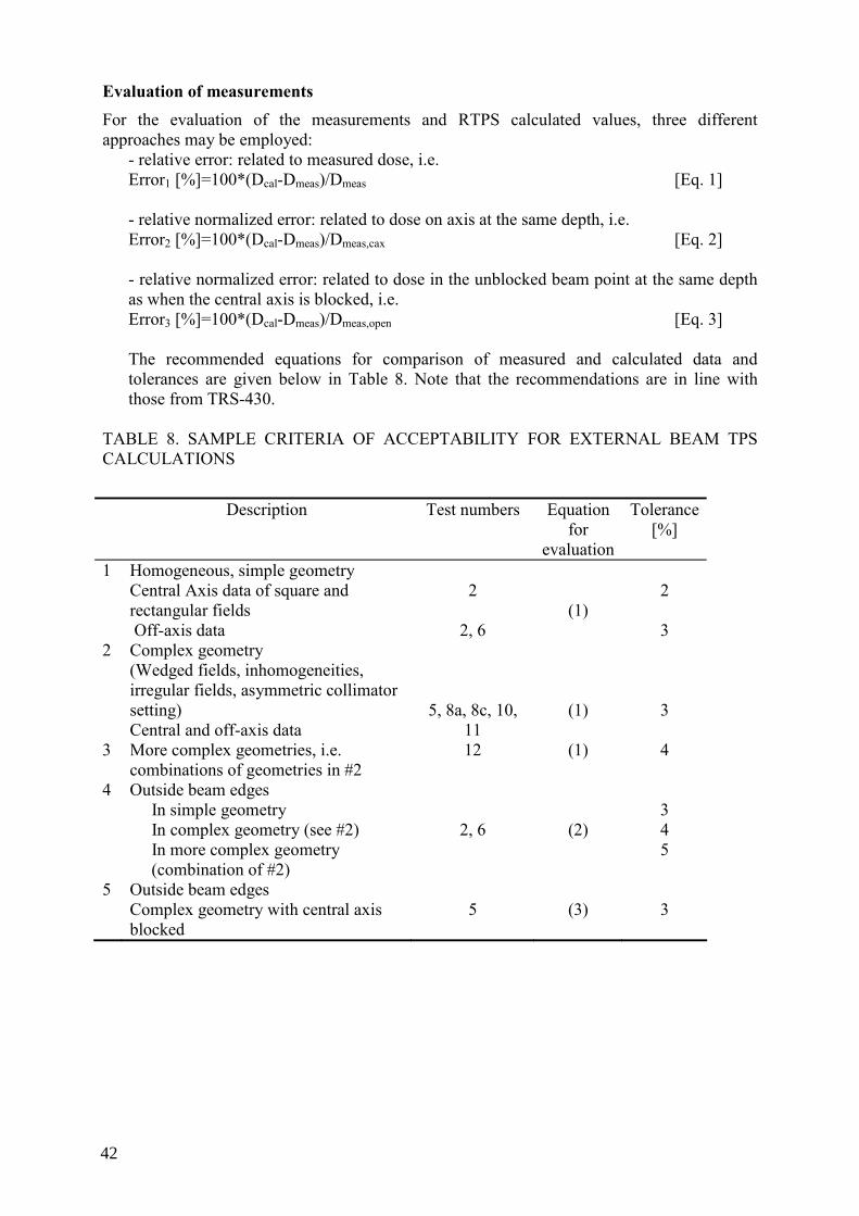
Evaluation of measurements For the evaluation of the measurements and RTPS calculated values, three different approaches may be employed:
- relative error: related to measured dose, i.e. Error1 [%]=100*(Dcal-Dmeas)/Dmeas [Eq. 1]
- relative normalized error: related to dose on axis at the same depth, i.e. Error2 [%]=100*(Dcal-Dmeas)/Dmeas,cax [Eq. 2] - relative normalized error: related to dose in the unblocked beam point at the same depth as when the central axis is blocked, i.e. Error3 [%]=100*(Dcal-Dmeas)/Dmeas,open [Eq. 3] The recommended equations for comparison of measured and calculated data and tolerances are given below in Table 8. Note that the recommendations are in line with those from TRS-430.
TABLE 8. SAMPLE CRITERIA OF ACCEPTABILITY FOR EXTERNAL BEAM TPS CALCULATIONS
Description Test numbers Equation
for evaluation
Tolerance [%]
1 Homogeneous, simple geometry Central Axis data of square and rectangular fields Off-axis data
2
2, 6
(1)
2 3
2 Complex geometry (Wedged fields, inhomogeneities, irregular fields, asymmetric collimator setting) Central and off-axis data
5, 8a, 8c, 10, 11
(1)
3
3 More complex geometries, i.e. combinations of geometries in #2
12 (1) 4
4 Outside beam edges In simple geometry In complex geometry (see #2) In more complex geometry (combination of #2)
2, 6
(2)
3 4 5
5 Outside beam edges Complex geometry with central axis blocked
5
(3)
3
42
Coordinate system The following coordinate system is defined relative to the water phantom for clarification of beam data and test case geometry. The phantom coordinate system is consistent with the fixed system defined by IEC 61217:
The origin is at the treatment unit isocenter. For all tests except the isocentric test, the phantom surface is positioned at the isocenter. The Z-axis is perpendicular to the upper surface of the water phantom and directed upward from the phantom. With the exception of the oblique entry test case, the Z-axis coincides with the beam central axis and is directed toward the source. The X-axis is directed to the right of the Z-axis and the X-Z plane is perpendicular to the axis of rotation of the treatment unit. The Y-axis coincides with the treatment unit gantry axis of rotation and is directed toward the gantry. With the exception of test case 9, all calculations are done at points in the X-Z plane (Y = 0).
Dose rate should also be calculated at points located 1 cm from the beam central axis.
Test cases The tests 2–9 are from the AAPM TG23, and the tests10–12 form the extension of the AAPM TG23 test package. Graphical representation of the test geometries for all tests is given in Appendix D.
2a) 5 cm x 25 cm Open Field Test Case
This test is designed to evaluate the performance of the treatment planning system when calculating in an elongated field. The smaller field dimension is aligned with the patient’s transverse axis (the X-axis) while the longer field dimension is aligned with the patient’s longitudinal axis (the Y-axis). Calculation should be performed as described in test case 1a, on the central axis, at 1 cm off axis, and at 5 cm off axis. The off-axis measurements are in the direction of the smaller field dimension, so that the 5 cm off-axis points fall outside the field edge.
2b) 25 cm x 5 cm Open Field Test Case
This test case also evaluates the performance of the treatment planning system for elongated fields. However, in this test case the longer dimension field dimension is aligned with the patient’s transverse axis (X-axis). Calculations are to be made on the central axis, at 9 cm off axis, and at 19 cm off axis.
5) Central Block Test Case
This test case evaluates the performance of the treatment planning system in determining doses under a narrow block. Set a 16 cm x 16 cm field at the nominal SSD that is modified by including an untapered (rectangular) alloy shielding block 1 cm wide, 6 cm thick and 4 cm long (physical size). The block is mounted on a standard plastic tray (source to tray distance 54.5 cm) and centered on the beam axis . The long dimension (4 cm) is orthogonal to the calculation plane (i.e. aligned with the Y axis). Test cases for 6 MV, 10 MV and 18 MV beams were performed with the block 2 cm wide , 7 cm long (projected size at the isocenter) and 8 cm thick.
43
Calculations are to be performed at points on the central axis and at 4 cm off-axis distance.
6) Off Center Plane Test Case Doses are to be calculated at locations in an off-center plane separated by 4 cm (Y = 4 cm)
from the central plane of a 10 cm x 10 cm field at the nominal SSD. Doses are all relative to the dose on the central axis of the 10 cm x 10 cm reference field at the nominal SSD, dmax. Doses are to be calculated at the depths defined in test case 1a, but in the off-center plane. Therefore, dose rates are to be calculated for values of Y = +4 cm and for X = 0 cm, 3 cm, and 8 cm, for the depths defined earlier.
8a) Lung Inhomogeneity Test Case This test case is calculated only for 6, 10 and 18 MV photons beams on the Y = 0 plane of
a 6 cm x 6 cm field at 100 cm SSD. A cylinder of lung-equivalent material is to be placed in the water phantom. The lung-equivalent cylinder is 6 cm in diameter and 12 cm long. The long axis of the cylinder is parallel to the surface and to the Y-axis of the phantom, at 8 cm depth, and centered on the beam central axis. The material is muscle-equivalent in composition and has a density of 0.20 g/cm3. Calculations are to be performed on the central axis, at 2 cm off axis and at 5 cm off axis. Calculation depths are 11, 15, 20, 25 and 35 cm. Calculated doses are relative to the dose on the central axis of the 10 cm x 10 cm reference field at 100 cm SSD, dmax.
8c) Bone Inhomogeneity Test Case
This test case is calculated on the central plane of a 16 cm x 16 cm field at 100 cm SSD. A cylinder of bone-equivalent material is to be placed in the water phantom. The bone-equivalent cylinder is 2 cm in diameter and 12 cm long. The long axis of the cylinder is parallel to the surface and to the Y-axis of the phantom, at 6 cm depth, and centered on the beam central axis. The material is bone-equivalent in composition and has a density of 1.8 g/cm3. Calculations are to be performed on the central axis, at 2 cm off axis and at 4 cm off axis. Calculation depths are 7.5, 8.0, 10.0, 20.0, 25.0 and 35.0 cm. Calculated doses are relative to the dose rate on the central axis of the 10 cm x 10 cm reference field at the nominal SSD, dmax.
10ab) Missing Tissue Test Case
In this test case two fields were used with field sizes of 10 cm x 10 cm and 20 cm x 20 cm. The central axis coincides with the side of the phantom. Only half of the beam hits the phantom. Points were at 1.0 cm, 2.5 cm and 4.0 cm from the phantom side wall for the smaller field, and at 1.0 cm, 5.0 cm and 9.0 cm from the phantom side wall in the larger field.
11) Asymmetric open half and quarter fields.
This test case uses an open field of 15 cm x 15 cm. The central beam axis is set first at the symmetrical position (0.0), and subsequently shifted to position (0 cm, +7.5 cm); (+7.5 cm, 0 cm); and (+7.5 cm, +7.5 cm) from the collimator rotation axis. Calculation points are used at +6.0 cm, 0.0 cm and –6.0 cm from the field center.
12) Asymmetric open half and quarter wedged fields.
This test case uses an open field of 15 cm x 15 cm with a 60 degree wedge. The central beam axis is set first at the symmetrical position (0,0), and subsequently shifted to position (0 cm, +7.5 cm); (+7.5 cm, 0 cm); and (+7.5 cm,+7.5 cm) from the collimator rotation axis. Calculation points are used at +6.0 cm, 0.0 cm and –6.0 cm from the field center.
44
Summary
The summary of the dosimetric accuracy calculation optional tests to be performed during acceptance testing is given below in Table 9. TABLE 9. SUMMARY OF EXTERNAL BEAM CALCULATION TESTS TO BE PERFORMED AS OPTIONAL TESTS.
Test No.
Short description of the test
(dimensions in cm) 2a Rectangular field, 5 x 25 2b Rectangular field, 25 x 5 5 Square field, 16 x 16, central block 6 Square field, 10 x 10, off-axis 8a Square field, 6 x 6, lung inhomogeneity 8c Square field, 16 x 16, bone inhomogeneity 10a Square field, 10 x 10, half phantom (“missing tissue”) 10b Square field, 20 x 20, half phantom (“missing tissue”) 11 Asymmetric field, 15 x 15; geometric radiation field center at:
7.5,0; 0, 7.5; 7.5,7.5 12 Asymmetrically wedged field, 15 x 15; geometric radiation
field center at: ±7.5,0; 0,7.5; ±7.5,7.5
45

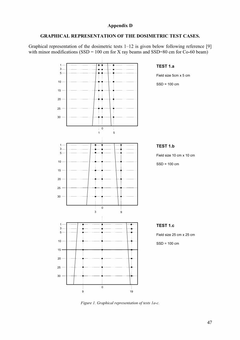
Appendix D
GRAPHICAL REPRESENTATION OF THE DOSIMETRIC TEST CASES.
Graphical representation of the dosimetric tests 1–12 is given below following reference [9] with minor modifications (SSD = 100 cm for X ray beams and SSD=80 cm for Co-60 beam)
TEST 1.a
Field size 5cm x 5 cm
SSD = 100 cm
TEST 1.b
Field size 10 cm x 10 cm
SSD = 100 cm
TEST 1.c
Field size 25 cm x 25 cm
SSD = 100 cm
135
10
15
20
25
30
1 5
135
10
15
20
25
30
3 9
135
10
15
20
25
30
9 19
0
0
0
Figure 1. Graphical representation of tests 1a-c.
47
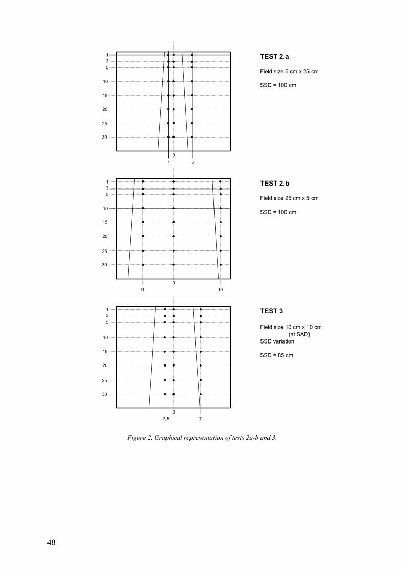
TEST 2.a
Field size 5 cm x 25 cm
SSD = 100 cm
TEST 2.b
Field size 25 cm x 5 cm
SSD = 100 cm
TEST 3
Field size 10 cm x 10 cm(at SAD)
SSD variation
SSD = 85 cm
135
10
15
20
25
30
1 5
135
10
15
20
25
30
2,5 7
135
10
15
20
25
30
9 19
0
0
0
Figure 2. Graphical representation of tests 2a-b and 3.
48
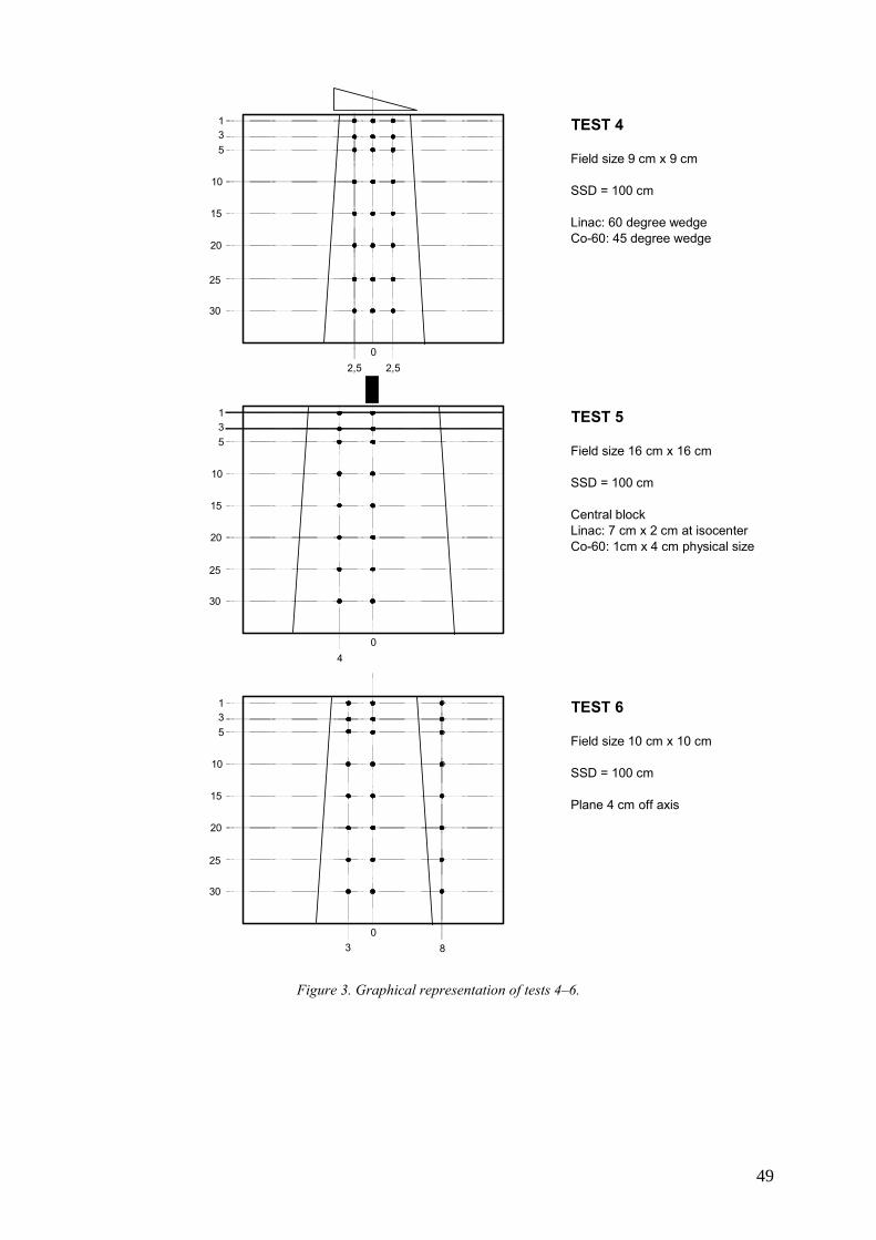
TEST 4
Field size 9 cm x 9 cm
SSD = 100 cm
Linac: 60 degree wedgeCo-60: 45 degree wedge
TEST 5
Field size 16 cm x 16 cm
SSD = 100 cm
Central blockLinac: 7 cm x 2 cm at isocenterCo-60: 1cm x 4 cm physical size
TEST 6
Field size 10 cm x 10 cm
SSD = 100 cm
Plane 4 cm off axis
135
10
15
20
25
30
2,50
2,5
135
10
15
20
25
30
40
135
10
15
20
25
30
3 80
Figure 3. Graphical representation of tests 4–6.
49
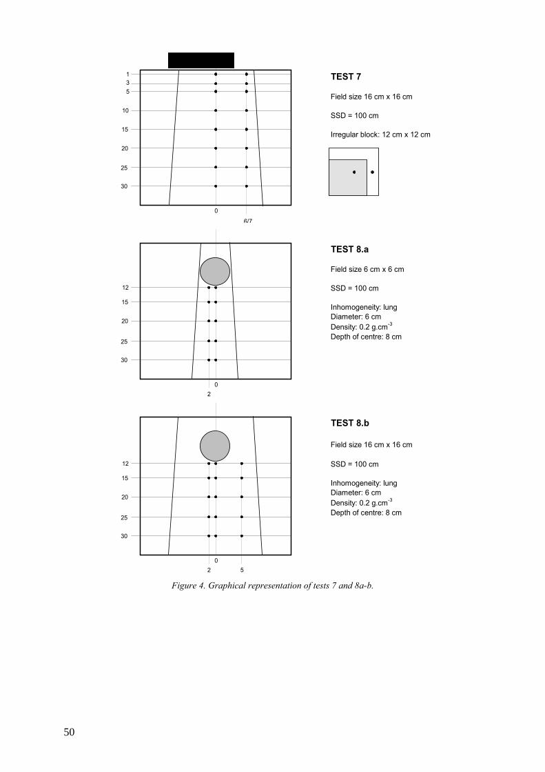
TEST 7
Field size 16 cm x 16 cm
SSD = 100 cm
Irregular block: 12 cm x 12 cm
TEST 8.a
Field size 6 cm x 6 cm
SSD = 100 cm
Inhomogeneity: lungDiameter: 6 cmDensity: 0.2 g.cm-3
Depth of centre: 8 cm
TEST 8.b
Field size 16 cm x 16 cm
SSD = 100 cm
Inhomogeneity: lungDiameter: 6 cmDensity: 0.2 g.cm-3
Depth of centre: 8 cm
135
10
15
20
25
30
6/7
0
12
15
20
25
30
20
12
15
20
25
30
20
5 Figure 4. Graphical representation of tests 7 and 8a-b.
50
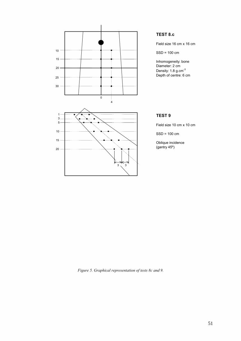
TEST 8.c
Field size 16 cm x 16 cm
SSD = 100 cm
Inhomogeneity: boneDiameter: 2 cmDensity: 1.8 g.cm-3
Depth of centre: 6 cm
TEST 9
Field size 10 cm x 10 cm
SSD = 100 cm
Oblique incidence(gantry 45º)
10
15
20
25
30
04
135
10
15
20
3 3
Figure 5. Graphical representation of tests 8c and 9.
51
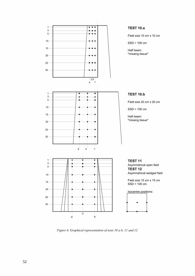
TEST 10.a
Field size 10 cm x 10 cm
SSD = 100 cm
Half beam:"missing tissue"
TEST 10.b
Field size 20 cm x 20 cm
SSD = 100 cm
Half beam:"missing tissue"
TEST 11Asymmetrical open fieldTEST 12Asymmetrical wedged field
Field size 15 cm x 15 cmSSD = 100 cm
Isocentre positions:
135
10
15
20
25
30
4 12.5
135
10
15
20
25
30
9 15
135
10
15
20
25
30
60
-6
Figure 6. Graphical representation of tests 10 a-b, 11 and 12.
52
REFERENCES
[1] FRAASS B., DOPPKE K., HUNT M., KUTCHER G., STARKSCHALL G., STERN
R., VAN DYK J., American Association of Physicists in Medicine Radiation Therapy Committee Task Group 53: quality assurance for clinical radiotherapy treatment planning, Med. Phys. 25 (1998) 1773–1829.
[2] INTERNATIONAL ATOMIC ENERGY AGENCY, Commissioning and Quality Assurance of Computerized Planning Systems for Radiation Treatment of Cancer, Technical Reports Series No. 430, IAEA, Vienna (2004).
[3] EUROPEAN SOCIETY OF THERAPEUTIC RADIATION ONCOLOGY, Quality assurance of treatment planning systems, practical examples for non-IMRT photon beams, ESTRO, (2004).
[4] NETHERLANDS COMMISSION ON RADIATION DOSIMETRY, Quality assurance of 3-D treatment planning systems for external photon and electron beams: practical guidelines for initial verification and periodic quality control of radiation therapy treatment planning systems, NCS, Delft (2006).
[5] INTERNATIONAL ELECTROTECHNICAL COMMISSION, Medical electrical equipment – Requirements for the safety of radiotherapy treatment planning systems, Rep. IEC 62083, IEC, Geneva (2000).
[6] INTERNATIONAL ATOMIC ENERGY AGENCY, Development of Procedures for Quality Assurance for Dosimetry Calculations in Radiotherapy, Report of IAEA Consultants Meeting, IAEA, Vienna, 13–18 October 2003.
[7] INTERNATIONAL ELECTROTECHNICAL COMMISSION, Medical radiology — Terminology, Rep. IEC 60788, IEC, Geneva (1984).
[8] AMERICAN ASSOCIATION OF PHYSICISTS IN MEDICINE, Radiation Therapy Committee Task Group 23, Radiation treatment planning verification, Rep. AAPM 55, AAPM (1995).
[9] VENSELAAR J., WELLEWEERD H., Application of a test package in an intercomparison of the photon dose calculation performance of treatment planning systems used in a clinical setting, Radiother. Oncol. 60 (2001) 203–213.
[10] INTERNATIONAL COMMISSION ON RADIOLOGICAL UNITS AND MEASUREMENTS, Use of computers in external beam radiotherapy procedures with high-energy photons and electrons, Rep. 42, ICRU, Bethesda, MD (1987).
[11] INTERNATIONAL ELECTROTECHNICAL COMMISSION, Radiotherapy Equipment - Co-ordinates, Movements and Scales, Rep. IEC 61217, IEC, Geneva (1996).
[12] INTERNATIONAL ELECTROTECHNICAL COMMISSION, General requirements for safety 4. Collateral standard: Programmable electrical systems, Rep. IEC 60601-1-4 Part 1, IEC, Geneva (1996).
53

GLOSSARY∗
ABSORBED DOSE Letter symbol: D. Mean energy imparted by IONIZING RADIATION to matter. ABSORBED DOSE is determined as the quotient of ds by dm , where ds is the mean energy imparted by IONIZING RADIATION to matter of mass dm :
D =dsdm
The unit of ABSORBED DOSE is the joule per kilogram ( J ⋅ kg−1 ). The special name of the unit of ABSORBED DOSE is the gray (Gy). The earlier unit of ABSORBED DOSE was the rad, 1 rad being equal to 10−2 J ⋅ kg−1 .
ABSORBED DOSE RATE Letter symbol: &D . ABSORBED DOSE per unit time. ABSORBED DOSE RATE is determined as the quotient of dD by dt , where dD is the increment of ABSORBED DOSE in the time interval dt :
&D =
dDdt
A unit of ABSORBED DOSE RATE is any quotient of the gray or its multiples or submultiples by a suitable unit of time ( Gy ⋅ s−1 , mGy ⋅h−1 , etc.).
ACCESSORY Optional component necessary and/or suitable to be used with EQUIPMENT in order to enable, facilitate or improve the intended use of EQUIPMENT or to integrate additional functions.
ACCOMPANYING DOCUMENTS Documents provided with an installation, EQUIPMENT, ASSOCIATED EQUIPMENT or ACCESSORY and containing important information for the assembler, installer and USER, particularly regarding SAFETY.
ACTIVITY Letter symbol: A. Quantitative indication of the RADIOACTIVITY of an amount of RADIONUCLIDE in a particular energy state at a given time. ACTIVITY is determined as the quotient of dN by dt, where dN is the expectation value of the number of spontaneous nuclear transitions from that energy state in the time interval dt:
A =dNdt
The unit of ACTIVITY is the reciprocal second (s-1). The special name of the unit of ACTIVITY is the Becquerel (Bq), 1Bq being equal to one transition per second.
ANATOMY MODELLING See patient anatomy odeling
ASSOCIATED EQUIPMENT In a RADIOLOGICAL INSTALLATION, EQUIPMENT other than those for the production and control of ionizing radiation, but essential for its application.
BEAM APPLICATOR In MEDICAL RADIOLOGY, device usually attached to the RADIATION SOURCE ASSEMBLY performing at least one of the following functions:
• To indicate the RADIATION BEAM AXIS; • To indicate the RADIATION FIELD; • To ensure a minimum distance from the RADIATION SOURCE to the ENTRANCE SURFACE; • To serve as a compression device.
Note 1. A BEAM APPLICATOR may include protective shielding and serve as a beam limiting device. Note 2. As BEAM APPLICATORS may be mentioned: pointing APPLICATOR, open-ended APPLICATOR, dental BEAM APPLICATOR, therapeutic BEAM APPLICATOR.
BEAM LIMITING DEVICE (BLD) Device to limit the RADIATION FIELD.
∗ Copyright © 2000, IEC, Geneva, Switzerland. www.iec.ch
55
BRACHYTHERAPY INTRACAVITARY, INTERSTITIAL, SUPERFICIAL or INTRALUMINAL RADIOTHERAPY using one or more SEALED RADIOACTIVE SOURCES.
BRACHYTHERAPY SOURCE MODEL/BRACHYTHERAPY SOURCE MODELLING All physical, geometric and RADIATION parameters required to plan a course of RADIOTHERAPY for a particular BRACHYTHERAPY RADIOACTIVE SOURCE. The process of establishing the BRACHYTHERAPY SOURCE MODEL is referred to as “BRACHYTHERAPY SOURCE MODELLING”
COMPUTED TOMOGRAPHY (CT) Reconstructive tomography in which recording and processing is effected by a computing system.
DEPTH DOSE ABSORBED DOSE at a specified depth beneath the entrance surface of the irradiated object, usually on the radiation beam axis.
DIGITALLY RECONSTRUCTED RADIOGRAPH (DRR) An image calculated from patient images (typically a CT set) that looks like a diagnostic or megavoltage film obtained for the same geometry of beam and patient. DISPLAY
Visual presentation of information. DOSE MONITOR UNIT
In a DOSE MONITORING SYSTEM, arbitrary unit in which a quantity is displayed and from which ABSORBED DOSE can be calculated.
DOSE-VOLUME HISTOGRAM (DVH)∗∗ A histogram showing the number of voxels (i.e. volume or relative volume) of a structure that receives a given dose. This type of DVH is often known as a differential DVH. A cumulative (or integral)DVH is a histogram showing the number of voxels (i.e. volume or relative volume) of a structure that receives more than or equal to a given dose.
DRR See DIGITALLY RECONSTRUCTED RADIOGRAPH.
DVH See DOSE-VOLUME HISTOGRAM.
ELECTROMAGNETIC COMPATIBILITY The ability of an EQUIPMENT or system to function satisfactorily in its electromagnetic environment without introducing intolerable electromagnetic disturbances to anything in that environment.
ELECTRON ACCELERATOR See PARTICLE ACCELERATOR.
ELECTRON Stable elementary particle having an electric charge of ± 1.60219 x 10⁻¹⁹ C and a rest mass of 9.10956 x 10⁻³¹ kg.
EQUIPMENT (MEDICAL ELECTRICAL EQUIPMENT) Electrical EQUIPMENT, provided with not more than one connection to a particular supply mains and intended to diagnose, treat, or monitor the PATIENT under medical supervision and which makes physical or electrical contact with the PATIENT and/or transfers energy to or from the patient and/or detects such energy transfer to or from the patient. The EQUIPMENT includes those accessories as defined by the MANUFACTURER which are necessary to enable the NORMAL USE of the EQUIPMENT.
EQUIPMENT MODEL/EQUIPMENT MODELLING All physical, geometric and RADIATION parameters required to plan a course of RADIOTHERAPY for particular EQUIPMENT. The process of establishing the EQUIPMENT MODEL is referred to as “EQUIPMENT MODELLING”.
GANTRY That part of the EQUIPMENT supporting the RADIATION HEAD.
HARM Physical injury or damage to the health of people, or damage to property or the environment.
HAZARD/SAFETY HAZARD Potential source of HARM.
INFORMATION TECHNOLOGY EQUIPMENT (ITE) EQUIPMENT designed for the purpose of: (a) (receiving data from an external source (such as a data input line or via a keyboard); (b) performing some processing functions on the received data (such as computation, data
transformation or recording, filing, sorting, storage, transfer of data); ∗∗Definitions were taken from TRS 430, published by the IAEA
56

(c) providing a data output (either to other EQUIPMENT or by the reproduction of data or images.) INSTRUCTIONS FOR USE
Those parts of ACCOMPANYING DOCUMENTS giving the necessary information for safe and proper use and operation of the EQUIPMENT.
INTERLOCK Device preventing the start or the continued operation of EQUIPMENT unless certain predetermined conditions prevail.
IONIZING RADIATION Radiation consisting of directly or indirectly ionizing particles or a mixture of both. By convention, ultraviolet radiation is excluded.
IRRADIATION Exposing of a living being or matter to radiation. In RADIOLOGY, exposing of a living being or matter to IONIZING RADIATION.
IRRADIATION TIME Duration of an IRRADIATION determined according to specific methods, usually the time a rate of a RADIATION QUANTITY exceeds a specified level.
MANUFACTURER Organization or individual who produces an EQUIPMENT.
MEDICAL ELECTRICAL EQUIPMENT (EQUIPMENT) Electrical EQUIPMENT, provided with not more than one connection to a particular supply mains and intended to diagnose, treat, or monitor the PATIENT under medical supervision and which makes physical or electrical contact with the PATIENT and/or transfers energy to or from the patient and/or detects such energy transfer to or from the patient. The EQUIPMENT includes those accessories as defined by the MANUFACTURER which are necessary to enable the NORMAL USE of the EQUIPMENT.
NOMINAL ENERGY For ELECTRON radiation, energy stated by the MANUFACTURER to characterize the RADIATION BEAM. This energy is approximately equal to the most probably energy at the surface of the measuring phantom, Ep,0 . For x radiation, the energy stated by the MANUFACTURER to characterize the RADIATION BEAM.
NORMAL USE Use and operation, as well as transport and storage between periods of use, according to the INSTRUCTIONS FOR USE or for the obvious intended purpose.
OPERATOR Person utilizing an EQUIPMENT individually with or without the aid of an assistant, who controls some or all functions of the EQUIPMENT in his presence.
PARTICLE ACCELERATOR Equipment for accelerating charged particles such as electrons, protons, deuterons and alpha particles to kinetic energies higher than corresponding to the voltage applied.
PASSWORD For EQUIPMENT under the control of a PROGRAMMABLE ELECTRONIC SYSTEM, sequence of keystrokes that permits OERATOR access for NORMAL USE or to reset INTERLOCKS and, with a different sequence of keystrokes, permits access for adjustment and maintenance.
PATIENT Living being (person or animal) undergoing medical or dental investigation or TREATMENT.
PATIENT ANATOMY MODEL/ANATOMY MODELLING All physical and anatomical parameters required to plan a course of RADIOTHERAPY for a particular PATIENT. The process of establishing the PATIENT ANATOMY MODEL is referred to as "ANATOMY MODELLING"
PENUMBRA In RADIOLOGY, spatial region around the RADIATION BEAM where the value of radiation flux is between two specified or specific fractions of the value that is measured in the RADIATION BEAM AXIS, these two values being measured in a same cross-section.
PROGRAMMABLE ELECTRONIC SYSTEM Term used to cover systems incorporating a wide range of programmable devices including microprocessors, programmable controllers, programmable logic controllers and other computer based devices. These devices may contain one or more central processing units connected to sensors and/or actuators, for the purpose of control protection or monitoring.
QUALIFIED PERSON Person competent in any relevant discipline by virtue of his training, knowledge and experience to perform required duties.
57
RADIATION Propagation of emitted energy through space or through a material medium in the form of waves or in the form of kinetic energy of particles.
RADIATION BEAM In RADIOLOGY, spatial region limited in solid angle and containing a flux of IONIZING RADIATION originating from a RADIATION SOURCE that is considered as a POINT SOURCE. Leakage radiation and SCATTERED RADIATION are considered not to form a RADIATION BEAM.
RADIATION ENERGY In RADIOLOGY, quantity indicating the energy that a photon or other particle is carrying, except its rest energy. The unit of RADIATION ENERGY is the electron volt (eV), 1 eV being equal to 1.60219 x 10⁻¹⁹ J.
RADIATION FIELD Area on a surface intersected by a RADIATION BEAM within which the radiation intensity exceeds a specific or specified level.
RADIATION HEAD Structure from which the RADIATION BEAM emerges.
RADIATION QUALITY Characteristic of IONIZING RADIATION determined by the spectral distribution of a RADIATION QUANTITY with respect to RADIATION ENERGY.
RADIATION QUANTITY Letter symbol: Φ . At a given point of space, the number dN of particles incident during a given time interval on a suitably small sphere centred at that point divided by the cross-sectional area da of the sphere.
Φ =dNda
RADIATION SOURCE Radioactive source or part of EQUIPMENT capable of emitting IONIZING RADIATION.
RADIOACTIVE HALF LIFE Letter symbol: T. For a single radioactive decay process, the time required for the ACTIVITY to decrease to half its value.
RADIOACTIVE SOURCE Quantity of radioactive material having both an ACTIVITY and a specific ACTIVITY above specific levels.
RADIOGRAM In RADIOLOGY, record of an X ray pattern.
RADIOLOGY Science of IONIZING RADIATION and its application.
RADIONUCLIDE Radioactive nuclide.
RADIOTHERAPY Medical therapy essentially consisting of one or more TREATMENTS by IONIZING RADIATION.
RADIOTHERAPY TREATMENT PLANNING SYSTEM (RTPS) A device, usually a PROGRAMMABLE ELECTRONIC SYSTEM including its associated peripherals, that is used to simulate the application of radiation to a PATIENT for a proposed RADIOTHERAPY TREATMENT. It usually, but not necessarily, provides estimations of ABSORBED DOSE distribution in human tissue using a particular algorithm or algorithms. These algorithms provide simulations of radiation that is typically from, but not necessarily limited to, medical ELECTRON accelerators, gamma beam therapy EQUIPMENT or RADIOACTIVE SOURCES when brachytherapy is planned.
RISK Combination of the probability of occurrence of HARM and the severity of that HARM.
RISK MANAGEMENT Systematic application of management policies, procedures and practices to the tasks of analyzing, evaluating and controlling RISK.
RISK MANAGEMENT FILE Set of records and other documents, not necessarily contiguous, that are produced by a RISK MANAGEMENT process.
SAFETY Freedom from unacceptable RISK.
SAFETY HAZARD (HAZARD) Potential source of HARM.
58
SCATTERED RADIATION IONIZING RADIATION emitted by the interaction of IONIZING RADIATION with matter, the interaction being accompanied by a reduction in RADIATION ENERGY and/or a change in direction of the RADIATION.
SITE TEST After installation, test of an individual device or equipment to establish compliance with specified criteria. Note: The recommended replacement is acceptance test.
SPECIFIC When used in combination with parameters or conditions: referring to a particular value or standardized arrangement, usually to those required in an IEC standard or a legal requirement.
SPECIFIED When used in combination with parameters or conditions: referring to a value or arrangement to be chosen for the purpose under consideration and indicated usually in ACCOMPANYING DOCUMENTS.
TARGET VOLUME In RADIOTHERAPY, region in the PATIENT, to which it is desired to deliver an ABSORBED DOSE.
TPS See RADIOTHERAPY TREATMENT PLANNING SYSTEM (RTPS)
TRANSMISSION In RADIOLOGY, passage of IONIZING RADIATION through, and emergence from, matter, essentially in the direction of its incidence, without or after interaction with that matter.
TRANSMISSION RATIO Ratio of the value of a SPECIFIED RADIATION QUANTITY in the centre of a beam of SPECIFIED RADIATION QUALITY and under specified geometrical conditions after passage through a material to the value which would be present at the same position without this material in the beam.
TREATMENT The application of a prescribed procedure, or a part thereof, for therapeutic purposes.
TREATMENT PLAN/TREATMENT PLANNING All PATIENT and dosimetric information that is intended for use by appropriately qualified persons for the purpose of prescribing or administering RADIOTHERAPY TREATMENT. A TREATMENT PLAN includes information transmitted to other EQUIPMENT for which the use of the information for prescribing or administering IRRADIATION is indirect. A printed or plotted TREATMENT PLAN is referred to as a TREATMENT PLAN report.
TYPE TEST For a particular design of device or equipment, a test by the manufacturer to establish compliance with specified criteria.
USER When used in an IEC standard on electromedical EQUIPMENT, organization or individual responsible for the use and maintenance of the EQUIPMENT.
WEDGE FILTER Filter which effects stepless change in TRANSMISSION over all or a part of the RADIATION FIELD.
59


CONTRIBUTORS TO DRAFTING AND REVIEW
Ibbott, G. MD Anderson Hospital, RPC, United States of America Izewska, J. International Atomic Energy Agency Schmidt, R. University Medical Centre Eppendorf, Germany Shortt, K. International Atomic Energy Agency Van Dyk, J. London Regional Cancer Centre, Canada Vatnitsky, S. International Atomic Energy Agency Welleweerd, J. Utrecht University Medical Centre, Netherlands
Consultants meetings
Vienna, Austria: 14–18 March 2005, 7–12 August 2006
61