Embed Size (px)
Citation preview
Updated date: 2015.02.05 Model: RGB-LE-/ Product code: RB-1001
VL6-CADVD
Specification & Installation
Compatible with Comand APS DVD (manufactured by Siemens/VDO)
also referred to by Mercedes Benz as NTG1
S-class W220, CL-class C215
www.dv
sbg.c
om
car a
udio
& mult
imed
ia sy
stem
2
2. Setup 2.1 DIP switch
2.2 Remote controller
2.3 Power cable wiring diagram
7 8 9
3. Installation
10 11
Contents
1. Before installation 1.1 Main specification
1.2 System diagram
1.3 Components
1.4 Exterior
4 3
5 6
3.1 Installation diagram
3.2 Cautions on installation
3.3 Installation
4. Troubleshooting 13
12
www.dv
sbg.c
om
car a
udio
& mult
imed
ia sy
stem

3
1. Input Spec. (MULTI VIDEO INTERFACE)
-. 2 x CVBS Input (External video source).
-. 1 x CVBS (REAR CAMERA) Input (Rear camera source)
-. 1 x Analog RGB Input (Car commander original monitor output)
-. 1 x Analog RGB Input (Navigation System output)-OPTION
2. Output Spec.
-. 1 x CVBS OUTPUT (Video Out for installing Headrest monitor)
-. 1 x RGB OUTPUT(LCD Operation)
-. 1 x Audio Select OUTPUT (For operating A/V sources – (ex) 12V is come out on V1 port,
when AV1 is chosen.)
3. Power Spec.
- Input Power : 8VDC ~ 18VDC
- Consumption Power : 5WATT, Max
4. Switch Input mode
- NAVI/CVBS1,2 Original MUTE Function : Possible to mute each input by operating Dip S/W
- Possible to switch Input mode with remote control or toggle switch.
- Rear View Camera mode : When to sense rear gear power, be switched to Rear view camera
mode (Impossible to switch to rear mode with Toggle S/W or the Remote control)
1.1 Main Specification
www.dv
sbg.c
om
car a
udio
& mult
imed
ia sy
stem
4
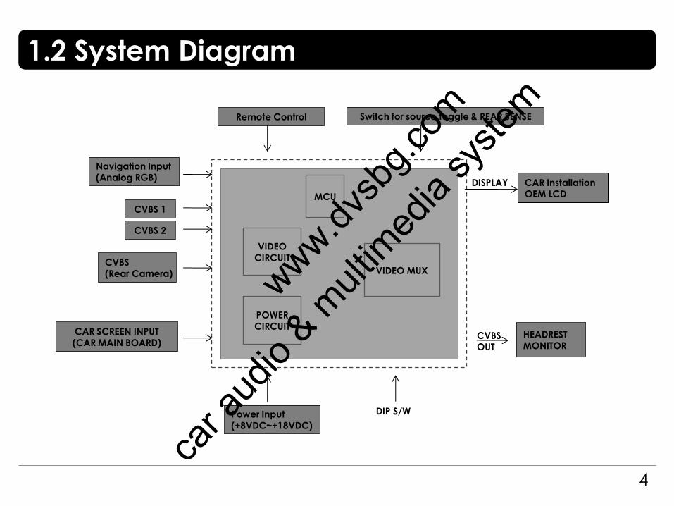
CVBS OUT
HEADREST MONITOR
MCU
VIDEO CIRCUIT
VIDEO MUX
POWER CIRCUIT
CVBS 1
CVBS (Rear Camera)
Power Input (+8VDC~+18VDC)
DIP S/W
Remote Control Switch for source toggle & REAR SENSE
Navigation Input (Analog RGB)
CAR Installation OEM LCD
DISPLAY
CVBS 2
CAR SCREEN INPUT (CAR MAIN BOARD)
1.2 System Diagram
www.dv
sbg.c
om
car a
udio
& mult
imed
ia sy
stem

1.3 Components
5
RGB NAVI cable * 1ea SEL cable * 1ea
(HSELCA0001) (HNAVIC0002)
REMOTE CONTROL * 1ea (REMOTE0001)
IR cable * 1ea POWER cable * 1ea MODE cable * 1ea
(HIRCAB0002) (HARETC0001) (HPOWER0001)
GROUND cable * 1ea
Extension connector * 1ea
FFC cable (28p) * 2ea
ORANGE cable * 1ea
Sub Board * 1ea
(HGROUN0001)
(QCPASS0062)
(FFCABL0001)
(HNAVIC0003)
(SMTASY0074)
www.dvsb
g.com
car a
udio
& mult
imed
ia sy
stem

1.4 Exterior
6
① POWER
② MODE
③ IR
④ V1
⑤ V2
⑥ R/V
⑦ V-OUT
⑧ NAVI (IN)
⑤ ⑥ ⑦
⑧
① ③ ④ ②
⑨ ⑩ ⑪ ⑫ ⑬
⑨ OEM (IN)
⑤ ⑥ ⑦ ① ③ ④ ②
⑧ ⑨ ⑩ ⑪ ⑫ ⑬
⑩ RGB OUT
⑪ DIP S/W
⑫ AUDIO-SEL
⑬ LED
Dimension
Horizontal length 129mm
Vertical length 75mm
Height 21mm
www.dv
sbg.c
om
car a
udio
& mult
imed
ia sy
stem
2.1 DIP switch
7
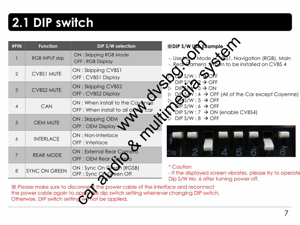
#PIN Function DIP S/W selection
1 RGB INPUT skip ON : Skipping RGB Mode
OFF : RGB Display
2 CVBS1 MUTE ON : Skipping CVBS1
OFF : CVBS1 Display
3 CVBS2 MUTE ON : Skipping CVBS2
OFF : CVBS2 Display
4 CAN ON : When install to the Cayenne
OFF : When install to all of the car
5 OEM MUTE ON : Skipping OEM
OFF : OEM Display
6 INTERLACE ON : Non-Interlace
OFF : Interlace
7 REAR MODE ON : External Rear Camera
OFF : OEM Rear Camera
8 SYNC ON GREEN ON : Sync On Green (RGSB)
OFF : Sync On Green Off
※DIP S/W Use Example
-. Use Input Mode : CVBS1, Navigation (RGB), Main
-. Rear Camera : When to be installed on CVBS 4
▷ DIP S/W : 1 OFF
▷ DIP S/W : 2 OFF
▷ DIP S/W : 3 ON
▷ DIP S/W : 4 OFF (All of the Car except Cayenne)
▷ DIP S/W : 5 OFF
▷ DIP S/W : 6 OFF
▷ DIP S/W : 7 ON (enable CVBS4)
▷ DIP S/W : 8 OFF
* Caution
- If the displayed screen vibrates, please try to operate
Dip S/W No. 6 after turning power off.
※ Please make sure to disconnect the power cable of the interface and reconnect
the power cable again to apply the dip switch setting whenever changing DIP switch.
Otherwise, DIP switch setting will not be applied.
www.dv
sbg.c
om
car a
udio
& mult
imed
ia sy
stem
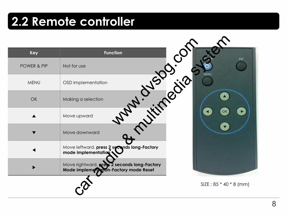
2.2 Remote controller
8
Key Function
POWER & PIP Not for use
MENU OSD implementation
OK Making a selection
▲ Move upward
▼ Move downward
◀ Move leftward, press 2 seconds long-Factory mode implementation
▶ Move rightward, press 2 seconds long-Factory Mode implementation-Factory mode Reset
SIZE : 85 * 40 * 8 (mm)
www.dv
sbg.c
om
car a
udio
& mult
imed
ia sy
stem
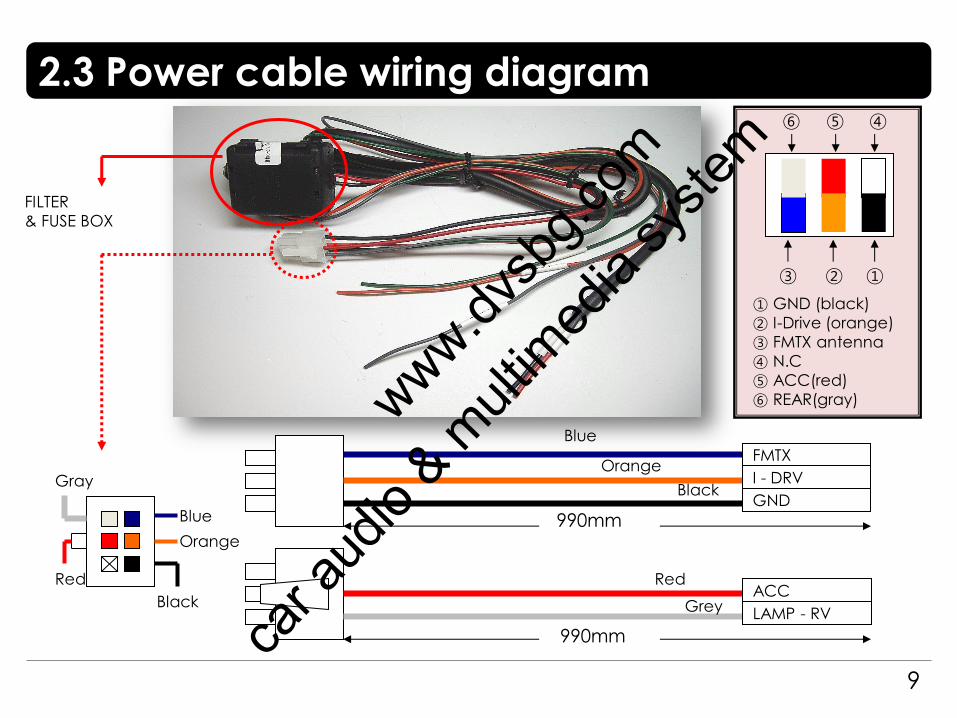
2.3 Power cable wiring diagram
9
I - DRV
GND
LAMP - RV
ACC
990mm
990mm
FILTER
& FUSE BOX
Orange
Black
Red
Grey
Red
Gray
Orange
Black
Blue
FMTX
Blue
① GND (black)
② I-Drive (orange)
③ FMTX antenna
④ N.C
⑤ ACC(red)
⑥ REAR(gray)
⑥ ⑤ ④
③ ② ①
www.dvsb
g.com
car a
udio
& mult
imed
ia sy
stem
10
3.1 Cautions on installation
Ignition key should be taken off before starting installation, interface power connection must be the last step
in installation.
Power cable should be separated when connecting interface.
Should be no any electronic devices or magnetic pole around installation place.
All steps of installation should be done by well-trained specialist.
Dismantling without manufacturer’s permission can not be guaranteed, (No permission to break attached
label on the board.)
Kindly check all parts are in the box, when receiving the product, if anything missing, inform to the supplier or
manufacturer.
According to our sales policy, any problems caused by user’s mistake, careless can not be guaranteed.
It may not work on a camera with 12V
www.dv
sbg.c
om
car a
udio
& mult
imed
ia sy
stem

11
3.2 Installation diagram
LED
POWER
NAVI(I
N)
MODE
RGB CONVERTER(LE)
DIP S/W
IR V1 V2 R/V V-OUT
SEL-OUT RGB(OUT) OEM(IN)
A
V
1
-S
E
L
R
E
A
R
S
E
L
N
A
V
I-
S
E
L R G B
S
y
n
c
G
N
D
B G R
S
Y
N
C
G
N
D
A
C
C
N
.
C
V
i
d
e
o
s
/
w
X
FMTX
GND
LAMP-RV
I-DRV
ACC
※ Please make sure that the installation should be carefully conducted to
avoid from the damage of a monitor by ESD(Electrostatic discharge) and
misalignment while connecting the module of a monitor with cables.
OEM FPC cable
Co
ntro
l Bo
x
MO
NIT
OR
LCD OUT
LCD IN
Offered FFC cable
Offered FFC cable
www.dv
sbg.c
om
car a
udio
& mult
imed
ia sy
stem
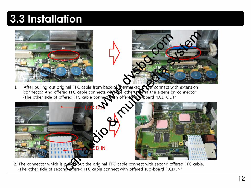
3.3 Installation
12
1. After pulling out original FPC cable from back of the marked place, connect with extension connector. And offered FFC cable connects with the other side of the extension connector.
(The other side of offered FFC cable connect with offered sub-board “LCD OUT”
2. The connector which is pulled out the original FPC cable connect with second offered FFC cable. (The other side of second offered FFC cable connect with offered sub-board “LCD IN”
LCD IN
LCD Out
www.dv
sbg.c
om
car a
udio
& mult
imed
ia sy
stem
3.3 Installation
13
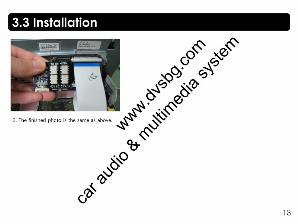
3. The finished photo is the same as above.
www.dv
sbg.c
om
car a
udio
& mult
imed
ia sy
stem
4. Troubleshooting
14
Q. I can not switch A/V sources.
A. Check IR or Ground cable connection. Check LED lamps in the interface, if it is not on, check power cable.
Q. All I got on the screen is black.
A. Check second LED lamp of the interface is on, if not, check A/V sources connected are working well.
(Second lamp indicates AV sources connected works well.) Check interface connection has been done well.
Q. Displayed image color is not proper. (too dim or not suitable color)
A. Try to select “INITIAL” in OSD menu, if it does not work, inform the manufacturer.)
Q. Rear camera image does NOT appear.
A. Set DIP switch #7 in “ON”
Q. Unwanted A/V mode is displayed. (A/V source switching order : OEM->RGB->AV1->AV2->AV3)
A. Check DIP Switch Setting.
Q. OEM image is not displayed.
A. Check interface’s LCD In/Out cable connection. If the status keeps on, inform the manufacturer.
Q. Screen only displays white like left picture.
A. Check LCD out cable is connected well, if this status keeps, inform the manufacturer.
www.dv
sbg.c
om
car a
udio
& mult
imed
ia sy
stem