Embed Size (px)
Citation preview
Hornsby Shire Council
ABN 20 706 996 972 PO Box 37, Hornsby NSW 1630 Phone 02 9847 6666 Email [email protected]
296 Peats Ferry Rd, Hornsby 2077 Fax 02 9847 6999 Web hornsby.nsw.gov.au
SPECIFICATION 1133
PLAIN AND REINFORCED CONCRETE BASE
© AUS-SPEC (Oct 11) July 2016
1133 Plain and Reinforced Concrete Base
© AUS-SPEC (Oct 11) HORNSBY SHIRE COUNCIL
SPECIFICATION 1133 – PLAIN AND REINFORCED CONCRETE BASE
CLAUSE CONTENTS PAGE
GENERAL ............................................................................................................................................................ 1
1.1 RESPONSIBILITIES ............................................................................................................................. 1
1.2 CROSS REFERENCES ........................................................................................................................ 1
1.3 STANDARD ........................................................................................................................................... 2
1.4 INTERPRETATIONS ............................................................................................................................ 2
1.5 SUBMISSIONS ..................................................................................................................................... 2
1.6 INSPECTION ........................................................................................................................................ 3
PRE-CONSTRUCTION PLANNING .................................................................................................................... 6
2.1 ACTIVITY PLAN .................................................................................................................................... 6
2.2 DESIGN AND CONTROL OF MIXES ................................................................................................... 6
2.3 ESTABLISHMENT ................................................................................................................................ 7
MATERIALS ......................................................................................................................................................... 7
3.1 CEMENT ............................................................................................................................................... 7
3.2 FLY ASH ............................................................................................................................................... 8
3.3 WATER ................................................................................................................................................. 8
3.4 ADMIXTURES ....................................................................................................................................... 8
3.5 AGGREGATES ..................................................................................................................................... 8
3.6 STEEL REINFORCEMENT ................................................................................................................ 10
3.7 SEALANTS .......................................................................................................................................... 11
3.8 CURING COMPOUNDS ..................................................................................................................... 11
EXECUTION ....................................................................................................................................................... 12
4.1 PROVISION OF TRAFFIC .................................................................................................................. 12
4.2 ESTABLISHMENT .............................................................................................................................. 12
4.3 CONCRETE QUALITY REQUIREMENTS ......................................................................................... 12
1133 Plain and Reinforced Concrete Base
© AUS-SPEC (Oct 10) HORNSBY SHIRE COUNCIL
4.4 TRIAL CONCRETE BASE .................................................................................................................. 13
4.5 SLAB ANCHORS ................................................................................................................................ 14
4.6 INSTALLATION OF STEEL REINFORCEMENT ................................................................................ 15
4.7 PRODUCTION AND TRANSPORT OF CONCRETE ......................................................................... 16
4.8 PLACING AND FINISHING ................................................................................................................. 17
4.9 JOINTS ................................................................................................................................................ 22
4.10 CURING ............................................................................................................................................. 25
4.11 CONCRETE CRACKING .................................................................................................................... 26
4.12 ACCEPTANCE OF CONCRETE STRENGTH, COMPACTION AND THICKNESS .......................... 26
4.13 REMOVAL AND REPLACEMENT OF BASE ..................................................................................... 29
4.14 LIMITS AND TOLERENCES ............................................................................................................... 30
MEASUREMENT AND PAYMENT .................................................................................................................... 32
5.1 GENERAL ........................................................................................................................................... 32
5.2 DEDUCTIONS..................................................................................................................................... 32
1133 Plain and reinforced concrete base
© AUS-SPEC (Oct 11) 1 HORNSBY SHIRE COUNCIL
1133 PLAIN AND REINFORCED CONCRETE BASE
1 GENERAL
1.1 RESPONSIBILITIES
Objectives General: Provide plain or reinforced concrete base to the dimensions and levels as documented.
Performance Quality: Requirements for quality control and testing, including maximum lot sizes and minimum test frequencies to conform with 0161 Quality (Construction).
1.2 CROSS REFERENCES
General Requirement: Conform to the following:
- 0136 General requirements (Construction).
- 0161 Quality (Construction)
Referenced documents
The following documents are incorporated into this worksection by reference:
Standards AS 1012 Methods of testing concrete AS 1012.1-1993 Sampling of fresh concrete AS 1012.3.1-1998 Determination of properties related to the consistency of concrete -
Slump test AS 1012.4.2-1999 Determination of air content of freshly mixed concrete - Measuring
reduction in air pressure in chamber above concrete AS 1012.8.1-2000 Method for making and curing concrete - Compression and indirect
tensile test specimens AS 1012.9-1999 Determination of the compressive strength of concrete specimens AS 1012.12.2-1998 Determination of mass per unit volume of hardened concrete - Water
displacement method AS 1012.13-1992 Determination of the drying shrinkage of concrete for samples prepared
in the field or in the laboratory AS 1012.14-1991 Method for securing and testing cores from hardened concrete for
compressive strength AS 1141 Methods for sampling and testing aggregates AS 1141.11-1996 Particle size distribution by sieving AS 1141.11.1-2009 Particle size distribution – sieving method AS 1141.14-2007 Particle shape, by proportional calliper AS 1141.18-1996 Crushed particles in coarse aggregate derived from gravel AS 1141.22-2008 Wet/dry strength variation AS 1141.24-1997 Aggregate soundness - Evaluation by exposure to sodium sulphate
solution AS 1160-1996 Bituminous emulsions for the construction and maintenance of pavements AS 1289 Methods of testing soils for engineering purposes AS 1289.4.2.1-1997 Determination of the sulphate content of a natural soil and the sulphate
content of the groundwater - Normal method AS 1379-2007 Specification and supply of concrete AS 1478 Chemical admixtures for concrete, mortar and grout AS 1478.1-2000 Admixtures for concrete AS/NZS 1554 Structural steel welding AS/NZS 1554.3: 2008 Welding of reinforcing steel AS 2350 various Methods of testing portland and blended cements AS 2758 Aggregates and rock for engineering purposes
1133 Plain and reinforced concrete base
© AUS-SPEC (Oct 11) 2 HORNSBY SHIRE COUNCIL
AS 2758.1-1998 Concrete aggregates AS 3582 Supplementary cementitious materials for use with portland and blended
cement AS 3582.1-1998 Fly ash AS 3583 Methods of test for supplementary cementitious materials for use with
portland cement AS 3583.13-1991 Determination of chloride ion content AS 3799-1998 Liquid membrane—forming curing compounds for concrete AS 3972-2010 General purpose and blended cements AS/NZS 4671: 2001 Steel reinforcing materials AS/NZS 4680:2006 Hot-dipped galvanized (zinc) coatings on fabricated ferrous articles SAA HB 155 – 2002 Guide to the use of recycled concrete and masonry materials Other publications AUSTROADS AP-C87-2010 Austroads Glossary of terms AGPT04C – 2009 Guide to Pavement Technology Part 4C: Materials for Concrete Road Pavements
AGPT04E – 2009 Guide to Pavement Technology Part 4E: Recycled Materials AGPT04J – 2008 Guide to Pavement Technology Part 4J: Aggregate and source rock NSW RTA Test Methods
T 1160 - 2001 Low temperature recovery of preformed polychloroprene elastomeric joint seals for bridge structures
T 1161 - 2001 High temperature recovery of polychloroprene elastomeric joint seals for bridge structures
T 1163 - 2001 Resistance of vulcanised rubber to the absorption of oil T 1192 – 2001 Adhesion of sealant T 1193 - 2001 Accelerated Aging of cured sealant ASTM Standards
C793 - 2010 Standard test method for effects of laboratory accelerated weathering on elastomeric joint sealants
C794 - 2010 Standard test method for adhesion-in-peel of elastomeric joint sealants D792 - 2008 Standard test methods for density and specific gravity (relative density) of
plastics by displacement D2240 - 2010 Standard test method for rubber property-durometer hardness D2628 - 2005 Standard specification for preformed polychloroprene elastomeric joint seals
for concrete pavements D2835 - 2007 Standard specification for lubricant for installation of preformed compression
seal in concrete pavements US Military Specifications
SAE AMS-S-8802 2011 Sealing compound, temperature resistant, integral fuel tanks and fuel cell cavities, high adhesion
1.3 STANDARD
General Standard: To AS 1379.
1.4 INTERPRETATIONS
Abbreviations General: For the purposes of this worksection the following abbreviations apply:
- JRCP: Jointed reinforced concrete.
- PCP: Jointed plain concrete.
1.5 SUBMISSIONS
Acceptance criteria General: All submissions will be subject to the approval of the Superintendent.
Documents Submit the following for approval:

1133 Plain and reinforced concrete base
© AUS-SPEC (Oct 11) 3 HORNSBY SHIRE COUNCIL
- Design:
Design and control of concrete mixes to achieve approval of the nominated mix.
Proposed changes to the nominated mix.
. Proposed methods of handling materials and mixing concrete
- Drawings:
. Subbase placement plan: As part of Quality Plan to show placements and daily out-puts.
. Joint details.
. Calculations:
Curing compound: Application rate calculated by test and certified.
Base levels: As derived from design finished levels.
- Execution details:
. Concrete mixing procedures.
. Concrete placing and finishing.
. Trial base.
. Concrete curing and protection.
. Conformity with dimensions and quality.
. Subbase work as executed survey.
. Joint sealant.
. Variation to subbase level.
- Materials: Technical data of materials:
. Cement.
. Flyash.
. Admixtures.
. Water.
. Aggregates.
. Steel reinforcement.
. Sealant.
. Curing compound in rolled concrete.
- Technical data: [complete/delete]
- Warranties: [complete/delete]
Prototype: Trial subbase for incorporation in the work.
Samples: Concrete cylinders for testing.
Type tests: [complete/delete]
- Type test results: [complete/delete]
1.6 INSPECTION
Notice General: Give notice so inspection may be made of the following:
Summary of HOLD POINTS
Clause title / Item Requirement Notice of inspection Release by
Design and control of concrete mixes
- Nominated mixes Details of nominated concrete mix and/or changes to approved mix
28 days before ordering concrete
Superintendent
- Certificates of compliance
Submit NATA certificates of compliance
28 days before ordering concrete
Superintendent
Establishment
- Subbase survey Work as executed survey of the subbase to the full
2 working days prior to commencing any works
Superintendent

1133 Plain and reinforced concrete base
© AUS-SPEC (Oct 11) 4 HORNSBY SHIRE COUNCIL
Clause title / Item Requirement Notice of inspection Release by
extent of the works
- Subbase survey Redesign due to non-conforming levels
2 working days prior to commencing any works
Superintendent
Trial concrete base
- Trial section Construct a trial section to demonstrate capability
At least 5 working days of proceeding with the remaining works
Superintendent
- Trial section Submit test results for trial Within 14 days Superintendent
- Procedure after placement
Review of deficiencies in the trial section or removal
2 working days after carrying out works
Superintendent
- Procedure after placement
If trial section does not conform then reject
At least 5 working days of proceeding with the remaining works
Superintendent
Slab anchors
-General Submit compacted excavated surface
1 working day prior to concreting
Superintendent
Installation of steel reinforcement
- Placing and cover requirements
Approval of placement and fastening of reinforcing steel
Not less than 4 working hours prior to placement of concreting
Superintendent
Production and transport of concrete
- Handling, storing and batching
Proposed methods and equipment for handling, storage, batching materials
Not less than 4 weeks prior to planned commencement of work
Superintendent
Placing and finishing
- Equipment and methods
Submit full details of placing and finishing concrete together with a paving plan
4 weeks before works to commence
Superintendent
- Surface texture Submit details of proposed texturing device and demonstration of method
Before commencement of texturing
Superintendent
Joints
- Permanent sealing Submit method for permanent joint sealing
Not less than 4 weeks prior to planned installation
Superintendent
Removal and replacement of base
- General Method of removal to preserve adjoining base and underlying subbase
Not less then 7 days before works to start
Superintendent
Summary of WITNESS POINTS – Off site activities
Clause/ subclause Requirement Notice of inspection
Design and control of concrete mixes
- Compressive strength Provide test results Within 1 working day of availability
Cement
1133 Plain and reinforced concrete base
© AUS-SPEC (Oct 11) 5 HORNSBY SHIRE COUNCIL
Clause/ subclause Requirement Notice of inspection
- Nominated cement Nominate brand, quality and source
With nominated mix
Flyash
- Nominated flyash Nominate powerhouse source With nominated mix
Admixtures
- Nominated admixture Nominate proprietary source, concentration, type and name. NATA Certificate of Compliance
With nominated mix
Aggregates
- Nominated aggregates Nominate sources and geological type. NATA Test Report on quality and grading
With nominated mix
Steel Reinforcement
- General Compliance with AS/NZS 4671 Before delivering to site
- Bar chairs Demonstrate load bearing conformity
Before delivering to site
Sealants
- Neoprene compression sealants
Submit NATA certificate of compliance for sealant
4 weeks prior to joint work carried out on site
- Silicone sealants Submit NATA certificate of compliance for sealant
4 weeks prior to joint work carried out on site
Curing compound
- General Submit NATA certificate of compliance for compound
4 weeks prior to curing
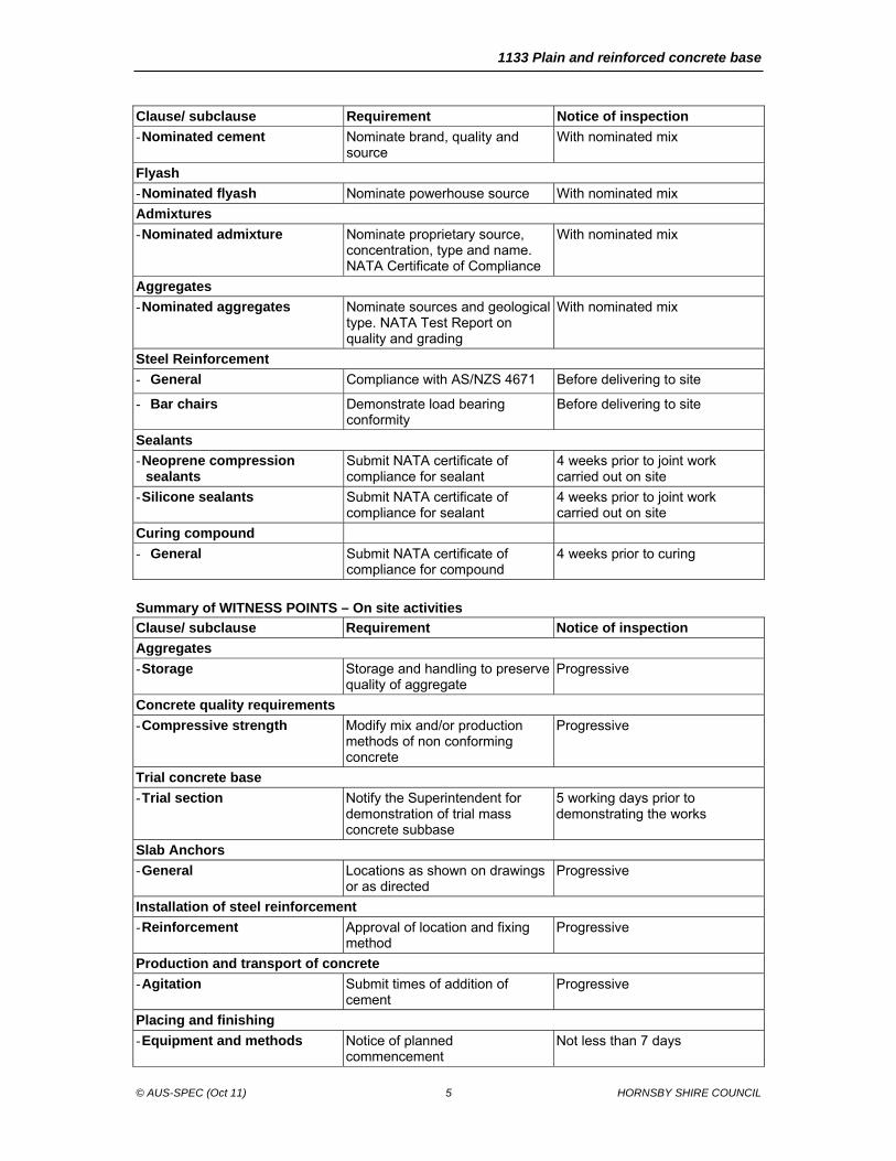
Summary of WITNESS POINTS – On site activities
Clause/ subclause Requirement Notice of inspection
Aggregates
- Storage Storage and handling to preserve quality of aggregate
Progressive
Concrete quality requirements
- Compressive strength Modify mix and/or production methods of non conforming concrete
Progressive
Trial concrete base
- Trial section Notify the Superintendent for demonstration of trial mass concrete subbase
5 working days prior to demonstrating the works
Slab Anchors
- General Locations as shown on drawings or as directed
Progressive
Installation of steel reinforcement
- Reinforcement Approval of location and fixing method
Progressive
Production and transport of concrete
- Agitation Submit times of addition of cement
Progressive
Placing and finishing
- Equipment and methods Notice of planned commencement
Not less than 7 days

1133 Plain and reinforced concrete base
© AUS-SPEC (Oct 11) 6 HORNSBY SHIRE COUNCIL
Clause/ subclause Requirement Notice of inspection
- Consistency Submit test results for review Progressive
- Evaporation and moisture loss
Precautionary measures to prevent moisture loss when evaporation rate exceeds prescribed limits
Progressive
- Paving in general Construction joint if hand or mechanical paving is disrupted
Progressive
- Alignment and surface tolerances
Survey of alignment and edge thickness
3 working days after works
- Protection of work Details of protection methods for low concrete temperatures
Progressive
- Protection of work Details of rain protection and remedial measures
Progressive
- Traffic considerations Provide traffic management measures
Progressive
Joints
- Location Locations as shown on drawings or as approved
Prior to works
Curing
- Application method Check curing compound application rate
Progressive
Acceptance of concrete strength, compaction and thickness
- Concrete cylinders Submit test results Progressive
- Specimens cut from the work Delay retesting of non conforming samples for at least 72 hours
Before coring
- Conformance for thickness Check thickness using a probe Progressive
- Relative compaction of concrete
Reject concrete with unacceptable relative compaction
Progressive
- Restoration after coring Restore holes with non-shrink cementitious concrete and guarantee integrity
After coring
2 PRE-CONSTRUCTION PLANNING
2.1 ACTIVITY PLAN
General Program: Plan the following activities:
- Provide planning resources to allocate plant and personnel for the contract period.
- Program the work to meet the constraints of HOLD POINTS, WITNESS POINTS.
- Plan work to ensure that where jointed concrete shoulders are specified, the plain and reinforced concrete base is constructed first.
- Provide survey data on subbase finished surface to provide data for base thickness. See Conformance for thickness.
2.2 DESIGN AND CONTROL OF CONCRETE MIXES
Nominated mixes Approval: Submit details of concrete mix(s) and the constituent materials including source, moisture condition of the aggregates (oven dry, surface saturated dry or other specified moisture content), setting time, soundness, compressive strength, fineness and nominated compatibility index (in range 60 -90). This is a HOLD POINT.
1133 Plain and reinforced concrete base
© AUS-SPEC (Oct 11) 7 HORNSBY SHIRE COUNCIL
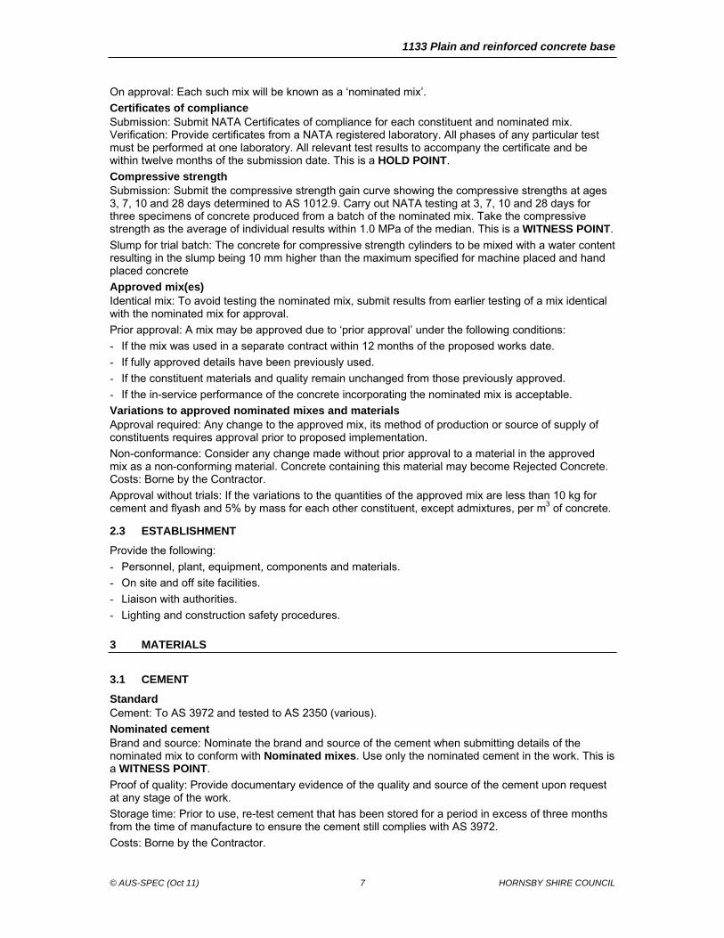
On approval: Each such mix will be known as a ‘nominated mix’.
Certificates of compliance Submission: Submit NATA Certificates of compliance for each constituent and nominated mix. Verification: Provide certificates from a NATA registered laboratory. All phases of any particular test must be performed at one laboratory. All relevant test results to accompany the certificate and be within twelve months of the submission date. This is a HOLD POINT.
Compressive strength Submission: Submit the compressive strength gain curve showing the compressive strengths at ages 3, 7, 10 and 28 days determined to AS 1012.9. Carry out NATA testing at 3, 7, 10 and 28 days for three specimens of concrete produced from a batch of the nominated mix. Take the compressive strength as the average of individual results within 1.0 MPa of the median. This is a WITNESS POINT.
Slump for trial batch: The concrete for compressive strength cylinders to be mixed with a water content resulting in the slump being 10 mm higher than the maximum specified for machine placed and hand placed concrete
Approved mix(es) Identical mix: To avoid testing the nominated mix, submit results from earlier testing of a mix identical with the nominated mix for approval.
Prior approval: A mix may be approved due to ‘prior approval’ under the following conditions:
- If the mix was used in a separate contract within 12 months of the proposed works date.
- If fully approved details have been previously used.
- If the constituent materials and quality remain unchanged from those previously approved.
- If the in-service performance of the concrete incorporating the nominated mix is acceptable.
Variations to approved nominated mixes and materials Approval required: Any change to the approved mix, its method of production or source of supply of constituents requires approval prior to proposed implementation.
Non-conformance: Consider any change made without prior approval to a material in the approved mix as a non-conforming material. Concrete containing this material may become Rejected Concrete. Costs: Borne by the Contractor.
Approval without trials: If the variations to the quantities of the approved mix are less than 10 kg for cement and flyash and 5% by mass for each other constituent, except admixtures, per m3 of concrete.
2.3 ESTABLISHMENT
Provide the following:
- Personnel, plant, equipment, components and materials.
- On site and off site facilities.
- Liaison with authorities.
- Lighting and construction safety procedures.
3 MATERIALS
3.1 CEMENT
Standard Cement: To AS 3972 and tested to AS 2350 (various).
Nominated cement Brand and source: Nominate the brand and source of the cement when submitting details of the nominated mix to conform with Nominated mixes. Use only the nominated cement in the work. This is a WITNESS POINT.
Proof of quality: Provide documentary evidence of the quality and source of the cement upon request at any stage of the work.
Storage time: Prior to use, re-test cement that has been stored for a period in excess of three months from the time of manufacture to ensure the cement still complies with AS 3972.
Costs: Borne by the Contractor.

1133 Plain and reinforced concrete base
© AUS-SPEC (Oct 11) 8 HORNSBY SHIRE COUNCIL
Transport: Cement in watertight packaging and protect from moisture until used. Do not use caked or lumpy cement.
3.2 FLYASH
General Standard: Fly ash to AS 3582.1.
Nominated fly ash Powerhouse source: Nominate the powerhouse source of the fly ash in accordance with Nominated mixes. On approval of a nominated mix, use only the fly ash from the nominated powerhouse. This is a WITNESS POINT.
Proof of quality: Provide documentary evidence of the quality and source of the fly ash upon request at any stage of the work.
3.3 WATER
General Standard: Chloride ion to AS 3583.13 and sulphate ion to AS 1289.4.2.1.
Quality: Water used in the production of concrete to be potable, free from materials harmful to concrete or reinforcement, and be neither salty nor brackish.
Limits: The water used must not contain more than:
- 300 parts per million of chloride ion, as determined to AS 3583.13;
- 400 parts per million of sulphate ion, as determined to AS 1289.4.2.1.
3.4 ADMIXTURES
General Standard: Chemical admixtures to comply with AS 1478.1. Quality: Provide admixtures free from calcium chloride, calcium formate, or triethanolamine or any other accelerator. Do not use admixtures or combinations of admixtures without prior written approval. Dosage: Vary the dosage of chemical admixture to account for air temperature and setting time in accordance with the manufacturer’s recommendations.
Nominated admixture Source and type: Nominate the proprietary source, type, dose rate, name and method of incorporation of each admixture to be used in accordance with nominated mixes. Submit NATA certificates of compliance and the proposed dosage chart. On approval of a nominated mix, use only the admixture and dosage that is approved. Variation to mixture: If the Contractor proposes to vary the admixture between warm and cool seasons such variation is to constitute a proposed change to an approved mix for the purposes of Variations to approved mixes. This is a WITNESS POINT.
Proof of quality: Provide documentary evidence of the quality upon request at any stage of the work.
Types of admixtures Air entraining agent: An air-entraining agent to Concrete quality requirements to be included.
Excess air content: Reject fresh concrete with an air content not complying with Concrete quality requirements. Warm season retarder: During the warm season, (October to March inclusive), use a lignin or lignin-based (‘ligpol’) set-retarding admixture (Type Re or Type WRRe) as approved to control slump within the limits stated in Consistency. Cool season retarder: During the cool season, (April to September inclusive), use only a lignin or lignin based set-retarding admixture containing not more than 6 % reducing sugars (Type WRRe complying with AS 1478.1).
3.5 AGGREGATES
General Standards: AS 2758.1 and Austroads AGPT04J.
Quality: Provide at least 40 % by mass of the total aggregates in the concrete mix of quartz sand aggregate having a nominal size of < 5 mm and containing at least 70 % quartz, by mass.
Durability: All constituent, fraction of constituent or aggregates to conform to AS 1141.22 and the following:
1133 Plain and reinforced concrete base
© AUS-SPEC (Oct 11) 9 HORNSBY SHIRE COUNCIL
- Wet Strength not less than 80 kN.
- 10% Fines Wet/Dry Variation not to exceed 35%.
Chert fragments: Chert fragments will be regarded as ‘quartz’ for the purpose of this worksection, provided that the chert content does not exceed quartz content.
Recycled concrete aggregate (RCA): The use of course aggregates from demolition concrete or RCA to conform with SAA HB 155 and Austroads AGPT04E.
Blending: If blending coarse RCA with natural aggregates ensure substitution rates are below 30 %.
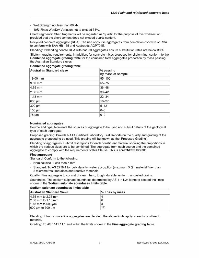
Slipform grading requirements: In addition, for concrete mixes proposed for slipforming, conform to the Combined aggregate grading table for the combined total aggregates proportion by mass passing the Australian Standard sieves .
Combined aggregate grading table
Australian Standard sieve % passingby mass of sample
19.00 mm 95–100
9.50 mm 55–75
4.75 mm 36–48
2.36 mm 30–42
1.18 mm 22–34
600 µm 16–27
300 µm 5–12
150 µm 0–3
75 µm 0–2
Nominated aggregates Source and type: Nominate the sources of aggregate to be used and submit details of the geological type of each aggregate.
Proposed grading: Provide NATA Certified Laboratory Test Reports on the quality and grading of the aggregate proposed to be used. This grading will be known as the ‘Proposed Grading’.
Blending of aggregates: Submit test reports for each constituent material showing the proportions in which the various sizes are to be combined. The aggregate from each source and the combined aggregate to comply with the requirements of this Clause. This is a WITNESS POINT.
Fine aggregate Standard: Conform to the following:
- Nominal size : Less then 5 mm
- Standard: To AS 2758.1 for bulk density, water absorption (maximum 5 %), material finer than 2 micrometres, impurities and reactive materials.
Quality: Fine aggregate to consist of clean, hard, tough, durable, uniform, uncoated grains.
Soundness: The sodium sulphate soundness determined by AS 1141.24 is not to exceed the limits shown in the Sodium sulphate soundness limits table.
Sodium sulphate soundness limits table
Australian Standard Sieve % Loss by mass
4.75 mm to 2.36 mm 2.36 mm to 1.18 mm 1.18 mm to 600 m 600 m to 300 m
4 6 8 12
Blending: If two or more fine aggregates are blended, the above limits apply to each constituent material.
Grading: To AS 1141.11.1 and within the limits shown in the Fine aggregate grading table.

1133 Plain and reinforced concrete base
© AUS-SPEC (Oct 11) 10 HORNSBY SHIRE COUNCIL
Fine aggregate grading table
Australian Standard sieve Proportion passing(% of mass of sample)
Deviation from proposed grading (% of mass of sample)
9.50 mm 4.75 mm 2.36 mm 1.18 mm 600 m 300 m 150 m 75 m
100 90–100 65–95 40–80 24–52 8–25 1–8 0–3
± 3 ± 10 ± 10 ± 10 ± 5 ± 2
Coarse aggregate Standard: To AS 2758.1 in respect of particle density, bulk density, water absorption (maximum 2.5 %), material finer than 75 micrometres, weak particles, light particles, impurities and reactive materials, iron unsoundness and falling or dusting unsoundness.
Quality: Clean, crushed, hard durable rock, metallurgical furnace slag or gravel. If required, wash coarse aggregates to satisfy these requirements.
Properties: Coarse aggregate to conform to the Coarse aggregate properties table.
Coarse aggregate properties table
Property Specification limits Method
Wet strength 80 kN AS 1141.22
Wet/dry strength variation 35% AS 1141.22
Soundness—loss in mass 9.0% AS 1141.24
Misshapen particles (2:1 ratio) 35% AS 1141.14
Fractured faces (two or more) 80% AS 1141.18
Grading: The grading of the coarse aggregate, determined by AS 1141.11.1, to be within the limits given in the Coarse aggregate grading table.
Coarse aggregate grading table
Australian Standard sieve Proportion passing(% of mass of sample)
Deviation from proposed grading (% of mass of sample)
26.50 mm 19.00 mm 13.20 mm 9.50 mm 4.75 mm 2.36 mm
100 95–100 (accepted design mix) 25–55 0–10 0–2
± 2 ± 5 ± 5 ± 3
Storage Storage areas: Provide a concrete floor for all storage areas and prevent the aggregates becoming intermixed or mixed with foreign materials or segregated.
Exclusion of foreign matter: Locate the storage area and mixing plant to make sure delivery vehicles, loaders and trucks cannot introduce foreign matter to the aggregates at any time.
Cease production: Immediately cease production of concrete if foreign matter is introduced or if directed by the Superintendent due to possible contamination. Resume production of concrete and delivery of materials on approval of the rectified condition. This is a WITNESS POINT.
3.6 STEEL REINFORCEMENT
General Standards: To AS/NZS 4671.
Type and size: As shown on the drawings.
1133 Plain and reinforced concrete base
© AUS-SPEC (Oct 11) 11 HORNSBY SHIRE COUNCIL
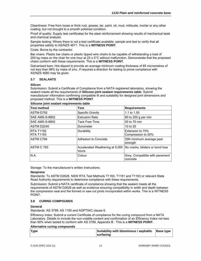
Cleanliness: Free from loose or thick rust, grease, tar, paint, oil, mud, millscale, mortar or any other coating, but not brought to a smooth polished condition.
Proof of quality: Supply test certificates for the steel reinforcement showing results of mechanical tests and chemical analysis.
Sample testing: Where there is not a test certificate available, sample and test to verify that all properties satisfy to AS/NZS 4671. This is a WITNESS POINT.
Costs: Borne by the contractor.
Bar chairs: Plastic bar chairs or plastic tipped wire chairs to be capable of withstanding a load of 200 kg mass on the chair for one hour at 23 ± 5°C without malfunction. Demonstrate that the proposed chairs conform with these requirements. This is a WITNESS POINT.
Galvanised bars: Hot-dipped to provide an average minimum coating thickness of 85 micrometres of not less than 98% by mass of zinc. If required a direction for testing to prove compliance with AS/NZS 4680 may be given.
3.7 SEALANTS
Silicon Submission: Submit a Certificate of Compliance from a NATA registered laboratory, showing the sealant meets all the requirements of Silicone joint sealant requirements table. Submit manufacturer information confirming compatible fit and suitability for designed joint dimensions and proposed method. This is a WITNESS POINT.
Silicone joint sealant requirements table
Test method Test Requirements
ASTM-D792 Specific Gravity 1.1 to 1.55
SAE AMS-S-8802 Extrusion Rate 90 to 250 g per min
SAE AMS-S-8802 Tack Free Time 30 to 70 min
ASTM D2240 Durometer 10 to 25
RTA T1192 RTA T1193
Durability Extension to 70% Compression to 50%
ASTM C794 Adhesion to Concrete 35N minimum average peel strength
ASTM C 793 Accelerated Weathering at 5,000 hours
No cracks, blisters or bond loss
N.A. Colour Grey, Compatible with pavement concrete
Storage: To the manufacturer’s written instructions.
Neoprene Standards: To ASTM D2628. NSW RTA Test Methods T1160, T1161 and T1163 or relevant State Road Authority requirements to determine compliance with these requirements.
Submission: Submit a NATA certificate of compliance showing that the sealant meets all the requirements of ASTM D2628 as well as evidence ensuring compatibility in width and depth between the compression seal and the formed or saw cut joints incorporated within works. This is a WITNESS POINT.
3.8 CURING COMPOUNDS
General Standards: AS 3799, AS 1160 and AGPT04C clause 6.
Efficiency index: Submit a current Certificate of compliance for the curing compound from a NATA Laboratory. Details to include the non-volatile content and confirmation of an Efficiency Index not less than 90% when tested to conform with AS 3799, Appendix B . This is a WITNESS POINT.
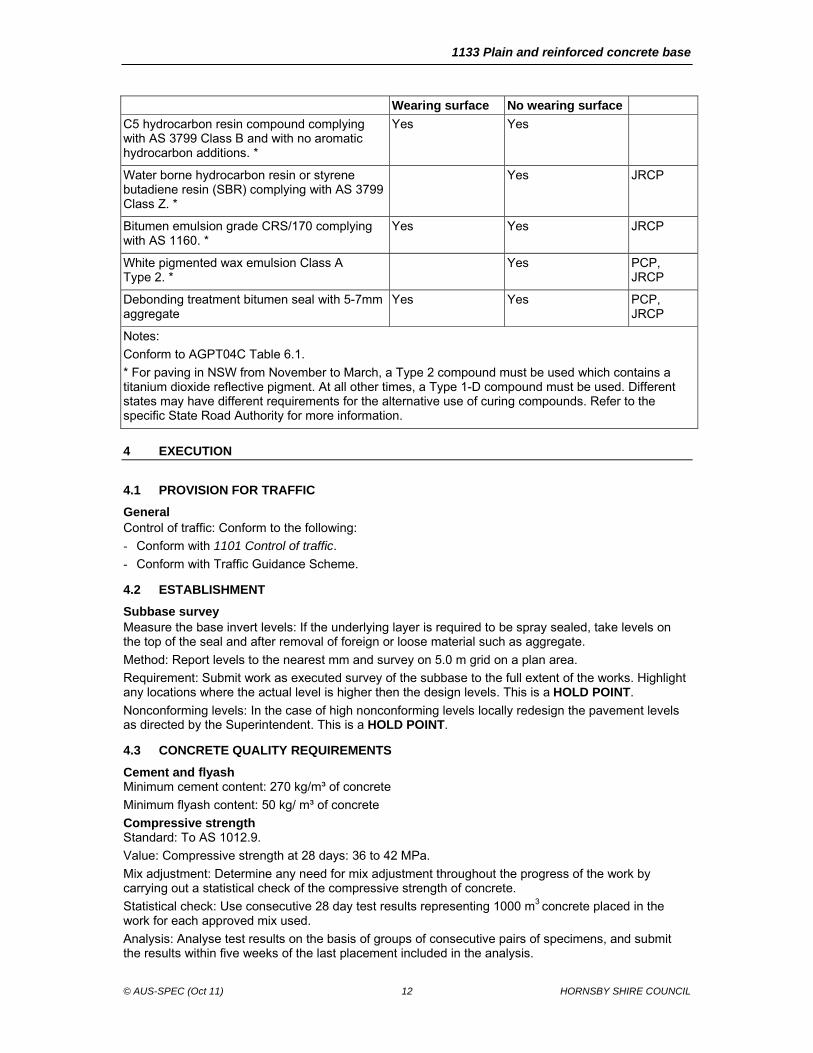
Alternative curing compounds
Type Suitability with bituminous / asphaltic surfacing
Base type
1133 Plain and reinforced concrete base
© AUS-SPEC (Oct 11) 12 HORNSBY SHIRE COUNCIL
Wearing surface No wearing surface
C5 hydrocarbon resin compound complying with AS 3799 Class B and with no aromatic hydrocarbon additions. *
Yes Yes
Water borne hydrocarbon resin or styrene butadiene resin (SBR) complying with AS 3799 Class Z. *
Yes JRCP
Bitumen emulsion grade CRS/170 complying with AS 1160. *
Yes Yes JRCP
White pigmented wax emulsion Class A Type 2. *
Yes PCP, JRCP
Debonding treatment bitumen seal with 5-7mm aggregate
Yes Yes PCP, JRCP
Notes:
Conform to AGPT04C Table 6.1.
* For paving in NSW from November to March, a Type 2 compound must be used which contains a titanium dioxide reflective pigment. At all other times, a Type 1-D compound must be used. Different states may have different requirements for the alternative use of curing compounds. Refer to the specific State Road Authority for more information.
4 EXECUTION
4.1 PROVISION FOR TRAFFIC
General Control of traffic: Conform to the following:
- Conform with 1101 Control of traffic.
- Conform with Traffic Guidance Scheme.
4.2 ESTABLISHMENT
Subbase survey Measure the base invert levels: If the underlying layer is required to be spray sealed, take levels on the top of the seal and after removal of foreign or loose material such as aggregate.
Method: Report levels to the nearest mm and survey on 5.0 m grid on a plan area.
Requirement: Submit work as executed survey of the subbase to the full extent of the works. Highlight any locations where the actual level is higher then the design levels. This is a HOLD POINT.
Nonconforming levels: In the case of high nonconforming levels locally redesign the pavement levels as directed by the Superintendent. This is a HOLD POINT.
4.3 CONCRETE QUALITY REQUIREMENTS
Cement and flyash Minimum cement content: 270 kg/m³ of concrete
Minimum flyash content: 50 kg/ m³ of concrete
Compressive strength Standard: To AS 1012.9.
Value: Compressive strength at 28 days: 36 to 42 MPa.
Mix adjustment: Determine any need for mix adjustment throughout the progress of the work by carrying out a statistical check of the compressive strength of concrete.
Statistical check: Use consecutive 28 day test results representing 1000 m3 concrete placed in the work for each approved mix used.
Analysis: Analyse test results on the basis of groups of consecutive pairs of specimens, and submit the results within five weeks of the last placement included in the analysis.
1133 Plain and reinforced concrete base
© AUS-SPEC (Oct 11) 13 HORNSBY SHIRE COUNCIL
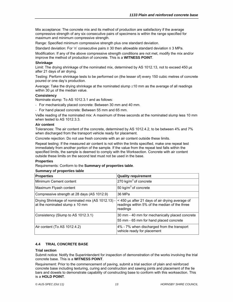
Mix acceptance: The concrete mix and its method of production are satisfactory if the average compressive strength of any six consecutive pairs of specimens is within the range specified for maximum and minimum compressive strength.
Range: Specified minimum compressive strength plus one standard deviation.
Standard deviation: For ‘n’ consecutive pairs ≥ 30 then allowable standard deviation ≤ 3 MPa.
Modification: If any of the above compressive strength conditions are not met, modify the mix and/or improve the method of production of concrete. This is a WITNESS POINT.
Shrinkage Limit: The drying shrinkage of the nominated mix, determined by AS 1012.13, not to exceed 450 µε after 21 days of air drying.
Testing: Perform shrinkage tests to be performed on (the lesser of) every 150 cubic metres of concrete poured or one day’s production.
Average: Take the drying shrinkage at the nominated slump 10 mm as the average of all readings within 30 µε of the median value.
Consistency Nominate slump: To AS 1012.3.1 and as follows:
- For mechanically placed concrete: Between 30 mm and 40 mm.
- For hand placed concrete: Between 55 mm and 65 mm.
VeBe reading of the nominated mix: A maximum of three seconds at the nominated slump less 10 mm when tested to AS 1012.3.3.
Air content Tolerances: The air content of the concrete, determined by AS 1012.4.2, to be between 4% and 7% when discharged from the transport vehicle ready for placement.
Concrete rejection: Do not use fresh concrete with an air content outside these limits.
Repeat testing: If the measured air content is not within the limits specified, make one repeat test immediately from another portion of the sample. If the value from the repeat test falls within the specified limits, the sample is deemed to comply with the Worksection. Concrete with air content outside these limits on the second test must not be used in the base.
Properties Requirements: Conform to the Summary of properties table.
Summary of properties table
Properties Quality requirement
Minimum Cement content 270 kg/m3 of concrete
Maximum Flyash content 50 kg/m3 of concrete
Compressive strength at 28 days (AS 1012.9) 36 MPa
Drying Shrinkage of nominated mix (AS 1012.13) - at the nominated slump ± 10 mm
< 450 µε after 21 days of air drying average of readings within 5% of the median of the three readings
Consistency (Slump to AS 1012.3.1) 30 mm - 40 mm for mechanically placed concrete
55 mm - 65 mm for hand placed concrete
Air content (To AS 1012.4.2) 4% - 7% when discharged from the transport vehicle ready for placement
4.4 TRIAL CONCRETE BASE
Trial section Submit notice: Notify the Superintendent for inspection of demonstration of the works involving the trial concrete base. This is a WITNESS POINT.
Requirement: Prior to the commencement of paving, submit a trial section of plain and reinforced concrete base including texturing, curing and construction and sawing joints and placement of the tie bars and dowels to demonstrate capability of constructing base to conform with this worksection. This is a HOLD POINT.
1133 Plain and reinforced concrete base
© AUS-SPEC (Oct 11) 14 HORNSBY SHIRE COUNCIL
Trial section: Construct as follows:
- So that it may be incorporated in to the finished work.
- For mechanical paving between 50 and 100 m length, or lesser length as approved. Separate trials required for each paver.
- For manual paving between 15 and 50 m length, or lesser length as approved.
- Width as proposed for the work.
Trial results: Submit relative density and 7 day cylinder and core compressive strength to demonstrate allowance for compressive strength, compaction and thickness. This is a HOLD POINT.
Procedure after placement Materials and methods: Construct the trial concrete base using the materials, concrete mix, equipment and methods for the entire base works. Approved trial section: Continue the remaining works following the approval of the trial section.
Deficient trial section: If there are deficiencies in the trial concrete base, the trial section may not be approved. The method, equipment, materials and personnel will be reviewed and an explanation submitted. A further length of trial concrete base may be requested. This is a HOLD POINT.
Next trial: Next trial treated as the first. If after 3 trials work is still deficient then justify why procedure should not be changed. New trial section: If changes are made in the equipment, materials, mix, plant or rate of paving for any other reason a new trial section may be requested. Non compliance: If rejected by the Superintendent, remove the trial concrete base immediately to conform with Removal and replacement of base. This is a HOLD POINT.
Costs: Borne by the Contractor.
Payment: Payment made for the base at the schedule rates for appropriate Pay items if it has been constructed without deficiencies and is incorporated into the work as base concrete.
4.5 SLAB ANCHORS
General Location: Construct anchors normal to the control line, to the dimensions and at the locations shown on the drawings and extended over the full width of the base.
Spacing: The associated transverse expansion joints must be no closer than 2 m to other transverse joints. A change in the spacing of transverse contraction joints may be directed to ensure that this minimum clearance is obtained. This is a WITNESS POINT.
Excavation Dimensions: Excavate trenches to the dimensions and details shown on the drawings.
Trim and consolidate: Remove all loose material and trim the vertical faces to neat lines.
Compaction: Where required, re-compact the bottom of the trench, to the degree of consolidation of the adjacent undisturbed material. This is a HOLD POINT.
Spoil: Dispose of excavated material at approved locations.
Adjacent to flexible pavement: If a slab anchor is required at the junction of an existing flexible pavement, make a straight sawcut to the full depth of the asphaltic concrete or bituminous seal in the flexible pavement along the joint line.
Damage: Do not disturb or damage the existing flexible pavement.
Remediation: Make good any disturbance or damage to the flexible pavement as directed.
Costs: Borne by the Contractor.
Sub-soil drains: Provide a subsoil drain at the bottom of the trench, to conform with 1172 Subsoil and foundation drains.
Construction Method: Produce, transport and place concrete for slab anchors to conform with the requirements for hand-placed base concrete.
Sequence: Pour slab anchors separately from the base slabs to the dimensions and details shown on the drawings, up to the top surface of the subbase.
Transverse isolation joint: Provide a transverse isolation joint on the downhill side of the slab anchor.
Steel reinforcement: Steel reinforcement type and size shown on the drawings and supplied and fixed to conform with Steel reinforcement.
1133 Plain and reinforced concrete base
© AUS-SPEC (Oct 11) 15 HORNSBY SHIRE COUNCIL
Bridge approach slabs Details: If not in the bridge contract, construct bridge approach slabs at bridge abutments to the dimensions and details shown on the drawings and to conform with the requirements for base concrete.
Transverse expansion joints: Provide as shown on the drawings.
4.6 INSTALLATION OF STEEL REINFORCEMENT
Reinforcement Conform to: Reinforcement must align to the following:
- Formed to the dimensions and shapes shown on the drawings.
- Bent to an internal bend radius at least twice the diameter of the bar.
- Do not bend or straighten in a manner that will damage the material.
- Do not use with kinks or bends not shown on the drawings.
- Do not heat for the purpose of bending.
Plan lengths: Conform to the following for length of lapped splices for unhooked bars not shown on the Drawings will be as follows:
- Plain bars, Grade 250: 40 bar diameters
- Deformed bars, Grade 500: 40 bar diameters
- Hard-drawn wire: 50 bar diameters
- Reinforcement fabric: Overlap between the outermost wire in each sheet of fabric transverse to the direction of the splice greater than the pitch of the transverse wires plus 25 mm.
Secure ends: The ends of the bars forming a lapped splice must be welded or securely wired together in at least 2 places. Welding to comply with AS 1554.3.
Splice dimensions: Splices in reinforcing fabric to be measured as the overlap between the outermost wire in each sheet of fabric transverse to the direction of splice. This overlap is not to be less than the pitch of the transverse wires plus 25 mm. This is a WITNESS POINT.
Storage: Protect reinforcement, during storage if not promptly incorporated into the concrete,
- By storage under a waterproof cover and supported clear of the ground, and
- Prevent damage and deterioration due to exposure.
Placing and cover requirements Inspection: Submit for approval the placement and fastening of reinforcing steel prior to planned concrete placement. Allow adequate time in giving notice of inspection for all corrective works to be completed before placing concrete. This is a HOLD POINT.
Position: Conform to the following:
- Accurately place reinforcing bars and wire reinforcing fabric as shown on the drawings.
- Secure the reinforcement in position by blocking from the forms, by supporting on concrete, plastic or plastic tipped wire chairs and by wiring together where required using annealed iron wire > 1.25 mm diameter.
- Provide these supports in a regular grid not exceeding 1.0 m. Do not support steel on metal supports which extend to any surface of the concrete. Do not use wooden supports or pieces of aggregate.
Chair spacing: Arrange and space of chairs to ensure support in proper position with permanent deflection or displacement of the reinforcement no more than 2mm during placing and consolidation of the concrete.
Chair bearing: To prevent overturning.
Chair support: 200 kg mass without permanent distortion in excess of 2 mm.
Cover minimum: Not less than 50 mm from the supporting surface on which the chair rests to the exposed steel of the chair. Not less than 50 mm cover of any bar to the nearest concrete surface unless shown otherwise on the drawings.
Longitudinal steel: Conform to the following:
- Placement: Place longitudinal steel on top of transverse steel.
- Minimum top cover: 70 ± 10 mm unless otherwise shown on the drawings.
1133 Plain and reinforced concrete base
© AUS-SPEC (Oct 11) 16 HORNSBY SHIRE COUNCIL
Tack welding: Tack welding instead of wire ties may be used if approved on reinforcing steel. Do not use cold-worked reinforcing bars.
Tie bars: Conform to with the following:
- Place tie bars in the pavement so that they remain in their specified location. Do not place tie bars through the finished upper surface of the pavement.
- Place tie bars either ahead of paving or by a bar vibrator into the edge of the joint or by an automatic tie bar inserter on the mechanical paver.
Submission: Submit details of the proposed method of tie bar insertion for approval.
Anchoring: Anchor tie bars extending from any side face of base concrete or gutter in a manner which will develop 85 % of the yield strength of the bar in tension. Remove loose bars.
Dowelled joints: Conform to the following:
- Place dowelled joints, parallel to the pavement surface and normal to the line of the joint, unless shown otherwise on the drawings.
- Install dowels ahead of paving by an approved dowel support assembly.
- Coat one end of each dowel on the same side of each joint for a distance of (L/2 + 25 mm) with two coats of bitumen emulsion (or one coat of bitumen) and sanded to ensure free movement of the concrete base slab with temperature variations.
- Provide a preformed cap at the coated end to provide a minimum of 30 mm clearance for movement.
- Dowel ends: Burr free and circular in cross-section. Do not provide dowels possessing crimped or ovoid end faces into the works.
4.7 PRODUCTION AND TRANSPORT OF CONCRETE
General Standard: To AS 1379 for mixers and agitation methods.
Handling, storing and batching Submit: Proposed details for the following methods:
- Handling, storing and batching materials for concrete.
- Monitoring and measuring the constituent materials for concrete.
- Mixers and methods of mixing.
- Method of transport. This is a HOLD POINT.
Verify scales accuracy: Submit certificates of calibration issued by a NATA registered laboratory as evidence of the accuracy of the scales prior to handling and batching of material.
Measurement: Weigh cementitious material in an individual hopper, with the cement weighed first.
Moisture content: Determine the moisture content of the aggregates at least daily immediately prior to batching. Make corresponding corrections to the quantities of aggregates and water.
Continuous weighing: If a continuous type mixer is used, measure the components by a method of continuous weighing as approved, except for liquids which may be measured by volume or flow rate meter.
Storage: Store materials only on sites specifically designated for the purpose. Do not use a new storage site without prior approval.
Mixing time Stationary batch mixers: The minimum mixing time must not be less than 54 seconds plus 6 seconds for each cubic metre.
Mobile batch mixers: The minimum mixing time must be the full period of mixing provided at either the testing station or the point of placement. All other mixing or agitation must be ignored for the purpose of assessing the actual mixing time for a specific batch.
Maximum mixing time: 5 minutes for split drum mixers or 10 minutes otherwise.
Admixture addition Pre-dilute: Admixtures must be separately and thoroughly pre-diluted in the mixing water prior to their introduction to other materials.
Manufacturer’s instructions: Mixing to conform with the manufacturer’s instructions and ensure no adverse interaction occurs.
1133 Plain and reinforced concrete base
© AUS-SPEC (Oct 11) 17 HORNSBY SHIRE COUNCIL
Batch delivery docket Identification number: The docket / Certificate must be pre-numbered and accompany each batch or load of concrete.
Record details: Including the time for completion of batching depending on the type of mixing. This will include time for charging and/or mixer discharge and/or slump adjustment.
Addition of water: The delivery docket must clearly indicate the amount of water added, but in no circumstance is the water/cement ratio to be exceeded.
Agitation Addition of water: For truck-mixed concrete, add water in accordance with AS 1379 within ten minutes of completion of batching and within 200 m of the batching facilities.
Cement addition: After addition of the cement to the aggregate, concrete to be incorporated into the work within:
- 90 minutes, where transported by truck mixer or agitator.
- 60 minutes, where transported by non-agitating trucks.
Outside of the time limitations: Legally dispose of any material delivered in excess of these time limitations with the cost borne by the Contractor. Verify time added: Submit times of addition of cement to the aggregate and the means of verification. This is a WITNESS POINT.
Maximum size of batch: The size of the batch in an agitator vehicle not to exceed the manufacturer’s rated capacity nor exceed 80 % of the gross volume of the drum of the mixer.
Maximum holding: If delays necessitate holding a batch in the mixer then mixing may continue for 10 minutes maximum or 5 minutes maximum for split drum mixers.
Longer holding: For longer periods, the batch may be held in the mixer and turned over at regular intervals, subject to the time limits specified for incorporation of the concrete into the work not being exceeded.
Testing and sampling Discharge: When conducting mixer uniformity tests on a split drum mixer producing centrally mixed concrete, discharge the whole of the batch into the tray of a moving vehicle mix tray length 8 m.
Sample method: Sample the concrete from the tray of the vehicle at points approximately 15 % and 85 % along the length of the tray.
Forming time Maximum forming time: Determine for each nominated mix a maximum forming time by considering the prevailing weather conditions and concrete temperature.
Air temperatures < 30°C: 90 minutes maximum.
Air temperature ≥ 30°C: 45 minutes.
Effects on forming time: Reduce the forming time as required due to the prevailing weather, mix type, or materials being used as directed.
4.8 PLACING AND FINISHING
General Subbase surface condition: Clean and free of loose or foreign matter and prepared to conform with 1132 Mass concrete subbase.
Slab anchors: If required, construct slab anchors prior to construction of the base.
Base thickness and levels: The Superintendent may alter the base thickness and levels by up to 30 mm before the commencement of each section of work.
Equipment and methods Proposal: Submit full details of the equipment and methods proposed for placing and finishing the concrete base together with a paving plan showing proposed paving widths, sequence and estimated daily outputs. This is a HOLD POINT.
Notice to commence: Give 7 days written notice of the intention to commence construction of the subbase on any section of work including the trial subbase. This is a WITNESS POINT.
Consistency Requirement: Produce and place concrete of a consistent, dense, non-segregated mass with bleeding limited to prevent bleed water flowing over the slab edge under the conditions of placement. If bleed
1133 Plain and reinforced concrete base
© AUS-SPEC (Oct 11) 18 HORNSBY SHIRE COUNCIL
water does flow, cease paving until the consistency of the mix is adjusted to prevent flow or the mix is redesigned and approved.
Concrete edges: Produce the edge so as to maintain its shape without sag or tear.
Testing: Check the consistency of the concrete by use of a slump cone to AS 1012.3.1 on concrete samples obtained to AS 1012.1. Perform check tests on each truckload of concrete.
Timing of testing: Check the consistency of the concrete within 30 minutes of adding cement to the aggregate. If the actual haul time exceeds 45 minutes, also check the consistency immediately prior to discharge. Do not incorporate concrete which is non-conforming into the work. Check each truck load of concrete for consistency.
Slump tolerances:
- Mechanically placed concrete: Within 10 mm of the Contractor’s nominated slump.
- Hand placed concrete: Within 15 mm of the Contractor’s nominated slump.
Equipment: Provide all equipment, materials and labour for consistency testing.
Test results: Submit all consistency test results. This is a WITNESS POINT.
Costs: Borne by the Contractor.
Evaporation and moisture loss Ambient conditions: Do not place concrete during rain or when the air temperature in the shade is below 10°C or above 30°C, unless appropriate heating or cooling procedures are adopted.
Concrete temperature limits: Within the range 5°C to 35°C.
Conditions: Measure and record concrete temperature and wind velocity at the point of concrete placement, and continuously measure and record air temperature and relative humidity daily, at the site throughout the course of the work.
Equipment: Provide and maintain all equipment and provide suitable personnel necessary for all such measuring and recording.
Costs of testing evaporation and moisture loss: Borne by the Contractor.
Evaporation limit: Take precautionary measures when the value of Rate of Evaporation as determined from the Rate of evaporation graph, exceeds 0.50 kg/m2/hr. Obtain approval of the methods used to prevent moisture loss or cease work. This is a WITNESS POINT.
Costs of precautionary measures: Borne by the Contractor.
Evaporation retarder: If it is proposed to use an evaporation retarder to prevent excessive moisture loss, apply by fine spray after all finishing operations are complete, except minor manual bull-floating. Re-application of evaporation retarder after level floating may be directed as required.
1133 Plain and reinforced concrete base
© AUS-SPEC (Oct 11) 19 HORNSBY SHIRE COUNCIL
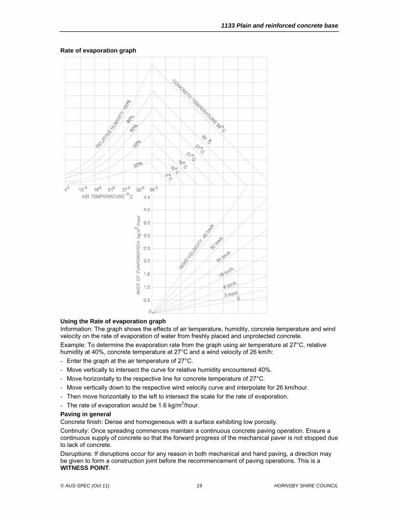
Rate of evaporation graph
Using the Rate of evaporation graph Information: The graph shows the effects of air temperature, humidity, concrete temperature and wind velocity on the rate of evaporation of water from freshly placed and unprotected concrete.
Example: To determine the evaporation rate from the graph using air temperature at 27°C, relative humidity at 40%, concrete temperature at 27°C and a wind velocity of 26 km/h:
- Enter the graph at the air temperature of 27°C.
- Move vertically to intersect the curve for relative humidity encountered 40%.
- Move horizontally to the respective line for concrete temperature of 27°C.
- Move vertically down to the respective wind velocity curve and interpolate for 26 km/hour.
- Then move horizontally to the left to intersect the scale for the rate of evaporation.
- The rate of evaporation would be 1.6 kg/m2/hour.
Paving in general Concrete finish: Dense and homogeneous with a surface exhibiting low porosity.
Continuity: Once spreading commences maintain a continuous concrete paving operation. Ensure a continuous supply of concrete so that the forward progress of the mechanical paver is not stopped due to lack of concrete.
Disruptions: If disruptions occur for any reason in both mechanical and hand paving, a direction may be given to form a construction joint before the recommencement of paving operations. This is a WITNESS POINT.
1133 Plain and reinforced concrete base
© AUS-SPEC (Oct 11) 20 HORNSBY SHIRE COUNCIL
Costs: Borne by the Contractor.
Non-monolithic concrete: If subsequent testing at the location of an interruption indicates the presence of non-monolithic concrete, remove and replace such concrete to conform with Removal and replacement of base.
Mechanical paving Paver machine: Conform to the following:
- A self-propelled machine with a gross operating mass of not less than 4 tonnes per lineal metre of paved width.
- Capable of paving at a speed of one metre per minute or less as required to enable the continuous operation of the paver and obtain the required degree of compaction.
- Include an automatic control system with a sensing device to control line and level to the specified tolerances.
- Able to spread the mix uniformly and regulate the flow of mix to the vibrators without segregation of the components.
- Contain internal vibrators capable of compacting the full depth of the concrete.
- Contain an adjustable extrusion screed and/or conforming plate to form the slab profile and produce the required finish on all surfaces.
- Capable of paving in the slab widths or combination of slab widths and slab depths shown on the drawings.
Concrete finish: Spread, compact, screed and finish the freshly placed concrete with the mechanical paver to the minimise finishing by hand.
Spreading device: Use a separate device ahead of the mechanical paver as follows:
- To transport and spread concrete uniformly over the full width being paved.
- Without disturbing the reinforcement or its supports.
- Without segregating or otherwise adversely affecting the concrete.
Supporting surface: The supporting surface for the tracks of the paver, curing machine and any other equipment in the paving and curing train is to be in a smooth and firm condition.
Hand placing Restriction: Use hand placement only in areas where mechanical placement is impracticable or where approved prior to commencement of work.
Formwork: Conform to the following:
- Design and construct for removal without damaging the concrete.
- True to line and grade.
- Braced in a substantial and unyielding manner.
- Mortar tight and debonded to ensure non-adhesion of concrete to the forms.
Placing in forms: Deliver concrete in agitator trucks and deposit uniformly in the forms without segregation.
Compaction: Compact the concrete by poker vibrators and by two passes only of a hand-guided vibratory screed traversing the full width of the slab on each pass.
Buildup: Prevent any buildup of concrete between the forms and vibratory screed.
Alignment and surface tolerances Horizontal alignment tolerances:
- Outer edges: Square to the subbase surface without deviation from the plan position at any point by more than 30 mm.
- Longitudinal joint: In conformance with Longitudinal tied joints.
Tolerances and rideability:
- Thickness of concrete: 0 mm below the specified thickness and in accordance with Conformance for thickness for excess thickness.
- Top of base level: +10 mm / –0 mm deviation from the design level and not below that shown on the drawings.
- Surface level: 5 mm maximum deviation from a 3 m straightedge, laid in any direction.
- Ponding: Not acceptable.
1133 Plain and reinforced concrete base
© AUS-SPEC (Oct 11) 21 HORNSBY SHIRE COUNCIL
Inspection: Survey the alignment, surface and edge thickness for conformance with the above requirements. This is a WITNESS POINT.
Odd-shaped and mismatched slabs Definitions:
- Slab: A portion of concrete base bounded by joints or free edges.
- Slab dimensions: The average dimensions measured normal and parallel to the longitudinal joints.
- Odd shaped:
. If the ratio of the longer dimension to the shorter dimension exceeds 1.6 or if the joint pattern produces an angle of less than 80 degrees between two adjacent sides.
. Slabs containing blockouts for drainage structures will be considered as odd-shaped.
- Mismatched slabs: Where any joint meets a slab and is not continued across that slab.
Reinforcing fabric: Unless otherwise shown on the drawings or directed, reinforce odd-shaped and mismatched slabs with SL82 reinforcing fabric placed with 50 mm to 60 mm cover to the surface of the base. Place fabric clear of all transverse and longitudinal joints by 50 mm to 100 mm.
Terminal slabs Placement location: Construct terminal slabs adjoining bridge approach slabs and at changes from a rigid pavement to a flexible pavement. Construct terminal slabs to the dimensions and details shown on the drawings.
Surface texture Transverse texture: Conform to the following:
- As soon as possible after placing, transversely texture the surface of the freshly placed concrete by means of a mechanical device for grooving plastic concrete.
- Utilise texturing equipment with rectangular-shaped tynes of flat spring steel, approximately 0.6 mm thick.
- Width of the tynes: 3 mm.
- Spacing of tynes: Random pattern.
Average texture depth: Between 0.30 mm and 0.65 mm when tested in accordance with RTA Test Method T240.
Corresponding individual groove depth: 1.5 mm to 3 mm.
Machine texture: For paving widths exceeding 2.5 m perform the texturing using a machine spanning the concrete slab and guided, with regard to both level and direction, by the rails in the case of side-form construction or by the paver guide wires in the case of slip form construction.
Texturing brushes or combs: At least 750 mm wide. Make provision for downward adjustment to compensate for wear.
Submission: Submit details of the proposed texturing device and demonstrate the method proposed to achieve the required texture. This is a HOLD POINT.
Remedial grooving: Transversely saw groove areas with less than the allowable average texture depth.
Saw groove dimensions: 3 mm wide x 3 mm deep, at random spacing as approved with a mean spacing neither less than 10 mm nor more than 21 mm.
Alternative: Where an asphalt surfacing is specified over the concrete base or as directed, texturing of the concrete surface may be by the use of a fine broom or hessian-drag.
Protection of work Temperature control: Ensure that the temperature of the concrete does not fall below 5°C during the first 24 hours after placing.
Submit: Provide details of procedures and equipment proposed for use in the event of low air temperatures, for the protection of sections recently placed. This is a WITNESS POINT.
Non compliance: If the Contractor fails to maintain the temperature of the concrete at or above 5°C and if the concrete exhibits any deficiencies that may be due to their failure to comply with this Worksection, the concrete will be rejected.
Rain protection: Protect the work from rain damage and submit detailed proposals for procedures and equipment to be used for such protection, and remedial action to restore any damaged concrete.
This is a WITNESS POINT.
1133 Plain and reinforced concrete base
© AUS-SPEC (Oct 11) 22 HORNSBY SHIRE COUNCIL
Traffic considerations Traffic restrictions: Do not allow traffic or construction equipment, other than that associated with testing, sawcutting, groove cleaning or joint sealing, on the finished base until the joints have been permanently sealed and at least 10 days have elapsed since placing concrete, and the concrete has reached a compressive strength of at least 20 MPa.
Traffic management: Traffic management required to effect the traffic restrictions to comply at a minimum with 1101 Control of traffic.
Additional measures: If such measures are warranted due to site specific requirements provide traffic management either pedestrian or vehicular in excess of that specified. This is a WITNESS POINT.
Costs: Borne by the Contractor.
4.9 JOINTS
Location General: Provide joints at locations indicated on the drawings or as approved by the Superintendent. This is a WITNESS POINT.
Inspection of joints Timing: The Contractor is to inspect each joint within 24 hours of its construction.
Remedial works: If non conformance is detected in relation to joint alignment and/or edge ravelling, undertake remedial action immediately.
Cost: Borne by the Contractor.
Sawcutting Sequence: Saw joints by a two-cut operation as follows:
- Initial cut: 3 mm wide x 0.4(D) deep, where (D) is the full depth of the base slab.
- Widening cut: 7 mm wide x 35 mm below the surface of the base slab.
Timing: Between 6 hours and 24 hours after initial paving so as not to cause excessive ravelling of aggregate adjacent to the cut.
Equipment: Use the type of blade and equipment and the method of control best suited to the hardness of the concrete being sawn and have sufficient standby equipment available on site to maintain continuity of sawing.
Tolerances: Continuous line with a maximum edge deviation from a 3 m straight edge of 10 mm.
Ravelling: Ensure the following:
- The surface of the transverse contraction joint is < 5 mm of vertical or horizontal edge ravelling.
- The length of edge ravelling is < 300 mm in any 1 m length of joint on each edge.
- Saw debris is washed from the joint and pavement immediately after sawing.
Rejected sawcuts: Sawcuts, which do not conform to the documented requirements, will be rejected. Rejected sawcuts may be repaired by an approved method.
Cleaning of sawcut: Immediately after any sawing, clean the sawcut of all debris. Use a cleaning method that will not damage the sawcut or leave any substance deleterious to the concrete or to the adhesion of the joint sealants used.
Method: of cleaning: A pressurised liquid or liquid/air jet. Do not gravity feed cleaning liquid from tanks.
Neoprene compression sealants Installation: Conform to the following:
- Coat the neoprene sealant with a clear or concrete-coloured lubricant compound approved by the Superintendent and conforming to ASTM D2835.
- Insert the sealant into the joint by means of equipment which does not damage the sealant during its insertion.
- The maximum increase in length of the sealant after installation: 5 % of original length.
- Reject any sealant exceeding 5 % extension.
- Locate the sealant in the transverse contraction joint in the design orientation without twist or buckle.
- Continuity between formed longitudinal joints. Where discontinuity occurs, angle butt join the sealant by an approved method.
1133 Plain and reinforced concrete base
© AUS-SPEC (Oct 11) 23 HORNSBY SHIRE COUNCIL
Silicone sealants Preparation: Conform to the following:
- Clean out any foreign or disturbed material from the joint and from the top of the backer rod by dry air jet.
- Depress the backer rod to the depth such that the bottom of the silicone sealant is at the planned location and of the correct shape.
- If the backer rod is damaged in any way replace it for the full length of the joint.
Sealant installation: To the manufacturer’s written instructions.
Compliance: Notwithstanding any approval given to a proposed method for producing a permanent seal.
Treatment prior to asphalt overlay: If asphaltic surfacing over the concrete base is specified provide only the initial 3 mm wide saw cut and fill with silicone joint sealant.
Temporary sealing Installation timing: Immediately after cleaning sawcut(s).
Temporary sealing material alternatives:
- Continuous closed-cell polyethylene backer rod of diameter shown on the Drawings or as required by the Superintendent. Install the top of the sealant neither higher than nor more than 10 mm below the concrete surface and pass over any longitudinal joint seal already in place.
- Continuous UV-stabilised PVC spline 5 1 mm in diameter installed at the top of the saw cut, passing under any sealant inserted in longitudinal sawn joints.
Compression: The maximum increase in length of a temporary sealant after installation to be 10 % of the original length.
Permanent sealing Timing: Within ten days of initial sawing and immediately on removal of the temporary sealant, place the permanent sealant in the joint. The permanent sealant may be either a neoprene compression seal or an in situ cast silicone sealant.
Submit: Submit the method for permanent sealing 4 weeks before commencing sealing works. This is a HOLD POINT.
Tolerance: The top of the sealant to be between 5 mm above and 7 mm below the surface of the base and to overlay any longitudinal sealants.
Transverse construction joints Conform to the following:
- Provide only at discontinuities in the placement of concrete determined by the paving operations.
- Do not place closer than 1.5 m to a transverse contraction joint. Where necessary, the Superintendent to authorise a change in the spacing and/or skew of transverse contraction joints to ensure that sufficient clearance is obtained.
- Construct normal to the control line and to the dimensions and details shown on the drawings. The tie bars to comply with Steel reinforcement.
- Make smooth across the joint before texturing.
- Do not to deviate from a 3 m straightedge placed along the joint by more than 10 mm.
- Align joints so that the skew angles of odd-shaped slabs is not increased.
Adjoining edge: Prior to placing adjoining concrete roughen the surface of the concrete to expose coarse aggregate. Wash clean the roughened surface and the projecting reinforcement and remove all excess water and loose material.
Transverse expansion joints Extent: Continuous across the full width of the base.
Method and sealant: As noted and detailed on the drawings.
Transverse contraction joints Conform to the following:
- Extent: Continuous across the full width of the base.
- Location: Normal to the control line and to the dimensions and details shown on the drawings. Where necessary, the joint may be skewed to a maximum 1 in 12 to accommodate construction joints and slab anchors.
1133 Plain and reinforced concrete base
© AUS-SPEC (Oct 11) 24 HORNSBY SHIRE COUNCIL
- Method: Sawn unless otherwise approved.
Plastic joint: Where the concrete base is to be overlaid with asphalt wearing course, the Superintendent may approve the joint to be formed with a suitable plastic joint inducing system.
Transverse isolation joints Location: At bridge approach slabs and at slab anchors where shown on the drawings and where directed.
Construction: Continuous across the full width of the base normal to the control line and constructed in accordance with the drawings.
Spacing: 2.0 m minimum to other transverse joints.
Changes: A change in the spacing and/or skew of adjacent transverse contraction joints to ensure that sufficient clearance is obtained may be approved or directed.
Joint filler: Preformed jointing material of bituminous fibreboard or equivalent approved joint sealant in conformance with the Silicone Joint Sealant Requirements Table.
Installation: In conformance with the drawings and the manufacturer’s recommendations except that reference to backer rods does not to apply.
Tolerance: 10 mm maximum deviation from a 3 m straightedge placed along the joint.
Longitudinal isolation joints Location: Provide longitudinal isolation joints where shown on the drawings and where directed by the Superintendent.
Tolerances:
- 10 mm maximum deviation from the designed position at any point.
- 10 mm maximum deviation from a 3 m straightedge.
Filler and sealant: Install preformed jointing material of bituminous fibreboard or approved alternative. Install to conform with the drawings and the manufacturer’s recommendations except that reference to backer rods not to apply.
Longitudinal tied joints Location: As shown on the drawings or as directed, parallel to the control line.
Method: Form or induce either by sawing or by machine insertion of a crack inducer ribbon.
Tie bars: Conform to the following:
- 12 mm diameter deformed steel bars Grade 500N, 1 m long and inserted to conform with Placing and cover requirements.
- Locate and space as shown on the drawings.
- All parts of any tie bar to lie within 50 mm of its designed position.
- Omit tie bars within 500 mm of a transverse joint.
- Use hydrophilic epoxy resin when installing tie bars in existing concrete. Use the setting system to develop an anchorage strength at least 85% of the yield strength of the bar.
Tolerances:
- 10 mm maximum deviation from the designed position at any point.
- 10 mm maximum deviation from a 3 m straightedge having made due allowance for any planned curvature.
Corrugated joint face: If the longitudinal tied joint is formed or slipformed, corrugate the joint face to conform with the details shown on the drawings.
Isolation joint: If the multi-lane width is greater than 18 m, construct a longitudinal isolation joint at each location shown on the drawings and to conform with Longitudinal isolation joints.
Asphalt surface: Provide longitudinal tied joints where asphalt surfacing is intended.
Sawn-induced joints Location: Provide sawn longitudinal tied joints to the dimensions shown on the drawings.
Sawcutting: Comply with Transverse contraction joints.
Joint cleaning: Remove all debris within 24 hours of sawing.
Sealant preparation: Insert a neoprene backing rod to conform to the details shown on the drawings.
Sealant insertion: Conform to the following:
1133 Plain and reinforced concrete base
© AUS-SPEC (Oct 11) 25 HORNSBY SHIRE COUNCIL
- Coat the sealant with an approved lubricant-adhesive compound, coloured to approximately match the pavement.
- Insert the sealant into the groove using equipment which will not damage the sealant.
- The maximum increase in length of the sealant after installation to be 10% of the original length, otherwise the sealant to be rejected.
Joints in sealant: Keep joints in the sealant to a minimum, cemented together by an adhesive recommended by the manufacturer.
The top of the sealant: Between 5 mm above and 7 mm below the surface of the base, except where the sealant is depressed to lie under the transverse joint sealant.
Ribbon-induced joints Location: To the dimensions and details shown on the drawings.
Insertion: By machine, so that the top of the ribbon does not protrude above the surface of the base, nor lie below the surface of the base by more than 3 mm.
Requirements: Provide the following:
- Inducer ribbon thickness: 0.5 mm minimum.
- Place it within 5° of the vertical plane.
- Reject inducer ribbon which curls on placement and when cut in the base is found to be curved in transverse section by more than 3 mm from straight.
Ribbon ends: Splice ribbon ends to ensure continuity of the induced joint.
Asphalt surfacing over sawn longitudinal tied joints: Depress the sealant to a depth below the concrete surface not less than 10 mm and, following thorough cleaning, seal the joint flush with the concrete surface with an approved bituminous rubber compound, compatible with the narrow groove.
Kerb and/or channel (gutter) Application: Kerbs and/or gutters constructed within the shoulder of a concrete base.
Location: Construct the longitudinal joint parallel to the control line (parallel to the centre line for ramps) and to the dimensions shown on the drawings.
Construction: Form directly onto the concrete subbase. Cast either integrally with the concrete base or separately.
Face of joint: Do not scabble the face and do not seal the joint.
Tie bars: If constructed separately, tie kerbs and/or gutters to the concrete base by 12 mm diameter deformed steel tie bars Grade 250N or 500N, 1000 mm long at 1 m centres. Insert the tie bars in accordance with the drawings and Placing and cover requirements.
Tolerances: Construct the line of the longitudinal joint to the tolerances to conform with Longitudinal tied joints.
Kerb and/or channel (gutter): Construct to conform with 1121 Open drains, including kerb and channel gutter regardless of method of construction except that the strength of the concrete used in the kerb and/or gutter to be greater than 36 MPa.
Longitudinal joint with kerb and/or channel (gutter) Tie bars: If the kerb and/or gutter is not constructed integrally with the concrete base, insert tie bars in conformance with the drawings and Placing and cover requirements.
Face of joint: Do not scabble the face and do not seal the joint.
4.10 CURING
Application method Fine spray: Apply the curing compound using a fine spray and as follows:
- For transversely tyned surfaces: In two applications:
. First application: Immediately following texturing.
. Second application: Fifteen to thirty minutes later.
- At the rate stated on the certificate of compliance or at 0.2 litres/m2, whichever rate is the greater.
- Apply bitumen emulsion at a minimum rate of 0.5 litres/m2.
- Apply the curing compound by a mechanical sprayer, spraying transversely or longitudinally, having a spray boom fitted with nozzles spaced to give a uniform cover for the full paving width in a single pass.
1133 Plain and reinforced concrete base
© AUS-SPEC (Oct 11) 26 HORNSBY SHIRE COUNCIL
- Ensure that the sprayer incorporates a device for continuous agitation and mixing of the compound in its container during spraying. Do not allow any dripping of the curing compound on the concrete surface, after shut-off of the spray nozzles.
- For hessian-dragged surface: Immediately following texturing at the rate stated on the Certificate of Compliance or 0.2 litres/m2, which rate is the greater. Apply bitumen emulsion at a minimum rate of 0.5 litres/m2.
Application time: Apply the curing compound immediately after the surface is free of bleed water, or as directed.
Application rate: Calculate the application rate, certify and submit for approval. Check the amount of curing compound falling on three felt mats, each approximately 0.25 litres /m2 in area, placed as directed. This is a WITNESS POINT.
Hand spraying: For the sides of formed slabs and for small areas where a mechanical means of distribution cannot be used, spray the compound by hand lance at a rate 25% higher than that used on the main base.
Curing membrane: Conform to the following:
- Maintain the curing membrane intact for seven days after placing the concrete.
- Make good any damage to the curing membrane by handspraying the affected areas.
Costs: Borne by the Contractor.
Equipment on site: Keep equipment and materials for curing operations on site at all times during concrete pours.
Plant unavailable: If the mechanical sprayer becomes inoperable, cease concrete paving by mechanical means and do not recommence until the mechanical sprayer becomes fully operable again.
4.11 CONCRETE CRACKING
Planned cracks Definition: Planned cracks in reinforced concrete pavements are discrete full depth transverse cracks over the full width of a paving run. These cracks do not require any treatment.
Unplanned cracks Treatment: If unplanned cracking occurs, immediately implement treatment as follows:
- Fill cracks whose width exceeds 0.3 mm with a suitable low viscosity penetrating epoxy resin.
- Cross stitch individual longitudinal cracks which are greater than 300 mm long and which lie within 1.0 m of an edge or longitudinal joint, as detailed in the drawings.
- If the cumulative length of unplanned cracks exceeds 40 m in any 40 m2 area measured between adjacent longitudinal joints or edges, then that area of concrete base is to be removed and replaced to conform with Replacement of base.
Exception: Do not treat unplanned cracks not covered in items above.
4.12 ACCEPTANCE OF CONCRETE STRENGTH, COMPACTION AND THICKNESS
Concrete cylinders Test specimens: Standard cylinder to AS 1012.8.1.
Moulds: Supply a sufficient number of moulds to meet the requirements for the frequency of testing and arrange for a NATA laboratory to conduct the sampling of fresh concrete, curing, delivery and testing of specimens.
Additional cylinders: If the Contractor considers that coring will be required to verify conformity then make arrangements at the trial batch stage to have sufficient cylinders to extend the strength gain graph from 28 days to 72 days.
Test results: Submit to the Superintendent. This is a WITNESS POINT.
Sampling: To AS 1012.1. Select the batches to be sampled randomly. Mould the specimens from each sample so that they are as identical as practicable.
Specimens: Make and cure the specimens to AS 1012.8.1 with compaction by internal vibration.
Identification marking: Include sampler’s name, date, batch number, and representative location of sample within works.
Costs: Borne by the Contractor.
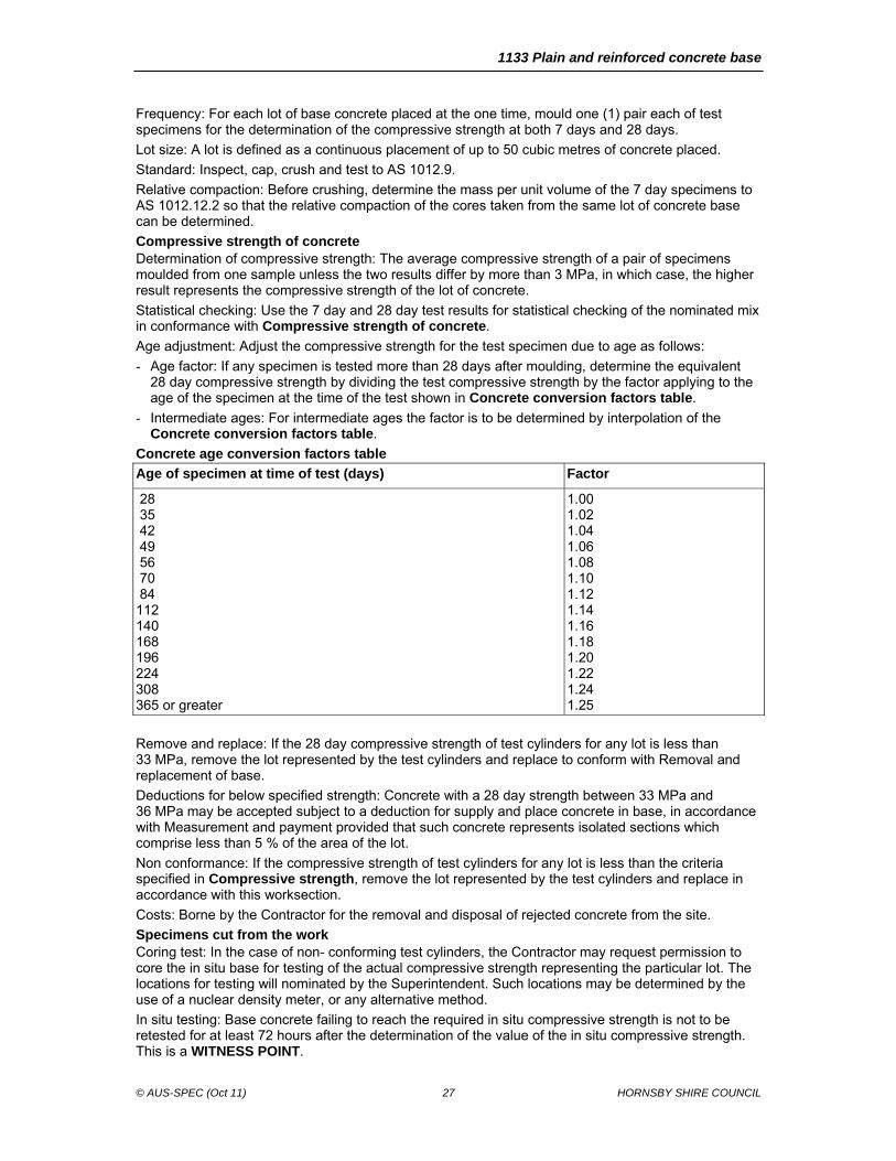
1133 Plain and reinforced concrete base
© AUS-SPEC (Oct 11) 27 HORNSBY SHIRE COUNCIL
Frequency: For each lot of base concrete placed at the one time, mould one (1) pair each of test specimens for the determination of the compressive strength at both 7 days and 28 days.
Lot size: A lot is defined as a continuous placement of up to 50 cubic metres of concrete placed.
Standard: Inspect, cap, crush and test to AS 1012.9.
Relative compaction: Before crushing, determine the mass per unit volume of the 7 day specimens to AS 1012.12.2 so that the relative compaction of the cores taken from the same lot of concrete base can be determined.
Compressive strength of concrete Determination of compressive strength: The average compressive strength of a pair of specimens moulded from one sample unless the two results differ by more than 3 MPa, in which case, the higher result represents the compressive strength of the lot of concrete.
Statistical checking: Use the 7 day and 28 day test results for statistical checking of the nominated mix in conformance with Compressive strength of concrete.
Age adjustment: Adjust the compressive strength for the test specimen due to age as follows:
- Age factor: If any specimen is tested more than 28 days after moulding, determine the equivalent 28 day compressive strength by dividing the test compressive strength by the factor applying to the age of the specimen at the time of the test shown in Concrete conversion factors table.
- Intermediate ages: For intermediate ages the factor is to be determined by interpolation of the Concrete conversion factors table.
Concrete age conversion factors table
Age of specimen at time of test (days) Factor
28 35 42 49 56 70 84 112 140 168 196 224 308 365 or greater
1.00 1.02 1.04 1.06 1.08 1.10 1.12 1.14 1.16 1.18 1.20 1.22 1.24 1.25
Remove and replace: If the 28 day compressive strength of test cylinders for any lot is less than 33 MPa, remove the lot represented by the test cylinders and replace to conform with Removal and replacement of base.
Deductions for below specified strength: Concrete with a 28 day strength between 33 MPa and 36 MPa may be accepted subject to a deduction for supply and place concrete in base, in accordance with Measurement and payment provided that such concrete represents isolated sections which comprise less than 5 % of the area of the lot.
Non conformance: If the compressive strength of test cylinders for any lot is less than the criteria specified in Compressive strength, remove the lot represented by the test cylinders and replace in accordance with this worksection.
Costs: Borne by the Contractor for the removal and disposal of rejected concrete from the site.
Specimens cut from the work Coring test: In the case of non- conforming test cylinders, the Contractor may request permission to core the in situ base for testing of the actual compressive strength representing the particular lot. The locations for testing will nominated by the Superintendent. Such locations may be determined by the use of a nuclear density meter, or any alternative method.
In situ testing: Base concrete failing to reach the required in situ compressive strength is not to be retested for at least 72 hours after the determination of the value of the in situ compressive strength. This is a WITNESS POINT.
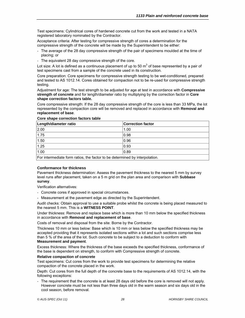
1133 Plain and reinforced concrete base
© AUS-SPEC (Oct 11) 28 HORNSBY SHIRE COUNCIL
Test specimens: Cylindrical cores of hardened concrete cut from the work and tested in a NATA registered laboratory nominated by the Contractor.
Acceptance criteria: After testing for compressive strength of cores a determination for the compressive strength of the concrete will be made by the Superintendent to be either:
- The average of the 28 day compressive strength of the pair of specimens moulded at the time of placing; or
- The equivalent 28 day compressive strength of the core.
Lot size: A lot is defined as a continuous placement of up to 50 m3 of base represented by a pair of test specimens cast from a sample of the concrete used in its construction.
Core preparation: Core specimens for compressive strength testing to be wet-conditioned, prepared and tested to AS 1012.14. Cores obtained for compaction not to be re-used for compressive strength testing.
Adjustment for age: The test strength to be adjusted for age at test in accordance with Compressive strength of concrete and for length/diameter ratio by multiplying by the correction factor in Core shape correction factors table.
Core compressive strength: If the 28 day compressive strength of the core is less than 33 MPa, the lot represented by the compaction core will be removed and replaced in accordance with Removal and replacement of base.
Core shape correction factors table
Length/diameter ratio Correction factor
2.00 1.00
1.75 0.98
1.50 0.96
1.25 0.93
1.00 0.89
For intermediate form ratios, the factor to be determined by interpolation.
Conformance for thickness Pavement thickness determination: Assess the pavement thickness to the nearest 5 mm by survey level runs after placement, taken on a 5 m grid on the plan area and comparison with Subbase survey.
Verification alternatives:
- Concrete cores if approved in special circumstances.
- Measurement at the pavement edge as directed by the Superintendent.
Audit checks: Obtain approval to use a suitable probe whilst the concrete is being placed measured to the nearest 5 mm. This is a WITNESS POINT.
Under thickness: Remove and replace base which is more than 10 mm below the specified thickness in accordance with Removal and replacement of base.
Costs of removal and disposal from the site: Borne by the Contractor.
Thickness 10 mm or less below: Base which is 10 mm or less below the specified thickness may be accepted providing that it represents isolated sections within a lot and such sections comprise less than 5 % of the area of the lot. Such concrete to be subject to a deduction to conform with Measurement and payment.
Excess thickness: Where the thickness of the base exceeds the specified thickness, conformance of the base is dependent on strength, to conform with Compressive strength of concrete.
Relative compaction of concrete Test specimens: Cut cores from the work to provide test specimens for determining the relative compaction of the concrete placed in the work.
Depth: Cut cores from the full depth of the concrete base to the requirements of AS 1012.14, with the following exceptions:
- The requirement that the concrete is at least 28 days old before the core is removed will not apply. However concrete must be not less than three days old in the warm season and six days old in the cool season, before removal.

1133 Plain and reinforced concrete base
© AUS-SPEC (Oct 11) 29 HORNSBY SHIRE COUNCIL
- The nominal diameter of the cores > 75 mm.
Location of cores: Select the location of coring to exclude joints, steel reinforcement or tie bars from the core. The locations are not intended to be random, but are intended to ensure that the whole of the concrete base conforms to the minimum requirements of the Worksection.
Marking: Mark cores for identification.
Storage: Place cores immediately either in a tank of lime saturated water or in an individual plastic bag and sealed to prevent water loss. Keep cores stored in plastic bags in the shade.
Temperature control: Do not subject cores to temperatures in excess of either ambient temperature or 23°C whichever is the higher, and to temperature < 10°C, until delivered to the testing laboratory.
Frequency of coring: Comply with the following:
- Minimum frequency: Take a minimum of one core specimen from each lot of concrete base represented by standard cylinders moulded to conform with Concrete cylinders.
- Hand placed concrete: Take two cores to represent a section of work.
- A section of work is confined between construction joints.
- Hand-worked or placed base that is cast with machine-placed concrete and not separated from the machine-placed concrete is deemed to be part of the machine-placed concrete, and to be cored and tested as part of the machine-placed concrete base.
Curing: The core specimens to be wet conditioned to AS 1012.14 for not less than 24 hours immediately prior to testing for compaction.
Testing: To determine mass per unit volume to be carried out on specimens at age 7 days.
Relative compaction: The relative compaction of a core specimen is the ratio, expressed as a percentage, of the mass per unit volume of the core specimen to the average mass per unit volume of the standard cylinders used to determine the 7 day compressive strength from the same lot of concrete base. The mass per unit volume of both standard cylinders and cores to AS 1012.12.2.
Testing: Obtain, cure and test cores for compliance.
Rejection percentage: If the relative compaction is less than 97 %, remove and replace the lot represented by the core to conform with Removal and replacement of base. This is a WITNESS POINT.
Restoration after coring Restoration method: Clean and restore all core holes taken in the base with non-shrink cementitious concrete having a compressive strength of not less than that in the base and a maximum nominal aggregate size of 10 mm.
Surface condition: The surface of the restored hole to be similar to the surrounding surface in texture and colour. This is a WITNESS POINT.
Guarantee: Guarantee the integrity of the core for a period of 6 months after the completion of works and passage by traffic. The Contractor to make good any core sites damaged by traffic within the warranty period.
Costs: Borne by the Contractor.
4.13 REMOVAL AND REPLACEMENT OF BASE
General Replacement method: Where directed, remove and replace rejected base as follows:
- Rejected base, which extends more than 25 m longitudinally, to be replaced by mechanical means unless the slabs are odd-shaped or mismatched.
- Replacement to be in full slab widths between longitudinal joints and/or external edges.
Approval of method: At least seven days before the commencement of base removal, submit, for approval, details of the proposed methods of carrying out the work such as to prevent damage to the adjoining base and the underlying subbase. This is a HOLD POINT.
Cost: Borne by the Contractor.
Disposal: Dispose of the removed base slabs at locations acceptable to the Superintendent.
Further damage: Remove and replace any slab adjoining the removed slabs damaged by the Contractor’s operations.
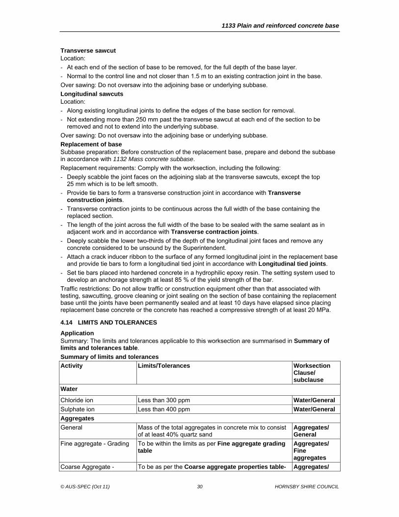
1133 Plain and reinforced concrete base
© AUS-SPEC (Oct 11) 30 HORNSBY SHIRE COUNCIL
Transverse sawcut Location:
- At each end of the section of base to be removed, for the full depth of the base layer.
- Normal to the control line and not closer than 1.5 m to an existing contraction joint in the base.
Over sawing: Do not oversaw into the adjoining base or underlying subbase.
Longitudinal sawcuts Location:
- Along existing longitudinal joints to define the edges of the base section for removal.
- Not extending more than 250 mm past the transverse sawcut at each end of the section to be removed and not to extend into the underlying subbase.
Over sawing: Do not oversaw into the adjoining base or underlying subbase.
Replacement of base Subbase preparation: Before construction of the replacement base, prepare and debond the subbase in accordance with 1132 Mass concrete subbase.
Replacement requirements: Comply with the worksection, including the following:
- Deeply scabble the joint faces on the adjoining slab at the transverse sawcuts, except the top 25 mm which is to be left smooth.
- Provide tie bars to form a transverse construction joint in accordance with Transverse construction joints.
- Transverse contraction joints to be continuous across the full width of the base containing the replaced section.
- The length of the joint across the full width of the base to be sealed with the same sealant as in adjacent work and in accordance with Transverse contraction joints.
- Deeply scabble the lower two-thirds of the depth of the longitudinal joint faces and remove any concrete considered to be unsound by the Superintendent.
- Attach a crack inducer ribbon to the surface of any formed longitudinal joint in the replacement base and provide tie bars to form a longitudinal tied joint in accordance with Longitudinal tied joints.
- Set tie bars placed into hardened concrete in a hydrophilic epoxy resin. The setting system used to develop an anchorage strength at least 85 % of the yield strength of the bar.
Traffic restrictions: Do not allow traffic or construction equipment other than that associated with testing, sawcutting, groove cleaning or joint sealing on the section of base containing the replacement base until the joints have been permanently sealed and at least 10 days have elapsed since placing replacement base concrete or the concrete has reached a compressive strength of at least 20 MPa.
4.14 LIMITS AND TOLERANCES
Application Summary: The limits and tolerances applicable to this worksection are summarised in Summary of limits and tolerances table.
Summary of limits and tolerances
Activity Limits/Tolerances Worksection Clause/ subclause
Water
Chloride ion Less than 300 ppm Water/General
Sulphate ion Less than 400 ppm Water/General
Aggregates
General Mass of the total aggregates in concrete mix to consist of at least 40% quartz sand
Aggregates/ General
Fine aggregate - Grading To be within the limits as per Fine aggregate grading table
Aggregates/ Fine aggregates
Coarse Aggregate - To be as per the Coarse aggregate properties table- Aggregates/
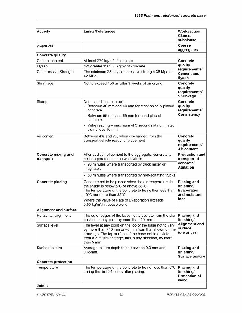
1133 Plain and reinforced concrete base
© AUS-SPEC (Oct 11) 31 HORNSBY SHIRE COUNCIL
Activity Limits/Tolerances Worksection Clause/ subclause
properties Coarse aggregates
Concrete quality
Cement content At least 270 kg/m3 of concrete Concrete quality requirements/ Cement and flyash
Flyash Not greater than 50 kg/m3 of concrete
Compressive Strength The minimum 28 day compressive strength 36 Mpa to 42 MPa
Shrinkage Not to exceed 450 µε after 3 weeks of air drying Concrete quality requirements/ Shrinkage
Slump Nominated slump to be: - Between 30 mm and 40 mm for mechanically placed
concrete.
- Between 55 mm and 65 mm for hand placed concrete.
- Vebe reading – maximum of 3 seconds at nominated slump less 10 mm.
Concrete quality requirements/ Consistency
Air content Between 4% and 7% when discharged from the transport vehicle ready for placement
Concrete quality requirements/ Air content
Concrete mixing and transport
After addition of cement to the aggregate, concrete to be incorporated into the work within:
Production and transport of concrete/ Agitation
- 90 minutes where transported by truck mixer or agitator.
- 60 minutes where transported by non-agitating trucks.
Concrete placing Concrete not to be placed when the air temperature in the shade is below 5°C or above 38°C. The temperature of the concrete to be neither less than 10°C nor more than 32°C.
Placing and finishing/ Evaporation and moisture loss Where the value of Rate of Evaporation exceeds
0.50 kg/m2/hr, cease work.
Alignment and surface
Horizontal alignment The outer edges of the base not to deviate from the plan position at any point by more than 10 mm.
Placing and finishing/ Alignment and surface tolerances
Surface level The level at any point on the top of the base not to vary by more than +10 mm or –0 mm from that shown on the drawings. The top surface of the base not to deviate from a 3 m straightedge, laid in any direction, by more than 5 mm.
Surface texture Average texture depth to be between 0.3 mm and 0.65mm.
Placing and finishing/ Surface texture
Concrete protection
Temperature The temperature of the concrete to be not less than 5°C during the first 24 hours after placing.
Placing and finishing/ Protection of work
Joints
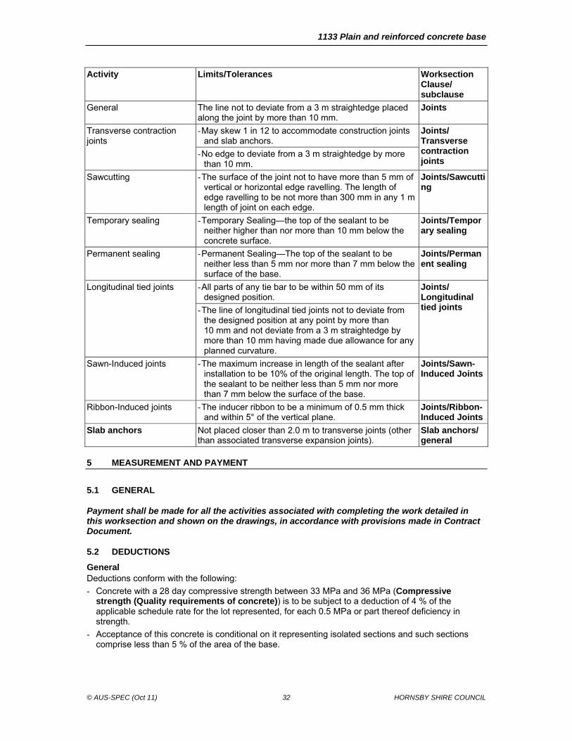
1133 Plain and reinforced concrete base
© AUS-SPEC (Oct 11) 32 HORNSBY SHIRE COUNCIL
Activity Limits/Tolerances Worksection Clause/ subclause
General The line not to deviate from a 3 m straightedge placed along the joint by more than 10 mm.
Joints
Transverse contraction joints
- May skew 1 in 12 to accommodate construction joints and slab anchors.
Joints/ Transverse contraction joints
- No edge to deviate from a 3 m straightedge by more than 10 mm.
Sawcutting - The surface of the joint not to have more than 5 mm of vertical or horizontal edge ravelling. The length of edge ravelling to be not more than 300 mm in any 1 m length of joint on each edge.
Joints/Sawcutting
Temporary sealing - Temporary Sealing—the top of the sealant to be neither higher than nor more than 10 mm below the concrete surface.
Joints/Temporary sealing
Permanent sealing - Permanent Sealing—The top of the sealant to be neither less than 5 mm nor more than 7 mm below the surface of the base.
Joints/Permanent sealing
Longitudinal tied joints - All parts of any tie bar to be within 50 mm of its designed position.
Joints/ Longitudinal tied joints - The line of longitudinal tied joints not to deviate from
the designed position at any point by more than 10 mm and not deviate from a 3 m straightedge by more than 10 mm having made due allowance for any planned curvature.
Sawn-Induced joints - The maximum increase in length of the sealant after installation to be 10% of the original length. The top of the sealant to be neither less than 5 mm nor more than 7 mm below the surface of the base.
Joints/Sawn-Induced Joints
Ribbon-Induced joints - The inducer ribbon to be a minimum of 0.5 mm thick and within 5° of the vertical plane.
Joints/Ribbon-Induced Joints
Slab anchors Not placed closer than 2.0 m to transverse joints (other than associated transverse expansion joints).
Slab anchors/ general
5 MEASUREMENT AND PAYMENT
5.1 GENERAL
Payment shall be made for all the activities associated with completing the work detailed in this worksection and shown on the drawings, in accordance with provisions made in Contract Document.
5.2 DEDUCTIONS
General Deductions conform with the following:
- Concrete with a 28 day compressive strength between 33 MPa and 36 MPa (Compressive strength (Quality requirements of concrete)) is to be subject to a deduction of 4 % of the applicable schedule rate for the lot represented, for each 0.5 MPa or part thereof deficiency in strength.
- Acceptance of this concrete is conditional on it representing isolated sections and such sections comprise less than 5 % of the area of the base.