Embed Size (px)
Citation preview
Hornsby Shire Council
ABN 20 706 996 972 PO Box 37, Hornsby NSW 1630 Phone 02 9847 6666 Email [email protected]
296 Peats Ferry Rd, Hornsby 2077 Fax 02 9847 6999 Web hornsby.nsw.gov.au
SPECIFICATION 1131
ROLLED CONCRETE SUBBASE
© AUS-SPEC (Oct 11) July 2016
1131 Rolled Concrete Subbase
© AUS-SPEC (Oct 11) HORNSBY SHIRE COUNCIL
SPECIFICATION 1131 – ROLLED CONCRETE SUBBASE
CLAUSE CONTENTS PAGE
GENERAL ............................................................................................................................................................ 1
1.1 RESPONSIBILITIES ............................................................................................................................. 1
1.2 CROSS REFERENCES ........................................................................................................................ 1
1.3 REFERENCED DOCUMENTS ............................................................................................................. 1
1.4 INTERPRETATIONS ............................................................................................................................ 2
1.5 SUBMISSIONS ..................................................................................................................................... 2
1.6 INSPECTIONS ...................................................................................................................................... 3
PRE-CONSTRUCTION PLANNING .................................................................................................................... 5
2.1 ACTIVITY PLAN .................................................................................................................................... 5
2.2 DESIGN AND CONTROL OF BASE AND SUBBASE MATERIAL ....................................................... 5
MATERIALS ......................................................................................................................................................... 5
3.1 CEMENT ............................................................................................................................................... 5
3.2 FLY ASH ............................................................................................................................................... 6
3.3 WATER ................................................................................................................................................. 6
3.4 ADMIXTURES ....................................................................................................................................... 6
3.5 AGGREGATES ..................................................................................................................................... 6
3.6 CURING AND DEBONDING COMPOUNDS ....................................................................................... 7
EXECUTION ......................................................................................................................................................... 8
4.1 PROVISION OF TRAFFIC .................................................................................................................... 8
4.2 ESTABLISHMENT ................................................................................................................................ 8
4.3 CONCRETE QUALITY REQUIREMENTS ........................................................................................... 8
4.4 TRIAL ROLLED CONCRETE SUBBASE ........................................................................................... 10
4.5 PRODUCTION AND TRANSPORT OF CONCRETE ......................................................................... 10
4.6 CONSTRUCTION PLANT AND EQUIPMENT ................................................................................... 11
1131 Rolled Concrete Subbase
© AUS-SPEC (Oct 10) HORNSBY SHIRE COUNCIL
4.7 CONCRETE PLACEMENT ................................................................................................................. 12
4.8 COMPACTION OF CONCRETE ........................................................................................................ 12
4.9 JOINTS ................................................................................................................................................ 13
4.10 CURING AND DEBONDING............................................................................................................... 14
4.11 CONCRETE CRACKING .................................................................................................................... 15
4.12 ACCEPTANCE OF CONCRETE SUBBASE ...................................................................................... 16
4.13 REMOVAL AND REPLACEMENT OF SUBBASE .............................................................................. 17
4.14 LIMITS AND TOLERENCES ............................................................................................................... 17
MEASUREMENT AND PAYMENT .................................................................................................................... 19
5.1 GENERAL ........................................................................................................................................... 19
5.2 DEDUCTIONS..................................................................................................................................... 19
1131 Rolled concrete subbase
© AUS-SPEC (Oct 11) 1 HORNSBY SHIRE COUNCIL
1131 ROLLED CONCRETE SUBBASE
1 GENERAL
1.1 RESPONSIBILITIES
Objectives General: Provide rolled concrete subbase as documented.
Performance Quality: Requirements for quality control and testing, including maximum lot sizes and minimum test frequencies to conform with 0161 Quality (Construction).
1.2 CROSS REFERENCES
General Requirement: Conform to the following:
- 0136 General requirements (Construction).
- 0161 Quality (Construction).
1.3 REFERENCED DOCUMENTS
The following documents are incorporated into this worksection by reference:
Standards AS 1012 Methods of testing concrete AS 1012.1-1993 Sampling of fresh concrete AS 1012.3.4-1998 Determination of properties related to the consistency of concrete -
Compactibility index AS 1012.8.1-2000 Method for making and curing concrete - Compression and indirect
tensile test specimens AS 1012.9-1999 Determination of the compressive strength of concrete specimens AS 1012.13-1992 Determination of the drying shrinkage of concrete for samples prepared
in the field or in the laboratory AS 1012.14-1991 Method for securing and testing cores from hardened concrete for
compressive strength AS 1141 Methods for sampling and testing aggregates AS 1141.11.1 - 2009 Particle size distribution – sieving method AS 1141.14-2007 Particle shape, by proportional calliper AS 1141.22-2008 Wet/dry strength variation AS 1160-1996 Bituminous emulsions for the construction and maintenance of pavements AS 1289 Methods of testing soils for engineering purposes AS 1289.4.2.1-1997 Determination of the sulphate content of a natural soil and the sulphate
content of the groundwater - Normal method AS 1289.5.8.1-2007 Soil compaction and density tests - Determination of field density and
field moisture content of a soil using a nuclear surface moisture-density gauge—Direct transmission mode
AS 1478 Chemical admixtures for concrete, mortar and grout AS 1478.1-2000 Admixtures for concrete AS 2350 (Various) Methods of testing portland and blended cements AS 2758 Aggregates and rock for engineering purposes AS 2758.1-1998 Concrete aggregates AS 3582 Supplementary cementitious materials for use with portland and blended
cement AS 3582.1-1998 Fly ash AS 3583 Methods of test for supplementary cementitious materials for use with
portland and blended cement AS 3583.13-1991 Determination of chloride ion content AS 3799-1998 Liquid membrane - forming curing compounds for concrete
1131 Rolled concrete subbase
© AUS-SPEC (Oct 11) 2 HORNSBY SHIRE COUNCIL
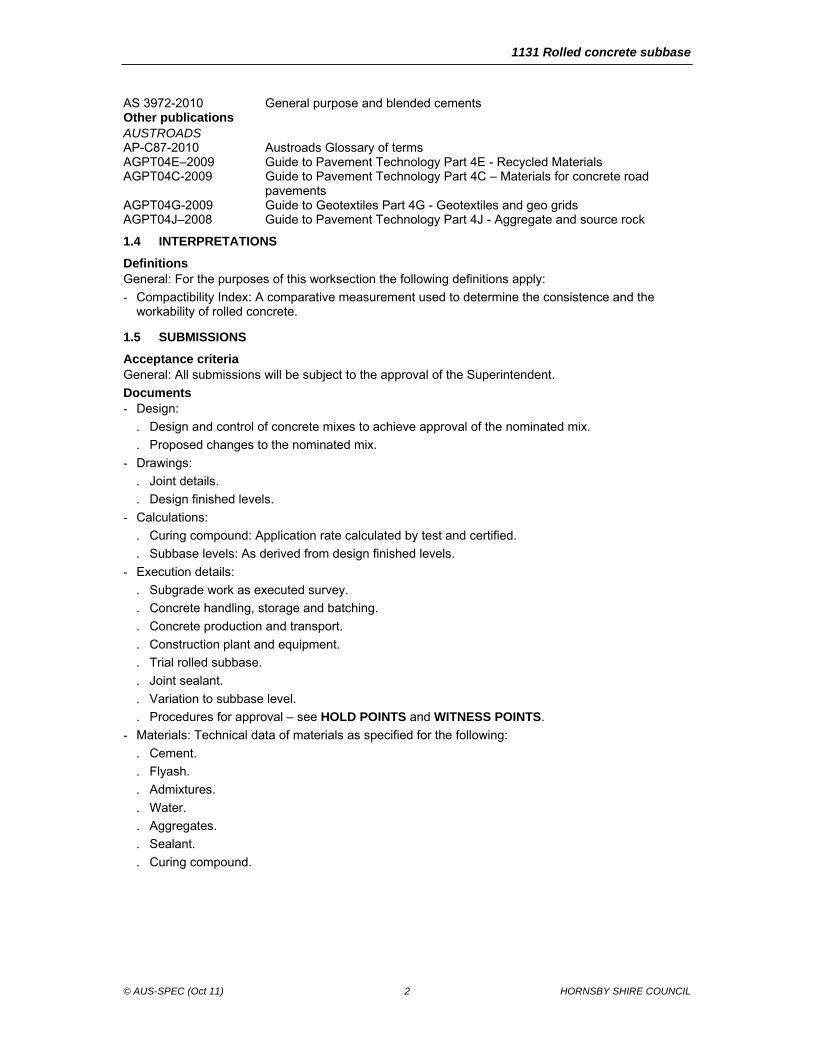
AS 3972-2010 General purpose and blended cements Other publications AUSTROADS AP-C87-2010 Austroads Glossary of terms AGPT04E–2009 Guide to Pavement Technology Part 4E - Recycled Materials AGPT04C-2009 Guide to Pavement Technology Part 4C – Materials for concrete road
pavements AGPT04G-2009 Guide to Geotextiles Part 4G - Geotextiles and geo grids AGPT04J–2008 Guide to Pavement Technology Part 4J - Aggregate and source rock
1.4 INTERPRETATIONS
Definitions General: For the purposes of this worksection the following definitions apply:
- Compactibility Index: A comparative measurement used to determine the consistence and the workability of rolled concrete.
1.5 SUBMISSIONS
Acceptance criteria General: All submissions will be subject to the approval of the Superintendent.
Documents - Design:
. Design and control of concrete mixes to achieve approval of the nominated mix.
. Proposed changes to the nominated mix.
- Drawings:
. Joint details.
. Design finished levels.
- Calculations:
. Curing compound: Application rate calculated by test and certified.
. Subbase levels: As derived from design finished levels.
- Execution details:
. Subgrade work as executed survey.
. Concrete handling, storage and batching.
. Concrete production and transport.
. Construction plant and equipment.
. Trial rolled subbase.
. Joint sealant.
. Variation to subbase level.
. Procedures for approval – see HOLD POINTS and WITNESS POINTS.
- Materials: Technical data of materials as specified for the following:
. Cement.
. Flyash.
. Admixtures.
. Water.
. Aggregates.
. Sealant.
. Curing compound.
1131 Rolled concrete subbase
© AUS-SPEC (Oct 11) 3 HORNSBY SHIRE COUNCIL
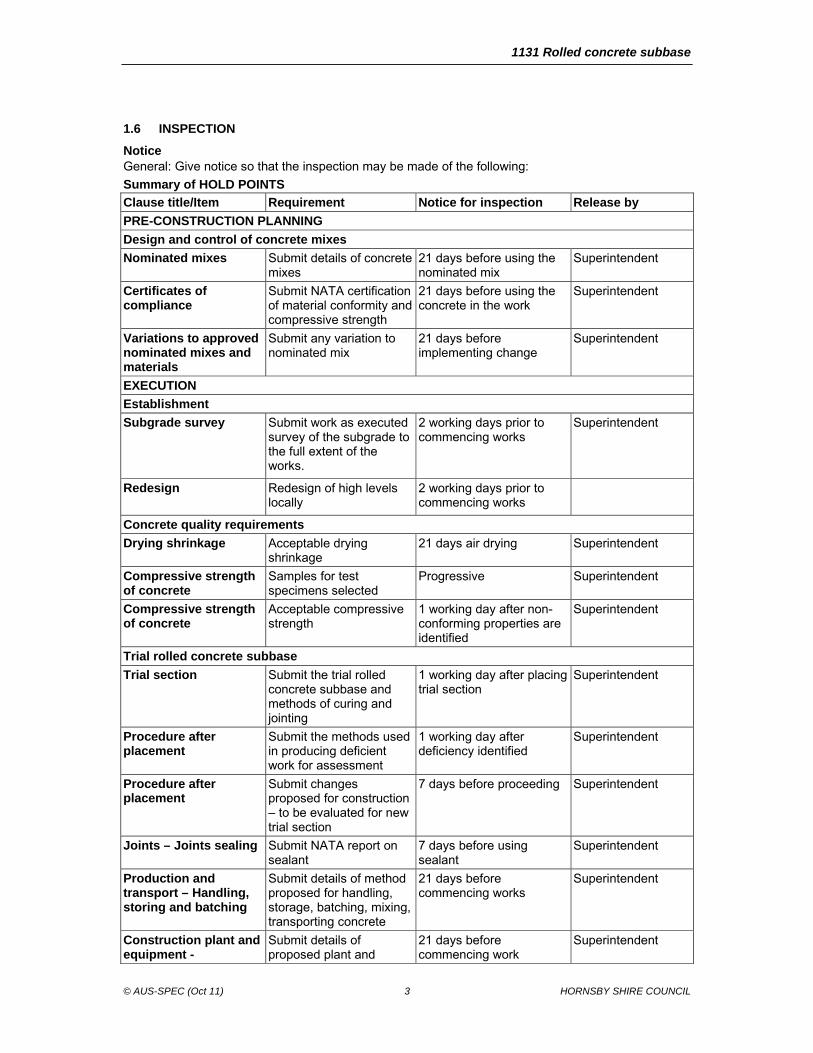
1.6 INSPECTION
Notice General: Give notice so that the inspection may be made of the following:
Summary of HOLD POINTS
Clause title/Item Requirement Notice for inspection Release by
PRE-CONSTRUCTION PLANNING
Design and control of concrete mixes
Nominated mixes Submit details of concrete mixes
21 days before using the nominated mix
Superintendent
Certificates of compliance
Submit NATA certification of material conformity and compressive strength
21 days before using the concrete in the work
Superintendent
Variations to approved nominated mixes and materials
Submit any variation to nominated mix
21 days before implementing change
Superintendent
EXECUTION
Establishment
Subgrade survey Submit work as executed survey of the subgrade to the full extent of the works.
2 working days prior to commencing works
Superintendent
Redesign Redesign of high levels locally
2 working days prior to commencing works
Concrete quality requirements
Drying shrinkage Acceptable drying shrinkage
21 days air drying Superintendent
Compressive strength of concrete
Samples for test specimens selected
Progressive Superintendent
Compressive strength of concrete
Acceptable compressive strength
1 working day after non-conforming properties are identified
Superintendent
Trial rolled concrete subbase
Trial section Submit the trial rolled concrete subbase and methods of curing and jointing
1 working day after placing trial section
Superintendent
Procedure after placement
Submit the methods used in producing deficient work for assessment
1 working day after deficiency identified
Superintendent
Procedure after placement
Submit changes proposed for construction – to be evaluated for new trial section
7 days before proceeding Superintendent
Joints – Joints sealing Submit NATA report on sealant
7 days before using sealant
Superintendent
Production and transport – Handling, storing and batching
Submit details of method proposed for handling, storage, batching, mixing, transporting concrete
21 days before commencing works
Superintendent
Construction plant and equipment -
Submit details of proposed plant and
21 days before commencing work
Superintendent
1131 Rolled concrete subbase
© AUS-SPEC (Oct 11) 4 HORNSBY SHIRE COUNCIL
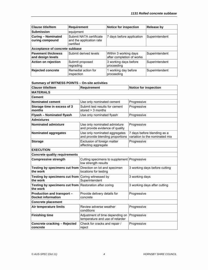
Clause title/Item Requirement Notice for inspection Release by
Submission equipment
Curing – Nominated curing compound
Submit NATA certificate and the application rate certified
7 days before application Superintendent
Acceptance of concrete subbase
Pavement thickness and design levels
Submit derived levels Within 3 working days after completion of works
Superintendent
Action on rejection Submit proposed regrading
3 working days before proceeding
Superintendent
Rejected concrete Remedial action for inspection
1 working day before proceeding
Superintendent
Summary of WITNESS POINTS – On-site activities
Clause title/Item Requirement Notice for inspection
MATERIALS
Cement
Nominated cement Use only nominated cement Progressive
Storage time in excess of 3 months
Submit test results for cement stored > 3 months
Progressive
Flyash – Nominated flyash Use only nominated flyash Progressive
Admixtures
Nominated admixture Use only nominated admixture and provide evidence of quality
Progressive
Nominated aggregates Use only nominated aggregates and provide blending proportions
7 days before blending as a variation to the nominated mix
Storage Exclusion of foreign matter affecting aggregate
Progressive
EXECUTION
Concrete quality requirements
Compressive strength Cutting specimens to supplement low strength results
Progressive
Testing by specimens cut from the work
Direction on lot and specimen locations for testing
3 working days before cutting
Testing by specimens cut from the work
Coring witnessed by Superintendent
3 working days
Testing by specimens cut from the work
Restoration after coring 3 working days after cutting
Production and transport – Docket information
Provide delivery details for concrete
Progressive
Concrete placement
Air temperature limits Review adverse weather conditions
Progressive
Finishing time Adjustment of time depending on temperature and use of retarder
Progressive
Concrete cracking – Rejected concrete
Check for cracks and repair / reject
Progressive
1131 Rolled concrete subbase
© AUS-SPEC (Oct 11) 5 HORNSBY SHIRE COUNCIL
2 PRE-CONSTRUCTION PLANNING
2.1 ACTIVITY PLAN
General Program: Plan the following activities:
- Provide planning resources to allocate plant and personnel for the contract period.
- Program the work to meet the constraints of HOLD POINTS and WITNESS POINTS.
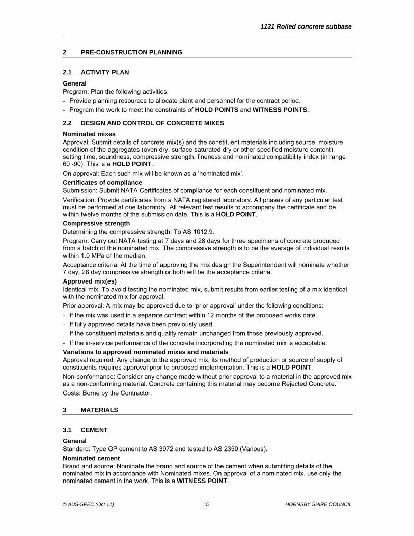
2.2 DESIGN AND CONTROL OF CONCRETE MIXES
Nominated mixes Approval: Submit details of concrete mix(s) and the constituent materials including source, moisture condition of the aggregates (oven dry, surface saturated dry or other specified moisture content), setting time, soundness, compressive strength, fineness and nominated compatibility index (in range 60 -90). This is a HOLD POINT.
On approval: Each such mix will be known as a ‘nominated mix’.
Certificates of compliance Submission: Submit NATA Certificates of compliance for each constituent and nominated mix.
Verification: Provide certificates from a NATA registered laboratory. All phases of any particular test must be performed at one laboratory. All relevant test results to accompany the certificate and be within twelve months of the submission date. This is a HOLD POINT.
Compressive strength Determining the compressive strength: To AS 1012.9.
Program: Carry out NATA testing at 7 days and 28 days for three specimens of concrete produced from a batch of the nominated mix. The compressive strength is to be the average of individual results within 1.0 MPa of the median.
Acceptance criteria: At the time of approving the mix design the Superintendent will nominate whether 7 day, 28 day compressive strength or both will be the acceptance criteria.
Approved mix(es) Identical mix: To avoid testing the nominated mix, submit results from earlier testing of a mix identical with the nominated mix for approval.
Prior approval: A mix may be approved due to ‘prior approval’ under the following conditions:
- If the mix was used in a separate contract within 12 months of the proposed works date.
- If fully approved details have been previously used.
- If the constituent materials and quality remain unchanged from those previously approved.
- If the in-service performance of the concrete incorporating the nominated mix is acceptable.
Variations to approved nominated mixes and materials Approval required: Any change to the approved mix, its method of production or source of supply of constituents requires approval prior to proposed implementation. This is a HOLD POINT.
Non-conformance: Consider any change made without prior approval to a material in the approved mix as a non-conforming material. Concrete containing this material may become Rejected Concrete.
Costs: Borne by the Contractor.
3 MATERIALS
3.1 CEMENT
General Standard: Type GP cement to AS 3972 and tested to AS 2350 (Various).
Nominated cement Brand and source: Nominate the brand and source of the cement when submitting details of the nominated mix in accordance with Nominated mixes. On approval of a nominated mix, use only the nominated cement in the work. This is a WITNESS POINT.
1131 Rolled concrete subbase
© AUS-SPEC (Oct 11) 6 HORNSBY SHIRE COUNCIL
Proof of quality: Provide documentary evidence of the quality and source of the cement upon request at any stage of the work.
Storage time in excess of 3 months Compliance testing: Retest cement which has been stored for a period in excess of three months from the time of manufacture to ensure the cement complies with AS 3972. Submit test results before use. This is a WITNESS POINT.
Costs: Borne by the Contractor.
Transport and storage Quality: Transport cement in watertight packaging and protected from moisture until used. Do not use caked or lumpy cement.
3.2 FLY ASH
General Standard: Fly ash to AS 3582.1.
Nominated fly ash Powerhouse source: Nominate the source of the fly ash to conform with Nominated mixes. On approval of a nominated mix, use only the fly ash from the nominated powerhouse. This is a WITNESS POINT.
Proof of quality: Provide documentary evidence of the quality and source of the fly ash upon request at any stage of the work.
3.3 WATER
General Standard: Chloride ion to AS 3583.13 and sulphate ion to AS 1289.4.2.1.
Quality: Water used in the production of concrete to be potable, free from materials harmful to concrete or reinforcement, and be neither salty nor brackish.
Limits: The water used must not contain more than:
- 300 parts per million of chloride ion, determined by AS 3583.13;
- 400 parts per million of sulphate ion, determined by AS 1289.4.2.1.
3.4 ADMIXTURES
General Standard: Chemical admixtures to comply with AS 1478.1.
Quality: Admixtures not to contain calcium chloride, calcium formate, or triethanolamine or any other accelerator. Do not use admixtures or combinations of admixtures without prior approval.
Dosage: Vary the dosage of chemical admixture to account for air temperature and setting time in to conform with the manufacturer’s recommendations.
Nominated admixture Source and type: Nominate the proprietary source, type, dose rate, name and method of incorporation of each admixture for use to conform with Nominated mixes. On approval of a nominated mix, use only the admixture and dosage that is approved.
Variation to mixture: If the Contractor proposes to vary the admixture between warm and cool seasons such variation is to constitute a proposed change to an approved mix for the purposes of Variations to approved nominated mixes and materials. This is a WITNESS POINT.
Proof of quality: Provide documentary evidence of the quality upon request at any stage of the work.
3.5 AGGREGATES
General Standards: As 2758.1 and Austroads AGPT04J.
Requirement: Aggregates passing the 37.5 mm AS sieve comply with AS 2758.1 in respect of bulk density, water absorption (maximum 5 %), material finer than 75 µm, impurities and reactive materials. Misshapen particles: The proportion of misshapen particles (2:1 ratio) determined by AS 1141.14 < 35 %.
1131 Rolled concrete subbase
© AUS-SPEC (Oct 11) 7 HORNSBY SHIRE COUNCIL
Quality: In the production of concrete use only aggregate that is clean, hard, durable rock fragments free from the inclusion of mineral salts, oils, organic matter or other materials deleterious to the performance of concrete.
Durability of all aggregates: Conform to AS 1141.22 and the following:
- Wet Strength > 50 kN.
- 10% Fines Wet/Dry Variation < 35%.
Recycled concrete aggregate (RCA): The use of course aggregates from demolition concrete or RCA to conform with SAA HB155 and Austroads AGPT04E.
Blending: If blending coarse RCA with natural aggregates ensure substitution rates are below 30 %.
Nominated aggregates Source and type: Nominate the sources of aggregate proposed for use and submit details of the geological type of each aggregate.
Proposed grading: Provide NATA Certified Laboratory Test Reports on the quality and grading of the aggregate proposed for use.
Blending of aggregates: Submit test reports for each constituent material showing the proportions in which the various sizes are combined. The aggregate from each source and the combined aggregate to comply with the requirements of this Clause. This is a WITNESS POINT.
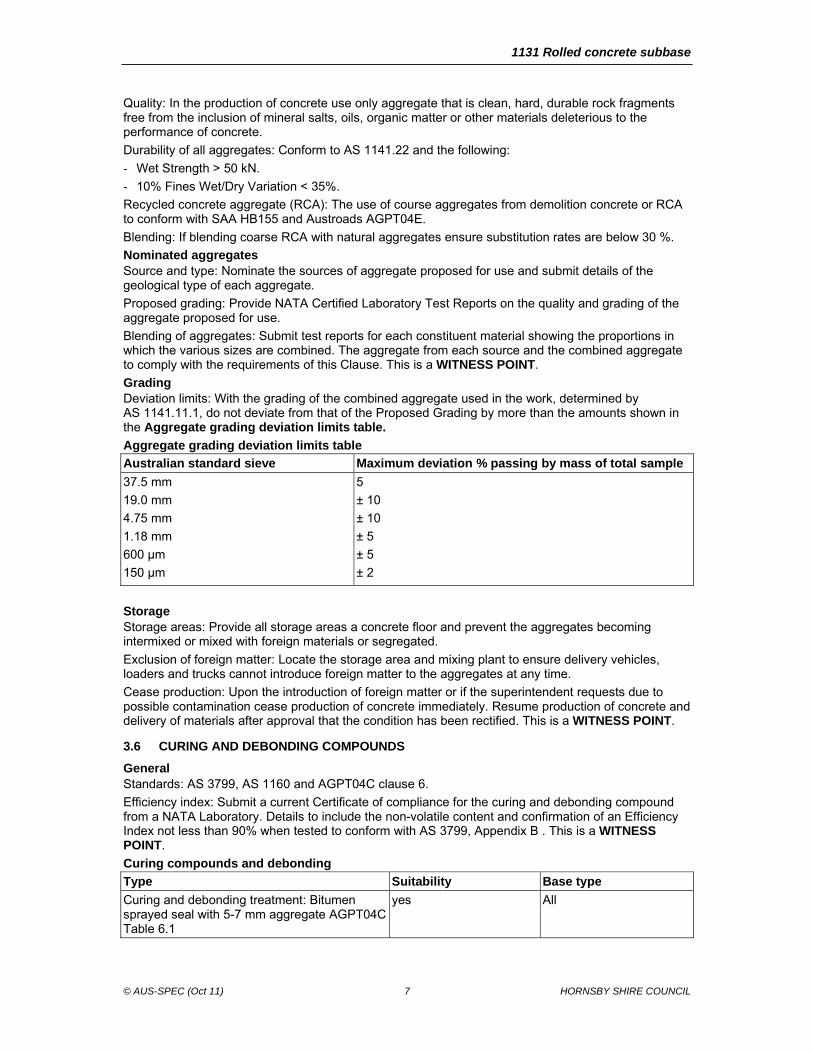
Grading Deviation limits: With the grading of the combined aggregate used in the work, determined by AS 1141.11.1, do not deviate from that of the Proposed Grading by more than the amounts shown in the Aggregate grading deviation limits table.
Aggregate grading deviation limits table
Australian standard sieve Maximum deviation % passing by mass of total sample
37.5 mm
19.0 mm
4.75 mm
1.18 mm
600 µm
150 µm
5
± 10
± 10
± 5
± 5
± 2
Storage Storage areas: Provide all storage areas a concrete floor and prevent the aggregates becoming intermixed or mixed with foreign materials or segregated.
Exclusion of foreign matter: Locate the storage area and mixing plant to ensure delivery vehicles, loaders and trucks cannot introduce foreign matter to the aggregates at any time.
Cease production: Upon the introduction of foreign matter or if the superintendent requests due to possible contamination cease production of concrete immediately. Resume production of concrete and delivery of materials after approval that the condition has been rectified. This is a WITNESS POINT.
3.6 CURING AND DEBONDING COMPOUNDS
General Standards: AS 3799, AS 1160 and AGPT04C clause 6.
Efficiency index: Submit a current Certificate of compliance for the curing and debonding compound from a NATA Laboratory. Details to include the non-volatile content and confirmation of an Efficiency Index not less than 90% when tested to conform with AS 3799, Appendix B . This is a WITNESS POINT.
Curing compounds and debonding
Type Suitability Base type
Curing and debonding treatment: Bitumen sprayed seal with 5-7 mm aggregate AGPT04C Table 6.1
yes All
1131 Rolled concrete subbase
© AUS-SPEC (Oct 11) 8 HORNSBY SHIRE COUNCIL
4 EXECUTION
4.1 PROVISION FOR TRAFFIC
General Control of traffic: Conform to the following:
- Conform with worksection 1101 Control of traffic.
- Conform with Traffic Guidance Scheme in 1101 Control of traffic.
4.2 ESTABLISHMENT
Subgrade survey Measure the subbase invert levels: If the underlying layer is required to be spray sealed, take levels on the top of the seal and after removal of foreign or loose material such as aggregate.
Method: Report levels to the nearest mm and survey on 5.0 m grid on a plan area.
Requirement: Submit work as executed survey of the subgrade to the full extent of the works. Highlight any locations where the actual level is higher then the design levels. This is a HOLD POINT.
Redesign Nonconforming levels: In the case of high nonconforming levels locally redesign the pavement levels as directed by the Superintendent. This is a HOLD POINT.
4.3 CONCRETE QUALITY REQUIREMENTS
Fly ash content Requirement: The fly ash content of the concrete must be within the range 40 – 75 % by mass of the total cementitious material (cement and fly ash) and comply with the requirements of AS 3582.1.
Moisture content Trial mix: The moisture content at the point of delivery must allow the production of a non-segregated concrete mix as determined by trial mix.
Consistency Compactibility measurement: Measure the consistence of the concrete at the point of discharge immediately prior to incorporation into the work using the test method for Index of Compactibility described in AS 1012.3.4.
Nominal consistency: Confirm the nominal consistency during placement of the trial pavement.
Limit range: Maintain the consistency within 10 of the nominated compactibility index to permit adequate compaction of the concrete by the paver and rollers.
Determine the Compactibility Index: CI, expressed to the nearest whole number, as follows:
C I= (300 – x)/3
where ‘x’ = mean drop in surface level due to compaction in mm.
Drying shrinkage Trial mix(s): Determine the drying shrinkage of the concrete from trial mixes in to AS 1012.13, except compact in 2 layers using a vibrating table and hand tamping to ensure full compaction is achieved.
Test moulds: Mark moulds indicating name of sampler, date and representative area within the works. Do not remove moulds until the concrete has gained sufficient strength so as not to damage specimens.
Limit: Drying shrinkage determined after 21 days air drying not to exceed 450 µε.
Non compliance: Any sample from a lot that does not comply with this clause is deemed as non-complying concrete.
Submit: All non-complying concrete areas for direction on whether it is to be treated as Rejected concrete. This is a HOLD POINT.
Requirement: Contractor to bear the cost to cover testing, removal or reinstatement of concrete to comply with this specification.
Compressive strength of concrete Minimum: Compressive strength for flyash blended cement at 7 days > 4 MPa, 28 days ≥ 5 MPa, unless otherwise specified.
1131 Rolled concrete subbase
© AUS-SPEC (Oct 11) 9 HORNSBY SHIRE COUNCIL
Maximum: Compressive strength at 28 days < 15 MPa, except when the nominated mix demonstrates a 28 day shrinkage less then 400 µε, acceptable compressive strength < 20 MPa.
Point of sampling: Mould test specimens for determining the compressive strength of rolled concrete from samples taken from the delivery vehicles, or from rolled concrete deposited ready for placement, to conform with AS 1012.1.
Frequency of testing: A sample will be selected by the Superintendent to represent the whole of the concrete being placed at one time or 50 tonnes, whichever is less. This is a HOLD POINT.
Number of moulds: Mould at least one pair of compressive strength specimens is to be moulded from the sample to represent any such lot of the work.
Method of moulding: To AS 1012.8.1 or by an approved equivalent compaction procedure.
Costs: Borne by the Contractor.
Curing: To AS 1012.8.1. Carry out initial curing on site between 18 – 36 hours. Defer demoulding for a further 48 hours during which time prevent the specimen moulds from drying.
Test method: Cap specimens and test at a nominated NATA registered laboratory to AS 1012.8.1 and AS 1012.9.
Strength determination: Average strength of a pair of specimens made from one sample using the accepted criteria of 7 or 28 day compressive strength or both. This is a HOLD POINT.
Strength: If less than 80% of design strength, concrete is rejected. If strength between 80 to 100% of design strength see Deductions.
Testing by specimens cut from the work Coring test: In the case of non-conforming test cylinders, the Contractor may request permission to core the in situ subbase for testing of the actual compressive strength representing the particular lot. The locations for testing will be nominated by the Superintendent. This is a WITNESS POINT.
In situ testing: Do not retest subbase concrete failing to reach the required in situ compressive strength for at least 72 hours after the determination of the value of the in situ compressive strength.
Test specimens: Cylindrical cores of hardened concrete cut from the work and tested in a NATA registered laboratory nominated by the Contractor.
Frequency of coring: Adopt a frequency of coring such that a core is taken to represent each lot or the subbase placed between any two consecutive construction joints whichever is the lesser. Nominate the lot represented by each core at the time of sampling and duly record prior to testing.
Supervision: Carry out core cutting in the presence of and at the locations nominated by the Superintendent. This is a WITNESS POINT.
Curing of cores: Despatch cores to arrive at the testing laboratory within 24 hours of the core being cut from the subbase. Commence wet curing within 24 hours of the receipt of the cores.
Costs: Borne by the Contractor.
Test method: To AS 1012.14 and the following:
- Concrete is not required to be at least 28 days old before the core is removed. Concrete must have hardened enough to permit removal without disturbing the bond between the mortar and the coarse aggregate.
- The preferred dimension for cores is 100 mm diameter but in no case is the diameter to be less than 75 mm or two and one half times the nominal size of the coarse aggregate, whichever is the greater.
- If inspected in the uncapped state, reject cores if any diameter departs by more than 5 mm from the mean diameter.
- Reject cores where the length of the core when ready for capping is less than the diameter.
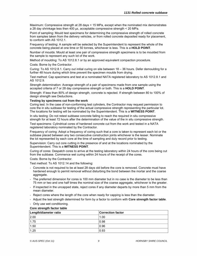
- Adjust the test strength determined for form by a factor to conform with Core strength factor table.
- Only use wet conditioning.
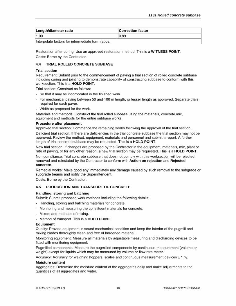
Core strength factor table
Length/diameter ratio Correction factor
2.00 1.00
1.75 0.98
1.50 0.96
1.25 0.93
1131 Rolled concrete subbase
© AUS-SPEC (Oct 11) 10 HORNSBY SHIRE COUNCIL
Length/diameter ratio Correction factor
1.00 0.89
Interpolate factors for intermediate form ratios.
Restoration after coring: Use an approved restoration method. This is a WITNESS POINT.
Costs: Borne by the Contractor.
4.4 TRIAL ROLLED CONCRETE SUBBASE
Trial section Requirement: Submit prior to the commencement of paving a trial section of rolled concrete subbase including curing and jointing to demonstrate capability of constructing subbase to conform with this worksection. This is a HOLD POINT.
Trial section: Construct as follows:
- So that it may be incorporated in the finished work.
- For mechanical paving between 50 and 100 m length, or lesser length as approved. Separate trials required for each paver.
- Width as proposed for the work.
Materials and methods: Construct the trial rolled subbase using the materials, concrete mix, equipment and methods for the entire subbase works.
Procedure after placement Approved trial section: Commence the remaining works following the approval of the trial section.
Deficient trial section: If there are deficiencies in the trial concrete subbase the trial section may not be approved. Review the method, equipment, materials and personnel and submit a report. A further length of trial concrete subbase may be requested. This is a HOLD POINT.
New trial section: If changes are proposed by the Contractor in the equipment, materials, mix, plant or rate of paving, or for any other reason, a new trial section may be requested. This is a HOLD POINT.
Non compliance: Trial concrete subbase that does not comply with this worksection will be rejected, removed and reinstated by the Contractor to conform with Action on rejection and Rejected concrete.
Remedial works: Make good any immediately any damage caused by such removal to the subgrade or subgrade beams and notify the Superintendent.
Costs: Borne by the Contractor.
4.5 PRODUCTION AND TRANSPORT OF CONCRETE
Handling, storing and batching Submit: Submit proposed work methods including the following details:
- Handling, storing and batching materials for concrete.
- Monitoring and measuring the constituent materials for concrete.
- Mixers and methods of mixing.
- Method of transport. This is a HOLD POINT.
Equipment Quality: Provide equipment in sound mechanical condition and keep the interior of the pugmill and mixing blades thoroughly clean and free of hardened material.
Monitoring equipment: Measure all materials by adjustable measuring and discharging devices to be fitted with monitoring equipment.
Pugmilled components: Measure the pugmilled components by continuous measurement (volume or weight) except for liquids which may be measured by volume or flow rate meter.
Accuracy: Accuracy for weighing hoppers, scales and continuous measurement devices ± 1 %.
Moisture content Aggregates: Determine the moisture content of the aggregates daily and make adjustments to the quantities of all aggregates and water.
1131 Rolled concrete subbase
© AUS-SPEC (Oct 11) 11 HORNSBY SHIRE COUNCIL
Delivery of mixed material Segregation: Do not deliver to the work area segregated or non-uniformly mixed material.
Time limits: Unless the mix contains approved retarder of the recommended dosage limit the time from mixing to delivery at site to maximum 45 minutes.
Evaporation: If loss of moisture is likely to occur in the delivered mix due to the haul distance from the plant and because of the effects of evaporation, cover the loads to prevent such moisture loss.
Docket information Submit: If requested at any time submit all relevant information regarding the delivery of each batch of mix include the following delivery information details:
- Supplier name and location.
- Volume of material supplied.
- Product constituents.
- Dispatch time and date. This is a WITNESS POINT.
4.6 CONSTRUCTION PLANT AND EQUIPMENT
Proposed plant Submission: Submit all details of Plant and Equipment proposed before commencing work. This is a HOLD POINT.
Paver equipment Paving machines: Select paving equipment to conform to the following:
- Designed to pug mill concrete conforming with nominated mix constituents.
- Heavy duty, self propelled, track driven.
- Have sufficient mass and stability to spread and finish concrete to the specified thickness, smoothness and surface texture without segregation.
- Have a hopper, distributing screws, a vibrating screed and interchangeable side forms.
- For surface course applications have at least one tamping bar with a minimum amplitude of 5 mm.
- Adjustable screed for pavement widths 3.0 to 5.0 m.
- Capacity consistent with the output of the pugmill.
- Paving at variable speeds and depths and reversing.
Level controls: Provide the paver screed with automatic and manual level controls separately operating both sides and capable of operating within 5 mm relative to the present or established datum.
Sensor operation: Provide sensors operating the automatic level control capable of operating from the following:
- A guideline of tensioned string or wire, set to within 5 mm of design levels and supported on preset blocks or pegs spaced at intervals not greater than 10 m.
- A levelling beam.
- A matching shoe travelling on a previously laid layer of material. The matching shoe to provide level control ensuring that the material being laid matches the level of the previously laid layer, at the junction of the two, after compaction has been completed.
- Approved computer based levelling system.
Water carts Wheel load: Maximum 2.8 t wheel load of a watering plant travelling over concrete pavement courses within 7 days of placement,.
Spraying requirement: Provide watering plant with spray bars capable of uniformly distributing water and be fitted with rapid acting positive shut-off valves controlled from the operator’s cabin.
Application: Apply water in such a manner that the surface of the concrete pavement does not form a slurry nor eroded.
Compaction plant Rollers: Conform to the following:
- Self propelled preferably with automatic vibration shut off when the progress of the roller stops.
1131 Rolled concrete subbase
© AUS-SPEC (Oct 11) 12 HORNSBY SHIRE COUNCIL
- Fitted with brushes or similar devices to enable the contact surface of each roll or tyre to be kept uniformly damp with a minimum amount of water and free from foreign material. The taps controlling the rate of flow readily accessible to the operator.
- Water is not allowed to run directly from taps on to the concrete being compacted.
- The initial rollers to be tandem, single or vibrating smooth drum rollers with a minimum static mass of 8.5 t and a minimum static load intensity of 2.0 t/m width of vibrating drum.
- Pneumatic tyred multi-wheeled rollers to have smooth tyres of equal size. Offset the rear wheels relative to the front wheels to give overlapping tyre paths and complete coverage for the effective width of the roller. Ballast the roller for loads between 1.5 t and 2.0 t per wheel and the tyre pressure adjustable between 250 kPa and 650 kPa.
- Combination rollers which conform with the requirements of this Clause are permitted.
- Finishing rollers to have a smooth steel wheeled tandem or single drum roller weighing between 5 t and 10 t.
Spraying equipment for curing, bonding or de-bonding compounds Spray nozzle capacity: To cover the full paved width with a uniform cover of curing compound in a single pass.
Compound suspension: Provide equipment to maintain the compound in suspension. Adequately protect the spray from the wind effects and after shut off avoid dripping of compound from the spray nozzles.
4.7 CONCRETE PLACEMENT
Air temperature limits Discontinuation of works: Do not place concrete during rain or when the shade temperature is below 10°C or above 30°C, unless appropriate heating or cooling procedures are adapted. In the event of light rain falling during placement, paving to continue at the discretion of the Superintendent, until all truck loads of mix in transit from the pugmill are placed. This is a WITNESS POINT.
Finishing time Normal conditions: Place, compact and finish the concrete within 90 minutes of mixing (unless it contains an approved retarder of the recommended dosage).
High air temperatures: When the shade temperature exceeds 30° place, compact and finish the concrete within 60 minutes of mixing. Adjustments may be made if a retarder is approved. This is a WITNESS POINT.
Use of guide lines (stringlines or wires) Guidelines: Set guide lines to within 5 mm of design levels and tensioned across pegs spaced at appropriate intervals to minimise sag. On all sag vertical curves and on all horizontal curves hold the wires in such a way that the design alignment and profile are accurately followed.
4.8 COMPACTION OF CONCRETE
General Compaction: To be uniform.
Timing: Commence compaction by roller immediately after paver placement.
Roller operator responsibility: Disengage any vibratory mechanism of a roller before stopping or reversing the direction of the roller. Keep roller wheels free from any build-up and surface defects occurring as a result of rolling to be corrected immediately.
Initial rolling Roll location: Perform initial rolling with a steel vibrating roller, with the driving roll nearer the paver except on steep grades or on sharp curves where the steering roll is to be nearer the paver.
Rolled joints: Roll joints with previously laid material first and then continue rolling longitudinally. Overhang the roller over the supported edge of the paver run.
Roller passes: Overlap each longitudinal pass over the previous pass by at least 600 mm.
Secondary rolling Roll location: Perform secondary rolling as soon as possible after initial rolling using a self-propelled pneumatic tyred roller with the driving wheels nearer the paver except on steep grades or on sharp curves where the steering wheels are to be nearer the paver.
1131 Rolled concrete subbase
© AUS-SPEC (Oct 11) 13 HORNSBY SHIRE COUNCIL
Roller passes: Carry out rolling longitudinally with each roller pass to overlap the previous pass by at least 600 mm. Make adjacent passes of different lengths.
Final rolling Roller marks: Eliminate roller marks during final rolling using a steel wheeled non-vibrating roller.
4.9 JOINTS
General Construct joints: As shown on drawings unless otherwise approved or directed.
Fresh joints: Joints are considered to be fresh joints when concrete on either side of the joint has been mixed within a 90 minute interval, or 60 minute interval when the air temperature is over 30°C, (unless the mix contains an approved retarder) and provided the concrete is still green.
Construction joints: All other joints are considered to be construction joints or cold joints.
Transverse jointing: Make transverse joints continuous from edge to edge of the pavement.
Raking excess concrete: Push back any concrete placed by the paver on the edge of a previously placed paver run by use of a rake to the edge of the paver run being placed. Rake or remove concrete to ensure production of a smooth, dense joint.
Disposal of excess concrete: Remove all excess concrete from site by approved methods.
Longitudinal joints Layout of longitudinal joints: Construct longitudinal joints parallel to the centreline of the pavement.
Overlap previous run: For cold longitudinal joints overlap the screed of the paver with the previously placed paver run, sufficiently high so that compaction will produce a smooth, dense joint.
Compaction of fresh joints Longitudinal joint compaction: Do not carry out rolling within 0.3 m of the proposed longitudinal joint during the first paver run. Compact this initially uncompacted section together with the adjoining paver run.
Transverse joint compaction: Stop the rolling of the initial strip about 0.5 m from the proposed joint and compact this initially uncompacted with the beginning of the succeeding run to form the joint.
Full depth compaction: Use extra passes of the vibratory roller or other compaction equipment or hand finishing as necessary to ensure full depth compaction and the specified surface finish at the joint.
Transverse construction joints Location of cold joints: Form a cold joint when the adjoining concrete was placed outside the time requirements specified in this Clause or where the adjoining concrete shows signs of setting. Organise work to minimise the length of cold joints.
Method of construction: Cut back the edge of the previously placed concrete by sawing the concrete, to at least 1/3 the slab depth to expose an even, clean, sound, vertical surface, without disturbing the concrete that is to remain in place. Remove the balance of section without undercutting so as to provide a face of full thickness of the pavement.
Layout: Construct cold transverse construction joints either normal to or at 1 in 6 skew to the centre line and not formed within 3.0 m of a planned contraction joint.
Tolerance: 20 mm maximum deviation from a 3 m straight edge.
Transverse contraction joints Time of sawing: At an appropriate time so as to prevent cracking of the concrete.
Spacing: Approximately 10 m.
Tolerance: 20 mm maximum deviation from a 3 m straight edge.
Method of construction: Do not construct sawn contraction joints within 1.5m of a transverse expansion joint. Initially form the joints as a sawn groove 3 mm wide to a depth approximately 1/3 the slab depth, sawn in the sequence of concrete placement. Before sawing a joint, examine the concrete layer closely for cracks and saw the joints within 1 m of any crack.
Method of cleaning: Wash saw debris from all joint grooves and pavement after sawing. Do not damage the groove or leave any substance deleterious to the concrete or to the adhesion of the joint sealants to be used. Incorporate jetting at an appropriately high pressure.
1131 Rolled concrete subbase
© AUS-SPEC (Oct 11) 14 HORNSBY SHIRE COUNCIL
Sealing joints Preliminary sealing: After cleaning install a continuous UV-stable PVC spline at the top of the groove. Allow the maximum increase in length of a preliminary seal after installation of 10 % of the original length.
Permanent sealing: After preliminary sealing, or after cleaning following the second sawcut, if the groove is produced by a two-cut operation, the pavement can be permanently sealed.
Timing of permanent sealing: Within two days of final sawing and on removal of the temporary seal, provide a permanent seal.
Type of permanent sealant: Either a neoprene compression seal, a cast in-situ silicone seal, a hot poured rubberised industrial bitumen sealant, a low shrinkage, rubberised rapid set anionic bitumen emulsion, as detailed in the Annexure or other as approved by the Superintendent.
Quality of sealant: Submit details of the proposed permanent sealant(s) and include a NATA Certified Laboratory Test Report on the quality of the sealant(s). This is a HOLD POINT.
Joints under asphalt overlay Joint cut: Provide a 3 mm wide groove to approximately 1/3 the slab depth followed by cleaning and preliminary sealing as specified in Transverse contraction joints and Sealing joints.
Fabric joint seal: Prior to asphalt surfacing, including tack coating, prime the groove then cover with a single sheet of an approved 300 mm minimum width geotextile backed polymer modified bitumen strip placed without wrinkles so as to overlap the joint by 150 mm either side. No neoprene seal is required beneath this fabric; only a preliminary seal as specified in Preliminary sealing is required.
Joint strip: Conform to Austroads AGPT04G.
Expansion joints Location: Expansion joints are generally formed around structures and features which project through, into or against the pavement and at other locations as specified or directed. Do not construct sawn contraction joints within 1.5 m of a transverse expansion joint.
Gap: 20 mm running vertically for the full depth of the slab.
Sealant: Hot poured joint sealant in combination with a preformed joint filler as detailed in the Drawings. Set the top of the sealant between 3 mm and 6 mm below the surface of the pavement.
Isolation joints Location: Provide isolation joints at the locations and to the details shown on the Drawings.
Tolerance: Conform to the following:
- 10 mm maximum deviation from the specified position.
- 10 mm maximum deviation from a 3 m straight edge.
Filler and sealant: Install the joint filler and sealant in accordance with the Drawings and to the manufacturer’s recommendations.
4.10 CURING AND DEBONDING
Debonding of a bound sub-base Application: Unless otherwise approved or directed, spray a rapid-setting (CRS) bitumen emulsion onto the bound subbase at the rate of approximately one litre of residual bitumen per m². Two 0.5 L/m2 applications may be used where the first application is required as a curing membrane.
Time of final application: 24 to 48 hours before the placement of concrete.
Cleaning: Prepare the surface to be sprayed by cleaning any loose or foreign material from the subbase.
Curing method Initial method of curing: Commence curing following the completion of rolling by keeping the surface of the concrete continuously wet by means of a water cart and/or wet hessian.
Compound curing method: After the initial 12 hours of curing, cure the pavement for a further 7 days by the use of the application of an approved curing compound.
Nominated curing compound Submit: A current NATA laboratory Certificate of Compliance and an average lot application rate for the nominated curing compound. The nominated lot will be provided by the Superintendent. This is a HOLD POINT.
1131 Rolled concrete subbase
© AUS-SPEC (Oct 11) 15 HORNSBY SHIRE COUNCIL
Quality: Efficiency index of curing compound showing non-volatile content and an Efficiency Index of not less than 90 % when tested to AS 3799 Appendix B.
Application of curing compound Timing: Apply the approved curing compound to conform with manufacturers instructions. Apply CRS membrane, if specified, within 1.5 hours of completion of compaction.
Rate for application of curing compound: As stated on the Certificate of compliance or at a minimum of 0.2 litres/ m2, whichever rate is the greater.
Rate for application of bitumen emulsion: Minimum 0.5 litres of residual bitumen/ m2.
Equipment: Apply the curing compound by a mechanical sprayer, spraying transversely or longitudinally, having a spray boom fitted with nozzles spaced to give a uniform cover for the full paving width in a single pass.
Continuous agitation: The sprayer to incorporate a device for continuous agitation and mixing of the compound in its container during spraying.
Residue on concrete surface: After shut-off of the spray nozzles, avoid dripping of the curing compound on the concrete surface.
Hand spraying: For small areas where a mechanical means of distribution cannot be used, spray the compound by hand lance at a rate 25% higher than that used on the main base.
Curing period: Maintain the curing membrane intact for 7 days after placing the concrete. Make good any damage to the curing membrane by hand spraying of the affected areas.
Curing equipment and materials: Equipment and materials for curing operations be kept on site at all times during concrete placement.
Costs: Borne by the Contractor.
4.11 CONCRETE CRACKING
Typical subbase cracking Acceptable: Full-depth transverse cracks continuous for the full width of the paving run at approximately 4 m centres. This is not considered nonconforming unless subsequent deterioration occurs prior to being covered with base.
Plastic shrinkage cracks Discrete cracks: Plastic shrinkage cracks are discrete cracks of length less than 300 mm and a depth less than 50% of the slab thickness that do not intersect a formed edge. No remedial action is required if a bond breaker is applied. Implement immediately the corrective action.
Additional longitudinal and transverse cracks Limit: Subbase cracking other than typical cracking and plastic shrinkage cracks is considered nonconforming if the cumulative length of cracking in any 25 m2 area of subbase exceeds 2 m. Implement immediate corrective action.
Corrective action Methods: Conform to the following:
- Apply an approved 300 mm minimum width geotextile backed polymer modified bitumen strip over the crack prior to placement of the first asphalt base layer or concrete base. Install the Stress Alleviating Membrane strip to conform with the manufacturer’s instructions. (see AUSTROADS AGPT04G).
- Apply extra wax emulsion for a width of 300 mm along the crack when a concrete base is required. Provide extra application of wax emulsion to ensure a doubling of the application rate over the strip width.
Rejected concrete Criteria: Remove and replace slab areas where one or more of the following occurs:
- Transverse cracking over 300 mm in length occurs at average spacing less than 2 m over a length of 5 metres.
- Longitudinal cracking for a contiguous length exceeding 5 metres.
- Cracking over 300 mm in length within a distance of 1.5 metres from a construction joint, isolation joint or free edge. This is a WITNESS POINT.
Costs: Borne by the Contractor.
1131 Rolled concrete subbase
© AUS-SPEC (Oct 11) 16 HORNSBY SHIRE COUNCIL
4.12 ACCEPTANCE OF CONCRETE SUBBASE
Determination of strength for acceptance of concrete Average: Determine the average compressive strength of two specimens from compressive strength of the concrete measured for a pair of specimens moulded from one sample.
Acceptance criteria: At the time of approving the mix design, the Superintendent to nominate whether 7 day or 28 day compressive strength or both are the acceptance criteria for strength.
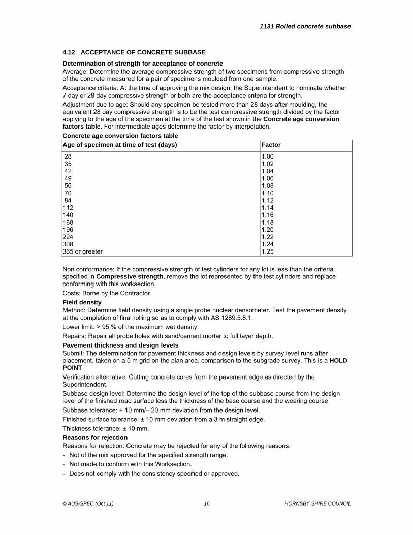
Adjustment due to age: Should any specimen be tested more than 28 days after moulding, the equivalent 28 day compressive strength is to be the test compressive strength divided by the factor applying to the age of the specimen at the time of the test shown in the Concrete age conversion factors table. For intermediate ages determine the factor by interpolation.
Concrete age conversion factors table
Age of specimen at time of test (days) Factor
28 35 42 49 56 70 84 112 140 168 196 224 308 365 or greater
1.00 1.02 1.04 1.06 1.08 1.10 1.12 1.14 1.16 1.18 1.20 1.22 1.24 1.25
Non conformance: If the compressive strength of test cylinders for any lot is less than the criteria specified in Compressive strength, remove the lot represented by the test cylinders and replace conforming with this worksection.
Costs: Borne by the Contractor.
Field density Method: Determine field density using a single probe nuclear densometer. Test the pavement density at the completion of final rolling so as to comply with AS 1289.5.8.1.
Lower limit: > 95 % of the maximum wet density.
Repairs: Repair all probe holes with sand/cement mortar to full layer depth.
Pavement thickness and design levels Submit: The determination for pavement thickness and design levels by survey level runs after placement, taken on a 5 m grid on the plan area, comparison to the subgrade survey. This is a HOLD POINT
Verification alternative: Cutting concrete cores from the pavement edge as directed by the Superintendent.
Subbase design level: Determine the design level of the top of the subbase course from the design level of the finished road surface less the thickness of the base course and the wearing course.
Subbase tolerance: + 10 mm/– 20 mm deviation from the design level.
Finished surface tolerance: ± 10 mm deviation from a 3 m straight edge.
Thickness tolerance: ± 10 mm.
Reasons for rejection Reasons for rejection: Concrete may be rejected for any of the following reasons:
- Not of the mix approved for the specified strength range.
- Not made to conform with this Worksection.
- Does not comply with the consistency specified or approved.
1131 Rolled concrete subbase
© AUS-SPEC (Oct 11) 17 HORNSBY SHIRE COUNCIL
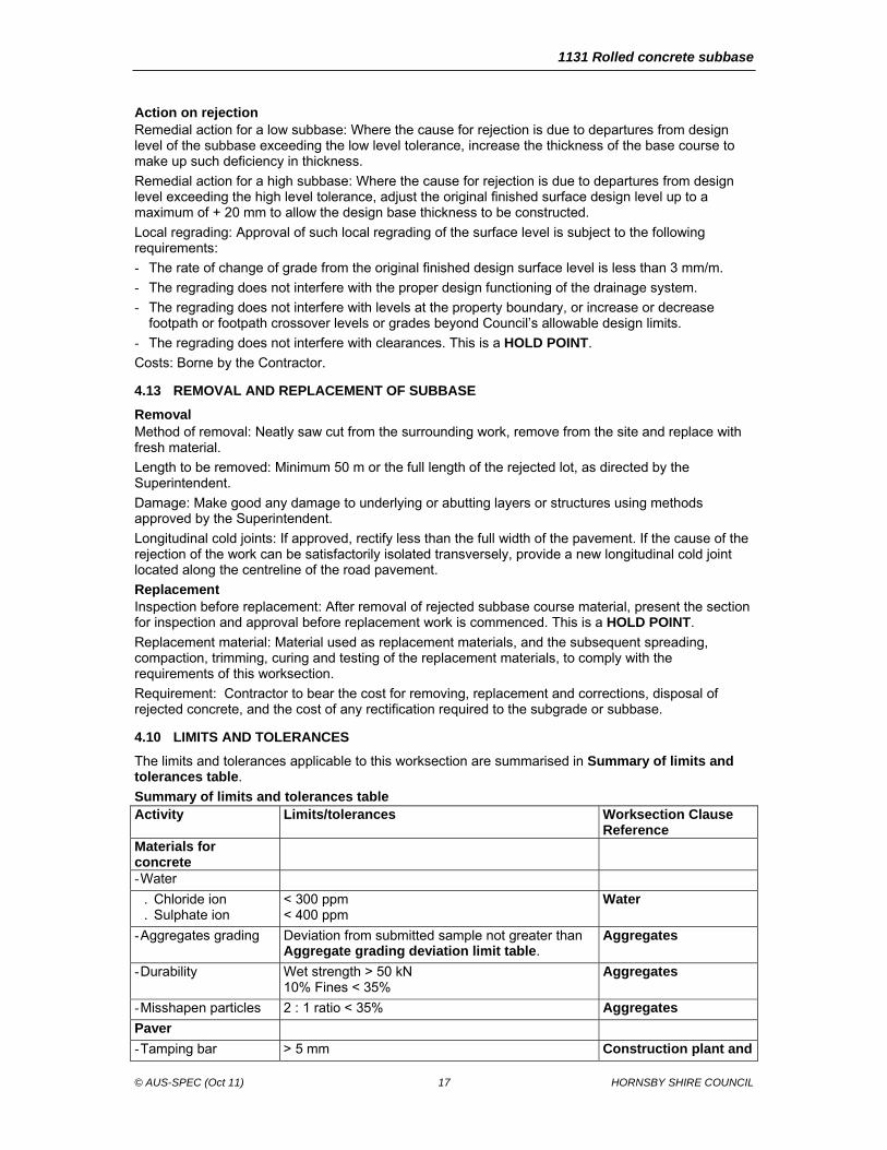
Action on rejection Remedial action for a low subbase: Where the cause for rejection is due to departures from design level of the subbase exceeding the low level tolerance, increase the thickness of the base course to make up such deficiency in thickness.
Remedial action for a high subbase: Where the cause for rejection is due to departures from design level exceeding the high level tolerance, adjust the original finished surface design level up to a maximum of + 20 mm to allow the design base thickness to be constructed.
Local regrading: Approval of such local regrading of the surface level is subject to the following requirements:
- The rate of change of grade from the original finished design surface level is less than 3 mm/m.
- The regrading does not interfere with the proper design functioning of the drainage system.
- The regrading does not interfere with levels at the property boundary, or increase or decrease footpath or footpath crossover levels or grades beyond Council’s allowable design limits.
- The regrading does not interfere with clearances. This is a HOLD POINT.
Costs: Borne by the Contractor.
4.13 REMOVAL AND REPLACEMENT OF SUBBASE
Removal Method of removal: Neatly saw cut from the surrounding work, remove from the site and replace with fresh material.
Length to be removed: Minimum 50 m or the full length of the rejected lot, as directed by the Superintendent.
Damage: Make good any damage to underlying or abutting layers or structures using methods approved by the Superintendent.
Longitudinal cold joints: If approved, rectify less than the full width of the pavement. If the cause of the rejection of the work can be satisfactorily isolated transversely, provide a new longitudinal cold joint located along the centreline of the road pavement.
Replacement Inspection before replacement: After removal of rejected subbase course material, present the section for inspection and approval before replacement work is commenced. This is a HOLD POINT.
Replacement material: Material used as replacement materials, and the subsequent spreading, compaction, trimming, curing and testing of the replacement materials, to comply with the requirements of this worksection.
Requirement: Contractor to bear the cost for removing, replacement and corrections, disposal of rejected concrete, and the cost of any rectification required to the subgrade or subbase.
4.10 LIMITS AND TOLERANCES
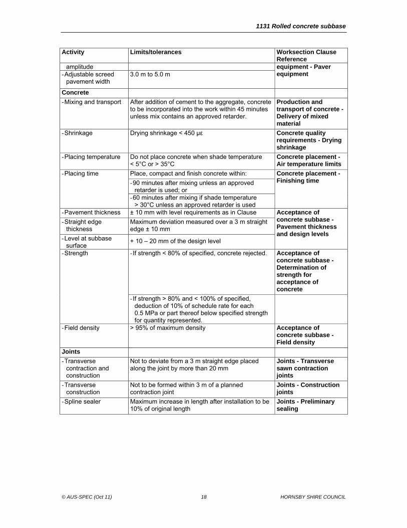
The limits and tolerances applicable to this worksection are summarised in Summary of limits and tolerances table.
Summary of limits and tolerances table Activity Limits/tolerances Worksection Clause
Reference Materials for concrete
- Water
. Chloride ion
. Sulphate ion < 300 ppm < 400 ppm
Water
- Aggregates grading Deviation from submitted sample not greater than Aggregate grading deviation limit table.
Aggregates
- Durability Wet strength > 50 kN 10% Fines < 35%
Aggregates
- Misshapen particles 2 : 1 ratio < 35% Aggregates
Paver
- Tamping bar > 5 mm Construction plant and
1131 Rolled concrete subbase
© AUS-SPEC (Oct 11) 18 HORNSBY SHIRE COUNCIL
Activity Limits/tolerances Worksection Clause Reference
amplitude equipment - Paver equipment
- Adjustable screed pavement width
3.0 m to 5.0 m
Concrete
- Mixing and transport After addition of cement to the aggregate, concrete to be incorporated into the work within 45 minutes unless mix contains an approved retarder.
Production and transport of concrete - Delivery of mixed material
- Shrinkage Drying shrinkage < 450 µε Concrete quality requirements - Drying shrinkage
- Placing temperature Do not place concrete when shade temperature < 5°C or > 35°C
Concrete placement -Air temperature limits
- Placing time Place, compact and finish concrete within: Concrete placement -Finishing time - 90 minutes after mixing unless an approved
retarder is used; or - 60 minutes after mixing if shade temperature
> 30°C unless an approved retarder is used - Pavement thickness ± 10 mm with level requirements as in Clause Acceptance of
concrete subbase - Pavement thickness and design levels
- Straight edge thickness
Maximum deviation measured over a 3 m straight edge ± 10 mm
- Level at subbase surface
+ 10 – 20 mm of the design level
- Strength - If strength < 80% of specified, concrete rejected. Acceptance of concrete subbase - Determination of strength for acceptance of concrete
- If strength > 80% and < 100% of specified, deduction of 10% of schedule rate for each 0.5 MPa or part thereof below specified strength for quantity represented.
- Field density > 95% of maximum density Acceptance of concrete subbase - Field density
Joints
- Transverse contraction and construction
Not to deviate from a 3 m straight edge placed along the joint by more than 20 mm
Joints - Transverse sawn contraction joints
- Transverse construction
Not to be formed within 3 m of a planned contraction joint
Joints - Construction joints
- Spline sealer Maximum increase in length after installation to be 10% of original length
Joints - Preliminary sealing
1131 Rolled concrete subbase
© AUS-SPEC (Oct 11) 19 HORNSBY SHIRE COUNCIL
5 MEASUREMENT AND PAYMENT
5.1 GENERAL
Payment shall be made for all the activities associated with completing the work detailed in this worksection and shown on the drawings, in accordance with provisions made in Contract Document.
5.2 DEDUCTIONS
Deduction for concrete strength: If approved, there may be a deduction in rate paid per m³ for under strength concrete. If the strength of concrete is measured to be within 80% to 100% of the specified strength then a deduction of 10% for each 0.5 MPa or part there of below specified strength will be made.

1131 Rolled concrete subbase
© AUS-SPEC (Oct 11) 20 HORNSBY SHIRE COUNCIL
6 ANNEXURE
6.1 JOINT SEALING REQUIREMENTS FOR ROLLED CONCRETE SUBBASE
Permanent joint sealing types:
(a) Transverse contraction joints
......................................................................................................................................
......................................................................................................................................
......................................................................................................................................
......................................................................................................................................
......................................................................................................................................
......................................................................................................................................
(b) Expansion joints
......................................................................................................................................
......................................................................................................................................
......................................................................................................................................
......................................................................................................................................
......................................................................................................................................
......................................................................................................................................
(c) Isolation joints
......................................................................................................................................
......................................................................................................................................
......................................................................................................................................
......................................................................................................................................
......................................................................................................................................