Embed Size (px)
Citation preview
Specialty fibers for sensors and sensor components
R. Yamauchi, K. Himeno, T. Tsumanuma, and R. Dahlgren*
Fujikura, Ltd., Optoelectronics Laboratory1440 Mutsuzaki, Sakura, Chiba, 285 Japan
*Fujjku Technology America Corp.3001 Oakmead Village Drive, Santa Clara, CA 95051
ABSTRACT
This paper surveys a variety of special fibers which have been developed for the sensor and componentmarkets, based upon the Polarization-mainmining And Absorption-reducing (PANDA) design. Various types ofpolarization-maintaining (PM) fibers, rare-earth doped fibers, image-transmitting fibers, and other special fibers willbe discussed.
L INTRODUCTION
PANDA polarization-maintaining fibers [1] have been developed over a period of years by NTT andFujikura into a variety of specialized optical fibers for sensor applications. Interferomethc fiber optic sensors oftendemand preservation of a linear state.of-polarization (SOP), and other sensors require deterministic retardationvalues in the fiber. This paper will review fibers used in these applications, and special fibers developed for thefabrication of sensor building blocks such as PM couplers, amplifiers, polarizers, and splices.
L POLARIZATION-MAINTAININGFIBER
2.1 High performance PANDA fiber
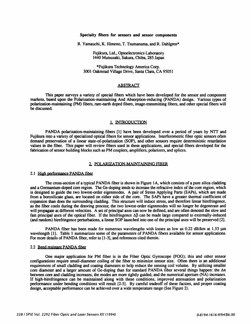
The cross-section of a typical PANDA fiber is shown in Figure 1A, which consists of a pure silica claddingand a Germanium-doped core region. The Ge-doping tends to increase the refractive index of the core region, whichis designed to guide the two lowest-order eigenmodes. A pair of Stress Applying Parts (SAPs), which are madefrom a borosilicate glass, are located on either side of the core. The SAPs have a greater thermal coefficient ofexpansion than does the surrounding cladding. This structure will induce stress, and therefore linear birefringence,as the fiber cools during the drawing process; the two lowest-order eigenmodes will no longer be degenerate andwill propagate at different velocities. A set of principal axes can now be defined, and are often denoted the slow andfast principal axes of the optical fiber. If the birefringence i can be made large compared to externally-induced(and random) birefringence perturbations, a linear SOP launched into one of the principal axes will be preserved [2].
PANDA fiber has been made for numerous wavelengths with losses as low as 0.22 dB/km at 1.55 unwavelength [1]. Table 1 summarizes some of the parameters of PANDA fibers available for sensor applications.For more details of PANDA fiber, refer to [1-3], and references cited therein.
2.2 Bend resistant PANDA fiber
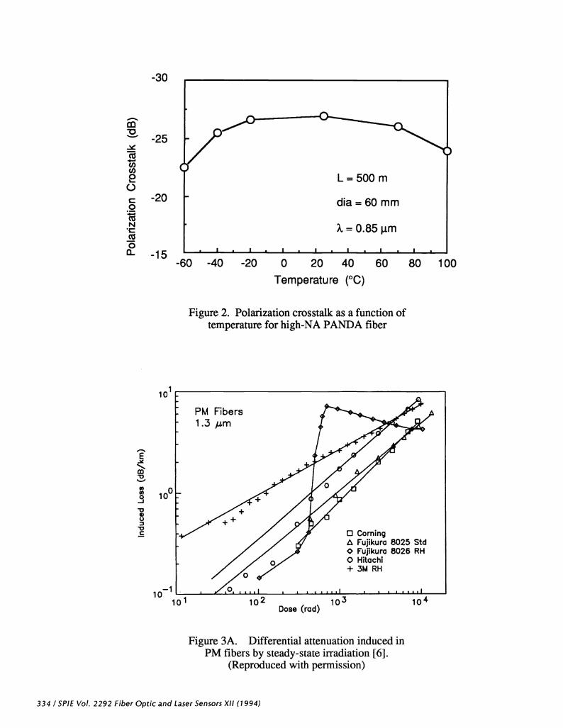
One major application for PM fiber is in the Fiber Optic Gyroscope (FOG); this and other sensorconfigurations require small-diameter coiling of the fiber to minimize sensor size. Often there is an additionalrequirement of small cladding and coating diameters to help reduce the sensing coil volume. By utilizing smallercore diameter and a larger amount of Ge-doping than for standard PANDA fiber several things happen: the nbetween core and cladding increases, the modes are more tightly guided, and the numerical aperture (NA) increases.If high-birefringence can be maintained along with these conditions, improved attenuation and polarizationperformance under bending conditions will result [2-5]. By careful tradeoff of these factors, and proper coatingdesign, acceptable performance can be achieved over a wide temperature range (See Figure 2).
328 ISPIE Vol. 2292 Fiber Optic and Laser Sensors XII (1994) O-8194-1616-9/94/$6.OO
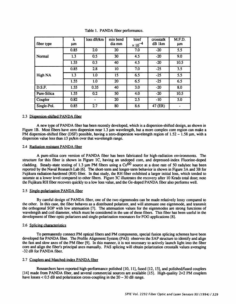
Table 1. PANDA fiber performance.
fiber type jimloss dB/km mm bend
dia mmbiref< io
crosstalkdB 1km
M.F.D.jim
Normal
0.85 2.0 20 7.0 -20 5.5
1.3 0.5 30 4.5 -20 9.0
1.55 0.3 40 4.5 -20 10.5
High NA
0.85 2.8 10 7.0 -25 3.5
1.3 1.0 15 6.5 -25 5.5
1.55 1.0 20 63 -25 6.5
D.S.F. 1.55 0.35 40 3.0 -20 8.0
Pure-Silica 1.55 0.2 50 4.0 -20 10.5
Coupler 0.82 - 20 2.5 -10 5.0
Single-Pol. 0.85 2.7 80 8.6 47 (ER) -
2.3 Dispersion-shifted PANDA fiber
A new type of PANDA fiber has been recently developed, which is a dispersion-shifted design, as shown inFigure lB. Most fibers have zero dispersion near 1.3 jim wavelength, but a more complex core region can make aPM dispersion-shifted fiber (DSF) possible, having a zero-dispersion wavelength region of 1 .52 —1 .58 jim, with adispersion value less than ps/km over that wavelength range.
2.4 Radiation resistant PANDA fiber
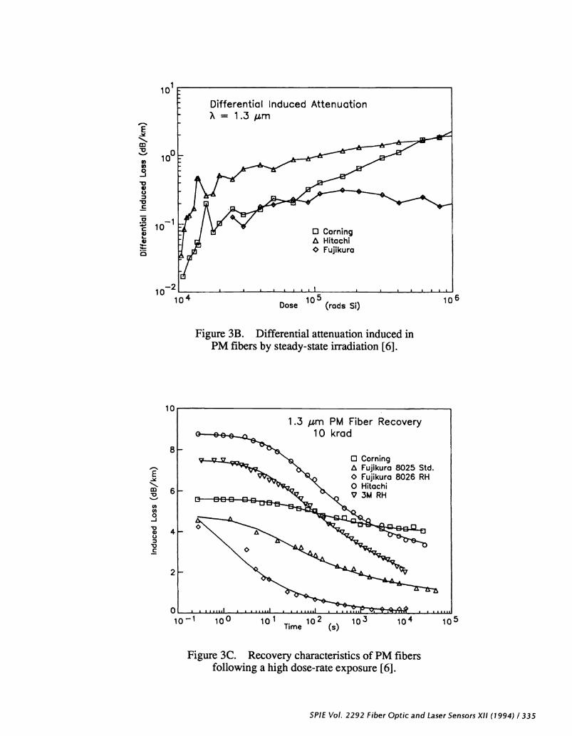
A pure-silica core version of PANDA fiber has been fabricated for high-radiation environments. Thestructure for this fiber is shown in Figure 1C, having an undoped core, and depressed-index Fluorine-dopedcladding. Steady-state testing of 1.3 jim PM fibers using a Co6° source at a dose rate of 50 rads/sec has beenreported by the Naval Research Lab [61. The short-term and longer-term behavior is shown in Figure 3A and 3B forFujikura radiation-hardened (RH) fiber. In that study, the RH fiber exhibited a larger initial loss, which tended tosaturate at a lower level compared to other fibers. Figure 3C illustrates the recovery after 10 Krads total dose; notethe Fujikura RH fiber recovers quickly to a low loss value, and the Ge-doped PANDA fiber also performs well.
2.5 Single-polarization PANDA fiber
By careful design of PANDA fiber, one of the two eigenmodes can be made relatively lossy compared tothe other. In this case, the fiber behaves as a distributed polarizer, and will attenuate one eigenmode, and transmitthe orthogonal SOP with low attenuation [7]. The attenuation values for the emgenmodes are strong functions ofwavelength and coil diameter, which must be considered in the use of these fibers. This fiber has been useful in thedevelopment of fiber optic polarizers and single-polarization resonators for FOG applications [811.
2.6 Splicing characteristics
To permanently connect PM optical fibers and PM components, special fusion splicing schemes have beendeveloped for PANDA fiber. The Profile Alignment System (PAS) observes the SAP structure to identify and alignthe fast and slow axes of the PM fiber [9]. In this manner, it is not necessary to actively launch light into the fibercore and align the fiber's principal axes manually. PAS splicing will obtain polarization crosstalk values averaging-32 dB for PANDA fiber.
2.7 Couplers and Matched-index PANDA fiber
Researchers have reported high-performance polished [10, 1 1], fused [12, 13], and polished/fused couplers[14] made from PANDA fiber, and several commercial sources are available [15]. High-quality 2x2 PM couplershave losses < 0.5 dB and polarization cross-coupling in the 20 —30 dB range.
SPIE Vol. 2292 Fiber Optic and Laser Sensors XII (1 994) I 329

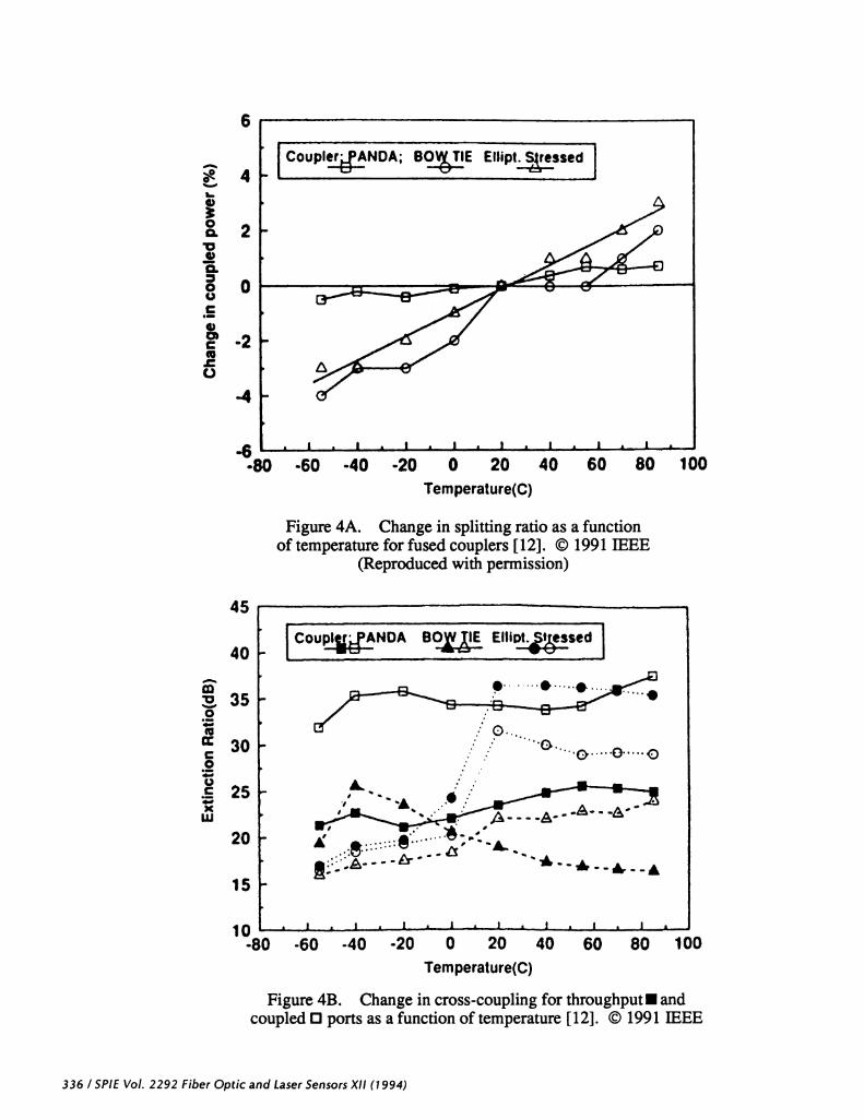
There is increased difficulty in fabricating high-performance fused PM couplers with standard PANDAfiber, because the SAPs have a slightly depressed index as shown in Figure 1A. By adding germanium to theborosilicate SAP material, the SAP refractive index can be compensated to nearly match the cladding, as shown inFigure 1D. This type of PANDA fiber design permits low-loss couplers to be fabricated which are stable over awide temperature range. The stability of fused couplers made from different types of fiber is compared in Figure 4Aand 4B after a number of temperature cycles [12]. The devices reported in that study operate at 0.8 jtm wavelength,and are packaged in a 32-mm long, 2.5-mm diameter stainless steel tube.
ERBIUM-DOPED FIBER
3.1 Erbium-doped single-mode fiber
A high NA erbium-doped single-mode fiber was manufactured, employing Ge-doping in the core and F-doping in the cladding to get an overall i = 1.6%. A small-diameter core further concentrates the pump and signaland the Er-doping and Al-codoping are also in the core region. The interested reader is referred to [16], whichdiscusses design and fabrication of a high NA Erbium fiber, Erbium-doped DSF, and radiation effects on Erbium-doped fibers.
When assembling amplifiers using fusion splicing, modal matching of normal fiber to high NA Erbium-doped fiber is important to avoid a 3—5 dB reduction of amplifier gain [17]. Mode matching is accomplished aftersplicing, by diffusion of the core dopants in the splice region at a high temperature. An optical amplifier has beenconstructed in the forward-pumping configuration, using a 1.48 im pump laser. At the signal wavelength of 1.552j.Lm, power conversion of up to 75% was demonstrated at 50 mW pump power.
3.2 Erbium-doped twin-peak core (TPC) fiber
A type of PM rare-earth doped fiber which has been demonstrated consists of two closely-spaced cores, asshown in Figure 1E, with A = 1.48%. The two cores produces a shape birefringence of approximately 1.6x1O at= 1.55 jim, low polarization crosstalk, and good splicability to standard PM fibers [18]. For 57 m of fiber at a signalpower of -40 dBm, and the same conditions as above, the gain efficiency was about 2.2 dB/mW of pump power.This is compared to 2.1 dB/mW for 26 m of single-mode Erbium-doped fiber under the same conditions.
3.3 Erbium-doped PANDA fiber
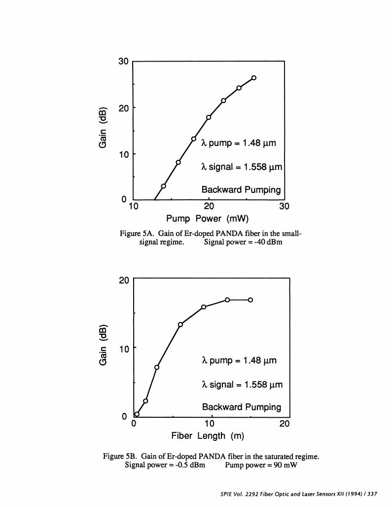
Recently, an Erbium-doped PANDA fiber has been demonstrated [3], which has high birefnngence ofroughly 5x1O at 1.55 tm. This fiber is illustrated in Figure iF. The small-signal and saturated gain for this fiberare shown in Figures 5A and SB, respectively. This fiber is finding applications in experiments such as modelockedring lasers for the generation of stable picosecond pulses [19, 20].
4 IMAGE BUNDLE FIBER
4. 1 High-resolution imagefiber
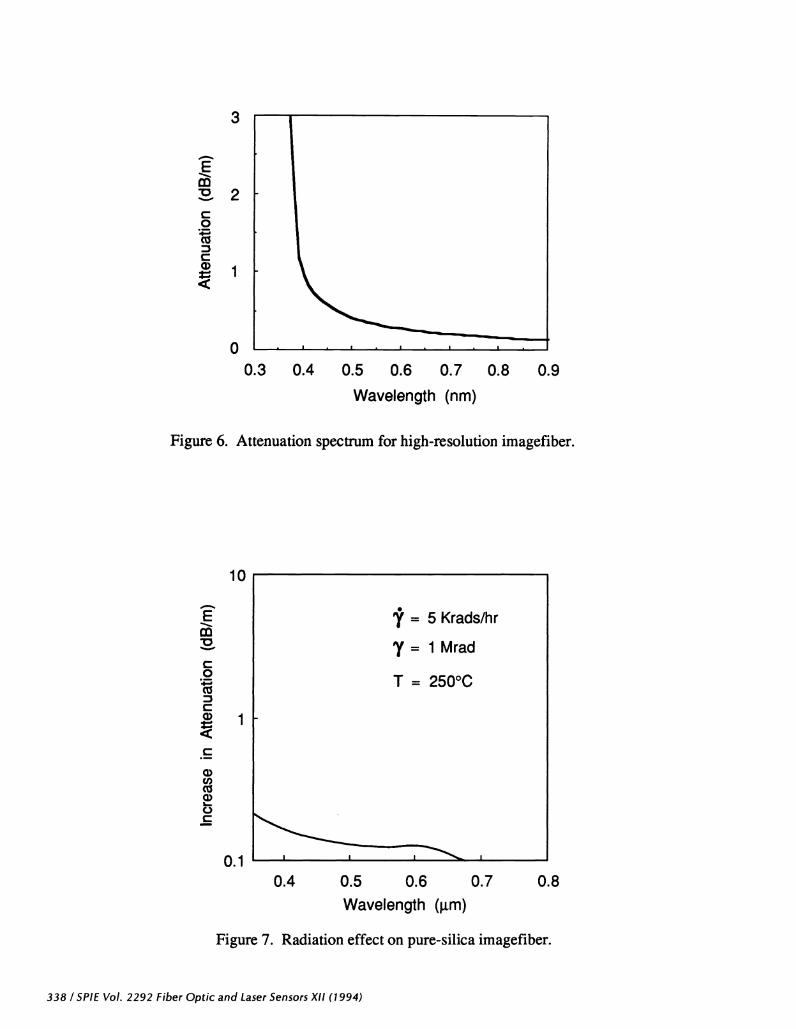
High resolution imaging bundles have been fabricated for the medical industry, with resolutions of 6000pixels in a 0.5 mm diameter; up to 100,000 pixels are possible on larger bundles. The individual cores of the bundleare sufficiently small to be single-mode at visible wavelengths [21]. This type of imagefiber exhibits a transmissionthat is a strong function of wavelength, and visible-light images would be highly tinted. However, for someapplications which use monochromatic light, it is highly desirable to have single-mode imagefiber [21,22]. Figure 6plots the spectral attenuation for a typical germanium-doped imagefiber bundle.
4.2 Radiation resistant imagefiber
By using a similar design to the radiation-hard fiber described in imagefiber can be fabricated withpure-silica core and a depressed-index cladding [23]. This type of imagefiber has excellent resistance to radiation,
330 / SPIE Vol. 2292 Fiber Optic and Laser Sensors XII (1994)

exhibiting roughly 0.15 dB/m loss increase for a total dose of 1 Mrad, as shown by Figure 7. The data was taken at250°C temperature at a steady-state dose rate of 5 Krads/hr. This fiber has found use nuclear industrial inspectionsystems, and inspection applications where survival at high temperatures is required.
ULTRAVIOLET TRANSMITTING FIBER
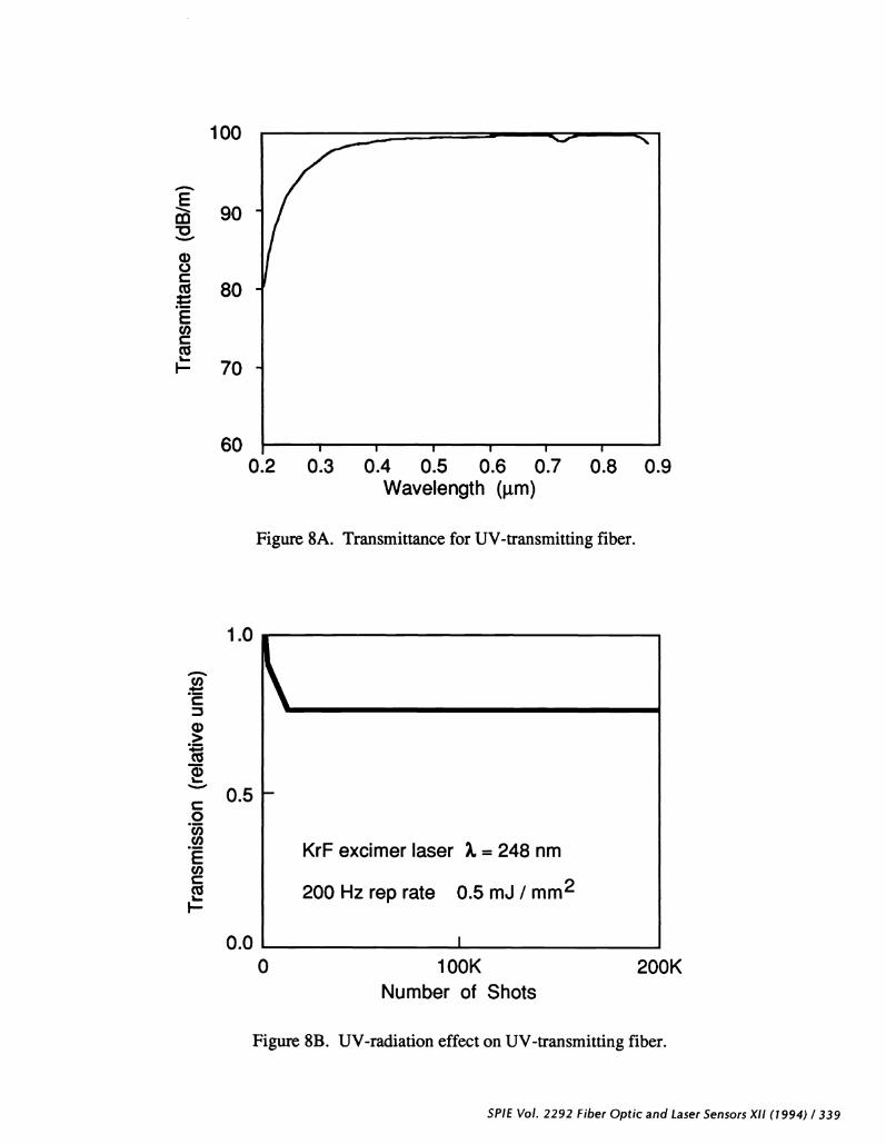
Figure 8 describes the characteristics of a newly developed UV-transmitting fiber, which may beconfigured as a multimode fiber or a nonimaging (incoherent) bundle. Figure 8A is the attenuation spectrum for amultimode UV4ransmitting fiber, showing a loss of about 0.3 dB/m at 248 nm. Figure 8B shows the increase ofattenuation at 248 nm after repeated exposure to 248 nm KrF laser 0.5 mJ/mm2 pulses at a rep rate of 200 Hz. Thisfiber is showing potential for new surgical techniques within the human body using excimer lasers.
CONCLUSIONS
In summary, a number of special fibers have been developed for sensor applications at Fujikura. Ofparticular interest are high NA fibers for compact sensing coils, and matched-SAP-index fiber for fused PM couplermanufacture. Other special PANDA fiber designs which have been developed are dispersion-shifted, radiation-hardened, and single-polarization types. These fibers are fmding applications in niche markets worldwide.
Erbium-doped silica fiber has revolutionized the long-haul telecom industry, by making all-fiber opticalamplifiers possible at the 1.55 tm wavelength region. High NA, PANDA, and twin-core variants have beendemonsirated for sensor R&D projects.
Bundle-fiber technology has been refined to produce ultrahigh-resolution, radiation-hardened, and UV-transmitting fiber products. These have many emerging applications in industrial inspection and medicalapplications.
IL ACKNOWLEDGMENTS
The authors would like to acknowledge J. Friebele of NRL, and Y. Anjan of Andrew Corp., for providingsome of the plots used in this paper. The assistance of K. Nishide of Fujikura and V. Martinelli of Corning is alsogratefully acknowledged.
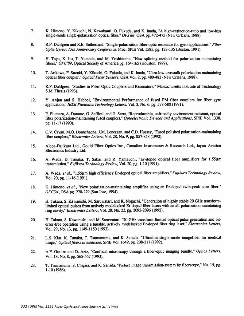
REFERENCES
1. Y. Sasaki, T. Hosaka, M. Horiguchi, and J. Noda, "Design and fabrication of low-loss and low-crosstalkpolarization-maintaining optical fibers," IEEE Journal ofLightwave Technology, Vol. 4, No. 8, pg. 1097-1102 (1986).
2. K. Inada, "Special Optical Fibers for Sensors," International Conference on Optical Fibre Sensors inChina, SPIE Vol. 1572, pg. 163-168 (Bejing, 1991).
3. K. Himeno, et al., "Polarization-maintaining optical fibers," Fujikura Giho (in Japanese), No. 85, pg. 1-9(1993).
4. Y. Kikuchi, K. Himeno, 0. Fukuda, and K. Inada, "High birefringence fiber with high numerical aperturefor compact optical components," Sino-Japanese OFSET'87, pg. 149-154 (1987).
5. Y. Kikuchi, N. Kawakami, K. Himeno, 0. Fukuda, and K. Inada, "Crosstalk in polarization maintainingoptical fiber," OEC'88, Vol. 4B2-3, pg. 126-127 (1988).
6. EJ. Friebele, et a!., "Radiation effects in polarization-maintaining fibers," Fibre Optics'90, SPIE Vol. 1314,pg. 146-154 (1990).
SPIE Vol. 2292 Fiber Optic and Laser Sensors Xl! (1994) /331
(fr66 1) lix siosus JaSE'7 pue D!dO q!J Z6ZZ IOn 3!dS I ZT
(9861) rn-i d 'çj N 14'OdOOSJ(!J Aq wosIs-uo!ss!wsufl OWT OJfllO!d41 'tjMUB N P" '!!qD 'S 'UInUWflS J
(66i) L9c-c9c d 'g °N 'i IA 'saJJa7 sand 1'ojpunq u2tnui ondo-ioq i qno.nfl idoosoioiw oojuo 'zrzy pim oiitw rv
(z661) LIZ-80Z d '6t'91 1°A RIdS '?UldlpU1 U! sJaqJ'vnJdQ 1'o2sn !0!P0W JOJ JqJ1?w OjOW-OjU!S U!LJ1flLfl11 '?jM?U N '1WflUWflSJ 'J '?)jt?U1?J 'W!N S'l
(66i) ocii-ii 2d ':i °N '6Z !OA 's4717 sdluoJP?lg 'Jstfl U!J I'J Pd0P3 PPOIPOW IjOAUO 'ojqum UISfl UOJXIO JJ-1OJiO
-iiq pui uoiou2 sjnd oido P!W!FU10JSUfl ZHO OZ '!11US 'Jft4 S 'intu. H
(z661) 960Z-S60t 2d ' ON '8t !A 'sJafla7 SfliOAPdj3 U!J u!u!mU!Iw Uo!Wz!iIod-I1 u 11!M S1OS J1!J podop-13 jO)3OjOjOW !OA!23 wO1J sosind iondo p2!w!! -wJoJsUn ZHO OZ ojqms 'qq!q jo UOflJU9 '!'1N 'N ptm 'umn.ns 'IA 'IqSIUM 'S ')IL H
(P661 'SOf uts) 6LZ-8LZ d vso 'fr63iO 'oq )jd-U!iW1 pdop-ii UE UiSfl 10!J!!dW U!U!mU!1rnI-UOIfl?Z!miOd MON,, 'iv J 'OUOLU!H 'N 81
(1661) 91-i I id ' i°A 'Male%a�! (8olouydaL ''fl['J 4'SJO!JijdIIW I!J iodo px!op-1: Icouo!oUJo q!q wiiçç4, '•iv ja "P'M V L1
(1661) rn-i d ' j0A 't�! (8olouyd?L ?1/•l[flJ 11'UO!SSiWSUIIj wilçç'j ioj SJO!J!IdWI ioqq jondo podop-i, '!tPflWA •a pu 'W)ftS .1 'IU1J •Q 'I?P1?A Y 91
'Ph ICIISflPUJ S3!UOflOOj UOfl1A uidç 'pri 2g SUOWflflSU UI!PuID 'OUJ sondO JI!d PifloD 'PV1 fl'P1d-°°IV ci
(z661) 8c8-Lcs id '6 °N '8Z bA ''fl7 saluo43;/q 1'siojdnoo oiqij U!UimUflW-UOflI?ZLWjOd poqsijod posnj 'AossnH u pu 'uiuo'j jf 'qpqouuoj oi 'uLi A'D i (066DLT-ii •2d
'8Ei 'I°A HIdS 'suowaiidd UV sd!4?U nuo4aapoJdO 14'sijdnoo psnj 2uuumw-uorwziiod IOq!J iiondo iumsisoj uouiuojiAuo Apuoujun 'uos o pu 'iiojs o 'ouun v 'flWfl!d i
(1661) 08S-8LS &J '9 'N ': 'iSA 'sJaflYj i(8oiouyaat sd,luololld 3'q:.qI 41'uoojdd oiA2 ioqij ioj sioidnoo iqij Nd SflJ jo ootmuu0JJd jrnUowUo1iAU3, 'qqj 's pUE ufuy A 'ZI
'(66I) ssoq 'N'S c2ojouqooj JO niisui snsnqossp 'sioiuosj pu slojdno3 o1d-Joq! UI sopni1, 'uo12qBQ 'd'J '11
'(8861 'suj1O j-p '2d ' 'IOA YSO 's.iosu9g qkt lvpdO 11'itdnoo iqij tondo 2UIUmiUU?w U0!Z!13IOd )1imsSo1o-M0!-I?Jflfl1 'tPUI 'N PU "P'W'd '0 '!tIOfll!N 'A 'pjnzn5 ',j 'miy ' '(6861 'UOISflOH) c9j-j9j '2d OUOWV JO '!°°S P3!d0 '6R3JO 'siqij
JOJ POtJ10U 2uioijds MN1 '3uIflUIqSO 'N 'I?pI?U1 'J 'O 'N 'tL 'H
'(1661 'uoiso) çj-gzj 'd 'cç 'ISA MS '3OiJ 'aaua1?fuo3 (ivsiai,iuuy yiç :soi( znidO
iaqy 11'suo!Wo!tddl? oi(2 ioj iowuosoi oido-iqij 'PUflJ(PflS ''J jU UO1IQ 'd '(8861 'SUpO MON) cLt-zLt' 'd vso 'wsio 'ioc oido uozuod-oj2uis pow-oj2uis
SSOj-MOj jUI? OU?1-UOfl3UflXO-q!q V '1PIUI 'N PU 'tPtd '0 '!WIP?MI?N 'N '!PPN 'A 'OUOW!H 'N
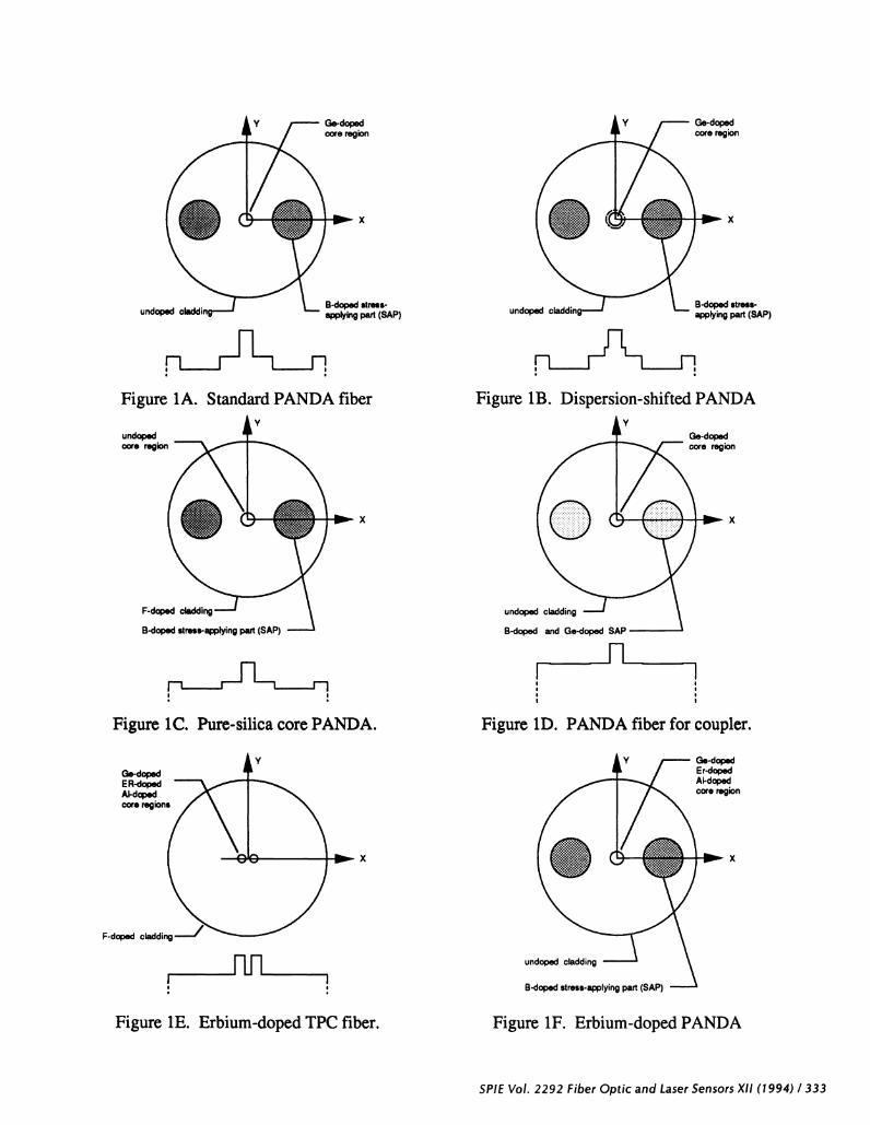
Figure 1D. PANDA fiber for coupler.
Ge dopedEr-dopedAs-dopedcore regn
SP1E Vol. 2292 Fiber Optic and Laser Sensors XII (1994) / 333
undoped
:iiiiiti
Figure 1A. Standard PANDA fiber
undopedcore region
B-doped stress-undoped applying part (SAP)
rrh1HnFigure lB. Dispersion-shifted PANDA
Ge-dopedcore region
x
F-doped
B-doped stress-applying part (SAP)
B-doped stress-applying part (SAP)
x
p__r-__Figure 1C. Pure-silica core PANDA.
Ge-dopedER-dopedAl-dopedcore regions
x
F-doped cladding
Figure 1E. Erbium-doped TPC fiber.
I I
x
undoped cladding
B-doped stress-applying part (SAP)
Figure iF. Erbium-doped PANDA
rn-D-4-'U)U)200N-C
00
E.£0-oa)(I)
-S-oVC.)
-VC
L = 500 m
dia=6Omm
=0.85.tm• I • I I • I • I
-60 -40 -20 0 20 40 60 80 100Temperature (°C)
Figure 2. Polarization crosstalk as a function oftemperature for high-NA PANDA fiber
-30
-25
-20
-15
10
100
10
Figure 3A. Differential attenuation induced inPM fibers by steady-state irradiation [6].
(Reproduced with permission)
334 / SPIE Vol. 2292 Fiber Optic and Laser Sensors XII (1994)
10Dose (rod)
E
.v0)U)
.3-V4)U
-oC
aC4)4)9-c
E-0U)U)0-J4)C)
C
101
1
10_i
10
Dose (rods Si)i06
Figure 3B. Differential attenuation induced inPM fibers by steady-state irradiation [6].
Figure 3C. Recovery characteristics of PM fibersfollowing a high dose-rate exposure [6].
SPIE Vol. 2292 Fiber Optic and Laser Sensors Xl! (1994)1335
03V0
C0UC
w
6
-2
-4
-6.80
Figure 4B. Change in cross-coupling for throughput andcoupled 0 ports as a function of temperature [12]. 1991 IEEE
336 / SPIE Vol. 2292 Fiber Optic and Laser Sensors XII (1994)
a2
-60 -40 -20 0 20 40 60 80 100Temperature(C)
Figure 4A. Change in splitting ratio as a functionof temperature for fused couplers [12]. 1991 IEEE
(Reproduced with permission)
LC0UANOA BOE4sej......
30 •. ....o....o o
25..
20 ::';A.15
10 _1 .1 1 1 —t-
•80 -60 -40 -20 0 20 40 60 80 100Temperature(C)
m-D
C
-D
C
0
30
10
010
Pump Power (mW)Figure 5A. Gain of Er-doped PANDA fiber in the small-
signal regime. Signal power = -40 dBm
Figure 5B. Gain of Er-doped PANDA fiber in the saturated regime.Signal power = -0.5 dBm Pump power =90 mW
20
pump= 1.48 pm
2signal= 1.558 p.m
Backward
20
Pumping
30
20
10
0
A?pump= 1.48 p.m
signaI= 1.558 p.m
Backward Pumping
Fiber Length (m)
SPIE Vol. 2292 Fiber Optic and Laser Sensors Xli (1994) / 337
VC0
Ca)
cciVC0
Ca)
Ca)C,)
ci)C.)C
3
2
1
00.3 0.4 0.5 0.6 0.7
Wavelength (nm)
0.8 0.9
Figure 6. Attenuation spectrum for high-resolution imagefiber.
10 -
1
0.1
= 5 Krads/hr
= 1 Mrad
T = 250°C
0.4 0.5 0.6 0.7 0.8
Wavelength (i.tm)
Figure 7. Radiation effect on pure-silica imagefiber.
338 I SPIE Vol. 2292 Fiber Optic and Laser Sensors XII (1994)
Va)C.)C
EC,)CC6
I—
U)
C
a)>
C0C,)(1)
E(1)C
F-
0.2 0.3 0.4 0.5 0.6 0.7 0.8 0.9
100
90
80
70
60
1.0
0.5
0.0
Wavelength (pm)
Figure 8A. Transmittance for UV-transmitting fiber.
KrF excimer laser . = 248 nm
200 Hz rep rate 0.5 mJ I mm2
0 lOOK 200KNumber of Shots
Figure 8B. UV-radiation effect on UV-transmitting fiber.
SPIE Vol. 2292 Fiber Optic and Laser Sensors Xl! (1994)1339