Embed Size (px)
Citation preview
Specialist Committee on Detailed Flow Measurement Techniques
Final Report and Recommendations to the 27th ITTC
1. INTRODUCTION
1.1 Membership The 27th ITTC Specialist Committee on
Detailed Flow Measurement Techniques consisted of:
Dr. Paisan Atsavapranee (Chairman)
Naval Surface Warfare Center Carderock Division (NSWCCD), USA
Dr. Mario Felli (Secretary) CNR INSEAN, Italy
Prof. In-won Lee Pusan National University, Korea
Dr. Chittiappa Muthanna MARINTEK, Norway
Dr. Shigeki Nagaya IHI, Japan
Dr. Feng Zhao China Ship Scientific Research Center (CSSRC), China
1.2 Meetings The committee met four times: CSSRC, China, March 2012
NSWCCD, USA, November 2012
MARINTEK, Norway, July 2013
Pusan National University, Korea, February 2014
2. SCOPE The scope of this report is to provide an
update to the review by the 26th ITTC Specialist Committee on Detailed Flow Measurements of systems and methods for flow-field and wave-field measurements and applications of Particle Image Velocimetry (PIV), stereoscopic PIV (SPIV), Laser Doppler Velocimetry (LDV), and other emergent methods, for the measurements of flow separation, wake, vortex strength, etc, for ship hydrodynamics and ocean engineering problems. Furthermore, an overview of the guidelines proposed to the 27th ITTC is provided.
3. OVERVIEW The 26th ITTC Specialist Committee on
Detailed Flow Measurements provided a comprehensive review of the state-of-the-art for flow-field and wave-field measurements in ship hydrodynamics and ocean engineering applications. Furthermore, the committee recognized that many practical issues and
568
challenges needed to be addressed before these measurements can be widely practiced in large-scale hydrodynamics facilities. For the 27th ITTC, the committee was tasked to:
• Survey and report on the existing
detailed flow visualization, measurement techniques and data analysis methods.
• Develop a best-practice guideline for the applications of PIV/SPIV in tow tanks and cavitation tunnels.
• Develop experimental benchmarks for the verification of PIV/SPIV setup.
• Develop a guideline for PIV/SPIV uncertainty analysis.
• Collaborate with the Specialist Committee on CFD to develop methods for the validation of CFD codes using detailed flow measurements.
4. STATE-OF-THE-ART REVIEW
4.1 Applications of Detailed Flow Measurements in Ship Propulsion
Since the 26th ITTC conference, there have
been many good examples of detailed flow measurements in ship propulsion, primarily dealing with wake flow surveys around isolated and installed propellers, waterjets and propeller-rudder configurations. Felli et al. (2011) presented a comprehensive time-resolved observations and analysis of the propeller wake/rudder interaction mechanisms by PIV and LDV measurements. Phase-locked measurements were performed along horizontal-chordwise, vertical-chordwise and transversal sections of the propeller wake
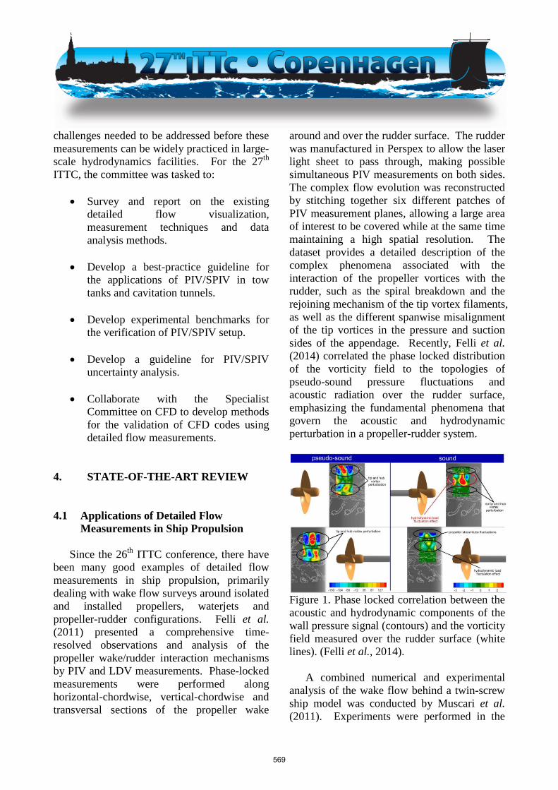
around and over the rudder surface. The rudder was manufactured in Perspex to allow the laser light sheet to pass through, making possible simultaneous PIV measurements on both sides. The complex flow evolution was reconstructed by stitching together six different patches of PIV measurement planes, allowing a large area of interest to be covered while at the same time maintaining a high spatial resolution. The dataset provides a detailed description of the complex phenomena associated with the interaction of the propeller vortices with the rudder, such as the spiral breakdown and the rejoining mechanism of the tip vortex filaments, as well as the different spanwise misalignment of the tip vortices in the pressure and suction sides of the appendage. Recently, Felli et al. (2014) correlated the phase locked distribution of the vorticity field to the topologies of pseudo-sound pressure fluctuations and acoustic radiation over the rudder surface, emphasizing the fundamental phenomena that govern the acoustic and hydrodynamic perturbation in a propeller-rudder system.
Figure 1. Phase locked correlation between the acoustic and hydrodynamic components of the wall pressure signal (contours) and the vorticity field measured over the rudder surface (white lines). (Felli et al., 2014).
A combined numerical and experimental analysis of the wake flow behind a twin-screw ship model was conducted by Muscari et al. (2011). Experiments were performed in the
569
Large cavitation Channel of CNR INSEAN and consisted of propeller phase-locked Laser Doppler Velocimetry (LDV) measurements along the vertical midplane of the rudder and two transversal planes behind the propeller and behind the rudder. Paik et al. (2011a) used PIV to investigate the wake flow in front of a semi-spade rudder, placed behind a propeller operating in a simulated wake. A PIV study to investigate the propeller singing mechanism is documented in Paik et al. (2011b) that measured the trailing wake characteristics of two hydrofoil geometries with standard and truncated trailing edge. Pecoraro et al. (2013) reported a detailed analysis of the flow around a single-screw ship model by phase-locked LDV measurements in a large cavitation channel. The study was focused on the assessment of the inflow characteristics and related separation phenomena through the analysis of the probability density function and skewness distributions in the propeller plane.
Figure 2. Distribution of the skewness (iso-contours) and the PDF (histograms) at the propeller plane (Pecoraro et al., 2013)
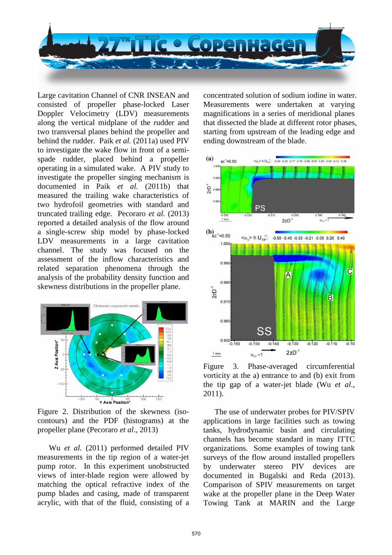
Wu et al. (2011) performed detailed PIV
measurements in the tip region of a water-jet pump rotor. In this experiment unobstructed views of inter-blade region were allowed by matching the optical refractive index of the pump blades and casing, made of transparent acrylic, with that of the fluid, consisting of a
concentrated solution of sodium iodine in water. Measurements were undertaken at varying magnifications in a series of meridional planes that dissected the blade at different rotor phases, starting from upstream of the leading edge and ending downstream of the blade.
Figure 3. Phase-averaged circumferential vorticity at the a) entrance to and (b) exit from the tip gap of a water-jet blade (Wu et al., 2011).
The use of underwater probes for PIV/SPIV
applications in large facilities such as towing tanks, hydrodynamic basin and circulating channels has become standard in many ITTC organizations. Some examples of towing tank surveys of the flow around installed propellers by underwater stereo PIV devices are documented in Bugalski and Reda (2013). Comparison of SPIV measurements on target wake at the propeller plane in the Deep Water Towing Tank at MARIN and the Large
570
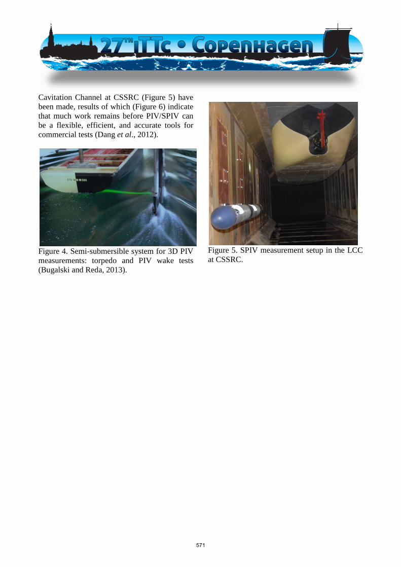
Cavitation Channel at CSSRC (Figure 5) have been made, results of which (Figure 6) indicate that much work remains before PIV/SPIV can be a flexible, efficient, and accurate tools for commercial tests (Dang et al., 2012).
Figure 4. Semi-submersible system for 3D PIV measurements: torpedo and PIV wake tests (Bugalski and Reda, 2013).
Figure 5. SPIV measurement setup in the LCC at CSSRC.
571
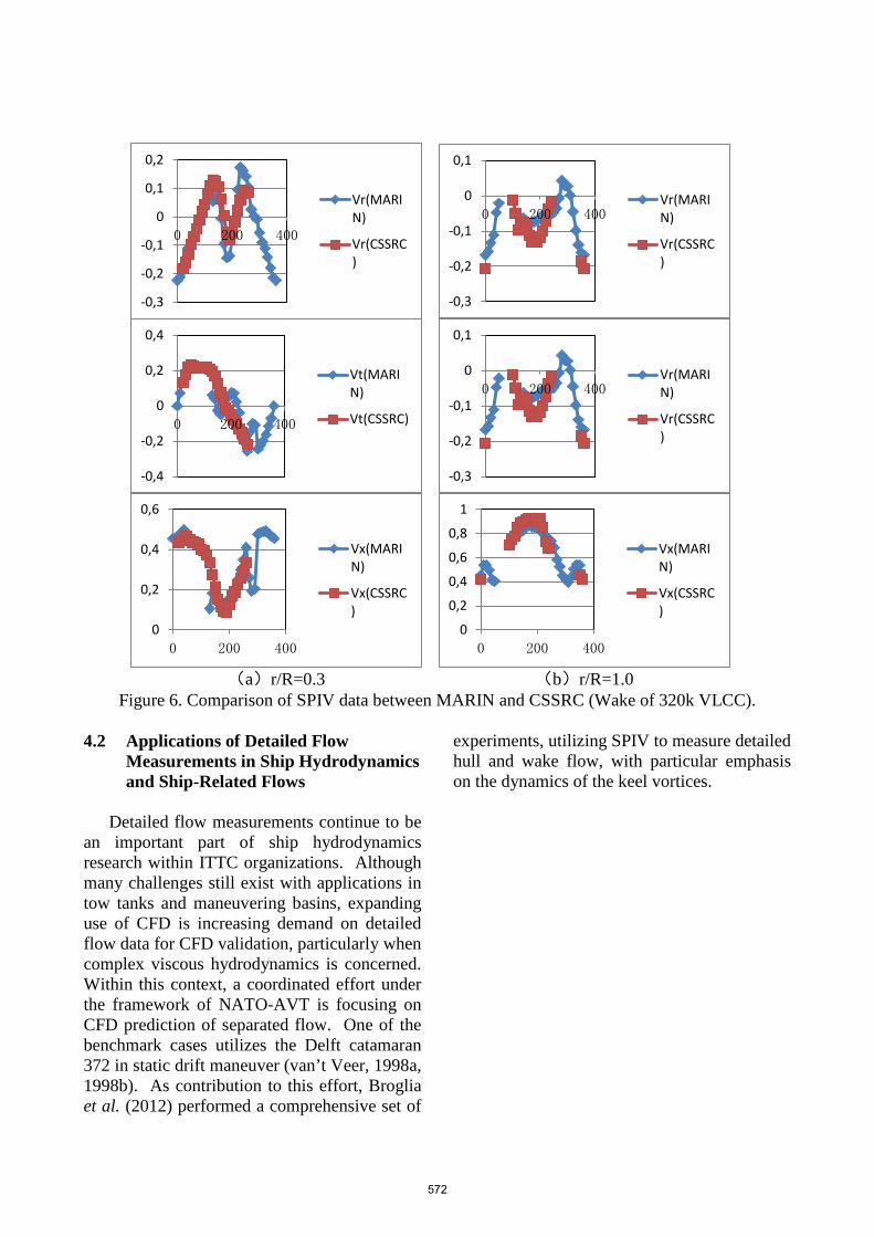
(a)r/R=0.3 (b)r/R=1.0
Figure 6. Comparison of SPIV data between MARIN and CSSRC (Wake of 320k VLCC).
4.2 Applications of Detailed Flow Measurements in Ship Hydrodynamics and Ship-Related Flows
Detailed flow measurements continue to be
an important part of ship hydrodynamics research within ITTC organizations. Although many challenges still exist with applications in tow tanks and maneuvering basins, expanding use of CFD is increasing demand on detailed flow data for CFD validation, particularly when complex viscous hydrodynamics is concerned. Within this context, a coordinated effort under the framework of NATO-AVT is focusing on CFD prediction of separated flow. One of the benchmark cases utilizes the Delft catamaran 372 in static drift maneuver (van’t Veer, 1998a, 1998b). As contribution to this effort, Broglia et al. (2012) performed a comprehensive set of
experiments, utilizing SPIV to measure detailed hull and wake flow, with particular emphasis on the dynamics of the keel vortices.
-0,3
-0,2
-0,1
0
0,1
0,2
0 200 400
Vr(MARIN)
Vr(CSSRC)
-0,3
-0,2
-0,1
0
0,1
0 200 400 Vr(MARIN)
Vr(CSSRC)
-0,4
-0,2
0
0,2
0,4
0 200 400
Vt(MARIN)
Vt(CSSRC)
-0,3
-0,2
-0,1
0
0,1
0 200 400 Vr(MARIN)
Vr(CSSRC)
0
0,2
0,4
0,6
0 200 400
Vx(MARIN)
Vx(CSSRC)
0
0,2
0,4
0,6
0,8
1
0 200 400
Vx(MARIN)
Vx(CSSRC)
572
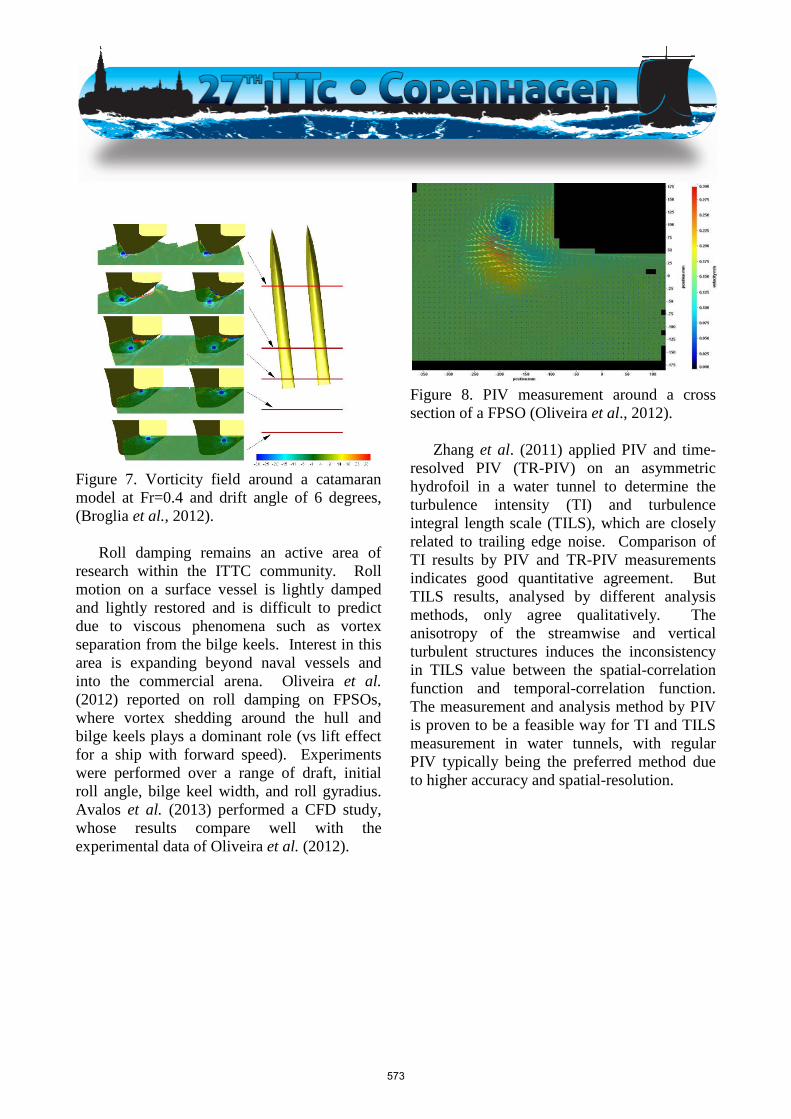
Figure 7. Vorticity field around a catamaran model at Fr=0.4 and drift angle of 6 degrees, (Broglia et al., 2012).
Roll damping remains an active area of
research within the ITTC community. Roll motion on a surface vessel is lightly damped and lightly restored and is difficult to predict due to viscous phenomena such as vortex separation from the bilge keels. Interest in this area is expanding beyond naval vessels and into the commercial arena. Oliveira et al. (2012) reported on roll damping on FPSOs, where vortex shedding around the hull and bilge keels plays a dominant role (vs lift effect for a ship with forward speed). Experiments were performed over a range of draft, initial roll angle, bilge keel width, and roll gyradius. Avalos et al. (2013) performed a CFD study, whose results compare well with the experimental data of Oliveira et al. (2012).
Figure 8. PIV measurement around a cross section of a FPSO (Oliveira et al., 2012).
Zhang et al. (2011) applied PIV and time-
resolved PIV (TR-PIV) on an asymmetric hydrofoil in a water tunnel to determine the turbulence intensity (TI) and turbulence integral length scale (TILS), which are closely related to trailing edge noise. Comparison of TI results by PIV and TR-PIV measurements indicates good quantitative agreement. But TILS results, analysed by different analysis methods, only agree qualitatively. The anisotropy of the streamwise and vertical turbulent structures induces the inconsistency in TILS value between the spatial-correlation function and temporal-correlation function. The measurement and analysis method by PIV is proven to be a feasible way for TI and TILS measurement in water tunnels, with regular PIV typically being the preferred method due to higher accuracy and spatial-resolution.
573
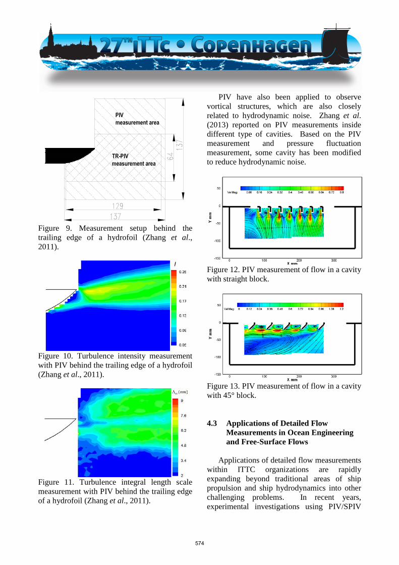
Figure 9. Measurement setup behind the trailing edge of a hydrofoil (Zhang et al., 2011).
Figure 10. Turbulence intensity measurement with PIV behind the trailing edge of a hydrofoil (Zhang et al., 2011).
Figure 11. Turbulence integral length scale measurement with PIV behind the trailing edge of a hydrofoil (Zhang et al., 2011).
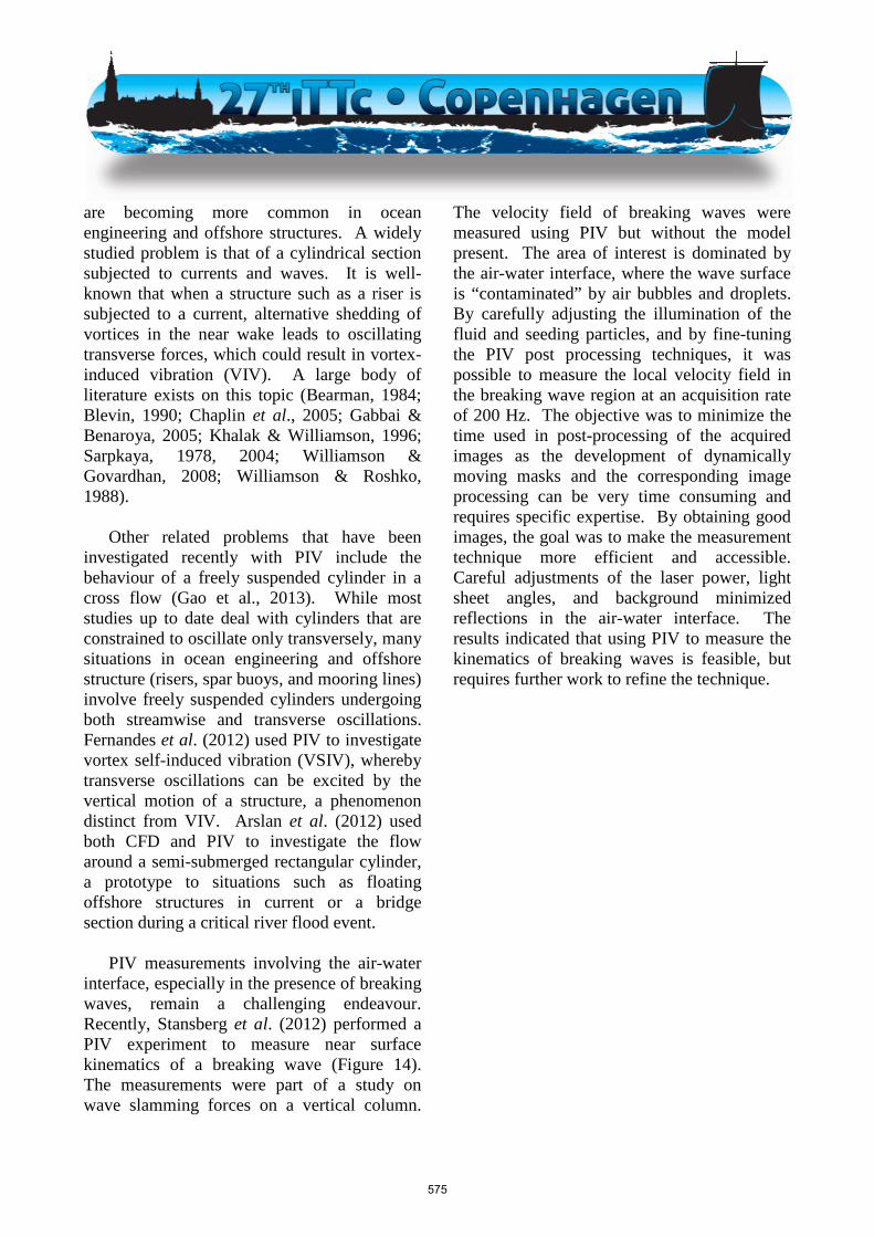
PIV have also been applied to observe vortical structures, which are also closely related to hydrodynamic noise. Zhang et al. (2013) reported on PIV measurements inside different type of cavities. Based on the PIV measurement and pressure fluctuation measurement, some cavity has been modified to reduce hydrodynamic noise.
Figure 12. PIV measurement of flow in a cavity with straight block.
Figure 13. PIV measurement of flow in a cavity with 45° block. 4.3 Applications of Detailed Flow
Measurements in Ocean Engineering and Free-Surface Flows
Applications of detailed flow measurements
within ITTC organizations are rapidly expanding beyond traditional areas of ship propulsion and ship hydrodynamics into other challenging problems. In recent years, experimental investigations using PIV/SPIV
574
are becoming more common in ocean engineering and offshore structures. A widely studied problem is that of a cylindrical section subjected to currents and waves. It is well-known that when a structure such as a riser is subjected to a current, alternative shedding of vortices in the near wake leads to oscillating transverse forces, which could result in vortex-induced vibration (VIV). A large body of literature exists on this topic (Bearman, 1984; Blevin, 1990; Chaplin et al., 2005; Gabbai & Benaroya, 2005; Khalak & Williamson, 1996; Sarpkaya, 1978, 2004; Williamson & Govardhan, 2008; Williamson & Roshko, 1988).
Other related problems that have been
investigated recently with PIV include the behaviour of a freely suspended cylinder in a cross flow (Gao et al., 2013). While most studies up to date deal with cylinders that are constrained to oscillate only transversely, many situations in ocean engineering and offshore structure (risers, spar buoys, and mooring lines) involve freely suspended cylinders undergoing both streamwise and transverse oscillations. Fernandes et al. (2012) used PIV to investigate vortex self-induced vibration (VSIV), whereby transverse oscillations can be excited by the vertical motion of a structure, a phenomenon distinct from VIV. Arslan et al. (2012) used both CFD and PIV to investigate the flow around a semi-submerged rectangular cylinder, a prototype to situations such as floating offshore structures in current or a bridge section during a critical river flood event.
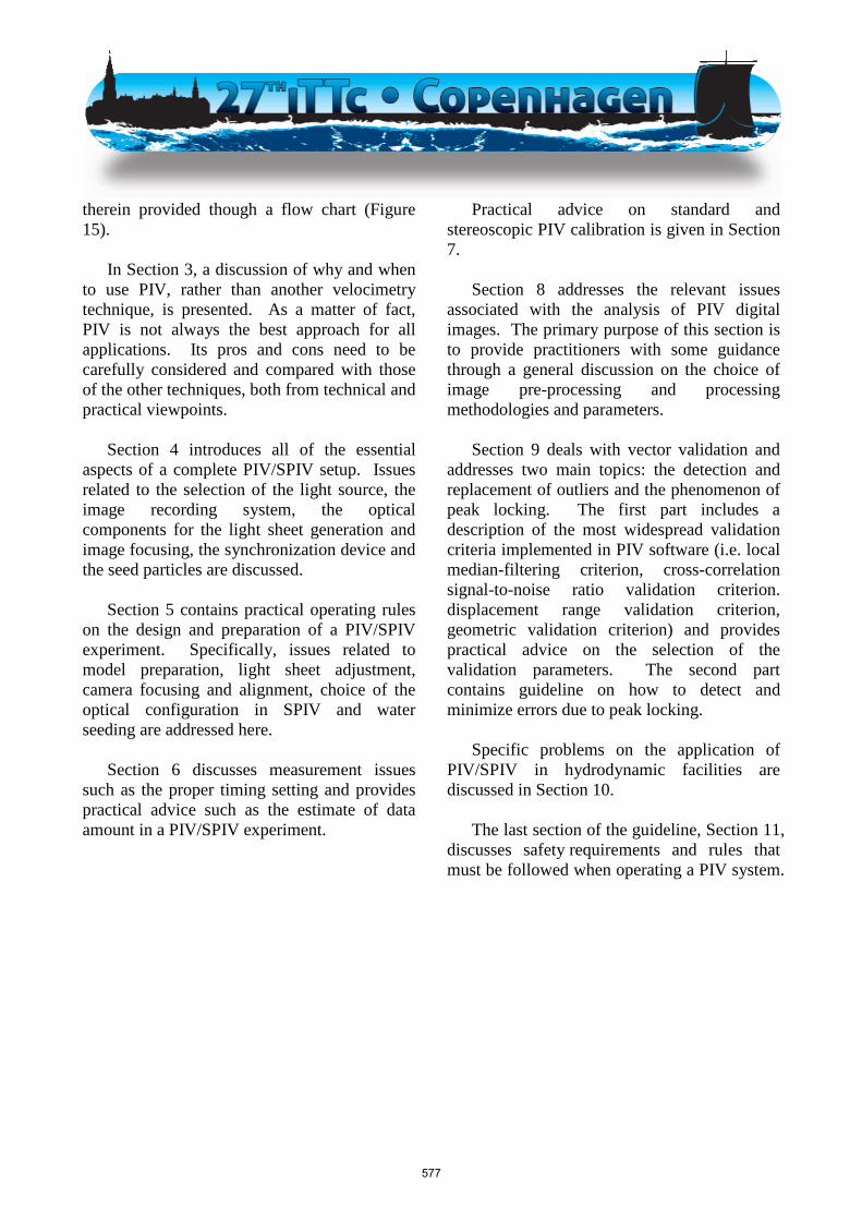
PIV measurements involving the air-water
interface, especially in the presence of breaking waves, remain a challenging endeavour. Recently, Stansberg et al. (2012) performed a PIV experiment to measure near surface kinematics of a breaking wave (Figure 14). The measurements were part of a study on wave slamming forces on a vertical column.
The velocity field of breaking waves were measured using PIV but without the model present. The area of interest is dominated by the air-water interface, where the wave surface is “contaminated” by air bubbles and droplets. By carefully adjusting the illumination of the fluid and seeding particles, and by fine-tuning the PIV post processing techniques, it was possible to measure the local velocity field in the breaking wave region at an acquisition rate of 200 Hz. The objective was to minimize the time used in post-processing of the acquired images as the development of dynamically moving masks and the corresponding image processing can be very time consuming and requires specific expertise. By obtaining good images, the goal was to make the measurement technique more efficient and accessible. Careful adjustments of the laser power, light sheet angles, and background minimized reflections in the air-water interface. The results indicated that using PIV to measure the kinematics of breaking waves is feasible, but requires further work to refine the technique.
575
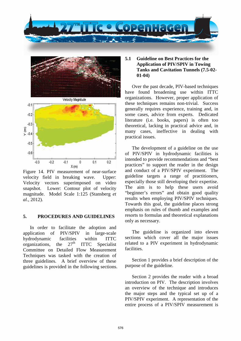
Figure 14. PIV measurement of near-surface velocity field in breaking wave. Upper: Velocity vectors superimposed on video snapshot. Lower: Contour plot of velocity magnitude. Model Scale 1:125 (Stansberg et al., 2012). 5. PROCEDURES AND GUIDELINES
In order to facilitate the adoption and
application of PIV/SPIV in large-scale hydrodynamic facilities within ITTC organizations, the 27th ITTC Specialist Committee on Detailed Flow Measurement Techniques was tasked with the creation of three guidelines. A brief overview of these guidelines is provided in the following sections.
5.1 Guideline on Best Practices for the Application of PIV/SPIV in Towing Tanks and Cavitation Tunnels (7.5-02-01-04)
Over the past decade, PIV-based techniques
have found broadening use within ITTC organizations. However, proper application of these techniques remains non-trivial. Success generally requires experience, training and, in some cases, advice from experts. Dedicated literature (i.e. books, papers) is often too theoretical, lacking in practical advice and, in many cases, ineffective in dealing with practical issues.
The development of a guideline on the use
of PIV/SPIV in hydrodynamic facilities is intended to provide recommendations and “best practices” to support the reader in the design and conduct of a PIV/SPIV experiment. The guideline targets a range of practitioners, especially those still developing their expertise. The aim is to help these users avoid “beginner’s errors” and obtain good quality results when employing PIV/SPIV techniques. Towards this goal, the guideline places strong emphasis on rules of thumb and examples and resorts to formulas and theoretical explanations only as necessary.
The guideline is organized into eleven
sections which cover all the major issues related to a PIV experiment in hydrodynamic facilities.
Section 1 provides a brief description of the
purpose of the guideline. Section 2 provides the reader with a broad
introduction on PIV. The description involves an overview of the technique and introduces the major steps and the typical set up of a PIV/SPIV experiment. A representation of the entire process of a PIV/SPIV measurement is
576
therein provided though a flow chart (Figure 15).
In Section 3, a discussion of why and when
to use PIV, rather than another velocimetry technique, is presented. As a matter of fact, PIV is not always the best approach for all applications. Its pros and cons need to be carefully considered and compared with those of the other techniques, both from technical and practical viewpoints.
Section 4 introduces all of the essential
aspects of a complete PIV/SPIV setup. Issues related to the selection of the light source, the image recording system, the optical components for the light sheet generation and image focusing, the synchronization device and the seed particles are discussed.
Section 5 contains practical operating rules
on the design and preparation of a PIV/SPIV experiment. Specifically, issues related to model preparation, light sheet adjustment, camera focusing and alignment, choice of the optical configuration in SPIV and water seeding are addressed here.
Section 6 discusses measurement issues
such as the proper timing setting and provides practical advice such as the estimate of data amount in a PIV/SPIV experiment.
Practical advice on standard and stereoscopic PIV calibration is given in Section 7.
Section 8 addresses the relevant issues
associated with the analysis of PIV digital images. The primary purpose of this section is to provide practitioners with some guidance through a general discussion on the choice of image pre-processing and processing methodologies and parameters.
Section 9 deals with vector validation and
addresses two main topics: the detection and replacement of outliers and the phenomenon of peak locking. The first part includes a description of the most widespread validation criteria implemented in PIV software (i.e. local median-filtering criterion, cross-correlation signal-to-noise ratio validation criterion. displacement range validation criterion, geometric validation criterion) and provides practical advice on the selection of the validation parameters. The second part contains guideline on how to detect and minimize errors due to peak locking.
Specific problems on the application of
PIV/SPIV in hydrodynamic facilities are discussed in Section 10.
The last section of the guideline, Section 11,
discusses safety requirements and rules that must be followed when operating a PIV system.
577
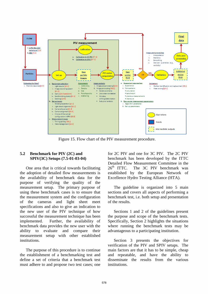
Figure 15. Flow chart of the PIV measurement procedure.
5.2 Benchmark for PIV (2C) and SPIV(3C) Setups (7.5-01-03-04)
One area that is critical towards facilitating
the adoption of detailed flow measurements is the availability of benchmark data for the purpose of verifying the quality of the measurement setup. The primary purpose of using these benchmark cases is to ensure that the measurement system and the configuration of the cameras and light sheet meet specifications and also to give an indication to the new user of the PIV technique of how successful the measurement technique has been implemented. Further, the availability of benchmark data provides the new user with the ability to evaluate and compare their measurement setup with other established institutions.
The purpose of this procedure is to continue
the establishment of a benchmarking test and define a set of criteria that a benchmark test must adhere to and propose two test cases; one
for 2C PIV and one for 3C PIV. The 2C PIV benchmark has been developed by the ITTC Detailed Flow Measurement Committee in the 26th ITTC. The 3C PIV benchmark was established by the European Network of Excellence Hydro Testing Alliance (HTA).
The guideline is organized into 5 main
sections and covers all aspects of performing a benchmark test, i.e. both setup and presentation of the results.
Sections 1 and 2 of the guidelines present
the purpose and scope of the benchmark tests. Specifically, Section 2 highlights the situations where running the benchmark tests may be advantageous to a participating institution.
Section 3 presents the objectives for
verification of the PIV and SPIV setups. The main factors are that it has to be simple, cheap and repeatable, and have the ability to disseminate the results from the various institutions.
578
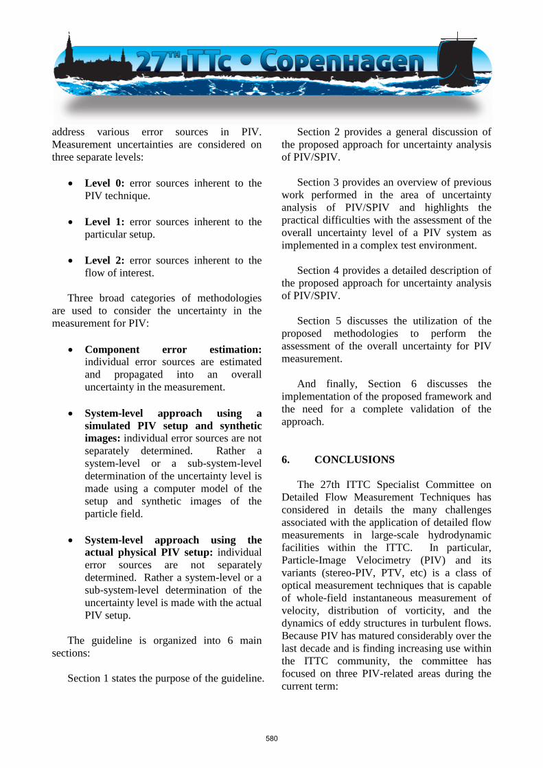
Section 4 presents the two PIV benchmark
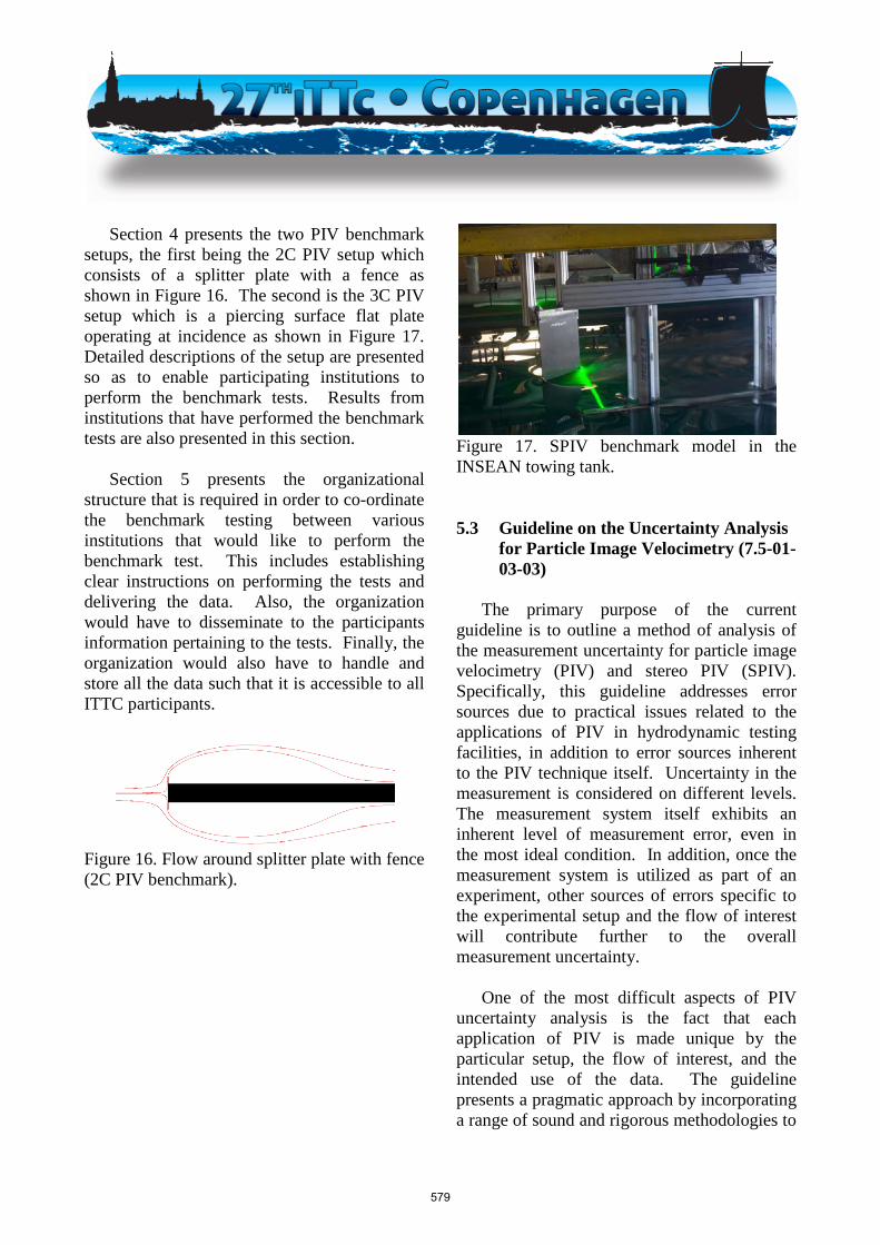
setups, the first being the 2C PIV setup which consists of a splitter plate with a fence as shown in Figure 16. The second is the 3C PIV setup which is a piercing surface flat plate operating at incidence as shown in Figure 17. Detailed descriptions of the setup are presented so as to enable participating institutions to perform the benchmark tests. Results from institutions that have performed the benchmark tests are also presented in this section.
Section 5 presents the organizational
structure that is required in order to co-ordinate the benchmark testing between various institutions that would like to perform the benchmark test. This includes establishing clear instructions on performing the tests and delivering the data. Also, the organization would have to disseminate to the participants information pertaining to the tests. Finally, the organization would also have to handle and store all the data such that it is accessible to all ITTC participants.
Figure 16. Flow around splitter plate with fence (2C PIV benchmark).
Figure 17. SPIV benchmark model in the INSEAN towing tank. 5.3 Guideline on the Uncertainty Analysis
for Particle Image Velocimetry (7.5-01-03-03)
The primary purpose of the current
guideline is to outline a method of analysis of the measurement uncertainty for particle image velocimetry (PIV) and stereo PIV (SPIV). Specifically, this guideline addresses error sources due to practical issues related to the applications of PIV in hydrodynamic testing facilities, in addition to error sources inherent to the PIV technique itself. Uncertainty in the measurement is considered on different levels. The measurement system itself exhibits an inherent level of measurement error, even in the most ideal condition. In addition, once the measurement system is utilized as part of an experiment, other sources of errors specific to the experimental setup and the flow of interest will contribute further to the overall measurement uncertainty.
One of the most difficult aspects of PIV
uncertainty analysis is the fact that each application of PIV is made unique by the particular setup, the flow of interest, and the intended use of the data. The guideline presents a pragmatic approach by incorporating a range of sound and rigorous methodologies to
579
address various error sources in PIV. Measurement uncertainties are considered on three separate levels:
• Level 0: error sources inherent to the
PIV technique.
• Level 1: error sources inherent to the particular setup.
• Level 2: error sources inherent to the flow of interest.
Three broad categories of methodologies are used to consider the uncertainty in the measurement for PIV:
• Component error estimation:
individual error sources are estimated and propagated into an overall uncertainty in the measurement.
• System-level approach using a simulated PIV setup and synthetic images: individual error sources are not separately determined. Rather a system-level or a sub-system-level determination of the uncertainty level is made using a computer model of the setup and synthetic images of the particle field.
• System-level approach using the actual physical PIV setup: individual error sources are not separately determined. Rather a system-level or a sub-system-level determination of the uncertainty level is made with the actual PIV setup.
The guideline is organized into 6 main sections:
Section 1 states the purpose of the guideline.
Section 2 provides a general discussion of the proposed approach for uncertainty analysis of PIV/SPIV.
Section 3 provides an overview of previous
work performed in the area of uncertainty analysis of PIV/SPIV and highlights the practical difficulties with the assessment of the overall uncertainty level of a PIV system as implemented in a complex test environment.
Section 4 provides a detailed description of
the proposed approach for uncertainty analysis of PIV/SPIV.
Section 5 discusses the utilization of the
proposed methodologies to perform the assessment of the overall uncertainty for PIV measurement.
And finally, Section 6 discusses the
implementation of the proposed framework and the need for a complete validation of the approach.
6. CONCLUSIONS The 27th ITTC Specialist Committee on
Detailed Flow Measurement Techniques has considered in details the many challenges associated with the application of detailed flow measurements in large-scale hydrodynamic facilities within the ITTC. In particular, Particle-Image Velocimetry (PIV) and its variants (stereo-PIV, PTV, etc) is a class of optical measurement techniques that is capable of whole-field instantaneous measurement of velocity, distribution of vorticity, and the dynamics of eddy structures in turbulent flows. Because PIV has matured considerably over the last decade and is finding increasing use within the ITTC community, the committee has focused on three PIV-related areas during the current term:
580
• The committee has compiled a set of recommendations and “best practices” into a guideline for the design and implementation of PIV experiments in large-scale hydrodynamic facilities. The guideline targets a range of practitioners, especially those still developing their expertise. Toward this goal, the guideline places strong emphasis on rules of thumb and examples and resorts to formulas and theoretical explanations only as necessary.
• The committee has proposed two experimental benchmark cases (2D and 3D) for the purpose of verifying the quality of the measurement setup. The primary purpose of using these benchmark cases is to ensure that the measurement system and the configuration of the cameras and light sheet meet specifications and also to give an indication to the new user of the PIV technique of how successful the measurement technique has been implemented. Further, the availability of benchmark data provides the new user with the ability to evaluate and compare their measurement setup with other established institutions.
• The committee has outlined a method of analysis of the measurement uncertainty for particle image velocimetry (PIV) and stereo PIV (SPIV). Specifically, the uncertainty analysis guideline addresses error sources due to practical issues related to the applications of PIV in hydrodynamic testing facilities, in addition to error sources inherent to the PIV technique itself. The assessment of the overall uncertainty of an actual PIV setup in a demanding environment such as tow tanks and cavitation tunnels is
particularly challenging due to the complexity of the system and the many sources of errors that need to be considered for each application. The proposed approach aims to strike the right balance between scientific rigor and practicality to yield an acceptable estimate of the overall uncertainty without requiring an unrealistic level of effort.
7. RECOMMENDATIONS
7.1 Recommendations to the Full Conference
The committee recommends that the ITTC: 1. Adopt the best practice guideline (7.5-
02-01-04).
2. Adopt the benchmark guideline (7.5-01-03-04).
3. Adopt the uncertainty analysis guideline (7.5-01-03-03).
7.2 Proposals for Future Work The committee recommends that the ITTC: • Recognizes the need for further
organized efforts to advance the application of detailed flow measurements in the ITTC community through detailed evaluation and implementation of the best-practice, the benchmark, and the uncertainty analysis guidelines.
• Develops a questionnaire to collect feedback and inputs from the general
581
ITTC community on how to refine and update the best-practice guideline. The guideline should then be revised based upon those inputs.
• Organizes an electronic repository of information and data on the benchmarks cases. ITTC member organizations should then be invited to participate in the adoption of the benchmark and contribute to the database.
• Implements and evaluates the proposed uncertainty analysis approach in details. It is further recommended that an ITTC case study be performed to assess the validity of the approach. The case study would involve PIV measurement performed on a flow of interest, with fully detailed uncertainty analysis. The results can then be compared with similar measurements done in different facilities or with high-quality CFD computations.
• Performs a state-of-the-art review on
frontier applications of detailed flow measurements. The state-of-the-art review performed by the 26th ITTC Detailed Flow Measurement Techniques Committee concentrated on the mainstream applications of detailed flow measurement techniques in the ITTC. A review of frontier applications would provide valuable information on a broad range of frontier techniques that can be implemented in demanding applications.
8. REFERENCES Arslan, T., Malavasi, S., Pettersen, B., and
Andersson, H.I., “Experimental and Numerical Study of the Flow Around a Semi-Submerged Rectangular Cylinder,” OMAE2012-83652.
Avalos, G.O.G., Wanderley, J.B.V., and
Fernandes, A.C., “Roll Damping Decay of a FPSO with Bilge Keel,” OMAE2013-10797.
Blevin, R.D., 1990, “Flow-Induced
Vibrations,” Van Nostrand Reinhold: New York.
Bearman, P.W., 1984, “Vortex Shedding from
Oscillating Bluff Bodies,” Annual Rev. Fluid Mech, Vol. 16, pp. 195-222.
Bugalski, T. and Reda, A., 2013, “Applications
of Particle Image Velocimetry to Complex Study of Propeller Flows,” Proceedings of the third International Conference on Advanced Model Measurement Technology (AMT’13), Gdansk, Poland.
Chaplin, J.R., Bearman, P.W., Huarte, F.J.H.,
and Patternden, R.J., M., 2005, “Laboratory Measurements of Vortex-Induced Vibrations of a Vertical Tension Riser in a Stepped Current,” Journal of Fluids and Structures, Vol. 21, pp. 3-24.
Dang, J., Radstaat, G. and Pouw, C.P., 2012,
“320K DWT VLCC; Calm Water Model Tests With Energy Saving Devices (ESD’s),” MARIN Draft Report.
Felli, M. and Falchi, M., 2011, “Propeller Tip
and Hub Vortex Dynamics in the Interaction with a Rudder,” Experiments in Fluids, Vol. 51, Issue 5, pp. 1385-1402.
582

Felli, M., Grizzi S. and Falchi, M., 2014, “A Novel Approach for the Isolation of the Sound and Pseudo-Sound Contributions from Near-Field Pressure Fluctuation Measurements: Analysis of the Hydroacoustic and Hydrodynamic Perturbation in a Propeller-Rudder System,” Experiments in Fluids, Vol. 55, Issue 1, pp. 1-17.
Fernandes, A.C., Sefat, S.M., Cascão, L.V.,
and Franciss, R., 2012, “Analysis of PIV Tests Results of the Vortex Self Induced Vibration (VSIV) of a Cylinder,” OMAE2012-84021.
Gabbai, R.D. and Benaroya, H., 2005, “An
Overview of Modeling and Experiments of Vortex-Induced Vibration of Circular Cylinders,” Journal of Sound and Vibration, Vol. 282, pp. 575-616.
Gao, Y., Tan, D.S., Zhang, B., and Tan, S.K.,
2013, “Experimental Study on the Flow Around a Moving Cylinder,” OMAE2013-10048.
Khalak, A. and Williamson, C.H.K., 1996,
“Dynamics of a Hydroelastic Cylinder with Very Low Mass and Damping,” Journal of Fluid and Structures, Vol. 10, pp. 455-472.
Muscari, R., Felli, M., and Di Mascio, A.,
2011, “Analysis of the Flow Past a Fully Appended Hull with Propellers by Computational and Experimental Fluid Dynamics,” Journal of Fluids Engineering, Vol. 133, Issue 6.
Oliveira, A.C., Fernandes, A.C., and
Guimarães, H.B., “The Influence of Vortex Formation on the Damping of FPSOs with Large Width Bilge Keels,” OMAE2012-83353.
Paik, B.G., Kim, K.S., Kim, K.Y., Kim, G.D. and Park, Y.H., 2011a, “PIV Measurements of Rudder Inflow Induced by Propeller Revolution ion Hull Wake,” Journal of the Society of Naval Architects of Korea, Vol. 48, issue 2, pp. 128-133 (in Korean).
Paik, B.G., Kim, K.S., Moon, I.S. and Ahn,
J.W., 2011b, “Experimental Study on the Vortical Flow Behind 2-D Blade with the Variation of Trailing Edge Shape,” Journal of the Society of Naval Architects of Korea, Vol. 48, issue 3, pp. 233-237 (in Korean).
Pecoraro, A., Di Felice, F., Felli, M., Salvatore,
F., and Viviani, M., 2013, “Propeller-Hull Interaction in a Single-Screw Vessel,” Proceedings of the third Symposium on Naval Propulsion, Launceston, Tasmania.
Sarpkaya, T., 1978, “Vortex-Induced
Oscillations,” Journal of Applied Mechanics, Vol. 46, pp. 241-258.
Sarpkaya, T., 2004, “A Critical Review of the Intrinsic Nature of Vortex-Induced Vibrations,” Journal of Fluids and Structures, Vol. 19, pp. 389-447.
Stansberg, C.T., Berget, K., Graczyk, M.,
Muthanna, C., and Pakozdi, C., 2012, “Breaking Wave Kinematics and Resulting Slamming Pressures on a Vertical Column,” OMAE2012-83929.
van’t Veer, R., 1998a, “Experimental Results
of Motions and Structural Loads on the 372 Catamaran Model in Head and Oblique Wave,” Technical Report, TU Delft, Repot N.1130.
583
van’t Veer, R., 1998b, “Experimental Results of Motions, Hydrodynamic Coefficients and Wave Loads on the 372 Catamaran Model,” Technical Report, TU Delft, Repot N.1129.
Williamson, C.H.K., and Govardhan, R., 2008,
“A Brief Review of Recent Results in Vortex-Induced Vibrations,” Journal of Wind Engineering and Industrial Aerodynamics, Vol. 96, pp. 713-735.
Williamson, C.H.K., and Roshko, A., 1988,
“Vortex Formation in the Wake of an Oscillating Cylinder,” Journal of Fluids and Structures, Vol. 2, issue 4, pp. 355-381.
Wu, H., Miorini, R.L., and Katz, J., 2011, “Measurements of the Tip Leakage Vortex Structures and Turbulence in the Meridional Plane of an Axial Water-Jet Pump,” Experiments in fluids, Vol. 50, issue 4, pp. 989-1003.
Zhang, J., Xue, Q., Zhang, G., and Zhao, F.,
2011, “TILS Measurement of the Flow Over Trailing Edge of Hydrofoil by PIV,” AMT’11, Newcastle, UK.
Zhang, G., Lu, L., Xue, Q., and Wu, Y., 2011,
“Comparison and Analysis on Hydrofoil Wake Turbulence by PIV and TR-PIV,” PIV’11, Tsukuba, Japan.
Zhang, G. and Zhang, N., 2013, “The Test
Report of Fluctuation Pressure and Flow Field of Cavity,” CSSRC Technical Report.
584