Embed Size (px)
Citation preview

Excellence in Engineering Simulation 2015
ADVANTAGETM
SPECIALISSUE:Oil and Gas
© 2015 ANSYS, INC. ANSYS ADVANTAGE | SPECIAL ISSUE: OIL AND GAS | 2015 2
Conquering engineering Challenges
Successful companies in every industry manage operating costs through engineering productivity, global collaboration and increased product reliability. By Ahmad H. Haidari, Global Industry Director, Energy and Process Industries, ANSYS
Challenges in the oil and gas industry can be simply summed up as using technology to overcome risks related to finding and producing resources at reasonable cost. The
industry is experiencing tremendous pressures due to a recent drop in prices. At the same time, advancements in seismic technology used in exploration have been critical in finding hydrocarbons in all types of formations. Now the challenge is to develop these fields in a safe, reliable, sustainable way. The industry must invest in developing new technologies to reduce cost and ensure profitability while meeting increasing regulatory requirements.
All engineering organizations, no matter what the indus-try, need to make trade-offs and balance competing demands. Balancing these competing needs — profits versus investments — requires creative solutions. Often, each proposed solution creates a host of new questions. In the oil and gas industry, petrophysicists, geologists and engineers are responsible for answering questions regarding developing and perfecting the next level of technologies. Making trade-offs and satisfying the needs of different projects under varying geological conditions adds complexity to field development strategies and related engineering and equipment requirements. To deal with com-plexity, best practices in all industries increasingly include use of computational technology to create a platform for global engineering collaboration, modeling and simulation studies.
Physics-based engineering design and analysis provides successful companies with solutions that impact compliance, the bottom line and equipment reliability while improving efficiencies and ultimately leading to technologies and practices that reduce cost. Simulation helps companies to minimize the cost of physical testing, develop new technologies, evaluate novel concepts and assess product performance in a low-risk virtual environment. The aerospace, defense and automotive industries have fully adopted the concepts of engineering simulation and system design for product development. There are many similarities in how organizations, no matter what industry, reach product development milestones. For example, the automotive industry’s push to develop autonomous vehicles closely mimics oil and gas industry requirements for remote drilling and ocean robotics.
Oil and gas companies are not strangers to computational simulation and analysis. They have been using the technology to perform large calculations for reservoir modeling for many years, for example. But as oil and gas industry project complex-ity increases, the broader adoption of model-based integrated engineering practices is a must.
How can the oil and gas industry increase the benefits from broader deployment of physics-based modeling and system design?
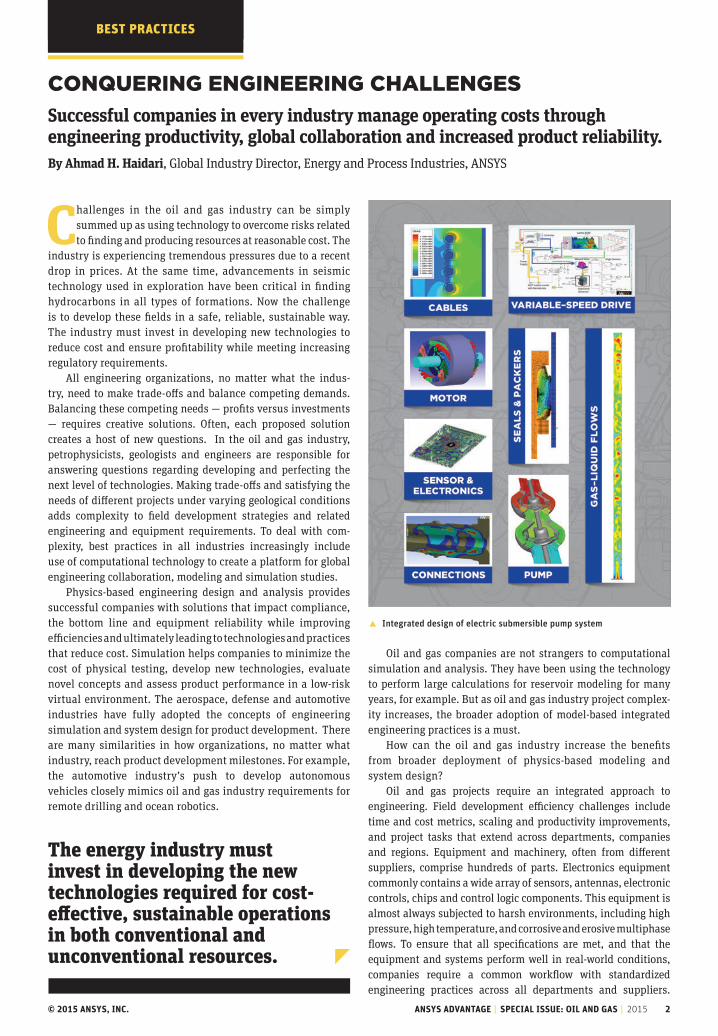
Oil and gas projects require an integrated approach to engineering. Field development efficiency challenges include time and cost metrics, scaling and productivity improvements, and project tasks that extend across departments, companies and regions. Equipment and machinery, often from different suppliers, comprise hundreds of parts. Electronics equipment commonly contains a wide array of sensors, antennas, electronic controls, chips and control logic components. This equipment is almost always subjected to harsh environments, including high pressure, high temperature, and corrosive and erosive multiphase flows. To ensure that all specifications are met, and that the equipment and systems perform well in real-world conditions, companies require a common workflow with standardized engineering practices across all departments and suppliers.
� Integrated design of electric submersible pump system
The energy industry must invest in developing the new technologies required for cost-effective, sustainable operations in both conventional and unconventional resources.
TKBEsT PrAcTicEs
© 2015 ANSYS, INC. ANSYS ADVANTAGE | SPECIAL ISSUE: OIL AND GAS | 2015 3
This requires a systems-level approach that focuses on the interoperability of all components during a product's design and operating life. Not only must each component be dependable, but it must perform as part of a larger subsystem and operate across a broad range of possible conditions. Performing systems-level multiphysics simulations with best-in-class individual physics early in the design process helps to ensure that the equipment will perform to expectations and not fail under adverse conditions.
The best engineering platform com-bines systems-level and physics-based detailed modeling with a common solu-tion set and workflows. A consistent engineering simulation platform brings key elements of engineering design, including systems functional engineer-ing, software engineering, and detailed design and optimization solutions across all applicable physics, including fluid mechanics, electromagnetics, thermal and structural mechanics. This common platform drives technology consolidation, leads to standardization, and optimizes workflow along with engineering and IT efficiencies.
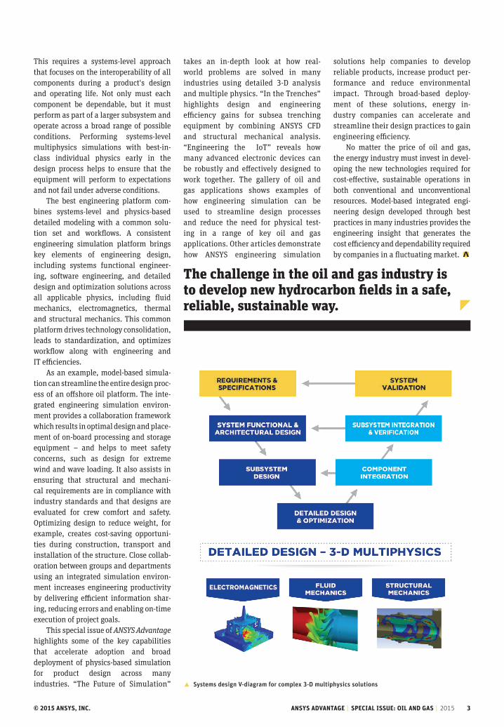
As an example, model-based simula-tion can streamline the entire design proc- ess of an offshore oil platform. The inte-grated engineering simulation environ-ment provides a collaboration framework which results in optimal design and place-ment of on-board processing and storage equipment – and helps to meet safety concerns, such as design for extreme wind and wave loading. It also assists in ensuring that structural and mechani-cal requirements are in compliance with industry standards and that designs are evaluated for crew comfort and safety. Optimizing design to reduce weight, for example, creates cost-saving opportuni-ties during construction, transport and installation of the structure. Close collab-oration between groups and departments using an integrated simulation environ-ment increases engineering productivity by delivering efficient information shar-ing, reducing errors and enabling on-time execution of project goals.
This special issue of ANSYS Advantage highlights some of the key capabilities that accelerate adoption and broad deployment of physics-based simulation for product design across many industries. “The Future of Simulation”
takes an in-depth look at how real-world problems are solved in many industries using detailed 3-D analysis and multiple physics. “In the Trenches” highlights design and engineering efficiency gains for subsea trenching equipment by combining ANSYS CFD and structural mechanical analysis. “Engineering the IoT” reveals how many advanced electronic devices can be robustly and effectively designed to work together. The gallery of oil and gas applications shows examples of how engineering simulation can be used to streamline design processes and reduce the need for physical test- ing in a range of key oil and gas applications. Other articles demonstrate how ANSYS engineering simulation
solutions help companies to develop reliable products, increase product per-formance and reduce environmental impact. Through broad-based deploy-ment of these solutions, energy in- dustry companies can accelerate and streamline their design practices to gain engineering efficiency.
No matter the price of oil and gas, the energy industry must invest in devel-oping the new technologies required for cost-effective, sustainable operations in both conventional and unconventional resources. Model-based integrated engi-neering design developed through best practices in many industries provides the engineering insight that generates the cost efficiency and dependability required by companies in a fluctuating market.
� Systems design V-diagram for complex 3-D multiphysics solutions
The challenge in the oil and gas industry is to develop new hydrocarbon fields in a safe, reliable, sustainable way.

© 2015 ANSYS, INC. ANSYS ADVANTAGE | SPECIAL ISSUE: OIL AND GAS | 2015 4
Don’t miss future issuesof ANSYS Advantage.
ansys.com/magazine
Subscribe
2Conquering Engineering ChallengesSuccessful companies in every industry manage operating costs through engineering productivity, global collaboration and increased product reliability.
5The Future of SimulationANSYS introduces new technology developments that make multiphysics simulations faster, more seamless and higher fidelity than ever.
10In the TrenchesStructural and fluids simulation help to optimize a subsea trenching vehicle.
14Engineering the “Internet of Things”ANSYS provides the comprehensive suite of simulation software to reliably and cost-effectively engineer high-performance electronic devices and systems.
19Gallery: Oil and Gas Industry ApplicationsThis gallery highlights some recent examples of best-in-class solutions using ANSYS software.
23Robust Electric Machine Design through MultiphysicsElectromagnetic, mechanical and thermal simulation plus design optimization help to improve electric motors.
28Power for a Sustainable Future: Reducing DowntimeSimulation helps to improve productivity, performance and engineering innovation at a PTT gas separation plant.
30Blending Design and SimulationSpaceClaim and ANSYS bring innovative design and analysis closer together.
© 2015 ANSYS, Inc. All Rights Reserved.
10
19
TABLE OF CONTENTS

© 2015 ANSYS, INC. ANSYS ADVANTAGE | SPECIAL ISSUE: OIL AND GAS | 2015 5
BEsT PrAcTicEs
By Chris Wolfe, Lead Product Manager for Multiphysics, ANSYS
Multiphysics: The FuTure of simulaTionas part of its comprehensive set of solutions for engineering simulation, ansYs introduces new technology developments that make multiphysics simulations faster, more seamless and higher fidelity — as well as more accessible than ever.

© 2015 ANSYS, INC. ANSYS ADVANTAGE | SPECIAL ISSUE: OIL AND GAS | 2015 6
engineering simulation plays a role in designing the buildings we live and work in, the cars we drive,
the smartphones we carry, the medical devices that keep us healthy, our comput-ers, our food and much more. Since ANSYS first introduced simulation software more than four decades ago, it has dramati-cally grown in its adoption by engineering teams around the world, in every indus-try, in every discipline.
Today, the majority of the world’s engineering teams apply simulation tools and methods in the design phases of prod-uct development, replacing costly physi-cal prototyping and testing with advanced numerical analyses.
Historically, engineers had to apply some degree of simplification to their simulations to meet product deadlines while improving those aspects of perfor-mance most valued by users. This often meant focusing on the single most impor-tant physical phenomenon affecting the product.
For example, designers of Formula 1 cars traditionally devoted resources to improving aerodynamics via computa-tional fluid dynamics (CFD) simulations. Designers of construction or agricultural equipment leveraged mechanical simula-tion software to optimize products’ ability to withstand heavy forces. Manufacturers of printed circuit boards (PCBs) invested the majority of their efforts in ensuring signal integrity.
This historic focus on a single physics yielded useful insights into critical prod-uct characteristics, often resulting in sig-nificant performance gains — at a lower investment of time and money than tra-ditional experimental and physical pro-totyping methods. But, as competitive pressures have increased and consumers have become more sophisticated in their demands, today it is rare to achieve the best-possible product design when opti-mizing a product’s response to a single physical force. To understand every force at play, and accurately predict if the prod-uct can perform well as a result, all the relevant physics need to be considered.
Being able to simulate all physics at the same time — and perform para-metric optimization using multiphys-ics results — allows engineers to quickly gain important insight into product per-formance, target optimal designs faster, and release products to market earlier.
�The Hyperthermia Group at Duke University relies on multiphysics simulation to develop new, non-invasive approaches to treat bladder cancer. Researchers leveraged ANSYS HFSS to design a miniature water-loaded microwave antenna that is used to investigate how to deliver chemotherapeutics to the bladder in a heat-activated manner. The simulated power deposition pattern is then incorporated in ANSYS Fluent, where engineers model the effects of biological mechanisms such as blood perfusion and metabolism — which are critical to analyzing heat transfer in biological systems. To avoid overheating tissues, the antenna is cooled with a circulating fluid modeled in ANSYS CFD. All physics analyses are coupled to optimize selective heating of the bladder region.
As a result of applying these tools and processes, today’s Formula 1 engineers gain new insights on how to balance aerodynamics with high power, struc-tural integrity and low weight. Heavy equipment manufacturers eliminate not just structural weaknesses, but thermal stresses that can cause part deformation and failure. And PCB product designers go well beyond investigating EMI, focus-ing on how heat affects multiple compo-nents and solder joints.
ProduCT ComPlexiTY: a growing ChallengeIn virtually every industry, multiphysics studies enable engineers to address an even greater challenge: the growing com-plexity of their product designs.
Modern product development trends — such as increasing power density of elec-tronic devices, product miniaturization across industries, consumer demand for smart products, growing use of advanced materials and increased emphasis on sustainability — have created special challenges.
Densely packed electronics need ade-quate cooling, which is often provided by
fans and heat sinks that must be carefully engineered. Chip manufacturers need to understand the impact of heat on the cir-cuit board and solder joints — especially thermal deformation caused by temper-ature fluctuations — to develop robust electronic products that don’t fail under on-design or off-design conditions.
Medical devices — which are increas-ingly designed for operation at nano scale — must perform flawlessly in the pres-ence of strong fluidic and body forces. The individual patient’s geometry, blood ves-sel contraction, blood flow patterns and characteristics of surrounding internal organs must all be accounted for simulta-neously when predicting the behavior of a particular device or procedure.
New advanced composite materials comprise layers of fibers, some of which have unique thermo-electric properties. Car bodies and airplane hulls made of such materials must be optimized not only for thermo-electric performance, but for aerodynamic performance, vibration response, energy efficiency and long-term reliability.
These and other trends make it more and more challenging for engineering
BEsT PrAcTicEs
© 2015 ANSYS, INC. ANSYS ADVANTAGE | SPECIAL ISSUE: OIL AND GAS | 2015 7
teams to answer essential product devel-opment questions:
• What are all the potential sources of product failure?
• How can we achieve the best trade-off among multiple performance requirements?
• Can the specified materials withstand all the expected fluidic and mechanical forces?
• Is the amount of cooling sufficient,given the potential for thermal transfer among components?
• Can this product be produced time- and cost-efficiently — while also minimizing material, energy and waste?
Growing design complexity is mak-ing it harder to answer these questions with absolute confidence. At the same time, it has never been more crucial to eliminate product failure and deliver reliable performance.
mulTiPhYsiCs analYsis: a Flexible, aCCessible aPProaChMultiphysics simulation, once considered an advanced engineering strategy lever-aged only by experts, is becoming a stan-dard part of today’s product development toolkit in many industries. By using mul-tiphysics studies to predict and verify product performance under a wide range of operating conditions — accounting for the effects of various physical forces — engineering teams can eliminate many sources of real-world product failure.
While multiple physics histor-ically have been considered via a series of unconnected single-physics studies — focusing separately on flu-ids, structural, thermal and electron-ics effects — engineers today increas-ingly recognize that the interactions
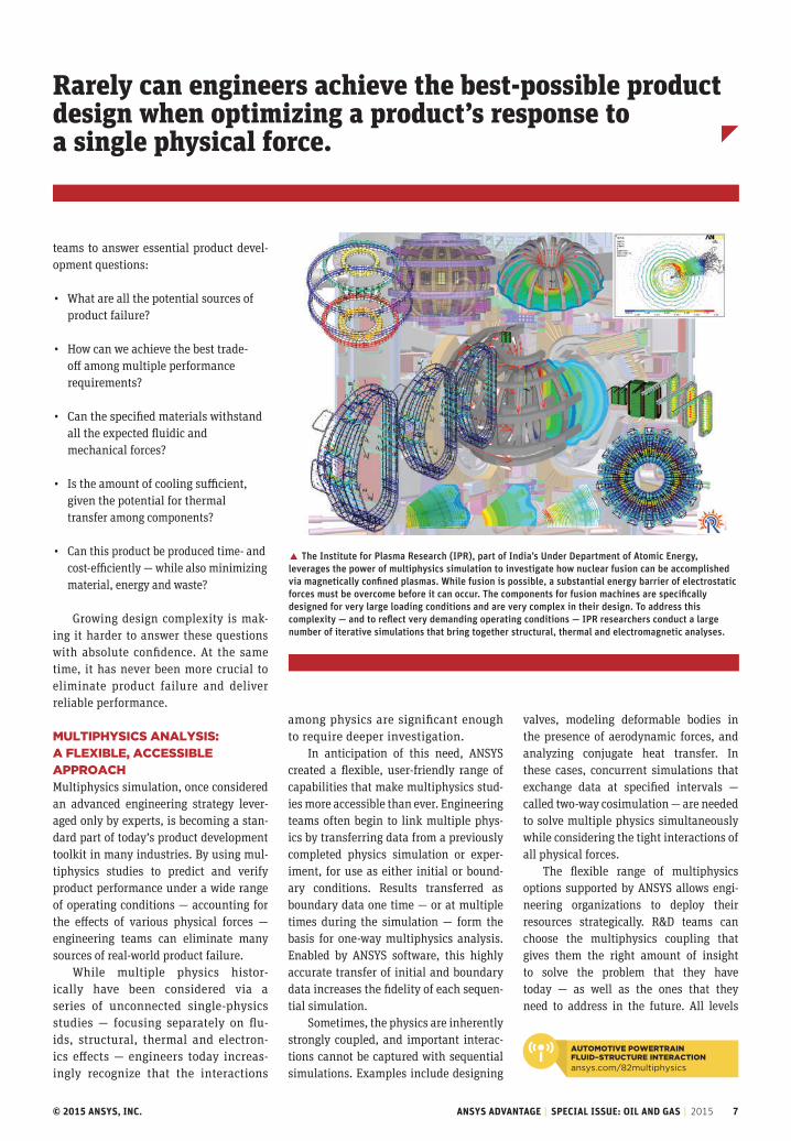
� The Institute for Plasma Research (IPR), part of India’s Under Department of Atomic Energy, leverages the power of multiphysics simulation to investigate how nuclear fusion can be accomplished via magnetically confined plasmas. While fusion is possible, a substantial energy barrier of electrostatic forces must be overcome before it can occur. The components for fusion machines are specifically designed for very large loading conditions and are very complex in their design. To address this complexity — and to reflect very demanding operating conditions — IPR researchers conduct a large number of iterative simulations that bring together structural, thermal and electromagnetic analyses.
among physics are significant enough to require deeper investigation.
In anticipation of this need, ANSYS created a flexible, user-friendly range of capabilities that make multiphysics stud-ies more accessible than ever. Engineering teams often begin to link multiple phys-ics by transferring data from a previously completed physics simulation or exper-iment, for use as either initial or bound-ary conditions. Results transferred as boundary data one time — or at multiple times during the simulation — form the basis for one-way multiphysics analysis. Enabled by ANSYS software, this highly accurate transfer of initial and boundary data increases the fidelity of each sequen-tial simulation.
Sometimes, the physics are inherently strongly coupled, and important interac-tions cannot be captured with sequential simulations. Examples include designing
valves, modeling deformable bodies in the presence of aerodynamic forces, and analyzing conjugate heat transfer. In these cases, concurrent simulations that exchange data at specified intervals — called two-way cosimulation — are needed to solve multiple physics simultaneously while considering the tight interactions of all physical forces.
The flexible range of multiphysics options supported by ANSYS allows engi-neering organizations to deploy their resources strategically. R&D teams can choose the multiphysics coupling that gives them the right amount of insight to solve the problem that they have today — as well as the ones that they need to address in the future. All levels
Rarely can engineers achieve the best-possible product design when optimizing a product’s response to a single physical force.
auTomoTive PowerTrain Fluid–sTruCTure inTeraCTion
ansys.com/82multiphysics

© 2015 ANSYS, INC. ANSYS ADVANTAGE | SPECIAL ISSUE: OIL AND GAS | 2015 8
� Space-based communication satellite dishes operate under challenging conditions. Electromagnetic losses — caused by induced high-frequency surface currents — lead to partial, asymmetric heating of the structure, which results in stress and deformation. Researchers use multiphysics simulation tools from ANSYS — specifically ANSYS HFSS and ANSYS Mechanical — to comprehensively analyze all these effects. The resulting deformed structure is brought back into the electromagnetic simulation tool, HFSS, to determine how any stress-induced deformations affect the antenna pattern.
� Multiphysics studies help engineers to solve complex challenges — such as designing plastic packaging that is both strong and lightweight while also meeting user needs. ANSYS Polyflow enables simulation of the manufacturing blow-molding process, using inputs including geometry, material and process conditions. Next, the liquid dispensing process is modeled via a fluid–structure interaction simulation with ANSYS Fluent. This simulation simultaneously employs ANSYS Mechanical to model bottle wall deformation during squeezing. Any thickness variation in the bottle’s material from the blow-molding process can be mapped from ANSYS Polyflow to the ANSYS Mechanical model.
Simulating all physics at the same time enables engineers to quickly gain important insight into product performance, target optimal designs faster, and release products to market earlier.
of ANSYS multiphysics simulation sup-port a robust design optimization strategy aimed at ensuring uncompromising prod-uct quality.
equiPPed For mulTiPhYsiCs suCCessTo support customer success, ANSYS delivers continued technology leadership in every individual physics area, includ-ing fluid dynamics, structural mechan-ics, thermodynamics and electronics. This technology leadership is critical. Simulation software must provide accu-rate and robust results for each individ-ual physics before it is able to capture the complex interactions among them.
Anticipating the growing need for multiphysics simulation as part of a robust
design process, ANSYS developed power-ful capabilities to facilitate multiphys-ics studies by making them faster, more streamlined and more intuitive. The lead-ership of ANSYS in individual physics, coupled with its support for parametric design optimization, makes ANSYS the perfect solution set for solving today’s complex design challenges — including fluid–thermal and fluid–mechanical sys-tems, robust electric machines and elec-tronics, and product applications for advanced materials.
Ongoing improvements in ANSYS Workbench have produced an easy, adapt-able multiphysics simulation solution right out of the box. Drag-and-drop cou-pling in Workbench makes it easy to set up a range of multiphysics studies,
supporting both one-way sequential sim-ulations and two-way cosimulations.
With flexible, open, automated and accurate data exchange capabilities, Workbench allows experimental data, data from third parties or data from another physics simulation to be used for the current simulation. In addi-tion, data exchange with external soft-ware solutions can be facilitated using the ANSYS Application Customization Toolkit (ACT), which includes the Workbench Software Development Kit (SDK). These tools allow a range of cus-tomization to optimize specific simu-lation capabilities, including informa-tion transfer with external technology solutions. Whether data is exchanged among ANSYS solutions or with exter-nal software, advanced methods and validation processes support both speed and accuracy.
The deep, sophisticated solver tech-nology underlying ANSYS Workbench
new mulTiPhYsiCs simulaTions using ansYs iCePak
ansys.com/82multiphysics2
BEsT PrAcTicEs
© 2015 ANSYS, INC. ANSYS ADVANTAGE | SPECIAL ISSUE: OIL AND GAS | 2015 9
can zero in on optimal designs faster, while deeply investigating the interactions of all relevant physics via multiphysics analysis.
ANSYS Engineering Knowledge Manager (EKM) helps product development teams manage the large scale and scope of infor-mation that is generated by multiphysics studies. ANSYS EKM addresses the many critical activities associated with manag-ing simulation data, including backup and archival, traceability and auditing, process automation, collaboration and capture of engineering expertise, and intellectual property protection.
In addition, reduced-order modeling (ROM) methods from ANSYS can trans-form a series of complex multiphysics sim-ulations into 0-D or 1-D models that rep-resent the dynamics of the multiphysics simulation in a systems-level analysis — while avoiding the high costs associated with rerunning simulations for each oper-ating point. Whether product development teams require the extreme high fidelity of 3-D modeling or the broad view and rapid results of lower-order simulation, ANSYS offers an unmatched level of scalability.
be insPired bY The besT in ClassIf conducting multiphysics simulations seems out of reach for your own engineer-ing team, ANSYS Advantage should serve as a powerful inspiration. Many issues show firsthand how engineers in every industry apply ANSYS software and best
includes high-performance computing (HPC) capabilities and parallel scalabil-ity that accelerate the solution of numer-ically large multiphysics simulations. Industry-leading ANSYS solver technol-ogy can easily accommodate large geom-etries with high mesh counts as well as the enormous amount of data generated during detailed multiphysics analyses. Workbench manages the complex inter-action between physics solvers during cosimulation.
a ComPrehensive answer To TodaY’s simulaTion ChallengesIn addition to providing these founda-tional capabilities, ANSYS offers an array of simulation platform services that help product development teams to support robust design optimization via multiphys-ics simulations.
ANSYS DesignXplorer enables engi-neers to explore, understand and optimize their designs via parametric analysis. They
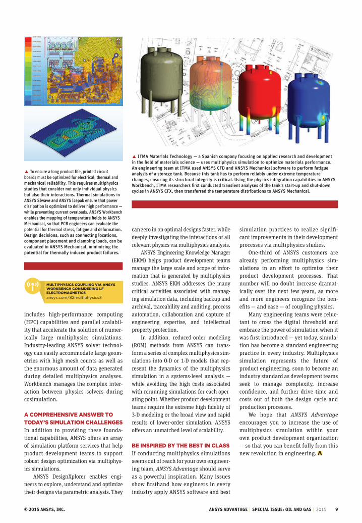
� ITMA Materials Technology — a Spanish company focusing on applied research and development in the field of materials science — uses multiphysics simulation to optimize materials performance. An engineering team at ITMA used ANSYS CFD and ANSYS Mechanical software to perform fatigue analysis of a storage tank. Because this tank has to perform reliably under extreme temperature changes, ensuring its structural integrity is critical. Using the physics integration capabilities in ANSYS Workbench, ITMA researchers first conducted transient analyses of the tank’s start-up and shut-down cycles in ANSYS CFX, then transferred the temperature distributions to ANSYS Mechanical.
� To ensure a long product life, printed circuit boards must be optimized for electrical, thermal and mechanical reliability. This requires multiphysics studies that consider not only individual physics but also their interactions. Thermal simulations in ANSYS SIwave and ANSYS Icepak ensure that power dissipation is optimized to deliver high performance — while preventing current overloads. ANSYS Workbench enables the mapping of temperature fields to ANSYS Mechanical, so that PCB engineers can evaluate the potential for thermal stress, fatigue and deformation. Design decisions, such as connecting locations, component placement and clamping loads, can be evaluated in ANSYS Mechanical, minimizing the potential for thermally induced product failures.
mulTiPhYsiCs CouPling via ansYs workbenCh Considering lF eleCTromagneTiCs
ansys.com/82multiphysics3
simulation practices to realize signifi-cant improvements in their development processes via multiphysics studies.
One-third of ANSYS customers are already performing multiphysics sim-ulations in an effort to optimize their product development processes. That number will no doubt increase dramat-ically over the next few years, as more and more engineers recognize the ben-efits — and ease — of coupling physics.
Many engineering teams were reluc-tant to cross the digital threshold and embrace the power of simulation when it was first introduced — yet today, simula-tion has become a standard engineering practice in every industry. Multiphysics simulation represents the future of product engineering, soon to become an industry standard as development teams seek to manage complexity, increase confidence, and further drive time and costs out of both the design cycle and production processes.
We hope that ANSYS Advantage encourages you to increase the use of multiphysics simulation within your own product development organization — so that you can benefit fully from this new revolution in engineering.
© 2015 ANSYS, INC. ANSYS ADVANTAGE | SPECIAL ISSUE: OIL AND GAS | 2015 10
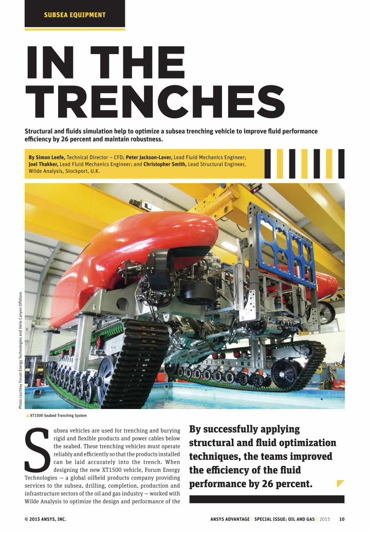
By successfully applying structural and fluid optimization techniques, the teams improved the efficiency of the fluid performance by 26 percent.
suBsEA EquiPMENT
in The TrenChesStructural and fluids simulation help to optimize a subsea trenching vehicle to improve fluid performance efficiency by 26 percent and maintain robustness.
By Simon Leefe, Technical Director – CFD; Peter Jackson-Laver, Lead Fluid Mechanics Engineer; Joel Thakker, Lead Fluid Mechanics Engineer; and Christopher Smith, Lead Structural Engineer, Wilde Analysis, Stockport, U.K.
Subsea vehicles are used for trenching and burying rigid and flexible products and power cables below the seabed. These trenching vehicles must operate reliably and efficiently so that the products installed can be laid accurately into the trench. When designing the new XT1500 vehicle, Forum Energy
Technologies — a global oilfield products company providing services to the subsea, drilling, completion, production and infrastructure sectors of the oil and gas industry — worked with Wilde Analysis to optimize the design and performance of the
�XT1500 Seabed Trenching System
Phot
o co
urte
sy F
orum
Ene
rgy
Tech
nolo
gies
and
Hel
ix C
anyo
n Off
shor
e.
© 2015 ANSYS, INC. ANSYS ADVANTAGE | SPECIAL ISSUE: OIL AND GAS | 2015 11
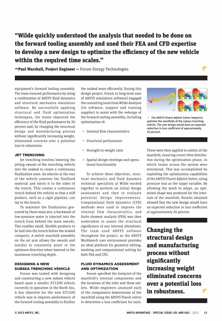
� The ANSYS Fluent Adjoint Solver helped to optimize the manifolds of the subsea trenching vehicle. The new design would have an expected reduction in loss coefficient of approximately 26 percent.
“Wilde quickly understood the analysis that needed to be done on the forward tooling assembly and used their FEA and CFD expertise to develop a new design to optimize the efficiency of the new vehicle within the required time scales.” –Paul Marshall, Project Engineer — Forum Energy Technologies
equipment’s forward tooling assembly. The team ensured performance by using a combination of ANSYS fluid dynamics and structural mechanics simulation software. By successfully applying structural and fluid optimization techniques, the teams improved the efficiency of the fluid performance by 26 percent and, by changing the structural design and manufacturing process without significantly increasing weight, eliminated concerns over a potential loss in robustness.
JeT TrenChingJet trenching involves lowering the
jetting swords of the trenching vehicle into the seabed to create a continuous fluidization zone. An eductor at the rear of the vehicle removes the fluidized material and ejects it to the sides of the trench. This creates a continuous trench behind the vehicle so that a stiff product, such as a rigid pipeline, can lay in the trench.
To maintain the fluidization gen-erated by these main jets, a backwash of low-pressure water is injected into the trench from behind the main swords. This enables small, flexible products to be laid into the trench before the seabed compacts. A swivel manifold assembly on the jet arm allows the swords and nozzles to constantly point in the optimum direction when lowered to the maximum trenching depth.
designing a new subsea TrenChing vehiCle
Forum was tasked with designing and constructing a new subsea vehicle based upon a smaller XT1200 vehicle currently in operation in the North Sea. A key objective for the new XT1500 vehicle was to improve performance of the forward tooling assembly to fluidize
the seabed more efficiently. During this design project, Forum (a long-term user of ANSYS simulation software) engaged the consulting team from Wilde Analysis (its software, support and training supplier) to assist with the redesign of the forward tooling assembly, including optimization of:
• Internal flow characteristics
• Structural performance
• Strength-to-weight ratio
• Spatial design envelope and opera-tional functionality
To achieve these objectives, struc-tural mechanics and fluid dynamics technical specialists at Wilde worked together to perform an initial design assessment and then to evaluate potential design improvements. Computational fluid dynamics (CFD) methods were used to improve the internal flow characteristics, and finite element analysis (FEA) was then undertaken to assess the structural significance of any internal alterations. The team used ANSYS software throughout the project, as the ANSYS Workbench user environment provides an ideal platform for geometry editing, meshing and computational solving for both FEA and CFD.
Fluid dYnamiCs assessmenT and oPTimizaTion
Forum specified the footprint of the manifold’s internal components and the locations of the inlet and three out-lets. Wilde engineers analyzed each of the components downstream of the manifold using the ANSYS Fluent solver to determine a loss coefficient for each.
These were then applied to outlets of the manifold, ensuring correct flow distribu-tion during the optimization phase, in which losses across the system were minimized. This was accomplished by exploiting the optimization capabilities of the ANSYS Fluent Adjoint Solver, using pressure loss as the target variable. By allowing the mesh to adapt, an opti-mized shape was produced for the inter-nals of the manifold. Results obtained showed that the new design would have an expected reduction in loss coefficient of approximately 26 percent.
Changing the structural design and manufacturing process without significantly increasing weight eliminated concerns over a potential loss in robustness.
© 2015 ANSYS, INC. ANSYS ADVANTAGE | SPECIAL ISSUE: OIL AND GAS | 2015 12
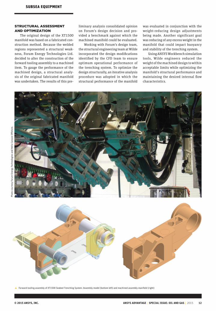
� Forward tooling assembly of XT1500 Seabed Trenching System: Assembly model (bottom left) and machined assembly manifold (right)
sTruCTural assessmenT and oPTimizaTion
The original design of the XT1500 manifold was based on a fabricated con-struction method. Because the welded regions represented a structural weak-ness, Forum Energy Technologies Ltd. decided to alter the construction of the forward tooling assembly to a machined item. To gauge the performance of the machined design, a structural analy-sis of the original fabricated manifold was undertaken. The results of this pre-
liminary analysis consolidated opinion on Forum’s design decision and pro-vided a benchmark against which the machined manifold could be evaluated.
Working with Forum’s design team, the structural engineering team at Wilde incorporated the design modifications identified by the CFD team to ensure optimum operational performance of the trenching system. To optimize the design structurally, an iterative analysis procedure was adopted in which the structural performance of the manifold
was evaluated in conjunction with the weight-reducing design adjustments being made. Another significant goal was reducing of any excess weight in the manifold that could impact buoyancy and stability of the trenching system.
Using ANSYS Workbench simulation tools, Wilde engineers reduced the weight of the machined design to within acceptable limits while optimizing the manifold's structural performance and maintaining the desired internal flow characteristics.
suBsEA EquiPMENTPh
oto
cour
tesy
For
um E
nerg
y Te
chno
logi
es a
nd H
elix
Can
yon
Offs
hore
.

© 2015 ANSYS, INC. ANSYS ADVANTAGE | SPECIAL ISSUE: OIL AND GAS | 2015 13
This was a truly collaborative project, not just between Wilde and Forum, but also between Wilde’s own fluid and structural mechanics engineers — and their tools. Wilde’s engineers were placed on-site at Forum and embedded into the design team there. This gave Forum guaranteed full-time access to the skilled analysts they required and facilitated direct and immediate communication across the combined team, to the benefit of all.
Beyond enabling the team to deliver a demonstrably improved design within time and budget, secondment arrangements like this offer educational advantages to both parties: Wilde’s talented analysts were directly exposed to real-world operational and manufacturing constraints on design, while Forum experienced first-hand the benefits of advanced interoperable simulation and optimization tools in driving design.
Successful Collaboration
� Using simulation, Wilde engineers reduced the weight of the machined design of the XT1500 Seabed Trenching System’s manifold to within acceptable limits while optimizing structural performance and maintaining the desired internal flow characteristics.
ANSYS Mechanical simulation plot of total displacement for operational loads (bottom left) and equivalent stress for operational loads (right)
The suCCessFul ouTComeCFD and structural simulation
carried out by Wilde enabled Forum to improve the forward tooling assembly on the new trencher vehicle well in excess of what could have been achieved through more-traditional engineering methods and within tight timescales. The successful application of simulation and optimization techniques, together with a close working relationship between the Forum and Wilde engineering teams, resulted in a vastly enhanced design. All initial objectives were satisfied, and subsequent physical testing confirmed that operational performance had been significantly improved.
Phot
o co
urte
sy F
orum
Ene
rgy
Tech
nolo
gies
and
Hel
ix C
anyo
n O
ffsho
re.
The ImporTance of fea In DesIgn cerTIfIcaTIon
ansys.com/2015trenches

© 2015 ANSYS, INC. ANSYS ADVANTAGE | SPECIAL ISSUE: OIL AND GAS | 2015 14
By Sudhir Sharma, Director of High-Tech Industry Strategy and Marketing, ANSYS
our world is more connected than ever, thanks to the growing web of visible and unseen electronics that surround us every day. ansYs provides the comprehensive suite of simulation software to reliably and cost-effectively engineer high-performance electronic devices and systems.
engineering The "inTerneT oF Things"
TKBEsT PrAcTicEs
© 2015 ANSYS, INC. ANSYS ADVANTAGE | SPECIAL ISSUE: OIL AND GAS | 2015 15
Today we live in a world based on connectivity and com-munication, in which a burgeoning network of electronic systems and devices helps us navigate our days.
Smartphones, tablets and GPS systems are the most obvious examples, but consider the increasingly sophisticated electron-ics in cars, homes, hotels and offices that keep us secure and comfortable, or the medical implants and prosthetics on which many people rely for everyday health. When we visit theme parks or attend concerts, we are likely to scan a wristband or smartphone for admittance. Wearable wristbands and activity trackers can monitor our physical movements, vital signs and sleep patterns. Today, high-tech devices are inescapable.
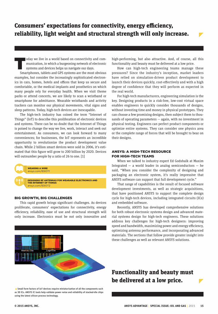
The high-tech industry has coined the term “Internet of Things” (IoT) to describe this proliferation of electronic devices and systems. There can be no doubt that the Internet of Things is poised to change the way we live, work, interact and seek out entertainment. As consumers, we can look forward to many conveniences; for businesses, the IoT represents an incredible opportunity to revolutionize the product development value chain. While 2 billion smart devices were sold in 2006, it’s esti-mated that this figure will grow to 200 billion by 2020. Devices will outnumber people by a ratio of 26 to one. [1]
big growTh, big ChallengesThis rapid growth brings significant challenges. As devices
proliferate, consumers’ expectations for connectivity, energy efficiency, reliability, ease of use and structural strength will only increase. Electronics must be not only innovative and
high-performing, but also attractive. And, of course, all this functionality and beauty must be delivered at a low price.
How can high-tech engineering teams manage these pressures? Since the industry’s inception, market leaders have relied on simulation-driven product development to launch their devices quickly, cost-effectively and with a high degree of confidence that they will perform as expected in the real world.
For high-tech manufacturers, engineering simulation is the key. Designing products in a risk-free, low-cost virtual space enables engineers to quickly consider thousands of designs, without investing time and money in physical prototypes. They can choose a few promising designs, then subject them to thou-sands of operating parameters — again, with no investment in physical testing. Engineers can perfect product components or optimize entire systems. They can consider one physics area or the complete range of forces that will be brought to bear on their designs.
ansYs: a high-TeCh resourCe For high-TeCh Teams
When we talked to industry expert Ed Godshalk at Maxim Integrated — a world leader in analog semiconductors — he said, “When you consider the complexity of designing and packaging an electronic system, it’s really impressive that ANSYS software can support that full development cycle.”
That range of capabilities is the result of focused software development investments, as well as strategic acquisitions, that have positioned ANSYS to support the complete design cycle for high-tech devices, including integrated circuits (ICs) and embedded software.
Recently, ANSYS has developed comprehensive solutions for both robust electronic systems design and advanced mate-rial systems design for high-tech engineers. These solutions address key challenges for high-tech designers: improving speed and bandwidth, maximizing power and energy efficiency, optimizing antenna performance, and incorporating advanced materials. The sections that follow provide greater insight into these challenges as well as relevant ANSYS solutions.
�Small form factors of IoT devices require miniaturization of all the components such as 3D ICs. ANSYS IC tools help validate power noise and reliability of stacked-die chips using the latest silicon process technology.
Consumers’ expectations for connectivity, energy efficiency, reliability, light weight and structural strength will only increase.
Functionality and beauty must be delivered at a low price.
designing rF anTennas For wearable eleCTroniCs and The inTerneT oF Things
ansys.com/83IOT2
wearing a wire
ansys.com/83IOT1

© 2015 ANSYS, INC. ANSYS ADVANTAGE | SPECIAL ISSUE: OIL AND GAS | 2015 16
ramPing uP sPeed and bandwidTh
As mobile devices proliferate, more and more data is being transmitted and received, driving the need for faster wired and wireless communications networks. Video streaming, interactive gaming and high-speed web service are pushing the limits of not only mobile devices, but also servers, routers and switches. Improving
speed and bandwidth is an industry imperative, but design complexity poses a significant challenge.
For example, designing printed circuit boards (PCBs) for high-speed, double data rate memory buses or serial communi-cation channels requires extreme care. High data rates combined with low oper-ating voltages can cause signal and power loss. In today’s device-crowded world,
electromagnetic interference (EMI) and electromagnetic compatibility (EMC) issues also affect power integrity (PI) and signal integrity (SI).
The ANSYS Nexxim circuit simula-tor (part of the ANSYS HFSS SI option and ANSYS SIwave) offers an efficient way to design and test memory chan-nels for servers that power our cloud-computing world. When this simulator is used in combination with IBIS-AMI, or Nexxim’s QuickEye and VerifEye models, it represents the industry’s leading solution for high-speed com-munication channel design.
End-to-end design and optimiza-tion for complex high-speed electronic devices is faster, easier and more accu-rate thanks to new functionality in the ANSYS SIwave electromagnetic simula-tion suite for the design of high-speed PCB and IC packages. This functional-ity is available via three targeted prod-ucts: SIwave-DC, SIwave-PI and SIwave. Engineers can quickly identify poten-tial power and signal integrity problems with increased flexibility, and more eas-ily access a complete set of analysis capa-bilities that they can leverage throughout the design cycle.
High-tech–industry product devel-opment teams routinely use coupled multiphysics software from ANSYS to analyze the trade-offs among speed, band-width, signal integrity, power integrity, thermal performance and EMI/EMC. For example, a smartphone manufacturer recently leveraged a suite of ANSYS soft-ware — including ANSYS HFSS, ANSYS Icepak, ANSYS Mechanical and ANSYS
�High-tech-industry product development teams routinely use coupled multiphysics software from ANSYS to analyze the trade-offs among speed, bandwidth, signal integrity, power integrity, thermal performance and EMI/EMC.
�As the sophistication of electronics increases, engineers must consider the comprehensive characteristics of the environment in which the equipment will operate — for example a cell phone within a car.
BEsT PrAcTicEs

© 2015 ANSYS, INC. ANSYS ADVANTAGE | SPECIAL ISSUE: OIL AND GAS | 2015 17
technology enables chips to operate at lower voltages with lower leakage, pro-viding chip designers with the flexibil-ity to choose transistors targeted for low power or high performance, depending on the application.
ANSYS is continually developing newer and better methods to ensure design robustness at the earliest possible stage.
sTaYing ConneCTedThe proliferation of wireless devices
creates new performance demands for antennas and radio systems, which need to deliver uninterrupted connectivity.
In designing antenna systems, engi-neers must consider the comprehensive characteristics of the environment in which the antenna will operate. This can include modeling such effects as a plas-tic covering over the antenna, the inter-action of a mobile handset with the human hand, or the way an antenna is installed in an automobile. With so much functionality crowded into devices — and so many wireless systems residing in close proximity — EMI is on the rise.
DesignXplorer — to significantly accel-erate the development of a smartphone shielding system to maximize data speed and throughput.
At Alcatel-Lucent, engineers are using ANSYS HFSS to ensure integrity and reli-ability, while also minimizing costs, as they link ICs on two separate boards across a high-speed channel.
oPTimizing Power and eFFiCienCY
Few issues are as important in the high-tech industry as effective power management. To help address this issue, ANSYS has created a strategic initiative centered on supporting the design of robust, power-efficient electronics.
Traditionally, engineers analyzed power consumption and delivery issues via a siloed approach, looking sepa-rately at the chip, board and package. Today, ANSYS supports the industry’s only truly integrated chip–package–sys-tem (CPS) design methodology, which allows component optimization — as well as co-analysis and co-optimization across the entire system. This approach balances the lower operating voltages needed to conserve power with the con-sistency and reliability required to elim-inate field failures.
By combining advanced physics solv-ers with industry-leading solutions for power-efficient electronics design, engi-neers can confidently predict systems-level performance at an early design stage, long before lab system integra-tion. The resulting capabilities for full electromagnetic extraction, SI/PI/EMI analysis, chip-level power optimization and reliability verification, and thermal and mechanical stress simulation are unmatched in the high-tech industry.
ANSYS also fosters partnerships with high-tech industry leaders to create unique simulation capabilities. For exam-ple, ANSYS and Intel® Custom Foundry teams have developed reference flows using ANSYS RedHawk for system-on-chip (SoC) power and electromigration sign-off, ANSYS Totem for custom intel-lectual property (IP) power — and EM —integrity, and ANSYS PathFinder for full-chip electrostatic discharge validation.
This collaboration extends the work on the Intel Custom Foundry 22 nm process design platform to the 14 nm platform. The 14 nm Tri-Grate process
�Designing printed circuit boards (PCBs) for high-speed, double data rate memory buses or serial communication channels requires extreme care. High data rates, combined with low operating voltages, can cause signal and power loss. Simulation of current distribution in a package is shown.
ANSYS software provides critical capabilities in multiphysics, systems-level simulation that will drive the continuing growth of the IoT.
inTegraTed ChiP–PaCkage–sYsTem simulaTion: The ComPleTe eleCTroniCs soluTion From ansYs and aPaChe
ansys.com/83IOT5
© 2015 ANSYS, INC. ANSYS ADVANTAGE | SPECIAL ISSUE: OIL AND GAS | 2015 18
material affected the electrical perfor-mance of a printed circuit board, relying on ANSYS SIwave to model the new board versus a conventional PCB. [2]
At the University of Pittsburgh and Carnegie Mellon University, engineers are using ANSYS PExprt and ANSYS RMxprt to assess the performance of new nano-composites that have the potential to revo-lutionize power transformer technology.
invesTing in The FuTureSince the earliest days of the high-
tech revolution, simulation-driven product development has been a criti-cal strategy for satisfying consumers’ increasing demand for device function-ality, speed, bandwidth, aesthetics and other product characteristics — while still meeting revenue and margin goals. ANSYS has helped hundreds of high-tech companies launch their game-changing designs quickly, cost-effectively and con-fidently, creating market leadership and building some of the industry’s stron-gest brand reputations.
Historical trends enable us to confi-dently predict that high-tech manufac-turers will continue to deliver incredi-bly innovative products that we cannot even imagine today. We can also be con-fident that — with a commitment to stra-tegic acquisitions as well as development of new software features and functional-ity — ANSYS will continue to invest in our high-tech customers’ success.
References
[1] A Guide to the Internet of Things
intel.com/content/www/us/en/internet-of-things/infographics/guide-to-iot.html
[2] Simulation and Design of Printed Circuit Boards Utilizing Novel Embedded Capacitance Material
multimedia.3m.com/mws/mediawebserver?mwsId=66666UgxGCuNyXTtnxM2NxT_EVtQEcuZgV-s6EVs6E666666--&fn=Huawei%20White%20Paper.pdf
Engineers are also challenged to develop new antenna technologies that require multiple frequency bands and greater efficiency, all within a smaller physical profile.
ANSYS is the industry leader in sim-ulating the performance of antenna, microwave, wireless and radio frequency (RF) systems. With new solver capabili-ties in ANSYS HFSS — such as finite ele-ment method (FEM) domain decomposi-tion, 3-D method of moment (MoM) and hybrid FEM–MoM — antenna engineers can rapidly solve electrically large, full-wave electromagnetic models. These models can accommodate regions of com-plex materials, as well as geometries with outer regions that are electrically large. In addition, transient solutions allow engi-neers to examine the behavior and scat-tering of radiation across time and space.
While antenna models are very large, high-performance computing (HPC) capa-bilities from ANSYS allow engineers to increase problem size and complexity while minimizing time-to-solution. Engineers at Synapse — a leader in wearable electronics — have used ANSYS HFSS in an HPC envi-ronment to increase antenna range by a factor of five, while reducing their overall design cycle by 25 percent.
At Vortis, engineers are applying ANSYS software to solve the problem of wasted RF energy in cell phones, which not only reduces battery life but also cre-ates acoustic noise. The company’s inno-vative new phased-array antenna system is just one example of how simulation-driven product development is impacting the future of the IoT.
inCorPoraTing advanCed maTerials
At ANSYS, today there is a cross-indus-try strategic initiative aimed at supporting the incorporation of advanced composite materials into the product development process — and with good reason. Composite materials are no longer used only by auto-makers and aerospace manufacturers.
Today, high-tech companies turn to advanced lightweight, yet strong, mate-rials to create flexible mobile and wear-able electronics. However, a range of complex issues must be considered when evaluating new materials — including electrical conduction properties, struc-tural strength, dimensional stability over time and resistance to thermal build-up. Design for manufacturability is also an important consideration.
High-tech engineers simulate the assembly of composite layers and con-duct finite element analysis via ANSYS Composite PrepPost and other special-ized modeling tools, subjecting these models to a range of real-world condi-tions. Electrical performance is verified using ANSYS HFSS and ANSYS SIwave, while ANSYS Icepak analyzes the ther-mal performance of electronic systems and devices.
ANSYS offers the industry’s most com-prehensive solution for evaluating the potential of advanced materials to reduce weight, while also optimizing conduc-tivity, signal integrity, dimensional sta-bility and thermal management within devices. For example, 3M recently pub-lished a groundbreaking study on how a novel embedded-capacitance composite
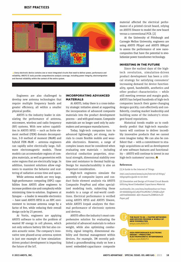
�Every electronic device contains one or more integrated circuits that need to deliver power, performance and reliability. ANSYS IC tools provide comprehensive analysis coverage, including power integrity, electromigration and thermal reliability within the context of the entire system.
The raCe To 6g — FasTer neTworks and deviCes Promise a world oF new PossibiliTies
ansys.com/83IOT3
high-PerFormanCe eleCTroniC design — PrediCTing eleCTromagneTiC inTerFerenCe
ansys.com/83IOT4
BEsT PrAcTicEs

© 2015 ANSYS, INC. ANSYS ADVANTAGE | SPECIAL ISSUE: OIL AND GAS | 2015 19
APPLicATiONs
gallerY: oil and gas indusTrY aPPliCaTionsAround the world, oil and gas companies require best-in-class technology to maintain profitabiliy, reliability and safety.
By ANSYS Advantage Staff
Design, engineering and manufacturing groups within the global energy supply chain span multiple geographies and encompass teams engaged in discovery, drilling, production, storage, transportation, refining and end-use petrochemicals. Each sector faces a broad set of challenges that require solving with different physics, scales and components. ANSYS delivers class-leading software and employs a network of technical experts who work with oil and gas customers around the world. These industry
mulTiPhase PiPe FlowANSYS CFD solutions are used throughout the oil and gas industry for subsurface, pipeline, transport, processing and refining applications; almost all these oil and gas applications involve multiphase flows. For example, flashing simulation can be performed using ANSYS Fluent. The images reveal contours of vapor-phase mass fractions at various downstream cross sections. The mass fractions of vaporized hydrocarbons increase with distance downstream from the mixing point. Red is maximum, blue is minimum.
professionals operate from regional offices close to energy companies in Houston, Aberdeen, Oslo, Stavanger, Kuala Lumpur, Beijing, Calgary and other locations worldwide. With a network of channel partners and ANSYS industry experts — and a long-standing commitment to the energy industry — ANSYS fosters close relationships with energy industry customers, and provides targeted solutions backed by local service and support. This gallery highlights some recent examples of best-in-class solutions.
PrediCTing equiPmenT Failure due To erosion Drill cuttings, produced sand and proppants transport reduce the life of equipment, pipelines and downhole tools through erosion. ANSYS solutions can predict erosion due to particulate flow as well as that caused by both impact and rolling at the surfaces. The ANSYS toolkit enables flow modeling of single or multiple fluids that take into account particle size and loadings. A wide array of industry-accepted models is provided to determine erosion rate. Calculations allow for material wear, so geometry is dynamically modified as the material is eroded. The image shows contours of erosion rate on a choke valve.
© 2015 ANSYS, INC. ANSYS ADVANTAGE | SPECIAL ISSUE: OIL AND GAS | 2015 20
APPLicATiONs
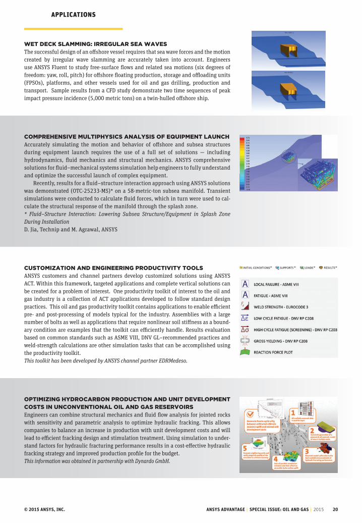
weT deCk slamming: irregular sea waves The successful design of an offshore vessel requires that sea wave forces and the motion created by irregular wave slamming are accurately taken into account. Engineers use ANSYS Fluent to study free-surface flows and related sea motions (six degrees of freedom: yaw, roll, pitch) for offshore floating production, storage and offloading units (FPSOs), platforms, and other vessels used for oil and gas drilling, production and transport. Sample results from a CFD study demonstrate two time sequences of peak impact pressure incidence (5,000 metric tons) on a twin-hulled offshore ship.
ComPrehensive mulTiPhYsiCs analYsis oF equiPmenT launCh Accurately simulating the motion and behavior of offshore and subsea structures during equipment launch requires the use of a full set of solutions — including hydrodynamics, fluid mechanics and structural mechanics. ANSYS comprehensive solutions for fluid–mechanical systems simulation help engineers to fully understand and optimize the successful launch of complex equipment.
Recently, results for a fluid–structure interaction approach using ANSYS solutions was demonstrated (OTC-25233-MS)* on a 58-metric-ton subsea manifold. Transient simulations were conducted to calculate fluid forces, which in turn were used to cal-culate the structural response of the manifold through the splash zone. * Fluid–Structure Interaction: Lowering Subsea Structure/Equipment in Splash ZoneDuring Installation D. Jia, Technip and M. Agrawal, ANSYS
CusTomizaTion and engineering ProduCTiviTY Tools ANSYS customers and channel partners develop customized solutions using ANSYS ACT. Within this framework, targeted applications and complete vertical solutions can be created for a problem of interest. One productivity toolkit of interest to the oil and gas industry is a collection of ACT applications developed to follow standard design practices. This oil and gas productivity toolkit contains applications to enable efficient pre- and post-processing of models typical for the industry. Assemblies with a large number of bolts as well as applications that require nonlinear soil stiffness as a bound-ary condition are examples that the toolkit can efficiently handle. Results evaluation based on common standards such as ASME VIII, DNV GL–recommended practices and weld-strength calculations are other simulation tasks that can be accomplished using the productivity toolkit.This toolkit has been developed by ANSYS channel partner EDRMedeso.
oPTimizing hYdroCarbon ProduCTion and uniT develoPmenT CosTs in unConvenTional oil and gas reservoirsEngineers can combine structural mechanics and fluid flow analysis for jointed rocks with sensitivity and parametric analysis to optimize hydraulic fracking. This allows companies to balance an increase in production with unit development costs and will lead to efficient fracking design and stimulation treatment. Using simulation to under-stand factors for hydraulic fracturing performance results in a cost-effective hydraulic fracking strategy and improved production profile for the budget.This information was obtained in partnership with Dynardo GmbH.

ANSYS.COM SPECIAL ISSUE: OIL AND GAS 21
THERMODYNAMIC PHASE CHANGE IN OIL AND GAS PIPELINE AND FACILITIESProduction, transport and refining of crude oil require equipment and processes that control oil components with different thermodynamic properties. Historically, only 1-D flow analysis software accounted for phase equilibrium in multiphase flow equipment. ANSYS customers use 3-D computational fluid dynamics analysis and PVT calculations to account for detailed fluid mechanics and related flow properties for different fluid temperatures and pressures. ANSYS channel partner Grupo SSC developed an applica-tion that determines thermodynamic characteristics of different reservoir fluids. This application matches available experimental data (saturation pressure, density and gas–oil ratios), and it allows prediction of properties when there is no data available. The application is connected to ANSYS CFD software and provides all the PVT information needed to accurately account for fluids properties, enabling more–accurate predictions of phase changes, such as with the vaporization process. This work was performed by Grupo SSC, ANSYS channel partner in Mexico.
COOL-DOWN ANALYSIS OF SUBSEA SEPARATORSDesign of subsea equipment to effectively and reliably operate for long periods of time is challenging. Some of the complexity is derived from understanding multiphase flows and cool-down for each device during a disruption or pause in production. Engineers are seeking to prevent the undesirable formation of hydrates. FMC Technologies engineers in Brazil performed thermal and fluid flow analysis of a three-phase gravitational separator to optimize the design and help determine the cool-down requirement for a temperature range from 55 C to 15 C (hydrate formation temperature) with an external temperature of 4 C (seawater).FMC Technologies in Brazil is supported by ESSS, the ANSYS channel partner for South America. This information was presented at CFDOIL2014.
FLOW ASSURANCE: GAS HYDRATE CHARACTERIZATION Utilizing a combination of species transport and population balance modeling, engineers can perform hydrate formation simulation in oil and gas equipment and pipelines under given pressure, temperature and gas composition conditions. Volumetric and surface-initiated phase change processes are accounted for by including hydrate formation kinetics. This framework enables the use of ANSYS computational fluid dynamics solutions to track hydrate deposition, aggregation and dissociation effects of two-phase flows in oil and gas applications.
NONLINEAR ANALYSIS OF ELASTOMERIC SEALS Downhole packers are critical to ensure a proper seal between different stages of the well; they are often subject to extreme loads and downhole conditions. Real-world wellbore conditions are very difficult to replicate in a laboratory setting, so there is a strong need to simulate the behavior of the packer using numerical tools. ANSYS has a rich library of highly nonlinear material models that replicate the behavior of packers under a variety of conditions. The robustness of the solver allows users to manage the complexity of self-contacts and large geometric distortions.
Courtesy FMC Technologies.
�Volume fraction of gas due to phase change (vaporization) behind a butterfly valve for a 41° API and 60 GOR

22 ANSYS ADVANTAGE | 2015
OPTIMIZING FUEL REFORMERSFuel reformers and cracking furnaces contain a combustion chamber in which heat is generated using burners. This heat is transferred to serpentine tubes carrying process steam. These tubes must uniformly heat the flow for effective cracking. To gain maximum efficiency and eliminate hot spots that can lead to fouling and tube failure, equipment designers must understand the interactions between 3-D combustion in the furnace and 1-D exothermic chemical reaction within the process tubes. ANSYS CFD software uses a channel model to simulate complex reformers and cracker furnaces in less time by coupling the desired 1-D to 3-D reactions in one integrated simulation. The image shows hot gases from the burners providing heat to the process tubes and enabling internal reactions. The ANSYS integrated solution allows engineers to change operating conditions to use the full length of the process tubes for production.
PORO-ELASTIC ANALYSIS: RESERVOIR VERTICAL COMPACTION Reservoir compaction as a result of hydrocarbon production causes surface subsidence, permeability loss and casing failure. Casing crushing, shear and stability (withstanding buckling) are the direct results of subsidence. Subsidence can also lead to the reactivation of faults. ANSYS structural mechanics products offer coupled pore–pressure thermal elements that can be used in the analysis of porous media. ANSYS engineers are assisting oil and gas companies with modeling vertical compaction of reservoir as well as vertical compaction causing damage to a surface facility. Given the right formation properties (assuming saturated porous media), it is possible to calculate pressure distribution in the reservoir as a result of fluid extraction. Although there are typically dozens of variables involved in accurately predicting reservoir behavior, this method is proven to provide valuable insights.
SUBSURFACE EQUIPMENT AND TOOLS IN SAGD Flow control devices (FCDs) are a critical part of production in oil sands operations for steam-assisted gravity drainage (SAGD). Variations on FCD designs can be used for injector and producer wells. One of the key performance parameters is the relationship between pressure drop and flow rates. It is desirable to have designs that do not exhibit large changes in pressure drop with flow changes. This ensures that consistent flow rates are obtained for a large range of conditions present in non-homogeneous reservoirs, helps mitigate flashing and steam production, and assists in controlling erosion. ANSYS CFX was used to perform CFD analyses on Alberta Flux Solutions’ production and injector tool designs. The simulations ensured that the correct pressure drop was obtained at a nominal flow rate. Additional sensitivity studies were conducted to obtain the pressure drop profile over a range of flow rates to help gauge performance relative to other products on the market and differentiate them from competition. Finally, the results guided newer designs and reduced the sensitivity of the FCDs’ performance to manufacturing tolerances. Alberta Flux Solutions is supported by ANSYS channel partner SimuTech Group.
TESTED EXPERIENCE, TRUSTED SOLUTIONS In a recent issue of the EnginSoft Newsletter, from the ANSYS channel partner in Italy, over 20 simulation case studies explore the technology requirements and range of problems that can be solved within the oil and gas industry. This magazine demonstrates how companies worldwide use simulation to understand root–cause failures, improve product reliability, evaluate new designs, and examine recovery concepts for topics including multiple–phase effects, electromechanical effects, particulate motion studies, free–surface flows, rock fractionation, erosion and fluid–structure interaction, thermal stresses, and soil–pipe interaction.
APPLICATIONS
Courtesy Alberta Flux Solutions.
For more information from ANSYS partners, visit the corresponding websites.

© 2015 ANSYS, INC. ANSYS ADVANTAGE | SPECIAL ISSUE: OIL AND GAS | 2015 23
robusT eleCTriC maChine design Through mulTiPhYsiCs
By Cassiano A. Cezario, Briam C. Bork, Marcelo Verardi, Research and Technological Innovation Department, and José R. Santos, Product Development and Application Department, WEG Equipamentos Elétricos S.A. — Motores, Jaraguá do Sul, Brazil
electromagnetic, mechanical and thermal simulation plus design optimization help to improve energy efficiency, noise and bearing life of robust electric motors.
rOBusT ELEcTric MAchiNE DEsiGN

© 2015 ANSYS, INC. ANSYS ADVANTAGE | SPECIAL ISSUE: OIL AND GAS | 2015 24
WEG engineers used a wide range of ANSYS tools to deliver optimal energy efficiency, low operating noise and long bearing life on its new line of electric motors.
WEG’s Robust Design of Electric Machines
electric motors are the single biggest consumer of electric-ity, accounting for about two-thirds of industrial power consumption and about 45 percent of global power con-
sumption, according to an analysis by the International Energy Agency. The World Energy Outlook 2012 states that the devel-oped world is planning to increase its energy efficiency by 1.8 percent annually over the next 25 years. Much of this improvement must come from advancements in electric motor design. Companies that develop these devices must ensure that motors have low operating noise and long life. Engineers have worked to balance these demands to improve and optimize the design of electric motors for almost two centuries, and now new methods and tools are needed to generate further progress.
WEG is the largest industrial electric motor manufacturer in the Americas and one of the largest manufacturers of indus-trial electric motors in the world, producing more than 10 million units annually. WEG engineers used the ANSYS comprehensive design solution for electric motors to leverage electromagnetic, mechanical and thermal simulation. Design optimization helped the engineering team to deliver optimal energy efficiency, low operating noise and long bearing life on the new W50 electric line
EvaluaTE a wIdE rangE
Of cOOlIng aIr
passagE dEsIgns
MInIMIzE TOTal nOIsE
gEnEraTEd by MOTOr
• prEdIcT aErOdynaMIc
nOIsE
• prEdIcT
ElEcTrOMagnETIc
nOIsE
rEducE OpEraTIng
TEMpEraTurE Of
bEarIng
auTOMaTE dEsIgn
ExplOraTIOn
cOMpuTaTIOnal fluId
dynaMIcs (cfd)–
ElEcTrOMagnETIc
sIMulaTIOn
ElEcTrOMagnETIc–
sTrucTural–ThErMal
analysEs
cfd–ThErMal
sIMulaTIOns
ansys dEsIgnxplOrEr
and ansys wOrkbEnch
rEducE fan lOssEs
and IMprOvE EnErgy
EffIcIEncy
lOwEr OpEraTIng nOIsE
IncrEasE bEarIng lIfE
OpTIMIzE MOTOr dEsIgn
wIThOuT havIng TO
Manually EvaluaTE
Each dEsIgn alTErnaTIvE
APPLICATION TECHNOLOGY EXPECTED RESULTS OR TARGET
rOBusT ELEcTric MAchiNE DEsiGN
� Response surface map depicts fan airflow efficiency as a function of several design variables.
eleCTriC maChine design meThodologY: a revoluTionarY aPProaCh
ansys.com/82robust

© 2015 ANSYS, INC. ANSYS ADVANTAGE | SPECIAL ISSUE: OIL AND GAS | 2015 25
of motors. The broad range of ANSYS capa-bilities was instrumental in designing and optimizing the electric motor with-out the need to individually evaluate each design alternative.
imProving energY eFFiCienCYLarge electric motors in the 125 horse-power to 1,750 horsepower range typ-ically have two fans: one to cool the motor interior and the other to cool its exterior. These fans consume a consid-erable amount of power, and WEG engi-neers believed that a promising approach to improving energy efficiency was to improve fan efficiency. They focused on the internal fan, particularly on reducing losses as air flows through the motor. The airflow generated by the fan flows through openings in the frame. Losses could be reduced by increasing these openings — but this strategy would reduce the motor’s electromagnetic performance.
WEG engineers used ANSYS CFD soft-ware to model the airflow through the interior of the motor. They defined key parameters, such as the openings where air passes through the frame, as para-metric dimension variables. Since many of these design parameters impact the motor’s electromagnetic performance, engineers produced an ANSYS Maxwell electromagnetic model of the motor with the same parametric variables as the CFD model. They generated a table of varying values for each of the parameters.
WEG employed ANSYS DesignXplorer to create a design of experiments (DOE) that subdivided the design space to effi-ciently explore it with a relatively small number of simulation experiments and to run multiphysics simulations with-out human intervention. Comprehensive simulation tools in the ANSYS Workbench environment and design optimization with ANSYS DesignXplorer enabled WEG
to increase the number of simulations per-formed from four per month in 2005 to 800 per month currently. High-performance computing (HPC) also helped enable this improvement. WEG uses HPC Packs for CFD, and Maxwell runs with 64 cores dis-tributed across eight workstations.
Output results for each design point were stored in a table and visualized with a response surface map that com-pletely maps out the design space. The response surface was used to graphically plot the effect of variables on fan losses. Simulations were not coupled in this case due to computing resource limitations; however, in the future, WEG will use cou-pled multiphysics simulations to even more accurately determine optimal val-ues for parametric variables by consid-ering all of the physics. WEG engineers manually compared response surface maps, plots and tables for the CFD and electromagnetic analysis to determine the
� Before-and-after comparison of ANSYS CFX simulations shows improved airflow that reduces fan losses in W50 motor compared to previous-generation design.
WEG increased the number of CFD simulations performed from four per month in 2005 to 800 per month currently.

© 2015 ANSYS, INC. ANSYS ADVANTAGE | SPECIAL ISSUE: OIL AND GAS | 2015 26
rOBusT ELEcTric MAchiNE DEsiGN
ANSYS multiphysics tools help WEG deliver best-in-class performance for electric motors while substantially reducing the lead time and cost of the product development process.
� ANSYS Maxwell simulation helps to optimize the trade-off between fan losses and electromagnetic performance.
� Fan efficiency plotted against two design variables (one on x axis and other in multiple plots)
combinations of parametric variables that delivered the best mix of performance. Engineers then reran the electromagnetic and CFD simulation for the best combina-tions and selected the one that delivered the best performance: a substantial reduc-tion in fan losses and a resulting improve-ment in energy efficiency without any sacrifice in electromagnetic performance.
reduCing noiseWEG engineers also wanted to reduce the noise generated by the new W50 motor design. An electric motor primarily gen-erates noise through two independent sources: aerodynamic and electromag-netic. Aerodynamic noise is generated by the fan rotor and transmitted through the air; WEG engineers used ANSYS CFD to optimize the fan rotor geometry to mini-mize aerodynamic noise. Electromagnetic noise is created by the interaction of mag-netic fields produced by stator and rotor. In extreme cases in which the resultant force frequency excites the natural fre-quencies of the mechanical structure, this noise will be dramatically amplified.
WEG engineers used ANSYS CFD to optimize the internal fan system. Engineers designed a new internal fan system to reduce the length of the motor, which improved the dynamic perfor-mance. However, the original design was not acceptable, so engineers used ANSYS DesignXplorer to optimize the internal fan geometry and develop a new solu-tion that met the requirements. The new internal fan reduces vibration, improves power density of the motor, and increases the maximum rotating speed.
To predict and avoid electromagnetic noise of the motor prior to the prototyping stage, WEG engineers used electromagnetic simulation to calculate the electromagnetic force and losses. These quantities are used as inputs to the structural and thermal sim-ulation to predict mechanical vibrations. WEG engineers used the ANSYS Application Customization Toolkit to implement the methodology of topological optimization to increase the natural frequency of the frame. They then set up parametric vari-ables and used ANSYS DesignXplorer to run a table of design points and optimize the design to produce the lowest levels of noise.
imProving bearing liFeBearings are usually the first component to fail during the lifetime of an electric

© 2015 ANSYS, INC. ANSYS ADVANTAGE | SPECIAL ISSUE: OIL AND GAS | 2015 27
� CFD simulation of airflow around the bearing was used to reduce bearing operating temperature.
ANSYS Mechanical simulation predicted vibration of the structure to reduce noise.
motor, and the life of bearings is strongly correlated with the operating tempera-ture. The cooler the bearing runs, the lon-ger is its life and the longer its lubrication intervals (how often grease is required), so the motor will require less mainte-nance. The team ran a CFD analysis of the airflow around the bearing and changed the shape and dimensions of some com-ponents in the region to ensure a constant airflow and reduce operating temperature.
Based on these and several other multiphysics simulations, WEG engi-neers developed the detailed design for the W50 motor. The company then built a prototype. Physical testing showed that the design worked exactly as pre-dicted by simulation. As a result, only a few very minor changes were required during the prototype phase. Normally, a larger number of more substantial design changes are required. The ability to get the design right the first time pro-vided a major cost saving.
The new W50 motors deliver signifi-cant improvements in performance over existing electric motors in their class. Energy efficiency varies depending on the application, but it is generally signif-icantly better than today’s best-in-class motors in the same applications. The new motors offer exceptionally low noise lev-els of 82 dB(A) at 3,600 rpm (60 Hz) and 78 dB(A) at 3,000 rpm (50 Hz). Bearing life has been improved to 100,000 hours of L10h life over the 40,000 hours pre-viously offered. At least 90 percent of all motors produced will achieve the L10h
life. The use of ANSYS multiphysics tools helps WEG to deliver best-in-class perfor-mance for electric motors while substan-tially reducing the lead time and cost of the product development process. Technical support and sales for WEG is provided by ESSS, ANSYS channel partner for South America.
� The final virtual motor prototype required only minor changes, making it possible to get the product to market faster. Virtual prototype (A) with a low-voltage terminal box and final product (B) with high-voltage terminal box.
A
B
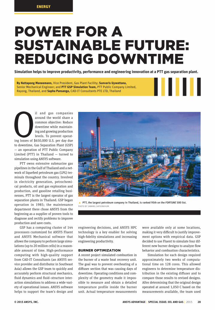
© 2015 ANSYS, INC. ANSYS ADVANTAGE | SPECIAL ISSUE: OIL AND GAS | 2015 28
ENErGY
Power For a susTainable FuTure: reduCing downTimeSimulation helps to improve productivity, performance and engineering innovation at a PTT gas separation plant.
By Nattapong Maneemann, Vice President, Gas Plant Facility; Sunvaris Uywattana, Senior Mechanical Engineer; and PTT GSP Simulation Team, PTT Public Company Limited, Rayong, Thailand, and Sapha Pansanga, CAD-IT Consultants PTE LTD, Thailand
O il and gas companies around the world share a common objective: Reduce downtime while maintain-ing and growing production levels. To prevent operat-
ing losses of $650,000 U.S. per day due to downtime, Gas Separation Plant (GSP) — an operation of PTT Public Company Limited (PTT) in Thailand — turned to simulation using ANSYS software.
PTT owns extensive submarine gas pipelines in the Gulf of Thailand and a net-work of liquefied petroleum gas (LPG) ter-minals throughout the country. Involved in electricity generation, petrochemi-cal products, oil and gas exploration and production, and gasoline retailing busi-nesses, PTT is the largest operator of gas separation plants in Thailand. GSP began operation in 1985; the maintenance department there chose ANSYS from the beginning as a supplier of proven tools to diagnose and rectify problems to improve production and save costs.
GSP has a computing cluster of 144 processors customized for ANSYS Fluent and ANSYS Mechanical software that allows the company to perform large simu-lations (up to 20 million cells) in a reason-able amount of time. High-performance computing with high-quality support from CAD-IT Consultants (an ANSYS ser-vice provider and distributor in Southeast Asia) allows the GSP team to quickly and accurately perform structural mechanics, fluid dynamics and fluid–structure inter-action simulations to address a wide vari-ety of operational issues. ANSYS software helps to support the team’s design and
engineering decisions, and ANSYS HPC technology is a key enabler for solving high-fidelity simulations and increasing engineering productivity.
burner oPTimizaTionA recent project simulated combustion in the burner of a waste heat recovery unit. The goal was to prevent overheating of a diffuser section that was causing days of downtime. Operating conditions and com-plexity of the geometry made it impos-sible to measure and obtain a detailed temperature profile inside the burner unit. Actual temperature measurements
were available only at some locations, making it very difficult to justify improve-ment options with empirical data. GSP decided to use Fluent to simulate four dif-ferent new burner designs to analyze flow behavior and combustion characteristics.
Simulation for each design required approximately two weeks of computa-tional time on 128 cores. This allowed engineers to determine temperature dis-tribution in the existing diffuser and to compare those results to revised designs. After determining that the original design operated at around 1,050 C based on the measurements available, the team used
� PTT, the largest petroleum company in Thailand, is ranked 95th on the FORTUNE 500 list. Photo by Sawang SaPoonkhum.

© 2015 ANSYS, INC. ANSYS ADVANTAGE | SPECIAL ISSUE: OIL AND GAS | 2015 29
Fluent’s combustion and radiation models to develop a new burner diffuser design that operates at a maximum temperature of approximately 950 C. The diffuser mate-rial (stainless steel grade 310 that has good resistance to oxidation in intermit-tent service up to 1,040 C) can withstand this temperature. Combining combustion with radiation models allowed engineers to ascertain the cause of the overheating, enhance their knowledge of flow behav-ior and temperature distribution inside the burner, and resolve the problem per-manently by making minor changes to the diffuser wing geometry that resulted in changes in the flow pattern inside the burner. This alteration made a big differ-ence in terms of maximum temperature in the system, and it allowed engineers to choose the appropriate material for the new operating conditions. The burner has a maintenance period of about four years; since implementation of this improve-ment, it has been running smoothly without any problems. The new design developed with simulation saves the com-pany at least $650,000 U.S. per day in costs that would have been incurred by lost productivity due to shutdown to solve unexpected problems or to check reliabil-ity of the improvement.
PiPing sYsTems sTress and vibraTionGSP operations include complex equip-ment — pipes, tanks, columns, support structures and heat exchangers — that must be correctly designed and main-tained to ensure continuous operation 24 hours a day, seven days a week, with
minimum shutdown time. Engineers at GSP rely on simulation to fulfill speci-fications and maintain equipment reli-ability and structural integrity during operation. They use ANSYS structural mechanics software to examine and improve these structures as well as to ensure that the company’s investment in these complex systems is secure.
For example, vibration issues in small branches of piping have been resolved using structural mechanics software. In these simulations, engineers per-form stress analysis followed by fatigue life analysis. The geometry is set up in SolidWorks® and imported into ANSYS Mechanical to carry out nonlinear tran-sient analysis. The team performed design improvements by adding some additional support elements then ran a stress analy-sis to verify the changes.
To ensure that temperature changes from elements added inside the pipe sys-tem had no external effect, the team per-formed thermal–stress analysis. The thermal load from CFD analysis was passed to ANSYS Mechanical, showing how the thermal load from the fluids influenced the structure of the new piping system design.
Engineering simulation helps the team to make certain that the system is not overengineered while ensuring that operating shutdowns are as short as pos-sible. The team faces high safety-factor requirements that lead to increased pip-ing support structures; these, in turn, constrain thermal expansion of the pip-ing material. Simulation helps GSP to make the correct trade-offs in terms of engineering improvement and invest-ment. Moreover, team members gain skill and knowledge through simulation, thereby enabling increased organiza-tional know-how and encouraging sus-tained innovation.
� Structural mechanics simulation predicted stress and deformation of pipes.
� Volume rendering of temperature around burner diffuser using ANSYS Fluent
Simulation saved the company at least $650,000 U.S. per day in costs that would have been incurred by shutdown.
Without ANSYS Fluent, we would not have been able to understand the cause of failure, because it is extremely difficult to measure all parameters in the burner diffuser unit.— Sunvaris Uywattana, Senior Mechanical Engineer

© 2015 ANSYS, INC. ANSYS ADVANTAGE | SPECIAL ISSUE: OIL AND GAS | 2015 30
ANALYsis TOOLs
SpaceClaim 3-D direct modeling software — avail-able from ANSYS for several years and now part of the ANSYS product family — is a powerful tool for creating, importing and working with 3-D geome-try. It has a simple and robust user interface that includes tools to defeature both parts and assem-
blies prior to meshing and solving. SpaceClaim has the power to simplify and automate what has traditionally been the time-consuming process of preparing geometry for use in a simu-lation system. With SpaceClaim, engineers can author new concepts and more easily use simulation to iterate on designs and drive innovation.
Increased speed and pressure from competition is compelling organizations to find easier, more effective ways to
blending design and simulaTionSpaceClaim and ANSYS bring innovative design and analysis closer together.
By Rebecca Swensen, Senior Product Marketing Manager, ANSYS
SpaceClaim 3-D direct modeling software was recently added to the ANSYS product family.
�Simulation engineers can easily change and improve the design to improve performance.
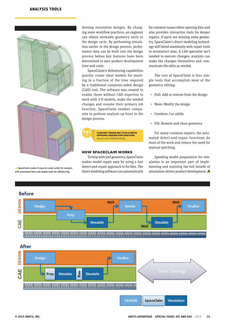
© 2015 ANSYS, INC. ANSYS ADVANTAGE | SPECIAL ISSUE: OIL AND GAS | 2015 31
ANALYsis TOOLs
develop innovative designs. By chang-ing some workflow practices, an engineer can obtain workable geometry early in the design cycle. By performing simula-tion earlier in the design process, perfor-mance data can be built into the design process before key features have been determined to save product development time and costs.
SpaceClaim’s defeaturing capabilities quickly create ideal models for mesh-ing in a fraction of the time required by a traditional computer-aided design (CAD) tool. The software was created to enable those without CAD expertise to work with 3-D models, make the needed changes and resume their primary job function. SpaceClaim enables compa-nies to perform analysis up front in the design process.
how sPaCeClaim worksTo help with bad geometry, SpaceClaim
makes model repair easy by using a fast detect-and-repair approach to fix files. The direct modeling software can automatically
fix common issues when opening files and also provides interactive tools for deeper repairs. If parts are missing some geome-try, SpaceClaim’s direct modeling technol-ogy will blend seamlessly with repair tools to reconstruct data. A CAD specialist isn’t needed to execute changes; analysts can make the changes themselves and com-municate the edits as needed.
The core of SpaceClaim is four sim-ple tools that accomplish most of the geometry editing:
• Pull: Add or remove from the design
• Move: Modify the design
• Combine: Cut solids
• Fill: Remove and clean geometry
For many common repairs, the auto-mated detect-and-repair functions do most of the work and reduce the need for manual patching.
Speeding model preparation for sim-ulation is an important part of imple-menting and realizing the full benefit of simulation-driven product development.
�SpaceClaim makes it easy to create solids for analysis with automated fixes and simple tools for defeaturing.
ConCePT modeling Tools drive uPFronT design exPloraTion
ansys.com/83blending
Realize Your Product Promise®
ANSYS is dedicated exclusively to developing engineering simulation software that fosters rapid and innovative product design. ANSYS technology enables you to predict with confidence that your product will thrive in the real world. For more than 40 years, customers in the most demanding markets have trusted our solutions to help ensure the integrity of their products and drive business success through innovation.
ANSYS, Inc. Southpointe 2600 ANSYS Drive Canonsburg, PA 15317 U.S.A.
For ANSYS, Inc. sales information call 1.866.267.9724. Email the editorial staff at [email protected].
ANSYS, Inc. does not guarantee or warrant accuracy or completeness of the material contained in this publication.
ANSYS, ACT, BladeModeler, CFD, CFX, DesignerSI, DesignModeler, DesignXplorer, EKM, Fluent, HFSS, ICEM CFD, Icepak, Maxwell, Mechanical, Multiphysics,Nexxim, Pathfinder, PExprt, Polyflow, Realize Your Product Promise, RedHawk, RMxprt, Sentinel, Simulation Driven Product Development, SIwave, SpaceClaim Direct Modeler, Structural, Totem, Workbench, and any and all ANSYS, Inc. brand, product, service, and feature names, logos and slogans are registered trademarks or trademarks of ANSYS, Inc., or its subsidiaries located in the United States or other countries. All other brand, product, service, and feature names or trademarks are the property of their respective owners.
Are You Up To The Challenge?From stricter environmental regulations to the plummeting price of oil, the energy industry continues to transform itself in the face of enormous challenges. By using ANSYS engineering simulation solutions, energy industry leaders from around the world are developing new technologies to meet these and other challenges.
Learn more at ANSYS.COM/energy
![Crude Assay Report · 15 Vacuum Gas Oil Cuts - Gas Oil [325-370°C] 15 16 Vacuum Gas Oil Cuts - Gas Oil 1[370 - 540°C] 16 17 Vacuum Gas Oil Cuts - Heavy Vacuum Gas Oil [370 - 548°C]](https://img.pdfslide.us/doc/110x75/5e68681c2598ff04995c67bc/crude-assay-report-15-vacuum-gas-oil-cuts-gas-oil-325-370c-15-16-vacuum-gas.jpg)