Embed Size (px)
Citation preview

MF1-12
Special Moment Frame
Tables with Allowable ASD Seismic ValuesFor Design at R = 6.5
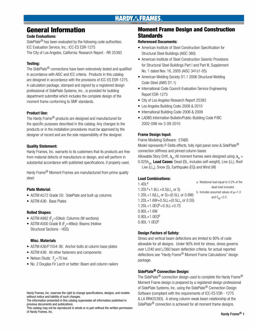
Table of ContentsIntroduction .......................................................................................................................Inside Front Cover
General Information .......................................................................................................................1
Moment Frame Design and Construction Standards .........................................................................1
Designing with the Hardy Frame Moment Frame Overview ................................................................2
Design Example .............................................................................................................................3
Photos ......................................................................................................................................4
Column Assembly and Column Footprint Dimensions ......................................................................5
Dimensions Table 1.0 .....................................................................................................................6
Tables 1.8 - 1.18-20: Hardy Frame Moment Frames, One Story .................................................... 7-15
Installer .....................................................................................................................................16
Template Kits & Anchorage ............................................................................................................17
Moment Frame Anchorage ......................................................................................................... 18-19
Details .................................................................................................................................. 20-23
HFX-Series Products .....................................................................................................................24
Non-Standard Specification Worksheet ................................................................................ Inside Back Cover
Hardy Frames, Inc manufactures and markets pre-fabricated shear wall systems. We have been the innovative leader in the industry for over 15 years. Our company first introduced the Original Hardy Frame® Panels and Brace Frames in 1996. In 2006, we joined forces with SidePlate Systems, Inc. to launch the Hardy Frame® Special
Moment Frame, the first pre-engineered, pre-fabricated Moment Frame in the industry.
The Hardy Frame® Moment Frame may be used in single and multistory structures, and uses the new-generation SidePlate® moment connection to resist lateral forces from earthquakes and wind. This connection was conceived and developed by David Houghton, a licensed structural engineer, to eliminate all problems that were exposed in traditional moment connections as a result of the 1994 Northridge earthquake. The outstanding performance of the SidePlate® system is nationally recognized and is the same technology we use in the Hardy Frame® Moment Frame to provide high allowable loads in narrow wall sections. Adding to the structural benefits, our Moment Frame is designed to arrive at the jobsite completely pre-assembled with no field welding and no special inspection required.
The mission of Hardy Frames is to provide cost effective, state-of-the-art, lateral force resisting systems that are easily installed to meet architectural, engineering and code requirements.
Hardy Frame® 1
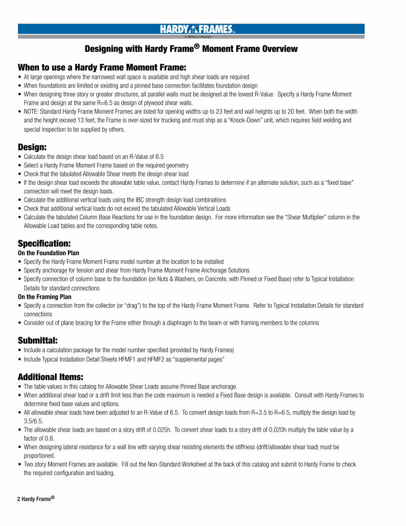
General InformationCode Evaluations: SidePlate® has been evaluated by the following code authorities:ICC Evaluation Service, Inc.: ICC-ES ESR-1275The City of Los Angeles, California: Research Report - RR 25393
Testing:The SidePlate® connections have been extensively tested and qualified in accordance with AISC and ICC criteria. Products in this catalog are designed in accordance with the provisions of ICC-ES ESR-1275. A calculation package, stamped and signed by a registered design professional of SidePlate Systems, Inc., is provided for building department submittal which includes the complete design of the moment frame conforming to SMF standards.
Product Use: The Hardy Frame® products are designed and manufactured for the specific purposes described in this catalog. Any changes to the products or in the installation procedures must be approved by the designer of record and are the sole responsibility of the designer.
Quality Statement: Hardy Frames, Inc. warrants to its customers that its products are free from material defects of manu facture or design, and will perform in substantial accordance with published specifications, if properly used.
Hardy Frame® Moment Frames are manufactured from prime quality steel:
Plate Material: • ASTM A572 Grade 50: SidePlate and built up columns• ASTM A36: Base Plates
Rolled Shapes:• ASTM A992 (Fy=50ksi): Columns (W-sections)• ASTM A500 Grade B (Fy=46ksi): Beams (Hollow
Structural Sections - HSS)
Misc. Materials• ASTM A36/F1554-36: Anchor bolts at column base plates• ASTM A36: All other fasteners and components• Nelson Studs: Fy=70 ksi• No. 2 Douglas Fir Larch or better: Beam and column nailers
Moment Frame Design and Construction StandardsReferenced Documents: • American Institute of Steel Construction Specification for
Structural Steel Buildings (AISC 360)• American Institute of Steel Construction Seismic Provisions
for Structural Steel Buildings Part I and Part III, Supplement No. 1 dated Nov. 16, 2005 (AISC 341s1-05)
• American Welding Society D1.1 2006 Structural Welding Code-Steel (AWS D1.1)
• International Code Council-Evaluation Service Engineering Report ESR-1275
• City of Los Angeles Research Report 25393• Los Angeles Building Code-2008 & 2010• International Building Code-2006 & 2009• LADBS Information Bulletin/Public-Building Code P/BC
2002-098 rev 3-09-2010 Frame Design Input:Frame Modeling Software: ETABSModel represents P-Delta effects, fully rigid panel zone & SidePlate® connection stiffness and pinned column basesAllowable Story Drift, ∆a: All moment frames were designed using ∆a = 0.025hsx. Load Cases: Dead (DL, includes self-weight), Live (LL), Roof Live (LLr), Snow (S), Earthquake (EQ) and Wind (W)
Load Combinations:1.4DLa
1.2DLa+1.6LL+0.5(LLr or S)1.2DL+1.6(LLr or S)+(0.5LL or 0.8W)1.2DL+1.6W+0.5LL+(0.5LLr or 0.5S)1.2DL+1.0EQb+0.5LL+0.7S0.9DL+1.6W0.9DL+1.0EQb
0.9DL-1.0EQb
Design Factors of Safety:Stress and vertical beam deflections are limited to 90% of code allowable for all designs. Under 90% limit for stress, stress governs over L/240 and L/360 beam deflection criteria; for actual reported deflections see “Hardy Frame® Moment Frame Calculations” design package.
SidePlate® Connection Design:The SidePlate® connection design used to complete the Hardy Frame® Moment Frame design is prepared by a registered design professional of SidePlate Systems, Inc. using the SidePlate® Connection Design Software (compliant with the requirements of ICC-ES ESR - 1275 & LA RR#25393). A strong column-weak beam relationship at the SidePlate® connection is achieved for all moment frame designs.
Hardy Frames, Inc. reserves the right to change specifications, designs, and models without notice and liability of such changes.The information presented in this catalog supersedes all information published in previous documents and publications.This catalog may not be reproduced in whole or in part without the written permission of Hardy Frames, Inc.
a. Notational load equal to 0.2% of the
dead load included.
b. Includes assumed values of ρ=1.0
and Sds=2.0.
2 Hardy Frame®
Designing with Hardy Frame® Moment Frame Overview
When to use a Hardy Frame Moment Frame:• At large openings where the narrowest wall space is available and high shear loads are required• When foundations are limited or existing and a pinned base connection facilitates foundation design• When designing three story or greater structures, all parallel walls must be designed at the lowest R-Value. Specify a Hardy Frame Moment
Frame and design at the same R=6.5 as design of plywood shear walls. • NOTE: Standard Hardy Frame Moment Frames are listed for opening widths up to 23 feet and wall heights up to 20 feet. When both the width
and the height exceed 13 feet, the Frame is over-sized for trucking and must ship as a “Knock-Down” unit, which requires field welding and special inspection to be supplied by others.
Design:• Calculate the design shear load based on an R-Value of 6.5 • Select a Hardy Frame Moment Frame based on the required geometry• Check that the tabulated Allowable Shear meets the design shear load• If the design shear load exceeds the allowable table value, contact Hardy Frames to determine if an alternate solution, such as a “fixed base”
connection will meet the design loads. • Calculate the additional vertical loads using the IBC strength design load combinations• Check that additional vertical loads do not exceed the tabulated Allowable Vertical Loads• Calculate the tabulated Column Base Reactions for use in the foundation design. For more information see the “Shear Multiplier” column in the
Allowable Load tables and the corresponding table notes.
Specification:On the Foundation Plan • Specify the Hardy Frame Moment Frame model number at the location to be installed• Specify anchorage for tension and shear from Hardy Frame Moment Frame Anchorage Solutions• Specify connection of column base to the foundation (on Nuts & Washers, on Concrete, with Pinned or Fixed Base) refer to Typical Installation
Details for standard connectionsOn the Framing Plan• Specify a connection from the collector (or “drag”) to the top of the Hardy Frame Moment Frame. Refer to Typical Installation Details for standard
connections• Consider out of plane bracing for the Frame either through a diaphragm to the beam or with framing members to the columns
Submittal:• Include a calculation package for the model number specified (provided by Hardy Frames)• Include Typical Installation Detail Sheets HFMF1 and HFMF2 as “supplemental pages”
Additional Items:• The table values in this catalog for Allowable Shear Loads assume Pinned Base anchorage. • When additional shear load or a drift limit less than the code maximum is needed a Fixed Base design is available. Consult with Hardy Frames to
determine fixed base values and options.• All allowable shear loads have been adjusted to an R-Value of 6.5. To convert design loads from R=3.5 to R=6.5, multiply the design load by
3.5/6.5.• The allowable shear loads are based on a story drift of 0.025h. To convert shear loads to a story drift of 0.020h multiply the table value by a
factor of 0.8.• When designing lateral resistance for a wall line with varying shear resisting elements the stiffness (drift/allowable shear load) must be
proportioned. • Two story Moment Frames are available. Fill out the Non-Standard Worksheet at the back of this catalog and submit to Hardy Frame to check
the required configuration and loading.
Hardy Frame® 3
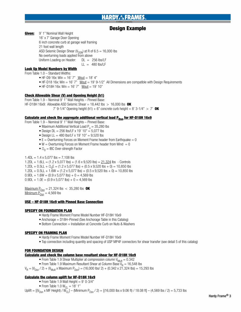
Design ExampleGiven: 9’ 1” Nominal Wall Height 16’ x 7’ Garage Door Opening 6 inch concrete curb at garage wall framing 21 foot wall length ASD Seismic Design Shear (VDSN) at R of 6.5 = 16,000 lbs No overturning loads applied from above Uniform Loading on Header: DL = 256 lbs/LF LL = 480 lbs/LF Look Up Model Numbers by WidthFrom Table 1.0 – Standard Widths: • HF-D9 16x: Win = 16’ 7” Wout = 18’ 4” • HF-D18 16x: Win = 16’ 7” Wout = 19’ 9-1/2” All Dimensions are compatible with Design Requirements • HF-D18H 16x: Win = 16’ 7” Wout = 19’ 10”
Check Allowable Shear (V) and Opening Height (h1) From Table 1.9 – Nominal 9’ 1” Wall Heights – Pinned Base:HF-D18H 16x9: Allowable ASD Seismic Shear = 18,442 lbs > 16,000 lbs OK 7’ 9-1/4” Opening height (h1) + 6” concrete curb height = 8’ 3-1/4” > 7’ OK
Calculate and check the aggregate additional vertical load PDsn for HF-D18H 16x9From Table 1.9 – Nominal 9’ 1” Wall Heights – Pinned Base: • Maximum Additional Vertical Load Pu = 35,280 lbs • Design DL = 256 lbs/LF x 19’ 10” = 5,077 lbs • Design LL = 480 lbs/LF x 19’ 10” = 9,520 lbs • E = Overturning Forces on Moment Frame header from Earthquake = 0 • W = Overturning Forces on Moment Frame header from Wind = 0 • Ω0 = IBC Over-strength Factor
1.4DL = 1.4 x 5,077 lbs = 7,108 lbs1.2DL + 1.6LL = (1.2 x 5,077 lbs) + (1.6 x 9,520 lbs) = 21,324 lbs - Controls1.2DL + 0.5LL + Ω0E = (1.2 x 5,077 lbs) + (0.5 x 9,520 lbs + 0) = 10,850 lbs1.2DL + 0.5LL + 1.6W = (1.2 x 5,077 lbs) + (0.5 x 9,520 lbs + 0) = 10,850 lbs0.9DL + 1.6W = (0.9 x 5,077 lbs) + 0 = 4,569 lbs0.9DL + 1.0E = (0.9 x 5,077 lbs) + 0 = 4,569 lbs
Maximum PDsn = 21,324 lbs < 35,280 lbs OK Minimum PDsn = 4,569 lbs
USE – HF-D18H 16x9 with Pinned Base Connection
SPECIFY ON FOUNDATION PLAN • Hardy Frame Moment Frame Model Number HF-D18H 16x9 • Anchorage = D18H–Pinned (See Anchorage Table in this Catalog) • Bottom Connection = Installation at Concrete Curb on Nuts & Washers
SPECIFY ON FRAMING PLAN • Hardy Frame Moment Frame Model Number HF-D18H 16x9 • Top connection including quantity and spacing of USP MP4F connectors for shear transfer (see detail 5 of this catalog)
FOR FOUNDATION DESIGNCalculate and check the column base resultant shear for HF-D18H 16x9 • From Table 1.9 Shear Multiplier at compression column VMult = 0.342 • From Table 1.9 Maximum Resultant Shear at Column Base VR = 16,548 lbsVR = (VDsn / 2) + (VMult x Maximum PDsn) = (16,000 lbs/ 2) + (0.342 x 21,324 lbs) = 15,293 lbs
Calculate the column uplift for HF-D18H 16x9 • From Table 1.9 Wall Height = 9’ 0-3/4” • From Table 1.0 WCL = 18’ 1”Uplift = [(VDsn x MF Height) / WCL] – (Minimum PDsn / 2) = [(16,000 lbs x 9.06 ft) / 18.08 ft] – (4,569 lbs / 2) = 5,733 lbs
4 Hardy Frame®
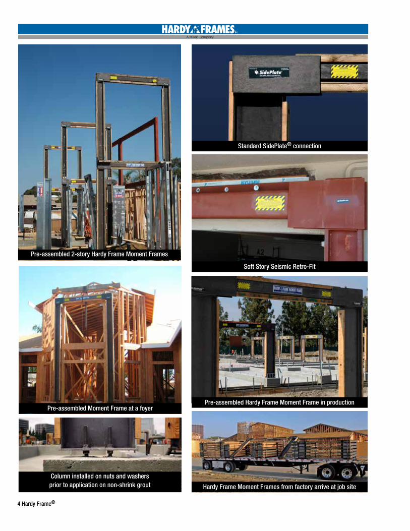
Pre-assembled Moment Frame at a foyer
Pre-assembled 2-story Hardy Frame Moment Frames
Standard SidePlate® connection
Soft Story Seismic Retro-Fit
Pre-assembled Hardy Frame Moment Frame in production
Column installed on nuts and washersprior to application on non-shrink grout Hardy Frame Moment Frames from factory arrive at job site
Hardy Frame® 5
D9 Col to 8x4 HdrWSP= 10
D18 Col to 6x6 HdrWSP= 11
D9 Col to 7x4 HdrWSP= 9-1/4
D9 Col to 6x4 Hdr
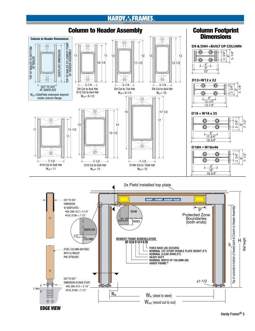
Column to Header Dimensions
10-1/4 11-1/2
13
12-1/2
11
11
11
5-1/4 5-1/4
7-1/2
5-1/4
11 12 12
11-1/2
D18 Col to 8x6 HdrWSP= 13
13
13-1/2
7-1/2
14
D18H Col to 10x6 HdrWSP= 15
15
17
7-1/2
17-1/2
13
D12 Col to 6x4 HdrWSP= 8-1/2
OUT TO OUTAT SIDEPLATE
WSP=SidePlate extension beyond inside column �ange
TOP
OF N
AILE
R TO
BOT
TOM
OF
NAI
LER
SIDE
PLAT
E DI
MEN
SION
TOP
OF N
AILE
R TO
LOW
EST
POIN
TOF
HEA
DER
ASSE
MBL
Y
Win (steel to steel)
h1
H
Wout (wood out to out)
Top of
concr
ete to
botto
m of
lowest
point
at Co
lumn t
o Hea
der A
ssemb
ly
Wall h
eight
2x Field installed top plate
MOMENT FRAME
Protected ZoneBoundaries(both ends)
±1-1/2
VARIESSIDEPLATE
BEAM
1/2"
SIDEPLATE
COLUMN
9"
WSP
FIXED BASE (AS OCCURS)NOMINAL 1ST STORY DOUBLE PLATE HEIGHT (FT)NOMINAL CLEAR SPAN (FT)HEAVY DUTYNOMINAL WIDTH OF COLUMN (IN)HARDY FRAME ®
MOMENT FRAME NOMENCLATUREHF-D18 H 16 X 9 FB
D9 & D9H =BUILT UP COLUMN D18 = W18 x 35
D12=W12 x 22 D18H = W18x46
9"10"
4"
4"12-1/4"13-1/4"
6"17-3/4"18-3/4"
6"18"
18-3/4"
5- 1
/4"
7- 1
/2"
2- 3
/4"
5- 1
/4"
2- 3
/4"
4"
4"
2- 3
/4"
6"7-
1/2
"
2- 3
/4"
6"Win (steel to steel)
h1
H
Wout (wood out to out)
Top of
concr
ete to
botto
m of
lowest
point
at Co
lumn t
o Hea
der A
ssemb
ly
Wall h
eight
2x Field installed top plate
MOMENT FRAME
Protected ZoneBoundaries(both ends)
±1-1/2
VARIESSIDEPLATE
BEAM
1/2"
SIDEPLATE
COLUMN
9"
WSP
FIXED BASE (AS OCCURS)NOMINAL 1ST STORY DOUBLE PLATE HEIGHT (FT)NOMINAL CLEAR SPAN (FT)HEAVY DUTYNOMINAL WIDTH OF COLUMN (IN)HARDY FRAME ®
MOMENT FRAME NOMENCLATUREHF-D18 H 16 X 9 FB
D9 & D9H =BUILT UP COLUMN D18 = W18 x 35
D12=W12 x 22 D18H = W18x46
9"10"
4"
4"12-1/4"13-1/4"
6"17-3/4"18-3/4"
6"18"
18-3/4"
5- 1
/4"
7- 1
/2"
2- 3
/4"
5- 1
/4"
2- 3
/4"
4"
4"
2- 3
/4"
6"7-
1/2
"
2- 3
/4"
6"
Column FootprintDimensions
Column to Header Assembly
Win (steel to steel)
h1
H
Wout (wood out to out)
Top of
concr
ete to
botto
m of
lowest
point
at Co
lumn t
o Hea
der A
ssemb
ly
Wall h
eight
2x Field installed top plate
MOMENT FRAME
Protected ZoneBoundaries(both ends)
±1-1/2
VARIESSIDEPLATE
BEAM
1/2"
SIDEPLATE
COLUMN
9"
WSP
FIXED BASE (AS OCCURS)NOMINAL 1ST STORY DOUBLE PLATE HEIGHT (FT)NOMINAL CLEAR SPAN (FT)HEAVY DUTYNOMINAL WIDTH OF COLUMN (IN)HARDY FRAME ®
MOMENT FRAME NOMENCLATUREHF-D18 H 16 X 9 FB
D9 & D9H =BUILT UP COLUMN D18 = W18 x 35
D12=W12 x 22 D18H = W18x46
9"10"
4"
4"12-1/4"13-1/4"
6"17-3/4"18-3/4"
6"18"
18-3/4"
5- 1
/4"
7- 1
/2"
2- 3
/4"
5- 1
/4"
2- 3
/4"
4"
4"
2- 3
/4"
6"7-
1/2
"
2- 3
/4"
6"
EDGE VIEW
OUT TO OUTDIMENSION @ SIDEPLATES: •D9, D9H, D12 = 5 1/4" •D18, D18H = 7 1/2"
STEEL COLUMN (BEYOND)WITH 2x NAILER PRE-ATTACHED
OUT TO OUT DIMENSION @ BASE PLATE •D9, D9H, D12 = 5 1/4" •D18, D18H = 7 1/2"3” MAX
6 Hardy Frame®
For two story moment frames see the non-standard worksheet at the back of this catalog
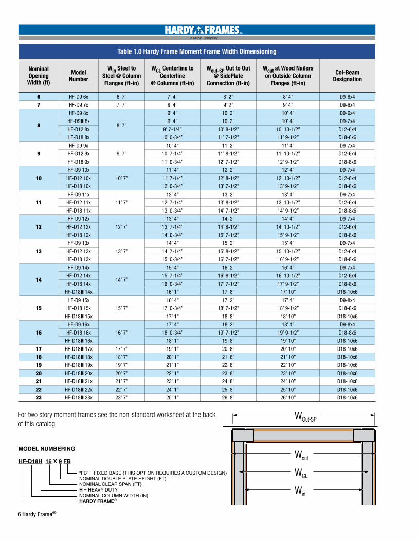
MODEL NUMBERING
HF-D18H 16 X 9 FB “FB” = FIXED BASE (THIS OPTION REQUIRES A CUSTOM DESIGN) NOMINAL DOUBLE PLATE HEIGHT (FT) NOMINAL CLEAR SPAN (FT} H = HEAVY DUTY NOMINAL COLUMN WIDTH (IN) HARDY FRAME®
D9 = BUILT UP COLUMN D18 = W18 x 35
D12 = W12 x 22 D18H = W18x46
H
WOut-SP
Wout WCL Win
4"9"
10"
4"3" 5" 6"4" 7"
6"4" 7"4"3"
6"12 1/4"13 1/4"
6"17 3/4"18 3/4"
6"18"
18 3/4"
5"
Table 1.0 Hardy Frame Moment Frame Width Dimensioning
Nominal Opening Width (ft)
Model Number
Win Steel to Steel @ Column Flanges (ft-in)
WCL Centerline to Centerline
@ Columns (ft-in)
Wout-SP Out to Out @ SidePlate
Connection (ft-in)
Wout at Wood Nailerson Outside Column
Flanges (ft-in)
Col-Beam Designation
6 HF-D9 6x 6’ 7” 7’ 4” 8’ 2” 8’ 4” D9-6x4
7 HF-D9 7x 7’ 7” 8’ 4” 9’ 2” 9’ 4” D9-6x4
8
HF-D9 8x
8’ 7”
9’ 4” 10’ 2” 10’ 4” D9-6x4
HF-D9H 8x 9’ 4” 10’ 2” 10’ 4” D9-7x4
HF-D12 8x 9’ 7-1/4” 10’ 8-1/2” 10’ 10-1/2” D12-6x4
HF-D18 8x 10’ 0-3/4” 11’ 7-1/2” 11’ 9-1/2” D18-6x6
9HF-D9 9x
9’ 7”
10’ 4” 11’ 2” 11’ 4” D9-7x4
HF-D12 9x 10’ 7-1/4” 11’ 8-1/2” 11’ 10-1/2” D12-6x4
HF-D18 9x 11’ 0-3/4” 12’ 7-1/2” 12’ 9-1/2” D18-8x6
10HF-D9 10x
10’ 7”
11’ 4” 12’ 2” 12’ 4” D9-7x4
HF-D12 10x 11’ 7-1/4” 12’ 8-1/2” 12’ 10-1/2” D12-6x4
HF-D18 10x 12’ 0-3/4” 13’ 7-1/2” 13’ 9-1/2” D18-8x6
11HF-D9 11x
11’ 7”
12’ 4” 13’ 2” 13’ 4” D9-7x4
HF-D12 11x 12’ 7-1/4” 13’ 8-1/2” 13’ 10-1/2” D12-6x4
HF-D18 11x 13’ 0-3/4” 14’ 7-1/2” 14’ 9-1/2” D18-8x6
12HF-D9 12x
12’ 7”
13’ 4” 14’ 2” 14’ 4” D9-7x4
HF-D12 12x 13’ 7-1/4” 14’ 8-1/2” 14’ 10-1/2” D12-6x4
HF-D18 12x 14’ 0-3/4” 15’ 7-1/2” 15’ 9-1/2” D18-8x6
13HF-D9 13x
13’ 7”
14’ 4” 15’ 2” 15’ 4” D9-7x4
HF-D12 13x 14’ 7-1/4” 15’ 8-1/2” 15’ 10-1/2” D12-6x4
HF-D18 13x 15’ 0-3/4” 16’ 7-1/2” 16’ 9-1/2” D18-8x6
14
HF-D9 14x
14’ 7”
15’ 4” 16’ 2” 16’ 4” D9-7x4
HF-D12 14x 15’ 7-1/4” 16’ 8-1/2” 16’ 10-1/2” D12-6x4
HF-D18 14x 16’ 0-3/4” 17’ 7-1/2” 17’ 9-1/2” D18-8x6
HF-D18H 14x 16’ 1” 17’ 8” 17’ 10” D18-10x6
15HF-D9 15x
15’ 7”
16’ 4” 17’ 2” 17’ 4” D9-8x4
HF-D18 15x 17’ 0-3/4” 18’ 7-1/2” 18’ 9-1/2” D18-8x6
HF-D18H 15x 17’ 1” 18’ 8” 18’ 10” D18-10x6
16HF-D9 16x
16’ 7”
17’ 4” 18’ 2” 18’ 4” D9-8x4
HF-D18 16x 18’ 0-3/4” 19’ 7-1/2” 19’ 9-1/2” D18-8x6
HF-D18H 16x 18’ 1” 19’ 8” 19’ 10” D18-10x6
17 HF-D18H 17x 17’ 7” 19’ 1” 20’ 8” 20’ 10” D18-10x6
18 HF-D18H 18x 18’ 7” 20’ 1” 21’ 8” 21’ 10” D18-10x6
19 HF-D18H 19x 19’ 7” 21’ 1” 22’ 8” 22’ 10” D18-10x6
20 HF-D18H 20x 20’ 7” 22’ 1” 23’ 8” 23’ 10” D18-10x6
21 HF-D18H 21x 21’ 7” 23’ 1” 24’ 8” 24’ 10” D18-10x6
22 HF-D18H 22x 22’ 7” 24’ 1” 25’ 8” 25’ 10” D18-10x6
23 HF-D18H 23x 23’ 7” 25’ 1” 26’ 8” 26’ 10” D18-10x6
Hardy Frame® 7
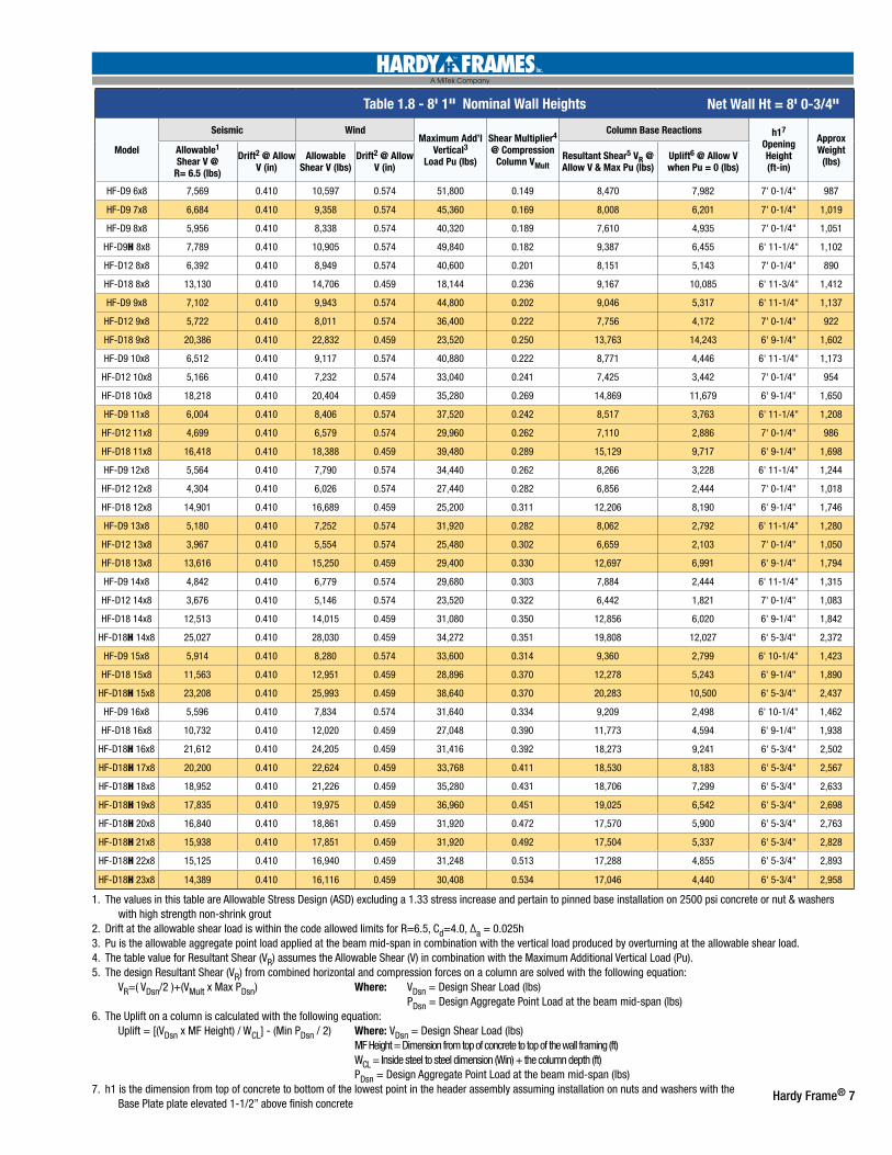
Table 1.8 - 8' 1" Nominal Wall Heights
Model
Seismic WindMaximum Add’l
Vertical3 Load Pu (lbs)
Shear Multiplier4 @ Compression
Column VMult
Column Base Reactions h17 Opening Height (ft-in)
Approx Weight
(lbs)Allowable1 Shear V @
R= 6.5 (lbs)
Drift2 @ Allow V (in)
Allowable Shear V (lbs)
Drift2 @ Allow V (in)
Resultant Shear5 VR @ Allow V & Max Pu (lbs)
Uplift6 @ Allow V when Pu = 0 (lbs)
HF-D9 6x8 7,569 0.410 10,597 0.574 51,800 0.149 8,470 7,982 7' 0-1/4" 987
HF-D9 7x8 6,684 0.410 9,358 0.574 45,360 0.169 8,008 6,201 7' 0-1/4" 1,019
HF-D9 8x8 5,956 0.410 8,338 0.574 40,320 0.189 7,610 4,935 7' 0-1/4" 1,051
HF-D9H 8x8 7,789 0.410 10,905 0.574 49,840 0.182 9,387 6,455 6' 11-1/4" 1,102
HF-D12 8x8 6,392 0.410 8,949 0.574 40,600 0.201 8,151 5,143 7' 0-1/4" 890
HF-D18 8x8 13,130 0.410 14,706 0.459 18,144 0.236 9,167 10,085 6' 11-3/4" 1,412
HF-D9 9x8 7,102 0.410 9,943 0.574 44,800 0.202 9,046 5,317 6' 11-1/4" 1,137
HF-D12 9x8 5,722 0.410 8,011 0.574 36,400 0.222 7,756 4,172 7' 0-1/4" 922
HF-D18 9x8 20,386 0.410 22,832 0.459 23,520 0.250 13,763 14,243 6' 9-1/4" 1,602
HF-D9 10x8 6,512 0.410 9,117 0.574 40,880 0.222 8,771 4,446 6' 11-1/4" 1,173
HF-D12 10x8 5,166 0.410 7,232 0.574 33,040 0.241 7,425 3,442 7' 0-1/4" 954
HF-D18 10x8 18,218 0.410 20,404 0.459 35,280 0.269 14,869 11,679 6' 9-1/4" 1,650
HF-D9 11x8 6,004 0.410 8,406 0.574 37,520 0.242 8,517 3,763 6' 11-1/4" 1,208
HF-D12 11x8 4,699 0.410 6,579 0.574 29,960 0.262 7,110 2,886 7' 0-1/4" 986
HF-D18 11x8 16,418 0.410 18,388 0.459 39,480 0.289 15,129 9,717 6' 9-1/4" 1,698
HF-D9 12x8 5,564 0.410 7,790 0.574 34,440 0.262 8,266 3,228 6' 11-1/4" 1,244
HF-D12 12x8 4,304 0.410 6,026 0.574 27,440 0.282 6,856 2,444 7' 0-1/4" 1,018
HF-D18 12x8 14,901 0.410 16,689 0.459 25,200 0.311 12,206 8,190 6' 9-1/4" 1,746
HF-D9 13x8 5,180 0.410 7,252 0.574 31,920 0.282 8,062 2,792 6' 11-1/4" 1,280
HF-D12 13x8 3,967 0.410 5,554 0.574 25,480 0.302 6,659 2,103 7' 0-1/4" 1,050
HF-D18 13x8 13,616 0.410 15,250 0.459 29,400 0.330 12,697 6,991 6' 9-1/4" 1,794
HF-D9 14x8 4,842 0.410 6,779 0.574 29,680 0.303 7,884 2,444 6' 11-1/4" 1,315
HF-D12 14x8 3,676 0.410 5,146 0.574 23,520 0.322 6,442 1,821 7' 0-1/4" 1,083
HF-D18 14x8 12,513 0.410 14,015 0.459 31,080 0.350 12,856 6,020 6' 9-1/4" 1,842
HF-D18H 14x8 25,027 0.410 28,030 0.459 34,272 0.351 19,808 12,027 6' 5-3/4" 2,372
HF-D9 15x8 5,914 0.410 8,280 0.574 33,600 0.314 9,360 2,799 6' 10-1/4" 1,423
HF-D18 15x8 11,563 0.410 12,951 0.459 28,896 0.370 12,278 5,243 6' 9-1/4" 1,890
HF-D18H 15x8 23,208 0.410 25,993 0.459 38,640 0.370 20,283 10,500 6' 5-3/4" 2,437
HF-D9 16x8 5,596 0.410 7,834 0.574 31,640 0.334 9,209 2,498 6' 10-1/4" 1,462
HF-D18 16x8 10,732 0.410 12,020 0.459 27,048 0.390 11,773 4,594 6' 9-1/4" 1,938
HF-D18H 16x8 21,612 0.410 24,205 0.459 31,416 0.392 18,273 9,241 6' 5-3/4" 2,502
HF-D18H 17x8 20,200 0.410 22,624 0.459 33,768 0.411 18,530 8,183 6' 5-3/4" 2,567
HF-D18H 18x8 18,952 0.410 21,226 0.459 35,280 0.431 18,706 7,299 6' 5-3/4" 2,633
HF-D18H 19x8 17,835 0.410 19,975 0.459 36,960 0.451 19,025 6,542 6' 5-3/4" 2,698
HF-D18H 20x8 16,840 0.410 18,861 0.459 31,920 0.472 17,570 5,900 6' 5-3/4" 2,763
HF-D18H 21x8 15,938 0.410 17,851 0.459 31,920 0.492 17,504 5,337 6' 5-3/4" 2,828
HF-D18H 22x8 15,125 0.410 16,940 0.459 31,248 0.513 17,288 4,855 6' 5-3/4" 2,893
HF-D18H 23x8 14,389 0.410 16,116 0.459 30,408 0.534 17,046 4,440 6' 5-3/4" 2,958
1. The values in this table are Allowable Stress Design (ASD) excluding a 1.33 stress increase and pertain to pinned base installation on 2500 psi concrete or nut & washers with high strength non-shrink grout2. Drift at the allowable shear load is within the code allowed limits for R=6.5, Cd=4.0, ∆a = 0.025h3. Pu is the allowable aggregate point load applied at the beam mid-span in combination with the vertical load produced by overturning at the allowable shear load.4. The table value for Resultant Shear (VR) assumes the Allowable Shear (V) in combination with the Maximum Additional Vertical Load (Pu). 5. The design Resultant Shear (VR) from combined horizontal and compression forces on a column are solved with the following equation: VR=( VDsn/2 )+(VMult x Max PDsn) Where: VDsn = Design Shear Load (lbs) PDsn = Design Aggregate Point Load at the beam mid-span (lbs)6. The Uplift on a column is calculated with the following equation: Uplift = [(VDsn x MF Height) / WCL] - (Min PDsn / 2) Where: VDsn = Design Shear Load (lbs) MF Height = Dimension from top of concrete to top of the wall framing (ft) WCL = Inside steel to steel dimension (Win) + the column depth (ft) PDsn = Design Aggregate Point Load at the beam mid-span (lbs)7. h1 is the dimension from top of concrete to bottom of the lowest point in the header assembly assuming installation on nuts and washers with the Base Plate plate elevated 1-1/2” above finish concrete
Net Wall Ht = 8' 0-3/4"
8 Hardy Frame®
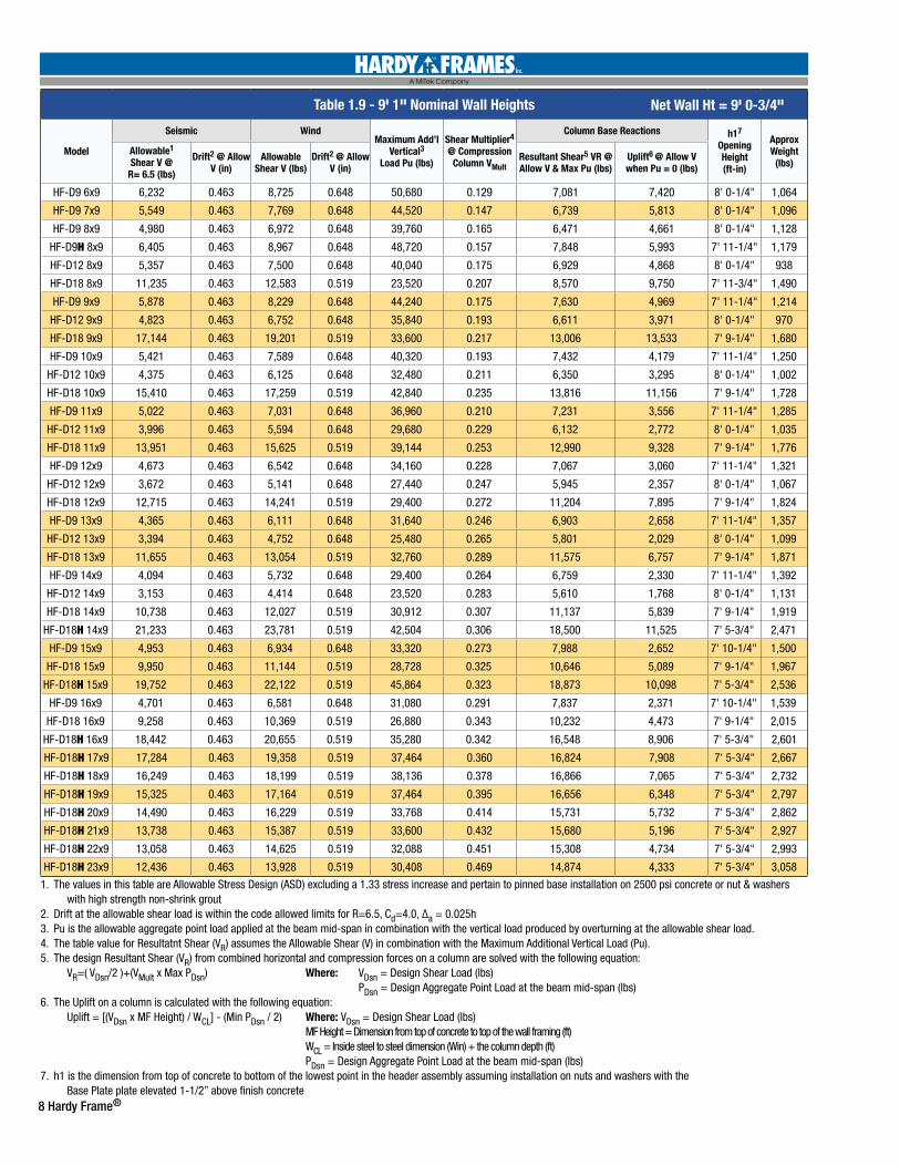
Table 1.9 - 9' 1" Nominal Wall Heights
Model
Seismic WindMaximum Add’l
Vertical3 Load Pu (lbs)
Shear Multiplier4 @ Compression
Column VMult
Column Base Reactions h17 Opening Height (ft-in)
Approx Weight
(lbs)Allowable1 Shear V @
R= 6.5 (lbs)
Drift2 @ Allow V (in)
Allowable Shear V (lbs)
Drift2 @ Allow V (in)
Resultant Shear5 VR @ Allow V & Max Pu (lbs)
Uplift6 @ Allow V when Pu = 0 (lbs)
HF-D9 6x9 6,232 0.463 8,725 0.648 50,680 0.129 7,081 7,420 8' 0-1/4" 1,064
HF-D9 7x9 5,549 0.463 7,769 0.648 44,520 0.147 6,739 5,813 8' 0-1/4" 1,096
HF-D9 8x9 4,980 0.463 6,972 0.648 39,760 0.165 6,471 4,661 8' 0-1/4" 1,128
HF-D9H 8x9 6,405 0.463 8,967 0.648 48,720 0.157 7,848 5,993 7' 11-1/4" 1,179
HF-D12 8x9 5,357 0.463 7,500 0.648 40,040 0.175 6,929 4,868 8' 0-1/4" 938
HF-D18 8x9 11,235 0.463 12,583 0.519 23,520 0.207 8,570 9,750 7' 11-3/4" 1,490
HF-D9 9x9 5,878 0.463 8,229 0.648 44,240 0.175 7,630 4,969 7' 11-1/4" 1,214
HF-D12 9x9 4,823 0.463 6,752 0.648 35,840 0.193 6,611 3,971 8' 0-1/4" 970
HF-D18 9x9 17,144 0.463 19,201 0.519 33,600 0.217 13,006 13,533 7' 9-1/4" 1,680
HF-D9 10x9 5,421 0.463 7,589 0.648 40,320 0.193 7,432 4,179 7' 11-1/4" 1,250
HF-D12 10x9 4,375 0.463 6,125 0.648 32,480 0.211 6,350 3,295 8' 0-1/4" 1,002
HF-D18 10x9 15,410 0.463 17,259 0.519 42,840 0.235 13,816 11,156 7' 9-1/4" 1,728
HF-D9 11x9 5,022 0.463 7,031 0.648 36,960 0.210 7,231 3,556 7' 11-1/4" 1,285
HF-D12 11x9 3,996 0.463 5,594 0.648 29,680 0.229 6,132 2,772 8' 0-1/4" 1,035
HF-D18 11x9 13,951 0.463 15,625 0.519 39,144 0.253 12,990 9,328 7' 9-1/4" 1,776
HF-D9 12x9 4,673 0.463 6,542 0.648 34,160 0.228 7,067 3,060 7' 11-1/4" 1,321
HF-D12 12x9 3,672 0.463 5,141 0.648 27,440 0.247 5,945 2,357 8' 0-1/4" 1,067
HF-D18 12x9 12,715 0.463 14,241 0.519 29,400 0.272 11,204 7,895 7' 9-1/4" 1,824
HF-D9 13x9 4,365 0.463 6,111 0.648 31,640 0.246 6,903 2,658 7' 11-1/4" 1,357
HF-D12 13x9 3,394 0.463 4,752 0.648 25,480 0.265 5,801 2,029 8' 0-1/4" 1,099
HF-D18 13x9 11,655 0.463 13,054 0.519 32,760 0.289 11,575 6,757 7' 9-1/4" 1,871
HF-D9 14x9 4,094 0.463 5,732 0.648 29,400 0.264 6,759 2,330 7' 11-1/4" 1,392
HF-D12 14x9 3,153 0.463 4,414 0.648 23,520 0.283 5,610 1,768 8' 0-1/4" 1,131
HF-D18 14x9 10,738 0.463 12,027 0.519 30,912 0.307 11,137 5,839 7' 9-1/4" 1,919
HF-D18H 14x9 21,233 0.463 23,781 0.519 42,504 0.306 18,500 11,525 7' 5-3/4" 2,471
HF-D9 15x9 4,953 0.463 6,934 0.648 33,320 0.273 7,988 2,652 7' 10-1/4" 1,500
HF-D18 15x9 9,950 0.463 11,144 0.519 28,728 0.325 10,646 5,089 7' 9-1/4" 1,967
HF-D18H 15x9 19,752 0.463 22,122 0.519 45,864 0.323 18,873 10,098 7' 5-3/4" 2,536
HF-D9 16x9 4,701 0.463 6,581 0.648 31,080 0.291 7,837 2,371 7' 10-1/4" 1,539
HF-D18 16x9 9,258 0.463 10,369 0.519 26,880 0.343 10,232 4,473 7' 9-1/4" 2,015
HF-D18H 16x9 18,442 0.463 20,655 0.519 35,280 0.342 16,548 8,906 7' 5-3/4" 2,601
HF-D18H 17x9 17,284 0.463 19,358 0.519 37,464 0.360 16,824 7,908 7' 5-3/4" 2,667
HF-D18H 18x9 16,249 0.463 18,199 0.519 38,136 0.378 16,866 7,065 7' 5-3/4" 2,732
HF-D18H 19x9 15,325 0.463 17,164 0.519 37,464 0.395 16,656 6,348 7' 5-3/4" 2,797
HF-D18H 20x9 14,490 0.463 16,229 0.519 33,768 0.414 15,731 5,732 7' 5-3/4" 2,862
HF-D18H 21x9 13,738 0.463 15,387 0.519 33,600 0.432 15,680 5,196 7' 5-3/4" 2,927
HF-D18H 22x9 13,058 0.463 14,625 0.519 32,088 0.451 15,308 4,734 7' 5-3/4" 2,993
HF-D18H 23x9 12,436 0.463 13,928 0.519 30,408 0.469 14,874 4,333 7' 5-3/4" 3,058
Net Wall Ht = 9' 0-3/4"
1. The values in this table are Allowable Stress Design (ASD) excluding a 1.33 stress increase and pertain to pinned base installation on 2500 psi concrete or nut & washers with high strength non-shrink grout2. Drift at the allowable shear load is within the code allowed limits for R=6.5, Cd=4.0, ∆a = 0.025h3. Pu is the allowable aggregate point load applied at the beam mid-span in combination with the vertical load produced by overturning at the allowable shear load.4. The table value for Resultatnt Shear (VR) assumes the Allowable Shear (V) in combination with the Maximum Additional Vertical Load (Pu). 5. The design Resultant Shear (VR) from combined horizontal and compression forces on a column are solved with the following equation: VR=( VDsn/2 )+(VMult x Max PDsn) Where: VDsn = Design Shear Load (lbs) PDsn = Design Aggregate Point Load at the beam mid-span (lbs)6. The Uplift on a column is calculated with the following equation: Uplift = [(VDsn x MF Height) / WCL] - (Min PDsn / 2) Where: VDsn = Design Shear Load (lbs) MF Height = Dimension from top of concrete to top of the wall framing (ft) WCL = Inside steel to steel dimension (Win) + the column depth (ft) PDsn = Design Aggregate Point Load at the beam mid-span (lbs)7. h1 is the dimension from top of concrete to bottom of the lowest point in the header assembly assuming installation on nuts and washers with the Base Plate plate elevated 1-1/2” above finish concrete
Hardy Frame® 9
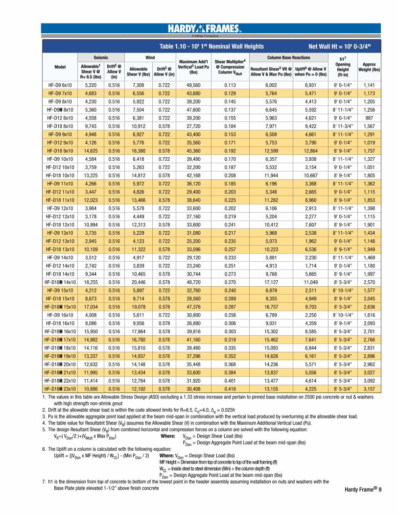
Table 1.10 - 10' 1" Nominal Wall Heights
Model
Seismic WindMaximum Add’l
Vertical3 Load Pu (lbs)
Shear Multiplier4
@ Compression Column VMult
Column Base Reactions h17 Opening Height (ft-in)
Approx Weight (lbs)
Allowable1 Shear V @
R= 6.5 (lbs)
Drift2 @ Allow V
(in)
Allowable Shear V (lbs)
Drift2 @ Allow V (in)
Resultant Shear5 VR @ Allow V & Max Pu (lbs)
Uplift6 @ Allow V when Pu = 0 (lbs)
HF-D9 6x10 5,220 0.516 7,308 0.722 49,560 0.113 6,002 6,931 9' 0-1/4" 1,141
HF-D9 7x10 4,683 0.516 6,556 0.722 43,680 0.129 5,764 5,471 9' 0-1/4" 1,173
HF-D9 8x10 4,230 0.516 5,922 0.722 39,200 0.145 5,576 4,413 9' 0-1/4" 1,205
HF-D9H 8x10 5,360 0.516 7,504 0.722 47,600 0.137 6,645 5,592 8' 11-1/4" 1,256
HF-D12 8x10 4,558 0.516 6,381 0.722 39,200 0.155 5,963 4,621 9' 0-1/4" 987
HF-D18 8x10 9,743 0.516 10,912 0.578 27,720 0.184 7,971 9,422 8' 11-3/4" 1,567
HF-D9 9x10 4,948 0.516 6,927 0.722 43,400 0.153 6,508 4,661 8' 11-1/4" 1,291
HF-D12 9x10 4,126 0.516 5,776 0.722 35,560 0.171 5,753 3,790 9' 0-1/4" 1,019
HF-D18 9x10 14,625 0.516 16,380 0.578 45,360 0.192 12,599 12,864 8' 9-1/4" 1,757
HF-D9 10x10 4,584 0.516 6,418 0.722 39,480 0.170 6,357 3,938 8' 11-1/4" 1,327
HF-D12 10x10 3,759 0.516 5,263 0.722 32,200 0.187 5,532 3,154 9' 0-1/4" 1,051
HF-D18 10x10 13,225 0.516 14,812 0.578 42,168 0.208 11,944 10,667 8' 9-1/4" 1,805
HF-D9 11x10 4,266 0.516 5,972 0.722 36,120 0.185 6,196 3,368 8' 11-1/4" 1,362
HF-D12 11x10 3,447 0.516 4,826 0.722 29,400 0.203 5,348 2,665 9' 0-1/4" 1,115
HF-D18 11x10 12,023 0.516 13,466 0.578 38,640 0.225 11,282 8,960 8' 9-1/4" 1,853
HF-D9 12x10 3,984 0.516 5,578 0.722 33,600 0.202 6,106 2,913 8' 11-1/4" 1,398
HF-D12 12x10 3,178 0.516 4,449 0.722 27,160 0.219 5,204 2,277 9' 0-1/4" 1,115
HF-D18 12x10 10,994 0.516 12,313 0.578 33,600 0.241 10,412 7,607 8' 9-1/4" 1,901
HF-D9 13x10 3,735 0.516 5,229 0.722 31,080 0.217 5,968 2,538 8' 11-1/4" 1,434
HF-D12 13x10 2,945 0.516 4,123 0.722 25,200 0.235 5,073 1,962 9' 0-1/4" 1,148
HF-D18 13x10 10,109 0.516 11,322 0.578 33,096 0.257 10,223 6,536 8' 9-1/4" 1,949
HF-D9 14x10 3,512 0.516 4,917 0.722 29,120 0.233 5,881 2,230 8' 11-1/4" 1,469
HF-D12 14x10 2,742 0.516 3,839 0.722 23,240 0.251 4,913 1,714 9' 0-1/4" 1,180
HF-D18 14x10 9,344 0.516 10,465 0.578 30,744 0.273 9,768 5,665 8' 9-1/4" 1,997
HF-D18H 14x10 18,255 0.516 20,446 0.578 48,720 0.270 17,127 11,049 8' 5-3/4" 2,570
HF-D9 15x10 4,212 0.516 5,897 0.722 32,760 0.240 6,879 2,511 8' 10-1/4" 1,577
HF-D18 15x10 8,673 0.516 9,714 0.578 28,560 0.289 9,355 4,949 8' 9-1/4" 2,045
HF-D18H 15x10 17,034 0.516 19,078 0.578 47,376 0.287 16,757 9,703 8' 5-3/4" 2,636
HF-D9 16x10 4,008 0.516 5,611 0.722 30,800 0.256 6,789 2,250 8' 10-1/4" 1,616
HF-D18 16x10 8,086 0.516 9,056 0.578 26,880 0.306 9,031 4,359 8' 9-1/4" 2,093
HF-D18H 16x10 15,950 0.516 17,864 0.578 39,816 0.303 15,302 8,585 8' 5-3/4" 2,701
HF-D18H 17x10 14,982 0.516 16,780 0.578 41,160 0.319 15,462 7,641 8' 5-3/4" 2,766
HF-D18H 18x10 14,116 0.516 15,810 0.578 39,480 0.335 15,093 6,844 8' 5-3/4" 2,831
HF-D18H 19x10 13,337 0.516 14,937 0.578 37,296 0.352 14,626 6,161 8' 5-3/4" 2,896
HF-D18H 20x10 12,632 0.516 14,148 0.578 35,448 0.368 14,236 5,571 8' 5-3/4" 2,962
HF-D18H 21x10 11,995 0.516 13,434 0.578 33,600 0.384 13,837 5,056 8' 5-3/4" 3,027
HF-D18H 22x10 11,414 0.516 12,784 0.578 31,920 0.401 13,477 4,614 8' 5-3/4" 3,092
HF-D18H 23x10 10,886 0.516 12,192 0.578 30,408 0.418 13,155 4,225 8' 5-3/4" 3,157
Net Wall Ht = 10' 0-3/4"
1. The values in this table are Allowable Stress Design (ASD) excluding a 1.33 stress increase and pertain to pinned base installation on 2500 psi concrete or nut & washers with high strength non-shrink grout2. Drift at the allowable shear load is within the code allowed limits for R=6.5, Cd=4.0, ∆a = 0.025h3. Pu is the allowable aggregate point load applied at the beam mid-span in combination with the vertical load produced by overturning at the allowable shear load.4. The table value for Resultatnt Shear (VR) assumes the Allowable Shear (V) in combination with the Maximum Additional Vertical Load (Pu). 5. The design Resultant Shear (VR) from combined horizontal and compression forces on a column are solved with the following equation: VR=( VDsn/2 )+(VMult x Max PDsn) Where: VDsn = Design Shear Load (lbs) PDsn = Design Aggregate Point Load at the beam mid-span (lbs)6. The Uplift on a column is calculated with the following equation: Uplift = [(VDsn x MF Height) / WCL] - (Min PDsn / 2) Where: VDsn = Design Shear Load (lbs) MF Height = Dimension from top of concrete to top of the wall framing (ft) WCL = Inside steel to steel dimension (Win) + the column depth (ft) PDsn = Design Aggregate Point Load at the beam mid-span (lbs)7. h1 is the dimension from top of concrete to bottom of the lowest point in the header assembly assuming installation on nuts and washers with the Base Plate plate elevated 1-1/2” above finish concrete
10 Hardy Frame®
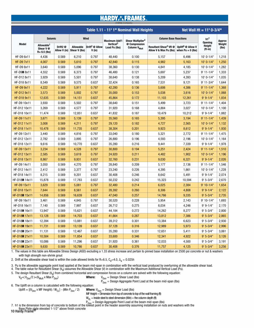
Table 1.11 - 11' 1" Nominal Wall Heights
Model
Seismic WindMaximum Add’l
Vertical3 Load Pu (lbs)
Shear Multiplier4 @ Compression
Column VMult
Column Base Reactions h17 Opening Height (ft-in)
Approx Weight
(lbs)Allowable1 Shear V @
R= 6.5 (lbs)
Drift2 @ Allow V (in)
Allowable Shear V (lbs)
Drift2 @ Allow V (in)
Resultant Shear5 VR @ Allow V & Max Pu (lbs)
Uplift6 @ Allow V when Pu = 0 (lbs)
HF-D9 6x11 4,436 0.569 6,210 0.797 48,440 0.100 5,157 6,496 10' 0-1/4" 1,218
HF-D9 7x11 4,007 0.569 5,610 0.797 42,840 0.115 4,982 5,163 10' 0-1/4" 1,250
HF-D9 8x11 3,640 0.569 5,096 0.797 38,360 0.130 4,841 4,185 10' 0-1/4" 1,282
HF-D9H 8x11 4,552 0.569 6,373 0.797 46,480 0.121 5,697 5,237 9' 11-1/4" 1,333
HF-D12 8x11 3,929 0.569 5,501 0.797 38,640 0.138 5,209 4,393 10' 0-1/4" 1,035
HF-D18 8x11 8,549 0.569 9,575 0.637 32,424 0.165 7,531 9,121 9' 11-3/4" 1,644
HF-D9 9x11 4,222 0.569 5,911 0.797 42,280 0.136 5,606 4,386 9' 11-1/4" 1,368
HF-D12 9x11 3,573 0.569 5,002 0.797 35,000 0.153 5,038 3,616 10' 0-1/4" 1,068
HF-D18 9x11 12,635 0.569 14,151 0.637 45,864 0.172 11,103 12,261 9' 9-1/4" 1,834
HF-D9 10x11 3,930 0.569 5,502 0.797 38,640 0.151 5,499 3,723 9' 11-1/4" 1,404
HF-D12 10x11 3,269 0.569 4,577 0.797 31,920 0.168 4,884 3,027 10' 0-1/4" 1,100
HF-D18 10x11 11,474 0.569 12,851 0.637 41,832 0.187 10,479 10,212 9' 9-1/4" 1,882
HF-D9 11x11 3,671 0.569 5,139 0.797 35,560 0.165 5,395 3,194 9' 11-1/4" 1,439
HF-D12 11x11 3,008 0.569 4,211 0.797 29,120 0.182 4,727 2,565 10' 0-1/4" 1,132
HF-D18 11x11 10,478 0.569 11,735 0.637 38,304 0.201 9,923 8,612 9' 9-1/4" 1,930
HF-D9 12x11 3,440 0.569 4,816 0.797 33,040 0.180 5,321 2,772 9' 11-1/4" 1,475
HF-D12 12x11 2,782 0.569 3,895 0.797 26,880 0.196 4,593 2,196 10' 0-1/4" 1,164
HF-D18 12x11 9,616 0.569 10,770 0.637 35,280 0.216 9,441 7,339 9' 9-1/4" 1,978
HF-D9 13x11 3,234 0.569 4,528 0.797 30,800 0.194 5,251 2,424 9' 11-1/4" 1,510
HF-D12 13x11 2,585 0.569 3,619 0.797 24,920 0.211 4,482 1,902 10' 0-1/4" 1,196
HF-D18 13x11 8,867 0.569 9,931 0.637 32,760 0.231 9,030 6,321 9' 9-1/4" 2,026
HF-D9 14x11 3,050 0.569 4,270 0.797 28,840 0.209 5,177 2,136 9' 11-1/4" 1,546
HF-D12 14x11 2,412 0.569 3,377 0.797 23,240 0.226 4,395 1,661 10' 0-1/4" 1,228
HF-D18 14x11 8,215 0.569 9,201 0.637 30,408 0.246 8,642 5,491 9' 9-1/4" 2,074
HF-D18H 14x11 15,878 0.569 17,783 0.637 50,232 0.242 15,323 10,594 9' 5-3/4" 2,670
HF-D9 15x11 3,629 0.569 5,081 0.797 32,480 0.214 6,025 2,384 9' 10-1/4" 1,654
HF-D18 15x11 7,644 0.569 8,561 0.637 28,392 0.260 8,306 4,808 9' 9-1/4" 2,122
HF-D18H 15x11 14,856 0.569 16,639 0.637 47,040 0.257 14,766 9,335 9' 5-3/4" 2,735
HF-D9 16x11 3,461 0.569 4,845 0.797 30,520 0.228 5,954 2,143 9' 10-1/4" 1,693
HF-D18 16x11 7,140 0.569 7,997 0.637 26,712 0.275 8,034 4,246 9' 9-1/4" 2,170
HF-D18H 16x11 13,947 0.569 15,621 0.637 44,184 0.272 14,262 8,277 9' 5-3/4" 2,800
HF-D18H 17x11 13,128 0.569 14,703 0.637 41,664 0.287 13,812 7,386 9' 5-3/4" 2,865
HF-D18H 18x11 12,394 0.569 13,881 0.637 39,312 0.301 13,384 6,623 9' 5-3/4" 2,930
HF-D18H 19x11 11,731 0.569 13,139 0.637 37,128 0.316 12,989 5,973 9' 5-3/4" 2,996
HF-D18H 20x11 11,131 0.569 12,467 0.637 35,280 0.331 12,651 5,411 9' 5-3/4" 3,061
HF-D18H 21x11 10,584 0.569 11,854 0.637 33,600 0.346 12,341 4,922 9' 5-3/4" 3,126
HF-D18H 22x11 10,086 0.569 11,296 0.637 31,920 0.361 12,033 4,500 9' 5-3/4" 3,191
HF-D18H 23x11 9,630 0.569 10,786 0.637 30,408 0.376 11,757 4,125 9' 5-3/4" 3,256
Net Wall Ht = 11' 0-3/4"
1. The values in this table are Allowable Stress Design (ASD) excluding a 1.33 stress increase and pertain to pinned base installation on 2500 psi concrete or nut & washers with high strength non-shrink grout2. Drift at the allowable shear load is within the code allowed limits for R=6.5, Cd=4.0, ∆a = 0.025h
3. Pu is the allowable aggregate point load applied at the beam mid-span in combination with the vertical load produced by overturning at the allowable shear load.4. The table value for Resultatnt Shear (VR) assumes the Allowable Shear (V) in combination with the Maximum Additional Vertical Load (Pu). 5. The design Resultant Shear (VR) from combined horizontal and compression forces on a column are solved with the following equation: VR=( VDsn/2 )+(VMult x Max PDsn) Where: VDsn = Design Shear Load (lbs) PDsn = Design Aggregate Point Load at the beam mid-span (lbs)6. The Uplift on a column is calculated with the following equation: Uplift = [(VDsn x MF Height) / WCL] - (Min PDsn / 2) Where: VDsn = Design Shear Load (lbs) MF Height = Dimension from top of concrete to top of the wall framing (ft) WCL = Inside steel to steel dimension (Win) + the column depth (ft) PDsn = Design Aggregate Point Load at the beam mid-span (lbs)7. h1 is the dimension from top of concrete to bottom of the lowest point in the header assembly assuming installation on nuts and washers with the Base Plate plate elevated 1-1/2” above finish concrete
Hardy Frame® 11
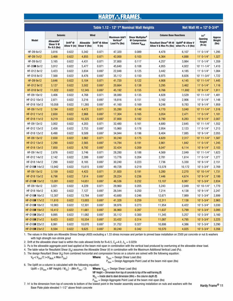
Table 1.12 - 12' 1" Nominal Wall Heights
Model
Seismic WindMaximum Add’l
Vertical3 Load Pu (lbs)
Shear Multiplier4 @ Compression
Column VMult
Column Base Reactions h17 Opening Height (ft-in)
Approx Weight
(lbs)Allowable1 Shear V @
R= 6.5 (lbs)
Drift2 @ Allow V (in)
Allowable Shear V (lbs)
Drift2 @ Allow V (in)
Resultant Shear5 VR @ Allow V & Max Pu (lbs)
Uplift6 @ Allow V when Pu = 0 (lbs)
HF-D9 6x12 3,816 0.622 5,342 0.871 47,320 0.089 4,478 6,107 11' 0-1/4" 1,295
HF-D9 7x12 3,468 0.622 4,855 0.871 42,000 0.103 4,364 4,888 11' 0-1/4" 1,327
HF-D9 8x12 3,165 0.622 4,431 0.871 37,800 0.117 4,257 3,984 11' 0-1/4" 1,359
HF-D9H 8x12 3,912 0.622 5,477 0.871 45,640 0.108 4,955 4,922 10' 11-1/4" 1,410
HF-D12 8x12 3,423 0.622 3,834 0.697 22,848 0.125 3,442 4,185 11' 0-1/4" 1,084
HF-D18 8x12 7,568 0.622 8,476 0.697 35,112 0.150 6,975 8,826 10' 11-3/4" 1,722
HF-D9 9x12 3,646 0.622 5,104 0.871 41,720 0.122 4,908 4,145 10' 11-1/4" 1,445
HF-D12 9x12 3,127 0.622 3,502 0.697 20,664 0.138 3,295 3,462 11' 0-1/4" 1,116
HF-D18 9x12 11,022 0.622 12,345 0.697 45,192 0.155 9,766 11,692 10' 9-1/4" 1,911
HF-D9 10x12 3,406 0.622 4,768 0.871 38,080 0.135 4,828 3,529 10' 11-1/4" 1,481
HF-D12 10x12 2,871 0.622 3,216 0.697 18,816 0.151 3,162 2,906 11' 0-1/4" 1,148
HF-D18 10x12 10,058 0.622 11,265 0.697 41,160 0.169 9,248 9,783 10' 9-1/4" 1,959
HF-D9 11x12 3,194 0.622 4,472 0.871 35,280 0.148 4,770 3,040 10' 11-1/4" 1,516
HF-D12 11x12 2,650 0.622 2,968 0.697 17,304 0.165 3,054 2,471 11' 0-1/4" 1,181
HF-D18 11x12 9,219 0.622 10,325 0.697 37,800 0.182 8,790 8,283 10' 9-1/4" 2,007
HF-D9 12x12 3,002 0.622 4,203 0.871 32,480 0.161 4,680 2,645 10' 11-1/4" 1,552
HF-D12 12x12 2,458 0.622 2,753 0.697 15,960 0.178 2,954 2,123 11' 0-1/4" 1,213
HF-D18 12x12 8,490 0.622 9,509 0.697 34,944 0.196 8,404 7,085 10' 9-1/4" 2,055
HF-D9 13x12 2,830 0.622 3,962 0.871 30,240 0.175 4,620 2,317 10' 11-1/4" 1,587
HF-D12 13x12 2,290 0.622 2,565 0.697 14,784 0.191 2,861 1,842 11' 0-1/4" 1,245
HF-D18 13x12 7,850 0.622 8,792 0.697 32,424 0.209 8,047 6,114 10' 9-1/4" 2,103
HF-D9 14x12 2,676 0.622 3,746 0.871 28,280 0.188 4,569 2,049 10' 11-1/4" 1,623
HF-D12 14x12 2,142 0.622 2,399 0.697 13,776 0.204 2,781 1,614 11' 0-1/4" 1,277
HF-D18 14x12 7,290 0.622 8,165 0.697 30,240 0.223 7,736 5,330 10' 9-1/4" 2,151
HF-D18H 14x12 13,942 0.622 15,615 0.697 49,728 0.219 13,578 10,172 10' 5-3/4" 2,769
HF-D9 15x12 3,159 0.622 4,423 0.871 31,920 0.191 5,280 2,270 10' 10-1/4" 1,731
HF-D18 15x12 6,798 0.622 7,614 0.697 28,224 0.236 7,446 4,674 10' 9-1/4" 2,199
HF-D18H 15x12 13,081 0.622 14,651 0.697 46,536 0.232 13,107 8,987 10' 5-3/4" 2,834
HF-D9 16x12 3,021 0.622 4,229 0.871 29,960 0.205 5,243 2,049 10' 10-1/4" 1,770
HF-D18 16x12 6,363 0.622 7,127 0.697 26,544 0.250 7,214 4,138 10' 9-1/4" 2,247
HF-D18H 16x12 12,307 0.622 13,784 0.697 43,680 0.246 12,671 7,989 10' 5-3/4" 2,899
HF-D18H 17x12 11,610 0.622 13,003 0.697 41,328 0.259 12,311 7,138 10' 5-3/4" 2,965
HF-D18H 18x12 10,983 0.622 12,301 0.697 38,976 0.273 11,954 6,422 10' 5-3/4" 3,030
HF-D18H 19x12 10,412 0.622 11,661 0.697 36,960 0.287 11,637 5,799 10' 5-3/4" 3,095
HF-D18H 20x12 9,895 0.622 11,082 0.697 35,112 0.300 11,345 5,257 10' 5-3/4" 3,160
HF-D18H 21x12 9,423 0.622 10,554 0.697 33,432 0.314 11,087 4,795 10' 5-3/4" 3,225
HF-D18H 22x12 8,991 0.622 10,070 0.697 31,752 0.327 10,806 4,386 10' 5-3/4" 3,290
HF-D18H 23x12 8,594 0.622 9,625 0.697 30,240 0.342 10,570 4,025 10' 5-3/4" 3,356
Net Wall Ht = 12' 0-3/4"
1. The values in this table are Allowable Stress Design (ASD) excluding a 1.33 stress increase and pertain to pinned base installation on 2500 psi concrete or nut & washers with high strength non-shrink grout2. Drift at the allowable shear load is within the code allowed limits for R=6.5, Cd=4.0, ∆a = 0.025h3. Pu is the allowable aggregate point load applied at the beam mid-span in combination with the vertical load produced by overturning at the allowable shear load.4. The table value for Resultatnt Shear (VR) assumes the Allowable Shear (V) in combination with the Maximum Additional Vertical Load (Pu). 5. The design Resultant Shear (VR) from combined horizontal and compression forces on a column are solved with the following equation: VR=( VDsn/2 )+(VMult x Max PDsn) Where: VDsn = Design Shear Load (lbs) PDsn = Design Aggregate Point Load at the beam mid-span (lbs)6. The Uplift on a column is calculated with the following equation: Uplift = [(VDsn x MF Height) / WCL] - (Min PDsn / 2) Where: VDsn = Design Shear Load (lbs) MF Height = Dimension from top of concrete to top of the wall framing (ft) WCL = Inside steel to steel dimension (Win) + the column depth (ft) PDsn = Design Aggregate Point Load at the beam mid-span (lbs)7. h1 is the dimension from top of concrete to bottom of the lowest point in the header assembly assuming installation on nuts and washers with the Base Plate plate elevated 1-1/2” above finish concrete
12 Hardy Frame®
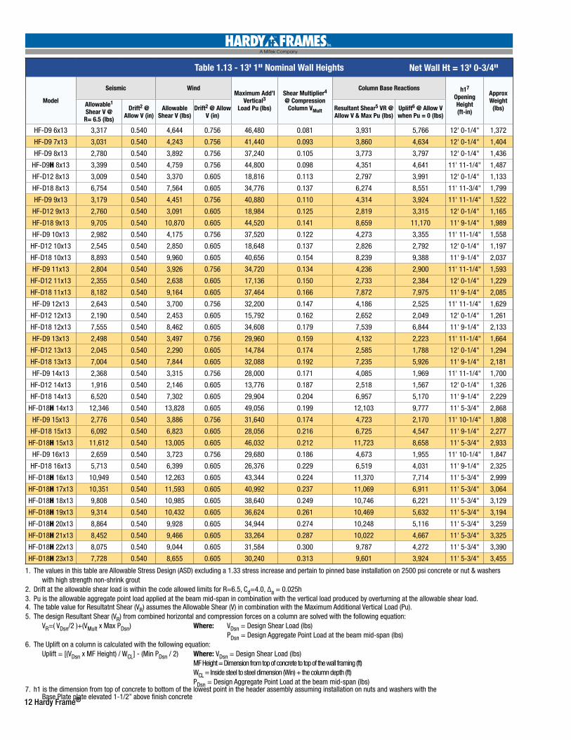
Table 1.13 - 13' 1" Nominal Wall Heights
Model
Seismic WindMaximum Add’l
Vertical3 Load Pu (lbs)
Shear Multiplier4 @ Compression
Column VMult
Column Base Reactions h17 Opening Height (ft-in)
Approx Weight
(lbs)Allowable1 Shear V @
R= 6.5 (lbs)
Drift2 @ Allow V (in)
Allowable Shear V (lbs)
Drift2 @ Allow V (in)
Resultant Shear5 VR @ Allow V & Max Pu (lbs)
Uplift6 @ Allow V when Pu = 0 (lbs)
HF-D9 6x13 3,317 0.540 4,644 0.756 46,480 0.081 3,931 5,766 12' 0-1/4" 1,372
HF-D9 7x13 3,031 0.540 4,243 0.756 41,440 0.093 3,860 4,634 12' 0-1/4" 1,404
HF-D9 8x13 2,780 0.540 3,892 0.756 37,240 0.105 3,773 3,797 12' 0-1/4" 1,436
HF-D9H 8x13 3,399 0.540 4,759 0.756 44,800 0.098 4,351 4,641 11' 11-1/4" 1,487
HF-D12 8x13 3,009 0.540 3,370 0.605 18,816 0.113 2,797 3,991 12' 0-1/4" 1,133
HF-D18 8x13 6,754 0.540 7,564 0.605 34,776 0.137 6,274 8,551 11' 11-3/4" 1,799
HF-D9 9x13 3,179 0.540 4,451 0.756 40,880 0.110 4,314 3,924 11' 11-1/4" 1,522
HF-D12 9x13 2,760 0.540 3,091 0.605 18,984 0.125 2,819 3,315 12' 0-1/4" 1,165
HF-D18 9x13 9,705 0.540 10,870 0.605 44,520 0.141 8,659 11,170 11' 9-1/4" 1,989
HF-D9 10x13 2,982 0.540 4,175 0.756 37,520 0.122 4,273 3,355 11' 11-1/4" 1,558
HF-D12 10x13 2,545 0.540 2,850 0.605 18,648 0.137 2,826 2,792 12' 0-1/4" 1,197
HF-D18 10x13 8,893 0.540 9,960 0.605 40,656 0.154 8,239 9,388 11' 9-1/4" 2,037
HF-D9 11x13 2,804 0.540 3,926 0.756 34,720 0.134 4,236 2,900 11' 11-1/4" 1,593
HF-D12 11x13 2,355 0.540 2,638 0.605 17,136 0.150 2,733 2,384 12' 0-1/4" 1,229
HF-D18 11x13 8,182 0.540 9,164 0.605 37,464 0.166 7,872 7,975 11' 9-1/4" 2,085
HF-D9 12x13 2,643 0.540 3,700 0.756 32,200 0.147 4,186 2,525 11' 11-1/4" 1,629
HF-D12 12x13 2,190 0.540 2,453 0.605 15,792 0.162 2,652 2,049 12' 0-1/4" 1,261
HF-D18 12x13 7,555 0.540 8,462 0.605 34,608 0.179 7,539 6,844 11' 9-1/4" 2,133
HF-D9 13x13 2,498 0.540 3,497 0.756 29,960 0.159 4,132 2,223 11' 11-1/4" 1,664
HF-D12 13x13 2,045 0.540 2,290 0.605 14,784 0.174 2,585 1,788 12' 0-1/4" 1,294
HF-D18 13x13 7,004 0.540 7,844 0.605 32,088 0.192 7,235 5,926 11' 9-1/4" 2,181
HF-D9 14x13 2,368 0.540 3,315 0.756 28,000 0.171 4,085 1,969 11' 11-1/4" 1,700
HF-D12 14x13 1,916 0.540 2,146 0.605 13,776 0.187 2,518 1,567 12' 0-1/4" 1,326
HF-D18 14x13 6,520 0.540 7,302 0.605 29,904 0.204 6,957 5,170 11' 9-1/4" 2,229
HF-D18H 14x13 12,346 0.540 13,828 0.605 49,056 0.199 12,103 9,777 11' 5-3/4" 2,868
HF-D9 15x13 2,776 0.540 3,886 0.756 31,640 0.174 4,723 2,170 11' 10-1/4" 1,808
HF-D18 15x13 6,092 0.540 6,823 0.605 28,056 0.216 6,725 4,547 11' 9-1/4" 2,277
HF-D18H 15x13 11,612 0.540 13,005 0.605 46,032 0.212 11,723 8,658 11' 5-3/4" 2,933
HF-D9 16x13 2,659 0.540 3,723 0.756 29,680 0.186 4,673 1,955 11' 10-1/4" 1,847
HF-D18 16x13 5,713 0.540 6,399 0.605 26,376 0.229 6,519 4,031 11' 9-1/4" 2,325
HF-D18H 16x13 10,949 0.540 12,263 0.605 43,344 0.224 11,370 7,714 11' 5-3/4" 2,999
HF-D18H 17x13 10,351 0.540 11,593 0.605 40,992 0.237 11,069 6,911 11' 5-3/4" 3,064
HF-D18H 18x13 9,808 0.540 10,985 0.605 38,640 0.249 10,746 6,221 11' 5-3/4" 3,129
HF-D18H 19x13 9,314 0.540 10,432 0.605 36,624 0.261 10,469 5,632 11' 5-3/4" 3,194
HF-D18H 20x13 8,864 0.540 9,928 0.605 34,944 0.274 10,248 5,116 11' 5-3/4" 3,259
HF-D18H 21x13 8,452 0.540 9,466 0.605 33,264 0.287 10,022 4,667 11' 5-3/4" 3,325
HF-D18H 22x13 8,075 0.540 9,044 0.605 31,584 0.300 9,787 4,272 11' 5-3/4" 3,390
HF-D18H 23x13 7,728 0.540 8,655 0.605 30,240 0.313 9,601 3,924 11' 5-3/4" 3,455
Net Wall Ht = 13' 0-3/4"
1. The values in this table are Allowable Stress Design (ASD) excluding a 1.33 stress increase and pertain to pinned base installation on 2500 psi concrete or nut & washers with high strength non-shrink grout2. Drift at the allowable shear load is within the code allowed limits for R=6.5, Cd=4.0, ∆a = 0.025h3. Pu is the allowable aggregate point load applied at the beam mid-span in combination with the vertical load produced by overturning at the allowable shear load.4. The table value for Resultatnt Shear (VR) assumes the Allowable Shear (V) in combination with the Maximum Additional Vertical Load (Pu). 5. The design Resultant Shear (VR) from combined horizontal and compression forces on a column are solved with the following equation: VR=( VDsn/2 )+(VMult x Max PDsn) Where: VDsn = Design Shear Load (lbs) PDsn = Design Aggregate Point Load at the beam mid-span (lbs)6. The Uplift on a column is calculated with the following equation: Uplift = [(VDsn x MF Height) / WCL] - (Min PDsn / 2) Where: VDsn = Design Shear Load (lbs) MF Height = Dimension from top of concrete to top of the wall framing (ft) WCL = Inside steel to steel dimension (Win) + the column depth (ft) PDsn = Design Aggregate Point Load at the beam mid-span (lbs)7. h1 is the dimension from top of concrete to bottom of the lowest point in the header assembly assuming installation on nuts and washers with the Base Plate plate elevated 1-1/2” above finish concrete
Hardy Frame® 13
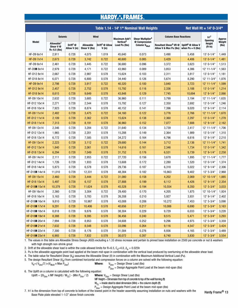
Table 1.14 - 14' 1" Nominal Wall Heights
Model
Seismic WindMaximum Add’l
Vertical3 Load Pu (lbs)
Shear Multiplier4 @ Compression
Column VMult
Column Base Reactions h17 Opening Height (ft-in)
Approx Weight
(lbs)Allowable1 Shear V @
R= 6.5 (lbs)
Drift2 @ Allow V (in)
Allowable Shear V (lbs)
Drift2 @ Allow V (in)
Resultant Shear5 VR @ Allow V & Max Pu (lbs)
Uplift6 @ Allow V when Pu = 0 (lbs)
HF-D9 6x14 2,911 0.728 4,075 1.019 45,640 0.073 3,490 5,458 13' 0-1/4" 1,449
HF-D9 7x14 2,673 0.728 3,742 0.722 40,600 0.085 3,429 4,406 13' 0-1/4" 1,481
HF-D9 8x14 2,461 0.728 3,445 0.722 36,680 0.096 3,372 3,623 13' 0-1/4" 1,513
HF-D9H 8x14 2,979 0.728 4,171 0.722 43,960 0.089 3,853 4,386 12' 11-1/4" 1,563
HF-D12 8x14 2,667 0.728 2,987 0.578 15,624 0.103 2,311 3,817 13' 0-1/4" 1,181
HF-D18 8x14 6,071 0.728 6,800 0.578 34,440 0.126 5,674 8,290 12' 11-3/4" 1,876
HF-D9 9x14 2,798 0.728 3,917 0.722 40,320 0.100 3,840 3,723 12' 11-1/4" 1,599
HF-D12 9x14 2,457 0.728 2,752 0.578 15,792 0.116 2,336 3,188 13' 0-1/4" 1,214
HF-D18 9x14 8,615 0.728 9,649 0.578 43,848 0.129 7,745 10,694 12' 9-1/4" 2,066
HF-D9 10x14 2,632 0.728 3,685 0.722 36,960 0.111 3,799 3,194 12' 11-1/4" 1,635
HF-D12 10x14 2,271 0.728 2,544 0.578 15,792 0.127 2,350 2,692 13' 0-1/4" 1,246
HF-D18 10x14 7,923 0.728 8,874 0.578 40,152 0.141 7,396 9,020 12' 9-1/4" 2,114
HF-D9 11x14 2,482 0.728 3,475 0.722 34,160 0.122 3,776 2,766 12' 11-1/4" 1,670
HF-D12 11x14 2,109 0.728 2,362 0.578 15,624 0.138 2,360 2,297 13' 0-1/4" 1,278
HF-D18 11x14 7,313 0.728 8,191 0.578 36,960 0.152 7,077 7,688 12' 9-1/4" 2,162
HF-D9 12x14 2,346 0.728 3,284 0.722 31,640 0.134 3,739 2,417 12' 11-1/4" 1,706
HF-D12 12x14 1,965 0.728 2,201 0.578 15,288 0.149 2,364 1,989 13' 0-1/4" 1,310
HF-D18 12x14 6,772 0.728 7,585 0.578 34,272 0.164 6,796 6,616 12' 9-1/4" 2,210
HF-D9 13x14 2,223 0.728 3,112 0.722 29,680 0.144 3,712 2,136 12' 11-1/4" 1,741
HF-D12 13x14 1,840 0.728 2,061 0.578 14,616 0.161 2,346 1,734 13' 0-1/4" 1,342
HF-D18 13x14 6,294 0.728 7,049 0.578 31,752 0.176 6,531 5,739 12' 9-1/4" 2,258
HF-D9 14x14 2,111 0.728 2,955 0.722 27,720 0.156 3,678 1,895 12' 11-1/4" 1,777
HF-D12 14x14 1,726 0.728 1,933 0.578 13,608 0.172 2,280 1,520 13' 0-1/4" 1,374
HF-D18 14x14 5,873 0.728 6,578 0.578 29,736 0.187 6,318 5,022 12' 9-1/4" 2,306
HF-D18H 14x14 11,010 0.728 12,331 0.578 48,384 0.182 10,863 9,402 12' 5-3/4" 2,968
HF-D9 15x14 2,460 0.728 3,444 0.722 31,080 0.158 4,202 2,069 12' 10-1/4" 1,885
HF-D18 15x14 5,497 0.728 6,157 0.578 27,888 0.199 6,112 4,426 12' 9-1/4" 2,354
HF-D18H 15x14 10,379 0.728 11,624 0.578 45,528 0.194 10,554 8,350 12' 5-3/4" 3,033
HF-D9 16x14 2,360 0.728 3,304 0.722 29,400 0.170 4,205 1,875 12' 10-1/4" 1,924
HF-D18 16x14 5,163 0.728 5,783 0.578 26,208 0.210 5,927 3,931 12' 9-1/4" 2,402
HF-D18H 16x14 9,810 0.728 10,987 0.578 43,008 0.206 10,272 7,453 12' 5-3/4" 3,098
HF-D18H 17x14 9,291 0.728 10,406 0.578 40,656 0.217 10,006 6,690 12' 5-3/4" 3,163
HF-D18H 18x14 8,818 0.728 9,876 0.578 38,304 0.229 9,729 6,033 12' 5-3/4" 3,228
HF-D18H 19x14 8,388 0.728 9,395 0.578 36,456 0.240 9,515 5,471 12' 5-3/4" 3,293
HF-D18H 20x14 7,994 0.728 8,953 0.578 34,608 0.252 9,296 4,975 12' 5-3/4" 3,359
HF-D18H 21x14 7,632 0.728 8,548 0.578 33,096 0.264 9,116 4,547 12' 5-3/4" 3,424
HF-D18H 22x14 7,300 0.728 8,176 0.578 31,584 0.276 8,936 4,165 12' 5-3/4" 3,489
HF-D18H 23x14 6,993 0.728 7,832 0.578 30,072 0.287 8,740 3,830 12' 5-3/4" 3,554
Net Wall Ht = 14' 0-3/4"
1. The values in this table are Allowable Stress Design (ASD) excluding a 1.33 stress increase and pertain to pinned base installation on 2500 psi concrete or nut & washers with high strength non-shrink grout2. Drift at the allowable shear load is within the code allowed limits for R=6.5, Cd=4.0, ∆a = 0.025h3. Pu is the allowable aggregate point load applied at the beam mid-span in combination with the vertical load produced by overturning at the allowable shear load.4. The table value for Resultatnt Shear (VR) assumes the Allowable Shear (V) in combination with the Maximum Additional Vertical Load (Pu). 5. The design Resultant Shear (VR) from combined horizontal and compression forces on a column are solved with the following equation: VR=( VDsn/2 )+(VMult x Max PDsn) Where: VDsn = Design Shear Load (lbs) PDsn = Design Aggregate Point Load at the beam mid-span (lbs)6. The Uplift on a column is calculated with the following equation: Uplift = [(VDsn x MF Height) / WCL] - (Min PDsn / 2) Where: VDsn = Design Shear Load (lbs) MF Height = Dimension from top of concrete to top of the wall framing (ft) WCL = Inside steel to steel dimension (Win) + the column depth (ft) PDsn = Design Aggregate Point Load at the beam mid-span (lbs)7. h1 is the dimension from top of concrete to bottom of the lowest point in the header assembly assuming installation on nuts and washers with the Base Plate plate elevated 1-1/2” above finish concrete
14 Hardy Frame®
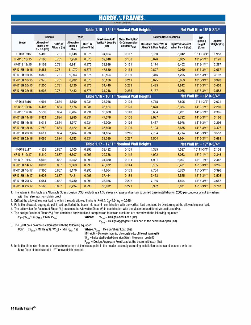
Table 1.15 - 15' 1" Nominal Wall Heights
Model
Seismic WindMaximum Add’l
Vertical3 Load Pu (lbs)
Shear Multiplier4 @ Compression
Column VMult
Column Base Reactions h17 Opening Height (ft-in)
Approx Weight (lbs)Allowable1
Shear V @ R= 6.5 (lbs)
Drift2 @ Allow V (in)
Allowable Shear V
(lbs)
Drift2 @ Allow V (in)
Resultant Shear5 VR @ Allow V & Max Pu (lbs)
Uplift6 @ Allow V when Pu = 0 (lbs)
HF-D18 8x15 5,489 0.781 6,148 0.875 34,104 0.117 5,158 8,042 13' 11-3/4" 1,953
HF-D18 10x15 7,106 0.781 7,959 0.875 39,648 0.130 6,676 8,685 13' 9-1/4" 2,191
HF-D18 12x15 6,108 0.781 6,841 0.875 33,936 0.151 6,174 6,402 13' 9-1/4" 2,287
HF-D18H 14x15 9,884 0.781 11,070 0.875 47,880 0.168 9,827 9,060 13' 5-3/4" 3,067
HF-D18H 16x15 8,842 0.781 9,903 0.875 42,504 0.190 9,316 7,205 13' 5-3/4" 3,197
HF-D18H 18x15 7,975 0.781 8,932 0.875 38,136 0.211 8,875 5,853 13' 5-3/4" 3,328
HF-D18H 20x15 7,250 0.781 8,120 0.875 34,440 0.233 8,495 4,842 13' 5-3/4" 3,458
HF-D18H 22x15 6,636 0.781 7,432 0.875 31,248 0.255 8,157 4,065 13' 5-3/4" 3,588
Table 1.16 - 16' 1" Nominal Wall HeightsHF-D18 8x16 4,991 0.834 5,590 0.934 33,768 0.108 4,718 7,808 14' 11-3/4" 2,031
HF-D18 10x16 6,407 0.834 7,176 0.934 36,624 0.120 5,878 8,364 14' 9-1/4" 2,269
HF-D18 12x16 5,539 0.834 6,204 0.934 33,600 0.140 5,634 6,201 14' 9-1/4" 2,365
HF-D18H 14x16 8,924 0.834 9,995 0.934 47,376 0.156 8,937 8,732 14' 5-3/4" 3,166
HF-D18H 16x16 8,015 0.834 8,977 0.934 42,000 0.176 8,487 6,978 14' 5-3/4" 3,296
HF-D18H 18x16 7,252 0.834 8,122 0.934 37,800 0.196 8,123 5,685 14' 5-3/4" 3,427
HF-D18H 20x16 6,611 0.834 7,404 0.934 34,104 0.216 7,784 4,714 14' 5-3/4" 3,557
HF-D18H 22x16 6,065 0.834 6,793 0.934 31,080 0.237 7,504 3,964 14' 5-3/4" 3,688
Table 1.17 - 17' 1" Nominal Wall HeightsHF-D18 8x17 4,558 0.887 5,105 0.993 33,432 0.101 4,335 7,587 15' 11-3/4" 2,108
HF-D18 10x17 5,810 0.887 6,507 0.993 29,736 0.112 4,922 8,063 15' 9-1/4" 2,346
HF-D18 12x17 5,046 0.887 5,652 0.993 31,080 0.131 4,991 6,007 15' 9-1/4" 2,442
HF-D18H 14x17 8,097 0.887 9,069 0.993 46,872 0.144 8,155 8,431 15' 5-3/4" 3,265
HF-D18H 16x17 7,300 0.887 8,176 0.993 41,664 0.163 7,784 6,763 15' 5-3/4" 3,396
HF-D18H 18x17 6,626 0.887 7,421 0.993 37,464 0.183 7,473 5,525 15' 5-3/4" 3,526
HF-D18H 20x17 6,054 0.887 6,780 0.993 33,936 0.202 7,185 4,594 15' 5-3/4" 3,657
HF-D18H 22x17 5,566 0.887 6,234 0.993 30,912 0.221 6,932 3,871 15' 5-3/4" 3,787
Net Wall Ht = 15' 0-3/4"
Net Wall Ht = 16' 0-3/4"
Net Wall Ht = 17' 0-3/4"
1. The values in this table are Allowable Stress Design (ASD) excluding a 1.33 stress increase and pertain to pinned base installation on 2500 psi concrete or nut & washers with high strength non-shrink grout2. Drift at the allowable shear load is within the code allowed limits for R=6.5, Cd=4.0, ∆a = 0.025h3. Pu is the allowable aggregate point load applied at the beam mid-span in combination with the vertical load produced by overturning at the allowable shear load.4. The table value for Resultatnt Shear (VR) assumes the Allowable Shear (V) in combination with the Maximum Additional Vertical Load (Pu). 5. The design Resultant Shear (VR) from combined horizontal and compression forces on a column are solved with the following equation: VR=( VDsn/2 )+(VMult x Max PDsn) Where: VDsn = Design Shear Load (lbs) PDsn = Design Aggregate Point Load at the beam mid-span (lbs)6. The Uplift on a column is calculated with the following equation: Uplift = [(VDsn x MF Height) / WCL] - (Min PDsn / 2) Where: VDsn = Design Shear Load (lbs) MF Height = Dimension from top of concrete to top of the wall framing (ft) WCL = Inside steel to steel dimension (Win) + the column depth (ft) PDsn = Design Aggregate Point Load at the beam mid-span (lbs)7. h1 is the dimension from top of concrete to bottom of the lowest point in the header assembly assuming installation on nuts and washers with the Base Plate plate elevated 1-1/2” above finish concrete
Hardy Frame® 15
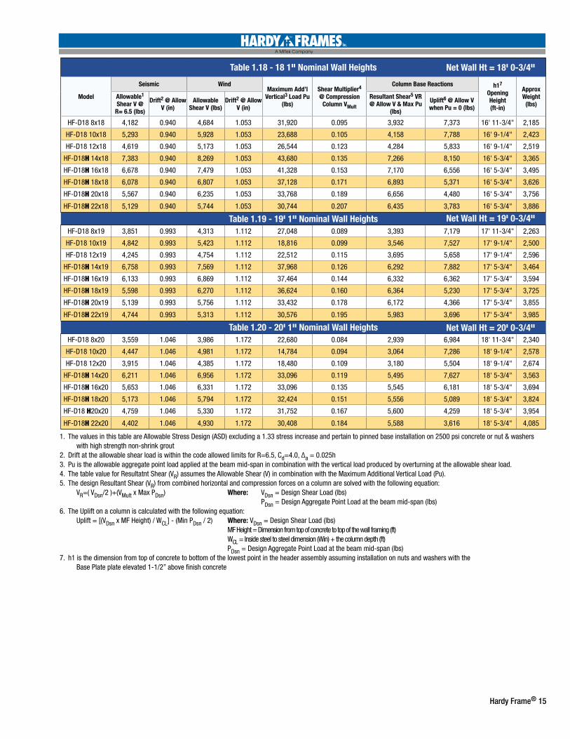
Table 1.18 - 18 1" Nominal Wall Heights
Model
Seismic WindMaximum Add’l
Vertical3 Load Pu (lbs)
Shear Multiplier4 @ Compression
Column VMult
Column Base Reactions h17 Opening Height (ft-in)
Approx Weight
(lbs)Allowable1 Shear V @
R= 6.5 (lbs)
Drift2 @ Allow V (in)
Allowable Shear V (lbs)
Drift2 @ Allow V (in)
Resultant Shear5 VR @ Allow V & Max Pu
(lbs)
Uplift6 @ Allow V when Pu = 0 (lbs)
HF-D18 8x18 4,182 0.940 4,684 1.053 31,920 0.095 3,932 7,373 16' 11-3/4" 2,185
HF-D18 10x18 5,293 0.940 5,928 1.053 23,688 0.105 4,158 7,788 16' 9-1/4" 2,423
HF-D18 12x18 4,619 0.940 5,173 1.053 26,544 0.123 4,284 5,833 16' 9-1/4" 2,519
HF-D18H 14x18 7,383 0.940 8,269 1.053 43,680 0.135 7,266 8,150 16' 5-3/4" 3,365
HF-D18H 16x18 6,678 0.940 7,479 1.053 41,328 0.153 7,170 6,556 16' 5-3/4" 3,495
HF-D18H 18x18 6,078 0.940 6,807 1.053 37,128 0.171 6,893 5,371 16' 5-3/4" 3,626
HF-D18H 20x18 5,567 0.940 6,235 1.053 33,768 0.189 6,656 4,480 16' 5-3/4" 3,756
HF-D18H 22x18 5,129 0.940 5,744 1.053 30,744 0.207 6,435 3,783 16' 5-3/4" 3,886
Table 1.19 - 19' 1" Nominal Wall HeightsHF-D18 8x19 3,851 0.993 4,313 1.112 27,048 0.089 3,393 7,179 17' 11-3/4" 2,263
HF-D18 10x19 4,842 0.993 5,423 1.112 18,816 0.099 3,546 7,527 17' 9-1/4" 2,500
HF-D18 12x19 4,245 0.993 4,754 1.112 22,512 0.115 3,695 5,658 17' 9-1/4" 2,596
HF-D18H 14x19 6,758 0.993 7,569 1.112 37,968 0.126 6,292 7,882 17' 5-3/4" 3,464
HF-D18H 16x19 6,133 0.993 6,869 1.112 37,464 0.144 6,332 6,362 17' 5-3/4" 3,594
HF-D18H 18x19 5,598 0.993 6,270 1.112 36,624 0.160 6,364 5,230 17' 5-3/4" 3,725
HF-D18H 20x19 5,139 0.993 5,756 1.112 33,432 0.178 6,172 4,366 17' 5-3/4" 3,855
HF-D18H 22x19 4,744 0.993 5,313 1.112 30,576 0.195 5,983 3,696 17' 5-3/4" 3,985
Table 1.20 - 20' 1" Nominal Wall HeightsHF-D18 8x20 3,559 1.046 3,986 1.172 22,680 0.084 2,939 6,984 18' 11-3/4" 2,340
HF-D18 10x20 4,447 1.046 4,981 1.172 14,784 0.094 3,064 7,286 18' 9-1/4" 2,578
HF-D18 12x20 3,915 1.046 4,385 1.172 18,480 0.109 3,180 5,504 18' 9-1/4" 2,674
HF-D18H 14x20 6,211 1.046 6,956 1.172 33,096 0.119 5,495 7,627 18' 5-3/4" 3,563
HF-D18H 16x20 5,653 1.046 6,331 1.172 33,096 0.135 5,545 6,181 18' 5-3/4" 3,694
HF-D18H 18x20 5,173 1.046 5,794 1.172 32,424 0.151 5,556 5,089 18' 5-3/4" 3,824
HF-D18 H20x20 4,759 1.046 5,330 1.172 31,752 0.167 5,600 4,259 18' 5-3/4" 3,954
HF-D18H 22x20 4,402 1.046 4,930 1.172 30,408 0.184 5,588 3,616 18' 5-3/4" 4,085
Net Wall Ht = 18' 0-3/4"
Net Wall Ht = 19' 0-3/4"
Net Wall Ht = 20' 0-3/4"
1. The values in this table are Allowable Stress Design (ASD) excluding a 1.33 stress increase and pertain to pinned base installation on 2500 psi concrete or nut & washers with high strength non-shrink grout2. Drift at the allowable shear load is within the code allowed limits for R=6.5, Cd=4.0, ∆a = 0.025h3. Pu is the allowable aggregate point load applied at the beam mid-span in combination with the vertical load produced by overturning at the allowable shear load.4. The table value for Resultatnt Shear (VR) assumes the Allowable Shear (V) in combination with the Maximum Additional Vertical Load (Pu). 5. The design Resultant Shear (VR) from combined horizontal and compression forces on a column are solved with the following equation: VR=( VDsn/2 )+(VMult x Max PDsn) Where: VDsn = Design Shear Load (lbs) PDsn = Design Aggregate Point Load at the beam mid-span (lbs)6. The Uplift on a column is calculated with the following equation: Uplift = [(VDsn x MF Height) / WCL] - (Min PDsn / 2) Where: VDsn = Design Shear Load (lbs) MF Height = Dimension from top of concrete to top of the wall framing (ft) WCL = Inside steel to steel dimension (Win) + the column depth (ft) PDsn = Design Aggregate Point Load at the beam mid-span (lbs)7. h1 is the dimension from top of concrete to bottom of the lowest point in the header assembly assuming installation on nuts and washers with the Base Plate plate elevated 1-1/2” above finish concrete
16 Hardy Frame®
Installer
How to Quote a Hardy Frame® Moment Frame:• Locate the model number call-out on Foundation and Framing plans.
Note: One Moment Frame consists of two columns and a header. Be careful not to double the count by confusing Moment Frame columns with individual Hardy Frame® Panels.
• Call your material supplier or Hardy Frames with the following information for a job quote: • Job name and location • Quantity and model number • Project accessibility for trucks to deliver •Jobsite access for installing the Frame
• Check anchorage edge dimensions to determine wood framing requirements• Check job conditions for accessibility and placement of pre-assembled Frames with a forklift or crane.
Ordering a Hardy Frame® Moment Frame:• Prior to fabrication a Moment Frame “Dimension Sheet” will be provided indicating standard inside and outside widths and heights. This is a
working document that allows the contractor to adjust dimensions, request changes to wood nailer sizes or customize nailer applications.• Template Kits are provided when purchasing Moment Frames. They are in stock and can ship within one to two business days to expedite
pouring concrete.• Allow 15 to 20 working days for delivery of Moment Frame
Installing Template Kits and Hold Down Anchors:• Assemble the Kit as shown in Hardy Frame Typical Installation Details and the illustrations provided on the Template and Template Kit box labels• Locate one Template Kit assembly at each of the column locations• Be sure to place the Templates so that the edges with the slotted holes are oriented in the same direction as the Moment Frame wall line• Measure the interior slot to slot distance to be the same as the “Win” (inside steel to steel) dimension for the Frame being ordered. • Set the top of all hold down bolts at 4-1/4 inches (minimum) to 6 inches (maximum) above top of concrete. Be sure that the embed end is
extending the required distance into the footing below. • Pour concrete and check that the assembly did not move out of alignment prior to the concrete hardening.
Installing the Hardy Frame® Moment Frame:• Install one nut with one washer above on all hold down anchors. Set the top of washer at approximately 1-1/2 inches above top of concrete.• Unload the Moment Frame by lifting with forks or a crane at the header.• Install the Moment Frame on the hold downs so that the base plates seat firmly on the washers and nuts below.• Install one washer in contact with the base plate and one nut above it on all hold down bolts.• Level the Frame and make minor height adjustments by raising or lowering the double nut connection at the base plates, then secure the
connection until all nuts are “snug-tight”. For installations on nuts and washers with high strength non-shrink grout, third party inspection may be required.
• Install wood framing above per the specified installation details and make connections to transfer shear loads. If the specified connection will be concealed when framing is installed above, be sure to get inspections while still visible.
Hardy Frame® 17
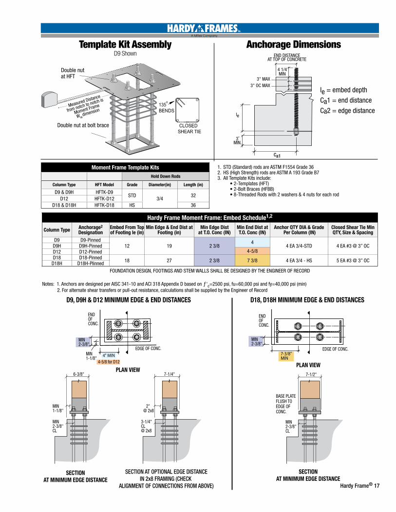
Template Kit Assembly D9 Shown
3˝MIN.
le
ANCHORAGE DIMENSIONS
END DISTANCEAT TOP OF CONCRETE
4 1/4MIN
3" MAX 3" OC MAX
CURB ELEVATION
EXTERIOR SLAB ELEVATION
Ca1 Ca1
3˝MIN.
Ie
STEM WALL SECTION
CURB SECTION
CURB SECTIONOTHER SECTION VIEWS SIMILAR
3"MIN
P0P-OUTPER PLAN
Ie
C a2 C a2
Ca1
3˝MIN.
Ie
le = embed depth Ca1 = end distance Ca2 = edge distance
Ca1
Ca1 Ca1 Ca2 Ca2CURB SECTION
Ca2 Ca2
Ca2 Ca2Ca1 Ca1INTERIOR SLAB ELEVATION
Ca1Ca1
Moment Frame Template KitsHold Down Rods
Column Type HFT Model Grade Diameter(in) Length (in)
D9 & D9H HFTK-D9STD
3/432
D12 HFTK-D12D18 & D18H HFTK-D18 HS 36
Measured Distance
from notch to notch is
Moment Frame
W IN dimension
Double nutat HFT
Double nut at bolt brace
Hardy Frame Moment Frame: Embed Schedule1,2
Column Type Anchorage2 Designation
Embed From Top of Footing le (in)
Min Edge & End Dist at Footing (in)
Min Edge Distat T.O. Conc (IN)
Min End Dist at T.O. Conc (IN)
Anchor QTY DIA & Grade Per Column (IN)
Closed Shear Tie Min QTY, Size & Spacing
D9 D9-Pinned12 19 2 3/8
44 EA 3/4-STD 4 EA #3 @ 3” OCD9H D9H-Pinned
4-5/8D12 D12-PinnedD18 D18-Pinned 18 27 2 3/8 7 3/8 4 EA 3/4 - HS 5 EA #3 @ 3” OCD18H D18H-PIinned
FOUNDATION DESIGN, FOOTINGS AND STEM WALLS SHALL BE DESIGNED BY THE ENGINEER OF RECORD
Notes: 1. Anchors are designed per AISC 341-10 and ACI 318 Appendix D based on ƒ'c=2500 psi, fu=60,000 psi and fy=40,000 psi (min) 2. For alternate shear transfers or pull-out resistance, calculations shall be supplied by the Engineer of Record
Anchorage Dimensions
1. STD (Standard) rods are ASTM F1554 Grade 362. HS (High Strength) rods are ASTM A 193 Grade B73. All Template Kits include: • 2-Templates (HFT) • 2-Bolt Braces (HFBB) • 8-Threaded Rods with 2 washers & 4 nuts for each rod
le = embed depth
Ca1 = end distance
Ca2 = edge distance
6-3/8"
MIN1-1/8"
MIN1-1/8"
MIN2-3/8"CL
MIN2-3/8"
MIN2-3/8"
ENDOF CONC.
ENDOF CONC.
EDGE OF CONC. EDGE OF CONC.
D18, D18H MINIMUM EDGE & END DISTANCESD9, D9H & D12 MINIMUM EDGE & END DISTANCES
MIN2-3/8"CL
7-1/4"
SECTION AT OPTIONAL EDGE DISTANCEIN 2x8 FRAMING (CHECK
ALIGNMENT OF CONNECTIONS FROM ABOVE)
SECTIONAT MINIMUM EDGE DISTANCE
4-5/8 for D12
SECTIONAT MINIMUM EDGE DISTANCE
2" @ 2x8
3-1/4"CL@ 2x8
7-1/2"
BASE PLATEFLUSH TOEDGE OFCONC.
4" MIN 7-3/8"MIN
PLAN VIEWPLAN VIEW
18 Hardy Frame®
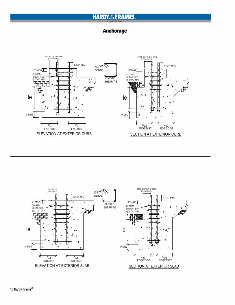
Anchorage
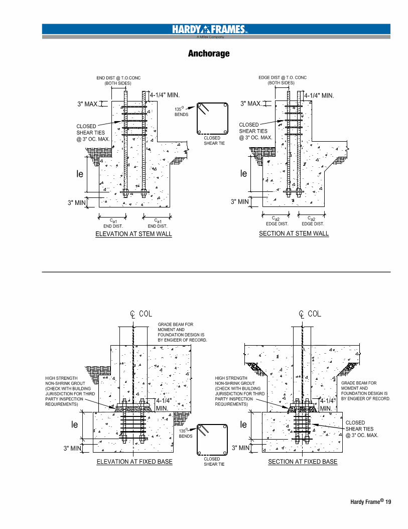
Hardy Frame® 19
Anchorage
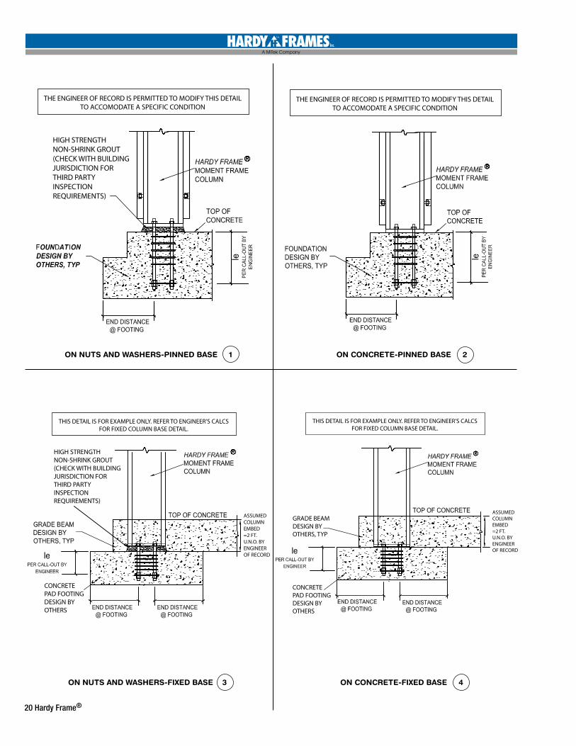
20 Hardy Frame®
THE ENGINEER OF RECORD IS PERMITTED TO MODIFY THIS DETAILTO ACCOMODATE A SPECIFIC CONDITION
HIGH STRENGTHNON-SHRINK GROUT(CHECK WITH BUILDINGJURISDICTION FOR THIRD PARTYINSPECTION REQUIREMENTS)
THE ENGINEER OF RECORD IS PERMITTED TO MODIFY THIS DETAILTO ACCOMODATE A SPECIFIC CONDITION
THIS DETAIL IS FOR EXAMPLE ONLY. REFER TO ENGINEER’S CALCSFOR FIXED COLUMN BASE DETAIL.
HIGH STRENGTHNON-SHRINK GROUT(CHECK WITH BUILDINGJURISDICTION FOR THIRD PARTYINSPECTION REQUIREMENTS)
CONCRETEPAD FOOTINGDESIGN BYOTHERS
ASSUMEDCOLUMNEMBED=2 FT. U.N.O. BY ENGINEEROF RECORD
THIS DETAIL IS FOR EXAMPLE ONLY. REFER TO ENGINEER’S CALCSFOR FIXED COLUMN BASE DETAIL.
CONCRETEPAD FOOTINGDESIGN BYOTHERS
ASSUMEDCOLUMNEMBED=2 FT. U.N.O. BY ENGINEEROF RECORD
GRADE BEAMDESIGN BYOTHERS, TYP
ON NUTS AND WASHERS-PINNED BASE 1
ON NUTS AND WASHERS-FIXED BASE 3
ON CONCRETE-PINNED BASE 2
ON CONCRETE-FIXED BASE 4
Hardy Frame® 21
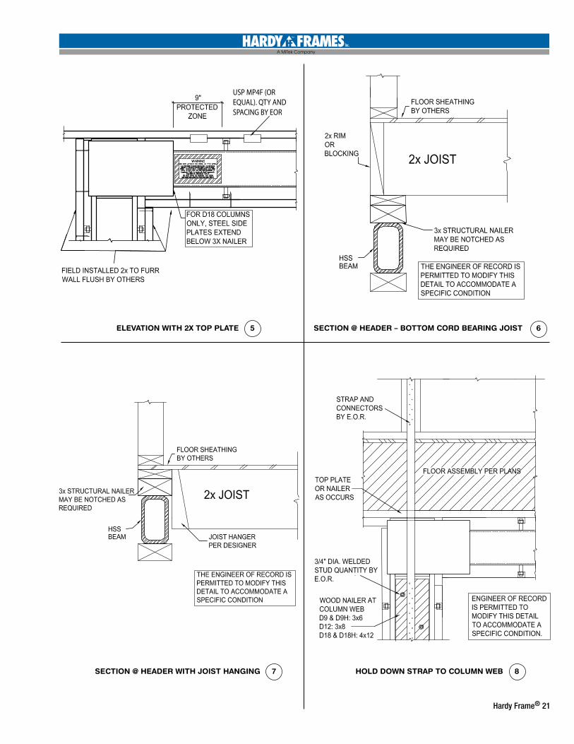
USP MP4F (OREQUAL). QTY ANDSPACING BY EOR
ELEVATION WITH 2X TOP PLATE 5
SECTION @ HEADER WITH JOIST HANGING 7 HOLD DOWN STRAP TO COLUMN WEB 8
SECTION @ HEADER – BOTTOM CORD BEARING JOIST 6
22 Hardy Frame®
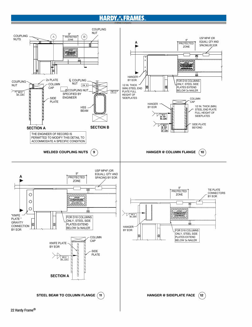
WELDED COUPLING NUTS 9
STEEL BEAM TO COLUMN FLANGE 11
HANGER @ COLUMN FLANGE 10
HANGER @ SIDEPLATE FACE 12
USP MP4F (OREQUAL). QTY ANDSPACING BY EOR
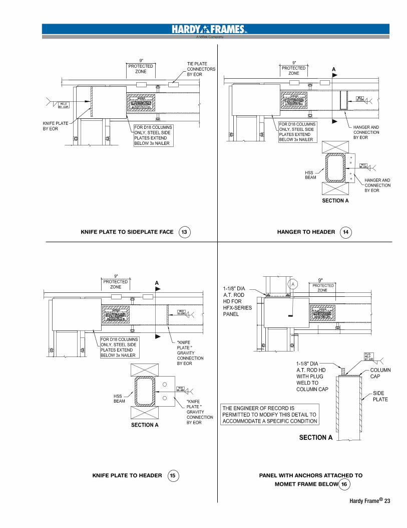
Hardy Frame® 23
KNIFE PLATE TO SIDEPLATE FACE 13
KNIFE PLATE TO HEADER 15 PANEL WITH ANCHORS ATTACHED TO
MOMET FRAME BELOW 16
HANGER TO HEADER 14
24 Hardy Frame®
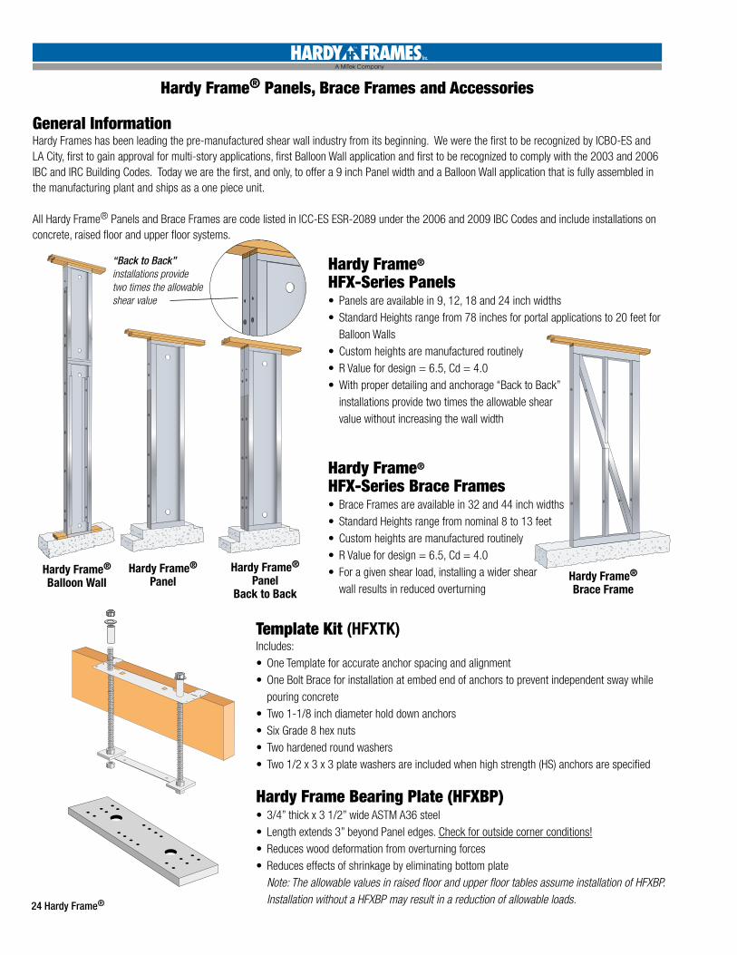
Hardy Frame® Panels, Brace Frames and Accessories
General InformationHardy Frames has been leading the pre-manufactured shear wall industry from its beginning. We were the first to be recognized by ICBO-ES and LA City, first to gain approval for multi-story applications, first Balloon Wall application and first to be recognized to comply with the 2003 and 2006 IBC and IRC Building Codes. Today we are the first, and only, to offer a 9 inch Panel width and a Balloon Wall application that is fully assembled in the manufacturing plant and ships as a one piece unit.
All Hardy Frame® Panels and Brace Frames are code listed in ICC-ES ESR-2089 under the 2006 and 2009 IBC Codes and include installations on concrete, raised floor and upper floor systems.
Template Kit (HFXTK)Includes:• One Template for accurate anchor spacing and alignment• One Bolt Brace for installation at embed end of anchors to prevent independent sway while
pouring concrete• Two 1-1/8 inch diameter hold down anchors • Six Grade 8 hex nuts• Two hardened round washers• Two 1/2 x 3 x 3 plate washers are included when high strength (HS) anchors are specified
Hardy Frame Bearing Plate (HFXBP) • 3/4” thick x 3 1/2” wide ASTM A36 steel• Length extends 3” beyond Panel edges. Check for outside corner conditions!• Reduces wood deformation from overturning forces• Reduces effects of shrinkage by eliminating bottom plate
Note: The allowable values in raised floor and upper floor tables assume installation of HFXBP. Installation without a HFXBP may result in a reduction of allowable loads.
Hardy Frame® HFX-Series Panels• Panels are available in 9, 12, 18 and 24 inch widths• Standard Heights range from 78 inches for portal applications to 20 feet for
Balloon Walls• Custom heights are manufactured routinely• R Value for design = 6.5, Cd = 4.0• With proper detailing and anchorage “Back to Back”
installations provide two times the allowable shear value without increasing the wall width
Hardy Frame® HFX-Series Brace Frames• Brace Frames are available in 32 and 44 inch widths• Standard Heights range from nominal 8 to 13 feet• Custom heights are manufactured routinely• R Value for design = 6.5, Cd = 4.0• For a given shear load, installing a wider shear
wall results in reduced overturning
Hardy Frame® Panel Hardy Frame®
Brace Frame
Hardy Frame®
Balloon WallHardy Frame®
PanelBack to Back
“Back to Back” installations provide two times the allowable shear value
Date:_________________________
Contact Name:________________________________________
Company:____________________________________________ Phone:______________________________________________ Fax:________________________________________________
Email:_______________________________________________
Address:_____________________________________________
Project:______________________________________________ City:___________________________________________
WIN, MIN
h1,
MIN
h1,
MIN
h2,
MIN
WOUT, MAX
V 1
Plat
e H
eig
ht
1st St
ory
Pla
te H
eig
ht
2n
d St
ory
Pla
te H
eig
ht
WIN, MIN
WIN, MIN
WOUT, MAX
V 1
V 2
TOP OF FLOOR SHEATHING
P1
P2
F2P
1
WIN, MIN
h1,
MIN
h1,
MIN
h2,
MIN
WOUT, MAX
V 1
Plat
e H
eig
ht
1st St
ory
Pla
te H
eig
ht
2n
d St
ory
Pla
te H
eig
ht
WIN, MIN
WIN, MIN
WOUT, MAX
V 1
V 2
TOP OF FLOOR SHEATHING
P1
P2
F2P
1
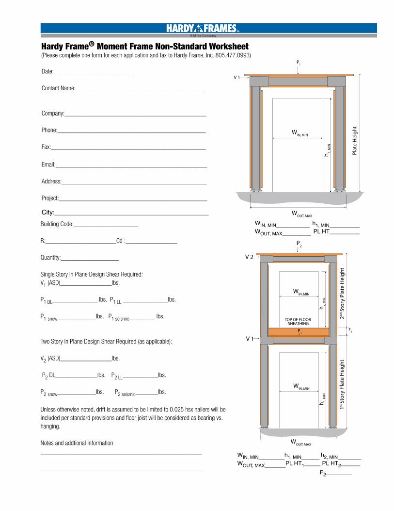
WIN, MIN_____________ h1, MIN____________WOUT, MAX___________ PL HT__________
WIN, MIN__________h1, MIN_______ h2, MIN_________WOUT, MAX________PL HT1_____ PL HT2______ F2________
Building Code:____________________ R:______________________Cd :________________
Quantity:__________________
Single Story In Plane Design Shear Required: V1 (ASD)________________lbs.
P1 DL______________ lbs. P1 LL ______________lbs. P1 snow____________lbs. P1 seismic________ lbs.
Two Story In Plane Design Shear Required (as applicable):
V2 (ASD)________________lbs.
P2 DL_____________lbs. P2 LL___________lbs. P2 snow____________lbs. P2 seismic_______lbs.
Hardy Frame® Moment Frame Non-Standard Worksheet
Unless otherwise noted, drift is assumed to be limited to 0.025 hsx nailers will be included per standard provisions and floor joist will be considered as bearing vs. hanging.
Notes and addtional information__________________________________________________
__________________________________________________
(Please complete one form for each application and fax to Hardy Frame, Inc. 805.477.0993)
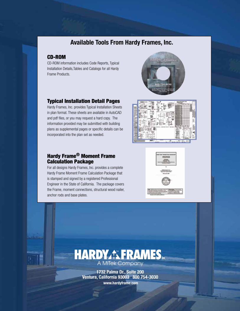
1732 Palma Dr., Suite 200 Ventura, California 93003 800 754-3030
www.hardyframe.com
CD-ROMCD-ROM information includes Code Reports, Typical Installation Details,Tables and Catalogs for all Hardy Frame Products.
Typical Installation Detail PagesHardy Frames, Inc. provides Typical Installation Sheets in plan format. These sheets are available in AutoCAD and pdf files, or you may request a hard copy. The information provided may be submitted with building plans as supplemental pages or specific details can be incorporated into the plan set as needed.
Hardy Frame® Moment Frame Calculation PackageFor all designs Hardy Frames, Inc. provides a complete Hardy Frame Moment Frame Calculation Package that is stamped and signed by a registered Professional Engineer in the State of California. The package covers the Frame, moment connections, structural wood nailer, anchor rods and base plates.
Available Tools From Hardy Frames, Inc.


![Identifi steel concrete moment-resisting frame structure subject … · steel–concrete moment-resisting frame structure subject to pseudodynamic tests ... et al. [8] analysed a](https://img.pdfslide.us/doc/110x75/5e51c5a0ede02257ee0a1f1f/identii-steel-concrete-moment-resisting-frame-structure-subject-steelaconcrete.jpg)