Embed Size (px)
Citation preview
SPECIAL MACHINES FOR FLASH WELDING OF STRIP
B. A. Ryss, S. G. Molchadskii, N. S. Kabanov, Yu. M. Nedodaev, N. N. Meshcheryakov, P. S. Karzov, and L. N. Lokhovinin
UDC 621.774:621.771.63:621.791.03
For butt welding of l-6-mm-thick and 300-, 400-, and 500-mm-wide strips in continuously operating tube and shape bending mills the All-Union Scientific-Research, Planning, and De- sign Institute of Metallurgical Machinery has developed the L-300, L-400, and L-500 special- ized butt welding machines with automatic placement of the strip, automatic welding, and mechanical cleaning of the joints.
The machines are equippedwith built-in shears with centerers, transfer tables, built-in flash removing tools, and other equipment making it possible to increase operating reliabil- ity, to stabilize joint quality, to ease the labor of the welders, to decrease scrap for sub- standard as a result of the use of metal with joints in the finished parts, to reduce weld cycles, and thereby to increase equipment productivity.
In the machines of the All-Union Scientific-Research, Planning, and Design Institute of Metallurgical Machinery the trailing end of the strip is centered (Fig. la) by the centere= I, clamped to the table 2, and cut by the shear 3 (Fig. Ib), and then moved to the jaws 4 of the welding machine and clamped in them (Fig. ic). The same operations are done on the lead- ing end of the following strip, which is centered by the centerer 1 (Fig. ic), clamped to the table 5, cut by the shears 3 (Fig. Id), moved to the jaws 6, and clamped (Fig. ie). Then
a r_...___~___~/ . - - - - - , / ~
b , __., ~ ~ , I ~ .
7 ( ~ f f 7 i
F i g . 1. P l a n o f o p e r a t i o n o f t h e s p e c i a l b u t t w e l d i n g m a c h i n e .
All-Union Scientific-Research, Planning, and Design Institute of Metallurgical Machinery. Leningrad Tube Steel Plant. Translated from Metallurg, No. 12, pp. 28-30, December, 1975.
l �9 1976 Plenum Publishing Corporation, 227 West 17th Street, New York, N.Y. 10011. No part o f this publication may be reproduced, I 1
stored in a retrieval system, or transmitted, in any form or by any means, electronic, mechanical, photocopying, microfilming, recording
J or otherwise, without written permission o f the publisher. A copy o f this article i, available from the publisher for $15.00.
894
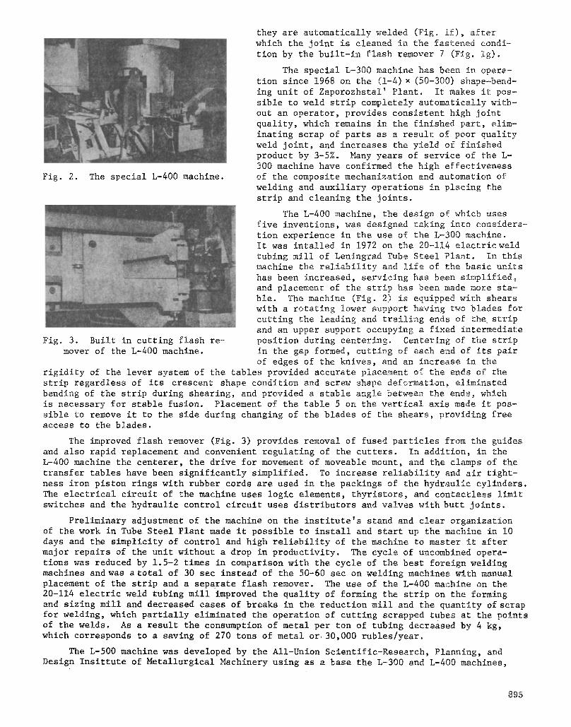
Fig. 2. The special L-400 machine.
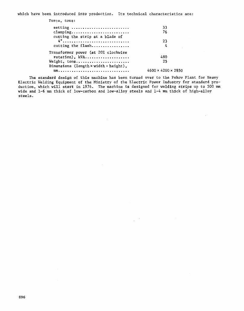
Fig~ 3. Built in cutting flash re- mover of the L-400 machine.
they are automatically welded (Fig~ if)~ after which the joint is cleaned in the fastened condi- tion by the built-in flash remover 7 (Fig. ig)~
The special L-300 machine has been in opera- tion since 1968 on the (1-4) • (50-300) shape-bend- ing unit of Zaporozhstal' Plant. It makes it pos- sible to weld strip completely automatically with- out an operator, provides consistent high joint quality, which remains in the finished part, elim- inating scrap of parts as a result of poor quality weld joint, and increases the yield of finished product by 3-5%. Many years of service of the L- 300 machine have confirmed the high effectiveness of the composite mechanization and automation of welding and auxiliary operations in placing the strip and cleaning the joints.
The L-400 machine, the design of which uses five inventions, was designed taking into considera- tion experience in the use of the L-300 machine~ It was intalled in 1972 on the 20-114 electric weld tubing mill of Leningrad Tube Steel Plant. In this machine the reliability and life of the basic units has been increased, servicing has been simplified, and placement of the strip has been made more sta- ble. The machine (Fig. 2) is equipped with shears with a rotating lower support having two blades for cutting the leading and trailing ends of the strip and an upper support occupying a fixed intermediate position during centering. Centering of the strip in the gap formed, cutting of each end of its pair of edges of the knives, and an increase in the
rigidity of the lever system of the tables provided accurate placement of the ends of the strip regardless of its crescent shape condition and screw shape deformation~ eliminated bending of the strip during shearing, and provided a stable angle between the ends, which is necessary for stable fusion. Placement of the table 5 on the vertical axis made it pos- sible to remove it to the side during changing of the blades of the shears, providing free access to the blades.
The improved flash remover (Fig. 3) provides removal of fused particles from the guides and also rapid replacement and convenient regulating of the cutters. In addition, in the L-400 machine the centerer, the drive for movement of moveable mount, and the clamps of the transfer tables have been significantly simplified. To increase reliability and air tight- ness iron piston rings with rubber cords are used in the packings of the hydraulic cylinders. The electrical circuit of the machine uses logic elements, thyristors, and contactless limit switches and the hydraulic control circuit uses distributors and valves with butt joints.
Preliminary adjustment of the machine on the institute's stand and clear organization of the work in Tube Steel Plant made it possible to install and start up the machine in I0 days and the simplicity of control and high reliability of the machine to master it after major repairs of the unit without a drop in productivity. The cycle of uncombined opera- tions was reduced by 1.5-2 times in comparison with the cycle of the best foreign welding machines and was a total of 30 sec instead of the 50-60 sec on welding machines with manual placement of the strip and a separate flash remover. The use of the L-400 machine on the 20-114 electric weld tubing mill improved the quality of forming the strip on the forming and sizing mill and decreased cases of breaks in the reduction mill and the quantity of scrap for welding, which partially eliminated the operation of cutting scrapped tubes at the points of the welds. As a result the consumption of metal per ton of tubing decreased by 4 kg, which corresponds to a saving of 270 tons of metal or 30,000 rubles/year.
The L-500 machine was developed by the All-Union Scientific-Research, Planning, and Design Insittute of Metallurgical Machinery using as a base the L-300 and L-400 machines,
895
which have been introduced into production.
Force, tons:
setting .......................... clamping .......................... cutting the strip at a blade of
0.el,oeo.oo.,oeloo,,oo..o,.oI.. cutting the flash .................
Transformer power (at 20% clockwise rotation), kVA ....................
Weight, tons ........................ Dimensions (length • width x height),
Its technical characteristics are:
33 76
23 4
480 25
mm ................................ 4600 x 4200 x 2850
The standard design of this machine has been turned over to the Pskov Plant for Heavy Electric Welding Equipment of the Ministry of the Electric Power Industry for standard pro- duction, which will start in 1976. The machine is designed for welding strips up to 500 mm wide and 1-6 mm thick of low-carbon and low-alloy steels and 1-4 mm thick of high-alloy steels.
896