Embed Size (px)
Citation preview

Special Laboratory Test for Landslides Modelling - The
Case of Stože and Lokavec Landslides
STANISLAV LENART, KARMEN FIFER BIZJAK
Slovenian National Building and Civil Engineering Institute (ZAG)
Dimičeva 12, SI-1000, Ljubljana
SLOVENIA
[email protected] http://www.zag.si
Key-Words: - landslides, debris flow, shear-box, residual shear strength, water content, rate of displacement
1 Introduction Landslides threaten approximately one-third of
Slovenian territory. The two severe landslides that
occurred in November 2000 attracted the attention
of the entire country, and also opened up some new
technical questions. Sudden movement of soils and
rocks under the influence of gravity seems to be
mostly induced by rainfall or some other cause of
ground water level change. Both landslides that are
described in the paper occurred in seismically very
active areas. There were no signs of an earthquake
when landslides triggered, but several small ground
movements, which took place before the landslides
occurred, could be the cause of cracks appear at the
base of the landslide. Combined with intensive
rainfall, these cracks could have satisfied the
condition for ground saturation.
The landslide material, especially in the case of
the Stože landslide, consisted of fines and also
gravel whose grain sizes make it impossible to test
in a simple shear cell. Special laboratory equipment,
a large-scale shear box, was therefore constructed to
test the landslide material. A new testing method is
presented. The results indicate the influence of water
content and the rate of displacement on the residual
shear strength of material.
Fig. 1: The village Log pod Mangartom was
destroyed by a landslide
2 The Stože landslide
2.1 History of the landslide Continuous rainy weather affected the western part
of Slovenia in autumn 2000. On November 15th,
2000, a mass of moranic material and slope gravel
began to move near the Mangartski potok gorge.
The area is known as Stože (1340 – 1580 m a.s.l.)
and is situated beneath Mount Mangart in the
western part of Slovenia. The mass damaged the
Mangart local road (Bovec-Predel) and moved down
to the Predelica ravine. It dammed up there the
Abstract: - Two severe landslides occurred in November 2000 in Slovenia. They attracted the attention of the
entire country and also opened up some new technical questions. Both landslides were initiated by a period of
heavy rainfall. The Stože landslide occurred between 15 and 17 November, 2000 close to Mt Mangart in the
Julian Alps of western Slovenia. It destroyed about 25 ha of forest as well as a considerable section of the road
leading over the Predel Pass. The landslide turned into a debris flow, and reached the village of Log pod
Mangartom more than 4 km downstream, where it took seven lives. Approximately 1 million m3 of material
was displaced. The Lokavec landslide occurred between 18 and 19 November, 2000, near Ajdovščina. Its area
was estimated to have been 20 ha, mostly forest and meadows. The sliding masses were composed of clayey
scree and weathered flysch cover. There was only sliding, and the danger of a debris flow. The landslide has
not reached the village downstream yet, but threatens it. The paper describes both landslides and their
particularities. Special laboratory equipment, a large-scale shearbox, has been constructed to test the landslide
material. An original testing method is presented.
WATER AND GEOSCIENCE
ISSN: 1790-5095 138 ISBN: 978-960-474-160-1

stream known as Mangartski potok at an altitude of
1250 m. The accumulated mass was about 10 m
high, and was deposited over a length of 1450 m of
the Mangartski potok stream.
As a consequence of the extreme rainfall a
second - major slide occurred on the slopes of
Mount Mangart in the early morning of November
17th, 2000. The mass reached the water collected
behind the first landslide and saturated itself there.
In a few hours it was transformed into a debris
flow - a mixture of water and soil. The flow moved
along the bed of the Predelica and reached the
village of Log pod Mangartom (Fig. 1). The velocity
of the flow was estimated to be 8 to 15 m/s [1].
An expert group was established to monitor the
slide, study the reasons for its occurrence and
propose solutions for its stabilization. Special
attention was paid to a range of possible causes of
the slide, including the earthquakes and rainfall in
the period before the landslide occurrence.
2.2 Some facts about the landslide
- The area of the second failure, the actual debris
flow, was estimated to cover about 25 hectares
of forest.
- Its width was about 300 m, and it was 1.5 km
long and up to 50 m thick.
- Approximately 1,500,000 m3 of material was
moved.
- The ground level during the landslide was
lowered by up to 40 m in some places, and has
been risen up to 20 m in others.
- Two bridges, and several residential and
industrial buildings, were destroyed.
- Seven people died.
- About 3,000,000 m3 of unstable material
remained in the landslide area, representing a
potential danger of landslide reoccurrence.
2.3 Geology Geological mapping of the landslide site proved the
existence of very good geological reasons for the
triggering of the landslide (Fig. 2). The mountain
ridge west of Mount Mangart is mainly composed of
massive Upper Triassic carbonate, which is partly
interrupted by clastic rocks and some poorly
permeable Carnian Calc stoneware [1]. The base of
the landslide forms a block of poorly permeable
carbonate-clastic strata situated between blocks of
massive and bedded dolomite. Glacial sediments
rich with silt were deposited over stepped bedrock
and dolomite gravel in the Pleistocene.
The event occurred at an altitude of 1525 m, in
glacial sediments - moraine and slope debris, which
covered tectonically highly-fractured dolomite
overlying impermeable layers of marly limestone
[2]. Dolomite is an excellent aquifer, and during
heavy precipitation the water level in the rock rises
substantially, saturating the overlying soils, rich in
clay, with water. The exact water level at the
moment of the beginning of the slide is not known.
An estimate was made using a back analysis.
2.4 Material properties Several laboratory and in situ tests were performed
in order to obtain the material properties [3, 4]. A
preliminary back analysis of the slope failure was
performed, with the aim of confirming the results of
the laboratory and on-site defined soil properties,
see Table 1.
Table 1: The constitutive parameters of the landslide
Stože material __________________________________________________________
Soil layer γ γsat Ε ν c ϕ [kN/m3] [kN/m3] [MPa] [kPa] [°] __________________________________________________________
Moraine1 22 23 50 0.3 20-30 36-38 Gravel2 22 23 100 0.3 5 42 Landslide3 19 20 110 0.3 0.5 33 Bedrock4 25 25 1000 0.3 500 50 __________________________________________________________ 1 silty-clay glacial moraine with limestone gravel 2 dolomite gravel with rock inclusions 3 landslide material with fine grained gravel 4 dolomite bedrock
Fig. 2: The Stože landslide
3 The Lokavec landslide
3.1 History of the landslide The landslide named Slano blato (Salty mud) is
situated beneath Mala Gora (1032 m) in western
Slovenia. Following continuous rainy weather, the
historically recorded landslide Slano blato was
triggered on the night of 18 to 19 November, 2000.
The same landslide was noticed already 200 years
ago, and it was rehabilitated in 1903 by regulation of
the nearby torrents and Grajšek stream.
WATER AND GEOSCIENCE
ISSN: 1790-5095 139 ISBN: 978-960-474-160-1

The landslide occupied ravines of two Grajšek
affluxes at an altitude of 360 to 660 m (Fig. 3). The
mud flow that was created started to move in the
direction of the less than 2 km away settlement
Lokavec near Ajdovščina. The toe of the landslide
moved with a velocity of 50-60 m/day in the first
few months. Due to the low velocity and strong
precipitation, water began to accumulate behind the
main body of the landslide. The sliding masses were
therefore completely saturated, and there was a
serious danger of a debris flow occurrence [5].
Lower precipitation during the winter, 2000,
caused the decrease of sliding velocity and
conditions improved. But the risk of a debris flow
still remains. Constant accumulation of new masses
put the pressure on the barrier in the middle part of
vast landslide. The behaviour of sliding masses
shows a close link-up to the degree of saturation and
any accumulation of water behind the main body of
landslide could threaten the safety of settlement
under the landslide again.
3.2 Some facts about the landslide - The landslide area covers around 20 ha of forest
and grassland
- Its width is about 60 to 200 m, and it is 1.1 km
long
- The ground level has been lowered for 20 to 30
m
- Accumulation of water behind the main body of
landslide threatens the debris flow occurrence
- The landslide has not reached the village
Fig. 3: The Lokavec landslide
3.3 Geology and precipitation characteristics The basis of the slope where the landslide appeared
is flysch rock, covered on the upper brow of the hill
with a stratum of limestone and dolomite [5]. Slope
debris limestone layer downhill is more than 30 m
thick. The crown of the landslide is situated on
marshy land. Due to the water accumulated there
and heavy rainfall, the material saturated. The
increasing of water content caused the decreasing of
the shear strength characteristics of the flysch rock.
Masses composed from clayed scree and weathered
flysch cover started to slide therefore.
3.4 Material properties Results of some laboratory tests are shown in Table
2. Samples of material from the head of the
landslide and the other from the main body of the
landslide were tested [5].
Table 2: Lokavec landslide material characteristics __________________________________________________________
Sample γ γd Ip Ic c ϕ [kN/m3] [kN/m3] [%] [%] [kPa] [°] __________________________________________________________
Head 19.5 15.4 25.1 0.723 14.4 19.9 Main body 18.5 13.8 25.3 0.616 5.1 30.2
4 The large-scale shear cell testing
method
4.1 Reasons for its use The expert group in the case of Stože landslide
assumed [3, 6] that the moraine, silt and clay fines,
with grain sizes smaller than 4 mm, in the sliding
material could lead to the general behaviour of the
landslide. It was necessary to prove that. On the
other side, it was a need to control the effective
shear strength of the material and its dependence
upon the velocity of sliding that was not possible to
ensure with a simple (small) shear box test.
Therefore a large-scale shear box apparatus, has
been constructed to test the landslide material
including grain sizes up to 45 mm. This size shear
box also gives the possibility to measure the pore
water pressure. It incorporates a special hydraulic
loading system, which controls the rate of
displacement.
4.2 Apparatus The large-scale shear box apparatus consists
essentially of components similar to those of the
standard (small) shear box except that they are on a
larger scale. It comprises a drive unit with a loading
piston, shear box assembly and as a difference to the
standard shear box, the pore pressure transducer
WATER AND GEOSCIENCE
ISSN: 1790-5095 140 ISBN: 978-960-474-160-1

facility is included.
A split box with inner dimension 630 mm × 630
mm is used. A lower fixed part of the box is 230 mm
high. It is filled during the test to 140 mm high with
a saturated porous material through which the
draining is enabled. A specimen with a height of 180
to 205 mm is positioned above this layer. The
specimen is impermeable covered at the top to
prevent the draining in the vertical direction and is
supposed to be subjected to shear under a certain
vertical load applied by a hydraulic piston. Two
valves in the bottom part of a shear box are used to
determine whether the drainage, i.e. the change of
water content, is permitted during the test.
The shear load is applied by a hydraulic piston
capacity of 160 kN and capable of applying
displacements amplitude ± 125 mm. Another
hydraulic piston, which can provide up to 200 kN
presents the normal loading system.
The upper and bottom parts of a box are fixed
together in longitudinal direction with special
waterproof elements covered with Teflon on sliding
plate. Sliding plates are waterproofed in transversal
direction by rubber washer combined with
impermeable fat.
Four pore pressure transducers build into the
specimen measure the pore water pressure in the
specimen during the test. Two of them are built
above the surface of sliding and two of them are
built under it.
The friction between both two parts of a box is
measured before the test at different strain rates. The
results of the shear test are corrected by its value.
Fig. 4: Arrangement of a large-scale shear box
apparatus (cross section)
Fig. 5: Arrangement of a large-scale shear box
apparatus (plan view)
Fig. 6: The large-scale shear box apparatus during
the test
4.3 Testing procedure Materials from the Stože and Lokavec landslide sites
were used in the tests. Reconstituted samples were
used, all prepared by means of wet temping with the
objective of achieving the certain moisture and
densities.
Samples were prepared at moisture content: 11-
12% and 15-16% (Stože) and 28, 40 and 50%
(Lokavec). They were subjected to constant normal
stresses 10, 50 and 100 kPa (Stože) and 50, 100 and
150 kPa (Lokavec). Tests were performed at
different strain rates 1, 2, 4, 6 and 8 mm/min,
respectively.
WATER AND GEOSCIENCE
ISSN: 1790-5095 141 ISBN: 978-960-474-160-1
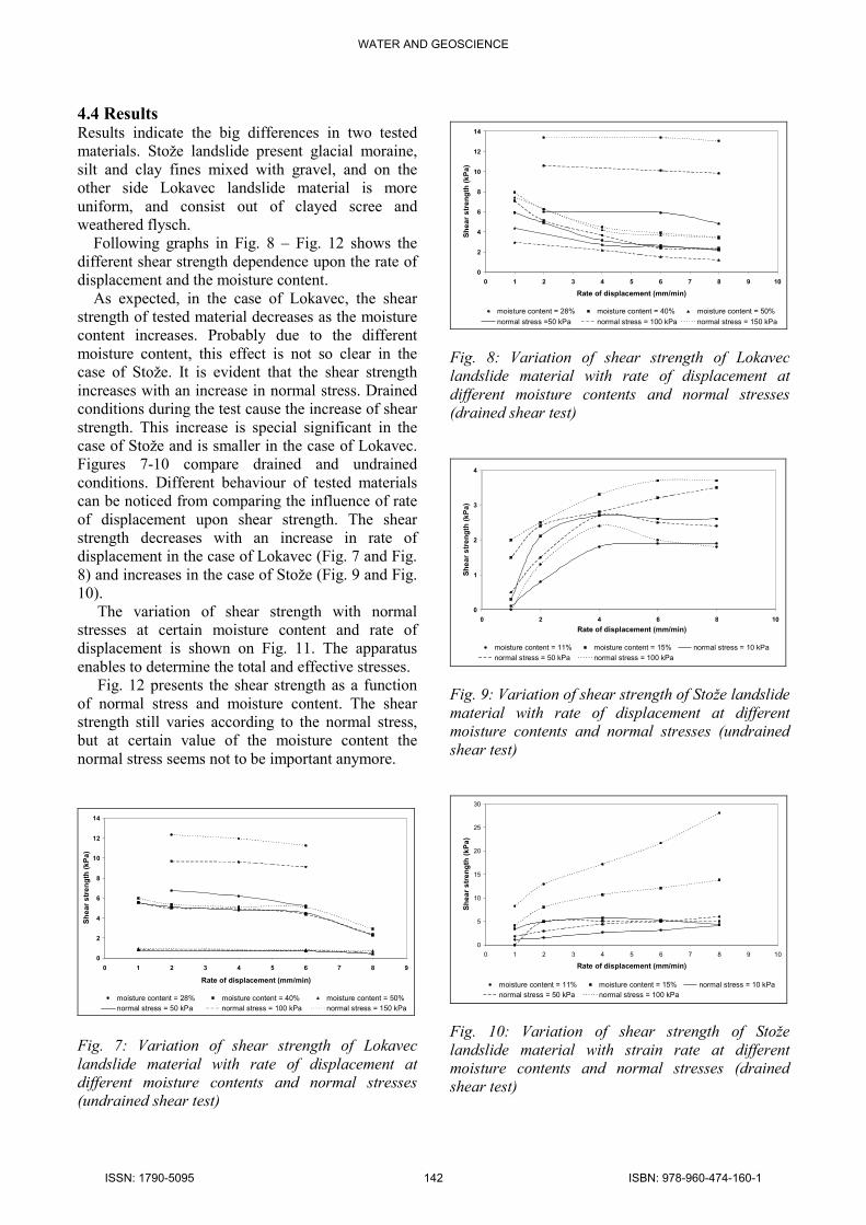
4.4 Results Results indicate the big differences in two tested
materials. Stože landslide present glacial moraine,
silt and clay fines mixed with gravel, and on the
other side Lokavec landslide material is more
uniform, and consist out of clayed scree and
weathered flysch.
Following graphs in Fig. 8 – Fig. 12 shows the
different shear strength dependence upon the rate of
displacement and the moisture content.
As expected, in the case of Lokavec, the shear
strength of tested material decreases as the moisture
content increases. Probably due to the different
moisture content, this effect is not so clear in the
case of Stože. It is evident that the shear strength
increases with an increase in normal stress. Drained
conditions during the test cause the increase of shear
strength. This increase is special significant in the
case of Stože and is smaller in the case of Lokavec.
Figures 7-10 compare drained and undrained
conditions. Different behaviour of tested materials
can be noticed from comparing the influence of rate
of displacement upon shear strength. The shear
strength decreases with an increase in rate of
displacement in the case of Lokavec (Fig. 7 and Fig.
8) and increases in the case of Stože (Fig. 9 and Fig.
10).
The variation of shear strength with normal
stresses at certain moisture content and rate of
displacement is shown on Fig. 11. The apparatus
enables to determine the total and effective stresses.
Fig. 12 presents the shear strength as a function
of normal stress and moisture content. The shear
strength still varies according to the normal stress,
but at certain value of the moisture content the
normal stress seems not to be important anymore.
0
2
4
6
8
10
12
14
0 1 2 3 4 5 6 7 8 9
Rate of displacement (mm/min)
Shear strength (kPa)
moisture content = 28% moisture content = 40% moisture content = 50%
normal stress = 50 kPa normal stress = 100 kPa normal stress = 150 kPa Fig. 7: Variation of shear strength of Lokavec
landslide material with rate of displacement at
different moisture contents and normal stresses
(undrained shear test)
0
2
4
6
8
10
12
14
0 1 2 3 4 5 6 7 8 9 10
Rate of displacement (mm/min)
Shear strength (kPa)
moisture content = 28% moisture content = 40% moisture content = 50%
normal stress =50 kPa normal stress = 100 kPa normal stress = 150 kPa
Fig. 8: Variation of shear strength of Lokavec
landslide material with rate of displacement at
different moisture contents and normal stresses
(drained shear test)
0
1
2
3
4
0 2 4 6 8 10
Rate of displacement (mm/min)
Shear strength (kPa)
moisture content = 11% moisture content = 15% normal stress = 10 kPa
normal stress = 50 kPa normal stress = 100 kPa
Fig. 9: Variation of shear strength of Stože landslide
material with rate of displacement at different
moisture contents and normal stresses (undrained
shear test)
0
5
10
15
20
25
30
0 1 2 3 4 5 6 7 8 9 10
Rate of displacement (mm/min)
Shear strength (kPa)
moisture content = 11% moisture content = 15% normal stress = 10 kPa
normal stress = 50 kPa normal stress = 100 kPa
Fig. 10: Variation of shear strength of Stože
landslide material with strain rate at different
moisture contents and normal stresses (drained
shear test)
WATER AND GEOSCIENCE
ISSN: 1790-5095 142 ISBN: 978-960-474-160-1

0
4
8
12
16
0 30 60 90 120 150 180
σσσσ (kPa)
ττ ττ (kPa)
effective stress total stress
Fig. 11: Effective and total shear strength
characteristics, Lokavec landslide, w = 28 %, strain
rate 6 mm/min.
0
2
4
6
8
10
12
14
20 25 30 35 40 45 50 55
Moisture content (%)
Shear strenght (kPa)
Average at normal stress 50 kPa
Average at normal stress 100 kPa
Average at normal stress 150 kPa
Fig. 12: Variation of shear strenght of Lokavec
landslide material with moisture content at different
normal stresses (undrained shear test)
5 Conclusions
Special laboratory equipment, large-scale shear box
apparatus, has been constructed to test the material
from Stože and Lokavec landslide. It enables to test
material including grain sizes up to 40 mm. This
size shearbox also gives the possibility to measure
the pore water pressure. It incorporates a special
hydraulic loading system, which controls the
displacement rate.
Two very different materials were tested and
results point to some not expected properties of
them. The shear strength of the material seems to
decrease as the moisture content increases and is not
affected by normal stress when the moisture content
achieves a certain level. Also the influence of a rate
of displacement has been noticed, but it
differentiates in case of both materials.
The large-scale shear box enables more detailed
testing of soils. Its main advantages are testing of
soil with bigger grain sizes, displacement control
and measuring of pore water pressure during the
test.
References:
[1] Oštir, K., Veljanovski, T. and Stančič, Z.
(2001). Log pod Mangartom Landslide,
Slovenia. "Space and Major Disasters", Final
Report, Ljubljana: Centre for Spatial Studies,
Scientific Research Centre of the Slovene
Academy of Sciences and Arts
[2] Petkovšek, B. (2001). Geological
Characteristics of the Stože Landslide. Ujma,
Ministrstvo za obrambo, Uprava RS za zaščito
in reševanje, 2001, No. 14-15, 98-101 (in
Slovenian)
[3] Majes, B. (2001). Final report of the
geotechnical expert group, Ministry of defence
(in Slovene)
[4] Lenart, S. (2006). Deformation characteristics of
lacustrine carbonate silt in the Julian Alps, Soil
Dynamics and Earthquake Engineering, 26,
131-142
[5] Bizjak, KF and Zupancic, A (2009). Site and
laboratory investigation of the Slano blato
landslide, Engineering Geology, Vol. 105, 3-4,
171-185
[6] Majes, B., Robas, A., Kuder, S., Logar, J.,
Pulko, B. and Petkovšek, A. (2001). Report on
stability analysis of Stože landslide, Faculty of
Civil Engineering and Geodesy, University of
Ljubljana
WATER AND GEOSCIENCE
ISSN: 1790-5095 143 ISBN: 978-960-474-160-1