Embed Size (px)
Citation preview

SPECIAL JOINTSSuper FMT Frame Mortise & Tenon Jig User Guide
CHAPTER 7SUPER FMT CHAPTER 7
Special Joints
43
Angled JointsThrough Tenons
Bridle JointsAsymmetric Tenons
Haunched JointsDoweling
1
I M P O R TA N T S A F E T Y N O T E
Take great care to not “trap” the bit against the side of tenon rails . Do not attempt to rout center tenons in rails thicker than 15/16"[34mm] before referring to 5-39 through 5-44.
Without using the table movement as prescribed, the bit would have to be plunged into the side of the tenon rail causing the bit to powerfully “drive” the router across the jig. This could be dangerous and can damage the jig.
Before using your Leigh Super FMT you must have completed all of the preparatory steps including reading the router safety recommendations on the previous pages. If you haven’t done so, it is essential that you do it now.
Angled Joints
90˚45˚
90˚45˚ 10˚
12
34
10˚
7-1 The majority of frame joints are at 90˚ but the ability to angle joints is essential in chair construction, for example. Whether these joints are single angles and or a compound angle they are easily achieved on the Super FMT.
7-2 Angling the sidestop fence gives a single angled joint in the left-right direction.
44 Chapter 7 SPECIAL JOINTSSuper FMT Mortise & Tenon Jig User Guide
1
2
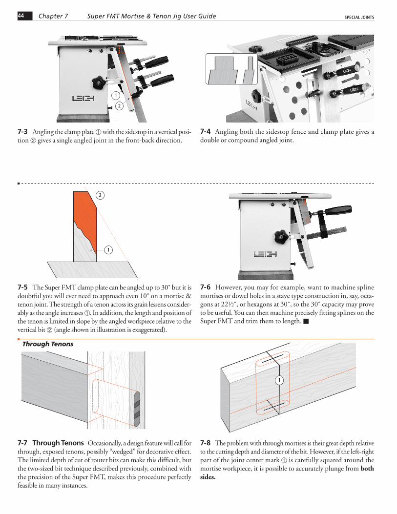
7-3 Angling the clamp plate with the sidestop in a vertical posi-tion gives a single angled joint in the front-back direction.
7-4 Angling both the sidestop fence and clamp plate gives a double or compound angled joint.
1
2
7-5 The Super FMT clamp plate can be angled up to 30˚ but it is doubtful you will ever need to approach even 10˚ on a mortise & tenon joint. The strength of a tenon across its grain lessens consider-ably as the angle increases . In addition, the length and position of the tenon is limited in slope by the angled workpiece relative to the vertical bit (angle shown in illustration is exaggerated).
7-6 However, you may for example, want to machine spline mortises or dowel holes in a stave type construction in, say, octa-gons at 221⁄2˚, or hexagons at 30˚, so the 30˚ capacity may prove to be useful. You can then machine precisely fitting splines on the Super FMT and trim them to length.
Through Tenons
7-7 Through Tenons Occasionally, a design feature will call for through, exposed tenons, possibly “wedged” for decorative effect. The limited depth of cut of router bits can make this difficult, but the two-sized bit technique described previously, combined with the precision of the Super FMT, makes this procedure perfectly feasible in many instances.
1
7-8 The problem with through mortises is their great depth relative to the cutting depth and diameter of the bit. However, if the left-right part of the joint center mark is carefully squared around the mortise workpiece, it is possible to accurately plunge from both sides.
45Chapter 7SPECIAL JOINTS Super FMT Mortise & Tenon Jig User Guide
1
2
3
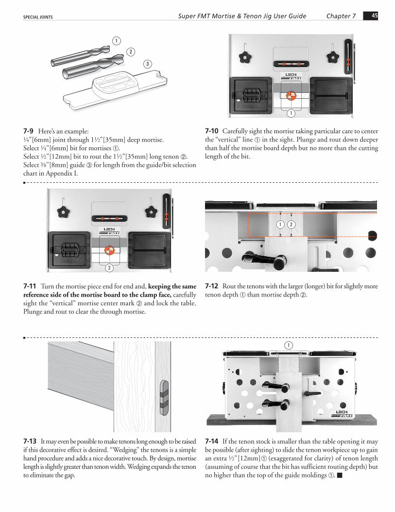
7-9 Here’s an example:1⁄4"[6mm] joint through 11⁄2"[35mm] deep mortise.Select 1⁄4"[6mm] bit for mortises .Select 1⁄2"[12mm] bit to rout the 11⁄2"[35mm] long tenon .Select 3⁄8"[8mm] guide for length from the guide/bit selection chart in Appendix I.
1
7-10 Carefully sight the mortise taking particular care to center the “vertical” line in the sight. Plunge and rout down deeper than half the mortise board depth but no more than the cutting length of the bit.
2
7-11 Turn the mortise piece end for end and, keeping the same reference side of the mortise board to the clamp face, carefully sight the “vertical” mortise center mark and lock the table. Plunge and rout to clear the through mortise.
1 2
7-12 Rout the tenons with the larger (longer) bit for slightly more tenon depth than mortise depth .
7-13 It may even be possible to make tenons long enough to be raised if this decorative effect is desired. “Wedging” the tenons is a simple hand procedure and adds a nice decorative touch. By design, mortise length is slightly greater than tenon width. Wedging expands the tenon to eliminate the gap.
1
7-14 If the tenon stock is smaller than the table opening it may be possible (after sighting) to slide the tenon workpiece up to gain an extra 1⁄2"[12mm] (exaggerated for clarity) of tenon length (assuming of course that the bit has sufficient routing depth) but no higher than the top of the guide moldings .
46 Chapter 7 SPECIAL JOINTSSuper FMT Mortise & Tenon Jig User Guide
Bridle Joints
1
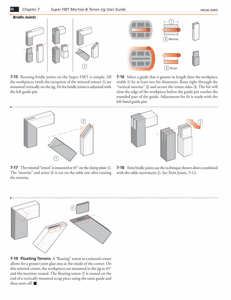
7-15 Routing bridle joints on the Super FMT is simple. All the workpieces (with the exception of the mitered tenon) are mounted vertically on the jig. Fit for bridle joints is adjusted with the left guide pin.
Mortise
Tenon
2
3
1
7-16 Select a guide that is greater in length than the workpiece width by at least two bit diameters. Rout right through the “vertical mortise” and across the tenon sides . The bit will clear the edge of the workpiece before the guide pin reaches the rounded part of the guide. Adjustment for fit is made with the left hand guide pin.
1
2
7-17 The mitered “tenon” is mounted at 45˚ on the clamp plate . The “mortise” end miter is cut on the table saw after routing the mortise.
1
7-18 Twin bridle joints use the technique shown above combined with the table movement . See Twin Joints, 5-12.
1
7-19 Floating Tenons A “floating” tenon in a mitered corner allows for a greater joint glue area at the inside of the corner. On this mitered corner, the workpieces are mounted in the jig at 45˚ and the mortises routed. The floating tenon is routed on the end of a vertically mounted scrap piece using the same guide and then sawn off.
47Chapter 7SPECIAL JOINTS Super FMT Mortise & Tenon Jig User Guide
Haunched Joints
Asymmetric Tenons
B
A
A
2
B
1
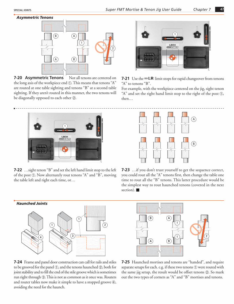
7-20 Asymmetric Tenons Not all tenons are centered on the long axis of the workpiece end . This means that tenons “A” are routed at one table sighting and tenons “B” at a second table sighting. If they aren’t routed in this manner, the two tenons will be diagonally opposed to each other .
1
7-21 Use the LR limit stops for rapid changeover from tenons “A” to tenons “B”.For example, with the workpiece centered on the jig, sight tenon “A” and set the right hand limit stop to the right of the post , then…
1
7-22 …sight tenon “B” and set the left hand limit stop to the left of the post . Now alternately rout tenons “A” and “B”, moving the table left and right each time, or…
B
A
7-23 …if you don’t trust yourself to get the sequence correct, you could rout all the “A” tenons first, then change the table one time to rout all the “B” tenons. This latter procedure would be the simplest way to rout haunched tenons (covered in the next section).
1
4 3
1
2
7-24 Frame and panel door construction can call for rails and stiles to be grooved for the panel , and the tenons haunched , both for joint stability and to fill the end of the stile groove which is sometimes run right through . This is not as common as it once was. Routers and router tables now make it simple to have a stopped groove , avoiding the need for the haunch.
B
A
A1
1 2
B
7-25 Haunched mortises and tenons are “handed”, and require separate setups for each. e.g. if these two tenons were routed with the same jig setup, the result would be offset tenons . So mark out the two types of corners as “A” and “B” mortises and tenons.

48 Chapter 7 SPECIAL JOINTSSuper FMT Mortise & Tenon Jig User Guide
1
3
2
7-26 First, groove all the workpieces . The groove should be less than the mortise width and shallower than the haunch recess .
BA
7-27 Sight both the “A” and “B” mortises. Set stops or mark the outrigger for repeatable successive workpieces. Position and lock the FB Limit Stops against the post.
2
13
4
7-28 “A” Mortises and Haunch Recesses Set right hand LR Limit Stop away from the post, 3⁄4 of the guide length . e.g. 1"
guide, move 3⁄4". Table still in “mortise center” position, rout mortise full depth . Raise the plunge. Move table left to the stop . Lower the bit to haunch depth; set router depth turret. The router is now set for both depths of cut. Rout haunch recess . Repeat for all “A” mortises.
2 1
3 4
7-29 “B” Mortises and Haunch Recesses Move the table left to touch the right hand LR Limit Stop against the post and lock the table. Move the left hand LR Limit Stop (by 3⁄4 of the guide length) to the left . Rout the “B” mortises and haunch recesses using the table movement and the same router depth settings.
BA
7-30 Routing the Tenons Mark the tenon centers “A” and “B”. Remember, the tenons are “off center” and each end of the tenon pieces are marked off center in opposite directions. Prepare and make a couple of extra (scrap) tenon pieces to use in setting haunch bit depth later (see 7-35).
1
7-31 “A” Tenons With the workpiece centered on the jig, sight the tenon center and set the right hand LR limit stop to the post .

49Chapter 7SPECIAL JOINTS Super FMT Mortise & Tenon Jig User Guide
3
12
7-32 Move the table right to a position where the bit will clear the end of the haunch while the guide pin is still on the straight part of the guide . Set the left hand LR limit stop to its post .
1
2
7-33 Move the table to the left again and if necessary, set a “guard” piece in the guide recess to prevent routing around the right end of the tenon . Rout the left end of the tenon (shaded area) at full shoulder depth.
12
7-34 Move the guard to the left end of the recess. Move the table right and rout the rest of the “A” tenon at full depth; the bit prevented from rounding the haunch off at by the guide pin against the guide side at .
1
1
7-35 Move the table left, remove the guard from the bit recess. Depth: You will have to preset the plunge router depth-of-cut rod and turret so that the routed haunch exactly equals the depth of the haunch recess . Use the scrap test tenons to achieve this setting by measurement and a little trial and error. Now rout completely around the actual tenon.
5
1 2 3
4 5
7-36 “B” Tenons on the other end are routed with the procedure reversed.

50 Chapter 7 SPECIAL JOINTSSuper FMT Mortise & Tenon Jig User Guide
Doweling
7-37 Sometimes where the strength of a mortise and tenon is not required, doweling may be a suitable alternative. A bonus use of the Super FMT is its ability to provide very precise dowel hole boring. Turn the left hand guide pin down to “zero free play” in the mortise guide slot. Simply use one or both ends of a mortise guide slot for positioning while plunging the dowel holes.

JOINT SPECIFICATIONS, GUIDE AND BIT SELECTION
SUPER FMT Appendix I
51
Joint Specifications,
Guide and Bit Selection
A1-1 Joint Terminology The tenon sides are the “Cheeks” . The tenon shoulders are called (luckily) the “Shoulders” .Unfortunately, references to dimensions of mortises and tenons do not share matching terminology, so...Long or short tenons fit into deep or shallow mortises .Tenon Length = Mortise Depth.
1
23
4
A1-2 Wide or narrow tenons fit into long or short mortises .Tenon Width = Mortise Length.
6
5
A1-3 Thick or thin tenons fit into wide or narrow mortises . Tenon Thickness = Mortise Width.
7
8
A1-4 Largest Single Rail and Tenon(using one table position with 1⁄4" bit)Workpiece 1 5⁄16" x 31⁄8"[34 x 80mm] .Tenon 1⁄2" x 21⁄2"[12 x 65mm] .Guide 1⁄2" x 21⁄2"[12 x 65mm].Note: Routing single tenons in stock thicker than 15⁄16"[34mm] would require the bit to be plunged into the edge of the workpiece, danger-ously “trapping” the bit. See 5-39 through 5-44 and follow the “Third Tenon” procedure.
1
2
1 2
ForewordThe illustrations and specifications in this Appendix show the largest tenon rail and tenon sizes possible on the Super FMT, either in one table position or multiple table positions as noted. For all smaller sizes, refer to the guide and bit selection chart.
Joint Specifications
52 Appendix I Super FMT Mortise & Tenon Jig User Guide JOINT SPECIFICATIONS, GUIDE AND BIT SELECTION
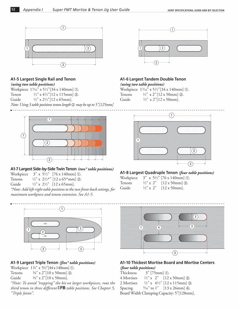
A1-10 Thickest Mortise Board and Mortise Centers(four table positions)Thickness 3" [75mm] .4 Mortises 1⁄2" x 2" [12 x 50mm] .2 Mortises 1⁄2" x 41⁄2" [12 x 115mm] .Spacing 9⁄16" to 1" [13 x 26mm] .Board Width Clamping Capacity: 5"[128mm].
2
3
1
2
4
A1-5 Largest Single Rail and Tenon(using two table positions) Workpiece 1 5⁄16" x 51⁄2"[34 x 140mm] .Tenon 1⁄2" x 41⁄2"[12 x 115mm] .Guide 1⁄2" x 21⁄2"[12 x 65mm].Note: Using 3 table positions tenon length may be up to 5"[125mm]
1
2
1 2
A1-6 Largest Tandem Double Tenon (using two table positions)Workpiece 1 5⁄16" x 51⁄2"[34 x 140mm] .Tenons 1⁄2" x 2" [12 x 50mm] .Guide 1⁄2" x 2"[12 x 50mm].
1
2
1 2
A1-7 Largest Side-by-Side Twin Tenon (two* table positions) Workpiece 3" x 51⁄2" [76 x 140mm] .Tenons 1⁄2" x 21⁄2+" [12 x 65+mm] .Guide 1⁄2" x 21⁄2" [12 x 65mm].*Note: Add left-right table positions to the two front-back settings, for maximum workpiece and tenons extension. See A1-5.
1
2
1
2
A1-8 Largest Quadruple Tenon (four table positions) Workpiece 3" x 51⁄2" [76 x 140mm] .Tenons 1⁄2" x 2" [12 x 50mm] .Guide 1⁄2" x 2" [12 x 50mm].
1
2
1
2
A1-9 Largest Triple Tenon (five* table positions) Workpiece 1 3⁄4" x 51⁄2"[44 x 140mm] .Tenons 3⁄8" x 2"[10 x 50mm] .Guide 3⁄8" x 2"[10 x 50mm].*Note: To avoid “trapping” the bit on larger workpieces, rout the third tenon in three different FB table positions. See Chapter 5, “Triple Joints”.
1
22
1 22
53Appendix IJOINT SPECIFICATIONS, GUIDE AND BIT SELECTION Super FMT Mortise & Tenon Jig User Guide
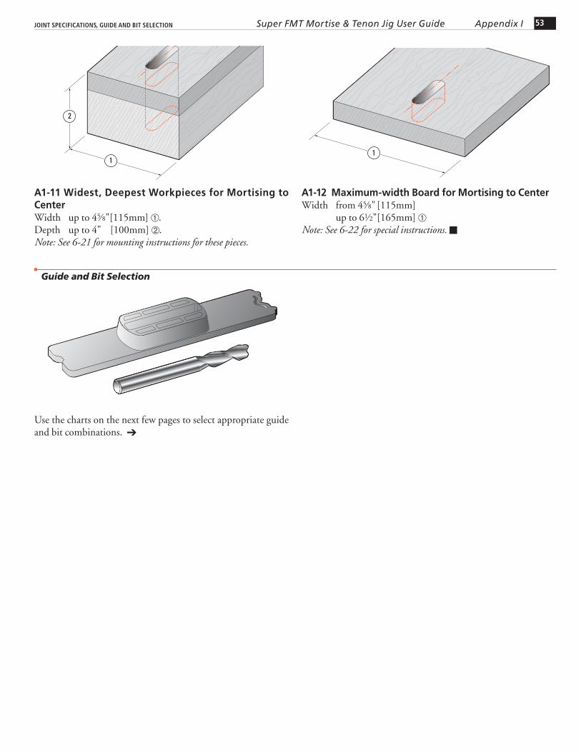
A1-11 Widest, Deepest Workpieces for Mortising to CenterWidth up to 45⁄8"[115mm] .Depth up to 4" [100mm] .Note: See 6-21 for mounting instructions for these pieces.
2
1
A1-12 Maximum-width Board for Mortising to CenterWidth from 45⁄8" [115mm] up to 61⁄2"[165mm] Note: See 6-22 for special instructions.
Guide and Bit Selection
1
Use the charts on the next few pages to select appropriate guide and bit combinations.
54 Appendix I
LEIGH BIT ITEM NO. A B B C
HSS Solid Carbide Mortise Size HSS Solid Carbide Shank Spiral Upcut Spiral Upcut Cutting Diameter Cutting Depth Cutting Depth Diameter
162 N/A 1/16" 3/16" - 1/4" 164 164C 1/8" 3/8" 1/2" 1/4" 166 166C 3/16" 5/8" 3/4" 1/4" 168 168C 1/4" 1" 1-1/8" 1/4" 170-500 170-500C 5/16" 1" 1-1/8" 1/2" 173-500 173-500C 3/8" 1-1/4" 1-1/4" 1/2" 177 177C 7/16" 1-3/4" 1-3/4" 1/2" 180 180CL 1/2" 1-1/2" 2-1/8" 1/2"
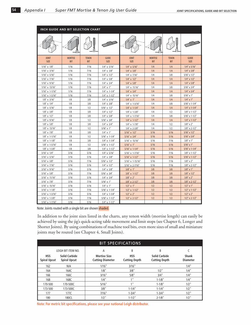
BIT SPECIFICATIONS
Note: For metric bit specifications, please see your national Leigh distributor.
Super FMT Mortise & Tenon Jig User Guide JOINT SPECIFICATIONS, GUIDE AND BIT SELECTION
Note: Joints routed with a single bit are shown shaded.
In addition to the joint sizes listed in the charts, any tenon width (mortise length) can easily be achieved by using the jig’s quick-acting table movement and limit stops (see Chapter 6, Longer and Shorter Joints). By using combinations of machine tool bits, even more sizes of small and miniature joints may be routed (see Chapter 4, Small Joints).
INCH GUIDE AND BIT SELECTION CHART
MORTISEBIT
MORTISEBIT
JOINTSIZE
JOINTSIZE
GUIDESIZE
GUIDESIZE
TENONBIT
TENONBIT
1/16" x 1/8"
1/16" x 3/16"
1/16" x 5/16"
1/16" x 7/16"
1/16" x 9/16"
1/16" x 13/16"
1/16" x 1-1/16"
1/16" x 1-5/16"
1/8" x 3/16"
1/8" x 1/4"
1/8" x 5/16"
1/8" x 3/8"
1/8" x 1/2"
1/8" x 9/16"
1/8" x 5/8"
1/8" x 13/16"
1/8" x 7/8"
1/8" x 1-1/16"
1/8" x 1-1/8"
1/8" x 1-5/16"
1/8" x 1-3/8"
3/16" x 1/4"
3/16" x 5/16"
3/16" x 3/8"
3/16" x 7/16"
3/16" x 9/16"
3/16" x 5/8"
3/16" x 11/16"
3/16" x 7/8"
3/16" x 15/16"
3/16" x 1-1/8"
3/16" x 1-3/16"
3/16" x 1-3/8"
3/16" x 1-7/16"
1/16
1/16
1/16
1/16
1/16
1/16
1/16
1/16
1/8
1/8
1/8
1/8
1/8
1/8
1/8
1/8
1/8
1/8
1/8
1/8
1/8
3/16
3/16
3/16
3/16
3/16
3/16
3/16
3/16
3/16
3/16
3/16
3/16
3/16
7/16
7/16
7/16
7/16
7/16
7/16
7/16
7/16
3/8
3/8
1/2
3/8
3/8
1/2
3/8
1/2
3/8
1/2
3/8
1/2
3/8
5/16
5/16
7/16
5/16
5/16
7/16
5/16
7/16
5/16
7/16
5/16
7/16
5/16
1/4" x 5/16"
1/4" x 3/8"
1/4" x 1/2"
1/4" x 5/8"
1/4" x 3/4"
1/4" x 1"
1/4" x 1-1/4"
1/4" x 1-1/2"
1/4" x 5/16"
1/4" x 3/8"
5/16" x 1/2"
1/4" x 1/2"
1/4" x 5/8"
5/16" x 3/4"
1/4" x 3/4"
5/16" x 1"
1/4" x 1"
5/16" x 1-1/4"
1/4" x 1-1/4"
5/16" x 1-1/2"
1/4" x 1-1/2"
1/4" x 5/16"
1/4" x 3/8"
5/16" x 1/2"
1/4" x 1/2"
1/4" x 5/8"
5/16" x 3/4"
1/4" x 3/4"
5/16" x 1"
1/4" x 1"
5/16" x 1-1/4"
1/4" x 1-1/4"
5/16" x 1-1/2"
1/4" x 1-1/2"
1/4" x 5/16"
1/4" x 3/8"
1/4" x 7/16"
1/4" x 1/2"
1/4" x 5/8"
1/4" x 11/16"
1/4" x 3/4"
1/4" x 15/16"
1/4" x 1"
1/4" x 1-3/16"
1/4" x 1-1/4"
1/4" x 1-3/8"
1/4" x 1-7/16"
1/4" x 1-1/2"
1/4" x 1-7/8"
1/4" x 2-3/8"
5/16" x 1/2"
5/16" x 3/4"
5/16" x 15/16"
5/16" x 1"
5/16" x 1-1/4"
5/16" x 1-7/16"
5/16" x 1-1/2"
5/16" x 1-15/16"
5/16" x 2-7/16"
3/8" x 1"
3/8" x 1-1/2"
3/8" x 2"
3/8" x 2-1/2"
1/2" x 1"
1/2" x 1-1/2"
1/2" x 2"
1/2" x 2-1/2"
1/4
1/4
1/4
1/4
1/4
1/4
1/4
1/4
1/4
1/4
1/4
1/4
1/4
1/4
1/4
1/4
5/16
5/16
5/16
5/16
5/16
5/16
5/16
5/16
5/16
3/8
3/8
3/8
3/8
1/2
1/2
1/2
1/2
1/4
1/4
3/8
1/4
1/4
3/8
1/4
3/8
1/4
3/8
1/4
1/2
3/8
1/4
1/2
1/2
5/16
5/16
7/16
5/16
5/16
7/16
5/16
7/16
7/16
3/8
3/8
3/8
3/8
1/2
1/2
1/2
1/2
1/4" x 5/16"
1/4" x 3/8"
5/16" x 1/2"
1/4" x 1/2"
1/4" x 5/8"
5/16" x 3/4"
1/4" x 3/4"
5/16" x 1"
1/4" x 1"
5/16" x 1-1/4"
1/4" x 1-1/4"
3/8" x 1-1/2"
5/16" x 1-1/2"
1/4" x 1-1/2"
3/8" x 2"
3/8" x 2-1/2"
5/16" x 1/2"
5/16" x 3/4"
3/8" x 1"
5/16" x 1"
5/16" x 1-1/4"
3/8" x 1-1/2"
5/16" x 1-1/2"
3/8" x 2"
3/8" x 2-1/2"
3/8" x 1"
3/8" x 1/2"
3/8" x 2"
3/8" x 2-1/2"
1/2" x 1"
1/2" x 1-1/2"
1/2" x 2"
1/2" x 2-1/2"
55Appendix ISuper FMT Mortise & Tenon Jig User GuideJOINT SPECIFICATIONS, GUIDE AND BIT SELECTION
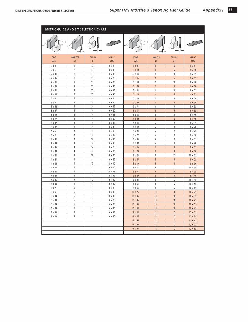
METRIC GUIDE AND BIT SELECTION CHART
6
6
6
6
6
6
6
6
6
6
6
6
6
6
7
7
7
7
7
7
8
8
8
8
8
8
8
8
8
8
8
10
10
10
10
10
12
12
12
12
12
2 x 4
2 x 6
2 x 11
2 x 16
2 x 21
2 x 26
2 x 31
2 x 36
3 x 5
3 x 7
3 x 12
3 x 17
3 x 22
3 x 27
3 x 32
3 x 37
4 x 6
4 x 8
4 x 11
4 x 13
4 x 16
4 x 18
4 x 21
4 x 23
4 x 26
4 x 28
4 x 31
4 x 33
4 x 36
4 x 38
5 x 7
5 x 9
5 x 14
5 x 19
5 x 24
5 x 29
5 x 34
5 x 39
2
2
2
2
2
2
2
2
3
3
3
3
3
3
3
34
4
4
4
4
4
4
4
4
4
4
4
4
4
5
5
5
5
5
5
5
5
10
10
10
10
10
10
10
10
9
9
9
9
9
9
9
9
8
8
12
8
12
8
12
8
12
8
12
8
12
8
7
7
7
7
7
7
7
7
6 x 8
6 x 10
6 x 15
6 x 20
6 x 25
6 x 30
6 x 35
6 x 40
6 x 8
6 x 10
6 x 15
6 x 20
6 x 25
6 x 30
6 x 35
6 x 40
6 x 8
6 x 10
8 x 15
6 x 15
8 x 20
6 x 20
8 x 25
6 x 25
8 x 30
6 x 30
8 x 35
6 x 35
8 x 40
6 x 40
6 x 8
6 x 10
6 x 15
6 x 20
6 x 25
6 x 30
6 x 35
6 x 40
6 x 8
6 x 10
6 x 13
6 x 15
6 x 18
6 x 20
6 x 23
6 x 25
6 x 28
6 x 30
6 x 33
6 x 35
6 x 38
6 x 40
7 x 14
7 x 19
7 x 24
7 x 29
7 x 34
7 x 39
8 x 15
8 x 20
8 x 23
8 x 25
8 x 30
8 x 33
8 x 35
8 x 40
8 x 43
8 x 53
8 x 63
10 x 25
10 x 35
10 x 45
10 x 55
10 x 65
12 x 25
12 x 35
12 x 45
12 x 55
12 x 65
6
6
10
6
10
6
10
6
10
6
10
6
10
6
9
9
9
9
9
9
8
8
12
8
8
12
8
8
12
12
12
10
10
10
10
10
12
12
12
12
12
6 x 8
6 x 10
8 x 15
6 x 15
8 x 20
6 x 20
8 x 25
6 x 25
8 x 30
6 x 30
8 x 35
6 x 35
8 x 40
6 x 40
8 x 15
8 x 20
8 x 25
8 x 30
8 x 35
8 x 40
8 x 15
8 x 20
10 x 25
8 x 25
8 x 30
10 x 35
8 x 35
8 x 40
10 x 45
10 x 55
10 x 65
10 x 25
10 x 35
10 x 45
10 x 55
10 x 65
12 x 25
12 x 35
12 x 45
12 x 55
12 x 65
GUIDESIZE
GUIDESIZE
JOINTSIZE
TENONBIT
TENONBIT
MORTISEBIT
MORTISEBIT
JOINTSIZE

56 Appendix I Super FMT Mortise & Tenon Jig User Guide JOINT SPECIFICATIONS, GUIDE AND BIT SELECTION

JIG ADJUSTMENTS
SUPER FMT Appendix II
57
Jig Adjustments
A2-1 Clamp Plate The clamp plate is factory set square to the table . However, this does not guarantee perfectly in-line joints. If your router shaft and bit are not perpendicular to the router sub-base and the Leigh sub-base, then the bit will not be square to the jig table (nor parallel to the clamp plate). This will cause a tiny “step” in the joint alignment . This is because the tenon center mark is now offset from the mortise center mark in the assembled joint . For clarity, the angle and step in this example is highly exaggerated.
90˚
2
3
2
1
A2-2 Check your test joints for alignment with a straightedge. The cross represents the inside face toward the clamp face. The left example shows the clamp plate should be adjusted in toward the jig body . The right example shows the clamp plate should be adjusted away from the jig body . Test and adjust the clamp plate angle (see below) until the workpieces are in the same plane, with no joint misalignment.
1 2
A2-3 The adjusting screw for setting the clamp plate is in the lower left front of the jig base. Loosen the quadrant knobs. Use the hex screwdriver to turn the screw clockwise to move the plate in . Turn the screw counterclockwise to move the plate out . The screw is treated with Loctite™ to prevent accidental rotation and will require firm pressure to adjust.
12
A2-4 Joint Alignment The clamp plate is factory set parallel to the guide track centerline and should not need attention. If the mortise or tenon is angled an adjustment may be required. Here’s how: Slightly loosen the two screws holding the left end quadrant using the hex driver. Turn the screw in or out to adjust the angle of the clamp plate relative to the guide track centerline. Firmly tighten the screws. After tightening the two screws, turn the adjusting screw in towards the jig body at least two full turns. Rout test joints to check the joint alignment.
2
1
1
58 Appendix II JIG ADJUSTMENTSSuper FMT Mortise & Tenon Jig User Guide
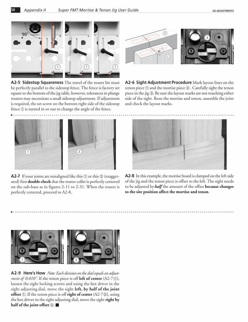
A2-5 Sidestop Squareness The travel of the router bit must be perfectly parallel to the sidestop fence. The fence is factory set square to the bottom of the jig table, however, tolerances in plunge routers may necessitate a small sidestop adjustment. If adjustment is required, the set screw on the bottom right side of the sidestop fence is turned in or out to change the angle of the fence.
90˚
1 11
A2-6 Sight Adjustment Procedure Mark layout lines on the tenon piece and the mortise piece . Carefully sight the tenon piece in the jig . Be sure the layout marks are not touching either side of the sight. Rout the mortise and tenon, assemble the joint and check the layout marks.
90˚
1
2
3
A2-7 If your joints are misaligned like this or this (exagger-ated) first double check that the router collet is perfectly centered on the sub-base as in figures 2-11 to 2-31. When the router is perfectly centered, proceed to A2-8.
A2-8 In this example, the mortise board is clamped on the left side of the jig and the tenon piece is offset to the left. The sight needs to be adjusted by half the amount of the offset because changes to the site position affect the mortise and tenon.
A2-9 Here’s How Note: Each division on the dial equals an adjust- ment of 0.010". If the tenon piece is off left of center (A2-7 ), loosen the sight locking screws and using the hex driver in the sight adjusting dial, move the sight left, by half of the joint offset . If the tenon piece is off right of center (A2-7 ), using the hex driver in the sight adjusting dial, move the sight right by half of the joint offset .
2
1
4 5 63 2
2
4 5 63 2
21

SUPER FMT PARTS LIST
SUPER FMT Appendix III
59
Super FMT Parts List
60 Appendix III Super FMT Mortise & Tenon Jig User Guide SUPER FMT PARTS LIST
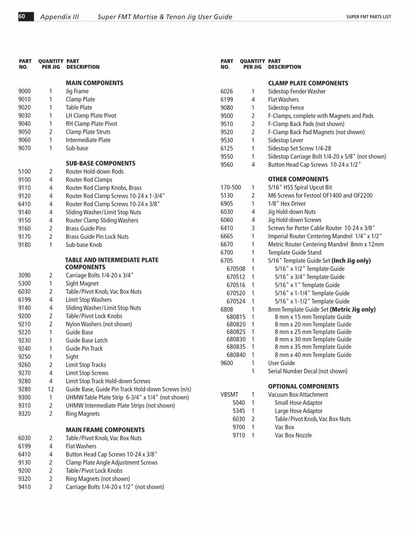
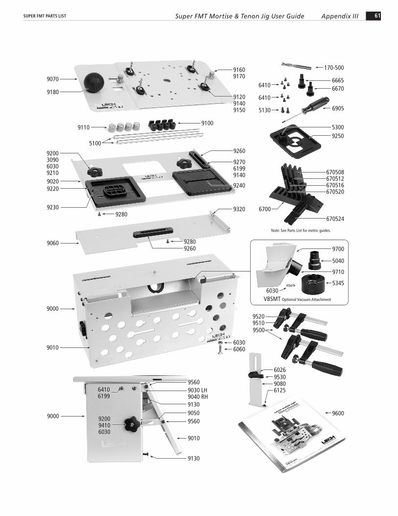
MAIN COMPONENTS9000 1 Jig Frame 9010 1 Clamp Plate 9020 1 Table Plate 9030 1 LH Clamp Plate Pivot 9040 1 RH Clamp Plate Pivot 9050 2 Clamp Plate Struts 9060 1 Intermediate Plate 9070 1 Sub-base SUB-BASE COMPONENTS 5100 2 Router Hold-down Rods 9100 4 Router Rod Clamps 9110 4 Router Rod Clamp Knobs, Brass 9120 4 Router Rod Clamp Screws 10-24 x 1-3/4" 6410 4 Router Rod Clamp Screws 10-24 x 3/8" 9140 4 Sliding Washer/Limit Stop Nuts 9150 4 Router Clamp Sliding Washers 9160 2 Brass Guide Pins 9170 2 Brass Guide Pin Lock Nuts 9180 1 Sub-base Knob TABLE AND INTERMEDIATE PLATE
COMPONENTS 3090 2 Carriage Bolts 1/4-20 x 3/4" 5300 1 Sight Magnet 6030 2 Table /Pivot Knob, Vac Box Nuts6199 4 Limit Stop Washers9140 4 Sliding Washer/Limit Stop Nuts 9200 2 Table/Pivot Lock Knobs 9210 2 Nylon Washers (not shown) 9220 1 Guide Base 9230 1 Guide Base Latch 9240 1 Guide Pin Track 9250 1 Sight 9260 2 Limit Stop Tracks 9270 4 Limit Stop Screws 9280 4 Limit Stop Track Hold-down Screws 9280 12 Guide Base, Guide Pin Track Hold-down Screws (n/s)9300 1 UHMW Table Plate Strip 6-3/4" x 1/4" (not shown) 9310 2 UHMW Intermediate Plate Strips (not shown)9320 2 Ring Magnets
MAIN FRAME COMPONENTS 6030 2 Table /Pivot Knob, Vac Box Nuts 6199 4 Flat Washers 6410 4 Button Head Cap Screws 10-24 x 3/8" 9130 2 Clamp Plate Angle Adjustment Screws 9200 2 Table/Pivot Lock Knobs 9320 2 Ring Magnets (not shown) 9410 2 Carriage Bolts 1/4-20 x 1/2" (not shown)
PART QUANTITY PARTNO. PER JIG DESCRIPTION
PART QUANTITY PARTNO. PER JIG DESCRIPTION
CLAMP PLATE COMPONENTS 6026 1 Sidestop Fender Washer 6199 4 Flat Washers9080 1 Sidestop Fence9500 2 F-Clamps, complete with Magnets and Pads 9510 2 F-Clamp Back Pads (not shown) 9520 2 F-Clamp Back Pad Magnets (not shown) 9530 1 Sidestop Lever6125 1 Sidestop Set Screw 1/4-28 9550 1 Sidestop Carriage Bolt 1/4-20 x 5/8" (not shown) 9560 4 Button Head Cap Screws 10-24 x 1/2" OTHER COMPONENTS 170-500 1 5/16" HSS Spiral Upcut Bit5130 2 M6 Screws for Festool OF1400 and OF2200 6905 1 1/8" Hex Driver 6030 4 Jig Hold-down Nuts 6060 4 Jig Hold-down Screws 6410 3 Screws for Porter Cable Router 10-24 x 3/8" 6665 1 Imperial Router Centering Mandrel 1/4" x 1/2" 6670 1 Metric Router Centering Mandrel 8mm x 12mm 6700 1 Template Guide Stand 6705 1 5/16" Template Guide Set (Inch Jig only) 670508 1 5/16" x 1/2" Template Guide 670512 1 5/16" x 3/4" Template Guide 670516 1 5/16" x 1" Template Guide 670520 1 5/16" x 1-1/4" Template Guide 670524 1 5/16" x 1-1/2" Template Guide6808 1 8mm Template Guide Set (Metric Jig only) 680815 1 8 mm x 15 mm Template Guide 680820 1 8 mm x 20 mm Template Guide 680825 1 8 mm x 25 mm Template Guide 680830 1 8 mm x 30 mm Template Guide 680835 1 8 mm x 35 mm Template Guide 680840 1 8 mm x 40 mm Template Guide9600 1 User Guide 1 Serial Number Decal (not shown)
OPTIONAL COMPONENTS VBSMT 1 Vacuum Box Attachment 5040 1 Small Hose Adaptor 5345 1 Large Hose Adaptor 6030 2 Table /Pivot Knob, Vac Box Nuts 9700 1 Vac Box 9710 1 Vac Box Nozzle
61Appendix IIISuper FMT Mortise & Tenon Jig User GuideSUPER FMT PARTS LIST
6700
6905
670508670512670516670520
670524
Note: See Parts List for metric guides.
Optional Vacuum Attachment
66709070
5130
6410
9230
9060
9000
9130
920094106030
9030 LH9040 RH
9050
64106199
9600
5300
9130
9560
9180
9200309060309210
170-500
9260
9520
6030
9510
9010
6410
924090209220
9250
9000
5100
9110
9010
9560
6665
9500
90806125
VBSMT
95306026
9700
5345
9710
5040
9320
9100
912091409150
927061999140
91609170
9260
9280
60306060
9280

62 Appendix III Super FMT Mortise & Tenon Jig User Guide SUPER FMT PARTS LIST

CUSTOMER SUPPORT
SUPER FMT Appendix IV
Customer Support
At Leigh Industries we take pride in our commitment to provide excellence in customer service and support. We hope your use of the Leigh Super FMT is enjoyable, rewarding and most of all, trouble free. This user guide should provide you with the answers to any questions you may have. If this is not the case, please feel free to contact our technical support staff or our distributor in your country by any of the means listed below.
Leigh Industries Ltd. (EST. 1981)P.O. Box 357,1615 Industrial Ave.,Port Coquitlam, B.C.,Canada V3C 4K6
Toll Free: 800-663-8932 Tel: (604) 464-2700 Fax: (604) 464-7404*Email: [email protected] Web: www.leighjigs.com
* Email can be useful, but technical queries usually raise queries from us. The telephone (if possible) is a much quicker and more convenient way to get those queries answered; either directly to Leigh (toll free in North America) or to your national distributor. …Thanks!
Manufacturer: Canada & USA
Australia & New ZealandCarba-Tec Pty. Ltd.128 Ingleston Rd., Wakerley, Qld., 4154AustraliaTel: +61 7 3390 5888Fax: +61 7 3890 5280Order: 1 800 658 111Email: [email protected]: www.carbatec.com.au
FranceEts Bordet23 Rue Traversiere93556 Montreuil CedexFranceTel: 01 48 58 28 39Fax: 01 48 58 48 58Email: [email protected]: www.bordet.fr/
Germany, Austria & SwitzerlandHacker GMBHHolzbearbeitungsmaschinenTraberhofstraße 103 D-83026 RosenheimDeutschlandTel: 08031 269650Fax: 08031 68221Email: [email protected]: www.leigh.de
JapanOff Corporation Inc.323-1 Shimizu-Yanbara Shimizu-KuShizuoka-Shi, Shizuoka-Ken,Japan 424-0002Tel: 81-54-367-6511Fax: 81-54-367-6515
Email: [email protected]: www.off.co.jp
KoreaLeigh Korea1st Floor, Yongyu Building 25-3Neung Pyung-Ri, Opo-Eup, Kwangju-SiKyunggi-do, KoreaTel: 82 (0) 70-8252-0988Fax: 82 (0) 31-765-5602Email: [email protected]: www.woodworking-academy.com
NorwayAurusStoelsmyrvn. 1035542 KarmsundNorwayTel: +47 992 71 932Fax: +47 529 10 011Email: [email protected]: www.aurus.no
RussiaUnicom Ltd.Nikitskij Boulevard 12Moscow, 119019RussiaTel/Fax: +7(495)690-0454Email: [email protected] (Russia)Email: [email protected] (Ukraine)Web: www.leighjigs.ru (Russia)Web: www.leighjigs.ua (Ukraine)
South AfricaHardware Centre GroupPO Box 4059, 2125Randburg, South AfricaTel: (011) 791-0844/46Fax: (011) 791-0850
Email: [email protected]: www. hardwarecentre.co.za
SwedenToolbox Sweden ABFacetten Faj 9S-597 30 AtvidabergSwedenTel: 46-120-854-50Fax: 46-120-854-69Email: [email protected]: www.toolbox.se
United Kingdom & IrelandBriMarc Tools & MachineryUnit 10a Weycroft AvenueAxminsterDevon EX13 5PHEnglandTel: 0300 100 1008Fax: 0300 100 1009Email: [email protected]: www.brimarc.com
Distributors
Our Commitment to You
63

© 2009 Leigh Industries Ltd. All rights reserved.No part of this publication may be reproduced, stored in a retrieval system, or transmitted in any form or by any means, electronic, mechanical, recording, or otherwise, without the prior written permission of Leigh Industries Ltd. 6/10
Printed in Canada
Joining Tradition with Today
LEIGH INDUSTRIES LTD.Manufacturers of Precision Woodworking ToolsPO Box 357(1615 Industrial Ave.)Port Coquitlam, BCCanada V3C 4K6


![Competing Transformations[Prnt Fmt]](https://img.pdfslide.us/doc/110x75/5400655bdab5caaf758b46eb/competing-transformationsprnt-fmt.jpg)