Embed Size (px)
Citation preview
The design of a navigation, guidance, and control systemfor an unmanned surface vehicle for environmentalmonitoringW Naeem1,2*, T Xu1, R Sutton1, and A Tiano31School of Engineering, University of Plymouth, Plymouth, UK2School of Electronics, Electrical Engineering and Computer Science, Queen’s University Belfast, Belfast, UK3Department of Information and Systems, University of Pavia, Italy
The manuscript was received on 22 January 2007 and was accepted after revision for publication on 27 July 2007.
DOI: 10.1243/14750902JEME80
Abstract: Maintaining the ecosystem is one of the main concerns in this modern age. Withthe fear of ever-increasing global warming, the UK is one of the key players to participateactively in taking measures to slow down at least its phenomenal rate. As an ingredient to thisprocess, the Springer vehicle has been designed and is being developed for environmentalmonitoring and pollutant tracking. This paper highlights the Springer hardware and softwarearchitecture including various navigational sensors, a speed controller, and an environmentalmonitoring unit. In addition, details regarding the modelling of the vessel are outlined whichare based mainly on recent trials data. The formulation of a fault tolerant multi-sensor datafusion technique is also presented. Moreover, control strategy based on a linear quadraticGaussian controller is developed and simulated on the Springer model.
Keywords: unmanned surface vehicle, navigation, guidance and control, linear quadraticGaussian, multi-sensor data fusion, pollutant tracking
1 INTRODUCTION
The potential of the use of unmanned surfacevehicles (USVs) for tasks such as shallow-watersurveying, weapon delivery, environmental datagathering, coordinating with autonomous under-water vehicles (AUVs), and surveillance is quitelucrative. Functionally, they are much simpler thanAUVs and yet quite versatile for the kinds of missionthat they are able to perform. In fact, the accuracy ofUSVs is far better than that of the AUVs because ofthe availability of global positioning system (GPS)fixes at all time in open waters. In contrast, AUVsregularly need to surface in order to correct for theerror incurred by the dead-reckoning navigation.
Some well-known USV projects around the globehave been detailed in reference [1]. The UK researchinterest in this key area has mainly been confined to
that being undertaken by Corfield [2] who developedvariants of Mimir EV1 for naval and surveyingmissions, and Young and Phillips [3] who developeda semisubmersible for deploying sensors for oceansurveys. Of late, Reed et al. [4] from the US NavalAcademy have published the design of a smallmonohull autonomous surface vehicle whilst Hook[5] enlisted his findings on the existing USV typesthat are known to have recently been or are beingdeveloped.
Also mentioned in the list is the Springer USVwhich has been designed and is being developed atthe University of Plymouth, UK. Springer is intendedto be a cost-effective and environmentally friendlyUSV which is designed primarily for undertakingpollutant tracking, and environmental and hydro-graphic surveys in rivers, reservoirs, inland water-ways, and coastal waters, particularly where shallowwaters prevail. An equally important secondary roleis also envisaged for Springer as a test bed platformfor other academic and scientific institutions in-volved in environmental data gathering, sensor
*Corresponding author: Now at: School of Electronics, Electrical
Engineering and Computer Science, Ashby Buildings, Stranmillis
Road, Queen’s University Belfast, Belfast, BT9 5AH, UK
SPECIAL ISSUE PAPER 67
JEME80 F IMechE 2008 Proc. IMechE Vol. 222 Part M: J. Engineering for the Maritime Environment
and instrumentation technology, control systemsengineering, and power systems based on alternativeenergy sources.
In order for the vehicle to be capable of under-taking the kinds of mission that are contemplated,Springer requires a robust, reliable, accurate, andadaptable navigation, guidance, and control (NGC)system which allows seamless switching betweenautomatic and manual control modes. Whilst AUVsare now in service in the offshore industry, such craftcannot be deployed in shallow or inland waters toperform the kind of tasks outlined above. As a result,operational costs are currently high, as scuba diversor special vessels containing a number of personnelhave to be employed. It is foreseen that Springer willbe portable and capable of operating in water from 1to 60 m in depth.
Several articles have already been published bythe present authors regarding the development ofSpringer USV (see, for example, references [1], [6],and [7]). This paper covers some of the previouslypublished material and amalgamates it with up-to-date developments that have been carried out on thevessel. This mainly includes the trial results fromexperiments conducted at Roadford Reservoir,Devon, UK. A model of the catamaran is deduced
from the trials data using system identification(SI) techniques and presented in section 3. Section4 details the Springer NGC architecture. This includesthe formulation and simulation of a control algo-rithm based on linear quadratic Gaussian (LQG)theory for the identified model. In addition, a fault-tolerant navigation subsystem based on a fuzzy multi-sensor data fusion methodology is also elaborated.
2 SPRINGER HARDWARE–SOFTWAREARCHITECTURE
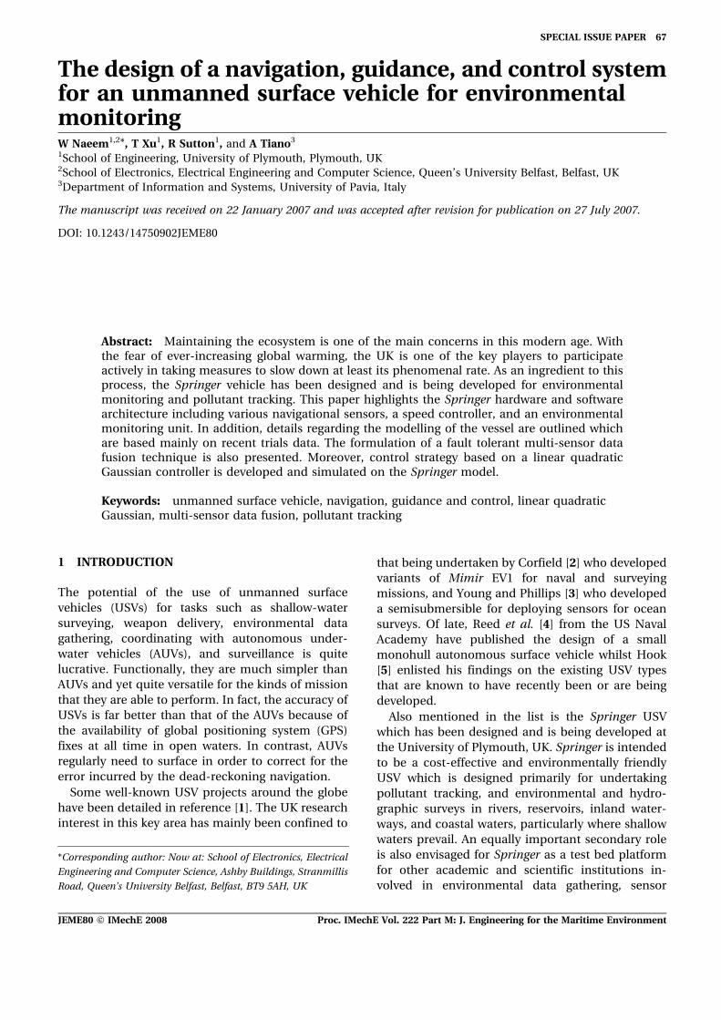
The Springer USV was designed as a mediumwaterplane twin-hull vessel which is versatile interms of mission profile and payload. It is approxi-mately 4 m long and 2.3 m wide with a displacementof 0.6 t. A schematic diagram is shown in Fig. 1showing the layout of the components within thehulls where each hull is divided into three watertightcompartments.
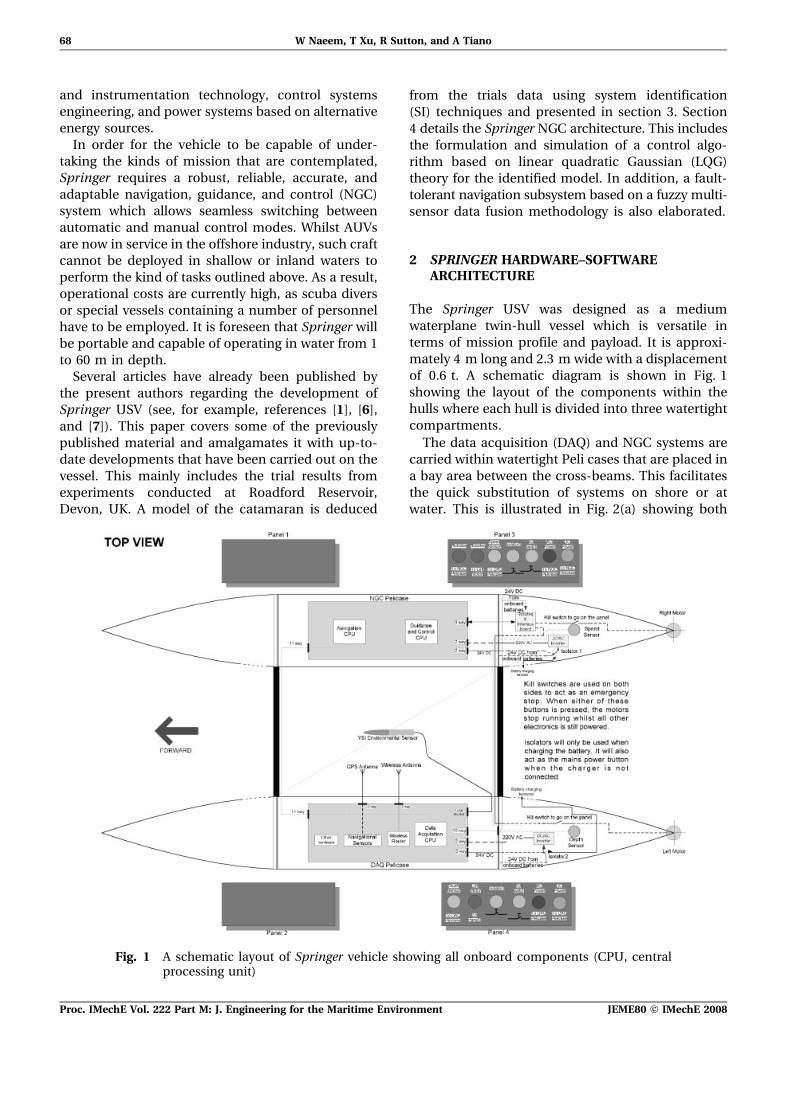
The data acquisition (DAQ) and NGC systems arecarried within watertight Peli cases that are placed ina bay area between the cross-beams. This facilitatesthe quick substitution of systems on shore or atwater. This is illustrated in Fig. 2(a) showing both
Fig. 1 A schematic layout of Springer vehicle showing all onboard components (CPU, centralprocessing unit)
68 W Naeem, T Xu, R Sutton, and A Tiano
Proc. IMechE Vol. 222 Part M: J. Engineering for the Maritime Environment JEME80 F IMechE 2008
Peli cases. In order to maintain the temperatureinside the Peli cases, an economical but effectivecooling system based on heat sinks is installed. Thisis vital for the onboard sensors; otherwise the heatgenerated by the onboard computers could gradu-ally build up to a level well outside the operatingtemperature of the sensors. An experiment is carriedout with and without the heat sinks in the Peli casesand it has been found that the heat sinks facilitatethe regulation of temperature within the Peli cases.
With the exception of the depth and speed sensorsthat are located at the bottom of the hulls, all othersensors are placed within the Peli cases. The depthsensor is shown in Fig. 2(b) whilst the speed sensoris located at the bottom of the rear section of theother hull. Within the rear section of the hulls arepresent the motor controller, radio control systems,and a.c. power source for the onboard computers.
These are mounted on custom-made plates whichare simple to install and replace.
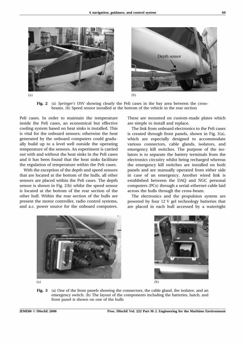
The link from onboard electronics to the Peli casesis created through front panels, shown in Fig. 3(a),which are especially designed to accommodatevarious connectors, cable glands, isolators, andemergency kill switches. The purpose of the iso-lators is to separate the battery terminals from theelectronics circuitry whilst being recharged whereasthe emergency kill switches are installed on bothpanels and are manually operated from either sidein case of an emergency. Another wired link isestablished between the DAQ and NGC personalcomputers (PCs) through a serial–ethernet cable laidacross the hulls through the cross-beam.
The electronics and the propulsion system arepowered by four 12 V gel technology batteries thatare placed in each hull accessed by a watertight
Fig. 2 (a) Springer’s USV showing clearly the Peli cases in the bay area between the cross-beams. (b) Speed sensor installed at the bottom of the vehicle in the rear section
Fig. 3 (a) One of the front panels showing the connectors, the cable gland, the isolator, and anemergency switch. (b) The layout of the components including the batteries, hatch, andfront panel is shown on one of the hulls
A navigation, guidance, and control system 69
JEME80 F IMechE 2008 Proc. IMechE Vol. 222 Part M: J. Engineering for the Maritime Environment
hatch, as shown in Fig. 3(b). These are pairedtogether to supply 24 V where each battery iscapable of sourcing 135 A h of current.
In order to prevent any catastrophe resulting froma water leakage, leak sensors are utilized within themotor housing. If a breach is detected, the onboardcomputer immediately issues warning to the userand/or takes appropriate action in order to minimizedamage to the onboard electronics.
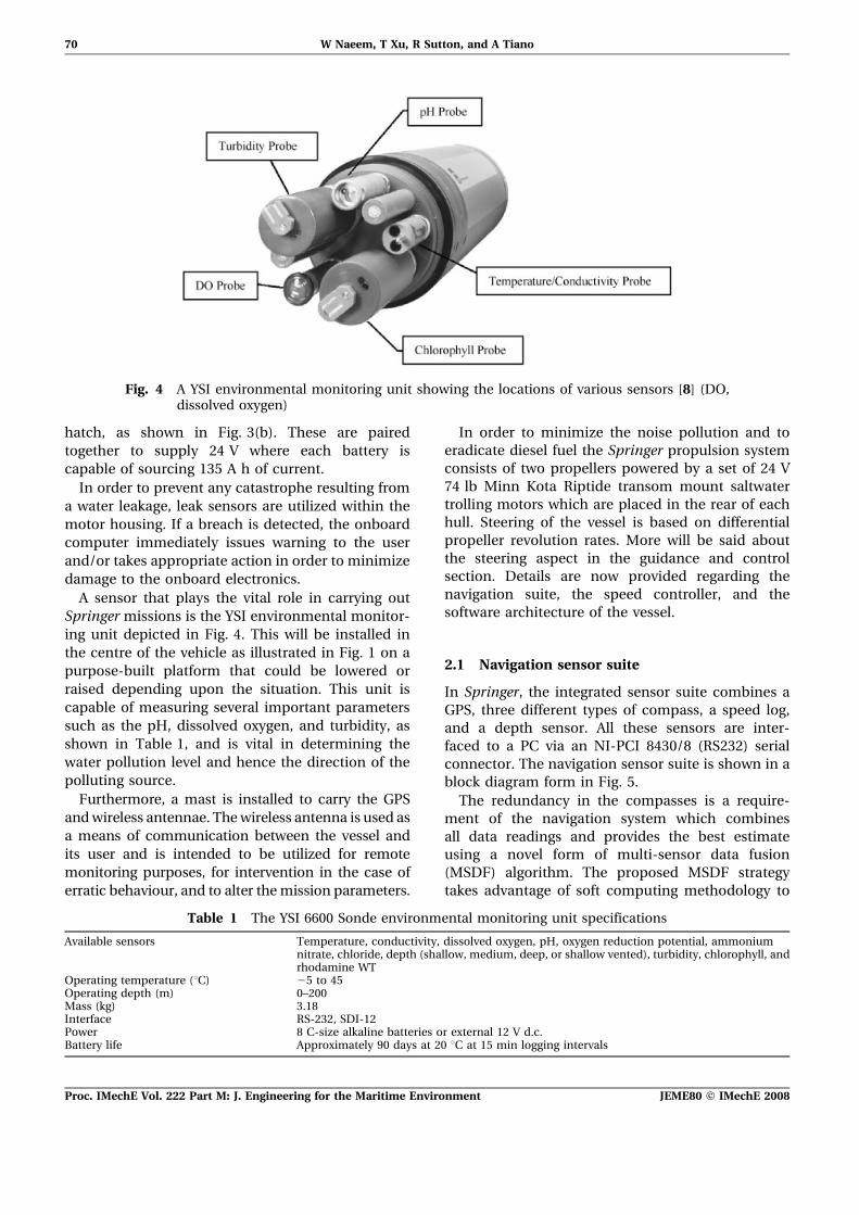
A sensor that plays the vital role in carrying outSpringer missions is the YSI environmental monitor-ing unit depicted in Fig. 4. This will be installed inthe centre of the vehicle as illustrated in Fig. 1 on apurpose-built platform that could be lowered orraised depending upon the situation. This unit iscapable of measuring several important parameterssuch as the pH, dissolved oxygen, and turbidity, asshown in Table 1, and is vital in determining thewater pollution level and hence the direction of thepolluting source.
Furthermore, a mast is installed to carry the GPSandwireless antennae. Thewireless antenna is used asa means of communication between the vessel andits user and is intended to be utilized for remotemonitoring purposes, for intervention in the case oferratic behaviour, and to alter themission parameters.
In order to minimize the noise pollution and toeradicate diesel fuel the Springer propulsion systemconsists of two propellers powered by a set of 24 V74 lb Minn Kota Riptide transom mount saltwatertrolling motors which are placed in the rear of eachhull. Steering of the vessel is based on differentialpropeller revolution rates. More will be said aboutthe steering aspect in the guidance and controlsection. Details are now provided regarding thenavigation suite, the speed controller, and thesoftware architecture of the vessel.
2.1 Navigation sensor suite
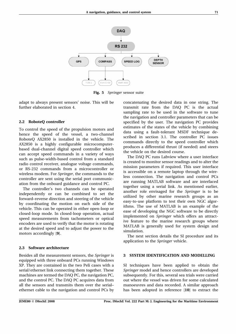
In Springer, the integrated sensor suite combines aGPS, three different types of compass, a speed log,and a depth sensor. All these sensors are inter-faced to a PC via an NI-PCI 8430/8 (RS232) serialconnector. The navigation sensor suite is shown in ablock diagram form in Fig. 5.
The redundancy in the compasses is a require-ment of the navigation system which combinesall data readings and provides the best estimateusing a novel form of multi-sensor data fusion(MSDF) algorithm. The proposed MSDF strategytakes advantage of soft computing methodology to
Fig. 4 A YSI environmental monitoring unit showing the locations of various sensors [8] (DO,dissolved oxygen)
Table 1 The YSI 6600 Sonde environmental monitoring unit specifications
Available sensors Temperature, conductivity, dissolved oxygen, pH, oxygen reduction potential, ammoniumnitrate, chloride, depth (shallow, medium, deep, or shallow vented), turbidity, chlorophyll, andrhodamine WT
Operating temperature (uC) 25 to 45Operating depth (m) 0–200Mass (kg) 3.18Interface RS-232, SDI-12Power 8 C-size alkaline batteries or external 12 V d.c.Battery life Approximately 90 days at 20 uC at 15 min logging intervals
70 W Naeem, T Xu, R Sutton, and A Tiano
Proc. IMechE Vol. 222 Part M: J. Engineering for the Maritime Environment JEME80 F IMechE 2008
adapt to always present sensors’ noise. This will befurther elaborated in section 4.
2.2 RoboteQ controller
To control the speed of the propulsion motors andhence the speed of the vessel, a two-channelRoboteQ AX2850 is installed in the vehicle. TheAX2850 is a highly configurable microcomputer-based dual-channel digital speed controller whichcan accept speed commands in a variety of wayssuch as pulse-width-based control from a standardradio control receiver, analogue voltage commands,or RS-232 commands from a microcontroller orwireless modem. For Springer, the commands to thecontroller are sent using the serial port communic-ation from the onboard guidance and control PC.
The controller’s two channels can be operatedindependently or can be combined to set theforward–reverse direction and steering of the vehicleby coordinating the motion on each side of thevehicle. This can be operated in either open-loop orclosed-loop mode. In closed-loop operation, actualspeed measurements from tachometers or opticalencoders are used to verify that the motor is rotatingat the desired speed and to adjust the power to themotors accordingly [9].
2.3 Software architecture
Besides all the measurement sensors, the Springer isequipped with three onboard PCs running WindowsXP. They are contained in the two Peli cases with aserial/ethernet link connecting them together. Thesemachines are termed the DAQ PC, the navigation PC,and the control PC. The DAQ PC acquires data fromall the sensors and transmits them over the serial–ethernet cable to the navigation and control PCs by
concatenating the desired data in one string. Thetransmit rate from the DAQ PC is the actualsampling rate to be used in the software to tunethe navigation and controller parameters that can bespecified by the user. The navigation PC providesestimates of the states of the vehicle by combiningdata using a fault-tolerant MSDF technique de-scribed in section 3.1. The controller PC issuescommands directly to the speed controller whichproduces a differential thrust (if needed) and steersthe vehicle on the desired course.
The DAQ PC runs Labview where a user interfaceis created to monitor sensor readings and to alter themission parameters if required. This user interfaceis accessible on a remote laptop through the wire-less connection. The navigation and control PCsare running MATLAB software and are interfacedtogether using a serial link. As mentioned earlier,another role envisaged for the Springer is to beutilized by other marine research groups as aneasy-to-use platform to test their own NGC algor-ithms. The use of MATLAB is an example of theease of developing the NGC software to be directlyimplemented on Springer which offers an attract-ive feature to the marine research groups whereMATLAB is generally used for system design andsimulation.
The next section details the SI procedure and itsapplication to the Springer vehicle.
3 SYSTEM IDENTIFICATION AND MODELLING
SI techniques have been applied to obtain theSpringer model and hence controllers are developedsubsequently. For this, several sea trials were carriedout where the vessel was driven for some calculatedmanoeuvres and data recorded. A similar approachhas been adopted in reference [10] to extract the
Fig. 5 Springer sensor suite
A navigation, guidance, and control system 71
JEME80 F IMechE 2008 Proc. IMechE Vol. 222 Part M: J. Engineering for the Maritime Environment
model of an AUV and proved to be quite successful.An LQG controller will then be designed for theextracted model and tested in real time.
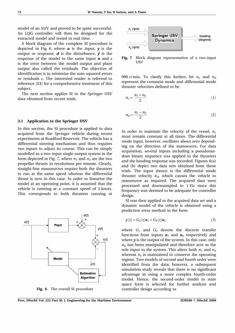
A block diagram of the complete SI procedure isdepicted in Fig. 6, where u is the input, y is theoutput or response, d is the disturbance, y is theresponse of the model to the same input u and eis the error between the model output and plantoutput also called the residuals. The objective ofidentification is to minimize the sum-squared errorsor residuals e. The interested reader is referred toreference [11] for a comprehensive treatment of thissubject.
The next section applies SI to the Springer USVdata obtained from recent trials.
3.1 Application to the Springer USV
In this section, the SI procedure is applied to dataacquired from the Springer vehicle during recentexperiments at Roadford Reservoir. The vehicle has adifferential steering mechanism and thus requirestwo inputs to adjust its course. This can be simplymodelled as a two-input single-output system in theform depicted in Fig. 7, where n1 and n2 are the twopropeller thrusts in revolutions per minute. Clearly,straight-line manoeuvres require both the thrustersto run at the same speed whereas the differentialthrust is zero in this case. In order to linearize themodel at an operating point, it is assumed that thevehicle is running at a constant speed of 3 knots.This corresponds to both thrusters running at
900 r/min. To clarify this further, let nc and nd
represent the common mode and differential modethruster velocities defined to be
nc~n1zn2
2!1"
nd~n1{n2
2!2"
In order to maintain the velocity of the vessel, nc
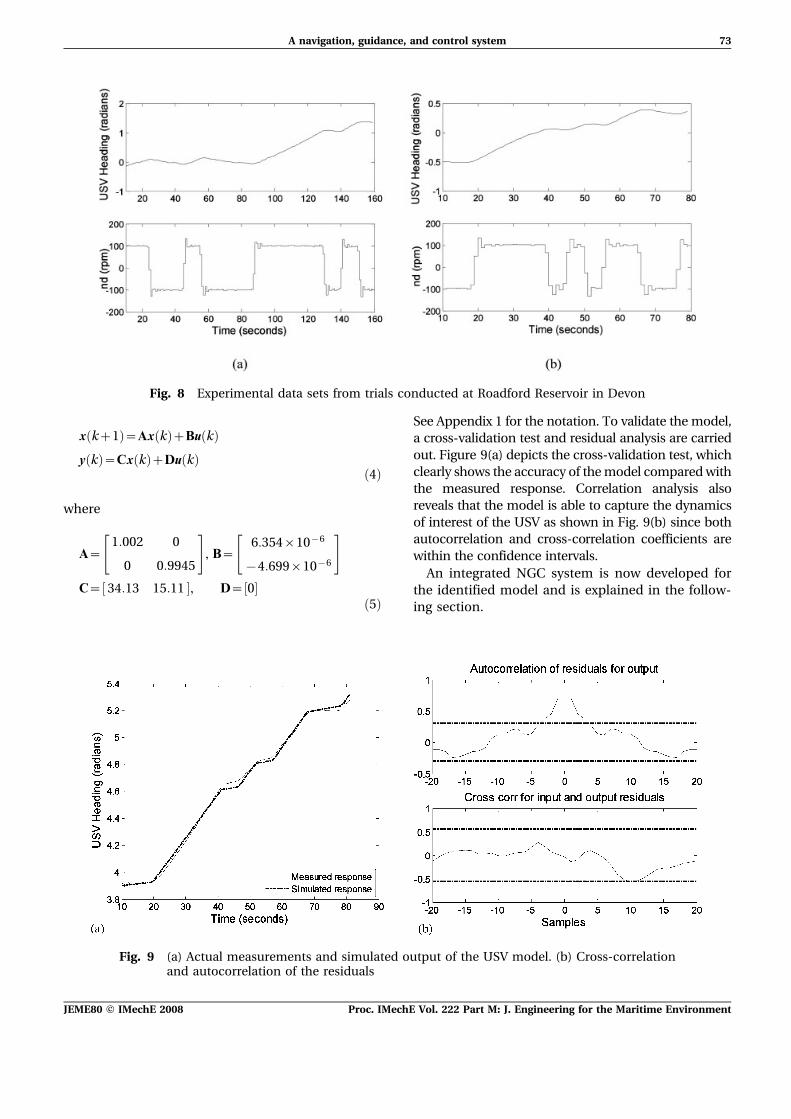
must remain constant at all times. The differentialmode input, however, oscillates about zero depend-ing on the direction of the manoeuvre. For dataacquisition, several inputs including a pseudoran-dom binary sequence was applied to the thrustersand the heading response was recorded. Figures 8(a)and (b) depict two data sets obtained from thosetrials. The input shown is the differential modethruster velocity nd, which causes the vehicle tomanoeuvre as required. The acquired data wereprocessed and downsampled to 1 Hz since thisfrequency was deemed to be adequate for controllerdesign.
SI was then applied to the acquired data set and adynamic model of the vehicle is obtained using aprediction error method in the form
y z! "~G1 z! "u1zG2 z! "u2 !3"
where G1 and G2 denote the discrete transferfunctions from inputs u1 and u2 respectively andwhere y is the output of the system. In this case, onlynd has been manipulated and therefore acts as thesole input to the system. This alters both n1 and n2
whereas nc is maintained to conserve the operatingregime. Two models of second and fourth order wereidentified from the data; however, a subsequentsimulation study reveals that there is no significantadvantage in using a more complex fourth-ordermodel. Hence, the second-order model in statespace form is selected for further analysis andcontroller design according toFig. 6 The overall SI procedure
Fig. 7 Block diagram representation of a two-inputUSV
72 W Naeem, T Xu, R Sutton, and A Tiano
Proc. IMechE Vol. 222 Part M: J. Engineering for the Maritime Environment JEME80 F IMechE 2008
x kz1! "~Ax k! "zBu k! "
y k! "~Cx k! "zDu k! "!4"
where
A~1:002 0
0 0:9945
" #
, B~6:354|10{6
{4:699|10{6
" #
C~ 34:13 15:11# $, D~ 0# $!5"
See Appendix 1 for the notation. To validate the model,a cross-validation test and residual analysis are carriedout. Figure 9(a) depicts the cross-validation test, whichclearly shows the accuracy of themodel comparedwiththe measured response. Correlation analysis alsoreveals that the model is able to capture the dynamicsof interest of the USV as shown in Fig. 9(b) since bothautocorrelation and cross-correlation coefficients arewithin the confidence intervals.
An integrated NGC system is now developed forthe identified model and is explained in the follow-ing section.
Fig. 8 Experimental data sets from trials conducted at Roadford Reservoir in Devon
Fig. 9 (a) Actual measurements and simulated output of the USV model. (b) Cross-correlationand autocorrelation of the residuals
A navigation, guidance, and control system 73
JEME80 F IMechE 2008 Proc. IMechE Vol. 222 Part M: J. Engineering for the Maritime Environment
4 NAVIGATION, GUIDANCE, AND CONTROL
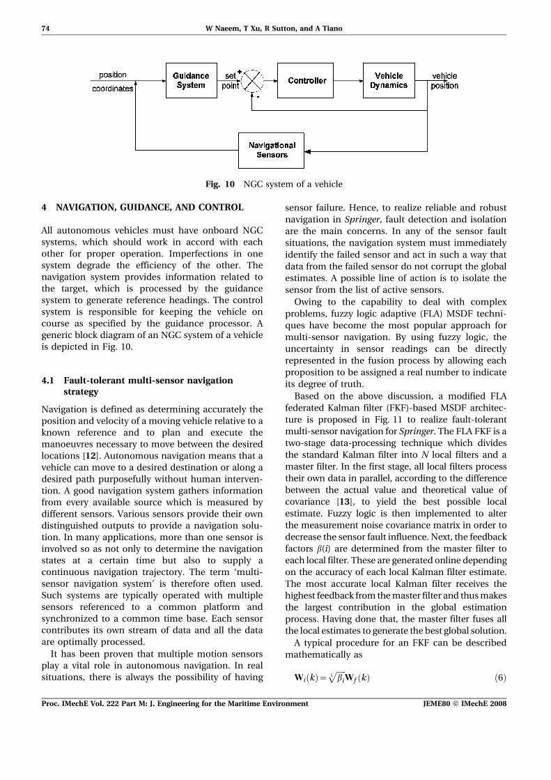
All autonomous vehicles must have onboard NGCsystems, which should work in accord with eachother for proper operation. Imperfections in onesystem degrade the efficiency of the other. Thenavigation system provides information related tothe target, which is processed by the guidancesystem to generate reference headings. The controlsystem is responsible for keeping the vehicle oncourse as specified by the guidance processor. Ageneric block diagram of an NGC system of a vehicleis depicted in Fig. 10.
4.1 Fault-tolerant multi-sensor navigationstrategy
Navigation is defined as determining accurately theposition and velocity of a moving vehicle relative to aknown reference and to plan and execute themanoeuvres necessary to move between the desiredlocations [12]. Autonomous navigation means that avehicle can move to a desired destination or along adesired path purposefully without human interven-tion. A good navigation system gathers informationfrom every available source which is measured bydifferent sensors. Various sensors provide their owndistinguished outputs to provide a navigation solu-tion. In many applications, more than one sensor isinvolved so as not only to determine the navigationstates at a certain time but also to supply acontinuous navigation trajectory. The term ‘multi-sensor navigation system’ is therefore often used.Such systems are typically operated with multiplesensors referenced to a common platform andsynchronized to a common time base. Each sensorcontributes its own stream of data and all the dataare optimally processed.
It has been proven that multiple motion sensorsplay a vital role in autonomous navigation. In realsituations, there is always the possibility of having
sensor failure. Hence, to realize reliable and robustnavigation in Springer, fault detection and isolationare the main concerns. In any of the sensor faultsituations, the navigation system must immediatelyidentify the failed sensor and act in such a way thatdata from the failed sensor do not corrupt the globalestimates. A possible line of action is to isolate thesensor from the list of active sensors.
Owing to the capability to deal with complexproblems, fuzzy logic adaptive (FLA) MSDF techni-ques have become the most popular approach formulti-sensor navigation. By using fuzzy logic, theuncertainty in sensor readings can be directlyrepresented in the fusion process by allowing eachproposition to be assigned a real number to indicateits degree of truth.
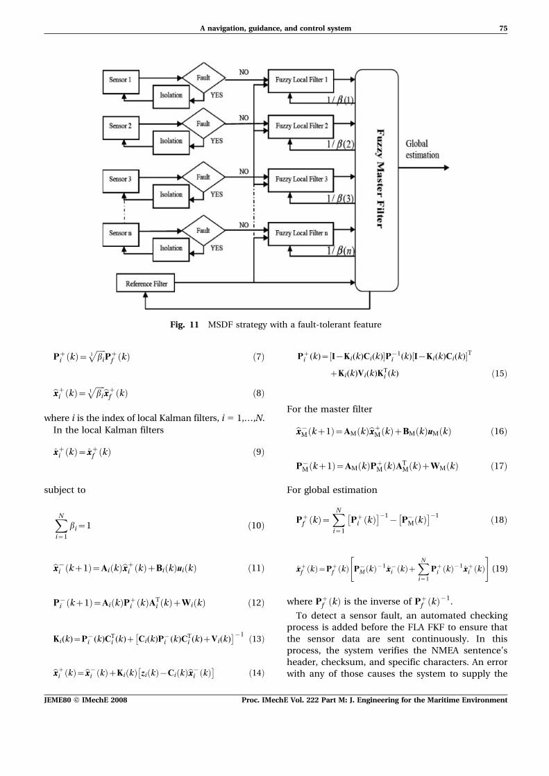
Based on the above discussion, a modified FLAfederated Kalman filter (FKF)-based MSDF architec-ture is proposed in Fig. 11 to realize fault-tolerantmulti-sensor navigation for Springer. The FLA FKF is atwo-stage data-processing technique which dividesthe standard Kalman filter into N local filters and amaster filter. In the first stage, all local filters processtheir own data in parallel, according to the differencebetween the actual value and theoretical value ofcovariance [13], to yield the best possible localestimate. Fuzzy logic is then implemented to alterthe measurement noise covariance matrix in order todecrease the sensor fault influence. Next, the feedbackfactors b(i) are determined from the master filter toeach local filter. These are generated online dependingon the accuracy of each local Kalman filter estimate.The most accurate local Kalman filter receives thehighest feedback from themaster filter and thusmakesthe largest contribution in the global estimationprocess. Having done that, the master filter fuses allthe local estimates to generate the best global solution.
A typical procedure for an FKF can be describedmathematically as
Wi k! "~!!!!!bi
1p
Wf k! " !6"
Fig. 10 NGC system of a vehicle
74 W Naeem, T Xu, R Sutton, and A Tiano
Proc. IMechE Vol. 222 Part M: J. Engineering for the Maritime Environment JEME80 F IMechE 2008
Pzi k! "~
!!!!!bi
1p
Pzf k! " !7"
bxxzi k! "~!!!!!bi
1p
bxxzf k! " !8"
where i is the index of local Kalman filters, i 5 1,…,N.In the local Kalman filters
xxzi k! "~xxzf k! " !9"
subject to
XN
i~1
bi~1 !10"
bxx{i kz1! "~Ai k! "bxxzi k! "zBi k! "ui k! " !11"
P{i kz1! "~Ai k! "Pz
i k! "ATi k! "zWi k! " !12"
Ki(k)~P{i (k)CT
i (k)z Ci(k)P{i (k)CT
i (k)zVi(k)" #{1 !13"
bxxzi k! "~bxx{i k! "zKi k! " zi k! "{Ci k! "bxx{i k! "" #
!14"
Pzi (k)~ I{Ki(k)Ci(k)# $P{1
i (k) I{Ki(k)Ci(k)# $T
zKi(k)Vi(k)KTi (k) !15"
For the master filter
bxx{M kz1! "~AM k! "bxxzM k! "zBM k! "uM k! " !16"
P{M kz1! "~AM k! "Pz
M k! "ATM k! "zWM k! " !17"
For global estimation
Pzf k! "~
XN
i~1
Pzi k! "
" #%1{ P%
M k! "" #%1 !18"
xxzf k! "~Pzf k! " P{
M k! "{1xx{i k! "zXN
i~1
Pzi k! "{1xxzi k! "
" #
!19"
where Pzf k! " is the inverse of Pz
f k! "{1.
To detect a sensor fault, an automated checkingprocess is added before the FLA FKF to ensure thatthe sensor data are sent continuously. In thisprocess, the system verifies the NMEA sentence’sheader, checksum, and specific characters. An errorwith any of those causes the system to supply the
Fig. 11 MSDF strategy with a fault-tolerant feature
(19)
A navigation, guidance, and control system 75
JEME80 F IMechE 2008 Proc. IMechE Vol. 222 Part M: J. Engineering for the Maritime Environment
previous measurements instead of the currentmeasurement. If this is persistent, the failed sensorsare isolated immediately. This mechanism cansimply improve the computation efficiency whenthe system is working under a large and complexsensor network. On the other hand, a GPS output isrequested by the system at the same sampling rate asother sensors. The current GPS data update rate is1 Hz, which is much slower than any other naviga-tion sensor on the Springer. This is done so that theGPS information not only provides location of thevehicle but also guarantees successful vehicle opera-tion even in the worst-case scenario of the failure ofall compasses.
The next section details the formulation of aguidance and control strategy for the Springervehicle.
4.2 Guidance and control
Certain guidance laws will be utilized in the Springervehicle and integrated with the control system toperform various missions. The simplest of these isthe line-of-sight (LOS) guidance which is at the heartof most guidance laws. In this guidance strategy, thevehicle follows the course between any two givenpoints. Another version of the LOS is the waypointguidance where a number of waypoints are definedbetween the start and destination coordinates. Thenext waypoint is selected when the vehicle enterswithin the circle of acceptance (defined as twice thelength of the vehicle) of the current waypoint. Acomprehensive review of guidance strategies forunmanned underwater and airborne vehicles hasbeen carried out by Naeem et al. [14]. For environ-mental monitoring, for instance to detect the sourceof a chemical discharge, the standard guidancesystem is replaced. In this case, the USV followsthe direction of a chemical plume detected by the
onboard sensors and the vessel is guided towards thesource of the discharge. The reader is referred toanother review paper [15] which is mainly based onchemical plume tracing and odour source localiz-ation by autonomous vehicles.
As mentioned earlier, the steering of Springer isbased on differential thrust. The vehicle will traversein a straight line if the speeds of the propellers arethe same. Any difference in the propellers’ speedsmakes the vehicle turn in one direction or the other.To maintain the speed of the vessel at all times, it isimportant that the average speeds of the propellersare kept the same. The manoeuvres are thenobtained by changing the revolution rates of bothmotors whilst keeping the average speeds constantat all times.
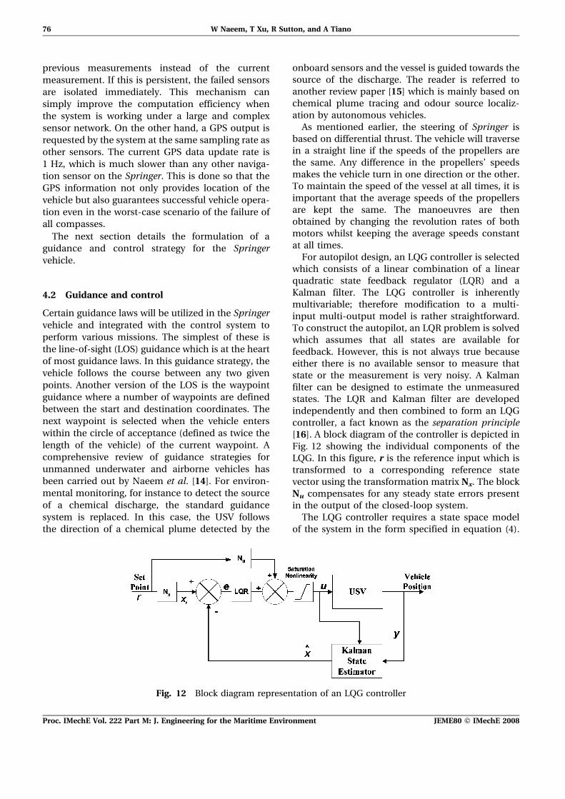
For autopilot design, an LQG controller is selectedwhich consists of a linear combination of a linearquadratic state feedback regulator (LQR) and aKalman filter. The LQG controller is inherentlymultivariable; therefore modification to a multi-input multi-output model is rather straightforward.To construct the autopilot, an LQR problem is solvedwhich assumes that all states are available forfeedback. However, this is not always true becauseeither there is no available sensor to measure thatstate or the measurement is very noisy. A Kalmanfilter can be designed to estimate the unmeasuredstates. The LQR and Kalman filter are developedindependently and then combined to form an LQGcontroller, a fact known as the separation principle[16]. A block diagram of the controller is depicted inFig. 12 showing the individual components of theLQG. In this figure, r is the reference input which istransformed to a corresponding reference statevector using the transformation matrix Nx. The blockNu compensates for any steady state errors presentin the output of the closed-loop system.
The LQG controller requires a state space modelof the system in the form specified in equation (4).
Fig. 12 Block diagram representation of an LQG controller
76 W Naeem, T Xu, R Sutton, and A Tiano
Proc. IMechE Vol. 222 Part M: J. Engineering for the Maritime Environment JEME80 F IMechE 2008
The parameters A, B, C, and D are also definedin equation (5) for the Springer vehicle. A uniqueclosed-form solution of the LQG control law isdefined as
u k! "~KLQR xr k! "{bxx k! "# $ !20"
See Appendixes 2 and 3 for Kalman filter equationsand a derivation of the Nx and Nu blocks respectively.
Herein, the intention is to validate the model ofthe USV by generating a step response throughsimulation of a closed-loop control system. It shouldbe noted that most of the missions undertaken byunmanned vehicles are mainly based on following aspecified heading angle or following the LOS anglebetween two waypoints. Hence it is found sufficientto include only a step response of the Springermodelto validate the closed-loop system.
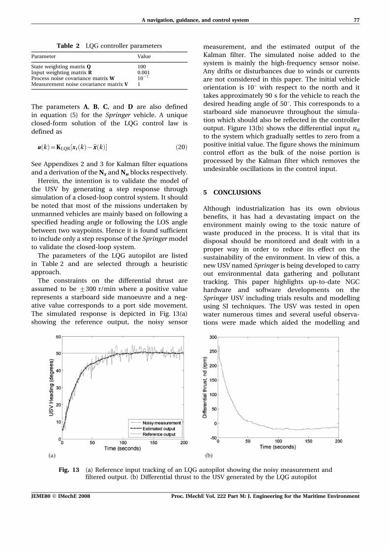
The parameters of the LQG autopilot are listedin Table 2 and are selected through a heuristicapproach.
The constraints on the differential thrust areassumed to be ¡300 r/min where a positive valuerepresents a starboard side manoeuvre and a neg-ative value corresponds to a port side movement.The simulated response is depicted in Fig. 13(a)showing the reference output, the noisy sensor
measurement, and the estimated output of theKalman filter. The simulated noise added to thesystem is mainly the high-frequency sensor noise.Any drifts or disturbances due to winds or currentsare not considered in this paper. The initial vehicleorientation is 10u with respect to the north and ittakes approximately 90 s for the vehicle to reach thedesired heading angle of 50u. This corresponds to astarboard side manoeuvre throughout the simula-tion which should also be reflected in the controlleroutput. Figure 13(b) shows the differential input nd
to the system which gradually settles to zero from apositive initial value. The figure shows the minimumcontrol effort as the bulk of the noise portion isprocessed by the Kalman filter which removes theundesirable oscillations in the control input.
5 CONCLUSIONS
Although industrialization has its own obviousbenefits, it has had a devastating impact on theenvironment mainly owing to the toxic nature ofwaste produced in the process. It is vital that itsdisposal should be monitored and dealt with in aproper way in order to reduce its effect on thesustainability of the environment. In view of this, anew USV named Springer is being developed to carryout environmental data gathering and pollutanttracking. This paper highlights up-to-date NGChardware and software developments on theSpringer USV including trials results and modellingusing SI techniques. The USV was tested in openwater numerous times and several useful observa-tions were made which aided the modelling and
Table 2 LQG controller parameters
Parameter Value
State weighting matrix Q 100Input weighting matrix R 0.001Process noise covariance matrix W 1027
Measurement noise covariance matrix V 1
Fig. 13 (a) Reference input tracking of an LQG autopilot showing the noisy measurement andfiltered output. (b) Differential thrust to the USV generated by the LQG autopilot
A navigation, guidance, and control system 77
JEME80 F IMechE 2008 Proc. IMechE Vol. 222 Part M: J. Engineering for the Maritime Environment
control system design. An LQG autopilot is formu-lated and simulated for the identified model. Resultsare shown which clearly validate the suitability ofthe model and the autopilot. Furthermore, a novelform of MSDF algorithm based on soft computingmethodology is proposed. The next step is to imp-lement the integrated NGC system in real time andto assess the autonomous performance of the vesselin full-scale sea trials.
ACKNOWLEDGEMENT
The authors wish to acknowledge the Engineeringand Physical Sciences Research Council for fundingthis project.
REFERENCES
1 Naeem, W., Xu, T., Chudley, J., and Sutton, R.Design of an unmanned surface vehicle forenvironmental monitoring. In Proceedings of theWorld Maritime Technology Conference, London,UK, March 2006.
2 Corfield, S. J. Unmanned surface vehicles andother things. In Proceedings of the UnmannedUnderwater Vehicle Showcase 2002 Conference,Southampton, UK, 2002, pp. 83–91.
3 Young, H. W. and Phillips, S. J. Development of anautonomous semi-submersible for deploying sen-sors for ocean survey. In Proceedings of theInternational UUV Symposium, Newport, RhodeIsland, USA, 2000.
4 Reed, C. M., Bishop, B. E., andWaters, J. K. Designof an autonomous surface vessel. In Proceedingsof the World Maritime Technology Conference,London, UK, March 2006.
5 Hook, D. J. Development of unmanned surfacevehicles. In Proceedings of the World MaritimeTechnology Conference, London, UK, March 2006.
6 Naeem, W., Xu, T., Sutton, R., and Chudley, J.Design of an unmanned catamaran with pollutanttracking and surveying capabilities. In Proceedingsof the UKACC International Control Conference,IMechE Mini Symposia, Glasgow, Scotland, UK,August 2006, pp. 99–113 (Institution of Engineeringand Technology, London).
7 Xu, T., Chudley, J., and Sutton, R. A fuzzy logicbased multi-sensor navigation system for anunmanned surface vehicle. In Proceedings ofthe UKACC International Control Conference,Glasgow, UK, August 2006.
8 YSI environmental operations manual, availablefrom http://www.YSI.com, date accessed, 18October 2005.
9 RoboteQ AX2550/2850 user’s manual, availablefrom http://www.roboteq.com, date accessed, 18October 2005.
10 Naeem, W. Guidance and control of an autono-mous underwater vehicle. PhD Thesis, School ofEngineering, University of Plymouth, 2004.
11 Ljung, L. System identification, theory for the user,2nd edition, 1999 (Prentice-Hall PTR, EnglewoodCliffs, New Jersey).
12 Farrell, A. J. and Barth, M. The global positioningsystem and inertial navigation, 1999 (McGraw-Hill,New York).
13 Mehra, R. On the identification of variances andadaptive Kalman filtering. IEEE Trans. Autom.Control, 1970, 15(2), 175–184.
14 Naeem, W., Sutton, R., Ahmad, S. M., and Burns,R. S. A review of guidance laws applicable tounmanned underwater vehicles. J. Navig., 2003,56(1), 15–29.
15 Naeem, W., Sutton, R., and Chudley, J. Chemicalplume tracing and odour source localisation byautonomous vehicles. J. Navig., 2007, 60(2), 173–190.
16 Burl, J. B. Linear optimal control, H2 and H‘
methods, 1999 (Addison-Wesley Longman, Read-ing, Massachusetts).
17 Franklin, G. F., Powell, J. D., and Workman, M.Digital control of dynamic systems, 3rd edition, 1998(Addison-Wesley Longman, Reading,Massachusetts).
APPENDIX 1
Notation
d disturbance inputK Kalman filter gainKLQR LQR gain of the controllernc common mode thruster velocity
(r/min)nd differential mode thruster velocity
(r/min)n1, n2 thruster velocities of individual
propellersNu steady state error compensatorNx reference state transformation matrixP error covariance matrixu input to the systemv measurement noiseV measurement noise covariance
matrixw process noiseW process noise covariance matrixx state vector of the processxr reference state vectorxss system state vector at steady statex estimated state vectory output of the systemy predicted output from the model
b adaptive feedback factor of the pro-posed fuzzy multi-sensor data fusionalgorithm
78 W Naeem, T Xu, R Sutton, and A Tiano
Proc. IMechE Vol. 222 Part M: J. Engineering for the Maritime Environment JEME80 F IMechE 2008
APPENDIX 2
Given a discrete-time controlled process describedby the linear stochastic difference equations
x kz1! "~Ax k! "zBu k! "zw k! "
z k! "~Cx k! "zDu k! "zv k! "!21"
where x(k) is an n6 1 state vector, A is an n6n statetransition matrix, u(k) is an l61 input vector, B is ann 6 l matrix, w(k) is an n 6 1 process noise vector,z(k) is an m6 1 measurement vector, C(k) is an m6n measurement matrix, and v(k) is an m 6 1measurement noise vector. Both w(k) and v(k) areassumed to be uncorrelated zero mean Gaussianwhite-noise sequences with covariances given by
E w k! "wT i! "" #
~W k! ",
0,
i~k
i=k
(
E v k! "vT i! "" #
~V k! ",
0,
i~k
i=k
(
E w k! "vT i! "" #
~0, for all k and i
The Kalman filter equations can be written into thetime update equations
bxx kz1! "~Abxx k! "zBu k! " !22"
P{ kz1! "~AP k! "ATzW k! " !23"
and the measurement update equations
K k! "~P{ k! "CT CP{ k! "CTzV k! "" #{1 !24"
bxx k! "~bxx{ k! "zK k! " z k! "{Cbxx{ k! "# $ !25"
P k! "~ I{K k! "C# $P{ k! " !26"
The measurement update equations incorporate anew observation into the a priori estimate fromthe time update equations to obtain an improved aposteriori estimate. In the time and measurementupdate equations, x is an estimate of the systemstate vector x, K is the Kalman gain, and P is thecovariance matrix of the state estimation error.
APPENDIX 3
A derivation has been carried out herein to evaluatethe contents of blocks Nx and Nu in Fig. 12 forreference input tracking in an LQR control strategy[17].
Let Nx denote the forward block which transformsthe reference input r to a reference state xr i.e. anequilibrium state for that r. Mathematically, this canbe stated as
Nxr~xr !27"
u~{KLQR x{xr! " !28"
The final or steady state value of the states can bewritten as
x ?! "~xss~xr[Nxr~xr~xss !29"
To compensate for any steady state output error inthe case of type 0 systems, a steady state controlterm is needed that is proportional to the referenceinput according to
uss~Nur !30"
Also
Cxss~y~r[CNxr~r[CNx~I !31"
Since the system is at steady state, i.e. x(k+1)5 x(k)5 xss and u 5 uss, therefore
xss~AxsszBuss[ A{I! "xsszBuss~0 !32"
Substituting equations (30) and (31) in the aboveequations gives
A{I! "NxrzBNur~0[ A{I! "NxzBNu~0 !33"
Finally writing equations (31) and (33) in matrixform gives
A{I
C
B
0
$ %Nx
Nu
$ %~
0
I
$ %!34"
and solving for Nx and Nu yields the desired result
Nx
Nu
$ %~
A{I
C
B
0
$ %{1 0
I
$ %!35"
A navigation, guidance, and control system 79
JEME80 F IMechE 2008 Proc. IMechE Vol. 222 Part M: J. Engineering for the Maritime Environment