Embed Size (px)
Citation preview

Vol. 130 (2016) ACTA PHYSICA POLONICA A No. 1
Special issue of the 2nd International Conference on Computational and Experimental Science and Engineering (ICCESEN 2015)
Thermodynamic Analysis of a Cascade Refrigeration SystemR. Karaali∗
aDepartment of Mechanical Engineering, Bayburt University, 69000 Bayburt, Turkey
There is a need for cooling by using the waste heat energy in food industry. Absorption cycles can bedriven by waste thermal, geothermal, solar or industrial processes energies. In this study, cascade refrigerationsystem is thermodynamically modeled, and analyzed by using first law of thermodynamics, and exergy method.Thermodynamic properties such as pressure, temperature, entropy, enthalpy, exergy, mass flow rate in each streamare calculated for 50, 75, 100 ◦C and for 0.8, 1.0, and 1.5 MPa pump pressure. A computer program is used thatwas prepared in FORTRAN by the author for the analyses. It is found that the compression-absorption cascadecooling cycle is appropriate for most of the kind of waste heat applications. Increase of the generator inlet heattemperature increases the generator inlet heat, the absorber outlet heat and the condenser 2 outlet heat energiesand decreases the coefficient of performance of the absorption and the overall cycles. The generator heat decreaseswith increase of the pump pressure. Also increase of the pump pressure decreases the coefficient of performanceof the absorption and the overall cycles. Increase of the pump pressure and the generator temperature decreasesthe exergetic coefficient of performance. Increase of the generator temperature and pump pressure increases thegenerator inlet exergy. It is concluded that increase of the generator temperature and the pump pressure increasesthe total destructed exergy of the cycle.
DOI: 10.12693/APhysPolA.130.101PACS/topics: 88.05.Sv, 88.10.cn
1. Introduction
Waste heat is an important energy resource for manyindustrial applications, because of the environmentalproblems and economical use of energy. Using waste heatis one of the best solutions especially for cooling appli-cations. To reduce the demand on electricity supply theabsorption refrigeration systems are very helpful. By us-ing inexpensive geothermal, biomass, waste heat, or so-lar energy sources absorption cooling can be done. Cas-caded refrigeration systems maintain the advantages ofboth vapor compression and absorption refrigeration sys-tems. Because the synthetic refrigerants (CFC’s, HFC’s)have environmental problems, natural substances such aswater–lithium bromide or ammonia–water pair startedto be used for cooling purposes. Ammonia–water solu-tions are available refrigerants for cooling systems. Forusing low temperatures heat sources, the most commonworking fluids for cooling are water–lithium bromide orammonia–water solutions [1]. The main advantage of theammonia–water cooling is that ammonia can evaporateat lower temperatures. The structure of the system ismore complex than the compression vapour cycles. Alsoits coefficient of performance is lower than the other cool-ing systems.
The thermodynamic analysis of an absorption-vaporcompression cascade cooling system is done in this study.One of study in literature on the comparison of NH3–H2O, NH3–LiNO3 and NH3–NaSCN absorption refriger-ation systems by using energy analysis method has been
∗e-mail: [email protected]
done by Sun [2]. He found that for temperatures be-low –10 ◦C the performance of the ammonia–water is bet-ter than the ammonia-lithium nitrate and the ammonia-sodium thiocyanate. However the ammonia-lithium ni-trate and the ammonia-sodium thiocyanate give betterperformance than the ammonia–water over –10 ◦C tem-peratures [2]. Seara et al. have found that the use ofCO2 or NH3 as refrigerants in compression stage doesnot affect significantly the operating conditions of theabsorption stage and they explained in their study onenergy analysis of compression-absorption cascade refrig-eration systems [3]. Cimsit and Ozturk have found that48–51% less electric energy is consumed in compression-absorption cascade refrigeration cycles than the classicvapor compression cycles for the same cooling capac-ity [4]. Jain et al. showed that electric power consump-tion in vapor compression absorption (LiBr–H2O) cas-caded refrigeration system is reduced by 61% and coef-ficient of performance (COP) of compression section isimproved by 155% as compared with equivalent vaporcompression refrigeration system [5]. Also Jain et al.have studied on thermo-economic optimization of thiscycle and found that this cycle decreases the total an-nual cost by 11.9% [6]. In addition, Jain et al., in theirrecent study have analyzed thermo-economic and envi-ronmental optimization of this cycle and found that themulti objective optimization is better than the thermo-economic optimization [7]. Xu et al. present a novel ab-sorption compression cascade refrigeration system whichcan reach an evaporating temperature –170 ◦C in theirstudy. They found in their theoretical energy analysisand experimental study that the performance of com-pression subsystem is improved and comparing theoret-ical data with experimental data the variation tendencywere similar [8]. Chen et al. proposes a novel heat driven
(101)

102 R. Karaali
absorption compression refrigeration system which canproduce 46% more cooling energy than the reference sys-tem and can reach a temperature as low as –60 ◦C [9].Mehrpooya et al. in their study introduced a novel mixedfluid cascade natural gas liquefaction process configura-tion using absorption refrigeration system obtained byreplacement of some vapor compression refrigeration cy-cles and they found that 30% reduction in power con-sumption could be achieved [10].
To obtain the exergetic analysis of the compression-absorption cascade refrigeration systems and the ex-ergetic destructions in the components which useammonia–water solutions is the goal of this study.
2. Description and analysis of the cycle
The pure accepted ammonia, the strong ammonia–water solution and the weak ammonia–water solution arethe three kinds of working fluids used in the ammonia–water cycles. The remaining solution is accepted as theweak ammonia–water solution that in the boiling processof the ammonia vapor leaves from the strong ammonia–water solution. In the analysis these assumptions havebeen done; the cycle is under steady state conditions,ammonia–water solutions are in the equilibrium for theirpressures and temperatures, ammonia–water mixtures
are in the states of Table I as given, the pressure losses inthe cycle are neglected, the ammonia vapor is condensedat the outlet of the condenser 2 and the isentropic effi-ciency of the compressor is ηis = 0.90.
For the cycles use as a working fluid the thermody-namic properties of ammonia–water solution are veryimportant. A thermodynamic design data and optimumdesign maps for absorption refrigeration systems hasbeen proposed by Sun, in his study. But the results ofthe equations proposed by him are for a limited rangeand difficult to use [11]. Calculating the enthalpy andthe entropy values of the ammonia–water mixtures canbe done with three methods. Those are the El-Sayedand Tribus method, the Gibbs free energy method, andthe Park and Sonntag method [2]. In this study, thetables of the enthalpy values of the ammonia–watermixtures are taken from Ref. [12] which is derivedfrom the Park and Sonntag method which uses theHelmholtz free energy equations. In Ref. [12], for pureammonia vapor at 1 atm pressure and at 195.495 Ktemperature are taken as the reference state valueswhich are u0 = 0, h0 = 0 and s0 = 0. However, in thisstudy for the sake of simplicity and understandability,for the mixture of water–ammonia, the reference statevalues are taken at 100 kPa pressure and –50 ◦C temper-ature as h0 = 118.47 kJ/kg and s0 = 0.5659 kJ/(kg K)
TABLE I
Mass, energy and exergy equations [13, 14] for each component and for overall cycle
Component Mass equation Energy equation Exergy equation
pump m1 = m2 WP = m1[h2 − h1)E1 = m1[h1 − h0 − T0(s1 − s0)]E2 = m2[h2 − h0 − T0(s2 − s0)]
m2 = m3E3 = m3[h3 − h0 − T0(s3 − s0)]
heat exchanger m2(h3 − h2) = m4[h4 − h5) E4 = m4[h4 − h0 − T0(s4 − s0)]m4 = m5
E5 = m5[h5 − h0 − T0(s5 − s0)]generator m3 = m7 + m4 m3h3 + QG = m4h4 + m7h7 E7 = m7[h7 − h0 − T0(s7 − s0)]condenser 2 m7 = m8 m8h8 + QC2 = m7h7 E8 = m8[h8 − h0 − T0(s8 − s0)]
evaporator 2 m9 = m10 m9h9 + QC1 = m10h10
E9 = m9[h9 − h0 − T0(s9 − s0)]E10 = m10[h10 − h0 − T0(s10 − s0)]
absorber m1 = m6 + m10 QA = m10h10 + m6h6 − m1h1 E6 = m6[h6 − h0 − T0(s6 − s0)]
condenser 1 m11 = m12 m12h12 + QC1 = m11h11
E11 = m11[h11 − h0 − T0(s11 − s0)]E12 = m12[h12 − h0 − T0(s12 − s0)]
evaporator 1 m13 = m14 m13h13 + QE1 = m14h14 E13 = m13[h13 − h0 − T0(s13 − s0)]compressor m14 = m11 WC = m14[h11 − h14)/ηC E14 = m14[h14 − h0 − T0(s14 − s0)]
overall cycle
msolution = mAmmonia + mwater
msolXsol = mAmmoniaXAmmonia + mwaterXwater
(QG + QE1 + WC + WP)inlet energy =
(QA + QC2)outlet energy
COP of the absorption section,COPAB = QE2/QG
COP of the compression section,COPC = QE1/WC
COP of the overall cycle,COPOC = QE1/(WC + QG)
TE1 = T13+T142
, TE2 = T9+T102
EE1 = QE1
(1− T0
TE1
)
exergetic COP of the overall cycle,
ECOPOC =QE1
(1− T0
TE1
)WC+QG
(1− T0
TG
)EE2 = QC1
(1− T0
TE2
)EG = E4 + E7 − E3
ED,A = E10 + E6 − E1
ED,C2 = E7 − E8
ED,HE = E4 + E2 − E3 − E5
ED,E2 = E9 + EE2 − E12
ED,C1 = E11 − E12 − EE2

Thermodynamic Analysis of a Cascade Refrigeration System 103
which is given in Ref. [12]. The reference state values forrefrigerant 134a are taken at 51.64 kPa pressure and –40 ◦C temperature as h0 = 0 kJ/kg and s0 = 0 kJ/(kg K)which is given in Ref. [13].
Fig. 1. Compression-absorption cascade cooling cycle.
The strong solution of NH3–H2O is pumped throughthe heat exchanger from the absorber. The high-pressuremixture enters the generator after heating in heat ex-changers. The hot ammonia vapor is condensed in thecondenser and the weak solution is sent back to the ab-sorber after giving its some heat energy in the heat ex-changer. In the absorber the strong solution is obtainedby absorption the ammonia vapor. The ammonia as asaturated liquid after the condenser passes through an ex-pansion valve. After the expansion valve the fluid passesthrough the evaporator.
In the evaporator liquid ammonia is evaporated by us-ing the heat of the condenser of the vapour compressioncycle. The cold vapour then enters the absorber, whereit is mixed with the hot solution and is absorbed. At thevapour compression section the vapour fluid of R134-a iscompressed to the high pressure at the compressor andthen enters to the condenser. The vapour is condensed inthe condenser and then the pressure of the liquid refrig-erant is reduced in the expansion valve and then entersinto evaporator.
There is no mass inlet or outlet of the cycle so that thecycle is a close cycle. The thermodynamic analysis of thecycle that is given in Fig. 1, will be done by using thethermodynamic modeling of the cycle for each componentand for overall cycle. The mass, energy, stream exergy,destructed exergy, exergy of the components, COP, andexergetic coefficient of performance (ECOP) equationsused in modeling and calculations are given in Table I.
3. Results and discussion
The temperature of most of the kinds of waste heatapplications is over 50 ◦C. The temperature of the heatgiven into the boiler is taken as 50 ◦C, 75 ◦C, 100 ◦C andthis means that the compression-absorption cascade cool-ing cycle is appropriate for most of the kinds of waste heatapplications. The power spends for the refrigeration sys-tems can be decreased by about 30–50% by using thiswaste heat in absorption cooling system integrated withrefrigeration systems.
Fig. 2. Variation of energy with pressure of the cyclefor 75 ◦C temperature of generator.
Fig. 3. Variation of COP with generator temperaturefor different pump pressure.
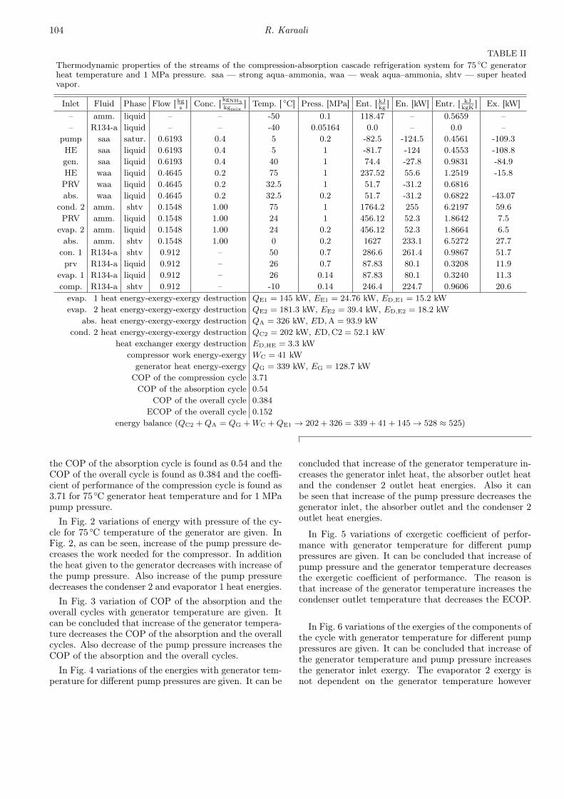
The description, the fluid, the concentration, the massflow rate, the phase, the pressure, the temperature, theenthalpy, and the energy of each streams of the cycle aregiven in Table II for 75 ◦C generator heat temperatureand for 1 MPa pump pressure. Also the heat energiesof the evaporator 1, the absorber, the condenser 2, thecompressor and the generator are given. In addition
104 R. Karaali
TABLE IIThermodynamic properties of the streams of the compression-absorption cascade refrigeration system for 75 ◦C generatorheat temperature and 1 MPa pressure. saa — strong aqua–ammonia, waa — weak aqua–ammonia, shtv — super heatedvapor.
Inlet Fluid Phase Flow [ kgs] Conc. [ kgNH3
kgmix] Temp. [ ◦C] Press. [MPa] Ent. [ kJ
kg] En. [kW] Entr. [ kJ
kgK] Ex. [kW]
– amm. liquid – – -50 0.1 118.47 – 0.5659 –– R134-a liquid – – -40 0.05164 0.0 – 0.0 –
pump saa satur. 0.6193 0.4 5 0.2 -82.5 -124.5 0.4561 -109.3HE saa liquid 0.6193 0.4 5 1 -81.7 -124 0.4553 -108.8gen. saa liquid 0.6193 0.4 40 1 74.4 -27.8 0.9831 -84.9HE waa liquid 0.4645 0.2 75 1 237.52 55.6 1.2519 -15.8PRV waa liquid 0.4645 0.2 32.5 1 51.7 -31.2 0.6816abs. waa liquid 0.4645 0.2 32.5 0.2 51.7 -31.2 0.6822 -43.07
cond. 2 amm. shtv 0.1548 1.00 75 1 1764.2 255 6.2197 59.6PRV amm. liquid 0.1548 1.00 24 1 456.12 52.3 1.8642 7.5
evap. 2 amm. liquid 0.1548 1.00 24 0.2 456.12 52.3 1.8664 6.5abs. amm. shtv 0.1548 1.00 0 0.2 1627 233.1 6.5272 27.7con. 1 R134-a shtv 0.912 – 50 0.7 286.6 261.4 0.9867 51.7prv R134-a liquid 0.912 – 26 0.7 87.83 80.1 0.3208 11.9
evap. 1 R134-a liquid 0.912 – 26 0.14 87.83 80.1 0.3240 11.3comp. R134-a shtv 0.912 – -10 0.14 246.4 224.7 0.9606 20.6evap. 1 heat energy-exergy-exergy destruction QE1 = 145 kW, EE1 = 24.76 kW, ED,E1 = 15.2 kWevap. 2 heat energy-exergy-exergy destruction QE2 = 181.3 kW, EE2 = 39.4 kW, ED,E2 = 18.2 kW
abs. heat energy-exergy-exergy destruction QA = 326 kW, ED,A = 93.9 kWcond. 2 heat energy-exergy-exergy destruction QC2 = 202 kW, ED,C2 = 52.1 kW
heat exchanger exergy destruction ED,HE = 3.3 kWcompressor work energy-exergy WC = 41 kWgenerator heat energy-exergy QG = 339 kW, EG = 128.7 kWCOP of the compression cycle 3.71COP of the absorption cycle 0.54
COP of the overall cycle 0.384ECOP of the overall cycle 0.152
energy balance (QC2 +QA = QG +WC +QE1 → 202 + 326 = 339 + 41 + 145→ 528 ≈ 525)
the COP of the absorption cycle is found as 0.54 and theCOP of the overall cycle is found as 0.384 and the coeffi-cient of performance of the compression cycle is found as3.71 for 75 ◦C generator heat temperature and for 1 MPapump pressure.
In Fig. 2 variations of energy with pressure of the cy-cle for 75 ◦C temperature of the generator are given. InFig. 2, as can be seen, increase of the pump pressure de-creases the work needed for the compressor. In additionthe heat given to the generator decreases with increase ofthe pump pressure. Also increase of the pump pressuredecreases the condenser 2 and evaporator 1 heat energies.
In Fig. 3 variation of COP of the absorption and theoverall cycles with generator temperature are given. Itcan be concluded that increase of the generator tempera-ture decreases the COP of the absorption and the overallcycles. Also decrease of the pump pressure increases theCOP of the absorption and the overall cycles.
In Fig. 4 variations of the energies with generator tem-perature for different pump pressures are given. It can be
concluded that increase of the generator temperature in-creases the generator inlet heat, the absorber outlet heatand the condenser 2 outlet heat energies. Also it canbe seen that increase of the pump pressure decreases thegenerator inlet, the absorber outlet and the condenser 2outlet heat energies.
In Fig. 5 variations of exergetic coefficient of perfor-mance with generator temperature for different pumppressures are given. It can be concluded that increase ofpump pressure and the generator temperature decreasesthe exergetic coefficient of performance. The reason isthat increase of the generator temperature increases thecondenser outlet temperature that decreases the ECOP.
In Fig. 6 variations of the exergies of the components ofthe cycle with generator temperature for different pumppressures are given. It can be concluded that increase ofthe generator temperature and pump pressure increasesthe generator inlet exergy. The evaporator 2 exergy isnot dependent on the generator temperature however

Thermodynamic Analysis of a Cascade Refrigeration System 105
Fig. 4. Variations of energy with generator tempera-ture for different pump pressure.
Fig. 5. Variation of exergetic coefficient of perfor-mance with generator inlet heat temperature for dif-ferent pump pressure.
Fig. 6. Variation of the exergy of the components ofthe cycle with generator temperature for different pumppressure.
Fig. 7. Variation of destructed exergy of the compo-nents of the cycle with generator inlet heat temperaturefor different pump pressure.
Fig. 8. Variation of destructed total exergy of the cyclewith generator inlet heat temperature for different pumppressure.
increase of the pump pressure decreases the exergy of thiscomponent. The same thing is valid for the evaporator 1.The reason is the evaporator 2 outlet temperature andinlet pressure is taken constant, and also for evaporator 1inlet and outlet temperature and inlet-outlet pressure istaken constant.
In Fig. 7 variations of the destructed exergies of thecomponents of the cycle with generator inlet heat tem-perature for different pump pressures are given. As canbe seen, the pump pressure is not effective on destructedexergy of the absorber, but increase of the generator tem-perature increases the destructed exergy of the absorber.Increase of the pump pressure increases the destructedexergy of the evaporator 2 and decreases the destructedexergy of the evaporator 1. It can be seen that increase ofthe generator temperature does not affect the destructedexergy of the evaporator 2 and evaporator 1. The reason

106 R. Karaali
is the evaporator 2 outlet temperature and inlet pres-sure is taken constant, and also for evaporator 1 inletand outlet temperature and inlet-outlet pressure is takenconstant.
In Fig. 8 variations of destructed total exergies of thecycle with generator inlet heat temperature for differentpump pressures are given. It is concluded that increaseof the generator temperature and the pump pressure in-creases the destructed total exergy of the cycle.
4. Conclusion
There is a need for cooling by using the waste heatenergy in food industry. The thermodynamic analysisof the compression-absorption cascade refrigeration sys-tems is obtained. The generator temperature is taken as50, 75, and 100 ◦C which is the compression-absorptioncascade cooling cycle appropriate for most of the kind ofwaste heat applications. Increase of the pump pressuredecreases the heat given to the generator. Also increaseof the pump pressure decreases the condenser 2 and evap-orator 1 heat energies and the COP of the absorptionand the overall cycles. Increase of the generator tem-perature decreases the COP of the absorption and theoverall cycles. Increase of the generator inlet heat tem-perature increases the generator inlet heat, the absorberoutlet heat and the condenser 2 outlet heat energies. Thepower spends for the cooling systems can be decreasedby about 30–50% by using this waste heat in absorptioncooling system integrated with refrigeration systems.
Increase of the pump pressure and the generator tem-perature decreases the exergetic coefficient of perfor-mance. The reason is that increase of the generator tem-perature increases the condenser outlet temperature thatdecreases the ECOP. Increase of the generator tempera-ture and pump pressure increases the generator inlet ex-ergy. It is concluded that increase of the generator tem-perature and the pump pressure increases the destructedtotal exergy of the cycle.
References
[1] J.A. Dopazo, J.F. Seara, J. Sieres, F.J. Uhia,10.1016/j.applthermaleng.2008.07.006Appl. Therm.Eng. 29, 1577 (2009).
[2] D. Sun, En. Convers. Manag. 39, 357 (1998).[3] J.F. Seara, J. Sieres, M. Vazquez, Appl. Therm. Eng.
26, 502 (2006).[4] C. Cimsit, I.T. Ozturk, Appl. Therm. Eng. 40, 311
(2012).[5] V. Jain, S.S. Kachhwaha, G. Sachdeva, En. Convers.
Manag. 75, 685 (2013).[6] V. Jain, G. Sachdeva, S.S. Kachhwaha, En. Convers.
Manag. 93, 49 (2015).[7] V. Jain, G. Sachdeva, S.S. Kachhwaha, B. Patel, En.
Convers. Manag. 113, 230 (2016).[8] Y. Xu, F. Chen, Q. Wang, X. Han, D. Li, G. Chen,
Appl. Therm. Eng. 75, 504 (2015).[9] Y. Chen, W. Han, H. Jin, Appl. En., available online
December, 2015.[10] M. Mehrpooya, M. Omidi, A. Vatani, Appl. Therm.
Eng. 98, 591 (2016).[11] D. Sun, Appl. Therm. Eng. 17, 211 (1997).[12] R. Tillner-Roth, D.G. Friend, J. Phys. Chem. Ref.
Data 27, 63 (1998).[13] K. Annamalai, I.K. Puri, Advanced Thermodynamics
Engineering, CRC Press LLC, 2002.[14] I. Dincer, M.A. Rosen, Exergy, Energy, Environment
and Sustainable Development, 1st ed., Elsevier, 2007.