Embed Size (px)
Citation preview

November 2012
Japan International Cooperation Agency (JICA)
Japan International Consultants for Transportation Co., Ltd.
Special Assistance for ProjectImplementation (SAPI)
forEstablishment of an Organization for
the Operation and Maintenance ofMetropolitan Railway Lines in Hanoi City
Supplementary Report:Interoperable AFC System
Socialist Republic of VietnamHanoi People’s Committee (HPC)Hanoi Metropolitan Railway Management Board (MRB)
EIJR
12-204

Establishment of an Organization for the Operation and
Supplementary Report: Interoperable AFC System Maintenance of Metropolitan Railway Lines in Hanoi City (SAPI)
i
Table of Contents Chapter 1 Introduction ................................................................................................................................. 1
1.1 General Description ......................................................................................................................... 1
1.2 Scope of Study ................................................................................................................................ 1
1.3 Definition of Technical Term........................................................................................................... 2
1.4 Standards ......................................................................................................................................... 4
Chapter 2 Introductions to Interoperable AFC System ................................................................................ 5
2.1 Layer Model of AFC System Structure ........................................................................................... 5
2.1.1 Level 4 –CCHS (Center Clearing House System) ....................................................................... 5
2.1.2 Level 3 –Central Server ............................................................................................................... 5
2.1.3 Level 2 –Station Server ............................................................................................................... 6
2.1.4 Level 1 –Station Equipment ........................................................................................................ 7
2.1.5 Level 0 – Ticket Media ................................................................................................................ 7
2.2 Interoperable AFC System Basic Requirements ............................................................................. 8
2.3 Comparison of Structure for AFC System ....................................................................................... 9
2.3.1 Single System .............................................................................................................................. 9
2.3.2 Combined Multiple System ......................................................................................................... 9
2.3.3 Comparison and Analysis .......................................................................................................... 10
2.4 Possible Approach to Single System ............................................................................................. 11
2.5 AFC System of Each Line ............................................................................................................. 12
Chapter 3 Fare System ............................................................................................................................... 13
3.1 General Description ....................................................................................................................... 13
3.2 Definition of Technical Terms ....................................................................................................... 13
3.3 Design Concept ............................................................................................................................. 15
3.4 Suggestion about Interoperability.................................................................................................. 15
3.5 Fare System and Fare Calculation Method ................................................................................... 16
3.5.1 Kinds of Fare Systems ............................................................................................................... 16
3.5.2 Comparative Evaluation ............................................................................................................ 18
3.5.3 Calculation Formula .................................................................................................................. 20
3.5.4 Fraction Process ........................................................................................................................ 22
3.5.5 Discount Fare ............................................................................................................................ 27
3.6 Interoperable Ticket ....................................................................................................................... 28
3.7 Classification of Transfer .............................................................................................................. 29
3.7.1 “Two-latch” Connection ............................................................................................................ 29
3.7.2 “One-latch” Connection ............................................................................................................ 30
3.7.3 “No-latch” Connection .............................................................................................................. 31

Establishment of an Organization for the Operation and
Supplementary Report: Interoperable AFC System Maintenance of Metropolitan Railway Lines in Hanoi City (SAPI)
ii
3.8 Transit Judgment: Items To Be Checked at a Transfer Point ......................................................... 33
3.9 Fare Calculation Method ............................................................................................................... 34
3.9.1 Separate Fare Collection Method .............................................................................................. 34
3.9.2 Total Fare Collection Method .................................................................................................... 35
3.10 Sales method of SJT ....................................................................................................................... 36
Chapter 4 Operation ................................................................................................................................... 38
4.1 Normal Operation of SVC (Stored Value Card) ............................................................................ 38
4.2 Normal Operation of SJT (Single Journey Ticket) ........................................................................ 38
4.3 Unification of Service Level: Standardization of Service Levels ................................................. 40
Chapter 5 Basic Scheme of the Clearing System ....................................................................................... 42
5.1 General Description ....................................................................................................................... 42
5.2 Basic Scheme ................................................................................................................................ 42
5.3 Clearing Method ............................................................................................................................ 45
Chapter 6 Common Data Infrastructure ..................................................................................................... 47
6.1 General Description ....................................................................................................................... 47
6.2 Scope ............................................................................................................................................. 47
6.3 Target ............................................................................................................................................. 48
6.4 Station Code .................................................................................................................................. 48
6.4.1 Structure of Station Code .......................................................................................................... 48
6.4.2 Allocation of Line-Code ............................................................................................................ 49
6.4.3 Allocation of Station Order Code .............................................................................................. 49
6.4.4 Scalability in the Future ............................................................................................................ 52
6.5 Company Code .............................................................................................................................. 53
6.6 Station Name ................................................................................................................................. 53
6.7 Card ID .......................................................................................................................................... 54
6.8 Process Identity Code .................................................................................................................... 58
6.9 Equipment Classification ID ......................................................................................................... 59
6.10 Equipment Arrangement Number................................................................................................ 60
6.11 Traceability .................................................................................................................................. 62
6.12 Operation and Maintenance of Common Data ............................................................................ 62
Chapter 7 Interfaces of AFC Systems between Lines ................................................................................ 63
7.1 General Description ....................................................................................................................... 63
7.2 Functional Model .......................................................................................................................... 64
7.2.1 Transaction Data Flow .............................................................................................................. 64
7.2.2 Black List .................................................................................................................................. 65
7.3 Data Exchange ............................................................................................................................... 68
7.4 Interface between CCHS and AFC System ................................................................................... 70
7.4.1 Layer 1 & Layer 2 ..................................................................................................................... 70
7.4.2 Layer 3 and Layer 4................................................................................................................... 71
Establishment of an Organization for the Operation and
Supplementary Report: Interoperable AFC System Maintenance of Metropolitan Railway Lines in Hanoi City (SAPI)
iii
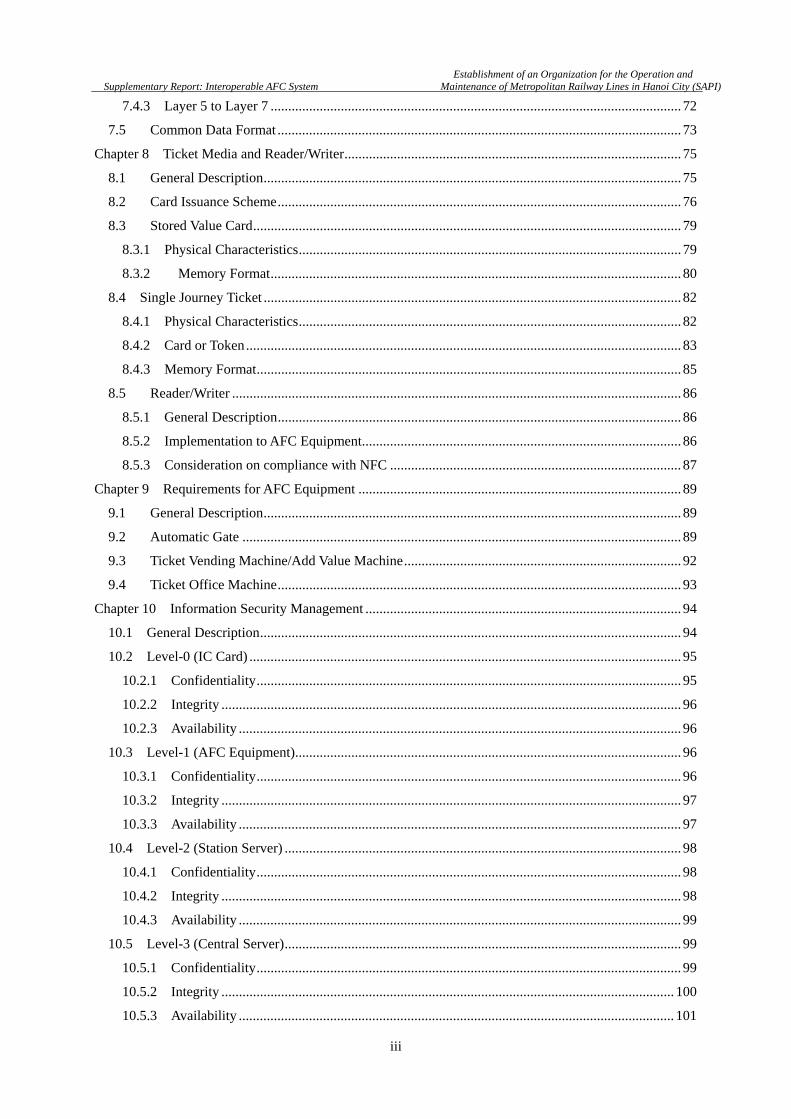
7.4.3 Layer 5 to Layer 7 ..................................................................................................................... 72
7.5 Common Data Format ................................................................................................................... 73
Chapter 8 Ticket Media and Reader/Writer ................................................................................................ 75
8.1 General Description ....................................................................................................................... 75
8.2 Card Issuance Scheme ................................................................................................................... 76
8.3 Stored Value Card .......................................................................................................................... 79
8.3.1 Physical Characteristics ............................................................................................................. 79
8.3.2 Memory Format ..................................................................................................................... 80
8.4 Single Journey Ticket ....................................................................................................................... 82
8.4.1 Physical Characteristics ............................................................................................................. 82
8.4.2 Card or Token ............................................................................................................................ 83
8.4.3 Memory Format ......................................................................................................................... 85
8.5 Reader/Writer ................................................................................................................................ 86
8.5.1 General Description ................................................................................................................... 86
8.5.2 Implementation to AFC Equipment. .......................................................................................... 86
8.5.3 Consideration on compliance with NFC ................................................................................... 87
Chapter 9 Requirements for AFC Equipment ............................................................................................ 89
9.1 General Description ....................................................................................................................... 89
9.2 Automatic Gate ............................................................................................................................. 89
9.3 Ticket Vending Machine/Add Value Machine ............................................................................... 92
9.4 Ticket Office Machine ................................................................................................................... 93
Chapter 10 Information Security Management .......................................................................................... 94
10.1 General Description ........................................................................................................................ 94
10.2 Level-0 (IC Card) ........................................................................................................................... 95
10.2.1 Confidentiality ......................................................................................................................... 95
10.2.2 Integrity ................................................................................................................................... 96
10.2.3 Availability .............................................................................................................................. 96
10.3 Level-1 (AFC Equipment) .............................................................................................................. 96
10.3.1 Confidentiality ......................................................................................................................... 96
10.3.2 Integrity ................................................................................................................................... 97
10.3.3 Availability .............................................................................................................................. 97
10.4 Level-2 (Station Server) ................................................................................................................. 98
10.4.1 Confidentiality ......................................................................................................................... 98
10.4.2 Integrity ................................................................................................................................... 98
10.4.3 Availability .............................................................................................................................. 99
10.5 Level-3 (Central Server) ................................................................................................................. 99
10.5.1 Confidentiality ......................................................................................................................... 99
10.5.2 Integrity ................................................................................................................................. 100
10.5.3 Availability ............................................................................................................................ 101

Establishment of an Organization for the Operation and
Supplementary Report: Interoperable AFC System Maintenance of Metropolitan Railway Lines in Hanoi City (SAPI)
iv
10.6 Level-4 (CCHS) ........................................................................................................................... 102
10.6.1 Confidentiality ....................................................................................................................... 102
10.6.2 Integrity ................................................................................................................................. 102
10.6.3 Availability ............................................................................................................................ 103
Chapter 11 Management of Interoperable AFC System ........................................................................... 104
11.1 General Description ..................................................................................................................... 104
11.2 Management of Standard for Interoperable AFC ........................................................................ 104
11.3 Management of Conformance ..................................................................................................... 105
Chapter 12 Technology for IC Ticket ....................................................................................................... 106
12.1 General Description ...................................................................................................................... 106
12.2 Compliance with International Standard ...................................................................................... 106
12.3 Speed Performance ....................................................................................................................... 107
12.4 Data Integrity (IC card data protection when “Incomplete Transaction” occurs) ..................... 109
12.5 Security ........................................................................................................................................ 109
12.6 Proven Technology ....................................................................................................................... 110
12.7 Availability ................................................................................................................................... 110
12.8 Summary on IC Ticket Technology .............................................................................................. 111
Appendix Comparison of IC card Technology ..................................................................................... 113

Establishment of an Organization for the Operation and
Supplementary Report: Interoperable AFC System Maintenance of Metropolitan Railway Lines in Hanoi City (SAPI)
1
Chapter 1 Introduction
1.1 General Description
This document reports the study on the interoperable AFC system of Hanoi Urban Railway
Network.
It is well known that the construction projects for railway lines of Hanoi Urban Railway Network
are proceeding with the support from Japan, China and France. Therefore, the AFC system of each
line tends to be developed independently each other and are supposed to be designed and built on the
different policy and technology, if interoperability among AFC systems is not considered.
By interoperable AFC system, all the railway lines constitute a unified railway network. Customer
can trip from any station to any destination with one ticket in the Urban Railway network regardless
of operators of lines. Otherwise, the railway system is only an assembly of discrete railway lines,
where customer shall purchase ticket for every transfer and shall have different IC cards in case of
stored value card with deposit. Urban Railways serve as social infrastructure to improve urban
transportation of citizen only by interoperable AFC system.
The objective of the study is to clarify the issues to build interoperable AFC system based on the
background and provide common design criteria for it.
1.2 Scope of Study
The study starts from the architectural analysis of total AFC system using layer model for Hanoi
Urban Railways. And it will describe that the common interfaces between layers are the key for
interoperability. Following the consideration on the system architecture, common AFC services is
discussed and described before technical matters. Fare design, especially fare to transfer lines, is the
crucial matter for the common AFC service.
Based on the study for AFC services, common technical specification is described about code
system, transaction record data, black list, data transfer/receive interface between servers and
electronic media for ticket. And it is also described about security protection policy and organization
to manage the interoperable AFC system.
This study reports the basic specification to build interoperable AFC system. Study on detail
specification shall be followed by incorporating available technology and product to be applied for the
implementation of the AFC system. Most suitable solution for Hanoi Urban Railway Network shall be
selected by the consideration of performance, reliability, availability, maintainability and cost.
Establishment of an Organization for the Operation and
Supplementary Report: Interoperable AFC System Maintenance of Metropolitan Railway Lines in Hanoi City (SAPI)
2
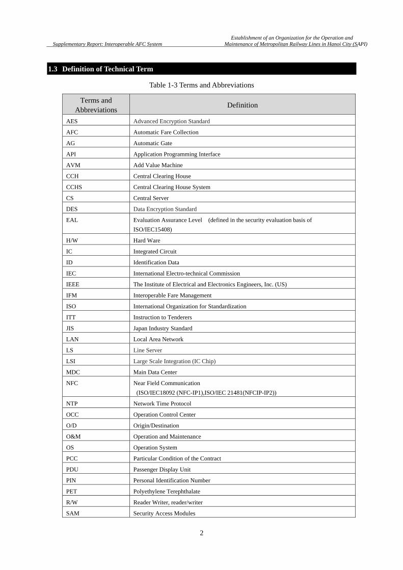
1.3 Definition of Technical Term
Table 1-3 Terms and Abbreviations
Terms and Abbreviations
Definition
AES Advanced Encryption Standard
AFC Automatic Fare Collection
AG Automatic Gate
API Application Programming Interface
AVM Add Value Machine
CCH Central Clearing House
CCHS Central Clearing House System
CS Central Server
DES Data Encryption Standard
EAL Evaluation Assurance Level (defined in the security evaluation basis of
ISO/IEC15408)
H/W Hard Ware
IC Integrated Circuit
ID Identification Data
IEC International Electro-technical Commission
IEEE The Institute of Electrical and Electronics Engineers, Inc. (US)
IFM Interoperable Fare Management
ISO International Organization for Standardization
ITT Instruction to Tenderers
JIS Japan Industry Standard
LAN Local Area Network
LS Line Server
LSI Large Scale Integration (IC Chip)
MDC Main Data Center
NFC Near Field Communication
(ISO/IEC18092 (NFC-IP1),ISO/IEC 21481(NFCIP-IP2))
NTP Network Time Protocol
OCC Operation Control Center
O/D Origin/Destination
O&M Operation and Maintenance
OS Operation System
PCC Particular Condition of the Contract
PDU Passenger Display Unit
PIN Personal Identification Number
PET Polyethylene Terephthalate
R/W Reader Writer, reader/writer
SAM Security Access Modules

Establishment of an Organization for the Operation and
Supplementary Report: Interoperable AFC System Maintenance of Metropolitan Railway Lines in Hanoi City (SAPI)
3
Terms and Abbreviations
Definition
SJT Single Journey Ticket
SNMP Simple Network Management Protocol
SS Station Server
SVC Stored Value Card
S/W Soft Ware
TCP/IP Transmission Control Protocol/Internet Protocol
T-DES Triple-DES (Data Encryption Standard)
TOM Ticket Office Machine
TVM Ticket Vending Machine
UPS Uninterruptable Power Supply
UT Urban Transportation
VPN Virtual Private Network
VLAN Virtual Local Area Network
WAN Communications Backbone Network using Wide Area Network technology
Establishment of an Organization for the Operation and
Supplementary Report: Interoperable AFC System Maintenance of Metropolitan Railway Lines in Hanoi City (SAPI)
4
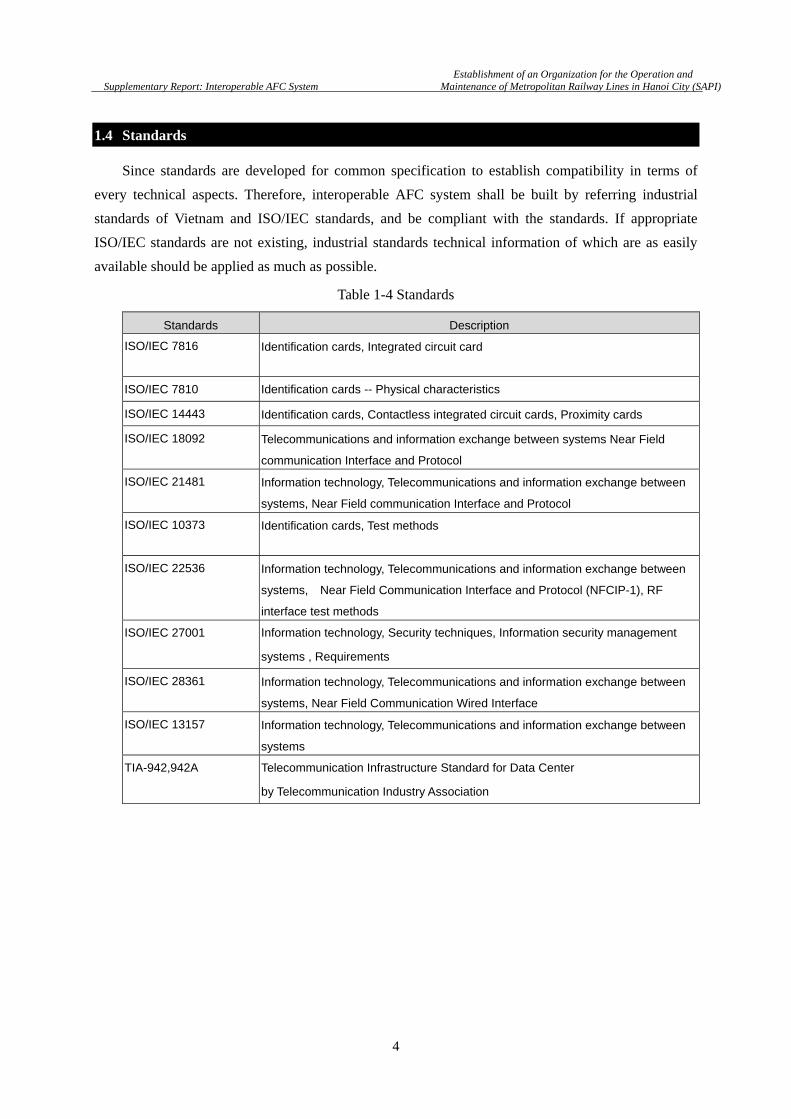
1.4 Standards
Since standards are developed for common specification to establish compatibility in terms of
every technical aspects. Therefore, interoperable AFC system shall be built by referring industrial
standards of Vietnam and ISO/IEC standards, and be compliant with the standards. If appropriate
ISO/IEC standards are not existing, industrial standards technical information of which are as easily
available should be applied as much as possible.
Table 1-4 Standards
Standards Description
ISO/IEC 7816 Identification cards, Integrated circuit card
ISO/IEC 7810 Identification cards -- Physical characteristics
ISO/IEC 14443 Identification cards, Contactless integrated circuit cards, Proximity cards
ISO/IEC 18092 Telecommunications and information exchange between systems Near Field
communication Interface and Protocol
ISO/IEC 21481 Information technology, Telecommunications and information exchange between
systems, Near Field communication Interface and Protocol
ISO/IEC 10373 Identification cards, Test methods
ISO/IEC 22536 Information technology, Telecommunications and information exchange between
systems, Near Field Communication Interface and Protocol (NFCIP-1), RF
interface test methods
ISO/IEC 27001 Information technology, Security techniques, Information security management
systems , Requirements
ISO/IEC 28361 Information technology, Telecommunications and information exchange between
systems, Near Field Communication Wired Interface
ISO/IEC 13157 Information technology, Telecommunications and information exchange between
systems
TIA-942,942A Telecommunication Infrastructure Standard for Data Center
by Telecommunication Industry Association
Establishment of an Organization for the Operation and
Supplementary Report: Interoperable AFC System Maintenance of Metropolitan Railway Lines in Hanoi City (SAPI)
5
Chapter 2 Introductions to Interoperable AFC System
2.1 Layer Model of AFC System Structure
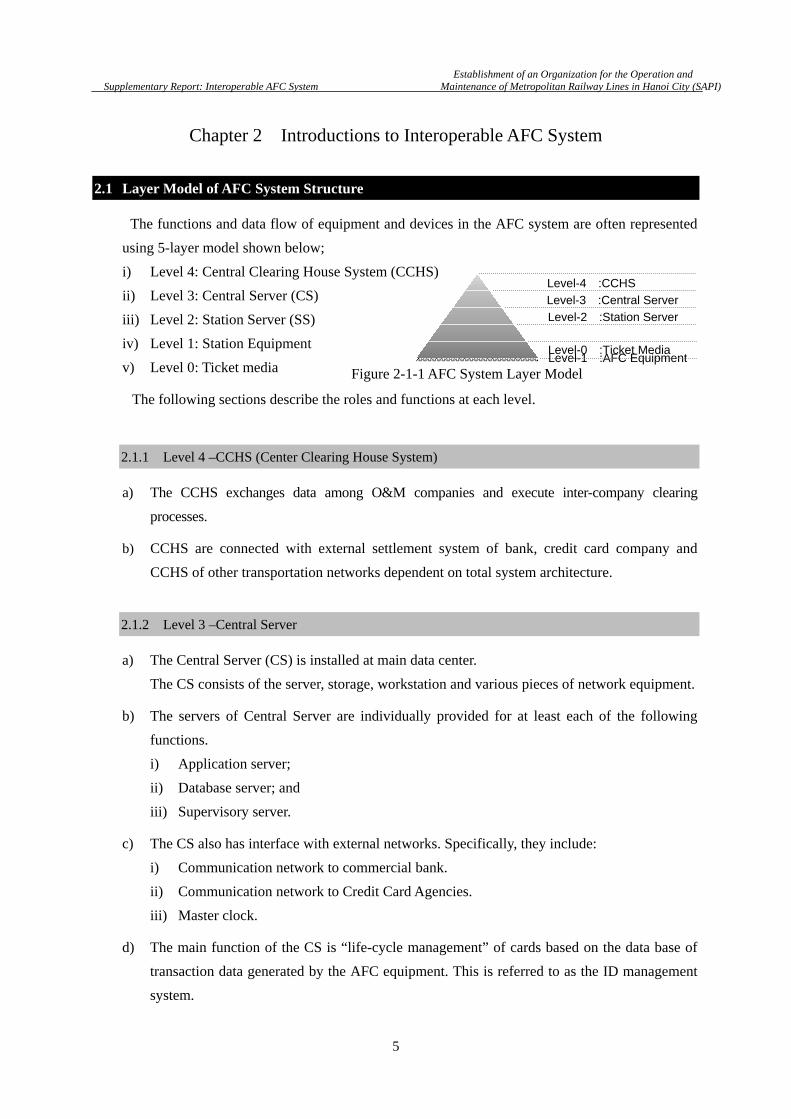
The functions and data flow of equipment and devices in the AFC system are often represented
using 5-layer model shown below;
i) Level 4: Central Clearing House System (CCHS)
ii) Level 3: Central Server (CS)
iii) Level 2: Station Server (SS)
iv) Level 1: Station Equipment
v) Level 0: Ticket media
The following sections describe the roles and functions at each level.
2.1.1 Level 4 –CCHS (Center Clearing House System)
a) The CCHS exchanges data among O&M companies and execute inter-company clearing
processes.
b) CCHS are connected with external settlement system of bank, credit card company and
CCHS of other transportation networks dependent on total system architecture.
2.1.2 Level 3 –Central Server
a) The Central Server (CS) is installed at main data center.
The CS consists of the server, storage, workstation and various pieces of network equipment.
b) The servers of Central Server are individually provided for at least each of the following
functions.
i) Application server;
ii) Database server; and
iii) Supervisory server.
c) The CS also has interface with external networks. Specifically, they include:
i) Communication network to commercial bank.
ii) Communication network to Credit Card Agencies.
iii) Master clock.
d) The main function of the CS is “life-cycle management” of cards based on the data base of
transaction data generated by the AFC equipment. This is referred to as the ID management
system.
Level-0 :Ticket Media
Level-1 :AFC Equipment
Level-2 :Station Server
Level-3 :Central Server
Level-4 :CCHS
Figure 2-1-1 AFC System Layer Model

Establishment of an Organization for the Operation and
Supplementary Report: Interoperable AFC System Maintenance of Metropolitan Railway Lines in Hanoi City (SAPI)
6
The CS also has the function that centrally manages and distributes various data items and
parameters required for the operation of AFC equipment.
e) In addition to the above, typical functions of the CS include:
i) Supervision and monitoring of subordinate AFC equipment and SS status.
ii) Check of revenue data by comparing to transaction data.
iii) Synchronization with the master clock and distribution of the clock time to subordinate
equipment.
iv) Link to external settlement networks and execution of necessary settlement
processing.
v) Output of report on revenue data and passenger flow data.
f) As a side note, there is a possibility to integrate the operations of lines into one O&M
company . In this case, O&M Company should have "Line Server". Typical functions of
Line Server include:
i) Collect and Manage the revenue of AFC system of subordinate line.
ii) Cooperation with financial system (e.g. ERP Package System) of O&M company.
iii) Settlement distribution process with other O&M company.
Therefore, company-server should have the position at Level-3. See Figure 2-1-1.
2.1.3 Level 2 –Station Server
a) At each station, one AFC station server (SS ) is installed.
b) Various data items (e.g. transaction data and revenue data) are transmitted to the station
computer at designated times. The station computer has the functions that control the
collected data and transmit data to the central server at regular time intervals.
c) Various operation parameters are distributed from the central server to the station computer.
Figure 2-1-2 AFC System Configuration

Establishment of an Organization for the Operation and
Supplementary Report: Interoperable AFC System Maintenance of Metropolitan Railway Lines in Hanoi City (SAPI)
7
The station computer controls the collected data and distributes data to the subordinate AFC
equipment at the designated times.
d) In addition to the above, typical functions of the station computer include:
i) Supervision and monitoring of subordinate AFC equipment status.
ii) Remote operation of subordinate AFC equipment.
iii) Report output of revenue data and passenger flow data.
2.1.4 Level 1 –Station Equipment
a) Station equipment is installed to provide customer services such as issuing tickets, collecting
fare, checking the validity of tickets at gates.
b) The main AFC equipment installed at the station includes.
i) Automatic gate: AG
ii) Ticket office machine: TOM and
iii) Add value machine: AVM
c) AFC equipment of the leve-1 that is installed at one location other than the stations includes:
i) IC card initializer;
ii) IC card personalizer (Staff Pass & Personalized SV Card);and
iii) AFC equipment installed at the education and training center (AG/TOM/AVM).
d) R/W device installed in AFC equipment shall adopt technology in consideration of the
common ticket available for all lines in Hanoi Urban Railway network.
2.1.5 Level 0 – Ticket Media
Typical types of tickets include paper-based magnetic tickets, PET magnetic SV cards,
contact-less IC cards and contact-less IC tokens. This system is all configured with contact-less
IC cards. For the contact-less IC cards adopted in this system, communication interfaces shall be
compliant with international standards to ensure mutual exploitation of them in Hanoi Urban
Railway lines.
Establishment of an Organization for the Operation and
Supplementary Report: Interoperable AFC System Maintenance of Metropolitan Railway Lines in Hanoi City (SAPI)
8
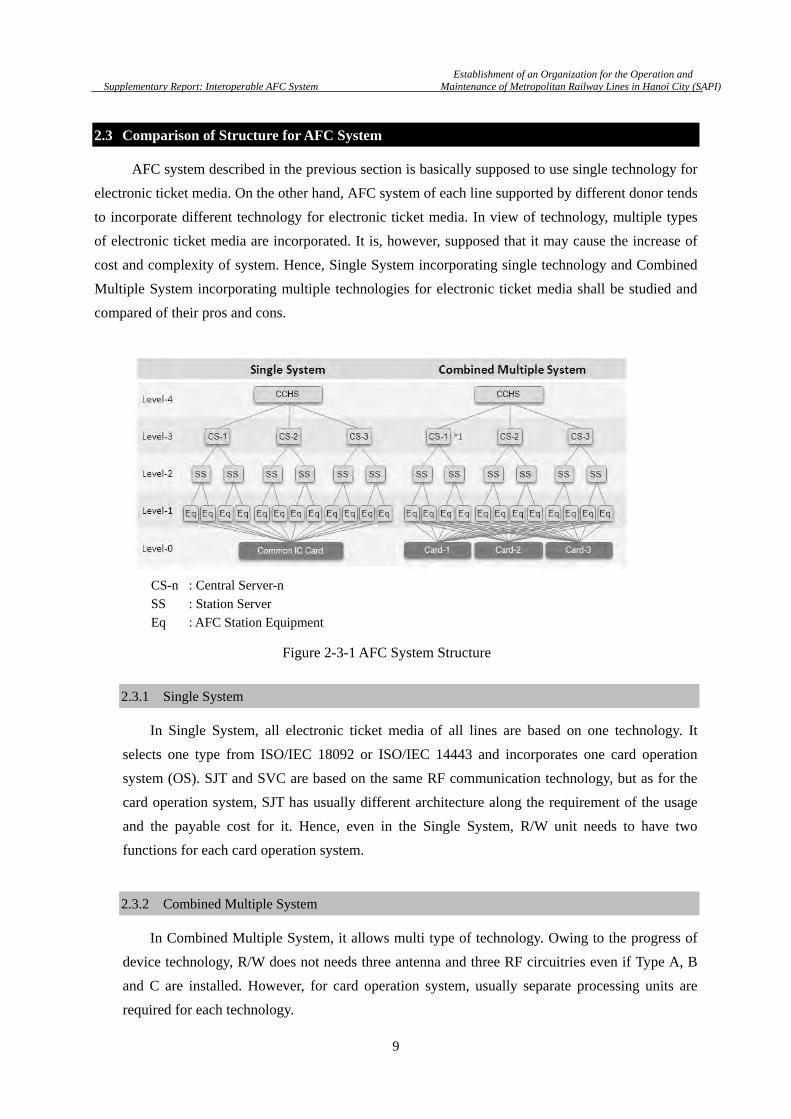
2.2 Interoperable AFC System Basic Requirements
a) Owing to interoperable AFC system, customer will trip with one ticket from any origin
station to any destination station in the Urban Railway network. Customers are not requested
to purchase additional SJT or to change SVC at transferring lines.
b) In view of layer model of AFC system, the interoperability is established by common
specification of interfaces between each layer, where ‘interface’ means not only hardware
interface but also software interface.
c) One of the most important interfaces is electronic ticket media and R/W of AFC equipment.
Electronic tickets issued by any line shall be available with R/W of AFC equipment of any
other lines. For this requirement, specifications about interface between electronic ticket and
R/W shall be defined as common specifications, which are RF communication, anti-collision,
authentication and file system shall be defined as common specifications.
d) Station AFC equipment are not connected directly to central servers. AFC equipment and
station server of each line are usually designed by one contractor. Hence, the interface
between AFC equipment and station server does not need to be strictly defined as common
specifications.
e) Each line often has a line sever, which processes all data of the line and communicate with
central server. In this case, station servers communicate with the line sever and not directly
with central server. Since line server is also designed and developed by the contractor of
AFC equipment, the interface between station server and line server does not need to be
strictly defined in common specifications as well.
f) The interface between line servers and central server, and that between central server and
CCHS shall be specified as the common specifications since central server and CCHS will be
designed and developed by separate contractors.
Detail requirements on the common specification will be described in the following
respective chapters.
Establishment of an Organization for the Operation and
Supplementary Report: Interoperable AFC System Maintenance of Metropolitan Railway Lines in Hanoi City (SAPI)
9
2.3 Comparison of Structure for AFC System
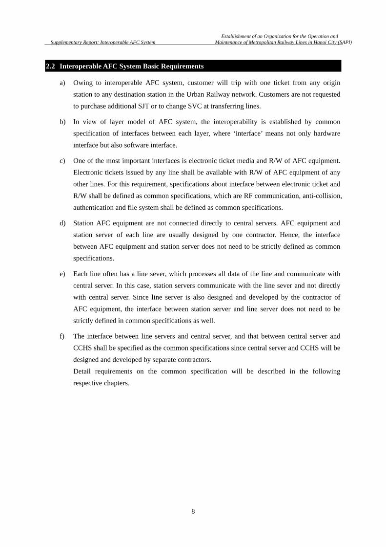
AFC system described in the previous section is basically supposed to use single technology for
electronic ticket media. On the other hand, AFC system of each line supported by different donor tends
to incorporate different technology for electronic ticket media. In view of technology, multiple types
of electronic ticket media are incorporated. It is, however, supposed that it may cause the increase of
cost and complexity of system. Hence, Single System incorporating single technology and Combined
Multiple System incorporating multiple technologies for electronic ticket media shall be studied and
compared of their pros and cons.
Table 2-3-1 AFC System Structure
2.3.1 Single System
In Single System, all electronic ticket media of all lines are based on one technology. It
selects one type from ISO/IEC 18092 or ISO/IEC 14443 and incorporates one card operation
system (OS). SJT and SVC are based on the same RF communication technology, but as for the
card operation system, SJT has usually different architecture along the requirement of the usage
and the payable cost for it. Hence, even in the Single System, R/W unit needs to have two
functions for each card operation system.
2.3.2 Combined Multiple System
In Combined Multiple System, it allows multi type of technology. Owing to the progress of
device technology, R/W does not needs three antenna and three RF circuitries even if Type A, B
and C are installed. However, for card operation system, usually separate processing units are
required for each technology.
CS-n : Central Server-n
SS : Station Server
Eq : AFC Station Equipment
Figure 2-3-1 AFC System Structure
Establishment of an Organization for the Operation and
Supplementary Report: Interoperable AFC System Maintenance of Metropolitan Railway Lines in Hanoi City (SAPI)
10
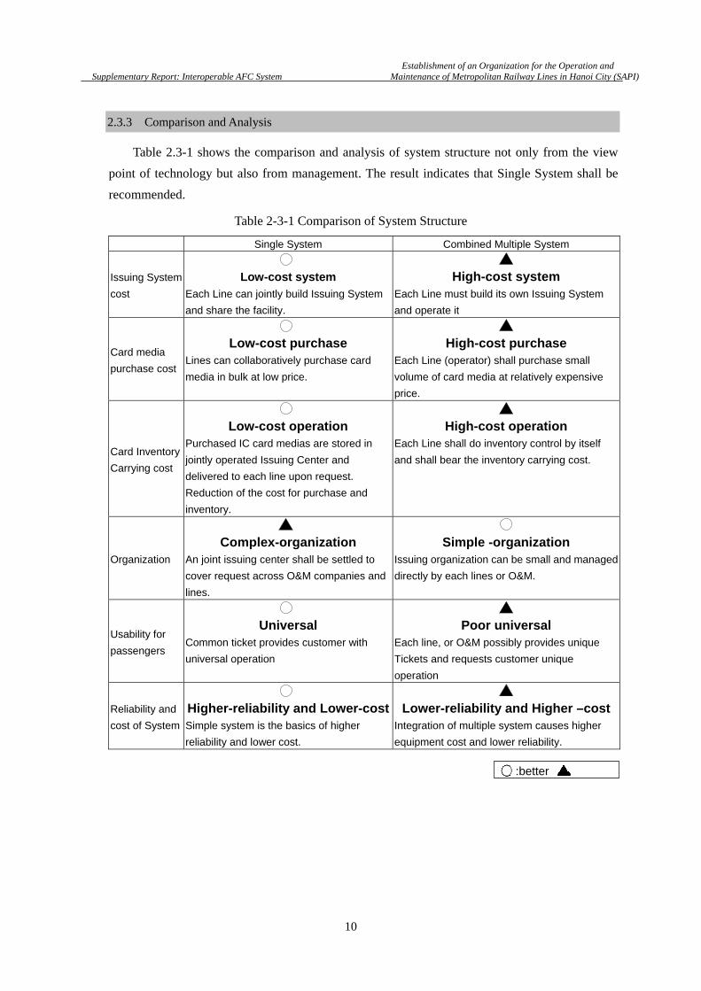
2.3.3 Comparison and Analysis
Table 2.3-1 shows the comparison and analysis of system structure not only from the view
point of technology but also from management. The result indicates that Single System shall be
recommended.
Table 2-3-1 Comparison of System Structure
Single System Combined Multiple System
Issuing System
cost
Low-cost system
Each Line can jointly build Issuing System
and share the facility.
High-cost system Each Line must build its own Issuing System
and operate it
Card media
purchase cost
Low-cost purchase Lines can collaboratively purchase card
media in bulk at low price.
High-cost purchase Each Line (operator) shall purchase small
volume of card media at relatively expensive
price.
Card Inventory
Carrying cost
Low-cost operation Purchased IC card medias are stored in
jointly operated Issuing Center and
delivered to each line upon request.
Reduction of the cost for purchase and
inventory.
High-cost operation Each Line shall do inventory control by itself
and shall bear the inventory carrying cost.
Organization
Complex-organization An joint issuing center shall be settled to
cover request across O&M companies and
lines.
Simple -organization Issuing organization can be small and managed
directly by each lines or O&M.
Usability for
passengers
Universal Common ticket provides customer with
universal operation
Poor universal Each line, or O&M possibly provides unique
Tickets and requests customer unique
operation
Reliability and
cost of System
Higher-reliability and Lower-costSimple system is the basics of higher
reliability and lower cost.
Lower-reliability and Higher –costIntegration of multiple system causes higher
equipment cost and lower reliability.
:better

Establishment of an Organization for the Operation and
Supplementary Report: Interoperable AFC System Maintenance of Metropolitan Railway Lines in Hanoi City (SAPI)
11
2.4 Possible Approach to Single System
a) A possible approach to construct Single System is described below. At first, card OS suitable
for electronic ticket shall be selected. High speed transaction enough for ticket validation
process in rush hour, high security to protect electronic money and personal information and
high capability to expand the applications not only for AFC but also for electronic commerce
are the essential requirements to the card OS.
b) Selection of semiconductor devices for SJT and SVC in accordance with the common
specification of AFC is the next step. Here, SJT and SVC are strongly recommended to be
based on the same card OS. It should be noted that each line or O&M company has
flexibility to install unique service which is available only within the line or lines of the
O&M company, besides common services.
c) R/W of AFC equipment, on the other hand, shall be installed with SAM and control unit for
the card OS. However, other parts of AFC equipment (data processing, mechanical control,
communication and display, for instance) are not directly affected by what card OS is
selected.
d) Data exchange between AFC equipment and station server is not depend on card OS. Thus,
Single System is built just by installing SAM and card OS unit of R/W.
Layer Facility Line 1 Line 5 Line 2 Line 2A Line 3
Level 4 CCHS
Level 3 Central SV
Line SV
Level 2 Station SV
Level 1 AFC Equipment
Level 0 IC Card
Figure 2-4-1 Schematic Diagram of R/W unit
O&M Company [B]
by Japan by China by France
Ticket on selected card OS technology
With R/W unit for selected card OS
Common CCHS(Central Clearing House System)
Figure 2-4-2 Possible Single System for Interoperable AFC R/W unit
O&M Company [A]
Establishment of an Organization for the Operation and
Supplementary Report: Interoperable AFC System Maintenance of Metropolitan Railway Lines in Hanoi City (SAPI)
12
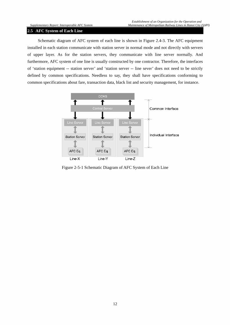
2.5 AFC System of Each Line
Schematic diagram of AFC system of each line is shown in Figure 2.4-3. The AFC equipment
installed in each station communicate with station server in normal mode and not directly with servers
of upper layer. As for the station servers, they communicate with line server normally. And
furthermore, AFC system of one line is usually constructed by one contractor. Therefore, the interfaces
of ‘station equipment -- station server’ and ‘station server -- line sever’ does not need to be strictly
defined by common specifications. Needless to say, they shall have specifications conforming to
common specifications about fare, transaction data, black list and security management, for instance.
Figure 2-5-1 Schematic Diagram of AFC System of Each Line
Establishment of an Organization for the Operation and
Supplementary Report: Interoperable AFC System Maintenance of Metropolitan Railway Lines in Hanoi City (SAPI)
13
Chapter 3 Fare System
3.1 General Description
The first decision-making task for any railway business operator to be able to realize
interoperability in the urban transport system is to design a viable fare system.
A fare system has a direct impact on the economic balance of each railway operator. At the same
time a user-friendly fare system has indirect effects on the railway utilization rate, such as the increase
of customer usage.
This Chapter describes the fare calculation logic, the fare settlement rules for transfer over
multiple lines, and the basic inter-company clearance scheme based on the explanation on the types of
basic fare systems as the starting point.
Note that the examples of mileages and fare ratios that are provided in this Chapter may not
match those of the actual lines. Ultimately the values of these parameters shall be decided by the
railway business operators.
3.2 Definition of Technical Terms
This Chapter uses many technical terms. This section describes the meanings of some key terms.
a) Latch
A latch refers to a gate or a gate-installed state as the “boundary” when a line is connected to
another line and passengers transfer between lines.
One of the following modes shall be selected depending on the constraints of the station
building and the train operation mode.
b) Trip
Trip refers to an action of a passenger to travel from a departing station to a destination or a travel
route that is virtually generated by calculation at the gate of the exit station.
c) Settlement distribution
Settlement distribution refers to distribution of revenues to the railway business operators
according to the actual mileages of the lines that are used. This procedure is necessary for
no-latch transfer where transfer stations cannot be specified.
Establishment of an Organization for the Operation and
Supplementary Report: Interoperable AFC System Maintenance of Metropolitan Railway Lines in Hanoi City (SAPI)
14
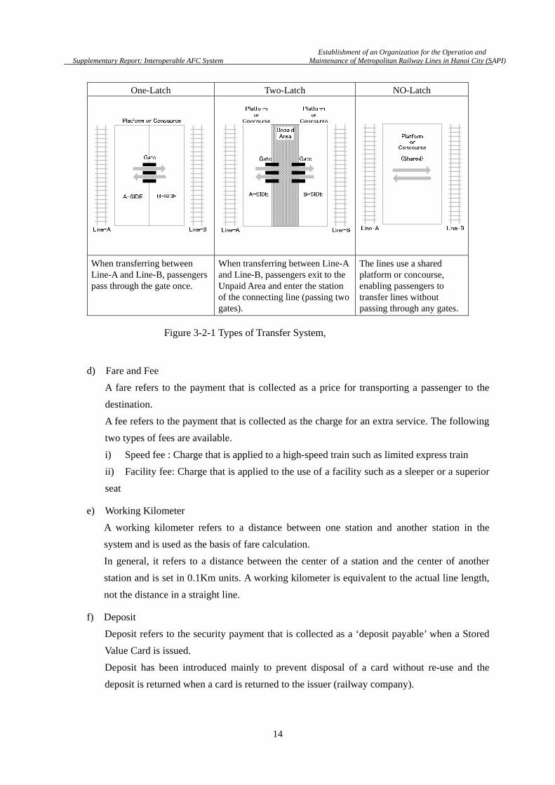
One-Latch Two-Latch NO-Latch
When transferring between Line-A and Line-B, passengers pass through the gate once.
When transferring between Line-A and Line-B, passengers exit to the Unpaid Area and enter the station of the connecting line (passing two gates).
The lines use a shared platform or concourse, enabling passengers to transfer lines without passing through any gates.
d) Fare and Fee
A fare refers to the payment that is collected as a price for transporting a passenger to the
destination.
A fee refers to the payment that is collected as the charge for an extra service. The following
two types of fees are available.
i) Speed fee : Charge that is applied to a high-speed train such as limited express train
ii) Facility fee: Charge that is applied to the use of a facility such as a sleeper or a superior
seat
e) Working Kilometer
A working kilometer refers to a distance between one station and another station in the
system and is used as the basis of fare calculation.
In general, it refers to a distance between the center of a station and the center of another
station and is set in 0.1Km units. A working kilometer is equivalent to the actual line length,
not the distance in a straight line.
f) Deposit
Deposit refers to the security payment that is collected as a ‘deposit payable’ when a Stored
Value Card is issued.
Deposit has been introduced mainly to prevent disposal of a card without re-use and the
deposit is returned when a card is returned to the issuer (railway company).
Figure 3-2-1 Types of Transfer System,

Establishment of an Organization for the Operation and
Supplementary Report: Interoperable AFC System Maintenance of Metropolitan Railway Lines in Hanoi City (SAPI)
15
3.3 Design Concept
The fare system that is proposed in this document is designed based on the concept with the
following considerations.
a) Simple and optimum fare system that matches the characteristics of the Hanoi Urban
Railway network by applying the know-how that has been accumulated in the Japanese
Urban Railway network as the basis.
b) Fare system that can cope with expansion of the railway network that is planned for the
future as well as the railway lines that are currently planned.
c) Simple user-friendly fare system that is designed by considering the use by passengers who
are unfamiliar with Urban Railway systems.
User-friendly railway systems result in an improved repeat rate and consequently an increase
of railway revenues.
d) Fare system that is easily understood by O&M companies and station attendants. Improved
proficiency of station attendants leads to smooth guidance to passengers, which result in
improvement of hospitability and service levels, and prevention of customer disputes.
e) Fare system that does not give customers an impression of unfairness.
As an example, the fare of the first leg and the fare of the return leg must be the same when
the same route is used.
f) Clear fare distribution rules to each railway company without giving an impression of
unfairness when passengers transfer across multiple lines.
g) Fare system that applies concise algorithm without any inconsistencies and is capable of
high-speed processing at installation of the fare calculation functions in the AFC equipment.
This leads to the reduction of the initial cost and the running cost as the secondary effects.
h) Fare system that is capable of strict fare distribution without ambiguity in inter-company
clearance.
i) Proper prices that reflect the currency distribution in the market and commodity prices.
j) Fare system that is capable of flexible handling of the increase of passenger volumes in the
future and change of the economic trend in Vietnam.
k) Fare system that is capable of strategic price setting to promote SVC (Stored Value Card),
which brings more revenue merits than SJT, which requires more operation cost to operators.
3.4 Suggestion about Interoperability
a) All the transfer stations of the lines that are currently planned will be connected in 2-latch
mode. It is recommended to observe the “latch separation” rules that request passengers to

Establishment of an Organization for the Operation and
Supplementary Report: Interoperable AFC System Maintenance of Metropolitan Railway Lines in Hanoi City (SAPI)
16
validate tickets by the gate at transfer due to the reasons that are provided later unless special
circumstances are applied such as direct link operation of railways.
b) The latch separation mode has the following merits.
i) Fares can be collected based on the actual routes that are taken by the passengers.
This rule is fair and clear for both the users and the business operators.
ii) Fares can be distributed according to the mileage at inter-company clearance as indicated
in (i).
iii) No major changes are necessary for the construction of civil engineering work of the
station or track that is currently in progress.
c) The following constraints may arise if a 2-latch mode is forced because of the building
design or the station.
i) A passenger transfer distance will increase dramatically.
ii) Passenger movements will be disturbed, causing congestion.
These constraints may be resolved by applying a 1-latch mode. See Figure 3-4-1.
Figure 3-4-1 Comparison of Latch Mode
3.5 Fare System and Fare Calculation Method
3.5.1 Kinds of Fare Systems
In general, the following kinds of fare systems are available. This Chapter describes the outline
and the features of each kind.
2-Latch Mode 1-Latch Mode

Establishment of an Organization for the Operation and
Supplementary Report: Interoperable AFC System Maintenance of Metropolitan Railway Lines in Hanoi City (SAPI)
17
a) Zone Fare System
A range within a fixed distance from the departure station is defined as a fixed-rate zone.
Multiple zones are set according to the distance from the departure station and the fare
increases in stages. Profit and loss may become disproportionate to either the user or the
operator depending on the zone setting so that advanced simulation is necessary such as
accurate prediction of the passenger flow rate.
b) Mileage fare system
The fare increases according to the working kilometers from the departure station to the
arrival station. This system is widely used by the railway systems and in general, the fare is
calculated by “working kilometers × fare ratio”. Since the exact fare can be set, this system is
fair for both the users and the operators.
c) Time Charge Fare System
In general, this fare system is used for accounting systems such as parking stations and none
of the railway systems use this system.
Fares are collected according to the time that is spent by the passenger.
Figure 3-5-1 Zone Fare
Figure 3-5-2 Mileage Fare
Figure 3-5-3 Time Charge Fare

Establishment of an Organization for the Operation and
Supplementary Report: Interoperable AFC System Maintenance of Metropolitan Railway Lines in Hanoi City (SAPI)
18
d) Flat-rate fare system
A flat rate is applied to the fare regardless of the mileage. This system is equivalent to the
case where a “single zone” is set in the zone fare system. This system may be used for the
lines that are not suitable for the mileage fare system such as a short distance between
stations and low total mileage. In some cases, the “all line flat-rate” may be set for some
special passes (such as 1-day pass) while applying a mileage fare system concurrently.
3.5.2 Comparative Evaluation
a) Of the fare systems that are described above, three kinds of fare systems are suitable for
Urban Railway systems, namely, “zone fare system”, “mileage system”, and “flat-rate fare
system”.
b) The zone fare system appears to adopt a simple fare calculation method and the system can
be constructed easily. However, it must be noted that the subways in Hanoi use a 2-latch
connection mode.
c) Either of the following methods is applied for fare deduction timing.
i) “Value balance method” that deducts the value of the fare from the departure
station progressively.
ii) “Total fare collection” method that deducts the total fare from the initial departure
station.
When (ii) is applied, a station with 2-latch connection mode that allows passengers to
escape to the unpaid area during the trip and, obviously, there is a possibility of fare
evasion. See the following diagram.
Figure 3-5-5 Total Fare Collection
Flat-rate Zone
X,000VND
Figure 3-5-4 Flat Fare

Establishment of an Organization for the Operation and
Supplementary Report: Interoperable AFC System Maintenance of Metropolitan Railway Lines in Hanoi City (SAPI)
19
Therefore, the fare from the departure station must be collected progressively. See the
following diagram.
d) The problem here is that, in the case of the zone fare system, the fare that is finally
collected from a passenger must be calculated based on the shortest distance from the
“departure station to the final arrival station”.
For instance, assume the following passenger trip route. In the following diagram;
i) Transfer stations that apply 2-latch mode is marked by ,
ii) The zone fare is assumed for the explanation purpose only.
*A real route similar to the route in this map exists in the Urban Railway network that is
planned for Hanoi.
Figure 3-5-6 Progressive Fare Collection
Figure 3-5-7 Diagram of Transfer in Zone Fare System

Establishment of an Organization for the Operation and
Supplementary Report: Interoperable AFC System Maintenance of Metropolitan Railway Lines in Hanoi City (SAPI)
20
The above diagram is based on the assumption that a passenger departed from station A and
completed the trip at station E.
After departure from station A, a fare equivalent to the Zone-C fare, which is [2,000VND], is
collected from the card when the passenger reaches station C.
However, since the Zone-B fare is applied for the section between station A and station E,
the difference of 500VND must be refunded from the 2,000VND that was deducted when
the passenger exited at the final station E.
e) The fare system that requires adjustments due to over-charging each time is far from simple
and not easy to understand and such a system is difficult for passengers to use.
In the Hanoi urban transport system where 2-latch connections exist consecutively, a
“mileage fare system” that collects fares according to the mileage of the actual trip is most
suitable.
f) All the lines must apply the same fare system as an important factor for realizing
interoperability. If a mileage fare system and a zone fare system are used in mixed mode by
the line, fare calculation at transfer becomes extremely complicated and this most likely
would cause inconvenience in inter-company clearance.
g) A mileage fare system is a “fair” fare system for both the users and the business operators,
since a fare is collected according to the route that is actually taken by the passenger. See
the following diagram.
3.5.3 Calculation Formula
a) The basic passenger fare calculation formula is shown below.
Fare = Base Fare + Mileage Fare
b) Here, the base fare refers to the “adjustment amount” that is set by the railway business
operators to prevent the state of “Backwardation” where the operating cost exceeds the fare
revenue when the mileage is low.
Figure 3-5-8 Transfer Diagram in Mileage Fare System
Establishment of an Organization for the Operation and
Supplementary Report: Interoperable AFC System Maintenance of Metropolitan Railway Lines in Hanoi City (SAPI)
21
The base fare is fixed regardless of the departure and destination station and the mileage. A
standard price is applied in each line that is engaged in interoperation.
c) The mileage fare calculation formula is shown below.
Mileage Fare = Working Kilometer Fare Ratio
d) The fare ratio refers to a fare calculation parameter that is set by the railway business
operators.
At the initial opening, it is recommended to apply a standard value for the fare ratio across
all the lines.
However, in the AFC system, the fare ratio is a “variable parameter” so that the value can be
increased or reduced in stages according to the trend of the number of passengers or the
domestic economic trend of Vietnam. For future fare ratio modifications, simultaneous
increase or reduction is recommended across all the lines.
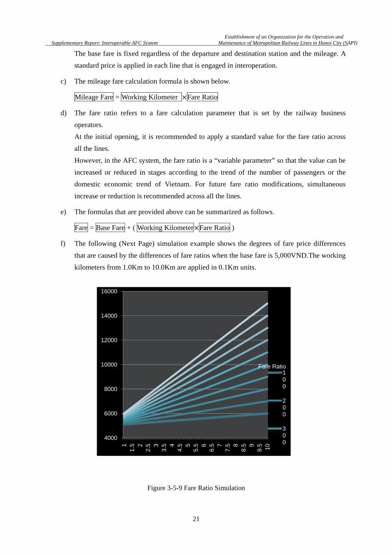
e) The formulas that are provided above can be summarized as follows.
Fare = Base Fare + ( Working Kilometer Fare Ratio )
f) The following (Next Page) simulation example shows the degrees of fare price differences
that are caused by the differences of fare ratios when the base fare is 5,000VND.The working
kilometers from 1.0Km to 10.0Km are applied in 0.1Km units.
Figure 3-5-9 Fare Ratio Simulation
4000
6000
8000
10000
12000
14000
16000
11.
5 22.
5 33.
5 44.
5 55.
5 66.
5 77.
5 88.
5 99.
5 10
100
200
300
Fare Ratio

Establishment of an Organization for the Operation and
Supplementary Report: Interoperable AFC System Maintenance of Metropolitan Railway Lines in Hanoi City (SAPI)
22
3.5.4 Fraction Process
a) Simple fare calculation by using the formulas that are provided in 3.5.3 may generate
fractions in the unit of 100VND or lower. This section examines a number of fraction
process techniques.
b) Fraction process is applied to the following two types of values.
i) Working kilometers (km)
ii) Calculated fare (VND)
Here, the fare ratio can be set freely based on the unit digit as the lowest limit.
c) The following fraction process methods are available for working kilometers.
i) Round-Up : e.g. 2.2Km -> 3Km
ii) Rounding : e.g. 2.4Km -> 2Km, 2.5Km-> 3Km
iii) Omit Fractions : e.g. 2.9Km -> 2Km
iv) Enable Fractions : e.g. 2.4Km -> 2.4Km
d) The following fraction process methods are available for fares.
i) Round-Up : e.g. 8,200VND -> 9,000VND
ii) Rounding : e.g. 8,400VND -> 8,000VND, 8500VND-> 9000VND
iii) Omit Fractions : e.g. 8,900VND -> 8,000VND
iv) Enable Fractions : e.g. 8,200VND -> 8,200VND
e) If the fractions of working kilometers are processed based on the 1Km units and if the fare
ratio is presented in the unit of 100VND, the fare that is calculated results in the minimum
unit of 100VND.
However, as described above, as the fare ratio may be changed to various values according to
the future economic trend, it is recommended to pre-determine the rules for the fraction
process for the final calculation of the fares.
In this case, although the fraction process of working kilometers is not required, in principle,
the railway business operator shall provide the contractor with the working kilometers that
are required for the designing of the system and the equipment.
f) The table (Next Page) shows the fares when fractions are enabled.
Here, 5,000VND is used as the base fare and 500 VND /Km as the fare ratio.
Establishment of an Organization for the Operation and
Supplementary Report: Interoperable AFC System Maintenance of Metropolitan Railway Lines in Hanoi City (SAPI)
23
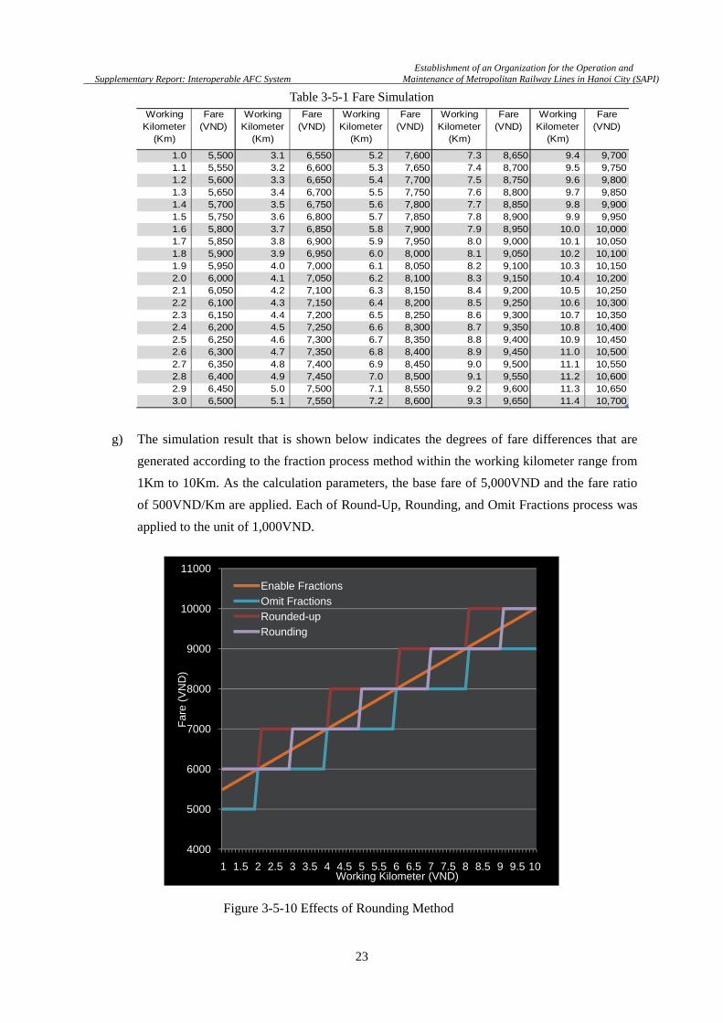
Table 3-5-1 Fare Simulation
g) The simulation result that is shown below indicates the degrees of fare differences that are
generated according to the fraction process method within the working kilometer range from
1Km to 10Km. As the calculation parameters, the base fare of 5,000VND and the fare ratio
of 500VND/Km are applied. Each of Round-Up, Rounding, and Omit Fractions process was
applied to the unit of 1,000VND.
4000
5000
6000
7000
8000
9000
10000
11000
1 1.5 2 2.5 3 3.5 4 4.5 5 5.5 6 6.5 7 7.5 8 8.5 9 9.5 10
Enable Fractions
Omit FractionsRounded-up
Rounding
Far
e (V
ND
)
Working Kilometer (VND)
WorkingKilometer
(Km)
Fare(VND)
WorkingKilometer
(Km)
Fare(VND)
WorkingKilometer
(Km)
Fare(VND)
WorkingKilometer
(Km)
Fare(VND)
WorkingKilometer
(Km)
Fare(VND)
1.0 5,500 3.1 6,550 5.2 7,600 7.3 8,650 9.4 9,7001.1 5,550 3.2 6,600 5.3 7,650 7.4 8,700 9.5 9,7501.2 5,600 3.3 6,650 5.4 7,700 7.5 8,750 9.6 9,8001.3 5,650 3.4 6,700 5.5 7,750 7.6 8,800 9.7 9,8501.4 5,700 3.5 6,750 5.6 7,800 7.7 8,850 9.8 9,9001.5 5,750 3.6 6,800 5.7 7,850 7.8 8,900 9.9 9,9501.6 5,800 3.7 6,850 5.8 7,900 7.9 8,950 10.0 10,0001.7 5,850 3.8 6,900 5.9 7,950 8.0 9,000 10.1 10,0501.8 5,900 3.9 6,950 6.0 8,000 8.1 9,050 10.2 10,1001.9 5,950 4.0 7,000 6.1 8,050 8.2 9,100 10.3 10,1502.0 6,000 4.1 7,050 6.2 8,100 8.3 9,150 10.4 10,2002.1 6,050 4.2 7,100 6.3 8,150 8.4 9,200 10.5 10,2502.2 6,100 4.3 7,150 6.4 8,200 8.5 9,250 10.6 10,3002.3 6,150 4.4 7,200 6.5 8,250 8.6 9,300 10.7 10,3502.4 6,200 4.5 7,250 6.6 8,300 8.7 9,350 10.8 10,4002.5 6,250 4.6 7,300 6.7 8,350 8.8 9,400 10.9 10,4502.6 6,300 4.7 7,350 6.8 8,400 8.9 9,450 11.0 10,5002.7 6,350 4.8 7,400 6.9 8,450 9.0 9,500 11.1 10,5502.8 6,400 4.9 7,450 7.0 8,500 9.1 9,550 11.2 10,6002.9 6,450 5.0 7,500 7.1 8,550 9.2 9,600 11.3 10,6503.0 6,500 5.1 7,550 7.2 8,600 9.3 9,650 11.4 10,700
Figure 3-5-10 Effects of Rounding Method

Establishment of an Organization for the Operation and
Supplementary Report: Interoperable AFC System Maintenance of Metropolitan Railway Lines in Hanoi City (SAPI)
24
h) The orange line in the diagram shows the fares that are to be collected based on the pure
calculation result.
The following table shows the maximum differences that are generated by rounding
up/omitting fractions by using the orange line as the “Ideal Fare”.
Table 3-5-2 Maximum Fare Differences by Rounding Method
i) The following table shows the differences of balances (totals) from the ideal fare within the
range from 1Km to 10Km.
Table 3-5-3 Differences of Balances by Rounding Method
A
As shown above, since the Omit Fractions method most likely unilaterally increases the
burden on the business operators, Round-Up or Rounding is recommended in this document.
j) Although the amount per transaction in the fraction process is low, the cumulative annual
total will be a huge amount.
As an example, if a fraction difference of 100VND occurs per passenger in a certain line, the
cumulative annual total will be as follows.
i) Number of passengers per day = 390,166
ii) Number of passengers per year = 142,410,590
iii) 100VND × Number of passengers per year = 14.2 billion VND
k) It is not necessary to apply the same fraction process method to both SVC and SJT.
For SJT that needs to be pre-purchased from the station office or TVM in cash, fares are
naturally applied in the “unit of 1,000VND” since fraction process needs to apply the
minimum currency that is used in the market.
On the other hand, e-purse of SVC may be top upped in the unit of 1,000VND (or
10,000VND units for AVM). Since, in the subsequent process, the fare is deducted from the
stored value as virtual money within the card, it is not necessary to be aware of the minimum
currency that is applied in the market.
Fraction Process Fare Difference
(Maximum) Remarks
Omit Fractions -950VND Occur at 1.9Km,3.9Km,5.9Km,7.9Km,9.9Km
Round-UP +950VND Occur at ,2.1Km 4.1Km,6.1Km,8.1Km
Rounding +500VND
-450VND
Occur at 1Km,3Km,5Km,3Km,9Km
Occur at 2.9Km,4.9Km,6.9Km,8.9Km,
Fraction Process Fare Difference
(Total Balance) Remarks
Omit Fractions -45,250 VND
Round-UP +40,750 VND
Rounding +4,750 VND

Establishment of an Organization for the Operation and
Supplementary Report: Interoperable AFC System Maintenance of Metropolitan Railway Lines in Hanoi City (SAPI)
25
This means that processing in the lowest currency unit, does not cause any problem.

Establishment of an Organization for the Operation and
Supplementary Report: Interoperable AFC System Maintenance of Metropolitan Railway Lines in Hanoi City (SAPI)
26
l) The following figure shows the fare differences that are generated within the range from
1Km to 10Km when fractions are rounded up to the unit of 1,000VND for SJT and in the
unit of 100VND for SVC.
m) As shown above, the fares in SVC that are processed in 100VND are extremely close to the
ideal fare settings.
In addition, since the fares are more reasonable than SJT in general, this result can be used
for promoting SVC to passengers.
The result of the calculation of the difference with the ideal fare that is estimated in (i)
indicates +2,350VND within the range from 1Km to 10Km. Therefore, the fare setting of
SVC will not increase the burden on railway business operators.
5000
6000
7000
8000
9000
10000
1 1.5 2 2.5 3 3.5 4 4.5 5 5.5 6 6.5 7 7.5 8 8.5 9 9.5 10
SJT(Round-up)
SVC(Round-up)
Working Kilometer(Km)
Far
e (V
ND
)
Figure 3-5-11 Fare Difference of SJT and SVC by Rounding Method

Establishment of an Organization for the Operation and
Supplementary Report: Interoperable AFC System Maintenance of Metropolitan Railway Lines in Hanoi City (SAPI)
27
3.5.5 Discount Fare
a) In the AFC equipment units of all the lines, various discount fares shall be set to the full
adult fare bases. Discount rates and eligible users should be standardized for all the lines.
b) Discount rates shall be set for both SVC and SJT.
c) For instance, the following passengers shall be eligible for discount fares.
i) Children
ii) Senior citizens
iii) Disabled persons
iv) Students
v) War veterans
d) Discount fares and free fares for children shall be distinguished and set according to the age.
The table below shows a setting example.
Table 3-5-4 Example of Discount Fare Criteria
e) A child fare shall be a half price of the adult fare and fractions shall be rounded up.
The table below shows the actual example of child fares that are applied when fractions are
processed in the following way, which is indicated in 3.5.4.
i) For SJT, fractions are rounded up to the unit of 1,000VND.
ii) For SVC, fractions are rounded up to the unit of 100VND.
Table 3-5-5 Example of Child and Adult Fare
f) Although railway business operators shall be able to individually set discount rates except for
child fares, it is recommended to apply standard discount rates across all the lines. For the
types of discount rates, it is recommended to set a certain upper limit and restrict the rate up
to 5 ranks.
g) Realistically, it is impossible for AFC equipment to automatically check the user’s eligibility.
(Example: Checking whether the passenger is a disabled person, student, etc.)
Therefore, the discount indicated above shall be realized by referencing the “discount flag”
Definition Fare Receiving
1 or younger Free
1 to younger than 6 Free if the child is accompanied by an adult. A child fare is applied if the child travels alone.
6 to younger than 12 Half price of the adult fare. Fractions are rounded up.
Working kilometer (example) Ticket Adult fare Child fare
2.4Km SJT 7,000VND 4,000VND
SVC 6,200VND 3,100VND
4.1Km SJT 8,000VND 4,000VND
SVC 7,100VND 3,600VND

Establishment of an Organization for the Operation and
Supplementary Report: Interoperable AFC System Maintenance of Metropolitan Railway Lines in Hanoi City (SAPI)
28
that is pre-recorded in the card. A photograph shall be printed on the discount card to enable
a station attendant to visually check whether the card holder is the principal. A procedure for
strict examination of the eligibility shall be necessary in the issuing process. It is important
for the railway business operator or the O&M company to establish a department or a ticket
office for issuing discount cards.
3.6 Interoperable Ticket
a) This section defines the types of interoperable tickets/cards that are available in each line.
Examples of the tickets/cards that are valid within each line only are provided separately.
b) The following interoperable tickets/cards are available.
i) Stored Value Card (Anonymous)
ii) Stored Value Card (Personalized/Discounted)
iii) Single Journey Ticket
c) The following are the examples of tickets/cards that are valid in each line only.
i) Staff Pass
ii) Season Pass(1-day, 3-day …)
d) Anonymous Stored Value Card is a SVC that is issued without printed photographic portrait
for verification and when this card is used, adult fares are collected unconditionally.
SVC is issued at the ticket office or TVM of each line and a deposit is collected.
e) Personalized Stored Value Card is a discount card that is issued to only a specific eligible
person and a photographic portrait and a name are printed on the card for identification.
In principle, this card is “valid for the card holder only” and cannot be used by any other
persons. When this card is used, an appropriate discount fare is deducted according to the
encoded discount flag. This card also requires a deposit.
f) SJT (Single Journey Ticket) allows a passenger to travel up to the designated arrival station.
The ticket is collected at the automatic gate at the arrival station and is reused.
This ticket is not associated with any individual and no deposit is required.
When a child discount SJT is to be issued, some measures are necessary such as face-to-face
confirmation at the ticket office to verify the identity.
g) A Staff-Pass is issued to the staff of the line.
In general, this card is effective for free travel within the section specified by the railway
company that issued the card. Personal information including a photographic portrait, name,
and employee number are printed on the card and this card can be also used for access
control to AFC equipment and buildings.
To issue a Staff-Pass that allows free travel over multiple lines, pre-consultation is necessary
between the railway business operators.
Establishment of an Organization for the Operation and
Supplementary Report: Interoperable AFC System Maintenance of Metropolitan Railway Lines in Hanoi City (SAPI)
29
Since the card is issued for an employee, in general a deposit is normally not requested.
h) A Season-Pass allows the passenger to freely use the train service within the pre-designated
period and section. This card is mainly intended for tourists.
Since the card needs to be collected at the ticket office after the use, a deposit is requested.
3.7 Classification of Transfer
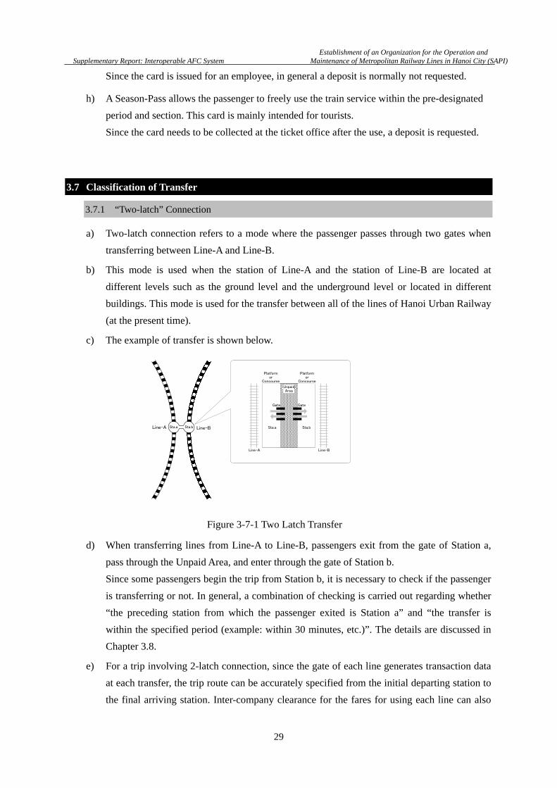
3.7.1 “Two-latch” Connection
a) Two-latch connection refers to a mode where the passenger passes through two gates when
transferring between Line-A and Line-B.
b) This mode is used when the station of Line-A and the station of Line-B are located at
different levels such as the ground level and the underground level or located in different
buildings. This mode is used for the transfer between all of the lines of Hanoi Urban Railway
(at the present time).
c) The example of transfer is shown below.
d) When transferring lines from Line-A to Line-B, passengers exit from the gate of Station a,
pass through the Unpaid Area, and enter through the gate of Station b.
Since some passengers begin the trip from Station b, it is necessary to check if the passenger
is transferring or not. In general, a combination of checking is carried out regarding whether
“the preceding station from which the passenger exited is Station a” and “the transfer is
within the specified period (example: within 30 minutes, etc.)”. The details are discussed in
Chapter 3.8.
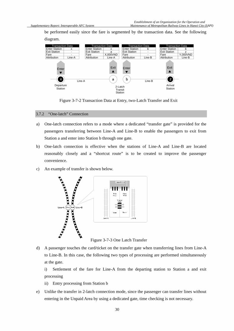
e) For a trip involving 2-latch connection, since the gate of each line generates transaction data
at each transfer, the trip route can be accurately specified from the initial departing station to
the final arriving station. Inter-company clearance for the fares for using each line can also
Sta.a
Gate
Line-A Line-B
Sta.b
Gate
UnpaidArea
Platformor
Concourse
Platformor
Concourse
Line-A Line-BSta.a Sta.b
Figure 3-7-1 Two Latch Transfer
Establishment of an Organization for the Operation and
Supplementary Report: Interoperable AFC System Maintenance of Metropolitan Railway Lines in Hanoi City (SAPI)
30
be performed easily since the fare is segmented by the transaction data. See the following
diagram.
3.7.2 “One-latch” Connection
a) One-latch connection refers to a mode where a dedicated “transfer gate” is provided for the
passengers transferring between Line-A and Line-B to enable the passengers to exit from
Station a and enter into Station b through one gate.
b) One-latch connection is effective when the stations of Line-A and Line-B are located
reasonably closely and a “shortcut route” is to be created to improve the passenger
convenience.
c) An example of transfer is shown below.
d) A passenger touches the card/ticket on the transfer gate when transferring lines from Line-A
to Line-B. In this case, the following two types of processing are performed simultaneously
at the gate.
i) Settlement of the fare for Line-A from the departing station to Station a and exit
processing
ii) Entry processing from Station b
e) Unlike the transfer in 2-latch connection mode, since the passenger can transfer lines without
entering in the Unpaid Area by using a dedicated gate, time checking is not necessary.
DepartureStation
ArrivalStationTransit
Station
2-Latch
Enter▼
ax zb
Enter StationExit Station
xa
Fare X,000VNDAttribution Line-A
Transaction Data
Line-A Line-B
Enter StationExit Station
bz
Fare Y,000VNDAttribution Line-B
Transaction DataEnter StationExit Station
x-
Fare -Attribution Line-A
Transaction DataEnter StationExit Station
b-
Fare -Attribution Line-B
Transaction Data
Enter▼
Exit▲
Exit▲
Figure 3-7-2 Transaction Data at Entry, two-Latch Transfer and Exit
Figure 3-7-3 One Latch Transfer

Establishment of an Organization for the Operation and
Supplementary Report: Interoperable AFC System Maintenance of Metropolitan Railway Lines in Hanoi City (SAPI)
31
f) For a trip in 2-latch connection mode also, as transaction data for the use of each line is
generated in the same way as for 2-latch connection, a trip route can be specified accurately.
Inter-company clearance can also be implemented easily. See the following diagram.
3.7.3 “No-latch” Connection
a) “No-latch” connection refers to a mode where Line-A and Line-B share the same station
since the platforms are located next to each other and passengers can transfer lines without
using any gate.
b) In general, a no-latch connection mode is used when a railway company owns multiple lines
and this mode is used for seamless operation including the train service for smooth transfer.
No-latch connection can be applied between different railway companies (although this is
not a usual exercise).
c) An example of the transfer is shown below.
Figure 3-7-4 Transaction Data at Entry, one-Latch Transfer and Exit
Figure 3-7-5 No Latch Transfer
Establishment of an Organization for the Operation and
Supplementary Report: Interoperable AFC System Maintenance of Metropolitan Railway Lines in Hanoi City (SAPI)
32
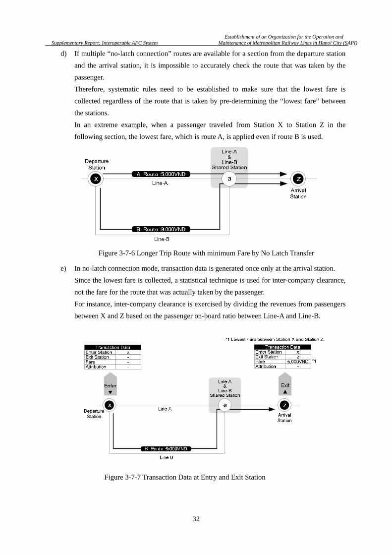
d) If multiple “no-latch connection” routes are available for a section from the departure station
and the arrival station, it is impossible to accurately check the route that was taken by the
passenger.
Therefore, systematic rules need to be established to make sure that the lowest fare is
collected regardless of the route that is taken by pre-determining the “lowest fare” between
the stations.
In an extreme example, when a passenger traveled from Station X to Station Z in the
following section, the lowest fare, which is route A, is applied even if route B is used.
e) In no-latch connection mode, transaction data is generated once only at the arrival station.
Since the lowest fare is collected, a statistical technique is used for inter-company clearance,
not the fare for the route that was actually taken by the passenger.
For instance, inter-company clearance is exercised by dividing the revenues from passengers
between X and Z based on the passenger on-board ratio between Line-A and Line-B.
Figure 3-7-6 Longer Trip Route with minimum Fare by No Latch Transfer
Figure 3-7-7 Transaction Data at Entry and Exit Station

Establishment of an Organization for the Operation and
Supplementary Report: Interoperable AFC System Maintenance of Metropolitan Railway Lines in Hanoi City (SAPI)
33
3.8 Transit Judgment: Items To Be Checked at a Transfer Point
a) At transfer of lines from Line-A to Line-B in 2-latch connection mode, at least the following
items need to be checked when the passenger touches the card/ticket on the gate to Line-B.
i) The preceding gate from which the passenger exited is the gate of the pre-registered station.
ii) The passenger entered the station of Line-B within the specified time from the preceding
exit.
iii) The ticket/card contains a sufficient remaining balance.
(At least the fare amount for one or more stations)
b) For (i), it is recommended to allow registration of multiple “designated transfer stations”
considering the connections of multiple lines in the future.
c) For (ii), it is recommended to allow any modifications by setting the item as a parameter
since the re-entry time limit varies according to the station building or the passenger traffic
volume.

Establishment of an Organization for the Operation and
Supplementary Report: Interoperable AFC System Maintenance of Metropolitan Railway Lines in Hanoi City (SAPI)
34
3.9 Fare Calculation Method
a) When a trip involving transfer is recognized, only the mileage fare is collected without
collecting the base fare at the exits of the second line and subsequent lines.
b) Two methods are available for calculating mileage fares according to the manner of selecting
the station as the reference point.
i) Separate Fare Collection Method
ii) Total Fare Collection Method
In (i), a mileage fare is calculated based on the working kilometers using the station as the
starting point. In (ii), a fare is calculated based on the total number of kilometers from the
initial departure station to the arrival station. Although these two methods are similar, the
fares that are collected may differ according to the fraction process that was described in
3.5.4.
3.9.1 Separate Fare Collection Method
a) In this method, a mileage fare is calculated at each transfer by defining the station as the zero
kilometer base point.
For instance, in the case of the following working kilometers, the final fare will be
7,300VND.
Here, the fare ratio is 500, fractions are rounded up to the unit of 100VND, and the base fare
is omitted for simplification of explanation.
b) One of the merits of the separate fare collection method is that users can intuitively
understand the fare amount since they can calculate the fare up to the arrival station. (Note
the difference from the total fare collection method that is described later.)
Another merit is that the gate of each line only needs to hold the “fares of the line of the gate
only”. This method is effective for the development of AFC equipment.
Figure 3-9-1 Fare Charge at Transfer
Figure 3-9-2 Fare Collection Method

Establishment of an Organization for the Operation and
Supplementary Report: Interoperable AFC System Maintenance of Metropolitan Railway Lines in Hanoi City (SAPI)
35
3.9.2 Total Fare Collection Method
a) The total fare collection method strictly complies with the policy of “calculating a mileage
fare based on the working kilometers from the departure station”. The following two items
are recorded in the card. The mileage fare is calculated based on the total working kilometers
when the passenger transfers between the lines, and the “difference” from the amount that
has been collected is detected.
(i) Initial departure station
(ii) Total fare that has been collected up to the preceding exit.
The following diagram shows an example when the passenger travelled the same distance as
for 3.9.1
b) In the example shown above, note that the fare that is collected in [C1-C2] is cheaper than
the fare collected by the separate fare collection method by 100VND.
The final fare will be 7,200VND.
The reason is that since the base point of working kilometers remains unchanged even if
transfer is involved, the influence by rounding up fractions is minimal.
c) The merit of the total fare collection method is that passengers can use railway services more
cheaply.
On the other hand, the total fare collection method is inferior to the separate fare collection
method for users in terms of the intuitive comprehensibility since the fare to be collected is
calculated at the exit by deduction.
Focusing on Line-C in the above diagram, a fare of 2,400VND can be charged for the trip of
4.7Km, while the fare distribution in calculation resulted in 2,300VND. Therefore, this
method may bring disadvantage to some operators.
Since the total fare collection method needs to store more information in the card, the fare
calculation logic of the AFC equipment will be presumably more complicated.
Figure 3-9-3 Total Fare Collection Method
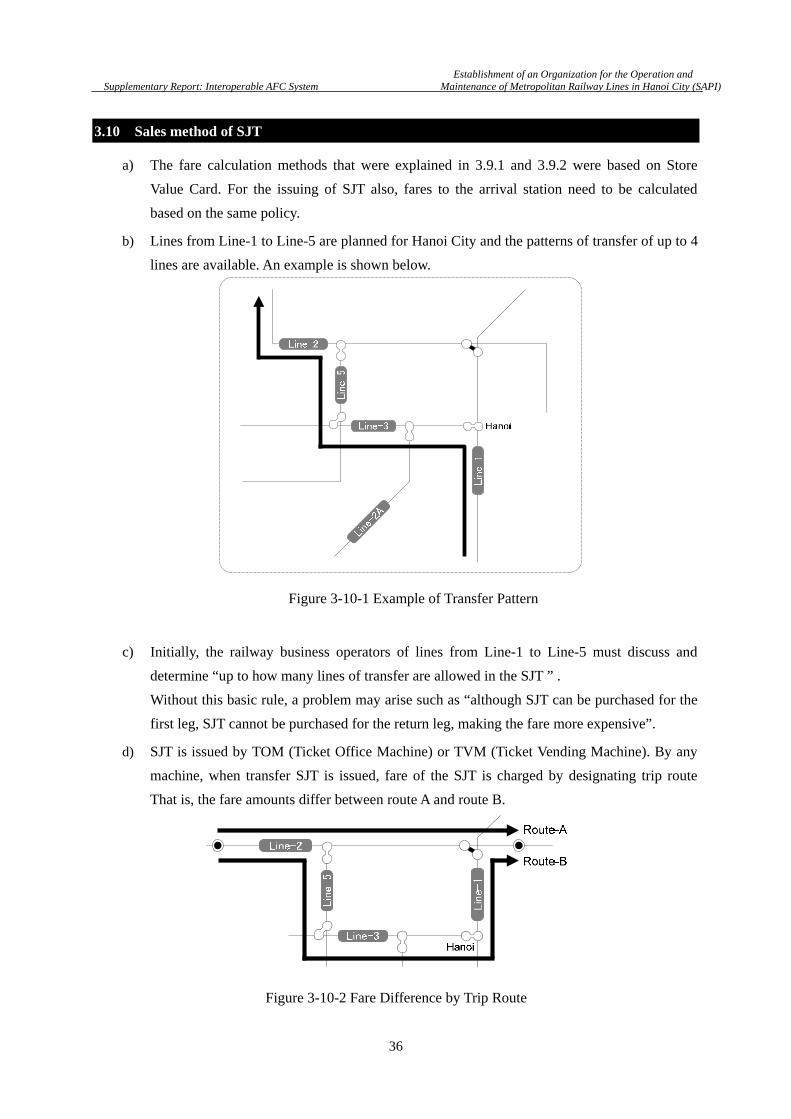
Establishment of an Organization for the Operation and
Supplementary Report: Interoperable AFC System Maintenance of Metropolitan Railway Lines in Hanoi City (SAPI)
36
3.10 Sales method of SJT
a) The fare calculation methods that were explained in 3.9.1 and 3.9.2 were based on Store
Value Card. For the issuing of SJT also, fares to the arrival station need to be calculated
based on the same policy.
b) Lines from Line-1 to Line-5 are planned for Hanoi City and the patterns of transfer of up to 4
lines are available. An example is shown below.
c) Initially, the railway business operators of lines from Line-1 to Line-5 must discuss and
determine “up to how many lines of transfer are allowed in the SJT ” .
Without this basic rule, a problem may arise such as “although SJT can be purchased for the
first leg, SJT cannot be purchased for the return leg, making the fare more expensive”.
d) SJT is issued by TOM (Ticket Office Machine) or TVM (Ticket Vending Machine). By any
machine, when transfer SJT is issued, fare of the SJT is charged by designating trip route
That is, the fare amounts differ between route A and route B.
Figure 3-10-1 Example of Transfer Pattern
Figure 3-10-2 Fare Difference by Trip Route

Establishment of an Organization for the Operation and
Supplementary Report: Interoperable AFC System Maintenance of Metropolitan Railway Lines in Hanoi City (SAPI)
37
e) The following two methods are available for issuing SJT.
i) Encoding trip route information such as the departure station, arrival station, and
transfer station (Distance Vector Method)
ii) Encoding the necessary fare up to the arrival station as the Stored Value
(Just Charge Method)
In this document, the latter method, the just charge method, is recommended due to the
following reasons.
Convenience
Information that indicates a route is not encoded in SJT. Therefore, even if the passenger
departs from the route that was declared at the purchase of the card for some reason, the
passenger can continue the trip as long as the sufficient remaining balance is available. (As
an example of the reason for departing from the route that was declared, the passenger is
forced to make a detour due to the service problem such as the problem in the train.)
Since the declared route is most likely the cheapest route, the remaining balance becomes
insufficient if the passenger takes a detour route. In this case, fare shortage needs to be
settled in cash. See the diagram below.
Design of AFC equipment
SVC and SJT can be processed with almost the same logic such as IC card encoding format
and update method, making the design simple.
Accounting processing
Since both SVC and SJT apply the advances received method by charging a certain amount
in advance, accounting processing on the server side is standardized.
Originally Route
Detour Route
Fare Shortage
×
Figure 3-10-3 Fare Shortage by Detour

Establishment of an Organization for the Operation and
Supplementary Report: Interoperable AFC System Maintenance of Metropolitan Railway Lines in Hanoi City (SAPI)
38
Chapter 4 Operation
This Chapter defines the basic usage of SVC and SJT, handling of SVC and SJT by station staffs,
the service menu, and the abnormality countermeasures.
4.1 Normal Operation of SVC (Stored Value Card)
a) SVC shall be able to be issued by the operator of each line.
However, it is recommended to reduce the initial cost and running cost for the supply of the
medium by sharing the issuing center as described in Chapter 2.
b) Considering the user convenience, the value of SVC shall be added in all the lines without
any discrimination. That is, the value of the card that is issued by company A shall be able to
be added by the AFC equipment of the line of the company B and vice versa.
c) Passengers enter the initial departure station through the gate by Touch & Go operation.
The exit gate of each line has an SJT collection slot. Some measure is necessary to prevent
passengers from submitting SVC to the SJT slot by mistake. For instance, since the shapes
and thickness are different between SVC and SJT, design the shape of the slot so that SVC
cannot be physically inserted.
d) When arriving at the transfer station, the passenger exits the station through the gate in Touch &
Go mode. The passenger enters the station of the transfer line through the gate of the line in
Touch & Go mode.
e) Each company shall install the necessary AFC equipment to enable passengers to exit the
station smoothly in either of the following methods when the remaining balance becomes
insufficient before the passenger reaches the arrival station.
i) Enable the passenger to settle the fare shortage in cash through TOM that is installed in
the Ticket Inspection Room.
ii) Install a Add Value Machine in the Paid Area to allow the passenger to exit the gate after
adding the value.
4.2 Normal Operation of SJT (Single Journey Ticket)
a) SJT shall be able to be issued by the operator of each line.
However, it is recommended to reduce the initial cost and running cost for the supply of the
medium by sharing the issuing center as described in Chapter 2.
b) SJT shall be issued after the route to the arrival station is designated by the passenger and the
necessary fare value is stored regardless of whether SJT is issued by a ticket vending
machine or a ticket office machine.

Establishment of an Organization for the Operation and
Supplementary Report: Interoperable AFC System Maintenance of Metropolitan Railway Lines in Hanoi City (SAPI)
39
As the number of transfers increases, the passenger will find it more difficult to purchase SJT
by selecting the most convenient route in fare or time. Thus, Ticket Office Machine or Ticket
Vending Machine needs to have the functionality to guide appropriate route to the
destination.
c) The following shows the operation of the SJT in the case of the simplest trip that completes
within the same line.
i) A passenger passes through the entry gate of the station by Touch & Go.
ii) The passenger submits SJT to the SJT collection slot of the exit gate of the station.
d) In contrast, when the trip involves transfer, the gates at the transfer and the final arrival
station are used differently.
i) A passenger passes through the entry gate of the station by Touch & Go.
ii) At the transfer station, the passenger exits through the gate by Touch & Go.
iii) The passenger enters through the gate of the station of the transfer line by Touch & Go.
iv) The passenger submits SJT to the SJT collection slot at the gate of the final arrival
station.
e) In (ii) of (d) that is indicated above, a passenger may submit SJT to the collection slot by
mistake.
Since the passenger with the SJT containing a remaining balance may continue the trip, some
measures are necessary such as closing the gate without collecting SJT, returning SJT, and
guiding the passenger to pass through the gate by Touch & Go.
As another suggestion, if sufficient space and the number of gates are available in the station
concourse, an “SVC & transfer SJT only lane” could be provided by covering the SJT
collection slot.
f) Settlement of fare shortage in cash shall be enabled at the station office when the remaining
balance becomes insufficient in such a case as that the passenger used the service outside of
the route that was designated at the purchase of SJT.
Unlike SVC, since SJT is the ticket for single trip and must be reused, it is shall be
prohibited to add value other than the store of fare value at the purchasing the SJT. Therefore,
the fare shortage shall be settled in cash as the precondition.
g) In relation to (f) indicated above, fare shortage is not necessarily settled at the final arrival
station.
If the fare becomes insufficient at the transfer station during the trip, SJT from that station to
the arrival station needs to be purchased. See the following diagram.

Establishment of an Organization for the Operation and
Supplementary Report: Interoperable AFC System Maintenance of Metropolitan Railway Lines in Hanoi City (SAPI)
40
In principle, the validity for transfer shall be lost once the fare has been settled and when SJT is
purchased again, both the base fare and mileage fare are collected. However, consideration is
necessary to enable flexible operation to handle the case that the route is to be diverted due to the
fault of the railway business operator such as a fault in the train or service problem.
4.3 Unification of Service Level: Standardization of Service Levels
In interoperable AFC system, differences in operations and service availabilities of SVC and SJT
by line railway operator and O&M company cause confusion amongst users.
Therefore, the services shall be standardized as common services in Hanoi Urban Railway
Network. In the Table 4-3-1, the services available across lines and services available only at
stations under the railway operator which issues the SVC and SJT are summarized as minimum
requirement,
i) Capable of processing SVC/SJT that are issued by own company only:
ii) Capable of processing SVC/SJT that are issued by own company and other company:
The services irrelevant to the media are marked by: -.
Table 4-3-1 Criteria of Services
*1 In principle, SJT that is collected at the gate shall be recycled at the station regardless of whether the
SJT has been issued by own company or other company. For the simple operation such as this, SJT
Service SVC SJT Remark
Purchase SJT - Note *1.
Add Value -
Enter
Exit (Normal)
Exit (without deducting Fare) Note *2.
Fare Adjustment
Print(Display) Record - Note *3
Re-Issue Registration -
Re-Issue SVC -
Refund Note *4
Black List Check
Figure 4-2-1 Fare Shortage by Detour and Re-Purchase

Establishment of an Organization for the Operation and
Supplementary Report: Interoperable AFC System Maintenance of Metropolitan Railway Lines in Hanoi City (SAPI)
41
shall be issued and supplied by an integrated issuing center with standardized designs and physical
specifications as well as the common specifications for interoperability. As the result, SJT can be
freely reused without having to be aware of the issuing companies.
*2 For instance, the card is not updated correctly at the previous exit through gate, thereby disabling
the next entry. This service refers to the service for exit processing only without collecting the Stored
Value with ticket office machine (TOM).
*3 Refers to the service for displaying Stored Value card use history on the screen and printing the receipts.
*4 Refund of SVC that accompanies return of the deposit shall be allowed only by the operator that
issued the card. In principle, refund of SJT is allowed under the following conditions only.
i) Issued on the day
ii) Unused
Since SJT is to be collected at the gate of the exit station, the passenger would not be able to keep SJT.
However, since a passenger exits to unpaid area at transfer, SJT may be disposed of without using the
remaining balance of Stored Value. To prevent anyone from cashing out of the disposed SJT by
collecting it and requesting refund at the station office, refund of unused SJT only is permitted as
indicated above.

Establishment of an Organization for the Operation and
Supplementary Report: Interoperable AFC System Maintenance of Metropolitan Railway Lines in Hanoi City (SAPI)
42
Chapter 5 Basic Scheme of the Clearing System
5.1 General Description
a) A clearing scheme must be agreed between the interoperable railway business operators.
Inter-company clearance processing is performed by the “Central Clearing House System
(CCHS)” that functions at the upper layer of the central server of each company.
b) The following points should be noted in defining the clearance scheme.
i) Attribution of the revenues from the sale of cards/tickets
ii) Attribution of deposits
iii) Attribution of revenues from add-value
iv) Attribution of revenues from fares of cards/tickets that are used by other companies
v) Scope and contents of the inter-company clearance that is performed by CCHS
vi) Timing of inter-company clearance (daily or monthly)
vii) Handling fee to be paid to CCHS by each company
c) This Chapter describes the data flow and clearance flow between the AFC system of each
line and CCHS regarding the items indicated in (i) to (vi). The economic conditions such as
the actual clearance handling fee is not presented in this document as such conditions shall
be decided by individual companies through deliberation.
5.2 Basic Scheme
a) This section initially summarizes the related stakeholders.
To issue a stored value card, an organization called a “value issuer” that practically manages
the stored value of the card is necessary. Value issuer must exist for each card type.
In issuing of common cards that can be used across all the lines in the Hanoi Urban Railway
system, the simplest proposal is to establish only “one” value issuer. In broad sense, ‘Value
Issuer + O&M Company’ is treated as O&M Company. In this document, considering the
possibility of two O&M Companies, two value issuers are described. See the diagram below.
Figure 5-2-1 Basic Scheme of Stakeholders
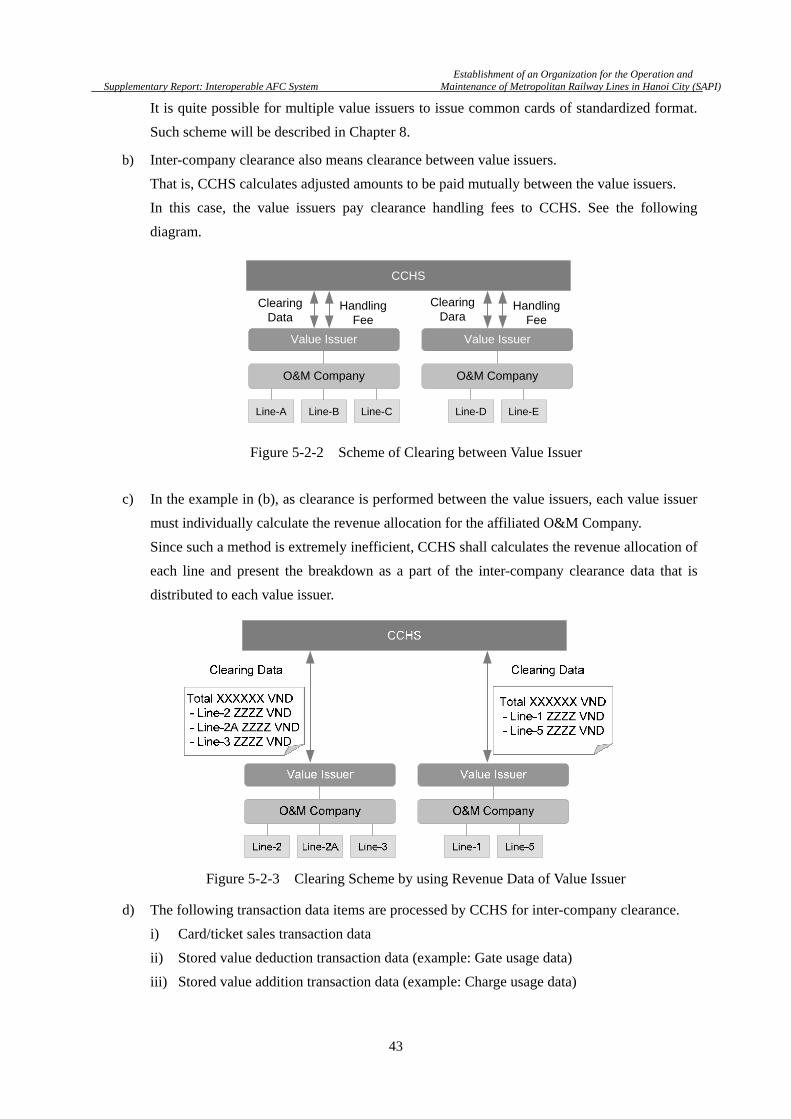
Establishment of an Organization for the Operation and
Supplementary Report: Interoperable AFC System Maintenance of Metropolitan Railway Lines in Hanoi City (SAPI)
43
It is quite possible for multiple value issuers to issue common cards of standardized format.
Such scheme will be described in Chapter 8.
b) Inter-company clearance also means clearance between value issuers.
That is, CCHS calculates adjusted amounts to be paid mutually between the value issuers.
In this case, the value issuers pay clearance handling fees to CCHS. See the following
diagram.
c) In the example in (b), as clearance is performed between the value issuers, each value issuer
must individually calculate the revenue allocation for the affiliated O&M Company.
Since such a method is extremely inefficient, CCHS shall calculates the revenue allocation of
each line and present the breakdown as a part of the inter-company clearance data that is
distributed to each value issuer.
d) The following transaction data items are processed by CCHS for inter-company clearance.
i) Card/ticket sales transaction data
ii) Stored value deduction transaction data (example: Gate usage data)
iii) Stored value addition transaction data (example: Charge usage data)
Line-A Line-B Line-C Line-D Line-E
Value Issuer Value Issuer
CCHS
O&M Company O&M Company
Clearing Data
Handling Fee
Handling Fee
Clearing Dara
Figure 5-2-2 Scheme of Clearing between Value Issuer
Figure 5-2-3 Clearing Scheme by using Revenue Data of Value Issuer

Establishment of an Organization for the Operation and
Supplementary Report: Interoperable AFC System Maintenance of Metropolitan Railway Lines in Hanoi City (SAPI)
44
e) CCHS collects a handling fee according to the number of transaction data items that have
been received. The billing destination varies depending on either one of the following cases.
i) Stored Value is used (deduction)
ii) Stored Value is topped up (Add Value)
See the explanation from the next page for the details.
f) The role of CCHS is to output revenue allocation information of each company as a
document (or data) and send it to each company.
Mutual payment processing is directly performed between the value issuers through the bank
accounts.
A scheme where CCHS performs remittance processing for value issuers as an agent. In this
case, a sufficient funding ability and an administrative ability are required for CCHS.
g) A Value Issuer refers to the following:
i) Owner of the IC card, and
ii) Issuer of the IC card, and
ii) Manager of the stored value
A value issuer may be an organization that is established independently from an O&M
company or an O&M company that also functions as a value issuer. See the following
diagram.
O&M Company
Line A Line B Line C Line D Line E
Value Issuer
O&M Company
Value Issuer
CCHS
Figure 5-2-4 Clearing Scheme with CCHS to output Revenue Allocation
Figure 5-2-5 Functions of Value Issuer
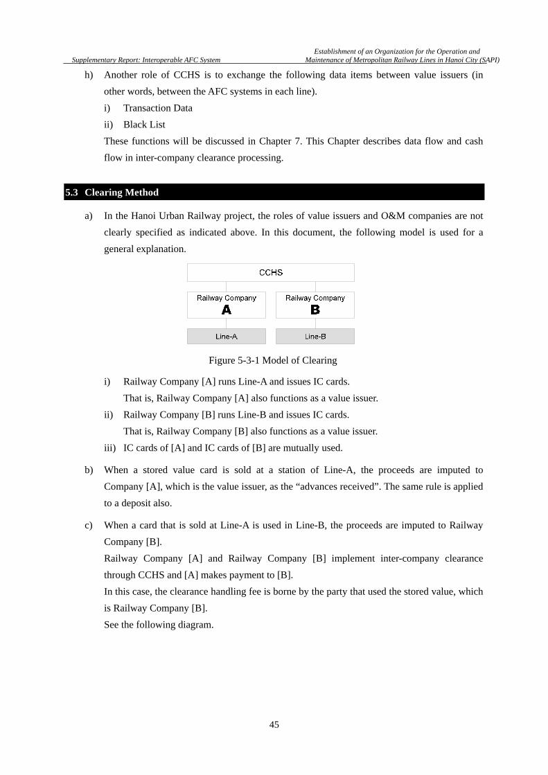
Establishment of an Organization for the Operation and
Supplementary Report: Interoperable AFC System Maintenance of Metropolitan Railway Lines in Hanoi City (SAPI)
45
h) Another role of CCHS is to exchange the following data items between value issuers (in
other words, between the AFC systems in each line).
i) Transaction Data
ii) Black List
These functions will be discussed in Chapter 7. This Chapter describes data flow and cash
flow in inter-company clearance processing.
5.3 Clearing Method
a) In the Hanoi Urban Railway project, the roles of value issuers and O&M companies are not
clearly specified as indicated above. In this document, the following model is used for a
general explanation.
i) Railway Company [A] runs Line-A and issues IC cards.
That is, Railway Company [A] also functions as a value issuer.
ii) Railway Company [B] runs Line-B and issues IC cards.
That is, Railway Company [B] also functions as a value issuer.
iii) IC cards of [A] and IC cards of [B] are mutually used.
b) When a stored value card is sold at a station of Line-A, the proceeds are imputed to
Company [A], which is the value issuer, as the “advances received”. The same rule is applied
to a deposit also.
c) When a card that is sold at Line-A is used in Line-B, the proceeds are imputed to Railway
Company [B].
Railway Company [A] and Railway Company [B] implement inter-company clearance
through CCHS and [A] makes payment to [B].
In this case, the clearance handling fee is borne by the party that used the stored value, which
is Railway Company [B].
See the following diagram.
Figure 5-3-1 Model of Clearing

Establishment of an Organization for the Operation and
Supplementary Report: Interoperable AFC System Maintenance of Metropolitan Railway Lines in Hanoi City (SAPI)
46
d) When the card that is sold at Line-A is charged at Line-B, the proceeds are imputed to
Railway Company [A], which is the card issuer.
Railway Company [A] and Railway Company [B] implement inter-company clearance
through CCHS and [B] makes a payment to [A].
In this case, the clearance handling fee is borne by Railway Company [A], which is the card
issuer. See the following diagram.
e) A value issuer may not necessarily be a railway company and in some cases, cards that are
issued by a value issuer are used by multiple railway companies as common cards. See the
following diagram.
Figure 5-3-3 Clearing Process for Add Value
Figure 5-3-4 Value Issuer and Railway Company
Figure 5-3-2 Clearing Process for Fare
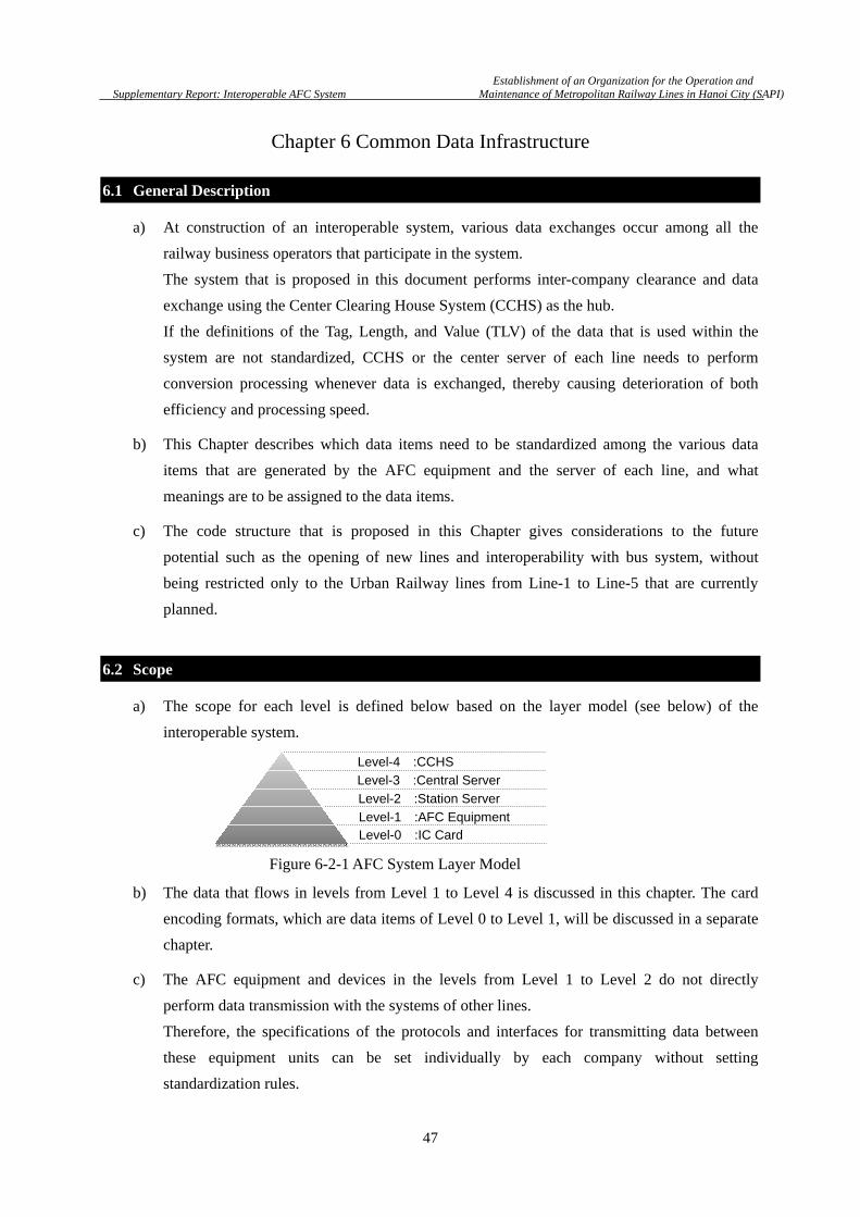
Establishment of an Organization for the Operation and
Supplementary Report: Interoperable AFC System Maintenance of Metropolitan Railway Lines in Hanoi City (SAPI)
47
Chapter 6 Common Data Infrastructure
6.1 General Description
a) At construction of an interoperable system, various data exchanges occur among all the
railway business operators that participate in the system.
The system that is proposed in this document performs inter-company clearance and data
exchange using the Center Clearing House System (CCHS) as the hub.
If the definitions of the Tag, Length, and Value (TLV) of the data that is used within the
system are not standardized, CCHS or the center server of each line needs to perform
conversion processing whenever data is exchanged, thereby causing deterioration of both
efficiency and processing speed.
b) This Chapter describes which data items need to be standardized among the various data
items that are generated by the AFC equipment and the server of each line, and what
meanings are to be assigned to the data items.
c) The code structure that is proposed in this Chapter gives considerations to the future
potential such as the opening of new lines and interoperability with bus system, without
being restricted only to the Urban Railway lines from Line-1 to Line-5 that are currently
planned.
6.2 Scope
a) The scope for each level is defined below based on the layer model (see below) of the
interoperable system.
b) The data that flows in levels from Level 1 to Level 4 is discussed in this chapter. The card
encoding formats, which are data items of Level 0 to Level 1, will be discussed in a separate
chapter.
c) The AFC equipment and devices in the levels from Level 1 to Level 2 do not directly
perform data transmission with the systems of other lines.
Therefore, the specifications of the protocols and interfaces for transmitting data between
these equipment units can be set individually by each company without setting
standardization rules.
Level-0 :IC CardLevel-1 :AFC Equipment
Level-2 :Station Server
Level-3 :Central Server
Level-4 :CCHS
Figure 6-2-1 AFC System Layer Model
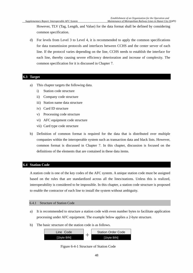
Establishment of an Organization for the Operation and
Supplementary Report: Interoperable AFC System Maintenance of Metropolitan Railway Lines in Hanoi City (SAPI)
48
However, TLV (Tag, Length, and Value) for the data format shall be defined by considering
common specification.
d) For levels from Level 3 to Level 4, it is recommended to apply the common specifications
for data transmission protocols and interfaces between CCHS and the center server of each
line. If the protocol varies depending on the line, CCHS needs to establish the interface for
each line, thereby causing severe efficiency deterioration and increase of complexity. The
common specification for it is discussed in Chapter 7.
6.3 Target
a) This chapter targets the following data.
i) Station code structure
ii) Company code structure
iii) Station name data structure
iv) Card ID structure
v) Processing code structure
vi) AFC equipment code structure
vii) Card type code structure
b) Definition of common format is required for the data that is distributed over multiple
companies within the interoperable system such as transaction data and black lists. However,
common format is discussed in Chapter 7. In this chapter, discussion is focused on the
definitions of the elements that are contained in these data items.
6.4 Station Code
A station code is one of the key codes of the AFC system. A unique station code must be assigned
based on the rules that are standardized across all the lines/stations. Unless this is realized,
interoperability is considered to be impossible. In this chapter, a station code structure is proposed
to enable the contractor of each line to install the system without ambiguity.
6.4.1 Structure of Station Code
a) It is recommended to structure a station code with even number bytes to facilitate application
processing under AFC equipment. The example below applies a 2-byte structure.
b) The basic structure of the station code is as follows.
+Line Code Station Order Code
[1byte BIN] [1byte BIN]
Figure 6-4-1 Structure of Station Code

Establishment of an Organization for the Operation and
Supplementary Report: Interoperable AFC System Maintenance of Metropolitan Railway Lines in Hanoi City (SAPI)
49
c) Up to 256 types of line codes from 000 to 255 can be allocated.
Likewise, up to 256 types of station order codes from 000 to 255 can be allocated.
d) Based on the above, the number of unique code combinations will be 255 255=65,536.
This is considered as the adequate number of code combinations for the Hanoi Urban
Railway system, including future extension.
6.4.2 Allocation of Line-Code
a) A certain number of line-codes is able to be pre-allocated to each of Line-1 to Line-5.
An example is shown below.
b) Line code 000 and line code 255 are specified as “reserved codes by the system” to which
special meaning is assigned in the system.
These codes shall not be allocated to any lines in the future either.
6.4.3 Allocation of Station Order Code
a) Some rules and techniques are applied to the allocation of station order codes.
Allocation suggestions are provided below by using examples.
b) Duplication of station order code is not allowed for a line code.
The combination of “line code-station order code” must be unique within the entire system. See
below for the example.
c) By specifying a base point, station order codes shall be assigned in the ascending order or
descending order from the point.
The order shall not be changed in the middle of the line.
Line Code Allocation
000 Reserved by the system
001 Line-1
002 Line-2
003 Line-2A
004 Line-3
005 Line-5
006 Reserved for other lines
・・・
254
255 Reserved by the system
Table 6-4-1 Example of Allocation for Line-Code
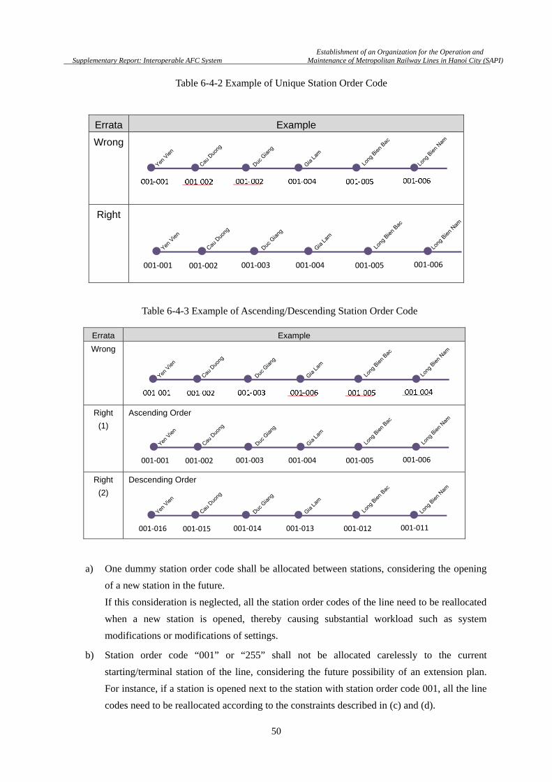
Establishment of an Organization for the Operation and
Supplementary Report: Interoperable AFC System Maintenance of Metropolitan Railway Lines in Hanoi City (SAPI)
50
a) One dummy station order code shall be allocated between stations, considering the opening
of a new station in the future.
If this consideration is neglected, all the station order codes of the line need to be reallocated
when a new station is opened, thereby causing substantial workload such as system
modifications or modifications of settings.
b) Station order code “001” or “255” shall not be allocated carelessly to the current
starting/terminal station of the line, considering the future possibility of an extension plan.
For instance, if a station is opened next to the station with station order code 001, all the line
codes need to be reallocated according to the constraints described in (c) and (d).
Errata Example
Wrong
Right
Errata Example
Wrong
Right
(1)
Ascending Order
Right
(2)
Descending Order
Table 6-4-2 Example of Unique Station Order Code
Table 6-4-3 Example of Ascending/Descending Station Order Code
001-001 001-002 001-003 001-004 001-005 001-006
001-016 001-015 001-014 001-013 001-012 001-011
001-001 001-002 001-003 001-004 001-005 001-006

Establishment of an Organization for the Operation and
Supplementary Report: Interoperable AFC System Maintenance of Metropolitan Railway Lines in Hanoi City (SAPI)
51
c) Station codes with the line code of “000” as a special codes and use it for the “all line valid
code” of a pass such as Staff Pass that is individually issued by each line. The allocation
example is shown below.
Errata Example
Wrong
Right
(1)
Right
(2)
Errata Example
Wrong
Right
Station Code Purpose Remarks
000-000 Reserved by the system Not used as it is equivalent to NULL
000-001 Line-1 All line valid
000-002 Line-2 All line valid
000-003 Line-2A All line valid
000-004 Line-3 All line valid
000-005 Line-5 All line valid
000-006 Line-VNR All line valid
000-007 Line-HPC All line valid
000-008 Hanoi All line valid
002-011 001-001002-001
001-015
Line Code:001Line Code:002
Table 6-4-4 Example of Dummy Station Order Coding
Table 6-4-5 Example of Reserving Station Order Code
Table 6-4-6 Example of Special Station Order Code
001-001 001-003 001-005 001-007
[DUMMY]001-002
[DUMMY]001-004
[DUMMY]001-006
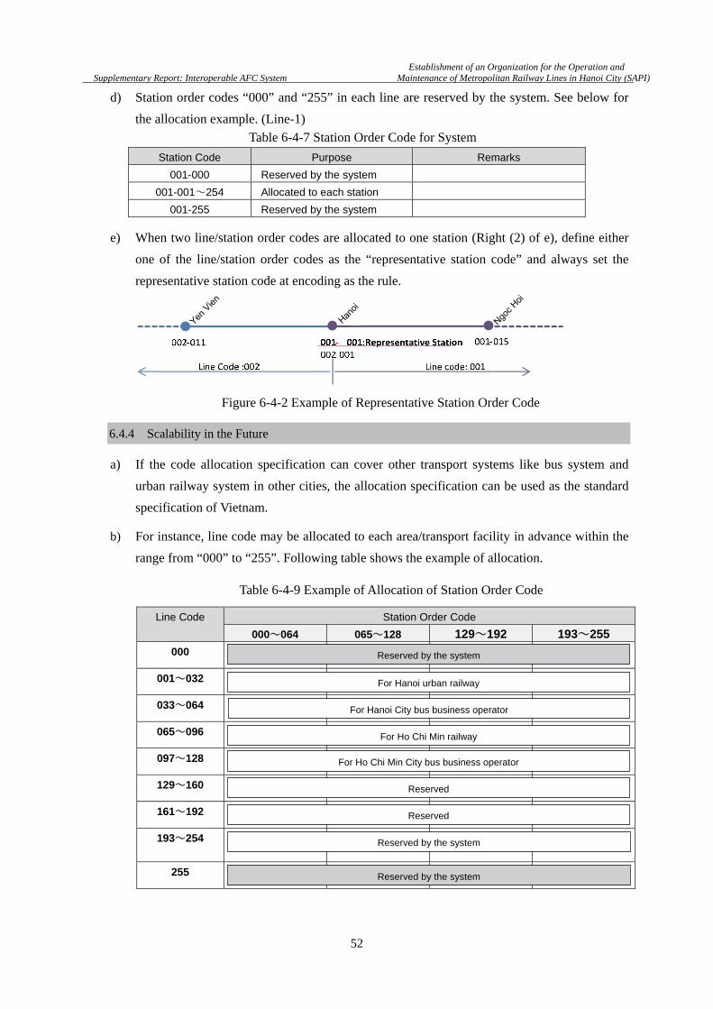
Establishment of an Organization for the Operation and
Supplementary Report: Interoperable AFC System Maintenance of Metropolitan Railway Lines in Hanoi City (SAPI)
52
d) Station order codes “000” and “255” in each line are reserved by the system. See below for
the allocation example. (Line-1)
e) When two line/station order codes are allocated to one station (Right (2) of e), define either
one of the line/station order codes as the “representative station code” and always set the
representative station code at encoding as the rule.
6.4.4 Scalability in the Future
a) If the code allocation specification can cover other transport systems like bus system and
urban railway system in other cities, the allocation specification can be used as the standard
specification of Vietnam.
b) For instance, line code may be allocated to each area/transport facility in advance within the
range from “000” to “255”. Following table shows the example of allocation.
Station Code Purpose Remarks
001-000 Reserved by the system
001-001~254 Allocated to each station
001-255 Reserved by the system
Line Code Station Order Code
000~064 065~128 129~192 193~255
000
001~032
033~064
065~096
097~128
129~160
161~192
193~254
255
Table 6-4-7 Station Order Code for System
Figure 6-4-2 Example of Representative Station Order Code
Table 6-4-9 Example of Allocation of Station Order Code
Reserved by the system
For Hanoi urban railway
For Hanoi City bus business operator
For Ho Chi Min railway
For Ho Chi Min City bus business operator
Reserved
Reserved
Reserved by the system
Reserved by the system
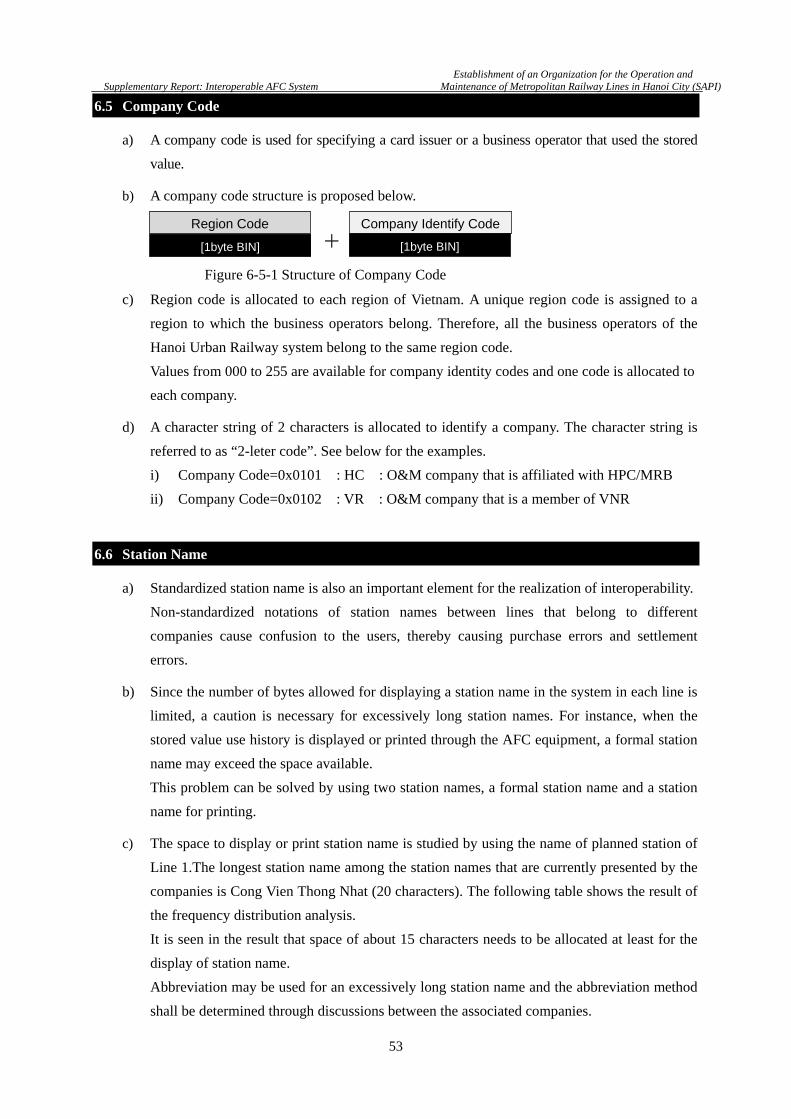
Establishment of an Organization for the Operation and
Supplementary Report: Interoperable AFC System Maintenance of Metropolitan Railway Lines in Hanoi City (SAPI)
53
6.5 Company Code
a) A company code is used for specifying a card issuer or a business operator that used the stored
value.
b) A company code structure is proposed below.
c) Region code is allocated to each region of Vietnam. A unique region code is assigned to a
region to which the business operators belong. Therefore, all the business operators of the
Hanoi Urban Railway system belong to the same region code.
Values from 000 to 255 are available for company identity codes and one code is allocated to
each company.
d) A character string of 2 characters is allocated to identify a company. The character string is
referred to as “2-leter code”. See below for the examples.
i) Company Code=0x0101 : HC : O&M company that is affiliated with HPC/MRB
ii) Company Code=0x0102 : VR : O&M company that is a member of VNR
6.6 Station Name
a) Standardized station name is also an important element for the realization of interoperability.
Non-standardized notations of station names between lines that belong to different
companies cause confusion to the users, thereby causing purchase errors and settlement
errors.
b) Since the number of bytes allowed for displaying a station name in the system in each line is
limited, a caution is necessary for excessively long station names. For instance, when the
stored value use history is displayed or printed through the AFC equipment, a formal station
name may exceed the space available.
This problem can be solved by using two station names, a formal station name and a station
name for printing.
c) The space to display or print station name is studied by using the name of planned station of
Line 1.The longest station name among the station names that are currently presented by the
companies is Cong Vien Thong Nhat (20 characters). The following table shows the result of
the frequency distribution analysis.
It is seen in the result that space of about 15 characters needs to be allocated at least for the
display of station name.
Abbreviation may be used for an excessively long station name and the abbreviation method
shall be determined through discussions between the associated companies.
+Region Code Company Identify Code
[1byte BIN] [1byte BIN]
Figure 6-5-1 Structure of Company Code
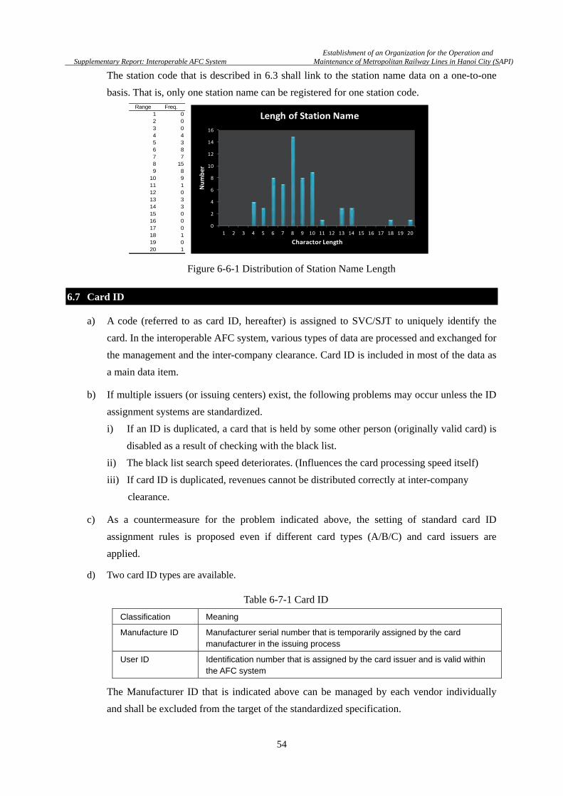
Establishment of an Organization for the Operation and
Supplementary Report: Interoperable AFC System Maintenance of Metropolitan Railway Lines in Hanoi City (SAPI)
54
The station code that is described in 6.3 shall link to the station name data on a one-to-one
basis. That is, only one station name can be registered for one station code.
6.7 Card ID
a) A code (referred to as card ID, hereafter) is assigned to SVC/SJT to uniquely identify the
card. In the interoperable AFC system, various types of data are processed and exchanged for
the management and the inter-company clearance. Card ID is included in most of the data as
a main data item.
b) If multiple issuers (or issuing centers) exist, the following problems may occur unless the ID
assignment systems are standardized.
i) If an ID is duplicated, a card that is held by some other person (originally valid card) is
disabled as a result of checking with the black list.
ii) The black list search speed deteriorates. (Influences the card processing speed itself)
iii) If card ID is duplicated, revenues cannot be distributed correctly at inter-company
clearance.
c) As a countermeasure for the problem indicated above, the setting of standard card ID
assignment rules is proposed even if different card types (A/B/C) and card issuers are
applied.
d) Two card ID types are available.
The Manufacturer ID that is indicated above can be managed by each vendor individually
and shall be excluded from the target of the standardized specification.
Classification Meaning
Manufacture ID Manufacturer serial number that is temporarily assigned by the card manufacturer in the issuing process
User ID Identification number that is assigned by the card issuer and is valid within the AFC system
Range Freq.1 02 03 04 45 36 87 78 159 8
10 911 112 013 314 315 016 017 018 119 020 1
0
2
4
6
8
10
12
14
16
1 2 3 4 5 6 7 8 9 10 11 12 13 14 15 16 17 18 19 20
Num
ber
Charactor Length
Lengh of Station Name
Figure 6-6-1 Distribution of Station Name Length
Table 6-7-1 Card ID
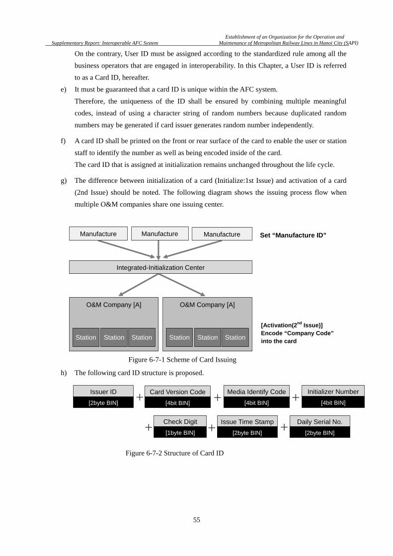
Establishment of an Organization for the Operation and
Supplementary Report: Interoperable AFC System Maintenance of Metropolitan Railway Lines in Hanoi City (SAPI)
55
On the contrary, User ID must be assigned according to the standardized rule among all the
business operators that are engaged in interoperability. In this Chapter, a User ID is referred
to as a Card ID, hereafter.
e) It must be guaranteed that a card ID is unique within the AFC system.
Therefore, the uniqueness of the ID shall be ensured by combining multiple meaningful
codes, instead of using a character string of random numbers because duplicated random
numbers may be generated if card issuer generates random number independently.
f) A card ID shall be printed on the front or rear surface of the card to enable the user or station
staff to identify the number as well as being encoded inside of the card.
The card ID that is assigned at initialization remains unchanged throughout the life cycle.
g) The difference between initialization of a card (Initialize:1st Issue) and activation of a card
(2nd Issue) should be noted. The following diagram shows the issuing process flow when
multiple O&M companies share one issuing center.
h) The following card ID structure is proposed.
O&M Company [A]
Station
Manufacture
Station Station
O&M Company [A]
Station Station Station
Manufacture Manufacture
Integrated-Initialization Center
Set “Manufacture ID”
[Activation(2nd Issue)] Encode “Company Code”into the card
Issuer ID
[2byte BIN]
Media Identify Code
[4bit BIN]
Issue Time Stamp
[2byte BIN]
Daily Serial No.
[2byte BIN]
+
+ + Check Digit
[1byte BIN]
Card Version Code
[4bit BIN] +
+
Initializer Number
[4bit BIN] +
Figure 6-7-1 Scheme of Card Issuing
Figure 6-7-2 Structure of Card ID
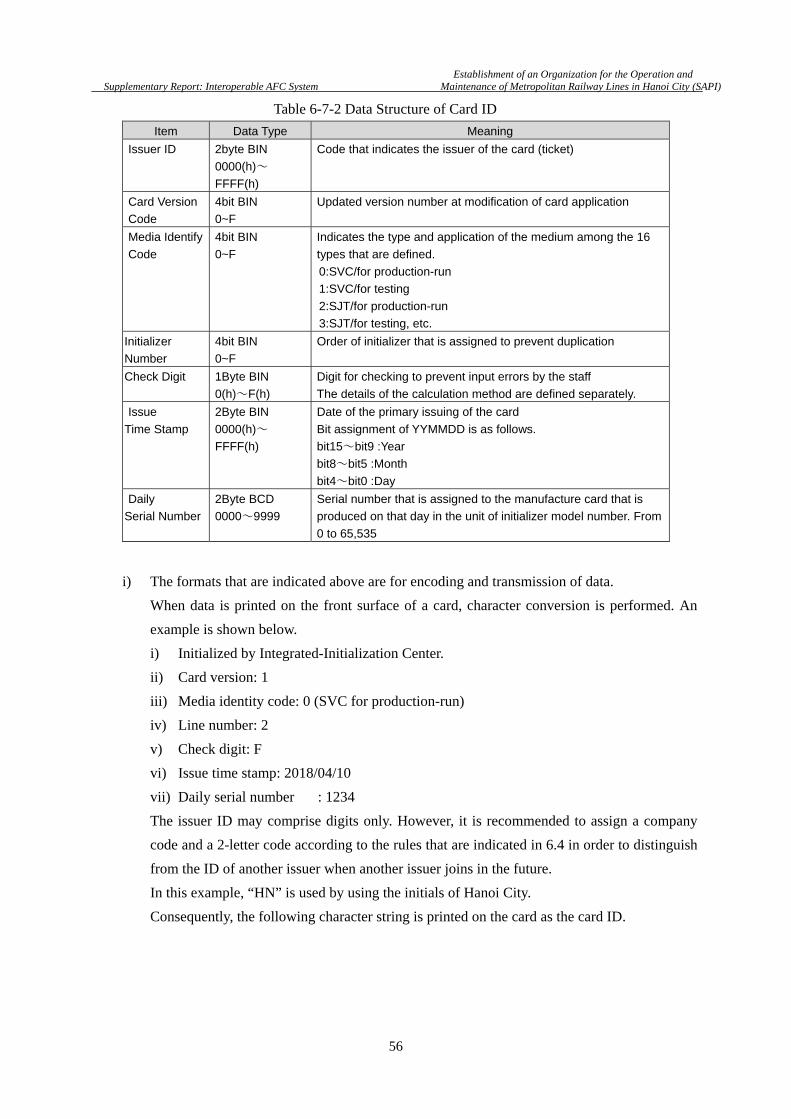
Establishment of an Organization for the Operation and
Supplementary Report: Interoperable AFC System Maintenance of Metropolitan Railway Lines in Hanoi City (SAPI)
56
i) The formats that are indicated above are for encoding and transmission of data.
When data is printed on the front surface of a card, character conversion is performed. An
example is shown below.
i) Initialized by Integrated-Initialization Center.
ii) Card version: 1
iii) Media identity code: 0 (SVC for production-run)
iv) Line number: 2
v) Check digit: F
vi) Issue time stamp: 2018/04/10
vii) Daily serial number : 1234
The issuer ID may comprise digits only. However, it is recommended to assign a company
code and a 2-letter code according to the rules that are indicated in 6.4 in order to distinguish
from the ID of another issuer when another issuer joins in the future.
In this example, “HN” is used by using the initials of Hanoi City.
Consequently, the following character string is printed on the card as the card ID.
Item Data Type Meaning
Issuer ID 2byte BIN
0000(h)~
FFFF(h)
Code that indicates the issuer of the card (ticket)
Card Version
Code
4bit BIN
0~F
Updated version number at modification of card application
Media Identify
Code
4bit BIN
0~F
Indicates the type and application of the medium among the 16
types that are defined.
0:SVC/for production-run
1:SVC/for testing
2:SJT/for production-run
3:SJT/for testing, etc.
Initializer
Number
4bit BIN
0~F
Order of initializer that is assigned to prevent duplication
Check Digit 1Byte BIN
0(h)~F(h)
Digit for checking to prevent input errors by the staff
The details of the calculation method are defined separately.
Issue
Time Stamp
2Byte BIN
0000(h)~
FFFF(h)
Date of the primary issuing of the card
Bit assignment of YYMMDD is as follows.
bit15~bit9 :Year
bit8~bit5 :Month
bit4~bit0 :Day
Daily
Serial Number
2Byte BCD
0000~9999
Serial number that is assigned to the manufacture card that is
produced on that day in the unit of initializer model number. From
0 to 65,535
Table 6-7-2 Data Structure of Card ID

Establishment of an Organization for the Operation and
Supplementary Report: Interoperable AFC System Maintenance of Metropolitan Railway Lines in Hanoi City (SAPI)
57
HN102 F180 4101 2345
Daily Serial No.
Issue Time Stamp
Check Digit
Line Number
Media Identify Code
Card Version
Issuer ID
Figure 6-7-3 Example of Strings printed as Card ID
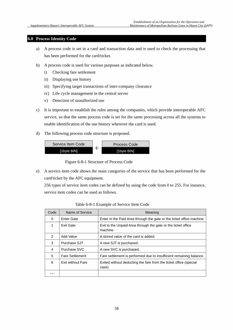
Establishment of an Organization for the Operation and
Supplementary Report: Interoperable AFC System Maintenance of Metropolitan Railway Lines in Hanoi City (SAPI)
58
6.8 Process Identity Code
a) A process code is set in a card and transaction data and is used to check the processing that
has been performed for the card/ticket.
b) A process code is used for various purposes as indicated below.
i) Checking fare settlement
ii) Displaying use history
iii) Specifying target transactions of inter-company clearance
iv) Life cycle management in the central server
v) Detection of unauthorized use
c) It is important to establish the rules among the companies, which provide interoperable AFC
service, so that the same process code is set for the same processing across all the systems to
enable identification of the use history wherever the card is used.
d) The following process code structure is proposed.
e) A service item code shows the main categories of the service that has been performed for the
card/ticket by the AFC equipment.
256 types of service item codes can be defined by using the code from 0 to 255. For instance,
service item codes can be used as follows.
Code Name of Service Meaning
0 Enter Gate Enter in the Paid Area through the gate or the ticket office machine
1 Exit Gate Exit to the Unpaid Area through the gate or the ticket office machine.
2 Add Value A stored value of the card is added.
3 Purchase SJT A new SJT is purchased.
4 Purchase SVC A new SVC is purchased.
5 Fare Settlement Fare settlement is performed due to insufficient remaining balance.
6 Exit without Fare Exited without deducting the fare from the ticket office (special case)
・・・
Service Item Code
[1byte BIN]
Process Code
[1byte BIN] +
Table 6-8-1 Example of Service Item Code
Figure 6-8-1 Structure of Process Code

Establishment of an Organization for the Operation and
Supplementary Report: Interoperable AFC System Maintenance of Metropolitan Railway Lines in Hanoi City (SAPI)
59
f) For the future use, it is recommended to define the codes for services other than railway
services as indicated below.
i) Used for bus services
ii) Used for electronic money
The details of code assignment shall be discussed in the future since all the service contents
of each line need to be covered.
g) Process code defines more detail applications for each service.
h) The services that were provided for the card can be defined by combination of (e) and (g).
6.9 Equipment Classification ID
a) An equipment classification ID is a code that is assigned to each equipment and is used for
specifying the equipment that is used for the processing. The following equipment
classification ID structure is proposed.
b) Up to 256 types of equipment classification ID can be defined ranging from 0 to 255.
An example of the code allocation is shown below.
c) It is strongly recommended to assign ID to all the devices that configure the AFC system
such as the station server and the center server as well as the AFC equipment of the station.
However, in general, communication devices that are used for general purposes such as a
router, switching HUB, and a cash counter that is not connected to a network are excluded.
Code Name of Service Meaning
0 Normal use of stored value Normal charge and purchase
1 Normal entry Entry without discount applied
2 Normal exit Exit without discount applied
3 Entry (transfer discount applied) Entry with transfer discount applied
4 Exit (transfer discount applied) Exit with transfer discount applied
5 Exit (due to emergency case) Exit through the gate in emergency mode
6 Exit (SJT collected) SJT is collected at exit
7 Exit (transfer discount applied and SJT
collected)
Transfer discount is applied and SJT is
collected
・・・
Equipment Classification ID
[1byte BIN]
Table 6-8-2 Example of Process Code
Figure 6-9-1 Structure of Equipment Classification ID
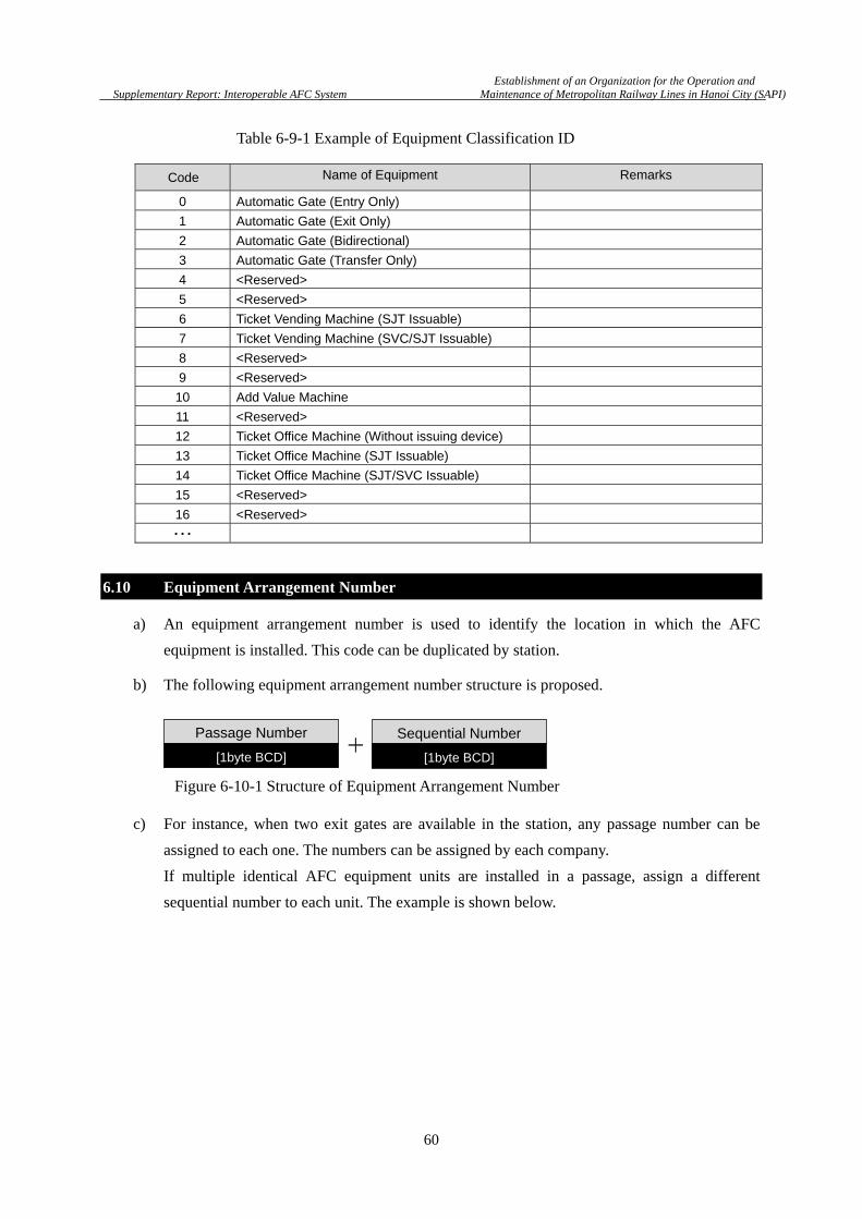
Establishment of an Organization for the Operation and
Supplementary Report: Interoperable AFC System Maintenance of Metropolitan Railway Lines in Hanoi City (SAPI)
60
6.10 Equipment Arrangement Number
a) An equipment arrangement number is used to identify the location in which the AFC
equipment is installed. This code can be duplicated by station.
b) The following equipment arrangement number structure is proposed.
c) For instance, when two exit gates are available in the station, any passage number can be
assigned to each one. The numbers can be assigned by each company.
If multiple identical AFC equipment units are installed in a passage, assign a different
sequential number to each unit. The example is shown below.
Code Name of Equipment Remarks
0 Automatic Gate (Entry Only)
1 Automatic Gate (Exit Only)
2 Automatic Gate (Bidirectional)
3 Automatic Gate (Transfer Only)
4 <Reserved>
5 <Reserved>
6 Ticket Vending Machine (SJT Issuable)
7 Ticket Vending Machine (SVC/SJT Issuable)
8 <Reserved>
9 <Reserved>
10 Add Value Machine
11 <Reserved>
12 Ticket Office Machine (Without issuing device)
13 Ticket Office Machine (SJT Issuable)
14 Ticket Office Machine (SJT/SVC Issuable)
15 <Reserved>
16 <Reserved>
・・・
Passage Number
[1byte BCD]
Sequential Number
[1byte BCD] +
Table 6-9-1 Example of Equipment Classification ID
Figure 6-10-1 Structure of Equipment Arrangement Number
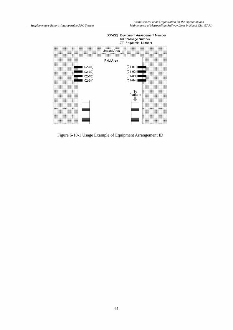
Establishment of an Organization for the Operation and
Supplementary Report: Interoperable AFC System Maintenance of Metropolitan Railway Lines in Hanoi City (SAPI)
61
Figure 6-10-1 Usage Example of Equipment Arrangement ID
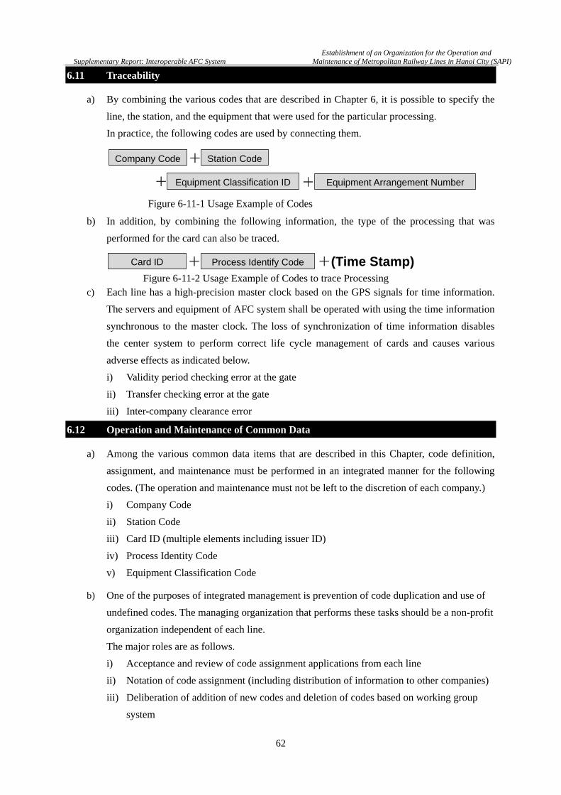
Establishment of an Organization for the Operation and
Supplementary Report: Interoperable AFC System Maintenance of Metropolitan Railway Lines in Hanoi City (SAPI)
62
6.11 Traceability
a) By combining the various codes that are described in Chapter 6, it is possible to specify the
line, the station, and the equipment that were used for the particular processing.
In practice, the following codes are used by connecting them.
b) In addition, by combining the following information, the type of the processing that was
performed for the card can also be traced.
c) Each line has a high-precision master clock based on the GPS signals for time information.
The servers and equipment of AFC system shall be operated with using the time information
synchronous to the master clock. The loss of synchronization of time information disables
the center system to perform correct life cycle management of cards and causes various
adverse effects as indicated below.
i) Validity period checking error at the gate
ii) Transfer checking error at the gate
iii) Inter-company clearance error
6.12 Operation and Maintenance of Common Data
a) Among the various common data items that are described in this Chapter, code definition,
assignment, and maintenance must be performed in an integrated manner for the following
codes. (The operation and maintenance must not be left to the discretion of each company.)
i) Company Code
ii) Station Code
iii) Card ID (multiple elements including issuer ID)
iv) Process Identity Code
v) Equipment Classification Code
b) One of the purposes of integrated management is prevention of code duplication and use of
undefined codes. The managing organization that performs these tasks should be a non-profit
organization independent of each line.
The major roles are as follows.
i) Acceptance and review of code assignment applications from each line
ii) Notation of code assignment (including distribution of information to other companies)
iii) Deliberation of addition of new codes and deletion of codes based on working group
system
Company Code + Station Code
+ Equipment Classification ID + Equipment Arrangement Number
Card ID + Process Identify Code +(Time Stamp)
Figure 6-11-1 Usage Example of Codes
Figure 6-11-2 Usage Example of Codes to trace Processing
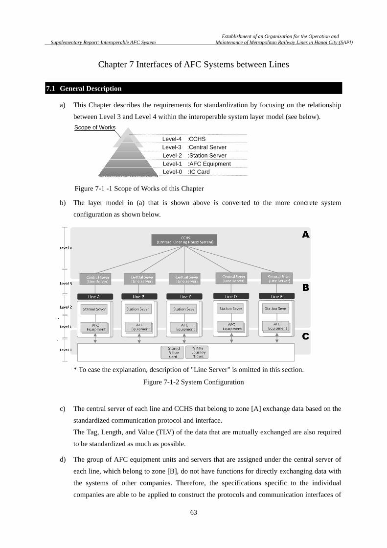
Establishment of an Organization for the Operation and
Supplementary Report: Interoperable AFC System Maintenance of Metropolitan Railway Lines in Hanoi City (SAPI)
63
Chapter 7 Interfaces of AFC Systems between Lines
7.1 General Description
a) This Chapter describes the requirements for standardization by focusing on the relationship
between Level 3 and Level 4 within the interoperable system layer model (see below).
b) The layer model in (a) that is shown above is converted to the more concrete system
configuration as shown below.
* To ease the explanation, description of "Line Server" is omitted in this section.
c) The central server of each line and CCHS that belong to zone [A] exchange data based on the
standardized communication protocol and interface.
The Tag, Length, and Value (TLV) of the data that are mutually exchanged are also required
to be standardized as much as possible.
d) The group of AFC equipment units and servers that are assigned under the central server of
each line, which belong to zone [B], do not have functions for directly exchanging data with
the systems of other companies. Therefore, the specifications specific to the individual
companies are able to be applied to construct the protocols and communication interfaces of
Level-0 :IC CardLevel-1 :AFC Equipment
Level-2 :Station Server
Level-3 :Central Server
Level-4 :CCHS
Scope of Works
Figure 7-1-2 System Configuration
Figure 7-1 -1 Scope of Works of this Chapter

Establishment of an Organization for the Operation and
Supplementary Report: Interoperable AFC System Maintenance of Metropolitan Railway Lines in Hanoi City (SAPI)
64
these equipment units. However, the same formats that are defined for zone [A] shall be
applied to the following types of data that is linked to the systems of other companies via
CCHS.
i) Transaction Data
ii) Black List
e) Zone [C] indicates the interface between the electronic ticket and the AFC equipment.
Radio frequency (RF) interfaces and encoding formats of electronic ticket will be discussed
in Chapter 8.
7.2 Functional Model
The functions to be realized by the AFC equipment and the servers of each level are classified as
follows based on the data flow.
7.2.1 Transaction Data Flow
a) This section describes the processing that is performed for each data type at each layer using
the more simplified model diagram.
When a card is used for the line operated by the card-issuing company, the transaction data is
processed according to the following flow.
Classification Meaning
Generate Function for generating data by itself
Store Function for storing/saving the data that is generated by itself in a DB or a file
Send Function for transmitting the data that is generated by itself to other systems
Receive Function for receiving data from external media (not transferring to other devices)
Convert Function for converting or re-arranging data
Forward Function for transferring/relaying received data to other systems
Statistics Function for performing statistical processing based on the data that is stored in its own DB and document output function
Table 7-2-1 Functions of AFC Equipment and Servers
Figure 7-2-1 Data Flow of Transaction when IC Card is used at Stations of Issuing Operator

Establishment of an Organization for the Operation and
Supplementary Report: Interoperable AFC System Maintenance of Metropolitan Railway Lines in Hanoi City (SAPI)
65
b) When a card that is issued by other company is used for the line of own company, the
transaction data is processed according to the following flow.
c) In the diagram that is shown above, most of the Central Servers and CCHS are equipped with
the function for outputting various statistical reports based on the transaction data.
In this case, the element of is added in each server.
7.2.2 Black List
a) When the black list that is generated by the card-issuing company is distributed to its own
equipment units, the data is processed in the following flow.
b) When the black list that is generated by the card-issuing company is distributed to the
equipment units of other companies, the data is processed according to the following flow.
Figure 7-2-2 Data Flow of Transaction when IC Card is used at Stations of Non-Issuing Operator
Figure 7-2-3 Data Flow of Black List generated by own Company
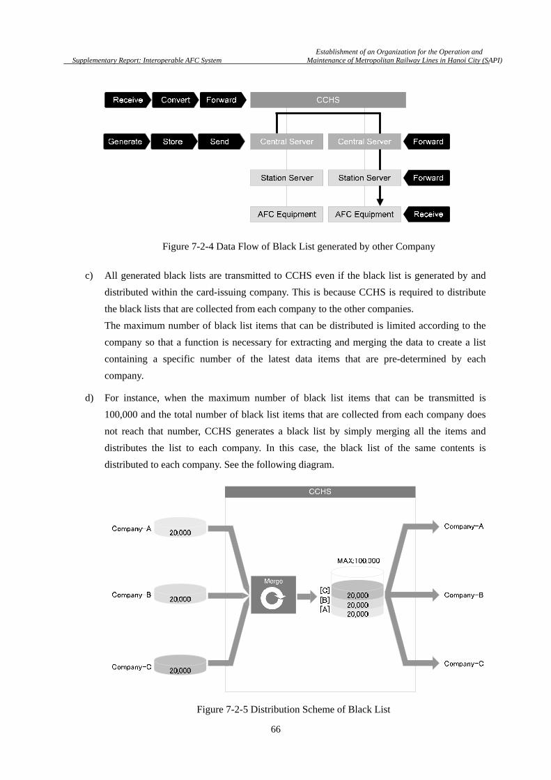
Establishment of an Organization for the Operation and
Supplementary Report: Interoperable AFC System Maintenance of Metropolitan Railway Lines in Hanoi City (SAPI)
66
c) All generated black lists are transmitted to CCHS even if the black list is generated by and
distributed within the card-issuing company. This is because CCHS is required to distribute
the black lists that are collected from each company to the other companies.
The maximum number of black list items that can be distributed is limited according to the
company so that a function is necessary for extracting and merging the data to create a list
containing a specific number of the latest data items that are pre-determined by each
company.
d) For instance, when the maximum number of black list items that can be transmitted is
100,000 and the total number of black list items that are collected from each company does
not reach that number, CCHS generates a black list by simply merging all the items and
distributes the list to each company. In this case, the black list of the same contents is
distributed to each company. See the following diagram.
Figure 7-2-4 Data Flow of Black List generated by other Company
Figure 7-2-5 Distribution Scheme of Black List

Establishment of an Organization for the Operation and
Supplementary Report: Interoperable AFC System Maintenance of Metropolitan Railway Lines in Hanoi City (SAPI)
67
e) If the total number of black list items that are collected from each company exceeds the upper
limit, which is 100,000 for example, a black list is generated for each company based on the
pre-determined distribution ratios. Following is the example.
i) Ratio for the black list of the card-issuing company: Up to 50% of the maximum number of
black list items that can be distributed
ii) Ratio for the black list of other companies: The remaining 50% is evenly distributed.
The diagram below shows the actual example.
80,000
70,000
90,000
50,000
25,00025,000
50,000
25,00025,000
50,000
25,00025,000
Company-A
Company-B
Company-C
[A]
[B]
[C]
[B]
[A]
[C]
[C]
[B]
[A]
Cut & Merge
Company-A
Company-B
Company-C
CCHS
Figure 7-2-6 Distribution Scheme of Black List exceeding Upper Limit
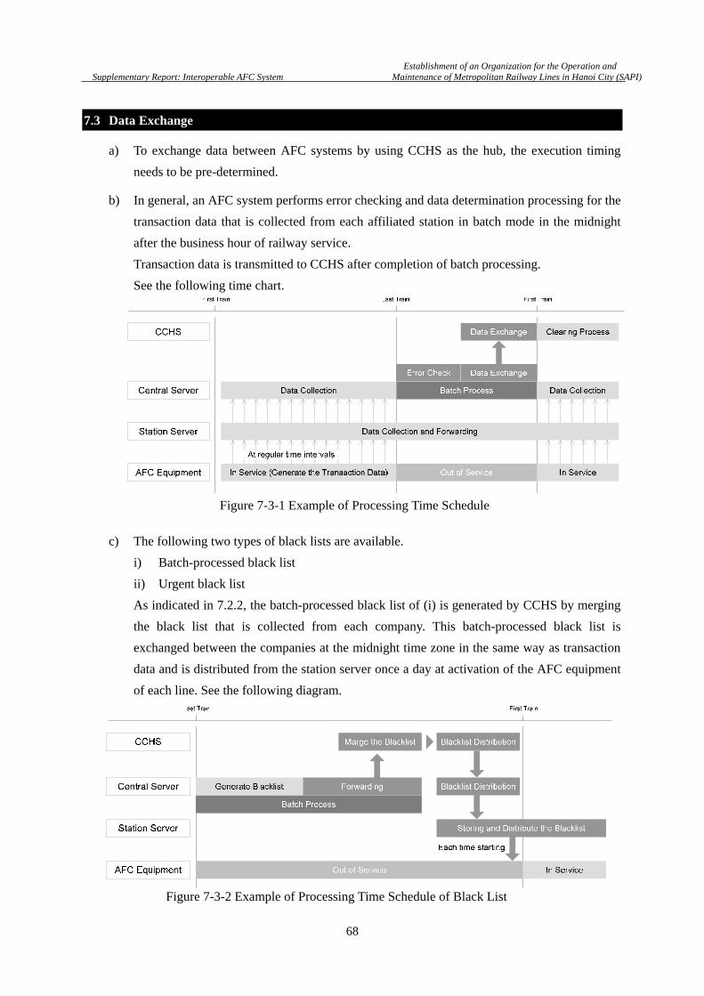
Establishment of an Organization for the Operation and
Supplementary Report: Interoperable AFC System Maintenance of Metropolitan Railway Lines in Hanoi City (SAPI)
68
7.3 Data Exchange
a) To exchange data between AFC systems by using CCHS as the hub, the execution timing
needs to be pre-determined.
b) In general, an AFC system performs error checking and data determination processing for the
transaction data that is collected from each affiliated station in batch mode in the midnight
after the business hour of railway service.
Transaction data is transmitted to CCHS after completion of batch processing.
See the following time chart.
c) The following two types of black lists are available.
i) Batch-processed black list
ii) Urgent black list
As indicated in 7.2.2, the batch-processed black list of (i) is generated by CCHS by merging
the black list that is collected from each company. This batch-processed black list is
exchanged between the companies at the midnight time zone in the same way as transaction
data and is distributed from the station server once a day at activation of the AFC equipment
of each line. See the following diagram.
Figure 7-3-1 Example of Processing Time Schedule
Figure 7-3-2 Example of Processing Time Schedule of Black List

Establishment of an Organization for the Operation and
Supplementary Report: Interoperable AFC System Maintenance of Metropolitan Railway Lines in Hanoi City (SAPI)
69
d) The urgent black list is distributed urgently to stop the use of the card when the customer has
lost the SVC or a fraud is detected.
An urgent black list is transmitted to CCHS in real time whenever it is generated by the AFC
system of the line and is immediately distributed to the AFC systems and AFC equipment
units of each company.
To prevent the unauthorized use of cards as much as possible, it is desirable to complete the
all processing for urgent blacklist at most within 10 minutes .
This means that the urgent black list is distributed to prevent exit with the unauthorized
electronic ticket as much as possible even if the electronic ticket is used to enter gate.
Figure 7-3-3 Example of Processing Time Schedule of Urgent Black List

Establishment of an Organization for the Operation and
Supplementary Report: Interoperable AFC System Maintenance of Metropolitan Railway Lines in Hanoi City (SAPI)
70
7.4 Interface between CCHS and AFC System
a) The inter-system interfaces are standardized in the scope shown in the following figure.
Systems at lower levels, which are Line Server, Station Server and AFC equipment of each line,
operate with the individual interfaces that are proposed by the contractor of each line.
b) The following basic requirements are applied to the common interfaces. The following
diagram shows the layer structure that is known as Open Systems Interconnection (OSI).
The following sections describe the requirements that are applied to the construction of
common interfaces for each layer.
7.4.1 Layer 1 & Layer 2
a) Layer 1 and Layer 2 are called a physical layer and a data link layer respectively.
In practice, the interface specifies the types of connection lines, hardware such as cables and
connectors, and the physical connection method. In the actual construction of a network, the
Line Server
Station Server
AFC Eq.
Line-A Line-B Line-C
Line Server
Station Server
AFC Eq.
Line Server
Station Server
AFC Eq.
CCHS
Central Server
Individual Interface
Common Interface
Figure 7-4-1 Inter-System Interface
Table 7-4-1 Layer Structure of OSI
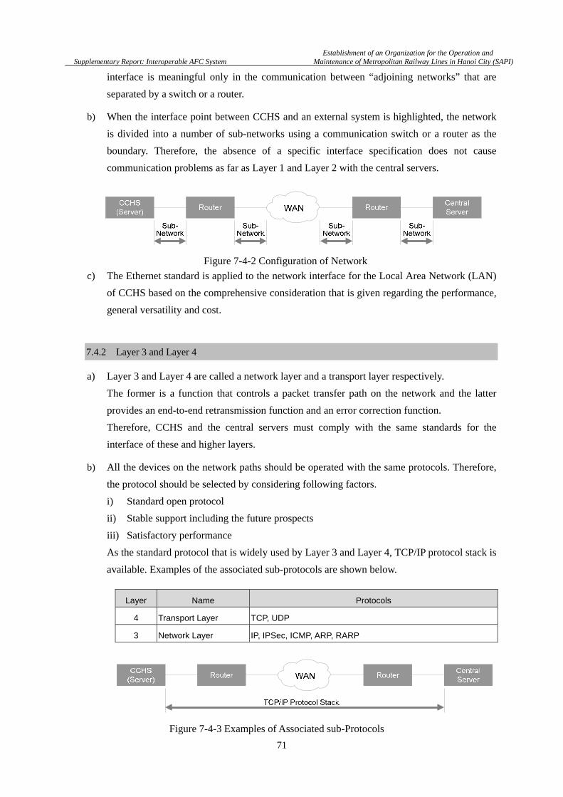
Establishment of an Organization for the Operation and
Supplementary Report: Interoperable AFC System Maintenance of Metropolitan Railway Lines in Hanoi City (SAPI)
71
interface is meaningful only in the communication between “adjoining networks” that are
separated by a switch or a router.
b) When the interface point between CCHS and an external system is highlighted, the network
is divided into a number of sub-networks using a communication switch or a router as the
boundary. Therefore, the absence of a specific interface specification does not cause
communication problems as far as Layer 1 and Layer 2 with the central servers.
c) The Ethernet standard is applied to the network interface for the Local Area Network (LAN)
of CCHS based on the comprehensive consideration that is given regarding the performance,
general versatility and cost.
7.4.2 Layer 3 and Layer 4
a) Layer 3 and Layer 4 are called a network layer and a transport layer respectively.
The former is a function that controls a packet transfer path on the network and the latter
provides an end-to-end retransmission function and an error correction function.
Therefore, CCHS and the central servers must comply with the same standards for the
interface of these and higher layers.
b) All the devices on the network paths should be operated with the same protocols. Therefore,
the protocol should be selected by considering following factors.
i) Standard open protocol
ii) Stable support including the future prospects
iii) Satisfactory performance
As the standard protocol that is widely used by Layer 3 and Layer 4, TCP/IP protocol stack is
available. Examples of the associated sub-protocols are shown below.
Layer Name Protocols
4 Transport Layer TCP, UDP
3 Network Layer IP, IPSec, ICMP, ARP, RARP
Figure 7-4-2 Configuration of Network
Figure 7-4-3 Examples of Associated sub-Protocols
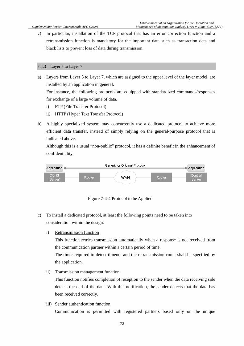
Establishment of an Organization for the Operation and
Supplementary Report: Interoperable AFC System Maintenance of Metropolitan Railway Lines in Hanoi City (SAPI)
72
c) In particular, installation of the TCP protocol that has an error correction function and a
retransmission function is mandatory for the important data such as transaction data and
black lists to prevent loss of data during transmission.
7.4.3 Layer 5 to Layer 7
a) Layers from Layer 5 to Layer 7, which are assigned to the upper level of the layer model, are
installed by an application in general.
For instance, the following protocols are equipped with standardized commands/responses
for exchange of a large volume of data.
i) FTP (File Transfer Protocol)
ii) HTTP (Hyper Text Transfer Protocol)
b) A highly specialized system may concurrently use a dedicated protocol to achieve more
efficient data transfer, instead of simply relying on the general-purpose protocol that is
indicated above.
Although this is a usual “non-public” protocol, it has a definite benefit in the enhancement of
confidentiality.
c) To install a dedicated protocol, at least the following points need to be taken into
consideration within the design.
i) Retransmission function
This function retries transmission automatically when a response is not received from
the communication partner within a certain period of time.
The timer required to detect timeout and the retransmission count shall be specified by
the application.
ii) Transmission management function
This function notifies completion of reception to the sender when the data receiving side
detects the end of the data. With this notification, the sender detects that the data has
been received correctly.
iii) Sender authentication function
Communication is permitted with registered partners based only on the unique
Figure 7-4-4 Protocol to be Applied

Establishment of an Organization for the Operation and
Supplementary Report: Interoperable AFC System Maintenance of Metropolitan Railway Lines in Hanoi City (SAPI)
73
identification number that is set in the data section.
This function prevents impersonation and unauthorized access.
iv) Health check (validity monitoring)
This function checks if applications are mutually functioning correctly by exchanging
signals with the communication partner at a certain interval. This function provides a
more reliable measure while the Ping command that is provided by the TCP/IP protocol
stack can perform health check at the hardware or OS level only.
v) Notification of status
This function notifies the processing result of the received data to the communication
partner. For instance, the following statuses can be notified.
vi) High-level activation and low-level activation High-level activation refers to a function that enables a station server to requests data transmission to AFC equipment. This function is used for the collection of transaction data and so on. Low-level activation refers to a function that performs data transmission and enquiry at any timing from the AFC equipment based on the action that is taken by the customer or station staff as the trigger.
vii) Resume function
A resume function enables resumption of file transmission from the point of interrupt
that occurred in the preceding transmission interruption when connection is interrupted
during transmission of multiple files.
d) When a dedicated protocol is installed, in principle, the system at a higher level shall present
the specification to the interface of the affiliated systems. That is, the protocol for connecting
with CCHS shall be established by CCHS, and the Central Servers shall install the protocol.
7.5 Common Data Format
a)
a) General Description
As is described in chapter 6, the data between CCHS and Central Server should be
exchanged with using “Common Message”, which has a common format for header, data and
footer. Common Messages, however, do not govern Message Format between CS and LS,
and between LS and station equipment. They are allowed to have independent format by
each line, as is shown below. However, the data eventually taken into the Common Message
Status Meaning
Normal Data has been received correctly.
Busy Data cannot be received because another processing is in progress.
Error An error is detected from the received data.
Unreachable Data could not be transferred.
Other Reasons Other reasons
Table 7-4-2 Example of Status Notification

Establishment of an Organization for the Operation and
Supplementary Report: Interoperable AFC System Maintenance of Metropolitan Railway Lines in Hanoi City (SAPI)
74
for interoperable AFC service shall be compliant with Common Message Data, which is the
same format of data in Common Message. Especially, followings are the most important
Common Message Data.
i) Transaction Data
ii) Black list
b) Data Format
i) Common Message Data
Table 7-5-1 Example of Transaction Data
.No. Item Description
1 Card ID See section 6.7
2 Transaction Data Serial number Counter for check the duplication
3 Time Stamp Process Date (YYYY/MM/DD hh:mm:ss)
4 Process Identify Code See section 6.8
5 Company Code See section 6.4 to 6.10
* To specify the place where the card processed. 6 Station Code
7 Equipment Classification ID
8 Equipment Arrangement Number
9 Amount of using Value To manage the recent stored value of IC card at server.
10 Amount of Remaining Value
11 Check SUM To verify the data integrity.
Table 7-5-2 Example of Black List (both of bulk and urgent)
No. Item Description
1 Card ID (Target) See section 6.7
2 Time Stamp Generated Date(YYYY/MM/DD)
3 Reason Code To specify why blacklisted.
4 Check SUM To verify the data integrity.
ii) Extensive Message Data
Extensive-Message is used for unique function of AFC system in each line.
For Extensive-Message, only maximum data length is specified but each item is not
defined. Therefore, AFC system of each line can be use this part freely. However, when
the transaction data forwarded to CCHS, only Common Message Data is taken into
Common Message.
Header (N/A)
Common Message Data Fixed Length( e.g. 128 byte)
Extensive Message Data Fixed Length (e.g. 64 byte)
Footer (N/A)
Figure 7-5-1Message Format
Establishment of an Organization for the Operation and
Supplementary Report: Interoperable AFC System Maintenance of Metropolitan Railway Lines in Hanoi City (SAPI)
75
Chapter 8 Ticket Media and Reader/Writer
8.1 General Description
a) As is described in Chapter 2, the most important key points for the user friendly
interoperable AFC system designed to provide AFC services are:
i) Travel with only one SJT or SVC.
No more SJT or SVC is requested to reach the destination.
ii) Same procedure
Customers can operate AG and TVM/AVM of any lines with the same procedure.
iii) Transfer to any line with the electronic ticket.
Customer can reach any destination station of the Urban Railway network by
transferring lines with the SJT or SVC used at the departure station.
b) Standardization of tickets by introducing common media benefits the O&M companies in
terms of the following points.
i) Saving initial investment cost for ticket issuing system.
By standardization, ticket can be issued by one issuing system.
ii) Saving purchasing cost of ticket.
By standardization, the kinds of ticket media are decreased and then procurement
volume per media becomes large. It results usually in a lower purchase price.
iii) Saving inventory cost.
By standardization, the stock of ticket media is shared among the companies. It
decreases the inventory cost of each company and the risk of obsolescent stock.
c) In terms of operation, SJT (Single Journey Ticket) is not always collected by the automatic
gate at the station of the O&M company that issued the SJT. If the ticket is not
standardized, collected SJT shall be returned to the respective issuer after sorting manually. It
obviously increases the work requirements and seriously decreases the work efficiency.
d) Referring the design of services and the AFC equipment, this chapter describes the
requirements on the common tickets, the functionality and the performance of the R/W for
the common tickets.
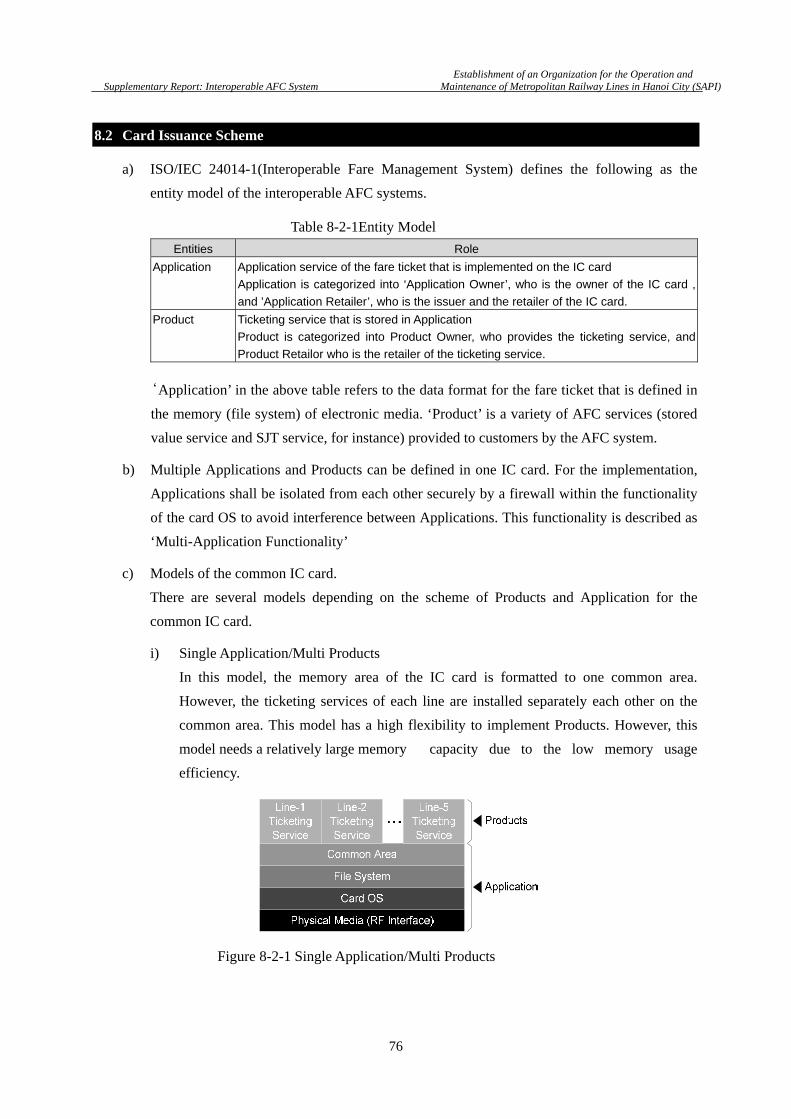
Establishment of an Organization for the Operation and
Supplementary Report: Interoperable AFC System Maintenance of Metropolitan Railway Lines in Hanoi City (SAPI)
76
8.2 Card Issuance Scheme
a) ISO/IEC 24014-1(Interoperable Fare Management System) defines the following as the
entity model of the interoperable AFC systems.
‘Application’ in the above table refers to the data format for the fare ticket that is defined in
the memory (file system) of electronic media. ‘Product’ is a variety of AFC services (stored
value service and SJT service, for instance) provided to customers by the AFC system.
b) Multiple Applications and Products can be defined in one IC card. For the implementation,
Applications shall be isolated from each other securely by a firewall within the functionality
of the card OS to avoid interference between Applications. This functionality is described as
‘Multi-Application Functionality’
c) Models of the common IC card.
There are several models depending on the scheme of Products and Application for the
common IC card.
i) Single Application/Multi Products
In this model, the memory area of the IC card is formatted to one common area.
However, the ticketing services of each line are installed separately each other on the
common area. This model has a high flexibility to implement Products. However, this
model needs a relatively large memory capacity due to the low memory usage
efficiency.
Entities Role
Application Application service of the fare ticket that is implemented on the IC card
Application is categorized into ‘Application Owner’, who is the owner of the IC card ,
and ’Application Retailer’, who is the issuer and the retailer of the IC card.
Product Ticketing service that is stored in Application
Product is categorized into Product Owner, who provides the ticketing service, and
Product Retailor who is the retailer of the ticketing service.
Figure 8-2-1 Single Application/Multi Products
Table 8-2-1Entity Model
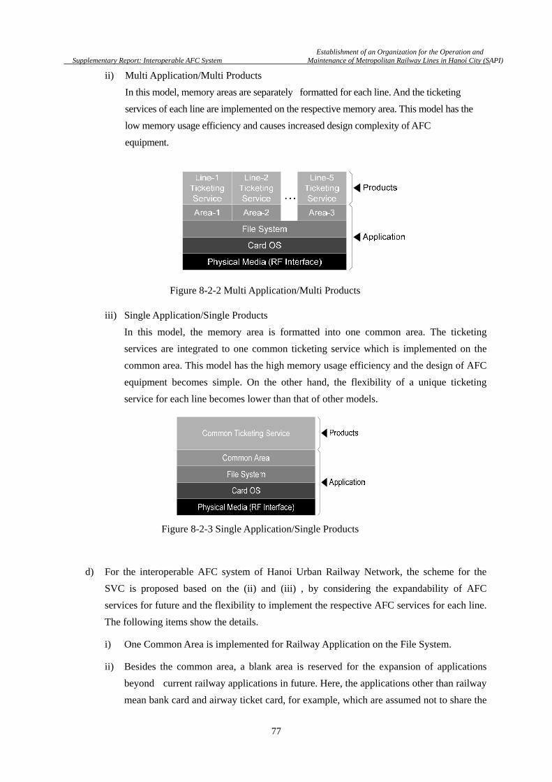
Establishment of an Organization for the Operation and
Supplementary Report: Interoperable AFC System Maintenance of Metropolitan Railway Lines in Hanoi City (SAPI)
77
ii) Multi Application/Multi Products
In this model, memory areas are separately formatted for each line. And the ticketing
services of each line are implemented on the respective memory area. This model has the
low memory usage efficiency and causes increased design complexity of AFC
equipment.
iii) Single Application/Single Products
In this model, the memory area is formatted into one common area. The ticketing
services are integrated to one common ticketing service which is implemented on the
common area. This model has the high memory usage efficiency and the design of AFC
equipment becomes simple. On the other hand, the flexibility of a unique ticketing
service for each line becomes lower than that of other models.
d) For the interoperable AFC system of Hanoi Urban Railway Network, the scheme for the
SVC is proposed based on the (ii) and (iii) , by considering the expandability of AFC
services for future and the flexibility to implement the respective AFC services for each line.
The following items show the details.
i) One Common Area is implemented for Railway Application on the File System.
ii) Besides the common area, a blank area is reserved for the expansion of applications
beyond current railway applications in future. Here, the applications other than railway
mean bank card and airway ticket card, for example, which are assumed not to share the
Figure 8-2-2 Multi Application/Multi Products
Figure 8-2-3 Single Application/Single Products

Establishment of an Organization for the Operation and
Supplementary Report: Interoperable AFC System Maintenance of Metropolitan Railway Lines in Hanoi City (SAPI)
78
electronic purse (e-Purse) of the railway ticket. With using this scheme, railway ticket
card and bank card will be able to be implemented into one card.
iii) The service area for railway is divided into the Private Service for the dedicated service
of the respective line and the Common Ticketing Service that is shared among the
various lines.
iv) Access Key information for the Common Service is shared among the lines. However,
the Access Key information for a Private Service shall be managed only by the
respective line of the service. The Private Service cannot be accessed without the
dedicated access key for the service. Therefore, as long as the confidentiality of the
key information is retained, confidential information that is stored in the Private
Service area remains secure.
e) The basic scheme of SVC is shown in Figure 8-2-4. The typical memory map of SVC is also
shown in Figure 8-2-5. SJT is used for a single trip and re-used by recycling. Thus SJT does
not need to handle multiple services as required for SVC. Therefore, only one Common Area
is defined as shown in Figure 8-2-6.
Figure 8-2-5 Memory Map of
Figure 8-2-4 Scheme of SVC
Figure 8-2-6 Configuration Memory of

Establishment of an Organization for the Operation and
Supplementary Report: Interoperable AFC System Maintenance of Metropolitan Railway Lines in Hanoi City (SAPI)
79
f) Hereafter, ‘Service’ means a cluster of memory areas that are defined for a certain common
objective. The minimum service types that are to be defined in the Common Area for SVC
and SJT are described respectively in the following chapter.
8.3 Stored Value Card
8.3.1 Physical Characteristics
a) Dimension
The overall size of SVC shall comply with ID-1 of ISO/IEC 7810.
b) Materials
The surface of the IC card shall be made by printable material for the print of color photo ID,
name and other necessary information for personalized card. Furthermore, the material shall
be selected in giving consideration to environmental protection.
c) Operation Range
Operation range of more than 8cm shall be ensured for one SVC from the surface of the
antenna of the R/W unit of AG (Automatic Gate). The operation range is the requirement to
process customers without serious congestion even at peak hours. It is, however, not
permissible for simultaneous usage of SVC with two or more cards at AG.
d) Transaction Speed
The time of internal data processing of SVC shall be less than 100msec for the transactions
between SVC and R/W, assuming the memory format described in section 8.3.2 of this
chapter. The total processing time, including the time to validate SVC by AG, shall be
within 200 msec per customer. This is also the requirement to establish the processing
performance of AG during peak hours.
e) Security
SVC shall be certified by the common criteria of EAL5+ or higher levels of ISO/IEC 15408
as composite product of hardware and software (card OS). The followings items are the
minimum specifications for the security functionality.
i) Mutual Authentication with 128bit-AES
ii) Encryption of transaction data
iii) Access authorization management of each user by dedicated Access Key.
The detail description about confidentiality is provided in Chapter 10 for Data Integrity and
Data Security.
f) Data Integrity
If SVC is removed from the operation range before completing the data processing, the data
of SVC is possibly corrupted. SVC shall have the functionality of card OS to restore the data
to retain the integrity of data. The detail of Data Integrity is described in Chapter 10 under
Establishment of an Organization for the Operation and
Supplementary Report: Interoperable AFC System Maintenance of Metropolitan Railway Lines in Hanoi City (SAPI)
80
Data Integrity and Data Security.
g) Memory Size
Memory capacity shall be 2.5KB or more to implement the memory map described in 8.3.2
of this chapter for planned lines. It includes the area reserved for expansion of services in
future. The memory size means the capacity for user data, excluding the system data such as
configuration for example.
h) RF(Radio Frequency)Interface
Radio frequency and signal interface shall be compliant with ISO/IEC 18092 or ISO/IEC
14443.
i) Card OS Card OS shall be implemented so as to satisfy the requirements, especially for high speed transaction and high security. j) Others
Dual interface card defined in ISO/IEC 7810 is allowed as well.
8.3.2 Memory Format
In this section, the specification of memory format for the common SVC is considered.
a) Memory Are consists of two areas;
i)System Area
System Area is the area to store the information of system management such as
Manufacturer ID, User ID and Access Key. Since the information shall be securely stored,
the System Area is not accessed except the initial access for issuing the electronic ticket.
ii)User Area
User Area is the area where AFC equipment reads, writes and updates data along the transaction.
b) Data Length;
In general, fixed length and variable length of data are used to access memory. Access by the
data format of fixed length, however, provides better performance in access speed, compared
to the access by variable length. Therefore, in the AFC system, the data format of fixed
length shall be used. Hereafter, ‘Block’, which is defined below, is used for the unit of data
length.
1 Block=16 byte
c) Memory area constituted with blocks used for the same purpose is the unit of Service. Access
control of every Service shall be executed independently each other with dedicated key
designated to the respective Service.

Establishment of an Organization for the Operation and
Supplementary Report: Interoperable AFC System Maintenance of Metropolitan Railway Lines in Hanoi City (SAPI)
81
d) Memory Capacity;
In the Table 8.3.2-1, the memory allocation for common usage is shown with minimum
requirements. Therefore, memory capacity of user area needs more than,
154Block * 16Byte = 2,464Byte =2.5KB
i) User Area
- Railway Common Area
Railway Common Area is the area for the data of common services such as e-Purse
and the information of Issuers which can be accessed by the AFC equipment of all
the Hanoi Urban Railways.
- Railway Private Area
Railway Private Area is the area for the data of private services such as Staff Pass or
limited discount ticket only available for a specified line. In the Table, 5 Blocks are
allocated for each planned line at present. 25 Blocks for 5 lines are reserved for the
future.
ii) System Area
The number of Block for System Area is increased with the number of services. In the
Table, 42 Blocks are allocated by taking into account the increase of services in the
future.
iii) Reserved Area
16 Blocks are reserved. This area is used to implement multiple applications in one card.
Settlement service of bank is the example of popular services.
Table 8-3-1 Memory Allocation Table
Service/BlockBlock
NumberManufacture ID Block 1
Issue ID Block 1
System Definition and KEY Information Block 40
Issuer Information Service 4
Personal Information Service 2
Card Attribution Service 2
e-Purse Service 2
Log Information Service [1] 20
Log Information Service [2] 6
<Reserve> 10
Unique Information Service [1] 5
Unique Information Service [2] 5
Unique Information Service [3] 5
Unique Information Service [4] 5
Unique Information Service [5] 5
<Reserve> 25
<Reserve> - - 16
154Total
Area
System Area
User Area [1]
RailwayCommon ServiceArea
RailwayPrivate Service Area
Establishment of an Organization for the Operation and
Supplementary Report: Interoperable AFC System Maintenance of Metropolitan Railway Lines in Hanoi City (SAPI)
82
8.4 Single Journey Ticket
8.4.1 Physical Characteristics
a) Dimension
SJT has the form of IC card or Token.
The pros and cons of both types are described in 8.4.2 of this chapter.
b) Materials
In the case of IC card form, the surface shall be made of printable material for the color print
of logo or other artworks for business purposes, which are printed at card manufacturing
factories. Furthermore, the material shall be environmentally friendly.
c) Operation Range
With one SJT of IC card form, the applicable operation range is 8cm or more from the
surface of the antenna of R/W unit of the AG. The same operation range of Token-type SJT is
also requested for using the R/W with the operation range that is 8cm for the IC card. The
request comes from the need to process customers at the AG without serious congestion even
at peak hours. It is, however, not permissible for simultaneous usage of SVC with two or
more cards at the AG.
d) Transaction Speed
The time of internal data processing of SJT shall be less than 100msec for the transactions
between SJT and R/W, based on the memory format described in section 8.4.3 of this chapter.
The total processing time, including the time to validate SJT by AG, shall be within 200
msec per customer. This is also the requirement to establish the processing performance of
AG during peak hours.
e) Security
SJT is a low cost electronic ticket. While the cost is low, the total cumulative number of
issued SJT/year is a very large. It will possibly reach a few hundred million per year. The
destination fare data is stored in the e-Purse of SJT, which is described in Chapter 3. While
SJT are collected at the exit gate for re-use at the destination station, it is possible for a
hacker to remove it from the transferring station. Therefore appropriate countermeasures
shall be taken against fraudulent use of SJT and falsification of e-Purse. The functionality of
mutual authentication by using Triple DES shall be implemented as the minimum
requirement. The detail about data confidentiality is described in Chapter 10 under Data
Integrity and Data Security.
f) Data Integrity
If SJT is removed from the operation range before completion of the data processing, the
data of SJT is possibly corrupted. SJT shall have the functionality to restore the data to retain

Establishment of an Organization for the Operation and
Supplementary Report: Interoperable AFC System Maintenance of Metropolitan Railway Lines in Hanoi City (SAPI)
83
the data integrity. The details of data integrity are described in Chapter 10 under Data
Integrity and Data Security.
g) Memory Size
SJT has a memory capacity as a minimum for the data described in 8.4.3 of this chapter.
h) RF (Radio Frequency) Interface
Radio frequency and signal interface shall be compliant with ISO/IEC 18092 or ISO/IEC
14443.
i) Card OS
Card OS shall be implemented so as to satisfy the requirements, especially for high speed
transaction and high security. SJT has normally single service for one trip. Thus, the
architecture of SJT is much simpler compared to that of SVC. It means that the OS can be
simpler than that of SVC. However, the card OS installed in R/W for SVC must be
applicable to access SJT. Otherwise, R/W shall be installed with Card OS only for SJT.
8.4.2 Card or Token
a) For interoperable AFC system, IC card or Token shall be defined as one common form for
SJT for all lines of Hanoi Urban Railway Network. The pros and cons of IC card and Toke
are described below.
b) IC card form
i) Advantage in comparison with Token
1. Longer operation distance since IC card has a larger antenna size than Token
2. Customer friendly since the SJT has as same size except thickness as SVC.
3. Front and rear surfaces are available to print the signage.
e.g. front surface : Company logo, route map,
rear surface : Ticket ID , terms& conditions of SJT.
4. Thin (around 0.52mm). Not bulky.
ii) Disadvantage in comparison with Token
1. Lower robustness against bending or breaking by the customer
2. More sophisticated mechanism is required for the AG by combining a belt and a
motor to collect IC cards at the exit by power drive carrying. Collection by free fall
may cause jam of IC cards.
4. Lower Durability for re-use cycles
c) Token form
i) Advantage in comparison with IC card
1. Higher robustness against heavy-usage.
2. Simpler mechanism for AG to collect tokens at the exit.
(Free-fall type is acceptable)

Establishment of an Organization for the Operation and
Supplementary Report: Interoperable AFC System Maintenance of Metropolitan Railway Lines in Hanoi City (SAPI)
84
3. Easier handling to re-use by station staff
ii) Disadvantage in comparison with IC card
1. Less customer friendly due to the small size and unfamiliar form. It is difficult for
customers to hold the token over the R/W due to its small size.
2. Shorter operation distance due to the small antenna size,
which increases technical issues to maintain required distance.
d) Definitive advantage or disadvantage is not seen for either IC card or Token. In view of total
usability for customers, IC card-type has the advantage .Token has advantage in cost, and
robustness.
Item IC Card Token Description
Cost Normal Less
expensive
Injection plastic mold process for Token is less
expensive at high volume production.
Cost of automatic
gate
Normal Less
expensive
Token can be collected in return box by free-falling
system , IC card by automated conveyer belt
Processing speed
of gate
High Lower Owing to the conveyer belt mechanics, the
processing speed of IC card is higher.
Performance at
gate
High Lower The large antenna of IC card provides usually
better operation distance and error rate.
Durability and
Stain resistance
Normal Higher Solid and hard package of token provides high
durability.
Easiness of
Re-use
Normal Better Token does not care about front/rear surface and
orderly stack in return box.
User friendliness Good Lower Token is too small and tends to be lost.
Portability Thin Bulky IC card (~0.52mm) vs. Token (~3mm)
Surface for
signage
Available Poor IC card provides good opportunity for signage.
Table 8-4-1 Comparison of IC card and Token
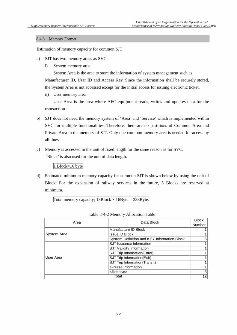
Establishment of an Organization for the Operation and
Supplementary Report: Interoperable AFC System Maintenance of Metropolitan Railway Lines in Hanoi City (SAPI)
85
8.4.3 Memory Format
Estimation of memory capacity for common SJT
a) SJT has two memory areas as SVC.
i) System memory area
System Area is the area to store the information of system management such as
Manufacturer ID, User ID and Access Key. Since the information shall be securely stored,
the System Area is not accessed except for the initial access for issuing electronic ticket.
ii) User memory area
User Area is the area where AFC equipment reads, writes and updates data for the
transaction.
b) SJT does not need the memory system of ‘Area’ and ‘Service’ which is implemented within
SVC for multiple functionalities. Therefore, there are no partitions of Common Area and
Private Area in the memory of SJT. Only one common memory area is needed for access by
all lines.
c) Memory is accessed in the unit of fixed length for the same reason as for SVC.
‘Block’ is also used for the unit of data length.
1 Block=16 byte
d) Estimated minimum memory capacity for common SJT is shown below by using the unit of
Block. For the expansion of railway services in the future, 5 Blocks are reserved at
minimum.
Total memory capacity; 18Block × 16Byte = 288Byte.
Data BlockBlock
NumberManufacture ID Block 1Issue ID Block 1System Definition and KEY Information Block 5SJT Issuance Information 1SJT Validity Information 1SJT Trip Information(Enter) 1SJT Trip Information(Exit) 1SJT Trip Information(Transit) 1e-Purse Information 1<Reserve> 5
18
Area
System Area
User Area
Total
Table 8-4-2 Memory Allocation Table
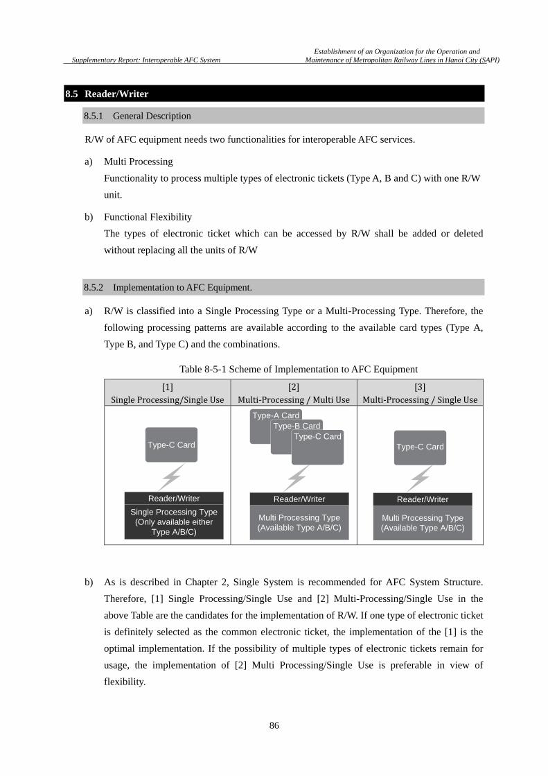
Establishment of an Organization for the Operation and
Supplementary Report: Interoperable AFC System Maintenance of Metropolitan Railway Lines in Hanoi City (SAPI)
86
8.5 Reader/Writer
8.5.1 General Description
R/W of AFC equipment needs two functionalities for interoperable AFC services.
a) Multi Processing
Functionality to process multiple types of electronic tickets (Type A, B and C) with one R/W
unit.
b) Functional Flexibility
The types of electronic ticket which can be accessed by R/W shall be added or deleted
without replacing all the units of R/W
8.5.2 Implementation to AFC Equipment.
a) R/W is classified into a Single Processing Type or a Multi-Processing Type. Therefore, the
following processing patterns are available according to the available card types (Type A,
Type B, and Type C) and the combinations.
b) As is described in Chapter 2, Single System is recommended for AFC System Structure.
Therefore, [1] Single Processing/Single Use and [2] Multi-Processing/Single Use in the
above Table are the candidates for the implementation of R/W. If one type of electronic ticket
is definitely selected as the common electronic ticket, the implementation of the [1] is the
optimal implementation. If the possibility of multiple types of electronic tickets remain for
usage, the implementation of [2] Multi Processing/Single Use is preferable in view of
flexibility.
[1] Single Processing/Single Use [2] Multi-Processing / Multi Use [3] Multi-Processing / Single Use Table 8-5-1 Scheme of Implementation to AFC Equipment
Single Processing Type(Only available either
Type A/B/C)
Type-C Card
Reader/Writer
Multi Processing Type(Available Type A/B/C)
Reader/Writer
Type-A CardType-B Card
Type-C Card
Multi Processing Type(Available Type A/B/C)
Reader/Writer
Type-C Card

Establishment of an Organization for the Operation and
Supplementary Report: Interoperable AFC System Maintenance of Metropolitan Railway Lines in Hanoi City (SAPI)
87
c) R/W must be easily modified if it is necessary to add or delete accessible types of electronic
tickets. RF circuitry based on NFC (Near Field Communication) technology is available for
multiple functional RF interface. With respect to authentication, the algorithm and related
secure information is added and deleted simply by appending or removing SAM (Security
Access Module) to R/W control unit. The design of R/W is requested so as to enable this
approach to be taken.
8.5.3 Consideration on compliance with NFC
a) Recently, NFC and the standard of ISO/IEC 18092 and 21481 have attracted much attention
for the reasons below.
i) Increased electronic payment by mobile or smart phone.
ii) Increased demand to device for seamless settlement service regardless of the
technology.
b) Therefore, it is necessary to consider the application of NFC to AFC equipment.
In this section, the difference between ‘Multi-Processing Reader/Writer’ and ‘NFC
Compliant Reader/Writer’ is discussed in detail to clarify the demands from the view point of
AFC system. Description, hereof, is based on the specification for implementation of NFC
defined by NFC Forum (http://www.nfc-forum.org) .
c) NFC device shall have the essential functionalities of
i) Reader/Writer Mode,
ii) Peer to Peer Mode and
iii) Card Emulation Mode.
In the Reader/Writer Mode, a NFC device works as a R/W to access contactless IC card of
Type A, Type B and Type C.
Figure 8-5-1 Diagram of Reader/Writer
Figure 8-5-2 Reader/Writer Mode
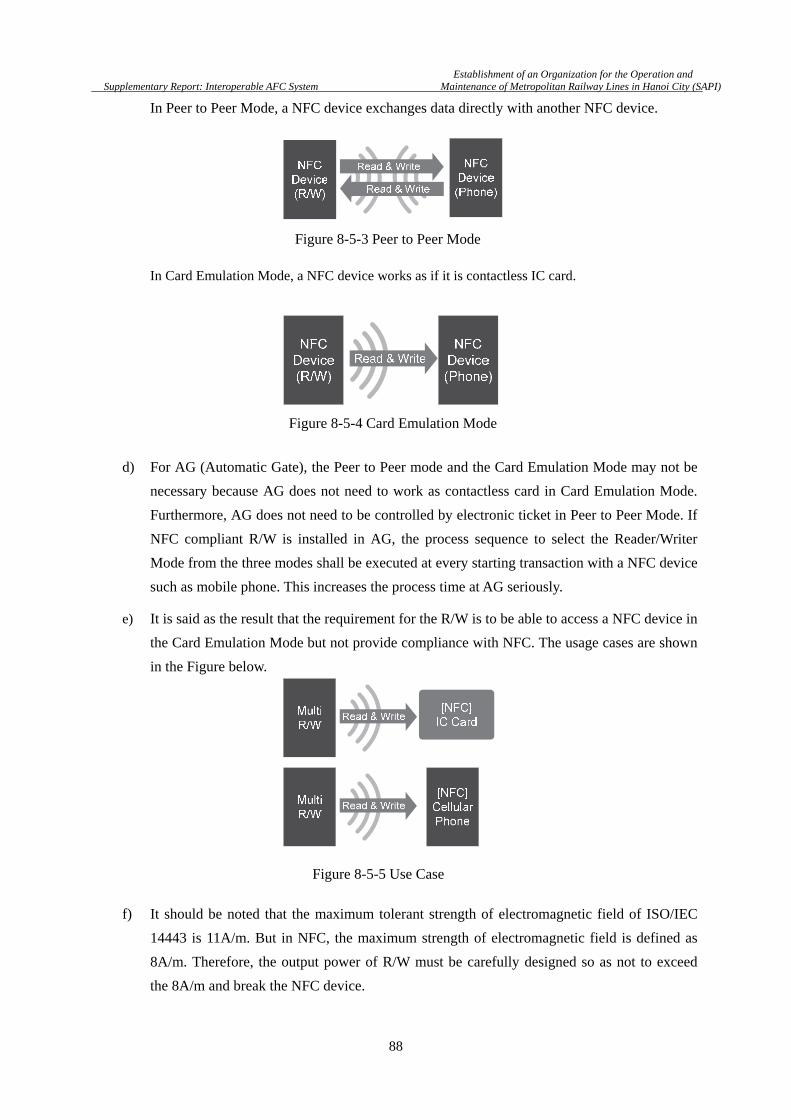
Establishment of an Organization for the Operation and
Supplementary Report: Interoperable AFC System Maintenance of Metropolitan Railway Lines in Hanoi City (SAPI)
88
In Peer to Peer Mode, a NFC device exchanges data directly with another NFC device.
In Card Emulation Mode, a NFC device works as if it is contactless IC card.
d) For AG (Automatic Gate), the Peer to Peer mode and the Card Emulation Mode may not be
necessary because AG does not need to work as contactless card in Card Emulation Mode.
Furthermore, AG does not need to be controlled by electronic ticket in Peer to Peer Mode. If
NFC compliant R/W is installed in AG, the process sequence to select the Reader/Writer
Mode from the three modes shall be executed at every starting transaction with a NFC device
such as mobile phone. This increases the process time at AG seriously.
e) It is said as the result that the requirement for the R/W is to be able to access a NFC device in
the Card Emulation Mode but not provide compliance with NFC. The usage cases are shown
in the Figure below.
f) It should be noted that the maximum tolerant strength of electromagnetic field of ISO/IEC
14443 is 11A/m. But in NFC, the maximum strength of electromagnetic field is defined as
8A/m. Therefore, the output power of R/W must be carefully designed so as not to exceed
the 8A/m and break the NFC device.
Figure 8-5-3 Peer to Peer Mode
Figure 8-5-4 Card Emulation Mode
Figure 8-5-5 Use Case
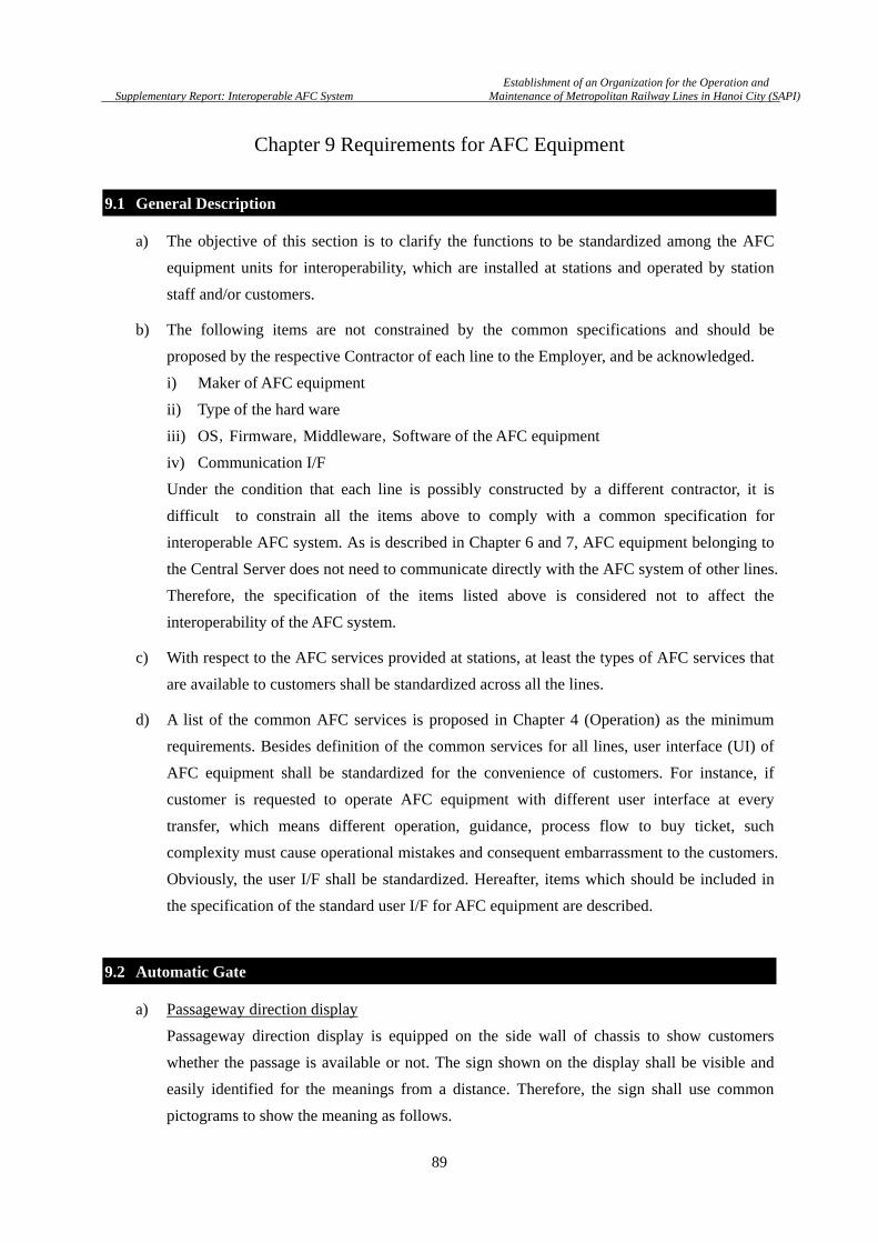
Establishment of an Organization for the Operation and
Supplementary Report: Interoperable AFC System Maintenance of Metropolitan Railway Lines in Hanoi City (SAPI)
89
Chapter 9 Requirements for AFC Equipment
9.1 General Description
a) The objective of this section is to clarify the functions to be standardized among the AFC
equipment units for interoperability, which are installed at stations and operated by station
staff and/or customers.
b) The following items are not constrained by the common specifications and should be
proposed by the respective Contractor of each line to the Employer, and be acknowledged.
i) Maker of AFC equipment
ii) Type of the hard ware
iii) OS,Firmware,Middleware,Software of the AFC equipment
iv) Communication I/F
Under the condition that each line is possibly constructed by a different contractor, it is
difficult to constrain all the items above to comply with a common specification for
interoperable AFC system. As is described in Chapter 6 and 7, AFC equipment belonging to
the Central Server does not need to communicate directly with the AFC system of other lines.
Therefore, the specification of the items listed above is considered not to affect the
interoperability of the AFC system.
c) With respect to the AFC services provided at stations, at least the types of AFC services that
are available to customers shall be standardized across all the lines.
d) A list of the common AFC services is proposed in Chapter 4 (Operation) as the minimum
requirements. Besides definition of the common services for all lines, user interface (UI) of
AFC equipment shall be standardized for the convenience of customers. For instance, if
customer is requested to operate AFC equipment with different user interface at every
transfer, which means different operation, guidance, process flow to buy ticket, such
complexity must cause operational mistakes and consequent embarrassment to the customers.
Obviously, the user I/F shall be standardized. Hereafter, items which should be included in
the specification of the standard user I/F for AFC equipment are described.
9.2 Automatic Gate
a) Passageway direction display
Passageway direction display is equipped on the side wall of chassis to show customers
whether the passage is available or not. The sign shown on the display shall be visible and
easily identified for the meanings from a distance. Therefore, the sign shall use common
pictograms to show the meaning as follows.

Establishment of an Organization for the Operation and
Supplementary Report: Interoperable AFC System Maintenance of Metropolitan Railway Lines in Hanoi City (SAPI)
90
i) In-Service
ii) Out-of-Service (Containing of STOP mark)
The colors and the designs of the pictograms shall also be standardized for easier recognition
by customers. Followings are the examples.
b) Pictogram on the Reader/Writer
Pictograms shall be placed at the positions of the R/W that is to be touched with IC
card/token ticket. The result of ticket validation can be indicated with lighting by LED for
easier user interface. The pictogram of a hand is often used for this purpose as the example
that is shown below, or the LOGO mark of IC card for Hanoi Urban Railway Network may
be also a good choice.
In-Service Out-of-Service
Color :Green Color :Red
GO Error
Color :Blue Color :Red
Figure 9-2-1 Passageway Direction Display
Figure 9-2-2 Pictogram on the Reader/Writer

Establishment of an Organization for the Operation and
Supplementary Report: Interoperable AFC System Maintenance of Metropolitan Railway Lines in Hanoi City (SAPI)
91
c) On the Passenger Display Unit (PDU) of an automatic gate, the result of processing SVC and
SJT shall be displayed by using characters, numeric numbers and pictogram in accordance
with common specification for the display.
In the table below, the items and the display forms are shown as the minimum requirements
of the common specification for the display.
-
d) In the event that AG judges SVC or SJT as invalid, the PDU should show the reason and
guide for the customer such as ‘Visit Ticket Inspection Room for Assistance’. The following
list shows the possible cases that AG judges as invalid ticket/card.
i) Insufficient balance for fare
ii) Expired SVC or SJT
iii) SVC in Blacklist
iv) Failure in transaction process
e) It is recommended that audio announcement is also standardized if AG provides audio
announcement with the display.
f) Universal Design
To minimize the embarrassment of customers due to the different design of respective AG,
‘universal design’ shall be incorporated into AG. In particular, the positions of the respective
features of AG that are listed below are strongly recommended to be standardized.
i) R/W, where SVC/SJT is touched.
ii) Slot to collect SJT
iii) PDU
iv) Passageway direction display
Following figure shows an example of AG designed by referring Ergonomics point of view.
Item Point of view
Proceed sign Success or Error, Pictogram(Like “Arrow” mark)
Amount of using Value Currency Unit, Number of digit to display
Amount of Remaining Value Currency Unit, Number of digit to display
Passageway direction display
SJT Collection Slot
Reader Writer
Passenger Display Unit
Table 9-2-1 Pictogram on the Reader/Writer
Figure 9-2-3 Example of AG Design
Establishment of an Organization for the Operation and
Supplementary Report: Interoperable AFC System Maintenance of Metropolitan Railway Lines in Hanoi City (SAPI)
92
9.3 Ticket Vending Machine/Add Value Machine
a) While the form and the coloration displayed on the screen are basically designed by the
Contractor with the approval of the Employer for each respective line, the items shown in the
following table shall be at least displayed with the common specification adopted for all
TVM/ AVM of any line to provide user friendly interface.
b) The following messages shall be also be standardized.
i) Message to reject SVC when error is detected.
ii) Message to reject SVC when it is found in blacklist
iii) Message to show out of service
c) It is recommended that audio announcement is also standardized if TVM/ADM provides
audio announcement with the display.
d) The kinds of acceptable bank notes are basically limited according to the capability of the
bank note acceptor to verify validity of notes. Therefore, bank notes that can be accepted by
the TVM/AVM of any lines shall be standardized based on the volume of circulation and
the acceptance rate by the bank note acceptor. The following table is the proposal to show
availability at TVM/AVM of respective bank note, coins, bank-, credit- and debit- card.
e) Braille signs shall be placed at the following locations of TVM/AVM as the common
requirement to provide sufficient services to disabled passengers, which is defined in the
common specification of user interface for visually impaired passenger.
i) Major operation buttons
ii) Insertion opening of slot for SJT
iii) Insertion opening of bank note
iv) Operation guide panel
Item Point of view
Name of Function e.g. “Purchase Single Journey Ticket”, “Add Value”, “Show History”
Name of Ticket e.g. “Stored Value Card”, “Single Journey Ticket”, “Daily Ticket”
Name of Station
Amount of Add Value Currency Unit, Number of digit to display
Amount of Remaining Value Currency Unit, Number of digit to display
Payment Method
Display Language Support Multilingual Mode(Vietnamese and English)
Table 9-3-1 Common Display Item of TVM and AVM

Establishment of an Organization for the Operation and
Supplementary Report: Interoperable AFC System Maintenance of Metropolitan Railway Lines in Hanoi City (SAPI)
93
Payment Method Type of Banknote Acceptance(Indispensable)
Banknote 100VND NO
200VND NO
500VND NO
1,000VND NO
2,000VND NO
5,000VND NO
10,000VND YES (But Polymer Banknote Only)
20,000VND YES (But Polymer Banknote Only)
50,000VND YES (But Polymer Banknote Only)
100,000VND YES (But Polymer Banknote Only)
200,000VND YES (But Polymer Banknote Only)
500,000VND NO at Initial Stage.
Coin - NO until coin is widely available.
Credit Card - NO at Initial Stage
Debit Card - NO at Initial Stage
9.4 Ticket Office Machine
a) TOM is normally operated by well-trained dedicated station staff and not by the customer.
Since customers do not directly handle the screen and the display is not shown directly to the
customer. Therefore, the standardization of display flow and message contents shall not be
made mandatory.
b) However, in the case that the TOM is equipped with PDU (Passenger Display Unit), the
following messages shall be standardized in all TOM of all lines.
c) It is recommended that audio announcement is also standardized if TOM provides audio
announcement with the display.
Item Point of view
Name of Function e.g. “Purchase Single Journey Ticket”, “Add Value”, “Show History”
Name of Ticket e.g. “Stored Value Card”, “Single Journey Ticket”, “Daily Ticket”
Name of Station
Amount of Add Value Currency Unit, Number of digit to display
Amount of remaining Value Currency Unit, Number of digit to display
Payment Method
Display Language Support Multilingual Mode(Vietnamese and English)
Table 9-3-2 Available Banknote at TVM and AVM Common Display
Table 9-4-1 Common Display Item of TOM

Establishment of an Organization for the Operation and
Supplementary Report: Interoperable AFC System Maintenance of Metropolitan Railway Lines in Hanoi City (SAPI)
94
Chapter 10 Information Security Management
10.1 General Description
a) Interoperable AFC system is the system that implements the exchange of data with integrity
and security between linked sub-AFC systems. The contemporary AFC system that applies
contactless IC cards has progressed by increasing the volume of data that can be stored
within a card. Another feature is its capability for tracing the life cycle of the card from the
issuing to collection of the card by storing the transaction data in the central server system.
b) IC cards, AFC equipment, communication devices and servers are the major components of
an AFC system. As these are hardware devices, they will exhibit mechanical faults and
operational problems with a certain statistical probability. As a countermeasure that is to be
taken in the event of these kinds of faults, protection from data corruption and loss of data is
one of the crucial issues for maintaining the integrity of data (Data Integrity).
c) It is the crucial issue as well to exchange data in a secure manner.
Along with the increase of data capacity of the IC card, personal information such as name
and age tend to be stored in the card, and as the result, the personal information is sometimes
included in the transaction data. Although the AFC system network is a closed system, not
open to any external network such as the Internet, the countermeasures against security
threats including tapping into the communication lines and theft of equipment shall be taken
by developing common security policy for the AFC systems across all the lines.
d) In the ISO/IEC 27001 for information security technique, information security is described to
be constituted by the following three factors. In the table, the meanings of each factor are
explained by using the words of security system design, not by using conceptual words.
e) In the following sections, the minimum requirements of security factors for the AFC system
are described in detail. Here, a five layer model of the AFC system is also adopted and the
requirements of a respective layer are provided.
f) It is recommended that the following description is treated as the common criteria which
each line shall comply with.
Confidentiality Encryption of Information Asset
(to keep confidentiality of information from unregistered third party)
Integrity Protection of Information Asset from Falsification
(to protect the integrity of data against attack, missing and corruption)
Availability Maintaining information Service
(to keep the availability of information by taking measures against troubles)
Table 10-1-1 Factors of Information Security

Establishment of an Organization for the Operation and
Supplementary Report: Interoperable AFC System Maintenance of Metropolitan Railway Lines in Hanoi City (SAPI)
95
10.2 Level-0 (IC Card)
10.2.1 Confidentiality
a) Stored value card (SVC) shall meet the higher level of security requirements than single
journey ticket (SJT), for the following reasons;
i) SVC has the capacity to store personal information
ii) SVC normally stores larger amount of value for money
iii) SVC is normally repeatedly used over a long period of time by the card holder without
discarding it
b) Countermeasure shall be taken within the hardware and the OS of the IC card against threats
to the security of the Access Key of the card.
c) IC card and R/W shall have the function of mutual authentication.
Mutual authentication is the process to authenticate each other between IC card and R/W to
prevent fraud by identifying that the Access Key in each device is the registered key. The
mutual authentication process shall be performed by using a secure encryption algorithm.
While DES (data encryption standard) has been widely used for the encryption over a long
period of time, 128-bit AES (Advanced Encryption Standard) is now used for high security
products instead of DES due to the compromise of DES. Here, ‘compromise’ means that the
protection strength of DES against security attack becomes weak due to the extended use and
the progress of techniques for attack. With regard to SJT, despite such countermeasures at
high level are hard to justify to provide SJT at an affordable price, mutual authentication
shall be still requested. While the value stored in each SJT is usually much smaller than SVC,
the total number of SJT is expected to be so much larger than SVC. The value of each SJT
multiplied by the total number of SJT becomes a huge value. That is enough reason for SJT
to be protected from fraud. For this purpose, T-DES (triple DES: technique to encrypt three
times with DES algorithm for higher security than ‘single’ DES) is recommended in view of
protection capability and the cost to be implemented into the IC card.
d) With respect to the communication between SVC and R/W, the transferring message shall be
protected by encryption with at least as high protection strength as that of T-DES.
Level-0 :Ticket MediaLevel-1 :AFC Equipment
Level-2 :Station Server
Level-3 :Central Server
Level-4 :CCHS
Figure 10-1-1 AFC Layer Model
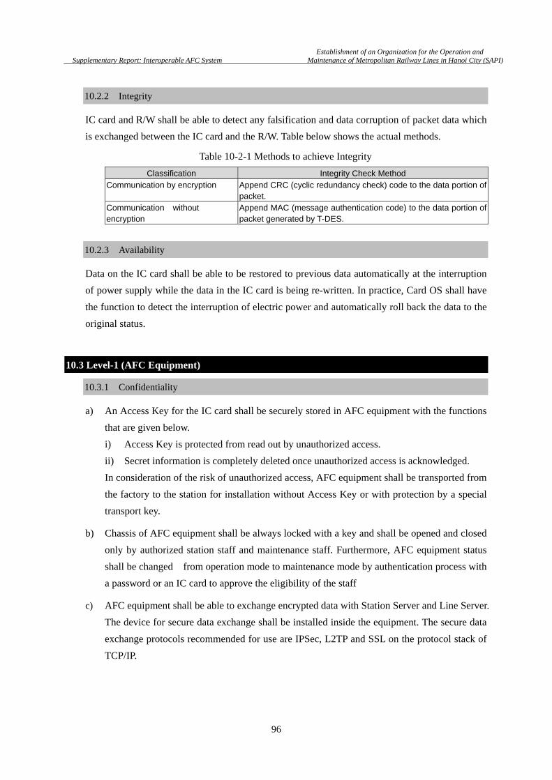
Establishment of an Organization for the Operation and
Supplementary Report: Interoperable AFC System Maintenance of Metropolitan Railway Lines in Hanoi City (SAPI)
96
10.2.2 Integrity
IC card and R/W shall be able to detect any falsification and data corruption of packet data which
is exchanged between the IC card and the R/W. Table below shows the actual methods.
10.2.3 Availability
Data on the IC card shall be able to be restored to previous data automatically at the interruption
of power supply while the data in the IC card is being re-written. In practice, Card OS shall have
the function to detect the interruption of electric power and automatically roll back the data to the
original status.
10.3 Level-1 (AFC Equipment)
10.3.1 Confidentiality
a) An Access Key for the IC card shall be securely stored in AFC equipment with the functions
that are given below.
i) Access Key is protected from read out by unauthorized access.
ii) Secret information is completely deleted once unauthorized access is acknowledged.
In consideration of the risk of unauthorized access, AFC equipment shall be transported from
the factory to the station for installation without Access Key or with protection by a special
transport key.
b) Chassis of AFC equipment shall be always locked with a key and shall be opened and closed
only by authorized station staff and maintenance staff. Furthermore, AFC equipment status
shall be changed from operation mode to maintenance mode by authentication process with
a password or an IC card to approve the eligibility of the staff
c) AFC equipment shall be able to exchange encrypted data with Station Server and Line Server.
The device for secure data exchange shall be installed inside the equipment. The secure data
exchange protocols recommended for use are IPSec, L2TP and SSL on the protocol stack of
TCP/IP.
Classification Integrity Check Method Communication by encryption Append CRC (cyclic redundancy check) code to the data portion of
packet. Communication without encryption
Append MAC (message authentication code) to the data portion of packet generated by T-DES.
Table 10-2-1 Methods to achieve Integrity
Establishment of an Organization for the Operation and
Supplementary Report: Interoperable AFC System Maintenance of Metropolitan Railway Lines in Hanoi City (SAPI)
97
10.3.2 Integrity
a) AFC equipment shall be able to hold the following data for 7 days at least, which include the
day of a problem, for the backup in order to recover the data that is lost.
i) Transaction Data
ii) Revenue Data
Redundancy measures, mirroring for instance, shall be taken to ensure secure data storage.
b) In exchanging the following data with the Station Server or the Line Server, the application
software shall have the functionality to detect data corruption by assigning a redundancy
code (Checksum) such as CRC32 in the transmission data.
i) Transaction Data
ii) Revenue Data
iii) Blacklist
iv) Fare Table
v) Operation Parameters
c) AFC equipment has only a limited capacity for storing unsent data, which should be sent to
the Station Server. Hence, when the capacity is filled, AFC equipment shall hold the
operation immediately to ensure protection to prevent unsent data from being overwritten.
10.3.3 Availability
a) AFC equipment shall have the functionality to operate in off-line mode in the event of
communication failure for certain duration. By considering the time to recovery, off-line
operation for at least 7 days including the day of the problem shall be maintained. The
following data that is generated in off-line mode shall be perfectly protected as described in
the previous section of 10.3.2.
i) Transaction Data
ii) Revenue Data
b) AFC equipment shall have the functionality to output the data of (a), into removable
electronic media to transfer the data to the Station Server in the case that offline mode has to
be continued over 7 days.
c) AFC equipment shall complete executing transaction with IC card even if electric power
failure occurs. Hence, device to backup electric power such as UPS (Uninterruptible Power
Supply) shall be provided to AFC equipment
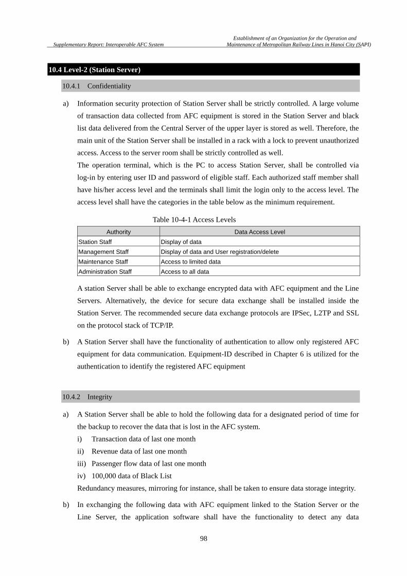
Establishment of an Organization for the Operation and
Supplementary Report: Interoperable AFC System Maintenance of Metropolitan Railway Lines in Hanoi City (SAPI)
98
10.4 Level-2 (Station Server)
10.4.1 Confidentiality
a) Information security protection of Station Server shall be strictly controlled. A large volume
of transaction data collected from AFC equipment is stored in the Station Server and black
list data delivered from the Central Server of the upper layer is stored as well. Therefore, the
main unit of the Station Server shall be installed in a rack with a lock to prevent unauthorized
access. Access to the server room shall be strictly controlled as well.
The operation terminal, which is the PC to access Station Server, shall be controlled via
log-in by entering user ID and password of eligible staff. Each authorized staff member shall
have his/her access level and the terminals shall limit the login only to the access level. The
access level shall have the categories in the table below as the minimum requirement.
A station Server shall be able to exchange encrypted data with AFC equipment and the Line
Servers. Alternatively, the device for secure data exchange shall be installed inside the
Station Server. The recommended secure data exchange protocols are IPSec, L2TP and SSL
on the protocol stack of TCP/IP.
b) A Station Server shall have the functionality of authentication to allow only registered AFC
equipment for data communication. Equipment-ID described in Chapter 6 is utilized for the
authentication to identify the registered AFC equipment
10.4.2 Integrity
a) A Station Server shall be able to hold the following data for a designated period of time for
the backup to recover the data that is lost in the AFC system.
i) Transaction data of last one month
ii) Revenue data of last one month
iii) Passenger flow data of last one month
iv) 100,000 data of Black List
Redundancy measures, mirroring for instance, shall be taken to ensure data storage integrity.
b) In exchanging the following data with AFC equipment linked to the Station Server or the
Line Server, the application software shall have the functionality to detect any data
Authority Data Access Level
Station Staff Display of data
Management Staff Display of data and User registration/delete
Maintenance Staff Access to limited data
Administration Staff Access to all data
Table 10-4-1 Access Levels

Establishment of an Organization for the Operation and
Supplementary Report: Interoperable AFC System Maintenance of Metropolitan Railway Lines in Hanoi City (SAPI)
99
corruption by assigning a redundancy code (Checksum) such as CRC32 in the transmission
data.
i) Transaction Data
ii) Revenue Data
iii) Blacklist
iv) Fare Table
v) Operation Parameters
c) A Station Server has only a limited capacity for storing unsent data, which should be sent to
the Line Server. Hence, when the capacity is filled, AFC equipment shall halt the operation
immediately to ensure data protection and to prevent unsent data from being overwritten.
10.4.3 Availability
a) A Station Server shall have the functionality to operate in off-line mode in the event of
communication failure for a certain duration. By considering the time to recovery, off-line
operation for at least 7 days including the day of the problem shall be maintained. Data that
is collected from AFC equipment linked to the Station Sever in off-line mode shall be
perfectly protected as described in the previous section of 10.3.2.
b) A Station Server shall have the functionality to output the data into removable electronic
media to transfer the data to the Line Server in the case that the offline mode has to be
continued over 7 days.
c) If a Station Server has a breakdown, it should be restored within 7 days even in the worst
case since the backup duration of AFC equipment linked to the Station Server is 7 days at the
maximum.
d) A Station Server shall have redundancy in electric power source with two independent power
sources or with a backup power source provided by a dedicated electric power generator.
Furthermore UPS shall be provided to the Station Server for instantaneous power failure.
10.5 Level-3 (Central Server)
10.5.1 Confidentiality
a) A Central Server is assigned at the highest layer of the AFC system in a railway operation
entity. All important data of the AFC system is sent to the Central Server. Therefore, the
access to the data shall be controlled most strictly. A Central Server shall be installed in a
room with electronic lock opened only by the ID card of authorized staff. In the server
room, the Central Server shall be mounted in a rack, which is locked by key to limit the
direct access to the main unit except for maintenance. Furthermore, the operation terminals

Establishment of an Organization for the Operation and
Supplementary Report: Interoperable AFC System Maintenance of Metropolitan Railway Lines in Hanoi City (SAPI)
100
of the server shall be controlled via log-in by authorized staff entering a user ID and
password. Each authorized staff shall have his/her access level and the terminals shall limit
the login only to the access level. The access level shall have the categories that are shown in
the table below, at least.
b) Among data stored in the Central Server, personal information at least shall be stored as
encrypted data.
c) A Central Server shall be able to exchange encrypted data with the Line Servers. The device
for encryption of data exchange shall be installed inside the server. The recommended
encryption data exchange protocols are IPSec, L2TP and SSL on the protocol stack of
TCP/IP.
d) A Central Server shall have the functionality of authentication to allow only registered Line
Server for data communication. Equipment-ID described in Chapter 6 is utilized for the
authentication to identify the registered Station Servers.
10.5.2 Integrity
a) The period of holding data at the Central Server affects not only the clearing process of the
AFC system belonging to the Central Server but the clearing process between O&M
companies at CCHS. In the interoperable AFC system, the AFC system needs to exchange
data with AFC systems of other O&M companies. Therefore, a common specification for the
period to hold data shall be defined and all AFC systems shall comply with the specification.
b) Following is the possible proposal for the holding period.
i) Last one year in main storage device, which is available for immediate access?
ii) Last ten years at back-up storage device or back-up media.
c) Data stored in main storage device shall be protected by redundancy measures like mirroring.
d) Data shall be checked for its integrity with using checksum for every file or every database.
e) In exchanging the following data with the AFC system that is linked to the Central Server,
the application software shall have the functionality to detect data corruption by assigning a
redundancy code such as CRC32 in the transmission data.
i) Transaction Data
ii) Revenue Data
Authority Data Access Level
Operation Staff Display of data
Management Staff Display of data and User registration/delete
Maintenance Staff Access to limited data
Administration Staff Access to all data
Table 10-5-1 Access Level
Establishment of an Organization for the Operation and
Supplementary Report: Interoperable AFC System Maintenance of Metropolitan Railway Lines in Hanoi City (SAPI)
101
iii) Blacklist
iv) Fare Table
v) Operation Parameters
In the case of transaction with CCHS, the data integrity shall be checked with using
checksum appended to the data.
10.5.3 Availability
a) In the event of communication line failure between the Central Server and CCHS for an
extended period of time, the Central Server shall maintain stand-alone functionality in
off-line mode. In such a case, data for clearing shall be exchanged by using removable
electronic media.
b) Failure in a communication line is as serious problem as breakdown of the server itself.
Therefore, the LAN in the data center or operation control center of AFC, where the Central
Server is installed, shall have redundancy by the method of Hot-Standby or Cold-Standby for
backup.
c) It should be noted that data may not be received as scheduled eventually due to any problem
in CCHS or some other system. Even in this case, the Central Server shall maintain the
function without hang-up or turning to locked mode through appropriate procedure for
reallocating the task schedule for un-received data processing.
d) If the Central Server breaks down, it should be restored within 7 days even in the worst case
since the backup duration of the AFC system belonging to the Central Server is 7 days at the
maximum.
e) A Central Server and devices for communication shall have redundancy in electric power
source with two independent power sources or with backup power source by in-house
electric power generator. Furthermore UPS shall be provided to the Central Server for
instantaneous power failure.
f) The necessary counter measures shall be taken against fire and any natural hazard such as
flood damage as well against problems in the system and electric power. Therefore, the data
center or operation control center where the Central Server is installed should refer for the
facility of the data server installment standards, TIA-942 by Telecommunication Industry
Association for recommendations.
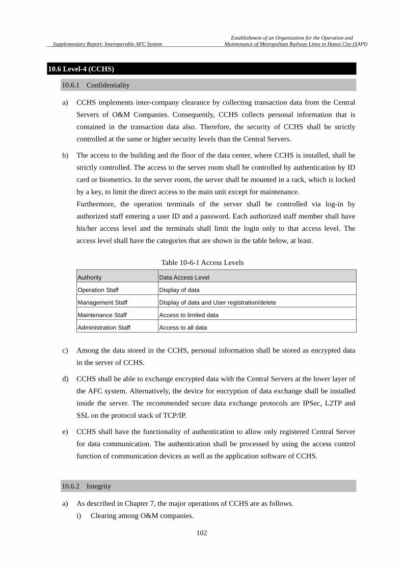
Establishment of an Organization for the Operation and
Supplementary Report: Interoperable AFC System Maintenance of Metropolitan Railway Lines in Hanoi City (SAPI)
102
10.6 Level-4 (CCHS)
10.6.1 Confidentiality
a) CCHS implements inter-company clearance by collecting transaction data from the Central
Servers of O&M Companies. Consequently, CCHS collects personal information that is
contained in the transaction data also. Therefore, the security of CCHS shall be strictly
controlled at the same or higher security levels than the Central Servers.
b) The access to the building and the floor of the data center, where CCHS is installed, shall be
strictly controlled. The access to the server room shall be controlled by authentication by ID
card or biometrics. In the server room, the server shall be mounted in a rack, which is locked
by a key, to limit the direct access to the main unit except for maintenance.
Furthermore, the operation terminals of the server shall be controlled via log-in by
authorized staff entering a user ID and a password. Each authorized staff member shall have
his/her access level and the terminals shall limit the login only to that access level. The
access level shall have the categories that are shown in the table below, at least.
c) Among the data stored in the CCHS, personal information shall be stored as encrypted data
in the server of CCHS.
d) CCHS shall be able to exchange encrypted data with the Central Servers at the lower layer of
the AFC system. Alternatively, the device for encryption of data exchange shall be installed
inside the server. The recommended secure data exchange protocols are IPSec, L2TP and
SSL on the protocol stack of TCP/IP.
e) CCHS shall have the functionality of authentication to allow only registered Central Server
for data communication. The authentication shall be processed by using the access control
function of communication devices as well as the application software of CCHS.
10.6.2 Integrity
a) As described in Chapter 7, the major operations of CCHS are as follows.
i) Clearing among O&M companies.
Authority Data Access Level
Operation Staff Display of data
Management Staff Display of data and User registration/delete
Maintenance Staff Access to limited data
Administration Staff Access to all data
Table 10-6-1 Access Levels

Establishment of an Organization for the Operation and
Supplementary Report: Interoperable AFC System Maintenance of Metropolitan Railway Lines in Hanoi City (SAPI)
103
ii) Exchanging transaction data from AFC systems of O&M companies
iii) Management of Black list to be distributed to the AFC system of each line
The operations process the most important data of the AFC system. Therefore, protection of
the data integrity is the crucial issues.
b) The integrity shall be checked for every file or database by using checksum.
c) For the communication with the AFC system linked to CCHS, every message shall be
appended with the checksum to detect the data error. It is recommended to authenticate the
sender by the technique of digital signature to avoid any falsification.
10.6.3 Availability
a) All data of CCHS shall be protected from corruption and missing data by using the
mirroring technique. The data shall be stored for the same or longer period for which the data
of AFC system linked to CCHS is stored.
b) In the case that the communication line between CCHS and the AFC system has any problem,
data for clearing shall be transferred to CCHS by removable storage media. If transaction
data is not collected as scheduled due to any problem with the AFC equipment, CCHS shall
incorporate delayed data for the clearing process regardless of online or offline data transfer.
However, initially, CCCHS and O&M companies must agree on the maximum delay to be
accepted by CCHS.
c) CCHS shall deliver the result of clearing by removable storage media or printed report in the
case of communication problems with the affiliated AFC systems.
d) The LAN in the building and the LAN in the server room where CCHS is installed shall have
redundancy with Hot-Standby or Cold Standby system availability.
e) CCHS should be restored in 7 days at maximum since the maximum period of holding data
at AFC system linked to CCHS is defined as 7days.
f) CCHS and devices for communication shall have redundancy in electric power source with
two independent power sources or with backup power source provided by in-house electric
power generator. Furthermore UPS shall be provided so as to protect CCHS and the
communication devices from instantaneous power failure.
g) The necessary counter measures shall be taken against fire and any natural hazard such as
flood damage as well against problems in the system and electric power. Therefore, the data
center or operation control center where the Central Server is installed should refer for the
facility of the data server installment standards, TIA-942 by Telecommunication Industry
Association for recommendations.
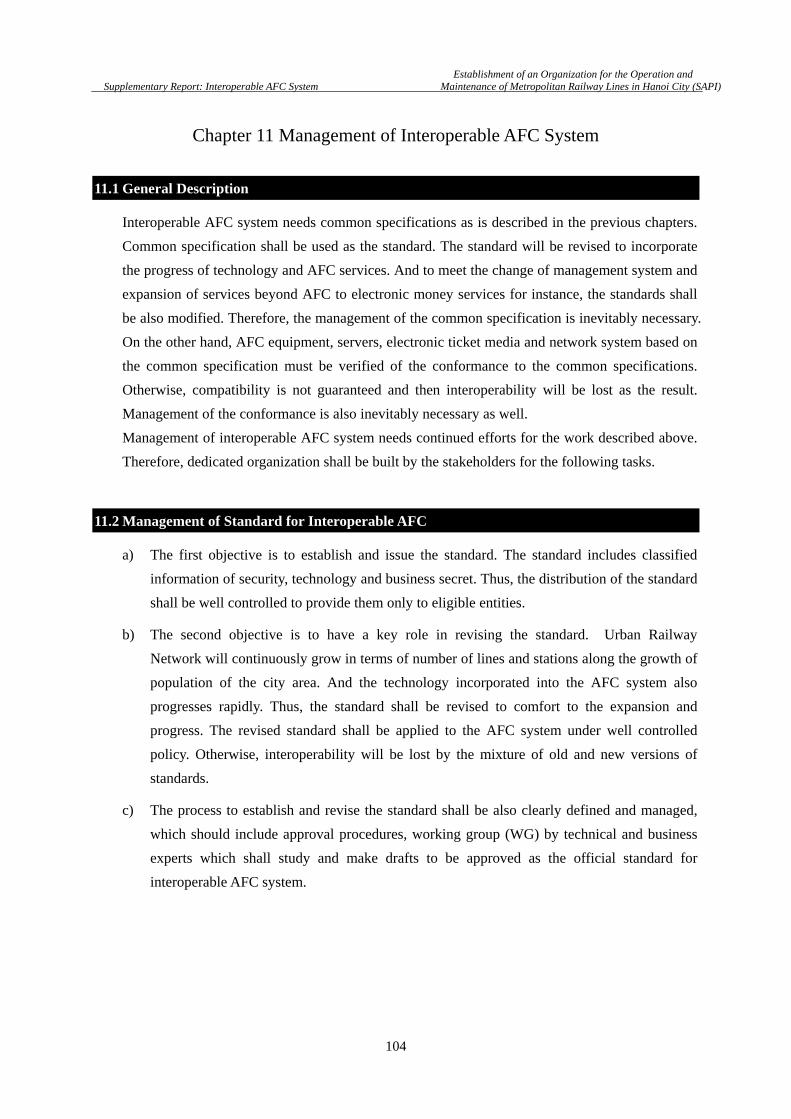
Establishment of an Organization for the Operation and
Supplementary Report: Interoperable AFC System Maintenance of Metropolitan Railway Lines in Hanoi City (SAPI)
104
Chapter 11 Management of Interoperable AFC System
11.1 General Description
Interoperable AFC system needs common specifications as is described in the previous chapters.
Common specification shall be used as the standard. The standard will be revised to incorporate
the progress of technology and AFC services. And to meet the change of management system and
expansion of services beyond AFC to electronic money services for instance, the standards shall
be also modified. Therefore, the management of the common specification is inevitably necessary.
On the other hand, AFC equipment, servers, electronic ticket media and network system based on
the common specification must be verified of the conformance to the common specifications.
Otherwise, compatibility is not guaranteed and then interoperability will be lost as the result.
Management of the conformance is also inevitably necessary as well.
Management of interoperable AFC system needs continued efforts for the work described above.
Therefore, dedicated organization shall be built by the stakeholders for the following tasks.
11.2 Management of Standard for Interoperable AFC
a) The first objective is to establish and issue the standard. The standard includes classified
information of security, technology and business secret. Thus, the distribution of the standard
shall be well controlled to provide them only to eligible entities.
b) The second objective is to have a key role in revising the standard. Urban Railway
Network will continuously grow in terms of number of lines and stations along the growth of
population of the city area. And the technology incorporated into the AFC system also
progresses rapidly. Thus, the standard shall be revised to comfort to the expansion and
progress. The revised standard shall be applied to the AFC system under well controlled
policy. Otherwise, interoperability will be lost by the mixture of old and new versions of
standards.
c) The process to establish and revise the standard shall be also clearly defined and managed,
which should include approval procedures, working group (WG) by technical and business
experts which shall study and make drafts to be approved as the official standard for
interoperable AFC system.

Establishment of an Organization for the Operation and
Supplementary Report: Interoperable AFC System Maintenance of Metropolitan Railway Lines in Hanoi City (SAPI)
105
11.3 Management of Conformance
a) The objective is enforcement of the standard and to verify the conformance to the standard.
Test methodology shall be established to verify the conformance and the test shall be
executed by authorized entities.
b) WG (Working Group) by experts shall be organized for the task. WG shall develop the test
methodology and issue as the test standard approved by authorization procedures.
Conformance test can be executed by authorized entities. The test results of equipment,
servers and system are approved to be applicable for interoperable AFC system.
Document Management 1
Technology Expert WG 2
Business Expert WG 3
Test 1
Test Methodology 2
Verification and Approval 3
Head Quarter of Council
Management ofStandard
Management of Conformance
Figure 11-3-1 Organization for the Management

Establishment of an Organization for the Operation and
Supplementary Report: Interoperable AFC System Maintenance of Metropolitan Railway Lines in Hanoi City (SAPI)
106
Chapter 12 Technology for IC Ticket
12.1 General Description
Requirements and the basic specifications to implement Interoperable AFC System are described
in previous chapters. In this chapter, the technology for IC ticket, which plays the key role in the
interoperability, is considered in the following aspects.
(1) Compliance with International Standards
(2) Speed Performance
(3) Data Integrity
(4) Security
(5) Proven Technology
(6) Availability
(7) Comparison of Technology
12.2 Compliance with International Standard
There are three prominent types of technology for wireless communication of contactless IC card,
that are well known as Type A, Type B and FeliCa Type (often called Type C). Type A and Type
B are registered as ISO/IEC 14443, which is the standard for IC card. Type C is not included in
ISO/IEC 14443. Thus, Type C is sometimes misunderstood as non-standard technology. In fact,
Type C and Type A comply with ISO/IEC 18092 (NFC IP-1). The difference between ISO/IEC
14443 and ISO/IEC 18092 is featured as that ISO/IEC 18092 does not specify any form factor
(form factor–free) while ISO/IEC 14443 is the standard only for card media. Hence, ISO/IEC
18092 attracts much attention for electronic payment by mobile phone. Type C has been already
widely adopted to mobile phone in Japan for electronic ticket and payment. Type C is said as the
most proven technology by both mobile phone and IC card.
It should be noted that Card Operation System (COS) is not treated by ISO/IEC standard.
Mifare/Mifare DESFire and FeliCa are well-known COS combined with Type A and Type C
technology, respectively. For Type B, there are several COS. Since COS contributes to major
performances of IC card, the consideration of technology type is, hereafter, focused on types of
COS.

Establishment of an Organization for the Operation and
Supplementary Report: Interoperable AFC System Maintenance of Metropolitan Railway Lines in Hanoi City (SAPI)
107
Figure 12-2-1 International Standard referred as technology for IC ticket
12.3 Speed Performance
(1) Transaction Time of Ticket Validation
During ticket validation at Automatic Gate, multiple transactions need to be done within a
short period of time since large numbers of passengers come to the Automatic Gate at every
arrival of trains. If the ticket validation throughput of Automatic Gate is low, the station
concourse becomes too congested with passengers that should increase the risk of troubles.
The throughput is closely related to “incomplete transaction” between IC ticket and
Reader/Writer of Automatic Gate. When an “incomplete transaction” occurs, passengers are
unable to pass through the Automatic Gate and need to step back for re-try, which results in
low throughput. The “incomplete transaction” is mainly attributed to the slow data
processing speed of IC ticket. Hence, it is important to select the technology advanced in
data processing speed. To define the specification about the processing speed, the maximum
period of time allowed for the ticket validation was investigated by JR East.
JR East advises passengers to touch IC ticket on Reader/Writer and then go through
Automatic Gate, which is said as ‘Touch & Go’ (Figure 12-3-1). According to the
measurement by JR East, the minimum period which IC ticket remains within the
communicative area is 0.2 second (Figure 12-3-2). Thus, the transaction for ticket validation
shall be completed within 0.2 second.
In the case of FeliCa (Card OS), the data processing is normally executed within 0.1sec.
Thus, with high speed Automatic Gate in Japan, the total transaction time for ticket
validation achieves less than 0.2 second.
The high speed data processing capability of FeliCa is attributed to the unique function to
authenticate multiple data by one interim key and read/write multiple data by single
command. On the other hand, other card OS usually needs to process one by one, which
cannot execute transactions in such a short time as FeliCa. For minimizing “incomplete
transaction”, FeliCa is considered as the most promising technology.
Re-distribution without permission Prohibited
Command &
Response
File System
R/F Interface
ISO/IEC18092212/424K bpsPassive mode
FeliCa I/F
ISO/IEC14443Type A
Devicecommunications
protocol
ISO/IEC 18092 NFCIP-1
ISO/IEC14443Type B
ISO/IEC15693
ISO/IEC 21481 NFCIP-2
International Standard for IC ticket = NFC (Near Field Communication)
FeliCaOS
FeliCa
Security /Data
management
DES FireOS
Security /Data
management
TypeA
TypeBSpecific
OS(Calypso, etc.)
TypeB
Security /Data management
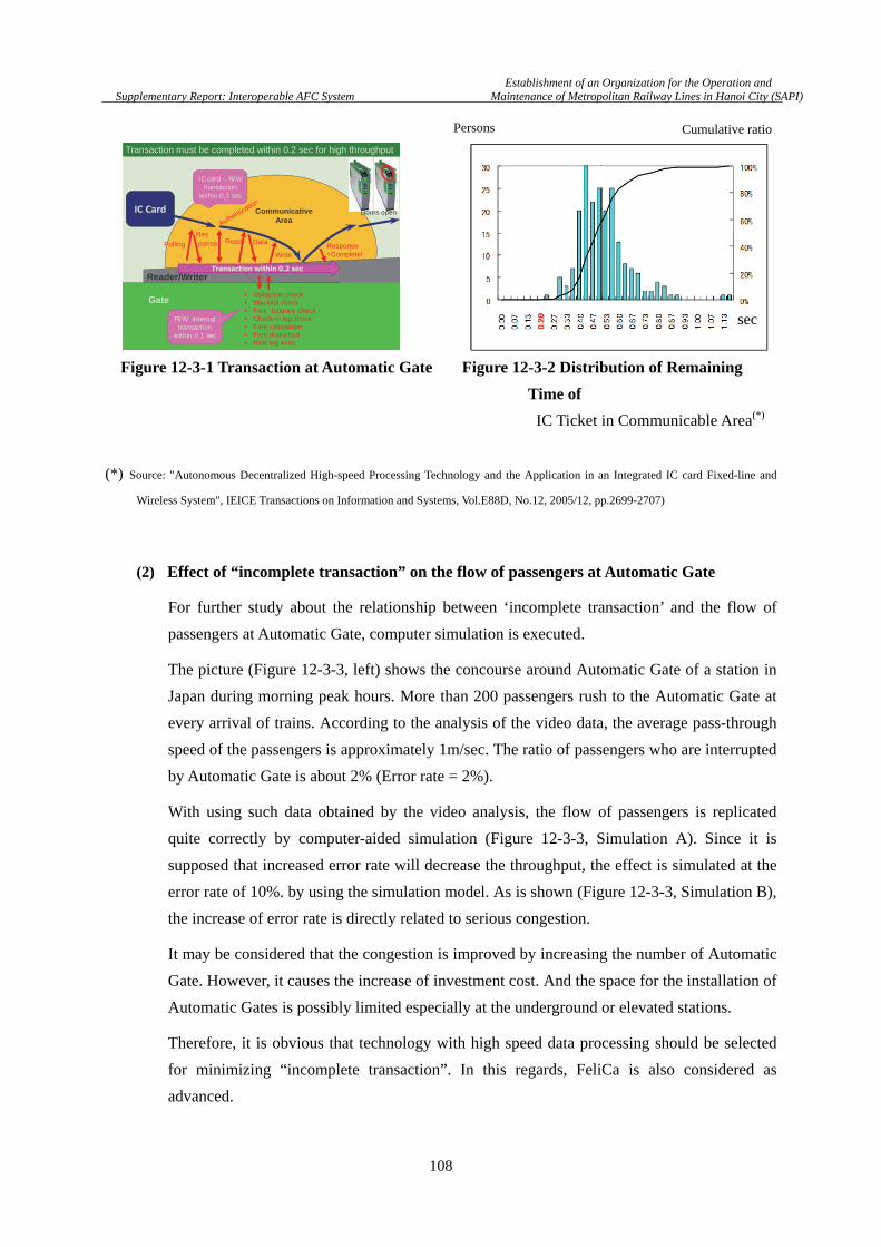
Establishment of an Organization for the Operation and
Supplementary Report: Interoperable AFC System Maintenance of Metropolitan Railway Lines in Hanoi City (SAPI)
108
Figure 12-3-1 Transaction at Automatic Gate Figure 12-3-2 Distribution of Remaining
Time of
IC Ticket in Communicable Area(*)
(*) Source: "Autonomous Decentralized High-speed Processing Technology and the Application in an Integrated IC card Fixed-line and
Wireless System", IEICE Transactions on Information and Systems, Vol.E88D, No.12, 2005/12, pp.2699-2707)
(2) Effect of “incomplete transaction” on the flow of passengers at Automatic Gate
For further study about the relationship between ‘incomplete transaction’ and the flow of
passengers at Automatic Gate, computer simulation is executed.
The picture (Figure 12-3-3, left) shows the concourse around Automatic Gate of a station in
Japan during morning peak hours. More than 200 passengers rush to the Automatic Gate at
every arrival of trains. According to the analysis of the video data, the average pass-through
speed of the passengers is approximately 1m/sec. The ratio of passengers who are interrupted
by Automatic Gate is about 2% (Error rate = 2%).
With using such data obtained by the video analysis, the flow of passengers is replicated
quite correctly by computer-aided simulation (Figure 12-3-3, Simulation A). Since it is
supposed that increased error rate will decrease the throughput, the effect is simulated at the
error rate of 10%. by using the simulation model. As is shown (Figure 12-3-3, Simulation B),
the increase of error rate is directly related to serious congestion.
It may be considered that the congestion is improved by increasing the number of Automatic
Gate. However, it causes the increase of investment cost. And the space for the installation of
Automatic Gates is possibly limited especially at the underground or elevated stations.
Therefore, it is obvious that technology with high speed data processing should be selected
for minimizing “incomplete transaction”. In this regards, FeliCa is also considered as
advanced.
24
Reader/Writer
Gate
Communicative Area
Transaction must be completed within 0.2 sec for high throughput
IC Card
Data
WriteResponse=Complete!
Doors open
• Validation check• Blacklist check• Fare balance check• Check-in log check• Fare calculation• Fare deduction• Ride log write
Transaction within 0.2 sec
ReadPolling
Res-ponse
IC card – R/W transaction
within 0.1 sec
R/W internal transaction
within 0.1 sec
sec
Persons Cumulative ratio
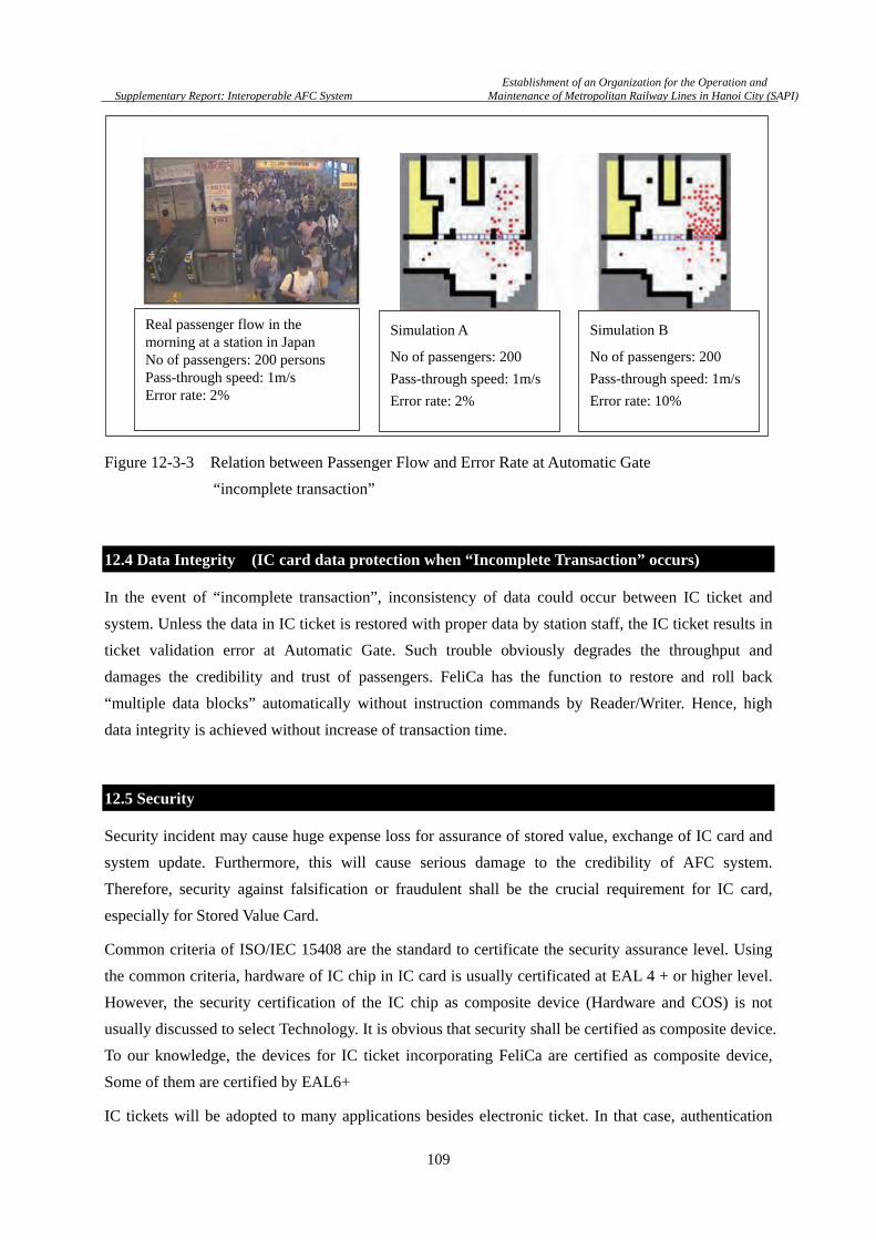
Establishment of an Organization for the Operation and
Supplementary Report: Interoperable AFC System Maintenance of Metropolitan Railway Lines in Hanoi City (SAPI)
109
Figure 12-3-3 Relation between Passenger Flow and Error Rate at Automatic Gate
“incomplete transaction”
12.4 Data Integrity (IC card data protection when “Incomplete Transaction” occurs)
In the event of “incomplete transaction”, inconsistency of data could occur between IC ticket and
system. Unless the data in IC ticket is restored with proper data by station staff, the IC ticket results in
ticket validation error at Automatic Gate. Such trouble obviously degrades the throughput and
damages the credibility and trust of passengers. FeliCa has the function to restore and roll back
“multiple data blocks” automatically without instruction commands by Reader/Writer. Hence, high
data integrity is achieved without increase of transaction time.
12.5 Security
Security incident may cause huge expense loss for assurance of stored value, exchange of IC card and
system update. Furthermore, this will cause serious damage to the credibility of AFC system.
Therefore, security against falsification or fraudulent shall be the crucial requirement for IC card,
especially for Stored Value Card.
Common criteria of ISO/IEC 15408 are the standard to certificate the security assurance level. Using
the common criteria, hardware of IC chip in IC card is usually certificated at EAL 4 + or higher level.
However, the security certification of the IC chip as composite device (Hardware and COS) is not
usually discussed to select Technology. It is obvious that security shall be certified as composite device.
To our knowledge, the devices for IC ticket incorporating FeliCa are certified as composite device,
Some of them are certified by EAL6+
IC tickets will be adopted to many applications besides electronic ticket. In that case, authentication
Real passenger flow in the morning at a station in Japan No of passengers: 200 persons Pass-through speed: 1m/s Error rate: 2%
Simulation A
No of passengers: 200
Pass-through speed: 1m/s
Error rate: 2%
Simulation B
No of passengers: 200
Pass-through speed: 1m/s
Error rate: 10%

Establishment of an Organization for the Operation and
Supplementary Report: Interoperable AFC System Maintenance of Metropolitan Railway Lines in Hanoi City (SAPI)
110
keys for each application are stored in one IC card. The key of each application shall be strictly
protected against access by unauthorized application. In the case of service combined by multiple
applications, however, the service needs to use keys of several applications. In the case of FeliCa,
using interim key scheme, the service securely access the data of each application without directly
disclosing the key information. This feature is quite important for IC ticket to expand its application,
and is attributed to the high security which serious hacking incident has not been reported since the
first implementation.
12.6 Proven Technology
It is also an important factor if the technology is proven through enough experience of actual usage in
AFC system as well as the performance of the technology.
The FeliCa has been used for IC ticket for large scale AFC systems since 1997 in Hong Kong and
since 2001 in Japan. In Japan, FeliCa is adopted to almost all IC tickets of railway and bus. In the
Tokyo metropolitan area, more than 40 million Suica cards, issued by JR East, have been issued and
their transaction number is beyond 25million times/day. In all over Japan, the number of FeliCa type
IC ticket exceeds 65 million. The IC tickets expand their applications to e-money, ID and other many
applications. More than 200 million FeliCa type cards have been issued for e-money, including IC
tickets. Today, it is quite usual to see customers pay by IC card at convenience stores in Japan. It
should be noted that no hacking incident has been reported with FeliCa since the opening of the
operation. It can be said that FeliCa technology is proven by one of the largest AFC and contactless IC
card application system in the world.
12.7 Availability
Availability of technology is also an important factor for sustainable supply in contingency situation
and fare competitions of suppliers. While FeliCa has many advanced features, monopoly is sometimes
raised. as the concern about FeliCa. Thus, the availability of IC card using FeliCa is studied with its
major components.
Contactless IC card usually consists of the major parts shown in Figure 12-3-7. According to the
information obtained in open domain, suppliers are listed below for example.
(1) IC chip: SONY, Panasonic
(2) Inlay: SONY, Panasonic, SMARTRAC
(3) IC card: SONY, Dai Nippon Printing, Foong Tone Technology, Thai British Security Printing
PCL

Establishment of an Organization for the Operation and
Supplementary Report: Interoperable AFC System Maintenance of Metropolitan Railway Lines in Hanoi City (SAPI)
111
Figure 12-7-1 Major Parts of Contactless IC card
In addition, there are many manufactures for FeliCa-enabled R/W and system integrators supporting
FeliCa. Furthermore, according to SONY, SONY has the policy to grant license of FeliCa COS to third
party IC chip vendors under proper security and reasonable economic conditions. Hence, FeliCa
products and systems can be manufactured and purchased from multiple sources.
12.8 Summary on IC Ticket Technology
Railway infrastructure shall not be designed for fulfilling current needs but shall be designed with the
forethought of future for next 10years or longer. This approach shall be applied to the AFC system as
well. Thus AFC system for Hanoi should be designed and constructed with the future picture of
Vietnam.
According to the data reported by Hanoi Public Transport Management and Operation Center
(TRAMOC), Hanoi citizen make 2 trips per day on an average using public or private transportation
modes. This figure is the same for the Tokyo Metropolitan area. However, there is an obvious
difference between the 2 cities. In Tokyo (central 23 wards area), trips by public transport, e.g.
railways and buses, account for approximately 80%. By contrast, in Hanoi, such trips account for 20%.
These figures back up the fact that many trips heavily depend on private transport mode, i.e. motor
bike. If integrated AFC system among buses and railway network is implemented, modal shift will be
expected as travelers prefer more convenient transport mode.
In addition, population of Hanoi is expected to increase from 6.5 million to 8 million by the time that
metropolitan railways, which are currently under construction, are ready in year 2020, and to over 10
million eventually in year 2050. It is easily imaginable that Hanoi city, where population will become
the same level as Tokyo in the future, may encounter heavy traffic situation. The expected ridership of
the metropolitan railway project supported by Japan is nearly the same as the one of major stations in
Tokyo.
In other words, it must be a good approach to plan the AFC system of Urban Railway Network by
②Inlay
Exterior Material
①IC chipAntenna
Exterior Material
③IC Card

Establishment of an Organization for the Operation and
Supplementary Report: Interoperable AFC System Maintenance of Metropolitan Railway Lines in Hanoi City (SAPI)
112
considering the implemented AFC system in Tokyo metropolitan area. As is previously described,
FeliCa technology has been proven well to meet the requirements on safety and convenience to the
AFC system owing to its high speed performance, high data integrity, high security and other
advanced features.
Considering above facts, FeliCa technology is strongly suggested as the IC card for the Urban Railway
Network in Vietnam.
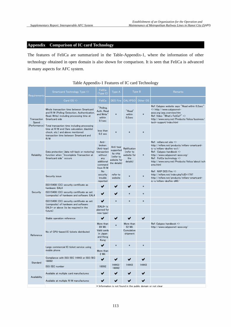
Establishment of an Organization for the Operation and
Supplementary Report: Interoperable AFC System Maintenance of Metropolitan Railway Lines in Hanoi City (SAPI)
113
Appendix Comparison of IC card Technology
The features of FeliCa are summarized in the Table-Appendix-1, where the information of other
technology obtained in open domain is also shown for comparison. It is seen that FeliCa is advanced
in many aspects for AFC system.
Table Appendix-1 Features of IC card Technology
Smartcard Technology Type =>FeliCa
(Type C)Type A Remarks
Card OS => FeliCa DES Fire CALYPSO Other OS
Whole transaction time between Smartcardand R/W (Polling/Detection, Authentication,Read, Write) including processing time atSmartcard side
"Polling,Auth, Readand Write"
within0.1sec
* "Read"within0.2sec
*
Ref: Calypso website says "Read within 0.2sec"=> http://www.calypsonet-asso.org/pop_overview.htmRef: Video "What's FeliCa?" =>http://www.sony.net/Products/felica/business/tech-support/index.html
Total transaction time including processingtime at R/W end (fare calculation, blacklistcheck, etc.) and above mentionedtransaction time between Smartcard andR/W
less than0.2 sec
* * *
ReliabilityData protection (data roll-back or restoring)function when "Incomplete Transaction atSmartcard side" occurs
Anti-broken
(Anti-tear)transaction
withoutany
additionalcommandfrom R/W
Anti-tearsupportedby chip(refer to
website forthe details)
Ratification(refer to
website forthe
details)
*
Ref: mifare.net site =>http://mifare.net/products/mifare-smartcard-ic-s/mifare-desfire-ev1/Ref: Calypso handbook =>http://www.calypsonet-asso.org/Ref: FeliCa technology =>http://www.sony.net/Products/felica/about/scheme.html
Security issue
Nosecuritytrouble
reported
refer towebsite
* *
Ref: NXP DES Fire =>http://mifare.net/index.php?cID=1797http://mifare.net/products/mifare-smartcard-ic-s/mifare-desfire-d40/
ISO15408 (CC) security certificate ashardware: EAL4 *
ISO15408 (CC) security certificate as set(composite) of hardware and software: EAL4 * *
* * *
(EAL6+ isplanned fornew type)
Stable operation reference More than
89 Mil.*
More than52 Mil.
Ref: Calypso handbook =>http://www.calypsonet-asso.org/
Valid cardsin Japanand Hong
Kong
Cumulativeshipment
* * *
More than2 Mil.
Compliance with ISO/IEC 14443 or ISO/IEC18092 ISO/IEC number 18092
14443/18092
14443 14443
Available at multiple card manufactures Available at multiple R/W manufactures
* Information is not found in the public domain or not clear
Standard
Availability
Requirements
Type B
TransactionSpeed
(Performance)
Security
ISO15408 (CC) security certificate as set(composite) of hardware and software:EAL5+ or above (to be required in thefuture)
Reference
No of CPU-based IC tickets distributed
Large commercial IC ticket service usingmobile phone


![Increasing Accuracy of Speech Recognition Applications · Figure 1: SAPI Overview [4] SAPI is the API that is developed by Microsoft in order to implement speech applications. Implementation](https://img.pdfslide.us/doc/110x75/5f65f2e025219e574b7f982b/increasing-accuracy-of-speech-recognition-applications-figure-1-sapi-overview-4.jpg)