Embed Size (px)
Citation preview
NOTE:1. Seasonal power consumption is a calculated value based on JIS B 8616: 2015 (Tokyo office), and it may vary depending on the area or usage conditions.2. As reference in Japanese domestic model
Specif ications
Dimensions
Service spaceNOTES:
1
The cooling and heating performances are the values when combined with our specified indoor units.Cooling Operation Conditions
Heating Operation Conditions
Indoor Air Inlet Temperature: 27oC DB (80oF DB) / 19.0oC WB (66.2oF WB)Outdoor Air Inlet Temperature: 35oC DB (95oF DB)
Indoor Air Inlet Temperature: 20oC DB (68oF DB)Outdoor Air Inlet Temperature: 7oC DB (45oF DB) / 6oC WB (43oF WB)
Piping Length: 7.5 MetersPiping Lift: 0 Meter
2
The sound pressure is based on the following conditions.The above data is based on the cooling mode. In case of heating mode, the sound pressure level increases by approximately 1~2 dB.The above data was measured in an anechoic chamber so that reflected sound should be taken into consideration in the field.
3 Except for the specified combination in the table (26~54HP), there is no other combination of the base unit.
4 The width of outer dimension, it is the value when each distance between the base outdoor units is specified to 20mm.
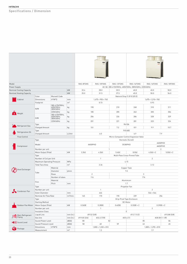
Model RAS-8FSNS RAS-10FSNS RAS-12FSNS RAS-14FSNS RAS-16FSNS RAS-18FSNS
Power Supply AC 3φ, 380-415V/50Hz, 400V/50Hz, 380V/60Hz, 220V/60Hz
Nominal Cooling Capacity kW 22.4 28.0 33.5 40.0 45.0 50.0
Nominal Heating Capacity kW 25.0 31.5 37.5 45.0 50.0 56.0
Cabinet
Color Munsell Code Natural Gray (1.0Y 8.5/0.5)
Dimensions H*W*D mm 1,675 × 950 × 765 1,675 × 1,210 × 765
Footprint m2 0.73 0.93
Weight
N/W
380-415V/50Hz, 400V/50Hz,380V/60Hz
kg 190 210 268 310 311
220V/60Hz kg 185 205 263 305 306
G/W
380-415V/50Hz, 400V/50Hz,380V/60Hz
kg 206 226 286 328 329
220V/60Hz kg 201 221 281 323 324
Refrigerant GasType R410A
Charged Amount kg 5.0 7.2 8.9 9.9 10.7
Refrigeration OilType FVC68D
Charged Amount L/Unit 6.0 6.9 7.9
Flow Control Micro-Computer Control Expansion Valve
Compressor
Type Hermetic (Scroll)
Model AA50PHD DC80PHDAA50PHD
AA50PHD
Number per unit 1 2
Motor Output (Pole) kW 3.3(6) 4.3(6) 5.4(6) 8.0(6) 4.5(6) × 2 5.0(6) × 2
Heat Exchanger
Type Multi-Pass Cross-Finned Tube
Number of Coil per Unit 1 2
Maximum Operating Pressure MPa 4.15
Total Face Area m2 2.36 3.12
Tube
Material Copper Tube
Diameter φmm 7.0
Rows 2 3
Number of tubes 116 174
FinnMaterial Aluminium
Pitch mm 1.7
Condenser Fan
Type Propeller Fan
Number per unit 1 2
Outer Diameter mm 644 544 + 544
Nominal Air Flow Rate m3/min. 165 170 190 239 256
Outdoor Fan Motor
Type Drip-Proof Type Enclosure
Starting Method DC Motor
Motor Output (Pole) kW 0.26(8) 0.28(8) 0.42(8) 0.33(8) × 2 0.39(8) × 2
Number per unit 1 2
Insulation Class E
Main Refrigerant Piping
Liquid Line mm (in.) φ9.52 (3/8) φ12.7 (1/2) φ15.88 (5/8)
mm (in.) φ19.05 (3/4) φ22.2 (7/8) φ25.4 (1) φ28.58 (1-1/8)Gas line
Sound LevelSound Power Level dB(A) 80 82 85 86
Sound Pressure Level dB(A) 58 60 59 63 65
PackageDimentions H*W*D mm 1,800 × 1,030 × 810 1,800 × 1,290 × 810
Measurement m3 1.5 1.9
Specifications / Dimension
23
33195 92 576 92
269
950
267
1675
1348
601432
729
1818
131131
268
Liqu
id L
ine
163
Gas
Lin
e
131 Gas Line117 Liquid Line
765
Hole for Suspention
Hole for Suspention
205239
245
87
382
720 115
80
127
6580
12724010
092
65305
225
248
253
M12 Anchor Bolt Mooting Hole(4-38×15 Long Hole]
Service cover
Liquid Line Refrigerant Piping Connection
Refrigerant Piping andWiring Connection Hole(Knockout Hole)
Gas Line RefrigerantPiping Connection
TB Box(Only 380-415V/50Hz 380V/60Hz model)
Electrical Control Box
Access Door
Mounting Position forDrain Boss (Optional)(Ø26×2)
Mounting Position forDrain Cap (Optional)(Ø26×2)
Power SourceCable Outlet(Ø65 Knockout Hole)
Power TransitionCable Outlet(Ø33 Knockout Hole)
Control Cable Outlet(Ø33 Knockout Hole)
※N/A in This Unit
Refrigerant Piping Outlet (Gas,Liquid)(Knockout Square Hole)
Power TransitionCable Outlet(Ø55 Knockout Hole)
Control Cable Outlet(Ø33 Knockout Hole)
Power Source Cable Outlet(Ø65 Knockout Hole)
RefrigerantPiping Outlet(Gas,Liquid)(Knockout Square Hole)
Not Used
(※2)688
(Anchor Bolt Hole Pitch)
(Anc
hor
Bol
t Hol
e P
itch)
Knockout Hole/Drain Hole (Top View)
Refrigerant Piping and Wiring Connection
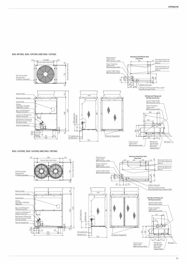
DIMENSIONAL DRAWING OF HITACHI AIR-TO-AIR HEAT PUMP AIR CONDITIONER,SET-FREE
( OUTDOOR UNIT ,MODELS: RAS-8FSNS,RAS-10FSNS and RAS-12FSNS
NOTES:
Choose a well drained place to install units or provide a ditch to drain.
If inevitable,provide the second drain pan to run drainage.
3.Do not install above the corridors.Drainage may fall.
1.Refer to "System Pipe Drawing"for diameters.
is prohibited.Drainage in the pipes may frozen and cause cracks on the pipes.
2.Drainage to come out during heating or defrost operation,and rain water,too.
4.Use a drain boss(optional)if drain setup for Outdoor Unit is necessary.
However,installation of the drain boss in regions where drainage may frozen
Follow the instructions on Installation Manual provided with drain boss.
317T158469
317T158469
CAD
23 01 201723 01 201723 01 2017
Y.KAGEYAMAY.UCHINO
DIMENSIONALDRAWING NTS
C
D
E
F
B
A
4 531 2
C
D
B
A
E
F
4 531 2 6 7 8
PROJECTIONSCALETITLE
APPD.
REMARKS
CHKD.DWN. SH. REGD.REV.
- -
REVISIONSCHKD. APPD.REVD.DATE
- -
SYM.
- -
SHIMIZU DWG. NO.
This drawing is under license by Johnson Controls-Hitachi Air Conditioning Technology(Hong Kong)Limited
1872
9
131 131
18
948
8780
267
1675
1348
Service cover
178239
9592
83692
1210
14
60
32
263
Liqu
id L
ine
160
Gas
Lin
e
130 Gas Line
112 Liquid Line
765
230 152
520230
147 127
127147
212
132
100
93
248
253
65
M12 Anchor Bolt Mooting Hole(4-38×15 Long Hole]
Electrical Control Box
483
115
Hole for Suspention
TB Box(Only 380-415V/50Hz,380/60Hz)
Access Door
Gas Line RefrigerantPiping Connection
Liquid Line RefrigerantPiping Connection
Refrigerant Piping andWiring Connection Hole(Knockout Hole)
Hole for Suspention
806524
5
Power SourceCable Outlet(Ø65 Knockout Hole)
Power TransitionCable Outlet(Ø33 Knockout Hole)
Control Cable Outlet(Ø33 Knockout Hole)
Mounting Position forDrain Boss (Optional)(Ø26×2)
Mounting Position forDrain Cap (Optional)(Ø26×2)
Control Cable Outlet(Ø33 Knockout Hole)
Power TransitionCable Outlet(Ø55 Knockout Hole)
RefrigerantPiping Outlet(Gas,Liquid)(Knockout Square Hole)
Power Source Cable Outlet(Ø65 Knockout Hole)
※N/A in This Unit
Refrigerant Piping Outlet(Gas,Liquid)(Knockout Square Hole)
Not Used
(Anc
hor
Bol
t Hol
e P
itch)
(Anchor Bolt Hole Pitch)
Knockout Hole/Drain Hole (Top View)
Refrigerant Piping and Wiring Connection
DIMENSIONAL DRAWING OF HITACHI AIR-TO-AIR HEAT PUMP AIR CONDITIONER,SET-FREE
( OUTDOOR UNIT ,MODELS: RAS-14FSNS,RAS-16FSNS and RAS-18FSNS
1.Refer to "System Pipe Drawing"for diameters.
NOTES:
If inevitable,provide the second drain pan to run drainage.
3.Do not install above the corridors.Drainage may fall.
is prohibited.Drainage in the pipes may frozen and cause cracks on the pipes.
Choose a well drained place to install units or provide a ditch to drain.
However,installation of the drain boss in regions where drainage may frozen
Follow the instructions on Installation Manual provided with drain boss.
2.Drainage to come out during heating or defrost operation,and rain water,too.
4.Use a drain boss(optional)if drain setup for Outdoor Unit is necessary.
317T158470
317T158470
CAD
23 01 201723 01 201723 01 2017
Y.KAGEYAMAY.UCHINO
DIMENSIONALDRAWING NTS
C
D
E
F
B
A
4 531 2
C
D
B
A
E
F
4 531 2 6 7 8
PROJECTIONSCALETITLE
APPD.
REMARKS
CHKD.DWN. SH. REGD.REV.
- -
REVISIONSCHKD. APPD.REVD.DATE
- -
SYM.
- -
SHIMIZU DWG. NO.
This drawing is under license by Johnson Controls-Hitachi Air Conditioning Technology(Hong Kong)Limited
RAS-8FSNS, RAS-10FSNS AND RAS-12FSNS
RAS-14FSNS, RAS-16FSNS AND RAS-18FSNS
24
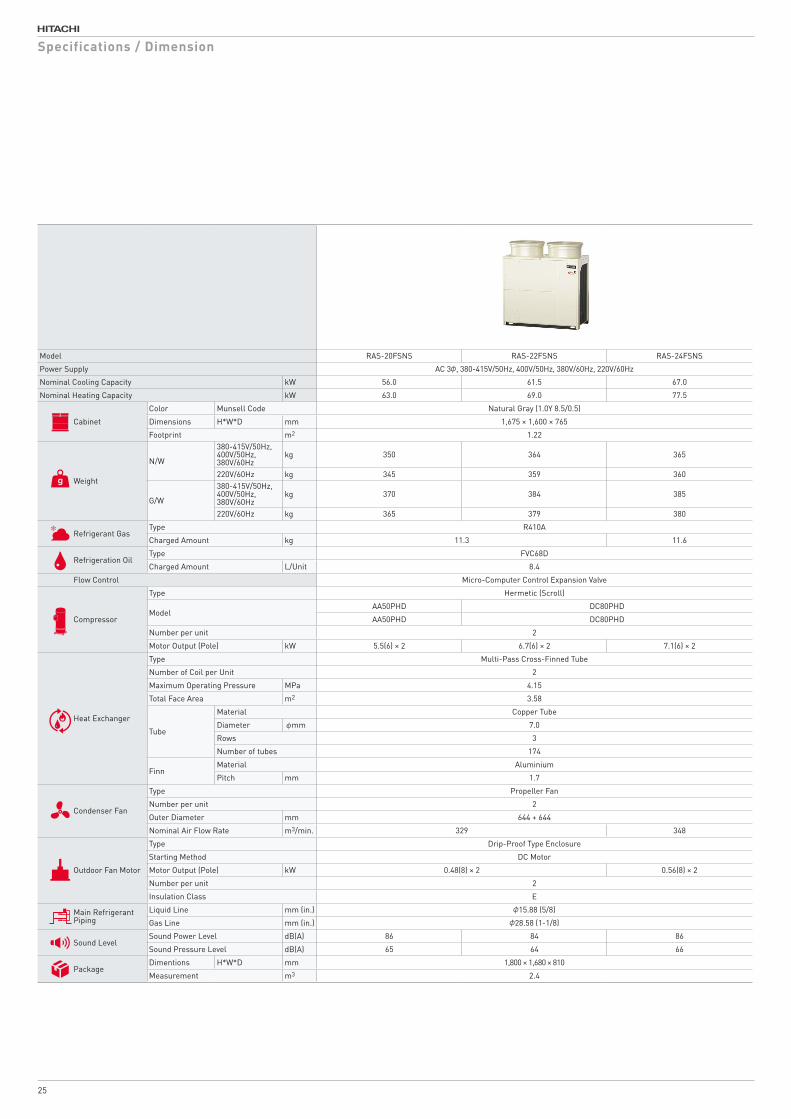
Model RAS-20FSNS RAS-22FSNS RAS-24FSNS
Power Supply AC 3φ, 380-415V/50Hz, 400V/50Hz, 380V/60Hz, 220V/60Hz
Nominal Cooling Capacity kW 56.0 61.5 67.0
Nominal Heating Capacity kW 63.0 69.0 77.5
Cabinet
Color Munsell Code Natural Gray (1.0Y 8.5/0.5)
Dimensions H*W*D mm 1,675 × 1,600 × 765
Footprint m2 1.22
Weight
N/W
380-415V/50Hz, 400V/50Hz,380V/60Hz
kg 350 364 365
220V/60Hz kg 345 359 360
G/W
380-415V/50Hz, 400V/50Hz,380V/60Hz
kg 370 384 385
220V/60Hz kg 365 379 380
Refrigerant GasType R410A
Charged Amount kg 11.3 11.6
Refrigeration OilType FVC68D
Charged Amount L/Unit 8.4
Flow Control Micro-Computer Control Expansion Valve
Compressor
Type Hermetic (Scroll)
ModelAA50PHD DC80PHD
AA50PHD DC80PHD
Number per unit 2
Motor Output (Pole) kW 5.5(6) × 2 6.7(6) × 2 7.1(6) × 2
Heat Exchanger
Type Multi-Pass Cross-Finned Tube
Number of Coil per Unit 2
Maximum Operating Pressure MPa 4.15
Total Face Area m2 3.58
Tube
Material Copper Tube
Diameter φmm 7.0
Rows 3
Number of tubes 174
FinnMaterial Aluminium
Pitch mm 1.7
Condenser Fan
Type Propeller Fan
Number per unit 2
Outer Diameter mm 644 + 644
Nominal Air Flow Rate m3/min. 329 348
Outdoor Fan Motor
Type Drip-Proof Type Enclosure
Starting Method DC Motor
Motor Output (Pole) kW 0.48(8) × 2 0.56(8) × 2
Number per unit 2
Insulation Class E
Main Refrigerant Piping
Liquid Line mm (in.) φ15.88 (5/8)
Gas Line mm (in.) φ28.58 (1-1/8)
Sound LevelSound Power Level dB(A) 86 84 86
Sound Pressure Level dB(A) 65 64 66
PackageDimentions H*W*D mm 1,800 × 1,680 × 810
Measurement m3 2.4
Specifications / Dimension
25
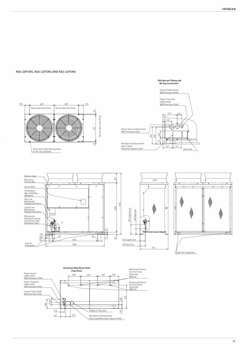
RAS-20FSNS, RAS-22FSNS AND RAS-24FSNS
95
92
1226
92
1600
1818
131 669 669 131
729
14 60
1675
267
1348
32
Hole forSuspention
Service cover
259
Liqu
id L
ine
160
Gas
Lin
e
765
152 Gas Line
132 Liquid Line
93
248
253
212
132
147 127
100
65
177239
Hole for Suspention
ElectricalControl Box
TB Box(Only380-415V/50Hz,380/60Hz)
M12 Anchor Bolt Mooting Hole
Access Door
Power TransitionCable Outlet(Ø55 Knockout Hole)
Control Cable Outlet(Ø33 Knockout Hole)
Gas LineRefrigerantPiping Connection
Liquid LineRefrigerantPiping Connection
RefrigerantPiping and wiringConnection Hole(Knockout Hole)
Power Source Cable Outlet(Ø65 Knockout Hole)
Refrigerant Piping Outlet(Gas,Liquid)(Knockout Square Hole)
6580
Power TransitionCable Outlet(Ø33 Knockout Hole)
Control Cable Outlet(Ø33 Knockout Hole)
Power SourceCable Outlet(Ø65 Knockout Hole)
635
462 339 239339
Mounting Positionfor Drain Cap(Optional)
Mounting Positionfor Drain Boss(Optional)
110
147 127 Refrigerant Piping Outlet(Gas,Liquid)(Knockout Square Hole)
8011
0
250
Not Used
(6-38 ×15 Long Hole]
※N/A in This Unit
(Ø26×2)
(Ø26×2)
(Anc
hor
Bol
t Hol
e P
itch)
(Anchor Bolt Hole Pitch)(Anchor Bolt Hole Pitch)
Knockout Hole/Drain Hole (Top View)
Refrigerant Piping and Wiring Connection
0
DIMENSIONAL DRAWING OF HITACHI AIR-TO-AIR HEAT PUMP AIR CONDITIONER,SET-FREE
( OUTDOOR UNIT ,MODEL: RAS-20FSNS,RAS-22FSNS and 24FSNS
NOTES:
1.Refer to "System Pipe Drawing"for diameters.
If inevitable,provide the second drain pan to run drainage.
Follow the instructions on Installation Manual provided with drain boss.
is prohibited.Drainage in the pipes may frozen and cause cracks on the pipes.
However,installation of the drain boss in regions where drainage may frozen
3.Do not install above the corridors.Drainage may fall.
2.Drainage to come out during heating or defrost operation,and rain water,too.
Choose a well drained place to install units or provide a ditch to drain.
4.Use a drain boss(optional)if drain setup for Outdoor Unit is necessary.
317T158471
317T158471
CAD
23 01 201723 01 201723 01 2017
Y.KAGEYAMAY.UCHINO
DIMENSIONALDRAWING NTS
C
D
E
F
B
A
4 531 2
C
D
B
A
E
F
4 531 2 6 7 8
PROJECTIONSCALETITLE
APPD.
REMARKS
CHKD.DWN. SH. REGD.REV.
- -
REVISIONSCHKD. APPD.REVD.DATE
- -
SYM.
- -
SHIMIZU DWG. NO.
This drawing is under license by Johnson Controls-Hitachi Air Conditioning Technology(Hong Kong)Limited
26
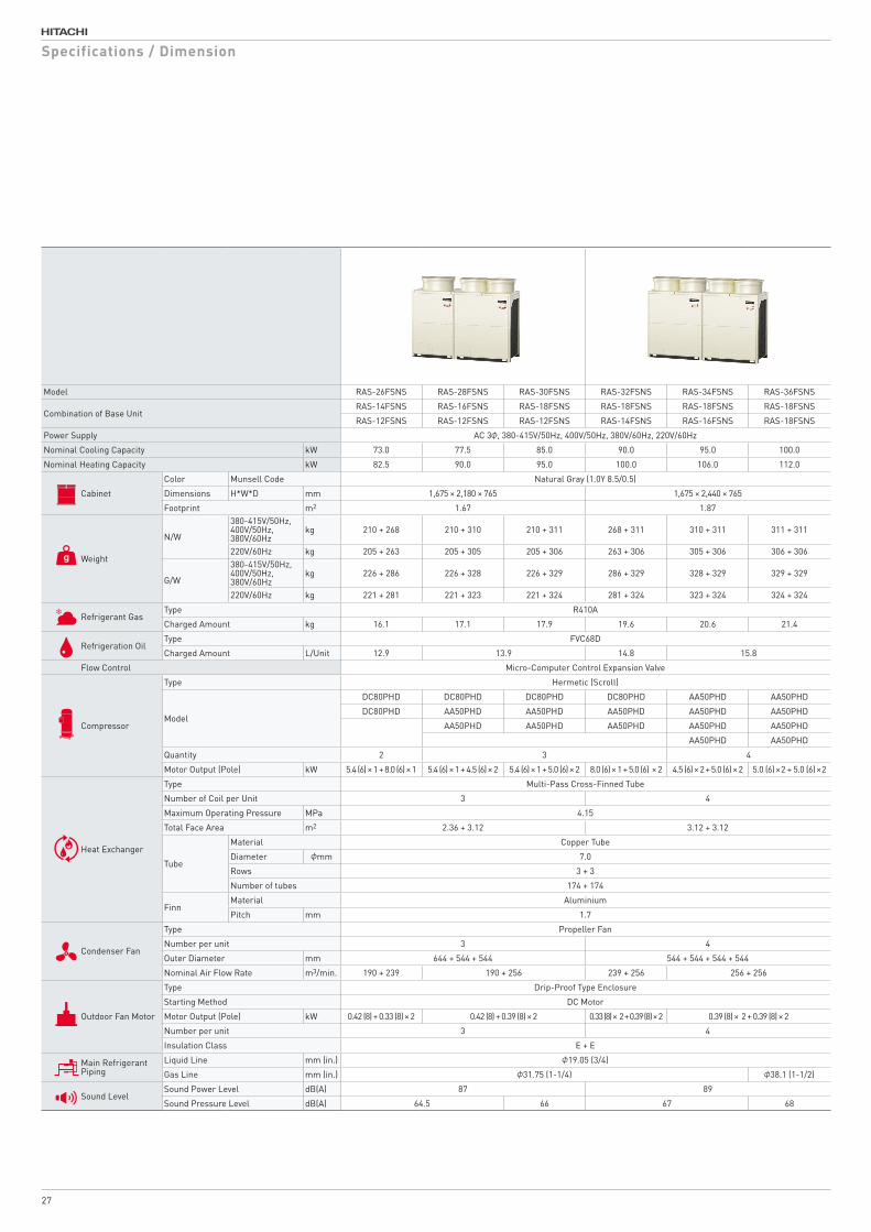
Model RAS-26FSNS RAS-28FSNS RAS-30FSNS RAS-32FSNS RAS-34FSNS RAS-36FSNS
Combination of Base Unit RAS-14FSNS RAS-16FSNS RAS-18FSNS RAS-18FSNS RAS-18FSNS RAS-18FSNS
RAS-12FSNS RAS-12FSNS RAS-12FSNS RAS-14FSNS RAS-16FSNS RAS-18FSNS
Power Supply AC 3φ, 380-415V/50Hz, 400V/50Hz, 380V/60Hz, 220V/60Hz
Nominal Cooling Capacity kW 73.0 77.5 85.0 90.0 95.0 100.0
Nominal Heating Capacity kW 82.5 90.0 95.0 100.0 106.0 112.0
Cabinet
Color Munsell Code Natural Gray (1.0Y 8.5/0.5)
Dimensions H*W*D mm 1,675 × 2,180 × 765 1,675 × 2,440 × 765
Footprint m2 1.67 1.87
Weight
N/W
380-415V/50Hz, 400V/50Hz,380V/60Hz
kg 210 + 268 210 + 310 210 + 311 268 + 311 310 + 311 311 + 311
220V/60Hz kg 205 + 263 205 + 305 205 + 306 263 + 306 305 + 306 306 + 306
G/W
380-415V/50Hz,400V/50Hz, 380V/60Hz
kg 226 + 286 226 + 328 226 + 329 286 + 329 328 + 329 329 + 329
220V/60Hz kg 221 + 281 221 + 323 221 + 324 281 + 324 323 + 324 324 + 324
Refrigerant GasType R410A
Charged Amount kg 16.1 17.1 17.9 19.6 20.6 21.4
Refrigeration OilType FVC68D
Charged Amount L/Unit 12.9 13.9 14.8 15.8
Flow Control Micro-Computer Control Expansion Valve
Compressor
Type Hermetic (Scroll)
Model
DC80PHD DC80PHD DC80PHD DC80PHD AA50PHD AA50PHD
DC80PHD AA50PHD AA50PHD AA50PHD AA50PHD AA50PHD
AA50PHD AA50PHD AA50PHD AA50PHD AA50PHD
AA50PHD AA50PHD
Quantity 2 3 4
Motor Output (Pole) kW 5.4 (6) × 1 + 8.0 (6) × 1 5.4 (6) × 1 + 4.5 (6) × 2 5.4 (6) × 1 + 5.0 (6) × 2 8.0 (6) × 1 + 5.0 (6) × 2 4.5 (6) × 2 + 5.0 (6) × 2 5.0 (6) × 2 + 5.0 (6) × 2
Heat Exchanger
Type Multi-Pass Cross-Finned Tube
Number of Coil per Unit 3 4
Maximum Operating Pressure MPa 4.15
Total Face Area m2 2.36 + 3.12 3.12 + 3.12
Tube
Material Copper Tube
Diameter φmm 7.0
Rows 3 + 3
Number of tubes 174 + 174
FinnMaterial Aluminium
Pitch mm 1.7
Condenser Fan
Type Propeller Fan
Number per unit 3 4
Outer Diameter mm 644 + 544 + 544 544 + 544 + 544 + 544
Nominal Air Flow Rate m3/min. 190 + 239 190 + 256 239 + 256 256 + 256
Outdoor Fan Motor
Type Drip-Proof Type Enclosure
Starting Method DC Motor
Motor Output (Pole) kW 0.42 (8) + 0.33 (8) × 2 0.42 (8) + 0.39 (8) × 2 0.33 (8) × 2 + 0.39 (8) × 2 0.39 (8) × 2 + 0.39 (8) × 2
Number per unit 3 4
Insulation Class E + E
Main Refrigerant Piping
Liquid Line mm (in.) φ19.05 (3/4)
Gas Line mm (in.) φ31.75 (1-1/4) φ38.1 (1-1/2)
Sound LevelSound Power Level dB(A) 87 89
Sound Pressure Level dB(A) 64.5 66 67 68
Specifications / Dimension
27
18
131
1872
9
688MIN.282
M12 Anchor Bolt Mooting Hole
131 948
765
950
(2180)MIN.20
1675
1210
OUTDOOR UNIT A OUTDOOR UNIT B
to Indoor UnitPiping Connection Kit
(Anchor Bolt Hole Pitch)(Anchor Bolt Hole Pitch)
(Anc
hor
Bol
t Hol
e P
itch)
to Indoor Unit
DIMENSIONAL DRAWING OF HITACHI AIR-TO-AIR HEAT PUMP AIR CONDITIONER,SET-FREE( OUTDOOR UNIT ,MODELS: RAS-26FSNS,RAS-28FSNS and RAS-30FSNS )
NOTES:
2.Check "Piping System" and "Dimensional Drawing" for the piping connection kit and piping connection size.
Arrange the outdoor units according to the
1.Make sure that the outdoor unit A is placed on the indoor unit side.
�@�@�����������������C�`���a�D
Dimension of piping outlet and Cable outlet.3.Check the "Dimensional Drawing" for the
4.This drawing shows that there is 20mm clearance between the base units. For outdoor unit snowproof hood,clearance is 50mm or more.�T�D�s�����@���������������������@�������������@���������@�@�¦�@�������������������@ the mounting pitch dimension for anchor bolts.
RAS-26FSNS
OUTDOOR UNIT A OUTDOOR UNIT B
RAS-14FSNS
RAS-16FSNSRAS-28FSNS
RAS-18FSNSRAS-30FSNS
RAS-12FSNS
RAS-12FSNS
Outdoor Unit ModelCombination of Base Unit Models
RAS-18FSNS
RAS-14FSNS
RAS-16FSNS
Combination ofBase Unit Models
RAS-12FSNS
Drawing NO.ofDimension
317T158469
317T158470
317T158470
317T158470
RAS-12FSNS
(8-38 ×15 Long Hole]
317T158472
317T158472
CAD
23 01 201723 01 201723 01 2017
Y.KAGEYAMAY.UCHINO
DIMENSIONALDRAWING NTS
C
D
E
F
B
A
4 531 2
C
D
B
A
E
F
4 531 2 6 7 8
PROJECTION SCALETITLE
APPD.
REMARKS
CHKD.DWN. SH. REGD.REV.
- -
REVISIONSCHKD. APPD.REVD.DATE
- -
SYM.
- -
SHIMIZU DWG. NO.
This drawing is under license by Johnson Controls-Hitachi Air Conditioning Technology(Hong Kong)Limi ted
131 948MIN.282
1675
1210
(2440)
1210
948 131
M12 Anchor Bolt Mooting Hole
1872
918
765
MIN.20
(8-38 ×15 Long Hole]
OUTDOOR UNIT A OUTDOOR UNIT B
to Indoor UnitPiping Connection Kit
(Anchor Bolt Hole Pitch) (Anchor Bolt Hole Pitch)
(Anc
hor
Bol
t Hol
e P
itch)
DIMENSIONAL DRAWING OF HITACHI AIR-TO-AIR HEAT PUMP AIR CONDITIONER,SET-FREE
( OUTDOOR UNIT ,MODELS: RAS-32FSNS,RAS-34FSNS and RAS-36FSNS )
�T�D�s�����@���������������������@�������������@���������@�@�¦�@�������������������@
NOTES:
2.Check "Piping System" and "Dimensional Drawing"
for the piping connection kit and piping
connection size.
Arrange the outdoor units according to the
1.Make sure that the outdoor unit A is placed
on the indoor unit side.
�@�@�����������������C�`���a�D
3.Check the "Dimensional Drawing" for the
Dimension of piping outlet and Cable outlet.
4.This drawing shows that there is 20mm clearance
50mm or more.
For outdoor unit snowproof hood,clearance is
between the base units.
the mounting pitch dimension for anchor bolts.
RAS-32FSNS
OUTDOOR UNIT A OUTDOOR UNIT B
RAS-18FSNS
RAS-18FSNSRAS-34FSNS
RAS-18FSNSRAS-36FSNS
RAS-16FSNS
RAS-18FSNS
Outdoor Unit ModelCombination of Base Unit Models
RAS-16FSNS
RAS-18FSNS
Combination ofBase Unit Models
RAS-14FSNS
Drawing NO.ofDimension
317T158470
317T158470
317T158470
RAS-14FSNS
317T158473
317T158473
CAD
23 01 201723 01 201723 01 2017
Y.KAGEYAMAY.UCHINO
DIMENSIONALDRAWING NTS
C
D
E
F
B
A
4 531 2
C
D
B
A
E
F
4 531 2 6 7 8
PROJECTIONSCALETITLE
APPD.
REMARKS
CHKD.DWN. SH. REGD.REV.
- -
REVISIONSCHKD. APPD.REVD.DATE
- -
SYM.
- -
SHIMIZU DWG. NO.
This drawing is under license by Johnson Controls-Hitachi Air Conditioning Technology(Hong Kong)Limited
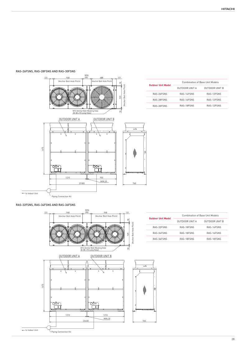
RAS-26FSNS, RAS-28FSNS AND RAS-30FSNS
RAS-32FSNS, RAS-34FSNS AND RAS-36FSNS
Outdoor Unit ModelCombination of Base Unit Models
OUTDOOR UNIT A OUTDOOR UNIT B
RAS-26FSNS RAS-14FSNS RAS-12FSNS
RAS-28FSNS RAS-16FSNS RAS-12FSNS
RAS-30FSNS RAS-18FSNS RAS-12FSNS
Outdoor Unit ModelCombination of Base Unit Models
OUTDOOR UNIT A OUTDOOR UNIT B
RAS-32FSNS RAS-18FSNS RAS-14FSNS
RAS-34FSNS RAS-18FSNS RAS-16FSNS
RAS-36FSNS RAS-18FSNS RAS-18FSNS
28
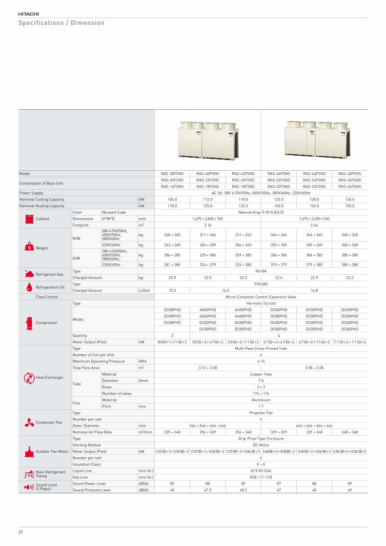
Model RAS-38FSNS RAS-40FSNS RAS-42FSNS RAS-44FSNS RAS-46FSNS RAS-48FSNS
Combination of Base Unit RAS-24FSNS RAS-22FSNS RAS-24FSNS RAS-22FSNS RAS-24FSNS RAS-24FSNS
RAS-14FSNS RAS-18FSNS RAS-18FSNS RAS-22FSNS RAS-22FSNS RAS-24FSNS
Power Supply AC 3φ, 380-415V/50Hz, 400V/50Hz, 380V/60Hz, 220V/60Hz
Nominal Cooling Capacity kW 106.0 112.0 118.0 122.0 128.0 136.0
Nominal Heating Capacity kW 118.0 125.0 132.0 140.0 145.0 150.0
Cabinet
Color Munsell Code Natural Gray (1.0Y 8.5/0.5)
Dimensions H*W*D mm 1,675 × 2,830 × 765 1,675 × 3,220 × 765
Footprint m2 2.16 2.46
Weight
N/W
380-415V/50Hz, 400V/50Hz,380V/60Hz
kg 268 + 365 311 + 364 311 + 365 364 + 364 364 + 365 365 + 365
220V/60Hz kg 263 + 360 306 + 359 306 + 360 359 + 359 359 + 360 360 + 360
G/W
380-415V/50Hz, 400V/50Hz,380V/60Hz,
kg 286 + 385 329 + 384 329 + 385 384 + 384 384 + 385 385 + 385
220V/60Hz kg 281 + 380 324 + 379 324 + 380 379 + 379 379 + 380 380 + 380
Refrigerant GasType R410A
Charged Amount kg 20.5 22.0 22.3 22.6 22.9 23.2
Refrigeration OilType FVC68D
Charged Amount L/Unit 15.3 16.3 16.8
Flow Control Micro-Computer Control Expansion Valve
Compressor
Type Hermetic (Scroll)
Model
DC80PHD AA50PHD AA50PHD DC80PHD DC80PHD DC80PHD
DC80PHD AA50PHD AA50PHD DC80PHD DC80PHD DC80PHD
DC80PHD DC80PHD DC80PHD DC80PHD DC80PHD DC80PHD
DC80PHD DC80PHD DC80PHD DC80PHD DC80PHD
Quantity 3 4
Motor Output (Pole) kW 8.0 (6) × 1 + 7.1 (6) × 2 5.0 (6) × 2 + 6.7 (6) × 2 5.0 (6) × 2 + 7.1 (6) × 2 6.7 (6) × 2 + 6.7 (6) × 2 6.7 (6) × 2 + 7.1 (6) × 2 7.1 (6) × 2 + 7.1 (6) × 2
Heat Exchanger
Type Multi-Pass Cross-Finned Tube
Number of Coil per Unit 4
Maximum Operating Pressure MPa 4.15
Total Face Area m2 3.12 + 3.58 3.58 + 3.58
Tube
Material Copper Tube
Diameter φmm 7.0
Rows 3 + 3
Number of tubes 174 + 174
FinnMaterial Aluminium
Pitch mm 1.7
Condenser Fan
Type Propeller Fan
Number per unit 4
Outer Diameter mm 544 + 544 + 644 + 644 644 + 644 + 644 + 644
Nominal Air Flow Rate m3/min. 239 + 348 256 + 329 256 + 348 329 + 329 329 + 348 348 + 348
Outdoor Fan Motor
Type Drip-Proof Type Enclosure
Starting Method DC Motor
Motor Output (Pole) kW 0.33 (8) × 2 + 0.56 (8) × 2 0.39 (8) × 2 + 0.48 (8) × 2 0.39 (8) × 2 + 0.56 (8) × 2 0.48 (8) × 2 + 0.48 (8) × 2 0.48 (8) × 2 + 0.56 (8) × 2 0.56 (8) × 2 + 0.56 (8) × 2
Number per unit 4
Insulation Class E + E
Main Refrigerant Piping
Liquid Line mm (in.) φ19.05 (3/4)
Gas Line mm (in.) φ38.1 (1-1/2)
Sound Level(2 Pipes)
Sound Power Level dB(A) 89 88 89 87 88 89
Sound Pressure Level dB(A) 68 67.5 68.5 67 68 69
Specifications / Dimension
29
Model RAS-38FSNS RAS-40FSNS RAS-42FSNS RAS-44FSNS RAS-46FSNS RAS-48FSNS
Combination of Base Unit RAS-24FSNS RAS-22FSNS RAS-24FSNS RAS-22FSNS RAS-24FSNS RAS-24FSNS
RAS-14FSNS RAS-18FSNS RAS-18FSNS RAS-22FSNS RAS-22FSNS RAS-24FSNS
Power Supply AC 3φ, 380-415V/50Hz, 400V/50Hz, 380V/60Hz, 220V/60Hz
Nominal Cooling Capacity kW 106.0 112.0 118.0 122.0 128.0 136.0
Nominal Heating Capacity kW 118.0 125.0 132.0 140.0 145.0 150.0
Cabinet
Color Munsell Code Natural Gray (1.0Y 8.5/0.5)
Dimensions H*W*D mm 1,675 × 2,830 × 765 1,675 × 3,220 × 765
Footprint m2 2.16 2.46
Weight
N/W
380-415V/50Hz, 400V/50Hz,380V/60Hz
kg 268 + 365 311 + 364 311 + 365 364 + 364 364 + 365 365 + 365
220V/60Hz kg 263 + 360 306 + 359 306 + 360 359 + 359 359 + 360 360 + 360
G/W
380-415V/50Hz, 400V/50Hz,380V/60Hz,
kg 286 + 385 329 + 384 329 + 385 384 + 384 384 + 385 385 + 385
220V/60Hz kg 281 + 380 324 + 379 324 + 380 379 + 379 379 + 380 380 + 380
Refrigerant GasType R410A
Charged Amount kg 20.5 22.0 22.3 22.6 22.9 23.2
Refrigeration OilType FVC68D
Charged Amount L/Unit 15.3 16.3 16.8
Flow Control Micro-Computer Control Expansion Valve
Compressor
Type Hermetic (Scroll)
Model
DC80PHD AA50PHD AA50PHD DC80PHD DC80PHD DC80PHD
DC80PHD AA50PHD AA50PHD DC80PHD DC80PHD DC80PHD
DC80PHD DC80PHD DC80PHD DC80PHD DC80PHD DC80PHD
DC80PHD DC80PHD DC80PHD DC80PHD DC80PHD
Quantity 3 4
Motor Output (Pole) kW 8.0 (6) × 1 + 7.1 (6) × 2 5.0 (6) × 2 + 6.7 (6) × 2 5.0 (6) × 2 + 7.1 (6) × 2 6.7 (6) × 2 + 6.7 (6) × 2 6.7 (6) × 2 + 7.1 (6) × 2 7.1 (6) × 2 + 7.1 (6) × 2
Heat Exchanger
Type Multi-Pass Cross-Finned Tube
Number of Coil per Unit 4
Maximum Operating Pressure MPa 4.15
Total Face Area m2 3.12 + 3.58 3.58 + 3.58
Tube
Material Copper Tube
Diameter φmm 7.0
Rows 3 + 3
Number of tubes 174 + 174
FinnMaterial Aluminium
Pitch mm 1.7
Condenser Fan
Type Propeller Fan
Number per unit 4
Outer Diameter mm 544 + 544 + 644 + 644 644 + 644 + 644 + 644
Nominal Air Flow Rate m3/min. 239 + 348 256 + 329 256 + 348 329 + 329 329 + 348 348 + 348
Outdoor Fan Motor
Type Drip-Proof Type Enclosure
Starting Method DC Motor
Motor Output (Pole) kW 0.33 (8) × 2 + 0.56 (8) × 2 0.39 (8) × 2 + 0.48 (8) × 2 0.39 (8) × 2 + 0.56 (8) × 2 0.48 (8) × 2 + 0.48 (8) × 2 0.48 (8) × 2 + 0.56 (8) × 2 0.56 (8) × 2 + 0.56 (8) × 2
Number per unit 4
Insulation Class E + E
Main Refrigerant Piping
Liquid Line mm (in.) φ19.05 (3/4)
Gas Line mm (in.) φ38.1 (1-1/2)
Sound Level(2 Pipes)
Sound Power Level dB(A) 89 88 89 87 88 89
Sound Pressure Level dB(A) 68 67.5 68.5 67 68 69
1210
(2830)
948 131MIN.282
M12 Anchor Bolt Mooting Hole
1872
918
765
131 669 669
1675
1600
MIN.20
OUTDOOR UNIT A OUTDOOR UNIT B
to Indoor UnitPiping Connection Kit
(Anchor Bolt Hole Pitch)
(Anc
hor
Bol
t Hol
e Pi
tch)
(Anchor Bolt Hole Pitch) (Anchor Bolt Hole Pitch)
DIMENSIONAL DRAWING OF HITACHI AIR-TO-AIR HEAT PUMP AIR CONDITIONER,SET-FREE
( OUTDOOR UNIT ,MODELS: RAS-38FSNS,RAS-40FSNS and RAS-42FSNS )
NOTES:
2.Check "Piping System" and "Dimensional Drawing"
for the piping connection kit and piping
connection size.
Arrange the outdoor units according to the
1.Make sure that the outdoor unit A is placed
on the indoor unit side.
�@�@�����������������C�`���a�D
3.Check the "Dimensional Drawing" for the
Dimension of piping outlet and Cable outlet.
4.This drawing shows that there is 20mm clearance
between the base units.
For outdoor unit snowproof hood,clearance is
the mounting pitch dimension for anchor bolts.
50mm or more.
�T�D�s�����@���������������������@�������������@���������@�@�¦�@�������������������@
RAS-38FSNS
OUTDOOR UNIT A OUTDOOR UNIT B
RAS-22FSNSRAS-40FSNS
RAS-24FSNSRAS-42FSNS
RAS-18FSNS
RAS-18FSNS
Outdoor Unit ModelCombination of Base Unit Models
RAS-24FSNS
RAS-18FSNS
RAS-22FSNS
Combination ofBase Unit Models
RAS-14FSNS
Drawing NO.ofDimension
317T158470
317T158470
317T158471
317T158471
RAS-24FSNS RAS-14FSNS
317T158474
317T158474
CAD
23 01 201723 01 201723 01 2017
Y.KAGEYAMAY.UCHINO
DIMENSIONALDRAWING NTS
C
D
E
F
B
A
4 531 2
C
D
B
A
E
F
4 531 2 6 7 8
PROJECTIONSCALETITLE
APPD.
REMARKS
CHKD.DWN. SH. REGD.REV.
- -
REVISIONSCHKD. APPD.REVD.DATE
- -
SYM.
- -
SHIMIZU DWG. NO.
This drawing is under license by Johnson Controls-Hitachi Air Conditioning Technology(Hong Kong)Limited
(10-38 ×15 Long Hole]
131 669 669MIN.282 669 669 131
1675
1600
(3220)MIN.20
1600
1872
918M12 Anchor Bolt Mooting Hole
765
(12-38 ×15 Long Hole]
OUTDOOR UNIT A OUTDOOR UNIT B
to Indoor UnitPiping Connection Kit
(Anchor Bolt Hole Pitch) (Anchor Bolt Hole Pitch)
(Anc
hor B
olt H
ole
Pitc
h)
(Anchor Bolt Hole Pitch) (Anchor Bolt Hole Pitch)
DIMENSIONAL DRAWING OF HITACHI AIR-TO-AIR HEAT PUMP AIR CONDITIONER,SET-FREE
( OUTDOOR UNIT ,MODELS: RAS-44FSNS,RAS-46FSNS and RAS-48FSNS )
NOTES:
2.Check "Piping System" and "Dimensional Drawing"
for the piping connection kit and piping
connection size.
Arrange the outdoor units according to the
1.Make sure that the outdoor unit A is placed
on the indoor unit side.
�@�@�����������������C�`���a�D
�T�D�s�����@���������������������@�������������@���������@�@�¦�@�������������������@
the mounting pitch dimension for anchor bolts.
3.Check the "Dimensional Drawing" for the
Dimension of piping outlet and Cable outlet.
4.This drawing shows that there is 20mm clearance
between the base units.
For outdoor unit snowproof hood,clearance is
50mm or more.
RAS-44FSNS
OUTDOOR UNIT A OUTDOOR UNIT B
RAS-22FSNS
RAS-24FSNSRAS-46FSNS
RAS-24FSNSRAS-48FSNS RAS-24FSNS
Outdoor Unit ModelCombination of Base Unit Models
RAS-24FSNS
Combination ofBase Unit Models
Drawing NO.ofDimension
317T158471 RAS-22FSNS
317T158471
RAS-22FSNS
RAS-22FSNS
317T158475
317T158475
CAD
23 01 201723 01 201723 01 2017
Y.KAGEYAMAY.UCHINO
DIMENSIONALDRAWING NTS
C
D
E
F
B
A
4 531 2
C
D
B
A
E
F
4 531 2 6 7 8
PROJECTIONSCALETITLE
APPD.
REMARKS
CHKD.DWN. SH. REGD.REV.
- -
REVISIONSCHKD. APPD.REVD.DATE
- -
SYM.
- -
SHIMIZU DWG. NO.
This drawing is under license by Johnson Controls-Hitachi Air Conditioning Technology(Hong Kong)Limited
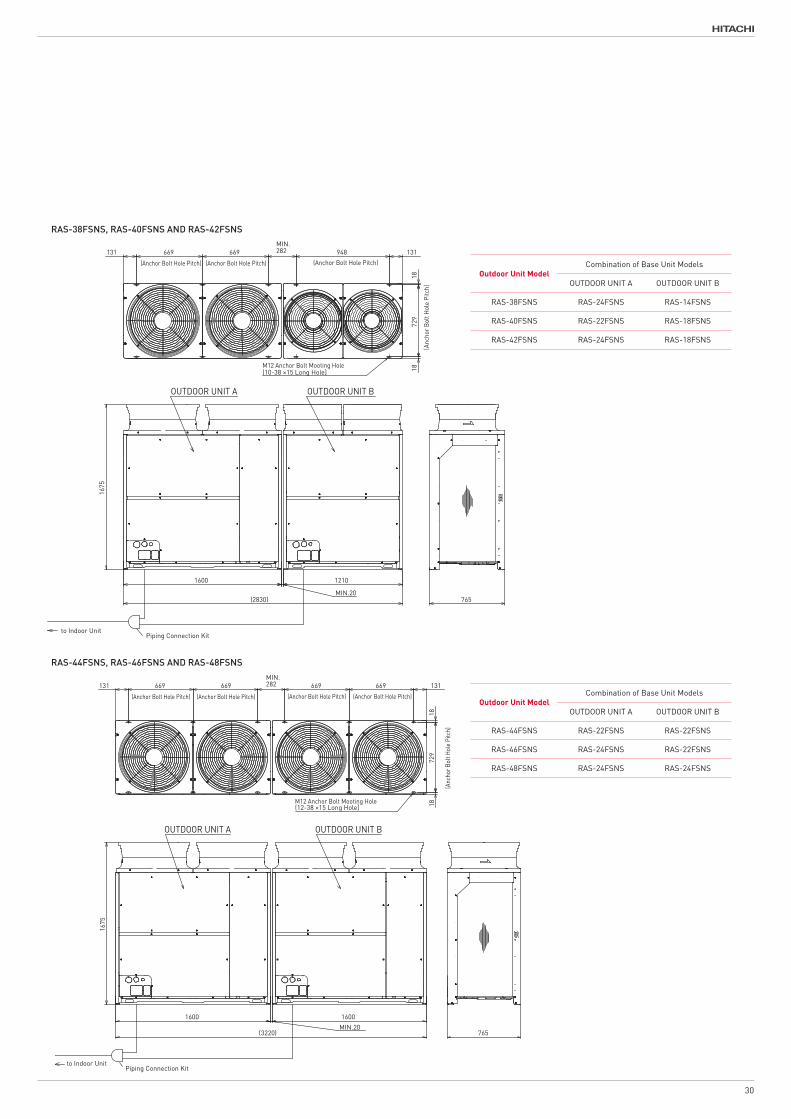
RAS-38FSNS, RAS-40FSNS AND RAS-42FSNS
RAS-44FSNS, RAS-46FSNS AND RAS-48FSNS
Outdoor Unit ModelCombination of Base Unit Models
OUTDOOR UNIT A OUTDOOR UNIT B
RAS-38FSNS RAS-24FSNS RAS-14FSNS
RAS-40FSNS RAS-22FSNS RAS-18FSNS
RAS-42FSNS RAS-24FSNS RAS-18FSNS
Outdoor Unit ModelCombination of Base Unit Models
OUTDOOR UNIT A OUTDOOR UNIT B
RAS-44FSNS RAS-22FSNS RAS-22FSNS
RAS-46FSNS RAS-24FSNS RAS-22FSNS
RAS-48FSNS RAS-24FSNS RAS-24FSNS
30
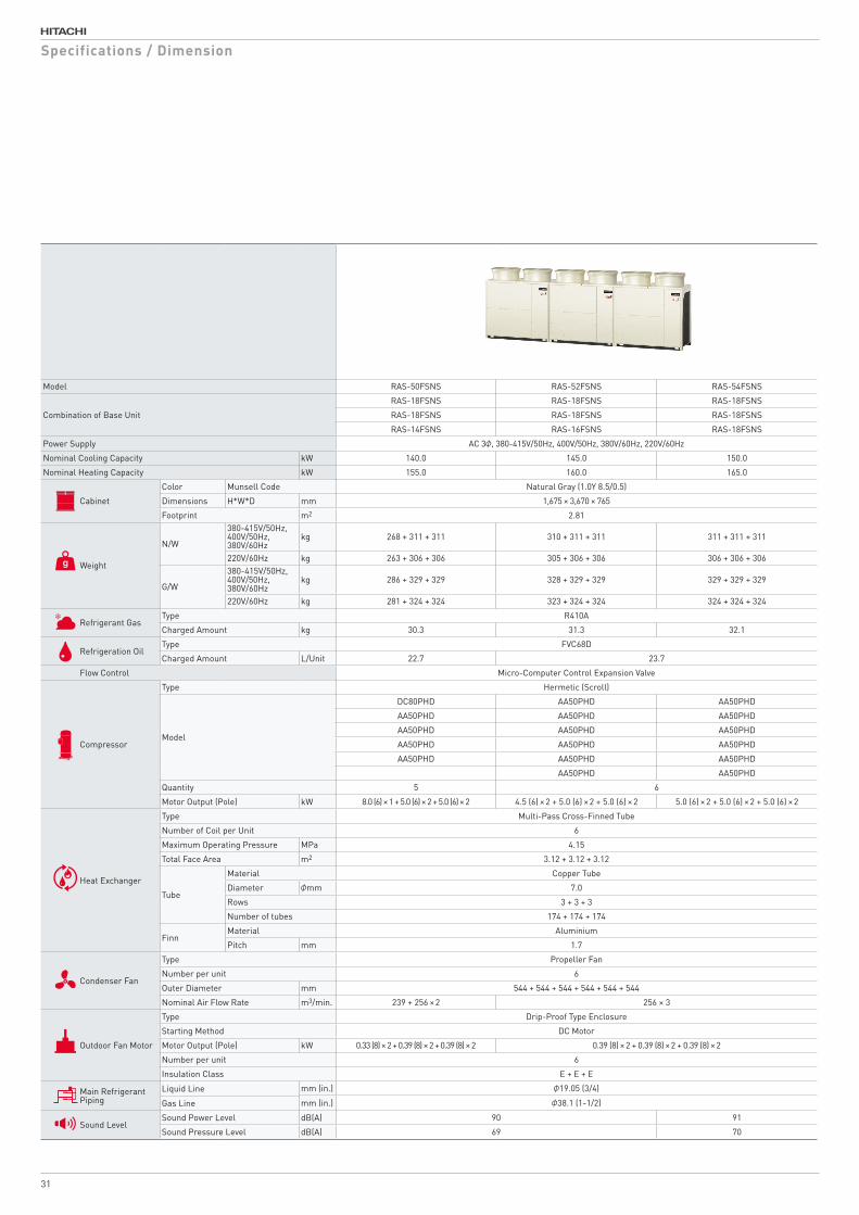
Model RAS-50FSNS RAS-52FSNS RAS-54FSNS
Combination of Base Unit
RAS-18FSNS RAS-18FSNS RAS-18FSNS
RAS-18FSNS RAS-18FSNS RAS-18FSNS
RAS-14FSNS RAS-16FSNS RAS-18FSNS
Power Supply AC 3φ, 380-415V/50Hz, 400V/50Hz, 380V/60Hz, 220V/60Hz
Nominal Cooling Capacity kW 140.0 145.0 150.0
Nominal Heating Capacity kW 155.0 160.0 165.0
Cabinet
Color Munsell Code Natural Gray (1.0Y 8.5/0.5)
Dimensions H*W*D mm 1,675 × 3,670 × 765
Footprint m2 2.81
Weight
N/W
380-415V/50Hz, 400V/50Hz, 380V/60Hz
kg 268 + 311 + 311 310 + 311 + 311 311 + 311 + 311
220V/60Hz kg 263 + 306 + 306 305 + 306 + 306 306 + 306 + 306
G/W
380-415V/50Hz, 400V/50Hz,380V/60Hz
kg 286 + 329 + 329 328 + 329 + 329 329 + 329 + 329
220V/60Hz kg 281 + 324 + 324 323 + 324 + 324 324 + 324 + 324
Refrigerant GasType R410A
Charged Amount kg 30.3 31.3 32.1
Refrigeration OilType FVC68D
Charged Amount L/Unit 22.7 23.7
Flow Control Micro-Computer Control Expansion Valve
Compressor
Type Hermetic (Scroll)
Model
DC80PHD AA50PHD AA50PHD
AA50PHD AA50PHD AA50PHD
AA50PHD AA50PHD AA50PHD
AA50PHD AA50PHD AA50PHD
AA50PHD AA50PHD AA50PHD
AA50PHD AA50PHD
Quantity 5 6
Motor Output (Pole) kW 8.0 (6) × 1 + 5.0 (6) × 2 + 5.0 (6) × 2 4.5 (6) × 2 + 5.0 (6) × 2 + 5.0 (6) × 2 5.0 (6) × 2 + 5.0 (6) × 2 + 5.0 (6) × 2
Heat Exchanger
Type Multi-Pass Cross-Finned Tube
Number of Coil per Unit 6
Maximum Operating Pressure MPa 4.15
Total Face Area m2 3.12 + 3.12 + 3.12
Tube
Material Copper Tube
Diameter φmm 7.0
Rows 3 + 3 + 3
Number of tubes 174 + 174 + 174
FinnMaterial Aluminium
Pitch mm 1.7
Condenser Fan
Type Propeller Fan
Number per unit 6
Outer Diameter mm 544 + 544 + 544 + 544 + 544 + 544
Nominal Air Flow Rate m3/min. 239 + 256 × 2 256 × 3
Outdoor Fan Motor
Type Drip-Proof Type Enclosure
Starting Method DC Motor
Motor Output (Pole) kW 0.33 (8) × 2 + 0.39 (8) × 2 + 0.39 (8) × 2 0.39 (8) × 2 + 0.39 (8) × 2 + 0.39 (8) × 2
Number per unit 6
Insulation Class E + E + E
Main Refrigerant Piping
Liquid Line mm (in.) φ19.05 (3/4)
mm (in.) φ38.1 (1-1/2)Gas Line
Sound LevelSound Power Level dB(A) 90 91
Sound Pressure Level dB(A) 69 70
Specifications / Dimension
31
765
1675
1210
MIN.20(3670)
1210
MIN.20
1210
948 948 131
M12 Anchor Bolt Mooting Hole
1872
918
131 948MIN.282
MIN.282
OUTDOOR UNIT A OUTDOOR UNIT B OUTDOOR UNIT C
Piping Connection Kit 1 Piping Connection Kit 2to Indoor Unit
(Anchor Bolt Hole Pitch)(Anchor Bolt Hole Pitch)(Anchor Bolt Hole Pitch)
(Anc
hor
Bol
t Hol
e P
itch)
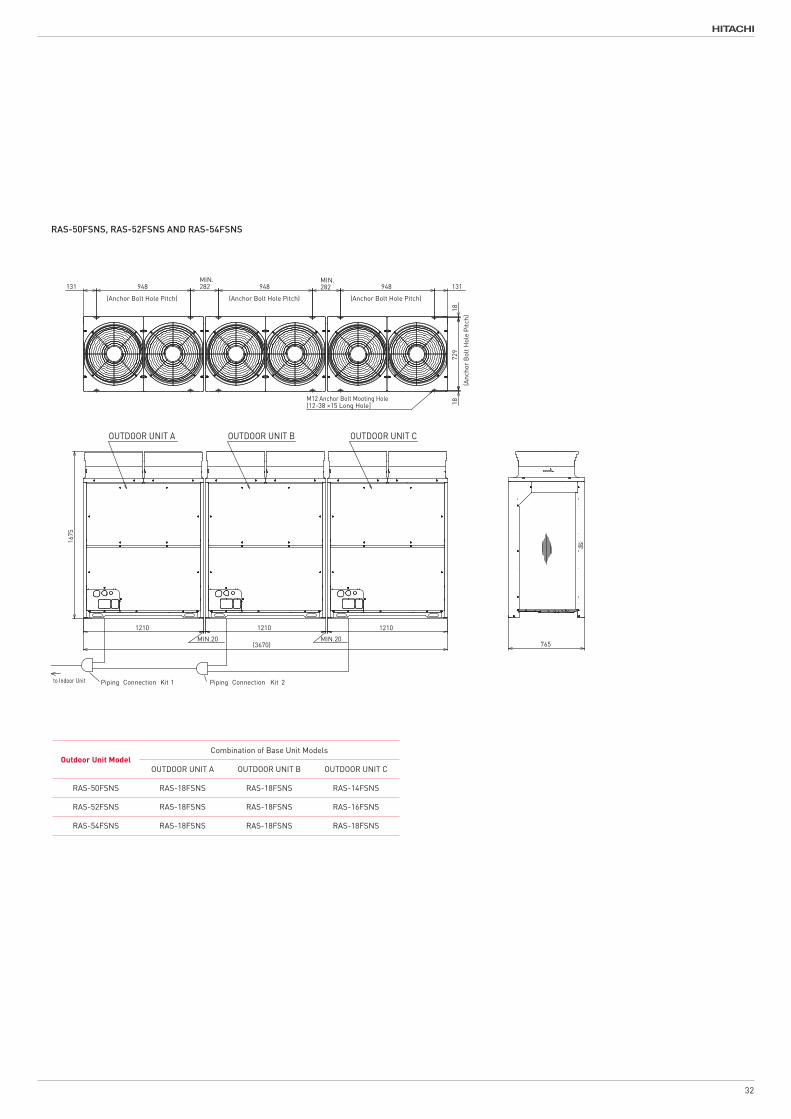
DIMENSIONAL DRAWING OF HITACHI AIR-TO-AIR HEAT PUMP AIR CONDITIONER,SET-FREE
( OUTDOOR UNIT ,MODELS: RAS-50FSNS,RAS-52FSNS and RAS-54FSNS )
�T�D�s�����@���������������������@�������������@���������@�@�¦�@�������������������@
bolts. the mounting pitch dimension for anchor
6.The entire modular length and anchor bolt positions are determined by the clearances.
NOTES:
Arrange the outdoor units according to the�@�@�����������������C�`���a���b�D
placed on the indoor unit side.1.Make sure that the outdoor unit A is
piping connection size. Drawing" for the piping connection kit and2.Check "Piping System" and "Dimensional
3.Check the "Dimensional Drawing" for the Dimension of piping outlet and Cable outlet.
clearance between the base units.4.This drawing shows that there is 20mm
is 50mm or more. For outdoor unit snowproof hood,clearance
RAS-50FSNS
OUTDOOR UNIT A OUTDOOR UNIT B
RAS-18FSNS
RAS-18FSNSRAS-52FSNS
RAS-18FSNSRAS-54FSNS
RAS-18FSNS
RAS-18FSNS
OUTDOOR UNIT C
RAS-16FSNS
RAS-18FSNS
RAS-18FSNS
Outdoor Unit ModelCombination of Base Unit Models
RAS-14FSNS
Combination ofBase Unit Models
Drawing NO.ofDimension
RAS-14FSNS
317T158470RAS-16FSNS
317T158470
RAS-18FSNS 317T158470
317T158476
317T158476
CAD
23 01 201723 01 201723 01 2017
Y.KAGEYAMAY.UCHINO
DIMENSIONALDRAWING NTS
C
D
E
F
B
A
4 531 2
C
D
B
A
E
F
4 531 2 6 7 8
PROJECTIONSCALETITLE
APPD.
REMARKS
CHKD.DWN. SH. REGD.REV.
- -
REVISIONSCHKD. APPD.REVD.DATE
- -
SYM.
- -
SHIMIZU DWG. NO.
This drawing is under license by Johnson Controls-Hitachi Air Conditioning Technology(Hong Kong)Limited
(12-38 ×15 Long Hole]
765
1675
1210
MIN.20(3670)
1210
MIN.20
1210
948 948 131
M12 Anchor Bolt Mooting Hole
1872
918
131 948MIN.282
MIN.282
OUTDOOR UNIT A OUTDOOR UNIT B OUTDOOR UNIT C
Piping Connection Kit 1 Piping Connection Kit 2to Indoor Unit
(Anchor Bolt Hole Pitch)(Anchor Bolt Hole Pitch)(Anchor Bolt Hole Pitch)
(Anc
hor
Bol
t Hol
e P
itch)
DIMENSIONAL DRAWING OF HITACHI AIR-TO-AIR HEAT PUMP AIR CONDITIONER,SET-FREE
( OUTDOOR UNIT ,MODELS: RAS-50FSNS,RAS-52FSNS and RAS-54FSNS )
�T�D�s�����@���������������������@�������������@���������@�@�¦�@�������������������@
bolts. the mounting pitch dimension for anchor
6.The entire modular length and anchor bolt positions are determined by the clearances.
NOTES:
Arrange the outdoor units according to the�@�@�����������������C�`���a���b�D
placed on the indoor unit side.1.Make sure that the outdoor unit A is
piping connection size. Drawing" for the piping connection kit and2.Check "Piping System" and "Dimensional
3.Check the "Dimensional Drawing" for the Dimension of piping outlet and Cable outlet.
clearance between the base units.4.This drawing shows that there is 20mm
is 50mm or more. For outdoor unit snowproof hood,clearance
RAS-50FSNS
OUTDOOR UNIT A OUTDOOR UNIT B
RAS-18FSNS
RAS-18FSNSRAS-52FSNS
RAS-18FSNSRAS-54FSNS
RAS-18FSNS
RAS-18FSNS
OUTDOOR UNIT C
RAS-16FSNS
RAS-18FSNS
RAS-18FSNS
Outdoor Unit ModelCombination of Base Unit Models
RAS-14FSNS
Combination ofBase Unit Models
Drawing NO.ofDimension
RAS-14FSNS
317T158470RAS-16FSNS
317T158470
RAS-18FSNS 317T158470
317T158476
317T158476
CAD
23 01 201723 01 201723 01 2017
Y.KAGEYAMAY.UCHINO
DIMENSIONALDRAWING NTS
C
D
E
F
B
A
4 531 2
C
D
B
A
E
F
4 531 2 6 7 8
PROJECTIONSCALETITLE
APPD.
REMARKS
CHKD.DWN. SH. REGD.REV.
- -
REVISIONSCHKD. APPD.REVD.DATE
- -
SYM.
- -
SHIMIZU DWG. NO.
This drawing is under license by Johnson Controls-Hitachi Air Conditioning Technology(Hong Kong)Limited
(12-38 ×15 Long Hole]
RAS-50FSNS, RAS-52FSNS AND RAS-54FSNS
Outdoor Unit ModelCombination of Base Unit Models
OUTDOOR UNIT A OUTDOOR UNIT B OUTDOOR UNIT C
RAS-50FSNS RAS-18FSNS RAS-18FSNS RAS-14FSNS
RAS-52FSNS RAS-18FSNS RAS-18FSNS RAS-16FSNS
RAS-54FSNS RAS-18FSNS RAS-18FSNS RAS-18FSNS
32
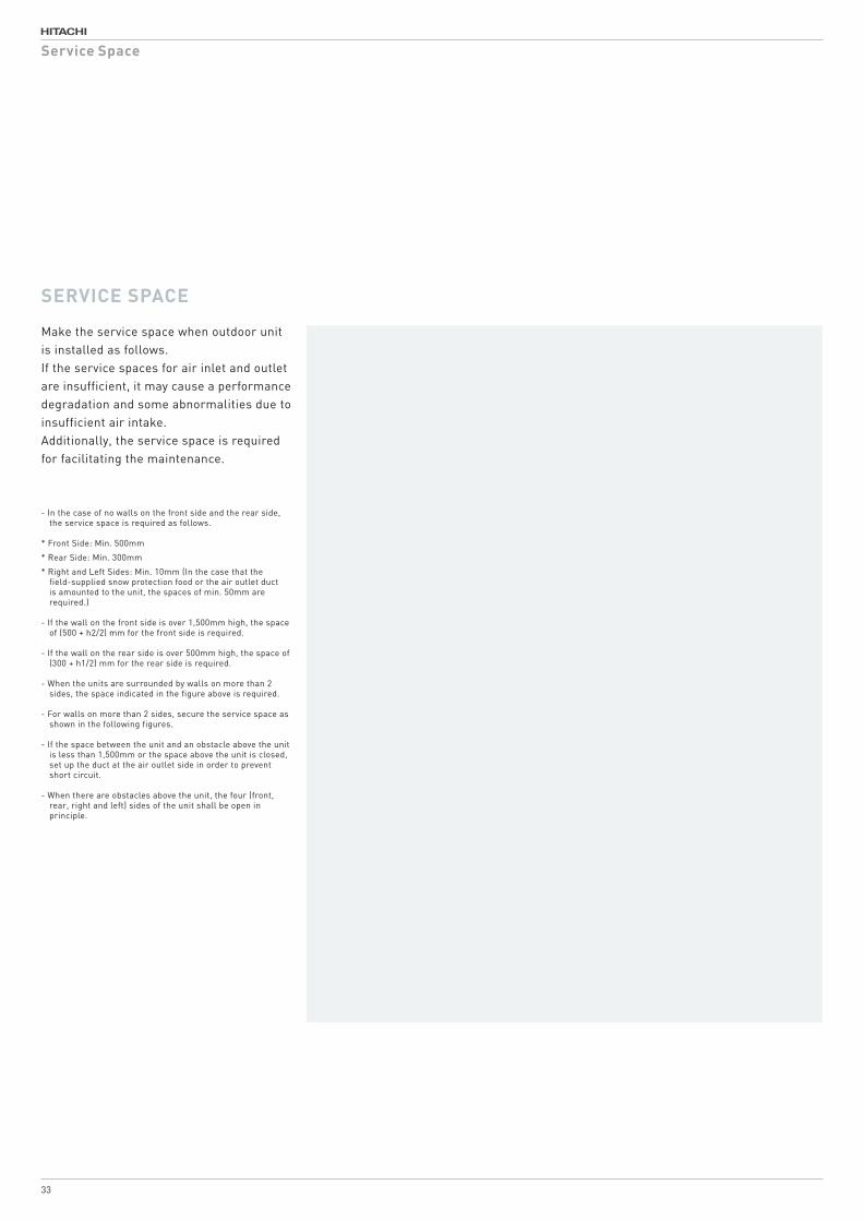
Make the service space when outdoor unit is installed as follows.If the service spaces for air inlet and outlet are insufficient, it may cause a performance degradation and some abnormalities due to insufficient air intake.Additionally, the service space is required for facilitating the maintenance.
- In the case of no walls on the front side and the rear side, the service space is required as follows.
* Front Side: Min. 500mm
* Rear Side: Min. 300mm
* Right and Left Sides: Min. 10mm (In the case that the field-supplied snow protection food or the air outlet duct is amounted to the unit, the spaces of min. 50mm are required.)
- If the wall on the front side is over 1,500mm high, the space of (500 + h2/2) mm for the front side is required.
- If the wall on the rear side is over 500mm high, the space of (300 + h1/2) mm for the rear side is required.
- When the units are surrounded by walls on more than 2 sides, the space indicated in the figure above is required.
- For walls on more than 2 sides, secure the service space as shown in the following figures.
- If the space between the unit and an obstacle above the unit is less than 1,500mm or the space above the unit is closed, set up the duct at the air outlet side in order to prevent short circuit.
- When there are obstacles above the unit, the four (front, rear, right and left) sides of the unit shall be open in principle.
SERVICE SPACE
P5417001 19
Min
.
1500
Min. 500 + h2/2 Min. 300 + h1/2
1500
h2
h150
0
765
(Unit: mm)
Vent Hole
FrontSide
RearSide
< Side View >
Service Space
33
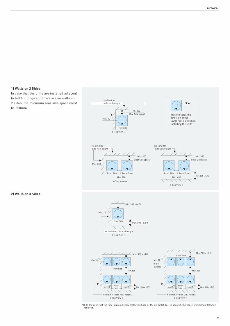
1) Walls on 2 SidesIn case that the units are installed adjacent to tall buildings and there are no walls on 2 sides, the minimum rear side space must be 300mm.
2) Walls on 3 Sides
• SINGLE INSTALLATION
• SINGLE INSTALLATION
• MULTIPLE / SERIAL INSTALLATION
• MULTIPLE / SERIAL INSTALLATION [ INSTALLATION IN THE SAME DIRECTION ] [ REAR TO REAR INSTALLATION ]
20 P5417001
Min. 300 + h1/2
Min.10 *1)
Min.20*1) Min.20*1)Min.20*1) Min.20*1)
No limit for side wall height.No limit for side wall height.
Min. 500 + h2/2 Min. 500 + h2/2
Min. 500 Min. 900
Min. 500 + h2/2
Min.10 *1)
(Side Space)
FrontSide
FrontSide
Min. 300 + h1/2
Min. 10 *1)
Min. 500 + h2/2
No limit for side wall height.
“ ”
Min. 300
Min. 10 *1)
No limit forside wall height.
Min. 300
Min. 400 Min. 400
Min. 200
Front Side Front Side Front Side Front Side
No limit forside wall height.
No limit forside wall height.
Min. 300
Min. 500 + h2/2<Top View>
<Top View>
<Top View> <Top View>
<Top View><Top View>
(Rear Side Space)
Front Side
Front Side
Front Side
Front Side
(Rear Side Space) (Rear Side Space)
This indicates the direction of the unit(Front Side) when installing the units.
*1): In the case that the field-supplied snow protection hood or the air outlet duct is adopted, the space of minimum 50mm is required.
34
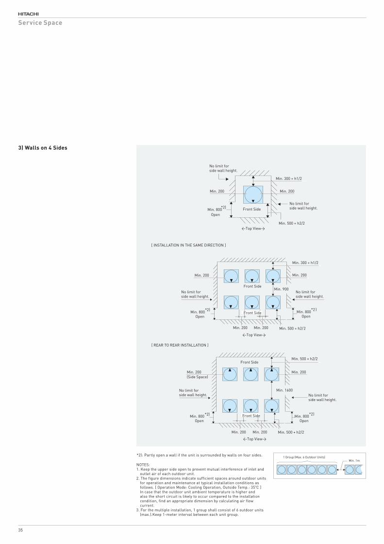
3) Walls on 4 Sides
• SINGLE INSTALLATION
• MULTIPLE / SERIAL INSTALLATION
P5417001 21
1 Group (Max. 6 Outdoor Units)Min. 1m
▼
▼
No limit for side wall height.
No limit for side wall height.
Min. 200Min. 200
Min. 500 + h2/2Min. 200Min. 200
Min. 900
Min. 800*2)
OpenMin. 800*2 )
Open
Min. 300 + h1/2
▼
Min. 200 Min. 200
Min. 800*2)
OpenFront Side
Front Side
Front Side
No limit for side wall height.
No limit for side wall height.
Min. 300 + h1/2
Min. 500 + h2/2
▼
▼ ▼ ▼
No limit for side wall height. No limit for
side wall height.
Min. 200
Min. 200Min. 200 Min. 500 + h2/2
Front Side
Min. 1600
Min. 200
Min. 800*2)
OpenMin. 800*2)
Open
(Side Space)
Min. 500 + h2/2
<Top View>
<Top View>
<Top View>
Front Side
NOTES:1. Keep the upper side open to prevent mutual interference of inlet and
outlet air of each outdoor unit.2. The figure dimensions indicate sufficient spaces around outdoor units
for operation and maintenance at typical installation conditions as follows. [ Operation Mode: Cooling Operation, Outside Temp.: 35oC ]
In case that the outdoor unit ambient temperature is higher and also the short circuit is likely to occur compared to the installation condition, find an appropriate dimension by calculating air flow current.
3. For the multiple installation, 1 group shall consist of 6 outdoor units (max.).Keep 1-meter interval between each unit group.
*2): Partly open a wall if the unit is surrounded by walls on four sides.
[ INSTALLATION IN THE SAME DIRECTION ]
[ REAR TO REAR INSTALLATION ]
Service Space
35