Embed Size (px)
Citation preview
SPECIFICATIONS
September 27, 2016 – Bid Set
CITY HALL SUITE 100 & 102 RENOVATIONS
Richmond City Hall Renovations Phase III
City of Richmond, Virginia
Architect’s Project No. 544850.1
CITY HALL SUITE 100 & 102 RENOVATIONS Richmond City Hall Renovations Phase III
City of Richmond, Virginia Architect’s Project No. 544850.1
TABLE OF CONTENTS 001100 - 1
TABLE OF CONTENTS
(Refer to “Project Book” under separate cover for additional requirements)
SPECIFICATIONS
DIVISION 1 - GENERAL REQUIREMENTS
011000 Summary 012500 Substitution Procedures 012600 Contract Modification Procedures 012900 Payment Procedures 013100 Project Management and Coordination 013200 Construction Progress Documentation 013300 Submittal Procedures 014000 Quality Requirements 014200 References 015000 Temporary Facilities and Controls 016000 Product Requirements 017300 Execution 017419 Construction Waste Management and Disposal 017700 Closeout Procedures 017823 Operation and Maintenance Data 017839 Project Record Documents 017900 Demonstration and Training 018119 Indoor Air Quality Requirements
DIVISION 2- EXISTING CONDITIONS
024119 Selective Structure Demolition
DIVISION 3 – CONCRETE
(Section Not Used)
DIVISION 4 - MASONRY
(Section Not Used)
DIVISION 5 - METALS
054000 Cold Formed Steel Framing
DIVISION 6 - WOOD PLASTICS AND COMPOSITES
061000 Rough Carpentry 064023 Interior Architectural Woodwork
DIVISION 7 - THERMAL AND MOISTURE PROTECTION
079200 Joint Sealants
CITY HALL SUITE 100 & 102 RENOVATIONS Richmond City Hall Renovations Phase III
City of Richmond, Virginia Architect’s Project No. 544850.1
TABLE OF CONTENTS 001100 - 2
DIVISION 8 - OPENINGS
081113 Steel Doors and Frames 081416 Flush Wood Doors 083113 Access Doors and Frames 087100 Door Hardware 088000 Glazing
DIVISION 9 - FINISHES
092216 Cold Formed Steel Framing - Non-Structural 092900 Gypsum Board 095113 Acoustical Panel Ceilings 096513 Resilient Base and Accessories 096519 Resilient Floor Tile 096813 Tile Carpeting 099100 Painting 099400 Decorative Finishes
DIVISION 10 - SPECIALTIES
104400 Fire-Protection Specialties
DIVISION 11 - EQUIPMENT
(Section Not Used)
DIVISION 12 - FURNISHINGS
(Section Not Used)
DIVISION 13 - SPECIAL CONSTRUCTION
(Section Not Used)
DIVISION 14 - CONVEYING SYSTEMS
(Section Not Used)
DIVISION 21 - FIRE SUPPRESSION
210500 Common Work Results for Fire-Suppression 210529 Hangers and Supports for Fire Suppression Piping 211000 Water-Based Fire-Suppression Systems
DIVISION 22 - PLUMBING
220500 Common Work Results for Plumbing 220517 Sleeves and Sleeve Seals for Plumbing Piping 220523 General-Duty Valves for Plumbing Piping 220529 Hangers and Supports for Plumbing Piping and Equipment 220553 Identification for Plumbing Piping and Equipment 220700 Plumbing Insulation 221116 Domestic Water Piping
CITY HALL SUITE 100 & 102 RENOVATIONS Richmond City Hall Renovations Phase III
City of Richmond, Virginia Architect’s Project No. 544850.1
TABLE OF CONTENTS 001100 - 3
221316 Sanitary Waste and Vent Piping 221319 Sanitary Waste Piping Specialties 224000 Plumbing Fixtures
DIVISION 23 - MECHANICAL
230500 Common Work Results for HVAC 230517 Sleeves and Sleeve Seals for HVAC Piping 230519 Meters and Gages for HVAC Piping 230523 General-Duty Valves for HVAC Piping 230529 Hangers and Supports for HVAC Piping and Equipment 230548 Vibration Control for HVAC 230553 Identification for HVAC Piping and Equipment 230593 Testing, Adjusting and Balancing 230700 HVAC Insulation 230900 Building Automation System 230993 Sequence of Control 232113 Hydronic Piping 233113 Metal Ducts 233300 Air Duct Accessories 233600 Air Terminal Units 233713 Diffusers, Registers, and Grilles
DIVISION 25 - INTEGRATED AUTOMATION
(Section Not Used)
DIVISION 26 - ELECTRICAL
260519 Conductors and Cables 260526 Grounding and Bonding 260529 Hangers and Supports for Electrical 260533 Raceways and Boxes 260544 Sleeves and Seals for Electrical Raceways and Cabling 260553 Electrical Identification 260573.16 Overcurrent Protective Device Coordination 260923 Lighting Control 262726 Wiring Devices 265119 LED Interior Lighting
DIVISION 27 - COMMUNICATIONS
270528 Pathways for Technology and Audio/Visual
DIVISIONS 28 - ELECTRONIC SAFETY AND SECURITY
(Section Not Used)
DIVISION 31 - EARTHWORK
(Section Not Used)
CITY HALL SUITE 100 & 102 RENOVATIONS Richmond City Hall Renovations Phase III
City of Richmond, Virginia Architect’s Project No. 544850.1
TABLE OF CONTENTS 001100 - 4
DIVISION 32 – EXTERIOR IMPROVEMENTS
(Section Not Used)
DIVISION 33 - UTILITIES
(Section Not Used)
DIVISION 34 - TRANSPORTATION
(Section Not Used)
END OF TABLE OF CONTENTS
CITY HALL SUITE 100 & 102 RENOVATIONS
Richmond City Hall Renovations Phase III
City of Richmond, Virginia
Architect’s Project No. 544850.1�
SUMMARY 011000 - 1
SECTION 011000 - SUMMARY
PART 1 - GENERAL
1.1 RELATED DOCUMENTS
A. Provisions of the Contract and of the Contract Documents apply to this Section.
1.2 SUMMARY
A. Section Includes:
1. Project information.
2. Work covered by Contract Documents.
3. Phased construction.
4. Work by Owner.
5. Work under separate contracts.
6. Future work.
7. Purchase contracts.
8. Owner-furnished products.
9. Contractor-furnished, Owner-installed products.
10. Access to site.
11. Coordination with occupants.
12. Work restrictions.
13. Miscellaneous provisions.
B. Related Requirements:
1. Section 015000 “Temporary Facilities and Controls” for limitations and procedures
governing temporary use of Owner's facilities.
1.3 PROJECT INFORMATION
A. Project Identification: City Hall Suite 100 & 102 Renovations, Richmond City Hall Renovations
Phase III.
1. Project Location: Richmond City Hall, 900 E. Broad St., Richmond, VA 23219.
2. Architect’s Project No. 544850.1
B. Owner: City of Richmond, Virginia.
1. Owner's Representative: Jennifer Breuninger.
C. Architect: Moseley Architects of Richmond, Virginia.
D. Architect's Consultants: The Architect has retained the following design professionals who have
prepared designated portions of the Contract Documents:
1. Mechanical, Plumbing, Electrical, and Fire Protection Engineering: Lu + Smith
Engineers.
1.4 WORK COVERED BY CONTRACT DOCUMENTS
A. The Work of Project is defined by the Contract Documents and includes the following:
CITY HALL SUITE 100 & 102 RENOVATIONS
Richmond City Hall Renovations Phase III
City of Richmond, Virginia
Architect’s Project No. 544850.1�
SUMMARY 011000 - 2
1. Renovations generally include selective demolition of interior office space; interior
gypsum board panel partitions, interior finishes, casework, mechanical, electrical, and
plumbing and fire protection work. The Work also includes hazardous materials
abatement, this work will be performed under separate cover.
B. Type of Contract:
1. Project will be constructed under a single prime contract.
C. Use of Professional Seals on Bidding, Procurement, and Contract Documents: or the purposes
of this paragraph, the term “Regulant” refers to the individual who signs and seals parts of the
Contract Documents (e.g. the Drawings and Specifications). Certain information has been
excerpted verbatim from a source or sources (e.g., UL Assemblies, SMACNA details, IBC code
text) which was considered or used by Regulant in preparing parts of the Contract Documents,
as follows:
1. The excerpted information was neither prepared under the direct control nor personal
supervision nor created by the Regulant, as it was prepared by the source and owner of
the excerpted information.
2. For purposes of bidding, procuring, and performance of the Work, and in any event of
conflicts or ambiguities between the excerpted information in the Contract Documents
and the requirements of applicable codes and standards, provide the better quality or
greater quantity of Work which, at a minimum, complies with the requirements of the
applicable codes and standards.
3. Advise Architect immediately upon becoming aware of requirements of the Work which
are not consistent with the requirements of the excerpted information.
4. Attribution is acknowledged for information obtained and included herein verbatim from
other source or sources.
5. Regulant has taken into consideration and used certain excerpted information from other
sources which are applicable to the Contract Documents, and the Regulant indicates by
it's seal that it is assuming responsibility for its services in use and application of the
excerpted information to the requirements of Work, but not for the excerpted information
itself which was prepared by others. Regulant does not indicate by its seal that it is
responsible for use or application of other information in such source or sources which
was not included herein.
1.5 PHASED CONSTRUCTION
A. The Work shall be conducted in three phases as indicated on the Drawings, with each phase
substantially complete before beginning subsequent phases:
1. Phase One: This phase shall commence within seven (7) days after the Notice to Proceed
and be substantially complete and ready for occupancy by date stated in the (City of
Richmond) Project Book.
2. Phase Two: This phase shall commence upon achieving Substantial Completion of Phase
One and shall be Substantially Complete and ready for occupancy by date stated in the
(City of Richmond) Project Book.
3. Phase Three: This phase shall commence upon achieving Substantial Completion of
Phase Two and shall be Substantially Complete and ready for occupancy by date stated in
the (City of Richmond) Project Book.
CITY HALL SUITE 100 & 102 RENOVATIONS
Richmond City Hall Renovations Phase III
City of Richmond, Virginia
Architect’s Project No. 544850.1�
SUMMARY 011000 - 3
B. Before commencing Work of each phase, submit an updated copy of Contractor's construction
schedule showing the sequence, commencement and completion dates, and move-out and -in
dates of Owner's personnel for all phases of the Work. Allow a minimum of three days between
each phase for the Owner to move into previously completed Phase and to move out of the work
area for the next Phase of work.
1.6 WORK BY OWNER
A. General: Cooperate fully with Owner and with separate contractors so work may be carried out
smoothly, without interfering with or delaying work under this Contract or work by Owner.
Coordinate the Work of this Contract with work performed by Owner.
B. Concurrent Work: Owner or their Subcontractor will perform the following construction
operations at Project site. Those operations will be conducted simultaneously with work under
this Contract and include but are not limited to the following:
1. Communications cabling and equipment installation.
2. Security and access control systems
3. HVAC Controls
4. Interior Signage
5. Furnishings
1.7 ACCESS TO SITE
A. General: Contractor shall have limited use of Project site for construction operations as
indicated by requirements of this Section.
B. Use of Site: Limit use of Project site to areas within the Contract limits indicated. Do not disturb
portions of Project site beyond areas in which the Work is indicated. Refer to Special
Conditions of the Contract for additional requirements.
1. Limits: Confine construction operations to the work areas indicated on the Drawings.
2. Driveways, Walkways and Entrances: Keep driveways parking garage, loading areas, and
entrances serving premises clear and available to Owner, Owner's employees, and
emergency vehicles at all times. Do not use these areas for parking or storage of
materials.
a. Schedule deliveries to minimize use of driveways and entrances by construction
operations.
b. Schedule deliveries to minimize space and time requirements for storage of
materials and equipment on-site.
C. Condition of Existing Building: Maintain portions of existing building affected by construction
operations in a weathertight condition throughout construction period. Repair damage caused by
construction operations.
1.8 COORDINATION WITH OCCUPANTS
A. Full Owner Occupancy: Owner will occupy site and existing building during entire construction
period. Cooperate fully with Owner during construction operations to minimize conflicts and
facilitate full Owner usage. Perform the Work so as not to interfere with Owner's day-to-day
operations. Maintain existing exits available for egress at all times unless otherwise indicated.
CITY HALL SUITE 100 & 102 RENOVATIONS
Richmond City Hall Renovations Phase III
City of Richmond, Virginia
Architect’s Project No. 544850.1�
SUMMARY 011000 - 4
1. Maintain access to existing walkways, corridors, Owner occupied areas, and other
adjacent occupied or used facilities. Do not close or obstruct walkways, corridors, or
other occupied or used facilities without written permission from Owner and approval of
authorities having jurisdiction.
2. Notify Owner not less than 7 days in advance of activities that will affect Owner's
operations.
B. Owner Limited Occupancy of Completed Areas of Construction: Owner reserves the right to
occupy and to place and install equipment in completed portions of the Work, prior to
Substantial Completion of the Work, provided such occupancy does not interfere with
completion of the Work. Such placement of equipment and limited occupancy shall not
constitute acceptance of the total Work.
1. Architect will prepare a Certificate of Substantial Completion for each specific portion of
the Work to be occupied prior to Owner acceptance of the completed Work.
2. Obtain a Certificate of Occupancy from authorities having jurisdiction before limited
Owner occupancy.
3. Before limited Owner occupancy, mechanical and electrical systems shall be fully
operational, and required tests and inspections shall be successfully completed. On
occupancy, Owner will operate and maintain mechanical and electrical systems serving
occupied portions of Work.
4. On occupancy, Owner will assume responsibility for maintenance and custodial service
for occupied portions of Work.
1.9 WORK RESTRICTIONS
A. Work Restrictions, General: Comply with restrictions on construction operations.
1. Comply with limitations on use of public streets and with other requirements of
authorities having jurisdiction.
2. HVAC and other utility Work indicated to occur in the ceiling space at the floor level
below the first floor, is in an area that will be occupied throughout the duration of the
project.
a. Perform this work after hours and on weekends and coordinate this work with the
Owner not less than 3 days in advance.
b. The furnishings in this area will remain in place, the Contractor shall protect the
furniture and/or remove and reinstall as required to facilitate the Work.
c. All furnishings shall be returned to their original locations and condition to provide
the occupants of this area full access to their work areas not later than 7:00 AM the
next business day.
B. On-Site Work Hours: Comply with the requirements indicated in the (City of Richmond)
Project Book.
C. Existing Utility Interruptions: Do not interrupt utilities serving facilities occupied by Owner or
others unless permitted under the following conditions and then only after providing temporary
utility services according to requirements indicated:
1. Notify Owner not less than 3 days in advance of proposed utility interruptions.
2. Obtain Owner's written permission before proceeding with utility interruptions.
CITY HALL SUITE 100 & 102 RENOVATIONS
Richmond City Hall Renovations Phase III
City of Richmond, Virginia
Architect’s Project No. 544850.1�
SUMMARY 011000 - 5
D. Noise, Vibration, and Odors: Coordinate operations that may result in high levels of noise and
vibration, odors, or other disruption to Owner occupancy with Owner.
1. Core drilling or other noisy, disruptive activities shall occur between the hours of 8:00
PM to 11:00 PM Mondays; and 5:00 PM and 11:00 PM Tuesday through Friday and shall
be coordinated in advance with the Owner’s representative in order to avoid disruption to
the adjacent occupied areas, including floors above and below the work area.
2. Notify Owner not less than 3 days in advance of proposed disruptive operations.
3. Obtain Owner's written permission before proceeding with disruptive operations.
E. Nonsmoking Building: Smoking is not permitted within the building or within 25 feet (8 m) of
entrances, operable windows, or outdoor-air intakes.
F. Controlled Substances: Use of tobacco products and other controlled substances within the
existing building is not permitted.
G. Employee Identification: Owner will provide identification tags for Contractor personnel
working on Project site. Require personnel to use identification tags at all times.
1.10 MISCELLANEOUS PROVISIONS
A. Refer to Special Conditions of the Contract for additional requirements.
PART 2 - PRODUCTS (Not Used)
PART 3 - EXECUTION (Not Used)
END OF SECTION 011000
CITY HALL SUITE 100 & 102 RENOVATIONS Richmond City Hall Renovations Phase III
City of Richmond, Virginia Architect’s Project No. 544850.1
SUBSTITUTION PROCEDURES 012500 - 1
SECTION 012500 - SUBSTITUTION PROCEDURES
PART 1 - GENERAL
1.1 RELATED DOCUMENTS
A. Provisions of the Contract and Contract Documents apply to this Section.
1.2 DEFINITIONS
A. Substitutions: Changes in products, materials, equipment, and methods of construction from those required by the Contract Documents and proposed by Contractor. 1. Substitutions for Cause: Changes proposed by Contractor that are required due to
changed Project conditions, such as unavailability of product, regulatory changes, or unavailability of required warranty terms.
2. Substitutions for Convenience: Changes proposed by Contractor or Owner that are not required in order to meet other Project requirements but may offer advantage to Contractor or Owner.
1.3 SUBMITTALS
A. Substitution Requests: Contractor shall request and submit a “Substitution Request Form – After Receipt of Bids” for all substitutions to be considered after receipt of bids. 1. Substitution Request Form: Use the Architect’s form, which can be obtained from the
Architect at the time of the request. a. The form is an electronic Word document requiring the Contractor to fill in “data
fields.” b. A copy of the form is attached to the end of this Section for informational purposes
only. Use the electronic Word document only. 2. No substitutions will be considered unless submitted using the referenced “Substitution
Request Form – After Receipt of Bids.” 3. All substitutions must be submitted by the Contractor, and shall include the Contractor’s
certification and signature. a. Substitution requests submitted directly from subcontractors, sub-subcontractors,
manufacturers, vendors, installer, and suppliers will be rejected. 4. Failure to submit the form, or a fully completed form, shall result in the rejection of the
proposed substitution; and shall also include: a. Coordination information, including a list of changes or modifications needed to
other parts of the Work and to construction performed by Owner and separate contractors, which will be necessary to accommodate proposed substitution.
b. Detailed comparison of significant qualities of proposed substitution with those of the Work specified. Include annotated copy of applicable specification section. Significant qualities may include attributes such as performance, weight, size, durability, visual effect, sustainable design characteristics, warranties, and specific features and requirements indicated. Indicate deviations, if any, from the Work specified.
CITY HALL SUITE 100 & 102 RENOVATIONS Richmond City Hall Renovations Phase III
City of Richmond, Virginia Architect’s Project No. 544850.1
SUBSTITUTION PROCEDURES 012500 - 2
c. Product Data, including drawings and descriptions of products and fabrication and installation procedures.
d. Samples, where applicable or requested. e. Certificates and qualification data, where applicable or requested. f. List of similar installations for completed projects with project names and
addresses and names and addresses of architects and owners. g. Material test reports from a qualified testing agency indicating and interpreting test
results for compliance with requirements indicated. h. Research reports evidencing compliance with building code in effect for Project. i. Detailed comparison of Contractor's construction schedule using proposed
substitution with products specified for the Work, including effect on the overall Contract Time. If specified product or method of construction cannot be provided within the Contract Time, include letter from manufacturer, on manufacturer's letterhead, stating date of receipt of purchase order, lack of availability, or delays in delivery.
j. Cost information, including a proposal of change, if any, in the Contract Sum. k. Contractor's certification that proposed substitution complies with requirements in
the Contract Documents except as indicated in substitution request, is compatible with related materials, and is appropriate for applications indicated.
l. Contractor's waiver of rights to additional payment or time that may subsequently become necessary because of failure of proposed substitution to produce indicated results.
5. If the proposed substitution is found to be acceptable to the Architect, the request will be forwarded to the Owner for their approval.
6. If the Owner approves the substitution, it will then be included in a Change Order or Construction Change Directive.
7. Only substitutions included in Change Orders or Construction Change Directives shall be allowed to be included in the Work
8. Architect's Action: If necessary, Architect will request additional information or documentation for evaluation within seven days of receipt of a request for substitution. Architect will notify Contractor of acceptance or rejection of proposed. a. Forms of Acceptance: Change Order or Construction Change Directive only.
1.4 QUALITY ASSURANCE
A. Compatibility of Substitutions: Investigate and document compatibility of proposed substitution with related products and materials. Engage qualified testing agency to perform compatibility tests recommended by manufacturers.
1.5 PROCEDURES
A. Coordination: Modify or adjust affected work as necessary to integrate work of the approved substitutions.
CITY HALL SUITE 100 & 102 RENOVATIONS Richmond City Hall Renovations Phase III
City of Richmond, Virginia Architect’s Project No. 544850.1
SUBSTITUTION PROCEDURES 012500 - 3
PART 2 - PRODUCTS
2.1 SUBSTITUTIONS
A. Substitutions for Cause: Submit requests for substitution immediately upon discovery of need for change, but not later than 21 days prior to time required for preparation and review of related submittals. 1. Conditions: Architect will consider Contractor's request for substitution when all of the
following conditions are satisfied. If all of the following conditions are not satisfied, Architect will return requests without action, except to record noncompliance with these requirements: a. Requested substitution is consistent with the Contract Documents and will produce
indicated results. b. Substitution request is fully documented and properly submitted. c. Requested substitution will not adversely affect Contractor's construction schedule. d. Requested substitution has received necessary approvals of authorities having
jurisdiction. e. Requested substitution is compatible with other portions of the Work. f. Requested substitution has been coordinated with other portions of the Work. g. Requested substitution provides specified warranty. h. If requested substitution involves more than one contractor, requested substitution
has been coordinated with other portions of the Work, is uniform and consistent, is compatible with other products, and is acceptable to all contractors involved.
B. Substitutions for Convenience: Not allowed, unless otherwise indicated.
C. Substitutions for Convenience: Architect will consider requests for substitution if received within 15 days after Award of Construction Contract. Requests received after that time may be considered or rejected at discretion of Architect. 1. Conditions: Architect will consider Contractor's request for substitution when all of the
following conditions are satisfied. If all of the following conditions are not satisfied, Architect will return requests without action, except to record noncompliance with these requirements: a. Requested substitution offers Owner a substantial advantage in cost, time, energy
conservation, or other considerations, after deducting additional responsibilities Owner must assume. 1) Owner's additional responsibilities may include compensation to Architect
for redesign and evaluation services, increased cost of other construction by Owner, and similar considerations.
b. Requested substitution does not require extensive revisions to the Contract Documents.
c. Requested substitution is consistent with the Contract Documents and will produce indicated results.
d. Substitution request is fully documented and properly submitted. e. Requested substitution will not adversely affect Contractor's construction schedule. f. Requested substitution has received necessary approvals of authorities having
jurisdiction.
CITY HALL SUITE 100 & 102 RENOVATIONS Richmond City Hall Renovations Phase III
City of Richmond, Virginia Architect’s Project No. 544850.1
SUBSTITUTION PROCEDURES 012500 - 4
g. Requested substitution is compatible with other portions of the Work. h. Requested substitution has been coordinated with other portions of the Work. i. Requested substitution provides specified warranty. j. If requested substitution involves more than one contractor, requested substitution
has been coordinated with other portions of the Work, is uniform and consistent, is compatible with other products, and is acceptable to all contractors involved.
PART 3 - EXECUTION (Not Used)
END OF SECTION 012500
CITY HALL SUITE 100 & 102 RENOVATIONS Richmond City Hall Renovations Phase III
City of Richmond, Virginia Architect’s Project No. 544850.1
CONTRACT MODIFICATION PROCEDURES 012600 - 1
SECTION 012600 - CONTRACT MODIFICATION PROCEDURES GENERAL
1.1 RELATED DOCUMENTS
A. Provisions of the Contract and of the Contract Documents apply to this Section.
1.2 SUMMARY
A. Section includes administrative and procedural requirements for handling and processing Contract modifications.
B. Related Requirements: 1. Section 012500 “Substitution Procedures” for administrative procedures for handling
requests for substitutions made after the Contract award.
1.3 MINOR CHANGES IN THE WORK
A. Architect will issue supplemental instructions authorizing minor changes in the Work, not involving adjustment to the Contract Sum or the Contract Time, as a Field Order on AIA Document G710, “Architect's Supplemental Instructions.”
1.4 PROPOSAL REQUESTS
A. Owner-Initiated Proposal Requests: Architect will issue a detailed description of proposed changes in the Work that may require adjustment to the Contract Sum or the Contract Time. If necessary, the description will include supplemental or revised Drawings and Specifications. 1. Work Change Proposal Requests issued by Architect are not instructions either to stop
work in progress or to execute the proposed change. 2. Within time specified in Proposal Request or 14 days, when not otherwise specified, after
receipt of Proposal Request, submit a quotation estimating cost adjustments to the Contract Sum and the Contract Time necessary to execute the change. a. Include a list of quantities of products required or eliminated and unit costs, with
total amount of purchases and credits to be made. If requested, furnish survey data to substantiate quantities.
b. Indicate applicable taxes, delivery charges, equipment rental, and amounts of trade discounts.
c. Include costs of labor and supervision directly attributable to the change. d. Include an updated Contractor's construction schedule that indicates the effect of
the change, including, but not limited to, changes in activity duration, start and finish times, and activity relationship. Use available total float before requesting an extension of the Contract Time.
e. Quotation Form: Use forms acceptable to Architect.
B. Contractor-Initiated Proposals: If latent or changed conditions require modifications to the Contract, Contractor may initiate a claim by submitting a request for a change to Architect. 1. Include a statement outlining reasons for the change and the effect of the change on the
Work. Provide a complete description of the proposed change. Indicate the effect of the proposed change on the Contract Sum and the Contract Time.
CITY HALL SUITE 100 & 102 RENOVATIONS Richmond City Hall Renovations Phase III
City of Richmond, Virginia Architect’s Project No. 544850.1
CONTRACT MODIFICATION PROCEDURES 012600 - 2
2. Include a list of quantities of products required or eliminated and unit costs, with total amount of purchases and credits to be made. If requested, furnish survey data to substantiate quantities.
3. Indicate applicable taxes, delivery charges, equipment rental, and amounts of trade discounts.
4. Include costs of labor and supervision directly attributable to the change. 5. Include an updated Contractor's construction schedule that indicates the effect of the
change, including, but not limited to, changes in activity duration, start and finish times, and activity relationship. Use available total float before requesting an extension of the Contract Time.
6. Comply with requirements in Section 012500 “Substitution Procedures” if the proposed change requires substitution of one product or system for product or system specified.
7. Proposal Request Form: Use form acceptable to Architect.
1.5 ADMINISTRATIVE CHANGE ORDERS
A. Allowance Adjustment: See Section 012100 “Allowances” for administrative procedures for preparation of Change Order Proposal for adjusting the Contract Sum to reflect actual costs of allowances.
1.6 CHANGE ORDER PROCEDURES
A. On Owner's approval of a Work Changes Proposal Request, Architect will issue a Change Order for signatures of Owner and Contractor on AIA Document G701.
1.7 CONSTRUCTION CHANGE DIRECTIVE
A. Construction Change Directive: Architect may issue a Construction Change Directive on AIA Document G714 or other form acceptable to the Owner. Construction Change Directive instructs Contractor to proceed with a change in the Work, for subsequent inclusion in a Change Order. 1. Construction Change Directive contains a complete description of change in the Work. It
also designates method to be followed to determine change in the Contract Sum or the Contract Time.
B. Documentation: Maintain detailed records on a time and material basis of work required by the Construction Change Directive. 1. After completion of change, submit an itemized account and supporting data necessary to
substantiate cost and time adjustments to the Contract.
PART 2 - PRODUCTS (Not Used)
PART 3 - EXECUTION (Not Used)
END OF SECTION 012600
CITY HALL SUITE 100 & 102 RENOVATIONS Richmond City Hall Renovations Phase III
City of Richmond, Virginia Architect’s Project No. 544850.1
PAYMENT PROCEDURES 012900 - 1
SECTION 012900 - PAYMENT PROCEDURES
PART 1 - GENERAL
1.1 RELATED DOCUMENTS
A. Provisions of the Contract and of the Contract Documents apply to this Section.
1.2 SUMMARY
A. This Section specifies administrative and procedural requirements necessary to prepare and process Applications for Payment.
B. Related Sections: 1. Division 01 Section “Allowances” for procedural requirements governing the handling
and processing of allowances. 2. Div 01 Section “Contract Modification Procedures” for administrative procedures for
handling changes to the Contract. 3. Division 01 Section “Construction Progress Documentation” for administrative
requirements governing the preparation and submittal of the Contractor's construction schedule.
4. Division 01 Section “Submittal Procedures” for administrative requirements governing the preparation and submittal of the submittal schedule.
1.3 DEFINITIONS
A. Schedule of Values: A statement furnished by Contractor allocating portions of the Contract Sum to various portions of the Work and used as the basis for reviewing Contractor's Applications for Payment.
1.4 SCHEDULE OF VALUES
A. Coordination: Coordinate preparation of the schedule of values with preparation of Contractor's construction schedule. 1. Correlate line items in the schedule of values with other required administrative forms
and schedules, including the following: a. Application for Payment forms with continuation sheets. b. Submittal schedule. c. Items required to be indicated as separate activities in Contractor's construction
schedule. 2. Submit the schedule of values to Architect at earliest possible date but no later than seven
days before the date scheduled for submittal of initial Applications for Payment. 3. Subschedules for Phased Work: Where the Work is separated into phases requiring
separately phased payments, provide subschedules showing values correlated with each phase of payment.
4. Subschedules for Separate Elements of Work: Where the Contractor's construction schedule defines separate elements of the Work, provide subschedules showing values correlated with each element.
CITY HALL SUITE 100 & 102 RENOVATIONS Richmond City Hall Renovations Phase III
City of Richmond, Virginia Architect’s Project No. 544850.1
PAYMENT PROCEDURES 012900 - 2
B. Format and Content: Use the Project Manual table of contents format (specification section numbers and names) to establish line items for the Schedule of Values. Provide at least one line item for each Specification Section. 1. Identification: Include the following Project identification on the schedule of values:
a. Project name and location. b. Name of Architect. c. Architect's project number. d. Contractor's name and address. e. Date of submittal.
2. Arrange the schedule of values in tabular form with separate columns to indicate the following for each item listed: a. Related Specification Section or Division. b. Description of the Work. c. Name of subcontractor. d. Name of manufacturer or fabricator. e. Name of supplier. f. Change Orders (numbers) that affect value. g. Dollar value of the following, as a percentage of the Contract Sum to nearest one-
hundredth percent, adjusted to total 100 percent. 1) Labor. 2) Materials. 3) Equipment.
3. Total shall equal the Contract Sum. 4. Provide a separate line item in the schedule of values for each part of the Work where
Applications for Payment may include materials or equipment purchased or fabricated and stored, but not yet installed. a. Differentiate between items stored on-site and items stored off-site. If required,
include evidence of insurance. 5. Provide separate line items in the schedule of values for initial cost of materials, for each
subsequent stage of completion, and for total installed value of that part of the Work. 6. Allowances: Provide a separate line item in the schedule of values for each allowance.
Show line-item value of unit-cost allowances, as a product of the unit cost, multiplied by measured quantity. Use information indicated in the Contract Documents to determine quantities.
7. Each item in the schedule of values and Applications for Payment shall be complete. Include total cost and proportionate share of general overhead and profit for each item. a. Temporary facilities and other major cost items that are not direct cost of actual
work-in-place may be shown either as separate line items in the schedule of values or distributed as general overhead expense, at Contractor's option.
8. Schedule Updating: Update and resubmit the schedule of values before the next Applications for Payment when Change Orders or Construction Change Directives result in a change in the Contract Sum.
CITY HALL SUITE 100 & 102 RENOVATIONS Richmond City Hall Renovations Phase III
City of Richmond, Virginia Architect’s Project No. 544850.1
PAYMENT PROCEDURES 012900 - 3
1.5 APPLICATIONS FOR PAYMENT
A. Each Application for Payment shall be consistent with previous applications and payments as certified by Architect and paid for by Owner. 1. Initial Application for Payment, Application for Payment at time of Substantial
Completion, and final Application for Payment involve additional requirements.
B. Payment Application Times: Contractor shall submit application for payment at regularly scheduled pay meetings as established at the Pre-Construction Conference. The period covered by each Application for Payment shall be clarified at the Pre-Construction Conference.
C. Application for Payment Forms: Use AIA Document G702 and AIA Document G703, or other form approved by the Owner, as form for Applications for Payment.
D. Application Preparation: Complete every entry on form. Notarize and execute by a person authorized to sign legal documents on behalf of Contractor. Architect will return incomplete applications without action. 1. Entries shall match data on the schedule of values and Contractor's construction schedule.
Use updated schedules if revisions were made. 2. Include amounts for work completed following previous Application for Payment,
whether or not payment has been received. Include only amounts for work completed at time of Application for Payment.
3. Include amounts of Change Orders and Construction Change Directives issued before last day of construction period covered by application.
4. Indicate separate amounts for work being carried out under Owner-requested project acceleration.
E. Stored Materials: Include in Application for Payment amounts applied for materials or equipment purchased or fabricated and stored, but not yet installed. Differentiate between items stored on-site and items stored off-site. 1. Provide certificate of insurance, evidence of transfer of title to Owner, and consent of
surety to payment, for stored materials. 2. Provide supporting documentation that verifies amount requested, such as paid invoices.
Match amount requested with amounts indicated on documentation; do not include overhead and profit on stored materials.
3. Provide summary documentation for stored materials indicating the following: a. Materials previously stored and included in previous Applications for Payment. b. Work completed for this Application utilizing previously stored materials. c. Additional materials stored with this Application. d. Total materials remaining stored, including materials with this Application.
F. Transmittal: Submit three signed and notarized original copies of each Application for Payment to Architect by a method ensuring receipt within 24 hours. One copy shall include waivers of lien and similar attachments if required. 1. Transmit each copy with a transmittal form listing attachments and recording appropriate
information about application.
G. Initial Application for Payment: Administrative actions and submittals that must precede or coincide with submittal of first Application for Payment include the following:
CITY HALL SUITE 100 & 102 RENOVATIONS Richmond City Hall Renovations Phase III
City of Richmond, Virginia Architect’s Project No. 544850.1
PAYMENT PROCEDURES 012900 - 4
1. List of subcontractors. 2. Schedule of values. 3. Contractor's construction schedule (preliminary if not final). 4. Combined Contractor's construction schedule (preliminary if not final) incorporating
Work of multiple contracts, with indication of acceptance of schedule by each Contractor. 5. Products list (preliminary if not final). 6. Schedule of unit prices. 7. Submittal schedule (preliminary if not final). 8. List of Contractor's staff assignments. 9. List of Contractor's principal consultants. 10. Copies of building permits. 11. Copies of authorizations and licenses from authorities having jurisdiction for
performance of the Work. 12. Initial progress report. 13. Report of preconstruction conference. 14. Certificates of insurance and insurance policies. 15. Performance and payment bonds. 16. Data needed to acquire Owner's insurance.
H. Application for Payment at Substantial Completion: After issuing the Certificate of Substantial Completion, submit an Application for Payment showing 100 percent completion for portion of the Work claimed as substantially complete. 1. Include documentation supporting claim that the Work is substantially complete and a
statement showing an accounting of changes to the Contract Sum. 2. This application shall reflect Certificates of Partial Substantial Completion issued
previously for Owner occupancy of designated portions of the Work.
I. Final Payment Application: Submit final Application for Payment with releases and supporting documentation not previously submitted and accepted, including, but not limited, to the following: 1. Evidence of completion of Project closeout requirements. 2. Insurance certificates for products and completed operations where required and proof
that taxes, fees, and similar obligations were paid. 3. Updated final statement, accounting for final changes to the Contract Sum. 4. AIA Document G706, “Contractor's Affidavit of Payment of Debts and Claims.” 5. AIA Document G706A, “Contractor's Affidavit of Release of Liens.” 6. AIA Document G707, “Consent of Surety to Final Payment.” 7. Evidence that claims have been settled. 8. Final meter readings for utilities, a measured record of stored fuel, and similar data as of
date of Substantial Completion or when Owner took possession of and assumed responsibility for corresponding elements of the Work.
9. Final liquidated damages settlement statement.
CITY HALL SUITE 100 & 102 RENOVATIONS Richmond City Hall Renovations Phase III
City of Richmond, Virginia Architect’s Project No. 544850.1
PAYMENT PROCEDURES 012900 - 5
PART 2 - PRODUCTS (Not Used)
PART 3 - EXECUTION (Not Used)
END OF SECTION 012900
CITY HALL SUITE 100 & 102 RENOVATIONS Richmond City Hall Renovations Phase III
City of Richmond, Virginia Architect’s Project No. 544850.1
PROJECT MANAGEMENT AND COORDINATION 013100 - 1
SECTION 013100 - PROJECT MANAGEMENT AND COORDINATION
PART 1 - GENERAL
1.1 RELATED DOCUMENTS
A. Provisions of the Contract and of the Contract Documents apply to this Section.
1.2 SUMMARY
A. This Section includes administrative provisions for coordinating construction operations on Project including, but not limited to, the following: 1. Coordination Drawings. 2. Administrative and supervisory personnel. 3. Project meetings. 4. Requests for Interpretation (RFIs).
B. Related Sections include the following: 1. Division 1 Section “Construction Progress Documentation” for preparing and submitting
Contractor's Construction Schedule. 2. Division 1 Section “Execution” for procedures for coordinating general installation
services. 3. Division 1 Section “Closeout Procedures” for coordinating closeout of the Contract.
1.3 DEFINITIONS
A. RFI: Request from Contractor seeking interpretation or clarification of the Contract Documents.
1.4 COORDINATION
A. Coordination: Coordinate construction operations included in different Sections of the Specifications to ensure efficient and orderly installation of each part of the Work. Coordinate construction operations, included in different Sections that depend on each other for proper installation, connection, and operation.
B. Prepare memoranda for distribution to each party involved, outlining special procedures required for coordination. Include such items as required notices, reports, and list of attendees at meetings. 1. Prepare similar memoranda for Owner and separate contractors if coordination of their
Work is required.
C. Administrative Procedures: Coordinate scheduling and timing of required administrative procedures with other construction activities and activities of other contractors to avoid conflicts and to ensure orderly progress of the Work. Such administrative activities include, but are not limited to, the following: 1. Preparation of Contractor's Construction Schedule. 2. Preparation of the Schedule of Values. 3. Installation and removal of temporary facilities and controls.
CITY HALL SUITE 100 & 102 RENOVATIONS Richmond City Hall Renovations Phase III
City of Richmond, Virginia Architect’s Project No. 544850.1
PROJECT MANAGEMENT AND COORDINATION 013100 - 2
4. Delivery and processing of submittals. 5. Progress meetings. 6. Preinstallation conferences. 7. Project closeout activities. 8. Startup and adjustment of systems. 9. Project closeout activities.
1.5 SUBMITTALS
A. Key Personnel Names: Prior to starting construction operations, submit a list of key personnel assignments, including superintendent and other personnel in attendance at Project site. Identify individuals and their duties and responsibilities; list addresses and telephone numbers, including home and office telephone numbers. Provide names, addresses, and telephone numbers of individuals assigned as standbys in the absence of individuals assigned to Project. 1. Post copies of list in Project meeting room, in temporary field office, and by each
temporary telephone. Keep list current at all times.
1.6 ABOVE-CEILING PRE-CONSTRUCTION CONFERENCE AND COORDINATION DRAWINGS
A. Coordination Drawings (Optional): Prior to the Above-Ceiling Pre-Construction Conference, prepare drawings where limited space availability necessitates maximum utilization of space for the proper and efficient installation of the components, materials, and systems (including, but may not be limited to: above finish ceilings; within chases and shafts; and within mechanical and electrical spaces). 1. Content: Project-specific information, drawn accurately to scale. Do not base
Coordination Drawings on reproductions of the Contract Documents or standard printed data. Include the following information, as applicable: a. Ensure components, materials, and systems are indicated where each are fully
functional, operational, accessible, and complete. b. Indicate relationships of components, materials, and systems with surrounding
construction. c. Indicate installation sequences to avoid conflicts d. Indicate dimensions shown on the Contract Drawings and make specific note of
dimensions that appear to be in conflict with submitted equipment and minimum clearance requirements. Provide alternate sketches to Architect for resolution of such conflicts. Minor dimension changes and difficult installations will not be considered changes to the Contract.
2. Sheet Size: At least 8-1/2 by 11 inches but no larger than 30 by 42 inches. 3. Number of Copies: Submit two opaque copies. Architect will return one copy.
a. Coordination Drawings will not be approved by the Architect and will be considered as “information only” and will be furnished to the Owner for filing.
b. Submit five copies where Coordination Drawings are required for operation and maintenance manuals. Architect will retain two copies; remainder will be returned. Mark up and retain one returned copy as a Project Record Drawing.
4. Refer to individual Sections for Coordination Drawing requirements for Work in those Sections.
CITY HALL SUITE 100 & 102 RENOVATIONS Richmond City Hall Renovations Phase III
City of Richmond, Virginia Architect’s Project No. 544850.1
PROJECT MANAGEMENT AND COORDINATION 013100 - 3
B. Above-Ceiling Pre-Construction Conference: Schedule and conduct with all affected parties present to review procedures for addressing potential conflicts, review of Coordination Drawings (if furnished) and obtain approval of each affected trade to ensure components, materials, and systems can be installed as intended prior to the Work being performed. 1. Identify Above-Ceiling Pre-Construction Conference on the Construction Schedule as a
“milestone” date. 2. Advise the Architect of potential conflicts identified in the Coordination Drawings (if
furnished) and Above-Ceiling Pre-Construction Conference. 3. Do not proceed with construction or installation of the components, materials, and
systems until potential conflicts identified have been resolved and affected parties have agreed to a remedy.
C. Remedies to address conflicts not identified in the Coordination Drawings (if furnished), Above-Ceiling Pre-Construction Conference, or otherwise addressed prior to construction or installation of the affected components, materials, and systems; or discovery of a non-workable situation without Coordination Drawings on file with the Owner will not be considered as a basis of delay, time extension, or additional cost to the Contract.
1.7 PROJECT MEETINGS
A. General: Schedule and conduct meetings and conferences at Project site, unless otherwise indicated. 1. Attendees: Inform participants and others involved, and individuals whose presence is
required, of date and time of each meeting. Notify Owner and Architect of scheduled meeting dates and times.
2. Agenda: The Architect will prepare the meeting agenda and distribute it to all invited attendees.
3. Minutes: The Architect will record significant discussions and agreements achieved. Within 7 days of the meeting the Architect will distribute the meeting minutes to the Owner, the Architect’s consultants, and to the Contractor for distribution to his personnel and attending major subcontractors, manufacturers, suppliers and other concerned parties.
B. Preconstruction Conference: Schedule a preconstruction conference before starting construction, at a time convenient to Owner and Architect, but no later than 15 days after execution of the Agreement. Hold the conference at Project site or another convenient location. The Architect shall conduct the meeting to review responsibilities and personnel assignments. 1. Attendees: Authorized representatives of Owner, Architect, and their consultants;
Contractor and its superintendent; major subcontractors; suppliers; and other concerned parties shall attend the conference. All participants at the conference shall be familiar with Project and authorized to conclude matters relating to the Work.
2. Agenda: Discuss items of significance that could affect progress, including the following: a. Tentative construction schedule. b. Phasing. c. Critical work sequencing and long-lead items. d. Designation of key personnel and their duties. e. Procedures for processing field decisions and Change Orders. f. Procedures for RFIs.
CITY HALL SUITE 100 & 102 RENOVATIONS Richmond City Hall Renovations Phase III
City of Richmond, Virginia Architect’s Project No. 544850.1
PROJECT MANAGEMENT AND COORDINATION 013100 - 4
g. Procedures for testing and inspecting. h. Procedures for processing Applications for Payment. i. Distribution of the Contract Documents. j. Submittal procedures. k. Coordination and submittal of color & finish related selections. l. Preparation of Record Documents. m. Use of the premises and existing building. n. Work restrictions. o. Owner's occupancy requirements. p. Responsibility for temporary facilities and controls. q. Construction waste management and recycling. r. Parking availability. s. Office, work, and storage areas. t. Equipment deliveries and priorities. u. First aid. v. Security. w. Progress cleaning. x. Working hours.
3. Minutes: Architect will record and Contractor will distribute meeting minutes. 4. Construction Indoor Air Quality (IAQ) Management Plan Development Session: (Refer
to Division 1 section “Indoor Air Quality Requirements.”)
C. Preinstallation Conferences: Conduct a preinstallation conference at Project site before each construction activity that requires coordination with other construction. 1. Attendees: Installer and representatives of manufacturers and fabricators involved in or
affected by the installation and its coordination or integration with other materials and installations that have preceded or will follow, shall attend the meeting. Advise Architect of scheduled meeting dates.
2. Contractor will record significant conference discussions, agreements, and disagreements, including required corrective measures and actions.
3. Reporting: Distribute minutes of the meeting to each party present and to parties who should have been present.
4. Do not proceed with installation if the conference cannot be successfully concluded. Initiate whatever actions are necessary to resolve impediments to performance of the Work and reconvene the conference at earliest feasible date.
D. Progress Meetings: The Architect shall conduct progress meetings at monthly intervals. Coordinate dates of meetings with preparation of payment requests. 1. Attendees: Representatives of the Owner, the Architect and the Contractor shall be
represented at each of these meetings. Design consultants, Subcontractors, suppliers, and other entities concerned with current progress or involved in planning, coordination, or performance of future activities may be invited to attend these meetings on an as needed basis to resolve specific issues. All participants at these meetings shall be familiar with Project and authorized to conclude matters relating to the Work.
2. Agenda: Review and correct or approve minutes of previous progress meeting. Review other items of significance that could affect progress. Include topics for discussion as appropriate to status of Project.
CITY HALL SUITE 100 & 102 RENOVATIONS Richmond City Hall Renovations Phase III
City of Richmond, Virginia Architect’s Project No. 544850.1
PROJECT MANAGEMENT AND COORDINATION 013100 - 5
a. Contractor's Construction Schedule: Review progress since the last meeting. Determine whether each activity is on time, ahead of schedule, or behind schedule, in relation to Contractor's Construction Schedule. Determine how construction behind schedule will be expedited; secure commitments from parties involved to do so. Discuss whether schedule revisions are required to ensure that current and subsequent activities will be completed within the Contract Time. 1) Review schedule for next period.
b. Review present and future needs of each entity present, including the following: 1) Interface requirements. 2) Sequence of operations. 3) Status of submittals. 4) Deliveries. 5) Off-site fabrication. 6) Access. 7) Site utilization. 8) Temporary facilities and controls. 9) Work hours. 10) Hazards and risks. 11) Progress cleaning. 12) Indoor Air Quality. 13) Quality and work standards. 14) Status of correction of deficient items. 15) Field observations. 16) RFIs. 17) Field Clarification. (FC) 18) Status of proposal requests. 19) Pending changes. (Potential Change Order – PCO) 20) Status of Change Orders. (CO) 21) Pending claims and disputes. 22) Documentation of information for payment requests.
3. Minutes: Architect will record and Contractor will distribute meeting minutes. 4. Reporting: Distribute minutes of the meeting to each party present and to parties who
should have been present. a. Schedule Updating: Revise Contractor's Construction Schedule after each progress
meeting where revisions to the schedule have been made or recognized. Issue revised schedule concurrently with the report of each meeting.
1.8 REQUESTS FOR INTERPRETATION (RFIs)
A. Procedure: Immediately on discovery of the need for interpretation of the Contract Documents, and if not possible to request interpretation at Project meeting, prepare and submit an RFI in the form specified. 1. RFIs shall originate with Contractor. RFIs submitted by entities other than Contractor
will be returned with no response. 2. Coordinate and submit RFIs in a prompt manner so as to avoid delays in Contractor's
work or work of subcontractors.
CITY HALL SUITE 100 & 102 RENOVATIONS Richmond City Hall Renovations Phase III
City of Richmond, Virginia Architect’s Project No. 544850.1
PROJECT MANAGEMENT AND COORDINATION 013100 - 6
3. RFIs that would be clearly answered by simply reading the Contract Documents and that are not open to reasonable misinterpretation there from may be deemed "frivolous" by the Architect. The cost in time and materials to respond to frivolous RFI's shall be the responsibility of the Contractor.
B. Content of the RFI: Include a detailed, legible description of item needing interpretation and the following: 1. Project name. 2. Date. 3. Name of Contractor. 4. Name of Architect. 5. RFI number, numbered sequentially. 6. Specification Section number and title and related paragraphs, as appropriate. 7. Drawing number and detail references, as appropriate. 8. Field dimensions and conditions, as appropriate. 9. Contractor's suggested solution(s). If Contractor's solution(s) impact the Contract Time
or the Contract Sum, Contractor shall state impact in the RFI. 10. Contractor's signature. 11. Attachments: Include drawings, descriptions, measurements, photos, Product Data, Shop
Drawings, and other information necessary to fully describe items needing interpretation. a. Supplementary drawings prepared by Contractor shall include dimensions,
thicknesses, structural grid references, and details of affected materials, assemblies, and attachments.
C. Architect's Action: Architect will review each RFI, determine action required, and return it. Allow seven working days for Architect's response for each RFI. RFIs received after 1:00 p.m. will be considered as received the following working day. 1. The following RFIs will be returned without action:
a. Requests for approval of submittals. b. Requests for approval of substitutions. c. Requests for coordination information already indicated in Contract Documents. d. Requests for adjustments in the Contract Time or the Contract Sum. e. Requests for interpretation of Architect's actions on submittals. f. Incomplete RFIs or RFIs with numerous errors.
2. Architect's action may include a request for additional information, in which case Architect's time for response will start again.
3. Architect's action on RFIs that may result in a change to the Contract Time or the Contract Sum may be eligible for Contractor to submit Change Proposal according to conditions of the Contract. a. If Contractor believes the RFI response warrants change in the Contract Time or
the Contract Sum, notify Architect in writing within 10 days of receipt of the RFI response.
CITY HALL SUITE 100 & 102 RENOVATIONS Richmond City Hall Renovations Phase III
City of Richmond, Virginia Architect’s Project No. 544850.1
PROJECT MANAGEMENT AND COORDINATION 013100 - 7
D. On receipt of Architect's action, update the RFI log and immediately distribute the RFI response to affected parties. Review response and notify Architect within 7 days if Contractor disagrees with response.
E. RFI Log: Prepare, maintain, and submit a tabular log of RFIs organized by the RFI number. Submit log at intervals as established. Software log with not less than the following: 1. Project name. 2. Name and address of Contractor. 3. Name and address of Architect. 4. RFI number including RFIs that were dropped and not submitted. 5. RFI description. 6. Date the RFI was submitted. 7. Date Architect's response was received. 8. Identification of related Minor Change in the Work, Construction Change Directive, and
Proposal Request, as appropriate.
PART 2 - PRODUCTS (Not Used)
PART 3 - EXECUTION (Not Used)
END OF SECTION 013100
CITY HALL SUITE 100 & 102 RENOVATIONS Richmond City Hall Renovations Phase III
City of Richmond, Virginia Architect’s Project No. 544850.1
CONSTRUCTION PROGRESS DOCUMENTATION 013200 - 1
SECTION 013200 - CONSTRUCTION PROGRESS DOCUMENTATION
PART 1 - GENERAL
1.1 RELATED DOCUMENTS
A. Provisions of the Contract and of the Contract Documents apply to this Section.
1.2 SUBMITTALS (for information only; no action will be taken by the Architect)
A. Submittal Schedule: Submit three copies of schedule. Arrange the following information in a tabular format: 1. Scheduled date for each submittal. 2. Specification Section number and title. 3. Submittal category (action or informational). 4. Name of subcontractor. 5. Description of the Work covered. 6. Scheduled date for Architect's final release or approval.
B. Contractor's Construction Schedule: Submit two opaque copies of initial schedule, large enough to show entire schedule for entire construction period. 1. Submit an electronic copy of schedule, using software indicated, on CD-R, and labeled to
comply with requirements for submittals. Include type of schedule (Initial or Updated) and date on label.
C. Daily Construction Reports: Submit two copies at monthly intervals.
D. Field Condition Reports: Submit two copies at time of discovery of differing conditions.
E. Special Reports: Submit two copies at time of unusual event.
1.3 COORDINATION
A. Coordinate preparation and processing of schedules and reports with performance of construction activities and with scheduling and reporting of separate contractors.
B. Coordinate Contractor's Construction Schedule with the Submittals Schedule, and other required schedules and reports. 1. Secure time commitments for performing critical elements of the Work from parties
involved. 2. Coordinate each construction activity with other activities and schedule them in proper
sequence.
PART 2 - PRODUCTS
2.1 SUBMITTAL SCHEDULE
A. Preparation: Submit a schedule of submittals, arranged in chronological order by dates required by Contractor’s Construction Schedule. Include time required for review, resubmittal, ordering, manufacturing, fabrication, and delivery when establishing dates.
CITY HALL SUITE 100 & 102 RENOVATIONS Richmond City Hall Renovations Phase III
City of Richmond, Virginia Architect’s Project No. 544850.1
CONSTRUCTION PROGRESS DOCUMENTATION 013200 - 2
1. Coordinate Submittals Schedule with Contractor's Construction Schedule. a. At Contractor's option, show submittals on the Construction Schedule, instead of
tabulating them separately.
2.2 CONTRACTOR'S CONSTRUCTION SCHEDULE (GANTT CHART)
A. Gantt-Chart Schedule: Submit a comprehensive, fully developed, horizontal, Gantt-chart-type, Contractor's construction schedule within 30 days of date established for the Notice of Award. Base schedule on the startup construction schedule and additional information received since the start of Project.
B. Preparation: Indicate each significant construction activity separately. Identify first workday of each week with a continuous vertical line. 1. For construction activities that require three months or longer to complete, indicate an
estimated completion percentage in 10 percent increments within time bar. Failure to include any work item required for performance of this Contract shall not excuse Contractor from completing all Work within applicable completion dates.
2. Use “one workday” as the unit of time. Include list of nonworking days and holidays incorporated into the schedule.
C. Activities: Treat each story or separate area as a separate activity for each principal element of the Work. Comply with the following: 1. Activity Duration: Define activities so no activity is longer than 20 days, unless
specifically allowed by Architect. 2. Procurement Activities: Include procurement process activities for long lead items and
major items, requiring a cycle of more than 60 days, as separate activities in schedule. Procurement cycle activities include, but are not limited to, submittals, approvals, purchasing, fabrication, and delivery.
3. Submittal Review Time: Include reasonable review periods and adequate time for resubmittals in the schedule. Coordinate submittal review times in Contractor's Construction Schedule with Submittals Schedule. a. Identify the minimum 30-day time period allowed for color selection activity
conducted by Owner and Architect to result in project color schedule. 4. Startup and Testing Time: As a predecessor to Substantial Completion include activities
of reasonable duration for startup and testing of equipment. Schedule should include activities for individual / specific areas, not just one activity for entire project.
5. Substantial Completion: Indicate completion of work activities in advance of the date established for Substantial Completion, and include separate activities for Architect's administrative procedures necessary for certification of Substantial Completion.
D. Schedule Preparation and Constraints: Prepare a list of all activities required to complete the Work. Include constraints and work restrictions indicated in the Contract Documents and as follows in schedule, and show how the sequence of the Work is affected. 1. Phasing: Arrange list of activities on schedule by phase. 2. Work by Others: Include a separate activity for each portion of the Work performed by
Owner or other contractors necessary for the completion of the Work.
CITY HALL SUITE 100 & 102 RENOVATIONS Richmond City Hall Renovations Phase III
City of Richmond, Virginia Architect’s Project No. 544850.1
CONSTRUCTION PROGRESS DOCUMENTATION 013200 - 3
3. Owner-Furnished Products: Include a separate activity for each product. Coordinate delivery dates established by Owner with the project schedule.
4. Owner-Furnished Permanent Utilities: Include separate activities indicating when permanent utilities are required.
5. Activities and Work Restrictions: Indicate estimated time duration, sequence requirements, and relationship of each activity in relation to other activities. Include estimated time frames and show the effect of the following items on the schedule as applicable: a. Coordination with existing construction. b. Limitations of continued occupancies. c. Utility interruptions. d. Uninterruptible services. e. Partial occupancy before Substantial Completion. f. Use of premises restrictions. g. Provisions for future construction. h. Seasonal variations. i. Environmental control. j. Preparation and processing of submittals. k. Mobilization and demobilization. l. Work by Owner that may affect or be affected by Contractor's activities.
6. Work Stages: Indicate estimated time duration, sequence requirements, and relationship of each activity in relation to other activities. Indicate important stages of construction for each major portion of the Work, including, but not limited to, the following: a. Fabrication. b. Installation. c. Tests and inspections, including commissioning. d. Adjusting. e. Startup and placement into final use and operation.
7. Area Separations: Identify each major area of construction for each major portion of the Work. Indicate where each construction activity within a major area must be sequenced or integrated with other construction activities to provide for the following: a. Substantial Completion of mechanical installation. b. Substantial Completion of electrical installation. c. Substantial Completion. d. Final Completion.
8. Critical Path Activities: Identify critical path activities, including those for interim completion dates. Scheduled start and completion dates shall be consistent with Contract milestone dates.
E. Milestones: Include milestones indicated in the Contract Documents in schedule, including, but not limited to, the Notice to Proceed (Commencement of the Work), Substantial Completion, and Final Completion.
F. Submittal of the Final Construction Schedule by the Contractor certifies that the work will be prosecuted in accordance with the Schedule, subject to any change therein which is implemented in accordance with the Contract Documents
CITY HALL SUITE 100 & 102 RENOVATIONS Richmond City Hall Renovations Phase III
City of Richmond, Virginia Architect’s Project No. 544850.1
CONSTRUCTION PROGRESS DOCUMENTATION 013200 - 4
G. Schedule Updating: Concurrent with making revisions to schedule, prepare reports showing the following: 1. Identification of all activities and relationships that have changed. 2. Changes in early and late start dates. 3. Changes in early and late finish dates. 4. Changes in activity durations in workdays. 5. Changes in the critical path. 6. Changes in total float or slack time. 7. Changes in the Contract Time.
H. Contract Modifications: For each proposed contract modification and concurrent with its submission, prepare a time-impact analysis using fragnets to demonstrate the effect of the proposed change on the overall project schedule.
2.3 RECOVERY SCHEDULE
A. Should the updated Construction Schedule show at any time during Contractor’s performance, in the sole opinion of the Owner, that the Contractor is fourteen (14) or more days behind schedule for any Specific Date, or should Contractor be required to undertake actions under the General Conditions hereof, the Contractor shall prepare a Recovery Schedule at no additional cost to the Owner (unless the sole responsibility for the event or occurrence which has caused the schedule slippage is through no fault of the Contractor) explaining and displaying how Contractor intends to reschedule the Work in order to regain compliance with the Construction Schedule during the immediate subsequent pay period.
B. Recovery Schedule Requirements: 1. The Contractor shall prepare and submit to the Owner a one-month maximum duration
Recovery Schedule, which demonstrates how the progress of the Work will return to the approved Construction Schedule at the earliest possible time. Prepare the Recovery Schedule to same level of detail as the Construction Schedule. This Recovery Schedule shall be prepared in coordination with other separate contractors on the Project.
2. Contractor shall advise the Owner of the effectiveness of the Recovery Schedule during the schedule recovery time period. At the conclusion of the one month schedule recovery period, the Owner will direct the Contractor as follows: a. If Owner determines the Contractor is still behind schedule, Owner will direct the
Contractor to prepare a Schedule Revision and comply with all of the requirements of a Schedule Revision as stated herein and the other requirements of the Contract Documents; provided, however, that nothing herein shall limit in any way the rights and remedies of the Owner as provided elsewhere in the Contract Documents.
b. If the Owner determines the Contractor has successfully complied with provisions of the Recovery Schedule, the Owner will direct the Contractor to return to the use of the approved Construction Schedule.
2.4 SCHEDULE REVISIONS
A. Should Contractor desire to or be required under the Contract Documents to make modifications or changes in his method of operation, his sequence of Work or the durations of activities in the Construction Schedule, the Contractor shall do so in accordance with requirements of Contract
CITY HALL SUITE 100 & 102 RENOVATIONS Richmond City Hall Renovations Phase III
City of Richmond, Virginia Architect’s Project No. 544850.1
CONSTRUCTION PROGRESS DOCUMENTATION 013200 - 5
Documents. Revisions to the approved Construction Schedule shall be identified by Contractor in writing and approved in writing by Owner prior to incorporation into the approved schedule.
B. Logic modifications associated with change orders shall affect only those activities and performance dates directly concerned. Adjustments in scheduled intermediate Completion Dates or for the Contract as a whole will be considered only to the extent that there is insufficient remaining float to absorb these changes.
C. Revisions to Contractor’s Construction Schedule required under terms of this Section shall not modify the Contract Time or any Milestone Date and shall not modify or limit the Contractor’s obligations under this Contract.
D. If there are separate contractors on the Project, prior to the submission by the Contractor of proposed schedule revision, the Contractor shall meet with and gain written approval of the separate contractors to make the revisions which shall be evidenced by the signatures of said separate contractors on the proposed schedule revisions. If accepted by the Owner the revisions shall be binding upon Contractor and all separate contractors on the Project. 1. Separate contractors include hazardous material remediation contractor. Schedule shall
address testing and monitoring associated with remediation.
E. Submittal of any proposed schedule revisions by the Contractor certifies that he will prosecute the Work in accordance with the schedule revision, subject to any change therein which is implemented in accordance with the Contract Documents.
2.5 REPORTS
A. Daily Construction Reports: Prepare a daily construction report recording, at a minimum, the following information concerning events at Project site: 1. List of subcontractors at Project site. 2. List of separate contractors at Project site. 3. Approximate count of personnel at Project site. 4. Equipment at Project site. 5. Material deliveries. 6. High and low temperatures and general weather conditions. 7. Meetings and significant decisions. 8. Unusual events (refer to special reports). 9. Stoppages, delays, shortages, and losses. 10. Meter readings and similar recordings. 11. Orders and requests of authorities having jurisdiction. 12. Change Orders received and implemented. 13. Construction Change Directives received and implemented. 14. Services connected and disconnected. 15. Equipment or system tests and startups. 16. Partial Completions and occupancies. 17. Substantial Completions authorized.
B. Field Condition Reports: Immediately on discovery of a difference between field conditions and the Contract Documents, prepare and submit a detailed report with a request for interpretation on CSI Form 13.2A or alternate form acceptable to Architect. Include a detailed description of the differing conditions, together with recommendations for changing the Contract Documents.
CITY HALL SUITE 100 & 102 RENOVATIONS Richmond City Hall Renovations Phase III
City of Richmond, Virginia Architect’s Project No. 544850.1
CONSTRUCTION PROGRESS DOCUMENTATION 013200 - 6
2.6 SPECIAL REPORTS
A. General: Submit special reports directly to Owner within one day of an occurrence. Distribute copies of report to parties affected by the occurrence.
B. Reporting Unusual Events: When an event of an unusual and significant nature occurs at Project site, whether or not related directly to the Work, prepare and submit a special report. List chain of events, persons participating, response by Contractor's personnel, evaluation of results or effects, and similar pertinent information. Advise Owner in advance when these events are known or predictable.
PART 3 - EXECUTION
3.1 CONTRACTOR'S CONSTRUCTION SCHEDULE
A. Contractor's Construction Schedule Updating: At monthly intervals, update schedule to reflect actual construction progress and activities. Issue schedule one week in advance of the regularly scheduled monthly meeting designated for the review of the project schedule by the Architect. 1. Revise schedule after each meeting or other activity where revisions have been
recognized or made. Issue updated schedule concurrently with the report of each such meeting.
2. Include a report with updated schedule that indicates every change, including, but not limited to, changes in logic, durations, actual starts and finishes, and activity durations.
3. As the Work progresses, indicate Actual Start Dates, Actual Finish Dates and an accurate Completion Percentage for each activity.
B. Distribution: Distribute copies of approved schedule to Architect, Owner, and additional parties determined by the Contractor. 1. Post copies in Project meeting rooms and temporary field offices. 2. When revisions are made, distribute updated schedules to the same parties and post in the
same locations. Delete parties from distribution when they have completed their assigned portion of the Work and are no longer involved in performance of construction activities.
END OF SECTION 013200
CITY HALL SUITE 100 & 102 RENOVATIONS Richmond City Hall Renovations Phase III
City of Richmond, Virginia Architect’s Project No. 544850.1
SUBMITTAL PROCEDURES 013300 - 1
SECTION 013300 - SUBMITTAL PROCEDURES
PART 1 - GENERAL
1.1 RELATED DOCUMENTS
A. Provisions of the Contract and of the Contract Documents apply to this Section.
1.2 SUMMARY
A. Section includes requirements for submittal schedule and administrative and procedural requirements for submitting Shop Drawings, Product Data, Samples, and other submittals.
B. Related Sections: 1. Division 01 Section “Payment Procedures” for submitting Applications for Payment and
the schedule of values. 2. Division 01 Section “Construction Progress Documentation” for submitting schedules
and reports, including Contractor's construction schedule. 3. Division 1 Section “Closeout Procedures” for submitting warranties, record documents,
operation and maintenance manuals, and video recordings of demonstration of equipment and training of Owner's personnel.
1.3 DEFINITIONS
A. Action Submittals: Written and graphic information and physical samples that require Architect's responsive action. Action submittals are those submittals indicated in individual Specification Sections as “action submittals.”
B. Informational Submittals: Written and graphic information and physical samples that do not require Architect's responsive action. Submittals may be rejected for not complying with requirements. Informational submittals are those submittals indicated in individual Specification Sections as “informational submittals.”
C. File Transfer Protocol (FTP): Communications protocol that enables transfer of files to and from another computer over a network and that serves as the basis for standard Internet protocols. An FTP site is a portion of a network located outside of network firewalls within which internal and external users are able to access files.
D. Portable Document Format (PDF): An open standard file format licensed by Adobe Systems used for representing documents in a device-independent and display resolution-independent fixed-layout document format.
1.4 SUBMITTAL SCHEDULE
A. Submittal Schedule: Submit a schedule of submittals, arranged in chronological order by dates required by construction schedule. Include time required for review, ordering, manufacturing, fabrication, and delivery when establishing dates. Include additional time required for making corrections or modifications to submittals noted by the Architect and additional time for handling and reviewing submittals required by those corrections.
CITY HALL SUITE 100 & 102 RENOVATIONS Richmond City Hall Renovations Phase III
City of Richmond, Virginia Architect’s Project No. 544850.1
SUBMITTAL PROCEDURES 013300 - 2
1. Coordinate submittal schedule with list of subcontracts, the schedule of values, and Contractor's construction schedule.
2. Initial Submittal: Submit concurrently with start-up construction schedule. Include submittals required during the first 60 days of construction. List those submittals required to maintain orderly progress of the Work and those required early because of long lead time for manufacture or fabrication.
3. Final Submittal: Submit concurrently with the first complete submittal of Contractor's construction schedule. a. Submit revised submittal schedule to reflect changes in current status and timing
for submittals.
1.5 SUBMITTAL ADMINISTRATIVE REQUIREMENTS
A. Electronic (CADD) Files: The Contractor may request electronic (CADD) files utilizing the Architect’s Request Form.
B. Completeness: Submittals shall be complete in every respect and bound in sets. Each Submittal shall be clearly marked to show each item, component and optional feature proposed to be incorporated into the Project. 1. Incomplete submittals may be returned without action. Incomplete submittal packages
returned without action or for additional information are not subject to delay claims.
C. Coordination: Coordinate preparation and processing of submittals with performance of construction activities. 1. Coordinate each submittal with fabrication, purchasing, testing, delivery, other
submittals, and related activities that require sequential activity. 2. Submit all submittal items required for each Specification Section concurrently unless
partial submittals for portions of the Work are indicated on approved submittal schedule. 3. Submit action submittals and informational submittals required by the same Specification
Section as separate packages under separate transmittals. 4. Coordinate transmittal of different types of submittals for related parts of the Work so
processing will not be delayed because of need to review submittals concurrently for coordination. a. Architect reserves the right to withhold action on a submittal requiring
coordination with other submittals until related submittals are received. 5. Color Selection: In individual specification sections, specific items are identified which
require color/finish selections to be made by the Architect from color chart or sample submittals. The Submittal Schedule prepared by the Architect identifies these required color/finish submittals. The Architect will make coordinated selections of colors/finishes for the building interior, present the resulting color concepts to the Owner for approval, and prepare the actual Color Schedule for the Work. a. Submittals requiring color selection must be submitted by Contractor and approved
by Architect for conformance with Contract Documents prior to the start of the color selection process. When the submittals have been approved for conformance with Contract Documents, the process for color selection, presentation of color concepts, Owner approval, and Color Schedule preparation will begin.
CITY HALL SUITE 100 & 102 RENOVATIONS Richmond City Hall Renovations Phase III
City of Richmond, Virginia Architect’s Project No. 544850.1
SUBMITTAL PROCEDURES 013300 - 3
b. After approval of all interior color related submittals for conformance with Contract Documents, the Contractor shall allow a minimum of thirty (30) days for the color selection, Owner’s approval process, and preparation of the Color Schedule.
D. Processing Time: Allow enough time for submittal review, including time for resubmittals, in accordance with General Conditions and as follows. No extension of the Contract Time will be authorized because of failure to transmit submittals enough in advance of the Work to permit processing, including resubmittals. 1. Initial Review: Allow sufficient time days for initial review of each submittal. Allow
additional time if coordination with subsequent submittals is required. Architect will advise Contractor when a submittal being processed must be delayed for coordination.
2. Intermediate Review: If intermediate submittal is necessary, process it in same manner as initial submittal.
3. Resubmittal Review: Allow sufficient time days for review of each resubmittal. 4. No extension of the Contract Time will be authorized because of failure to transmit
submittals enough in advance of the Work to permit processing or to allow for a resubmittal, if necessary.
E. Identification and Information: Identify and incorporate information in each electronic submittal file as follows: 1. Assemble complete submittal package into a single indexed file with links enabling
navigation to each item. 2. Name file with submittal number or other unique identifier, including revision identifier. 3. Provide means for insertion to permanently record Contractor's review and approval
markings and action taken by Architect. 4. Include the following information on an inserted cover sheet:
a. Project name. b. Date. c. Name and address of Architect. d. Name of Contractor. e. Name of firm or entity that prepared submittal. f. Name of subcontractor. g. Name of supplier. h. Name of manufacturer. i. Number and title of appropriate Specification Section. j. Drawing number and detail references, as appropriate. k. Location(s) where product is to be installed, as appropriate. l. Related physical samples submitted directly. m. Other necessary identification.
5. Include the following information as keywords in the electronic file metadata: a. Project name. b. Number and title of appropriate Specification Section. c. Manufacturer name. d. Product name.
F. Options: Identify options requiring selection by the Architect.
CITY HALL SUITE 100 & 102 RENOVATIONS Richmond City Hall Renovations Phase III
City of Richmond, Virginia Architect’s Project No. 544850.1
SUBMITTAL PROCEDURES 013300 - 4
G. Deviations: Identify deviations from the Contract Documents on submittals.
H. Transmittal: Assemble each submittal individually and appropriately for transmittal and handling. Transmit each submittal using a transmittal form. Architect will return submittals, without review, received from sources other than Contractor. 1. Transmittal Form: Use AIA Document G810, or other approved form. 2. On an attached separate sheet, prepared on Contractor's letterhead, record relevant
information, requests for data, revisions other than those requested by Architect on previous submittals, and deviations from requirements in the Contract Documents, including minor variations and limitations. Include same identification information as related submittal.
I. Resubmittals: Make resubmittals in same form and number of copies as initial submittal. 1. Note date and content of previous submittal. 2. Note date and content of revision in label or title block and clearly indicate extent of
revision. 3. Resubmit submittals until they are marked with approval notation from Architect's action
stamp.
J. Distribution: Furnish copies of final submittals to manufacturers, subcontractors, suppliers, fabricators, installers, authorities having jurisdiction, and others as necessary for performance of construction activities. Show distribution on transmittal forms.
K. Use for Construction: Use only final submittals that are marked with approval notation from Architect's action stamp.
PART 2 - PRODUCTS
2.1 SUBMITTAL PROCEDURES
A. General Submittal Procedure Requirements: Prepare and submit submittals required by individual Specification Sections. Types of submittals are indicated in individual Specification Sections. 1. Electronic submittals are acceptable on this project. Prior to construction, the Contractor
and Architect shall discuss the method for exchanging files. Use of the Architect’s Newforma InfoExchange website and procedures can be used at no charge. If the Contractor chooses to use a different platform and methodology:
2. The Architect may reject the methodology or platform proposed and. 1) use the Architect’s Newforma InfoExchange website, or 2) the project team will revert to traditional hard-copy exchange
b. or the Contractor shall bear the cost of software, licensing, training etc for the project team to participate.
3. Closeout Submittals and Maintenance Material Submittals: Comply with requirements specified in Division 01 Section “Closeout Procedures.”
4. Certificates and Certifications Submittals: Provide a statement that includes signature of entity responsible for preparing certification. Certificates and certifications shall be signed by an officer or other individual authorized to sign documents on behalf of that entity.
CITY HALL SUITE 100 & 102 RENOVATIONS Richmond City Hall Renovations Phase III
City of Richmond, Virginia Architect’s Project No. 544850.1
SUBMITTAL PROCEDURES 013300 - 5
a. Provide a digital signature with digital certificate on electronically-submitted certificates and certifications where indicated.
b. Provide a notarized statement on original paper copy certificates and certifications where indicated.
5. Test and Inspection Reports Submittals: Comply with requirements specified in Division 01 Section “Quality Requirements.”
B. Product Data: Collect information into a single submittal for each element of construction and type of product or equipment. 1. If information must be specially prepared for submittal because standard published data
are not suitable for use, submit as Shop Drawings, not as Product Data. 2. Mark each copy of each submittal to show which products and options are applicable. 3. Include the following information, as applicable:
a. Manufacturer's catalog cuts. b. Manufacturer's product specifications. c. Manufacturer’s printed and published installation instructions. d. Standard color charts. e. Statement of compliance with specified referenced standards. f. Testing by recognized testing agency. g. Application of testing agency labels and seals. h. Notation of coordination requirements. i. Availability and delivery time information.
4. For equipment, include the following in addition to the above, as applicable: a. Wiring diagrams showing factory-installed wiring. b. Printed performance curves. c. Operational range diagrams. d. Clearances required to other construction, if not indicated on accompanying Shop
Drawings. 5. Submit Product Data before or concurrent with Samples. 6. Submit Product Data as PDF electronic file.
C. Shop Drawings: Prepare Project-specific information, drawn accurately to scale. Do not base Shop Drawings on reproductions of the Contract Documents or standard printed data. 1. Preparation: Fully illustrate requirements in the Contract Documents. Include the
following information, as applicable: a. Identification of products. b. Schedules. c. Compliance with specified standards. d. Notation of coordination requirements. e. Notation of dimensions established by field measurement. f. Relationship and attachment to adjoining construction clearly indicated. g. Seal and signature of professional engineer if specified.
2. Sheet Size: Except for templates, patterns, and similar full-size drawings, submit Shop Drawings on sheets at least 8-1/2 by 11 inches but no larger than 30 by 42 inches.
3. Submit Shop Drawings as PDF electronic file.
CITY HALL SUITE 100 & 102 RENOVATIONS Richmond City Hall Renovations Phase III
City of Richmond, Virginia Architect’s Project No. 544850.1
SUBMITTAL PROCEDURES 013300 - 6
4. Samples: Submit Samples for review of kind, color, pattern, and texture for a check of these characteristics with other elements and for a comparison of these characteristics between submittal and actual component as delivered and installed.
5. Transmit Samples that contain multiple, related components such as accessories together in one submittal package.
6. Identification: Attach label on unexposed side of Samples that includes the following: a. Generic description of Sample. b. Product name and name of manufacturer. c. Sample source. d. Number and title of applicable Specification Section.
7. Disposition: Maintain sets of approved Samples at Project site, available for quality-control comparisons throughout the course of construction activity. Sample sets may be used to determine final acceptance of construction associated with each set. a. Samples that may be incorporated into the Work are indicated in individual
Specification Sections. Such Samples must be in an undamaged condition at time of use.
b. Samples not incorporated into the Work, or otherwise designated as Owner's property, are the property of Contractor.
8. Samples for Initial Selection: Submit manufacturer's color charts consisting of units or sections of units showing the full range of colors, textures, and patterns available. a. Number of Samples: Submit one full set(s) of available choices where color,
pattern, texture, or similar characteristics are required to be selected from manufacturer's product line. Architect will return submittal with options selected.
9. Samples for Verification: Submit full-size units or Samples of size indicated, prepared from same material to be used for the Work, cured and finished in manner specified, and physically identical with material or product proposed for use, and that show full range of color and texture variations expected. Samples include, but are not limited to, the following: partial sections of manufactured or fabricated components; small cuts or containers of materials; complete units of repetitively used materials; swatches showing color, texture, and pattern; color range sets; and components used for independent testing and inspection. a. Number of Samples: Submit three sets of Samples. Architect will retain two
Sample sets; remainder will be returned. 1) Submit a single Sample where assembly details, workmanship, fabrication
techniques, connections, operation, and other similar characteristics are to be demonstrated.
2) If variation in color, pattern, texture, or other characteristic is inherent in material or product represented by a Sample, submit at least three sets of paired units that show approximate limits of variations.
D. Contractor's Construction Schedule: Comply with requirements specified in Division 01 Section “Construction Progress Documentation.”
E. Application for Payment: Comply with requirements specified in Division 01 Section “Payment Procedures.”
CITY HALL SUITE 100 & 102 RENOVATIONS Richmond City Hall Renovations Phase III
City of Richmond, Virginia Architect’s Project No. 544850.1
SUBMITTAL PROCEDURES 013300 - 7
F. Schedule of Values: Comply with requirements specified in Division 01 Section “Payment Procedures.”
G. Subcontract List: Prepare a written summary identifying individuals or firms proposed for each portion of the Work, including those who are to furnish products or equipment fabricated to a special design. Include the following information in tabular form: 1. Name, address, and telephone number of entity performing subcontract or supplying
products. 2. Number and title of related Specification Section(s) covered by subcontract. 3. Drawing number and detail references, as appropriate, covered by subcontract. 4. Submit subcontract list as PDF electronic file.
H. Qualification Data: Prepare written information that demonstrates capabilities and experience of firm or person. Include lists of completed projects with project names and addresses, contact information of architects and owners, and other information specified.
I. Welding Certificates: Prepare written certification that welding procedures and personnel comply with requirements in the Contract Documents. Submit record of Welding Procedure Specification and Procedure Qualification Record on American Welding Society (AWS) forms. Include names of firms and personnel certified.
J. Installer Certificates: Submit written statements on manufacturer's letterhead certifying that Installer complies with requirements in the Contract Documents and, where required, is authorized by manufacturer for this specific Project.
K. Manufacturer Certificates: Submit written statements on manufacturer's letterhead certifying that manufacturer complies with requirements in the Contract Documents. Include evidence of manufacturing experience where required.
L. Product Certificates: Submit written statements on manufacturer's letterhead certifying that product complies with requirements in the Contract Documents.
M. Material Certificates: Submit written statements on manufacturer's letterhead certifying that material complies with requirements in the Contract Documents.
N. Material Test Reports: Submit reports written by a qualified testing agency, on testing agency's standard form, indicating and interpreting test results of material for compliance with requirements in the Contract Documents.
O. Product Test Reports: Submit written reports indicating current product produced by manufacturer complies with requirements in the Contract Documents. Base reports on evaluation of tests performed by manufacturer and witnessed by a qualified testing agency, or on comprehensive tests performed by a qualified testing agency.
P. Research Reports: Submit written evidence, from a model code organization acceptable to authorities having jurisdiction, that product complies with building code in effect for Project. Include the following information: 1. Name of evaluation organization. 2. Date of evaluation. 3. Time period when report is in effect. 4. Product and manufacturers' names. 5. Description of product. 6. Test procedures and results.
CITY HALL SUITE 100 & 102 RENOVATIONS Richmond City Hall Renovations Phase III
City of Richmond, Virginia Architect’s Project No. 544850.1
SUBMITTAL PROCEDURES 013300 - 8
7. Limitations of use.
Q. Schedule of Tests and Inspections: Comply with requirements specified in Division 01 Section “Quality Requirements.”
R. Preconstruction Test Reports: Submit reports written by a qualified testing agency, on testing agency's standard form, indicating and interpreting results of tests performed before installation of product, for compliance with performance requirements in the Contract Documents.
S. Compatibility Test Reports: Submit reports written by a qualified testing agency, on testing agency's standard form, indicating and interpreting results of compatibility tests performed before installation of product. Include written recommendations for primers and substrate preparation needed for adhesion.
T. Field Test Reports: Submit reports indicating and interpreting results of field tests performed either during installation of product or after product is installed in its final location, for compliance with requirements in the Contract Documents.
U. Maintenance Data: Comply with requirements specified in Division 01 Section “Operation and Maintenance Data.”
V. Design Data: Prepare and submit written and graphic information, including, but not limited to, performance and design criteria, list of applicable codes and regulations, and calculations. Include list of assumptions and other performance and design criteria and a summary of loads. Include load diagrams if applicable. Provide name and version of software, if any, used for calculations. Include page numbers.
2.2 DELEGATED-DESIGN SERVICES
A. Performance and Design Criteria: Where professional design services or certifications by a design professional are specifically required of Contractor by the Contract Documents, provide products and systems complying with specific performance and design criteria indicated. 1. If criteria indicated are not sufficient to perform services or certification required, submit
a written request for additional information to Architect.
B. Delegated-Design Services Certification: In addition to Shop Drawings, Product Data, and other required submittals, submit digitally-signed PDF electronic file, signed and sealed by the responsible design professional, for each product and system specifically assigned to Contractor to be designed or certified by a design professional. 1. Indicate that products and systems comply with performance and design criteria in the
Contract Documents. Include list of codes, loads, and other factors used in performing these services.
PART 3 - EXECUTION
3.1 CONTRACTOR'S REVIEW
A. Action and Informational Submittals: Review each submittal and check for coordination with other Work of the Contract and for compliance with the Contract Documents. Note corrections and field dimensions. Mark with approval stamp before submitting to Architect.
CITY HALL SUITE 100 & 102 RENOVATIONS Richmond City Hall Renovations Phase III
City of Richmond, Virginia Architect’s Project No. 544850.1
SUBMITTAL PROCEDURES 013300 - 9
B. Project Closeout and Maintenance/Material Submittals: Refer to requirements in Division 01 Section “Closeout Procedures.”
C. Approval Stamp: Stamp each submittal with a uniform, approval stamp. Include Project name and location, submittal number, Specification Section title and number, name of reviewer, date of Contractor's approval, and statement certifying that submittal has been reviewed, checked, and approved for compliance with the Contract Documents.
D. Perform no portion of the Work for which the Contract Documents require submittal and review of Shop Drawings, Product Data, Samples or similar submittals until the respective submittal has been approved by the Architect.
E. The Work shall be in accordance with approved submittals except that the Contractor shall not be relieved of responsibility for deviations from requirements of the Contract Documents by the Architect’s approval of Shop Drawings, Product Data, Samples or similar submittals unless the Contractor has specifically informed the Architect in writing of such deviation at the time of submittal and (1) the Architect has given written approval to the specific deviation as a minor change in the Work, or (2) a Change Order or Construction Change Directive has been issued authorizing the deviation. The Contractor shall not be relieved of responsibility for errors or omissions in Shop Drawings, Product Data, Samples or similar submittals by the Architect’s approval thereof.
F. Direct specific attention, in writing on resubmitted Shop Drawings, Product Data, Samples or similar submittals, to revisions other than those requested by the Architect on previous submittals. In the absence of such written notice, the Architect’s approval of a resubmission shall not apply to revisions not specifically identified in writing or requested by the Architect.
3.2 ARCHITECT'S ACTION
A. General: Architect will not review submittals that do not bear Contractor's approval stamp and will return them without action.
B. Action Submittals: Architect will review each submittal, make marks to indicate corrections required, and return it. The Architect will attach a comment sheet that will indicate what “action” the Contractor shall take. “Actions” and review procedure will be clarified at the Preconstruction Conference.
C. Informational Submittals: Architect will review each submittal and will not return it, or will return it if it does not comply with requirements. Architect will forward each submittal to appropriate party.
D. Partial submittals prepared for a portion of the Work will be reviewed when use of partial submittals has received prior approval as noted from Architect.
E. Incomplete submittals are not acceptable, will be considered nonresponsive, and will be returned without review.
F. Submittals not required by the Contract Documents may not be reviewed and may be discarded.
END OF SECTION 013300
CITY HALL SUITE 100 & 102 RENOVATIONS Richmond City Hall Renovations Phase III
City of Richmond, Virginia Architect’s Project No. 544850.1
QUALITY REQUIREMENTS 014000 - 1
SECTION 014000 - QUALITY REQUIREMENTS
PART 1 - GENERAL
1.1 RELATED DOCUMENTS
A. Provisions of the Contract and of the Contract Documents apply to this Section.
1.2 SUMMARY
A. Section includes administrative and procedural requirements for quality assurance and quality control.
B. Testing and inspecting services are required to verify compliance with requirements specified or indicated. These services do not relieve Contractor of responsibility for compliance with the Contract Document requirements. 1. Specific quality-assurance and -control requirements for individual construction activities
are specified in the Sections that specify those activities. Requirements in those Sections may also cover production of standard products.
2. Specified tests, inspections, and related actions do not limit Contractor's other quality-assurance and -control procedures that facilitate compliance with the Contract Document requirements.
3. Requirements for Contractor to provide quality-assurance and -control services required by Architect, Owner, or authorities having jurisdiction are not limited by provisions of this Section.
C. Related Sections: 1. Division 01 Section “Construction Progress Documentation” for developing a schedule of
required tests and inspections. 2. Divisions 02 through 49 Sections for specific test and inspection requirements.
1.3 DEFINITIONS
A. Quality-Assurance Services: Activities, actions, and procedures performed before and during execution of the Work to guard against defects and deficiencies and substantiate that proposed construction will comply with requirements.
B. Quality-Control Services: Tests, inspections, procedures, and related actions during and after execution of the Work to evaluate that actual products incorporated into the Work and completed construction comply with requirements. Services do not include contract enforcement activities performed by Architect.
C. Mockups: Full size physical assemblies that are constructed on-site. Mockups are constructed to verify selections made under sample submittals; to demonstrate aesthetic effects and, where indicated, qualities of materials and execution; to review coordination, testing, or operation; to show interface between dissimilar materials; and to demonstrate compliance with specified installation tolerances. Mockups are not Samples. Unless otherwise indicated, approved mockups establish the standard by which the Work will be judged.
CITY HALL SUITE 100 & 102 RENOVATIONS Richmond City Hall Renovations Phase III
City of Richmond, Virginia Architect’s Project No. 544850.1
QUALITY REQUIREMENTS 014000 - 2
D. Preconstruction Testing: Tests and inspections performed specifically for the Project before products and materials are incorporated into the Work to verify performance or compliance with specified criteria.
E. Product Testing: Tests and inspections that are performed by an NRTL, an NVLAP, or a testing agency qualified to conduct product testing and acceptable to authorities having jurisdiction, to establish product performance and compliance with specified requirements.
F. Source Quality-Control Testing: Tests and inspections that are performed at the source, i.e., plant, mill, factory, or shop.
G. Field Quality-Control Testing: Tests and inspections that are performed on-site for installation of the Work and for completed Work.
H. Testing Agency: An entity engaged to perform specific tests, inspections, or both. Testing laboratory shall mean the same as testing agency.
I. Installer/Applicator/Erector: Contractor or another entity engaged by Contractor as an employee, Subcontractor, or Sub-subcontractor, to perform a particular construction operation, including installation, erection, application, and similar operations. 1. Use of trade-specific terminology in referring to a trade or entity does not require that
certain construction activities be performed by accredited or unionized individuals, or that requirements specified apply exclusively to specific trade or trades.
J. Experienced: When used with an entity or individual, “experienced” means having successfully completed a minimum of five previous projects similar in nature, size, and extent to this Project; being familiar with special requirements indicated; and having complied with requirements of authorities having jurisdiction.
1.4 CONFLICTING REQUIREMENTS
A. Referenced Standards: If compliance with two or more standards is specified and the standards establish different or conflicting requirements for minimum quantities or quality levels, comply with the most stringent requirement. Refer conflicting requirements that are different, but apparently equal, to Architect for a decision before proceeding.
B. Minimum Quantity or Quality Levels: The quantity or quality level shown or specified shall be the minimum provided or performed. The actual installation may comply exactly with the minimum quantity or quality specified, or it may exceed the minimum within reasonable limits. To comply with these requirements, indicated numeric values are minimum or maximum, as appropriate, for the context of requirements. Refer uncertainties to Architect for a decision before proceeding.
1.5 INFORMATIONAL SUBMITTALS
A. Contractor's Quality-Control Plan: For quality-assurance and quality-control activities and responsibilities.
B. Contractor's Quality-Control Manager Qualifications: For supervisory personnel.
C. Testing Agency Qualifications: For testing agencies specified in “Quality Assurance” Article to demonstrate their capabilities and experience. Include proof of qualifications in the form of a recent report on the inspection of the testing agency by a recognized authority.
CITY HALL SUITE 100 & 102 RENOVATIONS Richmond City Hall Renovations Phase III
City of Richmond, Virginia Architect’s Project No. 544850.1
QUALITY REQUIREMENTS 014000 - 3
D. Schedule of Tests and Inspections: Prepare in tabular form and include the following: 1. Specification Section number and title. 2. Entity responsible for performing tests and inspections. 3. Description of test and inspection. 4. Identification of applicable standards. 5. Identification of test and inspection methods. 6. Number of tests and inspections required. 7. Time schedule or time span for tests and inspections. 8. Requirements for obtaining samples. 9. Unique characteristics of each quality-control service.
1.6 CONTRACTOR'S QUALITY-CONTROL PLAN
A. Quality-Control Plan, General: Submit quality-control plan within 10 days of Notice of Award, and not less than five days prior to preconstruction conference. Submit in format acceptable to Architect. Identify personnel, procedures, controls, instructions, tests, records, and forms to be used to carry out Contractor's quality-assurance and quality-control responsibilities. Coordinate with Contractor's construction schedule.
B. Quality-Control Personnel Qualifications: Engage qualified full-time personnel trained and experienced in managing and executing quality-assurance and quality-control procedures similar in nature and extent to those required for Project.
C. Submittal Procedure: Describe procedures for ensuring compliance with requirements through review and management of submittal process. Indicate qualifications of personnel responsible for submittal review.
D. Testing and Inspection: Include in quality-control plan a comprehensive schedule of Work requiring testing or inspection, including the following: 1. Contractor-performed tests and inspections including subcontractor-performed tests and
inspections. Include required tests and inspections and Contractor-elected tests and inspections.
2. Special inspections required by authorities having jurisdiction and indicated on the “Statement of Special Inspections.”
3. Owner-performed tests and inspections indicated in the Contract Documents.
E. Continuous Inspection of Workmanship: Describe process for continuous inspection during construction to identify and correct deficiencies in workmanship in addition to testing and inspection specified. Indicate types of corrective actions to be required to bring work into compliance with standards of workmanship established by Contract requirements and approved mockups.
F. Monitoring and Documentation: Maintain testing and inspection reports including log of approved and rejected results. Include work Architect has indicated as nonconforming or defective. Indicate corrective actions taken to bring nonconforming work into compliance with requirements. Comply with requirements of authorities having jurisdiction.
1.7 REPORTS AND DOCUMENTS
A. Test and Inspection Reports: Prepare and submit certified written reports specified in other Sections. Include the following:
CITY HALL SUITE 100 & 102 RENOVATIONS Richmond City Hall Renovations Phase III
City of Richmond, Virginia Architect’s Project No. 544850.1
QUALITY REQUIREMENTS 014000 - 4
1. Date of issue. 2. Project title and number. 3. Name, address, and telephone number of testing agency. 4. Dates and locations of samples and tests or inspections. 5. Names of individuals making tests and inspections. 6. Description of the Work and test and inspection method. 7. Identification of product and Specification Section. 8. Complete test or inspection data. 9. Test and inspection results and an interpretation of test results. 10. Record of temperature and weather conditions at time of sample taking and testing and
inspecting. 11. Comments or professional opinion on whether tested or inspected Work complies with
the Contract Document requirements. 12. Name and signature of laboratory inspector. 13. Recommendations on retesting and reinspecting.
B. Manufacturer's Technical Representative's Field Reports: Prepare written information documenting manufacturer's technical representative's tests and inspections specified in other Sections. Include the following: 1. Name, address, and telephone number of technical representative making report. 2. Statement on condition of substrates and their acceptability for installation of product. 3. Statement that products at Project site comply with requirements. 4. Summary of installation procedures being followed, whether they comply with
requirements and, if not, what corrective action was taken. 5. Results of operational and other tests and a statement of whether observed performance
complies with requirements. 6. Statement whether conditions, products, and installation will affect warranty. 7. Other required items indicated in individual Specification Sections.
C. Factory-Authorized Service Representative's Reports: Prepare written information documenting manufacturer's factory-authorized service representative's tests and inspections specified in other Sections. Include the following: 1. Name, address, and telephone number of factory-authorized service representative
making report. 2. Statement that equipment complies with requirements. 3. Results of operational and other tests and a statement of whether observed performance
complies with requirements. 4. Statement whether conditions, products, and installation will affect warranty. 5. Other required items indicated in individual Specification Sections.
D. Permits, Licenses, and Certificates: For Owner's records, submit copies of permits, licenses, certifications, inspection reports, releases, jurisdictional settlements, notices, receipts for fee payments, judgments, correspondence, records, and similar documents, established for compliance with standards and regulations bearing on performance of the Work.
1.8 QUALITY ASSURANCE
A. General: Qualifications paragraphs in this article establish the minimum qualification levels required; individual Specification Sections specify additional requirements.
CITY HALL SUITE 100 & 102 RENOVATIONS Richmond City Hall Renovations Phase III
City of Richmond, Virginia Architect’s Project No. 544850.1
QUALITY REQUIREMENTS 014000 - 5
B. Manufacturer Qualifications: A firm experienced in manufacturing products or systems similar to those indicated for this Project and with a record of successful in-service performance, as well as sufficient production capacity to produce required units.
C. Fabricator Qualifications: A firm experienced in producing products similar to those indicated for this Project and with a record of successful in-service performance, as well as sufficient production capacity to produce required units.
D. Installer Qualifications: A firm or individual experienced in installing, erecting, or assembling work similar in material, design, and extent to that indicated for this Project, whose work has resulted in construction with a record of successful in-service performance.
E. Professional Engineer Qualifications: A professional engineer who is legally qualified to practice in jurisdiction where Project is located and who is experienced in providing engineering services of the kind indicated. Engineering services are defined as those performed for installations of the system, assembly, or product that are similar to those indicated for this Project in material, design, and extent.
F. Specialists: Certain Specification Sections require that specific construction activities shall be performed by entities who are recognized experts in those operations. Specialists shall satisfy qualification requirements indicated and shall be engaged for the activities indicated. 1. Requirements of authorities having jurisdiction shall supersede requirements for
specialists.
G. Testing Agency Qualifications: An NRTL, an NVLAP, or an independent agency with the experience and capability to conduct testing and inspecting indicated, as documented according to ASTM E 329; and with additional qualifications specified in individual Sections; and where required by authorities having jurisdiction, that is acceptable to authorities. 1. NRTL: A nationally recognized testing laboratory according to 29 CFR 1910.7. 2. NVLAP: A testing agency accredited according to NIST's National Voluntary
Laboratory Accreditation Program.
H. Manufacturer's Technical Representative Qualifications: An authorized representative of manufacturer who is trained and approved by manufacturer to observe and inspect installation of manufacturer's products that are similar in material, design, and extent to those indicated for this Project.
I. Factory-Authorized Service Representative Qualifications: An authorized representative of manufacturer who is trained and approved by manufacturer to inspect installation of manufacturer's products that are similar in material, design, and extent to those indicated for this Project.
J. Preconstruction Testing: Where testing agency is indicated to perform preconstruction testing for compliance with specified requirements for performance and test methods, comply with the following: 1. Contractor responsibilities include the following:
a. Provide test specimens representative of proposed products and construction. b. Submit specimens in a timely manner with sufficient time for testing and analyzing
results to prevent delaying the Work.
CITY HALL SUITE 100 & 102 RENOVATIONS Richmond City Hall Renovations Phase III
City of Richmond, Virginia Architect’s Project No. 544850.1
QUALITY REQUIREMENTS 014000 - 6
c. Provide sizes and configurations of test assemblies, mockups, and laboratory mockups to adequately demonstrate capability of products to comply with performance requirements.
d. Build site-assembled test assemblies and mockups using installers who will perform same tasks for Project.
e. Build laboratory mockups at testing facility using personnel, products, and methods of construction indicated for the completed Work.
f. When testing is complete, remove test specimens, assemblies, mockups; do not reuse products on Project.
2. Testing Agency Responsibilities: Submit a certified written report of each test, inspection, and similar quality-assurance service to Architect, with copy to Contractor. Interpret tests and inspections and state in each report whether tested and inspected work complies with or deviates from the Contract Documents.
K. Mockups: Before installing portions of the Work requiring mockups, build mockups for each form of construction and finish required to comply with the following requirements, using materials indicated for the completed Work: 1. Build mockups in location and of size indicated or, if not indicated, as directed by
Architect. 2. Notify Architect seven days in advance of dates and times when mockups will be
constructed. 3. Employ supervisory personnel who will oversee mockup construction. Employ workers
that will be employed during the construction at the Project. 4. Demonstrate the proposed range of aesthetic effects and workmanship. 5. Obtain Architect's approval of mockups before starting work, fabrication, or construction.
a. Allow seven days for initial review and each re-review of each mockup. 6. Maintain mockups during construction in an undisturbed condition as a standard for
judging the completed Work. 7. Demolish and remove mockups when directed, unless otherwise indicated.
L. Department Entrance Mockups: Construct complete in place mockup of one department entrance at location agreed to with the Architect incorporating required materials and assemblies, finished in accordance with requirement to enable Architect to evaluate quality of the Work.
1.9 QUALITY CONTROL
A. Owner Responsibilities: Where quality-control services are indicated as Owner's responsibility, Owner will engage a qualified testing agency to perform these services. 1. Owner will furnish Contractor with names, addresses, and telephone numbers of testing
agencies engaged and a description of types of testing and inspecting they are engaged to perform.
2. Payment for these services will be made from testing and inspecting allowances, as authorized by Change Orders.
3. Costs for retesting and reinspecting construction that replaces or is necessitated by work that failed to comply with the Contract Documents will be charged to Contractor, and the Contract Sum will be adjusted by Change Order.
CITY HALL SUITE 100 & 102 RENOVATIONS Richmond City Hall Renovations Phase III
City of Richmond, Virginia Architect’s Project No. 544850.1
QUALITY REQUIREMENTS 014000 - 7
B. Contractor Responsibilities: Tests and inspections not explicitly assigned to Owner are Contractor's responsibility. Perform additional quality-control activities required to verify that the Work complies with requirements, whether specified or not. 1. Unless otherwise indicated, provide quality-control services specified and those required
by authorities having jurisdiction. Perform quality-control services required of Contractor by authorities having jurisdiction, whether specified or not.
2. Where services are indicated as Contractor's responsibility, engage a qualified testing agency to perform these quality-control services. a. Contractor shall not employ same entity engaged by Owner, unless agreed to in
writing by Owner. 3. Notify testing agencies at least 24 hours in advance of time when Work that requires
testing or inspecting will be performed. 4. Where quality-control services are indicated as Contractor's responsibility, submit a
certified written report, in duplicate, of each quality-control service. 5. Testing and inspecting requested by Contractor and not required by the Contract
Documents are Contractor's responsibility. 6. Submit additional copies of each written report directly to authorities having jurisdiction,
when they so direct.
C. Manufacturer's Field Services: Where indicated, engage a factory-authorized service representative to inspect field-assembled components and equipment installation, including service connections. Report results in writing as specified in Division 01 Section “Submittal Procedures.”
D. Manufacturer's Technical Services: Where indicated, engage a manufacturer's technical representative to observe and inspect the Work. Manufacturer's technical representative's services include participation in preinstallation conferences, examination of substrates and conditions, verification of materials, observation of Installer activities, inspection of completed portions of the Work, and submittal of written reports.
E. Retesting/Reinspecting: Regardless of whether original tests or inspections were Contractor's responsibility, provide quality-control services, including retesting and reinspecting, for construction that replaced Work that failed to comply with the Contract Documents.
F. Testing Agency Responsibilities: Cooperate with Architect and Contractor in performance of duties. Provide qualified personnel to perform required tests and inspections. 1. Notify Architect and Contractor promptly of irregularities or deficiencies observed in the
Work during performance of its services. 2. Determine the location from which test samples will be taken and in which in-situ tests
are conducted. 3. Conduct and interpret tests and inspections and state in each report whether tested and
inspected work complies with or deviates from requirements. 4. Submit a certified written report, in duplicate, of each test, inspection, and similar
quality-control service through Contractor. 5. Do not release, revoke, alter, or increase the Contract Document requirements or approve
or accept any portion of the Work. 6. Do not perform any duties of Contractor.
CITY HALL SUITE 100 & 102 RENOVATIONS Richmond City Hall Renovations Phase III
City of Richmond, Virginia Architect’s Project No. 544850.1
QUALITY REQUIREMENTS 014000 - 8
G. Associated Services: Cooperate with agencies performing required tests, inspections, and similar quality-control services, and provide reasonable auxiliary services as requested. Notify agency sufficiently in advance of operations to permit assignment of personnel. Provide the following: 1. Access to the Work. 2. Incidental labor and facilities necessary to facilitate tests and inspections. 3. Adequate quantities of representative samples of materials that require testing and
inspecting. Assist agency in obtaining samples. 4. Facilities for storage and field curing of test samples. 5. Delivery of samples to testing agencies. 6. Preliminary design mix proposed for use for material mixes that require control by testing
agency. 7. Security and protection for samples and for testing and inspecting equipment at Project
site.
H. Coordination: Coordinate sequence of activities to accommodate required quality-assurance and -control services with a minimum of delay and to avoid necessity of removing and replacing construction to accommodate testing and inspecting. 1. Schedule times for tests, inspections, obtaining samples, and similar activities.
I. Schedule of Tests and Inspections: Prepare a schedule of tests, inspections, and similar quality-control services required by the Contract Documents as a component of the Contractor's quality-control plan. Coordinate and submit concurrently with Contractor's construction schedule. Update as the Work progresses. . 1. Distribution: Distribute schedule to Owner, Architect, testing agencies, and each party
involved in performance of portions of the Work where tests and inspections are required.
1.10 SPECIAL INSPECTIONS AND TESTS
A. Special Inspections and Tests: Owner will engage a qualified special inspector to conduct special inspections and tests required by authorities having jurisdiction as the responsibility of Owner, and as follows: 1. Verifying that manufacturer maintains detailed fabrication and quality-control procedures
and reviewing the completeness and adequacy of those procedures to perform the Work. 2. Notifying Architect and Contractor promptly of irregularities and deficiencies observed
in the Work during performance of its services. 3. Submitting a certified written report of each test, inspection, and similar quality-control
service to Architect with copy to Contractor and to authorities having jurisdiction. 4. Submitting a final report of special tests and inspections at Substantial Completion,
which includes a list of unresolved deficiencies. 5. Interpreting tests and inspections and stating in each report whether tested and inspected
work complies with or deviates from the Contract Documents. 6. Retesting and reinspecting corrected work.
CITY HALL SUITE 100 & 102 RENOVATIONS Richmond City Hall Renovations Phase III
City of Richmond, Virginia Architect’s Project No. 544850.1
QUALITY REQUIREMENTS 014000 - 9
PART 2 - PRODUCTS (Not Used)
PART 3 - EXECUTION
3.1 TEST AND INSPECTION LOG
A. Prepare a record of tests and inspections. Include the following: 1. Date test or inspection was conducted. 2. Description of the Work tested or inspected. 3. Date test or inspection results were transmitted to Architect. 4. Identification of testing agency or special inspector conducting test or inspection.
B. Maintain log at Project site. Post changes and modifications as they occur. Provide access to test and inspection log for Architect's reference during normal working hours.
3.2 REPAIR AND PROTECTION
A. General: On completion of testing, inspecting, sample taking, and similar services, repair damaged construction and restore substrates and finishes. 1. Provide materials and comply with installation requirements specified in other
Specification Sections or matching existing substrates and finishes. Restore patched areas and extend restoration into adjoining areas with durable seams that are as invisible as possible. Comply with the Contract Document requirements for cutting and patching in Division 01 Section “Execution.”
B. Protect construction exposed by or for quality-control service activities.
C. Repair and protection are Contractor's responsibility, regardless of the assignment of responsibility for quality-control services.
END OF SECTION 014000
CITY HALL SUITE 100 & 102 RENOVATIONS Richmond City Hall Renovations Phase III
City of Richmond, Virginia Architect’s Project No. 544850.1
09/14/16 REFERENCES 014200 - 1
SECTION 014200 – REFERENCES
PART 1 - GENERAL
1.1 RELATED DOCUMENTS
A. Provisions of the Contract and of the Contract Documents apply to this Section.
1.2 DEFINITIONS
A. General: Basic Contract definitions are included in the Conditions of the Contract.
B. “Approved”: The term “approved,” when used in conjunction with Architect's action on Con-tractor's submittals, applications, and requests, is limited to Architect's duties and responsibili-ties as stated in the Conditions of the Contract.
C. “Directed”: Terms such as “directed,” “requested,” “authorized,” “selected,” “approved,” “re-quired,” and “permitted” mean directed by Architect, requested by Architect, and similar phrases.
D. “Indicated”: The term “indicated” refers to graphic representations, notes, or schedules on Draw-ings; or to other paragraphs or schedules in Specifications and similar requirements in the Con-tract Documents. Terms such as “shown,” “noted,” “scheduled,” and “specified” are used to help the user locate the reference.
E. “Regulations”: The term “regulations” includes laws, ordinances, statutes, and lawful orders is-sued by authorities having jurisdiction, as well as rules, conventions, and agreements within the construction industry that control performance of the Work.
F. “Furnish”: The term “furnish” means to supply and deliver to Project site, ready for unloading, unpacking, assembly, installation, and similar operations.
G. “Install”: The term “install” describes operations at Project site including unloading, temporary storage, unpacking, assembling, erecting, placing, anchoring, applying, working to dimension, finishing, curing, protecting, cleaning, and similar operations.
H. “Provide”: The term “provide” means to furnish and install, complete and ready for intended use.
I. “Installer”: An installer is Contractor or another entity engaged by Contractor, as an employee, subcontractor, or contractor of lower tier, to perform a particular construction operation, includ-ing installation, erection, application, and similar operations. 1. Using a term such as “carpentry” does not imply that certain construction activities must
be performed by accredited or unionized individuals of a corresponding generic name, such as “carpenter.” It also does not imply that requirements specified apply exclusively to tradespeople of the corresponding generic name.
J. The term “experienced,” when used with the term “installer,” means having successfully com-pleted a minimum of five previous projects similar in size and scope to this Project; being famil-iar with the special requirements indicated; and having complied with requirements of authori-ties having jurisdiction.
K. “Replace”: The term “replace” means to provide an acceptable like product or material in the place of a missing or unacceptable (rejected) product or material. To “replace” an unacceptable
CITY HALL SUITE 100 & 102 RENOVATIONS Richmond City Hall Renovations Phase III
City of Richmond, Virginia Architect’s Project No. 544850.1
09/14/16 REFERENCES 014200 - 2
product or material includes its removal and disposal. (The term “reinstall” shall be used to in-dicate reuse of the original.)
L. “Punch List”: A “punch list” is a listing of work items required by the Contract Documents which are incomplete or non-conforming. The list of observed deficiencies is compiled in the course of review to determine if the Contractor has attained Substantial Completion. It does not constitute a definitive list of remaining work items, and does not limit, amend or supersede re-quirements of the Contract Documents. Completion of punchlist items is a requirement to achieve Substantial Completion, in accordance with the General Conditions.
M. “Project site” is the space available for performing construction activities, either exclusively or in conjunction with others performing other work as part of Project. The extent of Project site is shown on the Drawings and may or may not be identical with the description of the land on which Project is to be built.
N. “Written” or “Printed” when used in conjunction with manufacturer’s product handling and installation requirements means to comply with the manufacturer’s current printed and published information.
1.3 INDUSTRY STANDARDS
A. Applicability of Standards: Unless the Contract Documents include more stringent require-ments, applicable construction industry standards have the same force and effect as if bound or copied directly into the Contract Documents to the extent referenced. Such standards are made a part of the Contract Documents by reference.
B. Publication Dates: Comply with standards in effect as of the date of the Contract Documents, unless otherwise indicated.
C. Copies of Standards: Each entity engaged in construction on Project must be familiar with in-dustry standards applicable to its construction activity. Copies of applicable standards are not bound with the Contract Documents. 1. Where copies of standards are needed to perform a required construction activity, obtain
copies directly from the publication source and make them available on request.
D. Abbreviations and Names: Abbreviations and acronyms are frequently used in the Specifica-tions and other Contract Documents to represent the name of a trade association, standards-developing organization, authorities having jurisdiction, or other entity in the context of refer-encing a standard or publication. Where abbreviations and acronyms are used in the Specifica-tions or other Contract Documents, they mean the recognized name of these entities. Refer to Gale Research's “Encyclopedia of Associations” or Columbia Books' “National Trade & Profes-sional Associations of the U.S.,” which are available in most libraries.
PART 2 - PRODUCTS (Not Used)
PART 3 - EXECUTION (Not Used)
END OF SECTION 014200
CITY HALL SUITE 100 & 102 RENOVATIONS Richmond City Hall Renovations Phase III
City of Richmond, Virginia Architect’s Project No. 544850.1
TEMPORARY FACILITIES AND CONTROLS 015000 - 1
SECTION 015000 - TEMPORARY FACILITIES AND CONTROLS
PART 1 - GENERAL
1.1 RELATED DOCUMENTS
A. Provisions of the Contract and of the Contract Documents apply to this Section.
1.2 SUMMARY
A. Section includes requirements for temporary utilities, support facilities, and security and protection facilities.
B. Related Requirements: 1. Section 011000 “Summary” for work restrictions and limitations on utility interruptions.
1.3 USE CHARGES
A. General: Installation and removal of and use charges for temporary facilities shall be included in the Contract Sum unless otherwise indicated. Allow other entities to use temporary services and facilities without cost, including, but not limited to, Owner's construction forces, Architect, occupants of Project, testing agencies, and authorities having jurisdiction.
B. Sewer Service: Owner will pay sewer-service use charges for sewer usage by all entities for construction operations.
C. Water Service: Owner will pay water-service use charges for water used by all entities for construction operations.
D. Electric Power Service: Owner will pay electric-power-service use charges for electricity used by all entities for construction operations.
E. Electric Power Service from Existing System: Electric power from Owner's existing system is available for use without metering and without payment of use charges. Provide connections and extensions of services as required for construction operations.
1.4 INFORMATIONAL SUBMITTALS
A. Facility Use Maintenance of Operations Plan: Provide floor plan drawings showing temporary facilities and sequence of work and demonstrate how access will be maintained to Owner occupied areas throughout construction prior to beginning construction operations.
B. Fire-Safety Program: Show compliance with requirements of NFPA 241 and authorities having jurisdiction. Indicate Contractor personnel responsible for management of fire-prevention program.
C. Moisture-Protection Plan: Describe procedures and controls for protecting materials and construction from water absorption and damage. 1. Describe delivery, handling, and storage provisions for materials subject to water
absorption or water damage.
CITY HALL SUITE 100 & 102 RENOVATIONS Richmond City Hall Renovations Phase III
City of Richmond, Virginia Architect’s Project No. 544850.1
TEMPORARY FACILITIES AND CONTROLS 015000 - 2
2. Indicate procedures for discarding water-damaged materials, protocols for mitigating water intrusion into completed Work, and replacing water-damaged Work.
3. Indicate sequencing of work that requires water and describe plans for dealing with water from these operations. Show procedures for verifying that wet construction has dried sufficiently to permit installation of finish materials.
D. Dust- and HVAC-Control Plan: Submit coordination drawing and narrative that indicates the dust- and HVAC-control measures proposed for use, proposed locations, and proposed time frame for their operation. Identify further options if proposed measures are later determined to be inadequate. Include the following: 1. Locations of dust-control partitions at each phase of work. 2. HVAC system isolation schematic drawing. 3. Location of proposed air-filtration system discharge. 4. Waste handling procedures. 5. Other dust-control measures.
1.5 QUALITY ASSURANCE
A. Electric Service: Comply with NECA, NEMA, and UL standards and regulations for temporary electric service. Install service to comply with NFPA 70.
B. Tests and Inspections: Arrange for authorities having jurisdiction to test and inspect each temporary utility before use. Obtain required certifications and permits.
C. Accessible Temporary Egress: Comply with applicable provisions in the U.S. Architectural & Transportation Barriers Compliance Board's ADA-ABA Accessibility Guidelines and ICC/ANSI A117.1.
1.6 PROJECT CONDITIONS
A. Temporary Use of Permanent Facilities: Engage Installer of each permanent service to assume responsibility for operation, maintenance, and protection of each permanent service during its use as a construction facility before Owner's acceptance, regardless of previously assigned responsibilities.
PART 2 - PRODUCTS
2.1 MATERIALS
A. Dust-Control Adhesive-Surface Walk-off Mats: Provide mats minimum 36 by 60 inches at every access point to the work area and change as required to prevent dust from being tracked into adjacent occupied areas.
2.2 TEMPORARY FACILITIES
A. Storage Areas: Refer to Special Conditions of the Contract.
2.3 EQUIPMENT
A. Fire Extinguishers: Portable, UL rated; with class and extinguishing agent as required by locations and classes of fire exposures.
CITY HALL SUITE 100 & 102 RENOVATIONS Richmond City Hall Renovations Phase III
City of Richmond, Virginia Architect’s Project No. 544850.1
TEMPORARY FACILITIES AND CONTROLS 015000 - 3
B. HVAC Equipment: 1. Permanent HVAC System: If Owner authorizes use of permanent HVAC system for
temporary use during construction, provide filter with MERV of 8 at each return-air grille in system and remove at end of construction and clean HVAC system as required in Section 017700 “Closeout Procedures.”
C. Air-Filtration Units: Primary and secondary HEPA-filter-equipped portable units with four-stage filtration. Provide single switch for emergency shutoff. Configure to run continuously.
PART 3 - EXECUTION
3.1 INSTALLATION, GENERAL
A. Locate facilities where they will serve Project adequately and result in minimum interference with performance of the Work. Relocate and modify facilities as required by progress of the Work. 1. Locate facilities to limit site disturbance as specified in Section 011000 “Summary.”
B. Provide each facility ready for use when needed to avoid delay. Do not remove until facilities are no longer needed or are replaced by authorized use of completed permanent facilities.
3.2 TEMPORARY UTILITY INSTALLATION
A. General: Install temporary service or connect to existing service. 1. Arrange with utility company, Owner, and existing users for time when service can be
interrupted, if necessary, to make connections for temporary services.
B. Sanitary Facilities: Provide drinking water for use of construction personnel. Comply with requirements of authorities having jurisdiction for type, number, location, operation, and maintenance of fixtures and facilities. 1. Toilets: Use of Owner's existing toilet facilities will be permitted, provided the facilities
are maintained in a condition acceptable to Owner. 2. Wash Facilities: Provide safety showers, eyewash fountains, and similar facilities for
convenience, safety, and sanitation of personnel. 3. Drinking-Water: Bottled-water, drinking-water units, or drinking water fountains
connected to permanent or temporary potable water source.
C. Heating and Cooling: Provide temporary heating and cooling required by construction activities for curing or drying of completed installations or for protecting installed construction from adverse effects of low temperatures or high humidity. Select equipment that will not have a harmful effect on completed installations or elements being installed. 1. Provide measures and equipment to meet warranty requirements of interior woodwork,
specified in Division 6 and 12 Sections.
D. Isolation of Work Areas in Occupied Facilities: Prevent dust, fumes, and odors from entering occupied areas. 1. Prior to commencing work, isolate the HVAC system in area where work is to be
performed according to coordination drawings.
CITY HALL SUITE 100 & 102 RENOVATIONS Richmond City Hall Renovations Phase III
City of Richmond, Virginia Architect’s Project No. 544850.1
TEMPORARY FACILITIES AND CONTROLS 015000 - 4
a. Disconnect supply and return ductwork in work area from HVAC systems servicing occupied areas.
b. Maintain negative air pressure within work area using HEPA-equipped air-filtration units, starting with commencement of temporary partition construction, and continuing until removal of temporary partitions is complete.
2. Maintain dust partitions during the Work. Use vacuum collection attachments on dust-producing equipment. Isolate limited work within occupied areas using portable dust-containment devices.
3. Perform daily construction cleanup and final cleanup using approved, HEPA-filter-equipped vacuum equipment.
E. Ventilation and Humidity Control: Provide temporary ventilation required by construction activities for curing or drying of completed installations or for protecting installed construction from adverse effects of high humidity. Select equipment that will not have a harmful effect on completed installations or elements being installed. Coordinate ventilation requirements to produce ambient condition required and minimize energy consumption. 1. Provide dehumidification systems when required to reduce substrate moisture levels to
level required to allow installation or application of finishes.
F. Electric Power Service: Connect to Owner's existing electric power service. Maintain equipment in a condition acceptable to Owner.
G. Electric Power Service: Provide electric power service and distribution system of sufficient size, capacity, and power characteristics required for construction operations. 1. Connect temporary service to Owner's existing power source, as directed by Owner.
H. Lighting: Provide temporary lighting with local switching that provides adequate illumination for construction operations, observations, inspections, and traffic conditions. 1. Install and operate temporary lighting that fulfills security and protection requirements
without operating entire system. 2. If permanent lighting is not available at time of installation of interior finishes, provide
temporary lighting that simulates permanent lighting conditions during installation of interior finishes.
I. Telephone/Cable Service: Provide temporary telephone service in common-use facilities for use by all construction personnel. Install one telephone line(s) for each field office. 1. Provide additional telephone lines for the following:
a. Provide a dedicated telephone line for each facsimile machine and computer in each field office. A total of three separate dedicated lines are required.
b. Provide a dedicated telephone line for each facsimile machine in each field office. A total of two separate dedicated lines are required.
2. At each telephone, post a list of important telephone numbers. a. Police and fire departments. b. Ambulance service. c. Contractor's home office. d. Contractor's emergency after-hours telephone number. e. Architect's office. f. Engineers' offices.
CITY HALL SUITE 100 & 102 RENOVATIONS Richmond City Hall Renovations Phase III
City of Richmond, Virginia Architect’s Project No. 544850.1
TEMPORARY FACILITIES AND CONTROLS 015000 - 5
g. Owner's office. h. Principal subcontractors' field and home offices.
3. Provide superintendent with cellular telephone or portable two-way radio for use when away from field office.
J. Electronic Communication Service: Provide temporary electronic communication service, including electronic mail, in common-use facilities.
3.3 SUPPORT FACILITIES INSTALLATION
A. General: Comply with the following: 1. Provide construction for temporary offices, shops, and sheds located within construction
area or within 30 feet of building lines that is noncombustible according to ASTM E 136. Comply with NFPA 241.
2. Maintain support facilities until Architect schedules Substantial Completion inspection. Remove before Substantial Completion. Personnel remaining after Substantial Completion will be permitted to use permanent facilities, under conditions acceptable to Owner.
3. Establish a smoking area outside the building for construction personnel since smoking within the building will not be permitted.
B. Traffic Controls: Comply with requirements of authorities having jurisdiction. 1. Protect existing site improvements to remain including curbs, pavement, and utilities. 2. Maintain access for fire-fighting equipment and access to fire hydrants.
C. Parking: Parking areas for construction personnel is limited; refer to Special Conditions of the Contract for parking information.
D. Project Signs: Unauthorized signs are not permitted. 1. Temporary Signs: Provide other signs as required to inform public and individuals
seeking entrance to Project. a. Provide temporary, directional signs for construction personnel and visitors.
2. Maintain and touchup signs so they are legible at all times.
E. Project Identification and Temporary Signs: Project signs are not part of the Contract. If the Contractor elects to provide Project identification signs, comply with layout and details indicated on Drawings. Submit proposed sign for Owner approval. Install signs in location(s) to inform public and individuals seeking entrance to Project. Unauthorized signs are not permitted.
F. Waste Disposal Facilities: Comply with requirements specified in Section 017419 “Construction Waste Management and Disposal.”
G. Waste Disposal Facilities: Provide waste-collection containers in sizes adequate to handle waste from construction operations. Comply with requirements of authorities having jurisdiction. Comply with progress cleaning requirements in Section 017300 “Execution.”
H. Lifts and Hoists: Provide facilities necessary for hoisting materials and personnel. 1. Truck cranes and similar devices used for hoisting materials are considered “tools and
equipment” and not temporary facilities.
CITY HALL SUITE 100 & 102 RENOVATIONS Richmond City Hall Renovations Phase III
City of Richmond, Virginia Architect’s Project No. 544850.1
TEMPORARY FACILITIES AND CONTROLS 015000 - 6
I. Existing Elevator Use: Use of Owner's existing elevators will be permitted in accordance with the Special Conditions of the Contract, provided elevators are cleaned and maintained in a condition acceptable to Owner. At Substantial Completion, restore elevators to condition existing before initial use. 1. Do not load elevators beyond their rated weight capacity. 2. Provide protective coverings, barriers, devices, signs, or other procedures to protect
elevator car and entrance doors and frame. If, despite such protection, elevators become damaged, engage elevator Installer to restore damaged work so no evidence remains of correction work. Return items that cannot be refinished in field to the shop, make required repairs and refinish entire unit, or provide new units as required.
J. Existing Stair Usage: Use of Owner's existing stairs will be permitted, provided egress is not impeded and stairs are cleaned and maintained in a condition acceptable to Owner. At Substantial Completion, restore stairs to condition existing before initial use. 1. Provide protective coverings, barriers, devices, signs, or other procedures to protect stairs
and to maintain means of egress. If stairs become damaged, restore damaged areas so no evidence remains of correction work.
3.4 SECURITY AND PROTECTION FACILITIES INSTALLATION
A. Protection of Existing Facilities: Protect existing vegetation, equipment, structures, utilities, and other improvements at Project site and on adjacent properties, except those indicated to be removed or altered. Repair damage to existing facilities.
B. Environmental Protection: Provide protection, operate temporary facilities, and conduct construction as required to comply with environmental regulations and that minimize possible air, waterway, and subsoil contamination or pollution or other undesirable effects. 1. Comply with work restrictions specified in Section 011000 “Summary.”
C. Pest Control: Engage pest-control service to recommend practices to minimize attraction and harboring of rodents, roaches, and other pests and to perform extermination and control procedures at regular intervals so Project will be free of pests and their residues at Substantial Completion. Perform control operations lawfully, using environmentally safe materials.
D. Security Enclosure and Lockup: Install temporary enclosure around partially completed areas of construction. Provide lockable entrances to prevent unauthorized entrance, vandalism, theft, and similar violations of security. Lock entrances at end of each work day.
E. Barricades, Warning Signs, and Lights: Comply with requirements of authorities having jurisdiction for erecting structurally adequate barricades, including warning signs and lighting.
F. Temporary Egress: Maintain temporary egress from existing occupied facilities as required by authorities having jurisdiction.
G. Temporary Enclosures: Provide temporary enclosures for protection of construction, in progress and completed, from exposure, foul weather, other construction operations, and similar activities. Provide temporary weathertight enclosure for building exterior. 1. Where heating or cooling is needed and permanent enclosure is incomplete, insulate
temporary enclosures.
CITY HALL SUITE 100 & 102 RENOVATIONS Richmond City Hall Renovations Phase III
City of Richmond, Virginia Architect’s Project No. 544850.1
TEMPORARY FACILITIES AND CONTROLS 015000 - 7
H. Temporary Partitions: Provide floor-to-underside of deck above dustproof partitions to limit dust and dirt migration and to separate areas occupied by Owner and tenants from fumes and noise. 1. Construct dustproof partitions which also restrict occupancy with uniformly painted ½”
thick FRT plywood, or 5/8” Type X gypsum board on each side of the partition and painted on occupied side, frame using cold formed steel framing spaced in accordance with manufacturer’s recommendations. Provide cold formed steel kickers at 4’-0” on center or as otherwise required to support and stabilize partitions.
2. Seal joints and perimeter. Equip partitions with gasketed dustproof doors and security locks where openings are required.
3. Protect air-handling equipment. 4. Provide walk-off mats at each entrance through temporary partition. 5. Provide doors in temporary partitions where needed for egress, to the satisfaction of the
Building Inspector.
I. Protect existing HVAC equipment from intrusion of dust, dirt and debris during alteration construction operations.
J. Temporary Fire Protection: Install and maintain temporary fire-protection facilities of types needed to protect against reasonably predictable and controllable fire losses. Comply with NFPA 241; manage fire-prevention program. 1. Prohibit smoking in construction areas. 2. Supervise welding operations, combustion-type temporary heating units, and similar
sources of fire ignition according to requirements of authorities having jurisdiction. 3. Develop and supervise an overall fire-prevention and -protection program for personnel
at Project site. Review needs with local fire department and establish procedures to be followed. Instruct personnel in methods and procedures. Post warnings and information.
4. Provide temporary standpipes and hoses for fire protection. Hang hoses with a warning sign stating that hoses are for fire-protection purposes only and are not to be removed. Match hose size with outlet size and equip with suitable nozzles.
3.5 MOISTURE AND MOLD CONTROL
A. Contractor's Moisture-Protection Plan: Avoid trapping water in finished work. Document visible signs of mold that may appear during construction.
B. Controlled Construction Phase of Construction: After completing and sealing of the building enclosure but prior to the full operation of permanent HVAC systems, maintain as follows: 1. Control moisture and humidity inside building by maintaining effective dry-in conditions. 2. Use permanent HVAC system to control humidity. 3. Comply with manufacturer's written instructions for temperature, relative humidity, and
exposure to water limits. a. Hygroscopic materials that may support mold growth, including wood and
gypsum-based products, that become wet during the course of construction and remain wet for 48 hours are considered defective.
b. Measure moisture content of materials that have been exposed to moisture during construction operations or after installation. Record readings beginning at time of
CITY HALL SUITE 100 & 102 RENOVATIONS Richmond City Hall Renovations Phase III
City of Richmond, Virginia Architect’s Project No. 544850.1
TEMPORARY FACILITIES AND CONTROLS 015000 - 8
exposure and continuing daily for 48 hours. Identify materials containing moisture levels higher than allowed. Report findings in writing to Architect.
c. Remove materials that cannot be completely restored to their manufactured moisture level within 48 hours.
3.6 OPERATION, TERMINATION, AND REMOVAL
A. Supervision: Enforce strict discipline in use of temporary facilities. To minimize waste and abuse, limit availability of temporary facilities to essential and intended uses.
B. Maintenance: Maintain facilities in good operating condition until removal. 1. Maintain operation of temporary enclosures, heating, cooling, humidity control,
ventilation, and similar facilities on a 24-hour basis where required to achieve indicated results and to avoid possibility of damage.
C. Temporary Facility Changeover: Do not change over from using temporary security and protection facilities to permanent facilities until Substantial Completion.
D. Termination and Removal: Remove each temporary facility when need for its service has ended, when it has been replaced by authorized use of a permanent facility, or no later than Substantial Completion. Complete or, if necessary, restore permanent construction that may have been delayed because of interference with temporary facility. Repair damaged Work, clean exposed surfaces, and replace construction that cannot be satisfactorily repaired. 1. Materials and facilities that constitute temporary facilities are property of Contractor.
Owner reserves right to take possession of Project identification signs. 2. At Substantial Completion, repair, renovate, and clean permanent facilities used during
construction period. Comply with final cleaning requirements specified in Section 017700 “Closeout Procedures.”
END OF SECTION 015000
CITY HALL SUITE 100 & 102 RENOVATIONS Richmond City Hall Renovations Phase III
City of Richmond, Virginia Architect’s Project No. 544850.1
PRODUCT REQUIREMENTS 016000 - 1
SECTION 016000 - PRODUCT REQUIREMENTS GENERAL
1.1 RELATED DOCUMENTS
A. Provisions of the Contract and of the Contract Documents apply to this Section.
1.2 SUMMARY
A. Section includes administrative and procedural requirements for selection of products for use in Project; product delivery, storage, and handling; manufacturers' standard warranties on products; special warranties; and comparable products.
B. Related Sections: 1. Division 01 Section “Alternates” for products selected under an alternate. 2. Division 01 Section “Substitution Procedures” for requests for substitutions. 3. Division 01 Section “References” for applicable industry standards for products
specified.
1.3 DEFINITIONS
A. Products: Items obtained for incorporating into the Work, whether purchased for Project or taken from previously purchased stock. The term “product” includes the terms “material,” “equipment,” “system,” and terms of similar intent. 1. Named Products: Items identified by manufacturer's product name, including make or
model number or other designation shown or listed in manufacturer's published product literature, that is current as of date of the Contract Documents.
2. New Products: Items that have not previously been incorporated into another project or facility. Products salvaged or recycled from other projects are not considered new products.
3. Comparable Product: Product that is demonstrated and approved through submittal process to have the indicated qualities related to type, function, dimension, in-service performance, physical properties, appearance, and other characteristics that are equivalent to or exceed those of specified product.
B. Basis-of-Design Product Specification: A specification in which a specific manufacturer's product is named and accompanied by the words “basis-of-design product,” including make or model number or other designation, to establish the significant qualities related to type, function, dimension, in-service performance, physical properties, appearance, and other characteristics for purposes of evaluating comparable products of additional manufacturers named in the specification.
1.4 ACTION SUBMITTALS
A. Comparable Product Requests: Submit request for consideration of each comparable product. Identify product or fabrication or installation method to be replaced. Include Specification Section number and title and Drawing numbers and titles. 1. Include data to indicate compliance with the requirements specified in “Comparable
Products” Article.
CITY HALL SUITE 100 & 102 RENOVATIONS Richmond City Hall Renovations Phase III
City of Richmond, Virginia Architect’s Project No. 544850.1
PRODUCT REQUIREMENTS 016000 - 2
2. Architect's Action: If necessary, Architect will request additional information or documentation for evaluation within one week of receipt of a comparable product request. Architect will notify Contractor of approval or rejection of proposed comparable product request. a. Form of Approval: As specified in Division 01 Section “Submittal Procedures.” b. Use product specified if Architect does not issue a decision on use of a comparable
product request within time allocated.
B. Basis-of-Design Product Specification Submittal: Comply with requirements in Division 01 Section “Submittal Procedures.” Show compliance with requirements.
1.5 QUALITY ASSURANCE
A. Compatibility of Options: If Contractor is given option of selecting between two or more products for use on Project, select product compatible with products previously selected, even if previously selected products were also options.
1.6 PRODUCT DELIVERY, STORAGE, AND HANDLING
A. Deliver, store, and handle products using means and methods that will prevent damage, deterioration, and loss, including theft and vandalism. Comply with manufacturer's written instructions.
B. Delivery and Handling: 1. Schedule delivery to minimize long-term storage at Project site and to prevent
overcrowding of construction spaces. 2. Coordinate delivery with installation time to ensure minimum holding time for items that
are flammable, hazardous, easily damaged, or sensitive to deterioration, theft, and other losses.
3. Deliver products to Project site in an undamaged condition in manufacturer's original sealed container or other packaging system, complete with labels and instructions for handling, storing, unpacking, protecting, and installing.
4. Inspect products on delivery to determine compliance with the Contract Documents and to determine that products are undamaged and properly protected.
C. Storage: 1. Store products to allow for inspection and measurement of quantity or counting of units. 2. Store materials in a manner that will not endanger Project structure. 3. Store products that are subject to damage by the elements, under cover in a weathertight
enclosure above ground, with ventilation adequate to prevent condensation. 4. Store foam plastic from exposure to sunlight, except to extent necessary for period of
installation and concealment. 5. Comply with product manufacturer's written instructions for temperature, humidity,
ventilation, and weather-protection requirements for storage. 6. Protect stored products from damage and liquids from freezing. 7. Provide a secure location and enclosure at Project site for storage of materials and
equipment by Owner's construction forces, if any. Coordinate location with Owner.
CITY HALL SUITE 100 & 102 RENOVATIONS Richmond City Hall Renovations Phase III
City of Richmond, Virginia Architect’s Project No. 544850.1
PRODUCT REQUIREMENTS 016000 - 3
1.7 PRODUCT WARRANTIES
A. Warranties specified in other Sections shall be in addition to, and run concurrent with, other warranties required by the Contract Documents. Manufacturer's disclaimers and limitations on product warranties do not relieve Contractor of obligations under requirements of the Contract Documents. 1. Manufacturer's Warranty: Written warranty furnished by individual manufacturer for a
particular product and specifically endorsed by manufacturer to Owner. 2. Special Warranty: Written warranty required by the Contract Documents to provide
specific rights for Owner.
B. Special Warranties: Prepare a written document that contains appropriate terms and identification, ready for execution. 1. Manufacturer's Standard Form: Modified to include Project-specific information and
properly executed. 2. Specified Form: When specified forms are included with the Specifications, prepare a
written document using indicated form properly executed. 3. Refer to Divisions 02 through 49. Sections for specific content requirements and
particular requirements for submitting special warranties.
C. Submittal Time: Comply with requirements in Division 01 Section “Closeout Procedures.”
PART 2 - PRODUCTS
2.1 PRODUCT SELECTION PROCEDURES
A. General Product Requirements: Provide products that comply with the Contract Documents, are undamaged and, unless otherwise indicated, are new at time of installation. 1. Provide products complete with accessories, trim, finish, fasteners, and other items
needed for a complete installation and indicated use and effect. 2. Standard Products: If available, and unless custom products or nonstandard options are
specified, provide standard products of types that have been produced and used successfully in similar situations on other projects.
3. Owner reserves the right to limit selection to products with warranties not in conflict with requirements of the Contract Documents.
4. Where products are accompanied by the term “as selected,” Architect will make selection.
5. Descriptive, performance, and reference standard requirements in the Specifications establish salient characteristics of products.
B. Product Selection Procedures: 1. Product: Where Specifications name a single manufacturer and product, provide the
named product that complies with requirements. Comparable products or substitutions for Contractor's convenience will not be considered.
2. Manufacturer/Source: Where Specifications name a single manufacturer or source, provide a product by the named manufacturer or source that complies with requirements.
CITY HALL SUITE 100 & 102 RENOVATIONS Richmond City Hall Renovations Phase III
City of Richmond, Virginia Architect’s Project No. 544850.1
PRODUCT REQUIREMENTS 016000 - 4
Comparable products or substitutions for Contractor's convenience will not be considered.
3. Products: a. Restricted List: Where Specifications include a list of names of both
manufacturers and products, provide one of the products listed that complies with requirements. Comparable products or substitutions for Contractor's convenience will not be considered.
b. Nonrestricted List: Where Specifications include a list of names of both available manufacturers and products, provide one of the products listed, or an unnamed product, that complies with requirements. Comply with requirements in “Comparable Products” Article for consideration of an unnamed product.
4. Manufacturers: a. Restricted List: Where Specifications include a list of manufacturers' names,
provide a product by one of the manufacturers listed that complies with requirements. Comparable products or substitutions for Contractor's convenience will not be considered.
b. Nonrestricted List: Where Specifications include a list of available manufacturers, provide a product by one of the manufacturers listed, or a product by an unnamed manufacturer, that complies with requirements. Comply with requirements in “Comparable Products” Article for consideration of an unnamed manufacturer's product.
5. Basis-of-Design Product: Where Specifications name a product, or refer to a product indicated on Drawings, and include a list of manufacturers, provide the specified or indicated product or a comparable product by one of the other named manufacturers. Drawings and Specifications indicate sizes, profiles, dimensions, and other characteristics that are based on the product named. Comply with requirements in “Comparable Products” Article for consideration of an unnamed product by one of the other named manufacturers.
C. Visual Matching Specification: Where Specifications require “match Architect's sample”, provide a product that complies with requirements and matches Architect's sample. Architect's decision will be final on whether a proposed product matches. 1. If no product available within specified category matches and complies with other
specified requirements, comply with requirements in Division 01 Section “Substitution Procedures” for proposal of product.
D. Visual Selection Specification: Where Specifications include the phrase “as selected by Architect from manufacturer's full range” or similar phrase, select a product that complies with requirements. Architect will select color, gloss, pattern, density, or texture from manufacturer's product line that includes both standard and premium items.
2.2 COMPARABLE PRODUCTS
A. Conditions for Consideration: Architect will consider Contractor's request for comparable product when all of the following conditions are satisfied. If the following conditions are not satisfied, Architect may return requests without action, except to record noncompliance with these requirements:
CITY HALL SUITE 100 & 102 RENOVATIONS Richmond City Hall Renovations Phase III
City of Richmond, Virginia Architect’s Project No. 544850.1
PRODUCT REQUIREMENTS 016000 - 5
1. Evidence that the proposed product does not require revisions to the Contract Documents, that it is consistent with the Contract Documents and will produce the indicated results, and that it is compatible with other portions of the Work.
2. Detailed comparison of significant qualities of proposed product with those named in the Specifications. Significant qualities include attributes such as performance, weight, size, durability, visual effect, and specific features and requirements indicated.
3. Evidence that proposed product provides specified warranty. 4. List of similar installations for completed projects with project names and addresses and
names and addresses of architects and owners, if requested. 5. Samples, if requested.
PART 3 - EXECUTION (Not Used)
END OF SECTION 016000
CITY HALL SUITE 100 & 102 RENOVATIONS Richmond City Hall Renovations Phase III
City of Richmond, Virginia Architect’s Project No. 544850.1
2/27/2015 EXECUTION 017300 - 1
SECTION 017300 – EXECUTION
PART 1 - GENERAL
1.1 RELATED DOCUMENTS
A. Provisions of the Contract and of the Contract Documents apply to this Section.
1.2 SUMMARY
A. Section includes general administrative and procedural requirements governing execution of the Work including, but not limited to, the following: 1. Installation of the Work. 2. Cutting and patching. 3. Coordination of Owner-installed products. 4. Progress cleaning. 5. Starting and adjusting. 6. Protection of installed construction. 7. Correction of the Work.
1.3 DEFINITIONS
A. Cutting: Removal of in-place construction necessary to permit installation or performance of other work.
B. Patching: Fitting and repair work required to restore construction to original conditions after installation of other work.
1.4 QUALITY ASSURANCE
A. Cutting and Patching: Comply with requirements for and limitations on cutting and patching of construction elements. 1. Structural Elements: When cutting and patching structural elements, notify Architect of
locations and details of cutting and await directions from the Architect before proceeding. Shore, brace, and support structural element during cutting and patching. Do not cut and patch structural elements in a manner that could change their load-carrying capacity or increase deflection
2. Operational Elements: Do not cut and patch operating elements and related components in a manner that results in reducing their capacity to perform as intended or that results in increased maintenance or decreased operational life or safety. Operational elements include, but are not limited to, the following: a. Primary operational systems and equipment. b. Fire separation assemblies. c. Air or smoke barriers. d. Fire-suppression systems. e. Mechanical systems piping and ducts. f. Control systems. g. Communication systems.
CITY HALL SUITE 100 & 102 RENOVATIONS Richmond City Hall Renovations Phase III
City of Richmond, Virginia Architect’s Project No. 544850.1
2/27/2015 EXECUTION 017300 - 2
h. Conveying systems. i. Electrical wiring systems. j. Operating systems of special construction.
3. Other Construction Elements: Do not cut and patch other construction elements or components in a manner that could change their load-carrying capacity, that results in reducing their capacity to perform as intended, or that results in increased maintenance or decreased operational life or safety. Other construction elements include, but are not limited to, the following: a. Water, moisture, or vapor barriers. b. Membranes and flashings. c. Exterior curtain-wall construction. d. Equipment supports. e. Piping, ductwork, vessels, and equipment. f. Noise- and vibration-control elements and systems.
4. Visual Elements: Do not cut and patch construction in a manner that results in visual evidence of cutting and patching. Do not cut and patch exposed construction in a manner that would, in Architect's opinion, reduce the building's aesthetic qualities. Remove and replace construction that has been cut and patched in a visually unsatisfactory manner.
B. Manufacturer's Installation Instructions: Comply with manufacturer's current printed and published (written) instructions and recommendations for storing and installing products and equipment in applications indicated. Maintain copies on-site.
1.5 WARRANTY
A. Existing Warranties: Remove, replace, patch, and repair materials and surfaces cut or damaged during installation or cutting and patching operations, by methods and with materials so as not to void existing warranties.
PART 2 - PRODUCTS
2.1 MATERIALS
A. General: Comply with requirements specified in other Sections.
B. In-Place Materials: Use materials for patching identical to in-place materials. For exposed surfaces, use materials that visually match in-place adjacent surfaces to the fullest extent possible. 1. If identical materials are unavailable or cannot be used, use materials that, when installed,
will provide a match acceptable to the Architect for the visual and functional performance of in-place materials.
PART 3 - EXECUTION
3.1 EXAMINATION
A. Examination and Acceptance of Conditions: Before proceeding with each component of the Work, examine substrates, areas, and conditions, with Installer or Applicator present where
CITY HALL SUITE 100 & 102 RENOVATIONS Richmond City Hall Renovations Phase III
City of Richmond, Virginia Architect’s Project No. 544850.1
2/27/2015 EXECUTION 017300 - 3
indicated, for compliance with requirements for installation tolerances and other conditions affecting performance. Record observations. 1. Verify compatibility with and suitability of substrates, including compatibility with
existing finishes or primers. 2. Examine roughing-in for mechanical and electrical systems to verify actual locations of
connections before equipment and fixture installation. 3. Examine walls, floors, and roofs for suitable conditions where products and systems are
to be installed. 4. Proceed with installation only after unsatisfactory conditions have been corrected.
Proceeding with the Work indicates acceptance of surfaces and conditions.
3.2 PREPARATION
A. Field Measurements: Take field measurements as required to fit the Work properly. Recheck measurements before installing each product. Where portions of the Work are indicated to fit to other construction, verify dimensions of other construction by field measurements before fabrication. Coordinate fabrication schedule with construction progress to avoid delaying the Work.
B. Space Requirements: Verify space requirements and dimensions of items shown diagrammatically on Drawings.
C. Review of Contract Documents and Field Conditions: Immediately on discovery of the need for clarification of the Contract Documents caused by differing field conditions outside the control of the Contractor, submit a request for information to Architect according to requirements in Division 01 Section “Project Management and Coordination.”
D. Coordinate setting drawings, diagrams, templates, instructions, and directions for installation of anchorages in the construction.
E. Coordinate delivery of items to Project site.
3.3 INSTALLATION
A. General: Locate the Work and components of the Work accurately, in correct alignment and elevation, as indicated. 1. Make vertical work plumb and make horizontal work level. 2. Where space is limited, install components to maximize space available for maintenance
and ease of removal for replacement. 3. Conceal pipes, ducts, and wiring in finished areas, unless otherwise indicated. 4. Maintain minimum headroom clearance of 96 inches in occupied spaces and 90 inches in
unoccupied spaces.
B. Comply with manufacturer's written instructions and recommendations for installing products in applications indicated.
C. Install products at the time and under conditions that will ensure the best possible results. Maintain conditions required for product performance until Substantial Completion.
D. Conduct construction operations so no part of the Work is subjected to damaging operations or loading in excess of that expected during normal conditions of occupancy.
CITY HALL SUITE 100 & 102 RENOVATIONS Richmond City Hall Renovations Phase III
City of Richmond, Virginia Architect’s Project No. 544850.1
2/27/2015 EXECUTION 017300 - 4
E. Tools and Equipment: Do not use tools or equipment that produce harmful noise levels.
F. Templates: Obtain and distribute to the parties involved templates for work specified to be factory prepared and field installed. Check Shop Drawings of other work to confirm that adequate provisions are made for locating and installing products to comply with indicated requirements.
G. Attachment: Provide blocking and attachment plates and anchors and fasteners of adequate size and number to securely anchor each component in place, accurately located and aligned with other portions of the Work. Where size and type of attachments are not indicated, verify size and type required for load conditions. 1. Mounting Heights: Where mounting heights are not indicated, mount components at
heights directed by Architect. 2. Allow for building movement, including thermal expansion and contraction. 3. Coordinate installation of anchorages. Furnish setting drawings, templates, and
directions for installing anchorages, including sleeves, concrete inserts, anchor bolts, and items with integral anchors, that are to be embedded in concrete or masonry. Deliver such items to Project site in time for installation.
H. Joints: Make joints of uniform width. Where joint locations in exposed work are not indicated, arrange joints for the best visual effect. Fit exposed connections together to form hairline joints.
I. Hazardous Materials: Use products, cleaners, and installation materials that are not considered hazardous.
3.4 CUTTING AND PATCHING
A. Cutting and Patching, General: Employ skilled workers to perform cutting and patching. Proceed with cutting and patching at the earliest feasible time, and complete without delay. 1. Cut in-place construction to provide for installation of other components or performance
of other construction, and subsequently patch as required to restore surfaces to their original condition.
B. Temporary Support: Provide temporary support of work to be cut.
C. Protection: Protect in-place construction during cutting and patching to prevent damage. Provide protection from adverse weather conditions for portions of Project that might be exposed during cutting and patching operations.
D. Adjacent Occupied Areas: Where interference with use of adjoining areas or interruption of free passage to adjoining areas is unavoidable, coordinate cutting and patching in accordance with requirements of Division 01 Section “Summary.”
E. Existing Utility Services and Mechanical/Electrical Systems: Where existing services/systems are required to be removed, relocated, or abandoned, bypass such services/systems before cutting to prevent interruption to occupied areas.
F. Cutting: Cut in-place construction by sawing, drilling, breaking, chipping, grinding, and similar operations, including excavation, using methods least likely to damage elements retained or adjoining construction. If possible, review proposed procedures with original Installer; comply with original Installer's written recommendations.
CITY HALL SUITE 100 & 102 RENOVATIONS Richmond City Hall Renovations Phase III
City of Richmond, Virginia Architect’s Project No. 544850.1
2/27/2015 EXECUTION 017300 - 5
1. In general, use hand or small power tools designed for sawing and grinding, not hammering and chopping. Cut holes and slots neatly to minimum size required, and with minimum disturbance of adjacent surfaces. Temporarily cover openings when not in use.
2. Finished Surfaces: Cut or drill from the exposed or finished side into concealed surfaces. 3. Concrete and Masonry: Cut using a cutting machine, such as an abrasive saw or a
diamond-core drill. 4. Mechanical and Electrical Services: Cut off pipe or conduit in walls or partitions to be
removed. Cap, valve, or plug and seal remaining portion of pipe or conduit to prevent entrance of moisture or other foreign matter after cutting.
5. Proceed with patching after construction operations requiring cutting are complete. 6. New Masonry Openings: Cut back existing masonry for new openings; remove whole
masonry units to suit opening size indicated. Cut masonry unit jambs are not acceptable. Do not remove excessive amounts of existing masonry.
G. Patching: Patch construction by filling, repairing, refinishing, closing up, and similar operations following performance of other work. Patch with durable seams that are as invisible as practicable. Provide materials and comply with installation requirements specified in other Sections, where applicable. 1. Inspection: Where feasible, test and inspect patched areas after completion to
demonstrate physical integrity of installation. 2. Exposed Finishes: Restore exposed finishes of patched areas and extend finish
restoration into retained adjoining construction in a manner that will minimize evidence of patching and refinishing. a. Clean piping, conduit, and similar features before applying paint or other finishing
materials. b. Restore damaged pipe covering to its original condition.
3. Floors and Walls: Where walls or partitions that are removed extend one finished area into another, patch and repair floor and wall surfaces in the new space. Provide an even surface of uniform finish, color, texture, and appearance. Remove in-place floor and wall coverings and replace with new materials, if necessary, to achieve uniform color and appearance. a. Where patching occurs in a painted surface, prepare substrate and apply primer and
intermediate paint coats appropriate for substrate over the patch, and apply final paint coat over entire unbroken surface containing the patch. Provide additional coats until patch blends with adjacent surfaces.
4. New Masonry Openings: Tooth in new matching masonry to build opening size required. Incorporate new lintel where required.
5. Ceilings: Patch, repair, or rehang in-place ceilings as necessary to provide an even-plane surface of uniform appearance.
6. Exterior Building Enclosure: Patch components in a manner that restores enclosure to a weathertight condition.
H. Existing Concrete Floor Surface: Provide trowelable leveling and patching compounds. Compounds shall be latex-modified, portland cement based or blended hydraulic-cement-based formulation provided or approved by manufacturer for applications indicated. Coordinate with Division 09 flooring specifications. Prepare concrete substrate in accordance with
CITY HALL SUITE 100 & 102 RENOVATIONS Richmond City Hall Renovations Phase III
City of Richmond, Virginia Architect’s Project No. 544850.1
2/27/2015 EXECUTION 017300 - 6
manufacturer’s printed and published instructions, including shot-blasting the substrate, to ensure proper adhesion of the leveling and patching compounds.
I. Cleaning: Clean areas and spaces where cutting and patching are performed. Remove paint, mortar, oils, putty, and similar materials from adjacent finished surfaces.
3.5 OWNER-INSTALLED PRODUCTS
A. Site Access: Provide access to Project site for Owner's construction personnel.
B. Coordination: Coordinate construction and operations of the Work with work performed by Owner's construction personnel. 1. Construction Schedule: Inform Owner of Contractor's preferred construction schedule
for Owner's portion of the Work. Adjust construction schedule based on a mutually agreeable timetable. Notify Owner if changes to schedule are required due to differences in actual construction progress.
2. Preinstallation Conferences: Include Owner's construction personnel at preinstallation conferences covering portions of the Work that are to receive Owner's work. Attend preinstallation conferences conducted by Owner's construction personnel if portions of the Work depend on Owner's construction.
3.6 PROGRESS CLEANING
A. General: Clean Project site and work areas daily, including common areas. Enforce requirements strictly. Dispose of materials lawfully. 1. Comply with requirements in NFPA 241 for removal of combustible waste materials and
debris. 2. Do not hold waste materials more than seven days during normal weather or three days if
the temperature is expected to rise above 80 deg F. 3. Containerize hazardous and unsanitary waste materials separately from other waste.
Mark containers appropriately and dispose of legally, according to regulations. a. Utilize containers intended for holding waste materials of type to be stored.
B. Site: Maintain Project site free of waste materials and debris.
C. Work Areas: Clean areas where work is in progress to the level of cleanliness necessary for proper execution of the Work. 1. Remove liquid spills promptly. 2. Where dust would impair proper execution of the Work, broom-clean or vacuum the
entire work area, as appropriate.
D. Installed Work: Keep installed work clean. Clean installed surfaces according to written instructions of manufacturer or fabricator of product installed, using only cleaning materials specifically recommended. If specific cleaning materials are not recommended, use cleaning materials that are not hazardous to health or property and that will not damage exposed surfaces.
E. Concealed Spaces: Remove debris from concealed spaces before enclosing the space.
F. Exposed Surfaces in Finished Areas: Clean exposed surfaces and protect as necessary to ensure freedom from damage and deterioration at time of Substantial Completion.
CITY HALL SUITE 100 & 102 RENOVATIONS Richmond City Hall Renovations Phase III
City of Richmond, Virginia Architect’s Project No. 544850.1
2/27/2015 EXECUTION 017300 - 7
G. Waste Disposal: Do not bury or burn waste materials on-site. Do not wash waste materials down sewers or into waterways. Comply with waste disposal requirements in Division 01 Section “Temporary Facilities and Controls.”
H. During handling and installation, clean and protect construction in progress and adjoining materials already in place. Apply protective covering where required to ensure protection from damage or deterioration at Substantial Completion.
I. Clean and provide maintenance on completed construction as frequently as necessary through the remainder of the construction period. Adjust and lubricate operable components to ensure operability without damaging effects.
J. Limiting Exposures: Supervise construction operations to assure that no part of the construction, completed or in progress, is subject to harmful, dangerous, damaging, or otherwise deleterious exposure during the construction period.
3.7 STARTING AND ADJUSTING
A. Start equipment and operating components to confirm proper operation. Remove malfunctioning units, replace with new units, and retest.
B. Adjust equipment for proper operation. Adjust operating components for proper operation without binding.
C. Test each piece of equipment to verify proper operation. Test and adjust controls and safeties. Replace damaged and malfunctioning controls and equipment.
D. Manufacturer's Field Service: Comply with qualification requirements in Division 01 Section “Quality Requirements.”
3.8 PROTECTION OF INSTALLED CONSTRUCTION
A. Provide final protection and maintain conditions that ensure installed Work is without damage or deterioration at time of Substantial Completion.
B. Comply with manufacturer's written instructions for temperature and relative humidity.
3.9 CORRECTION OF THE WORK
A. Repair or remove and replace defective construction. Restore damaged substrates and finishes. 1. Repairing includes replacing defective parts, refinishing damaged surfaces, touching up
with matching materials, and properly adjusting operating equipment.
B. Restore permanent facilities used during construction to their specified condition.
C. Remove and replace damaged surfaces that are exposed to view if surfaces cannot be repaired without visible evidence of repair.
D. Repair components that do not operate properly. Remove and replace operating components that cannot be repaired.
E. Remove and replace chipped, scratched, and broken glass or reflective surfaces.
END OF SECTION 017300
CITY HALL SUITE 100 & 102 RENOVATIONS Richmond City Hall Renovations Phase III
City of Richmond, Virginia Architect’s Project No. 544850.1
CONSTRUCTION WASTE MANAGEMENT AND DISPOSAL 017419 - 1
SECTION 017419 - CONSTRUCTION WASTE MANAGEMENT AND DISPOSAL
PART 1 - GENERAL
1.1 RELATED DOCUMENTS
A. Provisions of the Contract and of the Contract Documents apply to this Section.
1.2 SUMMARY
A. This Section includes administrative and procedural requirements for the following: 1. Recycling non-hazardous demolition and construction waste. 2. Disposing of non-hazardous demolition and construction waste.
1.3 DEFINITIONS
A. Construction Waste: Building and site improvement materials and other solid waste resulting from construction, remodeling, renovation, or repair operations. Construction waste includes packaging.
B. Demolition Waste: Building and site improvement materials resulting from demolition or selective demolition operations.
C. Disposal: Removal off-site of demolition and construction waste and subsequent sale, recycling, reuse, or deposit in landfill or incinerator acceptable to authorities having jurisdiction.
D. Recycle: Recovery of demolition or construction waste for subsequent processing in preparation for reuse.
1.4 QUALITY ASSURANCE
A. Regulatory Requirements: Comply with hauling and disposal regulations of authorities having jurisdiction.
1.5 WASTE MANAGEMENT PLAN
A. General: Develop a waste management plan. Indicate quantities by weight or volume, but use same units of measure throughout waste management plan. 1. The Waste Management Plan shall contain the following information, as a minimum:
a. A spreadsheet, which lists: 1) Each waste stream leaving the site (example: steel, concrete, cardboard,
trash) 2) The name and address of the receiving entity 3) Contact name and phone number at the receiving entity
b. A narrative, which describes: 1) Who is the primary person responsible for implementing the CWM plan 2) What wastes must be separated for recycling 3) How hazardous wastes are to be handled
CITY HALL SUITE 100 & 102 RENOVATIONS Richmond City Hall Renovations Phase III
City of Richmond, Virginia Architect’s Project No. 544850.1
CONSTRUCTION WASTE MANAGEMENT AND DISPOSAL 017419 - 2
4) How the construction waste management plan, including updates, will be communicated to all involved parties (example: CWM will be on the agenda of all construction progress meetings)
5) How the construction waste management plan will be enforced 6) How data will be tracked and filed (important: receipts must be legible and
must include the name of the hauler, the date hauled, the material hauled, the weight or volume of material hauled)
PART 2 - PRODUCTS
(Not Used)
PART 3 - EXECUTION
3.1 PLAN IMPLEMENTATION
A. General: Implement waste management plan as approved by Architect. Provide handling, containers, storage, signage, transportation, and other items as required to implement waste management plan during the entire duration of the Contract. 1. Comply with Division 1 Section “Temporary Facilities and Controls” for operation,
termination, and removal requirements.
B. Site Access and Temporary Controls: Conduct waste management operations to ensure minimum interference with roads, streets, walks, walkways, and other adjacent occupied and used facilities. 1. Designate and label specific areas on Project site necessary for separating materials that
are to be salvaged, recycled, reused, donated, and sold. 2. Comply with Division 1 Section “Temporary Facilities and Controls” for controlling dust
and dirt, environmental protection, and noise control.
3.2 RECYCLING DEMOLITION AND CONSTRUCTION WASTE, GENERAL
A. General: Recycle paper and beverage containers used by on-site workers.
B. Recycling Incentives: Revenues, savings, rebates, tax credits, and other incentives received for recycling waste materials shall accrue to Contractor.
C. Procedures: 1. Remove debris daily in accordance with Special Conditions of the Contract.
3.3 RECYCLING CARPET
A. Recycle any non-asbestos-contaminated carpet in accordance with selected carpet recycling facility guidelines. Carpet will need to be free of any metal (tacks, nails, stretcher strips, etc.), kept dry, shaken to remove loose debris, and carefully rolled, bound, and protected from further contamination and elements. 1. Acceptable removal may require a carpet installer.
CITY HALL SUITE 100 & 102 RENOVATIONS Richmond City Hall Renovations Phase III
City of Richmond, Virginia Architect’s Project No. 544850.1
CONSTRUCTION WASTE MANAGEMENT AND DISPOSAL 017419 - 3
B. Available recyclers include, but are not limited to, the following: 1. InterFace Flor ReEntry 2.0 Program, (800) 733-6873 2. Champion Polymer Recycling, Division of Infiltrator Systems, Inc. (800) 203-9158. 3. RM Brokerage, (703) 370-3638. 4. Ace Recycling (804) 318-3701.
3.4 RECYCLING CEILING TILES AND PANELS
A. Verify that existing acoustical ceiling panels can be recycled. Following verification, remove from the project site daily and stack ceiling tiles on pallets and wrap or band the pallet loads for delivery per recycler guidelines. 1. If following the Armstrong Ceiling Recycling Program or the USG Ceiling Recycling
Program, contact them once there is a full trailer load, or 30,000 square feet of removed ceiling, and Armstrong or USG will arrange for a track to pick up the material and transfer it to its nearest manufacturing facility at no cost. a. Where quantities are less than 30,000 square feet of removed ceiling, contact
Armstrong or USG for possible consolidation delivery points at Contractor’s cost.
3.5 DISPOSAL OF WASTE
A. General: Except for items or materials to be salvaged, recycled, or otherwise reused, remove waste materials from Project site daily and legally dispose of them in a landfill or incinerator acceptable to authorities having jurisdiction. 1. Except as otherwise specified, do not allow waste materials that are to be disposed of
accumulate on-site. 2. Remove and transport debris in a manner that will prevent spillage on adjacent surfaces
and areas.
B. Burning: Do not burn waste materials.
C. Disposal: Transport waste materials off Owner's property and legally dispose of them.
END OF SECTION 017419
CITY HALL SUITE 100 & 102 RENOVATIONS Richmond City Hall Renovations Phase III
City of Richmond, Virginia Architect’s Project No. 544850.1
CLOSEOUT PROCEDURES 017700 - 1
SECTION 017700 - CLOSEOUT PROCEDURES
PART 1 - GENERAL
1.1 RELATED DOCUMENTS
A. Provisions of the Contract and of the Contract Documents apply to this Section.
1.2 SUMMARY
A. Section includes administrative and procedural requirements for contract closeout, including, but not limited to, the following: 1. Substantial Completion procedures. 2. Final completion procedures. 3. Warranties. 4. Final cleaning. 5. Repair of the Work.
B. Related Requirements: 1. Section 017300 “Execution” for progress cleaning of Project site. 2. Section 017823 “Operation and Maintenance Data” for operation and maintenance
manual requirements. 3. Section 017839 “Project Record Documents” for submitting record Drawings, record
Specifications, and record Product Data. 4. Section 017900 “Demonstration and Training” for requirements for instructing Owner's
personnel.
1.3 ACTION SUBMITTALS
A. Product Data: For cleaning agents.
B. Contractor's List of Incomplete Items: Initial submittal at Substantial Completion.
C. Certified List of Incomplete Items: Final submittal at Final Completion.
1.4 CLOSEOUT SUBMITTALS
A. Certificates of Release: From authorities having jurisdiction.
B. Certificate of Insurance: For continuing coverage.
C. Field Report: For pest control inspection.
1.5 MAINTENANCE MATERIAL SUBMITTALS
A. Schedule of Maintenance Material Items: For maintenance material submittal items specified in other Sections.
CITY HALL SUITE 100 & 102 RENOVATIONS Richmond City Hall Renovations Phase III
City of Richmond, Virginia Architect’s Project No. 544850.1
CLOSEOUT PROCEDURES 017700 - 2
1.6 ABOVE-CEILING WORK:
A. Complete above-ceiling work prior to installation of finish ceilings. Coordinate with the Own-er's third-party contractors, such as data network and security systems, if any.
B. Complete or correct deficiencies, if any, noted by Architect, Owner and local authorities having jurisdiction or confirm with Architect that any such deficiencies may be completed or corrected at a later date without obstructing installation of ceilings.
C. Coordinate with local authorities having jurisdiction to obtain required above-ceiling reviews. Complete or correct above-ceiling work to comply with directives issued by the reviewing au-thorities. Upon completion or correction, certify in writing that all the items cited by reviewing authority have been completed or corrected and submit copies to the local authority, Owner, and Architect.
D. Following completion of Items A, B and C above, the ceiling may be “enclosed.” Coordinate installation of acoustical ceiling hold-down clips, if any, with late stage activities such as HVAC testing and balancing and data network testing.
1.7 SUBSTANTIAL COMPLETION PROCEDURES
A. Contractor's List of Incomplete Items: Prepare and submit a list of items to be completed and corrected (Contractor's punch list), indicating the value of each item on the list and reasons why the Work is incomplete. Substantial Completion shall be for entire scope of Work unless Owner has previously agreed to an alternative arrangement.
B. Submittals Prior to Substantial Completion: Complete the following a minimum of 10 days prior to requesting inspection for determining date of Substantial Completion. List items below that are incomplete at time of request. 1. Certificates of Release: Obtain and submit releases from authorities having jurisdiction
permitting Owner unrestricted use of the Work and access to services and utilities. Include occupancy permits, operating certificates, and similar releases.
2. Submit closeout submittals specified in other Division 01 Sections, including project record documents, operation and maintenance manuals, final completion construction photographic documentation, damage or settlement surveys, property surveys, and similar final record information.
3. Submit closeout submittals specified in individual Sections, including specific warranties, workmanship bonds, maintenance service agreements, final certifications, and similar documents.
4. Submit maintenance material submittals specified in individual Sections, including tools, spare parts, extra materials, and similar items, and deliver to location designated by Architect. Label with manufacturer's name and model number where applicable. a. Retain “Schedule of Maintenance Material Items” Subpara below when documen-
tation of maintenance material item submittal is required for Project. b. Schedule of Maintenance Material Items: Prepare and submit schedule of
maintenance material submittal items, including name and quantity of each item and name and number of related Specification Section. Obtain signature of Owner’s agent for receipt of submittals.
5. Submit test/adjust/balance records.
CITY HALL SUITE 100 & 102 RENOVATIONS Richmond City Hall Renovations Phase III
City of Richmond, Virginia Architect’s Project No. 544850.1
CLOSEOUT PROCEDURES 017700 - 3
6. Submit changeover information related to Owner's occupancy, use, operation, and maintenance.
C. Procedures Prior to Substantial Completion: Complete the following a minimum of 10 days prior to requesting inspection for determining date of Substantial Completion. List items below that are incomplete at time of request. 1. Advise Owner of pending insurance changeover requirements. 2. Make final changeover of permanent locks and deliver keys to Owner. Advise Owner's
personnel of changeover in security provisions. 3. Complete startup and testing of systems and equipment. Demonstrate that air and water
systems are balanced and that automatic temperature control system is in control of all equipment as indicated. This may require separate demonstrations if controls cannot be tested for applicable seasons of the year.
4. Submit written certification that all special inspections have been completed. 5. Submit written certification that all Building Commissioning has been completed, and as
required by the appropriate Sections. 6. Submit written certification that testing/adjusting/balancing operations have been com-
pleted, and that systems are operational and under control in conformance with require-ments of Section 230593.
7. Complete testing of the electronic security equipment demonstrating security control. 8. Perform preventive maintenance on equipment used prior to Substantial Completion. 9. Instruct Owner's personnel in operation, adjustment, and maintenance of products,
equipment, and systems. Submit demonstration and training video recordings specified in Section 017900 “Demonstration and Training.”
10. Advise Owner of changeover in heat and other utilities. 11. Participate with Owner in conducting inspection and walkthrough with local emergency
responders. 12. Terminate and remove temporary facilities from Project site, along with mockups,
construction tools, and similar elements. 13. Complete final cleaning requirements, including touchup painting. 14. Touch up and otherwise repair and restore marred exposed finishes to eliminate visual
defects.
D. Inspection: Submit a written request for inspection to determine Substantial Completion a minimum of 10 days prior to date the work will be completed and ready for final inspection and tests. On receipt of request, Architect will either proceed with inspection or notify Contractor of unfulfilled requirements. Architect will prepare the Certificate of Substantial Completion after inspection or will notify Contractor of items, either on Contractor's list or additional items identified by Architect, that must be completed or corrected before certificate will be issued. 1. Reinspection: Request reinspection when the Work identified in previous inspections as
incomplete is completed or corrected. 2. Results of completed inspection will form the basis of requirements for final completion.
CITY HALL SUITE 100 & 102 RENOVATIONS Richmond City Hall Renovations Phase III
City of Richmond, Virginia Architect’s Project No. 544850.1
CLOSEOUT PROCEDURES 017700 - 4
1.8 FINAL COMPLETION PROCEDURES
A. Submittals Prior to Final Completion: Before requesting final inspection for determining final completion, complete the following: 1. Submit a final Application for Payment according to Section 012900 “Payment
Procedures.” 2. Certified List of Incomplete Items: Submit certified copy of Architect's Substantial
Completion inspection list of items to be completed or corrected (punch list), endorsed and dated by Architect. Certified copy of the list shall state that each item has been completed or otherwise resolved for acceptance.
3. Certificate of Insurance: Submit evidence of final, continuing insurance coverage complying with insurance requirements.
4. Submit pest-control final inspection report.
B. Inspection: Submit a written request for final inspection to determine acceptance a minimum of 10 days prior to date the work will be completed and ready for final inspection and tests. On receipt of request, Architect will either proceed with inspection or notify Contractor of unfulfilled requirements. Architect will prepare a final Certificate for Payment after inspection or will notify Contractor of construction that must be completed or corrected before certificate will be issued. 1. Reinspection: Request reinspection when the Work identified in previous inspections as
incomplete is completed or corrected.
1.9 LIST OF INCOMPLETE ITEMS (PUNCH LIST)
A. Organization of List: Include name and identification of each space and area affected by construction operations for incomplete items and items needing correction including, if necessary, areas disturbed by Contractor that are outside the limits of construction. 1. Organize list of spaces in sequential order, starting with exterior areas first and
proceeding interior in numbered order of Architect’s finish schedule. 2. Organize items applying to each space by major element, including categories for ceiling,
individual walls, floors, equipment, and building systems. 3. Include the following information at the top of each page:
a. Project name. b. Date. c. Name of Architect. d. Name of Contractor. e. Page number.
4. Submit list of incomplete items in the following format: a. MS Excel electronic file. Architect will return annotated file.
1.10 SUBMITTAL OF PROJECT WARRANTIES
A. Time of Submittal: Submit written warranties on request of Architect for designated portions of the Work where commencement of warranties other than date of Substantial Completion is indicated, or when delay in submittal of warranties might limit Owner's rights under warranty.
CITY HALL SUITE 100 & 102 RENOVATIONS Richmond City Hall Renovations Phase III
City of Richmond, Virginia Architect’s Project No. 544850.1
CLOSEOUT PROCEDURES 017700 - 5
B. Partial Occupancy: Submit properly executed warranties within 15 days of completion of designated portions of the Work that are completed and occupied or used by Owner during construction period by separate agreement with Contractor.
C. Organize warranty documents into an orderly sequence based on the table of contents of Project Manual. 1. Bind warranties and bonds in heavy-duty, three-ring, vinyl-covered, loose-leaf binders,
thickness as necessary to accommodate contents, and sized to receive 8-1/2-by-11-inch (215-by-280-mm) paper.
2. Provide heavy paper dividers with plastic-covered tabs for each separate warranty. Mark tab to identify the product or installation. Provide a typed description of the product or installation, including the name of the product and the name, address, and telephone number of Installer.
3. Identify each binder on the front and spine with the typed or printed title “WARRANTIES,” Project name, and name of Contractor.
4. Warranty Electronic File: Scan warranties and bonds and assemble complete warranty and bond submittal package into a single indexed electronic PDF file with links enabling navigation to each item. Provide bookmarked table of contents at beginning of document.
D. Provide additional copies of each warranty to include in operation and maintenance manuals.
PART 2 - PRODUCTS
2.1 MATERIALS
A. Cleaning Agents: Use cleaning materials and agents recommended by manufacturer or fabricator of the surface to be cleaned. Do not use cleaning agents that are potentially hazardous to health or property or that might damage finished surfaces.
PART 3 - EXECUTION
3.1 FINAL CLEANING
A. General: Perform final cleaning. Conduct cleaning and waste-removal operations to comply with local laws and ordinances and Federal and local environmental and antipollution regulations.
B. Cleaning: Employ experienced workers or professional cleaners for final cleaning. Clean each surface or unit to condition expected in an average commercial building cleaning and maintenance program. Comply with manufacturer's written instructions. 1. Complete the following cleaning operations before requesting inspection for certification
of Substantial Completion for entire Project or for a designated portion of Project: a. Remove tools, construction equipment, machinery, and surplus material from
Project site.
CITY HALL SUITE 100 & 102 RENOVATIONS Richmond City Hall Renovations Phase III
City of Richmond, Virginia Architect’s Project No. 544850.1
CLOSEOUT PROCEDURES 017700 - 6
b. Clean exposed interior hard-surfaced finishes to a dirt-free condition, free of stains, films, and similar foreign substances. Avoid disturbing natural weathering of exterior surfaces. Restore reflective surfaces to their original condition.
c. Remove debris and surface dust from limited access spaces, including plenums, shafts, trenches, equipment vaultsand similar spaces.
d. Sweep concrete floors broom clean in unoccupied spaces. e. Vacuum carpet and similar soft surfaces, removing debris and excess nap; clean
according to manufacturer's recommendations if visible soil or stains remain. f. Clean transparent materials, including mirrors and glass in doors and windows.
Remove glazing compounds and other noticeable, vision-obscuring materials. Polish mirrors and glass, taking care not to scratch surfaces.
g. Remove labels that are not permanent. h. Wipe surfaces of mechanical and electrical equipment and similar equipment.
Remove excess lubrication, paint and mortar droppings, and other foreign substances.
i. Clean plumbing fixtures to a sanitary condition, free of stains, including stains resulting from water exposure.
j. Replace disposable air filters and clean permanent air filters. Clean exposed sur-faces of diffusers, registers, and grilles.
k. Clean ducts, blowers, and coils if units were operated without filters during construction or that display contamination with particulate matter on inspection. 1) Clean HVAC system in compliance with NADCA Standard 1992-01.
Provide written report on completion of cleaning. l. Clean light fixtures, lamps, globes, and reflectors to function with full efficiency. m. Leave Project clean and ready for occupancy.
C. Construction Waste Disposal: Comply with waste disposal requirements in Section 017419 “Construction Waste Management and Disposal.”
3.2 REPAIR OF THE WORK
A. Complete repair and restoration operations before requesting inspection for determination of Substantial Completion.
B. Repair or remove and replace defective construction. Repairing includes replacing defective parts, refinishing damaged surfaces, touching up with matching materials, and properly adjusting operating equipment. Where damaged or worn items cannot be repaired or restored, provide replacements. Remove and replace operating components that cannot be repaired. Restore damaged construction and permanent facilities used during construction to specified condition. 1. Remove and replace chipped, scratched, and broken glass, reflective surfaces, and other
damaged transparent materials. 2. Touch up and otherwise repair and restore marred or exposed finishes and surfaces.
Replace finishes and surfaces that that already show evidence of repair or restoration.
CITY HALL SUITE 100 & 102 RENOVATIONS Richmond City Hall Renovations Phase III
City of Richmond, Virginia Architect’s Project No. 544850.1
CLOSEOUT PROCEDURES 017700 - 7
a. Do not paint over “UL” and other required labels and identification, including mechanical and electrical nameplates. Remove paint applied to required labels and identification.
3. Replace parts subject to operating conditions during construction that may impede operation or reduce longevity.
4. Replace burned-out bulbs, bulbs noticeably dimmed by hours of use, and defective and noisy starters in fluorescent and mercury vapor fixtures to comply with requirements for new fixtures.
END OF SECTION 017700
CITY HALL SUITE 100 & 102 RENOVATIONS Richmond City Hall Renovations Phase III
City of Richmond, Virginia Architect’s Project No. 544850.1
OPERATION AND MAINTENANCE DATA 017823 - 1
SECTION 017823 - OPERATION AND MAINTENANCE DATA
PART 1 - GENERAL
1.1 RELATED DOCUMENTS
A. Provisions of the Contract and of the Contract Documents apply to this Section.
1.2 SUMMARY
A. Section includes administrative and procedural requirements for preparing operation and maintenance manuals, including the following: 1. Operation and maintenance documentation directory. 2. Emergency manuals. 3. Operation manuals for systems, subsystems, and equipment. 4. Product maintenance manuals. 5. Systems and equipment maintenance manuals.
B. Related Requirements: 1. Section 013300 “Submittal Procedures” for submitting copies of submittals for operation
and maintenance manuals.
1.3 DEFINITIONS
A. System: An organized collection of parts, equipment, or subsystems united by regular interaction.
B. Subsystem: A portion of a system with characteristics similar to a system.
1.4 CLOSEOUT SUBMITTALS
A. Manual Content: Operations and maintenance manual content is specified in individual Specification Sections to be reviewed at the time of Section submittals. Submit reviewed manual content formatted and organized as required by this Section. 1. Architect will comment on whether content of operations and maintenance submittals are
acceptable. 2. Where applicable, clarify and update reviewed manual content to correspond to revisions
and field conditions.
B. Format: Submit operations and maintenance manuals in the following format: 1. PDF electronic file. Assemble each manual into a composite electronically indexed file.
Submit on digital media acceptable to Architect. a. Name each indexed document file in composite electronic index with applicable
item name. Include a complete electronically linked operation and maintenance directory.
b. Enable inserted reviewer comments on draft submittals. 2. Three paper copies. Include a complete operation and maintenance directory. Enclose
title pages and directories in clear plastic sleeves. Architect will return two copies.
CITY HALL SUITE 100 & 102 RENOVATIONS Richmond City Hall Renovations Phase III
City of Richmond, Virginia Architect’s Project No. 544850.1
OPERATION AND MAINTENANCE DATA 017823 - 2
C. Initial Manual Submittal: Submit draft copy of each manual at least 30 days before commencing demonstration and training. Architect will comment on whether general scope and content of manual are acceptable.
D. Final Manual Submittal: Submit each manual in final form prior to requesting inspection for Substantial Completion and at least 15 days before commencing demonstration and training. Architect will return copy with comments. 1. Correct or revise each manual to comply with Architect's comments. Submit copies of
each corrected manual within 15 days of receipt of Architect's comments and prior to commencing demonstration and training.
PART 2 - PRODUCTS
2.1 OPERATION AND MAINTENANCE DOCUMENTATION DIRECTORY
A. Directory: Prepare a single, comprehensive directory of emergency, operation, and maintenance data and materials, listing items and their location to facilitate ready access to desired information. Include a section in the directory for each of the following: 1. List of documents. 2. List of systems. 3. List of equipment. 4. Table of contents.
B. List of Systems and Subsystems: List systems alphabetically. Include references to operation and maintenance manuals that contain information about each system.
C. List of Equipment: List equipment for each system, organized alphabetically by system. For pieces of equipment not part of system, list alphabetically in separate list.
D. Tables of Contents: Include a table of contents for each emergency, operation, and maintenance manual.
E. Identification: In the documentation directory and in each operation and maintenance manual, identify each system, subsystem, and piece of equipment with same designation used in the Contract Documents. If no designation exists, assign a designation according to ASHRAE Guideline 4, “Preparation of Operating and Maintenance Documentation for Building Systems.”
2.2 REQUIREMENTS FOR EMERGENCY, OPERATION, AND MAINTENANCE MANUALS
A. Organization: Unless otherwise indicated, organize each manual into a separate section for each system and subsystem, and a separate section for each piece of equipment not part of a system. Each manual shall contain the following materials, in the order listed: 1. Title page. 2. Table of contents. 3. Manual contents.
B. Title Page: Include the following information: 1. Subject matter included in manual. 2. Name and address of Project.
CITY HALL SUITE 100 & 102 RENOVATIONS Richmond City Hall Renovations Phase III
City of Richmond, Virginia Architect’s Project No. 544850.1
OPERATION AND MAINTENANCE DATA 017823 - 3
3. Name and address of Owner. 4. Date of submittal. 5. Name and contact information for Contractor. 6. Name and contact information for Construction Manager. 7. Name and contact information for Architect. 8. Name and contact information for Commissioning Authority. 9. Names and contact information for major consultants to the Architect that designed the
systems contained in the manuals. 10. Cross-reference to related systems in other operation and maintenance manuals.
C. Table of Contents: List each product included in manual, identified by product name, indexed to the content of the volume, and cross-referenced to Specification Section number in Project Manual. 1. If operation or maintenance documentation requires more than one volume to
accommodate data, include comprehensive table of contents for all volumes in each volume of the set.
D. Manual Contents: Organize into sets of manageable size. Arrange contents alphabetically by system, subsystem, and equipment. If possible, assemble instructions for subsystems, equipment, and components of one system into a single binder.
E. Manuals, Electronic Files: Submit manuals in the form of a multiple file composite electronic PDF file for each manual type required. 1. Electronic Files: Use electronic files prepared by manufacturer where available. Where
scanning of paper documents is required, configure scanned file for minimum readable file size.
2. File Names and Bookmarks: Enable bookmarking of individual documents based on file names. Name document files to correspond to system, subsystem, and equipment names used in manual directory and table of contents. Group documents for each system and subsystem into individual composite bookmarked files, then create composite manual, so that resulting bookmarks reflect the system, subsystem, and equipment names in a readily navigated file tree. Configure electronic manual to display bookmark panel on opening file.
F. Manuals, Paper Copy: Submit manuals in the form of hard copy, bound and labeled volumes. 1. Binders: Heavy-duty, three-ring, vinyl-covered, loose-leaf binders, in thickness necessary
to accommodate contents, sized to hold 8-1/2-by-11-inch paper; with clear plastic sleeve on spine to hold label describing contents and with pockets inside covers to hold folded oversize sheets. a. If two or more binders are necessary to accommodate data of a system, organize
data in each binder into groupings by subsystem and related components. Cross-reference other binders if necessary to provide essential information for proper operation or maintenance of equipment or system.
b. Provide separate Operation and Maintenance Manuals for each Phase. For Phases beyond Phase 1, the index must list all data required but, subject to agreement of Owner and Architect, the manual may reference materials included in the Phase 1 manual and need not duplicate them. Warranty data for each Phase must be included in the manual for that Phase.
CITY HALL SUITE 100 & 102 RENOVATIONS Richmond City Hall Renovations Phase III
City of Richmond, Virginia Architect’s Project No. 544850.1
OPERATION AND MAINTENANCE DATA 017823 - 4
c. Identify each binder on front and spine, with printed title “OPERATION AND MAINTENANCE MANUAL,” Project title or name, and subject matter of contents. Indicate volume number for multiple-volume sets.
2. Dividers: Heavy-paper dividers with plastic-covered tabs for each section of the manual. Mark each tab to indicate contents. Include typed list of products and major components of equipment included in the section on each divider, cross-referenced to Specification Section number and title of Project Manual.
3. Protective Plastic Sleeves: Transparent plastic sleeves designed to enclose diagnostic software storage media for computerized electronic equipment.
4. Supplementary Text: Prepared on 8-1/2-by-11-inch white bond paper. 5. Drawings: Attach reinforced, punched binder tabs on drawings and bind with text.
a. If oversize drawings are necessary, fold drawings to same size as text pages and use as foldouts.
b. If drawings are too large to be used as foldouts, fold and place drawings in labeled envelopes and bind envelopes in rear of manual. At appropriate locations in manual, insert typewritten pages indicating drawing titles, descriptions of contents, and drawing locations.
2.3 EMERGENCY MANUALS
A. Content: Organize manual into a separate section for each of the following: 1. Type of emergency. 2. Emergency instructions. 3. Emergency procedures.
B. Type of Emergency: Where applicable for each type of emergency indicated below, include instructions and procedures for each system, subsystem, piece of equipment, and component: 1. Fire. 2. Flood. 3. Gas leak. 4. Water leak. 5. Power failure. 6. Water outage. 7. System, subsystem, or equipment failure. 8. Chemical release or spill.
C. Emergency Instructions: Describe and explain warnings, trouble indications, error messages, and similar codes and signals. Include responsibilities of Owner's operating personnel for notification of Installer, supplier, and manufacturer to maintain warranties.
D. Emergency Procedures: Include the following, as applicable: 1. Instructions on stopping. 2. Shutdown instructions for each type of emergency. 3. Operating instructions for conditions outside normal operating limits. 4. Required sequences for electric or electronic systems. 5. Special operating instructions and procedures.
CITY HALL SUITE 100 & 102 RENOVATIONS Richmond City Hall Renovations Phase III
City of Richmond, Virginia Architect’s Project No. 544850.1
OPERATION AND MAINTENANCE DATA 017823 - 5
2.4 OPERATION MANUALS
A. Content: In addition to requirements in this Section, include operation data required in individual Specification Sections and the following information: 1. System, subsystem, and equipment descriptions. Use designations for systems and
equipment indicated on Contract Documents. 2. Performance and design criteria if Contractor has delegated design responsibility. 3. Operating standards. 4. Operating procedures. 5. Operating logs. 6. Wiring diagrams. 7. Control diagrams. 8. Piped system diagrams. 9. Precautions against improper use. 10. License requirements including inspection and renewal dates.
B. Descriptions: Include the following: 1. Product name and model number. Use designations for products indicated on Contract
Documents. 2. Manufacturer's name. 3. Equipment identification with serial number of each component. 4. Equipment function. 5. Operating characteristics. 6. Limiting conditions. 7. Performance curves. 8. Engineering data and tests. 9. Complete nomenclature and number of replacement parts.
C. Operating Procedures: Include the following, as applicable: 1. Startup procedures. 2. Equipment or system break-in procedures. 3. Routine and normal operating instructions. 4. Regulation and control procedures. 5. Instructions on stopping. 6. Normal shutdown instructions. 7. Seasonal and weekend operating instructions. 8. Required sequences for electric or electronic systems. 9. Special operating instructions and procedures.
D. Systems and Equipment Controls: Describe the sequence of operation, and diagram controls as installed.
E. Piped Systems: Diagram piping as installed, and identify color-coding where required for identification.
2.5 PRODUCT MAINTENANCE MANUALS
A. Content: Organize manual into a separate section for each product, material, and finish. Include source information, product information, maintenance procedures, repair materials and sources, and warranties and bonds, as described below.
CITY HALL SUITE 100 & 102 RENOVATIONS Richmond City Hall Renovations Phase III
City of Richmond, Virginia Architect’s Project No. 544850.1
OPERATION AND MAINTENANCE DATA 017823 - 6
B. Source Information: List each product included in manual, identified by product name and arranged to match manual's table of contents. For each product, list name, address, and telephone number of Installer or supplier and maintenance service agent, and cross-reference Specification Section number and title in Project Manual and drawing or schedule designation or identifier where applicable.
C. Product Information: Include the following, as applicable: 1. Product name and model number. 2. Manufacturer's name. 3. Color, pattern, and texture. 4. Material and chemical composition. 5. Reordering information for specially manufactured products.
D. Maintenance Procedures: Include manufacturer's written recommendations and the following: 1. Inspection procedures. 2. Types of cleaning agents to be used and methods of cleaning. 3. List of cleaning agents and methods of cleaning detrimental to product. 4. Schedule for routine cleaning and maintenance. 5. Repair instructions.
E. Repair Materials and Sources: Include lists of materials and local sources of materials and related services.
F. Warranties and Bonds: Include copies of warranties and bonds and lists of circumstances and conditions that would affect validity of warranties or bonds. 1. Include procedures to follow and required notifications for warranty claims.
2.6 SYSTEMS AND EQUIPMENT MAINTENANCE MANUALS
A. Content: For each system, subsystem, and piece of equipment not part of a system, include source information, manufacturers' maintenance documentation, maintenance procedures, maintenance and service schedules, spare parts list and source information, maintenance service contracts, and warranty and bond information, as described below.
B. Source Information: List each system, subsystem, and piece of equipment included in manual, identified by product name and arranged to match manual's table of contents. For each product, list name, address, and telephone number of Installer or supplier and maintenance service agent, and cross-reference Specification Section number and title in Project Manual and drawing or schedule designation or identifier where applicable.
C. Manufacturers' Maintenance Documentation: Manufacturers' maintenance documentation including the following information for each component part or piece of equipment: 1. Standard maintenance instructions and bulletins. 2. Drawings, diagrams, and instructions required for maintenance, including disassembly
and component removal, replacement, and assembly. 3. Identification and nomenclature of parts and components. 4. List of items recommended to be stocked as spare parts.
D. Maintenance Procedures: Include the following information and items that detail essential maintenance procedures: 1. Test and inspection instructions.
CITY HALL SUITE 100 & 102 RENOVATIONS Richmond City Hall Renovations Phase III
City of Richmond, Virginia Architect’s Project No. 544850.1
OPERATION AND MAINTENANCE DATA 017823 - 7
2. Troubleshooting guide. 3. Precautions against improper maintenance. 4. Disassembly; component removal, repair, and replacement; and reassembly instructions. 5. Aligning, adjusting, and checking instructions. 6. Demonstration and training video recording, if available.
E. Maintenance and Service Schedules: Include service and lubrication requirements, list of required lubricants for equipment, and separate schedules for preventive and routine maintenance and service with standard time allotment. 1. Scheduled Maintenance and Service: Tabulate actions for daily, weekly, monthly,
quarterly, semiannual, and annual frequencies. 2. Maintenance and Service Record: Include manufacturers' forms for recording
maintenance.
F. Spare Parts List and Source Information: Include lists of replacement and repair parts, with parts identified and cross-referenced to manufacturers' maintenance documentation and local sources of maintenance materials and related services.
G. Maintenance Service Contracts: Include copies of maintenance agreements with name and telephone number of service agent.
H. Warranties and Bonds: Include copies of warranties and bonds and lists of circumstances and conditions that would affect validity of warranties or bonds. 1. Include procedures to follow and required notifications for warranty claims.
PART 3 - EXECUTION
3.1 MANUAL PREPARATION
A. Operation and Maintenance Documentation Directory: Prepare a separate manual that provides an organized reference to emergency, operation, and maintenance manuals.
B. Emergency Manual: Assemble a complete set of emergency information indicating procedures for use by emergency personnel and by Owner's operating personnel for types of emergencies indicated.
C. Product Maintenance Manual: Assemble a complete set of maintenance data indicating care and maintenance of each product, material, and finish incorporated into the Work.
D. Operation and Maintenance Manuals: Assemble a complete set of operation and maintenance data indicating operation and maintenance of each system, subsystem, and piece of equipment not part of a system. 1. Engage a factory-authorized service representative to assemble and prepare information
for each system, subsystem, and piece of equipment not part of a system. 2. Prepare a separate manual for each system and subsystem, in the form of an instructional
manual for use by Owner's operating personnel.
E. Manufacturers' Data: Where manuals contain manufacturers' standard printed data, include only sheets pertinent to product or component installed. Mark each sheet to identify each product or component incorporated into the Work. If data include more than one item in a tabular format,
CITY HALL SUITE 100 & 102 RENOVATIONS Richmond City Hall Renovations Phase III
City of Richmond, Virginia Architect’s Project No. 544850.1
OPERATION AND MAINTENANCE DATA 017823 - 8
identify each item using appropriate references from the Contract Documents. Identify data applicable to the Work and delete references to information not applicable. 1. Prepare supplementary text if manufacturers' standard printed data are not available and
where the information is necessary for proper operation and maintenance of equipment or systems.
F. Drawings: Prepare drawings supplementing manufacturers' printed data to illustrate the relationship of component parts of equipment and systems and to illustrate control sequence and flow diagrams. Coordinate these drawings with information contained in record Drawings to ensure correct illustration of completed installation. 1. Do not use original project record documents as part of operation and maintenance
manuals. 2. Comply with requirements of newly prepared record Drawings in Section 017839
“Project Record Documents.”
G. Comply with Section 017700 “Closeout Procedures” for schedule for submitting operation and maintenance documentation.
END OF SECTION 017823
CITY HALL SUITE 100 & 102 RENOVATIONS Richmond City Hall Renovations Phase III
City of Richmond, Virginia Architect’s Project No. 544850.1
PROJECT RECORD DOCUMENTS 017839 - 1
SECTION 017839 - PROJECT RECORD DOCUMENTS
PART 1 - GENERAL
1.1 RELATED DOCUMENTS
A. Provisions of the Contract and of the Contract Documents apply to this Section.
1.2 SUMMARY
A. Section includes administrative and procedural requirements for project record documents, including the following: 1. Record Drawings. 2. Record Specifications. 3. Record Product Data. 4. Miscellaneous record submittals.
B. Related Requirements: 1. Section 017300 “Execution” for final property survey. 2. Section 017700 “Closeout Procedures” for general closeout procedures. 3. Section 017823 “Operation and Maintenance Data” for operation and maintenance
manual requirements.
1.3 CLOSEOUT SUBMITTALS
A. Record Drawings: Comply with the following: 1. Number of Copies: Submit copies of record Drawings as follows:
a. Initial Submittal: 1) Submit one paper-copy set(s) of marked-up record prints. 2) Architect will indicate whether general scope of changes, additional
information recorded, and quality of drafting are acceptable. b. Final Submittal:
1) Submit two paper-copy set(s) of marked-up record prints. 2) Submit PDF electronic files of scanned record prints and three set(s) of
prints. 3) Print each drawing, whether or not changes and additional information were
recorded.
B. Reports: Submit written report monthly indicating items incorporated into project record documents concurrent with progress of the Work, including revisions, concealed conditions, field changes, product selections, and other notations incorporated.
CITY HALL SUITE 100 & 102 RENOVATIONS Richmond City Hall Renovations Phase III
City of Richmond, Virginia Architect’s Project No. 544850.1
PROJECT RECORD DOCUMENTS 017839 - 2
PART 2 - PRODUCTS
2.1 RECORD DRAWINGS
A. Record Prints: Maintain one set of marked-up paper copies of the Contract Drawings and Shop Drawings, incorporating new and revised drawings as modifications are issued. 1. Preparation: Mark record prints to show the actual installation where installation varies
from that shown originally. Require individual or entity who obtained record data, whether individual or entity is Installer, subcontractor, or similar entity, to provide information for preparation of corresponding marked-up record prints. a. Give particular attention to information on concealed elements that would be
difficult to identify or measure and record later. b. Accurately record information in an acceptable drawing technique. c. Record data as soon as possible after obtaining it. d. Record and check the markup before enclosing concealed installations. e. Cross-reference record prints to corresponding archive photographic
documentation. 2. Content: Types of items requiring marking include, but are not limited to, the following:
a. Dimensional changes to Drawings. b. Revisions to details shown on Drawings. c. Depths of foundations below first floor. d. Locations and depths of underground utilities. e. Revisions to routing of piping and conduits. f. Revisions to electrical circuitry. g. Actual equipment locations. h. Duct size and routing. i. Locations of concealed internal utilities. j. Changes made by Change Order or Construction Change Directive. k. Changes made following Architect's written orders. l. Details not on the original Contract Drawings. m. Field records for variable and concealed conditions. n. Record information on the Work that is shown only schematically.
3. Mark the Contract Drawings and Shop Drawings completely and accurately. Use personnel proficient at recording graphic information in production of marked-up record prints.
4. Mark record sets with erasable, red-colored pencil. Use other colors to distinguish between changes for different categories of the Work at same location.
5. Mark important additional information that was either shown schematically or omitted from original Drawings.
6. Note Construction Change Directive numbers, alternate numbers, Change Order numbers, and similar identification, where applicable.
B. Record Digital Data Files: Immediately before inspection for Certificate of Substantial Completion, review marked-up record prints with Architect. When authorized, prepare a full set of corrected digital data files of the Contract Drawings, as follows: 1. Format: Annotated PDF electronic file with comment function enabled.
CITY HALL SUITE 100 & 102 RENOVATIONS Richmond City Hall Renovations Phase III
City of Richmond, Virginia Architect’s Project No. 544850.1
PROJECT RECORD DOCUMENTS 017839 - 3
2. Incorporate changes and additional information previously marked on record prints. Delete, redraw, and add details and notations where applicable.
3. Refer instances of uncertainty to Architect for resolution. 4. Architect will furnish Contractor one set of digital data files of the Contract Drawings for
use in recording information. a. See Section 013300 “Submittal Procedures” for requirements related to use of
Architect's digital data files. b. Architect will provide data file layer information. Record markups in separate
layers.
C. Newly Prepared Record Drawings: Prepare new Drawings instead of preparing record Drawings where Architect determines that neither the original Contract Drawings nor Shop Drawings are suitable to show actual installation. 1. New Drawings may be required when a Change Order is issued as a result of accepting
an alternate, substitution, or other modification. 2. Consult Architect for proper scale and scope of detailing and notations required to record
the actual physical installation and its relation to other construction. Integrate newly prepared record Drawings into record Drawing sets; comply with procedures for formatting, organizing, copying, binding, and submitting.
D. Format: Identify and date each record Drawing; include the designation “PROJECT RECORD DRAWING” in a prominent location. 1. Record Prints: Organize record prints and newly prepared record Drawings into
manageable sets. Bind each set with durable paper cover sheets. Include identification on cover sheets.
2. Format: Annotated PDF electronic file with comment function enabled. 3. Record Digital Data Files: Organize digital data information into separate electronic files
that correspond to each sheet of the Contract Drawings. Name each file with the sheet identification. Include identification in each digital data file.
4. Identification: As follows: a. Project name. b. Date. c. Designation “PROJECT RECORD DRAWINGS.” d. Name of Architect. e. Name of Contractor.
2.2 RECORD SPECIFICATIONS
A. Preparation: Mark Specifications to indicate the actual product installation where installa-tion varies from that indicated in Specifications, addenda, and contract modifications. 1. Give particular attention to information on concealed products and installations that
cannot be readily identified and recorded later. 2. Mark copy with the proprietary name and model number of products, materials, and
equipment furnished, including substitutions and product options selected. 3. Note related Change Orders, record Product Data, and record Drawings where applicable.
B. Format: Submit record Specifications as annotated PDF electronic file.
CITY HALL SUITE 100 & 102 RENOVATIONS Richmond City Hall Renovations Phase III
City of Richmond, Virginia Architect’s Project No. 544850.1
PROJECT RECORD DOCUMENTS 017839 - 4
PART 3 - EXECUTION
3.1 RECORDING AND MAINTENANCE
A. Recording: Maintain one copy of each submittal during the construction period for project record document purposes. Post changes and revisions to project record documents as they occur; do not wait until end of Project.
B. Maintenance of Record Documents and Samples: Store record documents and Samples in the field office apart from the Contract Documents used for construction. Do not use project record documents for construction purposes. Maintain record documents in good order and in a clean, dry, legible condition, protected from deterioration and loss. Provide access to project record documents for Architect's reference during normal working hours.
END OF SECTION 017839
CITY HALL SUITE 100 & 102 RENOVATIONS Richmond City Hall Renovations Phase III
City of Richmond, Virginia Architect’s Project No. 544850.1
DEMONSTRATION AND TRAINING 017900 - 1
SECTION 017900 - DEMONSTRATION AND TRAINING
PART 1 - GENERAL
1.1 RELATED DOCUMENTS
A. Provisions of the Contract and of the Contract Documents apply to this Section.
1.2 SUMMARY
A. Section includes administrative and procedural requirements for instructing Owner's personnel, including the following: 1. Demonstration of operation of systems, subsystems, and equipment. 2. Training in operation and maintenance of systems, subsystems, and equipment.
1.3 INFORMATIONAL SUBMITTALS
A. Instruction Program: Submit outline of instructional program for demonstration and training, including a list of training modules and a schedule of proposed dates, times, length of instruction time, and instructors' names for each training module. Include learning objective and outline for each training module. 1. Indicate proposed training modules using manufacturer-produced demonstration and
training video recordings for systems, equipment, and products in lieu of video recording of live instructional module.
B. Attendance Record: For each training module, submit list of participants and length of instruction time.
1.4 CLOSEOUT SUBMITTALS 1. At completion of training, submit complete training manual(s) for Owner's use prepared
and bound in format matching operation and maintenance manuals and in PDF electronic file format on compact disc.
1.5 COORDINATION
A. Coordinate instruction schedule with Owner's operations. Adjust schedule as required to minimize disrupting Owner's operations and to ensure availability of Owner's personnel.
B. Coordinate instructors, including providing notification of dates, times, length of instruction time, and course content.
C. Coordinate content of training modules with content of approved emergency, operation, and maintenance manuals. Do not submit instruction program until operation and maintenance data has been reviewed and approved by Architect.
CITY HALL SUITE 100 & 102 RENOVATIONS Richmond City Hall Renovations Phase III
City of Richmond, Virginia Architect’s Project No. 544850.1
DEMONSTRATION AND TRAINING 017900 - 2
PART 2 - PRODUCTS
2.1 INSTRUCTION PROGRAM
A. Program Structure: Develop an instruction program that includes individual training modules for each system and for equipment not part of a system, as required by individual Specification Sections.
B. Training Modules: Develop a learning objective and teaching outline for each module. Include a description of specific skills and knowledge that participant is expected to master. For each module, include instruction for the following as applicable to the system, equipment, or component: 1. Documentation: Review the following items in detail:
a. Emergency manuals. b. Operations manuals. c. Maintenance manuals. d. Project record documents. e. Identification systems. f. Warranties and bonds. g. Maintenance service agreements and similar continuing commitments.
2. Emergencies: Include the following, as applicable: a. Instructions on meaning of warnings, trouble indications, and error messages. b. Instructions on stopping. c. Shutdown instructions for each type of emergency. d. Operating instructions for conditions outside of normal operating limits. e. Sequences for electric or electronic systems. f. Special operating instructions and procedures.
3. Operations: Include the following, as applicable: a. Startup procedures. b. Equipment or system break-in procedures. c. Routine and normal operating instructions. d. Regulation and control procedures. e. Control sequences. f. Safety procedures. g. Instructions on stopping. h. Normal shutdown instructions. i. Operating procedures for emergencies. j. Operating procedures for system, subsystem, or equipment failure. k. Seasonal and weekend operating instructions. l. Required sequences for electric or electronic systems. m. Special operating instructions and procedures.
4. Adjustments: Include the following: a. Alignments. b. Checking adjustments. c. Noise and vibration adjustments. d. Economy and efficiency adjustments.
5. Maintenance: Include the following:
CITY HALL SUITE 100 & 102 RENOVATIONS Richmond City Hall Renovations Phase III
City of Richmond, Virginia Architect’s Project No. 544850.1
DEMONSTRATION AND TRAINING 017900 - 3
a. Inspection procedures. b. Types of cleaning agents to be used and methods of cleaning. c. List of cleaning agents and methods of cleaning detrimental to product. d. Procedures for routine cleaning e. Procedures for preventive maintenance. f. Procedures for routine maintenance. g. Instruction on use of special tools.
PART 3 - EXECUTION
3.1 PREPARATION
A. Assemble educational materials necessary for instruction, including documentation and training module. Assemble training modules into a training manual. [organized in coordination with requirements in Section 017823 “Operation and Maintenance Data.”]
B. Set up instructional equipment at instruction location.
3.2 INSTRUCTION
A. Engage qualified instructors to instruct Owner's personnel to adjust, operate, and maintain systems, subsystems, and equipment not part of a system. 1. Owner will furnish an instructor to describe Owner's operational philosophy. 2. Owner will furnish Contractor with names and positions of participants.
B. Scheduling: Provide instruction at mutually agreed on times. For equipment that requires seasonal operation, provide similar instruction at start of each season. 1. Schedule training with Owner, through Architect, with at least seven days' advance
notice.
C. Cleanup: Collect used and leftover educational materials and remove from Project site. Remove instructional equipment. Restore systems and equipment to condition existing before initial training use.
END OF SECTION 017900
CITY HALL SUITE 100 & 102 RENOVATIONS Richmond City Hall Renovations Phase III
City of Richmond, Virginia Architect’s Project No. 544850.1
INDOOR AIR QUALITY REQUIREMENTS 018119-1
SECTION 018119 - INDOOR AIR QUALITY REQUIREMENTS GENERAL
1.1 RELATED DOCUMENTS
A. Provisions of the Contract and of the Contract Documents apply to this Section.
1.2 SUMMARY
A. Provide Indoor Air Quality (IAQ) Management Plan to remain in force during the construction period.
B. Comply with Chapter 3 of the Sheet Metal and Air Conditioning National Contractors’ Association (SMACNA) IAQ Guideline for Occupied Buildings Under Construction, 2nd Edition 2007, available from SMACNA (703-803-2980 or www.smacna.org).
1.3 SUBMITTAL
A. Construction Indoor Air Quality Management Plan (CIAQM Plan).
PART 2 - OBJECTIVES DURING CONSTRUCTION
2.1 PROTECTION
A. Store all materials and equipment in a protected area (inside warehouse or storage trailer). Protect materials and equipment that are too large or heavy to store in a trailer from water and dirt/dust/debris. 1. OPTION: When stored outside, provide two layers of minimum 8-mil poly on the ground
and elevate equipment or material a minimum of 4 inches to allow water to run off. Secure top and sides with two layers of 8-mil poly to prevent water penetration and dust/dirt accumulation.
B. Protect HVAC equipment from dust and odors. Do not store equipment in areas near painting, pressure washing, or excavation. Do not operate equipment during cutting or grinding of masonry or concrete. 1. Refer to Division 23 for construction filter requirements for protection of mechanical
duct systems during construction. 2. Clean ductwork when installed. Cap ends with poly during construction to prevent
contamination. 3. Do not operate HVAC system until the exterior walls, roof, glass, doors and building
filters are properly installed. 4. If air handlers must be used during construction, provide filtration media with a
Minimum Efficiency Reporting Value (MERV) of 8 at each air-handling unit. Provide specified prefilters and final filters for operation during construction or install temporary 4-inch MERV 8 filters at each return air grille for operation during construction.
5. Replace all filtration media immediately prior to Substantial Completion. a. Filtration media installed in air-handling units shall have a Minimum Efficiency
Reporting Value (MERV) of 8. 6. Do not perform Testing and Balancing until dust or odor generating activities are
completed.
CITY HALL SUITE 100 & 102 RENOVATIONS Richmond City Hall Renovations Phase III
City of Richmond, Virginia Architect’s Project No. 544850.1
INDOOR AIR QUALITY REQUIREMENTS 018119-2
2.2 SOURCE CONTROL
A. Minimize IAQ contaminants introduced by construction materials.
B. Store waste construction materials a minimum of 30 feet away from the building.
C. Do not smoke within 30 feet of the exterior building perimeter.
2.3 PATHWAY INTERRUPTION
A. Provide barriers to contain construction areas to allow a portion of the building to be cleaned and then operate the HVAC system in that cleaned area. Acceptable barriers include dust curtains and temporary walls. 1. Protect areas of the building in which HVAC is operational by physical barriers from
areas of the building not acceptable for operation of the HVAC system.
B. Maintain areas within 30 feet of outdoor air intakes free of dust, dirt, debris, and volatile materials while the HVAC system is in operation.
2.4 HOUSKEEPING
A. As dust accumulates at the Site, it can become airborne when disturbed by nearby activity. Similarly, spills or excess applications of products containing solvents will increase odors at the Site. Leaving the Site wet or damp for more than a day could result in the growth of mold and bacteria. Therefore, Site cleanup and maintenance is important to maintaining good IAQ during construction.
B. Perform the following to control contaminants at the Site: 1. Suppress dust with wetting agents or sweeping compounds 2. Provide an efficient dust collection method (e.g. a damp rag, wet mop, or vacuum
equipped with a high efficiency particulate arrester (HEPA) filter or wet scrubber). 3. Remove spills or excess applications of solvent-containing products immediately.
Provide low-VOC emitting spot removers and cleaning agents near occupied areas. 4. Remove accumulated water and keep work areas as dry as possible, including the use of
dehumidification, if necessary. 5. Once building is enclosed, vacuum with HEPA filtered vacuum cleaners to prevent
settled dust from becoming airborne again. 6. Protect porous materials from exposure to moisture. Replace items that remain damp for
more than four hours.
END OF SECTION 018119
CITY HALL SUITE 100 & 102 RENOVATIONS
Richmond City Hall Renovations Phase III
City of Richmond, Virginia
Architect’s Project No. 544850.1�
SELECTIVE DEMOLITION 024119 - 1
SECTION 024119 - SELECTIVE DEMOLITION
PART 1 - GENERAL
1.1 RELATED DOCUMENTS
A. Provisions of the Contract and of the Contract Documents apply to this Section.
B. Division 1 Section EXECUTION for cutting and patching requirements.
1.2 SUMMARY
A. Section Includes:
1. Demolition and removal of selected portions of building or structure.
1.3 DEFINITIONS
A. Remove: Detach items from existing construction and dispose of them off-site unless indicated
to be salvaged or reinstalled.
B. Existing to Remain: Leave existing items that are not to be removed and that are not otherwise
indicated to be salvaged or reinstalled.
1.4 MATERIALS OWNERSHIP
A. Unless otherwise indicated, demolition waste becomes property of Contractor.
1.5 INFORMATIONAL SUBMITTALS
A. Pre-demolition Digital Photographs or Digital Video-recordings: Show existing conditions of
adjoining construction and site improvements, including finish surfaces, that might be
misconstrued as damage caused by selective demolition operations. Submit to Owner’s
representative as part of the submittal package required prior to release of the first request for
payment.
1. Prior to mobilization, Owner’s representative and Contractor shall together review
existing conditions in the construction and mobilization area. The Contractor in the
presence of the Owner shall digitally photograph or video-record existing conditions in
sufficient detail to record accurately the physical conditions at the start of construction.
2. The Contractor shall provide and the Owner and Contractor shall retain identical digital
copies of the documentation.
3. At closeout the Owner’s acceptance of the Work includes acceptance of the remaining
existing conditions as undamaged by Contractor’s forces.
B. Warranties: Documentation indicating that existing warranties are still in effect after completion
of selective demolition.
1.6 FIELD CONDITIONS
A. Owner will occupy portions of building immediately adjacent to, above, and below, selective
demolition area. Conduct selective demolition so Owner's operations will not be disrupted.
CITY HALL SUITE 100 & 102 RENOVATIONS
Richmond City Hall Renovations Phase III
City of Richmond, Virginia
Architect’s Project No. 544850.1�
SELECTIVE DEMOLITION 024119 - 2
1. The Owner and Contractor shall establish “staging areas” for temporary storage of
furniture and furnishings removed for alteration areas during construction activities.
2. The City will remove furniture as required for the Contractor to access the Phase 1, Phase
2, and Phase 3 Work areas; however furnishings and equipment located in the
Department of Information Technology in the floor area below the primary Work Area
on the first floor where above ceiling HVAC work is indicated to occur shall remain.
a. Contractor may remove and/or relocate furnishings as required to facilitate above
ceiling Work provided that all items are returned to their original location not later
than 7:00 AM the next business day. Refer to Division 1 Section Summary for
additional requirements.
3. The Contractor will be responsible for protecting adjacent furnishings and occupied
areas from damage.
B. Conditions existing at time of inspection for bidding purpose will be maintained by Owner as
far as practical.
1. Before selective demolition, Owner will remove loose furniture, furnishings and
equipment.
C. Notify Architect of discrepancies between existing conditions and Drawings before proceeding
with selective demolition.
D. Coordination of Selective Demolition Activities: Coordinate the following with Owner:
1. Detailed sequence of selective demolition and removal work, with starting and ending
dates for each activity. Ensure Owner's on-site operations are uninterrupted.
2. Interruption of utility services. Indicate how long utility services will be interrupted.
3. Coordination for shutoff, capping, and continuation of utility services.
4. Use of elevator and stairs.
5. Locations of proposed dust- and noise-control temporary partitions and means of egress.
6. Coordination of Owner's continuing occupancy of portions of existing building and of
Owner's partial occupancy of completed Work.
7. Means of protection for items to remain and items in path of waste removal from
building.
E. Hazardous Materials: A report on the presence of hazardous materials in the Work indicated to
be selectively demolished is being developed by the City’s Hazardous Materials Consultant,
France Environmental,Inc. and will be available to Bidders to downloaded from the City’s
procurement website http://richmondvaprocurementconstructionbids.blogspot.com/ during the
bidding phase of the project. Examine this report and become aware of locations where
hazardous materials are present.
1. Hazardous materials shall be abated under this Contract in accordance with the hazardous
materials abatement requirements identified by the City’s Hazardous Materials
Consultant, France Environmental,Inc.
2. A copy of the France Environmental hazardous materials abatement plans and
specifications may be downloaded from the City’s procurement website
http://richmondvaprocurementconstructionbids.blogspot.com/ during the bidding phase
of the project.
CITY HALL SUITE 100 & 102 RENOVATIONS
Richmond City Hall Renovations Phase III
City of Richmond, Virginia
Architect’s Project No. 544850.1�
SELECTIVE DEMOLITION 024119 - 3
3. If additional materials are encountered on site that are suspected to be hazardous, do not
disturb; immediately notify Architect and Owner. If such materials are confirmed by the
City’s hazardous materials consultant to be hazardous, instructions will be provided by
the hazardous materials consultant regarding the materials in question and the Contract
will be adjusted by appropriate Change Order. Cooperate and coordinate with the
Owner’s separate hazardous materials consultant.
F. Storage or sale of removed items or materials on-site is not permitted.
G. Utility Service: Maintain existing utilities indicated to remain in service and protect them
against damage during selective demolition operations.
1. Maintain fire-protection facilities in service during selective demolition operations.
1.7 COORDINATION
A. Arrange selective demolition schedule so as not to interfere with Owner's operations. At least 72
hours before starting selective demolition, meet with Owner’s representative and review
procedures and methods for keeping existing to remain services and utilities operational.
PART 2 - PRODUCTS
2.1 PERFORMANCE REQUIREMENTS
A. Regulatory Requirements: Comply with governing EPA notification regulations before
beginning selective demolition. Comply with hauling and disposal regulations of authorities
having jurisdiction.
B. Standards: Comply with ASSE A10.6 and NFPA 241.
PART 3 - EXECUTION
3.1 EXAMINATION
A. Verify that utilities have been disconnected and capped before starting selective demolition
operations.
B. Verify that hazardous materials have been remediated before proceeding with building
demolition operations.
C. Survey of Existing Conditions: Record existing conditions by use of preconstruction digital
photographs or preconstruction digital video recordings.
3.2 PREPARATION
A. Refrigerant: Before starting demolition, remove refrigerant from mechanical equipment
according to 40 CFR 82 and regulations of authorities having jurisdiction.
3.3 UTILITY SERVICES AND MECHANICAL/ELECTRICAL SYSTEMS
A. Existing Services/Systems to Remain: Maintain services/systems which will remain and protect
them against damage.
CITY HALL SUITE 100 & 102 RENOVATIONS
Richmond City Hall Renovations Phase III
City of Richmond, Virginia
Architect’s Project No. 544850.1�
SELECTIVE DEMOLITION 024119 - 4
B. Existing Services/Systems to Be Removed, Relocated, or Abandoned: Locate, identify,
disconnect, and seal or cap off utility services and mechanical/electrical systems serving areas
to be selectively demolished.
1. Arrange to shut off utilities with utility companies.
2. If services/systems are required to be removed, relocated, or abandoned, provide
temporary services/systems that bypass area of selective demolition and that maintain
continuity of services/systems to other parts of building.
3. Disconnect, demolish, and remove fire-suppression systems, plumbing, and HVAC
systems, equipment, and components indicated on Drawings to be removed.
a. Piping to Be Removed: Remove portion of piping indicated to be removed and cap
or plug remaining piping with same or compatible piping material.
b. Piping to Be Abandoned in Place: Drain piping and cap or plug piping with same
or compatible piping material and leave in place.
c. Equipment to Be Removed: Disconnect and cap services and remove equipment.
d. Ducts to Be Removed: Remove portion of ducts indicated to be removed and plug
remaining ducts with same or compatible ductwork material.
e. Ducts to Be Abandoned in Place: Cap or plug ducts with same or compatible
ductwork material and leave in place.
3.4 PROTECTION
A. Temporary Protection: Provide temporary barricades and other protection required to prevent
injury to people and damage to adjacent buildings, furnishings, equipment, and facilities to
remain.
1. Provide protection to ensure safe passage of people around selective demolition area and
to and from occupied portions of building.
2. Protect walls, ceilings, floors, and other existing finish work that are to remain or that are
exposed during selective demolition operations.
3. Cover and protect furniture, furnishings, and equipment that have not been removed.
4. Comply with requirements for temporary enclosures, dust control, heating, and cooling
specified in Section 015000 “Temporary Facilities and Controls.”
B. Remove temporary barricades and protections where hazards no longer exist.
3.5 SELECTIVE DEMOLITION, GENERAL
A. General: Demolish and remove existing construction only to the extent required by new
construction and as indicated. Use methods required to complete the Work within limitations of
governing regulations and as follows:
1. Proceed with selective demolition systematically, from higher to lower level. Complete
selective demolition operations above each floor or tier before disturbing supporting
members on the next lower level.
2. Neatly cut openings and holes plumb, square, and true to dimensions required. Use
cutting methods least likely to damage construction to remain or adjoining construction.
Use hand tools or small power tools designed for sawing or grinding, not hammering and
chopping. Temporarily cover openings to remain.
CITY HALL SUITE 100 & 102 RENOVATIONS
Richmond City Hall Renovations Phase III
City of Richmond, Virginia
Architect’s Project No. 544850.1�
SELECTIVE DEMOLITION 024119 - 5
3. Cut or drill from the exposed or finished side into concealed surfaces to avoid marring
existing finished surfaces.
4. Do not use cutting torches until work area is cleared of flammable materials. At
concealed spaces, such as duct and pipe interiors, verify condition and contents of hidden
space before starting flame-cutting operations. Maintain portable fire-suppression devices
during flame-cutting operations. Secure a Hot Work Permit with the Fire Department
prior to begging this type of work.
5. Maintain adequate ventilation when using cutting torches.
6. Remove decayed, vermin-infested, or otherwise dangerous or unsuitable materials and
promptly dispose of off-site.
7. Remove structural framing members and lower to ground by method suitable to avoid
free fall and to prevent ground impact or dust generation.
8. Locate selective demolition equipment and remove debris and materials so as not to
impose excessive loads on supporting walls, floors, or framing.
9. Dispose of demolished items and materials promptly. Comply with requirements in
Section 017419 “Construction Waste Management and Disposal.”
B. Site Access and Temporary Controls: Conduct selective demolition and debris-removal
operations to ensure minimum interference with roads, streets, walks, walkways, and other
adjacent occupied and used facilities.
C. Existing Items to Remain: Protect construction indicated to remain against damage and soiling
during selective demolition. When permitted by Architect, items may be removed to a suitable,
protected storage location during selective demolition and reinstalled in their original locations
after selective demolition operations are complete.
3.6 SELECTIVE DEMOLITION PROCEDURES FOR SPECIFIC MATERIALS
A. Concrete: Demolish in sections. Cut concrete full depth at junctures with construction to remain
and at regular intervals using power-driven saw, and then remove concrete between saw cuts.
B. Masonry: Demolish in small sections. Cut masonry at junctures with construction to remain,
using power-driven saw, and then remove masonry between saw cuts.
C. Concrete Slabs-on-Grade: Saw-cut perimeter of area to be demolished, and then break up and
remove.
D. Floor Finishes: After removal of existing floor finishes including backings, remove all residual
adhesives and glue. Provide grinding, sanding, or shot-blasting of existing concrete floor slab
as required to achieve the proper surface to receive new indicated floor finish. Coordinate slab
surface preparations required for each new indicated floor finish with appropriate subcontractor.
E. Resilient Floor Coverings: Remove floor coverings and adhesive according to recommendations
in RFCI's “Recommended Work Practices for the Removal of Resilient Floor Coverings.” Do
not use methods requiring solvent-based adhesive strippers.
3.7 DISPOSAL OF DEMOLISHED MATERIALS
A. Remove demolition waste materials from Project site and recycle or dispose of them according
to Section 017419 “Construction Waste Management and Disposal.”
1. Do not allow demolished materials to accumulate on-site.
CITY HALL SUITE 100 & 102 RENOVATIONS
Richmond City Hall Renovations Phase III
City of Richmond, Virginia
Architect’s Project No. 544850.1�
SELECTIVE DEMOLITION 024119 - 6
2. Remove and transport debris in a manner that will prevent spillage on adjacent surfaces
and areas.
3. Remove debris from elevated portions of building by freight elevator, chute, hoist, or
other device that will convey debris to grade level in a controlled descent. Prevent dust
from escaping to adjacent areas. Method of removal shall be a manner that is acceptable
to the Owner in accordance with the Special Conditions of the Contract.
4. Comply with requirements specified in Section 017419 “Construction Waste
Management and Disposal.”
B. Burning: Do not burn demolished materials.
3.8 CLEANING
A. Clean adjacent structures and improvements of dust, dirt, and debris caused by selective
demolition operations. Return adjacent areas to condition existing before selective demolition
operations began.
END OF SECTION 024119
CITY HALL SUITE 100 & 102 RENOVATIONS Richmond City Hall Renovations Phase III
City of Richmond, Virginia Architect’s Project No. 544850.1
COLD-FORMED STEEL FRAMING 054000 - 1
SECTION 054000 - COLD-FORMED STEEL FRAMING
PART 1 - GENERAL
1.1 RELATED DOCUMENTS
A. Provisions of the Contract and of the Contract Documents apply to this Section.
1.2 SUMMARY
A. This Section includes the following: 1. Interior non-load-bearing wall framing indicated as “CFSF-S.” 2. Exterior non-load-bearing wall framing. 3. Soffit, Bulkhead and Ceiling joist framing. 4. All other framing indicated as “CFSF-S” and all framing indicted as “CFSF” in the
structural drawings.
1.3 DEFINITIONS
A. Minimum Uncoated Steel Thickness: Minimum uncoated thickness of cold-formed framing delivered to the Project site shall be not less than 95 percent of the thickness used in the cold-formed framing design. Lesser thickness shall be permitted at bends due to cold forming.
B. Producer: Entity that produces steel sheet coil fabricated into cold-formed members.
1.4 PERFORMANCE REQUIREMENTS
A. Structural Performance: Provide cold-formed metal framing capable of withstanding design loads within limits and under conditions indicated.
1.5 SUBMITTALS
A. Product Data: For each type of cold-formed metal framing product and accessory indicated.
B. Shop Drawings: Show layout, spacings, sizes, thicknesses, and types of cold-formed metal framing; fabrication; and fastening and anchorage details, including mechanical fasteners. Show reinforcing channels, bracing, bridging, splices, accessories, connection details, and attachment to adjoining Work.
1. For cold-formed metal framing indicated to comply with design loads, include structural analysis data signed and sealed by the qualified professional engineer responsible for their preparation.
C. Structural Calculations: Design calculations, erection drawings, and detail drawings shall be submitted for review. Such drawings shall show design assumptions, procedures, truss members forces and reactions, member sizes and gages, bridging, accessory installation and details to clearly indicate proper assembly of building components.
D. Design calculations, erection drawings, and detail drawings shall be sealed and signed by a professional engineer registered in the Commonwealth of Virginia
E. Mill certificates signed by steel sheet producer or test reports from a qualified independent testing agency indicating steel sheet complies with requirements.
CITY HALL SUITE 100 & 102 RENOVATIONS Richmond City Hall Renovations Phase III
City of Richmond, Virginia Architect’s Project No. 544850.1
COLD-FORMED STEEL FRAMING 054000 - 2
F. Welding Certificates: Copies of certificates for welding procedures and personnel.
G. Qualification Data: For firms and persons specified in “Quality Assurance” Article to demonstrate their capabilities and experience. Include lists of completed projects with project names and addresses, names and addresses of architects and owners, and other information specified.
H. Product Test Reports: From a qualified testing agency indicating that each of the following complies with requirements, based on comprehensive testing of current products:
1. Power-actuated anchors. 2. Mechanical fasteners. 3. Miscellaneous structural clips and accessories.
I. Research/Evaluation Reports: Evidence of compliance of cold-formed metal framing with (VUSBC) building code in effect for Project, from a model code organization (ICC) acceptable to authorities having jurisdiction.
1.6 QUALITY ASSURANCE
A. Installer Qualifications: An experienced installer who has completed cold-formed metal framing similar in material, design, and extent to that indicated for this Project and whose work has resulted in construction with a record of successful in-service performance.
B. Engineering Responsibility: Engage a qualified professional engineer to prepare design calculations, Shop Drawings, and other structural data.
C. Professional Engineer Qualifications: A professional engineer who is legally qualified to practice in the Commonwealth of Virginia and who is experienced in providing engineering services of the kind indicated. Engineering services are defined as those performed for installations of cold-formed metal framing that are similar to those indicated for this Project in material, design, and extent.
D. Mill certificates signed by steel sheet producer or test reports from a qualified independent testing agency indicating steel sheet complies with requirements, including uncoated steel thickness, yield strength, tensile strength, total elongation, chemical requirements, ductility, and galvanized-coating thickness.
E. Testing Agency Qualifications: An independent testing agency, acceptable to authorities having jurisdiction, qualified according to ASTM E 329 to conduct the testing indicated, as documented according to ASTM E 548.
F. Welding: Qualify procedures and personnel according to AWS D1.1, “Structural Welding Code--Steel,” and AWS D1.3, “Structural Welding Code--Sheet Steel.”
G. AISI Specifications: Comply with AISI's “Specification for the Design of Cold-Formed Steel Structural Members” or “Load and Resistance Factor Design Specification for Cold-Formed Steel Structural Members” and the following for calculating structural characteristics of cold-formed metal framing:
1. CCFSS Technical Bulletin: “AISI Specification Provisions for Screw Connections.”
H. Preinstallation Conference: Conduct conference at Project site to comply with requirements of Contract Documents.
CITY HALL SUITE 100 & 102 RENOVATIONS Richmond City Hall Renovations Phase III
City of Richmond, Virginia Architect’s Project No. 544850.1
COLD-FORMED STEEL FRAMING 054000 - 3
1.7 DELIVERY, STORAGE, AND HANDLING
A. Protect cold-formed metal framing from corrosion, deformation, and other damage during delivery, storage, and handling.
B. Store cold-formed metal framing, protect with a waterproof covering, and ventilate to avoid condensation.
PART 2 - PRODUCTS
2.1 MATERIALS
A. Steel Sheet: ASTM A 653, structural steel, zinc coated, of grade and coating as follows: 1. Grade: As required by structural performance. 2. Coating: G60.
2.2 FRAMING ACCESSORIES
A. Fabricate steel-framing accessories of the same material and finish used for framing members, with minimum yield strength of 33,000 psi.
B. Provide manufacturer's standard thickness and configuration accessories, unless otherwise noted, as follows:
1. Supplementary framing. 2. Bracing, bridging, and solid blocking. 3. Web stiffeners. 4. End clips. 5. Gusset plates. 6. Backer plates.
2.3 ANCHORS, CLIPS, AND FASTENERS
A. Steel Shapes and Clips: ASTM A 36/A 36M, zinc coated by hot-dip process according to ASTM A 123.
B. Power-Actuated Anchors: Fastener system of type suitable for application indicated, fabricated from corrosion-resistant materials, with capability to sustain, without failure, a load equal to 10 times design load, as determined by testing per ASTM E 1190 conducted by a qualified independent testing agency.
C. Mechanical Fasteners: Corrosion-resistant-coated, self-drilling, self-threading steel drill screws.
1. Head Type: Low-profile head beneath sheathing, manufacturer's standard elsewhere.
D. Welding Electrodes: Comply with AWS standards.
2.4 MISCELLANEOUS MATERIALS
A. Galvanizing Repair Paint: ASTM A 780.
CITY HALL SUITE 100 & 102 RENOVATIONS Richmond City Hall Renovations Phase III
City of Richmond, Virginia Architect’s Project No. 544850.1
COLD-FORMED STEEL FRAMING 054000 - 4
2.5 FABRICATION
A. Fabricate cold-formed metal framing and accessories plumb, square, and true to line, and with connections securely fastened, according to manufacturer's written recommendations and requirements in this Section.
1. Fabricate framing assemblies using jigs or templates. 2. Cut framing members by sawing or shearing; do not torch cut. 3. Fasten exterior cold-formed metal framing members by welding. Wire tying of framing
members is not permitted. Comply with AWS D1.3 requirements and procedures for welding, appearance and quality of welds, and methods used in correcting welding work.
4. Fasten interior cold-formed metal framing members by welding or screw fastening, as standard with fabricator. Wire tying of framing members is not permitted. a. Comply with AWS D1.3 requirements and procedures for welding, appearance and
quality of welds, and methods used in correcting welding work. b. Locate mechanical fasteners and install according to Shop Drawings, with screw
penetrating joined members by not less than three exposed screw threads. 5. Fasten other materials to cold-formed metal framing by welding or screw fastening,
according to Shop Drawings.
B. Reinforce, stiffen, and brace framing assemblies to withstand handling, delivery, and erection stresses. Lift fabricated assemblies to prevent damage or permanent distortion.
C. Fabrication Tolerances: Fabricate assemblies level, plumb, and true to line to a maximum allowable tolerance variation of 1/8 inch in 10 feet and as follows:
1. Spacing: Space individual framing members no more than plus or minus 1/8 inch from plan location. Cumulative error shall not exceed minimum fastening requirements of sheathing or other finishing materials.
2. Squareness: Fabricate each cold-formed metal framing assembly to a maximum out-of-square tolerance of 1/8 inch.
PART 3 - EXECUTION
3.1 EXAMINATION
A. Examine supporting substrates and abutting structural framing for compliance with requirements for installation tolerances and other conditions affecting performance. Proceed with installation only after unsatisfactory conditions have been corrected.
3.2 INSTALLATION, GENERAL
A. Cold-formed metal framing may be shop or field fabricated for installation, or it may be field assembled.
B. Install cold-formed metal framing per ASTM C 1007, unless more stringent requirements are indicated.
C. Install cold-formed metal framing and accessories plumb, square, and true to line, and with connections securely fastened, according to manufacturer's written recommendations and requirements in this Section.
CITY HALL SUITE 100 & 102 RENOVATIONS Richmond City Hall Renovations Phase III
City of Richmond, Virginia Architect’s Project No. 544850.1
COLD-FORMED STEEL FRAMING 054000 - 5
1. Cut framing members by sawing or shearing; do not torch cut. 2. Fasten cold-formed metal framing members by welding or screw fastening, as standard
with fabricator. Wire tying of framing members is not permitted. a. Comply with AWS D1.3 requirements and procedures for welding, appearance and
quality of welds, and methods used in correcting welding work. b. Locate mechanical fasteners and install according to Shop Drawings, with screw
penetrating joined members by not less than three exposed screw threads.
D. Install framing members in one-piece lengths.
E. Install temporary bracing and supports to secure framing and support loads comparable in intensity to those for which structure was designed. Maintain braces and supports in place, undisturbed, until entire integrated supporting structure has been completed and permanent connections to framing are secured.
F. Fasten hole reinforcing plate over web penetrations that exceed size of manufacturer's standard punched openings.
G. Erection Tolerances: Install cold-formed metal framing level, plumb, and true to line to a maximum allowable tolerance variation of 1/8 inch in 10 feet and as follows:
1. Space individual framing members no more than plus or minus 1/8 inch from plan location. Cumulative error shall not exceed minimum fastening requirements of sheathing or other finishing materials.
3.3 FIELD QUALITY CONTROL
A. Testing: Owner will engage a qualified independent testing agency to perform field quality control testing.
B. Field and shop welds will be subject to inspection and testing.
C. Testing agency will report test results promptly and in writing to Contractor and Architect.
D. Remove and replace Work that does not comply with specified requirements.
E. Additional testing and inspecting, at Contractor's expense, will be performed to determine compliance of corrected Work with specified requirements.
3.4 REPAIRS AND PROTECTION
A. Galvanizing Repairs: Prepare and repair damaged galvanized coatings on fabricated and installed cold-formed metal framing with galvanized repair paint according to ASTM A 780 and manufacturer's written instructions.
B. Provide final protection and maintain conditions, in a manner acceptable to manufacturer and Installer that ensure cold-formed metal framing is without damage or deterioration at time of Substantial Completion.
END OF SECTION 054000
CITY HALL SUITE 100 & 102 RENOVATIONS Richmond City Hall Renovations Phase III
City of Richmond, Virginia Architect’s Project No. 544850.1
ROUGH CARPENTRY 061000 - 1
SECTION 061000 - ROUGH CARPENTRY
PART 1 - GENERAL
1.1 RELATED DOCUMENTS
A. Provisions of the Contract and of the Contract Documents apply to this Section.
1.2 SUMMARY
A. Section Includes: 1. Wood blocking and nailers. 2. Wood furring and grounds. 3. Plywood backing panels.
1.3 DEFINITIONS
A. Dimension Lumber: Lumber of 2 inches nominal or greater but less than 5 inches nominal in least dimension.
B. Timber: Lumber of 5 inches nominal or greater in least dimension.
C. Lumber grading agencies, and the abbreviations used to reference them, include the following: 1. NeLMA: Northeastern Lumber Manufacturers' Association. 2. NLGA: National Lumber Grades Authority. 3. SPIB: The Southern Pine Inspection Bureau. 4. WCLIB: West Coast Lumber Inspection Bureau. 5. WWPA: Western Wood Products Association.
1.4 ACTION SUBMITTALS
A. Product Data: For each type of process and factory-fabricated product. Indicate component materials and dimensions and include construction and application details. 1. Include data for wood-preservative treatment from chemical treatment manufacturer and
certification by treating plant that treated materials comply with requirements. Indicate type of preservative used and net amount of preservative retained.
2. Include data for fire-retardant treatment from chemical treatment manufacturer and certification by treating plant that treated materials comply with requirements. Include physical properties of treated materials based on testing by a qualified independent testing agency.
3. For products receiving a waterborne treatment, include statement that moisture content of treated materials was reduced to levels specified before shipment to Project site.
4. Include copies of warranties from chemical treatment manufacturers for each type of treatment.
1.5 INFORMATIONAL SUBMITTALS
A. Evaluation Reports: For the following, from ICC-ES:
CITY HALL SUITE 100 & 102 RENOVATIONS Richmond City Hall Renovations Phase III
City of Richmond, Virginia Architect’s Project No. 544850.1
ROUGH CARPENTRY 061000 - 2
1. Wood-preservative-treated wood. 2. Fire-retardant-treated wood. 3. Power-driven fasteners. 4. Powder-actuated fasteners. 5. Expansion anchors.
1.6 QUALITY ASSURANCE
A. Testing Agency Qualifications: For testing agency providing classification marking for fire-retardant treated material, an inspection agency acceptable to authorities having jurisdiction that periodically performs inspections to verify that the material bearing the classification marking is representative of the material tested.
1.7 DELIVERY, STORAGE, AND HANDLING
A. Stack lumber flat with spacers beneath and between each bundle to provide air circulation. Protect lumber from weather by covering with waterproof sheeting, securely anchored. Provide for air circulation around stacks and under coverings.
PART 2 - PRODUCTS
2.1 WOOD PRODUCTS, GENERAL
A. Lumber: DOC PS 20 and applicable rules of grading agencies indicated. If no grading agency is indicated, provide lumber that complies with the applicable rules of any rules-writing agency certified by the ALSC Board of Review. Provide lumber graded by an agency certified by the ALSC Board of Review to inspect and grade lumber under the rules indicated. 1. Factory mark each piece of lumber with grade stamp of grading agency. 2. Where nominal sizes are indicated, provide actual sizes required by DOC PS 20 for
moisture content specified. Where actual sizes are indicated, they are minimum dressed sizes for dry lumber.
3. Provide dressed lumber, S4S, unless otherwise indicated.
B. Maximum Moisture Content of Lumber: 15 percent for 2-inch nominal (thickness or less, 19 percent for more than 2-inch nominal thickness unless otherwise indicated.
2.2 WOOD-PRESERVATIVE-TREATED LUMBER
A. Preservative Treatment by Pressure Process: AWPA U1; Use Category UC2 for interior construction not in contact with the ground, Use Category UC3b for exterior construction not in contact with the ground, and Use Category UC4a for items in contact with the ground. 1. Preservative Chemicals: Acceptable to authorities having jurisdiction and containing no
arsenic or chromium. Do not use inorganic boron (SBX) for sill plates.
B. Kiln-dry lumber after treatment to a maximum moisture content of 19 percent. Do not use material that is warped or that does not comply with requirements for untreated material.
C. Mark lumber with treatment quality mark of an inspection agency approved by the ALSC Board of Review.
CITY HALL SUITE 100 & 102 RENOVATIONS Richmond City Hall Renovations Phase III
City of Richmond, Virginia Architect’s Project No. 544850.1
ROUGH CARPENTRY 061000 - 3
1. For exposed lumber indicated to receive a stained or natural finish, mark end or back of each piece.
D. Application: Treat items indicated on Drawings, and the following: 1. Wood sills, blocking, furring, stripping, and similar concealed members in contact with
masonry or concrete.
2.3 FIRE-RETARDANT-TREATED MATERIALS (Plywood only)
A. General: Where fire-retardant-treated materials are indicated, use materials complying with requirements in this article, that are acceptable to authorities having jurisdiction, and with fire-test-response characteristics specified as determined by testing identical products per test method indicated by a qualified testing agency.
B. Fire-Retardant-Treated Plywood by Pressure Process: Products with a flame spread index of 25 or less and a smoke developed index of 450 or less when tested according to ASTM E 84, and with no evidence of significant progressive combustion when the test is extended an additional 20 minutes, and with the flame front not extending more than 10.5 feet beyond the centerline of the burners at any time during the test. 1. Use treatment that does not promote corrosion of metal fasteners. 2. Exterior Type: Treated materials shall comply with requirements specified above for
fire-retardant-treated plywood by pressure process after being subjected to accelerated weathering according to ASTM D 2898. Use for exterior locations and where indicated.
3. Interior Type A: Treated materials shall have a moisture content of 28 percent or less when tested according to ASTM D 3201 at 92 percent relative humidity. Use where exterior type is not indicated.
C. Kiln-dry plywood after treatment to maximum moisture content of 15 percent.
D. Identify fire-retardant-treated wood with appropriate classification marking of qualified testing agency.
E. Application: Treat items indicated on Drawings and the following: 1. Concealed blocking. 2. Plywood backing panels.
2.4 MISCELLANEOUS LUMBER
A. General: Provide miscellaneous lumber indicated and lumber for support or attachment of other construction, including the following: 1. Blocking. 2. Nailers. 3. Furring. 4. Grounds.
B. For items of dimension lumber size, provide Construction or No. 2 grade lumber and any of the following species: 1. Hem-fir (north); NLGA. 2. Mixed southern pine; SPIB. 3. Spruce-pine-fir; NLGA. 4. Hem-fir; WCLIB or WWPA.
CITY HALL SUITE 100 & 102 RENOVATIONS Richmond City Hall Renovations Phase III
City of Richmond, Virginia Architect’s Project No. 544850.1
ROUGH CARPENTRY 061000 - 4
5. Spruce-pine-fir (south); NeLMA, WCLIB, or WWPA. 6. Western woods; WCLIB or WWPA.
C. For concealed boards, provide lumber with 19 percent maximum moisture content and any of the following species and grades: 1. Mixed southern pine; No. 3 grade; SPIB. 2. Hem-fir or hem-fir (north); Standard or No. 3 Common grade; NLGA, WCLIB, or
WWPA. 3. Spruce-pine-fir (south) or spruce-pine-fir; Standard or No. 3 Common grade; NeLMA,
NLGA, WCLIB, or WWPA.
D. For blocking not used for attachment of other construction, Utility, Stud, or No. 3 grade lumber of any species may be used provided that it is cut and selected to eliminate defects that will interfere with its attachment and purpose.
E. For blocking and nailers used for attachment of other construction, select and cut lumber to eliminate knots and other defects that will interfere with attachment of other work.
F. For furring strips for installing plywood or hardboard paneling, select boards with no knots capable of producing bent-over nails and damage to paneling.
2.5 PLYWOOD BACKING PANELS
A. Equipment Backing Panels: DOC PS 1, Exposure 1, C-D Plugged, fire-retardant treated, in thickness indicated or, if not indicated, not less than 3/4-inch nominal thickness.
2.6 FASTENERS
A. General: Provide fasteners of size and type indicated that comply with requirements specified in this article for material and manufacture. 1. Where rough carpentry is exposed to weather, in ground contact, pressure-preservative
treated, or in area of high relative humidity, provide fasteners with hot-dip zinc coating complying with ASTM A 153.
B. Nails, Brads, and Staples: ASTM F 1667.
C. Power-Driven Fasteners: NES NER-272.
D. Wood Screws: ASME B18.6.1.
E. Lag Bolts: ASME B18.2.1.
F. Bolts: Steel bolts complying with ASTM A 307, Grade A; with ASTM A 563 hex nuts and, where indicated, flat washers.
G. Expansion Anchors: Anchor bolt and sleeve assembly of material indicated below with capability to sustain, without failure, a load equal to six times the load imposed when installed in unit masonry assemblies and equal to four times the load imposed when installed in concrete as determined by testing per ASTM E 488 conducted by a qualified independent testing and inspecting agency. 1. Material: Carbon-steel components, zinc plated to comply with ASTM B 633,
Class Fe/Zn 5.
CITY HALL SUITE 100 & 102 RENOVATIONS Richmond City Hall Renovations Phase III
City of Richmond, Virginia Architect’s Project No. 544850.1
ROUGH CARPENTRY 061000 - 5
2.7 MISCELLANEOUS MATERIALS
A. Adhesives for Gluing Furring to Concrete or Masonry: Formulation complying with ASTM D 3498 that is approved for use indicated by adhesive manufacturer.
PART 3 - EXECUTION
3.1 INSTALLATION, GENERAL
A. Set rough carpentry to required levels and lines, with members plumb, true to line, cut, and fitted. Fit rough carpentry to other construction; scribe and cope as needed for accurate fit. Locate furring, nailers, blocking, grounds, and similar supports to comply with requirements for attaching other construction.
B. Install plywood backing panels by fastening to studs; coordinate locations with utilities requiring backing panels. Install fire-retardant treated plywood backing panels with classification marking of testing agency exposed to view.
C. Provide blocking and framing as indicated and as required to support facing materials, fixtures, specialty items, and trim. 1. Provide metal clips for fastening gypsum board or lath at corners and intersections where
framing or blocking does not provide a surface for fastening edges of panels. Space clips not more than 16 inches o.c.
D. Sort and select lumber so that natural characteristics will not interfere with installation or with fastening other materials to lumber. Do not use materials with defects that interfere with function of member or pieces that are too small to use with minimum number of joints or optimum joint arrangement.
E. Comply with AWPA M4 for applying field treatment to cut surfaces of preservative-treated lumber. 1. Use inorganic boron for items that are continuously protected from liquid water. 2. Use copper naphthenate for items not continuously protected from liquid water.
F. Securely attach rough carpentry work to substrate by anchoring and fastening as indicated, complying with the following: 1. NES NER-272 for power-driven fasteners. 2. Table 2304.9.1, “Fastening Schedule,” in ICC's International Building Code.
G. Use steel common nails unless otherwise indicated. Select fasteners of size that will not fully penetrate members where opposite side will be exposed to view or will receive finish materials. Make tight connections between members. Install fasteners without splitting wood. Drive nails snug but do not countersink nail heads unless otherwise indicated.
H. For exposed work, arrange fasteners in straight rows parallel with edges of members, with fasteners evenly spaced, and with adjacent rows staggered. 1. Use common nails unless otherwise indicated. Drive nails snug but do not countersink
nail heads.
CITY HALL SUITE 100 & 102 RENOVATIONS Richmond City Hall Renovations Phase III
City of Richmond, Virginia Architect’s Project No. 544850.1
ROUGH CARPENTRY 061000 - 6
3.2 WOOD GROUND, BLOCKING, AND NAILER INSTALLATION
A. Install where indicated and where required for attaching other work. Form to shapes indicated and cut as required for true line and level of attached work. Coordinate locations with other work involved.
B. Attach items to substrates to support applied loading. Recess bolts and nuts flush with surfaces unless otherwise indicated.
C. Where wood-preservative-treated lumber is installed adjacent to metal decking, install continuous flexible flashing separator between wood and metal decking. 1. Provide fasteners with hot-dip zinc coating complying with ASTM A 153 to secure
wood-preservative-treated lumber at steel deck.
3.3 WOOD FURRING INSTALLATION
A. Install level and plumb with closure strips at edges and openings. Shim with wood as required for tolerance of finish work.
B. Furring to Receive Plywood or Hardboard Paneling: Install 1-by-3-inch nominal- size furring at 24 inches o.c.
3.4 PROTECTION
A. Protect wood that has been treated with inorganic boron (SBX) from weather. If, despite protection, inorganic boron-treated wood becomes wet, apply EPA-registered borate treatment. Apply borate solution by spraying to comply with EPA-registered label.
END OF SECTION 061000
CITY HALL SUITE 100 & 102 RENOVATIONS Richmond City Hall Renovations Phase III
City of Richmond, Virginia Architect’s Project No. 544850.1
INTERIOR ARCHITECTURAL WOODWORK 064023 - 1
SECTION 064023 - INTERIOR ARCHITECTURAL WOODWORK
PART 1 - GENERAL
1.1 RELATED DOCUMENTS
A. Provisions of the Contract and of the Contract Documents apply to this Section.
1.2 SUMMARY
A. This Section includes the following: 1. Interior standing and running trim. 2. Plastic-laminate cabinets. 3. Plastic-laminate countertops. 4. Solid surfacing material countertops 5. Shop finishing of interior woodwork.
1.3 DEFINITIONS
A. Interior architectural woodwork includes wood furring, blocking, shims, and hanging strips for installing woodwork items unless concealed within other construction before woodwork installation.
B. For purposes of this contract, “Architectural Woodwork” includes (1) millwork/casework type items, and (2) some specialty work requiring both shop fabricated and field assembled high quality woodwork items. Some of the work could traditionally be considered “finish carpentry;” because of the special composite construction and generally high quality required, all is considered “architectural woodwork.”
1.4 SUBMITTALS
A. Product Data: For each type of product indicated, including cabinet hardware and accessories, and finishing materials and processes. 1. Include data for adhesives. 2. Include data for fire-retardant treatment from chemical treatment manufacturer and
certification by treating plant that treated materials comply with requirements.
B. Shop Drawings: Show location of each item, dimensioned plans and elevations, large-scale details, attachment devices, and other components. 1. Show locations and sizes of furring, blocking, and hanging strips, including concealed
blocking and reinforcement specified in other Sections. 2. Show locations and sizes of cutouts and holes for plumbing fixtures, faucets, boxes,
raceways and devices, and other items installed in architectural woodwork.
C. Samples for Initial Selection: 1. Plastic laminates. 2. PVC edge material. 3. Thermoset decorative panels.

CITY HALL SUITE 100 & 102 RENOVATIONS Richmond City Hall Renovations Phase III
City of Richmond, Virginia Architect’s Project No. 544850.1
INTERIOR ARCHITECTURAL WOODWORK 064023 - 2
4. Solid-surfacing materials.
D. Samples for Verification: 1. Plastic laminates, for each type, color, pattern, and surface finish, with 1 sample applied
to core material and specified edge material applied to 1 edge. 2. Solid-surfacing materials, 3 inches square. 3. 4.
E. Woodwork Quality Standard Compliance Labels: Provide proof of membership in AWI Quality Certification Program labels.
F. Qualification Data: For fabricator.
1.5 QUALITY ASSURANCE
A. Fabricator Qualifications: Shop that employs skilled workers who custom-fabricate products similar to those required for this Project and whose products have a record of successful in-service performance. Shop is a certified participant in AWI's Quality Certification Program.
B. Installer Qualifications: Fabricator of products. Certified participant in AWI's Quality Certification Program.
C. Quality Standard: Unless otherwise indicated, comply with “Architectural Woodwork Standards – 2nd Edition, October 1, 2014 published jointly by Architectural Woodwork Institute (AWI), Architectural Woodwork Manufacturer’s Association of Canada (AWMAC), and Woodwork Institute (WI) for grades of interior architectural woodwork indicated for construction, finishes, installation, and other requirements. 1. Provide AWI Quality Certification Program labels indicating that woodwork, including
installation, complies with requirements of grades specified. Contractor, upon award of work, shall register the work under this section with the AWI Quality Certification Program. Obtain and pass a third party final inspection of architectural woodwork by the AWI Quality Certification Corporation prior to delivery. AWI program of self-certification by manufacturer in lieu of third party inspection is not acceptable.
3. Obtain and pass a third party final inspection of installed architectural woodwork by the AWI Quality Certification Corporation. AWI program of self-certification by manufacturer in lieu of third party inspection is not acceptable.
D. Fire-Test-Response Characteristics: Where fire-retardant materials or products are indicated, provide materials and products with specified fire-test-response characteristics as determined by testing identical products per test method indicated by UL, ITS, or another testing and inspecting agency acceptable to authorities having jurisdiction. Identify with appropriate markings of applicable testing and inspecting agency in the form of separable paper label or, where required by authorities having jurisdiction, imprint on surfaces of materials that will be concealed from view after installation.
1.6 DELIVERY, STORAGE, AND HANDLING
A. Do not deliver woodwork until painting and similar operations that could damage woodwork have been completed in installation areas. If woodwork must be stored in other than installation
CITY HALL SUITE 100 & 102 RENOVATIONS Richmond City Hall Renovations Phase III
City of Richmond, Virginia Architect’s Project No. 544850.1
INTERIOR ARCHITECTURAL WOODWORK 064023 - 3
areas, store only in areas where environmental conditions comply with requirements specified in “Project Conditions” Article.
1.7 PROJECT CONDITIONS
A. Environmental Limitations: Do not deliver or install woodwork until building is enclosed, wet work is complete, and HVAC system is operating and maintaining temperature between 60 and 90 deg F (16 and 32 deg C) and relative humidity between 25 and 55 percent during the remainder of the construction period.
B. Field Measurements: Where woodwork is indicated to fit to other construction, verify dimensions of other construction by field measurements before fabrication, and indicate measurements on Shop Drawings. Coordinate fabrication schedule with construction progress to avoid delaying the Work. 1. Locate concealed framing, blocking, and reinforcements that support woodwork by field
measurements before being enclosed, and indicate measurements on Shop Drawings. 2. Established Dimensions: Where field measurements cannot be made without delaying
the Work, establish dimensions and proceed with fabricating woodwork without field measurements. Provide allowance for trimming at site, and coordinate construction to ensure that actual dimensions correspond to established dimensions.
1.8 COORDINATION
A. Coordinate sizes and locations of framing, blocking, furring, reinforcements, and other related units of Work specified in other Sections to ensure that interior architectural woodwork can be supported and installed as indicated.
B. Coordinate with Division 11 Section “Security Control System” for laminate casework control consoles. (DEC/SCSC may sub-subcontract security casework item to work of this section. Coordinate.)
PART 2 - PRODUCTS
2.1 MATERIALS
A. General: Provide materials that comply with requirements of AWI's quality standard for each type of woodwork and quality grade specified, unless otherwise indicated.
B. Wood Products: Comply with the following: 1. Hardboard: AHA A135.4. 2. Medium-Density Fiberboard: ANSI A208.2, Grade MD. 3. Particleboard: ANSI A208.1, Grade M-2. 4. Veneer-Faced Panel Products (Hardwood Plywood): HPVA HP-1.
C. Thermoset Decorative Panels: Particleboard or medium-density fiberboard finished with thermally fused, melamine-impregnated decorative paper complying with LMA SAT-1. 1. Provide PVC or polyester edge banding complying with LMA EDG-1 on components
with exposed or semi-exposed edges.
CITY HALL SUITE 100 & 102 RENOVATIONS Richmond City Hall Renovations Phase III
City of Richmond, Virginia Architect’s Project No. 544850.1
INTERIOR ARCHITECTURAL WOODWORK 064023 - 4
D. High-Pressure Decorative Laminate: NEMA LD 3, grades as indicated or, if not indicated, as required by woodwork quality standard. 1. Available Manufacturers: Subject to compliance with requirements, manufacturers offer-
ing high-pressure decorative laminates that may be incorporated into the Work include, but are not limited to, the following: a. Formica Corporation. b. Panolam Industries International Inc. Nevamar Div. c. Panolam Industries International Inc. Pionite Div. d. Wilsonart International; Div. of Premark International, Inc.
2. Available “Feature” Products: Subject to compliance with requirements, products that may be incorporated into the Work include, but are not limited to, the following: a. Chem Metal b. Wilsonart International – Decorative Metal
E. Solid-Surfacing Material: Homogeneous solid sheets of filled plastic resin complying with ISSFA-2. 1. Available Manufacturers: Subject to compliance with requirements, manufacturers
offering products that may be incorporated into the Work include, but are not limited to, the following: a. E. I. du Pont de Nemours and Company. (“Corian”) *Greenguard certified
(color selected from price groups B-D) b. Formica Corporation. *Greenguard certified c. Samsung; Cheil Industries Inc. (Staron) d. Wilsonart International
2. Type: Standard type, unless Special Purpose type is indicated. 3. Colors and Patterns: As selected by Architect from manufacturer's full range.
F. Edgebanding for Plastic Laminate: Rigid PVC extrusions, through color with satin finish, 3 mm thick at doors and drawer fronts, 0.5 mm thick elsewhere. 1. Available Manufacturers: Subject to compliance with requirements, manufacturers
offering products that may be incorporated into the Work include, but are not limited to, the following: a. Wilsonart International b. Canplast c. Charter Industries d. Doellken
G.
2.2 FIRE-RETARDANT-TREATED MATERIALS
A. General: Fire retardant treated floor platform and like structural framing, and blocking are specified in Division 6 Section “Rough Carpentry.” Where such internal framing is included in the woodwork fabrications, use fire retardant treated material as indicated. No actual finish woodwork items (trim, casings, bases, casework panel and worked lumber components etc.) are fire retardant treated.
CITY HALL SUITE 100 & 102 RENOVATIONS Richmond City Hall Renovations Phase III
City of Richmond, Virginia Architect’s Project No. 544850.1
INTERIOR ARCHITECTURAL WOODWORK 064023 - 5
B. General: Where fire-retardant-treated materials are indicated, use materials complying with requirements in this Article, that are acceptable to authorities having jurisdiction, and with fire-test-response characteristics specified. 1. Do not use treated materials that do not comply with requirements of referenced
woodworking standard or that are warped, discolored, or otherwise defective. 2. Use fire-retardant-treatment formulations that do not bleed through or otherwise
adversely affect finishes. Do not use colorants to distinguish treated materials from untreated materials.
3. Identify fire-retardant-treated materials with appropriate classification marking of UL, U.S. Testing, Timber Products Inspection, or another testing and inspecting agency acceptable to authorities having jurisdiction.
C. Fire-Retardant-Treated Lumber and Plywood by Pressure Process: Comply with performance requirements of AWPA C20 (lumber) and AWPA C27 (plywood). Use the following treatment type: 1. Interior Type A: Low-hygroscopic formulation. 2. Mill lumber before treatment and implement special procedures during treatment and
drying processes that prevent lumber from warping and developing discolorations from drying sticks or other causes, marring, and other defects affecting appearance of treated woodwork.
3. Kiln-dry materials before and after treatment to levels required for untreated materials.
D. Fire-Retardant Particleboard: Panels complying with the following requirements, made from softwood particles and fire-retardant chemicals mixed together at time of panel manufacture to achieve flame-spread index of 25 or less and smoke-developed index of 25 or less per ASTM E 84. 1. For panels 3/4-inch (19 mm) thick and less, comply with ANSI A208.1 for Grade M-2
except for the following minimum properties: modulus of rupture, 1600 psi (11 MPa); modulus of elasticity, 300,000 psi (2070 MPa); internal bond, 80 psi (550 kPa); and screw-holding capacity on face and edge, 250 and 225 lbf (1100 and 1000 N), respectively.
2. For panels 13/16 to 1-1/4 inches (20 to 32 mm) thick, comply with ANSI A208.1 for Grade M-1 except for the following minimum properties: modulus of rupture, 1300 psi (9 MPa); modulus of elasticity, 250,000 psi (1720 MPa); linear expansion, 0.50 percent; and screw-holding capacity on face and edge, 250 and 175 lbf (1100 and 780 N), respectively.
E. Fire-Retardant Fiberboard: Medium-density fiberboard panels complying with ANSI A208.2, made from softwood fibers, synthetic resins, and fire-retardant chemicals mixed together at time of panel manufacture to achieve flame-spread index of 25 or less and smoke-developed index of 200 or less per ASTM E 84.
2.3 CABINET HARDWARE AND ACCESSORIES
A. General: Provide cabinet hardware and accessory materials associated with architectural cabinets, except for items specified in Division 8 Section “Door Hardware.” Provide all hardware necessary for complete and functioning cabinets whether specified or not.
CITY HALL SUITE 100 & 102 RENOVATIONS Richmond City Hall Renovations Phase III
City of Richmond, Virginia Architect’s Project No. 544850.1
INTERIOR ARCHITECTURAL WOODWORK 064023 - 6
B. Frameless Concealed Hinges (European Type): BHMA A156.9, B01602, [100] [135] [170] degrees of opening[, self-closing].
C. Back-Mounted Pulls: BHMA A156.9, B02011. 1. Wire Pulls: Back-mounted, solid metal, 4 inches (100 mm) long, 5/16-inch (8 mm) in
diameter.
D. Handle Locks: Lever style locking disk tumbler, chrome finish, CompX International Inc. C8754, CCL Security Products 1000 Series, Eastloc Engineering L101, or equivalent. Provide model, spindle length, and accessories to suit application.
E. Catches: Roller catches, BHMA A156.9, B03071. Provide large roller catches, BHMA A156.9, B03112 for extra large cabinet doors, such as full-height cabinets.
F. Adjustable Shelf Standards and Supports: BHMA A156.9, B04071; with shelf rests, B04081.
G. Shelf Rests: BHMA A156.9, B04013; metal.
H. Drawer Slides: BHMA A156.9, B05091. 1. Heavy Duty (Grade 1HD-100 and Grade 1HD-200): Side mounted; full-extension type;
zinc-plated steel ball-bearing slides. a. Box Drawer Slides: 100 lbf. Accuride #7432, Knape & Vogt #KV8414, or
Fulterer #FR 5000 Series. b. File Drawer Slides: 150 lbf. Accuride #4032, Knape & Vogt #KV8500, or
Fulterer #FR 5755. c. File Drawer Slides: 200 lbf. Accuride #3640A, Knape & Vogt #KV8800, or
Fulterer #FR 5302 d. Pencil Drawer Slides (3/4 extension): 45 lbf (200 N). Accuride #2006, Knape &
Vogt #KV8200/8250, or Fulterer #FR 5162.
I. Door Locks: BHMA A156.11, E07121.
J. Drawer Locks: BHMA A156.11, E07041.
K. Grommets for Cable Passage through Countertops: 4-inch square, silver metal grommets and matching caps with protective brushes in slot for wire passage. 1. Available Manufacturers: Subject to compliance with requirements, manufacturers
offering products that may be incorporated into the Work include, but are not limited to, the following: a. Doug Mockett; Max2/A-94 b. Richelieu ; Square Grommet with Brush
L. Wire Management: Extruded vinyl channel or trough shapes indicated. Black color and screw-mounting unless noted otherwise. 1. J-shape wire manager for edge-of-counter mounting, where indicated. 1-inch wide
channel, 1-1/2-inches high, with 7/16-inch slot at top for cables.
M. Computer Monitor Arm: Swivel arm designed to hold most flat screen monitors with VESA 75 mm or 100 mm mounting and adjustable for 7 to 20 pound monitors. Arm shall be capable of at least 12 inches of vertical adjustment, 20 inches minimum projection from mounting post, and 350 degrees of rotation. Arm shall have built in wire management.
CITY HALL SUITE 100 & 102 RENOVATIONS Richmond City Hall Renovations Phase III
City of Richmond, Virginia Architect’s Project No. 544850.1
INTERIOR ARCHITECTURAL WOODWORK 064023 - 7
1. Finish: Metallic silver. 2. Available Products. Subject to compliance with requirements, provide one of the
following products or approved equivalent: a. Humanscale “M2.” b. Doug Mockett #FSA1. c. WorkRite Ergonomics #SA1000 Series or PA1000 Series. d. Herman Miller “Flo Monitor Arm.”
N. Exposed Hardware Finishes: For exposed hardware, provide finish that complies with BHMA A156.18 for BHMA finish number indicated.
O. For concealed hardware, provide manufacturer's standard finish that complies with product class requirements in BHMA A156.9.
2.4 UNDERCOUNTER UTILITY BRACES
A. Undercounter Utility Braces: Heavy-duty prefabricated steel braces for full cantilevered support of countertop from rear wall without reducing knee space. Provide braces designed to accommodate leveling cleats and passage of conduit and piping and complete with predrilled holes for screw fasteners. 1. Load Capacity: 500 pounds minimum per pair at 16 inches o.c. as installed, and up to
1000 pounds per pair as fabricated. Install at 16 inches o.c. along full length of countertops unsupported by cabinetry unless indicated otherwise.
2. Size: 21 inches x 28 inches minimum for standard 30-inch deep counter unless indicated otherwise. Provide smaller sizes suitable for smaller counters as approved.
3. Finish: Factory finish baked enamel or primed and ready for field painting. Factory finish color as selected by Architect from manufacturer’s full range.
4. Available Manufacturers: Subject to compliance with requirements, provide one of the following products or approved equivalent: a. FastCap; “SpeedBrace.” b. Lyman Associates. c. Best Brackets. d. A & M Brackets.
2.5 MISCELLANEOUS MATERIALS
A. Furring, Blocking, Shims, and Hanging Strips: Softwood or hardwood lumber, kiln dried to less than 15 percent moisture content.
B. Anchors: Select material, type, size, and finish required for each substrate for secure anchorage. Provide nonferrous-metal or hot-dip galvanized anchors and inserts on inside face of exterior walls and elsewhere as required for corrosion resistance. Provide toothed-steel or lead expansion sleeves for drilled-in-place anchors.
C. Steel Plates and Angles: ASTM A36, shop primed, (field paint in Division 9 Section “Paints”). (miscellaneous clips etc.)
D. Adhesives, General: Do not use adhesives that contain urea formaldehyde.
E. Adhesive for Bonding Plastic Laminate: Contact cement.
CITY HALL SUITE 100 & 102 RENOVATIONS Richmond City Hall Renovations Phase III
City of Richmond, Virginia Architect’s Project No. 544850.1
INTERIOR ARCHITECTURAL WOODWORK 064023 - 8
1. Adhesive for Bonding Edges: Hot-melt adhesive or as specified above for faces.
2.6 FABRICATION, GENERAL
A. Interior Woodwork Grade: Unless otherwise indicated, provide Premium-grade interior woodwork complying with referenced quality standard.
B. Wood Moisture Content: Comply with requirements of referenced quality standard for wood moisture content in relation to ambient relative humidity during fabrication and in installation areas.
C. Sand fire-retardant-treated wood lightly to remove raised grain on exposed surfaces before fabrication.
D. Fabricate woodwork to dimensions, profiles, and details indicated. Ease edges to radius indicated for the following: 1. Corners of Cabinets and Edges of Solid-Wood (Lumber) Members 3/4-inch (19 mm)
Thick or Less: 1/16-inch (1.5 mm). 2. Edges of Rails and Similar Members More Than 3/4-inch (19 mm) Thick: 1/8-inch (3
mm). 3. Corners of Cabinets and Edges of Solid-Wood (Lumber) Members and Rails: 1/16-inch
(1.5 mm).
E. Unless indicated otherwise, where wood studs are indicated, provide nominal 2 x 4 wood stud framing at 16 inches on center.
F. Complete fabrication, including assembly, finishing, and hardware application, to maximum extent possible before shipment to Project site. Disassemble components only as necessary for shipment and installation. Where necessary for fitting at site, provide ample allowance for scribing, trimming, and fitting.
G. Shop-cut openings to maximum extent possible to receive hardware, appliances, plumbing fixtures, electrical work, and similar items. Locate openings accurately and use templates or roughing-in diagrams to produce accurately sized and shaped openings. Sand edges of cutouts to remove splinters and burrs. 1. Seal edges of openings in countertops with a coat of varnish.
2.7 PLASTIC-LAMINATE CABINETS
A. Grade: Premium, except as noted for drawer construction.
B. AWI Type of Cabinet Construction: Flush overlay.
C. Laminate Cladding for Exposed Surfaces: High-pressure decorative laminate complying with the following requirements: 1. Horizontal Surfaces Other Than Tops: Grade HGS. 2. Vertical Surfaces: Grade VGS. 3. Cabinet Body and Shelf Edges: PVC tape, 0.5 mm (0.018-inch) minimum thickness,
matching laminate in color, pattern, and finish.
CITY HALL SUITE 100 & 102 RENOVATIONS Richmond City Hall Renovations Phase III
City of Richmond, Virginia Architect’s Project No. 544850.1
INTERIOR ARCHITECTURAL WOODWORK 064023 - 9
4. Door and Drawer Front Edges: PVC edge banding, 3 mm (0.12-inch) thick, matching laminate in color, pattern, and finish. Provide “eased” edges and corners.
D. Materials for Semi-exposed Surfaces: 1. Surfaces Other Than Drawer Bodies: Thermoset decorative panels.
a. Edges of Plastic-Laminate Shelves: PVC tape, 0.018-inch (0.460-mm) minimum thickness, matching laminate in color, pattern, and finish.
b. For semi-exposed backs of panels with exposed plastic-laminate surfaces, provide surface of high-pressure decorative laminate, Grade VGS.
2. Drawer Sides and Backs: Per AWI standard for “Custom” Grade, 1/2 inch minimum. 3. Drawer Bottoms: Per AWI standard for “Custom” Grade. Provide minimum 1/2 inch
thick thermoset decorative-panels or particleboard with CLS (.020) laminate both sides or 1/4-inch thick thermally fused melamine clad medium-density fiberboard fully captured four sides.
E. Concealed Backs of Panels with Exposed Plastic Laminate Surfaces: High-pressure decorative laminate, Grade BKL.
F. Colors, Patterns, and Finishes: Provide materials and products that result in colors and textures of exposed laminate surfaces complying with the following requirements: 1. Selected by Architect from laminate manufacturer’s full range (standard and premium
lines) of product in standard textured finish (textured gloss, fine textured or suede finish). High gloss, heavy textured, metallic, or other special surface products (abrasion-resistant, chemical-resistant) will not be required for use in this project.
G. Provide dust panels of 1/4-inch (6.4-mm) plywood or tempered hardboard above compartments and drawers, unless located directly under tops.
2.8 PLASTIC-LAMINATE COUNTERTOPS
A. Quality Standard: Comply with AWI Section 11 requirements for high-pressure decorative laminate countertops. Provide balanced construction for HDPL-faced core panel countertops. 1. Provide either built-up or one-piece countertop construction for minimum 1-inch deep
front counter edge. a. 1-1/2-inch counter edge built-up of 3/4-inch core material, self-edged with plastic
laminate. b. 1-1/4-inch counter edge built-up of 3/4-inch core material countertop + 1/2-inch
core material build-up, and 3 mm PVC edge banding.
B. Grade: Premium.
C. High-Pressure Decorative Laminate Grade: HGS.
D. Colors, Patterns, and Finishes: Provide materials and products that result in colors and textures of exposed laminate surfaces complying with the following requirements: 1. Selected by Architect from laminate manufacturer’s full range (standard and premium
lines) of product in standard textured finish (textured gloss, fine textured or suede finish). High gloss, heavy textured, metallic, or other special surface products (abrasion-resistant, chemical-resistant) will not be required for use in this project.
CITY HALL SUITE 100 & 102 RENOVATIONS Richmond City Hall Renovations Phase III
City of Richmond, Virginia Architect’s Project No. 544850.1
INTERIOR ARCHITECTURAL WOODWORK 064023 - 10
E. Grain Direction: Parallel to cabinet fronts.
F. Edge Treatment: Same as laminate cladding on horizontal surfaces.
G. Core Material: Particleboard or medium-density fiberboard.
H. Backer Sheet: Provide plastic-laminate backer sheet, Grade BKL, on underside of countertop substrate.
2.9 SOLID-SURFACING-MATERIAL COUNTERTOPS
A. Grade: Premium
B. Solid-Surfacing-Material Thickness: 1/2-inch
C. Colors, Patterns, and Finishes: Provide materials and products that result in colors of solid-surfacing material complying with the following requirements: 1. As selected by Architect from manufacturer's full range.
D. Fabricate tops in one piece, unless otherwise indicated. Comply with solid-surfacing-material manufacturer's written recommendations for adhesives, sealers, fabrication, and finishing. 1. Fabricate tops with shop-applied edges of materials and configuration indicated. 2. Fabricate tops with loose backsplashes for field application.
E. Drill holes in countertops for grommets in shop.
F. Fabricate tops in one piece, unless otherwise indicated. Comply with agglomerate stone surfacing material manufacturer's written recommendations for adhesives, sealers, fabrication, and finishing. 1. Fabricate tops with shop-applied edges of materials and configuration indicated. 2. Fabricate tops with loose backsplashes for field application.
2.10 SHOP FINISHING
A. Grade: Provide finishes of same grades as items to be finished.
B.
C. Shop Priming: Shop apply the prime coat including backpriming, if any, for items specified to be field finished. Refer to Division 9 painting Sections for material and application requirements.
D. Preparation for Finishing: Comply with referenced quality standard for sanding, filling countersunk fasteners, sealing concealed surfaces, and similar preparations for finishing architectural woodwork, as applicable to each unit of work. 1. Backpriming: Apply one coat of sealer or primer, compatible with finish coats, to con-
cealed surfaces of all transparent finish woodwork, as required for AWI premium grade. Apply two coats to back of paneling and to end-grain surfaces. Concealed surfaces of plastic-laminate-clad woodwork do not require backpriming when surfaced with plastic laminate, backing paper, or thermoset decorative panels.
CITY HALL SUITE 100 & 102 RENOVATIONS Richmond City Hall Renovations Phase III
City of Richmond, Virginia Architect’s Project No. 544850.1
INTERIOR ARCHITECTURAL WOODWORK 064023 - 11
PART 3 - EXECUTION
3.1 PREPARATION
A. Before installation, condition woodwork to average prevailing humidity conditions in installation areas.
B. Before installing architectural woodwork, examine shop-fabricated work for completion and complete work as required, including removal of packing and backpriming.
3.2 INSTALLATION
A. Grade: Install woodwork to comply with requirements for the same grade specified in Part 2 for fabrication of type of woodwork involved.
B. Assemble woodwork and complete fabrication at Project site to comply with requirements for fabrication in Part 2, to extent that it was not completed in the shop.
C. Install woodwork level, plumb, true, and straight. Shim as required with concealed shims. Install level and plumb (including tops) to a tolerance of 1/8-inch in 96 inches (3 mm in 2400 mm).
D. Scribe and cut woodwork to fit adjoining work, refinish cut surfaces, and repair damaged finish at cuts.
E. Fire-Retardant-Treated Wood: Handle, store, and install fire-retardant-treated wood to comply with chemical treatment manufacturer's written instructions, including those for adhesives used to install woodwork.
F. Anchor woodwork to anchors or blocking built in or directly attached to substrates. Secure with countersunk, concealed fasteners and blind nailing as required for complete installation. Use fine finishing nails or finishing screws for exposed fastening, countersunk and filled flush with woodwork and matching final finish if transparent finish is indicated.
G. Standing and Running Trim: Install with minimum number of joints possible, using full-length pieces (from maximum length of lumber available) to greatest extent possible. Do not use pieces less than 96 inches (2400 mm) long, except where shorter single-length pieces are necessary. Scarf running joints and stagger in adjacent and related members. 1. Fill gaps, if any, between top of base and wall with plastic wood filler, sand smooth, and
finish same as wood base if finished. 2. Install wall railings on indicated metal brackets securely fastened to wall framing. 3. Install standing and running trim with no more variation from a straight line than 1/8-inch
in 96 inches (3 mm in 2400 mm).
H. Paneling: Anchor paneling to supporting substrate with concealed panel-hanger clips. Do not use face fastening, unless otherwise indicated. 1. Install flush paneling with no more than 1/16-inch in 96-inch (1.5 mm in 2400-mm)
vertical cup or bow and 1/8-inch in 96-inch (3 mm in 2400-mm) horizontal variation from a true plane.
CITY HALL SUITE 100 & 102 RENOVATIONS Richmond City Hall Renovations Phase III
City of Richmond, Virginia Architect’s Project No. 544850.1
INTERIOR ARCHITECTURAL WOODWORK 064023 - 12
I. Cabinets: Install without distortion so doors and drawers fit openings properly and are accurately aligned. Adjust hardware to center doors and drawers in openings and to provide unencumbered operation. Complete installation of hardware and accessory items as indicated. 1. Install cabinets with no more than 1/8-inch in 96-inch (3 mm in 2400-mm) sag, bow, or
other variation from a straight line. 2. Maintain veneer sequence matching of cabinets with transparent finish. 3. Resilient base at base cabinets (all exposed sides) is specified in Division 9 Section
“Resilient Base and Accessories.” 4. Fasten wall cabinets through back, near top and bottom, at ends and not more than 16
inches (400 mm) o.c. with No. 10 wafer-head screws sized for 1-inch (25-mm) penetration into wood framing, blocking, or hanging strips.
5. Present keys to Owner’s representative. Identify keys by room number and casework type. Obtain receipt from Owner.
J. Countertops: Anchor securely by screwing through corner blocks of base cabinets or other supports into underside of countertop. 1. Align adjacent solid-surfacing-material countertops and form seams to comply with
manufacturer's written recommendations using adhesive in color to match countertop. Carefully dress joints smooth, remove surface scratches, and clean entire surface.
2. Install countertops with no more than 1/8-inch in 96-inch (3 mm in 2400-mm) sag, bow, or other variation from a straight line.
3. Secure backsplashes to tops with concealed metal brackets at 16 inches (400 mm) o.c.. 4. Calk space between backsplash and wall with sealant specified in Division 7 Section
“Joint Sealants.”
K. Touch up finishing work specified in this Section after installation of woodwork. Fill nail holes with matching filler where exposed.
L. Refer to Division 9 Sections for final finishing of installed architectural woodwork not indicated to be shop finished.
3.3 ADJUSTING AND CLEANING
A. Repair damaged and defective woodwork, where possible, to eliminate functional and visual defects; where not possible to repair, replace woodwork. Adjust joinery for uniform appearance.
B. Clean, lubricate, and adjust hardware.
C. Clean woodwork on exposed and semi-exposed surfaces. Touch up shop-applied finishes to restore damaged or soiled areas.
END OF SECTION 064023
CITY HALL SUITE 100 & 102 RENOVATIONS Richmond City Hall Renovations Phase III
City of Richmond, Virginia Architect’s Project No. 544850.1
JOINT SEALANTS 079200 - 1
SECTION 079200 - JOINT SEALANTS
PART 1 - GENERAL
1.1 RELATED DOCUMENTS
A. Provisions of the Contract and of the Contract Documents apply to this Section.
1.2 SUMMARY
A. Section Includes: 1. Silicone joint sealants. 2. Urethane joint sealants. 3. Butyl joint sealants. 4. Latex joint sealants. 5. Acoustical joint sealants.
1.3 ACTION SUBMITTALS
A. Product Data: For each joint-sealant product.
B. Samples for Initial Selection: Manufacturer's color charts consisting of strips of cured sealants showing the full range of colors available for each product exposed to view.
C. Samples for Verification: For each kind and color of joint sealant required, provide Samples with joint sealants in 1/2-inch- wide joints formed between two 6-inch-long strips of material matching the appearance of exposed surfaces adjacent to joint sealants.
D. Joint-Sealant Schedule: Include the following information: 1. Joint-sealant application, joint location, and designation. 2. Joint-sealant manufacturer and product name. 3. Joint-sealant formulation. 4. Joint-sealant color.
1.4 INFORMATIONAL SUBMITTALS
A. Qualification Data: For qualified testing agency.
B. Product Test Reports: For each kind of joint sealant, for tests performed by a qualified testing agency.
C. Preconstruction Laboratory Test Schedule: Include the following information for each joint sealant and substrate material to be tested: 1. Joint-sealant location and designation. 2. Manufacturer and product name. 3. Type of substrate material. 4. Proposed test. 5. Number of samples required.
D. Preconstruction Laboratory Test Reports: From sealant manufacturer, indicating the following:
CITY HALL SUITE 100 & 102 RENOVATIONS Richmond City Hall Renovations Phase III
City of Richmond, Virginia Architect’s Project No. 544850.1
JOINT SEALANTS 079200 - 2
1. Materials forming joint substrates and joint-sealant backings have been tested for compatibility and adhesion with joint sealants.
2. Interpretation of test results and written recommendations for primers and substrate preparation are needed for adhesion.
E. Field-Adhesion-Test Reports: For each sealant application tested.
F. Sample Warranties: For special warranties.
1.5 QUALITY ASSURANCE
A. Installer Qualifications: An authorized representative who is trained and approved by manufacturer.
B. Product Testing: Test joint sealants using a qualified testing agency. 1. Testing Agency Qualifications: Qualified according to ASTM C 1021 to conduct the
testing indicated.
C. Mockups: Install sealant in mockups of assemblies specified in other Sections that are indicated to receive joint sealants specified in this Section. Use materials and installation methods specified in this Section.
1.6 PRECONSTRUCTION TESTING
A. Preconstruction Laboratory Testing: Submit to joint-sealant manufacturers, for testing indicated below, samples of materials that will contact or affect joint sealants. 1. Adhesion Testing: Use ASTM C 794 to determine whether priming and other specific
joint preparation techniques are required to obtain rapid, optimum adhesion of joint sealants to joint substrates.
2. Compatibility Testing: Use ASTM C 1087 to determine sealant compatibility when in contact with glazing and gasket materials.
3. Submit manufacturer's recommended number of pieces of each type of material, including joint substrates, joint-sealant backings, and miscellaneous materials.
4. Schedule sufficient time for testing and analyzing results to prevent delaying the Work. 5. For materials failing tests, obtain joint-sealant manufacturer's written instructions for
corrective measures, including use of specially formulated primers. 6. Testing will not be required if joint-sealant manufacturers submit data that are based on
previous testing, not older than 24 months, of sealant products for adhesion to, staining of, and compatibility with joint substrates and other materials matching those submitted.
1.7 FIELD CONDITIONS
A. Do not proceed with installation of joint sealants under the following conditions: 1. When ambient and substrate temperature conditions are outside limits permitted by joint-
sealant manufacturer or are below 40 deg F. 2. When joint substrates are wet. 3. Where joint widths are less than those allowed by joint-sealant manufacturer for
applications indicated.
CITY HALL SUITE 100 & 102 RENOVATIONS Richmond City Hall Renovations Phase III
City of Richmond, Virginia Architect’s Project No. 544850.1
JOINT SEALANTS 079200 - 3
4. Where contaminants capable of interfering with adhesion have not yet been removed from joint substrates.
1.8 WARRANTY
A. Special Installer's Warranty: Installer agrees to repair or replace joint sealants that do not comply with performance and other requirements specified in this Section within specified warranty period. 1. Warranty Period: Two years from date of Substantial Completion.
B. Special Manufacturer's Warranty: Manufacturer agrees to furnish joint sealants to repair or replace those joint sealants that do not comply with performance and other requirements specified in this Section within specified warranty period. 1. Warranty Period - Silicone: 20 years from date of Substantial Completion. 2. Warranty Period - Urethane: 5 years from date of Substantial Completion.
C. Special warranties specified in this article exclude deterioration or failure of joint sealants from the following: 1. Movement of the structure caused by stresses on the sealant exceeding sealant
manufacturer's written specifications for sealant elongation and compression. 2. Disintegration of joint substrates from causes exceeding design specifications. 3. Mechanical damage caused by individuals, tools, or other outside agents. 4. Changes in sealant appearance caused by accumulation of dirt or other atmospheric
contaminants.
PART 2 - PRODUCTS
2.1 JOINT SEALANTS, GENERAL
A. Compatibility: Provide joint sealants, backings, and other related materials that are compatible with one another and with joint substrates under conditions of service and application, as demonstrated by joint-sealant manufacturer, based on testing and field experience.
B. Colors of Exposed Joint Sealants: As selected by Architect from manufacturer's full range, except provide custom colors matching Architect’s samples for exterior sealants, for each type.
C. Provide joint sealants for interior STC-rated acoustical applications that establish and maintain airtight and water-resistant continuous joint seals without staining or deteriorating joint substrates, while maintaining indicated partition STC rating.
2.2 SILICONE JOINT SEALANTS JS-2 (includes standard and nonstaining formulations)
A. Silicone, S, NS, 100/50, NT: Single-component, nonsag, plus 100 percent and minus 50 percent movement capability, nontraffic-use, neutral-curing silicone joint sealant; ASTM C 920, Type S, Grade NS, Class 100/50, Use NT. 1. Products: Subject to compliance with requirements, available products that may be
incorporated into the Work include, but are not limited to, the following: a. GE Construction Sealants; SCS2700 SilPruf LM . b. Sika Corporation U.S.; Sikasil WS-290.
CITY HALL SUITE 100 & 102 RENOVATIONS Richmond City Hall Renovations Phase III
City of Richmond, Virginia Architect’s Project No. 544850.1
JOINT SEALANTS 079200 - 4
c. Pecora Corporation; 890 NST. d. Tremco Incorporated; Spectrem 1. e. Dow Corning Corporation; 790.
2.3 URETHANE JOINT SEALANTS (includes standard and immersible formulations)
A. Urethane, S, NS, 25, NT: Single-component, nonsag, nontraffic-use, plus 25 percent and minus 25 percent movement capability, urethane joint sealant; ASTM C 920, Type S, Grade NS, Class 25, Use NT. JS-4 1. Products: Subject to compliance with requirements, available products that may be
incorporated into the Work include, but are not limited to, the following: a. BASF Construction Chemicals, LLC, Building Systems; Sonalastic TX1. b. Pecora Corporation; Dynatrol I-XL. c. Sika Corporation U.S.; Sikaflex Textured Sealant. d. Tremco Incorporated; Dymonic. e. Tremco Incorporated; Vulkem 116.
2.4 BUTYL JOINT SEALANTS JS-7
A. Butyl-Rubber-Based Joint Sealants: ASTM C 1311. 1. Products: Subject to compliance with requirements, available products that may be
incorporated into the Work include, but are not limited to, the following: a. Bostik, Inc.; Chem-Calk 300. b. Pecora Corporation; BC-158. c. Tremco Incorporated; Tremco Butyl Sealant.
2.5 LATEX JOINT SEALANTS JS-5
A. Acrylic Latex: Acrylic latex or siliconized acrylic latex, ASTM C 834, Type OP, Grade NF. 1. Products: Subject to compliance with requirements, available products that may be
incorporated into the Work include, but are not limited to, the following: a. BASF Construction Chemicals, LLC, Building Systems; Sonolac. b. Pecora Corporation; AC-20. c. Tremco Incorporated; Tremflex 834.
2.6 ACOUSTICAL JOINT SEALANTS
A. Acoustical Joint Sealant (AS-1): Manufacturer's standard nonsag, paintable, nonstaining latex sealant complying with ASTM C 834. Product effectively reduces airborne sound transmission through perimeter joints and openings in building construction as demonstrated by testing representative assemblies according to ASTM E 90. 1. Products: Subject to compliance with requirements, available products that may be
incorporated into the Work include, but are not limited to, the following: a. Accumetric LLC; BOSS 826 Acoustical Sound Sealant. b. GE Construction Sealants; RCS20 Acoustical. c. Grabber Construction Products; Acoustical Sealant GSC. d. Pecora Corporation; AC-20 FTR or AIS-919. e. Specified Technologies, Inc.; Smoke N Sound Acoustical Sealant.
CITY HALL SUITE 100 & 102 RENOVATIONS Richmond City Hall Renovations Phase III
City of Richmond, Virginia Architect’s Project No. 544850.1
JOINT SEALANTS 079200 - 5
f. USG Corporation; SHEETROCK Acoustical Sealant.
2.7 JOINT-SEALANT BACKING
A. Sealant Backing Material, General: Nonstaining; compatible with joint substrates, sealants, primers, and other joint fillers; and approved for applications indicated by sealant manufacturer based on field experience and laboratory testing. 1. Manufacturers: Subject to compliance with requirements, available manufacturers
offering products that may be incorporated into the Work include, but are not limited to, the following: a. BASF Construction Chemicals, LLC, Building Systems. b. Construction Foam Products, a division of Nomaco, Inc.
B. Cylindrical Sealant Backings: ASTM C 1330, either Type C (closed-cell material with a surface skin) or Type B (bicellular material with a surface skin), as approved in writing by joint-sealant manufacturer for joint application indicated, and of size and density to control sealant depth and otherwise contribute to producing optimum sealant performance.
C. Bond-Breaker Tape: Polyethylene tape or other plastic tape recommended by sealant manufacturer for preventing sealant from adhering to rigid, inflexible joint-filler materials or joint surfaces at back of joint. Provide self-adhesive tape where applicable.
2.8 MISCELLANEOUS MATERIALS
A. Primer: Material recommended by joint-sealant manufacturer where required for adhesion of sealant to joint substrates indicated, as determined from preconstruction joint-sealant-substrate tests and field tests.
B. Cleaners for Nonporous Surfaces: Chemical cleaners acceptable to manufacturers of sealants and sealant backing materials, free of oily residues or other substances capable of staining or harming joint substrates and adjacent nonporous surfaces in any way, and formulated to promote optimum adhesion of sealants to joint substrates.
C. Masking Tape: Nonstaining, nonabsorbent material compatible with joint sealants and surfaces adjacent to joints.
PART 3 - EXECUTION
3.1 EXAMINATION
A. Examine joints indicated to receive joint sealants, with Installer present, for compliance with requirements for joint configuration, installation tolerances, and other conditions affecting performance of the Work.
B. Proceed with installation only after unsatisfactory conditions have been corrected.
3.2 PREPARATION
A. Surface Cleaning of Joints: Clean out joints immediately before installing joint sealants to comply with joint-sealant manufacturer's written instructions and the following requirements:
CITY HALL SUITE 100 & 102 RENOVATIONS Richmond City Hall Renovations Phase III
City of Richmond, Virginia Architect’s Project No. 544850.1
JOINT SEALANTS 079200 - 6
1. Remove all foreign material from joint substrates that could interfere with adhesion of joint sealant, including dust, paints (except for permanent, protective coatings tested and approved for sealant adhesion and compatibility by sealant manufacturer), old joint sealants, oil, grease, waterproofing, water repellents, water, surface dirt, and frost.
2. Clean porous joint substrate surfaces by brushing, grinding, mechanical abrading, or a combination of these methods to produce a clean, sound substrate capable of developing optimum bond with joint sealants. Remove loose particles remaining after cleaning operations above by vacuuming or blowing out joints with oil-free compressed air. Porous joint substrates include the following: a. Concrete. b. Masonry.
3. Clean nonporous joint substrate surfaces with chemical cleaners or other means that do not stain, harm substrates, or leave residues capable of interfering with adhesion of joint sealants. Nonporous joint substrates include the following: a. Metal. b. Porcelain enamel.
B. Joint Priming: Prime joint substrates where recommended by joint-sealant manufacturer or as indicated by preconstruction joint-sealant-substrate tests or prior experience. Apply primer to comply with joint-sealant manufacturer's written instructions. Confine primers to areas of joint-sealant bond; do not allow spillage or migration onto adjoining surfaces.
C. Masking Tape: Use masking tape where required to prevent contact of sealant or primer with adjoining surfaces that otherwise would be permanently stained or damaged by such contact or by cleaning methods required to remove sealant smears. Remove tape immediately after tooling without disturbing joint seal.
3.3 INSTALLATION OF JOINT SEALANTS
A. General: Comply with joint-sealant manufacturer's written installation instructions for products and applications indicated, unless more stringent requirements apply. 1. Provide sealant for all joints where sealant is not specified in other Sections. Seal all
joints between dissimilar materials, unless indicated otherwise. 2. For interior partitions indicated to be full height, seal all penetrations and joints unless
indicated otherwise. 3. For STC-rated partitions, provide sealant on both sides of partition.
B. Sealant Installation Standard: Comply with recommendations in ASTM C 1193 for use of joint sealants as applicable to materials, applications, and conditions indicated.
C. Install sealant backings of kind indicated to support sealants during application and at position required to produce cross-sectional shapes and depths of installed sealants relative to joint widths that allow optimum sealant movement capability. 1. Do not leave gaps between ends of sealant backings. 2. Do not stretch, twist, puncture, or tear sealant backings. 3. Remove absorbent sealant backings that have become wet before sealant application, and
replace them with dry materials.
CITY HALL SUITE 100 & 102 RENOVATIONS Richmond City Hall Renovations Phase III
City of Richmond, Virginia Architect’s Project No. 544850.1
JOINT SEALANTS 079200 - 7
D. Install bond-breaker tape behind sealants where sealant backings are not used between sealants and backs of joints.
E. Install sealants using proven techniques that comply with the following and at the same time backings are installed: 1. Place sealants so they directly contact and fully wet joint substrates. 2. Completely fill recesses in each joint configuration. 3. Produce uniform, cross-sectional shapes and depths relative to joint widths that allow
optimum sealant movement capability.
F. Tooling of Nonsag Sealants: Immediately after sealant application and before skinning or curing begins, tool sealants according to requirements specified in subparagraphs below to form smooth, uniform beads of configuration indicated; to eliminate air pockets; and to ensure contact and adhesion of sealant with sides of joint. 1. Remove excess sealant from surfaces adjacent to joints. 2. Use tooling agents that are approved in writing by sealant manufacturer and that do not
discolor sealants or adjacent surfaces. 3. Provide concave joint profile per Figure 8A in ASTM C 1193 unless otherwise indicated.
G. Joint-Sealant Application: Vertical and perimeter joints on concealed surfaces of interior unit masonry, concrete, and panel full-height walls and partitions. Refer to other Division 9 Sections for acoustical sealant included as part of assembly installations. 1. Joint Sealant: Acoustical and Smoke Joint Sealant AS-1.
H. Joint-Sealant Application: Vertical and perimeter joints on exposed and concealed surfaces of interior unit masonry, concrete, and panel acoustic STC-rated walls and partitions. Refer to other Division 9 Sections for acoustical sealant included as part of assembly installations. 1. Joint Sealant: Acoustical and Smoke Joint Sealant AS-1.
3.4 FIELD QUALITY CONTROL
A. Field-Adhesion Testing: Field test joint-sealant adhesion to joint substrates as follows: 1. Extent of Testing: Test completed and cured sealant joints as follows:
a. Perform 10 tests for the first 1000 feet of joint length for each kind of sealant and joint substrate.
b. Perform one test for each 1000 feet of joint length thereafter or one test per each floor per elevation.
2. Test Method: Test joint sealants according to Method A, Field-Applied Sealant Joint Hand Pull Tab, in Appendix X1 in ASTM C 1193 or Method A, Tail Procedure, in ASTM C 1521. a. For joints with dissimilar substrates, verify adhesion to each substrate separately;
extend cut along one side, verifying adhesion to opposite side. Repeat procedure for opposite side.
3. Inspect tested joints and report on the following: a. Whether sealants filled joint cavities and are free of voids. b. Whether sealant dimensions and configurations meet specified requirements.
CITY HALL SUITE 100 & 102 RENOVATIONS Richmond City Hall Renovations Phase III
City of Richmond, Virginia Architect’s Project No. 544850.1
JOINT SEALANTS 079200 - 8
c. Whether sealants in joints connected to pulled-out portion failed to adhere to joint substrates or tore cohesively. Include data on pull distance used to test each kind of product and joint substrate. Compare results to determine if adhesion meets sealant manufacturer's field-adhesion hand-pull test criteria.
4. Record test results in a field-adhesion-test log. Include dates when sealants were installed, names of persons who installed sealants, test dates, test locations, whether joints were primed, adhesion results and percent elongations, sealant material, sealant configuration, and sealant dimensions.
5. Repair sealants pulled from test area by applying new sealants following same procedures used originally to seal joints. Ensure that original sealant surfaces are clean and that new sealant contacts original sealant.
B. Evaluation of Field-Adhesion-Test Results: Sealants not evidencing adhesive failure from testing or noncompliance with other indicated requirements will be considered satisfactory. Remove sealants that fail to adhere to joint substrates during testing or to comply with other requirements. Retest failed applications until test results prove sealants comply with indicated requirements.
3.5 CLEANING
A. Clean off excess sealant or sealant smears adjacent to joints as the Work progresses by methods and with cleaning materials approved in writing by manufacturers of joint sealants and of products in which joints occur.
3.6 PROTECTION
A. Protect joint sealants during and after curing period from contact with contaminating substances and from damage resulting from construction operations or other causes so sealants are without deterioration or damage at time of Substantial Completion. If, despite such protection, damage or deterioration occurs, cut out, remove, and repair damaged or deteriorated joint sealants immediately so installations with repaired areas are indistinguishable from original work.
3.7 JOINT-SEALANT SCHEDULE
A. Joint-Sealant Application: Exterior joints in vertical surfaces and horizontal nontraffic surfaces JS-2. 1. Joint Locations:
a. Control and expansion joints in unit masonry. b. Other joints as indicated on Drawings.
2. Joint Sealant: Silicone, S, NS, 100/50, NT. 3. Joint-Sealant Color: As selected by Architect from manufacturer's full range of colors.
B. Joint-Sealant Application: Interior joints in vertical surfaces and horizontal nontraffic surfaces JS-4. 1. Joint Locations:
a. Control and expansion joints on exposed interior surfaces of exterior walls. b. Vertical joints on exposed surfaces of unit masonry walls and partitions. c. Other joints as indicated on Drawings.
2. Joint Sealant: Urethane, S, NS, 25, NT.
CITY HALL SUITE 100 & 102 RENOVATIONS Richmond City Hall Renovations Phase III
City of Richmond, Virginia Architect’s Project No. 544850.1
JOINT SEALANTS 079200 - 9
3. Joint-Sealant Color: As selected by Architect from manufacturer's full range of colors.
C. Joint-Sealant Application: Interior joints in vertical surfaces and horizontal nontraffic surfaces not subject to significant movement JS-5. 1. Joint Locations:
a. Control joints on exposed interior surfaces of exterior walls. b. Perimeter joints between interior wall surfaces and frames of interior doors and
windows. c. Other joints as indicated on Drawings.
2. Joint Sealant: Acrylic latex. 3. Joint-Sealant Color: As selected by Architect from manufacturer's full range of colors.
D. Joint-Sealant Application: Concealed mastics JS-7. 1. Joint Locations:
a. Aluminum thresholds. b. Sill plates. c. Other joints as indicated on Drawings.
2. Joint Sealant: Butyl-rubber based. 3. Joint-Sealant Color: As selected by Architect from manufacturer's full range of colors.
E. Joint-Sealant Application: Acoustical joints on concealed surfaces of interior unit masonry, concrete, and panel full-height walls and partitions. 1. Joint Sealant: Acoustical and Smoke Joint Sealant AS-1. 2. Joint-Sealant Color: As selected by Architect from manufacturer's full range.
F. Joint-Sealant Application: Acoustical joints on exposed and concealed surfaces of interior unit masonry, concrete, and panel acoustic STC-rated walls and partitions. 1. Joint Sealant: Acoustical and Smoke Joint Sealant AS-1. 2. Joint-Sealant Color: As selected by Architect from manufacturer's full range.
END OF SECTION 079200
CITY HALL SUITE 100 & 102 RENOVATIONS Richmond City Hall Renovations Phase III
City of Richmond, Virginia Architect’s Project No. 544850.1
STEEL DOORS AND FRAMES 081113 - 1
SECTION 081113 - STEEL DOORS AND FRAMES
PART 1 - GENERAL
1.1 RELATED DOCUMENTS
A. Provisions of the Contract and of the Contract Documents apply to this Section.
1.2 SUMMARY
A. Section Includes: 1. Standard hollow metal doors and frames.
1.3 DEFINITIONS
A. Minimum Thickness: Minimum thickness of base metal without coatings.
B. Standard Hollow Metal Work: Hollow metal work fabricated according to ANSI/SDI A250.8.
1.4 SUBMITTALS
A. Product Data: For each type of product indicated. Include construction details, material descriptions, core descriptions, fire-resistance rating, temperature-rise ratings, and finishes.
B. Shop Drawings: Include the following: 1. Elevations of each door design. 2. Details of doors, including vertical and horizontal edge details and metal thicknesses. 3. Frame details for each frame type, including dimensioned profiles and metal thicknesses. 4. Indicate shop fabricated components of large HM frame assemblies requiring field as-
sembly, and detail site joinery required for site-assembly to maintain uniform sight-lines. 5. Locations of reinforcement and preparations for hardware. 6. Details of each different wall opening condition. 7. Details of anchorages, joints, field splices, and connections. 8. Details of accessories. 9. Details of moldings, removable stops, and glazing. 10. Details of conduit and preparations for power, signal, and control systems.
C. Product Test Reports: Based on evaluation of comprehensive tests performed by a qualified testing agency, for each type of hollow metal door and frame assembly.
1.5 QUALITY ASSURANCE
A. Source Limitations: Obtain hollow metal work from single source from single manufacturer.
B. Fire-Rated Door Assemblies: Assemblies complying with NFPA 80 that are listed and labeled by a qualified testing agency, for fire-protection ratings indicated, based on testing at positive pressure according to NFPA 252 or UL 10C. 1. Temperature-Rise Limit: Where indicated, provide doors that have a maximum
transmitted temperature end point of not more than 450 deg F above ambient after 30 minutes of standard fire-test exposure.
CITY HALL SUITE 100 & 102 RENOVATIONS Richmond City Hall Renovations Phase III
City of Richmond, Virginia Architect’s Project No. 544850.1
STEEL DOORS AND FRAMES 081113 - 2
C. Fire-Rated, Borrowed-Light Frame Assemblies: Assemblies complying with NFPA 80 that are listed and labeled, by a testing and inspecting agency acceptable to authorities having jurisdiction, for fire-protection ratings indicated, based on testing according to NFPA 257 or UL 9. Label each individual glazed lite.
D. Smoke-control Door Assemblies: Comply with NFPA 105 and UL 1784 and label doors per UL 1784.
1.6 DELIVERY, STORAGE, AND HANDLING
A. Deliver hollow metal work palletized, wrapped, or crated to provide protection during transit and Project-site storage. Do not use non-vented plastic. 1. Provide additional protection to prevent damage to finish of factory-finished units.
B. Deliver welded frames with two removable spreader bars across bottom of frames, tack welded to jambs and mullions.
C. Store hollow metal work under cover at Project site. Place in stacks of five units maximum in a vertical position with heads up, spaced by blocking, on minimum 4-inch- high wood blocking. Do not store in a manner that traps excess humidity. 1. Provide minimum 1/4-inch space between each stacked door to permit air circulation.
1.7 COORDINATION
A. Coordinate installation of anchorages for hollow metal frames. Furnish setting drawings, templates, and directions for installing anchorages, including sleeves, concrete inserts, anchor bolts, and items with integral anchors. Deliver such items to Project site in time for installation.
B. Coordinate installation of exterior door frames with air barrier to maintain continuity of air- and vapor barrier between adjacent opaque wall area and door frames.
C. Coordinate with Owner’s access control vendor for security provisions.
PART 2 - PRODUCTS
2.1 MANUFACTURERS
A. Manufacturers: Subject to compliance with requirements, available manufacturers offering products that may be incorporated into the Work include, but are not limited to, the following: 1. Black Mountain Door, LLC. (formerly Amweld) 2. Ceco Door Products; an Assa Abloy Group company. 3. Curries Company; an Assa Abloy Group company. 4. Fleming Door Products Ltd.; an Assa Abloy Group company. 5. Pioneer Industries, Inc. 6. Steelcraft; an Ingersoll-Rand company. 7. Windsor Republic Doors.
2.2 MATERIALS
A. Cold-Rolled Steel Sheet: ASTM A 1008, Commercial Steel (CS), Type B; suitable for exposed applications.
CITY HALL SUITE 100 & 102 RENOVATIONS Richmond City Hall Renovations Phase III
City of Richmond, Virginia Architect’s Project No. 544850.1
STEEL DOORS AND FRAMES 081113 - 3
B. Hot-Rolled Steel Sheet: ASTM A 1011, Commercial Steel (CS), Type B; free of scale, pitting, or surface defects; pickled and oiled.
C. Metallic-Coated Steel Sheet: ASTM A 653, Commercial Steel (CS), Type B; with minimum A40 metallic coating.
D. Frame Anchors: ASTM A 591, Commercial Steel (CS), 40Z coating designation; mill phosphatized. 1. For anchors built into exterior walls, steel sheet complying with ASTM A 1008 or
ASTM A 1011, hot-dip galvanized according to ASTM A 153, Class B.
E. Inserts, Bolts, and Fasteners: Hot-dip galvanized according to ASTM A 153.
F. Powder-Actuated Fasteners in Concrete: Fastener system of type suitable for application indicated, fabricated from corrosion-resistant materials, with clips or other accessory devices for attaching hollow metal frames of type indicated.
G. Grout: ASTM C 476 and maximum slump of 4 inches, as measured according to ASTM C 143/C 143M.
H. Mineral-Fiber Insulation: ASTM C 665, Type I (blankets without membrane facing); consisting of fibers manufactured from slag or rock wool with 6- to 12-lb/cu. ft. density; with maximum flame-spread and smoke-development indexes of 25 and 50, respectively; passing ASTM E 136 for combustion characteristics.
I. Glazing: Comply with requirements in Division 8 Section “Glazing.”
2.3 STANDARD HOLLOW METAL DOORS
A. General: Provide doors of design indicated, not less than thickness indicated; fabricated with smooth surfaces, without visible joints or seams on exposed faces unless otherwise indicated. Comply with ANSI/SDI A250.8. 1. Design: Flush panel. 2. Core Construction: Manufacturer's standard kraft-paper honeycomb, polystyrene,
polyurethane, polyisocyanurate, mineral-board, or vertical steel-stiffener core. a. Fire Door Core: As required to provide fire-protection and temperature-rise
ratings indicated. b. Thermal-Rated (Insulated) Doors: Where indicated, provide doors fabricated with
thermal-resistance value (R-value) of not less than 4.0 deg F x h x sq. ft./Btu when tested according to ASTM C 1363. 1) Locations: Exterior doors.
3. Vertical Edges for Single-Acting Doors: Beveled edge. a. Beveled Edge: 1/8 inch in 2 inches.
4. Top and Bottom Edges: Closed with flush or inverted 0.042-inch- thick, end closures or channels of same material as face sheets.
5. Tolerances: Comply with SDI 117, “Manufacturing Tolerances for Standard Steel Doors and Frames.”
CITY HALL SUITE 100 & 102 RENOVATIONS Richmond City Hall Renovations Phase III
City of Richmond, Virginia Architect’s Project No. 544850.1
STEEL DOORS AND FRAMES 081113 - 4
B. Exterior Doors: Face sheets fabricated from metallic-coated steel sheet. Provide doors complying with requirements indicated below by referencing ANSI/SDI A250.8 for level and model and ANSI/SDI A250.4 for physical performance level: 1. Level 3 and Physical Performance Level A (Extra Heavy Duty), Model 2 (Seamless).
C. Interior Doors: Face sheets fabricated from either cold-rolled steel sheet or metallic-coated sheet. Provide doors complying with requirements indicated below by referencing ANSI/SDI A250.8 for level and model and ANSI/SDI A250.4 for physical performance level: 1. Level 2 and Physical Performance Level B (Heavy Duty), Model 1 (Full Flush).
D. Hardware Reinforcement: Fabricate according to ANSI/SDI A250.6 with reinforcing plates from same material as door face sheets.
E. Fabricate concealed stiffeners and hardware reinforcement from cold- or hot-rolled steel sheet.
2.4 STANDARD HOLLOW METAL FRAMES
A. General: Comply with ANSI/SDI A250.8 and with details indicated for type and profile.
B. Exterior Frames: Fabricated from galvanized-coated steel sheet. 1. Fabricate frames with mitered or coped corners. 2. Fabricate frames as face welded unless otherwise indicated. 3. Frames for Level 3 Steel Doors: 0.053-inch- thick steel sheet.
C. Interior Frames: Fabricated from cold-rolled steel sheet or metallic-coated sheet. 1. Fabricate frames with mitered or coped corners. 2. Fabricate frames as face welded unless otherwise indicated. 3. Fabricate knocked-down, drywall slip-on frames for in-place gypsum board partitions. 4. Frames for Level 2 Steel Doors: 0.053-inch- thick steel sheet. 5. Frames for Wood Doors: 0.053-inch- thick steel sheet. 6. Frames for Borrowed Lights: 0.053-inch- thick steel sheet.
D. Hardware Reinforcement: Fabricate according to ANSI/SDI A250.6 with reinforcement plates from same material as frames.
2.5 FRAME ANCHORS
A. Jamb Anchors: 1. Masonry Type: Adjustable strap-and-stirrup or T-shaped anchors to suit frame size, not
less than 0.042 inch thick, with corrugated or perforated straps not less than 2 inches wide by 10 inches long; or wire anchors not less than 0.177 inch thick.
2. Stud-Wall Type: Designed to engage stud, welded to back of frames; not less than 0.042 inch thick.
3. Post-installed Expansion Type for In-Place Concrete or Masonry: Minimum 3/8-inch- diameter bolts with expansion shields or inserts. Provide pipe spacer from frame to wall, with throat reinforcement plate, welded to frame at each anchor location.
B. Floor Anchors: Formed of same material as frames, minimum 0.042 inch thick, and as follows: 1. Monolithic Concrete Slabs: Clip-type anchors, with two holes to receive fasteners.
CITY HALL SUITE 100 & 102 RENOVATIONS Richmond City Hall Renovations Phase III
City of Richmond, Virginia Architect’s Project No. 544850.1
STEEL DOORS AND FRAMES 081113 - 5
2. Separate Topping Concrete Slabs: Adjustable-type anchors with extension clips, allowing not less than 2-inch height adjustment. Terminate bottom of frames at finish floor surface. Provide where indicated or required.
2.6 STOPS AND MOLDINGS
A. Moldings for Glazed Lites in Doors: Minimum 0.032 inch thick, fabricated from same material as door face sheet in which they are installed.
B. Fixed Frame Moldings: Formed integral with hollow metal frames, a minimum of 5/8 inch high unless otherwise indicated.
C. Loose Stops for Glazed Lites in Frames: Minimum 0.032 inch thick, fabricated from same material as frames in which they are installed. 1. Provide standard 5/8-inch height stops for interior fixed glazing (glass or polycarbonate). 2. Provide security torx head fasteners at all stops inside the security perimeter of the jail.
2.7 ACCESSORIES
A. Mullions: Join to adjacent members by welding or rigid mechanical anchors.
B. Grout Guards: Formed from same material as frames, not less than 0.016 inch thick.
C. Provide custom break metal grout guard fabrications for closure and air barrier termination flange applications; form from same materials as frames.
2.8 FABRICATION
A. Fabricate hollow metal work to be rigid and free of defects, warp, or buckle. Accurately form metal to required sizes and profiles, with minimum radius for thickness of metal. Where practical, fit and assemble units in manufacturer's plant. To ensure proper assembly at Project site, clearly identify work that cannot be permanently factory assembled before shipment.
B. Tolerances: Fabricate hollow metal work to tolerances indicated in SDI 117.
C. Hollow Metal Doors: 1. Exterior Doors: Provide weep-hole openings in bottom of exterior doors to permit
moisture to escape. Seal joints in top edges of doors against water penetration. 2. Glazed Lites: Factory cut openings in doors.
D. Hollow Metal Frames: Where frames are fabricated in sections due to shipping or handling limitations, provide alignment plates or angles at each joint, fabricated of same thickness metal as frames. 1. Welded Frames: Weld flush face joints continuously; grind, fill, dress, and make smooth,
flush, and invisible. 2. Sidelight Frames: Provide closed tubular members with no visible face seams or joints,
fabricated from same material as door frame. Fasten members at crossings and to jambs by butt welding.
3. Provide countersunk, flat- or oval-head exposed screws and bolts for exposed fasteners unless otherwise indicated.
CITY HALL SUITE 100 & 102 RENOVATIONS Richmond City Hall Renovations Phase III
City of Richmond, Virginia Architect’s Project No. 544850.1
STEEL DOORS AND FRAMES 081113 - 6
4. Grout Guards: Weld guards to frame at back of hardware mortises in frames to be grouted.
5. Floor Anchors: Weld anchors to bottom of jambs and mullions with at least four spot welds per anchor.
6. Jamb Anchors: Provide number and spacing of anchors as follows: a. Masonry Type: Locate anchors not more than 18 inches from top and bottom of
frame. Space anchors not more than 32 inches o.c. and as follows: 1) Three anchors per jamb from 60 to 90 inches high. 2) Four anchors per jamb from 90 to 120 inches high.
b. Stud-Wall Type: Locate anchors not more than 18 inches from top and bottom of frame. Space anchors not more than 32 inches o.c. and as follows: 1) Four anchors per jamb from 60 to 90 inches high. 2) Five anchors per jamb from 90 to 96 inches high. 3) Two anchors per head for frames above 42 inches wide and mounted in
metal-stud partitions. 7. Door Silencers: Except on weather-stripped doors, drill stops to receive door silencers as
follows. Keep holes clear during construction. a. Single-Door Frames: Drill stop in strike jamb to receive three door silencers. b. Double-Door Frames: Drill stop in head jamb to receive two door silencers.
E. Fabricate concealed stiffeners, edge channels, and hardware reinforcement from either cold- or hot-rolled steel sheet.
F. Hardware Preparation: Factory prepare hollow metal work to receive templated mortised hardware; include cutouts, reinforcement, mortising, drilling, and tapping according to the Door Hardware Schedule and templates furnished as specified in Division 8 Section “Door Hardware.” 1. Locate hardware as indicated, or if not indicated, according to ANSI/SDI A250.8. 2. Reinforce doors and frames to receive non-templated, mortised and surface-mounted
door hardware. 3. Comply with applicable requirements in ANSI/SDI A250.6 and ANSI/DHI A115 Series
specifications for preparation of hollow metal work for hardware. 4. Coordinate locations of conduit and wiring boxes for electrical connections with
Divisions 26 Sections.
G. Stops and Moldings: Provide stops and moldings around glazed lites where indicated. Form corners of stops and moldings with butted or mitered hairline joints. 1. Single Glazed Lites: Provide fixed stops and moldings welded on secure side of hollow
metal work. 2. Multiple Glazed Lites: Provide fixed and removable stops and moldings so that each
glazed lite is capable of being removed independently. 3. Provide fixed frame moldings on outside of exterior and on secure side of interior doors
and frames. 4. Provide loose stops and moldings on inside of hollow metal work. 5. Coordinate rabbet width between fixed and removable stops with type of glazing and
type of installation indicated.
CITY HALL SUITE 100 & 102 RENOVATIONS Richmond City Hall Renovations Phase III
City of Richmond, Virginia Architect’s Project No. 544850.1
STEEL DOORS AND FRAMES 081113 - 7
2.9 STEEL FINISHES
A. Prime Finish: Apply manufacturer's standard primer immediately after cleaning and pretreating. 1. Shop Primer: Manufacturer's standard, fast-curing, lead- and chromate-free primer
complying with ANSI/SDI A250.10 acceptance criteria; recommended by primer manufacturer for substrate; compatible with substrate and field-applied coatings despite prolonged exposure.
2. Metallic-Coated Steel Sheet Finish: Manufacturer's standard rust prohibitive treatment by dry passivation process (“paint grip”) or factory-applied coat of rust-inhibiting primer complying with ANSI A250.10 for acceptance criteria.
PART 3 - EXECUTION
3.1 PREPARATION
A. Remove welded-in shipping spreaders installed at factory. Restore exposed finish by grinding, filling, and dressing, as required to make repaired area smooth, flush, and invisible on exposed faces.
B. Drill and tap doors and frames to receive non-templated, mortised, and surface-mounted door hardware.
3.2 INSTALLATION
A. General: Install hollow metal work plumb, rigid, properly aligned, and securely fastened in place; comply with Drawings and manufacturer's written instructions.
B. Hollow Metal Frames: Install hollow metal frames of size and profile indicated. Comply with ANSI/SDI A250.11. 1. Set frames accurately in position, plumbed, aligned, and braced securely until permanent
anchors are set. After wall construction is complete, remove temporary braces, leaving surfaces smooth and undamaged. a. At fire-protection-rated openings, install frames according to NFPA 80. b. Where frames are fabricated in sections because of shipping or handling
limitations, field splice at approved locations by welding face joint continuously; grind, fill, dress, and make splice smooth, flush, and invisible on exposed faces.
c. Install frames with removable glazing stops located on secure side of opening. d. Install door silencers in frames before grouting. e. Remove temporary braces necessary for installation only after frames have been
properly set and secured. f. Check plumbness, squareness, and twist of frames as walls are constructed. Shim
as necessary to comply with installation tolerances. 2. Floor Anchors: Provide floor anchors for each jamb and mullion that extends to floor,
and secure with post-installed expansion anchors. a. Floor anchors may be set with powder-actuated fasteners instead of post-installed
expansion anchors if so indicated and approved on Shop Drawings. 3. Metal-Stud Partitions: Solidly pack mineral-fiber insulation behind frames.
CITY HALL SUITE 100 & 102 RENOVATIONS Richmond City Hall Renovations Phase III
City of Richmond, Virginia Architect’s Project No. 544850.1
STEEL DOORS AND FRAMES 081113 - 8
4. Masonry Walls: Coordinate installation of frames to allow for solidly filling space between frames and masonry with grout.
5. Concrete Walls: Solidly fill space between frames and concrete with grout. Take precautions, including bracing frames, to ensure that frames are not deformed or damaged by grout forces.
6. In-Place Concrete or Masonry Construction: Secure frames in place with post-installed expansion anchors. Countersink anchors, and fill and make smooth, flush, and invisible on exposed faces.
7. Installation Tolerances: Adjust hollow metal door frames for squareness, alignment, twist, and plumb to the following tolerances: a. Squareness: Plus or minus 1/16 inch, measured at door rabbet on a line 90 degrees
from jamb perpendicular to frame head. b. Alignment: Plus or minus 1/16 inch, measured at jambs on a horizontal line
parallel to plane of wall. c. Twist: Plus or minus 1/16 inch, measured at opposite face corners of jambs on
parallel lines, and perpendicular to plane of wall. d. Plumbness: Plus or minus 1/16 inch, measured at jambs at floor.
C. Hollow Metal Doors: Fit hollow metal doors accurately in frames, within clearances specified below. Shim as necessary. 1. Non-Fire-Rated Standard Steel Doors:
a. Jambs and Head: 1/8 inch plus or minus 1/16 inch. b. Between Edges of Pairs of Doors: 1/8 inch plus or minus 1/16 inch. c. Between Bottom of Door and Top of Threshold: Maximum 3/8 inch. d. Between Bottom of Door and Finish Floor (No Threshold): Maximum 3/4 inch.
2. Fire-Rated Doors: Install doors with clearances in accordance with manufacturer’s recommendations for tested and labeled doors and NFPA 80 requirements.
3. Smoke-Control Doors: Install doors according to NFPA 105.
D. Glazing: Comply with installation requirements in Division 8 Section “Glazing” and with hollow metal manufacturer's written instructions. 1. Exterior Fixed Glazing: Confirm existence and placement of flashing at sill. Install
frame as indicated. For face welded (not full profile welded) frames, provide body putty at hairline joints between frame sections and finish flush and suitable for painted finish. Furnish glazier glazing applied stops of depth to match frame stop and width indicated.
2. Secure stops with countersunk flat- or oval-head machine screws spaced uniformly not more than 9 inches o.c. and not more than 2 inches o.c. from each corner. Provide security torx head type within the secure perimeter.
3. Provide non-removable glazing stops on corridor side of interior frames. If frame is not located on corridor, provide stops on the larger room side of the frame.
3.3 ADJUSTING AND CLEANING
A. Final Adjustments: Check and readjust operating hardware items immediately before final inspection. Leave work in complete and proper operating condition. Remove and replace defective work, including hollow metal work that is warped, bowed, or otherwise unacceptable.
B. Remove grout and soiling material from hollow metal work immediately after installation.
CITY HALL SUITE 100 & 102 RENOVATIONS Richmond City Hall Renovations Phase III
City of Richmond, Virginia Architect’s Project No. 544850.1
STEEL DOORS AND FRAMES 081113 - 9
C. Prime-Coat Touchup: Immediately after erection, sand smooth rusted or damaged areas of prime coat and apply touchup of compatible air-drying, rust-inhibitive primer.
D. Metallic-Coated Surfaces: Clean abraded areas and repair with galvanizing repair paint according to manufacturer's written instructions
END OF SECTION 081113
CITY HALL SUITE 100 & 102 RENOVATIONS Richmond City Hall Renovations Phase III
City of Richmond, Virginia Architect’s Project No. 544850.1
FLUSH WOOD DOORS 081416 - 1
SECTION 081416 - FLUSH WOOD DOORS
PART 1 - GENERAL
1.1 RELATED DOCUMENTS
A. Provisions of the Contract and of the Contract Documents apply to this Section.
1.2 SUMMARY
A. Section Includes: 1. Solid-core doors with wood-veneer faces. 2. Factory finishing flush wood doors. 3. Factory fitting flush wood doors to frames and factory machining for hardware.
1.3 ACTION SUBMITTALS
A. Product Data: For each type of door. Include details of core and edge construction, and trim for openings. Include factory-finishing specifications.
B. Shop Drawings: Indicate location, size, and hand of each door; elevation of each kind of door; construction details not covered in Product Data; and the following: 1. Dimensions and locations of mortises and holes for hardware. 2. Dimensions and locations of cutouts. 3. Undercuts. 4. Requirements for veneer matching. 5. Doors to be factory finished and finish requirements. 6. Fire-protection ratings for fire-rated doors.
C. Samples for Initial Selection: For factory-finished doors.
D. Samples for Verification: 1. Factory finishes applied to actual door face materials, approximately 8 by 10 inches, for
each material and finish. For each wood species and transparent finish, provide set of three Samples showing typical range of color and grain to be expected in finished Work.
2. Corner sections of doors, approximately 8 by 10 inches, with door faces and edges representing actual materials to be used. a. Provide Samples for each species of veneer and solid lumber required. b. Finish veneer-faced door Samples with same materials proposed for factory-
finished doors. 3. Frames for light openings, 6 inches long, for each material, type, and finish required.
1.4 INFORMATIONAL SUBMITTALS
A. Sample Warranty: For special warranty.
B. Quality Standard Compliance Certificates: AWI Quality Certification Program certificates.
CITY HALL SUITE 100 & 102 RENOVATIONS Richmond City Hall Renovations Phase III
City of Richmond, Virginia Architect’s Project No. 544850.1
FLUSH WOOD DOORS 081416 - 2
1.5 QUALITY ASSURANCE
A. Manufacturer Qualifications: A qualified manufacturer that is a certified participant in AWI's Quality Certification Program.
1.6 DELIVERY, STORAGE, AND HANDLING
A. Comply with requirements of referenced standard and manufacturer's written instructions.
B. Package doors individually in plastic bags or cardboard cartons.
C. Mark each door on top rail with opening number used on Shop Drawings.
1.7 FIELD CONDITIONS
A. Environmental Limitations: Do not deliver or install doors until spaces are enclosed and weathertight, wet work in spaces is complete and dry, and HVAC system is operating and maintaining temperature between 60 and 90 deg F and relative humidity between 25 and 55 percent during remainder of construction period.
1.8 WARRANTY
A. Special Warranty: Manufacturer agrees to repair or replace doors that fail in materials or workmanship within specified warranty period. 1. Failures include, but are not limited to, the following:
a. Warping (bow, cup, or twist) more than 1/4 inch in a 42-by-84-inch section. b. Telegraphing of core construction in face veneers exceeding 0.01 inch in a 3-inch
span. 2. Warranty shall also include installation and finishing that may be required due to repair
or replacement of defective doors. 3. Warranty Period for Solid-Core Interior Doors: Life of installation.
PART 2 - PRODUCTS
2.1 MANUFACTURERS
A. Manufacturers PC-5 with LD-2 core: Subject to compliance with requirements, provide products by the following: 1. Algoma Hardwoods, Inc. 2. Eggers Industries. 3. Marshfield Door Systems, Inc. 4. VT Industries, Inc.
2.2 FLUSH WOOD DOORS, GENERAL
A. Quality Standard: In addition to requirements specified, comply with AWI's, AWMAC's, and WI's “Architectural Woodwork Standards.” 1. Contract Documents contain selections chosen from options in quality standard and
additional requirements beyond those of quality standard. Comply with those selections and requirements in addition to quality standard.
CITY HALL SUITE 100 & 102 RENOVATIONS Richmond City Hall Renovations Phase III
City of Richmond, Virginia Architect’s Project No. 544850.1
FLUSH WOOD DOORS 081416 - 3
B. Fire-Rated Wood Doors: Doors complying with NFPA 80 that are listed and labeled by a qualified testing agency, for fire-protection ratings indicated, based on testing at positive pressure according to NFPA 252 or UL 10C. After 5 minutes into the NFPA 252 test, the neutral pressure level in the furnace shall be established at 40 inches or less above the sill. 1. Per NFPA 80, fire exit doors shall be labeled “Fire Door to be Equipped with Fire Exit
Hardware,” and shall be reinforced and constructed to maintain the rating of the specific listed and labeled fire exit devices mounted on them.
2. For fire doors bearing the Smoke and Draft Control Door “S” marking, provide UL Classified Category H gasketing materials.
3. Cores: Provide core specified or mineral core as needed to provide fire-protection rating indicated.
4. Edge Construction: Provide edge construction with intumescent seals concealed by outer stile. Comply with specified requirements for exposed edges.
5. Pairs: Provide fire-retardant stiles that are listed and labeled for applications indicated without formed-steel edges and astragals. Provide stiles with concealed intumescent seals. Comply with specified requirements for exposed edges.
C. Particleboard-Core Doors: 1. Particleboard: ANSI A208.1, Grade LD-2, made with binder containing no urea-
formaldehyde. 2. Provide doors with glued-wood-stave or structural-composite-lumber cores instead of
particleboard cores for doors indicated to receive exit devices and doors indicated to receive surface-mounted closers.
D. Mineral-Core Doors: 1. Core: Noncombustible mineral product complying with requirements of referenced
quality standard and testing and inspecting agency for fire-protection rating indicated. 2. Blocking: Provide composite blocking with improved screw-holding capability approved
for use in doors of fire-protection ratings indicated as needed to eliminate through-bolting hardware.
3. Edge Construction: At hinge stiles, provide laminated-edge construction with improved screw-holding capability and split resistance. Comply with specified requirements for exposed edges.
2.3 VENEER-FACED DOORS FOR TRANSPARENT FINISH
A. Interior Solid-Core Doors: 1. Grade: Custom (Grade A faces). 2. Species: Red oak. 3. Cut: Plain sliced (flat sliced). 4. Match between Veneer Leaves: Book match. 5. Assembly of Veneer Leaves on Door Faces: Running match. 6. Pair and Set Match: Provide for doors hung in same opening or separated only by
mullions. 7. Veneers for all doors in the Work well-matched for color and grain as approved.
CITY HALL SUITE 100 & 102 RENOVATIONS Richmond City Hall Renovations Phase III
City of Richmond, Virginia Architect’s Project No. 544850.1
FLUSH WOOD DOORS 081416 - 4
8. Transom Match: Continuous match. 9. Exposed Vertical Edges: Same species as faces or a compatible species - edge Type A. 1. Core: Particleboard. 2. Construction: Five plies. Stiles and rails are bonded to core, then entire unit is abrasive
planed before veneering. Faces are bonded to core using a hot press.
2.4 LIGHT FRAMES
A. Wood Beads for Light Openings in Wood Doors: Provide manufacturer's standard wood beads unless otherwise indicated. 1. Wood Species: Same species as door faces. 2. Profile: Flush rectangular beads. 3. At wood-core doors with 20-minute fire-protection ratings, provide wood beads and
metal glazing clips approved for such use.
B. Wood-Veneered Beads for Light Openings in Fire-Rated Doors: Manufacturer's standard wood-veneered noncombustible beads matching veneer species of door faces and approved for use in doors of fire-protection rating indicated. Include concealed metal glazing clips where required for opening size and fire-protection rating indicated.
2.5 FABRICATION
A. Factory fit doors to suit frame-opening sizes indicated. Comply with clearance requirements of referenced quality standard for fitting unless otherwise indicated. 1. Comply with NFPA 80 requirements for fire-rated doors.
B. Factory machine doors for hardware that is not surface applied. Locate hardware to comply with DHI-WDHS-3. Comply with final hardware schedules, door frame Shop Drawings, BHMA-156.115-W, and hardware templates. 1. Coordinate with hardware mortises in metal frames to verify dimensions and alignment
before factory machining.
C. Openings: Factory cut and trim openings through doors. 1. Light Openings: Trim openings with moldings of material and profile indicated. 2. Glazing: Factory install glazing in doors indicated to be factory finished. Comply with
applicable requirements in Section 088000 “Glazing.”
2.6 FACTORY FINISHING
A. General: Comply with referenced quality standard for factory finishing. Complete fabrication, including fitting doors for openings and machining for hardware that is not surface applied, before finishing. 1. Finish faces, all four edges, edges of cutouts, and mortises. Stains and fillers may be
omitted on top and bottom edges, edges of cutouts, and mortises.
B. Factory finish doors.
C. Transparent Finish: 1. Grade: Premium.
CITY HALL SUITE 100 & 102 RENOVATIONS Richmond City Hall Renovations Phase III
City of Richmond, Virginia Architect’s Project No. 544850.1
FLUSH WOOD DOORS 081416 - 5
2. Finish: AWI's, AWMAC's, and WI's “Architectural Woodwork Standards” System 5, conversion varnish or System 11, catalyzed polyurethane.
3. Staining: As selected by Architect from manufacturer's full range. 4. Effect: Open-grain finish. 5. Sheen: Satin.
PART 3 - EXECUTION
3.1 EXAMINATION
A. Examine doors and installed door frames, with Installer present, before hanging doors. 1. Verify that installed frames comply with indicated requirements for type, size, location,
and swing characteristics and have been installed with level heads and plumb jambs. 2. Reject doors with defects.
B. Proceed with installation only after unsatisfactory conditions have been corrected.
3.2 INSTALLATION
A. Hardware: For installation, see Section 087100 “Door Hardware.”
B. Installation Instructions: Install doors to comply with manufacturer's written instructions and referenced quality standard, and as indicated. 1. Install fire door assemblies per NFPA 80, the door and frame manufacturers’ installation
instructions, and manufacturers’ listing requirements.
C. Factory-Fitted Doors: Align in frames for uniform clearance at each edge. Adjust installed clearances to meet factory fitting requirements indicated for fabrication. Replace doors that do not meet clearance requirements.
D. Factory-Finished Doors: Restore finish before installation if fitting or machining is required at Project site.
3.3 ADJUSTING
A. Operation: Rehang or replace doors that do not swing or operate freely.
B. Finished Doors: Replace doors that are damaged or that do not comply with requirements. Doors may be repaired or refinished if Work complies with requirements and shows no evidence of repair or refinishing.
END OF SECTION 081416
CITY HALL SUITE 100 & 102 RENOVATIONS Richmond City Hall Renovations Phase III
City of Richmond, Virginia Architect’s Project No. 544850.1
ACCESS DOORS AND FRAMES 083113 - 1
SECTION 083113 - ACCESS DOORS AND FRAMES
PART 1 - GENERAL
1.1 RELATED DOCUMENTS
A. Provisions of the Contract and of the Contract Documents apply to this Section.
1.2 SUMMARY
A. Section Includes: 1. Access doors and frames for walls and ceilings.
1.3 ACTION SUBMITTALS
A. Product Data: For each type of product. 1. Include construction details, fire ratings, materials, individual components and profiles,
and finishes.
B. Product Schedule: Provide complete access door and frame schedule, including types, locations, sizes, latching or locking provisions, and other data pertinent to installation.
1.4 COORDINATION
A. Verification: Determine specific locations and sizes for access doors needed to gain access to concealed plumbing, mechanical, or other concealed work, and indicate in the schedule specified in “Submittals” Article. 1. This (083113) material specification includes access doors required for Divisions 21 (Fire
Suppression), Division 22, (Plumbing), 23 (HVAC) and Division 26 (Electrical) work and any other access doors indicated on Drawings.
PART 2 - PRODUCTS
2.1 PERFORMANCE REQUIREMENTS
A. Fire-Rated Access Doors and Frames: Units complying with NFPA 80 that are identical to access door and frame assemblies tested for fire-test-response characteristics according to the following test method and that are listed and labeled by UL or another testing and inspecting agency acceptable to authorities having jurisdiction: 1. NFPA 252 or UL 10B for fire-rated access door assemblies installed vertically.
2.2 ACCESS DOORS AND FRAMES FOR WALLS AND CEILINGS
A. Manufacturers: Subject to compliance with requirements, available manufacturers offering products that may be incorporated into the Work include, but are not limited to, the following: 1. Access Panel Solutions. 2. Acudor Products, Inc. 3. Babcock-Davis.
CITY HALL SUITE 100 & 102 RENOVATIONS Richmond City Hall Renovations Phase III
City of Richmond, Virginia Architect’s Project No. 544850.1
ACCESS DOORS AND FRAMES 083113 - 2
4. J. L. Industries, Inc.; Div. of Activar Construction Products Group. 5. Karp Associates, Inc. 6. Larsen's Manufacturing Company. 7. Milcor Inc. 8. Nystrom, Inc. 9. Williams Bros. Corporation of America (The).
B. Source Limitations: Obtain each type of access door and frame from single source from single manufacturer.
C. Flush Access Doors with Exposed Flanges: 1. Assembly Description: Fabricate door to fit flush to frame. Provide manufacturer's
standard-width exposed flange, proportional to door size. 2. Locations: Non-fire-rated masonry wall. 3. Uncoated Steel Sheet for Door: Nominal 0.060 inch, 16 gage.
a. Finish: Factory prime. 4. Frame Material: Same material, thickness, and finish as door. 5. Hinges: Manufacturer's standard. 6. Hardware: Cam latch operated by flush key.
D. Flush Access Doors with Concealed Flanges: 1. Assembly Description: Fabricate door to fit flush to frame. Provide frame with gypsum
board beads for concealed flange installation. 2. Locations: Non-fire-rated gypsum board wall and ceiling surfaces. 3. Uncoated Steel Sheet for Door: Nominal 0.060 inch, 16 gage.
a. Finish: Factory prime. 4. Frame Material: Same material, thickness, and finish as door. 5. Hinges: Manufacturer's standard. 6. Hardware: Cam latch operated by flush key.
E. Fire-Rated, Flush Access Doors with Exposed Flanges: 1. Assembly Description: Fabricate door to fit flush to frame, uninsulated. Provide self-
latching door with automatic closer and interior latch release. Provide manufacturer's standard-width exposed flange, proportional to door size.
2. Locations: Fire-rated masonry walls. 3. Fire-Resistance Rating: Not less than that of adjacent construction. 4. Uncoated Steel Sheet for Door: Nominal 0.036 inch, 20 gage.
a. Finish: Factory prime. 5. Frame Material: Same material, thickness, and finish as door. 6. Hinges: Manufacturer's standard. 7. Hardware: Self-latching bolt operated by flush key with interior release.
F. Fire-Rated, Flush Access Doors with Concealed Flanges: 1. Assembly Description: Fabricate door to fit flush to frame, uninsulated. Provide self-
latching door with automatic closer and interior latch release. Provide frame with gypsum board beads for concealed flange installation.
2. Locations: Fire-rate gypsum board wall and ceiling surfaces. 3. Fire-Resistance Rating: Not less than that of adjacent construction. 4. Uncoated Steel Sheet for Door: Nominal 0.036 inch, 20 gage.
CITY HALL SUITE 100 & 102 RENOVATIONS Richmond City Hall Renovations Phase III
City of Richmond, Virginia Architect’s Project No. 544850.1
ACCESS DOORS AND FRAMES 083113 - 3
a. Finish: Factory prime. 5. Frame Material: Same material, thickness, and finish as door. 6. Hinges: Manufacturer's standard. 7. Hardware: Self-latching bolt operated by flush key with interior release.
G. Hardware: 1. Latch: Cam latch or Self-latching bolt as indicated in schedule.
2.3 MATERIALS
A. Steel Plates, Shapes, and Bars: ASTM A 36/A 36M.
B. Steel Sheet: Uncoated or electrolytic zinc coated, ASTM A 879/A 879M, with cold-rolled steel sheet substrate complying with ASTM A 1008/A 1008M, Commercial Steel (CS), exposed.
C. Metallic-Coated Steel Sheet: ASTM A 653/A 653M, Commercial Steel (CS), Type B; with minimum G60 or A60 metallic coating.
D. Frame Anchors: Same type as door face.
E. Inserts, Bolts, and Anchor Fasteners: Hot-dip galvanized steel according to ASTM A 153 or ASTM F 2329.
2.4 FABRICATION
A. General: Provide access door and frame assemblies manufactured as integral units ready for installation.
B. Metal Surfaces: For metal surfaces exposed to view in the completed Work, provide materials with smooth, flat surfaces without blemishes. Do not use materials with exposed pitting, seam marks, roller marks, rolled trade names, or roughness.
C. Doors and Frames: Grind exposed welds smooth and flush with adjacent surfaces. Furnish attachment devices and fasteners of type required to secure access doors to types of supports indicated. 1. For concealed flanges with drywall bead, provide edge trim for gypsum board securely
attached to perimeter of frames. 2. Provide mounting holes in frame for attachment of masonry anchors.
D. Latching Mechanisms: Furnish number required to hold doors in flush, smooth plane when closed. 1. For manufacturer’s standard cam latch, furnish two keys per lock. Key all locks alike.
2.5 FINISHES
A. Comply with NAAMM's “Metal Finishes Manual for Architectural and Metal Products” for recommendations for applying and designating finishes.
B. Protect mechanical finishes on exposed surfaces from damage by applying a strippable, temporary protective covering before shipping.
C. Steel and Metallic-Coated-Steel Finishes: 1. Factory Prime: Apply manufacturer's standard, fast-curing, lead- and chromate-free,
universal primer immediately after surface preparation and pretreatment.
CITY HALL SUITE 100 & 102 RENOVATIONS Richmond City Hall Renovations Phase III
City of Richmond, Virginia Architect’s Project No. 544850.1
ACCESS DOORS AND FRAMES 083113 - 4
PART 3 - EXECUTION
3.1 EXAMINATION
A. Examine substrates for compliance with requirements for installation tolerances and other conditions affecting performance of the Work.
B. Proceed with installation only after unsatisfactory conditions have been corrected.
3.2 INSTALLATION
A. Comply with manufacturer's written instructions for installing access doors and frames.
B. Install doors flush with adjacent finish surfaces or recessed to receive finish material.
3.3 ADJUSTING
A. Adjust doors and hardware, after installation, for proper operation.
B. Remove and replace doors and frames that are warped, bowed, or otherwise damaged.
END OF SECTION 083113
CITY HALL SUITE 100 & 102 RENOVATIONS Richmond City Hall Renovations Phase III
City of Richmond, Virginia Architect’s Project No. 544850.1
SECTION 087100 - DOOR HARDWARE
PART 1 - GENERAL
1.1 RELATED DOCUMENTS
A. Provisions of the Contract and of the Contract Documents apply to this Section.
1.2 SUMMARY
A. This Section includes the following: 1. Commercial door hardware for the following:
a. Swinging doors. b. Other doors to the extent indicated.
2. Electrified door hardware.
B. Products furnished, but not installed, under this Section include the following. Coordinating, purchasing, delivering, and scheduling remain requirements of this Section.
1.3 SUBMITTALS
A. Product Data: Include installation details, material descriptions, dimensions of individual components and profiles, and finishes.
B. Shop Drawings: Details of electrified door hardware, indicating the following: 1. Operation Narrative: Describe the operation of doors controlled by electrified door
hardware.
C. Door Hardware Schedule: Prepared by or under the supervision of supplier, detailing fabrication and assembly of door hardware, as well as procedures and diagrams. Coordinate the final Door Hardware Schedule with doors, frames, and related work to ensure proper size, thickness, hand, function, and finish of door hardware. 1. Format: Comply with scheduling sequence and vertical format in DHI's “Sequence and
Format for the Hardware Schedule.” 2. Organization: Organize the Door Hardware Schedule into door hardware sets indicating
complete designations of every item required for each door or opening. a. Organize door hardware sets in same order as in the Door Hardware Schedule at
the end of Part 3. 3. Content: Include the following information:
a. Type, style, function, size, label, hand, and finish of each door hardware item. b. Manufacturer of each item. c. Fastenings and other pertinent information. d. Location of each door hardware set, cross-referenced to Drawings, both on floor
plans and in door and frame schedule. e. Explanation of abbreviations, symbols, and codes contained in schedule. f. Mounting locations for door hardware. g. Door and frame sizes and materials.
4. Submittal Sequence: Submit the final Door Hardware Schedule at earliest possible date, particularly where approval of the Door Hardware Schedule must precede fabrication of
CITY HALL SUITE 100 & 102 RENOVATIONS Richmond City Hall Renovations Phase III
City of Richmond, Virginia Architect’s Project No. 544850.1
other work that is critical in the Project construction schedule. Include Product Data, Samples, Shop Drawings of other work affected by door hardware, and other information essential to the coordinated review of the Door Hardware Schedule.
D. Keying Schedule: Prepared by or under the supervision of supplier, detailing Owner's final keying instructions for locks. Include schematic keying diagram and index each key set to unique door designations.
E. Product Test Reports: Based on evaluation of comprehensive tests performed by manufacturer and witnessed by a qualified testing agency, indicating current products meet requirements.
F. Maintenance Data: For each type of door hardware to include in maintenance manuals specified in Division 1.
G. Warranties: Special warranties specified in this Section.
1.4 QUALITY ASSURANCE
A. Installer Qualifications: An experienced installer who has completed door hardware similar in material, design, and extent to that indicated for this Project and whose work has resulted in construction with a record of successful in-service performance. 1. Engineering Responsibility: Preparation of data for electrified door hardware, including
Shop Drawings, based on testing and engineering analysis of manufacturer's standard units in assemblies similar to those indicated for this Project.
B. Supplier Qualifications: Door hardware supplier with local warehousing facilities and who is or employs a qualified Architectural Hardware Consultant, available during course of the Work to consult with Contractor, Architect, and Owner about door hardware and keying. 1. Scheduling Responsibility: Preparation of door hardware and keying schedules.
C. Architectural Hardware Consultant Qualifications: A person who is currently certified by the Door and Hardware Institute as an Architectural Hardware Consultant and who is experienced in providing consulting services for door hardware installations that are comparable in material, design, and extent to that indicated for this Project. 1. Electrified Door Hardware Consultant Qualifications: A qualified Architectural
Hardware Consultant who is experienced in providing consulting services for electrified door hardware installations.
D. Source Limitations: Obtain each type and variety of door hardware from a single manufacturer, unless otherwise indicated. 1. Provide electrified door hardware from same manufacturer as mechanical door hardware,
unless otherwise indicated. Manufacturers that perform electrical modifications and that are listed by a testing and inspecting agency acceptable to authorities having jurisdiction are acceptable.
E. Regulatory Requirements: Comply with provisions of the following: 1. Where indicated to comply with accessibility requirements, comply with Americans with
Disabilities Act (ADA), ANSI A117.1, as follows: a. Handles, Pulls, Latches, Locks, and other Operating Devices: Shape easy to grasp
with one hand and not requiring tight grasping, tight pinching, or twisting of wrist. b. Door Closers: Comply with the following opening-force requirements:
1) Interior Hinged Doors: Maximum 5 lbf applied perpendicular to door.
CITY HALL SUITE 100 & 102 RENOVATIONS Richmond City Hall Renovations Phase III
City of Richmond, Virginia Architect’s Project No. 544850.1
2) Fire Doors: Minimum opening force per authorities having jurisdiction.
c. Thresholds: Not more than 1/2 inch high, beveled with maximum slope of 1:2.
2. NFPA 101: Comply with the following for means of egress doors: a. Latches, Locks, and Exit Devices: Not more than 15 lbf to release the latch.
Locks shall not require the use of a key, tool, or special knowledge for operation. b. Door Closers: Not more than 30 lbf to set door in motion and not more than 15 lbf
to open door to minimum required width. c. Thresholds: Not more than 1/2 inch high.
F. Fire-Rated Door Assemblies: Provide door hardware for assemblies complying with NFPA 80 that are listed and labeled by a testing and inspecting agency acceptable to authorities having jurisdiction, for fire ratings indicated, based on testing according to NFPA 252. 1. Test Pressure: After 5 minutes into the test, neutral pressure level in furnace shall be
established at 40 inches or less above the sill.
G. Electrified Door Hardware: Listed and labeled as defined in NFPA 70, Article 100, by a testing agency acceptable to authorities having jurisdiction, and marked for intended use.
H. Keying Conference: Conduct conference at Project site to comply with requirements in Division 1 Section “Project Management and Coordination.” Incorporate keying conference decisions into final keying schedule after reviewing door hardware keying system including, but not limited to, the following: 1. Function of building, flow of traffic, purpose of each area, degree of security required,
and plans for future expansion. 2. Requirements for key control system. 3. Address for delivery of keys.
1.5 DELIVERY, STORAGE, AND HANDLING
A. Inventory door hardware on receipt and provide secure lock-up for door hardware delivered to Project site.
B. Tag each item or package separately with identification related to the final Door Hardware Schedule, and include basic installation instructions with each item or package.
C. Deliver keys to Owner by registered mail or overnight package service.
1.6 COORDINATION
A. Templates: Obtain and distribute to the parties involved templates for doors, frames, and other work specified to be factory prepared for installing door hardware. Check Shop Drawings of other work to confirm that adequate provisions are made for locating and installing door hardware to comply with indicated requirements.
1.7 WARRANTY
A. General Warranty: Special warranties specified in this Article shall not deprive Owner of other rights Owner may have under other provisions of the Contract Documents and shall be in addition to, and run concurrent with, other warranties made by Contractor under requirements of the Contract Documents.
CITY HALL SUITE 100 & 102 RENOVATIONS Richmond City Hall Renovations Phase III
City of Richmond, Virginia Architect’s Project No. 544850.1
B. Warranty Period: One year from date of Substantial Completion, unless otherwise indicated.
a. Exit Devices: Two (5) years from date of Substantial Completion. b. Manual Closers: Ten (10) years from date of Substantial Completion.
1.8 MAINTENANCE SERVICE
A. Maintenance Tools and Instructions: Furnish a complete set of specialized tools and maintenance instructions as needed for Owner's continued adjustment, maintenance, and removal and replacement of door hardware. General Contractor: turn over to owner after installation of hardware.
B. Maintenance Service: Beginning at Substantial Completion, provide six months' full maintenance by skilled employees of door hardware Installer. Include quarterly preventive maintenance, repair or replacement of worn or defective components, lubrication, cleaning, and adjusting as required for proper door hardware operation. Provide parts and supplies as used in the manufacture and installation of original products.
PART 2 - PRODUCTS
2.1 SCHEDULED DOOR HARDWARE
A. General: Provide door hardware for each door to comply with requirements in this Section, door hardware sets indicated in door and frame schedule, and the Door Hardware Schedule at the end of Part 3. 1. Door Hardware Sets: Provide quantity, item, size, finish or color indicated, and products
equivalent in function and comparable in quality to named products.
B. Designations: Requirements for design, grade, function, finish, size, and other distinctive qualities of each type of door hardware are indicated in the Door Hardware Schedule at the end of Part 3. Products are identified by using door hardware designations, as follows: 1. Named Manufacturer's Products: Product designation and manufacturer are listed for
each door hardware type required for the purpose of establishing minimum requirements. Manufacturers' names are abbreviated in the Door Hardware Schedule.
2.2 HINGES AND PIVOTS
A. Available Manufacturers: Subject to compliance with requirements, acceptable manufacturer’s that may be incorporated into the Work are the following: 1. Hinges:
a. Hager Companies b. McKinney Products Company c. Bommer
2. Aluminum Continuous Geared Hinges: a. Hager Companies b. Pemko c. Select Products Limited
B. Quantity: As scheduled.
C. Size: Provide sizes scheduled.
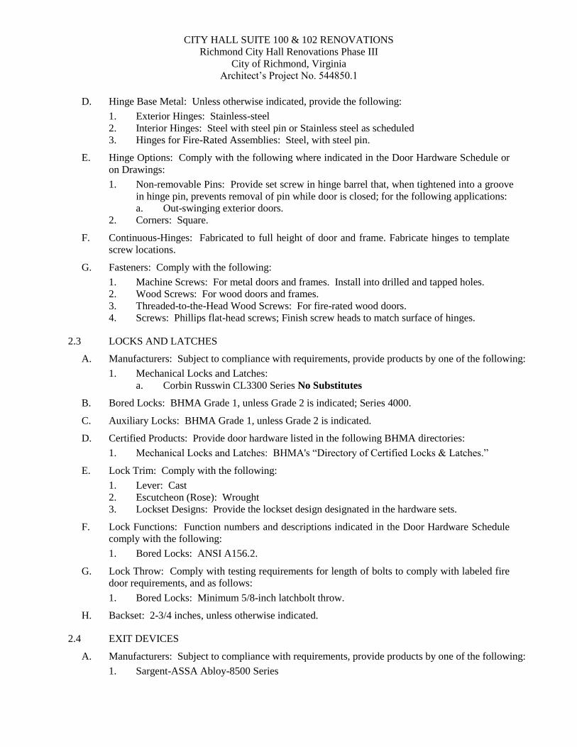
CITY HALL SUITE 100 & 102 RENOVATIONS Richmond City Hall Renovations Phase III
City of Richmond, Virginia Architect’s Project No. 544850.1
D. Hinge Base Metal: Unless otherwise indicated, provide the following:
1. Exterior Hinges: Stainless-steel 2. Interior Hinges: Steel with steel pin or Stainless steel as scheduled 3. Hinges for Fire-Rated Assemblies: Steel, with steel pin.
E. Hinge Options: Comply with the following where indicated in the Door Hardware Schedule or on Drawings: 1. Non-removable Pins: Provide set screw in hinge barrel that, when tightened into a groove
in hinge pin, prevents removal of pin while door is closed; for the following applications: a. Out-swinging exterior doors.
2. Corners: Square.
F. Continuous-Hinges: Fabricated to full height of door and frame. Fabricate hinges to template screw locations.
G. Fasteners: Comply with the following: 1. Machine Screws: For metal doors and frames. Install into drilled and tapped holes. 2. Wood Screws: For wood doors and frames. 3. Threaded-to-the-Head Wood Screws: For fire-rated wood doors. 4. Screws: Phillips flat-head screws; Finish screw heads to match surface of hinges.
2.3 LOCKS AND LATCHES
A. Manufacturers: Subject to compliance with requirements, provide products by one of the following: 1. Mechanical Locks and Latches:
a. Corbin Russwin CL3300 Series No Substitutes
B. Bored Locks: BHMA Grade 1, unless Grade 2 is indicated; Series 4000.
C. Auxiliary Locks: BHMA Grade 1, unless Grade 2 is indicated.
D. Certified Products: Provide door hardware listed in the following BHMA directories: 1. Mechanical Locks and Latches: BHMA's “Directory of Certified Locks & Latches.”
E. Lock Trim: Comply with the following: 1. Lever: Cast 2. Escutcheon (Rose): Wrought 3. Lockset Designs: Provide the lockset design designated in the hardware sets.
F. Lock Functions: Function numbers and descriptions indicated in the Door Hardware Schedule comply with the following: 1. Bored Locks: ANSI A156.2.
G. Lock Throw: Comply with testing requirements for length of bolts to comply with labeled fire door requirements, and as follows: 1. Bored Locks: Minimum 5/8-inch latchbolt throw.
H. Backset: 2-3/4 inches, unless otherwise indicated.
2.4 EXIT DEVICES
A. Manufacturers: Subject to compliance with requirements, provide products by one of the following: 1. Sargent-ASSA Abloy-8500 Series
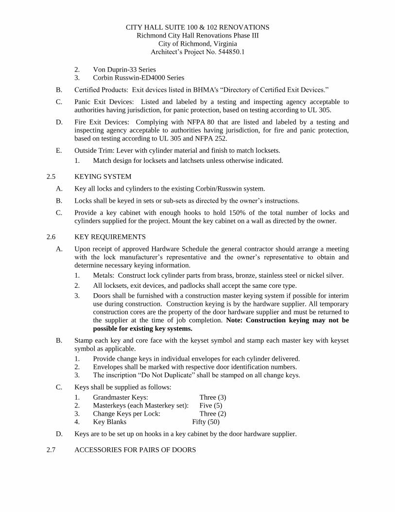
CITY HALL SUITE 100 & 102 RENOVATIONS Richmond City Hall Renovations Phase III
City of Richmond, Virginia Architect’s Project No. 544850.1
2. Von Duprin-33 Series 3. Corbin Russwin-ED4000 Series
B. Certified Products: Exit devices listed in BHMA's “Directory of Certified Exit Devices.”
C. Panic Exit Devices: Listed and labeled by a testing and inspecting agency acceptable to authorities having jurisdiction, for panic protection, based on testing according to UL 305.
D. Fire Exit Devices: Complying with NFPA 80 that are listed and labeled by a testing and inspecting agency acceptable to authorities having jurisdiction, for fire and panic protection, based on testing according to UL 305 and NFPA 252.
E. Outside Trim: Lever with cylinder material and finish to match locksets. 1. Match design for locksets and latchsets unless otherwise indicated.
2.5 KEYING SYSTEM
A. Key all locks and cylinders to the existing Corbin/Russwin system.
B. Locks shall be keyed in sets or sub-sets as directed by the owner’s instructions.
C. Provide a key cabinet with enough hooks to hold 150% of the total number of locks and cylinders supplied for the project. Mount the key cabinet on a wall as directed by the owner.
2.6 KEY REQUIREMENTS
A. Upon receipt of approved Hardware Schedule the general contractor should arrange a meeting with the lock manufacturer’s representative and the owner’s representative to obtain and determine necessary keying information. 1. Metals: Construct lock cylinder parts from brass, bronze, stainless steel or nickel silver. 2. All locksets, exit devices, and padlocks shall accept the same core type. 3. Doors shall be furnished with a construction master keying system if possible for interim
use during construction. Construction keying is by the hardware supplier. All temporary construction cores are the property of the door hardware supplier and must be returned to the supplier at the time of job completion. Note: Construction keying may not be possible for existing key systems.
B. Stamp each key and core face with the keyset symbol and stamp each master key with keyset symbol as applicable. 1. Provide change keys in individual envelopes for each cylinder delivered. 2. Envelopes shall be marked with respective door identification numbers. 3. The inscription “Do Not Duplicate” shall be stamped on all change keys.
C. Keys shall be supplied as follows: 1. Grandmaster Keys: Three (3) 2. Masterkeys (each Masterkey set): Five (5) 3. Change Keys per Lock: Three (2) 4. Key Blanks Fifty (50)
D. Keys are to be set up on hooks in a key cabinet by the door hardware supplier.
2.7 ACCESSORIES FOR PAIRS OF DOORS
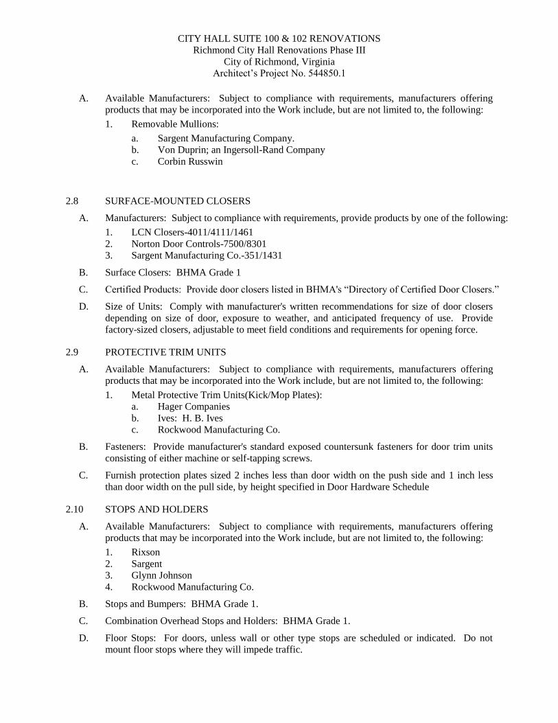
CITY HALL SUITE 100 & 102 RENOVATIONS Richmond City Hall Renovations Phase III
City of Richmond, Virginia Architect’s Project No. 544850.1
A. Available Manufacturers: Subject to compliance with requirements, manufacturers offering
products that may be incorporated into the Work include, but are not limited to, the following: 1. Removable Mullions:
a. Sargent Manufacturing Company. b. Von Duprin; an Ingersoll-Rand Company c. Corbin Russwin
2.8 SURFACE-MOUNTED CLOSERS
A. Manufacturers: Subject to compliance with requirements, provide products by one of the following: 1. LCN Closers-4011/4111/1461 2. Norton Door Controls-7500/8301 3. Sargent Manufacturing Co.-351/1431
B. Surface Closers: BHMA Grade 1
C. Certified Products: Provide door closers listed in BHMA's “Directory of Certified Door Closers.”
D. Size of Units: Comply with manufacturer's written recommendations for size of door closers depending on size of door, exposure to weather, and anticipated frequency of use. Provide factory-sized closers, adjustable to meet field conditions and requirements for opening force.
2.9 PROTECTIVE TRIM UNITS
A. Available Manufacturers: Subject to compliance with requirements, manufacturers offering products that may be incorporated into the Work include, but are not limited to, the following: 1. Metal Protective Trim Units(Kick/Mop Plates):
a. Hager Companies b. Ives: H. B. Ives c. Rockwood Manufacturing Co.
B. Fasteners: Provide manufacturer's standard exposed countersunk fasteners for door trim units consisting of either machine or self-tapping screws.
C. Furnish protection plates sized 2 inches less than door width on the push side and 1 inch less than door width on the pull side, by height specified in Door Hardware Schedule
2.10 STOPS AND HOLDERS
A. Available Manufacturers: Subject to compliance with requirements, manufacturers offering products that may be incorporated into the Work include, but are not limited to, the following: 1. Rixson 2. Sargent 3. Glynn Johnson 4. Rockwood Manufacturing Co.
B. Stops and Bumpers: BHMA Grade 1.
C. Combination Overhead Stops and Holders: BHMA Grade 1.
D. Floor Stops: For doors, unless wall or other type stops are scheduled or indicated. Do not mount floor stops where they will impede traffic.
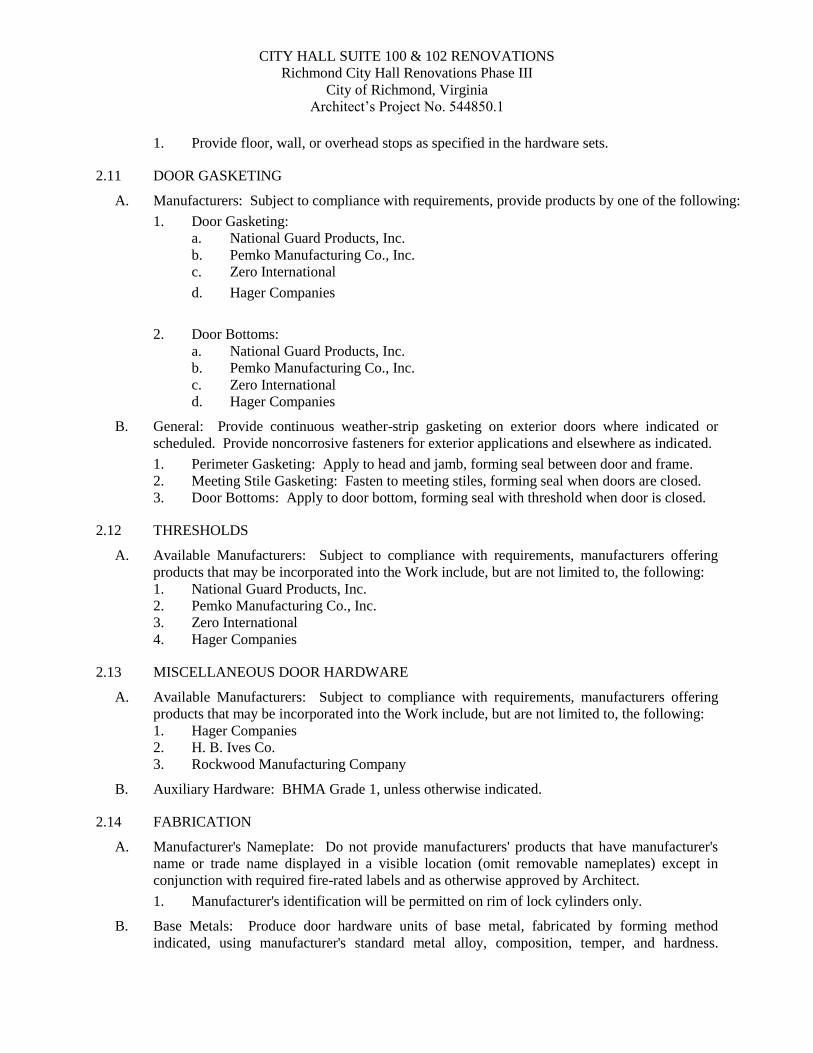
CITY HALL SUITE 100 & 102 RENOVATIONS Richmond City Hall Renovations Phase III
City of Richmond, Virginia Architect’s Project No. 544850.1
1. Provide floor, wall, or overhead stops as specified in the hardware sets.
2.11 DOOR GASKETING
A. Manufacturers: Subject to compliance with requirements, provide products by one of the following: 1. Door Gasketing:
a. National Guard Products, Inc. b. Pemko Manufacturing Co., Inc. c. Zero International d. Hager Companies
2. Door Bottoms:
a. National Guard Products, Inc. b. Pemko Manufacturing Co., Inc. c. Zero International d. Hager Companies
B. General: Provide continuous weather-strip gasketing on exterior doors where indicated or scheduled. Provide noncorrosive fasteners for exterior applications and elsewhere as indicated. 1. Perimeter Gasketing: Apply to head and jamb, forming seal between door and frame. 2. Meeting Stile Gasketing: Fasten to meeting stiles, forming seal when doors are closed. 3. Door Bottoms: Apply to door bottom, forming seal with threshold when door is closed.
2.12 THRESHOLDS
A. Available Manufacturers: Subject to compliance with requirements, manufacturers offering products that may be incorporated into the Work include, but are not limited to, the following: 1. National Guard Products, Inc. 2. Pemko Manufacturing Co., Inc. 3. Zero International 4. Hager Companies
2.13 MISCELLANEOUS DOOR HARDWARE
A. Available Manufacturers: Subject to compliance with requirements, manufacturers offering products that may be incorporated into the Work include, but are not limited to, the following: 1. Hager Companies 2. H. B. Ives Co. 3. Rockwood Manufacturing Company
B. Auxiliary Hardware: BHMA Grade 1, unless otherwise indicated.
2.14 FABRICATION
A. Manufacturer's Nameplate: Do not provide manufacturers' products that have manufacturer's name or trade name displayed in a visible location (omit removable nameplates) except in conjunction with required fire-rated labels and as otherwise approved by Architect. 1. Manufacturer's identification will be permitted on rim of lock cylinders only.
B. Base Metals: Produce door hardware units of base metal, fabricated by forming method indicated, using manufacturer's standard metal alloy, composition, temper, and hardness.
CITY HALL SUITE 100 & 102 RENOVATIONS Richmond City Hall Renovations Phase III
City of Richmond, Virginia Architect’s Project No. 544850.1
Furnish metals of a quality equal to or greater than that of specified door hardware units and BHMA A156.18 for finishes. Do not furnish manufacturer's standard materials or forming methods if different from specified standard.
C. Fasteners: Provide door hardware manufactured to comply with published templates generally prepared for machine, wood, and sheet metal screws. Provide screws according to commercially recognized industry standards for application intended. Provide Phillips flat-head screws with finished heads to match surface of door hardware, unless otherwise indicated. 1. Concealed Fasteners: For door hardware units that are exposed when door is closed,
except for units already specified with concealed fasteners. Do not use through bolts for installation where bolt head or nut on opposite face is exposed unless it is the only means of securely attaching the door hardware. Where through bolts are used on hollow door and frame construction, provide sleeves for each through bolt.
2. Steel Machine or Wood Screws: For the following fire-rated applications: a. Mortise hinges to doors. b. Strike plates to frames. c. Closers to doors and frames.
3. Fasteners for Wood Doors: Comply with requirements of DHI WDHS.2, “Recommended Fasteners for Wood Doors.” Supply wood screws for wood door applications. Self boring/drilling screws are not to be used.
2.15 FINISHES
A. Standard: Comply with BHMA A156.18.
B. Protect mechanical finishes on exposed surfaces from damage by applying a strippable, temporary protective covering before shipping.
C. Appearance of Finished Work: Variations in appearance of abutting or adjacent pieces are acceptable if they are within one-half of the range of approved Samples. Noticeable variations in the same piece are not acceptable. Variations in appearance of other components are acceptable if within the range of approved Samples and assembled or installed to minimize contrast.
D. BHMA Designations: Comply with base material and finish requirements indicated below: 1. BHMA 626: Satin chromium plated over brass or bronze base metal. 2. BHMA 628: Satin solid aluminum, clear anodized. 3. BHMA 630 (US32D): Satin solid stainless steel. 4. BHMA 652 (US26D): Satin chromium plated over steel base metal.
PART 3 - EXECUTION
3.1 EXAMINATION
A. Examine doors and frames, with Installer present, for compliance with requirements for installation tolerances, labeled fire door assembly construction, wall and floor construction, and other conditions affecting performance.
B. Examine roughing-in for electrical power systems to verify actual locations of wiring connections before electrified door hardware installation.
CITY HALL SUITE 100 & 102 RENOVATIONS Richmond City Hall Renovations Phase III
City of Richmond, Virginia Architect’s Project No. 544850.1
C. Proceed with installation only after unsatisfactory conditions have been corrected.
3.2 PREPARATION
A. Steel Doors and Frames: Comply with DHI A115 series. 1. Surface-Applied Door Hardware: Drill and tap doors and frames according to SDI 107.
B. Wood Doors: Comply with DHI A115-W series. Drill properly sized pilot holes for all wood screw applications.
3.3 INSTALLATION
A. Mounting Heights: Mount door hardware units at heights indicated in following applicable publications, unless specifically indicated or required to comply with governing regulations: 1. DHI WDHS.3, Locations for Wood Doors.” Typically the hollow metal frame
manufacturer’s standard hardware locations are acceptable.
B. Install each door hardware item to comply with manufacturer's written instructions. Where cutting and fitting are required to install door hardware onto or into surfaces that are later to be painted or finished in another way, coordinate removal, storage, and reinstallation of surface protective trim units with finishing work specified in Division 09 Sections. Do not install surface-mounted items until finishes have been completed on substrates involved. 1. Set units level, plumb, and true to line and location. Adjust and reinforce attachment
substrates as necessary for proper installation and operation. 2. Drill and countersink units that are not factory prepared for anchorage fasteners. Space
fasteners and anchors according to industry standards.
C. Thresholds: Set thresholds for exterior doors in full bed of sealant complying with requirements specified in Division 07 Section “Joint Sealants.”
3.4 ADJUSTING
A. Initial Adjustment: Adjust and check each operating item of door hardware and each door to ensure proper operation or function of every unit. Replace units that cannot be adjusted to operate as intended. Adjust door control devices to compensate for final operation of heating and ventilating equipment and to comply with referenced accessibility requirements. 1. Electric Strikes: Adjust horizontal and vertical alignment of keeper to properly engage
lock bolt. 2. Door Closers: Adjust sweep period so that, from an open position of 70 degrees, the door
will take at least 3 seconds to move to a point 3 inches from the latch, measured to the leading edge of the door. Adjust the opening force upon installation of all door closers so that ADA compliance is achieved.
B. Six-Month Adjustment: Approximately six months after date of Substantial Completion, Installer shall perform the following: 1. Examine and readjust each item of door hardware as necessary to ensure function of
doors, and door hardware, and electrified door hardware. 2. Consult with and instruct Owner's personnel on recommended maintenance procedures. 3. Replace door hardware items that have deteriorated or failed due to faulty design,
materials, or installation of door hardware units.
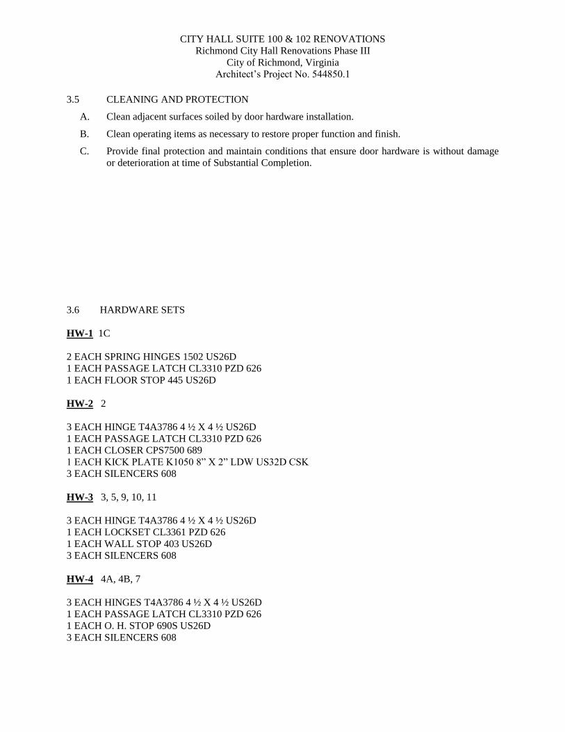
CITY HALL SUITE 100 & 102 RENOVATIONS Richmond City Hall Renovations Phase III
City of Richmond, Virginia Architect’s Project No. 544850.1
3.5 CLEANING AND PROTECTION
A. Clean adjacent surfaces soiled by door hardware installation.
B. Clean operating items as necessary to restore proper function and finish.
C. Provide final protection and maintain conditions that ensure door hardware is without damage or deterioration at time of Substantial Completion.
3.6 HARDWARE SETS HW-1 1C 2 EACH SPRING HINGES 1502 US26D 1 EACH PASSAGE LATCH CL3310 PZD 626 1 EACH FLOOR STOP 445 US26D HW-2 2 3 EACH HINGE T4A3786 4 ½ X 4 ½ US26D 1 EACH PASSAGE LATCH CL3310 PZD 626 1 EACH CLOSER CPS7500 689 1 EACH KICK PLATE K1050 8” X 2” LDW US32D CSK 3 EACH SILENCERS 608 HW-3 3, 5, 9, 10, 11 3 EACH HINGE T4A3786 4 ½ X 4 ½ US26D 1 EACH LOCKSET CL3361 PZD 626 1 EACH WALL STOP 403 US26D 3 EACH SILENCERS 608 HW-4 4A, 4B, 7 3 EACH HINGES T4A3786 4 ½ X 4 ½ US26D 1 EACH PASSAGE LATCH CL3310 PZD 626 1 EACH O. H. STOP 690S US26D 3 EACH SILENCERS 608
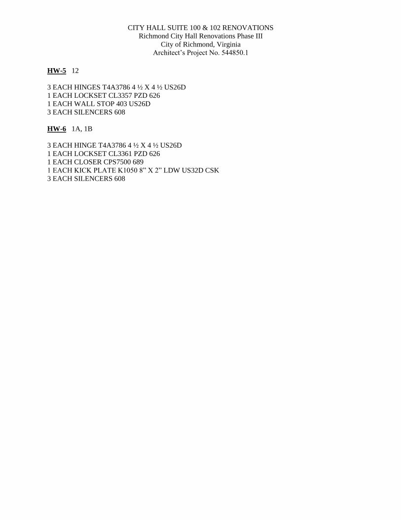
CITY HALL SUITE 100 & 102 RENOVATIONS Richmond City Hall Renovations Phase III
City of Richmond, Virginia Architect’s Project No. 544850.1
HW-5 12 3 EACH HINGES T4A3786 4 ½ X 4 ½ US26D 1 EACH LOCKSET CL3357 PZD 626 1 EACH WALL STOP 403 US26D 3 EACH SILENCERS 608 HW-6 1A, 1B 3 EACH HINGE T4A3786 4 ½ X 4 ½ US26D 1 EACH LOCKSET CL3361 PZD 626 1 EACH CLOSER CPS7500 689 1 EACH KICK PLATE K1050 8” X 2” LDW US32D CSK 3 EACH SILENCERS 608
CITY HALL SUITE 100 & 102 RENOVATIONS Richmond City Hall Renovations Phase III
City of Richmond, Virginia Architect’s Project No. 544850.1
Addendum 2 GLAZING 088000 - 1
SECTION 088000 - GLAZING
PART 1 - GENERAL
1.1 RELATED DOCUMENTS
A. Provisions of the Contract and of the Contract Documents apply to this Section.
1.2 SUMMARY
A. Section includes glazing for the following products and applications, including those specified in other Sections where glazing requirements are specified by reference to this Section: 1. Doors. 2. Interior borrowed lites.
B. Glazing types: 1. GL-1: 1/4" tempered clear (safety) glazing (interior glazing)
C. Related Sections: 1. Division 05 Section “Glazed Decorative Metal Railings” for glass panels in railings.
1.3 DEFINITIONS
A. Glass Manufacturers: Firms that produce primary glass, fabricated glass, or both, as defined in referenced glazing publications.
B. Glass Thicknesses: Indicated by thickness designations in millimeters according to ASTM C 1036.
1.4 ACTION SUBMITTALS
A. Product Data: For each glass product and glazing material indicated.
B. Glass Samples: NA.
C. Glazing Accessory Samples: NA.
1.5 INFORMATIONAL SUBMITTALS
A. Product Certificates: For glass and glazing products, from manufacturer.
1.6 QUALITY ASSURANCE
A. Safety Glazing Labeling: Where safety glazing labeling is indicated, permanently mark glazing with certification label of the SGCC or another certification agency acceptable to authorities having jurisdiction or the manufacturer. Label shall indicate manufacturer's name, type of glass, thickness, and safety glazing standard with which glass complies.
1.7 DELIVERY, STORAGE, AND HANDLING
A. Protect glazing materials according to manufacturer's written instructions. Prevent damage to glass and glazing materials from condensation, temperature changes, direct exposure to sun, or other causes.
CITY HALL SUITE 100 & 102 RENOVATIONS Richmond City Hall Renovations Phase III
City of Richmond, Virginia Architect’s Project No. 544850.1
Addendum 2 GLAZING 088000 - 2
PART 2 - PRODUCTS
2.1 GLASS PRODUCTS, GENERAL
A. Thickness: Where glass thickness is indicated, it is a minimum. Provide glass lites in thicknesses as needed to comply with requirements indicated. 1. Minimum Glass Thickness for Exterior Lites: Not less than 6.0 mm.
B. Safety Glazing: Where safety glazing is indicated, provide glazing that complies with 16 CFR 1201, Category II.
2.2 GLASS PRODUCTS
A. Float Glass: ASTM C 1036, Type I, Quality-Q3, Class I (clear) unless otherwise indicated.
B. Heat-Treated Float Glass: ASTM C 1048; Type I; Quality-Q3; Class I (clear) unless otherwise indicated; of kind and condition indicated.
2.3 GLAZING GASKETS
A. Dense Compression Gaskets: Molded or extruded gaskets of profile and hardness required to maintain watertight seal, made from one of the following: 1. EPDM complying with ASTM C 864. 2. Silicone complying with ASTM C 1115. 3. Thermoplastic polyolefin rubber complying with ASTM C 1115.
B. Soft Compression Gaskets: Extruded or molded, closed-cell, integral-skinned EPDM, silicone or thermoplastic polyolefin rubber gaskets complying with ASTM C 509, Type II, black; of profile and hardness required to maintain watertight seal. 1. Application: Use where soft compression gaskets will be compressed by inserting dense
compression gaskets on opposite side of glazing or pressure applied by means of pressure-glazing stops on opposite side of glazing.
2.4 GLAZING TAPES
A. Back-Bedding Mastic Glazing Tapes: Preformed, butyl-based, 100 percent solids elastomeric tape; nonstaining and nonmigrating in contact with nonporous surfaces; with or without spacer rod as recommended in writing by tape and glass manufacturers for application indicated; and complying with ASTM C 1281 and AAMA 800 for products indicated below: 1. AAMA 806.3 tape, for glazing tape applications subject to continuous pressure. 2. AAMA 807.3 tape, for glazing tape applications not subject to continuous pressure.
2.5 MISCELLANEOUS GLAZING MATERIALS
A. General: Provide products of material, size, and shape complying with referenced glazing standard, requirements of manufacturers of glass and other glazing materials for application indicated, and with a proven record of compatibility with surfaces contacted in installation.
B. Cleaners, Primers, and Sealers: Types recommended by sealant or gasket manufacturer.
C. Setting Blocks: Elastomeric material with a Shore, Type A durometer hardness of 85, plus or minus 5.
CITY HALL SUITE 100 & 102 RENOVATIONS Richmond City Hall Renovations Phase III
City of Richmond, Virginia Architect’s Project No. 544850.1
Addendum 2 GLAZING 088000 - 3
2.6 FABRICATION OF GLAZING UNITS
A. Fabricate glazing units in sizes required to fit openings indicated for Project, with edge and face clearances, edge and surface conditions, and bite complying with written instructions of product manufacturer and referenced glazing publications, to meet system performance requirements.
2.7 MONOLITHIC-GLASS TYPES
A. Glass Type GL-1: Clear fully tempered float glass. 1. Thickness: 6.0 mm. 2. Provide safety glazing labeling.
PART 3 - EXECUTION
3.1 EXAMINATION
A. Examine framing, glazing channels, and stops, with Installer present, for compliance with the following: 1. Manufacturing and installation tolerances, including those for size, squareness, and
offsets at corners. 2. Presence and functioning of weep systems. 3. Minimum required face and edge clearances. 4. Effective sealing between joints of glass-framing members.
B. Proceed with installation only after unsatisfactory conditions have been corrected.
3.2 PREPARATION
A. Clean glazing channels and other framing members receiving glass immediately before glazing. Remove coatings not firmly bonded to substrates.
3.3 GLAZING, GENERAL
A. Comply with combined written instructions of manufacturers of glass, sealants, gaskets, and other glazing materials, unless more stringent requirements are indicated, including those in referenced glazing publications.
B. Protect glass edges from damage during handling and installation. Remove damaged glass from Project site and legally dispose of off Project site. Damaged glass is glass with edge damage or other imperfections that, when installed, could weaken glass and impair performance and appearance.
C. Install setting blocks in sill rabbets, sized and located to comply with referenced glazing publications, unless otherwise required by glass manufacturer. Set blocks in thin course of compatible sealant suitable for heel bead.
D. Provide edge blocking where indicated or needed to prevent glass lites from moving sideways in glazing channel, as recommended in writing by glass manufacturer and according to requirements in referenced glazing publications.
E. Set glass lites in each series with uniform pattern, draw, bow, and similar characteristics.
CITY HALL SUITE 100 & 102 RENOVATIONS Richmond City Hall Renovations Phase III
City of Richmond, Virginia Architect’s Project No. 544850.1
Addendum 2 GLAZING 088000 - 4
3.4 TAPE GLAZING
A. Position tapes on fixed stops so that, when compressed by glass, their exposed edges are flush with or protrude slightly above sightline of stops.
B. Install tapes continuously, but not necessarily in one continuous length. Do not stretch tapes to make them fit opening.
C. Cover vertical framing joints by applying tapes to heads and sills first and then to jambs. Cover horizontal framing joints by applying tapes to jambs and then to heads and sills.
D. Place joints in tapes at corners of opening with adjoining lengths butted together, not lapped. Seal joints in tapes with compatible sealant approved by tape manufacturer.
E. Do not remove release paper from tape until right before each glazing unit is installed.
F. Center glass lites in openings on setting blocks and press firmly against tape by inserting dense compression gaskets formed and installed to lock in place against faces of remov-able stops. Start gasket applications at corners and work toward centers of openings.
3.5 CLEANING AND PROTECTION
A. Remove and replace glass that is broken, chipped, cracked, or abraded or that is damaged from natural causes, accidents, and vandalism, during construction period.
END OF SECTION 088000
CITY HALL SUITE 100 & 102 RENOVATIONS Richmond City Hall Renovations Phase III
City of Richmond, Virginia Architect’s Project No. 544850.1
COLD FORMED STEEL FRAMING - NON-STRUCTURAL (CFSF-NS) 092216 - 1
SECTION 092216 – COLD FORMED STEEL FRAMING - NON-STRUCTURAL (CFSF-NS)
PART 1 - GENERAL
1.1 RELATED DOCUMENTS
A. Provisions of the Contract and of the Contract Documents apply to this Section.
1.2 SUMMARY
A. Section Includes the following non-structural cold formed steel framing, noted as “CFSF-NS.” 1. Non-load-bearing steel framing systems for interior gypsum board assemblies. 2. Suspension systems for interior gypsum ceilings, soffits, and grid systems.
B. Related Requirements: 1. Section 054000 “Cold-Formed Steel Framing - Structural” for interior load-bearing and
non-load-bearing applications indicated for CFSF-S
1.3 ACTION SUBMITTALS
A. Product Data: For each type of product.
PART 2 - PRODUCTS
2.1 PERFORMANCE REQUIREMENTS
A. STC-Rated Assemblies: For STC-rated assemblies, provide materials and construction identical to those tested in assembly indicated, according to ASTM E 90 and classified according to ASTM E 413 by an independent testing agency.
2.2 FRAMING SYSTEMS
A. Framing Members, General: Comply with ASTM C 754 for conditions indicated. 1. Steel Sheet Components: Comply with ASTM C 645 requirements for metal unless oth-
erwise indicated. 2. Protective Coating: Coating with equivalent corrosion resistance of
ASTM A 653/A 653M, G40, hot-dip galvanized unless otherwise indicated.
B. Studs and Runners: ASTM C 645. 1. Steel Studs and Runners:
a. Minimum Base-Metal Thickness: 0.018 inch unless indicated otherwise or as re-quired by ASTM C 754 to meet L/240 deflection limit at a lateral pressure of 5psf. Provide 0.030 inch ASTM C 1178 tile backing panels and ASTM C 1629 Abuse-Resistant Gypsum Board, and at HM door frames. Provide minimum 0.030 inch
b. Depth: As indicated on Drawings.
C. Slip-Type Head Joints: Where indicated, provide one of the following: 1. Single Long-Leg Runner System: ASTM C 645 top runner with 2-inch-deep flanges in
thickness not less than indicated for studs, installed with studs friction fit into top runner
CITY HALL SUITE 100 & 102 RENOVATIONS Richmond City Hall Renovations Phase III
City of Richmond, Virginia Architect’s Project No. 544850.1
COLD FORMED STEEL FRAMING - NON-STRUCTURAL (CFSF-NS) 092216 - 2
and with continuous bridging located within 12 inches of the top of studs to provide lat-eral bracing.
2. Deflection Track: Steel sheet top runner manufactured to prevent cracking of finishes applied to interior partition framing resulting from deflection of structure above; in thick-ness not less than indicated for studs and in width to accommodate depth of studs. a. Products: Subject to compliance with requirements, available products that may be
incorporated into the Work include, but are not limited to, the following: 1) ClarkDietrich Building Systems; MaxTrack Slotted Deflection Track. 2) Steel Network Inc. (The); VertiClip SLD or VertiTrack VTD Series. 3) Superior Metal Trim; Superior Flex Track System (SFT).
D. Flat Strap and Backing Plate: Steel sheet for blocking and bracing in length and width indicat-ed. 1. Minimum Base-Steel Thickness: 0.0312 inch.
E. Cold-Rolled Channel Bridging: Steel, 0.053-inch minimum base-metal thickness, with mini-mum 1/2-inch-wide flanges. 1. Depth: 1-1/2 inches, unless indicated otherwise. 2. Clip Angle: Not less than 1-1/2 by 1-1/2 inches, 0.068-inch-thick, galvanized steel.
F. Hat-Shaped, Rigid Furring Channels: ASTM C 645. 1. Minimum Base-Metal Thickness: 0.018 inch, unless indicated otherwise. 2. Depth: 7/8 inch, unless indicated otherwise.
G. Corner Angle: Angle with both face flanges of 2-1/2 inches, minimum bare metal thickness of 0.0179 inch.
2.3 SUSPENSION SYSTEMS
A. Tie Wire: ASTM A 641, Class 1 zinc coating, soft temper, 0.062-inch-diameter wire, or double strand of 0.048-inch-diameter wire.
B. Hanger Attachments to Concrete: 1. Anchors: Fabricated from corrosion-resistant materials with holes or loops for attaching
wire hangers and capable of sustaining, without failure, a load equal to 5 times that im-posed by construction as determined by testing according to ASTM E 488 by an inde-pendent testing agency. a. Type: Postinstalled, expansion anchor.
C. Wire Hangers: ASTM A 641, Class 1 zinc coating, soft temper, 0.16 inch in diameter.
D. Carrying Channels: Cold-rolled, commercial-steel sheet with a base-metal thickness of 0.053 inch and minimum 1/2-inch-wide flanges. 1. Depth: 1-1/2 inches, or as required.
E. Furring Channels (Furring Members): 1. Hat-Shaped, Rigid Furring Channels: ASTM C 645, 7/8 inch deep.
a. Minimum Base-Metal Thickness: 0.018 inch, unless indicated otherwise.
F. Grid Suspension System for Gypsum Board Ceilings: ASTM C 645, direct-hung system com-posed of main beams and cross-furring members that interlock.
CITY HALL SUITE 100 & 102 RENOVATIONS Richmond City Hall Renovations Phase III
City of Richmond, Virginia Architect’s Project No. 544850.1
COLD FORMED STEEL FRAMING - NON-STRUCTURAL (CFSF-NS) 092216 - 3
1. The USG “Drywall Suspension System” accessory components for inside and outside corner joinery of main grid members for construction of “boxed soffits” and bulkheads without stud partition framing is acceptable in lieu of stud framed soffit type construc-tion.
2. Products: Subject to compliance with requirements, available products that may be in-corporated into the Work include, but are not limited to, the following: a. Armstrong World Industries, Inc.; Drywall Grid Systems. b. Chicago Metallic Corporation; Drywall Grid System. c. USG Corporation; Drywall Suspension System.
2.4 AUXILIARY MATERIALS
A. General: Provide auxiliary materials that comply with referenced installation standards. 1. Fasteners for Metal Framing: Of type, material, size, corrosion resistance, holding pow-
er, and other properties required to fasten steel members to substrates.
B. Isolation Strip at Exterior Walls: Provide one of the following: 1. Asphalt-Saturated Organic Felt: ASTM D 226, Type I (No. 15 asphalt felt), non-
perforated. 2. Foam Gasket: Adhesive-backed, closed-cell vinyl foam strips that allow fastener pene-
tration without foam displacement, 1/8 inch thick, in width to suit steel stud size.
PART 3 - EXECUTION
3.1 EXAMINATION
A. Examine areas and substrates, with Installer present, and including welded hollow-metal frames, cast-in anchors, and structural framing, for compliance with requirements and other conditions affecting performance of the Work.
B. Proceed with installation only after unsatisfactory conditions have been corrected.
3.2 PREPARATION
A. Suspended Assemblies: Coordinate installation of suspension systems with installation of overhead structure to ensure that inserts and other provisions for anchorages to building structure have been installed to receive hangers at spacing required to support the Work and that hangers will develop their full strength. 1. Furnish concrete inserts and other devices indicated to other trades for installation in
advance of time needed for coordination and construction.
3.3 INSTALLATION, GENERAL
A. Installation Standard: ASTM C 754. Provide framing to meet L/240 deflection limit at a lateral pressure of 5psf unless indicated otherwise. 1. Gypsum Board Assemblies: Also comply with requirements in ASTM C 840 that apply
to framing installation.
CITY HALL SUITE 100 & 102 RENOVATIONS Richmond City Hall Renovations Phase III
City of Richmond, Virginia Architect’s Project No. 544850.1
COLD FORMED STEEL FRAMING - NON-STRUCTURAL (CFSF-NS) 092216 - 4
B. Install supplementary framing, and blocking to support fixtures, equipment services, heavy trim, grab bars, toilet accessories, furnishings, or similar construction.
C. Install bracing at terminations in assemblies.
D. Do not bridge building control and expansion joints with non-load-bearing steel framing members. Frame both sides of joints independently.
3.4 INSTALLING FRAMED ASSEMBLIES
A. Install framing system components according to spacings indicated, but not greater than spacings required by referenced installation standards for assembly types. 1. Single-Layer Application: 16 inches o.c. unless otherwise indicated. Provide closer
spacing if required by ASTM C 754 to meet L/240 deflection limit at a lateral pressure of 5psf.
2. Multilayer Application: 16 inches o.c. unless otherwise indicated. 3. Tile Backing Panels: 16 inches o.c. unless otherwise indicated.
B. Where studs are installed directly against exterior masonry walls or dissimilar metals at exterior walls, install isolation strip between studs and exterior wall.
C. Install studs so flanges within framing system point in same direction.
D. Install tracks (runners) at floors and overhead supports. Extend framing full height to structural supports or substrates above suspended ceilings except where partitions are indicated to terminate 4 inches above highest adjacent suspended ceilings. Continue framing around ducts penetrating partitions above ceiling. 1. Slip-Type Head Joints: Where framing extends to overhead structural supports;
including roof decking, install to produce joints at tops of framing systems that prevent axial loading of finished assemblies.
2. Door Openings: Screw vertical studs at jambs to jamb anchor clips on door frames; install runner track section (for cripple studs) at head and secure to jamb studs. a. Install two studs at each jamb unless otherwise indicated. b. Install cripple studs at head adjacent to each jamb stud, with a minimum 1/2-inch
clearance from jamb stud to allow for installation of control joint in finished assembly.
c. Extend jamb studs through suspended ceilings and attach to underside of overhead structure.
3. Other Framed Openings: Frame openings other than door openings the same as required for door openings unless otherwise indicated. Install framing below sills of openings to match framing required above door heads.
4. Sound-Rated Partitions: Install framing to comply with sound-rated assembly indicated.
E. Direct Furring: 1. Attach to masonry with screws designed for masonry attachment, or powder-driven
fasteners spaced 24 inches o.c.
F. Off Furring:
CITY HALL SUITE 100 & 102 RENOVATIONS Richmond City Hall Renovations Phase III
City of Richmond, Virginia Architect’s Project No. 544850.1
COLD FORMED STEEL FRAMING - NON-STRUCTURAL (CFSF-NS) 092216 - 5
1. Where steel framing is indicated directly beside a primary wall and to receive finish board on only one side, provide bracing to the primary wall at no less than 48 inches o.c. between floor and ceiling.
G. Installation Tolerance: Install each framing member so fastening surfaces vary not more than 1/8 inch from the plane formed by faces of adjacent framing.
3.5 INSTALLING SUSPENSION SYSTEMS
A. Install suspension system components according to spacings indicated, but not greater than spacings required by referenced installation standards for assembly types. 1. Hangers: 48 inches o.c. 2. Carrying Channels (Main Runners): 48 inches o.c. 3. Furring Channels (Furring Members): 16 inches o.c.
B. Isolate suspension systems from building structure where they abut or are penetrated by building structure to prevent transfer of loading imposed by structural movement.
C. Suspend hangers from building structure as follows: 1. Install hangers plumb and free from contact with insulation or other objects within ceiling
plenum that are not part of supporting structural or suspension system. a. Splay hangers only where required to miss obstructions and offset resulting
horizontal forces by bracing, countersplaying, or other equally effective means. 2. Where width of ducts and other construction within ceiling plenum produces hanger
spacings that interfere with locations of hangers required to support standard suspension system members, install supplemental suspension members and hangers in the form of trapezes or equivalent devices. a. Size supplemental suspension members and hangers to support ceiling loads within
performance limits established by referenced installation standards. 3. Wire Hangers: Secure by looping and wire tying, either directly to structures or to
inserts, eye screws, or other devices and fasteners that are secure and appropriate for substrate, and in a manner that will not cause hangers to deteriorate or otherwise fail.
4. Do not attach hangers to steel roof deck. 5. Do not attach hangers to permanent metal forms. Furnish cast-in-place hanger inserts
that extend through forms. 6. Do not attach hangers to rolled-in hanger tabs of composite steel floor deck. 7. Do not connect or suspend steel framing from ducts, pipes, or conduit.
D. Grid Suspension Systems: Attach perimeter wall track or angle where grid suspension systems meet vertical surfaces. Mechanically join main beam and cross-furring members to each other and butt-cut to fit into wall track.
E. Installation Tolerances: Install suspension systems that are level to within 1/8 inch in 12 feet measured lengthwise on each member that will receive finishes and transversely between parallel members that will receive finishes.
END OF SECTION 092216
CITY HALL SUITE 100 & 102 RENOVATIONS Richmond City Hall Renovations Phase III
City of Richmond, Virginia Architect’s Project No. 544850.1
GYPSUM BOARD 092900 - 1
SECTION 092900 - GYPSUM BOARD
PART 1 - GENERAL
1.1 RELATED DOCUMENTS
A. Provisions of the Contract and of the Contract Documents apply to this Section.
1.2 SUMMARY
A. Section Includes: 1. Interior gypsum board. (partitions and bulkheads) 2. Moisture- and mold-resistant gypsum board: (toilet room ceilings 3. Tile backing panels.
B. Related Sections: 1. Division 05 Section “Cold Formed Steel Framing – Structural (CFSF-S)” for steel
framing at structural applications. 2. Division 09 Section “Cold Formed Steel Framing – Non Structural (CFSF-NS).” for steel
framing at non-structural applications.
1.3 ACTION SUBMITTALS
A. Product Data: For each type of product.
B. Samples: For the following products: 1. Trim Accessories: Full-size Sample in 12-inch- long length for each trim accessory
indicated.
1.4 DELIVERY, STORAGE AND HANDLING
A. Store materials inside under cover and keep them dry and protected against weather, condensation, direct sunlight, construction traffic, and other potential causes of damage. Stack panels flat and supported on risers on a flat platform to prevent sagging.
1.5 FIELD CONDITIONS
A. Environmental Limitations: Comply with ASTM C 840 requirements or gypsum board manufacturer's written recommendations, whichever are more stringent.
B. Do not install paper-faced gypsum panels until installation areas are enclosed and conditioned.
C. Do not install panels that are wet, those that are moisture damaged, and those that are mold damaged. 1. Indications that panels are wet or moisture damaged include, but are not limited to,
discoloration, sagging, or irregular shape. 2. Indications that panels are mold damaged include, but are not limited to, fuzzy or
splotchy surface contamination and discoloration.
CITY HALL SUITE 100 & 102 RENOVATIONS Richmond City Hall Renovations Phase III
City of Richmond, Virginia Architect’s Project No. 544850.1
GYPSUM BOARD 092900 - 2
PART 2 - PRODUCTS
2.1 PERFORMANCE REQUIREMENTS
A. Fire-Resistance-Rated Assemblies: For fire-resistance-rated assemblies, provide materials and construction identical to those tested in assembly indicated according to ASTM E 119 by an independent testing agency.
B. STC-Rated Assemblies: For STC-rated assemblies, provide materials and construction identical to those tested in assembly indicated according to ASTM E 90 and classified according to ASTM E 413 by an independent testing agency.
2.2 GYPSUM BOARD, GENERAL
A. Size: Provide maximum lengths and widths available that will minimize joints in each area and that correspond with support system indicated.
2.3 INTERIOR GYPSUM BOARD
A. Light Weight Gypsum Board: ASTM C 1396/C 1396M, with engineered high-strength, light weight gypsum core in 5/8 inch thickness may be used in lieu of standard weight 5/8 inch gypsum board for non-fire-rated applications only. (This new 5/8 inch thickness product is not a Type X board and is not tested for fire-rated assemblies.) 1. Core: 5/8 inch, regular type. 2. Long Edges: Tapered. 3. Non-Type X Products: Subject to compliance with requirements, available products that
may be incorporated into the Work include, but are not limited to, the following: a. National Gypsum Company; “Gold Bond High Strength Fire-Shield LITE 30.” b. USG Corporation; “UltraLight Panels Firecode 30”
B. Gypsum Board, Type X: ASTM C 1396. 1. Thickness: 5/8 inch. 2. Long Edges: Tapered.
2.4 TILE BACKING PANELS
A. Cementitious Backer Units: ANSI A118.9 and ASTM C 1288 or 1325, with manufacturer's standard edges. 1. Products: Subject to compliance with requirements, available products that may be
incorporated into the Work include, but are not limited to, the following: a. C-Cure; C-Cure Board 990. b. CertainTeed Corp.; FiberCement Underlayment. c. Custom Building Products; Wonderboard. d. FinPan, Inc.; Util-A-Crete Concrete Backer Board. e. James Hardie Building Products, Inc.; Hardiebacker. f. National Gypsum Company, Permabase Cement Board. g. USG Corporation; DUROCK Cement Board.
2. Thickness: Nominal 5/8 inch, unless indicated otherwise. 3. Mold Resistance: ASTM D 3273, score of 10.
CITY HALL SUITE 100 & 102 RENOVATIONS Richmond City Hall Renovations Phase III
City of Richmond, Virginia Architect’s Project No. 544850.1
GYPSUM BOARD 092900 - 3
2.5 TRIM ACCESSORIES
A. Interior Trim: ASTM C 1047. 1. Material: Paper-faced galvanized steel sheet. “No-Coat” synthetic-reinforced trim may
be used in lieu of paper-faced galvanized steel sheet for cornerbead applications. 2. Shapes:
a. Cornerbead. b. Bullnose bead. c. LC-Bead: J-shaped; exposed long flange receives joint compound. d. L-Bead: L-shaped; exposed long flange receives joint compound. e. U-Bead: J-shaped; exposed short flange does not receive joint compound. f. Control/ expansion joint. g. Curved-Edge Cornerbead: With notched or flexible flanges.
2.6 JOINT TREATMENT MATERIALS
A. General: Comply with ASTM C 475/C 475M.
B. Joint Tape: 1. Interior Gypsum Board: Paper. 2. Glass-Mat Gypsum Sheathing Board: 10-by-10 glass mesh. 3. Tile Backing Panels: As recommended by panel manufacturer.
C. Joint Compound for Interior Gypsum Board: For each coat use formulation that is compatible with other compounds applied on previous or for successive coats. 1. Prefilling: At open joints, rounded or beveled panel edges, and damaged surface areas,
use setting-type taping compound. 2. Embedding and First Coat: For embedding tape and first coat on joints, fasteners, and
trim flanges, use setting-type taping compound. a. Use setting-type compound for installing paper-faced metal trim accessories.
3. Fill Coat: For second coat, use drying-type, all-purpose compound. 4. Finish Coat: For third coat, use drying-type, all-purpose compound. 5. Skim Coat: For final coat of Level 5 finish, use drying-type, all-purpose compound.
D. Joint Compound for Tile Backing Panels: 1. Cementitious Backer Units (at tile backing): As recommended by backer unit
manufacturer.
2.7 AUXILIARY MATERIALS
A. General: Provide auxiliary materials that comply with referenced installation standards and manufacturer's written recommendations.
B. Laminating Adhesive: Adhesive or joint compound recommended for directly adhering gypsum panels to continuous substrate.
C. Steel Drill Screws: ASTM C 1002, unless otherwise indicated.
CITY HALL SUITE 100 & 102 RENOVATIONS Richmond City Hall Renovations Phase III
City of Richmond, Virginia Architect’s Project No. 544850.1
GYPSUM BOARD 092900 - 4
1. Use screws complying with ASTM C 954 for fastening panels to steel members from 0.033 to 0.112 inch thick. (CFMF specified in Division 05 Section “Cold-Formed Metal Framing.”)
2. For fastening cementitious backer units, use screws of type and size recommended by panel manufacturer.
D. Sound Attenuation Blankets: ASTM C 665, Type I (blankets without membrane facing) produced by combining thermosetting resins with mineral fibers manufactured from glass, slag wool, or rock wool. 1. Fire-Resistance-Rated Assemblies: Comply with mineral-fiber requirements of
assembly.
E. Acoustical Joint Sealant: Manufacturer's standard nonsag, paintable, nonstaining latex sealant complying with ASTM C 834. Product effectively reduces airborne sound transmission through perimeter joints and openings in building construction as demonstrated by testing representative assemblies according to ASTM E 90. 1. Products: Subject to compliance with requirements, available products that may be
incorporated into the Work include, but are not limited to, the following: a. Accumetric LLC; BOSS 824 Acoustical Sound Sealant. b. Grabber Construction Products; Acoustical Sealant GSC. c. Hilti CP506 Smoke and Acoustical Sealant. d. Pecora Corporation; AC-20 FTR or AIS-919. e. Specified Technologies, Inc.; Smoke N Sound Acoustical Sealant. f. USG Corporation; SHEETROCK Acoustical Sealant.
PART 3 - EXECUTION
3.1 EXAMINATION
A. Examine areas and substrates including welded hollow-metal frames and framing, with Installer present, for compliance with requirements and other conditions affecting performance.
B. Examine panels before installation. Reject panels that are wet, moisture damaged, and mold damaged.
C. Proceed with installation only after unsatisfactory conditions have been corrected.
3.2 APPLYING AND FINISHING PANELS, GENERAL
A. Comply with ASTM C 840.
B. Install ceiling panels across framing to minimize the number of abutting end joints and to avoid abutting end joints in central area of each ceiling. Stagger abutting end joints of adjacent panels not less than one framing member.
C. Install panels with face side out. Butt panels together for a light contact at edges and ends with not more than 1/16 inch of open space between panels. Do not force into place.
D. Locate edge and end joints over supports, except in ceiling applications where intermediate supports or gypsum board back-blocking is provided behind end joints. Do not place tapered
CITY HALL SUITE 100 & 102 RENOVATIONS Richmond City Hall Renovations Phase III
City of Richmond, Virginia Architect’s Project No. 544850.1
GYPSUM BOARD 092900 - 5
edges against cut edges or ends. Stagger vertical joints on opposite sides of partitions. Do not make joints other than control/ expansion joints at corners of framed openings.
E. Install gypsum board with open horizontal joint (gap) not to exceed ½-inch above finished floor slab and tape & finish vertical joints to bottom edge of board to afford a smooth substrate for ap-plied wall base.
F. Form control/expansion joints with space between edges of adjoining gypsum panels.
G. Cover both faces of support framing with gypsum panels in concealed spaces (above ceilings, etc., except in chases braced internally. 1. Unless concealed application is indicated or required for sound, fire, air, or smoke
ratings, coverage may be accomplished with scraps of not less than 8 sq. ft. in area. 2. Fit gypsum panels around ducts, pipes, and conduits. 3. Where partitions intersect structural members projecting below underside of floor/roof
slabs and decks, cut gypsum panels to fit profile formed by structural members; allow 1/4- to 3/8-inch- wide joints to install sealant.
H. Isolate perimeter of gypsum board applied to non-load-bearing partitions at structural abutments, except floors. Provide 1/4- to 1/2-inch- wide spaces at these locations and trim edges with edge trim where edges of panels are exposed. Seal joints between edges and abutting structural surfaces with acoustical sealant.
I. Isolate perimeter of gypsum board ceilings at surrounding non-gypsum board construction. Provide 1/4- to 1/2-inch- wide spaces at these locations, and trim edges with LC-bead edge trim where edges of gypsum panels are exposed and U-bead edge trim where concealed. Seal joints between edges and surrounding non-gypsum wall surfaces with acoustical sealant.
J. Attachment to Steel Framing: Attach panels so leading edge or end of each panel is attached to open (unsupported) edges of stud flanges first.
K. Install sound attenuation blankets before installing gypsum panels unless blankets are readily installed after panels have been installed on one side.
3.3 APPLYING INTERIOR GYPSUM BOARD
A. Install interior gypsum board in the following locations: 1. Type X: Vertical surfaces unless otherwise indicated. 2. Moisture- and Mold-Resistant Type: As indicated on Drawings.
B. Single-Layer Application: 1. On ceilings, apply gypsum panels before wall/partition board application to greatest
extent possible and at right angles to framing unless otherwise indicated. 2. On partitions/walls, apply gypsum panels vertically unless otherwise indicated or
required by fire-resistance-rated assembly, and minimize end joints. a. Stagger abutting end joints not less than one framing member in alternate courses
of panels. b. At stairwells and other high walls, install panels horizontally unless otherwise
indicated or required by fire-resistance-rated assembly. 3. On Z-furring members, apply gypsum panels vertically (parallel to framing) with no end
joints. Locate edge joints over furring members.
CITY HALL SUITE 100 & 102 RENOVATIONS Richmond City Hall Renovations Phase III
City of Richmond, Virginia Architect’s Project No. 544850.1
GYPSUM BOARD 092900 - 6
4. Fastening Methods: Apply gypsum panels to supports with steel drill screws.
3.4 APPLYING EXTERIOR GYPSUM PANELS FOR CEILINGS AND SOFFITS
A. Apply panels perpendicular to supports, with end joints staggered and located over supports. 1. Install with 1/4-inch open space where panels abut other construction or structural
penetrations. 2. Fasten with corrosion-resistant screws.
3.5 APPLYING TILE BACKING PANELS
A. Cementitious Backer Units: ANSI A108.11, at locations indicated to receive tile.
B. Where tile backing panels abut other types of panels in same plane, shim surfaces to produce a uniform plane across panel surfaces.
3.6 INSTALLING TRIM ACCESSORIES
A. General: For trim with back flanges intended for fasteners, attach to framing with same fasteners used for panels. Otherwise, attach trim according to manufacturer's written instructions.
B. Control/ Expansion Joints: Principal aesthetic and functional control/ expansion joint locations are indicated on Drawings. Provide additional control/ expansion joints as required by ASTM C 840. If additional control/ expansion joints are required in high visibility spaces such as Lobbies and Public Meeting Rooms, advise Architect of proposed location.
C. Aluminum Trim: Install in locations indicated on Drawings.
3.7 FINISHING GYPSUM BOARD
A. General: Treat gypsum board joints, interior angles, edge trim, control/expansion joints, penetrations, fastener heads, surface defects, and elsewhere as required to prepare gypsum board surfaces for decoration. Promptly remove residual joint compound from adjacent surfaces.
B. Prefill open joints, rounded or beveled edges, and damaged surface areas.
C. Apply joint tape over gypsum board joints, except for trim products specifically indicated as not intended to receive tape.
D. Gypsum Board Finish Levels: Finish panels to levels indicated below and according to ASTM C 840: 1. Level 1: Ceiling plenum areas, concealed areas, and where indicated. 2. Level 4: At panel surfaces that will be exposed to view unless otherwise indicated.
a. Primer and its application to surfaces are specified in other Division 09 Sections.
E. Glass-Mat Gypsum Sheathing Board: Finish according to manufacturer's written instructions for use as exposed soffit board.
F. Cementitious Backer Units: Finish according to manufacturer's written instructions.
3.8 FIELD QUALITY CONTROL
CITY HALL SUITE 100 & 102 RENOVATIONS Richmond City Hall Renovations Phase III
City of Richmond, Virginia Architect’s Project No. 544850.1
GYPSUM BOARD 092900 - 7
A. Above-Ceiling Observation: Before Contractor installs gypsum board ceilings, Architect will conduct an above-ceiling observation and report deficiencies in the Work observed. Do not proceed with installation of gypsum board to ceiling support framing until deficiencies have been corrected. 1. Notify Architect seven days in advance of date and time when Project, or part of Project,
will be ready for above-ceiling observation. 2. Before notifying Architect, complete the following in areas to receive gypsum board ceil-
ings: a. Installation of 80 percent of lighting fixtures, powered for operation. b. Installation, insulation, and leak and pressure testing of water piping systems. c. Installation of air-duct systems. d. Installation of air devices. e. Installation of mechanical system control-air tubing. f. Installation of ceiling support framing.
3.9 PROTECTION
A. Protect adjacent surfaces from drywall compound and promptly remove from floors and other non-drywall surfaces. Repair surfaces stained, marred, or otherwise damaged during drywall application.
B. Protect installed products from damage from weather, condensation, direct sunlight, construction, and other causes during remainder of the construction period.
C. Remove and replace panels that are wet, moisture damaged, and mold damaged. 1. Indications that panels are wet or moisture damaged include, but are not limited to,
discoloration, sagging, or irregular shape. 2. Indications that panels are mold damaged include, but are not limited to, fuzzy or
splotchy surface contamination and discoloration.
END OF SECTION 092900
CITY HALL SUITE 100 & 102 RENOVATIONS Richmond City Hall Renovations Phase III
City of Richmond, Virginia Architect’s Project No. 544850.1
ACOUSTICAL PANEL CEILINGS 095113 - 1
SECTION 095113 - ACOUSTICAL PANEL CEILINGS
PART 1 - GENERAL
1.1 RELATED DOCUMENTS
A. Provisions of the Contract and of the Contract Documents apply to this Section.
1.2 SUMMARY
A. This Section includes acoustical panels (acoustical ceiling panels = ACP) and exposed suspension systems for ceilings.
1.3 DEFINITIONS
A. CAC: Ceiling Attenuation Class.
B. LR: Light Reflectance coefficient.
C. NRC: Noise Reduction Coefficient.
1.4 SUBMITTALS
A. Product Data: For each type of product indicated.
B. Samples for Verification: For each component indicated and for each exposed finish required, prepared on Samples of size indicated below. 1. Acoustical Panel: Set of 6-inch- (150-mm-) square Samples of each type, color, pattern,
and texture. 2. Exposed Suspension System Members, Moldings, and Trim: Set of 12-inch- (300-mm-)
long Samples of each type, finish, and color.
C. Installation Instructions: Manufacturer’s installation instructions for ACP-A ceiling assemblies and components.
D. Qualification Data: For testing agency.
E. Product Test Reports: Based on evaluation of comprehensive tests performed by a qualified testing agency, for each acoustical panel ceiling.
F. Research/Evaluation Reports: For each acoustical panel ceiling and components and anchor and fastener type.
G. Sample Warranty: For 30-year panel and grid (single source) warranty systems specified.
H. Maintenance Data: For finishes to include in maintenance manuals.
1.5 QUALITY ASSURANCE
A. Source Limitations: 1. Acoustical Ceiling Panel: Obtain each type through one source from a single
manufacturer. 2. Suspension System: Obtain each type through one source from a single manufacturer.
CITY HALL SUITE 100 & 102 RENOVATIONS Richmond City Hall Renovations Phase III
City of Richmond, Virginia Architect’s Project No. 544850.1
ACOUSTICAL PANEL CEILINGS 095113 - 2
B. Source Limitations: Obtain each type of acoustical ceiling panel and supporting suspension system through one source from a single manufacturer.
C. Surface-Burning Characteristics: Provide acoustical panels with the following surface-burning characteristics as determined by testing identical products per ASTM E 84: 1. Flame-Spread Index: 25 or less. 2. Smoke-Developed Index: 50 or less.
1.6 DELIVERY, STORAGE, AND HANDLING
A. Deliver acoustical panels, suspension system components, and accessories to Project site in original, unopened packages and store them in a fully enclosed, conditioned space where they will be protected against damage from moisture, humidity, temperature extremes, direct sunlight, surface contamination, and other causes.
B. Before installing acoustical panels, permit them to reach room temperature and stabilized moisture content.
C. Handle acoustical panels carefully to avoid chipping edges or damaging units in any way.
1.7 PROJECT CONDITIONS
A. Environmental Limitations: Do not install acoustical panel ceilings until spaces are enclosed and weatherproof, wet work in spaces is complete and dry, work above ceilings is complete, and ambient temperature and humidity conditions are maintained at the levels indicated for Project when occupied for its intended use. 1. Pressurized Plenums: Operate ventilation system for not less than 48 hours before
beginning acoustical panel ceiling installation.
1.8 COORDINATION
A. Coordinate layout and installation of acoustical panels and suspension system with other construction that penetrates ceilings or is supported by them, including light fixtures, HVAC equipment, fire-suppression system, and partition assemblies.
1.9 EXTRA MATERIALS
A. Furnish extra materials described below that match products installed and that are packaged with protective covering for storage and identified with labels describing contents. 1. Acoustical Ceiling Panels: Full-size panels equal to 2.0 percent of quantity installed. 2. Suspension System Components: Quantity of each exposed component equal to 2.0
percent of quantity installed.
PART 2 - PRODUCTS
2.1 ACOUSTICAL PANELS, GENERAL
A. Acoustical Panel Standard: Provide manufacturer's standard panels of configuration indicated that comply with ASTM E 1264 classifications as designated by types, patterns, acoustical ratings, and light reflectances, unless otherwise indicated.
CITY HALL SUITE 100 & 102 RENOVATIONS Richmond City Hall Renovations Phase III
City of Richmond, Virginia Architect’s Project No. 544850.1
ACOUSTICAL PANEL CEILINGS 095113 - 3
1. Mounting Method for Measuring NRC: Type E-400; plenum mounting in which face of test specimen is 15-3/4 inches (400 mm) away from test surface per ASTM E 795.
B. Acoustical Panel Colors and Patterns: Match appearance characteristics indicated for each product type.
C. Broad Spectrum Antimicrobial Fungicide and Bactericide Treatment: Provide acoustical panels treated with manufacturer's standard antimicrobial formulation that inhibits fungus, mold, mildew, and gram-positive and gram-negative bacteria and showing no mold, mildew, or bacterial growth when tested according to ASTM D 3273 and evaluated according to ASTM D 3274 or ASTM G 21.
2.2 ACOUSTICAL PANELS FOR ACOUSTICAL PANEL CEILING – ACP
A. Products: Subject to compliance with requirements, provide one of the following: 1. USG Interiors, Inc.; “Eclipse ClimaPlus” Item #76975 (Basis of Design) 2. Armstrong World Industries, Inc.; “Ultima” Item #1912 3. CertainTeed, Inc.; “Symphony m” Item #1222-OVT-1.
B. Classification: Provide panels complying with ASTM E 1264 for type, form, and pattern as follows: 1. Type and Form: Type III, mineral base with painted finish; Form 2, water felted. 2. Pattern: E (lightly textured) or G (smooth).
C. Color: White. D. LR: Not less than 0.86. E. NRC: Not less than 0.70. F. CAC: Not less than 35. G. Edge/Joint Detail: Fineline. H. Thickness: 3/4 inch (19 mm). I. Modular Size: 24 by 24 inches (610 by 610 mm). J. Humidity Resistant: Minimum 10-year warranty against sag.
2.3 METAL SUSPENSION SYSTEMS, GENERAL
A. Metal Suspension System Standard: Provide manufacturer's standard direct-hung metal suspension systems of types, structural classifications, and finishes indicated that comply with applicable requirements in ASTM C 635.
B. Finishes and Colors, General: Comply with NAAMM's “Metal Finishes Manual for Architectural and Metal Products" for recommendations for applying and designating finishes. Provide manufacturer's standard factory-applied finish for type of system indicated.
C. Attachment Devices: Size for five times the design load indicated in ASTM C 635, Table 1, “Direct Hung,” unless otherwise indicated. Comply with seismic design requirements.
D. Wire Hangers, Braces, and Ties: Provide wires complying with the following requirements: 1. Zinc-Coated, Carbon-Steel Wire: ASTM A 641/A 641M, Class 1 zinc coating, soft
temper. 2. Size: Select wire diameter so its stress at 3 times hanger design load (ASTM C 635,
Table 1, “Direct Hung”) will be less than yield stress of wire, but provide not less than 0.106-inch- (2.69-mm-) diameter wire.
CITY HALL SUITE 100 & 102 RENOVATIONS Richmond City Hall Renovations Phase III
City of Richmond, Virginia Architect’s Project No. 544850.1
ACOUSTICAL PANEL CEILINGS 095113 - 4
2.4 METAL SUSPENSION SYSTEM FOR ACOUSTICAL PANEL CEILING ACP
A. Products: Subject to compliance with requirements, provide one of the following: 1. USG Interiors, Inc.; “DONN Centricitee DXT/DXLT” (Basis of Design) 2. Armstrong World Industries; “Suprafine XL 9/16" Exposed Tee System” 3. CertainTeed Corporation; “9/16" Elite Narrow Stab”
B. Narrow-Face, Capped, Double-Web, Steel Suspension System: Main and cross runners roll formed from cold-rolled steel sheet, prepainted, electrolytically zinc coated, or hot-dip galvanized according to ASTM A 653, G30 coating designation, with prefinished 9/16-inch- wide metal caps on flanges; other characteristics as follows. Both main beams and 48" length cross tees shall be 1-1/2" depth and support load carrying capacity required for main beams for specified structural class (intermediate duty). Provide positive locking cross tee to main beam connection and override cross tee ends, and a bayonet type end coupling (vs. knuckle type) for main runners. 1. Structural Classification: Intermediate-duty system. 2. End Condition of Cross Runners: Override (stepped) type. 3. Face Design: Flat, flush. 4. Cap Material: Steel sheet. 5. Cap Finish: Painted white.
2.5 METAL EDGE MOLDINGS AND TRIM
A. Roll-Formed, Sheet-Metal Edge Moldings and Trim: Type and profile indicated or, if not indicated, manufacturer's standard moldings for edges and penetrations that comply with seismic design requirements; formed from sheet metal of same material, finish, and color as that used for exposed flanges of suspension system runners. 1. For lay-in panels with square edge details, provide manufacturer's standard edge
moldings that fit acoustical panel edge details and suspension systems indicated and that match width and configuration of exposed runners, unless otherwise indicated.
2. For lay-in panels with reveal edge details, provide standard 7/8 by 7/8-inch size edge angle molding mounted in same plane as suspended grid. Provide cut reveal edge at cut edge of ceiling panels to match factory profile.
3. For circular penetrations of ceiling, provide edge moldings fabricated to diameter required to fit penetration exactly.
PART 3 - EXECUTION
3.1 EXAMINATION
A. Examine substrates, areas, and conditions, including structural framing to which acoustical panel ceilings attach or abut, with Installer present, for compliance with requirements specified in this and other Sections that affect ceiling installation and anchorage and with requirements for installation tolerances and other conditions affecting performance of acoustical panel ceilings. 1. Proceed with installation only after unsatisfactory conditions have been corrected.
CITY HALL SUITE 100 & 102 RENOVATIONS Richmond City Hall Renovations Phase III
City of Richmond, Virginia Architect’s Project No. 544850.1
ACOUSTICAL PANEL CEILINGS 095113 - 5
3.2 PREPARATION
A. Measure each ceiling area and establish layout of acoustical panels to balance border widths at opposite edges of each ceiling. Avoid using less-than-half-width panels at borders, and comply with layout shown on reflected ceiling plans.
3.3 INSTALLATION
A. General: Install acoustical panel ceilings to comply with ASTM C 636 and seismic design requirements indicated, per manufacturer's written instructions and CISCA's “Ceiling Systems Handbook.”
B. Suspend ceiling hangers from building's structural members and as follows: 1. Install hangers plumb and free from contact with insulation or other objects within ceiling
plenum that are not part of supporting structure or of ceiling suspension system. 2. Splay hangers only where required to miss obstructions; offset resulting horizontal forces
by bracing, countersplaying, or other equally effective means. 3. Where width of ducts and other construction within ceiling plenum produces hanger
spacings that interfere with location of hangers at spacings required to support standard suspension system members, install supplemental suspension members and hangers in form of trapezes or equivalent devices.
4. Secure wire hangers to ceiling suspension members and to supports above with a minimum of three tight turns. Connect hangers directly either to structures or to inserts, eye screws, or other devices that are secure and appropriate for substrate and that will not deteriorate or otherwise fail due to age, corrosion, or elevated temperatures.
5. Do not support ceilings directly from permanent metal forms or floor deck. Fasten hangers to cast-in-place hanger inserts, post installed mechanical or adhesive anchors, or power-actuated fasteners that extend through forms into concrete.
6. When steel framing does not permit installation of hanger wires at spacing required, install carrying channels or other supplemental support for attachment of hanger wires.
7. Do not attach hangers to steel deck tabs. 8. Space hangers not more than 48 inches (1200 mm) o.c. along each member supported
directly from hangers, unless otherwise indicated; provide hangers not more than 8 inches (200 mm) from ends of each member.
9. Size supplemental suspension members and hangers to support ceiling loads within performance limits established by referenced standards and publications.
C. Secure bracing wires to ceiling suspension members and to supports with a minimum of four tight turns. Suspend bracing from building's structural members as required for hangers, without attaching to permanent metal forms, steel deck, or steel deck tabs. Fasten bracing wires into concrete with cast-in-place or post installed anchors.
D. Install edge moldings and trim of type indicated at perimeter of acoustical ceiling area and where necessary to conceal edges of acoustical panels. 1. Screw attach moldings to substrate at intervals not more than 16 inches (400 mm) o.c.
and not more than 3 inches (75 mm) from ends, leveling with ceiling suspension system to a tolerance of 1/8 inch in 12 feet (3.2 mm in 3.6 m). Miter corners accurately and connect securely.
CITY HALL SUITE 100 & 102 RENOVATIONS Richmond City Hall Renovations Phase III
City of Richmond, Virginia Architect’s Project No. 544850.1
ACOUSTICAL PANEL CEILINGS 095113 - 6
2. Do not use exposed fasteners, including pop rivets, on moldings and trim.
E. Install suspension system runners so they are square and securely interlocked with one another. Remove and replace dented, bent, or kinked members.
F. Install acoustical panels with undamaged edges and fit accurately into suspension system runners and edge moldings. Scribe and cut panels at borders and penetrations to provide a neat, precise fit. 1. Arrange directionally patterned acoustical panels as indicated in finish schedule or
directed by Architect. 2. For reveal-edged panels on suspension system runners, install panels with bottom of
(factory- and field-cut) reveal edge in firm contact with top surface of runner flanges.
3.4 CLEANING
A. Clean exposed surfaces of acoustical panel ceilings, including trim, edge moldings, and suspension system members. Comply with manufacturer's written instructions for cleaning and touchup of minor finish damage. Remove and replace ceiling components that cannot be successfully cleaned and repaired to permanently eliminate evidence of damage.
END OF SECTION 095113
CITY HALL SUITE 100 & 102 RENOVATIONS Richmond City Hall Renovations Phase III
City of Richmond, Virginia Architect’s Project No. 544850.1
RESILIENT BASE AND ACCESSORIES 096513 - 1
SECTION 096513 - RESILIENT BASE AND ACCESSORIES
PART 1 - GENERAL
1.1 RELATED DOCUMENTS
A. Provisions of the Contract and of the Contract Documents apply to this Section.
1.2 SUMMARY
A. Section Includes: 1. Resilient base. 2. Resilient molding accessories.
1.3 SUBMITTALS
A. Product Data: For each type of product indicated.
B. Samples for Initial Selection: For each type of product indicated.
C. Samples for Verification: For each type of product indicated, in manufacturer's standard-size Samples but not less than 12 inches (300 mm) long, of each resilient product color, texture, and pattern required.
D. Product Schedule: For resilient products.
1.4 QUALITY ASSURANCE
A. Fire-Test-Response Characteristics: As determined by testing identical products according to ASTM E 648 or NFPA 253 by a qualified testing agency. 1. Critical Radiant Flux Classification: Class I, not less than 0.45 W/sq. cm.
1.5 DELIVERY, STORAGE, AND HANDLING
A. Store resilient products and installation materials in dry spaces protected from the weather, with ambient temperatures maintained within range recommended by manufacturer, but not less than 50 deg F (10 deg C) or more than 90 deg F (32 deg C).
1.6 PROJECT CONDITIONS
A. Maintain ambient temperatures within range recommended by manufacturer, but not below 70 deg F (21 deg C) or above 95 deg F (35 deg C), in spaces to receive resilient products during the following time periods: 1. 48 hours before installation. 2. During installation. 3. 48 hours after installation.
B. Until Substantial Completion, maintain ambient temperatures within range recommended by manufacturer, but not less than 55 deg F (13 deg C) or more than 95 deg F (35 deg C).
C. Install resilient products after other finishing operations, including painting, have been completed.
CITY HALL SUITE 100 & 102 RENOVATIONS Richmond City Hall Renovations Phase III
City of Richmond, Virginia Architect’s Project No. 544850.1
RESILIENT BASE AND ACCESSORIES 096513 - 2
1.7 EXTRA MATERIALS
A. Furnish extra materials that match products installed and that are packaged with protective covering for storage and identified with labels describing contents. 1. Furnish not less than 10 linear feet (3 linear m) for every 500 linear feet (150 linear m) or
fraction thereof, of each type, color, pattern, and size of resilient product installed.
PART 2 - PRODUCTS
2.1 RESILIENT BASE <RB>
A. Resilient Base: 1. Available Type TS (rubber, vulcanized thermoset) Products: Provide one of the
following or alternate complying material acceptable to Architect. a. Burke Flooring, Division of Burke Industries; “BurkeBase - Cove Base.” b. Flexco (USA), Inc.; “Wallflowers Premium – Cove.” c. Nora Rubber Flooring; “4" Cove Base S1028 B.” d. Roppe Corporation; “Pinnacle Rubber Base – Style B (Cove).”
B. Resilient Base Standard: ASTM F 1861. 1. Material Requirement and Manufacturing Group: Type TS (rubber, vulcanized
thermoset), Group I (solid, homogeneous). 2. Style: Cove (base with toe).
C. Minimum Thickness: 0.125 inch (3.2 mm).
D. Height: 4 inches (102 mm).
E. Lengths: Coils in manufacturer's standard length.
F. Outside and Inside Corners: Job formed.
G. Finish: Satin
H. Colors and Patterns: As selected by Architect from full range of industry colors.
2.2 RESILIENT MOLDING ACCESSORY
A. Resilient Molding Accessory: 1. Manufacturers: Subject to compliance with requirements, provide products by one of the
following: a. Burke Flooring, Division of Burke Industries b. Flexco, Inc. c. Johnsonite. d. R.C.A. Rubber Company (The). e. Roppe Corporation, USA. www.roppe.com f. VPI, LLC; Floor Products Division.
B. Description: Carpet edge for glue-down applications, reducer strip for resilient floor covering, joiner for tile and carpet and transition strips. 1. Carpet edge for glue-down applications: Roppe #38 or #39 to suit carpet thickness 2. Reducer strip for resilient flooring 1/8 inch x 1 inch: Roppe #22
CITY HALL SUITE 100 & 102 RENOVATIONS Richmond City Hall Renovations Phase III
City of Richmond, Virginia Architect’s Project No. 544850.1
RESILIENT BASE AND ACCESSORIES 096513 - 3
3. Reducer strip for resilient flooring 3/16 inch x 1 inch: Roppe #23 4. Reducer strip for resilient flooring 1/8 inch x 1.5 inch: Roppe #45 5. Joiner for tile and carpet 7/32 inch tile: Roppe #50
C. Material: Rubber.
D. Profile and Dimensions: As indicated.
E. Colors and Patterns: As selected by Architect from full range of industry colors.
2.3 INSTALLATION MATERIALS
A. Trowelable Leveling and Patching Compounds: Latex-modified, portland cement based or blended hydraulic-cement-based formulation provided or approved by manufacturer for applications indicated.
B. Adhesives: Water-resistant type recommended by manufacturer to suit resilient products and substrate conditions indicated.
C. Metal Edge Strips: Extruded aluminum with mill finish of width shown, of height required to protect exposed edges of tiles, and in maximum available lengths to minimize running joints.
D. Floor Polish: Provide protective liquid floor polish products as recommended by resilient stair tread manufacturer.
PART 3 - EXECUTION
3.1 EXAMINATION
A. Examine substrates, with Installer present, for compliance with requirements for maximum moisture content and other conditions affecting performance of the Work.
B. Verify that finishes of substrates comply with tolerances and other requirements specified in other Sections and that substrates are free of cracks, ridges, depressions, scale, and foreign deposits that might interfere with adhesion of resilient products.
C. Proceed with installation only after unsatisfactory conditions have been corrected.
3.2 PREPARATION
A. Prepare substrates according to manufacturer's written instructions to ensure adhesion of resilient products.
B. Fill cracks, holes, and depressions in substrates with trowelable leveling and patching compound and remove bumps and ridges to produce a uniform and smooth substrate.
C. Do not install resilient products until they are same temperature as the space where they are to be installed. 1. Move resilient products and installation materials into spaces where they will be installed
at least 48 hours in advance of installation.
D. Sweep and vacuum clean substrates to be covered by resilient products immediately before installation.
CITY HALL SUITE 100 & 102 RENOVATIONS Richmond City Hall Renovations Phase III
City of Richmond, Virginia Architect’s Project No. 544850.1
RESILIENT BASE AND ACCESSORIES 096513 - 4
3.3 RESILIENT BASE INSTALLATION
A. Comply with manufacturer's written instructions for installing resilient base.
B. Apply resilient base to walls, columns, pilasters, casework and cabinets in toe spaces, and other permanent fixtures in rooms and areas where base is required.
C. Install resilient base in lengths as long as practicable without gaps at seams and with tops of adjacent pieces aligned.
D. Tightly adhere resilient base to substrate throughout length of each piece, with base in continuous contact with horizontal and vertical substrates.
E. Do not stretch resilient base during installation.
F. On masonry surfaces or other similar irregular substrates, fill voids along top edge of resilient base with manufacturer's recommended adhesive filler material.
G. Job-Formed Corners: 1. Outside Corners: Use straight pieces of maximum lengths possible. Form without
producing discoloration (whitening) at bends. 2. Inside Corners: Use straight pieces of maximum lengths possible.
3.4 RESILIENT ACCESSORY INSTALLATION
A. Comply with manufacturer's written instructions for installing resilient accessories.
B. Resilient Molding Accessories: Butt to adjacent materials and tightly adhere to substrates throughout length of each piece. Install reducer strips at edges of carpet and resilient floor covering that would otherwise be exposed.
3.5 CLEANING AND PROTECTION
A. Comply with manufacturer's written instructions for cleaning and protection of resilient products.
B. Perform the following operations immediately after completing resilient product installation: 1. Remove adhesive and other blemishes from exposed surfaces. 2. Sweep and vacuum surfaces thoroughly. 3. Damp-mop surfaces to remove marks and soil.
C. Protect resilient products from mars, marks, indentations, and other damage from construction operations and placement of equipment and fixtures during remainder of construction period.
D. Cover resilient products until Substantial Completion.
END OF SECTION 096513
CITY HALL SUITE 100 & 102 RENOVATIONS Richmond City Hall Renovations Phase III
City of Richmond, Virginia Architect’s Project No. 544850.1
RESILIENT TILE FLOORING 096519 - 1
SECTION 096519 - RESILIENT TILE FLOORING
PART 1 - GENERAL
1.1 RELATED DOCUMENTS
A. Provisions of the Contract and of the Contract Documents apply to this Section.
1.2 SUMMARY
A. Section Includes: 1. Luxury Vinyl Tile. (“VT”)
1.3 ACTION SUBMITTALS
A. Product Data: For each type of product.
B. Shop Drawings: For each type of floor tile. Include floor tile layouts, edges, columns, doorways, enclosing partitions, built-in furniture, cabinets, and cutouts. 1. Show details of special patterns.
C. Samples for Initial Selection: For each type of floor tile indicated.
D. Samples for Verification: Full-size units of each color and pattern of floor tile required.
E. Product Schedule: For floor tile. Use same designations indicated on Drawings.
1.4 CLOSEOUT SUBMITTALS
A. Maintenance Data: For each type of floor tile to include in maintenance manuals.
1.5 MAINTENANCE MATERIAL SUBMITTALS
A. Furnish extra materials that match products installed and that are packaged with protective covering for storage and identified with labels describing contents. 1. Floor Tile: Furnish one box for every 50 boxes or fraction thereof, of each type, color,
and pattern of floor tile installed.
1.6 QUALITY ASSURANCE
A. Installer Qualifications: A qualified installer who employs workers for this Project who are competent in techniques required by manufacturer for floor tile installation and seaming method indicated.
1.7 DELIVERY, STORAGE, AND HANDLING
A. Store floor tile and installation materials in dry spaces protected from the weather, with ambient temperatures maintained within range recommended by manufacturer, but not less than 50 deg F (10 deg C) or more than 90 deg F (32 deg C). Store floor tiles on flat surfaces.

CITY HALL SUITE 100 & 102 RENOVATIONS Richmond City Hall Renovations Phase III
City of Richmond, Virginia Architect’s Project No. 544850.1
RESILIENT TILE FLOORING 096519 - 2
1.8 FIELD CONDITIONS
A. Maintain ambient temperatures within range recommended by manufacturer, but not less than 70 deg F (21 deg C) or more than 95 deg F (35 deg C), in spaces to receive floor tile during the following time periods: 1. 48 hours before installation. 2. During installation. 3. 48 hours after installation.
B. After installation and until Substantial Completion, maintain ambient temperatures within range recommended by manufacturer, but not less than 55 deg F (13 deg C) or more than 95 deg F (35 deg C).
C. Close spaces to traffic during floor tile installation.
D. Close spaces to traffic for 48 hours after floor tile installation.
E. Install floor tile after other finishing operations, including painting, have been completed.
PART 2 - PRODUCTS
2.1 PERFORMANCE REQUIREMENTS
A. Fire-Test-Response Characteristics: For resilient tile flooring, as determined by testing identical products according to ASTM E 648 or NFPA 253 by a qualified testing agency. 1. Critical Radiant Flux Classification: Class I, not less than 0.45 W/sq. cm.
2.2 LUXURY VINYL TILE <VT>
A. Products: Subject to compliance with requirements, provide one of the following: 1. Mannington Commercial; Amtico Collection – Wood (Basis-of-Design) 2. Centiva; Wood 3. Armstrong World Industries, Inc; Natural Creations Arbor Art
B. Tile Standard: ASTM F 1700. 1. Class: Class III, printed film vinyl tile. 2. Type: A, smooth surface and B, embossed surface.
C. Thickness: 0.096 inch (2.5 mm).
D. Size: 6 by 36 inches (229 x 915mm).
E. Wear layer thickness: 40 mil
F. Colors: As selected by Architect from full range of industry colors.
G. Warranty: 10 years
2.3 INSTALLATION MATERIALS
A. Trowelable Leveling and Patching Compounds: Latex-modified, portland cement based or blended hydraulic-cement-based formulation provided or approved by floor tile manufacturer for applications indicated.
CITY HALL SUITE 100 & 102 RENOVATIONS Richmond City Hall Renovations Phase III
City of Richmond, Virginia Architect’s Project No. 544850.1
RESILIENT TILE FLOORING 096519 - 3
B. Adhesives: Water-resistant type recommended by floor tile and adhesive manufacturers to suit floor tile and substrate conditions indicated.
C. Floor Polish: Not required. No wax flooring.
PART 3 - EXECUTION
3.1 EXAMINATION
A. Examine substrates, with Installer present, for compliance with requirements for maximum moisture content and other conditions affecting performance of the Work. 1. Verify that finishes of substrates comply with tolerances and other requirements specified
in other Sections and that substrates are free of cracks, ridges, depressions, scale, and foreign deposits that might interfere with adhesion of floor tile.
B. Proceed with installation only after unsatisfactory conditions have been corrected.
3.2 PREPARATION
A. Prepare substrates according to floor tile manufacturer's written instructions to ensure adhesion of resilient products.
B. Concrete Substrates: Prepare according to ASTM F 710. 1. Verify that substrates are dry and free of curing compounds, sealers, and hardeners. 2. Remove substrate coatings and other substances that are incompatible with adhesives and
that contain soap, wax, oil, or silicone, using mechanical methods recommended by floor tile manufacturer. Do not use solvents.
3. Alkalinity and Adhesion Testing: Perform tests recommended by floor tile manufacturer. Proceed with installation only after substrate alkalinity falls within range on pH scale recommended by manufacturer in writing, but not less than 5 or more than 10 pH.
4. Moisture Testing: Proceed with installation only after substrates pass testing according to floor tile manufacturer's written recommendations, but not less stringent than the following: a. Perform anhydrous calcium chloride test according to ASTM F 1869. Proceed
with installation only after substrates have maximum moisture-vapor-emission rate of 5 lb of water/1000 sq. ft. (2.26 kg of water/92.9 sq. m) in 24 hours.
b. Perform relative humidity test using in situ probes according to ASTM F 2170. Proceed with installation only after substrates have a maximum 75 percent relative humidity level.
C. Fill cracks, holes, and depressions in substrates with trowelable leveling and patching compound; remove bumps and ridges to produce a uniform and smooth substrate.
D. Do not install floor tiles until they are the same temperature as the space where they are to be installed. 1. At least 48 hours in advance of installation, move resilient floor tile and installation
materials into spaces where they will be installed.
E. Immediately before installation, sweep and vacuum clean substrates to be covered by resilient floor tile.
CITY HALL SUITE 100 & 102 RENOVATIONS Richmond City Hall Renovations Phase III
City of Richmond, Virginia Architect’s Project No. 544850.1
RESILIENT TILE FLOORING 096519 - 4
3.3 FLOOR TILE INSTALLATION
A. Comply with manufacturer's written instructions for installing floor tile.
B. Lay out floor tiles from center marks established with principal walls, discounting minor offsets, so tiles at opposite edges of room are of equal width. Adjust as necessary to avoid using cut widths that equal less than one-half tile at perimeter. 1. Lay tiles square with room axis unless indicated otherwise.
C. Match floor tiles for color and pattern by selecting tiles from cartons in the same sequence as manufactured and packaged, if so numbered. Discard broken, cracked, chipped, or deformed tiles.
D. Scribe, cut, and fit floor tiles to butt neatly and tightly to vertical surfaces and permanent fixtures including built-in furniture, cabinets, pipes, outlets, and door frames.
E. Extend floor tiles into toe spaces, door reveals, closets, and similar openings. Extend floor tiles to center of cased openings and to center under door leafs at door openings unless indicated otherwise. Where transitions occur to another flooring material, extend or cut floor tiles to suit transition.
F. Maintain reference markers, holes, and openings that are in place or marked for future cutting by repeating on floor tiles as marked on substrates. Use chalk or other nonpermanent marking device.
G. Install floor tiles on covers for telephone and electrical ducts, building expansion-joint covers, and similar items in finished floor areas. Maintain overall continuity of color and pattern between pieces of tile installed on covers and adjoining tiles. Tightly adhere tile edges to substrates that abut covers and to cover perimeters.
H. Adhere floor tiles to flooring substrates using a full spread of adhesive applied to substrate to produce a completed installation without open cracks, voids, raising and puckering at joints, telegraphing of adhesive spreader marks, and other surface imperfections.
3.4 CLEANING AND PROTECTION
A. Comply with manufacturer's written instructions for cleaning and protecting floor tile.
B. Perform the following operations immediately after completing floor tile installation: 1. Remove adhesive and other blemishes from exposed surfaces. 2. Sweep and vacuum surfaces thoroughly. 3. Damp-mop surfaces to remove marks and soil.
C. Protect floor tile from mars, marks, indentations, and other damage from construction operations and placement of equipment and fixtures during remainder of construction period.
D. Cover products installed on horizontal surfaces with undyed, untreated building paper until Substantial Completion.
E. Do not move heavy and sharp objects directly over surfaces. Place hardboard or plywood panels over flooring and under objects while they are being moved. Slide or roll objects over panels without moving panels.
END OF SECTION 096519
CITY HALL SUITE 100 & 102 RENOVATIONS Richmond City Hall Renovations Phase III
City of Richmond, Virginia Architect’s Project No. 544850.1
TILE CARPETING 096813 - 1
SECTION 096813 – TILE CARPETING
PART 1 - GENERAL
1.1 RELATED DOCUMENTS
A. Provisions of the Contract and of the Contract Documents apply to this Section.
1.2 SUMMARY
A. This Section includes modular, tufted carpet tile.
B. Related Sections include the following: 1. Division 02 Section “Selective Structure Demolition” for removing existing floor
coverings. 2. Division 9 Section “Resilient Base and Accessories” for resilient wall base and
accessories installed with carpet tile.
1.3 ACTION SUBMITTALS
A. Product Data: For each type of product indicated. Include manufacturer's written data on physical characteristics, durability, and fade resistance. Include installation recommendations for each type of substrate.
B. Shop Drawings: Show the following: 1. Columns, doorways, enclosing walls or partitions, built-in cabinets, and locations where
cutouts are required in carpet tiles. 2. Existing flooring materials to be removed. 3. Existing flooring materials to remain. 4. Carpet tile type, color, and dye lot. 5. Type of subfloor. 6. Type of installation. 7. Pattern of installation. 8. Pattern type, location, and direction. 9. Pile direction. 10. Type, color, and location of insets and borders. 11. Type, color, and location of edge, transition, and other accessory strips. 12. Transition details to other flooring materials.
C. Samples: For each of the following products and for each color and texture required. Label each Sample with manufacturer's name, material description, color, pattern, and designation indicated on Drawings and in schedules. 1. Carpet Tile: Full-size Sample.
D. Product Schedule: For carpet tile. Use same designations indicated on Drawings.
1.4 INFORMATIONAL SUBMITTALS
A. Qualification Data: For Installer.
B. Product Test Reports: Based on evaluation of comprehensive tests performed by a qualified testing agency.
CITY HALL SUITE 100 & 102 RENOVATIONS Richmond City Hall Renovations Phase III
City of Richmond, Virginia Architect’s Project No. 544850.1
TILE CARPETING 096813 - 2
C. Sample Warranty: For special warranty.
1.5 CLOSEOUT SUBMITTALS
A. Maintenance Data: For carpet tiles to include in maintenance manuals. Include the following: 1. Methods for maintaining carpet tile, including cleaning and stain-removal products and
procedures and manufacturer's recommended maintenance schedule. 2. Precautions for cleaning materials and methods that could be detrimental to carpet tile.
B. Warranty: Special warranty specified in this Section.
1.6 QUALITY ASSURANCE
A. Fire-Test-Response Characteristics: Provide products with the critical radiant flux classification indicated in Part 2, as determined by testing identical products per ASTM E 648 by an independent testing and inspecting agency acceptable to authorities having jurisdiction.
1.7 SUBSTITUTIONS:
A. Prequalifications: Manufacturers seeking consideration as an acceptable alternative to the specified carpet tile material must submit samples, specifications and certified test data a minimum of 10 days prior to receipt of bids to the Architect. Materials not meeting all product, technical and performance criteria will not be considered.
1.8 DELIVERY, STORAGE, AND HANDLING
A. Comply with CRI Carpet Installation Standard, Section 5, “Storage and Handling.”
1.9 PROJECT CONDITIONS
A. Comply with CRI Carpet Installation Standard, Section 7 “Site Conditions – All Installations” Section 11 “Ventilation.”
B. Environmental Limitations: Do not install carpet tiles until wet work in spaces is complete and dry, and ambient temperature and humidity conditions are maintained at the levels indicated for Project when occupied for its intended use.
C. Do not install carpet tiles over concrete slabs until slabs have cured and are sufficiently dry to bond with adhesive and concrete slabs have pH range recommended by carpet tile manufacturer.
D. Where demountable partitions or other items are indicated for installation on top of carpet tiles, install carpet tiles before installing these items.
1.10 WARRANTY
A. Special Warranty for Carpet Tiles: Manufacturer's standard form in which manufacturer agrees to repair or replace components of carpet tile installation that fail in materials or workmanship within specified warranty period. 1. Warranty does not include deterioration or failure of carpet tile due to unusual traffic,
failure of substrate, vandalism, or abuse.
CITY HALL SUITE 100 & 102 RENOVATIONS Richmond City Hall Renovations Phase III
City of Richmond, Virginia Architect’s Project No. 544850.1
TILE CARPETING 096813 - 3
2. Failures include, but are not limited to, more than 10 percent loss of face fiber, edge raveling, snags, runs, loss of tuft bind strength, dimensional stability, excess static discharge, and delamination.
3. Warranty Period: 15 years from date of Substantial Completion.
1.11 EXTRA MATERIALS
A. Furnish extra materials described below, before installation begins, that match products installed and that are packaged with protective covering for storage and identified with labels describing contents. 1. Carpet Tile: Full-size units equal to 5 percent of amount installed for each type indicated,
but not less than 10 sq. yd.. 2. Carpet Tile: Full-size units equal to cover high density file platform in spaces 423 and
446. Carpet tiles to be installed by high density file vendor.
PART 2 - PRODUCTS
2.1 CARPET TILE PRODUCTS: Provide specified carpet tile. No substitutions will be considered after award of Contract.
2.2 CARPET TILE (C-Tile)
A. Manufacturer: Shaw Contract 1. Contact: Joanne Miller (804) 363-1042 2. Product Name: “Link” Tile, 59105 3. Color: Fuse 05761 4. Fiber Content: Eco Solution Q® Nylon 5. Dye Method: Solution Dyed 6. Gauge: 1/12 Inches 7. Stitches: 9 per inch 8. Pile Thickness: .112 Inches 9. Tufted Weight: 17 oz/sq yd 10. Backing: ecoworx® tile 11. Size: 24 x 24 inch 12. Critical Radiant Flux Classification: Not less than 0.45 W/sq. cm.
2.3 INSTALLATION ACCESSORIES
A. Trowelable Leveling and Patching Compounds: Latex-modified, hydraulic-cement-based formulation provided or recommended by carpet tile manufacturer.
B. Adhesives: Water-resistant, mildew-resistant, nonstaining, pressure-sensitive type to suit products and subfloor conditions indicated, that complies with flammability requirements for installed carpet tile and is recommended by carpet tile manufacturer for releasable installation.
CITY HALL SUITE 100 & 102 RENOVATIONS Richmond City Hall Renovations Phase III
City of Richmond, Virginia Architect’s Project No. 544850.1
TILE CARPETING 096813 - 4
PART 3 - EXECUTION
3.1 EXAMINATION
A. Examine substrates, areas, and conditions, with Installer present, for compliance with requirements for maximum moisture content, alkalinity range, installation tolerances, and other conditions affecting carpet tile performance. Examine carpet tile for type, color, pattern, and potential defects.
B. Concrete Subfloors: Verify that concrete slabs comply with ASTM F 710 and the following: 1. Slab substrates are dry and free of curing compounds, sealers, and other materials that
may interfere with adhesive bond. Determine adhesion and dryness characteristics by performing bond and moisture tests recommended by carpet tile manufacturer.
2. Subfloor finishes comply with requirements specified in Division 3 Section “Cast-in-Place Concrete” for slabs receiving carpet tile.
3. Subfloors are free of cracks, ridges, depressions, scale, and foreign deposits.
C. Proceed with installation only after unsatisfactory conditions have been corrected.
3.2 PREPARATION
A. General: Comply with CRI Carpet Installation Standard, Section 7 “Site Conditions – All Installations,” and with carpet tile manufacturer's written installation instructions for preparing substrates indicated to receive carpet tile installation.
B. Use trowelable leveling and patching compounds, according to manufacturer's written instructions, to fill cracks, holes, depressions, and protrusions in substrates. Fill or level cracks, holes and depressions 1/8 inch wide or wider and protrusions more than 1/32 inch, unless more stringent requirements are required by manufacturer's written instructions.
C. Remove coatings, including curing compounds, and other substances that are incompatible with adhesives and that contain soap, wax, oil, or silicone, without using solvents. Use mechanical methods recommended in writing by carpet tile manufacturer.
D. Clean metal substrates of grease, oil, soil and rust, and prime if directed by adhesive manufacturer. Rough sand painted metal surfaces and remove loose paint. Sand aluminum surfaces, to remove metal oxides, immediately before applying adhesive.
E. Broom and vacuum clean substrates to be covered immediately before installing carpet tile.
3.3 INSTALLATION
A. General: Comply with CRI Carpet Installation Standard, Section 18 “Modular Carpet,” and with carpet tile manufacturer's written installation instructions.
B. Installation Method: Brick pattern as recommended in writing by carpet tile manufacturer for specific pattern used.
C. Maintain dye lot integrity. Do not mix dye lots in same area.
D. Cut and fit carpet tile to butt tightly to vertical surfaces, permanent fixtures, and built-in furniture including cabinets, pipes, outlets, edgings, thresholds, and nosings. Bind or seal cut edges as recommended by carpet tile manufacturer.
CITY HALL SUITE 100 & 102 RENOVATIONS Richmond City Hall Renovations Phase III
City of Richmond, Virginia Architect’s Project No. 544850.1
TILE CARPETING 096813 - 5
E. Extend carpet tile into toe spaces, door reveals, closets, open-bottomed obstructions, removable flanges, alcoves, and similar openings. Extend carpet tile to center of cased openings and to center under door leafs at door openings unless indicated otherwise. Where transitions occur to another flooring material, extend or cut carpet tile to suit transition.
F. Maintain reference markers, holes, and openings that are in place or marked for future cutting by repeating on finish flooring as marked on subfloor. Use nonpermanent, nonstaining marking device.
G. Install pattern parallel to walls and borders.
3.4 CLEANING AND PROTECTION
A. Perform the following operations immediately after installing carpet tile: 1. Remove excess adhesive, seam sealer, and other surface blemishes using cleaner
recommended by carpet tile manufacturer. 2. Remove yarns that protrude from carpet tile surface. 3. Vacuum carpet tile using commercial machine with face-beater element.
B. Protect installed carpet tile to comply with CRI Carpet Installation Standard, Section 20 “Protection of Indoor Installations.”
C. Protect carpet tile against damage from construction operations and placement of equipment and fixtures during the remainder of construction period. Use protection methods indicated or recommended in writing by carpet tile manufacturer.
3.5 OWNER TRAINING:
A. Instruct Owner’s personnel responsible for maintaining installed carpet in accordance with manufacturer’s published recommendations. Carpet manufacturer’s technical representative shall conduct a training seminar for Owner’s Lead of Facilities Maintenance and selected supervisors to demonstrate manufacturer’s recommended cleaning, spot cleaning and preventive maintenance procedures of the installed carpet products. 1. Conduct the training seminar within the Substantially Completed facility, utilizing
cleaning equipment purchased by the Owner for facilities maintenance. 2. Training seminar shall include both demonstrations and hands-on cleaning of the
installed product(s) by Owner’s personnel. 3. Carpet manufacturer’s technical representative shall digitally record the training seminar
and furnish the Owner with two (2) copies (in DVD format) for future instruction of Facilities Maintenance personnel.
END OF SECTION 096813
CITY HALL SUITE 100 & 102 RENOVATIONS Richmond City Hall Renovations Phase III
City of Richmond, Virginia Architect’s Project No. 544850.1
PAINTING 099100–1
SECTION 099100 — PAINTING
PART 1 - GENERAL
1.1 RELATED DOCUMENTS:
A. Provisions of the Contract and of the Contract Documents apply to this Section.
1.2 DESCRIPTION OF WORK: A. Extent of painting work is indicated on drawings and schedules, and as herein specified.
B. Work includes painting and finishing of interior and exterior exposed items and surfaces throughout Project, except as otherwise indicated. 1. Surface preparation, priming and coats of paint specified are in addition to shop-priming
and surface treatment specified under other sections of work. 2. Painted Patterns and Accent Colors: Location of multi-color paint patterns and accent
color areas are indicated in “Interior Accent Paint Color Schedule” on Drawings.
C. Work includes field painting of exposed bare and covered pipes and ducts, and of hangers, exposed steel and iron work, and primed metal surfaces of equipment installed under mechanical and electrical work. (Labeling on pipes and ducts, including possible stencil lettering, is included in Division 21, 22 and 23 work.)
D. “Paint” as used herein means all coating systems materials, including primers, emulsions, enamels, stains, sealers, fillers, & other applied materials whether used as prime, intermediate or finish coats.
E. Surfaces to be Painted: Except where natural finish of material is specifically noted as a surface not to be painted, paint exposed surfaces whether or not colors are designated in “schedules.” Where items or surfaces are not specifically mentioned to be painted, paint the same as similar adjacent materials or areas. If color or finish is not designated, Architect will select these from standard colors or finishes available.
F. Following categories of work are not included as part of field-applied finish work. 1. Pre-Finished Items: Unless otherwise indicated, do not field-paint items specified for
factory- or installer-finishing; such as toilet enclosures, acoustic materials, architectural woodwork, mechanical and electrical equipment, switchgear and distribution cabinets.
2. Concealed Surfaces: Unless otherwise indicated, painting is not required on surfaces such as walls or ceilings in concealed areas and generally inaccessible areas, foundation spaces, furred areas, utility tunnels, and pipe spaces, and elevator and duct shafts.
3. Finished Metal Surfaces: Unless otherwise indicated, metal surfaces of anodized aluminum, stainless steel, chromium plate, copper, bronze and similar finished materials will not require finish painting.
4. Operating Parts: Moving parts of operating units, mechanical and electrical parts, such as valve and damper operators, linkages, sensing devices, motor and fan shafts will not require finish painting.
G. Following categories of work are included under other sections of these specifications. 1. Shop Primers: Unless otherwise specified, shop priming of ferrous metal items is
included under various sections for structural steel, metal fabrications, hollow metal work and similar items.
CITY HALL SUITE 100 & 102 RENOVATIONS Richmond City Hall Renovations Phase III
City of Richmond, Virginia Architect’s Project No. 544850.1
PAINTING 099100–2
2. Unless otherwise specified, shop priming of fabricated components such as architectural woodwork, wood casework and shop-fabricated or factory-built mechanical and electrical equipment or accessories is included under other sections of these specifications.
H. Do not paint over any code-required labels, such as Underwriters' Laboratories and Factory Mutual, or any equipment identification, performance rating, name, or nomenclature plates. Do not paint over fire alarm devices, sprinklers and similar fire safety devices.
1.3 QUALITY ASSURANCE: A. Single Source Responsibility: Provide primers, other undercoat paint, and finish coat products
produced by same manufacturer for each paint system. Use only thinners approved by paint manufacturer, and use only within recommended limits.
B. Coordination of Work: Review other sections of these specifications in which prime paints are to be provided to ensure compatibility of total coatings system for various substrates. Upon request from other trades, furnish information or characteristics of finish materials provided for use, to ensure compatible prime coats are used. 1. Test primers, bonding primers and coating products for compatibility and adhesion to
existing substrates. C. Field Samples: On designated wall surfaces and other interior components, duplicate finishes of
prepared samples. Provide full-coat finish samples on at least 100 sq. ft. of surface until required sheen, color and texture are obtained; simulate finished lighting conditions for review of in-place work.
D. Color Selection Sample Areas: Architect will designate required field sample area colors and locations when color schedule is issued. Final acceptance of those colors will be from job-applied samples.
1.4 SUBMITTALS: A. Inspection Report: Paint manufacturer’s technical representative will inspect existing facility to
confirm the existing paint systems, and note substrates which require bond or barrier coating to render them compatible with specified paint systems. Submit copy of report to Architect. 1. Inspector shall indentify MPI DSD 3 Degree of Surface Degradation surfaces (“severely
deteriorated paint”) recommended to have paint film completely removed. B. Product Data: Submit manufacturer's technical information including Paint label analysis and
application instructions for each material proposed. Include paint system schedule in the format used in this specification section. 1. For DTM enamel products, provide the following performance data.
a. Abrasion Resistance test data per ASTM D4060 with CS-17 wheel, 1000 gram load for 1000 cycles. (CS-10 wheel data not acceptable).
b. Direct Impact Resistance test data per ASTM D2794. c. Adhesion test data per ASTM D4541.
C. Color Chips: Submit color chips of manufacturer's complete range of colors for each paint type for Architect's review of color and texture (sheen). These will be used for initial color selection if the submitted range is adequate. 1. Based on products of the selected manufacturer and paint systems specified in this
Section, the Architect will prepare an initial color schedule indicating paint colors to be used in each space. The Architect will indicate required colors by referencing the
CITY HALL SUITE 100 & 102 RENOVATIONS Richmond City Hall Renovations Phase III
City of Richmond, Virginia Architect’s Project No. 544850.1
PAINTING 099100–3
selected paint manufacturer's color chips, or by referencing drawdowns or other standard (such as “match laminate color”).
2. Provide 8-1/2 x 11 inch color samples (“drawdowns”) for all paint colors and sheens for which the color in Architect’s color schedule is not indicated by colors of the selected paint manufacturer for approval prior to application in the field. Provide paint drawdowns in finish sheens applicable to those in the field.
1.5 DELIVERY AND STORAGE: A. Deliver materials to job site in original, new and unopened packages and containers bearing
manufacturer's name and label, and following information: 1. Name or title of material. 2. Manufacturer's stock number and date of manufacture. 3. Manufacturer's name. 4. Contents by volume, for major pigment and vehicle constituents. 5. Thinning instructions. 6. Application instructions. 7. Color name and number.
B. Store materials not in actual use in tightly covered containers. Maintain containers used in storage of paint in a clean condition, free of foreign materials and residue.
C. Protect from freezing where necessary. Keep storage area neat and orderly. Remove oily rags and waste daily. Take precautions to ensure workmen and work areas are adequately protected from fire hazards and health hazards resulting from handling, mixing and application of paints.
1.6 JOB CONDITIONS:
A. Apply paints only when temperature of surfaces to be painted and surrounding air are between 50°F and 90°F for water-base paints; and between 45°F and 95°F for solvent-thinned paints, unless otherwise permitted by paint manufacturer's printed instructions.
B. Do not paint in snow, rain, fog or mist, or when relative humidity exceeds 85%, or to damp or wet surfaces, unless otherwise permitted by paint manufacturer's printed instructions. 1. Painting may be continued during inclement weather if areas and surfaces to be painted
are enclosed and heated within temperature and humidity limits specified by paint manufacturer during application and drying periods.
C. Wind: Do not spray coatings if wind velocity exceeds manufacturer's recommended limit.
D. Ventilation: Provide ventilation during coating evaporation stage in confined or enclosed areas in accordance with manufacturer's instructions.
E. Dust and Contaminants: 1. Schedule coating work to avoid excessive dust and airborne contaminants. 2. Protect work areas from excessive dust and airborne contaminants during coating
application and curing.
CITY HALL SUITE 100 & 102 RENOVATIONS Richmond City Hall Renovations Phase III
City of Richmond, Virginia Architect’s Project No. 544850.1
PAINTING 099100–4
PART 2 - PRODUCTS
2.1 ACCEPTABLE MANUFACTURERS:
A. Paint Manufacturer: Subject to compliance with requirements, provide products of one of the following: 1. Benjamin Moore and Co. (Ben Moore). 2. Glidden Professional (Glidden) 3. PPG Industries, Inc. (PPG) 4. Sherwin-Williams Co. (S-W). (Duron, a regional division of S-W, is not acceptable)
2.2 MATERIALS: A. Material Quality: Provide best quality grade of various types of coatings as regularly
manufactured by acceptable paint materials manufacturers. Materials not displaying manufacturer's identification as a standard, best-grade product will not be acceptable.
B. Color Pigments: Pure, non-fading, applicable types to suit substrates and service indicated. Lead content in pigment, if any, is limited to contain not more than 0.06% lead, as lead metal based on the total non-volatile (dry-film) of paint by weight.
PART 3 - EXECUTION
3.1 INSPECTION:
A. Applicator must examine areas and conditions under which painting work is to be applied and notify Contractor in writing of conditions detrimental to proper and timely completion of work. Do not proceed with work until unsatisfactory conditions have been correct in a manner acceptable to Applicator.
B. Starting of painting work will be construed as Applicator's acceptance of surfaces and conditions within any particular area.
C. Do not paint over dirt, rust, scale, grease, moisture, scuffed surfaces, or conditions otherwise detrimental to formation of a durable paint film.
3.2 SURFACE PREPARATION:
A. General: Perform preparation and cleaning procedures in accordance with paint manufacturer's instructions and as herein specified, for each particular substrate condition.
B. Remove hardware, covers, plates, and similar items already in place that are removable and are not to be painted. If removal is impractical or impossible because of size or weight of item, provide surface-applied protection before surface preparation and painting. 1. After completing painting operations, use workers skilled in the trades involved to
reinstall items that were removed. Remove surface-applied protection if any.
C. Cleaning: Before applying paint or surface treatments, clean substrates of substances that could impair bond of paints, including dust, dirt, oil, grease, and incompatible paints and encapsulants. 1. Remove oil and grease prior to mechanical cleaning. 2. Remove incompatible primers and reprime substrate with compatible primers or apply tie
coat as required to produce paint systems indicated.
CITY HALL SUITE 100 & 102 RENOVATIONS Richmond City Hall Renovations Phase III
City of Richmond, Virginia Architect’s Project No. 544850.1
PAINTING 099100–5
3. Schedule cleaning and painting so dust and other contaminants from the cleaning process will not fall on wet, newly painted surfaces.
D. Surface Preparation of Previously Painted Hard Surfaces and Steel Doors and Frames: Clean and prepare surfaces to be painted according to manufacturer's written instructions for each particular substrate condition and as specified. 1. Test all remaining previously painted substrates for adhesion of the current coating
systems using physical testing procedure ASTM D 3359 (Measuring Adhesion by Tape). 2. If indicated by testing remove all layers of poorly adhering coatings from previously
coated substrates. 3. Abrade tightly adhering previously coated/ painted substrates to provide a sufficient
surface profile for new coatings systems. 4. Provide barrier primers and/or bonding primers over prepared previously coated
substrates and previously coated tightly adhering coating systems on all substrates.
E. Cementitious Materials: Prepare cementitious surfaces of concrete, and concrete block to be painted by removing efflorescence, chalk, dust, dirt, grease, oils, and by roughening as required to remove glaze. 1. Determine alkalinity and moisture content of surfaces to be painted by performing
appropriate tests. If surfaces are sufficiently alkaline to cause blistering and burning of finish paint, correct this condition before application of paint. Do not paint over surfaces where moisture content exceeds that permitted in manufacturer's printed directions.
F. Wood: Clean wood surfaces to be painted of dirt, oil, or other foreign substances with scrapers, suitable solvent, and sandpaper, as required. Sandpaper smooth those finished surfaces exposed to view, and dust off. Scrape and clean small, dry, seasoned knots and apply a thin coat of white shellac or other recommended knot sealer, before application of priming coat. After priming, fill holes and imperfections in finish surfaces with putty or plastic wood-filler. Sandpaper smooth when dried. 1. Prime, stain, or seal wood required to be job-painted immediately upon delivery to job.
Prime edges, ends, faces, undersides, and backsides of such wood, including cabinets, counters, cases, paneling.
G. Ferrous Metals: Clean ferrous surfaces, which are not galvanized or shop-coated, of oil, grease, dirt, loose mill scale and other foreign substances by solvent or mechanical cleaning. 1. Touch-up shop-applied prime coats wherever damaged or bare, where required by other
sections of these specifications. Clean and touch-up with same type shop primer.
H. Galvanized Surfaces: Clean free of oil and surface contaminants with non-petroleum based solvent. Provide wash coat if required by paint system manufacturer for prepared substrate.
3.3 SURFACE-PREPARATION SCHEDULE FOR PREVIOUSLY PAINTED SURFACES
A. General: Before painting, prepare surfaces for painting according to applicable requirements specified in this schedule. 1. Examine surfaces to evaluate each surface condition according to the paragraphs below. 2. Where existing degree of soiling prevents examination, preclean surface and allow it to
dry before making an evaluation.
B. Surface Preparation for MPI DSD 0 Degree of Surface Degradation: 1. Surface Condition: Existing paint film in good condition and tightly adhered.
CITY HALL SUITE 100 & 102 RENOVATIONS Richmond City Hall Renovations Phase III
City of Richmond, Virginia Architect’s Project No. 544850.1
PAINTING 099100–6
2. Paint Removal: Not required. 3. Preparation for Painting: Wash surface by detergent cleaning; use solvent cleaning where
needed. Roughen or degloss cleaned surfaces to ensure paint adhesion according to paint manufacturer's written instructions.
C. Surface Preparation for MPI DSD 1 Degree of Surface Degradation: 1. Surface Condition: Paint film cracked or broken but adhered. 2. Paint Removal: Scrape by hand-tool cleaning methods to remove loose paint until only
tightly adhered paint remains. 3. Preparation for Painting: Wash surface by detergent cleaning; use other cleaning
methods for small areas of bare substrate if required. Roughen, degloss, and sand the cleaned surfaces to ensure paint adhesion and a smooth finish according to paint manufacturer's written instructions.
D. Surface Preparation for MPI DSD 2 Degree of Surface Degradation: 1. Surface Condition: Paint film loose, flaking, or peeling. 2. Paint Removal: Remove loose, flaking, or peeling paint film by hand-tool or chemical
paint-removal methods. 3. Preparation for Painting: Wash surface by detergent cleaning; use solvent cleaning where
needed. Use other cleaning methods for small areas of bare substrate if required. Sand surfaces to smooth remaining paint film edges. Prepare bare cleaned surface to be painted according to paint manufacturer's written instructions for substrate construction materials.
E. Surface Preparation for MPI DSD 3 Degree of Surface Degradation: 1. Surface Condition: Paint film severely deteriorated, obscuring fine architectural detail
work because of paint-layer buildup, and surface indicated in paint manufacturer’s technical representative’s inspection report to have paint completely removed.
2. Paint Removal: Completely remove paint film by hand-tool or chemical paint-removal methods. Remove rust.
3. Preparation for Painting: Prepare bare cleaned surface according to paint manufacturer's written instructions for substrate construction materials.
3.4 MATERIALS PREPARATION:
A. Mix and prepare painting materials in accordance with manufacturer's directions.
B. Maintain paint mixing and application containers in a clean condition, free of foreign materials and residue.
C. Stir materials before application to produce a mixture of uniform density, and stir as required during application. Do not stir surface film into material. Remove film and, if necessary, strain material before using.
3.5 APPLICATION:
A. General: Apply paint in accordance with manufacturer's directions. Use applicators and techniques best suited for substrate and type of material being applied. 1. Provide access to representative of selected coating manufacturer for observation of
material application only at all times during painting work. Unless specifically indicated by Architect, this representative shall have no authority to make decisions about the work.
CITY HALL SUITE 100 & 102 RENOVATIONS Richmond City Hall Renovations Phase III
City of Richmond, Virginia Architect’s Project No. 544850.1
PAINTING 099100–7
2. Paint surface treatments and finishes are indicated in “schedules” of Contract Documents. 3. Provide finish coats that are compatible with prime paints used. 4. Apply additional coats when undercoats, stains or other conditions show through final
coat of paint, until paint film is of uniform finish, color and appearance. Ensure that surfaces, including edges, corners, crevices, welds, and exposed fasteners receive dry film thickness equivalent to that of flat surfaces.
5. Paint surfaces behind movable and permanently fixed equipment and furniture. 6. Paint duct interior surfaces visible through registers or grilles, with flat, non-specular black
paint. 7. Paint back sides of access panels, and removable or hinged covers. 8. Finish exterior and interior doors on tops, bottoms and side edges same as faces. 9. Sand lightly between each succeeding enamel or varnish coat. 10. Omit first coat (primer) on metal surfaces which have been shop-primed and touch-up
painted, unless required to prevent “show-through” for finish topcoats.
B. Scheduling Painting: Apply first-coat material to surfaces that have been cleaned, pretreated or otherwise prepared for painting as soon as practicable after preparation and before subsequent surface deterioration. 1. Allow sufficient time between successive coatings to permit proper drying. Do not recoat
until paint has dried to where it feels firms, does not deform or feel sticky under moderate thumb pressure, and application of another coat of paint does not cause lifting or loss of adhesion of the undercoat.
C. Minimum Coating Thickness: Apply materials at not less than manufacturer's recommended spreading rate, to establish total DFT indicated or as recommended by coating manufacturer.
D. Mechanical and Electrical Work: Painting of mechanical and electrical work is limited to items exposed in equipment rooms and in occupied spaces. Do not paint prefinished equipment items unless directed otherwise.
E. Prime Coats: Apply prime coat to material which is required to be painted or finished, and which has not been prime coated by others. Recoat primed and sealed surfaces where there is evidence of suction spots or unsealed areas in first coat, to assure a finish coat with no burn-through or other defects due to insufficient sealing.
F. Finish Coats: Provide finish quality for new and repainted surfaces as follows: 1. Pigmented (Opaque) Finishes: Completely cover to provide an opaque, smooth surface of
uniform finish, color, appearance and coverage. Cloudiness, spotting, holidays, laps, brush marks, runs, sags, ropiness or other surface imperfections will not be acceptable.
G. Tinting: Tint each undercoat a lighter shade to simplify identification of each coat when multiple coats of the same material are applied. Tint undercoats to match the color of the finish coat, but provide sufficient differences in shade of undercoats to distinguish each separate coat.
H. Completed Work: Match approved samples for color, texture and coverage. Remove, refinish or repaint work not in compliance with specified requirements.
3.6 CLEAN-UP AND PROTECTION:
CITY HALL SUITE 100 & 102 RENOVATIONS Richmond City Hall Renovations Phase III
City of Richmond, Virginia Architect’s Project No. 544850.1
PAINTING 099100–8
A. Clean-Up: During progress of work, remove from site discarded paint materials, rubbish, cans and rags at end of each work day. Upon completion of painting work, clean window glass and other paint spattered surfaces. Remove spattered paint by proper methods of washing and scraping, using care not to scratch or damage finished surfaces.
B. Protection: Protect work of other trades, whether to be painted or not, against damage by painting and finishing work until date of Substantial Completion. Correct any damage by cleaning, repairing or replacing, and repainting, as acceptable to Architect. 1. Provide “Wet Paint” signs to protect newly-painted finishes. Remove temporary
protective wrappings provided by others for their work after completion of painting. 2. At completion of work of other trades, touch-up & restore all damaged painted surfaces.
3.7 INTERIOR PAINT SCHEDULE:
A. General: Provide the following paint systems for the various substrates, as indicated. Dry film thickness is noted as “DFT.” Provide compatibility test areas on existing painted substrates.
B. Gypsum Board Systems with Latex Finish: Satin (egg-shell) finish at walls and flat finish on ceilings except as noted. Provide best commercial Low-VOC formulation with 0 VOC per EPA test method 24. 1. Filler Coat: 0 VOC (per EPS test method 24) Latex Primer
Ben Moore: N534 Ultra Spec 500 Interior Latex Primer Glidden 9116-1200 Lifemaster No VOC Interior Primer PPG 6-4900 Speedhide Zero VOC Interior Latex Primer S-W: B28-2600 ProMar 200 Zero VOC Interior Latex Primer
2. First & Second Finish Coats: Interior Low-VOC Acrylic Satin Finish. (Low lustre/Satin = 25-45% @60°) Provide for wall finishes unless noted or directed otherwise.
Ben Moore: N538 Ultra Spec 500 Interior Eggshell Finish Glidden 1411 Ultra-Hide No VOC Interior Eggshell PPG 6-4300 Speedhide Zero VOC Interior Eggshell Latex S-W: B20-2600 ProMar 200 Zero VOC Interior Latex Eg-Shel
3. First & Second Finish Coats: Interior Low-VOC Acrylic Flat Finish. Provide for ceiling applications unless noted or directed otherwise.
Ben Moore: N536 Ultra Spec 500 Interior Flat Finish Glidden 1209 Ultra-Hide No VOC Interior Flat PPG 6-4100 Speedhide Zero VOC Interior Latex Flat S-W: B30-2600 ProMar 200 Zero VOC Interior Latex Flat
C. Ferrous Metal: Semi-Gloss Direct to Metal (“DTM”) Acrylic Enamel Finish: 2 Coats over primer, with total DFT not less than 2.5 mils. 1. Prime Coat: Lead-free, acrylic Base Primer. Not required on shop primed items.
Ben Moore: P29 DTM Acrylic Semi-Gloss (self priming) Glidden 4020PF Devflex DTM Primer and Flat Finish PPG 90-712 Pitt-Tech Int/Ext Primer/Finish Industrial Enamel S-W: B66 W1 DTM Acrylic Primer/Finish (or B66 W200)
2. Bonding Primer (previously painted): Acrylic bonding primer designed for previously painted ferrous metal to ensure secure bond. Brush, spray or roller apply and back roll.
Ben Moore/Insl-x 110 Stix Bonding Primer Glidden 4020PF Devflex DTM Primer and Flat Finish
CITY HALL SUITE 100 & 102 RENOVATIONS Richmond City Hall Renovations Phase III
City of Richmond, Virginia Architect’s Project No. 544850.1
PAINTING 099100–9
PPG 90-912 Pitt-Tech Plus DTM Industrial Primer S-W: B66A50 DTM Bonding Primer
3. First and Second Coat: DTM Acrylic Semi-Gloss Enamel. (30-40 units @ 60°) Ben Moore: P29 DTM Acrylic Semi-Gloss (self priming) Glidden 4216HP Devflex High Performance WB Acrylic Semi-Gloss Enamel PPG 90-1210 Pitt-Tech Int/Ext Semi-Gloss DTM Industrial Enamel S-W: B66 W200 DTM Acrylic Coating
D. Zinc-Coated Metal: Semi-Gloss Direct to Metal (“DTM”) Acrylic Enamel Finish: 2 Coats over primer, with min. total DFT of 2.5 mils. 1. Prime Coat: Lead-free, acrylic base interior galvanized metal primer, premium grade.
Ben Moore: P04 Acrylic Metal Primer Glidden 4020PF Devflex DTM Primer and Flat Finish PPG 90-712 Pitt-Tech Int/Ext Primer/Finish Industrial Enamel S-W: B66 W200 DTM Acrylic Coating
2. First and Second Coats: DTM Acrylic Semi-Gloss Enamel. Same as for ferrous metal.
E. Painted Woodwork and Hardboard: Semi-Gloss Direct to Metal (“DTM”) Acrylic Enamel Finish: Two topcoats over undercoater. Provide at painted wood shelving, electrical panel boards, and as noted. 1. First Coat: Interior Latex Undercoat, for medium-duty, low-VOC formulation.
Ben Moore: N023 All-Purpose 100% Acrylic Primer Glidden: 1000 High Hide Interior Primer-Sealer
PPG 17-955 Seal Grip Acrylic Latex Enamel Undercoat S-W: B28 W101 PrepRite Classic Int. Latex Primer.
2. First and Second Finish Coats: DTM Acrylic Semi-Gloss Enamel. DFT 3.5 Mils min. Ben Moore: P29 DTM Acrylic Semi-Gloss (self priming) Glidden: Devflex 4216HP High Performance WB Acrylic Semi-Gloss Enamel PPG 90-1110 Pitt-Tech Int/Ext Satin DTM Industrial Enamel S-W: B66 W200 DTM Acrylic Coating
END OF SECTION 099100
CITY HALL SUITE 100 & 102 RENOVATIONS Richmond City Hall Renovations Phase III
City of Richmond, Virginia Architect’s Project No. 544850.1
DECORATIVE FINISHES 099400-1
SECTION 099400 - DECORATIVE FINISHES
PART 1 - GENERAL
1.1 RELATED DOCUMENTS
A. Provisions of the Contract and of the Contract Documents apply to this Section.
1.2 SUMMARY
A. This Section includes surface preparation and field application of decorative finish systems considered “abuse-resistant coating” (noted “ARC” on the drawings) applied on the following substrates: 1. Gypsum board
B. Related Sections include the following: 1. Division 9 Section “Gypsum Board Assemblies” for substrate construction. 2. Division 9 Section “Painting” for general field painting (“PT”).
1.3 SUBMITTALS
A. Product Data: For each type of product indicated.
B. Samples for Initial Selection: For each coating system indicated.
C. Samples for Verification: For each coating system and in each color, pattern, and pigment density indicated. 1. Submit Samples on rigid backing, 8 inches square. 2. Label each Sample for location and application area.
1.4 QUALITY ASSURANCE
A. Master Painters Institute (MPI) Standards: Comply with recommendations in "MPI Architectural Painting Specification Manual" applicable to products and coating systems indicated.
B. Mockups: Apply benchmark samples of each coating system indicated to verify preliminary selections made under sample submittals and to demonstrate aesthetic effects and set quality standards for materials and execution. 1. Architect will select one surface to represent surfaces and conditions for
application of each coating system and type of substrate. a. Wall Surfaces: Provide samples of at least 100 sq. ft.. b. Other Items: Architect will designate items or areas required.
2. Apply benchmark samples after permanent lighting and other environmental services have been activated.
3. Final approval of color and pattern selections will be based on benchmark samples.
CITY HALL SUITE 100 & 102 RENOVATIONS Richmond City Hall Renovations Phase III
City of Richmond, Virginia Architect’s Project No. 544850.1
DECORATIVE FINISHES 099400-2
a. If preliminary color and pattern selections are not approved, apply additional benchmark samples of additional colors and patterns selected by Architect at no added cost to Owner.
1.5 DELIVERY, STORAGE, AND HANDLING
A. Store materials not in use in tightly covered containers in well-ventilated areas with ambient temperatures continuously maintained at not less than 45 deg F. 1. Maintain containers in clean condition, free of foreign materials and residue. 2. Remove rags and waste from storage areas daily.
1.6 PROJECT CONDITIONS
A. Environmental Limitations: Do not apply coatings until spaces are enclosed and weatherproof, work above ceilings is complete, and ambient temperature and humidity conditions are maintained at the levels indicated for Project when occupied for its intended use.
PART 2 - PRODUCTS
2.1 ACCEPTABLE MANUFACTURERS:
A. Basis of Design: Products specified are those as manufactured by Master Coating Technologies. Items specified are to establish a standard of quality for design, function, materials, and appearance. Equivalent products by listed manufacturers are acceptable.
1. Basis of Design: Master Coating Technologies “Scrubtough” www.scuffmaster.com
2. Muralo “Ultra Ceramic Matte #4757 Series” www.muralo.com
2.2 FILLERS AND PRIMERS
A. General: Undercoatings recommended in writing for use in coating systems by manufacturer of multicolor interior coating on substrates and under conditions indicated.
F. Gypsum Drywall Systems with Abuse-Resistant Coating Finish (PT-B): Satin (egg-shell) sheen finish unless noted otherwise. 1. Filler Coat: (Products are self-priming according to coating manufacturers.)
Master Coating Technologies “Scrubtough ” Muralo Company, Inc. “Ultra Ceramic Matte #4757 Series”
2. First & Second Finish Coats: Interior Satin Finish. (Low lustre/Satin = 25-45% @60°) Provide for ARC wall finishes indicated.
Master Coating Technologies “Scrubtough ” Muralo Company, Inc. “Ultra Ceramic Matte #4757 Series”
3. Color: Custom Color To be determined by Architect
G. Primer: Provide primer recommended by manufacturer for substrate. 1. New Gypsum Board:
CITY HALL SUITE 100 & 102 RENOVATIONS Richmond City Hall Renovations Phase III
City of Richmond, Virginia Architect’s Project No. 544850.1
DECORATIVE FINISHES 099400-3
a. Basis of Design: “Primemaster Primer/Sealer,” Master Coating Technologies.
H. Textured Finish System Components: 1. Finish Coat: Water-based two-component polyurethane-fortified coating and
cross-linker. a. Basis of Design: “Scuffmaster Scrub Tough,” Master Coating
Technologies. 2. Miscellaneous Materials: Surface patching compounds and other materials
necessary for application of finish system shall be of high quality and compatible with coating system.
PART 3 - EXECUTION
3.1 EXAMINATION
A. Examine substrates, areas, and conditions, with Applicator present, for compliance with requirements and conditions affecting performance of coatings.
1. Maximum Moisture Content of Substrates: 12 percent. 2. Verify compatibility with and suitability of substrates, including compatibility
with existing finishes or primers. 3. Proceed with coating application only after unsatisfactory conditions have been
corrected and surfaces receiving coating are dry. 4. Coating application indicates acceptance of surfaces and conditions.
3.2 PREPARATION
A. Comply with manufacturer's written instructions and recommendations in "MPI Architectural Painting Specification Manual" applicable to substrates indicated.
B. Remove plates, machined surfaces, and similar items already in place that are not to be coated. If removal is impractical or impossible because of size or weight of item, provide surface-applied protection before surface preparation and coating. 1. After completing coating operations, reinstall items that were removed; use
workers skilled in the trades involved.
C. Clean substrates of substances that could impair bond of coatings, including dirt, oil, grease, and incompatible primers, paints, and encapsulants.
3.3 APPLICATION
A. Apply coatings according to manufacturer's written instructions using applicators and techniques suited for coating and substrate indicated.
B. Coat surfaces behind movable equipment and furniture same as similar exposed surfaces. Before final installation, coat surfaces behind permanently fixed equipment or furniture with prime coat only.
C. Coat back sides of access panels, removable or hinged covers, and similar hinged items to match exposed surfaces.
CITY HALL SUITE 100 & 102 RENOVATIONS Richmond City Hall Renovations Phase III
City of Richmond, Virginia Architect’s Project No. 544850.1
DECORATIVE FINISHES 099400-4
D. Apply coating systems to produce uniformly textured, colored, and patterned finished-surface films without substrates, undercoats, marks, or stains showing through. Produce sharp, even glass lines and color breaks.
3.4 CLEANING AND PROTECTION
A. At end of each workday, remove rubbish, empty cans, rags, and other discarded materials from Project site.
B. After completing coating application, clean spattered surfaces. Remove spattered coatings by washing, scraping, or other methods. Do not scratch or damage adjacent finished surfaces.
C. Protect work of other trades against damage from coating operation. Correct damage by cleaning, repairing, replacing, and recoating, as approved by Architect, and leave in an undamaged condition.
D. At completion of construction activities of other trades, touch up and restore damaged or defaced coated surfaces.
3.5 DECORATIVE “ABUSE-RESISTANT” FINISH SCHEDULE
A. Gypsum Board Substrates: 1. Prime Coat: Primer/sealer for multicolor systems. 2. Base Coat: “Scuffmaster MC100,” Master Coating Technologies. 3. Pattern Coat: “Scuffmaster AC1200M,” Master Coating Technologies.
END OF SECTION 099400
CITY HALL SUITE 100 & 102 RENOVATIONS Richmond City Hall Renovations Phase III
City of Richmond, Virginia Architect’s Project No. 544850.1
FIRE-PROTECTION SPECIALTIES 104400 - 1
SECTION 104400 - FIRE-PROTECTION SPECIALTIES
PART 1 - GENERAL
1.1 RELATED DOCUMENTS
A. Provisions of the Contract and of the Contract Documents apply to this Section.
1.2 SUMMARY
A. This Section includes the following: 1. Portable fire extinguishers. 2. Fire-protection cabinets for portable fire extinguishers. 3. Mounting brackets for fire extinguishers.
1.3 SUBMITTALS
A. Product Data: Include construction details, material descriptions, dimensions of individual components and profiles, and finishes for fire-protection cabinets. 1. Fire Extinguishers: Include rating and classification. 2. Fire-Protection Cabinets: Include roughing-in dimensions, details showing mounting
methods, relationships of box and trim to surrounding construction, door hardware, cabinet type, trim style, and panel style.
B. Samples for Initial Selection: Manufacturer's color charts consisting of units or sections of units showing the full range of colors, textures, and patterns available for each type of cabinet finish indicated.
C. Samples for Verification: For each type of exposed cabinet finish required, prepared on Sam-ples of size indicated below and of same thickness and material indicated for the Work. If fin-ishes involve normal color and texture variations, include sample sets showing the full range of variations expected. 1. Size: 6-by-6-inch- square Samples.
1.4 QUALITY ASSURANCE
A. Source Limitations: Obtain fire extinguishers and cabinets through one source from a single manufacturer.
PART 2 - PRODUCTS
2.1 MANUFACTURERS
A. Available Manufacturers: Subject to compliance with requirements, manufacturers offering products that may be incorporated into the Work include, but are not limited to, the following: 1. Portable Fire Extinguishers and Fire-Protection Cabinets:
a. J.L. Industries, Inc. www.jlindustries.com b. Larsen's Manufacturing Company. www.larsensmfg.com c. Potter-Roemer; Div. of Smith Industries, Inc. (1724-A is design standard)
CITY HALL SUITE 100 & 102 RENOVATIONS Richmond City Hall Renovations Phase III
City of Richmond, Virginia Architect’s Project No. 544850.1
FIRE-PROTECTION SPECIALTIES 104400 - 2
d. Watrous; Div. of American Specialties, Inc. www.americanspecialties.com
2.2 MATERIALS
A. Cold-Rolled Steel Sheet: Carbon steel, complying with ASTM A 366/A 366M, commercial quality, stretcher leveled, temper rolled.
2.3 PORTABLE FIRE EXTINGUISHERS
A. Multipurpose Dry-Chemical Type: UL-rated 4-A:60-B:C, 10-lb nominal capacity, in enameled-steel container.
2.4 FIRE PROTECTION CABINET - FIRE EXTINGUISHERS
A. Cabinet Type: Suitable for fire extinguisher. 1. Products: Subject to compliance with requirements, available products that may be
incorporated into the Work include, but are not limited to, the following: a. J. L. Industries, Inc. b. Larsen's Manufacturing Co c. Potter Roemer LLC d. Watrous Division, ASI.
B. Cabinet Material: Steel sheet.
C. Semirecessed Cabinet: Cabinet box partially recessed in walls of sufficient depth to suit style of trim indicated; with one-piece combination trim and perimeter door frame overlapping surrounding wall surface with exposed trim face and wall return at outer edge (backbend). Provide where walls are of insufficient depth for recessed cabinets but are of sufficient depth to accommodate semirecessed cabinet installation. 1. Rolled-Edge Trim: 2-1/2-inch backbend depth.
D. Cabinet Trim Material: Same material and finish as door.
E. Door Material: Steel sheet.
F. Door Style: Vertical duo panel with frame.
G. Door Glazing: Tempered float glass (clear).
H. Door Hardware: Manufacturer's standard door-operating hardware of proper type for cabinet type, trim style, and door material and style indicated. 1. Provide manufacturer's standard. 2. Provide continuous hinge, of same material and finish as trim, permitting door to open
180 degrees.
I. Accessories: 1. Mounting Bracket: Manufacturer's standard steel, designed to secure fire extinguisher to
fire protection cabinet, of sizes required for types and capacities of fire extinguishers indicated, with plated or baked-enamel finish.
2. Door Lock: Cam lock that allows door to be opened during emergency by pulling sharply on door handle.
CITY HALL SUITE 100 & 102 RENOVATIONS Richmond City Hall Renovations Phase III
City of Richmond, Virginia Architect’s Project No. 544850.1
FIRE-PROTECTION SPECIALTIES 104400 - 3
3. Identification: Lettering complying with authorities having jurisdiction for letter style, size, spacing, and location. Locate as directed by Architect.
J. Finishes: 1. Manufacturer's standard baked-enamel paint for the following:
a. Exterior of cabinet, door, and trim except for those surfaces indicated to receive another finish.
b. Interior of cabinet and door. 2. Steel: Baked enamel or powder coat.
PART 3 - EXECUTION
3.1 EXAMINATION
A. Examine walls and partitions for suitable framing depth and blocking where recessed and semi-recessed cabinets are to be installed.
B. Proceed with installation only after unsatisfactory conditions have been corrected.
3.2 INSTALLATION
A. Comply with manufacturer's written instructions for installing fire-protection specialties.
B. Install three cabinets with fire extinguishers in locations and at mounting heights as directed by the Architect or, at locations acceptable to authorities having jurisdiction. 1. Prepare recesses for cabinets as required by type and size of cabinet and trim style. 2. Fasten cabinets to structure, square and plumb.
3.3 ADJUSTING, CLEANING, AND PROTECTION
A. Adjust cabinet doors that do not swing or operate freely.
B. Refinish or replace cabinets and doors damaged during installation.
C. Provide final protection and maintain conditions that ensure that cabinets and doors are without damage or deterioration at the time of Substantial Completion.
END OF SECTION 104400
CITY HALL SUITE 100 & 102 RENOVATIONS Richmond City Hall Renovations Phase III
City of Richmond, Virginia Architect’s Project No. 544850.1
COMMON WORK RESULTS FOR FIRE-PROTECTION SUPPRESSION 210500 - 1
SECTION 210500 - COMMON WORK RESULTS FOR FIRE-SUPPRESSION
PART 1 - GENERAL
1.1 RELATED DOCUMENTS
A. Provisions of the Contract and of the Contract Documents apply to this Section.
1.2 DEFINITIONS
A. Finished Spaces: Spaces other than mechanical and electrical equipment rooms, furred spaces, pipe chases, unheated spaces immediately below roof, spaces above ceilings, unexcavated spaces, crawlspaces, and tunnels.
B. Exposed, Interior Installations: Exposed to view indoors.
C. Exposed, Exterior Installations: Exposed to view outdoors.
D. Subject to Freezing: Subject to temperatures below 42 degrees F.
E. Concealed, Interior Installations: Concealed from view and protected from physical contact by
occupants.
F. Concealed, Exterior Installations: Concealed from view and protected from physical contact by occupants.
G. The following are industry abbreviations for rubber materials:
1. EPDM: Ethylene-propylene-diene terpolymer rubber. 2. NBR: Acrylonitrile-butadiene rubber.
1.3 QUALITY ASSURANCE
A. Equipment and appliances comprising portions of the mechanical systems regulated by the VUSBC shall be listed and labeled in accordance with the current edition of the VUSBC.
B. Equipment and appliances comprising portions of the mechanical systems regulated by the VUSBC shall be installed in accordance with the listing, manufacturer’s installation instructions, and the VUSBC. Manufacturer’s installation instructions shall be available on the job site for use and inspection.
C. Steel Support Welding: Qualify processes and operators according to AWS D1.1, "Structural
Welding Code--Steel."
CITY HALL SUITE 100 & 102 RENOVATIONS Richmond City Hall Renovations Phase III
City of Richmond, Virginia Architect’s Project No. 544850.1
COMMON WORK RESULTS FOR FIRE-PROTECTION SUPPRESSION 210500 - 2
D. Steel Pipe Welding: Qualify processes and operators according to ASME Boiler and Pressure Vessel Code: Section IX, "Welding and Brazing Qualifications."
1. Comply with provisions in ASME B31 Series, "Code for Pressure Fire-suppression
piping." 2. Certify that each welder has passed AWS qualification tests for welding processes
involved and that certification is current.
E. ASME Compliance: Comply with ASME A13.1, "Scheme for the Identification of Fire- suppression piping Systems," for letter size, length of color field, colors, and viewing angles of identification devices for fire-suppression piping.
F. Electrical Characteristics for Fire-Suppression Equipment: Equipment of higher electrical
characteristics may be furnished provided such proposed equipment is approved in writing and connecting electrical services, circuit breakers, and conduit sizes are appropriately modified. If minimum energy ratings or efficiencies are specified, equipment shall comply with requirements.
1.4 DELIVERY, STORAGE, AND HANDLING
A. Deliver pipes and tubes with factory-applied end caps. Maintain end caps through shipping, storage, and handling to prevent pipe end damage and to prevent entrance of dirt, debris, and moisture.
1.5 COORDINATION
A. Arrange for pipe spaces, chases, slots, and openings in building structure during progress of construction, to allow for fire-suppression installations.
B. Coordinate installation of required supporting devices and set sleeves in poured-in-place
concrete and other structural components as they are constructed.
C. Coordinate requirements for access panels and doors for fire-suppression items requiring access that are concealed behind finished surfaces. Access panels and doors are specified in Division 08 Section "Access Doors and Frames.
1.6 INTENT OF CONTRACT DOCUMENTS
A. Fire Suppression/Protection drawings are diagrammatic, indicating general locations and arrangements of pipe, and equipment. Not necessarily indicating all offsets, conditions, and appurtenances required to provide clearances for maximum practical accessibility to perform maintenance.
B. Coordinate work in order to achieve proper operation and to provide a maintainable installed
condition.
CITY HALL SUITE 100 & 102 RENOVATIONS Richmond City Hall Renovations Phase III
City of Richmond, Virginia Architect’s Project No. 544850.1
COMMON WORK RESULTS FOR FIRE-PROTECTION SUPPRESSION 210500 - 3
C. Notify the Architect’s representative immediately of conditions which do not comply or will not produce this result.
D. Indicated configurations were used to size pipes, pumps, expansion tanks and other devices.
Install piping and equipment generally as indicated. Minor deviations are permitted in the course of necessary coordination. Major changes shall be submitted for approval by the Architect’s representative. Additional fittings and offsets not shown on the drawings are expected, anticipated by the design, and shall be provided. If more than 5% of the indicated number of fittings are required or if one change in direction is within six inches of another change in direction and this “Z” shape is not indicated notify the Architect’s representative immediately. Provide necessary additional fittings and offsets. Changes in pipe size shall be made only with written approval from the Architect’s representative.
PART 2 - PRODUCTS
2.1 DIELECTRIC FITTINGS
A. Description: Combination fitting of copper alloy and ferrous materials with threaded, solder- joint, plain, or weld-neck end connections that match fire-suppression piping system materials.
B. Insulating Material: Suitable for system fluid, pressure, and temperature.
C. Dielectric Unions: Factory-fabricated, union assembly, for 250-psig minimum working
pressure at 180ºF.
D. Dielectric-Flange Kits: Companion-flange assembly for field assembly. Include flanges, full- face- or ring-type neoprene or phenolic gasket, phenolic or polyethylene bolt sleeves, phenolic washers, and steel backing washers.
1. Separate companion flanges and steel bolts and nuts shall have 150- or 300-psig
minimum working pressure where required to suit system pressures.
E. Dielectric Couplings: Galvanized-steel coupling with inert and non-corrosive, thermoplastic lining; threaded ends; and 300-psig minimum working pressure at 225ºF.
F. Dielectric Nipples: Electroplated steel nipple with inert and non-corrosive, thermoplastic
lining; plain, threaded, or grooved ends; and 300-psig minimum working pressure at 225ºF.
2.2 MECHANICAL SLEEVE SEALS
A. Description: Modular sealing element unit, designed for field assembly, to fill annular space between pipe and sleeve.
1. Available Manufacturers:
CITY HALL SUITE 100 & 102 RENOVATIONS Richmond City Hall Renovations Phase III
City of Richmond, Virginia Architect’s Project No. 544850.1
COMMON WORK RESULTS FOR FIRE-PROTECTION SUPPRESSION 210500 - 4
a. Advance Products & Systems, Inc. b. Calpico, Inc. c. Metraflex Co. d. Pipeline Seal and Insulator, Inc.
2. Sealing Elements: EPDM interlocking links shaped to fit surface of pipe. Include type
and number required for pipe material and size of pipe. 3. Pressure Plates: Plastic. Include two for each sealing element. 4. Connecting Bolts and Nuts: Carbon steel with corrosion-resistant coating of length
required to secure pressure plates to sealing elements. Include one for each sealing element.
2.3 JOINING MATERIALS
A. Pipe Joint Compound for Threaded Pipe: UL listed.
2.4 SLEEVES
A. Galvanized-Steel Sheet: 0.0239-inch minimum thickness; round tube closed with welded longitudinal joint.
B. Steel Pipe: ASTM A 53, Type E, Grade B, Schedule 40, galvanized, plain ends.
C. Cast Iron: Cast or fabricated "wall pipe" equivalent to ductile-iron pressure pipe, with plain
ends and integral waterstop, unless otherwise indicated.
D. Molded PE: Reusable, PE, tapered-cup shaped, and smooth-outer surface with nailing flange for attaching to wooden forms.
2.5 ESCUTCHEONS
A. Description: Manufactured wall and ceiling escutcheons and floor plates, with an ID to closely fit around fire-suppression piping and an OD that completely covers opening.
B. One-Piece, Deep-Pattern Type: Deep-drawn, box-shaped brass with polished chrome-plated
finish.
C. One-Piece, Cast-Brass Type: With set screw.
1. Finish: Polished chrome-plated and rough brass.
D. Split-Casting, Cast-Brass Type: With concealed hinge and set screw.
1. Finish: Polished chrome-plated and rough brass.
CITY HALL SUITE 100 & 102 RENOVATIONS Richmond City Hall Renovations Phase III
City of Richmond, Virginia Architect’s Project No. 544850.1
COMMON WORK RESULTS FOR FIRE-PROTECTION SUPPRESSION 210500 - 5
E. One-Piece, Stamped-Steel Type: With set screw or spring clips and chrome-plated finish.
F. Split-Plate, Stamped-Steel Type: With exposed-rivet hinge, set screw or spring clips, and chrome-plated finish.
G. One-Piece, Floor-Plate Type: Cast-iron floor plate.
H. Split-Casting, Floor-Plate Type: Cast brass with concealed hinge and set screw.
2.6 GROUT
A. Description: ASTM C 1107, Grade B, nonshrink and nonmetallic, dry hydraulic-cement grout.
1. Characteristics: Post-hardening, volume-adjusting, nonstaining, noncorrosive, nongaseous, and recommended for interior and exterior applications.
2. Design Mix: 5000-psi, 28-day compressive strength. 3. Packaging: Premixed and factory packaged.
2.7 FIRE-SUPPRESSION PIPING IDENTIFICATION DEVICES
A. Manufactured Pipe Markers, General: Preprinted, color-coded, with lettering indicating service, and showing direction of flow.
1. Colors: Comply with ASME A13.1, unless otherwise indicated. 2. Lettering: Use fire-suppression piping system terms indicated. 3. Pipes with OD, Including Insulation, Less Than 6 Inches: Full-band pipe markers
extending 360 degrees around pipe at each location. 4. Pipes with OD, Including Insulation, 6 Inches and Larger: Either full-band or strip-type
pipe markers at least three times letter height and of length required for label. 5. Arrows: Integral with fire-suppression piping system service lettering to accommodate
both directions; or as separate unit on each pipe marker to indicate direction of flow.
B. Pretensioned Pipe Markers: Precoiled semirigid plastic formed to cover full circumference of pipe and to attach to pipe without adhesive.
C. Self-Adhesive Pipe Markers: Plastic with pressure-sensitive, permanent-type, self-adhesive
back.
D. Plastic Tape: Continuously printed, vinyl tape at least 3 mils thick with pressure-sensitive, permanent-type, self-adhesive back.
1. Width for Markers on Pipes with OD, Including Insulation, Less Than 6 Inches: 3/4 inch
minimum. 2. Width for Markers on Pipes with OD, Including Insulation, 6 Inches or Larger: 1-1/2
inches minimum.
CITY HALL SUITE 100 & 102 RENOVATIONS Richmond City Hall Renovations Phase III
City of Richmond, Virginia Architect’s Project No. 544850.1
COMMON WORK RESULTS FOR FIRE-PROTECTION SUPPRESSION 210500 - 6
PART 3 - EXECUTION
3.1 FIRE-SUPPRESSION PIPING SYSTEMS - COMMON REQUIREMENTS
A. Install fire-suppression piping according to the following requirements and Division 21 Sections specifying fire-suppression piping systems.
B. Drawing plans, schematics, and diagrams indicate general location and arrangement of fire-
suppression piping systems. Indicated locations and arrangements were used to size pipe and calculate friction loss, expansion, pump sizing, and other design considerations. Install fire- suppression piping as indicated unless deviations to layout are approved on Coordination Drawings.
C. Install fire-suppression piping in concealed locations, unless otherwise indicated and except in
equipment rooms and service areas.
D. Install fire-suppression piping indicated to be exposed and fire-suppression piping in equipment rooms and service areas at right angles or parallel to building walls. Diagonal runs are prohibited unless specifically indicated otherwise.
E. Install fire-suppression piping above accessible ceilings to allow sufficient space for ceiling
panel removal.
F. Install fire-suppression piping to permit valve servicing.
G. Install fire-suppression piping at indicated slopes.
H. Install fire-suppression piping free of sags and bends.
I. Install fittings for changes in direction and branch connections.
J. Install fire-suppression piping to allow application of insulation.
K. Select system components with pressure rating equal to or greater than system operating pressure.
L. Install escutcheons for penetrations of walls, ceilings, and floors according to the following:
1. Fire-suppression piping:
a. Fire-suppression piping with Fitting or Sleeve Protruding from Wall: One-piece,
deep-pattern type. b. Bare Fire-suppression piping at Wall and Floor Penetrations in Finished Spaces:
One-piece, cast-brass type with polished chrome-plated finish. c. Bare Fire-suppression piping at Ceiling Penetrations in Finished Spaces: One-
piece, cast-brass type with polished chrome-plated finish.
CITY HALL SUITE 100 & 102 RENOVATIONS Richmond City Hall Renovations Phase III
City of Richmond, Virginia Architect’s Project No. 544850.1
COMMON WORK RESULTS FOR FIRE-PROTECTION SUPPRESSION 210500 - 7
d. Bare Fire-suppression piping in Unfinished Service Spaces: One-piece, cast-brass type with rough-brass finish.
e. Bare Fire-suppression piping in Equipment Rooms: One-piece, cast-brass type. f. Bare Fire-suppression piping at Floor Penetrations in Equipment Rooms: One-
piece, floor-plate type.
M. Sleeves are not required for core-drilled holes.
N. Permanent sleeves are not required for holes formed by removable PE sleeves.
O. Install sleeves for pipes passing through concrete and masonry walls, gypsum-board partitions, and concrete floor and roof slabs.
1. Cut sleeves to length for mounting flush with both surfaces.
a. Exception: Extend sleeves installed in floors of mechanical equipment areas or
other wet areas 2 inches above finished floor level. Extend cast-iron sleeve fittings below floor slab as required to secure clamping ring if ring is specified.
2. Install sleeves in new walls and slabs as new walls and slabs are constructed.
a. Steel Pipe Sleeves: For pipes smaller than NPS 6. b. Steel Sheet Sleeves: For pipes NPS 6 and larger, penetrating gypsum-board
partitions.
3. Except for underground wall penetrations, seal annular space between sleeve and pipe or pipe insulation, using joint sealants appropriate for size, depth, and location of joint. Refer to Division 07 Section "Joint Sealants" for materials and installation.
P. Aboveground, Exterior-Wall Pipe Penetrations: Seal penetrations using sleeves and mechanical
sleeve seals. Select sleeve size to allow for 1-inch annular clear space between pipe and sleeve for installing mechanical sleeve seals.
1. Install steel pipe for sleeves smaller than 6 inches in diameter. 2. Install cast-iron "wall pipes" for sleeves 6 inches and larger in diameter. 3. Mechanical Sleeve Seal Installation: Select type and number of sealing elements
required for pipe material and size. Position pipe in center of sleeve. Assemble mechanical sleeve seals and install in annular space between pipe and sleeve. Tighten bolts against pressure plates that cause sealing elements to expand and make watertight seal.
Q. Underground, Exterior-Wall Pipe Penetrations: Install cast-iron "wall pipes" for sleeves. Seal
pipe penetrations using mechanical sleeve seals. Select sleeve size to allow for 1-inch annular clear space between pipe and sleeve for installing mechanical sleeve seals.
1. Mechanical Sleeve Seal Installation: Select type and number of sealing elements
required for pipe material and size. Position pipe in center of sleeve. Assemble mechanical sleeve seals and install in annular space between pipe and sleeve. Tighten
CITY HALL SUITE 100 & 102 RENOVATIONS Richmond City Hall Renovations Phase III
City of Richmond, Virginia Architect’s Project No. 544850.1
COMMON WORK RESULTS FOR FIRE-PROTECTION SUPPRESSION 210500 - 8
bolts against pressure plates that cause sealing elements to expand and make watertight seal.
R. Fire-Barrier Penetrations: Maintain indicated fire rating of walls, partitions, ceilings, and floors
at pipe penetrations. Seal pipe penetrations with firestop materials. Refer to Division 07 Section "Penetration Firestopping" for materials.
S. Verify final equipment locations for roughing-in.
T. Refer to equipment specifications in other Sections of these Specifications for roughing-in
requirements.
3.2 FIRE-SUPPRESSION PIPING JOINT CONSTRUCTION
A. Join pipe and fittings according to the following requirements and Division 21 Sections specifying fire-suppression piping systems.
B. Ream ends of pipes and tubes and remove burrs. Bevel plain ends of steel pipe.
C. Remove scale, slag, dirt, and debris from inside and outside of pipe and fittings before
assembly.
D. Threaded Joints: Thread pipe with tapered pipe threads according to ASME B1.20.1. Cut threads full and clean using sharp dies. Ream threaded pipe ends to remove burrs and restore full ID. Join pipe fittings and valves as follows:
1. Apply appropriate tape or pipe joint compound to external pipe threads unless dry seal
threading is specified. 2. Damaged Threads: Do not use pipe or pipe fittings with threads that are corroded or
damaged. Do not use pipe sections that have cracked or open welds.
E. Welded Joints: Construct joints according to AWS D10.12, using qualified processes and welding operators according to Part 1 "Quality Assurance" Article.
F. Flanged Joints: Select appropriate gasket material, size, type, and thickness for service
application. Install gasket concentrically positioned. Use suitable lubricants on bolt threads.
3.3 CONCRETE BASES
A. Concrete Bases: Anchor equipment to concrete base according to equipment manufacturer's written instructions and according to seismic codes at Project.
1. Construct concrete bases of dimensions indicated, but not less than 4 inches larger in both
directions than supported unit. 2. Install dowel rods to connect concrete base to concrete floor. Unless otherwise indicated,
install dowel rods on 18-inch centers around the full perimeter of the base.
CITY HALL SUITE 100 & 102 RENOVATIONS Richmond City Hall Renovations Phase III
City of Richmond, Virginia Architect’s Project No. 544850.1
COMMON WORK RESULTS FOR FIRE-PROTECTION SUPPRESSION 210500 - 9
3. Install epoxy-coated anchor bolts for supported equipment that extend through concrete base, and anchor into structural concrete floor.
4. Place and secure anchorage devices. Use supported equipment manufacturer's setting drawings, templates, diagrams, instructions, and directions furnished with items to be embedded.
5. Install anchor bolts to elevations required for proper attachment to supported equipment. 6. Install anchor bolts according to anchor-bolt manufacturer's written instructions. 7. Use 3000-psi, 28-day compressive-strength concrete and reinforcement as specified in
Division 03 Section "Cast-in-Place Concrete."
3.4 ERECTION OF METAL SUPPORTS AND ANCHORAGES
A. Refer to Division 05 Section "Metal Fabrications" for structural steel.
B. Cut, fit, and place miscellaneous metal supports accurately in location, alignment, and elevation to support and anchor fire-suppression materials and equipment.
C. Field Welding: Comply with AWS D1.1.
3.5 FIRE-SUPPRESSION PIPING IDENTIFICATION
A. Install manufactured pipe markers indicating service on each fire-suppression piping system. Install with flow indication arrows showing direction of flow.
1. Pipes with OD, Including Insulation, Less Than 6 Inches: Pretensioned pipe markers
sized to ensure a tight fit. Or: Self-adhesive pipe markers. Use color-coded, self-adhesive plastic tape, 1-1/2 inches wide, lapped at least 1-1/2 inches at both ends of pipe marker, and covering full circumference of pipe.
2. Pipes with OD, Including Insulation, 6 Inches and Larger: Shaped pipe markers. Use size to match pipe and secure with fasteners. Or: Self-adhesive pipe markers. Use color-coded, self-adhesive plastic tape, at least 1-1/2 inches wide, lapped at least 3 inches at both ends of pipe marker, and covering full circumference of pipe.
B. Stenciled Pipe Marker Option: Stenciled markers may be provided instead of manufactured
pipe markers, at Installer's option. Install stenciled pipe markers with painted, color-coded bands or rectangles complying with ASME A13.1 on each fire-suppression piping system.
1. Identification Paint: Use for contrasting background. 2. Stencil Paint: Use for pipe marking.
C. Locate pipe markers and color bands where fire-suppression piping is exposed in finished
spaces; machine rooms; accessible maintenance spaces such as shafts, tunnels, and plenums; and exterior nonconcealed locations as follows:
CITY HALL SUITE 100 & 102 RENOVATIONS Richmond City Hall Renovations Phase III
City of Richmond, Virginia Architect’s Project No. 544850.1
COMMON WORK RESULTS FOR FIRE-PROTECTION SUPPRESSION 210500 - 10
1. Near each valve and control device. 2. Near penetrations through walls, floors, ceilings, and nonaccessible enclosures. 3. At access doors, manholes, and similar access points that permit view of concealed fire-
suppression piping. 4. Near major equipment items and other points of origination and termination. 5. Spaced at maximum intervals of 50 feet along each run. Reduce intervals to 25 feet in
areas of congested fire-suppression piping and equipment. 6. On fire-suppression piping above removable acoustical ceilings.
3.6 GROUTING
A. Mix and install grout for fire suppression equipment base bearing surfaces, pump and other equipment base plates, and anchors.
B. Clean surfaces that will come into contact with grout.
C. Provide forms as required for placement of grout.
D. Avoid air entrapment during placement of grout.
E. Place grout, completely filling equipment bases.
F. Place grout on concrete bases and provide smooth bearing surface for equipment.
G. Place grout around anchors.
H. Cure placed grout.
3.7 EXCAVATION AND BACKFILL
A. Excavation and backfill shall be as indicated in Division 1 specifications and on the drawings. If excavation and backfill is not otherwise indicated the following shall apply: 1. Excavate trenches to indicated gradients, lines, depths, and elevations.
a. Beyond the building perimeter, excavate trenches to allow installation of top of pipe below frost line.
2. Excavate trenches to uniform widths to provide twelve inches clear on each side of pipe. Excavate trench walls vertically from trench bottom.
3. Trench Bottoms: Excavate trench bottoms to provide flat surface. Place and compact six inches of sand. Excavate and shape sand to provide uniform bearing and support of pipes. Shape sand to provide continuous support for bells, joints, fittings, and barrels of pipes. Sand shall be free of projecting stones and sharp objects.
4. Backfill and hand tamp to 95% proctor to six inches above the top of the pipe. 5. Backfill and machine tamp the remainder of the trench to 95% proctor in twelve inch
lifts.
END OF SECTION 210500
CITY HALL SUITE 100 & 102 RENOVATIONS Richmond City Hall Renovations Phase III
City of Richmond, Virginia Architect’s Project No. 544850.1
HANGERS AND SUPPORTS FOR FIRE SUPPRESSION PIPING 210529 - 1
SECTION 210529 - HANGERS AND SUPPORTS FOR FIRE SUPPRESSION PIPING
PART 1 - GENERAL
1.1 RELATED DOCUMENTS
A. Provisions of the Contract and of the Contract Documents apply to this Section.
1.2 DEFINITIONS
A. MSS: Manufacturers Standardization Society of The Valve and Fittings Industry Inc.
B. Terminology: As defined in MSS SP-90, "Guidelines on Terminology for Pipe Hangers and Supports."
1.3 PERFORMANCE REQUIREMENTS
A. Design Requirement: Design trapeze pipe hangers and equipment supports, including comprehensive engineering analysis by a qualified professional engineer where using methods other than indicated.
B. Structural Performance: Hangers and supports for fire suppression piping and equipment shall
withstand the effects of gravity loads and stresses within limits and under conditions indicated according to ASCE/SEI 7.
1. Design supports for multiple pipes, including pipe stands, capable of
supporting combined weight of supported systems, system contents, and test medium.
2. Design equipment supports capable of supporting combined operating weight of supported equipment and connected systems and components.
3. Design seismic-restraint hangers and supports for piping and equipment.
1.4 SUBMITTALS
A. Product Data: For each type of product indicated.
B. Shop Drawings: . Show fabrication and installation details and include calculations for the following; include Product Data for components:
1. Trapeze pipe hangers. 2. Metal framing systems. 3. Pipe stands. 4. Equipment supports.
CITY HALL SUITE 100 & 102 RENOVATIONS Richmond City Hall Renovations Phase III
City of Richmond, Virginia Architect’s Project No. 544850.1
HANGERS AND SUPPORTS FOR FIRE SUPPRESSION PIPING 210529 - 2
C. Design Submittal: Signed and sealed by a qualified professional engineer where using methods
other than indicated.
1. Detail fabrication and assembly of trapeze hangers. 2. Design Calculations: Calculate requirements for designing trapeze hangers.
1.5 QUALITY ASSURANCE
A. Structural Steel Welding Qualifications: Qualify procedures and personnel according to AWS D1.1/D1.1M, "Structural Welding Code - Steel."
B. Pipe Welding Qualifications: Qualify procedures and operators according to ASME Boiler and
Pressure Vessel Code.
PART 2 - PRODUCTS
2.1 METAL PIPE HANGERS AND SUPPORTS
A. Carbon-Steel Pipe Hangers and Supports:
1. Description: MSS SP-58, Types 1 through 58, factory-fabricated components. 2. Galvanized Metallic Coatings: Pregalvanized or hot dipped. 3. Nonmetallic Coatings: Plastic coating, jacket, or liner. 4. Padded Hangers: Hanger with fiberglass or other pipe insulation pad or cushion to
support bearing surface of piping. 5. Hanger Rods: Continuous-thread rod, nuts, and washer made of carbon steel.
2.2 TRAPEZE PIPE HANGERS
A. Description: Shop- or field-fabricated pipe-support assembly made from structural carbon-steel shapes with carbon-steel hanger rods, nuts, saddles, and U-bolts.
B. Trapeze Pipe Hanger Installation: Arrange for grouping of parallel runs of piping and
support together on field-assembled channel systems.
1. Assemble and provide according to manufacturer's written instructions. Center piping on channel to evenly distribute load.
2. Pipe sizes and numbers shall be in accordance with the following:
TRAPEZE PIPE HANGER TABLE
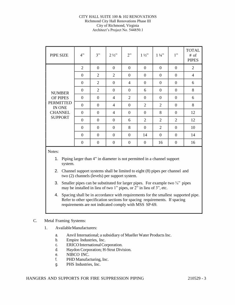
CITY HALL SUITE 100 & 102 RENOVATIONS Richmond City Hall Renovations Phase III
City of Richmond, Virginia Architect’s Project No. 544850.1
HANGERS AND SUPPORTS FOR FIRE SUPPRESSION PIPING 210529 - 3
PIPE SIZE
4”
3”
2 ½”
2”
1 ½”
1 ¼”
1”
TOTAL # of
PIPES
NUMBER OF PIPES
PERMITTED IN ONE
CHANNEL SUPPORT
2 0 0 0 0 0 0 2
0 2 2 0 0 0 0 4
0 2 0 4 0 0 0 6
0 2 0 0 6 0 0 8
0 0 4 2 0 0 0 6
0 0 4 0 2 2 0 8
0 0 4 0 0 8 0 12
0 0 0 6 2 2 2 12
0 0 0 8 0 2 0 10
0 0 0 0 14 0 0 14
0 0 0 0 0 16 0 16
Notes:
1. Piping larger than 4” in diameter is not permitted in a channel support system.
2. Channel support systems shall be limited to eight (8) pipes per channel and two (2) channels (levels) per support system.
3. Smaller pipes can be substituted for larger pipes. For example two ¾” pipes may be installed in lieu of two 1” pipes, or 2” in lieu of 3”, etc.
4. Spacing shall be in accordance with requirements for the smallest supported pipe. Refer to other specification sections for spacing requirements. If spacing requirements are not indicated comply with MSS SP-69.
C. Metal Framing Systems:
1. Available Manufacturers:
a. Anvil International; a subsidiary of Mueller Water Products Inc. b. Empire Industries, Inc. c. ERICO International Corporation. d. Haydon Corporation; H-Strut Division. e. NIBCO INC. f. PHD Manufacturing, Inc. g. PHS Industries, Inc.
CITY HALL SUITE 100 & 102 RENOVATIONS Richmond City Hall Renovations Phase III
City of Richmond, Virginia Architect’s Project No. 544850.1
HANGERS AND SUPPORTS FOR FIRE SUPPRESSION PIPING 210529 - 4
2. Description: Shop- or field-fabricated pipe-support assembly made of steel channels,
accessories, fittings, and other components for supporting multiple parallel pipes. 3. Standard: Comply with MFMA-4. 4. Channels: Continuous slotted steel channel with inturned lips. 5. Channel Nuts: Formed or stamped steel nuts or other devices designed to fit into channel
slot and, when tightened, prevent slipping along channel. 6. Hanger Rods: Continuous-thread rod, nuts, and washer made of carbon steel. 7. Coating: Zinc.
2.3 PIPE STANDS
A. General Requirements for Pipe Stands: Shop- or field-fabricated assemblies made of manufactured corrosion-resistant components to support roof-mounted piping.
B. Compact Pipe Stand: One-piece plastic unit with integral-rod roller, pipe clamps, or V-shaped
cradle to support pipe, for roof installation without membrane penetration.
C. Curb Mounted Pipe Stands: Shop- or field-fabricated pipe supports made from structural-steel shapes, continuous-thread rods, and rollers, for mounting on permanent stationary roof curb.
2.4 EQUIPMENT SUPPORTS
A. Description: Welded, shop or field fabricated equipment support made from structural carbon- steel shapes unless indicated otherwise.
2.5 MISCELLANEOUS MATERIALS
A. Structural Steel: ASTM A 36/A 36M, carbon-steel plates, shapes, and bars; black and galvanized.
B. Grout: ASTM C 1107, factory-mixed and -packaged, dry, hydraulic-cement, nonshrink
and nonmetallic grout; suitable for interior and exterior applications.
1. Properties: Nonstaining, noncorrosive, and nongaseous. 2. Design Mix: 5000-psi, 28-day compressive
strength. PART 3 - EXECUTION
3.1 HANGER AND SUPPORT INSTALLATION
A. Metal Pipe-Hanger Installation: Comply with NFPA 13. Provide hangers, supports, clamps, and attachments as required to properly support piping from the building structure.
CITY HALL SUITE 100 & 102 RENOVATIONS Richmond City Hall Renovations Phase III
City of Richmond, Virginia Architect’s Project No. 544850.1
HANGERS AND SUPPORTS FOR FIRE SUPPRESSION PIPING 210529 - 5
B. Metal Trapeze Pipe-Hanger Installation: Comply with NFPA 13, and Table above. Arrange for
grouping of parallel runs of horizontal piping, and support together on field-fabricated trapeze pipe hangers.
C. Metal Framing System Installation: Arrange for grouping of parallel runs of piping, and support together on field-assembled metal framing systems.
D.Pipe Stand Installation:
1. Pipe Stand Types except Curb-Mounted Type: Assemble components and mount on smooth roof surface. Do not penetrate roof membrane.
2. Curb-Mounted-Type Pipe Stands: Assemble components or fabricate pipe stand and mount on permanent, stationary roof curb. See Division 07 Section "Roof Accessories" for curbs.
E. Provide hangers and supports complete with necessary attachments, inserts, bolts, rods, nuts, washers, and other accessories.
F.Equipment Support Installation: Fabricate from welded-structural-steel shapes.
G. Provide hangers and supports to allow controlled thermal and seismic movement of piping systems, to permit freedom of movement between pipe anchors, and to facilitate action of expansion joints, expansion loops, expansion bends, and similar units.
H.Provide lateral bracing with pipe hangers and supports to prevent swaying.
I. Provide building attachments within concrete slabs or attach to structural steel. Building attachments may not used on steel joists unless otherwise indicated. Provide additional attachments at concentrated loads, including valves, flanges, and strainers, 2-1/2” and larger and at changes in direction of piping. Provide concrete inserts before concrete is placed; fasten inserts to forms and provide reinforcing bars through openings at top of inserts.
J. Load Distribution: Provide hangers and supports so that piping live and dead loads and stresses from movement will not be transmitted to connected equipment.
K. Pipe Slopes: Provide hangers and supports to provide indicated pipe slopes and to not exceed maximum pipe deflections allowed by ASME B31.9 for building services piping.
3.2 EQUIPMENT SUPPORTS
A. Fabricate structural-steel stands to suspend equipment from structure overhead or to support equipment above floor.
B. Grouting: Place grout under supports for equipment and make bearing surface
smooth. C. Provide lateral bracing, to prevent swaying, for equipment supports.
CITY HALL SUITE 100 & 102 RENOVATIONS Richmond City Hall Renovations Phase III
City of Richmond, Virginia Architect’s Project No. 544850.1
HANGERS AND SUPPORTS FOR FIRE SUPPRESSION PIPING 210529 - 6
3.3 METAL FABRICATIONS
A. Cut, drill, and fit miscellaneous metal fabrications for trapeze pipe hangers and equipment supports.
B. Fit exposed connections together to form hairline joints. Field weld connections that cannot be shop welded because of shipping size limitations.
C. Field Welding: Comply with AWS D1.1/D1.1M procedures for shielded, metal arc welding; appearance and quality of welds; and methods used in correcting welding work; and with the following:
1. Provide materials and methods that minimize distortion and develop strength and corrosion resistance of base metals.
2. Obtain fusion without undercut or overlap. 3. Remove welding flux immediately. 4. Finish welds at exposed connections so no roughness shows after finishing and so
contours of welded surfaces match adjacent contours.
3.4 ADJUSTING
A. Hanger Adjustments: Adjust hangers to distribute loads equally on attachments and to achieve indicated slope of pipe.
B.Trim excess length of continuous-thread hanger and support rods to 1-1/2 inches.
3.5 PAINTING
A. Touchup: Unless otherwise indicated clean field welds and abraded areas of shop paint. Paint exposed areas immediately after erecting hangers and supports. Provide same materials as used for shop painting. Comply with SSPC-PA 1 requirements for touching up field-painted surfaces.
1. Apply paint by brush or spray to provide a minimum dry film thickness of 2.0 mils.
B. Galvanized Surfaces: Clean welds, bolted connections, and abraded areas and immediately apply galvanizing-repair paint. Paint shall comply with ASTM A 780.
3.6 HANGER AND SUPPORT SCHEDULE
A. Specific hanger and support requirements are in Sections specifying piping systems and equipment.
B. Comply with NFPA 13 for pipe-hanger selections and applications that are not specified in piping system Sections.
CITY HALL SUITE 100 & 102 RENOVATIONS Richmond City Hall Renovations Phase III
City of Richmond, Virginia Architect’s Project No. 544850.1
HANGERS AND SUPPORTS FOR FIRE SUPPRESSION PIPING 210529 - 7
C. Provide hangers and supports with galvanized metallic coatings for piping and equipment that will
not have field-applied finish.
D.Horizontal-Piping Hangers and Supports: Unless otherwise indicated provide the following:
1. Adjustable, Steel Clevis Hangers: For suspension of stationary pipes ½” to 30”. 2. Pipe Hangers: For suspension of pipes ½” to 4”, to allow off-center closure for hanger
installation before pipe erection. 3. Adjustable, Swivel Split- or Solid-Ring Hangers: For suspension of
noninsulated, stationary pipes ¾” to 8”. 4. Adjustable, Steel Band Hangers: For suspension of noninsulated, stationary pipes ½” to
8”. 5. Adjustable Band Hangers: For suspension of noninsulated, stationary pipes ½” to 8”. 6. Adjustable, Swivel-Ring Band Hangers: For suspension of noninsulated, stationary pipes
½” to 8”. 7. Split Pipe Ring with or without Turnbuckle Hangers: For suspension of
noninsulated, stationary pipes ½” to 8”. 8. Pipe Saddle Supports: For support of pipes 4” to 14”, with steel-pipe base stanchion
support and cast-iron floor flange or carbon-steel plate. 9. Pipe Stanchion Saddles: For support of pipes 4” to 14”, with steel-pipe base stanchion
support and cast-iron floor flange or carbon-steel plate, and with U-bolt to retain pipe. 10. Adjustable Pipe Saddle Supports: For stanchion-type support for pipes 2-½” to 14” if
vertical adjustment is required, with steel-pipe base stanchion support and cast-iron floor flange.
11. Single-Pipe Rolls: For suspension of pipes 1” to 14”, from two rods if longitudinal movement caused by expansion and contraction might occur.
12. Adjustable Roller Hangers: For suspension of pipes 2-½” to 14”, from single rod if horizontal movement caused by expansion and contraction might occur.
13. Complete Pipe Rolls: For support of pipes 2” to 14” if longitudinal movement caused by expansion and contraction might occur but vertical adjustment is not necessary.
14. Pipe Roll and Plate Units: For support of pipes 2” to 14” if small horizontal movement caused by expansion and contraction might occur and vertical adjustment is not necessary.
15. Adjustable Pipe Roll and Base Units: For support of pipes 2” to 14”if vertical and lateral adjustment during installation might be required in addition to expansion and contraction.
E.Vertical-Piping Clamps: Unless otherwise indicated provide the following:
1. Extension Pipe or Riser Clamps: For support of pipe risers ¾” to 14”. 2. Carbon- or Alloy-Steel Riser Clamps: For support of pipe risers ¾” to 14” if longer ends
are required for riser clamps.
F.Hanger-Rod Attachments: Unless otherwise indicated provide the following:
1. Swivel Turnbuckles: For use with MSS Type 11, split pipe rings. 2. Malleable-Iron Sockets: For attaching hanger rods to various types of building
attachments.
HANGERS AND SUPPORTS FOR FIRE SUPPRESSION PIPING 210529 - 8
3. Flat Plate, Double Nut, and Washer as Detailed on Structural Drawings: For attaching to
bar joists. Method of attachment to bar joists must be approved by the structural engineer and joist manufacturer.
G.Building Attachments: Unless otherwise indicated provide the following:
1. Steel or Malleable Concrete Inserts: For upper attachment to suspend pipe hangers from concrete ceiling.
2. Flat Plate, Double Nuts, and Washer as Detailed on Structural Drawings: For use under roof installations with bar-joist construction to attach to bottom chord of joist.
3. Side-Beam or Channel Clamps: For attaching to bottom flange of beams, channels, or angles.
4. Center-Beam Clamps: For attaching to center of bottom flange of beams. 5. C-Clamps: For structural shapes except open web jar joists where hanger load exceeds
50 pounds. 6. Top-Beam Clamps: For top of beams if hanger rod is required tangent to flange edge. 7. Side-Beam Clamps: For bottom of steel I-beams. 8. Steel-Beam Clamps with Eye Nuts: For attaching to bottom of steel I-beams for heavy
loads. 9. Malleable-Beam Clamps with Extension Pieces: For attaching to structural steel. 10. Welded-Steel Brackets: For support of pipes from below or for suspending from
above by using clip and rod. Provide one of the following for indicated loads:
a. Light: 750 lb. b. Medium: 1500 lb. c. Heavy: 3000 lb.
11. Horizontal Travelers: For supporting piping systems subject to linear horizontal movement where headroom is limited.
H. Comply with NFPA 13 for trapeze pipe-hanger selections and applications that are not specified in piping system Sections.
I. Comply with NFPA 13 for metal framing system selections and applications that are not specified in piping system Sections.
J. Provide powder-actuated fasteners or mechanical-expansion anchors instead of building
attachments where indicated in concrete construction.
END OF SECTION 230529
CITY HALL SUITE 100 & 102 RENOVATIONS Richmond City Hall Renovations Phase III
City of Richmond, Virginia Architect’s Project No. 544850.1
WATER-BASED FIRE-SUPPRESSION SYSTEMS 211000 - 1
SECTION 211000 - WATER-BASED FIRE-SUPPRESSION SYSTEMS
PART 1 - GENERAL
1.1 RELATED DOCUMENTS
A. Provisions of the Contract and of the Contract Documents apply to this Section.
1.2 SUMMARY
A. Description of Work:
1. The work includes designing and providing an automatic fire extinguishing system of required hazard for building occupancy to afford complete fire protection coverage throughout. The design, equipment, materials, installation and workmanship shall be in strict accordance with the Owners insurance underwriters requirements, the Virginia Uniform Statewide Building Code, and the required and advisory provisions of NFPA.
2. Unless otherwise indicated piping shall not be run in spaces containing electrical
equipment in the form of transformers, panel-boards, switchgear, or computer servers. a. Exceptions:
1) Personal computers (PCs) 2) Spaces whose name does not include the term “Electrical”, ”Data”, or
“Computer.”
3. Each system shall include materials, accessories and equipment necessary to provide each system complete and ready for use.
4. The design of each system shall give full consideration to blind spaces, piping,
electrical equipment, ductwork, and all other construction and equipment to afford complete coverage.
5. Devices and equipment for fire protection service shall be of an approved make and type
listed by the Underwriters' Laboratories, Inc., or approved by the Factory Mutual System.
6. In the publications referred to herein, the advisory provisions shall be considered to be
mandatory, as though the word "shall" had been substituted for "should" wherever it appears.
7. Reference to the "authority having jurisdiction" shall be interpreted to mean the
Bureau of Capital Outlay Management (BCOM).
8. The work shall begin outside the building at a point five feet from the exterior surface of the wall at the location indicated on the drawings.
CITY HALL SUITE 100 & 102 RENOVATIONS Richmond City Hall Renovations Phase III
City of Richmond, Virginia Architect’s Project No. 544850.1
WATER-BASED FIRE-SUPPRESSION SYSTEMS 211000 - 2
9. Calculations shall include delivering water from the point of the fire hydrant flow test through the site piping.
10. Consideration shall be given to all unheated areas such as attics, utility rooms, loading
docks, outdoor storage spaces with canopies, etc., to provide freeze protection in accordance with NFPA 13. This shall include the installation of dry sprinklers, anti- freeze, and dry-pipe sprinkler systems where necessary.
1.3 DEFINITIONS
A. CR: Chlorosulfonated polyethylene synthetic rubber.
B. PE: Polyethylene plastic.
C. Email: for the purposes of this section email shall be considered “in writing”
1.4 SYSTEM DESCRIPTIONS
A. Wet-Pipe Sprinkler System: Automatic sprinklers are attached to piping containing water and that
is connected to water supply. Water discharges immediately from sprinklers when they are opened. Sprinklers open when heat melts fusible link or destroys frangible device. Hose connections are included if indicated.
B. Preaction Sprinkler System: Automatic sprinklers are attached to piping containing air.
Actuation of fire-detection system in same area as sprinklers opens deluge valve, permitting water to flow into piping and to discharge from sprinklers that have opened.
1.5 PERFORMANCE REQUIREMENTS
A. Component Working Pressure: Listed for at least 175 psig.
B. Design shall be approved by authorities having jurisdiction.
C. Fire-suppression sprinkler system design shall include the following:
1. Margin of Safety for Available Water Flow and Pressure: 20 percent, including losses through water-service piping, valves, and backflow preventers.
2. Sprinkler Occupancy Hazard Classifications shall be as indicated on the drawings. If not indicated comply with NFPA 13.
3. Maximum Protection Area per Sprinkler shall be in accordance with its UL listing.
D. Seismic Performance: Fire-suppression piping shall be capable of withstanding the effects of earthquake motions determined according to ASCE 7-02, "Minimum Design Loads for Buildings and Other Structures": Section 9, "Earthquake Loads."
CITY HALL SUITE 100 & 102 RENOVATIONS Richmond City Hall Renovations Phase III
City of Richmond, Virginia Architect’s Project No. 544850.1
WATER-BASED FIRE-SUPPRESSION SYSTEMS 211000 - 3
1.6 SUBMITTALS
A. Product Data: For the following:
1. Piping materials, including flexible connections, and sprinkler specialty fittings. 2. Pipe hangers and supports. 3. Valves, including listed fire-protection valves, unlisted general-duty valves, specialty
valves and trim. 4. Air compressors, including electrical data. 5. Sprinklers, escutcheons, and guards. Include sprinkler flow characteristics, mounting,
finish, and other pertinent data. 6. Alarm devices, including electrical data.
B. Fire-hydrant flow test report.
C. Approved Sprinkler Piping Shop Drawings: Working plans, prepared according to NFPA 13,
that have been approved by authorities having jurisdiction, including hydraulic calculations. Diagram power, signal, and control wiring. Indicate all ceiling conditions which affect sprinkler locations.
D. Welding certificates.
E. Operation and Maintenance Data to include in emergency, operation, and maintenance manuals.
1.7 CLOSEOUT SUBMITTALS
A. Field Test Reports and Certificates: Indicate and interpret test results for compliance with performance requirements and as described in NFPA 13 and NFPA 14. Include "Contractor's Material and Test Certificate for Aboveground Piping" and "Contractor's Material and Test Certificate for Underground Piping."
1.8 QUALITY ASSURANCE
A. Installer Qualifications:
1. Installer's responsibilities include designing, fabricating, and installing fire-suppression systems and providing professional engineering services needed to assume engineering responsibility.
B. Flow test:
1. Bid shall be based on the indicated fire-hydrant flow and pressure.
2. Design calculations shall be based on the results of a confirming fire-hydrant flow
test performed or caused to be performed by the contractor.
CITY HALL SUITE 100 & 102 RENOVATIONS Richmond City Hall Renovations Phase III
City of Richmond, Virginia Architect’s Project No. 544850.1
WATER-BASED FIRE-SUPPRESSION SYSTEMS 211000 - 4
C. Welding: Qualify processes and operators according to ASME Boiler and Pressure Vessel
Code: Section IX.
D. NFPA Standards: Fire-suppression-system equipment, specialties, accessories, installation, and testing shall comply with the following:
1. NFPA 13: "Installation of Sprinkler Systems." 2007 edition.
1.9 COORDINATION
A. Relocate piping to clear the path of ductwork.
B. Relocate piping to clear the path of conduit.
C. Relocate piping to clear the path of cable tray.
D. Coordinate layout and installation of sprinklers with other construction that penetrates ceilings, including light fixtures, HVAC equipment, and partition assemblies.
1.10 SPRINKLER CABINET(S) AND SPARE SPRINKLERS
A. Provide finished, wall-mounted, steel sprinkler cabinet with hinged cover.
B. Provide space for minimum of six spare sprinklers and sprinkler wrench.
C. Provide minimum of six spare sprinklers and sprinkler wrench in each cabinet.
D. Provide number of sprinklers required by NFPA 13 but no less than six per cabinet.
E. Provide separate cabinet with sprinklers and wrench for each type of sprinkler on Project.
F. Provide products packaged with protective covering for storage. Identify contents with
label. PART 2 - PRODUCTS
2.1 DUCTILE-IRON PIPE AND FITTINGS
A. Mechanical-Joint, Ductile-Iron Pipe: AWWA C151, with mechanical-joint bell end and plain end.
1. Mechanical-Joint, Ductile-Iron Fittings AWWA C110, ductile- or gray-iron standard
pattern or AWWA C153, ductile-iron compact pattern. 2. Glands, Gaskets, and Bolts: AWWA C111, ductile- or gray-iron gland, rubber
gasket, and steel bolts and nuts.
CITY HALL SUITE 100 & 102 RENOVATIONS Richmond City Hall Renovations Phase III
City of Richmond, Virginia Architect’s Project No. 544850.1
WATER-BASED FIRE-SUPPRESSION SYSTEMS 211000 - 5
3. Provide listing for Fire Protection service.
B. Push-on-Joint, Ductile-Iron Pipe: AWWA C151, with push-on-joint bell end and plain end.
1. Push-on-Joint, Ductile-Iron Fittings AWWA C110, ductile- or gray-iron standard
pattern or AWWA C153, ductile-iron compact pattern. 2. Gaskets: AWWA C111, rubber. 3. Provide listing for Fire Protection service.
C. Grooved-End, Ductile-Iron Pipe: AWWA C151, with factory formed, radius-cut-grooved ends according to AWWA C606.
1. Grooved-Joint Piping Systems:
a. Available Manufacturers:
1) Victaulic Co. of America.
b. Grooved-End Fittings: ASTM A 536, ductile-iron casting with OD matching ductile-iron-pipe OD.
c. Grooved-End-Pipe Couplings: AWWA C606, gasketed fitting matching ductile- iron-pipe OD. Include ductile-iron housing with keys matching ductile-iron-pipe and fitting grooves, prelubricated rubber gasket with center leg, and steel bolts and nuts.
d. Grooved-End-Pipe Transition Coupling: UL 213 and AWWA C606, gasketed fitting with end matching ductile-iron-pipe OD and end matching steel-pipe OD. Include ductile-iron housing with key matching ductile-iron-pipe groove and key matching steel-pipe groove, prelubricated rubber gasket listed for use with housing, and steel bolts and nuts.
2. Provide listing for Fire Protection service.
2.2 STEEL PIPE AND FITTINGS
A. Threaded-End, Schedule 40 Steel Pipe: ASTM A 53/A 53M, ASTM A 135, or ASTM A 795, hot-dip galvanized where indicated and with factory- or shop-formed threaded ends.
1. Cast-Iron Threaded Flanges: ASME B16.1. 2. Malleable-Iron Threaded Fittings: ASME B16.3. 3. Gray-Iron Threaded Fittings: ASME B16.4. 4. Steel Threaded Pipe Nipples: ASTM A 733, made of ASTM A 53/A 53M or
ASTM A 106, Schedule 40, seamless steel pipe. Include ends matching joining method. 5. Steel Threaded Couplings: ASTM A 865.
B. Plain-End, Schedule 40 Steel Pipe: ASTM A 53/A 53M, ASTM A 135, or ASTM A 795 hot-
dip galvanized where indicated.
1. Steel Welding Fittings: ASTM A 234/A 234M, and ASME B16.9 or ASME B16.11. 2. Steel Flanges and Flanged Fittings: ASME B16.5.
CITY HALL SUITE 100 & 102 RENOVATIONS Richmond City Hall Renovations Phase III
City of Richmond, Virginia Architect’s Project No. 544850.1
WATER-BASED FIRE-SUPPRESSION SYSTEMS 211000 - 6
C. Grooved-End, Schedule 40 Steel Pipe: ASTM A 53/A 53M, ASTM A 135, or ASTM A 795,
hot-dip galvanized where indicated and with factory- or field-formed, square-cut- or roll- grooved ends.
1. Grooved-Joint Piping Systems:
a. Available Manufacturers:
1) Anvil International, Inc. 2) Central Sprinkler Corp. 3) Ductilic, Inc. 4) JDH Pacific, Inc. 5) National Fittings, Inc. 6) Shurjoint Piping Products, Inc. 7) Southwestern Pipe, Inc. 8) Star Pipe Products; Star Fittings Div. 9) Victaulic Co. of America. 10) Ward Manufacturing.
b. Grooved-End Fittings: UL-listed, ASTM A 536, ductile-iron casting with OD
matching steel-pipe OD. c. Grooved-End-Pipe Couplings: UL 213 and AWWA C606, rigid pattern, unless
otherwise indicated; gasketed fitting matching steel-pipe OD. Include ductile-iron housing with keys matching steel-pipe and fitting grooves, prelubricated rubber gasket listed for use with housing, and steel bolts and nuts.
D. Grooved-End, Schedule 10 Steel Pipe: Schedule 10 in NPS 2-1/2 to NPS 5; and NFPA 13-
specified wall thickness in NPS 6 to NPS 10; with factory- or field-formed, roll-grooved ends.
1. Grooved-Joint Piping Systems:
a. Manufacturers: 1) Central Sprinkler Corp. 2) Victaulic Co. of America. 3) Ward Manufacturing.
b. Grooved-End Fittings: UL-listed, ASTM A 536, ductile-iron casting with OD
matching steel-pipe OD. c. Grooved-End-Pipe Couplings: UL 213 and AWWA C606, rigid pattern, unless
otherwise indicated; gasketed fitting matching steel-pipe OD. Include ductile-iron housing with keys matching steel-pipe and fitting grooves, prelubricated rubber gasket listed for use with housing, and steel bolts and nuts.
2. Provide listing for Fire Protection service.
CITY HALL SUITE 100 & 102 RENOVATIONS Richmond City Hall Renovations Phase III
City of Richmond, Virginia Architect’s Project No. 544850.1
WATER-BASED FIRE-SUPPRESSION SYSTEMS 211000 - 7
FLEXIBLE CONNECTORS
E. Flexible connectors shall have materials suitable for system fluid. Include 175-psig
minimum working-pressure rating and ends according to the following:
1. NPS 2 and Smaller: Threaded or grooved. 2. NPS 2-1/2 and Larger: Flanged or grooved. 3. Option for NPS 2-1/2 and Larger: Grooved for use with grooved-end-pipe couplings.
F. Available Manufacturers:
1. Flex Head Co., Inc. 2. Flex-Hose Co., Inc. 3. Hyspan Precision Products, Inc. 4. Metraflex, Inc.
G. Stainless-Steel-Hose/Stainless-Steel Pipe, Flexible Connectors: Corrugated, stainless-steel,
inner tubing covered with stainless-steel wire braid. Include stainless-steel nipples or flanges, welded to hose.
H. The devices shall be listed under UL category VENF and installed in accordance with the
manufacturer’s installation instructions indicated in the most recent UL listing. The devices shall be permitted only for suspended ceilings which comply with ASTM standards C635, C636, and the UL listed manufacturer’s installation instructions.
2.3 CORROSION-PROTECTIVE ENCASEMENT FOR PIPING
A. Encasement for Underground Metal Piping: ASTM A 674 or AWWA C105, PE film, 0.008- inch minimum thickness, tube or sheet.
2.4 SPRINKLER SPECIALTY FITTINGS
A. Sprinkler specialty fittings shall be UL listed or FMG approved, with 175-psig minimum working-pressure rating, and made of materials compatible with piping. Sprinkler specialty fittings shall have
B. Outlet Specialty Fittings:
1. Available Manufacturers:
a. Central Sprinkler Corp. b. Victaulic Co. of America. c. Ward Manufacturing.
2. Mechanical-T and -Cross Fittings: UL 213, ductile-iron housing with gaskets, bolts and nuts, and grooved outlets.
3. Snap-On and Strapless Outlet Fittings: UL 213, ductile-iron housing or casting with gasket and threaded or grooved or grooved outlet.
CITY HALL SUITE 100 & 102 RENOVATIONS Richmond City Hall Renovations Phase III
City of Richmond, Virginia Architect’s Project No. 544850.1
WATER-BASED FIRE-SUPPRESSION SYSTEMS 211000 - 8
C. Sprinkler Drain and Alarm Test Fittings: Cast- or ductile-iron body; with threaded, grooved or
locking-lug inlet and outlet, test valve, and orifice and sight glass.
1. Available Manufacturers:
a. Central Sprinkler Corp. b. Viking Corp. c. Victaulic Co. of America.
D. Sprinkler Branch-Line Test Fittings: Brass body with threaded or grooved inlet, capped drain
outlet, and threaded or grooved outlet for sprinkler.
1. Available Manufacturers:
a. Elkhart Brass Mfg. Co., Inc. b. Fire-End and Croker Corp. c. Potter-Roemer; Fire-Protection Div.
E. Sprinkler Inspector's Test Fitting: Cast- or ductile-iron housing with threaded or grooved inlet
and drain outlet and sight glass.
1. Available Manufacturers:
a. Central Sprinkler Corp. 2.5 LISTED FIRE-PROTECTION VALVES
A. Valves shall be UL listed or FMG approved, with 175-psig minimum pressure rating.
1. Available manufacturers:
a. Grinnell Fire Protection. b. McWane, Inc.; Kennedy Valve Div. c. NIBCO. d. Stockham.
B. Ball Valves: Comply with UL 1091, except with ball instead of disc.
1. Available Manufacturers:
a. NIBCO. b. Victaulic Co. of America.
2. NPS 1-1/2 and Smaller: Bronze body with threaded or grooved ends.
3. NPS 2 and NPS 2-1/2: Ductile-iron body with grooved ends.
4. NPS 3: Ductile-iron body with grooved ends.
C. Butterfly Valves: UL 1091.
1. NPS 2 and Smaller: Bronze body with grooved ends.
CITY HALL SUITE 100 & 102 RENOVATIONS Richmond City Hall Renovations Phase III
City of Richmond, Virginia Architect’s Project No. 544850.1
WATER-BASED FIRE-SUPPRESSION SYSTEMS 211000 - 9
a. Available Manufacturers:
1) Global Safety Products, Inc. 2) Victaulic Co. of America. 3) Milwaukee Valve Company.
2. NPS 2-1/2 and Larger: Bronze, cast-iron, or ductile-iron body; wafer type or with
flanged or grooved ends.
a. Available Manufacturers:
1) Central Sprinkler Corp. 2) McWane, Inc.; Kennedy Valve Div. 3) Mueller Company. 4) NIBCO. 5) Victaulic Co. of America.
D. Check Valves NPS 2 and Larger: UL 312, swing type, cast-iron body with flanged or
grooved ends.
1. Available Manufacturers: a. Clow Valve Co. b. Crane Co.; Crane Valve Group; Crane Valves. c. Crane Co.; Crane Valve Group; Jenkins Valves. d. Grinnell Fire Protection. e. NIBCO. f. Potter-Roemer; Fire Protection Div. g. Reliable Automatic Sprinkler Co., Inc. h. Stockham. i. Victaulic Co. of America. j. Watts Industries, Inc.; Water Products Div.
E. Indicating Valves: UL 1091, with integral indicating device and ends matching connecting
piping.
1. Indicator: Electrical, 15 amp @125-VAC 60 HZ, prewired, single-pole-single-throw, supervisory switch
2. NPS 2 and Smaller: Ball or butterfly valve with bronze body and threaded or grooved ends.
a. Available Manufacturers:
1) Milwaukee Valve Company. 2) NIBCO. 3) Victaulic Co. of America.
CITY HALL SUITE 100 & 102 RENOVATIONS Richmond City Hall Renovations Phase III
City of Richmond, Virginia Architect’s Project No. 544850.1
WATER-BASED FIRE-SUPPRESSION SYSTEMS 211000 - 10
3. NPS 2-1/2 and Larger: Butterfly valve with cast- or ductile-iron body; wafer type or with
flanged or grooved ends.
a. Available Manufacturers:
1) Central Sprinkler Corp. 2) Grinnell Fire Protection. 3) Milwaukee Valve Company. 4) NIBCO. 5) Victaulic Co. of America.
2.6 GENERAL-DUTY VALVES
A. Available Manufacturers: 1. Crane Co.; Crane Valve Group; Crane Valves. 2. Crane Co.; Crane Valve Group; Jenkins Valves. 3. Jamesbury; a subsidiary of Metso Automation. 4. Milwaukee Valve Company. 5. NIBCO INC. 6. Red-White Valve Corporation.
B. Ball Valves NPS 2 and Smaller: MSS SP-110, 2-piece copper-alloy body with chrome-plated
brass ball, 600-psig minimum CWP rating, blowout-proof stem, and threaded or grooved ends.
C. Check Valves NPS 2 and Smaller: MSS SP-80, Type 4, Class 125 minimum, swing type
with bronze body, nonmetallic disc, and threaded or grooved ends.
2.7 SPECIALTY VALVES
A. Sprinkler System Control Valves: UL listed or FMG approved, cast- or ductile-iron body with flanged or grooved ends, and 175-psig minimum pressure rating.
1. Available Manufacturers:
a. Central Sprinkler Corp. b. Grinnell Fire Protection. c. Reliable Automatic Sprinkler Co., Inc. d. Tyco Fire & Building Products. e. Victaulic Co. of America. f. Viking Corp.
2. Riser Check Valves: UL listed, designed for horizontal or vertical installation, with
bronze grooved seat with O-ring seals, single-hinge pin, and latch design. Include trim sets for bypass, drain, electrical sprinkler alarm switch, pressure gages, and fill-line attachment with strainer.
3. Deluge Valves: UL 260, cast-iron body, electrically operated, differential-pressure type.
CITY HALL SUITE 100 & 102 RENOVATIONS Richmond City Hall Renovations Phase III
City of Richmond, Virginia Architect’s Project No. 544850.1
WATER-BASED FIRE-SUPPRESSION SYSTEMS 211000 - 11
Include bronze seat with O-ring seals, trim sets for bypass, drain, electrical sprinkler alarm switch, pressure gages, drip cup assembly piped without valves and separate from main drain line, fill-line attachment with strainer, and push-rod chamber supply connection.
a. Provide documentation confirming listing for Pre-action
use.
b. Activation of BOTH the detection condition AND the opening of an automatic sprinkler will activate the solenoid valves, open the deluge valve, and cause water to discharge. This will sound an alarm and activate alarm and water flow contacts for auxiliary functions.
c. Air-Pressure Maintenance Device: UL 260, automatic device to maintain correct
air pressure in piping. Include shutoff valves to permit servicing without shutting down sprinkler piping, bypass valve for quick filling, pressure regulator or switch to maintain pressure, strainer, pressure ratings with 14- to 60-psig adjustable range, and 175-psig maximum inlet pressure.
1) Available Manufacturers:
a) AFAC Inc. b) Central Sprinkler Corp. c) General Air Products, Inc. d) Globe Fire Sprinkler Corporation. e) Grinnell Fire Protection. f) Reliable Automatic Sprinkler Co., Inc. g) Star Sprinkler Inc. h) Tyco Fire & Building Products. i) Viking Corp.
d. Air Compressor: UL 753, fractional horsepower, 120-V ac, 60 Hz, single phase.
1) Available Manufacturers:
a) AFAC Inc. b) Gast Manufacturing, Inc. c) Grinnell Fire Protection. d) Reliable Automatic Sprinkler Co., Inc. e) Tyco Fire & Building Products. f) Viking Corp.
B. Automatic Drain Valves: UL 1726, NPS 3/4, ball-check device with threaded or grooved ends.
1. Available Manufacturers:
a. Grinnell Fire Protection.
CITY HALL SUITE 100 & 102 RENOVATIONS Richmond City Hall Renovations Phase III
City of Richmond, Virginia Architect’s Project No. 544850.1
WATER-BASED FIRE-SUPPRESSION SYSTEMS 211000 - 12
2.8 SPRINKLERS
A. Sprinklers shall be UL listed or FMG approved, with 175-psig minimum pressure rating.
B. Sprinklers with O-rings are prohibited.
C. Available Manufacturers:
1. Central Sprinkler Corp. 2. Grinnell Fire Protection. 3. Reliable Automatic Sprinkler Co., Inc. 4. Tyco Fire & Building Products. 5. Victaulic Co. of America. 6. Viking Corp.
D. Automatic Sprinklers: With glass bulb type heat-responsive element complying with the
following:
1. UL 199, for nonresidential applications.
E. Sprinkler types, features, and options as follows:
1. Concealed ceiling sprinklers, including cover plate. 2. Extended-coverage sprinklers. 3. Flush ceiling sprinklers, including escutcheon. 4. Pendent sprinklers. 5. Pendent, dry-type sprinklers. 6. Quick-response sprinklers. 7. Recessed sprinklers, including escutcheon. 8. Sidewall sprinklers. 9. Sidewall, dry-type sprinklers. 10. Upright sprinklers.
F. Sprinkler Finishes: Chrome plated, bronze, and painted.
G. Sprinkler Escutcheons: Materials, types, and finishes for the following sprinkler mounting
applications. Escutcheons for concealed, flush, and recessed-type sprinklers are specified with sprinklers.
1. Ceiling Mounting: 2 piece, with 1-inch vertical adjustment. 2. Sidewall Mounting: 2 piece, with 1-inch horizontal adjustment.
H. Sprinkler Guards: Wire-cage type, including fastening device for attaching to sprinkler.
2.9 TEST HEADER FOR BACKFLOW PREVENTER
A. Manufacturers:
1. Elkhart Brass Mfg. Co., Inc. 2. Fire-End and Croker Corp.
CITY HALL SUITE 100 & 102 RENOVATIONS Richmond City Hall Renovations Phase III
City of Richmond, Virginia Architect’s Project No. 544850.1
WATER-BASED FIRE-SUPPRESSION SYSTEMS 211000 - 13
3. Guardian Fire Equipment Incorporated. 4. Potter-Roemer; Fire-Protection Div
B. Hose Valve Manifold Assembly:
1. Header Pipe: Schedule 40, galvanized-steel with threaded ends. 2. Header Pipe Fittings: galvanized cast-iron threaded fittings. 3. Automatic Drain Valve: UL 1726 4. Hose Valves: UL 668, straightway pattern, bronze with cap and chain. Include NFPA
1963 hose thread that complies with local fire department standards and finish same as for test- header-manifold escutcheon plate.
5. Nipples: Schedule 40 galvanized-steel pipe with threaded ends. 6. Adaptors and Caps with Chain: Brass or bronze with threaded outlet. 7. Escutcheon Plate: Brass or bronze, rectangular. 8. Exposed Parts Finish: Rough-chrome plated. 9. Escutcheon Plate Marking: “TEST HEADER.”
2.10 ALARM DEVICES
A. Alarm-device types shall match piping and equipment connections.
B. Wet Pipe Water-Flow Indicator: UL 346, electrical-supervision, paddle-operated-type, water- flow detector with 250-psig pressure rating and designed for horizontal or vertical installation. Include two single-pole, double-throw circuit switches for isolated alarm and auxiliary contacts, 7 A, 125-V ac and 0.25 A, 24-V dc; complete with factory-set, field-adjustable retard element to prevent false signals and tamperproof cover that sends signal if removed.
1. Available Manufacturers:
a. Grinnell Fire Protection. b. ITT McDonnell & Miller. c. Potter Electric Signal Company. d. Viking Corp. e. Watts Industries, Inc.; Water Products Div.
C. Pre-action-Flow Indicator (Pressure Switch): UL 753, electrical-supervision-type, water-
flow switch with retard feature. Include single-pole, double-throw, normally closed contacts and design that operates on rising pressure and signals water flow.
1. Available Manufacturers:
a. Grinnell Fire Protection. b. Potter Electric Signal Company. c. System Sensor. d. Viking Corp.
CITY HALL SUITE 100 & 102 RENOVATIONS Richmond City Hall Renovations Phase III
City of Richmond, Virginia Architect’s Project No. 544850.1
WATER-BASED FIRE-SUPPRESSION SYSTEMS 211000 - 14
D. Valve Supervisory Switch: UL 753, electrical, single-pole, double-throw switch with normally
closed contacts. Include design that signals controlled valve is in other than fully open position.
1. Available Manufacturers:
a. McWane, Inc.; Kennedy Valve Div. b. Potter Electric Signal Company. c. System Sensor.
E. No Retard Wet Pipe Water-Flow Indicator: UL S739, electrical-supervision, paddle-operated
type, water-flow detector with 250-psig pressure rating and designed for horizontal or vertical installation. Include two single-pole, double-throw circuit switches for isolated alarm and auxiliary contacts, 7A, 125-V ac and 0.25 A, 24-V dc; no retard element and tamperproof cover that sends signal if removed.
1. Available Manufacturers:
a. System Sensor b. Potter Electric Signal Company c. Viking Corp.
2.11 PRESSURE GAGES
A. Available Manufacturers: 1. Dresser Equipment Group; Instrument Div.
B. Description: UL 393, 3-1/2” to 4-1/2” diameter dial.
C. Water System Piping: Include caption "WATER" or "AIR/WATER" on dial face.
PART 3 - EXECUTION
3.1 PREPARATION
A. Perform fire-hydrant flow test according to NFPA standards, procedures, appendices, or recommendations.
B. Report test results no later than two days following the test in writing.
3.2 EARTHWORK
A. Refer to Division 31 Section "Earth Moving" for excavating, trenching, and backfilling.
CITY HALL SUITE 100 & 102 RENOVATIONS Richmond City Hall Renovations Phase III
City of Richmond, Virginia Architect’s Project No. 544850.1
WATER-BASED FIRE-SUPPRESSION SYSTEMS 211000 - 15
3.3 PIPING APPLICATIONS, GENERAL
A. Provide shop-welded joints where welding is required.
B. Provide shop or manufacturer-threaded or grooved joints where threads are required.
C. Field-threaded joints will not be permitted.
D. Field-welded joints will be permitted where indicated on the drawings. Field welding is
optional where indicated. Other approved or specified methods are acceptable.
E. Do not use welded joints for galvanized-steel.
F. Flanges, flanged fittings, unions, nipples, transition and special fittings with finish and pressure ratings same as or higher than system's pressure rating may be used in aboveground applications, unless otherwise indicated.
G. Underground Piping: Ductile-iron, mechanical-joint pipe and fittings with restrained joints.
Include corrosion-protective encasement.
3.4 SPRINKLER SYSTEM PIPING APPLICATIONS
A. Wet-Pipe Sprinkler System, 175-psig Maximum Working Pressure:
1. Sprinkler Piping NPS 2” and smaller use any of the following:
a. Threaded or grooved-end, black, schedule 40 steel pipe; cast- or malleable-iron threaded or grooved fittings; and threaded or grooved joints.
b. Plain-end, black, schedule 40 steel pipe; steel welding fittings; and welded joints. c. Grooved-end, black, schedule 40 steel pipe with square-cut- or roll-grooved ends;
grooved-end fittings; grooved-end-pipe couplings; and grooved joints. 2. Sprinkler Piping NPS 2 ½” and larger use any of the following:
a. Threaded or grooved-end, black, schedule 40 steel pipe; cast- or malleable-iron threaded or grooved fittings; and threaded or grooved joints.
b. Plain-end, black, schedule 10 steel pipe; steel welding fittings; and welded joints. c. Grooved-end, black, Schedule 10 steel pipe; grooved-end fittings; grooved-end-
pipe couplings; and roll grooved joints.
3.5 VALVE APPLICATIONS
A. Where specific valve types are not indicated, the following requirements apply:
1. Listed Fire-Protection Valves: UL listed and FMG approved for application.
a. Shutoff Duty: Use ball, or butterfly valves.
CITY HALL SUITE 100 & 102 RENOVATIONS Richmond City Hall Renovations Phase III
City of Richmond, Virginia Architect’s Project No. 544850.1
WATER-BASED FIRE-SUPPRESSION SYSTEMS 211000 - 16
3.6 JOINT CONSTRUCTION
A. Refer to Section "Common Work Results for Fire Suppression" for basic piping
joint construction.
B. Threaded Joints: Comply with NFPA 13 for pipe thickness and threads. Do not thread pipe smaller than 8” with wall thickness less than Schedule 40 unless approved by authorities having jurisdiction.
C. Threads shall be checked by a ring gage and shall comply with ASME B1.20.1.
D. Grooved Joints: Assemble joints with listed coupling, gasket, lubricant, and bolts.
1. Ductile-Iron Pipe: Radius-cut-groove ends of piping. Use grooved-end fittings
and grooved-end-pipe couplings. 2. Steel Pipe: Roll-groove piping. Use grooved-end fittings and rigid, grooved-end-
pipe couplings, unless otherwise indicated. 3. Dry-Pipe Systems: Use fittings and gaskets listed for dry-pipe service.
E. Dissimilar-Metal Piping Joints: Construct joints using dielectric fittings compatible with both
piping materials.
1. NPS 2 and Smaller: Use dielectric unions, couplings, or nipples. 2. NPS 2-1/2 to NPS 4: Use dielectric flanges. 3. NPS 5 and Larger: Use dielectric flange insulation kits.
3.7 SERVICE-ENTRANCE PIPING
A. Connect fire-suppression piping to water-service piping of size and in location indicated for service entrance to building.
B. Install shutoff valve, pressure gage, drain, and other accessories indicated at connection to
water-service piping.
3.8 PIPING INSTALLATION
A. Refer to Section "Common Work Results for Fire Suppression" for basic piping installation.
B. Locations and Arrangements: Drawing plans, shop drawings, schematics, and diagrams indicate general location and arrangement of piping. Install piping as indicated.
1. Deviations from approved working drawings for piping require written approval from
authorities having jurisdiction and Architect. File written approval with Architect before deviating.
CITY HALL SUITE 100 & 102 RENOVATIONS Richmond City Hall Renovations Phase III
City of Richmond, Virginia Architect’s Project No. 544850.1
WATER-BASED FIRE-SUPPRESSION SYSTEMS 211000 - 17
C. Install underground piping according to NFPA 13, NFPA 24 and Drawings. Provide
restrained joints. Provide corrosion-protective encasement.
D. Provide approved fittings to make changes in direction, branch takeoffs from mains, and reductions in pipe sizes.
E. Provide unions adjacent to each valve in pipes 2” and smaller. Unions are not required on
flanged devices or in piping installations using grooved joints.
F. Provide flanges or flange adapters on valves, and equipment having 2-1/2” and larger pipe connections.
G. Provide "Inspector's Test Connections" in sprinkler system piping, complete with shutoff valve.
Test connections that discharge to the exterior shall discharge 1’-0” above a concrete splash block. Provide splash block under this section of the specifications. Pipe penetration shall be installed to coursing dimensions where concrete masonry units are utilized to construct wall.
H. Provide sprinkler piping with drains for complete system drainage.
I. Provide alarm devices.
J. Hangers and Supports: Refer to Section “Hangers and Supports for Fire-Suppression Piping”
for hanger materials.
1. Install sprinkler system piping according to NFPA 13.
K. Install pressure gages on each riser or feed main, and at each sprinkler test connection. Include pressure gages with connection not less than ¼” and with soft metal seated globe valve, arranged for draining pipe between gage and valve. Install gages to permit removal, and install where not subject to freezing.
L. Drain dry-pipe sprinkler piping.
M. Pressurize and check dry-pipe sprinkler system piping and air compressors.
N. Pressurize and check preaction sprinkler system piping and air compressors.
O. Fill wet-pipe sprinkler system piping with water.
3.9 VALVE INSTALLATION
A. Install listed fire-protection valves, unlisted general-duty valves, specialty valves and trim, controls, and specialties according to NFPA 13 and authorities having jurisdiction.
B. Install listed fire-protection shutoff valves supervised-open, located to control sources of water
supply except from fire department connections. Install permanent identification signs indicating portion of system controlled by each valve.
CITY HALL SUITE 100 & 102 RENOVATIONS Richmond City Hall Renovations Phase III
City of Richmond, Virginia Architect’s Project No. 544850.1
WATER-BASED FIRE-SUPPRESSION SYSTEMS 211000 - 18
C. Valves for Wall-Type Fire Hydrants: Install nonrising-stem gate valve in water-supply pipe.
D. Specialty Valves:
1. Riser Check Valves: Install in vertical position for proper direction of flow, including
drain-line connection. 2. Deluge Valves: Install in vertical position, in proper direction of flow, in main supply to
preaction system.
a. Air-Pressure Maintenance Devices for Dry-Pipe Systems: Install shutoff valves to permit servicing without shutting down sprinkler system; bypass valve for quick system filling; pressure regulator or switch to maintain system pressure; strainer; pressure ratings with 14- to 60-psig adjustable range; and 175-psig maximum inlet pressure.
b. Install air compressor and compressed-air supply piping.
3.10 SPRINKLER APPLICATIONS
A. Use the following sprinkler types unless otherwise indicated.
1. Wall Mounting: Recessed Sidewall sprinklers. 2. Spaces Subject to Freezing: Dry type sprinklers. 3. Special Applications: Quick-response sprinklers. 4. Sprinkler Finishes:
a. Upright, Pendent, and Sidewall Sprinklers: Chrome plated in finished spaces
exposed to view; rough bronze in unfinished spaces not exposed to view. b. Concealed Sprinklers: Rough brass, with factory chrome plated cover plate. c. Flush Sprinklers: Bright chrome, with painted white escutcheon. d. Recessed Sprinklers: White polyester, with white escutcheon.
3.11 SPRINKLER INSTALLATION
A. Install sprinklers in suspended ceilings in center of acoustical ceiling panels and tiles.
B. Do not install pendent or sidewall, wet-type sprinklers in areas subject to freezing. Use dry- type sprinklers with water supply from heated space wherever possible. Otherwise, use antifreeze sprinkler systems, or dry-pipe systems.
3.12 CONNECTIONS
A. Install piping adjacent to equipment to allow service and maintenance.
B. Connect water-supply piping to fire-suppression piping.
CITY HALL SUITE 100 & 102 RENOVATIONS Richmond City Hall Renovations Phase III
City of Richmond, Virginia Architect’s Project No. 544850.1
WATER-BASED FIRE-SUPPRESSION SYSTEMS 211000 - 19
C. Install ball drip valves at each check valve for fire department connection. Drain as indicated.
If not indicated otherwise, drain to floor drain or outside building.
D. Connect piping to hose valves, specialties, fire department connections, and accessories.
E. Connect compressed-air supply to dry-pipe sprinkler piping.
F. Connect air compressor to the following piping and wiring:
1. Pressure gages and controls. 2. Electrical power system. 3. Fire alarm devices, including low-pressure alarm.
G. Coordinate connection of alarm devices to fire alarm.
H. Ground equipment. Grounding shall be in accordance with section "Grounding and Bonding for
Electrical Systems."
I. Coordinate connection of wiring.
J. Tighten electrical connectors and terminals according to manufacturer's published torque- tightening values. If manufacturer's torque values are not indicated, use those specified in UL 486A and UL 486B.
3.13 LABELING AND IDENTIFICATION
A. Install labeling and pipe markers on equipment and piping according to requirements in NFPA 13 and section “Common Work Results for Fire-Suppression” for piping identifications.
3.14 FIELD QUALITY CONTROL
A. Perform the following field tests and inspections and prepare test reports:
1. Leak Test: After installation, charge system and test for leaks. Repair leaks and retest until no leaks exist.
2. Test and adjust controls and safeties. Replace damaged and malfunctioning controls and equipment.
3. Energize circuits to electrical equipment and devices. 4. Start and run air compressors. 5. Flush, test, and inspect sprinkler systems according to NFPA 13, "Systems Acceptance"
Chapter. 6. Flush, test, and inspect standpipe systems according to NFPA 14, "System Acceptance"
Chapter. 7. Coordinate with fire alarm tests. Operate as required. 8. Coordinate with fire-pump tests. Operate as required. 9. Verify that equipment hose threads are same as local fire department equipment.
1ST FLOOR LOBBY AND 4TH FLOOR RENOVATIONS Richmond City Hall Renovations Phase III
City of Richmond, Virginia Architect’s Project No. 544850.1
WATER-BASED FIRE-SUPPRESSION SYSTEMS 211000 - 20
B. Report test results promptly and in writing to Architect and authorities having jurisdiction.
3.15 CLEANING AND PROTECTION
3.16 Clean dirt and debris from sprinklers.
A. Provide sprinklers to replace sprinklers with paint or coating other than the original factory finish.
B. Protect sprinklers from damage and debris until Substantial Completion.
C. Protect the building exterior when operating drains and test connections discharging to the
building exterior.
D. Dirt and stains on any surfaces resulting from the work of this section shall be cleaned and removed under this section.
3.17 DEMONSTRATION
A. Engage a factory-authorized service representative to train Owner's maintenance personnel to adjust, operate, and maintain the system.
END OF SECTION 211000
CITY HALL SUITE 100 & 102 RENOVATIONS
CITY HALL SUITE 100 & 102 RENOVATIONS Richmond City Hall Renovations Phase III
City of Richmond, Virginia Architect’s Project No. 544850.1
COMMON WORK RESULTS FOR HVAC 230500 - 1
SECTION 230500 - COMMON WORK RESULTS FOR HVAC
PART 1 - GENERAL
1.1 RELATED DOCUMENTS
A. Provisions of the Contract and of the Contract Documents apply to this Section. 1.2 DEFINITIONS
A. Finished Spaces: Spaces other than mechanical and electrical equipment rooms, furred spaces,
pipe chases, unheated spaces immediately below roof, spaces above ceilings, unexcavated spaces, crawlspaces, and tunnels.
B. Exposed, Interior Installations: Exposed to view indoors. Examples include finished occupied
spaces and mechanical equipment rooms.
C. Exposed, Exterior Installations: Exposed to view outdoors or subject to outdoor ambient temperatures and weather conditions. Examples include rooftop locations.
D. Concealed, Interior Installations: Concealed from view and protected from physical contact by
building occupants. Examples include above ceilings and in chases.
E. Concealed, Exterior Installations: Concealed from view and protected from weather conditions and physical contact by building occupants but subject to outdoor ambient temperatures. Examples include installations within unheated shelters.
F. The following are industry abbreviations for rubber materials:
1. EPDM: Ethylene-propylene-diene terpolymer rubber. 2. NBR: Acrylonitrile-butadiene rubber.
G. VUSBC: Virginia Uniform Statewide Building Code
1.3 SUBMITTALS
A. Product Data: For the following:
1. Transition fittings. 2. Dielectric fittings. 3. Mechanical sleeve seals. 4. Escutcheons.
1ST FLOOR LOBBY AND 4TH FLOOR RENOVATIONS Richmond City Hall Renovations Phase III
City of Richmond, Virginia Architect’s Project No. 544850.1
COMMON WORK RESULTS FOR HVAC 230500 - 2
1.4 QUALITY ASSURANCE
A. Equipment and appliances comprising portions of the mechanical systems regulated by the VUSBC shall be listed and labeled in accordance with the current edition of the VUSBC.
B. Equipment and appliances comprising portions of the mechanical systems regulated by the
VUSBC shall be installed in accordance with the listing, manufacturer’s installation instructions, and the VUSBC. Manufacturer’s installation instructions shall be available on the job site for use and inspection.
C. Steel Support Welding: Qualify processes and operators according to AWS D1.1, "Structural
Welding Code--Steel."
D. Steel Pipe Welding: Qualify processes and operators according to ASME Boiler and Pressure Vessel Code: Section IX, "Welding and Brazing Qualifications."
1. Comply with provisions in ASME B31 Series, "Code for Pressure Piping." 2. Certify that each welder has passed AWS qualification tests for welding processes
involved and that certification is current.
E. Electrical Characteristics for HVAC Equipment: Equipment of higher electrical characteristics may be furnished provided such proposed equipment is approved in writing and connecting electrical services, circuit breakers, and conduit sizes are appropriately modified. If minimum energy ratings or efficiencies are specified, equipment shall comply with requirements.
1.5 DELIVERY, STORAGE, AND HANDLING
A. Deliver pipes and tubes with factory-applied end caps. Maintain end caps through shipping,
storage, and handling to prevent pipe end damage and to prevent entrance of dirt, debris, and moisture.
1.6 COORDINATION
A. Arrange for pipe spaces, chases, slots, and openings in building structure during progress of
construction, to allow for HVAC installations.
B. Coordinate installation of required supporting devices and set sleeves in poured-in-place concrete and other structural components as they are constructed.
C. Coordinate requirements for access panels and doors for HVAC items requiring access that are
concealed behind finished surfaces. Access panels and doors are specified in Division 08 Section "Access Doors and Frames."
CITY HALL SUITE 100 & 102 RENOVATIONS
1ST FLOOR LOBBY AND 4TH FLOOR RENOVATIONS Richmond City Hall Renovations Phase III
City of Richmond, Virginia Architect’s Project No. 544850.1
COMMON WORK RESULTS FOR HVAC 230500 - 3
1.7 INTENT OF CONTRACT DOCUMENTS
A. Mechanical and HVAC drawings are diagrammatic, indicating general locations and arrangements of pipe, duct, and equipment. Not necessarily indicating all offsets, conditions, and appurtenances required to provide clearances for maximum practical accessibility to perform maintenance.
B. Coordinate work in order to achieve proper operation and to provide a maintainable installed
condition.
C. Notify the Architect’s representative immediately of conditions which do not comply or will not produce this result.
D. Indicated configurations were used to size pipes, pumps, expansion tanks and other devices.
Install piping, duct, and equipment generally as indicated. Minor deviations are permitted in the course of necessary coordination. Major changes shall be submitted for approval by the Architect’s representative. Additional fittings and offsets not indicated are expected, anticipated by the design, and shall be provided. If more than 5% of the indicated number of fittings are required or if one change in direction is within six inches of another change in direction and this “Z” shape is not indicated notify the Architect’s representative immediately. Provide necessary additional fittings and offsets. Changes in pipe size shall be made only with written approval from the Architect’s representative.
PART 2 - PRODUCTS
2.1 PIPE, TUBE, AND FITTINGS
A. Refer to Section “Hydronic Piping” for additional pipe, tube, and fitting materials and joining
methods.
B. Pipe Threads: ASME B1.20.1 for factory-threaded pipe and pipe fittings. 2.2 JOINING MATERIALS
A. Refer to individual Division 23 piping sections for joining materials not listed below.
B. Pipe-Flange Gasket Materials: Suitable for chemical and thermal conditions inside & outside
pipe and:
1. ASME B16.21, non-metallic, flat, asbestos-free, 1/8-inch maximum thickness unless thickness or specific material is otherwise indicated.
a. Full-Face Type: For flat-face, Class 125, cast-iron and cast-bronze flanges. b. Narrow-Face Type: For raised-face, Class 250, cast-iron and steel flanges.
CITY HALL SUITE 100 & 102 RENOVATIONS
1ST FLOOR LOBBY AND 4TH FLOOR RENOVATIONS Richmond City Hall Renovations Phase III
City of Richmond, Virginia Architect’s Project No. 544850.1
COMMON WORK RESULTS FOR HVAC 230500 - 4
2. AWWA C110, rubber, flat face, 1/8 inch thick, unless otherwise indicated, and full-face or ring type, unless otherwise indicated.
C. Solder Filler Metals: ASTM B 32, lead-free (95% Tin, 5% Antimony) alloy. Include water-
flushable flux according to ASTM B 813.
D. Brazing Filler Metals: AWS A5.8, BCuP Series, copper-phosphorus alloys for general-duty brazing, unless otherwise indicated; and AWS A5.8, BAg1, silver alloy for refrigerant piping, unless otherwise indicated.
E. Welding Filler Metals: Comply with AWS D10.12 for welding materials appropriate for wall
thickness and chemical analysis of steel pipe being welded. 2.3 DIELECTRIC FITTINGS
A. Description: Combination fitting of copper alloy and ferrous materials with threaded, solder-
joint, plain, or weld-neck end connections that match piping system materials.
B. Insulating Material: Suitable for system fluid, pressure, and temperature.
C. Dielectric Flanges: Factory-fabricated, companion-flange assembly, for 150- or 300-psig minimum working pressure as required to suit system pressures.
1. Available Manufacturers:
a. Capitol Manufacturing Co. b. Central Plastics Company. c. Epco Sales, Inc. d. Watts Industries, Inc.; Water Products Div.
D. Dielectric-Flange Kits: Companion-flange assembly for field assembly. Include flanges, full-
face- or ring-type neoprene or phenolic gasket, phenolic or polyethylene bolt sleeves, phenolic washers, and steel backing washers.
1. Available Manufacturers:
a. Advance Products & Systems, Inc. b. Calpico, Inc. c. Central Plastics Company. d. Pipeline Seal and Insulator, Inc.
2. Separate companion flanges and steel bolts and nuts shall have 150- or 300-psig
minimum working pressure where required to suit system pressures.
E. Dielectric Couplings: Galvanized steel coupling with inert and non-corrosive, thermoplastic lining; threaded ends; and 300-psig minimum working pressure at 225°F.
CITY HALL SUITE 100 & 102 RENOVATIONS
1ST FLOOR LOBBY AND 4TH FLOOR RENOVATIONS Richmond City Hall Renovations Phase III
City of Richmond, Virginia Architect’s Project No. 544850.1
COMMON WORK RESULTS FOR HVAC 230500 - 5
1. Available Manufacturers:
a. Calpico, Inc. b. Lochinvar Corp.
2.4 MECHANICAL SLEEVE SEALS
A. Description: Modular sealing element unit, designed for field assembly, to fill annular space
between pipe and sleeve.
1. Available Manufacturers:
a. Advance Products & Systems, Inc. b. Calpico, Inc. c. Metraflex Co. d. Pipeline Seal and Insulator, Inc.
2. Sealing Elements: EPDM interlocking links shaped to fit surface of pipe. Include type
and number required for pipe material and size of pipe. 3. Pressure Plates: Plastic. Include two for each sealing element. 4. Connecting Bolts and Nuts: Stainless steel of length required to secure pressure plates to
sealing elements. 2.5 SLEEVES
A. Galvanized-Steel Sheet: 0.0239-inch minimum thickness; round tube closed with welded
longitudinal joint.
B. Steel Pipe: ASTM A 53, Type E, Grade B, Schedule 40, galvanized, plain ends.
C. Cast Iron: Cast or fabricated "wall pipe" equivalent to ductile-iron pressure pipe, with plain ends and integral waterstop, unless otherwise indicated.
D. Stack Sleeve Fittings: Manufactured, cast-iron sleeve with integral clamping flange. Include
clamping ring and bolts and nuts for membrane flashing.
1. Underdeck Clamp: Clamping ring with set screws.
E. Molded PE: Reusable, PE, tapered cup-shaped and smooth-outer surface with nailing flange for attaching to wooden forms.
CITY HALL SUITE 100 & 102 RENOVATIONS
1ST FLOOR LOBBY AND 4TH FLOOR RENOVATIONS Richmond City Hall Renovations Phase III
City of Richmond, Virginia Architect’s Project No. 544850.1
COMMON WORK RESULTS FOR HVAC 230500 - 6
2.6 ESCUTCHEONS
A. Description: Manufactured wall and ceiling escutcheons and floor plates, with an ID to closely fit around pipe, tube, and insulation of insulated piping and an OD that completely covers opening.
B. One-Piece, Deep-Pattern Type: Deep-drawn, box-shaped brass with polished chrome-plated
finish.
C. One-Piece, Cast-Brass Type: With set screw.
1. Finish: Polished chrome-plated.
D. Split-Casting, Cast-Brass Type: With concealed hinge and set screw.
1. Finish: Polished chrome-plated.
E. One-Piece, Floor-Plate Type: Cast-iron floor plate.
F. Split-Casting, Floor-Plate Type: Cast brass with concealed hinge and set screw. 2.7 GROUT
A. Description: ASTM C 1107, Grade B, non-shrink and non-metallic, dry hydraulic cement
grout.
1. Characteristics: Post-hardening, volume-adjusting, non-staining, non-corrosive, non- gaseous, and recommended for interior and exterior applications.
2. Design Mix: 5000-psi, 28-day compressive strength. 3. Packaging: Premixed and factory packaged.
PART 3 - EXECUTION
3.1 HVAC DEMOLITION
A. Refer to Sections "Cutting and Patching" and "Selective Structure Demolition" for general
demolition requirements and procedures.
B. Disconnect, demolish, and remove HVAC systems, equipment, and components indicated to be removed.
1. Piping to Be Removed: Remove portion of piping indicated to be removed and cap or
plug remaining piping with same or compatible piping material. 2. Piping to Be Abandoned in Place: Drain piping and cap or plug piping with same or
compatible piping material.
CITY HALL SUITE 100 & 102 RENOVATIONS
1ST FLOOR LOBBY AND 4TH FLOOR RENOVATIONS Richmond City Hall Renovations Phase III
City of Richmond, Virginia Architect’s Project No. 544850.1
COMMON WORK RESULTS FOR HVAC 230500 - 7
3. Equipment to Be Removed: Remove equipment and associated piping back to main unless otherwise indicated. Cap services.
4. Equipment to Be Removed and Reinstalled: Disconnect and cap services. Remove, clean, and store equipment. When appropriate, reinstall, reconnect, and make equipment operational.
5. Equipment to Be Removed and Salvaged: Remove equipment and associated piping back to main unless otherwise indicated. Cap services. Remove equipment, clean, and store as directed (May be off-site). Make available to owner at time of the owner’s choosing.
C. If pipe, insulation, or equipment to remain is damaged in appearance or is unserviceable,
remove damaged or unserviceable portions and replace with new products of equal capacity and quality.
3.2 PIPING SYSTEMS - COMMON REQUIREMENTS
A. Install piping according to the following and Division 23 Sections specifying piping systems.
B. Install piping in concealed locations, unless otherwise indicated
and except in equipment rooms and service areas.
C. Install piping indicated to be exposed and piping in equipment rooms and service areas at right angles or parallel to building walls. Diagonal runs are prohibited unless specifically indicated.
D. Install piping above accessible ceilings allowing sufficient space for ceiling panel removal.
E. Install piping to permit valve operation & servicing.
F. Install condensate drain piping at 1% slope.
G. Install piping free of sags and bends.
H. Install fittings for changes in direction and branch connections unless otherwise indicated.
I. Install piping leaving room for installation of insulation.
J. Install system components with pressure rating equal to or greater than system operating
pressure.
K. Install escutcheons for penetrations of walls, ceilings, and floors according to the following:
1. Exposed, Interior Installations/Piping with Fitting or Sleeve Protruding from Wall: One- piece, deep-pattern type.
2. Exposed, Interior Installations/Chrome-Plated Piping: One-piece, cast-brass type with polished chrome-plated finish and set-screw.
3. Exposed, Interior Installations/Insulated Piping: One-piece, cast-brass type with polished chrome-plated finish.
CITY HALL SUITE 100 & 102 RENOVATIONS
1ST FLOOR LOBBY AND 4TH FLOOR RENOVATIONS Richmond City Hall Renovations Phase III
City of Richmond, Virginia Architect’s Project No. 544850.1
COMMON WORK RESULTS FOR HVAC 230500 - 8
4. Exposed, Interior Installations/Bare Piping at Wall and Floor Penetrations in Finished Spaces: One-piece, cast-brass type with finish to match surrounding surfaces.
5. Exposed, Interior Installations/Bare Piping at Ceiling Penetrations in Finished Spaces: One-piece or split-casting, cast-brass type with finish to match surrounding surfaces.
6. Exposed, Interior Installations/Piping in Unfinished Service Spaces: None, provide sealant.
7. Exposed, Interior Installations/Piping in Equipment Rooms: None, provide sealant. 8. Exposed, Interior Installations/Piping at Floor Penetrations in Equipment Rooms, Fan
Rooms, or similar wet spaces: None - provide sealant and sleeve extending 2” above floor to prevent liquid leaking to floor below.
L. Provide seal around piping penetrations of full height interior walls, both rated and non-rated,
that occur above ceilings. Refer to Section 079200 Joint Sealants.
M. Sleeves are not required for core-drilled holes. 1. Exception: Exposed, Interior Installations at Floor Penetrations in Equipment Rooms, Fan
Rooms, or similar wet spaces.
N. Permanent sleeves are not required for holes formed by removable PE sleeves. 1. Exception: Exposed, Interior Installations at Floor Penetrations in Equipment Rooms, Fan
Rooms, or similar wet spaces.
O. Install sleeves for pipes passing through walls, floors, or roofs.
1. Cut sleeves to length for mounting flush with both surfaces.
a. Exception: Extend sleeves installed in floors of mechanical equipment rooms, fan rooms or other similar wet areas 2 inches above finished floor level. Extend cast- iron sleeve fittings below floor slab as required to secure clamping ring.
2. Install sleeves as walls and slabs are constructed.
a. PVC Pipe Sleeves: Permitted for pipes smaller than 6” except aboveground,
exterior-walls. b. Steel Sheet Sleeves: Permitted for pipes 6” and larger, penetrating gypsum-board
partitions except aboveground, exterior-walls. c. Seal space outside sleeve fittings with grout and sealant.
3. Except for penetrations where mechanical sleeve seals are used, seal annular space
between sleeve and pipe or pipe insulation, using joint sealants appropriate for size, depth, and location of joint. Refer to Section "Joint Sealants".
P. Aboveground Exterior Penetrations: Seal penetrations using sleeves and mechanical sleeve
seals. Select sleeve size to allow for annular clear space required by the mechanical sleeve seal manufacturer between pipe and sleeve for installing mechanical sleeve seals.
1. Install steel pipe for sleeves smaller than 6 inches in diameter.
CITY HALL SUITE 100 & 102 RENOVATIONS
1ST FLOOR LOBBY AND 4TH FLOOR RENOVATIONS Richmond City Hall Renovations Phase III
City of Richmond, Virginia Architect’s Project No. 544850.1
COMMON WORK RESULTS FOR HVAC 230500 - 9
2. Install cast-iron "wall pipes" for sleeves 6 inches and larger in diameter. 3. Mechanical Sleeve Seal Installation: Select type and number of sealing elements
required for pipe material and size. Position pipe in center of sleeve. Assemble mechanical sleeve seals and install in annular space between pipe and sleeve. Tighten bolts against pressure plates that cause sealing elements to expand and make watertight seal.
4. Sleeves from an approved sleeve seal manufacturer shall be acceptable.
Q. Underground Exterior Penetrations: Install cast-iron "wall pipes" for sleeves. Seal pipe penetrations using mechanical sleeve seals. Select sleeve size to allow for annular clear space required by the mechanical sleeve seal manufacturer between pipe and sleeve for installing mechanical sleeve seals.
R. Mechanical Sleeve Seal Installation: Select type and number of sealing elements required for
pipe material and size. Position pipe in center of sleeve. Assemble mechanical sleeve seals and install in annular space between pipe and sleeve. Tighten bolts against pressure plates that cause sealing elements to expand and make watertight seal.
S. Fire-Barrier Penetrations: Maintain indicated fire rating of walls, partitions, ceilings, and floors
at pipe penetrations. Seal pipe penetrations with firestop materials. Refer to Section "Penetration Firestopping" for materials.
T. Verify final equipment locations for roughing-in.
U. Refer to equipment specifications in other Sections of these Specifications for roughing-in
requirements. 3.3 PIPING JOINT CONSTRUCTION
A. Join pipe and fittings according to the following requirements and Division 22 Sections
specifying piping systems.
B. Ream ends of pipes and tubes and remove burrs. Bevel plain ends of steel pipe.
C. Remove scale, slag, dirt, and debris from inside and outside of pipe and fittings before assembly.
D. Soldered Joints: Apply water-flushable flux, unless otherwise indicated, to tube end. Construct
joints using lead-free solder alloy.
E. Brazed Joints: Construct joints using copper-phosphorus brazing filler metal.
F. Threaded Joints: Thread pipe with tapered pipe threads. Cut threads full and clean using sharp dies. Ream threaded pipe ends to remove burrs and restore full ID. Join pipe fittings and valves as follows:
CITY HALL SUITE 100 & 102 RENOVATIONS
1ST FLOOR LOBBY AND 4TH FLOOR RENOVATIONS Richmond City Hall Renovations Phase III
City of Richmond, Virginia Architect’s Project No. 544850.1
COMMON WORK RESULTS FOR HVAC 230500 - 10
1. Apply appropriate tape or thread compound to external pipe threads unless otherwise indicated.
G. Welded Joints: Construct joints using qualified processes and welding operators.
H. Flanged Joints: Select appropriate gasket material, size, type, and thickness for service
application. Install gasket concentrically positioned. Use suitable lubricants on bolt threads.
I. Mechanical Joints: Prepare pipe ends and fittings, apply coupling, and join according to joint manufacturer's written instructions.
3.4 PIPING CONNECTIONS
A. Make connections according to the following, unless otherwise indicated:
1. Install unions, in piping 2” and smaller, one adjacent to each valve and at final
connections to each piece of equipment. 2. Install flanges, in piping NPS 2-1/2” and larger, adjacent to final connections to each
piece of equipment. 3. Install dielectric unions or flanges for connections of dissimilar metals.
3.5 EQUIPMENT INSTALLATION - COMMON REQUIREMENTS
A. Install equipment to allow maximum possible headroom unless specific mounting heights are
indicated.
B. Install equipment level and plumb, parallel and perpendicular to other building systems and components in exposed interior spaces, unless otherwise indicated.
C. Install HVAC equipment to facilitate service, maintenance, and repair or replacement of
components. Connect equipment for ease of disconnecting, with minimum interference to other installations. Extend grease fittings to service side of equipment.
D. Install equipment to allow space for other systems.
3.6 PAINTING
A. Damage and Touchup: Repair marred and damaged factory-painted finishes with materials and
procedures to match original factory finish. 3.7 HOUSEKEEPING PADS AND EQUIPMENT PADS
CITY HALL SUITE 100 & 102 RENOVATIONS
1ST FLOOR LOBBY AND 4TH FLOOR RENOVATIONS Richmond City Hall Renovations Phase III
City of Richmond, Virginia Architect’s Project No. 544850.1
COMMON WORK RESULTS FOR HVAC 230500 - 11
A. Housekeeping pads and equipment pads: Anchor equipment to concrete according to equipment manufacturer's written instructions and according to seismic codes at project location.
1. Construct concrete pads in accordance with drawing details.
2. Details may be found on structural drawings. If details are not provided comply with the following:
a. Housekeeping pads inside the building shall be 4” thick and 6” larger all around than supported equipment. Provide a 1” chamfer on all edges.
b. If details are not provided, equipment pads outside the building shall be 8” thick with a 24” deep 12” wide turndown (footing) all around the outside edge of the pad. Provide welded wire mesh reinforcement. Pad shall be 12” larger all around than supported equipment.
c. Install dowel rods to connect housekeeping pad to concrete floor. Unless otherwise indicated, install dowel rods on 18-inch centers around the full perimeter of the pad. Provide a 1” chamfer on all edges.
d. Install epoxy-coated anchor bolts. For equipment on housekeeping pads bolts shall extend through housekeeping pad, and anchor into structural concrete floor.
e. Place and secure anchor bolts using supported equipment manufacturer's setting drawings, templates, diagrams, instructions, and directions for placement.
f. Install anchor bolts to elevations required for proper attachment to supported equipment.
g. Install anchor bolts according to anchor bolt manufacturer's written instructions. h. Use 3000-psi, 28-day compressive-strength concrete and reinforcement as
specified in Section "Cast-in-Place Concrete”. 3.8 ERECTION OF METAL SUPPORTS AND ANCHORAGES
A. Refer to Section "Metal Fabrications" for structural steel.
B. Cut, fit, and place miscellaneous metal supports accurately in location, alignment, and elevation
to support and anchor HVAC materials and equipment.
C. Field Welding: Comply with AWS D1.1. 3.9 GROUTING
A. Mix and install grout for HVAC equipment base bearing surfaces, pump and other equipment
base plates, and anchors.
B. Clean surfaces that will come into contact with grout.
C. Provide forms as required for placement of grout.
D. Avoid air entrapment during placement of grout.
CITY HALL SUITE 100 & 102 RENOVATIONS
1ST FLOOR LOBBY AND 4TH FLOOR RENOVATIONS Richmond City Hall Renovations Phase III
City of Richmond, Virginia Architect’s Project No. 544850.1
COMMON WORK RESULTS FOR HVAC 230500 - 1
E. Place grout, completely filling equipment bases.
F. Place grout on concrete bases and provide smooth bearing surface for equipment.
G. Place grout around anchors.
H. Cure placed grout. 3.10 EXCAVATION AND BACKFILL
A. Excavation and backfill shall be as indicated in Division 1 specifications and on the drawings.
If excavation and backfill is not otherwise indicated the following shall apply: 1. Excavate trenches to indicated gradients, lines, depths, and elevations.
a. Beyond the building perimeter, excavate trenches to allow installation of top of pipe below frost line.
2. Excavate trenches to uniform widths to provide twelve inches clear on each side of pipe. Excavate trench walls vertically from trench bottom.
3. Trench Bottoms: Excavate trench bottoms to provide flat surface. Place and compact six inches of sand. Excavate and shape sand to provide uniform bearing and support of pipes. Shape sand to provide continuous support for bells, joints, fittings, and barrels of pipes. Sand shall be free of projecting stones and sharp objects.
4. Backfill and hand tamp to 95% proctor to six inches above the top of the pipe. 5. Backfill and machine tamp the remainder of the trench to 95% proctor in twelve inch
lifts. END OF SECTION 230500
CITY HALL SUITE 100 & 102 RENOVATIONS
CITY HALL SUITE 100 & 102 RENOVATIONS Richmond City Hall Renovations Phase III
City of Richmond, Virginia Architect’s Project No. 544850.1
SLEEVES AND SLEEVE SEALS FOR HVAC PIPING 230517 - 1
SECTION 230517 - SLEEVES AND SLEEVE SEALS FOR HVAC PIPING
PART 1 - GENERAL
1.1 RELATED DOCUMENTS
A. Provisions of the Contract and of the Contract Documents apply to this Section. 1.2 SUBMITTALS
A. Product Data: For each type of product indicated.
PART 2 - PRODUCTS
2.1 SLEEVES
A. Cast-Iron Wall Pipes: Cast or fabricated of cast or ductile iron and equivalent to ductile-iron pressure pipe, with plain ends and integral waterstop unless otherwise indicated.
B. Galvanized-Steel Wall Pipes: ASTM A 53/A 53M, Schedule 40, with plain ends and welded
steel collar; zinc coated.
C. Galvanized-Steel-Pipe Sleeves: ASTM A 53/A 53M, Type E, Grade B, Schedule 40, zinc coated, with plain ends.
D. Galvanized-Steel-Sheet Sleeves: 0.0239-inch minimum thickness; round tube closed with
welded longitudinal joint. 2.2 STACK-SLEEVE FITTINGS
A. Available Manufacturers:
1. Smith, Jay R. Mfg. Co. 2. Wade 3. Zurn Specification Drainage Operation; Zurn Plumbing Products Group.
B. Description: Manufactured, cast-iron sleeve with integral clamping flange. Include clamping
ring, bolts, and nuts for membrane flashing.
1. Underdeck Clamp: Clamping ring with setscrews.
CITY HALL SUITE 100 & 102 RENOVATIONS Richmond City Hall Renovations Phase III
City of Richmond, Virginia Architect’s Project No. 544850.1
SLEEVES AND SLEEVE SEALS FOR HVAC PIPING 230517 - 2
2.3 SLEEVE-SEAL SYSTEMS
A. Available Manufacturers:
1. Advance Products & Systems, Inc. 2. CALPICO, Inc. 3. Link Seal 4. Metraflex Company (The). 5. Pipeline Seal and Insulator, Inc. 6. Proco Products, Inc.
B. Description: Modular sealing-element unit, designed for field assembly, for filling annular space between piping and sleeve.
1. Sealing Elements: EPDM or Nitrile rubber interlocking links shaped to fit surface of pipe. Include type and number required for pipe material and size of pipe.
2. Pressure Plates: Stainless steel. 3. Connecting Bolts and Nuts: Stainless steel of length required to secure pressure plates to
sealing elements. 2.4 GROUT
A. Standard: ASTM C 1107/C 1107M, Grade B, post-hardening and volume-adjusting, dry,
hydraulic-cement grout.
B. Characteristics: Nonshrink; recommended for interior and exterior applications.
C. Design Mix: 5000-psi, 28-day compressive strength.
D. Packaging: Premixed and factory packaged.
PART 3 - EXECUTION
3.1 SLEEVE INSTALLATION
A. Install sleeves for piping passing through penetrations in floors, partitions, roofs, and walls.
B. For sleeves that will have sleeve-seal system installed, select sleeves of size large enough to provide 1-inch annular clear space between piping and concrete slabs and walls.
1. Sleeves are not required for core-drilled holes.
C. Install sleeves in concrete floors, concrete roof slabs, and concrete walls as new slabs and walls
are constructed.
1. Permanent sleeves are not required for holes in slabs formed by molded-PE or -PP sleeves.
CITY HALL SUITE 100 & 102 RENOVATIONS Richmond City Hall Renovations Phase III
City of Richmond, Virginia Architect’s Project No. 544850.1
SLEEVES AND SLEEVE SEALS FOR HVAC PIPING 230517 - 3
2. Cut sleeves to length for mounting flush with both surfaces.
a. Exception: Extend sleeves installed in floors of mechanical equipment areas or other wet areas 2 inches above finished floor level.
3. Using grout, seal the space outside of sleeves in slabs and walls without sleeve-seal system.
D. Install sleeves for pipes passing through interior partitions.
1. Cut sleeves to length for mounting flush with both surfaces. 2. Install sleeves that are large enough to provide ¼” clear space between sleeve and pipe or
pipe insulation. 3. Seal annular space between sleeve and piping or piping insulation; use joint sealants
appropriate for size, depth, and location of joint. Comply with requirements for sealants.
E. Fire Ratings: Maintain indicated fire rating of walls, partitions, ceilings, and floors at pipe penetrations. Seal pipe penetrations with firestop materials.
3.2 STACK-SLEEVE-FITTING INSTALLATION
A. Install stack-sleeve fittings in new slabs as slabs are constructed.
1. Install fittings that are large enough to provide ¼” clear space between sleeve and pipe or
pipe insulation. 2. Secure flashing between clamping flanges for pipes penetrating floors with membrane
waterproofing. Comply with requirements for flashing specified in Division 07 Section "Sheet Metal Flashing and Trim."
3. Install section of cast-iron soil pipe to extend sleeve to 2 inches above finished floor level.
4. Extend cast-iron sleeve fittings below floor slab as required to secure clamping ring if ring is specified.
5. Using grout, seal the space around outside of stack-sleeve fittings.
B. Fire Rating: Maintain indicated fire rating at pipe penetrations. Seal pipe penetrations with firestop materials.
3.3 SLEEVE-SEAL-SYSTEM INSTALLATION
A. Install sleeve-seal systems in sleeves in exterior concrete walls and slabs-on-grade at service
piping entries into building unless otherwise indicated. They are not required at sanitary and storm piping exits unless otherwise indicated.
B. Select type, size, and number of sealing elements required for piping material and size and for
sleeve ID or hole size. Position piping in center of sleeve. Center piping in penetration, assemble sleeve-seal system components, and install in annular space between piping and
CITY HALL SUITE 100 & 102 RENOVATIONS Richmond City Hall Renovations Phase III
City of Richmond, Virginia Architect’s Project No. 544850.1
SLEEVES AND SLEEVE SEALS FOR HVAC PIPING 230517 - 4
sleeve. Tighten bolts against pressure plates that cause sealing elements to expand and make a watertight seal.
3.4 SLEEVE AND SLEEVE-SEAL SCHEDULE
A. Use sleeves and sleeve seals for the following piping-penetration applications:
1. Exterior Concrete Walls above Grade, below Grade, Concrete Slabs-on-Grade, and
Concrete Slabs above Grade:
a. Piping Smaller Than NPS 6: Cast-iron wall sleeves with sleeve-seal system. 1) Select sleeve size to allow for 1-inch annular clear space between piping and
sleeve for installing sleeve-seal system. b. Piping NPS 6 and Larger: Galvanized-steel-pipe sleeves with sleeve-seal system.
END OF SECTION 230517
CITY HALL SUITE 100 & 102 RENOVATIONS Richmond City Hall Renovations Phase III
City of Richmond, Virginia Architect’s Project No. 544850.1
METERS AND GAUGES FOR HVAC PIPING 230519 - 1
SECTION 230519 - METERS AND GAUGES FOR HVAC PIPING
PART 1 - GENERAL
1.1 RELATED DOCUMENTS
A. Provisions of the Contract and of the Contract Documents apply to this Section. 1.2 ABBREVIATIONS
1.3 SUBMITTALS
A. Product Data: For each type of product indicated.
B. Wiring Diagrams: For power, signal, and control wiring.
C. Operation and Maintenance Data: For meters and gages to include in operation and
maintenance manuals.
A. ° Degree or degrees.
B.
AFF
Above Finished Floor.
C.
BAS
Building Automation System
D.
F
Fahrenheit.
E.
GPM
Gallons Per Minute.
F.
mA
Milliamp, or Milliamps.
G.
PSI
Pounds per Square Inch.
H.
PSIG
Pounds per Square Inch Gauge.
I.
V
Volt, or Volts
CITY HALL SUITE 100 & 102 RENOVATIONS Richmond City Hall Renovations Phase III
City of Richmond, Virginia Architect’s Project No. 544850.1
METERS AND GAUGES FOR HVAC PIPING 230519 - 2
PART 2 - PRODUCTS 2.1 THERMOMETERS
A. Available Manufacturers:
1. Flo Fab Inc. 2. Miljoco Corporation. 3. Palmer Wahl Instrumentation Group. 4. Tel-Tru Manufacturing Company. 5. Trerice, H. O. Co. 6. Weiss Instruments, Inc. 7. Winters Instruments - U.S.
B. Standard: ASME B40.200.
C. Case: Cast aluminum
D. Size: 9” nominal unless otherwise indicated.
E. Case Form: Adjustable angle.
F. Tube: Glass with magnifying lens and blue or red organic liquid. Mercury is not acceptable.
G. Tube Background: Nonreflective aluminum with permanently etched scale markings graduated
in 2° F increments.
H. Window: Glass.
I. Stem: 1. Duct Installation: Aluminum ventilated. 2. Pipe Installation: Brass.
J. Thermowell Connector for Pipe Installation: 1¼” with ASME B1.1 threads.
K. Accuracy: Plus or minus one scale division.
L. Scale Range: Suitable for service.
2.2 DUCT THERMOMETER MOUNTING BRACKETS
A. Description: Flanged bracket with screw holes for attachment to air duct and made to hold
thermometer stem.
CITY HALL SUITE 100 & 102 RENOVATIONS Richmond City Hall Renovations Phase III
City of Richmond, Virginia Architect’s Project No. 544850.1
METERS AND GAUGES FOR HVAC PIPING 230519 - 3
2.3 THERMOWELLS
A. Thermowells:
1. Standard: ASME B40.200. 2. Description: Manufactured by thermometer manufacturer, pressure-tight, socket-type
fitting made for insertion into piping tee. 3. Material:
a. Copper Tubing/Piping: Brass. b. Steel Piping: Type 316 stainless steel
4. Type: Stepped shank unless straight or tapered shank is recommended by manufacturer. 5. Bore: Diameter required to match thermometer stem. 6. Insertion Length: Length required to match thermometer stem and to reach center of
pipe. 7. Lagging Extension: Include for insulated piping and tubing. 8. Heat transfer medium: As available and recommended by manufacturer.
2.4 PRESSURE GAGES
1. Available Manufacturers:
a. Ernst Flow Industries. b. Flo Fab Inc. c. Palmer Wahl Instrumentation Group. d. Tel-Tru Manufacturing Company. e. Trerice, H. O. Co. f. Watts Regulator Co.; a div. of Watts Water Technologies, Inc. g. Weiss Instruments, Inc.
2. Application Standard: ASME B40.100. 3. Case: Dry, field liquid fillable, satin finished, type 304 stainless steel, stem mounted,
flangeless. 4. Pressure-Element Assembly: Bronze tube. 5. Pressure Connection: Brass, with ¼”or ½” ASME B1.20.1 pipe threads and bottom-
outlet unless back-outlet is indicated. 6. Movement: Stainless steel. 7. Dial Size: 4-1/2” 8. Dial Face: Nonreflective aluminum with permanently etched black scale markings
graduated in psi. Two PSI maximum per graduation. 9. Pointer: Adjustable black metal. 10. Window: Glass. 11. Ring: 304 stainless steel. 12. Accuracy: Grade 1A, plus or minus 1 percent of full scale. 13. Units: PSI 14. Scale range: Suitable for service
CITY HALL SUITE 100 & 102 RENOVATIONS Richmond City Hall Renovations Phase III
City of Richmond, Virginia Architect’s Project No. 544850.1
METERS AND GAUGES FOR HVAC PIPING 230519 - 4
2.5 GAGE ATTACHMENTS
A. Pulsation Dampener: ASME B40.100, brass; with ¼” or ½”, ASME B1.20.1 pipe threads and piston type surge-dampening device. Include extension for use on insulated piping.
B. Siphons: Loop-shaped section of brass for copper, and stainless steel for steel, pipe filled with
water with ¼” or ½” pipe threads to prevent live steam from entering gauge. Provide on all gauges serving steam systems.
C. Valves: Brass needle for copper pipe, or stainless-steel needle for steel pipe, with ¼” or ½”,
ASME B1.20.1 pipe threads. 2.6 TEMPERATURE/PRESSURE PLUG
A. Available Manufacturers:
1. Flow Design, Inc. 2. Trerice, H. O. Co. 3. Watts Regulator Co.; a div. of Watts Water Technologies, Inc. 4. Weiss Instruments, Inc.
B. Description: Test fitting made for insertion into piping tee fitting.
C. Body: Brass or stainless steel with core inserts and gasketed and threaded cap. Include
extended stem on units to be installed in insulated piping.
D. Thread Size: ½”, ASME B1.20.1 pipe thread.
E. Minimum Pressure and Temperature Rating: 500 psig at 200° F.
F. Core Inserts: EPDM self-sealing rubber. 2.7 TEMPERATURE/PRESSURE PLUG KITS
A. Available Manufacturers:
1. Flow Design, Inc. 2. Trerice, H. O. Co. 3. Watts Regulator Co.; a div. of Watts Water Technologies, Inc. 4. Weiss Instruments, Inc.
B. Provide one temperature/pressure plug kit containing two thermometers, one pressure gauge,
pressure gauge adapter, and carrying case. Thermometer sensing elements, pressure gauge, and gauge adapter probes shall be of a diameter to fit temperature/pressure plugs and of length to project into piping.
CITY HALL SUITE 100 & 102 RENOVATIONS Richmond City Hall Renovations Phase III
City of Richmond, Virginia Architect’s Project No. 544850.1
METERS AND GAUGES FOR HVAC PIPING 230519 - 5
C. Low Range Thermometer: Small, bimetallic insertion type with 1” to 2” diameter dial and tapered-end sensing element. Dial range shall be at least 25 to 125° F.
D. High Range Thermometer: Small, bimetallic insertion type with 1” to 2” diameter dial and
tapered-end sensing element. Dial range shall be at least 0 to 220° F.
E. Pressure Gage: Small, Bourdon-tube insertion type with 2” to 3” diameter dial and probe. Dial range shall be at least 0 to 200 PSIG.
F. Carrying Case: Metal or plastic, with formed instrument padding.
2.8 FLOWMETERS
A. Electromagnetic Flowmeters:
1. Available Manufacturers:
a. Onicon (F-3000 Series)
2. Description: Insertion electromagnetic flow meter with 4-20mA or 0-10VDC interface to BAS.
3. Flow Range: Sensor and indicator shall cover operating range of equipment or system served.
a. Scale: GPM. b. Accuracy: Plus or minus 1% from 2-20 ft/s. c. Turndown: 100:1
4. Display: Rate of flow in GPM.
PART 3 - EXECUTION
3.1 INSTALLATION
A. Thermowells: 1. In all locations install so thermometer will be easily visible. 2. In horizontal piping install with socket extending to center of pipe and in vertical position
in piping tees. 3. In vertical piping install with socket extending to center of pipe and in horizontal position
in piping tees.
B. Install thermowells of sizes required to match thermometer connectors.
C. Install thermowells with lagging extension on insulated piping.
D. Fill thermowells with heat-transfer medium as recommended by manufacturer.
CITY HALL SUITE 100 & 102 RENOVATIONS Richmond City Hall Renovations Phase III
City of Richmond, Virginia Architect’s Project No. 544850.1
METERS AND GAUGES FOR HVAC PIPING 230519 - 6
E. Install thermometers in thermowells and adjust vertical and tilted positions so they are with-in 15’ (Measured from 6’ above the floor) of an easily accessible location and the window is perpendicular to that location. 1. Exception: Where installed in piping or ductwork located in excess of 20’ AFF.
F. Install duct-thermometer mounting brackets in walls of ducts. Attach to duct with screws.
G. Install thermometers in the following locations:
1. Where indicated 2. Inlet and outlet of each hydronic zone. 3. Inlet and outlet of each hydronic boiler. 4. Inlet(s) and outlet(s) of each chiller. 5. Inlet and outlet of each hydronic coil in air-handling units. 6. Inlet(s) and outlet(s) of each hydronic heat exchanger. 7. Inlet and outlet of each thermal-storage tank. 8. Outside, return, and supply air ducts.
H. Install pressure gages in piping tees with pressure gage located on pipe at the most readable
position.
I. Install pressure gages in the following locations:
1. Inlet an outlet of each pressure-reducing valve. 2. Inlet and outlet of each chiller. 3. Inlet and outlet of each boiler. 4. Inlet and outlet of each coil.
a. Exceptions (Install test plugs instead): 1) Fan coil units. 2) Variable volume terminal units. 3) Blower coil units.
5. Inlet of each thermal-storage tank. 6. Suction and discharge of each pump.
J. Install valve in piping for each pressure gage.
K. Install snubber in piping for each pressure gage for fluids (except steam).
L. Install siphon fitting in piping for each pressure gage (for steam).
M. Install test plugs in piping tees where indicated and at all pipe mounted BAS pressure and
temperature sensors.
N. Install flowmeter elements in accessible positions in piping systems.
CITY HALL SUITE 100 & 102 RENOVATIONS Richmond City Hall Renovations Phase III
City of Richmond, Virginia Architect’s Project No. 544850.1
METERS AND GAUGES FOR HVAC PIPING 230519 - 7
3.2 CONNECTIONS
A. Install meters and gages adjacent to machines and equipment to allow service, maintenance, and cleaning of meters, gages, machines, and equipment.
3.3 ADJUSTING
A. After installation, calibrate meters according to manufacturer's written instructions.
B. Adjust faces of meters and gages to proper angle for best visibility.
END OF SECTION 230519
CITY HALL SUITE 100 & 102 RENOVATIONS Richmond City Hall Renovations Phase III
City of Richmond, Virginia Architect’s Project No. 544850.1
GENERAL DUTY VALVES FOR HVAC PIPING 230523 - 1
SECTION 230523 – GENERAL DUTY VALVES FOR HVAC PIPING
PART 1 - GENERAL
1.1 RELATED DOCUMENTS
A. Provisions of the Contract and of the Contract Documents apply to this Section. 1.2 DEFINITIONS
A. The following are standard abbreviations for valves:
1. CWP: Cold working pressure. 2. EPDM: Ethylene-propylene-diene terpolymer rubber. 3. MPTFE: Modified polytetrafluoroethylene plastic. 4. NBR: Acrylonitrile-butadiene rubber. 5. PTFE: Polytetrafluoroethylene plastic. 6. RPTFE: Reinforced polytetrafluoroethylene plastic. 7. TFE: Tetrafluoroethylene plastic. 8. WOG: Water Oil Gas.
1.3 SUBMITTALS
A. Product Data: For each type of valve proposed. Include body, seating, and trim materials;
valve design; pressure and temperature classifications; end connections; arrangement; dimensions; and required clearances. Include proposed specialties and accessories.
1.4 QUALITY ASSURANCE
A. ASME Compliance: ASME B31.1 for power piping valves and ASME B31.9 for building
services piping valves. 1. Exceptions: Domestic hot- and cold-water valves unless referenced.
B. ASME Compliance for Ferrous Valves: ASME B16.10 and ASME B16.34 for dimension and
design criteria.
C. NSF Compliance: NSF 61 for valve materials for potable-water service. 1.5 DELIVERY, STORAGE, AND HANDLING
A. Prepare valves for shipping as follows:
1. Protect internal parts against rust and corrosion. 2. Protect threads, flange faces, grooves, and weld ends.
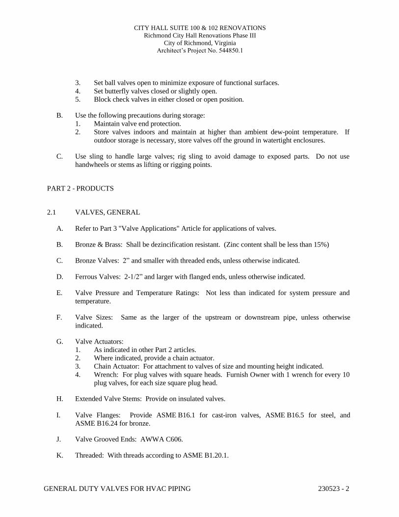
CITY HALL SUITE 100 & 102 RENOVATIONS Richmond City Hall Renovations Phase III
City of Richmond, Virginia Architect’s Project No. 544850.1
GENERAL DUTY VALVES FOR HVAC PIPING 230523 - 2
3. Set ball valves open to minimize exposure of functional surfaces. 4. Set butterfly valves closed or slightly open. 5. Block check valves in either closed or open position.
B. Use the following precautions during storage:
1. Maintain valve end protection. 2. Store valves indoors and maintain at higher than ambient dew-point temperature. If
outdoor storage is necessary, store valves off the ground in watertight enclosures.
C. Use sling to handle large valves; rig sling to avoid damage to exposed parts. Do not use handwheels or stems as lifting or rigging points.
PART 2 - PRODUCTS
2.1 VALVES, GENERAL
A. Refer to Part 3 "Valve Applications" Article for applications of valves.
B. Bronze & Brass: Shall be dezincification resistant. (Zinc content shall be less than 15%)
C. Bronze Valves: 2” and smaller with threaded ends, unless otherwise indicated.
D. Ferrous Valves: 2-1/2” and larger with flanged ends, unless otherwise indicated.
E. Valve Pressure and Temperature Ratings: Not less than indicated for system pressure and
temperature.
F. Valve Sizes: Same as the larger of the upstream or downstream pipe, unless otherwise indicated.
G. Valve Actuators:
1. As indicated in other Part 2 articles. 2. Where indicated, provide a chain actuator. 3. Chain Actuator: For attachment to valves of size and mounting height indicated. 4. Wrench: For plug valves with square heads. Furnish Owner with 1 wrench for every 10
plug valves, for each size square plug head.
H. Extended Valve Stems: Provide on insulated valves.
I. Valve Flanges: Provide ASME B16.1 for cast-iron valves, ASME B16.5 for steel, and ASME B16.24 for bronze.
J. Valve Grooved Ends: AWWA C606.
K. Threaded: With threads according to ASME B1.20.1.
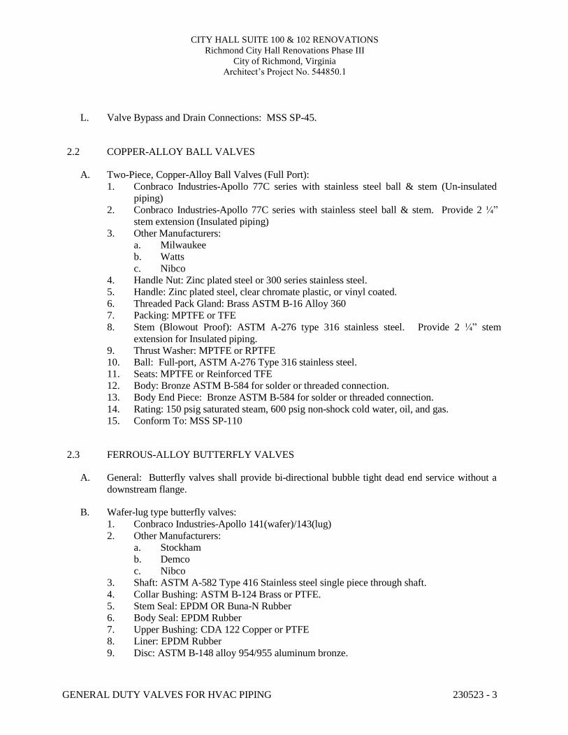
CITY HALL SUITE 100 & 102 RENOVATIONS Richmond City Hall Renovations Phase III
City of Richmond, Virginia Architect’s Project No. 544850.1
GENERAL DUTY VALVES FOR HVAC PIPING 230523 - 3
L. Valve Bypass and Drain Connections: MSS SP-45. 2.2 COPPER-ALLOY BALL VALVES
A. Two-Piece, Copper-Alloy Ball Valves (Full Port):
1. Conbraco Industries-Apollo 77C series with stainless steel ball & stem (Un-insulated piping)
2. Conbraco Industries-Apollo 77C series with stainless steel ball & stem. Provide 2 ¼” stem extension (Insulated piping)
3. Other Manufacturers: a. Milwaukee b. Watts c. Nibco
4. Handle Nut: Zinc plated steel or 300 series stainless steel. 5. Handle: Zinc plated steel, clear chromate plastic, or vinyl coated. 6. Threaded Pack Gland: Brass ASTM B-16 Alloy 360 7. Packing: MPTFE or TFE 8. Stem (Blowout Proof): ASTM A-276 type 316 stainless steel. Provide 2 ¼” stem
extension for Insulated piping. 9. Thrust Washer: MPTFE or RPTFE 10. Ball: Full-port, ASTM A-276 Type 316 stainless steel. 11. Seats: MPTFE or Reinforced TFE 12. Body: Bronze ASTM B-584 for solder or threaded connection. 13. Body End Piece: Bronze ASTM B-584 for solder or threaded connection. 14. Rating: 150 psig saturated steam, 600 psig non-shock cold water, oil, and gas. 15. Conform To: MSS SP-110
2.3 FERROUS-ALLOY BUTTERFLY VALVES
A. General: Butterfly valves shall provide bi-directional bubble tight dead end service without a
downstream flange.
B. Wafer-lug type butterfly valves: 1. Conbraco Industries-Apollo 141(wafer)/143(lug) 2. Other Manufacturers:
a. Stockham b. Demco c. Nibco
3. Shaft: ASTM A-582 Type 416 Stainless steel single piece through shaft. 4. Collar Bushing: ASTM B-124 Brass or PTFE. 5. Stem Seal: EPDM OR Buna-N Rubber 6. Body Seal: EPDM Rubber 7. Upper Bushing: CDA 122 Copper or PTFE 8. Liner: EPDM Rubber 9. Disc: ASTM B-148 alloy 954/955 aluminum bronze.

CITY HALL SUITE 100 & 102 RENOVATIONS Richmond City Hall Renovations Phase III
City of Richmond, Virginia Architect’s Project No. 544850.1
GENERAL DUTY VALVES FOR HVAC PIPING 230523 - 4
10. Lower Bushing: CDA 122 copper or PTFE. 11. Body Wafer: ASTM A-536 Ductile Iron or ASTM A-126 CL. B cast iron. 12. Body Lug: ASTM A-536 Ductile Iron or ASTM A-126 CL. B cast iron. 13. Ratings:
a. 2” through 12” 200 psig CWP. b. 14” through 24” 150 psig CWP.
14. Conform To: MSS SP-67, MSS SP-25, API-609 15. Operator:
a. Valves up to and including 6”: Lever-lock operator. b. Valves 8” and larger: Self locking worm gear operator equipped with adjustable
stops at open and shut positions.
C. Grooved-End 300 psig butterfly valves: 1. NIBCO Model GD 4765 2. Other Manufacturers:
a. Victaulic 3. Upper Stem: ASTM A-582 Type 416 Stainless steel. 4. Upper Bearing: Split metal. 5. O-Ring: EPDM 6. Body: ASTM A-395 ductile iron with polymide coating. 7. Disc: ASTM A-395 ductile iron with EPDM encapsulation. 8. Lower Bearing: Split metal. 9. Dust Plug: PVC 10. Rating: 300 psig CWP. 11. Conform To: MSS SP-67 12. Operator:
a. Valves up to and including 6”: Lever-lock operator. b. Valves 8” and larger: Self locking worm gear operator equipped with adjustable
stops at open and shut positions.
D. Flanged 200 psig butterfly valves: 1. NIBCO Model FC-2765-0 2. Upper Stem: ASTM A-582 Type 416 Stainless steel. 3. Upper Bushing: TFE over porous bronze, steel backed. 4. O-Ring: EPDM 5. Body: ASTM A-126 Class B cast iron with polymide coating. 6. Disc: ASTM A-395 ductile iron with EPDM encapsulation. 7. Lower Bushing: TFE over porous bronze, steel backed. 8. Lower Stem: ASTM A-582 Type 416 Stainless steel. 9. Dust Plug: PVC 10. Rating: 200 psig CWP. 11. Conform To: MSS SP-67 and MSS SP-25 12. Operator:
a. Valves up to and including 6”: Lever-lock operator. b. Valves 8” and larger: Self locking worm gear operator equipped with adjustable
stops at open and shut positions.
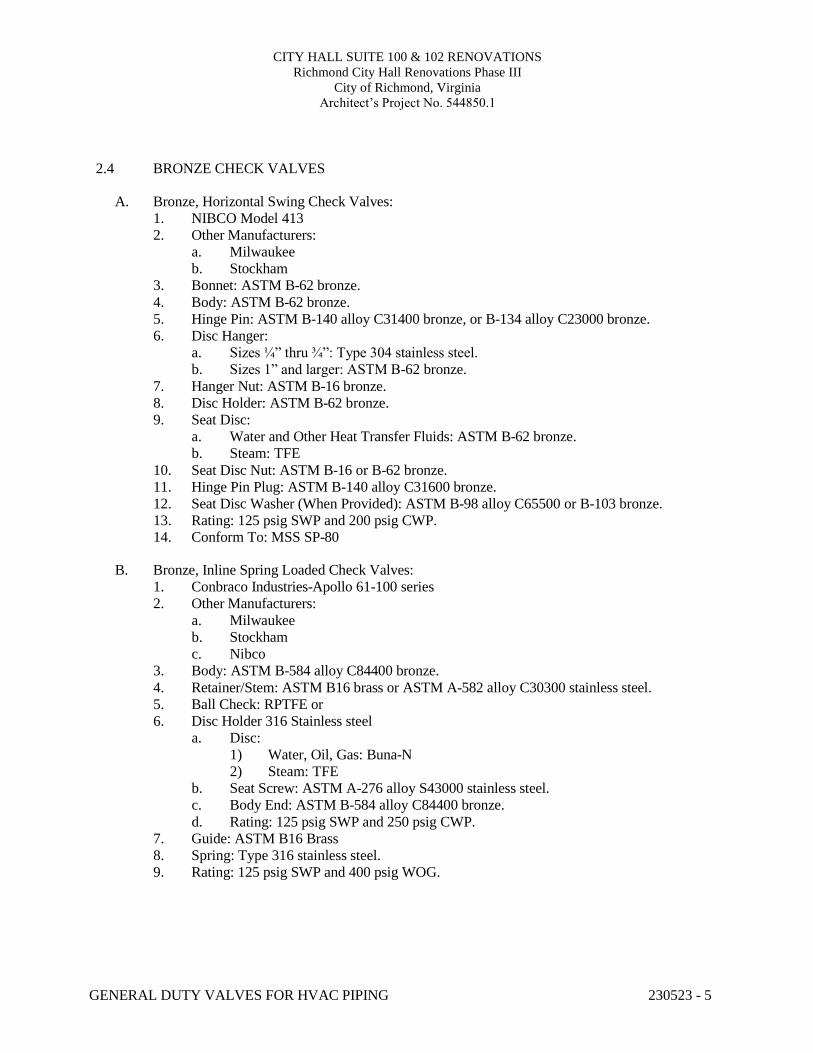
CITY HALL SUITE 100 & 102 RENOVATIONS Richmond City Hall Renovations Phase III
City of Richmond, Virginia Architect’s Project No. 544850.1
GENERAL DUTY VALVES FOR HVAC PIPING 230523 - 5
2.4 BRONZE CHECK VALVES
A. Bronze, Horizontal Swing Check Valves: 1. NIBCO Model 413 2. Other Manufacturers:
a. Milwaukee b. Stockham
3. Bonnet: ASTM B-62 bronze. 4. Body: ASTM B-62 bronze. 5. Hinge Pin: ASTM B-140 alloy C31400 bronze, or B-134 alloy C23000 bronze. 6. Disc Hanger:
a. Sizes ¼” thru ¾”: Type 304 stainless steel. b. Sizes 1” and larger: ASTM B-62 bronze.
7. Hanger Nut: ASTM B-16 bronze. 8. Disc Holder: ASTM B-62 bronze. 9. Seat Disc:
a. Water and Other Heat Transfer Fluids: ASTM B-62 bronze. b. Steam: TFE
10. Seat Disc Nut: ASTM B-16 or B-62 bronze. 11. Hinge Pin Plug: ASTM B-140 alloy C31600 bronze. 12. Seat Disc Washer (When Provided): ASTM B-98 alloy C65500 or B-103 bronze. 13. Rating: 125 psig SWP and 200 psig CWP. 14. Conform To: MSS SP-80
B. Bronze, Inline Spring Loaded Check Valves:
1. Conbraco Industries-Apollo 61-100 series 2. Other Manufacturers:
a. Milwaukee b. Stockham c. Nibco
3. Body: ASTM B-584 alloy C84400 bronze. 4. Retainer/Stem: ASTM B16 brass or ASTM A-582 alloy C30300 stainless steel. 5. Ball Check: RPTFE or 6. Disc Holder 316 Stainless steel
a. Disc: 1) Water, Oil, Gas: Buna-N 2) Steam: TFE
b. Seat Screw: ASTM A-276 alloy S43000 stainless steel. c. Body End: ASTM B-584 alloy C84400 bronze. d. Rating: 125 psig SWP and 250 psig CWP.
7. Guide: ASTM B16 Brass 8. Spring: Type 316 stainless steel. 9. Rating: 125 psig SWP and 400 psig WOG.
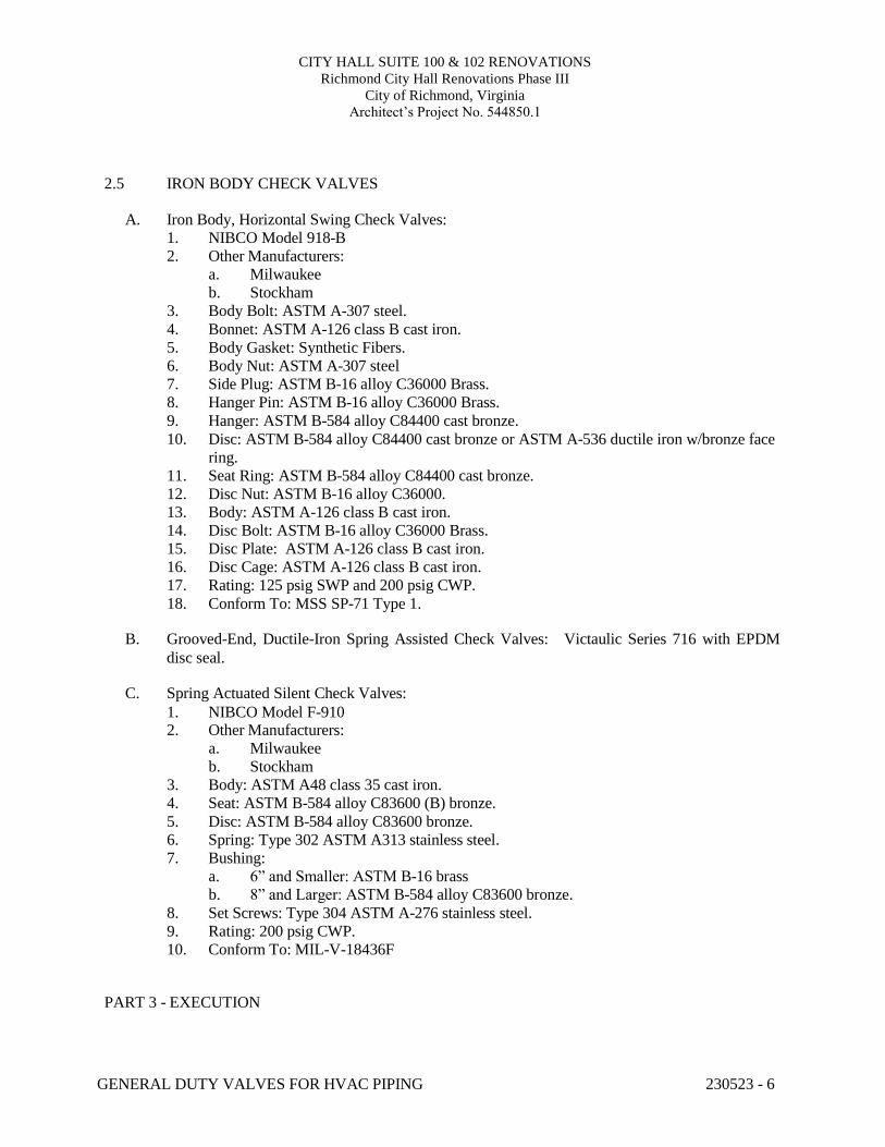
CITY HALL SUITE 100 & 102 RENOVATIONS Richmond City Hall Renovations Phase III
City of Richmond, Virginia Architect’s Project No. 544850.1
GENERAL DUTY VALVES FOR HVAC PIPING 230523 - 6
2.5 IRON BODY CHECK VALVES
A. Iron Body, Horizontal Swing Check Valves: 1. NIBCO Model 918-B 2. Other Manufacturers:
a. Milwaukee b. Stockham
3. Body Bolt: ASTM A-307 steel. 4. Bonnet: ASTM A-126 class B cast iron. 5. Body Gasket: Synthetic Fibers. 6. Body Nut: ASTM A-307 steel 7. Side Plug: ASTM B-16 alloy C36000 Brass. 8. Hanger Pin: ASTM B-16 alloy C36000 Brass. 9. Hanger: ASTM B-584 alloy C84400 cast bronze. 10. Disc: ASTM B-584 alloy C84400 cast bronze or ASTM A-536 ductile iron w/bronze face
ring. 11. Seat Ring: ASTM B-584 alloy C84400 cast bronze. 12. Disc Nut: ASTM B-16 alloy C36000. 13. Body: ASTM A-126 class B cast iron. 14. Disc Bolt: ASTM B-16 alloy C36000 Brass. 15. Disc Plate: ASTM A-126 class B cast iron. 16. Disc Cage: ASTM A-126 class B cast iron. 17. Rating: 125 psig SWP and 200 psig CWP. 18. Conform To: MSS SP-71 Type 1.
B. Grooved-End, Ductile-Iron Spring Assisted Check Valves: Victaulic Series 716 with EPDM C.
disc seal.
Spring Actuated Silent Check Valves:
1. NIBCO Model F-910 2. Other Manufacturers:
a. Milwaukee b. Stockham
3. Body: ASTM A48 class 35 cast iron. 4. Seat: ASTM B-584 alloy C83600 (B) bronze. 5. Disc: ASTM B-584 alloy C83600 bronze. 6. Spring: Type 302 ASTM A313 stainless steel. 7. Bushing:
a. 6” and Smaller: ASTM B-16 brass b. 8” and Larger: ASTM B-584 alloy C83600 bronze.
8. Set Screws: Type 304 ASTM A-276 stainless steel. 9. Rating: 200 psig CWP. 10. Conform To: MIL-V-18436F
PART 3 - EXECUTION
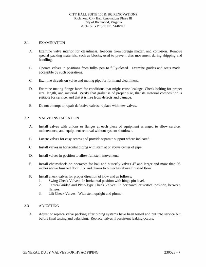
CITY HALL SUITE 100 & 102 RENOVATIONS Richmond City Hall Renovations Phase III
City of Richmond, Virginia Architect’s Project No. 544850.1
GENERAL DUTY VALVES FOR HVAC PIPING 230523 - 7
3.1 EXAMINATION
A. Examine valve interior for cleanliness, freedom from foreign matter, and corrosion. Remove special packing materials, such as blocks, used to prevent disc movement during shipping and handling.
B. Operate valves in positions from fully- pen to fully-closed. Examine guides and seats made
accessible by such operations.
C. Examine threads on valve and mating pipe for form and cleanliness.
D. Examine mating flange faces for conditions that might cause leakage. Check bolting for proper size, length, and material. Verify that gasket is of proper size, that its material composition is suitable for service, and that it is free from defects and damage.
E. Do not attempt to repair defective valves; replace with new valves.
3.2 VALVE INSTALLATION
A. Install valves with unions or flanges at each piece of equipment arranged to allow service,
maintenance, and equipment removal without system shutdown.
B. Locate valves for easy access and provide separate support where indicated.
C. Install valves in horizontal piping with stem at or above center of pipe.
D. Install valves in position to allow full stem movement.
E. Install chainwheels on operators for ball and butterfly valves 4” and larger and more than 96 inches above finished floor. Extend chains to 60 inches above finished floor.
F. Install check valves for proper direction of flow and as follows:
1. Swing Check Valves: In horizontal position with hinge pin level. 2. Center-Guided and Plate-Type Check Valves: In horizontal or vertical position, between
flanges. 3. Lift Check Valves: With stem upright and plumb.
3.3 ADJUSTING
A. Adjust or replace valve packing after piping systems have been tested and put into service but
before final testing and balancing. Replace valves if persistent leaking occurs.
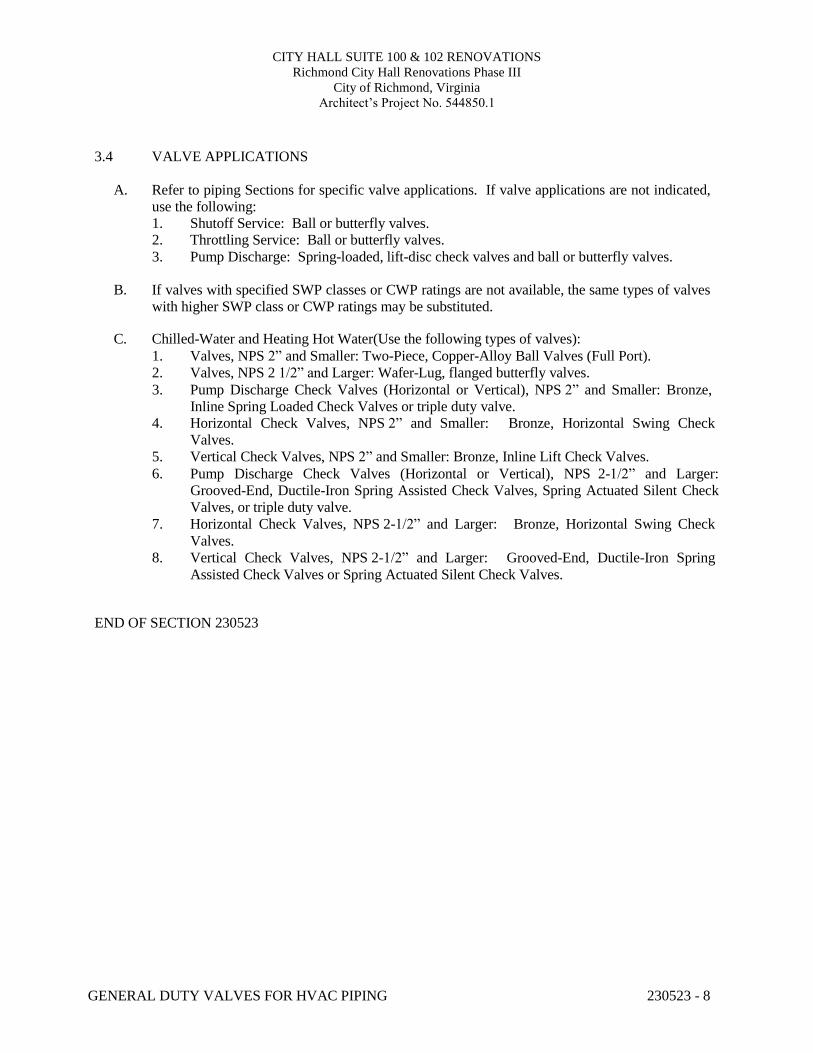
CITY HALL SUITE 100 & 102 RENOVATIONS Richmond City Hall Renovations Phase III
City of Richmond, Virginia Architect’s Project No. 544850.1
GENERAL DUTY VALVES FOR HVAC PIPING 230523 - 8
3.4 VALVE APPLICATIONS
A. Refer to piping Sections for specific valve applications. If valve applications are not indicated, use the following: 1. Shutoff Service: Ball or butterfly valves. 2. Throttling Service: Ball or butterfly valves. 3. Pump Discharge: Spring-loaded, lift-disc check valves and ball or butterfly valves.
B. If valves with specified SWP classes or CWP ratings are not available, the same types of valves
with higher SWP class or CWP ratings may be substituted.
C. Chilled-Water and Heating Hot Water(Use the following types of valves): 1. Valves, NPS 2” and Smaller: Two-Piece, Copper-Alloy Ball Valves (Full Port). 2. Valves, NPS 2 1/2” and Larger: Wafer-Lug, flanged butterfly valves. 3. Pump Discharge Check Valves (Horizontal or Vertical), NPS 2” and Smaller: Bronze,
Inline Spring Loaded Check Valves or triple duty valve. 4. Horizontal Check Valves, NPS 2” and Smaller: Bronze, Horizontal Swing Check
Valves. 5. Vertical Check Valves, NPS 2” and Smaller: Bronze, Inline Lift Check Valves. 6. Pump Discharge Check Valves (Horizontal or Vertical), NPS 2-1/2” and Larger:
Grooved-End, Ductile-Iron Spring Assisted Check Valves, Spring Actuated Silent Check Valves, or triple duty valve.
7. Horizontal Check Valves, NPS 2-1/2” and Larger: Bronze, Horizontal Swing Check Valves.
8. Vertical Check Valves, NPS 2-1/2” and Larger: Grooved-End, Ductile-Iron Spring Assisted Check Valves or Spring Actuated Silent Check Valves.
END OF SECTION 230523
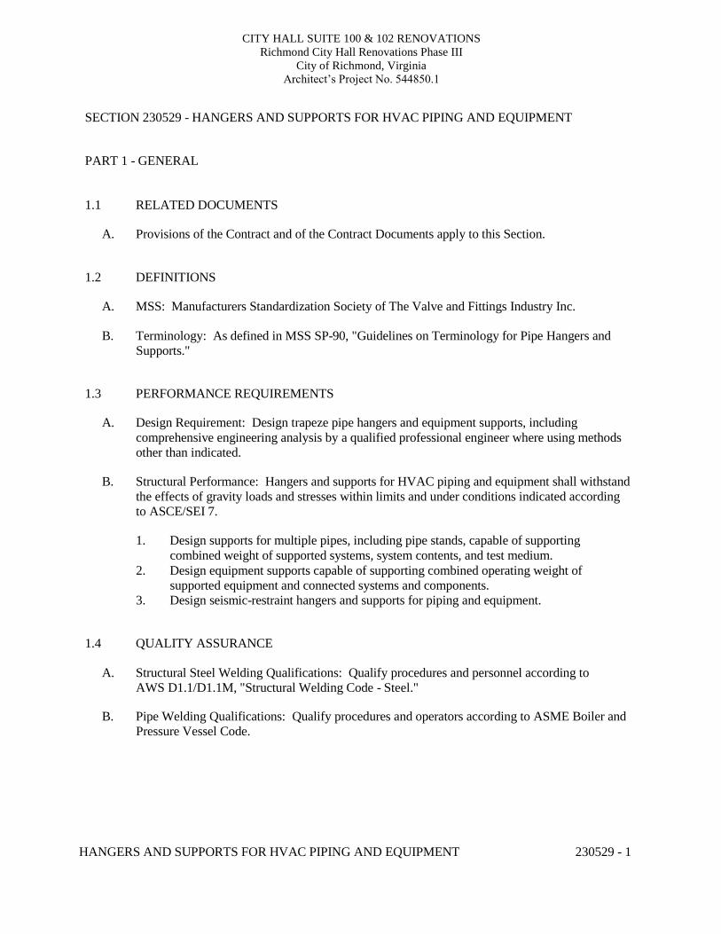
CITY HALL SUITE 100 & 102 RENOVATIONS Richmond City Hall Renovations Phase III
City of Richmond, Virginia Architect’s Project No. 544850.1
HANGERS AND SUPPORTS FOR HVAC PIPING AND EQUIPMENT 230529 - 1
SECTION 230529 - HANGERS AND SUPPORTS FOR HVAC PIPING AND EQUIPMENT
PART 1 - GENERAL
1.1 RELATED DOCUMENTS
A. Provisions of the Contract and of the Contract Documents apply to this Section. 1.2 DEFINITIONS
A. MSS: Manufacturers Standardization Society of The Valve and Fittings Industry Inc.
B. Terminology: As defined in MSS SP-90, "Guidelines on Terminology for Pipe Hangers and
Supports." 1.3 PERFORMANCE REQUIREMENTS
A. Design Requirement: Design trapeze pipe hangers and equipment supports, including
comprehensive engineering analysis by a qualified professional engineer where using methods other than indicated.
B. Structural Performance: Hangers and supports for HVAC piping and equipment shall withstand
the effects of gravity loads and stresses within limits and under conditions indicated according to ASCE/SEI 7.
1. Design supports for multiple pipes, including pipe stands, capable of supporting
combined weight of supported systems, system contents, and test medium. 2. Design equipment supports capable of supporting combined operating weight of
supported equipment and connected systems and components. 3. Design seismic-restraint hangers and supports for piping and equipment.
1.4 QUALITY ASSURANCE
A. Structural Steel Welding Qualifications: Qualify procedures and personnel according to
AWS D1.1/D1.1M, "Structural Welding Code - Steel."
B. Pipe Welding Qualifications: Qualify procedures and operators according to ASME Boiler and Pressure Vessel Code.
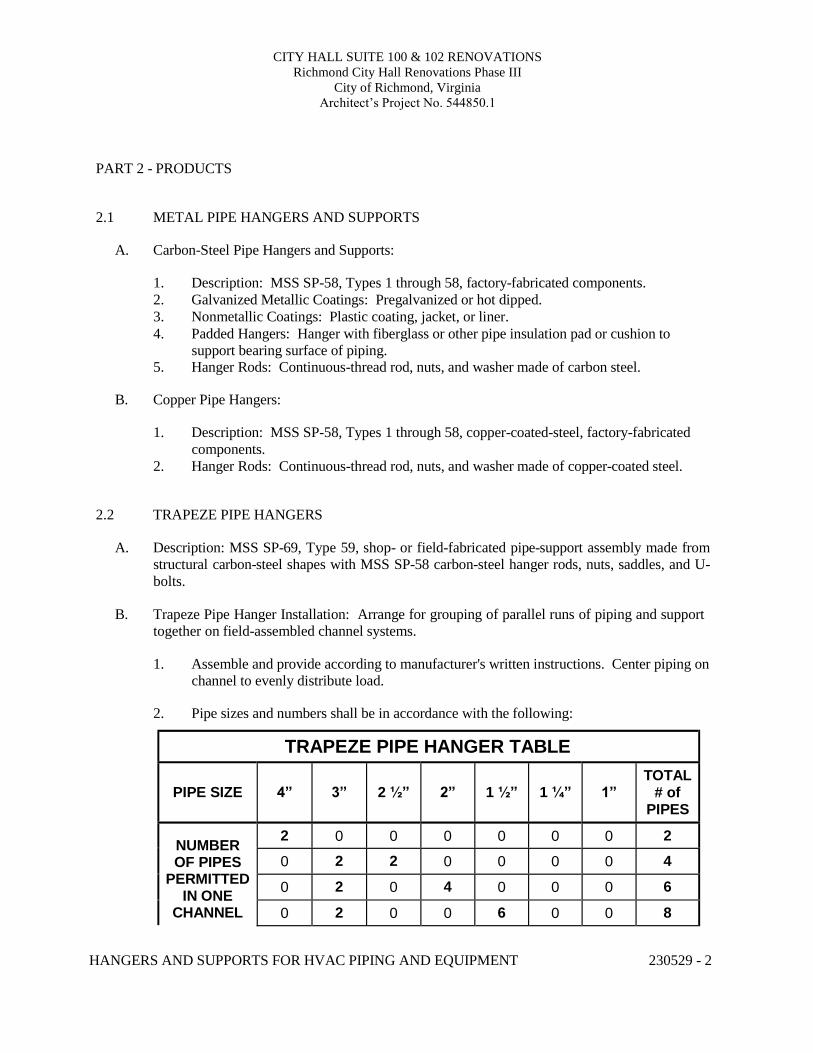
CITY HALL SUITE 100 & 102 RENOVATIONS Richmond City Hall Renovations Phase III
City of Richmond, Virginia Architect’s Project No. 544850.1
HANGERS AND SUPPORTS FOR HVAC PIPING AND EQUIPMENT 230529 - 2
PART 2 - PRODUCTS 2.1 METAL PIPE HANGERS AND SUPPORTS
A. Carbon-Steel Pipe Hangers and Supports:
1. Description: MSS SP-58, Types 1 through 58, factory-fabricated components. 2. Galvanized Metallic Coatings: Pregalvanized or hot dipped. 3. Nonmetallic Coatings: Plastic coating, jacket, or liner. 4. Padded Hangers: Hanger with fiberglass or other pipe insulation pad or cushion to
support bearing surface of piping. 5. Hanger Rods: Continuous-thread rod, nuts, and washer made of carbon steel.
B. Copper Pipe Hangers:
1. Description: MSS SP-58, Types 1 through 58, copper-coated-steel, factory-fabricated
components. 2. Hanger Rods: Continuous-thread rod, nuts, and washer made of copper-coated steel.
2.2 TRAPEZE PIPE HANGERS
A. Description: MSS SP-69, Type 59, shop- or field-fabricated pipe-support assembly made from
structural carbon-steel shapes with MSS SP-58 carbon-steel hanger rods, nuts, saddles, and U- bolts.
B. Trapeze Pipe Hanger Installation: Arrange for grouping of parallel runs of piping and support
together on field-assembled channel systems.
1. Assemble and provide according to manufacturer's written instructions. Center piping on channel to evenly distribute load.
2. Pipe sizes and numbers shall be in accordance with the following:
TRAPEZE PIPE HANGER TABLE
PIPE SIZE
4”
3”
2 ½”
2”
1 ½”
1 ¼”
1”
TOTAL # of
PIPES
NUMBER OF PIPES
PERMITTED IN ONE
CHANNEL
2 0 0 0 0 0 0 2
0 2 2 0 0 0 0 4
0 2 0 4 0 0 0 6
0 2 0 0 6 0 0 8
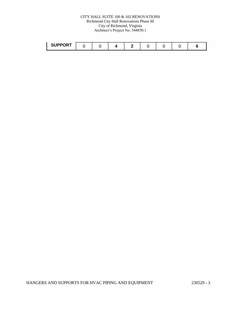
CITY HALL SUITE 100 & 102 RENOVATIONS Richmond City Hall Renovations Phase III
City of Richmond, Virginia Architect’s Project No. 544850.1
HANGERS AND SUPPORTS FOR HVAC PIPING AND EQUIPMENT 230529 - 3
SUPPORT 0 0 4 2 0 0 0 6
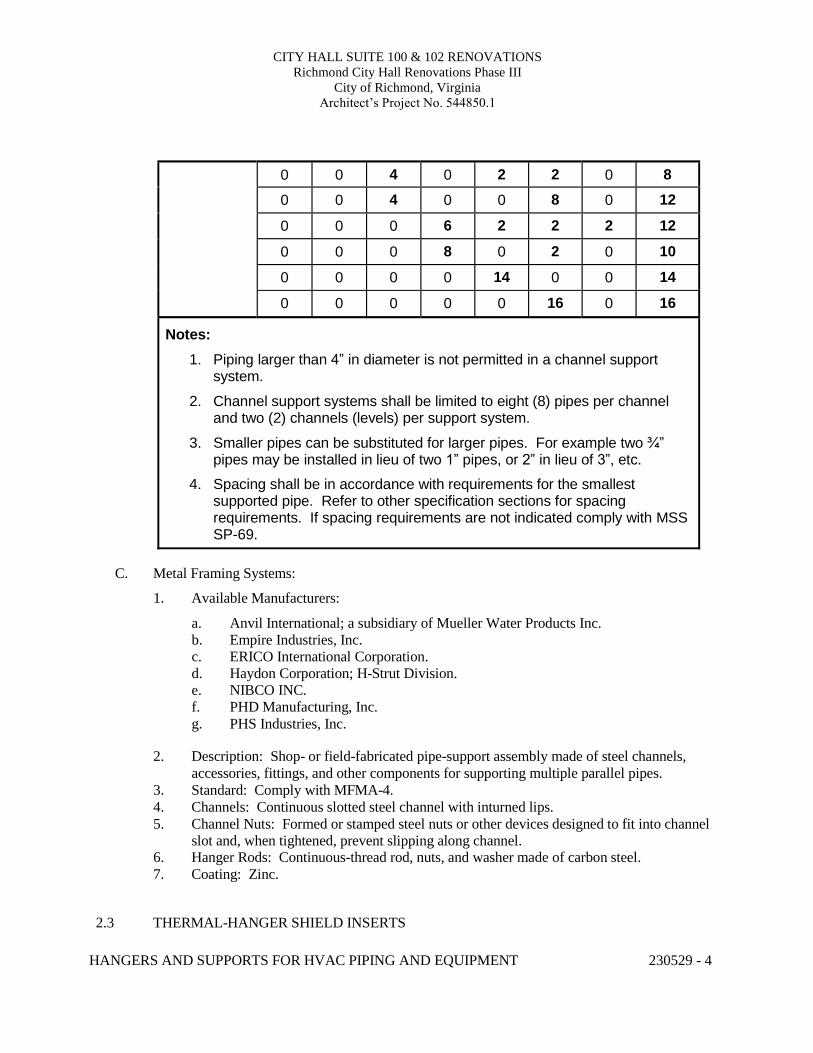
CITY HALL SUITE 100 & 102 RENOVATIONS Richmond City Hall Renovations Phase III
City of Richmond, Virginia Architect’s Project No. 544850.1
HANGERS AND SUPPORTS FOR HVAC PIPING AND EQUIPMENT 230529 - 4
0 0 4 0 2 2 0 8
0 0 4 0 0 8 0 12
0 0 0 6 2 2 2 12
0 0 0 8 0 2 0 10
0 0 0 0 14 0 0 14
0 0 0 0 0 16 0 16
Notes:
1. Piping larger than 4” in diameter is not permitted in a channel support system.
2. Channel support systems shall be limited to eight (8) pipes per channel and two (2) channels (levels) per support system.
3. Smaller pipes can be substituted for larger pipes. For example two ¾” pipes may be installed in lieu of two 1” pipes, or 2” in lieu of 3”, etc.
4. Spacing shall be in accordance with requirements for the smallest supported pipe. Refer to other specification sections for spacing requirements. If spacing requirements are not indicated comply with MSS SP-69.
C. Metal Framing Systems:
1. Available Manufacturers:
a. Anvil International; a subsidiary of Mueller Water Products Inc. b. Empire Industries, Inc. c. ERICO International Corporation. d. Haydon Corporation; H-Strut Division. e. NIBCO INC. f. PHD Manufacturing, Inc. g. PHS Industries, Inc.
2. Description: Shop- or field-fabricated pipe-support assembly made of steel channels,
accessories, fittings, and other components for supporting multiple parallel pipes. 3. Standard: Comply with MFMA-4. 4. Channels: Continuous slotted steel channel with inturned lips. 5. Channel Nuts: Formed or stamped steel nuts or other devices designed to fit into channel
slot and, when tightened, prevent slipping along channel. 6. Hanger Rods: Continuous-thread rod, nuts, and washer made of carbon steel. 7. Coating: Zinc.
2.3 THERMAL-HANGER SHIELD INSERTS
CITY HALL SUITE 100 & 102 RENOVATIONS Richmond City Hall Renovations Phase III
City of Richmond, Virginia Architect’s Project No. 544850.1
HANGERS AND SUPPORTS FOR HVAC PIPING AND EQUIPMENT 230529 - 5
A. Available Manufacturers: 1. Carpenter & Paterson, Inc. 2. Clement Support Services. 3. ERICO International Corporation. 4. National Pipe Hanger Corporation. 5. PHS Industries, Inc. 6. Pipe Shields, Inc.; a subsidiary of Piping Technology & Products, Inc. 7. Piping Technology & Products, Inc. 8. Rilco Manufacturing Co., Inc. 9. Value Engineered Products, Inc.
B. Insulation-Insert Material for Cold Piping: ASTM C 552, Type II cellular glass with 100-psig
or ASTM C 591, Type VI, Grade 1 polyisocyanurate with 125-psig minimum compressive strength and vapor barrier.
C. Insulation-Insert Material for Hot Piping: Water-repellent treated, ASTM C 533, Type I
calcium silicate with 100-psig, ASTM C 552, Type II cellular glass with 100-psig, or ASTM C 591, Type VI, Grade 1 polyisocyanurate with 125-psig minimum compressive strength.
D. For Trapeze or Clamped Systems: Insert and shield shall cover entire circumference of pipe.
E. For Clevis or Band Hangers: Insert and shield shall cover lower 180 degrees of pipe.
F. Insert Length: Extend 2” beyond sheet metal shield for piping operating below ambient air
temperature. 2.4 PIPE STANDS
A. General Requirements for Pipe Stands: Shop- or field-fabricated assemblies made of
manufactured corrosion-resistant components to support roof-mounted piping.
1. Available Manufacturers:
a. Cooper B-Line – Dura-Blok b. MAPA Products c. Mifab, Inc. – C-Port d. Miro Industries, Inc. e. OMG, Inc. f. PHP Systems/Design g. Pipe Prop h. Roof Top Blox
2. Provide pipe supports for supporting gas, condensate, refrigeration lines, or hyrdronic piping on flat roof surfaces. Support shall rest on roof surface without penetrating the roof surface. Supports for condensate piping shall be adjustable vertically to ensure pipe slopes as required.
CITY HALL SUITE 100 & 102 RENOVATIONS Richmond City Hall Renovations Phase III
City of Richmond, Virginia Architect’s Project No. 544850.1
HANGERS AND SUPPORTS FOR HVAC PIPING AND EQUIPMENT 230529 - 6
B. Compact Pipe Stand: One-piece plastic unit with integral-rod roller, pipe clamps, or V-shaped cradle to support pipe, for roof installation without membrane penetration.
C. Curb Mounted Pipe Stands: Shop- or field-fabricated pipe supports made from structural-steel
shapes, continuous-thread rods, and rollers, for mounting on permanent stationary roof curb. 2.5 EQUIPMENT SUPPORTS
A. Description: Welded, shop or field fabricated equipment support made from structural carbon-
steel shapes unless indicated otherwise. 2.6 MISCELLANEOUS MATERIALS
A. Structural Steel: ASTM A 36/A 36M, carbon-steel plates, shapes, and bars; black and
galvanized.
B. Grout: ASTM C 1107, factory-mixed and -packaged, dry, hydraulic-cement, non-shrink and nonmetallic grout; suitable for interior and exterior applications.
1. Properties: Non-staining, noncorrosive, and nongaseous. 2. Design Mix: 5000-psi, 28-day compressive strength.
PART 3 - EXECUTION
3.1 HANGER AND SUPPORT INSTALLATION
A. Metal Pipe-Hanger Installation: Comply with MSS SP-69 and MSS SP-89. Provide hangers,
supports, clamps, and attachments as required to properly support piping from the building structure.
B. Metal Trapeze Pipe-Hanger Installation: Comply with MSS SP-69, MSS SP-89, and Table
above. Arrange for grouping of parallel runs of horizontal piping, and support together on field- fabricated trapeze pipe hangers.
C. Metal Framing System Installation: Arrange for grouping of parallel runs of piping, and
support together on field-assembled metal framing systems.
D. Thermal-Hanger Shield Installation: Provide in pipe hanger or shield for insulated piping.
E. Pipe Stand Installation:
1. Pipe Stand Types except Curb-Mounted Type: Assemble components and mount on smooth roof surface. Do not penetrate roof membrane.
CITY HALL SUITE 100 & 102 RENOVATIONS Richmond City Hall Renovations Phase III
City of Richmond, Virginia Architect’s Project No. 544850.1
HANGERS AND SUPPORTS FOR HVAC PIPING AND EQUIPMENT 230529 - 7
2. Curb-Mounted-Type Pipe Stands: Assemble components or fabricate pipe stand and mount on permanent, stationary roof curb. See Division 07 Section "Roof Accessories" for curbs.
F. Provide hangers and supports complete with necessary attachments, inserts, bolts, rods, nuts,
washers, and other accessories.
G. Equipment Support Installation: Fabricate from welded-structural-steel shapes.
H. Provide hangers and supports to allow controlled thermal and seismic movement of piping systems, to permit freedom of movement between pipe anchors, and to facilitate action of expansion joints, expansion loops, expansion bends, and similar units.
I. Provide lateral bracing with pipe hangers and supports to prevent swaying.
J. Provide building attachments within concrete slabs or attach to structural steel. Building
attachments may not used on steel joists unless otherwise indicated. Provide additional attachments at concentrated loads, including valves, flanges, and strainers, 2-1/2” and larger and at changes in direction of piping. Provide concrete inserts before concrete is placed; fasten inserts to forms and provide reinforcing bars through openings at top of inserts.
K. Load Distribution: Provide hangers and supports so that piping live and dead loads and stresses
from movement will not be transmitted to connected equipment.
L. Pipe Slopes: Provide hangers and supports to provide indicated pipe slopes and to not exceed maximum pipe deflections allowed by ASME B31.9 for building services piping.
M. Insulated Piping:
1. Attach clamps and spacers to piping.
a. Piping Operating above Ambient Air Temperature: Clamp may project through
insulation. b. Piping Operating below Ambient Air Temperature: Provide thermal-hanger shield
insert with clamp sized to match OD of insert. c. Do not exceed pipe stress limits allowed by ASME B31.9 for building services
piping.
2. Provide MSS SP-58, Type 39, protection saddles if insulation without vapor barrier is indicated. Fill interior voids with insulation that matches adjoining insulation.
3. Provide MSS SP-58, Type 40, protective shields on cold piping with vapor barrier. Shields shall span an arc of 180 degrees.
4. Shield Dimensions for Pipe: Not less than the following:
a. Pipe ¼” to 3-½”: 12 inches long and 0.048 inch thick. b. Pipe 4”: 12 inches long and 0.06 inch thick. c. Pipe 5” and 6”: 18 inches long and 0.06 inch thick.
CITY HALL SUITE 100 & 102 RENOVATIONS Richmond City Hall Renovations Phase III
City of Richmond, Virginia Architect’s Project No. 544850.1
HANGERS AND SUPPORTS FOR HVAC PIPING AND EQUIPMENT 230529 - 8
d. Pipe 8” to 14”: 24 inches long and 0.075 inch thick.
5. Pipes 8” and Larger: Include wood or reinforced calcium-silicate-insulation inserts of length at least as long as protective shield.
6. Thermal-Hanger Shields: Provide with insulation same thickness as piping insulation. 3.2 EQUIPMENT SUPPORTS
A. Fabricate structural-steel stands to suspend equipment from structure overhead or to support equipment above floor.
B. Grouting: Place grout under supports for equipment and make bearing surface smooth.
C. Provide lateral bracing, to prevent swaying, for equipment supports. 3.3 METAL FABRICATIONS
A. Cut, drill, and fit miscellaneous metal fabrications for trapeze pipe hangers and equipment supports.
B. Fit exposed connections together to form hairline joints. Field weld connections that cannot be shop welded because of shipping size limitations.
C. Field Welding: Comply with AWS D1.1/D1.1M procedures for shielded, metal arc welding; appearance and quality of welds; and methods used in correcting welding work; and with the following:
1. Provide materials and methods that minimize distortion and develop strength and corrosion resistance of base metals.
2. Obtain fusion without undercut or overlap. 3. Remove welding flux immediately. 4. Finish welds at exposed connections so no roughness shows after finishing and so
contours of welded surfaces match adjacent contours. 3.4 ADJUSTING
A. Hanger Adjustments: Adjust hangers to distribute loads equally on attachments and to achieve
indicated slope of pipe.
B. Trim excess length of continuous-thread hanger and support rods to 1-1/2 inches. 3.5 PAINTING
A. Touchup: Unless otherwise indicated clean field welds and abraded areas of shop paint. Paint
exposed areas immediately after erecting hangers and supports. Provide same materials as used for shop painting. Comply with SSPC-PA 1 requirements for touching up field-painted surfaces.
CITY HALL SUITE 100 & 102 RENOVATIONS Richmond City Hall Renovations Phase III
City of Richmond, Virginia Architect’s Project No. 544850.1
HANGERS AND SUPPORTS FOR HVAC PIPING AND EQUIPMENT 230529 - 9
1. Apply paint by brush or spray to provide a minimum dry film thickness of 2.0 mils.
B. Galvanized Surfaces: Clean welds, bolted connections, and abraded areas and immediately apply galvanizing-repair paint. Paint shall comply with ASTM A 780.
3.6 HANGER AND SUPPORT SCHEDULE
A. Specific hanger and support requirements are in Sections specifying piping systems and
equipment.
B. Comply with MSS SP-69 for pipe-hanger selections and applications that are not specified in piping system Sections.
C. Provide hangers and supports with galvanized metallic coatings for piping and equipment that
will not have field-applied finish.
D. Provide nonmetallic coatings on attachments for electrolytic protection where attachments are in direct contact with copper tubing.
E. Provide copper-plated pipe hangers and copper attachments for copper piping and tubing.
F. Provide padded hangers for piping that is subject to scratching.
G. Provide thermal-hanger shield inserts for insulated piping and tubing.
H. Horizontal-Piping Hangers and Supports: Unless otherwise indicated provide the following:
1. Adjustable, Steel Clevis Hangers (MSS Type 1): For suspension of stationary pipes ½”
to 30”. 2. Yoke-Type Pipe Clamps (MSS Type 2): For suspension of up to 1050 deg F pipes 4” to
14”, requiring up to 4“ of insulation. 3. Carbon- or Alloy-Steel, Double-Bolt Pipe Clamps (MSS Type 3): For suspension of
pipes ¾” to 14”, requiring clamp flexibility and up to 4 inches of insulation. 4. Steel Pipe Clamps (MSS Type 4): For suspension of cold and hot pipes ½” to 14” if little
or no insulation is required. 5. Pipe Hangers (MSS Type 5): For suspension of pipes ½” to 4”, to allow off-center
closure for hanger installation before pipe erection. 6. Adjustable, Swivel Split- or Solid-Ring Hangers (MSS Type 6): For suspension of
noninsulated, stationary pipes ¾” to 8”. 7. Adjustable, Steel Band Hangers (MSS Type 7): For suspension of noninsulated,
stationary pipes ½” to 8”. 8. Adjustable Band Hangers (MSS Type 9): For suspension of noninsulated, stationary
pipes ½” to 8”. 9. Adjustable, Swivel-Ring Band Hangers (MSS Type 10): For suspension of noninsulated,
stationary pipes ½” to 8”.
CITY HALL SUITE 100 & 102 RENOVATIONS Richmond City Hall Renovations Phase III
City of Richmond, Virginia Architect’s Project No. 544850.1
HANGERS AND SUPPORTS FOR HVAC PIPING AND EQUIPMENT 230529 - 10
10. Split Pipe Ring with or without Turnbuckle Hangers (MSS Type 11): For suspension of noninsulated, stationary pipes ½” to 8”.
11. Extension Hinged or Two-Bolt Split Pipe Clamps (MSS Type 12): For suspension of noninsulated, stationary pipes NPS ½” to 3”.
12. U-Bolts (MSS Type 24): For support of heavy pipes ½” to 14”. 13. Clips (MSS Type 26): For support of insulated pipes not subject to expansion or
contraction. 14. Pipe Saddle Supports (MSS Type 36): For support of pipes 4” to 14”, with steel-pipe
base stanchion support and cast-iron floor flange or carbon-steel plate. 15. Pipe Stanchion Saddles (MSS Type 37): For support of pipes 4” to 14”, with steel-pipe
base stanchion support and cast-iron floor flange or carbon-steel plate, and with U-bolt to retain pipe.
16. Adjustable Pipe Saddle Supports (MSS Type 38): For stanchion-type support for pipes 2-½” to 14” if vertical adjustment is required, with steel-pipe base stanchion support and cast-iron floor flange.
17. Single-Pipe Rolls (MSS Type 41): For suspension of pipes 1” to 14”, from two rods if longitudinal movement caused by expansion and contraction might occur.
18. Adjustable Roller Hangers (MSS Type 43): For suspension of pipes 2-½” to 14”, from single rod if horizontal movement caused by expansion and contraction might occur.
19. Complete Pipe Rolls (MSS Type 44): For support of pipes 2” to 14” if longitudinal movement caused by expansion and contraction might occur but vertical adjustment is not necessary.
20. Pipe Roll and Plate Units (MSS Type 45): For support of pipes 2” to 14” if small horizontal movement caused by expansion and contraction might occur and vertical adjustment is not necessary.
21. Adjustable Pipe Roll and Base Units (MSS Type 46): For support of pipes 2” to 14”if vertical and lateral adjustment during installation might be required in addition to expansion and contraction.
I. Vertical-Piping Clamps: Unless otherwise indicated provide the following:
1. Extension Pipe or Riser Clamps (MSS Type 8): For support of pipe risers ¾” to 14”. 2. Carbon- or Alloy-Steel Riser Clamps (MSS Type 42): For support of pipe risers ¾” to
14” if longer ends are required for riser clamps.
J. Hanger-Rod Attachments: Unless otherwise indicated provide the following:
1. Steel Turnbuckles (MSS Type 13): For adjustment up to 6 inches for heavy loads. 2. Steel Clevises (MSS Type 14): For 120 to 450 deg F piping installations. 3. Swivel Turnbuckles (MSS Type 15): For use with MSS Type 11, split pipe rings. 4. Malleable-Iron Sockets (MSS Type 16): For attaching hanger rods to various types of
building attachments. 5. Steel Weldless Eye Nuts (MSS Type 17): For 120 to 450 deg F piping installations. 6. Flat Plate, Double Nut, and Washer as Detailed on Structural Drawings: For attaching to
bar joists. Method of attachment to bar joists must be approved by the structural engineer and joist manufacturer.
CITY HALL SUITE 100 & 102 RENOVATIONS Richmond City Hall Renovations Phase III
City of Richmond, Virginia Architect’s Project No. 544850.1
HANGERS AND SUPPORTS FOR HVAC PIPING AND EQUIPMENT 230529 - 11
K. Building Attachments: Unless otherwise indicated provide the following:
1. Steel or Malleable Concrete Inserts (MSS Type 18): For upper attachment to suspend pipe hangers from concrete ceiling.
2. Flat Plate, Double Nuts, and Washer as Detailed on Structural Drawings: For use under roof installations with bar-joist construction to attach to bottom chord of joist.
3. Side-Beam or Channel Clamps (MSS Type 20): For attaching to bottom flange of beams, channels, or angles.
4. Center-Beam Clamps (MSS Type 21): For attaching to center of bottom flange of beams. 5. Welded Beam Attachments (MSS Type 22): For attaching to bottom of beams if loads
are considerable and rod sizes are large. 6. C-Clamps (MSS Type 23): For structural shapes. 7. Top-Beam Clamps (MSS Type 25): For top of beams if hanger rod is required tangent to
flange edge. 8. Side-Beam Clamps (MSS Type 27): For bottom of steel I-beams. 9. Steel-Beam Clamps with Eye Nuts (MSS Type 28): For attaching to bottom of steel I-
beams for heavy loads. 10. Linked-Steel Clamps with Eye Nuts (MSS Type 29): For attaching to bottom of steel I-
beams for heavy loads, with link extensions. 11. Malleable-Beam Clamps with Extension Pieces (MSS Type 30): For attaching to
structural steel. 12. Welded-Steel Brackets: For support of pipes from below or for suspending from above
by using clip and rod. Provide one of the following for indicated loads:
a. Light (MSS Type 31): 750 lb. b. Medium (MSS Type 32): 1500 lb. c. Heavy (MSS Type 33): 3000 lb.
13. Side-Beam Brackets (MSS Type 34): For sides of steel or wooden beams. 14. Plate Lugs (MSS Type 57): For attaching to steel beams if flexibility at beam is required. 15. Horizontal Travelers (MSS Type 58): For supporting piping systems subject to linear
horizontal movement where headroom is limited.
L. Saddles and Shields: Unless otherwise indicated provide the followings:
1. Steel-Pipe-Covering Protection Saddles (MSS Type 39): To fill interior voids with insulation that matches adjoining insulation.
2. Protection Shields (MSS Type 40): Of length recommended in writing by manufacturer to prevent crushing insulation.
3. Thermal-Hanger Shield Inserts: For supporting insulated pipe.
M. Spring Hangers and Supports: Unless otherwise indicated provide the following:
1. Restraint-Control Devices (MSS Type 47): To control pipe movement. 2. Spring Cushions (MSS Type 48): For light loads if vertical movement does not exceed
1-1/4 inches.
CITY HALL SUITE 100 & 102 RENOVATIONS Richmond City Hall Renovations Phase III
City of Richmond, Virginia Architect’s Project No. 544850.1
HANGERS AND SUPPORTS FOR HVAC PIPING AND EQUIPMENT 230529 - 12
3. Spring-Cushion Roll Hangers (MSS Type 49): For equipping Type 41, roll hanger with springs.
4. Spring Sway Braces (MSS Type 50): To retard sway, shock, vibration, or thermal expansion in piping systems.
5. Variable-Spring Hangers (MSS Type 51): Preset to indicated load and limit variability factor to 25 percent to allow expansion and contraction of piping system from hanger.
6. Variable-Spring Base Supports (MSS Type 52): Preset to indicated load and limit variability factor to 25 percent to allow expansion and contraction of piping system from base support.
7. Variable-Spring Trapeze Hangers (MSS Type 53): Preset to indicated load and limit variability factor to 25 percent to allow expansion and contraction of piping system from trapeze support.
8. Constant Supports: For critical piping stress and if necessary to avoid transfer of stress from one support to another support, critical terminal, or connected equipment. Include auxiliary stops for erection, hydrostatic test, and load-adjustment capability. These supports include the following types:
a. Horizontal (MSS Type 54): Mounted horizontally. b. Vertical (MSS Type 55): Mounted vertically. c. Trapeze (MSS Type 56): Two vertical-type supports and one trapeze member.
N. Comply with MSS SP-69 for trapeze pipe-hanger selections and applications that are not
specified in piping system Sections.
O. Comply with MFMA-103 for metal framing system selections and applications that are not specified in piping system Sections.
P. Provide powder-actuated fasteners or mechanical-expansion anchors instead of building
attachments where indicated in concrete construction. END OF SECTION 230529
CITY HALL SUITE 100 & 102 RENOVATIONS Richmond City Hall Renovations Phase III
City of Richmond, Virginia Architect’s Project No. 544850.1
VIBRATION CONTROL FOR HVAC 230548 - 1
SECTION 230548 - VIBRATION CONTROL FOR HVAC PART 1 - GENERAL
1.1 RELATED DOCUMENTS
A. Provisions of the Contract and of the Contract Documents apply to this Section.
1.2 DEFINITIONS
A. IBC: International Building Code.
B. ICC-ES: ICC-Evaluation Service.
C. OSHPD: Office of Statewide Health Planning & Development for the State of California.
D. ASCE: American Society of Civil Engineers
E. VUSBC: Virginia Uniform Statewide Building Code
1.3 RESPONSIBILITIES:
A. The manufacturer of vibration isolation systems and devices shall:
1. Determine the sizes and locations of isolators and provide equipment isolation as indicated.
2. Guarantee indicated isolation system deflections. 3. Provide installation instructions and drawings. 4. Certify correctness of installation upon completion.
B. The Contractor shall cause all vibration isolation systems, including the isolators, and flexible
connectors between the isolated equipment and associated piping, ducting, and electrical work to be designed by a manufacturer experienced in this type of work.
1.4 SUBMITTALS
A. Product Data:
1. Include rated load, rated deflection, and overload capacity for each vibration isolation device.
2. Wind-Restraint Details: a. Design Analysis: To support selection and arrangement of wind restraints.
Include calculations of combined tensile and shear loads. b. Details: Coordinate vibration isolation details with wind-restraint details required
for equipment mounted outdoors.
CITY HALL SUITE 100 & 102 RENOVATIONS Richmond City Hall Renovations Phase III
City of Richmond, Virginia Architect’s Project No. 544850.1
VIBRATION CONTROL FOR HVAC 230548 - 2
B. Coordination Drawings: For areas indicated at ¼” = 1’0” and where sections are cut on contract drawings, indicate coordination of HVAC piping and equipment with other systems and equipment in the vicinity, include supports and restraints.
C. Qualification Data: For testing agency.
D. Shop Drawings:
1. Vibration Isolation Base Details: Detail fabrication, including anchorages, attachments to structure, and to supported equipment. Include auxiliary motor slides and rails, base weights, equipment static loads, power transmission, component misalignment, and cantilever loads.
2. Dimensioned Outline Drawings for Each Scheduled Piece of Equipment: Identify center of gravity.
3. Dimensioned Outline Drawings for Each Scheduled Piece of Equipment: Locate and describe mounting and anchorage provisions.
1.5 QUALITY ASSURANCE
A. Welding: Qualify procedures and personnel according to AWS D1.1/D1.1M, "Structural
Welding Code - Steel."
B. Testing Agency Qualifications: An independent agency, with the experience and capability to conduct the testing indicated, that is a nationally recognized testing laboratory (NRTL) as defined by OSHA in 29 CFR 1910.7, and that is acceptable to authorities having jurisdiction.
PART 2 - PRODUCTS
2.1 VIBRATION ISOLATORS
A. Available Manufacturers:
1. Amber/Booth Company, Inc. 2. B-Line Systems, Inc. 3. Kinetics Noise Control. 4. Mason Industries. 5. Vibration Mountings & Controls, Inc.
B. Pads: Oil- and water-resistant elastomer or natural rubber, arranged in single or multiple layers,
molded with a nonslip pattern and galvanized steel baseplates of sufficient stiffness for uniform loading over pad area, and factory cut to sizes that match requirements of supported equipment.
1. Resilient Material: Oil- and water-resistant neoprene. 2. Durometer Rating: Minimum 30. 3. Number of Layers: 1 2 3 or 4.
CITY HALL SUITE 100 & 102 RENOVATIONS Richmond City Hall Renovations Phase III
City of Richmond, Virginia Architect’s Project No. 544850.1
VIBRATION CONTROL FOR HVAC 230548 - 3
C. Mounts: Double-deflection type, with molded, oil-resistant rubber, or neoprene isolator elements with factory-drilled, encapsulated top plate for bolting to equipment and with baseplate for bolting to structure. Color-code or otherwise identify to indicate capacity range.
1. Durometer Rating: Minimum 30. 2. Materials: Cast-ductile-iron or welded steel housing containing two separate and
opposing, oil-resistant rubber or neoprene elements that prevent central threaded element and attachment hardware from contacting the housing during normal operation.
3. Neoprene: Shock-absorbing materials compounded according to the standard for bridge- bearing neoprene as defined by AASHTO.
D. Restrained Mounts: All-directional mountings with wind restraint.
1. Materials: Cast-ductile-iron or welded steel housing containing two separate and opposing, oil-resistant rubber or neoprene elements that prevent central threaded element and attachment hardware from contacting the housing during normal operation.
2. Neoprene: Shock-absorbing materials compounded according to the standard for bridge- bearing neoprene as defined by AASHTO.
E. Spring Isolators: Freestanding, laterally stable, open-spring isolators.
1. Outside Spring Diameter: Not less than 80 percent of the compressed height of the spring at rated load.
2. Minimum Additional Travel: 50 percent of the required deflection at rated load. 3. Lateral Stiffness: More than 80 percent of rated vertical stiffness. 4. Overload Capacity: Support 200 percent of rated load, fully compressed, without
deformation or failure. 5. Baseplates: Factory drilled for bolting to structure and bonded to ¼” thick, rubber
isolator pad attached to baseplate underside. Baseplates shall limit floor load to 500 psig. 6. Top Plate and Adjustment Bolt: Threaded top plate with adjustment bolt and cap screw
to fasten and level equipment.
F. Restrained Spring Isolators: Freestanding, steel, open-spring isolators with limit-stop restraint.
1. Housing: Steel with resilient vertical-limit stops to prevent spring extension due to weight being removed; factory-drilled baseplate bonded to ¼” thick, neoprene or rubber isolator pad attached to baseplate underside; and adjustable equipment mounting and leveling bolt that acts as blocking during installation.
2. Restraint: Limit stop as required for equipment and authorities having jurisdiction. 3. Outside Spring Diameter: Not less than 80 percent of the compressed height of the
spring at rated load. 4. Minimum Additional Travel: 50 percent of the required deflection at rated load. 5. Lateral Stiffness: More than 80 percent of rated vertical stiffness. 6. Overload Capacity: Support 200 percent of rated load, fully compressed, without
deformation or failure.
G. Housed Spring Mounts: Housed spring isolators.
1. Housing: Ductile-iron or steel housing to provide all-directional restraint. 2. Base: Factory drilled for bolting to structure.
CITY HALL SUITE 100 & 102 RENOVATIONS Richmond City Hall Renovations Phase III
City of Richmond, Virginia Architect’s Project No. 544850.1
VIBRATION CONTROL FOR HVAC 230548 - 4
3. Snubbers: Vertically adjustable to allow a maximum of ¼” travel up or down before contacting a resilient collar.
H. Elastomeric Hangers: Double-deflection type, with molded, oil-resistant rubber or neoprene
isolator elements bonded to steel housings with threaded connections for hanger rods. Color- code or otherwise identify to indicate capacity range.
I. Spring Hangers: Combination coil-spring and elastomeric-insert hanger with spring and insert
in compression.
1. Frame: Steel, fabricated for connection to threaded hanger rods and to allow for a maximum of 30 degrees of angular hanger-rod misalignment without binding or reducing isolation efficiency.
2. Outside Spring Diameter: Not less than 80 percent of the compressed height of the spring at rated load.
3. Minimum Additional Travel: 50 percent of the required deflection at rated load. 4. Lateral Stiffness: More than 80 percent of rated vertical stiffness. 5. Overload Capacity: Support 200 percent of rated load, fully compressed, without
deformation or failure. 6. Elastomeric Element: Molded, oil-resistant rubber or neoprene. Steel-washer-reinforced
cup to support spring and bushing projecting through bottom of frame. 7. Self-centering hanger rod cap to ensure concentricity between hanger rod and support
spring coil.
J. Spring Hangers with Vertical-Limit Stop: Combination coil-spring and elastomeric-insert hanger with spring and insert in compression and with a vertical-limit stop.
1. Frame: Steel, fabricated for connection to threaded hanger rods and to allow for a maximum of 30 degrees of angular hanger-rod misalignment without binding or reducing isolation efficiency.
2. Outside Spring Diameter: Not less than 80 percent of the compressed height of the spring at rated load.
3. Minimum Additional Travel: 50 percent of the required deflection at rated load. 4. Lateral Stiffness: More than 80 percent of rated vertical stiffness. 5. Overload Capacity: Support 200 percent of rated load, fully compressed, without
deformation or failure. 6. Elastomeric Element: Molded, oil-resistant rubber or neoprene. 7. Adjustable Vertical Stop: Steel washer with neoprene washer "up-stop" on lower
threaded rod. 8. Self-centering hanger rod cap to ensure concentricity between hanger rod and support
spring coil.
K. Thrust Limits: Combination coil spring and elastomeric insert with spring and insert in compression and with a load stop. Include rod and angle-iron brackets for attaching to equipment.
1. Frame: Steel, fabricated for connection to threaded rods and to allow for a maximum of 30 degrees of angular rod misalignment without binding or reducing isolation efficiency.
CITY HALL SUITE 100 & 102 RENOVATIONS Richmond City Hall Renovations Phase III
City of Richmond, Virginia Architect’s Project No. 544850.1
VIBRATION CONTROL FOR HVAC 230548 - 5
2. Outside Spring Diameter: Not less than 80 percent of the compressed height of the spring at rated load.
3. Minimum Additional Travel: 50 percent of the required deflection at rated load. 4. Lateral Stiffness: More than 80 percent of the rated vertical stiffness. 5. Overload Capacity: Support 200 percent of rated load, fully compressed, without
deformation or failure. 6. Elastomeric Element: Molded, oil-resistant rubber or neoprene. 7. Coil Spring: Factory set and field adjustable for a maximum of 1/4-inch movement at
start and stop.
L. Pipe Riser Resilient Support : All-directional, acoustical pipe anchor consisting of 2 steel tubes separated by a minimum of 1/2-inch- thick, 60-durometer neoprene. Include steel and neoprene vertical-limit stops arranged to prevent vertical travel in both directions. Design support for a maximum load on the isolation material of 500 psig and for equal resistance in all directions.
M. Resilient Pipe Guides: Telescopic arrangement of 2 steel tubes separated by a minimum of 1/2-
inch- thick, 60-durometer neoprene. Factory set guide height with a shear pin to allow vertical motion due to pipe expansion and contraction. Shear pin shall be removable and reinsertable to allow for selection of pipe movement. Guides shall be capable of motion to meet location requirements.
2.2 FACTORY FINISHES
A. Finish: Manufacturer's standard paint applied to factory-assembled and -tested equipment
before shipping.
1. Powder coating on springs and housings. 2. All hardware shall be galvanized. Hot-dip-galvanize metal components for exterior use. 3. Bake enamel or powder coat for metal components on isolators for interior use. 4. Color-code or otherwise mark vibration isolation and wind control devices to indicate
capacity range. PART 3 - EXECUTION
3.1 EXAMINATION
A. Examine areas and equipment to receive vibration isolation and wind-control devices for
compliance with requirements for installation tolerances and other conditions affecting performance.
B. Examine roughing-in of reinforcement and cast-in-place anchors to verify actual locations
before installation.
C. Proceed with installation only after unsatisfactory conditions have been corrected. 3.2 APPLICATIONS
CITY HALL SUITE 100 & 102 RENOVATIONS Richmond City Hall Renovations Phase III
City of Richmond, Virginia Architect’s Project No. 544850.1
VIBRATION CONTROL FOR HVAC 230548 - 6
A. Multiple Pipe Supports: Secure pipes to trapeze member with clamps approved for application by an agency acceptable to authorities having jurisdiction.
B. Strength of Support and Wind Restraint Assemblies: Where not indicated, select sizes of
components so strength will be adequate to resist loads within loading limits. 3.3 VIBRATION-CONTROL DEVICE INSTALLATION
A. Comply with requirements indicated in the Contract Documents, in codes and ordinances, by
Authority Having Jurisdiction, and by Manufacturer, for installation of all devices. 3.4 FIELD QUALITY CONTROL
A. Perform tests.
B. Tests:
1. Provide evidence of recent calibration of test equipment by a testing agency acceptable to authorities having jurisdiction.
2. Schedule test with Owner, through Architect, before connecting anchorage device to restrained component (unless postconnection testing has been approved), and with at least seven days' advance notice.
3. Obtain Architect's approval before transmitting test loads to structure. Provide temporary load-spreading members.
4. Test at least two of each type and size of installed anchors and fasteners. 5. Test to 90 percent of rated proof load of device. 6. Measure isolator restraint clearance. 7. Measure isolator deflection. 8. Verify snubber minimum clearances. 9. If a device fails test, fix and retest until satisfactory results are achieved then modify all
installations of same type to match. C. Prepare test reports.
3.5 ADJUSTING
A. Adjust isolators after piping system is at operating weight.
B. Adjust limit stops on restrained spring isolators to mount equipment at normal operating height.
After equipment installation is complete, adjust limit stops so they are out of contact during normal operation.
C. Adjust active height of spring isolators.
D. Adjust restraints to permit free movement of equipment within normal mode of operation.
END OF SECTION 230548
CITY HALL SUITE 100 & 102 RENOVATIONS Richmond City Hall Renovations Phase III
City of Richmond, Virginia Architect’s Project No. 544850.1
IDENTIFICATION FOR HVAC PIPING AND EQUIPMENT 230553 - 1
SECTION 230553 - IDENTIFICATION FOR HVAC PIPING AND EQUIPMENT
PART 1 - GENERAL
1.1 RELATED DOCUMENTS
A. Provisions of the Contract and of the Contract Documents apply to this Section. 1.2 SUBMITTALS
A. Product Data: For each type of product indicated.
1.3 QUALITY ASSURANCE
A. ASME Compliance: Comply with ASME A13.1, "Scheme for the Identification of Piping
Systems," for letter size, length of color field, colors, and viewing angles of identification devices for piping.
1.4 COORDINATION
A. Coordinate installation of identifying devices with completion of covering and painting of
surfaces where devices are to be applied.
B. Coordinate installation of identifying devices with location of access panels and doors.
C. Install identifying devices before installing acoustical ceilings and similar concealment.
PART 2 - PRODUCTS
2.1 EQUIPMENT IDENTIFICATION DEVICES
A. Equipment Nameplates: Metal, with data engraved or stamped, for permanent attachment on equipment. 1. Data:
a. Manufacturer, product name, model number, and serial number. b. Capacity, operating and power characteristics, and essential data. c. Labels of tested compliances.
2. Location: Accessible and visible. 3. Fasteners: As required to mount on equipment.
CITY HALL SUITE 100 & 102 RENOVATIONS Richmond City Hall Renovations Phase III
City of Richmond, Virginia Architect’s Project No. 544850.1
IDENTIFICATION FOR HVAC PIPING AND EQUIPMENT 230553 - 2
B. Equipment Markers: Engraved, color-coded laminated plastic. Include contact-type, permanent adhesive. 1. Terminology: Match schedules as closely as possible. 2. Data:
a. Name and plan number. b. Equipment service. c. Design capacity. d. Other design parameters such as pressure drop, entering and leaving conditions,
and speed. 3. Size: 2-1/2 by 4 inches for control devices, dampers, and valves; 4-1/2 by 6 inches for
equipment.
C. Equipment Signs: ASTM D 709, Type I, cellulose, paper-base, phenolic-resin-laminate engraving stock; Grade ES-2, black surface, black phenolic core, with white melamine subcore, unless otherwise indicated. Fabricate in sizes required for message. Provide holes for mechanical fastening. 1. Data: Instructions for operation of equipment and for safety procedures. 2. Engraving: Manufacturer's standard letter style, of sizes and with terms to match
equipment identification. 3. Thickness: 1/16 inch for units up to 20 sq. in. or 8 inches in length, and 1/8 inch for
larger units. 4. Fasteners: Self-tapping, stainless-steel screws or contact-type, permanent adhesive.
D. Access Panel and Door Markers: 1/16-inch- thick, engraved laminated plastic, with abbreviated
terms and numbers corresponding to identification. 1. Fasteners: Self-tapping, stainless-steel screws or contact-type, permanent adhesive.
2.2 PIPING IDENTIFICATION DEVICES
A. Manufactured Pipe Markers, General: Preprinted, color-coded, with lettering indicating service,
and showing direction of flow. 1. Colors: Comply with ASME A13.1, unless otherwise indicated. 2. Lettering: Use piping system terms indicated. 3. Pipes with OD, Including Insulation, Less Than 6 Inches: Full-band pipe markers
extending 360 degrees around pipe at each location. 4. Pipes with OD, Including Insulation, 6 Inches and Larger: Either full-band or strip-type
pipe markers at least three times letter height and of length required for label. 5. Arrows: Integral with piping system service lettering to accommodate both directions; or
as separate unit on each pipe marker to indicate direction of flow.
B. Pretensioned Pipe Markers: Precoiled semirigid plastic formed to cover full circumference of pipe and to attach to pipe without adhesive.
CITY HALL SUITE 100 & 102 RENOVATIONS Richmond City Hall Renovations Phase III
City of Richmond, Virginia Architect’s Project No. 544850.1
IDENTIFICATION FOR HVAC PIPING AND EQUIPMENT 230553 - 3
C. Shaped Pipe Markers: Preformed semirigid plastic formed to partially cover circumference of pipe and to attach to pipe with mechanical fasteners that do not penetrate insulation vapor barrier.
D. Self-Adhesive Pipe Markers: Plastic with pressure-sensitive, permanent-type, self-adhesive
back.
E. Plastic Tape: Continuously printed, vinyl tape at least 3 mils thick with pressure-sensitive, permanent-type, self-adhesive back. 1. Width for Markers on Pipes with OD, Including Insulation, Less Than 6 Inches: 3/4 inch
minimum. 2. Width for Markers on Pipes with OD, Including Insulation, 6 Inches or Larger: 1-1/2
inches minimum. 2.3 DUCT IDENTIFICATION DEVICES
A. Duct Markers: Engraved, color-coded laminated plastic. Include direction and quantity of
airflow and duct service (such as supply, return, and exhaust). Include contact-type, permanent adhesive.
2.4 STENCILS
A. Stencils: Prepared with letter sizes according to ASME A13.1 for piping; minimum letter
height of 1-1/4 inches for ducts; and minimum letter height of 3/4 inch for access panel and door markers, equipment markers, equipment signs, and similar operational instructions. 1. Stencil Material: Metal or fiberboard. 2. Stencil Paint: Exterior, gloss, black, unless otherwise indicated. Paint shall be low VOC
and shall meet the requirements of section 09910. Paint may be in pressurized spray-can form.
3. Identification Paint: Exterior, in colors according to ASME A13.1, unless otherwise indicated. Paint shall be low VOC and shall meet the requirements of section 09910.
2.5 VALVE TAGS
A. Valve Tags: Stamped or engraved with 1/4-inch letters for piping system abbreviation and 1/2-
inch numbers, with numbering scheme approved by Architect. Provide 5/32-inch hole for fastener. 1. Material: 0.032-inch- thick brass. 2. Valve-Tag Fasteners: Brass wire-link or beaded chain; or S-hook.
2.6 VALVE SCHEDULES
A. Valve Schedules: For each piping system, on standard-size bond paper. Tabulate valve
number, piping system, system abbreviation (as shown on valve tag), location of valve (room or
CITY HALL SUITE 100 & 102 RENOVATIONS Richmond City Hall Renovations Phase III
City of Richmond, Virginia Architect’s Project No. 544850.1
IDENTIFICATION FOR HVAC PIPING AND EQUIPMENT 230553 - 4
space), normal-operating position (open, closed, or modulating), and variations for identification. Mark valves for emergency shutoff and similar special uses. 1. Valve-Schedule Frames: Glazed display frame for removable mounting on masonry
walls for each page of valve schedule. Include mounting screws. 2. Frame: Finished hardwood or extruded aluminum. 3. Glazing: ASTM C 1036, Type I, Class 1, Glazing Quality B, 2.5-mm, single-thickness
glass. 2.7 WARNING TAGS
A. Warning Tags: Preprinted or partially preprinted, accident-prevention tags; of plasticized card
stock with matte finish suitable for writing. 1. Size: Approximately 4 by 7 inches]. 2. Fasteners: Brass grommet and wire. 3. Nomenclature: Large-size primary caption such as DANGER, CAUTION, or DO NOT
OPERATE. 4. Color: Yellow background with black lettering.
2.8 ACOUSTICAL CEILING GRID MARKER
A. General: Plastic tape a minimum of three one thousandths of an inch thick (3.0 mils) with
pressure-sensitive, permanent-type, self-adhesive back.
B. Width: three quarters of an inch (3/4”) or 22 millimeters.
C. Letter Size: ¼” minimum or 8 millimeters.
D. Letter Color: Black
E. Tape Color: White
PART 3 - EXECUTION
3.1 APPLICATIONS, GENERAL
A. Products specified are for applications referenced in other Division 23 Sections. If more than single-type material, device, or label is specified for listed applications, selection is Installer's option.
3.2 EQUIPMENT IDENTIFICATION
A. Install and permanently fasten equipment nameplates on each major item of mechanical
equipment that does not have nameplate or has nameplate that is damaged or located where not
CITY HALL SUITE 100 & 102 RENOVATIONS Richmond City Hall Renovations Phase III
City of Richmond, Virginia Architect’s Project No. 544850.1
IDENTIFICATION FOR HVAC PIPING AND EQUIPMENT 230553 - 5
easily visible. Locate nameplates where accessible and visible. Include nameplates for the following general categories of equipment: 1. Fuel-burning units, including boilers, furnaces, heaters, stills, and absorption units. 2. Pumps, compressors, chillers, condensers, and similar motor-driven units. 3. Heat exchangers, coils, evaporators, cooling towers, heat recovery units, and similar
equipment. 4. Fans, blowers, primary balancing dampers, and mixing boxes. 5. Packaged HVAC central-station and zone-type units.
B. Install equipment markers with permanent adhesive on or near each major item of mechanical
equipment. Data required for markers may be included on signs, and markers may be omitted if both are indicated. 1. Letter Size: Minimum 1/4 inch for name of units if viewing distance is less than 24
inches, 1/2 inch for viewing distances up to 72 inches, and proportionately larger lettering for greater viewing distances. Include secondary lettering two-thirds to three-fourths the size of principal lettering.
2. Data: Distinguish among multiple units, indicate operational requirements, indicate safety and emergency precautions, warn of hazards and improper operations, and identify units.
3. Locate markers where accessible and visible. Include markers for the following general categories of equipment:
a. Main control and operating valves, including safety devices and hazardous units
such as gas outlets. b. Fire department hose valves and hose stations. c. Meters, gages, thermometers, and similar units. d. Fuel-burning units, including boilers, furnaces, heaters, stills, and absorption units. e. Pumps, compressors, chillers, condensers, and similar motor-driven units. f. Heat exchangers, coils, evaporators, cooling towers, heat recovery units, and
similar equipment. g. Fans, blowers, primary balancing dampers, and mixing boxes. h. Packaged HVAC central-station and zone-type units. i. Tanks and pressure vessels. j. Strainers, filters, humidifiers, water-treatment systems, and similar equipment.
C. Stenciled Equipment Marker Option: Stenciled markers may be provided instead of laminated-
plastic equipment markers, at Installer's option, if lettering larger than 1 inch high is needed for proper identification because of distance from normal location of required identification.
D. Install equipment signs with screws or permanent adhesive on or near each major item of
mechanical equipment. Locate signs where accessible and visible.
1. Identify mechanical equipment with equipment markers in the colors conforming to ASME A13.1.
2. Letter Size: Minimum 1/4 inch for name of units if viewing distance is less than 24
inches, 1/2 inch for viewing distances up to 72 inches, and proportionately larger lettering
CITY HALL SUITE 100 & 102 RENOVATIONS Richmond City Hall Renovations Phase III
City of Richmond, Virginia Architect’s Project No. 544850.1
IDENTIFICATION FOR HVAC PIPING AND EQUIPMENT 230553 - 6
for greater viewing distances. Include secondary lettering two-thirds to three-fourths the size of principal lettering.
3. Data: Distinguish among multiple units, indicate operational requirements, indicate safety and emergency precautions, warn of hazards and improper operations, and identify units.
4. Include signs for the following general categories of equipment:
a. Main control and operating valves, including safety devices and hazardous units such as gas outlets.
b. Fuel-burning units, including boilers, furnaces, heaters, stills, and absorption units. c. Pumps, compressors, chillers, condensers, and similar motor-driven units. d. Heat exchangers, coils, evaporators, cooling towers, heat recovery units, and
similar equipment. e. Fans, blowers, primary balancing dampers, and mixing boxes. f. Packaged HVAC central-station and zone-type units. g. Tanks and pressure vessels. h. Strainers, filters, humidifiers, water-treatment systems, and similar equipment.
E. Stenciled Equipment Sign Option: Stenciled signs may be provided instead of laminated-plastic
equipment signs, at Installer's option, if lettering larger than 1 inch high is needed for proper identification because of distance from normal location of required identification.
F. Install access panel markers with screws on equipment access panels.
3.3 PIPING IDENTIFICATION
A. Install manufactured pipe markers indicating service on each piping system. Install with flow
indication arrows showing direction of flow. 1. Pipes with OD, Including Insulation, Less Than 6 Inches: Pretensioned pipe markers
sized to ensure a tight fit. Or: 2. Self-adhesive pipe markers. Use color-coded, self-adhesive plastic tape, 1-1/2 inches
wide, lapped at least 1-1/2 inches at both ends of pipe marker, and covering full circumference of pipe.
3. Pipes with OD, Including Insulation, 6 Inches and Larger: Shaped pipe markers. Use size to match pipe and secure with fasteners. Or:
4. Self-adhesive pipe markers. Use color-coded, self-adhesive plastic tape, at least 1-1/2 inches wide, lapped at least 3 inches at both ends of pipe marker, and covering full circumference of pipe.
B. Stenciled Pipe Marker Option: Stenciled markers may be provided instead of manufactured
pipe markers, at Installer's option. Install stenciled pipe markers with painted, color-coded bands or rectangles complying with ASME A13.1 on each piping system. 1. Identification Paint: Use for contrasting background. 2. Stencil Paint: Use for pipe marking.
CITY HALL SUITE 100 & 102 RENOVATIONS Richmond City Hall Renovations Phase III
City of Richmond, Virginia Architect’s Project No. 544850.1
IDENTIFICATION FOR HVAC PIPING AND EQUIPMENT 230553 - 7
C. Locate pipe markers and color bands where piping is exposed in finished spaces; machine rooms; accessible maintenance spaces such as shafts, tunnels, and plenums; and exterior nonconcealed locations as follows: 1. Near each valve and control device. 2. Near each branch connection, excluding short takeoffs for fixtures and terminal units.
Where flow pattern is not obvious, mark each pipe at branch. 3. Near penetrations through walls, floors, ceilings, and nonaccessible enclosures. 4. At access doors, manholes, and similar access points that permit view of concealed
piping. 5. Near major equipment items and other points of origination and termination. 6. Spaced at maximum intervals of 50 feet along each run. Reduce intervals to 25 feet in
areas of congested piping and equipment. 7. On piping above removable acoustical ceilings.
3.4 DUCT IDENTIFICATION
A. Install duct markers with permanent adhesive on air ducts in colors complying with ASME
A13.1.
B. Letter Size: Minimum 1/4 inch for name of units if viewing distance is less than 24 inches, 1/2 inch for viewing distances up to 72 inches, and proportionately larger lettering for greater viewing distances. Include secondary lettering two-thirds to three-fourths the size of principal lettering.
C. Stenciled Duct Marker Option: Stenciled markers, showing service and direction of flow, may
be provided instead of laminated-plastic duct markers, at Installer's option.
D. Locate markers near points where ducts enter into concealed spaces and at maximum intervals of 50 feet in each space where ducts are exposed or concealed by removable ceiling system.
3.5 VALVE-TAG INSTALLATION
A. Install tags on valves and control devices in piping systems, except check valves; valves within
factory-fabricated equipment units; plumbing fixture supply stops; shutoff valves; faucets; convenience and lawn-watering hose connections; and HVAC terminal devices and similar roughing-in connections of end-use fixtures and units. List tagged valves in a valve schedule.
B. Valve-Tag Application Schedule: Tag valves according to size, shape, and color scheme and
with captions similar to those indicated in the following: 1. Valve-Tag Size and Shape:
a. Cold Water: 1-1/2 inches, round. b. Hot Water: 1-1/2 inches, round. c. Fire Protection: 2 inches, round. d. Gas: 2 inches], round. e. Steam: 2 inches, round.
CITY HALL SUITE 100 & 102 RENOVATIONS Richmond City Hall Renovations Phase III
City of Richmond, Virginia Architect’s Project No. 544850.1
IDENTIFICATION FOR HVAC PIPING AND EQUIPMENT 230553 - 8
2. Valve-Tag Color:
a. Comply with ASTM A13.1 3. Letter Color:
a. Opposing: Provide sharp, easily viewed. Appearance of color on ASTM A13.1
background. 3.6 ACOUSTICAL CEILING GRID MARKER INSTALLATION
A. Attach tape with indicated text to t-bar below item of equipment.
B. Attach tape to grid.
C. Prepare surface and attach tape in accordance with manufacturer’ recommendations.
D. Surfaces to receive tape shall be clean and free of scale, dirt, and grease.
E. Center tape on support grid. Tape shall be visible from within space.
F. Provide with lettering at equipment located above lay-in tile ceilings including but not limited
to: 1. Valves: Text = V 2. Air Handling Units: Text = AHU 3. Air Removal Devices: Text = ARD 4. Strainers: Text = S 5. Terminal Units (VAV boxes): Text = TU 6. Fan Coil Units: Text = FCU 7. Blower Coils: Text = BC 8. Coils: Text = C 9. Heat Pumps: Text = HP 10. Cabinet Unit Heaters: Text = CUH 11. Fans: Text = F 12. Damper operators: Text = D
3.7 VALVE-SCHEDULE INSTALLATION
A. Mount valve schedule on wall in accessible location in each major equipment room.
3.8 WARNING-TAG INSTALLATION
A. Write required message on, and attach warning tags to, equipment and other items where
required.
CITY HALL SUITE 100 & 102 RENOVATIONS Richmond City Hall Renovations Phase III
City of Richmond, Virginia Architect’s Project No. 544850.1
IDENTIFICATION FOR HVAC PIPING AND EQUIPMENT 230553 - 9
3.9 ADJUSTING
A. Relocate mechanical identification materials and devices that have become visually blocked by other work.
3.10 CLEANING
A. Clean faces of mechanical identification devices and glass fronts of valve schedules.
END OF SECTION 230553
CITY HALL SUITE 100 & 102 RENOVATIONS Richmond City Hall Renovations Phase III
City of Richmond, Virginia Architect’s Project No. 544850.1
TESTING, ADJUSTING AND BALANCING 250593 - 1
SECTION 230593 TESTING, ADJUSTING, AND BALANCING FOR HVAC
PART 1 - GENERAL
1.1 RELATED DOCUMENTS
A. Drawings and general provisions of the Contract, including General and Supplementary Conditions and Division 01 Specification Sections, apply to this Section.
1.2 SUMMARY
A. Section Includes:
1. Balancing Air Systems:
a. Constant-volume air systems.
1.3 DEFINITIONS
A. AABC: Associated Air Balance Council.
B. NEBB: National Environmental Balancing Bureau.
C. TAB: Testing, adjusting, and balancing.
D. TABB: Testing, Adjusting, and Balancing Bureau.
E. TAB Specialist: An entity engaged to perform TAB Work.
1.4 INFORMATIONAL SUBMITTALS
A. Qualification Data: Within 45 days of Contractor's Notice to Proceed, submit documentation that the TAB contractor and this Project's TAB team members meet the qualifications specified in "Quality Assurance" Article.
B. Contract Documents Examination Report: Within 45 days of Contractor's Notice to Proceed, submit the Contract Documents review report as specified in Part 3.
C. Strategies and Procedures Plan: Within 90 days of Contractor's Notice to Proceed, submit TAB strategies and step-by-step procedures as specified in "Preparation" Article.
D. Certified TAB reports: Submit two (2) copies of reports prepared, as specified in this Section, on approved forms certified by TAB firm.
CITY HALL SUITE 100 & 102 RENOVATIONS Richmond City Hall Renovations Phase III
City of Richmond, Virginia Architect’s Project No. 544850.1
TESTING, ADJUSTING AND BALANCING 250593 - 2
E. Sample report forms: Submit two (2) sets of sample TAB report forms.
1.5 QUALITY ASSURANCE
A. TAB Contractor Qualifications: Engage a TAB entity certified by AABC or NEBB.
B. TAB Conference: Meet with Owner's and Architect's representatives on approval of the TAB strategies and procedures plan to develop a mutual understanding of the details. Require the participation of the TAB field supervisor and technicians. Provide seven days' advance notice of scheduled meeting time and location.
1. Agenda Items:
a. The Contract Documents examination report. b. The TAB plan. c. Coordination and cooperation of trades and subcontractors. d. Coordination of documentation and communication flow.
C. Certify TAB field data reports and perform the following:
1. Review field data reports to validate accuracy of data and to prepare certified TAB reports.
2. Certify that the TAB team complied with the approved TAB plan and the procedures specified and referenced in this Specification.
D. TAB Report Forms: Use standard TAB contractor's forms approved by Commissioning Authority.
E. Instrumentation Type, Quantity, Accuracy, and Calibration: As described in ASHRAE 111, Section 5, "Instrumentation."
F. ASHRAE Compliance: Applicable requirements in ASHRAE 62.1, Section 7.2.2 - "Air Balancing."
G. ASHRAE/IESNA Compliance: Applicable requirements in ASHRAE/IESNA 90.1, Section 6.7.2.3 - "System Balancing."
1.6 PROJECT CONDITIONS
A. Partial Owner Occupancy: Owner may occupy completed areas of building before Substantial Completion. Cooperate with Owner during TAB operations to minimize conflicts with Owner's operations.
1.7 COORDINATION
A. Notice: Provide seven days' advance notice for each test. Include scheduled test dates and times.
CITY HALL SUITE 100 & 102 RENOVATIONS Richmond City Hall Renovations Phase III
City of Richmond, Virginia Architect’s Project No. 544850.1
TESTING, ADJUSTING AND BALANCING 250593 - 3
B. Perform TAB after leakage and pressure tests on air distribution systems have been satisfactorily completed.
PART 2 - PRODUCTS (Not Applicable)
PART 3 - EXECUTION
3.1 EXAMINATION
A. Examine the Contract Documents to become familiar with Project requirements and to discover conditions in systems' designs that may preclude proper TAB of systems and equipment.
B. Examine systems for installed balancing devices, such as test ports, gage cocks, thermometer wells, flow-control devices, balancing valves and fittings, and manual volume dampers. Verify that locations of these balancing devices are accessible.
C. Examine the approved submittals for HVAC systems and equipment.
D. Examine design data including HVAC system descriptions, statements of design assumptions for environmental conditions and systems' output, and statements of philosophies and assumptions about HVAC system and equipment controls.
E. Examine ceiling plenums used for supply, return, or relief air to verify that they meet the leakage class of connected ducts as specified in Section 233113 "Metal Ducts" and are properly separated from adjacent areas. Verify that penetrations in plenum walls are sealed and fire-stopped if required.
F. Examine equipment performance data including fan and pump curves.
1. Relate performance data to Project conditions and requirements, including system effects that can create undesired or unpredicted conditions that cause reduced capacities in all or part of a system.
2. Calculate system-effect factors to reduce performance ratings of HVAC equipment when installed under conditions different from the conditions used to rate equipment performance. To calculate system effects for air systems, use tables and charts found in AMCA 201, "Fans and Systems," or in SMACNA's "HVAC Systems - Duct Design." Compare results with the design data and installed conditions.
G. Examine system and equipment installations and verify that field quality-control testing, cleaning, and adjusting specified in individual Sections have been performed.
H. Examine test reports specified in individual system and equipment Sections.
I. Examine HVAC equipment and filters and verify that bearings are greased, belts are aligned and tight, and equipment with functioning controls is ready for operation.
CITY HALL SUITE 100 & 102 RENOVATIONS Richmond City Hall Renovations Phase III
City of Richmond, Virginia Architect’s Project No. 544850.1
TESTING, ADJUSTING AND BALANCING 250593 - 4
J. Examine terminal units, such as variable-air-volume boxes, and verify that they are accessible and their controls are connected and functioning.
K. Examine heat-transfer coils for correct piping connections and for clean and straight fins.
L. Examine operating safety interlocks and controls on HVAC equipment.
M. Report deficiencies discovered before and during performance of TAB procedures. Observe and record system reactions to changes in conditions. Record default set points if different from indicated values.
3.2 PREPARATION
A. Prepare a TAB plan that includes strategies and step-by-step procedures.
B. Complete system-readiness checks and prepare reports. Verify the following:
1. Permanent electrical-power wiring is complete. 2. Hydronic systems are filled, clean, and free of air. 3. Automatic temperature-control systems are operational. 4. Equipment and duct access doors are securely closed. 5. Balance, smoke, and fire dampers are open. 6. Isolating and balancing valves are open and control valves are operational. 7. Ceilings are installed in critical areas where air-pattern adjustments are required and
access to balancing devices is provided. 8. Windows and doors can be closed so indicated conditions for system operations can be
met.
3.3 GENERAL PROCEDURES FOR TESTING AND BALANCING
A. Perform testing and balancing procedures on each system according to the procedures contained in AABC's "National Standards for Total System Balance" or NEBB's "Procedural Standards for Testing, Adjusting, and Balancing of Environmental Systems" and in this Section.
1. Comply with requirements in ASHRAE 62.1, Section 7.2.2 - "Air Balancing."
B. Cut insulation, ducts, pipes, and equipment cabinets for installation of test probes to the minimum extent necessary for TAB procedures.
1. After testing and balancing, patch probe holes in ducts with same material and thickness as used to construct ducts.
2. Install and join new insulation that matches removed materials. Restore insulation, coverings, vapor barrier, and finish according to Section 230713 "Duct Insulation" and Section 230716 "HVAC Equipment Insulation."
C. Mark equipment and balancing devices, including damper-control positions, valve position indicators, fan-speed-control levers, and similar controls and devices, with paint or other suitable, permanent identification material to show final settings.
CITY HALL SUITE 100 & 102 RENOVATIONS Richmond City Hall Renovations Phase III
City of Richmond, Virginia Architect’s Project No. 544850.1
TESTING, ADJUSTING AND BALANCING 250593 - 5
D. Take and report testing and balancing measurements in inch-pound (IP) units.
3.4 GENERAL PROCEDURES FOR BALANCING AIR SYSTEMS
A. Prepare test reports for both fans and outlets. Obtain manufacturer's outlet factors and recommended testing procedures. Crosscheck the summation of required outlet volumes with required fan volumes.
B. Prepare schematic diagrams of systems' "as-built" duct layouts.
C. For variable-air-volume systems, develop a plan to simulate diversity.
D. Determine the best locations in main and branch ducts for accurate duct-airflow measurements.
E. Check airflow patterns from the outdoor-air louvers and dampers and the return- and exhaust-air dampers through the supply-fan discharge and mixing dampers.
F. Locate start-stop and disconnect switches, electrical interlocks, and motor starters.
G. Verify that motor starters are equipped with properly sized thermal protection.
H. Check dampers for proper position to achieve desired airflow path.
I. Check for airflow blockages.
J. Check condensate drains for proper connections and functioning.
K. Check for proper sealing of air-handling-unit components.
L. Verify that air duct system is sealed as specified in Section 233113 "Metal Ducts."
3.5 PROCEDURES FOR CONSTANT-VOLUME AIR SYSTEMS
A. Adjust fans to deliver total indicated airflows within the maximum allowable fan speed listed by fan manufacturer.
1. Measure total airflow.
a. Where sufficient space in ducts is unavailable for Pitot-tube traverse measurements, measure airflow at terminal outlets and inlets and calculate the total airflow.
2. Measure fan static pressures as follows to determine actual static pressure:
a. Measure outlet static pressure as far downstream from the fan as practical and upstream from restrictions in ducts such as elbows and transitions.
b. Measure static pressure directly at the fan outlet or through the flexible connection.
CITY HALL SUITE 100 & 102 RENOVATIONS Richmond City Hall Renovations Phase III
City of Richmond, Virginia Architect’s Project No. 544850.1
TESTING, ADJUSTING AND BALANCING 250593 - 6
c. Measure inlet static pressure of single-inlet fans in the inlet duct as near the fan as possible, upstream from the flexible connection, and downstream from duct restrictions.
d. Measure inlet static pressure of double-inlet fans through the wall of the plenum that houses the fan.
3. Measure static pressure across each component that makes up an air-handling unit, rooftop unit, and other air-handling and -treating equipment.
a. Report the cleanliness status of filters and the time static pressures are measured.
4. Measure static pressures entering and leaving other devices, such as sound traps, heat-recovery equipment, and air washers, under final balanced conditions.
5. Review Record Documents to determine variations in design static pressures versus actual static pressures. Calculate actual system-effect factors. Recommend adjustments to accommodate actual conditions.
6. Obtain approval from Engineer for adjustment of fan speed higher or lower than indicated speed. Comply with requirements in HVAC Sections for air-handling units for adjustment of fans, belts, and pulley sizes to achieve indicated air-handling-unit performance.
7. Do not make fan-speed adjustments that result in motor overload. Consult equipment manufacturers about fan-speed safety factors. Modulate dampers and measure fan-motor amperage to ensure that no overload will occur. Measure amperage in full-cooling, full-heating, economizer, and any other operating mode to determine the maximum required brake horsepower.
B. Adjust volume dampers for main duct, submain ducts, and major branch ducts to indicated airflows within specified tolerances.
1. Measure airflow of submain and branch ducts.
a. Where sufficient space in submain and branch ducts is unavailable for Pitot-tube traverse measurements, measure airflow at terminal outlets and inlets and calculate the total airflow for that zone.
2. Measure static pressure at a point downstream from the balancing damper, and adjust volume dampers until the proper static pressure is achieved.
3. Remeasure each submain and branch duct after all have been adjusted. Continue to adjust submain and branch ducts to indicated airflows within specified tolerances.
C. Measure air outlets and inlets without making adjustments.
1. Measure terminal outlets using a direct-reading hood or outlet manufacturer's written instructions and calculating factors.
D. Adjust air outlets and inlets for each space to indicated airflows within specified tolerances of indicated values. Make adjustments using branch volume dampers rather than extractors and the dampers at air terminals.
CITY HALL SUITE 100 & 102 RENOVATIONS Richmond City Hall Renovations Phase III
City of Richmond, Virginia Architect’s Project No. 544850.1
TESTING, ADJUSTING AND BALANCING 250593 - 7
1. Adjust each outlet in same room or space to within specified tolerances of indicated quantities without generating noise levels above the limitations prescribed by the Contract Documents.
2. Adjust patterns of adjustable outlets for proper distribution without drafts.
3.6 PROCEDURES FOR MOTORS
A. Motors, 1/2 HP and Larger: Test at final balanced conditions and record the following data:
1. Manufacturer's name, model number, and serial number. 2. Motor horsepower rating. 3. Motor rpm. 4. Efficiency rating. 5. Nameplate and measured voltage, each phase. 6. Nameplate and measured amperage, each phase. 7. Starter thermal-protection-element rating.
B. Motors Driven by Variable-Frequency Controllers: Test for proper operation at speeds varying from minimum to maximum. Test the manual bypass of the controller to prove proper operation. Record observations including name of controller manufacturer, model number, serial number, and nameplate data.
3.7 PROCEDURES FOR CONDENSING UNITS
A. Verify proper rotation of fans.
B. Measure entering- and leaving-air temperatures.
C. Record compressor data.
3.8 TOLERANCES
A. Set HVAC system's air flow rates and water flow rates within the following tolerances:
1. Supply, Return, and Exhaust Fans and Equipment with Fans: Plus or minus 10 percent. 2. Air Outlets and Inlets: Plus or minus 10 percent.
3.9 REPORTING
A. Initial Construction-Phase Report: Based on examination of the Contract Documents as specified in "Examination" Article, prepare a report on the adequacy of design for systems' balancing devices. Recommend changes and additions to systems' balancing devices to facilitate proper performance measuring and balancing. Recommend changes and additions to HVAC systems and general construction to allow access for performance measuring and balancing devices.
CITY HALL SUITE 100 & 102 RENOVATIONS Richmond City Hall Renovations Phase III
City of Richmond, Virginia Architect’s Project No. 544850.1
TESTING, ADJUSTING AND BALANCING 250593 - 8
B. Status Reports: Prepare monthly progress reports to describe completed procedures, procedures in progress, and scheduled procedures. Include a list of deficiencies and problems found in systems being tested and balanced. Prepare a separate report for each system and each building floor for systems serving multiple floors.
3.10 FINAL REPORT
A. General: Prepare a certified written report; tabulate and divide the report into separate sections for tested systems and balanced systems.
1. Include a certification sheet at the front of the report's binder, signed and sealed by the certified testing and balancing engineer.
2. Include a list of instruments used for procedures, along with proof of calibration.
B. Final Report Contents: In addition to certified field-report data, include the following: 1. Fan curves. 2. Manufacturers' test data. 3. Field test reports prepared by system and equipment installers. 4. Other information relative to equipment performance; do not include Shop Drawings and
product data.
C. General Report Data: In addition to form titles and entries, include the following data:
1. Title page. 2. Name and address of the TAB contractor. 3. Project name. 4. Project location. 5. Architect's name and address. 6. Engineer's name and address. 7. Contractor's name and address. 8. Report date. 9. Signature of TAB supervisor who certifies the report. 10. Table of Contents with the total number of pages defined for each section of the report.
Number each page in the report. 11. Summary of contents including the following:
a. Indicated versus final performance. b. Notable characteristics of systems. c. Description of system operation sequence if it varies from the Contract
Documents.
12. Nomenclature sheets for each item of equipment. 13. Data for terminal units, including manufacturer's name, type, size, and fittings. 14. Notes to explain why certain final data in the body of reports vary from indicated values. 15. Test conditions for fans and pump performance forms including the following:
a. Settings for outdoor-, return-, and exhaust-air dampers. b. Conditions of filters. c. Cooling coil, wet- and dry-bulb conditions.
CITY HALL SUITE 100 & 102 RENOVATIONS Richmond City Hall Renovations Phase III
City of Richmond, Virginia Architect’s Project No. 544850.1
TESTING, ADJUSTING AND BALANCING 250593 - 9
d. Face and bypass damper settings at coils. e. Fan drive settings including settings and percentage of maximum pitch diameter. f. Inlet vane settings for variable-air-volume systems. g. Settings for supply-air, static-pressure controller. h. Other system operating conditions that affect performance.
D. System Diagrams: Include schematic layouts of air and hydronic distribution systems. Present each system with single-line diagram and include the following:
1. Quantities of outdoor, supply, return, and exhaust airflows. 2. Duct, outlet, and inlet sizes. 3. Terminal units. 4. Balancing stations. 5. Position of balancing devices.
E. Air-Handling-Unit Test Reports: For air-handling units with coils, include the following:
1. Unit Data:
a. Unit identification. b. Location. c. Make and type. d. Model number and unit size. e. Manufacturer's serial number. f. Unit arrangement and class. g. Discharge arrangement. h. Sheave make, size in inches, and bore. i. Center-to-center dimensions of sheave, and amount of adjustments in inches. j. Number, make, and size of belts. k. Number, type, and size of filters.
2. Motor Data:
a. Motor make, and frame type and size. b. Horsepower and rpm. c. Volts, phase, and hertz. d. Full-load amperage and service factor. e. Sheave make, size in inches, and bore. f. Center-to-center dimensions of sheave, and amount of adjustments in inches.
3. Test Data (Indicated and Actual Values):
a. Total air flow rate in cfm. b. Total system static pressure in inches wg. c. Fan rpm. d. Discharge static pressure in inches wg. e. Filter static-pressure differential in inches wg. f. Preheat-coil static-pressure differential in inches wg. g. Cooling-coil static-pressure differential in inches wg.
CITY HALL SUITE 100 & 102 RENOVATIONS Richmond City Hall Renovations Phase III
City of Richmond, Virginia Architect’s Project No. 544850.1
TESTING, ADJUSTING AND BALANCING 250593 - 10
h. Heating-coil static-pressure differential in inches wg. i. Outdoor airflow in cfm. j. Return airflow in cfm. k. Outdoor-air damper position. l. Return-air damper position.
F. Apparatus-Coil Test Reports:
1. Coil Data:
a. System identification. b. Location. c. Coil type. d. Number of rows. e. Fin spacing in fins per inch o.c. f. Make and model number. g. Face area in sq. ft.. h. Tube size in NPS. i. Tube and fin materials. j. Circuiting arrangement.
2. Test Data (Indicated and Actual Values):
a. Air flow rate in cfm. b. Average face velocity in fpm. c. Air pressure drop in inches wg. d. Outdoor-air, wet- and dry-bulb temperatures in deg F. e. Return-air, wet- and dry-bulb temperatures in deg F. f. Entering-air, wet- and dry-bulb temperatures in deg F. g. Leaving-air, wet- and dry-bulb temperatures in deg F. h. Refrigerant expansion valve and refrigerant types. i. Refrigerant suction pressure in psig. j. Refrigerant suction temperature in deg F.
G. Electric-Coil Test Reports: For electric furnaces, duct coils, and electric coils installed in central-station air-handling units, include the following:
1. Unit Data:
a. System identification. b. Location. c. Coil identification. d. Capacity in Btu/h. e. Number of stages. f. Connected volts, phase, and hertz. g. Rated amperage. h. Air flow rate in cfm. i. Face area in sq. ft.. j. Minimum face velocity in fpm.
CITY HALL SUITE 100 & 102 RENOVATIONS Richmond City Hall Renovations Phase III
City of Richmond, Virginia Architect’s Project No. 544850.1
TESTING, ADJUSTING AND BALANCING 250593 - 11
2. Test Data (Indicated and Actual Values):
a. Heat output in Btu/h. b. Air flow rate in cfm. c. Air velocity in fpm. d. Entering-air temperature in deg F. e. Leaving-air temperature in deg F. f. Voltage at each connection. g. Amperage for each phase.
H. Fan Test Reports: For supply, return, and exhaust fans, include the following:
1. Fan Data:
a. System identification. b. Location. c. Make and type. d. Model number and size. e. Manufacturer's serial number. f. Arrangement and class. g. Sheave make, size in inches, and bore. h. Center-to-center dimensions of sheave, and amount of adjustments in inches.
2. Motor Data:
a. Motor make, and frame type and size. b. Horsepower and rpm. c. Volts, phase, and hertz. d. Full-load amperage and service factor. e. Sheave make, size in inches, and bore. f. Center-to-center dimensions of sheave, and amount of adjustments in inches. g. Number, make, and size of belts.
3. Test Data (Indicated and Actual Values):
a. Total airflow rate in cfm. b. Total system static pressure in inches wg. c. Fan rpm. d. Discharge static pressure in inches wg. e. Suction static pressure in inches wg.
I. Round, Flat-Oval, and Rectangular Duct Traverse Reports: Include a diagram with a grid representing the duct cross-section and record the following:
1. Report Data:
a. System and air-handling-unit number. b. Location and zone. c. Traverse air temperature in deg F. d. Duct static pressure in inches wg.
CITY HALL SUITE 100 & 102 RENOVATIONS Richmond City Hall Renovations Phase III
City of Richmond, Virginia Architect’s Project No. 544850.1
TESTING, ADJUSTING AND BALANCING 250593 - 12
e. Duct size in inches. f. Duct area in sq. ft.. g. Indicated air flow rate in cfm. h. Indicated velocity in fpm. i. Actual air flow rate in cfm. j. Actual average velocity in fpm. k. Barometric pressure in psig.
J. Instrument Calibration Reports:
1. Report Data:
a. Instrument type and make. b. Serial number. c. Application. d. Dates of use. e. Dates of calibration.
3.11 INSPECTIONS
A. Initial Inspection:
1. After testing and balancing are complete, operate each system and randomly check measurements to verify that the system is operating according to the final test and balance readings documented in the final report.
2. Check the following for each system:
a. Measure airflow of at least 10 percent of air outlets. b. Measure water flow of at least 5 percent of terminals. c. Measure room temperature at each thermostat/temperature sensor. Compare the
reading to the set point. d. Verify that balancing devices are marked with final balance position. e. Note deviations from the Contract Documents in the final report.
B. Final Inspection:
1. After initial inspection is complete and documentation by random checks verifies that testing and balancing are complete and accurately documented in the final report, request that a final inspection be made by Commissioning Authority.
2. The TAB contractor's test and balance engineer shall conduct the inspection in the presence of Commissioning Authority.
3. Commissioning Authority shall randomly select measurements, documented in the final report, to be rechecked. Rechecking shall be limited to either 10 percent of the total measurements recorded or the extent of measurements that can be accomplished in a normal 8-hour business day.
4. If rechecks yield measurements that differ from the measurements documented in the final report by more than the tolerances allowed, the measurements shall be noted as "FAILED."
CITY HALL SUITE 100 & 102 RENOVATIONS Richmond City Hall Renovations Phase III
City of Richmond, Virginia Architect’s Project No. 544850.1
TESTING, ADJUSTING AND BALANCING 250593 - 13
5. If the number of "FAILED" measurements is greater than 10 percent of the total measurements checked during the final inspection, the testing and balancing shall be considered incomplete and shall be rejected.
C. TAB Work will be considered defective if it does not pass final inspections. If TAB Work fails, proceed as follows:
1. Recheck all measurements and make adjustments. Revise the final report and balancing device settings to include all changes; resubmit the final report and request a second final inspection.
2. If the second final inspection also fails, Owner may contract the services of another TAB contractor to complete TAB Work according to the Contract Documents and deduct the cost of the services from the original TAB contractor's final payment.
D. Prepare test and inspection reports.
3.12 ADDITIONAL TESTS
A. Within 90 days of completing TAB, perform additional TAB to verify that balanced conditions are being maintained throughout and to correct unusual conditions.
B. Seasonal Periods: If initial TAB procedures were not performed during near-peak summer and winter conditions, perform additional TAB during near-peak summer and winter conditions.
END OF SECTION 230593
CITY HALL SUITE 100 & 102 RENOVATIONS Richmond City Hall Renovations Phase III
City of Richmond, Virginia Architect’s Project No. 544850.1
HVAC INSULATION 220500 - 1
SECTION 230700 - HVAC INSULATION PART 1 - GENERAL
1.1 RELATED DOCUMENTS
A. Provisions of the Contract and of the Contract Documents apply to this Section. 1.2 DEFINITIONS
A. Outdoor duct and pipe: Duct conveying untreated outside air at ambient temperature and humidity.
B. Outdoor pipe: Pipe located outside the building insulation envelope.
C. Supply air duct: Duct conveying air on the discharge side of an air handling unit or fan which will be delivered to a space in a building through a diffuser or connection to the return duct of another unit. Ductwork on the discharge side of a 100% outside air unit is considered to be Supply air duct.
D. Return air duct: Duct conveying air from a space or plenum that will return to an air handling unit or energy transfer device. The air may be returned to the supply air duct after being conditioned, or it may be exhausted after passing through an energy transfer device. Typical examples of an energy transfer devices are plate heat exchangers, runaround coils, heat pipes, and energy wheels.
E. Exhaust air duct: Duct conveying air from a space or plenum that will be exhausted from the building without being passed through an energy transfer device.
F. Plenum: An unoccupied space or void, on the conditioned side of the building insulation and vapor barrier, being used to return conditioned air to the inlet side of a return or exhaust fan either directly or via a duct connection. An example would be a space with air handling light fixtures or openings in the ceiling used to transport air through the ceiling and then to an open duct located above the ceiling in another location.
G. Indirectly Conditioned Space: A space having no direct conditioning but, due to air movement induced by an exhaust, or return opening, is conditioned by makeup air from an adjacent space. An example would be a small toilet. Boiler rooms, fan rooms, and mechanical rooms do not qualify as indirectly conditioned spaces.
H. Inside the Building Insulation Envelope: For the purposes of this section, boiler rooms, fan rooms, and mechanical rooms are considered to be OUTSIDE the building insulation envelope.
1.3 SUBMITTALS
A. Product Data: Identify thermal conductivity, thickness, and jackets (both factory and field applied, if any), for each type of product indicated.
B. Shop Drawings: Show fabrication and installation details for the following:
1. Detail application of removable insulation covers.
CITY HALL SUITE 100 & 102 RENOVATIONS Richmond City Hall Renovations Phase III
City of Richmond, Virginia Architect’s Project No. 544850.1
HVAC INSULATION 220500 - 2
2. Detail application of protective shields, saddles, and inserts at hangers for each type of insulation and hanger.
3. Detail attachment and covering of heat tracing inside insulation. 4. Detail insulation application at pipe expansion joints for each type of insulation. 5. Detail insulation application at elbows, fittings, flanges, valves, and specialties for each
type of insulation. 6. Detail removable insulation at piping specialties, equipment connections, and access
panels. 7. Detail application of field-applied jackets. 8. Detail application at linkages of control devices. 9. Detail field application for each equipment type.
1.4 QUALITY ASSURANCE
A. Fire-Test-Response Characteristics: Insulation and related materials shall have fire-test- response characteristics indicated, as determined by testing identical products per ASTM E 84, by a testing and inspecting agency acceptable to authorities having jurisdiction. Factory label insulation and jacket materials and adhesive, mastic, tapes, and cement material containers, with appropriate markings of applicable testing and inspecting agency.
1. Insulation Installed Indoors: Flame-spread index of 25 or less, and smoke-developed index of 50 or less.
2. Insulation Installed Outdoors: Flame-spread index of 75 or less, and smoke-developed index of 150 or less.
1.5 DELIVERY, STORAGE, AND HANDLING
A. Packaging: Ship insulation materials in containers marked by manufacturer with type, grade, and maximum use temperature.
B. Ship Insulated Piping System Components on pallets and wood supports. Securely fasten and protect from damage. Store off the ground and cover with opaque waterproof tarp to protect materials from sunlight and rain.
1.6 COORDINATION
A. Coordinate size and location of supports, hangers, and insulation shields specified in Section "Hangers and Supports for HVAC Piping and Equipment."
B. Coordinate clearance requirements with piping Installer for piping insulation, duct Installer for duct insulation, and equipment Installer for equipment insulation.
C. Maintain clearances required for maintenance.
D. Coordinate installation and testing of heat tracing. PART 2 - PRODUCTS
2.1 MANUFACTURERS
A. Available Manufacturers:
CITY HALL SUITE 100 & 102 RENOVATIONS Richmond City Hall Renovations Phase III
City of Richmond, Virginia Architect’s Project No. 544850.1
HVAC INSULATION 220500 - 3
1. Mineral-Fiber Insulation: a. CertainTeed Manson. b. Johns Manville c. Knauf FiberGlass GmbH. d. Owens-Corning Fiberglas Corp. e. Schuller International, Inc.
2. Flexible Elastomeric Thermal Insulation: a. Armacell, LLC b. Rubatex Corp.
3. Removable Insulation Covers: a. Advance Thermal Corp.
B. Comply with requirements in Part 3 schedule articles for where insulating materials shall be applied.
C. Products shall not contain asbestos, lead, mercury, or mercury compounds.
D. Products that come in contact with stainless steel shall have a leachable chloride content of less than 50 ppm when tested according to ASTM C 871.
E. Insulation materials for use on austenitic stainless steel shall be qualified as acceptable according to ASTM C 795.
F. Foam insulation materials shall not use CFC or HCFC blowing agents in the manufacturing process.
G. Duct Liner: Refer to specification section “Metal Ducts”
H. Mineral-Fiber Board: Glass fibers bonded with a thermosetting resin. Comply with ASTM C 612, Type IB, with factory applied FSK Jacket. Meet the requirements of ASTM C 1290, Type III, inorganic glass fibers bonded by a thermosetting resin to maximum service temperature of 250°F.. Faced insulation shall not exceed 25 Flame Spread, 50 Smoke Developed when tested in accordance with ASTM E84.
I. Semi-Rigid Mineral-Fiber Board: Glass fibers bonded with a thermosetting resin. Comply with ASTM C 1136, Type I, II, III, & IV with factory applied all-service jacket (ASJ) or Type II, IV with factory applied Foil Scrim Kraft (FSK) jacket.
J. Mineral-Fiber Blanket with Factory Applied FSK Jacket: Meet the requirements of ASTM C 1290, Type III, inorganic glass fibers bonded by a thermosetting resin with a multi-purpose foil- scrim kraft (FSK) jacket to maximum service temperature of 250°F. FSK shall meet the requirements of ASTM C 1136, Type II, when surface burning characteristics are determined in accordance with ASTM E 84 with the foil surface of the material exposed to the flame as it is in the final composite. Composite (insulation, facing and adhesive) shall not exceed 25 Flame Spread, 50 Smoke Developed when tested in accordance with ASTM E 84. Insulation properties shall be as follows:
1. Thickness: 1-1/2”
CITY HALL SUITE 100 & 102 RENOVATIONS Richmond City Hall Renovations Phase III
City of Richmond, Virginia Architect’s Project No. 544850.1
HVAC INSULATION 220500 - 4
a. Density: 0.75 pcf b. Minimum uncompressed R value: 5.0 c. Minimum installed R value assuming 25% compression: 4.0
2. Thickness: 2” a. Density: 1.0 pcf b. Minimum uncompressed R value: 7.4 c. Minimum installed R value assuming 25% compression: 6.0
3. Alternate to 2” 1.0 pcf: Thickness: 2.2” a. Density: 0.75 pcf b. Minimum uncompressed R value: 7.4 c. Minimum installed R value assuming 25% compression: 6.0
4. Thickness: 3” a. Density: 0.75 pcf b. Minimum uncompressed R value: 10.0 c. Minimum installed R value assuming 25% compression: 8.3
K. Medium Temperature Mineral-Fiber Blanket for Operating Temperatures from 250 to 850 deg F: Glass fibers bonded with a thermosetting resin. Comply with ASTM C 553, Type II, without facing and with all-service jacket manufactured from kraft paper, reinforcing scrim, aluminum foil, and vinyl film.
L. High Temperature Mineral-Fiber Blanket for Temperatures above 850 deg F: Glass fibers bonded with a thermosetting resin. Comply with ASTM C 553, Type V, without facing and with all-service jacket manufactured from kraft paper, reinforcing scrim, aluminum foil, and vinyl film.
M. Mineral-Fiber Pipe Insulation: Glass fibers bonded with a thermosetting resin complying with the following:
1. Preformed Pipe Insulation: Comply with ASTM C 547, Type 1, with factory-applied, all- purpose, vapor-retarder jacket.
2. Semi-Rigid Mineral-Fiber Board: Glass fibers bonded with a thermosetting resin. Comply with ASTM C 1136, Type I, II, III, IV with factory applied all-service jacket (ASJ) or Type II, IV with factory applied Foil Scrim Kraft (FSK) jacket.
CITY HALL SUITE 100 & 102 RENOVATIONS Richmond City Hall Renovations Phase III
City of Richmond, Virginia Architect’s Project No. 544850.1
HVAC INSULATION 220500 - 5
3. Blanket Insulation: Comply with ASTM C 553, Type II, without facing. 4. Fire-Resistant Adhesive: Comply with MIL-A-3316C in the following classes and
grades: a. Class 1, Grade A for bonding glass cloth and tape to unfaced glass-fiber insulation,
for sealing edges of glass-fiber insulation, and for bonding lagging cloth to unfaced glass-fiber insulation.
b. Class 2, Grade A for bonding glass-fiber insulation to metal surfaces. 5. Vapor-Retarder Mastics: Fire- and water-resistant, vapor-retarder mastic for indoor
applications. Comply with MIL-C-19565C, Type II. 6. Mineral-Fiber Insulating Cements: Comply with ASTM C 195. 7. Expanded or Exfoliated Vermiculite Insulating Cements: Comply with ASTM C 196. 8. Mineral-Fiber, Hydraulic-Setting Insulating and Finishing Cement: Comply with
ASTM C 449/C 449M.
N. Flexible Elastomeric: Closed-cell, sponge- or expanded-rubber materials. Comply with ASTM C 534, Type I for tubular materials and Type II for sheet materials.
1. Adhesive: As recommended by insulation material manufacturer. 2. Ultraviolet-Protective Coating: As recommended by insulation manufacturer.
O. Prefabricated Thermal Insulating Fitting Covers: Comply with ASTM C 450 for dimensions used in preforming insulation to cover valves, elbows, tees, and flanges.
2.2 FIELD-APPLIED JACKETS
A. General: ASTM C 921, Type 1, unless otherwise indicated.
B. Glass Cloth: Woven glass-fiber fabric, plain weave, minimum 8 ounces per square yard.
C. Foil and Paper Jacket: Laminated, glass-fiber-reinforced, flame-retardant kraft paper and aluminum foil.
D. Aluminum Jacket: Deep corrugated sheets manufactured from aluminum alloy complying with ASTM B 209, and having an integrally bonded moisture barrier over entire surface in contact with insulation. Factory cut and rolled to indicated sizes. Comply with ASTM B 209, 3003 alloy, H-14 temper.
1. Finish and Thickness: Stucco-embossed finish, 0.016 inch thick. 2. Moisture Barrier: 1-mil- thick, heat-bonded polyethylene and kraft paper. 3. Elbows: Preformed, 45- and 90-degree, short- and long-radius elbows; same material,
finish, and thickness as jacket.
E. Stainless-Steel Jacket: Deep corrugated sheets of stainless steel complying with ASTM A 666, Type 304 or 316; 0.10 inch thick; and roll stock ready for shop or field cutting and forming to indicated sizes.
1. Moisture Barrier: 1-mil- thick, heat-bonded polyethylene and kraft paper. 2. Elbows: Gore type, for 45- and 90-degree elbows in same material, finish, and thickness
as jacket. 3. Jacket Bands: Stainless steel, Type 304, 3/4 inch wide.
F. PVC Pipe Fitting Covers: Factory-fabricated fitting covers manufactured from 20-mil- thick, high-impact, ultraviolet-resistant PVC.
CITY HALL SUITE 100 & 102 RENOVATIONS Richmond City Hall Renovations Phase III
City of Richmond, Virginia Architect’s Project No. 544850.1
HVAC INSULATION 220500 - 6
1. Shapes: 45- and 90-degree, short- and long-radius elbows, tees, valves, flanges, reducers, end caps, soil-pipe hubs, traps, mechanical joints, and P-trap and supply covers for lavatories for the disabled.
2. Adhesive: As recommended by insulation material manufacturer. 2.3 REMOVABLE INSULATION COVERS
A. Pre-manufactured easily removable insulation cover/blanket intended for insulation of equipment and devices requiring periodic maintenance.
2.4 ACCESSORIES AND ATTACHMENTS
A. Glass Cloth and Tape: Comply with MIL-C-20079H, Type I for cloth and Type II for tape. Woven glass-fiber fabrics, plain weave, presized a minimum of 8 oz./sq. yd..
1. Tape Width: 4 inches.
B. Bands: 3/4 inch wide, in one of the following materials compatible with jacket:
1. Stainless Steel: ASTM A 666, Type 304; 0.020 inch thick. 2. Galvanized Steel: 0.005 inch thick. 3. Aluminum: 0.007 inch thick. 4. Brass: 0.010 inch thick. 5. Nickel-Copper Alloy: 0.005 inch thick.
C. Wire: 0.080-inch, nickel-copper alloy; 0.062-inch, soft-annealed, stainless steel; or 0.062-inch, soft-annealed, galvanized steel.
D. Weld-Attached Anchor Pins and Washers: Copper-coated steel pin for capacitor-discharge welding and galvanized speed washer. Pin length sufficient for insulation thickness indicated.
1. Welded Pin Holding Capacity: 100 lb for direct pull perpendicular to the attached surface.
E. Adhesive-Attached Anchor Pins and Speed Washers: Galvanized steel plate, pin, and washer manufactured for attachment to duct, pipe, plenum and breeching with adhesive. Pin length sufficient for insulation thickness indicated.
1. Adhesive: Recommended by the anchor pin manufacturer as appropriate for surface temperatures of ducts, pipes, plenums, and breechings; and to achieve a holding capacity of 100 lb. for direct pull perpendicular to the adhered surface.
F. Self-Adhesive Anchor Pins and Speed Washers: Galvanized steel plate, pin, and washer manufactured for attachment to duct, pipe, and plenum with adhesive. Pin length sufficient for insulation thickness indicated.
2.5 VAPOR RETARDERS
A. Mastics: Materials that are compatible with insulation materials, jackets, and substrates. 2.6 REMOVABLE INSULATION COVERS
A. Pre-manufactured easily removable insulation cover/blanket intended for insulation of equipment and devices requiring periodic maintenance.
CITY HALL SUITE 100 & 102 RENOVATIONS Richmond City Hall Renovations Phase III
City of Richmond, Virginia Architect’s Project No. 544850.1
HVAC INSULATION 220500 - 7
PART 3 - EXECUTION 3.1 EXAMINATION
A. Examine substrates and conditions for compliance with requirements for installation and other conditions affecting performance of insulation application.
B. Proceed with installation only after unsatisfactory conditions have been corrected. 3.2 PREPARATION
A. Surface Preparation: Clean and dry surfaces to receive insulation. Remove materials that will adversely affect insulation application.
3.3 GENERAL APPLICATION REQUIREMENTS
A. Apply insulation materials, accessories, and finishes according to the manufacturer's written instructions; with smooth, straight, and even surfaces; and free of voids throughout the length of ducts, piping, and fittings.
B. Refer to schedules at the end of this Section for materials, forms, jackets, and thickness required for each system.
C. Use accessories compatible with insulation materials and suitable for the service. Use accessories that do not corrode, soften, or otherwise attack insulation or jacket in either wet or dry state.
D. Apply multiple layers of insulation with longitudinal and end seams staggered.
E. Do not weld brackets, clips, or other attachment devices to piping, fittings, and specialties.
F. Seal joints and seams with vapor-retarder mastic on insulation indicated to receive a vapor retarder.
G. Keep insulation materials dry at all times. Insulation that becomes wet or is otherwise damaged beyond repair, shall be removed immediately and replaced. Replacement material and installation shall be in accordance with these specifications.
H. Apply insulation with tight longitudinal seams and end joints. Bond seams and joints with adhesive recommended by the insulation material manufacturer.
I. Apply insulation with the minimum number of joints practical.
J. Apply insulation over fittings, valves, and specialties, with continuous thermal and vapor- retarder integrity, unless otherwise indicated.
K. Refer to special instructions for applying insulation over fittings, valves, and specialties.
L. Hangers and Anchors: Where vapor retarder is indicated, seal penetrations in insulation at hangers, supports, anchors, and other projections with vapor-retarder mastic.
1. Apply insulation continuously through hangers and around anchor attachments. 2. For insulation application where vapor retarders are indicated, extend insulation on
anchor legs at least 12 inches from point of attachment to pipe and taper insulation ends.
CITY HALL SUITE 100 & 102 RENOVATIONS Richmond City Hall Renovations Phase III
City of Richmond, Virginia Architect’s Project No. 544850.1
HVAC INSULATION 220500 - 8
Seal tapered ends with a compound recommended by the insulation material manufacturer to maintain vapor retarder.
3. Install insert materials and apply insulation to tightly join the insert. Seal insulation to insulation inserts with adhesive or sealing compound recommended by the insulation material manufacturer.
4. Cover inserts with jacket material matching adjacent pipe insulation. Install shields over jacket, arranged to protect the jacket from tear or puncture by the hanger, support, and shield.
M. Insulation Terminations: For insulation application where vapor retarders are indicated, seal ends with a compound recommended by the insulation material manufacturer to maintain vapor retarder.
N. Apply insulation with integral jackets as follows:
1. Pull jacket tight and smooth. 2. Joints and Seams: Cover with tape and vapor retarder to maintain vapor seal. 3. Vapor-Retarder Mastics: Where vapor retarders are indicated, apply mastic on seams and
joints and at ends adjacent to duct flanges, pipe joints, and fittings.
O. Cut insulation according to manufacturer's written instructions to prevent compressing insulation to less than 75 percent of its nominal thickness.
P. Install vapor-retarder mastic on ducts, pipes, plenums, and equipment.
1. Ducts, pipes, plenums, and equipment with Vapor Retarders: Overlap insulation facing at seams and seal with vapor-retarder mastic and pressure-sensitive tape having same facing as insulation. Repair punctures, tears, and penetrations with tape and mastic to maintain vapor-retarder seal.
2. Ducts, pipes, plenums, and equipment without Vapor Retarders: Overlap insulation facing at seams and secure with outward clinching staples and pressure-sensitive tape having same facing as insulation.
Q. Roof Penetrations: Apply insulation for interior applications to a point even with top of roof flashing.
1. Seal penetrations with vapor-retarder mastic. 2. Apply insulation for exterior applications tightly joined to interior insulation ends. 3. Seal insulation to roof flashing with vapor-retarder mastic.
R. Interior Wall and Partition Penetrations: Apply insulation continuously through walls and partitions, except fire-rated walls and partitions.
S. Fire-Rated Wall and Partition Penetrations: Terminate insulation at fire/smoke damper sleeves for fire-rated wall and partition penetrations.
T. Floor Penetrations: Terminate insulation at underside of floor assembly and at floor support at top of floor.
1. For insulation indicated to have vapor retarders, taper termination and seal insulation ends with vapor-retarder mastic.
CITY HALL SUITE 100 & 102 RENOVATIONS Richmond City Hall Renovations Phase III
City of Richmond, Virginia Architect’s Project No. 544850.1
HVAC INSULATION 220500 - 9
3.4 MINERAL-FIBER INSULATION APPLICATION
A. Blanket Applications for Ducts, Pipes, and Plenums: Secure blanket insulation with adhesive, and anchor pins with speed washers.
1. Apply adhesives according to manufacturer's recommended coverage rates per square foot, for 100 percent coverage of duct, pipe, and plenum surfaces.
2. Apply adhesive to entire circumference of ducts & pipes and to all surfaces of fittings and transitions. Adhesive may be omitted from the top of horizontal rectangular ducts.
3. Install anchor pins and speed washers on sides and bottom of horizontal ducts and sides of vertical ducts as follows: a. On duct sides with dimensions 18 inches and smaller, along longitudinal
centerline of duct. Space 3 inches maximum from insulation end joints, and 16 inches o.c.
b. On duct sides with dimensions larger than 18 inches. Space 16 inches o.c. each way, and 3 inches maximum from insulation joints. Apply additional pins and clips to hold insulation tightly against surface at cross bracing.
c. Anchor pins may be omitted from top surface of horizontal, rectangular ducts and plenums.
d. Do not compress insulation to less than 75% of its original thickness during installation.
4. Install anchor pins and speed washers on sides, top, and bottom of horizontal pipes. 5. Impale insulation over anchors and attach speed washers. 6. Cut excess portion of pins extending beyond speed washers. Cover exposed pins and
washers with tape matching insulation facing. 7. Create a facing lap for longitudinal seams and end joints with insulation by removing 2
inches from one edge and one end of insulation segment. Secure laps to adjacent insulation segment with 1/2-inch staples, 1-inch o.c., and cover with pressure-sensitive tape having same facing as insulation.
8. Overlap unfaced blankets a minimum of 2 inches on longitudinal seams and end joints. Secure with steel band at end joints and spaced a maximum of 18 inches o.c.
9. Apply insulation on rectangular duct elbows, pipe fittings, and transitions with a full insulation segment for each surface. Apply insulation on round and flat-oval duct elbows, and pipe elbows, with individually mitered gores cut to fit the elbow.
10. Insulate duct and pipe stiffeners, hangers, and flanges that protrude beyond the insulation surface with 6-inch- wide strips of the same material as insulation. Secure on alternating sides of stiffener, hanger, and flange with anchor pins spaced 6 inches o.c.
11. Apply vapor-retarder mastic to open joints, breaks, and punctures for insulation indicated to receive vapor retarder.
B. Board Applications for Ducts, Plenums, & Equipment: Secure board insulation with adhesive and anchor pins and speed washers.
1. Apply adhesives according to manufacturer's recommended coverage rates per square foot, for 100 percent coverage of duct, plenum, & equipment surfaces.
2. Apply adhesive to entire circumference of ducts and to all surfaces of fittings, transitions, and equipment. Adhesive may be omitted from top surface of horizontal rectangular ducts.
3. Space anchor pins as follows:
CITY HALL SUITE 100 & 102 RENOVATIONS Richmond City Hall Renovations Phase III
City of Richmond, Virginia Architect’s Project No. 544850.1
HVAC INSULATION 220500 - 10
a. On duct & equipment sides with dimensions 18 inches and smaller, along longitudinal centerline of duct. Space 3 inches maximum from insulation end joints, and 16 inches o.c.
b. On duct & equipment sides with dimensions larger than 18 inches. Space 16 inches o.c. each way, and 3 inches maximum from insulation joints. Apply additional pins and clips to hold insulation tightly against surface at bracing.
c. Anchor pins may be omitted from top surface of horizontal, rectangular ducts and plenums.
d. Do not compress insulation to less than 75% of its original thickness during installation.
4. Cut excess portion of pins extending beyond speed washers. Cover exposed pins and washers with tape matching insulation facing.
5. Create a facing lap for longitudinal seams and end joints with insulation by removing 2 inches from one edge and one end of insulation segment. Secure laps to adjacent insulation segment with 1/2-inch staples, 1-inch o.c., and cover with pressure-sensitive tape having same facing as insulation.
6. Apply insulation on rectangular duct elbows and transitions with a full insulation segment for each surface. Groove and score insulation to fit as closely as possible to outside and inside radius of elbows. Apply insulation on round and flat-oval duct elbows with individually mitered gores cut to fit the elbow.
7. Insulate duct and equipment stiffeners, hangers, and flanges that protrude beyond the insulation surface with 6” wide strips of the insulating materia. Secure on alternating sides of stiffener, hanger, and flange with anchor pins spaced 6 inches o.c.
8. Apply vapor-retarder mastic to open joints, breaks, and punctures for insulation indicated to receive vapor retarder.
3.5 FLEXIBLE ELASTOMERIC THERMAL INSULATION APPLICATION
A. Apply insulation to ducts, plenums, and equipment as follows:
1. Follow the manufacturer's written instructions for applying insulation. 2. Seal longitudinal seams and end joints with manufacturer's recommended adhesive.
Cement to avoid openings in insulation that will allow passage of air to the duct, plenum, and equipment surface.
3.6 FIELD-APPLIED JACKET APPLICATION
A. Apply glass-cloth jacket, where indicated, directly over bare insulation or insulation with factory-applied jackets.
1. Apply jacket smooth and tight to surface with 2-inch overlap at seams and joints. 2. Embed glass cloth between two 0.062-inch- thick coats of jacket manufacturer's
recommended adhesive. 3. Completely encapsulate insulation with jacket, leaving no exposed raw insulation.
3.7 FINISHES
A. Glass-Cloth Jacketed Insulation: Paint insulation finished with glass-cloth jacket as specified in Division 9 Section "Paints."
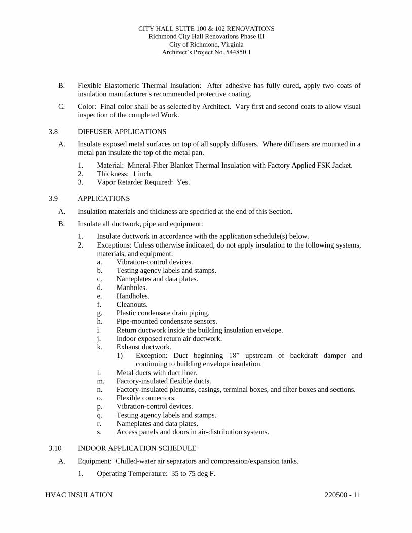
CITY HALL SUITE 100 & 102 RENOVATIONS Richmond City Hall Renovations Phase III
City of Richmond, Virginia Architect’s Project No. 544850.1
HVAC INSULATION 220500 - 11
B. Flexible Elastomeric Thermal Insulation: After adhesive has fully cured, apply two coats of insulation manufacturer's recommended protective coating.
C. Color: Final color shall be as selected by Architect. Vary first and second coats to allow visual inspection of the completed Work.
3.8 DIFFUSER APPLICATIONS
A. Insulate exposed metal surfaces on top of all supply diffusers. Where diffusers are mounted in a metal pan insulate the top of the metal pan.
1. Material: Mineral-Fiber Blanket Thermal Insulation with Factory Applied FSK Jacket. 2. Thickness: 1 inch. 3. Vapor Retarder Required: Yes.
3.9 APPLICATIONS
A. Insulation materials and thickness are specified at the end of this Section.
B. Insulate all ductwork, pipe and equipment:
1. Insulate ductwork in accordance with the application schedule(s) below. 2. Exceptions: Unless otherwise indicated, do not apply insulation to the following systems,
materials, and equipment: a. Vibration-control devices. b. Testing agency labels and stamps. c. Nameplates and data plates. d. Manholes. e. Handholes. f. Cleanouts. g. Plastic condensate drain piping. h. Pipe-mounted condensate sensors. i. Return ductwork inside the building insulation envelope. j. Indoor exposed return air ductwork. k. Exhaust ductwork.
1) Exception: Duct beginning 18” upstream of backdraft damper and continuing to building envelope insulation.
l. Metal ducts with duct liner. m. Factory-insulated flexible ducts. n. Factory-insulated plenums, casings, terminal boxes, and filter boxes and sections. o. Flexible connectors. p. Vibration-control devices. q. Testing agency labels and stamps. r. Nameplates and data plates. s. Access panels and doors in air-distribution systems.
3.10 INDOOR APPLICATION SCHEDULE
A. Equipment: Chilled-water air separators and compression/expansion tanks.
1. Operating Temperature: 35 to 75 deg F.
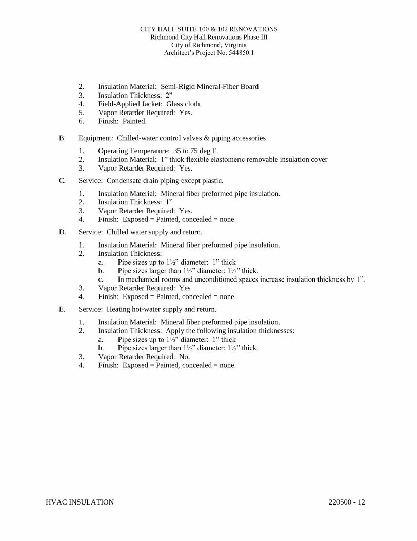
CITY HALL SUITE 100 & 102 RENOVATIONS Richmond City Hall Renovations Phase III
City of Richmond, Virginia Architect’s Project No. 544850.1
HVAC INSULATION 220500 - 12
2. Insulation Material: Semi-Rigid Mineral-Fiber Board 3. Insulation Thickness: 2” 4. Field-Applied Jacket: Glass cloth. 5. Vapor Retarder Required: Yes. 6. Finish: Painted.
B. Equipment: Chilled-water control valves & piping accessories
1. Operating Temperature: 35 to 75 deg F. 2. Insulation Material: 1” thick flexible elastomeric removable insulation cover 3. Vapor Retarder Required: Yes.
C. Service: Condensate drain piping except plastic.
1. Insulation Material: Mineral fiber preformed pipe insulation. 2. Insulation Thickness: 1” 3. Vapor Retarder Required: Yes. 4. Finish: Exposed = Painted, concealed = none.
D. Service: Chilled water supply and return.
1. Insulation Material: Mineral fiber preformed pipe insulation. 2. Insulation Thickness:
a. Pipe sizes up to 1½” diameter: 1” thick b. Pipe sizes larger than 1½” diameter: 1½” thick. c. In mechanical rooms and unconditioned spaces increase insulation thickness by 1”.
3. Vapor Retarder Required: Yes 4. Finish: Exposed = Painted, concealed = none.
E. Service: Heating hot-water supply and return.
1. Insulation Material: Mineral fiber preformed pipe insulation. 2. Insulation Thickness: Apply the following insulation thicknesses:
a. Pipe sizes up to 1½” diameter: 1” thick b. Pipe sizes larger than 1½” diameter: 1½” thick.
3. Vapor Retarder Required: No. 4. Finish: Exposed = Painted, concealed = none.
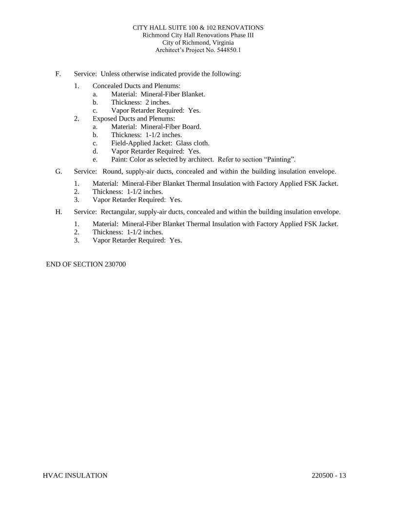
CITY HALL SUITE 100 & 102 RENOVATIONS Richmond City Hall Renovations Phase III
City of Richmond, Virginia Architect’s Project No. 544850.1
HVAC INSULATION 220500 - 13
F. Service: Unless otherwise indicated provide the following:
1. Concealed Ducts and Plenums: a. Material: Mineral-Fiber Blanket. b. Thickness: 2 inches. c. Vapor Retarder Required: Yes.
2. Exposed Ducts and Plenums: a. Material: Mineral-Fiber Board. b. Thickness: 1-1/2 inches. c. Field-Applied Jacket: Glass cloth. d. Vapor Retarder Required: Yes. e. Paint: Color as selected by architect. Refer to section “Painting”.
G. Service: Round, supply-air ducts, concealed and within the building insulation envelope.
1. Material: Mineral-Fiber Blanket Thermal Insulation with Factory Applied FSK Jacket. 2. Thickness: 1-1/2 inches. 3. Vapor Retarder Required: Yes.
H. Service: Rectangular, supply-air ducts, concealed and within the building insulation envelope.
1. Material: Mineral-Fiber Blanket Thermal Insulation with Factory Applied FSK Jacket. 2. Thickness: 1-1/2 inches. 3. Vapor Retarder Required: Yes.
END OF SECTION 230700
CITY HALL SUITE 100 & 102 RENOVATIONS Richmond City Hall Renovations Phase III
City of Richmond, Virginia Architect’s Project No. 544850.1
BUILDING AUTOMATION SYSTEM 230900 - 1
SECTION 230900 – BUILDING AUTOMATION SYSTEM
PART 1 - GENERAL
1.1 RELATED DOCUMENTS
A. Drawings and general provisions of the Contract, including General and Supplementary Conditions and Division 01 Specification Sections, apply to this Section.
1.2 SUMMARY
A. This Section includes control equipment for HVAC systems and components, including control
components for terminal heating and cooling units not supplied with factory-wired controls.
B. Related Sections include the following:
1. Division 23 Section "Meters and Gages for HVAC Piping" for measuring equipment that relates to this Section.
2. Division 23 Section "Sequences of Control" for requirements that relate to this Section. 3. Division 28 Sections for additional conduit requirements for all electronic safety and
security systems specified under Division 28.
C. Work Under Other Sections: 1. All wells, valves, taps, dampers, flow stations, etc. furnished by the BAS manufacturer
shall be installed under Section “Hydronic Piping.” 2. The following shall be provided under Division 23 specifications sections:
a. 120V power to BAS panels and devices with circuits indicated on the drawings. Refer to “Coordination” paragraph below.
b. Wiring of power feeds to disconnect switches and starters. c. Wiring from disconnect switches and starters to electric motors. d. Wiring of any remote start/stop switches and manual or automatic motor speed
control devices not furnished under this section of the specifications. 1.3 DEFINITIONS
A. BAS: Building Automation System.
B. DDC: Direct digital control.
C. I/O: Input/output.
D. IT: Information Technology.
E. IS: Information Systems.
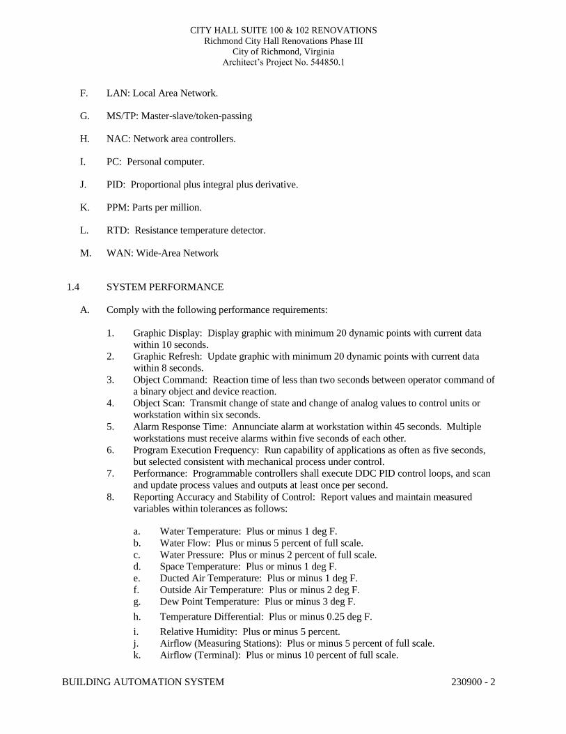
CITY HALL SUITE 100 & 102 RENOVATIONS Richmond City Hall Renovations Phase III
City of Richmond, Virginia Architect’s Project No. 544850.1
BUILDING AUTOMATION SYSTEM 230900 - 2
F. LAN: Local Area Network.
G. MS/TP: Master-slave/token-passing
H. NAC: Network area controllers.
I. PC: Personal computer.
J. PID: Proportional plus integral plus derivative.
K. PPM: Parts per million.
L. RTD: Resistance temperature detector.
M. WAN: Wide-Area Network 1.4 SYSTEM PERFORMANCE
A. Comply with the following performance requirements:
1. Graphic Display: Display graphic with minimum 20 dynamic points with current data
within 10 seconds. 2. Graphic Refresh: Update graphic with minimum 20 dynamic points with current data
within 8 seconds. 3. Object Command: Reaction time of less than two seconds between operator command of
a binary object and device reaction. 4. Object Scan: Transmit change of state and change of analog values to control units or
workstation within six seconds. 5. Alarm Response Time: Annunciate alarm at workstation within 45 seconds. Multiple
workstations must receive alarms within five seconds of each other. 6. Program Execution Frequency: Run capability of applications as often as five seconds,
but selected consistent with mechanical process under control. 7. Performance: Programmable controllers shall execute DDC PID control loops, and scan
and update process values and outputs at least once per second. 8. Reporting Accuracy and Stability of Control: Report values and maintain measured
variables within tolerances as follows:
a. Water Temperature: Plus or minus 1 deg F. b. Water Flow: Plus or minus 5 percent of full scale. c. Water Pressure: Plus or minus 2 percent of full scale. d. Space Temperature: Plus or minus 1 deg F. e. Ducted Air Temperature: Plus or minus 1 deg F. f. Outside Air Temperature: Plus or minus 2 deg F. g. Dew Point Temperature: Plus or minus 3 deg F. h. Temperature Differential: Plus or minus 0.25 deg F. i. Relative Humidity: Plus or minus 5 percent. j. Airflow (Measuring Stations): Plus or minus 5 percent of full scale. k. Airflow (Terminal): Plus or minus 10 percent of full scale.
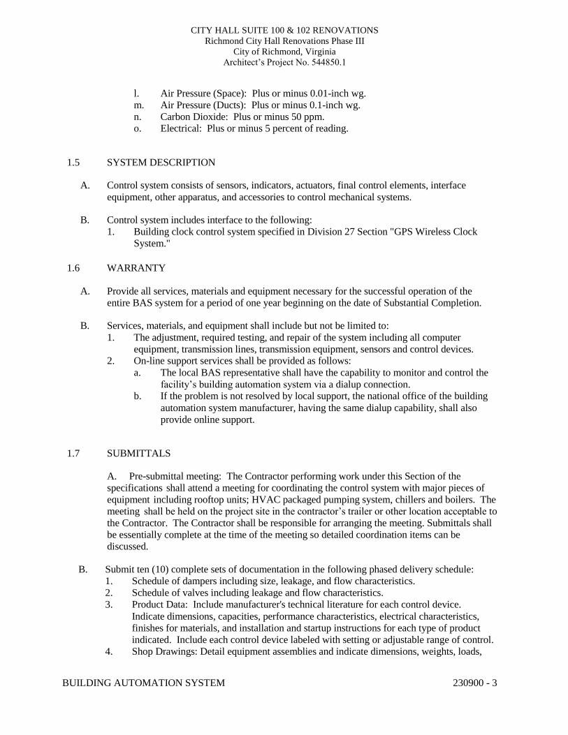
CITY HALL SUITE 100 & 102 RENOVATIONS Richmond City Hall Renovations Phase III
City of Richmond, Virginia Architect’s Project No. 544850.1
BUILDING AUTOMATION SYSTEM 230900 - 3
l. Air Pressure (Space): Plus or minus 0.01-inch wg. m. Air Pressure (Ducts): Plus or minus 0.1-inch wg. n. Carbon Dioxide: Plus or minus 50 ppm. o. Electrical: Plus or minus 5 percent of reading.
1.5 SYSTEM DESCRIPTION
A. Control system consists of sensors, indicators, actuators, final control elements, interface
equipment, other apparatus, and accessories to control mechanical systems.
B. Control system includes interface to the following: 1. Building clock control system specified in Division 27 Section "GPS Wireless Clock
System." 1.6 WARRANTY
A. Provide all services, materials and equipment necessary for the successful operation of the
entire BAS system for a period of one year beginning on the date of Substantial Completion.
B. Services, materials, and equipment shall include but not be limited to: 1. The adjustment, required testing, and repair of the system including all computer
equipment, transmission lines, transmission equipment, sensors and control devices. 2. On-line support services shall be provided as follows:
a. The local BAS representative shall have the capability to monitor and control the facility’s building automation system via a dialup connection.
b. If the problem is not resolved by local support, the national office of the building automation system manufacturer, having the same dialup capability, shall also provide online support.
1.7 SUBMITTALS
A. Pre-submittal meeting: The Contractor performing work under this Section of the specifications shall attend a meeting for coordinating the control system with major pieces of equipment including rooftop units; HVAC packaged pumping system, chillers and boilers. The meeting shall be held on the project site in the contractor’s trailer or other location acceptable to the Contractor. The Contractor shall be responsible for arranging the meeting. Submittals shall be essentially complete at the time of the meeting so detailed coordination items can be discussed.
B. Submit ten (10) complete sets of documentation in the following phased delivery schedule:
1. Schedule of dampers including size, leakage, and flow characteristics. 2. Schedule of valves including leakage and flow characteristics. 3. Product Data: Include manufacturer's technical literature for each control device.
Indicate dimensions, capacities, performance characteristics, electrical characteristics, finishes for materials, and installation and startup instructions for each type of product indicated. Include each control device labeled with setting or adjustable range of control.
4. Shop Drawings: Detail equipment assemblies and indicate dimensions, weights, loads,
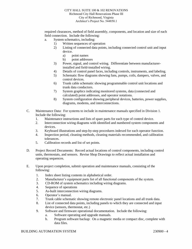
CITY HALL SUITE 100 & 102 RENOVATIONS Richmond City Hall Renovations Phase III
City of Richmond, Virginia Architect’s Project No. 544850.1
BUILDING AUTOMATION SYSTEM 230900 - 4
required clearances, method of field assembly, components, and location and size of each field connection. Include the following: a. System schematics, including:
1) Written sequences of operation 2) Listing of connected data points, including connected control unit and input
device. a) point names b) point addresses
3) Power, signal, and control wiring. Differentiate between manufacturer- installed and field-installed wiring.
4) Details of control panel faces, including controls, instruments, and labeling. 5) Schematic flow diagrams showing fans, pumps, coils, dampers, valves, and
control devices. 6) Trunk cable schematic showing programmable control unit locations and
trunk data conductors. 7) System graphics indicating monitored systems, data (connected and
calculated) point addresses, and operator notations. 8) System configuration showing peripheral devices, batteries, power supplies,
diagrams, modems, and interconnections.
C. Maintenance Data: For systems to include in maintenance manuals specified in Division 1. Include the following: 1. Maintenance instructions and lists of spare parts for each type of control device. 2. Interconnection wiring diagrams with identified and numbered system components and
devices. 3. Keyboard illustrations and step-by-step procedures indexed for each operator function. 4. Inspection period, cleaning methods, cleaning materials recommended, and calibration
tolerances. 5. Calibration records and list of set points.
D. Project Record Documents: Record actual locations of control components, including control
units, thermostats, and sensors. Revise Shop Drawings to reflect actual installation and operating sequences.
E. Upon project completion, submit operation and maintenance manuals, consisting of the
following: 1. Index sheet listing contents in alphabetical order. 2. Manufacturer’s equipment parts list of all functional components of the system. 3. CD-ROM of system schematics including wiring diagrams. 4. Sequence of operations 5. As-built interconnection wiring diagrams. 6. Operator’s manual. 7. Trunk cable schematic showing remote electronic panel locations and all trunk data. 8. List of connected data points, including panels to which they are connected and input
device (sensors, thermostat, etc.) 9. Software and firmware operational documentation. Include the following:
a. Software operating and upgrade manuals. b. Program software backup: On a magnetic media or compact disc, complete with
data files.
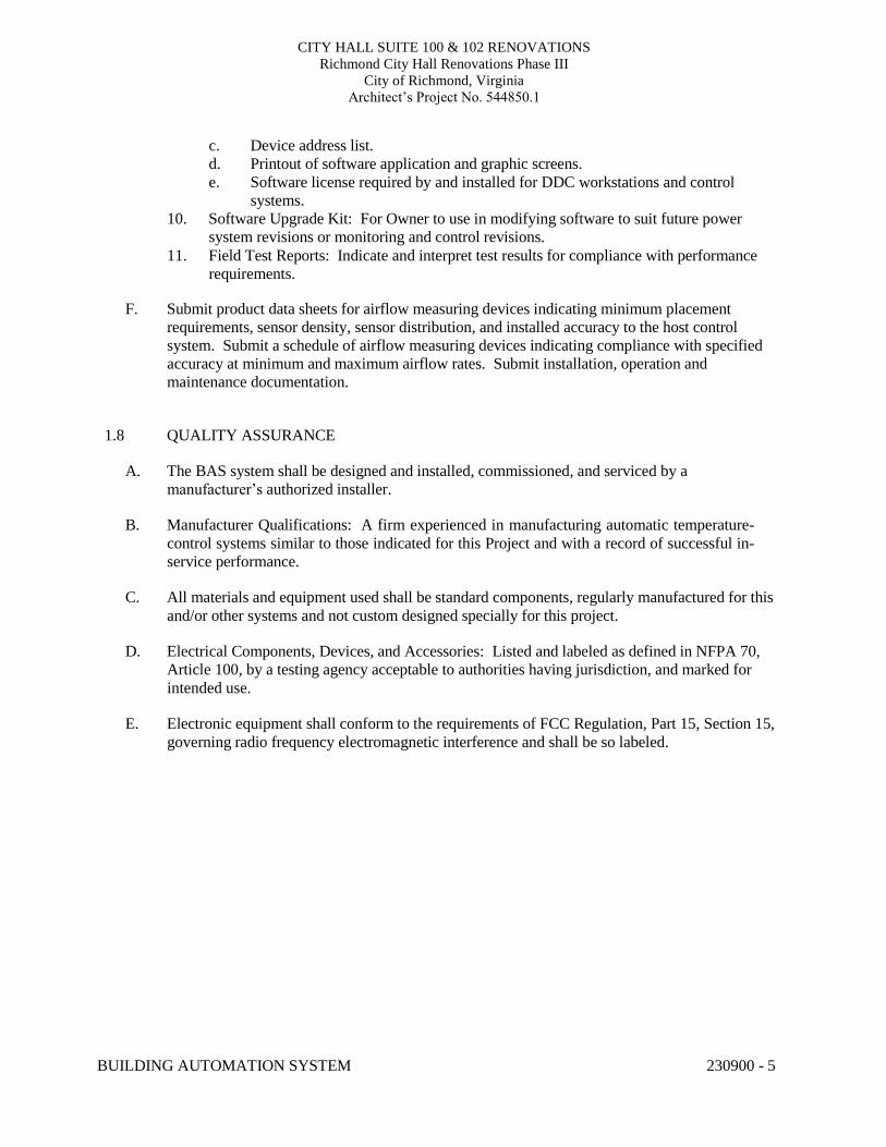
CITY HALL SUITE 100 & 102 RENOVATIONS Richmond City Hall Renovations Phase III
City of Richmond, Virginia Architect’s Project No. 544850.1
BUILDING AUTOMATION SYSTEM 230900 - 5
c. Device address list. d. Printout of software application and graphic screens. e. Software license required by and installed for DDC workstations and control
systems. 10. Software Upgrade Kit: For Owner to use in modifying software to suit future power
system revisions or monitoring and control revisions. 11. Field Test Reports: Indicate and interpret test results for compliance with performance
requirements.
F. Submit product data sheets for airflow measuring devices indicating minimum placement requirements, sensor density, sensor distribution, and installed accuracy to the host control system. Submit a schedule of airflow measuring devices indicating compliance with specified accuracy at minimum and maximum airflow rates. Submit installation, operation and maintenance documentation.
1.8 QUALITY ASSURANCE
A. The BAS system shall be designed and installed, commissioned, and serviced by a
manufacturer’s authorized installer.
B. Manufacturer Qualifications: A firm experienced in manufacturing automatic temperature- control systems similar to those indicated for this Project and with a record of successful in- service performance.
C. All materials and equipment used shall be standard components, regularly manufactured for this
and/or other systems and not custom designed specially for this project.
D. Electrical Components, Devices, and Accessories: Listed and labeled as defined in NFPA 70, Article 100, by a testing agency acceptable to authorities having jurisdiction, and marked for intended use.
E. Electronic equipment shall conform to the requirements of FCC Regulation, Part 15, Section 15,
governing radio frequency electromagnetic interference and shall be so labeled.
CITY HALL SUITE 100 & 102 RENOVATIONS Richmond City Hall Renovations Phase III
City of Richmond, Virginia Architect’s Project No. 544850.1
BUILDING AUTOMATION SYSTEM 230900 - 6
F. Comply with NFPA 90A, "Installation of Air Conditioning and Ventilation Systems." 1.9 DELIVERY, STORAGE, AND HANDLING
A. Factory-Mounted Components: Where control devices specified in this Section are indicated to
be factory-mounted on equipment, arrange for shipping of control devices to equipment manufacturer.
B. System Software: Update to latest version of software at Project completion.
1.10 COORDINATION
A. Control Wiring: The BAS manufacturer shall be responsible for all BAS and temperature
control wiring for a complete and operable system. All wire and cable shall be plenum-rated and shall be in accordance with Division 26 specification sections and all local, state and national codes and ordinances.
B. Where plenum-rated BAS cable is routed in concealed, accessible spaces, the cable may be run
in the cable trays or in J-Hooks provided under this section of the specifications. Where plenum-rated BAS cable is routed in exposed or inaccessible areas, it shall be run conduit provided under this section of the specifications.
C. Power Wiring:
1. Power wiring indicated (device and circuit designation indicated) on the drawings shall be provided under Division 26.
2. The BAS manufacturer shall be responsible for power wiring not indicated (device or circuit designation not indicated) on the Drawings. It shall be the BAS manufacturer’s responsibility to review the Contract Documents to determine the extent of power wiring included in Division 26 and to provide additional power wiring as required. Work shall be in accordance with Division 26 specifications and all local, state and national codes and ordinances.
3. Where the contractor performing work under this section requires an additional circuit for power wiring to a device or panel under paragraph 2 above, an RFI shall be issued requesting approval to use an available circuit in the nearest panel. Once approval is granted, all wiring and conduit from the breaker to the device or panel shall be provided under this section of the specifications.
D. Coordinate location of thermostats, humidistats, and other exposed control sensors with plans
and room details before installation. All conduits shall be concealed within walls and above ceilings unless indicated otherwise.
E. Coordinate installation of conduit to avoid cutting of finished surfaces.
CITY HALL SUITE 100 & 102 RENOVATIONS Richmond City Hall Renovations Phase III
City of Richmond, Virginia Architect’s Project No. 544850.1
BUILDING AUTOMATION SYSTEM 230900 - 7
F. Coordinate supply of conditioned electrical branch circuits for control units and operator workstation.
G. Coordinate equipment with Division 26 Section "Panelboards" to achieve compatibility with
starter coils and annunciation devices.
H. Coordinate equipment with Division 26 Section “Switchboards” to achieve compatibility with power monitoring and metering devices in that equipment.
PART 2 - PRODUCTS
2.1 MANUFACTURERS
A. Manufacturers:
1. Siemens
B. The design of the BAS shall network any existing operator workstations located off-site, the district supervisory server, network area controllers, and stand-alone DDC controllers. The network architecture shall consist of two levels: a high performance peer-to-peer network and DDC controller-specific local area networks. Access to the controller-specific LAN shall be totally transparent to the user when accessing data or developing control programs. The BAS shall be comprised of Network Area Controller(s) within each facility. The NAC shall connect to the owner’s wide area network. Access to the system, either locally in each building, or remotely from a central site or sites, shall be accomplished through standard web browsers, via the Internet and/or VPN access to the school system’s WAN. Each NAC shall communicate to LonMark/LonTalk (IDC) and/or BACnet (IBC) controllers provided under this Section.
C. Control system shall consist of sensors, indicators, actuators, final control elements, interface
equipment, other apparatus, accessories, and software connected to distributed controllers operating in multiuser, multitasking environment on token-passing network and programmed to control mechanical systems. An operator workstation permits interface with the network via
CITY HALL SUITE 100 & 102 RENOVATIONS Richmond City Hall Renovations Phase III
City of Richmond, Virginia Architect’s Project No. 544850.1
BUILDING AUTOMATION SYSTEM 230900 - 8
dynamic color graphics with each mechanical system, building floor plan, and control device depicted by point-and-click graphics.
D. Peer-to-Peer Network Level: All operator devices either network resident or connected via
dial-up modems shall have the ability to access all point status and application report data, and to execute control functions for any and all other devices via the peer-to-peer network. No hardware or software limits shall be imposed on the number of devices with global access to the network data at any time. 1. Telecommunication Capability:
a. Auto-dial/auto-answer communications shall be provided to allow DDC Controllers to communicate with remote operator stations and/or remote terminals via telephone lines, as indicated in the sequence of operations. Existing modems and existing remote host software shall be utilized to meet existing connection system.
b. Auto-dial DDC Controllers shall automatically place calls to workstations to report alarms or other significant events. The auto-dial program shall include provisions for handling busy signals, "no answers" and incomplete data transfers.
2. Operators at dial-up workstations shall be able to perform all control functions, all report functions and all database generation and modification functions as described for workstations connected via the network. Routines shall be provided to automatically answer calls from remote DDC Controllers. The fact that communications are taking place with remote DDC Controllers over telephone lines shall be completely transparent to an operator.
3. Main DDC panels shall be connected via fiber. All fiber, connection hardware, and work required for connection of main panels shall be included.
4. An Ethernet connection shall be made to the exiting central maintenance host workstation. The contractor performing work under this section of the specifications shall meet with the Owner’s IT or IS department and shall be responsible for providing a complete Ethernet connection over the Owner’s existing network. All software, hardware, wiring, fiber, and components necessary shall be provided.
2.2 DDC EQUIPMENT
A. Existing Operator Workstations: All BAS interface software should be installed on the campus
existing head end computers located in the Building and Ground Office. Provide at least two hard copies on CD or DVD of all software required for interface. 1. Application Software:
a. I/O capability from operator station. b. System security for each operator via software password and access levels. c. Automatic system diagnostics; monitor system and report failures. d. Database creation and support. e. Automatic and manual database save and restore. f. Dynamic color graphic displays with up to 10 screen displays at once. g. Custom graphics generation and graphics library of HVAC equipment and
symbols. h. Alarm processing, messages, and reactions.
CITY HALL SUITE 100 & 102 RENOVATIONS Richmond City Hall Renovations Phase III
City of Richmond, Virginia Architect’s Project No. 544850.1
BUILDING AUTOMATION SYSTEM 230900 - 9
i. Trend logs retrievable in spreadsheets and database programs. j. Alarm and event processing. k. Object and property status and control. l. Automatic restart of field equipment on restoration of power. m. Data collection, reports, and logs. Include standard reports for the following:
1) Current values of all objects. 2) Current alarm summary. 3) Disabled objects. 4) Alarm lockout objects. 5) Logs.
n. Custom report development. o. Workstation application editors for controllers and schedules. p. Maintenance management.
B. I/O Interface: Hardwired inputs and outputs may tie into system through controllers. Protect
points so that shorting will cause no damage to controllers.
1. Binary Inputs: Allow monitoring of on-off signals without external power. 2. Pulse Accumulation Inputs: Accept up to 10 pulses per second. 3. Analog Inputs: Allow monitoring of low-voltage (0- to 10-V dc), current (4 to 20 mA),
or resistance signals. 4. Binary Outputs: Provide on-off or pulsed low-voltage signal, selectable for normally
open or normally closed operation with three-position (on-off-auto) override switches and status lights.
5. Analog Outputs: Provide either modulating signal, low voltage (0- to 10-V dc) or current (4 to 20 mA) with status lights, two-position (auto-manual) switch, and manually adjustable potentiometer.
6. Tri-State Outputs: Provide two coordinated binary outputs for control of three-point, floating-type electronic actuators.
7. Universal I/Os: Provide software selectable binary or analog outputs.
C. Power Supplies: Transformers with Class 2 current-limiting type or overcurrent protection; limit connected loads to 80 percent of rated capacity. DC power supply shall match output current and voltage requirements and be full-wave rectifier type with the following:
1. Output ripple of 5.0 mV maximum peak to peak. 2. Combined 1 percent line and load regulation with 100-mic.sec. response time for 50
percent load changes. 3. Built-in overvoltage and overcurrent protection and be able to withstand 150 percent
overload for at least 3 seconds without failure. 2.3 DDC CONTROLLERS
A. No controller shall be loaded to more than 80%. IE: A controller with 20 available points shall
be loaded with 16 points or less.
CITY HALL SUITE 100 & 102 RENOVATIONS Richmond City Hall Renovations Phase III
City of Richmond, Virginia Architect’s Project No. 544850.1
BUILDING AUTOMATION SYSTEM 230900 - 10
B. DDC controllers shall be stand-alone, multi-tasking, multi-user, real-time digital control processors consisting of modular hardware with plug-in enclosed processors, communication controllers, power supplies and input/output point modules. Controller size shall be sufficient to fully meet the requirements of the contract documents. Each controller shall support a minimum of two (2) LAN Device Networks.
C. Each DDC controller shall have sufficient memory to support its own operating system and
databases, including: 1. Control processes 2. Energy management applications 3. Alarm management applications including custom alarm messages for each level alarm
for each point in the system. 4. Historical/trend data for points specified. 5. Maintenance support applications. 6. Custom processes. 7. Operator I/O. 8. Dial-up communications. 9. Manual override monitoring.
D. Each DDC controller shall support any combination of industry standard inputs and outputs.
E. Provide all processors, power supplies and communication controllers so that the
implementation of a point only requires the addition of the appropriate point input/output termination module and wiring.
F. DDC controllers shall provide a minimum two RS-232C serial data communication ports for
operation of operator I/O devices such as industry standard printers, operator terminals, modems and portable laptop operator's terminals. DDC controllers shall allow temporary use of portable devices without interrupting the normal operation of permanently connected modems, Ethernet connections, printers, or terminals.
G. Each DDC controller shall continuously perform self-diagnostics, communication diagnosis and
diagnosis of all panel components. The DDC controller shall provide both local and remote annunciation of any detected component failures, low battery conditions or repeated failure to establish communication.
H. Isolation shall be provided at all peer-to-peer network terminations, as well as all field point
terminations to suppress induced voltage transients consistent with IEEE Standards 587-1980.
I. In the event of the loss of normal power, there shall be an orderly shutdown of all DDC controllers to prevent the loss of database or operating system software. Non-volatile memory shall be incorporated for all critical controller configuration data and battery backup shall be provided to support the real-time clock and all volatile memory for a minimum of 100 days. 1. Upon restoration of normal power, the DDC controller shall automatically resume full
operation without manual intervention.
CITY HALL SUITE 100 & 102 RENOVATIONS Richmond City Hall Renovations Phase III
City of Richmond, Virginia Architect’s Project No. 544850.1
BUILDING AUTOMATION SYSTEM 230900 - 11
2. Should DDC controller memory be lost for any reason, the system shall automatically reload the DDC controller via the local RS-232C port, via telephone line dial-in or Ethernet from the existing network workstation PC.
J. Provide a separate DDC controller for each RTU or other HVAC system. It is intended that
each unique system be provided with its own point resident DDC controller. 2.4 DDC CONTROLLER RESIDENT SOFTWARE FEATURES
A. General:
1. The software programs specified in this Section shall be provided as an integral part of DDC Controllers and shall not be dependent upon any higher-level computer for execution.
B. Control Software Description:
1. The DDC Controllers shall have the ability to perform the following pre-tested control algorithms: a. Two-position control b. Proportional control c. Proportional plus integral control d. Proportional, integral, plus derivative control e. Automatic tuning of control loops
C. DDC Controllers shall have the ability to perform any or all the following energy management
routines: 1. Time-of-day scheduling 2. Calendar-based scheduling 3. Holiday scheduling 4. Temporary schedule overrides 5. Start-Stop Time Optimization 6. Automatic Daylight Savings Time Switchover 7. Night setback control 8. Enthalpy switchover (economizer) 9. Peak demand limiting 10. Temperature-compensated duty cycling 11. Trending
D. DDC Controllers shall be able to execute custom, job-specific processes defined by the user, to
automatically perform calculations and special control routines.
E. Alarm management shall be provided to monitor and direct alarm information to operator devices. Each DDC Controller shall perform distributed, independent alarm analysis and filtering to minimize operator interruptions due to non-critical alarms, minimize network traffic and prevent alarms from being lost. At no time shall the DDC Controllers ability to report alarms be affected by either operator or activity at a PC workstation, local I/O device or communications with other panels on the network.
CITY HALL SUITE 100 & 102 RENOVATIONS Richmond City Hall Renovations Phase III
City of Richmond, Virginia Architect’s Project No. 544850.1
BUILDING AUTOMATION SYSTEM 230900 - 12
F. A variety of historical data collection utilities shall be provided to manually or automatically sample, store and display system data for points as specified.
2.5 APPLICATION SPECIFIC CONTROLLERS (ASC)
A. Each DDC Controller shall be able to extend its performance and capacity using remote
application specific controllers (ASCs) through LAN Device Networks.
B. Each ASC shall operate as a stand-alone controller capable of performing its specified control responsibilities independently of other controllers in the network. Each ASC shall be a microprocessor-based, multi-tasking, real-time digital control processor. Provide the following types of ASCs as a minimum: 1. Terminal Equipment Controllers
a. Terminal Box (VAV box controllers) should have a differential pressure transmitter (transducer) accuracy of 0.015-inches w.g. or less.
C. Each ASC shall be capable of control of the terminal device independent of the manufacturer of
the terminal device.
D. Terminal Equipment Controllers: 1. Provide for control of each piece of equipment , including, but not limited to, the
following: a. Terminal Boxes b. Exhaust fans c. Terminal Units
2.6 ELECTRONIC SENSORS
A. Description: Vibration and corrosion resistant; for wall, immersion, or duct mounting as
required.
B. Thermistor Temperature Sensors and Transmitters and Resistance Temperature Detectors and Transmitters: 1. Accuracy: Plus or minus 0.5 deg F at calibration point. 2. Wire: Twisted, shielded-pair cable. 3. Insertion Elements in Ducts: Single point, 8 inches long; use where not affected by
temperature stratification or where ducts are smaller than 9 sq. ft. 4. Averaging Elements in Ducts: 36 inches long, flexible; use where prone to temperature
stratification or where ducts are larger than 10 sq. ft. 5. Insertion Elements for Liquids: Brass or stainless steel socket with minimum insertion
length of 2-1/2 inches. 6. Room Sensor Cover Construction: Manufacturer's standard locking covers.
a. Set-Point Adjustment: Concealed. b. Set-Point Indication: Concealed.
CITY HALL SUITE 100 & 102 RENOVATIONS Richmond City Hall Renovations Phase III
City of Richmond, Virginia Architect’s Project No. 544850.1
BUILDING AUTOMATION SYSTEM 230900 - 13
c. Thermometer: Concealed. d. Color: Manufacturer’s standard. e. Orientation: Vertical.
7. Outside-Air Sensors: Watertight inlet fitting, shielded from direct sunlight. 8. Specific Sensor Type Locations: In lobbies, corridors, & restroom locations, provide
blank stainless-steel cover plate sensors with insulated back and security screws.
C. Pressure Transmitters/Transducers:
1. Static-Pressure Transmitter: Nondirectional sensor with suitable range for expected input and temperature-compensated. a. Accuracy: 2 percent of full scale with repeatability of 0.5 percent. b. Output: 4 to 20 mA. c. Building Static-Pressure Range: 0- to 0.25-inch wg. d. Duct Static-Pressure Range: 0- to 5-inch wg.
2. Water Pressure Transducers: Stainless-steel diaphragm construction, suitable for service; minimum 150-psig operating pressure; linear output 4 to 20 mA.
3. Water Differential-Pressure Transducers: Stainless-steel diaphragm construction, suitable for service; minimum 150-psig operating pressure and tested to 300-psig; linear output 4 to 20 mA.
4. Differential-Pressure Switch (Air or Water): Snap acting, with pilot-duty rating and with suitable scale range and differential. Accuracy shall be +/- 5% of range.
5. Pressure Transmitters: Direct acting for gas, liquid, or steam service; range suitable for system; linear output 4 to 20 mA.
D. Current Sensing Switch:
1. Sensor supply voltage and supply current shall be induced from monitored conductor. Contact rating shall be 0.2 amperes at 30 volts DC/AC. Trip set point shall be adjustable to +/-1% of range. Current sensing switch wiring shall not be polarity sensitive.
2.7 STATUS SENSORS
A. Status Inputs for Fans: Differential-pressure switch with pilot-duty rating and with adjustable
range of 0- to 5-inch wg.
B. Status Inputs for Pumps: Differential-pressure switch with pilot-duty rating and with adjustable pressure-differential range of 8 to 60 psig, piped across pump.
C. Status Inputs for Electric Motors: Comply with ISA 50.00.01, current-sensing fixed- or split-
core transformers with self-powered transmitter, adjustable and suitable for 175 percent of rated motor current.
D. Voltage Transmitter (100- to 600-V ac): Comply with ISA 50.00.01, single-loop, self-powered
transmitter, adjustable, with suitable range and 1 percent full-scale accuracy.
E. Power Monitor: 3-phase type with disconnect/shorting switch assembly, listed voltage and
CITY HALL SUITE 100 & 102 RENOVATIONS Richmond City Hall Renovations Phase III
City of Richmond, Virginia Architect’s Project No. 544850.1
BUILDING AUTOMATION SYSTEM 230900 - 14
current transformers, with pulse kilowatt hour output and 4- to 20-mA kW output, with maximum 2 percent error at 1.0 power factor and 2.5 percent error at 0.5 power factor.
F. Current Switches: Self-powered, solid-state with adjustable trip current, selected to match current and system output requirements.
G. Electronic Valve/Damper Position Indicator: Visual scale indicating percent of travel and 2- to
10-V dc, feedback signal.
2.8 THERMOSTATS
A. Available Manufacturers: 1. Danfoss Inc.; Air-Conditioning and Refrigeration Div. 2. Heat-Timer Corporation. 3. Tekmar Control Systems, Inc.
B. Combination Thermostat and Fan Switches: Line-voltage thermostat with push-button or lever-
operated fan switch.
1. Label switches "FAN ON-OFF" or "FAN HIGH-LOW-OFF" or "FAN HIGH-MED- LOW-OFF."
2. Mount on single electric switch box.
C. Electric, solid-state, microcomputer-based room thermostat with remote sensor. 1. Automatic switching from heating to cooling. 2. Preferential rate control to minimize overshoot and deviation from set point. 3. Set up for four separate temperatures per day. 4. Instant override of set point for continuous or timed period from 1 hour to 31 days. 5. Short-cycle protection. 6. Programming based on every day of week. 7. Selection features include degree F or degree C display, 12- or 24-hour clock, keyboard
disable, remote sensor, and fan on-auto. 8. Battery replacement without program loss. 9. Thermostat display features include the following:
a. Time of day. b. Actual room temperature. c. Programmed temperature. d. Programmed time. e. Duration of timed override. f. Day of week. g. System mode indications include "heating," "off," "fan auto," and "fan on."
D. Low-Voltage, On-Off Thermostats: NEMA DC 3, 24-V, bimetal-operated, mercury-switch
type, with adjustable or fixed anticipation heater, concealed set-point adjustment, 55 to 85 deg F set-point range, and 2 deg F maximum differential.
CITY HALL SUITE 100 & 102 RENOVATIONS Richmond City Hall Renovations Phase III
City of Richmond, Virginia Architect’s Project No. 544850.1
BUILDING AUTOMATION SYSTEM 230900 - 15
E. Airstream Thermostats: Two-pipe, fully proportional, single-temperature type; with adjustable set point in middle of range, adjustable throttling range, plug-in test fitting or permanent pressure gage, remote bulb, bimetal rod and tube, or averaging element.
F. Electric, Low-Limit Duct Thermostat: Snap-acting, single-pole, single-throw, manual- or
automatic- reset switch that trips if temperature sensed across any 12 inches of bulb length is equal to or below set point.
1. Bulb Length: Minimum 20 feet. 2. Quantity: One thermostat for every 20 sq. ft. of coil surface.
G. Electric, High-Limit Duct Thermostat: Snap-acting, single-pole, single-throw, manual- or
automatic- reset switch that trips if temperature sensed across any 12 inches of bulb length is equal to or above set point.
1. Bulb Length: Minimum 20 feet. 2. Quantity: One thermostat for every 20 sq. ft. of coil surface.
2.9 ACTUATORS
A. Electric Motors: Size to operate with sufficient reserve power to provide smooth modulating
action or two-position action.
1. Comply with requirements in Division 23 Section "Common Motor Requirements for HVAC Equipment."
2. Permanent Split-Capacitor or Shaded-Pole Type: Gear trains completely oil immersed and sealed. Equip spring-return motors with integral spiral-spring mechanism in housings designed for easy removal for service or adjustment of limit switches, auxiliary switches, or feedback potentiometer.
3. Nonspring-Return Motors for Valves Larger Than NPS 2-1/2: Size for running torque of 150 in. x lbf and breakaway torque of 300 in. x lbf.
4. Spring-Return Motors for Valves Larger Than NPS 2-1/2: Size for running and breakaway torque of 150 in. x lbf.
5. Nonspring-Return Motors for Dampers Larger Than 25 Sq. Ft.: Size for running torque of 150 in. x lbf and breakaway torque of 300 in. x lbf.
6. Spring-Return Motors for Dampers Larger Than 25 Sq. Ft.: Size for running and breakaway torque of 150 in. x lbf.
B. Electronic Actuators: Direct-coupled type designed for minimum 60,000 full-stroke cycles at
rated torque.
1. Valves: Size for torque required for valve close off at maximum pump differential pressure.
2. Dampers: Size for running torque calculated as follows: a. Parallel-Blade Damper with Edge Seals: 7 inch-lb/sq. ft. of damper.
CITY HALL SUITE 100 & 102 RENOVATIONS Richmond City Hall Renovations Phase III
City of Richmond, Virginia Architect’s Project No. 544850.1
BUILDING AUTOMATION SYSTEM 230900 - 16
b. Opposed-Blade Damper with Edge Seals: 5 inch-lb/sq. ft. of damper. c. Parallel-Blade Damper without Edge Seals: 4 inch-lb/sq. ft of damper. d. Opposed-Blade Damper without Edge Seals: 3 inch-lb/sq. ft. of damper. e. Dampers with 2- to 3-Inch wg of Pressure Drop or Face Velocities of 1000 to 2500
fpm: Increase running torque by 1.5. f. Dampers with 3- to 4-Inch wg of Pressure Drop or Face Velocities of 2500 to 3000
fpm: Increase running torque by 2.0.
3. Coupling: V-bolt and V-shaped, toothed cradle. 4. Overload Protection: Electronic overload or digital rotation-sensing circuitry. 5. Fail-Safe Operation: Mechanical, spring-return mechanism. Provide external, manual
gear release on nonspring-return actuators. 6. Power Requirements (Modulating): Maximum 10 VA at 24-V ac or 8 W at 24-V dc. 7. Proportional Signal: 2- to 10-V dc or 4 to 20 mA, and 2- to 10-V dc position feedback
signal. 8. Temperature Rating: Minus 22 to plus 122 deg F. 9. Temperature Rating (Smoke Dampers): Minus 22 to plus 250 deg F.
2.10 DAMPERS
A. Dampers: AMCA-rated, parallel or opposed-blade design; 0.108-inch- minimum thick,
galvanized-steel or 0.125-inch- minimum thick, extruded-aluminum frames with holes for duct mounting; damper blades shall not be less than 0.064-inch- thick galvanized steel with maximum blade width of 8 inches and length of 48 inches.
1. Secure blades to 1/2-inch- diameter, zinc-plated axles using zinc-plated hardware, with
oil-impregnated sintered bronze blade bearings, blade-linkage hardware of zinc-plated steel and brass, ends sealed against spring-stainless-steel blade bearings, and thrust bearings at each end of every blade.
2. Operating Temperature Range: From minus 40 to plus 200 deg F. 3. Edge Seals, Standard Pressure Applications: Closed-cell neoprene. 4. Edge Seals, Low-Leakage Applications: Use inflatable blade edging or replaceable
rubber blade seals and spring-loaded stainless-steel side seals, rated for leakage at less than 10 cfm per sq. ft. of damper area, at differential pressure of 4-inch wg when damper is held by torque of 50 in. x lbf; when tested according to AMCA 500D.
2.11 CURRENT SENSING RELAYS: By controls contractor for all equipment.
2.12 MISCELLANEOUS RELAYS AND SWITCHES:
A. General: Where required by the sequence of operation switches, relays, and miscellaneous
CITY HALL SUITE 100 & 102 RENOVATIONS Richmond City Hall Renovations Phase III
City of Richmond, Virginia Architect’s Project No. 544850.1
BUILDING AUTOMATION SYSTEM 230900 - 17
devices necessary to accomplish the sequence shall be provided under this section. PART 3 - EXECUTION
3.1 PROJECT MANAGEMENT
A. Provide a designated project manager who will be responsible for the following:
1. Construct and maintain project schedule 2. On-site coordination with all applicable trades and subcontractors 3. Authorized to accept and execute orders or instructions from owner/architect 4. Attend project meetings as necessary to avoid conflicts and delays 5. Make necessary field decisions relating to this scope of work 6. Coordination/Single point of contact.
3.2 EXAMINATION
A. Verify that power supply is available to control units and operator workstation.
B. Verify that duct-, pipe-, and equipment-mounted devices are installed before proceeding with
installation. 3.3 INSTALLATION
A. Install software in control units and operator workstation(s). Implement all features of
programs to specified requirements and as appropriate to sequence of operation.
B. Connect and configure equipment and software to achieve sequence of operation specified in Section 23 section “Sequences of Control.”
Verify location of thermostats, humidistats, and other exposed control sensors with Drawings and room details before installation. Install devices next to light switch(es) when space is available with top of device at 48 inches above finished floor. Where space next to light switch(es) is not available, align device vertically with light switch and locate device with top at 40 inches above the finished floor.
1. Install averaging elements in ducts and plenums in crossing or zigzag pattern.
C. Install guards on thermostats where indicated on Drawings. Provide cast aluminum hinged
guards on sensors serving the gymnasium.
D. Install automatic dampers according to Division 23 Section "Air Duct Accessories."
E. Install damper motors on outside of duct in warm areas, not in locations exposed to outdoor temperatures.
CITY HALL SUITE 100 & 102 RENOVATIONS Richmond City Hall Renovations Phase III
City of Richmond, Virginia Architect’s Project No. 544850.1
BUILDING AUTOMATION SYSTEM 230900 - 18
F. Install labels and nameplates to identify control components according to Division 23 Section
"Identification for HVAC Piping and Equipment."
G. Install hydronic instrument wells, valves, and other accessories according to Division 23 Section "Hydronic Piping."
H. Install refrigerant instrument wells, valves, and other accessories according to Division 23
Section "Refrigerant Piping."
I. Install duct volume-control dampers according to Division 23 Sections specifying air ducts. 3.4 FIELD QUALITY CONTROL
A. Manufacturer's Field Service: Engage a factory-authorized service representative to
inspect, test, and adjust field-assembled components and equipment installation, including connections, and to assist in field testing. Report results in writing.
B. Perform the following field tests and inspections and prepare test reports:
1. Operational Test: After electrical circuitry has been energized, start units to confirm
proper unit operation. Remove and replace malfunctioning units and retest. 2. Test and adjust controls and safeties. 3. Test calibration of electronic controllers by disconnecting input sensors and stimulating
operation with compatible signal generator. 4. Test each point through its full operating range to verify that safety and operating control
set points are as required. 5. Test each control loop to verify stable mode of operation and compliance with sequence
of operation. Adjust PID actions. 6. Test each system for compliance with sequence of operation. 7. Test software and hardware interlocks.
C. DDC Verification:
1. Verify that instruments are installed before calibration, testing, and loop or leak checks. 2. Check instruments for proper location and accessibility. 3. Check instrument installation for direction of flow, elevation, orientation, insertion depth,
and other applicable considerations. 4. Check instrument tubing for proper fittings, slope, material, and support. 5. Check flow instruments. Inspect tag number and line and bore size, and verify that inlet
side is identified and that meters are installed correctly. 6. Check pressure instruments, piping slope, installation of valve manifold, and self-
contained pressure regulators. 7. Check temperature instruments and material and length of sensing elements. 8. Check control valves. Verify that they are in correct direction. 9. Check DDC system as follows:
CITY HALL SUITE 100 & 102 RENOVATIONS Richmond City Hall Renovations Phase III
City of Richmond, Virginia Architect’s Project No. 544850.1
BUILDING AUTOMATION SYSTEM 230900 - 19
a. Verify that DDC controller power supply is from emergency power supply. b. Verify that wires at control panels are tagged with their service designation and
approved tagging system. c. Verify that spare I/O capacity has been provided. d. Verify that DDC controllers are protected from power supply surges.
D. Replace damaged or malfunctioning controls and equipment and repeat testing procedures.
3.5 ADJUSTING
A. Calibrating and Adjusting:
1. Calibrate instruments. 2. Make three-point calibration test for both linearity and accuracy for each analog
instrument. 3. Calibrate equipment and procedures using manufacturer's written recommendations and
instruction manuals. Use test equipment with accuracy at least double that of instrument being calibrated.
4. Control System Inputs and Outputs:
a. Check analog inputs at 0, 50, and 100 percent of span. b. Check analog outputs using milliampere meter at 0, 50, and 100 percent output. c. Check digital inputs using jumper wire. d. Check digital outputs using ohmmeter to test for contact making or breaking. e. Check resistance temperature inputs at 0, 50, and 100 percent of span using a
precision-resistant source.
5. Flow:
a. Set differential pressure flow transmitters for 0 and 100 percent values with 3-point calibration accomplished at 50, 90, and 100 percent of span.
b. Manually operate flow switches to verify that they make or break contact.
CITY HALL SUITE 100 & 102 RENOVATIONS Richmond City Hall Renovations Phase III
City of Richmond, Virginia Architect’s Project No. 544850.1
BUILDING AUTOMATION SYSTEM 230900 - 20
6. Pressure:
a. Calibrate pressure transmitters at 0, 50, and 100 percent of span. b. Calibrate pressure switches to make or break contacts, with adjustable differential
set at minimum.
7. Temperature:
a. Calibrate resistance temperature transmitters at 0, 50, and 100 percent of span using a precision-resistance source.
b. Calibrate temperature switches to make or break contacts.
8. Stroke and adjust control valves and dampers without positioners, following the manufacturer's recommended procedure, so that valve or damper is 100 percent open and closed.
9. Stroke and adjust control valves and dampers with positioners, following manufacturer's recommended procedure, so that valve and damper is 0, 50, and 100 percent closed.
10. Provide diagnostic and test instruments for calibration and adjustment of system. 11. Provide written description of procedures and equipment for calibrating each type of
instrument. Submit procedures review and approval before initiating startup procedures.
B. Adjust initial temperature and humidity set points.
C. Occupancy Adjustments: When requested within 12 months of date of Substantial Completion, provide on-site assistance in adjusting system to suit actual occupied conditions. Provide up to three visits to Project during other than normal occupancy hours for this purpose.
3.6 TRAINING
A. Provide 8 hours of training for Owner’s designated operating personnel. Training shall include:
1. Explanation of drawings and operation & maintenance manuals 2. Walk-through of the job to locate control components 3. Operator workstation and peripherals 4. Operation of Portable computer 5. DDC controller and ASC operation/function 6. Operator control functions including graphic generation and field panel programming 7. Explanation of adjustment, calibration and replacement procedures
B. Since the Owner may require personnel to have more comprehensive understanding of the
hardware and software, additional training must be available form the Manufacturer. If necessary additional training will be contracted by the Owner at a later date.
C. Coordinate with Owner if video recording documentation of training is required.
END OF SECTION 230900
CITY HALL SUITE 100 & 102 RENOVATIONS Richmond City Hall Renovations Phase III
City of Richmond, Virginia Architect’s Project No. 544850.1
SEQUENCE OF CONTROL 230993 - 1
SECTION 230993 - SEQUENCES OF CONTROL
PART 1 - GENERAL
1.1 RELATED DOCUMENTS
A. Provisions of the Contract and of the Contract Documents apply to this Section.
1.2 ABBREVIATIONS
A. BAS Building Automation System
B. BCM Boiler Communication Module
C. CFM Cubic Feet per Minute
D. DDC Direct-digital controls
E. °F Degrees Fahrenheit
F. ECM Electrically-commutated motor
G. RTU Rooftop unit
H. VAV Variable-air volume
I. VUSBC Virginia Uniform Statewide Building Code
J. W Wire
1.3 DEFINITIONS
A. DDC: Direct digital control.
B. Head End: Main temperature control computer system storing data accessible to the internet for WEB accessible systems and storing data accessible to the building system backbone for non- WEB accessible systems.
C. Modulating: Able to electrically vary and stop in any position.
D. Occupied Mode: Occupied or “design” operation.
CITY HALL SUITE 100 & 102 RENOVATIONS Richmond City Hall Renovations Phase III
City of Richmond, Virginia Architect’s Project No. 544850.1
SEQUENCE OF CONTROL 230993 - 2
E. Outdoor air: Air outside the building or taken from outdoors and not previously circulated
through the building.
F. Outdoor air measurement: Reporting of the volume of outdoor air taken into the building by RTU and reported to the building operator in CFM.
G. Outdoor-Air Refrigerant Coil: Refrigerant coil in the outdoor-air stream to reject heat during
cooling operations.
H. Outdoor-Air Refrigerant-Coil Fan: The outdoor-air refrigerant-coil fan in RTUs. "Outdoor air" is defined as the air outside the building or taken from outdoors and not previously circulated through the system.
I. Record: Maintain in writing on paper and maintain an electronic copy (Portable Document
Format (*.PDF) is acceptable). Make paper copy available for inspection upon request by Owner, Owner’s representative, Architect, or Architect’s representative. Email electronic copy to requested email address when request is made by the Owner, Owner’s representative, Architect, or Architect’s representative.
J. Set Point: An operating parameter adjustable at the head end by the operator.
K. Supply-Air Fan: Fan providing supply air to conditioned space.
L. Supply air: Air entering a space from air-conditioning, heating, or ventilating equipment.
M. Supply-Air Refrigerant Coil: Refrigerant coil in the supply-air stream to absorb heat (provide
cooling) during cooling operations and to reject heat (provide heating) during heating operations. "Supply air" is defined as the air entering a space from air-conditioning, heating, or ventilating apparatus.
N. Two-Position: Able to electrically move and stop in only two positions. Usually open or closed.
1.4 Submittals:
A. Submit the following:
1. Proposed control sequences.
2. Freezestat manufacturer’s data and wiring diagrams indicating all components required to execute the indicated sequence.
1.5 Trending:
A. Unless otherwise indicated where trending is indicated the BAS shall measure or record each
point value every 1.0 seconds and shall save results for a minimum of 30 days.
CITY HALL SUITE 100 & 102 RENOVATIONS Richmond City Hall Renovations Phase III
City of Richmond, Virginia Architect’s Project No. 544850.1
SEQUENCE OF CONTROL 230993 - 3
1.6 Coordination
A. Refer to Section 019110 “General Commissioning Requirements” for Commissioning
Plan requirements.
PART 2 - PRODUCTS (Not Used)
PART 3 - EXECUTION (OPERATING SEQUENCES)
3.1 SET POINTS: Unless indicated otherwise all set points shall be adjustable from the head end.
3.2 OPTIMUM START/STOP:
A. The BAS shall institute optimum start strategies for morning warm up and cool down functions. Equipment shall start early enough to restore occupied temperature set points 30 minutes prior to occupancy. Morning warm up and cool down must look at outside conditions and building historic thermal loading data at a minimum to determine optimum start/stop of the building to save energy and keep the building at set back temperatures as long as possible during unoccupied periods.
3.3 TERMINAL UNIT
A. DESCRIPTION: Cooling, ceiling mounted, primary air control, variable air volume terminal unit. The unit contains a characterized damper, a pitot type velocity measuring device with transducer, and a hot water heating coil. The velocity of air, as sensed by the velocity sensor/transducer combination using a calculation with a known diameter provides flow (CFM) information to the BAS. The temperature of the space, as sensed by the space temperature sensor, allows the controller to determine the required CFM for cooling.
B. Set points
1. Occupied Mode:
a. Air Valve Minimum Air Flow: As scheduled. Refer to Terminal unit schedule on
M0.2. b. Cooling: 75° F c. Heating: 70° F
2. Unoccupied (Primary Unit Off):
CITY HALL SUITE 100 & 102 RENOVATIONS Richmond City Hall Renovations Phase III
City of Richmond, Virginia Architect’s Project No. 544850.1
SEQUENCE OF CONTROL 230993 - 4
a. Air Valve Minimum Air Flow: Zero
b. Cooling: 85° F C.
c.
Cooling:
Heating: 55° F
1. On a rise in space temperature, as sensed by the space temperature sensor, above the cooling set point, the BAS shall modulate the terminal unit air valve open in response to the increase in space temperature until the maximum cooling indicated CFM is reached.
2. On a fall in space temperature, as sensed by the space temperature sensor, the reverse
shall occur until the minimum cooling indicated CFM is reached.
D. Heating:
1. On a fall in space temperature, as sensed by the space temperature sensor, the BAS shall modulate open the terminal unit air valve open valve and adjust the air in response to the decrease in space temperature until the heating indicated CFM is reached.
2. If the temperature continues to fall, the heating valve shall modulate open to maintain space temperature.
3. On a rise in space temperature, as sensed by the space temperature sensor, the reverse shall occur.
E. Monitoring points: The following information shall be sent to the BAS by the unitary
controller and subsequently displayed on the head end graphics.
1. Air valve position feedback.
2. Measured/calculated primary air flow.
F. Deadband: A five-degree (5°F) deadband shall be maintained between heating and cooling set points at all times. This shall not be an adjustable value on the head end graphics.
3.4 TERMINAL UNIT – PLENUM HEATING
A. DESCRIPTION: H eating, ceiling mounted, primary air control, variable air volume terminal unit. The unit contains a characterized damper, a pitot type velocity measuring device with transducer. The velocity of air, as sensed by the velocity sensor/transducer combination using a calculation with a known diameter provides flow (CFM) information to the BAS. The temperature of the space, as sensed by the space temperature sensor, allows the controller to determine the required CFM for Heating.
B. Set points
1. Occupied Mode:
a. Air Valve Minimum Air Flow: As scheduled. Refer to Terminal unit schedule on
M0.1. b. Heating: 70° F
CITY HALL SUITE 100 & 102 RENOVATIONS Richmond City Hall Renovations Phase III
City of Richmond, Virginia Architect’s Project No. 544850.1
SEQUENCE OF CONTROL 230993 - 5
2. Un Occupied Mode:
a. Air Valve Minimum Air Flow: As scheduled. Refer to Terminal unit schedule on
M0.1. b. Heating: 70° F
G. Heating:
4. On a fall in space temperature, as sensed by the space temperature sensor, the BAS shall modulate open the terminal unit air valve open valve and adjust the air in response to the decrease in plenum space temperature until the maximum heating indicated CFM is reached.
5. On a rise in space temperature, as sensed by the space temperature sensor, the reverse shall occur.
H. Monitoring points: The following information shall be sent to the BAS by the unitary
controller and subsequently displayed on the head end graphics.
1. Air valve position feedback.
2. Measured/calculated primary air flow.
I. Deadband: A five-degree (5°F) deadband shall be maintained between heating and cooling set points at all times. This shall not be an adjustable value on the head end graphics.
3.5 AHU -2 – FAN SPEED
A. Supply fan control:
1. During occupied hours, the BAS shall start the supply fan at its minimum speed. The required speed shall be determined by the equipment manufacturer and shall be instituted as the minimum fan speed.
2. Speed Control: a. A static pressure sensors shall be located at the branch take offs of each floor. The
static pressure sensor shall function as the control input to the BAS (and thus to the supply fan VFD) such that a fall in downstream static pressure will result in a proportional increase in supply fan speed to maintain setpoint. The static pressure setpoint shall be determined in accordance with “Down Stream Static Pressure Setpoint” below. On a rise in downstream static pressure, the reverse shall occur. Initial maximum static pressure set-point shall be 1.0 inches W.G. and shall be adjustable.
b. Down Stream Static Pressure Setpoint: The BAS shall continuously monitor the damper position of all terminal units. When any damper opens beyond the maximum setpoint (initially 95%), the BAS shall reset the down-duct static pressure setpoint upward by 5% (adjustable) of the maximum static pressure setpoint. This shall occur
CITY HALL SUITE 100 & 102 RENOVATIONS Richmond City Hall Renovations Phase III
City of Richmond, Virginia Architect’s Project No. 544850.1
SEQUENCE OF CONTROL 230993 - 6
at 10 minute (adjustable) intervals until no damper is more than 95% open, or the static pressure setpoint has been reset upward to the system maximum setting, or the VFD is at its maximum setting. When all dampers are opened less than the minimum setpoint (initially 85%), the BAS shall reset the down-duct static pressure set-point downward by 5% (adjustable) of the maximum system static pressure setpoint. This shall occur at 10 minute (adjustable) intervals until any damper is more than 85% open, or the VFD is at its minimum setting.
END OF SECTION 230993
CITY HALL SUITE 100 & 102 RENOVATIONS Richmond City Hall Renovations Phase III
City of Richmond, Virginia Architect’s Project No. 544850.1
HYDRONIC PIPING 232113 - 1
SECTION 232113 - HYDRONIC PIPING
PART 1 - GENERAL
1.1 RELATED DOCUMENTS
A. Provisions of the Contract and of the Contract Documents apply to this Section. 1.2 PERFORMANCE REQUIREMENTS
A. Hydronic piping, components, and installation shall be capable of withstanding 150 psig at 200
degrees F.
B. Hydronic piping, accessories, components, and valves shall be suitable for a 30% propylene glycol and water mixture.
1.3 BUILDING AUTOMATION SYSTEM COORDINATION:
A. Whether or not indicated, all wells, valves, taps, dampers, flow stations, etc. furnished under
section “Building Automation System” shall be installed under this section. 1.4 SUBMITTALS
A. Pre-submittal meeting: The contractor performing work under this section of the specifications
shall attend a meeting for the purpose of coordinating with the control system. The meeting shall be held on the project site in the contractor’s trailer or other location acceptable to the contractor. The contractor shall be responsible for arranging the meeting. Submittals shall be essentially complete at the time of the meeting so detailed coordination items can be discussed.
B. Product Data: For each type of the following:
1. Pressure-seal fittings.
2. Valves-Include flow and pressure drop curves/information based on manufacturer's testing for calibrated-orifice balancing valves and automatic flow control valves.
3. Air control devices.
4. Chemical treatment.
5. Hydronic specialties.
CITY HALL SUITE 100 & 102 RENOVATIONS Richmond City Hall Renovations Phase III
City of Richmond, Virginia Architect’s Project No. 544850.1
HYDRONIC PIPING 232113 - 2
C. Maintenance Data: For hydronic specialties, balancing valves, automatic flow control valves,
and special-duty valves to include in maintenance manuals. 1.5 QUALITY ASSURANCE
A. ASME Compliance: Comply with ASME B31.9, "Building Services Piping," for materials,
products, and installation. Safety valves and pressure vessels shall bear the appropriate ASME label. Fabricate and stamp air separators and expansion tanks to comply with the ASME Boiler and Pressure Vessel Code, Section VIII, Division 1.
B. Insulated Piping System Installer Qualifications: Installers shall attend a 4 hour workshop to be
provided by the manufacturer, or manufacturer’s representative, intended to train them to properly install Insulated Piping Systems. The workshop shall include a live demonstration showing how to properly foam a joint and install the heat shrink sleeve. Training shall also include the proper methods of preparing bedding and backfill. The piping manufacturer shall provide a certificate to each person in attendance. The certificates shall be kept on site and shall be available for review upon request.
1.6 COORDINATION
A. Coordinate layout and installation of hydronic piping and suspension system components with
other construction, including light fixtures, HVAC equipment, fire-suppression-system components, and partition assemblies.
B. Coordinate pipe sleeve installations for foundation wall penetrations. C. Coordinate piping installation with roof curbs, equipment supports, and roof penetrations. Roof
specialties are specified in Division 7 Sections.
D. Coordinate pipe fitting pressure classes with products specified in related Sections.
E. Coordinate size and location of concrete bases. Cast anchor-bolt inserts into base. Concrete, reinforcement, and formwork requirements are specified in Division 3 Sections.
F. Coordinate installation of pipe sleeves for penetrations through exterior walls and floor
assemblies. Coordinate with requirements for firestopping specified in Division 7 Section "Penetration Firestopping Systems" for fire and smoke wall and floor assemblies.
PART 2 - PRODUCTS
2.1 PIPING MATERIALS
A. General: Refer to Part 3 "Piping Applications" Article for applications of pipe and fitting
materials.
CITY HALL SUITE 100 & 102 RENOVATIONS Richmond City Hall Renovations Phase III
City of Richmond, Virginia Architect’s Project No. 544850.1
HYDRONIC PIPING 232113 - 3
2.2 COPPER TUBE AND FITTINGS
A. Drawn-Temper Copper Tubing: ASTM B 88, Type L.
B. Annealed-Temper Copper Tubing: ASTM B 88, Type K.
C. DWV Copper Tubing: ASTM B 306, Type DWV.
D. Wrought-Copper Fittings: ASME B16.22.
1. Manufacturers:
E. Wrought-Copper Unions: ASME B16.22.
F. Solder Filler Metals: ASTM B 32, 95-5 tin antimony.
G. Brazing Filler Metals: AWS A5.8, Classification BAg-1 (silver).
H. Mechanically formed outlets:
1. Manufacturers: a. T-Drill
2. Mechanically formed outlets shall be perpendicular to the axis of the run tube (header). They shall be formed by drilling a pilot hole and drawing out the tube surface to form a collar having a height of not less than three times the thickness of the branch wall.
3. The inner branch tube end shall conform to the shape of the inner curve of the run tube. Insertion of the branch tube shall be controlled to assure alignment with specified depth into the collar without extending into the flow stream so as to provide internal reinforcement to the collar.
4. Branches can be formed up to the run tube size as shown in ASTM F 2014. Forming procedures shall be in accordance with the tool manufacturer’s recommendations.
5. All joints shall be brazed. 2.3 STEEL PIPE AND FITTINGS
A. Steel Pipe, NPS 2 and Smaller: ASTM A 53, Type S (seamless) or Type F (furnace-butt
welded), Grade B, Schedule 40, black steel, plain ends.
B. Steel Pipe, NPS 2-1/2 through NPS 12: ASTM A 53, Type E (electric-resistance welded), Grade B, Schedule 40, black steel, plain ends.
1. Steel Pipe Nipples: ASTM A 733, made of ASTM A 53, Schedule 40, black steel; seamless for NPS 2 and smaller and electric-resistance welded for NPS 2-1/2 and larger.
C. Cast-Iron Threaded Fittings: ASME B16.4; Classes 125 and 250.
CITY HALL SUITE 100 & 102 RENOVATIONS Richmond City Hall Renovations Phase III
City of Richmond, Virginia Architect’s Project No. 544850.1
HYDRONIC PIPING 232113 - 4
D. Malleable-Iron Threaded Fittings: ASME B16.3, Classes 150 and 300.
E. Malleable-Iron Unions: ASME B16.39; Classes 150, 250, and 300.
F. Cast-Iron Pipe Flanges and Flanged Fittings: ASME B16.1, Classes 25, 125, and 250; raised
ground face, and bolt holes spot faced.
G. Wrought-Steel Fittings: ASTM A 234/A 234M, wall thickness to match adjoining pipe.
H. Wrought Cast- and Forged-Steel Flanges and Flanged Fittings: ASME B16.5, including bolts, nuts, and gaskets of the following material group, end connections, and facings:
1. Material Group: 1.1.
2. End Connections: Butt welding.
3. Facings: Raised face.
I. Flexible Connectors: Stainless-steel bellows with woven, flexible, bronze, wire-reinforcing protective jacket; 150-psig minimum working pressure and 250 deg F maximum operating temperature. Connectors shall have flanged or threaded-end connections to match equipment connected and shall be capable of 3/4-inch misalignment.
J. Spherical, Rubber, Flexible Connectors: Fiber-reinforced rubber body with steel flanges drilled
to align with Classes 150 and 300 steel flanges; operating temperatures up to 250 deg F and pressures up to 150 psig.
K. Welding Materials: Comply with Section II, Part C, of the ASME Boiler and Pressure Vessel
Code for welding materials appropriate for wall thickness and for chemical analysis of pipe being welded.
L. Gasket Material: Thickness, material, and type suitable for fluid to be handled; and design
temperatures and pressures. 2.4 PLASTIC PIPE AND FITTINGS
A. PVC Plastic Pipe: ASTM D 1785, Schedules 40, plain ends.
B. PVC Plastic Pipe Fittings: Socket-type pipe fittings, ASTM D 2466
1. PVC Solvent Cement: ASTM D 2564. 2.5 INSULATED PIPING SYSTEMS
A. Manufacturers
1. Insulated Piping Systems: a. Perma-Pipe, Inc.
CITY HALL SUITE 100 & 102 RENOVATIONS Richmond City Hall Renovations Phase III
City of Richmond, Virginia Architect’s Project No. 544850.1
HYDRONIC PIPING 232113 - 5
b. Rovanco
B. Service/Carrier Pipe: Schedule 80 steel pipe.
C. Insulation: Insulation shall be polyurethane foam with a minimum density of 2 pounds per cubic foot. Minimum closed cell content shall be 90%. Maximum initial thermal conductivity shall be 0.16 BTU-in/hr-ft2- F. Insulation shall completely fill the annular space between the service pipe and jacket and shall be bonded to both. Minimum insulation thickness shall be as follows:
1. Pipe sizes up to 2 ½”: 1”
2. Pipe sizes 3” to 8”: 1½”
3. Pipe sizes above 8”: 2”
D. Insulation Jacket: The outer protective insulation shall be one of the following:
CITY HALL SUITE 100 & 102 RENOVATIONS Richmond City Hall Renovations Phase III
City of Richmond, Virginia Architect’s Project No. 544850.1
HYDRONIC PIPING 232113 - 6
1. Seamless high density polyethylene (HDPE) in accordance with ASTM D1248, Type 3 Class C. The minimum thickness of the HDPE jacket shall be in accordance with the following: a. Jacket Outside Diameter up to 12” 0.125” b. Jacket Outside Diameter 12” to 24” 0.150” c. Jacket Outside Diameter greater than 24” 0.175”
2. Schedule 40 PVC. Note: Standard thickness PVC (60 to 80 mills) shall not be permitted.
E. Fittings: All fittings shall be factory fabricated and pre-insulated. Straight tangent lengths shall be added to all ends so that all field joints are straight sections of pipe. Elbow insulation jackets shall be molded HDPE or Mitered (Minimum 3 gores) and but fusion welded PVC. Tee insulation jackets shall be extrusion welded or butt fusion welded HDPE or PVC. Gluing, taping, or hot air welding of the insulation jacket shall not be permitted.
F. Field Joints: Service pipe testing shall be completed prior to insulating joints. HDPE insulation
shall be poured into a form treated with a form releasing agent. Once the HDPE insulation is fully expanded and set the form shall be removed and the insulation shall be inspected for voids. After insulation has passed inspection an adhesive backed heat shrinkable sleeve shall be moved into place and heated to seal the joint. Do not begin backfill until joint has cooled. Materials for insulation of joints shall be furnished by the Insulated Piping System manufacturer.
G. Heat Tracing: Where heat tracing is required it shall extend to the first horizontal below grade
section of pipe. Provide a channel in the vertical riser through the vertical to horizontal elbow and 4” past the service/carrier pipe weld joint. Provide a pull plug in the factory insulated fitting assembly with a pull wire for the purpose of pulling in and terminating the heat tracing. After installation and testing of heat tracing fill the plug with HDPE insulation and install an adhesive backed heat shrinkable sleeve as specified above for “Field Joints”.
H. Bedding: Provide a 4” sand bed, tamped to provide a uniform surface to support the pipe
I. Backfill: Place sand in 6” lifts and compact uniformly to 6” above the top of the insulation
jacket. The remaining trench shall be backfilled in accordance with section “02310 Earthwork”. In the absence of this section evenly and continuously backfill and compact in uniform layers with previously excavated soil.
2.6 VALVES
A. Valves are specified in Division 23 Section "General-Duty Valves for HVAC Piping."
B. Refer to Part 3 "Valve Applications" Article for applications of each valve.
C. Calibrated Balancing Valves:
1. Available Manufacturers: a. NIBCO b. Armstrong Pumps, Inc. c. Flow Design, Inc.
CITY HALL SUITE 100 & 102 RENOVATIONS Richmond City Hall Renovations Phase III
City of Richmond, Virginia Architect’s Project No. 544850.1
HYDRONIC PIPING 232113 - 7
d. Griswold Controls. e. ITT Bell & Gossett; ITT Fluid Technology Corp. f. NuTech Hydronic Specialty Products g. Taco, Inc.
2. NPS 2 and Smaller: Bronze body, ball type, 125-psig working pressure, 250 deg F maximum operating temperature, and having threaded ends. Valves shall have calibrated orifice or venturi, connections for portable differential pressure meter with integral seals, and be equipped with a memory stop to retain set position.
3. NPS 2-1/2 and Larger: Cast-iron or steel body, ball type, 125-psig working pressure, 250 deg F maximum operating temperature, and having flanged connections. Valves shall have calibrated orifice or venturi, connections for portable differential pressure meter with integral seals, and be equipped with a memory stop to retain set position.
D. Pressure-Reducing Valves: Diaphragm-operated, bronze or brass body with low inlet pressure
check valve, inlet strainer removable without system shutdown, and noncorrosive valve seat and stem. Select valve size, capacity, and operating pressure to suit system. Valve shall be factory set at operating pressure and have capability for field adjustment.
E. Pressure Relief Valves and Temperature & Pressure Relief Valves:
1. Available Manufacturers a. Amtrol, Inc. b. Armstrong Pumps, Inc. c. Conbraco Industries, Inc. d. ITT McDonnell & Miller Div.; ITT Fluid Technology Corp. e. Kunkle Valve Division. f. NuTech Hydronic Specialty Products g. Spence Engineering Company, Inc. Pressure-Reducing Valves: h. Watts Industries, Inc.; Watts Regulators.
2. Diaphragm-operated, bronze or brass body with brass and rubber, wetted, internal working parts; shall suit system pressure and heat capacity and shall comply with the ASME Boiler and Pressure Vessel Code, Section IV.
F. Automatic Flow-Control Valves:
1. Manufacturers: a. Bell & Gossett b. Flow Design, Inc. c. Griswold Controls d. Hays Fluid Controls e. NuTech Hydronic Specialty Products f. Pro Hydronic Specialties
CITY HALL SUITE 100 & 102 RENOVATIONS Richmond City Hall Renovations Phase III
City of Richmond, Virginia Architect’s Project No. 544850.1
HYDRONIC PIPING 232113 - 8
2. Factory set to maintain constant flow with plus or minus 10 percent over system pressure fluctuations. Each valve shall have an identification tag attached by chain, and be factory marked with the zone or equipment identification, valve number, and flow rate. Valve shall be line size and as follows: a. Gray-iron or brass body, designed for 175 psig at 200 deg For; brass or ferrous-
metal body, designed for 300 psig at 250 deg F. b. Stainless steel or nickel chrome plated brass, tamperproof, self-cleaning, piston-
spring assembly, or polyphenylsulfone orifice seat with polymer diaphragm (Hays) easily removable for inspection or replacement.
c. “Y” or other configuration permitting cartridge replacement without valve removal for sizes 2” and smaller.
d. Unions and isolation valves or other configuration permitting cartridge replacement with valve removal for sizes larger than 2”.
e. Flow and pressure differential adjustable by cartridge replacement. f. Minimum pressure differential shall not exceed 2 psi. (Unless otherwise indicated) g. Maximum pressure differential shall not be less than 32 psi. (Unless otherwise
indicated) h. Flow rates shall be as indicated on equipment schedules on the drawings. i. Valves shall be installed in return piping. j. Ball valves and unions included as part of a valve package may be used in place of
ball valves and unions specified and indicated on the drawings only when in positions indicated. Ball valves shall be provided with a solid stainless steel ball.
k. Provide a #20 mesh Y-strainer with blow-down valve and garden hose connection between the supply side valve and equipment
l. Valves may be provided as part of a “hose kit” and are exempt from the requirements of section “General Duty Valves for HVAC Piping”.
2.7 AIR CONTROL DEVICES
A. Available Manufacturers:
1. Amtrol, Inc. 2. Armstrong Pumps, Inc. 3. Bell & Gossett Domestic Pump; a division of ITT Industries. 4. NuTech Hydronic Specialty Products 5. Taco.
B. Manual Air Vents:
1. Body: Bronze. 2. Internal Parts: Nonferrous. 3. Operator: Screwdriver or thumbscrew. 4. Inlet Connection: NPS 1/2 5. Discharge Connection: NPS 1/8 6. CWP Rating: 150 psig
CITY HALL SUITE 100 & 102 RENOVATIONS Richmond City Hall Renovations Phase III
City of Richmond, Virginia Architect’s Project No. 544850.1
HYDRONIC PIPING 232113 - 9
7. Maximum Operating Temperature: 225 deg F
C. Automatic Air Vent: Designed to vent automatically with float principle; bronze body and nonferrous internal parts; 150-psig working pressure; 240 deg F operating temperature; with NPS 1/4 discharge connection and NPS 1/2 inlet connection.
2.8 HYDRONIC PIPING SPECIALTIES
A. Compression/Expansion Tanks:
1. Available Manufacturers: a. Amtrol, Inc. b. Armstrong Pumps, Inc. c. ITT Bell & Gossett; ITT Fluid Technology Corp. d. Taco, Inc.
2. Welded carbon steel, rated for 125-psig working pressure and 375 deg F maximum operating temperature. Separate air charge from system water to maintain design expansion capacity by a flexible diaphragm securely sealed into tank. Include drain fitting and tap for air-charging fitting. Support vertical tanks with steel legs or base; support horizontal tanks with steel saddles. Factory fabricate and test tank with taps and supports installed and labeled according to the ASME Boiler and Pressure Vessel Code, Section VIII, Division 1.
3. Charge: Charge tank without applying system pressure to a pressure equal to that indicated for the domestic cold water makeup pressure reducing valve.
B. Y-Pattern Strainers: 125-psig working pressure; cast-iron body (ASTM A 126, Class B), flanged ends for NPS 2-1/2 and larger, threaded connections for NPS 2 and smaller, bolted cover, perforated stainless-steel basket, and bottom drain connection.
C. Flexible Connectors:
1. Stainless-steel bellows with woven, flexible, bronze, wire-reinforcing protective jacket; 150-psig minimum working pressure and 250 deg F maximum operating temperature. Connectors shall have flanged- or threaded-end connections to match equipment connected and shall be capable of 3/4-inch misalignment.
2. Spherical, Rubber, Flexible Connectors: Fiber-reinforced rubber body with steel flanges drilled to align with Classes 150 and 300 steel flanges; operating temperatures up to 250 deg F and pressures up to 150 psig.
D. Pressure temperature test (P/T) port
1. Manufacturers: a. NuTech Hydronic Specialty Products b. Petersen c. Sisco Manufacturing Co. d. Omega
CITY HALL SUITE 100 & 102 RENOVATIONS Richmond City Hall Renovations Phase III
City of Richmond, Virginia Architect’s Project No. 544850.1
HYDRONIC PIPING 232113 - 10
e. Watts Water Technologies, Inc.
2. Body: Brass. 3. Core: Nordel 4. Cap: Brass 5. Provide extension to allow insulation installation.
PART 3 - EXECUTION
3.1 PIPING APPLICATIONS
A. Hot Water and Chilled Water NPS 2” and Smaller: Aboveground, use Type L drawn-temper
copper tubing with soldered joints or Schedule 40 steel pipe with threaded joints. Belowground and below slabs, use Type K annealed-temper copper tubing with soldered joints. No joints shall be installed below floor slabs.
B. Hot Water and Chilled Water NPS 2-1/2” and Larger Inside and Outside Building:
Aboveground, use schedule 40 steel pipe with welded and flanged joints.
C. Chilled Water NPS 2-1/2and Larger Underground: Insulated pipe system with schedule 80 steel pipe with welded and flanged joints.
D. Make-up Water 2” and Smaller: Type L drawn-temper copper tubing with wrought-copper
fittings, and soldered joints.
E. Condensate-Drain Piping: Indoors, use Type DWV, drawn-temper copper tubing, wrought- copper fittings, and soldered joints. Outdoors, use schedule 40 PVC plastic pipe and fittings with solvent-welded joints.
F. Air-Vent Piping:
1. Inlet: Same as service where installed.
2. Outlet: Type K, annealed-temper copper tubing with soldered or flared joints.
G. Safety-Valve-Inlet and -Outlet Piping: Same materials and joining methods as for piping specified for the service in which safety valve is installed.
H. Miscellaneous: Same materials and joining methods as connecting service.
3.2 FITTING APPLICATIONS
CITY HALL SUITE 100 & 102 RENOVATIONS Richmond City Hall Renovations Phase III
City of Richmond, Virginia Architect’s Project No. 544850.1
HYDRONIC PIPING 232113 - 11
A. Fitting Options:
1. Mechanically formed tee-branch outlets (T-Drill) and brazed joints may be used on aboveground copper tubing.
3.3 VALVE APPLICATIONS
A. General-Duty Valve Applications: Unless otherwise indicated, use the following valve types:
1. Shutoff Duty: Ball, and butterfly valves.
2. Throttling Duty: Ball, and butterfly valves.
B. Install shutoff duty valves at each branch connection to supply mains, unless only one piece of equipment is connected in the branch lines, and at supply connections to each piece of equipment. Install automatic flow control valves at each branch connection to return mains, at return connections to each piece of equipment, and elsewhere as indicated.
C. Install Automatic Flow Control Valves in the return water line of each heating or cooling
element, each piece of equipment, and as indicated.
D. Install check valves at each pump discharge and elsewhere to control flow direction.
E. Install safety valves on hot-water generators and as required by the ASME Boiler and Pressure Vessel Code. Install safety-valve discharge piping without valves. Comply with the ASME Boiler and Pressure Vessel Code, Section VIII, Division 1.
F. Install pressure-reducing valves on makeup water piping to regulate system pressure.
3.4 PIPING INSTALLATIONS
A. Install all wells, valves, taps, flow stations, etc. furnished under Division 25 Section “Building
Automation System”.
B. Install groups of pipes parallel to each other, spaced to permit applying insulation and servicing of valves.
C. Install drains, consisting of a tee fitting, NPS 3/4 ball valve, and short NPS 3/4 threaded nipple
with cap, at low points in piping system mains and elsewhere as required for system drainage.
D. Install exterior piping at a uniform grade of 0.2 percent upward in direction of flow. Interior piping may be installed level.
E. Install condensate drain piping at a minimum uniform slope of 1” in 10’-0”in the direction of
flow.
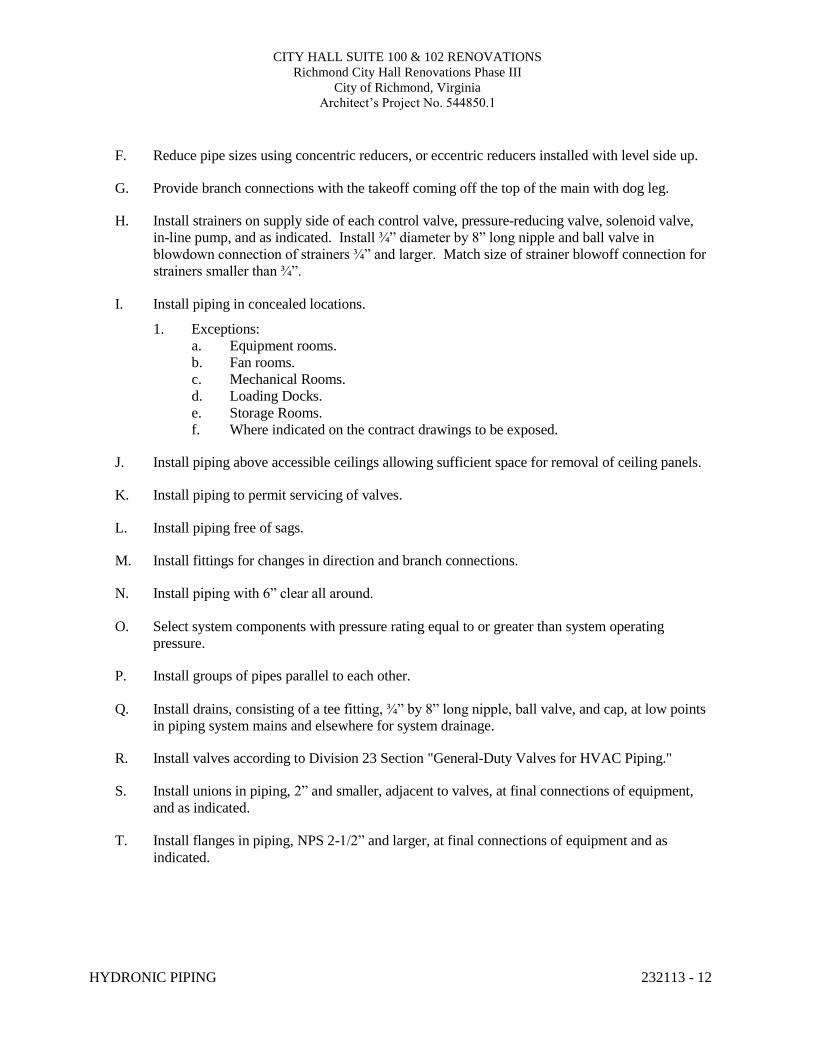
CITY HALL SUITE 100 & 102 RENOVATIONS Richmond City Hall Renovations Phase III
City of Richmond, Virginia Architect’s Project No. 544850.1
HYDRONIC PIPING 232113 - 12
F. Reduce pipe sizes using concentric reducers, or eccentric reducers installed with level side up.
G. Provide branch connections with the takeoff coming off the top of the main with dog leg.
H. Install strainers on supply side of each control valve, pressure-reducing valve, solenoid valve, in-line pump, and as indicated. Install ¾” diameter by 8” long nipple and ball valve in blowdown connection of strainers ¾” and larger. Match size of strainer blowoff connection for strainers smaller than ¾”.
I. Install piping in concealed locations.
1. Exceptions: a. Equipment rooms. b. Fan rooms. c. Mechanical Rooms. d. Loading Docks. e. Storage Rooms. f. Where indicated on the contract drawings to be exposed.
J. Install piping above accessible ceilings allowing sufficient space for removal of ceiling panels.
K. Install piping to permit servicing of valves.
L. Install piping free of sags.
M. Install fittings for changes in direction and branch connections.
N. Install piping with 6” clear all around.
O. Select system components with pressure rating equal to or greater than system operating
pressure.
P. Install groups of pipes parallel to each other.
Q. Install drains, consisting of a tee fitting, ¾” by 8” long nipple, ball valve, and cap, at low points in piping system mains and elsewhere for system drainage.
R. Install valves according to Division 23 Section "General-Duty Valves for HVAC Piping."
S. Install unions in piping, 2” and smaller, adjacent to valves, at final connections of equipment,
and as indicated.
T. Install flanges in piping, NPS 2-1/2” and larger, at final connections of equipment and as indicated.
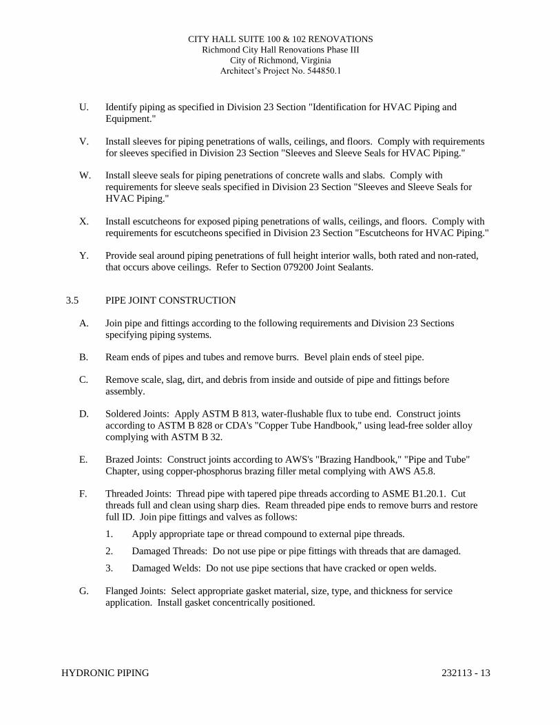
CITY HALL SUITE 100 & 102 RENOVATIONS Richmond City Hall Renovations Phase III
City of Richmond, Virginia Architect’s Project No. 544850.1
HYDRONIC PIPING 232113 - 13
U. Identify piping as specified in Division 23 Section "Identification for HVAC Piping and Equipment."
V. Install sleeves for piping penetrations of walls, ceilings, and floors. Comply with requirements
for sleeves specified in Division 23 Section "Sleeves and Sleeve Seals for HVAC Piping."
W. Install sleeve seals for piping penetrations of concrete walls and slabs. Comply with requirements for sleeve seals specified in Division 23 Section "Sleeves and Sleeve Seals for HVAC Piping."
X. Install escutcheons for exposed piping penetrations of walls, ceilings, and floors. Comply with
requirements for escutcheons specified in Division 23 Section "Escutcheons for HVAC Piping."
Y. Provide seal around piping penetrations of full height interior walls, both rated and non-rated, that occurs above ceilings. Refer to Section 079200 Joint Sealants.
3.5 PIPE JOINT CONSTRUCTION
A. Join pipe and fittings according to the following requirements and Division 23 Sections
specifying piping systems.
B. Ream ends of pipes and tubes and remove burrs. Bevel plain ends of steel pipe.
C. Remove scale, slag, dirt, and debris from inside and outside of pipe and fittings before assembly.
D. Soldered Joints: Apply ASTM B 813, water-flushable flux to tube end. Construct joints
according to ASTM B 828 or CDA's "Copper Tube Handbook," using lead-free solder alloy complying with ASTM B 32.
E. Brazed Joints: Construct joints according to AWS's "Brazing Handbook," "Pipe and Tube"
Chapter, using copper-phosphorus brazing filler metal complying with AWS A5.8.
F. Threaded Joints: Thread pipe with tapered pipe threads according to ASME B1.20.1. Cut threads full and clean using sharp dies. Ream threaded pipe ends to remove burrs and restore full ID. Join pipe fittings and valves as follows:
1. Apply appropriate tape or thread compound to external pipe threads.
2. Damaged Threads: Do not use pipe or pipe fittings with threads that are damaged.
3. Damaged Welds: Do not use pipe sections that have cracked or open welds.
G. Flanged Joints: Select appropriate gasket material, size, type, and thickness for service application. Install gasket concentrically positioned.
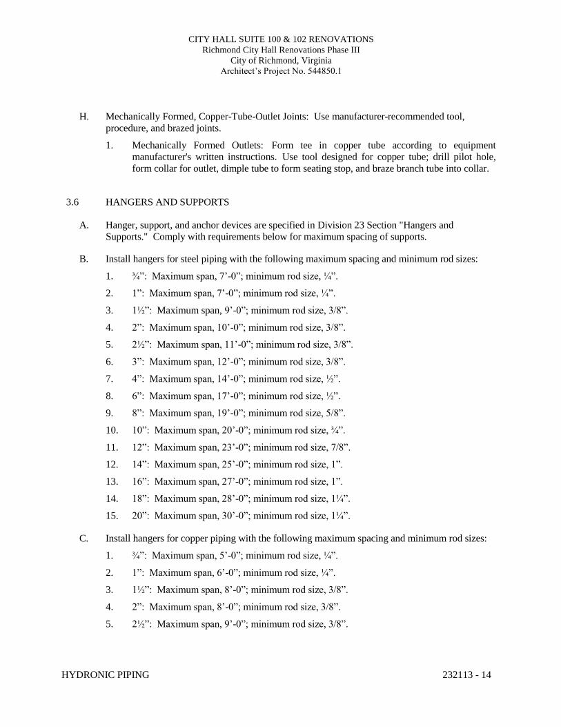
CITY HALL SUITE 100 & 102 RENOVATIONS Richmond City Hall Renovations Phase III
City of Richmond, Virginia Architect’s Project No. 544850.1
HYDRONIC PIPING 232113 - 14
H. Mechanically Formed, Copper-Tube-Outlet Joints: Use manufacturer-recommended tool,
procedure, and brazed joints.
1. Mechanically Formed Outlets: Form tee in copper tube according to equipment manufacturer's written instructions. Use tool designed for copper tube; drill pilot hole, form collar for outlet, dimple tube to form seating stop, and braze branch tube into collar.
3.6 HANGERS AND SUPPORTS
A. Hanger, support, and anchor devices are specified in Division 23 Section "Hangers and
Supports." Comply with requirements below for maximum spacing of supports.
B. Install hangers for steel piping with the following maximum spacing and minimum rod sizes:
1. ¾”: Maximum span, 7’-0”; minimum rod size, ¼”.
2. 1”: Maximum span, 7’-0”; minimum rod size, ¼”.
3. 1½”: Maximum span, 9’-0”; minimum rod size, 3/8”.
4. 2”: Maximum span, 10’-0”; minimum rod size, 3/8”.
5. 2½”: Maximum span, 11’-0”; minimum rod size, 3/8”.
6. 3”: Maximum span, 12’-0”; minimum rod size, 3/8”.
7. 4”: Maximum span, 14’-0”; minimum rod size, ½”.
8. 6”: Maximum span, 17’-0”; minimum rod size, ½”.
9. 8”: Maximum span, 19’-0”; minimum rod size, 5/8”.
10. 10”: Maximum span, 20’-0”; minimum rod size, ¾”.
11. 12”: Maximum span, 23’-0”; minimum rod size, 7/8”.
12. 14”: Maximum span, 25’-0”; minimum rod size, 1”.
13. 16”: Maximum span, 27’-0”; minimum rod size, 1”.
14. 18”: Maximum span, 28’-0”; minimum rod size, 1¼”.
15. 20”: Maximum span, 30’-0”; minimum rod size, 1¼”.
C. Install hangers for copper piping with the following maximum spacing and minimum rod sizes:
1. ¾”: Maximum span, 5’-0”; minimum rod size, ¼”.
2. 1”: Maximum span, 6’-0”; minimum rod size, ¼”.
3. 1½”: Maximum span, 8’-0”; minimum rod size, 3/8”.
4. 2”: Maximum span, 8’-0”; minimum rod size, 3/8”.
5. 2½”: Maximum span, 9’-0”; minimum rod size, 3/8”.
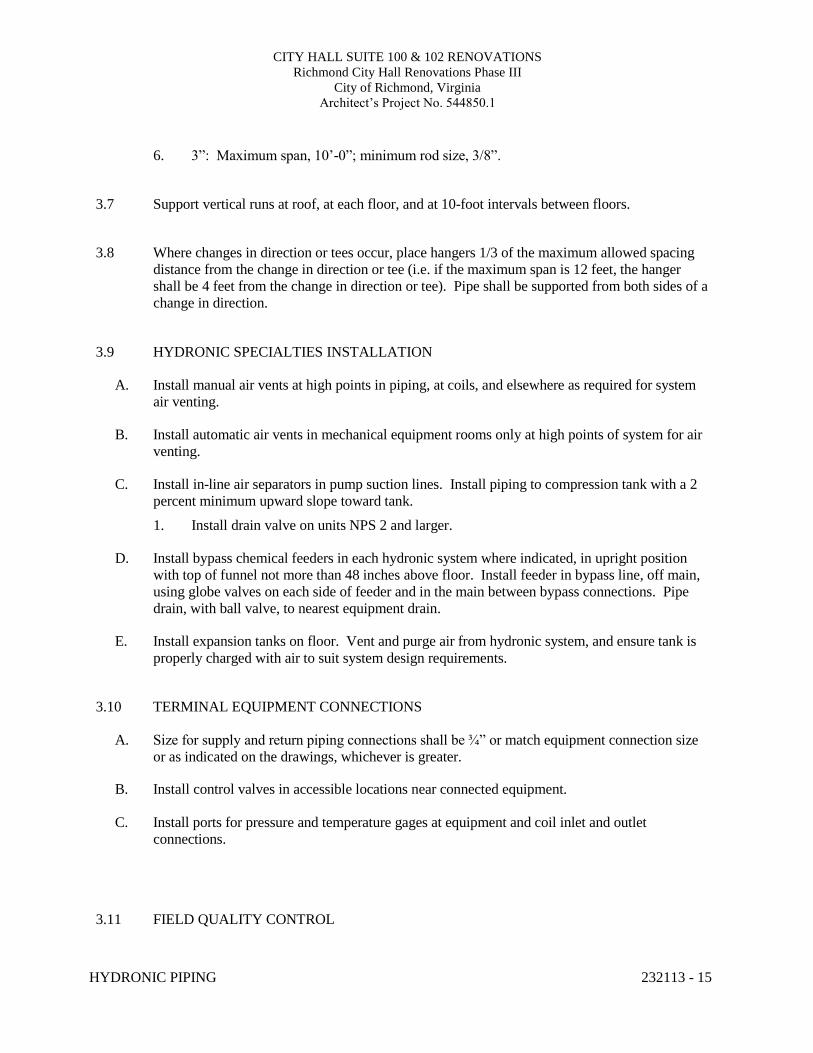
CITY HALL SUITE 100 & 102 RENOVATIONS Richmond City Hall Renovations Phase III
City of Richmond, Virginia Architect’s Project No. 544850.1
HYDRONIC PIPING 232113 - 15
6. 3”: Maximum span, 10’-0”; minimum rod size, 3/8”. 3.7 Support vertical runs at roof, at each floor, and at 10-foot intervals between floors.
3.8 Where changes in direction or tees occur, place hangers 1/3 of the maximum allowed spacing
distance from the change in direction or tee (i.e. if the maximum span is 12 feet, the hanger shall be 4 feet from the change in direction or tee). Pipe shall be supported from both sides of a change in direction.
3.9 HYDRONIC SPECIALTIES INSTALLATION
A. Install manual air vents at high points in piping, at coils, and elsewhere as required for system
air venting.
B. Install automatic air vents in mechanical equipment rooms only at high points of system for air venting.
C. Install in-line air separators in pump suction lines. Install piping to compression tank with a 2
percent minimum upward slope toward tank.
1. Install drain valve on units NPS 2 and larger.
D. Install bypass chemical feeders in each hydronic system where indicated, in upright position with top of funnel not more than 48 inches above floor. Install feeder in bypass line, off main, using globe valves on each side of feeder and in the main between bypass connections. Pipe drain, with ball valve, to nearest equipment drain.
E. Install expansion tanks on floor. Vent and purge air from hydronic system, and ensure tank is
properly charged with air to suit system design requirements. 3.10 TERMINAL EQUIPMENT CONNECTIONS
A. Size for supply and return piping connections shall be ¾” or match equipment connection size
or as indicated on the drawings, whichever is greater.
B. Install control valves in accessible locations near connected equipment.
C. Install ports for pressure and temperature gages at equipment and coil inlet and outlet connections.
3.11 FIELD QUALITY CONTROL
CITY HALL SUITE 100 & 102 RENOVATIONS Richmond City Hall Renovations Phase III
City of Richmond, Virginia Architect’s Project No. 544850.1
HYDRONIC PIPING 232113 - 16
A. Prepare hydronic piping according to ASME B31.9 and as follows:
1. Leave joints, including welds, uninsulated and exposed for examination during testing.
2. Provide temporary restraints for expansion joints that cannot sustain reactions due to test pressure. If temporary restraints are impractical, isolate expansion joints from testing.
3. Flush system with clean water. Clean strainers.
4. Isolate equipment from piping. If a valve is used to isolate equipment, its closure shall be capable of sealing against test pressure without damage to valve.
5. Install safety valve, set at a pressure no more than one-third higher than test pressure, to protect against damage by expanding liquid or other source of overpressure during test.
B. Perform the following tests on hydronic piping:
1. Use ambient temperature water as a testing medium unless there is risk of damage due to freezing. Another liquid that is safe for workers and compatible with piping may be used.
2. While filling system, use vents installed at high points of system to release trapped air. Use drains installed at low points for complete draining of liquid.
3. Check expansion tanks to determine that they are not air bound and that system is full of water.
4. Subject piping system to hydrostatic test pressure that is not less than 1.5 times the design pressure. Test pressure shall not exceed maximum pressure for any vessel, pump, valve, or other component in system under test.
5. After hydrostatic test pressure has been applied for at least 10 minutes, examine piping, joints, and connections for leakage. Eliminate leaks by tightening, repairing, or replacing components, and repeat hydrostatic test until there are no leaks.
6. Prepare written report of testing.
CITY HALL SUITE 100 & 102 RENOVATIONS Richmond City Hall Renovations Phase III
City of Richmond, Virginia Architect’s Project No. 544850.1
HYDRONIC PIPING 232113 - 17
3.12 ADJUSTING
A. Mark calibrated nameplates of pump discharge valves after hydronic system balancing has been
completed, to permanently indicate final balanced position.
B. Perform these adjustments before operating the system:
1. Open valves to fully open position. Close coil bypass valves.
2. Check pump for proper direction of rotation.
3. Set automatic fill valves for required system pressure.
4. Check air vents at high points of system and determine if all are installed and operating freely (automatic type), or bleed air completely (manual type).
5. Set temperature controls so all coils and equipment are calling for full flow.
6. Check and set equipment operating temperatures to design requirements.
7. Lubricate motors and bearings. 3.13 CLEANING
A. Remove and clean or replace strainer screens. After cleaning and flushing hydronic piping
systems, but before balancing, remove disposable fine-mesh strainers. END OF SECTION 232131
CITY HALL SUITE 100 & 102 RENOVATIONS Richmond City Hall Renovations Phase III
City of Richmond, Virginia Architect’s Project No. 544850.1
METAL DUCTS 233013 - 1
SECTION 233113 - METAL DUCTS
PART 1 - GENERAL
1.1 RELATED DOCUMENTS
A. Provisions of the Contract and of the Contract Documents apply to this Section.
1.2 PERFORMANCE REQUIREMENTS
A. Seal all ducts to seal class A as defined in SMACNA's HVAC Duct Construction Standards - Metal and Flexible, Third Edition 2005:
1. Seal all longitudinal joints. 2. Seal all transverse joints. 3. Seal all penetrations.
B. Seal Class: A
C. Test pressure:
1. Test pressure should be at the indicated pressure class as noted on M0.1.
D. Testing: Leak test all medium pressure ductwork, all lab fume hood exhaust ductwork and
20% of all low pressure ductwork, which will be selected randomly by the engineer during construction. Leak and light test all grease ductwork as required by VMC.
E. Duct Construction: Duct construction, including sheet metal thicknesses, seam and joint
construction, reinforcements, and hangers and supports, shall comply with SMACNA's "HVAC Duct Construction Standards - Metal and Flexible, Third Edition 2005" and performance requirements and design criteria indicated in "Duct Schedule" Article.
F. Liner Airstream Surfaces: Liner surfaces in contact with the airstream shall comply with
ASHRAE 62.1-2007, paragraph 5.5.
G. CLEANLINESS: All factory fabricated duct shall be cleaned with a non-toxic, biodegradable cleaner/degreaser and shall be shrink wrapped prior to shipment.
1.3 ABBREVIATIONS
A. BAS Building Automation System
B. NRTL Nationally Recognized Testing Laboratory
C. SMACNA Sheet Metal and Air conditioning Contractors’ National Association
D. WC Water Column
E. VMC Virginia Mechanical Code
CITY HALL SUITE 100 & 102 RENOVATIONS Richmond City Hall Renovations Phase III
City of Richmond, Virginia Architect’s Project No. 544850.1
METAL DUCTS 233013 - 2
1.4 DEFINITIONS:
A. Duct System: For the purposes of this section “duct system” shall mean all metal supply, return,
and exhaust duct and fittings between the air moving device and the space. B. Low Pressure: Plus two (2.0) inches WC to minus one (1.0) inches WC
C. Medium Pressure: More than two (2.0) inches WC to plus ten (10.0) inches WC or more
than minus one (1.0) inch to minus ten (10.0) inches WC
D. High Pressure: More than plus or minus ten(10.0) inches WC.
1.5 SUBMITTALS
A. Product Data / Documentation: For each of the following:
1. Sheet metal thicknesses. 2. Liners and adhesives. 3. Pre-manufactured ductwork. 4. Sealants and gaskets. 5. Statement of duct seal class. Describe how it will be achieved. 6. VOC content for adhesives and sealants.
B. CAD-generated Shop Drawings:
1. Show fabrication and installation details for metal ducts. 2. 1/4”=1’-0” scale minimum including duct layout indicating sizes and pressure classes for
the following areas:
a. Areas indicated on the drawings at 1/4”=1’-0” scale. b. Areas where sections are cut. c. Finished spaces with exposed ductwork.
1) Exceptions:
a) Janitors closets b) Storage Rooms c) Receiving Areas
2) Include:
a) Plans, elevations and sections. b) Elevations of top and bottom of ducts. c) Dimensions of main duct runs from building grid lines.
3. 3/4”=1’-0” scale minimum for the following:
C. Submittals during construction:
1. Leakage Test Report: Documentation of work performed for compliance with ASHRAE/IESNA 90.1-2007, Section 6.4.4.2.2 - "Duct Leakage Tests" and International Energy Conservation Code Equation 5-2.
2. Duct-Cleaning Test Report: Documentation of work performed for compliance with ASHRAE 62.1-2004, Section 7.2.4 - "Ventilation System Start-Up."
CITY HALL SUITE 100 & 102 RENOVATIONS Richmond City Hall Renovations Phase III
City of Richmond, Virginia Architect’s Project No. 544850.1
METAL DUCTS 233013 - 3
1.6 QUALITY ASSURANCE
A. Provide work in compliance with applicable Building Code requirements.
B. Welding Qualifications: Qualify procedures and personnel according to the following:
C. AWS D1.1/D1.1M, "Structural Welding Code - Steel," for hangers and supports.
D. AWS D1.2/D1.2M, "Structural Welding Code - Aluminum," for aluminum supports.
E. AWS D9.1M/D9.1, "Sheet Metal Welding Code," for duct joint and seam welding.
F. ASHRAE Compliance: Comply with applicable requirements in ASHRAE 62.1-2007, Section 5
- "Systems and Equipment" and Section 7 - "Construction and System Start-Up." G. ASHRAE/IESNA Compliance: Comply with applicable requirements in
ASHRAE/IESNA 90.1-2007, Section 6.4.4 - "HVAC System Construction and Insulation."
H. Mockups (Contractor’s option in lieu of 3”=1’-0” details):
1. Before installing duct systems, build mockups. Build mockups to comply with
the following requirements, using materials indicated for the completed Work: 2. Three transverse joints. 3. One Reinforced section with 3 reinforcements. 4. One of each type; attachments to other work. 5. Two typical flexible duct or flexible-connector connections. 6. Approved mockups may become part of the completed Work if undisturbed at time of
Substantial Completion.
PART 2 - PRODUCTS
2.1 SINGLE-WALL RECTANGULAR DUCTS AND FITTINGS
A. General Fabrication Requirements: Comply with SMACNA's "HVAC Duct Construction Standards - Metal and Flexible, Third Edition 2005" based on indicated static-pressure class unless otherwise indicated.
B. Transverse Joints: Select joint types and fabricate according to SMACNA's "HVAC Duct
Construction Standards - Metal and Flexible, Third Edition 2005," Figure 2-1, "Transverse (Girth) Joints," for static-pressure class, applicable sealing requirements, materials involved, duct-support intervals, and other provisions in SMACNA's "HVAC Duct Construction Standards - Metal and Flexible, Third Edition 2005."
C. Longitudinal Seams: Select seam types and fabricate according to SMACNA's "HVAC Duct
Construction Standards - Metal and Flexible, Third Edition 2005," Figure 2-2, "Rectangular Duct/Longitudinal Seams" for static-pressure class, applicable sealing requirements, materials involved, duct-support intervals, and other provisions in SMACNA's "HVAC Duct Construction Standards - Metal and Flexible, Third Edition 2005."
D. Elbows, Transitions, Offsets, Branch Connections, and Other Duct Construction: Select types
and fabricate according to SMACNA's "HVAC Duct Construction Standards - Metal and
CITY HALL SUITE 100 & 102 RENOVATIONS Richmond City Hall Renovations Phase III
City of Richmond, Virginia Architect’s Project No. 544850.1
METAL DUCTS 233013 - 4
Flexible, Third Edition 2005," Chapter 4, "Fittings and Other Construction," for static-pressure class, applicable sealing requirements, materials involved, duct-support intervals, and other provisions in SMACNA's "HVAC Duct Construction Standards - Metal and Flexible, Third Edition 2005."
2.2 LOW PRESSURE SINGLE-WALL ROUND DUCTS AND FITTINGS
A. General Fabrication Requirements: Comply with SMACNA's "HVAC Duct Construction Standards - Metal and Flexible, Third Edition 2005," Chapter 3, "Round, Oval, and Flexible Duct," based on specified static-pressure class unless otherwise indicated.
B. Manufacturers:
1. Eastern Sheet Metal. 2. Lindab Inc. 3. McGill AirFlow LLC. 4. Performance Duct Systems 5. Spiral Manufacturing Co., Inc.
C. Transverse Joints: Select joint types and fabricate according to SMACNA's "HVAC Duct
Construction Standards - Metal and Flexible, Third Edition 2005," Figure 3-1, "Round Duct Transverse Joints"
1. Transverse Joints in Ducts Equal to or Larger Than 48” in Diameter: Flanged. 2. Gasketed, EPDM, self sealing Joints such as Eastern Tight or Spiro Safe may be used
for ducts smaller than 48” in diameter. 3. Flanges may be substituted in ducts smaller than 48” in diameter.
D. Duct support intervals, and other provisions: In accordance with SMACNA's "HVAC Duct
Construction Standards - Metal and Flexible, Third Edition 2005."
E. Longitudinal Seams: Select seam types and fabricate according to SMACNA's "HVAC Duct Construction Standards - Metal and Flexible, Third Edition 2005," Figure 3-1, "Seams - Round Duct and Fittings," for static-pressure class, applicable sealing requirements, materials involved, duct-support intervals, and other provisions in SMACNA's "HVAC Duct Construction Standards - Metal and Flexible, Third Edition 2005."
F. Tees and Laterals: Select types and fabricate according to SMACNA's "HVAC Duct
Construction Standards - Metal and Flexible, Third Edition 2005," Figure 3-5, "90º Tees and Laterals," and Figure 3-6, "Conical Tees," for static-pressure class, applicable sealing requirements, materials involved, duct-support intervals, and other provisions in SMACNA's "HVAC Duct Construction Standards - Metal and Flexible, Third Edition 2005." Adjustable elbows are not permitted.
G. All seam types in FIGURE 3-2 are acceptable where approved by SMACNA.
2.3 MEDIUM PRESSURE SINGLE-WALL ROUND AND FLAT OVAL DUCTS AND FITTINGS
A. General Fabrication Requirements: Comply with SMACNA's "HVAC Duct Construction Standards - Metal and Flexible, Third Edition 2005," Chapter 3, "Round, Oval, and Flexible Duct," based on indicated static-pressure class unless otherwise indicated.
CITY HALL SUITE 100 & 102 RENOVATIONS Richmond City Hall Renovations Phase III
City of Richmond, Virginia Architect’s Project No. 544850.1
METAL DUCTS 233013 - 5
B. Manufacturers:
1. Eastern Sheet Metal. 2. Lindab Inc. 3. McGill AirFlow LLC. 4. Performance Duct Systems 5. Spiral Manufacturing Co., Inc.
C. Flat-Oval Ducts: Dimensions are the inside duct width (major dimension) and inside
diameter of the round sides connecting the flat portions of the duct (minor dimension) of the inner duct.
D. Transverse Joints: Select joint types and fabricate according to SMACNA's "HVAC Duct Construction Standards - Metal and Flexible, Third Edition 2005," Figure 3-1, "Round Duct Transverse Joints"
1. Transverse Joints in Ducts Equal to or Larger Than 48” in Diameter: Flanged. 2. Gasketed, EPDM, self sealing Joints such as Eastern Tight or Spiro Safe may be used
for ducts smaller than 48” in diameter. 3. Flanges may be substituted in ducts smaller than 48” in diameter.
E. Duct support intervals, and other provisions: In accordance with SMACNA's "HVAC Duct
Construction Standards - Metal and Flexible, Third Edition 2005."
F. Longitudinal Seams: Select seam types and fabricate according to SMACNA's "HVAC Duct Construction Standards - Metal and Flexible, Third Edition 2005," Figure 3-1, "Seams - Round Duct and Fittings," for static-pressure class, applicable sealing requirements, materials involved, duct-support intervals, and other provisions in SMACNA's "HVAC Duct Construction Standards - Metal and Flexible, Third Edition 2005."
G. Tees and Laterals: Select types and fabricate according to SMACNA's "HVAC Duct
Construction Standards - Metal and Flexible, Third Edition 2005," Figure 3-5, "90º Tees and Laterals," and Figure 3-6, "Conical Tees," for static-pressure class, applicable sealing requirements, materials involved, duct-support intervals, and other provisions in SMACNA's "HVAC Duct Construction Standards - Metal and Flexible, Third Edition 2005." Adjustable elbows are not permitted.
H. All seam type in FIGURE 3-2 are acceptable where approved by SMACNA.
2.4 SHEET METAL MATERIALS
A. General Material Requirements: Comply with SMACNA's "HVAC Duct Construction Standards - Metal and Flexible, Third Edition 2005" for acceptable materials, material thicknesses, and duct construction methods unless otherwise indicated. Sheet metal materials shall be free of pitting, seam marks, roller marks, stains, discolorations, and other imperfections.
B. Galvanized Sheet Steel: Comply with ASTM A 653/A 653M.
1. Galvanized Coating Designation: G60 or G90. 2. Finishes for Surfaces Exposed to View: Mill phosphatized.
CITY HALL SUITE 100 & 102 RENOVATIONS Richmond City Hall Renovations Phase III
City of Richmond, Virginia Architect’s Project No. 544850.1
METAL DUCTS 233013 - 6
C. Carbon-Steel Sheets: Comply with ASTM A 1008/A 1008M.
D. Stainless-Steel Sheets: Comply with ASTM A 480/A 480M, Type 316, cold rolled, annealed, sheet. Exposed surface finish shall be No. 4.
E. Aluminum Sheets: Comply with ASTM B 209 Alloy 3003, H14 temper; with mill finish for
concealed ducts, and standard, one-side bright finish for duct surfaces exposed to view.
F. Reinforcement Shapes and Plates: ASTM A 36/A 36M, steel plates, shapes, and bars; black and galvanized.
G. Where black- and galvanized-steel shapes and plates are used to reinforce aluminum ducts, isolate the different metals with butyl rubber, neoprene, or EPDM gasket materials.
H. Tie Rods: Galvanized steel, 1/4-inch minimum diameter for lengths 36 inches or less; 3/8-
inch minimum diameter for lengths longer than 36 inches.
2.5 HANGERS AND SUPPORTS
A. Hanger Rods: Galvanized, all-thread.
B. Strap and Rod Sizes: Comply with SMACNA's "HVAC Duct Construction Standards - Metal and Flexible, Third Edition 2005," Table 5-1, "Rectangular Duct Hangers Minimum Size," and Table 5-2, "Minimum Hanger Sizes for Round Duct."
C. Steel Cables for Galvanized-Steel Ducts: Galvanized steel complying with ASTM A 603.
D. Steel Cables for Stainless-Steel Ducts: Stainless steel complying with ASTM A 492. E. Steel Cable End Connections: Cadmium-plated steel assemblies with brackets, swivel, and
bolts designed for duct hanger service; with an automatic-locking and clamping device.
F. Duct Attachments: Sheet metal screws, blind rivets, or self-tapping metal screws; compatible with duct materials.
G. Trapeze and Riser Supports:
1. Supports for Galvanized-Steel Ducts: Galvanized-steel shapes and plates. 2. Supports for Stainless-Steel Ducts: Stainless-steel shapes and plates. 3. Supports for Aluminum Ducts: Aluminum or galvanized steel coated with
zinc chromate.
PART 3 - EXECUTION
3.1 DUCT INSTALLATION
A. Drawing plans, schematics, and diagrams indicate general location and arrangement of duct system. Duct locations, configurations, and arrangements were used to size ducts and calculate friction loss for air-handling equipment sizing and for other design considerations. Install duct systems as indicated unless deviations to layout are approved by Architect in writing.
B. Comply with SMACNA's "HVAC Duct Construction Standards - Metal and Flexible, Third
CITY HALL SUITE 100 & 102 RENOVATIONS Richmond City Hall Renovations Phase III
City of Richmond, Virginia Architect’s Project No. 544850.1
METAL DUCTS 233013 - 7
Edition 2005" unless otherwise indicated.
C. Install ducts with fewest possible joints.
D. Install factory-fabricated fittings for changes in direction, size, and shape and for branch connections.
E. Unless otherwise indicated, install ducts vertically or horizontally, and parallel or
perpendicular to building lines.
F. Install ducts close to walls, overhead construction, columns, and other structural and permanent enclosure elements of building. Maintain clearances for equipment maintenance.
G. Install ducts with a clearance of 1 inch, plus allowance for installation of insulation at specified
thickness.
H. Do not route ducts through transformer vaults, electrical equipment rooms, elevator equipment rooms or electrical enclosures.
I. Where ducts pass through non-fire-rated interior partitions and exterior walls and are exposed to
view, cover the opening between the partition and duct or duct insulation with sheet metal flanges of same metal thickness as the duct. Overlap openings on four sides by at least 1-1/2 inches.
J. Provide fire dampers where ducts pass through fire-rated interior partitions or fire rated exterior
walls.
K. Protect duct interiors from moisture, construction debris, dust, and other foreign materials. Comply with SMACNA's "Duct Cleanliness for New Construction Guidelines."
3.2 DUCT SEALING
A. Seal all ducts to seal class A as defined in SMACNA's HVAC Duct Construction Standards - Metal and Flexible, Third Edition 2005:
1. Seal all longitudinal joints. 2. Seal all transverse joints. 3. Seal all penetrations.
3.3 HANGER AND SUPPORT INSTALLATION
A. Comply with SMACNA's "HVAC Duct Construction Standards - Metal and Flexible, Third Edition 2005," Chapter 5, "Hangers and Supports."
CITY HALL SUITE 100 & 102 RENOVATIONS Richmond City Hall Renovations Phase III
City of Richmond, Virginia Architect’s Project No. 544850.1
METAL DUCTS 233013 - 8
B. Building Attachments: Unless indicated otherwise, provide concrete inserts, powder-actuated
fasteners, or structural-steel fasteners appropriate for construction materials to which hangers are being attached.
1. Where practical, install concrete inserts before placing concrete. 2. Do not use powder-actuated concrete fasteners for lightweight-aggregate concrete or for
slabs less than 4 inches thick.
C. Hanger Spacing: Comply with SMACNA's "HVAC Duct Construction Standards - Metal and Flexible, Third Edition 2005," Table 5-1, "Rectangular Duct Hangers Minimum Size," and Table 5-2, "Minimum Hanger Sizes for Round Duct," for maximum hanger spacing; install hangers and supports within 24 inches of each elbow and within 48 inches of each branch intersection.
D. Hangers Exposed to View: Threaded rod and channel supports.
E. Support vertical ducts with channel secured to the sides of the duct with welds, bolts, sheet
metal screws, or blind rivets; support at each floor or at a maximum intervals of 18 feet.
F. Install upper attachments to structures. Select and size upper attachments with pull-out, tension, and shear capacities appropriate for supported loads and building materials where used.
3.4 CONNECTIONS
A. Make connections to equipment with flexible connectors.
B. Comply with SMACNA's "HVAC Duct Construction Standards - Metal and Flexible, Third Edition 2005" for branch, outlet, inlet, and terminal unit connections unless otherwise indicated.
3.5 PAINTING
A. Paint interior of metal ducts that are visible through registers and grilles and that do not have duct liner. Apply two coats of flat black, latex paint over a compatible galvanized-steel primer.
3.6 FIELD QUALITY CONTROL
A. Perform tests and inspections.
B. Visually inspect, for proper seal application, all ductwork not tested prior to insulation application. Prepare inspection report.
C. Leakage Test.
1. Comply with SMACNA's "HVAC Air Duct Leakage Test Manual." Prepare a test
report for each test. 2. Test ducts, disassemble, reassemble, reseal, and retest until leakage class 3 (as defined
in SMACNA's HVAC Duct Construction Standards - Metal and Flexible, Third Edition 2005) is achieved.
CITY HALL SUITE 100 & 102 RENOVATIONS Richmond City Hall Renovations Phase III
City of Richmond, Virginia Architect’s Project No. 544850.1
METAL DUCTS 233013 - 9
3. Disassemble, reassemble, and seal segments of systems to accommodate leakage testing and for compliance with test requirements.
4. Test for leaks before applying external insulation. 5. Conduct tests at static pressures equal to maximum design pressure of system or section
being tested. 6. Give seven days' advance notice to Architect and Owner for testing.
D. Duct System Cleanliness Tests:
1. Visually inspect duct system to ensure that no visible contaminants are present. 2. Test sections of metal duct systems, up to one location per ten thousand (10,000) square feet
of building area, or a minimum of two (2) per system, whichever is greater, chosen randomly by the Owner’s Representative, for cleanliness according to "Vacuum Test" in NADCA ACR, "Assessment, Cleaning and Restoration of HVAC Systems." Net weight of debris collected on the filter media shall not exceed 0.75 mg/100 sq. cm. Cut hole in duct and install access door at each location selected. Size shall be as indicated in division 23 section “AIR DUCT ACCESSIRIES”.
3. Duct system shall be considered dirty and in need of cleaning if any test location does not pass the cleanliness test. Cleaning shall be performed in accordance with this specification.
E. Prepare and submit test and inspection reports.
3.7 DUCT CLEANING
A. Clean dirty and existing duct system(s) before testing, adjusting, and balancing.
B. Use service openings for entry.
1. Create new openings and provide access doors appropriate for duct static-pressure class if required for cleaning access. Provide insulated doors for insulated or lined duct. Patch insulation and liner as recommended by the insulation manufacturer.
2. Disconnect and reconnect flexible ducts for cleaning and inspection. 3. Remove and reinstall ceiling to gain access during the cleaning process.
C. Particulate Collection and Odor Control:
1. When venting vacuuming system inside the building, provide HEPA filtration with
99.97 percent collection efficiency for 0.3-micron-size (or larger) particles. 2. When venting vacuuming system to outdoors, provide vacuum manufacturer’s standard
filter to collect debris removed from HVAC system, and locate exhaust downwind and away from air intakes and other points of entry into building.
D. Clean the following components by removing surface contaminants and deposits:
1. Air outlets and inlets (registers, grilles, and diffusers). 2. Fans including fan housings, plenums, scrolls, blades or vanes, shafts, baffles, dampers,
and drive assemblies. 3. Exceptions:
1) Exhaust fans. 2) Ceiling plenums. 3) Fan Rooms.
1ST FLOOR LOBBY AND 4TH FLOOR RENOVATIONS Richmond City Hall Renovations Phase III
City of Richmond, Virginia Architect’s Project No. 544850.
METAL DUCTS 233013 - 10
E. Air-handling unit internal surfaces and components including mixing box, coil section, air wash
systems, spray eliminators, condensate drain pans, humidifiers, filter sections, drain pan, traps, and drains.
F. Coils and related components within air stream.
G. Ducts, dampers, actuators, and turning vanes.
1. Exceptions: 2. Exhaust dampers, actuators, and turning vanes. 3. Ceiling plenums. 4. Fan Rooms.
H. Mechanical Cleaning Methodology:
1. Clean components using mechanical cleaning methods that extract contaminants from
within components and remove contaminants from building. 2. Provide vacuum-collection devices that are operated continuously during cleaning.
Connect vacuum device to downstream end of duct sections so areas being cleaned are under negative pressure.
3. Provide mechanical agitation to dislodge debris adhered to surfaces without damaging integrity of surface.
4. Clean coils and coil drain pans according to NADCA 1992. Keep drain pan operational. Rinse coils with clean water to remove latent residues and cleaning materials; comb and straighten fins.
5. Provide drainage and cleanup for wash-down procedures. 6. Antimicrobial Agents and Coatings: Apply EPA-registered antimicrobial agents if
fungus is present. Apply antimicrobial agents according to manufacturer's written instructions after removal of surface deposits and debris.
3.8 START UP
A. Air Balance: Comply with requirements in Division 23 Section "Testing, Adjusting, and Balancing for HVAC."
3.9 DUCT SCHEDULE
A. Fabricate ducts with galvanized sheet steel except as otherwise indicated and as follows:
B. Elbow Configuration:
1. Rectangular Duct: Comply with SMACNA's "HVAC Duct Construction Standards - Metal and Flexible, Third Edition 2005," Figure 4-2, "Rectangular Elbows."
2. Velocity 1000 fpm or Lower:
a. Radius Type RE 1. Centerline radius = 3W/2. b. Mitered Type RE 4. SMACNA Type RE 4 does not have turning vanes.
3. Velocity Greater than 1000 to 1500 fpm:
CITY HALL SUITE 100 & 102 RENOVATIONS
1ST FLOOR LOBBY AND 4TH FLOOR RENOVATIONS Richmond City Hall Renovations Phase III
City of Richmond, Virginia Architect’s Project No. 544850.
METAL DUCTS 233013 - 11
a. Radius Type RE 1.Centerline radius = 3W/2. b. Radius Type RE 3 with two vanes. c. Mitered Type RE 2 with vanes complying with SMACNA's "HVAC Duct
Construction Standards - Metal and Flexible, Third Edition 2005," Figure 4-3, "Vanes and Vane Runners," and Figure 4-4, "Vane Support in Elbows."
4. Velocity 1500 fpm or Higher:
a. Radius Type RE 3. Conterline radius = 3w/2 and three vanes. b. Mitered Type RE 2 with vanes complying with SMACNA's "HVAC Duct
Construction Standards - Metal and Flexible, Third Edition 2005," Figure 2-3, "Vanes and Vane Runners," and Figure 2-4, "Vane Support in Elbows."
5. Round Duct: Comply with SMACNA's "HVAC Duct Construction Standards - Metal
and Flexible, Third Edition 2005," Figure 3-4, "Round Duct Elbows." 6. Minimum centerline radius-to-diameter ratio shall be 1.5 with a maximum of 5 Elbow
Segments. Comply with SMACNA's "HVAC Duct Construction Standards - Metal and Flexible, Third Edition 2005," Table 3-1, "Mitered Elbows." Elbows with less than a 90 degree change of direction shall have segments per table 3-1 in SMACNA's "HVAC Duct Construction Standards - Metal and Flexible, Third Edition 2005".
7. Round Elbows, 12 Inches and Smaller in Diameter: Stamped or pleated. 8. Round Elbows, 14 Inches and Larger in Diameter: Standing seam.
C. Branch Configuration:
D. Rectangular Duct: Comply with SMACNA's "HVAC Duct Construction Standards - Metal
and Flexible, Third Edition 2005," Figure 4-6, "Branch Connections."
1. Rectangular Main to Rectangular Branch: 45-degree entry. 2. Rectangular Main to Round Branch: Conical or bell mouth. Flanged or spin in.
E. Round and Flat Oval: Comply with SMACNA's "HVAC Duct Construction Standards - Metal
and Flexible, Third Edition 2005," Figure 3-6, "Conical Tees."
1. Conical fitting. 2. Conical saddle taps may be used only in locations approved in writing by the architect.
END OF SECTION 233113
CITY HALL SUITE 100 & 102 RENOVATIONS
CITY HALL SUITE 100 & 102 RENOVATIONS Richmond City Hall Renovations Phase III
City of Richmond, Virginia Architect’s Project No. 544850.1
AIR DUCT ACCESSORIES 233300 - 1
SECTION 233300 – AIR DUCT ACCESORIES PART 1 - GENERAL
1.1 RELATED DOCUMENTS
A. Provisions of the Contract and of the Contract Documents apply to this Section. 1.2 SUBMITTALS
A. Product Data: For the following:
1. Radius forming braces 2. Volume dampers. 3. Take-offs 4. Fire dampers. 5. Duct silencers. 6. Turning vanes. 7. Duct-mounting access doors. 8. Flexible connectors. 9. Flexible ducts. 10. For duct silencers, include pressure drop and dynamic insertion loss data. Include
breakout noise calculations for high transmission loss casings.
B. Wiring Diagrams: For power, signal, and control wiring.
C. Operation and Maintenance Data: For air duct accessories to include in operation and maintenance manuals.
1.3 ABBREVIATIONS
A. CFM Cubic Feet per Minute
B. F Fahrenheit
C. FPM Feet Per Minute
D. IN Inches
E. LBF Pound Feet, or Pound Foot.
F. NFPA National Fire Protection Association
G. NO Number
H. NRTL Nationally Recognized Testing laboratory
I. OC On Center
J. SqFt Square Feet
K. WC Water Column
CITY HALL SUITE 100 & 102 RENOVATIONS Richmond City Hall Renovations Phase III
City of Richmond, Virginia Architect’s Project No. 544850.1
AIR DUCT ACCESSORIES 233300 - 2
1.4 QUALITY ASSURANCE
A. Comply with NFPA 90A, "Installation of Air Conditioning and Ventilating Systems," and with NFPA 90B, "Installation of Warm Air Heating and Air Conditioning Systems."
B. Comply with AMCA 500-D testing for damper rating. 1.5 EXTRA MATERIALS
A. Furnish extra materials that match products installed and that are packaged with protective covering for storage and identified with labels describing contents.
1. Fusible Links: Furnish quantity equal to 10 percent of amount installed. Minimum 1 of each type used.
PART 2 - PRODUCTS
2.1 MATERIALS
A. Comply with SMACNA's "HVAC Duct Construction Standards - Metal and Flexible" for acceptable materials, material thicknesses, and duct construction methods unless otherwise indicated. Sheet metal materials shall be free of pitting, seam marks, roller marks, stains, discolorations, and other imperfections.
B. Comply with SMACNA's "HVAC Duct Construction Standards - Metal and Flexible" for acceptable duct installation methods unless otherwise indicated.
C. Galvanized Sheet Steel: Comply with ASTM A 653/A 653M.
1. Galvanized Coating Designation: G60 or G90. 2. Exposed-Surface Finish: Mill phosphatized.
D. Stainless-Steel Sheets: Comply with ASTM A 480/A 480M, Type 304, and having a NO 2 finish for concealed ducts and NO 4 finish for exposed ducts.
E. Aluminum Sheets: Comply with ASTM B 209, Alloy 3003, temper H14; with mill finish for concealed ducts and standard, 1-side bright finish for exposed ducts.
F. Extruded Aluminum: Comply with ASTM B 221, Alloy 6063, Temper T6.
G. Reinforcement Shapes and Plates: Galvanized-steel reinforcement where installed on galvanized sheet metal ducts; compatible materials for aluminum and stainless-steel ducts.
H. Tie Rods: Galvanized steel, 1/4-inch minimum diameter for lengths 36 inches or less; 3/8-inch minimum diameter for lengths longer than 36 inches; compatible materials for aluminum and stainless-steel ducts.
2.2 RADIUS FORMING BRACES
A. Available manufacturers:
1. Titus, FlexRight (Basis of Design) 2. Flexible Technologies, Inc., Thermaflex Division, FlexFlow
CITY HALL SUITE 100 & 102 RENOVATIONS Richmond City Hall Renovations Phase III
City of Richmond, Virginia Architect’s Project No. 544850.1
AIR DUCT ACCESSORIES 233300 - 3
3. Hart & Cooley, Smart Flow Elbow
B. General: UL-2043 listed or NRTL approved product constructed of metal or plastic manufactured for use with flexible duct to form a kink free elbow using the flexible duct. Any flexible duct used in forming the elbow shall be included in the maximum permitted length. Resulting flexible duct shall comply with SMACNA HVAC Duct Construction Standards.
C. Duct Size: 6” through 16” in diameter.
D. Inside (Bend) Radius: Minimum of one duct diameter along centerline.
E. Attachments: Plastic zip ties or stainless steel worm gear clamps.
F. Support to Overhead: Shall meet SMACNA requirements. Use of specified attachments for support shall not be permitted.
2.3 MANUAL VOLUME DAMPERS
A. Steel, Manual Volume Dampers:
1. Manufacturers: a. Air Balance Inc.; a division of Mestek, Inc. b. American Warming and Ventilating; a division of Mestek, Inc. c. Flexmaster U.S.A., Inc. d. Greenheck Fan Corporation. e. McGill AirFlow LLC. f. METALAIRE, Inc. g. PCI Industries - Pottorff h. Ruskin Company. i. Vent Products Company, Inc.
2. Standard leakage rating, with linkage outside airstream. 3. Suitable for horizontal or vertical applications. 4. Frames:
a. Hat-shaped, galvanized or stainless-steel channels, match duct material. b. Mitered and welded corners. c. Flanges for attaching to walls and flangeless frames for installing in ducts.
5. Blades: a. Multiple or single blade. b. Opposed-blade design. c. Stiffen damper blades for stability. d. Galvanized or stainless-steel channels, match duct material. e. Blade Axles: Galvanized steel or Stainless steel. Dampers over 12”
width/diameter shall include continuous axles. Dampers 12” and less may have non-continuous axles.
6. Bearings: a. Molded synthetic. Provide bearing at both duct wall penetrations.
7. Tie Bars and Brackets: Galvanized steel.
B. Stainless Steel, Manual Volume Dampers:
1. Manufacturers:
CITY HALL SUITE 100 & 102 RENOVATIONS Richmond City Hall Renovations Phase III
City of Richmond, Virginia Architect’s Project No. 544850.1
AIR DUCT ACCESSORIES 233300 - 4
a. Air Balance Inc.; a division of Mestek, Inc. b. American Warming and Ventilating; a division of Mestek, Inc. c. Flexmaster U.S.A., Inc. d. Greenheck Fan Corporation. e. McGill AirFlow LLC. f. METALAIRE, Inc. g. PCI Industries - Pottorff h. Ruskin Company. i. Vent Products Company, Inc.
2. Standard leakage rating, with linkage and operator outside airstream. 3. Suitable for horizontal or vertical applications. 4. Frames: Hat-shaped stainless steel channels for installing in ducts. 5. Blades:
a. Multiple or single blade. b. Parallel- or opposed-blade design. c. Stiffen damper blades for stability. d. Roll Formed or Extruded stainless steel e. Blade Axles: Stainless steel. Dampers over 12” width/diameter shall include
continuous axles. Dampers 12” and less may have non-continuous axles. 6. Bearings:
a. Molded synthetic. Provide bearing at both duct wall penetrations. 7. Tie Bars and Brackets: Stainless Steel
C. Damper Hardware:
1. Zinc-plated, die-cast quadrant with dial and handle made of zinc plated steel, and a hexagon lock nut. Friction lock dampers are not acceptable where system external static pressure exceeds 0.50”wc.
2. Include center hole to suit damper operating-rod size. 3. Include elevated platform or stand-off for insulated duct mounting.
2.4 CURTAIN TYPE FIRE DAMPERS (1½ HOUR)
A. Manufacturers:
1. Air Balance Inc.; a division of Mestek, Inc. 2. Cesco Products; a division of Mestek, Inc. 3. Greenheck Fan Corporation. 4. PCI Industries - Pottorff 5. Prefco; Perfect Air Control, Inc. 6. Ruskin Company.
B. Type: Dynamic; rated and labeled according to UL 555 by a NRTL.
C. Pressure: Dampers shall have a minimum UL 555 differential pressure rating of 4 in. WG
D. Velocity: Dampers shall have a minimum UL 555 velocity rating of 2000 FPM.
E. Fire Rating: 1½ hours.
CITY HALL SUITE 100 & 102 RENOVATIONS Richmond City Hall Renovations Phase III
City of Richmond, Virginia Architect’s Project No. 544850.1
AIR DUCT ACCESSORIES 233300 - 5
F. Frame: Curtain type with blades outside airstream; fabricated of roll-formed galvanized steel; with mitered and interlocking corners.
G. Sleeve: Factory-installed, galvanized sheet steel.
1. Minimum Thickness: Per UL requirements. 2. Minimum Length: To suit application.
H. Mounting Orientation: Vertical or horizontal.
I. Blades: Roll-formed, interlocking galvanized sheet steel. In place of interlocking blades, full- length galvanized-steel blade connectors may be used.
J. Horizontal Dampers: Include stainless-steel closure spring.
K. Fusible Link: Replaceable, 165 deg F rated.
L. Retaining Angles: Damper shall be supplied with factory retaining angles sized to provide installation overlap in accordance with the manufacturer’s UL listing
2.5 MULTI BLADE FIRE DAMPERS (1½ HOURS)
A. Manufacturers:
1. Air Balance Inc.; a division of Mestek, Inc. 2. Cesco Products; a division of Mestek, Inc. 3. Greenheck Fan Corporation. 4. PCI Industries - Pottorff 5. Prefco; Perfect Air Control, Inc. 6. Ruskin Company.
B. Type: Dynamic; rated and labeled according to UL 555 by an NRTL.
C. Pressure: Dampers shall have a minimum UL 555 differential pressure rating of 4 in. WG
D. Velocity: Dampers shall have a minimum UL 555 velocity rating of 4000 FPM.
E. Fire Rating: 1½ hours.
F. Frame: Multiple-blade type; fabricated of galvanized steel; with mitered and interlocking corners.
G. Sleeve: Factory-installed, galvanized sheet steel.
1. Minimum Thickness: Per UL requirements. 2. Minimum Length: To suit application.
H. Mounting Orientation: Vertical or horizontal.
I. Blades: Blades: Damper blades shall be galvanized steel. Each blade shall be symmetrical relative to its axle pivot point, presenting identical performance characteristics with air flowing in either direction. Provide symmetrical blades of varying size as required to completely fill the damper opening.
J. Blade Stops: Locate blade stops at top and bottom of damper frame. They shall occupy no more than ½” of the damper opening area.
CITY HALL SUITE 100 & 102 RENOVATIONS Richmond City Hall Renovations Phase III
City of Richmond, Virginia Architect’s Project No. 544850.1
AIR DUCT ACCESSORIES 233300 - 6
K. Bearings: Axle bearings shall be sintered bronze.
L. Horizontal Dampers: Include stainless-steel closure spring.
M. Fusible Link: Replaceable, 165 deg F rated.
N. Retaining Angles: Damper shall be supplied with factory retaining angles sized to provide installation overlap in accordance with the manufacturer’s UL listing.
2.6 FLANGE CONNECTORS
A. Available Manufacturers:
1. Ductmate Industries, Inc. 2. Nexus PDQ; Division of Shilco Holdings Inc. 3. Hart & Cooley, Inc.
B. Description: Add-on or roll-formed, factory-fabricated, slide-on transverse flange connectors, gaskets, and components.
C. Material: Match connecting ductwork.
D. Gauge: 18, 20, or 24 as recommended by manufacturer or match connecting ductwork. 2.7 DUCT SILENCERS
A. Available Manufacturers:
1. Industrial Noise Control, Inc. 2. McGill AirFlow LLC. 3. Price 4. Ruskin Company. 5. Vibro-Acoustics.
B. General Requirements:
1. Factory fabricated. 2. Fire-Performance Characteristics: Adhesives, sealants, packing materials, and
accessory materials shall have flame-spread index not exceeding 25 and smoke- developed index not exceeding 50 when tested according to ASTM E 84.
3. Airstream Surfaces: Surfaces in contact with the airstream shall comply with requirements in ASHRAE 62.1-2007.
C. Shape:
1. Rectangular straight with splitters or baffles. 2. Round straight with center bodies or pods. 3. Rectangular elbow with splitters or baffles. 4. Round elbow with center bodies or pods. 5. Rectangular transitional with splitters or baffles.
D. Rectangular Silencer Outer Casing: ASTM A 653/A 653M, G90, galvanized sheet steel, 0.034 inches thick minimum.
CITY HALL SUITE 100 & 102 RENOVATIONS Richmond City Hall Renovations Phase III
City of Richmond, Virginia Architect’s Project No. 544850.1
AIR DUCT ACCESSORIES 233300 - 7
E. Round Silencer Outer Casing: ASTM A 653/A 653M, G90, galvanized sheet steel.
1. Sheet Metal Thickness for Units up to 24 Inches in Diameter: 0.034 inches thick minimum.
2. Sheet Metal Thickness for Units 26 through 40 Inches in Diameter: 0.040 inches thick minimum.
3. Sheet Metal Thickness for Units 42 through 52 Inches in Diameter: 0.052 inches thick minimum.
4. Sheet Metal Thickness for Units 54 through 60 Inches in Diameter: 0.064 inches thick minimum.
5. Inner Casing and Baffles: ASTM A 653/A 653M, G90 galvanized sheet metal, 0.034 inches thick minimum, and with 1/8 inch diameter perforations.
F. Connection Sizes: Match connecting ductwork unless otherwise indicated.
G. Type: Film-lined with fill material.
1. Fill Material: Moisture-proof nonfibrous material. 2. Erosion Barrier: Polymer bag enclosing fill, and heat sealed before assembly.
H. Fabricate silencers to form rigid units that will not pulsate, vibrate, rattle, or otherwise react to system pressure variations. Do not use mechanical fasteners for unit assemblies.
1. Flange connections. 2. Suspend units using factory installed suspension hooks or lugs attached to frame spaced
to prevent deflection or distortion. 3. Provide cross or trapeze angle reinforcement for rigid suspension.
I. Accessories:
1. Factory-installed end caps to prevent contamination during shipping.
J. Capacities and Characteristics: Refer to “Fan Schedule” on drawings 2.8 TURNING VANES
A. Manufactured Turning Vanes for Metal Ducts: Curved blades of galvanized sheet steel; support with bars perpendicular to blades set; set into vane runners suitable for duct mounting.
B. General Requirements: Comply with SMACNA's "HVAC Duct Construction Standards - Metal and Flexible"; Figures 2-3, "Vanes and Vane Runners," and 2-4, "Vane Support in Elbows."
C. Vane Construction: Single wall for ducts up to 48 inches wide and double wall for larger dimensions.
2.9 DUCT-MOUNTED ACCESS DOORS
A. Available Manufacturers:
1. Ductmate Industries, Inc. 2. Flexmaster U.S.A., Inc. 3. Greenheck Fan Corporation. 4. Keys
CITY HALL SUITE 100 & 102 RENOVATIONS Richmond City Hall Renovations Phase III
City of Richmond, Virginia Architect’s Project No. 544850.1
AIR DUCT ACCESSORIES 233300 - 8
5. McGill AirFlow LLC.
B. Duct-Mounted Access Doors: Fabricate access panels according to SMACNA's "HVAC Duct Construction Standards - Metal and Flexible"; Figures 2-10, "Duct Access Doors and Panels," and 2-11, "Access Panels - Round Duct."
1. Door: a. Double wall, rectangular. b. Galvanized sheet metal with insulation fill and thickness as indicated for duct
pressure class. c. Vision panel. d. Hinges and Latches: 1-by-1-inch butt or piano hinge and cam latches. e. Fabricate doors airtight and suitable for duct pressure class.
2. Frame: Galvanized sheet steel, with bend-over tabs and foam gaskets. 3. Number of Hinges and Locks:
a. Access Doors Less Than 12 Inches Square: No hinges and two sash locks. b. Access Doors up to 18 Inches Square: Two hinges and two sash locks. c. Access Doors up to 24 by 48 Inches: Three hinges and two compression
latches with outside and inside handles. d. Access Doors Larger Than 24 by 48 Inches: Four hinges and two compression
latches with outside and inside handles. 2.10 DUCT ACCESS PANEL ASSEMBLIES
A. Available Manufacturers:
1. Ductmate Industries, Inc. 2. Flame Gard, Inc. 3. 3M. 4. Selkirk Metalbestos
B. Labeled according to UL 1978 by an NRTL.
C. Panel and Frame: Minimum thickness 0.0528-inch carbon or 0.0428-inch stainless steel. Match duct material.
D. Fasteners: Carbon or stainless steel. Match duct material. Panel fasteners shall not penetrate duct wall.
E. Gasket: Comply with NFPA 96; grease-tight, high-temperature ceramic fiber, rated for minimum 2000 deg F.
F. Minimum Pressure Rating: 10-inch wg, positive or negative. 2.11 FLEXIBLE CONNECTORS
A. Do not use on smoke control/management fans. Install on all other fans and fan equipped units even when provided with internal isolation.
B. Available Manufacturers:
1. Ductmate Industries, Inc.
CITY HALL SUITE 100 & 102 RENOVATIONS Richmond City Hall Renovations Phase III
City of Richmond, Virginia Architect’s Project No. 544850.1
AIR DUCT ACCESSORIES 233300 - 9
2. Duro Dyne Inc. 3. Ventfabrics, Inc. 4. Hart & Cooley, Inc.
C. Materials: Flame-retardant or noncombustible fabrics.
D. Coatings and Adhesives: Comply with UL 181, Class 1.
E. Connector: Factory fabricated with a fabric strip 3½ to 4½ inches wide attached to 2 strips of 2½ to 4½ inches wide, 23 to 25 gauge “0.0269 to .0209 inch thick” galvanized sheet steel, stainless sheet steel, or aluminum sheets. Provide metal compatible with connected ducts.
F. Fabric: Glass fabric coated with silicone rubber complying with NFPA 90A and NFPA 90B.
1. Minimum Weight: 16 oz./sq. yd.. 2. Tensile Strength: 285 lbf/inch in the warp and 185 lbf/inch in the filling. 3. Service Temperature: Minus 67 to plus 500 deg F.
G. Thrust Limiters:
1. Field fabricated cable restraints on equipment producing greater than 4.0” WC of positive pressure.
2. Field fabricated cable restraints as detailed. If not detailed; Provide restraint consisting of a 1/16 inch diameter vinyl coated steel cable at 24” maximum on center, attached to flange bolts on each side of flexible connector. Cable length shall be such that, when in tension, ½” of movement in the flexible connection is preserved. If flanges are not used, contractor may provide steel, stainless steel, or aluminum angles for attaching cables. Match duct material. Cables shall attach to screw or fastener holding angle to duct and shall be routed through a 3/16” diameter hole in the bracket offset approximately 1” from duct.
3. Direction of connector movement: Parallel with airflow, perpendicular to connector. 2.12 FLEXIBLE AIR DUCTS
A. Manufacturers:
1. Flexmaster U.S.A., Inc. (Basis of design, Provide Type 8M) 2. Thermaflex 3. Hart & Cooley, Inc.
B. Provide bead on connecting duct for sizes greater than 12” in diameter.
C. Insulated, Flexible Duct: UL 181, Class 1 or 2-ply vinyl film supported by helically wound, spring-steel wire; fibrous-glass insulation; aluminized vapor-barrier film.
1. Pressure Rating: 10-inch WC positive and 1.0-inch WC negative. 2. Maximum Air Velocity: 5000 fpm. 3. Vapor Barrier Permeance: 0.05 perm 4. Temperature Range: Minus 10 to plus 160 deg F. 5. Insulation R-value: 6.0
D. Flexible Duct Connection Accessories:
CITY HALL SUITE 100 & 102 RENOVATIONS Richmond City Hall Renovations Phase III
City of Richmond, Virginia Architect’s Project No. 544850.1
AIR DUCT ACCESSORIES 233300 - 10
1. Low pressure (Not up stream of terminal units): a. Clamps: Nylon strap in sizes 3 through 20”, to suit duct size. b. Sheet metal screws: No c. Liquid adhesive: No d. Tape: Yes
2. Medium pressure (Up stream of terminal units): a. Clamps: Stainless-steel band with cadmium-plated hex screw to tighten band with
worm-gear action in sizes 3 through 20 inches, to suit duct size. b. Sheet metal screws: No c. Liquid adhesive: Yes d. Tape: Yes
2.13 ACCESSORY HARDWARE
A. Temporary Test Holes: Drilled in duct as required.
B. Permanent Test Holes: Cast iron, or cast aluminum, to suit adjacent material, including cap and gasket. Size to allow insertion of pitot tube and other testing instruments and of length to suit wall + insulation thickness.
C. Adhesives: High strength, quick setting, waterproof, and resistant to grease. PART 3 - EXECUTION
3.1 INSTALLATION
A. Install duct accessories according to applicable details in SMACNA's "HVAC Duct Construction Standards - Metal and Flexible" for metal ducts and in NAIMA AH116, "Fibrous Glass Duct Construction Standards," for fibrous-glass ducts.
B. Install duct accessories of materials suited to duct materials; use galvanized-steel accessories in galvanized-steel and fibrous-glass ducts, stainless-steel accessories in stainless-steel ducts, and aluminum accessories in aluminum ducts.
C. Install volume dampers at points on supply, return, and exhaust systems where branches extend from larger ducts. Where dampers are installed in ducts having duct liner, install dampers with hat channels of same depth as liner, and terminate liner with nosing at hat channel.
1. Install steel volume dampers in steel ducts. 2. Install stainless steel volume dampers in stainless steel ducts.
D. Set dampers to fully open position before testing, adjusting, and balancing.
E. Install permanent test holes at fan inlets and outlets.
F. Install permanent test holes where indicated.
G. Provide temporary test holes where necessary for testing.
H. Install temporary test hole plugs in temporary test holes.
I. Repair insulation at temporary test holes.
CITY HALL SUITE 100 & 102 RENOVATIONS Richmond City Hall Renovations Phase III
City of Richmond, Virginia Architect’s Project No. 544850.1
AIR DUCT ACCESSORIES 233300 - 11
J. Install fire dampers according to UL listing.
K. Connect ducts to duct silencers with flexible duct connectors.
L. Install duct access doors on sides of ducts to allow for inspecting, adjusting, and maintaining accessories and equipment at the following locations:
1. Upstream or downstream of duct filters. 2. At outdoor-air intakes and mixed-air plenums. 3. Downstream of control dampers, and equipment. 4. Adjacent to and close enough to fire dampers, to reset and reinstall fusible links. 5. Upstream or downstream of duct silencers. 6. At control devices requiring inspection. 7. Elsewhere as indicated.
M. Install access doors with swing against duct static pressure except at fire dampers.
N. Access Door Size: Largest of the following permitted by duct dimensions:
1. 8 by 5 inches. 2. 12 by 6 inches. 3. 18 by 10 inches. 4. 21 by 14 inches. 5. 24 by 24 inches.
O. Label access doors to indicate purpose.
P. Install flexible connectors to connect ducts to air moving equipment.
1. Exception: Smoke control/management equipment.
Q. Connect terminal units to supply ducts with 36” of rigid duct and maximum 30” lengths of flexible duct.
R. Connect flexible ducts to metal ducts as follows:
1. Low pressure (Not up stream of terminal units): a. Clamps: Install in accordance with manufacturer’s recommendations. b. Sheet metal screws: Not required. c. Liquid adhesive: Not required. d. Tape: Install in accordance with manufacturer’s recommendations.
2. Medium pressure (Up stream of terminal units): a. Clamps: Install in accordance with manufacturer’s recommendations. b. Sheet metal screws: Not required. c. Liquid adhesive: Yes d. Tape: Yes
S. Connect flexible ducts to diffusers using a radius forming brace or rigid elbow. If using radius forming brace, deduct four (4) duct diameters from the indicated maximum flexible duct length.
T. Install temporary test holes where required for testing and balancing purposes. Cap with neoprene, plastic or rubber plugs and repair insulation with like material.
U. Install permanent test holes upstream and downstream of each fan within 6” of fan. Install in unit wall or adjacent duct.
CITY HALL SUITE 100 & 102 RENOVATIONS Richmond City Hall Renovations Phase III
City of Richmond, Virginia Architect’s Project No. 544850.1
AIR DUCT ACCESSORIES 233300 - 12
1. Exception: Outlet of roof mounted fans
V. Install thrust limiters at all flexible connectors consisting of a 1/16 inch diameter vinyl coated steel cable at 24” maximum on center, attached to flange bolts on each side of flexible connector. Cable length shall be such that, when in tension, ½” of movement in the flexible connection is preserved. If flanges are not used, contractor may provide steel, stainless steel, or aluminum angles for attaching cables. Match duct material. Cables shall attach to screw or fastener holding angle and shall be routed through a 3/16” diameter hole in the angle offset approximately 1” from duct.
W. TURNING VANES:
1. Install turning vanes in all duct elbows larger than 12” in height or width. 2. Exceptions:
a. Where prohibited by the applicable code. b. Where prohibited by laws or ordinances. c. Where prohibited by local requirements. d. Where specifically eliminated by contract.
X. FIELD QUALITY CONTROL
1. Tests and Inspections: a. Operate dampers to verify full range of movement without interference. b. Inspect access doors. Verify that door can be opened and closed. Verify fire
damper, and combination fire and smoke damper fusible links can be reset and changed. Verify fire damper, and combination fire and smoke damper doors open in the direction of air pressure (out on supply ducts and in on return and exhaust ducts).
c. Operate fire, smoke, and combination fire and smoke dampers to verify full range of movement, verify non-interference, and verify that the proper heat-response device is installed.
d. Inspect elbows for turning vanes. Verify they are installed where required. e. Inspect turning vanes using access doors for proper and secure installation. f. Operate remote damper operators prior to ceiling installation to verify full range of
movement of operator and damper. Verify no interference with damper movement.
END OF SECTION 233300
CITY HALL SUITE 100 & 102 RENOVATIONS Richmond City Hall Renovations Phase III
City of Richmond, Virginia Architect’s Project No. 544850.1
AIR TERMINAL UNITS 220500 - 1
SECTION 233600 - AIR TERMINAL UNITS
PART 1 - GENERAL
1.1 RELATED DOCUMENTS
A. Provisions of the Contract and of the Contract Documents apply to this Section. 1.2 ABBREVIATIONS
A. ° Degree, Degrees.
B.
BAS
Building Automation System.
C.
CFM
Cubic Feet per Minute.
D.
ECM
Electronically Commutated Motor.
E.
F
Fahrenheit.
F.
PSIG
Pounds per Square Inch Gauge.
G.
PSC
Permanent Split Capacitor
H.
SCR
Silicon Controlled Rectifier.
I.
VA
Volt Amps. (A measure of transformer power)
1.3 SUBMITTALS
A. Pre-submittal Meeting: A representative of the manufacturer producing equipment being
provided under this section of the specifications shall attend a meeting for the purpose of coordinating with the contractor performing work under section “Building Automation System”. The meeting shall be held at a location of the Contractor’s choosing. The Contractor shall arrange the meeting. Submittals shall be essentially complete at the time of the meeting so detailed coordination items can be discussed.
B. Product Data: For each type of the following products, including rated capacities, furnished
specialties, sound-power ratings, and accessories.
1. Air terminal units.
2. Liners and adhesives.
3. Sealants and gaskets.
CITY HALL SUITE 100 & 102 RENOVATIONS Richmond City Hall Renovations Phase III
City of Richmond, Virginia Architect’s Project No. 544850.1
AIR TERMINAL UNITS 220500 - 2
4. Seismic restraint devices.
C. Shop Drawings: For air terminal units. Include plans, elevations, sections, details, and attachments to other work.
1. Detail equipment assemblies and indicate dimensions, weights, loads, required clearances, method of field assembly, components, and location and size of each field connection.
2. Wiring Diagrams: For power, signal, and control wiring.
3. Hangers and supports, including methods for duct and building attachment, bracing, and vibration isolation.
D. Operation and Maintenance Data: For air terminal units to include in emergency, operation, and
maintenance manuals. In addition to items specified in Division 01 Section "Operation and Maintenance Data," include the following:
1. Instructions for resetting minimum and maximum air volumes.
2. Instructions for adjusting software set points. 1.4 QUALITY ASSURANCE
A. Electrical Components, Devices, and Accessories: Listed and labeled as defined in NFPA 70,
by a qualified testing agency, and marked for intended location and application.
B. ASHRAE Compliance: Applicable requirements in ASHRAE 62.1, Section 5 - "Systems and Equipment" and Section 7 - "Construction and System Start-Up."
PART 2 - PRODUCTS
2.1 SINGLE DUCT TERMINAL UNITS
A. Manufacturers:
1. Anemostat Products; a Mestek Company.
2. METALAIRE, Inc.
3. Price Industries.
4. Titus.
5. Trane; a business of American Standard Companies.
B. Configuration: Volume-damper assembly inside unit casing with control components inside a protective metal shroud.
C. Casing: Double wall.
CITY HALL SUITE 100 & 102 RENOVATIONS Richmond City Hall Renovations Phase III
City of Richmond, Virginia Architect’s Project No. 544850.1
AIR TERMINAL UNITS 220500 - 3
1. Outer Casing: Galvanized sheet steel. Manufacturer’s standard thickness.
2. Inner Casing/Lining: Perforated sheet steel, galvanized steel, or stainless steel. Manufacturer’s standard sheet metal thickness. Adhesive attached, 1” thick polyurethane foam or fiberglass insulation complying with UL 181 erosion requirements, and having a maximum flame spread index of 25 and a maximum smoke developed index of 50, for both insulation and adhesive, when tested according to ASTM E 84.
3. Air Inlets: Round stub connections or S-slip and drive connections for duct attachment.
4. Air Outlet: S-slip and drive connections.
5. Access: Removable panels for access to parts requiring service, adjustment, or maintenance; with airtight gasket and quarter-turn latches.
6. Airstream Surfaces: Surfaces in contact with the airstream shall comply with requirements in ASHRAE 62.1.
7. Air Inlets: Round stub connections or S-slip and drive connections for duct attachment.
8. Air Outlet: S-slip and drive connections.
9. Access: Removable panels for access to parts requiring service, adjustment, or maintenance; with airtight gasket and quarter-turn latches.
D. Hydronic Heating Coils: Copper tube, with mechanically bonded aluminum fins spaced no
closer than 0.1 inch, and rated for a minimum working pressure of 200 psig and a maximum entering-water temperature of 220 deg F. Include manual air vent and drain valve.
E. Volume Damper: Galvanized steel with flow-sensing ring and peripheral gasket and self-
lubricating bearings.
F. Velocity Sensors: Multipoint array with velocity sensors in inlet(s).
G. When indicated provide a Hydronic Heating Coil: Copper tube, with mechanically bonded aluminum fins spaced no closer than 0.1”, tested at 300 PSIG and rated for a minimum working pressure of 200 PSIG at a maximum entering-water temperature of 220° F. Include manual air vent and drain valve.
H. Factory mounted and wired components:
1. Electrical components mounted in control box with removable cover. Incorporate single point electrical connection to power source.
2. Control Transformer: 50 VA minimum factory mounted transformer for control voltage. Input voltage shall match the circuit provided. Coordinate output voltage with contractor performing work under Section “Building Automation System”. Provide terminal strip in control box and field wiring of BAS unit controller to terminal strip. Wiring shall be as indicated.
3. Wiring Terminations: Fan and controls to terminal strip. Terminal lugs to match quantities, sizes, and materials of branch-circuit conductors and BAS requirements. Enclose terminal lugs in terminal box sized according to NFPA 70.
4. Disconnect Switch: Factory mounted fused.
CITY HALL SUITE 100 & 102 RENOVATIONS Richmond City Hall Renovations Phase III
City of Richmond, Virginia Architect’s Project No. 544850.1
AIR TERMINAL UNITS 220500 - 4
I. Control Panel Enclosure: NEMA 250, Type 1, with access panel sealed from airflow and
mounted on side of unit. 2.2 HANGERS AND SUPPORTS
A. Hanger Rods: Cadmium-plated steel rods and nuts.
B. Steel Cable End Connections: Cadmium-plated steel assemblies with brackets, swivel, and
bolts designed for duct hanger service; with an automatic-locking and clamping device.
C. Air Terminal Unit Attachments: Sheet metal screws, blind rivets, or self-tapping metal screws; compatible with duct materials.
D. Trapeze and Riser Supports: Steel shapes and plates for units with steel casings; aluminum for
units with aluminum casings. 2.3 SOURCE QUALITY CONTROL
A. Label each air terminal unit with tag, nominal airflow, maximum and minimum factory-set
airflows, coil type if coil is included, and ARI certification seal. PART 3 - EXECUTION
3.1 INSTALLATION
A. Install air terminal units according to NFPA 90A, "Standard for the Installation of Air
Conditioning and Ventilating Systems."
B. Install air terminal units level and plumb. Maintain sufficient clearance for normal service and maintenance.
3.2 HANGER AND SUPPORT INSTALLATION
A. Comply with SMACNA's "HVAC Duct Construction Standards - Metal and Flexible," Chapter 5, "Hangers and Supports."
B. Building Attachments: Concrete inserts, powder-actuated fasteners, or structural-steel fasteners
appropriate for construction materials to which hangers are being attached.
1. Where practical, install concrete inserts before placing concrete.
2. Install powder-actuated concrete fasteners after concrete is placed and completely cured.
3. Use powder actuated concrete fasteners for standard-weight aggregate concretes and for slabs equal to or more than 4” thick.
4. Do not use powder actuated concrete fasteners for lightweight aggregate concretes and
CITY HALL SUITE 100 & 102 RENOVATIONS Richmond City Hall Renovations Phase III
City of Richmond, Virginia Architect’s Project No. 544850.1
AIR TERMINAL UNITS 220500 - 5
for slabs less than 4” thick.
C. Hangers Exposed to View: Threaded rod and angle or channel supports.
D. Install upper attachments to structures. Select and size upper attachments with pull-out, tension, and shear capacities appropriate for supported loads and building materials where used.
3.3 CONNECTIONS
A. Install piping adjacent to air terminal unit to allow service and maintenance.
B. Hot-Water Piping: In addition to requirements in Division 23 Section "Hydronic Piping,"
connect heating coils to supply with shutoff valve, strainer, control valve, and union or flange; and to return with balancing valve and union or flange.
C. Connect ducts to air terminal units according to division 23 duct specification sections for metal
and flexible ducts.
D. Make connections to air terminal units with flexible connectors complying with requirements in Division 23 Section "Air Duct Accessories."
3.4 IDENTIFICATION
A. Label each air terminal unit with tag, nominal airflow, and maximum and minimum factory set
airflows. Comply with requirements in Division 23 Section "Identification for HVAC Piping and Equipment" for equipment labels and warning signs/labels.
3.5 FIELD QUALITY CONTROL
A. Manufacturer's Field Service: Engage a factory-authorized service representative to inspect,
test, and adjust components, assemblies, and equipment installations, including connections. B. Tests and Inspections:
1. After installing air terminal units and after electrical circuitry has been energized, test for compliance with requirements.
2. Leak Test: After installation, fill water coils and test for leaks. Repair leaks and retest until no leaks exist.
3. Operational Test: After electrical circuitry has been energized, start units to confirm proper motor rotation and unit operation.
4. Test and adjust controls and safeties. Replace damaged and malfunctioning controls and equipment.
C. Air terminal unit will be considered defective if it does not pass tests and inspections.
D. Prepare test and inspection reports.
CITY HALL SUITE 100 & 102 RENOVATIONS Richmond City Hall Renovations Phase III
City of Richmond, Virginia Architect’s Project No. 544850.1
AIR TERMINAL UNITS 220500 - 6
3.6 STARTUP SERVICE
A. Engage a factory-authorized service representative to perform startup service.
1. Complete installation and startup checks according to manufacturer's written instructions.
2. Verify that inlet duct connections are as recommended by air terminal unit manufacturer to achieve proper performance.
3. Verify that controls and control enclosure are accessible.
4. Verify that control connections are complete.
5. Verify that nameplate and identification tag are visible.
6. Verify that controls respond to inputs as specified. 3.7 DEMONSTRATION
A. Engage a factory-authorized service representative to train Owner's maintenance personnel to
adjust, operate, and maintain air terminal units. END OF SECTION 233600
CITY HALL SUITE 100 & 102 RENOVATIONS Richmond City Hall Renovations Phase III
City of Richmond, Virginia Architect’s Project No. 544850.1
DIFFUSERS, REGISTERS, AND GRILLES 233713 - 1
SECTION 233713 - DIFFUSERS, REGISTERS, AND GRILLES
PART 1 - GENERAL
1.1 RELATED DOCUMENTS
A. Provisions of the Contract and of the Contract Documents apply to this Section. 1.2 SUBMITTALS
A. Product Data: For each type of product indicated, include the following:
1. Data Sheet: Indicate materials of construction, finish, mounting details, and performance
data including throw, drop, static pressure drop, and noise ratings.
2. Diffuser, Register, and Grille Schedule: Indicate drawing designation, room location, quantity, model number, size, and accessories furnished.
B. Installation Drawings: Drawn to scale (Minimum 1½” = 1’-0”), on which the following items
are indicated:
1. Trim & borders.
2. Ceiling suspension assembly members.
3. Method of attaching hangers to building structure.
PART 2 - PRODUCTS
2.1 DIFFUSERS, GRILLES, AND REGISTERS
A. Manufacturers:
1. Anemostat; a Mestek Company. 2. Carnes. 3. Krueger. 4. METALAIRE, Inc.; Metal Industries Inc. 5. Nailor Industries 6. Price Industries. 7. Titus. 8. Tuttle & Bailey.
B. General:
CITY HALL SUITE 100 & 102 RENOVATIONS Richmond City Hall Renovations Phase III
City of Richmond, Virginia Architect’s Project No. 544850.1
DIFFUSERS, REGISTERS, AND GRILLES 233713 - 2
1. The basis of design for each grille register and diffuser is indicated on the drawings. The contractor shall provide equivalent products by one of the listed manufacturers.
2. Where aluminum construction is indicated blades and frames shall be extruded.
3. All trim pieces shall be mechanically fastened. Friction fit trim rings/frames shall not be provided or shall be mechanically fastened in the field. Fasteners shall not be visible.
4. Units located on walls in heavy use areas including but not limited to basketball courts, gymnasiums, and shop areas shall be heavy duty steel. If not scheduled as heavy duty steel notify architect.
5. Finish: Powder Coated or Baked enamel, white.
6. Filter Grille Mounting Frame: Shall accept a 2” deep MERV 8 (30%) pleated media filter. Refer to section “Filters” for filter requirements. Provide two sets of filters for each filter grille.
7. Mounting: As Scheduled.
8. Damper Type: Adjustable opposed-blade assembly where damper is indicated on the schedule.
9. Specialty Critical Environment Diffusers: For RFD type diffusers, provide radial flow, non- aspirating, low velocity air patterns. The diffuser shall consist of a multi-angular perforated face, which extents below the ceiling by approximately 5.75”and integral plenum with duct connection. The plenum shall be fully accessible for cleaning with no internal baffles or obstructions. The perforated face shall be aluminum with white baked enamel finish and plenum shall be galvanized steel. Plenum shall be factory or field insulated on exterior complying with section “HVAC Insulation”.
2.2 SOURCE QUALITY CONTROL
A. Verification of Performance: Rate diffusers, registers, and grilles according to ASHRAE 70,
"Method of Testing for Rating the Performance of Air Outlets and Inlets." PART 3 - EXECUTION
3.1 EXAMINATION
A. Examine areas where diffusers, registers, and grilles are to be installed for installation
tolerances and other conditions affecting performance.
B. Proceed with installation only after unsatisfactory conditions have been corrected. 3.2 INSTALLATION
A. Install diffusers, registers, and grilles level and plumb.
CITY HALL SUITE 100 & 102 RENOVATIONS Richmond City Hall Renovations Phase III
City of Richmond, Virginia Architect’s Project No. 544850.1
DIFFUSERS, REGISTERS, AND GRILLES 233713 - 3
B. Install diffusers, registers, and grilles flush with ceiling unless otherwise indicated in contract documents.
C. Ceiling-Mounted Outlets and Inlets: Drawings indicate general arrangement of ducts, fittings,
and accessories. Air outlet and inlet locations have been indicated to achieve design requirements for air volume, noise criteria, airflow pattern, throw, and pressure drop. Install in locations indicated, as much as practical. For units installed in lay-in ceiling panels, center units in both directions in panel. Where architectural features or other items conflict with installation, notify Architect for a determination of final location.
D. Diffusers, registers and grilles shall be supported independently of the ceiling system and shall
not be supported from conduit, piping or unrelated ductwork.
E. Install diffusers, registers, and grilles with airtight connections to ducts and to allow service and maintenance.
3.3 ADJUSTING
A. After installation, adjust diffusers, registers, and grilles to air patterns indicated, or as directed,
before starting air balancing. END OF SECTION 233713
CITY HALL SUITE 100 & 102 RENOVATIONS Richmond City Hall Renovations Phase III
City of Richmond, Virginia Architect’s Project No. 544850.1
CONDUCTORS AND CABLES 260519 - 1
SECTION 260519 - CONDUCTORS AND CABLES
PART 1 - GENERAL
1.1 RELATED DOCUMENTS
A. Drawings and general provisions of the Contract, including General and Supplementary Conditions and Division 01 Specification Sections, apply to this Section.
1.2 SUMMARY
A. This Section includes the following: 1. Building wires and cables rated 600 V and less. 2. Connectors, splices, and terminations rated 600 V and less.
1.3 DEFINITIONS
A. EPDM: Ethylene-propylene-diene terpolymer rubber.
1.4 ACTION SUBMITTALS
A. Product Data: For each type of product indicated.
1.5 QUALITY ASSURANCE
A. Electrical Components, Devices, and Accessories: Listed and labeled as defined in NFPA 70, Article 100, by a testing agency acceptable to authorities having jurisdiction, and marked for intended use.
B. Comply with NFPA 70.
PART 2 - PRODUCTS
2.1 CONDUCTORS AND CABLES
A. Manufacturers: Subject to compliance with requirements, provide products by one of the following: 1. American Insulated Wire Corp.; a Leviton Company. 2. General Cable Corporation. 3. Senator Wire & Cable Company. 4. Southwire Company.
CITY HALL SUITE 100 & 102 RENOVATIONS Richmond City Hall Renovations Phase III
City of Richmond, Virginia Architect’s Project No. 544850.1
CONDUCTORS AND CABLES 260519 - 2
B. Copper Conductors: Comply with NEMA WC 70.
C. Conductor Insulation: Comply with NEMA WC 70 for Types THHN-THWN.
2.2 CONNECTORS AND SPLICES
A. Manufacturers: Subject to compliance with requirements, provide products by one of the following: 1. AFC Cable Systems, Inc. 2. Hubbell Power Systems, Inc. 3. O-Z/Gedney; EGS Electrical Group LLC. 4. 3M; Electrical Products Division.
B. Description: Factory-fabricated connectors and splices of size, ampacity rating, material, type, and class for application and service indicated.
PART 3 - EXECUTION
3.1 CONDUCTOR MATERIAL APPLICATIONS
A. Feeders: Copper. Solid for No. 10 AWG and smaller; stranded for No. 8 AWG and larger.
B. Branch Circuits: Copper. Solid for No. 10 AWG and smaller; stranded for No. 8 AWG and larger.
3.2 CONDUCTOR INSULATION AND MULTICONDUCTOR CABLE APPLICATIONS AND WIRING METHODS
A. Feeders Concealed in Ceilings, Walls, Partitions, and Crawlspaces: Type THHN-THWN, single conductors in raceway.
B. Branch Circuits Concealed in Ceilings, Walls, and Partitions: Type THHN-THWN, single conductors in raceway.
C. Class 1 Control Circuits: Type THHN-THWN, in raceway.
D. Class 2 Control Circuits: Type THHN-THWN, in raceway.
3.3 INSTALLATION OF CONDUCTORS AND CABLES
A. Conceal cables in finished walls, ceilings, and floors, unless otherwise indicated.
B. Use manufacturer-approved pulling compound or lubricant where necessary; compound used must not deteriorate conductor or insulation. Do not exceed manufacturer's recommended maximum pulling tensions and sidewall pressure values.
CITY HALL SUITE 100 & 102 RENOVATIONS Richmond City Hall Renovations Phase III
City of Richmond, Virginia Architect’s Project No. 544850.1
CONDUCTORS AND CABLES 260519 - 3
C. Use pulling means, including fish tape, cable, rope, and basket-weave wire/cable grips, that will not damage cables or raceway.
D. Support cables according to Section 16073 "Hangers and Supports for Electrical Systems."
E. Identify and color-code conductors and cables according to Section 16075 "Electrical Identification."
3.4 CONNECTIONS
A. Tighten electrical connectors and terminals according to manufacturer's published torque-tightening values. If manufacturer's torque values are not indicated, use those specified in UL 486A and UL 486B.
B. Make splices and taps that are compatible with conductor material and that possess equivalent or better mechanical strength and insulation ratings than unspliced conductors.
C. Wiring at Outlets: Install conductor at each outlet, with at least 6 inches of slack.
3.5 SLEEVE AND SLEEVE-SEAL INSTALLATION FOR ELECTRICAL PENETRATIONS
A. Install sleeves and sleeve seals at penetrations of exterior floor and wall assemblies. Comply with requirements in Section 16091 "Sleeves and Sleeve Seals for Electrical Raceways and Cabling."
3.6 FIRESTOPPING
A. Apply firestopping to electrical penetrations of fire-rated floor and wall assemblies to restore original fire-resistance rating of assembly according to Section 07841 "Through-Penetration Firestop Systems."
3.7 FIELD QUALITY CONTROL
A. Tests and Inspections: 1. After installing conductors and cables and before electrical circuitry has been energized,
test service entrance and feeder conductors. 2. Perform each visual and mechanical inspection and electrical test stated in NETA
Acceptance Testing Specification. Certify compliance with test parameters.
END OF SECTION 260519
CITY HALL SUITE 100 & 102 RENOVATIONS Richmond City Hall Renovations Phase III
City of Richmond, Virginia Architect’s Project No. 544850.1
GROUNDING AND BONDING 260526 - 1
SECTION 260526 - GROUNDING AND BONDING
PART 1 - GENERAL
1.1 RELATED DOCUMENTS
A. Drawings and general provisions of the Contract, including General and Supplementary Conditions and Division 01 Specification Sections, apply to this Section.
1.2 SUMMARY
A. Section includes grounding systems and equipment, plus the following special applications: 1. Ground bonding common with lightning protection system.
1.3 ACTION SUBMITTALS
A. Product Data: For each type of product indicated.
1.4 INFORMATIONAL SUBMITTALS
A. Informational Submittals: Plans showing dimensioned as-built locations of grounding features specified in "Field Quality Control" Article, including the following: 1. Ground rods.
1.5 QUALITY ASSURANCE
A. Electrical Components, Devices, and Accessories: Listed and labeled as defined in NFPA 70, by a qualified testing agency, and marked for intended location and application.
PART 2 - PRODUCTS
2.1 CONDUCTORS
A. Insulated Conductors: Copper wire or cable insulated for 600 V unless otherwise required by applicable Code or authorities having jurisdiction.
B. Bare Copper Conductors: 1. Solid Conductors: ASTM B 3. 2. Stranded Conductors: ASTM B 8. 3. Bonding Cable: 28 kcmil, 14 strands of No. 17 AWG conductor, 1/4 inch in diameter. 4. Bonding Conductor: No. 4 or No. 6 AWG, stranded conductor.
CITY HALL SUITE 100 & 102 RENOVATIONS Richmond City Hall Renovations Phase III
City of Richmond, Virginia Architect’s Project No. 544850.1
GROUNDING AND BONDING 260526 - 2
5. Bonding Jumper: Copper tape, braided conductors terminated with copper ferrules; 1-5/8 inches wide and 1/16 inch thick.
2.2 CONNECTORS
A. Bolted Connectors for Conductors and Pipes: Copper or copper alloy, pressure type with at least two bolts. 1. Pipe Connectors: Clamp type, sized for pipe.
B. Welded Connectors: Exothermic-welding kits of types recommended by kit manufacturer for materials being joined and installation conditions.
C. Bus-bar Connectors: Mechanical type, cast silicon bronze, solderless exothermic-type wire terminals, and long-barrel, two-bolt connection to ground bus bar.
PART 3 - EXECUTION
3.1 APPLICATIONS
A. Conductors: Install solid conductor for No. 8 AWG and smaller, and stranded conductors for No. 6 AWG and larger unless otherwise indicated.
B. Conductor Terminations and Connections: 1. Pipe and Equipment Grounding Conductor Terminations: Bolted connectors. 2. Connections to Structural Steel: Welded connectors.
3.2 EQUIPMENT GROUNDING
A. Install insulated equipment grounding conductors with all feeders and branch circuits.
B. Install insulated equipment grounding conductors with the following items, in addition to those required by NFPA 70: 1. Feeders and branch circuits. 2. Lighting circuits. 3. Receptacle circuits. 4. Single-phase motor and appliance branch circuits. 5. Three-phase motor and appliance branch circuits.
3.3 INSTALLATION
A. Grounding Conductors: Route along shortest and straightest paths possible unless otherwise indicated or required by Code. Avoid obstructing access or placing conductors where they may be subjected to strain, impact, or damage.
CITY HALL SUITE 100 & 102 RENOVATIONS Richmond City Hall Renovations Phase III
City of Richmond, Virginia Architect’s Project No. 544850.1
GROUNDING AND BONDING 260526 - 3
B. Bonding Straps and Jumpers: Install in locations accessible for inspection and maintenance except where routed through short lengths of conduit. 1. Bonding to Structure: Bond straps directly to basic structure, taking care not to penetrate
any adjacent parts. 2. Bonding to Equipment Mounted on Vibration Isolation Hangers and Supports: Install
bonding so vibration is not transmitted to rigidly mounted equipment.
C. Bonding Interior Metal Ducts: Bond metal air ducts to equipment grounding conductors of associated fans, blowers, electric heaters, and air cleaners. Install tinned bonding jumper to bond across flexible duct connections to achieve continuity.
3.4 FIELD QUALITY CONTROL
A. Tests and Inspections: 1. After installing grounding system but before permanent electrical circuits have been
energized, test for compliance with requirements. 2. Inspect physical and mechanical condition. Verify tightness of accessible, bolted,
electrical connections with a calibrated torque wrench according to manufacturer's written instructions.
END OF SECTION 260526
CITY HALL SUITE 100 & 102 RENOVATIONS Richmond City Hall Renovations Phase III
City of Richmond, Virginia Architect’s Project No. 544850.1
HANGERS AND SUPPORTS FOR ELECTRICAL SYSTEMS 260529 - 1
SECTION 260529 - HANGERS AND SUPPORTS FOR ELECTRICAL SYSTEMS
PART 1 - GENERAL
1.1 RELATED DOCUMENTS
A. Drawings and general provisions of the Contract, including General and Supplementary Conditions and Division 01 Specification Sections, apply to this Section.
1.2 SUMMARY
A. This Section includes the following: 1. Hangers and supports for electrical equipment and systems. 2. Construction requirements for concrete bases.
1.3 DEFINITIONS
A. EMT: Electrical metallic tubing.
B. IMC: Intermediate metal conduit.
C. RMC: Rigid metal conduit.
1.4 PERFORMANCE REQUIREMENTS
A. Design supports for multiple raceways capable of supporting combined weight of supported systems and its contents.
B. Design equipment supports capable of supporting combined operating weight of supported equipment and connected systems and components.
1.5 ACTION SUBMITTALS
A. Shop Drawings: Show fabrication and installation details and include calculations for the following: 1. Trapeze hangers. Include Product Data for components. 2. Steel slotted channel systems. Include Product Data for components. 3. Equipment supports.
1.6 QUALITY ASSURANCE
A. Comply with NFPA 70.
CITY HALL SUITE 100 & 102 RENOVATIONS Richmond City Hall Renovations Phase III
City of Richmond, Virginia Architect’s Project No. 544850.1
HANGERS AND SUPPORTS FOR ELECTRICAL SYSTEMS 260529 - 2
1.7 COORDINATION
A. Coordinate size and location of concrete bases. Cast anchor-bolt inserts into bases. Concrete, reinforcement, and formwork requirements are specified together with concrete Specifications.
PART 2 - PRODUCTS
2.1 SUPPORT, ANCHORAGE, AND ATTACHMENT COMPONENTS
A. Steel Slotted Support Systems: Comply with MFMA-4, factory-fabricated components for field assembly. 1. Manufacturers: Subject to compliance with requirements, provide products by one of the
following: a. Allied Tube & Conduit. b. Cooper B-Line, Inc.; a division of Cooper Industries. c. ERICO International Corporation. d. GS Metals Corp. e. Thomas & Betts Corporation. f. Unistrut; Tyco International, Ltd.
2. Metallic Coatings: Hot-dip galvanized after fabrication and applied according to MFMA-4.
3. Channel Dimensions: Selected for applicable load criteria.
B. Raceway and Cable Supports: As described in NECA 1 and NECA 101.
C. Conduit and Cable Support Devices: Steel hangers, clamps, and associated fittings, designed for types and sizes of raceway or cable to be supported.
D. Mounting, Anchoring, and Attachment Components: Items for fastening electrical items or their supports to building surfaces include the following: 1. Powder-Actuated Fasteners: Threaded-steel stud, for use in hardened portland cement
concrete, steel, or wood, with tension, shear, and pullout capacities appropriate for supported loads and building materials where used. a. Manufacturers: Subject to compliance with requirements, provide products by one
of the following: 1) Hilti Inc. 2) ITW Ramset/Red Head; a division of Illinois Tool Works, Inc. 3) MKT Fastening, LLC.
2. Mechanical-Expansion Anchors: Insert-wedge-type, stainless steel, for use in hardened portland cement concrete with tension, shear, and pullout capacities appropriate for supported loads and building materials in which used. a. Available Manufacturers: Subject to compliance with requirements, manufacturers
offering products that may be incorporated into the Work include, but are not limited to, the following:
b. Manufacturers: Subject to compliance with requirements, provide products by one of the following:
CITY HALL SUITE 100 & 102 RENOVATIONS Richmond City Hall Renovations Phase III
City of Richmond, Virginia Architect’s Project No. 544850.1
HANGERS AND SUPPORTS FOR ELECTRICAL SYSTEMS 260529 - 3
1) Cooper B-Line, Inc.; a division of Cooper Industries. 2) Empire Tool and Manufacturing Co., Inc. 3) Hilti Inc. 4) ITW Ramset/Red Head; a division of Illinois Tool Works, Inc. 5) MKT Fastening, LLC.
3. Concrete Inserts: Steel or malleable-iron, slotted support system units similar to MSS Type 18; complying with MFMA-4 or MSS SP-58.
4. Clamps for Attachment to Steel Structural Elements: MSS SP-58, type suitable for attached structural element.
5. Through Bolts: Structural type, hex head, and high strength. Comply with ASTM A 325.
6. Toggle Bolts: All-steel springhead type. 7. Hanger Rods: Threaded steel.
2.2 FABRICATED METAL EQUIPMENT SUPPORT ASSEMBLIES
A. Description: Welded or bolted, structural-steel shapes, shop or field fabricated to fit dimensions of supported equipment.
B. Materials: Comply with requirements in Section 05500 "Metal Fabrications" for steel shapes and plates.
PART 3 - EXECUTION
3.1 APPLICATION
A. Comply with NECA 1 and NECA 101 for application of hangers and supports for electrical equipment and systems except if requirements in this Section are stricter.
B. Maximum Support Spacing and Minimum Hanger Rod Size for Raceway: Space supports for EMT, IMC, and RMC as required by NFPA 70. Minimum rod size shall be 1/4 inch in diameter.
C. Multiple Raceways or Cables: Install trapeze-type supports fabricated with steel slottedsupport system, sized so capacity can be increased by at least 25 percent in future without exceeding specified design load limits. 1. Secure raceways and cables to these supports with two-bolt conduit clamps.
D. Spring-steel clamps designed for supporting single conduits without bolts may be used for 1-1/2-inch and smaller raceways serving branch circuits and communication systems above suspended ceilings and for fastening raceways to trapeze supports.
CITY HALL SUITE 100 & 102 RENOVATIONS Richmond City Hall Renovations Phase III
City of Richmond, Virginia Architect’s Project No. 544850.1
HANGERS AND SUPPORTS FOR ELECTRICAL SYSTEMS 260529 - 4
3.2 SUPPORT INSTALLATION
A. Comply with NECA 1 and NECA 101 for installation requirements except as specified in this Article.
B. Raceway Support Methods: In addition to methods described in NECA 1, EMT, IMC, and RMC may be supported by openings through structure members, as permitted in NFPA 70.
C. Strength of Support Assemblies: Where not indicated, select sizes of components so strength will be adequate to carry present and future static loads within specified loading limits. Minimum static design load used for strength determination shall be weight of supported components plus 200 lb.
D. Mounting and Anchorage of Surface-Mounted Equipment and Components: Anchor and fasten electrical items and their supports to building structural elements by the following methods unless otherwise indicated by code: 1. To Wood: Fasten with lag screws or through bolts. 2. To New Concrete: Bolt to concrete inserts. 3. To Masonry: Approved toggle-type bolts on hollow masonry units and expansion anchor
fasteners on solid masonry units. 4. Instead of expansion anchors, powder-actuated driven threaded studs provided with lock
washers and nuts may be used in existing standard-weight concrete 4 inches thick or greater. Do not use for anchorage to lightweight-aggregate concrete or for slabs less than 4 inches thick.
5. To Steel: Welded threaded studs complying with AWS D1.1/D1.1M, with lock washers and nuts.
6. To Light Steel: Sheet metal screws. 7. Items Mounted on Hollow Walls and Nonstructural Building Surfaces: Mount cabinets,
panelboards, disconnect switches, control enclosures, pull and junction boxes, transformers, and other devices on slotted-channel racks attached to substrate.
E. Drill holes for expansion anchors in concrete at locations and to depths that avoid reinforcing bars.
3.3 INSTALLATION OF FABRICATED METAL SUPPORTS
A. Comply with installation requirements in Section 05500 "Metal Fabrications" for site-fabricated metal supports.
B. Cut, fit, and place miscellaneous metal supports accurately in location, alignment, and elevation to support and anchor electrical materials and equipment.
C. Field Welding: Comply with AWS D1.1/D1.1M.
CITY HALL SUITE 100 & 102 RENOVATIONS Richmond City Hall Renovations Phase III
City of Richmond, Virginia Architect’s Project No. 544850.1
HANGERS AND SUPPORTS FOR ELECTRICAL SYSTEMS 260529 - 5
3.4 PAINTING
A. Touchup: Clean field welds and abraded areas of shop paint. Paint exposed areas immediately after erecting hangers and supports. Use same materials as used for shop painting. Comply with SSPC-PA 1 requirements for touching up field-painted surfaces. 1. Apply paint by brush or spray to provide minimum dry film thickness of 2.0 mils.
B. Galvanized Surfaces: Clean welds, bolted connections, and abraded areas and apply galvanizing-repair paint to comply with ASTM A 780.
END OF SECTION 260529
CITY HALL SUITE 100 & 102 RENOVATIONS Richmond City Hall Renovations Phase III
City of Richmond, Virginia Architect’s Project No. 544850.1
RACEWAYS AND BOXES 260533 - 1
SECTION 260533 - RACEWAYS AND BOXES
PART 1 - GENERAL
1.1 RELATED DOCUMENTS
A. Drawings and general provisions of the Contract, including General and Supplementary Conditions and Division 01 Specification Sections, apply to this Section.
1.2 SUMMARY
A. Section Includes: 1. Metal conduits, tubing, and fittings. 2. Surface raceways. 3. Boxes, enclosures, and cabinets.
1.3 DEFINITIONS
A. ARC: Aluminum rigid conduit.
B. IMC: Intermediate metal conduit.
1.4 ACTION SUBMITTALS
A. Product Data: For surface raceways, wireways and fittings, floor boxes, hinged-cover enclosures, and cabinets.
PART 2 - PRODUCTS
2.1 METAL CONDUITS, TUBING, AND FITTINGS
A. Manufacturers: Subject to compliance with requirements, provide products by one of the following: 1. Allied Tube & Conduit; a Tyco International Ltd. Co. 2. Electri-Flex Company. 3. O-Z/Gedney; a brand of EGS Electrical Group. 4. Southwire Company. 5. Thomas & Betts Corporation. 6. Wheatland Tube Company; a division of John Maneely Company.
B. Listing and Labeling: Metal conduits, tubing, and fittings shall be listed and labeled as defined in NFPA 70, by a qualified testing agency, and marked for intended location and application.
CITY HALL SUITE 100 & 102 RENOVATIONS Richmond City Hall Renovations Phase III
City of Richmond, Virginia Architect’s Project No. 544850.1
RACEWAYS AND BOXES 260533 - 2
C. ARC: Comply with ANSI C80.5 and UL 6A.
D. IMC: Comply with ANSI C80.6 and UL 1242.
E. EMT: Comply with ANSI C80.3 and UL 797.
F. FMC: Comply with UL 1; zinc-coated steel.
G. LFMC: Flexible steel conduit with PVC jacket and complying with UL 360.
H. Fittings for Metal Conduit: Comply with NEMA FB 1 and UL 514B. 1. Fittings for EMT:
a. Material: Steel. b. Type: compression.
2. Expansion Fittings: PVC or steel to match conduit type, complying with UL 651, rated for environmental conditions where installed, and including flexible external bonding jumper.
I. Joint Compound for IMC, GRC, or ARC: Approved, as defined in NFPA 70, by authorities having jurisdiction for use in conduit assemblies, and compounded for use to lubricate and protect threaded conduit joints from corrosion and to enhance their conductivity.
2.2 SURFACE RACEWAYS
A. Listing and Labeling: Surface raceways shall be listed and labeled as defined in NFPA 70, by a qualified testing agency, and marked for intended location and application.
B. Surface Metal Raceways: Galvanized steel with snap-on covers complying with UL 5. Manufacturer's standard enamel finish in color selected by Architect. 1. Manufacturers: Subject to compliance with requirements, provide products by one of the
following: a. Panduit Corp. b. Wiremold / Legrand.
2.3 BOXES, ENCLOSURES, AND CABINETS
A. Manufacturers: Subject to compliance with requirements, provide products by one of the following: 1. Cooper Technologies Company; Cooper Crouse-Hinds. 2. EGS/Appleton Electric. 3. Erickson Electrical Equipment Company. 4. Hoffman; a Pentair company. 5. Hubbell Incorporated; Killark Division. 6. O-Z/Gedney; a brand of EGS Electrical Group. 7. RACO; a Hubbell Company. 8. Spring City Electrical Manufacturing Company. 9. Thomas & Betts Corporation. 10. Wiremold / Legrand.
CITY HALL SUITE 100 & 102 RENOVATIONS Richmond City Hall Renovations Phase III
City of Richmond, Virginia Architect’s Project No. 544850.1
RACEWAYS AND BOXES 260533 - 3
B. General Requirements for Boxes, Enclosures, and Cabinets: Boxes, enclosures, and cabinets installed in wet locations shall be listed for use in wet locations.
C. Cast-Metal Outlet and Device Boxes: Comply with NEMA FB 1, ferrous alloy, Type FD, with gasketed cover.
D. Metal Floor Boxes: 1. Material: sheet metal. 2. Type: Fully adjustable. 3. Shape: Rectangular. 4. Listing and Labeling: Metal floor boxes shall be listed and labeled as defined in
NFPA 70, by a qualified testing agency, and marked for intended location and application.
E. Luminaire Outlet Boxes: Nonadjustable, designed for attachment of luminaire weighing 50 lb. Outlet boxes designed for attachment of luminaires weighing more than 50 lb shall be listed and marked for the maximum allowable weight.
F. Cast-Metal Access, Pull, and Junction Boxes: Comply with NEMA FB 1 and UL 1773, cast aluminum with gasketed cover.
G. Box extensions used to accommodate new building finishes shall be of same material as recessed box.
H. Device Box Dimensions: 4 inches square by 2-1/8 inches deep.
I. Hinged-Cover Enclosures: Comply with UL 50 and NEMA 250, with continuous-hinge cover with flush latch unless otherwise indicated. 1. Metal Enclosures: Steel, finished inside and out with manufacturer's standard enamel. 2. Interior Panels: Steel; all sides finished with manufacturer's standard enamel.
PART 3 - EXECUTION
3.1 RACEWAY APPLICATION
A. Indoors: Apply raceway products as specified below unless otherwise indicated: 1. Exposed, Not Subject to Physical Damage: EMT. 2. Exposed, Not Subject to Severe Physical Damage: EMT. 3. Exposed and Subject to Severe Physical Damage: IMC. Raceway locations include the
following: a. Mechanical rooms.
4. Concealed in Ceilings and Interior Walls and Partitions: EMT. 5. Connection to Vibrating Equipment (Including Transformers and Hydraulic, Pneumatic,
Electric Solenoid, or Motor-Driven Equipment): FMC, except use LFMC in damp or wet locations.
B. Minimum Raceway Size: 3/4-inch trade size.
CITY HALL SUITE 100 & 102 RENOVATIONS Richmond City Hall Renovations Phase III
City of Richmond, Virginia Architect’s Project No. 544850.1
RACEWAYS AND BOXES 260533 - 4
C. Raceway Fittings: Compatible with raceways and suitable for use and location. 1. EMT: Use compression, steel fittings. Comply with NEMA FB 2.10. 2. Flexible Conduit: Use only fittings listed for use with flexible conduit. Comply with
NEMA FB 2.20.
D. Do not install aluminum conduits, boxes, or fittings in contact with concrete or earth.
E. Install surface raceways only where indicated on Drawings.
3.2 INSTALLATION
A. Keep raceways at least 6 inches away from parallel runs of flues and steam or hot-water pipes. Install horizontal raceway runs above water and steam piping.
B. Complete raceway installation before starting conductor installation.
C. Comply with requirements in Section 16073 "Hangers and Supports for Electrical Systems" for hangers and supports.
D. Arrange stub-ups so curved portions of bends are not visible above finished slab.
E. Install no more than the equivalent of three 90-degree bends in any conduit run except for control wiring conduits, for which fewer bends are allowed. Support within 12 inches of changes in direction.
F. Conceal conduit and EMT within finished walls, ceilings, and floors unless otherwise indicated. Install conduits parallel or perpendicular to building lines.
G. Support conduit within 12 inches of enclosures to which attached.
H. Stub-ups to Above Recessed Ceilings: 1. Use EMT for raceways. 2. Use a conduit bushing or insulated fitting to terminate stub-ups not terminated in hubs or
in an enclosure.
I. Raceway Terminations at Locations Subject to Moisture or Vibration: Use insulating bushings to protect conductors including conductors smaller than No. 4 AWG.
J. Terminate threaded conduits into threaded hubs or with locknuts on inside and outside of boxes or cabinets. Install bushings on conduits up to 1-1/4-inch trade size and insulated throat metal bushings on 1-1/2-inch trade size and larger conduits terminated with locknuts. Install insulated throat metal grounding bushings on service conduits.
K. Install raceways square to the enclosure and terminate at enclosures with locknuts. Install locknuts hand tight plus 1/4 turn more.
L. Cut conduit perpendicular to the length. For conduits 2-inch trade size and larger, use roll cutter or a guide to make cut straight and perpendicular to the length.
CITY HALL SUITE 100 & 102 RENOVATIONS Richmond City Hall Renovations Phase III
City of Richmond, Virginia Architect’s Project No. 544850.1
RACEWAYS AND BOXES 260533 - 5
M. Install pull wires in empty raceways. Use polypropylene or monofilament plastic line with not less than 200-lb tensile strength. Leave at least 12 inches of slack at each end of pull wire. Cap underground raceways designated as spare above grade alongside raceways in use.
N. Surface Raceways: 1. Install surface raceway with a minimum 2-inch radius control at bend points. 2. Secure surface raceway with screws or other anchor-type devices at intervals not
exceeding 48 inches and with no less than two supports per straight raceway section. Support surface raceway according to manufacturer's written instructions. Tape and glue are not acceptable support methods.
O. Install raceway sealing fittings at accessible locations according to NFPA 70 and fill them with listed sealing compound. For concealed raceways, install each fitting in a flush steel box with a blank cover plate having a finish similar to that of adjacent plates or surfaces. Install raceway sealing fittings according to NFPA 70.
P. Install devices to seal raceway interiors at accessible locations. Locate seals so no fittings or boxes are between the seal and the following changes of environments. Seal the interior of all raceways at the following points: 1. Where conduits pass from warm to cold locations, such as boundaries of refrigerated
spaces. 2. Where an underground service raceway enters a building or structure. 3. Where otherwise required by NFPA 70.
Q. Comply with manufacturer's written instructions for solvent welding RNC and fittings.
R. Expansion-Joint Fittings: 1. Install expansion fittings at all locations where conduits cross building or structure
expansion joints.
S. Flexible Conduit Connections: Comply with NEMA RV 3. Use a maximum of 72 inches of flexible conduit for recessed and semirecessed luminaires, equipment subject to vibration, noise transmission, or movement; and for transformers and motors. 1. Use LFMC in damp or wet locations subject to severe physical damage. 2. Use LFMC in damp or wet locations not subject to severe physical damage.
T. Mount boxes at heights indicated on Drawings. If mounting heights of boxes are not individually indicated, give priority to ADA requirements. Install boxes with height measured to center of box unless otherwise indicated.
U. Recessed Boxes in Masonry Walls: Saw-cut opening for box in center of cell of masonry block, and install box flush with surface of wall. Prepare block surfaces to provide a flat surface for a raintight connection between box and cover plate or supported equipment and box.
V. Horizontally separate boxes mounted on opposite sides of walls so they are not in the same vertical channel.
W. Locate boxes so that cover or plate will not span different building finishes.
CITY HALL SUITE 100 & 102 RENOVATIONS Richmond City Hall Renovations Phase III
City of Richmond, Virginia Architect’s Project No. 544850.1
RACEWAYS AND BOXES 260533 - 6
X. Support boxes of three gangs or more from more than one side by spanning two framing members or mounting on brackets specifically designed for the purpose.
Y. Fasten junction and pull boxes to or support from building structure. Do not support boxes by conduits.
Z. Set metal floor boxes level and flush with finished floor surface.
3.3 SLEEVE AND SLEEVE-SEAL INSTALLATION FOR ELECTRICAL PENETRATIONS
A. Install sleeves and sleeve seals at penetrations of exterior floor and wall assemblies. Comply with requirements in Section 16091 "Sleeves and Sleeve Seals for Electrical Raceways and Cabling."
3.4 FIRESTOPPING
A. Install firestopping at penetrations of fire-rated floor and wall assemblies. Comply with requirements in Section 07841 "Through-Penetration Firestop Systems."
3.5 PROTECTION
A. Protect coatings, finishes, and cabinets from damage and deterioration. 1. Repair damage to galvanized finishes with zinc-rich paint recommended by
manufacturer.
END OF SECTION 260533
CITY HALL SUITE 100 & 102 RENOVATIONS Richmond City Hall Renovations Phase III
City of Richmond, Virginia Architect’s Project No. 544850.1
SLEEVES AND SLEEVE SEALS FOR ELECTRICAL RACEWAYS AND 260544 - 1
SECTION 260544 - SLEEVES AND SEALS FOR ELECTRICAL RACEWAYS AND CABLING
PART 1 - GENERAL
1.1 RELATED DOCUMENTS
A. Drawings and general provisions of the Contract, including General and Supplementary Conditions and Division 01 Specification Sections, apply to this Section.
1.2 SUMMARY
A. Section Includes: 1. Sleeves for raceway and cable penetration of non-fire-rated construction walls and floors. 2. Sleeve-seal systems. 3. Sleeve-seal fittings. 4. Grout. 5. Silicone sealants.
B. Related Requirements: 1. Section 07841 "Through-Penetration Firestop Systems" for penetration firestopping
installed in fire-resistance-rated walls, horizontal assemblies, and smoke barriers, with and without penetrating items.
1.3 ACTION SUBMITTALS
A. Product Data: For each type of product.
PART 2 - PRODUCTS
2.1 SLEEVES
A. Wall Sleeves: 1. Steel Pipe Sleeves: ASTM A 53/A 53M, Type E, Grade B, Schedule 40, zinc coated,
plain ends. 2. Cast-Iron Pipe Sleeves: Cast or fabricated "wall pipe," equivalent to ductile-iron pressure
pipe, with plain ends and integral waterstop unless otherwise indicated.
B. Sleeves for Conduits Penetrating Non-Fire-Rated Gypsum Board Assemblies: Galvanized-steel sheet; 0.0239-inch minimum thickness; round tube closed with welded longitudinal joint, with tabs for screw-fastening the sleeve to the board.
C. PVC-Pipe Sleeves: ASTM D 1785, Schedule 40.
D. Molded-PVC Sleeves: With nailing flange for attaching to wooden forms.
CITY HALL SUITE 100 & 102 RENOVATIONS Richmond City Hall Renovations Phase III
City of Richmond, Virginia Architect’s Project No. 544850.1
SLEEVES AND SLEEVE SEALS FOR ELECTRICAL RACEWAYS AND 260544 - 2
E. Molded-PE or -PP Sleeves: Removable, tapered-cup shaped, and smooth outer surface with nailing flange for attaching to wooden forms.
F. Sleeves for Rectangular Openings: 1. Material: Galvanized sheet steel. 2. Minimum Metal Thickness:
a. For sleeve cross-section rectangle perimeter less than 50 inches and with no side larger than 16 inches, thickness shall be 0.052 inch.
b. For sleeve cross-section rectangle perimeter 50 inches or more and one or more sides larger than 16 inches, thickness shall be 0.138 inch.
2.2 SLEEVE-SEAL SYSTEMS
A. Description: Modular sealing device, designed for field assembly, to fill annular space between sleeve and raceway or cable. 1. Manufacturers: Subject to compliance with requirements, provide products by one of the
following: a. Advance Products & Systems, Inc. b. CALPICO, Inc. c. Metraflex Company (The). d. Pipeline Seal and Insulator, Inc. e. Proco Products, Inc.
2. Sealing Elements: EPDM rubber interlocking links shaped to fit surface of pipe. Include type and number required for pipe material and size of pipe.
3. Pressure Plates: Stainless steel. 4. Connecting Bolts and Nuts: Stainless steel of length required to secure pressure plates to
sealing elements.
2.3 SLEEVE-SEAL FITTINGS
A. Description: Manufactured plastic, sleeve-type, waterstop assembly made for embedding in concrete slab or wall. Unit shall have plastic or rubber waterstop collar with center opening to match piping OD.
2.4 GROUT
A. Description: Nonshrink; recommended for interior and exterior sealing openings in non-fire-rated walls or floors.
B. Standard: ASTM C 1107/C 1107M, Grade B, post-hardening and volume-adjusting, dry, hydraulic-cement grout.
C. Design Mix: 5000-psi, 28-day compressive strength.
D. Packaging: Premixed and factory packaged.
CITY HALL SUITE 100 & 102 RENOVATIONS Richmond City Hall Renovations Phase III
City of Richmond, Virginia Architect’s Project No. 544850.1
SLEEVES AND SLEEVE SEALS FOR ELECTRICAL RACEWAYS AND 260544 - 3
2.5 SILICONE SEALANTS
A. Silicone Sealants: Single-component, silicone-based, neutral-curing elastomeric sealants of grade indicated below. 1. Grade: Pourable (self-leveling) formulation for openings in floors and other horizontal
surfaces that are not fire rated. 2. Sealant shall have VOC content of 250 g/L or less when calculated according to
40 CFR 59, Subpart D (EPA Method 24).
B. Silicone Foams: Multicomponent, silicone-based liquid elastomers that, when mixed, expand and cure in place to produce a flexible, nonshrinking foam.
PART 3 - EXECUTION
3.1 SLEEVE INSTALLATION FOR NON-FIRE-RATED ELECTRICAL PENETRATIONS
A. Comply with NECA 1.
B. Comply with NEMA VE 2 for cable tray and cable penetrations.
C. Sleeves for Conduits Penetrating Above-Grade Non-Fire-Rated Concrete and Masonry-Unit Floors and Walls: 1. Interior Penetrations of Non-Fire-Rated Walls and Floors:
a. Seal annular space between sleeve and raceway or cable, using joint sealant appropriate for size, depth, and location of joint. Comply with requirements in Section 07920 "Joint Sealants."
b. Seal space outside of sleeves with mortar or grout. Pack sealing material solidly between sleeve and wall so no voids remain. Tool exposed surfaces smooth; protect material while curing.
2. Use pipe sleeves unless penetration arrangement requires rectangular sleeved opening. 3. Size pipe sleeves to provide 1/4-inch annular clear space between sleeve and raceway or
cable unless sleeve seal is to be installed. 4. Install sleeves for wall penetrations unless core-drilled holes or formed openings are
used. Install sleeves during erection of walls. Cut sleeves to length for mounting flush with both surfaces of walls. Deburr after cutting.
5. Install sleeves for floor penetrations. Extend sleeves installed in floors 2 inches above finished floor level. Install sleeves during erection of floors.
D. Sleeves for Conduits Penetrating Non-Fire-Rated Gypsum Board Assemblies: 1. Use circular metal sleeves unless penetration arrangement requires rectangular sleeved
opening. 2. Seal space outside of sleeves with approved joint compound for gypsum board
assemblies.
E. Roof-Penetration Sleeves: Seal penetration of individual raceways and cables with flexible boot-type flashing units applied in coordination with roofing work.
CITY HALL SUITE 100 & 102 RENOVATIONS Richmond City Hall Renovations Phase III
City of Richmond, Virginia Architect’s Project No. 544850.1
SLEEVES AND SLEEVE SEALS FOR ELECTRICAL RACEWAYS AND 260544 - 4
F. Aboveground, Exterior-Wall Penetrations: Seal penetrations using cast-iron pipe sleeves and mechanical sleeve seals. Select sleeve size to allow for 1-inch annular clear space between pipe and sleeve for installing mechanical sleeve seals.
G. Underground, Exterior-Wall and Floor Penetrations: Install cast-iron pipe sleeves. Size sleeves to allow for 1-inch annular clear space between raceway or cable and sleeve for installing sleeve-seal system.
3.2 SLEEVE-SEAL-SYSTEM INSTALLATION
A. Install sleeve-seal systems in sleeves in exterior concrete walls and slabs-on-grade at raceway entries into building.
B. Install type and number of sealing elements recommended by manufacturer for raceway or cable material and size. Position raceway or cable in center of sleeve. Assemble mechanical sleeve seals and install in annular space between raceway or cable and sleeve. Tighten bolts against pressure plates that cause sealing elements to expand and make watertight seal.
3.3 SLEEVE-SEAL-FITTING INSTALLATION
A. Install sleeve-seal fittings in new walls and slabs as they are constructed.
B. Assemble fitting components of length to be flush with both surfaces of concrete slabs and walls. Position waterstop flange to be centered in concrete slab or wall.
C. Secure nailing flanges to concrete forms.
D. Using grout, seal the space around outside of sleeve-seal fittings.
END OF SECTION 260544
CITY HALL SUITE 100 & 102 RENOVATIONS Richmond City Hall Renovations Phase III
City of Richmond, Virginia Architect’s Project No. 544850.1
ELECTRICAL IDENTIFICATION 260553 - 1
SECTION 260553 - ELECTRICAL IDENTIFICATION
PART 1 - GENERAL
1.1 RELATED DOCUMENTS
A. Drawings and general provisions of the Contract, including General and Supplementary Conditions and Division 01 Specification Sections, apply to this Section.
1.2 SUMMARY
A. Section Includes: 1. Identification for conductors. 2. Equipment identification labels.
1.3 ACTION SUBMITTALS
A. Product Data: For each electrical identification product indicated.
1.4 QUALITY ASSURANCE
A. Comply with NFPA 70.
B. Adhesive-attached labeling materials, including label stocks, laminating adhesives, and inks used by label printers, shall comply with UL 969.
1.5 COORDINATION
A. Coordinate identification names, abbreviations, colors, and other features with requirements in other Sections requiring identification applications, Drawings, Shop Drawings, manufacturer's wiring diagrams, and the Operation and Maintenance Manual; and with those required by codes, standards, and 29 CFR 1910.145. Use consistent designations throughout Project.
B. Coordinate installation of identifying devices with completion of covering and painting of surfaces where devices are to be applied.
C. Coordinate installation of identifying devices with location of access panels and doors.
D. Install identifying devices before installing acoustical ceilings and similar concealment.
CITY HALL SUITE 100 & 102 RENOVATIONS Richmond City Hall Renovations Phase III
City of Richmond, Virginia Architect’s Project No. 544850.1
ELECTRICAL IDENTIFICATION 260553 - 2
PART 2 - PRODUCTS
2.1 CONDUCTOR IDENTIFICATION MATERIALS
A. Color-Coding Conductor Tape: Colored, self-adhesive vinyl tape not less than 3 mils thick by 1 to 2 inches wide.
B. Marker Tapes: Vinyl or vinyl-cloth, self-adhesive wraparound type, with circuit identification legend machine printed by thermal transfer or equivalent process.
2.2 EQUIPMENT IDENTIFICATION LABELS
A. Engraved, Laminated Acrylic or Melamine Label: Punched or drilled for screw mounting. White letters on a dark-gray background. Minimum letter height shall be 3/8 inch.
PART 3 - EXECUTION
3.1 INSTALLATION
A. Verify identity of each item before installing identification products.
B. Location: Install identification materials and devices at locations for most convenient viewing without interference with operation and maintenance of equipment.
C. Apply identification devices to surfaces that require finish after completing finish work.
3.2 IDENTIFICATION SCHEDULE
A. Accessible Raceways within Buildings: Identify the covers of each junction and pull box of the following systems with self-adhesive vinyl labels with the wiring system legend and system voltage. System legends shall be as follows: 1. Emergency Power. 2. Power.
B. Power-Circuit Conductor Identification, 600 V or Less: For conductors in pull and junction boxes, use color-coding conductor tape to identify the phase. 1. Color-Coding for Phase and Voltage Level Identification, 600 V or Less: Use colors
listed below for ungrounded service feeder and branch-circuit conductors. a. Color shall be factory applied or field applied for sizes larger than No. 8 AWG, if
authorities having jurisdiction permit. b. Colors for 208/120-V Circuits:
1) Phase A: Black. 2) Phase B: Red. 3) Phase C: Blue.
c. Colors for 480/277-V Circuits:
CITY HALL SUITE 100 & 102 RENOVATIONS Richmond City Hall Renovations Phase III
City of Richmond, Virginia Architect’s Project No. 544850.1
ELECTRICAL IDENTIFICATION 260553 - 3
1) Phase A: Brown. 2) Phase B: Orange. 3) Phase C: Yellow.
d. Field-Applied, Color-Coding Conductor Tape: Apply in half-lapped turns for a minimum distance of 6 inches from terminal points and in boxes where splices or taps are made. Apply last two turns of tape with no tension to prevent possible unwinding. Locate bands to avoid obscuring factory cable markings.
C. Equipment Identification Labels: On each unit of equipment, install unique designation label that is consistent with wiring diagrams, schedules, and the Operation and Maintenance Manual. Apply labels to disconnect switches and protection equipment, central or master units, control panels, control stations, terminal cabinets, and racks of each system. Systems include power, lighting, control, communication, signal, monitoring, and alarm systems unless equipment is provided with its own identification. 1. Labeling Instructions:
a. Indoor Equipment: Engraved, laminated acrylic or melamine label. Unless otherwise indicated, provide a single line of text with 1/2-inch- high letters on 1-1/2-inch- high label; where two lines of text are required, use labels 2 inches high.
b. Elevated Components: Increase sizes of labels and letters to those appropriate for viewing from the floor.
c. Unless provided with self-adhesive means of attachment, fasten labels with appropriate mechanical fasteners that do not change the NEMA or NRTL rating of the enclosure.
2. Equipment to Be Labeled: a. Enclosures and electrical cabinets. b. Access doors and panels for concealed electrical items. c. Emergency system boxes and enclosures. d. Contactors.
END OF SECTION 260553
CITY HALL SUITE 100 & 102 RENOVATIONS Richmond City Hall Renovations Phase III
City of Richmond, Virginia Architect’s Project No. 544850.1
OVERCURRENT PROTECTIVE DEVICE COORDINATION 260573.16 - 1
SECTION 260573.16 - OVERCURRENT PROTECTIVE DEVICE COORDINATION
PART 1 - GENERAL
1.1 RELATED DOCUMENTS
A. Drawings and general provisions of the Contract, including General and Supplementary Conditions and Division 01 Specification Sections, apply to this Section. Study shall also include arc flash calculations/assessment and provide labels for electrical equipment indicating flash hazard, PPE required, etc.
1.2 SUMMARY
A. This Section includes computer-based, fault-current and overcurrent protective device coordination studies. Protective devices shall be set based on results of the protective device coordination study.
1.3 ACTION SUBMITTALS
A. Product Data: For computer software program to be used for studies.
B. Other Action Submittals: The following submittals shall be made after the approval process for system protective devices has been completed. Submittals may be in digital form. 1. Coordination-study input data, including completed computer program input data sheets. 2. Study and Equipment Evaluation Reports. 3. Coordination-Study Report.
1.4 QUALITY ASSURANCE
A. Studies shall use computer programs that are distributed nationally and are in wide use. Software algorithms shall comply with requirements of standards and guides specified in this Section. Manual calculations are not acceptable.
B. Coordination-Study Specialist Qualifications: An entity experienced in the application of computer software used for studies, having performed successful studies of similar magnitude on electrical distribution systems using similar devices. 1. Professional engineer, licensed in the state where Project is located, shall be responsible
for the study. All elements of the study shall be performed under the direct supervision and control of engineer.
C. Comply with IEEE 242 for short-circuit currents and coordination time intervals.
D. Comply with IEEE 399 for general study procedures.
CITY HALL SUITE 100 & 102 RENOVATIONS Richmond City Hall Renovations Phase III
City of Richmond, Virginia Architect’s Project No. 544850.1
OVERCURRENT PROTECTIVE DEVICE COORDINATION 260573.16 - 2
PART 2 - PRODUCTS
2.1 COMPUTER SOFTWARE DEVELOPERS
A. Computer Software Developers: Subject to compliance with requirements, provide products by one of the following: 1. CGI CYME. 2. EDSA Micro Corporation. 3. ESA Inc. 4. Operation Technology, Inc. 5. SKM Systems Analysis, Inc.
2.2 COMPUTER SOFTWARE PROGRAM REQUIREMENTS
A. Comply with IEEE 399.
B. Analytical features of fault-current-study computer software program shall include "mandatory," "very desirable," and "desirable" features as listed in IEEE 399.
C. Computer software program shall be capable of plotting and diagramming time-current-characteristic curves as part of its output. Computer software program shall report device settings and ratings of all overcurrent protective devices and shall demonstrate selective coordination by computer-generated, time-current coordination plots.
PART 3 - EXECUTION
3.1 EXAMINATION
A. Examine Project overcurrent protective device submittals for compliance with electrical distribution system coordination requirements and other conditions affecting performance. Devices to be coordinated are indicated on Drawings. 1. Proceed with coordination study only after relevant equipment submittals have been
assembled. Overcurrent protective devices that have not been submitted and approved prior to coordination study may not be used in study.
3.2 POWER SYSTEM DATA
A. Gather and tabulate the following input data to support coordination study: 1. Product Data for overcurrent protective devices specified in other electrical Sections and
involved in overcurrent protective device coordination studies. Use equipment designation tags that are consistent with electrical distribution system diagrams, overcurrent protective device submittals, input and output data, and recommended device settings.
2. Impedance of utility service entrance.
CITY HALL SUITE 100 & 102 RENOVATIONS Richmond City Hall Renovations Phase III
City of Richmond, Virginia Architect’s Project No. 544850.1
OVERCURRENT PROTECTIVE DEVICE COORDINATION 260573.16 - 3
3. Electrical Distribution System Diagram: In hard-copy and electronic-copy formats, showing the following: a. Circuit-breaker and fuse-current ratings and types. b. Relays and associated power and current transformer ratings and ratios. c. Transformer kilovolt amperes, primary and secondary voltages, connection type,
impedance, and X/R ratios. d. Generator kilovolt amperes, size, voltage, and source impedance. e. Cables: Indicate conduit material, sizes of conductors, conductor material,
insulation, and length. f. Motor horsepower and code letter designation according to NEMA MG 1.
4. Data sheets to supplement electrical distribution system diagram, cross-referenced with tag numbers on diagram, showing the following: a. Special load considerations, including starting inrush currents and frequent starting
and stopping. b. Transformer characteristics, including primary protective device, magnetic inrush
current, and overload capability. c. Motor full-load current, locked rotor current, service factor, starting time, type of
start, and thermal-damage curve. d. Generator thermal-damage curve. e. Ratings, types, and settings of utility company's overcurrent protective devices. f. Time-current-characteristic curves of devices indicated to be coordinated. g. Manufacturer, frame size, interrupting rating in amperes rms symmetrical, ampere
or current sensor rating, long-time adjustment range, short-time adjustment range, and instantaneous adjustment range for circuit breakers.
h. Panelboards, switchboards, motor-control center ampacity, and interrupting rating in amperes rms symmetrical.
3.3 FAULT-CURRENT STUDY
A. Calculate the maximum available short-circuit current in amperes rms symmetrical at circuit-breaker positions of the electrical power distribution system. The calculation shall be for a current immediately after initiation and for a three-phase bolted short circuit at each of the following: 1. Switchboard bus. 2. Distribution panelboard. 3. Branch circuit panelboard.
B. Calculations to verify interrupting ratings of overcurrent protective devices shall comply with IEEE 241 and IEEE 242. 1. Transformers:
a. ANSI C57.12.22. b. IEEE C57.96.
2. Low-Voltage Circuit Breakers: IEEE 1015 and IEEE C37.20.1. 3. Low-Voltage Fuses: IEEE C37.46.
C. Study Report: 1. Show calculated X/R ratios and equipment interrupting rating (1/2-cycle) fault currents
on electrical distribution system diagram.
CITY HALL SUITE 100 & 102 RENOVATIONS Richmond City Hall Renovations Phase III
City of Richmond, Virginia Architect’s Project No. 544850.1
OVERCURRENT PROTECTIVE DEVICE COORDINATION 260573.16 - 4
2. Show interrupting (5-cycle) and time-delayed currents (6 cycles and above) on medium-voltage breakers as needed to set relays and assess the sensitivity of overcurrent relays.
D. Equipment Evaluation Report: 1. For 600-V overcurrent protective devices, ensure that interrupting ratings are equal to or
higher than calculated 1/2-cycle symmetrical fault current. 2. For devices and equipment rated for asymmetrical fault current, apply multiplication
factors listed in the standards to 1/2-cycle symmetrical fault current. 3. Verify adequacy of phase conductors at maximum three-phase bolted fault currents;
verify adequacy of equipment grounding conductors and grounding electrode conductors at maximum ground-fault currents. Ensure that short-circuit withstand ratings are equal to or higher than calculated 1/2-cycle symmetrical fault current.
3.4 COORDINATION STUDY
A. Perform coordination study using approved computer software program. Prepare a written report using results of fault-current study. Comply with IEEE 399. 1. Calculate the maximum and minimum 1/2-cycle short-circuit currents. 2. Calculate the maximum and minimum interrupting duty (5 cycles to 2 seconds) short-
circuit currents. 3. Calculate the maximum and minimum ground-fault currents.
B. Comply with IEEE 242 recommendations for fault currents and time intervals.
C. Coordination-Study Report: Prepare a written report indicating the following results of coordination study: 1. Tabular Format of Settings Selected for Overcurrent Protective Devices:
a. Device tag. b. Circuit-breaker sensor rating; and long-time, short-time, and instantaneous
settings. c. Fuse-current rating and type. d. Ground-fault relay-pickup and time-delay settings.
2. Coordination Curves: Prepared to determine settings of overcurrent protective devices to achieve selective coordination. Graphically illustrate that adequate time separation exists between devices installed in series, including power utility company's upstream devices. Prepare separate sets of curves for the switching schemes and for emergency periods where the power source is local generation. Show the following information: a. Device tag. b. Voltage and current ratio for curves. c. Three-phase and single-phase damage points for each transformer. d. No damage, melting, and clearing curves for fuses. e. Transformer inrush points. f. Maximum fault-current cutoff point.
D. Completed data sheets for setting of overcurrent protective devices.
END OF SECTION 260573.16
CITY HALL SUITE 100 & 102 RENOVATIONS Richmond City Hall Renovations Phase III
City of Richmond, Virginia Architect’s Project No. 544850.1
LIGHTING CONTROL DEVICES 260923 - 1
SECTION 260923 - LIGHTING CONTROL DEVICES
PART 1 - GENERAL
1.1 RELATED DOCUMENTS
A. Drawings and general provisions of the Contract, including General and Supplementary Conditions and Division 1 Specification Sections, apply to this Section.
1.2 SUMMARY
A. This Section includes the following lighting control devices: 1. Switch-box occupancy sensors. 2. Indoor occupancy sensors. 3. Multipole contactors.
1.3 SUBMITTALS
A. Product Data: For each type of product indicated.
1.4 QUALITY ASSURANCE
A. Electrical Components, Devices, and Accessories: Listed and labeled as defined in NFPA 70, Article 100, by a testing agency acceptable to authorities having jurisdiction, and marked for intended use.
1.5 COORDINATION
A. Coordinate layout and installation of ceiling-mounted devices with other construction that penetrates ceilings or is supported by them, including light fixtures, HVAC equipment, fire-suppression system, and partition assemblies.
PART 2 - PRODUCTS
2.1 MANUFACTURERS
A. In other Part 2 articles where titles below introduce lists, the following requirements apply to product selection: 1. Manufacturers: Subject to compliance with requirements, provide products by one of the
manufacturers specified.
CITY HALL SUITE 100 & 102 RENOVATIONS Richmond City Hall Renovations Phase III
City of Richmond, Virginia Architect’s Project No. 544850.1
LIGHTING CONTROL DEVICES 260923 - 2
2.2 SWITCH-BOX OCCUPANCY SENSORS
A. Manufacturers: 1. Sensor Switch, Inc.
B. Description: PIR type with integral power-switching contacts rated for 800 W at 120-V ac, suitable for incandescent light fixtures, flourescent light fixtures with magnetic or electronic ballasts, or 1/6-hp motors; and rated for 1000 W at 277-V ac, suitable for incandescent light fixtures, flourescent light fixtures with magnetic or electronic ballasts, or 1/3-hp motors, minimum.
2.3 INDOOR OCCUPANCY SENSORS
A. Manufacturers: 1. Sensor Switch, Inc.
B. Dual-Technology Type: Ceiling mounting; detect occupancy by using a combination of PIR and ultrasonic detection methods in area of coverage. Particular technology or combination of technologies that controls on and off functions shall be selectable in the field by operating controls on unit. 1. Sensitivity Adjustment: Separate for each sensing technology. 2. Detector Sensitivity: Detect occurrences of 6-inch minimum movement of any portion of
a human body that presents a target of at least 36 sq. in., and detect a person of average size and weight moving at least 12 inches in either a horizontal or a vertical manner at an approximate speed of 12 inches/s.
3. Detection Coverage (Standard Room): Detect occupancy anywhere within a circular area of 1000 sq. ft. when mounted on a 96-inch- high ceiling.
2.4 MULTIPOLE CONTACTORS
A. Manufacturers: 1. Allen-Bradley/Rockwell Automation. 2. ASCO Power Technologies, LP; a division of Emerson Electric Co. 3. Cutler-Hammer; Eaton Corporation. 4. Square D
B. Description: Electrically operated and mechanically held, complying with NEMA ICS 2 and UL 508. 1. Current Rating for Switching: Listing or rating consistent with type of load served,
including tungsten filament, inductive, and high-inrush ballast (ballast with 15 percent or less total harmonic distortion of normal load current).
2. Control-Coil Voltage: Match control power source. For contactors requiring a BAS interface, provide hardware interface (BacNet) to enable the BAS to monitor and control contactor, (Monitoring: On-Off Status, Control: On-Off Operation).
CITY HALL SUITE 100 & 102 RENOVATIONS Richmond City Hall Renovations Phase III
City of Richmond, Virginia Architect’s Project No. 544850.1
LIGHTING CONTROL DEVICES 260923 - 3
2.5 CONDUCTORS AND CABLES
A. Power Wiring to Supply Side of Remote-Control Power Sources: Not smaller than No. 12 AWG, complying with Division 16 Section " Conductors and Cables."
B. Classes 2 and 3 Control Cable: Multiconductor cable with stranded copper conductors not smaller than No. 18 AWG, complying with Division 16 Section "Conductors and Cables."
C. Class 1 Control Cable: Multiconductor cable with stranded copper conductors not smaller than No. 14 AWG, complying with Division 16 Section "Conductors and Cables."
PART 3 - EXECUTION
3.1 SENSOR INSTALLATION
A. Install and aim sensors in locations to achieve at least 90 percent coverage of areas indicated. Do not exceed coverage limits specified in manufacturer's written instructions.
3.2 WIRING INSTALLATION
A. Wiring Method: Comply with Division 16 Section "Conductors and Cables." Minimum conduit size shall be 3/4".
B. Wiring within Enclosures: Bundle, lace, and train conductors to terminal points. Separate power-limited and nonpower-limited conductors according to conductor manufacturer's written instructions.
C. Size conductors according to lighting control device manufacturer's written instructions, unless otherwise indicated.
D. Splices, Taps, and Terminations: Make connections only on numbered terminal strips in junction, pull, and outlet boxes; terminal cabinets; and equipment enclosures.
3.3 IDENTIFICATION
A. Identify components and power and control wiring according to Division 16 Section " Electrical Identification."
B. Label time switches and contactors with a unique designation.
3.4 FIELD QUALITY CONTROL
A. Perform the following field tests and inspections and prepare test reports:
CITY HALL SUITE 100 & 102 RENOVATIONS Richmond City Hall Renovations Phase III
City of Richmond, Virginia Architect’s Project No. 544850.1
LIGHTING CONTROL DEVICES 260923 - 4
1. After installing time switches and sensors, and after electrical circuitry has been energized, adjust and test for compliance with requirements.
2. Operational Test: Verify actuation of each sensor and adjust time delays.
B. Remove and replace lighting control devices where test results indicate that they do not comply with specified requirements.
C. Additional testing and inspecting, at Contractor's expense, will be performed to determine compliance of replaced or additional work with specified requirements.
3.5 ADJUSTING
A. Occupancy Adjustments: When requested within 12 months of date of Substantial Completion, provide on-site assistance in adjusting sensors to suit actual occupied conditions. Provide up to two visits to site outside normal occupancy hours for this purpose.
END OF SECTION 260923
CITY HALL SUITE 100 & 102 RENOVATIONS Richmond City Hall Renovations Phase III
City of Richmond, Virginia Architect’s Project No. 544850.1
WIRING DEVICES 262726 - 1
SECTION 262726 - WIRING DEVICES
PART 1 - GENERAL
1.1 RELATED DOCUMENTS
A. Drawings and general provisions of the Contract, including General and Supplementary Conditions and Division 01 Specification Sections, apply to this Section.
1.2 SUMMARY
A. Section Includes: 1. Receptacles, receptacles with integral GFCI, and associated device plates. 2. Snap switches. 3. Wall-switch occupancy sensors. 4. Floor service outlets and multioutlet assemblies.
1.3 DEFINITIONS
A. EMI: Electromagnetic interference.
B. GFCI: Ground-fault circuit interrupter.
C. Pigtail: Short lead used to connect a device to a branch-circuit conductor.
D. RFI: Radio-frequency interference.
E. TVSS: Transient voltage surge suppressor.
F. UTP: Unshielded twisted pair.
1.4 ADMINISTRATIVE REQUIREMENTS
A. Coordination: 1. Receptacles for Owner-Furnished Equipment: Match plug configurations. 2. Cord and Plug Sets: Match equipment requirements.
1.5 ACTION SUBMITTALS
A. Product Data: For each type of product.
CITY HALL SUITE 100 & 102 RENOVATIONS Richmond City Hall Renovations Phase III
City of Richmond, Virginia Architect’s Project No. 544850.1
WIRING DEVICES 262726 - 2
PART 2 - PRODUCTS
2.1 MANUFACTURERS
A. Manufacturers' Names: Shortened versions (shown in parentheses) of the following manufacturers' names are used in other Part 2 articles: 1. Cooper Wiring Devices; Division of Cooper Industries, Inc. (Cooper). 2. Hubbell Incorporated; Wiring Device-Kellems (Hubbell). 3. Leviton Mfg. Company Inc. (Leviton). 4. Pass & Seymour/Legrand (Pass & Seymour).
B. Source Limitations: Obtain each type of wiring device and associated wall plate from single source from single manufacturer.
2.2 GENERAL WIRING-DEVICE REQUIREMENTS
A. Wiring Devices, Components, and Accessories: Listed and labeled as defined in NFPA 70, by a qualified testing agency, and marked for intended location and application.
B. Comply with NFPA 70.
2.3 STRAIGHT-BLADE RECEPTACLES
A. Convenience Receptacles, 125 V, 20 A: Comply with NEMA WD 1, NEMA WD 6 Configuration 5-20R, UL 498, and FS W-C-596. 1. Products: Subject to compliance with requirements, provide one of the following:
a. Cooper. b. Hubbell. c. Leviton. d. Pass & Seymour.
2.4 GFCI RECEPTACLES
A. General Description: 1. Straight blade, non-feed-through type. 2. Comply with NEMA WD 1, NEMA WD 6, UL 498, UL 943 Class A, and FS W-C-596. 3. Include indicator light that shows when the GFCI has malfunctioned and no longer
provides proper GFCI protection.
B. Duplex GFCI Convenience Receptacles, 125 V, 20 A: 1. Products: Subject to compliance with requirements, provide one of the following:
a. Cooper. b. Hubbell. c. Pass & Seymour. d. Leviton.
CITY HALL SUITE 100 & 102 RENOVATIONS Richmond City Hall Renovations Phase III
City of Richmond, Virginia Architect’s Project No. 544850.1
WIRING DEVICES 262726 - 3
2.5 TOGGLE SWITCHES
A. Comply with NEMA WD 1, UL 20, and FS W-S-896.
B. Switches, 120/277 V, 20 A: 1. Products: Subject to compliance with requirements, provide one of the following:
1) Cooper. 2) Hubbell. 3) Leviton. 4) Pass & Seymour.
2.6 WALL PLATES
A. Single and combination types shall match corresponding wiring devices. 1. Plate-Securing Screws: Metal with head color to match plate finish. 2. Material for Finished Spaces: 0.035-inch- thick, satin-finished, Type 302 stainless steel. 3. Material for Unfinished Spaces: Galvanized steel. 4. Material for Damp Locations: Cast aluminum with spring-loaded lift cover, and listed
and labeled for use in wet and damp locations.
B. Wet-Location, Weatherproof Cover Plates: NEMA 250, complying with Type 3R, weather-resistant, die-cast aluminum with lockable cover.
2.7 FLOOR SERVICE FITTINGS
A. Type: Modular, flush-type, dual-service units suitable for wiring method used.
B. Compartments: Barrier separates power from voice and data communication cabling.
C. Service Plate: Rectangular, solid brass with satin finish.
D. Power Receptacle: NEMA WD 6 Configuration 5-20R, gray finish, unless otherwise indicated.
E. Voice and Data Communication Outlet: Blank cover with bushed cable opening
2.8 PREFABRICATED MULTIOUTLET ASSEMBLIES
A. Manufacturers: Subject to compliance with requirements, provide products by one of the following: 1. Hubbell Incorporated; Wiring Device-Kellems. 2. Wiremold/Legrand.
B. Description: 1. Two-piece surface metal raceway, with factory-wired multioutlet harness. 2. Components shall be products from single manufacturer designed for use as a complete,
matching assembly of raceways and receptacles.
CITY HALL SUITE 100 & 102 RENOVATIONS Richmond City Hall Renovations Phase III
City of Richmond, Virginia Architect’s Project No. 544850.1
WIRING DEVICES 262726 - 4
C. Raceway Material: Metal, with manufacturer's standard finish.
2.9 FINISHES
A. Device Color: 1. Wiring Devices Connected to Normal Power System: As selected by Architect unless
otherwise indicated or required by NFPA 70 or device listing. 2. Wiring Devices Connected to Emergency Power System: Red. 3. Isolated-Ground Receptacles: Orange.
PART 3 - EXECUTION
3.1 INSTALLATION
A. Comply with NECA 1, including mounting heights listed in that standard, unless otherwise indicated.
B. Coordination with Other Trades: 1. Protect installed devices and their boxes. Do not place wall finish materials over device
boxes and do not cut holes for boxes with routers that are guided by riding against outside of boxes.
2. Keep outlet boxes free of plaster, drywall joint compound, mortar, cement, concrete, dust, paint, and other material that may contaminate the raceway system, conductors, and cables.
3. Install device boxes in brick or block walls so that the cover plate does not cross a joint unless the joint is troweled flush with the face of the wall.
4. Install wiring devices after all wall preparation, including painting, is complete.
C. Conductors: 1. Do not strip insulation from conductors until right before they are spliced or terminated
on devices. 2. Strip insulation evenly around the conductor using tools designed for the purpose. Avoid
scoring or nicking of solid wire or cutting strands from stranded wire. 3. The length of free conductors at outlets for devices shall meet provisions of NFPA 70,
Article 300, without pigtails.
D. Device Installation: 1. Replace devices that have been in temporary use during construction and that were
installed before building finishing operations were complete. 2. Keep each wiring device in its package or otherwise protected until it is time to connect
conductors. 3. Do not remove surface protection, such as plastic film and smudge covers, until the last
possible moment. 4. Connect devices to branch circuits using pigtails that are not less than 6 inches in length. 5. When there is a choice, use side wiring with binding-head screw terminals. Wrap solid
conductor tightly clockwise, two-thirds to three-fourths of the way around terminal screw.
CITY HALL SUITE 100 & 102 RENOVATIONS Richmond City Hall Renovations Phase III
City of Richmond, Virginia Architect’s Project No. 544850.1
WIRING DEVICES 262726 - 5
6. Use a torque screwdriver when a torque is recommended or required by manufacturer. 7. When conductors larger than No. 12 AWG are installed on 15- or 20-A circuits, splice
No. 12 AWG pigtails for device connections. 8. Tighten unused terminal screws on the device. 9. When mounting into metal boxes, remove the fiber or plastic washers used to hold
device-mounting screws in yokes, allowing metal-to-metal contact.
E. Receptacle Orientation: 1. Install ground pin of vertically mounted receptacles up, and on horizontally mounted
receptacles to the right.
F. Device Plates: Do not use oversized or extra-deep plates. Repair wall finishes and remount outlet boxes when standard device plates do not fit flush or do not cover rough wall opening.
G. Arrangement of Devices: Unless otherwise indicated, mount flush, with long dimension vertical and with grounding terminal of receptacles on top. Group adjacent switches under single, multigang wall plates.
H. Adjust locations of floor service outlets and service poles to suit arrangement of partitions and furnishings.
3.2 IDENTIFICATION
A. Comply with Section 16075 "Electrical Identification."
B. Identify each receptacle with panelboard identification and circuit number. Use hot, stamped, or engraved machine printing with black-filled lettering on face of plate, and durable wire markers or tags inside outlet boxes.
3.3 FIELD QUALITY CONTROL
A. Tests for Convenience Receptacles: 1. Line Voltage: Acceptable range is 105 to 132 V. 2. Percent Voltage Drop under 15-A Load: A value of 6 percent or higher is unacceptable. 3. Ground Impedance: Values of up to 2 ohms are acceptable. 4. GFCI Trip: Test for tripping values specified in UL 1436 and UL 943. 5. Using the test plug, verify that the device and its outlet box are securely mounted. 6. Tests shall be diagnostic, indicating damaged conductors, high resistance at the circuit
breaker, poor connections, inadequate fault current path, defective devices, or similar problems. Correct circuit conditions, remove malfunctioning units and replace with new ones, and retest as specified above.
END OF SECTION 262726
CITY HALL SUITE 100 & 102 RENOVATIONS Richmond City Hall Renovations Phase III
City of Richmond, Virginia Architect’s Project No. 544850.1
LED INTERIOR LIGHTING 265119 - 1
SECTION 265119 - LED INTERIOR LIGHTING
PART 1 - GENERAL
1.1 SUMMARY
A. Section Includes:
1. Interior solid-state luminaires that use LED technology. 2. Lighting fixture supports.
B. Related Requirements:
1. Section 260923 "Lighting Control Devices" for automatic control of lighting, including time switches, photoelectric relays, occupancy sensors, and multipole lighting relays and contactors.
1.2 DEFINITIONS
A. CCT: Correlated color temperature.
B. CRI: Color Rendering Index.
C. Fixture: See "Luminaire."
D. IP: International Protection or Ingress Protection Rating.
E. LED: Light-emitting diode.
F. Lumen: Measured output of lamp and luminaire, or both.
G. Luminaire: Complete lighting unit, including lamp, reflector, and housing.
1.3 ACTION SUBMITTALS
A. Product Data: For each type of product, arranged by designation.
B. Shop Drawings: For nonstandard or custom luminaires.
1. Include plans, elevations, sections, and mounting and attachment details. 2. Include details of luminaire assemblies. Indicate dimensions, weights, loads, required
clearances, method of field assembly, components, and location and size of each field connection.
3. Include diagrams for power, signal, and control wiring.
CITY HALL SUITE 100 & 102 RENOVATIONS Richmond City Hall Renovations Phase III
City of Richmond, Virginia Architect’s Project No. 544850.1
LED INTERIOR LIGHTING 265119 - 2
C. Product Schedule: For luminaires and lamps.
1.4 INFORMATIONAL SUBMITTALS
A. Coordination Drawings: Reflected ceiling plan(s) and other details, drawn to scale and coordinated with each other, using input from installers of the items involved:
B. Seismic Qualification Certificates: For luminaires, accessories, and components, from manufacturer.
C. Product Certificates: For each type of luminaire.
D. Sample warranty.
1.5 CLOSEOUT SUBMITTALS
A. Operation and maintenance data.
1.6 WARRANTY
A. Warranty: Manufacturer and Installer agree to repair or replace components of luminaires that fail in materials or workmanship within specified warranty period.
B. Warranty Period: Five year(s) from date of Substantial Completion.
PART 2 - PRODUCTS
2.1 LUMINAIRE REQUIREMENTS
A. Electrical Components, Devices, and Accessories: Listed and labeled as defined in NFPA 70, by a qualified testing agency, and marked for intended location and application.
B. Recessed Fixtures: Comply with NEMA LE 4.
C. CRI of minimum 80. CCT of 3000 K.
D. Rated lamp life of 35,000 hours.
E. Lamps dimmable from 100 percent to 0 percent of maximum light output.
F. Internal driver.
G. Nominal Operating Voltage: 277 V ac.
1. Lens Thickness: At least 0.125 inch (3.175 mm) minimum unless otherwise indicated.
CITY HALL SUITE 100 & 102 RENOVATIONS Richmond City Hall Renovations Phase III
City of Richmond, Virginia Architect’s Project No. 544850.1
LED INTERIOR LIGHTING 265119 - 3
H. Housings:
1. Extruded-aluminum housing and heat sink.
2.2 RECESSED LINEAR
A. Minimum 1,500 lumens. Minimum allowable efficacy of 85 lumens per watt.
B. Integral junction box with conduit fittings.
2.3 MATERIALS
A. Metal Parts:
1. Free of burrs and sharp corners and edges. 2. Sheet metal components shall be steel unless otherwise indicated. 3. Form and support to prevent warping and sagging
B. Doors, Frames, and Other Internal Access: Smooth operating, free of light leakage under operating conditions, and designed to permit relamping without use of tools. Designed to prevent doors, frames, lenses, diffusers, and other components from falling accidentally during relamping and when secured in operating position.
C. Diffusers, and Globes:
1. prismatic acrylic or clear, UV-stabilized acrylic 2. Acrylic: One hundred percent virgin acrylic plastic, with high resistance to yellowing and
other changes due to aging, exposure to heat, and UV radiation. 3. Glass: Annealed crystal glass unless otherwise indicated. 4. Lens Thickness: At least 0.125 inch (3.175 mm) minimum unless otherwise indicated.
D. Housings:
1. Extruded-aluminum housing and heat sink. 2. Clear white finish.
2.4 METAL FINISHES
A. Variations in finishes are unacceptable in the same piece. Variations in finishes of adjoining components are acceptable if they are within the range of approved Samples and if they can be and are assembled or installed to minimize contrast.
2.5 LUMINAIRE SUPPORT COMPONENTS
A. Comply with requirements in Section 260529 "Hangers and Supports for Electrical Systems" for channel and angle iron supports and nonmetallic channel and angle supports.
CITY HALL SUITE 100 & 102 RENOVATIONS Richmond City Hall Renovations Phase III
City of Richmond, Virginia Architect’s Project No. 544850.1
LED INTERIOR LIGHTING 265119 - 4
B. Single-Stem Hangers: 1/2-inch (13-mm) steel tubing with swivel ball fittings and ceiling canopy. Finish same as luminaire.
C. Wires: ASTM A 641/A 641 M, Class 3, soft temper, zinc-coated steel, 12 gage (2.68 mm).
D. Rod Hangers: 3/16-inch (5-mm) minimum diameter, cadmium-plated, threaded steel rod.
E. Hook Hangers: Integrated assembly matched to luminaire, line voltage, and equipment with threaded attachment, cord, and locking-type plug.
PART 3 - EXECUTION
3.1 INSTALLATION
A. Comply with NECA 1.
B. Install luminaires level, plumb, and square with ceilings and walls unless otherwise indicated.
C. Install lamps in each luminaire.
D. Supports: Sized and rated for luminaire weight.
E. Flush-Mounted Luminaire Support: Secured to outlet box.
F. Ceiling-Grid-Mounted Luminaires:
1. Secure to any required outlet box. 2. Secure luminaire using approved fasteners in a minimum of four locations, spaced near
corners of luminaire.
G. Comply with requirements in Section 260519 "Low-Voltage Electrical Power Conductors and Cables" for wiring connections.
H. Identify system components, wiring, cabling, and terminals. Comply with requirements for identification specified in Section 260553 "Identification for Electrical Systems."
3.2 FIELD QUALITY CONTROL
A. Perform the following tests and inspections:
1. Operational Test: After installing luminaires, switches, and accessories, and after electrical circuitry has been energized, test units to confirm proper operation.
2. Test for Emergency Lighting: Interrupt power supply to demonstrate proper operation. Verify transfer from normal power to battery power and retransfer to normal.
B. Luminaire will be considered defective if it does not pass operation tests and inspections.
CITY HALL SUITE 100 & 102 RENOVATIONS Richmond City Hall Renovations Phase III
City of Richmond, Virginia Architect’s Project No. 544850.1
LED INTERIOR LIGHTING 265119 - 5
C. Prepare test and inspection reports.
END OF SECTION 265119
CITY HALL SUITE 100 & 102 RENOVATIONS Richmond City Hall Renovations Phase III
City of Richmond, Virginia Architect’s Project No. 544850.1
PATHWAYS FOR TECHNOLOGY AND AUDIO/VISUAL 270528 - 1
SECTION 270528 – PATHWAYS FOR TECHNOLOGY AND AUDIO/VISUAL
PART 1 - GENERAL
1.1 GENERAL PROVISIONS
A. Drawings and general provisions of the Contract, including General and Supplementary Conditions and Division 1 Specification Sections, apply to this Section.
1.2 SCOPE
A. The work covered under this section shall include furnishing and installing a complete pathway for Technology (voice and data cabling) and Audio Visual. A pathway shall consist of all conduit, sleeves, boxes troughs and pullboxes as indicated on the drawings. Pull wires shall be installed in all pathways. All wiring, devices including faceplates are furnished and installed by others.
B. Pathways for Technology and Audio/Visual shall also include extending the incoming service conduits. The incoming service conduits shall consist of two (2) 4" conduits for the telephone service and the two (2) 4" conduits for the data service. Install a pullwire in each conduit.
PART 2 - PRODUCTS
2.1 MATERIALS
A. Refer to related specification sections for materials including Section 16073 Hangers and Supports for Electrical Systems, Section 16130 Raceways and Boxes.
B. Refer to Electrical Drawings.
PART 3 - EXECUTION
3.1 INSTALLATION
A. The contractor shall install a complete pathway as shown on the drawings.
END OF SECTION 270528

![230900 INSTRUMENTATION AND CONTROLS [Rev1] (Draft)...Section 230900 – INSTRUMENTATION AND CONTROLS [Rev - 1] 07/18 ... referred to as "Points List(s)" and "I/O Summary". P. O&M Operating](https://img.pdfslide.us/doc/110x75/60cbe9455fda2a2f7d094f3c/230900-instrumentation-and-controls-rev1-draft-section-230900-a-instrumentation.jpg)


![Turbine suppression[2]](https://img.pdfslide.us/doc/110x75/546d3cafb4af9f662c8b53ba/turbine-suppression2.jpg)