Embed Size (px)
Citation preview

Application Guide for Yamaha Installation Series Speakers
1
Application Guide
for
Yamaha Installation Series Speakers
Ver.1.0
April 2007
© 2006 Yamaha Corporation
Application Guide for Yamaha Installation Series Speakers
2
Table of Contents Page Introduction ...............................................................................................................................3
Small Installation: Simple Center Cluster................................................................................4 Small Installation: Left/Right Cluster + Mono Sub ..................................................................6 Small Installation: 5.1ch Surround ..........................................................................................8 Small Installation: High Ceiling Distributed System ..............................................................10 Medium Installation: House of Worship ................................................................................12 Medium Installation: Cruciform Shaped House of worship....................................................14 Medium Installation: Fan Shaped #1 .....................................................................................16 Medium Installation: Fan Shaped #2 .....................................................................................18 Large Installation: House of Worship ....................................................................................23 Large Installation: Theater ...................................................................................................25
Mounting Brackets ...................................................................................................................28 Connector Pinout Guide ...........................................................................................................29 Yamaha Sound System Simulator Y-S3 ...................................................................................30 CLF Viewer ..............................................................................................................................31 Recommended Amplifier ..........................................................................................................32 Recommended Limiter Setting ..................................................................................................36 DME configuration guide .........................................................................................................40 Power Amplifiers ......................................................................................................................42 Signal Processors ......................................................................................................................44 Index by application Ball Room ................................................10 Bar ..........................................................20 Club.........................................................20 House of Worship........ 12, 14, 16, 18, 23, 25 Large Hall ..........................................23, 25 Medium Hall ................................ 12, 16, 18 Meeting Room .............................. 4, 6, 8, 10
Performing Arts Center ......12, 16, 18, 23, 25 Restaurant ................................................20 School ..........................................4, 6, 8, 10 Small Church ..........................................4, 6 Small Hall ....................................4, 6, 8, 10 Small Live Venue ........................................6 Theater .....................................................25
Application Guide for Yamaha Installation Series Speakers
3
Introduction
This application guide shows system design examples of the Yamaha Installation Series Speakers. Here, typical speaker layouts comprising single loudspeakers and speaker clusters suited to the size, geometry and application of the room are shown. We hope that by applying the examples shown in this guide, this application guide may assist your speaker system design The IF2112 (12” LF) and IF2115 (15” LF) models featured in this first edition are higher power models. Various examples using 12” & 15” LF medium power models and three way high power models will be provided in the forthcoming second edition. Important parameters such as coverage area, SPL and frequency response of speaker arrays can be worked out easily by using “Y-S3” – Yamaha Speaker System Simulator software. Common Loudspeaker Format (CLF) data such as frequency response, balloon data, polar pattern, directivity, and impedance response of each speaker model is provided in the free downloadable “CLF Viewer”. An introduction to Y-S3 and the CLF Viewer follows at the end of this guide. Also U-brackets, Array frame and Pin out are introduced. Yamaha prepares many kind of bracket to fit various uses. Yamaha Installation Series Speakers pursue the goal of being "truly arrayable". Yamaha considers this to be not only physically arrayable by providing suitable array frames, but also “acoustically arrayable” by ensuring maximum phase coherence and minimum destructive interference. In order to realize the goal of being “Acoustically Arrayable”, Yamaha unified the phase curve for the whole Installation series, thereby minimizing SPL cancellations caused by phase difference between speakers in a speaker array. A further benefit of this unified phase response is the sonic consistency when different models are used in the same room, resulting in less ‘muddiness’. We hope that Yamaha Installation Series Speakers help you to improve your projects’ sonic environments!
Application Guide for Yamaha Installation Series Speakers
4
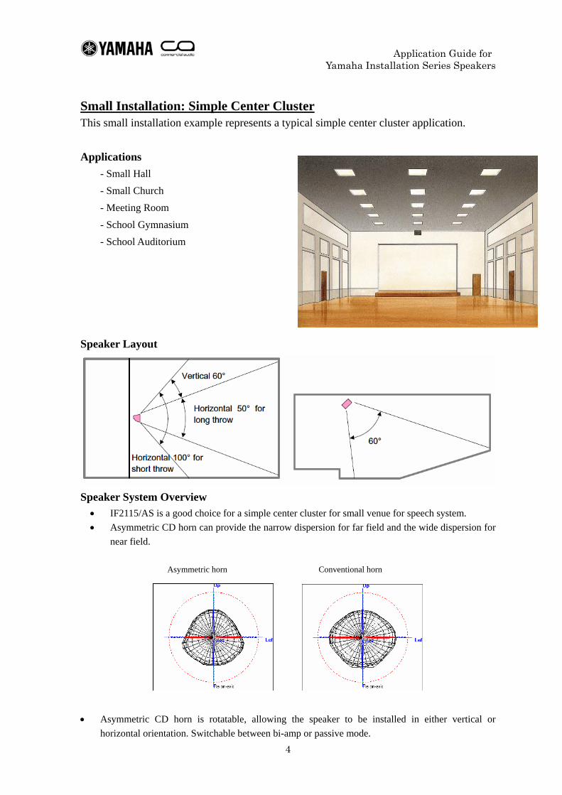
Small Installation: Simple Center Cluster This small installation example represents a typical simple center cluster application.
Applications - Small Hall - Small Church - Meeting Room - School Gymnasium - School Auditorium
Speaker Layout
Speaker System Overview • IF2115/AS is a good choice for a simple center cluster for small venue for speech system. • Asymmetric CD horn can provide the narrow dispersion for far field and the wide dispersion for
near field.
Asymmetric horn Conventional horn
• Asymmetric CD horn is rotatable, allowing the speaker to be installed in either vertical or
horizontal orientation. Switchable between bi-amp or passive mode.
Application Guide for Yamaha Installation Series Speakers
5
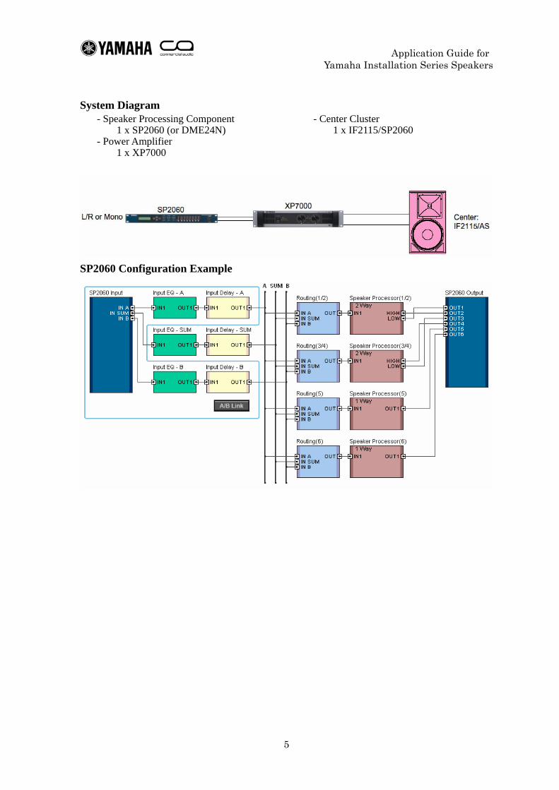
System Diagram - Speaker Processing Component
1 x SP2060 (or DME24N) - Power Amplifier
1 x XP7000
- Center Cluster 1 x IF2115/SP2060
SP2060 Configuration Example
Application Guide for Yamaha Installation Series Speakers
6
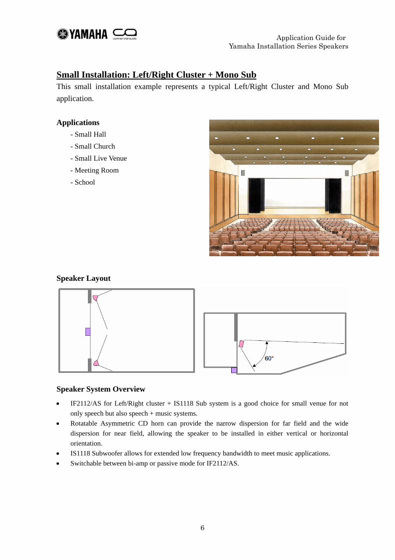
Small Installation: Left/Right Cluster + Mono Sub This small installation example represents a typical Left/Right Cluster and Mono Sub application.
Applications - Small Hall - Small Church - Small Live Venue - Meeting Room - School
Speaker Layout
Speaker System Overview
• IF2112/AS for Left/Right cluster + IS1118 Sub system is a good choice for small venue for not only speech but also speech + music systems.
• Rotatable Asymmetric CD horn can provide the narrow dispersion for far field and the wide dispersion for near field, allowing the speaker to be installed in either vertical or horizontal orientation.
• IS1118 Subwoofer allows for extended low frequency bandwidth to meet music applications. • Switchable between bi-amp or passive mode for IF2112/AS.
Application Guide for Yamaha Installation Series Speakers
7
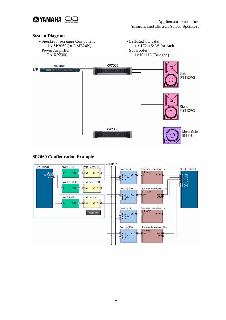
System Diagram - Speaker Processing Component
1 x SP2060 (or DME24N) - Power Amplifier
2 x XP7000
- Left/Right Cluster 1 x IF2115/AS for each
- Subwoofer 1x IS1118 (Bridged)
SP2060 Configuration Example
Application Guide for Yamaha Installation Series Speakers
8
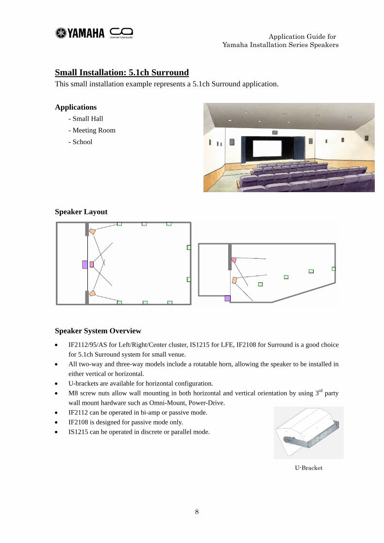
Small Installation: 5.1ch Surround This small installation example represents a 5.1ch Surround application.
Applications - Small Hall - Meeting Room - School
Speaker Layout
Speaker System Overview
• IF2112/95/AS for Left/Right/Center cluster, IS1215 for LFE, IF2108 for Surround is a good choice for 5.1ch Surround system for small venue.
• All two-way and three-way models include a rotatable horn, allowing the speaker to be installed in either vertical or horizontal.
• U-brackets are available for horizontal configuration. • M8 screw nuts allow wall mounting in both horizontal and vertical orientation by using 3rd party
wall mount hardware such as Omni-Mount, Power-Drive. • IF2112 can be operated in bi-amp or passive mode. • IF2108 is designed for passive mode only. • IS1215 can be operated in discrete or parallel mode.
U-Bracket
Application Guide for Yamaha Installation Series Speakers
9
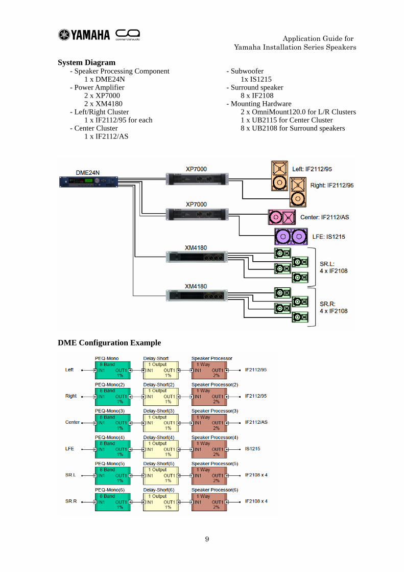
System Diagram - Speaker Processing Component
1 x DME24N - Power Amplifier
2 x XP7000 2 x XM4180
- Left/Right Cluster 1 x IF2112/95 for each
- Center Cluster 1 x IF2112/AS
- Subwoofer 1x IS1215
- Surround speaker 8 x IF2108
- Mounting Hardware 2 x OmniMount120.0 for L/R Clusters 1 x UB2115 for Center Cluster 8 x UB2108 for Surround speakers
DME Configuration Example
Application Guide for Yamaha Installation Series Speakers
10
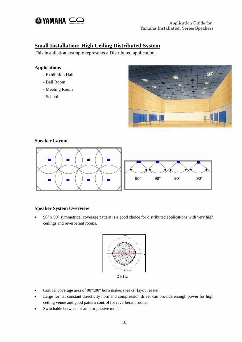
Small Installation: High Ceiling Distributed System This installation example represents a Distributed application.
Applications - Exhibition Hall - Ball Room - Meeting Room - School
Speaker Layout
Speaker System Overview
• 90° x 90° symmetrical coverage pattern is a good choice for distributed applications with very high ceilings and reverberant rooms.
• Conical coverage area of 90°x90° horn makes speaker layout easier. • Large format constant directivity horn and compression driver can provide enough power for high
ceiling venue and good pattern control for reverberant rooms. • Switchable between bi-amp or passive mode.
2 kHz
Application Guide for Yamaha Installation Series Speakers
11
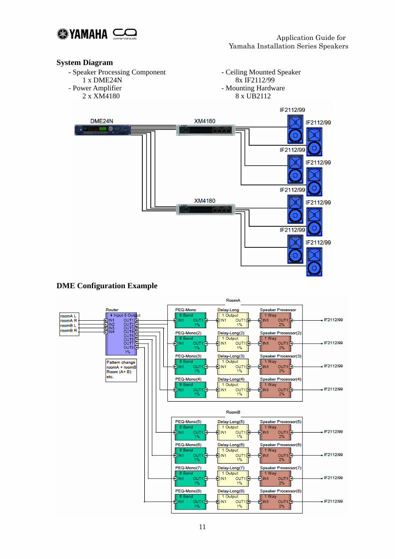
System Diagram - Speaker Processing Component
1 x DME24N - Power Amplifier
2 x XM4180
- Ceiling Mounted Speaker 8x IF2112/99
- Mounting Hardware 8 x UB2112
DME Configuration Example
Application Guide for Yamaha Installation Series Speakers
12
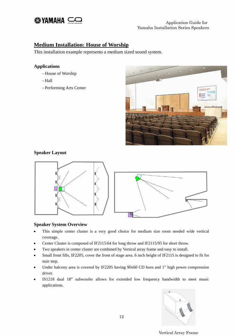
Medium Installation: House of Worship This installation example represents a medium sized sound system.
Applications - House of Worship - Hall - Performing Arts Center
Speaker Layout
Speaker System Overview
• This simple center cluster is a very good choice for medium size room needed wide vertical coverage.
• Center Cluster is composed of IF2115/64 for long throw and IF2115/95 for short throw. • Two speakers in center cluster are combined by Vertical array frame and easy to install. • Small front fills, IF2205, cover the front of stage area. 6 inch height of IF2115 is designed to fit for
stair step. • Under balcony area is covered by IF2205 having 90x60 CD horn and 1” high power compression
driver. • IS1218 dual 18” subwoofer allows for extended low frequency bandwidth to meet music
applications.
Vertical Array Frame
Application Guide for Yamaha Installation Series Speakers
13
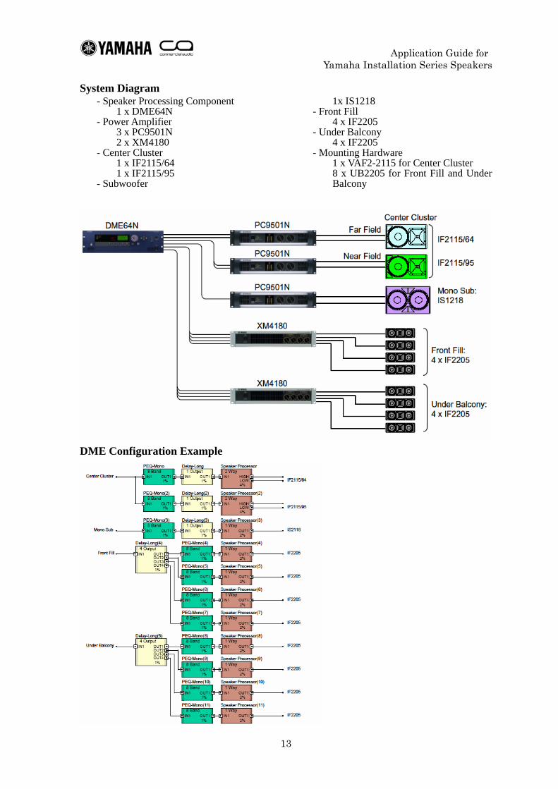
System Diagram - Speaker Processing Component
1 x DME64N - Power Amplifier
3 x PC9501N 2 x XM4180
- Center Cluster 1 x IF2115/64 1 x IF2115/95
- Subwoofer
1x IS1218 - Front Fill
4 x IF2205 - Under Balcony
4 x IF2205 - Mounting Hardware
1 x VAF2-2115 for Center Cluster 8 x UB2205 for Front Fill and Under Balcony
DME Configuration Example
Application Guide for Yamaha Installation Series Speakers
14
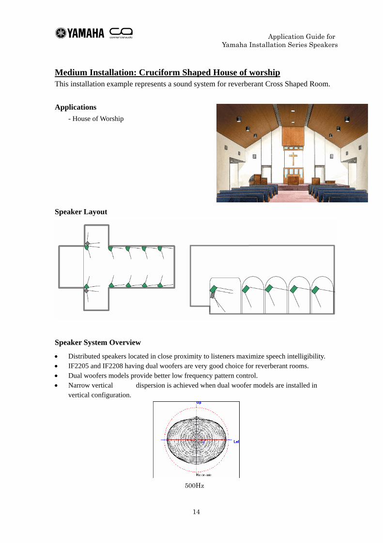
Medium Installation: Cruciform Shaped House of worship This installation example represents a sound system for reverberant Cross Shaped Room.
Applications - House of Worship
Speaker Layout
Speaker System Overview
• Distributed speakers located in close proximity to listeners maximize speech intelligibility. • IF2205 and IF2208 having dual woofers are very good choice for reverberant rooms. • Dual woofers models provide better low frequency pattern control. • Narrow vertical dispersion is achieved when dual woofer models are installed in
vertical configuration.
500Hz
Application Guide for Yamaha Installation Series Speakers
15
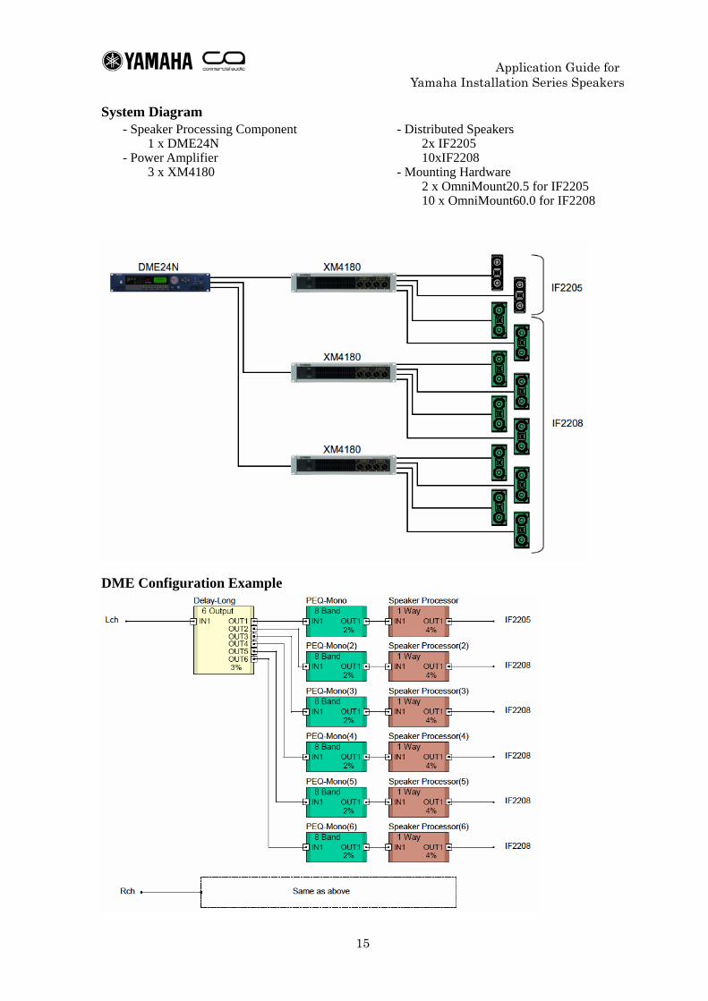
System Diagram - Speaker Processing Component
1 x DME24N - Power Amplifier
3 x XM4180
- Distributed Speakers 2x IF2205 10xIF2208
- Mounting Hardware 2 x OmniMount20.5 for IF2205 10 x OmniMount60.0 for IF2208
DME Configuration Example
Application Guide for Yamaha Installation Series Speakers
16
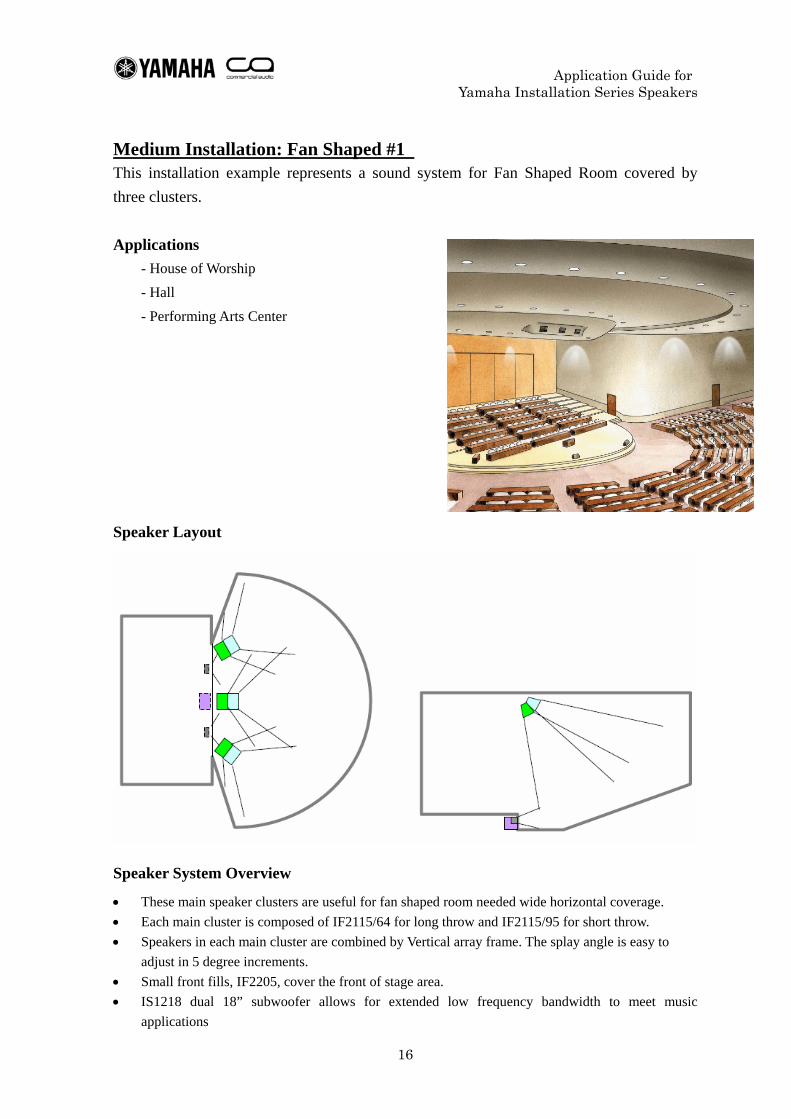
Medium Installation: Fan Shaped #1 This installation example represents a sound system for Fan Shaped Room covered by three clusters.
Applications - House of Worship - Hall - Performing Arts Center
Speaker Layout
Speaker System Overview
• These main speaker clusters are useful for fan shaped room needed wide horizontal coverage. • Each main cluster is composed of IF2115/64 for long throw and IF2115/95 for short throw. • Speakers in each main cluster are combined by Vertical array frame. The splay angle is easy to
adjust in 5 degree increments. • Small front fills, IF2205, cover the front of stage area. • IS1218 dual 18” subwoofer allows for extended low frequency bandwidth to meet music
applications
Application Guide for Yamaha Installation Series Speakers
17
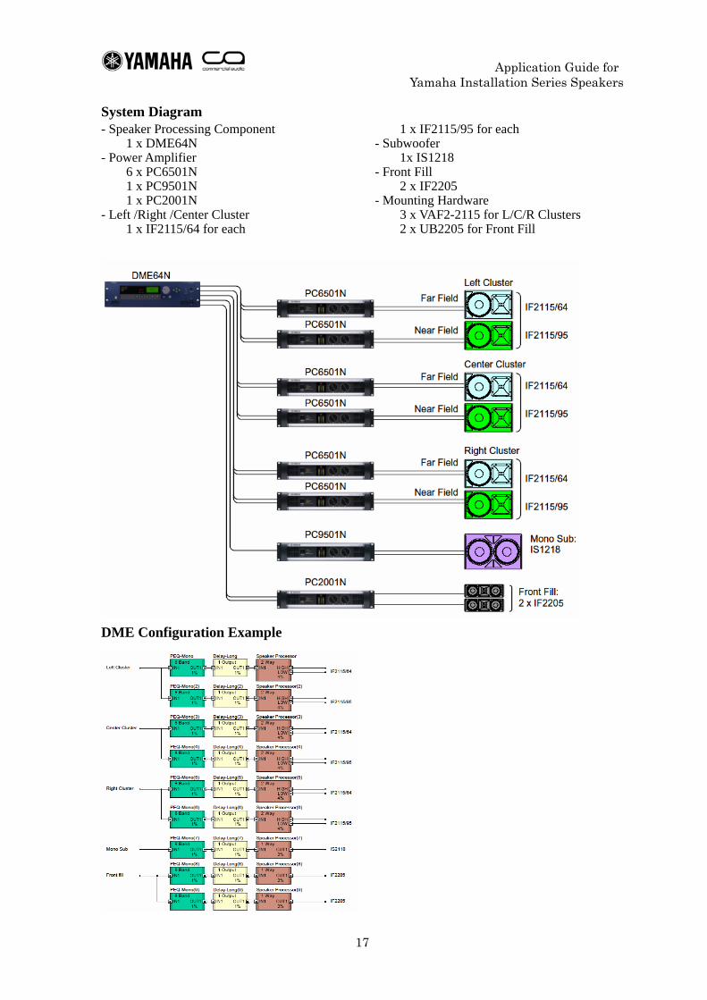
System Diagram - Speaker Processing Component
1 x DME64N - Power Amplifier
6 x PC6501N 1 x PC9501N 1 x PC2001N
- Left /Right /Center Cluster 1 x IF2115/64 for each
1 x IF2115/95 for each - Subwoofer
1x IS1218 - Front Fill
2 x IF2205 - Mounting Hardware
3 x VAF2-2115 for L/C/R Clusters 2 x UB2205 for Front Fill
DME Configuration Example
Application Guide for Yamaha Installation Series Speakers
18
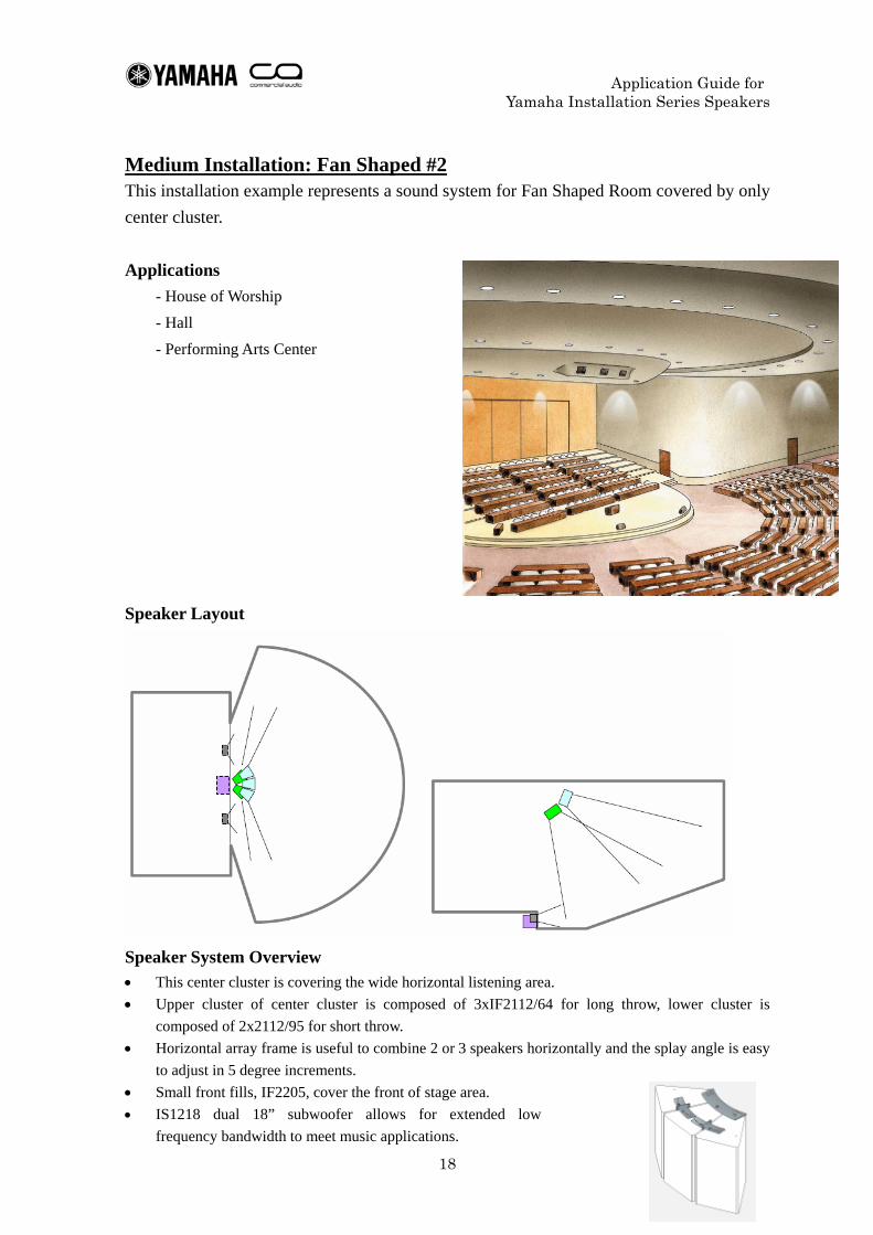
Medium Installation: Fan Shaped #2 This installation example represents a sound system for Fan Shaped Room covered by only center cluster.
Applications - House of Worship - Hall - Performing Arts Center
Speaker Layout
Speaker System Overview
• This center cluster is covering the wide horizontal listening area. • Upper cluster of center cluster is composed of 3xIF2112/64 for long throw, lower cluster is
composed of 2x2112/95 for short throw. • Horizontal array frame is useful to combine 2 or 3 speakers horizontally and the splay angle is easy
to adjust in 5 degree increments. • Small front fills, IF2205, cover the front of stage area. • IS1218 dual 18” subwoofer allows for extended low
frequency bandwidth to meet music applications.
Application Guide for Yamaha Installation Series Speakers
19
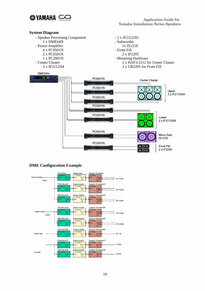
System Diagram - Speaker Processing Component
1 x DME64N - Power Amplifier
4 x PC9501N 2 x PC6501N 1 x PC2001N
- Center Cluster 3 x IF2112/64
- 2 x IF2112/95 - Subwoofer
1x IS1218 - Front Fill
2 x IF2205 - Mounting Hardware
2 x HAF3-2112 for Center Cluster 2 x UB2205 for Front Fill
DME Configuration Example
Application Guide for Yamaha Installation Series Speakers
20
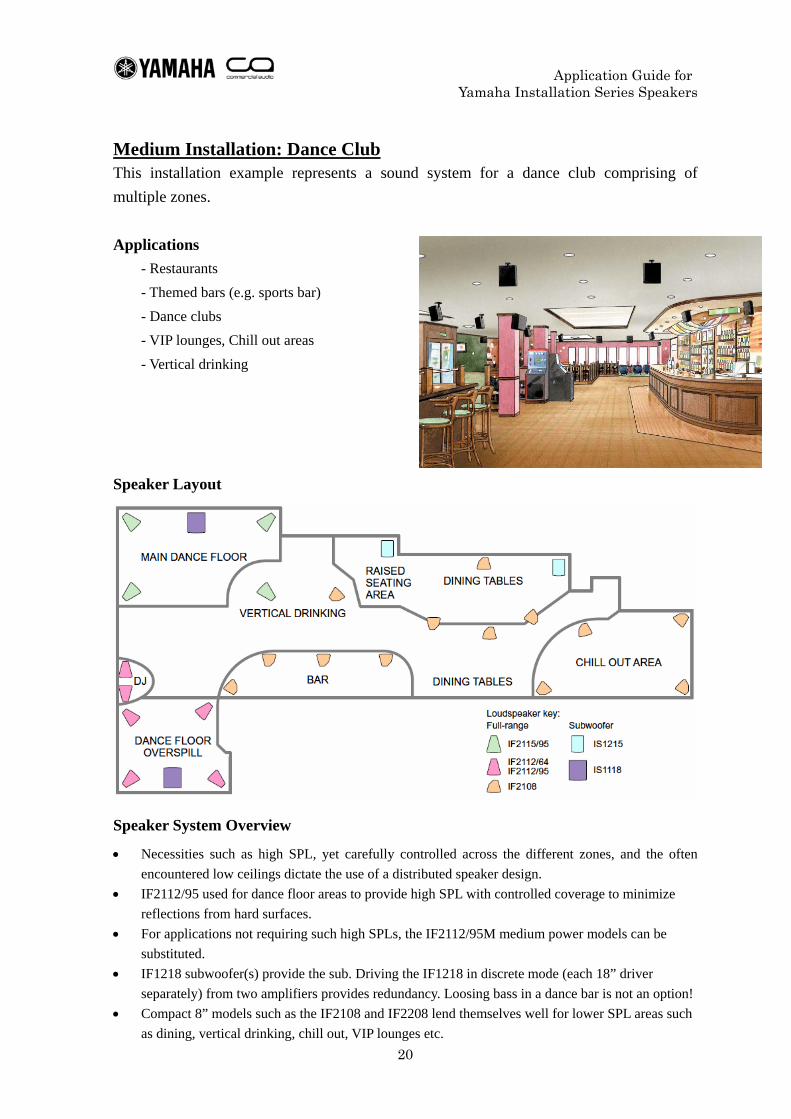
Medium Installation: Dance Club This installation example represents a sound system for a dance club comprising of multiple zones.
Applications - Restaurants - Themed bars (e.g. sports bar) - Dance clubs - VIP lounges, Chill out areas - Vertical drinking
Speaker Layout
Speaker System Overview
• Necessities such as high SPL, yet carefully controlled across the different zones, and the often encountered low ceilings dictate the use of a distributed speaker design.
• IF2112/95 used for dance floor areas to provide high SPL with controlled coverage to minimize reflections from hard surfaces.
• For applications not requiring such high SPLs, the IF2112/95M medium power models can be substituted.
• IF1218 subwoofer(s) provide the sub. Driving the IF1218 in discrete mode (each 18” driver separately) from two amplifiers provides redundancy. Loosing bass in a dance bar is not an option!
• Compact 8” models such as the IF2108 and IF2208 lend themselves well for lower SPL areas such as dining, vertical drinking, chill out, VIP lounges etc.
Application Guide for Yamaha Installation Series Speakers
21
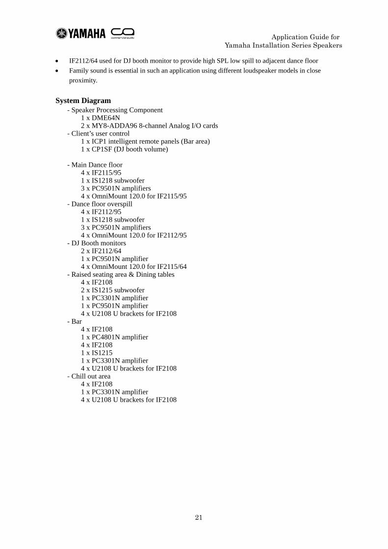
• IF2112/64 used for DJ booth monitor to provide high SPL low spill to adjacent dance floor • Family sound is essential in such an application using different loudspeaker models in close
proximity.
System Diagram - Speaker Processing Component
1 x DME64N 2 x MY8-ADDA96 8-channel Analog I/O cards
- Client’s user control 1 x ICP1 intelligent remote panels (Bar area) 1 x CP1SF (DJ booth volume)
- Main Dance floor 4 x IF2115/95 1 x IS1218 subwoofer 3 x PC9501N amplifiers 4 x OmniMount 120.0 for IF2115/95
- Dance floor overspill 4 x IF2112/95 1 x IS1218 subwoofer 3 x PC9501N amplifiers 4 x OmniMount 120.0 for IF2112/95
- DJ Booth monitors 2 x IF2112/64 1 x PC9501N amplifier 4 x OmniMount 120.0 for IF2115/64
- Raised seating area & Dining tables 4 x IF2108 2 x IS1215 subwoofer 1 x PC3301N amplifier 1 x PC9501N amplifier 4 x U2108 U brackets for IF2108
- Bar 4 x IF2108 1 x PC4801N amplifier 4 x IF2108 1 x IS1215 1 x PC3301N amplifier 4 x U2108 U brackets for IF2108
- Chill out area 4 x IF2108 1 x PC3301N amplifier 4 x U2108 U brackets for IF2108
Application Guide for Yamaha Installation Series Speakers
22
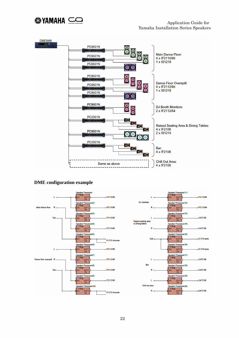
DME configuration example
Application Guide for Yamaha Installation Series Speakers
23
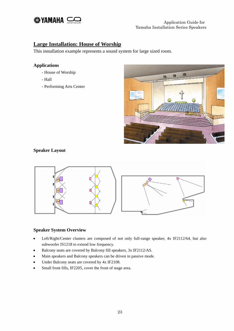
Large Installation: House of Worship
This installation example represents a sound system for large sized room.
Applications - House of Worship - Hall - Performing Arts Center
Speaker Layout
Speaker System Overview
• Left/Right/Center clusters are composed of not only full-range speaker, 4x IF2112/64, but also subwoofer IS1218 to extend low frequency.
• Balcony seats are covered by Balcony fill speakers, 3x IF2112/AS. • Main speakers and Balcony speakers can be driven in passive mode. • Under Balcony seats are covered by 4x IF2108. • Small front fills, IF2205, cover the front of stage area.
Application Guide for Yamaha Installation Series Speakers
24
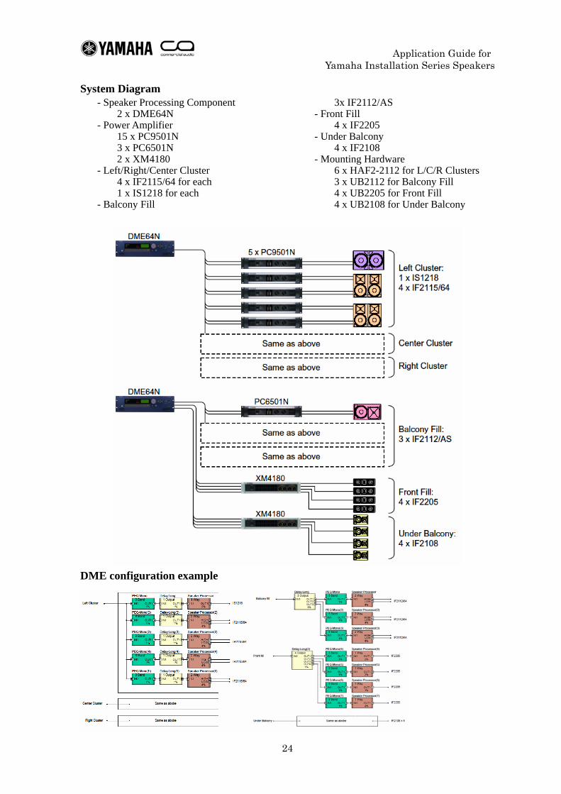
System Diagram - Speaker Processing Component
2 x DME64N - Power Amplifier
15 x PC9501N 3 x PC6501N 2 x XM4180
- Left/Right/Center Cluster 4 x IF2115/64 for each 1 x IS1218 for each
- Balcony Fill
3x IF2112/AS - Front Fill
4 x IF2205 - Under Balcony
4 x IF2108 - Mounting Hardware
6 x HAF2-2112 for L/C/R Clusters 3 x UB2112 for Balcony Fill 4 x UB2205 for Front Fill 4 x UB2108 for Under Balcony
DME configuration example
Application Guide for Yamaha Installation Series Speakers
25
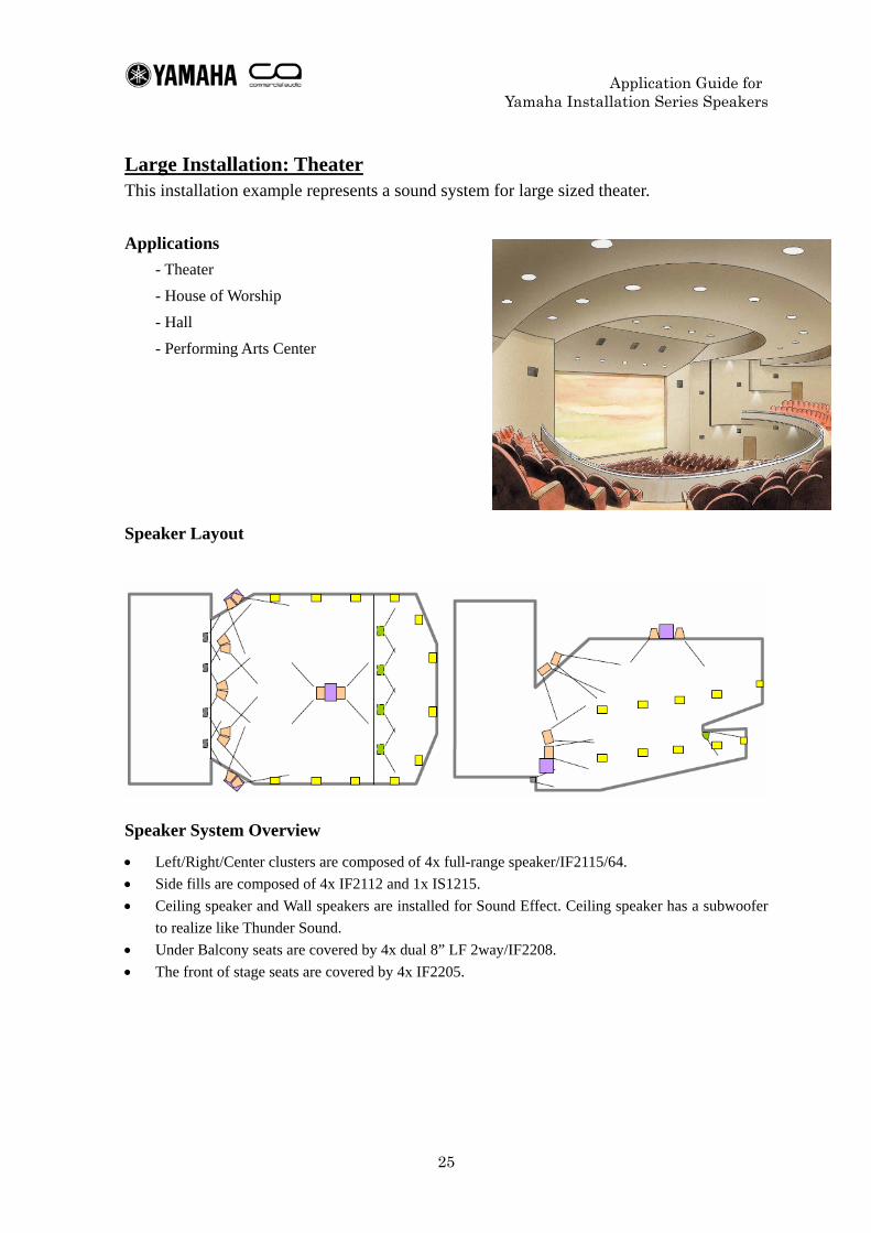
Large Installation: Theater This installation example represents a sound system for large sized theater.
Applications - Theater - House of Worship - Hall - Performing Arts Center
Speaker Layout
Speaker System Overview
• Left/Right/Center clusters are composed of 4x full-range speaker/IF2115/64. • Side fills are composed of 4x IF2112 and 1x IS1215. • Ceiling speaker and Wall speakers are installed for Sound Effect. Ceiling speaker has a subwoofer
to realize like Thunder Sound. • Under Balcony seats are covered by 4x dual 8” LF 2way/IF2208. • The front of stage seats are covered by 4x IF2205.
Application Guide for Yamaha Installation Series Speakers
26
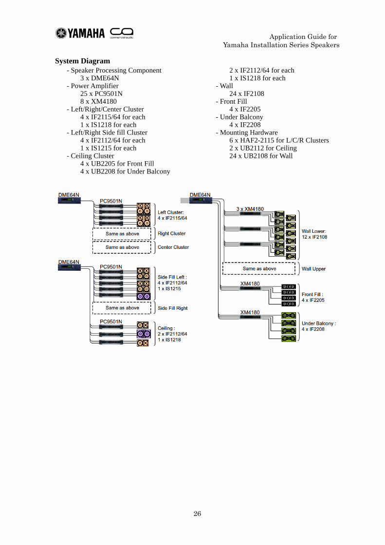
System Diagram - Speaker Processing Component
3 x DME64N - Power Amplifier
25 x PC9501N 8 x XM4180
- Left/Right/Center Cluster 4 x IF2115/64 for each 1 x IS1218 for each
- Left/Right Side fill Cluster 4 x IF2112/64 for each 1 x IS1215 for each
- Ceiling Cluster
2 x IF2112/64 for each 1 x IS1218 for each
- Wall 24 x IF2108
- Front Fill 4 x IF2205
- Under Balcony 4 x IF2208
- Mounting Hardware 6 x HAF2-2115 for L/C/R Clusters 2 x UB2112 for Ceiling 24 x UB2108 for Wall
4 x UB2205 for Front Fill 4 x UB2208 for Under Balcony
Application Guide for Yamaha Installation Series Speakers
27
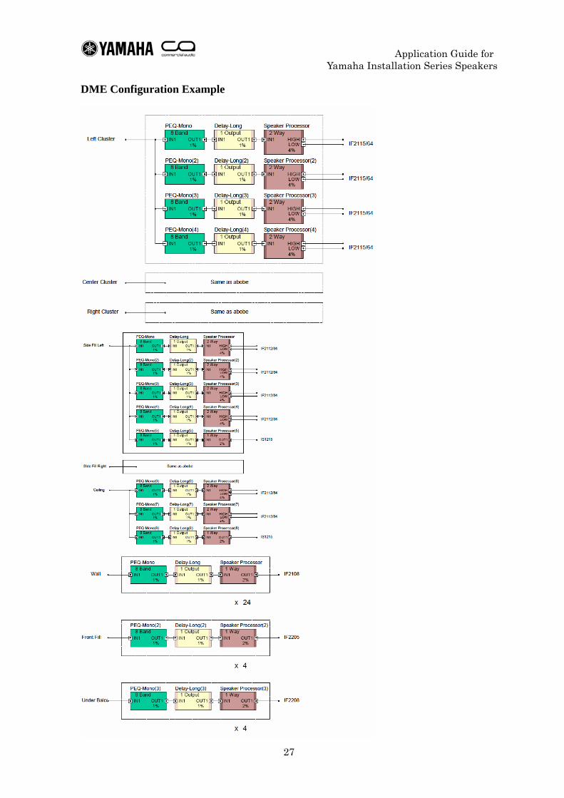
DME Configuration Example
Application Guide for Yamaha Installation Series Speakers
28
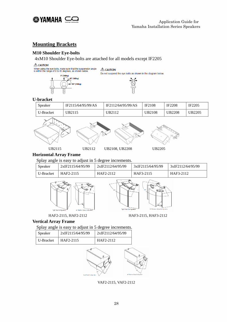
Mounting Brackets M10 Shoulder Eye-bolts 4xM10 Shoulder Eye-bolts are attached for all models except IF2205
U-bracket Speaker IF2115/64/95/99/AS IF2112/64/95/99/AS IF2108 IF2208 IF2205
U-Bracket UB2115 UB2112 UB2108 UB2208 UB2205
UB2115 UB2112 UB2108, UB2208 UB2205
Horizontal Array Frame Splay angle is easy to adjust in 5 degree increments. Speaker 2xIF2115/64/95/99 2xIF2112/64/95/99 3xIF2115/64/95/99 3xIF2112/64/95/99
U-Bracket HAF2-2115 HAF2-2112 HAF3-2115 HAF3-2112
HAF2-2115, HAF2-2112 HAF3-2115, HAF3-2112
Vertical Array Frame Splay angle is easy to adjust in 5 degree increments. Speaker 2xIF2115/64/95/99 2xIF2112/64/95/99
U-Bracket HAF2-2115 HAF2-2112
VAF2-2115, VAF2-2112
Application Guide for Yamaha Installation Series Speakers
29
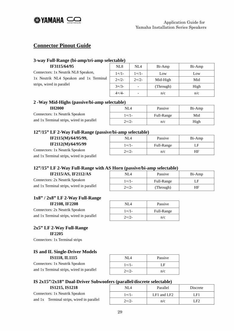
Connector Pinout Guide 3-way Full-Range (bi-amp/tri-amp selectable)
IF3115/64/95 Connectors: 1x Neutrik NL8 Speakon, 1x Neutrik NL4 Speakon and 1x Terminal strips, wired in parallel 2 -Way Mid-Highs (passive/bi-amp selectable)
IH2000 Connectors: 1x Neutrik Speakon and 1x Terminal strips, wired in parallel 12”/15” LF 2-Way Full-Range (passive/bi-amp selectable)
IF2115(M)/64/95/99, IF2112(M)/64/95/99
Connectors: 1x Neutrik Speakon and 1x Terminal strips, wired in parallel 12”/15” LF 2-Way Full-Range with AS Horn (passive/bi-amp selectable)
IF2115/AS, IF2112/AS Connectors: 2x Neutrik Speakon and 1x Terminal strips, wired in parallel 1x8” / 2x8” LF 2-Way Full-Range
IF2108, IF2208 Connectors: 2x Neutrik Speakon and 1x Terminal strips, wired in parallel 2x5” LF 2-Way Full-Range
IF2205 Connectors: 1x Terminal strips IS and IL Single-Driver Models
IS1118, IL1115 Connectors: 1x Neutrik Speakon and 1x Terminal strips, wired in parallel IS 2x15”/2x18” Dual-Driver Subwoofers (parallel/discrete selectable)
IS1215, IS1218 Connectors: 1x Neutrik Speakon and 1x Terminal strips, wired in parallel
NL8 NL4 Bi-Amp Bi-Amp
1+/1- 1+/1- Low Low 2+/2- 2+/2- Mid-High Mid
3+/3- - (Through) High
4+/4- - n/c n/c
NL4 Passive Bi-Amp
1+/1- Full-Range Mid 2+/2- n/c High
NL4 Passive Bi-Amp
1+/1- Full-Range LF 2+/2- n/c HF
NL4 Passive Bi-Amp
1+/1- Full-Range LF 2+/2- (Through) HF
NL4 Passive
1+/1- Full-Range 2+/2- n/c
NL4 Passive
1+/1- LF 2+/2- n/c
NL4 Parallel Discrete
1+/1- LF1 and LF2 LF1 2+/2- n/c LF2
Application Guide for Yamaha Installation Series Speakers
30
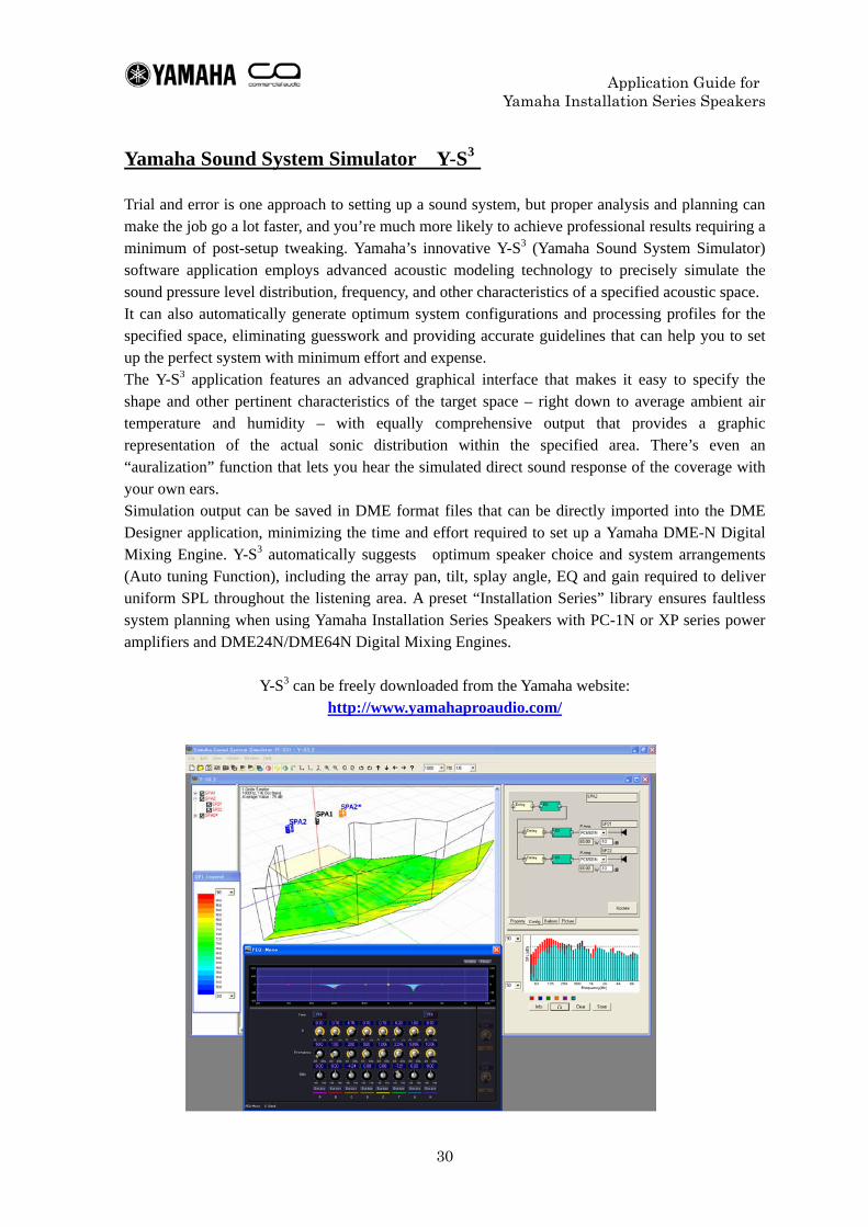
Yamaha Sound System Simulator Y-S3
Trial and error is one approach to setting up a sound system, but proper analysis and planning can make the job go a lot faster, and you’re much more likely to achieve professional results requiring a minimum of post-setup tweaking. Yamaha’s innovative Y-S3 (Yamaha Sound System Simulator) software application employs advanced acoustic modeling technology to precisely simulate the sound pressure level distribution, frequency, and other characteristics of a specified acoustic space. It can also automatically generate optimum system configurations and processing profiles for the specified space, eliminating guesswork and providing accurate guidelines that can help you to set up the perfect system with minimum effort and expense. The Y-S3 application features an advanced graphical interface that makes it easy to specify the shape and other pertinent characteristics of the target space – right down to average ambient air temperature and humidity – with equally comprehensive output that provides a graphic representation of the actual sonic distribution within the specified area. There’s even an “auralization” function that lets you hear the simulated direct sound response of the coverage with your own ears. Simulation output can be saved in DME format files that can be directly imported into the DME Designer application, minimizing the time and effort required to set up a Yamaha DME-N Digital Mixing Engine. Y-S3 automatically suggests optimum speaker choice and system arrangements (Auto tuning Function), including the array pan, tilt, splay angle, EQ and gain required to deliver uniform SPL throughout the listening area. A preset “Installation Series” library ensures faultless system planning when using Yamaha Installation Series Speakers with PC-1N or XP series power amplifiers and DME24N/DME64N Digital Mixing Engines.
Y-S3 can be freely downloaded from the Yamaha website:
http://www.yamahaproaudio.com/
Application Guide for Yamaha Installation Series Speakers
31
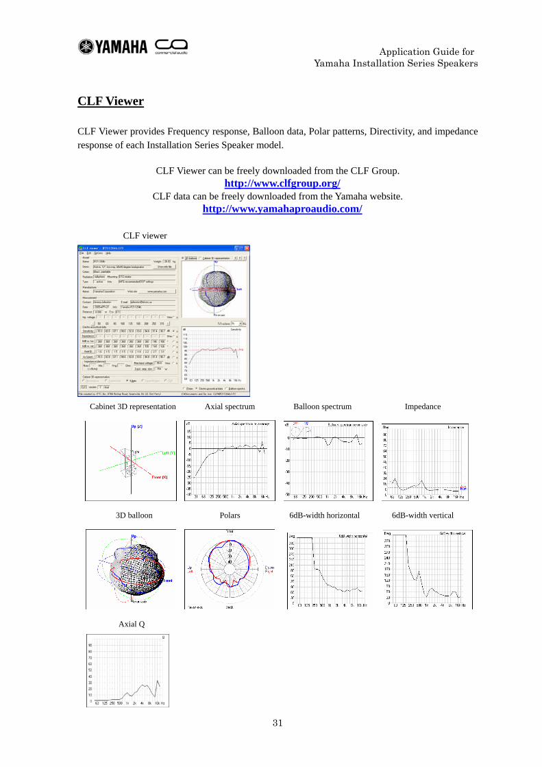
CLF Viewer
CLF Viewer provides Frequency response, Balloon data, Polar patterns, Directivity, and impedance response of each Installation Series Speaker model.
CLF Viewer can be freely downloaded from the CLF Group. http://www.clfgroup.org/
CLF data can be freely downloaded from the Yamaha website. http://www.yamahaproaudio.com/
CLF viewer
Cabinet 3D representation Axial spectrum Balloon spectrum Impedance
3D balloon Polars 6dB-width horizontal 6dB-width vertical
Axial Q
Application Guide for Yamaha Installation Series Speakers
32
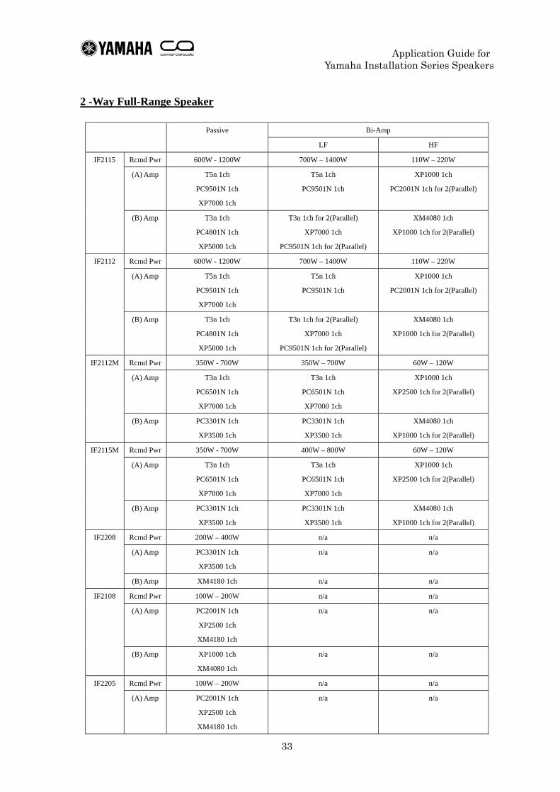
Recommended Amplifier Although there is no single correct answer to the question of which amplifier to select, we can offer some simple suggestions. The table in the following pages shows two different options and gives recommended power ratings along with examples of possible choices of models. One option is to maximize speaker performance, giving priority to sound quality, while the other gives priority to using your speakers in a safe manner. The former will give better sound, but increases the risk of speaker damage from signals received in an uncontrolled environment. The latter may increase the probability of signals from the amplifier being clipped. But if you can ensure the signals from the amplifier will not be clipped, it reduces the chance of damage to your speakers. Although the table in the following pages shows only recommended values for matching speakers and amplifiers, you should also consider the sound pressure level needed when selecting an amplifier. Lower sound pressure level requirements allow you to use amplifiers with lower power ratings. Using identical amplifiers can be beneficial as it allows for greater sonic consistency, and can simplify maintenance and inventory. When using multiple loudspeaker types simultaneously, or driving speakers in bi-amp or tri-amp mode, you may be using power amplifier channels with higher power ratings than required (i.e. unusued headroom). However, when the HF is driven by the same amplifier as the LF, you must take precautions to prevent excessive power reaching the driver(s). Therefore, in order to avoid damage , you should set an appropriate attenuation level and limiter level. Regardless of which of the above options you select, it is impossible to eliminate the possibility of speaker damage caused by factors such as microphone feedback, aggressive EQ, continuously clipped signals from amplifiers, processors, and mixers, and sine waves played back for extensive lengths of time. As such the recommendations listed here are not a guarantee of trouble-free operation. <Terminology used in the table> Rcmd Pwr: The recommended power ratings of the amplifier. (A) Amp: An amplifier recommendation for maximizing speaker performance when in a well-controlled environment. (B) Amp: An amplifier recommendation for using speakers safely when in an environment where there is a high probability of excessive signal input.
Application Guide for Yamaha Installation Series Speakers
33
2 -Way Full-Range Speaker
Bi-Amp Passive
LF HF
Rcmd Pwr 600W - 1200W 700W – 1400W 110W – 220W
(A) Amp T5n 1ch
PC9501N 1ch
XP7000 1ch
T5n 1ch
PC9501N 1ch
XP1000 1ch
PC2001N 1ch for 2(Parallel)
IF2115
(B) Amp T3n 1ch
PC4801N 1ch
XP5000 1ch
T3n 1ch for 2(Parallel)
XP7000 1ch
PC9501N 1ch for 2(Parallel)
XM4080 1ch
XP1000 1ch for 2(Parallel)
Rcmd Pwr 600W - 1200W 700W – 1400W 110W – 220W
(A) Amp T5n 1ch
PC9501N 1ch
XP7000 1ch
T5n 1ch
PC9501N 1ch
XP1000 1ch
PC2001N 1ch for 2(Parallel)
IF2112
(B) Amp T3n 1ch
PC4801N 1ch
XP5000 1ch
T3n 1ch for 2(Parallel)
XP7000 1ch
PC9501N 1ch for 2(Parallel)
XM4080 1ch
XP1000 1ch for 2(Parallel)
Rcmd Pwr 350W - 700W 350W – 700W 60W – 120W
(A) Amp T3n 1ch
PC6501N 1ch
XP7000 1ch
T3n 1ch
PC6501N 1ch
XP7000 1ch
XP1000 1ch
XP2500 1ch for 2(Parallel)
IF2112M
(B) Amp PC3301N 1ch
XP3500 1ch
PC3301N 1ch
XP3500 1ch
XM4080 1ch
XP1000 1ch for 2(Parallel)
Rcmd Pwr 350W - 700W 400W – 800W 60W – 120W
(A) Amp T3n 1ch
PC6501N 1ch
XP7000 1ch
T3n 1ch
PC6501N 1ch
XP7000 1ch
XP1000 1ch
XP2500 1ch for 2(Parallel)
IF2115M
(B) Amp PC3301N 1ch
XP3500 1ch
PC3301N 1ch
XP3500 1ch
XM4080 1ch
XP1000 1ch for 2(Parallel)
Rcmd Pwr 200W – 400W n/a n/a
(A) Amp PC3301N 1ch
XP3500 1ch
n/a n/a
IF2208
(B) Amp XM4180 1ch n/a n/a
Rcmd Pwr 100W – 200W n/a n/a
(A) Amp PC2001N 1ch
XP2500 1ch
XM4180 1ch
n/a n/a
IF2108
(B) Amp XP1000 1ch
XM4080 1ch
n/a n/a
Rcmd Pwr 100W – 200W n/a n/a IF2205
(A) Amp PC2001N 1ch
XP2500 1ch
XM4180 1ch
n/a n/a

Application Guide for Yamaha Installation Series Speakers
34
(B) Amp XP1000 1ch
XM4080 1ch
n/a n/a
Application Guide for Yamaha Installation Series Speakers
35
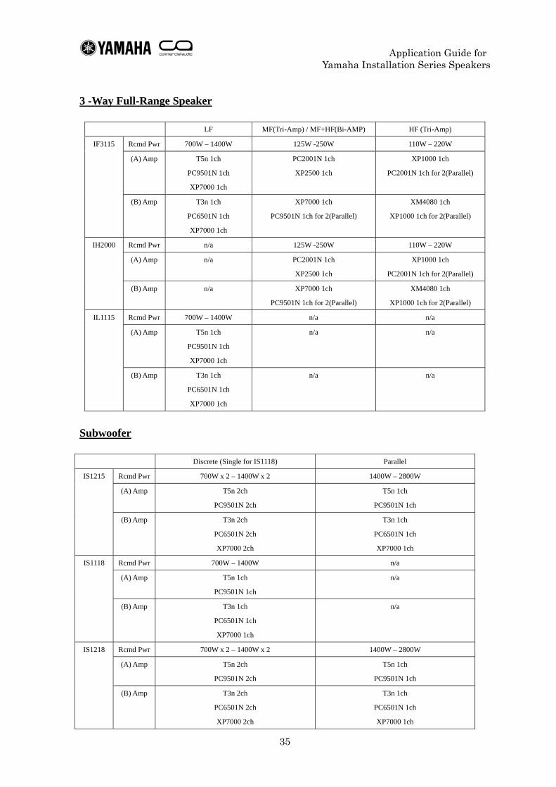
3 -Way Full-Range Speaker
LF MF(Tri-Amp) / MF+HF(Bi-AMP) HF (Tri-Amp)
Rcmd Pwr 700W – 1400W 125W -250W 110W – 220W
(A) Amp T5n 1ch
PC9501N 1ch
XP7000 1ch
PC2001N 1ch
XP2500 1ch
XP1000 1ch
PC2001N 1ch for 2(Parallel)
IF3115
(B) Amp T3n 1ch
PC6501N 1ch
XP7000 1ch
XP7000 1ch
PC9501N 1ch for 2(Parallel)
XM4080 1ch
XP1000 1ch for 2(Parallel)
Rcmd Pwr n/a 125W -250W 110W – 220W
(A) Amp n/a PC2001N 1ch
XP2500 1ch
XP1000 1ch
PC2001N 1ch for 2(Parallel)
IH2000
(B) Amp n/a XP7000 1ch
PC9501N 1ch for 2(Parallel)
XM4080 1ch
XP1000 1ch for 2(Parallel)
Rcmd Pwr 700W – 1400W n/a n/a
(A) Amp T5n 1ch
PC9501N 1ch
XP7000 1ch
n/a n/a
IL1115
(B) Amp T3n 1ch
PC6501N 1ch
XP7000 1ch
n/a n/a
Subwoofer
Discrete (Single for IS1118) Parallel
Rcmd Pwr 700W x 2 – 1400W x 2 1400W – 2800W
(A) Amp T5n 2ch
PC9501N 2ch
T5n 1ch
PC9501N 1ch
IS1215
(B) Amp T3n 2ch
PC6501N 2ch
XP7000 2ch
T3n 1ch
PC6501N 1ch
XP7000 1ch
Rcmd Pwr 700W – 1400W n/a
(A) Amp T5n 1ch
PC9501N 1ch
n/a
IS1118
(B) Amp T3n 1ch
PC6501N 1ch
XP7000 1ch
n/a
Rcmd Pwr 700W x 2 – 1400W x 2 1400W – 2800W
(A) Amp T5n 2ch
PC9501N 2ch
T5n 1ch
PC9501N 1ch
IS1218
(B) Amp T3n 2ch
PC6501N 2ch
XP7000 2ch
T3n 1ch
PC6501N 1ch
XP7000 1ch
Application Guide for Yamaha Installation Series Speakers
36
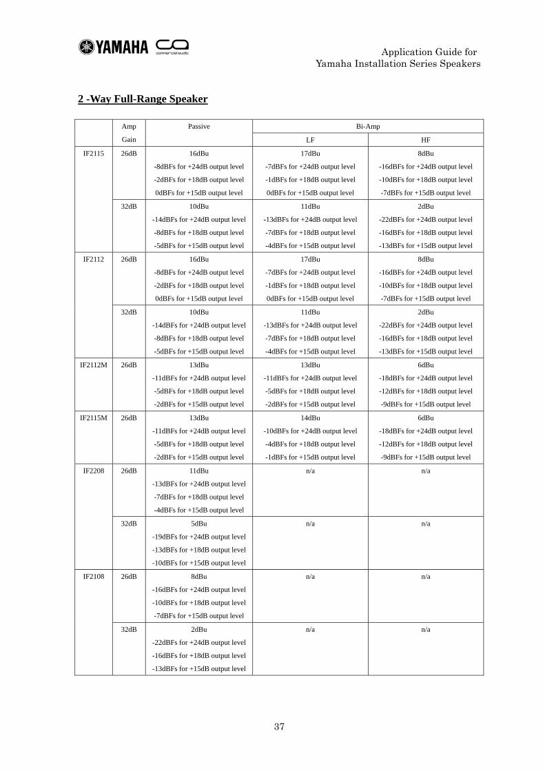
Recommended Limiter Setting Note that the figures are not a guarantee of protection for your speakers. Please refer to them on the understanding that they are provided as a guideline only. Limiters allow you to provide speakers with maximum protection from unpredictable signal overload. We have provided the following table as a list of threshold figures, which should give you a starting point to work from. When configuring threshold settings, you will need to know the power ratings of the speakers and the gain of the amplifier to which they are connected. The table in the following pages provides figures for amplifier gain levels of either 26 dB or 32 dB. For amplifiers with gain levels other than those listed here, deduct the positive difference of the gain from the figures listed for the 26 dB settings to calculate the correct setting. For example, for a gain level of 30 dB, subtract 4 dB from the figures provided for a 26 dB gain level to calculate each threshold. For amplifiers with specifications displayed in terms of input sensitivity, calculate the gain from the power and input sensitivity figures, then use the calculation method above to obtain the correct threshold. "DME library data for Installation Series Speakers" provides processor settings for Yamaha's "Installation Series Speakers" in the form of library data for DME24N/64N "Speaker Processor Components." Limiter settings (enabled by default) have been added to each library file. The settings assume maximum output gain of DME (excluding DME24N's analog output) is +24dBu and 26dB voltage gain of Amplifier (based on Yamaha PC series amplifier used at -6dB attenuation) for start point. If the set up differs from this, please check the level diagram and change the threshold parameters before using limiter. E.g. If +18dBu output cards such as MY4-DA or MY8-DA96 are used, raise the threshold by 6dB. E.g. If amplifiers with 30dB voltage gain are used, turn the threshold 4dB down. “DME library data for Installation Series Speakers” can be freely downloaded from the Yamaha website. http://www.yamahaproaudio.com/ Speaker Processor “SP2060” also contains these library files for Installation Series speakers as default presets.
Application Guide for Yamaha Installation Series Speakers
37
2 -Way Full-Range Speaker
Bi-Amp Amp
Gain
Passive
LF HF
26dB 16dBu
-8dBFs for +24dB output level
-2dBFs for +18dB output level
0dBFs for +15dB output level
17dBu
-7dBFs for +24dB output level
-1dBFs for +18dB output level
0dBFs for +15dB output level
8dBu
-16dBFs for +24dB output level
-10dBFs for +18dB output level
-7dBFs for +15dB output level
IF2115
32dB 10dBu
-14dBFs for +24dB output level
-8dBFs for +18dB output level
-5dBFs for +15dB output level
11dBu
-13dBFs for +24dB output level
-7dBFs for +18dB output level
-4dBFs for +15dB output level
2dBu
-22dBFs for +24dB output level
-16dBFs for +18dB output level
-13dBFs for +15dB output level
26dB 16dBu
-8dBFs for +24dB output level
-2dBFs for +18dB output level
0dBFs for +15dB output level
17dBu
-7dBFs for +24dB output level
-1dBFs for +18dB output level
0dBFs for +15dB output level
8dBu
-16dBFs for +24dB output level
-10dBFs for +18dB output level
-7dBFs for +15dB output level
IF2112
32dB 10dBu
-14dBFs for +24dB output level
-8dBFs for +18dB output level
-5dBFs for +15dB output level
11dBu
-13dBFs for +24dB output level
-7dBFs for +18dB output level
-4dBFs for +15dB output level
2dBu
-22dBFs for +24dB output level
-16dBFs for +18dB output level
-13dBFs for +15dB output level
IF2112M 26dB 13dBu
-11dBFs for +24dB output level
-5dBFs for +18dB output level
-2dBFs for +15dB output level
13dBu
-11dBFs for +24dB output level
-5dBFs for +18dB output level
-2dBFs for +15dB output level
6dBu
-18dBFs for +24dB output level
-12dBFs for +18dB output level
-9dBFs for +15dB output level
IF2115M 26dB 13dBu
-11dBFs for +24dB output level
-5dBFs for +18dB output level
-2dBFs for +15dB output level
14dBu
-10dBFs for +24dB output level
-4dBFs for +18dB output level
-1dBFs for +15dB output level
6dBu
-18dBFs for +24dB output level
-12dBFs for +18dB output level
-9dBFs for +15dB output level
26dB 11dBu
-13dBFs for +24dB output level
-7dBFs for +18dB output level
-4dBFs for +15dB output level
n/a n/a IF2208
32dB 5dBu
-19dBFs for +24dB output level
-13dBFs for +18dB output level
-10dBFs for +15dB output level
n/a n/a
26dB 8dBu
-16dBFs for +24dB output level
-10dBFs for +18dB output level
-7dBFs for +15dB output level
n/a n/a IF2108
32dB 2dBu
-22dBFs for +24dB output level
-16dBFs for +18dB output level
-13dBFs for +15dB output level
n/a n/a
Application Guide for Yamaha Installation Series Speakers
38
26dB 8dBu
-16dBFs for +24dB output level
-10dBFs for +18dB output level
-7dBFs for +15dB output level
n/a n/a IF2205
32dB 2dBu
-22dBFs for +24dB output level
-16dBFs for +18dB output level
-13dBFs for +15dB output level
n/a n/a
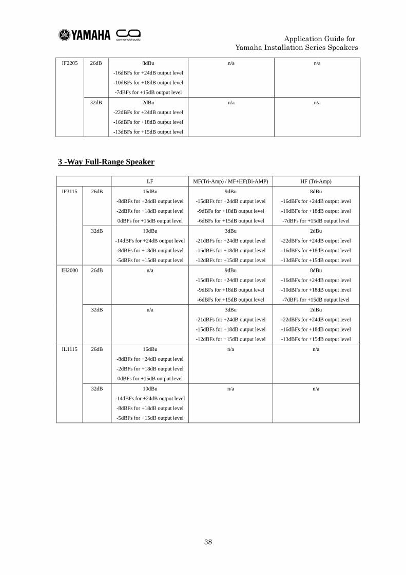
3 -Way Full-Range Speaker
LF MF(Tri-Amp) / MF+HF(Bi-AMP) HF (Tri-Amp)
26dB 16dBu
-8dBFs for +24dB output level
-2dBFs for +18dB output level
0dBFs for +15dB output level
9dBu
-15dBFs for +24dB output level
-9dBFs for +18dB output level
-6dBFs for +15dB output level
8dBu
-16dBFs for +24dB output level
-10dBFs for +18dB output level
-7dBFs for +15dB output level
IF3115
32dB 10dBu
-14dBFs for +24dB output level
-8dBFs for +18dB output level
-5dBFs for +15dB output level
3dBu
-21dBFs for +24dB output level
-15dBFs for +18dB output level
-12dBFs for +15dB output level
2dBu
-22dBFs for +24dB output level
-16dBFs for +18dB output level
-13dBFs for +15dB output level
26dB n/a 9dBu
-15dBFs for +24dB output level
-9dBFs for +18dB output level
-6dBFs for +15dB output level
8dBu
-16dBFs for +24dB output level
-10dBFs for +18dB output level
-7dBFs for +15dB output level
IH2000
32dB n/a 3dBu
-21dBFs for +24dB output level
-15dBFs for +18dB output level
-12dBFs for +15dB output level
2dBu
-22dBFs for +24dB output level
-16dBFs for +18dB output level
-13dBFs for +15dB output level
26dB 16dBu
-8dBFs for +24dB output level
-2dBFs for +18dB output level
0dBFs for +15dB output level
n/a n/a IL1115
32dB 10dBu
-14dBFs for +24dB output level
-8dBFs for +18dB output level
-5dBFs for +15dB output level
n/a n/a
Application Guide for Yamaha Installation Series Speakers
39
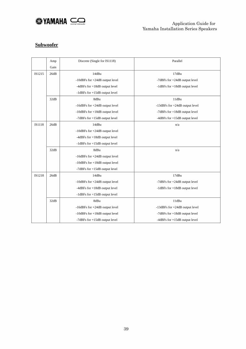
Subwoofer
Amp
Gain
Discrete (Single for IS1118) Parallel
26dB 14dBu
-10dBFs for +24dB output level
-4dBFs for +18dB output level
-1dBFs for +15dB output level
17dBu
-7dBFs for +24dB output level
-1dBFs for +18dB output level
IS1215
32dB 8dBu
-16dBFs for +24dB output level
-10dBFs for +18dB output level
-7dBFs for +15dB output level
11dBu
-13dBFs for +24dB output level
-7dBFs for +18dB output level
-4dBFs for +15dB output level
26dB 14dBu
-10dBFs for +24dB output level
-4dBFs for +18dB output level
-1dBFs for +15dB output level
n/a IS1118
32dB 8dBu
-16dBFs for +24dB output level
-10dBFs for +18dB output level
-7dBFs for +15dB output level
n/a
26dB 14dBu
-10dBFs for +24dB output level
-4dBFs for +18dB output level
-1dBFs for +15dB output level
17dBu
-7dBFs for +24dB output level
-1dBFs for +18dB output level
IS1218
32dB 8dBu
-16dBFs for +24dB output level
-10dBFs for +18dB output level
-7dBFs for +15dB output level
11dBu
-13dBFs for +24dB output level
-7dBFs for +18dB output level
-4dBFs for +15dB output level
Application Guide for Yamaha Installation Series Speakers
40
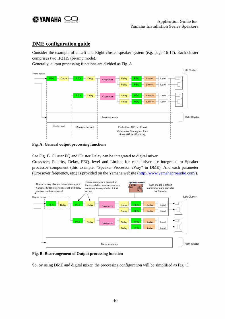
DME configuration guide Consider the example of a Left and Right cluster speaker system (e.g. page 16-17). Each cluster comprises two IF2115 (bi-amp mode). Generally, output processing functions are divided as Fig. A.
LimiterCrossover LevelPEQ Delay PEQ Delay
Limiter Level
CrossoverPEQ Delay
From Mixer
Same as above
Left Cluster
Right Cluster
Limiter Level
Limiter Level
Cluster unit
Cross over filtering and Each driver (HF or LF) setting.
Speaker box unit
PEQ
PEQ
PEQ
PEQ
Delay
Delay
Delay
Delay
Each driver (HF or LF) unit
Fig. A: General output processing functions See Fig. B. Cluster EQ and Cluster Delay can be integrated to digital mixer. Crossover, Polarity, Delay, PEQ, level and Limiter for each driver are integrated to Speaker processor component (this example, “Speaker Processor 2Way” in DME). And each parameter (Crossover frequency, etc.) is provided on the Yamaha website (http://www.yamahaproaudio.com/).
Fig. B: Rearrangement of Output processing function So, by using DME and digital mixer, the processing configuration will be simplified as Fig. C.
LimiterCrossover LevelPEQ Delay PEQ Delay
Limiter Level
CrossoverPEQ Delay
Same as above
Left Cluster
Right Cluster
Limiter Level
Limiter Level
PEQ
PEQ
PEQ
PEQ
Delay
Delay
Delay
Delay
Each model’s default parameters are provided
by Yamaha
Operator may change these parameters . Yamaha digital mixers have EQ and delay on every output channel
These parameters depend on the installation environment andare rarely changed after initial set up.
Digital mixer
Application Guide for Yamaha Installation Series Speakers
41
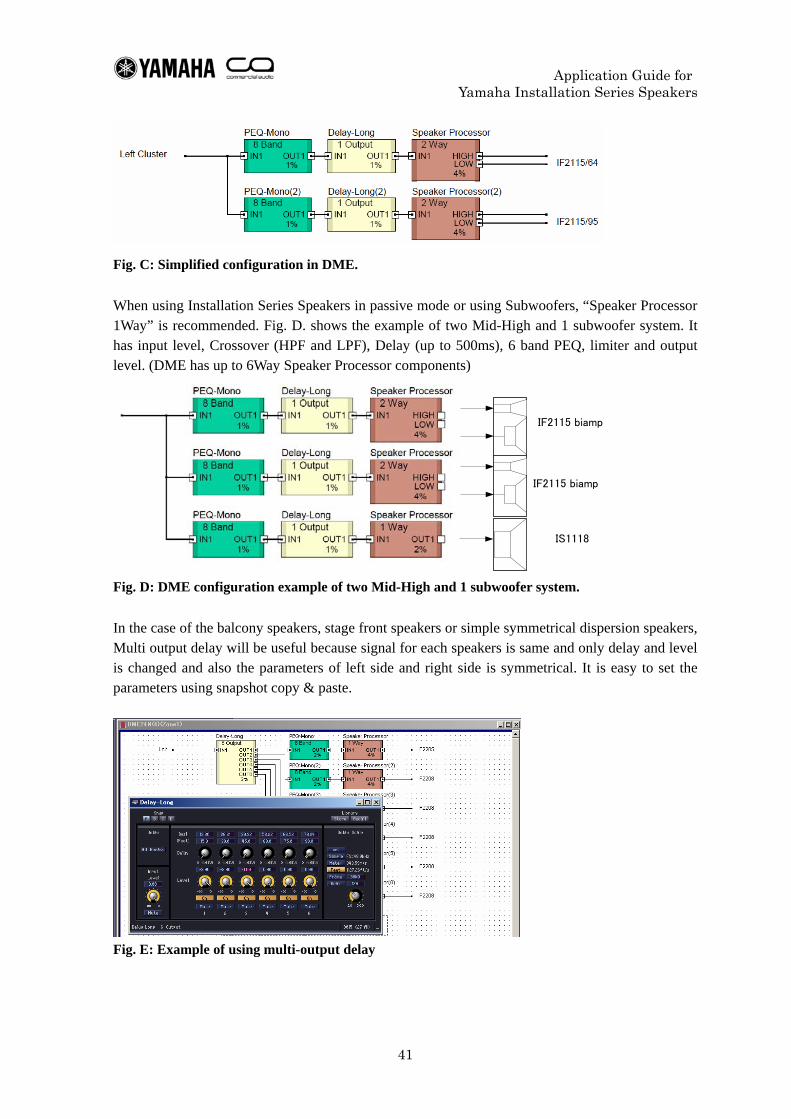
Fig. C: Simplified configuration in DME. When using Installation Series Speakers in passive mode or using Subwoofers, “Speaker Processor 1Way” is recommended. Fig. D. shows the example of two Mid-High and 1 subwoofer system. It has input level, Crossover (HPF and LPF), Delay (up to 500ms), 6 band PEQ, limiter and output level. (DME has up to 6Way Speaker Processor components)
IF2115 biamp
IF2115 biamp
IS1118
Fig. D: DME configuration example of two Mid-High and 1 subwoofer system. In the case of the balcony speakers, stage front speakers or simple symmetrical dispersion speakers, Multi output delay will be useful because signal for each speakers is same and only delay and level is changed and also the parameters of left side and right side is symmetrical. It is easy to set the parameters using snapshot copy & paste.
Fig. E: Example of using multi-output delay
Application Guide for Yamaha Installation Series Speakers
42
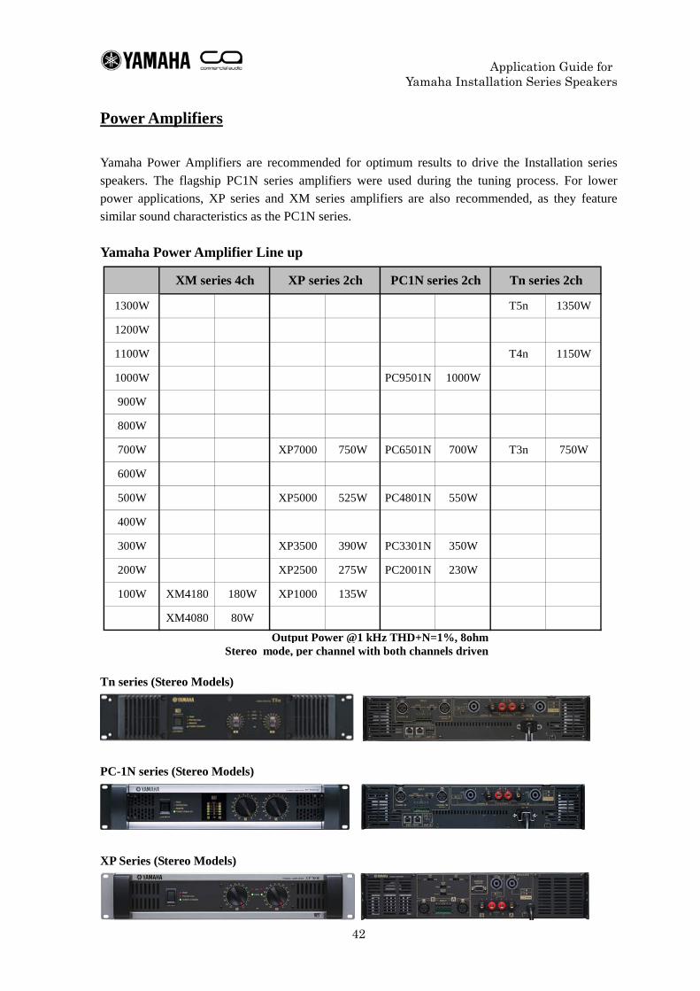
Power Amplifiers Yamaha Power Amplifiers are recommended for optimum results to drive the Installation series speakers. The flagship PC1N series amplifiers were used during the tuning process. For lower power applications, XP series and XM series amplifiers are also recommended, as they feature similar sound characteristics as the PC1N series. Yamaha Power Amplifier Line up
Output Power @1 kHz THD+N=1%, 8ohmStereo mode, per channel with both channels driven
PC2001N 230W
80WXM4080
135W
200W
XP1000
XP2500
100W XM4180 180W
XP3500 390W
275W
1000W
300W PC3301N 350W
900W
800W
1000W
400W
PC9501N
700W PC6501NXP7000
500W XP5000 525W
600W
XM series 4ch XP series 2ch PC1N series 2ch
PC4801N 550W
700W750W
Tn series 2ch
T5n 1350W
T4n 1150W
T3n 750W
1300W
1200W
1100W
Tn series (Stereo Models)
PC-1N series (Stereo Models)
XP Series (Stereo Models)
Application Guide for Yamaha Installation Series Speakers
43
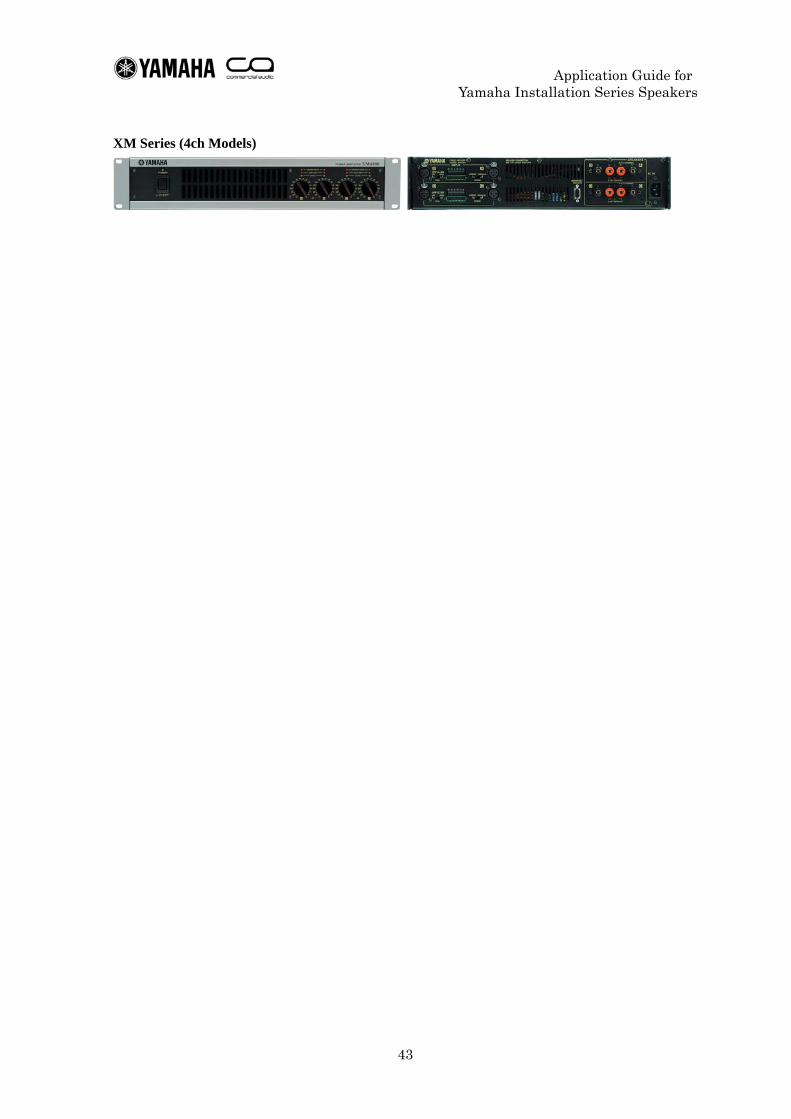
XM Series (4ch Models)
Application Guide for Yamaha Installation Series Speakers
44
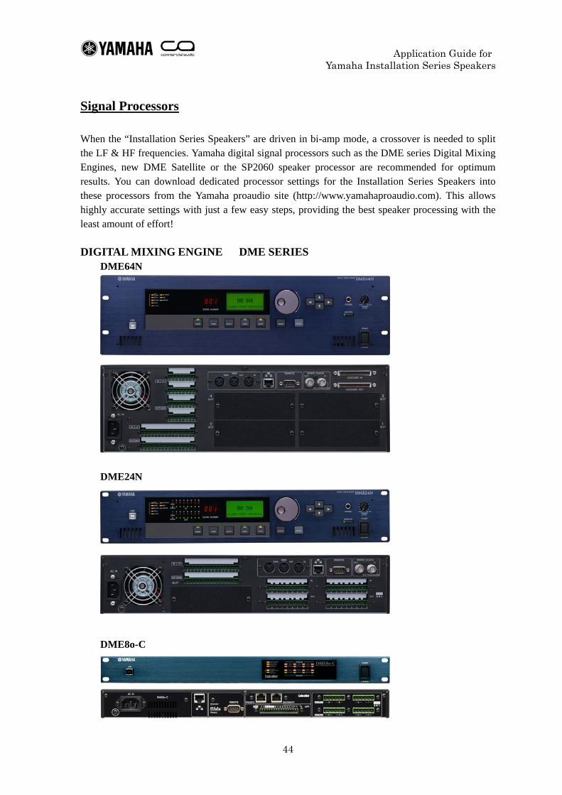
Signal Processors When the “Installation Series Speakers” are driven in bi-amp mode, a crossover is needed to split the LF & HF frequencies. Yamaha digital signal processors such as the DME series Digital Mixing Engines, new DME Satellite or the SP2060 speaker processor are recommended for optimum results. You can download dedicated processor settings for the Installation Series Speakers into these processors from the Yamaha proaudio site (http://www.yamahaproaudio.com). This allows highly accurate settings with just a few easy steps, providing the best speaker processing with the least amount of effort! DIGITAL MIXING ENGINE DME SERIES
DME64N
DME24N
DME8o-C
Application Guide for Yamaha Installation Series Speakers
45
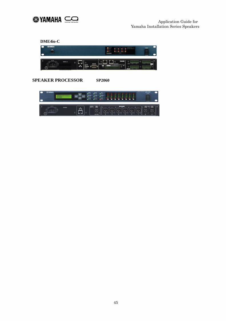
DME4io-C
SPEAKER PROCESSOR SP2060